PART 60 - STANDARDS OF PERFORMANCE FOR NEW STATIONARY SOURCES
Source:
36 FR 24877, Dec. 23, 1971, unless otherwise noted.
Subpart A - General Provisions
§ 60.1 Applicability.
(a) Except as provided in subparts B and C, the provisions of this part apply to the owner or operator of any stationary source which contains an affected facility, the construction or modification of which is commenced after the date of publication in this part of any standard (or, if earlier, the date of publication of any proposed standard) applicable to that facility.
(b) Any new or revised standard of performance promulgated pursuant to section 111(b) of the Act shall apply to the owner or operator of any stationary source which contains an affected facility, the construction or modification of which is commenced after the date of publication in this part of such new or revised standard (or, if earlier, the date of publication of any proposed standard) applicable to that facility.
(c) In addition to complying with the provisions of this part, the owner or operator of an affected facility may be required to obtain an operating permit issued to stationary sources by an authorized State air pollution control agency or by the Administrator of the U.S. Environmental Protection Agency (EPA) pursuant to Title V of the Clean Air Act (Act) as amended November 15, 1990 (42 U.S.C. 7661). For more information about obtaining an operating permit see part 70 of this chapter.
(d) Site-specific standard for Merck & Co., Inc.'s Stonewall Plant in Elkton, Virginia.
(1) This paragraph applies only to the pharmaceutical manufacturing facility, commonly referred to as the Stonewall Plant, located at Route 340 South, in Elkton, Virginia (“site”).
(2) Except for compliance with 40 CFR 60.49b(u), the site shall have the option of either complying directly with the requirements of this part, or reducing the site-wide emissions caps in accordance with the procedures set forth in a permit issued pursuant to 40 CFR 52.2454. If the site chooses the option of reducing the site-wide emissions caps in accordance with the procedures set forth in such permit, the requirements of such permit shall apply in lieu of the otherwise applicable requirements of this part.
(3) Notwithstanding the provisions of paragraph (d)(2) of this section, for any provisions of this part except for Subpart Kb, the owner/operator of the site shall comply with the applicable provisions of this part if the Administrator determines that compliance with the provisions of this part is necessary for achieving the objectives of the regulation and the Administrator notifies the site in accordance with the provisions of the permit issued pursuant to 40 CFR 52.2454.
[40 FR 53346, Nov. 17, 1975, as amended at 55 FR 51382, Dec. 13, 1990; 59 FR 12427, Mar. 16, 1994; 62 FR 52641, Oct. 8, 1997]
§ 60.2 Definitions.
The terms used in this part are defined in the Act or in this section as follows:
Act means the Clean Air Act (42 U.S.C. 7401 et seq.)
Administrator means the Administrator of the Environmental Protection Agency or his authorized representative.
Affected facility means, with reference to a stationary source, any apparatus to which a standard is applicable.
Alternative method means any method of sampling and analyzing for an air pollutant which is not a reference or equivalent method but which has been demonstrated to the Administrator's satisfaction to, in specific cases, produce results adequate for his determination of compliance.
Approved permit program means a State permit program approved by the Administrator as meeting the requirements of part 70 of this chapter or a Federal permit program established in this chapter pursuant to Title V of the Act (42 U.S.C. 7661).
Capital expenditure means an expenditure for a physical or operational change to an existing facility which exceeds the product of the applicable “annual asset guideline repair allowance percentage” specified in the latest edition of Internal Revenue Service (IRS) Publication 534 and the existing facility's basis, as defined by section 1012 of the Internal Revenue Code. However, the total expenditure for a physical or operational change to an existing facility must not be reduced by any “excluded additions” as defined in IRS Publication 534, as would be done for tax purposes.
Clean coal technology demonstration project means a project using funds appropriated under the heading ‘Department of Energy-Clean Coal Technology’, up to a total amount of $2,500,000,000 for commercial demonstrations of clean coal technology, or similar projects funded through appropriations for the Environmental Protection Agency.
Commenced means, with respect to the definition of new source in section 111(a)(2) of the Act, that an owner or operator has undertaken a continuous program of construction or modification or that an owner or operator has entered into a contractual obligation to undertake and complete, within a reasonable time, a continuous program of construction or modification.
Construction means fabrication, erection, or installation of an affected facility.
Continuous monitoring system means the total equipment, required under the emission monitoring sections in applicable subparts, used to sample and condition (if applicable), to analyze, and to provide a permanent record of emissions or process parameters.
Electric utility steam generating unit means any steam electric generating unit that is constructed for the purpose of supplying more than one-third of its potential electric output capacity and more than 25 MW electrical output to any utility power distribution system for sale. Any steam supplied to a steam distribution system for the purpose of providing steam to a steam-electric generator that would produce electrical energy for sale is also considered in determining the electrical energy output capacity of the affected facility.
Equivalent method means any method of sampling and analyzing for an air pollutant which has been demonstrated to the Administrator's satisfaction to have a consistent and quantitatively known relationship to the reference method, under specified conditions.
Excess Emissions and Monitoring Systems Performance Report is a report that must be submitted periodically by a source in order to provide data on its compliance with stated emission limits and operating parameters, and on the performance of its monitoring systems.
Existing facility means, with reference to a stationary source, any apparatus of the type for which a standard is promulgated in this part, and the construction or modification of which was commenced before the date of proposal of that standard; or any apparatus which could be altered in such a way as to be of that type.
Force majeure means, for purposes of § 60.8, an event that will be or has been caused by circumstances beyond the control of the affected facility, its contractors, or any entity controlled by the affected facility that prevents the owner or operator from complying with the regulatory requirement to conduct performance tests within the specified timeframe despite the affected facility's best efforts to fulfill the obligation. Examples of such events are acts of nature, acts of war or terrorism, or equipment failure or safety hazard beyond the control of the affected facility.
Isokinetic sampling means sampling in which the linear velocity of the gas entering the sampling nozzle is equal to that of the undisturbed gas stream at the sample point.
Issuance of a part 70 permit will occur, if the State is the permitting authority, in accordance with the requirements of part 70 of this chapter and the applicable, approved State permit program. When the EPA is the permitting authority, issuance of a Title V permit occurs immediately after the EPA takes final action on the final permit.
Malfunction means any sudden, infrequent, and not reasonably preventable failure of air pollution control equipment, process equipment, or a process to operate in a normal or usual manner. Failures that are caused in part by poor maintenance or careless operation are not malfunctions.
Modification means any physical change in, or change in the method of operation of, an existing facility which increases the amount of any air pollutant (to which a standard applies) emitted into the atmosphere by that facility or which results in the emission of any air pollutant (to which a standard applies) into the atmosphere not previously emitted.
Monitoring device means the total equipment, required under the monitoring of operations sections in applicable subparts, used to measure and record (if applicable) process parameters.
Nitrogen oxides means all oxides of nitrogen except nitrous oxide, as measured by test methods set forth in this part.
One-hour period means any 60-minute period commencing on the hour.
Opacity means the degree to which emissions reduce the transmission of light and obscure the view of an object in the background.
Owner or operator means any person who owns, leases, operates, controls, or supervises an affected facility or a stationary source of which an affected facility is a part.
Part 70 permit means any permit issued, renewed, or revised pursuant to part 70 of this chapter.
Particulate matter means any finely divided solid or liquid material, other than uncombined water, as measured by the reference methods specified under each applicable subpart, or an equivalent or alternative method.
Permit program means a comprehensive State operating permit system established pursuant to title V of the Act (42 U.S.C. 7661) and regulations codified in part 70 of this chapter and applicable State regulations, or a comprehensive Federal operating permit system established pursuant to title V of the Act and regulations codified in this chapter.
Proportional sampling means sampling at a rate that produces a constant ratio of sampling rate to stack gas flow rate.
Reactivation of a very clean coal-fired electric utility steam generating unit means any physical change or change in the method of operation associated with the commencement of commercial operations by a coal-fired utility unit after a period of discontinued operation where the unit:
(1) Has not been in operation for the two-year period prior to the enactment of the Clean Air Act Amendments of 1990, and the emissions from such unit continue to be carried in the permitting authority's emissions inventory at the time of enactment;
(2) Was equipped prior to shut-down with a continuous system of emissions control that achieves a removal efficiency for sulfur dioxide of no less than 85 percent and a removal efficiency for particulates of no less than 98 percent;
(3) Is equipped with low-NOX burners prior to the time of commencement of operations following reactivation; and
(4) Is otherwise in compliance with the requirements of the Clean Air Act.
Reference method means any method of sampling and analyzing for an air pollutant as specified in the applicable subpart.
Repowering means replacement of an existing coal-fired boiler with one of the following clean coal technologies: atmospheric or pressurized fluidized bed combustion, integrated gasification combined cycle, magnetohydrodynamics, direct and indirect coal-fired turbines, integrated gasification fuel cells, or as determined by the Administrator, in consultation with the Secretary of Energy, a derivative of one or more of these technologies, and any other technology capable of controlling multiple combustion emissions simultaneously with improved boiler or generation efficiency and with significantly greater waste reduction relative to the performance of technology in widespread commercial use as of November 15, 1990. Repowering shall also include any oil and/or gas-fired unit which has been awarded clean coal technology demonstration funding as of January 1, 1991, by the Department of Energy.
Run means the net period of time during which an emission sample is collected. Unless otherwise specified, a run may be either intermittent or continuous within the limits of good engineering practice.
Shutdown means the cessation of operation of an affected facility for any purpose.
Six-minute period means any one of the 10 equal parts of a one-hour period.
Standard means a standard of performance proposed or promulgated under this part.
Standard conditions means a temperature of 293 K (68F) and a pressure of 101.3 kilopascals (29.92 in Hg).
Startup means the setting in operation of an affected facility for any purpose.
State means all non-Federal authorities, including local agencies, interstate associations, and State-wide programs, that have delegated authority to implement:
(1) The provisions of this part; and/or
(2) the permit program established under part 70 of this chapter. The term State shall have its conventional meaning where clear from the context.
Stationary source means any building, structure, facility, or installation which emits or may emit any air pollutant.
Title V permit means any permit issued, renewed, or revised pursuant to Federal or State regulations established to implement title V of the Act (42 U.S.C. 7661). A title V permit issued by a State permitting authority is called a part 70 permit in this part.
Volatile Organic Compound means any organic compound which participates in atmospheric photochemical reactions; or which is measured by a reference method, an equivalent method, an alternative method, or which is determined by procedures specified under any subpart.
[44 FR 55173, Sept. 25, 1979, as amended at 45 FR 5617, Jan. 23, 1980; 45 FR 85415, Dec. 24, 1980; 54 FR 6662, Feb. 14, 1989; 55 FR 51382, Dec. 13, 1990; 57 FR 32338, July 21, 1992; 59 FR 12427, Mar. 16, 1994; 72 FR 27442, May 16, 2007]
§ 60.3 Units and abbreviations.
Used in this part are abbreviations and symbols of units of measure. These are defined as follows:
(a) System International (SI) units of measure:
A—ampere
g—gram
Hz—hertz
J—joule
K—degree Kelvin
kg—kilogram
m—meter
m3—cubic meter
mg—milligram—10−3 gram
mm—millimeter—10−3 meter
Mg—megagram—106 gram
mol—mole
N—newton
ng—nanogram—10−9 gram
nm—nanometer—10−9 meter
Pa—pascal
s—second
V—volt
W—watt
Ω—ohm
µg—microgram—10−6 gram
(b) Other units of measure:
Btu—British thermal unit
°C—degree Celsius (centigrade)
cal—calorie
cfm—cubic feet per minute
cu ft—cubic feet
dcf—dry cubic feet
dcm—dry cubic meter
dscf—dry cubic feet at standard conditions
dscm—dry cubic meter at standard conditions
eq—equivalent
°F—degree Fahrenheit
ft—feet
gal—gallon
gr—grain
g-eq—gram equivalent
hr—hour
in—inch
k—1,000
l—liter
lpm—liter per minute
lb—pound
meq—milliequivalent
min—minute
ml—milliliter
mol. wt.—molecular weight
ppb—parts per billion
ppm—parts per million
psia—pounds per square inch absolute
psig—pounds per square inch gage
°R—degree Rankine
scf—cubic feet at standard conditions
scfh—cubic feet per hour at standard conditions
scm—cubic meter at standard conditions
sec—second
sq ft—square feet
std—at standard conditions
(c) Chemical nomenclature:
CdS—cadmium sulfide
CO—carbon monoxide
CO2—carbon dioxide
HCl—hydrochloric acid
Hg—mercury
H2O—water
H2S—hydrogen sulfide
H2SO4—sulfuric acid
N2—nitrogen
NO—nitric oxide
NO2—nitrogen dioxide
NOX—nitrogen oxides
O2—oxygen
SO2—sulfur dioxide
SO3—sulfur trioxide
SOX—sulfur oxides
(d) Miscellaneous:
A.S.T.M.—American Society for Testing and Materials
[42 FR 37000, July 19, 1977; 42 FR 38178, July 27, 1977]
§ 60.4 Address.
(a) All requests, reports, applications, submittals, and other communications to the Administrator pursuant to this part shall be submitted in duplicate to the appropriate Regional Office of the U.S. Environmental Protection Agency to the attention of the Director of the Division indicated in the following list of EPA Regional Offices.
Region I (Connecticut, Maine, Massachusetts, New Hampshire, Rhode Island, Vermont) Director, Enforcement and Compliance Assurance Division, U.S. EPA Region I, 5 Post Office Square - Suite 100 (04-2), Boston, MA 02109-3912, Attn: Air Compliance Clerk.
Region II (New Jersey, New York, Puerto Rico, Virgin Islands), Director, Air and Waste Management Division, U.S. Environmental Protection Agency, Federal Office Building, 26 Federal Plaza (Foley Square), New York, NY 10278.
Region III (Delaware, District of Columbia, Maryland, Pennsylvania, Virginia, West Virginia), Director, Air Protection Division, Mail Code 3AP00, 1650 Arch Street, Philadelphia, PA 19103-2029.
Region IV (Alabama, Florida, Georgia, Kentucky, Mississippi, North Carolina, South Carolina, Tennessee), Director, Air, Pesticides and Toxics Management Division, U.S. Environmental Protection Agency, 61 Forsyth St. SW., Suite 9T43, Atlanta, Georgia 30303-8960.
Region V (Illinois, Indiana, Michigan, Minnesota, Ohio, Wisconsin), Director, Air and Radiation Division, U.S. Environmental Protection Agency, 77 West Jackson Boulevard, Chicago, IL 60604-3590.
Region VI (Arkansas, Louisiana, New Mexico, Oklahoma, Texas); Director; Enforcement and Compliance Assurance Division; U.S. Environmental Protection Agency, 1201 Elm Street, Suite 500, Mail Code 6ECD, Dallas, Texas 75270-2102.
Region VII (Iowa, Kansas, Missouri, Nebraska), Director, Air and Waste Management Division, 11201 Renner Boulevard, Lenexa, Kansas 66219.
Region VIII (Colorado, Montana, North Dakota, South Dakota, Utah, Wyoming) Director, Air and Toxics Technical Enforcement Program, Office of Enforcement, Compliance and Environmental Justice, Mail Code 8ENF-AT, 1595 Wynkoop Street, Denver, CO 80202-1129.
Region IX (Arizona, California, Hawaii and Nevada; the territories of American Samoa and Guam; the Commonwealth of the Northern Mariana Islands; the territories of Baker Island, Howland Island, Jarvis Island, Johnston Atoll, Kingman Reef, Midway Atoll, Palmyra Atoll, and Wake Islands; and certain U.S. Government activities in the freely associated states of the Republic of the Marshall Islands, the Federated States of Micronesia, and the Republic of Palau), Director, Air Division, U.S. Environmental Protection Agency, 75 Hawthorne Street, San Francisco, CA 94105.
Region X (Alaska, Oregon, Idaho, Washington), Director, Air and Waste Management Division, U.S. Environmental Protection Agency, 1200 Sixth Avenue, Seattle, WA 98101.
(b) Section 111(c) directs the Administrator to delegate to each State, when appropriate, the authority to implement and enforce standards of performance for new stationary sources located in such State. All information required to be submitted to EPA under paragraph (a) of this section, must also be submitted to the appropriate State Agency of any State to which this authority has been delegated (provided, that each specific delegation may except sources from a certain Federal or State reporting requirement). The appropriate mailing address for those States whose delegation request has been approved is as follows:
(1) [Reserved]
(2) State of Alabama: Alabama Department of Environmental Management, P.O. Box 301463, Montgomery, Alabama 36130-1463.
(3) State of Alaska, Department of Environmental Conservation, Pouch O, Juneau, AK 99811.
(4) Arizona:
Arizona Department of Environmental Quality, 1110 West Washington Street, Phoenix, AZ 85007.
Maricopa County Air Quality Department, 1001 North Central Avenue, Suite 900, Phoenix, AZ 85004.
Pima County Department of Environmental Quality, 33 North Stone Avenue, Suite 700, Tucson, AZ 85701.
Pinal County Air Quality Control District, 31 North Pinal Street, Building F, Florence, AZ 85132.
For tables listing the delegation status of agencies in Region IX, see paragraph (d) of this section.
(5) State of Arkansas: Chief, Division of Air Pollution Control, Arkansas Department of Pollution Control and Ecology, 8001 National Drive, P.O. Box 9583, Little Rock, AR 72209.
(6) California:
Amador County Air Pollution Control District, 12200-B Airport Road, Jackson, CA 95642.
Antelope Valley Air Quality Management District, 43301 Division Street, Suite 206, Lancaster, CA 93535.
Bay Area Air Quality Management District, 939 Ellis Street, San Francisco, CA 94109.
Butte County Air Quality Management District, 2525 Dominic Drive, Suite J, Chico, CA 95928.
Calaveras County Air Pollution Control District, 891 Mountain Ranch Road, San Andreas, CA 95249.
Colusa County Air Pollution Control District, 100 Sunrise Blvd., Suite A-3, Colusa, CA 95932-3246.
El Dorado County Air Quality Management District, 2850 Fairlane Court, Bldg. C, Placerville, CA 95667-4100.
Eastern Kern Air Pollution Control District, 2700 “M” Street, Suite 302, Bakersfield, CA 93301-2370.
Feather River Air Quality Management District, 1007 Live Oak Blvd., Suite B-3, Yuba City, CA 95991.
Glenn County Air Pollution Control District, 720 N. Colusa Street, P.O. Box 351, Willows, CA 95988-0351.
Great Basin Unified Air Pollution Control District, 157 Short Street, Suite 6, Bishop, CA 93514-3537.
Imperial County Air Pollution Control District, 150 South Ninth Street, El Centro, CA 92243-2801.
Lake County Air Quality Management District, 885 Lakeport Blvd., Lakeport, CA 95453-5405.
Lassen County Air Pollution Control District, 707 Nevada Street, Suite 1, Susanville, CA 96130.
Mariposa County Air Pollution Control District, P.O. Box 5, Mariposa, CA 95338.
Mendocino County Air Quality Management District, 306 E. Gobbi Street, Ukiah, CA 95482-5511.
Modoc County Air Pollution Control District, 619 North Main Street, Alturas, CA 96101.
Mojave Desert Air Quality Management District, 14306 Park Avenue, Victorville, CA 92392-2310.
Monterey Bay Unified Air Pollution Control District, 24580 Silver Cloud Court, Monterey, CA 93940.
North Coast Unified Air Quality Management District, 2300 Myrtle Avenue, Eureka, CA 95501-3327.
Northern Sierra Air Quality Management District, 200 Litton Drive, Suite 320, P.O. Box 2509, Grass Valley, CA 95945-2509.
Northern Sonoma County Air Pollution Control District, 150 Matheson Street, Healdsburg, CA 95448-4908.
Placer County Air Pollution Control District, 3091 County Center Drive, Suite 240, Auburn, CA 95603.
Sacramento Metropolitan Air Quality Management District, 777 12th Street, Third Floor, Sacramento, CA 95814-1908.
San Diego County Air Pollution Control District, 10124 Old Grove Road, San Diego, CA 92131-1649.
San Joaquin Valley Air Pollution Control District, 1990 E. Gettysburg, Fresno, CA 93726.
San Luis Obispo County Air Pollution Control District, 3433 Roberto Court, San Luis Obispo, CA 93401-7126.
Santa Barbara County Air Pollution Control District, 260 North San Antonio Road, Suite A, Santa Barbara, CA 93110-1315.
Shasta County Air Quality Management District, 1855 Placer Street, Suite 101, Redding, CA 96001-1759.
Siskiyou County Air Pollution Control District, 525 So. Foothill Drive, Yreka, CA 96097-3036.
South Coast Air Quality Management District, 21865 Copley Drive, Diamond Bar, CA 91765-4182.
Tehama County Air Pollution Control District, P.O. Box 8069 (1750 Walnut Street), Red Bluff, CA 96080-0038.
Tuolumne County Air Pollution Control District, 22365 Airport, Columbia, CA 95310.
Ventura County Air Pollution Control District, 669 County Square Drive, 2nd Floor, Ventura, CA 93003-5417.
Yolo-Solano Air Quality Management District, 1947 Galileo Court, Suite 103, Davis, CA 95616-4882.
For tables listing the delegation status of agencies in Region IX, see paragraph (d) of this section.
(7) State of Colorado, Department of Public Health and Environment, 4300 Cherry Creek Drive South, Denver, CO 80222-1530.
For a table listing Region VIII's NSPS delegation status, see paragraph (c) of this section.
(8) State of Connecticut, Compliance Analysis and Coordination Unit, Bureau of Air Management, Department of Energy and Environmental Protection, 79 Elm Street, 5th Floor, Hartford, CT 06106-5127.
(9) State of Delaware, Department of Natural Resources & Environmental Control, 89 Kings Highway, P.O. Box 1401, Dover, Delaware 19903.
(10) District of Columbia, Department of Public Health, Air Quality Division, 51 N Street, NE., Washington, DC 20002.
(11) State of Florida: Florida Department of Environmental Protection, Division of Air Resources Management, 2600 Blair Stone Road, MS 5500, Tallahassee, Florida 32399-2400.
(12) State of Georgia: Georgia Department of Natural Resources, Environmental Protection Division, Air Protection Branch, 4244 International Parkway, Suite 120, Atlanta, Georgia 30354.
(13) Hawaii:
Clean Air Branch, Hawaii Department of Health, 919 Ala Moana Blvd., Suite 203, Honolulu, HI 96814.
For tables listing the delegation status of agencies in Region IX, see paragraph (d) of this section.
(14) State of Idaho, Department of Health and Welfare, Statehouse, Boise, ID 83701.
(15) State of Illinois: Illinois Environmental Protection Agency, 1021 North Grand Avenue East, Springfield, Illinois 62794.
(16) State of Indiana: Indiana Department of Environmental Management, Office of Air Quality, 100 North Senate Avenue, Indianapolis, Indiana 46204.
(17) State of Iowa: Iowa Department of Natural Resources, Environmental Protection Division, Air Quality Bureau, 7900 Hickman Road, Suite 1, Urbandale, IA 50322.
(18) State of Kansas: Kansas Department of Health and Environment, Bureau of Air and Radiation, 1000 S.W. Jackson, Suite 310, Topeka, KS 66612-1366.
(19) Commonwealth of Kentucky: Kentucky Department for Environmental Protection, Division for Air Quality, 300 Sower Boulevard, 2nd Floor, Frankfort, Kentucky 40601 or local agency, Louisville Metro Air Pollution Control District, 701 W. Ormsby Ave., Suite 303, Louisville, Kentucky 40203.
(20) State of Louisiana: Louisiana Department of Environmental Quality, P.O. Box 4301, Baton Rouge, Louisiana 70821-4301.
For a list of delegated standards for Louisiana (excluding Indian country), see paragraph (e)(2) of this section.
(21) State of Maine, Maine Department of Environmental Protection, Bureau of Air Quality, 17 State House Station, Augusta, ME 04333-0017.
(22) State of Maryland, Department of the Environment, 1800 Washington Boulevard, Suite 705, Baltimore, Maryland 21230.
(23) Commonwealth of Massachusetts, Massachusetts Department of Environmental Protection, Division of Air and Climate Programs, One Winter Street, Boston, MA 02108.
(24) State of Michigan: Michigan Department of Natural Resources and Environment, Air Quality Division, P.O. Box 30028, Lansing, Michigan 48909.
(25) State of Minnesota: Minnesota Pollution Control Agency, Division of Air Quality, 520 Lafayette Road North, St. Paul, Minnesota 55155.
(26) State of Mississippi: Hand Deliver or Courier: Mississippi Department of Environmental Quality, Office of Pollution Control, Air Division, 515 East Amite Street, Jackson, Mississippi 39201, Mailing Address: Mississippi Department of Environmental Quality, Office of Pollution Control, Air Division, P.O. Box 2261, Jackson, Mississippi 39225.
(27) State of Missouri: Missouri Department of Natural Resources, Division of Environmental Quality, P.O. Box 176, Jefferson City, MO 65102.
(28) State of Montana, Department of Environmental Quality, 1520 E. 6th Ave., PO Box 200901, Helena, MT 59620-0901.
For a table listing Region VIII's NSPS delegation status, see paragraph (c) of this section.
(29) State of Nebraska, Nebraska Department of Environmental Control, P.O. Box 94877, State House Station, Lincoln, NE 68509.
Lincoln-Lancaster County Health Department, Division of Environmental Health, 2200 St. Marys Avenue, Lincoln, NE 68502
(30) Nevada:
Nevada Division of Environmental Protection, 901 South Stewart Street, Suite 4001, Carson City, NV 89701-5249.
Clark County Department of Air Quality and Environmental Management, 500 S. Grand Central Parkway, 1st Floor, P.O. Box 555210, Las Vegas, NV 89155-5210.
Washoe County Health District, Air Quality Management Division, 1001 E. 9th Street, Building A, Suite 115A, Reno, NV 89520.
For tables listing the delegation status of agencies in Region IX, see paragraph (d) of this section.
(31) State of New Hampshire, New Hampshire Department of Environmental Services, Air Resources Division, 29 Hazen Drive, P.O. Box 95, Concord, NH 03302-0095.
(32) State of New Jersey: New Jersey Department of Environmental Protection, Division of Environmental Quality, Enforcement Element, John Fitch Plaza, CN-027, Trenton, NJ 08625.
(1) The following table lists the specific source and pollutant categories that have been delegated to the states in Region II. The (X) symbol is used to indicate each category that has been delegated.
| Subpart | State | ||||
|---|---|---|---|---|---|
| New Jersey | New York | Puerto Rico | Virgin Islands | ||
| D | Fossil-Fuel Fired Steam Generators for Which Construction Commenced After August 17, 1971 (Steam Generators and Lignite Fired Steam Generators) | X | X | X | X |
| Da | Electric Utility Steam Generating Units for Which Construction Commenced After September 18, 1978 | X | X | ||
| Db | Industrial-Commercial-Institutional Steam Generating Units | X | X | X | X |
| E | Incinerators | X | X | X | X |
| F | Portland Cement Plants | X | X | X | X |
| G | Nitric Acid Plants | X | X | X | X |
| H | Sulfuric Acid Plants | X | X | X | X |
| I | Asphalt Concrete Plants | X | X | X | X |
| J | Petroleum Refineries - (All Categories) | X | X | X | X |
| K | Storage Vessels for Petroleum Liquids Constructed After June 11, 1973, and prior to May 19, 1978 | X | X | X | X |
| Ka | Storage Vessels for Petroleum Liquids Constructed After May 18, 1978 | X | X | X | |
| L | Secondary Lead Smelters | X | X | X | X |
| M | Secondary Brass and Bronze Ingot Production Plants | X | X | X | X |
| N | Iron and Steel Plants | X | X | X | X |
| O | Sewage Treatment Plants | X | X | X | X |
| P | Primary Copper Smelters | X | X | X | X |
| Q | Primary Zinc Smelters | X | X | X | X |
| R | Primary Lead Smelters | X | X | X | X |
| S | Primary Aluminum Reduction Plants | X | X | X | X |
| T | Phosphate Fertilizer Industry: Wet Process Phosphoric Acid Plants | X | X | X | X |
| U | Phosphate Fertilizer Industry: Superphosphoric Acid Plants | X | X | X | X |
| V | Phosphate Fertilizer Industry: Diammonium Phosphate Plants | X | X | X | X |
| W | Phosphate Fertilizer Industry: Triple Superphosphate Plants | X | X | X | X |
| X | Phosphate Fertilizer Industry: Granular Triple Superphosphate | X | X | X | X |
| Y | Coal Preparation Plants | X | X | X | X |
| Z | Ferroally Production Facilities | X | X | X | X |
| AA | Steel Plants: Electric Arc Furnaces | X | X | X | X |
| AAa | Electric Arc Furnaces and Argon-Oxygen Decarburization Vessels in Steel Plants | X | X | X | |
| BB | Kraft Pulp Mills | X | X | X | |
| CC | Glass Manufacturing Plants | X | X | X | |
| DD | Grain Elevators | X | X | X | |
| EE | Surface Coating of Metal Furniture | X | X | X | |
| GG | Stationary Gas Turbines | X | X | X | |
| HH | Lime Plants | X | X | X | |
| KK | Lead Acid Battery Manufacturing Plants | X | X | ||
| LL | Metallic Mineral Processing Plants | X | X | X | |
| MM | Automobile and Light-Duty Truck Surface Coating Operations | X | X | ||
| NN | Phosphate Rock Plants | X | X | ||
| PP | Ammonium Sulfate Manufacturing Plants | X | X | ||
| Graphic Art Industry Publication Rotogravure Printing | X | X | X | X | |
| RR | Pressure Sensitive Tape and Label Surface Coating Operations | X | X | X | |
| SS | Industrial Surface Coating: Large Appliances | X | X | X | |
| TT | Metal Coil Surface Coating | X | X | X | |
| UU | Asphalt Processing and Asphalt Roofing Manufacture | X | X | X | |
| VV | Equipment Leaks of Volatile Organic Compounds in Synthetic Organic Chemical Manufacturing Industry | X | X | ||
| WW | Beverage Can Surface Coating Industry | X | X | X | |
| XX | Bulk Gasoline Terminals | X | X | X | |
| FFF | Flexible Vinyl and Urethane Coating and Printing | X | X | X | |
| GGG | Equipment Leaks of VOC in Petroleum Refineries | X | X | ||
| HHH | Synthetic Fiber Production Facilities | X | X | ||
| JJJ | Petroleum Dry Clearners | X | X | X | |
| KKK | Equipment Leaks of VOC from Onshore Natural Gas Processing Plants | ||||
| LLL | Onshore Natural Gas Processing Plants; SO2 Emissions | X | |||
| OOO | Nonmetallic Mineral Processing Plants | X | X | ||
| PPP | Wool Fiberglass Insulation Manufacturing Plants | X | X | ||
(33) State of New Mexico: New Mexico Environment Department, P.O. Box 5469, Santa Fe, New Mexico 87502-5469. Note: For a list of delegated standards for New Mexico (excluding Bernalillo County and Indian country), see paragraph (e)(1) of this section.
(34) New York: New York State Department of Environmental Conservation, 50 Wolf Road Albany, New York 12233, attention: Division of Air Resources.
(35) State of North Carolina: North Carolina Department of Environmental Quality, Division of Air Quality, 1641 Mail Service Center, Raleigh, North Carolina 27699-1641 or local agencies, Forsyth County Office of Environmental Assistance and Protection, 201 North Chestnut Street, Winston-Salem, North Carolina 27101-4120; Mecklenburg County Land Use and Environmental Services Agency, Air Quality, 2145 Suttle Avenue, Charlotte, North Carolina 28208; Western North Carolina Regional Air Quality Agency, 125 S. Lexington Ave., Suite 101, Asheville, North Carolina 28801-3661.
(36) State of North Dakota, North Dakota Department of Environmental Quality, 918 East Divide Avenue, Bismarck, ND 58501-1947.
For a table listing Region VIII's NSPS delegation status, see paragraph (c) of this section.
(37) State of Ohio:
(i) Medina, Summit and Portage Counties; Director, Akron Regional Air Quality Management District, 146 South High Street, Room 904, Akron, OH 44308.
(ii) Stark County; Director, Canton City Health Department, Air Pollution Control Division, 420 Market Avenue North, Canton, Ohio 44702-1544.
(iii) Butler, Clermont, Hamilton, and Warren Counties; Director, Hamilton County Department of Environmental Services, 250 William Howard Taft Road, Cincinnati, Ohio 45219-2660.
(iv) Cuyahoga County; Commissioner, Cleveland Department of Public Health, Division of Air Quality, 75 Erieview Plaza 2nd Floor, Cleveland, Ohio 44114.
(v) Clark, Darke, Greene, Miami, Montgomery, and Preble Counties; Director, Regional Air Pollution Control Agency, 117 South Main Street, Dayton, Ohio 45422-1280.
(vi) Lucas County and the City of Rossford (in Wood County); Director, City of Toledo, Division of Environmental Services, 348 South Erie Street, Toledo, OH 43604.
(vii) Adams, Brown, Lawrence, and Scioto Counties; Portsmouth Local Air Agency, 605 Washington Street, Third Floor, Portsmouth, OH 45662.
(viii) Allen, Ashland, Auglaize, Crawford, Defiance, Erie, Fulton, Hancock, Hardin, Henry, Huron, Marion, Mercer, Ottawa, Paulding, Putnam, Richland, Sandusky, Seneca, Van Wert Williams, Wood (Except City of Rossford), and Wyandot Counties; Ohio Environmental Protection Agency, Northwest District Office, Air Pollution Control, 347 North Dunbridge Road, Bowling Green, Ohio 43402.
(ix) Ashtabula, Caroll, Colombiana, Holmes, Lorain, and Wayne Counties; Ohio Environmental Protection Agency, Northeast District Office, Air Pollution Unit, 2110 East Aurora Road, Twinsburg, OH 44087.
(x) Athens, Belmont, Coshocton, Gallia, Guemsey, Harrison, Hocking, Jackson, Jefferson, Meigs, Monroe, Morgan, Muskingum, Noble, Perry, Pike, Ross, Tuscarawas, Vinton, and Washington Counties; Ohio Environmental Protection Agency, Southeast District Office, Air Pollution Unit, 2195 Front Street, Logan, OH 43138.
(xi) Champaign, Clinton, Highland, Logan, and Shelby Counties; Ohio Environmental Protection Agency, Southwest District Office, Air Pollution Unit, 401 East Fifth Street, Dayton, Ohio 45402-2911.
(xii) Delaware, Fairfield, Fayette, Franklin, Knox, Licking, Madison, Morrow, Pickaway, and Union Counties; Ohio Environmental Protection Agency, Central District Office, Air Pollution control, 50 West Town Street, Suite 700, Columbus, Ohio 43215.
(xiii) Geauga and Lake Counties; Lake County General Health District, Air Pollution Control, 33 Mill Street, Painesville, OH 44077.
(xiv) Mahoning and Trumbull Counties; Mahoning-Trumbull Air Pollution Control Agency, 345 Oak Hill Avenue, Suite 200, Youngstown, OH 44502.
(38) State of Oklahoma, Oklahoma State Department of Health, Air Quality Service, P.O. Box 53551, Oklahoma City, OK 73152.
(i) Oklahoma City and County: Director, Oklahoma City-County Health Department, 921 Northeast 23rd Street, Oklahoma City, OK 73105.
(ii) Tulsa County: Tulsa City-County Health Department, 4616 East Fifteenth Street, Tulsa, OK 74112.
(39) State of Oregon.
(i) Oregon Department of Environmental Quality (ODEQ), 811 SW Sixth Avenue, Portland, OR 97204-1390, http://www.deq.state.or.us.
(ii) Lane Regional Air Pollution Authority (LRAPA), 1010 Main Street, Springfield, Oregon 97477, http://www.lrapa.org.
(40)
(i) City of Philadelphia, Department of Public Health, Air Management Services, 321 University Avenue, Philadelphia, Pennsylvania 19104.
(ii) Commonwealth of Pennsylvania, Department of Environmental Protection, Bureau of Air Quality Control, P.O. Box 8468, 400 Market Street, Harrisburg, Pennsylvania 17105.
(iii) Allegheny County Health Department, Bureau of Environmental Quality, Division of Air Quality, 301 39th Street, Pittsburgh, Pennsylvania 15201.
(41) State of Rhode Island, Rhode Island Department of Environmental Management, Office of Air Resources, 235 Promenade Street, Providence, RI 02908.
(42) State of South Carolina: South Carolina Department of Health and Environmental Control, 2600 Bull Street, Columbia, South Carolina 29201.
(43) State of South Dakota, Air Quality Program, Department of Environment and Natural Resources, Joe Foss Building, 523 East Capitol, Pierre, SD 57501-3181.
For a table listing Region VIII's NSPS delegation status, see paragragh (c) of this section.
(44) State of Tennessee: Tennessee Department of Environment and Conservation, Division of Air Pollution Control, William R. Snodgrass Tennessee Tower, 312 Rosa L. Parks Avenue, 15th Floor, Nashville, Tennessee 37243, or local agencies, Knox County Air Quality Management - Department of Public Health, 140 Dameron Avenue, Knoxville, Tennessee 37917; Metro Public Health Department, Pollution Control Division, 2500 Charlotte Ave., Nashville, Tennessee 37209; Chattanooga-Hamilton County Air Pollution Control Bureau, 6125 Preservation Drive, Chattanooga, Tennessee 37416; Shelby County Health Department, Pollution Control Section, 814 Jefferson Avenue, Memphis, Tennessee 38105.
(45) State of Texas, Texas Air Control Board, 6330 Highway 290 East, Austin, TX 78723.
(46) State of Utah, Division of Air Quality, Department of Environmental Quality, P.O. Box 144820, Salt Lake City, UT 84114-4820.
For a table listing Region VIII's NSPS delegation status, see paragraph (c) of this section.
(47) State of Vermont, Agency of Natural Resources, Department of Environmental Conservation, Air Quality and Climate Division, Davis 2, One National Life Drive, Montpelier, VT 05620-3802.
(48) Commonwealth of Virginia, Department of Environmental Quality, 629 East Main Street, Richmond, Virginia 23219.
(49) State of Washington.
(i) Washington State Department of Ecology (Ecology), P.O. Box 47600, Olympia, WA 98504-7600, http://www.ecy.wa.gov/
(ii) Benton Clean Air Authority (BCAA), 650 George Washington Way, Richland, WA 99352-4289, http://www.bcaa.net/
(iii) Northwest Air Pollution Control Authority (NWAPA), 1600 South Second St., Mount Vernon, WA 98273-5202, http://www.nwair.org/
(iv) Olympic Regional Clean Air Agency (ORCAA), 909 Sleater-Kinney Road S.E., Suite 1, Lacey, WA 98503-1128, http://www.orcaa.org/
(v) Puget Sound Clean Air Agency (PSCAA), 110 Union Street, Suite 500, Seattle, WA 98101-2038, http://www.pscleanair.org/
(vi) Spokane County Air Pollution Control Authority (SCAPCA), West 1101 College, Suite 403, Spokane, WA 99201, http://www.scapca.org/
(vii) Southwest Clean Air Agency (SWCAA), 1308 NE. 134th St., Vancouver, WA 98685-2747, http://www.swcleanair.org/
(viii) Yakima Regional Clean Air Authority (YRCAA), 6 South 2nd Street, Suite 1016, Yakima, WA 98901, http://co.yakima.wa.us/cleanair/default.htm
(ix) The following table lists the delegation status of the New Source Performance Standards for the State of Washington. An “X” indicates the subpart has been delegated, subject to all the conditions and limitations set forth in Federal law and the letters granting delegation. Some authorities cannot be delegated and are retained by EPA. Refer to the letters granting delegation for a discussion of these retained authorities. The dates noted at the end of the table indicate the effective dates of Federal rules that have been delegated. Authority for implementing and enforcing any amendments made to these rules after these effective dates are not delegated.
NSPS Subparts Delegated to Washington Air Agencies
| Subpart1 | Washington | |||||||
|---|---|---|---|---|---|---|---|---|
| Ecology2 | BCAA3 | NWAPA4 | ORCAA5 | PSCAA6 | SCAPCA7 | SWCAA8 | YRCAA9 | |
| A General Provisions | X | X | X | X | X | X | X | X |
| B Adoption and Submittal of State Plans for Designated Facilities | ||||||||
| C Emission Guidelines and Compliance Times | ||||||||
| Cb Large Municipal Waste Combustors that are Constructed on or before September 20, 1994 (Emission Guidelines and Compliance Times) | ||||||||
| Cc Municipal Solid Waste Landfills (Emission Guidelines and Compliance Times) | ||||||||
| Cd Sulfuric Acid Production Units (Emission Guidelines and Compliance Times) | ||||||||
| Ce Hospital/Medical/Infectious Waste Incinerators (Emission Guidelines and Compliance Times) | ||||||||
| D Fossil-Fuel-Fired Steam Generators for which Construction is Commenced after August 17, 1971 | X | X | X | X | X | X | X | X |
| Da Electric Utility Steam Generating Units for which Construction is Commenced after September 18, 1978 | X | X | X | X | X | X | X | X |
| Db Industrial-Commercial-Institutional Steam Generating Units | X | X | X | X | X | X | X | X |
| Dc Small Industrial-Commercial-Institutional Steam Generating Units | X | X | X | X | X | X | X | X |
| E Incinerators | X | X | X | X | X | X | X | X |
| Ea Municipal Waste Combustors for which Construction is Commenced after December 20, 1989 and on or before September 20, 1994 | X | X | X | X | X | X | X | X |
| Eb - Large Municipal Waste Combustors | X | X | X | X | ||||
| Ec - Hospital/Medical/Infectious Waste Incinerators | X | X | X | X | X | X | ||
| F Portland Cement Plants | X | X | X | X | X | X | X | X |
| G Nitric Acid Plants | X | X | X | X | X | X | X | X |
| H Sulfuric Acid Plants | X | X | X | X | X | X | X | X |
| I Hot Mix Asphalt Facilities | X | X | X | X | X | X | X | X |
| J Petroleum Refineries | X | X | X | X | X | X | X | X |
| K Storage Vessels for Petroleum Liquids for which Construction, Reconstruction, or Modification Commenced after June 11, 1973 and prior to May 19, 1978 | X | X | X | X | X | X | X | X |
| Ka Storage Vessels for Petroleum Liquids for which Construction, Reconstruction, or Modification Commenced after May 18, 1978 and prior to July 23, 1984 | X | X | X | X | X | X | X | X |
| Kb VOC Liquid Storage Vessels (including Petroleum Liquid Storage Vessels) for which Construction, Reconstruction, or Modification Commenced after July 23, 1984 | X | X | X | X | X | X | X | X |
| L Secondary Lead Smelters | X | X | X | X | X | X | X | X |
| M Secondary Brass and Bronze Production Plants | X | X | X | X | X | X | X | X |
| N Primary Emissions from Basic Oxygen Process Furnaces for which Construction is Commenced after June 11, 1973 | X | X | X | X | X | X | X | X |
| Na Secondary Emissions from Basic Oxygen Process Steel-making Facilities for which Construction is Commenced after January 20, 1983 | X | X | X | X | X | X | X | X |
| O Sewage Treatment Plants | X | X | X | X | X | X | X | X |
| P Primary Copper Smelters | X | X | X | X | X | X | X | X |
| Q Primary Zinc Smelters | X | X | X | X | X | X | X | X |
| R Primary Lead Smelters | X | X | X | X | X | X | X | X |
| S Primary Aluminum Reduction Plants10 | X | |||||||
| T Phosphate Fertilizer Industry: Wet Process Phosphoric Acid Plants | X | X | X | X | X | X | X | X |
| U Phosphate Fertilizer Industry: Superphosphoric Acid Plants | X | X | X | X | X | X | X | X |
| V Phosphate Fertilizer Industry: Diammonium Phosphate Plants | X | X | X | X | X | X | X | X |
| W Phosphate Fertilizer Industry: Triple Superphosphate Plants | X | X | X | X | X | X | X | X |
| X Phosphate Fertilizer Industry: Granular Triple Superphosphate Storage Facilities | X | X | X | X | X | X | X | X |
| Y Coal Preparation Plants | X | X | X | X | X | X | X | X |
| Z Ferroalloy Production Facilities | X | X | X | X | X | X | X | X |
| AA Steel Plants: Electric Arc Furnaces Constructed after October 21, 1974 and on or before August 17, 1983 | X | X | X | X | X | X | X | X |
| AAa Steel Plants: Electric Arc Furnaces and Argon-Oxygen Decarburization Vessels Constructed after August 7, 1983 | X | X | X | X | X | X | X | X |
| BB Kraft Pulp Mills11 | X | |||||||
| CC Glass Manufacturing Plants | X | X | X | X | X | X | X | X |
| DD Grain Elevators | X | X | X | X | X | X | X | X |
| EE Surface Coating of Metal Furniture | X | X | X | X | X | X | X | X |
| GG Stationary Gas Turbines | X | X | X | X | X | X | X | X |
| HH Lime Manufacturing Plants | X | X | X | X | X | X | X | X |
| KK Lead-Acid Battery Manufacturing Plants | X | X | X | X | X | X | X | X |
| LL Metallic Mineral Processing Plants | X | X | X | X | X | X | X | X |
| MM Automobile and Light Duty Truck Surface Coating Operations | X | X | X | X | X | X | X | X |
| NN Phosphate Rock Plants | X | X | X | X | X | X | X | X |
| PP Ammonium Sulfate Manufacture | X | X | X | X | X | X | X | X |
| QQ Graphic Arts Industry: Publication Rotogravure Printing | X | X | X | X | X | X | X | X |
| RR Pressure Sensitive Tape and Label Surface Coating Standards | X | X | X | X | X | X | X | X |
| SS Industrial Surface Coating: Large Appliances | X | X | X | X | X | X | X | X |
| TT Metal Coil Surface Coating | X | X | X | X | X | X | X | X |
| UU Asphalt Processing and Asphalt Roof Manufacture | X | X | X | X | X | X | X | X |
| VV Equipment Leaks of VOC in Synthetic Organic Chemical Manufacturing Industry | X | X | X | X | X | X | X | X |
| WW Beverage Can Surface Coating Industry | X | X | X | X | X | X | X | X |
| XX Bulk Gasoline Terminals | X | X | X | X | X | X | X | X |
| AAA New Residential Wood Heaters | ||||||||
| BBB Rubber Tire Manufacturing Industry | X | X | X | X | X | X | X | X |
| DDD VOC Emissions from Polymer Manufacturing Industry | X | X | X | X | X | X | X | X |
| FFF Flexible Vinyl and Urethane Coating and Printing | X | X | X | X | X | X | X | X |
| GGG Equipment Leaks of VOC in Petroleum Refineries | X | X | X | X | X | X | X | X |
| HHH Synthetic Fiber Production Facilities | X | X | X | X | X | X | X | X |
| III VOC Emissions from Synthetic Organic Chemical Manufacturing Industry Air Oxidation Unit Processes | X | X | X | X | X | X | X | X |
| JJJ Petroleum Dry Cleaners | X | X | X | X | X | X | X | X |
| KKK Equipment Leaks of VOC from Onshore Natural Gas Processing Plants | X | X | X | X | X | X | X | X |
| LLL Onshore Natural Gas Processing: SO2 Emissions | X | X | X | X | X | X | X | X |
| NNN VOC Emissions from Synthetic Organic Chemical Manufacturing Industry Distillation Operations | X | X | X | X | X | X | X | X |
| OOO Nonmetallic Mineral Processing Plants | X | X | X | |||||
| PPP Wool Fiberglass Insulation Manufacturing Plants | X | X | X | X | X | X | X | X |
| QQQ VOC Emissions from Petroleum Refinery Wastewater Systems | X | X | X | X | X | X | X | X |
| RRR VOCs from Synthetic Organic Chemical Manufacturing Industry Reactor Processes | X | X | X | X | X | X | X | X |
| SSS Magnetic Tape Coating Facilities | X | X | X | X | X | X | X | X |
| TTT Industrial Surface Coating: Surface Coating of Plastic Parts for Business Machines | X | X | X | X | X | X | X | X |
| UUU Calciners and Dryers in Mineral Industries | X | X | X | X | X | X | X | X |
| VVV Polymeric Coating of Supporting Substrates Facilities | X | X | X | X | X | X | X | X |
| WWW Municipal Solid Waste Landfills | X | X | X | X | X | X | X | X |
| AAAA Small Municipal Waste Combustion Units for which Construction is Commenced after August 30, 1999 or for which Modification or Reconstruction is Commenced after June 6, 2001 | X | X | X | X | X | X | ||
| BBBB Small Municipal Waste Combustion Units Constructed on or before August 30, 1999 (Emission Guidelines and Compliance Times) | ||||||||
| CCCC Commercial and Industrial Solid Waste Incineration Units for which Construction is Commenced after November, 30, 1999 or for which Modification or Reconstruction is Commenced on or after June 1, 2001 | X | X | X | X | X | X | ||
| DDDD Commercial and Industrial Solid Waste Incineration Units that Commenced Construction on or before November 30, 1999 (Emission Guidelines and Compliance Times) | ||||||||
(50) State of West Virginia, Department of Environmental Protection, Division of Air Quality, 601 57th Street, SE., Charleston, West Virginia 25304.
(51) State of Wisconsin: Wisconsin Department of Natural Resouces, 101 South Webster St., P.O. Box 7921, Madison, Wisconsin 53707-7921.
(52) State of Wyoming, Department of Environmental Quality, Air Quality Division, Herschler Building, 122 West 25th Street, Cheyenne, WY 82002.
For a table listing Region VIII's NSPS delegation status, see paragraph (c) of this section.
(53) Territory of Guam: Guam Environmental Protection Agency, P.O. Box 22439 GMF, Barrigada, Guam 96921.
For tables listing the delegation status of agencies in Region IX, see paragraph (d) of this section.
(54) Commonwealth of Puerto Rico: Commonwealth of Puerto Rico Environmental Quality Board, P.O. Box 11488, Santurce, PR 00910, Attention: Air Quality Area Director (see table under § 60.4(b)(FF)(1)).
(55) U.S. Virgin Islands: U.S. Virgin Islands Department of Conservation and Cultural Affairs, P.O. Box 578, Charlotte Amalie, St. Thomas, VI 00801.
(56) American Samoa: American Samoa Environmental Protection Agency, P.O. Box PPA, Pago Pago, American Samoa 96799.
For tables listing the delegation status of agencies in Region IX, see paragraph (d) of this section.
(57) Commonwealth of the Northern Mariana Islands: CNMI Division of Environmental Quality, P.O. Box 501304, Saipan, MP 96950.
For tables listing the delegation status of agencies in Region IX, see paragraph (d) of this section.
(c) The delegation status table for New Source Performance Standards for Region VIII can be found online at http://www2.epa.gov/region8/air-program.
(d) The following tables list the specific part 60 standards that have been delegated unchanged to the air pollution control agencies in Region IX. The (X) symbol is used to indicate each standard that has been delegated. The following provisions of this subpart are not delegated: §§ 60.4(b), 60.8(b), 60.9, 60.11(b), 60.11(e), 60.13(a), 60.13(d)(2), 60.13(g), 60.13(i).
(1) Arizona. The following table identifies delegations for Arizona:
Table 3 to Paragraph (d)(1) - Delegation Status for New Source Performance Standards for Arizona
| Subpart | Air pollution control agency | ||||
|---|---|---|---|---|---|
| Arizona
DEQ |
Maricopa
County |
Pima
County |
Pinal
County |
||
| A | General Provisions | X | X | X | X |
| D | Fossil-Fuel Fired Steam Generators Constructed After August 17, 1971 | X | X | X | X |
| Da | Electric Utility Steam Generating Units Constructed After September 18, 1978 | X | X | X | X |
| Db | Industrial-Commercial-Institutional Steam Generating Units | X | X | X | X |
| Dc | Small Industrial-Commercial-Institutional Steam Generating Units | X | X | X | X |
| E | Incinerators | X | X | X | X |
| Ea | Municipal Waste Combustors Constructed After December 20, 1989 and On or Before September 20, 1994 | X | X | X | X |
| Eb | Large Municipal Waste Combustors Constructed After September 20, 1994 | X | X | X | |
| Ec | Hospital/Medical/Infectious Waste Incinerators for Which Construction is Commenced After June 20, 1996 | X | X | X | |
| F | Portland Cement Plants | X | X | X | |
| G | Nitric Acid Plants | X | X | X | X |
| Ga | Nitric Acid Plants For Which Construction, Reconstruction or Modification Commenced After October 14, 2011 | X | X | ||
| H | Sulfuric Acid Plant | X | X | X | X |
| I | Hot Mix Asphalt Facilities | X | X | X | X |
| J | Petroleum Refineries | X | X | X | |
| Ja | Petroleum Refineries for Which Construction, Reconstruction, or Modification Commenced After May 14, 2007 | X | |||
| K | Storage Vessels for Petroleum Liquids for Which Construction, Reconstruction, or Modification Commenced After June 11, 1973, and Prior to May 19, 1978 | X | X | X | X |
| Ka | Storage Vessels for Petroleum Liquids for Which Construction, Reconstruction, or Modification Commenced After May 18, 1978, and Prior to July 23, 1984 | X | X | X | X |
| Kb | Volatile Organic Liquid Storage Vessels (Including Petroleum Liquid Storage Vessels) for Which Construction, Reconstruction, or Modification Commenced After July 23, 1984 | X | X | X | X |
| L | Secondary Lead Smelters | X | X | X | |
| M | Secondary Brass and Bronze Production Plants | X | X | X | X |
| N | Primary Emissions from Basic Oxygen Process Furnaces for Which Construction is Commenced After June 11, 1973 | X | X | X | X |
| Na | Secondary Emissions from Basic Oxygen Process Steelmaking Facilities for Which Construction is Commenced After January 20, 1983 | X | X | X | X |
| O | Sewage Treatment Plants | X | X | X | X |
| P | Primary Copper Smelters | X | X | X | |
| Q | Primary Zinc Smelters | X | X | X | |
| R | Primary Lead Smelters | X | X | X | |
| S | Primary Aluminum Reduction Plants | X | X | X | X |
| T | Phosphate Fertilizer Industry: Wet Process Phosphoric Acid Plants | X | X | X | X |
| U | Phosphate Fertilizer Industry: Superphosphoric Acid Plants | X | X | X | X |
| V | Phosphate Fertilizer Industry: Diammonium Phosphate Plants | X | X | X | X |
| W | Phosphate Fertilizer Industry: Triple Superphosphate Plants | X | X | X | X |
| X | Phosphate Fertilizer Industry: Granular Triple Superphosphate Storage Facilities | X | X | X | X |
| Y | Coal Preparation and Processing Plants | X | X | X | X |
| Z | Ferroalloy Production Facilities | X | X | X | X |
| AA | Steel Plants: Electric Arc Furnaces Constructed After October 21, 1974 and On or Before August 17, 1983 | X | X | X | X |
| AAa | Steel Plants: Electric Arc Furnaces and Argon-Oxygen Decarburization Vessels Constructed After August 7, 1983 | X | X | X | X |
| BB | Kraft Pulp Mills | X | X | X | X |
| BBa | Kraft Pulp Mill Sources for which Construction, Reconstruction or Modification Commenced after May 23, 2013 | X | X | ||
| CC | Glass Manufacturing Plants | X | X | X | X |
| DD | Grain Elevators | X | X | X | X |
| EE | Surface Coating of Metal Furniture | X | X | X | X |
| FF | (Reserved) | ||||
| GG | Stationary Gas Turbines | X | X | X | X |
| HH | Lime Manufacturing Plants | X | X | X | X |
| KK | Lead-Acid Battery Manufacturing Plants | X | X | X | X |
| LL | Metallic Mineral Processing Plants | X | X | X | X |
| MM | Automobile and Light Duty Trucks Surface Coating Operations | X | X | X | X |
| NN | Phosphate Rock Plants | X | X | X | X |
| PP | Ammonium Sulfate Manufacture | X | X | X | X |
| Graphic Arts Industry: Publication Rotogravure Printing | X | X | X | X | |
| RR | Pressure Sensitive Tape and Label Surface Coating Operations | X | X | X | X |
| SS | Industrial Surface Coating: Large Appliances | X | X | X | X |
| TT | Metal Coil Surface Coating | X | X | X | X |
| UU | Asphalt Processing and Asphalt Roofing Manufacture | X | X | X | X |
| VV | Equipment Leaks of VOC in the Synthetic Organic Industry Chemicals Manufacturing | X | X | X | X |
| VVa | Equipment Leaks of VOC in the Synthetic Organic Industry for Which Construction, Reconstruction, or Chemicals Manufacturing Modification Commenced After November 7, 2006 | X | X | X | |
| WW | Beverage Can Surface Coating Industry | X | X | X | X |
| XX | Bulk Gasoline Terminals | X | X | X | X |
| AAA | New Residential Wood Heaters | X | X | X | X |
| BBB | Rubber Tire Manufacturing Industry | X | X | X | X |
| CCC | (Reserved) | ||||
| DDD | Volatile Organic Compounds (VOC) Emissions from the Polymer Manufacturing Industry | X | X | X | X |
| EEE | (Reserved) | ||||
| FFF | Flexible Vinyl and Urethane Coating and Printing | X | X | X | X |
| GGG | Equipment Leaks of VOC in Petroleum Refineries | X | X | X | |
| GGGa | Equipment Leaks of VOC in Petroleum Refineries for Which Construction, Reconstruction, or Modification Commenced After November 7, 2006 | X | X | ||
| HHH | Synthetic Fiber Production Facilities | X | X | X | X |
| III | Volatile Organic Compound (VOC) Emissions From the Synthetic Organic Chemical Manufacturing Industry (SOCMI) Air Oxidation Unit Processes | X | X | X | X |
| JJJ | Petroleum Dry Cleaners | X | X | X | X |
| KKK | Equipment Leaks of VOC From Onshore Natural Gas Processing Plants | X | X | X | X |
| LLL | Onshore Natural Gas Processing: SO2 Emissions | X | X | X | X |
| MMM | (Reserved) | ||||
| NNN | Volatile Organic Compound (VOC) Emissions From Synthetic Organic Chemical Manufacturing Industry (SOCMI) Distillation Operations | X | X | X | X |
| OOO | Nonmetallic Mineral Processing Plants | X | X | X | X |
| PPP | Wool Fiberglass Insulation Manufacturing Plants | X | X | X | X |
| QQQ | VOC Emissions From Petroleum Refinery Wastewater Systems | X | X | X | |
| RRR | Volatile Organic Compound Emissions from Synthetic Organic Chemical Manufacturing Industry (SOCMI) Reactor Processes | X | X | ||
| SSS | Magnetic Tape Coating Facilities | X | X | X | X |
| TTT | Industrial Surface Coating: Surface Coating of Plastic Parts for Business Machines | X | X | X | X |
| UUU | Calciners and Dryers in Mineral Industries | X | X | X | |
| VVV | Polymeric Coating of Supporting Substrates Facilities | X | X | X | X |
| WWW | Municipal Solid Waste Landfills | X | X | X | |
| XXX | Municipal Solid Waste Landfills that Commenced Construction, Reconstruction, or Modification After July 17, 2014 | X | |||
| AAAA | Small Municipal Waste Combustion Units for Which Construction is Commenced After August 30, 1999 or for Which Modification or Reconstruction is Commended After June 6, 2001 | X | X | X | |
| CCCC | Commercial and Industrial Solid Waste Incineration Units for Which Construction Is Commenced After November 30, 1999 or for Which Modification or Reconstruction Is Commenced on or After June 1, 2001 | X | X | X | |
| EEEE | Other Solid Waste Incineration Units for Which Construction is Commenced After December 9, 2004, or for Which Modification or Reconstruction is Commenced on or After June 16, 2006 | X | X | X | |
| GGGG | (Reserved) | ||||
| HHHH | (Reserved) | ||||
| IIII | Stationary Compression Ignition Internal Combustion Engines | X | X | X | |
| JJJJ | Stationary Spark Ignition Internal Combustion Engines | X | X | ||
| KKKK | Stationary Combustion Turbines | X | X | X | |
| LLLL | New Sewage Sludge Incineration Units | X | |||
| MMMM | Emissions Guidelines and Compliance Times for Existing Sewage Sludge Incineration Units | X | |||
| OOOO | Crude Oil and Natural Gas Production, Transmission, and Distribution | X | X | ||
| OOOOa | Standards of Performance for Crude Oil and Natural Gas Facilities for Which Construction, Modification or Reconstruction Commenced After September 18, 2015 | X | |||
| QQQQ | Standards of Performance for New Residential Hydronic Heaters and Forced-Air Furnaces | X | X | ||
| TTTT | Standards of Performance for Greenhouse Gas Emissions for Electric Generating Units | X | |||
(2) California. The following tables identify delegations for each of the local air pollution control agencies of California.
(i) Delegations for Amador County Air Pollution Control District, Antelope Valley Air Quality Management District, Bay Area Air Quality Management District, and Butte County Air Quality Management District are shown in the following table:
Delegation Status for New Source Performance Standards for Amador County APCD, Antelope Valley AQMD, Bay Area AQMD, and Butte County AQMD
| Subpart | Air pollution control agency | ||||
|---|---|---|---|---|---|
| Amador
County APCD |
Antelope
Valley AQMD |
Bay Area AQMD | Butte County AQMD | ||
| A | General Provisions | X | |||
| D | Fossil-Fuel Fired Steam Generators Constructed After August 17, 1971 | X | X | ||
| Da | Electric Utility Steam Generating Units Constructed After September 18, 1978 | X | X | ||
| Db | Industrial-Commercial-Institutional Steam Generating Units | X | X | ||
| Dc | Small Industrial-Commercial-Institutional Steam Generating Units | X | X | ||
| E | Incinerators | X | X | ||
| Ea | Municipal Waste Combustors Constructed After December 20, 1989 and On or Before September 20, 1994 | X | X | ||
| Eb | Large Municipal Waste Combustors Constructed After September 20, 1994 | X | |||
| Ec | Hospital/Medical/Infectious Waste Incinerators for Which Construction is Commenced After June 20, 1996 | X | |||
| F | Portland Cement Plants | X | X | ||
| G | Nitric Acid Plants | X | X | ||
| Ga | Nitric Acid Plants For Which Construction, Reconstruction or Modification Commenced After October 14, 2011 | ||||
| H | Sulfuric Acid Plant | X | X | ||
| I | Hot Mix Asphalt Facilities | X | X | ||
| J | Petroleum Refineries | X | X | ||
| Ja | Petroleum Refineries for Which Construction, Reconstruction, or Modification Commenced After May 14, 2007 | X | |||
| K | Storage Vessels for Petroleum Liquids for Which Construction, Reconstruction, or Modification Commenced After June 11, 1973, and Prior to May 19, 1978 | X | X | ||
| Ka | Storage Vessels for Petroleum Liquids for Which Construction, Reconstruction, or Modification Commenced After May 18, 1978, and Prior to July 23, 1984 | X | X | ||
| Kb | Volatile Organic Liquid Storage Vessels (Including Petroleum Liquid Storage Vessels) for Which Construction, Reconstruction, or Modification Commenced After July 23, 1984 | X | X | ||
| L | Secondary Lead Smelters | X | X | ||
| M | Secondary Brass and Bronze Production Plants | X | X | ||
| N | Primary Emissions from Basic Oxygen Process Furnaces for Which Construction is Commenced After June 11, 1973 | X | X | ||
| Na | Secondary Emissions from Basic Oxygen Process Steelmaking Facilities for Which Construction is Commenced After January 20, 1983 | X | X | ||
| O | Sewage Treatment Plants | X | X | ||
| P | Primary Copper Smelters | X | X | ||
| Q | Primary Zinc Smelters | X | X | ||
| R | Primary Lead Smelters | X | X | ||
| S | Primary Aluminum Reduction Plants | X | X | ||
| T | Phosphate Fertilizer Industry: Wet Process Phosphoric Acid Plants | X | |||
| U | Phosphate Fertilizer Industry: Superphosphoric Acid Plants | X | X | ||
| V | Phosphate Fertilizer Industry: Diammonium Phosphate Plants | X | X | ||
| W | Phosphate Fertilizer Industry: Triple Superphosphate Plants | X | X | ||
| X | Phosphate Fertilizer Industry: Granular Triple Superphosphate Storage Facilities | X | X | ||
| Y | Coal Preparation and Processing Plants | X | X | ||
| Z | Ferroalloy Production Facilities | X | X | ||
| AA | Steel Plants: Electric Arc Furnaces Constructed After October 21, 1974 and On or Before August 17, 1983 | X | X | ||
| AAa | Steel Plants: Electric Arc Furnaces and Argon-Oxygen Decarburization Vessels Constructed After August 7, 1983 | X | X | ||
| BB | Kraft Pulp Mills | X | X | ||
| CC | Glass Manufacturing Plants | X | X | ||
| DD | Grain Elevators | X | X | ||
| EE | Surface Coating of Metal Furniture | X | X | ||
| FF | (Reserved) | ||||
| GG | Stationary Gas Turbines | X | X | ||
| HH | Lime Manufacturing Plants | X | X | ||
| KK | Lead-Acid Battery Manufacturing Plants | X | X | ||
| LL | Metallic Mineral Processing Plants | X | X | ||
| MM | Automobile and Light Duty Trucks Surface Coating Operations | X | X | ||
| NN | Phosphate Rock Plants | X | X | ||
| PP | Ammonium Sulfate Manufacture | X | X | ||
| Graphic Arts Industry: Publication Rotogravure Printing | X | X | |||
| RR | Pressure Sensitive Tape and Label Surface Coating Operations | X | X | ||
| SS | Industrial Surface Coating: Large Appliances | X | X | ||
| TT | Metal Coil Surface Coating | X | X | ||
| UU | Asphalt Processing and Asphalt Roofing Manufacture | X | X | ||
| VV | Equipment Leaks of VOC in the Synthetic Organic Industry Chemicals Manufacturing | X | X | ||
| VVa | Equipment Leaks of VOC in the Synthetic Organic Industry for Which Construction, Reconstruction, or Chemicals Manufacturing Modification Commenced After November 7, 2006 | X | |||
| WW | Beverage Can Surface Coating Industry | X | X | ||
| XX | Bulk Gasoline Terminals | ||||
| AAA | New Residential Wood Heaters | X | X | ||
| BBB | Rubber Tire Manufacturing Industry | X | X | ||
| CCC | (Reserved) | ||||
| DDD | Volatile Organic Compounds (VOC) Emissions from the Polymer Manufacturing Industry | X | X | ||
| EEE | (Reserved) | ||||
| FFF | Flexible Vinyl and Urethane Coating and Printing | X | X | ||
| GGG | Equipment Leaks of VOC in Petroleum Refineries | X | X | ||
| GGGa | Equipment Leaks of VOC in Petroleum Refineries for Which Construction, Reconstruction, or Modification Commenced After November 7, 2006 | X | |||
| HHH | Synthetic Fiber Production Facilities | X | X | ||
| III | Volatile Organic Compound (VOC) Emissions From the Synthetic Organic Chemical Manufacturing Industry (SOCMI) Air Oxidation Unit Processes | X | |||
| JJJ | Petroleum Dry Cleaners | X | X | ||
| KKK | Equipment Leaks of VOC From Onshore Natural Gas Processing Plants | X | X | ||
| LLL | Onshore Natural Gas Processing: SO2 Emissions | X | |||
| MMM | (Reserved) | ||||
| NNN | Volatile Organic Compound (VOC) Emissions From Synthetic Organic Chemical Manufacturing Industry (SOCMI) Distillation Operations | X | X | ||
| OOO | Nonmetallic Mineral Processing Plants | X | X | ||
| PPP | Wool Fiberglass Insulation Manufacturing Plants | X | X | ||
| QQQ | VOC Emissions From Petroleum Refinery Wastewater Systems | X | |||
| RRR | Volatile Organic Compound Emissions from Synthetic Organic Chemical Manufacturing Industry (SOCMI) Reactor Processes | X | |||
| SSS | Magnetic Tape Coating Facilities | X | X | ||
| TTT | Industrial Surface Coating: Surface Coating of Plastic Parts for Business Machines | X | X | ||
| UUU | Calciners and Dryers in Mineral Industries | X | X | ||
| VVV | Polymeric Coating of Supporting Substrates Facilities | X | X | ||
| WWW | Municipal Solid Waste Landfills | X | |||
| AAAA | Small Municipal Waste Combustion Units for Which Construction is Commenced After August 30, 1999 or for Which Modification or Reconstruction is Commended After June 6, 2001 | X | |||
| CCCC | Commercial and Industrial Solid Waste Incineration Units for Which Construction Is Commenced After November 30, 1999 or for Which Modification or Reconstruction Is Commenced on or After June 1, 2001 | X | |||
| EEEE | Other Solid Waste Incineration Units for Which Construction is Commenced After December 9, 2004, or for Which Modification or Reconstruction is Commenced on or After June 16, 2006 | X | |||
| GGGG | (Reserved) | ||||
| HHHH | (Reserved) | ||||
| IIII | Stationary Compression Ignition Internal Combustion Engines | X | |||
| JJJJ | Stationary Spark Ignition Internal Combustion Engines | X | |||
| KKKK | Stationary Combustion Turbines | X | |||
| LLLL | New Sewage Sludge Incineration Units | ||||
| OOOO | Crude Oil and Natural Gas Production, Transmission, and Distribution | ||||
(ii) [Reserved]
(iii) Delegations for Glenn County Air Pollution Control District, Great Basin Unified Air Pollution Control District, Imperial County Air Pollution Control District, and Kern County Air Pollution Control District are shown in the following table:
Delegation Status for New Source Performance Standards for Glenn County APCD, Great Basin Unified APCD, Imperial County APCD, and Kern County APCD
| Subpart | Air pollution control agency | ||||
|---|---|---|---|---|---|
| Glenn
County APCD |
Great Basin Unified APCD | Imperial County APCD | Kern County APCD | ||
| A | General Provisions | X | X | ||
| D | Fossil-Fuel Fired Steam Generators Constructed After August 17, 1971 | X | X | ||
| Da | Electric Utility Steam Generating Units Constructed After September 18, 1978 | X | X | ||
| Db | Industrial-Commercial-Institutional Steam Generating Units | X | X | ||
| Dc | Small Industrial Steam Generating Units | X | X | ||
| E | Incinerators | X | X | ||
| Ea | Municipal Waste Combustors Constructed After December 20, 1989 and On or Before September 20, 1994 | X | |||
| Eb | Municipal Waste Combustors Constructed After September 20, 1994 | ||||
| Ec | Hospital/Medical/Infectious Waste Incinerators for Which Construction is Commenced After June 20, 1996 | ||||
| F | Portland Cement Plants | X | X | ||
| G | Nitric Acid Plants | X | X | ||
| H | Sulfuric Acid Plants | X | |||
| I | Hot Mix Asphalt Facilities | X | X | ||
| J | Petroleum Refineries | X | X | ||
| K | Storage Vessels for Petroleum Liquids for Which Construction, Reconstruction, or Modification Commenced After June 11, 1973, and Prior to May 19, 1978 | X | X | ||
| Ka | Storage Vessels for Petroleum Liquids for Which Construction, Reconstruction, or Modification Commenced After May 18, 1978, and Prior to July 23, 1984 | X | X | ||
| Kb | Volatile Organic Liquid Storage Vessels (Including Petroleum Liquid Storage Vessels) for Which Construction, Reconstruction, or Modification Commenced After July 23, 1984 | X | X | ||
| L | Secondary Lead Smelters | X | X | ||
| M | Secondary Brass and Bronze Production Plants | X | X | ||
| N | Primary Emissions from Basic Oxygen Process Furnaces for Which Construction is Commenced After June 11, 1973 | X | X | ||
| Na | Secondary Emissions from Basic Oxygen Process Steelmaking Facilities for Which Construction is Commenced After January 20, 1983 | X | X | ||
| O | Sewage Treatment Plants | X | X | ||
| P | Primary Copper Smelters | X | X | ||
| Q | Primary Zinc Smelters | X | X | ||
| R | Primary Lead Smelters | X | X | ||
| S | Primary Aluminum Reduction Plants | X | X | ||
| T | Phosphate Fertilizer Industry: Wet Process Phosphoric Acid Plants | X | X | ||
| U | Phosphate Fertilizer Industry: Superphosphoric Acid Plants | X | X | ||
| V | Phosphate Fertilizer Industry: Diammonium Phosphate Plants | X | X | ||
| W | Phosphate Fertilizer Industry: Triple Superphosphate Plants | X | X | ||
| X | Phosphate Fertilizer Industry: Granular Triple Superphosphate Storage Facilities | X | X | ||
| Y | Coal Preparation Plants | X | X | ||
| Z | Ferroalloy Production Facilities | X | X | ||
| AA | Steel Plants: Electric Arc Furnaces Constructed After October 21, 1974 and On or Before August 17, 1983 | X | X | ||
| AAa | Steel Plants: Electric Arc Furnaces and Argon-Oxygen Decarburization Vessels Constructed After August 7, 1983 | X | X | ||
| BB | Kraft pulp Mills | X | X | ||
| CC | Glass Manufacturing Plants | X | X | ||
| DD | Grain Elevators | X | X | ||
| EE | Surface Coating of Metal Furniture | X | X | ||
| FF | (Reserved) | ||||
| GG | Stationary Gas Turbines | X | X | ||
| HH | Lime Manufacturing Plants | X | X | ||
| KK | Lead-Acid Battery Manufacturing Plants | X | X | ||
| LL | Metallic Mineral Processing Plants | X | X | ||
| MM | Automobile and Light Duty Trucks Surface Coating Operations | X | X | ||
| NN | Phosphate Rock Plants | X | X | ||
| PP | Ammonium Sulfate Manufacture | X | X | ||
| Graphic Arts Industry: Publication Rotogravure Printing | X | X | |||
| RR | Pressure Sensitive Tape and Label Surface Coating Operations | X | X | ||
| SS | Industrial Surface Coating: Large Appliances | X | X | ||
| TT | Metal Coil Surface Coating | X | X | ||
| UU | Asphalt Processing and Asphalt Roofing Manufacture | X | X | ||
| VV | Equipment Leaks of VOC in the Synthetic Organic Chemicals Manufacturing Industry | X | X | ||
| WW | Beverage Can Surface Coating Industry | X | X | ||
| XX | Bulk Gasoline Terminals | ||||
| AAA | New Residential Wool Heaters | X | X | ||
| BBB | Rubber Tire Manufacturing Industry | X | X | ||
| CCC | (Reserved) | ||||
| DDD | Volatile Organic Compounds (VOC) Emissions from the Polymer Manufacturing Industry | X | X | ||
| EEE | (Reserved) | ||||
| FFF | Flexible Vinyl and Urethane Coating and Printing | X | X | ||
| GGG | Equipment Leaks of VOC in Petroleum Refineries | X | X | ||
| HHH | Synthetic Fiber Production Facilities | X | X | ||
| III | Volatile Organic Compound (VOC) Emissions From the Synthetic Organic Chemical Manufacturing Industry (SOCMI) Air Oxidation Unit Processes | X | X | ||
| JJJ | Petroleum Dry Cleaners | X | X | ||
| KKK | Equipment Leaks of VOC From Onshore Natural Gas Processing Plants | X | X | ||
| LLL | Onshore Natural Gas Processing: SO2 Emissions | X | |||
| MMM | (Reserved) | ||||
| NNN | Volatile Organic Compound (VOC) Emissions From Synthetic Organic Chemical Manufacturing Industry (SOCMI) Distillation Operations | X | X | ||
| OOO | Nonmetallic Mineral Processing Plants | X | X | ||
| PPP | Wool Fiberglass Insulation Manufacturing Plants | X | X | ||
| QQQ | VOC Emissions From Petroleum Refinery Wastewater Systems | X | X | ||
| RRR | Volatile Organic Compound Emissions from Synthetic Organic Chemical Manufacturing Industry (SOCMI) Reactor Processes | X | |||
| SSS | Magnetic Tape Coating Facilities | X | X | ||
| TTT | Industrial Surface Coating: Surface Coating of Plastic Parts for Business Machines | X | X | ||
| UUU | Calciners and Dryers in Mineral Industries | X | X | ||
| VVV | Polymeric Coating of Supporting Substrates Facilities | X | X | ||
| WWW | Municipal Solid Waste Landfills | X | |||
(iv) Delegations for Lake County Air Quality Management District, Lassen County Air Pollution Control District, Mariposa County Air Pollution Control District, and Mendocino County Air Pollution Control District are shown in the following table:
Delegation Status for New Source Performance Standards for Lake County Air Quality Management District, Lassen County Air Pollution Control District, Mariposa County Air Pollution Control District, and Mendocino County Air Pollution Control District
| Subpart | Air pollution control agency | ||||
|---|---|---|---|---|---|
| Lake County AQMD | Lassen County APCD | Mariposa County AQMD | Mendocino County AQMD | ||
| A | General Provisions | X | X | ||
| D | Fossil-Fuel Fired Steam Generators Constructed After August 17, 1971 | X | X | ||
| Da | Electric Utility Steam Generating Units Constructed After September 18, 1978 | X | X | ||
| Db | Industrial-Commercial-Institutional Steam Generating Units | X | |||
| Dc | Small Industrial Steam Generating Units | X | X | ||
| E | Incinerators | X | X | ||
| Ea | Municipal Waste Combustors Constructed After December 20, 1989 and On or Before September 20, 1994 | X | X | ||
| Eb | Municipal Waste Combustors Constructed After September 20, 1994 | ||||
| Ec | Hospital/Medical/Infectious Waste Incinerators for Which Construction is Commenced After June 20, 1996 | ||||
| F | Portland Cement Plants | X | X | ||
| G | Nitric Acid Plants | X | X | ||
| H | Sulfuric Acid Plants | X | X | ||
| I | Hot Mix Asphalt Facilities | X | X | ||
| J | Petroleum Refineries | X | X | ||
| K | Storage Vessels for Petroleum Liquids for Which Construction, Reconstruction, or Modification Commenced After June 11, 1973, and Prior to May 19, 1978 | X | X | ||
| Ka | Storage Vessels for Petroleum Liquids for Which Construction, Reconstruction, or Modification Commenced After May 18, 1978, and Prior to July 23, 1984 | X | X | ||
| Kb | Volatile Organic Liquid Storage Vessels (Including Petroleum Liquid Storage Vessels) for Which Construction, Reconstruction, or Modification Commenced After July 23, 1984 | X | X | ||
| L | Secondary Lead Smelters | X | X | ||
| M | Secondary Brass and Bronze Production Plants | X | X | ||
| N | Primary Emissions from Basic Oxygen Process Furnaces for Which Construction is Commenced After June 11, 1973 | X | X | ||
| Na | Secondary Emissions from Basic Oxygen Process Steelmaking Facilities for Which Construction is Commenced After January 20, 1983 | X | X | ||
| O | Sewage Treatment Plants | X | X | ||
| P | Primary Copper Smelters | X | X | ||
| Q | Primary Zinc Smelters | X | X | ||
| R | Primary Lead Smelters | X | X | ||
| S | Primary Aluminum Reduction Plants | X | X | ||
| T | Phosphate Fertilizer Industry: Wet Process Phosphoric Acid Plants | X | X | ||
| U | Phosphate Fertilizer Industry: Superphosphoric Acid Plants | X | X | ||
| V | Phosphate Fertilizer Industry: Diammonium Phosphate Plants | X | X | ||
| W | Phosphate Fertilizer Industry: Triple Superphosphate Plants | X | X | ||
| X | Phosphate Fertilizer Industry: Granular Triple Superphosphate Storage Facilities | X | X | ||
| Y | Coal Preparation Plants | X | X | ||
| Z | Ferroalloy Production Facilities | X | X | ||
| AA | Steel Plants: Electric Arc Furnaces Constructed After October 21, 1974 and On or Before August 17, 1983 | X | X | ||
| AAa | Steel Plants: Electric Arc Furnaces and Argon-Oxygen Decarburization Vessels Constructed After August 7, 1983 | X | X | ||
| BB | Kraft Pulp Mills | X | X | ||
| CC | Glass Manufacturing Plants | X | X | ||
| DD | Grain Elevators | X | X | ||
| EE | Surface Coating of Metal Furniture | X | X | ||
| FF | (Reserved) | ||||
| GG | Stationary Gas Turbines | X | X | ||
| HH | Lime Manufacturing Plants | X | X | ||
| KK | Lead-Acid Battery Manufacturing Plants | X | X | ||
| LL | Metallic Mineral Processing Plants | X | X | ||
| MM | Automobile and Light Duty Trucks Surface Coating Operations | X | X | ||
| NN | Phosphate Rock Plants | X | X | ||
| PP | Ammonium Sulfate Manufacture | X | X | ||
| Graphic Arts Industry: Publication Rotogravure Printing | X | X | |||
| RR | Pressure Sensitive Tape and Label Surface Coating Operations | X | X | ||
| SS | Industrial Surface Coating: Large Appliances | X | X | ||
| TT | Metal Coil Surface Coating | X | X | ||
| UU | Asphalt Processing and Asphalt Roofing Manufacture | X | X | ||
| VV | Equipment Leaks of VOC in the Synthetic Organic Chemicals Manufacturing Industry | X | X | ||
| WW | Beverage Can Surface Coating Industry | X | X | ||
| XX | Bulk Gasoline Terminals | ||||
| AAA | New Residential Wool Heaters | X | X | ||
| BBB | Rubber Tire Manufacturing Industry | X | X | ||
| CCC | (Reserved) | ||||
| DDD | Volatile Organic Compounds (VOC) Emissions from the Polymer Manufacturing Industry | X | X | ||
| EEE | (Reserved) | ||||
| FFF | Flexible Vinyl and Urethane Coating and Printing | X | X | ||
| GGG | Equipment Leaks of VOC in Petroleum Refineries | X | X | ||
| HHH | Synthetic Fiber Production Facilities | X | X | ||
| III | Volatile Organic Compound (VOC) Emissions From the Synthetic Organic Chemical Manufacturing Industry (SOCMI) Air Oxidation Unit Processes | X | X | ||
| JJJ | Petroleum Dry Cleaners | X | X | ||
| KKK | Equipment Leaks of VOC From Onshore Natural Gas Processing Plants | X | X | ||
| LLL | Onshore Natural Gas Processing: SO2 Emissions | X | X | ||
| MMM | (Reserved) | ||||
| NNN | Volatile Organic Compound (VOC) Emissions From Synthetic Organic Chemical Manufacturing Industry (SOCMI) Distillation Operations | X | X | ||
| OOO | Nonmetallic Mineral Processing Plants | X | X | ||
| PPP | Wool Fiberglass Insulation Manufacturing Plants | X | X | ||
| QQQ | VOC Emissions From Petroleum Refinery Wastewater Systems | X | X | ||
| RRR | Volatile Organic Compound Emissions from Synthetic Organic Chemical Manufacturing Industry (SOCMI) Reactor Processes | X | |||
| SSS | Magnetic Tape Coating Facilities | X | X | ||
| TTT | Industrial Surface Coating: Surface Coating of Plastic Parts for Business Machines | ||||
| UUU | Calciners and Dryers in Mineral Industries | X | X | ||
| VVV | Polymeric Coating of Supporting Substrates Facilities | X | X | ||
| WWW | Municipal Solid Waste Landfills | X | |||
(v) Delegations for Modoc Air Pollution Control District, Mojave Desert Air Quality Management District, Monterey Bay Unified Air Pollution Control District and North Coast Unified Air Quality Management District are shown in the following table:
Delegation Status for New Source Performance Standards for Modoc County APCD, Mojave Desert AQMD, Monterey Bay Unified APCD, and North Coast Unified AQMD
| Subpart | Air pollution control agency | ||||
|---|---|---|---|---|---|
| Modoc County APCD | Mojave Desert AQMD | Monterey Bay Unified APCD | North Coast Unified AQMD | ||
| A | General Provisions | X | X | X | X |
| D | Fossil-Fuel Fired Steam Generators Constructed After August 17, 1971 | X | X | X | X |
| Da | Electric Utility Steam Generating Units Constructed After September 18, 1978 | X | X | X | X |
| Db | Industrial-Commercial-Institutional Steam Generating Units | X | X | X | X |
| Dc | Small Industrial-Commercial-Institutional Steam Generating Units | X | X | ||
| E | Incinerators | X | X | X | X |
| Ea | Municipal Waste Combustors Constructed After December 20, 1989 and On or Before September 20, 1994 | X | |||
| Eb | Large Municipal Waste Combustors Constructed After September 20, 1994 | X | |||
| Ec | Hospital/Medical/Infectious Waste Incinerators for Which Construction is Commenced After June 20, 1996 | X | |||
| F | Portland Cement Plants | X | X | X | X |
| G | Nitric Acid Plants | X | X | X | X |
| Ga | Nitric Acid Plants For Which Construction, Reconstruction or Modification Commenced After October 14, 2011 | ||||
| H | Sulfuric Acid Plant | X | X | X | X |
| I | Hot Mix Asphalt Facilities | X | X | X | X |
| J | Petroleum Refineries | X | X | X | X |
| Ja | Petroleum Refineries for Which Construction, Reconstruction, or Modification Commenced After May 14, 2007 | X | |||
| K | Storage Vessels for Petroleum Liquids for Which Construction, Reconstruction, or Modification Commenced After June 11, 1973, and Prior to May 19, 1978 | X | X | X | X |
| Ka | Storage Vessels for Petroleum Liquids for Which Construction, Reconstruction, or Modification Commenced After May 18, 1978, and Prior to July 23, 1984 | X | X | X | X |
| Kb | Volatile Organic Liquid Storage Vessels (Including Petroleum Liquid Storage Vessels) for Which Construction, Reconstruction, or Modification Commenced After July 23, 1984 | X | X | X | X |
| L | Secondary Lead Smelters | X | X | X | X |
| M | Secondary Brass and Bronze Production Plants | X | X | X | X |
| N | Primary Emissions from Basic Oxygen Process Furnaces for Which Construction is Commenced After June 11, 1973 | X | X | X | X |
| Na | Secondary Emissions from Basic Oxygen Process Steelmaking Facilities for Which Construction is Commenced After January 20, 1983 | X | X | X | X |
| O | Sewage Treatment Plants | X | X | X | X |
| P | Primary Copper Smelters | X | X | X | X |
| Q | Primary Zinc Smelters | X | X | X | X |
| R | Primary Lead Smelters | X | X | X | X |
| S | Primary Aluminum Reduction Plants | X | X | X | X |
| T | Phosphate Fertilizer Industry: Wet Process Phosphoric Acid Plants | X | X | X | X |
| U | Phosphate Fertilizer Industry: Superphosphoric Acid Plants | X | X | X | X |
| V | Phosphate Fertilizer Industry: Diammonium Phosphate Plants | X | X | X | X |
| W | Phosphate Fertilizer Industry: Triple Superphosphate Plants | X | X | X | X |
| X | Phosphate Fertilizer Industry: Granular Triple Superphosphate Storage Facilities | X | X | X | X |
| Y | Coal Preparation and Processing Plants | X | X | X | X |
| Z | Ferroalloy Production Facilities | X | X | X | X |
| AA | Steel Plants: Electric Arc Furnaces Constructed After October 21, 1974 and On or Before August 17, 1983 | X | X | X | X |
| AAa | Steel Plants: Electric Arc Furnaces and Argon-Oxygen Decarburization Vessels Constructed After August 7, 1983 | X | X | X | X |
| BB | Kraft Pulp Mills | X | X | X | X |
| CC | Glass Manufacturing Plants | X | X | X | X |
| DD | Grain Elevators | X | X | X | X |
| EE | Surface Coating of Metal Furniture | X | X | X | X |
| FF | (Reserved) | ||||
| GG | Stationary Gas Turbines | X | X | X | X |
| HH | Lime Manufacturing Plants | X | X | X | X |
| KK | Lead-Acid Battery Manufacturing Plants | X | X | X | X |
| LL | Metallic Mineral Processing Plants | X | X | X | X |
| MM | Automobile and Light Duty Trucks Surface Coating Operations | X | X | X | X |
| NN | Phosphate Rock Plants | X | X | X | X |
| PP | Ammonium Sulfate Manufacture | X | X | X | X |
| Graphic Arts Industry: Publication Rotogravure Printing | X | X | X | X | |
| RR | Pressure Sensitive Tape and Label Surface Coating Operations | X | X | X | X |
| SS | Industrial Surface Coating: Large Appliances | X | X | X | X |
| TT | Metal Coil Surface Coating | X | X | X | X |
| UU | Asphalt Processing and Asphalt Roofing Manufacture | X | X | X | X |
| VV | Equipment Leaks of VOC in the Synthetic Organic Industry Chemicals Manufacturing | X | X | X | X |
| VVa | Equipment Leaks of VOC in the Synthetic Organic Industry for Which Construction, Reconstruction, or Chemicals Manufacturing Modification Commenced After November 7, 2006 | X | |||
| WW | Beverage Can Surface Coating Industry | X | X | X | X |
| XX | Bulk Gasoline Terminals | ||||
| AAA | New Residential Wood Heaters | X | X | X | X |
| BBB | Rubber Tire Manufacturing Industry | X | X | X | X |
| CCC | (Reserved) | ||||
| DDD | Volatile Organic Compounds (VOC) Emissions from the Polymer Manufacturing Industry | X | X | X | |
| EEE | (Reserved) | ||||
| FFF | Flexible Vinyl and Urethane Coating and Printing | X | X | X | X |
| GGG | Equipment Leaks of VOC in Petroleum Refineries | X | X | X | X |
| GGGa | Equipment Leaks of VOC in Petroleum Refineries for Which Construction, Reconstruction, or Modification Commenced After November 7, 2006 | X | |||
| HHH | Synthetic Fiber Production Facilities | X | X | X | X |
| III | Volatile Organic Compound (VOC) Emissions From the Synthetic Organic Chemical Manufacturing Industry (SOCMI) Air Oxidation Unit Processes | X | |||
| JJJ | Petroleum Dry Cleaners | X | X | X | X |
| KKK | Equipment Leaks of VOC From Onshore Natural Gas Processing Plants | X | X | X | X |
| LLL | Onshore Natural Gas Processing: SO2 Emissions | X | X | X | X |
| MMM | (Reserved) | ||||
| NNN | Volatile Organic Compound (VOC) Emissions From Synthetic Organic Chemical Manufacturing Industry (SOCMI) Distillation Operations | X | X | X | |
| OOO | Nonmetallic Mineral Processing Plants | X | X | X | X |
| PPP | Wool Fiberglass Insulation Manufacturing Plants | X | X | X | X |
| QQQ | VOC Emissions From Petroleum Refinery Wastewater Systems | X | X | X | X |
| RRR | Volatile Organic Compound Emissions from Synthetic Organic Chemical Manufacturing Industry (SOCMI) Reactor Processes | X | |||
| SSS | Magnetic Tape Coating Facilities | X | X | X | X |
| TTT | Industrial Surface Coating: Surface Coating of Plastic Parts for Business Machines | X | X | X | X |
| UUU | Calciners and Dryers in Mineral Industries | X | X | ||
| VVV | Polymeric Coating of Supporting Substrates Facilities | X | X | X | |
| WWW | Municipal Solid Waste Landfills | X | |||
| AAAA | Small Municipal Waste Combustion Units for Which Construction is Commenced After August 30, 1999 or for Which Modification or Reconstruction is Commended After June 6, 2001 | X | |||
| CCCC | Commercial and Industrial Solid Waste Incineration Units for Which Construction Is Commenced After November 30, 1999 or for Which Modification or Reconstruction Is Commenced on or After June 1, 2001 | X | |||
| EEEE | Other Solid Waste Incineration Units for Which Construction is Commenced After December 9, 2004, or for Which Modification or Reconstruction is Commenced on or After June 16, 2006 | X | |||
| GGGG | (Reserved) | ||||
| HHHH | (Reserved) | ||||
| IIII | Stationary Compression Ignition Internal Combustion Engines | X | |||
| JJJJ | Stationary Spark Ignition Internal Combustion Engines | X | |||
| KKKK | Stationary Combustion Turbines | X | |||
| LLLL | New Sewage Sludge Incineration Units | ||||
| OOOO | Crude Oil and Natural Gas Production, Transmission, and Distribution | ||||
(vi) Delegations for Northern Sierra Air Quality Management District, Northern Sonoma County Air Pollution Control District, Placer County Air Pollution Control District, and Sacramento Metropolitan Air Quality Management District are shown in the following table:
Delegation Status for New Source Performance Standards for Northern Sierra Air Quality Management District, Northern Sonoma County Air Pollution Control District, Placer County Air Pollution Control District, and Sacramento Metropolitan Air Quality Management District
| Subpart | Air pollution control agency | ||||
|---|---|---|---|---|---|
| Northern Sierra AQMD | Northern Sonoma County APCD | Placer County APCD | Sacramento Metropolitan AQMD | ||
| A | General Provisions | X | X | ||
| D | Fossil-Fuel Fired Steam Generators Constructed After August 17, 1971 | X | X | ||
| Da | Electric Utility Steam Generating Units Constructed After September 18, 1978 | X | X | ||
| Db | Industrial-Commercial-Institutional Steam Generating Units | X | |||
| Dc | Small Industrial Steam Generating Units | X | |||
| E | Incinerators | X | X | ||
| Ea | Municipal Waste Combustors Constructed After December 20, 1989 and On or Before September 20, 1994 | X | |||
| Eb | Municipal Waste Combustors Constructed After September 20, 1994 | X | |||
| Ec | Hospital/Medical/Infectious Waste Incinerators for Which Construction is Commenced After June 20, 1996 | X | |||
| F | Portland Cement Plants | X | X | ||
| G | Nitric Acid Plants | X | X | ||
| H | Sulfuric Acid Plants | X | X | ||
| I | Hot Mix Asphalt Facilities | X | X | ||
| J | Petroleum Refineries | X | X | ||
| K | Storage Vessels for Petroleum Liquids for Which Construction, Reconstruction, or Modification Commenced After June 11, 1973, and Prior to May 19, 1978 | X | X | ||
| Ka | Storage Vessels for Petroleum Liquids for Which Construction, Reconstruction, or Modification Commenced After May 18, 1978, and Prior to July 23, 1984 | X | X | ||
| Kb | Volatile Organic Liquid Storage Vessels (Including Petroleum Liquid Storage Vessels) for Which Construction, Reconstruction, or Modification Commenced After July 23, 1984 | X | |||
| L | Secondary Lead Smelters | X | X | ||
| M | Secondary Brass and Bronze Production Plants | X | X | ||
| N | Primary Emissions from Basic Oxygen Process Furnaces for Which Construction is Commenced After June 11, 1973 | X | X | ||
| Na | Secondary Emissions from Basic Oxygen Process Steelmaking Facilities for Which Construction is Commenced After January 20, 1983 | X | |||
| O | Sewage Treatment Plants | X | X | ||
| P | Primary Copper Smelters | X | X | ||
| Q | Primary Zinc Smelters | X | X | ||
| R | Primary Lead Smelters | X | X | ||
| S | Primary Aluminum Reduction Plants | X | X | ||
| T | Phosphate Fertilizer Industry: Wet Process Phosphoric Acid Plants | X | X | ||
| U | Phosphate Fertilizer Industry: Superphosphoric Acid Plants | X | X | ||
| V | Phosphate Fertilizer Industry: Diammonium Phosphate Plants | X | X | ||
| W | Phosphate Fertilizer Industry: Triple Superphosphate Plants | X | X | ||
| X | Phosphate Fertilizer Industry: Granular Triple Superphosphate Storage Facilities | X | X | ||
| Y | Coal Preparation Plants | X | X | ||
| Z | Ferroalloy Production Facilities | X | X | ||
| AA | Steel Plants: Electric Arc Furnaces Constructed After October 21, 1974 and On or Before August 17, 1983 | X | X | ||
| AAa | Steel Plants: Electric Arc Furnaces and Argon-Oxygen Decarburization Vessels Constructed After August 7, 1983 | X | |||
| BB | Kraft pulp Mills | X | X | ||
| CC | Glass Manufacturing Plants | X | X | ||
| DD | Grain Elevators | X | X | ||
| EE | Surface Coating of Metal Furniture | X | |||
| FF | (Reserved) | ||||
| GG | Stationary Gas Turbines | X | X | ||
| HH | Lime Manufacturing Plants | X | X | ||
| KK | Lead-Acid Battery Manufacturing Plants | X | |||
| LL | Metallic Mineral Processing Plants | X | |||
| MM | Automobile and Light Duty Trucks Surface Coating Operations | X | X | ||
| NN | Phosphate Rock Plants | X | |||
| PP | Ammonium Sulfate Manufacture | X | X | ||
| Graphic Arts Industry: Publication Rotogravure Printing | X | ||||
| RR | Pressure Sensitive Tape and Label Surface Coating Operations | X | |||
| SS | Industrial Surface Coating: Large Appliances | X | |||
| TT | Metal Coil Surface Coating | X | |||
| UU | Asphalt Processing and Asphalt Roofing Manufacture | X | |||
| VV | Equipment Leaks of VOC in the Synthetic Organic Chemicals Manufacturing Industry | X | |||
| WW | Beverage Can Surface Coating Industry | X | |||
| XX | Bulk Gasoline Terminals | ||||
| AAA | New Residential Wool Heaters | X | |||
| BBB | Rubber Tire Manufacturing Industry | X | |||
| CCC | (Reserved) | ||||
| DDD | Volatile Organic Compounds (VOC) Emissions from the Polymer Manufacturing Industry | X | |||
| EEE | (Reserved) | ||||
| FFF | Flexible Vinyl and Urethane Coating and Printing | X | |||
| GGG | Equipment Leaks of VOC in Petroleum Refineries | X | |||
| HHH | Synthetic Fiber Production Facilities | X | |||
| III | Volatile Organic Compound (VOC) Emissions From the Synthetic Organic Chemical Manufacturing Industry (SOCMI) Air Oxidation Unit Processes | X | |||
| JJJ | Petroleum Dry Cleaners | X | |||
| KKK | Equipment Leaks of VOC From Onshore Natural Gas Processing Plants | X | |||
| LLL | Onshore Natural Gas Processing: SO2 Emissions | X | |||
| MMM | (Reserved) | ||||
| NNN | Volatile Organic Compound (VOC) Emissions From Synthetic Organic Chemical Manufacturing Industry (SOCMI) Distillation Operations | X | |||
| OOO | Nonmetallic Mineral Processing Plants | X | |||
| PPP | Wool Fiberglass Insulation Manufacturing Plants | X | |||
| QQQ | VOC Emissions From Petroleum Refinery Wastewater Systems | X | |||
| RRR | Volatile Organic Compound Emissions from Synthetic Organic Chemical Manufacturing Industry (SOCMI) Reactor Processes | X | |||
| SSS | Magnetic Tape Coating Facilities | X | |||
| TTT | Industrial Surface Coating: Surface Coating of Plastic Parts for Business Machines | X | |||
| UUU | Calciners and Dryers in Mineral Industries | X | |||
| VVV | Polymeric Coating of Supporting Substrates Facilities | X | |||
| WWW | Municipal Solid Waste Landfills | X | |||
(vii) Delegations for San Diego County Air Pollution Control District, San Joaquin Valley Unified Air Pollution Control District, San Luis Obispo County Air Pollution Control District, and Santa Barbara County Air Pollution Control District are shown in the following table:
Delegation Status for New Source Performance Standards for San Diego County APCD, San Joaquin Valley Unified APCD, San Luis Obispo County APCD, and Santa Barbara County APCD
| Subpart | Air pollution control agency | ||||
|---|---|---|---|---|---|
| San Diego County APCD | San Joaquin Valley Unified APCD | San Luis Obispo County APCD | Santa Barbara County APCD | ||
| A | General Provisions | X | X | X | X |
| D | Fossil-Fuel Fired Steam Generators Constructed After August 17, 1971 | X | X | X | X |
| Da | Electric Utility Steam Generating Units Constructed After September 18, 1978 | X | X | X | X |
| Db | Industrial-Commercial-Institutional Steam Generating Units | X | X | X | X |
| Dc | Small Industrial-Commercial-Institutional Steam Generating Units | X | X | X | X |
| E | Incinerators | X | X | X | X |
| Ea | Municipal Waste Combustors Constructed After December 20, 1989 and On or Before September 20, 1994 | X | X | X | |
| Eb | Large Municipal Waste Combustors Constructed After September 20, 1994 | X | X | X | |
| Ec | Hospital/Medical/Infectious Waste Incinerators for Which Construction is Commenced After June 20, 1996 | X | X | ||
| F | Portland Cement Plants | X | X | X | |
| G | Nitric Acid Plants | X | X | X | |
| Ga | Nitric Acid Plants For Which Construction, Reconstruction or Modification Commenced After October 14, 2011 | ||||
| H | Sulfuric Acid Plant | X | X | X | |
| I | Hot Mix Asphalt Facilities | X | X | X | X |
| J | Petroleum Refineries | X | X | X | X |
| Ja | Petroleum Refineries for Which Construction, Reconstruction, or Modification Commenced After May 14, 2007 | X | |||
| K | Storage Vessels for Petroleum Liquids for Which Construction, Reconstruction, or Modification Commenced After June 11, 1973, and Prior to May 19, 1978 | X | X | X | X |
| Ka | Storage Vessels for Petroleum Liquids for Which Construction, Reconstruction, or Modification Commenced After May 18, 1978, and Prior to July 23, 1984 | X | X | X | X |
| Kb | Volatile Organic Liquid Storage Vessels (Including Petroleum Liquid Storage Vessels) for Which Construction, Reconstruction, or Modification Commenced After July 23, 1984 | X | X | X | X |
| L | Secondary Lead Smelters | X | X | X | X |
| M | Secondary Brass and Bronze Production Plants | X | X | X | X |
| N | Primary Emissions from Basic Oxygen Process Furnaces for Which Construction is Commenced After June 11, 1973 | X | X | X | |
| Na | Secondary Emissions from Basic Oxygen Process Steelmaking Facilities for Which Construction is Commenced After January 20, 1983 | X | X | X | |
| O | Sewage Treatment Plants | X | X | X | X |
| P | Primary Copper Smelters | X | X | X | |
| Q | Primary Zinc Smelters | X | X | X | |
| R | Primary Lead Smelters | X | X | X | |
| S | Primary Aluminum Reduction Plants | X | X | X | |
| T | Phosphate Fertilizer Industry: Wet Process Phosphoric Acid Plants | X | X | X | |
| U | Phosphate Fertilizer Industry: Superphosphoric Acid Plants | X | X | X | |
| V | Phosphate Fertilizer Industry: Diammonium Phosphate Plants | X | X | X | |
| W | Phosphate Fertilizer Industry: Triple Superphosphate Plants | X | X | X | |
| X | Phosphate Fertilizer Industry: Granular Triple Superphosphate Storage Facilities | X | X | X | |
| Y | Coal Preparation and Processing Plants | X | X | X | |
| Z | Ferroalloy Production Facilities | X | X | X | |
| AA | Steel Plants: Electric Arc Furnaces Constructed After October 21, 1974 and On or Before August 17, 1983 | X | X | X | |
| AAa | Steel Plants: Electric Arc Furnaces and Argon-Oxygen Decarburization Vessels Constructed After August 7, 1983 | X | X | X | |
| BB | Kraft Pulp Mills | X | X | X | |
| CC | Glass Manufacturing Plants | X | X | X | X |
| DD | Grain Elevators | X | X | X | X |
| EE | Surface Coating of Metal Furniture | X | X | X | |
| FF | (Reserved) | ||||
| GG | Stationary Gas Turbines | X | X | X | X |
| HH | Lime Manufacturing Plants | X | X | X | |
| KK | Lead-Acid Battery Manufacturing Plants | X | X | X | |
| LL | Metallic Mineral Processing Plants | X | X | X | |
| MM | Automobile and Light Duty Trucks Surface Coating Operations | X | X | X | |
| NN | Phosphate Rock Plants | X | X | X | |
| PP | Ammonium Sulfate Manufacture | X | X | X | |
| Graphic Arts Industry: Publication Rotogravure Printing | X | X | X | ||
| RR | Pressure Sensitive Tape and Label Surface Coating Operations | X | X | X | |
| SS | Industrial Surface Coating: Large Appliances | X | X | X | |
| TT | Metal Coil Surface Coating | X | X | X | |
| UU | Asphalt Processing and Asphalt Roofing Manufacture | X | X | X | |
| VV | Equipment Leaks of VOC in the Synthetic Organic Industry Chemicals Manufacturing | X | X | X | |
| VVa | Equipment Leaks of VOC in the Synthetic Organic Industry for Which Construction, Reconstruction, or Chemicals Manufacturing Modification Commenced After November 7, 2006 | X | |||
| WW | Beverage Can Surface Coating Industry | X | X | X | |
| XX | Bulk Gasoline Terminals | ||||
| AAA | New Residential Wood Heaters | X | X | X | X |
| BBB | Rubber Tire Manufacturing Industry | X | X | X | |
| CCC | (Reserved) | ||||
| DDD | Volatile Organic Compounds (VOC) Emissions from the Polymer Manufacturing Industry | X | X | ||
| EEE | (Reserved) | ||||
| FFF | Flexible Vinyl and Urethane Coating and Printing | X | X | X | |
| GGG | Equipment Leaks of VOC in Petroleum Refineries | X | X | X | |
| GGGa | Equipment Leaks of VOC in Petroleum Refineries for Which Construction, Reconstruction, or Modification Commenced After November 7, 2006 | X | |||
| HHH | Synthetic Fiber Production Facilities | X | X | X | |
| III | Volatile Organic Compound (VOC) Emissions From the Synthetic Organic Chemical Manufacturing Industry (SOCMI) Air Oxidation Unit Processes | X | X | ||
| JJJ | Petroleum Dry Cleaners | X | X | X | |
| KKK | Equipment Leaks of VOC From Onshore Natural Gas Processing Plants | X | X | X | |
| LLL | Onshore Natural Gas Processing: SO2 Emissions | X | X | X | |
| MMM | (Reserved) | ||||
| NNN | Volatile Organic Compound (VOC) Emissions From Synthetic Organic Chemical Manufacturing Industry (SOCMI) Distillation Operations | X | X | ||
| OOO | Nonmetallic Mineral Processing Plants | X | X | X | X |
| PPP | Wool Fiberglass Insulation Manufacturing Plants | X | X | X | |
| QQQ | VOC Emissions From Petroleum Refinery Wastewater Systems | X | X | X | |
| RRR | Volatile Organic Compound Emissions from Synthetic Organic Chemical Manufacturing Industry (SOCMI) Reactor Processes | X | X | X | |
| SSS | Magnetic Tape Coating Facilities | X | X | X | |
| TTT | Industrial Surface Coating: Surface Coating of Plastic Parts for Business Machines | X | X | X | |
| UUU | Calciners and Dryers in Mineral Industries | X | X | X | X |
| VVV | Polymeric Coating of Supporting Substrates Facilities | X | X | X | X |
| WWW | Municipal Solid Waste Landfills | X | X | X | X |
| AAAA | Small Municipal Waste Combustion Units for Which Construction is Commenced After August 30, 1999 or for Which Modification or Reconstruction is Commended After June 6, 2001 | X | X | ||
| CCCC | Commercial and Industrial Solid Waste Incineration Units for Which Construction Is Commenced After November 30, 1999 or for Which Modification or Reconstruction Is Commenced on or After June 1, 2001 | X | X | ||
| EEEE | Other Solid Waste Incineration Units for Which Construction is Commenced After December 9, 2004, or for Which Modification or Reconstruction is Commenced on or After June 16, 2006 | X | X | ||
| GGGG | (Reserved) | ||||
| HHHH | (Reserved) | ||||
| IIII | Stationary Compression Ignition Internal Combustion Engines | X | |||
| JJJJ | Stationary Spark Ignition Internal Combustion Engines | X | |||
| KKKK | Stationary Combustion Turbines | X | X | ||
| LLLL | New Sewage Sludge Incineration Units | ||||
| OOOO | Crude Oil and Natural Gas Production, Transmission, and Distribution | ||||
(viii) Delegations for Shasta County Air Quality Management District, Siskiyou County Air Pollution Control District, South Coast Air Quality Management District, and Tehama County Air Pollution Control District are shown in the following table:
Delegation Status for New Source Performance Standards for Shasta County AQMD, Siskiyou County APCD, South Coast AQMD, and Tehama County APCD
| Subpart | Air pollution control agency | ||||
|---|---|---|---|---|---|
| Shasta County AQMD | Siskiyou County APCD | South Coast AQMD | Tehama
County APCD |
||
| A | General Provisions | X | X | X | |
| D | Fossil-Fuel Fired Steam Generators Constructed After August 17, 1971 | X | X | ||
| Da | Electric Utility Steam Generating Units Constructed After September 18, 1978 | X | |||
| Db | Industrial-Commercial-Institutional Steam Generating Units | X | |||
| Dc | Small Industrial-Commercial-Institutional Steam Generating Units | X | |||
| E | Incinerators | X | X | ||
| Ea | Municipal Waste Combustors Constructed After December 20, 1989 and On or Before September 20, 1994 | X | |||
| Eb | Large Municipal Waste Combustors Constructed After September 20, 1994 | X | |||
| Ec | Hospital/Medical/Infectious Waste Incinerators for Which Construction is Commenced After June 20, 1996 | X | |||
| F | Portland Cement Plants | X | X | ||
| G | Nitric Acid Plants | X | X | ||
| Ga | Nitric Acid Plants For Which Construction, Reconstruction or Modification Commenced After October 14, 2011 | ||||
| H | Sulfuric Acid Plant | X | X | ||
| I | Hot Mix Asphalt Facilities | X | X | ||
| J | Petroleum Refineries | X | X | ||
| Ja | Petroleum Refineries for Which Construction, Reconstruction, or Modification Commenced After May 14, 2007 | X | |||
| K | Storage Vessels for Petroleum Liquids for Which Construction, Reconstruction, or Modification Commenced After June 11, 1973, and Prior to May 19, 1978 | X | X | ||
| Ka | Storage Vessels for Petroleum Liquids for Which Construction, Reconstruction, or Modification Commenced After May 18, 1978, and Prior to July 23, 1984 | X | |||
| Kb | Volatile Organic Liquid Storage Vessels (Including Petroleum Liquid Storage Vessels) for Which Construction, Reconstruction, or Modification Commenced After July 23, 1984 | X | |||
| L | Secondary Lead Smelters | X | X | ||
| M | Secondary Brass and Bronze Production Plants | X | X | ||
| N | Primary Emissions from Basic Oxygen Process Furnaces for Which Construction is Commenced After June 11, 1973 | X | X | ||
| Na | Secondary Emissions from Basic Oxygen Process Steelmaking Facilities for Which Construction is Commenced After January 20, 1983 | X | |||
| O | Sewage Treatment Plants | X | X | ||
| P | Primary Copper Smelters | X | X | ||
| Q | Primary Zinc Smelters | X | X | ||
| R | Primary Lead Smelters | X | X | ||
| S | Primary Aluminum Reduction Plants | X | X | ||
| T | Phosphate Fertilizer Industry: Wet Process Phosphoric Acid Plants | X | X | ||
| U | Phosphate Fertilizer Industry: Superphosphoric Acid Plants | X | X | ||
| V | Phosphate Fertilizer Industry: Diammonium Phosphate Plants | X | X | ||
| W | Phosphate Fertilizer Industry: Triple Superphosphate Plants | X | X | ||
| X | Phosphate Fertilizer Industry: Granular Triple Superphosphate Storage Facilities | X | X | ||
| Y | Coal Preparation and Processing Plants | X | X | ||
| Z | Ferroalloy Production Facilities | X | X | ||
| AA | Steel Plants: Electric Arc Furnaces Constructed After October 21, 1974 and On or Before August 17, 1983 | X | X | ||
| AAa | Steel Plants: Electric Arc Furnaces and Argon-Oxygen Decarburization Vessels Constructed After August 7, 1983 | X | |||
| BB | Kraft Pulp Mills | X | X | ||
| CC | Glass Manufacturing Plants | X | |||
| DD | Grain Elevators | X | X | ||
| EE | Surface Coating of Metal Furniture | X | |||
| FF | (Reserved) | ||||
| GG | Stationary Gas Turbines | X | |||
| HH | Lime Manufacturing Plants | X | X | ||
| KK | Lead-Acid Battery Manufacturing Plants | X | |||
| LL | Metallic Mineral Processing Plants | X | |||
| MM | Automobile and Light Duty Trucks Surface Coating Operations | X | |||
| NN | Phosphate Rock Plants | X | |||
| PP | Ammonium Sulfate Manufacture | X | |||
| Graphic Arts Industry: Publication Rotogravure Printing | X | ||||
| RR | Pressure Sensitive Tape and Label Surface Coating Operations | X | |||
| SS | Industrial Surface Coating: Large Appliances | X | |||
| TT | Metal Coil Surface Coating | X | |||
| UU | Asphalt Processing and Asphalt Roofing Manufacture | X | |||
| VV | Equipment Leaks of VOC in the Synthetic Organic Industry Chemicals Manufacturing | X | |||
| VVa | Equipment Leaks of VOC in the Synthetic Organic Industry for Which Construction, Reconstruction, or Chemicals Manufacturing Modification Commenced After November 7, 2006 | X | |||
| WW | Beverage Can Surface Coating Industry | X | |||
| XX | Bulk Gasoline Terminals | ||||
| AAA | New Residential Wood Heaters | X | X | ||
| BBB | Rubber Tire Manufacturing Industry | X | X | ||
| CCC | (Reserved) | ||||
| DDD | Volatile Organic Compounds (VOC) Emissions from the Polymer Manufacturing Industry | X | |||
| EEE | (Reserved) | ||||
| FFF | Flexible Vinyl and Urethane Coating and Printing | X | |||
| GGG | Equipment Leaks of VOC in Petroleum Refineries | X | |||
| GGGa | Equipment Leaks of VOC in Petroleum Refineries for Which Construction, Reconstruction, or Modification Commenced After November 7, 2006 | X | |||
| HHH | Synthetic Fiber Production Facilities | X | |||
| III | Volatile Organic Compound (VOC) Emissions From the Synthetic Organic Chemical Manufacturing Industry (SOCMI) Air Oxidation Unit Processes | X | |||
| JJJ | Petroleum Dry Cleaners | X | |||
| KKK | Equipment Leaks of VOC From Onshore Natural Gas Processing Plants | X | |||
| LLL | Onshore Natural Gas Processing: SO2 Emissions | X | |||
| MMM | (Reserved) | ||||
| NNN | Volatile Organic Compound (VOC) Emissions From Synthetic Organic Chemical Manufacturing Industry (SOCMI) Distillation Operations | X | |||
| OOO | Nonmetallic Mineral Processing Plants | X | |||
| PPP | Wool Fiberglass Insulation Manufacturing Plants | X | |||
| QQQ | VOC Emissions From Petroleum Refinery Wastewater Systems | X | X | ||
| RRR | Volatile Organic Compound Emissions from Synthetic Organic Chemical Manufacturing Industry (SOCMI) Reactor Processes | X | |||
| SSS | Magnetic Tape Coating Facilities | X | X | ||
| TTT | Industrial Surface Coating: Surface Coating of Plastic Parts for Business Machines | X | X | ||
| UUU | Calciners and Dryers in Mineral Industries | X | |||
| VVV | Polymeric Coating of Supporting Substrates Facilities | X | |||
| WWW | Municipal Solid Waste Landfills | X | |||
| AAAA | Small Municipal Waste Combustion Units for Which Construction is Commenced After August 30, 1999 or for Which Modification or Reconstruction is Commended After June 6, 2001 | X | X | X | |
| CCCC | Commercial and Industrial Solid Waste Incineration Units for Which Construction Is Commenced After November 30, 1999 or for Which Modification or Reconstruction Is Commenced on or After June 1, 2001 | X | |||
| EEEE | Other Solid Waste Incineration Units for Which Construction is Commenced After December 9, 2004, or for Which Modification or Reconstruction is Commenced on or After June 16, 2006 | X | |||
| GGGG | (Reserved) | ||||
| HHHH | (Reserved) | ||||
| IIII | Stationary Compression Ignition Internal Combustion Engines | X | |||
| JJJJ | Stationary Spark Ignition Internal Combustion Engines | X | |||
| KKKK | Stationary Combustion Turbines | X | |||
| LLLL | New Sewage Sludge Incineration Units | ||||
| OOOO | Crude Oil and Natural Gas Production, Transmission, and Distribution | ||||
(ix) Delegations for Tuolumne County Air Pollution Control District, Ventura County Air Pollution Control District, and Yolo-Solano Air Quality Management District are shown in the following table:
Delegation Status for New Source Performance Standards for Tuolumne County Air Pollution Control District, Ventura County Air Pollution Control District, and Yolo-Solano Air Quality Management District
| Subpart | Air Pollution Control Agency | |||
|---|---|---|---|---|
| Tuolumne County APCD | Ventura County APCD | Yolo-Solano AQMD | ||
| A | General Provisions | X | X | |
| D | Fossil-Fuel Fired Steam Generators Constructed After August 17, 1971 | X | X | |
| Da | Electric Utility Steam Generating Units Constructed After September 18, 1978 | X | ||
| Db | Industrial-Commercial-Institutional Steam Generating Units | X | X | |
| Dc | Small Industrial Steam Generating Units | X | ||
| E | Incinerators | X | ||
| Ea | Municipal Waste Combustors Constructed After December 20, 1989 and On or Before September 20, 1994 | X | ||
| Eb | Municipal Waste Combustors Constructed After September 20, 1994 | X | ||
| Ec | Hospital/Medical/Infectious Waste Incinerators for Which Construction is Commenced After June 20, 1996 | X | ||
| F | Portland Cement Plants | X | ||
| G | Nitric Acid Plants | X | ||
| H | Sulfuric Acid Plants | X | ||
| I | Hot Mix Asphalt Facilities | X | X | |
| J | Petroleum Refineries | X | X | |
| Ja | Petroleum Refineries for Which Construction, Reconstruction, or Modification Commenced After May 14, 2007 | |||
| K | Storage Vessels for Petroleum Liquids for Which Construction, Reconstruction, or Modification Commenced After June 11, 1973, and Prior to May 19, 1978 | X | X | |
| Ka | Storage Vessels for Petroleum Liquids for Which Construction, Reconstruction, or Modification Commenced After May 18, 1978, and Prior to July 23, 1984 | X | ||
| Kb | Volatile Organic Liquid Storage Vessels (Including Petroleum Liquid Storage Vessels) for Which Construction, Reconstruction, or Modification Commenced After July 23, 1984 | X | ||
| L | Secondary Lead Smelters | X | ||
| M | Secondary Brass and Bronze Production Plants | X | ||
| N | Primary Emissions from Basic Oxygen Process Furnaces for Which Construction is Commenced After June 11, 1973 | X | ||
| Na | Secondary Emissions from Basic Oxygen Process Steelmaking Facilities for Which Construction is Commenced After January 20, 1983 | X | ||
| O | Sewage Treatment Plants | X | ||
| P | Primary Copper Smelters | X | ||
| Q | Primary Zinc Smelters | X | ||
| R | Primary Lead Smelters | X | ||
| S | Primary Aluminum Reduction Plants | X | ||
| T | Phosphate Fertilizer Industry: Wet Process Phosphoric Acid Plants | X | ||
| U | Phosphate Fertilizer Industry: Superphosphoric Acid Plants | X | ||
| V | Phosphate Fertilizer Industry: Diammonium Phosphate Plants | X | ||
| W | Phosphate Fertilizer Industry: Triple Superphosphate Plants | X | ||
| X | Phosphate Fertilizer Industry: Granular Triple Superphosphate Storage Facilities | X | ||
| Y | Coal Preparation Plants | X | ||
| Z | Ferroalloy Production Facilities | X | ||
| AA | Steel Plants: Electric Arc Furnaces Constructed After October 21, 1974 and On or Before August 17, 1983 | X | X | |
| AAa | Steel Plants: Electric Arc Furnaces and Argon-Oxygen Decarburization Vessels Constructed After August 7, 1983 | X | ||
| BB | Kraft pulp Mills | X | ||
| CC | Glass Manufacturing Plants | X | ||
| DD | Grain Elevators | X | ||
| EE | Surface Coating of Metal Furniture | X | ||
| FF | (Reserved) | |||
| GG | Stationary Gas Turbines | X | ||
| HH | Lime Manufacturing Plants | X | ||
| KK | Lead-Acid Battery Manufacturing Plants | X | ||
| LL | Metallic Mineral Processing Plants | X | ||
| MM | Automobile and Light Duty Trucks Surface Coating Operations | X | ||
| NN | Phosphate Rock Plants | X | ||
| PP | Ammonium Sulfate Manufacture | X | ||
| Graphic Arts Industry: Publication Rotogravure Printing | X | |||
| RR | Pressure Sensitive Tape and Label Surface Coating Operations | X | ||
| SS | Industrial Surface Coating: Large Appliances | X | ||
| TT | Metal Coil Surface Coating | X | ||
| UU | Asphalt Processing and Asphalt Roofing Manufacture | X | ||
| VV | Equipment Leaks of VOC in the Synthetic Organic Chemicals Manufacturing Industry | X | ||
| VVa | Equipment Leaks of VOC in the Synthetic Organic Chemicals Manufacturing Industry for Which Construction, Reconstruction, or Modification Commenced After November 7, 2006 | |||
| WW | Beverage Can Surface Coating Industry | X | ||
| XX | Bulk Gasoline Terminals | |||
| AAA | New Residential Wood Heaters | X | ||
| BBB | Rubber Tire Manufacturing Industry | X | ||
| CCC | (Reserved) | |||
| DDD | Volatile Organic Compounds (VOC) Emissions from the Polymer Manufacturing Industry | X | ||
| EEE | (Reserved) | |||
| FFF | Flexible Vinyl and Urethane Coating and Printing | X | ||
| GGG | Equipment Leaks of VOC in Petroleum Refineries | X | ||
| GGGa | Equipment Leaks of VOC in Petroleum Refineries for Which Construction, Reconstruction, or Modification Commenced After November 7, 2006 | |||
| HHH | Synthetic Fiber Production Facilities | X | ||
| III | Volatile Organic Compound (VOC) Emissions From the Synthetic Organic Chemical Manufacturing Industry (SOCMI) Air Oxidation Unit Processes | X | ||
| JJJ | Petroleum Dry Cleaners | X | ||
| KKK | Equipment Leaks of VOC From Onshore Natural Gas Processing Plants | X | ||
| LLL | Onshore Natural Gas Processing: SO2 Emissions | X | ||
| MMM | (Reserved) | |||
| NNN | Volatile Organic Compound (VOC) Emissions From Synthetic Organic Chemical Manufacturing Industry (SOCMI) Distillation Operations | X | ||
| OOO | Nonmetallic Mineral Processing Plants | X | X | |
| PPP | Wool Fiberglass Insulation Manufacturing Plants | X | ||
| QQQ | VOC Emissions From Petroleum Refinery Wastewater Systems | X | ||
| RRR | Volatile Organic Compound Emissions from Synthetic Organic Chemical Manufacturing Industry (SOCMI) Reactor Processes | X | ||
| SSS | Magnetic Tape Coating Facilities | X | ||
| TTT | Industrial Surface Coating: Surface Coating of Plastic Parts for Business Machines | X | ||
| UUU | Calciners and Dryers in Mineral Industries | X | ||
| VVV | Polymeric Coating of Supporting Substrates Facilities | X | ||
| WWW | Municipal Solid Waste Landfills | X | X | |
| AAAA | Small Municipal Waste Combustion Units for Which Construction is Commenced After August 30, 1999 or for Which Modification or Reconstruction is Commenced After June 6, 2001 | X | ||
| CCCC | Commercial and Industrial Solid Waste Incineration Units for Which Construction Is Commenced After November 30, 1999 or for Which Modification or Reconstruction Is Commenced on or After June 1, 2001 | X | ||
| EEEE | Other Solid Waste Incineration Units for Which Construction is Commenced After December 9, 2004, or for Which Modification or Reconstruction is Commenced on or After June 16, 2006 | |||
| GGGG | (Reserved) | |||
| IIII | Stationary Compression Ignition Internal Combustion Engines | |||
| JJJJ | Stationary Spark Ignition Internal Combustion Engines | |||
| KKKK | Stationary Combustion Turbines | |||
(3) Hawaii. The following table identifies delegations for Hawaii:
Delegation Status for New Source Performance Standards for Hawaii:
Delegation Status for New Source Performance Standards for Hawaii
| Subpart | Hawaii | |
|---|---|---|
| A | General Provisions | X |
| D | Fossil-Fuel Fired Steam Generators Constructed After August 17, 1971 | X |
| Da | Electric Utility Steam Generating Units Constructed After September 18, 1978 | X |
| Db | Industrial-Commercial-Institutional Steam Generating Units | X |
| Dc | Small Industrial Steam Generating Units | X |
| E | Incinerators | X |
| Ea | Municipal Waste Combustors Constructed After December 20, 1989 and On or Before September 20, 1994 | X |
| Eb | Municipal Waste Combustors Constructed After September 20, 1994 | X |
| Ec | Hospital/Medical/Infectious Waste Incinerators for Which Construction is Commenced After June 20, 1996 | X |
| F | Portland Cement Plants | X |
| G | Nitric Acid Plants | |
| H | Sulfuric Acid Plants | |
| I | Hot Mix Asphalt Facilities | X |
| J | Petroleum Refineries | X |
| Ja | Petroleum Refineries for Which Construction, Reconstruction, or Modification Commenced After May 14, 2007 | |
| K | Storage Vessels for Petroleum Liquids for Which Construction, Reconstruction, or Modification Commenced After June 11, 1973, and Prior to May 19, 1978 | X |
| Ka | Storage Vessels for Petroleum Liquids for Which Construction, Reconstruction, or Modification Commenced After May 18, 1978, and Prior to July 23, 1984 | X |
| Kb | Volatile Organic Liquid Storage Vessels (Including Petroleum Liquid Storage Vessels) for Which Construction, Reconstruction, or Modification Commenced After July 23, 1984 | X |
| L | Secondary Lead Smelters | |
| M | Secondary Brass and Bronze Production Plants | |
| N | Primary Emissions from Basic Oxygen Process Furnaces for Which Construction is Commenced After June 11, 1973 | |
| Na | Secondary Emissions from Basic Oxygen Process Steelmaking Facilities for Which Construction is Commenced After January 20, 1983 | |
| O | Sewage Treatment Plants | X |
| P | Primary Copper Smelters | |
| Q | Primary Zinc Smelters | |
| R | Primary Lead Smelters | |
| S | Primary Aluminum Reduction Plants | |
| T | Phosphate Fertilizer Industry: Wet Process Phosphoric Acid Plants | |
| U | Phosphate Fertilizer Industry: Superphosphoric Acid Plants | |
| V | Phosphate Fertilizer Industry: Diammonium Phosphate Plants | |
| W | Phosphate Fertilizer Industry: Triple Superphosphate Plants | |
| X | Phosphate Fertilizer Industry: Granular Triple Superphosphate Storage Facilities | |
| Y | Coal Preparation Plants | X |
| Z | Ferroalloy Production Facilities | |
| AA | Steel Plants: Electric Arc Furnaces Constructed After October 21, 1974 and On or Before August 17, 1983 | X |
| AAa | Steel Plants: Electric Arc Furnaces and Argon-Oxygen Decarburization Vessels Constructed After August 7, 1983 | X |
| BB | Kraft pulp Mills | |
| CC | Glass Manufacturing Plants | |
| DD | Grain Elevators | |
| EE | Surface Coating of Metal Furniture | |
| FF | (Reserved) | |
| GG | Stationary Gas Turbines | X |
| HH | Lime Manufacturing Plants | |
| KK | Lead-Acid Battery Manufacturing Plants | |
| LL | Metallic Mineral Processing Plants | |
| MM | Automobile and Light Duty Trucks Surface Coating Operations | |
| NN | Phosphate Rock Plants | |
| PP | Ammonium Sulfate Manufacture | |
| Graphic Arts Industry: Publication Rotogravure Printing | ||
| RR | Pressure Sensitive Tape and Label Surface Coating Operations | |
| SS | Industrial Surface Coating: Large Appliances | |
| TT | Metal Coil Surface Coating | |
| UU | Asphalt Processing and Asphalt Roofing Manufacture | |
| VV | Equipment Leaks of VOC in the Synthetic Organic Chemicals Manufacturing Industry | X |
| VVa | Equipment Leaks of VOC in the Synthetic Organic Chemicals Manufacturing Industry for Which Construction, Reconstruction, or Modification Commenced After November 7, 2006 | |
| WW | Beverage Can Surface Coating Industry | X |
| XX | Bulk Gasoline Terminals | X |
| AAA | New Residential Wool Heaters | |
| BBB | Rubber Tire Manufacturing Industry | |
| CCC | (Reserved) | |
| DDD | Volatile Organic Compounds (VOC) Emissions from the Polymer Manufacturing Industry | |
| EEE | (Reserved) | |
| FFF | Flexible Vinyl and Urethane Coating and Printing | |
| GGG | Equipment Leaks of VOC in Petroleum Refineries | X |
| GGGa | Equipment Leaks of VOC in Petroleum Refineries for Which Construction, Reconstruction, or Modification Commenced After November 7, 2006 | |
| HHH | Synthetic Fiber Production Facilities | |
| III | Volatile Organic Compound (VOC) Emissions From the Synthetic Organic Chemical Manufacturing Industry (SOCMI) Air Oxidation Unit Processes | |
| JJJ | Petroleum Dry Cleaners | X |
| KKK | Equipment Leaks of VOC From Onshore Natural Gas Processing Plants | |
| LLL | Onshore Natural Gas Processing: SO2 Emissions | |
| MMM | (Reserved) | |
| NNN | Volatile Organic Compound (VOC) Emissions From Synthetic Organic Chemical Manufacturing Industry (SOCMI) Distillation Operations | X |
| OOO | Nonmetallic Mineral Processing Plants | X |
| PPP | Wool Fiberglass Insulation Manufacturing Plants | |
| QQQ | VOC Emissions From Petroleum Refinery Wastewater | X |
| RRR | Volatile Organic Compound Emissions from Synthetic Organic Chemical Manufacturing Industry (SOCMI) Reactor Processes | |
| SSS | Magnetic Tape Coating Facilities | |
| TTT | Industrial Surface Coating: Surface Coating of Plastic Parts for Business Machines | |
| UUU | Calciners and Dryers in Mineral Industries | X |
| VVV | Polymeric Coating of Supporting Substrates Facilities | X |
| WWW | Municipal Solid Waste Landfills | X |
| AAAA | Small Municipal Waste Combustion Units for Which Construction is Commenced After August 30, 1999 or for Which Modification or Reconstruction is Commenced After June 6, 2001 | X |
| CCCC | Commercial and Industrial Solid Waste Incineration Units for Which Construction Is Commenced After November 30, 1999 or for Which Modification or Reconstruction Is Commenced on or After June 1, 2001 | X |
| EEEE | Other Solid Waste Incineration Units for Which Construction is Commenced After December 9, 2004, or for Which Modification or Reconstruction is Commenced on or After June 16, 2006 | |
| GGGG | (Reserved) | |
| IIII | Stationary Compression Ignition Internal Combustion Engines | |
| JJJJ | Stationary Spark Ignition Internal Combustion Engines | |
| KKKK | Stationary Combustion Turbines |
(4) Nevada. The following table identifies delegations for Nevada:
Table 12 to Paragraph (d)(4) - Delegation Status for New Source Performance Standards for Nevada
| Subpart | Air pollution control agency | |||
|---|---|---|---|---|
| Nevada
DEP |
Clark
County |
Washoe
County |
||
| A | General Provisions | X | X | X |
| Cf | Emission Guidelines and Compliance Times for Municipal Solid Waste Landfills | X | ||
| D | Fossil-Fuel Fired Steam Generators Constructed After August 17, 1971 | X | X | X |
| Da | Electric Utility Steam Generating Units Constructed After September 18, 1978 | X | X | |
| Db | Industrial-Commercial-Institutional Steam Generating Units | X | X | |
| Dc | Small Industrial-Commercial-Institutional Steam Generating Units | X | X | |
| E | Incinerators | X | X | X |
| Ea | Municipal Waste Combustors Constructed After December 20, 1989 and On or Before September 20, 1994 | X | X | |
| Eb | Large Municipal Waste Combustors Constructed After September 20, 1994 | X | X | |
| Ec | Hospital/Medical/Infectious Waste Incinerators for Which Construction is Commenced After June 20, 1996 | X | X | |
| F | Portland Cement Plants | X | X | X |
| G | Nitric Acid Plants | X | X | |
| Ga | Nitric Acid Plants For Which Construction, Reconstruction or Modification Commenced After October 14, 2011 | X | ||
| H | Sulfuric Acid Plant | X | X | |
| I | Hot Mix Asphalt Facilities | X | X | X |
| J | Petroleum Refineries | X | X | |
| Ja | Petroleum Refineries for Which Construction, Reconstruction, or Modification Commenced After May 14, 2007 | X | ||
| K | Storage Vessels for Petroleum Liquids for Which Construction, Reconstruction, or Modification Commenced After June 11, 1973, and Prior to May 19, 1978 | X | X | X |
| Ka | Storage Vessels for Petroleum Liquids for Which Construction, Reconstruction, or Modification Commenced After May 18, 1978, and Prior to July 23, 1984 | X | X | X |
| Kb | Volatile Organic Liquid Storage Vessels (Including Petroleum Liquid Storage Vessels) for Which Construction, Reconstruction, or Modification Commenced After July 23, 1984 | X | X | |
| L | Secondary Lead Smelters | X | X | X |
| M | Secondary Brass and Bronze Production Plants | X | X | |
| N | Primary Emissions from Basic Oxygen Process Furnaces for Which Construction is Commenced After June 11, 1973 | X | X | |
| Na | Secondary Emissions from Basic Oxygen Process Steelmaking Facilities for Which Construction is Commenced After January 20, 1983 | X | X | |
| O | Sewage Treatment Plants | X | X | X |
| P | Primary Copper Smelters | X | X | X |
| Q | Primary Zinc Smelters | X | X | X |
| R | Primary Lead Smelters | X | X | X |
| S | Primary Aluminum Reduction Plants | X | X | |
| T | Phosphate Fertilizer Industry: Wet Process Phosphoric Acid Plants | X | ||
| U | Phosphate Fertilizer Industry: Superphosphoric Acid Plants | X | ||
| V | Phosphate Fertilizer Industry: Diammonium Phosphate Plants | X | ||
| W | Phosphate Fertilizer Industry: Triple Superphosphate Plants | X | ||
| X | Phosphate Fertilizer Industry: Granular Triple Superphosphate Storage Facilities | X | ||
| Y | Coal Preparation and Processing Plants | X | X | X |
| Z | Ferroalloy Production Facilities | X | X | |
| AA | Steel Plants: Electric Arc Furnaces Constructed After October 21, 1974 and On or Before August 17, 1983 | X | X | |
| AAa | Steel Plants: Electric Arc Furnaces and Argon-Oxygen Decarburization Vessels Constructed After August 7, 1983 | X | X | |
| BB | Kraft Pulp Mills | X | ||
| CC | Glass Manufacturing Plants | X | X | |
| DD | Grain Elevators | X | X | X |
| EE | Surface Coating of Metal Furniture | X | X | X |
| FF | (Reserved) | |||
| GG | Stationary Gas Turbines | X | X | X |
| HH | Lime Manufacturing Plants | X | X | X |
| KK | Lead-Acid Battery Manufacturing Plants | X | X | X |
| LL | Metallic Mineral Processing Plants | X | X | X |
| MM | Automobile and Light Duty Trucks Surface Coating Operations | X | X | X |
| NN | Phosphate Rock Plants | X | X | X |
| PP | Ammonium Sulfate Manufacture | X | X | |
| Graphic Arts Industry: Publication Rotogravure Printing | X | X | X | |
| RR | Pressure Sensitive Tape and Label Surface Coating Operations | X | X | |
| SS | Industrial Surface Coating: Large Appliances | X | X | X |
| TT | Metal Coil Surface Coating | X | X | X |
| UU | Asphalt Processing and Asphalt Roofing Manufacture | X | X | X |
| VV | Equipment Leaks of VOC in the Synthetic Organic Industry Chemicals Manufacturing | X | X | X |
| VVa | Equipment Leaks of VOC in the Synthetic Organic Industry for Which Construction, Reconstruction, or Chemicals Manufacturing Modification Commenced After November 7, 2006 | X | X | |
| WW | Beverage Can Surface Coating Industry | X | X | |
| XX | Bulk Gasoline Terminals | X | X | |
| AAA | New Residential Wood Heaters | X | ||
| BBB | Rubber Tire Manufacturing Industry | X | X | |
| CCC | (Reserved) | |||
| DDD | Volatile Organic Compounds (VOC) Emissions from the Polymer Manufacturing Industry | X | X | |
| EEE | (Reserved) | |||
| FFF | Flexible Vinyl and Urethane Coating and Printing | X | X | |
| GGG | Equipment Leaks of VOC in Petroleum Refineries | X | X | |
| GGGa | Equipment Leaks of VOC in Petroleum Refineries for Which Construction, Reconstruction, or Modification Commenced After November 7, 2006 | X | X | |
| HHH | Synthetic Fiber Production Facilities | X | X | |
| III | Volatile Organic Compound (VOC) Emissions From the Synthetic Organic Chemical Manufacturing Industry (SOCMI) Air Oxidation Unit Processes | X | X | |
| JJJ | Petroleum Dry Cleaners | X | X | X |
| KKK | Equipment Leaks of VOC From Onshore Natural Gas Processing Plants | X | X | |
| LLL | Onshore Natural Gas Processing: SO2 Emissions | X | X | |
| MMM | (Reserved) | |||
| NNN | Volatile Organic Compound (VOC) Emissions From Synthetic Organic Chemical Manufacturing Industry (SOCMI) Distillation Operations | X | X | |
| OOO | Nonmetallic Mineral Processing Plants | X | X | |
| PPP | Wool Fiberglass Insulation Manufacturing Plants | X | X | |
| QQQ | VOC Emissions From Petroleum Refinery Wastewater Systems | X | X | |
| RRR | Volatile Organic Compound Emissions from Synthetic Organic Chemical Manufacturing Industry (SOCMI) Reactor Processes | X | X | |
| SSS | Magnetic Tape Coating Facilities | X | X | |
| TTT | Industrial Surface Coating: Surface Coating of Plastic Parts for Business Machines | X | X | X |
| UUU | Calciners and Dryers in Mineral Industries | X | X | X |
| VVV | Polymeric Coating of Supporting Substrates Facilities | X | X | X |
| WWW | Municipal Solid Waste Landfills | X | X | X |
| XXX | Municipal Solid Waste Landfills that Commenced Construction, Reconstruction, or Modification after July 17, 2014 | X | ||
| AAAA | Small Municipal Waste Combustion Units for Which Construction is Commenced After August 30, 1999 or for Which Modification or Reconstruction is Commended After June 6, 2001 | X | X | X |
| CCCC | Commercial and Industrial Solid Waste Incineration Units for Which Construction Is Commenced After November 30, 1999 or for Which Modification or Reconstruction Is Commenced on or After June 1, 2001 | X | X | X |
| EEEE | Other Solid Waste Incineration Units for Which Construction is Commenced After December 9, 2004, or for Which Modification or Reconstruction is Commenced on or After June 16, 2006 | X | X | X |
| GGGG | (Reserved) | |||
| HHHH | (Reserved) | |||
| IIII | Stationary Compression Ignition Internal Combustion Engines | X | X | X |
| JJJJ | Stationary Spark Ignition Internal Combustion Engines | X | X | X |
| KKKK | Stationary Combustion Turbines | X | X | X |
| LLLL | New Sewage Sludge Incineration Units | X | ||
| OOOO | Crude Oil and Natural Gas Production, Transmission, and Distribution | X | ||
(5) Guam. The following table identifies delegations as of June 15, 2001:
Delegation Status for New Source Performance Standards for Guam
| Subpart | Guam | |
|---|---|---|
| A | General Provisions | X |
| D | Fossil-Fuel Fired Steam Generators Constructed After August 17, 1971 | X |
| Da | Electric Utility Steam Generating Units Constructed After September 18, 1978 | |
| Db | Industrial-Commercial-Institutional Steam Generating Units | |
| Dc | Small Industrial Steam Generating Units | |
| E | Incinerators | |
| Ea | Municipal Waste Combustors Constructed After December 20, 1989 and On or Before September 20, 1994 | |
| Eb | Municipal Waste Combustors Constructed After September 20, 1994 | |
| Ec | Hospital/Medical/Infectious Waste Incinerators for Which Construction is Commenced After June 20, 1996 | |
| F | Portland Cement Plants | X |
| G | Nitric Acid Plants | |
| H | Sulfuric Acid Plants | |
| I | Hot Mix Asphalt Facilities | X |
| J | Petroleum Refineries | X |
| K | Storage Vessels for Petroleum Liquids for Which Construction, Reconstruction, or Modification Commenced After June 11, 1973, and Prior to May 19, 1978 | X |
(e) The following lists the specific part 60 standards that have been delegated unchanged to the air pollution control agencies in Region 6.
(1) New Mexico. The New Mexico Environment Department has been delegated all part 60 standards promulgated by the EPA, except subpart AAA - Standards of Performance for New Residential Wood Heaters; and subpart QQQQ - Standards of Performance for New Residential Hydronic Heaters and Forced-Air Furnaces, as amended in the Federal Register through January 15, 2017.
(2) Louisiana. The Louisiana Department of Environmental Quality has been delegated all part 60 standards promulgated by EPA, except subpart AAA - Standards of Performance for New Residential Wood Heaters, as amended in the Federal Register through July 1, 2013.
Delegation Status for Part 60 Standards - State of Louisiana
[Excluding Indian Country]
| Subpart | Source category | LDEQ1 |
|---|---|---|
| A | General Provisions | Yes |
| Ce | Emission Guidelines and Compliance Times for Hospital/Medical/Infectious Waste Incinerators | Yes |
| D | Fossil Fueled Steam Generators (>250 MM BTU/hr) | Yes |
| Da | Electric Utility Steam Generating Units (>250 MM BTU/hr) | Yes |
| Db | Industrial-Commercial-Institutional Steam Generating Units (100 to 250 MM BTU/hr) | Yes |
| Dc | Industrial-Commercial-Institutional Small Steam Generating Units (10 to 100 MM BTU/hr) | Yes |
| E | Incinerators (>50 tons per day) | Yes |
| Ea | Municipal Waste Combustors | Yes |
| Eb | Large Municipal Waste Combustors | Yes |
| Ec | Hospital/Medical/Infectious Waste Incinerators | Yes |
| F | Portland Cement Plants | Yes |
| G | Nitric Acid Plants | Yes |
| Ga | Nitric Acid Plants (after October 14, 2011) | Yes |
| H | Sulfuric Acid Plants | Yes |
| I | Hot Mix Asphalt Facilities | Yes |
| J | Petroleum Refineries | Yes |
| Ja | Petroleum Refineries (After May 14, 2007) | Yes |
| K | Storage Vessels for Petroleum Liquids (After 6/11/73 & Before 5/19/78) | Yes |
| Ka | Storage Vessels for Petroleum Liquids (After 6/11/73 & Before 5/19/78) | Yes |
| Kb | Volatile Organic Liquid Storage Vessels (Including Petroleum Liquid Stg/Vessels) After 7/23/84 | Yes |
| L | Secondary Lead Smelters Yes | Yes |
| M | Secondary Brass and Bronze Production Plants | Yes |
| N | Primary Emissions from Basic Oxygen Process Furnaces (Construction Commenced After June 11, 1973) | Yes |
| Na | Secondary Emissions from Basic Oxygen Process Steelmaking Facilities Construction is Commenced After January 20, 1983 | Yes |
| O | Sewage Treatment Plants | Yes |
| P | Primary Copper Smelters | Yes |
| Q | Primary Zinc Smelters | Yes |
| R | Primary Lead Smelters | Yes |
| S | Primary Aluminum Reduction Plants | Yes |
| T | Phosphate Fertilizer Industry: Wet Process Phosphoric Plants | Yes |
| U | Phosphate Fertilizer Industry: Superphosphoric Acid Plants | Yes |
| V | Phosphate Fertilizer Industry: Diammonium Phosphate Plants | Yes |
| W | Phosphate Fertilizer Industry: Triple Superphosphate Plants | Yes |
| X | Phosphate Fertilizer Industry: Granular Triple Superphosphate Storage Facilities | Yes |
| Y | Coal Preparation Plants | Yes |
| Z | Ferroalloy Production Facilities | Yes |
| AA | Steel Plants: Electric Arc Furnaces After 10/21/74 & On or Before 8/17/83 | Yes |
| AAa | Steel Plants: Electric Arc Furnaces & Argon-Oxygen Decarburization Vessels After 8/07/83 | Yes |
| BB | Kraft Pulp Mills | Yes |
| CC | Glass Manufacturing Plants | Yes |
| DD | Grain Elevators | Yes |
| EE | Surface Coating of Metal Furniture | Yes |
| GG | Stationary Gas Turbines | Yes |
| HH | Lime Manufacturing Plants | Yes |
| KK | Lead-Acid Battery Manufacturing Plants | Yes |
| LL | Metallic Mineral Processing Plants | Yes |
| MM | Automobile & Light Duty Truck Surface Coating Operations | Yes |
| NN | Phosphate Manufacturing Plants | Yes |
| PP | Ammonium Sulfate Manufacture | Yes |
| Graphic Arts Industry: Publication Rotogravure Printing | Yes | |
| RR | Pressure Sensitive Tape and Label Surface Coating Operations | Yes |
| SS | Industrial Surface Coating: Large Appliances | Yes |
| TT | Metal Coil Surface Coating | Yes |
| UU | Asphalt Processing and Asphalt Roofing Manufacture | Yes |
| VV | VOC Equipment Leaks in the SOCMI Industry | Yes |
| VVa | VOC Equipment Leaks in the SOCMI Industry (After November 7, 2006) | Yes |
| XX | Bulk Gasoline Terminals | Yes |
| AAA | New Residential Wood Heaters | No |
| BBB | Rubber Tire Manufacturing Industry | Yes |
| DDD | Volatile Organic Compound (VOC) Emissions from the Polymer Manufacturing Industry | Yes |
| FFF | Flexible Vinyl and Urethane Coating and Printing | Yes |
| GGG | VOC Equipment Leaks in Petroleum Refineries | Yes |
| HHH | Synthetic Fiber Production | Yes |
| III | VOC Emissions from the SOCMI Air Oxidation Unit Processes | Yes |
| JJJ | Petroleum Dry Cleaners | Yes |
| KKK | VOC Equipment Leaks From Onshore Natural Gas Processing Plants | Yes |
| LLL | Onshore Natural Gas Processing: SO2 Emissions | Yes |
| NNN | VOC Emissions from SOCMI Distillation Operations | Yes |
| OOO | Nonmetallic Mineral Processing Plants | Yes |
| PPP | Wool Fiberglass Insulation Manufacturing Plants | Yes |
| QQQ | VOC Emissions From Petroleum Refinery Wastewater Systems | Yes |
| RRR | VOC Emissions from SOCMI Reactor Processes | Yes |
| SSS | Magnetic Tape Coating Operations | Yes |
| TTT | Industrial Surface Coating: Plastic Parts for Business Machines | Yes |
| UUU | Calciners and Dryers in Mineral Industries | Yes |
| VVV | Polymeric Coating of Supporting Substrates Facilities | Yes |
| WWW | Municipal Solid Waste Landfills | Yes |
| AAAA | Small Municipal Waste Combustion Units (Construction is Commenced After 8/30/99 or Modification/Reconstruction is Commenced After 6/06/2001) | Yes |
| CCCC | Commercial & Industrial Solid Waste Incineration Units (Construction is Commenced After 11/30/1999 or Modification/Reconstruction is Commenced on or After 6/01/2001) | Yes |
| DDDD | Emission Guidelines & Compliance Times for Commercial & Industrial Solid Waste Incineration Units (Commenced Construction On or Before 11/30/1999) | Yes |
| EEEE | Other Solid Waste Incineration Units (Constructed after 12/09/2004 or Modification/Reconstruction is commenced on or after 06/16/2004) | Yes |
| IIII | Stationary Compression Ignition Internal Combustion Engines | Yes |
| JJJJ | Stationary Spark Ignition Internal Combustion Engines | Yes |
| KKKK | Stationary Combustion Turbines (Construction Commenced After 02/18/2005) | Yes |
| LLLL | New Sewage Sludge Incineration Units | Yes |
| MMMM | Emission Guidelines and Compliance Times for Existing Sewage Sludge Incineration Units | Yes |
| OOOO | Crude Oil and Natural Gas Production, Transmission and Distribution | Yes |
(3) Albuquerque-Bernalillo County Air Quality Control Board. The Albuquerque-Bernalillo County Air Quality Control Board has been delegated all part 60 standards promulgated by the EPA, except subpart AAA of this part and subpart QQQQ of this part as amended through January 23, 2017.
[40 FR 18169, Apr. 25, 1975]
§ 60.5 Determination of construction or modification.
(a) When requested to do so by an owner or operator, the Administrator will make a determination of whether action taken or intended to be taken by such owner or operator constitutes construction (including reconstruction) or modification or the commencement thereof within the meaning of this part.
(b) The Administrator will respond to any request for a determination under paragraph (a) of this section within 30 days of receipt of such request.
[40 FR 58418, Dec. 16, 1975]
§ 60.6 Review of plans.
(a) When requested to do so by an owner or operator, the Administrator will review plans for construction or modification for the purpose of providing technical advice to the owner or operator.
(b)
(1) A separate request shall be submitted for each construction or modification project.
(2) Each request shall identify the location of such project, and be accompanied by technical information describing the proposed nature, size, design, and method of operation of each affected facility involved in such project, including information on any equipment to be used for measurement or control of emissions.
(c) Neither a request for plans review nor advice furnished by the Administrator in response to such request shall
(1) relieve an owner or operator of legal responsibility for compliance with any provision of this part or of any applicable State or local requirement, or
(2) prevent the Administrator from implementing or enforcing any provision of this part or taking any other action authorized by the Act.
[36 FR 24877, Dec. 23, 1971, as amended at 39 FR 9314, Mar. 8, 1974]
§ 60.7 Notification and record keeping.
(a) Any owner or operator subject to the provisions of this part shall furnish the Administrator written notification or, if acceptable to both the Administrator and the owner or operator of a source, electronic notification, as follows:
(1) A notification of the date construction (or reconstruction as defined under § 60.15) of an affected facility is commenced postmarked no later than 30 days after such date. This requirement shall not apply in the case of mass-produced facilities which are purchased in completed form.
(2) [Reserved]
(3) A notification of the actual date of initial startup of an affected facility postmarked within 15 days after such date.
(4) A notification of any physical or operational change to an existing facility which may increase the emission rate of any air pollutant to which a standard applies, unless that change is specifically exempted under an applicable subpart or in § 60.14(e). This notice shall be postmarked 60 days or as soon as practicable before the change is commenced and shall include information describing the precise nature of the change, present and proposed emission control systems, productive capacity of the facility before and after the change, and the expected completion date of the change. The Administrator may request additional relevant information subsequent to this notice.
(5) A notification of the date upon which demonstration of the continuous monitoring system performance commences in accordance with § 60.13(c). Notification shall be postmarked not less than 30 days prior to such date.
(6) A notification of the anticipated date for conducting the opacity observations required by § 60.11(e)(1) of this part. The notification shall also include, if appropriate, a request for the Administrator to provide a visible emissions reader during a performance test. The notification shall be postmarked not less than 30 days prior to such date.
(7) A notification that continuous opacity monitoring system data results will be used to determine compliance with the applicable opacity standard during a performance test required by § 60.8 in lieu of Method 9 observation data as allowed by § 60.11(e)(5) of this part. This notification shall be postmarked not less than 30 days prior to the date of the performance test.
(b) Any owner or operator subject to the provisions of this part shall maintain records of the occurrence and duration of any startup, shutdown, or malfunction in the operation of an affected facility; any malfunction of the air pollution control equipment; or any periods during which a continuous monitoring system or monitoring device is inoperative.
(c) Each owner or operator required to install a continuous monitoring device shall submit excess emissions and monitoring systems performance report (excess emissions are defined in applicable subparts) and-or summary report form (see paragraph (d) of this section) to the Administrator semiannually, except when: more frequent reporting is specifically required by an applicable subpart; or the Administrator, on a case-by-case basis, determines that more frequent reporting is necessary to accurately assess the compliance status of the source. All reports shall be postmarked by the 30th day following the end of each six-month period. Written reports of excess emissions shall include the following information:
(1) The magnitude of excess emissions computed in accordance with § 60.13(h), any conversion factor(s) used, and the date and time of commencement and completion of each time period of excess emissions. The process operating time during the reporting period.
(2) Specific identification of each period of excess emissions that occurs during startups, shutdowns, and malfunctions of the affected facility. The nature and cause of any malfunction (if known), the corrective action taken or preventative measures adopted.
(3) The date and time identifying each period during which the continuous monitoring system was inoperative except for zero and span checks and the nature of the system repairs or adjustments.
(4) When no excess emissions have occurred or the continuous monitoring system(s) have not been inoperative, repaired, or adjusted, such information shall be stated in the report.
(d) The summary report form shall contain the information and be in the format shown in figure 1 unless otherwise specified by the Administrator. One summary report form shall be submitted for each pollutant monitored at each affected facility.
(1) If the total duration of excess emissions for the reporting period is less than 1 percent of the total operating time for the reporting period and CMS downtime for the reporting period is less than 5 percent of the total operating time for the reporting period, only the summary report form shall be submitted and the excess emission report described in § 60.7(c) need not be submitted unless requested by the Administrator.
(2) If the total duration of excess emissions for the reporting period is 1 percent or greater of the total operating time for the reporting period or the total CMS downtime for the reporting period is 5 percent or greater of the total operating time for the reporting period, the summary report form and the excess emission report described in § 60.7(c) shall both be submitted.
Figure 1—Summary Report—Gaseous and Opacity Excess Emission and Monitoring System Performance
Pollutant (Circle One—SO2/NOX/TRS/H2S/CO/Opacity)
Reporting period dates: From ____________________ to ____________________
Company:
Emission Limitation
Address:
Monitor Manufacturer and Model No.
Date of Latest CMS Certification or Audit
Process Unit(s) Description:
Total source operating time in reporting period1
| Emission data summary1 | CMS performance summary1 | ||
|---|---|---|---|
| 1. Duration of excess emissions in reporting period due to: | 1. CMS downtime in reporting period due to: | ||
| a. Startup/shutdown | a. Monitor equipment malfunctions | ||
| b. Control equipment problems | b. Non-Monitor equipment malfunctions | ||
| c. Process problems | c. Quality assurance calibration | ||
| d. Other known causes | d. Other known causes | ||
| e. Unknown causes | e. Unknown causes | ||
| 2. Total duration of excess emission | 2. Total CMS Downtime | ||
| 3. Total duration of excess emissions × (100) [Total source operating time] | %2 | 3. [Total CMS Downtime] × (100) [Total source operating time] | %2 |
On a separate page, describe any changes since last quarter in CMS, process or controls. I certify that the information contained in this report is true, accurate, and complete.
Name
Signature
Title
Date
(e)
(1) Notwithstanding the frequency of reporting requirements specified in paragraph (c) of this section, an owner or operator who is required by an applicable subpart to submit excess emissions and monitoring systems performance reports (and summary reports) on a quarterly (or more frequent) basis may reduce the frequency of reporting for that standard to semiannual if the following conditions are met:
(i) For 1 full year (e.g., 4 quarterly or 12 monthly reporting periods) the affected facility's excess emissions and monitoring systems reports submitted to comply with a standard under this part continually demonstrate that the facility is in compliance with the applicable standard;
(ii) The owner or operator continues to comply with all recordkeeping and monitoring requirements specified in this subpart and the applicable standard; and
(iii) The Administrator does not object to a reduced frequency of reporting for the affected facility, as provided in paragraph (e)(2) of this section.
(2) The frequency of reporting of excess emissions and monitoring systems performance (and summary) reports may be reduced only after the owner or operator notifies the Administrator in writing of his or her intention to make such a change and the Administrator does not object to the intended change. In deciding whether to approve a reduced frequency of reporting, the Administrator may review information concerning the source's entire previous performance history during the required recordkeeping period prior to the intended change, including performance test results, monitoring data, and evaluations of an owner or operator's conformance with operation and maintenance requirements. Such information may be used by the Administrator to make a judgment about the source's potential for noncompliance in the future. If the Administrator disapproves the owner or operator's request to reduce the frequency of reporting, the Administrator will notify the owner or operator in writing within 45 days after receiving notice of the owner or operator's intention. The notification from the Administrator to the owner or operator will specify the grounds on which the disapproval is based. In the absence of a notice of disapproval within 45 days, approval is automatically granted.
(3) As soon as monitoring data indicate that the affected facility is not in compliance with any emission limitation or operating parameter specified in the applicable standard, the frequency of reporting shall revert to the frequency specified in the applicable standard, and the owner or operator shall submit an excess emissions and monitoring systems performance report (and summary report, if required) at the next appropriate reporting period following the noncomplying event. After demonstrating compliance with the applicable standard for another full year, the owner or operator may again request approval from the Administrator to reduce the frequency of reporting for that standard as provided for in paragraphs (e)(1) and (e)(2) of this section.
(f) Any owner or operator subject to the provisions of this part shall maintain a file of all measurements, including continuous monitoring system, monitoring device, and performance testing measurements; all continuous monitoring system performance evaluations; all continuous monitoring system or monitoring device calibration checks; adjustments and maintenance performed on these systems or devices; and all other information required by this part recorded in a permanent form suitable for inspection. The file shall be retained for at least two years following the date of such measurements, maintenance, reports, and records, except as follows:
(1) This paragraph applies to owners or operators required to install a continuous emissions monitoring system (CEMS) where the CEMS installed is automated, and where the calculated data averages do not exclude periods of CEMS breakdown or malfunction. An automated CEMS records and reduces the measured data to the form of the pollutant emission standard through the use of a computerized data acquisition system. In lieu of maintaining a file of all CEMS subhourly measurements as required under paragraph (f) of this section, the owner or operator shall retain the most recent consecutive three averaging periods of subhourly measurements and a file that contains a hard copy of the data acquisition system algorithm used to reduce the measured data into the reportable form of the standard.
(2) This paragraph applies to owners or operators required to install a CEMS where the measured data is manually reduced to obtain the reportable form of the standard, and where the calculated data averages do not exclude periods of CEMS breakdown or malfunction. In lieu of maintaining a file of all CEMS subhourly measurements as required under paragraph (f) of this section, the owner or operator shall retain all subhourly measurements for the most recent reporting period. The subhourly measurements shall be retained for 120 days from the date of the most recent summary or excess emission report submitted to the Administrator.
(3) The Administrator or delegated authority, upon notification to the source, may require the owner or operator to maintain all measurements as required by paragraph (f) of this section, if the Administrator or the delegated authority determines these records are required to more accurately assess the compliance status of the affected source.
(g) If notification substantially similar to that in paragraph (a) of this section is required by any other State or local agency, sending the Administrator a copy of that notification will satisfy the requirements of paragraph (a) of this section.
(h) Individual subparts of this part may include specific provisions which clarify or make inapplicable the provisions set forth in this section.
[36 FR 24877, Dec. 28, 1971, as amended at 40 FR 46254, Oct. 6, 1975; 40 FR 58418, Dec. 16, 1975; 45 FR 5617, Jan. 23, 1980; 48 FR 48335, Oct. 18, 1983; 50 FR 53113, Dec. 27, 1985; 52 FR 9781, Mar. 26, 1987; 55 FR 51382, Dec. 13, 1990; 59 FR 12428, Mar. 16, 1994; 59 FR 47265, Sep. 15, 1994; 64 FR 7463, Feb. 12, 1999]
§ 60.8 Performance tests.
(a) Except as specified in paragraphs (a)(1),(a)(2), (a)(3), and (a)(4) of this section, within 60 days after achieving the maximum production rate at which the affected facility will be operated, but not later than 180 days after initial startup of such facility, or at such other times specified by this part, and at such other times as may be required by the Administrator under section 114 of the Act, the owner or operator of such facility shall conduct performance test(s) and furnish the Administrator a written report of the results of such performance test(s).
(1) If a force majeure is about to occur, occurs, or has occurred for which the affected owner or operator intends to assert a claim of force majeure, the owner or operator shall notify the Administrator, in writing as soon as practicable following the date the owner or operator first knew, or through due diligence should have known that the event may cause or caused a delay in testing beyond the regulatory deadline, but the notification must occur before the performance test deadline unless the initial force majeure or a subsequent force majeure event delays the notice, and in such cases, the notification shall occur as soon as practicable.
(2) The owner or operator shall provide to the Administrator a written description of the force majeure event and a rationale for attributing the delay in testing beyond the regulatory deadline to the force majeure; describe the measures taken or to be taken to minimize the delay; and identify a date by which the owner or operator proposes to conduct the performance test. The performance test shall be conducted as soon as practicable after the force majeure occurs.
(3) The decision as to whether or not to grant an extension to the performance test deadline is solely within the discretion of the Administrator. The Administrator will notify the owner or operator in writing of approval or disapproval of the request for an extension as soon as practicable.
(4) Until an extension of the performance test deadline has been approved by the Administrator under paragraphs (a)(1), (2), and (3) of this section, the owner or operator of the affected facility remains strictly subject to the requirements of this part.
(b) Performance tests shall be conducted and data reduced in accordance with the test methods and procedures contained in each applicable subpart unless the Administrator
(1) specifies or approves, in specific cases, the use of a reference method with minor changes in methodology,
(2) approves the use of an equivalent method,
(3) approves the use of an alternative method the results of which he has determined to be adequate for indicating whether a specific source is in compliance,
(4) waives the requirement for performance tests because the owner or operator of a source has demonstrated by other means to the Administrator's satisfaction that the affected facility is in compliance with the standard, or
(5) approves shorter sampling times and smaller sample volumes when necessitated by process variables or other factors. Nothing in this paragraph shall be construed to abrogate the Administrator's authority to require testing under section 114 of the Act.
(c) Performance tests shall be conducted under such conditions as the Administrator shall specify to the plant operator based on representative performance of the affected facility. The owner or operator shall make available to the Administrator such records as may be necessary to determine the conditions of the performance tests. Operations during periods of startup, shutdown, and malfunction shall not constitute representative conditions for the purpose of a performance test nor shall emissions in excess of the level of the applicable emission limit during periods of startup, shutdown, and malfunction be considered a violation of the applicable emission limit unless otherwise specified in the applicable standard.
(d) The owner or operator of an affected facility shall provide the Administrator at least 30 days prior notice of any performance test, except as specified under other subparts, to afford the Administrator the opportunity to have an observer present. If after 30 days notice for an initially scheduled performance test, there is a delay (due to operational problems, etc.) in conducting the scheduled performance test, the owner or operator of an affected facility shall notify the Administrator (or delegated State or local agency) as soon as possible of any delay in the original test date, either by providing at least 7 days prior notice of the rescheduled date of the performance test, or by arranging a rescheduled date with the Administrator (or delegated State or local agency) by mutual agreement.
(e) The owner or operator of an affected facility shall provide, or cause to be provided, performance testing facilities as follows:
(1) Sampling ports adequate for test methods applicable to such facility. This includes
(i) constructing the air pollution control system such that volumetric flow rates and pollutant emission rates can be accurately determined by applicable test methods and procedures and
(ii) providing a stack or duct free of cyclonic flow during performance tests, as demonstrated by applicable test methods and procedures.
(2) Safe sampling platform(s).
(3) Safe access to sampling platform(s).
(4) Utilities for sampling and testing equipment.
(f) Unless otherwise specified in the applicable subpart, each performance test shall consist of three separate runs using the applicable test method.
(1) Each run shall be conducted for the time and under the conditions specified in the applicable standard. For the purpose of determining compliance with an applicable standard, the arithmetic means of results of the three runs shall apply. In the event that a sample is accidentally lost or conditions occur in which one of the three runs must be discontinued because of forced shutdown, failure of an irreplaceable portion of the sample train, extreme meteorological conditions, or other circumstances, beyond the owner or operator's control, compliance may, upon the Administrator's approval, be determined using the arithmetic mean of the results of the two other runs.
(2) Contents of report (electronic or paper submitted copy). Unless otherwise specified in a relevant standard or test method, or as otherwise approved by the Administrator in writing, the report for a performance test shall include the elements identified in paragraphs (f)(2)(i) through (vi) of this section.
(i) General identification information for the facility including a mailing address, the physical address, the owner or operator or responsible official (where applicable) and his/her email address, and the appropriate Federal Registry System (FRS) number for the facility.
(ii) Purpose of the test including the applicable regulation(s) requiring the test, the pollutant(s) and other parameters being measured, the applicable emission standard and any process parameter component, and a brief process description.
(iii) Description of the emission unit tested including fuel burned, control devices, and vent characteristics; the appropriate source classification code (SCC); the permitted maximum process rate (where applicable); and the sampling location.
(iv) Description of sampling and analysis procedures used and any modifications to standard procedures, quality assurance procedures and results, record of process operating conditions that demonstrate the applicable test conditions are met, and values for any operating parameters for which limits were being set during the test.
(v) Where a test method requires you record or report, the following shall be included: Record of preparation of standards, record of calibrations, raw data sheets for field sampling, raw data sheets for field and laboratory analyses, chain-of-custody documentation, and example calculations for reported results.
(vi) Identification of the company conducting the performance test including the primary office address, telephone number, and the contact for this test program including his/her email address.
(g) The performance testing shall include a test method performance audit (PA) during the performance test. The PAs consist of blind audit samples supplied by an accredited audit sample provider and analyzed during the performance test in order to provide a measure of test data bias. Gaseous audit samples are designed to audit the performance of the sampling system as well as the analytical system and must be collected by the sampling system during the compliance test just as the compliance samples are collected. If a liquid or solid audit sample is designed to audit the sampling system, it must also be collected by the sampling system during the compliance test. If multiple sampling systems or sampling trains are used during the compliance test for any of the test methods, the tester is only required to use one of the sampling systems per method to collect the audit sample. The audit sample must be analyzed by the same analyst using the same analytical reagents and analytical system and at the same time as the compliance samples. Retests are required when there is a failure to produce acceptable results for an audit sample. However, if the audit results do not affect the compliance or noncompliance status of the affected facility, the compliance authority may waive the reanalysis requirement, further audits, or retests and accept the results of the compliance test. Acceptance of the test results shall constitute a waiver of the reanalysis requirement, further audits, or retests. The compliance authority may also use the audit sample failure and the compliance test results as evidence to determine the compliance or noncompliance status of the affected facility. A blind audit sample is a sample whose value is known only to the sample provider and is not revealed to the tested facility until after they report the measured value of the audit sample. For pollutants that exist in the gas phase at ambient temperature, the audit sample shall consist of an appropriate concentration of the pollutant in air or nitrogen that can be introduced into the sampling system of the test method at or near the same entry point as a sample from the emission source. If no gas phase audit samples are available, an acceptable alternative is a sample of the pollutant in the same matrix that would be produced when the sample is recovered from the sampling system as required by the test method. For samples that exist only in a liquid or solid form at ambient temperature, the audit sample shall consist of an appropriate concentration of the pollutant in the same matrix that would be produced when the sample is recovered from the sampling system as required by the test method. An accredited audit sample provider (AASP) is an organization that has been accredited to prepare audit samples by an independent, third party accrediting body.
(1) The source owner, operator, or representative of the tested facility shall obtain an audit sample, if commercially available, from an AASP for each test method used for regulatory compliance purposes. No audit samples are required for the following test methods: Methods 3A and 3C of appendix A-3 of part 60, Methods 6C, 7E, 9, and 10 of appendix A-4 of part 60, Methods 18 and 19 of appendix A-6 of part 60, Methods 20, 22, and 25A of appendix A-7 of part 60, Methods 30A and 30B of appendix A-8 of part 60, and Methods 303, 318, 320, and 321 of appendix A of part 63 of this chapter. If multiple sources at a single facility are tested during a compliance test event, only one audit sample is required for each method used during a compliance test. The compliance authority responsible for the compliance test may waive the requirement to include an audit sample if they believe that an audit sample is not necessary. “Commercially available” means that two or more independent AASPs have blind audit samples available for purchase. If the source owner, operator, or representative cannot find an audit sample for a specific method, the owner, operator, or representative shall consult the EPA Web site at the following URL, www.epa.gov/ttn/emc, to confirm whether there is a source that can supply an audit sample for that method. If the EPA Web site does not list an available audit sample at least 60 days prior to the beginning of the compliance test, the source owner, operator, or representative shall not be required to include an audit sample as part of the quality assurance program for the compliance test. When ordering an audit sample, the source owner, operator, or representative shall give the sample provider an estimate for the concentration of each pollutant that is emitted by the source or the estimated concentration of each pollutant based on the permitted level and the name, address, and phone number of the compliance authority. The source owner, operator, or representative shall report the results for the audit sample along with a summary of the emission test results for the audited pollutant to the compliance authority and shall report the results of the audit sample to the AASP. The source owner, operator, or representative shall make both reports at the same time and in the same manner or shall report to the compliance authority first and then report to the AASP. If the method being audited is a method that allows the samples to be analyzed in the field and the tester plans to analyze the samples in the field, the tester may analyze the audit samples prior to collecting the emission samples provided a representative of the compliance authority is present at the testing site. The tester may request and the compliance authority may grant a waiver to the requirement that a representative of the compliance authority must be present at the testing site during the field analysis of an audit sample. The source owner, operator, or representative may report the results of the audit sample to the compliance authority and report the results of the audit sample to the AASP prior to collecting any emission samples. The test protocol and final test report shall document whether an audit sample was ordered and utilized and the pass/fail results as applicable.
(2) An AASP shall have and shall prepare, analyze, and report the true value of audit samples in accordance with a written technical criteria document that describes how audit samples will be prepared and distributed in a manner that will ensure the integrity of the audit sample program. An acceptable technical criteria document shall contain standard operating procedures for all of the following operations:
(i) Preparing the sample;
(ii) Confirming the true concentration of the sample;
(iii) Defining the acceptance limits for the results from a well qualified tester. This procedure must use well established statistical methods to analyze historical results from well qualified testers. The acceptance limits shall be set so that there is 95 percent confidence that 90 percent of well qualified labs will produce future results that are within the acceptance limit range.
(iv) Providing the opportunity for the compliance authority to comment on the selected concentration level for an audit sample;
(v) Distributing the sample to the user in a manner that guarantees that the true value of the sample is unknown to the user;
(vi) Recording the measured concentration reported by the user and determining if the measured value is within acceptable limits;
(vii) The AASP shall report the results from each audit sample in a timely manner to the compliance authority and then to the source owner, operator, or representative. The AASP shall make both reports at the same time and in the same manner or shall report to the compliance authority first and then report to the source owner, operator, or representative. The results shall include the name of the facility tested, the date on which the compliance test was conducted, the name of the company performing the sample collection, the name of the company that analyzed the compliance samples including the audit sample, the measured result for the audit sample, and whether the testing company passed or failed the audit. The AASP shall report the true value of the audit sample to the compliance authority. The AASP may report the true value to the source owner, operator, or representative if the AASP's operating plan ensures that no laboratory will receive the same audit sample twice.
(viii) Evaluating the acceptance limits of samples at least once every two years to determine in cooperation with the voluntary consensus standard body if they should be changed;
(ix) Maintaining a database, accessible to the compliance authorities, of results from the audit that shall include the name of the facility tested, the date on which the compliance test was conducted, the name of the company performing the sample collection, the name of the company that analyzed the compliance samples including the audit sample, the measured result for the audit sample, the true value of the audit sample, the acceptance range for the measured value, and whether the testing company passed or failed the audit.
(3) The accrediting body shall have a written technical criteria document that describes how it will ensure that the AASP is operating in accordance with the AASP technical criteria document that describes how audit samples are to be prepared and distributed. This document shall contain standard operating procedures for all of the following operations:
(i) Checking audit samples to confirm their true value as reported by the AASP;
(ii) Performing technical systems audits of the AASP's facilities and operating procedures at least once every two years;
(iii) Providing standards for use by the voluntary consensus standard body to approve the accrediting body that will accredit the audit sample providers.
(4) The technical criteria documents for the accredited sample providers and the accrediting body shall be developed through a public process guided by a voluntary consensus standards body (VCSB). The VCSB shall operate in accordance with the procedures and requirements in the Office of Management and Budget Circular A-119. A copy of Circular A-119 is available upon request by writing the Office of Information and Regulatory Affairs, Office of Management and Budget, 725 17th Street, NW., Washington, DC 20503, by calling (202) 395-6880 or downloading online at http://standards.gov/standards__gov/a119.cfm. The VCSB shall approve all accrediting bodies. The Administrator will review all technical criteria documents. If the technical criteria documents do not meet the minimum technical requirements in paragraphs (g)(2) through (4)of this section, the technical criteria documents are not acceptable and the proposed audit sample program is not capable of producing audit samples of sufficient quality to be used in a compliance test. All acceptable technical criteria documents shall be posted on the EPA Web site at the following URL, http://www.epa.gov/ttn/emc.
(h) Unless otherwise specified in the applicable subpart, each test location must be verified to be free of cyclonic flow and evaluated for the existence of emission gas stratification and the required number of sampling traverse points. If other procedures are not specified in the applicable subpart to the regulations, use the appropriate procedures in Method 1 to check for cyclonic flow and Method 7E to evaluate emission gas stratification and selection of sampling points.
(i) Whenever the use of multiple calibration gases is required by a test method, performance specification, or quality assurance procedure in a part 60 standard or appendix, Method 205 of 40 CFR part 51, appendix M of this chapter, “Verification of Gas Dilution Systems for Field Instrument Calibrations,” may be used.
[36 FR 24877, Dec. 23, 1971, as amended at 39 FR 9314, Mar. 8, 1974; 42 FR 57126, Nov. 1, 1977; 44 FR 33612, June 11, 1979; 54 FR 6662, Feb. 14, 1989; 54 FR 21344, May 17, 1989; 64 FR 7463, Feb. 12, 1999; 72 FR 27442, May 16, 2007; 75 FR 55646, Sept. 13, 2010; 79 FR 11241, Feb. 27, 2014; 81 FR 59809, Aug. 30, 2016]
§ 60.9 Availability of information.
The availability to the public of information provided to, or otherwise obtained by, the Administrator under this part shall be governed by part 2 of this chapter. (Information submitted voluntarily to the Administrator for the purposes of §§ 60.5 and 60.6 is governed by §§ 2.201 through 2.213 of this chapter and not by § 2.301 of this chapter.)
§ 60.10 State authority.
The provisions of this part shall not be construed in any manner to preclude any State or political subdivision thereof from:
(a) Adopting and enforcing any emission standard or limitation applicable to an affected facility, provided that such emission standard or limitation is not less stringent than the standard applicable to such facility.
(b) Requiring the owner or operator of an affected facility to obtain permits, licenses, or approvals prior to initiating construction, modification, or operation of such facility.
§ 60.11 Compliance with standards and maintenance requirements.
(a) Compliance with standards in this part, other than opacity standards, shall be determined in accordance with performance tests established by § 60.8, unless otherwise specified in the applicable standard.
(b) Compliance with opacity standards in this part shall be determined by conducting observations in accordance with Method 9 in appendix A of this part, any alternative method that is approved by the Administrator, or as provided in paragraph (e)(5) of this section. For purposes of determining initial compliance, the minimum total time of observations shall be 3 hours (30 6-minute averages) for the performance test or other set of observations (meaning those fugitive-type emission sources subject only to an opacity standard).
(c) The opacity standards set forth in this part shall apply at all times except during periods of startup, shutdown, malfunction, and as otherwise provided in the applicable standard.
(d) At all times, including periods of startup, shutdown, and malfunction, owners and operators shall, to the extent practicable, maintain and operate any affected facility including associated air pollution control equipment in a manner consistent with good air pollution control practice for minimizing emissions. Determination of whether acceptable operating and maintenance procedures are being used will be based on information available to the Administrator which may include, but is not limited to, monitoring results, opacity observations, review of operating and maintenance procedures, and inspection of the source.
(e)
(1) For the purpose of demonstrating initial compliance, opacity observations shall be conducted concurrently with the initial performance test required in § 60.8 unless one of the following conditions apply. If no performance test under § 60.8 is required, then opacity observations shall be conducted within 60 days after achieving the maximum production rate at which the affected facility will be operated but no later than 180 days after initial startup of the facility. If visibility or other conditions prevent the opacity observations from being conducted concurrently with the initial performance test required under § 60.8, the source owner or operator shall reschedule the opacity observations as soon after the initial performance test as possible, but not later than 30 days thereafter, and shall advise the Administrator of the rescheduled date. In these cases, the 30-day prior notification to the Administrator required in § 60.7(a)(6) shall be waived. The rescheduled opacity observations shall be conducted (to the extent possible) under the same operating conditions that existed during the initial performance test conducted under § 60.8. The visible emissions observer shall determine whether visibility or other conditions prevent the opacity observations from being made concurrently with the initial performance test in accordance with procedures contained in Method 9 of appendix B of this part. Opacity readings of portions of plumes which contain condensed, uncombined water vapor shall not be used for purposes of determing compliance with opacity standards. The owner or operator of an affected facility shall make available, upon request by the Administrator, such records as may be necessary to determine the conditions under which the visual observations were made and shall provide evidence indicating proof of current visible observer emission certification. Except as provided in paragraph (e)(5) of this section, the results of continuous monitoring by transmissometer which indicate that the opacity at the time visual observations were made was not in excess of the standard are probative but not conclusive evidence of the actual opacity of an emission, provided that the source shall meet the burden of proving that the instrument used meets (at the time of the alleged violation) Performance Specification 1 in appendix B of this part, has been properly maintained and (at the time of the alleged violation) that the resulting data have not been altered in any way.
(2) Except as provided in paragraph (e)(3) of this section, the owner or operator of an affected facility to which an opacity standard in this part applies shall conduct opacity observations in accordance with paragraph (b) of this section, shall record the opacity of emissions, and shall report to the Administrator the opacity results along with the results of the initial performance test required under § 60.8. The inability of an owner or operator to secure a visible emissions observer shall not be considered a reason for not conducting the opacity observations concurrent with the initial performance test.
(3) The owner or operator of an affected facility to which an opacity standard in this part applies may request the Administrator to determine and to record the opacity of emissions from the affected facility during the initial performance test and at such times as may be required. The owner or operator of the affected facility shall report the opacity results. Any request to the Administrator to determine and to record the opacity of emissions from an affected facility shall be included in the notification required in § 60.7(a)(6). If, for some reason, the Administrator cannot determine and record the opacity of emissions from the affected facility during the performance test, then the provisions of paragraph (e)(1) of this section shall apply.
(4) An owner or operator of an affected facility using a continuous opacity monitor (transmissometer) shall record the monitoring data produced during the initial performance test required by § 60.8 and shall furnish the Administrator a written report of the monitoring results along with Method 9 and § 60.8 performance test results.
(5) An owner or operator of an affected facility subject to an opacity standard may submit, for compliance purposes, continuous opacity monitoring system (COMS) data results produced during any performance test required under § 60.8 in lieu of Method 9 observation data. If an owner or operator elects to submit COMS data for compliance with the opacity standard, he shall notify the Administrator of that decision, in writing, at least 30 days before any performance test required under § 60.8 is conducted. Once the owner or operator of an affected facility has notified the Administrator to that effect, the COMS data results will be used to determine opacity compliance during subsequent tests required under § 60.8 until the owner or operator notifies the Administrator, in writing, to the contrary. For the purpose of determining compliance with the opacity standard during a performance test required under § 60.8 using COMS data, the minimum total time of COMS data collection shall be averages of all 6-minute continuous periods within the duration of the mass emission performance test. Results of the COMS opacity determinations shall be submitted along with the results of the performance test required under § 60.8. The owner or operator of an affected facility using a COMS for compliance purposes is responsible for demonstrating that the COMS meets the requirements specified in § 60.13(c) of this part, that the COMS has been properly maintained and operated, and that the resulting data have not been altered in any way. If COMS data results are submitted for compliance with the opacity standard for a period of time during which Method 9 data indicates noncompliance, the Method 9 data will be used to determine compliance with the opacity standard.
(6) Upon receipt from an owner or operator of the written reports of the results of the performance tests required by § 60.8, the opacity observation results and observer certification required by § 60.11(e)(1), and the COMS results, if applicable, the Administrator will make a finding concerning compliance with opacity and other applicable standards. If COMS data results are used to comply with an opacity standard, only those results are required to be submitted along with the performance test results required by § 60.8. If the Administrator finds that an affected facility is in compliance with all applicable standards for which performance tests are conducted in accordance with § 60.8 of this part but during the time such performance tests are being conducted fails to meet any applicable opacity standard, he shall notify the owner or operator and advise him that he may petition the Administrator within 10 days of receipt of notification to make appropriate adjustment to the opacity standard for the affected facility.
(7) The Administrator will grant such a petition upon a demonstration by the owner or operator that the affected facility and associated air pollution control equipment was operated and maintained in a manner to minimize the opacity of emissions during the performance tests; that the performance tests were performed under the conditions established by the Administrator; and that the affected facility and associated air pollution control equipment were incapable of being adjusted or operated to meet the applicable opacity standard.
(8) The Administrator will establish an opacity standard for the affected facility meeting the above requirements at a level at which the source will be able, as indicated by the performance and opacity tests, to meet the opacity standard at all times during which the source is meeting the mass or concentration emission standard. The Administrator will promulgate the new opacity standard in the Federal Register.
(f) Special provisions set forth under an applicable subpart shall supersede any conflicting provisions in paragraphs (a) through (e) of this section.
(g) For the purpose of submitting compliance certifications or establishing whether or not a person has violated or is in violation of any standard in this part, nothing in this part shall preclude the use, including the exclusive use, of any credible evidence or information, relevant to whether a source would have been in compliance with applicable requirements if the appropriate performance or compliance test or procedure had been performed.
[38 FR 28565, Oct. 15, 1973, as amended at 39 FR 39873, Nov. 12, 1974; 43 FR 8800, Mar. 3, 1978; 45 FR 23379, Apr. 4, 1980; 48 FR 48335, Oct. 18, 1983; 50 FR 53113, Dec. 27, 1985; 51 FR 1790, Jan. 15, 1986; 52 FR 9781, Mar. 26, 1987; 62 FR 8328, Feb. 24, 1997; 65 FR 61749, Oct. 17, 2000]
§ 60.12 Circumvention.
No owner or operator subject to the provisions of this part shall build, erect, install, or use any article, machine, equipment or process, the use of which conceals an emission which would otherwise constitute a violation of an applicable standard. Such concealment includes, but is not limited to, the use of gaseous diluents to achieve compliance with an opacity standard or with a standard which is based on the concentration of a pollutant in the gases discharged to the atmosphere.
[39 FR 9314, Mar. 8, 1974]
§ 60.13 Monitoring requirements.
(a) For the purposes of this section, all continuous monitoring systems required under applicable subparts shall be subject to the provisions of this section upon promulgation of performance specifications for continuous monitoring systems under appendix B to this part and, if the continuous monitoring system is used to demonstrate compliance with emission limits on a continuous basis, appendix F to this part, unless otherwise specified in an applicable subpart or by the Administrator. Appendix F is applicable December 4, 1987.
(b) All continuous monitoring systems and monitoring devices shall be installed and operational prior to conducting performance tests under § 60.8. Verification of operational status shall, as a minimum, include completion of the manufacturer's written requirements or recommendations for installation, operation, and calibration of the device.
(c) If the owner or operator of an affected facility elects to submit continous opacity monitoring system (COMS) data for compliance with the opacity standard as provided under § 60.11(e)(5), he shall conduct a performance evaluation of the COMS as specified in Performance Specification 1, appendix B, of this part before the performance test required under § 60.8 is conducted. Otherwise, the owner or operator of an affected facility shall conduct a performance evaluation of the COMS or continuous emission monitoring system (CEMS) during any performance test required under § 60.8 or within 30 days thereafter in accordance with the applicable performance specification in appendix B of this part, The owner or operator of an affected facility shall conduct COMS or CEMS performance evaluations at such other times as may be required by the Administrator under section 114 of the Act.
(1) The owner or operator of an affected facility using a COMS to determine opacity compliance during any performance test required under § 60.8 and as described in § 60.11(e)(5) shall furnish the Administrator two or, upon request, more copies of a written report of the results of the COMS performance evaluation described in paragraph (c) of this section at least 10 days before the performance test required under § 60.8 is conducted.
(2) Except as provided in paragraph (c)(1) of this section, the owner or operator of an affected facility shall furnish the Administrator within 60 days of completion two or, upon request, more copies of a written report of the results of the performance evaluation.
(d)
(1) Owners and operators of a CEMS installed in accordance with the provisions of this part, must check the zero (or low level value between 0 and 20 percent of span value) and span (50 to 100 percent of span value) calibration drifts at least once each operating day in accordance with a written procedure. The zero and span must, at a minimum, be adjusted whenever either the 24-hour zero drift or the 24-hour span drift exceeds two times the limit of the applicable performance specification in appendix B of this part. The system must allow the amount of the excess zero and span drift to be recorded and quantified whenever specified. Owners and operators of a COMS installed in accordance with the provisions of this part must check the zero and upscale (span) calibration drifts at least once daily. For a particular COMS, the acceptable range of zero and upscale calibration materials is defined in the applicable version of PS-1 in appendix B of this part. For a COMS, the optical surfaces, exposed to the effluent gases, must be cleaned before performing the zero and upscale drift adjustments, except for systems using automatic zero adjustments. The optical surfaces must be cleaned when the cumulative automatic zero compensation exceeds 4 percent opacity.
(2) Unless otherwise approved by the Administrator, the following procedures must be followed for a COMS. Minimum procedures must include an automated method for producing a simulated zero opacity condition and an upscale opacity condition using a certified neutral density filter or other related technique to produce a known obstruction of the light beam. Such procedures must provide a system check of all active analyzer internal optics with power or curvature, all active electronic circuitry including the light source and photodetector assembly, and electronic or electro-mechanical systems and hardware and or software used during normal measurement operation.
(e) Except for system breakdowns, repairs, calibration checks, and zero and span adjustments required under paragraph (d) of this section, all continuous monitoring systems shall be in continuous operation and shall meet minimum frequency of operation requirements as follows:
(1) All continuous monitoring systems referenced by paragraph (c) of this section for measuring opacity of emissions shall complete a minimum of one cycle of sampling and analyzing for each successive 10-second period and one cycle of data recording for each successive 6-minute period.
(2) All continuous monitoring systems referenced by paragraph (c) of this section for measuring emissions, except opacity, shall complete a minimum of one cycle of operation (sampling, analyzing, and data recording) for each successive 15-minute period.
(f) All continuous monitoring systems or monitoring devices shall be installed such that representative measurements of emissions or process parameters from the affected facility are obtained. Additional procedures for location of continuous monitoring systems contained in the applicable Performance Specifications of appendix B of this part shall be used.
(g) When the effluents from a single affected facility or two or more affected facilities subject to the same emission standards are combined before being released to the atmosphere, the owner or operator may install applicable continuous monitoring systems on each effluent or on the combined effluent. When the affected facilities are not subject to the same emission standards, separate continuous monitoring systems shall be installed on each effluent. When the effluent from one affected facility is released to the atmosphere through more than one point, the owner or operator shall install an applicable continuous monitoring system on each separate effluent unless the installation of fewer systems is approved by the Administrator. When more than one continuous monitoring system is used to measure the emissions from one affected facility (e.g., multiple breechings, multiple outlets), the owner or operator shall report the results as required from each continuous monitoring system.
(h)
(1) Owners or operators of all continuous monitoring systems for measurement of opacity shall reduce all data to 6-minute averages and for continuous monitoring systems other than opacity to 1-hour averages for time periods as defined in § 60.2. Six-minute opacity averages shall be calculated from 36 or more data points equally spaced over each 6-minute period.
(2) For continuous monitoring systems other than opacity, 1-hour averages shall be computed as follows, except that the provisions pertaining to the validation of partial operating hours are only applicable for affected facilities that are required by the applicable subpart to include partial hours in the emission calculations:
(i) Except as provided under paragraph (h)(2)(iii) of this section, for a full operating hour (any clock hour with 60 minutes of unit operation), at least four valid data points are required to calculate the hourly average, i.e., one data point in each of the 15-minute quadrants of the hour.
(ii) Except as provided under paragraph (h)(2)(iii) of this section, for a partial operating hour (any clock hour with less than 60 minutes of unit operation), at least one valid data point in each 15-minute quadrant of the hour in which the unit operates is required to calculate the hourly average.
(iii) For any operating hour in which required maintenance or quality-assurance activities are performed:
(A) If the unit operates in two or more quadrants of the hour, a minimum of two valid data points, separated by at least 15 minutes, is required to calculate the hourly average; or
(B) If the unit operates in only one quadrant of the hour, at least one valid data point is required to calculate the hourly average.
(iv) If a daily calibration error check is failed during any operating hour, all data for that hour shall be invalidated, unless a subsequent calibration error test is passed in the same hour and the requirements of paragraph (h)(2)(iii) of this section are met, based solely on valid data recorded after the successful calibration.
(v) For each full or partial operating hour, all valid data points shall be used to calculate the hourly average.
(vi) Except as provided under paragraph (h)(2)(vii) of this section, data recorded during periods of continuous monitoring system breakdown, repair, calibration checks, and zero and span adjustments shall not be included in the data averages computed under this paragraph.
(vii) Owners and operators complying with the requirements of § 60.7(f)(1) or (2) must include any data recorded during periods of monitor breakdown or malfunction in the data averages.
(viii) When specified in an applicable subpart, hourly averages for certain partial operating hours shall not be computed or included in the emission averages (e.g., hours with < 30 minutes of unit operation under § 60.47b(d)).
(ix) Either arithmetic or integrated averaging of all data may be used to calculate the hourly averages. The data may be recorded in reduced or nonreduced form (e.g., ppm pollutant and percent O2 or ng/J of pollutant).
(3) All excess emissions shall be converted into units of the standard using the applicable conversion procedures specified in the applicable subpart. After conversion into units of the standard, the data may be rounded to the same number of significant digits used in the applicable subpart to specify the emission limit.
(i) After receipt and consideration of written application, the Administrator may approve alternatives to any monitoring procedures or requirements of this part including, but not limited to the following:
(1) Alternative monitoring requirements when installation of a continuous monitoring system or monitoring device specified by this part would not provide accurate measurements due to liquid water or other interferences caused by substances in the effluent gases.
(2) Alternative monitoring requirements when the affected facility is infrequently operated.
(3) Alternative monitoring requirements to accommodate continuous monitoring systems that require additional measurements to correct for stack moisture conditions.
(4) Alternative locations for installing continuous monitoring systems or monitoring devices when the owner or operator can demonstrate that installation at alternate locations will enable accurate and representative measurements.
(5) Alternative methods of converting pollutant concentration measurements to units of the standards.
(6) Alternative procedures for performing daily checks of zero and span drift that do not involve use of span gases or test cells.
(7) Alternatives to the A.S.T.M. test methods or sampling procedures specified by any subpart.
(8) Alternative continuous monitoring systems that do not meet the design or performance requirements in Performance Specification 1, appendix B, but adequately demonstrate a definite and consistent relationship between its measurements and the measurements of opacity by a system complying with the requirements in Performance Specification 1. The Administrator may require that such demonstration be performed for each affected facility.
(9) Alternative monitoring requirements when the effluent from a single affected facility or the combined effluent from two or more affected facilities is released to the atmosphere through more than one point.
(j) An alternative to the relative accuracy (RA) test specified in Performance Specification 2 of appendix B may be requested as follows:
(1) An alternative to the reference method tests for determining RA is available for sources with emission rates demonstrated to be less than 50 percent of the applicable standard. A source owner or operator may petition the Administrator to waive the RA test in Section 8.4 of Performance Specification 2 and substitute the procedures in Section 16.0 if the results of a performance test conducted according to the requirements in § 60.8 of this subpart or other tests performed following the criteria in § 60.8 demonstrate that the emission rate of the pollutant of interest in the units of the applicable standard is less than 50 percent of the applicable standard. For sources subject to standards expressed as control efficiency levels, a source owner or operator may petition the Administrator to waive the RA test and substitute the procedures in Section 16.0 of Performance Specification 2 if the control device exhaust emission rate is less than 50 percent of the level needed to meet the control efficiency requirement. The alternative procedures do not apply if the continuous emission monitoring system is used to determine compliance continuously with the applicable standard. The petition to waive the RA test shall include a detailed description of the procedures to be applied. Included shall be location and procedure for conducting the alternative, the concentration or response levels of the alternative RA materials, and the other equipment checks included in the alternative procedure. The Administrator will review the petition for completeness and applicability. The determination to grant a waiver will depend on the intended use of the CEMS data (e.g., data collection purposes other than NSPS) and may require specifications more stringent than in Performance Specification 2 (e.g., the applicable emission limit is more stringent than NSPS).
(2) The waiver of a CEMS RA test will be reviewed and may be rescinded at such time, following successful completion of the alternative RA procedure, that the CEMS data indicate that the source emissions are approaching the level. The criterion for reviewing the waiver is the collection of CEMS data showing that emissions have exceeded 70 percent of the applicable standard for seven, consecutive, averaging periods as specified by the applicable regulation(s). For sources subject to standards expressed as control efficiency levels, the criterion for reviewing the waiver is the collection of CEMS data showing that exhaust emissions have exceeded 70 percent of the level needed to meet the control efficiency requirement for seven, consecutive, averaging periods as specified by the applicable regulation(s) [e.g., §§ 60.45(g) (2) and (3), 60.73(e), and 60.84(e)]. It is the responsibility of the source operator to maintain records and determine the level of emissions relative to the criterion on the waiver of RA testing. If this criterion is exceeded, the owner or operator must notify the Administrator within 10 days of such occurrence and include a description of the nature and cause of the increasing emissions. The Administrator will review the notification and may rescind the waiver and require the owner or operator to conduct a RA test of the CEMS as specified in Section 8.4 of Performance Specification 2.
[40 FR 46255, Oct. 6, 1975]
§ 60.14 Modification.
(a) Except as provided under paragraphs (e) and (f) of this section, any physical or operational change to an existing facility which results in an increase in the emission rate to the atmosphere of any pollutant to which a standard applies shall be considered a modification within the meaning of section 111 of the Act. Upon modification, an existing facility shall become an affected facility for each pollutant to which a standard applies and for which there is an increase in the emission rate to the atmosphere.
(b) Emission rate shall be expressed as kg/hr of any pollutant discharged into the atmosphere for which a standard is applicable. The Administrator shall use the following to determine emission rate:
(1) Emission factors as specified in the latest issue of “Compilation of Air Pollutant Emission Factors,” EPA Publication No. AP-42, or other emission factors determined by the Administrator to be superior to AP-42 emission factors, in cases where utilization of emission factors demonstrates that the emission level resulting from the physical or operational change will either clearly increase or clearly not increase.
(2) Material balances, continuous monitor data, or manual emission tests in cases where utilization of emission factors as referenced in paragraph (b)(1) of this section does not demonstrate to the Administrator's satisfaction whether the emission level resulting from the physical or operational change will either clearly increase or clearly not increase, or where an owner or operator demonstrates to the Administrator's satisfaction that there are reasonable grounds to dispute the result obtained by the Administrator utilizing emission factors as referenced in paragraph (b)(1) of this section. When the emission rate is based on results from manual emission tests or continuous monitoring systems, the procedures specified in appendix C of this part shall be used to determine whether an increase in emission rate has occurred. Tests shall be conducted under such conditions as the Administrator shall specify to the owner or operator based on representative performance of the facility. At least three valid test runs must be conducted before and at least three after the physical or operational change. All operating parameters which may affect emissions must be held constant to the maximum feasible degree for all test runs.
(c) The addition of an affected facility to a stationary source as an expansion to that source or as a replacement for an existing facility shall not by itself bring within the applicability of this part any other facility within that source.
(d) [Reserved]
(e) The following shall not, by themselves, be considered modifications under this part:
(1) Maintenance, repair, and replacement which the Administrator determines to be routine for a source category, subject to the provisions of paragraph (c) of this section and § 60.15.
(2) An increase in production rate of an existing facility, if that increase can be accomplished without a capital expenditure on that facility.
(3) An increase in the hours of operation.
(4) Use of an alternative fuel or raw material if, prior to the date any standard under this part becomes applicable to that source type, as provided by § 60.1, the existing facility was designed to accommodate that alternative use. A facility shall be considered to be designed to accommodate an alternative fuel or raw material if that use could be accomplished under the facility's construction specifications as amended prior to the change. Conversion to coal required for energy considerations, as specified in section 111(a)(8) of the Act, shall not be considered a modification.
(5) The addition or use of any system or device whose primary function is the reduction of air pollutants, except when an emission control system is removed or is replaced by a system which the Administrator determines to be less environmentally beneficial.
(6) The relocation or change in ownership of an existing facility.
(f) Special provisions set forth under an applicable subpart of this part shall supersede any conflicting provisions of this section.
(g) Within 180 days of the completion of any physical or operational change subject to the control measures specified in paragraph (a) of this section, compliance with all applicable standards must be achieved.
(h) No physical change, or change in the method of operation, at an existing electric utility steam generating unit shall be treated as a modification for the purposes of this section provided that such change does not increase the maximum hourly emissions of any pollutant regulated under this section above the maximum hourly emissions achievable at that unit during the 5 years prior to the change.
(i) Repowering projects that are awarded funding from the Department of Energy as permanent clean coal technology demonstration projects (or similar projects funded by EPA) are exempt from the requirements of this section provided that such change does not increase the maximum hourly emissions of any pollutant regulated under this section above the maximum hourly emissions achievable at that unit during the five years prior to the change.
(j)
(1) Repowering projects that qualify for an extension under section 409(b) of the Clean Air Act are exempt from the requirements of this section, provided that such change does not increase the actual hourly emissions of any pollutant regulated under this section above the actual hourly emissions achievable at that unit during the 5 years prior to the change.
(2) This exemption shall not apply to any new unit that:
(i) Is designated as a replacement for an existing unit;
(ii) Qualifies under section 409(b) of the Clean Air Act for an extension of an emission limitation compliance date under section 405 of the Clean Air Act; and
(iii) Is located at a different site than the existing unit.
(k) The installation, operation, cessation, or removal of a temporary clean coal technology demonstration project is exempt from the requirements of this section. A temporary clean coal control technology demonstration project, for the purposes of this section is a clean coal technology demonstration project that is operated for a period of 5 years or less, and which complies with the State implementation plan for the State in which the project is located and other requirements necessary to attain and maintain the national ambient air quality standards during the project and after it is terminated.
(l) The reactivation of a very clean coal-fired electric utility steam generating unit is exempt from the requirements of this section.
[40 FR 58419, Dec. 16, 1975, as amended at 43 FR 34347, Aug. 3, 1978; 45 FR 5617, Jan. 23, 1980; 57 FR 32339, July 21, 1992; 65 FR 61750, Oct. 17, 2000]
§ 60.15 Reconstruction.
(a) An existing facility, upon reconstruction, becomes an affected facility, irrespective of any change in emission rate.
(b) “Reconstruction” means the replacement of components of an existing facility to such an extent that:
(1) The fixed capital cost of the new components exceeds 50 percent of the fixed capital cost that would be required to construct a comparable entirely new facility, and
(2) It is technologically and economically feasible to meet the applicable standards set forth in this part.
(c) “Fixed capital cost” means the capital needed to provide all the depreciable components.
(d) If an owner or operator of an existing facility proposes to replace components, and the fixed capital cost of the new components exceeds 50 percent of the fixed capital cost that would be required to construct a comparable entirely new facility, he shall notify the Administrator of the proposed replacements. The notice must be postmarked 60 days (or as soon as practicable) before construction of the replacements is commenced and must include the following information:
(1) Name and address of the owner or operator.
(2) The location of the existing facility.
(3) A brief description of the existing facility and the components which are to be replaced.
(4) A description of the existing air pollution control equipment and the proposed air pollution control equipment.
(5) An estimate of the fixed capital cost of the replacements and of constructing a comparable entirely new facility.
(6) The estimated life of the existing facility after the replacements.
(7) A discussion of any economic or technical limitations the facility may have in complying with the applicable standards of performance after the proposed replacements.
(e) The Administrator will determine, within 30 days of the receipt of the notice required by paragraph (d) of this section and any additional information he may reasonably require, whether the proposed replacement constitutes reconstruction.
(f) The Administrator's determination under paragraph (e) shall be based on:
(1) The fixed capital cost of the replacements in comparison to the fixed capital cost that would be required to construct a comparable entirely new facility;
(2) The estimated life of the facility after the replacements compared to the life of a comparable entirely new facility;
(3) The extent to which the components being replaced cause or contribute to the emissions from the facility; and
(4) Any economic or technical limitations on compliance with applicable standards of performance which are inherent in the proposed replacements.
(g) Individual subparts of this part may include specific provisions which refine and delimit the concept of reconstruction set forth in this section.
[40 FR 58420, Dec. 16, 1975]
§ 60.16 Priority list.
Prioritized Major Source Categories
| Priority Number1 | Source Category |
|---|---|
| 1. | Synthetic Organic Chemical Manufacturing Industry (SOCMI) and Volatile Organic Liquid Storage Vessels and Handling Equipment |
| (a) SOCMI unit processes | |
| (b) Volatile organic liquid (VOL) storage vessels and handling equipment | |
| (c) SOCMI fugitive sources | |
| (d) SOCMI secondary sources | |
| 2. | Industrial Surface Coating: Cans |
| 3. | Petroleum Refineries: Fugitive Sources |
| 4. | Industrial Surface Coating: Paper |
| 5. | Dry Cleaning |
| (a) Perchloroethylene | |
| (b) Petroleum solvent | |
| 6. | Graphic Arts |
| 7. | Polymers and Resins: Acrylic Resins |
| 8. | Mineral Wool (Deleted) |
| 9. | Stationary Internal Combustion Engines |
| 10. | Industrial Surface Coating: Fabric |
| 11. | Industrial-Commercial-Institutional Steam Generating Units. |
| 12. | Incineration: Non-Municipal (Deleted) |
| 13. | Non-Metallic Mineral Processing |
| 14. | Metallic Mineral Processing |
| 15. | Secondary Copper (Deleted) |
| 16. | Phosphate Rock Preparation |
| 17. | Foundries: Steel and Gray Iron |
| 18. | Polymers and Resins: Polyethylene |
| 19. | Charcoal Production |
| 20. | Synthetic Rubber |
| (a) Tire manufacture | |
| (b) SBR production | |
| 21. | Vegetable Oil |
| 22. | Industrial Surface Coating: Metal Coil |
| 23. | Petroleum Transportation and Marketing |
| 24. | By-Product Coke Ovens |
| 25. | Synthetic Fibers |
| 26. | Plywood Manufacture |
| 27. | Industrial Surface Coating: Automobiles |
| 28. | Industrial Surface Coating: Large Appliances |
| 29. | Crude Oil and Natural Gas Production |
| 30. | Secondary Aluminum |
| 31. | Potash (Deleted) |
| 32. | Lightweight Aggregate Industry: Clay, Shale, and Slate2 |
| 33. | Glass |
| 34. | Gypsum |
| 35. | Sodium Carbonate |
| 36. | Secondary Zinc (Deleted) |
| 37. | Polymers and Resins: Phenolic |
| 38. | Polymers and Resins: Urea-Melamine |
| 39. | Ammonia (Deleted) |
| 40. | Polymers and Resins: Polystyrene |
| 41. | Polymers and Resins: ABS-SAN Resins |
| 42. | Fiberglass |
| 43. | Polymers and Resins: Polypropylene |
| 44. | Textile Processing |
| 45. | Asphalt Processing and Asphalt Roofing Manufacture |
| 46. | Brick and Related Clay Products |
| 47. | Ceramic Clay Manufacturing (Deleted) |
| 48. | Ammonium Nitrate Fertilizer |
| 49. | Castable Refractories (Deleted) |
| 50. | Borax and Boric Acid (Deleted) |
| 51. | Polymers and Resins: Polyester Resins |
| 52. | Ammonium Sulfate |
| 53. | Starch |
| 54. | Perlite |
| 55. | Phosphoric Acid: Thermal Process (Deleted) |
| 56. | Uranium Refining |
| 57. | Animal Feed Defluorination (Deleted) |
| 58. | Urea (for fertilizer and polymers) |
| 59. | Detergent (Deleted) |
| Other Source Categories | |
| Lead acid battery manufacture3 | |
| Organic solvent cleaning3 | |
| Industrial surface coating: metal furniture3 | |
| Stationary gas turbines4 | |
| Municipal solid waste landfills4 | |
[47 FR 951, Jan. 8, 1982, as amended at 47 FR 31876, July 23, 1982; 51 FR 42796, Nov. 25, 1986; 52 FR 11428, Apr. 8, 1987; 61 FR 9919, Mar. 12, 1996]
§ 60.17 Incorporations by reference.
(a) Certain material is incorporated by reference into this part with the approval of the Director of the Federal Register under 5 U.S.C. 552(a) and 1 CFR part 51. To enforce any edition other than that specified in this section, the EPA must publish notice of change in the Federal Register and the material must be available to the public. All approved material is available for inspection at the EPA Docket Center, Public Reading Room, EPA WJC West, Room 3334, 1301 Constitution Ave. NW., Washington, DC, telephone number 202-566-1744, and is available from the sources listed below. It is also available for inspection at the National Archives and Records Administration (NARA). For information on the availability of this material at NARA, email fedreg.legal@nara.gov, or go to www.archives.gov/federal-register/cfr/ibr-locations.html.
(b) American Gas Association, available through ILI Infodisk, 610 Winters Avenue, Paramus, New Jersey 07652:
(1) American Gas Association Report No. 3: Orifice Metering for Natural Gas and Other Related Hydrocarbon Fluids, Part 1: General Equations and Uncertainty Guidelines (1990), IBR approved for § 60.107a(d).
(2) American Gas Association Report No. 3: Orifice Metering for Natural Gas and Other Related Hydrocarbon Fluids, Part 2: Specification and Installation Requirements (2000), IBR approved for § 60.107a(d).
(3) American Gas Association Report No. 11: Measurement of Natural Gas by Coriolis Meter (2003), IBR approved for § 60.107a(d).
(4) American Gas Association Transmission Measurement Committee Report No. 7: Measurement of Gas by Turbine Meters (Revised February 2006), IBR approved for § 60.107a(d).
(c) American Hospital Association (AHA) Service, Inc., Post Office Box 92683, Chicago, Illinois 60675-2683. You may inspect a copy at the EPA's Air and Radiation Docket and Information Center (Docket A-91-61, Item IV-J-124), Room M-1500, 1200 Pennsylvania Ave. NW., Washington, DC 20460.
(1) An Ounce of Prevention: Waste Reduction Strategies for Health Care Facilities. American Society for Health Care Environmental Services of the American Hospital Association. Chicago, Illinois. 1993. AHA Catalog No. 057007. ISBN 0-87258-673-5. IBR approved for §§ 60.35e and 60.55c.
(2) [Reserved]
(d) The following material is available for purchase from the American National Standards Institute (ANSI), 25 W. 43rd Street, 4th Floor, New York, NY 10036, Telephone (212) 642-4980, and is also available at the following Web site: http://www.ansi.org.
(1) ANSI No. C12.20-2010 American National Standard for Electricity Meters - 0.2 and 0.5 Accuracy Classes (Approved August 31, 2010), IBR approved for § 60.5535(d).
(2) [Reserved]
(e) American Petroleum Institute (API), 1220 L Street NW., Washington, DC 20005.
(1) API Publication 2517, Evaporation Loss from External Floating Roof Tanks, Second Edition, February 1980, IBR approved for §§ 60.111(i), 60.111a(f), and 60.116b(e).
(2) API Manual of Petroleum Measurement Standards, Chapter 14 - Natural Gas Fluids Measurement, Section 1 - Collecting and Handling of Natural Gas Samples for Custody Transfer, 7th Edition, May 2016, IBR approved for § 60.4415(a).
(3) API Manual of Petroleum Measurement Standards, Chapter 22 - Testing Protocol, Section 2 - Differential Pressure Flow Measurement Devices, First Edition, August 2005, IBR approved for § 60.107a(d).
(f) American Public Health Association, 1015 18th Street NW., Washington, DC 20036.
(1) “Standard Methods for the Examination of Water and Wastewater,” 16th edition, 1985. Method 303F: “Determination of Mercury by the Cold Vapor Technique.” Incorporated by reference for appendix A-8 to part 60, Method 29, §§ 9.2.3, 10.3, and 11.1.3.
(2) 2540 G. Total, Fixed, and Volatile Solids in Solid and Semisolid Samples, in Standard Methods for the Examination of Water and Wastewater, 20th Edition, 1998, IBR approved for § 60.154(b).
(g) The following material is available for purchase from the American Society of Mechanical Engineers (ASME), Two Park Avenue, New York, NY 10016-5990, Telephone (800) 843-2763, and is also available at the following Web site: http://www.asme.org.
(1) ASME Interim Supplement 19.5 on Instruments and Apparatus: Application, Part II of Fluid Meters, 6th Edition (1971), IBR approved for §§ 60.58a(h), 60.58b(i), 60.1320(a), and 60.1810(a).
(2) ASME MFC-3M-2004, Measurement of Fluid Flow in Pipes Using Orifice, Nozzle, and Venturi, IBR approved for § 60.107a(d).
(3) ASME/ANSI MFC-4M-1986 (Reaffirmed 2008), Measurement of Gas Flow by Turbine Meters, IBR approved for § 60.107a(d).
(4) ASME/ANSI MFC-5M-1985 (Reaffirmed 2006), Measurement of Liquid Flow in Closed Conduits Using Transit-Time Ultrasonic Flowmeters, IBR approved for § 60.107a(d).
(5) ASME MFC-6M-1998 (Reaffirmed 2005), Measurement of Fluid Flow in Pipes Using Vortex Flowmeters, IBR approved for § 60.107a(d).
(6) ASME/ANSI MFC-7M-1987 (Reaffirmed 2006), Measurement of Gas Flow by Means of Critical Flow Venturi Nozzles, IBR approved for § 60.107a(d).
(7) ASME/ANSI MFC-9M-1988 (Reaffirmed 2006), Measurement of Liquid Flow in Closed Conduits by Weighing Method, IBR approved for § 60.107a(d).
(8) ASME MFC-11M-2006, Measurement of Fluid Flow by Means of Coriolis Mass Flowmeters, IBR approved for § 60.107a(d).
(9) ASME MFC-14M-2003, Measurement of Fluid Flow Using Small Bore Precision Orifice Meters, IBR approved for § 60.107a(d).
(10) ASME MFC-16-2007, Measurement of Liquid Flow in Closed Conduits with Electromagnetic Flowmeters, IBR approved for § 60.107a(d).
(11) ASME MFC-18M-2001, Measurement of Fluid Flow Using Variable Area Meters, IBR approved for § 60.107a(d).
(12) ASME MFC-22-2007, Measurement of Liquid by Turbine Flowmeters, IBR approved for § 60.107a(d).
(13) ASME PTC 4.1-1964 (Reaffirmed 1991), Power Test Codes: Test Code for Steam Generating Units (with 1968 and 1969 Addenda), IBR approved for §§ 60.46b, 60.58a(h), 60.58b(i), 60.1320(a), and 60.1810(a).
(14) ASME/ANSI PTC 19.10-1981, Flue and Exhaust Gas Analyses [Part 10, Instruments and Apparatus], (Issued August 31, 1981), IBR approved for §§ 60.56c(b), 60.63(f), 60.106(e), 60.104a(d), (h), (i), and (j), 60.105a(b), (d), (f), and (g), 60.106a(a), 60.107a(a), (c), and (d), tables 1 and 3 to subpart EEEE, tables 2 and 4 to subpart FFFF, table 2 to subpart JJJJ, §§ 60.285a(f), 60.4415(a), 60.2145(s) and (t), 60.2710(s) and (t), 60.2730(q), 60.4900(b), 60.5220(b), tables 1 and 2 to subpart LLLL, tables 2 and 3 to subpart MMMM, §§ 60.5406(c), 60.5406a(c), 60.5407a(g), 60.5413(b), 60.5413a(b), and 60.5413a(d).
(15) ASME PTC 22-2014, Gas Turbines: Performance Test Codes, (Issued December 31, 2014), IBR approved for § 60.5580.
(16) ASME PTC 46-1996, Performance Test Code on Overall Plant Performance, (Issued October 15, 1997), IBR approved for § 60.5580.
(17) ASME QRO-1-1994, Standard for the Qualification and Certification of Resource Recovery Facility Operators, IBR approved for §§ 60.54b(a) and (b), 60.56a, 60.1185(a) and (c), and 60.1675(a) and (c).
(h) The following material is available for purchase from ASTM International, 100 Barr Harbor Drive, P.O. Box CB700, West Conshohocken, Pennsylvania 19428-2959, (800) 262-1373, http://www.astm.org.
(1) ASTM A99-76, Standard Specification for Ferromanganese, IBR approved for § 60.261.
(2) ASTM A99-82 (Reapproved 1987), Standard Specification for Ferromanganese, IBR approved for § 60.261.
(3) ASTM A100-69, Standard Specification for Ferrosilicon, IBR approved for § 60.261.
(4) ASTM A100-74, Standard Specification for Ferrosilicon, IBR approved for § 60.261.
(5) ASTM A100-93, Standard Specification for Ferrosilicon, IBR approved for § 60.261.
(6) ASTM A101-73, Standard Specification for Ferrochromium, IBR approved for § 60.261.
(7) ASTM A101-93, Standard Specification for Ferrochromium, IBR approved for § 60.261.
(8) ASTM A482-76, Standard Specification for Ferrochromesilicon, IBR approved for § 60.261.
(9) ASTM A482-93, Standard Specification for Ferrochromesilicon, IBR approved for § 60.261.
(10) ASTM A483-64, Standard Specification for Silicomanganese, IBR approved for § 60.261.
(11) ASTM A483-74 (Reapproved 1988), Standard Specification for Silicomanganese, IBR approved for § 60.261.
(12) ASTM A495-76, Standard Specification for Calcium-Silicon and Calcium Manganese-Silicon, IBR approved for § 60.261.
(13) ASTM A495-94, Standard Specification for Calcium-Silicon and Calcium Manganese-Silicon, IBR approved for § 60.261.
(14) ASTM D86-78, Distillation of Petroleum Products, IBR approved for §§ 60.562-2(d), 60.593(d), 60.593a(d), 60.633(h).
(15) ASTM D86-82, Distillation of Petroleum Products, IBR approved for §§ 60.562-2(d), 60.593(d), 60.593a(d), 60.633(h).
(16) ASTM D86-90, Distillation of Petroleum Products, IBR approved for §§ 60.562-2(d), 60.593(d), 60.593a(d), 60.633(h).
(17) ASTM D86-93, Distillation of Petroleum Products, IBR approved for §§ 60.562-2(d), 60.593(d), 60.593a(d), 60.633(h).
(18) ASTM D86-95, Distillation of Petroleum Products, IBR approved for §§ 60.562-2(d), 60.593(d), 60.593a(d), 60.633(h).
(19) ASTM D86-96, Distillation of Petroleum Products, (Approved April 10, 1996), IBR approved for §§ 60.562-2(d), 60.593(d), 60.593a(d), 60.633(h), 60.5401(f), 60.5401a(f).
(20) ASTM D129-64, Standard Test Method for Sulfur in Petroleum Products (General Bomb Method), IBR approved for §§ 60.106(j) and appendix A-7 to part 60: Method 19, Section 12.5.2.2.3.
(21) ASTM D129-78, Standard Test Method for Sulfur in Petroleum Products (General Bomb Method), IBR approved for §§ 60.106(j) and appendix A-7 to part 60: Method 19, Section 12.5.2.2.3.
(22) ASTM D129-95, Standard Test Method for Sulfur in Petroleum Products (General Bomb Method), IBR approved for §§ 60.106(j) and appendix A-7 to part 60: Method 19, Section 12.5.2.2.3.
(23) ASTM D129-00, Standard Test Method for Sulfur in Petroleum Products (General Bomb Method), IBR approved for § 60.335(b).
(24) ASTM D129-00 (Reapproved 2005), Standard Test Method for Sulfur in Petroleum Products (General Bomb Method), IBR approved for § 60.4415(a).
(25) ASTM D240-76, Standard Test Method for Heat of Combustion of Liquid Hydrocarbon Fuels by Bomb Calorimeter, IBR approved for §§ 60.46(c), 60.296(b), and appendix A-7 to part 60: Method 19, Section 12.5.2.2.3.
(26) ASTM D240-92, Standard Test Method for Heat of Combustion of Liquid Hydrocarbon Fuels by Bomb Calorimeter, IBR approved for §§ 60.46(c), 60.296(b), and appendix A-7: Method 19, Section 12.5.2.2.3.
(27) ASTM D240-02 (Reapproved 2007), Standard Test Method for Heat of Combustion of Liquid Hydrocarbon Fuels by Bomb Calorimeter, (Approved May 1, 2007), IBR approved for § 60.107a(d).
(28) ASTM D270-65, Standard Method of Sampling Petroleum and Petroleum Products, IBR approved for appendix A-7 to part 60: Method 19, Section 12.5.2.2.1.
(29) ASTM D270-75, Standard Method of Sampling Petroleum and Petroleum Products, IBR approved for appendix A-7 to part 60: Method 19, Section 12.5.2.2.1.
(30) ASTM D323-82, Test Method for Vapor Pressure of Petroleum Products (Reid Method), IBR approved for §§ 60.111(l), 60.111a(g), 60.111b, and 60.116b(f).
(31) ASTM D323-94, Test Method for Vapor Pressure of Petroleum Products (Reid Method), IBR approved for §§ 60.111(l), 60.111a(g), 60.111b, and 60.116b(f).
(32) ASTM D388-77, Standard Specification for Classification of Coals by Rank, IBR approved for §§ 60.41, 60.45(f), 60.41Da, 60.41b, 60.41c, and 60.251.
(33) ASTM D388-90, Standard Specification for Classification of Coals by Rank, IBR approved for §§ 60.41, 60.45(f), 60.41Da, 60.41b, 60.41c, and 60.251.
(34) ASTM D388-91, Standard Specification for Classification of Coals by Rank, IBR approved for §§ 60.41, 60.45(f), 60.41Da, 60.41b, 60.41c, and 60.251.
(35) ASTM D388-95, Standard Specification for Classification of Coals by Rank, IBR approved for §§ 60.41, 60.45(f), 60.41Da, 60.41b, 60.41c, and 60.251.
(36) ASTM D388-98a, Standard Specification for Classification of Coals by Rank, IBR approved for §§ 60.41, 60.45(f), 60.41Da, 60.41b, 60.41c, and 60.251.
(37) ASTM D388-99 (Reapproved 2004) 1 Standard Classification of Coals by Rank, IBR approved for §§ 60.41, 60.45(f), 60.41Da, 60.41b, 60.41c, 60.251, and 60.5580.
(38) ASTM D396-78, Standard Specification for Fuel Oils, IBR approved for §§ 60.41b, 60.41c, 60.111(b), and 60.111a(b).
(39) ASTM D396-89, Standard Specification for Fuel Oils, IBR approved for §§ 60.41b, 60.41c, 60.111(b), and 60.111a(b).
(40) ASTM D396-90, Standard Specification for Fuel Oils, IBR approved for §§ 60.41b, 60.41c, 60.111(b), and 60.111a(b).
(41) ASTM D396-92, Standard Specification for Fuel Oils, IBR approved for §§ 60.41b, 60.41c, 60.111(b), and 60.111a(b).
(42) ASTM D396-98, Standard Specification for Fuel Oils, IBR approved for §§ 60.41b, 60.41c, 60.111(b), 60.111a(b), and 60.5580.
(43) ASTM D975-78, Standard Specification for Diesel Fuel Oils, IBR approved for §§ 60.111(b) and 60.111a(b).
(44) ASTM D975-96, Standard Specification for Diesel Fuel Oils, IBR approved for §§ 60.111(b) and 60.111a(b).
(45) ASTM D975-98a, Standard Specification for Diesel Fuel Oils, IBR approved for §§ 60.111(b) and 60.111a(b).
(46) ASTM D975-08a, Standard Specification for Diesel Fuel Oils, IBR approved for §§ 60.41b 60.41c, and 60.5580.
(47) ASTM D1072-80, Standard Test Method for Total Sulfur in Fuel Gases, IBR approved for § 60.335(b).
(48) ASTM D1072-90 (Reapproved 1994), Standard Test Method for Total Sulfur in Fuel Gases, IBR approved for § 60.335(b).
(49) ASTM D1072-90 (Reapproved 1999), Standard Test Method for Total Sulfur in Fuel Gases, IBR approved for § 60.4415(a).
(50) ASTM D1137-53, Standard Method for Analysis of Natural Gases and Related Types of Gaseous Mixtures by the Mass Spectrometer, IBR approved for § 60.45(f).
(51) ASTM D1137-75, Standard Method for Analysis of Natural Gases and Related Types of Gaseous Mixtures by the Mass Spectrometer, IBR approved for § 60.45(f).
(52) ASTM D1193-77, Standard Specification for Reagent Water, IBR approved for appendix A-3 to part 60: Method 5, Section 7.1.3; Method 5E, Section 7.2.1; Method 5F, Section 7.2.1; appendix A-4 to part 60: Method 6, Section 7.1.1; Method 7, Section 7.1.1; Method 7C, Section 7.1.1; Method 7D, Section 7.1.1; Method 10A, Section 7.1.1; appendix A-5 to part 60: Method 11, Section 7.1.3; Method 12, Section 7.1.3; Method 13A, Section 7.1.2; appendix A-8 to part 60: Method 26, Section 7.1.2; Method 26A, Section 7.1.2; and Method 29, Section 7.2.2.
(53) ASTM D1193-91, Standard Specification for Reagent Water, IBR approved for appendix A-3 to part 60: Method 5, Section 7.1.3; Method 5E, Section 7.2.1; Method 5F, Section 7.2.1; appendix A-4 to part 60: Method 6, Section 7.1.1; Method 7, Section 7.1.1; Method 7C, Section 7.1.1; Method 7D, Section 7.1.1; Method 10A, Section 7.1.1; appendix A-5 to part 60: Method 11, Section 7.1.3; Method 12, Section 7.1.3; Method 13A, Section 7.1.2; appendix A-8 to part 60: Method 26, Section 7.1.2; Method 26A, Section 7.1.2; and Method 29, Section 7.2.2.
(54) ASTM D1266-87, Standard Test Method for Sulfur in Petroleum Products (Lamp Method), IBR approved for §§ 60.106(j) and 60.335(b).
(55) ASTM D1266-91, Standard Test Method for Sulfur in Petroleum Products (Lamp Method), IBR approved for §§ 60.106(j) and 60.335(b).
(56) ASTM D1266-98, Standard Test Method for Sulfur in Petroleum Products (Lamp Method), IBR approved for §§ 60.106(j) and 60.335(b).
(57) ASTM D1266-98 (Reapproved 2003)ε,1 Standard Test Method for Sulfur in Petroleum Products (Lamp Method), IBR approved for § 60.4415(a).
(58) ASTM D1475-60 (Reapproved 1980), Standard Test Method for Density of Paint, Varnish Lacquer, and Related Products, IBR approved for § 60.435(d), appendix A-7 to part 60: Method 24, Section 6.1; and Method 24A, Sections 6.5 and 7.1.
(59) ASTM D1475-90, Standard Test Method for Density of Paint, Varnish Lacquer, and Related Products, IBR approved for § 60.435(d), appendix A-7 to part 60: Method 24, Section 6.1; and Method 24A, §§ 6.5 and 7.1.
(60) ASTM D1552-83, Standard Test Method for Sulfur in Petroleum Products (High-Temperature Method), IBR approved for §§ 60.106(j), 60.335(b), and appendix A-7 to part 60: Method 19, Section 12.5.2.2.3.
(61) ASTM D1552-95, Standard Test Method for Sulfur in Petroleum Products (High-Temperature Method), IBR approved for §§ 60.106(j), 60.335(b), and appendix A-7 to part 60: Method 19, Section 12.5.2.2.3.
(62) ASTM D1552-01, Standard Test Method for Sulfur in Petroleum Products (High-Temperature Method), IBR approved for §§ 60.106(j), 60.335(b), and appendix A-7 to part 60: Method 19, Section 12.5.2.2.3.
(63) ASTM D1552-03, Standard Test Method for Sulfur in Petroleum Products (High-Temperature Method), IBR approved for § 60.4415(a).
(64) ASTM D1826-77, Standard Test Method for Calorific Value of Gases in Natural Gas Range by Continuous Recording Calorimeter, IBR approved for §§ 60.45(f), 60.46(c), 60.296(b), and appendix A-7 to part 60: Method 19, Section 12.3.2.4.
(65) ASTM D1826-94, Standard Test Method for Calorific Value of Gases in Natural Gas Range by Continuous Recording Calorimeter, IBR approved for §§ 60.45(f), 60.46(c), 60.296(b), and appendix A-7 to part 60: Method 19, Section 12.3.2.4.
(66) ASTM D1826-94 (Reapproved 2003), Standard Test Method for Calorific (Heating) Value of Gases in Natural Gas Range by Continuous Recording Calorimeter, (Approved May 10, 2003), IBR approved for § 60.107a(d).
(67) ASTM D1835-87, Standard Specification for Liquefied Petroleum (LP) Gases, IBR approved for §§ 60.41Da, 60.41b, and 60.41c.
(68) ASTM D1835-91, Standard Specification for Liquefied Petroleum (LP) Gases, IBR approved for §§ 60.41Da, 60.41b, and 60.41c.
(69) ASTM D1835-97, Standard Specification for Liquefied Petroleum (LP) Gases, IBR approved for §§ 60.41Da, 60.41b, and 60.41c.
(70) ASTM D1835-03a, Standard Specification for Liquefied Petroleum (LP) Gases, IBR approved for §§ 60.41Da, 60.41b, and 60.41c.
(71) ASTM D1945-64, Standard Method for Analysis of Natural Gas by Gas Chromatography, IBR approved for § 60.45(f).
(72) ASTM D1945-76, Standard Method for Analysis of Natural Gas by Gas Chromatography, IBR approved for § 60.45(f).
(73) ASTM D1945-91, Standard Method for Analysis of Natural Gas by Gas Chromatography, IBR approved for § 60.45(f).
(74) ASTM D1945-96, Standard Method for Analysis of Natural Gas by Gas Chromatography, IBR approved for § 60.45(f).
(75) ASTM D1945-03 (Reapproved 2010), Standard Method for Analysis of Natural Gas by Gas Chromatography, (Approved January 1, 2010), IBR approved for §§ 60.107a(d), 60.5413(d), 60.5413a(d).
(76) ASTM D1946-77, Standard Method for Analysis of Reformed Gas by Gas Chromatography, IBR approved for §§ 60.18(f), 60.45(f), 60.564(f), 60.614(e), 60.664(e), and 60.704(d).
(77) ASTM D1946-90 (Reapproved 1994), Standard Method for Analysis of Reformed Gas by Gas Chromatography, IBR approved for §§ 60.18(f), 60.45(f), 60.564(f), 60.614(e), 60.664(e), and 60.704(d).
(78) ASTM D1946-90 (Reapproved 2006), Standard Method for Analysis of Reformed Gas by Gas Chromatography, (Approved June 1, 2006), IBR approved for § 60.107a(d).
(79) ASTM D2013-72, Standard Method of Preparing Coal Samples for Analysis, IBR approved for appendix A-7 to part 60: Method 19, Section 12.5.2.1.3.
(80) ASTM D2013-86, Standard Method of Preparing Coal Samples for Analysis, IBR approved for appendix A-7 to part 60: Method 19, Section 12.5.2.1.3.
(81) ASTM D2015-77 (Reapproved 1978), Standard Test Method for Gross Calorific Value of Solid Fuel by the Adiabatic Bomb Calorimeter, IBR approved for §§ 60.45(f), 60.46(c), and appendix A-7 to part 60: Method 19, Section 12.5.2.1.3.
(82) ASTM D2015-96, Standard Test Method for Gross Calorific Value of Solid Fuel by the Adiabatic Bomb Calorimeter, IBR approved for §§ 60.45(f), 60.46(c), and appendix A-7 to part 60: Method 19, Section 12.5.2.1.3.
(83) ASTM D2016-74, Standard Test Methods for Moisture Content of Wood, IBR approved for appendix A-8 to part 60: Method 28, Section 16.1.1.
(84) ASTM D2016-83, Standard Test Methods for Moisture Content of Wood, IBR approved for appendix A-8 to part 60: Method 28, Section 16.1.1.
(85) ASTM D2234-76, Standard Methods for Collection of a Gross Sample of Coal, IBR approved for appendix A-7 to part 60: Method 19, Section 12.5.2.1.1.
(86) ASTM D2234-96, Standard Methods for Collection of a Gross Sample of Coal, IBR approved for appendix A-7 to part 60: Method 19, Section 12.5.2.1.1.
(87) ASTM D2234-97b, Standard Methods for Collection of a Gross Sample of Coal, IBR approved for appendix A-7 to part 60: Method 19, Section 12.5.2.1.1.
(88) ASTM D2234-98, Standard Methods for Collection of a Gross Sample of Coal, IBR approved for appendix A-7 to part 60: Method 19, Section 12.5.2.1.1.
(89) ASTM D2369-81, Standard Test Method for Volatile Content of Coatings, IBR approved for appendix A-7 to part 60: Method 24, Section 6.2.
(90) ASTM D2369-87, Standard Test Method for Volatile Content of Coatings, IBR approved for appendix A-7 to part 60: Method 24, Section 6.2.
(91) ASTM D2369-90, Standard Test Method for Volatile Content of Coatings, IBR approved for appendix A-7 to part 60: Method 24, Section 6.2.
(92) ASTM D2369-92, Standard Test Method for Volatile Content of Coatings, IBR approved for appendix A-7 to part 60: Method 24, Section 6.2.
(93) ASTM D2369-93, Standard Test Method for Volatile Content of Coatings, IBR approved for appendix A-7 to part 60: Method 24, Section 6.2.
(94) ASTM D2369-95, Standard Test Method for Volatile Content of Coatings, IBR approved for appendix A-7 to part 60: Method 24, Section 6.2.
(95) ASTM D2369-10 (Reapproved 2015)e1, Standard Test Method for Volatile Content of Coatings, (Approved June 1, 2015); IBR approved for appendix A-7 to part 60: Method 24, Section 6.2.
(96) ASTM D2382-76, Heat of Combustion of Hydrocarbon Fuels by Bomb Calorimeter (High-Precision Method), IBR approved for §§ 60.18(f), 60.485(g), 60.485a(g), 60.564(f), 60.614(e), 60.664(e), and 60.704(d).
(97) ASTM D2382-88, Heat of Combustion of Hydrocarbon Fuels by Bomb Calorimeter (High-Precision Method), IBR approved for §§ 60.18(f), 60.485(g), 60.485a(g), 60.564(f), 60.614(e), 60.664(e), and 60.704(d).
(98) ASTM D2504-67, Noncondensable Gases in C3 and Lighter Hydrocarbon Products by Gas Chromatography, IBR approved for §§ 60.485(g) and 60.485a(g).
(99) ASTM D2504-77, Noncondensable Gases in C3 and Lighter Hydrocarbon Products by Gas Chromatography, IBR approved for §§ 60.485(g) and 60.485a(g).
(100) ASTM D2504-88 (Reapproved 1993), Noncondensable Gases in C3 and Lighter Hydrocarbon Products by Gas Chromatography, IBR approved for §§ 60.485(g) and 60.485a(g).
(101) ASTM D2584-68(Reapproved 1985), Standard Test Method for Ignition Loss of Cured Reinforced Resins, IBR approved for § 60.685(c).
(102) ASTM D2584-94, Standard Test Method for Ignition Loss of Cured Reinforced Resins, IBR approved for § 60.685(c).
(103) ASTM D2597-94 (Reapproved 1999), Standard Test Method for Analysis of Demethanized Hydrocarbon Liquid Mixtures Containing Nitrogen and Carbon Dioxide by Gas Chromatography, IBR approved for § 60.335(b).
(104) ASTM D2622-87, Standard Test Method for Sulfur in Petroleum Products by Wavelength Dispersive X-Ray Fluorescence Spectrometry, IBR approved for §§ 60.106(j) and 60.335(b).
(105) ASTM D2622-94, Standard Test Method for Sulfur in Petroleum Products by Wavelength Dispersive X-Ray Fluorescence Spectrometry, IBR approved for §§ 60.106(j) and 60.335(b).
(106) ASTM D2622-98, Standard Test Method for Sulfur in Petroleum Products by Wavelength Dispersive X-Ray Fluorescence Spectrometry, IBR approved for §§ 60.106(j) and 60.335(b).
(107) ASTM D2622-05, Standard Test Method for Sulfur in Petroleum Products by Wavelength Dispersive X-Ray Fluorescence Spectrometry, IBR approved for § 60.4415(a).
(108) ASTM D2879-83Test Method for Vapor Pressure-Temperature Relationship and Initial Decomposition Temperature of Liquids by Isoteniscope, IBR approved for §§ 60.111b(f)(3), 60.116b(e), 60.116b(f), 60.485(e), and 60.485a(e).
(109) ASTM D2879-96, Test Method for Vapor Pressure-Temperature Relationship and Initial Decomposition Temperature of Liquids by Isoteniscope, IBR approved for §§ 60.111b(f)(3), 60.116b(e), 60.116b(f), 60.485(e), and 60.485a(e).
(110) ASTM D2879-97, Test Method for Vapor Pressure-Temperature Relationship and Initial Decomposition Temperature of Liquids by Isoteniscope, IBR approved for §§ 60.111b(f)(3), 60.116b(e), 60.116b(f), 60.485(e), and 60.485a(e).
(111) ASTM D2880-78, Standard Specification for Gas Turbine Fuel Oils, IBR approved for §§ 60.111(b), 60.111a(b), and 60.335(d).
(112) ASTM D2880-96, Standard Specification for Gas Turbine Fuel Oils, IBR approved for §§ 60.111(b), 60.111a(b), and 60.335(d).
(113) ASTM D2908-74, Standard Practice for Measuring Volatile Organic Matter in Water by Aqueous-Injection Gas Chromatography, IBR approved for § 60.564(j).
(114) ASTM D2908-91, Standard Practice for Measuring Volatile Organic Matter in Water by Aqueous-Injection Gas Chromatography, IBR approved for § 60.564(j).
(115) ASTM D2986-71, Standard Method for Evaluation of Air, Assay Media by the Monodisperse DOP (Dioctyl Phthalate) Smoke Test, IBR approved for appendix A-3 to part 60: Method 5, Section 7.1.1; appendix A-5 to part 60: Method 12, Section 7.1.1; and Method 13A, Section 7.1.1.2.
(116) ASTM D2986-78, Standard Method for Evaluation of Air, Assay Media by the Monodisperse DOP (Dioctyl Phthalate) Smoke Test, IBR approved for appendix A-3 to part 60: Method 5, Section 7.1.1; appendix A-5 to part 60: Method 12, Section 7.1.1; and Method 13A, Section 7.1.1.2.
(117) ASTM D2986-95a, Standard Method for Evaluation of Air, Assay Media by the Monodisperse DOP (Dioctyl Phthalate) Smoke Test, IBR approved for appendix A-3 to part 60: Method 5, Section 7.1.1; appendix A-5 to part 60: Method 12, Section 7.1.1; and Method 13A, Section 7.1.1.2.
(118) ASTM D3173-73, Standard Test Method for Moisture in the Analysis Sample of Coal and Coke, IBR approved for appendix A-7 to part 60: Method 19, Section 12.5.2.1.3.
(119) ASTM D3173-87, Standard Test Method for Moisture in the Analysis Sample of Coal and Coke, IBR approved for appendix A-7 to part 60: Method 19, Section 12.5.2.1.3.
(120) ASTM D3176-74, Standard Method for Ultimate Analysis of Coal and Coke, IBR approved for § 60.45(f)(5)(i) and appendix A-7 to part 60: Method 19, Section 12.3.2.3.
(121) ASTM D3176-89, Standard Method for Ultimate Analysis of Coal and Coke, IBR approved for § 60.45(f)(5)(i) and appendix A-7 to part 60: Method 19, Section 12.3.2.3.
(122) ASTM D3177-75, Standard Test Method for Total Sulfur in the Analysis Sample of Coal and Coke, IBR approved for appendix A-7 to part 60: Method 19, Section 12.5.2.1.3.
(123) ASTM D3177-89, Standard Test Method for Total Sulfur in the Analysis Sample of Coal and Coke, IBR approved for appendix A-7 to part 60: Method 19, Section 12.5.2.1.3.
(124) ASTM D3178-73 (Reapproved 1979), Standard Test Methods for Carbon and Hydrogen in the Analysis Sample of Coal and Coke, IBR approved for § 60.45(f).
(125) ASTM D3178-89, Standard Test Methods for Carbon and Hydrogen in the Analysis Sample of Coal and Coke, IBR approved for § 60.45(f).
(126) ASTM D3246-81, Standard Test Method for Sulfur in Petroleum Gas by Oxidative Microcoulometry, IBR approved for § 60.335(b).
(127) ASTM D3246-92, Standard Test Method for Sulfur in Petroleum Gas by Oxidative Microcoulometry, IBR approved for § 60.335(b).
(128) ASTM D3246-96, Standard Test Method for Sulfur in Petroleum Gas by Oxidative Microcoulometry, IBR approved for § 60.335(b).
(129) ASTM D3246-05, Standard Test Method for Sulfur in Petrolum Gas by Oxidative Microcoulometry, IBR approved for § 60.4415(a)(1).
(130) ASTM D3270-73T, Standard Test Methods for Analysis for Fluoride Content of the Atmosphere and Plant Tissues (Semiautomated Method), IBR approved for appendix A-5 to part 60: Method 13A, Section 16.1.
(131) ASTM D3270-80, Standard Test Methods for Analysis for Fluoride Content of the Atmosphere and Plant Tissues (Semiautomated Method), IBR approved for appendix A-5 to part 60: Method 13A, Section 16.1.
(132) ASTM D3270-91, Standard Test Methods for Analysis for Fluoride Content of the Atmosphere and Plant Tissues (Semiautomated Method), IBR approved for appendix A-5 to part 60: Method 13A, Section 16.1.
(133) ASTM D3270-95, Standard Test Methods for Analysis for Fluoride Content of the Atmosphere and Plant Tissues (Semiautomated Method), IBR approved for appendix A-5 to part 60: Method 13A, Section 16.1.
(134) ASTM D3286-85, Standard Test Method for Gross Calorific Value of Coal and Coke by the Isoperibol Bomb Calorimeter, IBR approved for appendix A-7 to part 60: Method 19, Section 12.5.2.1.3.
(135) ASTM D3286-96, Standard Test Method for Gross Calorific Value of Coal and Coke by the Isoperibol Bomb Calorimeter, IBR approved for appendix A-7 to part 60: Method 19, Section 12.5.2.1.3.
(136) ASTM D3370-76, Standard Practices for Sampling Water, IBR approved for § 60.564(j).
(137) ASTM D3370-95a, Standard Practices for Sampling Water, IBR approved for § 60.564(j).
(138) ASTM D3588-98 (Reapproved 2003), Standard Practice for Calculating Heat Value, Compressibility Factor, and Relative Density of Gaseous Fuels, (Approved May 10, 2003), IBR approved for §§ 60.107a(d), 60.5413(d), and 60.5413a(d).
(139) ASTM D3699-08, Standard Specification for Kerosine, including Appendix X1, (Approved September 1, 2008), IBR approved for §§ 60.41b, 60.41c, and 60.5580.
(140) ASTM D3792-79, Standard Test Method for Water Content of Water-Reducible Paints by Direct Injection into a Gas Chromatograph, IBR approved for appendix A-7 to part 60: Method 24, Section 6.3.
(141) ASTM D3792-91, Standard Test Method for Water Content of Water-Reducible Paints by Direct Injection into a Gas Chromatograph, IBR approved for appendix A-7 to part 60: Method 24, Section 6.3.
(142) ASTM D4017-81, Standard Test Method for Water in Paints and Paint Materials by the Karl Fischer Titration Method, IBR approved for appendix A-7 to part 60: Method 24, Section 6.4.
(143) ASTM D4017-90, Standard Test Method for Water in Paints and Paint Materials by the Karl Fischer Titration Method, IBR approved for appendix A-7 to part 60: Method 24, Section 6.4.
(144) ASTM D4017-96a, Standard Test Method for Water in Paints and Paint Materials by the Karl Fischer Titration Method, IBR approved for appendix A-7 to part 60: Method 24, Section 6.4.
(145) ASTM D4057-81, Standard Practice for Manual Sampling of Petroleum and Petroleum Products, IBR approved for appendix A-7 to part 60: Method 19, Section 12.5.2.2.3.
(146) ASTM D4057-95, Standard Practice for Manual Sampling of Petroleum and Petroleum Products, IBR approved for appendix A-7 to part 60: Method 19, Section 12.5.2.2.3.
(147) ASTM D4057-95 (Reapproved 2000), Standard Practice for Manual Sampling of Petroleum and Petroleum Products, IBR approved for § 60.4415(a).
(148) ASTM D4084-82, Standard Test Method for Analysis of Hydrogen Sulfide in Gaseous Fuels (Lead Acetate Reaction Rate Method), IBR approved for § 60.334(h).
(149) ASTM D4084-94, Standard Test Method for Analysis of Hydrogen Sulfide in Gaseous Fuels (Lead Acetate Reaction Rate Method), IBR approved for § 60.334(h).
(150) ASTM D4084-05, Standard Test Method for Analysis of Hydrogen Sulfide in Gaseous Fuels (Lead Acetate Reaction Rate Method), IBR approved for §§ 60.4360 and 60.4415(a).
(151) ASTM D4177-95, Standard Practice for Automatic Sampling of Petroleum and Petroleum Products, IBR approved for appendix A-7 to part 60: Method 19, Section 12.5.2.2.1.
(152) ASTM D4177-95 (Reapproved 2000), Standard Practice for Automatic Sampling of Petroleum and Petroleum Products, IBR approved for § 60.4415(a).
(153) ASTM D4239-85, Standard Test Methods for Sulfur in the Analysis Sample of Coal and Coke Using High Temperature Tube Furnace Combustion Methods, IBR approved for appendix A-7 to part 60: Method 19, Section 12.5.2.1.3.
(154) ASTM D4239-94, Standard Test Methods for Sulfur in the Analysis Sample of Coal and Coke Using High Temperature Tube Furnace Combustion Methods, IBR approved for appendix A-7 to part 60: Method 19, Section 12.5.2.1.3.
(155) ASTM D4239-97, Standard Test Methods for Sulfur in the Analysis Sample of Coal and Coke Using High Temperature Tube Furnace Combustion Methods, IBR approved for appendix A-7 to part 60: Method 19, Section 12.5.2.1.3.
(156) ASTM D4294-02, Standard Test Method for Sulfur in Petroleum and Petroleum Products by Energy-Dispersive X-Ray Fluorescence Spectrometry, IBR approved for § 60.335(b).
(157) ASTM D4294-03, Standard Test Method for Sulfur in Petroleum and Petroleum Products by Energy-Dispersive X-Ray Fluorescence Spectrometry, IBR approved for § 60.4415(a).
(158) ASTM D4442-84, Standard Test Methods for Direct Moisture Content Measurement in Wood and Wood-base Materials, IBR approved for appendix A-8 to part 60: Method 28, Section 16.1.1.
(159) ASTM D4442-92, Standard Test Methods for Direct Moisture Content Measurement in Wood and Wood-base Materials, IBR approved for appendix A-8 to part 60: Method 28, Section 16.1.1.
(160) ASTM D4444-92, Standard Test Methods for Use and Calibration of Hand-Held Moisture Meters, IBR approved for appendix A-8 to part 60: Method 28, Section 16.1.1.
(161) ASTM D4457-85 (Reapproved 1991), Test Method for Determination of Dichloromethane and 1,1,1-Trichloroethane in Paints and Coatings by Direct Injection into a Gas Chromatograph, IBR approved for appendix A-7 to part 60: Method 24, Section 6.5.
(162) ASTM D4468-85 (Reapproved 2000), Standard Test Method for Total Sulfur in Gaseous Fuels by Hydrogenolysis and Rateometric Colorimetry, IBR approved for §§ 60.335(b) and 60.4415(a).
(163) ASTM D4468-85 (Reapproved 2006), Standard Test Method for Total Sulfur in Gaseous Fuels by Hydrogenolysis and Rateometric Colorimetry, (Approved June 1, 2006), IBR approved for § 60.107a(e).
(164) ASTM D4629-02, Standard Test Method for Trace Nitrogen in Liquid Petroleum Hydrocarbons by Syringe/Inlet Oxidative Combustion and Chemiluminescence Detection, IBR approved for §§ 60.49b(e) and 60.335(b).
(165) ASTM D4809-95, Standard Test Method for Heat of Combustion of Liquid Hydrocarbon Fuels by Bomb Calorimeter (Precision Method), IBR approved for §§ 60.18(f), 60.485(g), 60.485a(g), 60.564(f), 60.614(d), 60.664(e), and 60.704(d).
(166) ASTM D4809-06, Standard Test Method for Heat of Combustion of Liquid Hydrocarbon Fuels by Bomb Calorimeter (Precision Method), (Approved December 1, 2006), IBR approved for § 60.107a(d).
(167) ASTM D4810-88 (Reapproved 1999), Standard Test Method for Hydrogen Sulfide in Natural Gas Using Length of Stain Detector Tubes, IBR approved for §§ 60.4360 and 60.4415(a).
(168) ASTM D4891-89 (Reapproved 2006) Standard Test Method for Heating Value of Gases in Natural Gas Range by Stoichiometric Combustion, (Approved June 1, 2006), IBR approved for §§ 60.107a(d), 60.5413(d), and 60.5413a(d).
(169) ASTM D5287-97 (Reapproved 2002), Standard Practice for Automatic Sampling of Gaseous Fuels, IBR approved for § 60.4415(a).
(170) ASTM D5403-93, Standard Test Methods for Volatile Content of Radiation Curable Materials, IBR approved for appendix A-7 to part 60: Method 24, Section 6.6.
(171) ASTM D5453-00, Standard Test Method for Determination of Total Sulfur in Light Hydrocarbons, Motor Fuels and Oils by Ultraviolet Fluorescence, IBR approved for § 60.335(b).
(172) ASTM D5453-05, Standard Test Method for Determination of Total Sulfur in Light Hydrocarbons, Motor Fuels and Oils by Ultraviolet Fluorescence, IBR approved for § 60.4415(a).
(173) ASTM D5504-01, Standard Test Method for Determination of Sulfur Compounds in Natural Gas and Gaseous Fuels by Gas Chromatography and Chemiluminescence, IBR approved for §§ 60.334(h) and 60.4360.
(174) ASTM D5504-08, Standard Test Method for Determination of Sulfur Compounds in Natural Gas and Gaseous Fuels by Gas Chromatography and Chemiluminescence, (Approved June 15, 2008), IBR approved for §§ 60.107a(e) and 60.5413(d).
(175) ASTM D5623-19, Standard Test Method for Sulfur Compounds in Light Petroleum Liquids by Gas Chromatography and Sulfur Selective Detection, (Approved July 1, 2019); IBR approved for § 60.4415(a).
(176) ASTM D5762-02, Standard Test Method for Nitrogen in Petroleum and Petroleum Products by Boat-Inlet Chemiluminescence, IBR approved for § 60.335(b).
(177) ASTM D5865-98, Standard Test Method for Gross Calorific Value of Coal and Coke, IBR approved for §§ 60.45(f) and 60.46(c), and appendix A-7 to part 60: Method 19, Section 12.5.2.1.3.
(178) ASTM D5865-10, Standard Test Method for Gross Calorific Value of Coal and Coke, (Approved January 1, 2010), IBR approved for §§ 60.45(f), 60.46(c), and appendix A-7 to part 60: Method 19, section 12.5.2.1.3.
(179) ASTM D6216-12, Standard Practice for Opacity Monitor Manufacturers to Certify Conformance with Design and Performance Specifications, approved October 1, 2012; IBR approved for appendix B to part 60.
(180) ASTM D6228-98, Standard Test Method for Determination of Sulfur Compounds in Natural Gas and Gaseous Fuels by Gas Chromatography and Flame Photometric Detection, IBR approved for § 60.334(h).
(181) ASTM D6228-98 (Reapproved 2003), Standard Test Method for Determination of Sulfur Compounds in Natural Gas and Gaseous Fuels by Gas Chromatography and Flame Photometric Detection, IBR approved for §§ 60.4360 and 60.4415.
(182) ASTM D6348-03, Standard Test Method for Determination of Gaseous Compounds by Extractive Direct Interface Fourier Transform Infrared (FTIR) Spectroscopy, (Approved October 1, 2003), IBR approved for § 60.73a(b), table 7 to subpart IIII, table 2 to subpart JJJJ, and § 60.4245(d).
(183) ASTM D6366-99, Standard Test Method for Total Trace Nitrogen and Its Derivatives in Liquid Aromatic Hydrocarbons by Oxidative Combustion and Electrochemical Detection, IBR approved for § 60.335(b)(9).
(184) ASTM D6420-99 (Reapproved 2004), Standard Test Method for Determination of Gaseous Organic Compounds by Direct Interface Gas Chromatography-Mass Spectrometry, (Approved October 1, 2004), IBR approved for § 60.107a(d) and table 2 to subpart JJJJ.
(185) ASTM D6522-00, Standard Test Method for Determination of Nitrogen Oxides, Carbon Monoxide, and Oxygen Concentrations in Emissions from Natural Gas-Fired Reciprocating Engines, Combustion Turbines, Boilers, and Process Heaters Using Portable Analyzers, IBR approved for § 60.335(a).
(186) ASTM D6522-00 (Reapproved 2005), Standard Test Method for Determination of Nitrogen Oxides, Carbon Monoxide, and Oxygen Concentrations in Emissions from Natural Gas-Fired Reciprocating Engines, Combustion Turbines, Boilers, and Process Heaters Using Portable Analyzers, (Approved October 1, 2005), IBR approved for table 2 to subpart JJJJ, §§ 60.5413(b) and (d), and 60.5413a(b).
(187) ASTM D6522-11 Standard Test Method for Determination of Nitrogen Oxides, Carbon Monoxide, and Oxygen Concentrations in Emissions from Natural Gas-Fired Reciprocating Engines, Combustion Turbines, Boilers, and Process Heaters Using Portable Analyzers (Approved December 1, 2011), IBR approved for § 60.37f(a), 60.766(a).
(188) ASTM D6667-01, Standard Test Method for Determination of Total Volatile Sulfur in Gaseous Hydrocarbons and Liquefied Petroleum Gases by Ultraviolet Fluorescence, IBR approved for § 60.335(b).
(189) ASTM D6667-04, Standard Test Method for Determination of Total Volatile Sulfur in Gaseous Hydrocarbons and Liquefied Petroleum Gases by Ultraviolet Fluorescence, IBR approved for § 60.4415(a).
(190) ASTM D6751-11b, Standard Specification for Biodiesel Fuel Blend Stock (B100) for Middle Distillate Fuels, including Appendices X1 through X3, (Approved July 15, 2011), IBR approved for §§ 60.41b, 60.41c, and 60.5580.
(191) ASTM D6784-02, Standard Test Method for Elemental, Oxidized, Particle-Bound and Total Mercury in Flue Gas Generated from Coal-Fired Stationary Sources (Ontario Hydro Method), IBR approved for § 60.56c(b) and appendix B to part 60: Performance Specification 12A, Section 8.6.2.
(192) ASTM D6784-02 (Reapproved 2008) Standard Test Method for Elemental, Oxidized, Particle-Bound and Total Mercury in Flue Gas Generated from Coal-Fired Stationary Sources (Ontario Hydro Method), (Approved April 1, 2008), IBR approved for §§ 60.2165(j) and 60.2730(j), tables 5, 6 and 8 to subpart CCCC, and tables 2, 6, 7, and 9 to subpart DDDD, §§ 60.4900(b), 60.5220(b), tables 1 and 2 to subpart LLLL, and tables 2 and 3 to subpart MMMM.
(193) ASTM D6911-15, Standard Guide for Packaging and Shipping Environmental Samples for Laboratory Analysis, approved January 15, 2015, IBR approved for appendix A-8: Method 30B.
(194) ASTM D7039-15a, Standard Test Method for Sulfur in Gasoline, Diesel Fuel, Jet Fuel, Kerosine, Boideisel, Biodiesel Blends, and Gasoline-Ethanol Blends by Monochromatic Wavelength Dispersive X-ray Fluorescence Spectrometry, (Approved July 1, 2015); IBR approved for § 60.4415(a).
(195) ASTM D7467-10, Standard Specification for Diesel Fuel Oil, Biodiesel Blend (B6 to B20), including Appendices X1 through X3, (Approved August 1, 2010), IBR approved for §§ 60.41b, 60.41c, and 60.5580.
(196) ASTM E168-67, General Techniques of Infrared Quantitative Analysis, IBR approved for §§ 60.485a(d), 60.593(b), 60.593a(b), and 60.632(f).
(197) ASTM E168-77, General Techniques of Infrared Quantitative Analysis, IBR approved for §§ 60.485a(d), 60.593(b), 60.593a(b), and 60.632(f).
(198) ASTM E168-92, General Techniques of Infrared Quantitative Analysis, IBR approved for §§ 60.485a(d), 60.593(b), 60.593a(b), 60.632(f), 60.5400, 60.5400a(f).
(199) ASTM E169-63, General Techniques of Ultraviolet Quantitative Analysis, IBR approved for §§ 60.485a(d), 60.593(b), 60.593a(b), and 60.632(f) .
(200) ASTM E169-77, General Techniques of Ultraviolet Quantitative Analysis, IBR approved for §§ 60.485a(d), 60.593(b), and 60.593a(b), 60.632(f).
(201) ASTM E169-93, General Techniques of Ultraviolet Quantitative Analysis, (Approved May 15, 1993), IBR approved for §§ 60.485a(d), 60.593(b), 60.593a(b), 60.632(f), 60.5400(f), and 60.5400a(f).
(202) ASTM E260-73, General Gas Chromatography Procedures, IBR approved for §§ 60.485a(d), 60.593(b), 60.593a(b), and 60.632(f).
(203) ASTM E260-91, General Gas Chromatography Procedures, (IBR approved for §§ 60.485a(d), 60.593(b), 60.593a(b), and 60.632(f).
(204) ASTM E260-96, General Gas Chromatography Procedures, (Approved April 10, 1996), IBR approved for §§ 60.485a(d), 60.593(b), 60.593a(b), 60.632(f), 60.5400(f), 60.5400a(f) 60.5406(b), and 60.5406a(b)(3).
(205) ASTM E617-13, Standard Specification for Laboratory Weights and Precision Mass Standards, approved May 1, 2013, IBR approved for appendix A-3: Methods 4, 5, 5H, 5I, and appendix A-8: Method 29.
(206) ASTM E871-82 (Reapproved 2013), Standard Test Method for Moisture Analysis of Particulate Wood Fuels, (Approved August 15, 2013), IBR approved for appendix A-8: method 28R.
(207) ASTM E1584-11, Standard Test Method for Assay of Nitric Acid, (Approved August 1, 2011), IBR approved for § 60.73a(c).
(208) ASTM E2515-11, Standard Test Method for Determination of Particulate Matter Emissions Collected by a Dilution Tunnel, (Approved November 1, 2011), IBR approved for § 60.534 and § 60.5476.
(209) ASTM E2618-13 Standard Test Method for Measurement of Particulate Matter Emissions and Heating Efficiency of Outdoor Solid Fuel-Fired Hydronic Heating Appliances, (Approved September 1, 2013), IBR approved for § 60.5476.
(210) ASTM E2779-10, Standard Test Method for Determining Particulate Matter Emissions from Pellet Heaters, (Approved October 1, 2010), IBR approved for § 60.534.
(211) ASTM E2780-10, Standard Test Method for Determining Particulate Matter Emissions from Wood Heaters, (Approved October 1, 2010), IBR approved for appendix A: method 28R.
(212) ASTM UOP539-97, Refinery Gas Analysis by Gas Chromatography, (Copyright 1997), IBR approved for § 60.107a(d).
(i) Association of Official Analytical Chemists, 1111 North 19th Street, Suite 210, Arlington, VA 22209.
(1) AOAC Method 9, Official Methods of Analysis of the Association of Official Analytical Chemists (AOAC), 11th edition, 1970, pp. 11-12, IBR approved for §§ 60.204(b), 60.214(b), 60.224(b), and 60.234(b).
(2) [Reserved]
(j) U.S. Environmental Protection Agency, 1200 Pennsylvania Avenue NW., Washington, DC 20460, (202) 272-0167, http://www.epa.gov.
(1) EPA-454/R-98-015, Office of Air Quality Planning and Standards (OAQPS) Fabric Filter Bag Leak Detection Guidance, September 1997, IBR approved for §§ 60.2145(r), 60.2710(r), 60.4905(b), and 60.5225(b).
(2) EPA-600/R-12/531, EPA Traceability Protocol for Assay and Certification of Gaseous Calibration Standards, May 2012, IBR approved for §§ 60.5413(d) and 60.5413a(d).
(3) SW-846-6010D, Inductively Coupled Plasma-Optical Emission Spectrometry, Revision 5, July 2018, in EPA Publication No. SW-846, Test Methods for Evaluating Solid Waste, Physical/Chemical Methods, Third Edition, IBR approved for appendix A-5 to part 60: Method 12.
(4) SW-846-6020B, Inductively Coupled Plasma-Mass Spectrometry, Revision 2, July 2014, in EPA Publication No. SW-846, Test Methods for Evaluating Solid Waste, Physical/Chemical Methods, Third Edition, IBR approved for appendix A-5 to part 60: Method 12.
(k) GPA Midstream Association (formerly known as Gas Processors Association), Sixty Sixty American Plaza, Suite 700, Tulsa, OK 74135.
Material in this paragraph that is no longer available from GPA may be available through the reseller HIS Markit, 15 Inverness Way East, P.O. Box 1154, Englewood, CO 80150-1154, https://global.ihs.com/. For material that is out-of-print, contact EPA's Air and Radiation Docket and Information Center, Room 3334, 1301 Constitution Ave. NW, Washington, DC 20460 or a-and-rdocket@epa.gov.
(1) GPA Midstream Standard 2140-17 (GPA 2140-17), Liquefied Petroleum Gas Specifications and Test Methods, (Revised 2017), IBR approved for § 60.4415(a).
(2) GPA Midstream Standard 2166-17 (GPA 2166-17), Obtaining Natural Gas Samples for Analysis by Gas Chromatography, (Reaffirmed 2017), IBR approved for § 60.4415(a).
(3) Gas Processors Association Standard 2172-09, Calculation of Gross Heating Value, Relative Density, Compressibility and Theoretical Hydrocarbon Liquid Content for Natural Gas Mixtures for Custody Transfer (2009), IBR approved for § 60.107a(d).
(4) GPA Standard 2174-14 (GPA 2174-14), Obtaining Liquid Hydrocarbon Samples for Analysis by Gas Chromatography, (Revised 2014), IBR approved for § 60.4415(a).
(5) GPA Standard 2261-19 (GPA 2261-19), Analysis for Natural Gas and Similar Gaseous Mixtures by Gas Chromatography, (Revised 2019), IBR approved for § 60.4415(a).
(6) Gas Processors Association Standard 2377-86, Test for Hydrogen Sulfide and Carbon Dioxide in Natural Gas Using Length of Stain Tubes, 1986 Revision, IBR approved for §§ 60.105(b), 60.107a(b), 60.334(h), 60.4360, and 60.4415(a).
(l) International Organization for Standardization (ISO) available through IHS Inc., 15 Inverness Way East, Englewood, CO 80112.
(1) ISO 8178-4: 1996(E), Reciprocating Internal Combustion Engines - Exhaust Emission Measurement - part 4: Test Cycles for Different Engine Applications, IBR approved for § 60.4241(b).
(2) ISO 10715:1997(E), Natural gas - Sampling guidelines, (First Edition, June 1, 1997), IBR approved for § 60.4415(a)
(m) International Organization for Standardization (ISO), 1, ch. de la Voie-Creuse, Case postale 56, CH-1211 Geneva 20, Switzerland, + 41 22 749 01 11, http://www.iso.org/iso/home.htm.
(1) ISO 2314:2009(E), Gas turbines-Acceptance tests, Third edition (December 15, 2009), IBR approved for § 60.5580.
(2) ISO 8316: Measurement of Liquid Flow in Closed Conduits - Method by Collection of the Liquid in a Volumetric Tank (1987-10-01) - First Edition, IBR approved for § 60.107a(d).
(n) This material is available for purchase from the National Technical Information Services (NTIS), 5285 Port Royal Road, Springfield, Virginia 22161. You may inspect a copy at the EPA's Air and Radiation Docket and Information Center (Docket A-91-61, Item IV-J-125), Room M-1500, 1200 Pennsylvania Ave. NW., Washington, DC 20460.
(1) OMB Bulletin No. 93-17: Revised Statistical Definitions for Metropolitan Areas. Office of Management and Budget, June 30, 1993. NTIS No. PB 93-192-664. IBR approved for § 60.31e.
(2) [Reserved]
(o) North American Electric Reliability Corporation, 1325 G Street NW., Suite 600, Washington, DC 20005-3801, http://www.nerc.com.
(1) North American Electric Reliability Corporation Reliability Standard EOP-002-3, Capacity and Energy Emergencies, updated November 19, 2012, IBR approved for §§ 60.4211(f) and 60.4243(d). Also available online: http://www.nerc.com/files/EOP-002-3__1.pdf.
(2) [Reserved]
(p) The following material is available for purchase from the Technical Association of the Pulp and Paper Industry (TAPPI), 15 Technology Parkway South, Suite 115, Peachtree Corners, GA 30092, Telephone (800) 332-8686, and is also available at the following Web site: http://www.tappi.org.
(1) TAPPI Method T 624 cm-11, (Copyright 2011), IBR approved, for §§ 60.285(d) and 60.285a(d).
(2) [Reserved]
(q) Underwriter's Laboratories, Inc. (UL), 333 Pfingsten Road, Northbrook, IL 60062.
(1) UL 103, Sixth Edition revised as of September 3, 1986, Standard for Chimneys, Factory-built, Residential Type and Building Heating Appliance, IBR approved for appendix A-8 to part 60.
(2) [Reserved]
(r) Water Pollution Control Federation (WPCF), 2626 Pennsylvania Avenue NW., Washington, DC 20037.
(1) Method 209A, Total Residue Dried at 103-105 °C, in Standard Methods for the Examination of Water and Wastewater, 15th Edition, 1980, IBR approved for § 60.683(b).
(2) [Reserved]
(s) West Coast Lumber Inspection Bureau, 6980 SW. Barnes Road, Portland, OR 97223.
(1) West Coast Lumber Standard Grading Rules No. 16, pages 5-21, 90 and 91, September 3, 1970, revised 1984, IBR approved for appendix A-8 to part 60.
(2) [Reserved]
(t) This material is available for purchase from the Canadian Standards Association (CSA), 5060 Spectrum Way, Suite 100, Mississauga, Ontario, Canada L4W 5N6, Telephone: 800-463-6727.
(1) CSA B415.1-10, Performance Testing of Solid-fuel-burning Heating Appliances, (March 2010), IBR approved for § 60.534 and § 60.5476. (The standard is also available at http://shop.csa.ca/en/canada/fuel-burning-equipment/b4151-10/invt/27013322010)
(2) [Reserved]
(u) This European National (EN) standards material is available for purchase at European Committee for Standardization, Management Centre, Avenue Marnix 17, B-1000 Brussels, Belgium, Telephone: + 32 2 550 08 11.
(1) DIN EN 303-5:2012E (EN 303-5), Heating boilers - Part 5: Heating boilers for solid fuels, manually and automatically stoked, nominal heat output of up to 500 kW - Terminology, requirements, testing and marking, (October 2012), IBR approved for § 60.5476. (The standard is also available at http://www.en-standard.eu/csn-en-303-5-heating-boilers-part-5-heating-boilers-for-solid-fuels-manually-and-automatically-stoked-nominal-heat-output-of-up-to-500-kw-terminology-requirements-testing-and-marking/?gclid=CJXI2P__97MMCFdccgQodan8ATA)
(2) [Reserved]
[79 FR 11242, Feb. 27, 2014, as amended at 79 FR 18965, Apr. 4, 2014; 80 FR 13701, Mar. 16, 2015; 80 FR 64648, Oct. 23, 2015; 81 FR 35895, June 3, 2016; 81 FR 59313, 59368, Aug. 29, 2016; 81 FR 59809, Aug. 30, 2016; 82 FR 28562, June 23, 2017; 83 FR 56720, Nov. 14, 2018; 83 FR 60713, Nov. 26, 2018; 84 FR 15852, Apr. 16, 2019; 85 FR 63402, Oct. 7, 2020]
§ 60.18 General control device and work practice requirements.
(a) Introduction.
(1) This section contains requirements for control devices used to comply with applicable subparts of 40 CFR parts 60 and 61. The requirements are placed here for administrative convenience and apply only to facilities covered by subparts referring to this section.
(2) This section also contains requirements for an alternative work practice used to identify leaking equipment. This alternative work practice is placed here for administrative convenience and is available to all subparts in 40 CFR parts 60, 61, 63, and 65 that require monitoring of equipment with a 40 CFR part 60, appendix A-7, Method 21 monitor.
(b) Flares. Paragraphs (c) through (f) apply to flares.
(c)
(1) Flares shall be designed for and operated with no visible emissions as determined by the methods specified in paragraph (f), except for periods not to exceed a total of 5 minutes during any 2 consecutive hours.
(2) Flares shall be operated with a flame present at all times, as determined by the methods specified in paragraph (f).
(3) An owner/operator has the choice of adhering to either the heat content specifications in paragraph (c)(3)(ii) of this section and the maximum tip velocity specifications in paragraph (c)(4) of this section, or adhering to the requirements in paragraph (c)(3)(i) of this section.
(i)
(A) Flares shall be used that have a diameter of 3 inches or greater, are nonassisted, have a hydrogen content of 8.0 percent (by volume), or greater, and are designed for and operated with an exit velocity less than 37.2 m/sec (122 ft/sec) and less than the velocity, Vmax, as determined by the following equation:
Vmax = (XH2−K1)* K2
Where:
Vmax = Maximum permitted velocity, m/sec.
K1 = Constant, 6.0 volume-percent hydrogen.
K2 = Constant, 3.9(m/sec)/volume-percent hydrogen.
XH2 = The volume-percent of hydrogen, on a wet basis, as calculated by using the American Society for Testing and Materials (ASTM) Method D1946-77. (Incorporated by reference as specified in § 60.17).
(B) The actual exit velocity of a flare shall be determined by the method specified in paragraph (f)(4) of this section.
(ii) Flares shall be used only with the net heating value of the gas being combusted being 11.2 MJ/scm (300 Btu/scf) or greater if the flare is steam-assisted or air-assisted; or with the net heating value of the gas being combusted being 7.45 MJ/scm (200 Btu/scf) or greater if the flare is nonassisted. The net heating value of the gas being combusted shall be determined by the methods specified in paragraph (f)(3) of this section.
(4)
(i) Steam-assisted and nonassisted flares shall be designed for and operated with an exit velocity, as determined by the methods specified in paragraph (f)(4) of this section, less than 18.3 m/sec (60 ft/sec), except as provided in paragraphs (c)(4) (ii) and (iii) of this section.
(ii) Steam-assisted and nonassisted flares designed for and operated with an exit velocity, as determined by the methods specified in paragraph (f)(4), equal to or greater than 18.3 m/sec (60 ft/sec) but less than 122 m/sec (400 ft/sec) are allowed if the net heating value of the gas being combusted is greater than 37.3 MJ/scm (1,000 Btu/scf).
(iii) Steam-assisted and nonassisted flares designed for and operated with an exit velocity, as determined by the methods specified in paragraph (f)(4), less than the velocity, Vmax, as determined by the method specified in paragraph (f)(5), and less than 122 m/sec (400 ft/sec) are allowed.
(5) Air-assisted flares shall be designed and operated with an exit velocity less than the velocity, Vmax, as determined by the method specified in paragraph (f)(6).
(6) Flares used to comply with this section shall be steam-assisted, air-assisted, or nonassisted.
(d) Owners or operators of flares used to comply with the provisions of this subpart shall monitor these control devices to ensure that they are operated and maintained in conformance with their designs. Applicable subparts will provide provisions stating how owners or operators of flares shall monitor these control devices.
(e) Flares used to comply with provisions of this subpart shall be operated at all times when emissions may be vented to them.
(f)
(1) Method 22 of appendix A to this part shall be used to determine the compliance of flares with the visible emission provisions of this subpart. The observation period is 2 hours and shall be used according to Method 22.
(2) The presence of a flare pilot flame shall be monitored using a thermocouple or any other equivalent device to detect the presence of a flame.
(3) The net heating value of the gas being combusted in a flare shall be calculated using the following equation:

where:
HT = Net heating value of the sample, MJ/scm; where the net enthalpy per mole of offgas is based on combustion at 25 °C and 760 mm Hg, but the standard temperature for determining the volume corresponding to one mole is 20 °C;

Ci = Concentration of sample component i in ppm on a wet basis, as measured for organics by Reference Method 18 and measured for hydrogen and carbon monoxide by ASTM D1946-77 or 90 (Reapproved 1994) (Incorporated by reference as specified in § 60.17); and
Hi = Net heat of combustion of sample component i, kcal/g mole at 25 °C and 760 mm Hg. The heats of combustion may be determined using ASTM D2382-76 or 88 or D4809-95 (incorporated by reference as specified in § 60.17) if published values are not available or cannot be calculated.
(4) The actual exit velocity of a flare shall be determined by dividing the volumetric flowrate (in units of standard temperature and pressure), as determined by Reference Methods 2, 2A, 2C, or 2D as appropriate; by the unobstructed (free) cross sectional area of the flare tip.
(5) The maximum permitted velocity, Vmax, for flares complying with paragraph (c)(4)(iii) shall be determined by the following equation.
Log10 (Vmax) = (HT + 28.8)/31.7
Vmax = Maximum permitted velocity, M/sec
28.8 = Constant
31.7 = Constant
HT = The net heating value as determined in paragraph (f)(3).
(6) The maximum permitted velocity, Vmax, for air-assisted flares shall be determined by the following equation.
Vmax = 8.706 + 0.7084 (HT)
Vmax = Maximum permitted velocity, m/sec
8.706 = Constant
0.7084 = Constant
HT = The net heating value as determined in paragraph (f)(3).
(g) Alternative work practice for monitoring equipment for leaks. Paragraphs (g), (h), and (i) of this section apply to all equipment for which the applicable subpart requires monitoring with a 40 CFR part 60, appendix A-7, Method 21 monitor, except for closed vent systems, equipment designated as leakless, and equipment identified in the applicable subpart as having no detectable emissions, as indicated by an instrument reading of less than 500 ppm above background. An owner or operator may use an optical gas imaging instrument instead of a 40 CFR part 60, appendix A-7, Method 21 monitor. Requirements in the existing subparts that are specific to the Method 21 instrument do not apply under this section. All other requirements in the applicable subpart that are not addressed in paragraphs (g), (h), and (i) of this section apply to this standard. For example, equipment specification requirements, and non-Method 21 instrument recordkeeping and reporting requirements in the applicable subpart continue to apply. The terms defined in paragraphs (g)(1) through (5) of this section have meanings that are specific to the alternative work practice standard in paragraphs (g), (h), and (i) of this section.
(1) Applicable subpart means the subpart in 40 CFR parts 60, 61, 63, or 65 that requires monitoring of equipment with a 40 CFR part 60, appendix A-7, Method 21 monitor.
(2) Equipment means pumps, valves, pressure relief valves, compressors, open-ended lines, flanges, connectors, and other equipment covered by the applicable subpart that require monitoring with a 40 CFR part 60, appendix A-7, Method 21 monitor.
(3) Imaging means making visible emissions that may otherwise be invisible to the naked eye.
(4) Optical gas imaging instrument means an instrument that makes visible emissions that may otherwise be invisible to the naked eye.
(5) Repair means that equipment is adjusted, or otherwise altered, in order to eliminate a leak.
(6) Leak means:
(i) Any emissions imaged by the optical gas instrument;
(ii) Indications of liquids dripping;
(iii) Indications by a sensor that a seal or barrier fluid system has failed; or
(iv) Screening results using a 40 CFR part 60, appendix A-7, Method 21 monitor that exceed the leak definition in the applicable subpart to which the equipment is subject.
(h) The alternative work practice standard for monitoring equipment for leaks is available to all subparts in 40 CFR parts 60, 61, 63, and 65 that require monitoring of equipment with a 40 CFR part 60, appendix A-7, Method 21 monitor.
(1) An owner or operator of an affected source subject to CFR parts 60, 61, 63, or 65 can choose to comply with the alternative work practice requirements in paragraph (i) of this section instead of using the 40 CFR part 60, appendix A-7, Method 21 monitor to identify leaking equipment. The owner or operator must document the equipment, process units, and facilities for which the alternative work practice will be used to identify leaks.
(2) Any leak detected when following the leak survey procedure in paragraph (i)(3) of this section must be identified for repair as required in the applicable subpart.
(3) If the alternative work practice is used to identify leaks, re-screening after an attempted repair of leaking equipment must be conducted using either the alternative work practice or the 40 CFR part 60, appendix A-7, Method 21 monitor at the leak definition required in the applicable subpart to which the equipment is subject.
(4) The schedule for repair is as required in the applicable subpart.
(5) When this alternative work practice is used for detecting leaking equipment, choose one of the monitoring frequencies listed in Table 1 to subpart A of this part in lieu of the monitoring frequency specified for regulated equipment in the applicable subpart. Reduced monitoring frequencies for good performance are not applicable when using the alternative work practice.
(6) When this alternative work practice is used for detecting leaking equipment the following are not applicable for the equipment being monitored:
(i) Skip period leak detection and repair;
(ii) Quality improvement plans; or
(iii) Complying with standards for allowable percentage of valves and pumps to leak.
(7) When the alternative work practice is used to detect leaking equipment, the regulated equipment in paragraph (h)(1)(i) of this section must also be monitored annually using a 40 CFR part 60, appendix A-7, Method 21 monitor at the leak definition required in the applicable subpart. The owner or operator may choose the specific monitoring period (for example, first quarter) to conduct the annual monitoring. Subsequent monitoring must be conducted every 12 months from the initial period. Owners or operators must keep records of the annual Method 21 screening results, as specified in paragraph (i)(4)(vii) of this section.
(i) An owner or operator of an affected source who chooses to use the alternative work practice must comply with the requirements of paragraphs (i)(1) through (i)(5) of this section.
(1) Instrument Specifications. The optical gas imaging instrument must comply with the requirements in (i)(1)(i) and (i)(1)(ii) of this section.
(i) Provide the operator with an image of the potential leak points for each piece of equipment at both the detection sensitivity level and within the distance used in the daily instrument check described in paragraph (i)(2) of this section. The detection sensitivity level depends upon the frequency at which leak monitoring is to be performed.
(ii) Provide a date and time stamp for video records of every monitoring event.
(2) Daily Instrument Check. On a daily basis, and prior to beginning any leak monitoring work, test the optical gas imaging instrument at the mass flow rate determined in paragraph (i)(2)(i) of this section in accordance with the procedure specified in paragraphs (i)(2)(ii) through (i)(2)(iv) of this section for each camera configuration used during monitoring (for example, different lenses used), unless an alternative method to demonstrate daily instrument checks has been approved in accordance with paragraph (i)(2)(v) of this section.
(i) Calculate the mass flow rate to be used in the daily instrument check by following the procedures in paragraphs (i)(2)(i)(A) and (i)(2)(i)(B) of this section.
(A) For a specified population of equipment to be imaged by the instrument, determine the piece of equipment in contact with the lowest mass fraction of chemicals that are detectable, within the distance to be used in paragraph (i)(2)(iv)(B) of this section, at or below the standard detection sensitivity level.
(B) Multiply the standard detection sensitivity level, corresponding to the selected monitoring frequency in Table 1 of subpart A of this part, by the mass fraction of detectable chemicals from the stream identified in paragraph (i)(2)(i)(A) of this section to determine the mass flow rate to be used in the daily instrument check, using the following equation.

Where:
Edic = Mass flow rate for the daily instrument check, grams per hour
xi = Mass fraction of detectable chemical(s) i seen by the optical gas imaging instrument, within the distance to be used in paragraph (i)(2)(iv)(B) of this section, at or below the standard detection sensitivity level, Esds.
Esds = Standard detection sensitivity level from Table 1 to subpart A, grams per hour
k = Total number of detectable chemicals emitted from the leaking equipment and seen by the optical gas imaging instrument.
(ii) Start the optical gas imaging instrument according to the manufacturer's instructions, ensuring that all appropriate settings conform to the manufacturer's instructions.
(iii) Use any gas chosen by the user that can be viewed by the optical gas imaging instrument and that has a purity of no less than 98 percent.
(iv) Establish a mass flow rate by using the following procedures:
(A) Provide a source of gas where it will be in the field of view of the optical gas imaging instrument.
(B) Set up the optical gas imaging instrument at a recorded distance from the outlet or leak orifice of the flow meter that will not be exceeded in the actual performance of the leak survey. Do not exceed the operating parameters of the flow meter.
(C) Open the valve on the flow meter to set a flow rate that will create a mass emission rate equal to the mass rate specified in paragraph (i)(2)(i) of this section while observing the gas flow through the optical gas imaging instrument viewfinder. When an image of the gas emission is seen through the viewfinder at the required emission rate, make a record of the reading on the flow meter.
(v) Repeat the procedures specified in paragraphs (i)(2)(ii) through (i)(2)(iv) of this section for each configuration of the optical gas imaging instrument used during the leak survey.
(vi) To use an alternative method to demonstrate daily instrument checks, apply to the Administrator for approval of the alternative under § 60.13(i).
(3) Leak Survey Procedure. Operate the optical gas imaging instrument to image every regulated piece of equipment selected for this work practice in accordance with the instrument manufacturer's operating parameters. All emissions imaged by the optical gas imaging instrument are considered to be leaks and are subject to repair. All emissions visible to the naked eye are also considered to be leaks and are subject to repair.
(4) Recordkeeping. You must keep the records described in paragraphs (i)(4)(i) through (i)(4)(vii) of this section:
(i) The equipment, processes, and facilities for which the owner or operator chooses to use the alternative work practice.
(ii) The detection sensitivity level selected from Table 1 to subpart A of this part for the optical gas imaging instrument.
(iii) The analysis to determine the piece of equipment in contact with the lowest mass fraction of chemicals that are detectable, as specified in paragraph (i)(2)(i)(A) of this section.
(iv) The technical basis for the mass fraction of detectable chemicals used in the equation in paragraph (i)(2)(i)(B) of this section.
(v) The daily instrument check. Record the distance, per paragraph (i)(2)(iv)(B) of this section, and the flow meter reading, per paragraph (i)(2)(iv)(C) of this section, at which the leak was imaged. Keep a video record of the daily instrument check for each configuration of the optical gas imaging instrument used during the leak survey (for example, the daily instrument check must be conducted for each lens used). The video record must include a time and date stamp for each daily instrument check. The video record must be kept for 5 years.
(vi) Recordkeeping requirements in the applicable subpart. A video record must be used to document the leak survey results. The video record must include a time and date stamp for each monitoring event. A video record can be used to meet the recordkeeping requirements of the applicable subparts if each piece of regulated equipment selected for this work practice can be identified in the video record. The video record must be kept for 5 years.
(vii) The results of the annual Method 21 screening required in paragraph (h)(7) of this section. Records must be kept for all regulated equipment specified in paragraph (h)(1) of this section. Records must identify the equipment screened, the screening value measured by Method 21, the time and date of the screening, and calibration information required in the existing applicable subpart.
(5) Reporting. Submit the reports required in the applicable subpart. Submit the records of the annual Method 21 screening required in paragraph (h)(7) of this section to the Administrator via e-mail to CCG-AWP@EPA.GOV.
[51 FR 2701, Jan. 21, 1986, as amended at 63 FR 24444, May 4, 1998; 65 FR 61752, Oct. 17, 2000; 73 FR 78209, Dec. 22, 2008]
§ 60.19 General notification and reporting requirements.
(a) For the purposes of this part, time periods specified in days shall be measured in calendar days, even if the word “calendar” is absent, unless otherwise specified in an applicable requirement.
(b) For the purposes of this part, if an explicit postmark deadline is not specified in an applicable requirement for the submittal of a notification, application, report, or other written communication to the Administrator, the owner or operator shall postmark the submittal on or before the number of days specified in the applicable requirement. For example, if a notification must be submitted 15 days before a particular event is scheduled to take place, the notification shall be postmarked on or before 15 days preceding the event; likewise, if a notification must be submitted 15 days after a particular event takes place, the notification shall be delivered or postmarked on or before 15 days following the end of the event. The use of reliable non-Government mail carriers that provide indications of verifiable delivery of information required to be submitted to the Administrator, similar to the postmark provided by the U.S. Postal Service, or alternative means of delivery, including the use of electronic media, agreed to by the permitting authority, is acceptable.
(c) Notwithstanding time periods or postmark deadlines specified in this part for the submittal of information to the Administrator by an owner or operator, or the review of such information by the Administrator, such time periods or deadlines may be changed by mutual agreement between the owner or operator and the Administrator. Procedures governing the implementation of this provision are specified in paragraph (f) of this section.
(d) If an owner or operator of an affected facility in a State with delegated authority is required to submit periodic reports under this part to the State, and if the State has an established timeline for the submission of periodic reports that is consistent with the reporting frequency(ies) specified for such facility under this part, the owner or operator may change the dates by which periodic reports under this part shall be submitted (without changing the frequency of reporting) to be consistent with the State's schedule by mutual agreement between the owner or operator and the State. The allowance in the previous sentence applies in each State beginning 1 year after the affected facility is required to be in compliance with the applicable subpart in this part. Procedures governing the implementation of this provision are specified in paragraph (f) of this section.
(e) If an owner or operator supervises one or more stationary sources affected by standards set under this part and standards set under part 61, part 63, or both such parts of this chapter, he/she may arrange by mutual agreement between the owner or operator and the Administrator (or the State with an approved permit program) a common schedule on which periodic reports required by each applicable standard shall be submitted throughout the year. The allowance in the previous sentence applies in each State beginning 1 year after the stationary source is required to be in compliance with the applicable subpart in this part, or 1 year after the stationary source is required to be in compliance with the applicable 40 CFR part 61 or part 63 of this chapter standard, whichever is latest. Procedures governing the implementation of this provision are specified in paragraph (f) of this section.
(f)
(1)
(i) Until an adjustment of a time period or postmark deadline has been approved by the Administrator under paragraphs (f)(2) and (f)(3) of this section, the owner or operator of an affected facility remains strictly subject to the requirements of this part.
(ii) An owner or operator shall request the adjustment provided for in paragraphs (f)(2) and (f)(3) of this section each time he or she wishes to change an applicable time period or postmark deadline specified in this part.
(2) Notwithstanding time periods or postmark deadlines specified in this part for the submittal of information to the Administrator by an owner or operator, or the review of such information by the Administrator, such time periods or deadlines may be changed by mutual agreement between the owner or operator and the Administrator. An owner or operator who wishes to request a change in a time period or postmark deadline for a particular requirement shall request the adjustment in writing as soon as practicable before the subject activity is required to take place. The owner or operator shall include in the request whatever information he or she considers useful to convince the Administrator that an adjustment is warranted.
(3) If, in the Administrator's judgment, an owner or operator's request for an adjustment to a particular time period or postmark deadline is warranted, the Administrator will approve the adjustment. The Administrator will notify the owner or operator in writing of approval or disapproval of the request for an adjustment within 15 calendar days of receiving sufficient information to evaluate the request.
(4) If the Administrator is unable to meet a specified deadline, he or she will notify the owner or operator of any significant delay and inform the owner or operator of the amended schedule.
[59 FR 12428, Mar. 16, 1994, as amended at 64 FR 7463, Feb. 12, 1998]
Table 1 to Subpart A of Part 60—Detection Sensitivity Levels (grams per hour)
| Monitoring frequency per subparta | Detection sensitivity level |
|---|---|
| Bi-Monthly | 60 |
| Semi-Quarterly | 85 |
| Monthly | 100 |
[73 FR 78211, Dec. 22, 2008]
Subpart B - Adoption and Submittal of State Plans for Designated Facilities
Source:
40 FR 53346, Nov. 17, 1975, unless otherwise noted.
§ 60.20 Applicability.
The provisions of this subpart apply to States upon publication of a final guideline document under § 60.22(a).
§ 60.21 Definitions.
Terms used but not defined in this subpart shall have the meaning given them in the Act and in subpart A:
(a) Designated pollutant means any air pollutant, the emissions of which are subject to a standard of performance for new stationary sources, but for which air quality criteria have not been issued and that is not included on a list published under section 108(a) or section 112(b)(1)(A) of the Act.
(b) Designated facility means any existing facility (see § 60.2(aa)) which emits a designated pollutant and which would be subject to a standard of performance for that pollutant if the existing facility were an affected facility (see § 60.2(e)).
(c) Plan means a plan under section 111(d) of the Act which establishes emission standards for designated pollutants from designated facilities and provides for the implementation and enforcement of such emission standards.
(d) Applicable plan means the plan, or most recent revision thereof, which has been approved under § 60.27(b) or promulgated under § 60.27(d).
(e) Emission guideline means a guideline set forth in subpart C of this part, or in a final guideline document published under § 60.22(a), which reflects the degree of emission reduction achievable through the application of the best system of emission reduction which (taking into account the cost of such reduction) the Administrator has determined has been adequately demonstrated for designated facilities.
(f) Emission standard means a legally enforceable regulation setting forth an allowable rate of emissions into the atmosphere, establishing an allowance system, or prescribing equipment specifications for control of air pollution emissions.
(g) Compliance schedule means a legally enforceable schedule specifying a date or dates by which a source or category of sources must comply with specific emission standards contained in a plan or with any increments of progress to achieve such compliance.
(h) Increments of progress means steps to achieve compliance which must be taken by an owner or operator of a designated facility, including:
(1) Submittal of a final control plan for the designated facility to the appropriate air pollution control agency;
(2) Awarding of contracts for emission control systems or for process modifications, or issuance of orders for the purchase of component parts to accomplish emission control or process modification;
(3) Initiation of on-site construction or installation of emission control equipment or process change;
(4) Completion of on-site construction or installation of emission control equipment or process change; and
(5) Final compliance.
(i) Region means an air quality control region designated under section 107 of the Act and described in part 81 of this chapter.
(j) Local agency means any local governmental agency.
[40 FR 53346, Nov. 17, 1975, as amended at 70 FR 28649, May 18, 2005; 77 FR 9447, Feb. 16, 2012]
§ 60.22 Publication of guideline documents, emission guidelines, and final compliance times.
(a) Concurrently upon or after proposal of standards of performance for the control of a designated pollutant from affected facilities, the Administrator will publish a draft guideline document containing information pertinent to control of the designated pollutant form designated facilities. Notice of the availability of the draft guideline document will be published in the Federal Register and public comments on its contents will be invited. After consideration of public comments and upon or after promulgation of standards of performance for control of a designated pollutant from affected facilities, a final guideline document will be published and notice of its availability will be published in the Federal Register.
(b) Guideline documents published under this section will provide information for the development of State plans, such as:
(1) Information concerning known or suspected endangerment of public health or welfare caused, or contributed to, by the designated pollutant.
(2) A description of systems of emission reduction which, in the judgment of the Administrator, have been adequately demonstrated.
(3) Information on the degree of emission reduction which is achievable with each system, together with information on the costs and environmental effects of applying each system to designated facilities.
(4) Incremental periods of time normally expected to be necessary for the design, installation, and startup of identified control systems.
(5) An emission guideline that reflects the application of the best system of emission reduction (considering the cost of such reduction) that has been adequately demonstrated for designated facilities, and the time within which compliance with emission standards of equivalent stringency can be achieved. The Administrator will specify different emission guidelines or compliance times or both for different sizes, types, and classes of designated facilities when costs of control, physical limitations, geographical location, or similar factors make subcategorization appropriate.
(6) Such other available information as the Administrator determines may contribute to the formulation of State plans.
(c) Except as provided in paragraph (d)(1) of this section, the emission guidelines and compliance times referred to in paragraph (b)(5) of this section will be proposed for comment upon publication of the draft guideline document, and after consideration of comments will be promulgated in subpart C of this part with such modifications as may be appropriate.
(d)
(1) If the Administrator determines that a designated pollutant may cause or contribute to endangerment of public welfare, but that adverse effects on public health have not been demonstrated, he will include the determination in the draft guideline document and in the Federal Register notice of its availability. Except as provided in paragraph (d)(2) of this section, paragraph (c) of this section shall be inapplicable in such cases.
(2) If the Administrator determines at any time on the basis of new information that a prior determination under paragraph (d)(1) of this section is incorrect or no longer correct, he will publish notice of the determination in the Federal Register, revise the guideline document as necessary under paragraph (a) of this section, and propose and promulgate emission guidelines and compliance times under paragraph (c) of this section.
[40 FR 53346, Nov. 17, 1975, as amended at 54 FR 52189, Dec. 20, 1989]
§ 60.23 Adoption and submittal of State plans; public hearings.
(a)
(1) Unless otherwise specified in the applicable subpart, within 9 months after notice of the availability of a final guideline document is published under § 60.22(a), each State shall adopt and submit to the Administrator, in accordance with § 60.4 of subpart A of this part, a plan for the control of the designated pollutant to which the guideline document applies.
(2) Within nine months after notice of the availability of a final revised guideline document is published as provided in § 60.22(d)(2), each State shall adopt and submit to the Administrator any plan revision necessary to meet the requirements of this subpart.
(b) If no designated facility is located within a State, the State shall submit a letter of certification to that effect to the Administrator within the time specified in paragraph (a) of this section. Such certification shall exempt the State from the requirements of this subpart for that designated pollutant.
(c)
(1) Except as provided in paragraphs (c)(2) and (c)(3) of this section, the State shall, prior to the adoption of any plan or revision thereof, conduct one or more public hearings within the State on such plan or plan revision.
(2) No hearing shall be required for any change to an increment of progress in an approved compliance schedule unless the change is likely to cause the facility to be unable to comply with the final compliance date in the schedule.
(3) No hearing shall be required on an emission standard in effect prior to the effective date of this subpart if it was adopted after a public hearing and is at least as stringent as the corresponding emission guideline specified in the applicable guideline document published under § 60.22(a).
(d) Any hearing required by paragraph (c) of this section shall be held only after reasonable notice. Notice shall be given at least 30 days prior to the date of such hearing and shall include:
(1) Notification to the public by prominently advertising the date, time, and place of such hearing in each region affected;
(2) Availability, at the time of public announcement, of each proposed plan or revision thereof for public inspection in at least one location in each region to which it will apply;
(3) Notification to the Administrator;
(4) Notification to each local air pollution control agency in each region to which the plan or revision will apply; and
(5) In the case of an interstate region, notification to any other State included in the region.
(e) The State shall prepare and retain, for a minimum of 2 years, a record of each hearing for inspection by any interested party. The record shall contain, as a minimum, a list of witnesses together with the text of each presentation.
(f) The State shall submit with the plan or revision:
(1) Certification that each hearing required by paragraph (c) of this section was held in accordance with the notice required by paragraph (d) of this section; and
(2) A list of witnesses and their organizational affiliations, if any, appearing at the hearing and a brief written summary of each presentation or written submission.
(g) Upon written application by a State agency (through the appropriate Regional Office), the Administrator may approve State procedures designed to insure public participation in the matters for which hearings are required and public notification of the opportunity to participate if, in the judgment of the Administrator, the procedures, although different from the requirements of this subpart, in fact provide for adequate notice to and participation of the public. The Administrator may impose such conditions on his approval as he deems necessary. Procedures approved under this section shall be deemed to satisfy the requirements of this subpart regarding procedures for public hearings.
[40 FR 53346, Nov. 17, 1975, as amended at 60 FR 65414, Dec. 19, 1995]
§ 60.24 Emission standards and compliance schedules.
(a) Each plan shall include emission standards and compliance schedules.
(b)
(1) Emission standards shall either be based on an allowance system or prescribe allowable rates of emissions except when it is clearly impracticable. Such cases will be identified in the guideline documents issued under § 60.22. Where emission standards prescribing equipment specifications are established, the plan shall, to the degree possible, set forth the emission reductions achievable by implementation of such specifications, and may permit compliance by the use of equipment determined by the State to be equivalent to that prescribed.
(2) Test methods and procedures for determining compliance with the emission standards shall be specified in the plan. Methods other than those specified in appendix A to this part may be specified in the plan if shown to be equivalent or alternative methods as defined in § 60.2 (t) and (u).
(3) Emission standards shall apply to all designated facilities within the State. A plan may contain emission standards adopted by local jurisdictions provided that the standards are enforceable by the State.
(c) Except as provided in paragraph (f) of this section, where the Administrator has determined that a designated pollutant may cause or contribute to endangerment of public health, emission standards shall be no less stringent than the corresponding emission guideline(s) specified in subpart C of this part, and final compliance shall be required as expeditiously as practicable but no later than the compliance times specified in subpart C of this part.
(d) Where the Administrator has determined that a designated pollutant may cause or contribute to endangerment of public welfare but that adverse effects on public health have not been demonstrated, States may balance the emission guidelines, compliance times, and other information provided in the applicable guideline document against other factors of public concern in establishing emission standards, compliance schedules, and variances. Appropriate consideration shall be given to the factors specified in § 60.22(b) and to information presented at the public hearing(s) conducted under § 60.23(c).
(e)
(1) Any compliance schedule extending more than 12 months from the date required for submittal of the plan must include legally enforceable increments of progress to achieve compliance for each designated facility or category of facilities. Unless otherwise specified in the applicable subpart, increments of progress must include, where practicable, each increment of progress specified in § 60.21(h) and must include such additional increments of progress as may be necessary to permit close and effective supervision of progress toward final compliance.
(2) A plan may provide that compliance schedules for individual sources or categories of sources will be formulated after plan submittal. Any such schedule shall be the subject of a public hearing held according to § 60.23 and shall be submitted to the Administrator within 60 days after the date of adoption of the schedule but in no case later than the date prescribed for submittal of the first semiannual report required by § 60.25(e).
(f) Unless otherwise specified in the applicable subpart on a case-by-case basis for particular designated facilities or classes of facilities, States may provide for the application of less stringent emissions standards or longer compliance schedules than those otherwise required by paragraph (c) of this section, provided that the State demonstrates with respect to each such facility (or class of facilities):
(1) Unreasonable cost of control resulting from plant age, location, or basic process design;
(2) Physical impossibility of installing necessary control equipment; or
(3) Other factors specific to the facility (or class of facilities) that make application of a less stringent standard or final compliance time significantly more reasonable.
(g) Nothing in this subpart shall be construed to preclude any State or political subdivision thereof from adopting or enforcing
(1) emission standards more stringent than emission guidelines specified in subpart C of this part or in applicable guideline documents or
(2) compliance schedules requiring final compliance at earlier times than those specified in subpart C or in applicable guideline documents.
[40 FR 53346, Nov. 17, 1975, as amended at 60 FR 65414, Dec. 19, 1995; 65 FR 76384, Dec. 6, 2000; 70 FR 28649, May 18, 2005; 71 FR 33398, June 9, 2006; 72 FR 59204, Oct. 19, 2007; 77 FR 9447, Feb. 16, 2012]
§ 60.25 Emission inventories, source surveillance, reports.
(a) Each plan shall include an inventory of all designated facilities, including emission data for the designated pollutants and information related to emissions as specified in appendix D to this part. Such data shall be summarized in the plan, and emission rates of designated pollutants from designated facilities shall be correlated with applicable emission standards. As used in this subpart, “correlated” means presented in such a manner as to show the relationship between measured or estimated amounts of emissions and the amounts of such emissions allowable under applicable emission standards.
(b) Each plan shall provide for monitoring the status of compliance with applicable emission standards. Each plan shall, as a minimum, provide for:
(1) Legally enforceable procedures for requiring owners or operators of designated facilities to maintain records and periodically report to the State information on the nature and amount of emissions from such facilities, and/or such other information as may be necessary to enable the State to determine whether such facilities are in compliance with applicable portions of the plan. Submission of electronic documents shall comply with the requirements of 40 CFR part 3—(Electronic reporting).
(2) Periodic inspection and, when applicable, testing of designated facilities.
(c) Each plan shall provide that information obtained by the State under paragraph (b) of this section shall be correlated with applicable emission standards (see § 60.25(a)) and made available to the general public.
(d) The provisions referred to in paragraphs (b) and (c) of this section shall be specifically identified. Copies of such provisions shall be submitted with the plan unless:
(1) They have been approved as portions of a preceding plan submitted under this subpart or as portions of an implementation plan submitted under section 110 of the Act, and
(2) The State demonstrates:
(i) That the provisions are applicable to the designated pollutant(s) for which the plan is submitted, and
(ii) That the requirements of § 60.26 are met.
(e) The State shall submit reports on progress in plan enforcement to the Administrator on an annual (calendar year) basis, commencing with the first full report period after approval of a plan or after promulgation of a plan by the Administrator. Information required under this paragraph must be included in the annual report required by § 51.321 of this chapter.
(f) Each progress report shall include:
(1) Enforcement actions initiated against designated facilities during the reporting period, under any emission standard or compliance schedule of the plan.
(2) Identification of the achievement of any increment of progress required by the applicable plan during the reporting period.
(3) Identification of designated facilities that have ceased operation during the reporting period.
(4) Submission of emission inventory data as described in paragraph (a) of this section for designated facilities that were not in operation at the time of plan development but began operation during the reporting period.
(5) Submission of additional data as necessary to update the information submitted under paragraph (a) of this section or in previous progress reports.
(6) Submission of copies of technical reports on all performance testing on designated facilities conducted under paragraph (b)(2) of this section, complete with concurrently recorded process data.
[40 FR 53346, Nov. 17, 1975, as amended at 44 FR 65071, Nov. 9, 1979; 70 FR 59887, Oct. 13, 2005]
§ 60.26 Legal authority.
(a) Each plan shall show that the State has legal authority to carry out the plan, including authority to:
(1) Adopt emission standards and compliance schedules applicable to designated facilities.
(2) Enforce applicable laws, regulations, standards, and compliance schedules, and seek injunctive relief.
(3) Obtain information necessary to determine whether designated facilities are in compliance with applicable laws, regulations, standards, and compliance schedules, including authority to require recordkeeping and to make inspections and conduct tests of designated facilities.
(4) Require owners or operators of designated facilities to install, maintain, and use emission monitoring devices and to make periodic reports to the State on the nature and amounts of emissions from such facilities; also authority for the State to make such data available to the public as reported and as correlated with applicable emission standards.
(b) The provisions of law or regulations which the State determines provide the authorities required by this section shall be specifically identified. Copies of such laws or regulations shall be submitted with the plan unless:
(1) They have been approved as portions of a preceding plan submitted under this subpart or as portions of an implementation plan submitted under section 110 of the Act, and
(2) The State demonstrates that the laws or regulations are applicable to the designated pollutant(s) for which the plan is submitted.
(c) The plan shall show that the legal authorities specified in this section are available to the State at the time of submission of the plan. Legal authority adequate to meet the requirements of paragraphs (a)(3) and (4) of this section may be delegated to the State under section 114 of the Act.
(d) A State governmental agency other than the State air pollution control agency may be assigned responsibility for carrying out a portion of a plan if the plan demonstrates to the Administrator's satisfaction that the State governmental agency has the legal authority necessary to carry out that portion of the plan.
(e) The State may authorize a local agency to carry out a plan, or portion thereof, within the local agency's jurisdiction if the plan demonstrates to the Administrator's satisfaction that the local agency has the legal authority necessary to implement the plan or portion thereof, and that the authorization does not relieve the State of responsibility under the Act for carrying out the plan or portion thereof.
§ 60.27 Actions by the Administrator.
(a) The Administrator may, whenever he determines necessary, extend the period for submission of any plan or plan revision or portion thereof.
(b) After receipt of a plan or plan revision, the Administrator will propose the plan or revision for approval or disapproval. The Administrator will, within four months after the date required for submission of a plan or plan revision, approve or disapprove such plan or revision or each portion thereof.
(c) The Administrator will, after consideration of any State hearing record, promptly prepare and publish proposed regulations setting forth a plan, or portion thereof, for a State if:
(1) The State fails to submit a plan within the time prescribed;
(2) The State fails to submit a plan revision required by § 60.23(a)(2) within the time prescribed; or
(3) The Administrator disapproves the State plan or plan revision or any portion thereof, as unsatisfactory because the requirements of this subpart have not been met.
(d) The Administrator will, within six months after the date required for submission of a plan or plan revision, promulgate the regulations proposed under paragraph (c) of this section with such modifications as may be appropriate unless, prior to such promulgation, the State has adopted and submitted a plan or plan revision which the Administrator determines to be approvable.
(e)
(1) Except as provided in paragraph (e)(2) of this section, regulations proposed and promulgated by the Administrator under this section will prescribe emission standards of the same stringency as the corresponding emission guideline(s) specified in the final guideline document published under § 60.22(a) and will require final compliance with such standards as expeditiously as practicable but no later than the times specified in the guideline document.
(2) Upon application by the owner or operator of a designated facility to which regulations proposed and promulgated under this section will apply, the Administrator may provide for the application of less stringent emission standards or longer compliance schedules than those otherwise required by this section in accordance with the criteria specified in § 60.24(f).
(f) Prior to promulgation of a plan under paragraph (d) of this section, the Administrator will provide the opportunity for at least one public hearing in either:
(1) Each State that failed to hold a public hearing as required by § 60.23(c); or
(2) Washington, DC or an alternate location specified in the Federal Register.
[40 FR 53346, Nov. 17, 1975, as amended at 65 FR 76384, Dec. 6, 2000]
§ 60.28 Plan revisions by the State.
(a) Plan revisions which have the effect of delaying compliance with applicable emission standards or increments of progress or of establishing less stringent emission standards shall be submitted to the Administrator within 60 days after adoption in accordance with the procedures and requirements applicable to development and submission of the original plan.
(b) More stringent emission standards, or orders which have the effect of accelerating compliance, may be submitted to the Administrator as plan revisions in accordance with the procedures and requirements applicable to development and submission of the original plan.
(c) A revision of a plan, or any portion thereof, shall not be considered part of an applicable plan until approved by the Administrator in accordance with this subpart.
§ 60.29 Plan revisions by the Administrator.
After notice and opportunity for public hearing in each affected State, the Administrator may revise any provision of an applicable plan if:
(a) The provision was promulgated by the Administrator, and
(b) The plan, as revised, will be consistent with the Act and with the requirements of this subpart.
Subpart Ba - Adoption and Submittal of State Plans for Designated Facilities
Source:
84 FR 32575, July 8, 2019, unless otherwise noted.
§ 60.20a Applicability.
(a) The provisions of this subpart apply upon publication of a final emission guideline under § 60.22a(a) if implementation of such final guideline is ongoing as of f or if the final guideline is published after July 8, 2019.
(1) Each emission guideline promulgated under this part is subject to the requirements of this subpart, except that each emission guideline may include specific provisions in addition to or that supersede requirements of this subpart. Each emission guideline must identify explicitly any provision of this subpart that is superseded.
(2) Terms used throughout this part are defined in § 60.21a or in the Clean Air Act (Act) as amended in 1990, except that emission guidelines promulgated as individual subparts of this part may include specific definitions in addition to or that supersede definitions in § 60.21a.
(b) No standard of performance or other requirement established under this part shall be interpreted, construed, or applied to diminish or replace the requirements of a more stringent emission limitation or other applicable requirement established by the Administrator pursuant to other authority of the Act (section 112, Part C or D, or any other authority of this Act), or a standard issued under State authority.
§ 60.21a Definitions.
Terms used but not defined in this subpart shall have the meaning given them in the Act and in subpart A of this part:
(a) Designated pollutant means any air pollutant, the emissions of which are subject to a standard of performance for new stationary sources, but for which air quality criteria have not been issued and that is not included on a list published under section 108(a) or section 112(b)(1)(A) of the Act.
(b) Designated facility means any existing facility (see § 60.2) which emits a designated pollutant and which would be subject to a standard of performance for that pollutant if the existing facility were an affected facility (see § 60.2).
(c) Plan means a plan under section 111(d) of the Act which establishes standards of performance for designated pollutants from designated facilities and provides for the implementation and enforcement of such standards of performance.
(d) Applicable plan means the plan, or most recent revision thereof, which has been approved under § 60.27a(b) or promulgated under § 60.27a(d).
(e) Emission guideline means a guideline set forth in subpart C of this part, or in a final guideline document published under § 60.22a(a), which reflects the degree of emission limitation achievable through the application of the best system of emission reduction which (taking into account the cost of such reduction and any non-air quality health and environmental impact and energy requirements) the Administrator has determined has been adequately demonstrated for designated facilities.
(f) Standard of performance means a standard for emissions of air pollutants which reflects the degree of emission limitation achievable through the application of the best system of emission reduction which (taking into account the cost of achieving such reduction and any nonair quality health and environmental impact and energy requirements) the Administrator determines has been adequately demonstrated, including, but not limited to a legally enforceable regulation setting forth an allowable rate or limit of emissions into the atmosphere, or prescribing a design, equipment, work practice, or operational standard, or combination thereof.
(g) Compliance schedule means a legally enforceable schedule specifying a date or dates by which a source or category of sources must comply with specific standards of performance contained in a plan or with any increments of progress to achieve such compliance.
(h) Increments of progress means steps to achieve compliance which must be taken by an owner or operator of a designated facility, including:
(1) Submittal of a final control plan for the designated facility to the appropriate air pollution control agency;
(2) Awarding of contracts for emission control systems or for process modifications, or issuance of orders for the purchase of component parts to accomplish emission control or process modification;
(3) Initiation of on-site construction or installation of emission control equipment or process change;
(4) Completion of on-site construction or installation of emission control equipment or process change; and
(5) Final compliance.
(i) Region means an air quality control region designated under section 107 of the Act and described in part 81 of this chapter.
(j) Local agency means any local governmental agency.
§ 60.22a Publication of emission guidelines.
(a) Concurrently upon or after proposal of standards of performance for the control of a designated pollutant from affected facilities, the Administrator will publish a draft emission guideline containing information pertinent to control of the designated pollutant from designated facilities. Notice of the availability of the draft emission guideline will be published in the Federal Register and public comments on its contents will be invited. After consideration of public comments and upon or after promulgation of standards of performance for control of a designated pollutant from affected facilities, a final emission guideline will be published and notice of its availability will be published in the Federal Register.
(b) Emission guidelines published under this section will provide information for the development of State plans, such as:
(1) Information concerning known or suspected endangerment of public health or welfare caused, or contributed to, by the designated pollutant.
(2) A description of systems of emission reduction which, in the judgment of the Administrator, have been adequately demonstrated.
(3) Information on the degree of emission limitation which is achievable with each system, together with information on the costs, nonair quality health environmental effects, and energy requirements of applying each system to designated facilities.
(4) Incremental periods of time normally expected to be necessary for the design, installation, and startup of identified control systems.
(5) The degree of emission limitation achievable through the application of the best system of emission reduction (considering the cost of such achieving reduction and any nonair quality health and environmental impact and energy requirements) that has been adequately demonstrated for designated facilities, and the time within which compliance with standards of performance can be achieved. The Administrator may specify different degrees of emission limitation or compliance times or both for different sizes, types, and classes of designated facilities when costs of control, physical limitations, geographical location, or similar factors make subcategorization appropriate.
(6) Such other available information as the Administrator determines may contribute to the formulation of State plans.
(c) The emission guidelines and compliance times referred to in paragraph (b)(5) of this section will be proposed for comment upon publication of the draft guideline document, and after consideration of comments will be promulgated in subpart C of this part with such modifications as may be appropriate.
§ 60.23a Adoption and submittal of State plans; public hearings.
(a)
(1) Unless otherwise specified in the applicable subpart, within three years after notice of the availability of a final emission guideline is published under § 60.22a(a), each State shall adopt and submit to the Administrator, in accordance with § 60.4, a plan for the control of the designated pollutant to which the emission guideline applies.
(2) At any time, each State may adopt and submit to the Administrator any plan revision necessary to meet the requirements of this subpart or an applicable subpart of this part.
(b) If no designated facility is located within a State, the State shall submit a letter of certification to that effect to the Administrator within the time specified in paragraph (a) of this section. Such certification shall exempt the State from the requirements of this subpart for that designated pollutant.
(c) The State shall, prior to the adoption of any plan or revision thereof, conduct one or more public hearings within the State on such plan or plan revision in accordance with the provisions under this section.
(d) Any hearing required by paragraph (c) of this section shall be held only after reasonable notice. Notice shall be given at least 30 days prior to the date of such hearing and shall include:
(1) Notification to the public by prominently advertising the date, time, and place of such hearing in each region affected. This requirement may be satisfied by advertisement on the internet;
(2) Availability, at the time of public announcement, of each proposed plan or revision thereof for public inspection in at least one location in each region to which it will apply. This requirement may be satisfied by posting each proposed plan or revision on the internet;
(3) Notification to the Administrator;
(4) Notification to each local air pollution control agency in each region to which the plan or revision will apply; and
(5) In the case of an interstate region, notification to any other State included in the region.
(e) The State may cancel the public hearing through a method it identifies if no request for a public hearing is received during the 30 day notification period under paragraph (d) of this section and the original notice announcing the 30 day notification period states that if no request for a public hearing is received the hearing will be cancelled; identifies the method and time for announcing that the hearing has been cancelled; and provides a contact phone number for the public to call to find out if the hearing has been cancelled.
(f) The State shall prepare and retain, for a minimum of 2 years, a record of each hearing for inspection by any interested party. The record shall contain, as a minimum, a list of witnesses together with the text of each presentation.
(g) The State shall submit with the plan or revision:
(1) Certification that each hearing required by paragraph (c) of this section was held in accordance with the notice required by paragraph (d) of this section; and
(2) A list of witnesses and their organizational affiliations, if any, appearing at the hearing and a brief written summary of each presentation or written submission.
(h) Upon written application by a State agency (through the appropriate Regional Office), the Administrator may approve State procedures designed to insure public participation in the matters for which hearings are required and public notification of the opportunity to participate if, in the judgment of the Administrator, the procedures, although different from the requirements of this subpart, in fact provide for adequate notice to and participation of the public. The Administrator may impose such conditions on his approval as he deems necessary. Procedures approved under this section shall be deemed to satisfy the requirements of this subpart regarding procedures for public hearings.
§ 60.24a Standards of performance and compliance schedules.
(a) Each plan shall include standards of performance and compliance schedules.
(b) Standards of performance shall either be based on allowable rate or limit of emissions, except when it is not feasible to prescribe or enforce a standard of performance. The EPA shall identify such cases in the emission guidelines issued under § 60.22a. Where standards of performance prescribing design, equipment, work practice, or operational standard, or combination thereof are established, the plan shall, to the degree possible, set forth the emission reductions achievable by implementation of such standards, and may permit compliance by the use of equipment determined by the State to be equivalent to that prescribed.
(1) Test methods and procedures for determining compliance with the standards of performance shall be specified in the plan. Methods other than those specified in appendix A to this part or an applicable subpart of this part may be specified in the plan if shown to be equivalent or alternative methods as defined in § 60.2.
(2) Standards of performance shall apply to all designated facilities within the State. A plan may contain standards of performance adopted by local jurisdictions provided that the standards are enforceable by the State.
(c) Except as provided in paragraph (e) of this section, standards of performance shall be no less stringent than the corresponding emission guideline(s) specified in subpart C of this part, and final compliance shall be required as expeditiously as practicable, but no later than the compliance times specified in an applicable subpart of this part.
(d) Any compliance schedule extending more than 24 months from the date required for submittal of the plan must include legally enforceable increments of progress to achieve compliance for each designated facility or category of facilities. Unless otherwise specified in the applicable subpart, increments of progress must include, where practicable, each increment of progress specified in § 60.21a(h) and must include such additional increments of progress as may be necessary to permit close and effective supervision of progress toward final compliance.
(e) In applying a standard of performance to a particular source, the State may take into consideration factors, such as the remaining useful life of such source, provided that the State demonstrates with respect to each such facility (or class of such facilities):
(1) Unreasonable cost of control resulting from plant age, location, or basic process design;
(2) Physical impossibility of installing necessary control equipment; or
(3) Other factors specific to the facility (or class of facilities) that make application of a less stringent standard or final compliance time significantly more reasonable.
(f) Nothing in this subpart shall be construed to preclude any State or political subdivision thereof from adopting or enforcing:
(1) Standards of performance more stringent than emission guidelines specified in subpart C of this part or in applicable emission guidelines; or
(2) Compliance schedules requiring final compliance at earlier times than those specified in subpart C of this part or in applicable emission guidelines.
§ 60.25a Emission inventories, source surveillance, reports.
(a) Each plan shall include an inventory of all designated facilities, including emission data for the designated pollutants and information related to emissions as specified in appendix D to this part. Such data shall be summarized in the plan, and emission rates of designated pollutants from designated facilities shall be correlated with applicable standards of performance. As used in this subpart, “correlated” means presented in such a manner as to show the relationship between measured or estimated amounts of emissions and the amounts of such emissions allowable under applicable standards of performance.
(b) Each plan shall provide for monitoring the status of compliance with applicable standards of performance. Each plan shall, as a minimum, provide for:
(1) Legally enforceable procedures for requiring owners or operators of designated facilities to maintain records and periodically report to the State information on the nature and amount of emissions from such facilities, and/or such other information as may be necessary to enable the State to determine whether such facilities are in compliance with applicable portions of the plan. Submission of electronic documents shall comply with the requirements of 40 CFR part 3 (Electronic reporting).
(2) Periodic inspection and, when applicable, testing of designated facilities.
(c) Each plan shall provide that information obtained by the State under paragraph (b) of this section shall be correlated with applicable standards of performance (see § 60.25a(a)) and made available to the general public.
(d) The provisions referred to in paragraphs (b) and (c) of this section shall be specifically identified. Copies of such provisions shall be submitted with the plan unless:
(1) They have been approved as portions of a preceding plan submitted under this subpart or as portions of an implementation plan submitted under section 110 of the Act; and
(2) The State demonstrates:
(i) That the provisions are applicable to the designated pollutant(s) for which the plan is submitted, and
(ii) That the requirements of § 60.26a are met.
(e) The State shall submit reports on progress in plan enforcement to the Administrator on an annual (calendar year) basis, commencing with the first full report period after approval of a plan or after promulgation of a plan by the Administrator. Information required under this paragraph must be included in the annual report required by § 51.321 of this chapter.
(f) Each progress report shall include:
(1) Enforcement actions initiated against designated facilities during the reporting period, under any standard of performance or compliance schedule of the plan.
(2) Identification of the achievement of any increment of progress required by the applicable plan during the reporting period.
(3) Identification of designated facilities that have ceased operation during the reporting period.
(4) Submission of emission inventory data as described in paragraph (a) of this section for designated facilities that were not in operation at the time of plan development but began operation during the reporting period.
(5) Submission of additional data as necessary to update the information submitted under paragraph (a) of this section or in previous progress reports.
(6) Submission of copies of technical reports on all performance testing on designated facilities conducted under paragraph (b)(2) of this section, complete with concurrently recorded process data.
§ 60.26a Legal authority.
(a) Each plan or plan revision shall show that the State has legal authority to carry out the plan or plan revision, including authority to:
(1) Adopt standards of performance and compliance schedules applicable to designated facilities.
(2) Enforce applicable laws, regulations, standards, and compliance schedules, and seek injunctive relief.
(3) Obtain information necessary to determine whether designated facilities are in compliance with applicable laws, regulations, standards, and compliance schedules, including authority to require recordkeeping and to make inspections and conduct tests of designated facilities.
(4) Require owners or operators of designated facilities to install, maintain, and use emission monitoring devices and to make periodic reports to the State on the nature and amounts of emissions from such facilities; also authority for the State to make such data available to the public as reported and as correlated with applicable standards of performance.
(b) The provisions of law or regulations which the State determines provide the authorities required by this section shall be specifically identified. Copies of such laws or regulations shall be submitted with the plan unless:
(1) They have been approved as portions of a preceding plan submitted under this subpart or as portions of an implementation plan submitted under section 110 of the Act; and
(2) The State demonstrates that the laws or regulations are applicable to the designated pollutant(s) for which the plan is submitted.
(c) The plan shall show that the legal authorities specified in this section are available to the State at the time of submission of the plan. Legal authority adequate to meet the requirements of paragraphs (a)(3) and (4) of this section may be delegated to the State under section 114 of the Act.
(d) A State governmental agency other than the State air pollution control agency may be assigned responsibility for carrying out a portion of a plan if the plan demonstrates to the Administrator's satisfaction that the State governmental agency has the legal authority necessary to carry out that portion of the plan.
(e) The State may authorize a local agency to carry out a plan, or portion thereof, within the local agency's jurisdiction if the plan demonstrates to the Administrator's satisfaction that the local agency has the legal authority necessary to implement the plan or portion thereof, and that the authorization does not relieve the State of responsibility under the Act for carrying out the plan or portion thereof.
§ 60.27a Actions by the Administrator.
(a) The Administrator may, whenever he determines necessary, shorten the period for submission of any plan or plan revision or portion thereof.
(b) After determination that a plan or plan revision is complete per the requirements of § 60.27a(g), the Administrator will take action on the plan or revision. The Administrator will, within twelve months of finding that a plan or plan revision is complete, approve or disapprove such plan or revision or each portion thereof.
(c) The Administrator will promulgate, through notice-and-comment rulemaking, a federal plan, or portion thereof, at any time within two years after the Administrator:
(1) Finds that a State fails to submit a required plan or plan revision or finds that the plan or plan revision does not satisfy the minimum criteria under paragraph (g) of this section; or
(2) Disapproves the required State plan or plan revision or any portion thereof, as unsatisfactory because the applicable requirements of this subpart or an applicable subpart under this part have not been met.
(d) The Administrator will promulgate a final federal plan as described in paragraph (c) of this section unless the State corrects the deficiency, and the Administrator approves the plan or plan revision, before the Administrator promulgates such federal plan.
(e)
(1) Except as provided in paragraph (e)(2) of this section, a federal plan promulgated by the Administrator under this section will prescribe standards of performance of the same stringency as the corresponding emission guideline(s) specified in the final emission guideline published under § 60.22a(a) and will require compliance with such standards as expeditiously as practicable but no later than the times specified in the emission guideline.
(2) Upon application by the owner or operator of a designated facility to which regulations proposed and promulgated under this section will apply, the Administrator may provide for the application of less stringent standards of performance or longer compliance schedules than those otherwise required by this section in accordance with the criteria specified in § 60.24a(e).
(f) Prior to promulgation of a federal plan under paragraph (d) of this section, the Administrator will provide the opportunity for at least one public hearing in either:
(1) Each State that failed to submit a required complete plan or plan revision, or whose required plan or plan revision is disapproved by the Administrator; or
(2) Washington, DC or an alternate location specified in the Federal Register.
(g) Each plan or plan revision that is submitted to the Administrator shall be reviewed for completeness as described in paragraphs (g)(1) through (3) of this section.
(1) General. Within 60 days of the Administrator's receipt of a state submission, but no later than 6 months after the date, if any, by which a State is required to submit the plan or revision, the Administrator shall determine whether the minimum criteria for completeness have been met. Any plan or plan revision that a State submits to the EPA, and that has not been determined by the EPA by the date 6 months after receipt of the submission to have failed to meet the minimum criteria, shall on that date be deemed by operation of law to meet such minimum criteria. Where the Administrator determines that a plan submission does not meet the minimum criteria of this paragraph, the State will be treated as not having made the submission and the requirements of § 60.27a regarding promulgation of a federal plan shall apply.
(2) Administrative criteria. In order to be deemed complete, a State plan must contain each of the following administrative criteria:
(i) A formal letter of submittal from the Governor or her designee requesting EPA approval of the plan or revision thereof;
(ii) Evidence that the State has adopted the plan in the state code or body of regulations; or issued the permit, order, consent agreement (hereafter “document”) in final form. That evidence must include the date of adoption or final issuance as well as the effective date of the plan, if different from the adoption/issuance date;
(iii) Evidence that the State has the necessary legal authority under state law to adopt and implement the plan;
(iv) A copy of the actual regulation, or document submitted for approval and incorporation by reference into the plan, including indication of the changes made (such as redline/strikethrough) to the existing approved plan, where applicable. The submittal must be a copy of the official state regulation or document signed, stamped and dated by the appropriate state official indicating that it is fully enforceable by the State. The effective date of the regulation or document must, whenever possible, be indicated in the document itself. The State's electronic copy must be an exact duplicate of the hard copy. If the regulation/document provided by the State for approval and incorporation by reference into the plan is a copy of an existing publication, the State submission should, whenever possible, include a copy of the publication cover page and table of contents;
(v) Evidence that the State followed all of the procedural requirements of the state's laws and constitution in conducting and completing the adoption and issuance of the plan;
(vi) Evidence that public notice was given of the proposed change with procedures consistent with the requirements of § 60.23a, including the date of publication of such notice;
(vii) Certification that public hearing(s) were held in accordance with the information provided in the public notice and the State's laws and constitution, if applicable and consistent with the public hearing requirements in § 60.23a;
(viii) Compilation of public comments and the State's response thereto; and
(ix) Such other criteria for completeness as may be specified by the Administrator under the applicable emission guidelines.
(3) Technical criteria. In order to be deemed complete, a State plan must contain each of the following technical criteria:
(i) Description of the plan approach and geographic scope;
(ii) Identification of each designated facility, identification of standards of performance for the designated facilities, and monitoring, recordkeeping and reporting requirements that will determine compliance by each designated facility;
(iii) Identification of compliance schedules and/or increments of progress;
(iv) Demonstration that the State plan submittal is projected to achieve emissions performance under the applicable emission guidelines;
(v) Documentation of state recordkeeping and reporting requirements to determine the performance of the plan as a whole; and
(vi) Demonstration that each emission standard is quantifiable, non-duplicative, permanent, verifiable, and enforceable.
§ 60.28a Plan revisions by the State.
(a) Any revision to a state plan shall be adopted by such State after reasonable notice and public hearing. For plan revisions required in response to a revised emission guideline, such plan revisions shall be submitted to the Administrator within three years, or shorter if required by the Administrator, after notice of the availability of a final revised emission guideline is published under § 60.22a. All plan revisions must be submitted in accordance with the procedures and requirements applicable to development and submission of the original plan.
(b) A revision of a plan, or any portion thereof, shall not be considered part of an applicable plan until approved by the Administrator in accordance with this subpart.
§ 60.29a Plan revisions by the Administrator.
After notice and opportunity for public hearing in each affected State, the Administrator may revise any provision of an applicable federal plan if:
(a) The provision was promulgated by the Administrator; and
(b) The plan, as revised, will be consistent with the Act and with the requirements of this subpart.
Subpart C - Emission Guidelines and Compliance Times
§ 60.30 Scope.
The following subparts contain emission guidelines and compliance times for the control of certain designated pollutants in accordance with section 111(d) and section 129 of the Clean Air Act and subpart B of this part.
(a) Subpart Ca [Reserved]
(b) Subpart Cb—Municipal Waste Combustors.
(c) Subpart Cc—Municipal Solid Waste Landfills.
(d) Subpart Cd—Sulfuric Acid Production Plants.
(e) Subpart Ce—Hospital/Medical/Infectious Waste Incinerators.
[62 FR 48379, Sept. 15, 1997]
§ 60.31 Definitions.
Terms used but not defined in this subpart have the meaning given them in the Act and in subparts A and B of this part.
[42 FR 55797, Oct. 18, 1977]
Subpart Ca [Reserved]
Subpart Cb - Emissions Guidelines and Compliance Times for Large Municipal Waste Combustors That are Constructed on or Before September 20, 1994
Source:
60 FR 65415, Dec. 19, 1995, unless otherwise noted.
§ 60.30b Scope and delegation of authority.
(a) This subpart contains emission guidelines and compliance schedules for the control of certain designated pollutants from certain municipal waste combustors in accordance with section 111(d) and section 129 of the Clean Air Act and subpart B of this part. The provisions in these emission guidelines apply instead of the provisions of § 60.24(f) of subpart B of this part.
(b) The following authorities are retained by EPA:
(1) Approval of exemption claims in § 60.32b(b)(1), (d), (e), (f)(1), (i)(1);
(2) Approval of a nitrogen oxides trading program under § 60.33b(d)(2);
(3) Approval of major alternatives to test methods;
(4) Approval of major alternatives to monitoring;
(5) Waiver of recordkeeping; and
(6) Performance test and data reduction waivers under § 608(b).
[71 FR 27332, May 10, 2006]
§ 60.31b Definitions.
Terms used but not defined in this subpart have the meaning given them in the Clean Air Act and subparts A, B, and Eb of this part.
EPA means the Administrator of the U.S. EPA or employee of the U.S. EPA who is delegated to perform the specified task.
Municipal waste combustor plant means one or more designated facilities (as defined in § 60.32b) at the same location.
Semi-suspension refuse-derived fuel-fired combustor/wet refuse-derived fuel process conversion means a combustion unit that was converted from a wet refuse-derived fuel process to a dry refuse-derived fuel process, and because of constraints in the design of the system, includes a low furnace height (less than 60 feet between the grate and the roof) and a high waste capacity-to-undergrate air zone ratio (greater than 300 tons of waste per day (tpd) fuel per each undergrate air zone).
Spreader stoker fixed floor refuse-derived fuel-fired combustor/100 percent coal capable means a spreader stoker type combustor with a fixed floor grate design that typically fires 100 percent refuse-derived fuel but is equipped to burn 100 percent coal instead of refuse-derived fuel to fulfill 100 percent steam or energy demand.
[60 FR 65415, Dec. 19, 1995, as amended at 62 FR 45119, 45125, Aug. 25, 1997; 71 FR 27332, May 10, 2006]
§ 60.32b Designated facilities.
(a) The designated facility to which these guidelines apply is each municipal waste combustor unit with a combustion capacity greater than 250 tons per day of municipal solid waste for which construction was commenced on or before September 20, 1994.
(b) Any municipal waste combustion unit that is capable of combusting more than 250 tons per day of municipal solid waste and is subject to a federally enforceable permit limiting the maximum amount of municipal solid waste that may be combusted in the unit to less than or equal to 11 tons per day is not subject to this subpart if the owner or operator:
(1) Notifies EPA of an exemption claim,
(2) Provides a copy of the federally enforceable permit that limits the firing of municipal solid waste to less than 11 tons per day, and
(3) Keeps records of the amount of municipal solid waste fired on a daily basis.
(c) Physical or operational changes made to an existing municipal waste combustor unit primarily for the purpose of complying with emission guidelines under this subpart are not considered in determining whether the unit is a modified or reconstructed facility under subpart Ea or subpart Eb of this part.
(d) A qualifying small power production facility, as defined in section 3(17)(C) of the Federal Power Act (16 U.S.C. 796(17)(C)), that burns homogeneous waste (such as automotive tires or used oil, but not including refuse-derived fuel) for the production of electric energy is not subject to this subpart if the owner or operator of the facility notifies EPA of this exemption and provides data documenting that the facility qualifies for this exemption.
(e) A qualifying cogeneration facility, as defined in section 3(18)(B) of the Federal Power Act (16 U.S.C. 796(18)(B)), that burns homogeneous waste (such as automotive tires or used oil, but not including refuse-derived fuel) for the production of electric energy and steam or forms of useful energy (such as heat) that are used for industrial, commercial, heating, or cooling purposes, is not subject to this subpart if the owner or operator of the facility notifies EPA of this exemption and provides data documenting that the facility qualifies for this exemption.
(f) Any unit combusting a single-item waste stream of tires is not subject to this subpart if the owner or operator of the unit:
(1) Notifies EPA of an exemption claim, and
(2) Provides data documenting that the unit qualifies for this exemption.
(g) Any unit required to have a permit under section 3005 of the Solid Waste Disposal Act is not subject to this subpart.
(h) Any materials recovery facility (including primary or secondary smelters) that combusts waste for the primary purpose of recovering metals is not subject to this subpart.
(i) Any cofired combustor, as defined under § 60.51b of subpart Eb of this part, that meets the capacity specifications in paragraph (a) of this section is not subject to this subpart if the owner or operator of the cofired combustor:
(1) Notifies EPA of an exemption claim,
(2) Provides a copy of the federally enforceable permit (specified in the definition of cofired combustor in this section), and
(3) Keeps a record on a calendar quarter basis of the weight of municipal solid waste combusted at the cofired combustor and the weight of all other fuels combusted at the cofired combustor.
(j) Air curtain incinerators, as defined under § 60.51b of subpart Eb of this part, that meet the capacity specifications in paragraph (a) of this section, and that combust a fuel stream composed of 100 percent yard waste are exempt from all provisions of this subpart except the opacity standard under § 60.37b, the testing procedures under § 60.38b, and the reporting and recordkeeping provisions under § 60.39b.
(k) Air curtain incinerators that meet the capacity specifications in paragraph (a) of this section and that combust municipal solid waste other than yard waste are subject to all provisions of this subpart.
(l) Pyrolysis/combustion units that are an integrated part of a plastics/rubber recycling unit (as defined in § 60.51b) are not subject to this subpart if the owner or operator of the plastics/rubber recycling unit keeps records of the weight of plastics, rubber, and/or rubber tires processed on a calendar quarter basis; the weight of chemical plant feedstocks and petroleum refinery feedstocks produced and marketed on a calendar quarter basis; and the name and address of the purchaser of the feedstocks. The combustion of gasoline, diesel fuel, jet fuel, fuel oils, residual oil, refinery gas, petroleum coke, liquified petroleum gas, propane, or butane produced by chemical plants or petroleum refineries that use feedstocks produced by plastics/rubber recycling units are not subject to this subpart.
(m) Cement kilns firing municipal solid waste are not subject to this subpart.
(n) Any affected facility meeting the applicability requirements under this section is not subject to subpart E of this part.
[60 FR 65415, Dec. 19, 1995, as amended at 62 FR 45119, 45125, Aug. 25, 1997; 71 FR 27332, May 10, 2006]
§ 60.33b Emission guidelines for municipal waste combustor metals, acid gases, organics, and nitrogen oxides.
(a) The emission limits for municipal waste combustor metals are specified in paragraphs (a)(1) through (a)(3) of this section.
(1) For approval, a State plan shall include emission limits for particulate matter and opacity at least as protective as the emission limits for particulate matter and opacity specified in paragraphs (a)(1)(i) through (a)(1)(iii) of this section.
(i) Before April 28, 2009, the emission limit for particulate matter contained in the gases discharged to the atmosphere from a designated facility is 27 milligrams per dry standard cubic meter, corrected to 7 percent oxygen. On and after April 28, 2009, the emission limit for particulate matter contained in the gases discharged to the atmosphere from a designated facility is 25 milligrams per dry standard cubic meter, corrected to 7 percent oxygen.
(ii) [Reserved]
(iii) The emission limit for opacity exhibited by the gases discharged to the atmosphere from a designated facility is 10 percent (6-minute average).
(2) For approval, a State plan shall include emission limits for cadmium at least as protective as the emission limits for cadmium specified in paragraphs (a)(2)(i) through (a)(2)(iv) of this section.
(i) Before April 28, 2009, the emission limit for cadmium contained in the gases discharged to the atmosphere from a designated facility is 40 micrograms per dry standard cubic meter, corrected to 7 percent oxygen. On and after April 28, 2009, the emission limit for cadmium contained in the gases discharged to the atmosphere from a designated facility is 35 micrograms per dry standard cubic meter, corrected to 7 percent oxygen.
(ii) [Reserved]
(3) For approval, a State plan shall include emission limits for mercury at least as protective as the emission limits specified in this paragraph. Before April 28, 2009, the emission limit for mercury contained in the gases discharged to the atmosphere from a designated facility is 80 micrograms per dry standard cubic meter or 15 percent of the potential mercury emission concentration (85-percent reduction by weight), corrected to 7 percent oxygen, whichever is less stringent. On and after April 28, 2009, the emission limit for mercury contained in the gases discharged to the atmosphere from a designated facility is 50 micrograms per dry standard cubic meter or 15 percent of the potential mercury emission concentration (85-percent reduction by weight), corrected to 7 percent oxygen, whichever is less stringent.
(4) For approval, a State plan shall include an emission limit for lead at least as protective as the emission limit for lead specified in this paragraph. Before April 28, 2009, the emission limit for lead contained in the gases discharged to the atmosphere from a designated facility is 440 micrograms per dry standard cubic meter, corrected to 7 percent oxygen. On and after April 28, 2009, the emission limit for lead contained in the gases discharged to the atmosphere from a designated facility is 400 micrograms per dry standard cubic meter, corrected to 7 percent oxygen.
(b) The emission limits for municipal waste combustor acid gases, expressed as sulfur dioxide and hydrogen chloride, are specified in paragraphs (b)(1) and (b)(2) of this section.
(1) For approval, a State plan shall include emission limits for sulfur dioxide at least as protective as the emission limits for sulfur dioxide specified in paragraphs (b)(1)(i) and (b)(1)(ii) of this section.
(i) The emission limit for sulfur dioxide contained in the gases discharged to the atmosphere from a designated facility is 31 parts per million by volume or 25 percent of the potential sulfur dioxide emission concentration (75-percent reduction by weight or volume), corrected to 7 percent oxygen (dry basis), whichever is less stringent. Compliance with this emission limit is based on a 24-hour daily geometric mean.
(ii) [Reserved]
(2) For approval, a State plan shall include emission limits for hydrogen chloride at least as protective as the emission limits for hydrogen chloride specified in paragraphs (b)(2)(i) and (b)(2)(ii) of this section.
(i) The emission limit for hydrogen chloride contained in the gases discharged to the atmosphere from a designated facility is 31 parts per million by volume or 5 percent of the potential hydrogen chloride emission concentration (95-percent reduction by weight or volume), corrected to 7 percent oxygen (dry basis), whichever is less stringent.
(ii) [Reserved]
(3) For approval, a State plan shall be submitted by August 25, 1998 and shall include emission limits for sulfur dioxide and hydrogen chloride at least as protective as the emission limits specified in paragraphs (b)(3)(i) and (b)(3)(ii) of this section.
(i) The emission limit for sulfur dioxide contained in the gases discharged to the atmosphere from a designated facility is 29 parts per million by volume or 25 percent of the potential sulfur dioxide emission concentration (75-percent reduction by weight or volume), corrected to 7 percent oxygen (dry basis), whichever is less stringent. Compliance with this emission limit is based on a 24-hour daily geometric mean.
(ii) The emission limit for hydrogen chloride contained in the gases discharged to the atmosphere from a designated facility is 29 parts per million by volume or 5 percent of the potential hydrogen chloride emission concentration (95-percent reduction by weight or volume), corrected to 7 percent oxygen (dry basis), whichever is less stringent.
(c) The emission limits for municipal waste combustor organics, expressed as total mass dioxin/furan, are specified in paragraphs (c)(1) and (c)(2) of this section.
(1) For approval, a State plan shall include an emission limit for dioxin/furan contained in the gases discharged to the atmosphere from a designated facility at least as protective as the emission limit for dioxin/furan specified in paragraphs (c)(1)(i), (c)(1)(ii), and (c)(1)(iii) of this section, as applicable.
(i) Before April 28, 2009, the emission limit for designated facilities that employ an electrostatic precipitator-based emission control system is 60 nanograms per dry standard cubic meter (total mass), corrected to 7 percent oxygen.
(ii) On and after April 28, 2009, the emission limit for designated facilities that employ an electrostatic precipitator-based emission control system is 35 nanograms per dry standard cubic meter (total mass), corrected to 7 percent oxygen.
(iii) The emission limit for designated facilities that do not employ an electrostatic precipitator-based emission control system is 30 nanograms per dry standard cubic meter (total mass), corrected to 7 percent oxygen.
(d) For approval, a State plan shall include emission limits for nitrogen oxides at least as protective as the emission limits listed in table 1 of this subpart for designated facilities. table 1 provides emission limits for the nitrogen oxides concentration level for each type of designated facility.
(1) A State plan may allow nitrogen oxides emissions averaging as specified in paragraphs (d)(1)(i) through (d)(1)(v) of this section.
(i) The owner or operator of a municipal waste combustor plant may elect to implement a nitrogen oxides emissions averaging plan for the designated facilities that are located at that plant and that are subject to subpart Cb, except as specified in paragraphs (d)(1)(i)(A) and (d)(1)(i)(B) of this section.
(A) Municipal waste combustor units subject to subpart Ea or Eb cannot be included in the emissions averaging plan.
(B) Mass burn refractory municipal waste combustor units and other municipal waste combustor technologies not listed in paragraph (d)(1)(iii) of this section may not be included in the emissions averaging plan.
(ii) The designated facilities included in the nitrogen oxides emissions averaging plan must be identified in the initial compliance report specified in § 60.59b(f) or in the annual report specified in § 60.59b(g), as applicable, prior to implementing the averaging plan. The designated facilities being included in the averaging plan may be redesignated each calendar year. Partial year redesignation is allowable with State approval.
(iii) To implement the emissions averaging plan, the average daily (24-hour) nitrogen oxides emission concentration level for gases discharged from the designated facilities being included in the emissions averaging plan must be no greater than the levels specified in table 2 of this subpart. table 2 provides emission limits for the nitrogen oxides concentration level for each type of designated facility.
(iv) Under the emissions averaging plan, the average daily nitrogen oxides emissions specified in paragraph (d)(1)(iii) of this section shall be calculated using equation (1). Designated facilities that are offline shall not be included in calculating the average daily nitrogen oxides emission level.

where:
NOX 24-hr = 24-hr daily average nitrogen oxides emission concentration level for the emissions averaging plan (parts per million by volume corrected to 7 percent oxygen).
NOX i-hr = 24-hr daily average nitrogen oxides emission concentration level for designated facility i (parts per million by volume, corrected to 7 percent oxygen), calculated according to the procedures in § 60.58b(h) of this subpart.
Si = maximum demonstrated municipal waste combustor unit load for designated facility i (pounds per hour steam or feedwater flow as determined in the most recent dioxin/furan performance test).
h = total number of designated facilities being included in the daily emissions average.
(v) For any day in which any designated facility included in the emissions averaging plan is offline, the owner or operator of the municipal waste combustor plant must demonstrate compliance according to either paragraph (d)(1)(v)(A) of this section or both paragraphs (d)(1)(v)(B) and (d)(1)(v)(C) of this section.
(A) Compliance with the applicable limits specified in table 2 of this subpart shall be demonstrated using the averaging procedure specified in paragraph (d)(1)(iv) of this section for the designated facilities that are online.
(B) For each of the designated facilities included in the emissions averaging plan, the nitrogen oxides emissions on a daily average basis shall be calculated and shall be equal to or less than the maximum daily nitrogen oxides emission level achieved by that designated facility on any of the days during which the emissions averaging plan was achieved with all designated facilities online during the most recent calendar quarter. The requirements of this paragraph do not apply during the first quarter of operation under the emissions averaging plan.
(C) The average nitrogen oxides emissions (kilograms per day) calculated according to paragraph (d)(1)(v)(C)(2) of this section shall not exceed the average nitrogen oxides emissions (kilograms per day) calculated according to paragraph (d)(1)(v)(C)(1) of this section.
(1) For all days during which the emissions averaging plan was implemented and achieved and during which all designated facilities were online, the average nitrogen oxides emissions shall be calculated. The average nitrogen oxides emissions (kilograms per day) shall be calculated on a calendar year basis according to paragraphs (d)(1)(v)(C)(1)(i) through (d)(1)(v)(C)(1)(iii) of this section.
(i) For each designated facility included in the emissions averaging plan, the daily amount of nitrogen oxides emitted (kilograms per day) shall be calculated based on the hourly nitrogen oxides data required under § 60.38b(a) and specified under § 60.58b(h)(5) of subpart Eb of this part, the flue gas flow rate determined using table 19-1 of EPA Reference Method 19 or a State-approved method, and the hourly average steam or feedwater flow rate.
(ii) The daily total nitrogen oxides emissions shall be calculated as the sum of the daily nitrogen oxides emissions from each designated facility calculated under paragraph (d)(1)(v)(C)(1)(i) of this section.
(iii) The average nitrogen oxides emissions (kilograms per day) on a calendar year basis shall be calculated as the sum of all daily total nitrogen oxides emissions calculated under paragraph (d)(1)(v)(C)(1)(ii) of this section divided by the number of calendar days for which a daily total was calculated.
(2) For all days during which one or more of the designated facilities under the emissions averaging plan was offline, the average nitrogen oxides emissions shall be calculated. The average nitrogen oxides emissions (kilograms per day) shall be calculated on a calendar year basis according to paragraphs (d)(1)(v)(C)(2)(i) through (d)(1)(v)(C)(2)(iii) of this section.
(i) For each designated facility included in the emissions averaging plan, the daily amount of nitrogen oxides emitted (kilograms per day) shall be calculated based on the hourly nitrogen oxides data required under § 60.38b(a) and specified under § 60.58b(h)(5) of subpart Eb of this part, the flue gas flow rate determined using table 19-1 of EPA Reference Method 19 or a State-approved method, and the hourly average steam or feedwater flow rate.
(ii) The daily total nitrogen oxides emissions shall be calculated as the sum of the daily nitrogen oxides emissions from each designated facility calculated under paragraph (d)(1)(v)(C)(2)(i) of this section.
(iii) The average nitrogen oxides emissions (kilograms per day) on a calendar year basis shall be calculated as the sum of all daily total nitrogen oxides emissions calculated under paragraph (d)(1)(v)(C)(2)(ii) of this section divided by the number of calendar days for which a daily total was calculated.
(2) A State plan may establish a program to allow owners or operators of municipal waste combustor plants to engage in trading of nitrogen oxides emission credits. A trading program must be approved by EPA before implementation.
(3) For approval, a State plan shall include emission limits for nitrogen oxides from fluidized bed combustors at least as protective as the emission limits listed in paragraphs (d)(3)(i) and (d)(3)(ii) of this section.
(i) The emission limit for nitrogen oxides contained in the gases discharged to the atmosphere from a designated facility that is a fluidized bed combustor is 180 parts per million by volume, corrected to 7 percent oxygen.
(ii) If a State plan allows nitrogen oxides emissions averaging as specified in paragraphs (d)(1)(i) through (d)(1)(v) of this section, the emission limit for nitrogen oxides contained in the gases discharged to the atmosphere from a designated facility that is a fluidized bed combustor is 165 parts per million by volume, corrected to 7 percent oxygen.
[60 FR 65415, Dec. 19, 1995, as amended at 62 FR 45119, 45125, Aug. 25, 1997; 71 FR 27333, May 10, 2006]
§ 60.34b Emission guidelines for municipal waste combustor operating practices.
(a) For approval, a State plan shall include emission limits for carbon monoxide at least as protective as the emission limits for carbon monoxide listed in table 3 of this subpart. table 3 provides emission limits for the carbon monoxide concentration level for each type of designated facility.
(b) For approval, a State plan shall include requirements for municipal waste combustor operating practices at least as protective as those requirements listed in § 60.53b(b) and (c) of subpart Eb of this part.
[60 FR 65415, Dec. 19, 1995, as amended at 62 FR 45120, 45125, Aug. 25, 1997; 69 FR 42121, July 14, 2004; 71 FR 27333, May 10, 2006]
§ 60.35b Emission guidelines for municipal waste combustor operator training and certification.
For approval, a State plan shall include requirements for designated facilities for municipal waste combustor operator training and certification at least as protective as those requirements listed in § 60.54b of subpart Eb of this part. The State plan shall require compliance with these requirements according to the schedule specified in § 60.39b(c)(4).
[60 FR 65415, Dec. 19, 1995, as amended at 62 FR 45120, Aug. 25, 1997]
§ 60.36b Emission guidelines for municipal waste combustor fugitive ash emissions.
For approval, a State plan shall include requirements for municipal waste combustor fugitive ash emissions at least as protective as those requirements listed in § 60.55b of subpart Eb of this part.
§ 60.37b Emission guidelines for air curtain incinerators.
For approval, a State plan shall include emission limits for opacity for air curtain incinerators at least as protective as those listed in § 60.56b of subpart Eb of this part.
§ 60.38b Compliance and performance testing.
(a) For approval, a State plan shall include the performance testing methods listed in § 60.58b of subpart Eb of this part, as applicable, except as provided for under § 60.24(b)(2) of subpart B of this part and paragraphs (b) and (c) of this section.
(b) For approval, a State plan shall include for designated facilities the alternative performance testing schedule for dioxins/furans specified in § 60.58b(g)(5)(iii) of subpart Eb of this part, as applicable, for those designated facilities that achieve a dioxin/furan emission level less than or equal to 15 nanograms per dry standard cubic meter total mass, corrected to 7 percent oxygen.
(c) [Reserved]
[60 FR 65415, Dec. 19, 1995, as amended at 62 FR 45120, Aug. 25, 1997]
§ 60.39b Reporting and recordkeeping guidelines and compliance schedules.
(a) For approval, a State plan shall include the reporting and recordkeeping provisions listed in § 60.59b of subpart Eb of this part, as applicable, except for the siting requirements under § 60.59b(a), (b)(5), and (d)(11) of subpart Eb of this part.
(b) Except as provided in paragraph (e) of this section, not later than December 19, 1996, each State in which a designated facility is located shall submit to EPA a plan to implement and enforce all provisions of this subpart except the revised April 28, 2009 emission limits in § 60.33b(a), (c), and (d). Not later than April 28, 2007, each State in which a designated facility is located shall submit to EPA a plan to implement and enforce all provisions of this subpart, as amended on May 10, 2006. The submittal schedule specified in this paragraph is in accordance with section 129(b)(2) of the Clean Air Act and applies instead of the schedule provided in § 60.23(a)(1) of subpart B of this part.
(c) For approval, a State plan that is submitted prior to May 10, 2006 shall include the compliance schedules specified in paragraphs (c)(1) through (c)(5) of this section.
(1) A State plan shall allow designated facilities to comply with all requirements of a State plan (or close) within 1 year after approval of the State plan, except as provided by paragraph (c)(1)(i) and (c)(1)(ii) of this section.
(i) A State plan that allows designated facilities more than 1 year but less than 3 years following the date of issuance of a revised construction or operation permit, if a permit modification is required, or more than 1 year but less than 3 years following approval of the State plan, if a permit modification is not required, shall include measurable and enforceable incremental steps of progress toward compliance. Suggested measurable and enforceable activities are specified in paragraphs (c)(1)(i)(A) through (c)(1)(i)(J) of this section.
(A) Date for obtaining services of an architectural and engineering firm regarding the air pollution control device(s);
(B) Date for obtaining design drawings of the air pollution control device(s);
(C) Date for submittal of permit modifications, if necessary;
(D) Date for submittal of the final control plan to the Administrator. [§ 60.21 (h)(1) of subpart B of this part.];
(E) Date for ordering the air pollution control device(s);
(F) Date for obtaining the major components of the air pollution control device(s);
(G) Date for initiation of site preparation for installation of the air pollution control device(s);
(H) Date for initiation of installation of the air pollution control device(s);
(I) Date for initial startup of the air pollution control device(s); and
(J) Date for initial performance test(s) of the air pollution control device(s).
(ii) A State plan that allows designated facilities more than 1 year but up to 3 years after State plan approval to close shall require a closure agreement. The closure agreement must include the date of plant closure.
(2) If the State plan requirements for a designated facility include a compliance schedule longer than 1 year after approval of the State plan in accordance with paragraph (c)(1)(i) or (c)(1)(ii) of this section, the State plan submittal (for approval) shall include performance test results for dioxin/furan emissions for each designated facility that has a compliance schedule longer than 1 year following the approval of the State plan, and the performance test results shall have been conducted during or after 1990. The performance test shall be conducted according to the procedures in § 60.38b.
(3) [Reserved]
(4) A State plan shall require compliance with the municipal waste combustor operator training and certification requirements under § 60.35b according to the schedule specified in paragraphs (c)(4)(i) through (c)(4)(iii) of this section.
(i) [Reserved]
(ii) For designated facilities, the State plan shall require compliance with the municipal waste combustor operator training and certification requirements specified under § 60.54b (a) through (c) of subpart Eb of this part by the date 6 months after the date of startup or 12 months after State plan approval, whichever is later.
(iii) For designated facilities, the State plan shall require compliance with the requirements specified in § 60.54b (d), (f), and (g) of subpart Eb of this part no later than 6 months after startup or 12 months after State plan approval, whichever is later.
(A) The requirement specified in § 60.54b(d) of subpart Eb of this part does not apply to chief facility operators, shift supervisors, and control room operators who have obtained full certification from the American Society of Mechanical Engineers on or before the date of State plan approval.
(B) The owner or operator of a designated facility may request that the Administrator waive the requirement specified in § 60.54b(d) of subpart Eb of this part for chief facility operators, shift supervisors, and control room operators who have obtained provisional certification from the American Society of Mechanical Engineers on or before the initial date of State plan approval.
(C) The initial training requirements specified in § 60.54b(f)(1) of subpart Eb of this part shall be completed no later than the date specified in paragraph (c)(4)(iii)(C)(1), (c)(4)(iii)(C)(2), or (c)(4)(iii)(C)(3), of this section whichever is later.
(1) The date 6 months after the date of startup of the affected facility;
(2) Twelve months after State plan approval; or
(3) The date prior to the day when the person assumes responsibilities affecting municipal waste combustor unit operation.
(5) A State plan shall require all designated facilities for which construction, modification, or reconstruction is commenced after June 26, 1987 to comply with the emission limit for mercury specified in § 60.33b(a)(3) and the emission limit for dioxins/furans specified in § 60.33b(c)(1) within 1 year following issuance of a revised construction or operation permit, if a permit modification is required, or within 1 year following approval of the State plan, whichever is later.
(d) In the event no plan for implementing the emission guidelines is approved by EPA, all designated facilities meeting the applicability requirements under § 60.32b shall be in compliance with all of the guidelines, except those specified under § 60.33b (a)(4), (b)(3), and (d)(3), no later than December 19, 2000.
(e) Not later than August 25, 1998, each State in which a designated facility is operating shall submit to EPA a plan to implement and enforce all provisions of this subpart specified in § 60.33b(b)(3) and (d)(3) and the emission limit in paragraph (a)(4) that applies before April 28, 2009.
(f) In the event no plan for implementing the emission guidelines is approved by EPA, all designated facilities meeting the applicability requirements under § 60.32b shall be in compliance with all of the guidelines, including those specified under § 60.33b (a)(4), (b)(3), and (d)(3), no later than August 26, 2002.
(g) For approval, a revised State plan submitted not later than April 28, 2007 in accordance with paragraph (b) of this section, shall include compliance schedules for meeting the revised April 28, 2009 emission limits in § 60.33b(a), (c), and (d) and the revised testing provisions in § 60.38b(b).
(1) Compliance with the revised April 28, 2009 emission limits is required as expeditiously as practicable, but no later than April 28, 2009, except as provided in paragraph (g)(2) of this section.
(2) The owner or operator of an affected facility who is planning an extensive emission control system upgrade may petition the Administrator for a longer compliance schedule and must demonstrate to the satisfaction of the Administrator the need for the additional time. If approved, the schedule may exceed the schedule in paragraph (g)(1) of this section, but cannot exceed May 10, 2011.
(h) In the event no plan for implementing the emission guidelines is approved by EPA, all designated facilities meeting the applicability requirements under § 60.32b shall be in compliance with all of the guidelines, including the revised April 28, 2009 emission limits in §§ 60.33b(a), (b), (c), (d), and 60.34b(a), and the revised testing provisions in § 60.38b(b), no later than May 10, 2011.
[60 FR 65415, Dec. 19, 1995, as amended at 62 FR 45120, 45125, Aug. 25, 1997; 71 FR 27333, May 10, 2006]
Table 1 to Subpart Cb of Part 60—Nitrogen Oxides Guidelines for Designated Facilities
| Municipal waste combustor technology | Before April 28, 2009,
nitrogen oxides emission limit (parts per million by volume)a |
On and after April 28, 2009,
nitrogen oxides emission limit (parts per million by volume)a |
|---|---|---|
| Mass burn waterwall | 205 | 205. |
| Mass burn rotary waterwall | 250 | 210. |
| Refuse-derived fuel combustor | 250 | 250. |
| Fluidized bed combustor | 180 | 180. |
| Mass burn refractory combustors | No limit | No limit. |
[71 FR 27334, May 10, 2006]
Table 2 to Subpart Cb of Part 60—Nitrogen Oxides Limits for Existing Designated Facilities Included in an Emissions Averaging Plan at a Municipal Waste Combustor Plantb
| Municipal waste combustor technology | Before April 28, 2009,
nitrogen oxides emission limit (parts per million by volume)b |
On and after April 28, 2009,
nitrogen oxides emission limit (parts per million by volume)a |
|---|---|---|
| Mass burn waterwall | 185 | 185 |
| Mass burn rotary waterwall | 220 | 190 |
| Refuse-derived fuel combustor | 230 | 230 |
| Fluidized bed combustor | 165 | 165 |
[71 FR 27334, May 10, 2006]
Table 3 to Subpart Cb of Part 60 - Municipal Waste Combustor Operating Guidelines
| Municipal waste combustor technology | Carbon monoxide emissions levels (parts per million by volume)a | Averaging time (hrs)b |
|---|---|---|
| Mass burn waterwall | 100 | 4 |
| Mass burn refractory | 100 | 4 |
| Mass burn rotary refractory | 100 | 24 |
| Mass burn rotary waterwall | 250 | 24 |
| Modular starved air | 50 | 4 |
| Modular excess air | 50 | 4 |
| Refuse-derived fuel stoker | 200 | 24 |
| Fluidized bed, mixed fuel (wood/refuse-derived fuel) | 200 | c 24 |
| Bubbling fluidized bed combustor | 100 | 4 |
| Circulating fluidized bed combustor | 100 | 4 |
| Pulverized coal/refuse-derived fuel mixed fuel-fired combustor | 150 | 4 |
| Spreader stoker coal/refuse-derived fuel mixed fuel-fired combustor | 200 | 24 |
| Semi-suspension refuse-derived fuel-fired combustor/wet refuse-derived fuel process conversion | 250 | c 24 |
| Spreader stoker fixed floor refuse-derived fuel-fired combustor/100 percent coal capable | 250 | c 24 |
[71 FR 27334, May 10, 2006]
Subpart Cc - Emission Guidelines and Compliance Times for Municipal Solid Waste Landfills
Source:
61 FR 9919, Mar. 12, 1996, unless otherwise noted.
§ 60.30c Scope.
This subpart contains emission guidelines and compliance times for the control of certain designated pollutants from certain designated municipal solid waste landfills in accordance with section 111(d) of the Act and subpart B.
§ 60.31c Definitions.
Terms used but not defined in this subpart have the meaning given them in the Act and in subparts A, B, and WWW of this part.
Municipal solid waste landfill or MSW landfill means an entire disposal facility in a contiguous geographical space where household waste is placed in or on land. An MSW landfill may also receive other types of RCRA Subtitle D wastes such as commercial solid waste, nonhazardous sludge, conditionally exempt small quantity generator waste, and industrial solid waste. Portions of an MSW landfill may be separated by access roads. An MSW landfill may be publicly or privately owned. An MSW landfill may be a new MSW landfill, an existing MSW landfill or a lateral expansion.
§ 60.32c Designated facilities.
(a) The designated facility to which the guidelines apply is each existing MSW landfill for which construction, reconstruction or modification was commenced before May 30, 1991.
(b) Physical or operational changes made to an existing MSW landfill solely to comply with an emission guideline are not considered a modification or reconstruction and would not subject an existing MSW landfill to the requirements of subpart WWW [see § 60.750 of subpart WWW].
(c) For purposes of obtaining an operating permit under title V of the Act, the owner or operator of a MSW landfill subject to this subpart with a design capacity less than 2.5 million megagrams or 2.5 million cubic meters is not subject to the requirement to obtain an operating permit for the landfill under part 70 or 71 of this chapter, unless the landfill is otherwise subject to either part 70 or 71. For purposes of submitting a timely application for an operating permit under part 70 or 71, the owner or operator of a MSW landfill subject to this subpart with a design capacity greater than or equal to 2.5 million megagrams and 2.5 million cubic meters on the effective date of EPA approval of the State's program under section 111(d) of the Act, and not otherwise subject to either part 70 or 71, becomes subject to the requirements of §§ 70.5(a)(1)(i) or 71.5(a)(1)(i) of this chapter 90 days after the effective date of such 111(d) program approval, even if the design capacity report is submitted earlier.
(d) When a MSW landfill subject to this subpart is closed, the owner or operator is no longer subject to the requirement to maintain an operating permit under part 70 or 71 of this chapter for the landfill if the landfill is not otherwise subject to the requirements of either part 70 or 71 and if either of the following conditions are met.
(1) The landfill was never subject to the requirement for a control system under § 60.33c(c) of this subpart; or
(2) The owner or operator meets the conditions for control system removal specified in § 60.752(b)(2)(v) of subpart WWW.
[61 FR 9919, Mar. 12, 1996, as amended at 63 FR 32750, June 16, 1998]
§ 60.33c Emission guidelines for municipal solid waste landfill emissions.
(a) For approval, a State plan shall include control of MSW landfill emissions at each MSW landfill meeting the following three conditions:
(1) The landfill has accepted waste at any time since November 8, 1987, or has additional design capacity available for future waste deposition;
(2) The landfill has a design capacity greater than or equal to 2.5 million megagrams and 2.5 million cubic meters. The landfill may calculate design capacity in either megagrams or cubic meters for comparison with the exemption values. Any density conversions shall be documented and submitted with the design capacity report; and
(3) The landfill has a nonmethane organic compound emission rate of 50 megagrams per year or more.
(b) For approval, a State plan shall include the installation of a collection and control system meeting the conditions provided in § 60.752(b)(2)(ii) of this part at each MSW landfill meeting the conditions in paragraph (a) of this section. The State plan shall include a process for State review and approval of the site-specific design plans for the gas collection and control system(s).
(c) For approval, a State plan shall include provisions for the control of collected MSW landfill emissions through the use of control devices meeting the requirements of paragraph (c)(1), (2), or (3) of this section, except as provided in § 60.24.
(1) An open flare designed and operated in accordance with the parameters established in § 60.18; or
(2) A control system designed and operated to reduce NMOC by 98 weight percent; or
(3) An enclosed combustor designed and operated to reduce the outlet NMOC concentration to 20 parts per million as hexane by volume, dry basis at 3 percent oxygen, or less.
(d) For approval, a State plan shall require each owner or operator of an MSW landfill having a design capacity less than 2.5 million megagrams by mass or 2.5 million cubic meters by volume to submit an initial design capacity report to the Administrator as provided in § 60.757(a)(2) of subpart WWW by the date specified in § 60.35c of this subpart. The landfill may calculate design capacity in either megagrams or cubic meters for comparison with the exemption values. Any density conversions shall be documented and submitted with the report. Submittal of the initial design capacity report shall fulfill the requirements of this subpart except as provided in paragraph (d)(1) and (d)(2) of this section.
(1) The owner or operator shall submit an amended design capacity report as provided in § 60.757(a)(3) of subpart WWW. [Guidance: Note that if the design capacity increase is the result of a modification, as defined in § 60.751 of subpart WWW, that was commenced on or after May 30, 1991, the landfill will become subject to subpart WWW instead of this subpart. If the design capacity increase is the result of a change in operating practices, density, or some other change that is not a modification, the landfill remains subject to this subpart.]
(2) When an increase in the maximum design capacity of a landfill with an initial design capacity less than 2.5 million megagrams or 2.5 million cubic meters results in a revised maximum design capacity equal to or greater than 2.5 million megagrams and 2.5 million cubic meters, the owner or operator shall comply with paragraph (e) of this section.
(e) For approval, a State plan shall require each owner or operator of an MSW landfill having a design capacity equal to or greater than 2.5 million megagrams and 2.5 million cubic meters to either install a collection and control system as provided in paragraph (b) of this section and § 60.752(b)(2) of subpart WWW or calculate an initial NMOC emission rate for the landfill using the procedures specified in § 60.34c of this subpart and § 60.754 of subpart WWW. The NMOC emission rate shall be recalculated annually, except as provided in § 60.757(b)(1)(ii) of subpart WWW.
(1) If the calculated NMOC emission rate is less than 50 megagrams per year, the owner or operator shall:
(i) Submit an annual emission report, except as provided for in § 60.757(b)(1)(ii); and
(ii) Recalculate the NMOC emission rate annually using the procedures specified in § 60.754(a)(1) of subpart WWW until such time as the calculated NMOC emission rate is equal to or greater than 50 megagrams per year, or the landfill is closed.
(2)
(i) If the NMOC emission rate, upon initial calculation or annual recalculation required in paragraph (e)(1)(ii) of this section, is equal to or greater than 50 megagrams per year, the owner or operator shall install a collection and control system as provided in paragraph (b) of this section and § 60.752(b)(2) of subpart WWW.
(ii) If the landfill is permanently closed, a closure notification shall be submitted to the Administrator as provided in § 60.35c of this subpart and § 60.757(d) of subpart WWW.
[61 FR 9919, Mar. 12, 1996, as amended at 63 FR 32750, June 16, 1998; 64 FR 9261, Feb. 24, 1999]
§ 60.34c Test methods and procedures.
For approval, a State plan shall include provisions for: the calculation of the landfill NMOC emission rate listed in § 60.754, as applicable, to determine whether the landfill meets the condition in § 60.33c(a)(3); the operational standards in § 60.753; the compliance provisions in § 60.755; and the monitoring provisions in § 60.756.
§ 60.35c Reporting and recordkeeping guidelines.
For approval, a State plan shall include the recordkeeping and reporting provisions listed in §§ 60.757 and 60.758, as applicable, except as provided under § 60.24.
(a) For existing MSW landfills subject to this subpart the initial design capacity report shall be submitted no later than 90 days after the effective date of EPA approval of the State's plan under section 111(d) of the Act.
(b) For existing MSW landfills covered by this subpart with a design capacity equal to or greater than 2.5 million megagrams and 2.5 million cubic meters, the initial NMOC emission rate report shall be submitted no later than 90 days after the effective date of EPA approval of the State's plan under section 111(d) of the Act.
[61 FR 9919, Mar. 12, 1996, as amended at 64 FR 9262, Feb. 24, 1999]
§ 60.36c Compliance times.
(a) Except as provided for under paragraph (b) of this section, planning, awarding of contracts, and installation of MSW landfill air emission collection and control equipment capable of meeting the emission guidelines established under § 60.33c shall be accomplished within 30 months after the date the initial NMOC emission rate report shows NMOC emissions equal or exceed 50 megagrams per year.
(b) For each existing MSW landfill meeting the conditions in § 60.33c(a)(1) and § 60.33c(a)(2) whose NMOC emission rate is less than 50 megagrams per year on the effective date of the State emission standard, installation of collection and control systems capable of meeting emission guidelines in § 60.33c shall be accomplished within 30 months of the date when the condition in § 60.33c(a)(3) is met (i.e., the date of the first annual nonmethane organic compounds emission rate which equals or exceeds 50 megagrams per year).
[61 FR 9919, Mar. 12, 1996, as amended at 63 FR 32750, June 16, 1998]
Subpart Cd - Emissions Guidelines and Compliance Times for Sulfuric Acid Production Units
Source:
60 FR 65414, Dec. 19, 1995, unless otherwise noted.
§ 60.30d Designated facilities.
Sulfuric acid production units. The designated facility to which §§ 60.31d and 60.32d apply is each existing “sulfuric acid production unit” as defined in § 60.81(a) of subpart H of this part.
§ 60.31d Emissions guidelines.
Sulfuric acid production units. The emission guideline for designated facilities is 0.25 grams sulfuric acid mist (as measured by EPA Reference Method 8 of appendix A of this part) per kilogram (0.5 pounds per ton) of sulfuric acid produced, the production being expressed as 100 percent sulfuric acid.
§ 60.32d Compliance times.
Sulfuric acid production units. Planning, awarding of contracts, and installation of equipment capable of attaining the level of the emission guideline established under § 60.31d can be accomplished within 17 months after the effective date of a State emission standard for sulfuric acid mist.
Subpart Ce - Emission Guidelines and Compliance Times for Hospital/Medical/Infectious Waste Incinerators
Source:
62 FR 48379, Sept. 15, 1997, unless otherwise noted.
§ 60.30e Scope.
This subpart contains emission guidelines and compliance times for the control of certain designated pollutants from hospital/medical/infectious waste incinerator(s) (HMIWI) in accordance with sections 111 and 129 of the Clean Air Act and subpart B of this part. The provisions in these emission guidelines supersede the provisions of § 60.24(f) of subpart B of this part.
§ 60.31e Definitions.
Terms used but not defined in this subpart have the meaning given them in the Clean Air Act and in subparts A, B, and Ec of this part.
Standard Metropolitan Statistical Area or SMSA means any areas listed in OMB Bulletin No. 93-17 entitled “Revised Statistical Definitions for Metropolitan Areas” dated June 30, 1993 (incorporated by reference, see § 60.17).
§ 60.32e Designated facilities.
(a) Except as provided in paragraphs (b) through (h) of this section, the designated facility to which the guidelines apply is each individual HMIWI:
(1) For which construction was commenced on or before June 20, 1996, or for which modification was commenced on or before March 16, 1998.
(2) For which construction was commenced after June 20, 1996 but no later than December 1, 2008, or for which modification is commenced after March 16, 1998 but no later than April 6, 2010.
(b) A combustor is not subject to this subpart during periods when only pathological waste, low-level radioactive waste, and/or chemotherapeutic waste (all defined in § 60.51c) is burned, provided the owner or operator of the combustor:
(1) Notifies the Administrator of an exemption claim; and
(2) Keeps records on a calendar quarter basis of the periods of time when only pathological waste, low-level radioactive waste, and/or chemotherapeutic waste is burned.
(c) Any co-fired combustor (defined in § 60.51c) is not subject to this subpart if the owner or operator of the co-fired combustor:
(1) Notifies the Administrator of an exemption claim;
(2) Provides an estimate of the relative weight of hospital waste, medical/infectious waste, and other fuels and/or wastes to be combusted; and
(3) Keeps records on a calendar quarter basis of the weight of hospital waste and medical/infectious waste combusted, and the weight of all other fuels and wastes combusted at the co-fired combustor.
(d) Any combustor required to have a permit under Section 3005 of the Solid Waste Disposal Act is not subject to this subpart.
(e) Any combustor which meets the applicability requirements under subpart Cb, Ea, or Eb of this part (standards or guidelines for certain municipal waste combustors) is not subject to this subpart.
(f) Any pyrolysis unit (defined in § 60.51c) is not subject to this subpart.
(g) Cement kilns firing hospital waste and/or medical/infectious waste are not subject to this subpart.
(h) Physical or operational changes made to an existing HMIWI unit solely for the purpose of complying with emission guidelines under this subpart are not considered a modification and do not result in an existing HMIWI unit becoming subject to the provisions of subpart Ec (see § 60.50c).
(i) Beginning September 15, 2000, or on the effective date of an EPA approved operating permit program under Clean Air Act title V and the implementing regulations under 40 CFR part 70 in the State in which the unit is located, whichever date is later, designated facilities subject to this subpart shall operate pursuant to a permit issued under the EPA-approved operating permit program.
(j) The requirements of this subpart as promulgated on September 15, 1997, shall apply to the designated facilities defined in paragraph (a)(1) of this section until the applicable compliance date of the requirements of this subpart, as amended on October 6, 2009. Upon the compliance date of the requirements of this subpart, designated facilities as defined in paragraph (a)(1) of this section are no longer subject to the requirements of this subpart, as promulgated on September 15, 1997, but are subject to the requirements of this subpart, as amended on October 6, 2009.
(k) The authorities listed under § 60.50c(i) shall be retained by the Administrator and not be transferred to a state.
[60 FR 65414, Dec. 19, 1995, as amended at 74 FR 51402, Oct. 6, 2009; 76 FR 18412, Apr. 4, 2011]
§ 60.33e Emissions guidelines.
(a) For approval, a State plan shall include the requirements for emissions limits at least as protective as the following requirements, as applicable:
(1) For a designated facility as defined in § 60.32e(a)(1) subject to the emissions guidelines as promulgated on September 15, 1997, the requirements listed in Table 1A of this subpart, except as provided in paragraph (b) of this section.
(2) For a designated facility as defined in § 60.32e(a)(1) subject to the emissions guidelines as amended on October 6, 2009, the requirements listed in Table 1B of this subpart, except as provided in paragraph (b) of this section.
(3) For a designated facility as defined in § 60.32e(a)(2), the more stringent of the requirements listed in Table 1B of this subpart and Table 1A of subpart Ec of this part.
(b) For approval, a State plan shall include the requirements for emissions limits for any small HMIWI constructed on or before June 20, 1996, which is located more than 50 miles from the boundary of the nearest Standard Metropolitan Statistical Area (defined in § 60.31e) and which burns less than 2,000 pounds per week of hospital waste and medical/infectious waste that are at least as protective as the requirements in paragraphs (b)(1) and (b)(2) of this section, as applicable. The 2,000 lb/week limitation does not apply during performance tests.
(1) For a designated facility as defined in § 60.32e(a)(1) subject to the emissions guidelines as promulgated on September 15, 1997, the requirements listed in Table 2A of this subpart.
(2) For a designated facility as defined in § 60.32e(a)(1) subject to the emissions guidelines as amended on October 6, 2009, the requirements listed in Table 2B of this subpart.
(c) For approval, a State plan shall include the requirements for stack opacity at least as protective as the following, as applicable:
(1) For a designated facility as defined in § 60.32e(a)(1) subject to the emissions guidelines as promulgated on September 15, 1997, the requirements in § 60.52c(b)(1) of subpart Ec of this part.
(2) For a designated facility as defined in § 60.32e(a)(1) subject to the emissions guidelines as amended on October 6, 2009 and a designated facility as defined in § 60.32e(a)(2), the requirements in § 60.52c(b)(2) of subpart Ec of this part.
[74 FR 51403, Oct. 6, 2009]
§ 60.34e Operator training and qualification guidelines.
For approval, a State plan shall include the requirements for operator training and qualification at least as protective as those requirements listed in § 60.53c of subpart Ec of this part. The State plan shall require compliance with these requirements according to the schedule specified in § 60.39e(e).
§ 60.35e Waste management guidelines.
For approval, a State plan shall include the requirements for a waste management plan at least as protective as those requirements listed in § 60.55c of subpart Ec of this part.
§ 60.36e Inspection guidelines.
(a) For approval, a State plan shall require each small HMIWI subject to the emissions limits under § 60.33e(b) and each HMIWI subject to the emissions limits under § 60.33e(a)(2) and (a)(3) to undergo an initial equipment inspection that is at least as protective as the following within 1 year following approval of the State plan:
(1) At a minimum, an inspection shall include the following:
(i) Inspect all burners, pilot assemblies, and pilot sensing devices for proper operation; clean pilot flame sensor, as necessary;
(ii) Ensure proper adjustment of primary and secondary chamber combustion air, and adjust as necessary;
(iii) Inspect hinges and door latches, and lubricate as necessary;
(iv) Inspect dampers, fans, and blowers for proper operation;
(v) Inspect HMIWI door and door gaskets for proper sealing;
(vi) Inspect motors for proper operation;
(vii) Inspect primary chamber refractory lining; clean and repair/replace lining as necessary;
(viii) Inspect incinerator shell for corrosion and/or hot spots;
(ix) Inspect secondary/tertiary chamber and stack, clean as necessary;
(x) Inspect mechanical loader, including limit switches, for proper operation, if applicable;
(xi) Visually inspect waste bed (grates), and repair/seal, as appropriate;
(xii) For the burn cycle that follows the inspection, document that the incinerator is operating properly and make any necessary adjustments;
(xiii) Inspect air pollution control device(s) for proper operation, if applicable;
(xiv) Inspect waste heat boiler systems to ensure proper operation, if applicable;
(xv) Inspect bypass stack components;
(xvi) Ensure proper calibration of thermocouples, sorbent feed systems and any other monitoring equipment; and
(xvii) Generally observe that the equipment is maintained in good operating condition.
(2) Within 10 operating days following an equipment inspection all necessary repairs shall be completed unless the owner or operator obtains written approval from the State agency establishing a date whereby all necessary repairs of the designated facility shall be completed.
(b) For approval, a State plan shall require each small HMIWI subject to the emissions limits under § 60.33e(b) and each HMIWI subject to the emissions limits under § 60.33e(a)(2) and (a)(3) to undergo an equipment inspection annually (no more than 12 months following the previous annual equipment inspection), as outlined in paragraph (a) of this section.
(c) For approval, a State plan shall require each small HMIWI subject to the emissions limits under § 60.33e(b)(2) and each HMIWI subject to the emissions limits under § 60.33e(a)(2) and (a)(3) to undergo an initial air pollution control device inspection, as applicable, that is at least as protective as the following within 1 year following approval of the State plan:
(1) At a minimum, an inspection shall include the following:
(i) Inspect air pollution control device(s) for proper operation, if applicable;
(ii) Ensure proper calibration of thermocouples, sorbent feed systems, and any other monitoring equipment; and
(iii) Generally observe that the equipment is maintained in good operating condition.
(2) Within 10 operating days following an air pollution control device inspection, all necessary repairs shall be completed unless the owner or operator obtains written approval from the State agency establishing a date whereby all necessary repairs of the designated facility shall be completed.
(d) For approval, a State plan shall require each small HMIWI subject to the emissions limits under § 60.33e(b)(2) and each HMIWI subject to the emissions limits under § 60.33e(a)(2) and (a)(3) to undergo an air pollution control device inspection, as applicable, annually (no more than 12 months following the previous annual air pollution control device inspection), as outlined in paragraph (c) of this section.
[60 FR 65414, Dec. 19, 1995, as amended at 74 FR 51403, Oct. 6, 2009]
§ 60.37e Compliance, performance testing, and monitoring guidelines.
(a) Except as provided in paragraph (b) of this section, for approval, a State plan shall include the requirements for compliance and performance testing listed in § 60.56c of subpart Ec of this part, with the following exclusions:
(1) For a designated facility as defined in § 60.32e(a)(1) subject to the emissions limits in § 60.33e(a)(1), the test methods listed in § 60.56c(b)(7) and (8), the fugitive emissions testing requirements under § 60.56c(b)(14) and (c)(3), the CO CEMS requirements under § 60.56c(c)(4), and the compliance requirements for monitoring listed in § 60.56c(c)(5)(ii) through (v), (c)(6), (c)(7), (e)(6) through (10), (f)(7) through (10), (g)(6) through (10), and (h).
(2) For a designated facility as defined in § 60.32e(a)(1) and (a)(2) subject to the emissions limits in § 60.33e(a)(2) and (a)(3), the annual fugitive emissions testing requirements under § 60.56c(c)(3), the CO CEMS requirements under § 60.56c(c)(4), and the compliance requirements for monitoring listed in § 60.56c(c)(5)(ii) through (v), (c)(6), (c)(7), (e)(6) through (10), (f)(7) through (10), and (g)(6) through (10). Sources subject to the emissions limits under § 60.33e(a)(2) and (a)(3) may, however, elect to use CO CEMS as specified under § 60.56c(c)(4) or bag leak detection systems as specified under § 60.57c(h).
(b) Except as provided in paragraphs (b)(1) and (b)(2) of this section, for approval, a State plan shall require each small HMIWI subject to the emissions limits under § 60.33e(b) to meet the performance testing requirements listed in § 60.56c of subpart Ec of this part. The 2,000 lb/week limitation under § 60.33e(b) does not apply during performance tests.
(1) For a designated facility as defined in § 60.32e(a)(1) subject to the emissions limits under § 60.33e(b)(1), the test methods listed in § 60.56c(b)(7), (8), (12), (13) (Pb and Cd), and (14), the annual PM, CO, and HCl emissions testing requirements under § 60.56c(c)(2), the annual fugitive emissions testing requirements under § 60.56c(c)(3), the CO CEMS requirements under § 60.56c(c)(4), and the compliance requirements for monitoring listed in § 60.56c(c)(5) through (7), and (d) through (k) do not apply.
(2) For a designated facility as defined in § 60.32e(a)(2) subject to the emissions limits under § 60.33e(b)(2), the annual fugitive emissions testing requirements under § 60.56c(c)(3), the CO CEMS requirements under § 60.56c(c)(4), and the compliance requirements for monitoring listed in § 60.56c(c)(5)(ii) through (v), (c)(6), (c)(7), (e)(6) through (10), (f)(7) through (10), and (g)(6) through (10) do not apply. Sources subject to the emissions limits under § 60.33e(b)(2) may, however, elect to use CO CEMS as specified under § 60.56c(c)(4) or bag leak detection systems as specified under § 60.57c(h).
(c) For approval, a State plan shall require each small HMIWI subject to the emissions limits under § 60.33e(b) that is not equipped with an air pollution control device to meet the following compliance and performance testing requirements:
(1) Establish maximum charge rate and minimum secondary chamber temperature as site-specific operating parameters during the initial performance test to determine compliance with applicable emission limits.
(2) Following the date on which the initial performance test is completed or is required to be completed under § 60.8, whichever date comes first, ensure that the designated facility does not operate above the maximum charge rate or below the minimum secondary chamber temperature measured as 3-hour rolling averages (calculated each hour as the average of the previous 3 operating hours) at all times. Operating parameter limits do not apply during performance tests. Operation above the maximum charge rate or below the minimum secondary chamber temperature shall constitute a violation of the established operating parameter(s).
(3) Except as provided in paragraph (c)(4) of this section, operation of the designated facility above the maximum charge rate and below the minimum secondary chamber temperature (each measured on a 3-hour rolling average) simultaneously shall constitute a violation of the PM, CO, and dioxin/furan emissions limits.
(4) The owner or operator of a designated facility may conduct a repeat performance test within 30 days of violation of applicable operating parameter(s) to demonstrate that the designated facility is not in violation of the applicable emissions limit(s). Repeat performance tests conducted pursuant to this paragraph must be conducted under process and control device operating conditions duplicating as nearly as possible those that indicated a violation under paragraph (c)(3) of this section.
(d) For approval, a State plan shall include the requirements for monitoring listed in § 60.57c of subpart Ec of this part for HMIWI subject to the emissions limits under § 60.33e(a) and (b), except as provided for under paragraph (e) of this section.
(e) For approval, a State plan shall require small HMIWI subject to the emissions limits under § 60.33e(b) that are not equipped with an air pollution control device to meet the following monitoring requirements:
(1) Install, calibrate (to manufacturers' specifications), maintain, and operate a device for measuring and recording the temperature of the secondary chamber on a continuous basis, the output of which shall be recorded, at a minimum, once every minute throughout operation.
(2) Install, calibrate (to manufacturers' specifications), maintain, and operate a device which automatically measures and records the date, time, and weight of each charge fed into the HMIWI.
(3) The owner or operator of a designated facility shall obtain monitoring data at all times during HMIWI operation except during periods of monitoring equipment malfunction, calibration, or repair. At a minimum, valid monitoring data shall be obtained for 75 percent of the operating hours per day for 90 percent of the operating hours per calendar quarter that the designated facility is combusting hospital waste and/or medical/infectious waste.
(f) The owner or operator of a designated facility as defined in § 60.32e(a)(1) or (a)(2) subject to emissions limits under § 60.33e(a)(2), (a)(3), or (b)(2) may use the results of previous emissions tests to demonstrate compliance with the emissions limits, provided that the conditions in paragraphs (f)(1) through (f)(3) of this section are met:
(1) The designated facility's previous emissions tests must have been conducted using the applicable procedures and test methods listed in § 60.56c(b) of subpart Ec of this part. Previous emissions test results obtained using EPA-accepted voluntary consensus standards are also acceptable.
(2) The HMIWI at the designated facility shall currently be operated in a manner (e.g., with charge rate, secondary chamber temperature, etc.) that would be expected to result in the same or lower emissions than observed during the previous emissions test(s), and the HMIWI may not have been modified such that emissions would be expected to exceed (notwithstanding normal test-to-test variability) the results from previous emissions test(s).
(3) The previous emissions test(s) must have been conducted in 1996 or later.
[60 FR 65414, Dec. 19, 1995, as amended at 74 FR 51403, Oct. 6, 2009]
§ 60.38e Reporting and recordkeeping guidelines.
(a) Except as provided in paragraphs (a)(1) and (a)(2) of this section, for approval, a State plan shall include the reporting and recordkeeping requirements listed in § 60.58c(b) through (g) of subpart Ec of this part.
(1) For a designated facility as defined in § 60.32e(a)(1) subject to emissions limits under § 60.33e(a)(1) or (b)(1), excluding § 60.58c(b)(2)(ii) (fugitive emissions), (b)(2)(viii) (NOX reagent), (b)(2)(xvii) (air pollution control device inspections), (b)(2)(xviii) (bag leak detection system alarms), (b)(2)(xix) (CO CEMS data), and (b)(7) (siting documentation).
(2) For a designated facility as defined in § 60.32e(a)(1) or (a)(2) subject to emissions limits under § 60.33e(a)(2), (a)(3), or (b)(2), excluding § 60.58c(b)(2)(xviii) (bag leak detection system alarms), (b)(2)(xix) (CO CEMS data), and (b)(7) (siting documentation).
(b) For approval, a State plan shall require the owner or operator of each HMIWI subject to the emissions limits under § 60.33e to:
(1) As specified in § 60.36e, maintain records of the annual equipment inspections that are required for each HMIWI subject to the emissions limits under § 60.33e(a)(2), (a)(3), and (b), and the annual air pollution control device inspections that are required for each HMIWI subject to the emissions limits under § 60.33e(a)(2), (a)(3), and (b)(2), any required maintenance, and any repairs not completed within 10 days of an inspection or the timeframe established by the State regulatory agency; and
(2) Submit an annual report containing information recorded under paragraph (b)(1) of this section no later than 60 days following the year in which data were collected. Subsequent reports shall be sent no later than 12 calendar months following the previous report (once the unit is subject to permitting requirements under Title V of the Act, the owner or operator must submit these reports semiannually). The report shall be signed by the facilities manager.
[60 FR 65414, Dec. 19, 1995, as amended at 74 FR 51404, Oct. 6, 2009]
§ 60.39e Compliance times.
(a) Each State in which a designated facility is operating shall submit to the Administrator a plan to implement and enforce the emissions guidelines as specified in paragraphs (a)(1) and (a)(2) of this section:
(1) Not later than September 15, 1998, for the emissions guidelines as promulgated on September 15, 1997.
(2) Not later than October 6, 2010, for the emissions guidelines as amended on October 6, 2009.
(b) Except as provided in paragraphs (c) and (d) of this section, State plans shall provide that designated facilities comply with all requirements of the State plan on or before the date 1 year after EPA approval of the State plan, regardless of whether a designated facility is identified in the State plan inventory required by § 60.25(a) of subpart B of this part.
(c) State plans that specify measurable and enforceable incremental steps of progress towards compliance for designated facilities planning to install the necessary air pollution control equipment may allow compliance on or before the date 3 years after EPA approval of the State plan (but not later than September 16, 2002), for the emissions guidelines as promulgated on September 15, 1997, and on or before the date 3 years after approval of an amended State plan (but not later than October 6, 2014), for the emissions guidelines as amended on October 6, 2009). Suggested measurable and enforceable activities to be included in State plans are:
(1) Date for submitting a petition for site-specific operating parameters under § 60.56c(j) of subpart Ec of this part.
(2) Date for obtaining services of an architectural and engineering firm regarding the air pollution control device(s);
(3) Date for obtaining design drawings of the air pollution control device(s);
(4) Date for ordering the air pollution control device(s);
(5) Date for obtaining the major components of the air pollution control device(s);
(6) Date for initiation of site preparation for installation of the air pollution control device(s);
(7) Date for initiation of installation of the air pollution control device(s);
(8) Date for initial startup of the air pollution control device(s); and
(9) Date for initial compliance test(s) of the air pollution control device(s).
(d) State plans that include provisions allowing designated facilities to petition the State for extensions beyond the compliance times required in paragraph (b) of this section shall:
(1) Require that the designated facility requesting an extension submit the following information in time to allow the State adequate time to grant or deny the extension within 1 year after EPA approval of the State plan:
(i) Documentation of the analyses undertaken to support the need for an extension, including an explanation of why up to 3 years after EPA approval of the State plan is sufficient time to comply with the State plan while 1 year after EPA approval of the State plan is not sufficient. The documentation shall also include an evaluation of the option to transport the waste offsite to a commercial medical waste treatment and disposal facility on a temporary or permanent basis; and
(ii) Documentation of measurable and enforceable incremental steps of progress to be taken towards compliance with the emission guidelines.
(2) Include procedures for granting or denying the extension; and
(3) If an extension is granted, require expeditious compliance with the emissions guidelines on or before the date 3 years after EPA approval of the state plan (but not later than September 16, 2002), for the emissions guidelines as promulgated on September 15, 1997, and on or before the date 3 years after EPA approval of an amended state plan (but not later than October 6, 2014), for the emissions guidelines as amended on October 6, 2009.
(e) For approval, a State plan shall require compliance with § 60.34e—Operator training and qualification guidelines and § 60.36e—Inspection guidelines by the date 1 year after EPA approval of a State plan.
(f) The Administrator shall develop, implement, and enforce a plan for existing HMIWI located in any State that has not submitted an approvable plan within 2 years after September 15, 1997, for the emissions guidelines as promulgated on September 15, 1997, and within 2 years after October 6, 2009 for the emissions guidelines as amended on October 6, 2009. Such plans shall ensure that each designated facility is in compliance with the provisions of this subpart no later than 5 years after September 15, 1997, for the emissions guidelines as promulgated on September 15, 1997, and no later than 5 years after October 6, 2009 for the emissions guidelines as amended on October 6, 2009.
[60 FR 65414, Dec. 19, 1995, as amended at 74 FR 51404, Oct. 6, 2009; 76 FR 18412, Apr. 4, 2011]
Table 1A to Subpart Ce of Part 60—Emissions Limits for Small, Medium, and Large HMIWI at Designated Facilities as Defined in § 60.32e(a)(1)
| Pollutant | Units (7 percent oxygen, dry basis) | Emissions limits | Averaging time1 | Method for demonstrating compliance2 | ||
|---|---|---|---|---|---|---|
| HMIWI size | ||||||
| Small | Medium | Large | ||||
| Particulate matter | Milligrams per dry standard cubic meter (mg/dscm) (grains per dry standard cubic foot (gr/dscf)) | 115 (0.05) | 69 (0.03) | 34 (0.015) | 3-run average (1-hour minimum sample time per run) | EPA Reference Method 5 of appendix A-3 of part 60, or EPA Reference Method 26A or 29 of appendix A-8 of part 60. |
| Carbon monoxide | Parts per million by volume (ppmv) | 40 | 40 | 40 | 3-run average (1-hour minimum sample time per run) | EPA Reference Method 10 or 10B of appendix A-4 of part 60. |
| Dioxins/furans | Nanograms per dry standard cubic meter total dioxins/furans (ng/dscm) (grains per billion dry standard cubic feet (gr/109 dscf)) or ng/dscm TEQ (gr/109 dscf) | 125 (55) or 2.3 (1.0) | 125 (55) or 2.3 (1.0) | 125 (55) or 2.3 (1.0) | 3-run average (4-hour minimum sample time per run) | EPA Reference Method 23 of appendix A-7 of part 60. |
| Hydrogen chloride | ppmv or percent reduction | 100 or 93% | 100 or 93% | 100 or 93% | 3-run average (1-hour minimum sample time per run) | EPA Reference Method 26 or 26A of appendix A-8 of part 60. |
| Sulfur dioxide | ppmv | 55 | 55 | 55 | 3-run average (1-hour minimum sample time per run) | EPA Reference Method 6 or 6C of appendix A-4 of part 60. |
| Nitrogen oxides | ppmv | 250 | 250 | 250 | 3-run average (1-hour minimum sample time per run) | EPA Reference Method 7 or 7E of appendix A-4 of part 60. |
| Lead | mg/dscm (grains per thousand dry standard cubic feet (gr/103 dscf)) or percent reduction | 1.2 (0.52) or 70% | 1.2 (0.52) or 70% | 1.2 (0.52) or 70% | 3-run average (1-hour minimum sample time per run) | EPA Reference Method 29 of appendix A-8 of part 60. |
| Cadmium | mg/dscm (gr/103 dscf) or percent reduction | 0.16 (0.07) or 65% | 0.16 (0.07) or 65% | 0.16 (0.07) or 65% | 3-run average (1-hour minimum sample time per run) | EPA Reference Method 29 of appendix A-8 of part 60. |
| Mercury | mg/dscm (gr/103 dscf) or percent reduction | 0.55 (0.24) or 85% | 0.55 (0.24) or 85% | 0.55 (0.24) or 85% | 3-run average (1-hour minimum sample time per run) | EPA Reference Method 29 of appendix A-8 of part 60. |
[60 FR 65414, Dec. 19, 1995, as amended at 74 FR 51405, Oct. 6, 2009; 76 FR 18412, Apr. 4, 2011]
Table 1B to Subpart Ce of Part 60—Emissions Limits for Small, Medium, and Large HMIWI at Designated Facilities as Defined in § 60.32e(a)(1) and (a)(2)
| Pollutant | Units
(7 percent oxygen, dry basis) |
Emissions limits | Averaging time1 | Method for demonstrating compliance2 | ||
|---|---|---|---|---|---|---|
| HMIWI size | ||||||
| Small | Medium | Large | ||||
| Particulate matter | Milligrams per dry standard cubic meter (mg/dscm) (grains per dry standard cubic foot (gr/dscf)) | 66 (0.029) | 46 (0.020) | 25 (0.011) | 3-run average (1-hour minimum sample time per run) | EPA Reference Method 5 of appendix A-3 of part 60, or EPA Reference Method 26A or 29 of appendix A-8 of part 60. |
| Carbon monoxide | Parts per million by volume (ppmv) | 20 | 5.5 | 11 | 3-run average (1-hour minimum sample time per run) | EPA Reference Method 10 or 10B of appendix A-4 of part 60. |
| Dioxins/furans | Nanograms per dry standard cubic meter total dioxins/furans (ng/dscm) (grains per billion dry standard cubic feet (gr/109 dscf)) or ng/dscm TEQ (gr/109 dscf) | 16 (7.0) or 0.013 (0.0057) | 0.85 (0.37) or 0.020 (0.0087) | 9.3 (4.1) or 0.054 (0.024) | 3-run average (4-hour minimum sample time per run) | EPA Reference Method 23 of appendix A-7 of part 60. |
| Hydrogen chloride | ppmv | 44 | 7.7 | 6.6 | 3-run average (1-hour minimum sample time per run) | EPA Reference Method 26 or 26A of appendix A-8 of part 60. |
| Sulfur dioxide | ppmv | 4.2 | 4.2 | 9.0 | 3-run average (1-hour minimum sample time per run) | EPA Reference Method 6 or 6C of appendix A-4 of part 60. |
| Nitrogen oxides | ppmv | 190 | 190 | 140 | 3-run average (1-hour minimum sample time per run) | EPA Reference Method 7 or 7E of appendix A-4 of part 60. |
| Lead | mg/dscm (grains per thousand dry standard cubic feet (gr/103 dscf)) | 0.31 (0.14) | 0.018 (0.0079) | 0.036 (0.016) | 3-run average (1-hour minimum sample time per run) | EPA Reference Method 29 of appendix A-8 of part 60. |
| Cadmium | mg/dscm (gr/103 dscf) | 0.017 (0.0074) | 0.013 (0.0057) | 0.0092 (0.0040) | 3-run average (1-hour minimum sample time per run) | EPA Reference Method 29 of appendix A-8 of part 60. |
| Mercury | mg/dscm (gr/103 dscf) | 0.014 (0.0061) | 0.025 (0.011) | 0.018 (0.0079) | 3-run average (1-hour minimum sample time per run) | EPA Reference Method 29 of appendix A-8 of part 60. |
[74 FR 51406, Oct. 6, 2009]
Table 2A to Subpart Ce of Part 60—Emissions Limits for Small HMIWI Which Meet the Criteria Under § 60.33e(b)(1)
| Pollutant | Units
(7 percent oxygen, dry basis) |
HMIWI emissions limits | Averaging time1 | Method for demonstrating compliance2 |
|---|---|---|---|---|
| Particulate matter | mg/dscm (gr/dscf) | 197 (0.086) | 3-run average (1-hour minimum sample time per run) | EPA Reference Method 5 of appendix A-3 of part 60, or EPA Reference Method 26A or 29 of appendix A-8 of part 60. |
| Carbon monoxide | ppmv | 40 | 3-run average (1-hour minimum sample time per run) | EPA Reference Method 10 or 10B of appendix A-4 of part 60. |
| Dioxins/furans | ng/dscm total dioxins/furans (gr/109 dscf) or ng/dscm TEQ (gr/109 dscf) | 800 (350) or 15 (6.6) | 3-run average (4-hour minimum sample time per run) | EPA Reference Method 23 of appendix A-7 of part 60. |
| Hydrogen chloride | ppmv | 3,100 | 3-run average (1-hour minimum sample time per run) | EPA Reference Method 26 or 26A of appendix A-8 of part 60. |
| Sulfur dioxide | ppmv | 55 | 3-run average (1-hour minimum sample time per run) | EPA Reference Method 6 or 6C of appendix A-4 of part 60. |
| Nitrogen oxides | ppmv | 250 | 3-run average (1-hour minimum sample time per run) | EPA Reference Method 7 or 7E of appendix A-4 of part 60. |
| Lead | mg/dscm (gr/103 dscf) | 10 (4.4) | 3-run average (1-hour minimum sample time per run) | EPA Reference Method 29 of appendix A-8 of part 60. |
| Cadmium | mg/dscm (gr/103 dscf) | 4 (1.7) | 3-run average (1-hour minimum sample time per run) | EPA Reference Method 29 of appendix A-8 of part 60. |
| Mercury | mg/dscm (gr/103 dscf) | 7.5 (3.3) | 3-run average (1-hour minimum sample time per run) | EPA Reference Method 29 of appendix A-8 of part 60. |
[74 FR 51407, Oct. 6, 2009]
Table 2B to Subpart Ce of Part 60—Emissions Limits for Small HMIWI Which Meet the Criteria Under § 60.33e(b)(2)
| Pollutant | Units
(7 percent oxygen, dry basis) |
HMIWI Emissions limits | Averaging time1 | Method for demonstrating compliance2 |
|---|---|---|---|---|
| Particulate matter | mg/dscm (gr/dscf) | 87 (0.038) | 3-run average (1-hour minimum sample time per run) | EPA Reference Method 5 of appendix A-3 of part 60, or EPA Reference Method 26A or 29 of appendix A-8 of part 60. |
| Carbon monoxide | ppmv | 20 | 3-run average (1-hour minimum sample time per run) | EPA Reference Method 10 or 10B of appendix A-4 of part 60. |
| Dioxins/furans | ng/dscm total dioxins/furans (gr/109 dscf) or ng/dscm TEQ (gr/109 dscf) | 240 (100) or 5.1 (2.2) | 3-run average (4-hour minimum sample time per run) | EPA Reference Method 23 of appendix A-7 of part 60. |
| Hydrogen chloride | ppmv | 810 | 3-run average (1-hour minimum sample time per run) | EPA Reference Method 26 or 26A of appendix A-8 of part 60. |
| Sulfur dioxide | ppmv | 55 | 3-run average (1-hour minimum sample time per run) | EPA Reference Method 6 or 6C of appendix A-4 of part 60. |
| Nitrogen oxides | ppmv | 130 | 3-run average (1-hour minimum sample time per run) | EPA Reference Method 7 or 7E of appendix A-4 of part 60. |
| Lead | mg/dscm (gr/103 dscf) | 0.50 (0.22) | 3-run average (1-hour minimum sample time per run) | EPA Reference Method 29 of appendix A-8 of part 60. |
| Cadmium | mg/dscm (gr/103 dscf) | 0.11 (0.048) | 3-run average (1-hour minimum sample time per run) | EPA Reference Method 29 of appendix A-8 of part 60. |
| Mercury | mg/dscm (gr/103 dscf) | 0.0051 (0.0022) | 3-run average (1-hour minimum sample time per run) | EPA Reference Method 29 of appendix A-8 of part 60. |
[74 FR 51407, Oct. 6, 2009]
Subpart Cf - Emission Guidelines and Compliance Times for Municipal Solid Waste Landfills
Source:
81 FR 59313, Aug. 29, 2016, unless otherwise noted.
§ 60.30f Scope and delegated authorities.
This subpart establishes Emission Guidelines and compliance times for the control of designated pollutants from certain designated municipal solid waste (MSW) landfills in accordance with section 111(d) of the Clean Air Act and subpart B of this part.
(a) If you are the Administrator of an air quality program in a state or United States protectorate with one or more existing MSW landfills that commenced construction, modification, or reconstruction on or before July 17, 2014, you must submit a state plan to the U.S. Environmental Protection Agency (EPA) that implements the Emission Guidelines contained in this subpart. The requirements for state and federal plans are specified in subpart B of this part with the exception that §§ 60.23 and 60.27 will not apply. Notwithstanding the provisions of § 60.20a(a) in subpart Ba of this part, the requirements of §§ 60.23a and 60.27a will apply for state plans submitted after September 6, 2019, and federal plans, except that the requirements of § 60.23a(a)(1) will apply to a notice of availability of a final guideline document that was published under § 60.22(a). Likewise, the requirements of § 60.27a(e)(1) will refer to a final guideline document that was published under § 60.22(a).
(b) You must submit a state plan to the EPA by August 29, 2019.
(c) The following authorities will not be delegated to state, local, or tribal agencies:
(1) Approval of alternative methods to determine the NMOC concentration or a site-specific methane generation rate constant (k).
(2) [Reserved]
[81 FR 59313, Aug. 29, 2016, as amended at 84 FR 44555, Aug. 26, 2019]
§ 60.31f Designated facilities.
(a) The designated facility to which these Emission Guidelines apply is each existing MSW landfill for which construction, reconstruction, or modification was commenced on or before July 17, 2014.
(b) Physical or operational changes made to an existing MSW landfill solely to comply with an emission guideline are not considered a modification or reconstruction and would not subject an existing MSW landfill to the requirements of a standard of performance for new MSW landfills.
(c) For purposes of obtaining an operating permit under title V of the Clean Air Act, the owner or operator of an MSW landfill subject to this subpart with a design capacity less than 2.5 million megagrams or 2.5 million cubic meters is not subject to the requirement to obtain an operating permit for the landfill under part 70 or 71 of this chapter, unless the landfill is otherwise subject to either part 70 or 71. For purposes of submitting a timely application for an operating permit under part 70 or 71, the owner or operator of an MSW landfill subject to this subpart with a design capacity greater than or equal to 2.5 million megagrams and 2.5 million cubic meters on the effective date of EPA approval of the state's program under section 111(d) of the Clean Air Act, and not otherwise subject to either part 70 or 71, becomes subject to the requirements of § 70.5(a)(1)(i) or § 71.5(a)(1)(i) of this chapter 90 days after the effective date of such section 111(d) program approval, even if the design capacity report is submitted earlier.
(d) When an MSW landfill subject to this subpart is closed as defined in this subpart, the owner or operator is no longer subject to the requirement to maintain an operating permit under part 70 or 71 of this chapter for the landfill if the landfill is not otherwise subject to the requirements of either part 70 or 71 and if either of the following conditions are met:
(1) The landfill was never subject to the requirement to install and operate a gas collection and control system under § 60.33f; or
(2) The landfill meets the conditions for control system removal specified in § 60.33f(f).
(e) When an MSW landfill subject to this subpart is in the closed landfill subcategory, the owner or operator is not subject to the following reports of this subpart, provided the owner or operator submitted these reports under the provisions of subpart WWW of this part; 40 CFR part 62, subpart GGG; or a state plan implementing subpart Cc of this part on or before July 17, 2014:
(1) Initial design capacity report specified in § 60.38f(a).
(2) Initial or subsequent NMOC emission rate report specified in § 60.38f(c), provided that the most recent NMOC emission rate report indicated the NMOC emissions were below 50 Mg/yr.
(3) Collection and control system design plan specified in § 60.38f(d).
(4) Closure report specified in § 60.38f(f).
(5) Equipment removal report specified in § 60.38f(g).
(6) Initial annual report specified in § 60.38f(h).
(7) Initial performance test report in § 60.38f(i).
§ 60.32f Compliance times.
Planning, awarding of contracts, installing, and starting up MSW landfill air emission collection and control equipment that is capable of meeting the Emission Guidelines under § 60.33f must be completed within 30 months after the date an NMOC emission rate report shows NMOC emissions equal or exceed 34 megagrams per year (50 megagrams per year for the closed landfill subcategory); or within 30 months after the date of the most recent NMOC emission rate report that shows NMOC emissions equal or exceed 34 megagrams per year (50 megagrams per year for the closed landfill subcategory), if Tier 4 surface emissions monitoring shows a surface emission concentration of 500 parts per million methane or greater.
§ 60.33f Emission Guidelines for municipal solid waste landfill emissions.
(a) Landfills. For approval, a state plan must require each owner or operator of an MSW landfill having a design capacity greater than or equal to 2.5 million megagrams by mass and 2.5 million cubic meters by volume to collect and control MSW landfill emissions at each MSW landfill that meets the following conditions:
(1) The landfill has accepted waste at any time since November 8, 1987, or has additional design capacity available for future waste deposition.
(2) The landfill commenced construction, reconstruction, or modification on or before July 17, 2014.
(3) The landfill has an NMOC emission rate greater than or equal to 34 megagrams per year or Tier 4 surface emissions monitoring shows a surface emission concentration of 500 parts per million methane or greater.
(4) The landfill in the closed landfill subcategory and has an NMOC emission rate greater than or equal to 50 megagrams per year or Tier 4 surface emissions monitoring shows a surface emission concentration of 500 parts per million methane or greater.
(b) Collection system. For approval, a state plan must include provisions for the installation of a gas collection and control system meeting the requirements in paragraphs (b)(1) through (3) and (c) of this section at each MSW landfill meeting the conditions in paragraph (a) of this section.
(1) Collection system. Install and start up a collection and control system that captures the gas generated within the landfill within 30 months after:
(i) The first annual report in which the NMOC emission rate equals or exceeds 34 megagrams per year, unless Tier 2 or Tier 3 sampling demonstrates that the NMOC emission rate is less than 34 megagrams per year, as specified in § 60.38f(d)(4); or
(ii) The first annual NMOC emission rate report for a landfill in the closed landfill subcategory in which the NMOC emission rate equals or exceeds 50 megagrams per year, unless Tier 2 or Tier 3 sampling demonstrates that the NMOC emission rate is less than 50 megagrams per year, as specified in § 60.38f(d)(4); or
(iii) The most recent NMOC emission rate report in which the NMOC emission rate equals or exceeds 34 megagrams per year based on Tier 2, if the Tier 4 surface emissions monitoring shows a surface methane emission concentration of 500 parts per million methane or greater as specified in § 60.38f(d)(4)(iii).
(2) Active. An active collection system must:
(i) Be designed to handle the maximum expected gas flow rate from the entire area of the landfill that warrants control over the intended use period of the gas control system equipment.
(ii) Collect gas from each area, cell, or group of cells in the landfill in which the initial solid waste has been placed for a period of 5 years or more if active; or 2 years or more if closed or at final grade.
(iii) Collect gas at a sufficient extraction rate.
(iv) Be designed to minimize off-site migration of subsurface gas.
(3) Passive. A passive collection system must:
(i) Comply with the provisions specified in paragraphs (b)(2)(i), (ii), and (iv) of this section.
(ii) Be installed with liners on the bottom and all sides in all areas in which gas is to be collected. The liners must be installed as required under § 258.40 of this chapter.
(c) Control system. For approval, a state plan must include provisions for the control of the gas collected from within the landfill through the use of control devices meeting the following requirements, except as provided in § 60.24.
(1) A non-enclosed flare designed and operated in accordance with the parameters established in § 60.18 except as noted in § 60.37f(d); or
(2) A control system designed and operated to reduce NMOC by 98 weight percent; or when an enclosed combustion device is used for control, to either reduce NMOC by 98 weight percent or reduce the outlet NMOC concentration to less than 20 parts per million by volume, dry basis as hexane at 3 percent oxygen or less. The reduction efficiency or concentration in parts per million by volume must be established by an initial performance test to be completed no later than 180 days after the initial startup of the approved control system using the test methods specified in § 60.35f(d). The performance test is not required for boilers and process heaters with design heat input capacities equal to or greater than 44 megawatts that burn landfill gas for compliance with this subpart.
(i) If a boiler or process heater is used as the control device, the landfill gas stream must be introduced into the flame zone.
(ii) The control device must be operated within the parameter ranges established during the initial or most recent performance test. The operating parameters to be monitored are specified in § 60.37f.
(iii) For the closed landfill subcategory, the initial or most recent performance test conducted to comply with subpart WWW of this part; 40 CFR part 62, subpart GGG; or a state plan implementing subpart Cc of this part on or before July 17, 2014 is sufficient for compliance with this subpart.
(3) Route the collected gas to a treatment system that processes the collected gas for subsequent sale or beneficial use such as fuel for combustion, production of vehicle fuel, production of high-Btu gas for pipeline injection, or use as a raw material in a chemical manufacturing process. Venting of treated landfill gas to the ambient air is not allowed. If the treated landfill gas cannot be routed for subsequent sale or beneficial use, then the treated landfill gas must be controlled according to either paragraph (c)(1) or (2) of this section.
(4) All emissions from any atmospheric vent from the gas treatment system are subject to the requirements of paragraph (b) or (c) of this section. For purposes of this subpart, atmospheric vents located on the condensate storage tank are not part of the treatment system and are exempt from the requirements of paragraph (b) or (c) of this section.
(d) Design capacity. For approval, a state plan must require each owner or operator of an MSW landfill having a design capacity less than 2.5 million megagrams by mass or 2.5 million cubic meters by volume to submit an initial design capacity report to the Administrator as provided in § 60.38f(a). The landfill may calculate design capacity in either megagrams or cubic meters for comparison with the exemption values. Any density conversions must be documented and submitted with the report. Submittal of the initial design capacity report fulfills the requirements of this subpart except as provided in paragraphs (d)(1) and (2) of this section.
(1) The owner or operator must submit an amended design capacity report as provided in § 60.38f(b).
Note that if the design capacity increase is the result of a modification, as defined in this subpart, that was commenced after July 17, 2014, then the landfill becomes subject to subpart XXX of this part instead of this subpart. If the design capacity increase is the result of a change in operating practices, density, or some other change that is not a modification as defined in this subpart, then the landfill remains subject to this subpart.
(2) When an increase in the maximum design capacity of a landfill with an initial design capacity less than 2.5 million megagrams or 2.5 million cubic meters results in a revised maximum design capacity equal to or greater than 2.5 million megagrams and 2.5 million cubic meters, the owner or operator must comply with paragraph (e) of this section.
(e) Emissions. For approval, a state plan must require each owner or operator of an MSW landfill having a design capacity equal to or greater than 2.5 million megagrams and 2.5 million cubic meters to either install a collection and control system as provided in paragraphs (b) and (c) of this section or calculate an initial NMOC emission rate for the landfill using the procedures specified in § 60.35f(a). The NMOC emission rate must be recalculated annually, except as provided in § 60.38f(c)(3).
(1) If the calculated NMOC emission rate is less than 34 megagrams per year, the owner or operator must:
(i) Submit an annual NMOC emission rate report according to § 60.38f(c), except as provided in § 60.38f(c)(3); and
(ii) Recalculate the NMOC emission rate annually using the procedures specified in § 60.35f(a) until such time as the calculated NMOC emission rate is equal to or greater than 34 megagrams per year, or the landfill is closed.
(A) If the calculated NMOC emission rate, upon initial calculation or annual recalculation required in paragraph (e)(1)(ii) of this section, is equal to or greater than 34 megagrams per year, the owner or operator must either: Comply with paragraphs (b) and (c) of this section; calculate NMOC emissions using the next higher tier in § 60.35f; or conduct a surface emission monitoring demonstration using the procedures specified in § 60.35f(a)(6).
(B) If the landfill is permanently closed, a closure report must be submitted to the Administrator as provided in § 60.38f(f), except for exemption allowed under § 60.31f(e)(4).
(C) For the closed landfill subcategory, if the most recently calculated NMOC emission rate is equal to or greater than 50 megagrams per year, the owner or operator must either: Submit a gas collection and control system design plan as specified in § 60.38f(d), except for exemptions allowed under § 60.31f(e)(3), and install a collection and control system as provided in paragraphs (b) and (c) of this section; calculate NMOC emissions using the next higher tier in § 60.35f; or conduct a surface emission monitoring demonstration using the procedures specified in § 60.35f(a)(6).
(2) If the calculated NMOC emission rate is equal to or greater than 34 megagrams per year using Tier 1, 2, or 3 procedures, the owner or operator must either: submit a collection and control system design plan prepared by a professional engineer to the Administrator within 1 year as specified in § 60.38f(d), except for exemptions allowed under § 60.31f(e)(3); calculate NMOC emissions using a higher tier in § 60.35f; or conduct a surface emission monitoring demonstration using the procedures specified in § 60.35f(a)(6).
(3) For the closed landfill subcategory, if the calculated NMOC emission rate is equal to or greater than 50 megagrams per year using Tier 1, 2, or 3 procedures, the owner or operator must either: Submit a collection and control system design plan as specified in § 60.38f(d), except for exemptions allowed under § 60.31f(e)(3); calculate NMOC emissions using a higher tier in § 60.35f; or conduct a surface emission monitoring demonstration using the procedures specified in § 60.35f(a)(6).
(f) Removal criteria. The collection and control system may be capped, removed, or decommissioned if the following criteria are met:
(1) The landfill is a closed landfill (as defined in § 60.41f). A closure report must be submitted to the Administrator as provided in § 60.38f(f).
(2) The collection and control system has been in operation a minimum of 15 years or the landfill owner or operator demonstrates that the GCCS will be unable to operate for 15 years due to declining gas flow.
(3) Following the procedures specified in § 60.35f(b), the calculated NMOC emission rate at the landfill is less than 34 megagrams per year on three successive test dates. The test dates must be no less than 90 days apart, and no more than 180 days apart.
(4) For the closed landfill subcategory (as defined in § 60.41), following the procedures specified in § 60.35f(b), the calculated NMOC emission rate at the landfill is less than 50 megagrams per year on three successive test dates. The test dates must be no less than 90 days apart, and no more than 180 days apart.
§ 60.34f Operational standards for collection and control systems.
For approval, a state plan must include provisions for the operational standards in this section (as well as the provisions in §§ 60.36f and 60.37f), or the operational standards in § 63.1958 of this chapter (as well as the provisions in §§ 63.1960 of this chapter and 63.1961 of this chapter), or both as alternative means of compliance, for an MSW landfill with a gas collection and control system used to comply with the provisions of § 60.33f(b) and (c). Once the owner or operator begins to comply with the provisions of § 63.1958 of this chapter, the owner or operator must continue to operate the collection and control device according to those provisions and cannot return to the provisions of this section. Each owner or operator of an MSW landfill with a gas collection and control system used to comply with the provisions of § 60.33f(b) and (c) must:
(a) Operate the collection system such that gas is collected from each area, cell, or group of cells in the MSW landfill in which solid waste has been in place for:
(1) Five (5) years or more if active; or
(2) Two (2) years or more if closed or at final grade.
(b) Operate the collection system with negative pressure at each wellhead except under the following conditions:
(1) A fire or increased well temperature. The owner or operator must record instances when positive pressure occurs in efforts to avoid a fire. These records must be submitted with the annual reports as provided in § 60.38f(h)(1).
(2) Use of a geomembrane or synthetic cover. The owner or operator must develop acceptable pressure limits in the design plan.
(3) A decommissioned well. A well may experience a static positive pressure after shut down to accommodate for declining flows. All design changes must be approved by the Administrator as specified in § 60.38f(d).
(c) Operate each interior wellhead in the collection system with a landfill gas temperature less than 55 degrees Celsius (131 degrees Fahrenheit). The owner or operator may establish a higher operating temperature value at a particular well. A higher operating value demonstration must be submitted to the Administrator for approval and must include supporting data demonstrating that the elevated parameter neither causes fires nor significantly inhibits anaerobic decomposition by killing methanogens. The demonstration must satisfy both criteria in order to be approved (i.e., neither causing fires nor killing methanogens is acceptable).
(d) Operate the collection system so that the methane concentration is less than 500 parts per million above background at the surface of the landfill. To determine if this level is exceeded, the owner or operator must conduct surface testing using an organic vapor analyzer, flame ionization detector, or other portable monitor meeting the specifications provided in § 60.36(d). The owner or operator must conduct surface testing around the perimeter of the collection area and along a pattern that traverses the landfill at no more than 30-meter intervals and where visual observations indicate elevated concentrations of landfill gas, such as distressed vegetation and cracks or seeps in the cover and all cover penetrations. Thus, the owner or operator must monitor any openings that are within an area of the landfill where waste has been placed and a gas collection system is required. The owner or operator may establish an alternative traversing pattern that ensures equivalent coverage. A surface monitoring design plan must be developed that includes a topographical map with the monitoring route and the rationale for any site-specific deviations from the 30-meter intervals. Areas with steep slopes or other dangerous areas may be excluded from the surface testing.
(e) Operate the system such that all collected gases are vented to a control system designed and operated in compliance with § 60.33f(c). In the event the collection or control system is not operating, the gas mover system must be shut down and all valves in the collection and control system contributing to venting of the gas to the atmosphere must be closed within 1 hour of the collection or control system not operating.
(f) Operate the control system at all times when the collected gas is routed to the system.
(g) If monitoring demonstrates that the operational requirements in paragraph (b), (c), or (d) of this section are not met, corrective action must be taken as specified in § 60.36f(a)(3) and (5) or (c). If corrective actions are taken as specified in § 60.36f, the monitored exceedance is not a violation of the operational requirements in this section.
[81 FR 59313, Aug. 29, 2016, as amended at 85 FR 17259, Mar. 26, 2020]
§ 60.35f Test methods and procedures.
For approval, a state plan must include provisions in this section to calculate the landfill NMOC emission rate or to conduct a surface emission monitoring demonstration.
(a)
(1) NMOC Emission Rate. The landfill owner or operator must calculate the NMOC emission rate using either Equation 1 provided in paragraph (a)(1)(i) of this section or Equation 2 provided in paragraph (a)(1)(ii) of this section. Both Equation 1 and Equation 2 may be used if the actual year-to-year solid waste acceptance rate is known, as specified in paragraph (a)(1)(i) of this section, for part of the life of the landfill and the actual year-to-year solid waste acceptance rate is unknown, as specified in paragraph (a)(1)(ii) of this section, for part of the life of the landfill. The values to be used in both Equation 1 and Equation 2 are 0.05 per year for k, 170 cubic meters per megagram for Lo, and 4,000 parts per million by volume as hexane for the CNMOC. For landfills located in geographical areas with a 30-year annual average precipitation of less than 25 inches, as measured at the nearest representative official meteorologic site, the k value to be used is 0.02 per year.
(i)
(A) Equation 1 must be used if the actual year-to-year solid waste acceptance rate is known.

Where:
MNMOC = Total NMOC emission rate from the landfill, megagrams per year.
k = Methane generation rate constant, year−1.
Lo = Methane generation potential, cubic meters per megagram solid waste.
Mi = Mass of solid waste in the ith section, megagrams.
ti = Age of the ith section, years.
CNMOC = Concentration of NMOC, parts per million by volume as hexane.
3.6 × 10−9 = Conversion factor.
(B) The mass of nondegradable solid waste may be subtracted from the total mass of solid waste in a particular section of the landfill when calculating the value for Mi if documentation of the nature and amount of such wastes is maintained.
(ii)
(A) Equation 2 must be used if the actual year-to-year solid waste acceptance rate is unknown.

Where:
MNMOC = Mass emission rate of NMOC, megagrams per year.
Lo = Methane generation potential, cubic meters per megagram solid waste.
R = Average annual acceptance rate, megagrams per year.
k = Methane generation rate constant, year−1.
t = Age of landfill, years.
CNMOC = Concentration of NMOC, parts per million by volume as hexane.
c = Time since closure, years; for an active landfill c = 0 and e−kc = 1.
3.6 × 10−9 = Conversion factor.
(B) The mass of nondegradable solid waste may be subtracted from the total mass of solid waste in a particular section of the landfill when calculating the value of R, if documentation of the nature and amount of such wastes is maintained.
(2) Tier 1. The owner or operator must compare the calculated NMOC mass emission rate to the standard of 34 megagrams per year.
(i) If the NMOC emission rate calculated in paragraph (a)(1) of this section is less than 34 megagrams per year, then the owner or operator must submit an NMOC emission rate report according to § 60.38f(c), and must recalculate the NMOC mass emission rate annually as required under § 60.33f(e).
(ii) If the NMOC emission rate calculated in paragraph (a)(1) of this section is equal to or greater than 34 megagrams per year, then the landfill owner or operator must either:
(A) Submit a gas collection and control system design plan within 1 year as specified in § 60.38f(d) and install and operate a gas collection and control system within 30 months according to § 60.33f(b) and (c);
(B) Determine a site-specific NMOC concentration and recalculate the NMOC emission rate using the Tier 2 procedures provided in paragraph (a)(3) of this section; or
(C) Determine a site-specific methane generation rate constant and recalculate the NMOC emission rate using the Tier 3 procedures provided in paragraph (a)(4) of this section.
(3) Tier 2. The landfill owner or operator must determine the site-specific NMOC concentration using the following sampling procedure. The landfill owner or operator must install at least two sample probes per hectare, evenly distributed over the landfill surface that has retained waste for at least 2 years. If the landfill is larger than 25 hectares in area, only 50 samples are required. The probes should be evenly distributed across the sample area. The sample probes should be located to avoid known areas of nondegradable solid waste. The owner or operator must collect and analyze one sample of landfill gas from each probe to determine the NMOC concentration using Method 25 or 25C of appendix A of this part. Taking composite samples from different probes into a single cylinder is allowed; however, equal sample volumes must be taken from each probe. For each composite, the sampling rate, collection times, beginning and ending cylinder vacuums, or alternative volume measurements must be recorded to verify that composite volumes are equal. Composite sample volumes should not be less than one liter unless evidence can be provided to substantiate the accuracy of smaller volumes. Terminate compositing before the cylinder approaches ambient pressure where measurement accuracy diminishes. If more than the required number of samples is taken, all samples must be used in the analysis. The landfill owner or operator must divide the NMOC concentration from Method 25 or 25C by six to convert from CNMOC as carbon to CNMOC as hexane. If the landfill has an active or passive gas removal system in place, Method 25 or 25C samples may be collected from these systems instead of surface probes provided the removal system can be shown to provide sampling as representative as the two sampling probe per hectare requirement. For active collection systems, samples may be collected from the common header pipe. The sample location on the common header pipe must be before any gas moving, condensate removal, or treatment system equipment. For active collection systems, a minimum of three samples must be collected from the header pipe.
(i) Within 60 days after the date of determining the NMOC concentration and corresponding NMOC emission rate, the owner or operator must submit the results according to § 60.38f(j)(2).
(ii) The landfill owner or operator must recalculate the NMOC mass emission rate using Equation 1 or Equation 2 provided in paragraph (a)(1)(i) or (ii) of this section using the average site-specific NMOC concentration from the collected samples instead of the default value provided in paragraph (a)(1) of this section.
(iii) If the resulting NMOC mass emission rate is less than 34 megagrams per year, then the owner or operator must submit a periodic estimate of NMOC emissions in an NMOC emission rate report according to § 60.38f(c), and must recalculate the NMOC mass emission rate annually as required under § 60.33f(e). The site-specific NMOC concentration must be retested every 5 years using the methods specified in this section.
(iv) If the NMOC mass emission rate as calculated using the Tier 2 site-specific NMOC concentration is equal to or greater than 34 megagrams per year, the owner or operator must either:
(A) Submit a gas collection and control system design plan within 1 year as specified in § 60.38f(d) and install and operate a gas collection and control system within 30 months according to § 60.33f(b) and (c);
(B) Determine a site-specific methane generation rate constant and recalculate the NMOC emission rate using the site-specific methane generation rate using the Tier 3 procedures specified in paragraph (a)(4) of this section; or
(C) Conduct a surface emission monitoring demonstration using the Tier 4 procedures specified in paragraph (a)(6) of this section.
(4) Tier 3. The site-specific methane generation rate constant must be determined using the procedures provided in Method 2E of appendix A of this part. The landfill owner or operator must estimate the NMOC mass emission rate using Equation 1 or Equation 2 in paragraph (a)(1)(i) or (ii) of this section and using a site-specific methane generation rate constant, and the site-specific NMOC concentration as determined in paragraph (a)(3) of this section instead of the default values provided in paragraph (a)(1) of this section. The landfill owner or operator must compare the resulting NMOC mass emission rate to the standard of 34 megagrams per year.
(i) If the NMOC mass emission rate as calculated using the Tier 2 site-specific NMOC concentration and Tier 3 site-specific methane generation rate is equal to or greater than 34 megagrams per year, the owner or operator must either:
(A) Submit a gas collection and control system design plan within 1 year as specified in § 60.38f(d) and install and operate a gas collection and control system within 30 months according to § 60.33f(b) and (c); or
(B) Conduct a surface emission monitoring demonstration using the Tier 4 procedures specified in paragraph (a)(6) of this section.
(ii) If the NMOC mass emission rate is less than 34 megagrams per year, then the owner or operator must recalculate the NMOC mass emission rate annually using Equation 1 or Equation 2 in paragraph (a)(1) of this section and using the site-specific Tier 2 NMOC concentration and Tier 3 methane generation rate constant and submit a periodic NMOC emission rate report as provided in § 60.38f(c). The calculation of the methane generation rate constant is performed only once, and the value obtained from this test must be used in all subsequent annual NMOC emission rate calculations.
(5) Other methods. The owner or operator may use other methods to determine the NMOC concentration or a site-specific methane generation rate constant as an alternative to the methods required in paragraphs (a)(3) and (4) of this section if the method has been approved by the Administrator.
(6) Tier 4. The landfill owner or operator must demonstrate that surface methane emissions are below 500 parts per million. Surface emission monitoring must be conducted on a quarterly basis using the following procedures. Tier 4 is allowed only if the landfill owner or operator can demonstrate that NMOC emissions are greater than or equal to 34 Mg/yr but less than 50 Mg/yr using Tier 1 or Tier 2. If both Tier 1 and Tier 2 indicate NMOC emissions are 50 Mg/yr or greater, then Tier 4 cannot be used. In addition, the landfill must meet the criteria in paragraph (a)(6)(viii) of this section.
(i) The owner or operator must measure surface concentrations of methane along the entire perimeter of the landfill and along a pattern that traverses the landfill at no more than 30-meter intervals using an organic vapor analyzer, flame ionization detector, or other portable monitor meeting the specifications provided in § 60.36f(d).
(ii) The background concentration must be determined by moving the probe inlet upwind and downwind at least 30 meters from the waste mass boundary of the landfill.
(iii) Surface emission monitoring must be performed in accordance with section 8.3.1 of Method 21 of appendix A of this part, except that the probe inlet must be placed no more than 5 centimeters above the landfill surface; the constant measurement of distance above the surface should be based on a mechanical device such as with a wheel on a pole.
(A) The owner or operator must use a wind barrier, similar to a funnel, when onsite average wind speed exceeds 4 miles per hour or 2 meters per second or gust exceeding 10 miles per hour. Average on-site wind speed must also be determined in an open area at 5-minute intervals using an on-site anemometer with a continuous recorder and data logger for the entire duration of the monitoring event. The wind barrier must surround the SEM monitor, and must be placed on the ground, to ensure wind turbulence is blocked. SEM cannot be conducted if average wind speed exceeds 25 miles per hour.
(B) Landfill surface areas where visual observations indicate elevated concentrations of landfill gas, such as distressed vegetation and cracks or seeps in the cover, and all cover penetrations must also be monitored using a device meeting the specifications provided in § 60.36f(d).
(iv) Each owner or operator seeking to comply with the Tier 4 provisions in paragraph (a)(6) of this section must maintain records of surface emission monitoring as provided in § 60.39f(g) and submit a Tier 4 surface emissions report as provided in § 60.38f(d)(4)(iii).
(v) If there is any measured concentration of methane of 500 parts per million or greater from the surface of the landfill, the owner or operator must submit a gas collection and control system design plan within 1 year of the first measured concentration of methane of 500 parts per million or greater from the surface of the landfill according to § 60.38f(d) and install and operate a gas collection and control system according to § 60.33f(b) and (c) within 30 months of the most recent NMOC emission rate report in which the NMOC emission rate equals or exceeds 34 megagrams per year based on Tier 2.
(vi) If after four consecutive quarterly monitoring periods at a landfill, other than a closed landfill, there is no measured concentration of methane of 500 parts per million or greater from the surface of the landfill, the owner or operator must continue quarterly surface emission monitoring using the methods specified in this section.
(vii) If after four consecutive quarterly monitoring periods at a closed landfill there is no measured concentration of methane of 500 parts per million or greater from the surface of the landfill, the owner or operator must conduct annual surface emission monitoring using the methods specified in this section.
(viii) If a landfill has installed and operates a collection and control system that is not required by this subpart, then the collection and control system must meet the following criteria:
(A) The gas collection and control system must have operated for at least 6,570 out of 8,760 hours preceding the Tier 4 surface emissions monitoring demonstration.
(B) During the Tier 4 surface emissions monitoring demonstration, the gas collection and control system must operate as it normally would to collect and control as much landfill gas as possible.
(b) After the installation and startup of a collection and control system in compliance with this subpart, the owner or operator must calculate the NMOC emission rate for purposes of determining when the system can be capped, removed, or decommissioned as provided in § 60.33f(f), using Equation 3:

Where:
MNMOC = Mass emission rate of NMOC, megagrams per year.
QLFG = Flow rate of landfill gas, cubic meters per minute.
CNMOC = NMOC concentration, parts per million by volume as hexane.
(1) The flow rate of landfill gas, QLFG, must be determined by measuring the total landfill gas flow rate at the common header pipe that leads to the control system using a gas flow measuring device calibrated according to the provisions of section 10 of Method 2E of appendix A of this part.
(2) The average NMOC concentration, CNMOC, must be determined by collecting and analyzing landfill gas sampled from the common header pipe before the gas moving or condensate removal equipment using the procedures in Method 25 or Method 25C of appendix A of this part. The sample location on the common header pipe must be before any condensate removal or other gas refining units. The landfill owner or operator must divide the NMOC concentration from Method 25 or Method 25C by six to convert from CNMOC as carbon to CNMOC as hexane.
(3) The owner or operator may use another method to determine landfill gas flow rate and NMOC concentration if the method has been approved by the Administrator.
(i) Within 60 days after the date of calculating the NMOC emission rate for purposes of determining when the system can be capped or removed, the owner or operator must submit the results according to § 60.38f(j)(2).
(ii) [Reserved]
(c) When calculating emissions for Prevention of Significant Deterioration purposes, the owner or operator of each MSW landfill subject to the provisions of this subpart must estimate the NMOC emission rate for comparison to the Prevention of Significant Deterioration major source and significance levels in § 51.166 or § 52.21 of this chapter using Compilation of Air Pollutant Emission Factors, Volume I: Stationary Point and Area Sources (AP-42) or other approved measurement procedures.
(d) For the performance test required in § 60.33f(c)(1), the net heating value of the combusted landfill gas as determined in § 60.18(f)(3) is calculated from the concentration of methane in the landfill gas as measured by Method 3C. A minimum of three 30-minute Method 3C samples are determined. The measurement of other organic components, hydrogen, and carbon monoxide is not applicable. Method 3C may be used to determine the landfill gas molecular weight for calculating the flare gas exit velocity under § 60.18(f)(4).
(1) Within 60 days after the date of completing each performance test (as defined in § 60.8), the owner or operator must submit the results of the performance tests required by paragraph (b) or (d) of this section, including any associated fuel analyses, according to § 60.38f(j)(1).
(2) [Reserved]
(e) For the performance test required in § 60.33f(c)(2), Method 25 or 25C (Method 25C may be used at the inlet only) of appendix A of this part must be used to determine compliance with the 98 weight-percent efficiency or the 20 parts per million by volume outlet NMOC concentration level, unless another method to demonstrate compliance has been approved by the Administrator as provided by § 60.38f(d)(2). Method 3, 3A, or 3C must be used to determine oxygen for correcting the NMOC concentration as hexane to 3 percent. In cases where the outlet concentration is less than 50 ppm NMOC as carbon (8 ppm NMOC as hexane), Method 25A should be used in place of Method 25. Method 18 may be used in conjunction with Method 25A on a limited basis (compound specific, e.g., methane) or Method 3C may be used to determine methane. The methane as carbon should be subtracted from the Method 25A total hydrocarbon value as carbon to give NMOC concentration as carbon. The landfill owner or operator must divide the NMOC concentration as carbon by 6 to convert the CNMOC as carbon to CNMOC as hexane. Equation 4 must be used to calculate efficiency:

Where:
NMOCin = Mass of NMOC entering control device.
NMOCout = Mass of NMOC exiting control device.
(1) Within 60 days after the date of completing each performance test (as defined in § 60.8), the owner or operator must submit the results of the performance tests, including any associated fuel analyses, according to § 60.38f(j)(1).
(2) [Reserved]
§ 60.36f Compliance provisions.
For approval, a state plan must include the compliance provisions in this section (as well as the provisions in §§ 60.34f and 60.37f), or the compliance provisions in § 63.1960 of this chapter (as well as the provisions in §§ 63.1958 of this chapter and 63.1961 of this chapter), or both as alternative means of compliance, for an MSW landfill with a gas collection and control system used to comply with the provisions of § 60.33f(b) and (c). Once the owner or operator begins to comply with the provisions of § 63.1960 of this chapter, the owner or operator must continue to operate the collection and control device according to those provisions and cannot return to the provisions of this section.
(a) Except as provided in § 60.38f(d)(2), the specified methods in paragraphs (a)(1) through (6) of this section must be used to determine whether the gas collection system is in compliance with § 60.33f(b)(2).
(1) For the purposes of calculating the maximum expected gas generation flow rate from the landfill to determine compliance with § 60.33f(b)(2)(i), either Equation 5 or Equation 6 in paragraph (a)(1)(i) or (ii) of this section must be used. The methane generation rate constant (k) and methane generation potential (Lo) kinetic factors should be those published in the most recent AP-42 or other site-specific values demonstrated to be appropriate and approved by the Administrator. If k has been determined as specified in § 60.35f(a)(4), the value of k determined from the test must be used. A value of no more than 15 years must be used for the intended use period of the gas mover equipment. The active life of the landfill is the age of the landfill plus the estimated number of years until closure.
(i) For sites with unknown year-to-year solid waste acceptance rate:

Where:
Qm = Maximum expected gas generation flow rate, cubic meters per year.
Lo = Methane generation potential, cubic meters per megagram solid waste.
R = Average annual acceptance rate, megagrams per year.
k = Methane generation rate constant, year−1.
t = Age of the landfill at equipment installation plus the time the owner or operator intends to use the gas mover equipment or active life of the landfill, whichever is less. If the equipment is installed after closure, t is the age of the landfill at installation, years.
c = Time since closure, years (for an active landfill c = 0 and e−kc = 1).
(ii) For sites with known year-to-year solid waste acceptance rate:

Where:
QM = Maximum expected gas generation flow rate, cubic meters per year.
k = Methane generation rate constant, year−1.
Lo = Methane generation potential, cubic meters per megagram solid waste.
Mi = Mass of solid waste in the ith section, megagrams.
ti = Age of the ith section, years.
(iii) If a collection and control system has been installed, actual flow data may be used to project the maximum expected gas generation flow rate instead of, or in conjunction with, Equation 5 or Equation 6 in paragraph (a)(1)(i) or (ii) of this section. If the landfill is still accepting waste, the actual measured flow data will not equal the maximum expected gas generation rate, so calculations using Equation 5 or Equation 6 or other methods must be used to predict the maximum expected gas generation rate over the intended period of use of the gas control system equipment.
(2) For the purposes of determining sufficient density of gas collectors for compliance with § 60.33f(b)(2)(ii), the owner or operator must design a system of vertical wells, horizontal collectors, or other collection devices, satisfactory to the Administrator, capable of controlling and extracting gas from all portions of the landfill sufficient to meet all operational and performance standards.
(3) For the purpose of demonstrating whether the gas collection system flow rate is sufficient to determine compliance with § 60.33f(b)(2)(iii), the owner or operator must measure gauge pressure in the gas collection header applied to each individual well monthly. If a positive pressure exists, action must be initiated to correct the exceedance within 5 calendar days, except for the three conditions allowed under § 60.34f(b). Any attempted corrective measure must not cause exceedances of other operational or performance standards.
(i) If negative pressure cannot be achieved without excess air infiltration within 15 calendar days of the first measurement of positive pressure, the owner or operator must conduct a root cause analysis and correct the exceedance as soon as practicable, but not later than 60 days after positive pressure was first measured. The owner or operator must keep records according to § 60.39f(e)(3).
(ii) If corrective actions cannot be fully implemented within 60 days following the positive pressure or elevated temperature measurement for which the root cause analysis was required, the owner or operator must also conduct a corrective action analysis and develop an implementation schedule to complete the corrective action(s) as soon as practicable, but no more than 120 days following the measurement of landfill gas temperature greater than 55 degrees Celsius (131 degrees Fahrenheit) or positive pressure. The owner or operator must submit the items listed in § 60.38f(h)(7) as part of the next annual report. The owner or operator must keep records according to § 60.39f(e)(4).
(iii) If corrective action is expected to take longer than 120 days to complete after the initial exceedance, the owner or operator must submit the root cause analysis, corrective action analysis, and corresponding implementation timeline to the Administrator, according to § 60.38f(h)(7) and (k). The owner or operator must keep records according to § 60.39f(e)(5).
(4) [Reserved]
(5) For the purpose of identifying whether excess air infiltration into the landfill is occurring, the owner or operator must monitor each well monthly for temperature as provided in § 60.34f(c). If a well exceeds the operating parameter for temperature, action must be initiated to correct the exceedance within 5 calendar days. Any attempted corrective measure must not cause exceedances of other operational or performance standards.
(i) If a landfill gas temperature less than 55 degrees Celsius (131 degrees Fahrenheit) cannot be achieved within 15 calendar days of the first measurement of landfill gas temperature greater than 55 degrees Celsius (131 degrees Fahrenheit), the owner or operator must conduct a root cause analysis and correct the exceedance as soon as practicable, but no later than 60 days after a landfill gas temperature greater than 55 degrees Celsius (131 degrees Fahrenheit) was first measured. The owner or operator must keep records according to § 60.39f(e)(3).
(ii) If corrective actions cannot be fully implemented within 60 days following the positive pressure measurement for which the root cause analysis was required, the owner or operator must also conduct a corrective action analysis and develop an implementation schedule to complete the corrective action(s) as soon as practicable, but no more than 120 days following the measurement of landfill gas temperature greater than 55 degrees Celsius (131 degrees Fahrenheit). The owner or operator must submit the items listed in § 60.38f(h)(7) as part of the next annual report. The owner or operator must keep records according to § 60.39f(e)(4).
(iii) If corrective action is expected to take longer than 120 days to complete after the initial exceedance, the owner or operator must submit the root cause analysis, corrective action analysis, and corresponding implementation timeline to the Administrator, according to § 60.38f(h)(7) and (k). The owner or operator must keep records according to § 60.39f(e)(5).
(6) An owner or operator seeking to demonstrate compliance with § 60.33f(b)(2)(iv) through the use of a collection system not conforming to the specifications provided in § 60.40f must provide information satisfactory to the Administrator as specified in § 60.38f(d)(3) demonstrating that off-site migration is being controlled.
(b) For purposes of compliance with § 60.34f(a), each owner or operator of a controlled landfill must place each well or design component as specified in the approved design plan as provided in § 60.38f(d). Each well must be installed no later than 60 days after the date on which the initial solid waste has been in place for a period of:
(1) Five (5) years or more if active; or
(2) Two (2) years or more if closed or at final grade.
(c) The following procedures must be used for compliance with the surface methane operational standard as provided in § 60.34f(d):
(1) After installation and startup of the gas collection system, the owner or operator must monitor surface concentrations of methane along the entire perimeter of the collection area and along a pattern that traverses the landfill at no more than 30-meter intervals (or a site-specific established spacing) for each collection area on a quarterly basis using an organic vapor analyzer, flame ionization detector, or other portable monitor meeting the specifications provided in paragraph (d) of this section.
(2) The background concentration must be determined by moving the probe inlet upwind and downwind outside the boundary of the landfill at a distance of at least 30 meters from the perimeter wells.
(3) Surface emission monitoring must be performed in accordance with section 8.3.1 of Method 21 of appendix A of this part, except that the probe inlet must be placed within 5 to 10 centimeters of the ground. Monitoring must be performed during typical meteorological conditions.
(4) Any reading of 500 parts per million or more above background at any location must be recorded as a monitored exceedance and the actions specified in paragraphs (c)(4)(i) through (v) of this section must be taken. As long as the specified actions are taken, the exceedance is not a violation of the operational requirements of § 60.34f(d).
(i) The location of each monitored exceedance must be marked and the location and concentration recorded. For location, you must determine the latitude and longitude coordinates using an instrument with an accuracy of at least 4 meters. The coordinates must be in decimal degrees with at least five decimal places.
(ii) Cover maintenance or adjustments to the vacuum of the adjacent wells to increase the gas collection in the vicinity of each exceedance must be made and the location must be re-monitored within 10 calendar days of detecting the exceedance.
(iii) If the re-monitoring of the location shows a second exceedance, additional corrective action must be taken and the location must be monitored again within 10 days of the second exceedance. If the re-monitoring shows a third exceedance for the same location, the action specified in paragraph (c)(4)(v) of this section must be taken, and no further monitoring of that location is required until the action specified in paragraph (c)(4)(v) of this section has been taken.
(iv) Any location that initially showed an exceedance but has a methane concentration less than 500 parts per million methane above background at the 10-day re-monitoring specified in paragraph (c)(4)(ii) or (iii) of this section must be re-monitored 1 month from the initial exceedance. If the 1-month re-monitoring shows a concentration less than 500 parts per million above background, no further monitoring of that location is required until the next quarterly monitoring period. If the 1-month re-monitoring shows an exceedance, the actions specified in paragraph (c)(4)(iii) or (v) of this section must be taken.
(v) For any location where monitored methane concentration equals or exceeds 500 parts per million above background three times within a quarterly period, a new well or other collection device must be installed within 120 calendar days of the initial exceedance. An alternative remedy to the exceedance, such as upgrading the blower, header pipes or control device, and a corresponding timeline for installation may be submitted to the Administrator for approval.
(5) The owner or operator must implement a program to monitor for cover integrity and implement cover repairs as necessary on a monthly basis.
(d) Each owner or operator seeking to comply with the provisions in paragraph (c) of this section or § 60.35f(a)(6) must comply with the following instrumentation specifications and procedures for surface emission monitoring devices:
(1) The portable analyzer must meet the instrument specifications provided in section 6 of Method 21 of appendix A of this part, except that “methane” replaces all references to “VOC”.
(2) The calibration gas must be methane, diluted to a nominal concentration of 500 parts per million in air.
(3) To meet the performance evaluation requirements in section 8.1 of Method 21 of appendix A of this part, the instrument evaluation procedures of section 8.1 of Method 21 must be used.
(4) The calibration procedures provided in sections 8 and 10 of Method 21 of appendix A of this part must be followed immediately before commencing a surface monitoring survey.
(e) The provisions of this subpart apply at all times, including periods of startup, shutdown, or malfunction. During periods of startup, shutdown, and malfunction, you must comply with the work practice specified in § 60.34f(e) in lieu of the compliance provisions in § 60.36f.
[81 FR 59313, Aug. 29, 2016, as amended at 85 FR 17259, Mar. 26, 2020]
§ 60.37f Monitoring of operations.
For approval, a state plan must include the monitoring provisions in this section, (as well as the provisions in §§ 60.34f and 60.36f) except as provided in § 60.38f(d)(2), or the monitoring provisions in § 63.1961 of this chapter (as well as the provisions in §§ 63.1958 of this chapter and 63.1960 of this chapter), or both as alternative means of compliance, for an MSW landfill with a gas collection and control system used to comply with the provisions of § 60.33f(b) and (c). Once the owner or operator begins to comply with the provisions of § 63.1961 of this chapter, the owner or operator must continue to operate the collection and control device according to those provisions and cannot return to the provisions of this section.
(a) Each owner or operator seeking to comply with § 60.33f(b)(2) for an active gas collection system must install a sampling port and a thermometer, other temperature measuring device, or an access port for temperature measurements at each wellhead and:
(1) Measure the gauge pressure in the gas collection header on a monthly basis as provided in § 60.36f(a)(3); and
(2) Monitor nitrogen or oxygen concentration in the landfill gas on a monthly basis as follows:
(i) The nitrogen level must be determined using Method 3C, unless an alternative test method is established as allowed by § 60.38f(d)(2).
(ii) Unless an alternative test method is established as allowed by § 60.38f(d)(2), the oxygen level must be determined by an oxygen meter using Method 3A, 3C, or ASTM D6522-11 (incorporated by reference, see § 60.17). Determine the oxygen level by an oxygen meter using Method 3A, 3C, or ASTM D6522-11 (if sample location is prior to combustion) except that:
(A) The span must be set between 10 and 12 percent oxygen;
(B) A data recorder is not required;
(C) Only two calibration gases are required, a zero and span;
(D) A calibration error check is not required; and
(E) The allowable sample bias, zero drift, and calibration drift are ±10 percent.
(iii) A portable gas composition analyzer may be used to monitor the oxygen levels provided:
(A) The analyzer is calibrated; and
(B) The analyzer meets all quality assurance and quality control requirements for Method 3A or ASTM D6522-11 (incorporated by reference, see § 60.17).
(3) Monitor temperature of the landfill gas on a monthly basis as provided in § 60.36f(a)(5). The temperature measuring device must be calibrated annually using the procedure in this part 60, appendix A-1, Method 2, Section 10.3.
(b) Each owner or operator seeking to comply with § 60.33f(c) using an enclosed combustor must calibrate, maintain, and operate according to the manufacturer's specifications, the following equipment:
(1) A temperature monitoring device equipped with a continuous recorder and having a minimum accuracy of ±1 percent of the temperature being measured expressed in degrees Celsius or ±0.5 degrees Celsius, whichever is greater. A temperature monitoring device is not required for boilers or process heaters with design heat input capacity equal to or greater than 44 megawatts.
(2) A device that records flow to the control device and bypass of the control device (if applicable). The owner or operator must:
(i) Install, calibrate, and maintain a gas flow rate measuring device that must record the flow to the control device at least every 15 minutes; and
(ii) Secure the bypass line valve in the closed position with a car-seal or a lock-and-key type configuration. A visual inspection of the seal or closure mechanism must be performed at least once every month to ensure that the valve is maintained in the closed position and that the gas flow is not diverted through the bypass line.
(c) Each owner or operator seeking to comply with § 60.33f(c) using a non-enclosed flare must install, calibrate, maintain, and operate according to the manufacturer's specifications the following equipment:
(1) A heat sensing device, such as an ultraviolet beam sensor or thermocouple, at the pilot light or the flame itself to indicate the continuous presence of a flame.
(2) A device that records flow to the flare and bypass of the flare (if applicable). The owner or operator must:
(i) Install, calibrate, and maintain a gas flow rate measuring device that records the flow to the control device at least every 15 minutes; and
(ii) Secure the bypass line valve in the closed position with a car-seal or a lock-and-key type configuration. A visual inspection of the seal or closure mechanism must be performed at least once every month to ensure that the valve is maintained in the closed position and that the gas flow is not diverted through the bypass line.
(d) Each owner or operator seeking to demonstrate compliance with § 60.33f(c) using a device other than a non-enclosed flare or an enclosed combustor or a treatment system must provide information satisfactory to the Administrator as provided in § 60.38f(d)(2) describing the operation of the control device, the operating parameters that would indicate proper performance, and appropriate monitoring procedures. The Administrator must review the information and either approve it, or request that additional information be submitted. The Administrator may specify additional appropriate monitoring procedures.
(e) Each owner or operator seeking to install a collection system that does not meet the specifications in § 60.40f or seeking to monitor alternative parameters to those required by §§ 60.34f through 60.37f must provide information satisfactory to the Administrator as provided in § 60.38f(d)(2) and (3) describing the design and operation of the collection system, the operating parameters that would indicate proper performance, and appropriate monitoring procedures. The Administrator may specify additional appropriate monitoring procedures.
(f) Each owner or operator seeking to demonstrate compliance with the 500 parts per million surface methane operational standard in § 60.34f(d) must monitor surface concentrations of methane according to the procedures provided in § 60.36f(c) and the instrument specifications in § 60.36f(d). Any closed landfill that has no monitored exceedances of the operational standard in three consecutive quarterly monitoring periods may skip to annual monitoring. Any methane reading of 500 parts per million or more above background detected during the annual monitoring returns the frequency for that landfill to quarterly monitoring.
(g) Each owner or operator seeking to demonstrate compliance with the control system requirements in § 60.33f(c) using a landfill gas treatment system must maintain and operate all monitoring systems associated with the treatment system in accordance with the site-specific treatment system monitoring plan required in § 60.39f(b)(5)(ii) and must calibrate, maintain, and operate according to the manufacturer's specifications a device that records flow to the treatment system and bypass of the treatment system (if applicable). The owner or operator must:
(1) Install, calibrate, and maintain a gas flow rate measuring device that records the flow to the treatment system at least every 15 minutes; and
(2) Secure the bypass line valve in the closed position with a car-seal or a lock-and-key type configuration. A visual inspection of the seal or closure mechanism must be performed at least once every month to ensure that the valve is maintained in the closed position and that the gas flow is not diverted through the bypass line.
(h) The monitoring requirements of paragraphs (b), (c) (d) and (g) of this section apply at all times the affected source is operating, except for periods of monitoring system malfunctions, repairs associated with monitoring system malfunctions, and required monitoring system quality assurance or quality control activities. A monitoring system malfunction is any sudden, infrequent, not reasonably preventable failure of the monitoring system to provide valid data. Monitoring system failures that are caused in part by poor maintenance or careless operation are not malfunctions. You are required to complete monitoring system repairs in response to monitoring system malfunctions and to return the monitoring system to operation as expeditiously as practicable.
[81 FR 59313, Aug. 29, 2016, as amended at 85 FR 17260, Mar. 26, 2020]
§ 60.38f Reporting guidelines.
For approval, a state plan must include the reporting provisions listed in this section, as applicable, except as provided under §§ 60.24 and 60.38f(d)(2).
(a) Design capacity report. For existing MSW landfills subject to this subpart, the initial design capacity report must be submitted no later than 90 days after the effective date of EPA approval of the state's plan under section 111(d) of the Clean Air Act. The initial design capacity report must contain the following information:
(1) A map or plot of the landfill, providing the size and location of the landfill, and identifying all areas where solid waste may be landfilled according to the permit issued by the state, local, or tribal agency responsible for regulating the landfill.
(2) The maximum design capacity of the landfill. Where the maximum design capacity is specified in the permit issued by the state, local, or tribal agency responsible for regulating the landfill, a copy of the permit specifying the maximum design capacity may be submitted as part of the report. If the maximum design capacity of the landfill is not specified in the permit, the maximum design capacity must be calculated using good engineering practices. The calculations must be provided, along with the relevant parameters as part of the report. The landfill may calculate design capacity in either megagrams or cubic meters for comparison with the exemption values. If the owner or operator chooses to convert the design capacity from volume to mass or from mass to volume to demonstrate its design capacity is less than 2.5 million megagrams or 2.5 million cubic meters, the calculation must include a site-specific density, which must be recalculated annually. Any density conversions must be documented and submitted with the design capacity report. The state, local, or tribal agency or the Administrator may request other reasonable information as may be necessary to verify the maximum design capacity of the landfill.
(b) Amended design capacity report. An amended design capacity report must be submitted providing notification of an increase in the design capacity of the landfill, within 90 days of an increase in the maximum design capacity of the landfill to meet or exceed 2.5 million megagrams and 2.5 million cubic meters. This increase in design capacity may result from an increase in the permitted volume of the landfill or an increase in the density as documented in the annual recalculation required in § 60.39f(f).
(c) NMOC emission rate report. For existing MSW landfills covered by this subpart with a design capacity equal to or greater than 2.5 million megagrams and 2.5 million cubic meters, the NMOC emission rate report must be submitted following the procedure specified in paragraph (j)(2) of this section no later than 90 days after the effective date of EPA approval of the state's plan under section 111(d) of the Clean Air Act. The NMOC emission rate report must be submitted to the Administrator annually following the procedure specified in paragraph (j)(2) of this section, except as provided for in paragraph (c)(3) of this section. The Administrator may request such additional information as may be necessary to verify the reported NMOC emission rate.
(1) The NMOC emission rate report must contain an annual or 5-year estimate of the NMOC emission rate calculated using the formula and procedures provided in § 60.35f(a) or (b), as applicable.
(2) The NMOC emission rate report must include all the data, calculations, sample reports and measurements used to estimate the annual or 5-year emissions.
(3) If the estimated NMOC emission rate as reported in the annual report to the Administrator is less than 34 megagrams per year in each of the next 5 consecutive years, the owner or operator may elect to submit, following the procedure specified in paragraph (j)(2) of this section, an estimate of the NMOC emission rate for the next 5-year period in lieu of the annual report. This estimate must include the current amount of solid waste-in-place and the estimated waste acceptance rate for each year of the 5 years for which an NMOC emission rate is estimated. All data and calculations upon which this estimate is based must be provided to the Administrator. This estimate must be revised at least once every 5 years. If the actual waste acceptance rate exceeds the estimated waste acceptance rate in any year reported in the 5-year estimate, a revised 5-year estimate must be submitted to the Administrator. The revised estimate must cover the 5-year period beginning with the year in which the actual waste acceptance rate exceeded the estimated waste acceptance rate.
(4) Each owner or operator subject to the requirements of this subpart is exempted from the requirements to submit an NMOC emission rate report, after installing a collection and control system that complies with § 60.33f(b) and (c), during such time as the collection and control system is in operation and in compliance with §§ 60.34f and 60.36f.
(d) Collection and control system design plan. The state plan must include a process for state review and approval of the site-specific design plan for each gas collection and control system. The collection and control system design plan must be prepared and approved by a professional engineer and must meet the following requirements:
(1) The collection and control system as described in the design plan must meet the design requirements in § 60.33f(b) and (c).
(2) The collection and control system design plan must include any alternatives to the operational standards, test methods, procedures, compliance measures, monitoring, recordkeeping, or reporting provisions of §§ 60.34f through 60.39f proposed by the owner or operator.
(3) The collection and control system design plan must either conform to specifications for active collection systems in § 60.40f or include a demonstration to the Administrator's satisfaction of the sufficiency of the alternative provisions to § 60.40f.
(4) Each owner or operator of an MSW landfill having a design capacity equal to or greater than 2.5 million megagrams and 2.5 million cubic meters must submit a copy of the collection and control system design plan cover page that contains the engineer's seal to the Administrator within 1 year of the first NMOC emission rate report in which the NMOC emission rate equals or exceeds 34 megagrams per year, except as follows:
(i) If the owner or operator elects to recalculate the NMOC emission rate after Tier 2 NMOC sampling and analysis as provided in § 60.35f(a)(3) and the resulting rate is less than 34 megagrams per year, annual periodic reporting must be resumed, using the Tier 2 determined site-specific NMOC concentration, until the calculated NMOC emission rate is equal to or greater than 34 megagrams per year or the landfill is closed. The revised NMOC emission rate report, with the recalculated NMOC emission rate based on NMOC sampling and analysis, must be submitted, following the procedures in paragraph (j)(2) of this section, within 180 days of the first calculated exceedance of 34 megagrams per year.
(ii) If the owner or operator elects to recalculate the NMOC emission rate after determining a site-specific methane generation rate constant k, as provided in Tier 3 in § 60.35f(a)(4), and the resulting NMOC emission rate is less than 34 megagrams per year, annual periodic reporting must be resumed. The resulting site-specific methane generation rate constant k must be used in the NMOC emission rate calculation until such time as the emissions rate calculation results in an exceedance. The revised NMOC emission rate report based on the provisions of § 60.35f(a)(4) and the resulting site-specific methane generation rate constant k must be submitted, following the procedure specified in paragraph (j)(2) of this section, to the Administrator within 1 year of the first calculated NMOC emission rate equaling or exceeding 34 megagrams per year.
(iii) If the owner or operator elects to demonstrate that site-specific surface methane emissions are below 500 parts per million methane, based on the provisions of § 60.35f(a)(6), then the owner or operator must submit annually a Tier 4 surface emissions report as specified in this paragraph (d)(4)(iii) following the procedure specified in paragraph (j)(2) of this section until a surface emissions readings of 500 parts per million methane or greater is found. If the Tier 4 surface emissions report shows no surface emissions readings of 500 parts per million methane or greater for four consecutive quarters at a closed landfill, then the landfill owner or operator may reduce Tier 4 monitoring from a quarterly to an annual frequency. The Administrator may request such additional information as may be necessary to verify the reported instantaneous surface emission readings. The Tier 4 surface emissions report must clearly identify the location, date and time (to the nearest second), average wind speeds including wind gusts, and reading (in parts per million) of any value 500 parts per million methane or greater, other than non-repeatable, momentary readings. For location, you must determine the latitude and longitude coordinates using an instrument with an accuracy of at least 4 meters. The coordinates must be in decimal degrees with at least five decimal places. The Tier 4 surface emission report should also include the results of the most recent Tier 1 and Tier 2 results in order to verify that the landfill does not exceed 50 Mg/yr of NMOC.
(A) The initial Tier 4 surface emissions report must be submitted annually, starting within 30 days of completing the fourth quarter of Tier 4 surface emissions monitoring that demonstrates that site-specific surface methane emissions are below 500 parts per million methane, and following the procedure specified in paragraph (j)(2) of this section.
(B) The Tier 4 surface emissions rate report must be submitted within 1 year of the first measured surface exceedance of 500 parts per million methane, following the procedure specified in paragraph (j)(2) of this section.
(iv) If the landfill is in the closed landfill subcategory, the owner or operator must submit a collection and control system design plan to the Administrator within 1 year of the first NMOC emission rate report in which the NMOC emission rate equals or exceeds 50 megagrams per year, except as follows:
(A) If the owner or operator elects to recalculate the NMOC emission rate after Tier 2 NMOC sampling and analysis as provided in § 60.35f(a)(3) and the resulting rate is less than 50 megagrams per year, annual periodic reporting must be resumed, using the Tier 2 determined site-specific NMOC concentration, until the calculated NMOC emission rate is equal to or greater than 50 megagrams per year or the landfill is closed. The revised NMOC emission rate report, with the recalculated NMOC emission rate based on NMOC sampling and analysis, must be submitted, following the procedure specified in paragraph (j)(2) of this section, within 180 days of the first calculated exceedance of 50 megagrams per year.
(B) If the owner or operator elects to recalculate the NMOC emission rate after determining a site-specific methane generation rate constant k, as provided in Tier 3 in § 60.35f(a)(4), and the resulting NMOC emission rate is less than 50 megagrams per year, annual periodic reporting must be resumed. The resulting site-specific methane generation rate constant k must be used in the NMOC emission rate calculation until such time as the emissions rate calculation results in an exceedance. The revised NMOC emission rate report based on the provisions of § 60.35f(a)(4) and the resulting site-specific methane generation rate constant k must be submitted, following the procedure specified in paragraph (j)(2) of this section, to the Administrator within 1 year of the first calculated NMOC emission rate equaling or exceeding 50 megagrams per year.
(C) The landfill owner or operator elects to demonstrate surface emissions are low, consistent with the provisions in paragraph (d)(4)(iii) of this section.
(D) The landfill has already submitted a gas collection and control system design plan consistent with the provisions of subpart WWW of this part; 40 CFR part 62, subpart GGG; or a state plan implementing subpart Cc of this part.
(5) The landfill owner or operator must notify the Administrator that the design plan is completed and submit a copy of the plan's signature page. The Administrator has 90 days to decide whether the design plan should be submitted for review. If the Administrator chooses to review the plan, the approval process continues as described in paragraph (c)(6) of this section. However, if the Administrator indicates that submission is not required or does not respond within 90 days, the landfill owner or operator can continue to implement the plan with the recognition that the owner or operator is proceeding at their own risk. In the event that the design plan is required to be modified to obtain approval, the owner or operator must take any steps necessary to conform any prior actions to the approved design plan and any failure to do so could result in an enforcement action.
(6) Upon receipt of an initial or revised design plan, the Administrator must review the information submitted under paragraphs (d)(1) through (3) of this section and either approve it, disapprove it, or request that additional information be submitted. Because of the many site-specific factors involved with landfill gas system design, alternative systems may be necessary. A wide variety of system designs are possible, such as vertical wells, combination horizontal and vertical collection systems, or horizontal trenches only, leachate collection components, and passive systems. If the Administrator does not approve or disapprove the design plan, or does not request that additional information be submitted within 90 days of receipt, then the owner or operator may continue with implementation of the design plan, recognizing they would be proceeding at their own risk.
(7) If the owner or operator chooses to demonstrate compliance with the emission control requirements of this subpart using a treatment system as defined in this subpart, then the owner or operator must prepare a site-specific treatment system monitoring plan as specified in § 60.39f(b)(5).
(e) Revised design plan. The owner or operator who has already been required to submit a design plan under paragraph (d) of this section, or under subpart WWW of this part; 40 CFR part 62, subpart GGG; or a state plan implementing subpart Cc of this part, must submit a revised design plan to the Administrator for approval as follows:
(1) At least 90 days before expanding operations to an area not covered by the previously approved design plan.
(2) Prior to installing or expanding the gas collection system in a way that is not consistent with the design plan that was submitted to the Administrator according to paragraph (d) of this section.
(f) Closure report. Each owner or operator of a controlled landfill must submit a closure report to the Administrator within 30 days of ceasing waste acceptance. The Administrator may request additional information as may be necessary to verify that permanent closure has taken place in accordance with the requirements of 40 CFR 258.60. If a closure report has been submitted to the Administrator, no additional wastes may be placed into the landfill without filing a notification of modification as described under § 60.7(a)(4).
(g) Equipment removal report. Each owner or operator of a controlled landfill must submit an equipment removal report to the Administrator 30 days prior to removal or cessation of operation of the control equipment.
(1) The equipment removal report must contain the following items:
(i) A copy of the closure report submitted in accordance with paragraph (f) of this section; and
(ii) A copy of the initial performance test report demonstrating that the 15-year minimum control period has expired, unless the report of the results of the performance test has been submitted to the EPA via the EPA's CDX, or information that demonstrates that the GCCS will be unable to operate for 15 years due to declining gas flows. In the equipment removal report, the process unit(s) tested, the pollutant(s) tested, and the date that such performance test was conducted may be submitted in lieu of the performance test report if the report has been previously submitted to the EPA's CDX; and
(iii) Dated copies of three successive NMOC emission rate reports demonstrating that the landfill is no longer producing 34 megagrams or greater of NMOC per year, unless the NMOC emission rate reports have been submitted to the EPA via the EPA's CDX. If the NMOC emission rate reports have been previously submitted to the EPA's CDX, a statement that the NMOC emission rate reports have been submitted electronically and the dates that the reports were submitted to the EPA's CDX may be submitted in the equipment removal report in lieu of the NMOC emission rate reports; or
(iv) For the closed landfill subcategory, dated copies of three successive NMOC emission rate reports demonstrating that the landfill is no longer producing 50 megagrams or greater of NMOC per year, unless the NMOC emission rate reports have been submitted to the EPA via the EPA's CDX. If the NMOC emission rate reports have been previously submitted to the EPA's CDX, a statement that the NMOC emission rate reports have been submitted electronically and the dates that the reports were submitted to the EPA's CDX may be submitted in the equipment removal report in lieu of the NMOC emission rate reports.
(2) The Administrator may request such additional information as may be necessary to verify that all of the conditions for removal in § 60.33f(f) have been met.
(h) Annual report. The owner or operator of a landfill seeking to comply with § 60.33f(e)(2) using an active collection system designed in accordance with § 60.33f(b) must submit to the Administrator, following the procedures specified in paragraph (j)(2) of this section, an annual report of the recorded information in paragraphs (h)(1) through (7) of this section. The initial annual report must be submitted within 180 days of installation and startup of the collection and control system. The initial annual report must include the initial performance test report required under § 60.8, as applicable, unless the report of the results of the performance test has been submitted to the EPA via the EPA's CDX. In the initial annual report, the process unit(s) tested, the pollutant(s) tested and the date that such performance test was conducted may be submitted in lieu of the performance test report if the report has been previously submitted to the EPA's CDX. The initial performance test report must be submitted, following the procedure specified in paragraph (j)(1) of this section, no later than the date that the initial annual report is submitted. For enclosed combustion devices and flares, reportable exceedances are defined under § 60.39f(c)(1). If complying with the operational provisions of §§ 63.1958, 63.1960, and 63.1961 of this chapter, as allowed at §§ 60.34f, 60.36f, and 60.37f, the owner or operator must follow the semi-annual reporting requirements in § 63.1981(h) of this chapter in lieu of this paragraph.
(1) Value and length of time for exceedance of applicable parameters monitored under § 60.37f(a)(1), (b), (c), (d), and (g).
(2) Description and duration of all periods when the gas stream was diverted from the control device or treatment system through a bypass line or the indication of bypass flow as specified under § 60.37f.
(3) Description and duration of all periods when the control device or treatment system was not operating and length of time the control device or treatment system was not operating.
(4) All periods when the collection system was not operating.
(5) The location of each exceedance of the 500 parts per million methane concentration as provided in § 60.34f(d) and the concentration recorded at each location for which an exceedance was recorded in the previous month. For location, you must determine the latitude and longitude coordinates using an instrument with an accuracy of at least 4 meters. The coordinates must be in decimal degrees with at least five decimal places.
(6) The date of installation and the location of each well or collection system expansion added pursuant to § 60.36f(a)(3), (a)(5), (b), and (c)(4).
(7) For any corrective action analysis for which corrective actions are required in § 60.36f(a)(3) or (5) and that take more than 60 days to correct the exceedance, the root cause analysis conducted, including a description of the recommended corrective action(s), the date for corrective action(s) already completed following the positive pressure or elevated temperature reading, and, for action(s) not already completed, a schedule for implementation, including proposed commencement and completion dates.
(i) Initial performance test report. Each owner or operator seeking to comply with § 60.33f(c) must include the following information with the initial performance test report required under § 60.8:
(1) A diagram of the collection system showing collection system positioning including all wells, horizontal collectors, surface collectors, or other gas extraction devices, including the locations of any areas excluded from collection and the proposed sites for the future collection system expansion;
(2) The data upon which the sufficient density of wells, horizontal collectors, surface collectors, or other gas extraction devices and the gas mover equipment sizing are based;
(3) The documentation of the presence of asbestos or nondegradable material for each area from which collection wells have been excluded based on the presence of asbestos or nondegradable material;
(4) The sum of the gas generation flow rates for all areas from which collection wells have been excluded based on nonproductivity and the calculations of gas generation flow rate for each excluded area;
(5) The provisions for increasing gas mover equipment capacity with increased gas generation flow rate, if the present gas mover equipment is inadequate to move the maximum flow rate expected over the life of the landfill; and
(6) The provisions for the control of off-site migration.
(j) Electronic reporting. The owner or operator must submit reports electronically according to paragraphs (j)(1) and (2) of this section.
(1) Within 60 days after the date of completing each performance test (as defined in § 60.8), the owner or operator must submit the results of each performance test according to the following procedures:
(i) For data collected using test methods supported by the EPA's Electronic Reporting Tool (ERT) as listed on the EPA's ERT Web site (https://www3.epa.gov/ttn/chief/ert/ert__info.html) at the time of the test, you must submit the results of the performance test to the EPA via the Compliance and Emissions Data Reporting Interface (CEDRI). CEDRI can be accessed through the EPA's Central Data Exchange (CDX) (https://cdx.epa.gov/). Performance test data must be submitted in a file format generated through the use of the EPA's ERT or an alternative file format consistent with the extensible markup language (XML) schema listed on the EPA's ERT Web site, once the XML schema is available. If you claim that some of the performance test information being submitted is confidential business information (CBI), you must submit a complete file generated through the use of the EPA's ERT or an alternate electronic file consistent with the XML schema listed on the EPA's ERT Web site, including information claimed to be CBI, on a compact disc, flash drive or other commonly used electronic storage media to the EPA. The electronic media must be clearly marked as CBI and mailed to U.S. EPA/OAQPS/CORE CBI Office, Attention: Group Leader, Measurement Policy Group, MD C404-02, 4930 Old Page Rd., Durham, NC 27703. The same ERT or alternate file with the CBI omitted must be submitted to the EPA via the EPA's CDX as described earlier in this paragraph (j)(1)(i).
(ii) For data collected using test methods that are not supported by the EPA's ERT as listed on the EPA's ERT Web site at the time of the test, you must submit the results of the performance test to the Administrator at the appropriate address listed in § 60.4.
(2) Each owner or operator required to submit reports following the procedure specified in this paragraph must submit reports to the EPA via the CEDRI. (CEDRI can be accessed through the EPA's CDX.) The owner or operator must use the appropriate electronic report in CEDRI for this subpart or an alternate electronic file format consistent with the XML schema listed on the CEDRI Web site (https://www3.epa.gov/ttn/chief/cedri/index.html). If the reporting form specific to this subpart is not available in CEDRI at the time that the report is due, the owner or operator must submit the report to the Administrator at the appropriate address listed in § 60.4. Once the form has been available in CEDRI for 90 calendar days, the owner or operator must begin submitting all subsequent reports via CEDRI. The reports must be submitted by the deadlines specified in this subpart, regardless of the method in which the reports are submitted.
(k) Corrective action and the corresponding timeline. The owner or operator must submit according to paragraphs (k)(1) and (2) of this section. If complying with the operational provisions of §§ 63.1958, 63.1960, and 63.1961 of this chapter, as allowed at §§ 60.34f, 60.36f, and 60.37f, the owner or operator must follow the corrective action and the corresponding timeline reporting requirements in § 63.1981(j) of this chapter in lieu of paragraphs (k)(1) and (2) of this section.
(1) For corrective action that is required according to § 60.36f(a)(3)(iii) or (a)(5)(iii) and is expected to take longer than 120 days after the initial exceedance to complete, you must submit the root cause analysis, corrective action analysis, and corresponding implementation timeline to the Administrator as soon as practicable but no later than 75 days after the first measurement of positive pressure or temperature monitoring value of 55 degrees Celsius (131 degrees Fahrenheit) or above. The Administrator must approve the plan for corrective action and the corresponding timeline.
(2) For corrective action that is required according to § 60.36f(a)(3)(iii) or (a)(5)(iii) and is not completed within 60 days after the initial exceedance, you must submit a notification to the Administrator as soon as practicable but no later than 75 days after the first measurement of positive pressure or temperature exceedance.
(l) Liquids addition. The owner or operator of an affected landfill with a design capacity equal to or greater than 2.5 million megagrams and 2.5 million cubic meters that has employed leachate recirculation or added liquids based on a Research, Development, and Demonstration permit (issued through Resource Conservation and Recovery Act, subtitle D, part 258) within the last 10 years must submit to the Administrator, annually, following the procedure specified in paragraph (j)(2) of this section, the following information:
(1) Volume of leachate recirculated (gallons per year) and the reported basis of those estimates (records or engineering estimates).
(2) Total volume of all other liquids added (gallons per year) and the reported basis of those estimates (records or engineering estimates).
(3) Surface area (acres) over which the leachate is recirculated (or otherwise applied).
(4) Surface area (acres) over which any other liquids are applied.
(5) The total waste disposed (megagrams) in the areas with recirculated leachate and/or added liquids based on on-site records to the extent data are available, or engineering estimates and the reported basis of those estimates.
(6) The annual waste acceptance rates (megagrams per year) in the areas with recirculated leachate and/or added liquids, based on on-site records to the extent data are available, or engineering estimates.
(7) The initial report must contain items in paragraph (l)(1) through (6) of this section per year for the most recent 365 days as well as for each of the previous 10 years, to the extent historical data are available in on-site records, and the report must be submitted no later than:
(i) September 27, 2017, for landfills that commenced construction, modification, or reconstruction after July 17, 2014 but before August 29, 2016; or
(ii) 365 days after the date of commenced construction, modification, or reconstruction for landfills that commence construction, modification, or reconstruction after August 29, 2016.
(8) Subsequent annual reports must contain items in paragraph (l)(1) through (6) of this section for the 365-day period following the 365-day period included in the previous annual report, and the report must be submitted no later than 365 days after the date the previous report was submitted.
(9) Landfills in the closed landfill subcategory are exempt from reporting requirements contained in paragraphs (l)(1) through (7) of this section.
(10) Landfills may cease annual reporting of items in paragraphs (l)(1) through (6) of this section once they have submitted the closure report in § 60.38f(f).
(m) Tier 4 notification.
(1) The owner or operator of an affected landfill with a design capacity equal to or greater than 2.5 million megagrams and 2.5 million cubic meters must provide a notification of the date(s) upon which it intends to demonstrate site-specific surface methane emissions are below 500 parts per million methane, based on the Tier 4 provisions of § 60.35f(a)(6). The landfill must also include a description of the wind barrier to be used during the SEM in the notification. Notification must be postmarked not less than 30 days prior to such date.
(2) If there is a delay to the scheduled Tier 4 SEM date due to weather conditions, including not meeting the wind requirements in § 60.35f (a)(6)(iii)(A), the owner or operator of a landfill shall notify the Administrator by email or telephone no later than 48 hours before any known delay in the original test date, and arrange an updated date with the Administrator by mutual agreement.
(n) Each owner or operator that chooses to comply with the provisions in §§ 63.1958, 63.1960, and 63.1961 of this chapter, as allowed in §§ 60.34f, 60.36f, and 60.37f, must submit the 24-hour high temperature report according to § 63.1981(k) of this chapter.
[81 FR 59313, Aug. 29, 2016, as amended at 85 FR 17260, Mar. 26, 2020]
§ 60.39f Recordkeeping guidelines.
For approval, a state plan must include the recordkeeping provisions in this section.
(a) Except as provided in § 60.38f(d)(2), each owner or operator of an MSW landfill subject to the provisions of § 60.33f(e) must keep for at least 5 years up-to-date, readily accessible, on-site records of the design capacity report that triggered § 60.33f(e), the current amount of solid waste in-place, and the year-by-year waste acceptance rate. Off-site records may be maintained if they are retrievable within 4 hours. Either paper copy or electronic formats are acceptable.
(b) Except as provided in § 60.38f(d)(2), each owner or operator of a controlled landfill must keep up-to-date, readily accessible records for the life of the control system equipment of the data listed in paragraphs (b)(1) through (5) of this section as measured during the initial performance test or compliance determination. Records of subsequent tests or monitoring must be maintained for a minimum of 5 years. Records of the control device vendor specifications must be maintained until removal.
(1) Where an owner or operator subject to the provisions of this subpart seeks to demonstrate compliance with § 60.33f(b):
(i) The maximum expected gas generation flow rate as calculated in § 60.36f(a)(1). The owner or operator may use another method to determine the maximum gas generation flow rate, if the method has been approved by the Administrator.
(ii) The density of wells, horizontal collectors, surface collectors, or other gas extraction devices determined using the procedures specified in § 60.40f(a)(1).
(2) Where an owner or operator subject to the provisions of this subpart seeks to demonstrate compliance with § 60.33f(c) through use of an enclosed combustion device other than a boiler or process heater with a design heat input capacity equal to or greater than 44 megawatts:
(i) The average temperature measured at least every 15 minutes and averaged over the same time period of the performance test.
(ii) The percent reduction of NMOC determined as specified in § 60.33f(c)(2) achieved by the control device.
(3) Where an owner or operator subject to the provisions of this subpart seeks to demonstrate compliance with § 60.33f(c)(2)(i) through use of a boiler or process heater of any size: A description of the location at which the collected gas vent stream is introduced into the boiler or process heater over the same time period of the performance testing.
(4) Where an owner or operator subject to the provisions of this subpart seeks to demonstrate compliance with § 60.33f(c)(1) through use of a non-enclosed flare, the flare type (i.e., steam-assisted, air-assisted, or non-assisted), all visible emission readings, heat content determination, flow rate or bypass flow rate measurements, and exit velocity determinations made during the performance test as specified in § 60.18; and continuous records of the flare pilot flame or flare flame monitoring and records of all periods of operations during which the pilot flame or the flare flame is absent.
(5) Where an owner or operator subject to the provisions of this subpart seeks to demonstrate compliance with § 60.33f(c)(3) through use of a landfill gas treatment system:
(i) Bypass records. Records of the flow of landfill gas to, and bypass of, the treatment system.
(ii) Site-specific treatment monitoring plan, to include:
(A) Monitoring records of parameters that are identified in the treatment system monitoring plan and that ensure the treatment system is operating properly for each intended end use of the treated landfill gas. At a minimum, records should include records of filtration, de-watering, and compression parameters that ensure the treatment system is operating properly for each intended end use of the treated landfill gas.
(B) Monitoring methods, frequencies, and operating ranges for each monitored operating parameter based on manufacturer's recommendations or engineering analysis for each intended end use of the treated landfill gas.
(C) Documentation of the monitoring methods and ranges, along with justification for their use.
(D) Identify who is responsible (by job title) for data collection.
(E) Processes and methods used to collect the necessary data.
(F) Description of the procedures and methods that are used for quality assurance, maintenance, and repair of all continuous monitoring systems.
(c) Except as provided in § 60.38f(d)(2), each owner or operator of a controlled landfill subject to the provisions of this subpart must keep for 5 years up-to-date, readily accessible continuous records of the equipment operating parameters specified to be monitored in § 60.37f as well as up-to-date, readily accessible records for periods of operation during which the parameter boundaries established during the most recent performance test are exceeded.
(1) The following constitute exceedances that must be recorded and reported under § 60.38f:
(i) For enclosed combustors except for boilers and process heaters with design heat input capacity of 44 megawatts (150 million British thermal unit per hour) or greater, all 3-hour periods of operation during which the average temperature was more than 28 degrees Celsius (82 degrees Fahrenheit) below the average combustion temperature during the most recent performance test at which compliance with § 60.33f(c) was determined.
(ii) For boilers or process heaters, whenever there is a change in the location at which the vent stream is introduced into the flame zone as required under paragraph (b)(3) of this section.
(2) Each owner or operator subject to the provisions of this subpart must keep up-to-date, readily accessible continuous records of the indication of flow to the control system and the indication of bypass flow or records of monthly inspections of car-seals or lock-and-key configurations used to seal bypass lines, specified under § 60.37f.
(3) Each owner or operator subject to the provisions of this subpart who uses a boiler or process heater with a design heat input capacity of 44 megawatts or greater to comply with § 60.33f(c) must keep an up-to-date, readily accessible record of all periods of operation of the boiler or process heater. (Examples of such records could include records of steam use, fuel use, or monitoring data collected pursuant to other state, local, tribal, or federal regulatory requirements.)
(4) Each owner or operator seeking to comply with the provisions of this subpart by use of a non-enclosed flare must keep up-to-date, readily accessible continuous records of the flame or flare pilot flame monitoring specified under § 60.37f(c), and up-to-date, readily accessible records of all periods of operation in which the flame or flare pilot flame is absent.
(5) Each owner or operator of a landfill seeking to comply with § 60.33f(e) using an active collection system designed in accordance with § 60.33f(b) must keep records of periods when the collection system or control device is not operating.
(d) Except as provided in § 60.38f(d)(2), each owner or operator subject to the provisions of this subpart must keep for the life of the collection system an up-to-date, readily accessible plot map showing each existing and planned collector in the system and providing a unique identification location label on each collector that matches the labeling on the plot map.
(1) Each owner or operator subject to the provisions of this subpart must keep up-to-date, readily accessible records of the installation date and location of all newly installed collectors as specified under § 60.36f(b).
(2) Each owner or operator subject to the provisions of this subpart must keep readily accessible documentation of the nature, date of deposition, amount, and location of asbestos-containing or nondegradable waste excluded from collection as provided in § 60.40f(a)(3)(i) as well as any nonproductive areas excluded from collection as provided in § 60.40f(a)(3)(ii).
(e) Except as provided in § 60.38f(d)(2), each owner or operator subject to the provisions of this subpart must keep for at least 5 years up-to-date, readily accessible records of the items in paragraphs (e)(1) through (5) of this section. Each owner or operator that chooses to comply with the provisions in §§ 63.1958, 63.1960, and 63.1961 of this chapter, as allowed in §§ 60.34f, 60.36f, and 60.37f, must keep the records in paragraph (e)(6) of this section and must keep records according to § 63.1983(e)(1) through (5) of this chapter in lieu of paragraphs (e)(1) through (5) of this section.
(1) All collection and control system exceedances of the operational standards in § 60.34f, the reading in the subsequent month whether or not the second reading is an exceedance, and the location of each exceedance.
(2) Each owner or operator subject to the provisions of this subpart must also keep records of each wellhead temperature monitoring value of 55 degrees Celsius (131 degrees Fahrenheit) or above, each wellhead nitrogen level at or above 20 percent, and each wellhead oxygen level at or above 5 percent.
(3) For any root cause analysis for which corrective actions are required in § 60.36f(a)(3) or (5), keep a record of the root cause analysis conducted, including a description of the recommended corrective action(s) taken, and the date(s) the corrective action(s) were completed.
(4) For any root cause analysis for which corrective actions are required in § 60.36f(a)(3)(ii) or (a)(5)(ii), keep a record of the root cause analysis conducted, the corrective action analysis, the date for corrective action(s) already completed following the positive pressure reading or high temperature reading, and, for action(s) not already completed, a schedule for implementation, including proposed commencement and completion dates.
(5) For any root cause analysis for which corrective actions are required in § 60.36f(a)(3)(iii) or (a)(5)(iii), keep a record of the root cause analysis conducted, the corrective action analysis, the date for corrective action(s) already completed following the positive pressure reading or high temperature reading, for action(s) not already completed, a schedule for implementation, including proposed commencement and completion dates, and a copy of any comments or final approval on the corrective action analysis or schedule from the regulatory agency.
(6) Each owner or operator that chooses to comply with the provisions in §§ 63.1958, 63.1960, and 63.1961 of this chapter, as allowed in §§ 60.34f, 60.36f, and 60.37f, must keep records of the date upon which the owner or operator started complying with the provisions in §§ 63.1958, 63.1960, and 63.1961.
(f) Landfill owners or operators who convert design capacity from volume to mass or mass to volume to demonstrate that landfill design capacity is less than 2.5 million megagrams or 2.5 million cubic meters, as provided in the definition of “design capacity”, must keep readily accessible, on-site records of the annual recalculation of site-specific density, design capacity, and the supporting documentation. Off-site records may be maintained if they are retrievable within 4 hours. Either paper copy or electronic formats are acceptable.
(g) Landfill owners or operators seeking to demonstrate that site-specific surface methane emissions are below 500 parts per million by conducting surface emission monitoring under the Tier 4 procedures specified in § 60.35f(a)(6) must keep for at least 5 years up-to-date, readily accessible records of all surface emissions monitoring and information related to monitoring instrument calibrations conducted according to sections 8 and 10 of Method 21 of appendix A of this part, including all of the following items:
(1) Calibration records:
(i) Date of calibration and initials of operator performing the calibration.
(ii) Calibration gas cylinder identification, certification date, and certified concentration.
(iii) Instrument scale(s) used.
(iv) A description of any corrective action taken if the meter readout could not be adjusted to correspond to the calibration gas value.
(v) If an owner or operator makes their own calibration gas, a description of the procedure used.
(2) Digital photographs of the instrument setup. The photographs must be time and date-stamped and taken at the first sampling location prior to sampling and at the last sampling location after sampling at the end of each sampling day, for the duration of the Tier 4 monitoring demonstration.
(3) Timestamp of each surface scan reading:
(i) Timestamp should be detailed to the nearest second, based on when the sample collection begins.
(ii) A log for the length of time each sample was taken using a stopwatch (e.g., the time the probe was held over the area).
(4) Location of each surface scan reading. The owner or operator must determine the coordinates using an instrument with an accuracy of at least 4 meters. Coordinates must be in decimal degrees with at least five decimal places.
(5) Monitored methane concentration (parts per million) of each reading.
(6) Background methane concentration (parts per million) after each instrument calibration test.
(7) Adjusted methane concentration using most recent calibration (parts per million).
(8) For readings taken at each surface penetration, the unique identification location label matching the label specified in paragraph (d) of this section.
(9) Records of the operating hours of the gas collection system for each destruction device.
(h) Except as provided in § 60.38f(d)(2), each owner or operator subject to the provisions of this subpart must keep for at least 5 years up-to-date, readily accessible records of all collection and control system monitoring data for parameters measured in § 60.37f(a)(1), (2), and (3).
(i) Any records required to be maintained by this subpart that are submitted electronically via the EPA's CDX may be maintained in electronic format.
(j) For each owner or operator reporting leachate or other liquids addition under § 60.38f(l), keep records of any engineering calculations or company records used to estimate the quantities of leachate or liquids added, the surface areas for which the leachate or liquids were applied, and the estimates of annual waste acceptance or total waste in place in the areas where leachate or liquids were applied.
[81 FR 59313, Aug. 29, 2016, as amended at 85 FR 17260, Mar. 26, 2020]
§ 60.40f Specifications for active collection systems.
For approval, a state plan must include the specifications for active collection systems in this section.
(a) Each owner or operator seeking to comply with § 60.33f(b) must site active collection wells, horizontal collectors, surface collectors, or other extraction devices at a sufficient density throughout all gas producing areas using the following procedures unless alternative procedures have been approved by the Administrator.
(1) The collection devices within the interior must be certified to achieve comprehensive control of surface gas emissions by a professional engineer. The following issues must be addressed in the design: depths of refuse, refuse gas generation rates and flow characteristics, cover properties, gas system expandability, leachate and condensate management, accessibility, compatibility with filling operations, integration with closure end use, air intrusion control, corrosion resistance, fill settlement, resistance to the refuse decomposition heat, and ability to isolate individual components or sections for repair or troubleshooting without shutting down entire collection system.
(2) The sufficient density of gas collection devices determined in paragraph (a)(1) of this section must address landfill gas migration issues and augmentation of the collection system through the use of active or passive systems at the landfill perimeter or exterior.
(3) The placement of gas collection devices determined in paragraph (a)(1) of this section must control all gas producing areas, except as provided by paragraphs (a)(3)(i) and (ii) of this section.
(i) Any segregated area of asbestos or nondegradable material may be excluded from collection if documented as provided under § 60.39f(d). The documentation must provide the nature, date of deposition, location and amount of asbestos or nondegradable material deposited in the area, and must be provided to the Administrator upon request.
(ii) Any nonproductive area of the landfill may be excluded from control, provided that the total of all excluded areas can be shown to contribute less than 1 percent of the total amount of NMOC emissions from the landfill. The amount, location, and age of the material must be documented and provided to the Administrator upon request. A separate NMOC emissions estimate must be made for each section proposed for exclusion, and the sum of all such sections must be compared to the NMOC emissions estimate for the entire landfill.
(A) The NMOC emissions from each section proposed for exclusion must be computed using Equation 7:

Where:
Qi = NMOC emission rate from the ith section, megagrams per year.
k = Methane generation rate constant, year−1.
Lo = Methane generation potential, cubic meters per megagram solid waste.
Mi = Mass of the degradable solid waste in the ith section, megagram.
ti = Age of the solid waste in the ith section, years.
CNMOC = Concentration of NMOC, parts per million by volume.
3.6×10−9 = Conversion factor.
(B) If the owner or operator is proposing to exclude, or cease gas collection and control from, nonproductive physically separated (e.g., separately lined) closed areas that already have gas collection systems, NMOC emissions from each physically separated closed area must be computed using either Equation 3 in § 60.35f or Equation 7 in paragraph (a)(3)(ii)(A) of this section.
(iii) The values for k and CNMOC determined in field testing must be used if field testing has been performed in determining the NMOC emission rate or the radii of influence (the distance from the well center to a point in the landfill where the pressure gradient applied by the blower or compressor approaches zero). If field testing has not been performed, the default values for k, Lo, and CNMOC provided in § 60.35f or the alternative values from § 60.35f must be used. The mass of nondegradable solid waste contained within the given section may be subtracted from the total mass of the section when estimating emissions provided the nature, location, age, and amount of the nondegradable material is documented as provided in paragraph (a)(3)(i) of this section.
(b) Each owner or operator seeking to comply with § 60.33f(b) must construct the gas collection devices using the following equipment or procedures:
(1) The landfill gas extraction components must be constructed of polyvinyl chloride (PVC), high density polyethylene (HDPE) pipe, fiberglass, stainless steel, or other nonporous corrosion resistant material of suitable dimensions to: Convey projected amounts of gases; withstand installation, static, and settlement forces; and withstand planned overburden or traffic loads. The collection system must extend as necessary to comply with emission and migration standards. Collection devices such as wells and horizontal collectors must be perforated to allow gas entry without head loss sufficient to impair performance across the intended extent of control. Perforations must be situated with regard to the need to prevent excessive air infiltration.
(2) Vertical wells must be placed so as not to endanger underlying liners and must address the occurrence of water within the landfill. Holes and trenches constructed for piped wells and horizontal collectors must be of sufficient cross-section so as to allow for their proper construction and completion including, for example, centering of pipes and placement of gravel backfill. Collection devices must be designed so as not to allow indirect short circuiting of air into the cover or refuse into the collection system or gas into the air. Any gravel used around pipe perforations should be of a dimension so as not to penetrate or block perforations.
(3) Collection devices may be connected to the collection header pipes below or above the landfill surface. The connector assembly must include a positive closing throttle valve, any necessary seals and couplings, access couplings and at least one sampling port. The collection devices must be constructed of PVC, HDPE, fiberglass, stainless steel, or other nonporous material of suitable thickness.
(c) Each owner or operator seeking to comply with § 60.33f(c) must convey the landfill gas to a control system in compliance with § 60.33f(c) through the collection header pipe(s). The gas mover equipment must be sized to handle the maximum gas generation flow rate expected over the intended use period of the gas moving equipment using the following procedures:
(1) For existing collection systems, the flow data must be used to project the maximum flow rate. If no flow data exist, the procedures in paragraph (c)(2) of this section must be used.
(2) For new collection systems, the maximum flow rate must be in accordance with § 60.36f(a)(1).
§ 60.41f Definitions.
Terms used but not defined in this subpart have the meaning given them in the Clean Air Act and in subparts A and B of this part.
Active collection system means a gas collection system that uses gas mover equipment.
Active landfill means a landfill in which solid waste is being placed or a landfill that is planned to accept waste in the future.
Administrator means the Administrator of the U.S. Environmental Protection Agency or his/her authorized representative or the Administrator of a state air pollution control agency.
Closed area means a separately lined area of an MSW landfill in which solid waste is no longer being placed. If additional solid waste is placed in that area of the landfill, that landfill area is no longer closed. The area must be separately lined to ensure that the landfill gas does not migrate between open and closed areas.
Closed landfill means a landfill in which solid waste is no longer being placed, and in which no additional solid wastes will be placed without first filing a notification of modification as prescribed under § 60.7(a)(4). Once a notification of modification has been filed, and additional solid waste is placed in the landfill, the landfill is no longer closed.
Closed landfill subcategory means a closed landfill that has submitted a closure report as specified in § 60.38f(f) on or before September 27, 2017.
Closure means that point in time when a landfill becomes a closed landfill.
Commercial solid waste means all types of solid waste generated by stores, offices, restaurants, warehouses, and other nonmanufacturing activities, excluding residential and industrial wastes.
Controlled landfill means any landfill at which collection and control systems are required under this subpart as a result of the NMOC emission rate. The landfill is considered controlled at the time a collection and control system design plan is prepared in compliance with § 60.33f(e)(2).
Corrective action analysis means a description of all reasonable interim and long-term measures, if any, that are available, and an explanation of why the selected corrective action(s) is/are the best alternative(s), including, but not limited to, considerations of cost effectiveness, technical feasibility, safety, and secondary impacts.
Design capacity means the maximum amount of solid waste a landfill can accept, as indicated in terms of volume or mass in the most recent permit issued by the state, local, or tribal agency responsible for regulating the landfill, plus any in-place waste not accounted for in the most recent permit. If the owner or operator chooses to convert the design capacity from volume to mass or from mass to volume to demonstrate its design capacity is less than 2.5 million megagrams or 2.5 million cubic meters, the calculation must include a site-specific density, which must be recalculated annually.
Disposal facility means all contiguous land and structures, other appurtenances, and improvements on the land used for the disposal of solid waste.
Emission rate cutoff means the threshold annual emission rate to which a landfill compares its estimated emission rate to determine if control under the regulation is required.
Enclosed combustor means an enclosed firebox which maintains a relatively constant limited peak temperature generally using a limited supply of combustion air. An enclosed flare is considered an enclosed combustor.
Flare means an open combustor without enclosure or shroud.
Gas mover equipment means the equipment (i.e., fan, blower, compressor) used to transport landfill gas through the header system.
Gust means the highest instantaneous wind speed that occurs over a 3-second running average.
Household waste means any solid waste (including garbage, trash, and sanitary waste in septic tanks) derived from households (including, but not limited to, single and multiple residences, hotels and motels, bunkhouses, ranger stations, crew quarters, campgrounds, picnic grounds, and day-use recreation areas). Household waste does not include fully segregated yard waste. Segregated yard waste means vegetative matter resulting exclusively from the cutting of grass, the pruning and/or removal of bushes, shrubs, and trees, the weeding of gardens, and other landscaping maintenance activities. Household waste does not include construction, renovation, or demolition wastes, even if originating from a household.
Industrial solid waste means solid waste generated by manufacturing or industrial processes that is not a hazardous waste regulated under Subtitle C of the Resource Conservation and Recovery Act, parts 264 and 265 of this chapter. Such waste may include, but is not limited to, waste resulting from the following manufacturing processes: electric power generation; fertilizer/agricultural chemicals; food and related products/by-products; inorganic chemicals; iron and steel manufacturing; leather and leather products; nonferrous metals manufacturing/foundries; organic chemicals; plastics and resins manufacturing; pulp and paper industry; rubber and miscellaneous plastic products; stone, glass, clay, and concrete products; textile manufacturing; transportation equipment; and water treatment. This term does not include mining waste or oil and gas waste.
Interior well means any well or similar collection component located inside the perimeter of the landfill waste. A perimeter well located outside the landfilled waste is not an interior well.
Landfill means an area of land or an excavation in which wastes are placed for permanent disposal, and that is not a land application unit, surface impoundment, injection well, or waste pile as those terms are defined under § 257.2 of this title.
Lateral expansion means a horizontal expansion of the waste boundaries of an existing MSW landfill. A lateral expansion is not a modification unless it results in an increase in the design capacity of the landfill.
Leachate recirculation means the practice of taking the leachate collected from the landfill and reapplying it to the landfill by any of one of a variety of methods, including pre-wetting of the waste, direct discharge into the working face, spraying, infiltration ponds, vertical injection wells, horizontal gravity distribution systems, and pressure distribution systems.
Modification means an increase in the permitted volume design capacity of the landfill by either lateral or vertical expansion based on its permitted design capacity as of July 17, 2014. Modification does not occur until the owner or operator commences construction on the lateral or vertical expansion.
Municipal solid waste landfill or MSW landfill means an entire disposal facility in a contiguous geographical space where household waste is placed in or on land. An MSW landfill may also receive other types of Resource Conservation and Recovery Act (RCRA) Subtitle D wastes (§ 257.2 of this title) such as commercial solid waste, nonhazardous sludge, conditionally exempt small quantity generator waste, and industrial solid waste. Portions of an MSW landfill may be separated by access roads. An MSW landfill may be publicly or privately owned. An MSW landfill may be a new MSW landfill, an existing MSW landfill, or a lateral expansion.
Municipal solid waste landfill emissions or MSW landfill emissions means gas generated by the decomposition of organic waste deposited in an MSW landfill or derived from the evolution of organic compounds in the waste.
NMOC means nonmethane organic compounds, as measured according to the provisions of § 60.35f.
Nondegradable waste means any waste that does not decompose through chemical breakdown or microbiological activity. Examples are, but are not limited to, concrete, municipal waste combustor ash, and metals.
Passive collection system means a gas collection system that solely uses positive pressure within the landfill to move the gas rather than using gas mover equipment.
Protectorate means American Samoa, the Commonwealth of Puerto Rico, the District of Columbia, Guam, the Northern Mariana Islands, and the Virgin Islands.
Root cause analysis means an assessment conducted through a process of investigation to determine the primary cause, and any other contributing causes, of positive pressure at a wellhead.
Sludge means the term sludge as defined in 40 CFR 258.2.
Solid waste means the term solid waste as defined in 40 CFR 258.2.
State means any of the 50 United States and the protectorates of the United States.
State plan means a plan submitted pursuant to section 111(d) of the Clean Air Act and subpart B of this part that implements and enforces this subpart.
Sufficient density means any number, spacing, and combination of collection system components, including vertical wells, horizontal collectors, and surface collectors, necessary to maintain emission and migration control as determined by measures of performance set forth in this part.
Sufficient extraction rate means a rate sufficient to maintain a negative pressure at all wellheads in the collection system without causing air infiltration, including any wellheads connected to the system as a result of expansion or excess surface emissions, for the life of the blower.
Treated landfill gas means landfill gas processed in a treatment system as defined in this subpart.
Treatment system means a system that filters, de-waters, and compresses landfill gas for sale or beneficial use.
Untreated landfil l gas means any landfill gas that is not treated landfill gas.
Subpart D - Standards of Performance for Fossil-Fuel-Fired Steam Generators
Source:
72 FR 32717, June 13, 2007, unless otherwise noted.
§ 60.40 Applicability and designation of affected facility.
(a) The affected facilities to which the provisions of this subpart apply are:
(1) Each fossil-fuel-fired steam generating unit of more than 73 megawatts (MW) heat input rate (250 million British thermal units per hour (MMBtu/hr)).
(2) Each fossil-fuel and wood-residue-fired steam generating unit capable of firing fossil fuel at a heat input rate of more than 73 MW (250 MMBtu/hr).
(b) Any change to an existing fossil-fuel-fired steam generating unit to accommodate the use of combustible materials, other than fossil fuels as defined in this subpart, shall not bring that unit under the applicability of this subpart.
(c) Except as provided in paragraph (d) of this section, any facility under paragraph (a) of this section that commenced construction or modification after August 17, 1971, is subject to the requirements of this subpart.
(d) The requirements of §§ 60.44 (a)(4), (a)(5), (b) and (d), and 60.45(f)(4)(vi) are applicable to lignite-fired steam generating units that commenced construction or modification after December 22, 1976.
(e) Any facility subject to either subpart Da or KKKK of this part is not subject to this subpart.
[72 FR 32717, June 13, 2007, as amended at 77 FR 9447, Feb. 16, 2012]
§ 60.41 Definitions.
As used in this subpart, all terms not defined herein shall have the meaning given them in the Act, and in subpart A of this part.
Boiler operating day means a 24-hour period between 12 midnight and the following midnight during which any fuel is combusted at any time in the steam-generating unit. It is not necessary for fuel to be combusted the entire 24-hour period.
Coal means all solid fuels classified as anthracite, bituminous, subbituminous, or lignite by ASTM D388 (incorporated by reference, see § 60.17).
Coal refuse means waste-products of coal mining, cleaning, and coal preparation operations (e.g. culm, gob, etc.) containing coal, matrix material, clay, and other organic and inorganic material.
Fossil fuel means natural gas, petroleum, coal, and any form of solid, liquid, or gaseous fuel derived from such materials for the purpose of creating useful heat.
Fossil fuel and wood residue-fired steam generating unit means a furnace or boiler used in the process of burning fossil fuel and wood residue for the purpose of producing steam by heat transfer.
Fossil-fuel-fired steam generating unit means a furnace or boiler used in the process of burning fossil fuel for the purpose of producing steam by heat transfer.
Natural gas means a fluid mixture of hydrocarbons (e.g., methane, ethane, or propane), composed of at least 70 percent methane by volume or that has a gross calorific value between 35 and 41 megajoules (MJ) per dry standard cubic meter (950 and 1,100 Btu per dry standard cubic foot), that maintains a gaseous state under ISO conditions. In addition, natural gas contains 20.0 grains or less of total sulfur per 100 standard cubic feet. Finally, natural gas does not include the following gaseous fuels: landfill gas, digester gas, refinery gas, sour gas, blast furnace gas, coal-derived gas, producer gas, coke oven gas, or any gaseous fuel produced in a process which might result in highly variable sulfur content or heating value.
Wood residue means bark, sawdust, slabs, chips, shavings, mill trim, and other wood products derived from wood processing and forest management operations.
[72 FR 32717, June 13, 2007, as amended at 77 FR 9447, Feb. 16, 2012]
§ 60.42 Standard for particulate matter (PM).
(a) Except as provided under paragraphs (b), (c), (d), and (e) of this section, on and after the date on which the performance test required to be conducted by § 60.8 is completed, no owner or operator subject to the provisions of this subpart shall cause to be discharged into the atmosphere from any affected facility any gases that:
(1) Contain PM in excess of 43 nanograms per joule (ng/J) heat input (0.10 lb/MMBtu) derived from fossil fuel or fossil fuel and wood residue.
(2) Exhibit greater than 20 percent opacity except for one six-minute period per hour of not more than 27 percent opacity.
(b)
(1) On or after December 28, 1979, no owner or operator shall cause to be discharged into the atmosphere from the Southwestern Public Service Company's Harrington Station #1, in Amarillo, TX, any gases which exhibit greater than 35 percent opacity, except that a maximum or 42 percent opacity shall be permitted for not more than 6 minutes in any hour.
(2) Interstate Power Company shall not cause to be discharged into the atmosphere from its Lansing Station Unit No. 4 in Lansing, IA, any gases which exhibit greater than 32 percent opacity, except that a maximum of 39 percent opacity shall be permitted for not more than six minutes in any hour.
(c) As an alternate to meeting the requirements of paragraph (a) of this section, an owner or operator that elects to install, calibrate, maintain, and operate a continuous emissions monitoring systems (CEMS) for measuring PM emissions can petition the Administrator (in writing) to comply with § 60.42Da(a) of subpart Da of this part. If the Administrator grants the petition, the source will from then on (unless the unit is modified or reconstructed in the future) have to comply with the requirements in § 60.42Da(a) of subpart Da of this part.
(d) An owner or operator of an affected facility that combusts only natural gas is exempt from the PM and opacity standards specified in paragraph (a) of this section.
(e) An owner or operator of an affected facility that combusts only gaseous or liquid fossil fuel (excluding residual oil) with potential SO2 emissions rates of 26 ng/J (0.060 lb/MMBtu) or less and that does not use post-combustion technology to reduce emissions of SO2 or PM is exempt from the PM standards specified in paragraph (a) of this section.
[60 FR 65415, Dec. 19, 1995, as amended at 76 FR 3522, Jan. 20, 2011; 74 FR 5077, Jan. 28, 2009; 77 FR 9447, Feb. 16, 2012]
§ 60.43 Standard for sulfur dioxide (SO2).
(a) Except as provided under paragraph (d) of this section, on and after the date on which the performance test required to be conducted by § 60.8 is completed, no owner or operator subject to the provisions of this subpart shall cause to be discharged into the atmosphere from any affected facility any gases that contain SO2 in excess of:
(1) 340 ng/J heat input (0.80 lb/MMBtu) derived from liquid fossil fuel or liquid fossil fuel and wood residue.
(2) 520 ng/J heat input (1.2 lb/MMBtu) derived from solid fossil fuel or solid fossil fuel and wood residue, except as provided in paragraph (e) of this section.
(b) Except as provided under paragraph (d) of this section, when different fossil fuels are burned simultaneously in any combination, the applicable standard (in ng/J) shall be determined by proration using the following formula:

Where:
PSSO2 = Prorated standard for SO2 when burning different fuels simultaneously, in ng/J heat input derived from all fossil fuels or from all fossil fuels and wood residue fired;
y = Percentage of total heat input derived from liquid fossil fuel; and
z = Percentage of total heat input derived from solid fossil fuel.
(c) Compliance shall be based on the total heat input from all fossil fuels burned, including gaseous fuels.
(d) As an alternate to meeting the requirements of paragraphs (a) and (b) of this section, an owner or operator can petition the Administrator (in writing) to comply with § 60.43Da(i)(3) of subpart Da of this part or comply with § 60.42b(k)(4) of subpart Db of this part, as applicable to the affected source. If the Administrator grants the petition, the source will from then on (unless the unit is modified or reconstructed in the future) have to comply with the requirements in § 60.43Da(i)(3) of subpart Da of this part or § 60.42b(k)(4) of subpart Db of this part, as applicable to the affected source.
(e) Units 1 and 2 (as defined in appendix G of this part) at the Newton Power Station owned or operated by the Central Illinois Public Service Company will be in compliance with paragraph (a)(2) of this section if Unit 1 and Unit 2 individually comply with paragraph (a)(2) of this section or if the combined emission rate from Units 1 and 2 does not exceed 470 ng/J (1.1 lb/MMBtu) combined heat input to Units 1 and 2.
[60 FR 65415, Dec. 19, 1995, as amended at 74 FR 5077, Jan. 28, 2009]
§ 60.44 Standard for nitrogen oxides (NOX).
(a) Except as provided under paragraph (e) of this section, on and after the date on which the performance test required to be conducted by § 60.8 is completed, no owner or operator subject to the provisions of this subpart shall cause to be discharged into the atmosphere from any affected facility any gases that contain NOX, expressed as NO2 in excess of:
(1) 86 ng/J heat input (0.20 lb/MMBtu) derived from gaseous fossil fuel.
(2) 129 ng/J heat input (0.30 lb/MMBtu) derived from liquid fossil fuel, liquid fossil fuel and wood residue, or gaseous fossil fuel and wood residue.
(3) 300 ng/J heat input (0.70 lb/MMBtu) derived from solid fossil fuel or solid fossil fuel and wood residue (except lignite or a solid fossil fuel containing 25 percent, by weight, or more of coal refuse).
(4) 260 ng/J heat input (0.60 lb MMBtu) derived from lignite or lignite and wood residue (except as provided under paragraph (a)(5) of this section).
(5) 340 ng/J heat input (0.80 lb MMBtu) derived from lignite which is mined in North Dakota, South Dakota, or Montana and which is burned in a cyclone-fired unit.
(b) Except as provided under paragraphs (c), (d), and (e) of this section, when different fossil fuels are burned simultaneously in any combination, the applicable standard (in ng/J) is determined by proration using the following formula:

Where:
PSNOX = Prorated standard for NOX when burning different fuels simultaneously, in ng/J heat input derived from all fossil fuels fired or from all fossil fuels and wood residue fired;
w = Percentage of total heat input derived from lignite;
x = Percentage of total heat input derived from gaseous fossil fuel;
y = Percentage of total heat input derived from liquid fossil fuel; and
z = Percentage of total heat input derived from solid fossil fuel (except lignite).
(c) When a fossil fuel containing at least 25 percent, by weight, of coal refuse is burned in combination with gaseous, liquid, or other solid fossil fuel or wood residue, the standard for NOX does not apply.
(d) Except as provided under paragraph (e) of this section, cyclone-fired units which burn fuels containing at least 25 percent of lignite that is mined in North Dakota, South Dakota, or Montana remain subject to paragraph (a)(5) of this section regardless of the types of fuel combusted in combination with that lignite.
(e) As an alternate to meeting the requirements of paragraphs (a), (b), and (d) of this section, an owner or operator can petition the Administrator (in writing) to comply with § 60.44Da(e)(3) of subpart Da of this part. If the Administrator grants the petition, the source will from then on (unless the unit is modified or reconstructed in the future) have to comply with the requirements in § 60.44Da(e)(3) of subpart Da of this part.
§ 60.45 Emissions and fuel monitoring.
(a) Each owner or operator of an affected facility subject to the applicable emissions standard shall install, calibrate, maintain, and operate continuous opacity monitoring system (COMS) for measuring opacity and a continuous emissions monitoring system (CEMS) for measuring SO2 emissions, NOX emissions, and either oxygen (O2) or carbon dioxide (CO2) except as provided in paragraph (b) of this section.
(b) Certain of the CEMS and COMS requirements under paragraph (a) of this section do not apply to owners or operators under the following conditions:
(1) For a fossil-fuel-fired steam generator that combusts only gaseous or liquid fossil fuel (excluding residual oil) with potential SO2 emissions rates of 26 ng/J (0.060 lb/MMBtu) or less and that does not use post-combustion technology to reduce emissions of SO2 or PM, COMS for measuring the opacity of emissions and CEMS for measuring SO2 emissions are not required if the owner or operator monitors SO2 emissions by fuel sampling and analysis or fuel receipts.
(2) For a fossil-fuel-fired steam generator that does not use a flue gas desulfurization device, a CEMS for measuring SO2 emissions is not required if the owner or operator monitors SO2 emissions by fuel sampling and analysis.
(3) Notwithstanding § 60.13(b), installation of a CEMS for NOX may be delayed until after the initial performance tests under § 60.8 have been conducted. If the owner or operator demonstrates during the performance test that emissions of NOX are less than 70 percent of the applicable standards in § 60.44, a CEMS for measuring NOX emissions is not required. If the initial performance test results show that NOX emissions are greater than 70 percent of the applicable standard, the owner or operator shall install a CEMS for NOX within one year after the date of the initial performance tests under § 60.8 and comply with all other applicable monitoring requirements under this part.
(4) If an owner or operator is not required to and elects not to install any CEMS for either SO2 or NOX, a CEMS for measuring either O2 or CO2 is not required.
(5) For affected facilities using a PM CEMS, a bag leak detection system to monitor the performance of a fabric filter (baghouse) according to the most current requirements in § 60.48Da of this part, or an ESP predictive model to monitor the performance of the ESP developed in accordance and operated according to the most current requirements in section § 60.48Da of this part a COMS is not required.
(6) A COMS for measuring the opacity of emissions is not required for an affected facility that does not use post-combustion technology (except a wet scrubber) for reducing PM, SO2, or carbon monoxide (CO) emissions, burns only gaseous fuels or fuel oils that contain less than or equal to 0.30 weight percent sulfur, and is operated such that emissions of CO to the atmosphere from the affected source are maintained at levels less than or equal to 0.15 lb/MMBtu on a boiler operating day average basis. Owners and operators of affected sources electing to comply with this paragraph must demonstrate compliance according to the procedures specified in paragraphs (b)(6)(i) through (iv) of this section.
(i) You must monitor CO emissions using a CEMS according to the procedures specified in paragraphs (b)(6)(i)(A) through (D) of this section.
(A) The CO CEMS must be installed, certified, maintained, and operated according to the provisions in § 60.58b(i)(3) of subpart Eb of this part.
(B) Each 1-hour CO emissions average is calculated using the data points generated by the CO CEMS expressed in parts per million by volume corrected to 3 percent oxygen (dry basis).
(C) At a minimum, valid 1-hour CO emissions averages must be obtained for at least 90 percent of the operating hours on a 30-day rolling average basis. The 1-hour averages are calculated using the data points required in § 60.13(h)(2).
(D) Quarterly accuracy determinations and daily calibration drift tests for the CO CEMS must be performed in accordance with procedure 1 in appendix F of this part.
(ii) You must calculate the 1-hour average CO emissions levels for each boiler operating day by multiplying the average hourly CO output concentration measured by the CO CEMS times the corresponding average hourly flue gas flow rate and divided by the corresponding average hourly heat input to the affected source. The 24-hour average CO emission level is determined by calculating the arithmetic average of the hourly CO emission levels computed for each boiler operating day.
(iii) You must evaluate the preceding 24-hour average CO emission level each boiler operating day excluding periods of affected source startup, shutdown, or malfunction. If the 24-hour average CO emission level is greater than 0.15 lb/MMBtu, you must initiate investigation of the relevant equipment and control systems within 24 hours of the first discovery of the high emission incident and, take the appropriate corrective action as soon as practicable to adjust control settings or repair equipment to reduce the 24-hour average CO emission level to 0.15 lb/MMBtu or less.
(iv) You must record the CO measurements and calculations performed according to paragraph (b)(6) of this section and any corrective actions taken. The record of corrective action taken must include the date and time during which the 24-hour average CO emission level was greater than 0.15 lb/MMBtu, and the date, time, and description of the corrective action.
(7) An owner or operator of an affected facility subject to an opacity standard under § 60.42 that elects to not use a COMS because the affected facility burns only fuels as specified under paragraph (b)(1) of this section, monitors PM emissions as specified under paragraph (b)(5) of this section, or monitors CO emissions as specified under paragraph (b)(6) of this section, shall conduct a performance test using Method 9 of appendix A-4 of this part and the procedures in § 60.11 to demonstrate compliance with the applicable limit in § 60.42 by April 29, 2011 or within 45 days after stopping use of an existing COMS, whichever is later, and shall comply with either paragraph (b)(7)(i), (b)(7)(ii), or (b)(7)(iii) of this section. The observation period for Method 9 of appendix A-4 of this part performance tests may be reduced from 3 hours to 60 minutes if all 6-minute averages are less than 10 percent and all individual 15-second observations are less than or equal to 20 percent during the initial 60 minutes of observation. The permitting authority may exempt owners or operators of affected facilities burning only natural gas from the opacity monitoring requirements.
(i) Except as provided in paragraph (b)(7)(ii) or (b)(7)(iii) of this section, the owner or operator shall conduct subsequent Method 9 of appendix A-4 of this part performance tests using the procedures in paragraph (b)(7) of this section according to the applicable schedule in paragraphs (b)(7)(i)(A) through (b)(7)(i)(D) of this section, as determined by the most recent Method 9 of appendix A-4 of this part performance test results.
(A) If no visible emissions are observed, a subsequent Method 9 of appendix A-4 of this part performance test must be completed within 12 calendar months from the date that the most recent performance test was conducted or within 45 days of the next day that fuel with an opacity standard is combusted, whichever is later;
(B) If visible emissions are observed but the maximum 6-minute average opacity is less than or equal to 5 percent, a subsequent Method 9 of appendix A-4 of this part performance test must be completed within 6 calendar months from the date that the most recent performance test was conducted or within 45 days of the next day that fuel with an opacity standard is combusted, whichever is later;
(C) If the maximum 6-minute average opacity is greater than 5 percent but less than or equal to 10 percent, a subsequent Method 9 of appendix A-4 of this part performance test must be completed within 3 calendar months from the date that the most recent performance test was conducted or within 45 days of the next day that fuel with an opacity standard is combusted, whichever is later; or
(D) If the maximum 6-minute average opacity is greater than 10 percent, a subsequent Method 9 of appendix A-4 of this part performance test must be completed within 45 calendar days from the date that the most recent performance test was conducted.
(ii) If the maximum 6-minute opacity is less than 10 percent during the most recent Method 9 of appendix A-4 of this part performance test, the owner or operator may, as an alternative to performing subsequent Method 9 of appendix A-4 of this part performance test, elect to perform subsequent monitoring using Method 22 of appendix A-7 of this part according to the procedures specified in paragraphs (b)(7)(ii)(A) and (B) of this section.
(A) The owner or operator shall conduct 10 minute observations (during normal operation) each operating day the affected facility fires fuel for which an opacity standard is applicable using Method 22 of appendix A-7 of this part and demonstrate that the sum of the occurrences of any visible emissions is not in excess of 5 percent of the observation period (i.e., 30 seconds per 10 minute period). If the sum of the occurrence of any visible emissions is greater than 30 seconds during the initial 10 minute observation, immediately conduct a 30 minute observation. If the sum of the occurrence of visible emissions is greater than 5 percent of the observation period (i.e., 90 seconds per 30 minute period), the owner or operator shall either document and adjust the operation of the facility and demonstrate within 24 hours that the sum of the occurrence of visible emissions is equal to or less than 5 percent during a 30 minute observation (i.e., 90 seconds) or conduct a new Method 9 of appendix A-4 of this part performance test using the procedures in paragraph (b)(7) of this section within 45 calendar days according to the requirements in § 60.46(b)(3).
(B) If no visible emissions are observed for 10 operating days during which an opacity standard is applicable, observations can be reduced to once every 7 operating days during which an opacity standard is applicable. If any visible emissions are observed, daily observations shall be resumed.
(iii) If the maximum 6-minute opacity is less than 10 percent during the most recent Method 9 of appendix A-4 of this part performance test, the owner or operator may, as an alternative to performing subsequent Method 9 of appendix A-4 performance tests, elect to perform subsequent monitoring using a digital opacity compliance system according to a site-specific monitoring plan approved by the Administrator. The observations shall be similar, but not necessarily identical, to the requirements in paragraph (b)(7)(ii) of this section. For reference purposes in preparing the monitoring plan, see OAQPS “Determination of Visible Emission Opacity from Stationary Sources Using Computer-Based Photographic Analysis Systems.” This document is available from the U.S. Environmental Protection Agency (U.S. EPA); Office of Air Quality and Planning Standards; Sector Policies and Programs Division; Measurement Policy Group (D243-02), Research Triangle Park, NC 27711. This document is also available on the Technology Transfer Network (TTN) under Emission Measurement Center Preliminary Methods.
(8) A COMS for measuring the opacity of emissions is not required for an affected facility at which the owner or operator installs, calibrates, operates, and maintains a particulate matter continuous parametric monitoring system (PM CPMS) according to the requirements specified in subpart UUUUU of part 63.
(c) For performance evaluations under § 60.13(c) and calibration checks under § 60.13(d), the following procedures shall be used:
(1) Methods 6, 7, and 3B of appendix A of this part, as applicable, shall be used for the performance evaluations of SO2 and NOX continuous monitoring systems. Acceptable alternative methods for Methods 6, 7, and 3B of appendix A of this part are given in § 60.46(d).
(2) Sulfur dioxide or nitric oxide, as applicable, shall be used for preparing calibration gas mixtures under Performance Specification 2 of appendix B to this part.
(3) For affected facilities burning fossil fuel(s), the span value for a continuous monitoring system measuring the opacity of emissions shall be 80, 90, or 100 percent. For a continuous monitoring system measuring sulfur oxides or NOX the span value shall be determined using one of the following procedures:
(i) Except as provided under paragraph (c)(3)(ii) of this section, SO2 and NOX span values shall be determined as follows:
| Fossil fuel | In parts per million | |
|---|---|---|
| Span value for SO2 | Span value for NOX | |
| Gas | (1) | 500. |
| Liquid | 1,000 | 500. |
| Solid | 1,500 | 1,000. |
| Combinations | 1,000y + 1,500z | 500 (x + y) + 1,000z. |
Where:
x = Fraction of total heat input derived from gaseous fossil fuel;
y = Fraction of total heat input derived from liquid fossil fuel; and
z = Fraction of total heat input derived from solid fossil fuel.
(ii) As an alternative to meeting the requirements of paragraph (c)(3)(i) of this section, the owner or operator of an affected facility may elect to use the SO2 and NOX span values determined according to sections 2.1.1 and 2.1.2 in appendix A to part 75 of this chapter.
(4) All span values computed under paragraph (c)(3)(i) of this section for burning combinations of fossil fuels shall be rounded to the nearest 500 ppm. Span values that are computed under paragraph (c)(3)(ii) of this section shall be rounded off according to the applicable procedures in section 2 of appendix A to part 75 of this chapter.
(5) For a fossil-fuel-fired steam generator that simultaneously burns fossil fuel and nonfossil fuel, the span value of all CEMS shall be subject to the Administrator's approval.
(d) [Reserved]
(e) For any CEMS installed under paragraph (a) of this section, the following conversion procedures shall be used to convert the continuous monitoring data into units of the applicable standards (ng/J, lb/MMBtu):
(1) When a CEMS for measuring O2 is selected, the measurement of the pollutant concentration and O2 concentration shall each be on a consistent basis (wet or dry). Alternative procedures approved by the Administrator shall be used when measurements are on a wet basis. When measurements are on a dry basis, the following conversion procedure shall be used:

Where E, C, F, and %O2 are determined under paragraph (f) of this section.
(2) When a CEMS for measuring CO2 is selected, the measurement of the pollutant concentration and CO2 concentration shall each be on a consistent basis (wet or dry) and the following conversion procedure shall be used:

Where E, C, Fc and %CO2 are determined under paragraph (f) of this section.
(f) The values used in the equations under paragraphs (e)(1) and (2) of this section are derived as follows:
(1) E = pollutant emissions, ng/J (lb/MMBtu).
(2) C = pollutant concentration, ng/dscm (lb/dscf), determined by multiplying the average concentration (ppm) for each one-hour period by 4.15 × 10⁴ M ng/dscm per ppm (2.59 × 10⁻⁹ M lb/dscf per ppm) where M = pollutant molecular weight, g/g-mole (lb/lb-mole). M = 64.07 for SO2 and 46.01 for NOX.
(3) %O2, %CO2 = O2 or CO2 volume (expressed as percent), determined with equipment specified under paragraph (a) of this section.
(4) F, Fc = a factor representing a ratio of the volume of dry flue gases generated to the calorific value of the fuel combusted (F), and a factor representing a ratio of the volume of CO2 generated to the calorific value of the fuel combusted (Fc), respectively. Values of F and Fc are given as follows:
(i) For anthracite coal as classified according to ASTM D388 (incorporated by reference, see § 60.17), F = 2,723 × 10−17 dscm/J (10,140 dscf/MMBtu) and Fc = 0.532 × 10⁻¹⁷ scm CO2/J (1,980 scf CO2/MMBtu).
(ii) For subbituminous and bituminous coal as classified according to ASTM D388 (incorporated by reference, see § 60.17), F = 2.637 × 10⁻⁷ dscm/J (9,820 dscf/MMBtu) and Fc = 0.486 × 10⁻⁷ scm CO2/J (1,810 scf CO2/MMBtu).
(iii) For liquid fossil fuels including crude, residual, and distillate oils, F = 2.476 × 10⁻⁷ dscm/J (9,220 dscf/MMBtu) and Fc = 0.384 × 10⁻⁷ scm CO2/J (1,430 scf CO2/MMBtu).
(iv) For gaseous fossil fuels, F = 2.347 × 10⁻⁷ dscm/J (8,740 dscf/MMBtu). For natural gas, propane, and butane fuels, Fc = 0.279 × 10⁻⁷ scm CO2/J (1,040 scf CO2/MMBtu) for natural gas, 0.322 × 10⁻⁷ scm CO2/J (1,200 scf CO2/MMBtu) for propane, and 0.338 × 10⁻⁷ scm CO2/J (1,260 scf CO2/MMBtu) for butane.
(v) For bark F = 2.589 × 10⁻⁷ dscm/J (9,640 dscf/MMBtu) and Fc = 0.500 × 10⁻⁷ scm CO2/J (1,840 scf CO2/MMBtu). For wood residue other than bark F = 2.492 × 10⁻⁷ dscm/J (9,280 dscf/MMBtu) and Fc = 0.494 × 10⁻⁷ scm CO2/J (1,860 scf CO2/MMBtu).
(vi) For lignite coal as classified according to ASTM D388 (incorporated by reference, see § 60.17), F = 2.659 × 10⁻⁷ dscm/J (9,900 dscf/MMBtu) and Fc = 0.516 × 10⁻⁷ scm CO2/J (1,920 scf CO2/MMBtu).
(5) The owner or operator may use the following equation to determine an F factor (dscm/J or dscf/MMBtu) on a dry basis (if it is desired to calculate F on a wet basis, consult the Administrator) or Fc factor (scm CO2/J, or scf CO2/MMBtu) on either basis in lieu of the F or Fc factors specified in paragraph (f)(4) of this section:

(i) %H, %C, %S, %N, and %O are content by weight of hydrogen, carbon, sulfur, nitrogen, and O2 (expressed as percent), respectively, as determined on the same basis as GCV by ultimate analysis of the fuel fired, using ASTM D3178 or D3176 (solid fuels), or computed from results using ASTM D1137, D1945, or D1946 (gaseous fuels) as applicable. (These five methods are incorporated by reference, see § 60.17.)
(ii) GVC is the gross calorific value (kJ/kg, Btu/lb) of the fuel combusted determined by the ASTM test methods D2015 or D5865 for solid fuels and D1826 for gaseous fuels as applicable. (These three methods are incorporated by reference, see § 60.17.)
(iii) For affected facilities which fire both fossil fuels and nonfossil fuels, the F or Fc value shall be subject to the Administrator's approval.
(6) For affected facilities firing combinations of fossil fuels or fossil fuels and wood residue, the F or Fc factors determined by paragraphs (f)(4) or (f)(5) of this section shall be prorated in accordance with the applicable formula as follows:

Where:
Xi = Fraction of total heat input derived from each type of fuel (e.g. natural gas, bituminous coal, wood residue, etc.);
Fi or (Fc)i = Applicable F or Fc factor for each fuel type determined in accordance with paragraphs (f)(4) and (f)(5) of this section; and
n = Number of fuels being burned in combination.
(g) Excess emission and monitoring system performance reports shall be submitted to the Administrator semiannually for each six-month period in the calendar year. All semiannual reports shall be postmarked by the 30th day following the end of each six-month period. Each excess emission and MSP report shall include the information required in § 60.7(c). Periods of excess emissions and monitoring systems (MS) downtime that shall be reported are defined as follows:
(1) Opacity. Excess emissions are defined as any six-minute period during which the average opacity of emissions exceeds 20 percent opacity, except that one six-minute average per hour of up to 27 percent opacity need not be reported.
(i) For sources subject to the opacity standard of § 60.42(b)(1), excess emissions are defined as any six-minute period during which the average opacity of emissions exceeds 35 percent opacity, except that one six-minute average per hour of up to 42 percent opacity need not be reported.
(ii) For sources subject to the opacity standard of § 60.42(b)(2), excess emissions are defined as any six-minute period during which the average opacity of emissions exceeds 32 percent opacity, except that one six-minute average per hour of up to 39 percent opacity need not be reported.
(2) Sulfur dioxide. Excess emissions for affected facilities are defined as:
(i) For affected facilities electing not to comply with § 60.43(d), any three-hour period during which the average emissions (arithmetic average of three contiguous one-hour periods) of SO2 as measured by a CEMS exceed the applicable standard in § 60.43; or
(ii) For affected facilities electing to comply with § 60.43(d), any 30 operating day period during which the average emissions (arithmetic average of all one-hour periods during the 30 operating days) of SO2 as measured by a CEMS exceed the applicable standard in § 60.43. Facilities complying with the 30-day SO2 standard shall use the most current associated SO2 compliance and monitoring requirements in §§ 60.48Da and 60.49Da of subpart Da of this part or §§ 60.45b and 60.47b of subpart Db of this part, as applicable.
(3) Nitrogen oxides. Excess emissions for affected facilities using a CEMS for measuring NOX are defined as:
(i) For affected facilities electing not to comply with § 60.44(e), any three-hour period during which the average emissions (arithmetic average of three contiguous one-hour periods) exceed the applicable standards in § 60.44; or
(ii) For affected facilities electing to comply with § 60.44(e), any 30 operating day period during which the average emissions (arithmetic average of all one-hour periods during the 30 operating days) of NOX as measured by a CEMS exceed the applicable standard in § 60.44. Facilities complying with the 30-day NOX standard shall use the most current associated NOX compliance and monitoring requirements in §§ 60.48Da and 60.49Da of subpart Da of this part.
(4) Particulate matter. Excess emissions for affected facilities using a CEMS for measuring PM are defined as any boiler operating day period during which the average emissions (arithmetic average of all operating one-hour periods) exceed the applicable standards in § 60.42. Affected facilities using PM CEMS must follow the most current applicable compliance and monitoring provisions in §§ 60.48Da and 60.49Da of subpart Da of this part.
(h) The owner or operator of an affected facility subject to the opacity limits in § 60.42 that elects to monitor emissions according to the requirements in § 60.45(b)(7) shall maintain records according to the requirements specified in paragraphs (h)(1) through (3) of this section, as applicable to the visible emissions monitoring method used.
(1) For each performance test conducted using Method 9 of appendix A-4 of this part, the owner or operator shall keep the records including the information specified in paragraphs (h)(1)(i) through (iii) of this section.
(i) Dates and time intervals of all opacity observation periods;
(ii) Name, affiliation, and copy of current visible emission reading certification for each visible emission observer participating in the performance test; and
(iii) Copies of all visible emission observer opacity field data sheets;
(2) For each performance test conducted using Method 22 of appendix A-4 of this part, the owner or operator shall keep the records including the information specified in paragraphs (h)(2)(i) through (iv) of this section.
(i) Dates and time intervals of all visible emissions observation periods;
(ii) Name and affiliation for each visible emission observer participating in the performance test;
(iii) Copies of all visible emission observer opacity field data sheets; and
(iv) Documentation of any adjustments made and the time the adjustments were completed to the affected facility operation by the owner or operator to demonstrate compliance with the applicable monitoring requirements.
(3) For each digital opacity compliance system, the owner or operator shall maintain records and submit reports according to the requirements specified in the site-specific monitoring plan approved by the Administrator.
[60 FR 65415, Dec. 19, 1995, as amended at 74 FR 5077, Jan. 28, 2009; 76 FR 3522, Jan. 20, 2011; 77 FR 9447, Feb. 16, 2012]
§ 60.46 Test methods and procedures.
(a) In conducting the performance tests required in § 60.8, and subsequent performance tests as requested by the EPA Administrator, the owner or operator shall use as reference methods and procedures the test methods in appendix A of this part or other methods and procedures as specified in this section, except as provided in § 60.8(b). Acceptable alternative methods and procedures are given in paragraph (d) of this section.
(b) The owner or operator shall determine compliance with the PM, SO2, and NOX standards in §§ 60.42, 60.43, and 60.44 as follows:
(1) The emission rate (E) of PM, SO2, or NOX shall be computed for each run using the following equation:

Where:
E = Emission rate of pollutant, ng/J (1b/million Btu);
C = Concentration of pollutant, ng/dscm (1b/dscf);
%O2 = O2 concentration, percent dry basis; and
Fd = Factor as determined from Method 19 of appendix A of this part.
(2) Method 5 of appendix A of this part shall be used to determine the PM concentration (C) at affected facilities without wet flue-gas-desulfurization (FGD) systems and Method 5B of appendix A of this part shall be used to determine the PM concentration (C) after FGD systems.
(i) The sampling time and sample volume for each run shall be at least 60 minutes and 0.85 dscm (30 dscf). The probe and filter holder heating systems in the sampling train shall be set to provide an average gas temperature of 160±14 °C (320±25 °F).
(ii) The emission rate correction factor, integrated or grab sampling and analysis procedure of Method 3B of appendix A of this part shall be used to determine the O2 concentration (%O2). The O2 sample shall be obtained simultaneously with, and at the same traverse points as, the particulate sample. If the grab sampling procedure is used, the O2 concentration for the run shall be the arithmetic mean of the sample O2 concentrations at all traverse points.
(iii) If the particulate run has more than 12 traverse points, the O2 traverse points may be reduced to 12 provided that Method 1 of appendix A of this part is used to locate the 12 O2 traverse points.
(3) Method 9 of appendix A of this part and the procedures in § 60.11 shall be used to determine opacity.
(4) Method 6 of appendix A of this part shall be used to determine the SO2 concentration.
(i) The sampling site shall be the same as that selected for the particulate sample. The sampling location in the duct shall be at the centroid of the cross section or at a point no closer to the walls than 1 m (3.28 ft). The sampling time and sample volume for each sample run shall be at least 20 minutes and 0.020 dscm (0.71 dscf). Two samples shall be taken during a 1-hour period, with each sample taken within a 30-minute interval.
(ii) The emission rate correction factor, integrated sampling and analysis procedure of Method 3B of appendix A of this part shall be used to determine the O2 concentration (%O2). The O2 sample shall be taken simultaneously with, and at the same point as, the SO2 sample. The SO2 emission rate shall be computed for each pair of SO2 and O2 samples. The SO2 emission rate (E) for each run shall be the arithmetic mean of the results of the two pairs of samples.
(5) Method 7 of appendix A of this part shall be used to determine the NOX concentration.
(i) The sampling site and location shall be the same as for the SO2 sample. Each run shall consist of four grab samples, with each sample taken at about 15-minute intervals.
(ii) For each NOX sample, the emission rate correction factor, grab sampling and analysis procedure of Method 3B of appendix A of this part shall be used to determine the O2 concentration (%O2). The sample shall be taken simultaneously with, and at the same point as, the NOX sample.
(iii) The NOX emission rate shall be computed for each pair of NOX and O2 samples. The NOX emission rate (E) for each run shall be the arithmetic mean of the results of the four pairs of samples.
(c) When combinations of fossil fuels or fossil fuel and wood residue are fired, the owner or operator (in order to compute the prorated standard as shown in §§ 60.43(b) and 60.44(b)) shall determine the percentage (w, x, y, or z) of the total heat input derived from each type of fuel as follows:
(1) The heat input rate of each fuel shall be determined by multiplying the gross calorific value of each fuel fired by the rate of each fuel burned.
(2) ASTM Methods D2015, or D5865 (solid fuels), D240 (liquid fuels), or D1826 (gaseous fuels) (all of these methods are incorporated by reference, see § 60.17) shall be used to determine the gross calorific values of the fuels. The method used to determine the calorific value of wood residue must be approved by the Administrator.
(3) Suitable methods shall be used to determine the rate of each fuel burned during each test period, and a material balance over the steam generating system shall be used to confirm the rate.
(d) The owner or operator may use the following as alternatives to the reference methods and procedures in this section or in other sections as specified:
(1) The emission rate (E) of PM, SO2 and NOX may be determined by using the Fc factor, provided that the following procedure is used:
(i) The emission rate (E) shall be computed using the following equation:

Where:
E = Emission rate of pollutant, ng/J (lb/MMBtu);
C = Concentration of pollutant, ng/dscm (lb/dscf);
%CO2 = CO2 concentration, percent dry basis; and
Fc = Factor as determined in appropriate sections of Method 19 of appendix A of this part.
(ii) If and only if the average Fc factor in Method 19 of appendix A of this part is used to calculate E and either E is from 0.97 to 1.00 of the emission standard or the relative accuracy of a continuous emission monitoring system is from 17 to 20 percent, then three runs of Method 3B of appendix A of this part shall be used to determine the O2 and CO2 concentration according to the procedures in paragraph (b)(2)(ii), (4)(ii), or (5)(ii) of this section. Then if Fo (average of three runs), as calculated from the equation in Method 3B of appendix A of this part, is more than ±3 percent than the average Fo value, as determined from the average values of Fd and Fc in Method 19 of appendix A of this part, i.e., Foa = 0.209 (Fda/Fca), then the following procedure shall be followed:
(A) When Fo is less than 0.97 Foa, then E shall be increased by that proportion under 0.97 Foa, e.g., if Fo is 0.95 Foa, E shall be increased by 2 percent. This recalculated value shall be used to determine compliance with the emission standard.
(B) When Fo is less than 0.97 Foa and when the average difference (d) between the continuous monitor minus the reference methods is negative, then E shall be increased by that proportion under 0.97 Foa, e.g., if Fo is 0.95 Foa, E shall be increased by 2 percent. This recalculated value shall be used to determine compliance with the relative accuracy specification.
(C) When Fo is greater than 1.03 Foa and when the average difference d is positive, then E shall be decreased by that proportion over 1.03 Foa, e.g., if Fo is 1.05 Foa, E shall be decreased by 2 percent. This recalculated value shall be used to determine compliance with the relative accuracy specification.
(2) For Method 5 or 5B of appendix A-3 of this part, Method 17 of appendix A-6 of this part may be used at facilities with or without wet FGD systems if the stack gas temperature at the sampling location does not exceed an average temperature of 160 °C (320 °F). The procedures of sections 8.1 and 11.1 of Method 5B of appendix A-3 of this part may be used with Method 17 of appendix A-6 of this part only if it is used after wet FGD systems. Method 17 of appendix A-6 of this part shall not be used after wet FGD systems if the effluent gas is saturated or laden with water droplets.
(3) Particulate matter and SO2 may be determined simultaneously with the Method 5 of appendix A of this part train provided that the following changes are made:
(i) The filter and impinger apparatus in sections 2.1.5 and 2.1.6 of Method 8 of appendix A of this part is used in place of the condenser (section 2.1.7) of Method 5 of appendix A of this part.
(ii) All applicable procedures in Method 8 of appendix A of this part for the determination of SO2 (including moisture) are used:
(4) For Method 6 of appendix A of this part, Method 6C of appendix A of this part may be used. Method 6A of appendix A of this part may also be used whenever Methods 6 and 3B of appendix A of this part data are specified to determine the SO2 emission rate, under the conditions in paragraph (d)(1) of this section.
(5) For Method 7 of appendix A of this part, Method 7A, 7C, 7D, or 7E of appendix A of this part may be used. If Method 7C, 7D, or 7E of appendix A of this part is used, the sampling time for each run shall be at least 1 hour and the integrated sampling approach shall be used to determine the O2 concentration (%O2) for the emission rate correction factor.
(6) For Method 3 of appendix A of this part, Method 3A or 3B of appendix A of this part may be used.
(7) For Method 3B of appendix A of this part, Method 3A of appendix A of this part may be used.
[60 FR 65415, Dec. 19, 1995, as amended at 74 FR 5078, Jan. 28, 2009]
Subpart Da - Standards of Performance for Electric Utility Steam Generating Units
Source:
72 FR 32722, June 13, 2007, unless otherwise noted.
§ 60.40Da Applicability and designation of affected facility.
(a) Except as specified in paragraph (e) of this section, the affected facility to which this subpart applies is each electric utility steam generating unit:
(1) That is capable of combusting more than 73 megawatts (MW) (250 million British thermal units per hour (MMBtu/hr)) heat input of fossil fuel (either alone or in combination with any other fuel); and
(2) For which construction, modification, or reconstruction is commenced after September 18, 1978.
(b) An IGCC electric utility steam generating unit (both the stationary combustion turbine and any associated duct burners) is subject to this part and is not subject to subpart GG or KKKK of this part if both of the conditions specified in paragraphs (b)(1) and (2) of this section are met.
(1) The IGCC electric utility steam generating unit is capable of combusting more than 73 MW (250 MMBtu/h) heat input of fossil fuel (either alone or in combination with any other fuel) in the combustion turbine engine and associated heat recovery steam generator; and
(2) The IGCC electric utility steam generating unit commenced construction, modification, or reconstruction after February 28, 2005.
(c) Any change to an existing fossil-fuel-fired steam generating unit to accommodate the use of combustible materials, other than fossil fuels, shall not bring that unit under the applicability of this subpart.
(d) Any change to an existing steam generating unit originally designed to fire gaseous or liquid fossil fuels, to accommodate the use of any other fuel (fossil or nonfossil) shall not bring that unit under the applicability of this subpart.
(e) Applicability of this subpart to an electric utility combined cycle gas turbine other than an IGCC electric utility steam generating unit is as specified in paragraphs (e)(1) through (3) of this section.
(1) Affected facilities (i.e. heat recovery steam generators used with duct burners) associated with a stationary combustion turbine that are capable of combusting more than 73 MW (250 MMBtu/h) heat input of fossil fuel are subject to this subpart except in cases when the affected facility (i.e. heat recovery steam generator) meets the applicability requirements of and is subject to subpart KKKK of this part.
(2) For heat recovery steam generators use with duct burners subject to this subpart, only emissions resulting from the combustion of fuels in the steam generating unit (i.e. duct burners) are subject to the standards under this subpart. (The emissions resulting from the combustion of fuels in the stationary combustion turbine engine are subject to subpart GG or KKKK, as applicable, of this part.)
(3) Any affected facility that meets the applicability requirements and is subject to subpart Eb or subpart CCCC of this part is not subject to the emission standards under subpart Da.
[72 FR 32722, June 13, 2007, as amended at 74 FR 5078, Jan. 28, 2009; 77 FR 9448, Feb. 16, 2012]
§ 60.41Da Definitions.
As used in this subpart, all terms not defined herein shall have the meaning given them in the Act and in subpart A of this part.
Affirmative defense means, in the context of an enforcement proceeding, a response or defense put forward by a defendant, regarding which the defendant has the burden of proof, and the merits of which are independently and objectively evaluated in a judicial or administrative proceeding.
Anthracite means coal that is classified as anthracite according to the American Society of Testing and Materials in ASTM D388 (incorporated by reference, see § 60.17).
Available system capacity means the capacity determined by subtracting the system load and the system emergency reserves from the net system capacity.
Biomass means plant materials and animal waste.
Bituminous coal means coal that is classified as bituminous according to the American Society of Testing and Materials in ASTM D388 (incorporated by reference, see § 60.17).
Boiler operating day for units constructed, reconstructed, or modified before March 1, 2005, means a 24-hour period during which fossil fuel is combusted in a steam-generating unit for the entire 24 hours. For units constructed, reconstructed, or modified after February 28, 2005, boiler operating day means a 24-hour period between 12 midnight and the following midnight during which any fuel is combusted at any time in the steam-generating unit. It is not necessary for fuel to be combusted the entire 24-hour period.
Coal means all solid fuels classified as anthracite, bituminous, subbituminous, or lignite by the American Society of Testing and Materials in ASTM D388 (incorporated by reference, see § 60.17) and coal refuse. Synthetic fuels derived from coal for the purpose of creating useful heat, including but not limited to solvent-refined coal, gasified coal, coal-oil mixtures, and coal-water mixtures are included in this definition for the purposes of this subpart.
Coal-fired electric utility steam generating unit means an electric utility steam generating unit that burns coal, coal refuse, or a synthetic gas derived from coal either exclusively, in any combination together, or in any combination with other fuels in any amount.
Coal refuse means waste products of coal mining, physical coal cleaning, and coal preparation operations (e.g. culm, gob, etc.) containing coal, matrix material, clay, and other organic and inorganic material.
Combined cycle gas turbine means a stationary turbine combustion system where heat from the turbine exhaust gases is recovered by a steam generating unit.
Combined heat and power, also known as “cogeneration,” means a steam-generating unit that simultaneously produces both electric (and mechanical) and useful thermal energy from the same primary energy source.
Duct burner means a device that combusts fuel and that is placed in the exhaust duct from another source, such as a stationary gas turbine, internal combustion engine, kiln, etc., to allow the firing of additional fuel to heat the exhaust gases before the exhaust gases enter a heat recovery steam generating unit.
Electric utility combined cycle gas turbine means any combined cycle gas turbine used for electric generation that is constructed for the purpose of supplying more than one-third of its potential electric output capacity and more than 25 MW net-electrical output to any utility power distribution system for sale. Any steam distribution system that is constructed for the purpose of providing steam to a steam electric generator that would produce electrical power for sale is also considered in determining the electrical energy output capacity of the affected facility.
Electric utility steam-generating unit means any steam electric generating unit that is constructed for the purpose of supplying more than one-third of its potential electric output capacity and more than 25 MW net-electrical output to any utility power distribution system for sale. Also, any steam supplied to a steam distribution system for the purpose of providing steam to a steam-electric generator that would produce electrical energy for sale is considered in determining the electrical energy output capacity of the affected facility.
Electrostatic precipitator or ESP means an add-on air pollution control device used to capture particulate matter (PM) by charging the particles using an electrostatic field, collecting the particles using a grounded collecting surface, and transporting the particles into a hopper.
Emission limitation means any emissions limit or operating limit.
Federally enforceable means all limitations and conditions that are enforceable by the Administrator, including the requirements of 40 CFR parts 60 and 61, requirements within any applicable State implementation plan, and any permit requirements established under 40 CFR 52.21 or under 40 CFR 51.18 and 51.24.
Fossil fuel means natural gas, petroleum, coal, and any form of solid, liquid, or gaseous fuel derived from such material for the purpose of creating useful heat.
Gaseous fuel means any fuel that is present as a gas at standard conditions and includes, but is not limited to, natural gas, refinery fuel gas, process gas, coke-oven gas, synthetic gas, and gasified coal.
Gross energy output means:
(1) For facilities constructed, reconstructed, or modified before May 4, 2011, the gross electrical or mechanical output from the affected facility plus 75 percent of the useful thermal output measured relative to ISO conditions that is not used to generate additional electrical or mechanical output or to enhance the performance of the unit (i.e., steam delivered to an industrial process);
(2) For facilities constructed, reconstructed, or modified after May 3, 2011, the gross electrical or mechanical output from the affected facility minus any electricity used to power the feedwater pumps and any associated gas compressors (air separation unit main compressor, oxygen compressor, and nitrogen compressor) plus 75 percent of the useful thermal output measured relative to ISO conditions that is not used to generate additional electrical or mechanical output or to enhance the performance of the unit (i.e., steam delivered to an industrial process);
(3) For combined heat and power facilities constructed, reconstructed, or modified after May 3, 2011, the gross electrical or mechanical output from the affected facility divided by 0.95 minus any electricity used to power the feedwater pumps and any associated gas compressors (air separation unit main compressor, oxygen compressor, and nitrogen compressor) plus 75 percent of the useful thermal output measured relative to ISO conditions that is not used to generate additional electrical or mechanical output or to enhance the performance of the unit (i.e., steam delivered to an industrial process);
(4) For a IGCC electric utility generating unit that coproduces chemicals constructed, reconstructed, or modified after May 3, 2011, the gross useful work performed is the gross electrical or mechanical output from the unit minus electricity used to power the feedwater pumps and any associated gas compressors (air separation unit main compressor, oxygen compressor, and nitrogen compressor) that are associated with power production plus 75 percent of the useful thermal output measured relative to ISO conditions that is not used to generate additional electrical or mechanical output or to enhance the performance of the unit (i.e., steam delivered to an industrial process). Auxiliary loads that are associated with power production are determined based on the energy in the coproduced chemicals compared to the energy of the syngas combusted in combustion turbine engine and associated duct burners.
24-hour period means the period of time between 12:01 a.m. and 12:00 midnight.
Integrated gasification combined cycle electric utility steam generating unit or IGCC electric utility steam generating unit means an electric utility combined cycle gas turbine that is designed to burn fuels containing 50 percent (by heat input) or more solid-derived fuel not meeting the definition of natural gas. The Administrator may waive the 50 percent solid-derived fuel requirement during periods of the gasification system construction, startup and commissioning, shutdown, or repair. No solid fuel is directly burned in the unit during operation.
ISO conditions means a temperature of 288 Kelvin, a relative humidity of 60 percent, and a pressure of 101.3 kilopascals.
Lignite means coal that is classified as lignite A or B according to the American Society of Testing and Materials in ASTM D388 (incorporated by reference, see § 60.17).
Natural gas means a fluid mixture of hydrocarbons (e.g., methane, ethane, or propane), composed of at least 70 percent methane by volume or that has a gross calorific value between 35 and 41 megajoules (MJ) per dry standard cubic meter (950 and 1,100 Btu per dry standard cubic foot), that maintains a gaseous state under ISO conditions. In addition, natural gas contains 20.0 grains or less of total sulfur per 100 standard cubic feet. Finally, natural gas does not include the following gaseous fuels: landfill gas, digester gas, refinery gas, sour gas, blast furnace gas, coal-derived gas, producer gas, coke oven gas, or any gaseous fuel produced in a process which might result in highly variable sulfur content or heating value.
Neighboring company means any one of those electric utility companies with one or more electric power interconnections to the principal company and which have geographically adjoining service areas.
Net-electric output means the gross electric sales to the utility power distribution system minus purchased power on a calendar year basis.
Net energy output means the gross energy output minus the parasitic load associated with power production. Parasitic load includes, but is not limited to, the power required to operate the equipment used for fuel delivery systems, air pollution control systems, wastewater treatment systems, ash handling and disposal systems, and other controls (i.e., pumps, fans, compressors, motors, instrumentation, and other ancillary equipment required to operate the affected facility).
Noncontinental area means the State of Hawaii, the Virgin Islands, Guam, American Samoa, the Commonwealth of Puerto Rico, or the Northern Mariana Islands.
Out-of-control period means any period beginning with the quadrant corresponding to the completion of a daily calibration error, linearity check, or quality assurance audit that indicates that the instrument is not measuring and recording within the applicable performance specifications and ending with the quadrant corresponding to the completion of an additional calibration error, linearity check, or quality assurance audit following corrective action that demonstrates that the instrument is measuring and recording within the applicable performance specifications.
Petroleum for facilities constructed, reconstructed, or modified before May 4, 2011, means crude oil or a fuel derived from crude oil, including, but not limited to, distillate oil, and residual oil. For units constructed, reconstructed, or modified after May 3, 2011, petroleum means crude oil or a fuel derived from crude oil, including, but not limited to, distillate oil, residual oil, and petroleum coke.
Petroleum coke, also known as “petcoke,” means a carbonization product of high-boiling hydrocarbon fractions obtained in petroleum processing (heavy residues). Petroleum coke is typically derived from oil refinery coker units or other cracking processes.
Potential combustion concentration means the theoretical emissions (nanograms per joule (ng/J), lb/MMBtu heat input) that would result from combustion of a fuel in an uncleaned state without emission control systems. For sulfur dioxide (SO2) the potential combustion concentration is determined under § 60.50Da(c).
Potential electrical output capacity means 33 percent of the maximum design heat input capacity of the steam generating unit, divided by 3,413 Btu/KWh, divided by 1,000 kWh/MWh, and multiplied by 8,760 hr/yr (e.g., a steam generating unit with a 100 MW (340 MMBtu/hr) fossil-fuel heat input capacity would have a 289,080 MWh 12 month potential electrical output capacity). For electric utility combined cycle gas turbines the potential electrical output capacity is determined on the basis of the fossil-fuel firing capacity of the steam generator exclusive of the heat input and electrical power contribution by the gas turbine.
Resource recovery unit means a facility that combusts more than 75 percent non-fossil fuel on a quarterly (calendar) heat input basis.
Solid-derived fuel means any solid, liquid, or gaseous fuel derived from solid fuel for the purpose of creating useful heat and includes, but is not limited to, solvent refined coal, liquified coal, synthetic gas, gasified coal, gasified petroleum coke, gasified biomass, and gasified tire derived fuel.
Steam generating unit for facilities constructed, reconstructed, or modified before May 4, 2011, means any furnace, boiler, or other device used for combusting fuel for the purpose of producing steam (including fossil-fuel-fired steam generators associated with combined cycle gas turbines; nuclear steam generators are not included). For units constructed, reconstructed, or modified after May 3, 2011, steam generating unit means any furnace, boiler, or other device used for combusting fuel for the purpose of producing steam (including fossil-fuel-fired steam generators associated with combined cycle gas turbines; nuclear steam generators are not included) plus any integrated combustion turbines and fuel cells.
Subbituminous coal means coal that is classified as subbituminous A, B, or C according to the American Society of Testing and Materials in ASTM D388 (incorporated by reference, see § 60.17).
Wet flue gas desulfurization technology or wet FGD means a SO2 control system that is located downstream of the steam generating unit and removes sulfur oxides from the combustion gases of the steam generating unit by contacting the combustion gases with an alkaline slurry or solution and forming a liquid material. This definition applies to devices where the aqueous liquid material product of this contact is subsequently converted to other forms. Alkaline reagents used in wet FGD technology include, but are not limited to, lime, limestone, and sodium.
[72 FR 32722, June 13, 2007, as amended at 74 FR 5079, Jan. 28, 2009; 77 FR 9448, Feb. 16, 2012; 77 FR 23402, Apr. 19, 2012; 78 FR 24082, Apr. 24, 2013]
§ 60.42Da Standards for particulate matter (PM).
(a) Except as provided in paragraph (f) of this section, on and after the date on which the initial performance test is completed or required to be completed under § 60.8, whichever date comes first, an owner or operator of an affected facility shall not cause to be discharged into the atmosphere from any affected facility for which construction, reconstruction, or modification commenced before March 1, 2005, any gases that contain PM in excess of 13 ng/J (0.03 lb/MMBtu) heat input.
(b) Except as provided in paragraphs (b)(1) and (b)(2) of this section, on and after the date the initial PM performance test is completed or required to be completed under § 60.8, whichever date comes first, an owner or operator of an affected facility shall not cause to be discharged into the atmosphere any gases which exhibit greater than 20 percent opacity (6-minute average), except for one 6-minute period per hour of not more than 27 percent opacity.
(1) An owner or operator of an affected facility that elects to install, calibrate, maintain, and operate a continuous emissions monitoring system (CEMS) for measuring PM emissions according to the requirements of this subpart is exempt from the opacity standard specified in this paragraph (b) of this section.
(2) An owner or operator of an affected facility that combusts only natural gas and/or synthetic natural gas that chemically meets the definition of natural gas is exempt from the opacity standard specified in paragraph (b) of this section.
(c) Except as provided in paragraphs (d) and (f) of this section, on and after the date on which the initial performance test is completed or required to be completed under § 60.8, whichever date comes first, no owner or operator of an affected facility that commenced construction, reconstruction, or modification after February 28, 2005, but before May 4, 2011, shall cause to be discharged into the atmosphere from that affected facility any gases that contain PM in excess of either:
(1) 18 ng/J (0.14 lb/MWh) gross energy output; or
(2) 6.4 ng/J (0.015 lb/MMBtu) heat input derived from the combustion of solid, liquid, or gaseous fuel.
(d) As an alternative to meeting the requirements of paragraph (c) of this section, the owner or operator of an affected facility for which construction, reconstruction, or modification commenced after February 28, 2005, but before May 4, 2011, may elect to meet the requirements of this paragraph. On and after the date on which the initial performance test is completed or required to be completed under § 60.8, whichever date comes first, no owner or operator of an affected facility shall cause to be discharged into the atmosphere from that affected facility any gases that contain PM in excess of:
(1) 13 ng/J (0.030 lb/MMBtu) heat input derived from the combustion of solid, liquid, or gaseous fuel, and
(2) For an affected facility that commenced construction or reconstruction, 0.1 percent of the combustion concentration determined according to the procedure in § 60.48Da(o)(5) (99.9 percent reduction) when combusting solid, liquid, or gaseous fuel, or
(3) For an affected facility that commenced modification, 0.2 percent of the combustion concentration determined according to the procedure in § 60.48Da(o)(5) (99.8 percent reduction) when combusting solid, liquid, or gaseous fuel.
(e) Except as provided in paragraph (f) of this section, the owner or operator of an affected facility that commenced construction, reconstruction, or modification commenced after May 3, 2011, shall meet the requirements specified in paragraphs (e)(1) and (2) of this section.
(1) On and after the date on which the initial performance test is completed or required to be completed under § 60.8, whichever date comes first, the owner or operator shall not cause to be discharged into the atmosphere from that affected facility any gases that contain PM in excess of the applicable emissions limit specified in paragraphs (e)(1)(i) or (ii) of this section.
(i) For an affected facility which commenced construction or reconstruction:
(A) 11 ng/J (0.090 lb/MWh) gross energy output; or
(B) 12 ng/J (0.097 lb/MWh) net energy output.
(ii) For an affected facility which commenced modification, the emission limits specified in paragraphs (c) or (d) of this section.
(2) During startup periods and shutdown periods, owners or operators of facilities subject to subpart UUUUU of part 63 of this chapter shall meet the work practice standards specified in Table 3 to subpart UUUUU of part 63 and use the relevant definitions in § 63.10042, and owners or operators of facilities subject to subpart DDDDD of part 63 shall meet the work practice standards specified in Table 3 to subpart DDDDD of part 63 and use the relevant definition used in § 63.7575.
(f) An owner or operator of an affected facility that meets the conditions in either paragraphs (f)(1) or (2) of this section is exempt from the PM emissions limits in this section.
(1) The affected facility combusts only gaseous or liquid fuels (excluding residual oil) with potential SO2 emissions rates of 26 ng/J (0.060 lb/MMBtu) or less, and that does not use a post-combustion technology to reduce emissions of SO2 or PM.
(2) The affected facility is operated under a PM commercial demonstration permit issued by the Administrator according to the provisions of § 60.47Da.
[77 FR 9450, Feb. 16, 2012, as amended at 78 FR 24083, Apr. 24, 2013; 79 FR 68788, Nov. 19, 2014]
§ 60.43Da Standards for sulfur dioxide (SO2).
(a) On and after the date on which the initial performance test is completed or required to be completed under § 60.8, whichever date comes first, no owner or operator subject to the provisions of this subpart shall cause to be discharged into the atmosphere from any affected facility which combusts solid fuel or solid-derived fuel and for which construction, reconstruction, or modification commenced before or on February 28, 2005, except as provided under paragraphs (c), (d), (f) or (h) of this section, any gases that contain SO2 in excess of:
(1) 520 ng/J (1.20 lb/MMBtu) heat input and 10 percent of the potential combustion concentration (90 percent reduction);
(2) 30 percent of the potential combustion concentration (70 percent reduction), when emissions are less than 260 ng/J (0.60 lb/MMBtu) heat input;
(3) 180 ng/J (1.4 lb/MWh) gross energy output; or
(4) 65 ng/J (0.15 lb/MMBtu) heat input.
(b) On and after the date on which the initial performance test is completed or required to be completed under § 60.8, whichever date comes first, no owner or operator subject to the provisions of this subpart shall cause to be discharged into the atmosphere from any affected facility which combusts liquid or gaseous fuels (except for liquid or gaseous fuels derived from solid fuels and as provided under paragraphs (e) or (h) of this section) and for which construction, reconstruction, or modification commenced before or on February 28, 2005, any gases that contain SO2 in excess of:
(1) 340 ng/J (0.80 lb/MMBtu) heat input and 10 percent of the potential combustion concentration (90 percent reduction); or
(2) 100 percent of the potential combustion concentration (zero percent reduction) when emissions are less than 86 ng/J (0.20 lb/MMBtu) heat input.
(c) On and after the date on which the initial performance test is completed or required to be completed under § 60.8, whichever date comes first, no owner or operator subject to the provisions of this subpart shall cause to be discharged into the atmosphere from any affected facility which combusts solid solvent refined coal (SRC-I) any gases that contain SO2 in excess of 520 ng/J (1.20 lb/MMBtu) heat input and 15 percent of the potential combustion concentration (85 percent reduction) except as provided under paragraph (f) of this section; compliance with the emission limitation is determined on a 30-day rolling average basis and compliance with the percent reduction requirement is determined on a 24-hour basis.
(d) Sulfur dioxide emissions are limited to 520 ng/J (1.20 lb/MMBtu) heat input from any affected facility which:
(1) Combusts 100 percent anthracite;
(2) Is classified as a resource recovery unit; or
(3) Is located in a noncontinental area and combusts solid fuel or solid-derived fuel.
(e) Sulfur dioxide emissions are limited to 340 ng/J (0.80 lb/MMBtu) heat input from any affected facility which is located in a noncontinental area and combusts liquid or gaseous fuels (excluding solid-derived fuels).
(f) The SO2 standards under this section do not apply to an owner or operator of an affected facility that is operated under an SO2 commercial demonstration permit issued by the Administrator in accordance with the provisions of § 60.47Da.
(g) Compliance with the emission limitation and percent reduction requirements under this section are both determined on a 30-day rolling average basis except as provided under paragraph (c) of this section.
(h) When different fuels are combusted simultaneously, the applicable standard is determined by proration using the following formula:
(1) If emissions of SO2 to the atmosphere are greater than 260 ng/J (0.60 lb/MMBtu) heat input

(2) If emissions of SO2 to the atmosphere are equal to or less than 260 ng/J (0.60 lb/MMBtu) heat input:

Where:
Es = Prorated SO2 emission limit (ng/J heat input);
%Ps = Percentage of potential SO2 emission allowed;
x = Percentage of total heat input derived from the combustion of liquid or gaseous fuels (excluding solid-derived fuels); and
y = Percentage of total heat input derived from the combustion of solid fuel (including solid-derived fuels).
(i) Except as provided in paragraphs (j) and (k) of this section, on and after the date on which the initial performance test is completed or required to be completed under § 60.8, whichever date comes first, no owner or operator of an affected facility for which construction, reconstruction, or modification commenced after February 28, 2005, but before May 4, 2011, shall cause to be discharged into the atmosphere from that affected facility, any gases that contain SO2 in excess of the applicable emissions limit specified in paragraphs (i)(1) through (3) of this section.
(1) For an affected facility which commenced construction, any gases that contain SO2 in excess of either:
(i) 180 ng/J (1.4 lb/MWh) gross energy output; or
(ii) 5 percent of the potential combustion concentration (95 percent reduction).
(2) For an affected facility which commenced reconstruction, any gases that contain SO2 in excess of either:
(i) 180 ng/J (1.4 lb/MWh) gross energy output;
(ii) 65 ng/J (0.15 lb/MMBtu) heat input; or
(iii) 5 percent of the potential combustion concentration (95 percent reduction).
(3) For an affected facility which commenced modification, any gases that contain SO2 in excess of either:
(i) 180 ng/J (1.4 lb/MWh) gross energy output;
(ii) 65 ng/J (0.15 lb/MMBtu) heat input; or
(iii) 10 percent of the potential combustion concentration (90 percent reduction).
(j) On and after the date on which the initial performance test is completed or required to be completed under § 60.8, whichever date comes first, no owner or operator of an affected facility that commenced construction, reconstruction, or modification commenced after February 28, 2005, and that burns 75 percent or more (by heat input) coal refuse on a 12-month rolling average basis, shall caused to be discharged into the atmosphere from that affected facility any gases that contain SO2 in excess of the applicable emission limitation specified in paragraphs (j)(1) through (3) of this section.
(1) For an affected facility for which construction commenced after February 28, 2005, any gases that contain SO2 in excess of either:
(i) 180 ng/J (1.4 lb/MWh) gross energy output on a 30-day rolling average basis; or
(ii) 6 percent of the potential combustion concentration (94 percent reduction) on a 30-day rolling average basis.
(2) For an affected facility for which reconstruction commenced after February 28, 2005, any gases that contain SO2 in excess of either:
(i) 180 ng/J (1.4 lb/MWh) gross energy output on a 30-day rolling average basis;
(ii) 65 ng/J (0.15 lb/MMBtu) heat input on a 30-day rolling average basis; or
(iii) 6 percent of the potential combustion concentration (94 percent reduction) on a 30-day rolling average basis.
(3) For an affected facility for which modification commenced after February 28, 2005, any gases that contain SO2 in excess of either:
(i) 180 ng/J (1.4 lb/MWh) gross energy output on a 30-day rolling average basis;
(ii) 65 ng/J (0.15 lb/MMBtu) heat input on a 30-day rolling average basis; or
(iii) 10 percent of the potential combustion concentration (90 percent reduction) on a 30-day rolling average basis.
(k) On and after the date on which the initial performance test is completed or required to be completed under § 60.8, whichever date comes first, no owner or operator of an affected facility located in a noncontinental area for which construction, reconstruction, or modification commenced after February 28, 2005, but before May 4, 2011, shall cause to be discharged into the atmosphere from that affected facility any gases that contain SO2 in excess of the applicable emissions limit specified in paragraphs (k)(1) and (2) of this section.
(1) For an affected facility that burns solid or solid-derived fuel, the owner or operator shall not cause to be discharged into the atmosphere any gases that contain SO2 in excess of 520 ng/J (1.2 lb/MMBtu) heat input.
(2) For an affected facility that burns other than solid or solid-derived fuel, the owner or operator shall not cause to be discharged into the atmosphere any gases that contain SO2 in excess of 230 ng/J (0.54 lb/MMBtu) heat input.
(l) Except as provided in paragraphs (j) and (m) of this section, on and after the date on which the initial performance test is completed or required to be completed under § 60.8, whichever date comes first, no owner or operator of an affected facility for which construction, reconstruction, or modification commenced after May 3, 2011, shall cause to be discharged into the atmosphere from that affected facility, any gases that contain SO2 in excess of the applicable emissions limit specified in paragraphs (l)(1) and (2) of this section.
(1) For an affected facility which commenced construction or reconstruction, any gases that contain SO2 in excess of either:
(i) 130 ng/J (1.0 lb/MWh) gross energy output; or
(ii) 140 ng/J (1.2 lb/MWh) net energy output; or
(iii) 3 percent of the potential combustion concentration (97 percent reduction).
(2) For an affected facility which commenced modification, any gases that contain SO2 in excess of either:
(i) 180 ng/J (1.4 lb/MWh) gross energy output; or
(ii) 10 percent of the potential combustion concentration (90 percent reduction).
(m) On and after the date on which the initial performance test is completed or required to be completed under § 60.8, whichever date comes first, no owner or operator of an affected facility located in a noncontinental area for which construction, reconstruction, or modification commenced after May 3, 2011, shall cause to be discharged into the atmosphere from that affected facility any gases that contain SO2 in excess of the applicable emissions limit specified in paragraphs (m)(1) and (2) of this section.
(1) For an affected facility that burns solid or solid-derived fuel, the owner or operator shall not cause to be discharged into the atmosphere any gases that contain SO2 in excess of 520 ng/J (1.2 lb/MMBtu) heat input.
(2) For an affected facility that burns other than solid or solid-derived fuel, the owner or operator shall not cause to be discharged into the atmosphere any gases that contain SO2 in excess of 230 ng/J (0.54 lb/MMBtu) heat input.
[72 FR 32722, June 13, 2007, as amended at 77 FR 9450, Feb. 16, 2012]
§ 60.44Da Standards for nitrogen oxides (NO2).
(a) Except as provided in paragraph (h) of this section, on and after the date on which the initial performance test is completed or required to be completed under § 60.8, whichever date comes first, no owner or operator subject to the provisions of this subpart shall cause to be discharged into the atmosphere from any affected facility for which construction, reconstruction, or modification commenced before July 10, 1997 any gases that contain NOX (expressed as NO2) in excess of the applicable emissions limit in paragraphs (a)(1) and (2) of this section.
(1) The owner or operator shall not cause to be discharged into the atmosphere any gases that contain NOX in excess of the emissions limit listed in the following table as applicable to the fuel type combusted and as determined on a 30-boiler operating day rolling average basis.
| Fuel type | Emission limit for heat input | |
|---|---|---|
| ng/J | lb/MMBtu | |
| Gaseous fuels: | ||
| Coal-derived fuels | 210 | 0.50 |
| All other fuels | 86 | 0.20 |
| Liquid fuels: | ||
| Coal-derived fuels | 210 | 0.50 |
| Shale oil | 210 | 0.50 |
| All other fuels | 130 | 0.30 |
| Solid fuels: | ||
| Coal-derived fuels | 210 | 0.50 |
| Any fuel containing more than 25%, by weight, coal refuse | (1) | (1) |
| Any fuel containing more than 25%, by weight, lignite if the lignite is mined in North Dakota, South Dakota, or Montana, and is combusted in a slag tap furnace2 | 340 | 0.80 |
| Any fuel containing more than 25%, by weight, lignite not subject to the 340 ng/J heat input emission limit2 | 260 | 0.60 |
| Subbituminous coal | 210 | 0.50 |
| Bituminous coal | 260 | 0.60 |
| Anthracite coal | 260 | 0.60 |
| All other fuels | 260 | 0.60 |
(2) When two or more fuels are combusted simultaneously in an affected facility, the applicable emissions limit (En) is determined by proration using the following formula:

Where:
En = Applicable NOX emissions limit when multiple fuels are combusted simultaneously (ng/J heat input);
w = Percentage of total heat input derived from the combustion of fuels subject to the 86 ng/J heat input standard;
x = Percentage of total heat input derived from the combustion of fuels subject to the 130 ng/J heat input standard;
y = Percentage of total heat input derived from the combustion of fuels subject to the 210 ng/J heat input standard;
z = Percentage of total heat input derived from the combustion of fuels subject to the 260 ng/J heat input standard; and
v = Percentage of total heat input delivered from the combustion of fuels subject to the 340 ng/J heat input standard.
(b)-(c) [Reserved]
(d) Except as provided in paragraph (h) of this section, on and after the date on which the initial performance test is completed or required to be completed under § 60.8, whichever date comes first, no owner or operator of an affected facility that commenced construction, reconstruction, or modification after July 9, 1997, but before March 1, 2005, shall cause to be discharged into the atmosphere from that affected facility any gases that contain NOX (expressed as NO2) in excess of the applicable emissions limit specified in paragraphs (d)(1) and (2) of this section as determined on a 30-boiler operating day rolling average basis.
(1) For an affected facility which commenced construction, any gases that contain NOX in excess of 200 ng/J (1.6 lb/MWh) gross energy output.
(2) For an affected facility which commenced reconstruction, any gases that contain NOX in excess of 65 ng/J (0.15 lb/MMBtu) heat input.
(e) Except as provided in paragraphs (f) and (h) of this section, on and after the date on which the initial performance test is completed or required to be completed under § 60.8, whichever date comes first, no owner or operator of an affected facility that commenced construction, reconstruction, or modification after February 28, 2005 but before May 4, 2011, shall cause to be discharged into the atmosphere from that affected facility any gases that contain NOX (expressed as NO2) in excess of the applicable emissions limit specified in paragraphs (e)(1) through (3) of this section as determined on a 30-boiler operating day rolling average basis.
(1) For an affected facility which commenced construction, any gases that contain NOX in excess of 130 ng/J (1.0 lb/MWh) gross energy output.
(2) For an affected facility which commenced reconstruction, any gases that contain NOX in excess of either:
(i) 130 ng/J (1.0 lb/MWh) gross energy output; or
(ii) 47 ng/J (0.11 lb/MMBtu) heat input.
(3) For an affected facility which commenced modification, any gases that contain NOX in excess of either:
(i) 180 ng/J (1.4 lb/MWh) gross energy output; or
(ii) 65 ng/J (0.15 lb/MMBtu) heat input.
(f) On and after the date on which the initial performance test is completed or required to be completed under § 60.8, whichever date comes first, the owner or operator of an IGCC electric utility steam generating unit subject to the provisions of this subpart and for which construction, reconstruction, or modification commenced after February 28, 2005 but before May 4, 2011, shall meet the requirements specified in paragraphs (f)(1) through (3) of this section.
(1) Except as provided for in paragraphs (f)(2) and (3) of this section, the owner or operator shall not cause to be discharged into the atmosphere any gases that contain NOX (expressed as NO2) in excess of 130 ng/J (1.0 lb/MWh) gross energy output.
(2) When burning liquid fuel exclusively or in combination with solid-derived fuel such that the liquid fuel contributes 50 percent or more of the total heat input to the combined cycle combustion turbine, the owner or operator shall not cause to be discharged into the atmosphere any gases that contain NOX (expressed as NO2) in excess of 190 ng/J (1.5 lb/MWh) gross energy output.
(3) In cases when during a 30-boiler operating day rolling average compliance period liquid fuel is burned in such a manner to meet the conditions in paragraph (f)(2) of this section for only a portion of the clock hours in the 30-day compliance period, the owner or operator shall not cause to be discharged into the atmosphere any gases that contain NOX (expressed as NO2) in excess of the computed weighted-average emissions limit based on the proportion of gross energy output (in MWh) generated during the compliance period for each of emissions limits in paragraphs (f)(1) and (2) of this section.
(g) Except as provided in paragraphs (h) of this section and § 60.45Da, on and after the date on which the initial performance test is completed or required to be completed under § 60.8, whichever date comes first, no owner or operator of an affected facility that commenced construction, reconstruction, or modification after May 3, 2011, shall cause to be discharged into the atmosphere from that affected facility any gases that contain NOX (expressed as NO2) in excess of the applicable emissions limit specified in paragraphs (g)(1) through (3) of this section.
(1) For an affected facility which commenced construction or reconstruction, any gases that contain NOX in excess of either:
(i) 88 ng/J (0.70 lb/MWh) gross energy output; or
(ii) 95 ng/J (0.76 lb/MWh) net energy output.
(2) For an affected facility which commenced construction or reconstruction and that burns 75 percent or more coal refuse (by heat input) on a 12-month rolling average basis, any gases that contain NOX in excess of either:
(i) 110 ng/J (0.85 lb/MWh) gross energy output; or
(ii) 120 ng/J (0.92 lb/MWh) net energy output.
(3) For an affected facility which commenced modification, any gases that contain NOX in excess of 140 ng/J (1.1 lb/MWh) gross energy output.
(h) The NOX emissions limits under this section do not apply to an owner or operator of an affected facility which is operating under a commercial demonstration permit issued by the Administrator in accordance with the provisions of § 60.47Da.
[77 FR 9451, Feb. 16, 2012]
§ 60.45Da Alternative standards for combined nitrogen oxides (NOX) and carbon monoxide (CO).
(a) The owner or operator of an affected facility that commenced construction, reconstruction, or modification after May 3, 2011 as alternate to meeting the applicable NOX emissions limits specified in § 60.44Da may elect to meet the applicable standards for combined NOX and CO specified in paragraph (b) of this section.
(b) On and after the date on which the initial performance test is completed or required to be completed under § 60.8 no owner or operator of an affected facility that commenced construction, reconstruction, or modification after May 3, 2011, shall cause to be discharged into the atmosphere from that affected facility any gases that contain NOX (expressed as NO2) plus CO in excess of the applicable emissions limit specified in paragraphs (b)(1) through (3) of this section as determined on a 30-boiler operating day rolling average basis.
(1) For an affected facility which commenced construction or reconstruction, any gases that contain NOX plus CO in excess of either:
(i) 140 ng/J (1.1 lb/MWh) gross energy output; or
(ii) 150 ng/J (1.2 lb/MWh) net energy output.
(2) For an affected facility which commenced construction or reconstruction and that burns 75 percent or more coal refuse (by heat input) on a 12-month rolling average basis, any gases that contain NOX plus CO in excess of either:
(i) 160 ng/J (1.3 lb/MWh) gross energy output; or
(ii) 170 ng/J (1.4 lb/MWh) net energy output.
(3) For an affected facility which commenced modification, any gases that contain NOX plus CO in excess of 190 ng/J (1.5 lb/MWh) gross energy output.
[77 FR 9453, Feb. 16, 2012]
§ 60.46Da [Reserved]
§ 60.47Da Commercial demonstration permit.
(a) An owner or operator of an affected facility proposing to demonstrate an emerging technology may apply to the Administrator for a commercial demonstration permit. The Administrator will issue a commercial demonstration permit in accordance with paragraph (e) of this section. Commercial demonstration permits may be issued only by the Administrator, and this authority will not be delegated.
(b) An owner or operator of an affected facility that combusts solid solvent refined coal (SRC-I) and who is issued a commercial demonstration permit by the Administrator is not subject to the SO2 emission reduction requirements under § 60.43Da(c) but must, as a minimum, reduce SO2 emissions to 20 percent of the potential combustion concentration (80 percent reduction) for each 24-hour period of steam generator operation and to less than 520 ng/J (1.20 lb/MMBtu) heat input on a 30-day rolling average basis.
(c) An owner or operator of an affected facility that uses fluidized bed combustion (atmospheric or pressurized) and who is issued a commercial demonstration permit by the Administrator is not subject to the SO2 emission reduction requirements under § 60.43Da(a) but must, as a minimum, reduce SO2 emissions to 15 percent of the potential combustion concentration (85 percent reduction) on a 30-day rolling average basis and to less than 520 ng/J (1.20 lb/MMBtu) heat input on a 30-day rolling average basis.
(d) The owner or operator of an affected facility that combusts coal-derived liquid fuel and who is issued a commercial demonstration permit by the Administrator is not subject to the applicable NOX emission limitation and percent reduction under § 60.44Da(a) but must, as a minimum, reduce emissions to less than 300 ng/J (0.70 lb/MMBtu) heat input on a 30-day rolling average basis.
(e) Commercial demonstration permits may not exceed the following equivalent MW electrical generation capacity for any one technology category, and the total equivalent MW electrical generation capacity for all commercial demonstration plants may not exceed 15,000 MW.
| Technology | Pollutant | Equivalent electrical capacity
(MW electrical output) |
|---|---|---|
| Solid solvent refined coal (SCR I) | SO2 | 6,000-10,000 |
| Fluidized bed combustion (atmospheric) | SO2 | 400-3,000 |
| Fluidized bed combustion (pressurized) | SO2 | 400-1,200 |
| Coal liquification | NOX | 750-10,000 |
| Total allowable for all technologies | 15,000 |
(f) An owner or operator of an affected facility that uses a pressurized fluidized bed or a multi-pollutant emissions controls system who is issued a commercial demonstration permit by the Administrator is not subject to the total PM emission reduction requirements under § 60.42Da but must, as a minimum, reduce PM emissions to less than 6.4 ng/J (0.015 lb/MMBtu) heat input.
(g) An owner or operator of an affected facility that uses a pressurized fluidized bed or a multi-pollutant emissions controls system who is issued a commercial demonstration permit by the Administrator is not subject to the SO2 standards or emission reduction requirements under § 60.43Da but must, as a minimum, reduce SO2 emissions to 5 percent of the potential combustion concentration (95 percent reduction) or to less than 180 ng/J (1.4 lb/MWh) gross energy output on a 30-boiler operating day rolling average basis.
(h) An owner or operator of an affected facility that uses a pressurized fluidized bed or a multi-pollutant emissions control system or advanced combustion controls who is issued a commercial demonstration permit by the Administrator is not subject to the NOX standards or emission reduction requirements under § 60.44Da but must, as a minimum, reduce NOX emissions to less than 130 ng/J (1.0 lb/MWh) or the combined NOX plus CO emissions to less than 180 ng/J (1.4 lb/MWh) gross energy output on a 30-boiler operating day rolling average basis.
(i) Commercial demonstration permits may not exceed the following equivalent MW electrical generation capacity for any one technology category listed in the following table.
| Technology | Pollutant | Equivalent electrical capacity
(MW electrical output) |
|---|---|---|
| Multi-pollutant Emission Control | SO2 | 1,000 |
| Multi-pollutant Emission Control | NOX | 1,000 |
| Multi-pollutant Emission Control | PM | 1,000 |
| Pressurized Fluidized Bed Combustion | SO2 | 1,000 |
| Pressurized Fluidized Bed Combustion | NOX | 1,000 |
| Pressurized Fluidized Bed Combustion | PM | 1,000 |
| Advanced Combustion Controls | NOX | 1,000 |
[72 FR 32722, June 13, 2007, as amended at 77 FR 9450, Feb. 16, 2012]
§ 60.48Da Compliance provisions.
(a) For affected facilities for which construction, modification, or reconstruction commenced before May 4, 2011, the applicable PM emissions limit and opacity standard under § 60.42Da, SO2 emissions limit under § 60.43Da, and NOX emissions limit under § 60.44Da apply at all times except during periods of startup, shutdown, or malfunction. For affected facilities for which construction, modification, or reconstruction commenced after May 3, 2011, the applicable SO2 emissions limit under § 60.43Da, NOX emissions limit under § 60.44Da, and NOX plus CO emissions limit under § 60.45Da apply at all times. The applicable PM emissions limit and opacity standard under § 60.42Da apply at all times except during periods of startup and shutdown.
(b) After the initial performance test required under § 60.8, compliance with the applicable SO2 emissions limit and percentage reduction requirements under § 60.43Da, NOX emissions limit under § 60.44Da, and NOX plus CO emissions limit under § 60.45Da is based on the average emission rate for 30 successive boiler operating days. A separate performance test is completed at the end of each boiler operating day after the initial performance test, and a new 30-boiler operating day rolling average emission rate for both SO2, NOX or NOX plus CO as applicable, and a new percent reduction for SO2 are calculated to demonstrate compliance with the standards.
(c) For the initial performance test required under § 60.8, compliance with the applicable SO2 emissions limits and percentage reduction requirements under § 60.43Da, the NOX emissions limits under § 60.44Da, and the NOX plus CO emissions limits under § 60.45Da is based on the average emission rates for SO2, NOX, CO, and percent reduction for SO2 for the first 30 successive boiler operating days. The initial performance test is the only test in which at least 30 days prior notice is required unless otherwise specified by the Administrator. The initial performance test is to be scheduled so that the first boiler operating day of the 30 successive boiler operating days is completed within 60 days after achieving the maximum production rate at which the affected facility will be operated, but not later than 180 days after initial startup of the facility.
(d) For affected facilities for which construction, modification, or reconstruction commenced before May 4, 2011, compliance with applicable 30-boiler operating day rolling average SO2 and NOX emissions limits is determined by calculating the arithmetic average of all hourly emission rates for SO2 and NOX for the 30 successive boiler operating days, except for data obtained during startup, shutdown, or malfunction. For affected facilities for which construction, modification, or reconstruction commenced after May 3, 2011, compliance with applicable 30-boiler operating day rolling average SO2 and NOX emissions limits is determined by dividing the sum of the SO2 and NOX emissions for the 30 successive boiler operating days by the sum of the gross energy output or net energy output, as applicable, for the 30 successive boiler operating days.
(e) For affected facilities for which construction, modification, or reconstruction commenced before May 4, 2011, compliance with applicable SO2 percentage reduction requirements is determined based on the average inlet and outlet SO2 emission rates for the 30 successive boiler operating days. For affected facilities for which construction, modification, or reconstruction commenced after May 3, 2011, compliance with applicable SO2 percentage reduction requirements is determined based on the “as fired” total potential emissions and the total outlet SO2 emissions for the 30 successive boiler operating days.
(f) For affected facilities for which construction, modification, or reconstruction commenced before May 4, 2011, compliance with the applicable daily average PM emissions limit is determined by calculating the arithmetic average of all hourly emission rates each boiler operating day, except for data obtained during startup, shutdown, or malfunction periods. Daily averages are only calculated for boiler operating days that have non-out-of-control data for at least 18 hours of unit operation during which the standard applies. Instead, all of the non-out-of-control hourly emission rates of the operating day(s) not meeting the minimum 18 hours non-out-of-control data daily average requirement are averaged with all of the non-out-of-control hourly emission rates of the next boiler operating day with 18 hours or more of non-out-of-control PM CEMS data to determine compliance. For affected facilities for which construction or reconstruction commenced after May 3, 2011 that elect to demonstrate compliance using PM CEMS, compliance with the applicable PM emissions limit in § 60.42Da is determined on a 30-boiler operating day rolling average basis by calculating the arithmetic average of all hourly PM emission rates for the 30 successive boiler operating days, except for data obtained during periods of startup and shutdown.
(g) For affected facilities for which construction, modification, or reconstruction commenced after May 3, 2011, compliance with applicable 30-boiler operating day rolling average NOX plus CO emissions limit is determined by dividing the sum of the NOX plus CO emissions for the 30 successive boiler operating days by the sum of the gross energy output or net energy output, as applicable, for the 30 successive boiler operating days.
(h) If an owner or operator has not obtained the minimum quantity of emission data as required under § 60.49Da of this subpart, compliance of the affected facility with the emission requirements under §§ 60.43Da and 60.44Da of this subpart for the day on which the 30-day period ends may be determined by the Administrator by following the applicable procedures in section 7 of Method 19 of appendix A of this part.
(i) Compliance provisions for sources subject to § 60.44Da(d)(1), (e)(1), (e)(2)(i), (e)(3)(i), (f), or (g). The owner or operator shall calculate NOX emissions as 1.194 × 10⁻⁷ lb/scf-ppm times the average hourly NOX output concentration in ppm (measured according to the provisions of § 60.49Da(c)), times the average hourly flow rate (measured in scfh, according to the provisions of § 60.49Da(l) or § 60.49Da(m)), divided by the average hourly gross energy output (measured according to the provisions of § 60.49Da(k)) or the average hourly net energy output, as applicable. Alternatively, for oil-fired and gas-fired units, NOX emissions may be calculated by multiplying the hourly NOX emission rate in lb/MMBtu (measured by the CEMS required under § 60.49Da(c) and (d)), by the hourly heat input rate (measured according to the provisions of § 60.49Da(n)), and dividing the result by the average gross energy output (measured according to the provisions of § 60.49Da(k)) or the average hourly net energy output, as applicable.
(j) Compliance provisions for duct burners subject to § 60.44Da(a)(1). To determine compliance with the emissions limits for NOX required by § 60.44Da(a) for duct burners used in combined cycle systems, either of the procedures described in paragraph (j)(1) or (2) of this section may be used:
(1) The owner or operator of an affected duct burner shall conduct the performance test required under § 60.8 using the appropriate methods in appendix A of this part. Compliance with the emissions limits under § 60.44Da(a)(1) is determined on the average of three (nominal 1-hour) runs for the initial and subsequent performance tests. During the performance test, one sampling site shall be located in the exhaust of the turbine prior to the duct burner. A second sampling site shall be located at the outlet from the heat recovery steam generating unit. Measurements shall be taken at both sampling sites during the performance test; or
(2) The owner or operator of an affected duct burner may elect to determine compliance by using the CEMS specified under § 60.49Da for measuring NOX and oxygen (O2) (or carbon dioxide (CO2)) and meet the requirements of § 60.49Da. Alternatively, data from a NOX emission rate (i.e., NOX-diluent) CEMS certified according to the provisions of § 75.20(c) of this chapter and appendix A to part 75 of this chapter, and meeting the quality assurance requirements of § 75.21 of this chapter and appendix B to part 75 of this chapter, may be used, with the following caveats. Data used to meet the requirements of § 60.51Da shall not include substitute data values derived from the missing data procedures in subpart D of part 75 of this chapter, nor shall the data have been bias adjusted according to the procedures of part 75 of this chapter. The sampling site shall be located at the outlet from the steam generating unit. The NOX emission rate at the outlet from the steam generating unit shall constitute the NOX emission rate from the duct burner of the combined cycle system.
(k) Compliance provisions for duct burners subject to § 60.44Da(d)(1) or (e)(1). To determine compliance with the emission limitation for NOX required by § 60.44Da(d)(1) or (e)(1) for duct burners used in combined cycle systems, either of the procedures described in paragraphs (k)(1) and (2) of this section may be used:
(1) The owner or operator of an affected duct burner used in combined cycle systems shall determine compliance with the applicable NOX emission limitation in § 60.44Da(d)(1) or (e)(1) as follows:
(i) The emission rate (E) of NOX shall be computed using Equation 2 in this section:

Where:
E = Emission rate of NOX from the duct burner, ng/J (lb/MWh) gross energy output;
Csg = Average hourly concentration of NOX exiting the steam generating unit, ng/dscm (lb/dscf);
Cte = Average hourly concentration of NOX in the turbine exhaust upstream from duct burner, ng/dscm (lb/dscf);
Qsg = Average hourly volumetric flow rate of exhaust gas from steam generating unit, dscm/h (dscf/h);
Qte = Average hourly volumetric flow rate of exhaust gas from combustion turbine, dscm/h (dscf/h);
Osg = Average hourly gross energy output from steam generating unit, J/h (MW); and
h = Average hourly fraction of the total heat input to the steam generating unit derived from the combustion of fuel in the affected duct burner.
(ii) Method 7E of appendix A of this part shall be used to determine the NOX concentrations (Csg and Cte). Method 2, 2F or 2G of appendix A of this part, as appropriate, shall be used to determine the volumetric flow rates (Qsg and Qte) of the exhaust gases. The volumetric flow rate measurements shall be taken at the same time as the concentration measurements.
(iii) The owner or operator shall develop, demonstrate, and provide information satisfactory to the Administrator to determine the average hourly gross energy output from the steam generating unit, and the average hourly percentage of the total heat input to the steam generating unit derived from the combustion of fuel in the affected duct burner.
(iv) Compliance with the applicable NOX emission limitation in § 60.44Da(d)(1) or (e)(1) is determined by the three-run average (nominal 1-hour runs) for the initial and subsequent performance tests.
(2) The owner or operator of an affected duct burner used in a combined cycle system may elect to determine compliance with the applicable NOX emission limitation in § 60.44Da(d)(1) or (e)(1) on a 30-day rolling average basis as indicated in paragraphs (k)(2)(i) through (iv) of this section.
(i) The emission rate (E) of NOX shall be computed using Equation 3 in this section:

Where:
E = Emission rate of NOX from the duct burner, ng/J (lb/MWh) gross energy output;
Csg = Average hourly concentration of NOX exiting the steam generating unit, ng/dscm (lb/dscf);
Qsg = Average hourly volumetric flow rate of exhaust gas from steam generating unit, dscm/h (dscf/h); and
Occ = Average hourly gross energy output from entire combined cycle unit, J/h (MW).
(ii) The CEMS specified under § 60.49Da for measuring NOX and O2 (or CO2) shall be used to determine the average hourly NOX concentrations (Csg). The continuous flow monitoring system specified in § 60.49Da(l) or § 60.49Da(m) shall be used to determine the volumetric flow rate (Qsg) of the exhaust gas. If the option to use the flow monitoring system in § 60.49Da(m) is selected, the flow rate data used to meet the requirements of § 60.51Da shall not include substitute data values derived from the missing data procedures in subpart D of part 75 of this chapter, nor shall the data have been bias adjusted according to the procedures of part 75 of this chapter. The sampling site shall be located at the outlet from the steam generating unit.
(iii) The continuous monitoring system specified under § 60.49Da(k) for measuring and determining gross energy output shall be used to determine the average hourly gross energy output from the entire combined cycle unit (Occ), which is the combined output from the combustion turbine and the steam generating unit.
(iv) The owner or operator may, in lieu of installing, operating, and recording data from the continuous flow monitoring system specified in § 60.49Da(l), determine the mass rate (lb/h) of NOX emissions by installing, operating, and maintaining continuous fuel flowmeters following the appropriate measurements procedures specified in appendix D of part 75 of this chapter. If this compliance option is selected, the emission rate (E) of NOX shall be computed using Equation 4 in this section:
Where:
E = Emission rate of NOX from the duct burner, ng/J (lb/MWh) gross energy output;
ERsg = Average hourly emission rate of NOX exiting the steam generating unit heat input calculated using appropriate F factor as described in Method 19 of appendix A of this part, ng/J (lb/MMBtu);
Hcc = Average hourly heat input rate of entire combined cycle unit, J/h (MMBtu/h); and
Occ = Average hourly gross energy output from entire combined cycle unit, J/h (MW).
(3) When an affected duct burner steam generating unit utilizes a common steam turbine with one or more affected duct burner steam generating units, the owner or operator shall either:
(i) Determine compliance with the applicable NOX emissions limits by measuring the emissions combined with the emissions from the other unit(s) utilizing the common steam turbine; or
(ii) Develop, demonstrate, and provide information satisfactory to the Administrator on methods for apportioning the combined gross energy output from the steam turbine for each of the affected duct burners. The Administrator may approve such demonstrated substitute methods for apportioning the combined gross energy output measured at the steam turbine whenever the demonstration ensures accurate estimation of emissions regulated under this part.
(l) [Reserved]
(m) Compliance provisions for sources subject to § 60.43Da(i)(1)(i), (i)(2)(i), (i)(3)(i), (j)(1)(i), (j)(2)(i), (j)(3)(i), (l)(1)(i), (l)(1)(ii), or (l)(2). The owner or operator shall calculate SO2 emissions as 1.660 × 10⁻⁷ lb/scf-ppm times the average hourly SO2 output concentration in ppm (measured according to the provisions of § 60.49Da(b)), times the average hourly flow rate (measured according to the provisions of § 60.49Da(l) or § 60.49Da(m)), divided by the average hourly gross energy output (measured according to the provisions of § 60.49Da(k)) or the average hourly net energy output, as applicable. Alternatively, for oil-fired and gas-fired units, SO2 emissions may be calculated by multiplying the hourly SO2 emission rate (in lb/MMBtu), measured by the CEMS required under § 60.49Da, by the hourly heat input rate (measured according to the provisions of § 60.49Da(n)), and dividing the result by the average gross energy output (measured according to the provisions of § 60.49Da(k)) or the average hourly net energy output, as applicable.
(n) Compliance provisions for sources subject to § 60.42Da(c)(1) or (e)(1)(i). The owner or operator shall calculate PM emissions by multiplying the average hourly PM output concentration (measured according to the provisions of § 60.49Da(t)), by the average hourly flow rate (measured according to the provisions of § 60.49Da(l) or § 60.49Da(m)), and dividing by the average hourly gross energy output (measured according to the provisions of § 60.49Da(k)) or the average hourly net energy output, as applicable.
(o) Compliance provisions for sources subject to § 60.42Da(c)(2), (d), or (e)(1)(ii). Except as provided for in paragraph (p) of this section, the owner or operator must demonstrate compliance with each applicable emissions limit according to the requirements in paragraphs (o)(1) through (o)(5) of this section.
(1) You must conduct a performance test to demonstrate initial compliance with the applicable PM emissions limit in § 60.42Da by the applicable date specified in § 60.8(a). Thereafter, you must conduct each subsequent performance test within 12 calendar months following the date the previous performance test was required to be conducted. You must conduct each performance test according to the requirements in § 60.8 using the test methods and procedures in § 60.50Da. The owner or operator of an affected facility that has not operated for 60 consecutive calendar days prior to the date that the subsequent performance test would have been required had the unit been operating is not required to perform the subsequent performance test until 30 calendar days after the next boiler operating day. Requests for additional 30 day extensions shall be granted by the relevant air division or office director of the appropriate Regional Office of the U.S. EPA.
(2) You must monitor the performance of each electrostatic precipitator or fabric filter (baghouse) operated to comply with the applicable PM emissions limit in § 60.42Da using a continuous opacity monitoring system (COMS) according to the requirements in paragraphs (o)(2)(i) through (vi) unless you elect to comply with one of the alternatives provided in paragraphs (o)(3) and (o)(4) of this section, as applicable to your control device.
(i) Each COMS must meet Performance Specification 1 in 40 CFR part 60, appendix B.
(ii) You must comply with the quality assurance requirements in paragraphs (o)(2)(ii)(A) through (E) of this section.
(A) You must automatically (intrinsic to the opacity monitor) check the zero and upscale (span) calibration drifts at least once daily. For a particular COMS, the acceptable range of zero and upscale calibration materials is as defined in the applicable version of Performance Specification 1 in 40 CFR part 60, appendix B.
(B) You must adjust the zero and span whenever the 24-hour zero drift or 24-hour span drift exceeds 4 percent opacity. The COMS must allow for the amount of excess zero and span drift measured at the 24-hour interval checks to be recorded and quantified. The optical surfaces exposed to the effluent gases must be cleaned prior to performing the zero and span drift adjustments, except for systems using automatic zero adjustments. For systems using automatic zero adjustments, the optical surfaces must be cleaned when the cumulative automatic zero compensation exceeds 4 percent opacity.
(C) You must apply a method for producing a simulated zero opacity condition and an upscale (span) opacity condition using a certified neutral density filter or other related technique to produce a known obscuration of the light beam. All procedures applied must provide a system check of the analyzer internal optical surfaces and all electronic circuitry including the lamp and photodetector assembly.
(D) Except during periods of system breakdowns, repairs, calibration checks, and zero and span adjustments, the COMS must be in continuous operation and must complete a minimum of one cycle of sampling and analyzing for each successive 10 second period and one cycle of data recording for each successive 6-minute period.
(E) You must reduce all data from the COMS to 6-minute averages. Six-minute opacity averages must be calculated from 36 or more data points equally spaced over each 6-minute period. Data recorded during periods of system breakdowns, repairs, calibration checks, and zero and span adjustments must not be included in the data averages. An arithmetic or integrated average of all data may be used.
(iii) During each performance test conducted according to paragraph (o)(1) of this section, you must establish an opacity baseline level. The value of the opacity baseline level is determined by averaging all of the 6-minute average opacity values (reported to the nearest 0.1 percent opacity) from the COMS measurements recorded during each of the test run intervals conducted for the performance test, and then adding 2.5 percent opacity to your calculated average opacity value for all of the test runs. If your opacity baseline level is less than 5.0 percent, then the opacity baseline level is set at 5.0 percent.
(iv) You must evaluate the preceding 24-hour average opacity level measured by the COMS each boiler operating day excluding periods of affected facility startup, shutdown, or malfunction. If the measured 24-hour average opacity emission level is greater than the baseline opacity level determined in paragraph (o)(2)(iii) of this section, you must initiate investigation of the relevant equipment and control systems within 24 hours of the first discovery of the high opacity incident and take the appropriate corrective action as soon as practicable to adjust control settings or repair equipment to reduce the measured 24-hour average opacity to a level below the baseline opacity level. In cases when a wet scrubber is used in combination with another PM control device that serves as the primary PM control device, the wet scrubber must be maintained and operated.
(v) You must record the opacity measurements, calculations performed, and any corrective actions taken. The record of corrective action taken must include the date and time during which the measured 24-hour average opacity was greater than baseline opacity level, and the date, time, and description of the corrective action.
(vi) If the measured 24-hour average opacity for your affected facility remains at a level greater than the opacity baseline level after 7 boiler operating days, then you must conduct a new PM performance test according to paragraph (o)(1) of this section and establish a new opacity baseline value according to paragraph (o)(2) of this section. This new performance test must be conducted within 60 days of the date that the measured 24-hour average opacity was first determined to exceed the baseline opacity level unless a waiver is granted by the permitting authority.
(3) As an alternative to complying with the requirements of paragraph (o)(2) of this section, an owner or operator may elect to monitor the performance of an electrostatic precipitator (ESP) operated to comply with the applicable PM emissions limit in § 60.42Da using an ESP predictive model developed in accordance with the requirements in paragraphs (o)(3)(i) through (v) of this section.
(i) You must calibrate the ESP predictive model with each PM control device used to comply with the applicable PM emissions limit in § 60.42Da operating under normal conditions. In cases when a wet scrubber is used in combination with an ESP to comply with the PM emissions limit, the wet scrubber must be maintained and operated.
(ii) You must develop a site-specific monitoring plan that includes a description of the ESP predictive model used, the model input parameters, and the procedures and criteria for establishing monitoring parameter baseline levels indicative of compliance with the PM emissions limit. You must submit the site-specific monitoring plan for approval by the permitting authority. For reference purposes in preparing the monitoring plan, see the OAQPS “Compliance Assurance Monitoring (CAM) Protocol for an Electrostatic Precipitator (ESP) Controlling Particulate Matter (PM) Emissions from a Coal-Fired Boiler.” This document is available from the U.S. Environmental Protection Agency (U.S. EPA); Office of Air Quality Planning and Standards; Sector Policies and Programs Division; Measurement Policy Group (D243-02), Research Triangle Park, NC 27711. This document is also available on the Technology Transfer Network (TTN) under Emission Measurement Center Continuous Emission Monitoring.
(iii) You must run the ESP predictive model using the applicable input data each boiler operating day and evaluate the model output for the preceding boiler operating day excluding periods of affected facility startup, shutdown, or malfunction. If the values for one or more of the model parameters exceed the applicable baseline levels determined according to your approved site-specific monitoring plan, you must initiate investigation of the relevant equipment and control systems within 24 hours of the first discovery of a model parameter deviation and, take the appropriate corrective action as soon as practicable to adjust control settings or repair equipment to return the model output to within the applicable baseline levels.
(iv) You must record the ESP predictive model inputs and outputs and any corrective actions taken. The record of corrective action taken must include the date and time during which the model output values exceeded the applicable baseline levels, and the date, time, and description of the corrective action.
(v) If after 7 consecutive days a model parameter continues to exceed the applicable baseline level, then you must conduct a new PM performance test according to paragraph (o)(1) of this section. This new performance test must be conducted within 60 calendar days of the date that the model parameter was first determined to exceed its baseline level unless a waiver is granted by the permitting authority.
(4) As an alternative to complying with the requirements of paragraph (o)(2) of this section, an owner or operator may elect to monitor the performance of a fabric filter (baghouse) operated to comply with the applicable PM emissions limit in § 60.42Da by using a bag leak detection system according to the requirements in paragraphs (o)(4)(i) through (v) of this section.
(i) Each bag leak detection system must meet the specifications and requirements in paragraphs (o)(4)(i)(A) through (H) of this section.
(A) The bag leak detection system must be certified by the manufacturer to be capable of detecting PM emissions at concentrations of 1 milligram per actual cubic meter (0.00044 grains per actual cubic foot) or less.
(B) The bag leak detection system sensor must provide output of relative PM loadings. The owner or operator must continuously record the output from the bag leak detection system using electronic or other means (e.g., using a strip chart recorder or a data logger.)
(C) The bag leak detection system must be equipped with an alarm system that will react when the system detects an increase in relative particulate loading over the alarm set point established according to paragraph (o)(4)(i)(D) of this section, and the alarm must be located such that it can be noticed by the appropriate plant personnel.
(D) In the initial adjustment of the bag leak detection system, you must establish, at a minimum, the baseline output by adjusting the sensitivity (range) and the averaging period of the device, the alarm set points, and the alarm delay time.
(E) Following initial adjustment, you must not adjust the averaging period, alarm set point, or alarm delay time without approval from the permitting authority except as provided in paragraph (d)(1)(vi) of this section.
(F) Once per quarter, you may adjust the sensitivity of the bag leak detection system to account for seasonal effects, including temperature and humidity, according to the procedures identified in the site-specific monitoring plan required by paragraph (o)(4)(ii) of this section.
(G) You must install the bag leak detection sensor downstream of the fabric filter and upstream of any wet scrubber.
(H) Where multiple detectors are required, the system's instrumentation and alarm may be shared among detectors.
(ii) You must develop and submit to the permitting authority for approval a site-specific monitoring plan for each bag leak detection system. You must operate and maintain the bag leak detection system according to the site-specific monitoring plan at all times. Each monitoring plan must describe the items in paragraphs (o)(4)(ii)(A) through (F) of this section.
(A) Installation of the bag leak detection system;
(B) Initial and periodic adjustment of the bag leak detection system, including how the alarm set-point will be established;
(C) Operation of the bag leak detection system, including quality assurance procedures;
(D) How the bag leak detection system will be maintained, including a routine maintenance schedule and spare parts inventory list;
(E) How the bag leak detection system output will be recorded and stored; and
(F) Corrective action procedures as specified in paragraph (o)(4)(iii) of this section. In approving the site-specific monitoring plan, the permitting authority may allow owners and operators more than 3 hours to alleviate a specific condition that causes an alarm if the owner or operator identifies in the monitoring plan this specific condition as one that could lead to an alarm, adequately explains why it is not feasible to alleviate this condition within 3 hours of the time the alarm occurs, and demonstrates that the requested time will ensure alleviation of this condition as expeditiously as practicable.
(iii) For each bag leak detection system, you must initiate procedures to determine the cause of every alarm within 1 hour of the alarm. Except as provided in paragraph (o)(4)(ii)(F) of this section, you must alleviate the cause of the alarm within 3 hours of the alarm by taking whatever corrective action(s) are necessary. Corrective actions may include, but are not limited to the following:
(A) Inspecting the fabric filter for air leaks, torn or broken bags or filter media, or any other condition that may cause an increase in particulate emissions;
(B) Sealing off defective bags or filter media;
(C) Replacing defective bags or filter media or otherwise repairing the control device;
(D) Sealing off a defective fabric filter compartment;
(E) Cleaning the bag leak detection system probe or otherwise repairing the bag leak detection system; or
(F) Shutting down the process producing the particulate emissions.
(iv) You must maintain records of the information specified in paragraphs (o)(4)(iv)(A) through (C) of this section for each bag leak detection system.
(A) Records of the bag leak detection system output;
(B) Records of bag leak detection system adjustments, including the date and time of the adjustment, the initial bag leak detection system settings, and the final bag leak detection system settings; and
(C) The date and time of all bag leak detection system alarms, the time that procedures to determine the cause of the alarm were initiated, if procedures were initiated within 1 hour of the alarm, the cause of the alarm, an explanation of the actions taken, the date and time the cause of the alarm was alleviated, and if the alarm was alleviated within 3 hours of the alarm.
(v) If after any period composed of 30 boiler operating days during which the alarm rate exceeds 5 percent of the process operating time (excluding control device or process startup, shutdown, and malfunction), then you must conduct a new PM performance test according to paragraph (o)(1) of this section. This new performance test must be conducted within 60 calendar days of the date that the alarm rate was first determined to exceed 5 percent limit unless a waiver is granted by the permitting authority.
(5) An owner or operator of a modified affected facility electing to meet the emission limitations in § 60.42Da(d) shall determine the percent reduction in PM by using the emission rate for PM determined by the performance test conducted according to the requirements in paragraph (o)(1) of this section and the ash content on a mass basis of the fuel burned during each performance test run as determined by analysis of the fuel as fired.
(p) As an alternative to meeting the compliance provisions specified in paragraph (o) of this section, an owner or operator may elect to install, evaluate, maintain, and operate a CEMS measuring PM emissions discharged from the affected facility to the atmosphere and record the output of the system as specified in paragraphs (p)(1) through (p)(8) of this section.
(1) The owner or operator shall submit a written notification to the Administrator of intent to demonstrate compliance with this subpart by using a CEMS measuring PM. This notification shall be sent at least 30 calendar days before the initial startup of the monitor for compliance determination purposes. The owner or operator may discontinue operation of the monitor and instead return to demonstration of compliance with this subpart according to the requirements in paragraph (o) of this section by submitting written notification to the Administrator of such intent at least 30 calendar days before shutdown of the monitor for compliance determination purposes.
(2) Each CEMS shall be installed, evaluated, operated, and maintained according to the requirements in § 60.49Da(v).
(3) The initial performance evaluation shall be completed no later than 180 days after the date of initial startup of the affected facility, as specified under § 60.8 of subpart A of this part or within 180 days of the date of notification to the Administrator required under paragraph (p)(1) of this section, whichever is later.
(4) Compliance with the applicable emissions limit shall be determined based on the 24-hour daily (block) average of the hourly arithmetic average emissions concentrations using the continuous monitoring system outlet data. The 24-hour block arithmetic average emission concentration shall be calculated using EPA Reference Method 19 of appendix A of this part, section 4.1.
(5) At a minimum, non-out-of-control CEMS hourly averages shall be obtained for 75 percent of all operating hours on a 30-boiler operating day rolling average basis. Beginning on January 1, 2012, non-out-of-control CEMS hourly averages shall be obtained for 90 percent of all operating hours on a 30-boiler operating day rolling average basis.
(i) At least two data points per hour shall be used to calculate each 1-hour arithmetic average.
(ii) [Reserved]
(6) The 1-hour arithmetic averages required shall be expressed in ng/J, MMBtu/hr, or lb/MWh and shall be used to calculate the boiler operating day daily arithmetic average emission concentrations. The 1-hour arithmetic averages shall be calculated using the data points required under § 60.13(e)(2) of subpart A of this part.
(7) All non-out-of-control CEMS data shall be used in calculating average emission concentrations even if the minimum CEMS data requirements of paragraph (j)(5) of this section are not met.
(8) When PM emissions data are not obtained because of CEMS breakdowns, repairs, calibration checks, and zero and span adjustments, emissions data shall be obtained by using other monitoring systems as approved by the Administrator or EPA Reference Method 19 of appendix A of this part to provide, as necessary, non-out-of-control emissions data for a minimum of 90 percent (only 75 percent is required prior to January 1, 2012) of all operating hours per 30-boiler operating day rolling average.
(q) Compliance provisions for sources subject to § 60.42Da(b). An owner or operator of an affected facility subject to the opacity standard in § 60.42Da(b) shall monitor the opacity of emissions discharged from the affected facility to the atmosphere according to the requirements in § 60.49Da(a), as applicable to the affected facility.
(r) Compliance provisions for sources subject to § 60.45Da. To determine compliance with the NOX plus CO emissions limit, the owner or operator shall use the procedures specified in paragraphs (r)(1) through (3) of this section.
(1) Calculate NOX emissions as 1.194 × 10⁻⁷ lb/scf-ppm times the average hourly NOX output concentration in ppm (measured according to the provisions of § 60.49Da(c)), times the average hourly flow rate (measured in scfh, according to the provisions of § 60.49Da(l) or § 60.49Da(m)), divided by the average hourly gross energy output (measured according to the provisions of § 60.49Da(k)) or the average hourly net energy output, as applicable.
(2) Calculate CO emissions by multiplying the average hourly CO output concentration (measured according to the provisions of § 60.49Da(u), by the average hourly flow rate (measured according to the provisions of § 60.49Da(l) or § 60.49Da(m)), and dividing by the average hourly gross energy output (measured according to the provisions of § 60.49Da(k)) or the average hourly net energy output, as applicable.
(3) Calculate NOX plus CO emissions by summing the NOX emissions results from paragraph (r)(1) of this section plus the CO emissions results from paragraph (r)(2) of this section.
(s) Affirmative defense for exceedance of emissions limit during malfunction. In response to an action to enforce the standards set forth in paragraph §§ 60.42Da, 60.43Da, 60.44Da, and 60.45Da, you may assert an affirmative defense to a claim for civil penalties for exceedances of such standards that are caused by malfunction, as defined at 40 CFR 60.2. Appropriate penalties may be assessed, however, if you fail to meet your burden of proving all of the requirements in the affirmative defense as specified in paragraphs (s)(1) and (2) of this section. The affirmative defense shall not be available for claims for injunctive relief.
(1) To establish the affirmative defense in any action to enforce such a limit, you must timely meet the notification requirements in paragraph (s)(2) of this section, and must prove by a preponderance of evidence that:
(i) The excess emissions:
(A) Were caused by a sudden, infrequent, and unavoidable failure of air pollution control and monitoring equipment, process equipment, or a process to operate in a normal or usual manner; and
(B) Could not have been prevented through careful planning, proper design, or better operation and maintenance practices; and
(C) Did not stem from any activity or event that could have been foreseen and avoided, or planned for; and
(D) Were not part of a recurring pattern indicative of inadequate design, operation, or maintenance; and
(ii) Repairs were made as expeditiously as possible when the applicable emissions limits were being exceeded. Off-shift and overtime labor were used, to the extent practicable to make these repairs; and
(iii) The frequency, amount, and duration of the excess emissions (including any bypass) were minimized to the maximum extent practicable during periods of such emissions; and
(iv) If the excess emissions resulted from a bypass of control equipment or a process, then the bypass was unavoidable to prevent loss of life, personal injury, or severe property damage; and
(v) All possible steps were taken to minimize the impact of the excess emissions on ambient air quality, the environment, and human health; and
(vi) All emissions monitoring and control systems were kept in operation if at all possible, consistent with safety and good air pollution control practices; and
(vii) All of the actions in response to the excess emissions were documented by properly signed, contemporaneous operating logs; and
(viii) At all times, the facility was operated in a manner consistent with good practices for minimizing emissions; and
(ix) A written root cause analysis has been prepared, the purpose of which is to determine, correct, and eliminate the primary causes of the malfunction and the excess emissions resulting from the malfunction event at issue. The analysis shall also specify, using best monitoring methods and engineering judgment, the amount of excess emissions that were the result of the malfunction.
(2) Notification. The owner or operator of the affected source experiencing an exceedance of its emission limit(s) during a malfunction shall notify the Administrator by telephone or facsimile (FAX) transmission as soon as possible, but no later than two business days after the initial occurrence of the malfunction or, if it is not possible to determine within two business days whether the malfunction caused or contributed to an exceedance, no later than two business days after the owner or operator knew or should have known that the malfunction caused or contributed to an exceedance, but, in no event later than two business days after the end of the averaging period, if it wishes to avail itself of an affirmative defense to civil penalties for that malfunction. The owner or operator seeking to assert an affirmative defense shall also submit a written report to the Administrator within 45 days of the initial occurrence of the exceedance of the standard in § 63.9991 to demonstrate, with all necessary supporting documentation, that it has met the requirements set forth in paragraph (s)(1) of this section. The owner or operator may seek an extension of this deadline for up to 30 additional days by submitting a written request to the Administrator before the expiration of the 45 day period. Until a request for an extension has been approved by the Administrator, the owner or operator is subject to the requirement to submit such report within 45 days of the initial occurrence of the exceedance.
[72 FR 32722, June 13, 2007, as amended at 74 FR 5079, Jan. 28, 2009; 76 FR 3522, Jan. 20, 2011; 77 FR 9454, Feb. 16, 2012; 78 FR 24083, Apr. 24, 2013; 81 FR 20180, Apr. 6, 2016]
§ 60.49Da Emission monitoring.
(a) An owner or operator of an affected facility subject to the opacity standard in § 60.42Da must monitor the opacity of emissions discharged from the affected facility to the atmosphere according to the applicable requirements in paragraphs (a)(1) through (4) of this section.
(1) Except as provided for in paragraphs (a)(2) and (4) of this section, the owner or operator of an affected facility subject to an opacity standard, shall install, calibrate, maintain, and operate a COMS, and record the output of the system, for measuring the opacity of emissions discharged to the atmosphere. If opacity interference due to water droplets exists in the stack (for example, from the use of an FGD system), the opacity is monitored upstream of the interference (at the inlet to the FGD system). If opacity interference is experienced at all locations (both at the inlet and outlet of the SO2 control system), alternate parameters indicative of the PM control system's performance and/or good combustion are monitored (subject to the approval of the Administrator).
(2) As an alternative to the monitoring requirements in paragraph (a)(1) of this section, an owner or operator of an affected facility that meets the conditions in either paragraph (a)(2)(i), (ii), (iii), or (iv) of this section may elect to monitor opacity as specified in paragraph (a)(3) of this section.
(i) The affected facility uses a fabric filter (baghouse) to meet the standards in § 60.42Da and a bag leak detection system is installed and operated according to the requirements in paragraphs § 60.48Da(o)(4)(i) through (v);
(ii) The affected facility burns only gaseous or liquid fuels (excluding residual oil) with potential SO2 emissions rates of 26 ng/J (0.060 lb/MMBtu) or less, and does not use a post-combustion technology to reduce emissions of SO2 or PM;
(iii) The affected facility meets all of the conditions specified in paragraphs (a)(2)(iii)(A) through (C) of this section.
(A) No post-combustion technology (except a wet scrubber) is used for reducing PM, SO2, or CO emissions;
(B) Only natural gas, gaseous fuels, or fuel oils that contain less than or equal to 0.30 weight percent sulfur are burned; and
(C) Emissions of CO discharged to the atmosphere are maintained at levels less than or equal to 1.4 lb/MWh on a boiler operating day average basis as demonstrated by the use of a CEMS measuring CO emissions according to the procedures specified in paragraph (u) of this section; or
(iv) The affected facility uses an ESP and uses an ESP predictive model to monitor the performance of the ESP developed in accordance and operated according to the most current requirements in section § 60.48Da of this part.
(3) The owner or operator of an affected facility that meets the conditions in paragraph (a)(2) of this section may, as an alternative to using a COMS, elect to monitor visible emissions using the applicable procedures specified in paragraphs (a)(3)(i) through (iv) of this section. The opacity performance test requirement in paragraph (a)(3)(i) must be conducted by April 29, 2011, within 45 days after stopping use of an existing COMS, or within 180 days after initial startup of the facility, whichever is later.
(i) The owner or operator shall conduct a performance test using Method 9 of appendix A-4 of this part and the procedures in § 60.11. If during the initial 60 minutes of the observation all the 6-minute averages are less than 10 percent and all the individual 15-second observations are less than or equal to 20 percent, then the observation period may be reduced from 3 hours to 60 minutes.
(ii) Except as provided in paragraph (a)(3)(iii) or (iv) of this section, the owner or operator shall conduct subsequent Method 9 of appendix A-4 of this part performance tests using the procedures in paragraph (a)(3)(i) of this section according to the applicable schedule in paragraphs (a)(3)(ii)(A) through (a)(3)(ii)(C) of this section, as determined by the most recent Method 9 of appendix A-4 of this part performance test results.
(A) If the maximum 6-minute average opacity is less than or equal to 5 percent, a subsequent Method 9 of appendix A-4 of this part performance test must be completed within 12 calendar months from the date that the most recent performance test was conducted or within 45 days of the next day that fuel with an opacity standard is combusted, whichever is later;
(B) If the maximum 6-minute average opacity is greater than 5 percent but less than or equal to 10 percent, a subsequent Method 9 of appendix A-4 of this part performance test must be completed within 3 calendar months from the date that the most recent performance test was conducted or within 45 days of the next day that fuel with an opacity standard is combusted, whichever is later; or
(C) If the maximum 6-minute average opacity is greater than 10 percent, a subsequent Method 9 of appendix A-4 of this part performance test must be completed within 45 calendar days from the date that the most recent performance test was conducted.
(iii) If the maximum 6-minute opacity is less than 10 percent during the most recent Method 9 of appendix A-4 of this part performance test, the owner or operator may, as an alternative to performing subsequent Method 9 of appendix A-4 of this part performance tests, elect to perform subsequent monitoring using Method 22 of appendix A-7 of this part according to the procedures specified in paragraphs (a)(3)(iii)(A) and (B) of this section.
(A) The owner or operator shall conduct 10 minute observations (during normal operation) each operating day the affected facility fires fuel for which an opacity standard is applicable using Method 22 of appendix A-7 of this part and demonstrate that the sum of the occurrences of any visible emissions is not in excess of 5 percent of the observation period (i.e., 30 seconds per 10 minute period). If the sum of the occurrence of any visible emissions is greater than 30 seconds during the initial 10 minute observation, immediately conduct a 30 minute observation. If the sum of the occurrence of visible emissions is greater than 5 percent of the observation period (i.e., 90 seconds per 30 minute period), the owner or operator shall either document and adjust the operation of the facility and demonstrate within 24 hours that the sum of the occurrence of visible emissions is equal to or less than 5 percent during a 30 minute observation (i.e., 90 seconds) or conduct a new Method 9 of appendix A-4 of this part performance test using the procedures in paragraph (a)(3)(i) of this section within 45 calendar days according to the requirements in § 60.50Da(b)(3).
(B) If no visible emissions are observed for 10 operating days during which an opacity standard is applicable, observations can be reduced to once every 7 operating days during which an opacity standard is applicable. If any visible emissions are observed, daily observations shall be resumed.
(iv) If the maximum 6-minute opacity is less than 10 percent during the most recent Method 9 of appendix A-4 of this part performance test, the owner or operator may, as an alternative to performing subsequent Method 9 of appendix A-4 performance tests, elect to perform subsequent monitoring using a digital opacity compliance system according to a site-specific monitoring plan approved by the Administrator. The observations must be similar, but not necessarily identical, to the requirements in paragraph (a)(3)(iii) of this section. For reference purposes in preparing the monitoring plan, see OAQPS “Determination of Visible Emission Opacity from Stationary Sources Using Computer-Based Photographic Analysis Systems.” This document is available from the U.S. Environmental Protection Agency (U.S. EPA); Office of Air Quality and Planning Standards; Sector Policies and Programs Division; Measurement Policy Group (D243-02), Research Triangle Park, NC 27711. This document is also available on the Technology Transfer Network (TTN) under Emission Measurement Center Preliminary Methods.
(4) An owner or operator of an affected facility that is subject to an opacity standard under § 60.42Da is not required to operate a COMS provided that affected facility meets the conditions in either paragraph (a)(4)(i) or (ii) of this section.
(i) The affected facility combusts only gaseous and/or liquid fuels (excluding residue oil) where the potential SO2 emissions rate of each fuel is no greater than 26 ng/J (0.060 lb/MMBtu), and the unit operates according to a written site-specific monitoring plan approved by the permitting authority. This monitoring plan must include procedures and criteria for establishing and monitoring specific parameters for the affected facility indicative of compliance with the opacity standard. For testing performed as part of this site-specific monitoring plan, the permitting authority may require as an alternative to the notification and reporting requirements specified in §§ 60.8 and 60.11 that the owner or operator submit any deviations with the excess emissions report required under § 60.51Da(d).
(ii) The owner or operator of the affected facility installs, calibrates, operates, and maintains a particulate matter continuous parametric monitoring system (PM CPMS) according to the requirements specified in subpart UUUUU of part 63.
(b) The owner or operator of an affected facility must install, calibrate, maintain, and operate a CEMS, and record the output of the system, for measuring SO2 emissions, except where only gaseous and/or liquid fuels (excluding residual oil) where the potential SO2 emissions rate of each fuel is 26 ng/J (0.060 lb/MMBtu) or less are combusted, as follows:
(1) Sulfur dioxide emissions are monitored at both the inlet and outlet of the SO2 control device.
(2) For a facility that qualifies under the numerical limit provisions of § 60.43Da, SO2 emissions are only monitored as discharged to the atmosphere.
(3) An “as fired” fuel monitoring system (upstream of coal pulverizers) meeting the requirements of Method 19 of appendix A of this part may be used to determine potential SO2 emissions in place of a continuous SO2 emission monitor at the inlet to the SO2 control device as required under paragraph (b)(1) of this section.
(4) If the owner or operator has installed and certified a SO2 CEMS according to the requirements of § 75.20(c)(1) of this chapter and appendix A to part 75 of this chapter, and is continuing to meet the ongoing quality assurance requirements of § 75.21 of this chapter and appendix B to part 75 of this chapter, that CEMS may be used to meet the requirements of this section, provided that:
(i) A CO2 or O2 continuous monitoring system is installed, calibrated, maintained and operated at the same location, according to paragraph (d) of this section; and
(ii) For sources subject to an SO2 emission limit in lb/MMBtu under § 60.43Da:
(A) When relative accuracy testing is conducted, SO2 concentration data and CO2 (or O2) data are collected simultaneously; and
(B) In addition to meeting the applicable SO2 and CO2 (or O2) relative accuracy specifications in Figure 2 of appendix B to part 75 of this chapter, the relative accuracy (RA) standard in section 13.2 of Performance Specification 2 in appendix B to this part is met when the RA is calculated on a lb/MMBtu basis; and
(iii) The reporting requirements of § 60.51Da are met. The SO2 and, if required, CO2 (or O2) data reported to meet the requirements of § 60.51Da shall not include substitute data values derived from the missing data procedures in subpart D of part 75 of this chapter, nor shall the SO2 data have been bias adjusted according to the procedures of part 75 of this chapter.
(c)
(1) The owner or operator of an affected facility shall install, calibrate, maintain, and operate a CEMS, and record the output of the system, for measuring NOX emissions discharged to the atmosphere; or
(2) If the owner or operator has installed a NOX emission rate CEMS to meet the requirements of part 75 of this chapter and is continuing to meet the ongoing requirements of part 75 of this chapter, that CEMS may be used to meet the requirements of this section, except that the owner or operator shall also meet the requirements of § 60.51Da. Data reported to meet the requirements of § 60.51Da shall not include data substituted using the missing data procedures in subpart D of part 75 of this chapter, nor shall the data have been bias adjusted according to the procedures of part 75 of this chapter.
(d) The owner or operator of an affected facility not complying with an output based limit shall install, calibrate, maintain, and operate a CEMS, and record the output of the system, for measuring the O2 or carbon dioxide (CO2) content of the flue gases at each location where SO2 or NOX emissions are monitored. For affected facilities subject to a lb/MMBtu SO2 emission limit under § 60.43Da, if the owner or operator has installed and certified a CO2 or O2 monitoring system according to § 75.20(c) of this chapter and appendix A to part 75 of this chapter and the monitoring system continues to meet the applicable quality-assurance provisions of § 75.21 of this chapter and appendix B to part 75 of this chapter, that CEMS may be used together with the part 75 SO2 concentration monitoring system described in paragraph (b) of this section, to determine the SO2 emission rate in lb/MMBtu. SO2 data used to meet the requirements of § 60.51Da shall not include substitute data values derived from the missing data procedures in subpart D of part 75 of this chapter, nor shall the data have been bias adjusted according to the procedures of part 75 of this chapter.
(e) The CEMS under paragraphs (b), (c), and (d) of this section are operated and data recorded during all periods of operation of the affected facility including periods of startup, shutdown, and malfunction, except for CEMS breakdowns, repairs, calibration checks, and zero and span adjustments.
(f)
(1) For units that began construction, reconstruction, or modification on or before February 28, 2005, the owner or operator shall obtain emission data for at least 18 hours in at least 22 out of 30 successive boiler operating days. If this minimum data requirement cannot be met with CEMS, the owner or operator shall supplement emission data with other monitoring systems approved by the Administrator or the reference methods and procedures as described in paragraph (h) of this section.
(2) For units that began construction, reconstruction, or modification after February 28, 2005, the owner or operator shall obtain emission data for at least 90 percent of all operating hours for each 30 successive boiler operating days. If this minimum data requirement cannot be met with a CEMS, the owner or operator shall supplement emission data with other monitoring systems approved by the Administrator or the reference methods and procedures as described in paragraph (h) of this section.
(g) The 1-hour averages required under paragraph § 60.13(h) are expressed in ng/J (lb/MMBtu) heat input and used to calculate the average emission rates under § 60.48Da. The 1-hour averages are calculated using the data points required under § 60.13(h)(2).
(h) When it becomes necessary to supplement CEMS data to meet the minimum data requirements in paragraph (f) of this section, the owner or operator shall use the reference methods and procedures as specified in this paragraph. Acceptable alternative methods and procedures are given in paragraph (j) of this section.
(1) Method 6 of appendix A of this part shall be used to determine the SO2 concentration at the same location as the SO2 monitor. Samples shall be taken at 60-minute intervals. The sampling time and sample volume for each sample shall be at least 20 minutes and 0.020 dscm (0.71 dscf). Each sample represents a 1-hour average.
(2) Method 7 of appendix A of this part shall be used to determine the NOX concentration at the same location as the NOX monitor. Samples shall be taken at 30-minute intervals. The arithmetic average of two consecutive samples represents a 1-hour average.
(3) The emission rate correction factor, integrated bag sampling and analysis procedure of Method 3B of appendix A of this part shall be used to determine the O2 or CO2 concentration at the same location as the O2 or CO2 monitor. Samples shall be taken for at least 30 minutes in each hour. Each sample represents a 1-hour average.
(4) The procedures in Method 19 of appendix A of this part shall be used to compute each 1-hour average concentration in ng/J (lb/MMBtu) heat input.
(i) The owner or operator shall use methods and procedures in this paragraph to conduct monitoring system performance evaluations under § 60.13(c) and calibration checks under § 60.13(d). Acceptable alternative methods and procedures are given in paragraph (j) of this section.
(1) Methods 3B, 6, and 7 of appendix A of this part shall be used to determine O2, SO2, and NOX concentrations, respectively.
(2) SO2 or NOX (NO), as applicable, shall be used for preparing the calibration gas mixtures (in N2, as applicable) under Performance Specification 2 of appendix B of this part.
(3) For affected facilities burning only fossil fuel, the span value for a COMS is between 60 and 80 percent. Span values for a CEMS measuring NOX shall be determined using one of the following procedures:
(i) Except as provided under paragraph (i)(3)(ii) of this section, NOX span values shall be determined as follows:
| Fossil fuel | Span values for NOX
(ppm) |
|---|---|
| Gas | 500. |
| Liquid | 500. |
| Solid | 1,000. |
| Combination | 500 (x + y) + 1,000z. |
Where:
x = Fraction of total heat input derived from gaseous fossil fuel,
y = Fraction of total heat input derived from liquid fossil fuel, and
z = Fraction of total heat input derived from solid fossil fuel.
(ii) As an alternative to meeting the requirements of paragraph (i)(3)(i) of this section, the owner or operator of an affected facility may elect to use the NOX span values determined according to section 2.1.2 in appendix A to part 75 of this chapter.
(4) All span values computed under paragraph (i)(3)(i) of this section for burning combinations of fossil fuels are rounded to the nearest 500 ppm. Span values computed under paragraph (i)(3)(ii) of this section shall be rounded off according to section 2.1.2 in appendix A to part 75 of this chapter.
(5) For affected facilities burning fossil fuel, alone or in combination with non-fossil fuel and determining span values under paragraph (i)(3)(i) of this section, the span value of the SO2 CEMS at the inlet to the SO2 control device is 125 percent of the maximum estimated hourly potential emissions of the fuel fired, and the outlet of the SO2 control device is 50 percent of maximum estimated hourly potential emissions of the fuel fired. For affected facilities determining span values under paragraph (i)(3)(ii) of this section, SO2 span values shall be determined according to section 2.1.1 in appendix A to part 75 of this chapter.
(j) The owner or operator may use the following as alternatives to the reference methods and procedures specified in this section:
(1) For Method 6 of appendix A of this part, Method 6A or 6B (whenever Methods 6 and 3 or 3B of appendix A of this part data are used) or 6C of appendix A of this part may be used. Each Method 6B of appendix A of this part sample obtained over 24 hours represents 24 1-hour averages. If Method 6A or 6B of appendix A of this part is used under paragraph (i) of this section, the conditions under § 60.48Da(d)(1) apply; these conditions do not apply under paragraph (h) of this section.
(2) For Method 7 of appendix A of this part, Method 7A, 7C, 7D, or 7E of appendix A of this part may be used. If Method 7C, 7D, or 7E of appendix A of this part is used, the sampling time for each run shall be 1 hour.
(3) For Method 3 of appendix A of this part, Method 3A or 3B of appendix A of this part may be used if the sampling time is 1 hour.
(4) For Method 3B of appendix A of this part, Method 3A of appendix A of this part may be used.
(k) The procedures specified in paragraphs (k)(1) through (3) of this section shall be used to determine gross energy output for sources demonstrating compliance with an output-based standard.
(1) The owner or operator of an affected facility with electricity generation shall install, calibrate, maintain, and operate a wattmeter; measure gross electrical output in MWh on a continuous basis; and record the output of the monitor.
(2) The owner or operator of an affected facility with process steam generation shall install, calibrate, maintain, and operate meters for steam flow, temperature, and pressure; measure gross process steam output in joules per hour (or Btu per hour) on a continuous basis; and record the output of the monitor.
(3) For an affected facility generating process steam in combination with electrical generation, the gross energy output is determined according to the definition of “gross energy output” specified in § 60.41Da that is applicable to the affected facility.
(l) The owner or operator of an affected facility demonstrating compliance with an output-based standard shall install, certify, operate, and maintain a continuous flow monitoring system meeting the requirements of Performance Specification 6 of appendix B of this part and the calibration drift (CD) assessment, relative accuracy test audit (RATA), and reporting provisions of procedure 1 of appendix F of this part, and record the output of the system, for measuring the volumetric flow rate of exhaust gases discharged to the atmosphere; or
(m) Alternatively, data from a continuous flow monitoring system certified according to the requirements of § 75.20(c) of this chapter and appendix A to part 75 of this chapter, and continuing to meet the applicable quality control and quality assurance requirements of § 75.21 of this chapter and appendix B to part 75 of this chapter, may be used. Flow rate data reported to meet the requirements of § 60.51Da shall not include substitute data values derived from the missing data procedures in subpart D of part 75 of this chapter, nor shall the data have been bias adjusted according to the procedures of part 75 of this chapter.
(n) Gas-fired and oil-fired units. The owner or operator of an affected unit that qualifies as a gas-fired or oil-fired unit, as defined in 40 CFR 72.2, may use, as an alternative to the requirements specified in either paragraph (l) or (m) of this section, a fuel flow monitoring system certified and operated according to the requirements of appendix D of part 75 of this chapter.
(o) The owner or operator of a duct burner, as described in § 60.41Da, which is subject to the NOX standards of § 60.44Da(a)(1), (d)(1), or (e)(1) is not required to install or operate a CEMS to measure NOX emissions; a wattmeter to measure gross electrical output; meters to measure steam flow, temperature, and pressure; and a continuous flow monitoring system to measure the flow of exhaust gases discharged to the atmosphere.
(p)-(r) [Reserved]
(s) The owner or operator shall prepare and submit to the Administrator for approval a unit-specific monitoring plan for each monitoring system, at least 45 days before commencing certification testing of the monitoring systems. The owner or operator shall comply with the requirements in your plan. The plan must address the requirements in paragraphs (s)(1) through (6) of this section.
(1) Installation of the CEMS sampling probe or other interface at a measurement location relative to each affected process unit such that the measurement is representative of the exhaust emissions (e.g., on or downstream of the last control device);
(2) Performance and equipment specifications for the sample interface, the pollutant concentration or parametric signal analyzer, and the data collection and reduction systems;
(3) Performance evaluation procedures and acceptance criteria (e.g., calibrations, relative accuracy test audits (RATA), etc.);
(4) Ongoing operation and maintenance procedures in accordance with the general requirements of § 60.13(d) or part 75 of this chapter (as applicable);
(5) Ongoing data quality assurance procedures in accordance with the general requirements of § 60.13 or part 75 of this chapter (as applicable); and
(6) Ongoing recordkeeping and reporting procedures in accordance with the requirements of this subpart.
(t) The owner or operator of an affected facility demonstrating compliance with the output-based emissions limit under § 60.42Da must either install, certify, operate, and maintain a CEMS for measuring PM emissions according to the requirements of paragraph (v) of this section or install, calibrate, operate, and maintain a PM CPMS according to the requirements for new facilities specified in subpart UUUUU of part 63 of this chapter. An owner or operator of an affected facility demonstrating compliance with the input-based emissions limit in § 60.42Da may install, certify, operate, and maintain a CEMS for measuring PM emissions according to the requirements of paragraph (v) of this section.
(u) The owner or operator of an affected facility using a CEMS measuring CO emissions to meet requirements of this subpart shall meet the requirements specified in paragraphs (u)(1) through (4) of this section.
(1) You must monitor CO emissions using a CEMS according to the procedures specified in paragraphs (u)(1)(i) through (iv) of this section.
(i) The CO CEMS must be installed, certified, maintained, and operated according to the provisions in § 60.58b(i)(3) of subpart Eb of this part.
(ii) Each 1-hour CO emissions average is calculated using the data points generated by the CO CEMS expressed in parts per million by volume corrected to 3 percent oxygen (dry basis).
(iii) At a minimum, non-out-of-control 1-hour CO emissions averages must be obtained for at least 90 percent of the operating hours on a 30-boiler operating day rolling average basis. The 1-hour averages are calculated using the data points required in § 60.13(h)(2).
(iv) Quarterly accuracy determinations and daily calibration drift tests for the CO CEMS must be performed in accordance with procedure 1 in appendix F of this part.
(2) You must calculate the 1-hour average CO emissions levels for each boiler operating day by multiplying the average hourly CO output concentration measured by the CO CEMS times the corresponding average hourly flue gas flow rate and divided by the corresponding average hourly useful energy output from the affected facility. The 24-hour average CO emission level is determined by calculating the arithmetic average of the hourly CO emission levels computed for each boiler operating day.
(3) You must evaluate the preceding 24-hour average CO emission level each boiler operating day excluding periods of affected facility startup, shutdown, or malfunction. If the 24-hour average CO emission level is greater than 1.4 lb/MWh, you must initiate investigation of the relevant equipment and control systems within 24 hours of the first discovery of the high emission incident and, take the appropriate corrective action as soon as practicable to adjust control settings or repair equipment to reduce the 24-hour average CO emission level to 1.4 lb/MWh or less.
(4) You must record the CO measurements and calculations performed according to paragraph (u)(3) of this section and any corrective actions taken. The record of corrective action taken must include the date and time during which the 24-hour average CO emission level was greater than 1.4 lb/MWh, and the date, time, and description of the corrective action.
(v) The owner or operator of an affected facility using a CEMS measuring PM emissions to meet requirements of this subpart shall install, certify, operate, and maintain the CEMS as specified in paragraphs (v)(1) through (v)(4) of this section.
(1) The owner or operator shall conduct a performance evaluation of the CEMS according to the applicable requirements of § 60.13, Performance Specification 11 in appendix B of this part, and procedure 2 in appendix F of this part.
(2) During each PM correlation testing run of the CEMS required by Performance Specification 11 in appendix B of this part, PM and O2 (or CO2) data shall be collected concurrently (or within a 30- to 60-minute period) by both the CEMS and performance tests conducted using the following test methods.
(i) For PM, Method 5 or 5B of appendix A-3 of this part or Method 17 of appendix A-6 of this part shall be used; and
(ii) For O2 (or CO2), Method 3A or 3B of appendix A-2 of this part, as applicable shall be used.
(3) Quarterly accuracy determinations and daily calibration drift tests shall be performed in accordance with procedure 2 in appendix F of this part. Relative Response Audit's must be performed annually and Response Correlation Audits must be performed every 3 years.
(4) As of January 1, 2012, and within 90 days after the date of completing each performance test, as defined in § 60.8, conducted to demonstrate compliance with this subpart, you must submit relative accuracy test audit (i.e., reference method) data and performance test (i.e., compliance test) data, except opacity data, electronically to EPA's Central Data Exchange (CDX) by using the Electronic Reporting Tool (ERT) (see http://www.epa.gov/ttn/chief/ert/ert tool.html/) or other compatible electronic spreadsheet. Only data collected using test methods compatible with ERT are subject to this requirement to be submitted electronically into EPA's WebFire database.
(w) The owner or operator using a SO2, NOX, CO2, and O2 CEMS to meet the requirements of this subpart shall install, certify, operate, and maintain the CEMS as specified in paragraphs (w)(1) through (w)(5) of this section.
(1) Except as provided for under paragraphs (w)(2), (w)(3), and (w)(4) of this section, each SO2, NOX, CO2, and O2 CEMS required under paragraphs (b) through (d) of this section shall be installed, certified, and operated in accordance with the applicable procedures in Performance Specification 2 or 3 in appendix B to this part or according to the procedures in appendices A and B to part 75 of this chapter. Daily calibration drift assessments and quarterly accuracy determinations shall be done in accordance with Procedure 1 in appendix F to this part, and a data assessment report (DAR), prepared according to section 7 of Procedure 1 in appendix F to this part, shall be submitted with each compliance report required under § 60.51Da.
(2) As an alternative to meeting the requirements of paragraph (w)(1) of this section, an owner or operator may elect to implement the following alternative data accuracy assessment procedures. For all required CO2 and O2 CEMS and for SO2 and NOX CEMS with span values greater than or equal to 100 ppm, the daily calibration error test and calibration adjustment procedures described in sections 2.1.1 and 2.1.3 of appendix B to part 75 of this chapter may be followed instead of the CD assessment procedures in Procedure 1, section 4.1 of appendix F of this part. If this option is selected, the data validation and out-of-control provisions in sections 2.1.4 and 2.1.5 of appendix B to part 75 of this chapter shall be followed instead of the excessive CD and out-of-control criteria in Procedure 1, section 4.3 of appendix F to this part. For the purposes of data validation under this subpart, the excessive CD and out-of-control criteria in Procedure 1, section 4.3 of appendix F to this part shall apply to SO2 and NOX span values less than 100 ppm;
(3) As an alternative to meeting the requirements of paragraph (w)(1) of this section, an owner or operator may elect to may elect to implement the following alternative data accuracy assessment procedures. For all required CO2 and O2 CEMS and for SO2 and NOX CEMS with span values greater than 30 ppm, quarterly linearity checks may be performed in accordance with section 2.2.1 of appendix B to part 75 of this chapter, instead of performing the cylinder gas audits (CGAs) described in Procedure 1, section 5.1.2 of appendix F to this part. If this option is selected: The frequency of the linearity checks shall be as specified in section 2.2.1 of appendix B to part 75 of this chapter; the applicable linearity specifications in section 3.2 of appendix A to part 75 of this chapter shall be met; the data validation and out-of-control criteria in section 2.2.3 of appendix B to part 75 of this chapter shall be followed instead of the excessive audit inaccuracy and out-of-control criteria in Procedure 1, section 5.2 of appendix F to this part; and the grace period provisions in section 2.2.4 of appendix B to part 75 of this chapter shall apply. For the purposes of data validation under this subpart, the cylinder gas audits described in Procedure 1, section 5.1.2 of appendix F to this part shall be performed for SO2 and NOX span values less than or equal to 30 ppm;
(4) As an alternative to meeting the requirements of paragraph (w)(1) of this section, an owner or operator may elect to may elect to implement the following alternative data accuracy assessment procedures. For SO2, CO2, and O2 CEMS and for NOX CEMS, RATAs may be performed in accordance with section 2.3 of appendix B to part 75 of this chapter instead of following the procedures described in Procedure 1, section 5.1.1 of appendix F to this part. If this option is selected: The frequency of each RATA shall be as specified in section 2.3.1 of appendix B to part 75 of this chapter; the applicable relative accuracy specifications shown in Figure 2 in appendix B to part 75 of this chapter shall be met; the data validation and out-of-control criteria in section 2.3.2 of appendix B to part 75 of this chapter shall be followed instead of the excessive audit inaccuracy and out-of-control criteria in Procedure 1, section 5.2 of appendix F to this part; and the grace period provisions in section 2.3.3 of appendix B to part 75 of this chapter shall apply. For the purposes of data validation under this subpart, the relative accuracy specification in section 13.2 of Performance Specification 2 in appendix B to this part shall be met on a lb/MMBtu basis for SO2 (regardless of the SO2 emission level during the RATA), and for NOX when the average NOX emission rate measured by the reference method during the RATA is less than 0.100 lb/MMBtu;
(5) If the owner or operator elects to implement the alternative data assessment procedures described in paragraphs (w)(2) through (w)(4) of this section, each data assessment report shall include a summary of the results of all of the RATAs, linearity checks, CGAs, and calibration error or drift assessments required by paragraphs (w)(2) through (w)(4) of this section.
[72 FR 32722, June 13, 2007, as amended at 74 FR 5081, Jan. 28, 2009; 76 FR 3523, Jan. 20, 2011; 77 FR 9456, Feb. 16, 2012; 77 FR 23402, Apr. 19, 2012; 78 FR 24083, Apr. 24, 2013]
§ 60.50Da Compliance determination procedures and methods.
(a) In conducting the performance tests required in § 60.8, the owner or operator shall use as reference methods and procedures the methods in appendix A of this part or the methods and procedures as specified in this section, except as provided in § 60.8(b). Section 60.8(f) does not apply to this section for SO2 and NOX. Acceptable alternative methods are given in paragraph (e) of this section.
(b) In conducting the performance tests to determine compliance with the PM emissions limits in § 60.42Da, the owner or operator shall meet the requirements specified in paragraphs (b)(1) through (3) of this section.
(1) The owner or operator shall measure filterable PM to determine compliance with the applicable PM emissions limit in § 60.42Da as specified in paragraphs (b)(1)(i) through (ii) of this section.
(i) The dry basis F factor (O2) procedures in Method 19 of appendix A of this part shall be used to compute the emission rate of PM.
(ii) For the PM concentration, Method 5 of appendix A of this part shall be used for an affected facility that does not use a wet FGD. For an affected facility that uses a wet FGD, Method 5B of appendix A of this part shall be used downstream of the wet FGD.
(A) The sampling time and sample volume for each run shall be at least 120 minutes and 1.70 dscm (60 dscf). The probe and filter holder heating system in the sampling train may be set to provide an average gas temperature of no greater than 160 14 °C (320 25 °F).
(B) For each particulate run, the emission rate correction factor, integrated or grab sampling and analysis procedures of Method 3B of appendix A of this part shall be used to determine the O2 concentration. The O2 sample shall be obtained simultaneously with, and at the same traverse points as, the particulate run. If the particulate run has more than 12 traverse points, the O2 traverse points may be reduced to 12 provided that Method 1 of appendix A of this part is used to locate the 12 O2 traverse points. If the grab sampling procedure is used, the O2 concentration for the run shall be the arithmetic mean of the sample O2 concentrations at all traverse points.
(2) In conjunction with a performance test performed according to the requirements in paragraph (b)(1) of this section, the owner or operator of an affected facility for which construction, reconstruction, or modification commenced after May 3, 2011, shall measure condensable PM using Method 202 of appendix M of part 51.
(3) Method 9 of appendix A of this part and the procedures in § 60.11 shall be used to determine opacity.
(c) The owner or operator shall determine compliance with the SO2 standards in § 60.43Da as follows:
(1) The percent of potential SO2 emissions (%Ps) to the atmosphere shall be computed using the following equation:

Where:
%Ps = Percent of potential SO2 emissions, percent;
%Rf = Percent reduction from fuel pretreatment, percent; and
%Rg = Percent reduction by SO2 control system, percent.
(2) The procedures in Method 19 of appendix A of this part may be used to determine percent reduction (%Rf) of sulfur by such processes as fuel pretreatment (physical coal cleaning, hydrodesulfurization of fuel oil, etc.), coal pulverizers, and bottom and fly ash interactions. This determination is optional.
(3) The procedures in Method 19 of appendix A of this part shall be used to determine the percent SO2 reduction (%Rg) of any SO2 control system. Alternatively, a combination of an “as fired” fuel monitor and emission rates measured after the control system, following the procedures in Method 19 of appendix A of this part, may be used if the percent reduction is calculated using the average emission rate from the SO2 control device and the average SO2 input rate from the “as fired” fuel analysis for 30 successive boiler operating days.
(4) The appropriate procedures in Method 19 of appendix A of this part shall be used to determine the emission rate.
(5) The CEMS in § 60.49Da(b) and (d) shall be used to determine the concentrations of SO2 and CO2 or O2.
(d) The owner or operator shall determine compliance with the NOX standard in § 60.44Da as follows:
(1) The appropriate procedures in Method 19 of appendix A of this part shall be used to determine the emission rate of NOX.
(2) The continuous monitoring system in § 60.49Da(c) and (d) shall be used to determine the concentrations of NOX and CO2 or O2.
(e) The owner or operator may use the following as alternatives to the reference methods and procedures specified in this section:
(1) For Method 5 or 5B of appendix A-3 of this part, Method 17 of appendix A-6 of this part may be used at facilities with or without wet FGD systems if the stack temperature at the sampling location does not exceed an average temperature of 160 °C (320 °F). The procedures of sections 8.1 and 11.1 of Method 5B of appendix A-3 of this part may be used in Method 17 of appendix A-6 of this part only if it is used after wet FGD systems. Method 17 of appendix A-6 of this part shall not be used after wet FGD systems if the effluent is saturated or laden with water droplets.
(2) The Fc factor (CO2) procedures in Method 19 of appendix A of this part may be used to compute the emission rate of PM under the stipulations of § 60.46(d)(1). The CO2 shall be determined in the same manner as the O2 concentration.
(f) The owner or operator of an electric utility combined cycle gas turbine that does not meet the definition of an IGCC must conduct performance tests for PM, SO2, and NOX using the procedures of Method 19 of appendix A-7 of this part. The SO2 and NOX emission rates calculations from the gas turbine used in Method 19 of appendix A-7 of this part are determined when the gas turbine is performance tested under subpart GG of this part. The potential uncontrolled PM emission rate from a gas turbine is defined as 17 ng/J (0.04 lb/MMBtu) heat input.
[72 FR 32722, June 13, 2007, as amended at 74 FR 5083, Jan. 28, 2009; 77 FR 9458, Feb. 16, 2012; 78 FR 24084, Apr. 24, 2013]
§ 60.51Da Reporting requirements.
(a) For SO2, NOX, PM, and NOX plus CO emissions, the performance test data from the initial and subsequent performance test and from the performance evaluation of the continuous monitors (including the transmissometer) must be reported to the Administrator.
(b) For SO2 and NOX the following information is reported to the Administrator for each 24-hour period.
(1) Calendar date.
(2) The average SO2 and NOX emission rates (ng/J, lb/MMBtu, or lb/MWh) for each 30 successive boiler operating days, ending with the last 30-day period in the quarter; reasons for non-compliance with the emission standards; and, description of corrective actions taken.
(3) For owners or operators of affected facilities complying with the percent reduction requirement, percent reduction of the potential combustion concentration of SO2 for each 30 successive boiler operating days, ending with the last 30-day period in the quarter; reasons for non-compliance with the standard; and, description of corrective actions taken.
(4) Identification of the boiler operating days for which pollutant or diluent data have not been obtained by an approved method for at least 75 percent of the hours of operation of the facility; justification for not obtaining sufficient data; and description of corrective actions taken.
(5) Identification of the times when emissions data have been excluded from the calculation of average emission rates because of startup, shutdown, or malfunction.
(6) Identification of “F” factor used for calculations, method of determination, and type of fuel combusted.
(7) Identification of times when hourly averages have been obtained based on manual sampling methods.
(8) Identification of the times when the pollutant concentration exceeded full span of the CEMS.
(9) Description of any modifications to CEMS which could affect the ability of the CEMS to comply with Performance Specifications 2 or 3.
(c) If the minimum quantity of emission data as required by § 60.49Da is not obtained for any 30 successive boiler operating days, the following information obtained under the requirements of § 60.48Da(h) is reported to the Administrator for that 30-day period:
(1) The number of hourly averages available for outlet emission rates (no) and inlet emission rates (ni) as applicable.
(2) The standard deviation of hourly averages for outlet emission rates (so) and inlet emission rates (si) as applicable.
(3) The lower confidence limit for the mean outlet emission rate (Eo*) and the upper confidence limit for the mean inlet emission rate (Ei*) as applicable.
(4) The applicable potential combustion concentration.
(5) The ratio of the upper confidence limit for the mean outlet emission rate (Eo*) and the allowable emission rate (Estd) as applicable.
(d) In addition to the applicable requirements in § 60.7, the owner or operator of an affected facility subject to the opacity limits in § 60.43c(c) and conducting performance tests using Method 9 of appendix A-4 of this part shall submit excess emission reports for any excess emissions from the affected facility that occur during the reporting period and maintain records according to the requirements specified in paragraph (d)(1) of this section.
(1) For each performance test conducted using Method 9 of appendix A-4 of this part, the owner or operator shall keep the records including the information specified in paragraphs (d)(1)(i) through (iii) of this section.
(i) Dates and time intervals of all opacity observation periods;
(ii) Name, affiliation, and copy of current visible emission reading certification for each visible emission observer participating in the performance test; and
(iii) Copies of all visible emission observer opacity field data sheets.
(2) [Reserved]
(e) If fuel pretreatment credit toward the SO2 emission standard under § 60.43Da is claimed, the owner or operator of the affected facility shall submit a signed statement:
(1) Indicating what percentage cleaning credit was taken for the calendar quarter, and whether the credit was determined in accordance with the provisions of § 60.50Da and Method 19 of appendix A of this part; and
(2) Listing the quantity, heat content, and date each pretreated fuel shipment was received during the previous quarter; the name and location of the fuel pretreatment facility; and the total quantity and total heat content of all fuels received at the affected facility during the previous quarter.
(f) For any periods for which opacity, SO2 or NOX emissions data are not available, the owner or operator of the affected facility shall submit a signed statement indicating if any changes were made in operation of the emission control system during the period of data unavailability. Operations of the control system and affected facility during periods of data unavailability are to be compared with operation of the control system and affected facility before and following the period of data unavailability.
(g) [Reserved]
(h) The owner or operator of the affected facility shall submit a signed statement indicating whether:
(1) The required CEMS calibration, span, and drift checks or other periodic audits have or have not been performed as specified.
(2) The data used to show compliance was or was not obtained in accordance with approved methods and procedures of this part and is representative of plant performance.
(3) The minimum data requirements have or have not been met; or, the minimum data requirements have not been met for errors that were unavoidable.
(4) Compliance with the standards has or has not been achieved during the reporting period.
(i) For the purposes of the reports required under § 60.7, periods of excess emissions are defined as all 6-minute periods during which the average opacity exceeds the applicable opacity standards under § 60.42Da(b). Opacity levels in excess of the applicable opacity standard and the date of such excesses are to be submitted to the Administrator each calendar quarter.
(j) The owner or operator of an affected facility shall submit the written reports required under this section and subpart A to the Administrator semiannually for each six-month period. All semiannual reports shall be postmarked by the 30th day following the end of each six-month period.
(k) The owner or operator of an affected facility may submit electronic quarterly reports for SO2 and/or NOX and/or opacity in lieu of submitting the written reports required under paragraphs (b) and (i) of this section. The format of each quarterly electronic report shall be coordinated with the permitting authority. The electronic report(s) shall be submitted no later than 30 days after the end of the calendar quarter and shall be accompanied by a certification statement from the owner or operator, indicating whether compliance with the applicable emission standards and minimum data requirements of this subpart was achieved during the reporting period.
[72 FR 32722, June 13, 2007, as amended at 74 FR 5083, Jan. 28, 2009; 77 FR 9458, Feb. 16, 2012]
§ 60.52Da Recordkeeping requirements.
(a) [Reserved]
(b) The owner or operator of an affected facility subject to the opacity limits in § 60.42Da(b) that elects to monitor emissions according to the requirements in § 60.49Da(a)(3) shall maintain records according to the requirements specified in paragraphs (b)(1) through (3) of this section, as applicable to the visible emissions monitoring method used.
(1) For each performance test conducted using Method 9 of appendix A-4 of this part, the owner or operator shall keep the records including the information specified in paragraphs (b)(1)(i) through (iii) of this section.
(i) Dates and time intervals of all opacity observation periods;
(ii) Name, affiliation, and copy of current visible emission reading certification for each visible emission observer participating in the performance test; and
(iii) Copies of all visible emission observer opacity field data sheets;
(2) For each performance test conducted using Method 22 of appendix A-4 of this part, the owner or operator shall keep the records including the information specified in paragraphs (b)(2)(i) through (iv) of this section.
(i) Dates and time intervals of all visible emissions observation periods;
(ii) Name and affiliation for each visible emission observer participating in the performance test;
(iii) Copies of all visible emission observer opacity field data sheets; and
(iv) Documentation of any adjustments made and the time the adjustments were completed to the affected facility operation by the owner or operator to demonstrate compliance with the applicable monitoring requirements.
(3) For each digital opacity compliance system, the owner or operator shall maintain records and submit reports according to the requirements specified in the site-specific monitoring plan approved by the Administrator.
[74 FR 5083, Jan. 28, 2009, as amended at 77 FR 9459, Feb. 16, 2012]
Subpart Db - Standards of Performance for Industrial-Commercial-Institutional Steam Generating Units
Source:
72 FR 32742, June 13, 2007, unless otherwise noted.
§ 60.40b Applicability and delegation of authority.
(a) The affected facility to which this subpart applies is each steam generating unit that commences construction, modification, or reconstruction after June 19, 1984, and that has a heat input capacity from fuels combusted in the steam generating unit of greater than 29 megawatts (MW) (100 million British thermal units per hour (MMBtu/hr)).
(b) Any affected facility meeting the applicability requirements under paragraph (a) of this section and commencing construction, modification, or reconstruction after June 19, 1984, but on or before June 19, 1986, is subject to the following standards:
(1) Coal-fired affected facilities having a heat input capacity between 29 and 73 MW (100 and 250 MMBtu/hr), inclusive, are subject to the particulate matter (PM) and nitrogen oxides (NOX) standards under this subpart.
(2) Coal-fired affected facilities having a heat input capacity greater than 73 MW (250 MMBtu/hr) and meeting the applicability requirements under subpart D (Standards of performance for fossil-fuel-fired steam generators; § 60.40) are subject to the PM and NOX standards under this subpart and to the sulfur dioxide (SO2) standards under subpart D (§ 60.43).
(3) Oil-fired affected facilities having a heat input capacity between 29 and 73 MW (100 and 250 MMBtu/hr), inclusive, are subject to the NOX standards under this subpart.
(4) Oil-fired affected facilities having a heat input capacity greater than 73 MW (250 MMBtu/hr) and meeting the applicability requirements under subpart D (Standards of performance for fossil-fuel-fired steam generators; § 60.40) are also subject to the NOX standards under this subpart and the PM and SO2 standards under subpart D (§§ 60.42 and 60.43).
(c) Affected facilities that also meet the applicability requirements under subpart J or subpart Ja of this part are subject to the PM and NOX standards under this subpart and the SO2 standards under subpart J or subpart Ja of this part, as applicable.
(d) Affected facilities that also meet the applicability requirements under subpart E (Standards of performance for incinerators; § 60.50) are subject to the NOX and PM standards under this subpart.
(e) Steam generating units meeting the applicability requirements under subpart Da (Standards of performance for electric utility steam generating units; § 60.40Da) are not subject to this subpart.
(f) Any change to an existing steam generating unit for the sole purpose of combusting gases containing total reduced sulfur (TRS) as defined under § 60.281 is not considered a modification under § 60.14 and the steam generating unit is not subject to this subpart.
(g) In delegating implementation and enforcement authority to a State under section 111(c) of the Clean Air Act, the following authorities shall be retained by the Administrator and not transferred to a State.
(1) Section 60.44b(f).
(2) Section 60.44b(g).
(3) Section 60.49b(a)(4).
(h) Any affected facility that meets the applicability requirements and is subject to subpart Ea, subpart Eb, subpart AAAA, or subpart CCCC of this part is not subject to this subpart.
(i) Affected facilities (i.e., heat recovery steam generators) that are associated with stationary combustion turbines and that meet the applicability requirements of subpart KKKK of this part are not subject to this subpart. This subpart will continue to apply to all other affected facilities (i.e. heat recovery steam generators with duct burners) that are capable of combusting more than 29 MW (100 MMBtu/h) heat input of fossil fuel. If the affected facility (i.e. heat recovery steam generator) is subject to this subpart, only emissions resulting from combustion of fuels in the steam generating unit are subject to this subpart. (The stationary combustion turbine emissions are subject to subpart GG or KKKK, as applicable, of this part.)
(j) Any affected facility meeting the applicability requirements under paragraph (a) of this section and commencing construction, modification, or reconstruction after June 19, 1986 is not subject to subpart D (Standards of Performance for Fossil-Fuel-Fired Steam Generators, § 60.40).
(k) Any affected facility that meets the applicability requirements and is subject to an EPA approved State or Federal section 111(d)/129 plan implementing subpart Cb or subpart BBBB of this part is not covered by this subpart.
(l) Affected facilities that also meet the applicability requirements under subpart BB of this part (Standards of Performance for Kraft Pulp Mills) are subject to the SO2 and NOX standards under this subpart and the PM standards under subpart BB.
(m) Temporary boilers are not subject to this subpart.
[72 FR 32742, June 13, 2007, as amended at 74 FR 5084, Jan. 28, 2009; 77 FR 9459, Feb. 16, 2012]
§ 60.41b Definitions.
As used in this subpart, all terms not defined herein shall have the meaning given them in the Clean Air Act and in subpart A of this part.
Annual capacity factor means the ratio between the actual heat input to a steam generating unit from the fuels listed in § 60.42b(a), § 60.43b(a), or § 60.44b(a), as applicable, during a calendar year and the potential heat input to the steam generating unit had it been operated for 8,760 hours during a calendar year at the maximum steady state design heat input capacity. In the case of steam generating units that are rented or leased, the actual heat input shall be determined based on the combined heat input from all operations of the affected facility in a calendar year.
Byproduct/waste means any liquid or gaseous substance produced at chemical manufacturing plants, petroleum refineries, or pulp and paper mills (except natural gas, distillate oil, or residual oil) and combusted in a steam generating unit for heat recovery or for disposal. Gaseous substances with carbon dioxide (CO2) levels greater than 50 percent or carbon monoxide levels greater than 10 percent are not byproduct/waste for the purpose of this subpart.
Chemical manufacturing plants mean industrial plants that are classified by the Department of Commerce under Standard Industrial Classification (SIC) Code 28.
Coal means all solid fuels classified as anthracite, bituminous, subbituminous, or lignite by the American Society of Testing and Materials in ASTM D388 (incorporated by reference, see § 60.17), coal refuse, and petroleum coke. Coal-derived synthetic fuels, including but not limited to solvent refined coal, gasified coal not meeting the definition of natural gas, coal-oil mixtures, coke oven gas, and coal-water mixtures, are also included in this definition for the purposes of this subpart.
Coal refuse means any byproduct of coal mining or coal cleaning operations with an ash content greater than 50 percent, by weight, and a heating value less than 13,900 kJ/kg (6,000 Btu/lb) on a dry basis.
Cogeneration , also known as combined heat and power, means a facility that simultaneously produces both electric (or mechanical) and useful thermal energy from the same primary energy source.
Coke oven gas means the volatile constituents generated in the gaseous exhaust during the carbonization of bituminous coal to form coke.
Combined cycle system means a system in which a separate source, such as a gas turbine, internal combustion engine, kiln, etc., provides exhaust gas to a steam generating unit.
Conventional technology means wet flue gas desulfurization (FGD) technology, dry FGD technology, atmospheric fluidized bed combustion technology, and oil hydrodesulfurization technology.
Distillate oil means fuel oils that contain 0.05 weight percent nitrogen or less and comply with the specifications for fuel oil numbers 1 and 2, as defined by the American Society of Testing and Materials in ASTM D396 (incorporated by reference, see § 60.17), diesel fuel oil numbers 1 and 2, as defined by the American Society for Testing and Materials in ASTM D975 (incorporated by reference, see § 60.17), kerosine, as defined by the American Society of Testing and Materials in ASTM D3699 (incorporated by reference, see § 60.17), biodiesel as defined by the American Society of Testing and Materials in ASTM D6751 (incorporated by reference, see § 60.17), or biodiesel blends as defined by the American Society of Testing and Materials in ASTM D7467 (incorporated by reference, see § 60.17).
Dry flue gas desulfurization technology means a SO2 control system that is located downstream of the steam generating unit and removes sulfur oxides from the combustion gases of the steam generating unit by contacting the combustion gases with an alkaline reagent and water, whether introduced separately or as a premixed slurry or solution and forming a dry powder material. This definition includes devices where the dry powder material is subsequently converted to another form. Alkaline slurries or solutions used in dry flue gas desulfurization technology include but are not limited to lime and sodium.
Duct burner means a device that combusts fuel and that is placed in the exhaust duct from another source, such as a stationary gas turbine, internal combustion engine, kiln, etc., to allow the firing of additional fuel to heat the exhaust gases before the exhaust gases enter a steam generating unit.
Emerging technology means any SO2 control system that is not defined as a conventional technology under this section, and for which the owner or operator of the facility has applied to the Administrator and received approval to operate as an emerging technology under § 60.49b(a)(4).
Federally enforceable means all limitations and conditions that are enforceable by the Administrator, including the requirements of 40 CFR parts 60 and 61, requirements within any applicable State Implementation Plan, and any permit requirements established under 40 CFR 52.21 or under 40 CFR 51.18 and 51.24.
Fluidized bed combustion technology means combustion of fuel in a bed or series of beds (including but not limited to bubbling bed units and circulating bed units) of limestone aggregate (or other sorbent materials) in which these materials are forced upward by the flow of combustion air and the gaseous products of combustion.
Fuel pretreatment means a process that removes a portion of the sulfur in a fuel before combustion of the fuel in a steam generating unit.
Full capacity means operation of the steam generating unit at 90 percent or more of the maximum steady-state design heat input capacity.
Gaseous fuel means any fuel that is a gas at ISO conditions. This includes, but is not limited to, natural gas and gasified coal (including coke oven gas).
Gross output means the gross useful work performed by the steam generated. For units generating only electricity, the gross useful work performed is the gross electrical output from the turbine/generator set. For cogeneration units, the gross useful work performed is the gross electrical or mechanical output plus 75 percent of the useful thermal output measured relative to ISO conditions that is not used to generate additional electrical or mechanical output or to enhance the performance of the unit (i.e., steam delivered to an industrial process).
Heat input means heat derived from combustion of fuel in a steam generating unit and does not include the heat derived from preheated combustion air, recirculated flue gases, or exhaust gases from other sources, such as gas turbines, internal combustion engines, kilns, etc.
Heat release rate means the steam generating unit design heat input capacity (in MW or Btu/hr) divided by the furnace volume (in cubic meters or cubic feet); the furnace volume is that volume bounded by the front furnace wall where the burner is located, the furnace side waterwall, and extending to the level just below or in front of the first row of convection pass tubes.
Heat transfer medium means any material that is used to transfer heat from one point to another point.
High heat release rate means a heat release rate greater than 730,000 J/sec-m3 (70,000 Btu/hr-ft3).
ISO Conditions means a temperature of 288 Kelvin, a relative humidity of 60 percent, and a pressure of 101.3 kilopascals.
Lignite means a type of coal classified as lignite A or lignite B by the American Society of Testing and Materials in ASTM D388 (incorporated by reference, see § 60.17).
Low heat release rate means a heat release rate of 730,000 J/sec-m3 (70,000 Btu/hr-ft3) or less.
Mass-feed stoker steam generating unit means a steam generating unit where solid fuel is introduced directly into a retort or is fed directly onto a grate where it is combusted.
Maximum heat input capacity means the ability of a steam generating unit to combust a stated maximum amount of fuel on a steady state basis, as determined by the physical design and characteristics of the steam generating unit.
Municipal-type solid waste means refuse, more than 50 percent of which is waste consisting of a mixture of paper, wood, yard wastes, food wastes, plastics, leather, rubber, and other combustible materials, and noncombustible materials such as glass and rock.
Natural gas means:
(1) A naturally occurring mixture of hydrocarbon and nonhydrocarbon gases found in geologic formations beneath the earth's surface, of which the principal constituent is methane; or
(2) Liquefied petroleum gas, as defined by the American Society for Testing and Materials in ASTM D1835 (incorporated by reference, see § 60.17); or
(3) A mixture of hydrocarbons that maintains a gaseous state at ISO conditions. Additionally, natural gas must either be composed of at least 70 percent methane by volume or have a gross calorific value between 34 and 43 megajoules (MJ) per dry standard cubic meter (910 and 1,150 Btu per dry standard cubic foot).
Noncontinental area means the State of Hawaii, the Virgin Islands, Guam, American Samoa, the Commonwealth of Puerto Rico, or the Northern Mariana Islands.
Oil means crude oil or petroleum or a liquid fuel derived from crude oil or petroleum, including distillate and residual oil.
Petroleum refinery means industrial plants as classified by the Department of Commerce under Standard Industrial Classification (SIC) Code 29.
Potential sulfur dioxide emission rate means the theoretical SO2 emissions (nanograms per joule (ng/J) or lb/MMBtu heat input) that would result from combusting fuel in an uncleaned state and without using emission control systems. For gasified coal or oil that is desulfurized prior to combustion, the Potential sulfur dioxide emission rate is the theoretical SO2 emissions (ng/J or lb/MMBtu heat input) that would result from combusting fuel in a cleaned state without using any post combustion emission control systems.
Process heater means a device that is primarily used to heat a material to initiate or promote a chemical reaction in which the material participates as a reactant or catalyst.
Pulp and paper mills means industrial plants that are classified by the Department of Commerce under North American Industry Classification System (NAICS) Code 322 or Standard Industrial Classification (SIC) Code 26.
Pulverized coal-fired steam generating unit means a steam generating unit in which pulverized coal is introduced into an air stream that carries the coal to the combustion chamber of the steam generating unit where it is fired in suspension. This includes both conventional pulverized coal-fired and micropulverized coal-fired steam generating units. Residual oil means crude oil, fuel oil numbers 1 and 2 that have a nitrogen content greater than 0.05 weight percent, and all fuel oil numbers 4, 5 and 6, as defined by the American Society of Testing and Materials in ASTM D396 (incorporated by reference, see § 60.17).
Spreader stoker steam generating unit means a steam generating unit in which solid fuel is introduced to the combustion zone by a mechanism that throws the fuel onto a grate from above. Combustion takes place both in suspension and on the grate.
Steam generating unit means a device that combusts any fuel or byproduct/waste and produces steam or heats water or heats any heat transfer medium. This term includes any municipal-type solid waste incinerator with a heat recovery steam generating unit or any steam generating unit that combusts fuel and is part of a cogeneration system or a combined cycle system. This term does not include process heaters as they are defined in this subpart.
Steam generating unit operating day means a 24-hour period between 12:00 midnight and the following midnight during which any fuel is combusted at any time in the steam generating unit. It is not necessary for fuel to be combusted continuously for the entire 24-hour period.
Temporary boiler means any gaseous or liquid fuel-fired steam generating unit that is designed to, and is capable of, being carried or moved from one location to another by means of, for example, wheels, skids, carrying handles, dollies, trailers, or platforms. A steam generating unit is not a temporary boiler if any one of the following conditions exists:
(1) The equipment is attached to a foundation.
(2) The steam generating unit or a replacement remains at a location for more than 180 consecutive days. Any temporary boiler that replaces a temporary boiler at a location and performs the same or similar function will be included in calculating the consecutive time period.
(3) The equipment is located at a seasonal facility and operates during the full annual operating period of the seasonal facility, remains at the facility for at least 2 years, and operates at that facility for at least 3 months each year.
(4) The equipment is moved from one location to another in an attempt to circumvent the residence time requirements of this definition.
Very low sulfur oil means for units constructed, reconstructed, or modified on or before February 28, 2005, oil that contains no more than 0.5 weight percent sulfur or that, when combusted without SO2 emission control, has a SO2 emission rate equal to or less than 215 ng/J (0.5 lb/MMBtu) heat input. For units constructed, reconstructed, or modified after February 28, 2005 and not located in a noncontinental area, very low sulfur oil means oil that contains no more than 0.30 weight percent sulfur or that, when combusted without SO2 emission control, has a SO2 emission rate equal to or less than 140 ng/J (0.32 lb/MMBtu) heat input. For units constructed, reconstructed, or modified after February 28, 2005 and located in a noncontinental area, very low sulfur oil means oil that contains no more than 0.5 weight percent sulfur or that, when combusted without SO2 emission control, has a SO2 emission rate equal to or less than 215 ng/J (0.50 lb/MMBtu) heat input.
Wet flue gas desulfurization technology means a SO2 control system that is located downstream of the steam generating unit and removes sulfur oxides from the combustion gases of the steam generating unit by contacting the combustion gas with an alkaline slurry or solution and forming a liquid material. This definition applies to devices where the aqueous liquid material product of this contact is subsequently converted to other forms. Alkaline reagents used in wet flue gas desulfurization technology include, but are not limited to, lime, limestone, and sodium.
Wet scrubber system means any emission control device that mixes an aqueous stream or slurry with the exhaust gases from a steam generating unit to control emissions of PM or SO2.
Wood means wood, wood residue, bark, or any derivative fuel or residue thereof, in any form, including, but not limited to, sawdust, sanderdust, wood chips, scraps, slabs, millings, shavings, and processed pellets made from wood or other forest residues.
[72 FR 32742, June 13, 2007, as amended at 74 FR 5084, Jan. 28, 2009; 77 FR 9459, Feb. 16, 2012]
§ 60.42b Standard for sulfur dioxide (SO2).
(a) Except as provided in paragraphs (b), (c), (d), or (j) of this section, on and after the date on which the performance test is completed or required to be completed under § 60.8, whichever comes first, no owner or operator of an affected facility that commenced construction, reconstruction, or modification on or before February 28, 2005, that combusts coal or oil shall cause to be discharged into the atmosphere any gases that contain SO2 in excess of 87 ng/J (0.20 lb/MMBtu) or 10 percent (0.10) of the potential SO2 emission rate (90 percent reduction) and the emission limit determined according to the following formula:

Where:
Es = SO2 emission limit, in ng/J or lb/MMBtu heat input;
Ka = 520 ng/J (or 1.2 lb/MMBtu);
Kb = 340 ng/J (or 0.80 lb/MMBtu);
Ha = Heat input from the combustion of coal, in J (MMBtu); and
Hb = Heat input from the combustion of oil, in J (MMBtu).
For facilities complying with the percent reduction standard, only the heat input supplied to the affected facility from the combustion of coal and oil is counted in this paragraph. No credit is provided for the heat input to the affected facility from the combustion of natural gas, wood, municipal-type solid waste, or other fuels or heat derived from exhaust gases from other sources, such as gas turbines, internal combustion engines, kilns, etc.
(b) On and after the date on which the performance test is completed or required to be completed under § 60.8, whichever date comes first, no owner or operator of an affected facility that commenced construction, reconstruction, or modification on or before February 28, 2005, that combusts coal refuse alone in a fluidized bed combustion steam generating unit shall cause to be discharged into the atmosphere any gases that contain SO2 in excess of 87 ng/J (0.20 lb/MMBtu) or 20 percent (0.20) of the potential SO2 emission rate (80 percent reduction) and 520 ng/J (1.2 lb/MMBtu) heat input. If coal or oil is fired with coal refuse, the affected facility is subject to paragraph (a) or (d) of this section, as applicable. For facilities complying with the percent reduction standard, only the heat input supplied to the affected facility from the combustion of coal and oil is counted in this paragraph. No credit is provided for the heat input to the affected facility from the combustion of natural gas, wood, municipal-type solid waste, or other fuels or heat derived from exhaust gases from other sources, such as gas turbines, internal combustion engines, kilns, etc.
(c) On and after the date on which the performance test is completed or is required to be completed under § 60.8, whichever comes first, no owner or operator of an affected facility that combusts coal or oil, either alone or in combination with any other fuel, and that uses an emerging technology for the control of SO2 emissions, shall cause to be discharged into the atmosphere any gases that contain SO2 in excess of 50 percent of the potential SO2 emission rate (50 percent reduction) and that contain SO2 in excess of the emission limit determined according to the following formula:

Where:
Es = SO2 emission limit, in ng/J or lb/MM Btu heat input;
Kc = 260 ng/J (or 0.60 lb/MMBtu);
Kd = 170 ng/J (or 0.40 lb/MMBtu);
Hc = Heat input from the combustion of coal, in J (MMBtu); and
Hd = Heat input from the combustion of oil, in J (MMBtu).
For facilities complying with the percent reduction standard, only the heat input supplied to the affected facility from the combustion of coal and oil is counted in this paragraph. No credit is provided for the heat input to the affected facility from the combustion of natural gas, wood, municipal-type solid waste, or other fuels, or from the heat input derived from exhaust gases from other sources, such as gas turbines, internal combustion engines, kilns, etc.
(d) On and after the date on which the performance test is completed or required to be completed under § 60.8, whichever comes first, no owner or operator of an affected facility that commenced construction, reconstruction, or modification on or before February 28, 2005 and listed in paragraphs (d)(1), (2), (3), or (4) of this section shall cause to be discharged into the atmosphere any gases that contain SO2 in excess of 520 ng/J (1.2 lb/MMBtu) heat input if the affected facility combusts coal, or 215 ng/J (0.5 lb/MMBtu) heat input if the affected facility combusts oil other than very low sulfur oil. Percent reduction requirements are not applicable to affected facilities under paragraphs (d)(1), (2), (3) or (4) of this section. For facilities complying with paragraphs (d)(1), (2), or (3) of this section, only the heat input supplied to the affected facility from the combustion of coal and oil is counted in this paragraph. No credit is provided for the heat input to the affected facility from the combustion of natural gas, wood, municipal-type solid waste, or other fuels or heat derived from exhaust gases from other sources, such as gas turbines, internal combustion engines, kilns, etc.
(1) Affected facilities that have an annual capacity factor for coal and oil of 30 percent (0.30) or less and are subject to a federally enforceable permit limiting the operation of the affected facility to an annual capacity factor for coal and oil of 30 percent (0.30) or less;
(2) Affected facilities located in a noncontinental area; or
(3) Affected facilities combusting coal or oil, alone or in combination with any fuel, in a duct burner as part of a combined cycle system where 30 percent (0.30) or less of the heat entering the steam generating unit is from combustion of coal and oil in the duct burner and 70 percent (0.70) or more of the heat entering the steam generating unit is from the exhaust gases entering the duct burner; or
(4) The affected facility burns coke oven gas alone or in combination with natural gas or very low sulfur distillate oil.
(e) Except as provided in paragraph (f) of this section, compliance with the emission limits, fuel oil sulfur limits, and/or percent reduction requirements under this section are determined on a 30-day rolling average basis.
(f) Except as provided in paragraph (j)(2) of this section, compliance with the emission limits or fuel oil sulfur limits under this section is determined on a 24-hour average basis for affected facilities that
(1) have a federally enforceable permit limiting the annual capacity factor for oil to 10 percent or less,
(2) combust only very low sulfur oil, and
(3) do not combust any other fuel.
(g) Except as provided in paragraph (i) of this section and § 60.45b(a), the SO2 emission limits and percent reduction requirements under this section apply at all times, including periods of startup, shutdown, and malfunction.
(h) Reductions in the potential SO2 emission rate through fuel pretreatment are not credited toward the percent reduction requirement under paragraph (c) of this section unless:
(1) Fuel pretreatment results in a 50 percent or greater reduction in potential SO2 emissions and
(2) Emissions from the pretreated fuel (without combustion or post-combustion SO2 control) are equal to or less than the emission limits specified in paragraph (c) of this section.
(i) An affected facility subject to paragraph (a), (b), or (c) of this section may combust very low sulfur oil or natural gas when the SO2 control system is not being operated because of malfunction or maintenance of the SO2 control system.
(j) Percent reduction requirements are not applicable to affected facilities combusting only very low sulfur oil. The owner or operator of an affected facility combusting very low sulfur oil shall demonstrate that the oil meets the definition of very low sulfur oil by:
(1) Following the performance testing procedures as described in § 60.45b(c) or § 60.45b(d), and following the monitoring procedures as described in § 60.47b(a) or § 60.47b(b) to determine SO2 emission rate or fuel oil sulfur content; or
(2) maintaining fuel records as described in § 60.49b(r).
(k)
(1) Except as provided in paragraphs (k)(2), (k)(3), and (k)(4) of this section, on and after the date on which the initial performance test is completed or is required to be completed under § 60.8, whichever date comes first, no owner or operator of an affected facility that commences construction, reconstruction, or modification after February 28, 2005, and that combusts coal, oil, natural gas, a mixture of these fuels, or a mixture of these fuels with any other fuels shall cause to be discharged into the atmosphere any gases that contain SO2 in excess of 87 ng/J (0.20 lb/MMBtu) heat input or 8 percent (0.08) of the potential SO2 emission rate (92 percent reduction) and 520 ng/J (1.2 lb/MMBtu) heat input. For facilities complying with the percent reduction standard and paragraph (k)(3) of this section, only the heat input supplied to the affected facility from the combustion of coal and oil is counted in paragraph (k) of this section. No credit is provided for the heat input to the affected facility from the combustion of natural gas, wood, municipal-type solid waste, or other fuels or heat derived from exhaust gases from other sources, such as gas turbines, internal combustion engines, kilns, etc.
(2) Units firing only very low sulfur oil, gaseous fuel, a mixture of these fuels, or a mixture of these fuels with any other fuels with a potential SO2 emission rate of 140 ng/J (0.32 lb/MMBtu) heat input or less are exempt from the SO2 emissions limit in paragraph (k)(1) of this section.
(3) Units that are located in a noncontinental area and that combust coal, oil, or natural gas shall not discharge any gases that contain SO2 in excess of 520 ng/J (1.2 lb/MMBtu) heat input if the affected facility combusts coal, or 215 ng/J (0.50 lb/MMBtu) heat input if the affected facility combusts oil or natural gas.
(4) As an alternative to meeting the requirements under paragraph (k)(1) of this section, modified facilities that combust coal or a mixture of coal with other fuels shall not cause to be discharged into the atmosphere any gases that contain SO2 in excess of 87 ng/J (0.20 lb/MMBtu) heat input or 10 percent (0.10) of the potential SO2 emission rate (90 percent reduction) and 520 ng/J (1.2 lb/MMBtu) heat input.
[72 FR 32742, June 13, 2007, as amended at 74 FR 5084, Jan. 28, 2009; 76 FR 3523, Jan. 20, 2011]
§ 60.43b Standard for particulate matter (PM).
(a) On and after the date on which the initial performance test is completed or is required to be completed under § 60.8, whichever comes first, no owner or operator of an affected facility that commenced construction, reconstruction, or modification on or before February 28, 2005 that combusts coal or combusts mixtures of coal with other fuels, shall cause to be discharged into the atmosphere from that affected facility any gases that contain PM in excess of the following emission limits:
(1) 22 ng/J (0.051 lb/MMBtu) heat input,
(i) If the affected facility combusts only coal, or
(ii) If the affected facility combusts coal and other fuels and has an annual capacity factor for the other fuels of 10 percent (0.10) or less.
(2) 43 ng/J (0.10 lb/MMBtu) heat input if the affected facility combusts coal and other fuels and has an annual capacity factor for the other fuels greater than 10 percent (0.10) and is subject to a federally enforceable requirement limiting operation of the affected facility to an annual capacity factor greater than 10 percent (0.10) for fuels other than coal.
(3) 86 ng/J (0.20 lb/MMBtu) heat input if the affected facility combusts coal or coal and other fuels and
(i) Has an annual capacity factor for coal or coal and other fuels of 30 percent (0.30) or less,
(ii) Has a maximum heat input capacity of 73 MW (250 MMBtu/hr) or less,
(iii) Has a federally enforceable requirement limiting operation of the affected facility to an annual capacity factor of 30 percent (0.30) or less for coal or coal and other solid fuels, and
(iv) Construction of the affected facility commenced after June 19, 1984, and before November 25, 1986.
(4) An affected facility burning coke oven gas alone or in combination with other fuels not subject to a PM standard under § 60.43b and not using a post-combustion technology (except a wet scrubber) for reducing PM or SO2 emissions is not subject to the PM limits under § 60.43b(a).
(b) On and after the date on which the performance test is completed or required to be completed under § 60.8, whichever comes first, no owner or operator of an affected facility that commenced construction, reconstruction, or modification on or before February 28, 2005, and that combusts oil (or mixtures of oil with other fuels) and uses a conventional or emerging technology to reduce SO2 emissions shall cause to be discharged into the atmosphere from that affected facility any gases that contain PM in excess of 43 ng/J (0.10 lb/MMBtu) heat input.
(c) On and after the date on which the initial performance test is completed or is required to be completed under § 60.8, whichever comes first, no owner or operator of an affected facility that commenced construction, reconstruction, or modification on or before February 28, 2005, and that combusts wood, or wood with other fuels, except coal, shall cause to be discharged from that affected facility any gases that contain PM in excess of the following emission limits:
(1) 43 ng/J (0.10 lb/MMBtu) heat input if the affected facility has an annual capacity factor greater than 30 percent (0.30) for wood.
(2) 86 ng/J (0.20 lb/MMBtu) heat input if
(i) The affected facility has an annual capacity factor of 30 percent (0.30) or less for wood;
(ii) Is subject to a federally enforceable requirement limiting operation of the affected facility to an annual capacity factor of 30 percent (0.30) or less for wood; and
(iii) Has a maximum heat input capacity of 73 MW (250 MMBtu/hr) or less.
(d) On and after the date on which the initial performance test is completed or is required to be completed under § 60.8, whichever date comes first, no owner or operator of an affected facility that combusts municipal-type solid waste or mixtures of municipal-type solid waste with other fuels, shall cause to be discharged into the atmosphere from that affected facility any gases that contain PM in excess of the following emission limits:
(1) 43 ng/J (0.10 lb/MMBtu) heat input;
(i) If the affected facility combusts only municipal-type solid waste; or
(ii) If the affected facility combusts municipal-type solid waste and other fuels and has an annual capacity factor for the other fuels of 10 percent (0.10) or less.
(2) 86 ng/J (0.20 lb/MMBtu) heat input if the affected facility combusts municipal-type solid waste or municipal-type solid waste and other fuels; and
(i) Has an annual capacity factor for municipal-type solid waste and other fuels of 30 percent (0.30) or less;
(ii) Has a maximum heat input capacity of 73 MW (250 MMBtu/hr) or less;
(iii) Has a federally enforceable requirement limiting operation of the affected facility to an annual capacity factor of 30 percent (0.30) or less for municipal-type solid waste, or municipal-type solid waste and other fuels; and
(iv) Construction of the affected facility commenced after June 19, 1984, but on or before November 25, 1986.
(e) For the purposes of this section, the annual capacity factor is determined by dividing the actual heat input to the steam generating unit during the calendar year from the combustion of coal, wood, or municipal-type solid waste, and other fuels, as applicable, by the potential heat input to the steam generating unit if the steam generating unit had been operated for 8,760 hours at the maximum heat input capacity.
(f) On and after the date on which the initial performance test is completed or is required to be completed under § 60.8, whichever date comes first, no owner or operator of an affected facility that combusts coal, oil, wood, or mixtures of these fuels with any other fuels shall cause to be discharged into the atmosphere any gases that exhibit greater than 20 percent opacity (6-minute average), except for one 6-minute period per hour of not more than 27 percent opacity. An owner or operator of an affected facility that elects to install, calibrate, maintain, and operate a continuous emissions monitoring system (CEMS) for measuring PM emissions according to the requirements of this subpart and is subject to a federally enforceable PM limit of 0.030 lb/MMBtu or less is exempt from the opacity standard specified in this paragraph.
(g) The PM and opacity standards apply at all times, except during periods of startup, shutdown, or malfunction.
(h)
(1) Except as provided in paragraphs (h)(2), (h)(3), (h)(4), (h)(5), and (h)(6) of this section, on and after the date on which the initial performance test is completed or is required to be completed under § 60.8, whichever date comes first, no owner or operator of an affected facility that commenced construction, reconstruction, or modification after February 28, 2005, and that combusts coal, oil, wood, a mixture of these fuels, or a mixture of these fuels with any other fuels shall cause to be discharged into the atmosphere from that affected facility any gases that contain PM in excess of 13 ng/J (0.030 lb/MMBtu) heat input,
(2) As an alternative to meeting the requirements of paragraph (h)(1) of this section, the owner or operator of an affected facility for which modification commenced after February 28, 2005, may elect to meet the requirements of this paragraph. On and after the date on which the initial performance test is completed or required to be completed under § 60.8, no owner or operator of an affected facility that commences modification after February 28, 2005 shall cause to be discharged into the atmosphere from that affected facility any gases that contain PM in excess of both:
(i) 22 ng/J (0.051 lb/MMBtu) heat input derived from the combustion of coal, oil, wood, a mixture of these fuels, or a mixture of these fuels with any other fuels; and
(ii) 0.2 percent of the combustion concentration (99.8 percent reduction) when combusting coal, oil, wood, a mixture of these fuels, or a mixture of these fuels with any other fuels.
(3) On and after the date on which the initial performance test is completed or is required to be completed under § 60.8, whichever date comes first, no owner or operator of an affected facility that commences modification after February 28, 2005, and that combusts over 30 percent wood (by heat input) on an annual basis and has a maximum heat input capacity of 73 MW (250 MMBtu/h) or less shall cause to be discharged into the atmosphere from that affected facility any gases that contain PM in excess of 43 ng/J (0.10 lb/MMBtu) heat input.
(4) On and after the date on which the initial performance test is completed or is required to be completed under § 60.8, whichever date comes first, no owner or operator of an affected facility that commences modification after February 28, 2005, and that combusts over 30 percent wood (by heat input) on an annual basis and has a maximum heat input capacity greater than 73 MW (250 MMBtu/h) shall cause to be discharged into the atmosphere from that affected facility any gases that contain PM in excess of 37 ng/J (0.085 lb/MMBtu) heat input.
(5) On and after the date on which the initial performance test is completed or is required to be completed under § 60.8, whichever date comes first, an owner or operator of an affected facility not located in a noncontinental area that commences construction, reconstruction, or modification after February 28, 2005, and that combusts only oil that contains no more than 0.30 weight percent sulfur, coke oven gas, a mixture of these fuels, or either fuel (or a mixture of these fuels) in combination with other fuels not subject to a PM standard in § 60.43b and not using a post-combustion technology (except a wet scrubber) to reduce SO2 or PM emissions is not subject to the PM limits in (h)(1) of this section.
(6) On and after the date on which the initial performance test is completed or is required to be completed under § 60.8, whichever date comes first, an owner or operator of an affected facility located in a noncontinental area that commences construction, reconstruction, or modification after February 28, 2005, and that combusts only oil that contains no more than 0.5 weight percent sulfur, coke oven gas, a mixture of these fuels, or either fuel (or a mixture of these fuels) in combination with other fuels not subject to a PM standard in § 60.43b and not using a post-combustion technology (except a wet scrubber) to reduce SO2 or PM emissions is not subject to the PM limits in (h)(1) of this section.
[72 FR 32742, June 13, 2007, as amended at 74 FR 5084, Jan. 28, 2009; 77 FR 9459, Feb. 16, 2012]
§ 60.44b Standard for nitrogen oxides (NO2).
(a) Except as provided under paragraphs (k) and (l) of this section, on and after the date on which the initial performance test is completed or is required to be completed under § 60.8, whichever date comes first, no owner or operator of an affected facility that is subject to the provisions of this section and that combusts only coal, oil, or natural gas shall cause to be discharged into the atmosphere from that affected facility any gases that contain NOX (expressed as NO2) in excess of the following emission limits:
| Fuel/steam generating unit type | Nitrogen oxide emission limits (expressed as NO2) heat input | |
|---|---|---|
| ng/J | lb/MMBTu | |
| (1) Natural gas and distillate oil, except (4): | ||
| (i) Low heat release rate | 43 | 0.10 |
| (ii) High heat release rate | 86 | 0.20 |
| (2) Residual oil: | ||
| (i) Low heat release rate | 130 | 0.30 |
| (ii) High heat release rate | 170 | 0.40 |
| (3) Coal: | ||
| (i) Mass-feed stoker | 210 | 0.50 |
| (ii) Spreader stoker and fluidized bed combustion | 260 | 0.60 |
| (iii) Pulverized coal | 300 | 0.70 |
| (iv) Lignite, except (v) | 260 | 0.60 |
| (v) Lignite mined in North Dakota, South Dakota, or Montana and combusted in a slag tap furnace | 340 | 0.80 |
| (vi) Coal-derived synthetic fuels | 210 | 0.50 |
| (4) Duct burner used in a combined cycle system: | ||
| (i) Natural gas and distillate oil | 86 | 0.20 |
| (ii) Residual oil | 170 | 0.40 |
(b) Except as provided under paragraphs (k) and (l) of this section, on and after the date on which the initial performance test is completed or is required to be completed under § 60.8, whichever date comes first, no owner or operator of an affected facility that simultaneously combusts mixtures of only coal, oil, or natural gas shall cause to be discharged into the atmosphere from that affected facility any gases that contain NOX in excess of a limit determined by the use of the following formula:

Where:
En = NOX emission limit (expressed as NO2), ng/J (lb/MMBtu);
ELgo = Appropriate emission limit from paragraph (a)(1) for combustion of natural gas or distillate oil, ng/J (lb/MMBtu);
Hgo = Heat input from combustion of natural gas or distillate oil, J (MMBtu);
ELro = Appropriate emission limit from paragraph (a)(2) for combustion of residual oil, ng/J (lb/MMBtu);
Hro = Heat input from combustion of residual oil, J (MMBtu);
ELc = Appropriate emission limit from paragraph (a)(3) for combustion of coal, ng/J (lb/MMBtu); and
Hc = Heat input from combustion of coal, J (MMBtu).
(c) Except as provided under paragraph (d) and (l) of this section, on and after the date on which the initial performance test is completed or is required to be completed under § 60.8, whichever date comes first, no owner or operator of an affected facility that simultaneously combusts coal or oil, natural gas (or any combination of the three), and wood, or any other fuel shall cause to be discharged into the atmosphere any gases that contain NOX in excess of the emission limit for the coal, oil, natural gas (or any combination of the three), combusted in the affected facility, as determined pursuant to paragraph (a) or (b) of this section. This standard does not apply to an affected facility that is subject to and in compliance with a federally enforceable requirement that limits operation of the affected facility to an annual capacity factor of 10 percent (0.10) or less for coal, oil, natural gas (or any combination of the three).
(d) On and after the date on which the initial performance test is completed or is required to be completed under § 60.8, whichever date comes first, no owner or operator of an affected facility that simultaneously combusts natural gas and/or distillate oil with a potential SO2 emissions rate of 26 ng/J (0.060 lb/MMBtu) or less with wood, municipal-type solid waste, or other solid fuel, except coal, shall cause to be discharged into the atmosphere from that affected facility any gases that contain NOX in excess of 130 ng/J (0.30 lb/MMBtu) heat input unless the affected facility has an annual capacity factor for natural gas, distillate oil, or a mixture of these fuels of 10 percent (0.10) or less and is subject to a federally enforceable requirement that limits operation of the affected facility to an annual capacity factor of 10 percent (0.10) or less for natural gas, distillate oil, or a mixture of these fuels.
(e) Except as provided under paragraph (l) of this section, on and after the date on which the initial performance test is completed or is required to be completed under § 60.8, whichever date comes first, no owner or operator of an affected facility that simultaneously combusts only coal, oil, or natural gas with byproduct/waste shall cause to be discharged into the atmosphere any gases that contain NOX in excess of the emission limit determined by the following formula unless the affected facility has an annual capacity factor for coal, oil, and natural gas of 10 percent (0.10) or less and is subject to a federally enforceable requirement that limits operation of the affected facility to an annual capacity factor of 10 percent (0.10) or less:
(f) Any owner or operator of an affected facility that combusts byproduct/waste with either natural gas or oil may petition the Administrator within 180 days of the initial startup of the affected facility to establish a NOX emission limit that shall apply specifically to that affected facility when the byproduct/waste is combusted. The petition shall include sufficient and appropriate data, as determined by the Administrator, such as NOX emissions from the affected facility, waste composition (including nitrogen content), and combustion conditions to allow the Administrator to confirm that the affected facility is unable to comply with the emission limits in paragraph (e) of this section and to determine the appropriate emission limit for the affected facility.
(1) Any owner or operator of an affected facility petitioning for a facility-specific NOX emission limit under this section shall:
(i) Demonstrate compliance with the emission limits for natural gas and distillate oil in paragraph (a)(1) of this section or for residual oil in paragraph (a)(2) or (l)(1) of this section, as appropriate, by conducting a 30-day performance test as provided in § 60.46b(e). During the performance test only natural gas, distillate oil, or residual oil shall be combusted in the affected facility; and
(ii) Demonstrate that the affected facility is unable to comply with the emission limits for natural gas and distillate oil in paragraph (a)(1) of this section or for residual oil in paragraph (a)(2) or (l)(1) of this section, as appropriate, when gaseous or liquid byproduct/waste is combusted in the affected facility under the same conditions and using the same technological system of emission reduction applied when demonstrating compliance under paragraph (f)(1)(i) of this section.
(2) The NOX emission limits for natural gas or distillate oil in paragraph (a)(1) of this section or for residual oil in paragraph (a)(2) or (l)(1) of this section, as appropriate, shall be applicable to the affected facility until and unless the petition is approved by the Administrator. If the petition is approved by the Administrator, a facility-specific NOX emission limit will be established at the NOX emission level achievable when the affected facility is combusting oil or natural gas and byproduct/waste in a manner that the Administrator determines to be consistent with minimizing NOX emissions. In lieu of amending this subpart, a letter will be sent to the facility describing the facility-specific NOX limit. The facility shall use the compliance procedures detailed in the letter and make the letter available to the public. If the Administrator determines it is appropriate, the conditions and requirements of the letter can be reviewed and changed at any point.
(g) Any owner or operator of an affected facility that combusts hazardous waste (as defined by 40 CFR part 261 or 40 CFR part 761) with natural gas or oil may petition the Administrator within 180 days of the initial startup of the affected facility for a waiver from compliance with the NOX emission limit that applies specifically to that affected facility. The petition must include sufficient and appropriate data, as determined by the Administrator, on NOX emissions from the affected facility, waste destruction efficiencies, waste composition (including nitrogen content), the quantity of specific wastes to be combusted and combustion conditions to allow the Administrator to determine if the affected facility is able to comply with the NOX emission limits required by this section. The owner or operator of the affected facility shall demonstrate that when hazardous waste is combusted in the affected facility, thermal destruction efficiency requirements for hazardous waste specified in an applicable federally enforceable requirement preclude compliance with the NOX emission limits of this section. The NOX emission limits for natural gas or distillate oil in paragraph (a)(1) of this section or for residual oil in paragraph (a)(2) or (l)(1) of this section, as appropriate, are applicable to the affected facility until and unless the petition is approved by the Administrator. (See 40 CFR 761.70 for regulations applicable to the incineration of materials containing polychlorinated biphenyls (PCB's).) In lieu of amending this subpart, a letter will be sent to the facility describing the facility-specific NOX limit. The facility shall use the compliance procedures detailed in the letter and make the letter available to the public. If the Administrator determines it is appropriate, the conditions and requirements of the letter can be reviewed and changed at any point.
(h) For purposes of paragraph (i) of this section, the NOX standards under this section apply at all times including periods of startup, shutdown, or malfunction.
(i) Except as provided under paragraph (j) of this section, compliance with the emission limits under this section is determined on a 30-day rolling average basis.
(j) Compliance with the emission limits under this section is determined on a 24-hour average basis for the initial performance test and on a 3-hour average basis for subsequent performance tests for any affected facilities that:
(1) Combust, alone or in combination, only natural gas, distillate oil, or residual oil with a nitrogen content of 0.30 weight percent or less;
(2) Have a combined annual capacity factor of 10 percent or less for natural gas, distillate oil, and residual oil with a nitrogen content of 0.30 weight percent or less; and
(3) Are subject to a federally enforceable requirement limiting operation of the affected facility to the firing of natural gas, distillate oil, and/or residual oil with a nitrogen content of 0.30 weight percent or less and limiting operation of the affected facility to a combined annual capacity factor of 10 percent or less for natural gas, distillate oil, and residual oil with a nitrogen content of 0.30 weight percent or less.
(k) Affected facilities that meet the criteria described in paragraphs (j)(1), (2), and (3) of this section, and that have a heat input capacity of 73 MW (250 MMBtu/hr) or less, are not subject to the NOX emission limits under this section.
(l) On and after the date on which the initial performance test is completed or is required to be completed under 60.8, whichever date is first, no owner or operator of an affected facility that commenced construction after July 9, 1997 shall cause to be discharged into the atmosphere from that affected facility any gases that contain NOx (expressed as NO2) in excess of the following limits:
(1) 86 ng/J (0.20 lb/MMBtu) heat input if the affected facility combusts coal, oil, or natural gas (or any combination of the three), alone or with any other fuels. The affected facility is not subject to this limit if it is subject to and in compliance with a federally enforceable requirement that limits operation of the facility to an annual capacity factor of 10 percent (0.10) or less for coal, oil, and natural gas (or any combination of the three); or
(2) If the affected facility has a low heat release rate and combusts natural gas or distillate oil in excess of 30 percent of the heat input on a 30-day rolling average from the combustion of all fuels, a limit determined by use of the following formula:

Where:
En = NOX emission limit, (lb/MMBtu);
Hgo = 30-day heat input from combustion of natural gas or distillate oil; and
Hr = 30-day heat input from combustion of any other fuel.
(3) After February 27, 2006, units where more than 10 percent of total annual output is electrical or mechanical may comply with an optional limit of 270 ng/J (2.1 lb/MWh) gross energy output, based on a 30-day rolling average. Units complying with this output-based limit must demonstrate compliance according to the procedures of § 60.48Da(i) of subpart Da of this part, and must monitor emissions according to § 60.49Da(c), (k), through (n) of subpart Da of this part.
[72 FR 32742, June 13, 2007, as amended at 74 FR 5086, Jan. 28, 2009; 77 FR 9459, Feb. 16, 2012]
§ 60.45b Compliance and performance test methods and procedures for sulfur dioxide.
(a) The SO2 emission standards in § 60.42b apply at all times. Facilities burning coke oven gas alone or in combination with any other gaseous fuels or distillate oil are allowed to exceed the limit 30 operating days per calendar year for SO2 control system maintenance.
(b) In conducting the performance tests required under § 60.8, the owner or operator shall use the methods and procedures in appendix A (including fuel certification and sampling) of this part or the methods and procedures as specified in this section, except as provided in § 60.8(b). Section 60.8(f) does not apply to this section. The 30-day notice required in § 60.8(d) applies only to the initial performance test unless otherwise specified by the Administrator.
(c) The owner or operator of an affected facility shall conduct performance tests to determine compliance with the percent of potential SO2 emission rate (% Ps) and the SO2 emission rate (Es) pursuant to § 60.42b following the procedures listed below, except as provided under paragraph (d) and (k) of this section.
(1) The initial performance test shall be conducted over 30 consecutive operating days of the steam generating unit. Compliance with the SO2 standards shall be determined using a 30-day average. The first operating day included in the initial performance test shall be scheduled within 30 days after achieving the maximum production rate at which the affected facility will be operated, but not later than 180 days after initial startup of the facility.
(2) If only coal, only oil, or a mixture of coal and oil is combusted, the following procedures are used:
(i) The procedures in Method 19 of appendix A-7 of this part are used to determine the hourly SO2 emission rate (Eho) and the 30-day average emission rate (Eao). The hourly averages used to compute the 30-day averages are obtained from the CEMS of § 60.47b(a) or (b).
(ii) The percent of potential SO2 emission rate (%Ps) emitted to the atmosphere is computed using the following formula:

Where:
%Ps = Potential SO2 emission rate, percent;
%Rg = SO2 removal efficiency of the control device as determined by Method 19 of appendix A of this part, in percent; and
%Rf = SO2 removal efficiency of fuel pretreatment as determined by Method 19 of appendix A of this part, in percent.
(3) If coal or oil is combusted with other fuels, the same procedures required in paragraph (c)(2) of this section are used, except as provided in the following:
(i) An adjusted hourly SO2 emission rate (Ehoo) is used in Equation 19-19 of Method 19 of appendix A of this part to compute an adjusted 30-day average emission rate (Eaoo). The Eho° is computed using the following formula:

Where:
Ehoo = Adjusted hourly SO2 emission rate, ng/J (lb/MMBtu);
Eho = Hourly SO2 emission rate, ng/J (lb/MMBtu);
Ew = SO2 concentration in fuels other than coal and oil combusted in the affected facility, as determined by the fuel sampling and analysis procedures in Method 19 of appendix A of this part, ng/J (lb/MMBtu). The value Ew for each fuel lot is used for each hourly average during the time that the lot is being combusted; and
Xk = Fraction of total heat input from fuel combustion derived from coal, oil, or coal and oil, as determined by applicable procedures in Method 19 of appendix A of this part.
(ii) To compute the percent of potential SO2 emission rate (%Ps), an adjusted %Rg (%Rgo) is computed from the adjusted Eaoo from paragraph (b)(3)(i) of this section and an adjusted average SO2 inlet rate (Eaio) using the following formula:

To compute Eaio, an adjusted hourly SO2 inlet rate (Ehio) is used. The Ehio is computed using the following formula:

Where:
Ehio = Adjusted hourly SO2 inlet rate, ng/J (lb/MMBtu); and
Ehi = Hourly SO2 inlet rate, ng/J (lb/MMBtu).
(4) The owner or operator of an affected facility subject to paragraph (c)(3) of this section does not have to measure parameters Ew or Xk if the owner or operator elects to assume that Xk = 1.0. Owners or operators of affected facilities who assume Xk = 1.0 shall:
(i) Determine %Ps following the procedures in paragraph (c)(2) of this section; and
(ii) Sulfur dioxide emissions (Es) are considered to be in compliance with SO2 emission limits under § 60.42b.
(5) The owner or operator of an affected facility that qualifies under the provisions of § 60.42b(d) does not have to measure parameters Ew or Xk in paragraph (c)(3) of this section if the owner or operator of the affected facility elects to measure SO2 emission rates of the coal or oil following the fuel sampling and analysis procedures in Method 19 of appendix A-7 of this part.
(d) Except as provided in paragraph (j) of this section, the owner or operator of an affected facility that combusts only very low sulfur oil, natural gas, or a mixture of these fuels, has an annual capacity factor for oil of 10 percent (0.10) or less, and is subject to a federally enforceable requirement limiting operation of the affected facility to an annual capacity factor for oil of 10 percent (0.10) or less shall:
(1) Conduct the initial performance test over 24 consecutive steam generating unit operating hours at full load;
(2) Determine compliance with the standards after the initial performance test based on the arithmetic average of the hourly emissions data during each steam generating unit operating day if a CEMS is used, or based on a daily average if Method 6B of appendix A of this part or fuel sampling and analysis procedures under Method 19 of appendix A of this part are used.
(e) The owner or operator of an affected facility subject to § 60.42b(d)(1) shall demonstrate the maximum design capacity of the steam generating unit by operating the facility at maximum capacity for 24 hours. This demonstration will be made during the initial performance test and a subsequent demonstration may be requested at any other time. If the 24-hour average firing rate for the affected facility is less than the maximum design capacity provided by the manufacturer of the affected facility, the 24-hour average firing rate shall be used to determine the capacity utilization rate for the affected facility, otherwise the maximum design capacity provided by the manufacturer is used.
(f) For the initial performance test required under § 60.8, compliance with the SO2 emission limits and percent reduction requirements under § 60.42b is based on the average emission rates and the average percent reduction for SO2 for the first 30 consecutive steam generating unit operating days, except as provided under paragraph (d) of this section. The initial performance test is the only test for which at least 30 days prior notice is required unless otherwise specified by the Administrator. The initial performance test is to be scheduled so that the first steam generating unit operating day of the 30 successive steam generating unit operating days is completed within 30 days after achieving the maximum production rate at which the affected facility will be operated, but not later than 180 days after initial startup of the facility. The boiler load during the 30-day period does not have to be the maximum design load, but must be representative of future operating conditions and include at least one 24-hour period at full load.
(g) After the initial performance test required under § 60.8, compliance with the SO2 emission limits and percent reduction requirements under § 60.42b is based on the average emission rates and the average percent reduction for SO2 for 30 successive steam generating unit operating days, except as provided under paragraph (d). A separate performance test is completed at the end of each steam generating unit operating day after the initial performance test, and a new 30-day average emission rate and percent reduction for SO2 are calculated to show compliance with the standard.
(h) Except as provided under paragraph (i) of this section, the owner or operator of an affected facility shall use all valid SO2 emissions data in calculating %Ps and Eho under paragraph (c), of this section whether or not the minimum emissions data requirements under § 60.46b are achieved. All valid emissions data, including valid SO2 emission data collected during periods of startup, shutdown and malfunction, shall be used in calculating %Ps and Eho pursuant to paragraph (c) of this section.
(i) During periods of malfunction or maintenance of the SO2 control systems when oil is combusted as provided under § 60.42b(i), emission data are not used to calculate %Ps or Es under § 60.42b(a), (b) or (c), however, the emissions data are used to determine compliance with the emission limit under § 60.42b(i).
(j) The owner or operator of an affected facility that only combusts very low sulfur oil, natural gas, or a mixture of these fuels with any other fuels not subject to an SO2 standard is not subject to the compliance and performance testing requirements of this section if the owner or operator obtains fuel receipts as described in § 60.49b(r).
(k) The owner or operator of an affected facility seeking to demonstrate compliance in §§ 60.42b(d)(4), 60.42b(j), 60.42b(k)(2), and 60.42b(k)(3) (when not burning coal) shall follow the applicable procedures in § 60.49b(r).
[72 FR 32742, June 13, 2007, as amended at 74 FR 5086, Jan. 28, 2009]
§ 60.46b Compliance and performance test methods and procedures for particulate matter and nitrogen oxides.
(a) The PM emission standards and opacity limits under § 60.43b apply at all times except during periods of startup, shutdown, or malfunction. The NOX emission standards under § 60.44b apply at all times.
(b) Compliance with the PM emission standards under § 60.43b shall be determined through performance testing as described in paragraph (d) of this section, except as provided in paragraph (i) of this section.
(c) Compliance with the NOX emission standards under § 60.44b shall be determined through performance testing under paragraph (e) or (f), or under paragraphs (g) and (h) of this section, as applicable.
(d) To determine compliance with the PM emission limits and opacity limits under § 60.43b, the owner or operator of an affected facility shall conduct an initial performance test as required under § 60.8, and shall conduct subsequent performance tests as requested by the Administrator, using the following procedures and reference methods:
(1) Method 3A or 3B of appendix A-2 of this part is used for gas analysis when applying Method 5 of appendix A-3 of this part or Method 17 of appendix A-6 of this part.
(2) Method 5, 5B, or 17 of appendix A of this part shall be used to measure the concentration of PM as follows:
(i) Method 5 of appendix A of this part shall be used at affected facilities without wet flue gas desulfurization (FGD) systems; and
(ii) Method 17 of appendix A-6 of this part may be used at facilities with or without wet scrubber systems provided the stack gas temperature does not exceed a temperature of 160 °C (320 °F). The procedures of sections 8.1 and 11.1 of Method 5B of appendix A-3 of this part may be used in Method 17 of appendix A-6 of this part only if it is used after a wet FGD system. Do not use Method 17 of appendix A-6 of this part after wet FGD systems if the effluent is saturated or laden with water droplets.
(iii) Method 5B of appendix A of this part is to be used only after wet FGD systems.
(3) Method 1 of appendix A of this part is used to select the sampling site and the number of traverse sampling points. The sampling time for each run is at least 120 minutes and the minimum sampling volume is 1.7 dscm (60 dscf) except that smaller sampling times or volumes may be approved by the Administrator when necessitated by process variables or other factors.
(4) For Method 5 of appendix A of this part, the temperature of the sample gas in the probe and filter holder is monitored and is maintained at 160±14 °C (320±25 °F).
(5) For determination of PM emissions, the oxygen (O2) or CO2 sample is obtained simultaneously with each run of Method 5, 5B, or 17 of appendix A of this part by traversing the duct at the same sampling location.
(6) For each run using Method 5, 5B, or 17 of appendix A of this part, the emission rate expressed in ng/J heat input is determined using:
(i) The O2 or CO2 measurements and PM measurements obtained under this section;
(ii) The dry basis F factor; and
(iii) The dry basis emission rate calculation procedure contained in Method 19 of appendix A of this part.
(7) Method 9 of appendix A of this part is used for determining the opacity of stack emissions.
(e) To determine compliance with the emission limits for NOX required under § 60.44b, the owner or operator of an affected facility shall conduct the performance test as required under § 60.8 using the continuous system for monitoring NOX under § 60.48(b).
(1) For the initial compliance test, NOX from the steam generating unit are monitored for 30 successive steam generating unit operating days and the 30-day average emission rate is used to determine compliance with the NOX emission standards under § 60.44b. The 30-day average emission rate is calculated as the average of all hourly emissions data recorded by the monitoring system during the 30-day test period.
(2) Following the date on which the initial performance test is completed or is required to be completed in § 60.8, whichever date comes first, the owner or operator of an affected facility which combusts coal (except as specified under § 60.46b(e)(4)) or which combusts residual oil having a nitrogen content greater than 0.30 weight percent shall determine compliance with the NOX emission standards in § 60.44b on a continuous basis through the use of a 30-day rolling average emission rate. A new 30-day rolling average emission rate is calculated for each steam generating unit operating day as the average of all of the hourly NOX emission data for the preceding 30 steam generating unit operating days.
(3) Following the date on which the initial performance test is completed or is required to be completed under § 60.8, whichever date comes first, the owner or operator of an affected facility that has a heat input capacity greater than 73 MW (250 MMBtu/hr) and that combusts natural gas, distillate oil, or residual oil having a nitrogen content of 0.30 weight percent or less shall determine compliance with the NOX standards under § 60.44b on a continuous basis through the use of a 30-day rolling average emission rate. A new 30-day rolling average emission rate is calculated each steam generating unit operating day as the average of all of the hourly NOX emission data for the preceding 30 steam generating unit operating days.
(4) Following the date on which the initial performance test is completed or required to be completed under § 60.8, whichever date comes first, the owner or operator of an affected facility that has a heat input capacity of 73 MW (250 MMBtu/hr) or less and that combusts natural gas, distillate oil, gasified coal, or residual oil having a nitrogen content of 0.30 weight percent or less shall upon request determine compliance with the NOX standards in § 60.44b through the use of a 30-day performance test. During periods when performance tests are not requested, NOX emissions data collected pursuant to § 60.48b(g)(1) or § 60.48b(g)(2) are used to calculate a 30-day rolling average emission rate on a daily basis and used to prepare excess emission reports, but will not be used to determine compliance with the NOX emission standards. A new 30-day rolling average emission rate is calculated each steam generating unit operating day as the average of all of the hourly NOX emission data for the preceding 30 steam generating unit operating days.
(5) If the owner or operator of an affected facility that combusts residual oil does not sample and analyze the residual oil for nitrogen content, as specified in § 60.49b(e), the requirements of § 60.48b(g)(1) apply and the provisions of § 60.48b(g)(2) are inapplicable.
(f) To determine compliance with the emissions limits for NOX required by § 60.44b(a)(4) or § 60.44b(l) for duct burners used in combined cycle systems, either of the procedures described in paragraph (f)(1) or (2) of this section may be used:
(1) The owner or operator of an affected facility shall conduct the performance test required under § 60.8 as follows:
(i) The emissions rate (E) of NOX shall be computed using Equation 1 in this section:

Where:
E = Emissions rate of NOX from the duct burner, ng/J (lb/MMBtu) heat input;
Esg = Combined effluent emissions rate, in ng/J (lb/MMBtu) heat input using appropriate F factor as described in Method 19 of appendix A of this part;
Hg = Heat input rate to the combustion turbine, in J/hr (MMBtu/hr);
Hb = Heat input rate to the duct burner, in J/hr (MMBtu/hr); and
Eg = Emissions rate from the combustion turbine, in ng/J (lb/MMBtu) heat input calculated using appropriate F factor as described in Method 19 of appendix A of this part.
(ii) Method 7E of appendix A of this part or Method 320 of appendix A of part 63 shall be used to determine the NOX concentrations. Method 3A or 3B of appendix A of this part shall be used to determine O2 concentration.
(iii) The owner or operator shall identify and demonstrate to the Administrator's satisfaction suitable methods to determine the average hourly heat input rate to the combustion turbine and the average hourly heat input rate to the affected duct burner.
(iv) Compliance with the emissions limits under § 60.44b(a)(4) or § 60.44b(l) is determined by the three-run average (nominal 1-hour runs) for the initial and subsequent performance tests; or
(2) The owner or operator of an affected facility may elect to determine compliance on a 30-day rolling average basis by using the CEMS specified under § 60.48b for measuring NOX and O2 and meet the requirements of § 60.48b. The sampling site shall be located at the outlet from the steam generating unit. The NOX emissions rate at the outlet from the steam generating unit shall constitute the NOX emissions rate from the duct burner of the combined cycle system.
(g) The owner or operator of an affected facility described in § 60.44b(j) or § 60.44b(k) shall demonstrate the maximum heat input capacity of the steam generating unit by operating the facility at maximum capacity for 24 hours. The owner or operator of an affected facility shall determine the maximum heat input capacity using the heat loss method or the heat input method described in sections 5 and 7.3 of the ASME Power Test Codes 4.1 (incorporated by reference, see § 60.17). This demonstration of maximum heat input capacity shall be made during the initial performance test for affected facilities that meet the criteria of § 60.44b(j). It shall be made within 60 days after achieving the maximum production rate at which the affected facility will be operated, but not later than 180 days after initial start-up of each facility, for affected facilities meeting the criteria of § 60.44b(k). Subsequent demonstrations may be required by the Administrator at any other time. If this demonstration indicates that the maximum heat input capacity of the affected facility is less than that stated by the manufacturer of the affected facility, the maximum heat input capacity determined during this demonstration shall be used to determine the capacity utilization rate for the affected facility. Otherwise, the maximum heat input capacity provided by the manufacturer is used.
(h) The owner or operator of an affected facility described in § 60.44b(j) that has a heat input capacity greater than 73 MW (250 MMBtu/hr) shall:
(1) Conduct an initial performance test as required under § 60.8 over a minimum of 24 consecutive steam generating unit operating hours at maximum heat input capacity to demonstrate compliance with the NOX emission standards under § 60.44b using Method 7, 7A, or 7E of appendix A of this part, Method 320 of appendix A of part 63 of this chapter, or other approved reference methods; and
(2) Conduct subsequent performance tests once per calendar year or every 400 hours of operation (whichever comes first) to demonstrate compliance with the NOX emission standards under § 60.44b over a minimum of 3 consecutive steam generating unit operating hours at maximum heat input capacity using Method 7, 7A, or 7E of appendix A of this part, Method 320 of appendix A of part 63, or other approved reference methods.
(i) The owner or operator of an affected facility seeking to demonstrate compliance with the PM limit in paragraphs § 60.43b(a)(4) or § 60.43b(h)(5) shall follow the applicable procedures in § 60.49b(r).
(j) In place of PM testing with Method 5 or 5B of appendix A-3 of this part, or Method 17 of appendix A-6 of this part, an owner or operator may elect to install, calibrate, maintain, and operate a CEMS for monitoring PM emissions discharged to the atmosphere and record the output of the system. The owner or operator of an affected facility who elects to continuously monitor PM emissions instead of conducting performance testing using Method 5 or 5B of appendix A-3 of this part or Method 17 of appendix A-6 of this part shall comply with the requirements specified in paragraphs (j)(1) through (j)(14) of this section.
(1) Notify the Administrator one month before starting use of the system.
(2) Notify the Administrator one month before stopping use of the system.
(3) The monitor shall be installed, evaluated, and operated in accordance with § 60.13 of subpart A of this part.
(4) The initial performance evaluation shall be completed no later than 180 days after the date of initial startup of the affected facility, as specified under § 60.8 of subpart A of this part or within 180 days of notification to the Administrator of use of the CEMS if the owner or operator was previously determining compliance by Method 5, 5B, or 17 of appendix A of this part performance tests, whichever is later.
(5) The owner or operator of an affected facility shall conduct an initial performance test for PM emissions as required under § 60.8 of subpart A of this part. Compliance with the PM emission limit shall be determined by using the CEMS specified in paragraph (j) of this section to measure PM and calculating a 24-hour block arithmetic average emission concentration using EPA Reference Method 19 of appendix A of this part, section 4.1.
(6) Compliance with the PM emission limit shall be determined based on the 24-hour daily (block) average of the hourly arithmetic average emission concentrations using CEMS outlet data.
(7) At a minimum, valid CEMS hourly averages shall be obtained as specified in paragraphs (j)(7)(i) of this section for 75 percent of the total operating hours per 30-day rolling average.
(i) At least two data points per hour shall be used to calculate each 1-hour arithmetic average.
(ii) [Reserved]
(8) The 1-hour arithmetic averages required under paragraph (j)(7) of this section shall be expressed in ng/J or lb/MMBtu heat input and shall be used to calculate the boiler operating day daily arithmetic average emission concentrations. The 1-hour arithmetic averages shall be calculated using the data points required under § 60.13(e)(2) of subpart A of this part.
(9) All valid CEMS data shall be used in calculating average emission concentrations even if the minimum CEMS data requirements of paragraph (j)(7) of this section are not met.
(10) The CEMS shall be operated according to Performance Specification 11 in appendix B of this part.
(11) During the correlation testing runs of the CEMS required by Performance Specification 11 in appendix B of this part, PM and O2 (or CO2) data shall be collected concurrently (or within a 30-to 60-minute period) by both the continuous emission monitors and performance tests conducted using the following test methods.
(i) For PM, Method 5 or 5B of appendix A-3 of this part or Method 17 of appendix A-6 of this part shall be used; and
(ii) For O2 (or CO2), Method 3A or 3B of appendix A-2 of this part, as applicable shall be used.
(12) Quarterly accuracy determinations and daily calibration drift tests shall be performed in accordance with procedure 2 in appendix F of this part. Relative Response Audit's must be performed annually and Response Correlation Audits must be performed every 3 years.
(13) When PM emissions data are not obtained because of CEMS breakdowns, repairs, calibration checks, and zero and span adjustments, emissions data shall be obtained by using other monitoring systems as approved by the Administrator or EPA Reference Method 19 of appendix A of this part to provide, as necessary, valid emissions data for a minimum of 75 percent of total operating hours per 30-day rolling average.
(14) As of January 1, 2012, and within 90 days after the date of completing each performance test, as defined in § 60.8, conducted to demonstrate compliance with this subpart, you must submit relative accuracy test audit (i.e., reference method) data and performance test (i.e., compliance test) data, except opacity data, electronically to EPA's Central Data Exchange (CDX) by using the Electronic Reporting Tool (ERT) (see http://www.epa.gov/ttn/chief/ert/ert__tool.html/) or other compatible electronic spreadsheet. Only data collected using test methods compatible with ERT are subject to this requirement to be submitted electronically into EPA's WebFIRE database.
[72 FR 32742, June 13, 2007, as amended at 74 FR 5086, Jan. 28, 2009; 76 FR 3523, Jan. 20, 2011; 77 FR 9460, Feb. 16, 2012; 79 FR 11249, Feb. 27, 2014]
§ 60.47b Emission monitoring for sulfur dioxide.
(a) Except as provided in paragraphs (b) and (f) of this section, the owner or operator of an affected facility subject to the SO2 standards in § 60.42b shall install, calibrate, maintain, and operate CEMS for measuring SO2 concentrations and either O2 or CO2 concentrations and shall record the output of the systems. For units complying with the percent reduction standard, the SO2 and either O2 or CO2 concentrations shall both be monitored at the inlet and outlet of the SO2 control device. If the owner or operator has installed and certified SO2 and O2 or CO2 CEMS according to the requirements of § 75.20(c)(1) of this chapter and appendix A to part 75 of this chapter, and is continuing to meet the ongoing quality assurance requirements of § 75.21 of this chapter and appendix B to part 75 of this chapter, those CEMS may be used to meet the requirements of this section, provided that:
(1) When relative accuracy testing is conducted, SO2 concentration data and CO2 (or O2) data are collected simultaneously; and
(2) In addition to meeting the applicable SO2 and CO2 (or O2) relative accuracy specifications in Figure 2 of appendix B to part 75 of this chapter, the relative accuracy (RA) standard in section 13.2 of Performance Specification 2 in appendix B to this part is met when the RA is calculated on a lb/MMBtu basis; and
(3) The reporting requirements of § 60.49b are met. SO2 and CO2 (or O2) data used to meet the requirements of § 60.49b shall not include substitute data values derived from the missing data procedures in subpart D of part 75 of this chapter, nor shall the SO2 data have been bias adjusted according to the procedures of part 75 of this chapter.
(b) As an alternative to operating CEMS as required under paragraph (a) of this section, an owner or operator may elect to determine the average SO2 emissions and percent reduction by:
(1) Collecting coal or oil samples in an as-fired condition at the inlet to the steam generating unit and analyzing them for sulfur and heat content according to Method 19 of appendix A of this part. Method 19 of appendix A of this part provides procedures for converting these measurements into the format to be used in calculating the average SO2 input rate, or
(2) Measuring SO2 according to Method 6B of appendix A of this part at the inlet or outlet to the SO2 control system. An initial stratification test is required to verify the adequacy of the sampling location for Method 6B of appendix A of this part. The stratification test shall consist of three paired runs of a suitable SO2 and CO2 measurement train operated at the candidate location and a second similar train operated according to the procedures in Section 3.2 and the applicable procedures in Section 7 of Performance Specification 2. Method 6B of appendix A of this part, Method 6A of appendix A of this part, or a combination of Methods 6 and 3 or 3B of appendix A of this part or Methods 6C or Method 320 of appendix A of part 63 of this chapter and 3A of appendix A of this part are suitable measurement techniques. If Method 6B of appendix A of this part is used for the second train, sampling time and timer operation may be adjusted for the stratification test as long as an adequate sample volume is collected; however, both sampling trains are to be operated similarly. For the location to be adequate for Method 6B of appendix A of this part, 24-hour tests, the mean of the absolute difference between the three paired runs must be less than 10 percent.
(3) A daily SO2 emission rate, ED, shall be determined using the procedure described in Method 6A of appendix A of this part, section 7.6.2 (Equation 6A-8) and stated in ng/J (lb/MMBtu) heat input.
(4) The mean 30-day emission rate is calculated using the daily measured values in ng/J (lb/MMBtu) for 30 successive steam generating unit operating days using equation 19-20 of Method 19 of appendix A of this part.
(c) The owner or operator of an affected facility shall obtain emission data for at least 75 percent of the operating hours in at least 22 out of 30 successive boiler operating days. If this minimum data requirement is not met with a single monitoring system, the owner or operator of the affected facility shall supplement the emission data with data collected with other monitoring systems as approved by the Administrator or the reference methods and procedures as described in paragraph (b) of this section.
(d) The 1-hour average SO2 emission rates measured by the CEMS required by paragraph (a) of this section and required under § 60.13(h) is expressed in ng/J or lb/MMBtu heat input and is used to calculate the average emission rates under § 60.42(b). Each 1-hour average SO2 emission rate must be based on 30 or more minutes of steam generating unit operation. The hourly averages shall be calculated according to § 60.13(h)(2). Hourly SO2 emission rates are not calculated if the affected facility is operated less than 30 minutes in a given clock hour and are not counted toward determination of a steam generating unit operating day.
(e) The procedures under § 60.13 shall be followed for installation, evaluation, and operation of the CEMS.
(1) Except as provided for in paragraph (e)(4) of this section, all CEMS shall be operated in accordance with the applicable procedures under Performance Specifications 1, 2, and 3 of appendix B of this part.
(2) Except as provided for in paragraph (e)(4) of this section, quarterly accuracy determinations and daily calibration drift tests shall be performed in accordance with Procedure 1 of appendix F of this part.
(3) For affected facilities combusting coal or oil, alone or in combination with other fuels, the span value of the SO2 CEMS at the inlet to the SO2 control device is 125 percent of the maximum estimated hourly potential SO2 emissions of the fuel combusted, and the span value of the CEMS at the outlet to the SO2 control device is 50 percent of the maximum estimated hourly potential SO2 emissions of the fuel combusted. Alternatively, SO2 span values determined according to section 2.1.1 in appendix A to part 75 of this chapter may be used.
(4) As an alternative to meeting the requirements of requirements of paragraphs (e)(1) and (e)(2) of this section, the owner or operator may elect to implement the following alternative data accuracy assessment procedures:
(i) For all required CO2 and O2 monitors and for SO2 and NOX monitors with span values greater than or equal to 100 ppm, the daily calibration error test and calibration adjustment procedures described in sections 2.1.1 and 2.1.3 of appendix B to part 75 of this chapter may be followed instead of the CD assessment procedures in Procedure 1, section 4.1 of appendix F to this part.
(ii) For all required CO2 and O2 monitors and for SO2 and NOX monitors with span values greater than 30 ppm, quarterly linearity checks may be performed in accordance with section 2.2.1 of appendix B to part 75 of this chapter, instead of performing the cylinder gas audits (CGAs) described in Procedure 1, section 5.1.2 of appendix F to this part. If this option is selected: The frequency of the linearity checks shall be as specified in section 2.2.1 of appendix B to part 75 of this chapter; the applicable linearity specifications in section 3.2 of appendix A to part 75 of this chapter shall be met; the data validation and out-of-control criteria in section 2.2.3 of appendix B to part 75 of this chapter shall be followed instead of the excessive audit inaccuracy and out-of-control criteria in Procedure 1, section 5.2 of appendix F to this part; and the grace period provisions in section 2.2.4 of appendix B to part 75 of this chapter shall apply. For the purposes of data validation under this subpart, the cylinder gas audits described in Procedure 1, section 5.1.2 of appendix F to this part shall be performed for SO2 and NOX span values less than or equal to 30 ppm; and
(iii) For SO2, CO2, and O2 monitoring systems and for NOX emission rate monitoring systems, RATAs may be performed in accordance with section 2.3 of appendix B to part 75 of this chapter instead of following the procedures described in Procedure 1, section 5.1.1 of appendix F to this part. If this option is selected: The frequency of each RATA shall be as specified in section 2.3.1 of appendix B to part 75 of this chapter; the applicable relative accuracy specifications shown in Figure 2 in appendix B to part 75 of this chapter shall be met; the data validation and out-of-control criteria in section 2.3.2 of appendix B to part 75 of this chapter shall be followed instead of the excessive audit inaccuracy and out-of-control criteria in Procedure 1, section 5.2 of appendix F to this part; and the grace period provisions in section 2.3.3 of appendix B to part 75 of this chapter shall apply. For the purposes of data validation under this subpart, the relative accuracy specification in section 13.2 of Performance Specification 2 in appendix B to this part shall be met on a lb/MMBtu basis for SO2 (regardless of the SO2 emission level during the RATA), and for NOX when the average NOX emission rate measured by the reference method during the RATA is less than 0.100 lb/MMBtu.
(f) The owner or operator of an affected facility that combusts very low sulfur oil or is demonstrating compliance under § 60.45b(k) is not subject to the emission monitoring requirements under paragraph (a) of this section if the owner or operator maintains fuel records as described in § 60.49b(r).
[72 FR 32742, June 13, 2007, as amended at 74 FR 5087, Jan. 28, 2009; 79 FR 11249, Feb. 27, 2014]
§ 60.48b Emission monitoring for particulate matter and nitrogen oxides.
(a) Except as provided in paragraph (j) of this section, the owner or operator of an affected facility subject to the opacity standard under § 60.43b shall install, calibrate, maintain, and operate a continuous opacity monitoring systems (COMS) for measuring the opacity of emissions discharged to the atmosphere and record the output of the system. The owner or operator of an affected facility subject to an opacity standard under § 60.43b and meeting the conditions under paragraphs (j)(1), (2), (3), (4), (5), or (6) of this section who elects not to use a COMS shall conduct a performance test using Method 9 of appendix A-4 of this part and the procedures in § 60.11 to demonstrate compliance with the applicable limit in § 60.43b by April 29, 2011, within 45 days of stopping use of an existing COMS, or within 180 days after initial startup of the facility, whichever is later, and shall comply with either paragraphs (a)(1), (a)(2), or (a)(3) of this section. The observation period for Method 9 of appendix A-4 of this part performance tests may be reduced from 3 hours to 60 minutes if all 6-minute averages are less than 10 percent and all individual 15-second observations are less than or equal to 20 percent during the initial 60 minutes of observation.
(1) Except as provided in paragraph (a)(2) and (a)(3) of this section, the owner or operator shall conduct subsequent Method 9 of appendix A-4 of this part performance tests using the procedures in paragraph (a) of this section according to the applicable schedule in paragraphs (a)(1)(i) through (a)(1)(iv) of this section, as determined by the most recent Method 9 of appendix A-4 of this part performance test results.
(i) If no visible emissions are observed, a subsequent Method 9 of appendix A-4 of this part performance test must be completed within 12 calendar months from the date that the most recent performance test was conducted or within 45 days of the next day that fuel with an opacity standard is combusted, whichever is later;
(ii) If visible emissions are observed but the maximum 6-minute average opacity is less than or equal to 5 percent, a subsequent Method 9 of appendix A-4 of this part performance test must be completed within 6 calendar months from the date that the most recent performance test was conducted or within 45 days of the next day that fuel with an opacity standard is combusted, whichever is later;
(iii) If the maximum 6-minute average opacity is greater than 5 percent but less than or equal to 10 percent, a subsequent Method 9 of appendix A-4 of this part performance test must be completed within 3 calendar months from the date that the most recent performance test was conducted or within 45 days of the next day that fuel with an opacity standard is combusted, whichever is later; or
(iv) If the maximum 6-minute average opacity is greater than 10 percent, a subsequent Method 9 of appendix A-4 of this part performance test must be completed within 45 calendar days from the date that the most recent performance test was conducted.
(2) If the maximum 6-minute opacity is less than 10 percent during the most recent Method 9 of appendix A-4 of this part performance test, the owner or operator may, as an alternative to performing subsequent Method 9 of appendix A-4 of this part performance tests, elect to perform subsequent monitoring using Method 22 of appendix A-7 of this part according to the procedures specified in paragraphs (a)(2)(i) and (ii) of this section.
(i) The owner or operator shall conduct 10 minute observations (during normal operation) each operating day the affected facility fires fuel for which an opacity standard is applicable using Method 22 of appendix A-7 of this part and demonstrate that the sum of the occurrences of any visible emissions is not in excess of 5 percent of the observation period (i.e., 30 seconds per 10 minute period). If the sum of the occurrence of any visible emissions is greater than 30 seconds during the initial 10 minute observation, immediately conduct a 30 minute observation. If the sum of the occurrence of visible emissions is greater than 5 percent of the observation period (i.e., 90 seconds per 30 minute period), the owner or operator shall either document and adjust the operation of the facility and demonstrate within 24 hours that the sum of the occurrence of visible emissions is equal to or less than 5 percent during a 30 minute observation (i.e., 90 seconds) or conduct a new Method 9 of appendix A-4 of this part performance test using the procedures in paragraph (a) of this section within 45 calendar days according to the requirements in § 60.46d(d)(7).
(ii) If no visible emissions are observed for 10 operating days during which an opacity standard is applicable, observations can be reduced to once every 7 operating days during which an opacity standard is applicable. If any visible emissions are observed, daily observations shall be resumed.
(3) If the maximum 6-minute opacity is less than 10 percent during the most recent Method 9 of appendix A-4 of this part performance test, the owner or operator may, as an alternative to performing subsequent Method 9 of appendix A-4 performance tests, elect to perform subsequent monitoring using a digital opacity compliance system according to a site-specific monitoring plan approved by the Administrator. The observations shall be similar, but not necessarily identical, to the requirements in paragraph (a)(2) of this section. For reference purposes in preparing the monitoring plan, see OAQPS “Determination of Visible Emission Opacity from Stationary Sources Using Computer-Based Photographic Analysis Systems.” This document is available from the U.S. Environmental Protection Agency (U.S. EPA); Office of Air Quality and Planning Standards; Sector Policies and Programs Division; Measurement Policy Group (D243-02), Research Triangle Park, NC 27711. This document is also available on the Technology Transfer Network (TTN) under Emission Measurement Center Preliminary Methods.
(b) Except as provided under paragraphs (g), (h), and (i) of this section, the owner or operator of an affected facility subject to a NOX standard under § 60.44b shall comply with either paragraphs (b)(1) or (b)(2) of this section.
(1) Install, calibrate, maintain, and operate CEMS for measuring NOX and O2 (or CO2) emissions discharged to the atmosphere, and shall record the output of the system; or
(2) If the owner or operator has installed a NOX emission rate CEMS to meet the requirements of part 75 of this chapter and is continuing to meet the ongoing requirements of part 75 of this chapter, that CEMS may be used to meet the requirements of this section, except that the owner or operator shall also meet the requirements of § 60.49b. Data reported to meet the requirements of § 60.49b shall not include data substituted using the missing data procedures in subpart D of part 75 of this chapter, nor shall the data have been bias adjusted according to the procedures of part 75 of this chapter.
(c) The CEMS required under paragraph (b) of this section shall be operated and data recorded during all periods of operation of the affected facility except for CEMS breakdowns and repairs. Data is recorded during calibration checks, and zero and span adjustments.
(d) The 1-hour average NOX emission rates measured by the continuous NOX monitor required by paragraph (b) of this section and required under § 60.13(h) shall be expressed in ng/J or lb/MMBtu heat input and shall be used to calculate the average emission rates under § 60.44b. The 1-hour averages shall be calculated using the data points required under § 60.13(h)(2).
(e) The procedures under § 60.13 shall be followed for installation, evaluation, and operation of the continuous monitoring systems.
(1) For affected facilities combusting coal, wood or municipal-type solid waste, the span value for a COMS shall be between 60 and 80 percent.
(2) For affected facilities combusting coal, oil, or natural gas, the span value for NOX is determined using one of the following procedures:
(i) Except as provided under paragraph (e)(2)(ii) of this section, NOX span values shall be determined as follows:
| Fuel | Span values for NOX
(ppm) |
|---|---|
| Natural gas | 500. |
| Oil | 500. |
| Coal | 1,000. |
| Mixtures | 500 (x + y) + 1,000z. |
Where:
x = Fraction of total heat input derived from natural gas;
y = Fraction of total heat input derived from oil; and
z = Fraction of total heat input derived from coal.
(ii) As an alternative to meeting the requirements of paragraph (e)(2)(i) of this section, the owner or operator of an affected facility may elect to use the NOX span values determined according to section 2.1.2 in appendix A to part 75 of this chapter.
(3) All span values computed under paragraph (e)(2)(i) of this section for combusting mixtures of regulated fuels are rounded to the nearest 500 ppm. Span values computed under paragraph (e)(2)(ii) of this section shall be rounded off according to section 2.1.2 in appendix A to part 75 of this chapter.
(f) When NOX emission data are not obtained because of CEMS breakdowns, repairs, calibration checks and zero and span adjustments, emission data will be obtained by using standby monitoring systems, Method 7 of appendix A of this part, Method 7A of appendix A of this part, or other approved reference methods to provide emission data for a minimum of 75 percent of the operating hours in each steam generating unit operating day, in at least 22 out of 30 successive steam generating unit operating days.
(g) The owner or operator of an affected facility that has a heat input capacity of 73 MW (250 MMBtu/hr) or less, and that has an annual capacity factor for residual oil having a nitrogen content of 0.30 weight percent or less, natural gas, distillate oil, gasified coal, or any mixture of these fuels, greater than 10 percent (0.10) shall:
(1) Comply with the provisions of paragraphs (b), (c), (d), (e)(2), (e)(3), and (f) of this section; or
(2) Monitor steam generating unit operating conditions and predict NOX emission rates as specified in a plan submitted pursuant to § 60.49b(c).
(h) The owner or operator of a duct burner, as described in § 60.41b, that is subject to the NOX standards in § 60.44b(a)(4), § 60.44b(e), or § 60.44b(l) is not required to install or operate a continuous emissions monitoring system to measure NOX emissions.
(i) The owner or operator of an affected facility described in § 60.44b(j) or § 60.44b(k) is not required to install or operate a CEMS for measuring NOX emissions.
(j) The owner or operator of an affected facility that meets the conditions in either paragraph (j)(1), (2), (3), (4), (5), (6), or (7) of this section is not required to install or operate a COMS if:
(1) The affected facility uses a PM CEMS to monitor PM emissions; or
(2) The affected facility burns only liquid (excluding residual oil) or gaseous fuels with potential SO2 emissions rates of 26 ng/J (0.060 lb/MMBtu) or less and does not use a post-combustion technology to reduce SO2 or PM emissions. The owner or operator must maintain fuel records of the sulfur content of the fuels burned, as described under § 60.49b(r); or
(3) The affected facility burns coke oven gas alone or in combination with fuels meeting the criteria in paragraph (j)(2) of this section and does not use a post-combustion technology to reduce SO2 or PM emissions; or
(4) The affected facility does not use post-combustion technology (except a wet scrubber) for reducing PM, SO2, or carbon monoxide (CO) emissions, burns only gaseous fuels or fuel oils that contain less than or equal to 0.30 weight percent sulfur, and is operated such that emissions of CO to the atmosphere from the affected facility are maintained at levels less than or equal to 0.15 lb/MMBtu on a steam generating unit operating day average basis. Owners and operators of affected facilities electing to comply with this paragraph must demonstrate compliance according to the procedures specified in paragraphs (j)(4)(i) through (iv) of this section; or
(i) You must monitor CO emissions using a CEMS according to the procedures specified in paragraphs (j)(4)(i)(A) through (D) of this section.
(A) The CO CEMS must be installed, certified, maintained, and operated according to the provisions in § 60.58b(i)(3) of subpart Eb of this part.
(B) Each 1-hour CO emissions average is calculated using the data points generated by the CO CEMS expressed in parts per million by volume corrected to 3 percent oxygen (dry basis).
(C) At a minimum, valid 1-hour CO emissions averages must be obtained for at least 90 percent of the operating hours on a 30-day rolling average basis. The 1-hour averages are calculated using the data points required in § 60.13(h)(2).
(D) Quarterly accuracy determinations and daily calibration drift tests for the CO CEMS must be performed in accordance with procedure 1 in appendix F of this part.
(ii) You must calculate the 1-hour average CO emissions levels for each steam generating unit operating day by multiplying the average hourly CO output concentration measured by the CO CEMS times the corresponding average hourly flue gas flow rate and divided by the corresponding average hourly heat input to the affected source. The 24-hour average CO emission level is determined by calculating the arithmetic average of the hourly CO emission levels computed for each steam generating unit operating day.
(iii) You must evaluate the preceding 24-hour average CO emission level each steam generating unit operating day excluding periods of affected source startup, shutdown, or malfunction. If the 24-hour average CO emission level is greater than 0.15 lb/MMBtu, you must initiate investigation of the relevant equipment and control systems within 24 hours of the first discovery of the high emission incident and, take the appropriate corrective action as soon as practicable to adjust control settings or repair equipment to reduce the 24-hour average CO emission level to 0.15 lb/MMBtu or less.
(iv) You must record the CO measurements and calculations performed according to paragraph (j)(4) of this section and any corrective actions taken. The record of corrective action taken must include the date and time during which the 24-hour average CO emission level was greater than 0.15 lb/MMBtu, and the date, time, and description of the corrective action.
(5) The affected facility uses a bag leak detection system to monitor the performance of a fabric filter (baghouse) according to the most current requirements in section § 60.48Da of this part; or
(6) The affected facility uses an ESP as the primary PM control device and uses an ESP predictive model to monitor the performance of the ESP developed in accordance and operated according to the most current requirements in section § 60.48Da of this part; or
(7) The affected facility burns only gaseous fuels or fuel oils that contain less than or equal to 0.30 weight percent sulfur and operates according to a written site-specific monitoring plan approved by the permitting authority. This monitoring plan must include procedures and criteria for establishing and monitoring specific parameters for the affected facility indicative of compliance with the opacity standard.
(k) Owners or operators complying with the PM emission limit by using a PM CEMS must calibrate, maintain, operate, and record the output of the system for PM emissions discharged to the atmosphere as specified in § 60.46b(j). The CEMS specified in paragraph § 60.46b(j) shall be operated and data recorded during all periods of operation of the affected facility except for CEMS breakdowns and repairs. Data is recorded during calibration checks, and zero and span adjustments.
(l) An owner or operator of an affected facility that is subject to an opacity standard under § 60.43b(f) is not required to operate a COMS provided that the unit burns only gaseous fuels and/or liquid fuels (excluding residue oil) with a potential SO2 emissions rate no greater than 26 ng/J (0.060 lb/MMBtu), and the unit operates according to a written site-specific monitoring plan approved by the permitting authority is not required to operate a COMS. This monitoring plan must include procedures and criteria for establishing and monitoring specific parameters for the affected facility indicative of compliance with the opacity standard. For testing performed as part of this site-specific monitoring plan, the permitting authority may require as an alternative to the notification and reporting requirements specified in §§ 60.8 and 60.11 that the owner or operator submit any deviations with the excess emissions report required under § 60.49b(h).
[72 FR 32742, June 13, 2007, as amended at 74 FR 5087, Jan. 28, 2009; 76 FR 3523, Jan. 20, 2011; 77 FR 9460, Feb. 16, 2012]
§ 60.49b Reporting and recordkeeping requirements.
(a) The owner or operator of each affected facility shall submit notification of the date of initial startup, as provided by § 60.7. This notification shall include:
(1) The design heat input capacity of the affected facility and identification of the fuels to be combusted in the affected facility;
(2) If applicable, a copy of any federally enforceable requirement that limits the annual capacity factor for any fuel or mixture of fuels under § 60.42b(d)(1), § 60.43b(a)(2), (a)(3)(iii), (c)(2)(ii), (d)(2)(iii), § 60.44b(c), (d), (e), (i), (j), (k), § 60.45b(d), (g), § 60.46b(h), or § 60.48b(i);
(3) The annual capacity factor at which the owner or operator anticipates operating the facility based on all fuels fired and based on each individual fuel fired; and
(4) Notification that an emerging technology will be used for controlling emissions of SO2. The Administrator will examine the description of the emerging technology and will determine whether the technology qualifies as an emerging technology. In making this determination, the Administrator may require the owner or operator of the affected facility to submit additional information concerning the control device. The affected facility is subject to the provisions of § 60.42b(a) unless and until this determination is made by the Administrator.
(b) The owner or operator of each affected facility subject to the SO2, PM, and/or NOX emission limits under §§ 60.42b, 60.43b, and 60.44b shall submit to the Administrator the performance test data from the initial performance test and the performance evaluation of the CEMS using the applicable performance specifications in appendix B of this part. The owner or operator of each affected facility described in § 60.44b(j) or § 60.44b(k) shall submit to the Administrator the maximum heat input capacity data from the demonstration of the maximum heat input capacity of the affected facility.
(c) The owner or operator of each affected facility subject to the NOX standard in § 60.44b who seeks to demonstrate compliance with those standards through the monitoring of steam generating unit operating conditions in the provisions of § 60.48b(g)(2) shall submit to the Administrator for approval a plan that identifies the operating conditions to be monitored in § 60.48b(g)(2) and the records to be maintained in § 60.49b(g). This plan shall be submitted to the Administrator for approval within 360 days of the initial startup of the affected facility. An affected facility burning coke oven gas alone or in combination with other gaseous fuels or distillate oil shall submit this plan to the Administrator for approval within 360 days of the initial startup of the affected facility or by November 30, 2009, whichever date comes later. If the plan is approved, the owner or operator shall maintain records of predicted nitrogen oxide emission rates and the monitored operating conditions, including steam generating unit load, identified in the plan. The plan shall:
(1) Identify the specific operating conditions to be monitored and the relationship between these operating conditions and NOX emission rates (i.e., ng/J or lbs/MMBtu heat input). Steam generating unit operating conditions include, but are not limited to, the degree of staged combustion (i.e., the ratio of primary air to secondary and/or tertiary air) and the level of excess air (i.e., flue gas O2 level);
(2) Include the data and information that the owner or operator used to identify the relationship between NOX emission rates and these operating conditions; and
(3) Identify how these operating conditions, including steam generating unit load, will be monitored under § 60.48b(g) on an hourly basis by the owner or operator during the period of operation of the affected facility; the quality assurance procedures or practices that will be employed to ensure that the data generated by monitoring these operating conditions will be representative and accurate; and the type and format of the records of these operating conditions, including steam generating unit load, that will be maintained by the owner or operator under § 60.49b(g).
(d) Except as provided in paragraph (d)(2) of this section, the owner or operator of an affected facility shall record and maintain records as specified in paragraph (d)(1) of this section.
(1) The owner or operator of an affected facility shall record and maintain records of the amounts of each fuel combusted during each day and calculate the annual capacity factor individually for coal, distillate oil, residual oil, natural gas, wood, and municipal-type solid waste for the reporting period. The annual capacity factor is determined on a 12-month rolling average basis with a new annual capacity factor calculated at the end of each calendar month.
(2) As an alternative to meeting the requirements of paragraph (d)(1) of this section, the owner or operator of an affected facility that is subject to a federally enforceable permit restricting fuel use to a single fuel such that the facility is not required to continuously monitor any emissions (excluding opacity) or parameters indicative of emissions may elect to record and maintain records of the amount of each fuel combusted during each calendar month.
(e) For an affected facility that combusts residual oil and meets the criteria under § 60.46b(e)(4), § 60.44b(j), or (k), the owner or operator shall maintain records of the nitrogen content of the residual oil combusted in the affected facility and calculate the average fuel nitrogen content for the reporting period. The nitrogen content shall be determined using ASTM Method D4629 (incorporated by reference, see § 60.17), or fuel suppliers. If residual oil blends are being combusted, fuel nitrogen specifications may be prorated based on the ratio of residual oils of different nitrogen content in the fuel blend.
(f) For an affected facility subject to the opacity standard in § 60.43b, the owner or operator shall maintain records of opacity. In addition, an owner or operator that elects to monitor emissions according to the requirements in § 60.48b(a) shall maintain records according to the requirements specified in paragraphs (f)(1) through (3) of this section, as applicable to the visible emissions monitoring method used.
(1) For each performance test conducted using Method 9 of appendix A-4 of this part, the owner or operator shall keep the records including the information specified in paragraphs (f)(1)(i) through (iii) of this section.
(i) Dates and time intervals of all opacity observation periods;
(ii) Name, affiliation, and copy of current visible emission reading certification for each visible emission observer participating in the performance test; and
(iii) Copies of all visible emission observer opacity field data sheets;
(2) For each performance test conducted using Method 22 of appendix A-4 of this part, the owner or operator shall keep the records including the information specified in paragraphs (f)(2)(i) through (iv) of this section.
(i) Dates and time intervals of all visible emissions observation periods;
(ii) Name and affiliation for each visible emission observer participating in the performance test;
(iii) Copies of all visible emission observer opacity field data sheets; and
(iv) Documentation of any adjustments made and the time the adjustments were completed to the affected facility operation by the owner or operator to demonstrate compliance with the applicable monitoring requirements.
(3) For each digital opacity compliance system, the owner or operator shall maintain records and submit reports according to the requirements specified in the site-specific monitoring plan approved by the Administrator.
(g) Except as provided under paragraph (p) of this section, the owner or operator of an affected facility subject to the NOX standards under § 60.44b shall maintain records of the following information for each steam generating unit operating day:
(1) Calendar date;
(2) The average hourly NOX emission rates (expressed as NO2) (ng/J or lb/MMBtu heat input) measured or predicted;
(3) The 30-day average NOX emission rates (ng/J or lb/MMBtu heat input) calculated at the end of each steam generating unit operating day from the measured or predicted hourly nitrogen oxide emission rates for the preceding 30 steam generating unit operating days;
(4) Identification of the steam generating unit operating days when the calculated 30-day average NOX emission rates are in excess of the NOX emissions standards under § 60.44b, with the reasons for such excess emissions as well as a description of corrective actions taken;
(5) Identification of the steam generating unit operating days for which pollutant data have not been obtained, including reasons for not obtaining sufficient data and a description of corrective actions taken;
(6) Identification of the times when emission data have been excluded from the calculation of average emission rates and the reasons for excluding data;
(7) Identification of “F” factor used for calculations, method of determination, and type of fuel combusted;
(8) Identification of the times when the pollutant concentration exceeded full span of the CEMS;
(9) Description of any modifications to the CEMS that could affect the ability of the CEMS to comply with Performance Specification 2 or 3; and
(10) Results of daily CEMS drift tests and quarterly accuracy assessments as required under appendix F, Procedure 1 of this part.
(h) The owner or operator of any affected facility in any category listed in paragraphs (h)(1) or (2) of this section is required to submit excess emission reports for any excess emissions that occurred during the reporting period.
(1) Any affected facility subject to the opacity standards in § 60.43b(f) or to the operating parameter monitoring requirements in § 60.13(i)(1).
(2) Any affected facility that is subject to the NOX standard of § 60.44b, and that:
(i) Combusts natural gas, distillate oil, gasified coal, or residual oil with a nitrogen content of 0.3 weight percent or less; or
(ii) Has a heat input capacity of 73 MW (250 MMBtu/hr) or less and is required to monitor NOX emissions on a continuous basis under § 60.48b(g)(1) or steam generating unit operating conditions under § 60.48b(g)(2).
(3) For the purpose of § 60.43b, excess emissions are defined as all 6-minute periods during which the average opacity exceeds the opacity standards under § 60.43b(f).
(4) For purposes of § 60.48b(g)(1), excess emissions are defined as any calculated 30-day rolling average NOX emission rate, as determined under § 60.46b(e), that exceeds the applicable emission limits in § 60.44b.
(i) The owner or operator of any affected facility subject to the continuous monitoring requirements for NOX under § 60.48(b) shall submit reports containing the information recorded under paragraph (g) of this section.
(j) The owner or operator of any affected facility subject to the SO2 standards under § 60.42b shall submit reports.
(k) For each affected facility subject to the compliance and performance testing requirements of § 60.45b and the reporting requirement in paragraph (j) of this section, the following information shall be reported to the Administrator:
(1) Calendar dates covered in the reporting period;
(2) Each 30-day average SO2 emission rate (ng/J or lb/MMBtu heat input) measured during the reporting period, ending with the last 30-day period; reasons for noncompliance with the emission standards; and a description of corrective actions taken; For an exceedance due to maintenance of the SO2 control system covered in paragraph 60.45b(a), the report shall identify the days on which the maintenance was performed and a description of the maintenance;
(3) Each 30-day average percent reduction in SO2 emissions calculated during the reporting period, ending with the last 30-day period; reasons for noncompliance with the emission standards; and a description of corrective actions taken;
(4) Identification of the steam generating unit operating days that coal or oil was combusted and for which SO2 or diluent (O2 or CO2) data have not been obtained by an approved method for at least 75 percent of the operating hours in the steam generating unit operating day; justification for not obtaining sufficient data; and description of corrective action taken;
(5) Identification of the times when emissions data have been excluded from the calculation of average emission rates; justification for excluding data; and description of corrective action taken if data have been excluded for periods other than those during which coal or oil were not combusted in the steam generating unit;
(6) Identification of “F” factor used for calculations, method of determination, and type of fuel combusted;
(7) Identification of times when hourly averages have been obtained based on manual sampling methods;
(8) Identification of the times when the pollutant concentration exceeded full span of the CEMS;
(9) Description of any modifications to the CEMS that could affect the ability of the CEMS to comply with Performance Specification 2 or 3;
(10) Results of daily CEMS drift tests and quarterly accuracy assessments as required under appendix F, Procedure 1 of this part; and
(11) The annual capacity factor of each fired as provided under paragraph (d) of this section.
(l) For each affected facility subject to the compliance and performance testing requirements of § 60.45b(d) and the reporting requirements of paragraph (j) of this section, the following information shall be reported to the Administrator:
(1) Calendar dates when the facility was in operation during the reporting period;
(2) The 24-hour average SO2 emission rate measured for each steam generating unit operating day during the reporting period that coal or oil was combusted, ending in the last 24-hour period in the quarter; reasons for noncompliance with the emission standards; and a description of corrective actions taken;
(3) Identification of the steam generating unit operating days that coal or oil was combusted for which S02 or diluent (O2 or CO2) data have not been obtained by an approved method for at least 75 percent of the operating hours; justification for not obtaining sufficient data; and description of corrective action taken;
(4) Identification of the times when emissions data have been excluded from the calculation of average emission rates; justification for excluding data; and description of corrective action taken if data have been excluded for periods other than those during which coal or oil were not combusted in the steam generating unit;
(5) Identification of “F” factor used for calculations, method of determination, and type of fuel combusted;
(6) Identification of times when hourly averages have been obtained based on manual sampling methods;
(7) Identification of the times when the pollutant concentration exceeded full span of the CEMS;
(8) Description of any modifications to the CEMS that could affect the ability of the CEMS to comply with Performance Specification 2 or 3; and
(9) Results of daily CEMS drift tests and quarterly accuracy assessments as required under Procedure 1 of appendix F 1 of this part. If the owner or operator elects to implement the alternative data assessment procedures described in §§ 60.47b(e)(4)(i) through (e)(4)(iii), each data assessment report shall include a summary of the results of all of the RATAs, linearity checks, CGAs, and calibration error or drift assessments required by §§ 60.47b(e)(4)(i) through (e)(4)(iii).
(m) For each affected facility subject to the SO2 standards in § 60.42(b) for which the minimum amount of data required in § 60.47b(c) were not obtained during the reporting period, the following information is reported to the Administrator in addition to that required under paragraph (k) of this section:
(1) The number of hourly averages available for outlet emission rates and inlet emission rates;
(2) The standard deviation of hourly averages for outlet emission rates and inlet emission rates, as determined in Method 19 of appendix A of this part, section 7;
(3) The lower confidence limit for the mean outlet emission rate and the upper confidence limit for the mean inlet emission rate, as calculated in Method 19 of appendix A of this part, section 7; and
(4) The ratio of the lower confidence limit for the mean outlet emission rate and the allowable emission rate, as determined in Method 19 of appendix A of this part, section 7.
(n) If a percent removal efficiency by fuel pretreatment (i.e., %Rf) is used to determine the overall percent reduction (i.e., %Ro) under § 60.45b, the owner or operator of the affected facility shall submit a signed statement with the report.
(1) Indicating what removal efficiency by fuel pretreatment (i.e., %Rf) was credited during the reporting period;
(2) Listing the quantity, heat content, and date each pre-treated fuel shipment was received during the reporting period, the name and location of the fuel pretreatment facility; and the total quantity and total heat content of all fuels received at the affected facility during the reporting period;
(3) Documenting the transport of the fuel from the fuel pretreatment facility to the steam generating unit; and
(4) Including a signed statement from the owner or operator of the fuel pretreatment facility certifying that the percent removal efficiency achieved by fuel pretreatment was determined in accordance with the provisions of Method 19 of appendix A of this part and listing the heat content and sulfur content of each fuel before and after fuel pretreatment.
(o) All records required under this section shall be maintained by the owner or operator of the affected facility for a period of 2 years following the date of such record.
(p) The owner or operator of an affected facility described in § 60.44b(j) or (k) shall maintain records of the following information for each steam generating unit operating day:
(1) Calendar date;
(2) The number of hours of operation; and
(3) A record of the hourly steam load.
(q) The owner or operator of an affected facility described in § 60.44b(j) or § 60.44b(k) shall submit to the Administrator a report containing:
(1) The annual capacity factor over the previous 12 months;
(2) The average fuel nitrogen content during the reporting period, if residual oil was fired; and
(3) If the affected facility meets the criteria described in § 60.44b(j), the results of any NOX emission tests required during the reporting period, the hours of operation during the reporting period, and the hours of operation since the last NOX emission test.
(r) The owner or operator of an affected facility who elects to use the fuel based compliance alternatives in § 60.42b or § 60.43b shall either:
(1) The owner or operator of an affected facility who elects to demonstrate that the affected facility combusts only very low sulfur oil, natural gas, wood, a mixture of these fuels, or any of these fuels (or a mixture of these fuels) in combination with other fuels that are known to contain an insignificant amount of sulfur in § 60.42b(j) or § 60.42b(k) shall obtain and maintain at the affected facility fuel receipts (such as a current, valid purchase contract, tariff sheet, or transportation contract) from the fuel supplier that certify that the oil meets the definition of distillate oil and gaseous fuel meets the definition of natural gas as defined in § 60.41b and the applicable sulfur limit. For the purposes of this section, the distillate oil need not meet the fuel nitrogen content specification in the definition of distillate oil. Reports shall be submitted to the Administrator certifying that only very low sulfur oil meeting this definition, natural gas, wood, and/or other fuels that are known to contain insignificant amounts of sulfur were combusted in the affected facility during the reporting period; or
(2) The owner or operator of an affected facility who elects to demonstrate compliance based on fuel analysis in § 60.42b or § 60.43b shall develop and submit a site-specific fuel analysis plan to the Administrator for review and approval no later than 60 days before the date you intend to demonstrate compliance. Each fuel analysis plan shall include a minimum initial requirement of weekly testing and each analysis report shall contain, at a minimum, the following information:
(i) The potential sulfur emissions rate of the representative fuel mixture in ng/J heat input;
(ii) The method used to determine the potential sulfur emissions rate of each constituent of the mixture. For distillate oil and natural gas a fuel receipt or tariff sheet is acceptable;
(iii) The ratio of different fuels in the mixture; and
(iv) The owner or operator can petition the Administrator to approve monthly or quarterly sampling in place of weekly sampling.
(s) Facility specific NOX standard for Cytec Industries Fortier Plant's C.AOG incinerator located in Westwego, Louisiana:
(1) Definitions.
Oxidation zone is defined as the portion of the C.AOG incinerator that extends from the inlet of the oxidizing zone combustion air to the outlet gas stack.
Reducing zone is defined as the portion of the C.AOG incinerator that extends from the burner section to the inlet of the oxidizing zone combustion air.
Total inlet air is defined as the total amount of air introduced into the C.AOG incinerator for combustion of natural gas and chemical by-product waste and is equal to the sum of the air flow into the reducing zone and the air flow into the oxidation zone.
(2) Standard for nitrogen oxides.
(i) When fossil fuel alone is combusted, the NOX emission limit for fossil fuel in § 60.44b(a) applies.
(ii) When natural gas and chemical by-product waste are simultaneously combusted, the NOX emission limit is 289 ng/J (0.67 lb/MMBtu) and a maximum of 81 percent of the total inlet air provided for combustion shall be provided to the reducing zone of the C.AOG incinerator.
(3) Emission monitoring.
(i) The percent of total inlet air provided to the reducing zone shall be determined at least every 15 minutes by measuring the air flow of all the air entering the reducing zone and the air flow of all the air entering the oxidation zone, and compliance with the percentage of total inlet air that is provided to the reducing zone shall be determined on a 3-hour average basis.
(ii) The NOX emission limit shall be determined by the compliance and performance test methods and procedures for NOX in § 60.46b(i).
(iii) The monitoring of the NOX emission limit shall be performed in accordance with § 60.48b.
(4) Reporting and recordkeeping requirements.
(i) The owner or operator of the C.AOG incinerator shall submit a report on any excursions from the limits required by paragraph (a)(2) of this section to the Administrator with the quarterly report required by paragraph (i) of this section.
(ii) The owner or operator of the C.AOG incinerator shall keep records of the monitoring required by paragraph (a)(3) of this section for a period of 2 years following the date of such record.
(iii) The owner of operator of the C.AOG incinerator shall perform all the applicable reporting and recordkeeping requirements of this section.
(t) Facility-specific NOX standard for Rohm and Haas Kentucky Incorporated's Boiler No. 100 located in Louisville, Kentucky:
(1) Definitions.
Air ratio control damper is defined as the part of the low NOX burner that is adjusted to control the split of total combustion air delivered to the reducing and oxidation portions of the combustion flame.
Flue gas recirculation line is defined as the part of Boiler No. 100 that recirculates a portion of the boiler flue gas back into the combustion air.
(2) Standard for nitrogen oxides.
(i) When fossil fuel alone is combusted, the NOX emission limit for fossil fuel in § 60.44b(a) applies.
(ii) When fossil fuel and chemical by-product waste are simultaneously combusted, the NOX emission limit is 473 ng/J (1.1 lb/MMBtu), and the air ratio control damper tee handle shall be at a minimum of 5 inches (12.7 centimeters) out of the boiler, and the flue gas recirculation line shall be operated at a minimum of 10 percent open as indicated by its valve opening position indicator.
(3) Emission monitoring for nitrogen oxides.
(i) The air ratio control damper tee handle setting and the flue gas recirculation line valve opening position indicator setting shall be recorded during each 8-hour operating shift.
(ii) The NOX emission limit shall be determined by the compliance and performance test methods and procedures for NOX in § 60.46b.
(iii) The monitoring of the NOX emission limit shall be performed in accordance with § 60.48b.
(4) Reporting and recordkeeping requirements.
(i) The owner or operator of Boiler No. 100 shall submit a report on any excursions from the limits required by paragraph (b)(2) of this section to the Administrator with the quarterly report required by § 60.49b(i).
(ii) The owner or operator of Boiler No. 100 shall keep records of the monitoring required by paragraph (b)(3) of this section for a period of 2 years following the date of such record.
(iii) The owner of operator of Boiler No. 100 shall perform all the applicable reporting and recordkeeping requirements of § 60.49b.
(u) Site-specific standard for Merck & Co., Inc.'s Stonewall Plant in Elkton, Virginia.
(1) This paragraph (u) applies only to the pharmaceutical manufacturing facility, commonly referred to as the Stonewall Plant, located at Route 340 South, in Elkton, Virginia (“site”) and only to the natural gas-fired boilers installed as part of the powerhouse conversion required pursuant to 40 CFR 52.2454(g). The requirements of this paragraph shall apply, and the requirements of §§ 60.40b through 60.49b(t) shall not apply, to the natural gas-fired boilers installed pursuant to 40 CFR 52.2454(g).
(i) The site shall equip the natural gas-fired boilers with low NOX technology.
(ii) The site shall install, calibrate, maintain, and operate a continuous monitoring and recording system for measuring NOX emissions discharged to the atmosphere and opacity using a continuous emissions monitoring system or a predictive emissions monitoring system.
(iii) Within 180 days of the completion of the powerhouse conversion, as required by 40 CFR 52.2454, the site shall perform a performance test to quantify criteria pollutant emissions.
(2) [Reserved]
(v) The owner or operator of an affected facility may submit electronic quarterly reports for SO2 and/or NOX and/or opacity in lieu of submitting the written reports required under paragraphs (h), (i), (j), (k) or (l) of this section. The format of each quarterly electronic report shall be coordinated with the permitting authority. The electronic report(s) shall be submitted no later than 30 days after the end of the calendar quarter and shall be accompanied by a certification statement from the owner or operator, indicating whether compliance with the applicable emission standards and minimum data requirements of this subpart was achieved during the reporting period. Before submitting reports in the electronic format, the owner or operator shall coordinate with the permitting authority to obtain their agreement to submit reports in this alternative format.
(w) The reporting period for the reports required under this subpart is each 6 month period. All reports shall be submitted to the Administrator and shall be postmarked by the 30th day following the end of the reporting period.
(x) Facility-specific NOX standard for Weyerhaeuser Company's No. 2 Power Boiler located in New Bern, North Carolina:
(1) Standard for nitrogen oxides.
(i) When fossil fuel alone is combusted, the NOX emission limit for fossil fuel in § 60.44b(a) applies.
(ii) When fossil fuel and chemical by-product waste are simultaneously combusted, the NOX emission limit is 215 ng/J (0.5 lb/MMBtu).
(2) Emission monitoring for nitrogen oxides.
(i) The NOX emissions shall be determined by the compliance and performance test methods and procedures for NOX in § 60.46b.
(ii) The monitoring of the NOX emissions shall be performed in accordance with § 60.48b.
(3) Reporting and recordkeeping requirements.
(i) The owner or operator of the No. 2 Power Boiler shall submit a report on any excursions from the limits required by paragraph (x)(2) of this section to the Administrator with the quarterly report required by § 60.49b(i).
(ii) The owner or operator of the No. 2 Power Boiler shall keep records of the monitoring required by paragraph (x)(3) of this section for a period of 2 years following the date of such record.
(iii) The owner or operator of the No. 2 Power Boiler shall perform all the applicable reporting and recordkeeping requirements of § 60.49b.
(y) Facility-specific NOX standard for INEOS USA's AOGI located in Lima, Ohio:
(1) Standard for NOX.
(i) When fossil fuel alone is combusted, the NOX emission limit for fossil fuel in § 60.44b(a) applies.
(ii) When fossil fuel and chemical byproduct/waste are simultaneously combusted, the NOX emission limit is 645 ng/J (1.5 lb/MMBtu).
(2) Emission monitoring for NOX.
(i) The NOX emissions shall be determined by the compliance and performance test methods and procedures for NOX in § 60.46b.
(ii) The monitoring of the NOX emissions shall be performed in accordance with § 60.48b.
(3) Reporting and recordkeeping requirements.
(i) The owner or operator of the AOGI shall submit a report on any excursions from the limits required by paragraph (y)(2) of this section to the Administrator with the quarterly report required by paragraph (i) of this section.
(ii) The owner or operator of the AOGI shall keep records of the monitoring required by paragraph (y)(3) of this section for a period of 2 years following the date of such record.
(iii) The owner or operator of the AOGI shall perform all the applicable reporting and recordkeeping requirements of this section.
[72 FR 32742, June 13, 2007, as amended at 74 FR 5089, Jan. 28, 2009; 77 FR 9461, Feb. 16, 2012]
Subpart Dc - Standards of Performance for Small Industrial-Commercial-Institutional Steam Generating Units
Source:
72 FR 32759, June 13, 2007, unless otherwise noted.
§ 60.40c Applicability and delegation of authority.
(a) Except as provided in paragraphs (d), (e), (f), and (g) of this section, the affected facility to which this subpart applies is each steam generating unit for which construction, modification, or reconstruction is commenced after June 9, 1989 and that has a maximum design heat input capacity of 29 megawatts (MW) (100 million British thermal units per hour (MMBtu/h)) or less, but greater than or equal to 2.9 MW (10 MMBtu/h).
(b) In delegating implementation and enforcement authority to a State under section 111(c) of the Clean Air Act, § 60.48c(a)(4) shall be retained by the Administrator and not transferred to a State.
(c) Steam generating units that meet the applicability requirements in paragraph (a) of this section are not subject to the sulfur dioxide (SO2) or particulate matter (PM) emission limits, performance testing requirements, or monitoring requirements under this subpart (§ 60.42c, § 60.43c, § 60.44c, § 60.45c, § 60.46c, or § 60.47c) during periods of combustion research, as defined in § 60.41c.
(d) Any temporary change to an existing steam generating unit for the purpose of conducting combustion research is not considered a modification under § 60.14.
(e) Affected facilities (i.e. heat recovery steam generators and fuel heaters) that are associated with stationary combustion turbines and meet the applicability requirements of subpart KKKK of this part are not subject to this subpart. This subpart will continue to apply to all other heat recovery steam generators, fuel heaters, and other affected facilities that are capable of combusting more than or equal to 2.9 MW (10 MMBtu/h) heat input of fossil fuel but less than or equal to 29 MW (100 MMBtu/h) heat input of fossil fuel. If the heat recovery steam generator, fuel heater, or other affected facility is subject to this subpart, only emissions resulting from combustion of fuels in the steam generating unit are subject to this subpart. (The stationary combustion turbine emissions are subject to subpart GG or KKKK, as applicable, of this part.)
(f) Any affected facility that meets the applicability requirements of and is subject to subpart AAAA or subpart CCCC of this part is not subject to this subpart.
(g) Any facility that meets the applicability requirements and is subject to an EPA approved State or Federal section 111(d)/129 plan implementing subpart BBBB of this part is not subject to this subpart.
(h) Affected facilities that also meet the applicability requirements under subpart J or subpart Ja of this part are subject to the PM and NOX standards under this subpart and the SO2 standards under subpart J or subpart Ja of this part, as applicable.
(i) Temporary boilers are not subject to this subpart.
[72 FR 32759, June 13, 2007, as amended at 74 FR 5090, Jan. 28, 2009; 77 FR 9461, Feb. 16, 2012]
§ 60.41c Definitions.
As used in this subpart, all terms not defined herein shall have the meaning given them in the Clean Air Act and in subpart A of this part.
Annual capacity factor means the ratio between the actual heat input to a steam generating unit from an individual fuel or combination of fuels during a period of 12 consecutive calendar months and the potential heat input to the steam generating unit from all fuels had the steam generating unit been operated for 8,760 hours during that 12-month period at the maximum design heat input capacity. In the case of steam generating units that are rented or leased, the actual heat input shall be determined based on the combined heat input from all operations of the affected facility during a period of 12 consecutive calendar months.
Coal means all solid fuels classified as anthracite, bituminous, subbituminous, or lignite by the American Society of Testing and Materials in ASTM D388 (incorporated by reference, see § 60.17), coal refuse, and petroleum coke. Coal-derived synthetic fuels derived from coal for the purposes of creating useful heat, including but not limited to solvent refined coal, gasified coal not meeting the definition of natural gas, coal-oil mixtures, and coal-water mixtures, are also included in this definition for the purposes of this subpart.
Coal refuse means any by-product of coal mining or coal cleaning operations with an ash content greater than 50 percent (by weight) and a heating value less than 13,900 kilojoules per kilogram (kJ/kg) (6,000 Btu per pound (Btu/lb) on a dry basis.
Combined cycle system means a system in which a separate source (such as a stationary gas turbine, internal combustion engine, or kiln) provides exhaust gas to a steam generating unit.
Combustion research means the experimental firing of any fuel or combination of fuels in a steam generating unit for the purpose of conducting research and development of more efficient combustion or more effective prevention or control of air pollutant emissions from combustion, provided that, during these periods of research and development, the heat generated is not used for any purpose other than preheating combustion air for use by that steam generating unit (i.e., the heat generated is released to the atmosphere without being used for space heating, process heating, driving pumps, preheating combustion air for other units, generating electricity, or any other purpose).
Conventional technology means wet flue gas desulfurization technology, dry flue gas desulfurization technology, atmospheric fluidized bed combustion technology, and oil hydrodesulfurization technology.
Distillate oil means fuel oil that complies with the specifications for fuel oil numbers 1 or 2, as defined by the American Society for Testing and Materials in ASTM D396 (incorporated by reference, see § 60.17), diesel fuel oil numbers 1 or 2, as defined by the American Society for Testing and Materials in ASTM D975 (incorporated by reference, see § 60.17), kerosine, as defined by the American Society of Testing and Materials in ASTM D3699 (incorporated by reference, see § 60.17), biodiesel as defined by the American Society of Testing and Materials in ASTM D6751 (incorporated by reference, see § 60.17), or biodiesel blends as defined by the American Society of Testing and Materials in ASTM D7467 (incorporated by reference, see § 60.17).
Dry flue gas desulfurization technology means a SO2 control system that is located between the steam generating unit and the exhaust vent or stack, and that removes sulfur oxides from the combustion gases of the steam generating unit by contacting the combustion gases with an alkaline reagent and water, whether introduced separately or as a premixed slurry or solution and forming a dry powder material. This definition includes devices where the dry powder material is subsequently converted to another form. Alkaline reagents used in dry flue gas desulfurization systems include, but are not limited to, lime and sodium compounds.
Duct burner means a device that combusts fuel and that is placed in the exhaust duct from another source (such as a stationary gas turbine, internal combustion engine, kiln, etc.) to allow the firing of additional fuel to heat the exhaust gases before the exhaust gases enter a steam generating unit.
Emerging technology means any SO2 control system that is not defined as a conventional technology under this section, and for which the owner or operator of the affected facility has received approval from the Administrator to operate as an emerging technology under § 60.48c(a)(4).
Federally enforceable means all limitations and conditions that are enforceable by the Administrator, including the requirements of 40 CFR parts 60 and 61, requirements within any applicable State implementation plan, and any permit requirements established under 40 CFR 52.21 or under 40 CFR 51.18 and 51.24.
Fluidized bed combustion technology means a device wherein fuel is distributed onto a bed (or series of beds) of limestone aggregate (or other sorbent materials) for combustion; and these materials are forced upward in the device by the flow of combustion air and the gaseous products of combustion. Fluidized bed combustion technology includes, but is not limited to, bubbling bed units and circulating bed units.
Fuel pretreatment means a process that removes a portion of the sulfur in a fuel before combustion of the fuel in a steam generating unit.
Heat input means heat derived from combustion of fuel in a steam generating unit and does not include the heat derived from preheated combustion air, recirculated flue gases, or exhaust gases from other sources (such as stationary gas turbines, internal combustion engines, and kilns).
Heat transfer medium means any material that is used to transfer heat from one point to another point.
Maximum design heat input capacity means the ability of a steam generating unit to combust a stated maximum amount of fuel (or combination of fuels) on a steady state basis as determined by the physical design and characteristics of the steam generating unit.
Natural gas means:
(1) A naturally occurring mixture of hydrocarbon and nonhydrocarbon gases found in geologic formations beneath the earth's surface, of which the principal constituent is methane; or
(2) Liquefied petroleum (LP) gas, as defined by the American Society for Testing and Materials in ASTM D1835 (incorporated by reference, see § 60.17); or
(3) A mixture of hydrocarbons that maintains a gaseous state at ISO conditions. Additionally, natural gas must either be composed of at least 70 percent methane by volume or have a gross calorific value between 34 and 43 megajoules (MJ) per dry standard cubic meter (910 and 1,150 Btu per dry standard cubic foot).
Noncontinental area means the State of Hawaii, the Virgin Islands, Guam, American Samoa, the Commonwealth of Puerto Rico, or the Northern Mariana Islands.
Oil means crude oil or petroleum, or a liquid fuel derived from crude oil or petroleum, including distillate oil and residual oil.
Potential sulfur dioxide emission rate means the theoretical SO2 emissions (nanograms per joule (ng/J) or lb/MMBtu heat input) that would result from combusting fuel in an uncleaned state and without using emission control systems.
Process heater means a device that is primarily used to heat a material to initiate or promote a chemical reaction in which the material participates as a reactant or catalyst.
Residual oil means crude oil, fuel oil that does not comply with the specifications under the definition of distillate oil, and all fuel oil numbers 4, 5, and 6, as defined by the American Society for Testing and Materials in ASTM D396 (incorporated by reference, see § 60.17).
Steam generating unit means a device that combusts any fuel and produces steam or heats water or heats any heat transfer medium. This term includes any duct burner that combusts fuel and is part of a combined cycle system. This term does not include process heaters as defined in this subpart.
Steam generating unit operating day means a 24-hour period between 12:00 midnight and the following midnight during which any fuel is combusted at any time in the steam generating unit. It is not necessary for fuel to be combusted continuously for the entire 24-hour period.
Temporary boiler means a steam generating unit that combusts natural gas or distillate oil with a potential SO2 emissions rate no greater than 26 ng/J (0.060 lb/MMBtu), and the unit is designed to, and is capable of, being carried or moved from one location to another by means of, for example, wheels, skids, carrying handles, dollies, trailers, or platforms. A steam generating unit is not a temporary boiler if any one of the following conditions exists:
(1) The equipment is attached to a foundation.
(2) The steam generating unit or a replacement remains at a location for more than 180 consecutive days. Any temporary boiler that replaces a temporary boiler at a location and performs the same or similar function will be included in calculating the consecutive time period.
(3) The equipment is located at a seasonal facility and operates during the full annual operating period of the seasonal facility, remains at the facility for at least 2 years, and operates at that facility for at least 3 months each year.
(4) The equipment is moved from one location to another in an attempt to circumvent the residence time requirements of this definition.
Wet flue gas desulfurization technology means an SO2 control system that is located between the steam generating unit and the exhaust vent or stack, and that removes sulfur oxides from the combustion gases of the steam generating unit by contacting the combustion gases with an alkaline slurry or solution and forming a liquid material. This definition includes devices where the liquid material is subsequently converted to another form. Alkaline reagents used in wet flue gas desulfurization systems include, but are not limited to, lime, limestone, and sodium compounds.
Wet scrubber system means any emission control device that mixes an aqueous stream or slurry with the exhaust gases from a steam generating unit to control emissions of PM or SO2.
Wood means wood, wood residue, bark, or any derivative fuel or residue thereof, in any form, including but not limited to sawdust, sanderdust, wood chips, scraps, slabs, millings, shavings, and processed pellets made from wood or other forest residues.
[72 FR 32759, June 13, 2007, as amended at 74 FR 5090, Jan. 28, 2009; 77 FR 9461, Feb. 16, 2012]
§ 60.42c Standard for sulfur dioxide (SO2).
(a) Except as provided in paragraphs (b), (c), and (e) of this section, on and after the date on which the performance test is completed or required to be completed under § 60.8, whichever date comes first, the owner or operator of an affected facility that combusts only coal shall neither: cause to be discharged into the atmosphere from the affected facility any gases that contain SO2 in excess of 87 ng/J (0.20 lb/MMBtu) heat input or 10 percent (0.10) of the potential SO2 emission rate (90 percent reduction), nor cause to be discharged into the atmosphere from the affected facility any gases that contain SO2 in excess of 520 ng/J (1.2 lb/MMBtu) heat input. If coal is combusted with other fuels, the affected facility shall neither: cause to be discharged into the atmosphere from the affected facility any gases that contain SO2 in excess of 87 ng/J (0.20 lb/MMBtu) heat input or 10 percent (0.10) of the potential SO2 emission rate (90 percent reduction), nor cause to be discharged into the atmosphere from the affected facility any gases that contain SO2 in excess of the emission limit is determined pursuant to paragraph (e)(2) of this section.
(b) Except as provided in paragraphs (c) and (e) of this section, on and after the date on which the performance test is completed or required to be completed under § 60.8, whichever date comes first, the owner or operator of an affected facility that:
(1) Combusts only coal refuse alone in a fluidized bed combustion steam generating unit shall neither:
(i) Cause to be discharged into the atmosphere from that affected facility any gases that contain SO2 in excess of 87 ng/J (0.20 lb/MMBtu) heat input or 20 percent (0.20) of the potential SO2 emission rate (80 percent reduction); nor
(ii) Cause to be discharged into the atmosphere from that affected facility any gases that contain SO2 in excess of SO2 in excess of 520 ng/J (1.2 lb/MMBtu) heat input. If coal is fired with coal refuse, the affected facility subject to paragraph (a) of this section. If oil or any other fuel (except coal) is fired with coal refuse, the affected facility is subject to the 87 ng/J (0.20 lb/MMBtu) heat input SO2 emissions limit or the 90 percent SO2 reduction requirement specified in paragraph (a) of this section and the emission limit is determined pursuant to paragraph (e)(2) of this section.
(2) Combusts only coal and that uses an emerging technology for the control of SO2 emissions shall neither:
(i) Cause to be discharged into the atmosphere from that affected facility any gases that contain SO2 in excess of 50 percent (0.50) of the potential SO2 emission rate (50 percent reduction); nor
(ii) Cause to be discharged into the atmosphere from that affected facility any gases that contain SO2 in excess of 260 ng/J (0.60 lb/MMBtu) heat input. If coal is combusted with other fuels, the affected facility is subject to the 50 percent SO2 reduction requirement specified in this paragraph and the emission limit determined pursuant to paragraph (e)(2) of this section.
(c) On and after the date on which the initial performance test is completed or required to be completed under § 60.8, whichever date comes first, no owner or operator of an affected facility that combusts coal, alone or in combination with any other fuel, and is listed in paragraphs (c)(1), (2), (3), or (4) of this section shall cause to be discharged into the atmosphere from that affected facility any gases that contain SO2 in excess of the emission limit determined pursuant to paragraph (e)(2) of this section. Percent reduction requirements are not applicable to affected facilities under paragraphs (c)(1), (2), (3), or (4).
(1) Affected facilities that have a heat input capacity of 22 MW (75 MMBtu/h) or less;
(2) Affected facilities that have an annual capacity for coal of 55 percent (0.55) or less and are subject to a federally enforceable requirement limiting operation of the affected facility to an annual capacity factor for coal of 55 percent (0.55) or less.
(3) Affected facilities located in a noncontinental area; or
(4) Affected facilities that combust coal in a duct burner as part of a combined cycle system where 30 percent (0.30) or less of the heat entering the steam generating unit is from combustion of coal in the duct burner and 70 percent (0.70) or more of the heat entering the steam generating unit is from exhaust gases entering the duct burner.
(d) On and after the date on which the initial performance test is completed or required to be completed under § 60.8, whichever date comes first, no owner or operator of an affected facility that combusts oil shall cause to be discharged into the atmosphere from that affected facility any gases that contain SO2 in excess of 215 ng/J (0.50 lb/MMBtu) heat input from oil; or, as an alternative, no owner or operator of an affected facility that combusts oil shall combust oil in the affected facility that contains greater than 0.5 weight percent sulfur. The percent reduction requirements are not applicable to affected facilities under this paragraph.
(e) On and after the date on which the initial performance test is completed or required to be completed under § 60.8, whichever date comes first, no owner or operator of an affected facility that combusts coal, oil, or coal and oil with any other fuel shall cause to be discharged into the atmosphere from that affected facility any gases that contain SO2 in excess of the following:
(1) The percent of potential SO2 emission rate or numerical SO2 emission rate required under paragraph (a) or (b)(2) of this section, as applicable, for any affected facility that
(i) Combusts coal in combination with any other fuel;
(ii) Has a heat input capacity greater than 22 MW (75 MMBtu/h); and
(iii) Has an annual capacity factor for coal greater than 55 percent (0.55); and
(2) The emission limit determined according to the following formula for any affected facility that combusts coal, oil, or coal and oil with any other fuel:

Where:
Es = SO2 emission limit, expressed in ng/J or lb/MMBtu heat input;
Ka = 520 ng/J (1.2 lb/MMBtu);
Kb = 260 ng/J (0.60 lb/MMBtu);
Kc = 215 ng/J (0.50 lb/MMBtu);
Ha = Heat input from the combustion of coal, except coal combusted in an affected facility subject to paragraph (b)(2) of this section, in Joules (J) [MMBtu];
Hb = Heat input from the combustion of coal in an affected facility subject to paragraph (b)(2) of this section, in J (MMBtu); and
Hc = Heat input from the combustion of oil, in J (MMBtu).
(f) Reduction in the potential SO2 emission rate through fuel pretreatment is not credited toward the percent reduction requirement under paragraph (b)(2) of this section unless:
(1) Fuel pretreatment results in a 50 percent (0.50) or greater reduction in the potential SO2 emission rate; and
(2) Emissions from the pretreated fuel (without either combustion or post-combustion SO2 control) are equal to or less than the emission limits specified under paragraph (b)(2) of this section.
(g) Except as provided in paragraph (h) of this section, compliance with the percent reduction requirements, fuel oil sulfur limits, and emission limits of this section shall be determined on a 30-day rolling average basis.
(h) For affected facilities listed under paragraphs (h)(1), (2), (3), or (4) of this section, compliance with the emission limits or fuel oil sulfur limits under this section may be determined based on a certification from the fuel supplier, as described under § 60.48c(f), as applicable.
(1) Distillate oil-fired affected facilities with heat input capacities between 2.9 and 29 MW (10 and 100 MMBtu/hr).
(2) Residual oil-fired affected facilities with heat input capacities between 2.9 and 8.7 MW (10 and 30 MMBtu/hr).
(3) Coal-fired affected facilities with heat input capacities between 2.9 and 8.7 MW (10 and 30 MMBtu/h).
(4) Other fuels-fired affected facilities with heat input capacities between 2.9 and 8.7 MW (10 and 30 MMBtu/h).
(i) The SO2 emission limits, fuel oil sulfur limits, and percent reduction requirements under this section apply at all times, including periods of startup, shutdown, and malfunction.
(j) For affected facilities located in noncontinental areas and affected facilities complying with the percent reduction standard, only the heat input supplied to the affected facility from the combustion of coal and oil is counted under this section. No credit is provided for the heat input to the affected facility from wood or other fuels or for heat derived from exhaust gases from other sources, such as stationary gas turbines, internal combustion engines, and kilns.
[72 FR 32759, June 13, 2007, as amended at 74 FR 5090, Jan. 28, 2009; 77 FR 9462, Feb. 16, 2012]
§ 60.43c Standard for particulate matter (PM).
(a) On and after the date on which the initial performance test is completed or required to be completed under § 60.8, whichever date comes first, no owner or operator of an affected facility that commenced construction, reconstruction, or modification on or before February 28, 2005, that combusts coal or combusts mixtures of coal with other fuels and has a heat input capacity of 8.7 MW (30 MMBtu/h) or greater, shall cause to be discharged into the atmosphere from that affected facility any gases that contain PM in excess of the following emission limits:
(1) 22 ng/J (0.051 lb/MMBtu) heat input if the affected facility combusts only coal, or combusts coal with other fuels and has an annual capacity factor for the other fuels of 10 percent (0.10) or less.
(2) 43 ng/J (0.10 lb/MMBtu) heat input if the affected facility combusts coal with other fuels, has an annual capacity factor for the other fuels greater than 10 percent (0.10), and is subject to a federally enforceable requirement limiting operation of the affected facility to an annual capacity factor greater than 10 percent (0.10) for fuels other than coal.
(b) On and after the date on which the initial performance test is completed or required to be completed under § 60.8, whichever date comes first, no owner or operator of an affected facility that commenced construction, reconstruction, or modification on or before February 28, 2005, that combusts wood or combusts mixtures of wood with other fuels (except coal) and has a heat input capacity of 8.7 MW (30 MMBtu/h) or greater, shall cause to be discharged into the atmosphere from that affected facility any gases that contain PM in excess of the following emissions limits:
(1) 43 ng/J (0.10 lb/MMBtu) heat input if the affected facility has an annual capacity factor for wood greater than 30 percent (0.30); or
(2) 130 ng/J (0.30 lb/MMBtu) heat input if the affected facility has an annual capacity factor for wood of 30 percent (0.30) or less and is subject to a federally enforceable requirement limiting operation of the affected facility to an annual capacity factor for wood of 30 percent (0.30) or less.
(c) On and after the date on which the initial performance test is completed or required to be completed under § 60.8, whichever date comes first, no owner or operator of an affected facility that combusts coal, wood, or oil and has a heat input capacity of 8.7 MW (30 MMBtu/h) or greater shall cause to be discharged into the atmosphere from that affected facility any gases that exhibit greater than 20 percent opacity (6-minute average), except for one 6-minute period per hour of not more than 27 percent opacity. Owners and operators of an affected facility that elect to install, calibrate, maintain, and operate a continuous emissions monitoring system (CEMS) for measuring PM emissions according to the requirements of this subpart and are subject to a federally enforceable PM limit of 0.030 lb/MMBtu or less are exempt from the opacity standard specified in this paragraph (c).
(d) The PM and opacity standards under this section apply at all times, except during periods of startup, shutdown, or malfunction.
(e)
(1) On and after the date on which the initial performance test is completed or is required to be completed under § 60.8, whichever date comes first, no owner or operator of an affected facility that commences construction, reconstruction, or modification after February 28, 2005, and that combusts coal, oil, wood, a mixture of these fuels, or a mixture of these fuels with any other fuels and has a heat input capacity of 8.7 MW (30 MMBtu/h) or greater shall cause to be discharged into the atmosphere from that affected facility any gases that contain PM in excess of 13 ng/J (0.030 lb/MMBtu) heat input, except as provided in paragraphs (e)(2), (e)(3), and (e)(4) of this section.
(2) As an alternative to meeting the requirements of paragraph (e)(1) of this section, the owner or operator of an affected facility for which modification commenced after February 28, 2005, may elect to meet the requirements of this paragraph. On and after the date on which the initial performance test is completed or required to be completed under § 60.8, whichever date comes first, no owner or operator of an affected facility that commences modification after February 28, 2005 shall cause to be discharged into the atmosphere from that affected facility any gases that contain PM in excess of both:
(i) 22 ng/J (0.051 lb/MMBtu) heat input derived from the combustion of coal, oil, wood, a mixture of these fuels, or a mixture of these fuels with any other fuels; and
(ii) 0.2 percent of the combustion concentration (99.8 percent reduction) when combusting coal, oil, wood, a mixture of these fuels, or a mixture of these fuels with any other fuels.
(3) On and after the date on which the initial performance test is completed or is required to be completed under § 60.8, whichever date comes first, no owner or operator of an affected facility that commences modification after February 28, 2005, and that combusts over 30 percent wood (by heat input) on an annual basis and has a heat input capacity of 8.7 MW (30 MMBtu/h) or greater shall cause to be discharged into the atmosphere from that affected facility any gases that contain PM in excess of 43 ng/J (0.10 lb/MMBtu) heat input.
(4) An owner or operator of an affected facility that commences construction, reconstruction, or modification after February 28, 2005, and that combusts only oil that contains no more than 0.50 weight percent sulfur or a mixture of 0.50 weight percent sulfur oil with other fuels not subject to a PM standard under § 60.43c and not using a post-combustion technology (except a wet scrubber) to reduce PM or SO2 emissions is not subject to the PM limit in this section.
[72 FR 32759, June 13, 2007, as amended at 74 FR 5091, Jan. 28, 2009; 77 FR 9462, Feb. 16, 2012]
§ 60.44c Compliance and performance test methods and procedures for sulfur dioxide.
(a) Except as provided in paragraphs (g) and (h) of this section and § 60.8(b), performance tests required under § 60.8 shall be conducted following the procedures specified in paragraphs (b), (c), (d), (e), and (f) of this section, as applicable. Section 60.8(f) does not apply to this section. The 30-day notice required in § 60.8(d) applies only to the initial performance test unless otherwise specified by the Administrator.
(b) The initial performance test required under § 60.8 shall be conducted over 30 consecutive operating days of the steam generating unit. Compliance with the percent reduction requirements and SO2 emission limits under § 60.42c shall be determined using a 30-day average. The first operating day included in the initial performance test shall be scheduled within 30 days after achieving the maximum production rate at which the affect facility will be operated, but not later than 180 days after the initial startup of the facility. The steam generating unit load during the 30-day period does not have to be the maximum design heat input capacity, but must be representative of future operating conditions.
(c) After the initial performance test required under paragraph (b) of this section and § 60.8, compliance with the percent reduction requirements and SO2 emission limits under § 60.42c is based on the average percent reduction and the average SO2 emission rates for 30 consecutive steam generating unit operating days. A separate performance test is completed at the end of each steam generating unit operating day, and a new 30-day average percent reduction and SO2 emission rate are calculated to show compliance with the standard.
(d) If only coal, only oil, or a mixture of coal and oil is combusted in an affected facility, the procedures in Method 19 of appendix A of this part are used to determine the hourly SO2 emission rate (Eho) and the 30-day average SO2 emission rate (Eao). The hourly averages used to compute the 30-day averages are obtained from the CEMS. Method 19 of appendix A of this part shall be used to calculate Eao when using daily fuel sampling or Method 6B of appendix A of this part.
(e) If coal, oil, or coal and oil are combusted with other fuels:
(1) An adjusted Eho (Ehoo) is used in Equation 19-19 of Method 19 of appendix A of this part to compute the adjusted Eao (Eaoo). The Ehoo is computed using the following formula:

Where:
Ehoo = Adjusted Eho, ng/J (lb/MMBtu);
Eho = Hourly SO2 emission rate, ng/J (lb/MMBtu);
Ew = SO2 concentration in fuels other than coal and oil combusted in the affected facility, as determined by fuel sampling and analysis procedures in Method 9 of appendix A of this part, ng/J (lb/MMBtu). The value Ew for each fuel lot is used for each hourly average during the time that the lot is being combusted. The owner or operator does not have to measure Ew if the owner or operator elects to assume Ew = 0.
Xk = Fraction of the total heat input from fuel combustion derived from coal and oil, as determined by applicable procedures in Method 19 of appendix A of this part.
(2) The owner or operator of an affected facility that qualifies under the provisions of § 60.42c(c) or (d) (where percent reduction is not required) does not have to measure the parameters Ew or Xk if the owner or operator of the affected facility elects to measure emission rates of the coal or oil using the fuel sampling and analysis procedures under Method 19 of appendix A of this part.
(f) Affected facilities subject to the percent reduction requirements under § 60.42c(a) or (b) shall determine compliance with the SO2 emission limits under § 60.42c pursuant to paragraphs (d) or (e) of this section, and shall determine compliance with the percent reduction requirements using the following procedures:
(1) If only coal is combusted, the percent of potential SO2 emission rate is computed using the following formula:

Where:
%Ps = Potential SO2 emission rate, in percent;
%Rg = SO2 removal efficiency of the control device as determined by Method 19 of appendix A of this part, in percent; and
%Rf = SO2 removal efficiency of fuel pretreatment as determined by Method 19 of appendix A of this part, in percent.
(2) If coal, oil, or coal and oil are combusted with other fuels, the same procedures required in paragraph (f)(1) of this section are used, except as provided for in the following:
(i) To compute the %Ps, an adjusted %Rg (%Rgo) is computed from Eaoo from paragraph (e)(1) of this section and an adjusted average SO2 inlet rate (Eaio) using the following formula:

Where:
%Rgo = Adjusted %Rg, in percent;
Eaoo = Adjusted Eao, ng/J (lb/MMBtu); and
Eaio = Adjusted average SO2 inlet rate, ng/J (lb/MMBtu).
(ii) To compute Eaio, an adjusted hourly SO2 inlet rate (Ehio) is used. The Ehio is computed using the following formula:

Where:
Ehio = Adjusted Ehi, ng/J (lb/MMBtu);
Ehi = Hourly SO2 inlet rate, ng/J (lb/MMBtu);
Ew = SO2 concentration in fuels other than coal and oil combusted in the affected facility, as determined by fuel sampling and analysis procedures in Method 19 of appendix A of this part, ng/J (lb/MMBtu). The value Ew for each fuel lot is used for each hourly average during the time that the lot is being combusted. The owner or operator does not have to measure Ew if the owner or operator elects to assume Ew = 0; and
Xk = Fraction of the total heat input from fuel combustion derived from coal and oil, as determined by applicable procedures in Method 19 of appendix A of this part.
(g) For oil-fired affected facilities where the owner or operator seeks to demonstrate compliance with the fuel oil sulfur limits under § 60.42c based on shipment fuel sampling, the initial performance test shall consist of sampling and analyzing the oil in the initial tank of oil to be fired in the steam generating unit to demonstrate that the oil contains 0.5 weight percent sulfur or less. Thereafter, the owner or operator of the affected facility shall sample the oil in the fuel tank after each new shipment of oil is received, as described under § 60.46c(d)(2).
(h) For affected facilities subject to § 60.42c(h)(1), (2), or (3) where the owner or operator seeks to demonstrate compliance with the SO2 standards based on fuel supplier certification, the performance test shall consist of the certification from the fuel supplier, as described in § 60.48c(f), as applicable.
(i) The owner or operator of an affected facility seeking to demonstrate compliance with the SO2 standards under § 60.42c(c)(2) shall demonstrate the maximum design heat input capacity of the steam generating unit by operating the steam generating unit at this capacity for 24 hours. This demonstration shall be made during the initial performance test, and a subsequent demonstration may be requested at any other time. If the demonstrated 24-hour average firing rate for the affected facility is less than the maximum design heat input capacity stated by the manufacturer of the affected facility, the demonstrated 24-hour average firing rate shall be used to determine the annual capacity factor for the affected facility; otherwise, the maximum design heat input capacity provided by the manufacturer shall be used.
(j) The owner or operator of an affected facility shall use all valid SO2 emissions data in calculating %Ps and Eho under paragraphs (d), (e), or (f) of this section, as applicable, whether or not the minimum emissions data requirements under § 60.46c(f) are achieved. All valid emissions data, including valid data collected during periods of startup, shutdown, and malfunction, shall be used in calculating %Ps or Eho pursuant to paragraphs (d), (e), or (f) of this section, as applicable.
[72 FR 32759, June 13, 2007, as amended at 74 FR 5091, Jan. 28, 2009]
§ 60.45c Compliance and performance test methods and procedures for particulate matter.
(a) The owner or operator of an affected facility subject to the PM and/or opacity standards under § 60.43c shall conduct an initial performance test as required under § 60.8, and shall conduct subsequent performance tests as requested by the Administrator, to determine compliance with the standards using the following procedures and reference methods, except as specified in paragraph (c) of this section.
(1) Method 1 of appendix A of this part shall be used to select the sampling site and the number of traverse sampling points.
(2) Method 3A or 3B of appendix A-2 of this part shall be used for gas analysis when applying Method 5 or 5B of appendix A-3 of this part or 17 of appendix A-6 of this part.
(3) Method 5, 5B, or 17 of appendix A of this part shall be used to measure the concentration of PM as follows:
(i) Method 5 of appendix A of this part may be used only at affected facilities without wet scrubber systems.
(ii) Method 17 of appendix A of this part may be used at affected facilities with or without wet scrubber systems provided the stack gas temperature does not exceed a temperature of 160 °C (320 °F). The procedures of Sections 8.1 and 11.1 of Method 5B of appendix A of this part may be used in Method 17 of appendix A of this part only if Method 17 of appendix A of this part is used in conjunction with a wet scrubber system. Method 17 of appendix A of this part shall not be used in conjunction with a wet scrubber system if the effluent is saturated or laden with water droplets.
(iii) Method 5B of appendix A of this part may be used in conjunction with a wet scrubber system.
(4) The sampling time for each run shall be at least 120 minutes and the minimum sampling volume shall be 1.7 dry standard cubic meters (dscm) [60 dry standard cubic feet (dscf)] except that smaller sampling times or volumes may be approved by the Administrator when necessitated by process variables or other factors.
(5) For Method 5 or 5B of appendix A of this part, the temperature of the sample gas in the probe and filter holder shall be monitored and maintained at 160 ±14 °C (320±25 °F).
(6) For determination of PM emissions, an oxygen (O2) or carbon dioxide (CO2) measurement shall be obtained simultaneously with each run of Method 5, 5B, or 17 of appendix A of this part by traversing the duct at the same sampling location.
(7) For each run using Method 5, 5B, or 17 of appendix A of this part, the emission rates expressed in ng/J (lb/MMBtu) heat input shall be determined using:
(i) The O2 or CO2 measurements and PM measurements obtained under this section,
(ii) The dry basis F factor, and
(iii) The dry basis emission rate calculation procedure contained in Method 19 of appendix A of this part.
(8) Method 9 of appendix A-4 of this part shall be used for determining the opacity of stack emissions.
(b) The owner or operator of an affected facility seeking to demonstrate compliance with the PM standards under § 60.43c(b)(2) shall demonstrate the maximum design heat input capacity of the steam generating unit by operating the steam generating unit at this capacity for 24 hours. This demonstration shall be made during the initial performance test, and a subsequent demonstration may be requested at any other time. If the demonstrated 24-hour average firing rate for the affected facility is less than the maximum design heat input capacity stated by the manufacturer of the affected facility, the demonstrated 24-hour average firing rate shall be used to determine the annual capacity factor for the affected facility; otherwise, the maximum design heat input capacity provided by the manufacturer shall be used.
(c) In place of PM testing with Method 5 or 5B of appendix A-3 of this part or Method 17 of appendix A-6 of this part, an owner or operator may elect to install, calibrate, maintain, and operate a CEMS for monitoring PM emissions discharged to the atmosphere and record the output of the system. The owner or operator of an affected facility who elects to continuously monitor PM emissions instead of conducting performance testing using Method 5 or 5B of appendix A-3 of this part or Method 17 of appendix A-6 of this part shall install, calibrate, maintain, and operate a CEMS and shall comply with the requirements specified in paragraphs (c)(1) through (c)(14) of this section.
(1) Notify the Administrator 1 month before starting use of the system.
(2) Notify the Administrator 1 month before stopping use of the system.
(3) The monitor shall be installed, evaluated, and operated in accordance with § 60.13 of subpart A of this part.
(4) The initial performance evaluation shall be completed no later than 180 days after the date of initial startup of the affected facility, as specified under § 60.8 of subpart A of this part or within 180 days of notification to the Administrator of use of CEMS if the owner or operator was previously determining compliance by Method 5, 5B, or 17 of appendix A of this part performance tests, whichever is later.
(5) The owner or operator of an affected facility shall conduct an initial performance test for PM emissions as required under § 60.8 of subpart A of this part. Compliance with the PM emission limit shall be determined by using the CEMS specified in paragraph (d) of this section to measure PM and calculating a 24-hour block arithmetic average emission concentration using EPA Reference Method 19 of appendix A of this part, section 4.1.
(6) Compliance with the PM emission limit shall be determined based on the 24-hour daily (block) average of the hourly arithmetic average emission concentrations using CEMS outlet data.
(7) At a minimum, valid CEMS hourly averages shall be obtained as specified in paragraph (c)(7)(i) of this section for 75 percent of the total operating hours per 30-day rolling average.
(i) At least two data points per hour shall be used to calculate each 1-hour arithmetic average.
(ii) [Reserved]
(8) The 1-hour arithmetic averages required under paragraph (c)(7) of this section shall be expressed in ng/J or lb/MMBtu heat input and shall be used to calculate the boiler operating day daily arithmetic average emission concentrations. The 1-hour arithmetic averages shall be calculated using the data points required under § 60.13(e)(2) of subpart A of this part.
(9) All valid CEMS data shall be used in calculating average emission concentrations even if the minimum CEMS data requirements of paragraph (c)(7) of this section are not met.
(10) The CEMS shall be operated according to Performance Specification 11 in appendix B of this part.
(11) During the correlation testing runs of the CEMS required by Performance Specification 11 in appendix B of this part, PM and O2 (or CO2) data shall be collected concurrently (or within a 30- to 60-minute period) by both the continuous emission monitors and performance tests conducted using the following test methods.
(i) For PM, Method 5 or 5B of appendix A-3 of this part or Method 17 of appendix A-6 of this part shall be used; and
(ii) For O2 (or CO2), Method 3A or 3B of appendix A-2 of this part, as applicable shall be used.
(12) Quarterly accuracy determinations and daily calibration drift tests shall be performed in accordance with procedure 2 in appendix F of this part. Relative Response Audit's must be performed annually and Response Correlation Audits must be performed every 3 years.
(13) When PM emissions data are not obtained because of CEMS breakdowns, repairs, calibration checks, and zero and span adjustments, emissions data shall be obtained by using other monitoring systems as approved by the Administrator or EPA Reference Method 19 of appendix A of this part to provide, as necessary, valid emissions data for a minimum of 75 percent of total operating hours on a 30-day rolling average.
(14) As of January 1, 2012, and within 90 days after the date of completing each performance test, as defined in § 60.8, conducted to demonstrate compliance with this subpart, you must submit relative accuracy test audit (i.e., reference method) data and performance test (i.e., compliance test) data, except opacity data, electronically to EPA's Central Data Exchange (CDX) by using the Electronic Reporting Tool (ERT) (see http://www.epa.gov/ttn/chief/ert/ert tool.html/) or other compatible electronic spreadsheet. Only data collected using test methods compatible with ERT are subject to this requirement to be submitted electronically into EPA's WebFIRE database.
(d) The owner or operator of an affected facility seeking to demonstrate compliance under § 60.43c(e)(4) shall follow the applicable procedures under § 60.48c(f). For residual oil-fired affected facilities, fuel supplier certifications are only allowed for facilities with heat input capacities between 2.9 and 8.7 MW (10 to 30 MMBtu/h).
[72 FR 32759, June 13, 2007, as amended at 74 FR 5091, Jan. 28, 2009; 76 FR 3523, Jan. 20, 2011; 77 FR 9463, Feb. 16, 2012]
§ 60.46c Emission monitoring for sulfur dioxide.
(a) Except as provided in paragraphs (d) and (e) of this section, the owner or operator of an affected facility subject to the SO2 emission limits under § 60.42c shall install, calibrate, maintain, and operate a CEMS for measuring SO2 concentrations and either O2 or CO2 concentrations at the outlet of the SO2 control device (or the outlet of the steam generating unit if no SO2 control device is used), and shall record the output of the system. The owner or operator of an affected facility subject to the percent reduction requirements under § 60.42c shall measure SO2 concentrations and either O2 or CO2 concentrations at both the inlet and outlet of the SO2 control device.
(b) The 1-hour average SO2 emission rates measured by a CEMS shall be expressed in ng/J or lb/MMBtu heat input and shall be used to calculate the average emission rates under § 60.42c. Each 1-hour average SO2 emission rate must be based on at least 30 minutes of operation, and shall be calculated using the data points required under § 60.13(h)(2). Hourly SO2 emission rates are not calculated if the affected facility is operated less than 30 minutes in a 1-hour period and are not counted toward determination of a steam generating unit operating day.
(c) The procedures under § 60.13 shall be followed for installation, evaluation, and operation of the CEMS.
(1) All CEMS shall be operated in accordance with the applicable procedures under Performance Specifications 1, 2, and 3 of appendix B of this part.
(2) Quarterly accuracy determinations and daily calibration drift tests shall be performed in accordance with Procedure 1 of appendix F of this part.
(3) For affected facilities subject to the percent reduction requirements under § 60.42c, the span value of the SO2 CEMS at the inlet to the SO2 control device shall be 125 percent of the maximum estimated hourly potential SO2 emission rate of the fuel combusted, and the span value of the SO2 CEMS at the outlet from the SO2 control device shall be 50 percent of the maximum estimated hourly potential SO2 emission rate of the fuel combusted.
(4) For affected facilities that are not subject to the percent reduction requirements of § 60.42c, the span value of the SO2 CEMS at the outlet from the SO2 control device (or outlet of the steam generating unit if no SO2 control device is used) shall be 125 percent of the maximum estimated hourly potential SO2 emission rate of the fuel combusted.
(d) As an alternative to operating a CEMS at the inlet to the SO2 control device (or outlet of the steam generating unit if no SO2 control device is used) as required under paragraph (a) of this section, an owner or operator may elect to determine the average SO2 emission rate by sampling the fuel prior to combustion. As an alternative to operating a CEMS at the outlet from the SO2 control device (or outlet of the steam generating unit if no SO2 control device is used) as required under paragraph (a) of this section, an owner or operator may elect to determine the average SO2 emission rate by using Method 6B of appendix A of this part. Fuel sampling shall be conducted pursuant to either paragraph (d)(1) or (d)(2) of this section. Method 6B of appendix A of this part shall be conducted pursuant to paragraph (d)(3) of this section.
(1) For affected facilities combusting coal or oil, coal or oil samples shall be collected daily in an as-fired condition at the inlet to the steam generating unit and analyzed for sulfur content and heat content according the Method 19 of appendix A of this part. Method 19 of appendix A of this part provides procedures for converting these measurements into the format to be used in calculating the average SO2 input rate.
(2) As an alternative fuel sampling procedure for affected facilities combusting oil, oil samples may be collected from the fuel tank for each steam generating unit immediately after the fuel tank is filled and before any oil is combusted. The owner or operator of the affected facility shall analyze the oil sample to determine the sulfur content of the oil. If a partially empty fuel tank is refilled, a new sample and analysis of the fuel in the tank would be required upon filling. Results of the fuel analysis taken after each new shipment of oil is received shall be used as the daily value when calculating the 30-day rolling average until the next shipment is received. If the fuel analysis shows that the sulfur content in the fuel tank is greater than 0.5 weight percent sulfur, the owner or operator shall ensure that the sulfur content of subsequent oil shipments is low enough to cause the 30-day rolling average sulfur content to be 0.5 weight percent sulfur or less.
(3) Method 6B of appendix A of this part may be used in lieu of CEMS to measure SO2 at the inlet or outlet of the SO2 control system. An initial stratification test is required to verify the adequacy of the Method 6B of appendix A of this part sampling location. The stratification test shall consist of three paired runs of a suitable SO2 and CO2 measurement train operated at the candidate location and a second similar train operated according to the procedures in § 3.2 and the applicable procedures in section 7 of Performance Specification 2 of appendix B of this part. Method 6B of appendix A of this part, Method 6A of appendix A of this part, or a combination of Methods 6 and 3 of appendix A of this part or Methods 6C and 3A of appendix A of this part are suitable measurement techniques. If Method 6B of appendix A of this part is used for the second train, sampling time and timer operation may be adjusted for the stratification test as long as an adequate sample volume is collected; however, both sampling trains are to be operated similarly. For the location to be adequate for Method 6B of appendix A of this part 24-hour tests, the mean of the absolute difference between the three paired runs must be less than 10 percent (0.10).
(e) The monitoring requirements of paragraphs (a) and (d) of this section shall not apply to affected facilities subject to § 60.42c(h) (1), (2), or (3) where the owner or operator of the affected facility seeks to demonstrate compliance with the SO2 standards based on fuel supplier certification, as described under § 60.48c(f), as applicable.
(f) The owner or operator of an affected facility operating a CEMS pursuant to paragraph (a) of this section, or conducting as-fired fuel sampling pursuant to paragraph (d)(1) of this section, shall obtain emission data for at least 75 percent of the operating hours in at least 22 out of 30 successive steam generating unit operating days. If this minimum data requirement is not met with a single monitoring system, the owner or operator of the affected facility shall supplement the emission data with data collected with other monitoring systems as approved by the Administrator.
§ 60.47c Emission monitoring for particulate matter.
(a) Except as provided in paragraphs (c), (d), (e), and (f) of this section, the owner or operator of an affected facility combusting coal, oil, or wood that is subject to the opacity standards under § 60.43c shall install, calibrate, maintain, and operate a continuous opacity monitoring system (COMS) for measuring the opacity of the emissions discharged to the atmosphere and record the output of the system. The owner or operator of an affected facility subject to an opacity standard in § 60.43c(c) that is not required to use a COMS due to paragraphs (c), (d), (e), or (f) of this section that elects not to use a COMS shall conduct a performance test using Method 9 of appendix A-4 of this part and the procedures in § 60.11 to demonstrate compliance with the applicable limit in § 60.43c by April 29, 2011, within 45 days of stopping use of an existing COMS, or within 180 days after initial startup of the facility, whichever is later, and shall comply with either paragraphs (a)(1), (a)(2), or (a)(3) of this section. The observation period for Method 9 of appendix A-4 of this part performance tests may be reduced from 3 hours to 60 minutes if all 6-minute averages are less than 10 percent and all individual 15-second observations are less than or equal to 20 percent during the initial 60 minutes of observation.
(1) Except as provided in paragraph (a)(2) and (a)(3) of this section, the owner or operator shall conduct subsequent Method 9 of appendix A-4 of this part performance tests using the procedures in paragraph (a) of this section according to the applicable schedule in paragraphs (a)(1)(i) through (a)(1)(iv) of this section, as determined by the most recent Method 9 of appendix A-4 of this part performance test results.
(i) If no visible emissions are observed, a subsequent Method 9 of appendix A-4 of this part performance test must be completed within 12 calendar months from the date that the most recent performance test was conducted or within 45 days of the next day that fuel with an opacity standard is combusted, whichever is later;
(ii) If visible emissions are observed but the maximum 6-minute average opacity is less than or equal to 5 percent, a subsequent Method 9 of appendix A-4 of this part performance test must be completed within 6 calendar months from the date that the most recent performance test was conducted or within 45 days of the next day that fuel with an opacity standard is combusted, whichever is later;
(iii) If the maximum 6-minute average opacity is greater than 5 percent but less than or equal to 10 percent, a subsequent Method 9 of appendix A-4 of this part performance test must be completed within 3 calendar months from the date that the most recent performance test was conducted or within 45 days of the next day that fuel with an opacity standard is combusted, whichever is later; or
(iv) If the maximum 6-minute average opacity is greater than 10 percent, a subsequent Method 9 of appendix A-4 of this part performance test must be completed within 45 calendar days from the date that the most recent performance test was conducted.
(2) If the maximum 6-minute opacity is less than 10 percent during the most recent Method 9 of appendix A-4 of this part performance test, the owner or operator may, as an alternative to performing subsequent Method 9 of appendix A-4 of this part performance tests, elect to perform subsequent monitoring using Method 22 of appendix A-7 of this part according to the procedures specified in paragraphs (a)(2)(i) and (ii) of this section.
(i) The owner or operator shall conduct 10 minute observations (during normal operation) each operating day the affected facility fires fuel for which an opacity standard is applicable using Method 22 of appendix A-7 of this part and demonstrate that the sum of the occurrences of any visible emissions is not in excess of 5 percent of the observation period (i.e. , 30 seconds per 10 minute period). If the sum of the occurrence of any visible emissions is greater than 30 seconds during the initial 10 minute observation, immediately conduct a 30 minute observation. If the sum of the occurrence of visible emissions is greater than 5 percent of the observation period (i.e., 90 seconds per 30 minute period), the owner or operator shall either document and adjust the operation of the facility and demonstrate within 24 hours that the sum of the occurrence of visible emissions is equal to or less than 5 percent during a 30 minute observation (i.e., 90 seconds) or conduct a new Method 9 of appendix A-4 of this part performance test using the procedures in paragraph (a) of this section within 45 calendar days according to the requirements in § 60.45c(a)(8).
(ii) If no visible emissions are observed for 10 operating days during which an opacity standard is applicable, observations can be reduced to once every 7 operating days during which an opacity standard is applicable. If any visible emissions are observed, daily observations shall be resumed.
(3) If the maximum 6-minute opacity is less than 10 percent during the most recent Method 9 of appendix A-4 of this part performance test, the owner or operator may, as an alternative to performing subsequent Method 9 of appendix A-4 performance tests, elect to perform subsequent monitoring using a digital opacity compliance system according to a site-specific monitoring plan approved by the Administrator. The observations shall be similar, but not necessarily identical, to the requirements in paragraph (a)(2) of this section. For reference purposes in preparing the monitoring plan, see OAQPS “Determination of Visible Emission Opacity from Stationary Sources Using Computer-Based Photographic Analysis Systems.” This document is available from the U.S. Environmental Protection Agency (U.S. EPA); Office of Air Quality and Planning Standards; Sector Policies and Programs Division; Measurement Policy Group (D243-02), Research Triangle Park, NC 27711. This document is also available on the Technology Transfer Network (TTN) under Emission Measurement Center Preliminary Methods.
(b) All COMS shall be operated in accordance with the applicable procedures under Performance Specification 1 of appendix B of this part. The span value of the opacity COMS shall be between 60 and 80 percent.
(c) Owners and operators of an affected facilities that burn only distillate oil that contains no more than 0.5 weight percent sulfur and/or liquid or gaseous fuels with potential sulfur dioxide emission rates of 26 ng/J (0.060 lb/MMBtu) heat input or less and that do not use a post-combustion technology to reduce SO2 or PM emissions and that are subject to an opacity standard in § 60.43c(c) are not required to operate a COMS if they follow the applicable procedures in § 60.48c(f).
(d) Owners or operators complying with the PM emission limit by using a PM CEMS must calibrate, maintain, operate, and record the output of the system for PM emissions discharged to the atmosphere as specified in § 60.45c(c). The CEMS specified in paragraph § 60.45c(c) shall be operated and data recorded during all periods of operation of the affected facility except for CEMS breakdowns and repairs. Data is recorded during calibration checks, and zero and span adjustments.
(e) Owners and operators of an affected facility that is subject to an opacity standard in § 60.43c(c) and that does not use post-combustion technology (except a wet scrubber) for reducing PM, SO2, or carbon monoxide (CO) emissions, burns only gaseous fuels or fuel oils that contain less than or equal to 0.5 weight percent sulfur, and is operated such that emissions of CO discharged to the atmosphere from the affected facility are maintained at levels less than or equal to 0.15 lb/MMBtu on a boiler operating day average basis is not required to operate a COMS. Owners and operators of affected facilities electing to comply with this paragraph must demonstrate compliance according to the procedures specified in paragraphs (e)(1) through (4) of this section; or
(1) You must monitor CO emissions using a CEMS according to the procedures specified in paragraphs (e)(1)(i) through (iv) of this section.
(i) The CO CEMS must be installed, certified, maintained, and operated according to the provisions in § 60.58b(i)(3) of subpart Eb of this part.
(ii) Each 1-hour CO emissions average is calculated using the data points generated by the CO CEMS expressed in parts per million by volume corrected to 3 percent oxygen (dry basis).
(iii) At a minimum, valid 1-hour CO emissions averages must be obtained for at least 90 percent of the operating hours on a 30-day rolling average basis. The 1-hour averages are calculated using the data points required in § 60.13(h)(2).
(iv) Quarterly accuracy determinations and daily calibration drift tests for the CO CEMS must be performed in accordance with procedure 1 in appendix F of this part.
(2) You must calculate the 1-hour average CO emissions levels for each steam generating unit operating day by multiplying the average hourly CO output concentration measured by the CO CEMS times the corresponding average hourly flue gas flow rate and divided by the corresponding average hourly heat input to the affected source. The 24-hour average CO emission level is determined by calculating the arithmetic average of the hourly CO emission levels computed for each steam generating unit operating day.
(3) You must evaluate the preceding 24-hour average CO emission level each steam generating unit operating day excluding periods of affected source startup, shutdown, or malfunction. If the 24-hour average CO emission level is greater than 0.15 lb/MMBtu, you must initiate investigation of the relevant equipment and control systems within 24 hours of the first discovery of the high emission incident and, take the appropriate corrective action as soon as practicable to adjust control settings or repair equipment to reduce the 24-hour average CO emission level to 0.15 lb/MMBtu or less.
(4) You must record the CO measurements and calculations performed according to paragraph (e) of this section and any corrective actions taken. The record of corrective action taken must include the date and time during which the 24-hour average CO emission level was greater than 0.15 lb/MMBtu, and the date, time, and description of the corrective action.
(f) An owner or operator of an affected facility that is subject to an opacity standard in § 60.43c(c) is not required to operate a COMS provided that the affected facility meets the conditions in either paragraphs (f)(1), (2), or (3) of this section.
(1) The affected facility uses a fabric filter (baghouse) as the primary PM control device and, the owner or operator operates a bag leak detection system to monitor the performance of the fabric filter according to the requirements in section § 60.48Da of this part.
(2) The affected facility uses an ESP as the primary PM control device, and the owner or operator uses an ESP predictive model to monitor the performance of the ESP developed in accordance and operated according to the requirements in section § 60.48Da of this part.
(3) The affected facility burns only gaseous fuels and/or fuel oils that contain no greater than 0.5 weight percent sulfur, and the owner or operator operates the unit according to a written site-specific monitoring plan approved by the permitting authority. This monitoring plan must include procedures and criteria for establishing and monitoring specific parameters for the affected facility indicative of compliance with the opacity standard. For testing performed as part of this site-specific monitoring plan, the permitting authority may require as an alternative to the notification and reporting requirements specified in §§ 60.8 and 60.11 that the owner or operator submit any deviations with the excess emissions report required under § 60.48c(c).
[72 FR 32759, June 13, 2007, as amended at 74 FR 5091, Jan. 28, 2009; 76 FR 3523, Jan. 20, 2011; 77 FR 9463, Feb. 16, 2012]
§ 60.48c Reporting and recordkeeping requirements.
(a) The owner or operator of each affected facility shall submit notification of the date of construction or reconstruction and actual startup, as provided by § 60.7 of this part. This notification shall include:
(1) The design heat input capacity of the affected facility and identification of fuels to be combusted in the affected facility.
(2) If applicable, a copy of any federally enforceable requirement that limits the annual capacity factor for any fuel or mixture of fuels under § 60.42c, or § 60.43c.
(3) The annual capacity factor at which the owner or operator anticipates operating the affected facility based on all fuels fired and based on each individual fuel fired.
(4) Notification if an emerging technology will be used for controlling SO2 emissions. The Administrator will examine the description of the control device and will determine whether the technology qualifies as an emerging technology. In making this determination, the Administrator may require the owner or operator of the affected facility to submit additional information concerning the control device. The affected facility is subject to the provisions of § 60.42c(a) or (b)(1), unless and until this determination is made by the Administrator.
(b) The owner or operator of each affected facility subject to the SO2 emission limits of § 60.42c, or the PM or opacity limits of § 60.43c, shall submit to the Administrator the performance test data from the initial and any subsequent performance tests and, if applicable, the performance evaluation of the CEMS and/or COMS using the applicable performance specifications in appendix B of this part.
(c) In addition to the applicable requirements in § 60.7, the owner or operator of an affected facility subject to the opacity limits in § 60.43c(c) shall submit excess emission reports for any excess emissions from the affected facility that occur during the reporting period and maintain records according to the requirements specified in paragraphs (c)(1) through (3) of this section, as applicable to the visible emissions monitoring method used.
(1) For each performance test conducted using Method 9 of appendix A-4 of this part, the owner or operator shall keep the records including the information specified in paragraphs (c)(1)(i) through (iii) of this section.
(i) Dates and time intervals of all opacity observation periods;
(ii) Name, affiliation, and copy of current visible emission reading certification for each visible emission observer participating in the performance test; and
(iii) Copies of all visible emission observer opacity field data sheets;
(2) For each performance test conducted using Method 22 of appendix A-4 of this part, the owner or operator shall keep the records including the information specified in paragraphs (c)(2)(i) through (iv) of this section.
(i) Dates and time intervals of all visible emissions observation periods;
(ii) Name and affiliation for each visible emission observer participating in the performance test;
(iii) Copies of all visible emission observer opacity field data sheets; and
(iv) Documentation of any adjustments made and the time the adjustments were completed to the affected facility operation by the owner or operator to demonstrate compliance with the applicable monitoring requirements.
(3) For each digital opacity compliance system, the owner or operator shall maintain records and submit reports according to the requirements specified in the site-specific monitoring plan approved by the Administrator
(d) The owner or operator of each affected facility subject to the SO2 emission limits, fuel oil sulfur limits, or percent reduction requirements under § 60.42c shall submit reports to the Administrator.
(e) The owner or operator of each affected facility subject to the SO2 emission limits, fuel oil sulfur limits, or percent reduction requirements under § 60.42c shall keep records and submit reports as required under paragraph (d) of this section, including the following information, as applicable.
(1) Calendar dates covered in the reporting period.
(2) Each 30-day average SO2 emission rate (ng/J or lb/MMBtu), or 30-day average sulfur content (weight percent), calculated during the reporting period, ending with the last 30-day period; reasons for any noncompliance with the emission standards; and a description of corrective actions taken.
(3) Each 30-day average percent of potential SO2 emission rate calculated during the reporting period, ending with the last 30-day period; reasons for any noncompliance with the emission standards; and a description of the corrective actions taken.
(4) Identification of any steam generating unit operating days for which SO2 or diluent (O2 or CO2) data have not been obtained by an approved method for at least 75 percent of the operating hours; justification for not obtaining sufficient data; and a description of corrective actions taken.
(5) Identification of any times when emissions data have been excluded from the calculation of average emission rates; justification for excluding data; and a description of corrective actions taken if data have been excluded for periods other than those during which coal or oil were not combusted in the steam generating unit.
(6) Identification of the F factor used in calculations, method of determination, and type of fuel combusted.
(7) Identification of whether averages have been obtained based on CEMS rather than manual sampling methods.
(8) If a CEMS is used, identification of any times when the pollutant concentration exceeded the full span of the CEMS.
(9) If a CEMS is used, description of any modifications to the CEMS that could affect the ability of the CEMS to comply with Performance Specifications 2 or 3 of appendix B of this part.
(10) If a CEMS is used, results of daily CEMS drift tests and quarterly accuracy assessments as required under appendix F, Procedure 1 of this part.
(11) If fuel supplier certification is used to demonstrate compliance, records of fuel supplier certification as described under paragraph (f)(1), (2), (3), or (4) of this section, as applicable. In addition to records of fuel supplier certifications, the report shall include a certified statement signed by the owner or operator of the affected facility that the records of fuel supplier certifications submitted represent all of the fuel combusted during the reporting period.
(f) Fuel supplier certification shall include the following information:
(1) For distillate oil:
(i) The name of the oil supplier;
(ii) A statement from the oil supplier that the oil complies with the specifications under the definition of distillate oil in § 60.41c; and
(iii) The sulfur content or maximum sulfur content of the oil.
(2) For residual oil:
(i) The name of the oil supplier;
(ii) The location of the oil when the sample was drawn for analysis to determine the sulfur content of the oil, specifically including whether the oil was sampled as delivered to the affected facility, or whether the sample was drawn from oil in storage at the oil supplier's or oil refiner's facility, or other location;
(iii) The sulfur content of the oil from which the shipment came (or of the shipment itself); and
(iv) The method used to determine the sulfur content of the oil.
(3) For coal:
(i) The name of the coal supplier;
(ii) The location of the coal when the sample was collected for analysis to determine the properties of the coal, specifically including whether the coal was sampled as delivered to the affected facility or whether the sample was collected from coal in storage at the mine, at a coal preparation plant, at a coal supplier's facility, or at another location. The certification shall include the name of the coal mine (and coal seam), coal storage facility, or coal preparation plant (where the sample was collected);
(iii) The results of the analysis of the coal from which the shipment came (or of the shipment itself) including the sulfur content, moisture content, ash content, and heat content; and
(iv) The methods used to determine the properties of the coal.
(4) For other fuels:
(i) The name of the supplier of the fuel;
(ii) The potential sulfur emissions rate or maximum potential sulfur emissions rate of the fuel in ng/J heat input; and
(iii) The method used to determine the potential sulfur emissions rate of the fuel.
(g)
(1) Except as provided under paragraphs (g)(2) and (g)(3) of this section, the owner or operator of each affected facility shall record and maintain records of the amount of each fuel combusted during each operating day.
(2) As an alternative to meeting the requirements of paragraph (g)(1) of this section, the owner or operator of an affected facility that combusts only natural gas, wood, fuels using fuel certification in § 60.48c(f) to demonstrate compliance with the SO2 standard, fuels not subject to an emissions standard (excluding opacity), or a mixture of these fuels may elect to record and maintain records of the amount of each fuel combusted during each calendar month.
(3) As an alternative to meeting the requirements of paragraph (g)(1) of this section, the owner or operator of an affected facility or multiple affected facilities located on a contiguous property unit where the only fuels combusted in any steam generating unit (including steam generating units not subject to this subpart) at that property are natural gas, wood, distillate oil meeting the most current requirements in § 60.42C to use fuel certification to demonstrate compliance with the SO2 standard, and/or fuels, excluding coal and residual oil, not subject to an emissions standard (excluding opacity) may elect to record and maintain records of the total amount of each steam generating unit fuel delivered to that property during each calendar month.
(h) The owner or operator of each affected facility subject to a federally enforceable requirement limiting the annual capacity factor for any fuel or mixture of fuels under § 60.42c or § 60.43c shall calculate the annual capacity factor individually for each fuel combusted. The annual capacity factor is determined on a 12-month rolling average basis with a new annual capacity factor calculated at the end of the calendar month.
(i) All records required under this section shall be maintained by the owner or operator of the affected facility for a period of two years following the date of such record.
(j) The reporting period for the reports required under this subpart is each six-month period. All reports shall be submitted to the Administrator and shall be postmarked by the 30th day following the end of the reporting period.
[72 FR 32759, June 13, 2007, as amended at 74 FR 5091, Jan. 28, 2009]
Subpart E - Standards of Performance for Incinerators
§ 60.50 Applicability and designation of affected facility.
(a) The provisions of this subpart are applicable to each incinerator of more than 45 metric tons per day charging rate (50 tons/day), which is the affected facility.
(b) Any facility under paragraph (a) of this section that commences construction or modification after August 17, 1971, is subject to the requirements of this subpart.
(c) Any facility covered by subpart Cb, Eb, AAAA, or BBBB of this part is not covered by this subpart.
(d) Any facility covered by an EPA approved State section 111(d)/129 plan implementing subpart Cb or BBBB of this part is not covered by this subpart.
(e) Any facility covered by subpart FFF or JJJ of part 62 of this title (Federal section 111(d)/129 plan implementing subpart Cb or BBBB of this part) is not covered by this subpart.
[42 FR 37936, July 25, 1977, as amended at 71 FR 27335, May 10, 2006]
§ 60.51 Definitions.
As used in this subpart, all terms not defined herein shall have the meaning given them in the Act and in subpart A of this part.
(a) Incinerator means any furnace used in the process of burning solid waste for the purpose of reducing the volume of the waste by removing combustible matter.
(b) Solid waste means refuse, more than 50 percent of which is municipal type waste consisting of a mixture of paper, wood, yard wastes, food wastes, plastics, leather, rubber, and other combustibles, and noncombustible materials such as glass and rock.
(c) Day means 24 hours.
[36 FR 24877, Dec. 23, 1971, as amended at 39 FR 20792, June 14, 1974]
§ 60.52 Standard for particulate matter.
(a) On and after the date on which the initial performance test is completed or required to be completed under § 60.8 of this part, whichever date comes first, no owner or operator subject to the provisions of this part shall cause to be discharged into the atmosphere from any affected facility any gases which contain particulate matter in excess of 0.18 g/dscm (0.08 gr/dscf) corrected to 12 percent CO2.
[39 FR 20792, June 14, 1974, as amended at 65 FR 61753, Oct. 17, 2000]
§ 60.53 Monitoring of operations.
(a) The owner or operator of any incinerator subject to the provisions of this part shall record the daily charging rates and hours of operation.
§ 60.54 Test methods and procedures.
(a) In conducting the performance tests required in § 60.8, the owner or operator shall use as reference methods and procedures the test methods in appendix A of this part or other methods and procedures as specified in this section, except as provided in § 60.8(b).
(b) The owner or operator shall determine compliance with the particulate matter standard in § 60.52 as follows:
(1) The concentration (c12) of particulate matter, corrected to 12 percent CO2, shall be computed for each run using the following equation:
c12 = cs (12/%CO2)
where:
c12 = concentration of particulate matter, corrected to 12 percent CO2, g/dscm (gr/dscf).
cs = concentration of particulate matter, g/dscm (gr/dscf).
%CO2 = CO2 concentration, percent dry basis.
(2) Method 5 shall be used to determine the particulate matter concentration (cs). The sampling time and sample volume for each run shall be at least 60 minutes and 0.85 dscm (30 dscf).
(3) The emission rate correction factor, integrated or grab sampling and analysis procedure of Method 3B shall be used to determine CO2 concentration (%CO2).
(i) The CO2 sample shall be obtained simultaneously with, and at the same traverse points as, the particulate run. If the particulate run has more than 12 traverse points, the CO2 traverse points may be reduced to 12 if Method 1 is used to locate the 12 CO2 traverse points. If individual CO2 samples are taken at each traverse point, the CO2 concentration (%CO2) used in the correction equation shall be the arithmetic mean of the sample CO2 concentrations at all traverse points.
(ii) If sampling is conducted after a wet scrubber, an “adjusted” CO2 concentration [(%CO2)adj], which accounts for the effects of CO2 absorption and dilution air, may be used instead of the CO2 concentration determined in this paragraph. The adjusted CO2 concentration shall be determined by either of the procedures in paragraph (c) of this section.
(c) The owner or operator may use either of the following procedures to determine the adjusted CO2 concentration.
(1) The volumetric flow rates at the inlet and outlet of the wet scrubber and the inlet CO2 concentration may be used to determine the adjusted CO2 concentration [(%CO2)adj] using the following equation:
(%CO2)adj = (%CO2)di (Qdi/Qdo)
where:
(%CO2)adj = adjusted outlet CO2 concentration, percent dry basis.
(%CO2)di = CO2 concentration measured before the scrubber, percent dry basis.
Qdi = volumetric flow rate of effluent gas before the wet scrubber, dscm/min (dscf/min).
Qdo = volumetric flow rate of effluent gas after the wet scrubber, dscm/min (dscf/min).
(i) At the outlet, Method 5 is used to determine the volumetric flow rate (Qdo) of the effluent gas.
(ii) At the inlet, Method 2 is used to determine the volumetric flow rate (Qdi) of the effluent gas as follows: Two full velocity traverses are conducted, one immediately before and one immediately after each particulate run conducted at the outlet, and the results are averaged.
(iii) At the inlet, the emission rate correction factor, integrated sampling and analysis procedure of Method 3B is used to determine the CO2 concentration [(%CO2)di] as follows: At least nine sampling points are selected randomly from the velocity traverse points and are divided randomly into three sets, equal in number of points; the first set of three or more points is used for the first run, the second set for the second run, and the third set for the third run. The CO2 sample is taken simultaneously with each particulate run being conducted at the outlet, by traversing the three sampling points (or more) and sampling at each point for equal increments of time.
(2) Excess air measurements may be used to determine the adjusted CO2 concentration [(%CO2)adj] using the following equation:
(%CO2)adj = (%CO2)di [(100 + %EAi)/(100 + %EAo)]
where:
(%CO2)adj = adjusted outlet CO2 concentration, percent dry basis.
(%CO2)di = CO2 concentration at the inlet of the wet scrubber, percent dry basis.
%EAi = excess air at the inlet of the scrubber, percent.
%EAo = excess air at the outlet of the scrubber, percent.
(i) A gas sample is collected as in paragraph (c)(1)(iii) of this section and the gas samples at both the inlet and outlet locations are analyzed for CO2, O2, and N2.
(ii) Equation 3B-3 of Method 3B is used to compute the percentages of excess air at the inlet and outlet of the wet scrubber.
[54 FR 6665, Feb. 14, 1989, as amended at 55 FR 5212, Feb. 14, 1990; 65 FR 61753, Oct. 17, 2000]
Subpart Ea - Standards of Performance for Municipal Waste Combustors for Which Construction Is Commenced After December 20, 1989 and On or Before September 20, 1994
Source:
56 FR 5507, Feb. 11, 1991, unless otherwise noted.
§ 60.50a Applicability and delegation of authority.
(a) The affected facility to which this subpart applies is each municipal waste combustor unit with a municipal waste combustor unit capacity greater than 225 megagrams per day (250 tons per day) of municipal solid waste for which construction, modification, or reconstruction is commenced as specified in paragraphs (a)(1) and (a)(2) of this section.
(1) Construction is commenced after December 20, 1989 and on or before September 20, 1994.
(2) Modification or reconstruction is commenced after December 20, 1989 and on or before June 19, 1996.
(b) [Reserved]
(c) Any unit combusting a single-item waste stream of tires is not subject to this subpart if the owner or operator of the unit:
(1) Notifies the Administrator of an exemption claim; and
(2) Provides data documenting that the unit qualifies for this exemption.
(d) Any cofired combustor, as defined under § 60.51a, located at a plant that meets the capacity specifications in paragraph (a) of this section is not subject to this subpart if the owner or operator of the cofired combustor:
(1) Notifies the Administrator of an exemption claim;
(2) Provides a copy of the federally enforceable permit (specified in the definition of cofired combustor in this section); and
(3) Keeps a record on a calendar quarter basis of the weight of municipal solid waste combusted at the cofired combustor and the weight of all other fuels combusted at the cofired combustor.
(e) Any cofired combustor that is subject to a federally enforceable permit limiting the operation of the combustor to no more than 225 megagrams per day (250 tons per day) of municipal solid waste is not subject to this subpart.
(f) Physical or operational changes made to an existing municipal waste combustor unit primarily for the purpose of complying with emission guidelines under subpart Cb are not considered a modification or reconstruction and do not result in an existing municipal waste combustor unit becoming subject to this subpart.
(g) A qualifying small power production facility, as defined in section 3(17)(C) of the Federal Power Act (16 U.S.C. 796(17)(C)), that burns homogeneous waste (such as automotive tires or used oil, but not including refuse-derived fuel) for the production of electric energy is not subject to this subpart if the owner or operator of the facility notifies the Administrator of an exemption claim and provides data documenting that the facility qualifies for this exemption.
(h) A qualifying cogeneration facility, as defined in section 3(18)(B) of the Federal Power Act (16 U.S.C. 796(18)(B)), that burns homogeneous waste (such as automotive tires or used oil, but not including refuse-derived fuel) for the production of electric energy and steam or forms of useful energy (such as heat) that are used for industrial, commercial, heating, or cooling purposes, is not subject to this subpart if the owner or operator of the facility notifies the Administrator of an exemption claim and provides data documenting that the facility qualifies for this exemption.
(i) Any unit required to have a permit under section 3005 of the Solid Waste Disposal Act is not subject to this subpart.
(j) Any materials recovery facility (including primary or secondary smelters) that combusts waste for the primary purpose of recovering metals is not subject to this subpart.
(k) Pyrolysis/combustion units that are an integrated part of a plastics/rubber recycling unit (as defined in § 60.51a) are not subject to this subpart if the owner or operator of the plastics/rubber recycling unit keeps records of: the weight of plastics, rubber, and/or rubber tires processed on a calendar quarter basis; the weight of chemical plant feedstocks and petroleum refinery feedstocks produced and marketed on a calendar quarter basis; and the name and address of the purchaser of the feedstocks. The combustion of gasoline, diesel fuel, jet fuel, fuel oils, residual oil, refinery gas, petroleum coke, liquified petroleum gas, propane, or butane produced by chemical plants or petroleum refineries that use feedstocks produced by plastics/rubber recycling units are not subject to this subpart.
(l) The following authorities shall be retained by the Administrator and not transferred to a State:
None.
(m) This subpart shall become effective on August 12, 1991.
[56 FR 5507, Feb. 11, 1991, as amended at 60 FR 65384, Dec. 19, 1995]
§ 60.51a Definitions.
ASME means the American Society of Mechanical Engineers.
Batch MWC means an MWC unit designed such that it cannot combust MSW continuously 24 hours per day because the design does not allow waste to be fed to the unit or ash to be removed while combustion is occurring.
Bubbling fluidized bed combustor means a fluidized bed combustor in which the majority of the bed material remains in a fluidized state in the primary combustion zone.
Calendar quarter means a consecutive 3-month period (nonoverlapping) beginning on January 1, April 1, July 1, and October 1.
Chief facility operator means the person in direct charge and control of the operation of an MWC and who is responsible for daily on-site supervision, technical direction, management, and overall performance of the facility.
Circulating fluidized bed combustor means a fluidized bed combustor in which the majority of the fluidized bed material is carried out of the primary combustion zone and is transported back to the primary zone through a recirculation loop.
Clean wood means untreated wood or untreated wood products including clean untreated lumber, tree stumps (whole or chipped), and tree limbs (whole or chipped). Clean wood does not include yard waste, which is defined elsewhere in this section, or construction, renovation, and demolition wastes (which includes but is not limited to railroad ties and telephone poles), which are exempt from the definition of municipal solid waste in this section.
Cofired combustor means a unit combusting municipal solid waste with nonmunicipal solid waste fuel (e.g., coal, industrial process waste) and subject to a federally enforceable permit limiting the unit to combusting a fuel feed stream, 30 percent or less of the weight of which is comprised, in aggregate, of municipal solid waste as measured on a calendar quarter basis.
Continuous emission monitoring system or CEMS means a monitoring system for continuously measuring the emissions of a pollutant from an affected facility.
Continuous monitoring system means the total equipment used to sample and condition (if applicable), to analyze, and to provide a permanent record of emissions or process parameters.
Dioxin/furan means total tetra- through octachlorinated dibenzo-p-dioxins and dibenzofurans.
Federally-enforceable means all limitations and conditions that are enforceable by the Administrator including the requirements of 40 CFR parts 60 and 61, requirements within any applicable State implementation plan, and any permit requirements established under 40 CFR 52.21 or under 40 CFR 51.18 and 40 CFR 51.24.
Four-hour block average or 4-hour block average means the average of all hourly emission rates when the affected facility is operating and combusting MSW measured over 4-hour periods of time from 12 midnight to 4 a.m., 4 a.m. to 8 a.m., 8 a.m. to 12 noon, 12 noon to 4 p.m., 4 p.m. to 8 p.m., and 8 p.m. to 12 midnight.
Large municipal waste combustor plant means a municipal waste combustor plant with a municipal waste combustor aggregate plant capacity for affected facilities that is greater than 225 megagrams per day (250 tons per day) of municipal solid waste.
Mass burn refractory municipal waste combustor means a field-erected combustor that combusts municipal solid waste in a refractory wall furnace. Unless otherwise specified, this includes combustors with a cylindrical rotary refractory wall furnace.
Mass burn rotary waterwall municipal waste combustor means a field-erected combustor that combusts municipal solid waste in a cylindrical rotary waterwall furnace.
Mass burn waterwall municipal waste combustor means a field-erected combustor that combusts municipal solid waste in a waterwall furnace.
Maximum demonstrated municipal waste combustor unit load means the highest 4-hour arithmetic average municipal waste combustor unit load achieved during four consecutive hours during the most recent dioxin/furan performance test demonstrating compliance with the applicable limit for municipal waste combustor organics specified under § 60.53a.
Maximum demonstrated particulate matter control device temperature means the highest 4-hour arithmetic average flue gas temperature measured at the particulate matter control device inlet during four consecutive hours during the most recent dioxin/furan performance test demonstrating compliance with the applicable limit for municipal waste combustor organics specified under § 60.53a.
Modification or modified municipal waste combustor unit means a municipal waste combustor unit to which changes have been made if the cumulative cost of the changes, over the life of the unit, exceed 50 percent of the original cost of construction and installation of the unit (not including the cost of any land purchased in connection with such construction or installation) updated to current costs; or any physical change in the municipal waste combustor unit or change in the method of operation of the municipal waste combustor unit increases the amount of any air pollutant emitted by the unit for which standards have been established under section 129 or section 111. Increases in the amount of any air pollutant emitted by the municipal waste combustor unit are determined at 100-percent physical load capability and downstream of all air pollution control devices, with no consideration given for load restrictions based on permits or other nonphysical operational restrictions.
Modular excess air MWC means a combustor that combusts MSW and that is not field-erected and has multiple combustion chambers, all of which are designed to operate at conditions with combustion air amounts in excess of theoretical air requirements.
Modular starved air MWC means a combustor that combusts MSW and that is not field-erected and has multiple combustion chambers in which the primary combustion chamber is designed to operate at substoichiometric conditions.
Municipal solid waste or municipal-type solid waste or MSW means household, commercial/retail, and/or institutional waste. Household waste includes material discarded by single and multiple residential dwellings, hotels, motels, and other similar permanent or temporary housing establishments or facilities. Commercial/retail waste includes material discarded by stores, offices, restaurants, warehouses, nonmanufacturing activities at industrial facilities, and other similar establishments or facilities. Institutional waste includes material discarded by schools, nonmedical waste discarded by hospitals, material discarded by nonmanufacturing activities at prisons and government facilities, and material discarded by other similar establishments or facilities. Household, commercial/retail, and institutional waste does not include used oil; sewage sludge; wood pallets; construction, renovation, and demolition wastes (which includes but is not limited to railroad ties and telephone poles); clean wood; industrial process or manufacturing wastes; medical waste; or motor vehicles (including motor vehicle parts or vehicle fluff). Household, commercial/retail, and institutional wastes include:
(1) Yard waste;
(2) Refuse-derived fuel; and
(3) Motor vehicle maintenance materials limited to vehicle batteries and tires except as specified in § 60.50a(c).
Municipal waste combustor, MWC, or municipal waste combustor unit:
(1) Means any setting or equipment that combusts solid, liquid, or gasified MSW including, but not limited to, field-erected incinerators (with or without heat recovery), modular incinerators (starved-air or excess-air), boilers (i.e., steam-generating units), furnaces (whether suspension-fired, grate-fired, mass-fired, air curtain incinerators, or fluidized bed-fired), and pyrolysis/combustion units. Municipal waste combustors do not include pyrolysis/combustion units located at plastics/ rubber recycling units (as specified in § 60.50a(k) of this section). Municipal waste combustors do not include internal combustion engines, gas turbines, or other combustion devices that combust landfill gases collected by landfill gas collection systems.
(2) The boundaries of an MWC are defined as follows. The MWC unit includes, but is not limited to, the MSW fuel feed system, grate system, flue gas system, bottom ash system, and the combustor water system. The MWC boundary starts at the MSW pit or hopper and extends through:
(i) The combustor flue gas system, which ends immediately following the heat recovery equipment or, if there is no heat recovery equipment, immediately following the combustion chamber;
(ii) The combustor bottom ash system, which ends at the truck loading station or similar ash handling equipment that transfer the ash to final disposal, including all ash handling systems that are connected to the bottom ash handling system; and
(iii) The combustor water system, which starts at the feed water pump and ends at the piping exiting the steam drum or superheater.
(3) The MWC unit does not include air pollution control equipment, the stack, water treatment equipment, or the turbine generator set.
Municipal waste combustor plant means one or more MWC units at the same location for which construction, modification, or reconstruction is commenced after December 20, 1989 and on or before September 20, 1994.
Municipal waste combustor plant capacity means the aggregate MWC unit capacity of all MWC units at an MWC plant for which construction, modification, or reconstruction of the units commenced after December 20, 1989 and on or before September 20, 1994. Any MWC units for which construction, modification, or reconstruction is commenced on or before December 20, 1989 or after September 20, 1994 are not included for determining applicability under this subpart.
Municipal waste combustor unit capacity means the maximum design charging rate of an MWC unit expressed in megagrams per day (tons per day) of MSW combusted, calculated according to the procedures under § 60.58a(j). Municipal waste combustor unit capacity is calculated using a design heating value of 10,500 kilojoules per kilogram (4,500 British thermal units per pound) for MSW. The calculational procedures under § 60.58a(j) include procedures for determining MWC unit capacity for continuous and batch feed MWC's.
Municipal waste combustor unit load means the steam load of the MWC unit measured as specified in § 60.58a(h)(6).
MWC acid gases means all acid gases emitted in the exhaust gases from MWC units including, but not limited to, sulfur dioxide and hydrogen chloride gases.
MWC metals means metals and metal compounds emitted in the exhaust gases from MWC units.
MWC organics means organic compounds emitted in the exhaust gases from MWC units and includes total tetra- through octa-chlorinated dibenzo-p-dioxins and dibenzofurans.
Particulate matter means total particulate matter emitted from MWC units as measured by Method 5 (see § 60.58a).
Plastics/rubber recycling unit means an integrated processing unit where plastics, rubber, and/or rubber tires are the only feed materials (incidental contaminants may be included in the feed materials) and they are processed into a chemical plant feedstock or petroleum refinery feedstock, where the feedstock is marketed to and used by a chemical plant or petroleum refinery as input feedstock. The combined weight of the chemical plant feedstock and petroleum refinery feedstock produced by the plastics/rubber recycling unit on a calendar quarter basis shall be more than 70 percent of the combined weight of the plastics, rubber, and rubber tires processed by the plastics/rubber recycling unit on a calendar quarter basis. The plastics, rubber, and/or rubber tire feed materials to the plastics/rubber recycling unit may originate from the separation or diversion of plastics, rubber, or rubber tires from MSW or industrial solid waste, and may include manufacturing scraps, trimmings, and off-specification plastics, rubber, and rubber tire discards. The plastics, rubber, and rubber tire feed materials to the plastics/rubber recycling unit may contain incidental contaminants (e.g., paper labels on plastic bottles, metal rings on plastic bottle caps, etc.).
Potential hydrogen chloride emission rate means the hydrogen chloride emission rate that would occur from combustion of MSW in the absence of any hydrogen chloride emissions control.
Potential sulfur dioxide emission rate means the sulfur dioxide emission rate that would occur from combustion of MSW in the absence of any sulfur dioxide emissions control.
Pulverized coal/refuse-derived fuel mixed fuel-fired combustor or pulverized coal/RDF mixed fuel-fired combustor means a combustor that fires coal and RDF simultaneously, in which pulverized coal is introduced into an air stream that carries the coal to the combustion chamber of the unit where it is fired in suspension. This includes both conventional pulverized coal and micropulverized coal.
Pyrolysis/combustion unit means a unit that produces gases, liquids, or solids through the heating of MSW, and the gases, liquids, or solids produced are combusted and emissions vented to the atmosphere.
Reconstruction means rebuilding an MWC unit for which the cumulative costs of the construction over the life of the unit exceed 50 percent of the original cost of construction and installation of the unit (not including any cost of land purchased in connection with such construction or installation) updated to current costs (current dollars).
Refractory unit or refractory wall furnace means a combustion unit having no energy recovery (e.g., via a waterwall) in the furnace (i.e., radiant heat transfer section) of the combustor.
Refuse-derived fuel or RDF means a type of MSW produced by processing MSW through shredding and size classification.
This includes all classes of RDF including low density fluff RDF through densified RDF and RDF fuel pellets.
RDF stoker means a steam generating unit that combusts RDF in a semi-suspension firing mode using air-fed distributors.
Same location means the same or contiguous property that is under common ownership or control, including properties that are separated only by a street, road, highway, or other public right-of-way. Common ownership or control includes properties that are owned, leased, or operated by the same entity, parent entity, subsidiary, subdivision, or any combination thereof, including any municipality or other governmental unit, or any quasigovernmental authority (e.g., a public utility district or regional waste disposal authority).
Shift supervisor means the person in direct charge and control of the operation of an MWC and who is responsible for on-site supervision, technical direction, management, and overall performance of the facility during an assigned shift.
Spreader stoker coal/refuse-derived fuel mixed fuel-fired combustor or spreader stoker coal/RDF mixed fuel-fired combustor means a combustor that fires coal and refuse-derived fuel simultaneously, in which coal is introduced to the combustion zone by a mechanism that throws the fuel onto a grate from above. Combustion takes place both in suspension and on the grate.
Standard conditions means a temperature of 20 °C (68 °F) and a pressure of 101.3 kilopascals (29.92 inches of mercury).
Twenty-four hour daily average or 24-hour daily average means the arithmetic or geometric mean (as specified in § 60.58a (e), (g), or (h) as applicable) of all hourly emission rates when the affected facility is operating and firing MSW measured over a 24-hour period between 12 midnight and the following midnight.
Untreated lumber means wood or wood products that have been cut or shaped and include wet, air-dried, and kiln-dried wood products. Untreated lumber does not include wood products that have been painted, pigment-stained, or “pressure-treated.” Pressure-treating compounds include, but are not limited to, chromate copper arsenate, pentachlorophenol, and creosote.
Waterwall furnace means a combustion unit having energy (heat) recovery in the furnace (i.e., radiant heat transfer section) of the combustor.
Yard waste means grass, grass clippings, bushes, shrubs, and clippings from bushes and shrubs that are generated by residential, commercial/retail, institutional, and/or industrial sources as part of maintenance activities associated with yards or other private or public lands. Yard waste does not include construction, renovation, and demolition wastes, which are exempt from the definition of MSW in this section. Yard waste does not include clean wood, which is exempt from the definition of MSW in this section.
[56 FR 5507, Feb. 11, 1991, as amended at 60 FR 65384, Dec. 19, 1995; 65 FR 61753, Oct. 17, 2000]
§ 60.52a Standard for municipal waste combustor metals.
(a) On and after the date on which the initial compliance test is completed or is required to be completed under § 60.8, no owner or operator of an affected facility located within a large MWC plant shall cause to be discharged into the atmosphere from that affected facility any gases that contain particulate matter in excess of 34 milligrams per dry standard cubic meter (0.015 grains per dry standard cubic foot), corrected to 7 percent oxygen (dry basis).
(b) On and after the date on which the initial compliance test is completed or is required to be completed under § 60.8, no owner or operator of an affected facility subject to the particulate matter emission limit under paragraph (a) of this section shall cause to be discharged into the atmosphere from that affected facility any gases that exhibit greater than 10 percent opacity (6-minute average).
(c) [Reserved]
§ 60.53a Standard for municipal waste combustor organics.
(a) [Reserved]
(b) On and after the date on which the initial compliance test is completed or is required to be completed under § 60.8, no owner or operator of an affected facility located within a large MWC plant shall cause to be discharged into the atmosphere from that affected facility any gases that contain dioxin/furan emissions that exceed 30 nanograms per dry standard cubic meter (12 grains per billion dry standard cubic feet), corrected to 7 percent oxygen (dry basis).
§ 60.54a Standard for municipal waste combustor acid gases.
(a)-(b) [Reserved]
(c) On and after the date on which the initial compliance test is completed or is required to be completed under § 60.8, no owner or operator of an affected facility located within a large MWC plant shall cause to be discharged into the atmosphere from that affected facility any gases that contain sulfur dioxide in excess of 20 percent of the potential sulfur dioxide emission rate (80 percent reduction by weight or volume) or 30 parts per million by volume, corrected to 7 percent oxygen (dry basis), whichever is less stringent. The averaging time is specified in § 60.58a(e).
(d) On and after the date on which the initial compliance test is completed or is required to be completed under § 60.8, no owner or operator of an affected facility located within a large MWC plant shall cause to be discharged into the atmosphere from that affected facility any gases that contain hydrogen chloride in excess of 5 percent of the potential hydrogen chloride emission rate (95 percent reduction by weight or volume) or 25 parts per million by volume, corrected to 7 percent oxygen (dry basis), whichever is less stringent.
§ 60.55a Standard for nitrogen oxides.
On and after the date on which the initial compliance test is completed or is required to be completed under § 60.8, no owner or operator of an affected facility located within a large MWC plant shall cause to be discharged into the atmosphere from that affected facility any gases that contain nitrogen oxides in excess of 180 parts per million by volume, corrected to 7 percent oxygen (dry basis). The averaging time is specified under § 60.58a(g).
§ 60.56a Standards for municipal waste combustor operating practices.
(a) On and after the date on which the initial compliance test is completed or is required to be completed under § 60.8, no owner or operator of an affected facility located within a large MWC plant shall cause such facility to exceed the carbon monoxide standards shown in table 1.
Table 1—MWC Operating Standards
| MWC technology | Carbon monoxide emission limit (parts per million by volume)1 |
|---|---|
| Mass burn waterwall | 100 |
| Mass burn refractory | 100 |
| Mass burn rotary waterwall | 100 |
| Modular starved air | 50 |
| Modular excess air | 50 |
| RDF stoker | 150 |
| Bubbling fluidized bed combustor | 100 |
| Circulating fluidized bed combustor | 100 |
| Pulverized coal/RDF mixed fuel-fired combustor | 150 |
| Spreader stoker coal/RDF mixed fuel-fird combustor | 150 |
(b) No owner or operator of an affected facility located within a large MWC plant shall cause such facility to operate at a load level greater than 110 percent of the maximum demonstrated MWC unit load as defined in § 60.51a. The averaging time is specified under § 60.58a(h).
(c) No owner or operator of an affected facility located within a large MWC plant shall cause such facility to operate at a temperature, measured at the final particulate matter control device inlet, exceeding 17 °Centigrade (30 °Fahrenheit) above the maximum demonstrated particulate matter control device temperature as defined in § 60.51a. The averaging time is specified under § 60.58a(h).
(d) Within 24 months from the date of start-up of an affected facility or before February 11, 1993, whichever is later, each chief facility operator and shift supervisor of an affected facility located within a large MWC plant shall obtain and keep current either a provisional or operator certification in accordance with ASME QRO-1-1994 (incorporated by reference, see § 60.17) or an equivalent State-approved certification program.
(e) No owner or operator of an affected facility shall allow such affected facility located at a large MWC plant to operate at any time without a certified shift supervisor, as provided under paragraph (d) of this section, on duty at the affected facility. This requirement shall take effect 24 months after the date of start-up of the affected facility or on and after February 11, 1993, whichever is later.
(f) The owner or operator of an affected facility located within a large MWC plant shall develop and update on a yearly basis a sitespecific operating manual that shall, at a minimum, address the following elements of MWC unit operation:
(1) Summary of the applicable standards under this subpart;
(2) Description of basic combustion theory applicable to an MWC unit;
(3) Procedures for receiving, handling, and feeding MSW;
(4) MWC unit start-up, shutdown, and malfunction procedures;
(5) Procedures for maintaining proper combustion air supply levels;
(6) Procedures for operating the MWC unit within the standards established under this subpart;
(7) Procedures for responding to periodic upset or off-specification conditions;
(8) Procedures for minimizing particulate matter carryover;
(9) [Reserved]
(10) Procedures for handling ash;
(11) Procedures for monitoring MWC unit emissions; and
(12) Reporting and recordkeeping procedures.
(g) The owner or operator of an affected facility located within a large MWC plant shall establish a program for reviewing the operating manual annually with each person who has responsibilities affecting the operation of an affected facility including, but not limited to, chief facility operators, shift supervisors, control room operators, ash handlers, maintenance personnel, and crane/load handlers.
(h) The initial review of the operating manual, as specified under paragraph (g) of this section, shall be conducted prior to assumption of responsibilities affecting MWC unit operation by any person required to undergo training under paragraph (g) of this section. Subsequent reviews of the manual shall be carried out annually by each such person.
(i) The operating manual shall be kept in a readily accessible location for all persons required to undergo training under paragraph (g) of this section. The operating manual and records of training shall be available for inspection by EPA or its delegated enforcement agent upon request.
(j)-(k) [Reserved]
[56 FR 5507, Feb. 11, 1991, as amended at 60 FR 65386, Dec. 19, 1995]
§ 60.57a [Reserved]
§ 60.58a Compliance and performance testing.
(a) The standards under this subpart apply at all times, except during periods of start-up, shutdown, or malfunction; provided, however, that the duration of start-up, shutdown, or malfunction shall not exceed 3 hours per occurrence.
(1) The start-up period commences when the affected facility begins the continuous burning of MSW and does not include any warm-up period when the affected facility is combusting only a fossil fuel or other non-MSW fuel and no MSW is being combusted.
(2) Continuous burning is the continuous, semicontinuous, or batch feeding of MSW for purposes of waste disposal, energy production, or providing heat to the combustion system in preparation for waste disposal or energy production. The use of MSW solely to provide thermal protection of grate or hearth during the start-up period shall not be considered to be continuous burning.
(b) The following procedures and test methods shall be used to determine compliance with the emission limits for particulate matter under § 60.52a:
(1) Method 1 shall be used to select sampling site and number of traverse points.
(2) Method 3 shall be used for gas analysis.
(3) Method 5 shall be used for determining compliance with the particulate matter emission limit. The minimum sample volume shall be 1.7 cubic meters (60 cubic feet). The probe and filter holder heating systems in the sample train shall be set to provide a gas temperature of 160°±14 °Centigrade (320°±25 °Fahrenheit). An oxygen or carbon dioxide measurement shall be obtained simultaneously with each Method 5 run.
(4) For each Method 5 run, the emission rate shall be determined using:
(i) Oxygen or carbon dioxide measurements,
(ii) Dry basis F factor, and
(iii) Dry basis emission rate calculation procedures in Method 19.
(5) An owner or operator may request that compliance be determined using carbon dioxide measurements corrected to an equivalent of 7 percent oxygen. The relationship between oxygen and carbon dioxide levels for the affected facility shall be established during the initial compliance test.
(6) The owner or operator of an affected facility shall conduct an initial compliance test for particulate matter and opacity as required under § 60.8.
(7) Method 9 shall be used for determining compliance with the opacity limit.
(8) The owner or operator of an affected facility shall install, calibrate, maintain, and operate a continuous opacity monitoring system (COMS) and record the output of the system on a 6-minute average basis.
(9) Following the date the initial compliance test for particulate matter is completed or is required to be completed under § 60.8 for an affected facility located within a large MWC plant, the owner or operator shall conduct a performance test for particulate matter on an annual basis (no more than 12 calendar months following the previous compliance test).
(10) [Reserved]
(c) [Reserved]
(d) The following procedures and test methods shall be used to determine compliance with the limits for dioxin/furan emissions under § 60.53a:
(1) Method 23 shall be used for determining compliance with the dioxin/furan emission limits. The minimum sample time shall be 4 hours per test run.
(2) The owner or operator of an affected facility shall conduct an initial compliance test for dioxin/furan emissions as required under § 60.8.
(3) Following the date of the initial compliance test or the date on which the initial compliance test is required to be completed under § 60.8, the owner or operator of an affected facility located within a large MWC plant shall conduct a performance test for dioxin/furan emissions on an annual basis (no more than 12 calendar months following the previous compliance test).
(4) [Reserved]
(5) An owner or operator may request that compliance with the dioxin/furan emissions limit be determined using carbon dioxide measurements corrected to an equivalent of 7 percent oxygen. The relationship between oxygen and carbon dioxide levels for the affected facility shall be established during the initial compliance test.
(e) The following procedures and test methods shall be used for determining compliance with the sulfur dioxide limit under § 60.54a:
(1) Method 19, section 5.4, shall be used to determine the daily geometric average percent reduction in the potential sulfur dioxide emission rate.
(2) Method 19, section 4.3, shall be used to determine the daily geometric average sulfur dioxide emission rate.
(3) An owner or operator may request that compliance with the sulfur dioxide emissions limit be determined using carbon dioxide measurements corrected to an equivalent of 7 percent oxygen. The relationship between oxygen and carbon dioxide levels for the affected facility shall be established during the initial compliance test.
(4) The owner or operator of an affected facility shall conduct an initial compliance test for sulfur dioxide as required under § 60.8. Compliance with the sulfur dioxide emission limit and percent reduction is determined by using a CEMS to measure sulfur dioxide and calculating a 24-hour daily geometric mean emission rate and daily geometric mean percent reduction using Method 19 sections 4.3 and 5.4, as applicable, except as provided under paragraph (e)(5) of this section.
(5) For batch MWC's or MWC units that do not operate continuously, compliance shall be determined using a daily geometric mean of all hourly average values for the hours during the day that the affected facility is combusting MSW.
(6) The owner or operator of an affected facility shall install, calibrate, maintain, and operate a CEMS for measuring sulfur dioxide emissions discharged to the atmosphere and record the output of the system.
(7) Following the date of the initial compliance test or the date on which the initial compliance test is required to be completed under § 60.8, compliance with the sulfur dioxide emission limit or percent reduction shall be determined based on the geometric mean of the hourly arithmetic average emission rates during each 24-hour daily period measured between 12:00 midnight and the following midnight using: CEMS inlet and outlet data, if compliance is based on a percent reduction; or CEMS outlet data only if compliance is based on an emission limit.
(8) At a minimum, valid CEMS data shall be obtained for 75 percent of the hours per day for 75 percent of the days per month the affected facility is operated and combusting MSW.
(9) The 1-hour arithmetic averages required under paragraph (e)(7) of this section shall be expressed in parts per million (dry basis) and used to calculate the 24-hour daily geometric mean emission rates. The 1-hour arithmetic averages shall be calculated using the data points required under § 60.13(e)(2). At least two data points shall be used to calculate each 1-hour arithmetic average.
(10) All valid CEMS data shall be used in calculating emission rates and percent reductions even if the minimum CEMS data requirements of paragraph (e)(8) of this section are not met.
(11) The procedures under § 60.1 3 shall be followed for installation, evaluation, and operation of the CEMS.
(12) The CEMS shall be operated according to Performance Specifications 1, 2, and 3 (appendix B of part 60).
(13) Quarterly accuracy determinations and daily calibration drift tests shall be performed in accordance with Procedure 1 (appendix F of part 60).
(14) The span value of the CEMS at the inlet to the sulfur dioxide control device is 125 percent of the maximum estimated hourly potential sulfur dioxide emissions of the MWC unit, and the span value of the CEMS at the outlet of the sulfur dioxide control device is 50 percent of the maximum estimated hourly potential sulfur dioxide emissions of the MWC unit.
(15) When sulfur dioxide emissions data are not obtained because of CEMS breakdowns, repairs, calibration checks and zero and span adjustments, emissions data shall be obtained by using other monitoring systems as approved by the Administrator or Method 19 to provide as necessary valid emission data for a minimum of 75 percent of the hours per day for 75 percent of the days per month the unit is operated and combusting MSW.
(16) Not operating a sorbent injection system for the sole purpose of testing in order to demonstrate compliance with the percent reduction standards for MWC acid gases shall not be considered a physical change in the method of operation under 40 CFR 52.21, or under regulations approved pursuant to 40 CFR 51.166 or 40 CFR 51.165 (a) and (b).
(f) The following procedures and test methods shall be used for determining compliance with the hydrogen chloride limits under § 60.54a:
(1) The percentage reduction in the potential hydrogen chloride emissions (%PHCl) is computed using the following formula:

where:
Ei is the potential hydrogen chloride emission rate.
Eo is the hydrogen chloride emission rate measured at the outlet of the acid gas control device.
(2) Method 26 or 26A shall be used for determining the hydrogen chloride emission rate. The minimum sampling time for Method 26 or 26A shall be 1 hour.
(3) An owner or operator may request that compliance with the hydrogen chloride emissions limit be determined using carbon dioxide measurements corrected to an equivalent of 7 percent oxygen. The relationship between oxygen and carbon dioxide levels for the affected facility shall be established during the initial compliance test.
(4) The owner or operator of an affected facility shall conduct an initial compliance test for hydrogen chloride as required under § 60.8.
(5) Following the date of the initial compliance test or the date on which the initial compliance test is required under § 60.8, the owner or operator of an affected facility located within a large MWC plant shall conduct a performance test for hydrogen chloride on an annual basis (no more than 12 calendar months following the previous compliance test).
(6) [Reserved]
(7) Not operating a sorbent injection system for the sole purpose of testing in order to demonstrate compliance with the percent reduction standards for MWC acid gases shall not be considered a physical change in the method of operation under 40 CFR 52.21, or under regulations approved pursuant to 40 CFR 51.166 or 40 CFR 51.165 (a) and (b).
(g) The following procedures and test methods shall be used to determine compliance with the nitrogen oxides limit under § 60.55a:
(1) Method 19, section 4.1, shall be used for determining the daily arithmetic average nitrogen oxides emission rate.
(2) An owner or operator may request that compliance with the nitrogen oxides emissions limit be determined using carbon dioxide measurements corrected to an equivalent of 7 percent oxygen. The relationship between oxygen and carbon dioxide levels for the affected facility shall be established during the initial compliance test.
(3) The owner or operator of an affected facility subject to the nitrogen oxides limit under § 60.55a shall conduct an initial compliance test for nitrogen oxides as required under § 60.8. Compliance with the nitrogen oxides emission standard shall be determined by using a CEMS for measuring nitrogen oxides and calculating a 24-hour daily arithmetic average emission rate using Method 19, section 4.1, except as specified under paragraph (g)(4) of this section.
(4) For batch MWC's or MWC's that do not operate continuously, compliance shall be determined using a daily arithmetic average of all hourly average values for the hours during the day that the affected facility is combusting MSW.
(5) The owner or operator of an affected facility subject to the nitrogen oxides emissions limit under § 60.55a shall install, calibrate, maintain, and operate a CEMS for measuring nitrogen oxides discharged to the atmosphere and record the output of the system.
(6) Following the initial compliance test or the date on which the initial compliance test is required to be completed under § 60.8, compliance with the emission limit for nitrogen oxides required under § 60.55a shall be determined based on the arithmetic average of the arithmetic average hourly emission rates during each 24-hour daily period measured between 12:00 midnight and the following midnight using CEMS data.
(7) At a minimum valid CEMS data shall be obtained for 75 percent of the hours per day for 75 percent of the days per month the affected facility is operated and combusting MSW.
(8) The 1-hour arithmetic averages required by paragraph (g)(6) of this section shall be expressed in parts per million volume (dry basis) and used to calculate the 24-hour daily arithmetic average emission rates. The 1-hour arithmetic averages shall be calculated using the data points required under § 60.13(b). At least two data points shall be used to calculate each 1-hour arithmetic average.
(9) All valid CEMS data must be used in calculating emission rates even if the minimum CEMS data requirements of paragraph (g)(7) of this section are not met.
(10) The procedures under § 60.13 shall be followed for installation, evaluation, and operation of the CEMS.
(11) Quarterly accuracy determinations and daily calibration drift tests shall be performed in accordance with Procedure 1 (appendix F of part 60).
(12) When nitrogen oxides emissions data are not obtained because of CEMS breakdowns, repairs, calibration checks, and zero and span adjustments, emission data calculations to determine compliance shall be made using other monitoring systems as approved by the Administrator or Method 19 to provide as necessary valid emission data for a minimum of 75 percent of the hours per day for 75 percent of the days per month the unit is operated and combusting MSW.
(h) The following procedures shall be used for determining compliance with the operating standards under § 60.56a:
(1) Compliance with the carbon monoxide emission limits in § 60.56a(a) shall be determined using a 4-hour block arithmetic average for all types of affected facilities except mass burn rotary waterwall MWC's, RDF stokers, and spreader stoker/RDF mixed fuel-fired combustors.
(2) For affected mass burn rotary waterwall MWC's, RDF stokers, and spreader stoker/RDF mixed fuel-fired combustors, compliance with the carbon monoxide emission limits in § 60.56a(a) shall be determined using a 24-hour daily arithmetic average.
(3) The owner or operator of an affected facility shall install, calibrate, maintain, and operate a CEMS for measuring carbon monoxide at the combustor outlet and record the output of the system.
(4) The 4-hour and 24-hour daily arithmetic averages in paragraphs (h) (1) and (2) of this section shall be calculated from 1-hour arithmetic averages expressed in parts per million by volume (dry basis). The 1-hour arithmetic averages shall be calculated using the data points generated by the CEMS. At least two data points shall be used to calculate each 1-hour arithmetic average.
(5) An owner or operator may request that compliance with the carbon monoxide emission limit be determined using carbon dioxide measurements corrected to an equivalent of 7 percent oxygen. The relationship between oxygen and carbon dioxide levels for the affected facility shall be established during the initial compliance test.
(6) The following procedures shall be used to determine compliance with load level requirements under § 60.56a(b):
(i) The owner or operator of an affected facility with steam generation capability shall install, calibrate, maintain, and operate a steam flow meter or a feedwater flow meter; measure steam or feedwater flow in kilograms per hour (pounds per hour) on a continuous basis; and record the output of the monitor. Steam or feedwater flow shall be calculated in 4-hour block arithmetic averages.
(ii) The method included in “American Society of Mechanical Engineers Power Test Codes: Test Code for Steam Generating Units, Power Test Code 4.1—1964”, Section 4 (incorporated by reference, see § 60.17) shall be used for calculating the steam (or feedwater flow) required under paragraph (h)(6)(i) of this section. The recommendations of “American Society of Mechanical Engineers Interim Supplement 19.5 on Instruments and Apparatus: Application, Part II of Fluid Meters, 6th edition (1971),” chapter 4 (incorporated by reference, see § 60.17) shall be followed for design, construction, installation, calibration, and use of nozzles and orifices except as specified in (h)(6)(iii) of this section.
(iii) Measurement devices such as flow nozzles and orifices are not required to be recalibrated after they are installed.
(iv) All signal conversion elements associated with steam (or feedwater flow) measurements must be calibrated according to the manufacturer's instructions before each dioxin/furan compliance and performance test, and at least once per year.
(v) The owner or operator of an affected facility without heat recovery shall:
(A) [Reserved]
(7) To determine compliance with the maximum particulate matter control device temperature requirements under § 60.56a(c), the owner or operator of an affected facility shall install, calibrate, maintain, and operate a device for measuring temperature of the flue gas stream at the inlet to the final particulate matter control device on a continuous basis and record the output of the device. Temperature shall be calculated in 4-hour block arithmetic averages.
(8) Maximum demonstrated MWC unit load shall be determined during the initial compliance test for dioxins/furans and each subsequent performance test during which compliance with the dioxin/furan emission limit under § 60.53a is achieved. Maximum demonstrated MWC unit load shall be the maximum 4-hour arithmetic average load achieved during the most recent test during which compliance with the dioxin/furan limit was achieved.
(9) The maximum demonstrated particulate matter control device temperature shall be determined during the initial compliance test for dioxins/furans and each subsequent performance test during which compliance with the dioxin/furan emission limit under § 60.53a is achieved. Maximum demonstrated particulate matter control device temperature shall be the maximum 4-hour arithmetic average temperature achieved at the final particulate matter control device inlet during the most recent test during which compliance with the dioxin/furan limit was achieved.
(10) At a minimum, valid CEMS data for carbon monoxide, steam or feedwater flow, and particulate matter control device inlet temperature shall be obtained 75 percent of the hours per day for 75 percent of the days per month the affected facility is operated and combusting MSW.
(11) All valid data must be used in calculating the parameters specified under paragraph (h) of this section even if the minimum data requirements of paragraph (h)(10) of this section are not met.
(12) Quarterly accuracy determinations and daily calibration drift tests for carbon monoxide CEMS shall be performed in accordance with Procedure 1 (appendix F).
(i) [Reserved]
(j) The following procedures shall be used for calculating MWC unit capacity as defined under § 60.51a:
(1) For MWC units capable of combusting MSW continuously for a 24-hour period, MWC unit capacity, in megagrams per day (tons per day) of MSW combusted, shall be calculated based on 24 hours of operation at the maximum design charging rate. The design heating values under paragraph (j)(4) of this section shall be used in calculating the design charging rate.
(2) For batch MWC units, MWC unit capacity, in megagrams per day (tons per day) of MSW combusted, shall be calculated as the maximum design amount of MSW that can be charged per batch multiplied by the maximum number of batches that could be processed in a 24-hour period. The maximum number of batches that could be processed in a 24-hour period is calculated as 24 hours divided by the design number of hours required to process one batch of MSW, and may include fractional batches.[1] The design heating values under paragraph (j)(4) of this section shall be used in calculating the MWC unit capacity in megagrams per day (tons per day) of MSW.
(3) [Reserved]
(4) The MWC unit capacity shall be calculated using a design heating value of 10,500 kilojoules per kilogram (4,500 British thermal units per pound) for all MSW.
[56 FR 5507, Feb. 11, 1991, as amended at 60 FR 65387, Dec. 19, 1995; 65 FR 61753, Oct. 17, 2000]
§ 60.59a Reporting and recordkeeping requirements.
(a) The owner or operator of an affected facility located at an MWC plant with a capacity greater than 225 megagrams per day (250 tons per day) shall provide notification of intent to construct and of planned initial start-up date and the type(s) of fuels that they plan to combust in the affected facility. The MWC unit capacity and MWC plant capacity and supporting capacity calculations shall be provided at the time of the notification of construction.
(b) The owner or operator of an affected facility located within a small or large MWC plant and subject to the standards under § 60.52a, § 60.53a, § 60.54a, § 60.55a, § 60.56a, or § 60.57a shall maintain records of the following information for each affected facility for a period of at least 2 years:
(1) Calendar date.
(2) The emission rates and parameters measured using CEMS as specified under (b)(2) (i) and (ii) of this section:
(i) The following measurements shall be recorded in computer-readable format and on paper:
(A) All 6-minute average opacity levels required under § 60.58a(b).
(B) All 1 hour average sulfur dioxide emission rates at the inlet and outlet of the acid gas control device if compliance is based on a percent reduction, or at the outlet only if compliance is based on the outlet emission limit, as specified under § 60.58a(e).
(C) All 1-hour average nitrogen oxides emission rates as specified under § 60.58a(g).
(D) All 1-hour average carbon monoxide emission rates, MWC unit load measurements, and particulate matter control device inlet temperatures as specified under § 60.58a(h).
(ii) The following average rates shall be computed and recorded:
(A) All 24-hour daily geometric average percent reductions in sulfur dioxide emissions and all 24-hour daily geometric average sulfur dioxide emission rates as specified under § 60.58a(e).
(B) All 24-hour daily arithmetic average nitrogen oxides emission rates as specified under § 60.58a(g).
(C) All 4-hour block or 24-hour daily arithmetic average carbon monoxide emission rates, as applicable, as specified under § 60.58a(h).
(D) All 4-hour block arithmetic average MWC unit load levels and particulate matter control device inlet temperatures as specified under § 60.58a(h).
(3) Identification of the operating days when any of the average emission rates, percent reductions, or operating parameters specified under paragraph (b)(2)(ii) of this section or the opacity level exceeded the applicable limits, with reasons for such exceedances as well as a description of corrective actions taken.
(4) Identification of operating days for which the minimum number of hours of sulfur dioxide or nitrogen oxides emissions or operational data (carbon monoxide emissions, unit load, particulate matter control device temperature) have not been obtained, including reasons for not obtaining sufficient data and a description of corrective actions taken.
(5) Identification of the times when sulfur dioxide or nitrogen oxides emission or operational data (carbon monoxide emissions, unit load, particulate matter control device temperature) have been excluded from the calculation of average emission rates or parameters and the reasons for excluding data.
(6) The results of daily sulfur dioxide, nitrogen oxides, and carbon monoxide CEMS drift tests and accuracy assessments as required under appendix F, Procedure 1.
(7) The results of all annual performance tests conducted to determine compliance with the particulate matter, dioxin/furan and hydrogen chloride limits. For all annual dioxin/furan tests, the maximum demonstrated MWC unit load and maximum demonstrated particulate matter control device temperature shall be recorded along with supporting calculations.
(8)-(15) [Reserved]
(c) Following the initial compliance test as required under §§ 60.8 and 60.58a, the owner or operator of an affected facility located within a large MWC plant shall submit the initial compliance test data, the performance evaluation of the CEMS using the applicable performance specifications in appendix B, and the maximum demonstrated MWC unit load and maximum demonstrated particulate matter control device temperature established during the dioxin/furan compliance test.
(d) [Reserved]
(e)
(1) The owner or operator of an affected facility located within a large MWC plant shall submit annual compliance reports for sulfur dioxide, nitrogen oxide (if applicable), carbon monoxide, load level, and particulate matter control device temperature to the Administrator containing the information recorded under paragraphs (b)(1), (2)(ii), (4), (5), and (6) of this section for each pollutant or parameter. The hourly average values recorded under paragraph (b)(2)(i) of this section are not required to be included in the annual reports. Combustors firing a mixture of medical waste and other MSW shall also provide the information under paragraph (b)(15) of this section, as applicable, in each annual report. The owner or operator of an affected facility must submit reports semiannually once the affected facility is subject to permitting requirements under Title V of the Act.
(2) The owner or operator shall submit a semiannual report for any pollutant or parameter that does not comply with the pollutant or parameter limits specified in this subpart. Such report shall include the information recorded under paragraph (b)(3) of this section. For each of the dates reported, include the sulfur dioxide, nitrogen oxide, carbon monoxide, load level, and particulate matter control device temperature data, as applicable, recorded under paragraphs (b)(2)(ii)(A) through (D) of this section.
(3) Reports shall be postmarked no later than the 30th day following the end of the annual or semiannual period, as applicable.
(f)
(1) The owner or operator of an affected facility located within a large MWC plant shall submit annual compliance reports, as applicable, for opacity. The annual report shall list the percent of the affected facility operating time for the reporting period that the opacity CEMS was operating and collecting valid data. Once the unit is subject to permitting requirements under Title V of the Act, the owner or operator of an affected facility must submit these reports semiannually.
(2) The owner or operator shall submit a semiannual report for all periods when the 6-minute average levels exceeded the opacity limit under § 60.52a. The semiannual report shall include all information recorded under paragraph (b)(3) of this section which pertains to opacity, and a listing of the 6-minute average opacity levels recorded under paragraph (b)(2)(i)(A) of this section, which exceeded the opacity limit.
(3) Reports shall be postmarked no later than the 30th day following the end of the annual of semiannual period, as applicable.
(g)
(1) The owner or operator of an affected facility located within a large MWC plant shall submit reports to the Administrator of all annual performance tests for particulate matter, dioxin/furan, and hydrogen chloride as recorded under paragraph (b)(7) of this section, as applicable, from the affected facility. For each annual dioxin/furan compliance test, the maximum demonstrated MWC unit load and maximum demonstrated particulate matter control device temperature shall be reported. Such reports shall be submitted when available and in no case later than the date of required submittal of the annual report specified under paragraphs (e) and (f) of this section, or within six months of the date the test was conducted, whichever is earlier.
(2) The owner or operator shall submit a report of test results which document any particulate matter, dioxin/furan, and hydrogen chloride levels that were above the applicable pollutant limit. The report shall include a copy of the test report documenting the emission levels and shall include the corrective action taken. Such reports shall be submitted when available and in no case later than the date required for submittal of any semiannual report required in paragraphs (e) or (f) of this section, or within six months of the date the test was conducted, whichever is earlier.
(h) [Reserved]
(i) Records of CEMS data for opacity, sulfur dioxide, nitrogen oxides, and carbon monoxide, load level data, and particulate matter control device temperature data shall be maintained for at least 2 years after date of recordation and be made available for inspection upon request.
(j) Records showing the names of persons who have completed review of the operating manual, including the date of the initial review and all subsequent annual reviews, shall be maintained for at least 2 years after date of review and be made available for inspection upon request.
[56 FR 5507, Feb. 11, 1991, as amended at 60 FR 65387, Dec. 19, 1995; 64 FR 7465, Feb. 12, 1999]
Subpart Eb - Standards of Performance for Large Municipal Waste Combustors for Which Construction is Commenced After September 20, 1994 or for Which Modification or Reconstruction is Commenced After June 19, 1996
Source:
60 FR 65419, Dec. 19, 1995, unless otherwise noted.
§ 60.50b Applicability and delegation of authority.
(a) The affected facility to which this subpart applies is each municipal waste combustor unit with a combustion capacity greater than 250 tons per day of municipal solid waste for which construction, modification, or reconstruction is commenced after September 20, 1994.
(b) Any waste combustion unit that is capable of combusting more than 250 tons per day of municipal solid waste and is subject to a federally enforceable permit limiting the maximum amount of municipal solid waste that may be combusted in the unit to less than or equal to 11 tons per day is not subject to this subpart if the owner or operator:
(1) Notifies EPA of an exemption claim;
(2) Provides a copy of the federally enforceable permit that limits the firing of municipal solid waste to less than 11 tons per day; and
(3) Keeps records of the amount of municipal solid waste fired on a daily basis.
(c) An affected facility to which this subpart applies is not subject to subpart E or Ea of this part.
(d) Physical or operational changes made to an existing municipal waste combustor unit primarily for the purpose of complying with emission guidelines under subpart Cb are not considered a modification or reconstruction and do not result in an existing municipal waste combustor unit becoming subject to this subpart.
(e) A qualifying small power production facility, as defined in section 3(17)(C) of the Federal Power Act (16 U.S.C. 796(17)(C)), that burns homogeneous waste (such as automotive tires or used oil, but not including refuse-derived fuel) for the production of electric energy is not subject to this subpart if the owner or operator of the facility notifies EPA of this exemption and provides data documenting that the facility qualifies for this exemption.
(f) A qualifying cogeneration facility, as defined in section 3(18)(B) of the Federal Power Act (16 U.S.C. 796(18)(B)), that burns homogeneous waste (such as automotive tires or used oil, but not including refuse-derived fuel) for the production of electric energy and steam or forms of useful energy (such as heat) that are used for industrial, commercial, heating, or cooling purposes, is not subject to this subpart if the owner or operator of the facility notifies EPA of this exemption and provides data documenting that the facility qualifies for this exemption.
(g) Any unit combusting a single-item waste stream of tires is not subject to this subpart if the owner or operator of the unit:
(1) Notifies EPA of an exemption claim; and
(2) [Reserved]
(3) Provides data documenting that the unit qualifies for this exemption.
(h) Any unit required to have a permit under section 3005 of the Solid Waste Disposal Act is not subject to this subpart.
(i) Any materials recovery facility (including primary or secondary smelters) that combusts waste for the primary purpose of recovering metals is not subject to this subpart.
(j) Any cofired combustor, as defined under § 60.51b, that meets the capacity specifications in paragraph (a) of this section is not subject to this subpart if the owner or operator of the cofired combustor:
(1) Notifies EPA of an exemption claim;
(2) Provides a copy of the federally enforceable permit (specified in the definition of cofired combustor in this section); and
(3) Keeps a record on a calendar quarter basis of the weight of municipal solid waste combusted at the cofired combustor and the weight of all other fuels combusted at the cofired combustor.
(k) Air curtain incinerators, as defined under § 60.51b, located at a plant that meet the capacity specifications in paragraph (a) of this section and that combust a fuel stream composed of 100 percent yard waste are exempt from all provisions of this subpart except the opacity limit under § 60.56b, the testing procedures under § 60.58b(l), and the reporting and recordkeeping provisions under § 60.59b (e) and (i).
(l) Air curtain incinerators located at plants that meet the capacity specifications in paragraph (a) of this section combusting municipal solid waste other than yard waste are subject to all provisions of this subpart.
(m) Pyrolysis/combustion units that are an integrated part of a plastics/rubber recycling unit (as defined in § 60.51b) are not subject to this subpart if the owner or operator of the plastics/rubber recycling unit keeps records of the weight of plastics, rubber, and/or rubber tires processed on a calendar quarter basis; the weight of chemical plant feedstocks and petroleum refinery feedstocks produced and marketed on a calendar quarter basis; and the name and address of the purchaser of the feedstocks. The combustion of gasoline, diesel fuel, jet fuel, fuel oils, residual oil, refinery gas, petroleum coke, liquified petroleum gas, propane, or butane produced by chemical plants or petroleum refineries that use feedstocks produced by plastics/rubber recycling units are not subject to this subpart.
(n) The following authorities are retained by the Administrator of the U.S. EPA and are not transferred to a State:
(1) Approval of exemption claims in paragraphs (b), (e), (f), (g) and (j) of this section;
(2) Enforceability under Federal law of all Federally enforceable, as defined in § 60.51b, limitations and conditions;
(3) Determination of compliance with the siting requirements as specified in § 60.57b(a);
(4) Acceptance of relationship between carbon monoxide and oxygen as part of initial and annual performance tests as specified in § 60.58b(b)(7);
(5) Approval of other monitoring systems used to obtain emissions data when data is not obtained by CEMS as specified in § 60.58b(e)(14), (h)(12), (i)(11), and (n)(14), and (p)(11);
(6) Approval of a site-specific monitoring plan for the continuous emission monitoring system specified in “60.58b(n)(13) and (o) of this section or the continuous automated sampling system specified in § 60.58b(p)(10) and (q) of this section;
(7) Approval of major alternatives to test methods;
(8) Approval of major alternatives to monitoring;
(9) Waiver of recordkeeping; and
(10) Performance test and data reduction waivers under “608(b).
(o) This subpart shall become effective June 19, 1996.
(p) Cement kilns firing municipal solid waste are not subject to this subpart.
[60 FR 65419, Dec. 19, 1995, as amended at 62 FR 45120, 45125, Aug. 25, 1997; 71 FR 27335, May 10, 2006]
§ 60.51b Definitions.
Administrator means:
(1) For approved and effective State Section 111(d)/129 plans, the Director of the State air pollution control agency, or employee of the State air pollution control agency that is delegated the authority to perform the specified task;
(2) For Federal Section 111(d)/129 plans, the Administrator of the EPA, an employee of the EPA, the Director of the State air pollution control agency, or employee of the State air pollution control agency to whom the authority has been delegated by the Administrator of the EPA to perform the specified task; and
(3) For NSPS, the Administrator of the EPA, an employee of the EPA, the Director of the State air pollution control agency, or employee of the State air pollution control agency to whom the authority has been delegated by the Administrator of the EPA to perform the specified task.
Air curtain incinerator means an incinerator that operates by forcefully projecting a curtain of air across an open chamber or pit in which burning occurs. Incinerators of this type can be constructed above or below ground and with or without refractory walls and floor.
Batch municipal waste combustor means a municipal waste combustor unit designed so that it cannot combust municipal solid waste continuously 24 hours per day because the design does not allow waste to be fed to the unit or ash to be removed while combustion is occurring.
Bubbling fluidized bed combustor means a fluidized bed combustor in which the majority of the bed material remains in a fluidized state in the primary combustion zone.
Calendar quarter means a consecutive 3-month period (nonoverlapping) beginning on January 1, April 1, July 1, and October 1.
Calendar year means the period including 365 days starting January 1 and ending on December 31.
Chief facility operator means the person in direct charge and control of the operation of a municipal waste combustor and who is responsible for daily onsite supervision, technical direction, management, and overall performance of the facility.
Circulating fluidized bed combustor means a fluidized bed combustor in which the majority of the fluidized bed material is carried out of the primary combustion zone and is transported back to the primary zone through a recirculation loop.
Clean wood means untreated wood or untreated wood products including clean untreated lumber, tree stumps (whole or chipped), and tree limbs (whole or chipped). Clean wood does not include yard waste, which is defined elsewhere in this section, or construction, renovation, and demolition wastes (including but not limited to railroad ties and telephone poles), which are exempt from the definition of municipal solid waste in this section.
Cofired combustor means a unit combusting municipal solid waste with nonmunicipal solid waste fuel (e.g., coal, industrial process waste) and subject to a federally enforceable permit limiting the unit to combusting a fuel feed stream, 30 percent or less of the weight of which is comprised, in aggregate, of municipal solid waste as measured on a calendar quarter basis.
Continuous automated sampling system means the total equipment and procedures for automated sample collection and sample recovery/analysis to determine a pollutant concentration or emission rate by collecting a single or multiple integrated sample(s) of the pollutant (or diluent gas) for subsequent on-or off-site analysis; integrated sample(s) collected are representative of the emissions for the sample time as specified by the applicable requirement.
Continuous emission monitoring system means a monitoring system for continuously measuring the emissions of a pollutant from an affected facility.
Dioxin/furan means tetra- through octa- chlorinated dibenzo-p-dioxins and dibenzofurans.
EPA means the Administrator of the U.S. EPA or employee of the U.S. EPA who is delegated to perform the specified task.
Federally enforceable means all limitations and conditions that are enforceable by EPA including the requirements of 40 CFR part 60, 40 CFR part 61, and 40 CFR part 63, requirements within any applicable State implementation plan, and any permit requirements established under 40 CFR 52.21 or under 40 CFR 51.18 and 40 CFR 51.24.
First calendar half means the period starting on January 1 and ending on June 30 in any year.
Four-hour block average or 4-hour block average means the average of all hourly emission concentrations when the affected facility is operating and combusting municipal solid waste measured over 4-hour periods of time from 12:00 midnight to 4 a.m., 4 a.m. to 8 a.m., 8 a.m. to 12:00 noon, 12:00 noon to 4 p.m., 4 p.m. to 8 p.m., and 8 p.m. to 12:00 midnight.
Mass burn refractory municipal waste combustor means a field-erected combustor that combusts municipal solid waste in a refractory wall furnace. Unless otherwise specified, this includes combustors with a cylindrical rotary refractory wall furnace.
Mass burn rotary waterwall municipal waste combustor means a field-erected combustor that combusts municipal solid waste in a cylindrical rotary waterwall furnace or on a tumbling-tile grate.
Mass burn waterwall municipal waste combustor means a field-erected combustor that combusts municipal solid waste in a waterwall furnace.
Materials separation plan means a plan that identifies both a goal and an approach to separate certain components of municipal solid waste for a given service area in order to make the separated materials available for recycling. A materials separation plan may include elements such as dropoff facilities, buy-back or deposit-return incentives, curbside pickup programs, or centralized mechanical separation systems. A materials separation plan may include different goals or approaches for different subareas in the service area, and may include no materials separation activities for certain subareas or, if warranted, an entire service area.
Maximum demonstrated municipal waste combustor unit load means the highest 4-hour arithmetic average municipal waste combustor unit load achieved during four consecutive hours during the most recent dioxin/furan performance test demonstrating compliance with the applicable limit for municipal waste combustor organics specified under § 60.52b(c).
Maximum demonstrated particulate matter control device temperature means the highest 4-hour arithmetic average flue gas temperature measured at the particulate matter control device inlet during four consecutive hours during the most recent dioxin/furan performance test demonstrating compliance with the applicable limit for municipal waste combustor organics specified under § 60.52b(c).
Modification or modified municipal waste combustor unit means a municipal waste combustor unit to which changes have been made after June 19, 1996 if the cumulative cost of the changes, over the life of the unit, exceed 50 percent of the original cost of construction and installation of the unit (not including the cost of any land purchased in connection with such construction or installation) updated to current costs; or any physical change in the municipal waste combustor unit or change in the method of operation of the municipal waste combustor unit increases the amount of any air pollutant emitted by the unit for which standards have been established under section 129 or section 111. Increases in the amount of any air pollutant emitted by the municipal waste combustor unit are determined at 100-percent physical load capability and downstream of all air pollution control devices, with no consideration given for load restrictions based on permits or other nonphysical operational restrictions.
Modular excess-air municipal waste combustor means a combustor that combusts municipal solid waste and that is not field-erected and has multiple combustion chambers, all of which are designed to operate at conditions with combustion air amounts in excess of theoretical air requirements.
Modular starved-air municipal waste combustor means a combustor that combusts municipal solid waste and that is not field-erected and has multiple combustion chambers in which the primary combustion chamber is designed to operate at substoichiometric conditions.
Municipal solid waste or municipal-type solid waste or MSW means household, commercial/retail, and/or institutional waste. Household waste includes material discarded by single and multiple residential dwellings, hotels, motels, and other similar permanent or temporary housing establishments or facilities. Commercial/retail waste includes material discarded by stores, offices, restaurants, warehouses, nonmanufacturing activities at industrial facilities, and other similar establishments or facilities. Institutional waste includes material discarded by schools, nonmedical waste discarded by hospitals, material discarded by nonmanufacturing activities at prisons and government facilities, and material discarded by other similar establishments or facilities. Household, commercial/retail, and institutional waste does not include used oil; sewage sludge; wood pallets; construction, renovation, and demolition wastes (which includes but is not limited to railroad ties and telephone poles); clean wood; industrial process or manufacturing wastes; medical waste; or motor vehicles (including motor vehicle parts or vehicle fluff). Household, commercial/retail, and institutional wastes include:
(1) Yard waste;
(2) Refuse-derived fuel; and
(3) Motor vehicle maintenance materials limited to vehicle batteries and tires except as specified in § 60.50b(g).
Municipal waste combustor, MWC, or municipal waste combustor unit:
(1) Means any setting or equipment that combusts solid, liquid, or gasified municipal solid waste including, but not limited to, field-erected incinerators (with or without heat recovery), modular incinerators (starved-air or excess-air), boilers (i.e., steam generating units), furnaces (whether suspension-fired, grate-fired, mass-fired, air curtain incinerators, or fluidized bed-fired), and pyrolysis/combustion units. Municipal waste combustors do not include pyrolysis/combustion units located at a plastics/rubber recycling unit (as specified in § 60.50b(m)). Municipal waste combustors do not include cement kilns firing municipal solid waste (as specified in § 60.50b(p)). Municipal waste combustors do not include internal combustion engines, gas turbines, or other combustion devices that combust landfill gases collected by landfill gas collection systems.
(2) The boundaries of a municipal solid waste combustor are defined as follows. The municipal waste combustor unit includes, but is not limited to, the municipal solid waste fuel feed system, grate system, flue gas system, bottom ash system, and the combustor water system. The municipal waste combustor boundary starts at the municipal solid waste pit or hopper and extends through:
(i) The combustor flue gas system, which ends immediately following the heat recovery equipment or, if there is no heat recovery equipment, immediately following the combustion chamber,
(ii) The combustor bottom ash system, which ends at the truck loading station or similar ash handling equipment that transfer the ash to final disposal, including all ash handling systems that are connected to the bottom ash handling system; and
(iii) The combustor water system, which starts at the feed water pump and ends at the piping exiting the steam drum or superheater.
(3) The municipal waste combustor unit does not include air pollution control equipment, the stack, water treatment equipment, or the turbine-generator set.
Municipal waste combustor acid gases means all acid gases emitted in the exhaust gases from municipal waste combustor units including, but not limited to, sulfur dioxide and hydrogen chloride gases.
Municipal waste combustor metals means metals and metal compounds emitted in the exhaust gases from municipal waste combustor units.
Municipal waste combustor organics means organic compounds emitted in the exhaust gases from municipal waste combustor units and includes tetra-through octa- chlorinated dibenzo-p-dioxins and dibenzofurans.
Municipal waste combustor plant means one or more affected facilities (as defined in § 60.50b) at the same location.
Municipal waste combustor unit capacity means the maximum charging rate of a municipal waste combustor unit expressed in tons per day of municipal solid waste combusted, calculated according to the procedures under § 60.58b(j). Section 60.58b(j) includes procedures for determining municipal waste combustor unit capacity for continuous and batch feed municipal waste combustors.
Municipal waste combustor unit load means the steam load of the municipal waste combustor unit measured as specified in § 60.58b(i)(6).
Particulate matter means total particulate matter emitted from municipal waste combustor units as measured by EPA Reference Method 5 (see § 60.58b(c)).
Plastics/rubber recycling unit means an integrated processing unit where plastics, rubber, and/or rubber tires are the only feed materials (incidental contaminants may be included in the feed materials) and they are processed into a chemical plant feedstock or petroleum refinery feedstock, where the feedstock is marketed to and used by a chemical plant or petroleum refinery as input feedstock. The combined weight of the chemical plant feedstock and petroleum refinery feedstock produced by the plastics/rubber recycling unit on a calendar quarter basis shall be more than 70 percent of the combined weight of the plastics, rubber, and rubber tires processed by the plastics/rubber recycling unit on a calendar quarter basis. The plastics, rubber, and/or rubber tire feed materials to the plastics/rubber recycling unit may originate from the separation or diversion of plastics, rubber, or rubber tires from MSW or industrial solid waste, and may include manufacturing scraps, trimmings, and off-specification plastics, rubber, and rubber tire discards. The plastics, rubber, and rubber tire feed materials to the plastics/rubber recycling unit may contain incidental contaminants (e.g., paper labels on plastic bottles, metal rings on plastic bottle caps, etc.).
Potential hydrogen chloride emission concentration means the hydrogen chloride emission concentration that would occur from combustion of municipal solid waste in the absence of any emission controls for municipal waste combustor acid gases.
Potential mercury emission concentration means the mercury emission concentration that would occur from combustion of municipal solid waste in the absence of any mercury emissions control.
Potential sulfur dioxide emissions means the sulfur dioxide emission concentration that would occur from combustion of municipal solid waste in the absence of any emission controls for municipal waste combustor acid gases.
Pulverized coal/refuse-derived fuel mixed fuel-fired combustor means a combustor that fires coal and refuse-derived fuel simultaneously, in which pulverized coal is introduced into an air stream that carries the coal to the combustion chamber of the unit where it is fired in suspension. This includes both conventional pulverized coal and micropulverized coal.
Pyrolysis/combustion unit means a unit that produces gases, liquids, or solids through the heating of municipal solid waste, and the gases, liquids, or solids produced are combusted and emissions vented to the atmosphere.
Reconstruction means rebuilding a municipal waste combustor unit for which the reconstruction commenced after June 19, 1996, and the cumulative costs of the construction over the life of the unit exceed 50 percent of the original cost of construction and installation of the unit (not including any cost of land purchased in connection with such construction or installation) updated to current costs (current dollars).
Refractory unit or refractory wall furnace means a combustion unit having no energy recovery (e.g., via a waterwall) in the furnace (i.e., radiant heat transfer section) of the combustor.
Refuse-derived fuel means a type of municipal solid waste produced by processing municipal solid waste through shredding and size classification. This includes all classes of refuse-derived fuel including low-density fluff refuse-derived fuel through densified refuse-derived fuel and pelletized refuse-derived fuel.
Refuse-derived fuel stoker means a steam generating unit that combusts refuse-derived fuel in a semisuspension firing mode using air-fed distributors.
Same location means the same or contiguous property that is under common ownership or control including properties that are separated only by a street, road, highway, or other public right-of-way. Common ownership or control includes properties that are owned, leased, or operated by the same entity, parent entity, subsidiary, subdivision, or any combination thereof including any municipality or other governmental unit, or any quasi-governmental authority (e.g., a public utility district or regional waste disposal authority).
Second calendar half means the period starting July 1 and ending on December 31 in any year.
Shift supervisor means the person who is in direct charge and control of the operation of a municipal waste combustor and who is responsible for onsite supervision, technical direction, management, and overall performance of the facility during an assigned shift.
Spreader stoker coal/refuse-derived fuel mixed fuel-fired combustor means a combustor that fires coal and refuse-derived fuel simultaneously, in which coal is introduced to the combustion zone by a mechanism that throws the fuel onto a grate from above. Combustion takes place both in suspension and on the grate.
Standard conditions means a temperature of 20 °C and a pressure of 101.3 kilopascals.
Total mass dioxin/furan or total mass means the total mass of tetra- through octa- chlorinated dibenzo-p-dioxins and dibenzofurans, as determined using EPA Reference Method 23 and the procedures specified under § 60.58b(g).
Tumbling-tile means a grate tile hinged at one end and attached to a ram at the other end. When the ram extends, the grate tile rotates around the hinged end.
Twenty-four hour daily average or 24-hour daily average means either the arithmetic mean or geometric mean (as specified) of all hourly emission concentrations when the affected facility is operating and combusting municipal solid waste measured over a 24-hour period between 12:00 midnight and the following midnight.
Untreated lumber means wood or wood products that have been cut or shaped and include wet, air-dried, and kiln-dried wood products. Untreated lumber does not include wood products that have been painted, pigment-stained, or “pressure-treated.” Pressure-treating compounds include, but are not limited to, chromate copper arsenate, pentachlorophenol, and creosote.
Waterwall furnace means a combustion unit having energy (heat) recovery in the furnace (i.e., radiant heat transfer section) of the combustor.
Yard waste means grass, grass clippings, bushes, shrubs, and clippings from bushes and shrubs that are generated by residential, commercial/retail, institutional, and/or industrial sources as part of maintenance activities associated with yards or other private or public lands. Yard waste does not include construction, renovation, and demolition wastes, which are exempt from the definition of municipal solid waste in this section. Yard waste does not include clean wood, which is exempt from the definition of municipal solid waste in this section.
[60 FR 65419, Dec. 19, 1995, as amended at 62 FR 45121, 45126, Aug. 25, 1997; 66 FR 36476, July 12, 2001; 71 FR 27335, May 10, 2006]
§ 60.52b Standards for municipal waste combustor metals, acid gases, organics, and nitrogen oxides.
(a) The limits for municipal waste combustor metals are specified in paragraphs (a)(1) through (a)(5) of this section.
(1) On and after the date on which the initial performance test is completed or is required to be completed under § 60.8 of subpart A of this part, no owner or operator of an affected facility shall cause to be discharged into the atmosphere from that affected facility any gases that contain particulate matter in excess of the limits specified in paragraph (a)(1)(i) or (a)(1)(ii) of this section.
(i) For affected facilities that commenced construction, modification, or reconstruction after September 20, 1994, and on or before December 19, 2005, the emission limit is 24 milligrams per dry standard cubic meter, corrected to 7 percent oxygen.
(ii) For affected facilities that commenced construction, modification, or reconstruction after December 19, 2005, the emission limit is 20 milligrams per dry standard cubic meter, corrected to 7 percent oxygen.
(2) On and after the date on which the initial performance test is completed or is required to be completed under § 60.8 of subpart A of this part, no owner or operator of an affected facility shall cause to be discharged into the atmosphere from that affected facility any gases that exhibit greater than 10 percent opacity (6-minute average).
(3) On and after the date on which the initial performance test is completed or is required to be completed under § 60.8 of subpart A of this part, no owner or operator of an affected facility shall cause to be discharged into the atmosphere from that affected facility any gases that contain cadmium in excess of the limits specified in paragraph (a)(3)(i) or (a)(3)(ii) of this section.
(i) For affected facilities that commenced construction, modification, or reconstruction after September 20, 1994, and on or before December 19, 2005, the emission limit is 20 micrograms per dry standard cubic meter, corrected to 7 percent oxygen.
(ii) For affected facilities that commenced construction, modification, or reconstruction after December 19, 2005, the emission limit is 10 micrograms per dry standard cubic meter, corrected to 7 percent oxygen.
(4) On and after the date on which the initial performance test is completed or is required to be completed under § 60.8 of subpart A of this part, no owner or operator of an affected facility shall cause to be discharged into the atmosphere from the affected facility any gases that contain lead in excess of the limits specified in paragraph (a)(4)(i) or (a)(4)(ii) of this section.
(i) For affected facilities that commenced construction, modification, or reconstruction after September 20, 1994, and on or before December 19, 2005, the emission limit is 200 micrograms per dry standard cubic meter, corrected to 7 percent oxygen.
(ii) For affected facilities that commenced construction, modification, or reconstruction after December 19, 2005, the emission limit is 140 micrograms per dry standard cubic meter, corrected to 7 percent oxygen.
(5) On and after the date on which the initial performance test is completed or is required to be completed under § 60.8 of subpart A of this part, no owner or operator of an affected facility shall cause to be discharged into the atmosphere from the affected facility any gases that contain mercury in excess of the limits specified in paragraph (a)(5)(i) or (a)(5)(ii) of this section.
(i) For affected facilities that commenced construction, modification, or reconstruction after September 20, 1994 and on or before December 19, 2005, the emission limit is 80 micrograms per dry standard cubic meter or 15 percent of the potential mercury emission concentration (85-percent reduction by weight), corrected to 7 percent oxygen, whichever is less stringent.
(ii) For affected facilities that commenced construction, modification, or reconstruction after December 19, 2005, the emission limit is 50 micrograms per dry standard cubic meter, or 15 percent of the potential mercury emission concentration (85-percent reduction by weight), corrected to 7 percent oxygen, whichever is less stringent.
(b) The limits for municipal waste combustor acid gases are specified in paragraphs (b)(1) and (b)(2) of this section.
(1) On and after the date on which the initial performance test is completed or is required to be completed under § 60.8 of subpart A of this part, no owner or operator of an affected facility shall cause to be discharged into the atmosphere from that affected facility any gases that contain sulfur dioxide in excess of 30 parts per million by volume or 20 percent of the potential sulfur dioxide emission concentration (80-percent reduction by weight or volume), corrected to 7 percent oxygen (dry basis), whichever is less stringent. The averaging time is specified under § 60.58b(e).
(2) On and after the date on which the initial performance test is completed or is required to be completed under § 60.8 of subpart A of this part, no owner or operator of an affected facility shall cause to be discharged into the atmosphere from that affected facility any gases that contain hydrogen chloride in excess of 25 parts per million by volume or 5 percent of the potential hydrogen chloride emission concentration (95-percent reduction by weight or volume), corrected to 7 percent oxygen (dry basis), whichever is less stringent.
(c) The limits for municipal waste combustor organics are specified in paragraphs (c)(1) and (c)(2) of this section.
(1) On and after the date on which the initial performance test is completed or is required to be completed under § 60.8 of subpart A of this part, no owner or operator of an affected facility for which construction, modification or reconstruction commences on or before November 20, 1997 shall cause to be discharged into the atmosphere from that affected facility any gases that contain dioxin/furan emissions that exceed 30 nanograms per dry standard cubic meter (total mass), corrected to 7 percent oxygen, for the first 3 years following the date of initial startup. After the first 3 years following the date of initial startup, no owner or operator shall cause to be discharged into the atmosphere from that affected facility any gases that contain dioxin/furan total mass emissions that exceed 13 nanograms per dry standard cubic meter (total mass), corrected to 7 percent oxygen.
(2) On and after the date on which the initial performance test is completed or is required to be completed under § 60.8 of subpart A of this part, no owner or operator of an affected facility for which construction, modification, or reconstruction commences after November 20, 1997 shall cause to be discharged into the atmosphere from that affected facility any gases that contain dioxin/furan total mass emissions that exceed 13 nanograms per dry standard cubic meter (total mass), corrected to 7 percent oxygen.
(d) The limits for nitrogen oxides are specified in paragraphs (d)(1) and (d)(2) of this section.
(1) During the first year of operation after the date on which the initial performance test is completed or is required to be completed under § 60.8 of subpart A of this part, no owner or operator of an affected facility shall cause to be discharged into the atmosphere from that affected facility any gases that contain nitrogen oxides in excess of 180 parts per million by volume, corrected to 7 percent oxygen (dry basis). The averaging time is specified under § 60.58b(h).
(2) After the first year of operation following the date on which the initial performance test is completed or is required to be completed under § 60.8 of subpart A of this part, no owner or operator of an affected facility shall cause to be discharged into the atmosphere from that affected facility any gases that contain nitrogen oxides in excess of 150 parts per million by volume, corrected to 7 percent oxygen (dry basis). The averaging time is specified under § 60.58b(h).
[60 FR 65419, Dec. 19, 1995, as amended at 62 FR 45121, 45126, Aug. 25, 1997; 71 FR 27336, May 10, 2006]
§ 60.53b Standards for municipal waste combustor operating practices.
(a) On and after the date on which the initial performance test is completed or is required to be completed under § 60.8 of subpart A of this part, no owner or operator of an affected facility shall cause to be discharged into the atmosphere from that affected facility any gases that contain carbon monoxide in excess of the emission limits specified in table 1 of this subpart.
Table 1—Municipal Waste Combustor Operating Standards
| Municipal waste combustor technology | Carbon monoxide emission limit (parts per million by volume)a | Averaging time (hours)b |
|---|---|---|
| Mass burn waterwall | 100 | 4 |
| Mass burn refractory | 100 | 4 |
| Mass burn rotary waterwall | 100 | 24 |
| Modular starved air | 50 | 4 |
| Modular excess air | 50 | 4 |
| Refuse-derived fuel stoker | 150 | 24 |
| Bubbling fluidized bed combustor | 100 | 4 |
| Circulating fluidized bed combustor | 100 | 4 |
| Pulverized coal/refuse-derived fuel mixed fuel-fired combustor | 150 | 4 |
| Spreader stoker coal/refuse-derived fuel mixed fuel-fired combustor | 150 | 24 |
(b) No owner or operator of an affected facility shall cause such facility to operate at a load level greater than 110 percent of the maximum demonstrated municipal waste combustor unit load as defined in § 60.51b, except as specified in paragraphs (b)(1) and (b)(2) of this section. The averaging time is specified under § 60.58b(i).
(1) During the annual dioxin/furan or mercury performance test and the 2 weeks preceding the annual dioxin/furan or mercury performance test, no municipal waste combustor unit load limit is applicable if the provisions of paragraph (b)(2) of this section are met.
(2) The municipal waste combustor unit load limit may be waived in writing by the Administrator for the purpose of evaluating system performance, testing new technology or control technologies, diagnostic testing, or related activities for the purpose of improving facility performance or advancing the state-of-the-art for controlling facility emissions. The municipal waste combustor unit load limit continues to apply, and remains enforceable, until and unless the Administrator grants the waiver.
(c) No owner or operator of an affected facility shall cause such facility to operate at a temperature, measured at the particulate matter control device inlet, exceeding 17 °C above the maximum demonstrated particulate matter control device temperature as defined in § 60.51b, except as specified in paragraphs (c)(1) and (c)(2) of this section. The averaging time is specified under § 60.58b(i). The requirements specified in this paragraph apply to each particulate matter control device utilized at the affected facility.
(1) During the annual dioxin/furan or mercury performance test and the 2 weeks preceding the annual dioxin/furan or mercury performance test, no particulate matter control device temperature limitations are applicable if the provisions of paragraph (b)(2) of this section are met.
(2) The particulate matter control device temperature limits may be waived in writing by the Administrator for the purpose of evaluating system performance, testing new technology or control technologies, diagnostic testing, or related activities for the purpose of improving facility performance or advancing the state-of-the-art for controlling facility emissions. The temperature limits continue to apply, and remain enforceable, until and unless the Administrator grants the waiver.
(d) Paragraph (m)(2) of § 60.58b addresses treatment of activated carbon injection rate during dioxin/furan or mercury testing.
[60 FR 65419, Dec. 19, 1995, as amended at 62 FR 45126, Aug. 25, 1997; 71 FR 27336, May 10, 2006]
§ 60.54b Standards for municipal waste combustor operator training and certification.
(a) No later than the date 6 months after the date of startup of an affected facility or on December 19, 1996, whichever is later, each chief facility operator and shift supervisor shall obtain and maintain a current provisional operator certification from either the American Society of Mechanical Engineers [QRO-1-1994 (incorporated by reference—see § 60.17 of subpart A of this part)] or a State certification program.
(b) Not later than the date 6 months after the date of startup of an affected facility or on December 19, 1996, whichever is later, each chief facility operator and shift supervisor shall have completed full certification or shall have scheduled a full certification exam with either the American Society of Mechanical Engineers [QRO-1-1994 (incorporated by reference—see § 60.17 of subpart A of this part)] or a State certification program.
(c) No owner or operator of an affected facility shall allow the facility to be operated at any time unless one of the following persons is on duty and at the affected facility: A fully certified chief facility operator, a provisionally certified chief facility operator who is scheduled to take the full certification exam according to the schedule specified in paragraph (b) of this section, a fully certified shift supervisor, or a provisionally certified shift supervisor who is scheduled to take the full certification exam according to the schedule specified in paragraph (b) of this section.
(1) The requirement specified in paragraph (c) of this section shall take effect 6 months after the date of startup of the affected facility or on December 19, 1996, whichever is later.
(2) If both the certified chief facility operator and certified shift supervisor are unavailable, a provisionally certified control room operator on site at the municipal waste combustion unit may fulfill the certified operator requirement. Depending on the length of time that a certified chief facility operator and certified shift supervisor are away, the owner or operator of the affected facility must meet one of three criteria:
(i) When the certified chief facility operator and certified shift supervisor are both off site for 12 hours or less, and no other certified operator is on site, the provisionally certified control room operator may perform the duties of the certified chief facility operator or certified shift supervisor.
(ii) When the certified chief facility operator and certified shift supervisor are off site for more than 12 hours, but for two weeks or less, and no other certified operator is on site, the provisionally certified control room operator may perform the duties of the certified chief facility operator or certified shift supervisor without notice to, or approval by, the Administrator. However, the owner or operator of the affected facility must record the period when the certified chief facility operator and certified shift supervisor are off site and include that information in the annual report as specified under § 60.59b(g)(5).
(iii) When the certified chief facility operator and certified shift supervisor are off site for more than two weeks, and no other certified operator is on site, the provisionally certified control room operator may perform the duties of the certified chief facility operator or certified shift supervisor without approval by the Administrator. However, the owner or operator of the affected facility must take two actions:
(A) Notify the Administrator in writing. In the notice, state what caused the absence and what actions are being taken by the owner or operator of the facility to ensure that a certified chief facility operator or certified shift supervisor is on site as expeditiously as practicable.
(B) Submit a status report and corrective action summary to the Administrator every four weeks following the initial notification. If the Administrator provides notice that the status report or corrective action summary is disapproved, the municipal waste combustion unit may continue operation for 90 days, but then must cease operation. If corrective actions are taken in the 90-day period such that the Administrator withdraws the disapproval, municipal waste combustion unit operation may continue.
(3) A provisionally certified operator who is newly promoted or recently transferred to a shift supervisor position or a chief facility operator position at the municipal waste combustion unit may perform the duties of the certified chief facility operator or certified shift supervisor without notice to, or approval by, the Administrator for up to six months before taking the ASME QRO certification exam.
(d) All chief facility operators, shift supervisors, and control room operators at affected facilities must complete the EPA or State municipal waste combustor operator training course no later than the date 6 months after the date of startup of the affected facility or by December 19, 1996, whichever is later.
(e) The owner or operator of an affected facility shall develop and update on a yearly basis a site-specific operating manual that shall, at a minimum, address the elements of municipal waste combustor unit operation specified in paragraphs (e)(1) through (e)(11) of this section.
(1) A summary of the applicable standards under this subpart;
(2) A description of basic combustion theory applicable to a municipal waste combustor unit;
(3) Procedures for receiving, handling, and feeding municipal solid waste;
(4) Municipal waste combustor unit startup, shutdown, and malfunction procedures;
(5) Procedures for maintaining proper combustion air supply levels;
(6) Procedures for operating the municipal waste combustor unit within the standards established under this subpart;
(7) Procedures for responding to periodic upset or off-specification conditions;
(8) Procedures for minimizing particulate matter carryover;
(9) Procedures for handling ash;
(10) Procedures for monitoring municipal waste combustor unit emissions; and
(11) Reporting and recordkeeping procedures.
(f) The owner or operator of an affected facility shall establish a training program to review the operating manual according to the schedule specified in paragraphs (f)(1) and (f)(2) of this section with each person who has responsibilities affecting the operation of an affected facility including, but not limited to, chief facility operators, shift supervisors, control room operators, ash handlers, maintenance personnel, and crane/load handlers.
(1) Each person specified in paragraph (f) of this section shall undergo initial training no later than the date specified in paragraph (f)(1)(i), (f)(1)(ii), or (f)(1)(iii) of this section whichever is later.
(i) The date 6 months after the date of startup of the affected facility;
(ii) The date prior to the day the person assumes responsibilities affecting municipal waste combustor unit operation; or
(iii) December 19, 1996.
(2) Annually, following the initial review required by paragraph (f)(1) of this section.
(g) The operating manual required by paragraph (e) of this section shall be kept in a readily accessible location for all persons required to undergo training under paragraph (f) of this section. The operating manual and records of training shall be available for inspection by the EPA or its delegated enforcement agency upon request.
[60 FR 65419, Dec. 19, 1995, as amended at 62 FR 45126, Aug. 25, 1997; 71 FR 27337, May 10, 2006]
§ 60.55b Standards for municipal waste combustor fugitive ash emissions.
(a) On and after the date on which the initial performance test is completed or is required to be completed under § 60.8 of subpart A of this part, no owner or operator of an affected facility shall cause to be discharged to the atmosphere visible emissions of combustion ash from an ash conveying system (including conveyor transfer points) in excess of 5 percent of the observation period (i.e., 9 minutes per 3-hour period), as determined by EPA Reference Method 22 observations as specified in § 60.58b(k), except as provided in paragraphs (b) and (c) of this section.
(b) The emission limit specified in paragraph (a) of this section does not cover visible emissions discharged inside buildings or enclosures of ash conveying systems; however, the emission limit specified in paragraph (a) of this section does cover visible emissions discharged to the atmosphere from buildings or enclosures of ash conveying systems.
(c) The provisions specified in paragraph (a) of this section do not apply during maintenance and repair of ash conveying systems.
[60 FR 65419, Dec. 19, 1995, as amended at 62 FR 45126, Aug. 25, 1997]
§ 60.56b Standards for air curtain incinerators.
On and after the date on which the initial performance test is completed or is required to be completed under § 60.8 of subpart A of this part, the owner or operator of an air curtain incinerator with the capacity to combust greater than 250 tons per day of municipal solid waste and that combusts a fuel feed stream composed of 100 percent yard waste and no other municipal solid waste materials shall at no time cause to be discharged into the atmosphere from that incinerator any gases that exhibit greater than 10-percent opacity (6-minute average), except that an opacity level of up to 35 percent (6-minute average) is permitted during startup periods during the first 30 minutes of operation of the unit.
[60 FR 65419, Dec. 19, 1995, as amended at 62 FR 45126, Aug. 25, 1997]
§ 60.57b Siting requirements.
(a) The owner or operator of an affected facility shall prepare a materials separation plan, as defined in § 60.51b, for the affected facility and its service area, and shall comply with the requirements specified in paragraphs (a)(1) through (a)(10) of this section. The initial application is defined as representing a good faith submittal as determined by EPA.
(1) The owner or operator shall prepare a preliminary draft materials separation plan and shall make the plan available to the public as specified in paragraphs (a)(1)(i) and (a)(1)(ii) of this section.
(i) The owner or operator shall distribute the preliminary draft materials separation plan to the principal public libraries in the area where the affected facility is to be constructed.
(ii) The owner or operator shall publish a notification of a public meeting in the principal newspaper(s) serving the area where the affected facility is to be constructed and where the waste treated by the affected facility will primarily be collected. As a minimum, the notification shall include the information specified in paragraphs (a)(1)(ii)(A) through (a)(1)(ii)(D) of this section.
(A) The date, time, and location of the public meeting.
(B) The location of the public libraries where the preliminary draft materials separation plan may be found, including normal business hours of the libraries.
(C) An agenda of the issues to be discussed at the public meeting.
(D) The dates that the public comment period on the preliminary draft materials separation plan begins and ends.
(2) The owner or operator shall conduct a public meeting, accept comments on the preliminary draft materials separation plan, and comply with the requirements specified in paragraphs (a)(2)(i) through (a)(2)(iv) of this section.
(i) The public meeting shall be conducted in the county where the affected facility is to be located.
(ii) The public meeting shall be scheduled to occur 30 days or more after making the preliminary draft materials separation plan available to the public as specified under paragraph (a)(1) of this section.
(iii) Suggested issues to be addressed at the public meeting are listed in paragraphs (a)(2)(iii)(A) through (a)(2)(iii)(H) of this section.
(A) The expected size of the service area for the affected facility.
(B) The amount of waste generation anticipated for the service area.
(C) The types and estimated amounts of materials proposed for separation.
(D) The methods proposed for materials separation.
(E) The amount of residual waste to be disposed.
(F) Alternate disposal methods for handling the residual waste.
(G) Identification of the location(s) where responses to public comment on the preliminary draft materials separation plan will be available for inspection, as specified in paragraphs (a)(3) and (a)(4) of this section.
(H) Identification of the locations where the final draft materials separation plan will be available for inspection, as specified in paragraph (a)(7).
(iv) Nothing in this section shall preclude an owner or operator from combining this public meeting with any other public meeting required as part of any other Federal, State, or local permit review process except the public meeting required under paragraph (b)(4) of this section.
(3) Following the public meeting required by paragraph (a)(2) of this section, the owner or operator shall prepare responses to the comments received at the public meeting.
(4) The owner or operator shall make the document summarizing responses to public comments available to the public (including distribution to the principal public libraries used to announce the meeting) in the service area where the affected facility is to be located.
(5) The owner or operator shall prepare a final draft materials separation plan for the affected facility considering the public comments received at the public meeting.
(6) As required under § 60.59b(a), the owner or operator shall submit to EPA a copy of the notification of the public meeting, a transcript of the public meeting, the document summarizing responses to public comments, and copies of both the preliminary and final draft materials separation plans on or before the time the facility's application for a construction permit is submitted under 40 CFR part 51, subpart I, or part 52, as applicable.
(7) As part of the distribution of the siting analysis required under paragraph (b)(3) of this section, the owner or operator shall make the final draft materials separation plan required under paragraph (a)(5) of this section available to the public, as specified in paragraph (b)(3) of this section.
(8) As part of the public meeting for review of the siting analysis required under paragraph (b)(4) of this section, the owner or operator shall address questions concerning the final draft materials separation plan required by paragraph (a)(5) of this section including discussion of how the final draft materials separation plan has changed from the preliminary draft materials separation plan that was discussed at the first public meeting required by paragraph (a)(2) of this section.
(9) If the owner or operator receives any comments on the final draft materials separation plan during the public meeting required in paragraph (b)(4) of this section, the owner or operator shall respond to those comments in the document prepared in accordance with paragraph (b)(5) of this section.
(10) The owner or operator shall prepare a final materials separation plan and shall submit, as required under § 60.59b(b)(5)(ii), the final materials separation plan as part of the initial notification of construction.
(b) The owner or operator of an affected facility for which the initial application for a construction permit under 40 CFR part 51, subpart I, or part 52, as applicable, is submitted after December 19, 1995 shall prepare a siting analysis in accordance with paragraphs (b)(1) and (b)(2) of this section and shall comply with the requirements specified in paragraphs (b)(3) through (b)(7) of this section.
(1) The siting analysis shall be an analysis of the impact of the affected facility on ambient air quality, visibility, soils, and vegetation.
(2) The analysis shall consider air pollution control alternatives that minimize, on a site-specific basis, to the maximum extent practicable, potential risks to the public health or the environment.
(3) The owner or operator shall make the siting analysis and final draft materials separation plan required by paragraph (a)(5) of this section available to the public as specified in paragraphs (b)(3)(i) and (b)(3)(ii) of this section.
(i) The owner or operator shall distribute the siting analysis and final draft materials separation plan to the principal public libraries in the area where the affected facility is to be constructed.
(ii) The owner or operator shall publish a notification of a public meeting in the principal newspaper(s) serving the area where the affected facility is to be constructed and where the waste treated by the affected facility will primarily be collected. As a minimum, the notification shall include the information specified in paragraphs (b)(3)(ii)(A) through (b)(3)(ii)(D) of this section.
(A) The date, time, and location of the public meeting.
(B) The location of the public libraries where the siting analyses and final draft materials separation plan may be found, including normal business hours.
(C) An agenda of the issues to be discussed at the public meeting.
(D) The dates that the public comment period on the siting analyses and final draft materials separation plan begins and ends.
(4) The owner or operator shall conduct a public meeting and accept comments on the siting analysis and the final draft materials separation plan required under paragraph (a)(5) of this section. The public meeting shall be conducted in the county where the affected facility is to be located and shall be scheduled to occur 30 days or more after making the siting analysis available to the public as specified under paragraph (b)(3) of this section.
(5) The owner or operator shall prepare responses to the comments on the siting analysis and the final draft materials separation plan that are received at the public meeting.
(6) The owner or operator shall make the document summarizing responses to public comments available to the public (including distribution to all public libraries) in the service area where the affected facility is to be located.
(7) As required under § 60.59b(b)(5), the owner or operator shall submit a copy of the notification of the public meeting, a transcript of the public meeting, the document summarizing responses to public comments, and the siting analysis as part of the initial notification of construction.
(c) The owner or operator of an affected facility for which construction is commenced after September 20, 1994 shall prepare a siting analysis in accordance with 40 CFR part 51, subpart I, or part 52, as applicable, and shall submit the siting analysis as part of the initial notification of construction. Affected facilities subject to paragraphs (a) and (b) of this section are not subject to this paragraph.
[60 FR 65419, Dec. 19, 1995, as amended at 62 FR 45126, Aug. 25, 1997; 71 FR 27337, May 10, 2006]
§ 60.58b Compliance and performance testing.
(a) The provisions for startup, shutdown, and malfunction are provided in paragraphs (a)(1) and (a)(2) of this section.
(1) Except as provided by § 60.56b, the standards under this subpart apply at all times except during periods of startup, shutdown, and malfunction. Duration of startup, shutdown, or malfunction periods are limited to 3 hours per occurrence, except as provided in paragraph (a)(1)(iii) of this section. During periods of startup, shutdown, or malfunction, monitoring data shall be dismissed or excluded from compliance calculations, but shall be recorded and reported in accordance with the provisions of 40 CFR 60.59b(d)(7).
(i) The startup period commences when the affected facility begins the continuous burning of municipal solid waste and does not include any warmup period when the affected facility is combusting fossil fuel or other nonmunicipal solid waste fuel, and no municipal solid waste is being fed to the combustor.
(ii) Continuous burning is the continuous, semicontinuous, or batch feeding of municipal solid waste for purposes of waste disposal, energy production, or providing heat to the combustion system in preparation for waste disposal or energy production. The use of municipal solid waste solely to provide thermal protection of the grate or hearth during the startup period when municipal solid waste is not being fed to the grate is not considered to be continuous burning.
(iii) For the purpose of compliance with the carbon monoxide emission limits in § 60.53b(a), if a loss of boiler water level control (e.g., boiler waterwall tube failure) or a loss of combustion air control (e.g., loss of combustion air fan, induced draft fan, combustion grate bar failure) is determined to be a malfunction, the duration of the malfunction period is limited to 15 hours per occurrence. During such periods of malfunction, monitoring data shall be dismissed or excluded from compliance calculations, but shall be recorded and reported in accordance with the provisions of § 60.59b(d)(7).
(b) The owner or operator of an affected facility shall install, calibrate, maintain, and operate a continuous emission monitoring system for measuring the oxygen or carbon dioxide content of the flue gas at each location where carbon monoxide, sulfur dioxide, nitrogen oxides emissions, or particulate matter (if the owner or operator elects to continuously monitor emissions under paragraph (n) of this section) are monitored and record the output of the system and shall comply with the test procedures and test methods specified in paragraphs (b)(1) through (b)(8) of this section.
(1) The span value of the oxygen (or 20 percent carbon dioxide) monitor shall be 25 percent oxygen (or 20 percent carbon dioxide).
(2) The monitor shall be installed, evaluated, and operated in accordance with § 60.13 of subpart A of this part.
(3) The initial performance evaluation shall be completed no later than 180 days after the date of initial startup of the affected facility, as specified under § 60.8 of subpart A of this part.
(4) The monitor shall conform to Performance Specification 3 in appendix B of this part except for section 2.3 (relative accuracy requirement).
(5) The quality assurance procedures of appendix F of this part except for section 5.1.1 (relative accuracy test audit) shall apply to the monitor.
(6) If carbon dioxide is selected for use in diluent corrections, the relationship between oxygen and carbon dioxide levels shall be established during the initial performance test according to the procedures and methods specified in paragraphs (b)(6)(i) through (b)(6)(iv) of this section. This relationship may be reestablished during performance compliance tests.
(i) The fuel factor equation in Method 3B shall be used to determine the relationship between oxygen and carbon dioxide at a sampling location. Method 3, 3A, or 3B, or as an alternative ASME PTC-19-10-1981—part10, as applicable, shall be used to determine the oxygen concentration at the same location as the carbon dioxide monitor.
(ii) Samples shall be taken for at least 30 minutes in each hour.
(iii) Each sample shall represent a 1-hour average.
(iv) A minimum of three runs shall be performed.
(7) The relationship between carbon dioxide and oxygen concentrations that is established in accordance with paragraph (b)(6) of this section shall be submitted to EPA as part of the initial performance test report and, if applicable, as part of the annual test report if the relationship is reestablished during the annual performance test.
(8) During a loss of boiler water level control or loss of combustion air control malfunction period as specified in paragraph (a)(1)(iii) of this section, a diluent cap of 14 percent for oxygen or 5 percent for carbon dioxide may be used in the emissions calculations for sulfur dioxide and nitrogen oxides.
(c) Except as provided in paragraph (c)(10) of this section, the procedures and test methods specified in paragraphs (c)(1) through (c)(11) of this section shall be used to determine compliance with the emission limits for particulate matter and opacity under § 60.52b(a)(1) and (a)(2).
(1) The EPA Reference Method 1 shall be used to select sampling site and number of traverse points.
(2) The EPA Reference Method 3, 3A or 3B, or as an alternative ASME PTC-19-10-1981—part10, as applicable, shall be used for gas analysis.
(3) EPA Reference Method 5 shall be used for determining compliance with the particulate matter emission limit. The minimum sample volume shall be 1.7 cubic meters. The probe and filter holder heating systems in the sample train shall be set to provide a gas temperature no greater than 160 °C. An oxygen or carbon dioxide measurement shall be obtained simultaneously with each Method 5 run.
(4) The owner or operator of an affected facility may request that compliance with the particulate matter emission limit be determined using carbon dioxide measurements corrected to an equivalent of 7 percent oxygen. The relationship between oxygen and carbon dioxide levels for the affected facility shall be established as specified in paragraph (b)(6) of this section.
(5) As specified under § 60.8 of subpart A of this part, all performance tests shall consist of three test runs. The average of the particulate matter emission concentrations from the three test runs is used to determine compliance.
(6) In accordance with paragraphs (c)(7) and (c)(11) of this section, EPA Reference Method 9 shall be used for determining compliance with the opacity limit except as provided under § 60.11(e) of subpart A of this part.
(7) The owner or operator of an affected facility shall conduct an initial performance test for particulate matter emissions and opacity as required under § 60.8 of subpart A of this part.
(8) The owner or operator of an affected facility shall install, calibrate, maintain, and operate a continuous opacity monitoring system for measuring opacity and shall follow the methods and procedures specified in paragraphs (c)(8)(i) through (c)(8)(iv) of this section.
(i) The output of the continuous opacity monitoring system shall be recorded on a 6-minute average basis.
(ii) The continuous opacity monitoring system shall be installed, evaluated, and operated in accordance with § 60.13 of subpart A of this part.
(iii) The continuous opacity monitoring system shall conform to Performance Specification 1 in appendix B of this part.
(iv) The initial performance evaluation shall be completed no later than 180 days after the date of the initial startup of the municipal waste combustor unit, as specified under § 60.8 of subpart A of this part.
(9) Following the date that the initial performance test for particulate matter is completed or is required to be completed under § 60.8 of subpart A of this part for an affected facility, the owner or operator shall conduct a performance test for particulate matter on a calendar year basis (no less than 9 calendar months and no more than 15 calendar months following the previous performance test; and must complete five performance tests in each 5-year calendar period).
(10) In place of particulate matter testing with EPA Reference Method 5, an owner or operator may elect to install, calibrate, maintain, and operate a continuous emission monitoring system for monitoring particulate matter emissions discharged to the atmosphere and record the output of the system. The owner or operator of an affected facility who elects to continuously monitor particulate matter emissions instead of conducting performance testing using EPA Method 5 shall install, calibrate, maintain, and operate a continuous emission monitoring system and shall comply with the requirements specified in paragraphs (c)(10)(i) through (c)(10)(xiv) of this section. The owner or operator who elects to continuously monitor particulate matter emissions instead of conducting performance testing using EPA Method 5 is not required to complete performance testing for particulate matter as specified in paragraph (c)(9) of this section and is not required to continuously monitor opacity as specified in paragraph (c)(8) of this section.
(i) Notify the Administrator one month before starting use of the system.
(ii) Notify the Administrator one month before stopping use of the system.
(iii) The monitor shall be installed, evaluated, and operated in accordance with § 60.13 of subpart A of this part.
(iv) The initial performance evaluation shall be completed no later than 180 days after the date of initial startup of the affected facility, as specified under § 60.8 of subpart A of this part or within 180 days of notification to the Administrator of use of the continuous monitoring system if the owner or operator was previously determining compliance by Method 5 performance tests, whichever is later.
(v) The owner or operator of an affected facility may request that compliance with the particulate matter emission limit be determined using carbon dioxide measurements corrected to an equivalent of 7 percent oxygen. The relationship between oxygen and carbon dioxide levels for the affected facility shall be established as specified in paragraph (b)(6) of this section.
(vi) The owner or operator of an affected facility shall conduct an initial performance test for particulate matter emissions as required under § 60.8 of subpart A of this part. Compliance with the particulate matter emission limit shall be determined by using the continuous emission monitoring system specified in paragraph (c)(10) of this section to measure particulate matter and calculating a 24-hour block arithmetic average emission concentration using EPA Reference Method 19, section 12.4.1.
(vii) Compliance with the particulate matter emission limit shall be determined based on the 24-hour daily (block) average of the hourly arithmetic average emission concentrations using continuous emission monitoring system outlet data.
(viii) After April 28, 2008, at a minimum, valid continuous monitoring system hourly averages shall be obtained as specified in paragraphs (c)(10)(viii)(A) and (c)(10)(viii)(B) for at least 90 percent of the operating hours per calendar quarter and 95 percent of the operating hours per calendar year that the affected facility is combusting municipal solid waste.
(A) At least two data points per hour shall be used to calculate each 1-hour arithmetic average.
(B) Each particulate matter 1-hour arithmetic average shall be corrected to 7 percent oxygen on an hourly basis using the 1-hour arithmetic average of the oxygen (or carbon dioxide) continuous emission monitoring system data.
(ix) The 1-hour arithmetic averages required under paragraph (c)(10)(vii) of this section shall be expressed in milligrams per dry standard cubic meter corrected to 7 percent oxygen (dry basis) and shall be used to calculate the 24-hour daily arithmetic average emission concentrations. The 1-hour arithmetic averages shall be calculated using the data points required under § 60.13(e)(2) of subpart A of this part.
(x) All valid continuous emission monitoring system data shall be used in calculating average emission concentrations even if the minimum continuous emission monitoring system data requirements of paragraph (c)(10)(viii) of this section are not met.
(xi) The continuous emission monitoring system shall be operated according to Performance Specification 11 in appendix B of this part.
(xii) During each relative accuracy test run of the continuous emission monitoring system required by Performance Specification 11 in appendix B of this part, particulate matter and oxygen (or carbon dioxide) data shall be collected concurrently (or within a 30- to 60-minute period) by both the continuous emission monitors and the test methods specified in paragraphs (c)(10)(xii)(A) and (c)(10)(xii)(B) of this section.
(A) For particulate matter, EPA Reference Method 5 shall be used.
(B) For oxygen (or carbon dioxide), EPA Reference Method 3, 3A, or 3B, as applicable shall be used.
(xiii) Quarterly accuracy determinations and daily calibration drift tests shall be performed in accordance with procedure 2 in appendix F of this part.
(xiv) When particulate matter emissions data are not obtained because of continuous emission monitoring system breakdowns, repairs, calibration checks, and zero and span adjustments, emissions data shall be obtained by using other monitoring systems as approved by the Administrator or EPA Reference Method 19 to provide, as necessary, valid emissions data for a minimum of 90 percent of the hours per calendar quarter and 95 percent of the hours per calendar year that the affected facility is operated and combusting municipal solid waste.
(11) Following the date that the initial performance test for opacity is completed or is required to be completed under § 60.8 of subpart A of this part for an affected facility, the owner or operator shall conduct a performance test for opacity on an annual basis (no less than 9 calendar months and no more than 15 calendar months following the previous performance test; and must complete five performance tests in each 5-year calendar period) using the test method specified in paragraph (c)(6) of this section.
(d) The procedures and test methods specified in paragraphs (d)(1) and (d)(2) of this section shall be used to determine compliance with the emission limits for cadmium, lead, and mercury under § 60.52b(a).
(1) The procedures and test methods specified in paragraphs (d)(1)(i) through (d)(1)(ix) of this section shall be used to determine compliance with the emission limits for cadmium and lead under § 60.52b(a) (3) and (4).
(i) The EPA Reference Method 1 shall be used for determining the location and number of sampling points.
(ii) The EPA Reference Method 3, 3A, or 3B, or as an alternative ASME PTC-19-10-1981—part10, as applicable, shall be used for flue gas analysis.
(iii) The EPA Reference Method 29 shall be used for determining compliance with the cadmium and lead emission limits.
(iv) An oxygen or carbon dioxide measurement shall be obtained simultaneously with each Method 29 test run for cadmium and lead required under paragraph (d)(1)(iii) of this section.
(v) The owner or operator of an affected facility may request that compliance with the cadmium or lead emission limit be determined using carbon dioxide measurements corrected to an equivalent of 7 percent oxygen. The relationship between oxygen and carbon dioxide levels for the affected facility shall be established as specified in paragraph (b)(6) of this section.
(vi) All performance tests shall consist of a minimum of three test runs conducted under representative full load operating conditions. The average of the cadmium or lead emission concentrations from three test runs or more shall be used to determine compliance.
(vii) Following the date of the initial performance test or the date on which the initial performance test is required to be completed under § 60.8 of subpart A of this part, the owner or operator of an affected facility shall conduct a performance test for compliance with the emission limits for cadmium and lead on a calendar year basis (no less than 9 calendar months and no more than 15 calendar months following the previous performance test; and must complete five performance tests in each 5-year calendar period).
(viii)-(ix) [Reserved]
(2) The procedures and test methods specified in paragraphs (d)(2)(i) through (d)(2)(xi) of this section shall be used to determine compliance with the mercury emission limit under § 60.52b(a)(5).
(i) The EPA Reference Method 1 shall be used for determining the location and number of sampling points.
(ii) The EPA Reference Method 3, 3A, or 3B, or as an alternative ASME PTC-19-10-1981—part10, as applicable, shall be used for flue gas analysis.
(iii) The EPA Reference Method 29 or as an alternative ASTM D6784-02 shall be used to determine the mercury emission concentration. The minimum sample volume when using Method 29 as an alternative ASTM D6784-02 for mercury shall be 1.7 cubic meters.
(iv) An oxygen (or carbon dioxide) measurement shall be obtained simultaneously with each Method 29 or as an alternative ASTM D6784-02 test run for mercury required under paragraph (d)(2)(iii) of this section.
(v) The percent reduction in the potential mercury emissions (%PHg) is computed using equation 1:

where:
%PHg = percent reduction of the potential mercury emissions achieved.
Ei = potential mercury emission concentration measured at the control device inlet, corrected to 7 percent oxygen (dry basis).
Eo = controlled mercury emission concentration measured at the mercury control device outlet, corrected to 7 percent oxygen (dry basis).
(vi) All performance tests shall consist of a minimum of three test runs conducted under representative full load operating conditions. The average of the mercury emission concentrations or percent reductions from three test runs or more is used to determine compliance.
(vii) The owner or operator of an affected facility may request that compliance with the mercury emission limit be determined using carbon dioxide measurements corrected to an equivalent of 7 percent oxygen. The relationship between oxygen and carbon dioxide levels for the affected facility shall be established as specified in paragraph (b)(6) of this section.
(viii) The owner or operator of an affected facility shall conduct an initial performance test for mercury emissions as required under § 60.8 of subpart A of this part.
(ix) Following the date that the initial performance test for mercury is completed or is required to be completed under § 60.8 of subpart A of this part, the owner or operator of an affected facility shall conduct a performance test for mercury emissions on a calendar year basis (no less than 9 calendar months and no more than 15 calendar months from the previous performance test; and must complete five performance tests in each 5-year calendar period).
(x) [Reserved]
(xi) The owner or operator of an affected facility where activated carbon injection is used to comply with the mercury emission limit shall follow the procedures specified in paragraph (m) of this section for measuring and calculating carbon usage.
(3) In place of cadmium and lead testing with EPA Reference Method 29 as an alternative ASTM D6784-02, an owner or operator may elect to install, calibrate, maintain, and operate a continuous emission monitoring system for monitoring cadmium and lead emissions discharged to the atmosphere and record the output of the system according to the provisions of paragraphs (n) and (o) of this section.
(4) In place of mercury testing with EPA Reference Method 29 or as an alternative ASTM D6784-02, an owner or operator may elect to install, calibrate, maintain, and operate a continuous emission monitoring system or a continuous automated sampling system for monitoring mercury emissions discharged to the atmosphere and record the output of the system according to the provisions of paragraphs (n) and (o) of this section, or paragraphs (p) and (q) of this section, as appropriate. The owner or operator who elects to continuously monitor mercury in place of mercury testing with EPA Reference Method 29 or as an alternative ASTM D6784-02 is not required to complete performance testing for mercury as specified in paragraph (d)(2)(ix) of this section.
(e) The procedures and test methods specified in paragraphs (e)(1) through (e)(14) of this section shall be used for determining compliance with the sulfur dioxide emission limit under § 60.52b(b)(1).
(1) The EPA Reference Method 19, section 4.3, shall be used to calculate the daily geometric average sulfur dioxide emission concentration.
(2) The EPA Reference Method 19, section 5.4, shall be used to determine the daily geometric average percent reduction in the potential sulfur dioxide emission concentration.
(3) The owner or operator of an affected facility may request that compliance with the sulfur dioxide emission limit be determined using carbon dioxide measurements corrected to an equivalent of 7 percent oxygen. The relationship between oxygen and carbon dioxide levels for the affected facility shall be established as specified in paragraph (b)(6) of this section.
(4) The owner or operator of an affected facility shall conduct an initial performance test for sulfur dioxide emissions as required under § 60.8 of subpart A of this part. Compliance with the sulfur dioxide emission limit (concentration or percent reduction) shall be determined by using the continuous emission monitoring system specified in paragraph (e)(5) of this section to measure sulfur dioxide and calculating a 24-hour daily geometric average emission concentration or a 24-hour daily geometric average percent reduction using EPA Reference Method 19, sections 4.3 and 5.4, as applicable.
(5) The owner or operator of an affected facility shall install, calibrate, maintain, and operate a continuous emission monitoring system for measuring sulfur dioxide emissions discharged to the atmosphere and record the output of the system.
(6) Following the date that the initial performance test for sulfur dioxide is completed or is required to be completed under § 60.8 of subpart A of this part, compliance with the sulfur dioxide emission limit shall be determined based on the 24-hour daily geometric average of the hourly arithmetic average emission concentrations using continuous emission monitoring system outlet data if compliance is based on an emission concentration, or continuous emission monitoring system inlet and outlet data if compliance is based on a percent reduction.
(7) At a minimum, valid continuous monitoring system hourly averages shall be obtained as specified in paragraphs (e)(7)(i) and (e)(7)(ii) for 90 percent of the operating hours per calendar quarter and 95 percent of the operating days per calendar year that the affected facility is combusting municipal solid waste.
(i) At least two data points per hour shall be used to calculate each 1-hour arithmetic average.
(ii) Each sulfur dioxide 1-hour arithmetic average shall be corrected to 7 percent oxygen on an hourly basis using the 1-hour arithmetic average of the oxygen (or carbon dioxide) continuous emission monitoring system data.
(8) The 1-hour arithmetic averages required under paragraph (e)(6) of this section shall be expressed in parts per million corrected to 7 percent oxygen (dry basis) and used to calculate the 24-hour daily geometric average emission concentrations and daily geometric average emission percent reductions. The 1-hour arithmetic averages shall be calculated using the data points required under § 60.13(e)(2) of subpart A of this part.
(9) All valid continuous emission monitoring system data shall be used in calculating average emission concentrations and percent reductions even if the minimum continuous emission monitoring system data requirements of paragraph (e)(7) of this section are not met.
(10) The procedures under § 60.13 of subpart A of this part shall be followed for installation, evaluation, and operation of the continuous emission monitoring system.
(11) The initial performance evaluation shall be completed no later than 180 days after the date of initial startup of the municipal waste combustor as specified under § 60.8 of subpart A of this part.
(12) The continuous emission monitoring system shall be operated according to Performance Specification 2 in appendix B of this part. For sources that have actual inlet emissions less than 100 parts per million dry volume, the relative accuracy criterion for inlet sulfur dioxide continuous emission monitoring systems should be no greater than 20 percent of the mean value of the reference method test data in terms of the units of the emission standard, or 5 parts per million dry volume absolute value of the mean difference between the reference method and the continuous emission monitoring systems, whichever is greater.
(i) During each relative accuracy test run of the continuous emission monitoring system required by Performance Specification 2 in appendix B of this part, sulfur dioxide and oxygen (or carbon dioxide) data shall be collected concurrently (or within a 30- to 60-minute period) by both the continuous emission monitors and the test methods specified in paragraphs (e)(12)(i)(A) and (e)(12)(i)(B) of this section.
(A) For sulfur dioxide, EPA Reference Method 6, 6A, or 6C, or as an alternative ASME PTC-19-10-1981—part10, shall be used.
(B) For oxygen (or carbon dioxide), EPA Reference Method 3, 3A, or 3B, or as an alternative ASME PTC-19-10-1981—part10, as applicable, shall be used.
(ii) The span value of the continuous emissions monitoring system at the inlet to the sulfur dioxide control device shall be 125 percent of the maximum estimated hourly potential sulfur dioxide emissions of the municipal waste combustor unit. The span value of the continuous emission monitoring system at the outlet of the sulfur dioxide control device shall be 50 percent of the maximum estimated hourly potential sulfur dioxide emissions of the municipal waste combustor unit.
(13) Quarterly accuracy determinations and daily calibration drift tests shall be performed in accordance with procedure 1 in appendix F of this part.
(14) When sulfur dioxide emissions data are not obtained because of continuous emission monitoring system breakdowns, repairs, calibration checks, and/or zero and span adjustments, emissions data shall be obtained by using other monitoring systems as approved by EPA or EPA Reference Method 19 to provide, as necessary, valid emissions data for a minimum of 90 percent of the hours per calendar quarter and 95 percent of the hours per calendar year that the affected facility is operated and combusting municipal solid waste.
(f) The procedures and test methods specified in paragraphs (f)(1) through (f)(8) of this section shall be used for determining compliance with the hydrogen chloride emission limit under § 60.52b(b)(2).
(1) The EPA Reference Method 26 or 26A, as applicable, shall be used to determine the hydrogen chloride emission concentration. The minimum sampling time shall be 1 hour.
(2) An oxygen (or carbon dioxide) measurement shall be obtained simultaneously with each test run for hydrogen chloride required by paragraph (f)(1) of this section.
(3) The percent reduction in potential hydrogen chloride emissions (% PHCl) is computed using equation 2:

where:
%PHCl = percent reduction of the potential hydrogen chloride emissions achieved.
Ei = potential hydrogen chloride emission concentration measured at the control device inlet, corrected to 7 percent oxygen (dry basis).
Eo = controlled hydrogen chloride emission concentration measured at the control device outlet, corrected to 7 percent oxygen (dry basis).
(4) The owner or operator of an affected facility may request that compliance with the hydrogen chloride emission limit be determined using carbon dioxide measurements corrected to an equivalent of 7 percent oxygen. The relationship between oxygen and carbon dioxide levels for the affected facility shall be established as specified in paragraph (b)(6) of this section.
(5) As specified under § 60.8 of subpart A of this part, all performance tests shall consist of three test runs. The average of the hydrogen chloride emission concentrations or percent reductions from the three test runs is used to determine compliance.
(6) The owner or operator of an affected facility shall conduct an initial performance test for hydrogen chloride as required under § 60.8 of subpart A of this part.
(7) Following the date that the initial performance test for hydrogen chloride is completed or is required to be completed under § 60.8 of subpart A of this part, the owner or operator of an affected facility shall conduct a performance test for hydrogen chloride emissions on an annual basis (no more than 12 calendar months following the previous performance test).
(8) In place of hydrogen chloride testing with EPA Reference Method 26 or 26A, an owner or operator may elect to install, calibrate, maintain, and operate a continuous emission monitoring system for monitoring hydrogen chloride emissions discharged to the atmosphere and record the output of the system according to the provisions of paragraphs (n) and (o) of this section.
(g) The procedures and test methods specified in paragraphs (g)(1) through (g)(9) of this section shall be used to determine compliance with the limits for dioxin/furan emissions under § 60.52b(c).
(1) The EPA Reference Method 1 shall be used for determining the location and number of sampling points.
(2) The EPA Reference Method 3, 3A, or 3B, or as an alternative ASME PTC-19-10-1981—part10, as applicable, shall be used for flue gas analysis.
(3) The EPA Reference Method 23 shall be used for determining the dioxin/furan emission concentration.
(i) The minimum sample time shall be 4 hours per test run.
(ii) An oxygen (or carbon dioxide) measurement shall be obtained simultaneously with each Method 23 test run for dioxins/furans.
(4) The owner or operator of an affected facility shall conduct an initial performance test for dioxin/furan emissions in accordance with paragraph (g)(3) of this section, as required under § 60.8 of subpart A of this part.
(5) Following the date that the initial performance test for dioxins/furans is completed or is required to be completed under § 60.8 of subpart A of this part, the owner or operator of an affected facility shall conduct performance tests for dioxin/furan emissions in accordance with paragraph (g)(3) of this section, according to one of the schedules specified in paragraphs (g)(5)(i) through (g)(5)(iii) of this section.
(i) For affected facilities, performance tests shall be conducted on a calendar year basis (no less than 9 calendar months and no more than 15 calendar months following the previous performance test; and must complete five performance tests in each 5-year calendar period).
(ii) For the purpose of evaluating system performance to establish new operating parameter levels, testing new technology or control technologies, diagnostic testing, or related activities for the purpose of improving facility performance or advancing the state-of-the-art for controlling facility emissions, the owner or operator of an affected facility that qualifies for the performance testing schedule specified in paragraph (g)(5)(iii) of this section, may test one unit for dioxin/furan and apply the dioxin/furan operating parameters to similarly designed and equipped units on site by meeting the requirements specified in paragraphs (g)(5)(ii)(A) through (g)(5)(ii)(D) of this section.
(A) Follow the testing schedule established in paragraph (g)(5)(iii) of this section. For example, each year a different affected facility at the municipal waste combustor plant shall be tested, and the affected facilities at the plant shall be tested in sequence (e.g., unit 1, unit 2, unit 3, as applicable).
(B) Upon meeting the requirements in paragraph (g)(5)(iii) of this section for one affected facility, the owner or operator may elect to apply the average carbon mass feed rate and associated carbon injection system operating parameter levels for dioxin/furan as established in paragraph (m) of this section to similarly designed and equipped units on site.
(C) Upon testing each subsequent unit in accordance with the testing schedule established in paragraph (g)(5)(iii) of this section, the dioxin/furan and mercury emissions of the subsequent unit shall not exceed the dioxin/furan and mercury emissions measured in the most recent test of that unit prior to the revised operating parameter levels.
(D) The owner or operator of an affected facility that selects to follow the performance testing schedule specified in paragraph (g)(5)(iii) of this section and apply the carbon injection system operating parameters to similarly designed and equipped units on site shall follow the procedures specified in § 60.59b(g)(4) for reporting.
(iii) Where all performance tests over a 2-year period indicate that dioxin/furan emissions are less than or equal to 7 nanograms per dry standard cubic meter (total mass) for all affected facilities located within a municipal waste combustor plant, the owner or operator of the municipal waste combustor plant may elect to conduct annual performance tests for one affected facility (i.e., unit) per year at the municipal waste combustor plant. At a minimum, a performance test for dioxin/furan emissions shall be conducted on a calendar year basis (no less than 9 calendar months and no more than 15 months following the previous performance test; and must complete five performance tests in each 5-year calendar period) for one affected facility at the municipal waste combustor plant. Each year a different affected facility at the municipal waste combustor plant shall be tested, and the affected facilities at the plant shall be tested in sequence (e.g., unit 1, unit 2, unit 3, as applicable). If each annual performance test continues to indicate a dioxin/furan emission level less than or equal to 7 nanograms per dry standard cubic meter (total mass), the owner or operator may continue conducting a performance test on only one affected facility per calendar year. If any annual performance test indicates either a dioxin/furan emission level greater than 7 nanograms per dry standard cubic meter (total mass), performance tests shall thereafter be conducted annually on all affected facilities at the plant until and unless all annual performance tests for all affected facilities at the plant over a 2-year period indicate a dioxin/furan emission level less than or equal to 7 nanograms per dry standard cubic meter (total mass).
(6) The owner or operator of an affected facility that selects to follow the performance testing schedule specified in paragraph (g)(5)(iii) of this section shall follow the procedures specified in § 60.59b(g)(4) for reporting the selection of this schedule.
(7) The owner or operator of an affected facility where activated carbon is used shall follow the procedures specified in paragraph (m) of this section for measuring and calculating the carbon usage rate.
(8) The owner or operator of an affected facility may request that compliance with the dioxin/furan emission limit be determined using carbon dioxide measurements corrected to an equivalent of 7 percent oxygen. The relationship between oxygen and carbon dioxide levels for the affected facility shall be established as specified in paragraph (b)(6) of this section.
(9) As specified under § 60.8 of subpart A of this part, all performance tests shall consist of three test runs. The average of the dioxin/furan emission concentrations from the three test runs is used to determine compliance.
(10) In place of dioxin/furan sampling and testing with EPA Reference Method 23, an owner or operator may elect to sample dioxin/furan by installing, calibrating, maintaining, and operating a continuous automated sampling system for monitoring dioxin/furan emissions discharged to the atmosphere, recording the output of the system, and analyzing the sample using EPA Method 23. This option to use a continuous automated sampling system takes effect on the date a final performance specification applicable to dioxin/furan from monitors is published in the Federal Register or the date of approval of a site-specific monitoring plan. The owner or operator of an affected facility who elects to continuously sample dioxin/furan emissions instead of sampling and testing using EPA Method 23 shall install, calibrate, maintain, and operate a continuous automated sampling system and shall comply with the requirements specified in paragraphs (p) and (q) of this section.
(h) The procedures and test methods specified in paragraphs (h)(1) through (h)(12) of this section shall be used to determine compliance with the nitrogen oxides emission limit for affected facilities under § 60.52b(d).
(1) The EPA Reference Method 19, section 4.1, shall be used for determining the daily arithmetic average nitrogen oxides emission concentration.
(2) The owner or operator of an affected facility may request that compliance with the nitrogen oxides emission limit be determined using carbon dioxide measurements corrected to an equivalent of 7 percent oxygen. The relationship between oxygen and carbon dioxide levels for the affected facility shall be established as specified in paragraph (b)(6) of this section.
(3) The owner or operator of an affected facility subject to the nitrogen oxides limit under § 60.52b(d) shall conduct an initial performance test for nitrogen oxides as required under § 60.8 of subpart A of this part. Compliance with the nitrogen oxides emission limit shall be determined by using the continuous emission monitoring system specified in paragraph (h)(4) of this section for measuring nitrogen oxides and calculating a 24-hour daily arithmetic average emission concentration using EPA Reference Method 19, section 4.1.
(4) The owner or operator of an affected facility subject to the nitrogen oxides emission limit under § 60.52b(d) shall install, calibrate, maintain, and operate a continuous emission monitoring system for measuring nitrogen oxides discharged to the atmosphere, and record the output of the system.
(5) Following the date that the initial performance test for nitrogen oxides is completed or is required to be completed under § 60.8 of subpart A of this part, compliance with the emission limit for nitrogen oxides required under § 60.52b(d) shall be determined based on the 24-hour daily arithmetic average of the hourly emission concentrations using continuous emission monitoring system outlet data.
(6) At a minimum, valid continuous emission monitoring system hourly averages shall be obtained as specified in paragraphs (h)(6)(i) and (h)(6)(ii) of this section for 90 percent of the operating hours per calendar quarter and for 95 percent of the operating hours per calendar year that the affected facility is combusting municipal solid waste.
(i) At least 2 data points per hour shall be used to calculate each 1-hour arithmetic average.
(ii) Each nitrogen oxides 1-hour arithmetic average shall be corrected to 7 percent oxygen on an hourly basis using the 1-hour arithmetic average of the oxygen (or carbon dioxide) continuous emission monitoring system data.
(7) The 1-hour arithmetic averages required by paragraph (h)(5) of this section shall be expressed in parts per million by volume (dry basis) and used to calculate the 24-hour daily arithmetic average concentrations. The 1-hour arithmetic averages shall be calculated using the data points required under § 60.13(e)(2) of subpart A of this part.
(8) All valid continuous emission monitoring system data must be used in calculating emission averages even if the minimum continuous emission monitoring system data requirements of paragraph (h)(6) of this section are not met.
(9) The procedures under § 60.13 of subpart A of this part shall be followed for installation, evaluation, and operation of the continuous emission monitoring system. The initial performance evaluation shall be completed no later than 180 days after the date of initial startup of the municipal waste combustor unit, as specified under § 60.8 of subpart A of this part.
(10) The owner or operator of an affected facility shall operate the continuous emission monitoring system according to Performance Specification 2 in appendix B of this part and shall follow the procedures and methods specified in paragraphs (h)(10)(i) and (h)(10)(ii) of this section.
(i) During each relative accuracy test run of the continuous emission monitoring system required by Performance Specification 2 of appendix B of this part, nitrogen oxides and oxygen (or carbon dioxide) data shall be collected concurrently (or within a 30- to 60-minute period) by both the continuous emission monitors and the test methods specified in paragraphs (h)(10)(i)(A) and (h)(10)(i)(B) of this section.
(A) For nitrogen oxides, EPA Reference Method 7, 7A, 7C, 7D, or 7E shall be used.
(B) For oxygen (or carbon dioxide), EPA Reference Method 3, 3A, or 3B, or as an alternative ASME PTC-19-10-1981—part10, as applicable, shall be used.
(ii) The span value of the continuous emission monitoring system shall be 125 percent of the maximum estimated hourly potential nitrogen oxide emissions of the municipal waste combustor unit.
(11) Quarterly accuracy determinations and daily calibration drift tests shall be performed in accordance with procedure 1 in appendix F of this part.
(12) When nitrogen oxides continuous emission data are not obtained because of continuous emission monitoring system breakdowns, repairs, calibration checks, and zero and span adjustments, emissions data shall be obtained using other monitoring systems as approved by EPA or EPA Reference Method 19 to provide, as necessary, valid emissions data for a minimum of 90 percent of the hours per calendar quarter and 95 percent of the hours per calendar year the unit is operated and combusting municipal solid waste.
(i) The procedures specified in paragraphs (i)(1) through (i)(12) of this section shall be used for determining compliance with the operating requirements under § 60.53b.
(1) Compliance with the carbon monoxide emission limits in § 60.53b(a) shall be determined using a 4-hour block arithmetic average for all types of affected facilities except mass burn rotary waterwall municipal waste combustors and refuse-derived fuel stokers.
(2) For affected mass burn rotary waterwall municipal waste combustors and refuse-derived fuel stokers, compliance with the carbon monoxide emission limits in § 60.53b(a) shall be determined using a 24-hour daily arithmetic average.
(3) The owner or operator of an affected facility shall install, calibrate, maintain, and operate a continuous emission monitoring system for measuring carbon monoxide at the combustor outlet and record the output of the system and shall follow the procedures and methods specified in paragraphs (i)(3)(i) through (i)(3)(iii) of this section.
(i) The continuous emission monitoring system shall be operated according to Performance Specification 4A in appendix B of this part.
(ii) During each relative accuracy test run of the continuous emission monitoring system required by Performance Specification 4A in appendix B of this part, carbon monoxide and oxygen (or carbon dioxide) data shall be collected concurrently (or within a 30- to 60-minute period) by both the continuous emission monitors and the test methods specified in paragraphs (i)(3)(ii)(A) and (i)(3)(ii)(B) of this section. For affected facilities subject to the 100 parts per million dry volume carbon monoxide standard, the relative accuracy criterion of 5 parts per million dry volume is calculated as the absolute value of the mean difference between the reference method and continuous emission monitoring systems.
(A) For carbon monoxide, EPA Reference Method 10, 10A, or 10B shall be used.
(B) For oxygen (or carbon dioxide), EPA Reference Method 3, 3A, or 3B, or ASME PTC-19-10-1981—part10 (incorporated by reference, see § 60.17 of subpart A of this part), as applicable, shall be used.
(iii) The span value of the continuous emission monitoring system shall be 125 percent of the maximum estimated hourly potential carbon monoxide emissions of the municipal waste combustor unit.
(4) The 4-hour block and 24-hour daily arithmetic averages specified in paragraphs (i)(1) and (i)(2) of this section shall be calculated from 1-hour arithmetic averages expressed in parts per million by volume corrected to 7 percent oxygen (dry basis). The 1-hour arithmetic averages shall be calculated using the data points generated by the continuous emission monitoring system. At least two data points shall be used to calculate each 1-hour arithmetic average.
(5) The owner or operator of an affected facility may request that compliance with the carbon monoxide emission limit be determined using carbon dioxide measurements corrected to an equivalent of 7 percent oxygen. The relationship between oxygen and carbon dioxide levels for the affected facility shall be established as specified in paragraph (b)(6) of this section.
(6) The procedures specified in paragraphs (i)(6)(i) through (i)(6)(v) of this section shall be used to determine compliance with load level requirements under § 60.53b(b).
(i) The owner or operator of an affected facility with steam generation capability shall install, calibrate, maintain, and operate a steam flow meter or a feedwater flow meter; measure steam (or feedwater) flow in kilograms per hour (or pounds per hour) on a continuous basis; and record the output of the monitor. Steam (or feedwater) flow shall be calculated in 4-hour block arithmetic averages.
(ii) The method included in the “American Society of Mechanical Engineers Power Test Codes: Test Code for Steam Generating Units, Power Test Code 4.1—1964 (R1991)” section 4 (incorporated by reference, see § 60.17 of subpart A of this part) shall be used for calculating the steam (or feedwater) flow required under paragraph (i)(6)(i) of this section. The recommendations in “American Society of Mechanical Engineers Interim Supplement 19.5 on Instruments and Apparatus: Application, partII of Fluid Meters, 6th edition (1971),” chapter 4 (incorporated by reference—see § 60.17 of subpart A of this part) shall be followed for design, construction, installation, calibration, and use of nozzles and orifices except as specified in (i)(6)(iii) of this section.
(iii) Measurement devices such as flow nozzles and orifices are not required to be recalibrated after they are installed.
(iv) All signal conversion elements associated with steam (or feedwater flow) measurements must be calibrated according to the manufacturer's instructions before each dioxin/furan performance test, and at least once per year.
(7) To determine compliance with the maximum particulate matter control device temperature requirements under § 60.53b(c), the owner or operator of an affected facility shall install, calibrate, maintain, and operate a device for measuring on a continuous basis the temperature of the flue gas stream at the inlet to each particulate matter control device utilized by the affected facility. Temperature shall be calculated in 4-hour block arithmetic averages.
(8) The maximum demonstrated municipal waste combustor unit load shall be determined during the initial performance test for dioxins/furans and each subsequent performance test during which compliance with the dioxin/furan emission limit specified in § 60.52b(c) is achieved. The maximum demonstrated municipal waste combustor unit load shall be the highest 4-hour arithmetic average load achieved during four consecutive hours during the most recent test during which compliance with the dioxin/furan emission limit was achieved. If a subsequent dioxin/furan performance test is being performed on only one affected facility at the MWC plant, as provided in paragraph (g)(5)(iii) of this section, the owner or operator may elect to apply the same maximum municipal waste combustor unit load from the tested facility for all the similarly designed and operated affected facilities at the MWC plant.
(9) For each particulate matter control device employed at the affected facility, the maximum demonstrated particulate matter control device temperature shall be determined during the initial performance test for dioxins/furans and each subsequent performance test during which compliance with the dioxin/furan emission limit specified in § 60.52b(c) is achieved. The maximum demonstrated particulate matter control device temperature shall be the highest 4-hour arithmetic average temperature achieved at the particulate matter control device inlet during four consecutive hours during the most recent test during which compliance with the dioxin/furan limit was achieved. If a subsequent dioxin/furan performance test is being performed on only one affected facility at the MWC plant, as provided in paragraph (g)(5)(iii) of this section, the owner or operator may elect to apply the same maximum particulate matter control device temperature from the tested facility for all the similarly designed and operated affected facilities at the MWC plant.
(10) At a minimum, valid continuous emission monitoring system hourly averages shall be obtained as specified in paragraphs (i)(10)(i) and (i)(10)(ii) of this section for at least 90 percent of the operating hours per calendar quarter and 95 percent of the operating hours per calendar year that the affected facility is combusting municipal solid waste.
(i) At least two data points per hour shall be used to calculate each 1-hour arithmetic average.
(ii) At a minimum, each carbon monoxide 1-hour arithmetic average shall be corrected to 7 percent oxygen on an hourly basis using the 1-hour arithmetic average of the oxygen (or carbon dioxide) continuous emission monitoring system data.
(11) All valid continuous emission monitoring system data must be used in calculating the parameters specified under paragraph (i) of this section even if the minimum data requirements of paragraph (i)(10) of this section are not met. When carbon monoxide continuous emission data are not obtained because of continuous emission monitoring system breakdowns, repairs, calibration checks, and zero and span adjustments, emissions data shall be obtained using other monitoring systems as approved by EPA or EPA Reference Method 10 to provide, as necessary, the minimum valid emission data.
(12) Quarterly accuracy determinations and daily calibration drift tests for the carbon monoxide continuous emission monitoring system shall be performed in accordance with procedure 1 in appendix F of this part.
(j) The procedures specified in paragraphs (j)(1) and (j)(2) of this section shall be used for calculating municipal waste combustor unit capacity as defined under § 60.51b.
(1) For municipal waste combustor units capable of combusting municipal solid waste continuously for a 24-hour period, municipal waste combustor unit capacity shall be calculated based on 24 hours of operation at the maximum charging rate. The maximum charging rate shall be determined as specified in paragraphs (j)(1)(i) and (j)(1)(ii) of this section as applicable.
(i) For combustors that are designed based on heat capacity, the maximum charging rate shall be calculated based on the maximum design heat input capacity of the unit and a heating value of 12,800 kilojoules per kilogram for combustors firing refuse-derived fuel and a heating value of 10,500 kilojoules per kilogram for combustors firing municipal solid waste that is not refuse-derived fuel.
(ii) For combustors that are not designed based on heat capacity, the maximum charging rate shall be the maximum design charging rate.
(2) For batch feed municipal waste combustor units, municipal waste combustor unit capacity shall be calculated as the maximum design amount of municipal solid waste that can be charged per batch multiplied by the maximum number of batches that could be processed in a 24-hour period. The maximum number of batches that could be processed in a 24-hour period is calculated as 24 hours divided by the design number of hours required to process one batch of municipal solid waste, and may include fractional batches (e.g., if one batch requires 16 hours, then 24/16, or 1.5 batches, could be combusted in a 24-hour period). For batch combustors that are designed based on heat capacity, the design heating value of 12,800 kilojoules per kilogram for combustors firing refuse-derived fuel and a heating value of 10,500 kilojoules per kilogram for combustors firing municipal solid waste that is not refuse-derived fuel shall be used in calculating the municipal waste combustor unit capacity in megagrams per day of municipal solid waste.
(k) The procedures specified in paragraphs (k)(1) through (k)(4) of this section shall be used for determining compliance with the fugitive ash emission limit under § 60.55b.
(1) The EPA Reference Method 22 shall be used for determining compliance with the fugitive ash emission limit under § 60.55b. The minimum observation time shall be a series of three 1-hour observations. The observation period shall include times when the facility is transferring ash from the municipal waste combustor unit to the area where ash is stored or loaded into containers or trucks.
(2) The average duration of visible emissions per hour shall be calculated from the three 1-hour observations. The average shall be used to determine compliance with § 60.55b.
(3) The owner or operator of an affected facility shall conduct an initial performance test for fugitive ash emissions as required under § 60.8 of subpart A of this part.
(4) Following the date that the initial performance test for fugitive ash emissions is completed or is required to be completed under § 60.8 of subpart A of this part for an affected facility, the owner or operator shall conduct a performance test for fugitive ash emissions on an annual basis (no more than 12 calendar months following the previous performance test).
(l) The procedures specified in paragraphs (l)(1) through (l)(3) of this section shall be used to determine compliance with the opacity limit for air curtain incinerators under § 60.56b.
(1) The EPA Reference Method 9 shall be used for determining compliance with the opacity limit.
(2) The owner or operator of the air curtain incinerator shall conduct an initial performance test for opacity as required under § 60.8 of subpart A of this part.
(3) Following the date that the initial performance test is completed or is required to be completed under § 60.8 of subpart A of this part, the owner or operator of the air curtain incinerator shall conduct a performance test for opacity on an annual basis (no more than 12 calendar months following the previous performance test).
(m) The owner or operator of an affected facility where activated carbon injection is used to comply with the mercury emission limit under § 60.52b(a)(5), and/or the dioxin/furan emission limits under § 60.52(b)(c), or the dioxin/furan emission level specified in paragraph (g)(5)(iii) of this section shall follow the procedures specified in paragraphs (m)(1) through (m)(4) of this section.
(1) During the performance tests for dioxins/furans and mercury, as applicable, the owner or operator shall estimate an average carbon mass feed rate based on carbon injection system operating parameters such as the screw feeder speed, hopper volume, hopper refill frequency, or other parameters appropriate to the feed system being employed, as specified in paragraphs (m)(1)(i) and (m)(1)(ii) of this section.
(i) An average carbon mass feed rate in kilograms per hour or pounds per hour shall be estimated during the initial performance test for mercury emissions and each subsequent performance test for mercury emissions.
(ii) An average carbon mass feed rate in kilograms per hour or pounds per hour shall be estimated during the initial performance test for dioxin/furan emissions and each subsequent performance test for dioxin/furan emissions. If a subsequent dioxin/furan performance test is being performed on only one affected facility at the MWC plant, as provided in paragraph (g)(5)(iii) of this section, the owner or operator may elect to apply the same estimated average carbon mass feed rate from the tested facility for all the similarly designed and operated affected facilities at the MWC plant.
(2) During operation of the affected facility, the carbon injection system operating parameter(s) that are the primary indicator(s) of the carbon mass feed rate (e.g., screw feeder setting) shall be averaged over a block 8-hour period, and the 8-hour block average must equal or exceed the level(s) documented during the performance tests specified under paragraphs (m)(1)(i) and (m)(1)(ii) of this section, except as specified in paragraphs (m)(2)(i) and (m)(2)(ii) of this section.
(i) During the annual dioxin/furan or mercury performance test and the 2 weeks preceding the annual dioxin/furan or mercury performance test, no limit is applicable for average mass carbon feed rate if the provisions of paragraph (m)(2)(ii) of this section are met.
(ii) The limit for average mass carbon feed rate may be waived in accordance with permission granted by the Administrator for the purpose of evaluating system performance, testing new technology or control technologies, diagnostic testing, or related activities for the purpose of improving facility performance or advancing the state-of-the-art for controlling facility emissions.
(3) The owner or operator of an affected facility shall estimate the total carbon usage of the plant (kilograms or pounds) for each calendar quarter by two independent methods, according to the procedures in paragraphs (m)(3)(i) and (m)(3)(ii) of this section.
(i) The weight of carbon delivered to the plant.
(ii) Estimate the average carbon mass feed rate in kilograms per hour or pounds per hour for each hour of operation for each affected facility based on the parameters specified under paragraph (m)(1) of this section, and sum the results for all affected facilities at the plant for the total number of hours of operation during the calendar quarter.
(4) Pneumatic injection pressure or other carbon injection system operational indicator shall be used to provide additional verification of proper carbon injection system operation. The operational indicator shall provide an instantaneous visual and/or audible alarm to alert the operator of a potential interruption in the carbon feed that would not normally be indicated by direct monitoring of carbon mass feed rate (e.g., continuous weight loss feeder) or monitoring of the carbon system operating parameter(s) that are the indicator(s) of carbon mass feed rate (e.g., screw feeder speed). The carbon injection system operational indicator used to provide additional verification of carbon injection system operation, including basis for selecting the indicator and operator response to the indicator alarm, shall be included in section (e)(6) of the site-specific operating manual required under § 60.54b(e) of this subpart.
(n) In place of periodic manual testing of mercury, cadmium, lead, or hydrogen chloride with EPA Reference Method 26, 26A, 29, or as an alternative ASTM D6784-02 (as applicable), the owner or operator of an affected facility may elect to install, calibrate, maintain, and operate a continuous emission monitoring system for monitoring emissions discharged to the atmosphere and record the output of the system. The option to use a continuous emission monitoring system for mercury takes effect on the date of approval of the site-specific monitoring plan required in paragraph (n)(13) and (o) of this section. The option to use a continuous emission monitoring system for cadmium, lead, or hydrogen chloride takes effect on the date a final performance specification applicable to cadmium, lead, or hydrogen chloride monitor is published in the Federal Register or the date of approval of the site-specific monitoring plan required in paragraphs (n)(13) and (o) of this section. The owner or operator of an affected facility who elects to continuously monitor emissions instead of conducting manual performance testing shall install, calibrate, maintain, and operate a continuous emission monitoring system and shall comply with the requirements specified in paragraphs (n)(1) through (n)(13) of this section.
(1) Notify the Administrator one month before starting use of the system.
(2) Notify the Administrator one month before stopping use of the system.
(3) The monitor shall be installed, evaluated, and operated in accordance with § 60.13 of subpart A of this part.
(4) The initial performance evaluation shall be completed no later than 180 days after the date of initial startup of the affected facility, as specified under § 60.8 of subpart A of this part or within 180 days of notification to the Administrator of use of the continuous monitoring system if the owner or operator was previously determining compliance by Method 26, 26A, 29, or as an alternative ASTM D6784-02 (as applicable) performance tests, whichever is later.
(5) The owner or operator may request that compliance with the emission limits be determined using carbon dioxide measurements corrected to an equivalent of 7 percent oxygen. The relationship between oxygen and carbon dioxide levels for the affected facility shall be established as specified in paragraph (b)(6) of this section.
(6) The owner or operator shall conduct an initial performance test for emissions as required under § 60.8 of subpart A of this part. Compliance with the emission limits shall be determined by using the continuous emission monitoring system specified in paragraph (n) of this section to measure emissions and calculating a 24-hour block arithmetic average emission concentration using EPA Reference Method 19, section 12.4.1.
(7) Compliance with the emission limits shall be determined based on the 24-hour daily (block) average of the hourly arithmetic average emission concentrations using continuous emission monitoring system outlet data.
(8) Beginning on April 28, 2008 for mercury and on the date two years after final performance specifications for cadmium, lead or hydrogen chloride monitors are published in the Federal Register or the date two years after approval of a site-specific monitoring plan, valid continuous monitoring system hourly averages shall be obtained as specified in paragraphs (n)(8)(i) and (n)(8)(ii) of this section for at least 90 percent of the operating hours per calendar quarter and 95 percent of the operating hours per calendar year that the affected facility is combusting municipal solid waste.
(i) At least two data points per hour shall be used to calculate each 1-hour arithmetic average.
(ii) Each 1-hour arithmetic average shall be corrected to 7 percent oxygen on an hourly basis using the 1-hour arithmetic average of the oxygen (or carbon dioxide) continuous emission monitoring system data.
(9) The 1-hour arithmetic averages required under paragraph (n)(7) of this section shall be expressed in micrograms per dry standard cubic meter for mercury, cadmium, lead and parts per million dry volume for hydrogen chloride corrected to 7 percent oxygen (dry basis) and shall be used to calculate the 24-hour daily arithmetic (block) average emission concentrations. The 1-hour arithmetic averages shall be calculated using the data points required under § 60.13(e)(2) of subpart A of this part.
(10) All valid continuous emission monitoring system data shall be used in calculating average emission concentrations even if the minimum continuous emission monitoring system data requirements of paragraph (n)(8) of this section are not met.
(11) The continuous emission monitoring system shall be operated according to the performance specifications in paragraphs (n)(11)(i) through (n)(11)(iii) of this section or the approved site-specific monitoring plan.
(i) For mercury, Performance Specification 12A in appendix B of this part.
(ii)-(iii) [Reserved]
(12) During each relative accuracy test run of the continuous emission monitoring system required by the performance specifications in paragraph (n)(11) of this section, mercury, cadmium, lead, hydrogen chloride, and oxygen (or carbon dioxide) data shall be collected concurrently (or within a 30- to 60-minute period) by both the continuous emission monitors and the test methods specified in paragraphs (n)(12)(i) through (n)(12)(iii) of this section.
(i) For mercury, cadmium, and lead, EPA Reference Method 29 or as an alternative ASTM D6784-02 shall be used.
(ii) For hydrogen chloride, EPA Reference Method 26 or 26A shall be used.
(iii) For oxygen (or carbon dioxide), EPA Reference Method 3, 3A, or 3B, as applicable shall be used.
(13) The owner or operator who elects to install, calibrate, maintain, and operate a continuous emission monitoring system for mercury, cadmium, lead, or hydrogen chloride must develop and implement a site-specific monitoring plan as specified in paragraph (o) of this section. The owner or operator who relies on a performance specification may refer to that document in addressing applicable procedures and criteria.
(14) When emissions data are not obtained because of continuous emission monitoring system breakdowns, repairs, calibration checks, and zero and span adjustments, parametric monitoring data shall be obtained by using other monitoring systems as approved by EPA.
(o) The owner or operator who elects to install, calibrate, maintain, and operate a continuous emission monitoring system for mercury, cadmium, lead, or hydrogen chloride must develop and submit for approval by EPA, a site-specific mercury, cadmium, lead, or hydrogen chloride monitoring plan that addresses the elements and requirements in paragraphs (o)(1) through (o)(7) of this section.
(1) Installation of the continuous emission monitoring system sampling probe or other interface at a measurement location relative to each affected process unit such that the measurement is representative of control of the exhaust emissions (e.g., on or downstream of the last control device).
(2) Performance and equipment specifications for the sample interface, the pollutant concentration analyzer, and the data collection and reduction system.
(3) Performance evaluation procedures and acceptance criteria (e.g., calibrations).
(4) Provisions for periods when the continuous emission monitoring system is out of control as described in paragraphs (o)(4)(i) through (o)(4)(iii) of this section.
(i) A continuous emission monitoring system is out of control if either of the conditions in paragraphs (o)(4)(i)(A) or (o)(4)(ii)(B) of this section are met.
(A) The zero (low-level), mid-level (if applicable), or high-level calibration drift exceeds two times the applicable calibration drift specification in the applicable performance specification or in the relevant standard; or
(B) The continuous emission monitoring system fails a performance test audit (e.g., cylinder gas audit), relative accuracy audit, relative accuracy test audit, or linearity test audit.
(ii) When the continuous emission monitoring system is out of control as defined in paragraph (o)(4)(i) of this section, the owner or operator of the affected source shall take the necessary corrective action and shall repeat all necessary tests that indicate that the system is out of control. The owner or operator shall take corrective action and conduct retesting until the performance requirements are below the applicable limits. The beginning of the out-of-control period is the hour the owner or operator conducts a performance check (e.g., calibration drift) that indicates an exceedance of the performance requirements established under this part. The end of the out-of-control period is the hour following the completion of corrective action and successful demonstration that the system is within the allowable limits. During the period the continuous emission monitoring system is out of control, recorded data shall not be used in data averages and calculations or to meet any data availability requirements in paragraph (n)(8) of this section.
(iii) The owner or operator of a continuous emission monitoring system that is out of control as defined in paragraph (o)(4) of this section shall submit all information concerning out-of-control periods, including start and end dates and hours and descriptions of corrective actions taken in the annual or semiannual compliance reports required in § 60.59b(g) or (h).
(5) Ongoing data quality assurance procedures for continuous emission monitoring systems as described in paragraphs (o)(5)(i) and (o)(5)(ii) of this section.
(i) Develop and implement a continuous emission monitoring system quality control program. As part of the quality control program, the owner or operator shall develop and submit to EPA for approval, upon request, a site-specific performance evaluation test plan for the continuous emission monitoring system performance evaluation required in paragraph (o)(5)(ii) of this section. In addition, each quality control program shall include, at a minimum, a written protocol that describes procedures for each of the operations described in paragraphs (o)(7)(i)(A) through (o)(7)(i)(F) of this section.
(A) Initial and any subsequent calibration of the continuous emission monitoring system;
(B) Determination and adjustment of the calibration drift of the continuous emission monitoring system;
(C) Preventive maintenance of the continuous emission monitoring system, including spare parts inventory;
(D) Data recording, calculations, and reporting;
(E) Accuracy audit procedures, including sampling and analysis methods; and
(F) Program of corrective action for a malfunctioning continuous emission monitoring system.
(ii) The performance evaluation test plan shall include the evaluation program objectives, an evaluation program summary, the performance evaluation schedule, data quality objectives, and both an internal and external quality assurance program. Data quality objectives are the pre-evaluation expectations of precision, accuracy, and completeness of data. The internal quality assurance program shall include, at a minimum, the activities planned by routine operators and analysts to provide an assessment of continuous emission monitoring system performance, for example, plans for relative accuracy testing using the appropriate reference method in § 60.58b(n)(12) of this section. The external quality assurance program shall include, at a minimum, systems audits that include the opportunity for on-site evaluation by the Administrator of instrument calibration, data validation, sample logging, and documentation of quality control data and field maintenance activities.
(6) Conduct a performance evaluation of each continuous emission monitoring system in accordance with the site-specific monitoring plan.
(7) Operate and maintain the continuous emission monitoring system in continuous operation according to the site-specific monitoring plan.
(p) In place of periodic manual testing of dioxin/furan or mercury with EPA Reference Method 23, 29, or as an alternative ASTM D6784-02 (as applicable), the owner or operator of an affected facility may elect to install, calibrate, maintain, and operate a continuous automated sampling system for determining emissions discharged to the atmosphere. This option takes effect on the date a final performance specification applicable to such continuous automated sampling systems is published in the Federal Register or the date of approval of a site-specific monitoring plan required in paragraphs (p)(10) and (q) of this section. The owner or operator of an affected facility who elects to use a continuous automated sampling system to determine emissions instead of conducting manual performance testing shall install, calibrate, maintain, and operate the sampling system and conduct analyses in compliance with the requirements specified in paragraphs (p)(1) through (p)(12) of this section.
(1) Notify the Administrator one month before starting use of the system.
(2) Notify the Administrator one month before stopping use of the system.
(3) The initial performance evaluation shall be completed no later than 180 days after the date of initial startup of the affected facility, as specified under § 60.8 of subpart A of this part or within 180 days of notification to the Administrator of use of the continuous monitoring system if the owner or operator was previously determining compliance by manual performance testing using Method 23, 29, or as an alternative ASTM D6784-02 (as applicable), whichever is later.
(4) The owner or operator may request that compliance with the emission limits be determined using carbon dioxide measurements corrected to an equivalent of 7 percent oxygen. The relationship between oxygen and carbon dioxide levels for the affected facility shall be established as specified in paragraph (b)(6) of this section.
(5) The owner or operator shall conduct an initial performance test for emissions as required under § 60.8 of subpart A of this part. Compliance with the emission limits shall be determined by using the continuous automated sampling system specified in paragraph (p) of this section to collect integrated samples and analyze emissions for the time period specified in paragraphs (p)(5)(i) and (ii) of this section.
(i) For dioxin/furan, the continuous automated sampling system shall collect an integrated sample over each 2-week period. The collected sample shall be analyzed using Method 23.
(ii) For mercury, the continuous automated sampling system shall collect an integrated sample over each 24-hour daily period and the sample shall be analyzed according to the applicable final performance specification or the approved site-specific monitoring plan required by paragraph (q) of this section.
(6) Compliance with the emission limits shall be determined based on 2-week emission concentrations for dioxin/furan and on the 24-hour daily emission concentrations for mercury using samples collected at the system outlet. The emission concentrations shall be expressed in nanograms per dry standard cubic meter (total mass) for dioxin/furan and micrograms per dry standard cubic meter for mercury, corrected to 7 percent oxygen (dry basis).
(7) Beginning on the date two years after the respective final performance specification for continuous automated sampling systems for dioxin/furan or mercury is published in the Federal Register or two years after approval of a site-specific monitoring plan, the continuous automated sampling system must be operated and collect emissions for at least 90 percent of the operating hours per calendar quarter and 95 percent of the operating hours per calendar year that the affected facility is combusting municipal solid waste.
(8) All valid data shall be used in calculating emission concentrations.
(9) The continuous automated sampling system shall be operated according to the final performance specification in paragraphs (p)(9)(i) or (p)(9)(ii) of this section or the approved site-specific monitoring plan.
(i)-(ii) [Reserved]
(10) The owner or operator who elects to install, calibrate, maintain, and operate a continuous automated sampling system for dioxin/furan or mercury must develop and implement a site-specific monitoring plan as specified in paragraph (q) of this section. The owner or operator who relies on a performance specification may refer to that document in addressing applicable procedures and criteria.
(11) When emissions data are not obtained because of continuous automated sampling system breakdowns, repairs, quality assurance checks, or adjustments, parametric monitoring data shall be obtained by using other monitoring systems as approved by EPA.
(q) The owner or operator who elects to install, calibrate, maintain, and operate a continuous automated sampling system for dioxin/furan or mercury must develop and submit for approval by EPA, a site-specific monitoring plan that has sufficient detail to assure the validity of the continuous automated sampling system data and that addresses the elements and requirements in paragraphs (q)(1) through (q)(7) of this section.
(1) Installation of the continuous automated sampling system sampling probe or other interface at a measurement location relative to each affected process unit such that the measurement is representative of control of the exhaust emissions (e.g., on or downstream of the last control device).
(2) Performance and equipment specifications for the sample interface, the pollutant concentration analytical method, and the data collection system.
(3) Performance evaluation procedures and acceptance criteria.
(4) Provisions for periods when the continuous automated sampling system is malfunctioning or is out of control as described in paragraphs (q)(4)(i) through (q)(4)(iii) of this section.
(i) The site-specific monitoring plan shall identify criteria for determining that the continuous automated sampling system is out of control. This shall include periods when the sampling system is not collecting a representative sample or is malfunctioning, or when the analytical method does not meet site-specific quality criteria established in paragraph (q)(5) of this section.
(ii) When the continuous automated sampling system is out of control as defined in paragraph (q)(4)(i) of this section, the owner or operator shall take the necessary corrective action and shall repeat all necessary tests that indicate that the system is out of control. The owner or operator shall take corrective action and conduct retesting until the performance requirements are within the applicable limits. The out-of-control period includes all hours that the sampling system was not collecting a representative sample or was malfunctioning, or hours represented by a sample for which the analysis did not meet the relevant quality criteria. Emissions data obtained during an out-of-control period shall not be used in determining compliance with the emission limits or to meet any data availability requirements in paragraph (p)(8) of this section.
(iii) The owner or operator of a continuous automated sampling system that is out of control as defined in paragraph (q)(4) of this section shall submit all information concerning out-of-control periods, including start and end dates and hours and descriptions of corrective actions taken in the annual or semiannual compliance reports required in § 60.59b(g) or (h).
(5) Ongoing data quality assurance procedures for continuous automated sampling systems as described in paragraphs (q)(5)(i) and (q)(5)(ii) of this section.
(i) Develop and implement a continuous automated sampling system and analysis quality control program. As part of the quality control program, the owner or operator shall develop and submit to EPA for approval, upon request, a site-specific performance evaluation test plan for the continuous automated sampling system performance evaluation required in paragraph (q)(5)(ii) of this section. In addition, each quality control program shall include, at a minimum, a written protocol that describes procedures for each of the operations described in paragraphs (q)(7)(i)(A) through (q)(7)(i)(F) of this section.
(A) Correct placement, installation of the continuous automated sampling system such that the system is collecting a representative sample of gas;
(B) Initial and subsequent calibration of flow such that the sample collection rate of the continuous automated sampling system is known and verifiable;
(C) Procedures to assure representative (e.g., proportional or isokinetic) sampling;
(D) Preventive maintenance of the continuous automated sampling system, including spare parts inventory and procedures for cleaning equipment, replacing sample collection media, or other servicing at the end of each sample collection period;
(E) Data recording and reporting, including an automated indicator and recording device to show when the continuous automated monitoring system is operating and collecting data and when it is not collecting data;
(F) Accuracy audit procedures for analytical methods; and
(G) Program of corrective action for a malfunctioning continuous automated sampling system.
(ii) The performance evaluation test plan shall include the evaluation program objectives, an evaluation program summary, the performance evaluation schedule, data quality objectives, and both an internal and external quality assurance program. Data quality objectives are the pre-evaluation expectations of precision, accuracy, and completeness of data. The internal quality assurance program shall include, at a minimum, the activities planned by routine operators and analysts to provide an assessment of continuous automated sampling system performance, for example, plans for relative accuracy testing using the appropriate reference method in 60.58b(p)(3), and an assessment of quality of analysis results. The external quality assurance program shall include, at a minimum, systems audits that include the opportunity for on-site evaluation by the Administrator of instrument calibration, data validation, sample logging, and documentation of quality control data and field maintenance activities.
(6) Conduct a performance evaluation of each continuous automated sampling system in accordance with the site-specific monitoring plan.
(7) Operate and maintain the continuous automated sampling system in continuous operation according to the site-specific monitoring plan.
[60 FR 65419, Dec. 19, 1995, as amended at 62 FR 45126, Aug. 25, 1997; 65 FR 61753, Oct. 17, 2000; 66 FR 57827, Nov. 16, 2001; 71 FR 27337, May 10, 2006]
§ 60.59b Reporting and recordkeeping requirements.
(a) The owner or operator of an affected facility with a capacity to combust greater than 250 tons per day shall submit, on or before the date the application for a construction permit is submitted under 40 CFR part 51, subpart I, or part 52, as applicable, the items specified in paragraphs (a)(1) through (a)(4) of this section.
(1) The preliminary and final draft materials separation plans required by § 60.57b(a)(1) and (a)(5).
(2) A copy of the notification of the public meeting required by § 60.57b(a)(1)(ii).
(3) A transcript of the public meeting required by § 60.57b(a)(2).
(4) A copy of the document summarizing responses to public comments required by § 60.57b(a)(3).
(b) The owner or operator of an affected facility with a capacity to combust greater than 250 tons per day shall submit a notification of construction, which includes the information specified in paragraphs (b)(1) through (b)(5) of this section.
(1) Intent to construct.
(2) Planned initial startup date.
(3) The types of fuels that the owner or operator plans to combust in the affected facility.
(4) The municipal waste combustor unit capacity, and supporting capacity calculations prepared in accordance with § 60.58b(j).
(5) Documents associated with the siting requirements under § 60.57b (a) and (b), as specified in paragraphs (b)(5)(i) through (b)(5)(v) of this section.
(i) The siting analysis required by § 60.57b (b)(1) and (b)(2).
(ii) The final materials separation plan for the affected facility required by § 60.57b(a)(10).
(iii) A copy of the notification of the public meeting required by § 60.57b(b)(3)(ii).
(iv) A transcript of the public meeting required by § 60.57b(b)(4).
(v) A copy of the document summarizing responses to public comments required by § 60.57b (a)(9) and (b)(5).
(c) The owner or operator of an air curtain incinerator subject to the opacity limit under § 60.56b shall provide a notification of construction that includes the information specified in paragraphs (b)(1) through (b)(4) of this section.
(d) The owner or operator of an affected facility subject to the standards under §§ 60.52b, 60.53b, 60.54b, 60.55b, and 60.57b shall maintain records of the information specified in paragraphs (d)(1) through (d)(15) of this section, as applicable, for each affected facility for a period of at least 5 years.
(1) The calendar date of each record.
(2) The emission concentrations and parameters measured using continuous monitoring systems as specified under paragraphs (d)(2)(i) and (d)(2)(ii) of this section.
(i) The measurements specified in paragraphs (d)(2)(i)(A) through (d)(2)(i)(F) of this section shall be recorded and be available for submittal to the Administrator or review on site by an EPA or State inspector.
(A) All 6-minute average opacity levels as specified under § 60.58b(c).
(B) All 1-hour average sulfur dioxide emission concentrations as specified under § 60.58b(e).
(C) All 1-hour average nitrogen oxides emission concentrations as specified under § 60.58b(h).
(D) All 1-hour average carbon monoxide emission concentrations, municipal waste combustor unit load measurements, and particulate matter control device inlet temperatures as specified under § 60.58b(i).
(E) For owners and operators who elect to continuously monitor particulate matter, cadmium, lead, mercury, or hydrogen chloride emissions instead of conducting performance testing using EPA manual test methods, all 1-hour average particulate matter, cadmium, lead, mercury, or hydrogen chloride emission concentrations as specified under § 60.58b(n).
(ii) The average concentrations and percent reductions, as applicable, specified in paragraphs (d)(2)(ii)(A) through (d)(2)(ii)(F) of this section shall be computed and recorded, and shall be available for submittal to the Administrator or review on-site by an EPA or State inspector.
(A) All 24-hour daily geometric average sulfur dioxide emission concentrations and all 24-hour daily geometric average percent reductions in sulfur dioxide emissions as specified under § 60.58b(e).
(B) All 24-hour daily arithmetic average nitrogen oxides emission concentrations as specified under § 60.58b(h).
(C) All 4-hour block or 24-hour daily arithmetic average carbon monoxide emission concentrations, as applicable, as specified under § 60.58b(i).
(D) All 4-hour block arithmetic average municipal waste combustor unit load levels and particulate matter control device inlet temperatures as specified under § 60.58b(i).
(E) For owners and operators who elect to continuously monitor particulate matter, cadmium, lead, mercury, or hydrogen chloride emissions instead of conducting performance testing using EPA manual test methods, all 24-hour daily arithmetic average particulate matter, cadmium, lead, mercury, or hydrogen chloride emission concentrations as specified under § 60.58b(n).
(F) For owners and operators who elect to use a continuous automated sampling system to monitor mercury or dioxin/furan instead of conducting performance testing using EPA manual test methods, all integrated 24-hour mercury concentrations or all integrated 2-week dioxin/furan concentrations as specified under § 60.586(p).
(3) Identification of the calendar dates when any of the average emission concentrations, percent reductions, or operating parameters recorded under paragraphs (d)(2)(ii)(A) through (d)(2)(ii)(F) of this section, or the opacity levels recorded under paragraph (d)(2)(i)(A) of this section are above the applicable limits, with reasons for such exceedances and a description of corrective actions taken.
(4) For affected facilities that apply activated carbon for mercury or dioxin/furan control, the records specified in paragraphs (d)(4)(i) through (d)(4)(v) of this section.
(i) The average carbon mass feed rate (in kilograms per hour or pounds per hour) estimated as required under § 60.58b(m)(1)(i) of this section during the initial mercury performance test and all subsequent annual performance tests, with supporting calculations.
(ii) The average carbon mass feed rate (in kilograms per hour or pounds per hour) estimated as required under § 60.58b(m)(1)(ii) of this section during the initial dioxin/furan performance test and all subsequent annual performance tests, with supporting calculations.
(iii) The average carbon mass feed rate (in kilograms per hour or pounds per hour) estimated for each hour of operation as required under § 60.58b(m)(3)(ii) of this section, with supporting calculations.
(iv) The total carbon usage for each calendar quarter estimated as specified by paragraph 60.58b(m)(3) of this section, with supporting calculations.
(v) Carbon injection system operating parameter data for the parameter(s) that are the primary indicator(s) of carbon feed rate (e.g., screw feeder speed).
(5) [Reserved]
(6) Identification of the calendar dates and times (hours) for which valid hourly data specified in paragraphs (d)(6)(i) through (d)(6)(vi) of this section have not been obtained, or continuous automated sampling systems were not operated as specified in paragraph (d)(6)(vii) of this section, including reasons for not obtaining the data and a description of corrective actions taken.
(i) Sulfur dioxide emissions data;
(ii) Nitrogen oxides emissions data;
(iii) Carbon monoxide emissions data;
(iv) Municipal waste combustor unit load data;
(v) Particulate matter control device temperature data; and
(vi) For owners and operators who elect to continuously monitor particulate matter, cadmium, lead, mercury, or hydrogen chloride emissions instead of performance testing by EPA manual test methods, particulate matter, cadmium, lead, mercury, or hydrogen chloride emissions data.
(vii) For owners and operators who elect to use continuous automated sampling systems for dioxins/furans or mercury as allowed under “60.58b(p) and (q), dates and times when the sampling systems were not operating or were not collecting a valid sample.
(7) Identification of each occurrence that sulfur dioxide emissions data, nitrogen oxides emissions data, particulate matter emissions data, cadmium emissions data, lead emissions data, mercury emissions data, hydrogen chloride emissions data, or dioxin/furan emissions data (for owners and operators who elect to continuously monitor particulate matter, cadmium, lead, mercury, or hydrogen chloride, or who elect to use continuous automated sampling systems for dioxin/furan or mercury emissions, instead of conducting performance testing using EPA manual test methods) or operational data (i.e., carbon monoxide emissions, unit load, and particulate matter control device temperature) have been excluded from the calculation of average emission concentrations or parameters, and the reasons for excluding the data.
(8) The results of daily drift tests and quarterly accuracy determinations for sulfur dioxide, nitrogen oxides, and carbon monoxide continuous emission monitoring systems, as required under appendix F of this part, procedure 1.
(9) The test reports documenting the results of the initial performance test and all annual performance tests listed in paragraphs (d)(9)(i) and (d)(9)(ii) of this section shall be recorded along with supporting calculations.
(i) The results of the initial performance test and all annual performance tests conducted to determine compliance with the particulate matter, opacity, cadmium, lead, mercury, dioxins/furans, hydrogen chloride, and fugitive ash emission limits.
(ii) For the initial dioxin/furan performance test and all subsequent dioxin/furan performance tests recorded under paragraph (d)(9)(i) of this section, the maximum demonstrated municipal waste combustor unit load and maximum demonstrated particulate matter control device temperature (for each particulate matter control device).
(10) An owner or operator who elects to continuously monitor emissions instead of performance testing by EPA manual methods must maintain records specified in paragraphs (10)(i) through (iii) of this section.
(i) For owners and operators who elect to continuously monitor particulate matter instead of conducting performance testing using EPA manual test methods), as required under appendix F of this part, procedure 2, the results of daily drift tests and quarterly accuracy determinations for particulate matter.
(ii) For owners and operators who elect to continuously monitor cadmium, lead, mercury, or hydrogen chloride instead of conducting EPA manual test methods, the results of all quality evaluations, such as daily drift tests and periodic accuracy determinations, specified in the approved site-specific performance evaluation test plan required by § 60.58b(o)(5).
(iii) For owners and operators who elect to use continuous automated sampling systems for dioxin/furan or mercury, the results of all quality evaluations specified in the approved site-specific performance evaluation test plan required by § 60.58b(q)(5).
(11) For each affected facility subject to the siting provisions under § 60.57b, the siting analysis, the final materials separation plan, a record of the location and date of the public meetings, and the documentation of the responses to public comments received at the public meetings.
(12) The records specified in paragraphs (d)(12)(i) through (d)(12)(iv) of this section.
(i) Records showing the names of the municipal waste combustor chief facility operator, shift supervisors, and control room operators who have been provisionally certified by the American Society of Mechanical Engineers or an equivalent State-approved certification program as required by § 60.54b(a) including the dates of initial and renewal certifications and documentation of current certification.
(ii) Records showing the names of the municipal waste combustor chief facility operator, shift supervisors, and control room operators who have been fully certified by the American Society of Mechanical Engineers or an equivalent State-approved certification program as required by § 60.54b(b) including the dates of initial and renewal certifications and documentation of current certification.
(iii) Records showing the names of the municipal waste combustor chief facility operator, shift supervisors, and control room operators who have completed the EPA municipal waste combustor operator training course or a State-approved equivalent course as required by § 60.54b(d) including documentation of training completion.
(iv) Records of when a certified operator is temporarily off site. Include two main items:
(A) If the certified chief facility operator and certified shift supervisor are off site for more than 12 hours, but for 2 weeks or less, and no other certified operator is on site, record the dates that the certified chief facility operator and certified shift supervisor were off site.
(B) When all certified chief facility operators and certified shift supervisors are off site for more than 2 weeks and no other certified operator is on site, keep records of four items:
(1) Time of day that all certified persons are off site.
(2) The conditions that cause those people to be off site.
(3) The corrective actions taken by the owner or operator of the affected facility to ensure a certified chief facility operator or certified shift supervisor is on site as soon as practicable.
(4) Copies of the written reports submitted every 4 weeks that summarize the actions taken by the owner or operator of the affected facility to ensure that a certified chief facility operator or certified shift supervisor will be on site as soon as practicable.
(13) Records showing the names of persons who have completed a review of the operating manual as required by § 60.54b(f) including the date of the initial review and subsequent annual reviews.
(14) For affected facilities that apply activated carbon, identification of the calendar dates when the average carbon mass feed rates recorded under paragraph (d)(4)(iii) of this section were less than either of the hourly carbon feed rates estimated during performance tests for mercury emissions and recorded under paragraphs (d)(4)(i) and (d)(4)(ii) of this section, respectively, with reasons for such feed rates and a description of corrective actions taken. For affected facilities that apply activated carbon, identification of the calendar dates when the average carbon mass feed rates recorded under paragraph (d)(4)(iii) of this section were less than either of the hourly carbon feed rates estimated during performance tests for dioxin/furan emissions and recorded under paragraphs (d)(4)(i) and (d)(4)(ii) of this section, respectively, with reasons for such feed rates and a description of corrective actions taken.
(15) For affected facilities that apply activated carbon for mercury or dioxin/furan control, identification of the calendar dates when the carbon injection system operating parameter(s) that are the primary indicator(s) of carbon mass feed rate (e.g., screw feeder speed) recorded under paragraph (d)(4)(v) of this section are below the level(s) estimated during the performance tests as specified in § 60.58b(m)(1)(i) and § 60.58b(m)(1)(ii) of this section, with reasons for such occurrences and a description of corrective actions taken.
(e) The owner or operator of an air curtain incinerator subject to the opacity limit under § 60.56b shall maintain records of results of the initial opacity performance test and subsequent performance tests required by § 60.58b(l) for a period of at least 5 years.
(f) The owner or operator of an affected facility shall submit the information specified in paragraphs (f)(1) through (f)(6) of this section in the initial performance test report.
(1) The initial performance test data as recorded under paragraphs (d)(2)(ii)(A) through (d)(2)(ii)(D) of this section for the initial performance test for sulfur dioxide, nitrogen oxides, carbon monoxide, municipal waste combustor unit load level, and particulate matter control device inlet temperature.
(2) The test report documenting the initial performance test recorded under paragraph (d)(9) of this section for particulate matter, opacity, cadmium, lead, mercury, dioxins/furans, hydrogen chloride, and fugitive ash emissions.
(3) The performance evaluation of the continuous emission monitoring system using the applicable performance specifications in appendix B of this part.
(4) The maximum demonstrated municipal waste combustor unit load and maximum demonstrated particulate matter control device inlet temperature(s) established during the initial dioxin/furan performance test as recorded under paragraph (d)(9) of this section.
(5) For affected facilities that apply activated carbon injection for mercury control, the owner or operator shall submit the average carbon mass feed rate recorded under paragraph (d)(4)(i) of this section.
(6) For those affected facilities that apply activated carbon injection for dioxin/furan control, the owner or operator shall submit the average carbon mass feed rate recorded under paragraph (d)(4)(ii) of this section.
(g) Following the first year of municipal waste combustor operation, the owner or operator of an affected facility shall submit an annual report that includes the information specified in paragraphs (g)(1) through (g)(5) of this section, as applicable, no later than February 1 of each year following the calendar year in which the data were collected (once the unit is subject to permitting requirements under title V of the Act, the owner or operator of an affected facility must submit these reports semiannually).
(1) A summary of data collected for all pollutants and parameters regulated under this subpart, which includes the information specified in paragraphs (g)(1)(i) through (g)(1)(v) of this section.
(i) A list of the particulate matter, opacity, cadmium, lead, mercury, dioxins/furans, hydrogen chloride, and fugitive ash emission levels achieved during the performance tests recorded under paragraph (d)(9) of this section.
(ii) A list of the highest emission level recorded for sulfur dioxide, nitrogen oxides, carbon monoxide, particulate matter, cadmium, lead, mercury, hydrogen chloride, and dioxin/furan (for owners and operators who elect to continuously monitor particulate matter, cadmium, lead, mercury, hydrogen chloride, and dioxin/furan emissions instead of conducting performance testing using EPA manual test methods), municipal waste combustor unit load level, and particulate matter control device inlet temperature based on the data recorded under paragraphs (d)(2)(ii)(A) through (d)(2)(ii)(E) of this section.
(iii) List the highest opacity level measured, based on the data recorded under paragraph (d)(2)(i)(A) of this section.
(iv) Periods when valid data were not obtained as described in paragraphs (g)(1)(iv)(A) through (g)(1)(iv)(C) of this section.
(A) The total number of hours per calendar quarter and hours per calendar year that valid data for sulfur dioxide, nitrogen oxides, carbon monoxide, municipal waste combustor unit load, or particulate matter control device temperature data were not obtained based on the data recorded under paragraph (d)(6) of this section.
(B) For owners and operators who elect to continuously monitor particulate matter, cadmium, lead, mercury, and hydrogen chloride emissions instead of conducting performance testing using EPA manual test methods, the total number of hours per calendar quarter and hours per calendar year that valid data for particulate matter, cadmium, lead, mercury, and hydrogen chloride were not obtained based on the data recorded under paragraph (d)(6) of this section. For each continuously monitored pollutant or parameter, the hours of valid emissions data per calendar quarter and per calendar year expressed as a percent of the hours per calendar quarter or year that the affected facility was operating and combusting municipal solid waste.
(C) For owners and operators who elect to use continuous automated sampling systems for dioxin/furan or mercury, the total number of hours per calendar quarter and hours per calendar year that the sampling systems were not operating or were not collecting a valid sample based on the data recorded under paragraph (d)(6)(vii) of this section. Also, the number of hours during which the continuous automated sampling system was operating and collecting a valid sample as a percent of hours per calendar quarter or year that the affected facility was operating and combusting municipal solid waste.
(v) Periods when valid data were excluded from the calculation of average emission concentrations or parameters as described in paragraphs (g)(1)(v)(A) through (g)(1)(v)(C) of this section.
(A) The total number of hours that data for sulfur dioxide, nitrogen oxides, carbon monoxide, municipal waste combustor unit load, and particulate matter control device temperature were excluded from the calculation of average emission concentrations or parameters based on the data recorded under paragraph (d)(7) of this section.
(B) For owners and operators who elect to continuously monitor particulate matter, cadmium, lead, mercury, or hydrogen chloride emissions instead of conducting performance testing using EPA manual test methods, the total number of hours that data for particulate matter, cadmium, lead, mercury, or hydrogen chloride were excluded from the calculation of average emission concentrations or parameters based on the data recorded under paragraph (d)(7) of this section.
(C) For owners and operators who elect to use continuous automated sampling systems for dioxin/furan or mercury, the total number of hours that data for mercury and dioxin/furan were excluded from the calculation of average emission concentrations or parameters based on the data recorded under paragraph (d)(7) of this section.
(2) The summary of data reported under paragraph (g)(1) of this section shall also provide the types of data specified in paragraphs (g)(1)(i) through (g)(1)(vi) of this section for the calendar year preceding the year being reported, in order to provide the Administrator with a summary of the performance of the affected facility over a 2-year period.
(3) The summary of data including the information specified in paragraphs (g)(1) and (g)(2) of this section shall highlight any emission or parameter levels that did not achieve the emission or parameter limits specified under this subpart.
(4) A notification of intent to begin the reduced dioxin/furan performance testing schedule specified in § 60.58b(g)(5)(iii) of this section during the following calendar year and notification of intent to apply the average carbon mass feed rate and associated carbon injection system operating parameter levels as established in § 60.58b(m) to similarly designed and equipped units on site.
(5) Documentation of periods when all certified chief facility operators and certified shift supervisors are off site for more than 12 hours.
(h) The owner or operator of an affected facility shall submit a semiannual report that includes the information specified in paragraphs (h)(1) through (h)(5) of this section for any recorded pollutant or parameter that does not comply with the pollutant or parameter limit specified under this subpart, according to the schedule specified under paragraph (h)(6) of this section.
(1) The semiannual report shall include information recorded under paragraph (d)(3) of this section for sulfur dioxide, nitrogen oxides, carbon monoxide, particulate matter, cadmium, lead, mercury, hydrogen chloride, dioxin/furan (for owners and operators who elect to continuously monitor particulate matter, cadmium, lead, mercury, or hydrogen chloride, or who elect to use continuous automated sampling systems for dioxin/furan or mercury emissions, instead of conducting performance testing using EPA manual test methods) municipal waste combustor unit load level, particulate matter control device inlet temperature, and opacity.
(2) For each date recorded as required by paragraph (d)(3) of this section and reported as required by paragraph (h)(1) of this section, the semiannual report shall include the sulfur dioxide, nitrogen oxides, carbon monoxide, municipal waste combustor unit load level, particulate matter control device inlet temperature, or opacity data, as applicable, recorded under paragraphs (d)(2)(ii)(A) through (d)(2)(ii)(D) and (d)(2)(i)(A) of this section, as applicable.
(3) If the test reports recorded under paragraph (d)(9) of this section document any particulate matter, opacity, cadmium, lead, mercury, dioxins/furans, hydrogen chloride, and fugitive ash emission levels that were above the applicable pollutant limits, the semiannual report shall include a copy of the test report documenting the emission levels and the corrective actions taken.
(4) The semiannual report shall include the information recorded under paragraph (d)(15) of this section for the carbon injection system operating parameter(s) that are the primary indicator(s) of carbon mass feed rate.
(5) For each operating date reported as required by paragraph (h)(4) of this section, the semiannual report shall include the carbon feed rate data recorded under paragraph (d)(4)(iii) of this section.
(6) Semiannual reports required by paragraph (h) of this section shall be submitted according to the schedule specified in paragraphs (h)(6)(i) and (h)(6)(ii) of this section.
(i) If the data reported in accordance with paragraphs (h)(1) through (h)(5) of this section were collected during the first calendar half, then the report shall be submitted by August 1 following the first calendar half.
(ii) If the data reported in accordance with paragraphs (h)(1) through (h)(5) of this section were collected during the second calendar half, then the report shall be submitted by February 1 following the second calendar half.
(i) The owner or operator of an air curtain incinerator subject to the opacity limit under § 60.56b shall submit the results of the initial opacity performance test and all subsequent annual performance tests recorded under paragraph (e) of this section. Annual performance tests shall be submitted by February 1 of the year following the year of the performance test.
(j) All reports specified under paragraphs (a), (b), (c), (f), (g), (h), and (i) of this section shall be submitted as a paper copy, postmarked on or before the submittal dates specified under these paragraphs, and maintained onsite as a paper copy for a period of 5 years.
(k) All records specified under paragraphs (d) and (e) of this section shall be maintained onsite in either paper copy or computer-readable format, unless an alternative format is approved by the Administrator.
(l) If the owner or operator of an affected facility would prefer a different annual or semiannual date for submitting the periodic reports required by paragraphs (g), (h) and (i) of this section, then the dates may be changed by mutual agreement between the owner or operator and the Administrator according to the procedures specified in § 60.19(c) of subpart A of this part.
(m) Owners and operators who elect to continuously monitor particulate matter, cadmium, lead, mercury, or hydrogen chloride, or who elect to use continuous automated sampling systems for dioxin/furan or mercury emissions, instead of conducting performance testing using EPA manual test methods must notify the Administrator one month prior to starting or stopping use of the particulate matter, cadmium, lead, mercury, hydrogen chloride, and dioxin/furan continuous emission monitoring systems or continuous automated sampling systems.
(n) Additional recordkeeping and reporting requirements for affected facilities with continuous cadmium, lead, mercury, or hydrogen chloride monitoring systems. In addition to complying with the requirements specified in paragraphs (a) through (m) of this section, the owner or operator of an affected source who elects to install a continuous emission monitoring system for cadmium, lead, mercury, or hydrogen chloride as specified in § 60.58b(n), shall maintain the records in paragraphs (n)(1) through (n)(10) of this section and report the information in paragraphs (n)(11) through (n)(12) of this section, relevant to the continuous emission monitoring system:
(1) All required continuous emission monitoring measurements (including monitoring data recorded during unavoidable continuous emission monitoring system breakdowns and out-of-control periods);
(2) The date and time identifying each period during which the continuous emission monitoring system was inoperative except for zero (low-level) and high-level checks;
(3) The date and time identifying each period during which the continuous emission monitoring system was out of control, as defined in § 60.58b(o)(4);
(4) The specific identification (i.e., the date and time of commencement and completion) of each period of excess emissions and parameter monitoring exceedances, as defined in the standard, that occurs during startups, shutdowns, and malfunctions of the affected source;
(5) The specific identification (i.e., the date and time of commencement and completion) of each time period of excess emissions and parameter monitoring exceedances, as defined in the standard, that occurs during periods other than startups, shutdowns, and malfunctions of the affected source;
(6) The nature and cause of any malfunction (if known);
(7) The corrective action taken to correct any malfunction or preventive measures adopted to prevent further malfunctions;
(8) The nature of the repairs or adjustments to the continuous emission monitoring system that was inoperative or out of control;
(9) All procedures that are part of a quality control program developed and implemented for the continuous emission monitoring system under § 60.58b(o);
(10) When more than one continuous emission monitoring system is used to measure the emissions from one affected source (e.g., multiple breechings, multiple outlets), the owner or operator shall report the results as required for each continuous emission monitoring system.
(11) Submit to EPA for approval, the site-specific monitoring plan required by § 60.58b(n)(13) and § 60.58b(o), including the site-specific performance evaluation test plan for the continuous emission monitoring system required by § 60.58(b)(o)(5). The owner or operator shall maintain copies of the site-specific monitoring plan on record for the life of the affected source to be made available for inspection, upon request, by the Administrator. If the site-specific monitoring plan is revised and approved, the owner or operator shall keep previous (i.e., superseded) versions of the plan on record to be made available for inspection, upon request, by the Administrator, for a period of 5 years after each revision to the plan.
(12) Submit information concerning all out-of-control periods for each continuous emission monitoring system, including start and end dates and hours and descriptions of corrective actions taken, in the annual or semiannual reports required in paragraphs (g) or (h) of this section.
(o) Additional recordkeeping and reporting requirements for affected facilities with continuous automated sampling systems for dioxin/furan or mercury monitoring. In addition to complying with the requirements specified in paragraphs (a) through (m) of this section, the owner or operator of an affected source who elects to install a continuous automated sampling system for dioxin/furan or mercury, as specified in § 60.58b(p), shall maintain the records in paragraphs (o)(1) through (o)(10) of this section and report the information in (o)(11) and (o)(12) of this section, relevant to the continuous automated sampling system:
(1) All required 24-hour integrated mercury concentration or 2-week integrated dioxin/furan concentration data (including any data obtained during unavoidable system breakdowns and out-of-control periods);
(2) The date and time identifying each period during which the continuous automated sampling system was inoperative;
(3) The date and time identifying each period during which the continuous automated sampling system was out of control, as defined in § 60.58b(q)(4);
(4) The specific identification (i.e., the date and time of commencement and completion) of each period of excess emissions and parameter monitoring exceedances, as defined in the standard, that occurs during startups, shutdowns, and malfunctions of the affected source;
(5) The specific identification (i.e., the date and time of commencement and completion) of each time period of excess emissions and parameter monitoring exceedances, as defined in the standard, that occurs during periods other than startups, shutdowns, and malfunctions of the affected source;
(6) The nature and cause of any malfunction (if known);
(7) The corrective action taken to correct any malfunction or preventive measures adopted to prevent further malfunctions;
(8) The nature of the repairs or adjustments to the continuous automated sampling system that was inoperative or out of control;
(9) All procedures that are part of a quality control program developed and implemented for the continuous automated sampling system under § 60.58b(q);
(10) When more than one continuous automated sampling system is used to measure the emissions from one affected source (e.g., multiple breechings, multiple outlets), the owner or operator shall report the results as required for each system.
(11) Submit to EPA for approval, the site-specific monitoring plan required by § 60.58b(p)(11) and § 60.58b(q) including the site-specific performance evaluation test plan for the continuous emission monitoring system required by § 60.58(b)(q)(5). The owner or operator shall maintain copies of the site-specific monitoring plan on record for the life of the affected source to be made available for inspection, upon request, by the Administrator. If the site-specific monitoring plan is revised and approved, the owner or operator shall keep previous (i.e., superseded) versions of the plan on record to be made available for inspection, upon request, by the Administrator, for a period of 5 years after each revision to the plan.
(12) Submit information concerning all out-of-control periods for each continuous automated sampling system, including start and end dates and hours and descriptions of corrective actions taken in the annual or semiannual reports required in paragraphs (g) or (h) of this section.
[60 FR 65419, Dec. 19, 1995, as amended at 62 FR 45121, 45127, Aug. 25, 1997; 71 FR 27345, May 10, 2006]
Subpart Ec - Standards of Performance for New Stationary Sources: Hospital/Medical/Infectious Waste Incinerators
Source:
62 FR 48382, Sept. 15, 1997, unless otherwise noted.
§ 60.50c Applicability and delegation of authority.
(a) Except as provided in paragraphs (b) through (h) of this section, the affected facility to which this subpart applies is each individual hospital/medical/infectious waste incinerator (HMIWI):
(1) For which construction is commenced after June 20, 1996 but no later than December 1, 2008; or
(2) For which modification is commenced after March 16, 1998 but no later than April 6, 2010.
(3) For which construction is commenced after December 1, 2008; or
(4) For which modification is commenced after April 6, 2010.
(b) A combustor is not subject to this subpart during periods when only pathological waste, low-level radioactive waste, and/or chemotherapeutic waste (all defined in § 60.51c) is burned, provided the owner or operator of the combustor:
(1) Notifies the Administrator of an exemption claim; and
(2) Keeps records on a calendar quarter basis of the periods of time when only pathological waste, low-level radioactivewaste and/or chemotherapeutic waste is burned.
(c) Any co-fired combustor (defined in § 60.51c) is not subject to this subpart if the owner or operator of the co-fired combustor:
(1) Notifies the Administrator of an exemption claim;
(2) Provides an estimate of the relative amounts of hospital waste, medical/infectious waste, and other fuels and wastes to be combusted; and
(3) Keeps records on a calendar quarter basis of the weight of hospital waste and medical/infectious waste combusted, and the weight of all other fuels and wastes combusted at the co-fired combustor.
(d) Any combustor required to have a permit under section 3005 of the Solid Waste Disposal Act is not subject to this subpart.
(e) Any combustor which meets the applicability requirements under subpart Cb, Ea, or Eb of this part (standards or guidelines for certain municipal waste combustors) is not subject to this subpart.
(f) Any pyrolysis unit (defined in § 60.51c) is not subject to this subpart.
(g) Cement kilns firing hospital waste and/or medical/infectious waste are not subject to this subpart.
(h) Physical or operational changes made to an existing HMIWI solely for the purpose of complying with emission guidelines under subpart Ce are not considered a modification and do not result in an existing HMIWI becoming subject to this subpart.
(i) In delegating implementation and enforcement authority to a State under section 111(c) of the Clean Air Act, the following authorities shall be retained by the Administrator and not transferred to a State:
(1) The requirements of Sec. 60.56c(i) establishing operating parameters when using controls other than those listed in Sec. 60.56c(d).
(2) Approval of alternative methods of demonstrating compliance under § 60.8 including:
(i) Approval of CEMS for PM, HCl, multi-metals, and Hg where used for purposes of demonstrating compliance,
(ii) Approval of continuous automated sampling systems for dioxin/furan and Hg where used for purposes of demonstrating compliance, and
(iii) Approval of major alternatives to test methods;
(3) Approval of major alternatives to monitoring;
(4) Waiver of recordkeeping requirements; and
(5) Performance test and data reduction waivers under § 60.8(b).
(j) Affected facilities subject to this subpart are not subject to the requirements of 40 CFR part 64.
(i) Approval of CEMS for PM, HCl, multi-metals, and Hg where used for purposes of demonstrating compliance,
(ii) Approval of continuous automated sampling systems for dioxin/furan and Hg where used for purposes of demonstrating compliance, and
(iii) Approval of major alternatives to test methods;
(3) Approval of major alternatives to monitoring;
(4) Waiver of recordkeeping requirements; and
(5) Performance test and data reduction waivers under § 60.8(b).
(k) The requirements of this subpart shall become effective March 16, 1998
(l) Beginning September 15, 2000, or on the effective date of an EPA-approved operating permit program under Clean Air Act title V and the implementing regulations under 40 CFR part 70 in the State in which the unit is located, whichever date is later, affected facilities subject to this subpart shall operate pursuant to a permit issued under the EPA approved State operating permit program.
(m) The requirements of this subpart as promulgated on September 15, 1997, shall apply to the affected facilities defined in paragraph (a)(1) and (2) of this section until the applicable compliance date of the requirements of subpart Ce of this part, as amended on October 6, 2009. Upon the compliance date of the requirements of the amended subpart Ce of this part, affected facilities as defined in paragraph (a) of this section are no longer subject to the requirements of this subpart, but are subject to the requirements of subpart Ce of this part, as amended on October 6, 2009, except where the emissions limits of this subpart as promulgated on September 15, 1997 are more stringent than the emissions limits of the amended subpart Ce of this part. Compliance with subpart Ce of this part, as amended on October 6, 2009 is required on or before the date 3 years after EPA approval of the State plan for States in which an affected facility as defined in paragraph (a) of this section is located (but not later than the date 5 years after promulgation of the amended subpart).
(n) The requirements of this subpart, as amended on October 6, 2009, shall become effective April 6, 2010.
[62 FR 48382, Sept. 15, 1997, as amended at 74 FR 51408, Oct. 6, 2009]
§ 60.51c Definitions.
Bag leak detection system means an instrument that is capable of monitoring PM loadings in the exhaust of a fabric filter in order to detect bag failures. A bag leak detection system includes, but is not limited to, an instrument that operates on triboelectric, light-scattering, light-transmittance, or other effects to monitor relative PM loadings.
Batch HMIWI means an HMIWI that is designed such that neither waste charging nor ash removal can occur during combustion.
Biologicals means preparations made from living organisms and their products, including vaccines, cultures, etc., intended for use in diagnosing, immunizing, or treating humans or animals or in research pertaining thereto.
Blood products means any product derived from human blood, including but not limited to blood plasma, platelets, red or white blood corpuscles, and other derived licensed products, such as interferon, etc.
Body fluids means liquid emanating or derived from humans and limited to blood; dialysate; amniotic, cerebrospinal, synovial, pleural, peritoneal and pericardial fluids; and semen and vaginal secretions.
Bypass stack means a device used for discharging combustion gases to avoid severe damage to the air pollution control device or other equipment.
Chemotherapeutic waste means waste material resulting from the production or use of antineoplastic agents used for the purpose of stopping or reversing the growth of malignant cells.
Co-fired combustor means a unit combusting hospital waste and/or medical/infectious waste with other fuels or wastes (e.g., coal, municipal solid waste) and subject to an enforceable requirement limiting the unit to combusting a fuel feed stream, 10 percent or less of the weight of which is comprised, in aggregate, of hospital waste and medical/infectious waste as measured on a calendar quarter basis. For purposes of this definition, pathological waste, chemotherapeutic waste, and low-level radioactive waste are considered “other” wastes when calculating the percentage of hospital waste and medical/infectious waste combusted.
Commercial HMIWI means a HMIWI which offers incineration services for hospital/medical/infectious waste generated offsite by firms unrelated to the firm that owns the HMIWI.
Continuous emission monitoring system or CEMS means a monitoring system for continuously measuring and recording the emissions of a pollutant from an affected facility.
Continuous HMIWI means an HMIWI that is designed to allow waste charging and ash removal during combustion.
Dioxins/furans means the combined emissions of tetra-through octa-chlorinated dibenzo-para-dioxins and dibenzofurans, as measured by EPA Reference Method 23.
Dry scrubber means an add-on air pollution control system that injects dry alkaline sorbent (dry injection) or sprays an alkaline sorbent (spray dryer) to react with and neutralize acid gases in the HMIWI exhaust stream forming a dry powder material.
Fabric filter or baghouse means an add-on air pollution control system that removes particulate matter (PM) and nonvaporous metals emissions by passing flue gas through filter bags.
Facilities manager means the individual in charge of purchasing, maintaining, and operating the HMIWI or the owner's or operator's representative responsible for the management of the HMIWI. Alternative titles may include director of facilities or vice president of support services.
High-air phase means the stage of the batch operating cycle when the primary chamber reaches and maintains maximum operating temperatures.
Hospital means any facility which has an organized medical staff, maintains at least six inpatient beds, and where the primary function of the institution is to provide diagnostic and therapeutic patient services and continuous nursing care primarily to human inpatients who are not related and who stay on average in excess of 24 hours per admission. This definition does not include facilities maintained for the sole purpose of providing nursing or convalescent care to human patients who generally are not acutely ill but who require continuing medical supervision.
Hospital/medical/infectious waste incinerator or HMIWI or HMIWI unit means any device that combusts any amount of hospital waste and/or medical/infectious waste.
Hospital/medical/infectious waste incinerator operator or HMIWI operator means any person who operates, controls or supervises the day-to-day operation of an HMIWI.
Hospital waste means discards generated at a hospital, except unused items returned to the manufacturer. The definition of hospital waste does not include human corpses, remains, and anatomical parts that are intended for interment or cremation.
Infectious agent means any organism (such as a virus or bacteria) that is capable of being communicated by invasion and multiplication in body tissues and capable of causing disease or adverse health impacts in humans.
Intermittent HMIWI means an HMIWI that is designed to allow waste charging, but not ash removal, during combustion.
Large HMIWI means:
(1) Except as provided in (2);
(i) An HMIWI whose maximum design waste burning capacity is more than 500 pounds per hour; or
(ii) A continuous or intermittent HMIWI whose maximum charge rate is more than 500 pounds per hour; or
(iii) A batch HMIWI whose maximum charge rate is more than 4,000 pounds per day.
(2) The following are not large HMIWI:
(i) A continuous or intermittent HMIWI whose maximum charge rate is less than or equal to 500 pounds per hour; or
(ii) A batch HMIWI whose maximum charge rate is less than or equal to 4,000 pounds per day.
Low-level radioactive waste means waste material which contains radioactive nuclides emitting primarily beta or gamma radiation, or both, in concentrations or quantities that exceed applicable federal or State standards for unrestricted release. Low-level radioactive waste is not high-level radioactive waste, spent nuclear fuel, or by-product material as defined by the Atomic Energy Act of 1954 (42 U.S.C. 2014(e)(2)).
Malfunction means any sudden, infrequent, and not reasonably preventable failure of air pollution control equipment, process equipment, or a process to operate in a normal or usual manner. Failures that are caused, in part, by poor maintenance or careless operation are not malfunctions. During periods of malfunction the operator shall operate within established parameters as much as possible, and monitoring of all applicable operating parameters shall continue until all waste has been combusted or until the malfunction ceases, whichever comes first.
Maximum charge rate means:
(1) For continuous and intermittent HMIWI, 110 percent of the lowest 3-hour average charge rate measured during the most recent performance test demonstrating compliance with all applicable emission limits.
(2) For batch HMIWI, 110 percent of the lowest daily charge rate measured during the most recent performance test demonstrating compliance with all applicable emission limits.
Maximum design waste burning capacity means:
(1) For intermittent and continuous HMIWI,
C = PV × 15,000/8,500
Where:
C = HMIWI capacity, lb/hr
PV = primary chamber volume, ft3
15,000 = primary chamber heat release rate factor, Btu/ft3/hr
8,500 = standard waste heating value, Btu/lb;
(2) For batch HMIWI,
C = PV × 4.5/8
Where:
C = HMIWI capacity, lb/hr
PV = primary chamber volume, ft3
4.5 = waste density, lb/ft3
8 = typical hours of operation of a batch HMIWI, hours.
Maximum fabric filter inlet temperature means 110 percent of the lowest 3-hour average temperature at the inlet to the fabric filter (taken, at a minimum, once every minute) measured during the most recent performance test demonstrating compliance with the dioxin/furan emission limit.
Maximum flue gas temperature means 110 percent of the lowest 3-hour average temperature at the outlet from the wet scrubber (taken, at a minimum, once every minute) measured during the most recent performance test demonstrating compliance with the mercury (Hg) emission limit.
Medical/infectious waste means any waste generated in the diagnosis, treatment, or immunization of human beings or animals, in research pertaining thereto, or in the production or testing of biologicals that are listed in paragraphs (1) through (7) of this definition. The definition of medical/infectious waste does not include hazardous waste identified or listed under the regulations in part 261 of this chapter; household waste, as defined in § 261.4(b)(1) of this chapter; ash from incineration of medical/infectious waste, once the incineration process has been completed; human corpses, remains, and anatomical parts that are intended for interment or cremation; and domestic sewage materials identified in § 261.4(a)(1) of this chapter.
(1) Cultures and stocks of infectious agents and associated biologicals, including: Cultures from medical and pathological laboratories; cultures and stocks of infectious agents from research and industrial laboratories; wastes from the production of biologicals; discarded live and attenuated vaccines; and culture dishes and devices used to transfer, inoculate, and mix cultures.
(2) Human pathological waste, including tissues, organs, and body parts and body fluids that are removed during surgery or autopsy, or other medical procedures, and specimens of body fluids and their containers.
(3) Human blood and blood products including:
(i) Liquid waste human blood;
(ii) Products of blood;
(iii) Items saturated and/or dripping with human blood; or
(iv) Items that were saturated and/or dripping with human blood that are now caked with dried human blood; including serum, plasma, and other blood components, and their containers, which were used or intended for use in either patient care, testing and laboratory analysis or the development of pharmaceuticals. Intravenous bags are also included in this category.
(4) Sharps that have been used in animal or human patient care or treatment or in medical, research, or industrial laboratories, including hypodermic needles, syringes (with or without the attached needle), pasteur pipettes, scalpel blades, blood vials, needles with attached tubing, and culture dishes (regardless of presence of infectious agents). Also included are other types of broken or unbroken glassware that were in contact with infectious agents, such as used slides and cover slips.
(5) Animal waste including contaminated animal carcasses, body parts, and bedding of animals that were known to have been exposed to infectious agents during research (including research in veterinary hospitals), production of biologicals or testing of pharmaceuticals.
(6) Isolation wastes including biological waste and discarded materials contaminated with blood, excretions, exudates, or secretions from humans who are isolated to protect others from certain highly communicable diseases, or isolated animals known to be infected with highly communicable diseases.
(7) Unused sharps including the following unused, discarded sharps: hypodermic needles, suture needles, syringes, and scalpel blades.
Medium HMIWI means:
(1) Except as provided in paragraph (2);
(i) An HMIWI whose maximum design waste burning capacity is more than 200 pounds per hour but less than or equal to 500 pounds per hour; or
(ii) A continuous or intermittent HMIWI whose maximum charge rate is more than 200 pounds per hour but less than or equal to 500 pounds per hour; or
(iii) A batch HMIWI whose maximum charge rate is more than 1,600 pounds per day but less than or equal to 4,000 pounds per day.
(2) The following are not medium HMIWI:
(i) A continuous or intermittent HMIWI whose maximum charge rate is less than or equal to 200 pounds per hour or more than 500 pounds per hour; or
(ii) A batch HMIWI whose maximum charge rate is more than 4,000 pounds per day or less than or equal to 1,600 pounds per day.
Minimum dioxin/furan sorbent flow rate means 90 percent of the highest 3-hour average dioxin/furan sorbent flow rate (taken, at a minimum, once every hour) measured during the most recent performance test demonstrating compliance with the dioxin/furan emission limit.
Minimum Hg sorbent flow rate means 90 percent of the highest 3-hour average Hg sorbent flow rate (taken, at a minimum, once every hour) measured during the most recent performance test demonstrating compliance with the Hg emission limit.
Minimum hydrogen chloride (HCl) sorbent flow rate means 90 percent of the highest 3-hour average HCl sorbent flow rate (taken, at a minimum, once every hour) measured during the most recent performance test demonstrating compliance with the HCl emission limit.
Minimum horsepower or amperage means 90 percent of the highest 3-hour average horsepower or amperage to the wet scrubber (taken, at a minimum, once every minute) measured during the most recent performance test demonstrating compliance with the applicable emission limits.
Minimum pressure drop across the wet scrubber means 90 percent of the highest 3-hour average pressure drop across the wet scrubber PM control device (taken, at a minimum, once every minute) measured during the most recent performance test demonstrating compliance with the PM emission limit.
Minimum reagent flow rate means 90 percent of the highest 3-hour average reagent flow rate at the inlet to the selective noncatalytic reduction technology (taken, at a minimum, once every minute) measured during the most recent performance test demonstrating compliance with the NOX emissions limit.
Minimum scrubber liquor flow rate means 90 percent of the highest 3-hour average liquor flow rate at the inlet to the wet scrubber (taken, at a minimum, once every minute) measured during the most recent performance test demonstrating compliance with all applicable emission limits.
Minimum scrubber liquor pH means 90 percent of the highest 3-hour average liquor pH at the inlet to the wet scrubber (taken, at a minimum, once every minute) measured during the most recent performance test demonstrating compliance with the HCl emission limit.
Minimum secondary chamber temperature means 90 percent of the highest 3-hour average secondary chamber temperature (taken, at a minimum, once every minute) measured during the most recent performance test demonstrating compliance with the PM, CO, dioxin/furan, and NOX emissions limits.
Modification or Modified HMIWI means any change to an HMIWI unit after the effective date of these standards such that:
(1) The cumulative costs of the modifications, over the life of the unit, exceed 50 per centum of the original cost of the construction and installation of the unit (not including the cost of any land purchased in connection with such construction or installation) updated to current costs, or
(2) The change involves a physical change in or change in the method of operation of the unit which increases the amount of any air pollutant emitted by the unit for which standards have been established under section 129 or section 111.
Operating day means a 24-hour period between 12:00 midnight and the following midnight during which any amount of hospital waste or medical/infectious waste is combusted at any time in the HMIWI.
Operation means the period during which waste is combusted in the incinerator excluding periods of startup or shutdown.
Particulate matter or PM means the total particulate matter emitted from an HMIWI as measured by EPA Reference Method 5 or EPA Reference Method 29.
Pathological waste means waste material consisting of only human or animal remains, anatomical parts, and/or tissue, the bags/containers used to collect and transport the waste material, and animal bedding (if applicable).
Primary chamber means the chamber in an HMIWI that receives waste material, in which the waste is ignited, and from which ash is removed.
Pyrolysis means the endothermic gasification of hospital waste and/or medical/infectious waste using external energy.
Secondary chamber means a component of the HMIWI that receives combustion gases from the primary chamber and in which the combustion process is completed.
Shutdown means the period of time after all waste has been combusted in the primary chamber. For continuous HMIWI, shutdown shall commence no less than 2 hours after the last charge to the incinerator. For intermittent HMIWI, shutdown shall commence no less than 4 hours after the last charge to the incinerator. For batch HMIWI, shutdown shall commence no less than 5 hours after the high-air phase of combustion has been completed.
Small HMIWI means:
(1) Except as provided in (2);
(i) An HMIWI whose maximum design waste burning capacity is less than or equal to 200 pounds per hour; or
(ii) A continuous or intermittent HMIWI whose maximum charge rate is less than or equal to 200 pounds per hour; or
(iii) A batch HMIWI whose maximum charge rate is less than or equal to 1,600 pounds per day.
(2) The following are not small HMIWI:
(i) A continuous or intermittent HMIWI whose maximum charge rate is more than 200 pounds per hour;
(ii) A batch HMIWI whose maximum charge rate is more than 1,600 pounds per day.
Standard conditions means a temperature of 20 °C and a pressure of 101.3 kilopascals.
Startup means the period of time between the activation of the system and the first charge to the unit. For batch HMIWI, startup means the period of time between activation of the system and ignition of the waste.
Wet scrubber means an add-on air pollution control device that utilizes an alkaline scrubbing liquor to collect particulate matter (including nonvaporous metals and condensed organics) and/or to absorb and neutralize acid gases.
[62 FR 48382, Sept. 15, 1997, as amended at 74 FR 51408, Oct. 6, 2009; 79 FR 11249, Feb. 27, 2014]
§ 60.52c Emission limits.
(a) On and after the date on which the initial performance test is completed or is required to be completed under § 60.8, whichever date comes first, no owner or operator of an affected facility shall cause to be discharged into the atmosphere:
(1) From an affected facility as defined in § 60.50c(a)(1) and (2), any gases that contain stack emissions in excess of the limits presented in Table 1A to this subpart.
(2) From an affected facility as defined in § 60.50c(a)(3) and (4), any gases that contain stack emissions in excess of the limits presented in Table 1B to this subpart.
(b) On and after the date on which the initial performance test is completed or is required to be completed under § 60.8, whichever date comes first, no owner or operator of an affected facility shall cause to be discharged into the atmosphere:
(1) From an affected facility as defined in § 60.50c(a)(1) and (2), any gases that exhibit greater than 10 percent opacity (6-minute block average).
(2) From an affected facility as defined in § 60.50c(a)(3) and (4), any gases that exhibit greater than 6 percent opacity (6-minute block average).
(c) On and after the date on which the initial performance test is completed or is required to be completed under § 60.8, whichever date comes first, no owner or operator of an affected facility as defined in § 60.50c(a)(1) and (2) and utilizing a large HMIWI, and in § 60.50c(a)(3) and (4), shall cause to be discharged into the atmosphere visible emissions of combustion ash from an ash conveying system (including conveyor transfer points) in excess of 5 percent of the observation period (i.e., 9 minutes per 3-hour period), as determined by EPA Reference Method 22 of appendix A-1 of this part, except as provided in paragraphs (d) and (e) of this section.
(d) The emission limit specified in paragraph (c) of this section does not cover visible emissions discharged inside buildings or enclosures of ash conveying systems; however, the emission limit does cover visible emissions discharged to the atmosphere from buildings or enclosures of ash conveying systems.
(e) The provisions specified in paragraph (c) of this section do not apply during maintenance and repair of ash conveying systems. Maintenance and/or repair shall not exceed 10 operating days per calendar quarter unless the owner or operator obtains written approval from the State agency establishing a date whereby all necessary maintenance and repairs of ash conveying systems shall be completed.
[62 FR 48382, Sept. 15, 1997, as amended at 74 FR 51409, Oct. 6, 2009]
§ 60.53c Operator training and qualification requirements.
(a) No owner or operator of an affected facility shall allow the affected facility to operate at any time unless a fully trained and qualified HMIWI operator is accessible, either at the facility or available within 1 hour. The trained and qualified HMIWI operator may operate the HMIWI directly or be the direct supervisor of one or more HMIWI operators.
(b) Operator training and qualification shall be obtained through a State-approved program or by completing the requirements included in paragraphs (c) through (g) of this section.
(c) Training shall be obtained by completing an HMIWI operator training course that includes, at a minimum, the following provisions:
(1) 24 hours of training on the following subjects:
(i) Environmental concerns, including pathogen destruction and types of emissions;
(ii) Basic combustion principles, including products of combustion;
(iii) Operation of the type of incinerator to be used by the operator, including proper startup, waste charging, and shutdown procedures;
(iv) Combustion controls and monitoring;
(v) Operation of air pollution control equipment and factors affecting performance (if applicable);
(vi) Methods to monitor pollutants (continuous emission monitoring systems and monitoring of HMIWI and air pollution control device operating parameters) and equipment calibration procedures (where applicable);
(vii) Inspection and maintenance of the HMIWI, air pollution control devices, and continuous emission monitoring systems;
(viii) Actions to correct malfunctions or conditions that may lead to malfunction;
(ix) Bottom and fly ash characteristics and handling procedures;
(x) Applicable Federal, State, and local regulations;
(xi) Work safety procedures;
(xii) Pre-startup inspections; and
(xiii) Recordkeeping requirements.
(2) An examination designed and administered by the instructor.
(3) Reference material distributed to the attendees covering the course topics.
(d) Qualification shall be obtained by:
(1) Completion of a training course that satisfies the criteria under paragraph (c) of this section; and
(2) Either 6 months experience as an HMIWI operator, 6 months experience as a direct supervisor of an HMIWI operator, or completion of at least two burn cycles under the observation of two qualified HMIWI operators.
(e) Qualification is valid from the date on which the examination is passed or the completion of the required experience, whichever is later.
(f) To maintain qualification, the trained and qualified HMIWI operator shall complete and pass an annual review or refresher course of at least 4 hours covering, at a minimum, the following:
(1) Update of regulations;
(2) Incinerator operation, including startup and shutdown procedures;
(3) Inspection and maintenance;
(4) Responses to malfunctions or conditions that may lead to malfunction; and
(5) Discussion of operating problems encountered by attendees.
(g) A lapsed qualification shall be renewed by one of the following methods:
(1) For a lapse of less than 3 years, the HMIWI operator shall complete and pass a standard annual refresher course described in paragraph (f) of this section.
(2) For a lapse of 3 years or more, the HMIWI operator shall complete and pass a training course with the minimum criteria described in paragraph (c) of this section.
(h) The owner or operator of an affected facility shall maintain documentation at the facility that address the following:
(1) Summary of the applicable standards under this subpart;
(2) Description of basic combustion theory applicable to an HMIWI;
(3) Procedures for receiving, handling, and charging waste;
(4) HMIWI startup, shutdown, and malfunction procedures;
(5) Procedures for maintaining proper combustion air supply levels;
(6) Procedures for operating the HMIWI and associated air pollution control systems within the standards established under this subpart;
(7) Procedures for responding to periodic malfunction or conditions that may lead to malfunction;
(8) Procedures for monitoring HMIWI emissions;
(9) Reporting and recordkeeping procedures; and
(10) Procedures for handling ash.
(i) The owner or operator of an affected facility shall establish a program for reviewing the information listed in paragraph (h) of this section annually with each HMIWI operator (defined in § 60.51c).
(1) The initial review of the information listed in paragraph (h) of this section shall be conducted within 6 months after the effective date of this subpart or prior to assumption of responsibilities affecting HMIWI operation, whichever date is later.
(2) Subsequent reviews of the information listed in paragraph (h) of this section shall be conducted annually.
(j) The information listed in paragraph (h) of this section shall be kept in a readily accessible location for all HMIWI operators. This information, along with records of training shall be available for inspection by the EPA or its delegated enforcement agent upon request.
§ 60.54c Siting requirements.
(a) The owner or operator of an affected facility for which construction is commenced after September 15, 1997 shall prepare an analysis of the impacts of the affected facility. The analysis shall consider air pollution control alternatives that minimize, on a site-specific basis, to the maximum extent practicable, potential risks to public health or the environment. In considering such alternatives, the analysis may consider costs, energy impacts, non-air environmental impacts, or any other factors related to the practicability of the alternatives.
(b) Analyses of facility impacts prepared to comply with State, local, or other Federal regulatory requirements may be used to satisfy the requirements of this section, as long as they include the consideration of air pollution control alternatives specified in paragraph (a) of this section.
(c) The owner or operator of the affected facility shall complete and submit the siting requirements of this section as required under § 60.58c(a)(1)(iii).
§ 60.55c Waste management plan.
The owner or operator of an affected facility shall prepare a waste management plan. The waste management plan shall identify both the feasibility and the approach to separate certain components of solid waste from the health care waste stream in order to reduce the amount of toxic emissions from incinerated waste. A waste management plan may include, but is not limited to, elements such as segregation and recycling of paper, cardboard, plastics, glass, batteries, food waste, and metals (e.g., aluminum cans, metals-containing devices); segregation of non-recyclable wastes (e.g., polychlorinated biphenyl-containing waste, pharmaceutical waste, and mercury-containing waste, such as dental waste); and purchasing recycled or recyclable products. A waste management plan may include different goals or approaches for different areas or departments of the facility and need not include new waste management goals for every waste stream. It should identify, where possible, reasonably available additional waste management measures, taking into account the effectiveness of waste management measures already in place, the costs of additional measures, the emissions reductions expected to be achieved, and any other environmental or energy impacts they might have. The American Hospital Association publication entitled “An Ounce of Prevention: Waste Reduction Strategies for Health Care Facilities” (incorporated by reference, see § 60.17) shall be considered in the development of the waste management plan. The owner or operator of each commercial HMIWI company shall conduct training and education programs in waste segregation for each of the company's waste generator clients and ensure that each client prepares its own waste management plan that includes, but is not limited to, the provisions listed previously in this section.
[74 FR 51409, Oct. 6, 2009]
§ 60.56c Compliance and performance testing.
(a) The emissions limits apply at all times.
(b) The owner or operator of an affected facility as defined in § 60.50c(a)(1) and (2), shall conduct an initial performance test as required under § 60.8 to determine compliance with the emissions limits using the procedures and test methods listed in paragraphs (b)(1) through (b)(6) and (b)(9) through (b)(14) of this section. The owner or operator of an affected facility as defined in § 60.50c(a)(3) and (4), shall conduct an initial performance test as required under § 60.8 to determine compliance with the emissions limits using the procedures and test methods listed in paragraphs (b)(1) through (b)(14). The use of the bypass stack during a performance test shall invalidate the performance test.
(1) All performance tests shall consist of a minimum of three test runs conducted under representative operating conditions.
(2) The minimum sample time shall be 1 hour per test run unless otherwise indicated.
(3) EPA Reference Method 1 of appendix A of this part shall be used to select the sampling location and number of traverse points.
(4) EPA Reference Method 3, 3A, or 3B of appendix A-2 of this part shall be used for gas composition analysis, including measurement of oxygen concentration. EPA Reference Method 3, 3A, or 3B of appendix A-2 of this part shall be used simultaneously with each of the other EPA reference methods. As an alternative to EPA Reference Method 3B, ASME PTC-19-10-1981-Part 10 may be used (incorporated by reference, see § 60.17).
(5) The pollutant concentrations shall be adjusted to 7 percent oxygen using the following equation:
Cadj = Cmeas (20.9−7)/(20.9−%O2)
where:
Cadj = pollutant concentration adjusted to 7 percent oxygen;
Cmeas = pollutant concentration measured on a dry basis (20.9−7) = 20.9 percent oxygen—7 percent oxygen (defined oxygen correction basis);
20.9 = oxygen concentration in air, percent; and
%O2 = oxygen concentration measured on a dry basis, percent.
(6) EPA Reference Method 5 of appendix A-3 or Method 26A or Method 29 of appendix A-8 of this part shall be used to measure the particulate matter emissions. As an alternative, PM CEMS may be used as specified in paragraph (c)(5) of this section.
(7) EPA Reference Method 7 or 7E of appendix A-4 of this part shall be used to measure NOX emissions.
(8) EPA Reference Method 6 or 6C of appendix A-4 of this part shall be used to measure SO2 emissions.
(9) EPA Reference Method 9 of appendix A-4 of this part shall be used to measure stack opacity. As an alternative, demonstration of compliance with the PM standards using bag leak detection systems as specified in § 60.57c(h) or PM CEMS as specified in paragraph (c)(5) of this section is considered demonstrative of compliance with the opacity requirements.
(10) EPA Reference Method 10 or 10B of appendix A-4 of this part shall be used to measure the CO emissions. As specified in paragraph (c)(4) of this section, use of CO CEMS are required for affected facilities under § 60.50c(a)(3) and (4).
(11) EPA Reference Method 23 of appendix A-7 of this part shall be used to measure total dioxin/furan emissions. As an alternative, an owner or operator may elect to sample dioxins/furans by installing, calibrating, maintaining, and operating a continuous automated sampling system for monitoring dioxin/furan emissions as specified in paragraph (c)(6) of this section. For Method 23 of appendix A-7 sampling, the minimum sample time shall be 4 hours per test run. If the affected facility has selected the toxic equivalency standards for dioxins/furans, under § 60.52c, the following procedures shall be used to determine compliance:
(i) Measure the concentration of each dioxin/furan tetra-through octa-congener emitted using EPA Reference Method 23.
(ii) For each dioxin/furan congener measured in accordance with paragraph (b)(9)(i) of this section, multiply the congener concentration by its corresponding toxic equivalency factor specified in table 2 of this subpart.
(iii) Sum the products calculated in accordance with paragraph (b)(9)(ii) of this section to obtain the total concentration of dioxins/furans emitted in terms of toxic equivalency.
(12) EPA Reference Method 26 or 26A of appendix A-8 of this part shall be used to measure HCl emissions. As an alternative, HCl CEMS may be used as specified in paragraph (c)(5) of this section.
(13) EPA Reference Method 29 of appendix A-8 of this part shall be used to measure Pb, Cd, and Hg emissions. As an alternative, Hg emissions may be measured using ASTM D6784-02 (incorporated by reference, see § 60.17). As an alternative for Pb, Cd, and Hg, multi-metals CEMS or Hg CEMS, may be used as specified in paragraph (c)(5) of this section. As an alternative, an owner or operator may elect to sample Hg by installing, calibrating, maintaining, and operating a continuous automated sampling system for monitoring Hg emissions as specified in paragraph (c)(7) of this section.
(14) The EPA Reference Method 22 of appendix A-7 of this part shall be used to determine compliance with the fugitive ash emissions limit under § 60.52c(c). The minimum observation time shall be a series of three 1-hour observations.
(c) Following the date on which the initial performance test is completed or is required to be completed under § 60.8, whichever date comes first, the owner or operator of an affected facility shall:
(1) Determine compliance with the opacity limit by conducting an annual performance test (no more than 12 months following the previous performance test) using the applicable procedures and test methods listed in paragraph (b) of this section.
(2) Except as provided in paragraphs (c)(4) and (c)(5) of this section, determine compliance with the PM, CO, and HCl emissions limits by conducting an annual performance test (no more than 12 months following the previous performance test) using the applicable procedures and test methods listed in paragraph (b) of this section. If all three performance tests over a 3-year period indicate compliance with the emissions limit for a pollutant (PM, CO, or HCl), the owner or operator may forego a performance test for that pollutant for the subsequent 2 years. At a minimum, a performance test for PM, CO, and HCl shall be conducted every third year (no more than 36 months following the previous performance test). If a performance test conducted every third year indicates compliance with the emissions limit for a pollutant (PM, CO, or HCl), the owner or operator may forego a performance test for that pollutant for an additional 2 years. If any performance test indicates noncompliance with the respective emissions limit, a performance test for that pollutant shall be conducted annually until all annual performance tests over a 3-year period indicate compliance with the emissions limit. The use of the bypass stack during a performance test shall invalidate the performance test.
(3) For an affected facility as defined in § 60.50c(a)(1) and (2) and utilizing a large HMIWI, and in § 60.50c(a)(3) and (4), determine compliance with the visible emissions limits for fugitive emissions from flyash/bottom ash storage and handling by conducting a performance test using EPA Reference Method 22 of appendix A-7 on an annual basis (no more than 12 months following the previous performance test).
(4) For an affected facility as defined in § 60.50c(a)(3) and (4), determine compliance with the CO emissions limit using a CO CEMS according to paragraphs (c)(4)(i) through (c)(4)(iii) of this section:
(i) Determine compliance with the CO emissions limit using a 24-hour block average, calculated as specified in section 12.4.1 of EPA Reference Method 19 of appendix A-7 of this part.
(ii) Operate the CO CEMS in accordance with the applicable procedures under appendices B and F of this part.
(iii) Use of a CO CEMS may be substituted for the CO annual performance test and minimum secondary chamber temperature to demonstrate compliance with the CO emissions limit.
(5) Facilities using CEMS to demonstrate compliance with any of the emissions limits under § 60.52c shall:
(i) For an affected facility as defined in § 60.50c(a)(1) and (2), determine compliance with the appropriate emissions limit(s) using a 12-hour rolling average, calculated each hour as the average of the previous 12 operating hours.
(ii) For an affected facility as defined in § 60.50c(a)(3) and (4), determine compliance with the appropriate emissions limit(s) using a 24-hour block average, calculated as specified in section 12.4.1 of EPA Reference Method 19 of appendix A-7 of this part.
(iii) Operate all CEMS in accordance with the applicable procedures under appendices B and F of this part. For those CEMS for which performance specifications have not yet been promulgated (HCl, multi-metals), this option for an affected facility as defined in § 60.50c(a)(3) and (4) takes effect on the date a final performance specification is published in the Federal Register or the date of approval of a site-specific monitoring plan.
(iv) For an affected facility as defined in § 60.50c(a)(3) and (4), be allowed to substitute use of an HCl CEMS for the HCl annual performance test, minimum HCl sorbent flow rate, and minimum scrubber liquor pH to demonstrate compliance with the HCl emissions limit.
(v) For an affected facility as defined in § 60.50c(a)(3) and (4), be allowed to substitute use of a PM CEMS for the PM annual performance test and minimum pressure drop across the wet scrubber, if applicable, to demonstrate compliance with the PM emissions limit.
(6) An affected facility as defined in § 60.50c(a)(3) and (4) using a continuous automated sampling system to demonstrate compliance with the dioxin/furan emissions limits under § 60.52c shall record the output of the system and analyze the sample according to EPA Reference Method 23 of appendix A-7 of this part. This option to use a continuous automated sampling system takes effect on the date a final performance specification applicable to dioxin/furan from monitors is published in the Federal Register or the date of approval of a site-specific monitoring plan. The owner or operator of an affected facility as defined in § 60.50c(a)(3) and (4) who elects to continuously sample dioxin/furan emissions instead of sampling and testing using EPA Reference Method 23 of appendix A-7 shall install, calibrate, maintain, and operate a continuous automated sampling system and shall comply with the requirements specified in § 60.58b(p) and (q) of subpart Eb of this part.
(7) An affected facility as defined in § 60.50c(a)(3) and (4) using a continuous automated sampling system to demonstrate compliance with the Hg emissions limits under § 60.52c shall record the output of the system and analyze the sample at set intervals using any suitable determinative technique that can meet appropriate performance criteria. This option to use a continuous automated sampling system takes effect on the date a final performance specification applicable to Hg from monitors is published in the Federal Register or the date of approval of a site-specific monitoring plan. The owner or operator of an affected facility as defined in § 60.50c(a)(3) and (4) who elects to continuously sample Hg emissions instead of sampling and testing using EPA Reference Method 29 of appendix A-8 of this part, or an approved alternative method for measuring Hg emissions, shall install, calibrate, maintain, and operate a continuous automated sampling system and shall comply with the requirements specified in § 60.58b(p) and (q) of subpart Eb of this part.
(d) Except as provided in paragraphs (c)(4) through (c)(7) of this section, the owner or operator of an affected facility equipped with a dry scrubber followed by a fabric filter, a wet scrubber, or a dry scrubber followed by a fabric filter and wet scrubber shall:
(1) Establish the appropriate maximum and minimum operating parameters, indicated in table 3 of this subpart for each control system, as site specific operating parameters during the initial performance test to determine compliance with the emission limits; and
(2) Following the date on which the initial performance test is completed or is required to be completed under § 60.8, whichever date comes first, ensure that the affected facility does not operate above any of the applicable maximum operating parameters or below any of the applicable minimum operating parameters listed in table 3 of this subpart and measured as 3-hour rolling averages (calculated each hour as the average of the previous 3 operating hours) at all times. Operating parameter limits do not apply during performance tests. Operation above the established maximum or below the established minimum operating parameter(s) shall constitute a violation of established operating parameter(s).
(e) Except as provided in paragraph (i) of this section, for affected facilities equipped with a dry scrubber followed by a fabric filter:
(1) Operation of the affected facility above the maximum charge rate and below the minimum secondary chamber temperature (each measured on a 3-hour rolling average) simultaneously shall constitute a violation of the CO emission limit.
(2) Operation of the affected facility above the maximum fabric filter inlet temperature, above the maximum charge rate, and below the minimum dioxin/furan sorbent flow rate (each measured on a 3-hour rolling average) simultaneously shall constitute a violation of the dioxin/furan emission limit.
(3) Operation of the affected facility above the maximum charge rate and below the minimum HCl sorbent flow rate (each measured on a 3-hour rolling average) simultaneously shall constitute a violation of the HCl emission limit.
(4) Operation of the affected facility above the maximum charge rate and below the minimum Hg sorbent flow rate (each measured on a 3-hour rolling average) simultaneously shall constitute a violation of the Hg emission limit.
(5) Use of the bypass stack shall constitute a violation of the PM, dioxin/furan, HCl, Pb, Cd and Hg emissions limits.
(6) Operation of the affected facility as defined in § 60.50c(a)(3) and (4) above the CO emissions limit as measured by the CO CEMS specified in paragraph (c)(4) of this section shall constitute a violation of the CO emissions limit.
(7) For an affected facility as defined in § 60.50c(a)(3) and (4), failure to initiate corrective action within 1 hour of a bag leak detection system alarm; or failure to operate and maintain the fabric filter such that the alarm is not engaged for more than 5 percent of the total operating time in a 6-month block reporting period shall constitute a violation of the PM emissions limit. If inspection of the fabric filter demonstrates that no corrective action is required, no alarm time is counted. If corrective action is required, each alarm is counted as a minimum of 1 hour. If it takes longer than 1 hour to initiate corrective action, the alarm time is counted as the actual amount of time taken to initiate corrective action. If the bag leak detection system is used to demonstrate compliance with the opacity limit, this would also constitute a violation of the opacity emissions limit.
(8) Operation of the affected facility as defined in § 60.50c(a)(3) and (4) above the PM, HCl, Pb, Cd, and/or Hg emissions limit as measured by the CEMS specified in paragraph (c)(5) of this section shall constitute a violation of the applicable emissions limit.
(9) Operation of the affected facility as defined in § 60.50c(a)(3) and (4) above the dioxin/furan emissions limit as measured by the continuous automated sampling system specified in paragraph (c)(6) of this section shall constitute a violation of the dioxin/furan emissions limit.
(10) Operation of the affected facility as defined in § 60.50c(a)(3) and (4) above the Hg emissions limit as measured by the continuous automated sampling system specified in paragraph (c)(7) of this section shall constitute a violation of the Hg emissions limit.
(f) Except as provided in paragraph (i) of this section, for affected facilities equipped with a wet scrubber:
(1) Operation of the affected facility above the maximum charge rate and below the minimum pressure drop across the wet scrubber or below the minimum horsepower or amperage to the system (each measured on a 3-hour rolling average) simultaneously shall constitute a violation of the PM emission limit.
(2) Operation of the affected facility above the maximum charge rate and below the minimum secondary chamber temperature (each measured on a 3-hour rolling average) simultaneously shall constitute a violation of the CO emission limit.
(3) Operation of the affected facility above the maximum charge rate, below the minimum secondary chamber temperature, and below the minimum scrubber liquor flow rate (each measured on a 3-hour rolling average) simultaneously shall constitute a violation of the dioxin/furan emission limit.
(4) Operation of the affected facility above the maximum charge rate and below the minimum scrubber liquor pH (each measured on a 3-hour rolling average) simultaneously shall constitute a violation of the HCl emission limit.
(5) Operation of the affected facility above the maximum flue gas temperature and above the maximum charge rate (each measured on a 3-hour rolling average) simultaneously shall constitute a violation of the Hg emission limit.
(6) Use of the bypass stack shall constitute a violation of the PM, dioxin/furan, HCl, Pb, Cd and Hg emissions limits.
(7) Operation of the affected facility as defined in § 60.50c(a)(3) and (4) above the CO emissions limit as measured by the CO CEMS specified in paragraph (c)(4) of this section shall constitute a violation of the CO emissions limit.
(8) Operation of the affected facility as defined in § 60.50c(a)(3) and (4) above the PM, HCl, Pb, Cd, and/or Hg emissions limit as measured by the CEMS specified in paragraph (c)(5) of this section shall constitute a violation of the applicable emissions limit.
(9) Operation of the affected facility as defined in § 60.50c(a)(3) and (4) above the dioxin/furan emissions limit as measured by the continuous automated sampling system specified in paragraph (c)(6) of this section shall constitute a violation of the dioxin/furan emissions limit.
(10) Operation of the affected facility as defined in § 60.50c(a)(3) and (4) above the Hg emissions limit as measured by the continuous automated sampling system specified in paragraph (c)(7) of this section shall constitute a violation of the Hg emissions limit.
(g) Except as provided in paragraph (i) of this section, for affected facilities equipped with a dry scrubber followed by a fabric filter and a wet scrubber:
(1) Operation of the affected facility above the maximum charge rate and below the minimum secondary chamber temperature (each measured on a 3-hour rolling average) simultaneously shall constitute a violation of the CO emission limit.
(2) Operation of the affected facility above the maximum fabric filter inlet temperature, above the maximum charge rate, and below the minimum dioxin/furan sorbent flow rate (each measured on a 3-hour rolling average) simultaneously shall constitute a violation of the dioxin/furan emission limit.
(3) Operation of the affected facility above the maximum charge rate and below the minimum scrubber liquor pH (each measured on a 3-hour rolling average) simultaneously shall constitute a violation of the HCl emission limit.
(4) Operation of the affected facility above the maximum charge rate and below the minimum Hg sorbent flow rate (each measured on a 3-hour rolling average) simultaneously shall constitute a violation of the Hg emission limit.
(5) Use of the bypass stack shall constitute a violation of the PM, dioxin/furan, HCl, Pb, Cd and Hg emissions limits.
(6) Operation of the affected facility as defined in § 60.50c(a)(3) and (4) above the CO emissions limit as measured by the CO CEMS specified in paragraph (c)(4) of this section shall constitute a violation of the CO emissions limit.
(7) For an affected facility as defined in § 60.50c(a)(3) and (4), failure to initiate corrective action within 1 hour of a bag leak detection system alarm; or failure to operate and maintain the fabric filter such that the alarm is not engaged for more than 5 percent of the total operating time in a 6-month block reporting period shall constitute a violation of the PM emissions limit. If inspection of the fabric filter demonstrates that no corrective action is required, no alarm time is counted. If corrective action is required, each alarm is counted as a minimum of 1 hour. If it takes longer than 1 hour to initiate corrective action, the alarm time is counted as the actual amount of time taken to initiate corrective action. If the bag leak detection system is used to demonstrate compliance with the opacity limit, this would also constitute a violation of the opacity emissions limit.
(8) Operation of the affected facility as defined in § 60.50c(a)(3) and (4) above the PM, HCl, Pb, Cd, and/or Hg emissions limit as measured by the CEMS specified in paragraph (c)(5) of this section shall constitute a violation of the applicable emissions limit.
(9) Operation of the affected facility as defined in § 60.50c(a)(3) and (4) above the dioxin/furan emissions limit as measured by the continuous automated sampling system specified in paragraph (c)(6) of this section shall constitute a violation of the dioxin/furan emissions limit.
(10) Operation of the affected facility as defined in § 60.50c(a)(3) and (4) above the Hg emissions limit as measured by the continuous automated sampling system specified in paragraph (c)(7) of this section shall constitute a violation of the Hg emissions limit.
(h) The owner or operator of an affected facility as defined in § 60.50c(a)(3) and (4) equipped with selective noncatalytic reduction technology shall:
(1) Establish the maximum charge rate, the minimum secondary chamber temperature, and the minimum reagent flow rate as site specific operating parameters during the initial performance test to determine compliance with the emissions limits;
(2) Following the date on which the initial performance test is completed or is required to be completed under § 60.8, whichever date comes first, ensure that the affected facility does not operate above the maximum charge rate, or below the minimum secondary chamber temperature or the minimum reagent flow rate measured as 3-hour rolling averages (calculated each hour as the average of the previous 3 operating hours) at all times. Operating parameter limits do not apply during performance tests.
(3) Except as provided in paragraph (i) of this section, operation of the affected facility above the maximum charge rate, below the minimum secondary chamber temperature, and below the minimum reagent flow rate simultaneously shall constitute a violation of the NOX emissions limit.
(i) The owner or operator of an affected facility may conduct a repeat performance test within 30 days of violation of applicable operating parameter(s) to demonstrate that the affected facility is not in violation of the applicable emissions limit(s). Repeat performance tests conducted pursuant to this paragraph shall be conducted using the identical operating parameters that indicated a violation under paragraph (e), (f), (g), or (h) of this section.
(j) The owner or operator of an affected facility using an air pollution control device other than a dry scrubber followed by a fabric filter, a wet scrubber, a dry scrubber followed by a fabric filter and a wet scrubber, or selective noncatalytic reduction technology to comply with the emissions limits under § 60.52c shall petition the Administrator for other site-specific operating parameters to be established during the initial performance test and continuously monitored thereafter. The owner or operator shall not conduct the initial performance test until after the petition has been approved by the Administrator.
(k) The owner or operator of an affected facility may conduct a repeat performance test at any time to establish new values for the operating parameters. The Administrator may request a repeat performance test at any time.
[62 FR 48382, Sept. 15, 1997, as amended at 65 FR 61753, Oct. 17, 2000; 74 FR 51409, Oct. 6, 2009; 78 FR 28066, May 13, 2013]
§ 60.57c Monitoring requirements.
(a) Except as provided in § 60.56c(c)(4) through (c)(7), the owner or operator of an affected facility shall install, calibrate (to manufacturers' specifications), maintain, and operate devices (or establish methods) for monitoring the applicable maximum and minimum operating parameters listed in Table 3 to this subpart (unless CEMS are used as a substitute for certain parameters as specified) such that these devices (or methods) measure and record values for these operating parameters at the frequencies indicated in Table 3 of this subpart at all times.
(b) The owner or operator of an affected facility as defined in § 60.50c(a)(3) and (4) that uses selective noncatalytic reduction technology shall install, calibrate (to manufacturers' specifications), maintain, and operate devices (or establish methods) for monitoring the operating parameters listed in § 60.56c(h) such that the devices (or methods) measure and record values for the operating parameters at all times. Operating parameter values shall be measured and recorded at the following minimum frequencies:
(1) Maximum charge rate shall be measured continuously and recorded once each hour;
(2) Minimum secondary chamber temperature shall be measured continuously and recorded once each minute; and
(3) Minimum reagent flow rate shall be measured hourly and recorded once each hour.
(c) The owner or operator of an affected facility shall install, calibrate (to manufacturers' specifications), maintain, and operate a device or method for measuring the use of the bypass stack including date, time, and duration.
(d) The owner or operator of an affected facility using an air pollution control device other than a dry scrubber followed by a fabric filter, a wet scrubber, a dry scrubber followed by a fabric filter and a wet scrubber, or selective noncatalytic reduction technology to comply with the emissions limits under § 60.52c shall install, calibrate (to manufacturers' specifications), maintain, and operate the equipment necessary to monitor the site-specific operating parameters developed pursuant to § 60.56c(j).
(e) The owner or operator of an affected facility shall obtain monitoring data at all times during HMIWI operation except during periods of monitoring equipment malfunction, calibration, or repair. At a minimum, valid monitoring data shall be obtained for 75 percent of the operating hours per day for 90 percent of the operating days per calendar quarter that the affected facility is combusting hospital waste and/or medical/infectious waste.
(f) The owner or operator of an affected facility as defined in § 60.50c(a)(3) and (4) shall ensure that each HMIWI subject to the emissions limits in § 60.52c undergoes an initial air pollution control device inspection that is at least as protective as the following:
(1) At a minimum, an inspection shall include the following:
(i) Inspect air pollution control device(s) for proper operation, if applicable;
(ii) Ensure proper calibration of thermocouples, sorbent feed systems, and any other monitoring equipment; and
(iii) Generally observe that the equipment is maintained in good operating condition.
(2) Within 10 operating days following an air pollution control device inspection, all necessary repairs shall be completed unless the owner or operator obtains written approval from the Administrator establishing a date whereby all necessary repairs of the designated facility shall be completed.
(g) The owner or operator of an affected facility as defined in § 60.50c(a)(3) and (4) shall ensure that each HMIWI subject to the emissions limits under § 60.52c undergoes an air pollution control device inspection annually (no more than 12 months following the previous annual air pollution control device inspection), as outlined in paragraphs (f)(1) and (f)(2) of this section.
(h) For affected facilities as defined in § 60.50c(a)(3) and (4) that use an air pollution control device that includes a fabric filter and are not demonstrating compliance using PM CEMS, determine compliance with the PM emissions limit using a bag leak detection system and meet the requirements in paragraphs (h)(1) through (h)(12) of this section for each bag leak detection system.
(1) Each triboelectric bag leak detection system may be installed, calibrated, operated, and maintained according to the “Fabric Filter Bag Leak Detection Guidance,” (EPA-454/R-98-015, September 1997). This document is available from the U.S. Environmental Protection Agency (U.S. EPA); Office of Air Quality Planning and Standards; Sector Policies and Programs Division; Measurement Policy Group (D-243-02), Research Triangle Park, NC 27711. This document is also available on the Technology Transfer Network (TTN) under Emissions Measurement Center Continuous Emissions Monitoring. Other types of bag leak detection systems shall be installed, operated, calibrated, and maintained in a manner consistent with the manufacturer's written specifications and recommendations.
(2) The bag leak detection system shall be certified by the manufacturer to be capable of detecting PM emissions at concentrations of 10 milligrams per actual cubic meter (0.0044 grains per actual cubic foot) or less.
(3) The bag leak detection system sensor shall provide an output of relative PM loadings.
(4) The bag leak detection system shall be equipped with a device to continuously record the output signal from the sensor.
(5) The bag leak detection system shall be equipped with an audible alarm system that will sound automatically when an increase in relative PM emissions over a preset level is detected. The alarm shall be located where it is easily heard by plant operating personnel.
(6) For positive pressure fabric filter systems, a bag leak detector shall be installed in each baghouse compartment or cell.
(7) For negative pressure or induced air fabric filters, the bag leak detector shall be installed downstream of the fabric filter.
(8) Where multiple detectors are required, the system's instrumentation and alarm may be shared among detectors.
(9) The baseline output shall be established by adjusting the range and the averaging period of the device and establishing the alarm set points and the alarm delay time according to section 5.0 of the “Fabric Filter Bag Leak Detection Guidance.”
(10) Following initial adjustment of the system, the sensitivity or range, averaging period, alarm set points, or alarm delay time may not be adjusted. In no case may the sensitivity be increased by more than 100 percent or decreased more than 50 percent over a 365-day period unless such adjustment follows a complete fabric filter inspection that demonstrates that the fabric filter is in good operating condition. Each adjustment shall be recorded.
(11) Record the results of each inspection, calibration, and validation check.
(12) Initiate corrective action within 1 hour of a bag leak detection system alarm; operate and maintain the fabric filter such that the alarm is not engaged for more than 5 percent of the total operating time in a 6-month block reporting period. If inspection of the fabric filter demonstrates that no corrective action is required, no alarm time is counted. If corrective action is required, each alarm is counted as a minimum of 1 hour. If it takes longer than 1 hour to initiate corrective action, the alarm time is counted as the actual amount of time taken to initiate corrective action.
[62 FR 48382, Sept. 15, 1997, as amended at 74 FR 51412, Oct. 6, 2009]
§ 60.58c Reporting and recordkeeping requirements.
(a) The owner or operator of an affected facility shall submit notifications, as provided by § 60.7. In addition, the owner or operator shall submit the following information:
(1) Prior to commencement of construction;
(i) A statement of intent to construct;
(ii) The anticipated date of commencement of construction; and
(iii) All documentation produced as a result of the siting requirements of § 60.54c.
(2) Prior to initial startup;
(i) The type(s) of waste to be combusted;
(ii) The maximum design waste burning capacity;
(iii) The anticipated maximum charge rate; and
(iv) If applicable, the petition for site-specific operating parameters under § 60.56c(j).
(b) The owner or operator of an affected facility shall maintain the following information (as applicable) for a period of at least 5 years:
(1) Calendar date of each record;
(2) Records of the following data:
(i) Concentrations of any pollutant listed in § 60.52c or measurements of opacity as determined by the continuous emission monitoring system (if applicable);
(ii) Results of fugitive emissions (by EPA Reference Method 22) tests, if applicable;
(iii) HMIWI charge dates, times, and weights and hourly charge rates;
(iv) Fabric filter inlet temperatures during each minute of operation, as applicable;
(v) Amount and type of dioxin/furan sorbent used during each hour of operation, as applicable;
(vi) Amount and type of Hg sorbent used during each hour of operation, as applicable;
(vii) Amount and type of HCl sorbent used during each hour of operation, as applicable;
(viii) For affected facilities as defined in § 60.50c(a)(3) and (4), amount and type of NOX reagent used during each hour of operation, as applicable;
(ix) Secondary chamber temperatures recorded during each minute of operation;
(x) Liquor flow rate to the wet scrubber inlet during each minute of operation, as applicable;
(xi) Horsepower or amperage to the wet scrubber during each minute of operation, as applicable;
(xii) Pressure drop across the wet scrubber system during each minute of operation, as applicable,
(xiii) Temperature at the outlet from the wet scrubber during each minute of operation, as applicable;
(xiv) pH at the inlet to the wet scrubber during each minute of operation, as applicable,
(xv) Records indicating use of the bypass stack, including dates, times, and durations, and
(xvi) For affected facilities complying with § 60.56c(j) and § 60.57c(d), the owner or operator shall maintain all operating parameter data collected;
(xvii) For affected facilities as defined in § 60.50c(a)(3) and (4), records of the annual air pollution control device inspections, any required maintenance, and any repairs not completed within 10 days of an inspection or the timeframe established by the Administrator.
(xviii) For affected facilities as defined in § 60.50c(a)(3) and (4), records of each bag leak detection system alarm, the time of the alarm, the time corrective action was initiated and completed, and a brief description of the cause of the alarm and the corrective action taken, as applicable.
(xix) For affected facilities as defined in § 60.50c(a)(3) and (4), concentrations of CO as determined by the continuous emissions monitoring system.
(3) Identification of calendar days for which data on emission rates or operating parameters specified under paragraph (b)(2) of this section have not been obtained, with an identification of the emission rates or operating parameters not measured, reasons for not obtaining the data, and a description of corrective actions taken.
(4) Identification of calendar days, times and durations of malfunctions, a description of the malfunction and the corrective action taken.
(5) Identification of calendar days for which data on emission rates or operating parameters specified under paragraph (b)(2) of this section exceeded the applicable limits, with a description of the exceedances, reasons for such exceedances, and a description of corrective actions taken.
(6) The results of the initial, annual, and any subsequent performance tests conducted to determine compliance with the emissions limits and/or to establish or re-establish operating parameters, as applicable, and a description, including sample calculations, of how the operating parameters were established or re-established, if applicable.
(7) All documentation produced as a result of the siting requirements of § 60.54c;
(8) Records showing the names of HMIWI operators who have completed review of the information in § 60.53c(h) as required by § 60.53c(i), including the date of the initial review and all subsequent annual reviews;
(9) Records showing the names of the HMIWI operators who have completed the operator training requirements, including documentation of training and the dates of the training;
(10) Records showing the names of the HMIWI operators who have met the criteria for qualification under § 60.53c and the dates of their qualification; and
(11) Records of calibration of any monitoring devices as required under § 60.57c(a) through (d).
(c) The owner or operator of an affected facility shall submit the information specified in paragraphs (c)(1) through (c)(4) of this section no later than 60 days following the initial performance test. All reports shall be signed by the facilities manager.
(1) The initial performance test data as recorded under § 60.56c(b)(1) through (b)(14), as applicable.
(2) The values for the site-specific operating parameters established pursuant to § 60.56c(d), (h), or (j), as applicable, and a description, including sample calculations, of how the operating parameters were established during the initial performance test.
(3) The waste management plan as specified in § 60.55c.
(4) For each affected facility as defined in § 60.50c(a)(3) and (4) that uses a bag leak detection system, analysis and supporting documentation demonstrating conformance with EPA guidance and specifications for bag leak detection systems in § 60.57c(h).
(d) An annual report shall be submitted 1 year following the submissions of the information in paragraph (c) of this section and subsequent reports shall be submitted no more than 12 months following the previous report (once the unit is subject to permitting requirements under title V of the Clean Air Act, the owner or operator of an affected facility must submit these reports semiannually). The annual report shall include the information specified in paragraphs (d)(1) through (11) of this section. All reports shall be signed by the facilities manager.
(1) The values for the site-specific operating parameters established pursuant to § 60.56c(d), (h), or (j), as applicable.
(2) The highest maximum operating parameter and the lowest minimum operating parameter, as applicable, for each operating parameter recorded for the calendar year being reported, pursuant to § 60.56c(d), (h), or (j), as applicable.
(3) The highest maximum operating parameter and the lowest minimum operating parameter, as applicable, for each operating parameter recorded pursuant to § 60.56c(d), (h), or (j) for the calendar year preceding the year being reported, in order to provide the Administrator with a summary of the performance of the affected facility over a 2-year period.
(4) Any information recorded under paragraphs (b)(3) through (b)(5) of this section for the calendar year being reported.
(5) Any information recorded under paragraphs (b)(3) through (b)(5) of this section for the calendar year preceding the year being reported, in order to provide the Administrator with a summary of the performance of the affected facility over a 2-year period.
(6) If a performance test was conducted during the reporting period, the results of that test.
(7) If no exceedances or malfunctions were reported under paragraphs (b)(3) through (b)(5) of this section for the calendar year being reported, a statement that no exceedances occurred during the reporting period.
(8) Any use of the bypass stack, the duration, reason for malfunction, and corrective action taken.
(9) For affected facilities as defined in § 60.50c(a)(3) and (4), records of the annual air pollution control device inspection, any required maintenance, and any repairs not completed within 10 days of an inspection or the timeframe established by the Administrator.
(10) For affected facilities as defined in § 60.50c(a)(3) and (4), records of each bag leak detection system alarm, the time of the alarm, the time corrective action was initiated and completed, and a brief description of the cause of the alarm and the corrective action taken, as applicable.
(11) For affected facilities as defined in § 60.50c(a)(3) and (4), concentrations of CO as determined by the continuous emissions monitoring system.
(e) The owner or operator of an affected facility shall submit semiannual reports containing any information recorded under paragraphs (b)(3) through (b)(5) of this section no later than 60 days following the reporting period. The first semiannual reporting period ends 6 months following the submission of information in paragraph (c) of this section. Subsequent reports shall be submitted no later than 6 calendar months following the previous report. All reports shall be signed by the facilities manager.
(f) All records specified under paragraph (b) of this section shall be maintained onsite in either paper copy or computer-readable format, unless an alternative format is approved by the Administrator.
(g) For affected facilities, as defined in § 60.50c(a)(3) and (4), that choose to submit an electronic copy of stack test reports to EPA's WebFIRE data base, as of December 31, 2011, the owner or operator of an affected facility shall enter the test data into EPA's data base using the Electronic Reporting Tool located at http://www.epa.gov/ttn/chief/ert/ert__tool.html.
[62 FR 48382, Sept. 15, 1997, as amended at 74 FR 51413, Oct. 6, 2009; 76 FR 18413, Apr. 4, 2011]
Table 1A to Subpart Ec of Part 60—Emissions Limits for Small, Medium, and Large HMIWI at Affected Facilities as Defined in § 60.50c(a)(1) and (2)
| Pollutant | Units (7 percent oxygen, dry basis) | Emissions limits | Averaging time1 | Method
for demonstrating compliance2 |
||
|---|---|---|---|---|---|---|
| HMIWI size | ||||||
| Small | Medium | Large | ||||
| Particulate matter | Milligrams per dry standard cubic meter (grains per dry standard cubic foot) | 69 (0.03) | 34 (0.015) | 34 (0.015) | 3-run average (1-hour minimum sample time per run) | EPA Reference Method 5 of appendix A-3 of part 60, or EPA Reference Method M 26A or 29 of appendix A-8 of part 60. |
| Carbon monoxide | Parts per million by volume | 40 | 40 | 40 | 3-run average (1-hour minimum sample time per run) | EPA Reference Method 10 or 10B of appendix A-4 of part 60. |
| Dioxins/furans | Nanograms per dry standard cubic meter total dioxins/furans (grains per billion dry standard cubic feet) or nanograms per dry standard cubic meter TEQ (grains per billion dry standard cubic feet) | 125 (55) or 2.3 (1.0) | 25 (11) or 0.6 (0.26) | 25 (11) or 0.6 (0.26) | 3-run average (4-hour minimum sample time per run) | EPA Reference Method 23 of appendix A-7 of part 60. |
| Hydrogen chloride | Parts per million by volume or percent reduction | 15 or 99% | 15 or 99% | 15 or 99% | 3-run average (1-hour minimum sample time per run) | EPA Reference Method 26 or 26A of appendix A-8 of part 60. |
| Sulfur dioxide | Parts per million by volume | 55 | 55 | 55 | 3-run average (1-hour minimum sample time per run) | EPA Reference Method 6 or 6C of appendix A-4 of part 60. |
| Nitrogen oxides | Parts per million by volume | 250 | 250 | 250 | 3-run average (1-hour minimum sample time per run) | EPA Reference Method 7 or 7E of appendix A-4 of part 60. |
| Lead | Milligrams per dry standard cubic meter (grains per thousand dry standard cubic feet) or percent reduction | 1.2 (0.52) or 70% | 0.07 (0.03) or 98% | 0.07 (0.03) or 98% | 3-run average (1-hour minimum sample time per run) | EPA Reference Method 29 of appendix A-8 of part 60. |
| Cadmium | Milligrams per dry standard cubic meter (grains per thousand dry standard cubic feet) or percent reduction | 0.16 (0.07) or 65% | 0.04 (0.02) or 90% | 0.04 (0.02) or 90% | 3-run average (1-hour minimum sample time per run) | EPA Reference Method 29 of appendix A-8 of part 60. |
| Mercury | Milligrams per dry standard cubic meter (grains per thousand dry standard cubic feet) or percent reduction | 0.55 (0.24) or 85% | 0.55 (0.24) or 85% | 0.55 (0.24) or 85% | 3-run average (1-hour minimum sample time per run) | EPA Reference Method 29 of appendix A-8 of part 60. |
[74 FR 51414, Oct. 6, 2009, as amended at 76 FR 18414, Apr. 4, 2011]
Table 1B to Subpart Ec of Part 60—Emissions Limits for Small, Medium, and Large HMIWI at Affected Facilities as Defined in § 60.50c(a)(3) and (4)
| Pollutant | Units
(7 percent oxygen, dry basis) |
Emissions limits | Averaging time1 | Method for
demonstrating compliance2 |
||
|---|---|---|---|---|---|---|
| HMIWI size | ||||||
| Small | Medium | Large | ||||
| Particulate matter | Milligrams per dry standard cubic meter (grains per dry standard cubic foot) | 66 (0.029) | 22 (0.0095) | 18 (0.0080) | 3-run average (1-hour minimum sample time per run) | EPA Reference Method 5 of appendix A-3 of part 60, or EPA Reference Method M 26A or 29 of appendix A-8 of part 60. |
| Carbon monoxide | Parts per million by volume | 20 | 1.8 | 11 | 3-run average (1-hour minimum sample time per run) | EPA Reference Method 10 or 10B of appendix A-4 of part 60. |
| Dioxins/furans | Nanograms per dry standard cubic meter total dioxins/furans (grains per billion dry standard cubic feet) or nanograms per dry standard cubic meter TEQ (grains per billion dry standard cubic feet) | 16 (7.0) or 0.013 (0.0057) | 0.47 (0.21) or 0.014 (0.0061) | 9.3 (4.1) or 0.035 (0.015) | 3-run average (4-hour minimum sample time per run) | EPA Reference Method 23 of appendix A-7 of part 60. |
| Hydrogen chloride | Parts per million by volume | 15 | 7.7 | 5.1 | 3-run average (1-hour minimum sample time per run) | EPA Reference Method 26 or 26A of appendix A-8 of part 60. |
| Sulfur dioxide | Parts per million by volume | 1.4 | 1.4 | 8.1 | 3-run average (1-hour minimum sample time per run) | EPA Reference Method 6 or 6C of appendix A-4 of part 60. |
| Nitrogen oxides | Parts per million by volume | 67 | 67 | 140 | 3-run average (1-hour minimum sample time per run) | EPA Reference Method 7 or 7E of appendix A-4 of part 60. |
| Lead | Milligrams per dry standard cubic meter (grains per thousand dry standard cubic feet) | 0.31 (0.14) | 0.018 (0.0079) | 0.00069 (0.00030) | 3-run average (1-hour minimum sample time per run) | EPA Reference Method 29 of appendix A-8 of part 60. |
| Cadmium | Milligrams per dry standard cubic meter (grains per thousand dry standard cubic feet) | 0.017 (0.0074) | 0.0098 (0.0043) | 0.00013 (0.000057) | 3-run average (1-hour minimum sample time per run) | EPA Reference Method 29 of appendix A-8 of part 60. |
| Mercury | Milligrams per dry standard cubic meter (grains per thousand dry standard cubic feet) | 0.014 (0.0061) | 0.0035 (0.0015) | 0.0013 (0.00057) | 3-run average (1-hour minimum sample time per run) | EPA Reference Method 29 of appendix A-8 of part 60. |
[74 FR 51414, Oct. 6, 2009, as amended at 76 FR 18414, Apr. 4, 2011]
Table 2 to Subpart Ec of Part 60 - Toxic Equivalency Factors
| Dioxin/furan congener | Toxic equivalency factor |
|---|---|
| 2,3,7,8-tetrachlorinated dibenzo-p-dioxin | 1 |
| 1,2,3,7,8-pentachlorinated dibenzo-p-dioxin | 0.5 |
| 1,2,3,4,7,8-hexachlorinated dibenzo-p-dioxin | 0.1 |
| 1,2,3,7,8,9-hexachlorinated dibenzo-p-dioxin | 0.1 |
| 1,2,3,6,7,8-hexachlorinated dibenzo-p-dioxin | 0.1 |
| 1,2,3,4,6,7,8-heptachlorinated dibenzo-p-dioxin | 0.01 |
| octachlorinated dibenzo-p-dioxin | 0.001 |
| 2,3,7,8-tetrachlorinated dibenzofuran | 0.1 |
| 2,3,4,7,8-pentachlorinated dibenzofuran | 0.5 |
| 1,2,3,7,8-pentachlorinated dibenzofuran | 0.05 |
| 1,2,3,4,7,8-hexachlorinated dibenzofuran | 0.1 |
| 1,2,3,6,7,8-hexachlorinated dibenzofuran | 0.1 |
| 1,2,3,7,8,9-hexachlorinated dibenzofuran | 0.1 |
| 2,3,4,6,7,8-hexachlorinated dibenzofuran | 0.1 |
| 1,2,3,4,6,7,8-heptachlorinated dibenzofuran | 0.01 |
| 1,2,3,4,7,8,9-heptachlorinated dibenzofuran | 0.01 |
| Octachlorinated dibenzofuran | 0.001 |
Table 3 to Subpart Ec of Part 60—Operating Parameters To Be Monitored and Minimum Measurement and Recording Frequencies
| Operating parameters to be monitored | Minimum frequency | Control system | |||
|---|---|---|---|---|---|
| Data measurement | Data recording | Dry scrubber followed by fabric filter | Wet scrubber | Dry scrubber followed by fabric filter and wet scrubber | |
| Maximum operating parameters: | |||||
| Maximum charge rate | Continuous | 1 × hour | ✔ | ✔ | ✔ |
| Maximum fabric filter inlet temperature | Continuous | 1 × minute | ✔ | ✔ | |
| Maximum flue gas temperature | Continuous | 1 × minute | ✔ | ✔ | |
| Minimum operating parameters: | |||||
| Minimum secondary chamber temperature | Continuous | 1 × minute | ✔ | ✔ | ✔ |
| Minimum dioxin/furan sorbent flow rate | Hourly | 1 × hour | ✔ | ✔ | |
| Minimum HCI sorbent flow rate | Hourly | 1 × hour | ✔ | ✔ | |
| Minimum mercury (Hg) sorbent flow rate | Hourly | 1 × hour | ✔ | ✔ | |
| Minimum pressure drop across the wet scrubber or minimum horsepower or amperage to wet scrubber | Continuous | 1 × minute | ✔ | ✔ | |
| Minimum scrubber liquor flow rate | Continuous | 1 × minute | ✔ | ✔ | |
| Minimum scrubber liquor pH | Continuous | 1 × minute | ✔ | ✔ | |
Subpart F - Standards of Performance for Portland Cement Plants
§ 60.60 Applicability and designation of affected facility.
(a) The provisions of this subpart are applicable to the following affected facilities in portland cement plants: Kiln, clinker cooler, raw mill system, finish mill system, raw mill dryer, raw material storage, clinker storage, finished product storage, conveyor transfer points, bagging and bulk loading and unloading systems.
(b) Any facility under paragraph (a) of this section that commences construction or modification after August 17, 1971, is subject to the requirements of this subpart.
[42 FR 37936, July 25, 1977]
§ 60.61 Definitions.
As used in this subpart, all terms not defined herein shall have the meaning given them in the Act and in subpart A of this part.
(a) Portland cement plant means any facility manufacturing portland cement by either the wet or dry process.
(b) Bypass means any system that prevents all or a portion of the kiln or clinker cooler exhaust gases from entering the main control device and ducts the gases through a separate control device. This does not include emergency systems designed to duct exhaust gases directly to the atmosphere in the event of a malfunction of any control device controlling kiln or clinker cooler emissions.
(c) Bypass stack means the stack that vents exhaust gases to the atmosphere from the bypass control device.
(d) Monovent means an exhaust configuration of a building or emission control device (e.g., positive-pressure fabric filter) that extends the length of the structure and has a width very small in relation to its length (i.e., length to width ratio is typically greater than 5:1). The exhaust may be an open vent with or without a roof, louvered vents, or a combination of such features.
(e) Excess emissions means, with respect to this subpart, results of any required measurements outside the applicable range (e.g., emissions limitations, parametric operating limits) that is permitted by this subpart. The values of measurements will be in the same units and averaging time as the values specified in this subpart for the limitations.
(f) Operating day means a 24-hour period beginning at 12:00 midnight during which the kiln produces clinker at any time. For calculating 30 day rolling average emissions, an operating day does not include the hours of operation during startup or shutdown.
(g) Rolling average means the weighted average of all data, meeting QA/QC requirements or otherwise normalized, collected during the applicable averaging period. The period of a rolling average stipulates the frequency of data averaging and reporting. To demonstrate compliance with an operating parameter a 30-day rolling average period requires calculation of a new average value each operating day and shall include the average of all the hourly averages of the specific operating parameter. For demonstration of compliance with an emissions limit based on pollutant concentration, a 30-day rolling average is comprised of the average of all the hourly average concentrations over the previous 30 operating days. For demonstration of compliance with an emissions limit based on lbs-pollutant per production unit, the 30-day rolling average is calculated by summing the hourly mass emissions over the previous 30 operating days, then dividing that sum by the total production during the same period.
(h) Run average means the average of the recorded parameter values for a run.
[36 FR 24877, Dec. 23, 1971, as amended at 39 FR 20793, June 13, 1974; 53 FR 50363, Dec. 14, 1988; 78 FR 10032, Feb. 12, 2013; 80 FR 44776, July 27, 2015]
§ 60.62 Standards.
(a) On and after the date on which the performance test required to be conducted by § 60.8 is completed, you may not discharge into the atmosphere from any kiln any gases which:
(1) Contain particulate matter (PM) in excess of:
(i) 0.30 pounds per ton of feed (dry basis) to the kiln for kilns constructed, reconstructed, or modified after August 17, 1971 but on or before June 16, 2008.
(ii) 0.02 pound per ton of clinker if construction or reconstruction of the kiln commenced after June 16, 2008.
(iii) Kilns that have undergone a modification may not discharge into the atmosphere any gases which contain PM in excess of 0.07 pound per ton of clinker.
(2) Exhibit greater than 20 percent opacity for kilns constructed, reconstructed, or modified after August 17, 1971 but on or before June 16, 2008, except that this opacity limit does not apply to any kiln subject to a PM limit in paragraph (a)(1) of this section that uses a PM continuous parametric monitoring system (CPMS).
(3) Exceed 1.50 pounds of nitrogen oxide (NOX) per ton of clinker on a 30-operating day rolling average if construction, reconstruction, or modification of the kiln commences after June 16, 2008, except this limit does not apply to any alkali bypass installed on the kiln. An operating day includes all valid data obtained in any daily 24-hour period during which the kiln operates and excludes any measurements made during the daily 24-hour period when the kiln was not operating.
(4) Exceed 0.4 pounds of sulfur dioxide (SO2) per ton of clinker on a 30-operating day rolling average if construction, reconstruction, or modification commences after June 16, 2008, unless you are demonstrating a 90 percent SO2 emissions reduction measured across the SO2 control device. An operating day includes all valid data obtained in any daily 24-hour period during which the kiln operates, and excludes any measurements made during the daily 24-hour period when the kiln was not operating.
(b) On and after the date on which the performance test required to be conducted by § 60.8 is completed, you may not discharge into the atmosphere from any clinker cooler any gases which:
(1) Contain PM in excess of:
(i) 0.02 pound per ton of clinker if construction or reconstruction of the clinker cooler commences after June 16, 2008.
(ii) 0.07 pound per ton of clinker if the clinker cooler has undergone a modification.
(iii) 0.10 lb per ton of feed (dry basis) for clinker coolers constructed, reconstructed, or modified after August 17, 1971, but on or before June 16, 2008.
(iv) 10 percent opacity for clinker coolers constructed, reconstructed, or modified after August 17, 1971, but on or before June 16, 2008, except that this opacity limit does not apply to any clinker cooler subject to a PM limit in paragraph (b)(1) of this section that uses a PM continuous parametric monitoring system (CPMS).
(2) If the kiln and clinker cooler exhaust are combined for energy efficiency purposes and sent to a single control device, the appropriate kiln PM limit may be adjusted using the procedures in § 63.1343(b) of this chapter.
(3) If the kiln has a separated alkali bypass stack and/or an inline coal mill with a separate stack, you must combine the PM emissions from the bypass stack and/or the inline coal mill stack with the PM emissions from the main kiln exhaust to determine total PM emissions.
(c) On and after the date on which the performance test required to be conducted by § 60.8 is completed, you may not discharge into the atmosphere from any affected facility other than the kiln and clinker cooler any gases which exhibit 10 percent opacity, or greater.
(d) If you have an affected source subject to this subpart with a different emissions limit or requirement for the same pollutant under another regulation in title 40 of this chapter, once you are in compliance with the most stringent emissions limit or requirement, you are not subject to the less stringent requirement. Until you are in compliance with the more stringent limit, the less stringent limit continues to apply.
(e) The compliance date for all revised monitoring and recordkeeping requirements contained in this rule will be the same as listed in 63.1351(c) unless you commenced construction as of June 16, 2008, at which time the compliance date is November 8, 2010 or upon startup, whichever is later.
[75 FR 55034, Sept. 9, 2010, as amended at 78 FR 10032, Feb. 12, 2013; 80 FR 44777, July 27, 2015]
§ 60.63 Monitoring of operations.
(a) [Reserved]
(b) Clinker production monitoring requirements. For any kiln subject to an emissions limitation on PM, NOX, or SO2 emissions (lb/ton of clinker), you must:
(1) Determine hourly clinker production by one of two methods:
(i) Install, calibrate, maintain, and operate a permanent weigh scale system to measure and record weight rates of the amount of clinker produced in tons of mass per hour. The system of measuring hourly clinker production must be maintained within ±5 percent accuracy or
(ii) Install, calibrate, maintain, and operate a permanent weigh scale system to measure and record weight rates of the amount of feed to the kiln in tons of mass per hour. The system of measuring feed must be maintained within ±5 percent accuracy. Calculate your hourly clinker production rate using a kiln specific feed-to-clinker ratio based on reconciled clinker production rates determined for accounting purposes and recorded feed rates. This ratio should be updated monthly. Note that if this ratio changes at clinker reconciliation, you must use the new ratio going forward, but you do not have to retroactively change clinker production rates previously estimated.
(iii) For each kiln operating hour for which you do not have data on clinker production or the amount of feed to the kiln, use the value from the most recent previous hour for which valid data are available.
(2) Determine, record, and maintain a record of the accuracy of the system of measuring hourly clinker production rates or feed rates before initial use (for new sources) or by the effective compliance date of this rule (for existing sources). During each quarter of source operation, you must determine, record, and maintain a record of the ongoing accuracy of the system of measuring hourly clinker production rates or feed rates.
(3) If you measure clinker production directly, record the daily clinker production rates; if you measure the kiln feed rates and calculate clinker production, record the daily kiln feed and clinker production rates.
(c) PM Emissions Monitoring Requirements.
(1) For each kiln or clinker cooler subject to a PM emissions limit in §§ 60.62(a)1(ii) and 60.62(a)1(iii) or §§ 60.62(b)(1)(i) and 60.62(b)(1)(ii), you must demonstrate compliance through an initial performance test. You will conduct your performance test using Method 5 or Method 5I at appendix A-3 to part 60 of this chapter. You must also monitor continuous performance through use of a PM CPMS.
(2) For your PM CPMS, you will establish a site-specific operating limit. If your PM performance test demonstrates your PM emission levels to be below 75 percent of your emission limit you will use the average PM CPMS value recorded during the PM compliance test, the milliamp equivalent of zero output from your PM CPMS, and the average PM result of your compliance test to establish your operating limit equivalent to 75 percent of the standard. If your PM compliance test demonstrates your PM emission levels to be at or above 75 percent of your emission limit you will use the average PM CPMS value recorded during the PM compliance test demonstrating compliance with the PM limit to establish your operating limit. You will use the PM CPMS to demonstrate continuous compliance with your operating limit. You must repeat the performance test annually and reassess and adjust the site-specific operating limit in accordance with the results of the performance test.
(i) Your PM CPMS must provide a 4-20 milliamp or digital signal output and the establishment of its relationship to manual reference method measurements must be determined in units of milliamps or the monitors digital equivalent.
(ii) Your PM CPMS operating range must be capable of reading PM concentrations from zero to a level equivalent to two times your allowable emission limit. If your PM CPMS is an auto-ranging instrument capable of multiple scales, the primary range of the instrument must be capable of reading PM concentration from zero to a level equivalent to two times your allowable emission limit.
(iii) During the initial performance test or any such subsequent performance test that demonstrates compliance with the PM limit, record and average all milliamp or digital output values from the PM CPMS for the periods corresponding to the compliance test runs (e.g., average all your PM CPMS output values for three corresponding 2-hour Method 5I test runs).
(3) Determine your operating limit as specified in paragraphs (c)(4)(i) through (c)(5) of this section. If your PM performance test demonstrates your PM emission levels to be below 75 percent of your emission limit, you will use the average PM CPMS value recorded during the PM compliance test, the milliamp or digital equivalent of zero output from your PM CPMS, and the average PM result of your compliance test to establish your operating limit. If your PM compliance test demonstrates your PM emission levels to be at or above 75 percent of your emission limit, you will use the average PM CPMS value recorded during the PM compliance test to establish your operating limit. You must verify an existing or establish a new operating limit after each repeated performance test. You must repeat the performance test at least annually and reassess and adjust the site-specific operating limit in accordance with the results of the performance test.
(4) If the average of your three Method 5 or 5I compliance test runs are below 75 percent of your PM emission limit, you must calculate an operating limit by establishing a relationship of PM CPMS signal to PM concentration using the PM CPMS instrument zero, the average PM CPMS values corresponding to the three compliance test runs, and the average PM concentration from the Method 5 or 5I compliance test with the procedures in (c)(4)(i)(A) through (D) of this section.
(i) Determine your PM CPMS instrument zero output with one of the following procedures.
(A) Zero point data for in-situ instruments should be obtained by removing the instrument from the stack and monitoring ambient air on a test bench.
(B) Zero point data for extractive instruments should be obtained by removing the extractive probe from the stack and drawing in clean ambient air.
(C) The zero point can also can be obtained by performing manual reference method measurements when the flue gas is free of PM emissions or contains very low PM concentrations (e.g., when your process is not operating, but the fans are operating or your source is combusting only natural gas) and plotting these with the compliance data to find the zero intercept.
(D) If none of the steps in paragraphs (c)(4)(i)(A) through (C) of this section are possible, you must use a zero output value provided by the manufacturer.
(ii) Determine your PM CPMS instrument average in milliamps or digital equivalent and the average of your corresponding three PM compliance test runs, using equation 1.

Where:
X1 = The PM CPMS data points for the three runs constituting the performance test,
Y1 = The PM concentration value for the three runs constituting the performance test, and
n = The number of data points.
(iii) With your PM CPMS instrument zero expressed in milliamps or a digital value, your three run average PM CPMS milliamp or digital signal value, and your three run average PM concentration from your three PM performance test runs, determine a relationship of lb/ton-clinker per milliamp or digital signal with equation 2.
Where:
R = The relative lb/ton clinker per milliamp or digital equivalent for your PM CPMS.
Y1 = The three run average PM lb/ton clinker.
X1 = The three run average milliamp or digital signal output from your PM CPMS.
z = The milliamp or digital equivalent of your instrument zero determined from (c)(4)(i) of this section.
(iv) Determine your source specific 30-day rolling average operating limit using the lb/ton-clinker per milliamp or digital signal value from Equation 2 above in Equation 3, below. This sets your operating limit at the PM CPMS output value corresponding to 75 percent of your emission limit.

Where:
Ol = The operating limit for your PM CPMS on a 30-day rolling average, in milliamps or the digital equivalent.
L = Your source emission limit expressed in lb/ton clinker.
z = Your instrument zero in milliamps or a digital equivalent, determined from (1)(i).
R = The relative lb/ton-clinker per milliamp or digital equivalent, for your PM CPMS, from Equation 2.
(5) If the average of your three PM compliance test runs is at or above 75 percent of your PM emission limit, you must determine your operating limit by averaging the PM CPMS milliamp or digital equivalent output corresponding to your three PM performance test runs that demonstrate compliance with the emission limit using Equation 4.
Where:
X1 = The PM CPMS data points for all runs i.
n = The number of data points.
Oh = Your site specific operating limit, in milliamps or digital equivalent.
(6) To determine continuous compliance, you must record the PM CPMS output data for all periods when the process is operating, and use all the PM CPMS data for calculations when the source is not out-of-control. You must demonstrate continuous compliance by using all quality-assured hourly average data collected by the PM CPMS for all operating hours to calculate the arithmetic average operating parameter in units of the operating limit (milliamps or the digital equivalent) on a 30 operating day rolling average basis, updated at the end of each new kiln operating day. Use Equation 5 to determine the 30 kiln operating day average.

Where:
Hpvi = The hourly parameter value for hour i.
n = The number of valid hourly parameter values collected over the previous 30 kiln operating days.
(7) Use EPA Method 5 or Method 5I of appendix A to part 60 of this chapter to determine PM emissions. For each performance test, conduct at least three separate runs each while the mill is on and the mill is off under the conditions that exist when the affected source is operating at the level reasonably expected to occur. Conduct each test run to collect a minimum sample volume of 2 dscm for determining compliance with a new source limit and 1 dscm for determining compliance with an existing source limit. Calculate the time weighted average of the results from three consecutive runs to determine compliance. You need not determine the particulate matter collected in the impingers (“back half”) of the Method 5 or Method 5I particulate sampling train to demonstrate compliance with the PM standards of this subpart. This shall not preclude the permitting authority from requiring a determination of the “back half” for other purposes.
(8) For PM performance test reports used to set a PM CPMS operating limit, the electronic submission of the test report must also include the make and model of the PM CPMS instrument, serial number of the instrument, analytical principle of the instrument (e.g. beta attenuation), span of the instruments primary analytical range, milliamp or digital signal value equivalent to the instrument zero output, technique by which this zero value was determined, and the average milliamp or digital equivalent signals corresponding to each PM compliance test run.
(d) You must install, operate, calibrate, and maintain a CEMS continuously monitoring and recording the concentration by volume of NOX emissions into the atmosphere for any kiln subject to the NOX emissions limit in § 60.62(a)(3). If the kiln has an alkali bypass, NOX emissions from the alkali bypass do not need to be monitored, and NOX emission monitoring of the kiln exhaust may be done upstream of any commingled alkali bypass gases.
(e) You must install, operate, calibrate, and maintain a CEMS for continuously monitoring and recording the concentration by volume of SO2 emissions into the atmosphere for any kiln subject to the SO2 emissions limit in § 60.62(a)(4). If you are complying with the alternative 90 percent SO2 emissions reduction emissions limit, you must also continuously monitor and record the concentration by volume of SO2 present at the wet scrubber inlet.
(f) The NOX and SO2 CEMS required under paragraphs (d) and (e) of this section must be installed, operated and maintained according to Performance Specification 2 of appendix B of this part and the requirements in paragraphs (f)(1) through (5) of this section.
(1) The span value of each NOX CEMS monitor must be set at 125 percent of the maximum estimated hourly potential NOX emission concentration that translates to the applicable emissions limit at full clinker production capacity.
(2) You must conduct performance evaluations of each NOX CEMS monitor according to the requirements in § 60.13(c) and Performance Specification 2 of appendix B to this part. You must use Methods 7, 7A, 7C, 7D, or 7E of appendix A-4 to this part for conducting the relative accuracy evaluations. The method ASME PTC 19.10-1981, “Flue and Exhaust Gas Analyses,” (incorporated by reference—see § 60.17) is an acceptable alternative to Method 7 or 7C of appendix A-4 to this part.
(3) The span value for the SO2 CEMS monitor is the SO2 emission concentration that corresponds to 125 percent of the applicable emissions limit at full clinker production capacity and the expected maximum fuel sulfur content.
(4) You must conduct performance evaluations of each SO2 CEMS monitor according to the requirements in § 60.13(c) and Performance Specification 2 of appendix B to this part. You must use Methods 6, 6A, or 6C of appendix A-4 to this part for conducting the relative accuracy evaluations. The method ASME PTC 19.10-1981, “Flue and Exhaust Gas Analyses,” (incorporated by reference—see § 60.17) is an acceptable alternative to Method 6 or 6A of appendix A-4 to this part.
(5) You must comply with the quality assurance requirements in Procedure 1 of appendix F to this part for each NOX and SO2 CEMS, including quarterly accuracy determinations for monitors, and daily calibration drift tests.
(g) For each CPMS or CEMS required under paragraphs (c) through (e) of this section:
(1) You must operate the monitoring system and collect data at all required intervals at all times the affected source is operating, except for periods of monitoring system malfunctions, repairs associated with monitoring system malfunctions, and required monitoring system quality assurance or quality control activities (including, as applicable, calibration checks and required zero and span adjustments).
(2) You may not use data recorded during the monitoring system malfunctions, repairs associated with monitoring system malfunctions, or required monitoring system quality assurance or control activities in calculations used to report emissions or operating levels. A monitoring system malfunction is any sudden, infrequent, not reasonably preventable failure of the monitoring system to provide valid data. Monitoring system failures that are caused in part by poor maintenance or careless operation are not malfunctions. An owner or operator must use all the data collected during all other periods in reporting emissions or operating levels.
(3) You must meet the requirements of § 60.13(h) when determining the 1-hour averages of emissions data.
(h) You must install, operate, calibrate, and maintain instruments for continuously measuring and recording the stack gas flow rate to allow determination of the pollutant mass emissions rate to the atmosphere for each kiln subject to the PM emissions limits in § 60.62(a)(1)(ii) and (iii) and (b)(1)(i) and (ii), the NOX emissions limit in § 60.62(a)(3), or the SO2 emissions limit in § 60.62(a)(4) according to the requirements in paragraphs (h)(1) through (10), where appropriate, of this section.
(1) The owner or operator must install each sensor of the flow rate monitoring system in a location that provides representative measurement of the exhaust gas flow rate at the sampling location of the NOX and/or SO2 CEMS, taking into account the manufacturer's recommendations. The flow rate sensor is that portion of the system that senses the volumetric flow rate and generates an output proportional to that flow rate.
(2) The flow rate monitoring system must be designed to measure the exhaust gas flow rate over a range that extends from a value of at least 20 percent less than the lowest expected exhaust flow rate to a value of at least 20 percent greater than the highest expected exhaust gas flow rate.
(3) The flow rate monitoring system must have a minimum accuracy of 5 percent of the flow rate.
(4) The flow rate monitoring system must be equipped with a data acquisition and recording system that is capable of recording values over the entire range specified in paragraph (h)(2) of this section.
(5) The signal conditioner, wiring, power supply, and data acquisition and recording system for the flow rate monitoring system must be compatible with the output signal of the flow rate sensors used in the monitoring system.
(6) The flow rate monitoring system must be designed to measure a minimum of one cycle of operational flow for each successive 15-minute period.
(7) The flow rate sensor must be able to determine the daily zero and upscale calibration drift (CD) (see sections 3.1 and 8.3 of Performance Specification 2 in appendix B to this part for a discussion of CD).
(i) Conduct the CD tests at two reference signal levels, zero (e.g., 0 to 20 percent of span) and upscale (e.g., 50 to 70 percent of span).
(ii) The absolute value of the difference between the flow monitor response and the reference signal must be equal to or less than 3 percent of the flow monitor span.
(8) You must perform an initial relative accuracy test of the flow rate monitoring system according to section 8.2 of Performance Specification 6 of appendix B to this part, with the exceptions noted in paragraphs (h)(8)(i) and (ii) of this section.
(i) The relative accuracy test is to evaluate the flow rate monitoring system alone rather than a continuous emission rate monitoring system.
(ii) The relative accuracy of the flow rate monitoring system shall be no greater than 10 percent of the mean value of the reference method data.
(9) You must verify the accuracy of the flow rate monitoring system at least once per year by repeating the relative accuracy test specified in paragraph (h)(8) of this section.
(10) You must operate the flow rate monitoring system and record data during all periods of operation of the affected facility including periods of startup, shutdown, and malfunction, except for periods of monitoring system malfunctions, repairs associated with monitoring system malfunctions, and required monitoring system quality assurance or quality control activities (including, as applicable, calibration checks and required zero and span adjustments.
(i) Development and Submittal (Upon Request) of Monitoring Plans. To demonstrate compliance with any applicable emissions limit through performance stack testing or other emissions monitoring (including PM CPMS), you must develop a site-specific monitoring plan according to the requirements in paragraphs (i)(1) through (4) of this section. This requirement also applies to you if you petition the EPA Administrator for alternative monitoring parameters under § 60.13(3)(i). If you use a bag leak detector system (BLDS), you must also meet the requirements specified in paragraph § 63.1350(m)(10) of this chapter.
(1) For each continuous monitoring system (CMS) required in this section, you must develop, and submit to the permitting authority for approval upon request, a site-specific monitoring plan that addresses paragraphs (i)(1)(i) through (iii) of this section. You must submit this site-specific monitoring plan, if requested, at least 30 days before the initial performance evaluation of your CMS.
(i) Installation of the CMS sampling probe or other interface at a measurement location relative to each affected process unit such that the measurement is representative of control of the exhaust emissions (e.g., on or downstream of the last control device);
(ii) Performance and equipment specifications for the sample interface, the pollutant concentration or parametric signal analyzer, and the data collection and reduction systems; and
(iii) Performance evaluation procedures and acceptance criteria (e.g., calibrations).
(2) In your site-specific monitoring plan, you must also address paragraphs (i)(2)(i) through (iii) of this section.
(i) Ongoing operation and maintenance procedures in accordance with the general requirements of § 63.8(c)(1), (c)(3), and (c)(4)(ii);
(ii) Ongoing data quality assurance procedures in accordance with the general requirements of § 63.8(d); and
(iii) Ongoing recordkeeping and reporting procedures in accordance with the general requirements of § 63.10(c), (e)(1), and (e)(2)(i).
(3) You must conduct a performance evaluation of each CMS in accordance with your site-specific monitoring plan.
(4) You must operate and maintain the CMS in continuous operation according to the site-specific monitoring plan.
[75 FR 55035, Sept. 9, 2010, as amended at 78 FR 10032, Feb. 12, 2013; 80 FR 44777, July 27, 2015]
§ 60.64 Test methods and procedures.
(a) In conducting the performance tests and relative accuracy tests required in § 60.8, you must use reference methods and procedures and the test methods in appendix A of this part or other methods and procedures as specified in this section, except as provided in § 60.8(b).
(b)
(1) You must demonstrate compliance with the PM standards in § 60.62 using EPA method 5 or method 5I.
(2) Use Method 9 and the procedures in § 60.11 to determine opacity.
(3) Any sources other than kilns (including associated alkali bypass and clinker cooler) that are subject to the 10 percent opacity limit must follow the appropriate monitoring procedures in § 63.1350(f), (m)(1)through (4), (10) and (11), (o), and (p) of this chapter.
(c) Calculate and record the rolling 30 kiln operating day average emission rate daily of NOX and SO2 according to the procedures in paragraph (c)(1) of this section.
(1) Calculate the rolling 30 kiln operating day average emissions according to equation 6:
Where:
E30D = 30 kiln operating day average emission rate of NOX or SO2, lb/ton of clinker.
Ci = Concentration of NOX or SO2 for hour i, ppm.
Qi = Volumetric flow rate of effluent gas for hour i, where
Ci and Qi are on the same basis (either wet or dry), scf/hr.
P = 30 days of clinker production during the same time period as the NOX or SO2 emissions measured, tons.
k = Conversion factor, 1.194 × 10⁻⁷ for NOX and 1.660 × 10⁻⁷ for SO2, lb/scf/ppm.
n = Number of kiln operating hours over 30 kiln operating days.
(2) [Reserved]
(d)
(1) Within 60 days after the date of completing each performance test (see § 60.8) as required by this subpart you must submit the results of the performance tests conducted to demonstrate compliance under this subpart to the EPA's WebFIRE database by using the Compliance and Emissions Data Reporting Interface (CEDRI) that is accessed through the EPA's Central Data Exchange (CDX) (http://www.epa.gov/cdx). Performance test data must be submitted in the file format generated through use of the EPA's Electronic Reporting Tool (ERT) (see http://www.epa.gov/ttn/chief/ert/index.html). Only data collected using test methods on the ERT Web site are subject to this requirement for submitting reports electronically to WebFIRE. Owners or operators who claim that some of the information being submitted for performance tests is confidential business information (CBI) must submit a complete ERT file including information claimed to be CBI on a compact disk, flash drive or other commonly used electronic storage media to the EPA. The electronic media must be clearly marked as CBI and mailed to U.S. EPA/OAPQS/CORE CBI Office, Attention: WebFIRE Administrator, MD C404-02, 4930 Old Page Rd., Durham, NC 27703. The same ERT file with the CBI omitted must be submitted to the EPA via CDX as described earlier in this paragraph. At the discretion of the delegated authority, you must also submit these reports, including the CBI, to the delegated authority in the format specified by the delegated authority. For any performance test conducted using test methods that are not listed on the ERT Web site, you must submit the results of the performance test to the Administrator at the appropriate address listed in § 63.13.
(2) Within 60 days after the date of completing each CEMS performance evaluation test as defined in § 63.2, you must submit relative accuracy test audit (RATA) data to the EPA's CDX by using CEDRI in accordance with paragraph (d)(1) of this section. Only RATA pollutants that can be documented with the ERT (as listed on the ERT Web site) are subject to this requirement. For any performance evaluations with no corresponding RATA pollutants listed on the ERT Web site, you must submit the results of the performance evaluation to the Administrator at the appropriate address listed in § 63.13.
(3) For PM performance test reports used to set a PM CPMS operating limit, the electronic submission of the test report must also include the make and model of the PM CPMS instrument, serial number of the instrument, analytical principle of the instrument (e.g. beta attenuation), span of the instruments primary analytical range, milliamp value equivalent to the instrument zero output, technique by which this zero value was determined, and the average milliamp signals corresponding to each PM compliance test run.
(4) All reports required by this subpart not subject to the requirements in paragraphs (d)(1) and (2) of this section must be sent to the Administrator at the appropriate address listed in § 63.13. The Administrator or the delegated authority may request a report in any form suitable for the specific case (e.g., by commonly used electronic media such as Excel spreadsheet, on CD or hard copy). The Administrator retains the right to require submittal of reports subject to paragraph (d)(1) and (2) of this section in paper format.
[78 FR 10035, Feb. 12, 2013, as amended at 80 FR 44778, July 27, 2015]
§ 60.65 Recordkeeping and reporting requirements.
(a) Each owner or operator required to install a CPMS or CEMS under sections § 60.63(c) through (e) shall submit reports of excess emissions. The content of these reports must comply with the requirements in § 60.7(c). Notwithstanding the provisions of § 60.7(c), such reports shall be submitted semiannually.
(b) Each owner or operator of facilities subject to the provisions of § 60.63(c) through (e) shall submit semiannual reports of the malfunction information required to be recorded by § 60.7(b). These reports shall include the frequency, duration, and cause of any incident resulting in deenergization of any device controlling kiln emissions or in the venting of emissions directly to the atmosphere.
(c) The requirements of this section remain in force until and unless the Agency, in delegating enforcement authority to a State under section 111(c) of the Clean Air Act, 42 U.S.C. 7411, approves reporting requirements or an alternative means of compliance surveillance adopted by such States. In that event, affected sources within the State will be relieved of the obligation to comply with this section, provided that they comply with the requirements established by the State.
[78 FR 10035, Feb. 12, 2013]
§ 60.66 Delegation of authority.
(a) This subpart can be implemented and enforced by the U.S. EPA or a delegated authority such as a State, local, or Tribal agency. You should contact your U.S. EPA Regional Office to find out if this subpart is delegated to a State, local, or Tribal agency within your State.
(b) In delegating implementation and enforcement authority to a State, local, or Tribal agency, the approval authorities contained paragraphs (b)(1) through (4) of this section are retained by the Administrator of the U.S EPA and are not transferred to the State, local, or Tribal agency.
(1) Approval of an alternative to any non-opacity emissions standard.
(2) Approval of a major change to test methods under § 60.8(b). A “major change to test method” is defined in 40 CFR 63.90.
(3) Approval of a major change to monitoring under § 60.13(i). A “major change to monitoring” is defined in 40 CFR 63.90.
(4) Approval of a major change to recordkeeping/reporting under § 60.7(b) through (f). A “major change to recordkeeping/reporting” is defined in 40 CFR 63.90.
[75 FR 55037, Sept. 9, 2010]
Subpart G - Standards of Performance for Nitric Acid Plants
§ 60.70 Applicability and designation of affected facility.
(a) The provisions of this subpart are applicable to each nitric acid production unit, which is the affected facility.
(b) Any facility under paragraph (a) of this section that commences construction or modification after August 17, 1971, and on or before October 14, 2011 is subject to the requirements of this subpart. Any facility that commences construction or modification after October 14, 2011 is subject to subpart Ga of this part.
[42 FR 37936, July 25, 1977, as amended at 77 FR 48445, Aug. 14, 2012]
§ 60.71 Definitions.
As used in this subpart, all terms not defined herein shall have the meaning given them in the Act and in subpart A of this part.
(a) Nitric acid production unit means any facility producing weak nitric acid by either the pressure or atmospheric pressure process.
(b) Weak nitric acid means acid which is 30 to 70 percent in strength.
§ 60.72 Standard for nitrogen oxides.
(a) On and after the date on which the performance test required to be conducted by § 60.8 is completed, no owner or operator subject to the provisions of this subpart shall cause to be discharged into the atmosphere from any affected facility any gases which:
(1) Contain nitrogen oxides, expressed as NO2, in excess of 1.5 kg per metric ton of acid produced (3.0 lb per ton), the production being expressed as 100 percent nitric acid.
(2) Exhibit 10 percent opacity, or greater.
[39 FR 20794, June 14, 1974, as amended at 40 FR 46258, Oct. 6, 1975]
§ 60.73 Emission monitoring.
(a) The source owner or operator shall install, calibrate, maintain, and operate a continuous monitoring system for measuring nitrogen oxides (NOX). The pollutant gas mixtures under Performance Specification 2 and for calibration checks under § 60.13(d) of this part shall be nitrogen dioxide (NO2). The span value shall be 500 ppm of NO2. Method 7 shall be used for the performance evaluations under § 60.13(c). Acceptable alternative methods to Method 7 are given in § 60.74(c).
(b) The owner or operator shall establish a conversion factor for the purpose of converting monitoring data into units of the applicable standard (kg/metric ton, lb/ton). The conversion factor shall be established by measuring emissions with the continuous monitoring system concurrent with measuring emissions with the applicable reference method tests. Using only that portion of the continuous monitoring emission data that represents emission measurements concurrent with the reference method test periods, the conversion factor shall be determined by dividing the reference method test data averages by the monitoring data averages to obtain a ratio expressed in units of the applicable standard to units of the monitoring data, i.e., kg/metric ton per ppm (lb/ton per ppm). The conversion factor shall be reestablished during any performance test under § 60.8 or any continuous monitoring system performance evaluation under § 60.13(c).
(c) The owner or operator shall record the daily production rate and hours of operation.
(d) [Reserved]
(e) For the purpose of reports required under § 60.7(c), periods of excess emissions that shall be reported are defined as any 3-hour period during which the average nitrogen oxides emissions (arithmetic average of three contiguous 1-hour periods) as measured by a continuous monitoring system exceed the standard under § 60.72(a).
[39 FR 20794, June 14, 1974, as amended at 40 FR 46258, Oct. 6, 1975; 50 FR 15894, Apr. 22, 1985; 54 FR 6666, Feb. 14, 1989]
§ 60.74 Test methods and procedures.
(a) In conducting the performance tests required in § 60.8, the owner or operator shall use as reference methods and procedures the test methods in appendix A of this part or other methods and procedures as specified in this section, except as provided in § 60.8(b). Acceptable alternative methods and procedures are given in paragraph (c) of this section.
(b) The owner or operator shall determine compliance with the NOX standard in § 60.72 as follows:
(1) The emission rate (E) of NOX shall be computed for each run using the following equation:
E = (Cs Qsd)/(P K)
where:
E = emission rate of NOX as NO2, kg/metric ton (lb/ton) of 100 percent nitric acid.
Cs = concentration of NOX as NO2, g/dscm (lb/dscf).
Qsd = volumetric flow rate of effluent gas, dscm/hr (dscf/hr).
P = acid production rate, metric ton/hr (ton/hr) or 100 percent nitric acid.
K = conversion factor, 1000 g/kg (1.0 lb/lb).
(2) Method 7 shall be used to determine the NOX concentration of each grab sample. Method 1 shall be used to select the sampling site, and the sampling point shall be the centroid of the stack or duct or at a point no closer to the walls than 1 m (3.28 ft). Four grab samples shall be taken at approximately 15-minute intervals. The arithmetic mean of the four sample concentrations shall constitute the run value (Cs).
(3) Method 2 shall be used to determine the volumetric flow rate (Qsd) of the effluent gas. The measurement site shall be the same as for the NOX sample. A velocity traverse shall be made once per run within the hour that the NOX samples are taken.
(4) The methods of § 60.73(c) shall be used to determine the production rate (P) of 100 percent nitric acid for each run. Material balance over the production system shall be used to confirm the production rate.
(c) The owner or operator may use the following as alternatives to the reference methods and procedures specified in this section:
(1) For Method 7, Method 7A, 7B, 7C, or 7D may be used. If Method 7C or 7D is used, the sampling time shall be at least 1 hour.
(d) The owner or operator shall use the procedure in § 60.73(b) to determine the conversion factor for converting the monitoring data to the units of the standard.
[54 FR 6666, Feb. 14, 1989]
Subpart Ga - Standards of Performance for Nitric Acid Plants for Which Construction, Reconstruction, or Modification Commenced After October 14, 2011
Source:
77 FR 48445, Aug. 14, 2012, unless otherwise noted.
§ 60.70a Applicability and designation of affected facility.
(a) The provisions of this subpart are applicable to each nitric acid production unit, which is the affected facility.
(b) This subpart applies to any nitric acid production unit that commences construction or modification after October 14, 2011.
§ 60.71a Definitions.
As used in this subpart, all terms not defined herein shall have the meaning given them in the Act and in subpart A of this part.
Affirmative defense means, in the context of an enforcement proceeding, a response or defense put forward by a defendant, regarding which the defendant has the burden of proof, and the merits of which are independently and objectively evaluated in a judicial or administrative proceeding.
Monitoring system malfunction means a sudden, infrequent, not reasonably preventable failure of the monitoring system to provide valid data. Monitoring system failures that are caused in part by poor maintenance or careless operation are not malfunctions. You are required to implement monitoring system repairs in response to monitoring system malfunctions or out-of-control periods, and to return the monitoring system to operation as expeditiously as practicable.
Nitric acid production unit means any facility producing weak nitric acid by either the pressure or atmospheric pressure process.
Operating day means a 24-hour period beginning at 12:00 a.m. during which the nitric acid production unit operated at any time during this period.
Weak nitric acid means acid which is 30 to 70 percent in strength.
§ 60.72a Standards.
Nitrogen oxides. On and after the date on which the performance test required to be conducted by § 60.73a(e) is completed, you may not discharge into the atmosphere from any affected facility any gases which contain NOX, expressed as NO2, in excess of 0.50 pounds (lb) per ton of nitric acid produced, as a 30-day emission rate calculated based on 30 consecutive operating days, the production being expressed as 100 percent nitric acid. The emission standard applies at all times.
§ 60.73a Emissions testing and monitoring.
(a) General emissions monitoring requirements. You must install and operate a NOX concentration (ppmv) continuous emissions monitoring system (CEMS). You must also install and operate a stack gas flow rate monitoring system. With measurements of stack gas NOX concentration and stack gas flow rate, you will determine hourly NOX emissions rate (e.g., lb/hr) and with measured data of the hourly nitric acid production (tons), calculate emissions in units of the applicable emissions limit (lb/ton of 100 percent acid produced). You must operate the monitoring system and report emissions during all operating periods including unit startup and shutdown, and malfunction.
(b) Nitrogen oxides concentration continuous emissions monitoring system.
(1) You must install, calibrate, maintain, and operate a CEMS for measuring and recording the concentration of NOX emissions in accordance with the provisions of § 60.13 and Performance Specification 2 of appendix B and Procedure 1 of appendix F of this part. You must use cylinder gas audits to fulfill the quarterly auditing requirement at section 5.1 of Procedure 1 of appendix F of this part for the NOX concentration CEMS.
(2) For the NOX concentration CEMS, use a span value, as defined in Performance Specification 2, section 3.11, of appendix B of this part, of 500 ppmv (as NO2). If you emit NOX at concentrations higher than 600 ppmv (e.g., during startup or shutdown periods), you must apply a second CEMS or dual range CEMS and a second span value equal to 125 percent of the maximum estimated NOX emission concentration to apply to the second CEMS or to the higher of the dual analyzer ranges during such periods.
(3) For conducting the relative accuracy test audits, per Performance Specification 2, section 8.4, of appendix B of this part and Procedure 1, section 5.1.1, of appendix F of this part, use either EPA Reference Method 7, 7A, 7C, 7D, or 7E of appendix A-4 of this part; EPA Reference Method 320 of appendix A of part 63 of this chapter; or ASTM D6348-03 (incorporated by reference, see § 60.17). To verify the operation of the second CEMS or the higher range of a dual analyzer CEMS described in paragraph (b)(2) of this section, you need not conduct a relative accuracy test audit but only the calibration drift test initially (found in Performance Specification 2, section 8.3.1, of appendix B of this part) and the cylinder gas audit thereafter (found in Procedure 1, section 5.1.2, of appendix F of this part).
(4) If you use EPA Reference Method 7E of appendix A-4 of this part, you must mitigate loss of NO2 in water according to the requirements in paragraphs (b)(4)(i), (ii), or (iii) of this section and verify performance by conducting the system bias checks required in EPA Reference Method 7E, section 8, of appendix A-4 of this part according to (b)(4)(iv) of this section, or follow the dynamic spike procedure according to paragraph (b)(4)(v) of this section.
(i) For a wet-basis measurement system, you must measure and report temperature of sample line and components (up to analyzer inlet) to demonstrate that the temperatures remain above the sample gas dew point at all times during the sampling.
(ii) You may use a dilution probe to reduce the dew point of the sample gas.
(iii) You may use a refrigerated-type condenser or similar device (e.g., permeation dryer) to remove condensate continuously from sample gas while maintaining minimal contact between condensate and sample gas.
(iv) If your analyzer measures nitric oxide (NO) and nitrogen dioxide (NO2) separately, you must use both NO and NO2 calibration gases. Otherwise, you must substitute NO2 calibration gas for NO calibration gas in the performance of system bias checks.
(v) You must conduct dynamic spiking according to EPA Reference Method 7E, section 16.1, of appendix A-4 of this part using NO2 as the spike gas.
(5) Instead of a NOX concentration CEMS meeting Performance Specification 2, you may apply an FTIR CEMS meeting the requirements of Performance Specification 15 of appendix B of this part to measure NOX concentrations. Should you use an FTIR CEMS, you must replace the Relative Accuracy Test Audit requirements of Procedure 1 of appendix F of this part with the validation requirements and criteria of Performance Specification 15, sections 11.1.1 and 12.0, of appendix B of this part.
(c) Determining NOX mass emissions rate values. You must use the NOX concentration CEMS, acid production, gas flow rate monitor and other monitoring data to calculate emissions data in units of the applicable limit (lb NOX/ton of acid produced expressed as 100 percent nitric acid).
(1) You must install, calibrate, maintain, and operate a CEMS for measuring and recording the stack gas flow rates to use in combination with data from the CEMS for measuring emissions concentrations of NOX to produce data in units of mass rate (e.g., lb/hr) of NOX on an hourly basis. You will operate and certify the continuous emissions rate monitoring system (CERMS) in accordance with the provisions of § 60.13 and Performance Specification 6 of appendix B of this part. You must comply with the following provisions in (c)(1)(i) through (iii) of this section.
(i) You must use a stack gas flow rate sensor with a full scale output of at least 125 percent of the maximum expected exhaust volumetric flow rate (see Performance Specification 6, section 8, of appendix B of this part).
(ii) For conducting the relative accuracy test audits, per Performance Specification 6, section 8.2 of appendix B of this part and Procedure 1, section 5.1.1, of appendix F of this part, you must use either EPA Reference Method 2, 2F, or 2G of appendix A-4 of this part. You may also apply Method 2H in conjunction with other velocity measurements.
(iii) You must verify that the CERMS complies with the quality assurance requirements in Procedure 1 of appendix F of this part. You must conduct relative accuracy testing to provide for calculating the relative accuracy for RATA and RAA determinations in units of lb/hour.
(2) You must determine the nitric acid production parameters (production rate and concentration) by installing, calibrating, maintaining, and operating a permanent monitoring system (e.g., weigh scale, volume flow meter, mass flow meter, tank volume) to measure and record the weight rates of nitric acid produced in tons per hour. If your nitric acid production rate measurements are for periods longer than hourly (e.g., daily values), you will determine average hourly production values, tons acid/hr, by dividing the total acid production by the number of hours of process operation for the subject measurement period. You must comply with the following provisions in (c)(2)(i) through (iv) of this section.
(i) You must verify that each component of the monitoring system has an accuracy and precision of no more than ±5 percent of full scale.
(ii) You must analyze product concentration via titration or by determining the temperature and specific gravity of the nitric acid. You may also use ASTM E1584-11 (incorporated by reference, see § 60.17), for determining the concentration of nitric acid in percent. You must determine product concentration daily.
(iii) You must use the acid concentration to express the nitric acid production as 100 percent nitric acid.
(iv) You must record the nitric acid production, expressed as 100 percent nitric acid, and the hours of operation.
(3) You must calculate hourly NOX emissions rates in units of the standard (lb/ton acid) for each hour of process operation. For process operating periods for which there is little or no acid production (e.g., startup or shutdown), you must use the average hourly acid production rate determined from the data collected over the previous 30 days of normal acid production periods (see § 60.75a).
(d) Continuous monitoring system. For each continuous monitoring system, including NOX concentration measurement, volumetric flow rate measurement, and nitric acid production measurement equipment, you must meet the requirements in paragraphs (d)(1) through (3) of this section.
(1) You must operate the monitoring system and collect data at all required intervals at all times the affected facility is operating except for periods of monitoring system malfunctions or out-of-control periods as defined in appendix F, sections 4 and 5, of this part, repairs associated with monitoring system malfunctions or out-of-control periods, and required monitoring system quality assurance or quality control activities including, as applicable, calibration checks and required zero and span adjustments.
(2) You may not use data recorded during monitoring system malfunctions or out-of-control periods, repairs associated with monitoring system malfunctions or out-of-control periods, or required monitoring system quality assurance or control activities in calculations used to report emissions or operating levels. You must use all the data collected during all other periods in calculating emissions and the status of compliance with the applicable emissions limit in accordance with § 60.72a(a).
(e) Initial performance testing. You must conduct an initial performance test to demonstrate compliance with the NOX emissions limit under § 60.72a(a) beginning in the calendar month following initial certification of the NOX and flow rate monitoring CEMS. The initial performance test consists of collection of hourly NOX average concentration, mass flow rate recorded with the certified NOX concentration and flow rate CEMS and the corresponding acid generation (tons) data for all of the hours of operation for the first 30 days beginning on the first day of the first month following completion of the CEMS installation and certification as described above. You must assure that the CERMS meets all of the data quality assurance requirements as per § 60.13 and appendix F, Procedure 1, of this part and you must use the data from the CERMS for this compliance determination.
§ 60.74a Affirmative defense for violations of emission standards during malfunction.
In response to an action to enforce the standards set forth in § 60.72a, you may assert an affirmative defense to a claim for civil penalties for violations of such standards that are caused by malfunction, as defined at 40 CFR 60.2. Appropriate penalties may be assessed, however, if you fail to meet your burden of proving all of the requirements in the affirmative defense. The affirmative defense shall not be available for claims for injunctive relief.
(a) To establish the affirmative defense in any action to enforce such a standard, you must timely meet the reporting requirements in paragraph (b) of this section, and must prove by a preponderance of evidence that:
(1) The violation:
(i) Was caused by a sudden, infrequent, and unavoidable failure of air pollution control equipment, process equipment, or a process to operate in a normal or usual manner; and
(ii) Could not have been prevented through careful planning, proper design or better operation and maintenance practices; and
(iii) Did not stem from any activity or event that could have been foreseen and avoided, or planned for; and
(iv) Was not part of a recurring pattern indicative of inadequate design, operation, or maintenance; and
(2) Repairs were made as expeditiously as possible when a violation occurred. Off-shift and overtime labor were used, to the extent practicable to make these repairs; and
(3) The frequency, amount, and duration of the violation (including any bypass) were minimized to the maximum extent practicable; and
(4) If the violation resulted from a bypass of control equipment or a process, then the bypass was unavoidable to prevent loss of life, personal injury, or severe property damage; and
(5) All possible steps were taken to minimize the impact of the violation on ambient air quality, the environment, and human health; and
(6) All emissions monitoring and control systems were kept in operation if at all possible, consistent with safety and good air pollution control practices; and
(7) All of the actions in response to the violation were documented by properly signed, contemporaneous operating logs; and
(8) At all times, the affected facility was operated in a manner consistent with good practices for minimizing emissions; and
(9) A written root cause analysis has been prepared, the purpose of which is to determine, correct, and eliminate the primary causes of the malfunction and the violation resulting from the malfunction event at issue. The analysis shall also specify, using best monitoring methods and engineering judgment, the amount of any emissions that were the result of the malfunction.
(b) Report. The owner or operator seeking to assert an affirmative defense shall submit a written report to the Administrator with all necessary supporting documentation, that it has met the requirements set forth in paragraph (a) of this section. This affirmative defense report shall be included in the first periodic compliance, deviation report or excess emission report otherwise required after the initial occurrence of the violation of the relevant standard (which may be the end of any applicable averaging period). If such compliance, deviation report or excess emission report is due less than 45 days after the initial occurrence of the violation, the affirmative defense report may be included in the second compliance, deviation report or excess emission report due after the initial occurrence of the violation of the relevant standard.
§ 60.75a Calculations.
(a) You must calculate the 30 operating day rolling arithmetic average emissions rate in units of the applicable emissions standard (lb NOX/ton 100 percent acid produced) at the end of each operating day using all of the quality assured hourly average CEMS data for the previous 30 operating days.
(b) You must calculate the 30 operating day average emissions rate according to Equation 1:
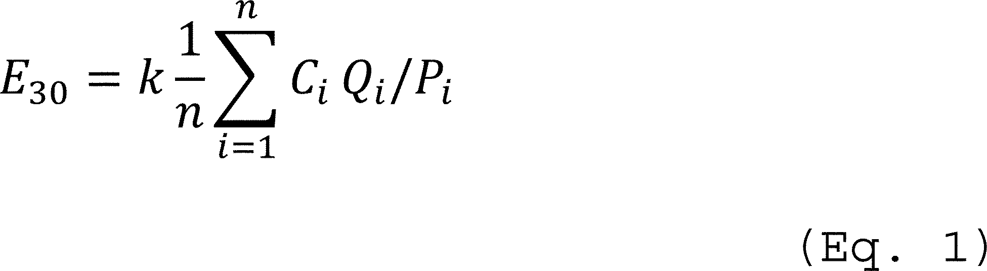
Where:
E30 = 30 operating day average emissions rate of NOX, lb NOX/ton of 100 percent HNO3;
Ci = concentration of NOX for hour i, ppmv;
Qi = volumetric flow rate of effluent gas for hour i, where Ci and Qi are on the same basis (either wet or dry), scf/hr;
Pi = total acid produced during production hour i, tons 100 percent HNO3;
k = conversion factor, 1.194 × 10⁻⁷ for NOX; and
n = number of operating hours in the 30 operating day period, i.e., n is between 30 and 720.
[77 FR 48445, Aug. 14, 2012; 79 FR 25681, May 6, 2014]
§ 60.76a Recordkeeping.
(a) For the NOX emissions rate, you must keep records for and results of the performance evaluations of the continuous emissions monitoring systems.
(b) You must maintain records of the following information for each 30 operating day period:
(1) Hours of operation.
(2) Production rate of nitric acid, expressed as 100 percent nitric acid.
(3) 30 operating day average NOX emissions rate values.
(c) You must maintain records of the following time periods:
(1) Times when you were not in compliance with the emissions standards.
(2) Times when the pollutant concentration exceeded full span of the NOX monitoring equipment.
(3) Times when the volumetric flow rate exceeded the high value of the volumetric flow rate monitoring equipment.
(d) You must maintain records of the reasons for any periods of noncompliance and description of corrective actions taken.
(e) You must maintain records of any modifications to CEMS which could affect the ability of the CEMS to comply with applicable performance specifications.
(f) For each malfunction, you must maintain records of the following information:
(1) Records of the occurrence and duration of each malfunction of operation (i.e., process equipment) or the air pollution control and monitoring equipment.
(2) Records of actions taken during periods of malfunction to minimize emissions in accordance with § 60.11(d), including corrective actions to restore malfunctioning process and air pollution control and monitoring equipment to its normal or usual manner of operation.
§ 60.77a Reporting.
(a) The performance test data from the initial and subsequent performance tests and from the performance evaluations of the continuous monitors must be submitted to the Administrator at the appropriate address as shown in 40 CFR 60.4.
(b) The following information must be reported to the Administrator for each 30 operating day period where you were not in compliance with the emissions standard:
(1) Time period;
(2) NOX emission rates (lb/ton of acid produced);
(3) Reasons for noncompliance with the emissions standard; and
(4) Description of corrective actions taken.
(c) You must also report the following whenever they occur:
(1) Times when the pollutant concentration exceeded full span of the NOX pollutant monitoring equipment.
(2) Times when the volumetric flow rate exceeded the high value of the volumetric flow rate monitoring equipment.
(d) You must report any modifications to CERMS which could affect the ability of the CERMS to comply with applicable performance specifications.
(e) Within 60 days of completion of the relative accuracy test audit (RATA) required by this subpart, you must submit the data from that audit to EPA's WebFIRE database by using the Compliance and Emissions Data Reporting Interface (CEDRI) that is accessed through EPA's Central Data Exchange (CDX) (https://cdx.epa.gov/SSL/cdx/EPA__Home.asp). You must submit performance test data in the file format generated through use of EPA's Electronic Reporting Tool (ERT) (http://www.epa.gov/ttn/chief/ert/index.html). Only data collected using test methods listed on the ERT Web site are subject to this requirement for submitting reports electronically to WebFIRE. Owners or operators who claim that some of the information being submitted for performance tests is confidential business information (CBI) must submit a complete ERT file including information claimed to be CBI on a compact disk or other commonly used electronic storage media (including, but not limited to, flash drives) by registered letter to EPA and the same ERT file with the CBI omitted to EPA via CDX as described earlier in this paragraph. Mark the compact disk or other commonly used electronic storage media clearly as CBI and mail to U.S. EPA/OAPQS/CORE CBI Office, Attention: WebFIRE Administrator, MD C404-02, 4930 Old Page Rd., Durham, NC 27703. At the discretion of the delegated authority, you must also submit these reports to the delegated authority in the format specified by the delegated authority. You must submit the other information as required in the performance evaluation as described in § 60.2 and as required in this chapter.
(f) If a malfunction occurred during the reporting period, you must submit a report that contains the following:
(1) The number, duration, and a brief description for each type of malfunction which occurred during the reporting period and which caused or may have caused any applicable emission limitation to be exceeded.
(2) A description of actions taken by an owner or operator during a malfunction of an affected facility to minimize emissions in accordance with § 60.11(d), including actions taken to correct a malfunction.
Subpart H - Standards of Performance for Sulfuric Acid Plants
§ 60.80 Applicability and designation of affected facility.
(a) The provisions of this subpart are applicable to each sulfuric acid production unit, which is the affected facility.
(b) Any facility under paragraph (a) of this section that commences construction or modification after August 17, 1971, is subject to the requirements of this subpart.
[42 FR 37936, July 25, 1977]
§ 60.81 Definitions.
As used in this subpart, all terms not defined herein shall have the meaning given them in the Act and in subpart A of this part.
(a) Sulfuric acid production unit means any facility producing sulfuric acid by the contact process by burning elemental sulfur, alkylation acid, hydrogen sulfide, organic sulfides and mercaptans, or acid sludge, but does not include facilities where conversion to sulfuric acid is utilized primarily as a means of preventing emissions to the atmosphere of sulfur dioxide or other sulfur compounds.
(b) Acid mist means sulfuric acid mist, as measured by Method 8 of appendix A to this part or an equivalent or alternative method.
[36 FR 24877, Dec. 23, 1971, as amended at 39 FR 20794, June 14, 1974]
§ 60.82 Standard for sulfur dioxide.
(a) On and after the date on which the performance test required to be conducted by § 60.8 is completed, no owner or operator subject to the provisions of this subpart shall cause to be discharged into the atmosphere from any affected facility any gases which contain sulfur dioxide in excess of 2 kg per metric ton of acid produced (4 lb per ton), the production being expressed as 100 percent H2SO4.
[39 FR 20794, June 14, 1974]
§ 60.83 Standard for acid mist.
(a) On and after the date on which the performance test required to be conducted by § 60.8 is completed, no owner or operator subject to the provisions of this subpart shall cause to be discharged into the atmosphere from any affected facility any gases which:
(1) Contain acid mist, expressed as H2SO4, in excess of 0.075 kg per metric ton of acid produced (0.15 lb per ton), the production being expressed as 100 percent H2SO4.
(2) Exhibit 10 percent opacity, or greater.
[39 FR 20794, June 14, 1974, as amended at 40 FR 46258, Oct. 6, 1975]
§ 60.84 Emission monitoring.
(a) A continuous monitoring system for the measurement of sulfur dioxide shall be installed, calibrated, maintained, and operated by the owner or operator. The pollutant gas used to prepare calibration gas mixtures under Performance Specification 2 and for calibration checks under § 60.13(d), shall be sulfur dioxide (SO2). Method 8 shall be used for conducting monitoring system performance evaluations under § 60.13(c) except that only the sulfur dioxide portion of the Method 8 results shall be used. The span value shall be set at 1000 ppm of sulfur dioxide.
(b) The owner or operator shall establish a conversion factor for the purpose of converting monitoring data into units of the applicable standard (kg/metric ton, lb/ton). The conversion factor shall be determined, as a minimum, three times daily by measuring the concentration of sulfur dioxide entering the converter using suitable methods (e.g., the Reich test, National Air Pollution Control Administration Publication No. 999-AP-13) and calculating the appropriate conversion factor for each eight-hour period as follows:
CF = k[(1.000−0.015r)/(r−s)]
where:
CF = conversion factor (kg/metric ton per ppm, lb/ton per ppm).
k = constant derived from material balance. For determining CF in metric units, k = 0.0653. For determining CF in English units, k = 0.1306.
r = percentage of sulfur dioxide by volume entering the gas converter. Appropriate corrections must be made for air injection plants subject to the Administrator's approval.
s = percentage of sulfur dioxide by volume in the emissions to the atmosphere determined by the continuous monitoring system required under paragraph (a) of this section.
(c) The owner or operator shall record all conversion factors and values under paragraph (b) of this section from which they were computed (i.e., CF, r, and s).
(d) Alternatively, a source that processes elemental sulfur or an ore that contains elemental sulfur and uses air to supply oxygen may use the following continuous emission monitoring approach and calculation procedures in determining SO2 emission rates in terms of the standard. This procedure is not required, but is an alternative that would alleviate problems encountered in the measurement of gas velocities or production rate. Continuous emission monitoring systems for measuring SO2, O2, and CO2 (if required) shall be installed, calibrated, maintained, and operated by the owner or operator and subjected to the certification procedures in Performance Specifications 2 and 3. The calibration procedure and span value for the SO2 monitor shall be as specified in paragraph (b) of this section. The span value for CO2 (if required) shall be 10 percent and for O2 shall be 20.9 percent (air). A conversion factor based on process rate data is not necessary. Calculate the SO2 emission rate as follows:
Es = (Cs S)/[0.265 − (0.0126 %O2) − (A %CO2)]
where:
Es = emission rate of SO2, kg/metric ton (lb/ton) of 100 percent of H2SO4 produced.
Cs = concentration of SO2, kg/dscm (lb/dscf).
S = acid production rate factor, 368 dscm/metric ton (11,800 dscf/ton) of 100 percent H2SO4 produced.
%O2 = oxygen concentration, percent dry basis.
A = auxiliary fuel factor,
= 0.00 for no fuel.
= 0.0226 for methane.
= 0.0217 for natural gas.
= 0.0196 for propane.
= 0.0172 for No 2 oil.
= 0.0161 for No 6 oil.
= 0.0148 for coal.
= 0.0126 for coke.
%CO2 = carbon dioxide concentration, percent dry basis.
It is necessary in some cases to convert measured concentration units to other units for these calculations:
Use the following table for such conversions:
| From— | To— | Multiply by— |
|---|---|---|
| g/scm | kg/scm | 10−3 |
| mg/scm | kg/scm | 10−6 |
| ppm (SO2) | kg/scm | 2.660 × 10⁻⁶ |
| ppm (SO2) | lb/scf | 1.660 × 10⁻⁷ |
(e) For the purpose of reports under § 60.7(c), periods of excess emissions shall be all three-hour periods (or the arithmetic average of three consecutive one-hour periods) during which the integrated average sulfur dioxide emissions exceed the applicable standards under § 60.82.
[39 FR 20794, June 14, 1974, as amended at 40 FR 46258, Oct. 6, 1975; 48 FR 23611, May 25, 1983; 48 FR 4700, Sept. 29, 1983; 48 FR 48669, Oct. 20, 1983; 54 FR 6666, Feb. 14, 1989; 65 FR 61753, Oct. 17, 2000; 79 FR 11250, Feb. 27, 2014]
§ 60.85 Test methods and procedures.
(a) In conducting the performance tests required in § 60.8, the owner or operator shall use as reference methods and procedures the test methods in appendix A of this part or other methods and procedures as specified in this section, except as provided in § 60.8(b). Acceptable alternative methods and procedures are given in paragraph (c) of this section.
(b) The owner or operator shall determine compliance with the SO2 acid mist, and visible emission standards in §§ 60.82 and 60.83 as follows:
(1) The emission rate (E) of acid mist or SO2 shall be computed for each run using the following equation:
E = (CQsd) / (PK)
where:
E = emission rate of acid mist or SO2 kg/metric ton (lb/ton) of 100 percent H2SO4 produced.
C = concentration of acid mist or SO2, g/dscm (lb/dscf).
Qsd = volumetric flow rate of the effluent gas, dscm/hr (dscf/hr).
P = production rate of 100 percent H2SO4, metric ton/hr (ton/hr).
K = conversion factor, 1000 g/kg (1.0 lb/lb).
(2) Method 8 shall be used to determine the acid mist and SO2 concentrations (C's) and the volumetric flow rate (Qsd) of the effluent gas. The moisture content may be considered to be zero. The sampling time and sample volume for each run shall be at least 60 minutes and 1.15 dscm (40.6 dscf).
(3) Suitable methods shall be used to determine the production rate (P) of 100 percent H2SO4 for each run. Material balance over the production system shall be used to confirm the production rate.
(4) Method 9 and the procedures in § 60.11 shall be used to determine opacity.
(c) The owner or operator may use the following as alternatives to the reference methods and procedures specified in this section:
(1) If a source processes elemental sulfur or an ore that contains elemental sulfur and uses air to supply oxygen, the following procedure may be used instead of determining the volumetric flow rate and production rate:
(i) The integrated technique of Method 3 is used to determine the O2 concentration and, if required, CO2 concentration.
(ii) The SO2 or acid mist emission rate is calculated as described in § 60.84(d), substituting the acid mist concentration for Cs as appropriate.
[54 FR 6666, Feb. 14, 1989]
Subpart I - Standards of Performance for Hot Mix Asphalt Facilities
§ 60.90 Applicability and designation of affected facility.
(a) The affected facility to which the provisions of this subpart apply is each hot mix asphalt facility. For the purpose of this subpart, a hot mix asphalt facility is comprised only of any combination of the following: dryers; systems for screening, handling, storing, and weighing hot aggregate; systems for loading, transferring, and storing mineral filler, systems for mixing hot mix asphalt; and the loading, transfer, and storage systems associated with emission control systems.
(b) Any facility under paragraph (a) of this section that commences construction or modification after June 11, 1973, is subject to the requirements of this subpart.
[42 FR 37936, July 25, 1977, as amended at 51 FR 12325, Apr. 10, 1986]
§ 60.91 Definitions.
As used in this subpart, all terms not defined herein shall have the meaning given them in the Act and in subpart A of this part.
(a) Hot mix asphalt facility means any facility, as described in § 60.90, used to manufacture hot mix asphalt by heating and drying aggregate and mixing with asphalt cements.
[51 FR 12325, Apr. 10, 1986]
§ 60.92 Standard for particulate matter.
(a) On and after the date on which the performance test required to be conducted by § 60.8 is completed, no owner or operator subject to the provisions of this subpart shall discharge or cause the discharge into the atmosphere from any affected facility any gases which:
(1) Contain particulate matter in excess of 90 mg/dscm (0.04 gr/dscf).
(2) Exhibit 20 percent opacity, or greater.
[39 FR 9314, Mar. 8, 1974, as amended at 40 FR 46259, Oct. 6, 1975]
§ 60.93 Test methods and procedures.
(a) In conducting the performance tests required in § 60.8, the owner or operator shall use as reference methods and procedures the test methods in appendix A of this part or other methods and procedures as specified in this section, except as provided in § 60.8(b).
(b) The owner or operator shall determine compliance with the particulate matter standards in § 60.92 as follows:
(1) Method 5 shall be used to determine the particulate matter concentration. The sampling time and sample volume for each run shall be at least 60 minutes and 0.90 dscm (31.8 dscf).
(2) Method 9 and the procedures in § 60.11 shall be used to determine opacity.
[54 FR 6667, Feb. 14, 1989]
Subpart J - Standards of Performance for Petroleum Refineries
§ 60.100 Applicability, designation of affected facility, and reconstruction.
(a) The provisions of this subpart are applicable to the following affected facilities in petroleum refineries: fluid catalytic cracking unit catalyst regenerators, fuel gas combustion devices, and all Claus sulfur recovery plants except Claus plants with a design capacity for sulfur feed of 20 long tons per day (LTD) or less. The Claus sulfur recovery plant need not be physically located within the boundaries of a petroleum refinery to be an affected facility, provided it processes gases produced within a petroleum refinery.
(b) Any fluid catalytic cracking unit catalyst regenerator or fuel gas combustion device under paragraph (a) of this section other than a flare which commences construction, reconstruction or modification after June 11, 1973, and on or before May 14, 2007, or any fuel gas combustion device under paragraph (a) of this section that is also a flare which commences construction, reconstruction or modification after June 11, 1973, and on or before June 24, 2008, or any Claus sulfur recovery plant under paragraph (a) of this section which commences construction, reconstruction or modification after October 4, 1976, and on or before May 14, 2007, is subject to the requirements of this subpart except as provided under paragraphs (c) through (e) of this section.
(c) Any fluid catalytic cracking unit catalyst regenerator under paragraph (b) of this section which commences construction, reconstruction, or modification on or before January 17, 1984, is exempted from § 60.104(b).
(d) Any fluid catalytic cracking unit in which a contact material reacts with petroleum derivatives to improve feedstock quality and in which the contact material is regenerated by burning off coke and/or other deposits and that commences construction, reconstruction, or modification on or before January 17, 1984, is exempt from this subpart.
(e) Owners or operators may choose to comply with the applicable provisions of subpart Ja of this part to satisfy the requirements of this subpart for an affected facility.
(f) For purposes of this subpart, under § 60.15, the “fixed capital cost of the new components” includes the fixed capital cost of all depreciable components which are or will be replaced pursuant to all continuous programs of component replacement which are commenced within any 2-year period following January 17, 1984. For purposes of this paragraph, “commenced” means that an owner or operator has undertaken a continuous program of component replacement or that an owner or operator has entered into a contractual obligation to undertake and complete, within a reasonable time, a continuous program of component replacement.
[43 FR 10868, Mar. 15, 1978, as amended at 44 FR 61543, Oct. 25, 1979; 54 FR 34026, Aug. 17, 1989; 73 FR 35865, June 24, 2008; 77 FR 56463, Sep. 12, 2012]
§ 60.101 Definitions.
As used in this subpart, all terms not defined herein shall have the meaning given them in the Act and in subpart A.
(a) Petroleum refinery means any facility engaged in producing gasoline, kerosene, distillate fuel oils, residual fuel oils, lubricants, or other products through distillation of petroleum or through redistillation, cracking or reforming of unfinished petroleum derivatives.
(b) Petroleum means the crude oil removed from the earth and the oils derived from tar sands, shale, and coal.
(c) Process gas means any gas generated by a petroleum refinery process unit, except fuel gas and process upset gas as defined in this section.
(d) Fuel gas means any gas which is generated at a petroleum refinery and which is combusted. Fuel gas includes natural gas when the natural gas is combined and combusted in any proportion with a gas generated at a refinery. Fuel gas does not include gases generated by catalytic cracking unit catalyst regenerators and fluid coking burners. Fuel gas does not include vapors that are collected and combusted in a thermal oxidizer or flare installed to control emissions from wastewater treatment units or marine tank vessel loading operations.
(e) Process upset gas means any gas generated by a petroleum refinery process unit as a result of start-up, shut-down, upset or malfunction.
(f) Refinery process unit means any segment of the petroleum refinery in which a specific processing operation is conducted.
(g) Fuel gas combustion device means any equipment, such as process heaters, boilers and flares used to combust fuel gas, except facilities in which gases are combusted to produce sulfur or sulfuric acid.
(h) Coke burn-off means the coke removed from the surface of the fluid catalytic cracking unit catalyst by combustion in the catalyst regenerator. The rate of coke burn-off is calculated by the formula specified in § 60.106.
(i) Claus sulfur recovery plant means a process unit which recovers sulfur from hydrogen sulfide by a vapor-phase catalytic reaction of sulfur dioxide and hydrogen sulfide.
(j) Oxidation control system means an emission control system which reduces emissions from sulfur recovery plants by converting these emissions to sulfur dioxide.
(k) Reduction control system means an emission control system which reduces emissions from sulfur recovery plants by converting these emissions to hydrogen sulfide.
(l) Reduced sulfur compounds means hydrogen sulfide (H2S), carbonyl sulfide (COS) and carbon disulfide (CS2).
(m) Fluid catalytic cracking unit means a refinery process unit in which petroleum derivatives are continuously charged; hydrocarbon molecules in the presence of a catalyst suspended in a fluidized bed are fractured into smaller molecules, or react with a contact material suspended in a fluidized bed to improve feedstock quality for additional processing; and the catalyst or contact material is continuously regenerated by burning off coke and other deposits. The unit includes the riser, reactor, regenerator, air blowers, spent catalyst or contact material stripper, catalyst or contact material recovery equipment, and regenerator equipment for controlling air pollutant emissions and for heat recovery.
(n) Fluid catalytic cracking unit catalyst regenerator means one or more regenerators (multiple regenerators) which comprise that portion of the fluid catalytic cracking unit in which coke burn-off and catalyst or contact material regeneration occurs, and includes the regenerator combustion air blower(s).
(o) Fresh feed means any petroleum derivative feedstock stream charged directly into the riser or reactor of a fluid catalytic cracking unit except for petroleum derivatives recycled within the fluid catalytic cracking unit, fractionator, or gas recovery unit.
(p) Contact material means any substance formulated to remove metals, sulfur, nitrogen, or any other contaminant from petroleum derivatives.
(q) Valid day means a 24-hour period in which at least 18 valid hours of data are obtained. A “valid hour” is one in which at least 2 valid data points are obtained.
[39 FR 9315, Mar. 8, 1974, as amended at 43 FR 10868, Mar. 15, 1978; 44 FR 13481, Mar. 12, 1979; 45 FR 79453, Dec. 1, 1980; 54 FR 34027, Aug. 17, 1989; 73 FR 35865, June 24, 2008; 77 FR 56463, Sep. 12, 2012]
§ 60.102 Standard for particulate matter.
Each owner or operator of any fluid catalytic cracking unit catalyst regenerator that is subject to the requirements of this subpart shall comply with the emission limitations set forth in this section on and after the date on which the initial performance test, required by § 60.8, is completed, but not later than 60 days after achieving the maximum production rate at which the fluid catalytic cracking unit catalyst regenerator will be operated, or 180 days after initial startup, whichever comes first.
(a) No owner or operator subject to the provisions of this subpart shall discharge or cause the discharge into the atmosphere from any fluid catalytic cracking unit catalyst regenerator:
(1) Particulate matter in excess of 1.0 kg/Mg (2.0 lb/ton) of coke burn-off in the catalyst regenerator.
(2) Gases exhibiting greater than 30 percent opacity, except for one six-minute average opacity reading in any one hour period.
(b) Where the gases discharged by the fluid catalytic cracking unit catalyst regenerator pass through an incinerator or waste heat boiler in which auxiliary or supplemental liquid or solid fossil fuel is burned, particulate matter in excess of that permitted by paragraph (a)(1) of this section may be emitted to the atmosphere, except that the incremental rate of particulate matter emissions shall not exceed 43 grams per Gigajoule (g/GJ) (0.10 lb/million British thermal units (Btu)) of heat input attributable to such liquid or solid fossil fuel.
[39 FR 9315, Mar. 8, 1974, as amended at 42 FR 32427, June 24, 1977; 42 FR 39389, Aug. 4, 1977; 43 FR 10868, Feb. 15, 1978; 54 FR 34027, Aug. 17, 1989; 65 FR 61753, Oct. 17, 2000; 73 FR 35866, June 24, 2008]
§ 60.103 Standard for carbon monoxide.
Each owner or operator of any fluid catalytic cracking unit catalyst regenerator that is subject to the requirements of this subpart shall comply with the emission limitations set forth in this section on and after the date on which the initial performance test, required by § 60.8, is completed, but not later than 60 days after achieving the maximum production rate at which the fluid catalytic cracking unit catalyst regenerator will be operated, or 180 days after initial startup, whichever comes first.
(a) No owner or operator subject to the provisions of this subpart shall discharge or cause the discharge into the atmosphere from any fluid catalytic cracking unit catalyst regenerator any gases that contain carbon monoxide (CO) in excess of 500 ppm by volume (dry basis).
[54 FR 34027, Aug. 17, 1989, as amended at 55 FR 40175, Oct. 2, 1990]
§ 60.104 Standards for sulfur oxides.
Each owner or operator that is subject to the requirements of this subpart shall comply with the emission limitations set forth in this section on and after the date on which the initial performance test, required by § 60.8, is completed, but not later than 60 days after achieving the maximum production rate at which the affected facility will be operated, or 180 days after initial startup, whichever comes first.
(a) No owner or operator subject to the provisions of this subpart shall:
(1) Burn in any fuel gas combustion device any fuel gas that contains hydrogen sulfide (H2S) in excess of 230 mg/dscm (0.10 gr/dscf). The combustion in a flare of process upset gases or fuel gas that is released to the flare as a result of relief valve leakage or other emergency malfunctions is exempt from this paragraph.
(2) Discharge or cause the discharge of any gases into the atmosphere from any Claus sulfur recovery plant containing in excess of:
(i) For an oxidation control system or a reduction control system followed by incineration, 250 ppm by volume (dry basis) of sulfur dioxide (SO2) at zero percent excess air.
(ii) For a reduction control system not followed by incineration, 300 ppm by volume of reduced sulfur compounds and 10 ppm by volume of hydrogen sulfide (H2S), each calculated as ppm SO2 by volume (dry basis) at zero percent excess air.
(b) Each owner or operator that is subject to the provisions of this subpart shall comply with one of the following conditions for each affected fluid catalytic cracking unit catalyst regenerator:
(1) With an add-on control device, reduce SO2 emissions to the atmosphere by 90 percent or maintain SO2 emissions to the atmosphere less than or equal to 50 ppm by volume (ppmv), whichever is less stringent; or
(2) Without the use of an add-on control device to reduce SO2 emission, maintain sulfur oxides emissions calculated as SO2 to the atmosphere less than or equal to 9.8 kg/Mg (20 lb/ton) coke burn-off; or
(3) Process in the fluid catalytic cracking unit fresh feed that has a total sulfur content no greater than 0.30 percent by weight.
(c) Compliance with paragraph (b)(1), (b)(2), or (b)(3) of this section is determined daily on a 7-day rolling average basis using the appropriate procedures outlined in § 60.106.
(d) A minimum of 22 valid days of data shall be obtained every 30 rolling successive calendar days when complying with paragraph (b)(1) of this section.
[43 FR 10869, Mar. 15, 1978, as amended at 54 FR 34027, Aug. 17, 1989; 55 FR 40175, Oct. 2, 1990; 65 FR 61754, Oct. 17, 2000; 73 FR 35866, June 24, 2008]
§ 60.105 Monitoring of emissions and operations.
(a) Continuous monitoring systems shall be installed, calibrated, maintained, and operated by the owner or operator subject to the provisions of this subpart as follows:
(1) For fluid catalytic cracking unit catalyst regenerators subject to § 60.102(a)(2), an instrument for continuously monitoring and recording the opacity of emissions into the atmosphere. The instrument shall be spanned at 60, 70, or 80 percent opacity.
(2) For fluid catalytic cracking unit catalyst regenerators subject to § 60.103(a), an instrument for continuously monitoring and recording the concentration by volume (dry basis) of CO emissions into the atmosphere, except as provided in paragraph (a)(2) (ii) of this section.
(i) The span value for this instrument is 1,000 ppm CO.
(ii) A CO continuous monitoring system need not be installed if the owner or operator demonstrates that the average CO emissions are less than 50 ppm (dry basis) and also files a written request for exemption to the Administrator and receives such an exemption. The demonstration shall consist of continuously monitoring CO emissions for 30 days using an instrument that shall meet the requirements of Performance Specification 4 of appendix B of this part. The span value shall be 100 ppm CO instead of 1,000 ppm, and the relative accuracy limit shall be 10 percent of the average CO emissions or 5 ppm CO, whichever is greater. For instruments that are identical to Method 10 and employ the sample conditioning system of Method 10A, the alternative relative accuracy test procedure in § 10.1 of Performance Specification 2 may be used in place of the relative accuracy test.
(3) For fuel gas combustion devices subject to § 60.104(a)(1), either an instrument for continuously monitoring and recording the concentration by volume (dry basis, zero percent excess air) of SO2 emissions into the atmosphere or monitoring as provided in paragraph (a)(4) of this section). The monitor shall include an oxygen monitor for correcting the data for excess.
(i) The span values for this monitor are 50 ppm SO2 and 25 percent oxygen (O2).
(ii) The SO2 monitoring level equivalent to the H2S standard under § 60.104(a)(1) shall be 20 ppm (dry basis, zero percent excess air).
(iii) The performance evaluations for this SO2 monitor under § 60.13(c) shall use Performance Specification 2. Methods 6 or 6C and 3 or 3A shall be used for conducting the relative accuracy evaluations. Method 6 samples shall be taken at a flow rate of approximately 2 liters/min for at least 30 minutes. The relative accuracy limit shall be 20 percent or 4 ppm, whichever is greater, and the calibration drift limit shall be 5 percent of the established span value.
(iv) Fuel gas combustion devices having a common source of fuel gas may be monitored at only one location (i.e., after one of the combustion devices), if monitoring at this location accurately represents the SO2 emissions into the atmosphere from each of the combustion devices.
(4) Instead of the SO2 monitor in paragraph (a)(3) of this section for fuel gas combustion devices subject to § 60.104(a)(1), an instrument for continuously monitoring and recording the concentration (dry basis) of H2S in fuel gases before being burned in any fuel gas combustion device.
(i) The span value for this instrument is 425 mg/dscm H2S.
(ii) Fuel gas combustion devices having a common source of fuel gas may be monitored at only one location, if monitoring at this location accurately represents the concentration of H2S in the fuel gas being burned.
(iii) The performance evaluations for this H2S monitor under § 60.13(c) shall use Performance Specification 7. Method 11, 15, 15A, or 16 shall be used for conducting the relative accuracy evaluations.
(iv) The owner or operator of a fuel gas combustion device is not required to comply with paragraph (a)(3) or (4) of this section for fuel gas streams that are exempt under § 60.104(a)(1) and fuel gas streams combusted in a fuel gas combustion device that are inherently low in sulfur content. Fuel gas streams meeting one of the requirements in paragraphs (a)(4)(iv)(A) through (D) of this section will be considered inherently low in sulfur content. If the composition of a fuel gas stream changes such that it is no longer exempt under § 60.104(a)(1) or it no longer meets one of the requirements in paragraphs (a)(4)(iv)(A) through (D) of this section, the owner or operator must begin continuous monitoring under paragraph (a)(3) or (4) of this section within 15 days of the change.
(A) Pilot gas for heaters and flares.
(B) Fuel gas streams that meet a commercial-grade product specification for sulfur content of 30 ppmv or less. In the case of a liquefied petroleum gas (LPG) product specification in the pressurized liquid state, the gas phase sulfur content should be evaluated assuming complete vaporization of the LPG and sulfur containing-compounds at the product specification concentration.
(C) Fuel gas streams produced in process units that are intolerant to sulfur contamination, such as fuel gas streams produced in the hydrogen plant, the catalytic reforming unit, the isomerization unit, and HF alkylation process units.
(D) Other fuel gas streams that an owner or operator demonstrates are low-sulfur according to the procedures in paragraph (b) of this section.
(5) For Claus sulfur recovery plants with oxidation control systems or reduction control systems followed by incineration subject to § 60.104(a)(2)(i), an instrument for continuously monitoring and recording the concentration (dry basis, zero percent excess air) of SO2 emissions into the atmosphere. The monitor shall include an oxygen monitor for correcting the data for excess air.
(i) The span values for this monitor are 500 ppm SO2 and 25 percent O2.
(ii) The performance evaluations for this SO2 monitor under § 60.13(c) shall use Performance Specification 2. Methods 6 or 6C and 3 or 3A shall be used for conducting the relative accuracy evaluations.
(6) For Claus sulfur recovery plants with reduction control systems not followed by incineration subject to § 60.104(a)(2)(ii), an instrument for continuously monitoring and recording the concentration of reduced sulfur and O2 emissions into the atmosphere. The reduced sulfur emissions shall be calculated as SO2 (dry basis, zero percent excess air).
(i) The span values for this monitor are 450 ppm reduced sulfur and 25 percent O2.
(ii) The performance evaluations for this reduced sulfur (and O2) monitor under § 60.13(c) shall use Performance Specification 5 of appendix B of this part(and Performance Specification 3 of appendix B of this partfor the O2 analyzer). Methods 15 or 15A and Method 3 shall be used for conducting the relative accuracy evaluations. If Method 3 yields O2 concentrations below 0.25 percent during the performance specification test, the O2 concentration may be assumed to be zero and the reduced sulfur CEMS need not include an O2 monitor.
(7) In place of the reduced sulfur monitor under paragraph (a)(6) of this section, an instrument using an air or O2 dilution and oxidation system to convert the reduced sulfur to SO2 for continuously monitoring and recording the concentration (dry basis, zero percent excess air) of the resultant SO2. The monitor shall include an oxygen monitor for correcting the data for excess oxygen.
(i) The span values for this monitor are 375 ppm SO2 and 25 percent O2.
(ii) For reporting purposes, the SO2 exceedance level for this monitor is 250 ppm (dry basis, zero percent excess air).
(iii) The performance evaluations for this SO2 (and O2) monitor under § 60.13(c) shall use Performance Specification 5. Methods 15 or 15A and Method 3 shall be used for conducting the relative accuracy evaluations.
(8) An instrument for continuously monitoring and recording concentrations of SO2 in the gases at both the inlet and outlet of the SO2 control device from any fluid catalytic cracking unit catalyst regenerator for which the owner or operator seeks to comply specifically with the 90 percent reduction option under § 60.104(b)(1).
(i) The span value of the inlet monitor shall be set at 125 percent of the maximum estimated hourly potential SO2 emission concentration entering the control device, and the span value of the outlet monitor shall be set at 50 percent of the maximum estimated hourly potential SO2 emission concentration entering the control device.
(ii) The performance evaluations for these SO2 monitors under § 60.13(c) shall use Performance Specification 2. Methods 6 or 6C and 3 or 3A shall be used for conducting the relative accuracy evaluations.
(9) An instrument for continuously monitoring and recording concentrations of SO2 in the gases discharged into the atmosphere from any fluid catalytic cracking unit catalyst regenerator for which the owner or operator seeks to comply specifically with the 50 ppmv emission limit under § 60.104 (b)(1).
(i) The span value of the monitor shall be set at 50 percent of the maximum hourly potential SO2 emission concentration of the control device.
(ii) The performance evaluations for this SO2 monitor under § 60.13 (c) shall use Performance Specification 2. Methods 6 or 6C and 3 or 3A shall be used for conducting the relative accuracy evaluations.
(10) An instrument for continuously monitoring and recording concentrations of oxygen (O2) in the gases at both the inlet and outlet of the sulfur dioxide control device (or the outlet only if specifically complying with the 50 ppmv standard) from any fluid catalytic cracking unit catalyst regenerator for which the owner or operator has elected to comply with § 60.104(b)(1). The span of this continuous monitoring system shall be set at 10 percent.
(11) The continuous monitoring systems under paragraphs (a)(8), (a)(9), and (a)(10) of this section are operated and data recorded during all periods of operation of the affected facility including periods of startup, shutdown, or malfunction, except for continuous monitoring system breakdowns, repairs, calibration checks, and zero and span adjustments.
(12) The owner or operator shall use the following procedures to evaluate the continuous monitoring systems under paragraphs (a)(8), (a)(9), and (a)(10) of this section.
(i) Method 3 or 3A and Method 6 or 6C for the relative accuracy evaluations under the § 60.13(e) performance evaluation.
(ii) Appendix F, Procedure 1, including quarterly accuracy determinations and daily calibration drift tests.
(13) When seeking to comply with § 60.104(b)(1), when emission data are not obtained because of continuous monitoring system breakdowns, repairs, calibration checks and zero and span adjustments, emission data will be obtained by using one of the following methods to provide emission data for a minimum of 18 hours per day in at least 22 out of 30 rolling successive calendar days.
(i) The test methods as described in § 60.106(k);
(ii) A spare continuous monitoring system; or
(iii) Other monitoring systems as approved by the Administrator.
(b) An owner or operator may demonstrate that a fuel gas stream combusted in a fuel gas combustion device subject to § 60.104(a)(1) that is not specifically exempted in § 60.105(a)(4)(iv) is inherently low in sulfur. A fuel gas stream that is determined to be low-sulfur is exempt from the monitoring requirements in paragraphs (a)(3) and (4) of this section until there are changes in operating conditions or stream composition.
(1) The owner or operator shall submit to the Administrator a written application for an exemption from monitoring. The application must contain the following information:
(i) A description of the fuel gas stream/system to be considered, including submission of a portion of the appropriate piping diagrams indicating the boundaries of the fuel gas stream/system, and the affected fuel gas combustion device(s) to be considered;
(ii) A statement that there are no crossover or entry points for sour gas (high H2S content) to be introduced into the fuel gas stream/system (this should be shown in the piping diagrams);
(iii) An explanation of the conditions that ensure low amounts of sulfur in the fuel gas stream (i.e., control equipment or product specifications) at all times;
(iv) The supporting test results from sampling the requested fuel gas stream/system demonstrating that the sulfur content is less than 5 ppmv. Sampling data must include, at minimum, 2 weeks of daily monitoring (14 grab samples) for frequently operated fuel gas streams/systems; for infrequently operated fuel gas streams/systems, seven grab samples must be collected unless other additional information would support reduced sampling. The owner or operator shall use detector tubes (“length-of-stain tube” type measurement) following the “Gas Processors Association Standard 2377-86 (incorporated by reference—see § 60.17), using tubes with a maximum span between 10 and 40 ppmv inclusive when 1≤N≤10, where N = number of pump strokes, to test the applicant fuel gas stream for H2S; and
(v) A description of how the 2 weeks (or seven samples for infrequently operated fuel gas streams/systems) of monitoring results compares to the typical range of H2S concentration (fuel quality) expected for the fuel gas stream/system going to the affected fuel gas combustion device (e.g., the 2 weeks of daily detector tube results for a frequently operated loading rack included the entire range of products loaded out, and, therefore, should be representative of typical operating conditions affecting H2S content in the fuel gas stream going to the loading rack flare).
(2) The effective date of the exemption is the date of submission of the information required in paragraph (b)(1) of this section).
(3) No further action is required unless refinery operating conditions change in such a way that affects the exempt fuel gas stream/system (e.g., the stream composition changes). If such a change occurs, the owner or operator will follow the procedures in paragraph (b)(3)(i), (b)(3)(ii), or (b)(3)(iii) of this section.
(i) If the operation change results in a sulfur content that is still within the range of concentrations included in the original application, the owner or operator shall conduct an H2S test on a grab sample and record the results as proof that the concentration is still within the range.
(ii) If the operation change results in a sulfur content that is outside the range of concentrations included in the original application, the owner or operator may submit new information following the procedures of paragraph (b)(1) of this section within 60 days (or within 30 days after the seventh grab sample is tested for infrequently operated process units).
(iii) If the operation change results in a sulfur content that is outside the range of concentrations included in the original application and the owner or operator chooses not to submit new information to support an exemption, the owner or operator must begin H2S monitoring using daily stain sampling to demonstrate compliance using length-of stain tubes with a maximum span between 200 and 400 ppmv inclusive when 1≤N≤5, where N = number of pump strokes. The owner or operator must begin monitoring according to the requirements in paragraph (a)(1) or (2) of this section as soon as practicable but in no case later than 180 days after the operation change. During daily stain tube sampling, a daily sample exceeding 162 ppmv is an exceedance of the 3-hour H2S concentration limit.
(c) The average coke burn-off rate (Mg (tons) per hour) and hours of operation shall be recorded daily for any fluid catalytic cracking unit catalyst regenerator subject to § 60.102, § 60.103, or § 60.104(b)(2).
(d) For any fluid catalytic cracking unit catalyst regenerator under § 60.102 that uses an incinerator-waste heat boiler to combust the exhaust gases from the catalyst regenerator, the owner or operator shall record daily the rate of combustion of liquid or solid fossil-fuels and the hours of operation during which liquid or solid fossil-fuels are combusted in the incinerator-waste heat boiler.
(e) For the purpose of reports under § 60.7(c), periods of excess emissions that shall be determined and reported are defined as follows:
All averages, except for opacity, shall be determined as the arithmetic average of the applicable 1-hour averages, e.g., the rolling 3-hour average shall be determined as the arithmetic average of three contiguous 1-hour averages.
(1) Opacity. All 1-hour periods that contain two or more 6-minute periods during which the average opacity as measured by the continuous monitoring system under § 60.105(a)(1) exceeds 30 percent.
(2) Carbon monoxide. All 1-hour periods during which the average CO concentration as measured by the CO continuous monitoring system under § 60.105(a)(2) exceeds 500 ppm.
(3) Sulfur dioxide from fuel gas combustion.
(i) All rolling 3-hour periods during which the average concentration of SO2 as measured by the SO2 continuous monitoring system under § 60.105(a)(3) exceeds 20 ppm (dry basis, zero percent excess air); or
(ii) All rolling 3-hour periods during which the average concentration of H2S as measured by the H2S continuous monitoring system under § 60.105(a)(4) exceeds 230 mg/dscm (0.10 gr/dscf).
(4) Sulfur dioxide from Claus sulfur recovery plants.
(i) All 12-hour periods during which the average concentration of SO2 as measured by the SO2 continuous monitoring system under § 60.105(a)(5) exceeds 250 ppm (dry basis, zero percent excess air); or
(ii) All 12-hour periods during which the average concentration of reduced sulfur (as SO2) as measured by the reduced sulfur continuous monitoring system under § 60.105(a)(6) exceeds 300 ppm; or
(iii) All 12-hour periods during which the average concentration of SO2 as measured by the SO2 continuous monitoring system under § 60.105(a)(7) exceeds 250 ppm (dry basis, zero percent excess air).
[39 FR 9315, Mar. 8, 1974, as amended at 40 FR 46259, Oct. 6, 1975; 42 FR 32427, June 24, 1977; 42 FR 39389, Aug. 4, 1977; 43 FR 10869, Mar. 15, 1978; 48 FR 23611, May 25, 1983; 50 FR 31701, Aug. 5, 1985; 54 FR 34028, Aug. 17, 1989; 55 FR 40175, Oct. 2, 1990; 65 FR 61754, Oct. 17, 2000; 73 FR 35866, June 24, 2008; 80 FR 75229, Dec. 1, 2015]
§ 60.106 Test methods and procedures.
(a) In conducting the performance tests required in § 60.8, the owner or operator shall use as reference methods and procedures the test methods in appendix A of this part or other methods and procedures as specified in this section, except as provided in § 60.8(b).
(b) The owner or operator shall determine compliance with the particulate matter (PM) standards in § 60.102(a) as follows:
(1) The emission rate (E) of PM shall be computed for each run using the following equation:

Where:
E = Emission rate of PM, kg/Mg (lb/ton) of coke burn-off.
cs = Concentration of PM, g/dscm (gr/dscf).
Qsd = Volumetric flow rate of effluent gas, dscm/hr (dscf/hr).
Rc = Coke burn-off rate, Mg/hr (ton/hr) coke.
K = Conversion factor, 1,000 g/kg (7,000 gr/lb).
(2) Method 5B or 5F is to be used to determine particulate matter emissions and associated moisture content from affected facilities without wet FGD systems; only Method 5B is to be used after wet FGD systems. The sampling time for each run shall be at least 60 minutes and the sampling rate shall be at least 0.015 dscm/min (0.53 dscf/min), except that shorter sampling times may be approved by the Administrator when process variables or other factors preclude sampling for at least 60 minutes.
(3) The coke burn-off rate (Rc) shall be computed for each run using the following equation:
Rc = K1Qr (%CO2 + %CO) + K2Qa−K3Qr (%CO/2 + %CO2 + %O2) + K3Qoxy (%Ooxy)
Where:
Rc = Coke burn-off rate, kilograms per hour (kg/hr) (lb/hr).
Qr = Volumetric flow rate of exhaust gas from fluid catalytic cracking unit regenerator before entering the emission control system, dscm/min (dscf/min).
Qa = Volumetric flow rate of air to fluid catalytic cracking unit regenerator, as determined from the fluid catalytic cracking unit control room instrumentation, dscm/min (dscf/min).
Qoxy = Volumetric flow rate of O2 enriched air to fluid catalytic cracking unit regenerator, as determined from the fluid catalytic cracking unit control room instrumentation, dscm/min (dscf/min).
%CO2 = Carbon dioxide concentration in fluid catalytic cracking unit regenerator exhaust, percent by volume (dry basis).
%CO = CO concentration in FCCU regenerator exhaust, percent by volume (dry basis).
%O2 = O2 concentration in fluid catalytic cracking unit regenerator exhaust, percent by volume (dry basis).
%Ooxy = O2 concentration in O2 enriched air stream inlet to the fluid catalytic cracking unit regenerator, percent by volume (dry basis).
K1 = Material balance and conversion factor, 0.2982 (kg-min)/(hr-dscm-%) [0.0186 (lb-min)/(hr-dscf-%)].
K2 = Material balance and conversion factor, 2.088 (kg-min)/(hr-dscm) [0.1303 (lb-min)/(hr-dscf)].
K3 = Material balance and conversion factor, 0.0994 (kg-min)/(hr-dscm-%) [0.00624 (lb-min)/(hr-dscf-%)].
(i) Method 2 shall be used to determine the volumetric flow rate (Qr).
(ii) The emission correction factor, integrated sampling and analysis procedure of Method 3B shall be used to determine CO2, CO, and O2 concentrations.
(4) Method 9 and the procedures of § 60.11 shall be used to determine opacity.
(c) If auxiliary liquid or solid fossil-fuels are burned in an incinerator-waste heat boiler, the owner or operator shall determine the emission rate of PM permitted in § 60.102(b) as follows:
(1) The allowable emission rate (Es) of PM shall be computed for each run using the following equation:
Es = F + A (H/Rc)
Where:
Es = Emission rate of PM allowed, kg/Mg (lb/ton) of coke burn-off in catalyst regenerator.
F = Emission standard, 1.0 kg/Mg (2.0 lb/ton) of coke burn-off in catalyst regenerator.
A = Allowable incremental rate of PM emissions, 43 g/GJ (0.10 lb/million Btu).
H = Heat input rate from solid or liquid fossil fuel, GJ/hr (million Btu/hr).
Rc = Coke burn-off rate, Mg coke/hr (ton coke/hr).
(2) Procedures subject to the approval of the Administrator shall be used to determine the heat input rate.
(3) The procedure in paragraph (b)(3) of this section shall be used to determine the coke burn-off rate (Rc).
(d) The owner or operator shall determine compliance with the CO standard in § 60.103(a) by using the integrated sampling technique of Method 10 to determine the CO concentration (dry basis). The sampling time for each run shall be 60 minutes.
(e)
(1) The owner or operator shall determine compliance with the H2S standard in § 60.104(a)(1) as follows: Method 11, 15, 15A, or 16 shall be used to determine the H2S concentration. The gases entering the sampling train should be at about atmospheric pressure. If the pressure in the refinery fuel gas lines is relatively high, a flow control valve may be used to reduce the pressure. If the line pressure is high enough to operate the sampling train without a vacuum pump, the pump may be eliminated from the sampling train. The sample shall be drawn from a point near the centroid of the fuel gas line.
(i) For Method 11, the sampling time and sample volume shall be at least 10 minutes and 0.010 dscm (0.35 dscf). Two samples of equal sampling times shall be taken at about 1-hour intervals. The arithmetic average of these two samples shall constitute a run. For most fuel gases, sampling times exceeding 20 minutes may result in depletion of the collection solution, although fuel gases containing low concentrations of H2S may necessitate sampling for longer periods of time.
(ii) For Method 15 or 16, at least three injects over a 1-hour period shall constitute a run.
(iii) For Method 15A, a 1-hour sample shall constitute a run.
(2) Where emissions are monitored by § 60.105(a)(3), compliance with § 60.104(a)(1) shall be determined using Method 6 or 6C and Method 3 or 3A. The method ANSI/ASME PTC 19.10-1981, “Flue and Exhaust Gas Analyses,” (incorporated by reference—see § 60.17) is an acceptable alternative to EPA Method 6. A 1-hour sample shall constitute a run. Method 6 samples shall be taken at a rate of approximately 2 liters/min. The ppm correction factor (Method 6) and the sampling location in paragraph (f)(1) of this section apply. Method 4 shall be used to determine the moisture content of the gases. The sampling point for Method 4 shall be adjacent to the sampling point for Method 6 or 6C.
(f) The owner or operator shall determine compliance with the SO2 and the H2S and reduced sulfur standards in § 60.104(a)(2) as follows:
(1) Method 6 shall be used to determine the SO2 concentration. The concentration in mg/dscm obtained by Method 6 or 6C is multiplied by 0.3754 to obtain the concentration in ppm. The sampling point in the duct shall be the centroid of the cross section if the cross-sectional area is less than 5.00 m2 (53.8 ft2) or at a point no closer to the walls than 1.00 m (39.4 in.) if the cross-sectional area is 5.00 m2 or more and the centroid is more than 1 m from the wall. The sampling time and sample volume shall be at least 10 minutes and 0.010 dscm (0.35 dscf) for each sample. Eight samples of equal sampling times shall be taken at about 30-minute intervals. The arithmetic average of these eight samples shall constitute a run. For Method 6C, a run shall consist of the arithmetic average of four 1-hour samples. Method 4 shall be used to determine the moisture content of the gases. The sampling point for Method 4 shall be adjacent to the sampling point for Method 6 or 6C. The sampling time for each sample shall be equal to the time it takes for two Method 6 samples. The moisture content from this sample shall be used to correct the corresponding Method 6 samples for moisture. For documenting the oxidation efficiency of the control device for reduced sulfur compounds, Method 15 shall be used following the procedures of paragraph (f)(2) of this section.
(2) Method 15 shall be used to determine the reduced sulfur and H2 S concentrations. Each run shall consist of 16 samples taken over a minimum of 3 hours. The sampling point shall be the same as that described for Method 6 in paragraph (f)(1) of this section. To ensure minimum residence time for the sample inside the sample lines, the sampling rate shall be at least 3.0 lpm (0.10 cfm). The SO2 equivalent for each run shall be calculated after being corrected for moisture and oxygen as the arithmetic average of the SO2 equivalent for each sample during the run. Method 4 shall be used to determine the moisture content of the gases as the paragraph (f)(1) of this section. The sampling time for each sample shall be equal to the time it takes for four Method 15 samples.
(3) The oxygen concentration used to correct the emission rate for excess air shall be obtained by the integrated sampling and analysis procedure of Method 3 or 3A. The samples shall be taken simultaneously with the SO2, reduced sulfur and H2S, or moisture samples. The SO2, reduced sulfur, and H2S samples shall be corrected to zero percent excess air using the equation in paragraph (h)(6) of this section.
(g) Each performance test conducted for the purpose of determining compliance under § 60.104(b) shall consist of all testing performed over a 7-day period using Method 6 or 6C and Method 3 or 3A. To determine compliance, the arithmetic mean of the results of all the tests shall be compared with the applicable standard.
(h) For the purpose of determining compliance with § 60.104(b)(1), the following calculation procedures shall be used:
(1) Calculate each 1-hour average concentration (dry, zero percent oxygen, ppmv) of sulfur dioxide at both the inlet and the outlet to the add-on control device as specified in § 60.13(h). These calculations are made using the emission data collected under § 60.105(a).
(2) Calculate a 7-day average (arithmetic mean) concentration of sulfur dioxide for the inlet and for the outlet to the add-on control device using all of the 1-hour average concentration values obtained during seven successive 24-hour periods.
(3) Calculate the 7-day average percent reduction using the following equation:
Rso2 = 100(Cso2(i) − Cso2(o)) / Cso2(i)
where:
Rso2 = 7-day average sulfur dioxide emission reduction, percent
Cso2(i) = sulfur dioxide emission concentration determined in § 60.106(h)(2) at the inlet to the add-on control device, ppmv
Cso2(o) = sulfur dioxide emission concentration determined in § 60.106(h)(2) at the outlet to the add-on control device, ppmv
100 = conversion factor, decimal to percent
(4) Outlet concentrations of sulfur dioxide from the add-on control device for compliance with the 50 ppmv standard, reported on a dry, O2-free basis, shall be calculated using the procedures outlined in § 60.106(h)(1) and (2) above, but for the outlet monitor only.
(5) If supplemental sampling data are used for determining the 7-day averages under paragraph (h) of this section and such data are not hourly averages, then the value obtained for each supplemental sample shall be assumed to represent the hourly average for each hour over which the sample was obtained.
(6) For the purpose of adjusting pollutant concentrations to zero percent oxygen, the following equation shall be used:
Cadj = Cmeas[20.9c/(20.9−%O2)]
where:
Cadj = pollutant concentration adjusted to zero percent oxygen, ppm or g/dscm
Cmeas = pollutant concentration measured on a dry basis, ppm or g/dscm
20.9c = 20.9 percent oxygen−0.0 percent oxygen (defined oxygen correction basis), percent
20.9 = oxygen concentration in air, percent
%O2 = oxygen concentration measured on a dry basis, percent
(i) For the purpose of determining compliance with § 60.104(b)(2), the following reference methods and calculation procedures shall be used except as provided in paragraph (i)(12) of this section:
(1) One 3-hour test shall be performed each day.
(2) For gases released to the atmosphere from the fluid catalytic cracking unit catalyst regenerator:
(i) Method 8 as modified in § 60.106(i)(3) for moisture content and for the concentration of sulfur oxides calculated as sulfur dioxide,
(ii) Method 1 for sample and velocity traverses,
(iii) Method 2 calculation procedures (data obtained from Methods 3 and 8) for velocity and volumetric flow rate, and
(iv) Method 3 for gas analysis.
(3) Method 8 shall be modified by the insertion of a heated glass fiber filter between the probe and first impinger. The probe liner and glass fiber filter temperature shall be maintained above 160 °C (320 °F). The isopropanol impinger shall be eliminated. Sample recovery procedures described in Method 8 for container No. 1 shall be eliminated. The heated glass fiber filter also shall be excluded; however, rinsing of all connecting glassware after the heated glass fiber filter shall be retained and included in container No. 2. Sampled volume shall be at least 1 dscm.
(4) For Method 3, the integrated sampling technique shall be used.
(5) Sampling time for each run shall be at least 3 hours.
(6) All testing shall be performed at the same location. Where the gases discharged by the fluid catalytic cracking unit catalyst regenerator pass through an incinerator-waste heat boiler in which auxiliary or supplemental gaseous, liquid, or solid fossil fuel is burned, testing shall be conducted at a point between the regenerator outlet and the incinerator-waste heat boiler. An alternative sampling location after the waste heat boiler may be used if alternative coke burn-off rate equations, and, if requested, auxiliary/supplemental fuel SOX credits, have been submitted to and approved by the Administrator prior to sampling.
(7) Coke burn-off rate shall be determined using the procedures specified under paragraph (b)(3) of this section, unless paragraph (i)(6) of this section applies.
(8) Calculate the concentration of sulfur oxides as sulfur dioxide using equation 8-3 in Section 6.5 of Method 8 to calculate and report the total concentration of sulfur oxides as sulfur dioxide (Csox).
(9) Sulfur oxides emission rate calculated as sulfur dioxide shall be determined for each test run by the following equation:

Where:
ESOx = sulfur oxides emission rate calculated as sulfur dioxide, kg/hr (lb/hr)
CSOx = sulfur oxides emission concentration calculated as sulfur dioxide, g/dscm (gr/dscf)
Qsd = dry volumetric stack gas flow rate corrected to standard conditions, dscm/hr (dscf/hr)
K = 1,000 g/kg (7,000 gr/lb)
(10) Sulfur oxides emissions calculated as sulfur dioxide shall be determined for each test run by the following equation:

Where:
RSOx = Sulfur oxides emissions calculated as kg sulfur dioxide per Mg (lb/ton) coke burn-off.
ESOx = Sulfur oxides emission rate calculated as sulfur dioxide, kg/hr (lb/hr).
Rc = Coke burn-off rate, Mg/hr (ton/hr).
(11) Calculate the 7-day average sulfur oxides emission rate as sulfur dioxide per Mg (ton) of coke burn-off by dividing the sum of the individual daily rates by the number of daily rates summed.
(12) An owner or operator may, upon approval by the Administrator, use an alternative method for determining compliance with § 60.104(b)(2), as provided in § 60.8(b). Any requests for approval must include data to demonstrate to the Administrator that the alternative method would produce results adequate for the determination of compliance.
(j) For the purpose of determining compliance with § 60.104(b)(3), the following analytical methods and calculation procedures shall be used:
(1) One fresh feed sample shall be collected once per 8-hour period.
(2) Fresh feed samples shall be analyzed separately by using any one of the following applicable analytical test methods: ASTM D129-64, 78, or 95, ASTM D1552-83 or 95, ASTM D2622-87, 94, or 98, or ASTM D1266-87, 91, or 98. (These methods are incorporated by reference: see § 60.17.) The applicable range of some of these ASTM methods is not adequate to measure the levels of sulfur in some fresh feed samples. Dilution of samples prior to analysis with verification of the dilution ratio is acceptable upon prior approval of the Administrator.
(3) If a fresh feed sample cannot be collected at a single location, then the fresh feed sulfur content shall be determined as follows:
(i) Individual samples shall be collected once per 8-hour period for each separate fresh feed stream charged directly into the riser or reactor of the fluid catalytic cracking unit. For each sample location the fresh feed volumetric flow rate at the time of collecting the fresh feed sample shall be measured and recorded. The same method for measuring volumetric flow rate shall be used at all locations.
(ii) Each fresh feed sample shall be analyzed separately using the methods specified under paragraph (j)(2) of this section.
(iii) Fresh feed sulfur content shall be calculated for each 8-hour period using the following equation:

where:
Sf = fresh feed sulfur content expressed in percent by weight of fresh feed.
n = number of separate fresh feed streams charged directly to the riser or reactor of the fluid catalytic cracking unit.
Qf = total volumetric flow rate of fresh feed charged to the fluid catalytic cracking unit.
Si = fresh feed sulfur content expressed in percent by weight of fresh feed for the “ith” sampling location.
Qi = volumetric flow rate of fresh feed stream for the “ith” sampling location.
(4) Calculate a 7-day average (arithmetic mean) sulfur content of the fresh feed using all of the fresh feed sulfur content values obtained during seven successive 24-hour periods.
(k) The test methods used to supplement continuous monitoring system data to meet the minimum data requirements in § 60.104(d) will be used as described below or as otherwise approved by the Administrator.
(1) Methods 6, 6B, or 8 are used. The sampling location(s) are the same as those specified for the monitor.
(2) For Method 6, the minimum sampling time is 20 minutes and the minimum sampling volume is 0.02 dscm (0.71 dscf) for each sample. Samples are taken at approximately 60-minute intervals. Each sample represents a 1-hour average. A minimum of 18 valid samples is required to obtain one valid day of data.
(3) For Method 6B, collection of a sample representing a minimum of 18 hours is required to obtain one valid day of data.
(4) For Method 8, the procedures as outlined in this section are used. The equivalent of 16 hours of sampling is required to obtain one valid day of data.
[39 FR 9315, Mar. 8, 1974, as amended at 43 FR 10869, Mar. 15, 1978; 51 FR 42842, Nov. 26, 1986; 52 FR 20392, June 1, 1987; 53 FR 41333, Oct. 21, 1988; 54 FR 34028, Aug. 17, 1989; 55 FR 40176, Oct. 2, 1990; 56 FR 4176, Feb. 4, 1991; 65 FR 61754, Oct. 17, 2000; 71 FR 55127, Sept. 21, 2006; 73 FR 35867, June 24, 2008; 77 FR 56463, Sep. 12, 2012]
§ 60.107 Reporting and recordkeeping requirements.
(a) Each owner or operator subject to § 60.104(b) shall notify the Administrator of the specific provisions of § 60.104(b) with which the owner or operator seeks to comply. Notification shall be submitted with the notification of initial startup required by § 60.7(a)(3). If an owner or operator elects at a later date to comply with an alternative provision of § 60.104(b), then the Administrator shall be notified by the owner or operator in the report described in paragraph (c) of this section.
(b) Each owner or operator subject to § 60.104(b) shall record and maintain the following information:
(1) If subject to § 60.104(b)(1),
(i) All data and calibrations from continuous monitoring systems located at the inlet and outlet to the control device, including the results of the daily drift tests and quarterly accuracy assessments required under appendix F, Procedure 1;
(ii) Measurements obtained by supplemental sampling (refer to § 60.105(a)(13) and § 60.106(k)) for meeting minimum data requirements; and
(iii) The written procedures for the quality control program required by appendix F, Procedure 1.
(2) If subject to § 60.104(b)(2), measurements obtained in the daily Method 8 testing, or those obtained by alternative measurement methods, if § 60.106(i)(12) applies.
(3) If subject to § 60.104(b)(3), data obtained from the daily feed sulfur tests.
(4) Each 7-day rolling average compliance determination.
(c) Each owner or operator subject to § 60.104(b) shall submit a report except as provided by paragraph (d) of this section. The following information shall be contained in the report:
(1) Any 7-day period during which:
(i) The average percent reduction and average concentration of sulfur dioxide on a dry, O2-free basis in the gases discharged to the atmosphere from any fluid cracking unit catalyst regenerator for which the owner or operator seeks to comply with § 60.104(b)(1) is below 90 percent and above 50 ppmv, as measured by the continuous monitoring system prescribed under § 60.105(a)(8), or above 50 ppmv, as measured by the outlet continuous monitoring system prescribed under § 60.105(a)(9). The average percent reduction and average sulfur dioxide concentration shall be determined using the procedures specified under § 60.106(h);
(ii) The average emission rate of sulfur dioxide in the gases discharged to the atmosphere from any fluid catalytic cracking unit catalyst regenerator for which the owner or operator seeks to comply with § 60.104(b)(2) exceeds 9.8 kg SOX per 1,000 kg coke burn-off, as measured by the daily testing prescribed under § 60.106(i). The average emission rate shall be determined using the procedures specified under § 60.106(i); and
(iii) The average sulfur content of the fresh feed for which the owner or operator seeks to comply with § 60.104(b)(3) exceeds 0.30 percent by weight. The fresh feed sulfur content, a 7-day rolling average, shall be determined using the procedures specified under § 60.106(j).
(2) Any 30-day period in which the minimum data requirements specified in § 60.104(d) are not obtained.
(3) For each 7-day period during which an exceedance has occurred as defined in paragraphs (c)(1)(i) through (c)(1)(iii) and (c)(2) of this section:
(i) The date that the exceedance occurred;
(ii) An explanation of the exceedance;
(iii) Whether the exceedance was concurrent with a startup, shutdown, or malfunction of the fluid catalytic cracking unit or control system; and
(iv) A description of the corrective action taken, if any.
(4) If subject to § 60.104(b)(1),
(i) The dates for which and brief explanations as to why fewer than 18 valid hours of data were obtained for the inlet continuous monitoring system;
(ii) The dates for which and brief explanations as to why fewer than 18 valid hours of data were obtained for the outlet continuous monitoring system;
(iii) Identification of times when hourly averages have been obtained based on manual sampling methods;
(iv) Identification of the times when the pollutant concentration exceeded full span of the continuous monitoring system; and
(v) Description of any modifications to the continuous monitoring system that could affect the ability of the continuous monitoring system to comply with Performance Specifications 2 or 3.
(vi) Results of daily drift tests and quarterly accuracy assessments as required under appendix F, Procedure 1.
(5) If subject to § 60.104(b)(2), for each day in which a Method 8 sample result required by § 60.106(i) was not obtained, the date for which and brief explanation as to why a Method 8 sample result was not obtained, for approval by the Administrator.
(6) If subject to § 60.104(b)(3), for each 8-hour period in which a feed sulfur measurement required by § 60.106(j) was not obtained, the date for which and brief explanation as to why a feed sulfur measurement was not obtained, for approval by the Administrator.
(d) For any periods for which sulfur dioxide or oxides emissions data are not available, the owner or operator of the affected facility shall submit a signed statement indicating if any changes were made in operation of the emission control system during the period of data unavailability which could affect the ability of the system to meet the applicable emission limit. Operations of the control system and affected facility during periods of data unavailability are to be compared with operation of the control system and affected facility before and following the period of data unavailability.
(e) For each fuel gas stream combusted in a fuel gas combustion device subject to § 60.104(a)(1), if an owner or operator determines that one of the exemptions listed in § 60.105(a)(4)(iv) applies to that fuel gas stream, the owner or operator shall maintain records of the specific exemption chosen for each fuel gas stream. If the owner or operator applies for the exemption described in § 60.105(a)(4)(iv)(D), the owner or operator must keep a copy of the application as well as the letter from the Administrator granting approval of the application.
(f) The owner or operator of an affected facility shall submit the reports required under this subpart to the Administrator semiannually for each six-month period. All semiannual reports shall be postmarked by the 30th day following the end of each six-month period.
(g) The owner or operator of the affected facility shall submit a signed statement certifying the accuracy and completeness of the information contained in the report.
[54 FR 34029, Aug. 17, 1989, as amended at 55 FR 40178, Oct. 2, 1990; 64 FR 7465, Feb. 12, 1999; 65 FR 61755, Oct. 17, 2000; 73 FR 35867, June 24, 2008]
§ 60.108 Performance test and compliance provisions.
(a) Section 60.8(d) shall apply to the initial performance test specified under paragraph (c) of this section, but not to the daily performance tests required thereafter as specified in § 60.108(d). Section 60.8(f) does not apply when determining compliance with the standards specified under § 60.104(b). Performance tests conducted for the purpose of determining compliance under § 60.104(b) shall be conducted according to the applicable procedures specified under § 60.106.
(b) Owners or operators who seek to comply with § 60.104(b)(3) shall meet that standard at all times, including periods of startup, shutdown, and malfunctions.
(c) The initial performance test shall consist of the initial 7-day average calculated for compliance with § 60.104(b)(1), (b)(2), or (b)(3).
(d) After conducting the initial performance test prescribed under § 60.8, the owner or operator of a fluid catalytic cracking unit catalyst regenerator subject to § 60.104(b) shall conduct a performance test for each successive 24-hour period thereafter. The daily performance tests shall be conducted according to the appropriate procedures specified under § 60.106. In the event that a sample collected under § 60.106(i) or (j) is accidentally lost or conditions occur in which one of the samples must be discontinued because of forced shutdown, failure of an irreplaceable portion of the sample train, extreme meteorological conditions, or other circumstances, beyond the owner or operators' control, compliance may be determined using available data for the 7-day period.
(e) Each owner or operator subject to § 60.104(b) who has demonstrated compliance with one of the provisions of § 60.104(b) but a later date seeks to comply with another of the provisions of § 60.104(b) shall begin conducting daily performance tests as specified under paragraph (d) of this section immediately upon electing to become subject to one of the other provisions of § 60.104(b). The owner or operator shall furnish the Administrator with a written notification of the change in the semiannual report required by § 60.107(f).
[54 FR 34030, Aug. 17, 1989, as amended at 55 FR 40178, Oct. 2, 1990; 64 FR 7466, Feb. 12, 1999; 73 FR 35867, June 24, 2008]
§ 60.109 Delegation of authority.
(a) In delegating implementation and enforcement authority to a State under section 111(c) of the Act, the authorities contained in paragraph (b) of this section shall be retained by the Administrator and not transferred to a State.
(b) Authorities which shall not be delegated to States:
(1) Section 60.105(a)(13)(iii),
(2) Section 60.106(i)(12).
[54 FR 34031, Aug. 17, 1989, as amended at 55 FR 40178, Oct. 2, 1990]
Subpart Ja - Standards of Performance for Petroleum Refineries for Which Construction, Reconstruction, or Modification Commenced After May 14, 2007
Source:
73 FR 35867, June 24, 2008, unless otherwise noted.
§ 60.100a Applicability, designation of affected facility, and reconstruction.
(a) The provisions of this subpart apply to the following affected facilities in petroleum refineries: fluid catalytic cracking units (FCCU), fluid coking units (FCU), delayed coking units, fuel gas combustion devices (including process heaters), flares and sulfur recovery plants. The sulfur recovery plant need not be physically located within the boundaries of a petroleum refinery to be an affected facility, provided it processes gases produced within a petroleum refinery.
(b) Except for flares and delayed coking units, the provisions of this subpart apply only to affected facilities under paragraph (a) of this section which either commence construction, modification or reconstruction after May 14, 2007, or elect to comply with the provisions of this subpart in lieu of complying with the provisions in subpart J of this part. For flares, the provisions of this subpart apply only to flares which commence construction, modification or reconstruction after June 24, 2008. For the purposes of this subpart, a modification to a flare commences when a project that includes any of the activities in paragraphs (c)(1) or (2) of this section is commenced. For delayed coking units, the provisions of this subpart apply to delayed coking units that commence construction, reconstruction or modification on the earliest of the following dates:
(1) May 14, 2007, for such activities that involve a “delayed coking unit” defined as follows: one or more refinery process units in which high molecular weight petroleum derivatives are thermally cracked and petroleum coke is produced in a series of closed, batch system reactors;
(2) December 22, 2008, for such activities that involve a “delayed coking unit” defined as follows: a refinery process unit in which high molecular weight petroleum derivatives are thermally cracked and petroleum coke is produced in a series of closed, batch system reactors. A delayed coking unit consists of the coke drums and associated fractionator;
(3) September 12, 2012, for such activities that involve a “delayed coking unit” as defined in § 60.101a.
(c) For all affected facilities other than flares, the provisions in § 60.14 regarding modification apply. As provided in § 60.14(f), the special provisions set forth under this subpart shall supersede the provisions in § 60.14 with respect to flares. For the purposes of this subpart, a modification to a flare occurs as provided in paragraphs (c)(1) or (2) of this section.
(1) Any new piping from a refinery process unit, including ancillary equipment, or a fuel gas system is physically connected to the flare (e.g., for direct emergency relief or some form of continuous or intermittent venting). However, the connections described in paragraphs (c)(1)(i) through (vii) of this section are not considered modifications of a flare.
(i) Connections made to install monitoring systems to the flare.
(ii) Connections made to install a flare gas recovery system or connections made to upgrade or enhance components of a flare gas recovery system (e.g., addition of compressors or recycle lines).
(iii) Connections made to replace or upgrade existing pressure relief or safety valves, provided the new pressure relief or safety valve has a set point opening pressure no lower and an internal diameter no greater than the existing equipment being replaced or upgraded.
(iv) Connections made for flare gas sulfur removal.
(v) Connections made to install back-up (redundant) equipment associated with the flare (such as a back-up compressor) that does not increase the capacity of the flare.
(vi) Replacing piping or moving an existing connection from a refinery process unit to a new location in the same flare, provided the new pipe diameter is less than or equal to the diameter of the pipe/connection being replaced/moved.
(vii) Connections that interconnect two or more flares.
(2) A flare is physically altered to increase the flow capacity of the flare.
(d) For purposes of this subpart, under § 60.15, the “fixed capital cost of the new components” includes the fixed capital cost of all depreciable components which are or will be replaced pursuant to all continuous programs of component replacement which are commenced within any 2-year period following the relevant applicability date specified in paragraph (b) of this section.
[73 FR 35867, June 24, 2008, as amended at 77 FR 56464, Sep. 12, 2012; 80 FR 75230, Dec. 1, 2015]
§ 60.101a Definitions.
Terms used in this subpart are defined in the Clean Air Act (CAA), in § 60.2 and in this section.
Air preheat means a device used to heat the air supplied to a process heater generally by use of a heat exchanger to recover the sensible heat of exhaust gas from the process heater.
Ancillary equipment means equipment used in conjunction with or that serve a refinery process unit. Ancillary equipment includes, but is not limited to, storage tanks, product loading operations, wastewater treatment systems, steam- or electricity-producing units (including coke gasification units), pressure relief valves, pumps, sampling vents and continuous analyzer vents.
Cascaded flare system means a series of flares connected to one flare gas header system arranged with increasing pressure set points so that discharges will be initially directed to the first flare in the series (i.e., the primary flare). If the discharge pressure exceeds a set point at which the flow to the primary flare would exceed the primary flare's capacity, flow will be diverted to the second flare in the series. Similarly, flow would be diverted to a third (or fourth) flare if the pressure in the flare gas header system exceeds a threshold where the flow to the first two (or three) flares would exceed their capacities.
Co-fired process heater means a process heater that employs burners that are designed to be supplied by both gaseous and liquid fuels on a routine basis. Process heaters that have gas burners with emergency oil back-up burners are not considered co-fired process heaters.
Coke burn-off means the coke removed from the surface of the FCCU catalyst by combustion in the catalyst regenerator. The rate of coke burn-off is calculated by the formula specified in § 60.104a.
Contact material means any substance formulated to remove metals, sulfur, nitrogen, or any other contaminant from petroleum derivatives.
Corrective action means the design, operation and maintenance changes that one takes consistent with good engineering practice to reduce or eliminate the likelihood of the recurrence of the primary cause and any other contributing cause(s) of an event identified by a root cause analysis as having resulted in a discharge of gases from an affected facility in excess of specified thresholds.
Corrective action analysis means a description of all reasonable interim and long-term measures, if any, that are available, and an explanation of why the selected corrective action(s) is/are the best alternative(s), including, but not limited to, considerations of cost effectiveness, technical feasibility, safety and secondary impacts.
Delayed coking unit means a refinery process unit in which high molecular weight petroleum derivatives are thermally cracked and petroleum coke is produced in a series of closed, batch system reactors. A delayed coking unit includes, but is not limited to, all of the coke drums associated with a single fractionator; the fractionator, including the bottoms receiver and the overhead condenser; the coke drum cutting water and quench system, including the jet pump and coker quench water tank; and the coke drum blowdown recovery compressor system.
Emergency flare means a flare that combusts gas exclusively released as a result of malfunctions (and not startup, shutdown, routine operations or any other cause) on four or fewer occasions in a rolling 365-day period. For purposes of this rule, a flare cannot be categorized as an emergency flare unless it maintains a water seal.
Flare means a combustion device that uses an uncontrolled volume of air to burn gases. The flare includes the foundation, flare tip, structural support, burner, igniter, flare controls, including air injection or steam injection systems, flame arrestors and the flare gas header system. In the case of an interconnected flare gas header system, the flare includes each individual flare serviced by the interconnected flare gas header system and the interconnected flare gas header system.
Flare gas header system means all piping and knockout pots, including those in a subheader system, used to collect and transport gas to a flare either from a process unit or a pressure relief valve from the fuel gas system, regardless of whether or not a flare gas recovery system draws gas from the flare gas header system. The flare gas header system includes piping inside the battery limit of a process unit if the purpose of the piping is to transport gas to a flare or knockout pot that is part of the flare.
Flare gas recovery system means a system of one or more compressors, piping and the associated water seal, rupture disk or similar device used to divert gas from the flare and direct the gas to the fuel gas system or to a fuel gas combustion device.
Flexicoking unit means a refinery process unit in which high molecular weight petroleum derivatives are thermally cracked and petroleum coke is continuously produced and then gasified to produce a synthetic fuel gas.
Fluid catalytic cracking unit means a refinery process unit in which petroleum derivatives are continuously charged and hydrocarbon molecules in the presence of a catalyst suspended in a fluidized bed are fractured into smaller molecules, or react with a contact material suspended in a fluidized bed to improve feedstock quality for additional processing and the catalyst or contact material is continuously regenerated by burning off coke and other deposits. The unit includes the riser, reactor, regenerator, air blowers, spent catalyst or contact material stripper, catalyst or contact material recovery equipment, and regenerator equipment for controlling air pollutant emissions and for heat recovery. When fluid catalyst cracking unit regenerator exhaust from two separate fluid catalytic cracking units share a common exhaust treatment (e.g., CO boiler or wet scrubber), the fluid catalytic cracking unit is a single affected facility.
Fluid coking unit means a refinery process unit in which high molecular weight petroleum derivatives are thermally cracked and petroleum coke is continuously produced in a fluidized bed system. The fluid coking unit includes the coking reactor, the coking burner, and equipment for controlling air pollutant emissions and for heat recovery on the fluid coking burner exhaust vent.
Forced draft process heater means a process heater in which the combustion air is supplied under positive pressure produced by a fan at any location in the inlet air line prior to the point where the combustion air enters the process heater or air preheat. For the purposes of this subpart, a process heater that uses fans at both the inlet air side and the exhaust air side (i.e., balanced draft system) is considered to be a forced draft process heater.
Fuel gas means any gas which is generated at a petroleum refinery and which is combusted. Fuel gas includes natural gas when the natural gas is combined and combusted in any proportion with a gas generated at a refinery. Fuel gas does not include gases generated by catalytic cracking unit catalyst regenerators, coke calciners (used to make premium grade coke) and fluid coking burners, but does include gases from flexicoking unit gasifiers and other gasifiers. Fuel gas does not include vapors that are collected and combusted in a thermal oxidizer or flare installed to control emissions from wastewater treatment units other than those processing sour water, marine tank vessel loading operations or asphalt processing units (i.e., asphalt blowing stills).
Fuel gas combustion device means any equipment, such as process heaters and boilers, used to combust fuel gas. For the purposes of this subpart, fuel gas combustion device does not include flares or facilities in which gases are combusted to produce sulfur or sulfuric acid.
Fuel gas system means a system of compressors, piping, knock-out pots, mix drums, and units used to remove sulfur contaminants from the fuel gas (e.g., amine scrubbers) that collects refinery fuel gas from one or more sources for treatment as necessary prior to combusting in process heaters or boilers. A fuel gas system may have an overpressure vent to a flare but the primary purpose for a fuel gas system is to provide fuel to the refinery.
Natural draft process heater means any process heater in which the combustion air is supplied under ambient or negative pressure without the use of an inlet air (forced draft) fan. For the purposes of this subpart, a natural draft process heater is any process heater that is not a forced draft process heater, including induced draft systems.
Non-emergency flare means any flare that is not an emergency flare as defined in this subpart.
Oxidation control system means an emission control system which reduces emissions from sulfur recovery plants by converting these emissions to sulfur dioxide (SO2) and recycling the SO2 to the reactor furnace or the first-stage catalytic reactor of the Claus sulfur recovery plant or converting the SO2 to a sulfur product.
Petroleum means the crude oil removed from the earth and the oils derived from tar sands, shale, and coal.
Petroleum refinery means any facility engaged in producing gasoline, kerosene, distillate fuel oils, residual fuel oils, lubricants, asphalt (bitumen) or other products through distillation of petroleum or through redistillation, cracking or reforming of unfinished petroleum derivatives. A facility that produces only oil shale or tar sands-derived crude oil for further processing at a petroleum refinery using only solvent extraction and/or distillation to recover diluent is not a petroleum refinery.
Primary flare means the first flare in a cascaded flare system.
Process heater means an enclosed combustion device used to transfer heat indirectly to process stream materials (liquids, gases, or solids) or to a heat transfer material for use in a process unit instead of steam.
Process upset gas means any gas generated by a petroleum refinery process unit or by ancillary equipment as a result of startup, shutdown, upset or malfunction.
Purge gas means gas introduced between a flare's water seal and a flare's tip to prevent oxygen infiltration (backflow) into the flare tip. For flares with no water seals, the function of purge gas is performed by sweep gas (i.e., flares without water seals do not use purge gas).
Reduced sulfur compounds means hydrogen sulfide (H2S), carbonyl sulfide, and carbon disulfide.
Reduction control system means an emission control system which reduces emissions from sulfur recovery plants by converting these emissions to H2S and either recycling the H2S to the reactor furnace or the first-stage catalytic reactor of the Claus sulfur recovery plant or converting the H2S to a sulfur product.
Refinery process unit means any segment of the petroleum refinery in which a specific processing operation is conducted.
Root cause analysis means an assessment conducted through a process of investigation to determine the primary cause, and any other contributing cause(s), of a discharge of gases in excess of specified thresholds.
Secondary flare means a flare in a cascaded flare system that provides additional flare capacity and pressure relief to a flare gas system when the flare gas flow exceeds the capacity of the primary flare. For purposes of this subpart, a secondary flare is characterized by infrequent use and must maintain a water seal.
Sour water means water that contains sulfur compounds (usually H2S) at concentrations of 10 parts per million by weight or more.
Sulfur pit means the storage vessel in which sulfur that is condensed after each Claus catalytic reactor is initially accumulated and stored. A sulfur pit does not include secondary sulfur storage vessels downstream of the initial Claus reactor sulfur pits.
Sulfur recovery plant means all process units which recover sulfur from H2S and/or SO2 from a common source of sour gas produced at a petroleum refinery. The sulfur recovery plant also includes sulfur pits used to store the recovered sulfur product, but it does not include secondary sulfur storage vessels or loading facilities downstream of the sulfur pits. For example, a Claus sulfur recovery plant includes: Reactor furnace and waste heat boiler, catalytic reactors, sulfur pits and, if present, oxidation or reduction control systems or incinerator, thermal oxidizer or similar combustion device. Multiple sulfur recovery units are a single affected facility only when the units share the same source of sour gas. Sulfur recovery plants that receive source gas from completely segregated sour gas treatment systems are separate affected facilities.
Sweep gas means the gas introduced in a flare gas header system to maintain a constant flow of gas to prevent oxygen buildup in the flare header. For flares with no water seals, sweep gas also performs the function of preventing oxygen infiltration (backflow) into the flare tip.
[73 FR 35867, June 24, 2008, as amended at 77 FR 56464, Sep. 12, 2012; 78 FR 76756, Dec. 19, 2013; 80 FR 75230, Dec. 1, 2015]
§ 60.102a Emissions limitations.
(a) Each owner or operator that is subject to the requirements of this subpart shall comply with the emissions limitations in paragraphs (b) through (i) of this section on and after the date on which the initial performance test, required by § 60.8, is completed, but not later than 60 days after achieving the maximum production rate at which the affected facility will be operated or 180 days after initial startup, whichever comes first.
(b) An owner or operator subject to the provisions of this subpart shall not discharge or cause the discharge into the atmosphere from any FCCU or FCU:
(1) Particulate matter (PM) in excess of the limits in paragraphs (b)(1)(i), (ii), or (iii) of this section.
(i) 1.0 gram per kilogram (g/kg) (1 pound (lb) per 1,000 lb) coke burn-off or, if a PM continuous emission monitoring system (CEMS) is used, 0.040 grain per dry standard cubic feet (gr/dscf) corrected to 0 percent excess air for each modified or reconstructed FCCU.
(ii) 0.5 gram per kilogram (g/kg) coke burn-off (0.5 lb PM/1,000 lb coke burn-off) or, if a PM CEMS is used, 0.020 gr/dscf corrected to 0 percent excess air for each newly constructed FCCU.
(iii) 1.0 g/kg (1 lb/1,000 lb) coke burn-off or, if a PM CEMS is used, 0.040 grain per dry standard cubic feet (gr/dscf) corrected to 0 percent excess air for each affected FCU.
(2) Nitrogen oxides (NOX) in excess of 80 parts per million by volume (ppmv), dry basis corrected to 0 percent excess air, on a 7-day rolling average basis.
(3) Sulfur dioxide (SO2) in excess of 50 ppmv dry basis corrected to 0 percent excess air, on a 7-day rolling average basis and 25 ppmv, dry basis corrected to 0 percent excess air, on a 365-day rolling average basis.
(4) Carbon monoxide (CO) in excess of 500 ppmv, dry basis corrected to 0 percent excess air, on an hourly average basis.
(c) The owner or operator of a FCCU or FCU that uses a continuous parameter monitoring system (CPMS) according to § 60.105a(b)(1) shall comply with the applicable control device parameter operating limit in paragraph (c)(1) or (2) of this section.
(1) If the FCCU or FCU is controlled using an electrostatic precipitator:
(i) The 3-hour rolling average total power and secondary current to the entire system must not fall below the level established during the most recent performance test; and
(ii) The daily average exhaust coke burn-off rate must not exceed the level established during the most recent performance test.
(2) If the FCCU or FCU is controlled using a wet scrubber:
(i) The 3-hour rolling average pressure drop must not fall below the level established during the most recent performance test; and
(ii) The 3-hour rolling average liquid-to-gas ratio must not fall below the level established during the most recent performance test.
(d) If an FCCU or FCU uses a continuous opacity monitoring system (COMS) according to the alternative monitoring option in § 60.105a(e), the 3-hour rolling average opacity of emissions from the FCCU or FCU as measured by the COMS must not exceed the site-specific opacity limit established during the most recent performance test.
(e) The owner or operator of a FCCU or FCU that is exempted from the requirement for a CO continuous emissions monitoring system under § 60.105a(h)(3) shall comply with the parameter operating limits in paragraph (e)(1) or (2) of this section.
(1) For a FCCU or FCU with no post-combustion control device:
(i) The hourly average temperature of the exhaust gases exiting the FCCU or FCU must not fall below the level established during the most recent performance test.
(ii) The hourly average oxygen (O2) concentration of the exhaust gases exiting the FCCU or FCU must not fall below the level established during the most recent performance test.
(2) For a FCCU or FCU with a post-combustion control device:
(i) The hourly average temperature of the exhaust gas vent stream exiting the control device must not fall below the level established during the most recent performance test.
(ii) The hourly average O2 concentration of the exhaust gas vent stream exiting the control device must not fall below the level established during the most recent performance test.
(f) Except as provided in paragraph (f)(3) of this section, each owner or operator of an affected sulfur recovery plant shall comply with the applicable emission limits in paragraph (f)(1) or (2) of this section.
(1) For a sulfur recovery plant with a design production capacity greater than 20 long tons per day (LTD), the owner or operator shall comply with the applicable emission limit in paragraph (f)(1)(i) or (ii) of this section. If the sulfur recovery plant consists of multiple process trains or release points, the owner or operator shall comply with the applicable emission limit for each process train or release point individually or comply with the applicable emission limit in paragraph (f)(1)(i) or (ii) as a flow rate weighted average for a group of release points from the sulfur recovery plant provided that flow is monitored as specified in § 60.106a(a)(7); if flow is not monitored as specified in § 60.106a(a)(7), the owner or operator shall comply with the applicable emission limit in paragraph (f)(1)(i) or (ii) for each process train or release point individually. For a sulfur recovery plant with a design production capacity greater than 20 long LTD and a reduction control system not followed by incineration, the owner or operator shall also comply with the H2S emission limit in paragraph (f)(1)(iii) of this section for each individual release point.
(i) For a sulfur recovery plant with an oxidation control system or a reduction control system followed by incineration, the owner or operator shall not discharge or cause the discharge of any gases containing SO2 into the atmosphere in excess of the emission limit calculated using Equation 1 of this section. For Claus units that use only ambient air in the Claus burner or that elect not to monitor O2 concentration of the air/oxygen mixture used in the Claus burner or for non-Claus sulfur recovery plants, this SO2 emissions limit is 250 ppmv (dry basis) at zero percent excess air.

Where:
ELS = Emission limit for large sulfur recovery plant, ppmv (as SO2, dry basis at zero percent excess air);
k1 = Constant factor for emission limit conversion: k1 = 1 for converting to the SO2 limit for a sulfur recovery plant with an oxidation control system or a reduction control system followed by incineration and k1 = 1.2 for converting to the reduced sulfur compounds limit for a sulfur recovery plant with a reduction control system not followed by incineration; and
%O2 = O2 concentration of the air/oxygen mixture supplied to the Claus burner, percent by volume (dry basis). If only ambient air is used for the Claus burner or if the owner or operator elects not to monitor O2 concentration of the air/oxygen mixture used in the Claus burner or for non-Claus sulfur recovery plants, use 20.9% for %O2.
(ii) For a sulfur recovery plant with a reduction control system not followed by incineration, the owner or operator shall not discharge or cause the discharge of any gases into the atmosphere containing reduced sulfur compounds in excess of the emission limit calculated using Equation 1 of this section. For Claus units that use only ambient air in the Claus burner or for non-Claus sulfur recovery plants, this reduced sulfur compounds emission limit is 300 ppmv calculated as ppmv SO2 (dry basis) at 0-percent excess air.
(iii) For a sulfur recovery plant with a reduction control system not followed by incineration, the owner or operator shall not discharge or cause the discharge of any gases into the atmosphere containing hydrogen sulfide (H2S) in excess of 10 ppmv calculated as ppmv SO2 (dry basis) at zero percent excess air.
(2) For a sulfur recovery plant with a design production capacity of 20 LTD or less, the owner or operator shall comply with the applicable emission limit in paragraph (f)(2)(i) or (ii) of this section. If the sulfur recovery plant consists of multiple process trains or release points, the owner or operator may comply with the applicable emission limit for each process train or release point individually or comply with the applicable emission limit in paragraph (f)(2)(i) or (ii) as a flow rate weighted average for a group of release points from the sulfur recovery plant provided that flow is monitored as specified in § 60.106a(a)(7); if flow is not monitored as specified in § 60.106a(a)(7), the owner or operator shall comply with the applicable emission limit in paragraph (f)(2)(i) or (ii) for each process train or release point individually. For a sulfur recovery plant with a design production capacity of 20 LTD or less and a reduction control system not followed by incineration, the owner or operator shall also comply with the H2S emission limit in paragraph (f)(2)(iii) of this section for each individual release point.
(i) For a sulfur recovery plant with an oxidation control system or a reduction control system followed by incineration, the owner or operator shall not discharge or cause the discharge of any gases into the atmosphere containing SO2 in excess of the emission limit calculated using Equation 2 of this section. For Claus units that use only ambient air in the Claus burner or that elect not to monitor O2 concentration of the air/oxygen mixture used in the Claus burner or for non-Claus sulfur recovery plants, this SO2 emission limit is 2,500 ppmv (dry basis) at zero percent excess air.

Where:
ESS = Emission limit for small sulfur recovery plant, ppmv (as SO2, dry basis at zero percent excess air);
k1 = Constant factor for emission limit conversion: k1 = 1 for converting to the SO2 limit for a sulfur recovery plant with an oxidation control system or a reduction control system followed by incineration and k1 = 1.2 for converting to the reduced sulfur compounds limit for a sulfur recovery plant with a reduction control system not followed by incineration; and
%O2 = O2 concentration of the air/oxygen mixture supplied to the Claus burner, percent by volume (dry basis). If only ambient air is used in the Claus burner or if the owner or operator elects not to monitor O2 concentration of the air/oxygen mixture used in the Claus burner or for non-Claus sulfur recovery plants, use 20.9% for %O2.
(ii) For a sulfur recovery plant with a reduction control system not followed by incineration, the owner or operator shall not discharge or cause the discharge of any gases into the atmosphere containing reduced sulfur compounds in excess of the emission limit calculated using Equation 2 of this section. For Claus units that use only ambient air in the Claus burner or for non-Claus sulfur recovery plants, this reduced sulfur compounds emission limit is 3,000 ppmv calculated as ppmv SO2 (dry basis) at zero percent excess air.
(iii) For a sulfur recovery plant with a reduction control system not followed by incineration, the owner or operator shall not discharge or cause the discharge of any gases into the atmosphere containing H2S in excess of 100 ppmv calculated as ppmv SO2 (dry basis) at zero percent excess air.
(3) The emission limits in paragraphs (f)(1) and (2) of this section shall not apply during periods of maintenance of the sulfur pit, which shall not exceed 240 hours per year. The owner or operator must document the time periods during which the sulfur pit vents were not controlled and measures taken to minimize emissions during these periods. Examples of these measures include not adding fresh sulfur or shutting off vent fans.
(g) Each owner or operator of an affected fuel gas combustion device shall comply with the emissions limits in paragraphs (g)(1) and (2) of this section.
(1) Except as provided in (g)(1)(iii) of this section, for each fuel gas combustion device, the owner or operator shall comply with either the emission limit in paragraph (g)(1)(i) of this section or the fuel gas concentration limit in paragraph (g)(1)(ii) of this section. For CO boilers or furnaces that are part of a fluid catalytic cracking unit or fluid coking unit affected facility, the owner or operator shall comply with the fuel gas concentration limit in paragraph (g)(1)(ii) for all fuel gas streams combusted in these units.
(i) The owner or operator shall not discharge or cause the discharge of any gases into the atmosphere that contain SO2 in excess of 20 ppmv (dry basis, corrected to 0-percent excess air) determined hourly on a 3-hour rolling average basis and SO2 in excess of 8 ppmv (dry basis, corrected to 0-percent excess air), determined daily on a 365 successive calendar day rolling average basis; or
(ii) The owner or operator shall not burn in any fuel gas combustion device any fuel gas that contains H2S in excess of 162 ppmv determined hourly on a 3-hour rolling average basis and H2S in excess of 60 ppmv determined daily on a 365 successive calendar day rolling average basis.
(iii) The combustion in a portable generator of fuel gas released as a result of tank degassing and/or cleaning is exempt from the emissions limits in paragraphs (g)(1)(i) and (ii) of this section.
(2) For each process heater with a rated capacity of greater than 40 million British thermal units per hour (MMBtu/hr) on a higher heating value basis, the owner or operator shall not discharge to the atmosphere any emissions of NOX in excess of the applicable limits in paragraphs (g)(2)(i) through (iv) of this section.
(i) For each natural draft process heater, comply with the limit in either paragraph (g)(2)(i)(A) or (B) of this section. The owner or operator may comply with either limit at any time, provided that the appropriate parameters for each alternative are monitored as specified in § 60.107a; if fuel gas composition is not monitored as specified in § 60.107a(d), the owner or operator must comply with the concentration limits in paragraph (g)(2)(i)(A) of this section.
(A) 40 ppmv (dry basis, corrected to 0-percent excess air) determined daily on a 30-day rolling average basis; or
(B) 0.040 pounds per million British thermal units (lb/MMBtu) higher heating value basis determined daily on a 30-day rolling average basis.
(ii) For each forced draft process heater, comply with the limit in either paragraph (g)(2)(ii)(A) or (B) of this section. The owner or operator may comply with either limit at any time, provided that the appropriate parameters for each alternative are monitored as specified in § 60.107a; if fuel gas composition is not monitored as specified in § 60.107a(d), the owner or operator must comply with the concentration limits in paragraph (g)(2)(ii)(A) of this section.
(A) 60 ppmv (dry basis, corrected to 0-percent excess air) determined daily on a 30-day rolling average basis; or
(B) 0.060 lb/MMBtu higher heating value basis determined daily on a 30-day rolling average basis.
(iii) For each co-fired natural draft process heater, comply with the limit in either paragraph (g)(2)(iii)(A) or (B) of this section. The owner or operator must choose one of the emissions limits with which to comply at all times:
(A) 150 ppmv (dry basis, corrected to 0-percent excess air) determined daily on a 30 successive operating day rolling average basis; or
(B) The daily average emissions limit calculated using Equation 3 of this section:

Where:
ERNOx = Daily allowable average emission rate of NOX, lb/MMBtu (higher heating value basis);
Qgas = Daily average volumetric flow rate of fuel gas, standard cubic feet per day (scf/day);
Qoil = Daily average volumetric flow rate of fuel oil, scf/day;
HHVgas = Daily average higher heating value of gas fired to the process heater, MMBtu/scf; and
HHVoil = Daily average higher heating value of fuel oil fired to the process heater, MMBtu/scf.
(iv) For each co-fired forced draft process heater, comply with the limit in either paragraph (g)(2)(iv)(A) or (B) of this section. The owner or operator must choose one of the emissions limits with which to comply at all times:
(A) 150 ppmv (dry basis, corrected to 0-percent excess air) determined daily on a 30 successive operating day rolling average basis; or
(B) The daily average emissions limit calculated using Equation 4 of this section:

Where:
ERNOx = Daily allowable average emission rate of NOX, lb/MMBtu (higher heating value basis);
Qgas = Daily average volumetric flow rate of fuel gas, scf/day;
Qoil = Daily average volumetric flow rate of fuel oil, scf/day;
HHVgas = Daily average higher heating value of gas fired to the process heater, MMBtu/scf; and
HHVoil = Daily average higher heating value of fuel oil fired to the process heater, MMBtu/scf.
(h) [Reserved]
(i) For a process heater that meets any of the criteria of paragraphs (i)(1)(i) through (iv) of this section, an owner or operator may request approval from the Administrator for a NOX emissions limit which shall apply specifically to that affected facility. The request shall include information as described in paragraph (i)(2) of this section. The request shall be submitted and followed as described in paragraph (i)(3) of this section.
(1) A process heater that meets one of the criteria in paragraphs (i)(1)(i) through (iv) of this section may apply for a site-specific NOX emissions limit:
(i) A modified or reconstructed process heater that lacks sufficient space to accommodate installation and proper operation of combustion modification-based technology (e.g., ultra-low NOX burners); or
(ii) A modified or reconstructed process heater that has downwardly firing induced draft burners; or
(iii) A co-fired process heater; or
(iv) A process heater operating at reduced firing conditions for an extended period of time (i.e., operating in turndown mode). The site-specific NOX emissions limit will only apply for those operating conditions.
(2) The request shall include sufficient and appropriate data, as determined by the Administrator, to allow the Administrator to confirm that the process heater is unable to comply with the applicable NOX emissions limit in paragraph (g)(2) of this section. At a minimum, the request shall contain the information described in paragraphs (i)(2)(i) through (iv) of this section.
(i) The design and dimensions of the process heater, evaluation of available combustion modification-based technology, description of fuel gas and, if applicable, fuel oil characteristics, information regarding the combustion conditions (temperature, oxygen content, firing rates) and other information needed to demonstrate that the process heater meets one of the four classes of process heaters listed in paragraph (i)(1) of this section.
(ii) An explanation of how the data in paragraph (i)(2)(i) demonstrate that ultra-low NOX burners, flue gas recirculation, control of excess air or other combustion modification-based technology (including combinations of these combustion modification-based technologies) cannot be used to meet the applicable emissions limit in paragraph (g)(2) of this section.
(iii) Results of a performance test conducted under representative conditions using the applicable methods specified in § 60.104a(i) to demonstrate the performance of the technology the owner or operator will use to minimize NOX emissions.
(iv) The means by which the owner or operator will document continuous compliance with the site-specific emissions limit.
(3) The request shall be submitted and followed as described in paragraphs (i)(3)(i) through (iii) of this section.
(i) The owner or operator of a process heater that meets one of the criteria in paragraphs (i)(1)(i) through (iv) of this section may request approval from the Administrator within 180 days after initial startup of the process heater for a NOX emissions limit which shall apply specifically to that affected facility.
(ii) The request must be submitted to the Administrator for approval. The owner or operator must comply with the request as submitted until it is approved.
(iii) The request shall also be submitted to the following address: U.S. Environmental Protection Agency, Office of Air Quality Planning and Standards, Sector Policies and Programs Division, U.S. EPA Mailroom (E143-01), Attention: Refinery Sector Lead, 109 T.W. Alexander Drive, Research Triangle Park, NC 27711. Electronic copies in lieu of hard copies may also be submitted to refinerynsps@epa.gov.
(4) The approval process for a request for a facility-specific NOX emissions limit is described in paragraphs (i)(4)(i) through (iii) of this section.
(i) Approval by the Administrator of a facility-specific NOX emissions limit request will be based on the completeness, accuracy and reasonableness of the request. Factors that the EPA will consider in reviewing the request for approval include, but are not limited to, the following:
(A) A demonstration that the process heater meets one of the four classes of process heaters outlined in paragraphs (i)(1) of this section;
(B) A description of the low-NOX burner designs and other combustion modifications considered for reducing NOX emissions;
(C) The combustion modification option selected; and
(D) The operating conditions (firing rate, heater box temperature and excess oxygen concentration) at which the NOX emission level was established.
(ii) If the request is approved by the Administrator, a facility-specific NOX emissions limit will be established at the NOX emission level demonstrated in the approved request.
(iii) If the Administrator finds any deficiencies in the request, the request must be revised to address the deficiencies and be re-submitted for approval.
[73 FR 35867, June 24, 2008, as amended at 77 FR 56466, Sep. 12, 2012; 80 FR 75230, Dec. 1, 2015; 81 FR 45240, July 13, 2016]
§ 60.103a Design, equipment, work practice or operational standards.
(a) Except as provided in paragraph (g) of this section, each owner or operator that operates a flare that is subject to this subpart shall develop and implement a written flare management plan no later than the date specified in paragraph (b) of this section. The flare management plan must include the information described in paragraphs (a)(1) through (7) of this section.
(1) A listing of all refinery process units, ancillary equipment, and fuel gas systems connected to the flare for each affected flare.
(2) An assessment of whether discharges to affected flares from these process units, ancillary equipment and fuel gas systems can be minimized. The flare minimization assessment must (at a minimum) consider the items in paragraphs (a)(2)(i) through (iv) of this section. The assessment must provide clear rationale in terms of costs (capital and annual operating), natural gas offset credits (if applicable), technical feasibility, secondary environmental impacts and safety considerations for the selected minimization alternative(s) or a statement, with justifications, that flow reduction could not be achieved. Based upon the assessment, each owner or operator of an affected flare shall identify the minimization alternatives that it has implemented by the due date of the flare management plan and shall include a schedule for the prompt implementation of any selected measures that cannot reasonably be completed as of that date.
(i) Elimination of process gas discharge to the flare through process operating changes or gas recovery at the source.
(ii) Reduction of the volume of process gas to the flare through process operating changes.
(iii) Installation of a flare gas recovery system or, for facilities that are fuel gas rich, a flare gas recovery system and a co-generation unit or combined heat and power unit.
(iv) Minimization of sweep gas flow rates and, for flares with water seals, purge gas flow rates.
(3) A description of each affected flare containing the information in paragraphs (a)(3)(i) through (vii) of this section.
(i) A general description of the flare, including the information in paragraphs (a)(3)(i)(A) through (G) of this section.
(A) Whether it is a ground flare or elevated (including height).
(B) The type of assist system (e.g., air, steam, pressure, non-assisted).
(C) Whether it is simple or complex flare tip (e.g., staged, sequential).
(D) Whether the flare is part of a cascaded flare system (and if so, whether the flare is primary or secondary).
(E) Whether the flare serves as a backup to another flare.
(F) Whether the flare is an emergency flare or a non-emergency flare.
(G) Whether the flare is equipped with a flare gas recovery system.
(ii) Description and simple process flow diagram showing the interconnection of the following components of the flare: flare tip (date installed, manufacturer, nominal and effective tip diameter, tip drawing); knockout or surge drum(s) or pot(s) (including dimensions and design capacities); flare header(s) and subheader(s); assist system; and ignition system.
(iii) Flare design parameters, including the maximum vent gas flow rate; minimum sweep gas flow rate; minimum purge gas flow rate (if any); maximum supplemental gas flow rate; maximum pilot gas flow rate; and, if the flare is steam-assisted, minimum total steam rate.
(iv) Description and simple process flow diagram showing all gas lines (including flare, purge (if applicable), sweep, supplemental and pilot gas) that are associated with the flare. For purge, sweep, supplemental and pilot gas, identify the type of gas used. Designate which lines are exempt from sulfur, H2S or flow monitoring and why (e.g., natural gas, inherently low sulfur, pilot gas). Designate which lines are monitored and identify on the process flow diagram the location and type of each monitor.
(v) For each flow rate, H2S, sulfur content, pressure or water seal monitor identified in paragraph (a)(3)(iv) of this section, provide a detailed description of the manufacturer's specifications, including, but not limited to, make, model, type, range, precision, accuracy, calibration, maintenance and quality assurance procedures.
(vi) For emergency flares, secondary flares and flares equipped with a flare gas recovery system designed, sized and operated to capture all flows except those resulting from startup, shutdown or malfunction:
(A) Description of the water seal, including the operating range for the liquid level.
(B) Designation of the monitoring option elected (flow and sulfur monitoring or pressure and water seal liquid level monitoring).
(vii) For flares equipped with a flare gas recovery system:
(A) A description of the flare gas recovery system, including number of compressors and capacity of each compressor.
(B) A description of the monitoring parameters used to quantify the amount of flare gas recovered.
(C) For systems with staged compressors, the maximum time period required to begin gas recovery with the secondary compressor(s), the monitoring parameters and procedures used to minimize the duration of releases during compressor staging and a justification for why the maximum time period cannot be further reduced.
(4) An evaluation of the baseline flow to the flare. The baseline flow to the flare must be determined after implementing the minimization assessment in paragraph (a)(2) of this section. Baseline flows do not include pilot gas flow or purge gas flow (i.e., gas introduced after the flare's water seal) provided these gas flows remain reasonably constant (i.e., separate flow monitors for these streams are not required). Separate baseline flow rates may be established for different operating conditions provided that the management plan includes:
(i) A primary baseline flow rate that will be used as the default baseline for all conditions except those specifically delineated in the plan;
(ii) A description of each special condition for which an alternate baseline is established, including the rationale for each alternate baseline, the daily flow for each alternate baseline and the expected duration of the special conditions for each alternate baseline; and
(iii) Procedures to minimize discharges to the affected flare during each special condition described in paragraph (a)(4)(ii) of this section, unless procedures are already developed for these cases under paragraph (a)(5) through (7) of this section, as applicable.
(5) Procedures to minimize or eliminate discharges to the flare during the planned startup and shutdown of the refinery process units and ancillary equipment that are connected to the affected flare, together with a schedule for the prompt implementation of any procedures that cannot reasonably be implemented as of the date of the submission of the flare management plan.
(6) Procedures to reduce flaring in cases of fuel gas imbalance (i.e., excess fuel gas for the refinery's energy needs), together with a schedule for the prompt implementation of any procedures that cannot reasonably be implemented as of the date of the submission of the flare management plan.
(7) For flares equipped with flare gas recovery systems, procedures to minimize the frequency and duration of outages of the flare gas recovery system and procedures to minimize the volume of gas flared during such outages, together with a schedule for the prompt implementation of any procedures that cannot reasonably be implemented as of the date of the submission of the flare management plan.
(b) Except as provided in paragraph (g) of this section, each owner or operator required to develop and implement a written flare management plan as described in paragraph (a) of this section must submit the plan to the Administrator as described in paragraphs (b)(1) through (3) of this section.
(1) The owner or operator of a newly constructed or reconstructed flare must develop and implement the flare management plan by no later than the date that the flare becomes an affected facility subject to this subpart, except for the selected minimization alternatives in paragraph (a)(2) and/or the procedures in paragraphs (a)(5) though (a)(7) of this section that cannot reasonably be implemented by that date, which the owner or operator must implement in accordance with the schedule in the flare management plan. The owner or operator of a modified flare must develop and implement the flare management plan by no later than November 11, 2015 or upon startup of the modified flare, whichever is later.
(2) The owner or operator must comply with the plan as submitted by the date specified in paragraph (b)(1) of this section. The plan should be updated periodically to account for changes in the operation of the flare, such as new connections to the flare or the installation of a flare gas recovery system, but the plan need be re-submitted to the Administrator only if the owner or operator adds an alternative baseline flow rate, revises an existing baseline as described in paragraph (a)(4) of this section, installs a flare gas recovery system or is required to change flare designations and monitoring methods as described in § 60.107a(g). The owner or operator must comply with the updated plan as submitted.
(3) All versions of the plan submitted to the Administrator shall also be submitted to the following address: U.S. Environmental Protection Agency, Office of Air Quality Planning and Standards, Sector Policies and Programs Division, U.S. EPA Mailroom (E143-01), Attention: Refinery Sector Lead, 109 T.W. Alexander Drive, Research Triangle Park, NC 27711. Electronic copies in lieu of hard copies may also be submitted to refinerynsps@epa.gov.
(c) Except as provided in paragraphs (f) and (g) of this section, each owner or operator that operates a fuel gas combustion device, flare or sulfur recovery plant subject to this subpart shall conduct a root cause analysis and a corrective action analysis for each of the conditions specified in paragraphs (c)(1) through (3) of this section.
(1) For a flare:
(i) Any time the SO2 emissions exceed 227 kilograms (kg) (500 lb) in any 24-hour period; or
(ii) Any discharge to the flare in excess of 14,160 standard cubic meters (m3) (500,000 standard cubic feet (scf)) above the baseline, determined in paragraph (a)(4) of this section, in any 24-hour period; or
(iii) If the monitoring alternative in § 60.107a(g) is elected, any period when the flare gas line pressure exceeds the water seal liquid depth, except for periods attributable to compressor staging that do not exceed the staging time specified in paragraph (a)(3)(vii)(C) of this section.
(2) For a fuel gas combustion device, each exceedance of an applicable short-term emissions limit in § 60.102a(g)(1) if the SO2 discharge to the atmosphere is 227 kg (500 lb) greater than the amount that would have been emitted if the emissions limits had been met during one or more consecutive periods of excess emissions or any 24-hour period, whichever is shorter.
(3) For a sulfur recovery plant, each time the SO2 emissions are more than 227 kg (500 lb) greater than the amount that would have been emitted if the SO2 or reduced sulfur concentration was equal to the applicable emissions limit in § 60.102a(f)(1) or (2) during one or more consecutive periods of excess emissions or any 24-hour period, whichever is shorter.
(d) Except as provided in paragraphs (f) and (g) of this section, a root cause analysis and corrective action analysis must be completed as soon as possible, but no later than 45 days after a discharge meeting one of the conditions specified in paragraphs (c)(1) through (3) of this section. Special circumstances affecting the number of root cause analyses and/or corrective action analyses are provided in paragraphs (d)(1) through (5) of this section.
(1) If a single continuous discharge meets any of the conditions specified in paragraphs (c)(1) through (3) of this section for 2 or more consecutive 24-hour periods, a single root cause analysis and corrective action analysis may be conducted.
(2) If a single discharge from a flare triggers a root cause analysis based on more than one of the conditions specified in paragraphs (c)(1)(i) through (iii) of this section, a single root cause analysis and corrective action analysis may be conducted.
(3) If the discharge from a flare is the result of a planned startup or shutdown of a refinery process unit or ancillary equipment connected to the affected flare and the procedures in paragraph (a)(5) of this section were followed, a root cause analysis and corrective action analysis is not required; however, the discharge must be recorded as described in § 60.108a(c)(6) and reported as described in § 60.108a(d)(5).
(4) If both the primary and secondary flare in a cascaded flare system meet any of the conditions specified in paragraphs (c)(1)(i) through (iii) of this section in the same 24-hour period, a single root cause analysis and corrective action analysis may be conducted.
(5) Except as provided in paragraph (d)(4) of this section, if discharges occur that meet any of the conditions specified in paragraphs (c)(1) through (3) of this section for more than one affected facility in the same 24-hour period, initial root cause analyses shall be conducted for each affected facility. If the initial root cause analyses indicate that the discharges have the same root cause(s), the initial root cause analyses can be recorded as a single root cause analysis and a single corrective action analysis may be conducted.
(e) Except as provided in paragraphs (f) and (g) of this section, each owner or operator of a fuel gas combustion device, flare or sulfur recovery plant subject to this subpart shall implement the corrective action(s) identified in the corrective action analysis conducted pursuant to paragraph (d) of this section in accordance with the applicable requirements in paragraphs (e)(1) through (3) of this section.
(1) All corrective action(s) must be implemented within 45 days of the discharge for which the root cause and corrective action analyses were required or as soon thereafter as practicable. If an owner or operator concludes that corrective action should not be conducted, the owner or operator shall record and explain the basis for that conclusion no later than 45 days following the discharge as specified in § 60.108a(c)(6)(ix).
(2) For corrective actions that cannot be fully implemented within 45 days following the discharge for which the root cause and corrective action analyses were required, the owner or operator shall develop an implementation schedule to complete the corrective action(s) as soon as practicable.
(3) No later than 45 days following the discharge for which a root cause and corrective action analyses were required, the owner or operator shall record the corrective action(s) completed to date, and, for action(s) not already completed, a schedule for implementation, including proposed commencement and completion dates as specified in § 60.108a(c)(6)(x).
(f) Modified flares shall comply with the requirements of paragraphs (c) through (e) of this section by November 11, 2015 or at startup of the modified flare, whichever is later. Modified flares that were not affected facilities subject to subpart J of this part prior to becoming affected facilities under § 60.100a shall comply with the requirements of paragraph (h) of this section and the requirements of § 60.107a(a)(2) by November 11, 2015 or at startup of the modified flare, whichever is later. Modified flares that were affected facilities subject to subpart J of this part prior to becoming affected facilities under § 60.100a shall comply with the requirements of paragraph (h) of this section and the requirements of § 60.107a(a)(2) by November 13, 2012 or at startup of the modified flare, whichever is later, except that modified flares that have accepted applicability of subpart J under a federal consent decree shall comply with the subpart J requirements as specified in the consent decree, but shall comply with the requirements of paragraph (h) of this section and the requirements of § 60.107a(a)(2) by no later than November 11, 2015.
(g) An affected flare subject to this subpart located in the Bay Area Air Quality Management District (BAAQMD) may elect to comply with both BAAQMD Regulation 12, Rule 11 and BAAQMD Regulation 12, Rule 12 as an alternative to complying with the requirements of paragraphs (a) through (e) of this section. An affected flare subject to this subpart located in the South Coast Air Quality Management District (SCAQMD) may elect to comply with SCAQMD Rule 1118 as an alternative to complying with the requirements of paragraphs (a) through (e) of this section. The owner or operator of an affected flare must notify the Administrator that the flare is in compliance with BAAQMD Regulation 12, Rule 11 and BAAQMD Regulation 12, Rule 12 or SCAQMD Rule 1118. The owner or operator of an affected flare shall also submit the existing flare management plan to the following address: U.S. Environmental Protection Agency, Office of Air Quality Planning and Standards, Sector Policies and Programs Division, U.S. EPA Mailroom (E143-01), Attention: Refinery Sector Lead, 109 T.W. Alexander Drive, Research Triangle Park, NC 27711. Electronic copies in lieu of hard copies may also be submitted to refinerynsps@epa.gov.
(h) Each owner or operator shall not burn in any affected flare any fuel gas that contains H2S in excess of 162 ppmv determined hourly on a 3-hour rolling average basis. The combustion in a flare of process upset gases or fuel gas that is released to the flare as a result of relief valve leakage or other emergency malfunctions is exempt from this limit.
(i) Each owner or operator of a delayed coking unit shall depressure each coke drum to 5 lb per square inch gauge (psig) or less prior to discharging the coke drum steam exhaust to the atmosphere. Until the coke drum pressure reaches 5 psig, the coke drum steam exhaust must be managed in an enclosed blowdown system and the uncondensed vapor must either be recovered (e.g., sent to the delayed coking unit fractionators) or vented to the fuel gas system, a fuel gas combustion device or a flare.
(j) Alternative means of emission limitation.
(1) Each owner or operator subject to the provisions of this section may apply to the Administrator for a determination of equivalence for any means of emission limitation that achieves a reduction in emissions of a specified pollutant at least equivalent to the reduction in emissions of that pollutant achieved by the controls required in this section.
(2) Determination of equivalence to the design, equipment, work practice or operational requirements of this section will be evaluated by the following guidelines:
(i) Each owner or operator applying for a determination of equivalence shall be responsible for collecting and verifying test data to demonstrate the equivalence of the alternative means of emission limitation.
(ii) For each affected facility for which a determination of equivalence is requested, the emission reduction achieved by the design, equipment, work practice or operational requirements shall be demonstrated.
(iii) For each affected facility for which a determination of equivalence is requested, the emission reduction achieved by the alternative means of emission limitation shall be demonstrated.
(iv) Each owner or operator applying for a determination of equivalence to a work practice standard shall commit in writing to work practice(s) that provide for emission reductions equal to or greater than the emission reductions achieved by the required work practice.
(v) The Administrator will compare the demonstrated emission reduction for the alternative means of emission limitation to the demonstrated emission reduction for the design, equipment, work practice or operational requirements and, if applicable, will consider the commitment in paragraph (j)(2)(iv) of this section.
(vi) The Administrator may condition the approval of the alternative means of emission limitation on requirements that may be necessary to ensure operation and maintenance to achieve the same emissions reduction as the design, equipment, work practice or operational requirements.
(3) An owner or operator may offer a unique approach to demonstrate the equivalence of any equivalent means of emission limitation.
(4) Approval of the application for equivalence to the design, equipment, work practice or operational requirements of this section will be evaluated by the following guidelines:
(i) After a request for determination of equivalence is received, the Administrator will publish a notice in the Federal Register and provide the opportunity for public hearing if the Administrator judges that the request may be approved.
(ii) After notice and opportunity for public hearing, the Administrator will determine the equivalence of a means of emission limitation and will publish the determination in the Federal Register.
(iii) Any equivalent means of emission limitations approved under this section shall constitute a required work practice, equipment, design or operational standard within the meaning of section 111(h)(1) of the CAA.
(5) Manufacturers of equipment used to control emissions may apply to the Administrator for determination of equivalence for any alternative means of emission limitation that achieves a reduction in emissions achieved by the equipment, design and operational requirements of this section. The Administrator will make an equivalence determination according to the provisions of paragraphs (j)(2) through (4) of this section.
[77 FR 56467, Sep. 12, 2012]
§ 60.104a Performance tests.
(a) The owner or operator shall conduct a performance test for each FCCU, FCU, sulfur recovery plant and fuel gas combustion device to demonstrate initial compliance with each applicable emissions limit in § 60.102a and conduct a performance test for each flare to demonstrate initial compliance with the H2S concentration requirement in § 60.103a(h) according to the requirements of § 60.8. The notification requirements of § 60.8(d) apply to the initial performance test and to subsequent performance tests required by paragraph (b) of this section (or as required by the Administrator), but does not apply to performance tests conducted for the purpose of obtaining supplemental data because of continuous monitoring system breakdowns, repairs, calibration checks and zero and span adjustments.
(b) The owner or operator of a FCCU or FCU that elects to monitor control device operating parameters according to the requirements in § 60.105a(b), to use bag leak detectors according to the requirements in § 60.105a(c), or to use COMS according to the requirements in § 60.105a(e) shall conduct a PM performance test at least annually (i.e., once per calendar year, with an interval of at least 8 months but no more than 16 months between annual tests) and furnish the Administrator a written report of the results of each test.
(c) In conducting the performance tests required by this subpart (or as requested by the Administrator), the owner or operator shall use the test methods in 40 CFR part 60, Appendices A-1 through A-8 or other methods as specified in this section, except as provided in § 60.8(b).
(d) The owner or operator shall determine compliance with the PM, NOX, SO2, and CO emissions limits in § 60.102a(b) for FCCU and FCU using the following methods and procedures:
(1) Method 1 of appendix A-1 to part 60 for sample and velocity traverses.
(2) Method 2 of appendix A-1 to part 60 for velocity and volumetric flow rate.
(3) Method 3, 3A, or 3B of appendix A-2 to part 60 for gas analysis. The method ANSI/ASME PTC 19.10-1981, “Flue and Exhaust Gas Analyses,” (incorporated by reference—see § 60.17) is an acceptable alternative to EPA Method 3B of appendix A-2 to part 60.
(4) Method 5, 5B, or 5F of appendix A-3 to part 60 for determining PM emissions and associated moisture content from a FCCU or FCU without a wet scrubber subject to the emissions limit in § 63.102a(b)(1). Use Method 5 or 5B of appendix A-3 to part 60 for determining PM emissions and associated moisture content from a FCCU or FCU with a wet scrubber subject to the emissions limit in § 63.102a(b)(1).
(i) The PM performance test consists of 3 valid test runs; the duration of each test run must be no less than 60 minutes.
(ii) The emissions rate of PM (EPM) is computed for each run using Equation 5 of this section:
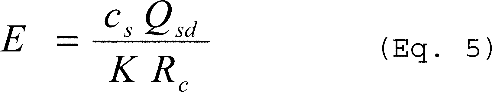
Where:
E = Emission rate of PM, g/kg (lb/1,000 lb) of coke burn-off;
cs = Concentration of total PM, grams per dry standard cubic meter (g/dscm) (gr/dscf);
Qsd = Volumetric flow rate of effluent gas, dry standard cubic meters per hour (dry standard cubic feet per hour);
Rc = Coke burn-off rate, kilograms per hour (kg/hr) [lb per hour (lb/hr)] coke; and
K = Conversion factor, 1.0 grams per gram (7,000 grains per lb).
(iii) The coke burn-off rate (Rc) is computed for each run using Equation 6 of this section:
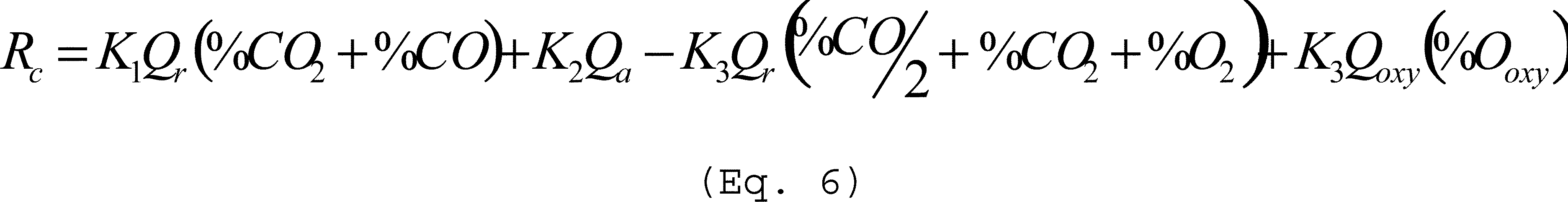
Where:
Rc = Coke burn-off rate, kg/hr (lb/hr);
Qr = Volumetric flow rate of exhaust gas from FCCU regenerator or fluid coking burner before any emissions control or energy recovery system that burns auxiliary fuel, dry standard cubic meters per minute (dscm/min) [dry standard cubic feet per minute (dscf/min)];
Qa = Volumetric flow rate of air to FCCU regenerator or fluid coking burner, as determined from the unit's control room instrumentation, dscm/min (dscf/min);
Qoxy = Volumetric flow rate of O2 enriched air to FCCU regenerator or fluid coking unit, as determined from the unit's control room instrumentation, dscm/min (dscf/min);
%CO2 = Carbon dioxide (CO2) concentration in FCCU regenerator or fluid coking burner exhaust, percent by volume (dry basis);
%CO = CO concentration in FCCU regenerator or fluid coking burner exhaust, percent by volume (dry basis);
%O2 = O2 concentration in FCCU regenerator or fluid coking burner exhaust, percent by volume (dry basis);
%Ooxy = O2 concentration in O2 enriched air stream inlet to the FCCU regenerator or fluid coking burner, percent by volume (dry basis);
K1 = Material balance and conversion factor, 0.2982 (kg-min)/(hr-dscm-%) [0.0186 (lb-min)/(hr-dscf-%)];
K2 = Material balance and conversion factor, 2.088 (kg-min)/(hr-dscm) [0.1303 (lb-min)/(hr-dscf)]; and
K3 = Material balance and conversion factor, 0.0994 (kg-min)/(hr-dscm-%) [0.00624 (lb-min)/(hr-dscf-%)].
(iv) During the performance test, the volumetric flow rate of exhaust gas from catalyst regenerator (Qr) before any emission control or energy recovery system that burns auxiliary fuel is measured using Method 2 of appendix A-1 to part 60.
(v) For subsequent calculations of coke burn-off rates or exhaust gas flow rates, the volumetric flow rate of Qr is calculated using average exhaust gas concentrations as measured by the monitors required in § 60.105a(b)(2), if applicable, using Equation 7 of this section:
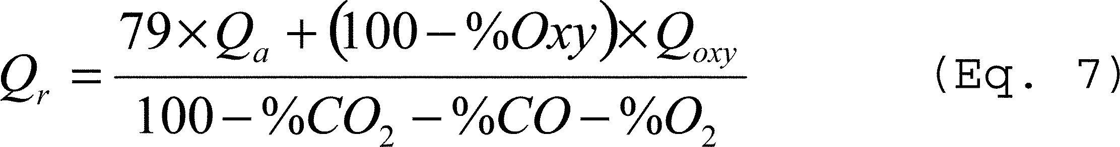
Where:
Qr = Volumetric flow rate of exhaust gas from FCCU regenerator or fluid coking burner before any emission control or energy recovery system that burns auxiliary fuel, dscm/min (dscf/min);
Qa = Volumetric flow rate of air to FCCU regenerator or fluid coking burner, as determined from the unit's control room instrumentation, dscm/min (dscf/min);
Qoxy = Volumetric flow rate of O2 enriched air to FCCU regenerator or fluid coking unit, as determined from the unit's control room instrumentation, dscm/min (dscf/min);
%CO2 = Carbon dioxide concentration in FCCU regenerator or fluid coking burner exhaust, percent by volume (dry basis);
%CO = CO concentration FCCU regenerator or fluid coking burner exhaust, percent by volume (dry basis). When no auxiliary fuel is burned and a continuous CO monitor is not required in accordance with § 60.105a(h)(3), assume %CO to be zero;
%O2 = O2 concentration in FCCU regenerator or fluid coking burner exhaust, percent by volume (dry basis); and
%Ooxy = O2 concentration in O2 enriched air stream inlet to the FCCU regenerator or fluid coking burner, percent by volume (dry basis).
(5) Method 6, 6A, or 6C of appendix A-4 to part 60 for moisture content and for the concentration of SO2; the duration of each test run must be no less than 4 hours. The method ANSI/ASME PTC 19.10-1981, “Flue and Exhaust Gas Analyses,” (incorporated by reference—see § 60.17) is an acceptable alternative to EPA Method 6 or 6A of appendix A-4 to part 60.
(6) Method 7, 7A, 7C, 7D, or 7E of appendix A-4 to part 60 for moisture content and for the concentration of NOX calculated as nitrogen dioxide (NO2); the duration of each test run must be no less than 4 hours. The method ANSI/ASME PTC 19.10-1981, “Flue and Exhaust Gas Analyses,” (incorporated by reference—see § 60.17) is an acceptable alternative to EPA Method 7 or 7C of appendix A-4 to part 60.
(7) Method 10, 10A, or 10B of appendix A-4 to part 60 for moisture content and for the concentration of CO. The sampling time for each run must be 60 minutes.
(8) The owner or operator shall adjust PM, NOX, SO2 and CO pollutant concentrations to 0-percent excess air or 0-percent O2 using Equation 8 of this section:

Where:
Cadj = pollutant concentration adjusted to 0-percent excess air or O2, parts per million (ppm) or g/dscm;
Cmeas = pollutant concentration measured on a dry basis, ppm or g/dscm;
20.9c = 20.9 percent O2−0.0 percent O2 (defined O2 correction basis), percent;
20.9 = O2 concentration in air, percent; and
%O2 = O2 concentration measured on a dry basis, percent.
(e) The owner or operator of a FCCU or FCU that is controlled by an electrostatic precipitator or wet scrubber and that is subject to control device operating parameter limits in § 60.102a(c) shall establish the limits based on the performance test results according to the following procedures:
(1) Reduce the parameter monitoring data to hourly averages for each test run;
(2) Determine the hourly average operating limit for each required parameter as the average of the three test runs.
(f) The owner or operator of an FCCU or FCU that uses cyclones to comply with the PM per coke burn-off emissions limit in § 60.102a(b)(1) shall establish a site-specific opacity operating limit according to the procedures in paragraphs (f)(1) through (3) of this section.
(1) Collect COMS data every 10 seconds during the entire period of the PM performance test and reduce the data to 6-minute averages.
(2) Determine and record the hourly average opacity from all the 6-minute averages.
(3) Compute the site-specific limit using Equation 9 of this section:

Where:
Opacity limit = Maximum permissible 3-hour average opacity, percent, or 10 percent, whichever is greater;
Opacityst = Hourly average opacity measured during the source test, percent; and
PMEmRst = PM emission rate measured during the source test, lb/1,000 lb coke burn.
(g) The owner or operator of a FCCU or FCU that is exempt from the requirement to install and operate a CO CEMS pursuant to § 60.105a(h)(3) and that is subject to control device operating parameter limits in § 60.102a(c) shall establish the limits based on the performance test results using the procedures in paragraphs (g)(1) and (2) of this section.
(1) Reduce the temperature and O2 concentrations from the parameter monitoring systems to hourly averages for each test run.
(2) Determine the operating limit for temperature and O2 concentrations as the average of the average temperature and O2 concentration for the three test runs.
(h) The owner or operator shall determine compliance with the SO2 emissions limits for sulfur recovery plants in § 60.102a(f)(1)(i) and (f)(2)(i) and the reduced sulfur compounds and H2S emissions limits for sulfur recovery plants in § 60.102a(f)(1)(ii), (f)(1)(iii), (f)(2)(ii), and (f)(2)(iii) using the following methods and procedures:
(1) Method 1 of appendix A-1 to part 60 for sample and velocity traverses.
(2) Method 2 of appendix A-1 to part 60 for velocity and volumetric flow rate.
(3) Method 3, 3A, or 3B of appendix A-2 to part 60 for gas analysis. The method ANSI/ASME PTC 19.10-1981, “Flue and Exhaust Gas Analyses,” (incorporated by reference—see § 60.17) is an acceptable alternative to EPA Method 3B of appendix A-2 to part 60.
(4) Method 6, 6A, or 6C of appendix A-4 to part 60 to determine the SO2 concentration. The method ANSI/ASME PTC 19.10-1981, “Flue and Exhaust Gas Analyses,” (incorporated by reference—see § 60.17) is an acceptable alternative to EPA Method 6 or 6A of appendix A-4 to part 60.
(5) Method 15 or 15A of appendix A-5 to part 60 or Method 16 of appendix A-6 to part 60 to determine the reduced sulfur compounds and H2S concentrations. The method ANSI/ASME PTC 19.10-1981, “Flue and Exhaust Gas Analyses,” (incorporated by reference—see § 60.17) is an acceptable alternative to EPA Method 15A of appendix A-5 to part 60.
(i) Each run consists of 16 samples taken over a minimum of 3 hours.
(ii) The owner or operator shall calculate the average H2S concentration after correcting for moisture and O2 as the arithmetic average of the H2S concentration for each sample during the run (ppmv, dry basis, corrected to 0 percent excess air).
(iii) The owner or operator shall calculate the SO2 equivalent for each run after correcting for moisture and O2 as the arithmetic average of the SO2 equivalent of reduced sulfur compounds for each sample during the run (ppmv, dry basis, corrected to 0 percent excess air).
(iv) The owner or operator shall use Equation 8 of this section to adjust pollutant concentrations to 0-percent O2 or 0- percent excess air.
(6) If oxygen or oxygen-enriched air is used in the Claus burner and either Equation 1 or 2 of this subpart is used to determine the applicable emissions limit, determine the average O2 concentration of the air/oxygen mixture supplied to the Claus burner, in percent by volume (dry basis), for the performance test using all hourly average O2 concentrations determined during the test runs using the procedures in § 60.106a(a)(5) or (6).
(i) The owner or operator shall determine compliance with the SO2 and NOX emissions limits in § 60.102a(g) for a fuel gas combustion device according to the following test methods and procedures:
(1) Method 1 of appendix A-1 to part 60 for sample and velocity traverses;
(2) Method 2 of appendix A-1 to part 60 for velocity and volumetric flow rate;
(3) Method 3, 3A, or 3B of appendix A-2 to part 60 for gas analysis. The method ANSI/ASME PTC 19.10-1981, “Flue and Exhaust Gas Analyses,” (incorporated by reference—see § 60.17) is an acceptable alternative to EPA Method 3B of appendix A-2 to part 60;
(4) Method 6, 6A, or 6C of appendix A-4 to part 60 to determine the SO2 concentration. The method ANSI/ASME PTC 19.10-1981, “Flue and Exhaust Gas Analyses,” (incorporated by reference—see § 60.17) is an acceptable alternative to EPA Method 6 or 6A of appendix A-4 to part 60.
(i) The performance test consists of 3 valid test runs; the duration of each test run must be no less than 1 hour.
(ii) If a single fuel gas combustion device having a common source of fuel gas is monitored as allowed under § 60.107a(a)(1)(v), only one performance test is required. That is, performance tests are not required when a new affected fuel gas combustion device is added to a common source of fuel gas that previously demonstrated compliance.
(5) Method 7, 7A, 7C, 7D, or 7E of appendix A-4 to part 60 for moisture content and for the concentration of NOX calculated as NO2; the duration of each test run must be no less than 4 hours. The method ANSI/ASME PTC 19.10-1981, “Flue and Exhaust Gas Analyses,” (incorporated by reference—see § 60.17) is an acceptable alternative to EPA Method 7 or 7C of appendix A-4 to part 60.
(6) For process heaters with a rated heat capacity between 40 and 100 MMBtu/hr that elect to demonstrate continuous compliance with a maximum excess oxygen limit as provided in § 60.107a(c)(6) or (d)(8), the owner or operator shall establish the O2 operating limit or O2 operating curve based on the performance test results according to the requirements in paragraph (i)(6)(i) or (ii) of this section, respectively.
(i) If a single O2 operating limit will be used:
(A) Conduct the performance test following the methods provided in paragraphs (i)(1), (2), (3) and (5) of this section when the process heater is firing at no less than 70 percent of the rated heat capacity. For co-fired process heaters, conduct at least one of the test runs while the process heater is being supplied by both fuel gas and fuel oil and conduct at least one of the test runs while the process heater is being supplied solely by fuel gas.
(B) Each test will consist of three test runs. Calculate the NOX concentration for the performance test as the average of the NOX concentrations from each of the three test runs. If the NOX concentration for the performance test is less than or equal to the numerical value of the applicable NOX emissions limit (regardless of averaging time), then the test is considered to be a valid test.
(C) Determine the average O2 concentration for each test run of a valid test.
(D) Calculate the O2 operating limit as the average O2 concentration of the three test runs from a valid test.
(ii) If an O2 operating curve will be used:
(A) Conduct a performance test following the methods provided in paragraphs (i)(1), (2), (3) and (5) of this section at a representative condition for each operating range for which different O2 operating limits will be established. Different operating conditions may be defined as different firing rates (e.g., above 50 percent of rated heat capacity and at or below 50 percent of rated heat capacity) and/or, for co-fired process heaters, different fuel mixtures (e.g., primarily gas fired, primarily oil fired, and equally co-fired, i.e., approximately 50 percent of the input heating value is from fuel gas and approximately 50 percent of the input heating value is from fuel oil). Performance tests for different operating ranges may be conducted at different times.
(B) Each test will consist of three test runs. Calculate the NOX concentration for the performance test as the average of the NOX concentrations from each of the three test runs. If the NOX concentration for the performance test is less than or equal to the numerical value of the applicable NOX emissions limit (regardless of averaging time), then the test is considered to be a valid test.
(C) If an operating curve is developed for different firing rates, conduct at least one test when the process heater is firing at no less than 70 percent of the rated heat capacity and at least one test under turndown conditions (i.e., when the process heater is firing at 50 percent or less of the rated heat capacity). If O2 operating limits are developed for co-fired process heaters based only on overall firing rates (and not by fuel mixtures), conduct at least one of the test runs for each test while the process heater is being supplied by both fuel gas and fuel oil and conduct at least one of the test runs while the process heater is being supplied solely by fuel gas.
(D) Determine the average O2 concentration for each test run of a valid test.
(E) Calculate the O2 operating limit for each operating range as the average O2 concentration of the three test runs from a valid test conducted at the representative conditions for that given operating range.
(F) Identify the firing rates for which the different operating limits apply. If only two operating limits are established based on firing rates, the O2 operating limits established when the process heater is firing at no less than 70 percent of the rated heat capacity must apply when the process heater is firing above 50 percent of the rated heat capacity and the O2 operating limits established for turndown conditions must apply when the process heater is firing at 50 percent or less of the rated heat capacity.
(G) Operating limits associated with each interval will be valid for 2 years or until another operating limit is established for that interval based on a more recent performance test specific for that interval, whichever occurs first. Owners and operators must use the operating limits determined for a given interval based on the most recent performance test conducted for that interval.
(7) The owner or operator of a process heater complying with a NOX limit in terms of lb/MMBtu as provided in § 60.102a(g)(2)(i)(B), (g)(2)(ii)(B), (g)(2)(iii)(B) or (g)(2)(iv)(B) or a process heater with a rated heat capacity between 40 and 100 MMBtu/hr that elects to demonstrate continuous compliance with a maximum excess O2 limit, as provided in § 60.107a(c)(6) or (d)(8), shall determine heat input to the process heater in MMBtu/hr during each performance test run by measuring fuel gas flow rate, fuel oil flow rate (as applicable) and heating value content according to the methods provided in § 60.107a(d)(5), (d)(6), and (d)(4) or (d)(7), respectively.
(8) The owner or operator shall use Equation 8 of this section to adjust pollutant concentrations to 0-percent O2 or 0- percent excess air.
(j) The owner or operator shall determine compliance with the applicable H2S emissions limit in § 60.102a(g)(1) for a fuel gas combustion device or the concentration requirement in § 60.103a(h) for a flare according to the following test methods and procedures:
(1)—(3) [Reserved]
(4) EPA Method 11, 15 or 15A of appendix A-5 to part 60 or EPA Method 16 of appendix A-6 to part 60 for determining the H2S concentration for affected facilities using an H2S monitor as specified in § 60.107a(a)(2). The method ANSI/ASME PTC 19.10-1981 (incorporated by reference—see § 60.17) is an acceptable alternative to EPA Method 15A of appendix A-5 to part 60. The owner or operator may demonstrate compliance based on the mixture used in the fuel gas combustion device or flare or for each individual fuel gas stream used in the fuel gas combustion device or flare.
(i) For Method 11 of appendix A-5 to part 60, the sampling time and sample volume must be at least 10 minutes and 0.010 dscm (0.35 dscf). Two samples of equal sampling times must be taken at about 1-hour intervals. The arithmetic average of these two samples constitutes a run. For most fuel gases, sampling times exceeding 20 minutes may result in depletion of the collection solution, although fuel gases containing low concentrations of H2S may necessitate sampling for longer periods of time.
(ii) For Method 15 of appendix A-5 to part 60, at least three injects over a 1-hour period constitutes a run.
(iii) For Method 15A of appendix A-5 to part 60, a 1-hour sample constitutes a run. The method ANSI/ASME PTC 19.10-1981, “Flue and Exhaust Gas Analyses,” (incorporated by reference—see § 60.17) is an acceptable alternative to EPA Method 15A of appendix A-5 to part 60.
(iv) If monitoring is conducted at a single point in a common source of fuel gas as allowed under § 60.107a(a)(2)(iv), only one performance test is required. That is, performance tests are not required when a new affected fuel gas combustion device or flare is added to a common source of fuel gas that previously demonstrated compliance.
[73 FR 35867, June 24, 2008, as amended at 77 FR 56470, Sep. 12, 2012; 80 FR 75231, Dec. 1, 2015]
§ 60.105a Monitoring of emissions and operations for fluid catalytic cracking units (FCCU) and fluid coking units (FCU).
(a) FCCU and FCU subject to PM emissions limit. Each owner or operator subject to the provisions of this subpart shall monitor each FCCU and FCU subject to the PM emissions limit in § 60.102a(b)(1) according to the requirements in paragraph (b), (c), (d), or (e) of this section.
(b) Control device operating parameters. Each owner or operator of a FCCU or FCU subject to the PM per coke burn-off emissions limit in § 60.102a(b)(1) that uses a control device other than fabric filter or cyclone shall comply with the requirements in paragraphs (b)(1) and (2) of this section.
(1) The owner or operator shall install, operate and maintain continuous parameter monitor systems (CPMS) to measure and record operating parameters for each control device according to the applicable requirements in paragraphs (b)(1)(i) through (v) of this section.
(i) For units controlled using an electrostatic precipitator, the owner or operator shall use CPMS to measure and record the hourly average total power input and secondary current to the entire system.
(ii) For units controlled using a wet scrubber, the owner or operator shall use CPMS to measure and record the hourly average pressure drop, liquid feed rate, and exhaust gas flow rate. As an alternative to a CPMS, the owner or operator must comply with the requirements in either paragraph (b)(1)(ii)(A) or (B) of this section.
(A) As an alternative to pressure drop, the owner or operator of a jet ejector type wet scrubber or other type of wet scrubber equipped with atomizing spray nozzles must conduct a daily check of the air or water pressure to the spray nozzles and record the results of each check. Faulty (e.g., leaking or plugged) air or water lines must be repaired within 12 hours of identification of an abnormal pressure reading.
(B) As an alternative to exhaust gas flow rate, the owner or operator shall comply with the approved alternative for monitoring exhaust gas flow rate in 40 CFR 63.1573(a) of the National Emission Standards for Hazardous Air Pollutants for Petroleum Refineries: Catalytic Cracking Units, Catalytic Reforming Units, and Sulfur Recovery Units.
(iii) The owner or operator shall install, operate, and maintain each CPMS according to the manufacturer's specifications and requirements.
(iv) The owner or operator shall determine and record the average coke burn-off rate and hours of operation for each FCCU or FCU using the procedures in § 60.104a(d)(4)(iii).
(v) If you use a control device other than an electrostatic precipitator, wet scrubber, fabric filter, or cyclone, you may request approval to monitor parameters other than those required in paragraph (b)(1) of this section by submitting an alternative monitoring plan to the Administrator. The request must include the information in paragraphs (b)(1)(v)(A) through (E) of this section.
(A) A description of each affected facility and the parameter(s) to be monitored to determine whether the affected facility will continuously comply with the emission limitations and an explanation of the criteria used to select the parameter(s).
(B) A description of the methods and procedures that will be used to demonstrate that the parameter(s) can be used to determine whether the affected facility will continuously comply with the emission limitations and the schedule for this demonstration. The owner or operator must certify that an operating limit will be established for the monitored parameter(s) that represents the conditions in existence when the control device is being properly operated and maintained to meet the emission limitation.
(C) The frequency and content of the recordkeeping, recording, and reporting, if monitoring and recording are not continuous. The owner or operator also must include the rationale for the proposed monitoring, recording, and reporting requirements.
(D) Supporting calculations.
(E) Averaging time for the alternative operating parameter.
(2) For use in determining the coke burn-off rate for an FCCU or FCU, the owner or operator shall install, operate, calibrate, and maintain an instrument for continuously monitoring the concentrations of CO2, O2 (dry basis), and if needed, CO in the exhaust gases prior to any control or energy recovery system that burns auxiliary fuels. A CO monitor is not required for determining coke burn-off rate when no auxiliary fuel is burned and a continuous CO monitor is not required in accordance with paragraph (h)(3) of this section.
(i) The owner or operator shall install, operate, and maintain each CO2 and O2 monitor according to Performance Specification 3 of appendix B to this part.
(ii) The owner or operator shall conduct performance evaluations of each CO2 and O2 monitor according to the requirements in § 60.13(c) and Performance Specification 3 of appendix B to this part. The owner or operator shall use Method 3, 3A or 3B of appendix A-2 to this part for conducting the relative accuracy evaluations. The method ANSI/ASME PTC 19.10-1981, “Flue and Exhaust Gas Analyses,” (incorporated by reference—see § 60.17) is an acceptable alternative to EPA Method 3B of appendix A-2 to part 60.
(iii) If a CO monitor is required, the owner or operator shall install, operate, and maintain each CO monitor according to Performance Specification 4 or 4A of appendix B to this part. If this CO monitor also serves to demonstrate compliance with the CO emissions limit in § 60.102a(b)(4), the span value for this instrument is 1,000 ppm; otherwise, the span value for this instrument should be set at approximately 2 times the typical CO concentration expected in the FCCU of FCU flue gas prior to any emission control or energy recovery system that burns auxiliary fuels.
(iv) If a CO monitor is required, the owner or operator shall conduct performance evaluations of each CO monitor according to the requirements in § 60.13(c) and Performance Specification 4 of appendix B to this part. The owner or operator shall use Method 10, 10A, or 10B of appendix A-3 to this part for conducting the relative accuracy evaluations.
(v) The owner or operator shall comply with the quality assurance requirements of procedure 1 of appendix F to this part, including quarterly accuracy determinations for CO2 and CO monitors, annual accuracy determinations for O2 monitors, and daily calibration drift tests.
(c) Bag leak detection systems. Each owner or operator shall install, operate, and maintain a bag leak detection system for each baghouse or similar fabric filter control device that is used to comply with the PM per coke burn-off emissions limit in § 60.102a(b)(1) for an FCCU or FCU according to paragraph (c)(1) of this section; prepare and operate by a site-specific monitoring plan according to paragraph (c)(2) of this section; take action according to paragraph (c)(3) of this section; and record information according to paragraph (c)(4) of this section.
(1) Each bag leak detection system must meet the specifications and requirements in paragraphs (c)(1)(i) through (viii) of this section.
(i) The bag leak detection system must be certified by the manufacturer to be capable of detecting PM emissions at concentrations of 0.00044 grains per actual cubic foot or less.
(ii) The bag leak detection system sensor must provide output of relative PM loadings. The owner or operator shall continuously record the output from the bag leak detection system using electronic or other means (e.g., using a strip chart recorder or a data logger).
(iii) The bag leak detection system must be equipped with an alarm system that will sound when the system detects an increase in relative particulate loading over the alarm set point established according to paragraph (c)(1)(iv) of this section, and the alarm must be located such that it can be heard by the appropriate plant personnel.
(iv) In the initial adjustment of the bag leak detection system, the owner or operator must establish, at a minimum, the baseline output by adjusting the sensitivity (range) and the averaging period of the device, the alarm set points, and the alarm delay time.
(v) Following initial adjustment, the owner or operator shall not adjust the averaging period, alarm set point, or alarm delay time without approval from the Administrator or delegated authority except as provided in paragraph (c)(1)(vi) of this section.
(vi) Once per quarter, the owner or operator may adjust the sensitivity of the bag leak detection system to account for seasonal effects, including temperature and humidity, according to the procedures identified in the site-specific monitoring plan required by paragraph (c)(2) of this section.
(vii) The owner or operator shall install the bag leak detection sensor downstream of the baghouse and upstream of any wet scrubber.
(viii) Where multiple detectors are required, the system's instrumentation and alarm may be shared among detectors.
(2) The owner or operator shall develop and submit to the Administrator for approval a site-specific monitoring plan for each baghouse and bag leak detection system. The owner or operator shall operate and maintain each baghouse and bag leak detection system according to the site-specific monitoring plan at all times. Each monitoring plan must describe the items in paragraphs (c)(2)(i) through (vii) of this section.
(i) Installation of the bag leak detection system;
(ii) Initial and periodic adjustment of the bag leak detection system, including how the alarm set-point will be established;
(iii) Operation of the bag leak detection system, including quality assurance procedures;
(iv) How the bag leak detection system will be maintained, including a routine maintenance schedule and spare parts inventory list;
(v) How the bag leak detection system output will be recorded and stored;
(vi) Procedures as specified in paragraph (c)(3) of this section. In approving the site-specific monitoring plan, the Administrator or delegated authority may allow owners and operators more than 3 hours to alleviate a specific condition that causes an alarm if the owner or operator identifies in the monitoring plan this specific condition as one that could lead to an alarm, adequately explains why it is not feasible to alleviate this condition within 3 hours of the time the alarm occurs, and demonstrates that the requested time will ensure alleviation of this condition as expeditiously as practicable; and
(vii) How the baghouse system will be operated and maintained, including monitoring of pressure drop across baghouse cells and frequency of visual inspections of the baghouse interior and baghouse components such as fans and dust removal and bag cleaning mechanisms.
(3) For each bag leak detection system, the owner or operator shall initiate procedures to determine the cause of every alarm within 1 hour of the alarm. Except as provided in paragraph (c)(2)(vi) of this section, the owner or operator shall alleviate the cause of the alarm within 3 hours of the alarm by taking whatever action(s) are necessary. Actions may include, but are not limited to the following:
(i) Inspecting the baghouse for air leaks, torn or broken bags or filter media, or any other condition that may cause an increase in particulate emissions;
(ii) Sealing off defective bags or filter media;
(iii) Replacing defective bags or filter media or otherwise repairing the control device;
(iv) Sealing off a defective baghouse compartment;
(v) Cleaning the bag leak detection system probe or otherwise repairing the bag leak detection system; or
(vi) Shutting down the process producing the particulate emissions.
(4) The owner or operator shall maintain records of the information specified in paragraphs (c)(4)(i) through (iii) of this section for each bag leak detection system.
(i) Records of the bag leak detection system output;
(ii) Records of bag leak detection system adjustments, including the date and time of the adjustment, the initial bag leak detection system settings, and the final bag leak detection system settings; and
(iii) The date and time of all bag leak detection system alarms, the time that procedures to determine the cause of the alarm were initiated, the cause of the alarm, an explanation of the actions taken, the date and time the cause of the alarm was alleviated, and whether the alarm was alleviated within 3 hours of the alarm.
(d) Continuous emissions monitoring systems (CEMS). An owner or operator subject to the PM concentration emission limit (in gr/dscf) in § 60.102a(b)(1) for an FCCU or FCU shall install, operate, calibrate, and maintain an instrument for continuously monitoring and recording the concentration (0 percent excess air) of PM in the exhaust gases prior to release to the atmosphere. The monitor must include an O2 monitor for correcting the data for excess air.
(1) The owner or operator shall install, operate, and maintain each PM monitor according to Performance Specification 11 of appendix B to part 60. The span value of this PM monitor is 0.08 gr/dscf PM.
(2) The owner or operator shall conduct performance evaluations of each PM monitor according to the requirements in § 60.13(c) and Performance Specification 11 of appendix B to part 60. The owner or operator shall use EPA Methods 5 or 5I of appendix A-3 to part 60 or Method 17 of appendix A-6 to part 60 for conducting the relative accuracy evaluations.
(3) The owner or operator shall install, operate, and maintain each O2 monitor according to Performance Specification 3 of appendix B to part 60. The span value of this O2 monitor must be selected between 10 and 25 percent, inclusive.
(4) The owner or operator shall conduct performance evaluations of each O2 monitor according to the requirements in § 60.13(c) and Performance Specification 3 of appendix B to part 60. Method 3, 3A, or 3B of appendix A-2 to part 60 shall be used for conducting the relative accuracy evaluations. The method ANSI/ASME PTC 19.10-1981, “Flue and Exhaust Gas Analyses,” (incorporated by reference—see § 60.17) is an acceptable alternative to EPA Method 3B of appendix A-2 to part 60.
(5) The owner or operator shall comply with the quality assurance requirements of Procedure 2 of appendix B to part 60 for each PM CEMS and Procedure 1 of appendix F to part 60 for each O2 monitor, including quarterly accuracy determinations for each PM monitor, annual accuracy determinations for each O2 monitor, and daily calibration drift tests.
(e) Alternative monitoring option for FCCU and FCU—COMS. Each owner or operator of an FCCU or FCU that uses cyclones to comply with the PM emission limit in § 60.102a(b)(1) shall monitor the opacity of emissions according to the requirements in paragraphs (e)(1) through (3) of this section.
(1) The owner or operator shall install, operate, and maintain an instrument for continuously monitoring and recording the opacity of emissions from the FCCU or the FCU exhaust vent.
(2) The owner or operator shall install, operate, and maintain each COMS according to Performance Specification 1 of appendix B to part 60. The instrument shall be spanned at 20 to 60 percent opacity.
(3) The owner or operator shall conduct performance evaluations of each COMS according to § 60.13(c) and Performance Specification 1 of appendix B to part 60.
(f) FCCU and FCU subject to NOX limit. Each owner or operator subject to the NOX emissions limit in § 60.102a(b)(2) for an FCCU or FCU shall install, operate, calibrate, and maintain an instrument for continuously monitoring and recording the concentration by volume (dry basis, 0 percent excess air) of NOX emissions into the atmosphere. The monitor must include an O2 monitor for correcting the data for excess air.
(1) The owner or operator shall install, operate, and maintain each NOX monitor according to Performance Specification 2 of appendix B to part 60. The span value of this NOX monitor is 200 ppmv NOX.
(2) The owner or operator shall conduct performance evaluations of each NOX monitor according to the requirements in § 60.13(c) and Performance Specification 2 of appendix B to part 60. The owner or operator shall use Methods 7, 7A, 7C, 7D, or 7E of appendix A-4 to part 60 for conducting the relative accuracy evaluations. The method ANSI/ASME PTC 19.10-1981, “Flue and Exhaust Gas Analyses,” (incorporated by reference—see § 60.17) is an acceptable alternative to EPA Method 7 or 7C of appendix A-4 to part 60.
(3) The owner or operator shall install, operate, and maintain each O2 monitor according to Performance Specification 3 of appendix B to part 60. The span value of this O2 monitor must be selected between 10 and 25 percent, inclusive.
(4) The owner or operator shall conduct performance evaluations of each O2 monitor according to the requirements in § 60.13(c) and Performance Specification 3 of appendix B to part 60. Method 3, 3A, or 3B of appendix A-2 to part 60 shall be used for conducting the relative accuracy evaluations. The method ANSI/ASME PTC 19.10-1981, “Flue and Exhaust Gas Analyses,” (incorporated by reference—see § 60.17) is an acceptable alternative to EPA Method 3B of appendix A-2 to part 60.
(5) The owner or operator shall comply with the quality assurance requirements of Procedure 1 of appendix F to part 60 for each NOX and O2 monitor, including quarterly accuracy determinations for NOX monitors, annual accuracy determinations for O2 monitors, and daily calibration drift tests.
(g) FCCU and FCU subject to SO2 limit. The owner or operator subject to the SO2 emissions limit in § 60.102a(b)(3) for an FCCU or an FCU shall install, operate, calibrate, and maintain an instrument for continuously monitoring and recording the concentration by volume (dry basis, corrected to 0 percent excess air) of SO2 emissions into the atmosphere. The monitor shall include an O2 monitor for correcting the data for excess air.
(1) The owner or operator shall install, operate, and maintain each SO2 monitor according to Performance Specification 2 of appendix B to part 60. The span value of this SO2 monitor is 200 ppmv SO2.
(2) The owner or operator shall conduct performance evaluations of each SO2 monitor according to the requirements in § 60.13(c) and Performance Specification 2 of appendix B to part 60. The owner or operator shall use Methods 6, 6A, or 6C of appendix A-4 to part 60 for conducting the relative accuracy evaluations. The method ANSI / ASME PTC 19.10-1981, “Flue and Exhaust Gas Analyses,” (incorporated by reference—see § 60.17) is an acceptable alternative to EPA Method 6 or 6A of appendix A-4 to part 60.
(3) The owner or operator shall install, operate, and maintain each O2 monitor according to Performance Specification 3 of appendix B to part 60. The span value of this O2 monitor must be selected between 10 and 25 percent, inclusive.
(4) The owner or operator shall conduct performance evaluations of each O2 monitor according to the requirements in § 60.13(c) and Performance Specification 3 of appendix B to part 60. Method 3, 3A, or 3B of appendix A-2 to part 60 shall be used for conducting the relative accuracy evaluations. The method ANSI/ASME PTC 19.10-1981, “Flue and Exhaust Gas Analyses,” (incorporated by reference—see § 60.17) is an acceptable alternative to EPA Method 3B of appendix A-2 to part 60.
(5) The owner or operator shall comply with the quality assurance requirements in Procedure 1 of appendix F to part 60 for each SO2 and O2 monitor, including quarterly accuracy determinations for SO2 monitors, annual accuracy determinations for O2 monitors, and daily calibration drift tests.
(h) FCCU and fluid coking units subject to CO emissions limit. Except as specified in paragraph (h)(3) of this section, the owner or operator shall install, operate, calibrate, and maintain an instrument for continuously monitoring and recording the concentration by volume (dry basis) of CO emissions into the atmosphere from each FCCU and FCU subject to the CO emissions limit in § 60.102a(b)(4).
(1) The owner or operator shall install, operate, and maintain each CO monitor according to Performance Specification 4 or 4A of appendix B to this part. The span value for this instrument is 1,000 ppmv CO.
(2) The owner or operator shall conduct performance evaluations of each CO monitor according to the requirements in § 60.13(c) and Performance Specification 4 or 4A of appendix B to part 60. The owner or operator shall use Methods 10, 10A, or 10B of appendix A-4 to part 60 for conducting the relative accuracy evaluations.
(3) A CO CEMS need not be installed if the owner or operator demonstrates that all hourly average CO emissions are and will remain less than 50 ppmv (dry basis) corrected to 0 percent excess air. The Administrator may revoke this exemption from monitoring upon a determination that CO emissions on an hourly average basis have exceeded 50 ppmv (dry basis) corrected to 0 percent excess air, in which case a CO CEMS shall be installed within 180 days.
(i) The demonstration shall consist of continuously monitoring CO emissions for 30 days using an instrument that meets the requirements of Performance Specification 4 or 4A of appendix B to this part. The span value shall be 100 ppmv CO instead of 1,000 ppmv, and the relative accuracy limit shall be 10 percent of the average CO emissions or 5 ppmv CO, whichever is greater. For instruments that are identical to Method 10 of appendix A-4 to this part and employ the sample conditioning system of Method 10A of appendix A-4 to this part, the alternative relative accuracy test procedure in section 10.1 of Performance Specification 2 of appendix B to this part may be used in place of the relative accuracy test.
(ii) The owner or operator must submit the following information to the Administrator:
(A) The measurement data specified in paragraph (h)(3)(i) of this section along with all other operating data known to affect CO emissions; and
(B) Descriptions of the CPMS for exhaust gas temperature and O2 monitor required in paragraph (h)(4) of this section and operating limits for those parameters to ensure combustion conditions remain similar to those that exist during the demonstration period.
(iii) The effective date of the exemption from installation and operation of a CO CEMS is the date of submission of the information and data required in paragraph (h)(3)(ii) of this section.
(4) The owner or operator of a FCCU or FCU that is exempted from the requirement to install and operate a CO CEMS in paragraph (h)(3) of this section shall install, operate, calibrate, and maintain CPMS to measure and record the operating parameters in paragraph (h)(4)(i) or (ii) of this section. The owner or operator shall install, operate, and maintain each CPMS according to the manufacturer's specifications.
(i) For a FCCU or FCU with no post-combustion control device, the temperature and O2 concentration of the exhaust gas stream exiting the unit.
(ii) For a FCCU or FCU with a post-combustion control device, the temperature and O2 concentration of the exhaust gas stream exiting the control device.
(i) Excess emissions. For the purpose of reports required by § 60.7(c), periods of excess emissions for a FCCU or FCU subject to the emissions limitations in § 60.102a(b) are defined as specified in paragraphs (i)(1) through (6) of this section. Note: Determine all averages, except for opacity, as the arithmetic average of the applicable 1-hour averages, e.g., determine the rolling 3-hour average as the arithmetic average of three contiguous 1-hour averages.
(1) If a CPMS is used according to paragraph (b)(1) of this section, all 3-hour periods during which the average PM control device operating characteristics, as measured by the continuous monitoring systems under paragraph (b)(1), fall below the levels established during the performance test. If the alternative to pressure drop CPMS is used for the owner or operator of a jet ejector type wet scrubber or other type of wet scrubber equipped with atomizing spray nozzles, each day in which abnormal pressure readings are not corrected within 12 hours of identification.
(2) If a bag leak detection system is used according to paragraph (c) of this section, each day in which the cause of an alarm is not alleviated within the time period specified in paragraph (c)(3) of this section.
(3) If a PM CEMS is used according to § 60.105a(d), all 7-day periods during which the average PM emission rate, as measured by the continuous PM monitoring system under § 60.105a(d) exceeds 0.040 gr/dscf corrected to 0 percent excess air for a modified or reconstructed FCCU, 0.020 gr/dscf corrected to 0 percent excess air for a newly constructed FCCU, or 0.040 gr/dscf for an affected fluid coking unit.
(4) If a COMS is used according to § 60.105a(e), all 3-hour periods during which the average opacity, as measured by the COMS under § 60.105a(e), exceeds the site-specific limit established during the most recent performance test.
(5) All rolling 7-day periods during which the average concentration of NOX as measured by the NOX CEMS under § 60.105a(f) exceeds 80 ppmv for an affected FCCU or FCU.
(6) All rolling 7-day periods during which the average concentration of SO2 as measured by the SO2 CEMS under § 60.105a(g) exceeds 50 ppmv, and all rolling 365-day periods during which the average concentration of SO2 as measured by the SO2 CEMS exceeds 25 ppmv.
(7) All 1-hour periods during which the average CO concentration as measured by the CO continuous monitoring system under paragraph (h) of this section exceeds 500 ppmv or, if applicable, all 1-hour periods during which the average temperature and O2 concentration as measured by the continuous monitoring systems under paragraph (h)(4) of this section fall below the operating limits established during the performance test.
[73 FR 35867, June 24, 2008, as amended at 77 FR 56473, Sep. 12, 2012; 80 FR 75232, Dec. 1, 2015; 83 FR 60713, Nov. 26, 2018]
§ 60.106a Monitoring of emissions and operations for sulfur recovery plants.
(a) The owner or operator of a sulfur recovery plant that is subject to the emissions limits in § 60.102a(f)(1) or § 60.102a(f)(2) shall:
(1) For sulfur recovery plants subject to the SO2 emission limit in § 60.102a(f)(1)(i) or § 60.102a(f)(2)(i), the owner or operator shall install, operate, calibrate, and maintain an instrument for continuously monitoring and recording the concentration (dry basis, zero percent excess air) of any SO2 emissions into the atmosphere. The monitor shall include an oxygen monitor for correcting the data for excess air.
(i) The span value for the SO2 monitor is two times the applicable SO2 emission limit at the highest O2 concentration in the air/oxygen stream used in the Claus burner, if applicable.
(ii) The owner or operator shall install, operate, and maintain each SO2 CEMS according to Performance Specification 2 of appendix B to part 60.
(iii) The owner or operator shall conduct performance evaluations of each SO2 monitor according to the requirements in § 60.13(c) and Performance Specification 2 of appendix B to part 60. The owner or operator shall use Method 6 or 6C of appendix A-4 to part 60. The method ANSI/ASME PTC 19.10-1981, “Flue and Exhaust Gas Analyses,” (incorporated by reference—see § 60.17) is an acceptable alternative to EPA Method 6.
(iv) The owner or operator shall install, operate, and maintain each O2 monitor according to Performance Specification 3 of appendix B to this part.
(v) The span value for the O2 monitor must be selected between 10 and 25 percent, inclusive.
(vi) The owner or operator shall conduct performance evaluations for the O2 monitor according to the requirements of § 60.13(c) and Performance Specification 3 of appendix B to this part. The owner or operator shall use Methods 3, 3A, or 3B of appendix A-2 to this part for conducting the relative accuracy evaluations. The method ANSI/ASME PTC 19.10-1981 (incorporated by reference—see § 60.17) is an acceptable alternative to EPA Method 3B of appendix A-2 to this part.
(vii) The owner or operator shall comply with the applicable quality assurance procedures of appendix F to this part for each monitor, including annual accuracy determinations for each O2 monitor, and daily calibration drift determinations.
(2) For sulfur recovery plants that are subject to the reduced sulfur compounds emission limit in § 60.102a(f)(1)(ii) or (f)(2)(ii), the owner or operator shall install, operate, calibrate, and maintain an instrument for continuously monitoring and recording the concentration of reduced sulfur compounds and O2 emissions into the atmosphere. The reduced sulfur compounds emissions shall be calculated as SO2 (dry basis, zero percent excess air).
(i) The span value for the reduced sulfur compounds monitor is two times the applicable reduced sulfur compounds emission limit as SO2 at the highest O2 concentration in the air/oxygen stream used in the Claus burner, if applicable.
(ii) The owner or operator shall install, operate, and maintain each reduced sulfur compounds CEMS according to Performance Specification 5 of appendix B to this part.
(iii) The owner or operator shall conduct performance evaluations of each reduced sulfur compounds monitor according to the requirements in § 60.13(c) and Performance Specification 5 of appendix B to this part. The owner or operator shall use Methods 15 or 15A of appendix A-5 to part 60 for conducting the relative accuracy evaluations. The method ANSI/ASME PTC 19.10-1981, “Flue and Exhaust Gas Analyses,” (incorporated by reference—see § 60.17) is an acceptable alternative to EPA Method 15A of appendix A-5 to part 60.
(iv) The owner or operator shall install, operate, and maintain each O2 monitor according to Performance Specification 3 of appendix B to part 60.
(v) The span value for the O2 monitor must be selected between 10 and 25 percent, inclusive.
(vi) The owner or operator shall conduct performance evaluations for the O2 monitor according to the requirements of § 60.13(c) and Performance Specification 3 of appendix B to part 60. The owner or operator shall use Methods 3, 3A, or 3B of appendix A-2 to part 60 for conducting the relative accuracy evaluations. The method ANSI/ASME PTC 19.10-1981, “Flue and Exhaust Gas Analyses,” (incorporated by reference—see § 60.17) is an acceptable alternative to EPA Method 3B of appendix A-2 to part 60.
(vii) The owner or operator shall comply with the applicable quality assurance procedures of appendix F to part 60 for each monitor, including annual accuracy determinations for each O2 monitor, and daily calibration drift determinations.
(3) In place of the reduced sulfur compounds monitor required in paragraph (a)(2) of this section, the owner or operator may install, calibrate, operate, and maintain an instrument using an air or O2 dilution and oxidation system to convert any reduced sulfur to SO2 for continuously monitoring and recording the concentration (dry basis, 0 percent excess air) of the total resultant SO2. The monitor must include an O2 monitor for correcting the data for excess O2.
(i) The span value for this monitor is two times the applicable reduced sulfur compounds emission limit as SO2 at the highest O2 concentration in the air/oxygen stream used in the Claus burner, if applicable.
(ii) The owner or operator shall conduct performance evaluations of each SO2 monitor according to the requirements in § 60.13(c) and Performance Specification 5 of appendix B to part 60. The owner or operator shall use Methods 15 or 15A of appendix A-5 to part 60 for conducting the relative accuracy evaluations. The method ANSI/ASME PTC 19.10-1981, “Flue and Exhaust Gas Analyses,” (incorporated by reference—see § 60.17) is an acceptable alternative to EPA Method 15A of appendix A-5 to part 60.
(iii) The owner or operator shall install, operate, and maintain each O2 monitor according to Performance Specification 3 of appendix B to part 60.
(iv) The span value for the O2 monitor must be selected between 10 and 25 percent, inclusive.
(v) The owner or operator shall conduct performance evaluations for the O2 monitor according to the requirements of § 60.13(c) and Performance Specification 3 of appendix B to part 60. The owner or operator shall use Methods 3, 3A, or 3B of appendix A-2 to part 60 for conducting the relative accuracy evaluations. The method ANSI/ASME PTC 19.10-1981, “Flue and Exhaust Gas Analyses,” (incorporated by reference—see § 60.17) is an acceptable alternative to EPA Method 3B of appendix A-2 to part 60.
(vi) The owner or operator shall comply with the applicable quality assurance procedures of appendix F to part 60 for each monitor, including quarterly accuracy determinations for each SO2 monitor, annual accuracy determinations for each O2 monitor, and daily calibration drift determinations.
(4) For sulfur recovery plants that are subject to the H2S emission limit in § 60.102a(f)(1)(iii) or (f)(2)(iii), the owner or operator shall install, operate, calibrate, and maintain an instrument for continuously monitoring and recording the concentration of H2S, and O2 emissions into the atmosphere. The H2S emissions shall be calculated as SO2 (dry basis, zero percent excess air).
(i) The span value for this monitor is two times the applicable H2S emission limit.
(ii) The owner or operator shall install, operate, and maintain each H2S CEMS according to Performance Specification 7 of appendix B to this part.
(iii) The owner or operator shall conduct performance evaluations for each H2S monitor according to the requirements of § 60.13(c) and Performance Specification 7 of appendix B to this part. The owner or operator shall use Methods 11 or 15 of appendix A-5 to this part or Method 16 of appendix A-6 to this part for conducting the relative accuracy evaluations. The method ANSI/ASME PTC 19.10-1981 (incorporated by reference—see § 60.17) is an acceptable alternative to EPA Method 15A of appendix A-5 to this part.
(iv) The owner or operator shall install, operate, and maintain each O2 monitor according to Performance Specification 3 of appendix B to this part.
(v) The span value for the O2 monitor must be selected between 10 and 25 percent, inclusive.
(vi) The owner or operator shall conduct performance evaluations for the O2 monitor according to the requirements of § 60.13(c) and Performance Specification 3 of appendix B to this part. The owner or operator shall use Methods 3, 3A, or 3B of appendix A-2 to this part for conducting the relative accuracy evaluations. The method ANSI/ASME PTC 19.10-1981 (incorporated by reference—see § 60.17) is an acceptable alternative to EPA Method 3B of appendix A-2 to this part.
(vii) The owner or operator shall comply with the applicable quality assurance procedures of appendix F to this part for each monitor, including annual accuracy determinations for each O2 monitor, and daily calibration drift determinations.
(5) For sulfur recovery plants that use oxygen or oxygen enriched air in the Claus burner and that elects to monitor O2 concentration of the air/oxygen mixture supplied to the Claus burner, the owner or operator shall install, operate, calibrate, and maintain an instrument for continuously monitoring and recording the O2 concentration of the air/oxygen mixture supplied to the Claus burner in order to determine the allowable emissions limit.
(i) The owner or operator shall install, operate, and maintain each O2 monitor according to Performance Specification 3 of appendix B to this part.
(ii) The span value for the O2 monitor shall be 100 percent.
(iii) The owner or operator shall conduct performance evaluations for the O2 monitor according to the requirements of § 60.13(c) and Performance Specification 3 of appendix B to this part. The owner or operator shall use Methods 3, 3A, or 3B of appendix A-2 to this part for conducting the relative accuracy evaluations. The method ANSI/ASME PTC 19.10-1981 (incorporated by reference—see § 60.17) is an acceptable alternative to EPA Method 3B of appendix A-2 to this part.
(iv) The owner or operator shall comply with the applicable quality assurance procedures of appendix F to this part for each monitor, including annual accuracy determinations for each O2 monitor, and daily calibration drift determinations.
(v) The owner or operator shall use the hourly average O2 concentration from this monitor for use in Equation 1 or 2 of § 60.102a(f), as applicable, for each hour and determine the allowable emission limit as the arithmetic average of 12 contiguous 1-hour averages (i.e., the rolling 12-hour average).
(6) As an alternative to the O2 monitor required in paragraph (a)(5) of this section, the owner or operator may install, calibrate, operate, and maintain a CPMS to measure and record the volumetric gas flow rate of ambient air and oxygen-enriched gas supplied to the Claus burner and calculate the hourly average O2 concentration of the air/oxygen mixture used in the Claus burner as specified in paragraphs (a)(6)(i) through (iv) of this section in order to determine the allowable emissions limit as specified in paragraphs (a)(6)(v) of this section.
(i) The owner or operator shall install, calibrate, operate and maintain each flow monitor according to the manufacturer's procedures and specifications and the following requirements.
(A) Locate the monitor in a position that provides a representative measurement of the total gas flow rate.
(B) Use a flow sensor meeting an accuracy requirement of ±5 percent over the normal range of flow measured or 10 cubic feet per minute, whichever is greater.
(C) Use a flow monitor that is maintainable online, is able to continuously correct for temperature, pressure and, for ambient air flow monitor, moisture content, and is able to record dry flow in standard conditions (as defined in § 60.2) over one-minute averages.
(D) At least quarterly, perform a visual inspection of all components of the monitor for physical and operational integrity and all electrical connections for oxidation and galvanic corrosion if the flow monitor is not equipped with a redundant flow sensor.
(E) Recalibrate the flow monitor in accordance with the manufacturer's procedures and specifications biennially (every two years) or at the frequency specified by the manufacturer.
(ii) The owner or operator shall use 20.9 percent as the oxygen content of the ambient air.
(iii) The owner or operator shall use product specifications (e.g., as reported in material safety data sheets) for percent oxygen for purchased oxygen. For oxygen produced onsite, the percent oxygen shall be determined by periodic measurements or process knowledge.
(iv) The owner or operator shall calculate the hourly average O2 concentration of the air/oxygen mixture used in the Claus burner using Equation 10 of this section:

Where:
%O2 = O2 concentration of the air/oxygen mixture used in the Claus burner, percent by volume (dry basis);
20.9 = O2 concentration in air, percent dry basis;
Qair = Volumetric flow rate of ambient air used in the Claus burner, dscfm;
%O2,oxy = O2 concentration in the enriched oxygen stream, percent dry basis; and
Qoxy = Volumetric flow rate of enriched oxygen stream used in the Claus burner, dscfm.
(v) The owner or operator shall use the hourly average O2 concentration determined using Equation 8 of § 60.104a(d)(8) for use in Equation 1 or 2 of § 60.102a(f), as applicable, for each hour and determine the allowable emission limit as the arithmetic average of 12 contiguous 1-hour averages (i.e., the rolling 12-hour average).
(7) Owners or operators of a sulfur recovery plant that elects to comply with the SO2 emission limit in § 60.102a(f)(1)(i) or (f)(2)(i) or the reduced sulfur compounds emission limit in § 60.102a(f)(1)(ii) or (f)(2)(ii) as a flow rate weighted average for a group of release points from the sulfur recovery plant rather than for each process train or release point individually shall install, calibrate, operate, and maintain a CPMS to measure and record the volumetric gas flow rate of each release point within the group of release points from the sulfur recovery plant as specified in paragraphs (a)(7)(i) through (iv) of this section.
(i) The owner or operator shall install, calibrate, operate and maintain each flow monitor according to the manufacturer's procedures and specifications and the following requirements.
(A) Locate the monitor in a position that provides a representative measurement of the total gas flow rate.
(B) Use a flow sensor meeting an accuracy requirement of ±5 percent over the normal range of flow measured or 10 cubic feet per minute, whichever is greater.
(C) Use a flow monitor that is maintainable online, is able to continuously correct for temperature, pressure, and moisture content, and is able to record dry flow in standard conditions (as defined in § 60.2) over one-minute averages.
(D) At least quarterly, perform a visual inspection of all components of the monitor for physical and operational integrity and all electrical connections for oxidation and galvanic corrosion if the flow monitor is not equipped with a redundant flow sensor.
(E) Recalibrate the flow monitor in accordance with the manufacturer's procedures and specifications biennially (every two years) or at the frequency specified by the manufacturer.
(ii) The owner or operator shall correct the flow to 0 percent excess air using Equation 11 of this section:

Where:
Qadj = Volumetric flow rate adjusted to 0 percent excess air, dry standard cubic feet per minute (dscfm);
Cmeas = Volumetric flow rate measured by the flow meter corrected to dry standard conditions, dscfm;
20.9c = 20.9 percent O2−0.0 percent O2 (defined O2 correction basis), percent;
20.9 = O2 concentration in air, percent; and
%O2 = O2 concentration measured on a dry basis, percent.
(iii) The owner or operator shall calculate the flow weighted average SO2 or reduced sulfur compounds concentration for each hour using Equation 12 of this section:

Where:
Cave = Flow weighted average concentration of the pollutant, ppmv (dry basis, zero percent excess air). The pollutant is either SO2 (if complying with the SO2 emission limit in § 60.102a(f)(1)(i) or (f)(2)(i)) or reduced sulfur compounds (if complying with the reduced sulfur compounds emission limit in § 60.102a(f)(1)(ii) or (f)(2)(ii));
N = Number of release points within the group of release points from the sulfur recovery plant for which emissions averaging is elected;
Cn = Pollutant concentration in the nth release point within the group of release points from the sulfur recovery plant for which emissions averaging is elected, ppmv (dry basis, zero percent excess air);
Qadj,n = Volumetric flow rate of the nth release point within the group of release points from the sulfur recovery plant for which emissions averaging is elected, dry standard cubic feet per minute (dscfm, adjusted to 0 percent excess air).
(iv) For sulfur recovery plants that use oxygen or oxygen enriched air in the Claus burner, the owner or operator shall use Equation 10 of this section and the hourly emission limits determined in paragraph (a)(5)(v) or (a)(6)(v) of this section in-place of the pollutant concentration to determine the flow weighted average hourly emission limit for each hour. The allowable emission limit shall be calculated as the arithmetic average of 12 contiguous 1-hour averages (i.e., the rolling 12-hour average).
(b) Excess emissions. For the purpose of reports required by § 60.7(c), periods of excess emissions for sulfur recovery plants subject to the emissions limitations in § 60.102a(f) are defined as specified in paragraphs (b)(1) through (3) of this section.
Determine all averages as the arithmetic average of the applicable 1-hour averages, e.g., determine the rolling 12-hour average as the arithmetic average of 12 contiguous 1-hour averages.
(1) All 12-hour periods during which the average concentration of SO2 as measured by the SO2 continuous monitoring system required under paragraph (a)(1) of this section exceeds the applicable emission limit (dry basis, zero percent excess air); or
(2) All 12-hour periods during which the average concentration of reduced sulfur compounds (as SO2) as measured by the reduced sulfur compounds continuous monitoring system required under paragraph (a)(2) or (3) of this section exceeds the applicable emission limit; or
(3) All 12-hour periods during which the average concentration of H2S as measured by the H2S continuous monitoring system required under paragraph (a)(4) of this section exceeds the applicable emission limit (dry basis, 0 percent excess air).
[73 FR 35867, June 24, 2008, as amended at 80 FR 75232, Dec. 1, 2015; 83 FR 60713, Nov. 26, 2018]
§ 60.107a Monitoring of emissions and operations for fuel gas combustion devices and flares.
(a) Fuel gas combustion devices subject to SO2 or H2S limit and flares subject to H2S concentration requirements. The owner or operator of a fuel gas combustion device that is subject to § 60.102a(g)(1) and elects to comply with the SO2 emission limits in § 60.102a(g)(1)(i) shall comply with the requirements in paragraph (a)(1) of this section. The owner or operator of a fuel gas combustion device that is subject to § 60.102a(g)(1) and elects to comply with the H2S concentration limits in § 60.102a(g)(1)(ii) or a flare that is subject to the H2S concentration requirement in § 60.103a(h) shall comply with paragraph (a)(2) of this section.
(1) The owner or operator of a fuel gas combustion device that elects to comply with the SO2 emissions limits in § 60.102a(g)(1)(i) shall install, operate, calibrate and maintain an instrument for continuously monitoring and recording the concentration (dry basis, 0-percent excess air) of SO2 emissions into the atmosphere. The monitor must include an O2 monitor for correcting the data for excess air.
(i) The owner or operator shall install, operate, and maintain each SO2 monitor according to Performance Specification 2 of appendix B to this part. The span value for the SO2 monitor is 50 ppmv SO2.
(ii) The owner or operator shall conduct performance evaluations for the SO2 monitor according to the requirements of § 60.13(c) and Performance Specification 2 of appendix B to this part. The owner or operator shall use Methods 6, 6A, or 6C of appendix A-4 to this part for conducting the relative accuracy evaluations. The method ANSI/ASME PTC 19.10-1981 (incorporated by reference—see § 60.17) is an acceptable alternative to EPA Method 6 or 6A of appendix A-4 to this part. Samples taken by Method 6 of appendix A-4 to this part shall be taken at a flow rate of approximately 2 liters/min for at least 30 minutes. The relative accuracy limit shall be 20 percent or 4 ppmv, whichever is greater, and the calibration drift limit shall be 5 percent of the established span value.
(iii) The owner or operator shall install, operate, and maintain each O2 monitor according to Performance Specification 3 of appendix B to part 60. The span value for the O2 monitor must be selected between 10 and 25 percent, inclusive.
(iv) The owner or operator shall conduct performance evaluations for the O2 monitor according to the requirements of § 60.13(c) and Performance Specification 3 of appendix B to part 60. The owner or operator shall use Methods 3, 3A, or 3B of appendix A-2 to part 60 for conducting the relative accuracy evaluations. The method ANSI/ASME PTC 19.10-1981, “Flue and Exhaust Gas Analyses,” (incorporated by reference—see § 60.17) is an acceptable alternative to EPA Method 3B of appendix A-2 to part 60.
(v) The owner or operator shall comply with the applicable quality assurance procedures in appendix F to part 60, including quarterly accuracy determinations for SO2 monitors, annual accuracy determinations for O2 monitors, and daily calibration drift tests.
(vi) Fuel gas combustion devices having a common source of fuel gas may be monitored at only one location (i.e., after one of the combustion devices), if monitoring at this location accurately represents the SO2 emissions into the atmosphere from each of the combustion devices.
(2) The owner or operator of a fuel gas combustion device that elects to comply with the H2S concentration limits in § 60.102a(g)(1)(ii) or a flare that is subject to the H2S concentration requirement in § 60.103a(h) shall install, operate, calibrate and maintain an instrument for continuously monitoring and recording the concentration by volume (dry basis) of H2S in the fuel gases before being burned in any fuel gas combustion device or flare.
(i) The owner or operator shall install, operate and maintain each H2S monitor according to Performance Specification 7 of appendix B to part 60. The span value for this instrument is 300 ppmv H2S.
(ii) The owner or operator shall conduct performance evaluations for each H2S monitor according to the requirements of § 60.13(c) and Performance Specification 7 of appendix B to part 60. The owner or operator shall use Method 11, 15, or 15A of appendix A-5 to part 60 or Method 16 of appendix A-6 to part 60 for conducting the relative accuracy evaluations. The method ANSI/ASME PTC 19.10-1981, “Flue and Exhaust Gas Analyses,” (incorporated by reference—see § 60.17) is an acceptable alternative to EPA Method 15A of appendix A-5 to part 60.
(iii) The owner or operator shall comply with the applicable quality assurance procedures in appendix F to part 60 for each H2S monitor.
(iv) Fuel gas combustion devices or flares having a common source of fuel gas may be monitored at only one location, if monitoring at this location accurately represents the concentration of H2S in the fuel gas being burned in the respective fuel gas combustion devices or flares.
(v) The owner or operator of a flare subject to § 60.103a(c) through (e) may use the instrument required in paragraph (e)(1) of this section to demonstrate compliance with the H2S concentration requirement in § 60.103a(h) if the owner or operator complies with the requirements of paragraph (e)(1)(i) through (iv) and if the instrument has a span (or dual span, if necessary) capable of accurately measuring concentrations between 20 and 300 ppmv. If the instrument required in paragraph (e)(1) of this section is used to demonstrate compliance with the H2S concentration requirement, the concentration directly measured by the instrument must meet the numeric concentration in § 60.103a(h).
(vi) The owner or operator of modified flare that meets all three criteria in paragraphs (a)(2)(vi)(A) through (C) of this section shall comply with the requirements of paragraphs (a)(2)(i) through (v) of this section no later than November 11, 2015. The owner or operator shall comply with the approved alternative monitoring plan or plans pursuant to § 60.13(i) until the flare is in compliance with requirements of paragraphs (a)(2)(i) through (v) of this section.
(A) The flare was an affected facility subject to subpart J of this part prior to becoming an affected facility under § 60.100a.
(B) The owner or operator had an approved alternative monitoring plan or plans pursuant to § 60.13(i) for all fuel gases combusted in the flare.
(C) The flare did not have in place on or before September 12, 2012 an instrument for continuously monitoring and recording the concentration by volume (dry basis) of H2S in the fuel gases that is capable of complying with the requirements of paragraphs (a)(2)(i) through (v) of this section.
(3) The owner or operator of a fuel gas combustion device or flare is not required to comply with paragraph (a)(1) or (2) of this section for fuel gas streams that are exempt under §§ 60.102a(g)(1)(iii) or 60.103a(h) or, for fuel gas streams combusted in a process heater, other fuel gas combustion device or flare that are inherently low in sulfur content. Fuel gas streams meeting one of the requirements in paragraphs (a)(3)(i) through (iv) of this section will be considered inherently low in sulfur content.
(i) Pilot gas for heaters and flares.
(ii) Fuel gas streams that meet a commercial-grade product specification for sulfur content of 30 ppmv or less. In the case of a liquefied petroleum gas (LPG) product specification in the pressurized liquid state, the gas phase sulfur content should be evaluated assuming complete vaporization of the LPG and sulfur containing-compounds at the product specification concentration.
(iii) Fuel gas streams produced in process units that are intolerant to sulfur contamination, such as fuel gas streams produced in the hydrogen plant, catalytic reforming unit, isomerization unit, and HF alkylation process units.
(iv) Other fuel gas streams that an owner or operator demonstrates are low-sulfur according to the procedures in paragraph (b) of this section.
(4) If the composition of an exempt fuel gas stream changes, the owner or operator must follow the procedures in paragraph (b)(3) of this section.
(b) Exemption from H2S monitoring requirements for low-sulfur fuel gas streams. The owner or operator of a fuel gas combustion device or flare may apply for an exemption from the H2S monitoring requirements in paragraph (a)(2) of this section for a fuel gas stream that is inherently low in sulfur content. A fuel gas stream that is demonstrated to be low-sulfur is exempt from the monitoring requirements of paragraphs (a)(1) and (2) of this section until there are changes in operating conditions or stream composition.
(1) The owner or operator shall submit to the Administrator a written application for an exemption from monitoring. The application must contain the following information:
(i) A description of the fuel gas stream/system to be considered, including submission of a portion of the appropriate piping diagrams indicating the boundaries of the fuel gas stream/system and the affected fuel gas combustion device(s) or flare(s) to be considered;
(ii) A statement that there are no crossover or entry points for sour gas (high H2S content) to be introduced into the fuel gas stream/system (this should be shown in the piping diagrams);
(iii) An explanation of the conditions that ensure low amounts of sulfur in the fuel gas stream (i.e., control equipment or product specifications) at all times;
(iv) The supporting test results from sampling the requested fuel gas stream/system demonstrating that the sulfur content is less than 5 ppmv H2S. Sampling data must include, at minimum, 2 weeks of daily monitoring (14 grab samples) for frequently operated fuel gas streams/systems; for infrequently operated fuel gas streams/systems, seven grab samples must be collected unless other additional information would support reduced sampling. The owner or operator shall use detector tubes (“length-of-stain tube” type measurement) following the “Gas Processors Association Standard 2377-86 (incorporated by reference—see § 60.17), using tubes with a maximum span between 10 and 40 ppmv inclusive when 1≤N≤10, where N = number of pump strokes, to test the applicant fuel gas stream for H2S; and
(v) A description of how the 2 weeks (or seven samples for infrequently operated fuel gas streams/systems) of monitoring results compares to the typical range of H2S concentration (fuel quality) expected for the fuel gas stream/system going to the affected fuel gas combustion device or flare (e.g., the 2 weeks of daily detector tube results for a frequently operated loading rack included the entire range of products loaded out and, therefore, should be representative of typical operating conditions affecting H2S content in the fuel gas stream going to the loading rack flare).
(2) The effective date of the exemption is the date of submission of the information required in paragraph (b)(1) of this section.
(3) No further action is required unless refinery operating conditions change in such a way that affects the exempt fuel gas stream/system (e.g., the stream composition changes). If such a change occurs, the owner or operator shall follow the procedures in paragraph (b)(3)(i), (b)(3)(ii), or (b)(3)(iii) of this section.
(i) If the operation change results in a sulfur content that is still within the range of concentrations included in the original application, the owner or operator shall conduct an H2S test on a grab sample and record the results as proof that the concentration is still within the range.
(ii) If the operation change results in a sulfur content that is outside the range of concentrations included in the original application, the owner or operator may submit new information following the procedures of paragraph (b)(1) of this section within 60 days (or within 30 days after the seventh grab sample is tested for infrequently operated process units).
(iii) If the operation change results in a sulfur content that is outside the range of concentrations included in the original application and the owner or operator chooses not to submit new information to support an exemption, the owner or operator must begin H2S monitoring using daily stain sampling to demonstrate compliance using length-of-stain tubes with a maximum span between 200 and 400 ppmv inclusive when 1≤N≤5, where N = number of pump strokes. The owner or operator must begin monitoring according to the requirements in paragraphs (a)(1) or (a)(2) of this section as soon as practicable, but in no case later than 180 days after the operation change. During daily stain tube sampling, a daily sample exceeding 162 ppmv is an exceedance of the 3-hour H2S concentration limit. The owner or operator of a fuel gas combustion device must also determine a rolling 365-day average using the stain sampling results; an average H2S concentration of 5 ppmv must be used for days within the rolling 365-day period prior to the operation change.
(c) Process heaters complying with the NOX concentration-based limit. The owner or operator of a process heater subject to the NOX emissions limit in § 60.102a(g)(2) and electing to comply with the applicable emissions limit in § 60.102a(g)(2)(i)(A), (g)(2)(ii)(A), (g)(2)(iii)(A) or (g)(2)(iv)(A) shall install, operate, calibrate and maintain an instrument for continuously monitoring and recording the concentration (dry basis, 0-percent excess air) of NOX emissions into the atmosphere according to the requirements in paragraphs (c)(1) through (5) of this section, except as provided in paragraph (c)(6) of this section. The monitor must include an O2 monitor for correcting the data for excess air.
(1) Except as provided in paragraph (c)(6) of this section, the owner or operator shall install, operate and maintain each NOX monitor according to Performance Specification 2 of appendix B to part 60. The span value of this NOX monitor must be between 2 and 3 times the applicable emissions limit, inclusive.
(2) The owner or operator shall conduct performance evaluations of each NOX monitor according to the requirements in § 60.13(c) and Performance Specification 2 of appendix B to part 60. The owner or operator shall use Methods 7, 7A, 7C, 7D, or 7E of appendix A-4 to part 60 for conducting the relative accuracy evaluations. The method ANSI/ASME PTC 19.10-1981, “Flue and Exhaust Gas Analyses,” (incorporated by reference—see § 60.17) is an acceptable alternative to EPA Method 7 or 7C of appendix A-4 to part 60.
(3) The owner or operator shall install, operate, and maintain each O2 monitor according to Performance Specification 3 of appendix B to part 60. The span value of this O2 monitor must be selected between 10 and 25 percent, inclusive.
(4) The owner or operator shall conduct performance evaluations of each O2 monitor according to the requirements in § 60.13(c) and Performance Specification 3 of appendix B to part 60. Method 3, 3A, or 3B of appendix A-2 to part 60 shall be used for conducting the relative accuracy evaluations. The method ANSI/ASME PTC 19.10-1981, “Flue and Exhaust Gas Analyses,” (incorporated by reference—see § 60.17) is an acceptable alternative to EPA Method 3B of appendix A-2 to part 60.
(5) The owner or operator shall comply with the quality assurance requirements in Procedure 1 of appendix F to part 60 for each NOX and O2 monitor, including quarterly accuracy determinations for NOX monitors, annual accuracy determinations for O2 monitors, and daily calibration drift tests.
(6) The owner or operator of a process heater that has a rated heating capacity of less than 100 MMBtu and is equipped with combustion modification-based technology to reduce NOX emissions (i.e., low-NOX burners, ultra-low-NOX burners) may elect to comply with the monitoring requirements in paragraphs (c)(1) through (5) of this section or, alternatively, the owner or operator of such a process heater shall conduct biennial performance tests according to the requirements in § 60.104a(i), establish a maximum excess O2 operating limit or operating curve according to the requirements in § 60.104a(i)(6) and comply with the O2 monitoring requirements in paragraphs (c)(3) through (5) of this section to demonstrate compliance. If an O2 operating curve is used (i.e., if different O2 operating limits are established for different operating ranges), the owner or operator of the process heater must also monitor fuel gas flow rate, fuel oil flow rate (as applicable) and heating value content according to the methods provided in paragraphs (d)(5), (d)(6), and (d)(4) or (d)(7) of this section, respectively.
(d) Process heaters complying with the NOX heating value-based or mass-based limit. The owner or operator of a process heater subject to the NOX emissions limit in § 60.102a(g)(2) and electing to comply with the applicable emissions limit in § 60.102a(g)(2)(i)(B) or (g)(2)(ii)(B) shall install, operate, calibrate and maintain an instrument for continuously monitoring and recording the concentration (dry basis, 0-percent excess air) of NOX emissions into the atmosphere and shall determine the F factor of the fuel gas stream no less frequently than once per day according to the monitoring requirements in paragraphs (d)(1) through (4) of this section. The owner or operator of a co-fired process heater subject to the NOX emissions limit in § 60.102a(g)(2) and electing to comply with the heating value-based limit in § 60.102a(g)(2)(iii)(B) or (g)(2)(iv)(B) shall install, operate, calibrate and maintain an instrument for continuously monitoring and recording the concentration (dry basis, 0-percent excess air) of NOX emissions into the atmosphere according to the monitoring requirements in paragraph (d)(1) of this section; install, operate, calibrate and maintain an instrument for continuously monitoring and recording the flow rate of the fuel gas and fuel oil fed to the process heater according to the monitoring requirements in paragraph (d)(5) and (6) of this section; for fuel gas streams, determine gas composition according to the requirements in paragraph (d)(4) of this section or the higher heating value according to the requirements in paragraph (d)(7) of this section; and for fuel oil streams, determine the heating value according to the monitoring requirements in paragraph (d)(7) of this section.
(1) Except as provided in paragraph (d)(8) of this section, the owner or operator shall install, operate and maintain each NOX monitor according to the requirements in paragraphs (c)(1) through (5) of this section. The monitor must include an O2 monitor for correcting the data for excess air.
(2) Except as provided in paragraph (d)(3) of this section, the owner or operator shall sample and analyze each fuel stream fed to the process heater using the methods and equations in section 12.3.2 of EPA Method 19 of appendix A-7 to part 60 to determine the F factor on a dry basis. If a single fuel gas system provides fuel gas to several process heaters, the F factor may be determined at a single location in the fuel gas system provided it is representative of the fuel gas fed to the affected process heater(s).
(3) As an alternative to the requirements in paragraph (d)(2) of this section, the owner or operator of a gas-fired process heater shall install, operate and maintain a gas composition analyzer and determine the average F factor of the fuel gas using the factors in Table 1 of this subpart and Equation 13 of this section. If a single fuel gas system provides fuel gas to several process heaters, the F factor may be determined at a single location in the fuel gas system provided it is representative of the fuel gas fed to the affected process heater(s).

Where:
Fd = F factor on dry basis at 0% excess air, dscf/MMBtu.
Xi = mole or volume fraction of each component in the fuel gas.
MEVi = molar exhaust volume, dry standard cubic feet per mole (dscf/mol).
MHCi = molar heat content, Btu per mole (Btu/mol).
1,000,000 = unit conversion, Btu per MMBtu.
(4) The owner or operator shall conduct performance evaluations of each compositional monitor according to the requirements in Performance Specification 9 of appendix B to part 60. Any of the following methods shall be used for conducting the relative accuracy evaluations:
(i) EPA Method 18 of appendix A-6 to part 60;
(ii) ASTM D1945-03 (Reapproved 2010)(incorporated by reference-see § 60.17);
(iii) ASTM D1946-90 (Reapproved 2006)(incorporated by reference-see § 60.17);
(iv) ASTM D6420-99 (Reapproved 2004)(incorporated by reference-see § 60.17);
(v) GPA 2261-00 (incorporated by reference-see § 60.17); or
(vi) ASTM UOP539-97 (incorporated by reference-see § 60.17).
(5) The owner or operator shall install, operate and maintain fuel gas flow monitors according to the manufacturer's recommendations. For volumetric flow meters, temperature and pressure monitors must be installed in conjunction with the flow meter or in a representative location to correct the measured flow to standard conditions (i.e., 68 °F and 1 atmosphere). For mass flow meters, use gas compositions determined according to paragraph (d)(4) of this section to determine the average molecular weight of the fuel gas and convert the mass flow to a volumetric flow at standard conditions (i.e., 68 °F and 1 atmosphere). The owner or operator shall conduct performance evaluations of each fuel gas flow monitor according to the requirements in § 60.13 and Performance Specification 6 of appendix B to part 60. Any of the following methods shall be used for conducting the relative accuracy evaluations:
(i) EPA Method 2, 2A, 2B, 2C or 2D of appendix A-2 to part 60;
(ii) ASME MFC-3M-2004 (incorporated by reference-see § 60.17);
(iii) ANSI/ASME MFC-4M-1986 (Reaffirmed 2008) (incorporated by reference-see § 60.17);
(iv) ASME MFC-6M-1998 (Reaffirmed 2005) (incorporated by reference-see § 60.17);
(v) ASME/ANSI MFC-7M-1987 (Reaffirmed 2006) (incorporated by reference-see § 60.17);
(vi) ASME MFC-11M-2006 (incorporated by reference-see § 60.17);
(vii) ASME MFC-14M-2003 (incorporated by reference-see § 60.17);
(viii) ASME MFC-18M-2001 (incorporated by reference-see § 60.17);
(ix) AGA Report No. 3, Part 1 (incorporated by reference-see § 60.17);
(x) AGA Report No. 3, Part 2 (incorporated by reference-see § 60.17);
(xi) AGA Report No. 11 (incorporated by reference-see § 60.17);
(xii) AGA Report No. 7 (incorporated by reference-see § 60.17); and
(xiii) API Manual of Petroleum Measurement Standards, Chapter 22, Section 2 (incorporated by reference-see § 60.17).
(6) The owner or operator shall install, operate and maintain each fuel oil flow monitor according to the manufacturer's recommendations. The owner or operator shall conduct performance evaluations of each fuel oil flow monitor according to the requirements in § 60.13 and Performance Specification 6 of appendix B to part 60. Any of the following methods shall be used for conducting the relative accuracy evaluations:
(i) Any one of the methods listed in paragraph (d)(5) of this section that are applicable to fuel oil (i.e., “fluids”);
(ii) ANSI/ASME-MFC-5M-1985 (Reaffirmed 2006) (incorporated by reference-see § 60.17);
(iii) ASME/ANSI MFC-9M-1988 (Reaffirmed 2006) (incorporated by reference-see § 60.17);
(iv) ASME MFC-16-2007 (incorporated by reference-see § 60.17);
(v) ASME MFC-22-2007 (incorporated by reference-see § 60.17); or
(vi) ISO 8316 (incorporated by reference-see § 60.17).
(7) The owner or operator shall determine the higher heating value of each fuel fed to the process heater using any of the applicable methods included in paragraphs (d)(7)(i) through (ix) of this section. If a common fuel supply system provides fuel gas or fuel oil to several process heaters, the higher heating value of the fuel in each fuel supply system may be determined at a single location in the fuel supply system provided it is representative of the fuel fed to the affected process heater(s). The higher heating value of each fuel fed to the process heater must be determined no less frequently than once per day except as provided in paragraph (d)(7)(x) of this section.
(i) ASTM D240-02 (Reapproved 2007) (incorporated by reference-see § 60.17).
(ii) ASTM D1826-94 (Reapproved 2003) (incorporated by reference-see § 60.17).
(iii) ASTM D1945-03 (Reapproved 2010) (incorporated by reference-see § 60.17).
(iv) ASTM D1946-90 (Reapproved 2006) (incorporated by reference-see § 60.17).
(v) ASTM D3588-98 (Reapproved 2003) (incorporated by reference-see § 60.17).
(vi) ASTM D4809-06 (incorporated by reference-see § 60.17).
(vii) ASTM D4891-89 (Reapproved 2006) (incorporated by reference-see § 60.17).
(viii) GPA 2172-09 (incorporated by reference-see § 60.17).
(ix) Any of the methods specified in section 2.2.7 of appendix D to part 75.
(x) If the fuel oil supplied to the affected co-fired process heater originates from a single storage tank, the owner or operator may elect to use the storage tank sampling method in section 2.2.4.2 of appendix D to part 75 instead of daily sampling, except that the most recent value for heating content must be used.
(8) The owner or operator of a process heater that has a rated heating capacity of less than 100 MMBtu and is equipped with combustion modification based technology to reduce NOX emissions (i.e., low-NOX burners or ultra-low NOX burners) may elect to comply with the monitoring requirements in paragraphs (d)(1) through (7) of this section or, alternatively, the owner or operator of such a process heater shall conduct biennial performance tests according to the requirements in § 60.104a(i), establish a maximum excess O2 operating limit or operating curve according to the requirements in § 60.104a(i)(6) and comply with the O2 monitoring requirements in paragraphs (c)(3) through (5) of this section to demonstrate compliance. If an O2 operating curve is used (i.e., if different O2 operating limits are established for different operating ranges), the owner or operator of the process heater must also monitor fuel gas flow rate, fuel oil flow rate (as applicable) and heating value content according to the methods provided in paragraphs (d)(5), (d)(6), and (d)(4) or (d)(7) of this section, respectively.
(e) Sulfur monitoring for assessing root cause analysis threshold for affected flares. Except as described in paragraphs (e)(4) and (h) of this section, the owner or operator of an affected flare subject to § 60.103a(c) through (e) shall determine the total reduced sulfur concentration for each gas line directed to the affected flare in accordance with either paragraph (e)(1), (e)(2) or (e)(3) of this section. Different options may be elected for different gas lines. If a monitoring system is in place that is capable of complying with the requirements related to either paragraph (e)(1), (e)(2) or (e)(3) of this section, the owner or operator of a modified flare must comply with the requirements related to either paragraph (e)(1), (e)(2) or (e)(3) of this section upon startup of the modified flare. If a monitoring system is not in place that is capable of complying with the requirements related to either paragraph (e)(1), (e)(2) or (e)(3) of this section, the owner or operator of a modified flare must comply with the requirements related to either paragraph (e)(1), (e)(2) or (e)(3) of this section no later than November 11, 2015 or upon startup of the modified flare, whichever is later.
(1) Total reduced sulfur monitoring requirements. The owner or operator shall install, operate, calibrate and maintain an instrument or instruments for continuously monitoring and recording the concentration of total reduced sulfur in gas discharged to the flare.
(i) The owner or operator shall install, operate and maintain each total reduced sulfur monitor according to Performance Specification 5 of appendix B to part 60. The span value should be determined based on the maximum sulfur content of gas that can be discharged to the flare (e.g., roughly 1.1 to 1.3 times the maximum anticipated sulfur concentration), but may be no less than 5,000 ppmv. A single dual range monitor may be used to comply with the requirements of this paragraph and paragraph (a)(2) of this section provided the applicable span specifications are met.
(ii) The owner or operator shall conduct performance evaluations of each total reduced sulfur monitor according to the requirements in § 60.13(c) and Performance Specification 5 of appendix B to this part. The owner or operator of each total reduced sulfur monitor shall use EPA Method 15A of appendix A-5 to this part for conducting the relative accuracy evaluations. The method ANSI/ASME PTC 19.10-1981 (incorporated by reference-see § 60.17) is an acceptable alternative to EPA Method 15A of appendix A-5 to this part. The alternative relative accuracy procedures described in section 16.0 of Performance Specification 2 of appendix B to this part (cylinder gas audits) may be used for conducting the relative accuracy evaluations, except that it is not necessary to include as much of the sampling probe or sampling line as practical.
(iii) The owner or operator shall comply with the applicable quality assurance procedures in appendix F to part 60 for each total reduced sulfur monitor.
(2) H2S monitoring requirements. The owner or operator shall install, operate, calibrate, and maintain an instrument or instruments for continuously monitoring and recording the concentration of H2S in gas discharged to the flare according to the requirements in paragraphs (e)(2)(i) through (iii) of this section and shall collect and analyze samples of the gas and calculate total sulfur concentrations as specified in paragraphs (e)(2)(iv) through (ix) of this section.
(i) The owner or operator shall install, operate and maintain each H2S monitor according to Performance Specification 7 of appendix B to part 60. The span value should be determined based on the maximum sulfur content of gas that can be discharged to the flare (e.g., roughly 1.1 to 1.3 times the maximum anticipated sulfur concentration), but may be no less than 5,000 ppmv. A single dual range H2S monitor may be used to comply with the requirements of this paragraph and paragraph (a)(2) of this section provided the applicable span specifications are met.
(ii) The owner or operator shall conduct performance evaluations of each H2S monitor according to the requirements in § 60.13(c) and Performance Specification 7 of appendix B to this part. The owner or operator shall use EPA Method 11, 15 or 15A of appendix A-5 to this part for conducting the relative accuracy evaluations. The method ANSI/ASME PTC 19.10-1981 (incorporated by reference—see § 60.17) is an acceptable alternative to EPA Method 15A of appendix A-5 to this part. The alternative relative accuracy procedures described in section 16.0 of Performance Specification 2 of appendix B to this part (cylinder gas audits) may be used for conducting the relative accuracy evaluations, except that it is not necessary to include as much of the sampling probe or sampling line as practical.
(iii) The owner or operator shall comply with the applicable quality assurance procedures in appendix F to part 60 for each H2S monitor.
(iv) In the first 10 operating days after the date the flare must begin to comply with § 60.103a(c)(1), the owner or operator shall collect representative daily samples of the gas discharged to the flare. The samples may be grab samples or integrated samples. The owner or operator shall take subsequent representative daily samples at least once per week or as required in paragraph (e)(2)(ix) of this section.
(v) The owner or operator shall analyze each daily sample for total sulfur using either EPA Method 15A of appendix A-5 to part 60, EPA Method 16A of appendix A-6 to part 60, ASTM Method D4468-85 (Reapproved 2006) (incorporated by reference—see § 60.17) or ASTM Method D5504-08 (incorporated by reference—see § 60.17).
(vi) The owner or operator shall develop a 10-day average total sulfur-to-H2S ratio and 95-percent confidence interval as follows:
(A) Calculate the ratio of the total sulfur concentration to the H2S concentration for each day during which samples are collected.
(B) Determine the 10-day average total sulfur-to-H2S ratio as the arithmetic average of the daily ratios calculated in paragraph (e)(2)(vi)(A) of this section.
(C) Determine the acceptable range for subsequent weekly samples based on the 95-percent confidence interval for the distribution of daily ratios based on the 10 individual daily ratios using Equation 14 of this section.

Where:
AR = Acceptable range of subsequent ratio determinations, unitless.
RatioAvg = 10-day average total sulfur-to-H2S concentration ratio, unitless.
2.262 = t-distribution statistic for 95-percent 2-sided confidence interval for 10 samples (9 degrees of freedom).
SDev = Standard deviation of the 10 daily average total sulfur-to-H2S concentration ratios used to develop the 10-day average total sulfur-to-H2S concentration ratio, unitless.
(vii) For each day during the period when data are being collected to develop a 10-day average, the owner or operator shall estimate the total sulfur concentration using the measured total sulfur concentration measured for that day.
(viii) For all days other than those during which data are being collected to develop a 10-day average, the owner or operator shall multiply the most recent 10-day average total sulfur-to-H2S ratio by the daily average H2S concentrations obtained using the monitor as required by paragraph (e)(2)(i) through (iii) of this section to estimate total sulfur concentrations.
(ix) If the total sulfur-to-H2S ratio for a subsequent weekly sample is outside the acceptable range for the most recent distribution of daily ratios, the owner or operator shall develop a new 10-day average ratio and acceptable range based on data for the outlying weekly sample plus data collected over the following 9 operating days.
(3) SO2 monitoring requirements. The owner or operator shall install, operate, calibrate, and maintain an instrument for continuously monitoring and recording the concentration of SO2 from a process heater or other fuel gas combustion device that is combusting gas representative of the fuel gas in the flare gas line according to the requirements in paragraph (a)(1) of this section, determine the F factor of the fuel gas at least daily according to the requirements in paragraphs (d)(2) through (4) of this section, determine the higher heating value of the fuel gas at least daily according to the requirements in paragraph (d)(7) of this section, and calculate the total sulfur content (as SO2) in the fuel gas using Equation 15 of this section.

Where:
TSFG = Total sulfur concentration, as SO2, in the fuel gas, ppmv.
CSO2 = Concentration of SO2 in the exhaust gas, ppmv (dry basis at 0-percent excess air).
Fd = F factor gas on dry basis at 0-percent excess air, dscf/MMBtu.
HHVFG = Higher heating value of the fuel gas, MMBtu/scf.
(4) Exemptions from sulfur monitoring requirements. Flares identified in paragraphs (e)(4)(i) through (iv) of this section are exempt from the requirements in paragraphs (e)(1) through (3) of this section. For each such flare, except as provided in paragraph (e)(4)(iv), engineering calculations shall be used to calculate the SO2 emissions in the event of a discharge that may trigger a root cause analysis under § 60.103a(c)(1).
(i) Flares that can only receive:
(A) Fuel gas streams that are inherently low in sulfur content as described in paragraph (a)(3)(i) through (iv) of this section; and/or
(B) Fuel gas streams that are inherently low in sulfur content for which the owner or operator has applied for an exemption from the H2S monitoring requirements as described in paragraph (b) of this section.
(ii) Emergency flares, provided that for each such flare, the owner or operator complies with the monitoring alternative in paragraph (g) of this section.
(iii) Flares equipped with flare gas recovery systems designed, sized and operated to capture all flows except those resulting from startup, shutdown or malfunction, provided that for each such flare, the owner or operator complies with the monitoring alternative in paragraph (g) of this section.
(iv) Secondary flares that receive gas diverted from the primary flare. In the event of a discharge from the secondary flare, the sulfur content measured by the sulfur monitor on the primary flare should be used to calculate SO2 emissions, regardless of whether or not the monitoring alternative in paragraph (g) of this section is selected for the secondary flare.
(f) Flow monitoring for flares. Except as provided in paragraphs (f)(2) and (h) of this section, the owner or operator of an affected flare subject to § 60.103a(c) through (e) shall install, operate, calibrate and maintain, in accordance with the specifications in paragraph (f)(1) of this section, a CPMS to measure and record the flow rate of gas discharged to the flare. If a flow monitor is not already in place, the owner or operator of a modified flare shall comply with the requirements of this paragraph by no later than November 11, 2015 or upon startup of the modified flare, whichever is later.
(1) The owner or operator shall install, calibrate, operate and maintain each flow monitor according to the manufacturer's procedures and specifications and the following requirements.
(i) Locate the monitor in a position that provides a representative measurement of the total gas flow rate.
(ii) Use a flow sensor meeting an accuracy requirement of ±20 percent of the flow rate at velocities ranging from 0.1 to 1 feet per second and an accuracy of ±5 percent of the flow rate for velocities greater than 1 feet per second.
(iii) Use a flow monitor that is maintainable online, is able to continuously correct for temperature and pressure and is able to record flow in standard conditions (as defined in § 60.2) over one-minute averages.
(iv) At least quarterly, perform a visual inspection of all components of the monitor for physical and operational integrity and all electrical connections for oxidation and galvanic corrosion if the flow monitor is not equipped with a redundant flow sensor.
(v) Recalibrate the flow monitor in accordance with the manufacturer's procedures and specifications biennially (every two years) or at the frequency specified by the manufacturer.
(2) Emergency flares, secondary flares and flares equipped with flare gas recovery systems designed, sized and operated to capture all flows except those resulting from startup, shutdown or malfunction are not required to install continuous flow monitors; provided, however, that for any such flare, the owner or operator shall comply with the monitoring alternative in paragraph (g) of this section.
(g) Alternative monitoring for certain flares equipped with water seals. The owner or operator of an affected flare subject to § 60.103a(c) through (e) that can be classified as either an emergency flare, a secondary flare or a flare equipped with a flare gas recovery system designed, sized and operated to capture all flows except those resulting from startup, shutdown or malfunction may, as an alternative to the sulfur and flow monitoring requirements of paragraphs (e) and (f) of this section, install, operate, calibrate and maintain, in accordance with the requirements in paragraphs (g)(1) through (7) of this section, a CPMS to measure and record the pressure in the flare gas header between the knock-out pot and water seal and to measure and record the water seal liquid level. If the required monitoring systems are not already in place, the owner or operator of a modified flare shall comply with the requirements of this paragraph by no later than November 11, 2015 or upon startup of the modified flare, whichever is later.
(1) Locate the pressure sensor(s) in a position that provides a representative measurement of the pressure and locate the liquid seal level monitor in a position that provides a representative measurement of the water column height.
(2) Minimize or eliminate pulsating pressure, vibration and internal and external corrosion.
(3) Use a pressure sensor and level monitor with a minimum tolerance of 1.27 centimeters of water.
(4) Using a manometer, check pressure sensor calibration quarterly.
(5) Conduct calibration checks any time the pressure sensor exceeds the manufacturer's specified maximum operating pressure range or install a new pressure sensor.
(6) In a cascaded flare system that employs multiple secondary flares, pressure and liquid level monitoring is required only on the first secondary flare in the system (i.e., the secondary flare with the lowest pressure release set point).
(7) This alternative monitoring option may be elected only for flares with four or fewer pressure exceedances required to be reported under § 60.108a(d)(5) (“reportable pressure exceedances”) in any 365 consecutive calendar days. Following the fifth reportable pressure exceedance in a 365-day period, the owner or operator must comply with the sulfur and flow monitoring requirements of paragraphs (e) and (f) of this section as soon as practical, but no later than 180 days after the fifth reportable pressure exceedance in a 365-day period.
(h) Alternative monitoring for flares located in the BAAQMD or SCAQMD. An affected flare subject to this subpart located in the BAAQMD may elect to comply with the monitoring requirements in both BAAQMD Regulation 12, Rule 11 and BAAQMD Regulation 12, Rule 12 as an alternative to complying with the requirements of paragraphs (e) and (f) of this section. An affected flare subject to this subpart located in the SCAQMD may elect to comply with the monitoring requirements in SCAQMD Rule 1118 as an alternative to complying with the requirements of paragraphs (e) and (f) of this section.
(i) Excess emissions. For the purpose of reports required by § 60.7(c), periods of excess emissions for fuel gas combustion devices subject to the emissions limitations in § 60.102a(g) and flares subject to the concentration requirement in § 60.103a(h) are defined as specified in paragraphs (i)(1) through (5) of this section. Determine a rolling 3-hour or a rolling daily average as the arithmetic average of the applicable 1-hour averages (e.g., a rolling 3-hour average is the arithmetic average of three contiguous 1-hour averages). Determine a rolling 30-day or a rolling 365-day average as the arithmetic average of the applicable daily averages (e.g., a rolling 30-day average is the arithmetic average of 30 contiguous daily averages).
(1) SO2 or H2S limits for fuel gas combustion devices.
(i) If the owner or operator of a fuel gas combustion device elects to comply with the SO2 emission limits in § 60.102a(g)(1)(i), each rolling 3-hour period during which the average concentration of SO2 as measured by the SO2 continuous monitoring system required under paragraph (a)(1) of this section exceeds 20 ppmv, and each rolling 365-day period during which the average concentration of SO2 as measured by the SO2 continuous monitoring system required under paragraph (a)(1) of this section exceeds 8 ppmv.
(ii) If the owner or operator of a fuel gas combustion device elects to comply with the H2S concentration limits in § 60.102a(g)(1)(ii), each rolling 3-hour period during which the average concentration of H2S as measured by the H2S continuous monitoring system required under paragraph (a)(2) of this section exceeds 162 ppmv and each rolling 365-day period during which the average concentration as measured by the H2S continuous monitoring system under paragraph (a)(2) of this section exceeds 60 ppmv.
(iii) If the owner or operator of a fuel gas combustion device becomes subject to the requirements of daily stain tube sampling in paragraph (b)(3)(iii) of this section, each day during which the daily concentration of H2S exceeds 162 ppmv and each rolling 365-day period during which the average concentration of H2S exceeds 60 ppmv.
(2) H2S concentration limits for flares.
(i) Each rolling 3-hour period during which the average concentration of H2S as measured by the H2S continuous monitoring system required under paragraph (a)(2) of this section exceeds 162 ppmv.
(ii) If the owner or operator of a flare becomes subject to the requirements of daily stain tube sampling in paragraph (b)(3)(iii) of this section, each day during which the daily concentration of H2S exceeds 162 ppmv.
(3) Rolling 30-day average NOX limits for fuel gas combustion devices. Each rolling 30-day period during which the average concentration of NOX as measured by the NOX continuous monitoring system required under paragraph (c) or (d) of this section exceeds:
(i) For a natural draft process heater, 40 ppmv and, if monitored according to § 60.107a(d), 0.040 lb/MMBtu;
(ii) For a forced draft process heater, 60 ppmv and, if monitored according to § 60.107a(d), 0.060 lb/MMBtu; and
(iii) For a co-fired process heater electing to comply with the NOX limit in § 60.102a(g)(2)(iii)(A) or (g)(2)(iv)(A), 150 ppmv.
(iv) The site-specific limit determined by the Administrator under § 60.102a(i).
(4) Daily NOX limits for fuel gas combustion devices. Each day during which the concentration of NOX as measured by the NOX continuous monitoring system required under paragraph (d) of this section exceeds the daily average emissions limit calculated using Equation 3 in § 60.102a(g)(2)(iii)(B) or Equation 4 in § 60.102a(g)(2)(iv)(B).
(5) Daily O2 limits for fuel gas combustion devices. Each day during which the concentration of O2 as measured by the O2 continuous monitoring system required under paragraph (c)(6) or (d)(8) of this section exceeds the O2 operating limit or operating curve determined during the most recent biennial performance test.
[73 FR 35867, June 24, 2008, as amended at 77 FR 56473, Sep. 12, 2012; 80 FR 75235, Dec. 1, 2015]
§ 60.108a Recordkeeping and reporting requirements.
(a) Each owner or operator subject to the emissions limitations in § 60.102a shall comply with the notification, recordkeeping, and reporting requirements in § 60.7 and other requirements as specified in this section.
(b) Each owner or operator subject to an emissions limitation in § 60.102a shall notify the Administrator of the specific monitoring provisions of §§ 60.105a, 60.106a and 60.107a with which the owner or operator intends to comply. Each owner or operator of a co-fired process heater subject to an emissions limitation in § 60.102a(g)(2)(iii) or (iv) shall submit to the Administrator documentation showing that the process heater meets the definition of a co-fired process heater in § 60.101a. Notifications required by this paragraph shall be submitted with the notification of initial startup required by § 60.7(a)(3).
(c) The owner or operator shall maintain the following records:
(1) A copy of the flare management plan.
(2) Records of information to document conformance with bag leak detection system operation and maintenance requirements in § 60.105a(c).
(3) Records of bag leak detection system alarms and actions according to § 60.105a(c).
(4) For each FCCU and fluid coking unit subject to the monitoring requirements in § 60.105a(b)(1), records of the average coke burn-off rate and hours of operation.
(5) For each fuel gas stream to which one of the exemptions listed in § 60.107a(a)(3) applies, records of the specific exemption determined to apply for each fuel stream. If the owner or operator applies for the exemption described in § 60.107a(a)(3)(iv), the owner or operator must keep a copy of the application as well as the letter from the Administrator granting approval of the application.
(6) Records of discharges greater than 500 lb SO2 in any 24-hour period from any affected flare, discharges greater than 500 lb SO2 in excess of the allowable limits from a fuel gas combustion device or sulfur recovery plant and discharges to an affected flare in excess of 500,000 scf above baseline in any 24-hour period as required by § 60.103a(c). If the monitoring alternative provided in § 60.107a(g) is selected, the owner or operator shall record any instance when the flare gas line pressure exceeds the water seal liquid depth, except for periods attributable to compressor staging that do not exceed the staging time specified in § 60.103a(a)(3)(vii)(C). The following information shall be recorded no later than 45 days following the end of a discharge exceeding the thresholds:
(i) A description of the discharge.
(ii) The date and time the discharge was first identified and the duration of the discharge.
(iii) The measured or calculated cumulative quantity of gas discharged over the discharge duration. If the discharge duration exceeds 24 hours, record the discharge quantity for each 24-hour period. For a flare, record the measured or calculated cumulative quantity of gas discharged to the flare over the discharge duration. If the discharge duration exceeds 24 hours, record the quantity of gas discharged to the flare for each 24-hour period. Engineering calculations are allowed for fuel gas combustion devices, but are not allowed for flares, except for those complying with the alternative monitoring requirements in § 60.107a(g).
(iv) For each discharge greater than 500 lb SO2 in any 24-hour period from a flare, the measured total sulfur concentration or both the measured H2S concentration and the estimated total sulfur concentration in the fuel gas at a representative location in the flare inlet.
(v) For each discharge greater than 500 lb SO2 in excess of the applicable short-term emissions limit in § 60.102a(g)(1) from a fuel gas combustion device, either the measured concentration of H2S in the fuel gas or the measured concentration of SO2 in the stream discharged to the atmosphere. Process knowledge can be used to make these estimates for fuel gas combustion devices, but cannot be used to make these estimates for flares, except as provided in § 60.107a(e)(4).
(vi) For each discharge greater than 500 lb SO2 in excess of the allowable limits from a sulfur recovery plant, either the measured concentration of reduced sulfur or SO2 discharged to the atmosphere.
(vii) For each discharge greater than 500 lb SO2 in any 24-hour period from any affected flare or discharge greater than 500 lb SO2 in excess of the allowable limits from a fuel gas combustion device or sulfur recovery plant, the cumulative quantity of H2S and SO2 released into the atmosphere. For releases controlled by flares, assume 99-percent conversion of reduced sulfur or total sulfur to SO2. For fuel gas combustion devices, assume 99-percent conversion of H2S to SO2.
(viii) The steps that the owner or operator took to limit the emissions during the discharge.
(ix) The root cause analysis and corrective action analysis conducted as required in § 60.103a(d), including an identification of the affected facility, the date and duration of the discharge, a statement noting whether the discharge resulted from the same root cause(s) identified in a previous analysis and either a description of the recommended corrective action(s) or an explanation of why corrective action is not necessary under § 60.103a(e).
(x) For any corrective action analysis for which corrective actions are required in § 60.103a(e), a description of the corrective action(s) completed within the first 45 days following the discharge and, for action(s) not already completed, a schedule for implementation, including proposed commencement and completion dates.
(xi) For each discharge from any affected flare that is the result of a planned startup or shutdown of a refinery process unit or ancillary equipment connected to the affected flare, a statement that a root cause analysis and corrective action analysis are not necessary because the owner or operator followed the flare management plan.
(7) If the owner or operator elects to comply with § 60.107a(e)(2) for a flare, records of the H2S and total sulfur analyses of each grab or integrated sample, the calculated daily total sulfur-to-H2S ratios, the calculated 10-day average total sulfur-to-H2S ratios and the 95-percent confidence intervals for each 10-day average total sulfur-to-H2S ratio.
(d) Each owner or operator subject to this subpart shall submit an excess emissions report for all periods of excess emissions according to the requirements of § 60.7(c) except that the report shall contain the information specified in paragraphs (d)(1) through (7) of this section.
(1) The date that the exceedance occurred;
(2) An explanation of the exceedance;
(3) Whether the exceedance was concurrent with a startup, shutdown, or malfunction of an affected facility or control system; and
(4) A description of the action taken, if any.
(5) The information described in paragraph (c)(6) of this section for all discharges listed in paragraph (c)(6) of this section. For a flare complying with the monitoring alternative under § 60.107a(g), following the fifth discharge required to be recorded under paragraph (c)(6) of this section and reported under this paragraph, the owner or operator shall include notification that monitoring systems will be installed according to § 60.107a(e) and (f) within 180 days following the fifth discharge.
(6) For any periods for which monitoring data are not available, any changes made in operation of the emission control system during the period of data unavailability which could affect the ability of the system to meet the applicable emission limit. Operations of the control system and affected facility during periods of data unavailability are to be compared with operation of the control system and affected facility before and following the period of data unavailability.
(7) A written statement, signed by a responsible official, certifying the accuracy and completeness of the information contained in the report.
[73 FR 35867, June 24, 2008, as amended at 77 FR 56479, Sep. 12, 2012]
§ 60.109a Delegation of authority.
(a) This subpart can be implemented and enforced by the U.S. EPA or a delegated authority such as a State, local, or tribal agency. You should contact your U.S. EPA Regional Office to find out if this subpart is delegated to a State, local, or tribal agency within your State.
(b) In delegating implementation and enforcement authority of this subpart to a state, local or tribal agency, the approval authorities contained in paragraphs (b)(1) through (4) of this section are retained by the Administrator of the U.S. EPA and are not transferred to the state, local or tribal agency.
(1) Approval of a major change to test methods under § 60.8(b). A “major change to test method” is defined in 40 CFR 63.90.
(2) Approval of a major change to monitoring under § 60.13(i). A “major change to monitoring” is defined in 40 CFR 63.90.
(3) Approval of a major change to recordkeeping/reporting under § 60.7(b) through (f). A “major change to recordkeeping/reporting” is defined in 40 CFR 63.90.
(4) Approval of an application for an alternative means of emission limitation under § 60.103a(j) of this subpart.
[73 FR 35867, June 24, 2008, as amended at 77 FR 56480, Sep. 12, 2012]
Table 1 to Subpart Ja of Part 60—Molar Exhaust Volumes and Molar Heat Content of Fuel Gas Constituents
| Constituent | MEVa
dscf/mol |
MHCb
Btu/mol |
|---|---|---|
| Methane (CH4) | 7.29 | 842 |
| Ethane (C2H6) | 12.96 | 1,475 |
| Hydrogen (H2) | 1.61 | 269 |
| Ethene (C2H4) | 11.34 | 1,335 |
| Propane (C3H8) | 18.62 | 2,100 |
| Propene (C3H6) | 17.02 | 1,947 |
| Butane (C4H10) | 24.30 | 2,717 |
| Butene (C4H8) | 22.69 | 2,558 |
| Inerts | 0.85 | 0 |
[77 FR 56480, Sep. 12, 2012]
Subpart K - Standards of Performance for Storage Vessels for Petroleum Liquids for Which Construction, Reconstruction, or Modification Commenced After June 11, 1973, and Prior to May 19, 1978
§ 60.110 Applicability and designation of affected facility.
(a) Except as provided in § 60.110(b), the affected facility to which this subpart applies is each storage vessel for petroleum liquids which has a storage capacity greater than 151,412 liters (40,000 gallons).
(b) This subpart does not apply to storage vessels for petroleum or condensate stored, processed, and/or treated at a drilling and production facility prior to custody transfer.
(c) Subject to the requirements of this subpart is any facility under paragraph (a) of this section which:
(1) Has a capacity greater than 151, 416 liters (40,000 gallons), but not exceeding 246,052 liters (65,000 gallons), and commences construction or modification after March 8, 1974, and prior to May 19, 1978.
(2) Has a capacity greater than 246,052 liters (65,000 gallons) and commences construction or modification after June 11, 1973, and prior to May 19, 1978.
[42 FR 37937, July 25, 1977, as amended at 45 FR 23379, Apr. 4, 1980]
§ 60.111 Definitions.
As used in this subpart, all terms not defined herein shall have the meaning given them in the Act and in subpart A of this part.
(a) Storage vessel means any tank, reservoir, or container used for the storage of petroleum liquids, but does not include:
(1) Pressure vessels which are designed to operate in excess of 15 pounds per square inch gauge without emissions to the atmosphere except under emergency conditions,
(2) Subsurface caverns or porous rock reservoirs, or
(3) Underground tanks if the total volume of petroleum liquids added to and taken from a tank annually does not exceed twice the volume of the tank.
(b) Petroleum liquids means petroleum, condensate, and any finished or intermediate products manufactured in a petroleum refinery but does not mean Nos. 2 through 6 fuel oils as specified in ASTM D396-78, 89, 90, 92, 96, or 98, gas turbine fuel oils Nos. 2-GT through 4-GT as specified in ASTM D2880-78 or 96, or diesel fuel oils Nos. 2-D and 4-D as specified in ASTM D975-78, 96, or 98a. (These three methods are incorporated by reference—see § 60.17.)
(c) Petroleum refinery means each facility engaged in producing gasoline, kerosene, distillate fuel oils, residual fuel oils, lubricants, or other products through distillation of petroleum or through redistillation, cracking, extracting, or reforming of unfinished petroleum derivatives.
(d) Petroleum means the crude oil removed from the earth and the oils derived from tar sands, shale, and coal.
(e) Hydrocarbon means any organic compound consisting predominantly of carbon and hydrogen.
(f) Condensate means hydrocarbon liquid separated from natural gas which condenses due to changes in the temperature and/or pressure and remains liquid at standard conditions.
(g) Custody transfer means the transfer of produced petroleum and/or condensate, after processing and/or treating in the producing operations, from storage tanks or automatic transfer facilities to pipelines or any other forms of transportation.
(h) Drilling and production facility means all drilling and servicing equipment, wells, flow lines, separators, equipment, gathering lines, and auxiliary nontransportation-related equipment used in the production of petroleum but does not include natural gasoline plants.
(i) True vapor pressure means the equilibrium partial pressure exerted by a petroleum liquid as determined in accordance with methods described in American Petroleum Institute Bulletin 2517, Evaporation Loss from External Floating-Roof Tanks, Second Edition, February 1980 (incorporated by reference—see § 60.17).
(j) Floating roof means a storage vessel cover consisting of a double deck, pontoon single deck, internal floating cover or covered floating roof, which rests upon and is supported by the petroleum liquid being contained, and is equipped with a closure seal or seals to close the space between the roof edge and tank wall.
(k) Vapor recovery system means a vapor gathering system capable of collecting all hydrocarbon vapors and gases discharged from the storage vessel and a vapor disposal system capable of processing such hydrocarbon vapors and gases so as to prevent their emission to the atmosphere.
(l) Reid vapor pressure is the absolute vapor pressure of volatile crude oil and volatile nonviscous petroleum liquids, except liquified petroleum gases, as determined by ASTM D323-82 or 94 (incorporated by reference—see § 60.17).
[39 FR 9317, Mar. 8, 1974; 39 FR 13776, Apr. 17, 1974, as amended at 39 FR 20794, June 14, 1974; 45 FR 23379, Apr. 4, 1980; 48 FR 3737, Jan. 27, 1983; 52 FR 11429, Apr. 8, 1987; 65 FR 61755, Oct. 17, 2000]
§ 60.112 Standard for volatile organic compounds (VOC).
(a) The owner or operator of any storage vessel to which this subpart applies shall store petroleum liquids as follows:
(1) If the true vapor pressure of the petroleum liquid, as stored, is equal to or greater than 78 mm Hg (1.5 psia) but not greater than 570 mm Hg (11.1 psia), the storage vessel shall be equipped with a floating roof, a vapor recovery system, or their equivalents.
(2) If the true vapor pressure of the petroleum liquid as stored is greater than 570 mm Hg (11.1 psia), the storage vessel shall be equipped with a vapor recovery system or its equivalent.
[39 FR 9317, Mar. 8, 1974; 39 FR 13776, Apr. 17, 1974, as amended at 45 FR 23379, Apr. 4, 1980]
§ 60.113 Monitoring of operations.
(a) Except as provided in paragraph (d) of this section, the owner or operator subject to this subpart shall maintain a record of the petroleum liquid stored, the period of storage, and the maximum true vapor pressure of that liquid during the respective storage period.
(b) Available data on the typical Reid vapor pressure and the maximum expected storage temperature of the stored product may be used to determine the maximum true vapor pressure from nomographs contained in API Bulletin 2517, unless the Administrator specifically requests that the liquid be sampled, the actual storage temperature determined, and the Reid vapor pressure determined from the sample(s).
(c) The true vapor pressure of each type of crude oil with a Reid vapor pressure less than 13.8 kPa (2.0 psia) or whose physical properties preclude determination by the recommended method is to be determined from available data and recorded if the estimated true vapor pressure is greater than 6.9 kPa (1.0 psia).
(d) The following are exempt from the requirements of this section:
(1) Each owner or operator of each affected facility which stores petroleum liquids with a Reid vapor pressure of less than 6.9 kPa (1.0 psia) provided the maximum true vapor pressure does not exceed 6.9 kPa (1.0 psia).
(2) Each owner or operator of each affected facility equipped with a vapor recovery and return or disposal system in accordance with the requirements of § 60.112.
[45 FR 23379, Apr. 4, 1980]
Subpart Ka - Standards of Performance for Storage Vessels for Petroleum Liquids for Which Construction, Reconstruction, or Modification Commenced After May 18, 1978, and Prior to July 23, 1984
§ 60.110a Applicability and designation of affected facility.
(a) Affected facility. Except as provided in paragraph (b) of this section, the affected facility to which this subpart applies is each storage vessel with a storage capacity greater than 151,416 liters (40,000 gallons) that is used to store petroleum liquids for which construction is commenced after May 18, 1978.
(b) Each petroleum liquid storage vessel with a capacity of less than 1,589,873 liters (420,000 gallons) used for petroleum or condensate stored, processed, or treated prior to custody transfer is not an affected facility and, therefore, is exempt from the requirements of this subpart.
(c) Alternative means of compliance —
(1) Option to comply with part 65. Owners or operators may choose to comply with 40 CFR part 65, subpart C, to satisfy the requirements of §§ 60.112a through 60.114a for storage vessels that are subject to this subpart that store petroleum liquids that, as stored, have a maximum true vapor pressure equal to or greater than 10.3 kPa (1.5 psia). Other provisions applying to owners or operators who choose to comply with 40 CFR part 65 are provided in 40 CFR 65.1.
(2) Part 60, subpart A. Owners or operators who choose to comply with 40 CFR part 65, subpart C, must also comply with §§ 60.1, 60.2, 60.5, 60.6, 60.7(a)(1) and (4), 60.14, 60.15, and 60.16 for those storage vessels. All sections and paragraphs of subpart A of this part that are not mentioned in this paragraph (c)(2) do not apply to owners or operators of storage vessels complying with 40 CFR part 65, subpart C, except that provisions required to be met prior to implementing 40 CFR part 65 still apply. Owners and operators who choose to comply with 40 CFR part 65, subpart C, must comply with 40 CFR part 65, subpart A.
[45 FR 23379, Apr. 4, 1980, as amended at 65 FR 78275, Dec. 14, 2000]
§ 60.111a Definitions.
In addition to the terms and their definitions listed in the Act and subpart A of this part the following definitions apply in this subpart:
(a) Storage vessel means each tank, reservoir, or container used for the storage of petroleum liquids, but does not include:
(1) Pressure vessels which are designed to operate in excess of 204.9 kPa (15 psig) without emissions to the atmosphere except under emergency conditions.
(2) Subsurface caverns or porous rock reservoirs, or
(3) Underground tanks if the total volume of petroleum liquids added to and taken from a tank annually does not exceed twice the volume of the tank.
(b) Petroleum liquids means petroleum, condensate, and any finished or intermediate products manufactured in a petroleum refinery but does not mean Nos. 2 through 6 fuel oils as specified in ASTM D396-78, 89, 90, 92, 96, or 98, gas turbine fuel oils Nos. 2-GT through 4-GT as specified in ASTM D2880-78 or 96, gas turbine fuel oils Nos. 2-GT through 4-GT as specified in ASTM D2880-78 or 96, or diesel fuel oils Nos. 2-D and 4-D as specified in ASTM D975-78, 96, or 98a. (These three methods are incorporated by reference—see § 60.17.)
(c) Petroleum refinery means each facility engaged in producing gasoline, kerosene, distillate fuel oils, residual fuel oils, lubricants, or other products through distillation of petroleum or through redistillation, cracking, extracting, or reforming of unfinished petroleum derivatives.
(d) Petroleum means the crude oil removed from the earth and the oils derived from tar sands, shale, and coal.
(e) Condensate means hydrocarbon liquid separated from natural gas which condenses due to changes in the temperature or pressure, or both, and remains liquid at standard conditions.
(f) True vapor pressure means the equilibrium partial pressure exerted by a petroleum liquid such as determined in accordance with methods described in American Petroleum Institute Bulletin 2517, Evaporation Loss from External Floating-Roof Tanks, Second Edition, February 1980 (incorporated by reference—see § 60.17).
(g) Reid vapor pressure is the absolute vapor pressure of volatile crude oil and nonviscous petroleum liquids, except liquified petroleum gases, as determined by ASTM D323-82 or 94 (incorporated by reference—see § 60.17).
(h) Liquid-mounted seal means a foam or liquid-filled primary seal mounted in contact with the liquid between the tank wall and the floating roof continuously around the circumference of the tank.
(i) Metallic shoe seal includes but is not limited to a metal sheet held vertically against the tank wall by springs or weighted levers and is connected by braces to the floating roof. A flexible coated fabric (envelope) spans the annular space between the metal sheet and the floating roof.
(j) Vapor-mounted seal means a foam-filled primary seal mounted continuously around the circumference of the tank so there is an annular vapor space underneath the seal. The annular vapor space is bounded by the bottom of the primary seal, the tank wall, the liquid surface, and the floating roof.
(k) Custody transfer means the transfer of produced petroleum and/or condensate, after processing and/or treating in the producing operations, from storage tanks or automatic transfer facilities to pipelines or any other forms of transportation.
[45 FR 23379, Apr. 4, 1980, as amended at 48 FR 3737, Jan. 27, 1983; 52 FR 11429, Apr. 8, 1987; 65 FR 61756, Oct. 17, 2000]
§ 60.112a Standard for volatile organic compounds (VOC).
(a) The owner or operator of each storage vessel to which this subpart applies which contains a petroleum liquid which, as stored, has a true vapor pressure equal to or greater than 10.3 kPa (1.5 psia) but not greater than 76.6 kPa (11.1 psia) shall equip the storage vessel with one of the following:
(1) An external floating roof, consisting of a pontoon-type or double-deck-type cover that rests on the surface of the liquid contents and is equipped with a closure device between the tank wall and the roof edge. Except as provided in paragraph (a)(1)(ii)(D) of this section, the closure device is to consist of two seals, one above the other. The lower seal is referred to as the primary seal and the upper seal is referred to as the secondary seal. The roof is to be floating on the liquid at all times (i.e., off the roof leg supports) except during initial fill and when the tank is completely emptied and subsequently refilled. The process of emptying and refilling when the roof is resting on the leg supports shall be continuous and shall be accomplished as rapidly as possible.
(i) The primary seal is to be either a metallic shoe seal, a liquid-mounted seal, or a vapor-mounted seal. Each seal is to meet the following requirements:
(A) The accumulated area of gaps between the tank wall and the metallic shoe seal or the liquid-mounted seal shall not exceed 212 cm2 per meter of tank diameter (10.0 in2 per ft of tank diameter) and the width of any portion of any gap shall not exceed 3.81 cm (11⁄2 in).
(B) The accumulated area of gaps between the tank wall and the vapor-mounted seal shall not exceed 21.2 cm2 per meter of tank diameter (1.0 in2 per ft of tank diameter) and the width of any portion of any gap shall not exceed 1.27 cm (1⁄2 in).
(C) One end of the metallic shoe is to extend into the stored liquid and the other end is to extend a minimum vertical distance of 61 cm (24 in) above the stored liquid surface.
(D) There are to be no holes, tears, or other openings in the shoe, seal fabric, or seal envelope.
(ii) The secondary seal is to meet the following requirements:
(A) The secondary seal is to be installed above the primary seal so that it completely covers the space between the roof edge and the tank wall except as provided in paragraph (a)(1)(ii)(B) of this section.
(B) The accumulated area of gaps between the tank wall and the secondary seal used in combination with a metallic shoe or liquid-mounted primary seal shall not exceed 21.2 cm2 per meter of tank diameter (1.0 in2 per ft. of tank diameter) and the width of any portion of any gap shall not exceed 1.27 cm (1⁄2 in.). There shall be no gaps between the tank wall and the secondary seal used in combination with a vapor-mounted primary seal.
(C) There are to be no holes, tears or other openings in the seal or seal fabric.
(D) The owner or operator is exempted from the requirements for secondary seals and the secondary seal gap criteria when performing gap measurements or inspections of the primary seal.
(iii) Each opening in the roof except for automatic bleeder vents and rim space vents is to provide a projection below the liquid surface. Each opening in the roof except for automatic bleeder vents, rim space vents and leg sleeves is to be equipped with a cover, seal or lid which is to be maintained in a closed position at all times (i.e., no visible gap) except when the device is in actual use or as described in pargraph (a)(1)(iv) of this section. Automatic bleeder vents are to be closed at all times when the roof is floating, except when the roof is being floated off or is being landed on the roof leg supports. Rim vents are to be set to open when the roof is being floated off the roof legs supports or at the manufacturer's recommended setting.
(iv) Each emergency roof drain is to be provided with a slotted membrane fabric cover that covers at least 90 percent of the area of the opening.
(2) A fixed roof with an internal floating type cover equipped with a continuous closure device between the tank wall and the cover edge. The cover is to be floating at all times, (i.e., off the leg supports) except during initial fill and when the tank is completely emptied and subsequently refilled. The process of emptying and refilling when the cover is resting on the leg supports shall be continuous and shall be accomplished as rapidly as possible. Each opening in the cover except for automatic bleeder vents and the rim space vents is to provide a projection below the liquid surface. Each opening in the cover except for automatic bleeder vents, rim space vents, stub drains and leg sleeves is to be equipped with a cover, seal, or lid which is to be maintained in a closed position at all times (i.e., no visible gap) except when the device is in actual use. Automatic bleeder vents are to be closed at all times when the cover is floating except when the cover is being floated off or is being landed on the leg supports. Rim vents are to be set to open only when the cover is being floated off the leg supports or at the manufacturer's recommended setting.
(3) A vapor recovery system which collects all VOC vapors and gases discharged from the storage vessel, and a vapor return or disposal system which is designed to process such VOC vapors and gases so as to reduce their emission to the atmosphere by at least 95 percent by weight.
(4) A system equivalent to those described in paragraphs (a)(1), (a)(2), or (a)(3) of this section as provided in § 60.114a.
(b) The owner or operator of each storage vessel to which this subpart applies which contains a petroleum liquid which, as stored, has a true vapor pressure greater than 76.6 kPa (11.1 psia), shall equip the storage vessel with a vapor recovery system which collects all VOC vapors and gases discharged from the storage vessel, and a vapor return or disposal system which is designed to process such VOC vapors and gases so as to reduce their emission to the atmosphere by at least 95 percent by weight.
[45 FR 23379, Apr. 4, 1980, as amended at 45 FR 83229, Dec. 18, 1980]
§ 60.113a Testing and procedures.
(a) Except as provided in § 60.8(b) compliance with the standard prescribed in § 60.112a shall be determined as follows or in accordance with an equivalent procedure as provided in § 60.114a.
(1) The owner or operator of each storage vessel to which this subpart applies which has an external floating roof shall meet the following requirements:
(i) Determine the gap areas and maximum gap widths between the primary seal and the tank wall and between the secondary seal and the tank wall according to the following frequency:
(A) For primary seals, gap measurements shall be performed within 60 days of the initial fill with petroleum liquid and at least once every five years thereafter. All primary seal inspections or gap measurements which require the removal or dislodging of the secondary seal shall be accomplished as rapidly as possible and the secondary seal shall be replaced as soon as possible.
(B) For secondary seals, gap measurements shall be performed within 60 days of the initial fill with petroleum liquid and at least once every year thereafter.
(C) If any storage vessel is out of service for a period of one year or more, subsequent refilling with petroleum liquid shall be considered initial fill for the purposes of paragraphs (a)(1)(i)(A) and (a)(1)(i)(B) of this section.
(D) Keep records of each gap measurement at the plant for a period of at least 2 years following the date of measurement. Each record shall identify the vessel on which the measurement was performed and shall contain the date of the seal gap measurement, the raw data obtained in the measurement process required by paragraph (a)(1)(ii) of this section and the calculation required by paragraph (a)(1)(iii) of this section.
(E) If either the seal gap calculated in accord with paragraph (a)(1)(iii) of this section or the measured maximum seal gap exceeds the limitations specified by § 60.112a of this subpart, a report shall be furnished to the Administrator within 60 days of the date of measurements. The report shall identify the vessel and list each reason why the vessel did not meet the specifications of § 60.112a. The report shall also describe the actions necessary to bring the storage vessel into compliance with the specifications of § 60.112a.
(ii) Determine gap widths in the primary and secondary seals individually by the following procedures:
(A) Measure seal gaps, if any, at one or more floating roof levels when the roof is floating off the roof leg supports.
(B) Measure seal gaps around the entire circumference of the tank in each place where a 1⁄8″ diameter uniform probe passes freely (without forcing or binding against seal) between the seal and the tank wall and measure the circumferential distance of each such location.
(C) The total surface area of each gap described in paragraph (a)(1)(ii)(B) of this section shall be determined by using probes of various widths to accurately measure the actual distance from the tank wall to the seal and multiplying each such width by its respective circumferential distance.
(iii) Add the gap surface area of each gap location for the primary seal and the secondary seal individually. Divide the sum for each seal by the nominal diameter of the tank and compare each ratio to the appropriate ratio in the standard in § 60.112a(a)(1)(i) and § 60.112a(a)(1)(ii).
(iv) Provide the Administrator 30 days prior notice of the gap measurement to afford the Administrator the opportunity to have an observer present.
(2) The owner or operator of each storage vessel to which this subpart applies which has a vapor recovery and return or disposal system shall provide the following information to the Administrator on or before the date on which construction of the storage vessel commences:
(i) Emission data, if available, for a similar vapor recovery and return or disposal system used on the same type of storage vessel, which can be used to determine the efficiency of the system. A complete description of the emission measurement method used must be included.
(ii) The manufacturer's design specifications and estimated emission reduction capability of the system.
(iii) The operation and maintenance plan for the system.
(iv) Any other information which will be useful to the Administrator in evaluating the effectiveness of the system in reducing VOC emissions.
[45 FR 23379, Apr. 4, 1980, as amended at 52 FR 11429, Apr. 8, 1987]
§ 60.114a Alternative means of emission limitation.
(a) If, in the Administrator's judgment, an alternative means of emission limitation will achieve a reduction in emissions at least equivalent to the reduction in emissions achieved by any requirement in § 60.112a, the Administrator will publish in the Federal Register a notice permitting the use of the alternative means for purposes of compliance with that requirement.
(b) Any notice under paragraph (a) of this section will be published only after notice and an opportunity for a hearing.
(c) Any person seeking permission under this section shall submit to the Administrator a written application including:
(1) An actual emissions test that uses a full-sized or scale-model storage vessel that accurately collects and measures all VOC emissions from a given control device and that accurately simulates wind and accounts for other emission variables such as temperature and barometric pressure.
(2) An engineering evaluation that the Administrator determines is an accurate method of determining equivalence.
(d) The Administrator may condition the permission on requirements that may be necessary to ensure operation and maintenance to achieve the same emissions reduction as specified in § 60.112a.
(e) The primary vapor-mounted seal in the “Volume-Maximizing Seal” manufactured by R.F.I. Services Corporation is approved as equivalent to the vapor-mounted seal required by § 60.112a(a)(1)(i) and must meet the gap criteria specified in § 60.112a(a)(1)(i)(B). There shall be no gaps between the tank wall and any secondary seal used in conjunction with the primary seal in the “Volume-Maximizing Seal”.
[52 FR 11429, Apr. 8, 1987]
§ 60.115a Monitoring of operations.
(a) Except as provided in paragraph (d) of this section, the owner or operator subject to this subpart shall maintain a record of the petroleum liquid stored, the period of storage, and the maximum true vapor pressure of that liquid during the respective storage period.
(b) Available data on the typical Reid vapor pressure and the maximum expected storage temperature of the stored product may be used to determine the maximum true vapor pressure from nomographs contained in API Bulletin 2517, unless the Administrator specifically requests that the liquid be sampled, the actual storage temperature determined, and the Reid vapor pressure determined from the sample(s).
(c) The true vapor pressure of each type of crude oil with a Reid vapor pressure less than 13.8 kPa (2.0 psia) or whose physical properties preclude determination by the recommended method is to be determined from available data and recorded if the estimated true vapor pressure is greater than 6.9 kPa (1.0 psia).
(d) The following are exempt from the requirements of this section:
(1) Each owner or operator of each storage vessel storing a petroleum liquid with a Reid vapor pressure of less than 6.9 kPa (1.0 psia) provided the maximum true vapor pressure does not exceed 6.9 kPa (1.0 psia).
(2) The owner or operator of each storage vessel equipped with a vapor recovery and return or disposal system in accordance with the requirements of § 60.112a(a)(3) and (b), or a closed vent system and control device meeting the specifications of 40 CFR 65.42(b)(4), (b)(5), or (c).
[45 FR 23379, Apr. 4, 1980, as amended at 65 FR 78275, Dec. 14, 2000]
Subpart Kb - Standards of Performance for Volatile Organic Liquid Storage Vessels (Including Petroleum Liquid Storage Vessels) for Which Construction, Reconstruction, or Modification Commenced After July 23, 1984
Source:
52 FR 11429, Apr. 8, 1987, unless otherwise noted.
§ 60.110b Applicability and designation of affected facility.
(a) Except as provided in paragraph (b) of this section, the affected facility to which this subpart applies is each storage vessel with a capacity greater than or equal to 75 cubic meters (m3) that is used to store volatile organic liquids (VOL) for which construction, reconstruction, or modification is commenced after July 23, 1984.
(b) This subpart does not apply to storage vessels with a capacity greater than or equal to 151 m3 storing a liquid with a maximum true vapor pressure less than 3.5 kilopascals (kPa) or with a capacity greater than or equal to 75 m3 but less than 151 m3 storing a liquid with a maximum true vapor pressure less than 15.0 kPa.
(c) [Reserved]
(d) This subpart does not apply to the following:
(1) Vessels at coke oven by-product plants.
(2) Pressure vessels designed to operate in excess of 204.9 kPa and without emissions to the atmosphere.
(3) Vessels permanently attached to mobile vehicles such as trucks, railcars, barges, or ships.
(4) Vessels with a design capacity less than or equal to 1,589.874 m3 used for petroleum or condensate stored, processed, or treated prior to custody transfer.
(5) Vessels located at bulk gasoline plants.
(6) Storage vessels located at gasoline service stations.
(7) Vessels used to store beverage alcohol.
(8) Vessels subject to subpart GGGG of 40 CFR part 63.
(e) Alternative means of compliance —
(1) Option to comply with part 65. Owners or operators may choose to comply with 40 CFR part 65, subpart C, to satisfy the requirements of §§ 60.112b through 60.117b for storage vessels that are subject to this subpart that meet the specifications in paragraphs (e)(1)(i) and (ii) of this section. When choosing to comply with 40 CFR part 65, subpart C, the monitoring requirements of § 60.116b(c), (e), (f)(1), and (g) still apply. Other provisions applying to owners or operators who choose to comply with 40 CFR part 65 are provided in 40 CFR 65.1.
(i) A storage vessel with a design capacity greater than or equal to 151 m3 containing a VOL that, as stored, has a maximum true vapor pressure equal to or greater than 5.2 kPa; or
(ii) A storage vessel with a design capacity greater than 75 m3 but less than 151 m3 containing a VOL that, as stored, has a maximum true vapor pressure equal to or greater than 27.6 kPa.
(2) Part 60, subpart A. Owners or operators who choose to comply with 40 CFR part 65, subpart C, must also comply with §§ 60.1, 60.2, 60.5, 60.6, 60.7(a)(1) and (4), 60.14, 60.15, and 60.16 for those storage vessels. All sections and paragraphs of subpart A of this part that are not mentioned in this paragraph (e)(2) do not apply to owners or operators of storage vessels complying with 40 CFR part 65, subpart C, except that provisions required to be met prior to implementing 40 CFR part 65 still apply. Owners and operators who choose to comply with 40 CFR part 65, subpart C, must comply with 40 CFR part 65, subpart A.
(3) Internal floating roof report. If an owner or operator installs an internal floating roof and, at initial startup, chooses to comply with 40 CFR part 65, subpart C, a report shall be furnished to the Administrator stating that the control equipment meets the specifications of 40 CFR 65.43. This report shall be an attachment to the notification required by 40 CFR 65.5(b).
(4) External floating roof report. If an owner or operator installs an external floating roof and, at initial startup, chooses to comply with 40 CFR part 65, subpart C, a report shall be furnished to the Administrator stating that the control equipment meets the specifications of 40 CFR 65.44. This report shall be an attachment to the notification required by 40 CFR 65.5(b).
(5) Option to comply with part 63, subpart WW, of this chapter. Except as specified in paragraphs (e)(5)(i) through (iv) of this section, owners or operators may choose to comply with 40 CFR part 63, subpart WW, to satisfy the requirements of §§ 60.112b through 60.117b for storage vessels either with a design capacity greater than or equal to 151 m3 containing a VOL that, as stored, has a maximum true vapor pressure equal to or greater than 5.2 kPa but less than 76.6 kPa, or with a design capacity greater than or equal to 75 m3 but less than 151 m3 containing a VOL that, as stored, has a maximum true vapor pressure equal to or greater than 27.6 kPa but less than 76.6 kPa.
(i) The general provisions in subpart A of this part apply instead of the general provisions in subpart A of part 63 of this chapter.
(ii) Where terms are defined in both this subpart and 40 CFR part 63, subpart WW, the definitions in this subpart apply.
(iii) Owners or operators who choose to comply with 40 CFR part 63, subpart WW, also must comply with the monitoring requirements of § 60.116b(a), (c), (e), and (f)(1), except as specified in paragraphs (e)(5)(iii)(A) through (C) of this section.
(A) The reference to all records applies only to the records required by § 60.116b(c);
(B) The reference to § 60.116b(b) does not apply; and
(C) The reference to § 60.116b(g) does not apply.
(iv) Owners or operators who choose to comply with 40 CFR part 63, subpart WW, must also keep records and furnish reports as specified in paragraphs (e)(5)(iv)(A) through (F) of this section.
(A) For each affected facility, the owner or operator must notify the Administrator at least 30 days before the first inspection is conducted under 40 CFR part 63, subpart WW. After this notification is submitted to the Administrator, the owner or operator must continue to comply with the alternative standard described in this paragraph (e)(5) until the owner or operator submits another notification to the Administrator indicating the affected facility is using the requirements of §§ 60.112b through 60.117b instead of the alternative standard described in this paragraph (e)(5). The compliance schedule for events does not reset upon switching between compliance with this subpart and 40 CFR part 63, subpart WW.
(B) Keep a record of each affected facility using the alternative standard described in this paragraph (e)(5) when conducting an inspection required by § 63.1063(c)(1) of this chapter.
(C) Keep a record of each affected facility using the alternative standard described in this paragraph (e)(5) when conducting an inspection required by § 63.1063(c)(2) of this chapter.
(D) Copies of all records and reports kept pursuant to § 60.115b(a) and (b) that have not met the 2-year record retention required by the introductory text of § 60.115b must be kept for an additional 2 years after the date of submittal of the inspection notification specified in paragraph (e)(5)(iv)(A) of this section, indicating the affected facility is using the requirements of 40 CFR part 63, subpart WW.
(E) Copies of all records and reports kept pursuant to § 63.1065 of this chapter that have not met the 5-year record retention required by the introductory text of § 63.1065 must be kept for an additional 5 years after the date of submittal of the notification specified in paragraph (e)(5)(iv)(A) of this section, indicating the affected facility is using the requirements of §§ 60.112b through 60.117b.
(F) The following exceptions to the reporting requirements of § 63.1066 of this chapter apply:
(1) The notification of initial startup required under § 63.1066(a)(1) and (2) of this chapter must be submitted as an attachment to the notification required by §§ 60.7(a)(3) and 60.115b(a)(1);
(2) The reference in § 63.1066(b)(2) of this chapter to periodic reports “when inspection failures occur” means to submit inspections results within 60 days of the initial gap measurements required by § 63.1063(c)(2)(i) of this chapter and within 30 days of all other inspections required by § 63.1063(c)(1) and (2) of this chapter.
[52 FR 11429, Apr. 8, 1987, as amended at 54 FR 32973, Aug. 11, 1989; 65 FR 78275, Dec. 14, 2000; 68 FR 59332, Oct. 15, 2003; 86 FR 5019, Jan. 19, 2021]
§ 60.111b Definitions.
Terms used in this subpart are defined in the Act, in subpart A of this part, or in this subpart as follows:
Bulk gasoline plant means any gasoline distribution facility that has a gasoline throughput less than or equal to 75,700 liters per day. Gasoline throughput shall be the maximum calculated design throughput as may be limited by compliance with an enforceable condition under Federal requirement or Federal, State or local law, and discoverable by the Administrator and any other person.
Condensate means hydrocarbon liquid separated from natural gas that condenses due to changes in the temperature or pressure, or both, and remains liquid at standard conditions.
Custody transfer means the transfer of produced petroleum and/or condensate, after processing and/or treatment in the producing operations, from storage vessels or automatic transfer facilities to pipelines or any other forms of transportation.
Fill means the introduction of VOL into a storage vessel but not necessarily to complete capacity.
Gasoline service station means any site where gasoline is dispensed to motor vehicle fuel tanks from stationary storage tanks.
Maximum true vapor pressure means the equilibrium partial pressure exerted by the volatile organic compounds (as defined in 40 CFR 51.100) in the stored VOL at the temperature equal to the highest calendar-month average of the VOL storage temperature for VOL's stored above or below the ambient temperature or at the local maximum monthly average temperature as reported by the National Weather Service for VOL's stored at the ambient temperature, as determined:
(1) In accordance with methods described in American Petroleum institute Bulletin 2517, Evaporation Loss From External Floating Roof Tanks, (incorporated by reference—see § 60.17); or
(2) As obtained from standard reference texts; or
(3) As determined by ASTM D2879-83, 96, or 97 (incorporated by reference—see § 60.17);
(4) Any other method approved by the Administrator.
Petroleum means the crude oil removed from the earth and the oils derived from tar sands, shale, and coal.
Petroleum liquids means petroleum, condensate, and any finished or intermediate products manufactured in a petroleum refinery.
Process tank means a tank that is used within a process (including a solvent or raw material recovery process) to collect material discharged from a feedstock storage vessel or equipment within the process before the material is transferred to other equipment within the process, to a product or by-product storage vessel, or to a vessel used to store recovered solvent or raw material. In many process tanks, unit operations such as reactions and blending are conducted. Other process tanks, such as surge control vessels and bottoms receivers, however, may not involve unit operations.
Reid vapor pressure means the absolute vapor pressure of volatile crude oil and volatile nonviscous petroleum liquids except liquified petroleum gases, as determined by ASTM D323-82 or 94 (incorporated by reference—see § 60.17).
Storage vessel means each tank, reservoir, or container used for the storage of volatile organic liquids but does not include:
(1) Frames, housing, auxiliary supports, or other components that are not directly involved in the containment of liquids or vapors;
(2) Subsurface caverns or porous rock reservoirs; or
(3) Process tanks.
Volatile organic liquid (VOL) means any organic liquid which can emit volatile organic compounds (as defined in 40 CFR 51.100) into the atmosphere.
Waste means any liquid resulting from industrial, commercial, mining or agricultural operations, or from community activities that is discarded or is being accumulated, stored, or physically, chemically, or biologically treated prior to being discarded or recycled.
[52 FR 11429, Apr. 8, 1987, as amended at 54 FR 32973, Aug. 11, 1989; 65 FR 61756, Oct. 17, 2000; 68 FR 59333, Oct. 15, 2003]
§ 60.112b Standard for volatile organic compounds (VOC).
(a) The owner or operator of each storage vessel either with a design capacity greater than or equal to 151 m3 containing a VOL that, as stored, has a maximum true vapor pressure equal to or greater than 5.2 kPa but less than 76.6 kPa or with a design capacity greater than or equal to 75 m3 but less than 151 m3 containing a VOL that, as stored, has a maximum true vapor pressure equal to or greater than 27.6 kPa but less than 76.6 kPa, shall equip each storage vessel with one of the following:
(1) A fixed roof in combination with an internal floating roof meeting the following specifications:
(i) The internal floating roof shall rest or float on the liquid surface (but not necessarily in complete contact with it) inside a storage vessel that has a fixed roof. The internal floating roof shall be floating on the liquid surface at all times, except during initial fill and during those intervals when the storage vessel is completely emptied or subsequently emptied and refilled. When the roof is resting on the leg supports, the process of filling, emptying, or refilling shall be continuous and shall be accomplished as rapidly as possible.
(ii) Each internal floating roof shall be equipped with one of the following closure devices between the wall of the storage vessel and the edge of the internal floating roof:
(A) A foam- or liquid-filled seal mounted in contact with the liquid (liquid-mounted seal). A liquid-mounted seal means a foam- or liquid-filled seal mounted in contact with the liquid between the wall of the storage vessel and the floating roof continuously around the circumference of the tank.
(B) Two seals mounted one above the other so that each forms a continuous closure that completely covers the space between the wall of the storage vessel and the edge of the internal floating roof. The lower seal may be vapor-mounted, but both must be continuous.
(C) A mechanical shoe seal. A mechanical shoe seal is a metal sheet held vertically against the wall of the storage vessel by springs or weighted levers and is connected by braces to the floating roof. A flexible coated fabric (envelope) spans the annular space between the metal sheet and the floating roof.
(iii) Each opening in a noncontact internal floating roof except for automatic bleeder vents (vacuum breaker vents) and the rim space vents is to provide a projection below the liquid surface.
(iv) Each opening in the internal floating roof except for leg sleeves, automatic bleeder vents, rim space vents, column wells, ladder wells, sample wells, and stub drains is to be equipped with a cover or lid which is to be maintained in a closed position at all times (i.e., no visible gap) except when the device is in actual use. The cover or lid shall be equipped with a gasket. Covers on each access hatch and automatic gauge float well shall be bolted except when they are in use.
(v) Automatic bleeder vents shall be equipped with a gasket and are to be closed at all times when the roof is floating except when the roof is being floated off or is being landed on the roof leg supports.
(vi) Rim space vents shall be equipped with a gasket and are to be set to open only when the internal floating roof is not floating or at the manufacturer's recommended setting.
(vii) Each penetration of the internal floating roof for the purpose of sampling shall be a sample well. The sample well shall have a slit fabric cover that covers at least 90 percent of the opening.
(viii) Each penetration of the internal floating roof that allows for passage of a column supporting the fixed roof shall have a flexible fabric sleeve seal or a gasketed sliding cover.
(ix) Each penetration of the internal floating roof that allows for passage of a ladder shall have a gasketed sliding cover.
(2) An external floating roof. An external floating roof means a pontoon-type or double-deck type cover that rests on the liquid surface in a vessel with no fixed roof. Each external floating roof must meet the following specifications:
(i) Each external floating roof shall be equipped with a closure device between the wall of the storage vessel and the roof edge. The closure device is to consist of two seals, one above the other. The lower seal is referred to as the primary seal, and the upper seal is referred to as the secondary seal.
(A) The primary seal shall be either a mechanical shoe seal or a liquid-mounted seal. Except as provided in § 60.113b(b)(4), the seal shall completely cover the annular space between the edge of the floating roof and tank wall.
(B) The secondary seal shall completely cover the annular space between the external floating roof and the wall of the storage vessel in a continuous fashion except as allowed in § 60.113b(b)(4).
(ii) Except for automatic bleeder vents and rim space vents, each opening in a noncontact external floating roof shall provide a projection below the liquid surface. Except for automatic bleeder vents, rim space vents, roof drains, and leg sleeves, each opening in the roof is to be equipped with a gasketed cover, seal, or lid that is to be maintained in a closed position at all times (i.e., no visible gap) except when the device is in actual use. Automatic bleeder vents are to be closed at all times when the roof is floating except when the roof is being floated off or is being landed on the roof leg supports. Rim vents are to be set to open when the roof is being floated off the roof legs supports or at the manufacturer's recommended setting. Automatic bleeder vents and rim space vents are to be gasketed. Each emergency roof drain is to be provided with a slotted membrane fabric cover that covers at least 90 percent of the area of the opening.
(iii) The roof shall be floating on the liquid at all times (i.e., off the roof leg supports) except during initial fill until the roof is lifted off leg supports and when the tank is completely emptied and subsequently refilled. The process of filling, emptying, or refilling when the roof is resting on the leg supports shall be continuous and shall be accomplished as rapidly as possible.
(3) A closed vent system and control device meeting the following specifications:
(i) The closed vent system shall be designed to collect all VOC vapors and gases discharged from the storage vessel and operated with no detectable emissions as indicated by an instrument reading of less than 500 ppm above background and visual inspections, as determined in part 60, subpart VV, § 60.485(b).
(ii) The control device shall be designed and operated to reduce inlet VOC emissions by 95 percent or greater. If a flare is used as the control device, it shall meet the specifications described in the general control device requirements (§ 60.18) of the General Provisions.
(4) A system equivalent to those described in paragraphs (a)(1), (a)(2), or (a)(3) of this section as provided in § 60.114b of this subpart.
(b) The owner or operator of each storage vessel with a design capacity greater than or equal to 75 m3 which contains a VOL that, as stored, has a maximum true vapor pressure greater than or equal to 76.6 kPa shall equip each storage vessel with one of the following:
(1) A closed vent system and control device as specified in § 60.112b(a)(3).
(2) A system equivalent to that described in paragraph (b)(1) as provided in § 60.114b of this subpart.
(c) Site-specific standard for Merck & Co., Inc.'s Stonewall Plant in Elkton, Virginia. This paragraph applies only to the pharmaceutical manufacturing facility, commonly referred to as the Stonewall Plant, located at Route 340 South, in Elkton, Virginia (“site”).
(1) For any storage vessel that otherwise would be subject to the control technology requirements of paragraphs (a) or (b) of this section, the site shall have the option of either complying directly with the requirements of this subpart, or reducing the site-wide total criteria pollutant emissions cap (total emissions cap) in accordance with the procedures set forth in a permit issued pursuant to 40 CFR 52.2454. If the site chooses the option of reducing the total emissions cap in accordance with the procedures set forth in such permit, the requirements of such permit shall apply in lieu of the otherwise applicable requirements of this subpart for such storage vessel.
(2) For any storage vessel at the site not subject to the requirements of 40 CFR 60.112b (a) or (b), the requirements of 40 CFR 60.116b (b) and (c) and the General Provisions (subpart A of this part) shall not apply.
[52 FR 11429, Apr. 8, 1987, as amended at 62 FR 52641, Oct. 8, 1997]
§ 60.113b Testing and procedures.
The owner or operator of each storage vessel as specified in § 60.112b(a) shall meet the requirements of paragraph (a), (b), or (c) of this section. The applicable paragraph for a particular storage vessel depends on the control equipment installed to meet the requirements of § 60.112b.
(a) After installing the control equipment required to meet § 60.112b(a)(1) (permanently affixed roof and internal floating roof), each owner or operator shall:
(1) Visually inspect the internal floating roof, the primary seal, and the secondary seal (if one is in service), prior to filling the storage vessel with VOL. If there are holes, tears, or other openings in the primary seal, the secondary seal, or the seal fabric or defects in the internal floating roof, or both, the owner or operator shall repair the items before filling the storage vessel.
(2) For Vessels equipped with a liquid-mounted or mechanical shoe primary seal, visually inspect the internal floating roof and the primary seal or the secondary seal (if one is in service) through manholes and roof hatches on the fixed roof at least once every 12 months after initial fill. If the internal floating roof is not resting on the surface of the VOL inside the storage vessel, or there is liquid accumulated on the roof, or the seal is detached, or there are holes or tears in the seal fabric, the owner or operator shall repair the items or empty and remove the storage vessel from service within 45 days. If a failure that is detected during inspections required in this paragraph cannot be repaired within 45 days and if the vessel cannot be emptied within 45 days, a 30-day extension may be requested from the Administrator in the inspection report required in § 60.115b(a)(3). Such a request for an extension must document that alternate storage capacity is unavailable and specify a schedule of actions the company will take that will assure that the control equipment will be repaired or the vessel will be emptied as soon as possible.
(3) For vessels equipped with a double-seal system as specified in § 60.112b(a)(1)(ii)(B):
(i) Visually inspect the vessel as specified in paragraph (a)(4) of this section at least every 5 years; or
(ii) Visually inspect the vessel as specified in paragraph (a)(2) of this section.
(4) Visually inspect the internal floating roof, the primary seal, the secondary seal (if one is in service), gaskets, slotted membranes and sleeve seals (if any) each time the storage vessel is emptied and degassed. If the internal floating roof has defects, the primary seal has holes, tears, or other openings in the seal or the seal fabric, or the secondary seal has holes, tears, or other openings in the seal or the seal fabric, or the gaskets no longer close off the liquid surfaces from the atmosphere, or the slotted membrane has more than 10 percent open area, the owner or operator shall repair the items as necessary so that none of the conditions specified in this paragraph exist before refilling the storage vessel with VOL. In no event shall inspections conducted in accordance with this provision occur at intervals greater than 10 years in the case of vessels conducting the annual visual inspection as specified in paragraphs (a)(2) and (a)(3)(ii) of this section and at intervals no greater than 5 years in the case of vessels specified in paragraph (a)(3)(i) of this section.
(5) Notify the Administrator in writing at least 30 days prior to the filling or refilling of each storage vessel for which an inspection is required by paragraphs (a)(1) and (a)(4) of this section to afford the Administrator the opportunity to have an observer present. If the inspection required by paragraph (a)(4) of this section is not planned and the owner or operator could not have known about the inspection 30 days in advance or refilling the tank, the owner or operator shall notify the Administrator at least 7 days prior to the refilling of the storage vessel. Notification shall be made by telephone immediately followed by written documentation demonstrating why the inspection was unplanned. Alternatively, this notification including the written documentation may be made in writing and sent by express mail so that it is received by the Administrator at least 7 days prior to the refilling.
(b) After installing the control equipment required to meet § 60.112b(a)(2) (external floating roof), the owner or operator shall:
(1) Determine the gap areas and maximum gap widths, between the primary seal and the wall of the storage vessel and between the secondary seal and the wall of the storage vessel according to the following frequency.
(i) Measurements of gaps between the tank wall and the primary seal (seal gaps) shall be performed during the hydrostatic testing of the vessel or within 60 days of the initial fill with VOL and at least once every 5 years thereafter.
(ii) Measurements of gaps between the tank wall and the secondary seal shall be performed within 60 days of the initial fill with VOL and at least once per year thereafter.
(iii) If any source ceases to store VOL for a period of 1 year or more, subsequent introduction of VOL into the vessel shall be considered an initial fill for the purposes of paragraphs (b)(1)(i) and (b)(1)(ii) of this section.
(2) Determine gap widths and areas in the primary and secondary seals individually by the following procedures:
(i) Measure seal gaps, if any, at one or more floating roof levels when the roof is floating off the roof leg supports.
(ii) Measure seal gaps around the entire circumference of the tank in each place where a 0.32-cm diameter uniform probe passes freely (without forcing or binding against seal) between the seal and the wall of the storage vessel and measure the circumferential distance of each such location.
(iii) The total surface area of each gap described in paragraph (b)(2)(ii) of this section shall be determined by using probes of various widths to measure accurately the actual distance from the tank wall to the seal and multiplying each such width by its respective circumferential distance.
(3) Add the gap surface area of each gap location for the primary seal and the secondary seal individually and divide the sum for each seal by the nominal diameter of the tank and compare each ratio to the respective standards in paragraph (b)(4) of this section.
(4) Make necessary repairs or empty the storage vessel within 45 days of identification in any inspection for seals not meeting the requirements listed in (b)(4) (i) and (ii) of this section:
(i) The accumulated area of gaps between the tank wall and the mechanical shoe or liquid-mounted primary seal shall not exceed 212 cm2 per meter of tank diameter, and the width of any portion of any gap shall not exceed 3.81 cm.
(A) One end of the mechanical shoe is to extend into the stored liquid, and the other end is to extend a minimum vertical distance of 61 cm above the stored liquid surface.
(B) There are to be no holes, tears, or other openings in the shoe, seal fabric, or seal envelope.
(ii) The secondary seal is to meet the following requirements:
(A) The secondary seal is to be installed above the primary seal so that it completely covers the space between the roof edge and the tank wall except as provided in paragraph (b)(2)(iii) of this section.
(B) The accumulated area of gaps between the tank wall and the secondary seal shall not exceed 21.2 cm2 per meter of tank diameter, and the width of any portion of any gap shall not exceed 1.27 cm.
(C) There are to be no holes, tears, or other openings in the seal or seal fabric.
(iii) If a failure that is detected during inspections required in paragraph (b)(1) of § 60.113b(b) cannot be repaired within 45 days and if the vessel cannot be emptied within 45 days, a 30-day extension may be requested from the Administrator in the inspection report required in § 60.115b(b)(4). Such extension request must include a demonstration of unavailability of alternate storage capacity and a specification of a schedule that will assure that the control equipment will be repaired or the vessel will be emptied as soon as possible.
(5) Notify the Administrator 30 days in advance of any gap measurements required by paragraph (b)(1) of this section to afford the Administrator the opportunity to have an observer present.
(6) Visually inspect the external floating roof, the primary seal, secondary seal, and fittings each time the vessel is emptied and degassed.
(i) If the external floating roof has defects, the primary seal has holes, tears, or other openings in the seal or the seal fabric, or the secondary seal has holes, tears, or other openings in the seal or the seal fabric, the owner or operator shall repair the items as necessary so that none of the conditions specified in this paragraph exist before filling or refilling the storage vessel with VOL.
(ii) For all the inspections required by paragraph (b)(6) of this section, the owner or operator shall notify the Administrator in writing at least 30 days prior to the filling or refilling of each storage vessel to afford the Administrator the opportunity to inspect the storage vessel prior to refilling. If the inspection required by paragraph (b)(6) of this section is not planned and the owner or operator could not have known about the inspection 30 days in advance of refilling the tank, the owner or operator shall notify the Administrator at least 7 days prior to the refilling of the storage vessel. Notification shall be made by telephone immediately followed by written documentation demonstrating why the inspection was unplanned. Alternatively, this notification including the written documentation may be made in writing and sent by express mail so that it is received by the Administrator at least 7 days prior to the refilling.
(c) The owner or operator of each source that is equipped with a closed vent system and control device as required in § 60.112b (a)(3) or (b)(2) (other than a flare) is exempt from § 60.8 of the General Provisions and shall meet the following requirements.
(1) Submit for approval by the Administrator as an attachment to the notification required by § 60.7(a)(1) or, if the facility is exempt from § 60.7(a)(1), as an attachment to the notification required by § 60.7(a)(2), an operating plan containing the information listed below.
(i) Documentation demonstrating that the control device will achieve the required control efficiency during maximum loading conditions. This documentation is to include a description of the gas stream which enters the control device, including flow and VOC content under varying liquid level conditions (dynamic and static) and manufacturer's design specifications for the control device. If the control device or the closed vent capture system receives vapors, gases, or liquids other than fuels from sources that are not designated sources under this subpart, the efficiency demonstration is to include consideration of all vapors, gases, and liquids received by the closed vent capture system and control device. If an enclosed combustion device with a minimum residence time of 0.75 seconds and a minimum temperature of 816 °C is used to meet the 95 percent requirement, documentation that those conditions will exist is sufficient to meet the requirements of this paragraph.
(ii) A description of the parameter or parameters to be monitored to ensure that the control device will be operated in conformance with its design and an explanation of the criteria used for selection of that parameter (or parameters).
(2) Operate the closed vent system and control device and monitor the parameters of the closed vent system and control device in accordance with the operating plan submitted to the Administrator in accordance with paragraph (c)(1) of this section, unless the plan was modified by the Administrator during the review process. In this case, the modified plan applies.
(d) The owner or operator of each source that is equipped with a closed vent system and a flare to meet the requirements in § 60.112b (a)(3) or (b)(2) shall meet the requirements as specified in the general control device requirements, § 60.18 (e) and (f).
[52 FR 11429, Apr. 8, 1987, as amended at 54 FR 32973, Aug. 11, 1989]
§ 60.114b Alternative means of emission limitation.
(a) If, in the Administrator's judgment, an alternative means of emission limitation will achieve a reduction in emissions at least equivalent to the reduction in emissions achieved by any requirement in § 60.112b, the Administrator will publish in the Federal Register a notice permitting the use of the alternative means for purposes of compliance with that requirement.
(b) Any notice under paragraph (a) of this section will be published only after notice and an opportunity for a hearing.
(c) Any person seeking permission under this section shall submit to the Administrator a written application including:
(1) An actual emissions test that uses a full-sized or scale-model storage vessel that accurately collects and measures all VOC emissions from a given control device and that accurately simulates wind and accounts for other emission variables such as temperature and barometric pressure.
(2) An engineering evaluation that the Administrator determines is an accurate method of determining equivalence.
(d) The Administrator may condition the permission on requirements that may be necessary to ensure operation and maintenance to achieve the same emissions reduction as specified in § 60.112b.
§ 60.115b Reporting and recordkeeping requirements.
The owner or operator of each storage vessel as specified in § 60.112b(a) shall keep records and furnish reports as required by paragraphs (a), (b), or (c) of this section depending upon the control equipment installed to meet the requirements of § 60.112b. The owner or operator shall keep copies of all reports and records required by this section, except for the record required by (c)(1), for at least 2 years. The record required by (c)(1) will be kept for the life of the control equipment.
(a) After installing control equipment in accordance with § 60.112b(a)(1) (fixed roof and internal floating roof), the owner or operator shall meet the following requirements.
(1) Furnish the Administrator with a report that describes the control equipment and certifies that the control equipment meets the specifications of § 60.112b(a)(1) and § 60.113b(a)(1). This report shall be an attachment to the notification required by § 60.7(a)(3).
(2) Keep a record of each inspection performed as required by § 60.113b (a)(1), (a)(2), (a)(3), and (a)(4). Each record shall identify the storage vessel on which the inspection was performed and shall contain the date the vessel was inspected and the observed condition of each component of the control equipment (seals, internal floating roof, and fittings).
(3) If any of the conditions described in § 60.113b(a)(2) are detected during the annual visual inspection required by § 60.113b(a)(2), a report shall be furnished to the Administrator within 30 days of the inspection. Each report shall identify the storage vessel, the nature of the defects, and the date the storage vessel was emptied or the nature of and date the repair was made.
(4) After each inspection required by § 60.113b(a)(3) that finds holes or tears in the seal or seal fabric, or defects in the internal floating roof, or other control equipment defects listed in § 60.113b(a)(3)(ii), a report shall be furnished to the Administrator within 30 days of the inspection. The report shall identify the storage vessel and the reason it did not meet the specifications of § 60.112b(a)(1) or § 60.113b(a)(3) and list each repair made.
(b) After installing control equipment in accordance with § 60.112b(a)(2) (external floating roof), the owner or operator shall meet the following requirements.
(1) Furnish the Administrator with a report that describes the control equipment and certifies that the control equipment meets the specifications of § 60.112b(a)(2) and § 60.113b(b)(2), (b)(3), and (b)(4). This report shall be an attachment to the notification required by § 60.7(a)(3).
(2) Within 60 days of performing the seal gap measurements required by § 60.113b(b)(1), furnish the Administrator with a report that contains:
(i) The date of measurement.
(ii) The raw data obtained in the measurement.
(iii) The calculations described in § 60.113b (b)(2) and (b)(3).
(3) Keep a record of each gap measurement performed as required by § 60.113b(b). Each record shall identify the storage vessel in which the measurement was performed and shall contain:
(i) The date of measurement.
(ii) The raw data obtained in the measurement.
(iii) The calculations described in § 60.113b (b)(2) and (b)(3).
(4) After each seal gap measurement that detects gaps exceeding the limitations specified by § 60.113b(b)(4), submit a report to the Administrator within 30 days of the inspection. The report will identify the vessel and contain the information specified in paragraph (b)(2) of this section and the date the vessel was emptied or the repairs made and date of repair.
(c) After installing control equipment in accordance with § 60.112b (a)(3) or (b)(1) (closed vent system and control device other than a flare), the owner or operator shall keep the following records.
(1) A copy of the operating plan.
(2) A record of the measured values of the parameters monitored in accordance with § 60.113b(c)(2).
(d) After installing a closed vent system and flare to comply with § 60.112b, the owner or operator shall meet the following requirements.
(1) A report containing the measurements required by § 60.18(f) (1), (2), (3), (4), (5), and (6) shall be furnished to the Administrator as required by § 60.8 of the General Provisions. This report shall be submitted within 6 months of the initial start-up date.
(2) Records shall be kept of all periods of operation during which the flare pilot flame is absent.
(3) Semiannual reports of all periods recorded under § 60.115b(d)(2) in which the pilot flame was absent shall be furnished to the Administrator.
[52 FR 11429, Apr. 8, 1987, as amended at 86 FR 5019, Jan. 19, 2021]
§ 60.116b Monitoring of operations.
(a) The owner or operator shall keep copies of all records required by this section, except for the record required by paragraph (b) of this section, for at least 2 years. The record required by paragraph (b) of this section will be kept for the life of the source.
(b) The owner or operator of each storage vessel as specified in § 60.110b(a) shall keep readily accessible records showing the dimension of the storage vessel and an analysis showing the capacity of the storage vessel.
(c) Except as provided in paragraphs (f) and (g) of this section, the owner or operator of each storage vessel either with a design capacity greater than or equal to 151 m3 storing a liquid with a maximum true vapor pressure greater than or equal to 3.5 kPa or with a design capacity greater than or equal to 75 m3 but less than 151 m3 storing a liquid with a maximum true vapor pressure greater than or equal to 15.0 kPa shall maintain a record of the VOL stored, the period of storage, and the maximum true vapor pressure of that VOL during the respective storage period.
(d) Except as provided in paragraph (g) of this section, the owner or operator of each storage vessel either with a design capacity greater than or equal to 151 m3 storing a liquid with a maximum true vapor pressure that is normally less than 5.2 kPa or with a design capacity greater than or equal to 75 m3 but less than 151 m3 storing a liquid with a maximum true vapor pressure that is normally less than 27.6 kPa shall notify the Administrator within 30 days when the maximum true vapor pressure of the liquid exceeds the respective maximum true vapor vapor pressure values for each volume range.
(e) Available data on the storage temperature may be used to determine the maximum true vapor pressure as determined below.
(1) For vessels operated above or below ambient temperatures, the maximum true vapor pressure is calculated based upon the highest expected calendar-month average of the storage temperature. For vessels operated at ambient temperatures, the maximum true vapor pressure is calculated based upon the maximum local monthly average ambient temperature as reported by the National Weather Service.
(2) For crude oil or refined petroleum products the vapor pressure may be obtained by the following:
(i) Available data on the Reid vapor pressure and the maximum expected storage temperature based on the highest expected calendar-month average temperature of the stored product may be used to determine the maximum true vapor pressure from nomographs contained in API Bulletin 2517 (incorporated by reference—see § 60.17), unless the Administrator specifically requests that the liquid be sampled, the actual storage temperature determined, and the Reid vapor pressure determined from the sample(s).
(ii) The true vapor pressure of each type of crude oil with a Reid vapor pressure less than 13.8 kPa or with physical properties that preclude determination by the recommended method is to be determined from available data and recorded if the estimated maximum true vapor pressure is greater than 3.5 kPa.
(3) For other liquids, the vapor pressure:
(i) May be obtained from standard reference texts, or
(ii) Determined by ASTM D2879-83, 96, or 97 (incorporated by reference—see § 60.17); or
(iii) Measured by an appropriate method approved by the Administrator; or
(iv) Calculated by an appropriate method approved by the Administrator.
(f) The owner or operator of each vessel storing a waste mixture of indeterminate or variable composition shall be subject to the following requirements.
(1) Prior to the initial filling of the vessel, the highest maximum true vapor pressure for the range of anticipated liquid compositions to be stored will be determined using the methods described in paragraph (e) of this section.
(2) For vessels in which the vapor pressure of the anticipated liquid composition is above the cutoff for monitoring but below the cutoff for controls as defined in § 60.112b(a), an initial physical test of the vapor pressure is required; and a physical test at least once every 6 months thereafter is required as determined by the following methods:
(i) ASTM D2879-83, 96, or 97 (incorporated by reference—see § 60.17); or
(ii) ASTM D323-82 or 94 (incorporated by reference—see § 60.17); or
(iii) As measured by an appropriate method as approved by the Administrator.
(g) The owner or operator of each vessel equipped with a closed vent system and control device meeting the specification of § 60.112b or with emissions reductions equipment as specified in 40 CFR 65.42(b)(4), (b)(5), (b)(6), or (c) is exempt from the requirements of paragraphs (c) and (d) of this section.
[52 FR 11429, Apr. 8, 1987, as amended at 65 FR 61756, Oct. 17, 2000; 65 FR 78276, Dec. 14, 2000; 68 FR 59333, Oct. 15, 2003]
§ 60.117b Delegation of authority.
(a) In delegating implementation and enforcement authority to a State under section 111(c) of the Act, the authorities contained in paragraph (b) of this section shall be retained by the Administrator and not transferred to a State.
(b) Authorities which will not be delegated to States: §§ 60.111b(f)(4), 60.114b, 60.116b(e)(3)(iii), 60.116b(e)(3)(iv), and 60.116b(f)(2)(iii).
[52 FR 11429, Apr. 8, 1987, as amended at 52 FR 22780, June 16, 1987]
Subpart L - Standards of Performance for Secondary Lead Smelters
§ 60.120 Applicability and designation of affected facility.
(a) The provisions of this subpart are applicable to the following affected facilities in secondary lead smelters: Pot furnaces of more than 250 kg (550 lb) charging capacity, blast (cupola) furnaces, and reverberatory furnaces.
(b) Any facility under paragraph (a) of this section that commences construction or modification after June 11, 1973, is subject to the requirements of this subpart.
[42 FR 37937, July 25, 1977]
§ 60.121 Definitions.
As used in this subpart, all terms not defined herein shall have the meaning given them in the Act and in subpart A of this part.
(a) Reverberatory furnace includes the following types of reverberatory furnaces: stationary, rotating, rocking, and tilting.
(b) Secondary lead smelter means any facility producing lead from a leadbearing scrap material by smelting to the metallic form.
(c) Lead means elemental lead or alloys in which the predominant component is lead.
(d) Blast furnace means any furnace used to recover metal from slag.
[39 FR 9317, Mar. 8, 1974; 39 FR 13776, Apr. 17, 1974, as amended at 65 FR 61756, Oct. 17, 2000]
§ 60.122 Standard for particulate matter.
(a) On and after the date on which the performance test required to be conducted by § 60.8 is completed, no owner or operator subject to the provisions of this subpart shall discharge or cause the discharge into the atmosphere from a blast (cupola) or reverberatory furnace any gases which:
(1) Contain particulate matter in excess of 50 mg/dscm (0.022 gr/dscf).
(2) Exhibit 20 percent opacity or greater.
(b) On and after the date on which the performance test required to be conducted by § 60.8 is completed, no owner or operator subject to the provisions of this subpart shall discharge or cause the discharge into the atmosphere from any pot furnace any gases which exhibit 10 percent opacity or greater.
[39 FR 9317, Mar. 8, 1974, as amended at 40 FR 46259, Oct. 6, 1975]
§ 60.123 Test methods and procedures.
(a) In conducting the performance tests required in § 60.8, the owner or operator shall use as reference methods and procedures the test methods in appendix A of this part or other methods and procedures as specified in this section, except as provided in § 60.8(b).
(b) The owner or operator shall determine compliance with the particulate matter standards in § 60.122 as follows:
(1) Method 5 shall be used to determine the particulate matter concentration during representative periods of furnace operation, including charging and tapping. The sampling time and sample volume for each run shall be at least 60 minutes and 0.90 dscm (31.8 dscf).
(2) Method 9 and the procedures in § 60.11 shall be used to determine opacity.
[54 FR 6667, Feb. 14, 1989]
Subpart M - Standards of Performance for Secondary Brass and Bronze Production Plants
§ 60.130 Applicability and designation of affected facility.
(a) The provisions of this subpart are applicable to the following affected facilities in secondary brass or bronze production plants: Reverberatory and electric furnaces of 1,000 kg (2205 lb) or greater production capacity and blast (cupola) furnaces of 250 kg/h (550 lb/h) or greater production capacity. Furnaces from which molten brass or bronze are cast into the shape of finished products, such as foundry furnaces, are not considered to be affected facilities.
(b) Any facility under paragraph (a) of this section that commences construction or modification after June 11, 1973, is subject to the requirements of this subpart.
[42 FR 37937, July 25, 1977, as amended at 49 FR 43618, Oct. 30, 1984]
§ 60.131 Definitions.
As used in this subpart, all terms not defined herein shall have the meaning given them in the Act and in subpart A of this part.
(a) Brass or bronze means any metal alloy containing copper as its predominant constituent, and lesser amounts of zinc, tin, lead, or other metals.
(b) Reverberatory furnace includes the following types of reverberatory furnaces: Stationary, rotating, rocking, and tilting.
(c) Electric furnace means any furnace which uses electricity to produce over 50 percent of the heat required in the production of refined brass or bronze.
(d) Blast furnace means any furnace used to recover metal from slag.
[39 FR 9318, Mar. 8, 1974]
§ 60.132 Standard for particulate matter.
(a) On and after the date on which the performance test required to be conducted by § 60.8 is completed, no owner or operator subject to the provisions of this subpart shall discharge or cause the discharge into the atmosphere from a reverberatory furnace any gases which:
(1) Contain particulate matter in excess of 50 mg/dscm (0.022 gr/dscf).
(2) Exhibit 20 percent opacity or greater.
(b) On and after the date on which the performance test required to be conducted by § 60.8 is completed, no owner or operator subject to the provisions of this subpart shall discharge or cause the discharge into the atmosphere from any blast (cupola) or electric furnace any gases which exhibit 10 percent opacity or greater.
[39 FR 9318, Mar. 8, 1974, as amended at 40 FR 46259, Oct. 6, 1975]
§ 60.133 Test methods and procedures.
(a) In conducting performance tests required in § 60.8, the owner or operator shall use as reference methods and procedures the test methods in appendix A of this part or other methods and procedures as specified in this section, except as provided in § 60.8(b).
(b) The owner or operator shall determine compliance with the particulate matter standards in § 60.132 as follows:
(1) Method 5 shall be used to determine the particulate matter concentration during representative periods of charging and refining, but not during pouring of part of the production cycle. The sampling time and sample volume for each run shall be at least 120 minutes and 1.80 dscm (63.6 dscf).
(2) Method 9 and the procedures in § 60.11 shall be used to determine opacity.
[54 FR 6667, Feb. 14, 1989, as amended at 65 FR 61756, Oct. 17, 2000]
Subpart N - Standards of Performance for Primary Emissions from Basic Oxygen Process Furnaces for Which Construction is Commenced After June 11, 1973
§ 60.140 Applicability and designation of affected facility.
(a) The affected facility to which the provisions of this subpart apply is each basic oxygen process furnace.
(b) Any facility under paragraph (a) of this section that commences construction or modification after June 11, 1973, is subject to the requirements of this subpart.
[42 FR 37937, July 25, 1977]
§ 60.141 Definitions.
As used in this subpart, all terms not defined herein shall have the meaning given them in the Act and in subpart A of this part.
(a) Basic oxygen process furnace (BOPF) means any furnace with a refractory lining in which molten steel is produced by charging scrap metal, molten iron, and flux materials or alloy additions into a vessel and introducing a high volume of oxygen-rich gas. Open hearth, blast, and reverberatory furnaces are not included in this definition.
(b) Primary emissions means particulate matter emissions from the BOPF generated during the steel production cycle and captured by the BOPF primary control system.
(c) Primary oxygen blow means the period in the steel production cycle of a BOPF during which a high volume of oxygen-rich gas is introduced to the bath of molten iron by means of a lance inserted from the top of the vessel or through tuyeres in the bottom or through the bottom and sides of the vessel. This definition does not include any additional or secondary oxygen blows made after the primary blow or the introduction of nitrogen or other inert gas through tuyeres in the bottom or bottom and sides of the vessel.
(d) Steel production cycle means the operations conducted within the BOPF steelmaking facility that are required to produce each batch of steel and includes the following operations: scrap charging, preheating (when used), hot metal charging, primary oxygen blowing, sampling (vessel turndown and turnup), additional oxygen blowing (when used), tapping, and deslagging. This definition applies to an affected facility constructed, modified, or reconstructed after January 20, 1983. For an affected facility constructed, modified, or reconstructed after June 11, 1973, but on or before January 20, 1983, steel production cycle means the operations conducted within the BOPF steelmaking facility that are required to produce each batch of steel and includes the following operations: scrap charging, preheating (when used), hot metal charging, primary oxygen blowing, sampling (vessel turndown and turnup), additional oxygen blowing (when used), and tapping.
[39 FR 9318, Mar. 8, 1974, as amended at 51 FR 160, Jan. 2, 1986]
§ 60.142 Standard for particulate matter.
(a) Except as provided under paragraph (b) of this section, on and after the date on which the performance test required to be conducted by § 60.8 is completed, no owner or operator subject to the provisions of this subpart shall discharge or cause the discharge into the atmosphere from any affected facility any gases which:
(1) Contain particulate matter in excess of 50 mg/dscm (0.022 gr/dscf).
(2) Exit from a control device and exhibit 10 percent opacity or greater, except that an opacity of greater than 10 percent but less than 20 percent may occur once per steel production cycle.
(b) For affected facilities constructed, modified, or reconstructed after January 20, 1983, the following limits shall apply:
(1) On or after the date on which the performance test under § 60.8 is required to be completed, no owner or operator of an affected facility for which open hooding is the method for controlling primary emissions shall cause to be discharged to the atmosphere any gases that:
(i) Contain particulate matter in excess of 50 mg/dscm (0.022 gr/dscf), as measured for the primary oxygen blow.
(ii) Exit from a control device not used solely for the collection of secondary emissions, as defined in § 60.141a, and exhibit 10 percent opacity or greater, except that an opacity greater than 10 percent but less than 20 percent may occur once per steel production cycle.
(2) On or after the date on which the performance test required by § 60.8 is completed, no owner or operator of an affected facility for which closed hooding is the method for controlling primary emissions shall cause to be discharged into the atmosphere any gases that:
(i) Contain particulate matter in excess of 68 mg/dscm (0.030 gr/dscf), as measured for the primary oxygen blow.
(ii) Exit from a control device not used solely for the collection of secondary emissions, as defined in § 60.141a, and exhibit 10 percent opacity or greater, except that an opacity greater than 10 percent but less than 20 percent may occur once per steel production cycle.
(c) On and after the date on which the performance test required by § 60.8 is completed, each owner or operator of an affected facility subject to paragraph (b) of this section shall operate the primary gas cleaning system during any reblow in a manner identical to operation during the primary oxygen blow.
[39 FR 9318, Mar. 8, 1974, as amended at 43 FR 15602, Apr. 13, 1978; 51 FR 161, Jan. 2, 1986]
§ 60.143 Monitoring of operations.
(a) The owner or operator of an affected facility shall maintain a single time-measuring instrument which shall be used in recording daily the time and duration of each steel production cycle, and the time and duration of any diversion of exhaust gases from the main stack servicing the BOPF.
(b) The owner or operator of any affected facility that uses venturi scrubber emission control equipment shall install, calibrate, maintain, and continuously operate monitoring devices as follows:
(1) A monitoring device for the continuous measurement of the pressure loss through the venturi constriction of the control equipment. The monitoring device is to be certified by the manufacturer to be accurate within ±250 Pa (±1 inch water).
(2) A monitoring device for the continual measurement of the water supply pressure to the control equipment. The monitoring device is to be certified by the manufacturer to be accurate within ±5 percent of the design water supply pressure. The monitoring device's pressure sensor or pressure tap must be located close to the water discharge point. The Administrator must be consulted for approval in advance of selecting alternative locations for the pressure sensor or tap.
(3) All monitoring devices shall be synchronized each day with the time-measuring instrument used under paragraph (a) of this section. The chart recorder error directly after synchronization shall not exceed 0.08 cm (1⁄32 inch).
(4) All monitoring devices shall use chart recorders which are operated at a minimum chart speed of 3.8 cm/hr (1.5 in/hr).
(5) All monitoring devices are to be recalibrated annually, and at other times as the Administrator may require, in accordance with the procedures under § 60.13(b).
(c) Any owner or operator subject to the requirements of paragraph (b) of this section shall report to the Administrator, on a semiannual basis, all measurements over any 3-hour period that average more than 10 percent below the average levels maintained during the most recent performance test conducted under § 60.8 in which the affected facility demonstrated compliance with the mass standards under § 60.142(a)(1), (b)(1)(i) or (b)(2)(i). The accuracy of the respective measurements, not to exceed the values specified in paragraphs (b)(1) and (b)(2) of this section, may be taken into consideration when determining the measurement results that must be reported.
[43 FR 15602, Apr. 13, 1978, as amended at 51 FR 161, Jan. 2, 1986; 54 FR 6667, Feb. 14, 1989]
§ 60.144 Test methods and procedures.
(a) In conducting the performance tests required in § 60.8, the owner or operator shall use as reference methods and procedures the test methods in appendix A of this part or other methods and procedures as specified in this section, except as provided in § 60.8(b).
(b) The owner or operator shall determine compliance with the particulate matter standards in § 60.142 as follows:
(1) The time-measuring instrument of § 60.143 shall be used to document the time and duration of each steel production cycle and each diversion period during each run.
(2) Method 5 shall be used to determine the particulate matter concentration. The sampling time and sample volume for each run shall be at least 60 minutes and 1.50 dscm (53 dscf). Sampling shall be discontinued during periods of diversions.
(i) For affected facilities that commenced construction, modification, or reconstruction on or before January 20, 1983, the sampling for each run shall continue for an integral number of steel production cycles. A cycle shall start at the beginning of either the scrap preheat or the oxygen blow and shall terminate immediately before tapping.
(ii) For affected facilities that commenced construction, modification, or reconstruction after January 20, 1983, the sampling for each run shall continue for an integral number of primary oxygen blows.
(3) Method 9 and the procedures in § 60.11 shall be used to determine opacity. Observations taken during a diversion period shall not be used in determining compliance with the opacity standard. Opacity observations taken at 15-second intervals immediately before and after a diversion of exhaust gases from the stack may be considered to be consecutive for the purpose of computing an average opacity for a 6-minute period.
(c) The owner or operator shall use the monitoring devices of § 60.143(b)(1) and (2) for the duration of the particulate matter runs. The arithmetic average of all measurements taken during these runs shall be used to determine compliance with § 60.143(c).
[54 FR 6667, Feb. 14, 1989, as amended at 65 FR 61756, Oct. 17, 2000]
Subpart Na - Standards of Performance for Secondary Emissions from Basic Oxygen Process Steelmaking Facilities for Which Construction is Commenced After January 20, 1983
Source:
51 FR 161, Jan. 2, 1986, unless otherwise noted.
§ 60.140a Applicability and designation of affected facilities.
(a) The provisions of this subpart apply to the following affected facilities in an iron and steel plant: top-blown BOPF's and hot metal transfer stations and skimming stations used with bottom-blown or top-blown BOPF's.
(b) This subpart applies to any facility identified in paragraph (a) of this section that commences construction, modification, or reconstruction after January 20, 1983.
(c) Any BOPF subject to the provisions of this subpart is subject to those provisions of subpart N of this part applicable to affected facilities commencing construction, modification or reconstruction after January 20, 1983.
§ 60.141a Definitions.
All terms in this subpart not defined below are given the same meaning as in the Clean Air Act as amended or in subpart A of this part.
Basic oxygen process furnace (BOPF) means any furnace with a refractory lining in which molten steel is produced by charging scrap metal, molten iron, and flux materials or alloy additions into a vessel and by introducing a high volume of oxygen-rich gas. Open hearth, blast, and reverberatory furnaces are not included in this definition.
Bottom-blown furnace means any BOPF in which oxygen and other combustion gases are introduced to the bath of molten iron through tuyeres in the bottom of the vessel or through tuyeres in the bottom and sides of the vessel.
Fume suppression system means the equipment comprising any system used to inhibit the generation of emissions from steelmaking facilities with an inert gas, flame, or steam blanket applied to the surface of molten iron or steel.
Hot metal transfer station means the facility where molten iron is emptied from the railroad torpedo car or hot metal car to the shop ladle. This includes the transfer of molten iron from the torpedo car or hot metal car to a mixer (or other intermediate vessel) and from a mixer (or other intermediate vessel) to the ladle. This facility is also known as the reladling station or ladle transfer station.
Primary emission control system means the combination of equipment used for the capture and collection of primary emissions (e.g., an open hood capture system used in conjunction with a particulate matter cleaning device such as an electrostatic precipitator or a closed hood capture system used in conjunction with a particulate matter cleaning device such as a scrubber).
Primary emissions means particulate matter emissions from the BOPF generated during the steel production cycle which are captured by, and do not thereafter escape from, the BOPF primary control system.
Primary oxygen blow means the period in the steel production cycle of a BOPF during which a high volume of oxygen-rich gas is introduced to the bath of molten iron by means of a lance inserted from the top of the vessel. This definition does not include any additional, or secondary, oxygen blows made after the primary blow.
Secondary emission control system means the combination of equipment used for the capture and collection of secondary emissions (e.g.,
(1) An open hood system for the capture and collection of primary and secondary emissions from the BOPF, with local hooding ducted to a secondary emission collection device such as a baghouse for the capture and collection of emissions from the hot metal transfer and skimming station; or
(2) An open hood system for the capture and collection of primary and secondary emissions from the furnace, plus a furnace enclosure with local hooding ducted to a secondary emission collection device, such as a baghouse, for additional capture and collection of secondary emissions from the furnace, with local hooding ducted to a secondary emission collection device, such as a baghouse, for the capture and collection of emissions from hot metal transfer and skimming station; or
(3) A furnace enclosure with local hooding ducted to a secondary emission collection device such as a baghouse for the capture and collection of secondary emissions from a BOPF controlled by a closed hood primary emission control system, with local hooding ducted to a secondary emission collection device, such as a baghouse, for the capture and collection of emissions from hot metal transfer and skimming stations).
Secondary emissions means particulate matter emissions that are not captured by the BOPF primary control system, including emissions from hot metal transfer and skimming stations. This definition also includes particulate matter emissions that escape from openings in the primary emission control system, such as from lance hole openings, gaps or tears in the ductwork of the primary emission control system, or leaks in hoods.
Skimming station means the facility where slag is mechanically raked from the top of the bath of molten iron.
Steel production cycle means the operations conducted within the BOPF steelmaking facility that are required to produce each batch of steel, including the following operations: scrap charging, preheating (when used), hot metal charging, primary oxygen blowing, sampling (vessel turndown and turnup), additional oxygen blowing (when used), tapping, and deslagging. Hot metal transfer and skimming operations for the next steel production cycle are also included when the hot metal transfer station or skimming station is an affected facility.
Top-blown furnace means any BOPF in which oxygen is introduced to the bath of molten iron by means of an oxygen lance inserted from the top of the vessel.
§ 60.142a Standards for particulate matter.
(a) Except as provided under paragraphs (b) and (c) of this section, on and after the date on which the performance test under § 60.8 is required to be completed, no owner or operator subject to the provisions of this subpart shall cause to be discharged into the atmosphere from any affected facility any secondary emissions that:
(1) Exit from the BOPF shop roof monitor (or other building openings) and exhibit greater than 10 percent opacity during the steel production cycle of any top-blown BOPF or during hot metal transfer or skimming operations for any bottom-blown BOPF; except that an opacity greater than 10 percent but less than 20 percent may occur once per steel production cycle.
(2) Exit from a control device used solely for the collection of secondary emissions from a top-blown BOPF or from hot metal transfer or skimming for a top-blown or a bottom-blown BOPF and contain particulate matter in excess of 23 mg/dscm (0.010 gr/dscf).
(3) Exit from a control device used solely for the collection of secondary emissions from a top-blown BOPF or from hot metal transfer or skimming for a top-blown or a bottom-blown BOPF and exhibit more than 5 percent opacity.
(b) A fume suppression system used to control secondary emissions from an affected facility is not subject to paragraphs (a)(2) and (a)(3) of this section.
(c) A control device used to collect both primary and secondary emissions from a BOPF is not subject to paragraphs (a)(2) and (a)(3) of this section.
§ 60.143a Monitoring of operations.
(a) Each owner or operator of an affected facility shall install, calibrate, operate, and maintain a monitoring device that continually measures and records for each steel production cycle the various rates or levels of exhaust ventilation at each phase of the cycle through each duct of the secondary emission capture system. The monitoring device or devices are to be placed at locations near each capture point of the secondary emission capture system to monitor the exhaust ventilation rates or levels adequately, or in alternative locations approved in advance by the Administrator.
(b) If a chart recorder is used, the owner or operator shall use chart recorders that are operated at a minimum chart speed of 3.8 cm/hr (1.5 in./hr).
(c) All monitoring devices required by paragraph (a) of this section are to be certified by the manufacturer to be accurate to within ±10 percent compared to Method 2 of appendix A of this part. The owner or operator shall recalibrate and check the device(s) annually and at other times as the Administrator may require, in accordance with the written instructions of the manufacturer and by comparing the device against Method 2.
(d) Each owner or operator subject to the requirements of paragraph (a) of this section shall report on a semiannual basis all measurements of exhaust ventilation rates or levels over any 3-hour period that average more than 10 percent below the average rates or levels of exhaust ventilation maintained during the most recent performance test conducted under § 60.8 in which the affected facility demonstrated compliance with the standard under § 60.142a(a)(2). The accuracy of the respective measurements, not to exceed the values specified in paragraph (c) of this section, may be considered when determining the measurement results that must be reported.
(e) If a scrubber primary emission control device is used to collect secondary emissions, the owner or operator shall report on a semiannual basis all measurements of exhaust ventilation rate over any 3-hour period that average more than 10 percent below the average levels maintained during the most recent performance test conducted under § 60.8 in which the affected facility demonstrated compliance with the standard under § 60.142(a)(1).
[51 FR 161, Jan. 2, 1986, as amended at 65 FR 61756, Oct. 17, 2000]
§ 60.144a Test methods and procedures.
(a) In conducting the performance tests required in § 60.8, the owner or operator shall use as reference methods and procedures the test methods in appendix A of this part or other methods and procedures as specified in this section, except as provided in § 60.8(b).
(b) The owner or operator shall determine compliance with the particulate matter standards in § 60.142a as follows:
(1) Start and end times of each steel production cycle during each run shall be recorded (see § 60.145a (c) and (d) for the definitions of start and end times of a cycle).
(2) Method 5 shall be used to determine the particulate matter concentration. Sampling shall be conducted only during the steel production cycle and for a sufficient number of steel production cycles to obtain a total sample volume of at least 5.67 dscm (200 dscf) for each run.
(3) Method 9 and the procedures of § 60.11 shall be used to determine opacity, except sections 2.4 and 2.5 of Method 9 shall be replaced with the following instructions for recording observations and reducing data:
(i) Section 2.4. Opacity observations shall be recorded to the nearest 5 percent at 15-second intervals. During the initial performance test conducted pursuant to § 60.8, observations shall be made and recorded in this manner for a minimum of three steel production cycles. During any subsequent compliance test, observations may be made for any number of steel production cycles, although, where conditions permit, observations will generally be made for a minimum of three steel production cycles.
(ii) Section 2.5. Opacity shall be determined as an average of 12 consecutive observations recorded at 15-second intervals. For each steel production cycle, divide the observations recorded into sets of 12 consecutive observations. Sets need not be consecutive in time, and in no case shall two sets overlap. For each set of 12 observations, calculate the average by summing the opacity of 12 consecutive observations and dividing this sum by 12.
(c) In complying with the requirements of § 60.143a(c), the owner or operator shall conduct an initial test as follows:
(1) For devices that monitor and record the exhaust ventilation rate, compare velocity readings recorded by the monitoring device against the velocity readings obtained by Method 2. Take Method 2 readings at a point or points that would properly characterize the monitoring device's performance and that would adequately reflect the various rates of exhaust ventilation. Obtain readings at sufficient intervals to obtain 12 pairs of readings for each duct of the secondary emission capture system. Compare the averages of the two sets to determine whether the monitoring device velocity is within ±10 percent of the Method 2 average.
(2) For devices that monitor the level of exhaust ventilation and record only step changes when a set point rate is reached, compare step changes recorded by the monitoring device against the velocity readings obtained by Method 2. Take Method 2 readings at a point or points that would properly characterize the performance of the monitoring device and that would adequately reflect the various rates of exhaust ventilation. Obtain readings at sufficient intervals to obtain 12 pairs of readings for each duct of the secondary emission capture system. Compare the averages of the two sets to determine whether the monitoring device step change is within ±10 percent of the setpoint rate.
(d) To comply with § 60.143a(d) or (e), the owner or operator shall use the monitoring device of § 60.143a(a) to determine the exhaust ventilation rates or levels during the particulate matter runs. Each owner or operator shall then use these rates or levels to determine the 3-hour averages required by § 60.143a(d) and (e).
[51 FR 161, Jan. 2, 1986, as amended at 54 FR 6667, Feb. 14, 1989; 65 FR 61756, Oct. 17, 2000]
§ 60.145a Compliance provisions.
(a) When determining compliance with mass and visible emission limits specified in § 60.142a(a) (2) and (3), the owner or operator of a BOPF shop that normally operates two furnaces with overlapping cycles may elect to operate only one furnace. If an owner or operator chooses to shut down one furnace, he shall be allowed a reasonable time period to adjust his production schedule before the compliance tests are conducted. The owner or operator of an affected facility may also elect to suspend shop operations not subject to this subpart during compliance testing.
(b) During compliance testing for mass and visible emission standards, if an owner or operator elects to shut down one furnace in a shop that normally operates two furnaces with overlapping cycles, the owner or operator shall operate the secondary emission control system for the furnace being tested at exhaust ventilation rates or levels for each duct of the secondary emission control system that are appropriate for single-furnace operation. Following the compliance test, the owner or operator shall operate the secondary emission control system at exhaust ventilation rates or levels for each duct of the system that are no lower than 90 percent of the exhaust ventilation values established during the most recent compliance test.
(c) For the purpose of determining compliance with visible and mass emission standards, a steel production cycle begins when the scrap or hot metal is charged to the vessel (whichever operation occurs first) and terminates 3 minutes after slag is emptied from the vessel into the slag pot. Consecutive steel production cycles are not required for the purpose of determining compliance. Where a hot metal transfer or skimming station is an affected facility, the steel production cycle also includes the hot metal transfer or skimming operation for the next steel production cycle for the affected vessel. Visible emission observations for both hot metal transfer and skimming operations begin with the start of the operation and terminate 3 minutes after completion of the operation.
(d) For the purpose of determining compliance with visible emission standards specified in § 60.142a(a) (1) and (3), the starting and stopping times of regulated process operations shall be determined and the starting and stopping times of visible emissions data sets shall be determined accordingly.
(e) To determine compliance with § 60.142a(a)(1), select the data sets yielding the highest and second highest 3-minute average opacities for each steel production cycle. Compliance is achieved if the highest 3-minute average for each cycle observed is less than 20 percent and the second highest 3-minute average is 10 percent or less.
(f) To determine compliance with § 60.142(a)(2), determine the concentration of particulate matter in exhaust gases exiting the secondary emission collection device with Method 5. Compliance is achieved if the concentration of particulate matter does not exceed 23 mg/dscm (0.010 gr/dscf).
(g) To determine compliance with § 60.142a(a)(3), construct consecutive 3-minute averages for each steel production cycle. Compliance is achieved if no 3-minute average is more than 5 percent.
[51 FR 161, Jan. 2, 1986, as amended at 65 FR 61756, Oct. 17, 2000]
Subpart O - Standards of Performance for Sewage Treatment Plants
§ 60.150 Applicability and designation of affected facility.
(a) The affected facility is each incinerator that combusts wastes containing more than 10 percent sewage sludge (dry basis) produced by municipal sewage treatment plants, or each incinerator that charges more than 1000 kg (2205 lb) per day municipal sewage sludge (dry basis).
(b) Any facility under paragraph (a) of this section that commences construction or modification after June 11, 1973, is subject to the requirements of this subpart.
[42 FR 58521, Nov. 10, 1977]
§ 60.151 Definitions.
As used in this subpart, all terms not defined herein shall have the meaning given them in the Act and in subpart A of this part.
[39 FR 9319, Mar. 8, 1974]
§ 60.152 Standard for particulate matter.
(a) On and after the date on which the performance test required to be conducted by § 60.8 is completed, no owner or operator of any sewage sludge incinerator subject to the provisions of this subpart shall discharge or cause the discharge into the atmosphere of:
(1) Particulate matter at a rate in excess of 0.65 g/kg dry sludge input (1.30 lb/ton dry sludge input).
(2) Any gases which exhibit 20 percent opacity or greater.
[39 FR 9319, Mar. 8, 1974, as amended at 40 FR 46259, Oct. 6, 1975]
§ 60.153 Monitoring of operations.
(a) The owner or operator of any sludge incinerator subject to the provisions of this subpart shall:
(1) Install, calibrate, maintain, and operate a flow measuring device which can be used to determine either the mass or volume of sludge charged to the incinerator. The flow measuring device shall be certified by the manufacturer to have an accuracy of ±5 percent over its operating range. Except as provided in paragraph (d) of this section, the flow measuring device shall be operated continuously and data recorded during all periods of operation of the incinerator.
(2) Provide access to the sludge charged so that a well-mixed representative grab sample of the sludge can be obtained.
(3) Install, calibrate, maintain, and operate a weighing device for determining the mass of any municipal solid waste charged to the incinerator when sewage sludge and municipal solid waste are incinerated together. The weighing device shall have an accuracy of ±5 percent over its operating range.
(b) The owner or operator of any multiple hearth, fluidized bed, or electric sludge incinerator subject to the provisions of this subpart shall comply with the requirements of paragraph (a) of this section and:
(1) For incinerators equipped with a wet scrubbing device, install, calibrate, maintain and operate a monitoring device that continuously measures and records the pressure drop of the gas flow through the wet scrubbing device. Where a combination of wet scrubbers is used in series, the pressure drop of the gas flow through the combined system shall be continuously monitored. The device used to monitor scrubber pressure drop shall be certified by the manufacturer to be accurate within ±250 pascals (±1 inch water gauge) and shall be calibrated on an annual basis in accordance with the manufacturer's instructions.
(2) Install, calibrate, maintain and operate a monitoring device that continuously measures and records the oxygen content of the incinerator exhaust gas. The oxygen monitor shall be located upstream of any rabble shaft cooling air inlet into the incinerator exhaust gas stream, fan, ambient air recirculation damper, or any other source of dilution air. The oxygen monitoring device shall be certified by the manufacturer to have a relative accurancy of ±5 percent over its operating range and shall be calibrated according to method(s) prescribed by the manufacturer at least once each 24-hour operating period.
(3) Install, calibrate, maintain and operate temperature measuring devices at every hearth in multiple hearth furnaces; in the bed and outlet of fluidized bed incinerators; and in the drying, combustion, and cooling zones of electric incinerators. For multiple hearth furnaces, a minimum of one temperature measuring device shall be installed in each hearth in the cooling and drying zones, and a minimum of two temperature measuring devices shall be installed in each hearth in the combustion zone. For electric incinerators, a minimum of one temperature measuring device shall be installed in the drying zone and one in the cooling zone, and a minimum of two temperature measuring devices shall be installed in the combustion zone. Each temperature measuring device shall be certified by the manufacturer to have an accuracy of ±5 percent over its operating range. Except as provided in paragraph (d) of this section, the temperature monitoring devices shall be operated continuously and data recorded during all periods of operation of the incinerator.
(4) Install, calibrate, maintain and operate a device for measuring the fuel flow to the incinerator. The flow measuring device shall be certified by the manufacturer to have an accuracy of ±5 percent over its operating range. Except as provided in paragraph (d) of the section, the fuel flow measuring device shall be operated continuously and data recorded during all periods of operation of the incinerator.
(5) Except as provided in paragraph (d) of this section, collect and analyze a grab sample of the sludge fed to the incinerator once per day. The dry sludge content and the volatile solids content of the sample shall be determined in accordance with the method specified under § 60.154(b)(5), except that the determination of volatile solids, step (3)(b) of the method, may not be deleted.
(c) The owner or operator of any multiple hearth, fluidized bed, or electric sludge incinerator subject to the provisions of this subpart shall retain the following information and make it available for inspection by the Administrator for a minimum of 2 years:
(1) For incinerators equipped with a wet scrubbing device, a record of the measured pressure drop of the gas flow through the wet scrubbing device, as required by paragraph (b)(1) of this section.
(2) A record of the measured oxygen content of the incinerator exhaust gas, as required by paragraph (b)(2) of this section.
(3) A record of the rate of sludge charged to the incinerator, the measured temperatures of the incinerator, the fuel flow to the incinerator, and the total solids and volatile solids content of the sludge charged to the incinerator, as required by paragraphs (a)(1), (b)(3), (b)(4), and (b)(5) of this section.
(d) The owner or operator of any multiple hearth, fluidized bed, or electric sludge incinerator subject to the provisions of this subpart from which the particulate matter emission rate measured during the performance test required under § 60.154(d) is less than or equal to 0.38 g/kg of dry sludge input (0.75 lb/ton) shall be required to comply with the requirements in paragraphs (a), (b), and (c) of this section during all periods of this incinerator following the performance test except that:
(1) Continuous operation of the monitoring devices and data recorders in paragraphs (a)(1), (b)(3), and (b)(4) of this section shall not be required.
(2) Daily sampling and analysis of sludge feed in paragraph (b)(5) of this section shall not be required.
(3) Recordkeeping specified in paragraph (c)(3) of this section shall not be required.
(e) The owner or operator of any sludge incinerator other than a multiple hearth, fluidized bed, or electric incinerator or any sludge incinerator equipped with a control device other than a wet scrubber shall submit to the Administrator for approval a plan for monitoring and recording incinerator and control device operation parameters. The plan shall be submitted to the Administrator:
(1) No later than 90 days after October 6, 1988, for sources which have provided notification of commencement of construction prior to October 6, 1988.
(2) No later than 90 days after the notification of commencement of construction, for sources which provide notification of commencement of construction on or after October 6, 1988.
(3) At least 90 days prior to the date on which the new control device becomes operative, for sources switching to a control device other than a wet scrubber.
[36 FR 24877, Dec. 23, 1971, as amended at 53 FR 39416, Oct. 6, 1988; 65 FR 61756, Oct. 17, 2000]
§ 60.154 Test methods and procedures.
(a) In conducting the performance tests required in § 60.8, the owner or operator shall use as reference methods and procedures the test methods in appendix A of this part or other methods and procedures as specified in this section, except as provided for in § 60.8(b).
(b) The owner or operator shall determine compliance with the particulate matter emission standards in § 60.152 as follows:
(1) The emission rate (E) of particulate matter for each run shall be computed using the following equation:

Where:
E = Emission rate of particulate matter, g/kg (lb/ton) of dry sludge input.
cs = Concentration of particulate matter, g/dscm (gr/dscf).
Qsd = Volumetric flow rate of effluent gas, dscm/hr (dscf/hr).
S = Charging rate of dry sludge during the run, kg/hr (ton/hr).
K = Conversion factor, 1.0 g/g (7,000 gr/lb).
(2) Method 5 shall be used to determine the particulate matter concentration (cs) and the volumetric flow rate (Qsd) of the effluent gas. The sampling time and sample volume for each run shall be at least 60 minutes and 0.90 dscm (31.8 dscf).
(3) The dry sludge charging rate (S) for each run shall be computed using either of the following equations:

Where:
S = Charging rate of dry sludge, kg/hr (ton/hr).
Sm = Total mass of sludge charge, kg (ton).
Rdm = Average mass of dry sludge per unit mass of sludge charged, kg/kg (ton/ton).
θ = Duration of run, hr.
Sv = Total volume of sludge charged, m3 (gal).
Rdv = Average mass of dry sludge per unit volume of sludge charged, kg/m3 (lb/gal).
Kv = Conversion factor, 1 g/g (2,000 lb/ton).
(4) the flow measuring device of § 60.153(a)(1) shall be used to determine the total mass (Sm) or volume (Sv) of sludge charged to the incinerator during each run. If the flow measuring device is on a time rate basis, readings shall be taken and recorded at 5-minute intervals during the run and the total charge of sludge shall be computed using the following equations, as applicable:


Where:
Sm = Total mass of sludge charged to the incinerator during the test run.
Sv = Total volume of sludge charged to the incinerator during the test run.
Qmi = Average mass flow rate calculated by averaging the flow rates at the beginning and end of each interval “i,” kg/hr (ton/hr).
Qvi = Average volume flow rate calculated by averaging the flow rates at the beginning and end of each interval “i,” m3/hr (gal/hr).
θi = Duration of interval “i,” hr.
(5) Samples of the sludge charged to the incinerator shall be collected in nonporous jars at the beginning of each run and at approximately 1-hour intervals thereafter until the test ends; and “2540 G. Total, Fixed, and Volatile Solids in Solid and Semisolid Samples, in Standard Methods for the Examination of Water and Wastewater, 20th Edition, 1998” (incorporated by reference—see § 60.17) shall be used to determine dry sludge content of each sample (total solids residue), except that:
(i) Evaporating dishes shall be ignited to at least 103 °C rather than the 550 °C specified in step 3(a)(1).
(ii) Determination of volatile residue, step 3(b) may be deleted.
(iii) The quantity of dry sludge per unit sludge charged shall be determined in terms of kg/m3 (lb/gal) or kg/kg (ton/ton).
(iv) The average dry sludge content shall be the arithmetic average of all the samples taken during the run.
(6) Method 9 and the procedures in § 60.11 shall be used to determine opacity.
(c) [Reserved]
(d) The owner or operator of any sludge incinerator subject to the provisions of this subpart shall conduct a performance test during which the monitoring and recording devices required under § 60.153(a)(1), (b)(1), (b)(2), (b)(3), and (b)(4) are installed and operating and for which the sampling and analysis procedures required under § 60.153(b)(5) are performed. The owner or operator shall provide the Administrator at least 30 days prior notice of the performance test to afford the Administrator the opportunity to have an observer present.
(1) For incinerators that commenced construction or modification on or before April 18, 1986, the performance test shall be conducted within 360 days of the effective date of these regulations unless the monitoring and recording devices required under § 60.153(a)(1), (b)(1), (b)(2), (b)(3), and (b)(4) were installed and operating and the sampling and analysis procedures required under § 60.153(b)(5) were performed during the most recent performance test and a record of the measurements taken during the performance test is available.
(2) For incinerators that commence construction or modification after April 18, 1986, the date of the performance test shall be determined by the requirements in § 60.8.
[54 FR 6668, Feb. 14, 1989, as amended at 54 FR 27015, June 27, 1989; 59 FR 5108, Feb. 3, 1994; 65 FR 61756, Oct. 17, 2000; 79 FR 11250, Feb. 27, 2014]
§ 60.155 Reporting.
(a) The owner or operator of any multiple hearth, fluidized bed, or electric sludge incinerator subject to the provisions of this subpart shall submit to the Administrator semi-annually a report in writing which contains the following:
(1) A record of average scrubber pressure drop measurements for each period of 15 minutes duration or more during which the pressure drop of the scrubber was less than, by a percentage specified below, the average scrubber pressure drop measured during the most recent performance test. The percent reduction in scrubber pressure drop for which a report is required shall be determined as follows:
(i) For incinerators that achieved an average particulate matter emission rate of 0.38 kg/Mg (0.75 lb/ton) dry sludge input or less during the most recent performance test, a scrubber pressure drop reduction of more than 30 percent from the average scrubber pressure drop recorded during the most recent performance test shall be reported.
(ii) For incinerators that achieved an average particulate matter emission rate of greater than 0.38 kg/Mg (0.75 lb/ton) dry sludge input during the most recent performance test, a percent reduction in pressure drop greater than that calculated according to the following equation shall be reported:
P=−111E + 72.15
where P = Percent reduction in pressure drop, and
E = Average particulate matter emissions (kg/megagram)
(2) A record of average oxygen content in the incinerator exhaust gas for each period of 1-hour duration or more that the oxygen content of the incinerator exhaust gas exceeds the average oxygen content measured during the most recent performance test by more than 3 percent.
(b) The owner or operator of any multiple hearth, fluidized bed, or electric sludge incinerator from which the average particulate matter emission rate measured during the performance test required under § 60.154(d) exceeds 0.38 g/kg of dry sludge input (0.75 lb/ton of dry sludge input) shall include in the report for each calendar day that a decrease in scrubber pressure drop or increase in oxygen content of exhaust gas is reported a record of the following:
(1) Scrubber pressure drop averaged over each 1-hour incinerator operating period.
(2) Oxygen content in the incinerator exhaust averaged over each 1-hour incinerator operating period.
(3) Temperatures of every hearth in multiple hearth incinerators; of the bed and outlet of fluidized bed incinerators; and of the drying, combustion, and cooling zones of electric incinerators averaged over each 1-hour incinerator operating period.
(4) Rate of sludge charged to the incinerator averaged over each 1-hour incinerator operating period.
(5) Incinerator fuel use averaged over each 8-hour incinerator operating period.
(6) Moisture and volatile solids content of the daily grab sample of sludge charged to the incinerator.
(c) The owner or operator of any sludge incinerator other than a multiple hearth, fluidized bed, or electric incinerator or any sludge incinerator equipped with a control device other than a wet scrubber shall include in the semi-annual report a record of control device operation measurements, as specified in the plan approved under § 60.153(e).
[53 FR 39417, Oct. 6, 1988]
§ 60.156 Delegation of authority.
(a) In delegating implementation and enforcement authority to a State under section 111(c) of the Act, the authorities contained in paragraph (b) of this section shall be retained by the Administrator and not transferred to a State.
(b) Authorities which will not be delegated to States: § 60.153(e).
[53 FR 39418, Oct. 6, 1988]
Subpart P - Standards of Performance for Primary Copper Smelters
Source:
41 FR 2338, Jan. 15, 1976, unless otherwise noted.
§ 60.160 Applicability and designation of affected facility.
(a) The provisions of this subpart are applicable to the following affected facilities in primary copper smelters: Dryer, roaster, smelting furnace, and copper converter.
(b) Any facility under paragraph (a) of this section that commences construction or modification after October 16, 1974, is subject to the requirements of this subpart.
[42 FR 37937, July 25, 1977]
§ 60.161 Definitions.
As used in this subpart, all terms not defined herein shall have the meaning given them in the Act and in subpart A of this part.
(a) Primary copper smelter means any installation or any intermediate process engaged in the production of copper from copper sulfide ore concentrates through the use of pyrometallurgical techniques.
(b) Dryer means any facility in which a copper sulfide ore concentrate charge is heated in the presence of air to eliminate a portion of the moisture from the charge, provided less than 5 percent of the sulfur contained in the charge is eliminated in the facility.
(c) Roaster means any facility in which a copper sulfide ore concentrate charge is heated in the presence of air to eliminate a significant portion (5 percent or more) of the sulfur contained in the charge.
(d) Calcine means the solid materials produced by a roaster.
(e) Smelting means processing techniques for the melting of a copper sulfide ore concentrate or calcine charge leading to the formation of separate layers of molten slag, molten copper, and/or copper matte.
(f) Smelting furnace means any vessel in which the smelting of copper sulfide ore concentrates or calcines is performed and in which the heat necessary for smelting is provided by an electric current, rapid oxidation of a portion of the sulfur contained in the concentrate as it passes through an oxidizing atmosphere, or the combustion of a fossil fuel.
(g) Copper converter means any vessel to which copper matte is charged and oxidized to copper.
(h) Sulfuric acid plant means any facility producing sulfuric acid by the contact process.
(i) Fossil fuel means natural gas, petroleum, coal, and any form of solid, liquid, or gaseous fuel derived from such materials for the purpose of creating useful heat.
(j) Reverberatory smelting furnace means any vessel in which the smelting of copper sulfide ore concentrates or calcines is performed and in which the heat necessary for smelting is provided primarily by combustion of a fossil fuel.
(k) Total smelter charge means the weight (dry basis) of all copper sulfide ore concentrates processed at a primary copper smelter, plus the weight of all other solid materials introduced into the roasters and smelting furnaces at a primary copper smelter, except calcine, over a one-month period.
(l) High level of volatile impurities means a total smelter charge containing more than 0.2 weight percent arsenic, 0.1 weight percent antimony, 4.5 weight percent lead or 5.5 weight percent zinc, on a dry basis.
§ 60.162 Standard for particulate matter.
(a) On and after the date on which the performance test required to be conducted by § 60.8 is completed, no owner or operator subject to the provisions of this subpart shall cause to be discharged into the atmosphere from any dryer any gases which contain particulate matter in excess of 50 mg/dscm (0.022 gr/dscf).
§ 60.163 Standard for sulfur dioxide.
(a) On and after the date on which the performance test required to be conducted by § 60.8 is completed, no owner or operator subject to the provisions of this subpart shall cause to be discharged into the atmosphere from any roaster, smelting furnace, or copper converter any gases which contain sulfur dioxide in excess of 0.065 percent by volume, except as provided in paragraphs (b) and (c) of this section.
(b) Reverberatory smelting furnaces shall be exempted from paragraph (a) of this section during periods when the total smelter charge at the primary copper smelter contains a high level of volatile impurities.
(c) A change in the fuel combusted in a reverberatory smelting furnace shall not be considered a modification under this part.
§ 60.164 Standard for visible emissions.
(a) On and after the date on which the performance test required to be conducted by § 60.8 is completed, no owner or operator subject to the provisions of this subpart shall cause to be discharged into the atmosphere from any dryer any visible emissions which exhibit greater than 20 percent opacity.
(b) On and after the date on which the performance test required to be conducted by § 60.8 is completed, no owner or operator subject to the provisions of this subpart shall cause to be discharged into the atmosphere from any affected facility that uses a sulfuric acid plant to comply with the standard set forth in § 60.163, any visible emissions which exhibit greater than 20 percent opacity.
§ 60.165 Monitoring of operations.
(a) The owner or operator of any primary copper smelter subject to § 60.163 (b) shall keep a monthly record of the total smelter charge and the weight percent (dry basis) of arsenic, antimony, lead and zinc contained in this charge. The analytical methods and procedures employed to determine the weight of the total smelter charge and the weight percent of arsenic, antimony, lead and zinc shall be approved by the Administrator and shall be accurate to within plus or minus ten percent.
(b) The owner or operator of any primary copper smelter subject to the provisions of this subpart shall install and operate:
(1) A continuous monitoring system to monitor and record the opacity of gases discharged into the atmosphere from any dryer. The span of this system shall be set at 80 to 100 percent opacity.
(2) A continuous monitoring system to monitor and record sulfur dioxide emissions discharged into the atmosphere from any roaster, smelting furnace or copper converter subject to § 60.163 (a). The span of this system shall be set at a sulfur dioxide concentration of 0.20 percent by volume.
(i) The continuous monitoring system performance evaluation required under § 60.13(c) shall be completed prior to the initial performance test required under § 60.8.
(ii) For the purpose of the continuous monitoring system performance evaluation required under § 60.13(c) the reference method referred to under the Relative Accuracy Test Procedure in Performance Specification 2 of appendix B to this part shall be Method 6. For the performance evaluation, each concentration measurement shall be of one hour duration. The pollutant gas used to prepare the calibration gas mixtures required under Performance Specification 2 of appendix B, and for calibration checks under § 60.13 (d), shall be sulfur dioxide.
(c) Six-hour average sulfur dioxide concentrations shall be calculated and recorded daily for the four consecutive 6-hour periods of each operating day. Each six-hour average shall be determined as the arithmetic mean of the appropriate six contiguous one-hour average sulfur dioxide concentrations provided by the continuous monitoring system installed under paragraph (b) of this section.
(d) For the purpose of reports required under § 60.7(c), periods of excess emissions that shall be reported are defined as follows:
(1) Opacity. Any six-minute period during which the average opacity, as measured by the continuous monitoring system installed under paragraph (b) of this section, exceeds the standard under § 60.164(a).
(2) Sulfur dioxide. All six-hour periods during which the average emissions of sulfur dioxide, as measured by the continuous monitoring system installed under paragraph (b) of this section, exceed the level of the standard. The Administrator will not consider emissions in excess of the level of the standard for less than or equal to 1.5 percent of the six-hour periods during the quarter as indicative of a potential violation of § 60.11(d) provided the affected facility, including air pollution control equipment, is maintained and operated in a manner consistent with good air pollution control practice for minimizing emissions during these periods. Emissions in excess of the level of the standard during periods of startup, shutdown, and malfunction are not to be included within the 1.5 percent.
[41 FR 2338, Jan. 15, 1976; 41 FR 8346, Feb. 26, 1976, as amended at 42 FR 57126, Nov. 1, 1977; 48 FR 23611, May 25, 1983; 54 FR 6668, Feb. 14, 1989; 65 FR 61756, Oct. 17, 2000]
§ 60.166 Test methods and procedures.
(a) In conducting performance tests required in § 60.8, the owner or operator shall use as reference methods and procedures the test methods in appendix A of this part or other methods and procedures as specified in this section, except as provided in § 60.8(b).
(b) The owner or operator shall determine compliance with the particulate matter, sulfur dioxide (SO2) and visible emission standards in §§ 60.162, 60.163, and 60.164 as follows:
(1) Method 5 shall be used to determine the particulate matter concentration. The sampling time and sample volume for each run shall be at least 60 minutes and 0.85 dscm (30 dscf).
(2) The continuous monitoring system of § 60.165(b)(2) shall be used to determine the SO2 concentrations on a dry basis. The sampling time for each run shall be 6 hours, and the average SO2 concentration shall be computed for the 6-hour period as in § 60.165(c). The monitoring system drift during the run may not exceed 2 percent of the span value.
(3) Method 9 and the procedures in § 60.11 shall be used to determine opacity.
[54 FR 6668, Feb. 14, 1989]
Subpart Q - Standards of Performance for Primary Zinc Smelters
Source:
41 FR 2340, Jan. 15, 1976, unless otherwise noted.
§ 60.170 Applicability and designation of affected facility.
(a) The provisions of this subpart are applicable to the following affected facilities in primary zinc smelters: roaster and sintering machine.
(b) Any facility under paragraph (a) of this section that commences construction or modification after October 16, 1974, is subject to the requirements of this subpart.
[42 FR 37937, July 25, 1977]
§ 60.171 Definitions.
As used in this subpart, all terms not defined herein shall have the meaning given them in the Act and in subpart A of this part.
(a) Primary zinc smelter means any installation engaged in the production, or any intermediate process in the production, of zinc or zinc oxide from zinc sulfide ore concentrates through the use of pyrometallurgical techniques.
(b) Roaster means any facility in which a zinc sulfide ore concentrate charge is heated in the presence of air to eliminate a significant portion (more than 10 percent) of the sulfur contained in the charge.
(c) Sintering machine means any furnace in which calcines are heated in the presence of air to agglomerate the calcines into a hard porous mass called sinter.
(d) Sulfuric acid plant means any facility producing sulfuric acid by the contact process.
§ 60.172 Standard for particulate matter.
(a) On and after the date on which the performance test required to be conducted by § 60.8 is completed, no owner or operator subject to the provisions of this subpart shall cause to be discharged into the atmosphere from any sintering machine any gases which contain particulate matter in excess of 50 mg/dscm (0.022 gr/dscf).
§ 60.173 Standard for sulfur dioxide.
(a) On and after the date on which the performance test required to be conducted by § 60.8 is completed, no owner or operator subject to the provisions of this subpart shall cause to be discharged into the atmosphere from any roaster any gases which contain sulfur dioxide in excess of 0.065 percent by volume.
(b) Any sintering machine which eliminates more than 10 percent of the sulfur initially contained in the zinc sulfide ore concentrates will be considered as a roaster under paragraph (a) of this section.
§ 60.174 Standard for visible emissions.
(a) On and after the date on which the performance test required to be conducted by § 60.8 is completed, no owner or operator subject to the provisions of this subpart shall cause to be discharged into the atmosphere from any sintering machine any visible emissions which exhibit greater than 20 percent opacity.
(b) On and after the date on which the performance test required to be conducted by § 60.8 is completed, no owner or operator subject to the provisions of this subpart shall cause to be discharged into the atmosphere from any affected facility that uses a sulfuric acid plant to comply with the standard set forth in § 60.173, any visible emissions which exhibit greater than 20 percent opacity.
§ 60.175 Monitoring of operations.
(a) The owner or operator of any primary zinc smelter subject to the provisions of this subpart shall install and operate:
(1) A continuous monitoring system to monitor and record the opacity of gases discharged into the atmosphere from any sintering machine. The span of this system shall be set at 80 to 100 percent opacity.
(2) A continuous monitoring system to monitor and record sulfur dioxide emissions discharged into the atmosphere from any roaster subject to § 60.173. The span of this system shall be set at a sulfur dioxide concentration of 0.20 percent by volume.
(i) The continuous monitoring system performance evaluation required under § 60.13(c) shall be completed prior to the initial performance test required under § 60.8.
(ii) For the purpose of the continuous monitoring system performance evaluation required under § 60.13(c), the reference method referred to under the Relative Accuracy Test Procedure in Performance Specification 2 of appendix B to this part shall be Method 6. For the performance evaluation, each concentration measurement shall be of 1 hour duration. The pollutant gas used to prepare the calibration gas mixtures required under Performance Specification 2 of appendix B, and for calibration checks under § 60.13(d), shall be sulfur dioxide.
(b) Two-hour average sulfur dioxide concentrations shall be calculated and recorded daily for the 12 consecutive 2-hour periods of each operating day. Each 2-hour average shall be determined as the arithmetic mean of the appropriate two contiguous 1-hour average sulfur dioxide concentrations provided by the continuous monitoring system installed under paragraph (a) of this section.
(c) For the purpose of reports required under § 60.7(c), periods of excess emissions that shall be reported are defined as follows:
(1) Opacity. Any 6-minute period during which the average opacity, as measured by the continuous monitoring system installed under paragraph (a) of this section, exceeds the standard under § 60.174(a).
(2) Sulfur dioxide. Any 2-hour period, as described in paragraph (b) of this section, during which the average emissions of sulfur dioxide, as measured by the continuous monitoring system installed under paragraph (a) of this section, exceeds the standard under § 60.173.
[41 FR 2340, Jan. 15, 1976, as amended at 48 FR 23611, May 25, 1983; 54 FR 6668, Feb. 14, 1989]
§ 60.176 Test methods and procedures.
(a) In conducting the performance tests required in § 60.8, the owner or operator shall use as reference methods and procedures the test methods in appendix A of this part or other methods and procedures as specified in this section, except as provided in § 60.8(b).
(b) The owner or operator shall determine compliance with the particulate matter, sulfur dioxide (SO2), and visible emission standards in §§ 60.172, 60.173, and 60.174 as follows:
(1) Method 5 shall be used to determine the particulate matter concentration. The sampling time and sample volume for each run shall be at least 60 minutes and 0.85 dscm (30 dscf).
(2) The continuous monitoring system of § 60.175(a)(2) shall be used to determine the SO2 concentrations on a dry basis. The sampling time for each run shall be 2 hours, and the average SO2 concentration for the 2-hour period shall be computed as in § 60.175(b). The monitoring system drift during the run may not exceed 2 percent of the span value.
(3) Method 9 and the procedures in § 60.11 shall be used to determine opacity.
[54 FR 6669, Feb. 14, 1989]
Subpart R - Standards of Performance for Primary Lead Smelters
Source:
41 FR 2340, Jan. 15, 1976, unless otherwise noted.
§ 60.180 Applicability and designation of affected facility.
(a) The provisions of this subpart are applicable to the following affected facilities in primary lead smelters: sintering machine, sintering machine discharge end, blast furnace, dross reverberatory furnace, electric smelting furnace, and converter.
(b) Any facility under paragraph (a) of this section that commences construction or modification after October 16, 1974, is subject to the requirements of this subpart.
[42 FR 37937, July 25, 1977]
§ 60.181 Definitions.
As used in this subpart, all terms not defined herein shall have the meaning given them in the Act and in subpart A of this part.
(a) Primary lead smelter means any installation or any intermediate process engaged in the production of lead from lead sulfide ore concentrates through the use of pyrometallurgical techniques.
(b) Sintering machine means any furnace in which a lead sulfide ore concentrate charge is heated in the presence of air to eliminate sulfur contained in the charge and to agglomerate the charge into a hard porous mass called sinter.
(c) Sinter bed means the lead sulfide ore concentrate charge within a sintering machine.
(d) Sintering machine discharge end means any apparatus which receives sinter as it is discharged from the conveying grate of a sintering machine.
(e) Blast furnace means any reduction furnace to which sinter is charged and which forms separate layers of molten slag and lead bullion.
(f) Dross reverberatory furnace means any furnace used for the removal or refining of impurities from lead bullion.
(g) Electric smelting furnace means any furnace in which the heat necessary for smelting of the lead sulfide ore concentrate charge is generated by passing an electric current through a portion of the molten mass in the furnace.
(h) Converter means any vessel to which lead concentrate or bullion is charged and refined.
(i) Sulfuric acid plant means any facility producing sulfuric acid by the contact process.
§ 60.182 Standard for particulate matter.
(a) On and after the date on which the performance test required to be conducted by § 60.8 is completed, no owner or operator subject to the provisions of this subpart shall cause to be discharged into the atmosphere from any blast furnace, dross reverberatory furnace, or sintering machine discharge end any gases which contain particulate matter in excess of 50 mg/dscm (0.022 gr/dscf).
(b) [Reserved]
§ 60.183 Standard for sulfur dioxide.
(a) On and after the date on which the performance test required to be conducted by § 60.8 is completed, no owner or operator subject to the provisions of this subpart shall cause to be discharged into the atmosphere from any sintering machine, electric smelting furnace, or converter gases which contain sulfur dioxide in excess of 0.065 percent by volume.
(b) [Reserved]
§ 60.184 Standard for visible emissions.
(a) On and after the date on which the performance test required to be conducted by § 60.8 is completed, no owner or operator subject to the provisions of this subpart shall cause to be discharged into the atmosphere from any blast furnace, dross reverberatory furnace, or sintering machine discharge end any visible emissions which exhibit greater than 20 percent opacity.
(b) On and after the date on which the performance test required to be conducted by § 60.8 is completed, no owner or operator subject to the provisions of this subpart shall cause to be discharged into the atmosphere from any affected facility that uses a sulfuric acid plant to comply with the standard set forth in § 60.183, any visible emissions which exhibit greater than 20 percent opacity.
§ 60.185 Monitoring of operations.
(a) The owner or operator of any primary lead smelter subject to the provisions of this subpart shall install and operate:
(1) A continuous monitoring system to monitor and record the opacity of gases discharged into the atmosphere from any blast furnace, dross reverberatory furnace, or sintering machine discharge end. The span of this system shall be set at 80 to 100 percent opacity.
(2) A continuous monitoring system to monitor and record sulfur dioxide emissions discharged into the atmosphere from any sintering machine, electric furnace or converter subject to § 60.183. The span of this system shall be set at a sulfur dioxide concentration of 0.20 percent by volume.
(i) The continuous monitoring system performance evaluation required under § 60.13(c) shall be completed prior to the initial performance test required under § 60.8.
(ii) For the purpose of the continuous monitoring system performance evaluation required under § 60.13(c), the reference method referred to under the Relative Accuracy Test Procedure in Performance Specification 2 of appendix B to this part shall be Method 6. For the performance evaluation, each concentration measurement shall be of one hour duration. The pollutant gases used to prepare the calibration gas mixtures required under Performance Specification 2 of appendix B, and for calibration checks under § 60.13(d), shall be sulfur dioxide.
(b) Two-hour average sulfur dioxide concentrations shall be calculated and recorded daily for the twelve consecutive two-hour periods of each operating day. Each two-hour average shall be determined as the arithmetic mean of the appropriate two contiguous one-hour average sulfur dioxide concentrations provided by the continuous monitoring system installed under paragraph (a) of this section.
(c) For the purpose of reports required under § 60.7(c), periods of excess emissions that shall be reported are defined as follows:
(1) Opacity. Any six-minute period during which the average opacity, as measured by the continuous monitoring system installed under paragraph (a) of this section, exceeds the standard under § 60.184(a).
(2) Sulfur dioxide. Any two-hour period, as described in paragraph (b) of this section, during which the average emissions of sulfur dioxide, as measured by the continuous monitoring system installed under paragraph (a) of this section, exceeds the standard under § 60.183.
[41 FR 2340, Jan. 15, 1976, as amended at 48 FR 23611, May 25, 1983; 54 FR 6668, Feb. 14, 1989]
§ 60.186 Test methods and procedures.
(a) In conducting the performance tests required in § 60.8, the owner or operator shall use as reference methods and procedures the test methods in appendix A of this part or other methods and procedures as specified in this section, except as provided in § 60.8(b).
(b) The owner or operator shall determine compliance with the particulate matter, sulfur dioxide (SO2), and visible emission standards in §§ 60.182, 60.183, and 60.184 as follows:
(1) Method 5 shall be used to determine the particulate matter concentration. The sampling time and sample volume for each run shall be at least 60 minutes and 0.85 dscm (30 dscf).
(2) The continuous monitoring system of § 60.185(a)(2) shall be used to determine the SO2 concentrations on a dry basis. The sampling time for each run shall be 2 hours, and the average SO2 concentration for the 2-hour period shall be computed as in § 60.185(b). The monitoring system drift during the run may not exceed 2 percent of the span value.
(3) Method 9 and the procedures in § 60.11 shall be used to determine opacity.
[54 FR 6669, Feb. 14, 1989]
Subpart S - Standards of Performance for Primary Aluminum Reduction Plants
Source:
45 FR 44207, June 30, 1980, unless otherwise noted.
§ 60.190 Applicability and designation of affected facility.
(a) The affected facilities in primary aluminum reduction plants to which this subpart applies are potroom groups and anode bake plants.
(b) Except as provided in paragraph (c) of this section, any affected facility under paragraph (a) of this section that commences construction or modification after October 23, 1974, is subject to the requirements of this subpart.
(c) An owner or operator of an affected facility under paragraph (a) of this section may elect to comply with the requirements of this subpart or the requirements of subpart LL of part 63 of this chapter.
[42 FR 37937, July 25, 1977, as amended at 45 FR 44206, June 30, 1980; 62 FR 52399, Oct. 7, 1997]
§ 60.191 Definitions.
As used in this subpart, all terms not defined herein shall have the meaning given them in the Act and in subpart A of this part.
Aluminum equivalent means an amount of aluminum which can be produced from a Mg of anodes produced by an anode bake plant as determined by § 60.195(g).
Anode bake plant means a facility which produces carbon anodes for use in a primary aluminum reduction plant.
Potroom means a building unit which houses a group of electrolytic cells in which aluminum is produced.
Potroom group means an uncontrolled potroom, a potroom which is controlled individually, or a group of potrooms or potroom segments ducted to a common control system.
Primary aluminum reduction plant means any facility manufacturing aluminum by electrolytic reduction.
Primary control system means an air pollution control system designed to remove gaseous and particulate flourides from exhaust gases which are captured at the cell.
Roof monitor means that portion of the roof of a potroom where gases not captured at the cell exit from the potroom.
§ 60.192 Standard for fluorides.
(a) On and after the date on which the initial performance test required to be conducted by § 60.8 is completed, no owner or operator subject to the provisions of this subpart shall cause to be discharged into the atmosphere from any affected facility any gases containing total fluorides, as measured according to § 60.195, in excess of:
(1) 1.0 kg/Mg (2.0 lb/ton) of aluminum produced for potroom groups at Soderberg plants: except that emissions between 1.0 kg/Mg and 1.3 kg/Mg (2.6 lb/ton) will be considered in compliance if the owner or operator demonstrates that exemplary operation and maintenance procedures were used with respect to the emission control system and that proper control equipment was operating at the affected facility during the performance tests;
(2) 0.95 kg/Mg (1.9 lb/ton) of aluminum produced for potroom groups at prebake plants; except that emissions between 0.95 kg/Mg and 1.25 kg/Mg (2.5 lb/ton) will be considered in compliance if the owner or operator demonstrates that exemplary operation and maintenance procedures were used with respect to the emission control system and that proper control equipment was operating at the affected facility during the performance test; and
(3) 0.05 kg/Mg (0.1 lb/ton) of aluminum equivalent for anode bake plants.
(b) Within 30 days of any performance test which reveals emissions which fall between the 1.0 kg/Mg and 1.3 kg/Mg levels in paragraph (a)(1) of this section or between the 0.95 kg/Mg and 1.25 kg/Mg levels in paragraph (a)(2) of this section, the owner or operator shall submit a report indicating whether all necessary control devices were on-line and operating properly during the performance test, describing the operating and maintenance procedures followed, and setting forth any explanation for the excess emissions, to the Director of the Enforcement Division of the appropriate EPA Regional Office.
[45 FR 44207, June 30, 1980, as amended at 65 FR 61757, Oct. 17, 2000]
§ 60.193 Standard for visible emissions.
(a) On and after the date on which the performance test required to be conducted by § 60.8 is completed, no owner or operator subject to the provisions of this subpart shall cause to be discharged into the atmosphere:
(1) From any potroom group any gases which exhibit 10 percent opacity or greater, or
(2) From any anode bake plant any gases which exhibit 20 percent opacity or greater.
§ 60.194 Monitoring of operations.
(a) The owner or operator of any affected facility subject to the provisions of this subpart shall install, calibrate, maintain, and operate monitoring devices which can be used to determine daily the weight of aluminum and anode produced. The weighing devices shall have an accuracy of ±5 percent over their operating range.
(b) The owner or operator of any affected facility shall maintain a record of daily production rates of aluminum and anodes, raw material feed rates, and cell or potline voltages.
(c) Following the initial performance test as required under § 60.8(a), an owner or operator shall conduct a performance test at least once each month during the life of the affected facility, except when malfunctions prevent representative sampling, as provided under § 60.8(c). The owner or operator shall give the Administrator at least 15 days advance notice of each test. The Administrator may require additional testing under section 114 of the Clean Air Act.
(d) An owner or operator may petition the Administrator to establish an alternative testing requirement that requires testing less frequently than once each month for a primary control system or an anode bake plant. If the owner or operator show that emissions from the primary control system or the anode bake plant have low variability during day-to-day operations, the Administrator may establish such an alternative testing requirement. The alternative testing requirement shall include a testing schedule and, in the case of a primary control system, the method to be used to determine primary control system emissions for the purpose of performance tests. The Administrator shall publish the alternative testing requirement in the Federal Register.
(1) Alternative testing requirements are established for Anaconda Aluminum Company's Sebree plant in Henderson, Kentucky: The anode bake plant and primary control system are to be tested once a year rather than once a month.
(2) Alternative testing requirements are established for Alumax of South Carolina's Mt. Holly Plant in Mt. Holly, South Carolina: The anode bake plant and primary control system are to be tested once a year rather than once a month.
[45 FR 44207, June 30, 1980, as amended at 54 FR 6669, Feb. 14, 1989]
§ 60.195 Test methods and procedures.
(a) In conducting the performance tests required in § 60.8, the owner or operator shall use as reference methods and procedures the test methods in appendix A of this part or other methods and procedures as specified in this section, except as provided in § 60.8(b).
(b) The owner or operator shall determine compliance with the total fluorides and visible emission standards in §§ 60.192 and 60.193 as follows:
(1) The emission rate (Ep) of total fluorides from potroom groups shall be computed for each run using the following equation:
Ep = [(Cs Qsd)1 + (Cs Qsd)2]/(P K)
where:
Ep = emission rate of total fluorides from a potroom group, kg/Mg (lb/ton).
Cs = concentration of total fluorides, mg/dscm (gr/dscf).
Qsd = volumetric flow rate of effluent gas, dscm/hr (dscf/hr).
P = aluminum production rate, Mg/hr (ton/hr).
K = conversion factor, 106 mg/kg (7,000 gr/lb).
1 = subscript for primary control system effluent gas.
2 = subscript for secondary control system or roof monitor effluent gas.
(2) The emission rate (Eb) of total fluorides from anode bake plants shall be computed for each run using the following equation:
Eb = (Cs Qsd)/(PeK)
where:
Eb = emission rate of total fluorides, kg/Mg (lb/ton) of aluminum equivalent.
Cs = concentration of total fluorides, mg/dscm (gr/dscf).
Qsd = volumetric flow rate of effluent gas, dscm/hr (dscf/hr).
Pe = aluminum equivalent for anode production rate, Mg/hr (ton/hr).
K = conversion factor, 106 mg/kg (7,000 gr/lb).
(3) Methods 13A or 13B shall be used for ducts or stacks, and Method 14 for roof monitors not employing stacks or pollutant collection systems, to determine the total fluorides concentration (Cs) and volumetric flow rate (Qsd) of the effluent gas. The sampling time and sample volume for each run shall be at least 8 hours and 6.80 dscm (240 dscf) for potroom groups and at least 4 hours and 3.40 dscm (120 dscf) for anode bake plants.
(4) The monitoring devices of § 60.194(a) shall be used to determine the daily weight of aluminum and anode produced.
(i) The aluminum production rate (P) shall be determined by dividing 720 hours into the weight of aluminum tapped from the affected facility during a period of 30 days before and including the final run of a performance test.
(ii) The aluminum equivalent production rate (Pe) for anodes shall be determined as 2 times the average weight of anode produced during a representative oven cycle divided by the cycle time. An owner or operator may establish a multiplication factor other than 2 by submitting production records of the amount of aluminum produced and the concurrent weight of anodes consumed by the potrooms.
(5) Method 9 and the procedures in § 60.11 shall be used to determine opacity.
[54 FR 6669, Feb. 14, 1989, as amended at 65 FR 61757, Oct. 17, 2000]
Subpart T - Standards of Performance for the Phosphate Fertilizer Industry: Wet-Process Phosphoric Acid Plants
§ 60.200 Applicability and designation of affected facility.
(a) The affected facility to which the provisions of this subpart apply is each wet-process phosphoric acid plant having a design capacity of more than 15 tons of equivalent P2O5 feed per calendar day.
(b) Any facility under paragraph (a) of this section that commences construction or modification after October 22, 1974, is subject to the requirements of this subpart.
[42 FR 37937, July 25, 1977, as amended at 48 FR 7129, Feb. 17, 1983; 80 FR 50432, Aug. 19, 2015]
§ 60.201 Definitions.
As used in this subpart, all terms not defined herein shall have the meaning given them in the Act and in subpart A of this part.
(a) Wet-process phosphoric acid plant means any facility manufacturing phosphoric acid by reacting phosphate rock and acid. A wet-process phosphoric acid plant includes: Reactors, filters, evaporators, and hot wells.
(b) Total fluorides means elemental fluorine and all fluoride compounds as measured by reference methods specified in § 60.204, or equivalent or alternative methods.
(c) Equivalent P2O5 feed means the quantity of phosphorus, expressed as phosphorus pentoxide, fed to the process.
[40 FR 33154, Aug. 6, 1975, as amended at 65 FR 61757, Oct. 17, 2000; 80 FR 50433, Aug. 19, 2015]
§ 60.202 Standard for fluorides.
(a) On and after the date on which the performance test required to be conducted by § 60.8 is completed, no owner or operator subject to the provisions of this subpart shall cause to be discharged into the atmosphere from any affected facility any gases which contain total fluorides in excess of 10.0 g/Mg of equivalent P2O5 feed (0.020 lb/ton).
[40 FR 33154, Aug. 6, 1975, as amended at 65 FR 61757, Oct. 17, 2000]
§ 60.203 Monitoring of operations.
(a) The owner or operator of any wet-process phosphoric acid plant subject to the provisions of this subpart shall install, calibrate, maintain, and operate a monitoring device which can be used to determine the mass flow of phosphorus-bearing feed material to the process. The monitoring device shall have an accuracy of ±5 percent over its operating range.
(b) The owner or operator of any wet-process phosphoric acid plant shall maintain a daily record of equivalent P2O5 feed by first determining the total mass rate in Mg/hr of phosphorus bearing feed using a monitoring device for measuring mass flowrate which meets the requirements of paragraph (a) of this section and then by proceeding according to § 60.204(b)(3).
(c) The owner or operator of any wet-process phosphoric acid plant subject to the provisions of this part shall install, calibrate, maintain, and operate a monitoring device which continuously measures and permanently records the total pressure drop across the absorber. The monitoring device shall have an accuracy of ±5 percent over its operating range.
(d) Any facility under § 60.200(a) that commences construction, modification or reconstruction after November 7, 2014 is subject to the requirements of this paragraph instead of the requirements in paragraph (c) of this section. If an absorber is used to comply with § 60.202, then the owner or operator shall continuously monitor pressure drop through the absorber and meet the requirements specified in paragraphs (d)(1) through (4) of this section.
(1) The owner or operator shall install, calibrate, maintain, and operate a continuous monitoring system (CMS) that continuously measures and permanently records the pressure at the gas stream inlet and outlet of the absorber. The pressure at the gas stream inlet of the absorber may be measured using amperage on the blower if a correlation between pressure and amperage is established.
(2) The CMS must have an accuracy of ±5 percent over the normal range measured or 0.12 kilopascals (0.5 inches of water column), whichever is greater.
(3) The owner or operator shall establish an allowable range for the pressure drop through the absorber. The allowable range is ±20 percent of the arithmetic average of the three test runs conducted during the performance test required in § 60.8. The Administrator retains the right to reduce the ±20 percent adjustment to the baseline average values of operating ranges in those instances where performance test results indicate that a source's level of emissions is near the value of an applicable emissions standard. However, the adjustment must not be reduced to less than ±10 percent under any instance.
(4) The owner or operator shall demonstrate continuous compliance by maintaining the daily average pressure drop through the absorber to within the allowable range established in paragraph (d)(3) of this section. The daily average pressure drop through the absorber for each operating day shall be calculated using the data recorded by the monitoring system. If the emissions unit operation is continuous, the operating day is a 24-hour period. If the emissions unit operation is not continuous, the operating day is the total number of hours of control device operation per 24-hour period. Valid data points must be available for 75 percent of the operating hours in an operating day to compute the daily average.
[40 FR 3154, Aug. 6, 1975, as amended at 54 FR 6669, Feb. 14, 1989; 65 FR 61757, Oct. 17, 2000; 80 FR 50433, Aug. 19, 2015]
§ 60.204 Test methods and procedures.
(a) In conducting the performance tests required in § 60.8, the owner or operator shall use as reference methods and procedures the test methods in appendix A of this part or other methods and procedures as specified in this section, except as provided in § 60.8(b).
(b) The owner or operator shall determine compliance with the total fluorides standard in § 60.202 as follows:
(1) The emission rate (E) of total fluorides shall be computed for each run using the following equation:

where:
E = emission rate of total fluorides, g/Mg (lb/ton) of equivalent P2O5 feed.
Csi = concentration of total fluorides from emission point “i,” mg/dscm (gr/dscf).
Qsdi = volumetric flow rate of effluent gas from emission point “i,” dscm/hr (dscf/hr).
N = number of emission points associated with the affected facility.
P = equivalent P2O5 feed rate, Mg/hr (ton/hr).
K = conversion factor, 1000 mg/g (7,000 gr/lb).
(2) Method 13A or 13B shall be used to determine the total fluorides concentration (Csi) and volumetric flow rate (Qsdi) of the effluent gas from each of the emission points. The sampling time and sample volume for each run shall be at least 60 minutes and 0.85 dscm (30 dscf).
(3) The equivalent P2O5 feed rate (P) shall be computed for each run using the following equation:
P = Mp Rp
where:
Mp = total mass flow rate of phosphorus-bearing feed, Mg/hr (ton/hr).
Rp = P2O5 content, decimal fraction.
(i) The accountability system of § 60.203(a) shall be used to determine the mass flow rate (Mp) of the phosphorus-bearing feed.
(ii) The Association of Official Analytical Chemists (AOAC) Method 9 (incorporated by reference—see § 60.17) shall be used to determine the P2O5 content (Rp) of the feed.
[54 FR 6669, Feb. 14, 1989, as amended at 65 FR 61757, Oct. 17, 2000]
§ 60.205 Recordkeeping.
Any facility under § 60.200(a) that commences construction, modification or reconstruction after November 7, 2014 is subject to the requirements of this section. You must maintain the records identified as specified in § 60.7(f) and in paragraphs (a) and (b) of this section. All records required by this subpart must be maintained on site for at least 5 years.
(a) Records of the daily average pressure. Records of the daily average pressure drop through the absorber.
(b) Records of deviations. A deviation is determined to have occurred when the monitoring data or lack of monitoring data result in any one of the criteria specified in paragraphs (b)(1) and (2) of this section being met.
(1) A deviation occurs when the daily average value of a monitored operating parameter is less than the minimum pressure drop, or greater than the maximum pressure drop established in § 60.203(d)(3).
(2) A deviation occurs when the monitoring data are not available for at least 75 percent of the operating hours in a day.
[80 FR 50433, Aug. 19, 2015]
Subpart U - Standards of Performance for the Phosphate Fertilizer Industry: Superphosphoric Acid Plants
§ 60.210 Applicability and designation of affected facility.
(a) The affected facility to which the provisions of this subpart apply is each superphosphoric acid plant having a design capacity of more than 15 tons of equivalent P2O5 feed per calendar day.
(b) Any facility under paragraph (a) of this section that commences construction or modification after October 22, 1974, is subject to the requirements of this subpart.
[42 FR 37937, July 25, 1977, as amended at 48 FR 7129, Feb. 17, 1983; 80 FR 50433, Aug. 19, 2015]
§ 60.211 Definitions.
As used in this subpart, all terms not defined herein shall have the meaning given them in the Act and in subpart A of this part.
(a) Superphosphoric acid plant means any facility that concentrates wet-process phosphoric acid to 66 percent or greater P2O5 content by weight for eventual consumption as a fertilizer. A superphosphoric acid plant includes: evaporators, hot wells, acid sumps, oxidation reactors, and cooling tanks. An oxidation reactor includes any equipment or step that uses an oxidizing agent (e.g., nitric acid, ammonium nitrate, or potassium permanganate) to treat superphosphoric acid.
(b) Total fluorides means elemental fluorine and all fluoride compounds as measured by reference methods specified in § 60.214, or equivalent or alternative methods.
(c) Equivalent P2O5 feed means the quantity of phosphorus, expressed as phosphorus pentoxide, fed to the process.
[40 FR 33155, Aug. 6, 1975, as amended at 65 FR 61757, Oct. 17, 2000; 80 FR 50433, Aug. 19, 2015]
§ 60.212 Standard for fluorides.
(a) On and after the date on which the performance test required to be conducted by § 60.8 is completed, no owner or operator subject to the provisions of this subpart shall cause to be discharged into the atmosphere from any affected facility any gases which contain total fluorides in excess of 5.0 g/megagram (Mg) of equivalent P2O5 feed (0.010 lb/ton).
(b) [Reserved]
[40 FR 33155, Aug. 6, 1975, as amended at 65 FR 61757, Oct. 17, 2000]
§ 60.213 Monitoring of operations.
(a) The owner or operator of any superphosphoric acid plant subject to the provisions of this subpart shall install, calibrate, maintain, and operate a flow monitoring device which can be used to determine the mass flow of phosphorus-bearing feed material to the process. The flow monitoring device shall have an accuracy of ±5 percent over its operating range.
(b) The owner or operator of any superphosphoric acid plant shall maintain a daily record of equivalent P2O5 feed by first determining the total mass rate in Mg/hr of phosphorus-bearing feed using a flow monitoring device meeting the requirements of paragraph (a) of this section and then by proceeding according to § 60.214(b)(3).
(c) Except as specified in paragraph (d) of this section, the owner or operator of any superphosphoric acid plant subject to the provisions of this part shall install, calibrate, maintain, and operate a monitoring device which continuously measures and permanently records the total pressure drop across the absorber. The monitoring device shall have an accuracy of ±5 percent over its operating range.
(d) Any affected facility as defined in § 60.210(a) that commences construction, modification or reconstruction after November 7, 2014 is subject to the requirements of this paragraph instead of the requirements in paragraph (c) of this section. If an absorber is used to comply with § 60.212, then the owner or operator shall continuously monitor pressure drop through the absorber and meet the requirements specified in paragraphs (d)(1) through (4) of this section.
(1) The owner or operator shall install, calibrate, maintain, and operate a continuous monitoring system (CMS) that continuously measures and permanently records the pressure at the gas stream inlet and outlet of the absorber. The pressure at the gas stream inlet of the absorber may be measured using amperage on the blower if a correlation between pressure and amperage is established.
(2) The CMS must have an accuracy of ±5 percent over the normal range measured or 0.12 kilopascals (0.5 inches of water column), whichever is greater.
(3) The owner or operator shall establish an allowable range for the pressure drop through the absorber. The allowable range is ±20 percent of the arithmetic average of the three test runs conducted during the performance test required in § 60.8. The Administrator retains the right to reduce the ±20 percent adjustment to the baseline average values of operating ranges in those instances where performance test results indicate that a source's level of emissions is near the value of an applicable emissions standard. However, the adjustment must not be reduced to less than ±10 percent under any instance.
(4) The owner or operator shall demonstrate continuous compliance by maintaining the daily average pressure drop through the absorber to within the allowable range established in paragraph (d)(3) of this section. The daily average pressure drop through the absorber for each operating day shall be calculated using the data recorded by the monitoring system. If the emissions unit operation is continuous, the operating day is a 24-hour period. If the emissions unit operation is not continuous, the operating day is the total number of hours of control device operation per 24-hour period. Valid data points must be available for 75 percent of the operating hours in an operating day to compute the daily average.
[40 FR 33155, Aug. 6, 1975, as amended at 54 FR 6670, Feb. 14, 1989; 65 FR 61757, Oct. 17, 2000; 80 FR 50433, Aug. 19, 2015]
§ 60.214 Test methods and procedures.
(a) In conducting the performance tests required in § 60.8, the owner or operator shall use as reference methods and procedures the test methods in appendix A of this part or other methods and procedures as specified in this section, except as provided in § 60.8(b).
(b) The owner or operator shall determine compliance with the total fluorides standard in § 60.212 as follows:
(1) The emission rate (E) of total fluorides shall be computed for each run using the following equation:

where:
E = emission rate of total fluorides, g/Mg (lb/ton) of equivalent P2O5 feed.
Csi = concentration of total fluorides from emission point “i,” mg/dscm (gr/dscf).
Qsdi = volumetric flow rate of effluent gas from emission point “i,” dscm/hr (dscf/hr).
N = number of emission points associated with the affected facility.
P = equivalent P2O5 feed rate, Mg/hr (ton/hr).
K = conversion factor, 1000 mg/g (7,000 gr/lb).
(2) Method 13A or 13B shall be used to determine the total fluorides concentration (Csi) and volumetric flow rate (Qsdi) of the effluent gas from each of the emission points. The sampling time and sample volume for each run shall be at least 60 minutes and 0.85 dscm (30 dscf).
(3) The equivalent P2O5 feed rate (P) shall be computed for each run using the following equation:
P = Mp Rp
where:
Mp = total mass flow rate of phosphorus-bearing feed, Mg/hr (ton/hr).
Rp = P2O5 content, decimal fraction.
(i) The accountability system of § 60.213(a) shall be used to determine the mass flow rate (Mp) of the phosphorus-bearing feed.
(ii) The Association of Official Analytical Chemists (AOAC) Method 9 (incorporated by reference—see § 60.17) shall be used to determine the P2O5 content (Rp) of the feed.
[54 FR 6670, Feb. 14, 1989, as amended at 65 FR 61757, Oct. 17, 2000]
§ 60.215 Recordkeeping.
An affected facility as defined in § 60.210(a) that commences construction, modification, or reconstruction after November 7, 2014 is subject to the requirements of this section. You must maintain the records identified as specified in § 60.7(f) and in paragraphs (a) and (b) of this section. All records required by this subpart must be maintained on site for at least 5 years.
(a) Records of the daily average pressure. Records of the daily average pressure drop through the absorber.
(b) Records of deviations. A deviation is determined to have occurred when the monitoring data or lack of monitoring data result in any one of the criteria specified in paragraphs (b)(1) and (2) of this section being met.
(1) A deviation occurs when the daily average value of a monitored operating parameter is less than the minimum pressure drop, or greater than the maximum pressure drop established in § 60.213(d)(3).
(2) A deviation occurs when the monitoring data are not available for at least 75 percent of the operating hours in a day.
[80 FR 50434, Aug. 19, 2015]
Subpart V - Standards of Performance for the Phosphate Fertilizer Industry: Diammonium Phosphate Plants
§ 60.220 Applicability and designation of affected facility.
(a) The affected facility to which the provisions of this subpart apply is each granular diammonium phosphate plant having a design capacity of more than 15 tons of equivalent P2O5 feed per calendar day. For the purpose of this subpart, the affected facility includes any combination of: reactors, granulators, dryers, coolers, screens, and mills.
(b) Any facility under paragraph (a) of this section that commences construction or modification after October 22, 1974, is subject to the requirements of this subpart.
[42 FR 37938, July 25, 1977, as amended at 48 FR 7129, Feb. 17, 1983]
§ 60.221 Definitions.
As used in this subpart, all terms not defined herein shall have the meaning given them in the Act and in subpart A of this part.
(a) Granular diammonium phosphate plant means any plant manufacturing granular diammonium phosphate by reacting phosphoric acid with ammonia.
(b) Total fluorides means elemental fluorine and all fluoride compounds as measured by reference methods specified in § 60.224, or equivalent or alternative methods.
(c) Equivalent P2O5 feed means the quantity of phosphorus, expressed as phosphorus pentoxide, fed to the process.
[40 FR 33155, Aug. 6, 1975]
§ 60.222 Standard for fluorides.
(a) On and after the date on which the performance test required to be conducted by § 60.8 is completed, no owner or operator subject to the provisions of this subpart shall cause to be discharged into the atmosphere from any affected facility any gases which contain total fluorides in excess of 30 g/megagram (Mg) of equivalent P2O5 feed (0.060 lb/ton).
(b) [Reserved]
[40 FR 33155, Aug. 6, 1975, as amended at 65 FR 61757, Oct. 17, 2000]
§ 60.223 Monitoring of operations.
(a) The owner or operator of any granular diammonium phosphate plant subject to the provisions of this subpart shall install, calibrate, maintain, and operate a flow monitoring device which can be used to determine the mass flow of phosphorus-bearing feed material to the process. The flow monitoring device shall have an accuracy of ±5 percent over its operating range.
(b) The owner or operator of any granular diammonium phosphate plant shall maintain a daily record of equivalent P2O5 feed by first determining the total mass rate in Mg/hr of phosphorus-bearing feed using a flow monitoring device meeting the requirements of paragraph (a) of this section and then by proceeding according to § 60.224(b)(3).
(c) Except as specified in paragraph (d) of this section, the owner or operator of any granular diammonium phosphate plant subject to the provisions of this subpart shall install, calibrate, maintain, and operate a monitoring device which continuously measures and permanently records the total pressure drop across the scrubbing system. The monitoring device shall have an accuracy of ±5 percent over its operating range.
(d) Any affected facility as defined in § 60.220(a) that commences construction, modification, or reconstruction after November 7, 2014 is subject to the requirements of this paragraph instead of the requirements in paragraph (c) of this section. If an absorber is used to comply with § 60.222, then the owner or operator shall continuously monitor pressure drop through the absorber and meet the requirements specified in paragraphs (d)(1) through (4) of this section.
(1) The owner or operator shall install, calibrate, maintain, and operate a continuous monitoring system (CMS) that continuously measures and permanently records the pressure at the gas stream inlet and outlet of the absorber. The pressure at the gas stream inlet of the absorber may be measured using amperage on the blower if a correlation between pressure and amperage is established.
(2) The CMS must have an accuracy of ±5 percent over the normal range measured or 0.12 kilopascals (0.5 inches of water column), whichever is greater.
(3) The owner or operator shall establish an allowable range for the pressure drop through the absorber. The allowable range is ±20 percent of the arithmetic average of the three test runs conducted during the performance test required in § 60.8. The Administrator retains the right to reduce the ±20 percent adjustment to the baseline average values of operating ranges in those instances where performance test results indicate that a source's level of emissions is near the value of an applicable emissions standard. However, the adjustment must not be reduced to less than ±10 percent under any instance.
(4) The owner or operator shall demonstrate continuous compliance by maintaining the daily average pressure drop through the absorber to within the allowable range established in paragraph (d)(3) of this section. The daily average pressure drop through the absorber for each operating day shall be calculated using the data recorded by the monitoring system. If the emissions unit operation is continuous, the operating day is a 24-hour period. If the emissions unit operation is not continuous, the operating day is the total number of hours of control device operation per 24-hour period. Valid data points must be available for 75 percent of the operating hours in an operating day to compute the daily average.
[40 FR 33155, Aug. 6, 1975, as amended at 54 FR 6670, Feb. 14, 1989; 65 FR 61757, Oct. 17, 2000; 80 FR 50434, Aug. 19, 2015]
§ 60.224 Test methods and procedures.
(a) In conducting the performance tests required in § 60.8, the owner or operator shall use as reference methods and procedures the test methods in appendix A of this part or other methods and procedures as specified in this section, except as provided in § 60.8(b).
(b) The owner or operator shall determine compliance with the total fluorides standard in § 60.222 as follows:
(1) The emission rate (E) of total fluorides shall be computed for each run using the following equation:

where:
E = emission rate of total fluorides, g/Mg (lb/ton) of equivalent P2O5 feed.
Csi = concentration of total fluorides from emission point “i,” mg/dscm (gr/dscf).
Qsdi = volumetric flow rate of effluent gas from emission point “i,” dscm/hr (dscf/hr).
N = number of emission points associated with the affected facility.
P = equivalent P2O5 feed rate, Mg/hr (ton/hr).
K = conversion factor, 1000 mg/g (7,000 gr/lb).
(2) Method 13A or 13B shall be used to determine the total fluorides concentration (Csi) and volumetric flow rate (Qsdi) of the effluent gas from each of the emission points. The sampling time and sample volume for each run shall be at least 60 minutes and 0.85 dscm (30 dscf).
(3) The equivalent P2O5 feed rate (P) shall be computed for each run using the following equation:
P = Mp Rp
where:
Mp = total mass flow rate of phosphorus-bearing feed, Mg/hr (ton/hr).
Rp = P2O5 content, decimal fraction.
(i) The accountability system of § 60.223(a) shall be used to determine the mass flow rate (Mp) of the phosphorus-bearing feed.
(ii) The Association of Official Analytical Chemists (AOAC) Method 9 (incorporated by reference—see § 60.17) shall be used to determine the P2O5 content (Rp) of the feed.
[54 FR 6670, Feb. 14, 1989, as amended at 65 FR 61757, Oct. 17, 2000; 80 FR 50434, Aug. 19, 2015]
§ 60.225 Recordkeeping.
An affected facility as defined in § 60.220(a) that commences construction, modification, or reconstruction after November 7, 2014 is subject to the requirements of this section. You must maintain the records identified as specified in § 60.7(f) and in paragraphs (a) and (b) of this section. All records required by this subpart must be maintained on site for at least 5 years.
(a) Records of the daily average pressure drop through the absorber.
(b) Records of deviations. A deviation is determined to have occurred when the monitoring data or lack of monitoring data result in any one of the criteria specified in paragraphs (b)(1) and (2) of this section being met.
(1) A deviation occurs when the daily average value of a monitored operating parameter is less than the minimum pressure drop, or greater than the maximum pressure drop established in § 60.223(d)(3).
(2) A deviation occurs when the monitoring data are not available for at least 75 percent of the operating hours in a day.
[80 FR 50434, Aug. 19, 2015]
Subpart W - Standards of Performance for the Phosphate Fertilizer Industry: Triple Superphosphate Plants
§ 60.230 Applicability and designation of affected facility.
(a) The affected facility to which the provisions of this subpart apply is each triple superphosphate plant having a design capacity of more than 15 tons of equivalent P2O5 feed per calendar day. For the purpose of this subpart, the affected facility includes any combination of: mixers, curing belts (dens), reactors, granulators, dryers, coolers, screens, mills, and facilities that store run-of-pile triple superphosphate.
(b) Any facility under paragraph (a) of this section that commences construction or modification after October 22, 1974, is subject to the requirements of this subpart.
[42 FR 37938, July 25, 1977, as amended at 48 FR 7129, Feb. 17, 1983; 80 FR 50435, Aug. 19, 2015]
§ 60.231 Definitions.
As used in this subpart, all terms not defined herein shall have the meaning given them in the Act and in subpart A of this part.
(a) Triple superphosphate plant means any facility manufacturing triple superphosphate by reacting phosphate rock with phosphoric acid. A run-of-pile triple superphosphate plant includes curing and storing.
(b) Run-of-pile triple superphosphate means any triple superphosphate that has not been processed in a granulator and is composed of particles at least 25 percent by weight of which (when not caked) will pass through a 16 mesh screen.
(c) Total fluorides means elemental fluorine and all fluoride compounds as measured by reference methods specified in § 60.234, or equivalent or alternative methods.
(d) Equivalent P2O5 feed means the quantity of phosphorus, expressed as phosphorus pentoxide, fed to the process.
[40 FR 33156, Aug. 6, 1975]
§ 60.232 Standard for fluorides.
On and after the date on which the performance test required to be conducted by § 60.8 is completed, no owner or operator subject to the provisions of this subpart shall cause to be discharged into the atmosphere from any affected facility any gases which contain total fluorides in excess of 100 g/megagram (Mg) of equivalent P2O5 feed (0.20 lb/ton).
[40 FR 33156, Aug. 6, 1975, as amended at 65 FR 61757, Oct. 17, 2000]
§ 60.233 Monitoring of operations.
(a) The owner or operator of any triple superphosphate plant subject to the provisions of this subpart shall install, calibrate, maintain, and operate a flow monitoring device that can be used to determine the mass flow of phosphorus-bearing feed material to the process. The flow monitoring device shall have an accuracy of ±5 percent over its operating range.
(b) The owner or operator of any triple superphosphate plant shall maintain a daily record of equivalent P2O5 feed by first determining the total mass rate in Mg/hr of phosphorus-bearing feed using a flow monitoring device meeting the requirements of paragraph (a) of this section and then by proceeding according to § 60.234(b)(3).
(c) Except as specified in paragraph (d) of this section, the owner or operator of any triple superphosphate plant subject to the provisions of this part shall install, calibrate, maintain, and operate a monitoring device that continuously measures and permanently records the total pressure drop across the absorber. The monitoring device shall have an accuracy of ±5 percent over its operating range.
(d) Any facility under § 60.230(a) that commences construction, modification, or reconstruction after November 7, 2014 is subject to the requirements of this paragraph instead of the requirements in paragraph (c) of this section. If an absorber is used to comply with § 60.232, then the owner or operator shall continuously monitor pressure drop through the absorber and meet the requirements specified in paragraphs (d)(1) through (4) of this section.
(1) The owner or operator shall install, calibrate, maintain, and operate a continuous monitoring system (CMS) that continuously measures and permanently records the pressure at the gas stream inlet and outlet of the absorber. The pressure at the gas stream inlet of the absorber may be measured using amperage on the blower if a correlation between pressure and amperage is established.
(2) The CMS must have an accuracy of ±5 percent over the normal range measured or 0.12 kilopascals (0.5 inches of water column), whichever is greater.
(3) The owner or operator shall establish an allowable range for the pressure drop through the absorber. The allowable range is ±20 percent of the arithmetic average of the three test runs conducted during the performance test required in § 60.8. The Administrator retains the right to reduce the ±20 percent adjustment to the baseline average values of operating ranges in those instances where performance test results indicate that a source's level of emissions is near the value of an applicable emissions standard. However, the adjustment must not be reduced to less than ±10 percent under any instance.
(4) The owner or operator shall demonstrate continuous compliance by maintaining the daily average pressure drop through the absorber to within the allowable range established in paragraph (d)(3) of this section. The daily average pressure drop through the absorber for each operating day shall be calculated using the data recorded by the monitoring system. If the emissions unit operation is continuous, the operating day is a 24-hour period. If the emissions unit operation is not continuous, the operating day is the total number of hours of control device operation per 24-hour period. Valid data points must be available for 75 percent of the operating hours in an operating day to compute the daily average.
[80 FR 50435, Aug. 19, 2015]
§ 60.234 Test methods and procedures.
(a) In conducting the performance tests required in § 60.8, the owner or operator shall use as reference methods and procedures the test methods in appendix A of this part or other methods and procedures as specified in this section, except as provided in § 60.8(b).
(b) The owner or operator shall determine compliance with the total fluorides standards in § 60.232 as follows:
(1) The emission rate (E) of total fluorides shall be computed for each run using the following equation:

where:
E = emission rate of total fluorides, g/Mg (lb/ton) of equivalent P2O5 feed.
Csi = concentration of total fluorides from emission point “i,” mg/dscm (gr/dscf).
Qsdi = volumetric flow rate of effluent gas from emission point “i,” dscm/hr (dscf/hr).
N = number of emission points in the affected facility.
P = equivalent P2O5 feed rate, Mg/hr (ton/hr).
K = conversion factor, 1000 mg/g (7,000 gr/lb).
(2) Method 13A or 13b shall be used to determine the total fluorides concentration (Csi) and volumetric flow rate (Qsdi) of the effluent gas from each of the emission points. The sampling time and sample volume for each run shall be at least 60 minutes and 0.85 dscm (30 dscf).
(3) The equivalent P2O5 feed rate (P) shall be computed for each run using the following equation:
P = Mp Rp
where:
Mp total mass flow rate of phosphorus-bearing feed, Mg/hr (ton/hr).
Rp = P2O5 content, decimal fraction.
(i) The accountability system of § 60.233(a) shall be used to determine the mass flow rate (Mp) of the phosphorus-bearing feed.
(ii) The Association of Official Analytical Chemists (AOAC) Method 9 (incorporated by reference—see § 60.17) shall be used to determine the P2O5 content (Rp) of the feed.
[54 FR 6670, Feb. 14, 1989; 54 FR 21344, May 17, 1989, as amended at 65 FR 61757, Oct. 17, 2000]
§ 60.235 Recordkeeping.
Any facility under § 60.230(a) that commences construction, modification, or reconstruction after November 7, 2014 is subject to the requirements of this section. You must maintain the records identified as specified in § 60.7(f) and in paragraphs (a) and (b) of this section. All records required by this subpart must be maintained onsite for at least 5 years.
(a) Records of the daily average pressure drop through the absorber.
(b) Records of deviations. A deviation is determined to have occurred when the monitoring data or lack of monitoring data result in any one of the criteria specified in paragraphs (b)(1) and (2) of this section being met.
(1) A deviation occurs when the daily average value of a monitored operating parameter is less than the minimum pressure drop, or greater than the maximum pressure drop established in § 60.233(d)(3).
(2) A deviation occurs when the monitoring data are not available for at least 75 percent of the operating hours in a day.
[80 FR 50435, Aug. 19, 2015]
Subpart X - Standards of Performance for the Phosphate Fertilizer Industry: Granular Triple Superphosphate Storage Facilities
§ 60.240 Applicability and designation of affected facility.
(a) The affected facility to which the provisions of this subpart apply is each granular triple superphosphate storage facility. For the purpose of this subpart, the affected facility includes any combination of: Storage or curing piles, conveyors, elevators, screens and mills.
(b) Any facility under paragraph (a) of this section that commences construction or modification after October 22, 1974, is subject to the requirements of this subpart.
[42 FR 37938, July 25, 1977]
§ 60.241 Definitions.
As used in this subpart, all terms not defined herein shall have the meaning given them in the Act and in subpart A of this part.
(a) Granular triple superphosphate storage facility means any facility curing or storing fresh granular triple superphosphate.
(b) Total fluorides means elemental fluorine and all fluoride compounds as measured by reference methods specified in § 60.244, or equivalent or alternative methods.
(c) Equivalent P2 O5 stored means the quantity of phosphorus, expressed as phosphorus pentoxide, being cured or stored in the affected facility.
(d) Fresh granular triple superphosphate means granular triple superphosphate produced within the preceding 72 hours.
[40 FR 33156, Aug. 6, 1975, as amended at 62 FR 18280, Apr. 15, 1997; 65 FR 61757, Oct. 17, 2000]
§ 60.242 Standard for fluorides.
(a) On and after the date on which the performance test required to be conducted by § 60.8 is completed, no owner or operator subject to the provisions of this subpart shall cause to be discharged into the atmosphere from any affected facility any gases which contain total fluorides in excess of 0.25 g/hr/megagram (Mg) of equivalent P2O5 stored (5.0 × 10⁻⁴ lb/hr/ton of equivalent P2O5 stored).
(b) No owner or operator subject to the provisions of this subpart shall ship fresh granular triple superphosphate from an affected facility.
[40 FR 33156, Aug. 6, 1975, as amended at 62 FR 18280, Apr. 15, 1997; 65 FR 61757, Oct. 17, 2000]
§ 60.243 Monitoring of operations.
(a) The owner or operator of any granular triple superphosphate storage facility subject to the provisions of this subpart shall maintain an accurate account of triple superphosphate in storage to permit the determination of the amount of equivalent P2O5 stored.
(b) The owner or operator of any granular triple superphosphate storage facility subject to the provisions of this subpart shall maintain a daily record of total equivalent P2O5 stored by multiplying the percentage P2O5 content, as determined by § 60.244(c)(3), times the total mass of granular triple superphosphate stored.
(c) Except as specified in paragraph (e) of this section, the owner or operator of any granular triple superphosphate storage facility subject to the provisions of this subpart shall install, calibrate, maintain, and operate a monitoring device that continuously measures and permanently records the total pressure drop across any absorber. The monitoring device shall have an accuracy of ±5 percent over its operating range.
(d) The owner or operator of any granular triple superphosphate storage facility subject to the provisions of this subpart shall develop for approval by the Administrator a site-specific methodology including sufficient recordkeeping for the purposes of demonstrating compliance with § 60.242 (b).
(e) Any facility under § 60.240(a) that commences construction, modification, or reconstruction after November 7, 2014 is subject to the requirements of this paragraph instead of the requirements in paragraph (c) of this section. If an absorber is used to comply with § 60.232, then the owner or operator shall continuously monitor pressure drop through the absorber and meet the requirements specified in paragraphs (e)(1) through (4) of this section.
(1) The owner or operator shall install, calibrate, maintain, and operate a continuous monitoring system (CMS) that continuously measures and permanently records the pressure at the gas stream inlet and outlet of the absorber. The pressure at the gas stream inlet of the absorber may be measured using amperage on the blower if a correlation between pressure and amperage is established.
(2) The CMS must have an accuracy of ±5 percent over the normal range measured or 0.12 kilopascals (0.5 inches of water column), whichever is greater.
(3) The owner or operator shall establish an allowable range for the pressure drop through the absorber. The allowable range is ±20 percent of the arithmetic average of the three test runs conducted during the performance test required in § 60.8. The Administrator retains the right to reduce the ±20 percent adjustment to the baseline average values of operating ranges in those instances where performance test results indicate that a source's level of emissions is near the value of an applicable emissions standard. However, the adjustment must not be reduced to less than ±10 percent under any instance.
(4) The owner or operator shall demonstrate continuous compliance by maintaining the daily average pressure drop through the absorber to within the allowable range established in paragraph (e)(3) of this section. The daily average pressure drop through the absorber for each operating day shall be calculated using the data recorded by the monitoring system. If the emissions unit operation is continuous, the operating day is a 24-hour period. If the emissions unit operation is not continuous, the operating day is the total number of hours of control device operation per 24-hour period. Valid data points must be available for 75 percent of the operating hours in an operating day to compute the daily average.
[40 FR 33156, Aug. 6, 1975, as amended at 54 FR 6671, Feb. 14, 1989; 62 FR 18280, Apr. 15, 1997; 80 FR 50435, Aug. 19, 2015]
§ 60.244 Test methods and procedures.
(a) The owner or operator shall conduct performance tests required in § 60.8 only when the following quantities of product are being cured or stored in the facility.
(1) Total granular triple superphosphate is at least 10 percent of the building capacity, and
(2) Fresh granular triple superphosphate is at least 6 percent of the total amount of triple superphosphate, or
(3) If the provision in paragraph (a)(2) of this section exceeds production capabilities for fresh granular triple superphosphate, fresh granular triple superphosphate is equal to at least 5 days maximum production.
(b) In conducting the performance tests required in § 60.8, the owner or operator shall use as reference methods and procedures the test methods in appendix A of this part or other methods and procedures as specified in this section, except as provided in § 60.8(b).
(c) The owner or operator shall determine compliance with the total fluorides standard in § 60.242 as follows:
(1) The emission rate (E) of total fluorides shall be computed for each run using the following equation:

where:
E = emission rate of total fluorides, g/hr/Mg (lb/hr/ton) of equivalent P2O5 stored.
Csi = concentration of total fluorides from emission point “i,” mg/dscm (gr/dscf).
Qsdi = volumetric flow rate of effluent gas from emission point “i,” dscm/hr (dscf/hr).
N = number of emission points in the affected facility.
P = equivalent P2O5 stored, metric tons (tons).
K = conversion factor, 1000 mg/g (7,000 gr/lb).
(2) Method 13A or 13B shall be used to determine the total fluorides concentration (Csi) and volumetric flow rate (Qsdi) of the effluent gas from each of the emission points. The sampling time and sample volume for each run shall be at least 60 minutes and 0.85 dscm (30 dscf).
(3) The equivalent P2O5 feed rate (P) shall be computed for each run using the following equation:
P = Mp Rp
where:
Mp = amount of product in storage, Mg (ton).
Rp = P2O5 content of product in storage, weight fraction.
(i) The accountability system of § 60.243(a) shall be used to determine the amount of product (Mp) in storage.
(ii) The Association of Official Analytical Chemists (AOAC) Method 9 (incorporated by reference—see § 60.17) shall be used to determine the P2O5 content (Rp) of the product in storage.
[54 FR 6671, Feb. 14, 1989, as amended at 62 FR 18280, Apr. 15, 1997; 65 FR 61757, Oct. 17, 2000]
§ 60.245 Recordkeeping.
Any facility under § 60.240(a) that commences construction, modification, or reconstruction after November 7, 2014 is subject to the requirements of this section. You must maintain the records identified as specified in § 60.7(f) and in paragraphs (a) and (b) of this section. All records required by this subpart must be maintained onsite for at least 5 years.
(a) Records of the daily average pressure drop through the absorber.
(b) Records of deviations. A deviation is determined to have occurred when the monitoring data or lack of monitoring data result in any one of the criteria specified in paragraphs (b)(1) and (2) of this section being met.
(1) A deviation occurs when the daily average value of a monitored operating parameter is less than the minimum pressure drop, or greater than the maximum pressure drop established in § 60.243(e)(3).
(2) A deviation occurs when the monitoring data are not available for at least 75 percent of the operating hours in a day.
[80 FR 50436, Aug. 19, 2015]
Subpart Y - Standards of Performance for Coal Preparation and Processing Plants
Source:
74 FR 51977, Oct. 8, 2009, unless otherwise noted.
§ 60.250 Applicability and designation of affected facility.
(a) The provisions of this subpart apply to affected facilities in coal preparation and processing plants that process more than 181 megagrams (Mg) (200 tons) of coal per day.
(b) The provisions in §§ 60.251, 60.252(a), 60.253(a), 60.254(a), 60.255(a), and 60.256(a) of this subpart are applicable to any of the following affected facilities that commenced construction, reconstruction or modification after October 27, 1974, and on or before April 28, 2008: Thermal dryers, pneumatic coal-cleaning equipment (air tables), coal processing and conveying equipment (including breakers and crushers), and coal storage systems, transfer and loading systems.
(c) The provisions in §§ 60.251, 60.252(b)(1) and (c), 60.253(b), 60.254(b), 60.255(b) through (h), 60.256(b) and (c), 60.257, and 60.258 of this subpart are applicable to any of the following affected facilities that commenced construction, reconstruction or modification after April 28, 2008, and on or before May 27, 2009: Thermal dryers, pneumatic coal-cleaning equipment (air tables), coal processing and conveying equipment (including breakers and crushers), and coal storage systems, transfer and loading systems.
(d) The provisions in §§ 60.251, 60.252(b)(1) through (3), and (c), 60.253(b), 60.254(b) and (c), 60.255(b) through (h), 60.256(b) and (c), 60.257, and 60.258 of this subpart are applicable to any of the following affected facilities that commenced construction, reconstruction or modification after May 27, 2009: Thermal dryers, pneumatic coal-cleaning equipment (air tables), coal processing and conveying equipment (including breakers and crushers), coal storage systems, transfer and loading systems, and open storage piles.
§ 60.251 Definitions.
As used in this subpart, all terms not defined herein have the meaning given them in the Clean Air Act (Act) and in subpart A of this part.
(a) Anthracite means coal that is classified as anthracite according to the American Society of Testing and Materials in ASTM D388 (incorporated by reference, see § 60.17).
(b) Bag leak detection system means a system that is capable of continuously monitoring relative particulate matter (dust loadings) in the exhaust of a fabric filter to detect bag leaks and other upset conditions. A bag leak detection system includes, but is not limited to, an instrument that operates on triboelectric, light scattering, light transmittance, or other effect to continuously monitor relative particulate matter loadings.
(c) Bituminous coal means solid fossil fuel classified as bituminous coal by ASTM D388 (incorporated by reference—see § 60.17).
(d) Coal means:
(1) For units constructed, reconstructed, or modified on or before May 27, 2009, all solid fossil fuels classified as anthracite, bituminous, subbituminous, or lignite by ASTM D388 (incorporated by reference—see § 60.17).
(2) For units constructed, reconstructed, or modified after May 27, 2009, all solid fossil fuels classified as anthracite, bituminous, subbituminous, or lignite by ASTM D388 (incorporated by reference—see § 60.17), and coal refuse.
(e) Coal preparation and processing plant means any facility (excluding underground mining operations) which prepares coal by one or more of the following processes: breaking, crushing, screening, wet or dry cleaning, and thermal drying.
(f) Coal processing and conveying equipment means any machinery used to reduce the size of coal or to separate coal from refuse, and the equipment used to convey coal to or remove coal and refuse from the machinery. This includes, but is not limited to, breakers, crushers, screens, and conveyor belts. Equipment located at the mine face is not considered to be part of the coal preparation and processing plant.
(g) Coal refuse means waste products of coal mining, physical coal cleaning, and coal preparation operations (e.g., culm, gob, etc.) containing coal, matrix material, clay, and other organic and inorganic material.
(h) Coal storage system means any facility used to store coal except for open storage piles.
(i) Design controlled potential PM emissions rate means the theoretical particulate matter (PM) emissions (Mg) that would result from the operation of a control device at its design emissions rate (grams per dry standard cubic meter (g/dscm)), multiplied by the maximum design flow rate (dry standard cubic meter per minute (dscm/min)), multiplied by 60 (minutes per hour (min/hr)), multiplied by 8,760 (hours per year (hr/yr)), divided by 1,000,000 (megagrams per gram (Mg/g)).
(j) Indirect thermal dryer means a thermal dryer that reduces the moisture content of coal through indirect heating of the coal through contact with a heat transfer medium. If the source of heat (the source of combustion or furnace) is subject to another subpart of this part, then the furnace and the associated emissions are not part of the affected facility. However, if the source of heat is not subject to another subpart of this part, then the furnace and the associated emissions are part of the affected facility.
(k) Lignite means coal that is classified as lignite A or B according to the American Society of Testing and Materials in ASTM D388 (incorporated by reference, see § 60.17).
(l) Mechanical vent means any vent that uses a powered mechanical drive (machine) to induce air flow.
(m) Open storage pile means any facility, including storage area, that is not enclosed that is used to store coal, including the equipment used in the loading, unloading, and conveying operations of the facility.
(n) Operating day means a 24-hour period between 12 midnight and the following midnight during which coal is prepared or processed at any time by the affected facility. It is not necessary that coal be prepared or processed the entire 24-hour period.
(o) Pneumatic coal-cleaning equipment means:
(1) For units constructed, reconstructed, or modified on or before May 27, 2009, any facility which classifies bituminous coal by size or separates bituminous coal from refuse by application of air stream(s).
(2) For units constructed, reconstructed, or modified after May 27, 2009, any facility which classifies coal by size or separates coal from refuse by application of air stream(s).
(p) Potential combustion concentration means the theoretical emissions (nanograms per joule (ng/J) or pounds per million British thermal units (lb/MMBtu) heat input) that would result from combustion of a fuel in an uncleaned state without emission control systems, as determined using Method 19 of appendix A-7 of this part.
(q) Subbituminous coal means coal that is classified as subbituminous A, B, or C according to the American Society of Testing and Materials in ASTM D388 (incorporated by reference, see § 60.17).
(r) Thermal dryer means:
(1) For units constructed, reconstructed, or modified on or before May 27, 2009, any facility in which the moisture content of bituminous coal is reduced by contact with a heated gas stream which is exhausted to the atmosphere.
(2) For units constructed, reconstructed, or modified after May 27, 2009, any facility in which the moisture content of coal is reduced by either contact with a heated gas stream which is exhausted to the atmosphere or through indirect heating of the coal through contact with a heated heat transfer medium.
(s) Transfer and loading system means any facility used to transfer and load coal for shipment.
§ 60.252 Standards for thermal dryers.
(a) On and after the date on which the performance test is conducted or required to be completed under § 60.8, whichever date comes first, an owner or operator of a thermal dryer constructed, reconstructed, or modified on or before April 28, 2008, subject to the provisions of this subpart must meet the requirements in paragraphs (a)(1) and (a)(2) of this section.
(1) The owner or operator shall not cause to be discharged into the atmosphere from the thermal dryer any gases which contain PM in excess of 0.070 g/dscm (0.031 grains per dry standard cubic feet (gr/dscf)); and
(2) The owner or operator shall not cause to be discharged into the atmosphere from the thermal dryer any gases which exhibit 20 percent opacity or greater.
(b) Except as provided in paragraph (c) of this section, on and after the date on which the performance test is conducted or required to be completed under § 60.8, whichever date comes first, an owner or operator of a thermal dryer constructed, reconstructed, or modified after April 28, 2008, subject to the provisions of this subpart must meet the applicable standards for PM and opacity, as specified in paragraph (b)(1) of this section. In addition, and except as provided in paragraph (c) of this section, on and after the date on which the performance test is conducted or required to be completed under § 60.8, whichever date comes first, an owner or operator of a thermal dryer constructed, reconstructed, or modified after May 29, 2009, subject to the provisions of this subpart must also meet the applicable standards for sulfur dioxide (SO2), and combined nitrogen oxides (NOX) and carbon monoxide (CO) as specified in paragraphs (b)(2) and (b)(3) of this section.
(1) The owner or operator must meet the requirements for PM emissions in paragraphs (b)(1)(i) through (iii) of this section, as applicable to the affected facility.
(i) For each thermal dryer constructed or reconstructed after April 28, 2008, the owner or operator must meet the requirements of (b)(1)(i)(A) and (b)(1)(i)(B).
(A) The owner or operator must not cause to be discharged into the atmosphere from the thermal dryer any gases that contain PM in excess of 0.023 g/dscm (0.010 grains per dry standard cubic feet (gr/dscf)); and
(B) The owner or operator must not cause to be discharged into the atmosphere from the thermal dryer any gases that exhibit 10 percent opacity or greater.
(ii) For each thermal dryer modified after April 28, 2008, the owner or operator must meet the requirements of paragraphs (b)(1)(ii)(A) and (b)(1)(ii)(B) of this section.
(A) The owner or operator must not cause to be discharged to the atmosphere from the affected facility any gases which contain PM in excess of 0.070 g/dscm (0.031 gr/dscf); and
(B) The owner or operator must not cause to be discharged into the atmosphere from the affected facility any gases which exhibit 20 percent opacity or greater.
(2) Except as provided in paragraph (b)(2)(iii) of this section, for each thermal dryer constructed, reconstructed, or modified after May 27, 2009, the owner or operator must meet the requirements for SO2 emissions in either paragraph (b)(2)(i) or (b)(2)(ii) of this section.
(i) The owner or operator must not cause to be discharged into the atmosphere from the affected facility any gases that contain SO2 in excess of 85 ng/J (0.20 lb/MMBtu) heat input; or
(ii) The owner or operator must not cause to be discharged into the atmosphere from the affected facility any gases that either contain SO2 in excess of 520 ng/J (1.20 lb/MMBtu) heat input or contain SO2 in excess of 10 percent of the potential combustion concentration (i.e., the facility must achieve at least a 90 percent reduction of the potential combustion concentration and may not exceed a maximum emissions rate of 1.2 lb/MMBtu (520 ng/J)).
(iii) Thermal dryers that receive all of their thermal input from a source other than coal or residual oil, that receive all of their thermal input from a source subject to an SO2 limit under another subpart of this part, or that use waste heat or residual from the combustion of coal or residual oil as their only thermal input are not subject to the SO2 limits of this section.
(3) Except as provided in paragraph (b)(3)(iii) of this section, the owner or operator must meet the requirements for combined NOX and CO emissions in paragraph (b)(3)(i) or (b)(3)(ii) of this section, as applicable to the affected facility.
(i) For each thermal dryer constructed after May 27, 2009, the owner or operator must not cause to be discharged into the atmosphere from the affected facility any gases which contain a combined concentration of NOX and CO in excess of 280 ng/J (0.65 lb/MMBtu) heat input.
(ii) For each thermal dryer reconstructed or modified after May 27, 2009, the owner or operator must not cause to be discharged into the atmosphere from the affected facility any gases which contain combined concentration of NOX and CO in excess of 430 ng/J (1.0 lb/MMBtu) heat input.
(iii) Thermal dryers that receive all of their thermal input from a source other than coal or residual oil, that receive all of their thermal input from a source subject to a NOX limit and/or CO limit under another subpart of this part, or that use waste heat or residual from the combustion of coal or residual oil as their only thermal input, are not subject to the combined NOX and CO limits of this section.
(c) Thermal dryers receiving all of their thermal input from an affected facility covered under another 40 CFR Part 60 subpart must meet the applicable requirements in that subpart but are not subject to the requirements in this subpart.
§ 60.253 Standards for pneumatic coal-cleaning equipment.
(a) On and after the date on which the performance test is conducted or required to be completed under § 60.8, whichever date comes first, an owner or operator of pneumatic coal-cleaning equipment constructed, reconstructed, or modified on or before April 28, 2008, must meet the requirements of paragraphs (a)(1) and (a)(2) of this section.
(1) The owner or operator must not cause to be discharged into the atmosphere from the pneumatic coal-cleaning equipment any gases that contain PM in excess of 0.040 g/dscm (0.017 gr/dscf); and
(2) The owner or operator must not cause to be discharged into the atmosphere from the pneumatic coal-cleaning equipment any gases that exhibit 10 percent opacity or greater.
(b) On and after the date on which the performance test is conducted or required to be completed under § 60.8, whichever date comes first, an owner or operator of pneumatic coal-cleaning equipment constructed, reconstructed, or modified after April 28, 2008, must meet the requirements in paragraphs (b)(1) and (b)(2) of this section.
(1) The owner of operator must not cause to be discharged into the atmosphere from the pneumatic coal-cleaning equipment any gases that contain PM in excess or 0.023 g/dscm (0.010 gr/dscf); and
(2) The owner or operator must not cause to be discharged into the atmosphere from the pneumatic coal-cleaning equipment any gases that exhibit greater than 5 percent opacity.
§ 60.254 Standards for coal processing and conveying equipment, coal storage systems, transfer and loading systems, and open storage piles.
(a) On and after the date on which the performance test is conducted or required to be completed under § 60.8, whichever date comes first, an owner or operator shall not cause to be discharged into the atmosphere from any coal processing and conveying equipment, coal storage system, or coal transfer and loading system processing coal constructed, reconstructed, or modified on or before April 28, 2008, gases which exhibit 20 percent opacity or greater.
(b) On and after the date on which the performance test is conducted or required to be completed under § 60.8, whichever date comes first, an owner or operator of any coal processing and conveying equipment, coal storage system, or coal transfer and loading system processing coal constructed, reconstructed, or modified after April 28, 2008, must meet the requirements in paragraphs (b)(1) through (3) of this section, as applicable to the affected facility.
(1) Except as provided in paragraph (b)(3) of this section, the owner or operator must not cause to be discharged into the atmosphere from the affected facility any gases which exhibit 10 percent opacity or greater.
(2) The owner or operator must not cause to be discharged into the atmosphere from any mechanical vent on an affected facility gases which contain particulate matter in excess of 0.023 g/dscm (0.010 gr/dscf).
(3) Equipment used in the loading, unloading, and conveying operations of open storage piles are not subject to the opacity limitations of paragraph (b)(1) of this section.
(c) The owner or operator of an open storage pile, which includes the equipment used in the loading, unloading, and conveying operations of the affected facility, constructed, reconstructed, or modified after May 27, 2009, must prepare and operate in accordance with a submitted fugitive coal dust emissions control plan that is appropriate for the site conditions as specified in paragraphs (c)(1) through (6) of this section.
(1) The fugitive coal dust emissions control plan must identify and describe the control measures the owner or operator will use to minimize fugitive coal dust emissions from each open storage pile.
(2) For open coal storage piles, the fugitive coal dust emissions control plan must require that one or more of the following control measures be used to minimize to the greatest extent practicable fugitive coal dust: Locating the source inside a partial enclosure, installing and operating a water spray or fogging system, applying appropriate chemical dust suppression agents on the source (when the provisions of paragraph (c)(6) of this section are met), use of a wind barrier, compaction, or use of a vegetative cover. The owner or operator must select, for inclusion in the fugitive coal dust emissions control plan, the control measure or measures listed in this paragraph that are most appropriate for site conditions. The plan must also explain how the measure or measures selected are applicable and appropriate for site conditions. In addition, the plan must be revised as needed to reflect any changing conditions at the source.
(3) Any owner or operator of an affected facility that is required to have a fugitive coal dust emissions control plan may petition the Administrator to approve, for inclusion in the plan for the affected facility, alternative control measures other than those specified in paragraph (c)(2) of this section as specified in paragraphs (c)(3)(i) through (iv) of this section.
(i) The petition must include a description of the alternative control measures, a copy of the fugitive coal dust emissions control plan for the affected facility that includes the alternative control measures, and information sufficient for EPA to evaluate the demonstrations required by paragraph (c)(3)(ii) of this section.
(ii) The owner or operator must either demonstrate that the fugitive coal dust emissions control plan that includes the alternate control measures will provide equivalent overall environmental protection or demonstrate that it is either economically or technically infeasible for the affected facility to use the control measures specifically identified in paragraph (c)(2).
(iii) While the petition is pending, the owner or operator must comply with the fugitive coal dust emissions control plan including the alternative control measures submitted with the petition. Operation in accordance with the plan submitted with the petition shall be deemed to constitute compliance with the requirement to operate in accordance with a fugitive coal dust emissions control plan that contains one of the control measures specifically identified in paragraph (c)(2) of this section while the petition is pending.
(iv) If the petition is approved by the Administrator, the alternative control measures will be approved for inclusion in the fugitive coal dust emissions control plan for the affected facility. In lieu of amending this subpart, a letter will be sent to the facility describing the specific control measures approved. The facility shall make any such letters and the applicable fugitive coal dust emissions control plan available to the public. If the Administrator determines it is appropriate, the conditions and requirements of the letter can be reviewed and changed at any point.
(4) The owner or operator must submit the fugitive coal dust emissions control plan to the Administrator or delegated authority as specified in paragraphs (c)(4)(i) and (c)(4)(ii) of this section.
(i) The plan must be submitted to the Administrator or delegated authority prior to startup of the new, reconstructed, or modified affected facility, or 30 days after the effective date of this rule, whichever is later.
(ii) The plan must be revised as needed to reflect any changing conditions at the source. Such revisions must be dated and submitted to the Administrator or delegated authority before a source can operate pursuant to these revisions. The Administrator or delegated authority may also object to such revisions as specified in paragraph (c)(5) of this section.
(5) The Administrator or delegated authority may object to the fugitive coal dust emissions control plan as specified in paragraphs (c)(5)(i) and (c)(5)(ii) of this section.
(i) The Administrator or delegated authority may object to any fugitive coal dust emissions control plan that it has determined does not meet the requirements of paragraphs (c)(1) and (c)(2) of this section.
(ii) If an objection is raised, the owner or operator, within 30 days from receipt of the objection, must submit a revised fugitive coal dust emissions control plan to the Administrator or delegated authority. The owner or operator must operate in accordance with the revised fugitive coal dust emissions control plan. The Administrator or delegated authority retain the right, under paragraph (c)(5) of this section, to object to the revised control plan if it determines the plan does not meet the requirements of paragraphs (c)(1) and (c)(2) of this section.
(6) Where appropriate chemical dust suppression agents are selected by the owner or operator as a control measure to minimize fugitive coal dust emissions, (1) only chemical dust suppressants with Occupational Safety and Health Administration (OSHA)-compliant material safety data sheets (MSDS) are to be allowed; (2) the MSDS must be included in the fugitive coal dust emissions control plan; and (3) the owner or operator must consider and document in the fugitive coal dust emissions control plan the site-specific impacts associated with the use of such chemical dust suppressants.
§ 60.255 Performance tests and other compliance requirements.
(a) An owner or operator of each affected facility that commenced construction, reconstruction, or modification on or before April 28, 2008, must conduct all performance tests required by § 60.8 to demonstrate compliance with the applicable emission standards using the methods identified in § 60.257.
(b) An owner or operator of each affected facility that commenced construction, reconstruction, or modification after April 28, 2008, must conduct performance tests according to the requirements of § 60.8 and the methods identified in § 60.257 to demonstrate compliance with the applicable emissions standards in this subpart as specified in paragraphs (b)(1) and (2) of this section.
(1) For each affected facility subject to a PM, SO2, or combined NOX and CO emissions standard, an initial performance test must be performed. Thereafter, a new performance test must be conducted according the requirements in paragraphs (b)(1)(i) through (iii) of this section, as applicable.
(i) If the results of the most recent performance test demonstrate that emissions from the affected facility are greater than 50 percent of the applicable emissions standard, a new performance test must be conducted within 12 calendar months of the date that the previous performance test was required to be completed.
(ii) If the results of the most recent performance test demonstrate that emissions from the affected facility are 50 percent or less of the applicable emissions standard, a new performance test must be conducted within 24 calendar months of the date that the previous performance test was required to be completed.
(iii) An owner or operator of an affected facility that has not operated for the 60 calendar days prior to the due date of a performance test is not required to perform the subsequent performance test until 30 calendar days after the next operating day.
(2) For each affected facility subject to an opacity standard, an initial performance test must be performed. Thereafter, a new performance test must be conducted according to the requirements in paragraphs (b)(2)(i) through (iii) of this section, as applicable, except as provided for in paragraphs (e) and (f) of this section. Performance test and other compliance requirements for coal truck dump operations are specified in paragraph (h) of this section.
(i) If any 6-minute average opacity reading in the most recent performance test exceeds half the applicable opacity limit, a new performance test must be conducted within 90 operating days of the date that the previous performance test was required to be completed.
(ii) If all 6-minute average opacity readings in the most recent performance test are equal to or less than half the applicable opacity limit, a new performance test must be conducted within 12 calendar months of the date that the previous performance test was required to be completed.
(iii) An owner or operator of an affected facility continuously monitoring scrubber parameters as specified in § 60.256(b)(2) is exempt from the requirements in paragraphs (b)(2)(i) and (ii) if opacity performance tests are conducted concurrently with (or within a 60-minute period of) PM performance tests.
(c) If any affected coal processing and conveying equipment (e.g., breakers, crushers, screens, conveying systems), coal storage systems, or coal transfer and loading systems that commenced construction, reconstruction, or modification after April 28, 2008, are enclosed in a building, and emissions from the building do not exceed any of the standards in § 60.254 that apply to the affected facility, then the facility shall be deemed to be in compliance with such standards.
(d) An owner or operator of an affected facility (other than a thermal dryer) that commenced construction, reconstruction, or modification after April 28, 2008, is subject to a PM emission standard and uses a control device with a design controlled potential PM emissions rate of 1.0 Mg (1.1 tons) per year or less is exempted from the requirements of paragraphs (b)(1)(i) and (ii) of this section provided that the owner or operator meets all of the conditions specified in paragraphs (d)(1) through (3) of this section. This exemption does not apply to thermal dryers.
(1) PM emissions, as determined by the most recent performance test, are less than or equal to the applicable limit,
(2) The control device manufacturer's recommended maintenance procedures are followed, and
(3) All 6-minute average opacity readings from the most recent performance test are equal to or less than half the applicable opacity limit or the monitoring requirements in paragraphs (e) or (f) of this section are followed.
(e) For an owner or operator of a group of up to five of the same type of affected facilities that commenced construction, reconstruction, or modification after April 28, 2008, that are subject to PM emissions standards and use identical control devices, the Administrator or delegated authority may allow the owner or operator to use a single PM performance test for one of the affected control devices to demonstrate that the group of affected facilities is in compliance with the applicable emissions standards provided that the owner or operator meets all of the conditions specified in paragraphs (e)(1) through (3) of this section.
(1) PM emissions from the most recent performance test for each individual affected facility are 90 percent or less of the applicable PM standard;
(2) The manufacturer's recommended maintenance procedures are followed for each control device; and
(3) A performance test is conducted on each affected facility at least once every 5 calendar years.
(f) As an alternative to meeting the requirements in paragraph (b)(2) of this section, an owner or operator of an affected facility that commenced construction, reconstruction, or modification after April 28, 2008, may elect to comply with the requirements in paragraph (f)(1) or (f)(2) of this section.
(1) Monitor visible emissions from each affected facility according to the requirements in paragraphs (f)(1)(i) through (iii) of this section.
(i) Conduct one daily 15-second observation each operating day for each affected facility (during normal operation) when the coal preparation and processing plant is in operation. Each observation must be recorded as either visible emissions observed or no visible emissions observed. Each observer determining the presence of visible emissions must meet the training requirements specified in § 2.3 of Method 22 of appendix A-7 of this part. If visible emissions are observed during any 15-second observation, the owner or operator must adjust the operation of the affected facility and demonstrate within 24 hours that no visible emissions are observed from the affected facility. If visible emissions are observed, a Method 9, of appendix A-4 of this part, performance test must be conducted within 45 operating days.
(ii) Conduct monthly visual observations of all process and control equipment. If any deficiencies are observed, the necessary maintenance must be performed as expeditiously as possible.
(iii) Conduct a performance test using Method 9 of appendix A-4 of this part at least once every 5 calendar years for each affected facility.
(2) Prepare a written site-specific monitoring plan for a digital opacity compliance system for approval by the Administrator or delegated authority. The plan shall require observations of at least one digital image every 15 seconds for 10-minute periods (during normal operation) every operating day. An approvable monitoring plan must include a demonstration that the occurrences of visible emissions are not in excess of 5 percent of the observation period. For reference purposes in preparing the monitoring plan, see OAQPS “Determination of Visible Emission Opacity from Stationary Sources Using Computer-Based Photographic Analysis Systems.” This document is available from the U.S. Environmental Protection Agency (U.S. EPA); Office of Air Quality and Planning Standards; Sector Policies and Programs Division; Measurement Group (D243-02), Research Triangle Park, NC 27711. This document is also available on the Technology Transfer Network (TTN) under Emission Measurement Center Preliminary Methods. The monitoring plan approved by the Administrator or delegated authority shall be implemented by the owner or operator.
(g) As an alternative to meeting the requirements in paragraph (b)(2) of this section, an owner or operator of an affected facility that commenced construction, reconstruction, or modification after April 28, 2008, subject to a visible emissions standard under this subpart may install, operate, and maintain a continuous opacity monitoring system (COMS). Each COMS used to comply with provisions of this subpart must be installed, calibrated, maintained, and continuously operated according to the requirements in paragraphs (g)(1) and (2) of this section.
(1) The COMS must meet Performance Specification 1 in 40 CFR part 60, appendix B.
(2) The COMS must comply with the quality assurance requirements in paragraphs (g)(2)(i) through (v) of this section.
(i) The owner or operator must automatically (intrinsic to the opacity monitor) check the zero and upscale (span) calibration drifts at least once daily. For particular COMS, the acceptable range of zero and upscale calibration materials is as defined in the applicable version of Performance Specification 1 in 40 CFR part 60, appendix B.
(ii) The owner or operator must adjust the zero and span whenever the 24-hour zero drift or 24-hour span drift exceeds 4 percent opacity. The COMS must allow for the amount of excess zero and span drift measured at the 24-hour interval checks to be recorded and quantified. The optical surfaces exposed to the effluent gases must be cleaned prior to performing the zero and span drift adjustments, except for systems using automatic zero adjustments. For systems using automatic zero adjustments, the optical surfaces must be cleaned when the cumulative automatic zero compensation exceeds 4 percent opacity.
(iii) The owner or operator must apply a method for producing a simulated zero opacity condition and an upscale (span) opacity condition using a certified neutral density filter or other related technique to produce a known obscuration of the light beam. All procedures applied must provide a system check of the analyzer internal optical surfaces and all electronic circuitry including the lamp and photodetector assembly.
(iv) Except during periods of system breakdowns, repairs, calibration checks, and zero and span adjustments, the COMS must be in continuous operation and must complete a minimum of one cycle of sampling and analyzing for each successive 10-second period and one cycle of data recording for each successive 6-minute period.
(v) The owner or operator must reduce all data from the COMS to 6-minute averages. Six-minute opacity averages must be calculated from 36 or more data points equally spaced over each 6-minute period. Data recorded during periods of system breakdowns, repairs, calibration checks, and zero and span adjustments must not be included in the data averages. An arithmetic or integrated average of all data may be used.
(h) The owner or operator of each affected coal truck dump operation that commenced construction, reconstruction, or modification after April 28, 2008, must meet the requirements specified in paragraphs (h)(1) through (3) of this section.
(1) Conduct an initial performance test using Method 9 of appendix A-4 of this part according to the requirements in paragraphs (h)(1)(i) and(ii).
(i) Opacity readings shall be taken during the duration of three separate truck dump events. Each truck dump event commences when the truck bed begins to elevate and concludes when the truck bed returns to a horizontal position.
(ii) Compliance with the applicable opacity limit is determined by averaging all 15-second opacity readings made during the duration of three separate truck dump events.
(2) Conduct monthly visual observations of all process and control equipment. If any deficiencies are observed, the necessary maintenance must be performed as expeditiously as possible.
(3) Conduct a performance test using Method 9 of appendix A-4 of this part at least once every 5 calendar years for each affected facility.
§ 60.256 Continuous monitoring requirements.
(a) The owner or operator of each affected facility constructed, reconstructed, or modified on or before April 28, 2008, must meet the monitoring requirements specified in paragraphs (a)(1) and (2) of this section, as applicable to the affected facility.
(1) The owner or operator of any thermal dryer shall install, calibrate, maintain, and continuously operate monitoring devices as follows:
(i) A monitoring device for the measurement of the temperature of the gas stream at the exit of the thermal dryer on a continuous basis. The monitoring device is to be certified by the manufacturer to be accurate within ±1.7 °C (±3 °F).
(ii) For affected facilities that use wet scrubber emission control equipment:
(A) A monitoring device for the continuous measurement of the pressure loss through the venturi constriction of the control equipment. The monitoring device is to be certified by the manufacturer to be accurate within ±1 inch water gauge.
(B) A monitoring device for the continuous measurement of the water supply pressure to the control equipment. The monitoring device is to be certified by the manufacturer to be accurate within ±5 percent of design water supply pressure. The pressure sensor or tap must be located close to the water discharge point. The Administrator shall have discretion to grant requests for approval of alternative monitoring locations.
(2) All monitoring devices under paragraph (a) of this section are to be recalibrated annually in accordance with procedures under § 60.13(b).
(b) The owner or operator of each affected facility constructed, reconstructed, or modified after April 28, 2008, that has one or more mechanical vents must install, calibrate, maintain, and continuously operate the monitoring devices specified in paragraphs (b)(1) through (3) of this section, as applicable to the mechanical vent and any control device installed on the vent.
(1) For mechanical vents with fabric filters (baghouses) with design controlled potential PM emissions rates of 25 Mg (28 tons) per year or more, a bag leak detection system according to the requirements in paragraph (c) of this section.
(2) For mechanical vents with wet scrubbers, monitoring devices according to the requirements in paragraphs (b)(2)(i) through (iv) of this section.
(i) A monitoring device for the continuous measurement of the pressure loss through the venturi constriction of the control equipment. The monitoring device is to be certified by the manufacturer to be accurate within ±1 inch water gauge.
(ii) A monitoring device for the continuous measurement of the water supply flow rate to the control equipment. The monitoring device is to be certified by the manufacturer to be accurate within ±5 percent of design water supply flow rate.
(iii) A monitoring device for the continuous measurement of the pH of the wet scrubber liquid. The monitoring device is to be certified by the manufacturer to be accurate within ±5 percent of design pH.
(iv) An average value for each monitoring parameter must be determined during each performance test. Each monitoring parameter must then be maintained within 10 percent of the value established during the most recent performance test on an operating day average basis.
(3) For mechanical vents with control equipment other than wet scrubbers, a monitoring device for the continuous measurement of the reagent injection flow rate to the control equipment, as applicable. The monitoring device is to be certified by the manufacturer to be accurate within ±5 percent of design injection flow rate. An average reagent injection flow rate value must be determined during each performance test. The reagent injection flow rate must then be maintained within 10 percent of the value established during the most recent performance test on an operating day average basis.
(c) Each bag leak detection system used to comply with provisions of this subpart must be installed, calibrated, maintained, and continuously operated according to the requirements in paragraphs (c)(1) through (3) of this section.
(1) The bag leak detection system must meet the specifications and requirements in paragraphs (c)(1)(i) through (viii) of this section.
(i) The bag leak detection system must be certified by the manufacturer to be capable of detecting PM emissions at concentrations of 1 milligram per dry standard cubic meter (mg/dscm) (0.00044 grains per actual cubic foot (gr/acf)) or less.
(ii) The bag leak detection system sensor must provide output of relative PM loadings. The owner or operator shall continuously record the output from the bag leak detection system using electronic or other means (e.g., using a strip chart recorder or a data logger).
(iii) The bag leak detection system must be equipped with an alarm system that will sound when the system detects an increase in relative particulate loading over the alarm set point established according to paragraph (c)(1)(iv) of this section, and the alarm must be located such that it can be heard by the appropriate plant personnel.
(iv) In the initial adjustment of the bag leak detection system, the owner or operator must establish, at a minimum, the baseline output by adjusting the sensitivity (range) and the averaging period of the device, the alarm set points, and the alarm delay time.
(v) Following initial adjustment, the owner or operator must not adjust the averaging period, alarm set point, or alarm delay time without approval from the Administrator or delegated authority except as provided in paragraph (c)(2)(vi) of this section.
(vi) Once per quarter, the owner or operator may adjust the sensitivity of the bag leak detection system to account for seasonal effects, including temperature and humidity, according to the procedures identified in the site-specific monitoring plan required by paragraph (c)(2) of this section.
(vii) The owner or operator must install the bag leak detection sensor downstream of the fabric filter.
(viii) Where multiple detectors are required, the system's instrumentation and alarm may be shared among detectors.
(2) The owner or operator must develop and submit to the Administrator or delegated authority for approval a site-specific monitoring plan for each bag leak detection system. This plan must be submitted to the Administrator or delegated authority 30 days prior to startup of the affected facility. The owner or operator must operate and maintain the bag leak detection system according to the site-specific monitoring plan at all times. Each monitoring plan must describe the items in paragraphs (c)(2)(i) through (vi) of this section.
(i) Installation of the bag leak detection system;
(ii) Initial and periodic adjustment of the bag leak detection system, including how the alarm set-point will be established;
(iii) Operation of the bag leak detection system, including quality assurance procedures;
(iv) How the bag leak detection system will be maintained, including a routine maintenance schedule and spare parts inventory list;
(v) How the bag leak detection system output will be recorded and stored; and
(vi) Corrective action procedures as specified in paragraph (c)(3) of this section. In approving the site-specific monitoring plan, the Administrator or delegated authority may allow the owner and operator more than 3 hours to alleviate a specific condition that causes an alarm if the owner or operator identifies in the monitoring plan this specific condition as one that could lead to an alarm, adequately explains why it is not feasible to alleviate this condition within 3 hours of the time the alarm occurs, and demonstrates that the requested time will ensure alleviation of this condition as expeditiously as practicable.
(3) For each bag leak detection system, the owner or operator must initiate procedures to determine the cause of every alarm within 1 hour of the alarm. Except as provided in paragraph (c)(2)(vi) of this section, the owner or operator must alleviate the cause of the alarm within 3 hours of the alarm by taking whatever corrective action(s) are necessary. Corrective actions may include, but are not limited to the following:
(i) Inspecting the fabric filter for air leaks, torn or broken bags or filter media, or any other condition that may cause an increase in PM emissions;
(ii) Sealing off defective bags or filter media;
(iii) Replacing defective bags or filter media or otherwise repairing the control device;
(iv) Sealing off a defective fabric filter compartment;
(v) Cleaning the bag leak detection system probe or otherwise repairing the bag leak detection system; or
(vi) Shutting down the process producing the PM emissions.
§ 60.257 Test methods and procedures.
(a) The owner or operator must determine compliance with the applicable opacity standards as specified in paragraphs (a)(1) through (3) of this section.
(1) Method 9 of appendix A-4 of this part and the procedures in § 60.11 must be used to determine opacity, with the exceptions specified in paragraphs (a)(1)(i) and (ii).
(i) The duration of the Method 9 of appendix A-4 of this part performance test shall be 1 hour (ten 6-minute averages).
(ii) If, during the initial 30 minutes of the observation of a Method 9 of appendix A-4 of this part performance test, all of the 6-minute average opacity readings are less than or equal to half the applicable opacity limit, then the observation period may be reduced from 1 hour to 30 minutes.
(2) To determine opacity for fugitive coal dust emissions sources, the additional requirements specified in paragraphs (a)(2)(i) through (iii) must be used.
(i) The minimum distance between the observer and the emission source shall be 5.0 meters (16 feet), and the sun shall be oriented in the 140-degree sector of the back.
(ii) The observer shall select a position that minimizes interference from other fugitive coal dust emissions sources and make observations such that the line of vision is approximately perpendicular to the plume and wind direction.
(iii) The observer shall make opacity observations at the point of greatest opacity in that portion of the plume where condensed water vapor is not present. Water vapor is not considered a visible emission.
(3) A visible emissions observer may conduct visible emission observations for up to three fugitive, stack, or vent emission points within a 15-second interval if the following conditions specified in paragraphs (a)(3)(i) through (iii) of this section are met.
(i) No more than three emissions points may be read concurrently.
(ii) All three emissions points must be within a 70 degree viewing sector or angle in front of the observer such that the proper sun position can be maintained for all three points.
(iii) If an opacity reading for any one of the three emissions points is within 5 percent opacity from the applicable standard (excluding readings of zero opacity), then the observer must stop taking readings for the other two points and continue reading just that single point.
(b) The owner or operator must conduct all performance tests required by § 60.8 to demonstrate compliance with the applicable emissions standards specified in § 60.252 according to the requirements in § 60.8 using the applicable test methods and procedures in paragraphs (b)(1) through (8) of this section.
(1) Method 1 or 1A of appendix A-4 of this part shall be used to select sampling port locations and the number of traverse points in each stack or duct. Sampling sites must be located at the outlet of the control device (or at the outlet of the emissions source if no control device is present) prior to any releases to the atmosphere.
(2) Method 2, 2A, 2C, 2D, 2F, or 2G of appendix A-4 of this part shall be used to determine the volumetric flow rate of the stack gas.
(3) Method 3, 3A, or 3B of appendix A-4 of this part shall be used to determine the dry molecular weight of the stack gas. The owner or operator may use ANSI/ASME PTC 19.10-1981, “Flue and Exhaust Gas Analyses (incorporated by reference—see § 60.17) as an alternative to Method 3B of appendix A-2 of this part.
(4) Method 4 of appendix A-4 of this part shall be used to determine the moisture content of the stack gas.
(5) Method 5, 5B or 5D of appendix A-4 of this part or Method 17 of appendix A-7 of this part shall be used to determine the PM concentration as follows:
(i) The sampling time and sample volume for each run shall be at least 60 minutes and 0.85 dscm (30 dscf). Sampling shall begin no less than 30 minutes after startup and shall terminate before shutdown procedures begin. A minimum of three valid test runs are needed to comprise a PM performance test.
(ii) Method 5 of appendix A of this part shall be used only to test emissions from affected facilities without wet flue gas desulfurization (FGD) systems.
(iii) Method 5B of appendix A of this part is to be used only after wet FGD systems.
(iv) Method 5D of appendix A-4 of this part shall be used for positive pressure fabric filters and other similar applications (e.g., stub stacks and roof vents).
(v) Method 17 of appendix A-6 of this part may be used at facilities with or without wet scrubber systems provided the stack gas temperature does not exceed a temperature of 160 °C (320 °F). The procedures of sections 8.1 and 11.1 of Method 5B of appendix A-3 of this part may be used in Method 17 of appendix A-6 of this part only if it is used after a wet FGD system. Do not use Method 17 of appendix A-6 of this part after wet FGD systems if the effluent is saturated or laden with water droplets.
(6) Method 6, 6A, or 6C of appendix A-4 of this part shall be used to determine the SO2 concentration. A minimum of three valid test runs are needed to comprise an SO2 performance test.
(7) Method 7 or 7E of appendix A-4 of this part shall be used to determine the NOX concentration. A minimum of three valid test runs are needed to comprise an NOX performance test.
(8) Method 10 of appendix A-4 of this part shall be used to determine the CO concentration. A minimum of three valid test runs are needed to comprise a CO performance test. CO performance tests are conducted concurrently (or within a 60-minute period) with NOX performance tests.
§ 60.258 Reporting and recordkeeping.
(a) The owner or operator of a coal preparation and processing plant that commenced construction, reconstruction, or modification after April 28, 2008, shall maintain in a logbook (written or electronic) on-site and make it available upon request. The logbook shall record the following:
(1) The manufacturer's recommended maintenance procedures and the date and time of any maintenance and inspection activities and the results of those activities. Any variance from manufacturer recommendation, if any, shall be noted.
(2) The date and time of periodic coal preparation and processing plant visual observations, noting those sources with visible emissions along with corrective actions taken to reduce visible emissions. Results from the actions shall be noted.
(3) The amount and type of coal processed each calendar month.
(4) The amount of chemical stabilizer or water purchased for use in the coal preparation and processing plant.
(5) Monthly certification that the dust suppressant systems were operational when any coal was processed and that manufacturer's recommendations were followed for all control systems. Any variance from the manufacturer's recommendations, if any, shall be noted.
(6) Monthly certification that the fugitive coal dust emissions control plan was implemented as described. Any variance from the plan, if any, shall be noted. A copy of the applicable fugitive coal dust emissions control plan and any letters from the Administrator providing approval of any alternative control measures shall be maintained with the logbook. Any actions, e.g., objections, to the plan and any actions relative to the alternative control measures, e.g., approvals, shall be noted in the logbook as well.
(7) For each bag leak detection system, the owner or operator must keep the records specified in paragraphs (a)(7)(i) through (iii) of this section.
(i) Records of the bag leak detection system output;
(ii) Records of bag leak detection system adjustments, including the date and time of the adjustment, the initial bag leak detection system settings, and the final bag leak detection settings; and
(iii) The date and time of all bag leak detection system alarms, the time that procedures to determine the cause of the alarm were initiated, the cause of the alarm, an explanation of the actions taken, the date and time the cause of the alarm was alleviated, and whether the cause of the alarm was alleviated within 3 hours of the alarm.
(8) A copy of any applicable monitoring plan for a digital opacity compliance system and monthly certification that the plan was implemented as described. Any variance from plan, if any, shall be noted.
(9) During a performance test of a wet scrubber, and each operating day thereafter, the owner or operator shall record the measurements of the scrubber pressure loss, water supply flow rate, and pH of the wet scrubber liquid.
(10) During a performance test of control equipment other than a wet scrubber, and each operating day thereafter, the owner or operator shall record the measurements of the reagent injection flow rate, as applicable.
(b) For the purpose of reports required under section 60.7(c), any owner operator subject to the provisions of this subpart also shall report semiannually periods of excess emissions as follow:
(1) The owner or operator of an affected facility with a wet scrubber shall submit semiannual reports to the Administrator or delegated authority of occurrences when the measurements of the scrubber pressure loss, water supply flow rate, or pH of the wet scrubber liquid vary by more than 10 percent from the average determined during the most recent performance test.
(2) The owner or operator of an affected facility with control equipment other than a wet scrubber shall submit semiannual reports to the Administrator or delegated authority of occurrences when the measurements of the reagent injection flow rate, as applicable, vary by more than 10 percent from the average determined during the most recent performance test.
(3) All 6-minute average opacities that exceed the applicable standard.
(c) The owner or operator of an affected facility shall submit the results of initial performance tests to the Administrator or delegated authority, consistent with the provisions of section 60.8. The owner or operator who elects to comply with the reduced performance testing provisions of sections 60.255(c) or (d) shall include in the performance test report identification of each affected facility that will be subject to the reduced testing. The owner or operator electing to comply with section 60.255(d) shall also include information which demonstrates that the control devices are identical.
(d) After July 1, 2011, within 60 days after the date of completing each performance evaluation conducted to demonstrate compliance with this subpart, the owner or operator of the affected facility must submit the test data to EPA by successfully entering the data electronically into EPA's WebFIRE data base available at http://cfpub.epa.gov/oarweb/index.cfm?action = fire.main. For performance tests that cannot be entered into WebFIRE (i.e., Method 9 of appendix A-4 of this part opacity performance tests) the owner or operator of the affected facility must mail a summary copy to United States Environmental Protection Agency; Energy Strategies Group; 109 TW Alexander DR; mail code: D243-01; RTP, NC 27711.
Subpart Z - Standards of Performance for Ferroalloy Production Facilities
Source:
41 FR 18501, May 4, 1976, unless otherwise noted.
§ 60.260 Applicability and designation of affected facility.
(a) The provisions of this subpart are applicable to the following affected facilities: Electric submerged arc furnaces which produce silicon metal, ferrosilicon, calcium silicon, silicomanganese zirconium, ferrochrome silicon, silvery iron, high-carbon ferrochrome, charge chrome, standard ferromanganese, silicomanganese, ferromanganese silicon, or calcium carbide; and dust-handling equipment.
(b) Any facility under paragraph (a) of this section that commences construction or modification after October 21, 1974, is subject to the requirements of this subpart.
[42 FR 37938, July 25, 1977]
§ 60.261 Definitions.
As used in this subpart, all terms not defined herein shall have the meaning given them in the Act and in subpart A of this part.
(a) Electric submerged arc furnace means any furnace wherein electrical energy is converted to heat energy by transmission of current between electrodes partially submerged in the furnace charge.
(b) Furnace charge means any material introduced into the electric submerged arc furnace, and may consist of, but is not limited to, ores, slag, carbonaceous material, and limestone.
(c) Product change means any change in the composition of the furnace charge that would cause the electric submerged arc furnace to become subject to a different mass standard applicable under this subpart.
(d) Slag means the more or less completely fused and vitrified matter separated during the reduction of a metal from its ore.
(e) Tapping means the removal of slag or product from the electric submerged arc furnace under normal operating conditions such as removal of metal under normal pressure and movement by gravity down the spout into the ladle.
(f) Tapping period means the time duration from initiation of the process of opening the tap hole until plugging of the tap hole is complete.
(g) Furnace cycle means the time period from completion of a furnace product tap to the completion of the next consecutive product tap.
(h) Tapping station means that general area where molten product or slag is removed from the electric submerged arc furnace.
(i) Blowing tap means any tap in which an evolution of gas forces or projects jets of flame or metal sparks beyond the ladle, runner, or collection hood.
(j) Furnace power input means the resistive electrical power consumption of an electric submerged arc furnace as measured in kilowatts.
(k) Dust-handling equipment means any equipment used to handle particulate matter collected by the air pollution control device (and located at or near such device) serving any electric submerged arc furnace subject to this subpart.
(l) Control device means the air pollution control equipment used to remove particulate matter generated by an electric submerged arc furnace from an effluent gas stream.
(m) Capture system means the equipment (including hoods, ducts, fans, dampers, etc.) used to capture or transport particulate matter generated by an affected electric submerged arc furnace to the control device.
(n) Standard ferromanganese means that alloy as defined by ASTM Designation A99-76 or 82 (Reapproved 1987) (incorporated by reference—see § 60.17).
(o) Silicomanganese means that alloy as defined by ASTM Designation A483-64 or 74 (Reapproved 1988) (incorporated by reference—see § 60.17).
(p) Calcium carbide means material containing 70 to 85 percent calcium carbide by weight.
(q) High-carbon ferrochrome means that alloy as defined by ASTM Designation A101-73 or 93 (incorporated by reference—see § 60.17) grades HC1 through HC6.
(r) Charge chrome means that alloy containing 52 to 70 percent by weight chromium, 5 to 8 percent by weight carbon, and 3 to 6 percent by weight silicon.
(s) Silvery iron means any ferrosilicon, as defined by ASTM Designation A100-69, 74, or 93 (incorporated by reference—see § 60.17), which contains less than 30 percent silicon.
(t) Ferrochrome silicon means that alloy as defined by ASTM Designation A482-76 or 93 (incorporated by reference—see § 60.17).
(u) Silicomanganese zirconium means that alloy containing 60 to 65 percent by weight silicon, 1.5 to 2.5 percent by weight calcium, 5 to 7 percent by weight zirconium, 0.75 to 1.25 percent by weight aluminum, 5 to 7 percent by weight manganese, and 2 to 3 percent by weight barium.
(v) Calcium silicon means that alloy as defined by ASTM Designation A495-76 or 94 (incorporated by reference—see § 60.17).
(w) Ferrosilicon means that alloy as defined by ASTM Designation A100-69, 74, or 93 (incorporated by reference—see § 60.17) grades A, B, C, D, and E, which contains 50 or more percent by weight silicon.
(x) Silicon metal means any silicon alloy containing more than 96 percent silicon by weight.
(y) Ferromanganese silicon means that alloy containing 63 to 66 percent by weight manganese, 28 to 32 percent by weight silicon, and a maximum of 0.08 percent by weight carbon.
[41 FR 18501, May 4, 1976; 41 FR 20659, May 20, 1976, as amended at 48 FR 3738, Jan. 27, 1983; 65 FR 61758, Oct. 17, 2000]
§ 60.262 Standard for particulate matter.
(a) On and after the date on which the performance test required to be conducted by § 60.8 is completed, no owner or operator subject to the provisions of this subpart shall cause to be discharged into the atmosphere from any electric submerged arc furnace any gases which:
(1) Exit from a control device and contain particulate matter in excess of 0.45 kg/MW-hr (0.99 lb/MW-hr) while silicon metal, ferrosilicon, calcium silicon, or silicomanganese zirconium is being produced.
(2) Exit from a control device and contain particulate matter in excess of 0.23 kg/MW-hr (0.51 lb/MW-hr) while highcarbon ferrochrome, charge chrome, standard ferromanganese, silicomanganese, calcium carbide, ferrochrome silicon, ferromanganese silicon, or silvery iron is being produced.
(3) Exit from a control device and exhibit 15 percent opacity or greater.
(4) Exit from an electric submerged arc furnace and escape the capture system and are visible without the aid of instruments. The requirements under this subparagraph apply only during periods when flow rates are being established under § 60.265(d).
(5) Escape the capture system at the tapping station and are visible without the aid of instruments for more than 40 percent of each tapping period. There are no limitations on visible emissions under this subparagraph when a blowing tap occurs. The requirements under this subparagraph apply only during periods when flow rates are being established under § 60.265(d).
(b) On and after the date on which the performance test required to be conducted by § 60.8 is completed, no owner or operator subject to the provisions of this subpart shall cause to be discharged into the atmosphere from any dust-handling equipment any gases which exhibit 10 percent opacity or greater.
§ 60.263 Standard for carbon monoxide.
(a) On and after the date on which the performance test required to be conducted by § 60.8 is completed, no owner or operator subject to the provisions of this subpart shall cause to be discharged in to the atmosphere from any electric submerged arc furnace any gases which contain, on a dry basis, 20 or greater volume percent of carbon monoxide. Combustion of such gases under conditions acceptable to the Administrator constitutes compliance with this section. Acceptable conditions include, but are not limited to, flaring of gases or use of gases as fuel for other processes.
§ 60.264 Emission monitoring.
(a) The owner or operator subject to the provisions of this subpart shall install, calibrate, maintain and operate a continuous monitoring system for measurement of the opacity of emissions discharged into the atmosphere from the control device(s).
(b) For the purpose of reports required under § 60.7(c), the owner or operator shall report as excess emissions all six-minute periods in which the average opacity is 15 percent or greater.
(c) The owner or operator subject to the provisions of this subpart shall submit a written report of any product change to the Administrator. Reports of product changes must be postmarked not later than 30 days after implementation of the product change.
§ 60.265 Monitoring of operations.
(a) The owner or operator of any electric submerged arc furnace subject to the provisions of this subpart shall maintain daily records of the following information:
(1) Product being produced.
(2) Description of constituents of furnace charge, including the quantity, by weight.
(3) Time and duration of each tapping period and the identification of material tapped (slag or product.)
(4) All furnace power input data obtained under paragraph (b) of this section.
(5) All flow rate data obtained under paragraph (c) of this section or all fan motor power consumption and pressure drop data obtained under paragraph (e) of this section.
(b) The owner or operator subject to the provisions of this subpart shall install, calibrate, maintain, and operate a device to measure and continuously record the furnace power input. The furnace power input may be measured at the output or input side of the transformer. The device must have an accuracy of ±5 percent over its operating range.
(c) The owner or operator subject to the provisions of this subpart shall install, calibrate, and maintain a monitoring device that continuously measures and records the volumetric flow rate through each separately ducted hood of the capture system, except as provided under paragraph (e) of this section. The owner or operator of an electric submerged arc furnace that is equipped with a water cooled cover which is designed to contain and prevent escape of the generated gas and particulate matter shall monitor only the volumetric flow rate through the capture system for control of emissions from the tapping station. The owner or operator may install the monitoring device(s) in any appropriate location in the exhaust duct such that reproducible flow rate monitoring will result. The flow rate monitoring device must have an accuracy of ±10 percent over its normal operating range and must be calibrated according to the manufacturer's instructions. The Administrator may require the owner or operator to demonstrate the accuracy of the monitoring device relative to Methods 1 and 2 of appendix A to this part.
(d) When performance tests are conducted under the provisions of § 60.8 of this part to demonstrate compliance with the standards under §§ 60.262(a) (4) and (5), the volumetric flow rate through each separately ducted hood of the capture system must be determined using the monitoring device required under paragraph (c) of this section. The volumetric flow rates must be determined for furnace power input levels at 50 and 100 percent of the nominal rated capacity of the electric submerged arc furnace. At all times the electric submerged arc furnace is operated, the owner or operator shall maintain the volumetric flow rate at or above the appropriate levels for that furnace power input level determined during the most recent performance test. If emissions due to tapping are captured and ducted separately from emissions of the electric submerged arc furnace, during each tapping period the owner or operator shall maintain the exhaust flow rates through the capture system over the tapping station at or above the levels established during the most recent performance test. Operation at lower flow rates may be considered by the Administrator to be unacceptable operation and maintenance of the affected facility. The owner or operator may request that these flow rates be reestablished by conducting new performance tests under § 60.8 of this part.
(e) The owner or operator may as an alternative to paragraph (c) of this section determine the volumetric flow rate through each fan of the capture system from the fan power consumption, pressure drop across the fan and the fan performance curve. Only data specific to the operation of the affected electric submerged arc furnace are acceptable for demonstration of compliance with the requirements of this paragraph. The owner or operator shall maintain on file a permanent record of the fan performance curve (prepared for a specific temperature) and shall:
(1) Install, calibrate, maintain, and operate a device to continuously measure and record the power consumption of the fan motor (measured in kilowatts), and
(2) Install, calibrate, maintain, and operate a device to continuously measure and record the pressure drop across the fan. The fan power consumption and pressure drop measurements must be synchronized to allow real time comparisions of the data. The monitoring devices must have an accuracy of ±5 percent over their normal operating ranges.
(f) The volumetric flow rate through each fan of the capture system must be determined from the fan power consumption, fan pressure drop, and fan performance curve specified under paragraph (e) of this section, during any performance test required under § 60.8 to demonstrate compliance with the standards under §§ 60.262(a)(4) and (5). The owner or operator shall determine the volumetric flow rate at a representative temperature for furnace power input levels of 50 and 100 percent of the nominal rated capacity of the electric submerged arc furnace. At all times the electric submerged arc furnace is operated, the owner or operator shall maintain the fan power consumption and fan pressure drop at levels such that the volumetric flow rate is at or above the levels established during the most recent performance test for that furnace power input level. If emissions due to tapping are captured and ducted separately from emissions of the electric submerged arc furnace, during each tapping period the owner or operator shall maintain the fan power consumption and fan pressure drop at levels such that the volumetric flow rate is at or above the levels established during the most recent performance test. Operation at lower flow rates may be considered by the Administrator to be unacceptable operation and maintenance of the affected facility. The owner or operator may request that these flow rates be reestablished by conducting new performance tests under § 60.8. The Administrator may require the owner or operator to verify the fan performance curve by monitoring necessary fan operating parameters and determining the gas volume moved relative to Methods 1 and 2 of appendix A to this part.
(g) All monitoring devices required under paragraphs (c) and (e) of this section are to be checked for calibration annually in accordance with the procedures under § 60.13(b).
§ 60.266 Test methods and procedures.
(a) During any performance test required in § 60.8, the owner or operator shall not allow gaseous diluents to be added to the effluent gas stream after the fabric in an open pressurized fabric filter collector unless the total gas volume flow from the collector is accurately determined and considered in the determination of emissions.
(b) In conducting the performance tests required in § 60.8, the owner or operator shall use as reference methods and procedures the test methods in appendix A of this part or other methods and procedures as specified in this section, except as provided in § 60.8(b).
(c) The owner or operator shall determine compliance with the particulate matter standards in § 60.262 as follows:
(1) The emission rate (E) of particulate matter shall be computed for each run using the following equation:

where:
E = emission rate of particulate matter, kg/MW-hr (1b/MW-hr).
n = total number of exhaust streams at which emissions are quantified.
csi = concentration of particulate matter from exhaust stream “i”, g/dscm (gr/dscf).
Qsdi = volumetric flow rate of effluent gas from exhaust stream “i”, dscm/hr (dscf/hr).
P = average furnace power input, MW.
K = conversion factor, 1000 g/kg (7000 gr/lb).
(2) Method 5 shall be used to determine the particulate matter concentration (csi) and volumetric flow rate (Qsdi) of the effluent gas, except that the heating systems specified in sections 2.1.2 and 2.1.6 are not to be used when the carbon monoxide content of the gas stream exceeds 10 percent by volume, dry basis. If a flare is used to comply with § 60.263, the sampling site shall be upstream of the flare. The sampling time shall include an integral number of furnace cycles.
(i) When sampling emissions from open electric submerged arc furnaces with wet scrubber control devices, sealed electric submerged arc furnaces, or semienclosed electric arc furnaces, the sampling time and sample volume for each run shall be at least 60 minutes and 1.80 dscm (63.6 dscf).
(ii) When sampling emissions from other types of installations, the sampling time and sample volume for each run shall be at least 200 minutes and 5.66 dscm (200 dscf).
(3) The measurement device of § 60.265(b) shall be used to determine the average furnace power input (P) during each run.
(4) Method 9 and the procedures in § 60.11 shall be used to determine opacity.
(5) The emission rate correction factor, integrated sampling procedure of Method 3B shall be used to determine the CO concentration. The sample shall be taken simultaneously with each particulate matter sample.
(d) During the particulate matter run, the maximum open hood area (in hoods with segmented or otherwise moveable sides) under which the process is expected to be operated and remain in compliance with all standards shall be recorded. Any future operation of the hooding system with open areas in excess of the maximum is not permitted.
(e) To comply with § 60.265 (d) or (f), the owner or operator shall use the monitoring devices in § 60.265 (c) or (e) to make the required measurements as determined during the performance test.
[54 FR 6671, Feb. 14, 1989; 54 FR 21344, May 17, 1989, as amended at 55 FR 5212, Feb. 14, 1990; 65 FR 61758, Oct. 17, 2000]
Subpart AA - Standards of Performance for Steel Plants: Electric Arc Furnaces Constructed After October 21, 1974, and On or Before August 17, 1983
§ 60.270 Applicability and designation of affected facility.
(a) The provisions of this subpart are applicable to the following affected facilities in steel plants that produce carbon, alloy, or specialty steels: electric arc furnaces and dust-handling systems.
(b) The provisions of this subpart apply to each affected facility identified in paragraph (a) of this section that commenced construction, modification, or reconstruction after October 21, 1974, and on or before August 17, 1983.
[49 FR 43843, Oct. 31, 1984]
§ 60.271 Definitions.
As used in this subpart, all terms not defined herein shall have the meaning given them in the Act and in subpart A of this part.
(a) Electric arc furnace (EAF) means a furnace that produces molten steel and heats the charge materials with electric arcs from carbon electrodes. Furnaces that continuously feed direct-reduced iron ore pellets as the primary source of iron are not affected facilities within the scope of this definition.
(b) Dust-handling equipment means any equipment used to handle particulate matter collected by the control device and located at or near the control device for an EAF subject to this subpart.
(c) Control device means the air pollution control equipment used to remove particulate matter generated by an EAF(s) from the effluent gas stream.
(d) Capture system means the equipment (including ducts, hoods, fans, dampers, etc.) used to capture or transport particulate matter generated by an EAF to the air pollution control device.
(e) Charge means the addition of iron and steel scrap or other materials into the top of an electric arc furnace.
(f) Charging period means the time period commencing at the moment an EAF starts to open and ending either three minutes after the EAF roof is returned to its closed position or six minutes after commencement of opening of the roof, whichever is longer.
(g) Tap means the pouring of molten steel from an EAF.
(h) Tapping period means the time period commencing at the moment an EAF begins to pour molten steel and ending either three minutes after steel ceases to flow from an EAF, or six minutes after steel begins to flow, whichever is longer.
(i) Meltdown and refining means that phase of the steel production cycle when charge material is melted and undesirable elements are removed from the metal.
(j) Meltdown and refining period means the time period commencing at the termination of the initial charging period and ending at the initiation of the tapping period, excluding any intermediate charging periods and times when power to the EAF is off.
(k) Shop opacity means the arithmetic average of 24 or more opacity observations of emissions from the shop taken in accordance with Method 9 of appendix A of this part for the applicable time periods.
(l) Heat time means the period commencing when scrap is charged to an empty EAF and terminating when the EAF tap is completed.
(m) Shop means the building which houses one or more EAF's.
(n) Direct shell evacuation system means any system that maintains a negative pressure within the EAF above the slag or metal and ducts these emissions to the control device.
(o) Bag leak detection system means a system that is capable of continuously monitoring relative particulate matter (dust) loadings in the exhaust of a baghouse to detect bag leaks and other conditions that result in increases in particulate loadings. A bag leak detection system includes, but is not limited to, an instrument that operates on triboelectric, electrodynamic, light scattering, light transmittance, or other effect to continuously monitor relative particulate matter loadings.
[40 FR 43852, Sept. 23, 1975, as amended at 49 FR 43843, Oct. 31, 1984; 64 FR 10109, Mar. 2, 1999; 70 FR 8530, Feb. 22, 2005]
§ 60.272 Standard for particulate matter.
(a) On and after the date on which the performance test required to be conducted by § 60.8 is completed, no owner or operator subject to the provisions of this subpart shall cause to be discharged into the atmosphere from an electric arc furnace any gases which:
(1) Exit from a control device and contain particulate matter in excess of 12 mg/dscm (0.0052 gr/dscf).
(2) Exit from a control device and exhibit three percent opacity or greater.
(3) Exit from a shop and, due solely to operations of any EAF(s), exhibit 6 percent opacity or greater except:
(i) Shop opacity less than 20 percent may occur during charging periods.
(ii) Shop opacity less than 40 percent may occur during tapping periods.
(iii) The shop opacity standards under paragraph (a)(3) of this section shall apply only during periods when the monitoring parameter limits specified in § 60.274(b) are being established according to § 60.274(c) and (g), unless the owner or operator elects to perform daily shop opacity observations in lieu of furnace static pressure monitoring as provided for under § 60.273(d).
(iv) Where the capture system is operated such that the roof of the shop is closed during the charge and the tap, and emissions to the atmosphere are prevented until the roof is opened after completion of the charge or tap, the shop opacity standards under paragraph (a)(3) of this section shall apply when the roof is opened and shall continue to apply for the length of time defined by the charging and/or tapping periods.
(b) On and after the date on which the performance test required to be conducted by § 60.8 is completed, no owner or operator subject to the provisions of this subpart shall cause to be discharged into the atmosphere from dust-handling equipment any gases which exhibit 10 percent opacity or greater.
[40 FR 43852, Sept. 23, 1975, as amended at 49 FR 43843, Oct. 31, 1984; 64 FR 10109, Mar. 2, 1999]
§ 60.273 Emission monitoring.
(a) A continuous monitoring system for the measurement of the opacity of emissions discharged into the atmosphere from the control device(s) shall be installed, calibrated, maintained, and operated by the owner or operator subject to the provisions of this subpart.
(b) For the purpose of reports under § 60.7(c), all six-minute periods during which the average opacity is three percent or greater shall indicate a period of excess emission, and shall be reported to the Administrator semi-annually.
(c) A continuous monitoring system for the measurement of the opacity of emissions discharged into the atmosphere from the control device(s) is not required on any modular, multi-stack, negative-pressure or positive-pressure fabric filter if observations of the opacity of the visible emissions from the control device are performed by a certified visible emission observer; or on any single-stack fabric filter if visible emissions from the control device are performed by a certified visible emission observer and the owner installs and continuously operates a bag leak detection system according to paragraph (e) of this section. Visible emission observations shall be conducted at least once per day for at least three 6-minute periods when the furnace is operating in the melting and refining period. All visible emissions observations shall be conducted in accordance with Method 9 of appendix A to this part. If visible emissions occur from more than one point, the opacity shall be recorded for any points where visible emissions are observed. Where it is possible to determine that a number of visible emission sites relate to only one incident of the visible emission, only one set of three 6-minute observations will be required. In that case, the Method 9 observations must be made for the site of highest opacity that directly relates to the cause (or location) of visible emissions observed during a single incident. Records shall be maintained of any 6-minute average that is in excess of the emission limit specified in § 60.272(a).
(d) A furnace static pressure monitoring device is not required on any EAF equipped with a DEC system if observations of shop opacity are performed by a certified visible emission observer as follows: Shop opacity observations shall be conducted at least once per day when the furnace is operating in the meltdown and refining period. Shop opacity shall be determined as the arithmetic average of 24 or more consecutive 15-second opacity observations of emissions from the shop taken in accordance with Method 9. Shop opacity shall be recorded for any point(s) where visible emissions are observed in proximity to an affected EAF. Where it is possible to determine that a number of visible emission sites relate to only one incident of visible emissions, only one observation of shop opacity will be required. In this case, the shop opacity observations must be made for the site of highest opacity that directly relates to the cause (or location) of visible emissions observed during a single incident.
(e) A bag leak detection system must be installed and continuously operated on all single-stack fabric filters if the owner or operator elects not to install and operate a continuous opacity monitoring system as provided for under paragraph (c) of this section. In addition, the owner or operator shall meet the visible emissions observation requirements in paragraph (c) of this section. The bag leak detection system must meet the specifications and requirements of paragraphs (e)(1) through (8) of this section.
(1) The bag leak detection system must be certified by the manufacturer to be capable of detecting particulate matter emissions at concentrations of 1 milligram per actual cubic meter (0.00044 grains per actual cubic foot) or less.
(2) The bag leak detection system sensor must provide output of relative particulate matter loadings and the owner or operator shall continuously record the output from the bag leak detection system using electronic or other means (e.g., using a strip chart recorder or a data logger.)
(3) The bag leak detection system must be equipped with an alarm system that will sound when an increase in relative particulate loading is detected over the alarm set point established according to paragraph (e)(4) of this section, and the alarm must be located such that it can be heard by the appropriate plant personnel.
(4) For each bag leak detection system required by paragraph (e) of this section, the owner or operator shall develop and submit to the Administrator or delegated authority, for approval, a site-specific monitoring plan that addresses the items identified in paragraphs (i) through (v) of this paragraph (e)(4). For each bag leak detection system that operates based on the triboelectric effect, the monitoring plan shall be consistent with the recommendations contained in the U.S. Environmental Protection Agency guidance document “Fabric Filter Bag Leak Detection Guidance” (EPA-454/R-98-015). The owner or operator shall operate and maintain the bag leak detection system according to the site-specific monitoring plan at all times. The plan shall describe:
(i) Installation of the bag leak detection system;
(ii) Initial and periodic adjustment of the bag leak detection system including how the alarm set-point will be established;
(iii) Operation of the bag leak detection system including quality assurance procedures;
(iv) How the bag leak detection system will be maintained including a routine maintenance schedule and spare parts inventory list; and
(v) How the bag leak detection system output shall be recorded and stored.
(5) The initial adjustment of the system shall, at a minimum, consist of establishing the baseline output by adjusting the sensitivity (range) and the averaging period of the device, and establishing the alarm set points and the alarm delay time (if applicable).
(6) Following initial adjustment, the owner or operator shall not adjust the averaging period, alarm set point, or alarm delay time without approval from the Administrator or delegated authority except as provided for in paragraphs (e)(6)(i) and (ii) of this section.
(i) Once per quarter, the owner or operator may adjust the sensitivity of the bag leak detection system to account for seasonal effects including temperature and humidity according to the procedures identified in the site-specific monitoring plan required under paragraphs (e)(4) of this section.
(ii) If opacities greater than zero percent are observed over four consecutive 15-second observations during the daily opacity observations required under paragraph (c) of this section and the alarm on the bag leak detection system does not sound, the owner or operator shall lower the alarm set point on the bag leak detection system to a point where the alarm would have sounded during the period when the opacity observations were made.
(7) For negative pressure, induced air baghouses, and positive pressure baghouses that are discharged to the atmosphere through a stack, the bag leak detection sensor must be installed downstream of the baghouse and upstream of any wet scrubber.
(8) Where multiple detectors are required, the system's instrumentation and alarm may be shared among detectors.
(f) For each bag leak detection system installed according to paragraph (e) of this section, the owner or operator shall initiate procedures to determine the cause of all alarms within 1 hour of an alarm. Except as provided for in paragraph (g) of this section, the cause of the alarm must be alleviated within 3 hours of the time the alarm occurred by taking whatever corrective action(s) are necessary. Corrective actions may include, but are not limited to the following:
(1) Inspecting the baghouse for air leaks, torn or broken bags or filter media, or any other condition that may cause an increase in particulate emissions;
(2) Sealing off defective bags or filter media;
(3) Replacing defective bags or filter media or otherwise repairing the control device;
(4) Sealing off a defective baghouse compartment;
(5) Cleaning the bag leak detection system probe or otherwise repairing the bag leak detection system; or
(6) Shutting down the process producing the particulate emissions.
(g) In approving the site-specific monitoring plan required in paragraph (e)(4) of this section, the Administrator or delegated authority may allow owners or operators more than 3 hours to alleviate specific conditions that cause an alarm if the owner or operator identifies the condition that could lead to an alarm in the monitoring plan, adequately explains why it is not feasible to alleviate the condition within 3 hours of the time the alarm occurred, and demonstrates that the requested additional time will ensure alleviation of the condition as expeditiously as practicable.
[40 FR 43852, Sept. 23, 1975, as amended at 49 FR 43843, Oct. 31, 1984; 54 FR 6672. Feb. 14, 1989; 64 FR 10109, Mar. 2, 1999; 70 FR 8530, Feb. 22, 2005]
§ 60.274 Monitoring of operations.
(a) The owner or operator subject to the provisions of this subpart shall maintain records daily of the following information:
(1) Time and duration of each charge;
(2) Time and duration of each tap;
(3) All flow rate data obtained under paragraph (b) of this section, or equivalent obtained under paragraph (d) of this section; and
(4) All pressure data obtained under paragraph (f) of this section.
(b) Except as provided under paragraph (d) of this section, the owner or operator subject to the provisions of this subpart shall check and record on a once-per-shift basis furnace static pressure (if a DEC system is in use, and a furnace static pressure gauge is installed according to paragraph (f) of this section) and either: check and record the control system fan motor amperes and damper positions on a once-per-shift basis; install, calibrate, and maintain a monitoring device that continuously records the volumetric flow rate through each separately ducted hood; or install, calibrate, and maintain a monitoring device that continuously records the volumetric flow rate at the control device inlet and check and record damper positions on a once-per-shift basis. The monitoring device(s) may be installed in any appropriate location in the exhaust duct such that reproducible flow rate monitoring will result. The flow rate monitoring device(s) shall have an accuracy of ±10 percent over its normal operating range and shall be calibrated according to the manufacturer's instructions. The Administrator may require the owner or operator to demonstrate the accuracy of the monitoring device(s) relative to Methods 1 and 2 of appendix A of this part.
(c) When the owner or operator of an affected facility is required to demonstrate compliance with the standards under § 60.272(a)(3) and at any other time that the Administrator may require (under section 114 of the CAA, as amended) either: the control system fan motor amperes and all damper positions, the volumetric flow rate through each separately ducted hood, or the volumetric flow rate at the control device inlet and all damper positions shall be determined during all periods in which a hood is operated for the purpose of capturing emissions from the affected facility subject to paragraph (b) of this section. The owner or operator may petition the Administrator for reestablishment of these parameters whenever the owner or operator can demonstrate to the Administrator's satisfaction that the EAF operating conditions upon which the parameters were previously established are no longer applicable. The values of these parameters as determined during the most recent demonstration of compliance shall be maintained at the appropriate level for each applicable period. Operation at other than baseline values may be subject to the requirements of § 60.276(a).
(d) The owner or operator may petition the Administrator to approve any alternative method that will provide a continuous record of operation of each emission capture system.
(e) The owner or operator shall perform monthly operational status inspections of the equipment that is important to the performance of the total capture system (i.e., pressure sensors, dampers, and damper switches). This inspection shall include observations of the physical appearance of the equipment (e.g., presence of hole in ductwork or hoods, flow constrictions caused by dents or accumulated dust in ductwork, and fan erosion). Any deficiencies shall be noted and proper maintenance performed.
(f) Except as provided for under § 60.273(d), where emissions during any phase of the heat time are controlled by use of a direct shell evacuation system, the owner or operator shall install, calibrate, and maintain a monitoring device that continuously records the pressure in the free space inside the EAF. The pressure shall be recorded as 15-minute integrated averages. The monitoring device may be installed in any appropriate location in the EAF or DEC duct prior to the introduction of ambient air such that reproducible results will be obtained. The pressure monitoring device shall have an accuracy of ±5 mm of water gauge over its normal operating range and shall be calibrated according to the manufacturer's instructions.
(g) Except as provided for under § 60.273(d), when the owner or operator of an EAF is required to demonstrate compliance with the standard under § 60.272(a)(3) and at any other time the Administrator may require (under section 114 of the Act, as amended), the pressure in the free space inside the furnace shall be determined during the meltdown and refining period(s) using the monitoring device under paragraph (f) of this section. The owner or operator may petition the Administrator for reestablishment of the 15-minute integrated average pressure whenever the owner or operator can demonstrate to the Administrator's satisfaction that the EAF operating conditions upon which the pressures were previously established are no longer applicable. The pressure determined during the most recent demonstration of compliance shall be maintained at all times the EAF is operating in a meltdown and refining period. Operation at higher pressures may be considered by the Administrator to be unacceptable operation and maintenance of the affected facility.
(h) Where the capture system is designed and operated such that all emissions are captured and ducted to a control device, the owner or operator shall not be subject to the requirements of this section.
(i) During any performance test required under § 60.8, and for any report thereof required by § 60.276(c) of this subpart or to determine compliance with § 60.272(a)(3) of this subpart, the owner or operator shall monitor the following information for all heats covered by the test:
(1) Charge weights and materials, and tap weights and materials;
(2) Heat times, including start and stop times, and a log of process operation, including periods of no operation during testing and the pressure inside the furnace where direct-shell evacuation systems are used;
(3) Control device operation log; and
(4) Continuous opacity monitor or Method 9 data.
[40 FR 43852, Sept. 23, 1975, as amended at 49 FR 43843, Oct. 31, 1984; 64 FR 10110, Mar. 2, 1999; 65 FR 61758, Oct. 17, 2000; 70 FR 8532, Feb. 22, 2005]
§ 60.275 Test methods and procedures.
(a) During performance tests required in § 60.8, the owner or operator shall not add gaseous diluent to the effluent gas after the fabric in any pressurized fabric collector, unless the amount of dilution is separately determined and considered in the determination of emissions.
(b) When emissions from any EAF(s) are combined with emissions from facilities not subject to the provisions of this subpart but controlled by a common capture system and control device, the owner or operator shall use either or both of the following procedures during a performance test (see also § 60.276(b)):
(1) Determine compliance using the combined emissions.
(2) Use a method that is acceptable to the Administrator and that compensates for the emissions from the facilities not subject to the provisions of this subpart.
(c) When emissions from any EAF(s) are combined with emissions from facilities not subject to the provisions of this subpart, the owner or operator shall use either or both of the following procedures to demonstrate compliance with § 60.272(a)(3):
(1) Determine compliance using the combined emissions.
(2) Shut down operation of facilities not subject to the provisions of this subpart during the performance test.
(d) In conducting the performance tests required in § 60.8, the owner or operator shall use as reference methods and procedures the test methods in appendix A of this part or other methods and procedures as specified in this section, except as provided in § 60.8(b).
(e) The owner or operator shall determine compliance with the particulate matter standards in § 60.272 as follows:
(1) Method 5 shall be used for negative-pressure fabric filters and other types of control devices and Method 5D shall be used for positive-pressure fabric filters to determine the particular matter concentration and, if applicable, the volumetric flow rate of the effluent gas. The sampling time and sample volume for each run shall be at least 4 hours and 4.5 dscm (160 dscf) and, when a single EAF is sampled, the sampling time shall include an integral number of heats.
(2) When more than one control device serves the EAF(s) being tested, the concentration of particulate matter shall be determined using the following equation:

where:
cst = average concentration of particulate matter, mg/dscm (gr/dscf).
csi = concentration of particulate matter from control device “i”, mg/dscm (gr/dscf).
n = total number of control devices tested.
Qsdi = volumetric flow rate of stack gas from control device “i”, dscm/hr (dscf/hr).
(3) Method 9 and the procedures of § 60.11 shall be used to determine opacity.
(4) To demonstrate compliance with § 60.272(a) (1), (2), and (3), the Method 9 test runs shall be conducted concurrently with the particulate matter test runs, unless inclement weather interferes.
(f) To comply with § 60.274 (c), (f), (g), and (i), the owner or operator shall obtain the information in these paragraphs during the particulate matter runs.
(g) Where emissions from any EAF(s) are combined with emissions from facilities not subject to the provisions of this subpart but controlled by a common capture system and control device, the owner or operator may use any of the following procedures during a performance test:
(1) Base compliance on control of the combined emissions.
(2) Utilize a method acceptable to the Administrator which compensates for the emissions from the facilities not subject to the provisions of this subpart.
(3) Any combination of the criteria of paragraphs (g)(1) and (g)(2) of this section.
(h) Where emissions from any EAF(s) are combined with emissions from facilities not subject to the provisions of this subpart, the owner or operator may use any of the following procedures for demonstrating compliance with § 60.272(a)(3):
(1) Base compliance on control of the combined emissions.
(2) Shut down operation of facilities not subject to the provisions of this subpart.
(3) Any combination of the criteria of paragraphs (h)(1) and (h)(2) of this section.
(i) If visible emissions observations are made in lieu of using a continuous opacity monitoring system, as allowed for by § 60.273(c), visible emission observations shall be conducted at least once per day for at least three 6-minute periods when the furnace is operating in the melting and refining period. All visible emissions observations shall be conducted in accordance with Method 9. If visible emissions occur from more than one point, the opacity shall be recorded for any points where visible emissions are observed. Where it is possible to determine that a number of visible emission sites relate to only one incident of the visible emission, only one set of three 6-minute observations will be required. In that case, the Method 9 observations must be made for the site of highest opacity that directly relates to the cause (or location) of visible emissions observed during a single incident. Records shall be maintained of any 6-minute average that is in excess of the emission limit specified in § 60.272(a).
(j) Unless the presence of inclement weather makes concurrent testing infeasible, the owner or operator shall conduct concurrently the performance tests required under § 60.8 to demonstrate compliance with § 60.272(a) (1), (2), and (3) of this subpart.
[40 FR 43852, Sept. 23, 1975, as amended at 49 FR 43844, Oct. 31, 1984; 54 FR 6672, Feb. 14, 1989; 54 FR 21344, May 17, 1989; 65 FR 61758, Oct. 17, 2000; 70 FR 8532, Feb. 22, 2005]
§ 60.276 Recordkeeping and reporting requirements.
(a) Operation at a furnace static pressure that exceeds the value established under § 60.274(g) and either operation of control system fan motor amperes at values exceeding ±15 percent of the value established under § 60.274(c) or operation at flow rates lower than those established under § 60.274(c) may be considered by the Administrator to be unacceptable operation and maintenance of the affected facility. Operation at such values shall be reported to the Administrator semiannually.
(b) When the owner or operator of an EAF is required to demonstrate compliance with the standard under § 60.275 (b)(2) or a combination of (b)(1) and (b)(2), the owner or operator shall obtain approval from the Administrator of the procedure(s) that will be used to determine compliance. Notification of the procedure(s) to be used must be postmarked at least 30 days prior to the performance test.
(c) For the purpose of this subpart, the owner or operator shall conduct the demonstration of compliance with § 60.272(a) of this subpart and furnish the Administrator a written report of the results of the test. This report shall include the following information:
(1) Facility name and address;
(2) Plant representative;
(3) Make and model of process, control device, and continuous monitoring equipment;
(4) Flow diagram of process and emission capture equipment including other equipment or process(es) ducted to the same control device;
(5) Rated (design) capacity of process equipment;
(6) Those data required under § 60.274(i) of this subpart;
(i) List of charge and tap weights and materials;
(ii) Heat times and process log;
(iii) Control device operation log; and
(iv) Continuous opacity monitor or Method 9 data.
(7) Test dates and test times;
(8) Test company;
(9) Test company representative;
(10) Test observers from outside agency;
(11) Description of test methodology used, including any deviation from standard reference methods
(12) Schematic of sampling location;
(13) Number of sampling points;
(14) Description of sampling equipment;
(15) Listing of sampling equipment calibrations and procedures;
(16) Field and laboratory data sheets;
(17) Description of sample recovery procedures;
(18) Sampling equipment leak check results;
(19) Description of quality assurance procedures;
(20) Description of analytical procedures;
(21) Notation of sample blank corrections; and
(22) Sample emission calculations.
(d) The owner or operator shall maintain records of all shop opacity observations made in accordance with § 60.273(d). All shop opacity observations in excess of the emission limit specified in § 60.272(a)(3) of this subpart shall indicate a period of excess emission, and shall be reported to the Administrator semi-annually, according to § 60.7(c).
(e) The owner or operator shall maintain the following records for each bag leak detection system required under § 60.273(e):
(1) Records of the bag leak detection system output;
(2) Records of bag leak detection system adjustments, including the date and time of the adjustment, the initial bag leak detection system settings, and the final bag leak detection system settings; and
(3) An identification of the date and time of all bag leak detection system alarms, the time that procedures to determine the cause of the alarm were initiated, if procedures were initiated within 1 hour of the alarm, the cause of the alarm, an explanation of the actions taken, the date and time the cause of the alarm was alleviated, and if the alarm was alleviated within 3 hours of the alarm.
[49 FR 43844, Oct. 31, 1984, as amended at 54 FR 6672, Feb. 14, 1989; 64 FR 10110, Mar. 2, 1999; 65 FR 61758, Oct. 17, 2000; 70 FR 8532, Feb. 22, 2005]
Subpart AAa - Standards of Performance for Steel Plants: Electric Arc Furnaces and Argon-Oxygen Decarburization Vessels Constructed After August 17, 1983
Source:
49 FR 43845, Oct. 31, 1984, unless otherwise noted.
§ 60.270a Applicability and designation of affected facility.
(a) The provisions of this subpart are applicable to the following affected facilities in steel plants that produce carbon, alloy, or specialty steels: electric arc furnaces, argon-oxygen decarburization vessels, and dust-handling systems.
(b) The provisions of this subpart apply to each affected facility identified in paragraph (a) of this section that commences construction, modification, or reconstruction after August 17, 1983.
§ 60.271a Definitions.
As used in this subpart, all terms not defined herein shall have the meaning given them in the Act and in subpart A of this part.
Argon-oxygen decarburization vessel (AOD vessel) means any closed-bottom, refractory-lined converter vessel with submerged tuyeres through which gaseous mixtures containing argon and oxygen or nitrogen may be blown into molten steel for further refining.
Bag leak detection system means a system that is capable of continuously monitoring relative particulate matter (dust) loadings in the exhaust of a baghouse to detect bag leaks and other conditions that result in increases in particulate loadings. A bag leak detection system includes, but is not limited to, an instrument that operates on triboelectric, electrodynamic, light scattering, light transmittance, or other effect to continuously monitor relative particulate matter loadings.
Capture system means the equipment (including ducts, hoods, fans, dampers, etc.) used to capture or transport particulate matter generated by an electric arc furnace or AOD vessel to the air pollution control device.
Charge means the addition of iron and steel scrap or other materials into the top of an electric arc furnace or the addition of molten steel or other materials into the top of an AOD vessel.
Control device means the air pollution control equipment used to remove particulate matter from the effluent gas stream generated by an electric arc furnace or AOD vessel.
Direct-shell evacuation control system (DEC system) means a system that maintains a negative pressure within the electric arc furnace above the slag or metal and ducts emissions to the control device.
Dust-handling system means equipment used to handle particulate matter collected by the control device for an electric arc furnace or AOD vessel subject to this subpart. For the purposes of this subpart, the dust-handling system shall consist of the control device dust hoppers, the dust-conveying equipment, any central dust storage equipment, the dust-treating equipment (e.g., pug mill, pelletizer), dust transfer equipment (from storage to truck), and any secondary control devices used with the dust transfer equipment.
Electric arc furnace (EAF) means a furnace that produces molten steel and heats the charge materials with electric arcs from carbon electrodes. For the purposes of this subpart, an EAF shall consist of the furnace shell and roof and the transformer. Furnaces that continuously feed direct-reduced iron ore pellets as the primary source of iron are not affected facilities within the scope of this definition.
Heat cycle means the period beginning when scrap is charged to an empty EAF and ending when the EAF tap is completed or beginning when molten steel is charged to an empty AOD vessel and ending when the AOD vessel tap is completed.
Meltdown and refining period means the time period commencing at the termination of the initial charging period and ending at the initiation of the tapping period, excluding any intermediate charging periods and times when power to the EAF is off.
Melting means that phase of steel production cycle during which the iron and steel scrap is heated to the molten state.
Negative-pressure fabric filter means a fabric filter with the fans on the downstream side of the filter bags.
Positive-pressure fabric filter means a fabric filter with the fans on the upstream side of the filter bags.
Refining means that phase of the steel production cycle during which undesirable elements are removed from the molten steel and alloys are added to reach the final metal chemistry.
Shop means the building which houses one or more EAF's or AOD vessels.
Shop opacity means the arithmetic average of 24 observations of the opacity of emissions from the shop taken in accordance with Method 9 of appendix A of this part.
Tap means the pouring of molten steel from an EAF or AOD vessel.
Tapping period means the time period commencing at the moment an EAF begins to pour molten steel and ending either three minutes after steel ceases to flow from an EAF, or six minutes after steel begins to flow, whichever is longer.
[49 FR 43845, Oct. 31, 1984, as amended at 64 FR 10110, Mar. 2, 1999; 70 FR 8532, Feb. 22, 2005]
§ 60.272a Standard for particulate matter.
(a) On and after the date of which the performance test required to be conducted by § 60.8 is completed, no owner or operator subject to the provisions of this subpart shall cause to be discharged into the atmosphere from an EAF or an AOD vessel any gases which:
(1) Exit from a control device and contain particulate matter in excess of 12 mg/dscm (0.0052 gr/dscf);
(2) Exit from a control device and exhibit 3 percent opacity or greater; and
(3) Exit from a shop and, due solely to the operations of any affected EAF(s) or AOD vessel(s), exhibit 6 percent opacity or greater.
(b) On and after the date on which the performance test required to be conducted by § 60.8 is completed, no owner or operator subject to the provisions of this subpart shall cause to be discharged into the atmosphere from the dust-handling system any gases that exhibit 10 percent opacity or greater.
§ 60.273a Emission monitoring.
(a) Except as provided under paragraphs (b) and (c) of this section, a continuous monitoring system for the measurement of the opacity of emissions discharged into the atmosphere from the control device(s) shall be installed, calibrated, maintained, and operated by the owner or operator subject to the provisions of this subpart.
(b) No continuous monitoring system shall be required on any control device serving the dust-handling system.
(c) A continuous monitoring system for the measurement of the opacity of emissions discharged into the atmosphere from the control device(s) is not required on any modular, multi-stack, negative-pressure or positive-pressure fabric filter if observations of the opacity of the visible emissions from the control device are performed by a certified visible emission observer; or on any single-stack fabric filter if visible emissions from the control device are performed by a certified visible emission observer and the owner installs and continuously operates a bag leak detection system according to paragraph (e) of this section. Visible emission observations shall be conducted at least once per day for at least three 6-minute periods when the furnace is operating in the melting and refining period. All visible emissions observations shall be conducted in accordance with Method 9. If visible emissions occur from more than one point, the opacity shall be recorded for any points where visible emissions are observed. Where it is possible to determine that a number of visible emission sites relate to only one incident of the visible emission, only one set of three 6-minute observations will be required. In that case, the Method 9 observations must be made for the site of highest opacity that directly relates to the cause (or location) of visible emissions observed during a single incident. Records shall be maintained of any 6-minute average that is in excess of the emission limit specified in § 60.272a(a).
(d) A furnace static pressure monitoring device is not required on any EAF equipped with a DEC system if observations of shop opacity are performed by a certified visible emission observer as follows: Shop opacity observations shall be conducted at least once per day when the furnace is operating in the meltdown and refining period. Shop opacity shall be determined as the arithmetic average of 24 consecutive 15-second opacity observations of emissions from the shop taken in accordance with Method 9. Shop opacity shall be recorded for any point(s) where visible emissions are observed. Where it is possible to determine that a number of visible emission sites relate to only one incident of visible emissions, only one observation of shop opacity will be required. In this case, the shop opacity observations must be made for the site of highest opacity that directly relates to the cause (or location) of visible emissions observed during a single incident.
(e) A bag leak detection system must be installed and continuously operated on all single-stack fabric filters if the owner or operator elects not to install and operate a continuous opacity monitoring system as provided for under paragraph (c) of this section. In addition, the owner or operator shall meet the visible emissions observation requirements in paragraph (c) of this section. The bag leak detection system must meet the specifications and requirements of paragraphs (e)(1) through (8) of this section.
(1) The bag leak detection system must be certified by the manufacturer to be capable of detecting particulate matter emissions at concentrations of 1 milligram per actual cubic meter (0.00044 grains per actual cubic foot) or less.
(2) The bag leak detection system sensor must provide output of relative particulate matter loadings and the owner or operator shall continuously record the output from the bag leak detection system using electronic or other means (e.g., using a strip chart recorder or a data logger.)
(3) The bag leak detection system must be equipped with an alarm system that will sound when an increase in relative particulate loading is detected over the alarm set point established according to paragraph (e)(4) of this section, and the alarm must be located such that it can be heard by the appropriate plant personnel.
(4) For each bag leak detection system required by paragraph (e) of this section, the owner or operator shall develop and submit to the Administrator or delegated authority, for approval, a site-specific monitoring plan that addresses the items identified in paragraphs (i) through (v) of this paragraph (e)(4). For each bag leak detection system that operates based on the triboelectric effect, the monitoring plan shall be consistent with the recommendations contained in the U.S. Environmental Protection Agency guidance document “Fabric Filter Bag Leak Detection Guidance” (EPA-454/R-98-015). The owner or operator shall operate and maintain the bag leak detection system according to the site-specific monitoring plan at all times. The plan shall describe the following:
(i) Installation of the bag leak detection system;
(ii) Initial and periodic adjustment of the bag leak detection system including how the alarm set-point will be established;
(iii) Operation of the bag leak detection system including quality assurance procedures;
(iv) How the bag leak detection system will be maintained including a routine maintenance schedule and spare parts inventory list; and
(v) How the bag leak detection system output shall be recorded and stored.
(5) The initial adjustment of the system shall, at a minimum, consist of establishing the baseline output by adjusting the sensitivity (range) and the averaging period of the device, and establishing the alarm set points and the alarm delay time (if applicable).
(6) Following initial adjustment, the owner or operator shall not adjust the averaging period, alarm set point, or alarm delay time without approval from the Administrator or delegated authority except as provided for in paragraphs (e)(6)(i) and (ii) of this section.
(i) Once per quarter, the owner or operator may adjust the sensitivity of the bag leak detection system to account for seasonal effects including temperature and humidity according to the procedures identified in the site-specific monitoring plan required under paragraphs (e)(4) of this section.
(ii) If opacities greater than zero percent are observed over four consecutive 15-second observations during the daily opacity observations required under paragraph (c) of this section and the alarm on the bag leak detection system does not sound, the owner or operator shall lower the alarm set point on the bag leak detection system to a point where the alarm would have sounded during the period when the opacity observations were made.
(7) For negative pressure, induced air baghouses, and positive pressure baghouses that are discharged to the atmosphere through a stack, the bag leak detection sensor must be installed downstream of the baghouse and upstream of any wet scrubber.
(8) Where multiple detectors are required, the system's instrumentation and alarm may be shared among detectors.
(f) For each bag leak detection system installed according to paragraph (e) of this section, the owner or operator shall initiate procedures to determine the cause of all alarms within 1 hour of an alarm. Except as provided for under paragraph (g) of this section, the cause of the alarm must be alleviated within 3 hours of the time the alarm occurred by taking whatever corrective action(s) are necessary. Corrective actions may include, but are not limited to, the following:
(1) Inspecting the baghouse for air leaks, torn or broken bags or filter media, or any other condition that may cause an increase in particulate emissions;
(2) Sealing off defective bags or filter media;
(3) Replacing defective bags or filter media or otherwise repairing the control device;
(4) Sealing off a defective baghouse compartment;
(5) Cleaning the bag leak detection system probe or otherwise repairing the bag leak detection system; and
(6) Shutting down the process producing the particulate emissions.
(g) In approving the site-specific monitoring plan required in paragraph (e)(4) of this section, the Administrator or delegated authority may allow owners or operators more than 3 hours to alleviate specific conditions that cause an alarm if the owner or operator identifies the condition that could lead to an alarm in the monitoring plan, adequately explains why it is not feasible to alleviate the condition within 3 hours of the time the alarm occurred, and demonstrates that the requested additional time will ensure alleviation of the condition as expeditiously as practicable.
[49 FR 43845, Oct. 31, 1984, as amended at 54 FR 6672, Feb. 14, 1989; 64 FR 10111, Mar. 2, 1999; 70 FR 8532, Feb. 22, 2005]
§ 60.274a Monitoring of operations.
(a) The owner or operator subject to the provisions of this subpart shall maintain records of the following information:
(1) All data obtained under paragraph (b) of this section; and
(2) All monthly operational status inspections performed under paragraph (c) of this section.
(b) Except as provided under paragraph (e) of this section, the owner or operator subject to the provisions of this subpart shall check and record on a once-per-shift basis the furnace static pressure (if DEC system is in use, and a furnace static pressure gauge is installed according to paragraph (f) of this section) and either: check and record the control system fan motor amperes and damper position on a once-per-shift basis; install, calibrate, and maintain a monitoring device that continuously records the volumetric flow rate through each separately ducted hood; or install, calibrate, and maintain a monitoring device that continuously records the volumetric flow rate at the control device inlet and check and record damper positions on a once-per-shift basis. The monitoring device(s) may be installed in any appropriate location in the exhaust duct such that reproducible flow rate monitoring will result. The flow rate monitoring device(s) shall have an accuracy of ±10 percent over its normal operating range and shall be calibrated according to the manufacturer's instructions. The Administrator may require the owner or operator to demonstrate the accuracy of the monitoring device(s) relative to Methods 1 and 2 of appendix A of this part.
(c) When the owner or operator of an affected facility is required to demonstrate compliance with the standards under § 60.272a(a)(3) and at any other time that the Administrator may require (under section 114 of the CAA, as amended) either: the control system fan motor amperes and all damper positions, the volumetric flow rate through each separately ducted hood, or the volumetric flow rate at the control device inlet and all damper positions shall be determined during all periods in which a hood is operated for the purpose of capturing emissions from the affected facility subject to paragraph (b) of this section. The owner or operator may petition the Administrator for reestablishment of these parameters whenever the owner or operator can demonstrate to the Administrator's satisfaction that the affected facility operating conditions upon which the parameters were previously established are no longer applicable. The values of these parameters as determined during the most recent demonstration of compliance shall be maintained at the appropriate level for each applicable period. Operation at other than baseline values may be subject to the requirements of § 60.276a(c).
(d) Except as provided under paragraph (e) of this section, the owner or operator shall perform monthly operational status inspections of the equipment that is important to the performance of the total capture system (i.e., pressure sensors, dampers, and damper switches). This inspection shall include observations of the physical appearance of the equipment (e.g., presence of holes in ductwork or hoods, flow constrictions caused by dents or accumulated dust in ductwork, and fan erosion). Any deficiencies shall be noted and proper maintenance performed.
(e) The owner or operator may petition the Administrator to approve any alternative to either the monitoring requirements specified in paragraph (b) of this section or the monthly operational status inspections specified in paragraph (d) of this section if the alternative will provide a continuous record of operation of each emission capture system.
(f) Except as provided for under § 60.273a(d), if emissions during any phase of the heat time are controlled by the use of a DEC system, the owner or operator shall install, calibrate, and maintain a monitoring device that allows the pressure in the free space inside the EAF to be monitored. The pressure shall be recorded as 15-minute integrated averages. The monitoring device may be installed in any appropriate location in the EAF or DEC duct prior to the introduction of ambient air such that reproducible results will be obtained. The pressure monitoring device shall have an accuracy of ±5 mm of water gauge over its normal operating range and shall be calibrated according to the manufacturer's instructions.
(g) Except as provided for under § 60.273a(d), when the owner or operator of an EAF controlled by a DEC is required to demonstrate compliance with the standard under § 60.272a(a)(3), and at any other time the Administrator may require (under section 114 of the Clean Air Act, as amended), the pressure in the free space inside the furnace shall be determined during the meltdown and refining period(s) using the monitoring device required under paragraph (f) of this section. The owner or operator may petition the Administrator for reestablishment of the pressure whenever the owner or operator can demonstrate to the Administrator's satisfaction that the EAF operating conditions upon which the pressures were previously established are no longer applicable. The pressure determined during the most recent demonstration of compliance shall be maintained at all times when the EAF is operating in a meltdown and refining period. Operation at higher pressures may be considered by the Administrator to be unacceptable operation and maintenance of the affected facility.
(h) During any performance test required under § 60.8, and for any report thereof required by § 60.276a(f) of this subpart, or to determine compliance with § 60.272a(a)(3) of this subpart, the owner or operator shall monitor the following information for all heats covered by the test:
(1) Charge weights and materials, and tap weights and materials;
(2) Heat times, including start and stop times, and a log of process operation, including periods of no operation during testing and the pressure inside an EAF when direct-shell evacuation control systems are used;
(3) Control device operation log; and
(4) Continuous opacity monitor or Method 9 data.
[49 FR 43845, Oct. 31, 1984, as amended at 64 FR 10111, Mar. 2, 1999; 65 FR 61758, Oct. 17, 2000; 70 FR 8533, Feb. 22, 2005]
§ 60.275a Test methods and procedures.
(a) During performance tests required in § 60.8, the owner or operator shall not add gaseous diluents to the effluent gas stream after the fabric in any pressurized fabric filter collector, unless the amount of dilution is separately determined and considered in the determination of emissions.
(b) When emissions from any EAF(s) or AOD vessel(s) are combined with emissions from facilities not subject to the provisions of this subpart but controlled by a common capture system and control device, the owner or operator shall use either or both of the following procedures during a performance test (see also § 60.276a(e)):
(1) Determine compliance using the combined emissions.
(2) Use a method that is acceptable to the Administrator and that compensates for the emissions from the facilities not subject to the provisions of this subpart.
(c) When emission from any EAF(s) or AOD vessel(s) are combined with emissions from facilities not subject to the provisions of this subpart, the owner or operator shall demonstrate compliance with § 60.272(a)(3) based on emissions from only the affected facility(ies).
(d) In conducting the performance tests required in § 60.8, the owner or operator shall use as reference methods and procedures the test methods in appendix A of this part or other methods and procedures as specified in this section, except as provided in § 60.8(b).
(e) The owner or operator shall determine compliance with the particulate matter standards in § 60.272a as follows:
(1) Method 5 shall be used for negative-pressure fabric filters and other types of control devices and Method 5D shall be used for positive-pressure fabric filters to determine the particulate matter concentration and volumetric flow rate of the effluent gas. The sampling time and sample volume for each run shall be at least 4 hours and 4.50 dscm (160 dscf) and, when a single EAF or AOD vessel is sampled, the sampling time shall include an integral number of heats.
(2) When more than one control device serves the EAF(s) being tested, the concentration of particulate matter shall be determined using the following equation:

where:
cst = average concentration of particulate matter, mg/dscm (gr/dscf).
csi = concentration of particulate matter from control device “i”, mg/dscm (gr/dscf).
n = total number of control devices tested.
Qsdi = volumetric flow rate of stack gas from control device “i”, dscm/hr (dscf/hr).
(3) Method 9 and the procedures of § 60.11 shall be used to determine opacity.
(4) To demonstrate compliance with § 60.272a(a) (1), (2), and (3), the Method 9 test runs shall be conducted concurrently with the particulate matter test runs, unless inclement weather interferes.
(f) To comply with § 60.274a (c), (f), (g), and (h), the owner or operator shall obtain the information required in these paragraphs during the particulate matter runs.
(g) Any control device subject to the provisions of the subpart shall be designed and constructed to allow measurement of emissions using applicable test methods and procedures.
(h) Where emissions from any EAF(s) or AOD vessel(s) are combined with emissions from facilities not subject to the provisions of this subpart but controlled by a common capture system and control device, the owner or operator may use any of the following procedures during a performance test:
(1) Base compliance on control of the combined emissions;
(2) Utilize a method acceptable to the Administrator that compensates for the emissions from the facilities not subject to the provisions of this subpart, or;
(3) Any combination of the criteria of paragraphs (h)(1) and (h)(2) of this section.
(i) Where emissions from any EAF(s) or AOD vessel(s) are combined with emissions from facilities not subject to the provisions of this subpart, determinations of compliance with § 60.272a(a)(3) will only be based upon emissions originating from the affected facility(ies).
(j) Unless the presence of inclement weather makes concurrent testing infeasible, the owner or operator shall conduct concurrently the performance tests required under § 60.8 to demonstrate compliance with § 60.272a(a) (1), (2), and (3) of this subpart.
[49 FR 43845, Oct. 31, 1984, as amended at 54 FR 6673, Feb. 14, 1989; 54 FR 21344, May 17, 1989; 65 FR 61758, Oct. 17, 2000]
§ 60.276a Recordkeeping and reporting requirements.
(a) Records of the measurements required in § 60.274a must be retained for at least 2 years following the date of the measurement.
(b) Each owner or operator shall submit a written report of exceedances of the control device opacity to the Administrator semi-annually. For the purposes of these reports, exceedances are defined as all 6-minute periods during which the average opacity is 3 percent or greater.
(c) Operation at a furnace static pressure that exceeds the value established under § 60.274a(g) and either operation of control system fan motor amperes at values exceeding ±15 percent of the value established under § 60.274a(c) or operation at flow rates lower than those established under § 60.274a(c) may be considered by the Administrator to be unacceptable operation and maintenance of the affected facility. Operation at such values shall be reported to the Administrator semiannually.
(d) The requirements of this section remain in force until and unless EPA, in delegating enforcement authority to a State under section 111(c) of the Act, approves reporting requirements or an alternative means of compliance surveillance adopted by such State. In that event, affected sources within the State will be relieved of the obligation to comply with this section, provided that they comply with the requirements established by the State.
(e) When the owner or operator of an EAF or AOD is required to demonstrate compliance with the standard under § 60.275 (b)(2) or a combination of (b)(1) and (b)(2) the owner or operator shall obtain approval from the Administrator of the procedure(s) that will be used to determine compliance. Notification of the procedure(s) to be used must be postmarked at least 30 days prior to the performance test.
(f) For the purpose of this subpart, the owner or operator shall conduct the demonstration of compliance with § 60.272a(a) of this subpart and furnish the Administrator a written report of the results of the test. This report shall include the following information:
(1) Facility name and address;
(2) Plant representative;
(3) Make and model of process, control device, and continuous monitoring equipment;
(4) Flow diagram of process and emission capture equipment including other equipment or process(es) ducted to the same control device;
(5) Rated (design) capacity of process equipment;
(6) Those data required under § 60.274a(h) of this subpart;
(i) List of charge and tap weights and materials;
(ii) Heat times and process log;
(iii) Control device operation log; and
(iv) Continuous opacity monitor or Method 9 data.
(7) Test dates and test times;
(8) Test company;
(9) Test company representative;
(10) Test observers from outside agency;
(11) Description of test methodology used, including any deviation from standard reference methods;
(12) Schematic of sampling location;
(13) Number of sampling points;
(14) Description of sampling equipment;
(15) Listing of sampling equipment calibrations and procedures;
(16) Field and laboratory data sheets;
(17) Description of sample recovery procedures;
(18) Sampling equipment leak check results;
(19) Description of quality assurance procedures;
(20) Description of analytical procedures;
(21) Notation of sample blank corrections; and
(22) Sample emission calculations.
(g) The owner or operator shall maintain records of all shop opacity observations made in accordance with § 60.273a(d). All shop opacity observations in excess of the emission limit specified in § 60.272a(a)(3) of this subpart shall indicate a period of excess emission, and shall be reported to the administrator semi-annually, according to § 60.7(c).
(h) The owner or operator shall maintain the following records for each bag leak detection system required under § 60.273a(e):
(1) Records of the bag leak detection system output;
(2) Records of bag leak detection system adjustments, including the date and time of the adjustment, the initial bag leak detection system settings, and the final bag leak detection system settings; and
(3) An identification of the date and time of all bag leak detection system alarms, the time that procedures to determine the cause of the alarm were initiated, if procedures were initiated within 1 hour of the alarm, the cause of the alarm, an explanation of the actions taken, the date and time the cause of the alarm was alleviated, and if the alarm was alleviated within 3 hours of the alarm.
[49 FR 43845, Oct. 31, 1984, as amended at 54 FR 6673, Feb. 14, 1989; 64 FR 10111, Mar. 2, 1999; 65 FR 61758, Oct. 17, 2000; 70 FR 8533, Feb. 22, 2005]
Subpart BB - Standards of Performance for Kraft Pulp Mills
§ 60.280 Applicability and designation of affected facility.
(a) The provisions of this subpart are applicable to the following affected facilities in kraft pulp mills: Digester system, brown stock washer system, multiple-effect evaporator system, recovery furnace, smelt dissolving tank, lime kiln, and condensate stripper system. In pulp mills where kraft pulping is combined with neutral sulfite semichemical pulping, the provisions of this subpart are applicable when any portion of the material charged to an affected facility is produced by the kraft pulping operation.
(b) Except as noted in § 60.283(a)(1)(iv), any facility under paragraph (a) of this section that commences construction, reconstruction, or modification after September 24, 1976, and on or before May 23, 2013 is subject to the requirements of this subpart. Any facility under paragraph (a) of this section that commences construction, reconstruction, or modification after May 23, 2013 is subject to the requirements of subpart BBa of this part.
[51 FR 18544, May 20, 1986, as amended at 79 FR 18966, Apr. 4, 2014]
§ 60.281 Definitions.
As used in this subpart, all terms not defined herein shall have the same meaning given them in the Act and in subpart A.
(a) Kraft pulp mill means any stationary source which produces pulp from wood by cooking (digesting) wood chips in a water solution of sodium hydroxide and sodium sulfide (white liquor) at high temperature and pressure. Regeneration of the cooking chemicals through a recovery process is also considered part of the kraft pulp mill.
(b) Neutral sulfite semichemical pulping operation means any operation in which pulp is produced from wood by cooking (digesting) wood chips in a solution of sodium sulfite and sodium bicarbonate, followed by mechanical defibrating (grinding).
(c) Total reduced sulfur (TRS) means the sum of the sulfur compounds hydrogen sulfide, methyl mercaptan, dimethyl sulfide, and dimethyl disulfide, that are released during the kraft pulping operation and measured by Method 16.
(d) Digester system means each continuous digester or each batch digester used for the cooking of wood in white liquor, and associated flash tank(s), blow tank(s), chip steamer(s), and condenser(s).
(e) Brown stock washer system means brown stock washers and associated knotters, vacuum pumps, and filtrate tanks used to wash the pulp following the digester system. Diffusion washers are excluded from this definition.
(f) Multiple-effect evaporator system means the multiple-effect evaporators and associated condenser(s) and hotwell(s) used to concentrate the spent cooking liquid that is separated from the pulp (black liquor).
(g) Black liquor oxidation system means the vessels used to oxidize, with air or oxygen, the black liquor, and associated storage tank(s).
(h) Recovery furnace means either a straight kraft recovery furnace or a cross recovery furnace, and includes the direct-contact evaporator for a direct-contact furnace.
(i) Straight kraft recovery furnace means a furnace used to recover chemicals consisting primarily of sodium and sulfur compounds by burning black liquor which on a quarterly basis contains 7 weight percent or less of the total pulp solids from the neutral sulfite semichemical process or has green liquor sulfidity of 28 percent or less.
(j) Cross recovery furnace means a furnace used to recover chemicals consisting primarily of sodium and sulfur compounds by burning black liquor which on a quarterly basis contains more than 7 weight percent of the total pulp solids from the neutral sulfite semichemical process and has a green liquor sulfidity of more than 28 percent.
(k) Black liquor solids means the dry weight of the solids which enter the recovery furnace in the black liquor.
(l) Green liquor sulfidity means the sulfidity of the liquor which leaves the smelt dissolving tank.
(m) Smelt dissolving tank means a vessel used for dissolving the smelt collected from the recovery furnace.
(n) Lime kiln means a unit used to calcine lime mud, which consists primarily of calcium carbonate, into quicklime, which is calcium oxide.
(o) Condensate stripper system means a column, and associated condensers, used to strip, with air or steam, TRS compounds from condensate streams from various processes within a kraft pulp mill.
[43 FR 7572, Feb. 23, 1978, as amended at 51 FR 18544, May 20, 1986; 65 FR 61758, Oct. 17, 2000]
§ 60.282 Standard for particulate matter.
(a) On and after the date on which the performance test required to be conducted by § 60.8 is completed, no owner or operator subject to the provisions of this subpart shall cause to be discharged into the atmosphere:
(1) From any recovery furnace any gases which:
(i) Contain particulate matter in excess of 0.10 g/dscm (0.044 gr/dscf) corrected to 8 percent oxygen.
(ii) Exhibit 35 percent opacity or greater.
(2) From any smelt dissolving tank any gases which contain particulate matter in excess of 0.1 g/kg black liquor solids (dry weight)[0.2 lb/ton black liquor solids (dry weight)].
(3) From any lime kiln any gases which contain particulate matter in excess of:
(i) 0.15 g/dscm (0.066 gr/dscf) corrected to 10 percent oxygen, when gaseous fossil fuel is burned.
(ii) 0.30 g/dscm (0.13 gr/dscf) corrected to 10 percent oxygen, when liquid fossil fuel is burned.
[43 FR 7572, Feb. 23, 1978, as amended at 65 FR 61758, Oct. 17, 2000]
§ 60.283 Standard for total reduced sulfur (TRS).
(a) On and after the date on which the performance test required to be conducted by § 60.8 is completed, no owner or operator subject to the provisions of this subpart shall cause to be discharged into the atmosphere:
(1) From any digester system, brown stock washer system, multiple-effect evaporator system, or condensate stripper system any gases which contain TRS in excess of 5 ppm by volume on a dry basis, corrected to 10 percent oxygen, unless the following conditions are met:
(i) The gases are combusted in a lime kiln subject to the provisions of paragraph (a)(5) of this section; or
(ii) The gases are combusted in a recovery furnace subject to the provisions of paragraphs (a)(2) or (a)(3) of this section; or
(iii) The gases are combusted with other waste gases in an incinerator or other device, or combusted in a lime kiln or recovery furnace not subject to the provisions of this subpart, and are subjected to a minimum temperature of 650 °C (1200 °F) for at least 0.5 second; or
(iv) It has been demonstrated to the Administrator's satisfaction by the owner or operator that incinerating the exhaust gases from a new, modified, or reconstructed brown stock washer system is technologically or economically unfeasible. Any exempt system will become subject to the provisions of this subpart if the facility is changed so that the gases can be incinerated.
(v) The gases from the digester system, brown stock washer system, or condensate stripper system are controlled by a means other than combustion. In this case, this system shall not discharge any gases to the atmosphere which contain TRS in excess of 5 ppm by volume on a dry basis, uncorrected for oxygen content.
(vi) The uncontrolled exhaust gases from a new, modified, or reconstructed digester system contain TRS less than 0.005 g/kg air dried pulp (ADP) (0.01 lb/ton ADP).
(2) From any straight kraft recovery furnace any gases which contain TRS in excess of 5 ppm by volume on a dry basis, corrected to 8 percent oxygen.
(3) From any cross recovery furnace any gases which contain TRS in excess of 25 ppm by volume on a dry basis, corrected to 8 percent oxygen.
(4) From any smelt dissolving tank any gases which contain TRS in excess of 0.016 g/kg black liquor solids as H2S (0.033 lb/ton black liquor solids as H2S).
(5) From any lime kiln any gases which contain TRS in excess of 8 ppm by volume on a dry basis, corrected to 10 percent oxygen.
[43 FR 7572, Feb. 23, 1978, as amended at 50 FR 6317, Feb. 14, 1985; 51 FR 18544, May 20, 1986; 65 FR 61758, Oct. 17, 2000]
§ 60.284 Monitoring of emissions and operations.
(a) Any owner or operator subject to the provisions of this subpart shall install, calibrate, maintain, and operate the following continuous monitoring systems:
(1) A continuous monitoring system to monitor and record the opacity of the gases discharged into the atmosphere from any recovery furnace. The span of this system shall be set at 70 percent opacity.
(2) Continuous monitoring systems to monitor and record the concentration of TRS emissions on a dry basis and the percent of oxygen by volume on a dry basis in the gases discharged into the atmosphere from any lime kiln, recovery furnace, digester system, brown stock washer system, multiple-effect evaporator system, or condensate stripper system, except where the provisions of § 60.283(a)(1) (iii) or (iv) apply. These systems shall be located downstream of the control device(s) and the spans of these continuous monitoring system(s) shall be set:
(i) At a TRS concentration of 30 ppm for the TRS continuous monitoring system, except that for any cross recovery furnace the span shall be set at 50 ppm.
(ii) At 25 percent oxygen for the continuous oxygen monitoring system.
(b) Any owner or operator subject to the provisions of this subpart shall install, calibrate, maintain, and operate the following continuous monitoring devices:
(1) For any incinerator, a monitoring device which measures and records the combustion temperature at the point of incineration of effluent gases which are emitted from any digester system, brown stock washer system, multiple-effect evaporator system, black liquor oxidation system, or condensate stripper system where the provisions of § 60.283(a)(1)(iii) apply. The monitoring device is to be certified by the manufacturer to be accurate within ±1 percent of the temperature being measured.
(2) For any lime kiln or smelt dissolving tank using a scrubber emission control device:
(i) A monitoring device for the continuous measurement of the pressure loss of the gas stream through the control equipment. The monitoring device is to be certified by the manufacturer to be accurate to within a gage pressure of ±500 pascals (ca. ±2 inches water gage pressure).
(ii) A monitoring device for the continuous measurement of the scrubbing liquid supply pressure to the control equipment. The monitoring device is to be certified by the manufacturer to be accurate within ±15 percent of design scrubbing liquid supply pressure. The pressure sensor or tap is to be located close to the scrubber liquid discharge point. The Administrator may be consulted for approval of alternative locations.
(c) Any owner or operator subject to the provisions of this subpart shall, except where the provisions of § 60.283(a)(1)(iii) or (iv) apply, perform the following:
(1) Calculate and record on a daily basis 12-hour average TRS concentrations for the two consecutive periods of each operating day. Each 12-hour average shall be determined as the arithmetic mean of the appropriate 12 contiguous 1-hour average total reduced sulfur concentrations provided by each continuous monitoring system installed under paragraph (a)(2) of this section.
(2) Calculate and record on a daily basis 12-hour average oxygen concentrations for the two consecutive periods of each operating day for the recovery furnace and lime kiln. These 12-hour averages shall correspond to the 12-hour average TRS concentrations under paragraph (c)(1) of this section and shall be determined as an arithmetic mean of the appropriate 12 contiguous 1-hour average oxygen concentrations provided by each continuous monitoring system installed under paragraph (a)(2) of this section.
(3) Using the following equation, correct all 12-hour average TRS concentrations to 10 volume percent oxygen, except that all 12-hour average TRS concentrations from a recovery furnace shall be corrected to 8 volume percent oxygen instead of 10 percent, and all 12-hour average TRS concentrations from a facility to which the provisions of § 60.283(a)(1)(v) apply shall not be corrected for oxygen content:
Ccorr = Cmeas × (21− X)/(21− Y)
where:
Ccorr = the concentration corrected for oxygen.
Cmeas = the concentration uncorrected for oxygen.
X = the volumetric oxygen concentration in percentage to be corrected to (8 percent for recovery furnaces and 10 percent for lime kilns, incinerators, or other devices).
Y = the measured 12-hour average volumetric oxygen concentration.
(4) Record once per shift measurements obtained from the continuous monitoring devices installed under paragraph (b)(2) of this section.
(d) For the purpose of reports required under § 60.7(c), any owner or operator subject to the provisions of this subpart shall report semiannually periods of excess emissions as follows:
(1) For emissions from any recovery furnace periods of excess emissions are:
(i) All 12-hour averages of TRS concentrations above 5 ppm by volume for straight kraft recovery furnaces and above 25 ppm by volume for cross recovery furnaces.
(ii) All 6-minute average opacities that exceed 35 percent.
(2) For emissions from any lime kiln, periods of excess emissions are all 12-hour average TRS concentration above 8 ppm by volume.
(3) For emissions from any digester system, brown stock washer system, multiple-effect evaporator system, or condensate stripper system periods of excess emissions are:
(i) All 12-hour average TRS concentrations above 5 ppm by volume unless the provisions of § 60.283(a)(1) (i), (ii), or (iv) apply; or
(ii) All periods in excess of 5 minutes and their duration during which the combustion temperature at the point of incineration is less than 650 °C (1200 °F), where the provisions of § 60.283(a)(1)(iii) apply.
(e) The Administrator will not consider periods of excess emissions reported under paragraph (d) of this section to be indicative of a violation of § 60.11(d) provided that:
(1) The percent of the total number of possible contiguous periods of excess emissions in a quarter (excluding periods of startup, shutdown, or malfunction and periods when the facility is not operating) during which excess emissions occur does not exceed:
(i) One percent for TRS emissions from recovery furnaces.
(ii) Six percent for average opacities from recovery furnaces.
(2) The Administrator determines that the affected facility, including air pollution control equipment, is maintained and operated in a manner which is consistent with good air pollution control practice for minimizing emissions during periods of excess emissions.
(f) The procedures under § 60.13 shall be followed for installation, evaluation, and operation of the continuous monitoring systems required under this section. All continuous monitoring systems shall be operated in accordance with the applicable procedures under Performance Specifications 1, 3, and 5 of appendix B of this part.
[43 FR 7572, Feb. 23, 1978, as amended at 51 FR 18545, May 20, 1986; 65 FR 61759, Oct. 17, 2000; 71 FR 55127, Sept. 21, 2006; 79 FR 11250, Feb. 27, 2014]
§ 60.285 Test methods and procedures.
(a) In conducting the performance tests required in § 60.8, the owner or operator shall use as reference methods and procedures the test methods in appendix A of this part or other methods and procedures in this section, except as provided in § 60.8(b). Acceptable alternative methods and procedures are given in paragraph (f) of this section.
(b) The owner or operator shall determine compliance with the particulate matter standards in § 60.282(a) (1) and (3) as follows:
(1) Method 5 shall be used to determine the particulate matter concentration. The sampling time and sample volume for each run shall be at least 60 minutes and 0.90 dscm (31.8 dscf). Water shall be used as the cleanup solvent instead of acetone in the sample recovery procedure. The particulate concentration shall be corrected to the appropriate oxygen concentration according to § 60.284(c)(3).
(2) The emission rate correction factor, integrated sampling and analysis procedure of Method 3B shall be used to determine the oxygen concentration. The gas sample shall be taken at the same time and at the same traverse points as the particulate sample.
(3) Method 9 and the procedures in § 60.11 shall be used to determine opacity.
(c) The owner or operator shall determine compliance with the particular matter standard in § 60.282(a)(2) as follows:
(1) The emission rate (E) of particulate matter shall be computed for each run using the following equation:
E = cs Qsd / BLS
where:
E = emission rate of particulate matter, g/kg (lb/ton) of BLS.
cs = Concentration of particulate matter, g/dscm (lb/dscf).
Qsd = volumetric flow rate of effluent gas, dscm/hr (dscf/hr).
BLS = black liquor solids (dry weight) feed rate, kg/hr (ton/hr).
(2) Method 5 shall be used to determine the particulate matter concentration (cs) and the volumetric flow rate (Qsd) of the effluent gas. The sampling time and sample volume shall be at least 60 minutes and 0.90 dscm (31.8 dscf). Water shall be used instead of acetone in the sample recovery.
(3) Process data shall be used to determine the black liquor solids (BLS) feed rate on a dry weight basis.
(d) The owner or operator shall determine compliance with the TRS standards in § 60.283, except § 60.283(a)(1)(vi) and (4), as follows:
(1) Method 16 shall be used to determine the TRS concentration. The TRS concentration shall be corrected to the appropriate oxygen concentration using the procedure in § 60.284(c)(3). The sampling time shall be at least 3 hours, but no longer than 6 hours.
(2) The emission rate correction factor, integrated sampling and analysis procedure of Method 3B shall be used to determine the oxygen concentration. The sample shall be taken over the same time period as the TRS samples.
(3) When determining whether a furnace is a straight kraft recovery furnace or a cross recovery furnace, TAPPI Method T.624 (incorporated by reference—see § 60.17) shall be used to determine sodium sulfide, sodium hydroxide, and sodium carbonate. These determinations shall be made 3 times daily from the green liquor, and the daily average values shall be converted to sodium oxide (Na20) and substituted into the following equation to determine the green liquor sulfidity:

Where:
GLS = green liquor sulfidity, percent.
CNa2S = concentration of Na2S as Na2O, mg/liter (gr/gal).
CNaOH = concentration of NaOH as Na2O, mg/liter (gr/gal).
CNa2CO3 = concentration of Na2CO3 as Na2O, mg/liter (gr/gal).
(e) The owner or operator shall determine compliance with the TRS standards in § 60.283(a)(1)(vi) and (4) as follows:
(1) The emission rate (E) of TRS shall be computed for each run using the following equation:
E = CTRS F Qsd/P
where:
E = emission rate of TRS, g/kg (lb/ton) of BLS or ADP.
CTRS = average combined concentration of TRS, ppm.
F = conversion factor, 0.001417 g H2S/m3-ppm (8.846 × 10⁻⁸ lb H2S/ft3-ppm).
Qsd = volumetric flow rate of stack gas, dscm/hr (dscf/hr).
P = black liquor solids feed or pulp production rate, kg/hr (ton/hr).
(2) Method 16 shall be used to determine the TRS concentration (CTRS).
(3) Method 2 shall be used to determine the volumetric flow rate (Qsd) of the effluent gas.
(4) Process data shall be used to determine the black liquor feed rate or the pulp production rate (P).
(f) The owner or operator may use the following as alternatives to the reference methods and procedures specified in this section:
(1) For Method 5, Method 17 may be used if a constant value of 0.009 g/dscm (0.004 gr/dscf) is added to the results of Method 17 and the stack temperature is no greater than 204 °C (400 °F).
(2) In place of Method 16, Method 16A or 16B may be used.
[54 FR 6673, Feb. 14, 1989; 54 FR 21344, May 17, 1989, as amended at 55 FR 5212, Feb. 14, 1990; 65 FR 61759, Oct. 17, 2000]
Subpart BBa - Standards of Performance for Kraft Pulp Mill Affected Sources for Which Construction, Reconstruction, or Modification Commenced After May 23, 2013
Source:
79 FR 18966, Apr. 4, 2014, unless otherwise noted.
§ 60.280a Applicability and designation of affected facility.
(a) The provisions of this subpart are applicable to the following affected facilities in kraft pulp mills: digester system, brown stock washer system, multiple-effect evaporator system, recovery furnace, smelt dissolving tank, lime kiln and condensate stripper system. In pulp mills where kraft pulping is combined with neutral sulfite semichemical pulping, the provisions of this subpart are applicable when any portion of the material charged to an affected facility is produced by the kraft pulping operation.
(b) Except as noted in § 60.283a(a)(1)(iv), any facility under paragraph (a) of this section that commences construction, reconstruction or modification after May 23, 2013, is subject to the requirements of this subpart. Any facility under paragraph (a) of this section that commenced construction, reconstruction, or modification after September 24, 1976, and on or before May 23, 2013 is subject to the requirements of subpart BB of this part.
§ 60.281a Definitions.
As used in this subpart, all terms not defined herein must have the same meaning given them in the Act and in subpart A.
Affirmative defense means, in the context of an enforcement proceeding, a response or defense put forward by a defendant, regarding which the defendant has the burden of proof, and the merits of which are independently and objectively evaluated in a judicial or administrative proceeding.
Black liquor solids (BLS) means the dry weight of the solids which enter the recovery furnace in the black liquor.
Brown stock washer system means brown stock washers and associated knotters, vacuum pumps, and filtrate tanks used to wash the pulp following the digester system. Diffusion washers are excluded from this definition.
Closed-vent system means a system that is not open to the atmosphere and is composed of piping, ductwork, connections, and, if necessary, flow-inducing devices that transport gas or vapor from an emission point to a control device.
Condensable particulate matter, for purposes of this subpart, means particulate matter (PM) measured by EPA Method 202 of appendix M of 40 CFR part 51 that is vapor phase at stack conditions, but condenses and/or reacts upon cooling and dilution in the ambient air to form solid or liquid PM immediately after discharge from the stack.
Condensate stripper system means a column, and associated condensers, used to strip, with air or steam, total reduced sulfur (TRS) compounds from condensate streams from various processes within a kraft pulp mill.
Cross recovery furnace means a furnace used to recover chemicals consisting primarily of sodium and sulfur compounds by burning black liquor which on a quarterly basis contains more than 7 weight percent of the total pulp solids from the neutral sulfite semichemical process and has a green liquor sulfidity of more than 28 percent.
Digester system means each continuous digester or each batch digester used for the cooking of wood in white liquor, and associated flash tank(s), blow tank(s), chip steamer(s) including chip bins using live steam, and condenser(s).
Filterable particulate matter, for purposes of this subpart, means particulate matter measured by EPA Method 5 of appendix A-3 of this part.
Green liquor sulfidity means the sulfidity of the liquor which leaves the smelt dissolving tank.
High volume, low concentration (HVLC) closed-vent system means the gas collection and transport system used to convey gases from the brown stock washer system to a control device.
Kraft pulp mill means any stationary source which produces pulp from wood by cooking (digesting) wood chips in a water solution of sodium hydroxide and sodium sulfide (white liquor) at high temperature and pressure. Regeneration of the cooking chemicals through a recovery process is also considered part of the kraft pulp mill.
Lime kiln means a unit used to calcine lime mud, which consists primarily of calcium carbonate, into quicklime, which is calcium oxide.
Low volume, high concentration (LVHC) closed-vent system means the gas collection and transport system used to convey gases from the digester system, condensate stripper system, and multiple-effect evaporator system to a control device.
Monitoring system malfunction means a sudden, infrequent, not reasonably preventable failure of the monitoring system to provide valid data. Monitoring system failures that are caused in part by poor maintenance or careless operation are not malfunctions. The owner or operator is required to implement monitoring system repairs in response to monitoring system malfunctions or out-of-control periods, and to return the monitoring system to operation as expeditiously as practicable.
Multiple-effect evaporator system means the multiple-effect evaporators and associated condenser(s) and hotwell(s) used to concentrate the spent cooking liquid that is separated from the pulp (black liquor).
Neutral sulfite semichemical pulping operation means any operation in which pulp is produced from wood by cooking (digesting) wood chips in a solution of sodium sulfite and sodium bicarbonate, followed by mechanical defibrating (grinding).
No-load fan amperage means, for the purposes of this subpart, the amperage pulled by the fan motor when the fan is operating under no-load, specifically the amperage value the motor would use if the fan belt was removed or the coupling to a direct drive fan was disconnected.
Recovery furnace means either a straight kraft recovery furnace or a cross recovery furnace, and includes the direct-contact evaporator for a direct-contact furnace.
Smelt dissolving tank means a vessel used for dissolving the smelt collected from the recovery furnace.
Straight kraft recovery furnace means a furnace used to recover chemicals consisting primarily of sodium and sulfur compounds by burning black liquor which on a quarterly basis contains 7 weight percent or less of the total pulp solids from the neutral sulfite semichemical process or has green liquor sulfidity of 28 percent or less.
Total reduced sulfur (TRS) means the sum of the sulfur compounds hydrogen sulfide, methyl mercaptan, dimethyl sulfide, and dimethyl disulfide that are released during the kraft pulping operation and measured by Method 16 of appendix A-6 of this part.
[79 FR 18966, Apr. 4, 2014, as amended at 85 FR 70492, Nov. 5, 2020]
§ 60.282a Standard for filterable particulate matter.
(a) On and after the date on which the performance test required to be conducted by § 60.8 is completed, no owner or operator subject to the provisions of this subpart shall cause to be discharged into the atmosphere:
(1) From any modified recovery furnace any gases which:
(i) Contain filterable particulate matter in excess of 0.10 gram per dry standard cubic meter (g/dscm) (0.044 grain per dry standard cubic foot (gr/dscf)) corrected to 8-percent oxygen.
(ii) Exhibit 20-percent opacity or greater, where an electrostatic precipitator (ESP) emission control device is used, except where it is used in combination with a wet scrubber.
(2) From any new or reconstructed recovery furnace any gases which:
(i) Contain filterable particulate matter in excess of 0.034 g/dscm (0.015 gr/dscf) corrected to 8-percent oxygen.
(ii) Exhibit 20-percent opacity or greater, where an ESP emission control device is used, except where it is used in combination with a wet scrubber.
(3) From any modified or reconstructed smelt dissolving tank, or from any new smelt dissolving tank that is not associated with a new or reconstructed recovery furnace subject to the provisions of paragraph (a)(2) of this section, any gases which contain filterable particulate matter in excess of 0.1 gram per kilogram (g/kg) (0.2 pound per ton (lb/ton)) of black liquor solids (dry weight).
(4) From any new smelt dissolving tank associated with a new or reconstructed recovery furnace subject to the provisions of paragraph (a)(2) of this section, any gases which contain filterable particulate matter in excess of 0.060 g/kg (0.12 lb/ton) black liquor solids (dry weight).
(5) From any modified lime kiln any gases which:
(i) Contain filterable particulate matter in excess of 0.15 g/dscm (0.064 gr/dscf) corrected to 10-percent oxygen.
(ii) Exhibit 20-percent opacity or greater, where an ESP emission control device is used, except where it is used in combination with a wet scrubber.
(6) From any new or reconstructed lime kiln any gases which:
(i) Contain filterable particulate matter in excess of 0.023 g/dscm (0.010 gr/dscf) corrected to 10-percent oxygen.
(ii) Exhibit 20-percent opacity or greater, where an ESP emission control device is used, except where it is used in combination with a wet scrubber.
(b) These standards apply at all times as specified in §§ 60.284a and 60.285a.
(c) The exemptions to opacity standards under 40 CFR 60.11(c) do not apply to subpart BBa.
§ 60.283a Standard for total reduced sulfur (TRS).
(a) On and after the date on which the performance test required to be conducted by § 60.8 is completed, no owner or operator subject to the provisions of this subpart must cause to be discharged into the atmosphere:
(1) From any digester system, brown stock washer system, multiple-effect evaporator system, or condensate stripper system any gases which contain TRS in excess of 5 parts per million (ppm) by volume on a dry basis, corrected to 10-percent oxygen, unless one of the following conditions are met:
(i) The gases are collected in an LVHC or HVLC closed-vent system meeting the requirements of § 63.450 and combusted in a lime kiln subject to the provisions of either paragraph (a)(5) of this section or § 60.283(a)(5); or
(ii) The gases are collected in an LVHC or HVLC closed-vent system meeting the requirements of § 63.450 and combusted in a recovery furnace subject to the provisions of either paragraphs (a)(2) or (3) of this section or § 60.283(a)(2) or (3); or
(iii) The gases are collected in an LVHC or HVLC closed-vent system meeting the requirements of § 63.450 and combusted with other waste gases in an incinerator or other device, or combusted in a lime kiln or recovery furnace not subject to the provisions of this subpart (or subpart BB of this part), and are subjected to a minimum temperature of 650 °C (1200 14 °F) for at least 0.5 second; or
(iv) It has been demonstrated to the Administrator's satisfaction by the owner or operator that incinerating the exhaust gases from a new, modified, or reconstructed brown stock washer system is technologically or economically unfeasible. Any exempt system will become subject to the provisions of this subpart if the facility is changed so that the gases can be incinerated.
(v) The gases from the digester system, brown stock washer system, or condensate stripper system are collected in an LVHC or HVLC closed-vent system meeting the requirements of § 63.450 and controlled by a means other than combustion. In this case, this system must not discharge any gases to the atmosphere which contain TRS in excess of 5 ppm by volume on a dry basis, uncorrected for oxygen content.
(vi) The uncontrolled exhaust gases from a new, modified, or reconstructed digester system contain TRS less than 0.005 g/kg (0.01 lb/ton) air dried pulp (ADP).
(2) From any straight kraft recovery furnace any gases which contain TRS in excess of 5 ppm by volume on a dry basis, corrected to 8-percent oxygen.
(3) From any cross recovery furnace any gases which contain TRS in excess of 25 ppm by volume on a dry basis, corrected to 8-percent oxygen.
(4) From any smelt dissolving tank any gases which contain TRS in excess of 0.016 g/kg (0.033 lb/ton) of black liquor solids as hydrogen sulfide (H2S).
(5) From any lime kiln any gases which contain TRS in excess of 8 ppm by volume on a dry basis, corrected to 10-percent oxygen.
(b) These standards apply at all times as specified in §§ 60.284a and 60.285a.
§ 60.284a Monitoring of emissions and operations.
(a) Any owner or operator subject to the provisions of this subpart must install, calibrate, maintain, and operate the continuous monitoring systems specified in paragraphs (a)(1) and (2) of this section:
(1) A continuous monitoring system to monitor and record the opacity of the gases discharged into the atmosphere from any recovery furnace or lime kiln using an ESP emission control device, except as specified in paragraph (b)(4) of this section. The span of this system must be set at 70-percent opacity. You must install, certify, and operate the continuous opacity monitoring system in accordance with Performance Specification (PS) 1 in appendix B to 40 CFR part 60.
(2) Continuous monitoring systems to monitor and record the concentration of TRS emissions on a dry basis and the percent of oxygen by volume on a dry basis in the gases discharged into the atmosphere from any lime kiln, recovery furnace, digester system, brown stock washer system, multiple-effect evaporator system, or condensate stripper system, except where the provisions of § 60.283a(a)(1)(iii) or (iv) apply. You must install, certify, and operate the continuous TRS monitoring system in accordance with Performance Specification (PS) 5 in appendix B to 40 CFR part 60. You must install, certify, and operate the continuous oxygen monitoring system in accordance with Performance Specification (PS) 3 in appendix B to 40 CFR part 60. These systems must be located downstream of the control device(s). The range of the continuous monitoring system must encompass all expected concentration values, including the zero and span values used for calibration. The spans of these continuous monitoring system(s) must be set:
(i) At a TRS concentration of 30 ppm for the TRS continuous monitoring system, except that for any cross recovery furnace the span must be set at 50 ppm.
(ii) At 21-percent oxygen for the continuous oxygen monitoring system.
(b) Any owner or operator subject to the provisions of this subpart must install, calibrate, maintain, and operate the following continuous parameter monitoring devices specified in paragraphs (b)(1) through (4) of this section.
(1) For any incinerator, a monitoring device for the continuous measurement of the combustion temperature at the point of incineration of effluent gases which are emitted from any digester system, brown stock washer system, multiple effect evaporator system, or condensate stripper system where the provisions of § 60.283a(a)(1)(iii) apply. The monitoring device is to be certified by the manufacturer to be accurate within ±1 percent of the temperature being measured.
(2) For any recovery furnace, lime kiln, or smelt dissolving tank using a wet scrubber emission control device:
(i) A monitoring device for the continuous measurement of the pressure drop of the gas stream through the control equipment. The monitoring device is to be certified by the manufacturer to be accurate to within a gage pressure of ±500 Pascals (±2 inches water gage pressure).
(ii) A monitoring device for the continuous measurement of the scrubbing liquid flow rate. The monitoring device used for continuous measurement of the scrubbing liquid flow rate must be certified by the manufacturer to be accurate within ±5 percent of the design scrubbing liquid flow rate.
(iii) As an alternative to pressure drop measurement under paragraph (b)(2)(i) of this section, a monitoring device for measurement of fan amperage or revolutions per minute (RPM) may be used for smelt dissolving tank dynamic scrubbers that operate at ambient pressure or for low-energy entrainment scrubbers where the fan speed does not vary.
(iv) As an alternative to scrubbing liquid flow rate measurement under paragraph (b)(2)(ii) of this section, a monitoring device for measurement of scrubbing liquid supply pressure may be used. The monitoring device is to be certified by the manufacturer to be accurate within ±15 percent of design scrubbing liquid supply pressure. The pressure sensor or tap is to be located close to the scrubber liquid discharge point. The Administrator may be consulted for approval of alternative locations.
(3) For any recovery furnace or lime kiln using an ESP emission control device, the owner or operator must use the continuous parameter monitoring devices specified in paragraphs (b)(3)(i) and (ii) of this section.
(i) A monitoring device for the continuous measurement of the secondary voltage of each ESP collection field.
(ii) A monitoring device for the continuous measurement of the secondary current of each ESP collection field.
(iii) Total secondary power may be calculated as the product of the secondary voltage and secondary current measurements for each ESP collection field and used to demonstrate compliance as an alternative to the secondary voltage and secondary current measurements.
(4) For any recovery furnace or lime kiln using an ESP followed by a wet scrubber, the owner or operator must use the continuous parameter monitoring devices specified in paragraphs (b)(2) and (3) of this section. The opacity monitoring system specified in paragraph (a)(1) of this section is not required for combination ESP/wet scrubber control device systems.
(c) Monitor operation and calculations. Any owner or operator subject to the provisions of this subpart must follow the procedures for collecting and reducing monitoring data and setting operating limits in paragraphs (c)(1) through (6) of this section. Subpart A of this part specifies methods for reducing continuous opacity monitoring system data.
(1) Any owner or operator subject to the provisions of this subpart must, except where the provisions of § 60.283a(a)(1)(iii) or (iv) apply, perform the following:
(i) Calculate and record on a daily basis 12-hour average TRS concentrations for the two consecutive periods of each operating day. Each 12-hour average must be determined as the arithmetic mean of the appropriate 12 contiguous 1-hour average TRS concentrations provided by each continuous monitoring system installed under paragraph (a)(2) of this section.
(ii) Calculate and record on a daily basis 12-hour average oxygen concentrations for the two consecutive periods of each operating day for the recovery furnace and lime kiln. These 12- hour averages must correspond to the 12-hour average TRS concentrations under paragraph (c)(1)(i) of this section and must be determined as an arithmetic mean of the appropriate 12 contiguous 1-hour average oxygen concentrations provided by each continuous monitoring system installed under paragraph (a)(2) of this section.
(iii) Using the following equation, correct all 12-hour average TRS concentrations to 10 volume percent oxygen, except that all 12-hour average TRS concentrations from a recovery furnace must be corrected to 8 volume percent oxygen instead of 10 percent, and all 12-hour average TRS concentrations from a facility to which the provisions of § 60.283a(a)(1)(v) apply must not be corrected for oxygen content:
Ccorr = Cmeas × (21−X/21−Y)
Where:
Ccorr = the concentration corrected for oxygen.
Cmeas = the 12-hour average of the measured concentrations uncorrected for oxygen.
X = the volumetric oxygen concentration in percentage to be corrected to (8 percent for recovery furnaces and 10 percent for lime kilns, incinerators, or other devices).
Y = the 12-hour average of the measured volumetric oxygen concentration.
(2) Record at least once each successive 5-minute period all measurements obtained from the continuous monitoring devices installed under paragraph (b)(1) of this section. Calculate 3-hour block averages from the recorded measurements of incinerator temperature. Temperature measurements recorded when no TRS emissions are fired in the incinerator (e.g., during incinerator warm-up and cool-down periods when no TRS emissions are generated or an alternative control device is used) may be omitted from the block average calculation.
(3) Record at least once each successive 15-minute period all measurements obtained from the continuous monitoring devices installed under paragraph (b)(2) through (4) of this section and reduce the data as follows:
(i) Calculate 12-hour block averages from the recorded measurements of wet scrubber pressure drop (or smelt dissolving tank scrubber fan amperage or RPM) and liquid flow rate (or liquid supply pressure), as applicable.
(ii) Calculate semiannual averages from the recorded measurements of ESP parameters (secondary voltage and secondary current, or total secondary power) for ESP-controlled recovery furnaces or lime kilns that measure opacity in addition to ESP parameters.
(iii) Calculate 12-hour block averages from the recorded measurements of ESP parameters (secondary voltage and secondary current, or total secondary power) for recovery furnaces or lime kilns with combination ESP/wet scrubber controls.
(4) During the initial performance test required in § 60.285a, the owner or operator must establish site-specific operating limits for the monitoring parameters in paragraphs (b)(2) through (4) of this section by continuously monitoring the parameters and determining the arithmetic average value of each parameter during the performance test. The arithmetic average of the measured values for the three test runs establishes your minimum site-specific operating limit for each wet scrubber or ESP parameter (except for smelt dissolving tank scrubber fan amperage or RPM). For smelt dissolving tank scrubber fan amperage, set the minimum operating limit using one of the methods in paragraphs (c)(4)(i) or (ii) of this section. For smelt dissolving tank scrubber RPM, the minimum RPM must be set as specified in paragraph (c)(4)(iii) of this section. Multiple performance tests may be conducted to establish a range of parameter values. The owner or operator may establish replacement operating limits for the monitoring parameters during subsequent performance tests using the test methods in § 60.285a.
(i) The minimum fan amperage operating limit must be set as the midpoint between the lowest of the 1-hour average fan amperage values associated with each test run demonstrating compliance with the applicable emission limit in § 60.282a and the no-load amperage value. The no-load amperage value must be determined using manufacturers specifications, or by performing a no-load test of the fan motor for each smelt dissolving tank scrubber; or
(ii) The minimum percent full load amperage (PFLA) to the fan motor must be set as the percent of full load amperage under no-load, plus 10 percent. The PFLA is calculated by dividing the no-load amperage value by the highest of the 1-hour average fan amperage values associated with each test run demonstrating compliance with the applicable emission limit in § 60.282a multiplied by 100 and then adding 10 percent. The no-load amperage value must be determined using manufacturers specifications, or by performing a no-load test of the fan motor for each smelt dissolving tank scrubber.
(iii) The minimum RPM must be set as 5 percent lower than the lowest 1-hour average RPM associated with each test run demonstrating compliance with the applicable emission limit.
(5) You must operate the continuous monitoring systems required in paragraphs (a) and (b) of this section to collect data at all required intervals at all times the affected facility is operating except for periods of monitoring system malfunctions or out-of-control periods, repairs associated with monitoring system malfunctions or out-of-control periods, and required monitoring system quality assurance or quality control activities including, as applicable, calibration checks and required zero and span adjustments.
(6) You may not use data recorded during monitoring system malfunctions or out-of-control periods, repairs associated with monitoring system malfunctions or out-of-control periods, or required monitoring system quality assurance or control activities in calculations used to report emissions or operating limits. You must use all the data collected during all other periods in assessing the operation of the control device and associated control system.
(7) Except for periods of monitoring system malfunctions, repairs associated with monitoring system malfunctions, and required quality monitoring system quality assurance or quality control activities (including, as applicable, system accuracy audits and required zero and span adjustments), failure to collect required data is a deviation of the monitoring requirements.
(d) Excess emissions are defined for this subpart as follows:
(1) For emissions from any recovery furnace, periods of excess emissions are:
(i) All 12-hour averages of TRS concentrations above 5 ppm by volume at 8-percent oxygen for straight kraft recovery furnaces and above 25 ppm by volume at 8-percent oxygen for cross recovery furnaces during times when BLS is fired.
(ii) All 6-minute average opacities that exceed 20 percent during times when BLS is fired.
(2) For emissions from any lime kiln, periods of excess emissions are:
(i) All 12-hour average TRS concentrations above 8 ppm by volume at 10-percent oxygen during times when lime mud is fired.
(ii) All 6-minute average opacities that exceed 20 percent during times when lime mud is fired.
(3) For emissions from any digester system, brown stock washer system, multiple-effect evaporator system, or condensate stripper system, periods of excess emissions are:
(i) All 12-hour average TRS concentrations above 5 ppm by volume at 10-percent oxygen unless the provisions of § 60.283a(a)(1)(i), (ii), or (iv) apply; or
(ii) All 3-hour block averages during which the combustion temperature at the point of incineration is less than 650 °C (1200 14 °F), where the provisions of § 60.283a(a)(1)(iii) apply and an incinerator is used as the combustion device.
(iii) All times when gases are not routed through the closed-vent system to one of the control devices specified in § 60.283a(a)(1)(i) through (iii) and (v).
(4) For any recovery furnace, lime kiln, or smelt dissolving tank controlled with a wet scrubber emission control device that complies with the parameter monitoring requirements specified in § 60.284a(b)(2), periods of excess emissions are:
(i) All 12-hour block average scrubbing liquid flow rate (or scrubbing liquid supply pressure) measurements below the minimum site-specific limit established during performance testing during times when BLS or lime mud is fired (as applicable), and
(ii) All 12-hour block average scrubber pressure drop (or fan amperage or RPM, if used as an alternative under paragraph (b)(2)(iii) of this section) measurements below the minimum site-specific limit established during performance testing during times when BLS or lime mud is fired (as applicable), except during startup and shutdown.
(5) For any recovery furnace or lime kiln controlled with an ESP followed by a wet scrubber that complies with the parameter monitoring requirements specified in § 60.284a(b)(4), periods of excess emissions are:
(i) All 12-hour block average scrubbing liquid flow rate (or scrubbing liquid supply pressure) measurements below the minimum site-specific limit established during performance testing during times when BLS or lime mud is fired (as applicable), and
(ii) All 12-hour block average scrubber pressure drop measurements below the minimum site-specific limit established during performance testing during times when BLS or lime mud is fired (as applicable) except during startup and shutdown,
(iii) All 12-hour block average ESP secondary voltage measurements below the minimum site-specific limit established during performance testing during times when BLS or lime mud is fired (as applicable) including startup and shutdown.
(iv) All 12-hour block average ESP secondary current measurements (or total secondary power values) below the minimum site-specific limit established during performance testing during times when BLS or lime mud is fired (as applicable) except during startup and shutdown.
(e) The Administrator will not consider periods of excess emissions reported under § 60.288a(a) to be indicative of a violation of the standards provided the criteria in paragraphs (e)(1) and (2) of this section are met.
(1) The percent of the total number of possible contiguous periods of excess emissions in the semiannual reporting period does not exceed:
(i) One percent for TRS emissions from straight recovery furnaces, provided that the 12-hour average TRS concentration does not exceed 30 ppm corrected to 8-percent oxygen.
(ii) Two percent for average opacities from recovery furnaces, provided that the ESP secondary voltage and secondary current (or total secondary power) averaged over the semiannual period remained above the minimum operating limits established during the performance test.
(iii) One percent for TRS emissions from lime kilns, provided that the 12-hour average TRS concentration does not exceed 22 ppm corrected to 10-percent oxygen.
(iv) One percent for average opacities from lime kilns, provided that the ESP secondary voltage and secondary current (or total secondary power) averaged over the semiannual period remained above the minimum operating limits established during the performance test.
(v) One percent for TRS emissions from cross recovery furnaces, provided that the 12-hour average TRS concentration does not exceed 50 ppm corrected to 8-percent oxygen.
(vi) For closed-vent systems delivering gases to one of the control devices specified in § 60.283a(a)(1)(i) through (iii) and (v), the time of excess emissions divided by the total process operating time in the semiannual reporting period does not exceed:
(A) One percent for LVHC closed-vent systems; or
(B) Four percent for HVLC closed-vent systems or for HVLC and LVHC closed-vent systems combined.
(2) The Administrator determines that the affected facility, including air pollution control equipment, is maintained and operated in a manner which is consistent with good air pollution control practice for minimizing emissions during periods of excess emissions.
(3) The 12-hour average TRS concentration uncorrected for oxygen may be considered when determining compliance with the excess emission provisions in paragraphs (e)(1)(i) and (iii) of this section during periods of startup or shutdown when the 12-hour average stack oxygen percentage approaches ambient conditions. If the 12-hour average TRS concentration uncorrected for oxygen is less than the applicable limit (5 ppm for recovery furnaces or 8 ppm for lime kilns) during periods of startup or shutdown when the 12-hour average stack oxygen concentration is 15 percent or greater, then the Administrator will consider the TRS average to be in compliance. This provision only applies during periods of affected facility startup and shutdown.
(f) The procedures under § 60.13 must be followed for installation, evaluation, and operation of the continuous monitoring systems required under this section. All continuous monitoring systems must be operated in accordance with the applicable procedures under Performance Specifications 1, 3, and 5 of appendix B of this part.
[79 FR 18966, Apr. 4, 2014, as amended at 85 FR 70492, Nov. 5, 2020]
§ 60.285a Test methods and procedures.
(a) In conducting the performance tests required by this subpart and § 60.8, the owner or operator must use as reference methods and procedures the test methods in appendix A of this part or other methods and procedures in this section, except as provided in § 60.8(b). Acceptable alternative methods and procedures are given in paragraph (f) of this section. Section 60.8(c) must be read as follows for purposes of this subpart: Performance tests shall be conducted under such conditions as the Administrator shall specify to the plant operator based on representative performance of the affected facility. The owner or operator shall make available to the Administrator such records as may be necessary to determine the conditions of the performance tests. Operations during periods of startup, shutdown and malfunction shall not constitute representative conditions for the purpose of a performance test.
(b) The owner or operator must determine compliance with the filterable particulate matter standards in § 60.282a(a)(1), (2), (5) and (6) as follows:
(1) Method 5 of appendix A-3 of this part must be used to determine the filterable particulate matter concentration. The sampling time and sample volume for each run must be at least 60 minutes and 0.90 dscm (31.8 dscf). Water must be used as the cleanup solvent instead of acetone in the sample recovery procedure. The particulate concentration must be corrected to the appropriate oxygen concentration according to § 60.284a(c)(1)(iii).
(2) The emission rate correction factor, integrated sampling and analysis procedure of Method 3B of appendix A-2 of this part must be used to determine the oxygen concentration. The gas sample must be taken at the same time and at the same traverse points as the particulate sample.
(3) Method 9 of appendix A-4 of this part and the procedures in § 60.11 must be used to determine opacity. Opacity measurement is not required for recovery furnaces or lime kilns operating with a wet scrubber alone or a wet scrubber in combination with an ESP.
(4) In addition to the initial performance test required by this subpart and § 60.8(a), you must conduct repeat performance tests for filterable particulate matter at intervals no longer than 5 years following the previous performance test using the procedures in paragraphs (b)(1) and (2) of this section.
(5) When the initial and repeat performance tests are conducted for filterable particulate matter, the owner or operator must also measure condensable particulate matter using Method 202 of appendix M of 40 CFR part 51.
(c) The owner or operator must determine compliance with the filterable particular matter standards in § 60.282a(a)(3) and (4) as follows:
(1) The emission rate (E) of filterable particulate matter must be computed for each run using the following equation:
E = csQsd/BLS
Where:
E = emission rate of filterable particulate matter, g/kg (lb/ton) of BLS.
cs = Concentration of filterable particulate matter, g/dscm (lb/dscf).
Qsd = volumetric flow rate of effluent gas, dry standard cubic meter per hour (dscm/hr) (dry standard cubic feet per hour (dscf/hr)).
BLS = black liquor solids (dry weight) feed rate, kg/hr (ton/hr).
(2) Method 5 of appendix A-3 of this part must be used to determine the filterable particulate matter concentration (cs) and the volumetric flow rate (Qsd) of the effluent gas. The sampling time and sample volume must be at least 60 minutes and 0.90 dscm (31.8 dscf). Water must be used instead of acetone in the sample recovery.
(3) Process data must be used to determine the black liquor solids (BLS) feed rate on a dry weight basis.
(4) In addition to the initial performance test required by this subpart and § 60.8(a), you must conduct repeat performance tests for filterable particulate matter at intervals no longer than 5 years following the previous performance test using the procedures in paragraphs (c)(1) through (3) of this section.
(5) When the initial and repeat performance tests are conducted for filterable particulate matter, the owner or operator must also measure condensable particulate matter using Method 202 of appendix M of 40 CFR part 51.
(d) The owner or operator must determine compliance with the TRS standards in § 60.283a, except § 60.283a(a)(1)(vi) and (4), as follows:
(1) Method 16 of appendix A-6 of this part must be used to determine the TRS concentration. The TRS concentration must be corrected to the appropriate oxygen concentration using the procedure in § 60.284a(c)(1)(iii). The sampling time must be at least 3 hours, but no longer than 6 hours.
(2) The emission rate correction factor, integrated sampling and analysis procedure of Method 3B of appendix A-2 of this part must be used to determine the oxygen concentration. The sample must be taken over the same time period as the TRS samples.
(3) When determining whether a furnace is a straight kraft recovery furnace or a cross recovery furnace, TAPPI Method T 624 (incorporated by reference—see § 60.17) must be used to determine sodium sulfide, sodium hydroxide, and sodium carbonate. These determinations must be made 3 times daily from the green liquor, and the daily average values must be converted to sodium oxide (Na20) and substituted into the following equation to determine the green liquor sulfidity:
GLS = 100CNa2S / (CNa2SCNaOH CNa2CO3)
Where:
GLS = green liquor sulfidity, percent.
CNa2S = concentration of Na2S as Na2O, milligrams per liter (mg/L) (grains per gallon (gr/gal)).
CNaOH = concentration of NaOH as Na2O, mg/L (gr/gal).
CNa2CO3 = concentration of Na2CO3 as Na2O, mg/L (gr/gal).
(4) For recovery furnaces and lime kilns, in addition to the initial performance test required in this subpart and § 60.8(a), you must conduct repeat TRS performance tests at intervals no longer than 5 years following the previous performance test using the procedures in paragraphs (d)(1) and (2) of this section.
(e) The owner or operator must determine compliance with the TRS standards in § 60.283a(a)(1)(vi) and (4) as follows:
(1) The emission rate (E) of TRS must be computed for each run using the following equation:
E = CTRS F Qsd/P
Where:
E = emission rate of TRS, g/kg (lb/ton) of BLS or ADP.
CTRS = average combined concentration of TRS, ppm.
F = conversion factor, 0.001417 g H2S/cubic meter (m3)-ppm (8.846 × 10⁻⁸ lb H2S/cubic foot (ft3)-ppm).
Qsd = volumetric flow rate of stack gas, dscm/hr (dscf/hr).
P = black liquor solids feed or pulp production rate, kg/hr (ton/hr).
(2) Method 16 of appendix A-6 of this part must be used to determine the TRS concentration (CTRS).
(3) Method 2 of appendix A-1 of this part must be used to determine the volumetric flow rate (Qsd) of the effluent gas.
(4) Process data must be used to determine the black liquor feed rate or the pulp production rate (P).
(5) For smelt dissolving tanks, in addition to the initial performance test required in this subpart and § 60.8(a), you must conduct repeat TRS performance tests at intervals no longer than 5 years following the previous performance test using the procedures in paragraphs (e)(1) through (4) of this section.
(f) The owner or operator may use the following as alternatives to the reference methods and procedures specified in this section:
(1) In place of Method 5 of appendix A-3 of this part, Method 17 of appendix A-6 of this part may be used if a constant value of 0.009 g/dscm (0.004 gr/dscf) is added to the results of Method 17 and the stack temperature is no greater than 204 °C (400 °F).
(2) In place of Method 16 of appendix A-6 of this part, Method 16A, 16B, or 16C of appendix A-6 of this part may be used.
(3) In place of Method 3B of appendix A-2 of this part, ASME PTC 19.10-1981 (incorporated by reference—see § 60.17) may be used.
[79 FR 18966, Apr. 4, 2014, as amended at 85 FR 70493, Nov. 5, 2020]
§ 60.286a Affirmative defense for violations of emission standards during malfunction.
In response to an action to enforce the standards set forth in §§ 60.282a and 60.283a, you may assert an affirmative defense to a claim for civil penalties for violations of such standards that are caused by malfunction, as defined at § 60.2. Appropriate penalties may be assessed if you fail to meet your burden of proving all of the requirements in the affirmative defense. The affirmative defense must not be available for claims for injunctive relief.
(a) Assertion of affirmative defense. To establish the affirmative defense in any action to enforce such a standard, you must timely meet the reporting requirements in paragraph (b) of this section, and must prove by a preponderance of evidence that:
(1) The violation:
(i) Was caused by a sudden, infrequent, and unavoidable failure of air pollution control equipment, process equipment, or a process to operate in a normal or usual manner; and
(ii) Could not have been prevented through careful planning, proper design or better operation and maintenance practices; and
(iii) Did not stem from any activity or event that could have been foreseen and avoided, or planned for; and
(iv) Was not part of a recurring pattern indicative of inadequate design, operation, or maintenance; and
(2) Repairs were made as expeditiously as possible when a violation occurred; and
(3) The frequency, amount, and duration of the violation (including any bypass) were minimized to the maximum extent practicable; and
(4) If the violation resulted from a bypass of control equipment or a process, then the bypass was unavoidable to prevent loss of life, personal injury, or severe property damage; and
(5) All possible steps were taken to minimize the impact of the violation on ambient air quality, the environment, and human health; and
(6) All emission monitoring and control systems were kept in operation if at all possible, consistent with safety and good air pollution control practices; and
(7) All of the actions in response to the violation were documented by properly signed, contemporaneous operating logs; and
(8) At all times, the affected source was operated in a manner consistent with good practices for minimizing emissions; and
(9) A written root cause analysis has been prepared, the purpose of which is to determine, correct, and eliminate the primary causes of the malfunction and the violation resulting from the malfunction event at issue. The analysis must also specify, using best monitoring methods and engineering judgment, the amount of any emissions that were the result of the malfunction.
(b) Report. The owner or operator seeking to assert an affirmative defense must submit a written report to the Administrator with all necessary supporting documentation that explains how it has met the requirements set forth in paragraph (a) of this section. This affirmative defense report must be included in the first periodic compliance, deviation report or excess emission report otherwise required after the initial occurrence of the violation of the relevant standard (which may be the end of any applicable averaging period). If such compliance, deviation report or excess emission report is due less than 45 days after the initial occurrence of the violation, the affirmative defense report may be included in the second compliance, deviation report or excess emission report due after the initial occurrence of the violation of the relevant standard.
§ 60.287a Recordkeeping.
(a) The owner or operator must maintain records of the performance evaluations of the continuous monitoring systems.
(b) For each continuous monitoring system, the owner or operator must maintain records of the following information, as applicable:
(1) Records of the opacity of the gases discharged into the atmosphere from any recovery furnace or lime kiln using an ESP emission control device, except as specified in paragraph (b)(6) of this section, and records of the ESP secondary voltage and secondary current (or total secondary power) averaged over the reporting period for the opacity allowances specified in § 60.284a(e)(1)(ii) and (iv).
(2) Records of the concentration of TRS emissions on a dry basis and the percent of oxygen by volume on a dry basis in the gases discharged into the atmosphere from any lime kiln, recovery furnace, digester system, brown stock washer system, multiple-effect evaporator system, or condensate stripper system, except where the provisions of § 60.283a(a)(1)(iii) or (iv) apply.
(3) Records of the incinerator combustion temperature at the point of incineration of effluent gases which are emitted from any digester system, brown stock washer system, multiple effect evaporator system, or condensate stripper system where the provisions of § 60.283a(a)(1)(iii) apply and an incinerator is used as the combustion device.
(4) For any recovery furnace, lime kiln, or smelt dissolving tank using a wet scrubber emission control device:
(i) Records of the pressure drop of the gas stream through the control equipment (or smelt dissolving tank scrubber fan amperage or RPM), and
(ii) Records of the scrubbing liquid flow rate (or scrubbing liquid supply pressure).
(5) For any recovery furnace or lime kiln using an ESP control device:
(i) Records of the secondary voltage of each ESP collection field, and
(ii) Records of the secondary current of each ESP collection field, and
(iii) If used as an alternative to secondary voltage and current, records of the total secondary power of each ESP collection field.
(6) For any recovery furnace or lime kiln using an ESP followed by a wet scrubber, the records specified under paragraphs (b)(4) and (5) of this section.
(7) Records of excess emissions as defined in § 60.284a(d).
(c) For each malfunction, the owner or operator must maintain records of the following information:
(1) Records of the occurrence and duration of each malfunction of operation (i.e., process equipment) or the air pollution control and monitoring equipment.
(2) Records of actions taken during periods of malfunction to minimize emissions in accordance with § 60.11(d), including corrective actions to restore malfunctioning process and air pollution control and monitoring equipment to its normal or usual manner of operation.
[79 FR 18966, Apr. 4, 2014, as amended at 85 FR 70493, Nov. 5, 2020]
§ 60.288a Reporting.
(a) For the purpose of reports required under § 60.7(c), any owner or operator subject to the provisions of this subpart must report semiannually periods of excess emissions defined in § 60.284a(d).
(b) Within 60 days after the date of completing each performance test (defined in § 60.8) as required by this subpart you must submit the results of the performance tests, including any associated fuel analyses, required by this subpart to the EPA as follows. You must use the latest version of the EPA's Electronic Reporting Tool (ERT) (see http://www.epa.gov/ttn/chief/ert/index.html) existing at the time of the performance test to generate a submission package file, which documents performance test data. You must then submit the file generated by the ERT through the EPA's Compliance and Emissions Data Reporting Interface (CEDRI), which can be accessed by logging in to the EPA's Central Data Exchange (CDX) (https://cdx.epa.gov/). Only data collected using test methods supported by the ERT as listed on the ERT Web site are subject to the requirement to submit the performance test data electronically. Owners or operators who claim that some of the information being submitted for performance tests is confidential business information (CBI) must submit a complete ERT file including information claimed to be CBI on a compact disk, flash drive, or other commonly used electronic storage media to the EPA. The electronic media must be clearly marked as CBI and mailed to U.S. EPA/OAPQS/CORE CBI Office, Attention: WebFIRE Administrator, MD C404-02, 4930 Old Page Rd., Durham, NC 27703. The same ERT file with the CBI omitted must be submitted to the EPA via CDX as described earlier in this paragraph (b). At the discretion of the delegated authority, you must also submit these reports, including the CBI, to the delegated authority in the format specified by the delegated authority. For any performance test conducted using test methods that are not listed on the ERT Web site, the owner or operator must submit the results of the performance test to the Administrator at the appropriate address listed in § 60.4.
(c) Within 60 days after the date of completing each CEMS performance evaluation test as defined in § 60.13, you must submit relative accuracy test audit (RATA) data to the EPA's Central Data Exchange (CDX) by using CEDRI in accordance with paragraph (b) of this section. Only RATA pollutants that can be documented with the ERT (as listed on the ERT Web site) are subject to this requirement. For any performance evaluations with no corresponding RATA pollutants listed on the ERT Web site, the owner or operator must submit the results of the performance evaluation to the Administrator at the appropriate address listed in § 60.4.
(d) If a malfunction occurred during the reporting period, you must submit a report that contains the following:
(1) The number, duration, and a brief description for each type of malfunction which occurred during the reporting period and which caused or may have caused any applicable emission limitation to be exceeded.
(2) A description of actions taken by an owner or operator during a malfunction of an affected facility to minimize emissions in accordance with § 60.11(d), including actions taken to correct a malfunction.
Subpart CC - Standards of Performance for Glass Manufacturing Plants
§ 60.290 Applicability and designation of affected facility.
(a) Each glass melting furnace is an affected facility to which the provisions of this subpart apply.
(b) Any facility under paragraph (a) of this section that commences construction or modification after June 15, 1979, is subject to the requirements of this subpart.
(c) This subpart does not apply to hand glass melting furnaces, glass melting furnaces designed to produce less than 4.55 Mg (5 tons) of glass per day and all-electric melters.
[45 FR 66751, Oct. 7, 1980, as amended at 65 FR 61759, Oct. 17, 2000]
§ 60.291 Definitions.
As used in this subpart, all terms not defined herein shall have the meaning given them in the Act and in subpart A of this part, unless otherwise required by the context.
All-electric melter means a glass melting furnace in which all the heat required for melting is provided by electric current from electrodes submerged in the molten glass, although some fossil fuel may be charged to the furnace as raw material only.
Borosilicate recipe means glass product composition of the following approximate ranges of weight proportions: 60 to 80 percent silicon dioxide, 4 to 10 percent total R2O (e.g., Na2O and K2O), 5 to 35 percent boric oxides, and 0 to 13 percent other oxides.
Container glass means glass made of soda-lime recipe, clear or colored, which is pressed and/or blown into bottles, jars, ampoules, and other products listed in Standard Industrial Classification 3221 (SIC 3221).
Experimental furnace means a glass melting furnace with the sole purpose of operating to evaluate glass melting processes, technologies, or glass products. An experimental furnace does not produce glass that is sold (except for further research and development purposes) or that is used as a raw material for nonexperimental furnaces.
Flat glass means glass made of soda-lime recipe and produced into continuous flat sheets and other products listed in SIC 3211.
Flow channels means appendages used for conditioning and distributing molten glass to forming apparatuses and are a permanently separate source of emissions such that no mixing of emissions occurs with emissions from the melter cooling system prior to their being vented to the atmosphere.
Glass melting furnace means a unit comprising a refractory vessel in which raw materials are charged, melted at high temperature, refined, and conditioned to produce molten glass. The unit includes foundations, superstructure and retaining walls, raw material charger systems, heat exchangers, melter cooling system, exhaust system, refractory brick work, fuel supply and electrical boosting equipment, integral control systems and instrumentation, and appendages for conditioning and distributing molten glass to forming apparatuses. The forming apparatuses, including the float bath used in flat glass manufacturing and flow channels in wool fiberglass and textile fiberglass manufacturing, are not considered part of the glass melting furnace.
Glass produced means the weight of the glass pulled from the glass melting furnace.
Hand glass melting furnace means a glass melting furnace where the molten glass is removed from the furnace by a glassworker using a blowpipe or a pontil.
Lead recipe means glass product composition of the following ranges of weight proportions: 50 to 60 percent silicon dioxide, 18 to 35 percent lead oxides, 5 to 20 percent total R2O (e.g., Na2O and K2O), 0 to 8 percent total R2O3 (e.g., Al2O3), 0 to 15 percent total RO (e.g., CaO, MgO), other than lead oxide, and 5 to 10 percent other oxides.
Pressed and blown glass means glass which is pressed, blown, or both, including textile fiberglass, noncontinuous flat glass, noncontainer glass, and other products listed in SIC 3229. It is separated into:
(1) Glass of borosilicate recipe.
(2) Glass of soda-lime and lead recipes.
(3) Glass of opal, fluoride, and other recipes.
Rebricking means cold replacement of damaged or worn refractory parts of the glass melting furnace. Rebricking includes replacement of the refractories comprising the bottom, sidewalls, or roof of the melting vessel; replacement of refractory work in the heat exchanger; replacement of refractory portions of the glass conditioning and distribution system.
Soda-lime recipe means glass product composition of the following ranges of weight proportions: 60 to 75 percent silicon dioxide, 10 to 17 percent total R2O (e.g., Na2O and K2O), 8 to 20 percent total RO but not to include any PbO (e.g., CaO, and MgO), 0 to 8 percent total R2O3 (e.g., Al2O3), and 1 to 5 percent other oxides.
Textile fiberglass means fibrous glass in the form of continuous strands having uniform thickness.
With modified-processes means using any technique designed to minimize emissions without the use of add-on pollution controls.
Wool fiberglass means fibrous glass of random texture, including fiberglass insulation, and other products listed in SIC 3296.
[45 FR 66751, Oct. 7, 1980, as amended at 49 FR 41035, Oct. 19, 1984; 65 FR 61759, Oct. 17, 2000]
§ 60.292 Standards for particulate matter.
(a) On and after the date on which the performance test required to be conducted by § 60.8 is completed, no owner or operator of a glass melting furnace subject to the provisions of this subpart shall cause to be discharged into the atmosphere—
(1) From any glass melting furnace fired exclusively with either a gaseous fuel or a liquid fuel, particulate matter at emission rates exceeding those specified in table CC-1, Column 2 and Column 3, respectively, or
(2) From any glass melting furnace, fired simultaneously with gaseous and liquid fuels, particulate matter at emission rates exceeding STD as specified by the following equation:
STD = X [1.3(Y) + (Z)]
Where:
STD = Particulate matter emission limit, g of particulate/kg (lb of particulate/ton) of glass produced.
X = Emission rate specified in table CC-1 for furnaces fired with gaseous fuel (Column 2).
Y = Decimal fraction of liquid fuel heating value to total (gaseous and liquid) fuel heating value fired in the glass melting furnaces as determined in § 60.296(b). (joules/joules).
Z = (1-Y).
(b) Conversion of a glass melting furnace to the use of liquid fuel is not considered a modification for the purposes of § 60.14.
(c) Rebricking and the cost of rebricking is not considered a reconstruction for the purposes of § 60.15.
(d) An owner or operator of an experimental furnace is not subject to the requirements of this section.
(e) During routine maintenance of add-on pollution controls, an owner or operator of a glass melting furnace subject to the provisions of paragraph (a) of this section is exempt from the provisions of paragraph (a) of this section if:
(1) Routine maintenance in each calendar year does not exceed 6 days;
(2) Routine maintenance is conducted in a manner consistent with good air pollution control practices for minimizing emissions; and
(3) A report is submitted to the Administrator 10 days before the start of the routine maintenance (if 10 days cannot be provided, the report must be submitted as soon as practicable) and the report contains an explanation of the schedule of the maintenance.
Table CC-1—Emission Rates
[g of particulate/kg of glass produced]
| Col. 1—Glass manufacturing plant industry segment | Col. 2—Furnace fired with gaseous fuel | Col. 3—Furnace fired with liquid fuel |
|---|---|---|
| Container glass | 0.1 | 0.13 |
| Pressed and blown glass | ||
| (a) Borosilicate Recipes | 0.5 | 0.65 |
| (b) Soda-Lime and Lead Recipes | 0.1 | 0.13 |
| (c) Other-Than Borosilicate, Soda-Lime, and Lead Recipes (including opal, fluoride, and other recipes) | 0.25 | 0.325 |
| Wool fiberglass | 0.25 | 0.325 |
| Flat glass | 0.225 | 0.225 |
[45 FR 66751, Oct. 7, 1980, as amended at 49 FR 41035, Oct. 19, 1984; 54 FR 6674, Feb. 14, 1989; 65 FR 61759, Oct. 17, 2000]
§ 60.293 Standards for particulate matter from glass melting furnace with modified-processes.
(a) An owner or operator of a glass melting furnaces with modified-processes is not subject to the provisions of § 60.292 if the affected facility complies with the provisions of this section.
(b) On and after the date on which the performance test required to be conducted by § 60.8 is completed, no owner or operator of a glass melting furnace with modified-processes subject to the provisions of this subpart shall cause to be discharged into the atmosphere from the affected facility:
(1) Particulate matter at emission rates exceeding 0.5 gram of particulate per kilogram of glass produced (g/kg) as measured according to paragraph (e) of this section for container glass, flat glass, and pressed and blown glass with a soda-lime recipe melting furnaces.
(2) Particulate matter at emission rates exceeding 1.0 g/kg as measured according to paragraph (e) of this section for pressed and blown glass with a borosilicate recipe melting furnace.
(3) Particulate matter at emission rates exceeding 0.5 g/kg as measured according to paragraph (e) of this section for textile fiberglass and wool fiberglass melting furnaces.
(c) The owner or operator of an affected facility that is subject to emission limits specified under paragraph (b) of this section shall:
(1) Install, calibrate, maintain, and operate a continuous monitoring system for the measurement of the opacity of emissions discharged into the atmosphere from the affected facility.
(2) During the performance test required to be conducted by § 60.8, conduct continuous opacity monitoring during each test run.
(3) Calculate 6-minute opacity averages from 24 or more data points equally spaced over each 6-minute period during the test runs.
(4) Determine, based on the 6-minute opacity averages, the opacity value corresponding to the 99 percent upper confidence level of a normal distribution of average opacity values.
(5) For the purposes of § 60.7, report to the Administrator as excess emissions all of the 6-minute periods during which the average opacity, as measured by the continuous monitoring system installed under paragraph (c)(1) of this section, exceeds the opacity value corresponding to the 99 percent upper confidence level determined under paragraph (c)(4) of this section.
(d)
(1) After receipt and consideration of written application, the Administrator may approve alternative continuous monitoring systems for the measurement of one or more process or operating parameters that is or are demonstrated to enable accurate and representative monitoring of an emission limit specified in paragraph (b) of this section.
(2) After the Administrator approves an alternative continuous monitoring system for an affected facility, the requirements of paragraphs (c) (1) through (5) of this section will not apply for that affected facility.
(e) An owner or operator may redetermine the opacity value corresponding to the 99 percent upper confidence level as described in paragraph (c)(4) of this section if the owner or operator:
(1) Conducts continuous opacity monitoring during each test run of a performance test that demonstrates compliance with an emission limit of paragraph (b) of this section,
(2) Recalculates the 6-minute opacity averages as described in paragraph (c)(3) of this section, and
(3) Uses the redetermined opacity value corresponding to the 99 percent upper confidence level for the purposes of paragraph (c)(5) of this section.
(f) Test methods and procedures as specified in § 60.296 shall be used to determine compliance with this section except that to determine compliance for any glass melting furnace using modified processes and fired with either a gaseous fuel or a liquid fuel containing less than 0.50 weight percent sulfur, Method 5 shall be used with the probe and filter holder heating system in the sampling train set to provide a gas temperature of 120 ±14 °C (248 ±25 °F).
[49 FR 41036, Oct. 19, 1984, as amended at 64 FR 7466, Feb. 12, 1999; 65 FR 61759, Oct. 17, 2000]
§§ 60.294-60.295 [Reserved]
§ 60.296 Test methods and procedures.
(a) If a glass melting furnace with modified processes is changed to one without modified processes or if a glass melting furnace without modified processes is changed to one with modified processes, the owner or operator shall notify the Administrator at least 60 days before the change is scheduled to occur.
(b) When gaseous and liquid fuels are fired simultaneously in a glass melting furnace, the owner or operator shall determine the applicable standard under § 60.292(a)(2) as follows:
(1) The ratio (Y) of liquid fuel heating value to total (gaseous and liquid) fuel heating value fired in the glass melting furnaces shall be computed for each run using the following equation:
Y = (Hl L)/(Hl L + Hg G)
where:
Y = decimal fraction of liquid fuel heating value to total fuel heating value.
Hl = gross calorific value of liquid fuel, J/kg.
Hg = gross calorific value of gaseous fuel, J/kg.
L = liquid flow rate, kg/hr.
G = gaseous flow rate, kg/hr.
(2) Suitable methods shall be used to determine the rates (L and G) of fuels burned during each test period and a material balance over the glass melting furnace shall be used to confirm the rates.
(3) ASTM Method D240-76 or 92 (liquid fuels) and D1826-77 or 94 (gaseous fuels) (incorporated by reference—see § 60.17), as applicable, shall be used to determine the gross calorific values.
(c) In conducting the performance tests required in § 60.8, the owner or operator shall use as reference methods and procedures the test methods in appendix A of this part or other methods and procedures as specified in this section, except as provided in § 60.8(b).
(d) The owner or operator shall determine compliance with the particulate matter standards in §§ 60.292 and 60.293 as follows:
(1) The emission rate (E) of particulate matter shall be computed for each run using the following equation:
E = (cs Qsd−A)/P
where:
E = emission rate of particulate matter, g/kg.
cs = concentration of particulate matter, g/dsm.
Qsd = volumetric flow rate, dscm/hr.
A = zero production rate correction
= 227 g/hr for container glass, pressed and blown (soda-lime and lead) glass, and pressed and blown (other than borosilicate, soda-lime, and lead) glass.
= 454 g/hr for pressed and blown (borosilicate) glass, wool fiberglass, and flat glass.
P = glass production rate, kg/hr.
(2) Method 5 shall be used to determine the particulate matter concentration (cs) and volumetric flow rate (Qsd) of the effluent gas. The sampling time and sample volume for each run shall be at least 60 minutes and 0.90 dscm (31.8 dscf). The probe and filter holder heating system may be set to provide a gas temperature no greater than 177 ±14 °C (350 ±25 °F), except under the conditions specified in § 60.293(e).
(3) Direct measurement or material balance using good engineering practice shall be used to determine the amount of glass pulled during the performance test. The rate of glass produced is defined as the weight of glass pulled from the affected facility during the performance test divided by the number of hours taken to perform the performance test.
(4) Method 9 and the procedures in § 60.11 shall be used to determine opacity.
[54 FR 6674, Feb. 14, 1989; 54 FR 21344, May 17, 1989, as amended at 65 FR 61759, Oct. 17, 2000]
Subpart DD - Standards of Performance for Grain Elevators
Source:
43 FR 34347, Aug. 3, 1978, unless otherwise noted.
§ 60.300 Applicability and designation of affected facility.
(a) The provisions of this subpart apply to each affected facility at any grain terminal elevator or any grain storage elevator, except as provided under § 60.304(b). The affected facilities are each truck unloading station, truck loading station, barge and ship unloading station, barge and ship loading station, railcar loading station, railcar unloading station, grain dryer, and all grain handling operations.
(b) Any facility under paragraph (a) of this section which commences construction, modification, or reconstruction after August 3, 1978, is subject to the requirements of this part.
[43 FR 34347, Aug. 3, 1978, as amended at 52 FR 42434, Nov. 5, 1988]
§ 60.301 Definitions.
As used in this subpart, all terms not defined herein shall have the meaning given them in the Act and in subpart A of this part.
(a) Grain means corn, wheat, sorghum, rice, rye, oats, barley, and soybeans.
(b) Grain elevator means any plant or installation at which grain is unloaded, handled, cleaned, dried, stored, or loaded.
(c) Grain terminal elevator means any grain elevator which has a permanent storage capacity of more than 88,100 m3 (ca. 2.5 million U.S. bushels), except those located at animal food manufacturers, pet food manufacturers, cereal manufacturers, breweries, and livestock feedlots.
(d) Permanent storage capacity means grain storage capacity which is inside a building, bin, or silo.
(e) Railcar means railroad hopper car or boxcar.
(f) Grain storage elevator means any grain elevator located at any wheat flour mill, wet corn mill, dry corn mill (human consumption), rice mill, or soybean oil extraction plant which has a permanent grain storage capacity of 35,200 m3 (ca. 1 million bushels).
(g) Process emission means the particulate matter which is collected by a capture system.
(h) Fugitive emission means the particulate matter which is not collected by a capture system and is released directly into the atmosphere from an affected facility at a grain elevator.
(i) Capture system means the equipment such as sheds, hoods, ducts, fans, dampers, etc. used to collect particulate matter generated by an affected facility at a grain elevator.
(j) Grain unloading station means that portion of a grain elevator where the grain is transferred from a truck, railcar, barge, or ship to a receiving hopper.
(k) Grain loading station means that portion of a grain elevator where the grain is transferred from the elevator to a truck, railcar, barge, or ship.
(l) Grain handling operations include bucket elevators or legs (excluding legs used to unload barges or ships), scale hoppers and surge bins (garners), turn heads, scalpers, cleaners, trippers, and the headhouse and other such structures.
(m) Column dryer means any equipment used to reduce the moisture content of grain in which the grain flows from the top to the bottom in one or more continuous packed columns between two perforated metal sheets.
(n) Rack dryer means any equipment used to reduce the moisture content of grain in which the grain flows from the top to the bottom in a cascading flow around rows of baffles (racks).
(o) Unloading leg means a device which includes a bucket-type elevator which is used to remove grain from a barge or ship.
[43 FR 34347, Aug. 3, 1978, as amended at 65 FR 61759, Oct. 17, 2000]
§ 60.302 Standard for particulate matter.
(a) On and after the 60th day of achieving the maximum production rate at which the affected facility will be operated, but no later than 180 days after initial startup, no owner or operator subject to the provisions of this subpart shall cause to be discharged into the atmosphere any gases which exhibit greater than 0 percent opacity from any:
(1) Column dryer with column plate perforation exceeding 2.4 mm diameter (ca. 0.094 inch).
(2) Rack dryer in which exhaust gases pass through a screen filter coarser than 50 mesh.
(b) On and after the date on which the performance test required to be conducted by § 60.8 is completed, no owner or operator subject to the provisions of this subpart shall cause to be discharged into the atmosphere from any affected facility except a grain dryer any process emission which:
(1) Contains particulate matter in excess of 0.023 g/dscm (ca. 0.01 gr/dscf).
(2) Exhibits greater than 0 percent opacity.
(c) On and after the 60th day of achieving the maximum production rate at which the affected facility will be operated, but no later than 180 days after initial startup, no owner or operator subject to the provisions of this subpart shall cause to be discharged into the atmosphere any fugitive emission from:
(1) Any individual truck unloading station, railcar unloading station, or railcar loading station, which exhibits greater than 5 percent opacity.
(2) Any grain handling operation which exhibits greater than 0 percent opacity.
(3) Any truck loading station which exhibits greater than 10 percent opacity.
(4) Any barge or ship loading station which exhibits greater than 20 percent opacity.
(d) The owner or operator of any barge or ship unloading station shall operate as follows:
(1) The unloading leg shall be enclosed from the top (including the receiving hopper) to the center line of the bottom pulley and ventilation to a control device shall be maintained on both sides of the leg and the grain receiving hopper.
(2) The total rate of air ventilated shall be at least 32.1 actual cubic meters per cubic meter of grain handling capacity (ca. 40 ft3/bu).
(3) Rather than meet the requirements of paragraphs (d)(1) and (2) of this section the owner or operator may use other methods of emission control if it is demonstrated to the Administrator's satisfaction that they would reduce emissions of particulate matter to the same level or less.
§ 60.303 Test methods and procedures.
(a) In conducting the performance tests required in § 60.8, the owner or operator shall use as reference methods and procedures the test methods in appendix A of this part or other methods and procedures as specified in this section, except as provided in § 60.8(b). Acceptable alternative methods and procedures are given in paragraph (c) of this section.
(b) The owner or operator shall determine compliance with the particulate matter standards in § 60.302 as follows:
(1) Method 5 shall be used to determine the particulate matter concentration and the volumetric flow rate of the effluent gas. The sampling time and sample volume for each run shall be at least 60 minutes and 1.70 dscm (60 dscf). The probe and filter holder shall be operated without heaters.
(2) Method 2 shall be used to determine the ventilation volumetric flow rate.
(3) Method 9 and the procedures in § 60.11 shall be used to determine opacity.
(c) The owner or operator may use the following as alternatives to the reference methods and procedures specified in this section:
(1) For Method 5, Method 17 may be used.
[54 FR 6674, Feb. 14, 1989]
§ 60.304 Modifications.
(a) The factor 6.5 shall be used in place of “annual asset guidelines repair allowance percentage,” to determine whether a capital expenditure as defined by § 60.2 has been made to an existing facility.
(b) The following physical changes or changes in the method of operation shall not by themselves be considered a modification of any existing facility:
(1) The addition of gravity loadout spouts to existing grain storage or grain transfer bins.
(2) The installation of automatic grain weighing scales.
(3) Replacement of motor and drive units driving existing grain handling equipment.
(4) The installation of permanent storage capacity with no increase in hourly grain handling capacity.
Subpart EE - Standards of Performance for Surface Coating of Metal Furniture
Source:
47 FR 49287, Oct. 29, 1982, unless otherwise noted.
§ 60.310 Applicability and designation of affected facility.
(a) The affected facility to which the provisions of this subpart apply is each metal furniture surface coating operation in which organic coatings are applied.
(b) This subpart applies to each affected facility identified in paragraph (a) of this section on which construction, modification, or reconstruction is commenced after November 28, 1980.
(c) Any owner or operator of a metal furniture surface coating operation that uses less than 3,842 liters of coating (as applied) per year and keeps purchase or inventory records or other data necessary to substantiate annual coating usage shall be exempt from all other provisions of this subpart. These records shall be maintained at the source for a period of at least 2 years.
[47 FR 49287, Oct. 29, 1982, as amended at 50 FR 18248, Apr. 30, 1985]
§ 60.311 Definitions and symbols.
(a) All terms used in this subpart not defined below are given the meaning in the Act and in subpart A of this part.
Bake oven means a device which uses heat to dry or cure coatings.
Dip coating means a method of applying coatings in which the part is submerged in a tank filled with the coatings.
Electrodeposition (EDP) means a method of applying coatings in which the part is submerged in a tank filled with the coatings and in which an electrical potential is used to enhance deposition of the coatings on the part.
Electrostatic spray application means a spray application method that uses an electrical potential to increase the transfer efficiency of the coatings.
Flash-off area means the portion of a surface coating operation between the coating application area and bake oven.
Flow coating means a method of applying coatings in which the part is carried through a chamber containing numerous nozzles which direct unatomized streams of coatings from many different angles onto the surface of the part.
Organic coating means any coating used in a surface coating operation, including dilution solvents, from which volatile organic compound emissions occur during the application or the curing process. For the purpose of this regulation, powder coatings are not included in this definition.
Powder coating means any surface coating which is applied as a dry powder and is fused into a continuous coating film through the use of heat.
Spray application means a method of applying coatings by atomizing and directing the atomized spray toward the part to be coated.
Surface coating operation means the system on a metal furniture surface coating line used to apply and dry or cure an organic coating on the surface of the metal furniture part or product. The surface coating operation may be a prime coat or a top coat operation and includes the coating application station(s), flash-off area, and curing oven.
Transfer efficiency means the ratio of the amount of coating solids deposited onto the surface of a part or product to the total amount of coating solids used.
VOC content means the proportion of a coating that is volatile organic compounds (VOC's), expressed as kilograms of VOC's per liter of coating solids.
VOC emissions means the mass of volatile organic compounds (VOC's), expressed as kilograms of VOC's per liter of applied coating solids, emitted from a metal furniture surface coating operation.
(b) All symbols used in this subpart not defined below are given the meaning in the Act and in subpart A of this part.
Ca = the VOC concentration in each gas stream leaving the control device and entering the atmosphere (parts per million by volume, as carbon)
Cb = the VOC concentration in each gas stream entering the control device (parts per million by volume, as carbon)
Cf = the VOC concentration in each gas stream emitted directly to the atmosphere (parts per million by volume, as carbon)
Dc = density of each coating, as received (kilograms per liter)
Dd = density of each diluent VOC-solvent (kilograms per liter)
Dr = density of VOC-solvent recovered by an emission control device (kilograms per liter)
E = VOC destruction efficiency of the control device (fraction)
F = the proportion of total VOC's emitted by an affected facility that enters the control device (fraction)
G = the volume-weighted average mass of VOC's in coatings consumed in a calendar month per unit volume of coating solids applied (kilograms per liter)
Lc = the volume of each coating consumed, as received (liters)
Ld = the volume of each diluent VOC-solvent added to coatings (liters)
Lr = the volume of VOC-solvent recovered by an emission control device (liters)
Ls = the volume of coating solids consumed (liters)
Md = the mass of diluent VOC-solvent consumed (kilograms)
Mo = the mass of VOC's in coatings consumed, as received (kilograms)
Mr = the mass of VOC's recovered by an emission control device (kilograms)
N = the volume weighted average mass of VOC emissions to the atmosphere per unit volume of coating solids applied (kilograms per liter)
Qa = the volumetric flow rate of each gas stream leaving the control device and entering the atmosphere (dry standard cubic meters per hour)
Qb = the volumetric flow rate of each gas stream entering the control device (dry standard cubic meters per hour)
Qf = the volumetric flow rate of each gas stream emitted directly to the atmosphere (dry standard cubic meters per hour)
R = the overall VOC emission reduction achieved for an affected facility (fraction)
T = the transfer efficiency (fraction)
Vs = the proportion of solids in each coating (or input stream), as received (fraction by volume)
Wo = the proportion of VOC's in each coating (or input stream), as received (fraction by weight)
§ 60.312 Standard for volatile organic compounds (VOC).
(a) On and after the date on which the initial performance test required to be conducted by § 60.8(a) is completed, no owner or operator subject to the provisions of this subpart shall cause the discharge into the atmosphere of VOC emissions from any metal furniture surface coating operation in excess of 0.90 kilogram of VOC per liter of coating solids applied.
§ 60.313 Performance tests and compliance provisions.
(a) Section 60.8(d) and (f) do not apply to the performance test procedures required by this subpart.
(b) The owner or operator of an affected facility shall conduct an initial performance test as required under § 60.8(a) and thereafter a performance test each calendar month for each affected facility according to the procedures in this section.
(c) The owner or operator shall use the following procedures for determining monthly volume-weighted average emissions of VOC's in kilograms per liter of coating solids applied (G).
(1) An owner or operator shall use the following procedures for any affected facility which does not use a capture system and control device to comply with the emissions limit specified under § 60.312. The owner or operator shall determine the composition of the coatings by formulation data supplied by the manufacturer of the coating or by an analysis of each coating, as received, using Method 24. The Administrator may require the owner or operator who uses formulation data supplied by the manufacturer of the coating to determine the VOC content of coatings using Method 24. The owner or operator shall determine the volume of coating and the mass of VOC-solvent used for thinning purposes from company records on a monthly basis. If a common coating distribution system serves more than one affected facility or serves both affected and existing facilities, the owner or operator shall estimate the volume of coating used at each facility by using the average dry weight of coating and the surface area coated by each affected and existing facility or by other procedures acceptable to the Administrator.
(i) Calculate the volume-weighted average of the total mass of VOC's consumed per unit volume of coating solids applied (G) during each calendar month for each affected facility, except as provided under § 60.313(c)(2) and (c)(3). Each monthly calculation is considered a performance test. Except as provided in paragraph (c)(1)(iv) of this section, the volume-weighted average of the total mass of VOC's consumed per unit volume of coating solids applied (G) each calendar month will be determined by the following procedures.
(A) Calculate the mass of VOC's used (Mo + Md) during each calendar month for each affected facility by the following equation:

(ΣLdjDdj will be 0 if no VOC solvent is added to the coatings, as received.)
Where: n is the number of different coatings used during the calendar month and m is the number of different diluent VOC-solvents used during the calendar month.
(B) Calculate the total volume of coating solids used (Ls) in each calendar month for each affected facility by the following equation:

Where: n is the number of different coatings used during the calendar month.
Select the appropriate transfer efficiency from table 1. If the owner or operator can demonstrate to the satisfaction of the Administrator that transfer efficiencies other than those shown are appropriate, the Administrator will approve their use on a case-by-case basis. Transfer efficiency values for application methods not listed below shall be determined by the Administrator on a case-by-case basis. An owner or operator must submit sufficient data for the Administrator to judge the accuracy of the transfer efficiency claims.
Table 1—Transfer Efficiencies
| Application methods | Transfer efficiency (T) |
|---|---|
| Air atomized spray | 0.25 |
| Airless spray | .25 |
| Manual electrostatic spray | .60 |
| Nonrotational automatic electrostatic spray | .70 |
| Rotating head electrostatic spray (manual and automatic) | .80 |
| Dip coat and flow coat | .90 |
| Electrodeposition | .95 |
Where more than one application method is used within a single surface coating operation, the owner or operator shall determine the composition and volume of each coating applied by each method through a means acceptable to the Administrator and compute the weighted average transfer efficiency by the following equation:

Where n is the number of coatings used and p is the number of application methods used.
(C) Calculate the volume-weighted average mass of VOC's consumed per unit volume of coating solids applied (G) during the calendar month for each affected facility by the following equation:

(ii) Calculate the volume-weighted average of VOC emissions to the atmosphere (N) during the calendar month for each affected facility by the following equation:
N = G
(iii) Where the volume-weighted average mass of VOC discharged to the atmosphere per unit volume of coating solids applied (N) is less than or equal to 0.90 kilogram per liter, the affected facility is in compliance.
(iv) If each individual coating used by an affected facility has a VOC content, as received, which when divided by the lowest transfer efficiency at which the coating is applied, results in a value equal to or less than 0.90 kilogram per liter, the affected facility is in compliance provided no VOC's are added to the coatings during distribution or application.
(2) An owner or operator shall use the following procedures for any affected facility that uses a capture system and a control device that destroys VOC's (e.g., incinerator) to comply with the emission limit specified under § 60.312.
(i) Determine the overall reduction efficiency (R) for the capture system and control device. For the initial performance test the overall reduction efficiency (R) shall be determined as prescribed in paragraphs (c)(2)(i) (A), (B), and (C) of this section. In subsequent months, the owner or operator may use the most recently determined overall reduction efficiency (R) for the performance test providing control device and capture system operating conditions have not changed. The procedure in, paragraphs (c)(2)(i) (A), (B), and (C), of this section, shall be repeated when directed by the Administrator or when the owner or operator elects to operate the control device or capture system at conditions different from the initial performance test.
(A) Determine the fraction (F) of total VOC's emitted by an affected facility that enters the control device using the following equation:

Where
n is the number of gas streams entering the control device and
m is the number of gas streams emitted directly to the atmosphere.
(B) Determine the destruction efficiency of the control device (E) using values of the volumetric flow rate of each of the gas streams and the VOC content (as carbon) of each of the gas streams in and out of the device by the following equation:

Where:
n is the number of gas streams entering the control device, and
m is the number of gas streams leaving the contol device and entering the atmosphere.
(C) Determine overall reduction efficiency (R) using the following equation:
R = EF
(ii) Calculate the volume-weighted average of the total mass of VOC's per unit volume of coating solids applied (G) during each calendar month for each affected facility using equations in paragraphs (c)(1)(i) (A), (B), and (C) of this section.
(iii) Calculate the volume-weighted average of VOC emissions to the atmosphere (N) during each calendar month by the following equation:
N = G(1−R)
(iv) If the volume-weighted average mass of VOC's emitted to the atmosphere for each calendar month (N) is less than or equal to 0.90 kilogram per liter of coating solids applied, the affected facility is in compliance. Each monthly calculation is a performance test.
(3) An owner or operator shall use the following procedure for any affected facility which uses a control device that recovers the VOC's (e.g., carbon adsorber) to comply with the applicable emission limit specified under § 60.312.
(i) Calculate the total mass of VOC's consumed (Mo + Md) and the volume-weighted average of the total mass of VOC's per unit volume of coating solids applied (G) during each calendar month for each affected facility using equations in paragraph (c)(1)(i) (A), (B), and (C) of this section.
(ii) Calculate the total mass of VOC's recovered (Mr) during each calendar month using the following equation:
Mr = Lr Dr
(iii) Calculate overall reduction efficiency of the control device (R) for each calendar month for each affected facility using the following equation:

(iv) Calculate the volume-weighted average mass of VOC's emitted to the atmosphere (N) for each calendar month for each affected facility using equation in paragraph (c)(2)(iii) of this section.
(v) If the weighted average mass of VOC's emitted to the atmosphere for each calendar month (N) is less than or equal to 0.90 kilogram per liter of coating solids applied, the affected facility is in compliance. Each monthly calculation is a performance test.
[47 FR 49287, Oct. 29, 1982, as amended at 65 FR 61759, Oct. 17, 2000]
§ 60.314 Monitoring of emissions and operations.
(a) The owner or operator of an affected facility which uses a capture system and an incinerator to comply with the emission limits specified under § 60.312 shall install, calibrate, maintain, and operate temperature measurement devices according to the following procedures:
(1) Where thermal incineration is used, a temperature measurement device shall be installed in the firebox. Where catalytic incineration is used, a temperature measurement device shall be installed in the gas stream immediately before and after the catalyst bed.
(2) Each temperature measurement device shall be installed, calibrated, and maintained according to the manufacturer's specifications. The device shall have an accuracy of the greater of 0.75 percent of the temperature being measured expressed in degrees Celsius or ±2.5 °C.
(3) Each temperature measurement device shall be equipped with a recording device so that a permanent continuous record is produced.
(b) The owner or operator of an affected facility which uses a capture system and a solvent recovery system to comply with the emission limits specified under § 60.312 shall install the equipment necessary to determine the total volume of VOC-solvent recovered daily.
§ 60.315 Reporting and recordkeeping requirements.
(a) The reporting requirements of § 60.8(a) apply only to the initial performance test. Each owner or operator subject to the provisions of this subpart shall include the following data in the report of the initial performance test required under § 60.8(a):
(1) Except as provided in paragraph (a)(2) of this section, the volume-weighted average mass of VOC's emitted to the atmosphere per volume of applied coating solids (N) for a period of one calendar month from each affected facility.
(2) For each affected facility where compliance is determined under the provisions of § 60.313(c)(1)(iv), a list of the coatings used during a period of one calendar month, the VOC content of each coating calculated from data determined using Method 24 or supplied by the manufacturer of the coating, and the minimum transfer efficiency of any coating application equipment used during the month.
(3) For each affected facility where compliance is achieved through the use of an incineration system, the following additional information will be reported:
(i) The proportion of total VOC's emitted that enters the control device (F),
(ii) The VOC reduction efficiency of the control device (E),
(iii) The average combustion temperature (or the average temperature upstream and downstream of the catalyst bed), and
(iv) A description of the method used to establish the amount of VOC's captured and sent to the incinerator.
(4) For each affected facility where compliance is achieved through the use of a solvent recovery system, the following additional information will be reported:
(i) The volume of VOC-solvent recovered (Lr), and
(ii) The overall VOC emission reduction achieved (R).
(b) Following the initial performance test, the owner or operator of an affected facility shall identify, record, and submit a written report to the Administrator every calendar quarter of each instance in which the volume-weighted average of the total mass of VOC's emitted to the atmosphere per volume of applied coating solids (N) is greater than the limit specified under § 60.312. If no such instances have occurred during a particular quarter, a report stating this shall be submitted to the Administrator semiannually.
(c) Following the initial performance test, the owner or operator of an affected facility shall identify, record, and submit at the frequency specified in § 60.7(c) the following:
(1) Where compliance with § 60.312 is achieved through the use of thermal incineration, each 3-hour period when metal furniture is being coated during which the average temperature of the device was more than 28 °C below the average temperature of the device during the most recent performance test at which destruction efficiency was determined as specified under § 60.313.
(2) Where compliance with § 60.312 is achieved through the use of catalytic incineration, each 3-hour period when metal furniture is being coated during which the average temperature of the device immediately before the catalyst bed is more than 28 °C below the average temperature of the device immediately before the catalyst bed during the most recent performance test at which destruction efficiency was determined as specified under § 60.313. Additionally, when metal furniture is being coated, all 3-hour periods during which the average temperature difference across the catalyst bed is less than 80 percent of the average temperature difference across the catalyst bed during the most recent performance test at which destruction efficiency was determined as specified under § 60.313 will be recorded.
(3) For thermal and catalytic incinerators, if no such periods as described in paragraphs (c)(1) and (c)(2) of this section occur, the owner or operator shall state this in the report.
(d) Each owner or operator subject to the provisions of this subpart shall maintain at the source, for a period of at least 2 years, records of all data and calculations used to determine VOC emissions from each affected facility. Where compliance is achieved through the use of thermal incineration, each owner or operator shall maintain, at the source, daily records of the incinerator combustion chamber temperature. If catalytic incineration is used, the owner or operator shall maintain at the source daily records of the gas temperature, both upstream and downstream of the incinerator catalyst bed. Where compliance is achieved through the use of a solvent recovery system, the owner or operator shall maintain at the source daily records of the amount of solvent recovered by the system for each affected facility.
[47 FR 49287, Oct. 29, 1982, as amended at 55 FR 51383, Dec. 13, 1990; 65 FR 61759, Oct. 17, 2000]
§ 60.316 Test methods and procedures.
(a) The reference methods in appendix A to this part except as provided under § 60.8(b) shall be used to determine compliance with § 60.312 as follows:
(1) Method 24, or coating manufacturer's formulation data, for use in the determination of VOC content of each batch of coating as applied to the surface of the metal parts. In case of an inconsistency between the Method 24 results and the formulation data, the Method 24 results will govern.
(2) Method 25 for the measurement of VOC concentration.
(3) Method 1 for sample and velocity traverses.
(4) Method 2 for velocity and volumetric flow rate.
(5) Method 3 for gas analysis.
(6) Method 4 for stack gas moisture.
(b) For Method 24, the coating sample must be at least a 1 liter sample in a 1 liter container taken at a point where the sample will be representative of the coating material as applied to the surface of the metal part.
(c) For Method 25, the minimum sampling time for each of 3 runs is 60 minutes and the minimum sample volume is 0.003 dry standard cubic meters except that shorter sampling times or smaller volumes, when necessitated by process variables or other factors, may be approved by the Administrator.
(d) The Administrator will approve testing of representative stacks on a case-by-case basis if the owner or operator can demonstrate to the satisfaction of the Administrator that testing of representative stacks yields results comparable to those that would be obtained by testing all stacks.
Subpart FF [Reserved]
Subpart GG - Standards of Performance for Stationary Gas Turbines
§ 60.330 Applicability and designation of affected facility.
(a) The provisions of this subpart are applicable to the following affected facilities: All stationary gas turbines with a heat input at peak load equal to or greater than 10.7 gigajoules (10 million Btu) per hour, based on the lower heating value of the fuel fired.
(b) Any facility under paragraph (a) of this section which commences construction, modification, or reconstruction after October 3, 1977, is subject to the requirements of this part except as provided in paragraphs (e) and (j) of § 60.332.
[44 FR 52798, Sept. 10, 1979, as amended at 52 FR 42434, Nov. 5, 1987; 65 FR 61759, Oct. 17, 2000]
§ 60.331 Definitions.
As used in this subpart, all terms not defined herein shall have the meaning given them in the Act and in subpart A of this part.
(a) Stationary gas turbine means any simple cycle gas turbine, regenerative cycle gas turbine or any gas turbine portion of a combined cycle steam/electric generating system that is not self propelled. It may, however, be mounted on a vehicle for portability.
(b) Simple cycle gas turbine means any stationary gas turbine which does not recover heat from the gas turbine exhaust gases to preheat the inlet combustion air to the gas turbine, or which does not recover heat from the gas turbine exhaust gases to heat water or generate steam.
(c) Regenerative cycle gas turbine means any stationary gas turbine which recovers heat from the gas turbine exhaust gases to preheat the inlet combustion air to the gas turbine.
(d) Combined cycle gas turbine means any stationary gas turbine which recovers heat from the gas turbine exhaust gases to heat water or generate steam.
(e) Emergency gas turbine means any stationary gas turbine which operates as a mechanical or electrical power source only when the primary power source for a facility has been rendered inoperable by an emergency situation.
(f) Ice fog means an atmospheric suspension of highly reflective ice crystals.
(g) ISO standard day conditions means 288 degrees Kelvin, 60 percent relative humidity and 101.3 kilopascals pressure.
(h) Efficiency means the gas turbine manufacturer's rated heat rate at peak load in terms of heat input per unit of power output based on the lower heating value of the fuel.
(i) Peak load means 100 percent of the manufacturer's design capacity of the gas turbine at ISO standard day conditions.
(j) Base load means the load level at which a gas turbine is normally operated.
(k) Fire-fighting turbine means any stationary gas turbine that is used solely to pump water for extinguishing fires.
(l) Turbines employed in oil/gas production or oil/gas transportation means any stationary gas turbine used to provide power to extract crude oil/natural gas from the earth or to move crude oil/natural gas, or products refined from these substances through pipelines.
(m) A Metropolitan Statistical Area or MSA as defined by the Department of Commerce.
(n) Offshore platform gas turbines means any stationary gas turbine located on a platform in an ocean.
(o) Garrison facility means any permanent military installation.
(p) Gas turbine model means a group of gas turbines having the same nominal air flow, combuster inlet pressure, combuster inlet temperature, firing temperature, turbine inlet temperature and turbine inlet pressure.
(q) Electric utility stationary gas turbine means any stationary gas turbine constructed for the purpose of supplying more than one-third of its potential electric output capacity to any utility power distribution system for sale.
(r) Emergency fuel is a fuel fired by a gas turbine only during circumstances, such as natural gas supply curtailment or breakdown of delivery system, that make it impossible to fire natural gas in the gas turbine.
(s) Unit operating hour means a clock hour during which any fuel is combusted in the affected unit. If the unit combusts fuel for the entire clock hour, it is considered to be a full unit operating hour. If the unit combusts fuel for only part of the clock hour, it is considered to be a partial unit operating hour.
(t) Excess emissions means a specified averaging period over which either:
(1) The NOX emissions are higher than the applicable emission limit in § 60.332;
(2) The total sulfur content of the fuel being combusted in the affected facility exceeds the limit specified in § 60.333; or
(3) The recorded value of a particular monitored parameter is outside the acceptable range specified in the parameter monitoring plan for the affected unit.
(u) Natural gas means a naturally occurring fluid mixture of hydrocarbons (e.g., methane, ethane, or propane) produced in geological formations beneath the Earth's surface that maintains a gaseous state at standard atmospheric temperature and pressure under ordinary conditions. Natural gas contains 20.0 grains or less of total sulfur per 100 standard cubic feet. Equivalents of this in other units are as follows: 0.068 weight percent total sulfur, 680 parts per million by weight (ppmw) total sulfur, and 338 parts per million by volume (ppmv) at 20 degrees Celsius total sulfur. Additionally, natural gas must either be composed of at least 70 percent methane by volume or have a gross calorific value between 950 and 1100 British thermal units (Btu) per standard cubic foot. Natural gas does not include the following gaseous fuels: landfill gas, digester gas, refinery gas, sour gas, blast furnace gas, coal-derived gas, producer gas, coke oven gas, or any gaseous fuel produced in a process which might result in highly variable sulfur content or heating value.
(v) Duct burner means a device that combusts fuel and that is placed in the exhaust duct from another source, such as a stationary gas turbine, internal combustion engine, kiln, etc., to allow the firing of additional fuel to heat the exhaust gases before the exhaust gases enter a heat recovery steam generating unit.
(w) Lean premix stationary combustion turbine means any stationary combustion turbine where the air and fuel are thoroughly mixed to form a lean mixture for combustion in the combustor. Mixing may occur before or in the combustion chamber. A unit which is capable of operating in both lean premix and diffusion flame modes is considered a lean premix stationary combustion turbine when it is in the lean premix mode, and it is considered a diffusion flame stationary combustion turbine when it is in the diffusion flame mode.
(x) Diffusion flame stationary combustion turbine means any stationary combustion turbine where fuel and air are injected at the combustor and are mixed only by diffusion prior to ignition. A unit which is capable of operating in both lean premix and diffusion flame modes is considered a lean premix stationary combustion turbine when it is in the lean premix mode, and it is considered a diffusion flame stationary combustion turbine when it is in the diffusion flame mode.
(y) Unit operating day means a 24-hour period between 12:00 midnight and the following midnight during which any fuel is combusted at any time in the unit. It is not necessary for fuel to be combusted continuously for the entire 24-hour period.
[44 FR 52798, Sept. 10, 1979, as amended at 47 FR 3770, Jan. 27, 1982; 65 FR 61759, Oct. 17, 2000; 69 FR 41359, July 8, 2004]
§ 60.332 Standard for nitrogen oxides.
(a) On and after the date on which the performance test required by § 60.8 is completed, every owner or operator subject to the provisions of this subpart as specified in paragraphs (b), (c), and (d) of this section shall comply with one of the following, except as provided in paragraphs (e), (f), (g), (h), (i), (j), (k), and (l) of this section.
(1) No owner or operator subject to the provisions of this subpart shall cause to be discharged into the atmosphere from any stationary gas turbine, any gases which contain nitrogen oxides in excess of:

where:
STD = allowable ISO corrected (if required as given in § 60.335(b)(1)) NOX emission concentration (percent by volume at 15 percent oxygen and on a dry basis),
Y = manufacturer's rated heat rate at manufacturer's rated load (kilojoules per watt hour) or, actual measured heat rate based on lower heating value of fuel as measured at actual peak load for the facility. The value of Y shall not exceed 14.4 kilojoules per watt hour, and
F = NOX emission allowance for fuel-bound nitrogen as defined in paragraph (a)(4) of this section.
(2) No owner or operator subject to the provisions of this subpart shall cause to be discharged into the atmosphere from any stationary gas turbine, any gases which contain nitrogen oxides in excess of:

where:
STD = allowable ISO corrected (if required as given in § 60.335(b)(1)) NOX emission concentration (percent by volume at 15 percent oxygen and on a dry basis),
Y = manufacturer's rated heat rate at manufacturer's rated peak load (kilojoules per watt hour), or actual measured heat rate based on lower heating value of fuel as measured at actual peak load for the facility. The value of Y shall not exceed 14.4 kilojoules per watt hour, and
F = NOX emission allowance for fuel-bound nitrogen as defined in paragraph (a)(4) of this section.
(3) The use of F in paragraphs (a)(1) and (2) of this section is optional. That is, the owner or operator may choose to apply a NOX allowance for fuel-bound nitrogen and determine the appropriate F-value in accordance with paragraph (a)(4) of this section or may accept an F-value of zero.
(4) If the owner or operator elects to apply a NOX emission allowance for fuel-bound nitrogen, F shall be defined according to the nitrogen content of the fuel during the most recent performance test required under § 60.8 as follows:
| Fuel-bound nitrogen (percent by weight) | F (NOX percent by volume) |
|---|---|
| N ≤ .015 | 0 |
| 0.015 <N≤0.1 | 0.04 (N) |
| 0.1<N≤0.25 | 0.004 + 0.0067(N-0.1) |
| N >0.25 | 0.005 |
Where:
N = the nitrogen content of the fuel (percent by weight).
or:
Manufacturers may develop and submit to EPA custom fuel-bound nitrogen allowances for each gas turbine model they manufacture. These fuel-bound nitrogen allowances shall be substantiated with data and must be approved for use by the Administrator before the initial performance test required by § 60.8. Notices of approval of custom fuel-bound nitrogen allowances will be published in the Federal Register.
(b) Electric utility stationary gas turbines with a heat input at peak load greater than 107.2 gigajoules per hour (100 million Btu/hour) based on the lower heating value of the fuel fired shall comply with the provisions of paragraph (a)(1) of this section.
(c) Stationary gas turbines with a heat input at peak load equal to or greater than 10.7 gigajoules per hour (10 million Btu/hour) but less than or equal to 107.2 gigajoules per hour (100 million Btu/hour) based on the lower heating value of the fuel fired, shall comply with the provisions of paragraph (a)(2) of this section.
(d) Stationary gas turbines with a manufacturer's rated base load at ISO conditions of 30 megawatts or less except as provided in § 60.332(b) shall comply with paragraph (a)(2) of this section.
(e) Stationary gas turbines with a heat input at peak load equal to or greater than 10.7 gigajoules per hour (10 million Btu/hour) but less than or equal to 107.2 gigajoules per hour (100 million Btu/hour) based on the lower heating value of the fuel fired and that have commenced construction prior to October 3, 1982 are exempt from paragraph (a) of this section.
(f) Stationary gas turbines using water or steam injection for control of NOX emissions are exempt from paragraph (a) when ice fog is deemed a traffic hazard by the owner or operator of the gas turbine.
(g) Emergency gas turbines, military gas turbines for use in other than a garrison facility, military gas turbines installed for use as military training facilities, and fire fighting gas turbines are exempt from paragraph (a) of this section.
(h) Stationary gas turbines engaged by manufacturers in research and development of equipment for both gas turbine emission control techniques and gas turbine efficiency improvements are exempt from paragraph (a) on a case-by-case basis as determined by the Administrator.
(i) Exemptions from the requirements of paragraph (a) of this section will be granted on a case-by-case basis as determined by the Administrator in specific geographical areas where mandatory water restrictions are required by governmental agencies because of drought conditions. These exemptions will be allowed only while the mandatory water restrictions are in effect.
(j) Stationary gas turbines with a heat input at peak load greater than 107.2 gigajoules per hour that commenced construction, modification, or reconstruction between the dates of October 3, 1977, and January 27, 1982, and were required in the September 10, 1979, Federal Register (44 FR 52792) to comply with paragraph (a)(1) of this section, except electric utility stationary gas turbines, are exempt from paragraph (a) of this section.
(k) Stationary gas turbines with a heat input greater than or equal to 10.7 gigajoules per hour (10 million Btu/hour) when fired with natural gas are exempt from paragraph (a)(2) of this section when being fired with an emergency fuel.
(l) Regenerative cycle gas turbines with a heat input less than or equal to 107.2 gigajoules per hour (100 million Btu/hour) are exempt from paragraph (a) of this section.
[44 FR 52798, Sept. 10, 1979, as amended at 47 FR 3770, Jan. 27, 1982; 65 FR 61759, Oct. 17, 2000; 69 FR 41359, July 8, 2004]
§ 60.333 Standard for sulfur dioxide.
On and after the date on which the performance test required to be conducted by § 60.8 is completed, every owner or operator subject to the provision of this subpart shall comply with one or the other of the following conditions:
(a) No owner or operator subject to the provisions of this subpart shall cause to be discharged into the atmosphere from any stationary gas turbine any gases which contain sulfur dioxide in excess of 0.015 percent by volume at 15 percent oxygen and on a dry basis.
(b) No owner or operator subject to the provisions of this subpart shall burn in any stationary gas turbine any fuel which contains total sulfur in excess of 0.8 percent by weight (8000 ppmw).
[44 FR 52798, Sept. 10, 1979, as amended at 69 FR 41360, July 8, 2004]
§ 60.334 Monitoring of operations.
(a) Except as provided in paragraph (b) of this section, the owner or operator of any stationary gas turbine subject to the provisions of this subpart and using water or steam injection to control NOX emissions shall install, calibrate, maintain and operate a continuous monitoring system to monitor and record the fuel consumption and the ratio of water or steam to fuel being fired in the turbine.
(b) The owner or operator of any stationary gas turbine that commenced construction, reconstruction or modification after October 3, 1977, but before July 8, 2004, and which uses water or steam injection to control NOX emissions may, as an alternative to operating the continuous monitoring system described in paragraph (a) of this section, install, certify, maintain, operate, and quality-assure a continuous emission monitoring system (CEMS) consisting of NOX and O2 monitors. As an alternative, a CO2 monitor may be used to adjust the measured NOX concentrations to 15 percent O2 by either converting the CO2 hourly averages to equivalent O2 concentrations using Equation F-14a or F-14b in appendix F to part 75 of this chapter and making the adjustments to 15 percent O2, or by using the CO2 readings directly to make the adjustments, as described in Method 20. If the option to use a CEMS is chosen, the CEMS shall be installed, certified, maintained and operated as follows:
(1) Each CEMS must be installed and certified according to PS 2 and 3 (for diluent) of 40 CFR part 60, appendix B, except the 7-day calibration drift is based on unit operating days, not calendar days. Appendix F, Procedure 1 is not required. The relative accuracy test audit (RATA) of the NOX and diluent monitors may be performed individually or on a combined basis, i.e., the relative accuracy tests of the CEMS may be performed either:
(i) On a ppm basis (for NOX) and a percent O2 basis for oxygen; or
(ii) On a ppm at 15 percent O2 basis; or
(iii) On a ppm basis (for NOX) and a percent CO2 basis (for a CO2 monitor that uses the procedures in Method 20 to correct the NOX data to 15 percent O2).
(2) As specified in § 60.13(e)(2), during each full unit operating hour, each monitor must complete a minimum of one cycle of operation (sampling, analyzing, and data recording) for each 15-minute quadrant of the hour, to validate the hour. For partial unit operating hours, at least one valid data point must be obtained for each quadrant of the hour in which the unit operates. For unit operating hours in which required quality assurance and maintenance activities are performed on the CEMS, a minimum of two valid data points (one in each of two quadrants) are required to validate the hour.
(3) For purposes of identifying excess emissions, CEMS data must be reduced to hourly averages as specified in § 60.13(h).
(i) For each unit operating hour in which a valid hourly average, as described in paragraph (b)(2) of this section, is obtained for both NOX and diluent, the data acquisition and handling system must calculate and record the hourly NOX emissions in the units of the applicable NOX emission standard under § 60.332(a), i.e., percent NOX by volume, dry basis, corrected to 15 percent O2 and International Organization for Standardization (ISO) standard conditions (if required as given in § 60.335(b)(1)). For any hour in which the hourly average O2 concentration exceeds 19.0 percent O2, a diluent cap value of 19.0 percent O2 may be used in the emission calculations.
(ii) A worst case ISO correction factor may be calculated and applied using historical ambient data. For the purpose of this calculation, substitute the maximum humidity of ambient air (Ho), minimum ambient temperature (Ta), and minimum combustor inlet absolute pressure (Po) into the ISO correction equation.
(iii) If the owner or operator has installed a NOX CEMS to meet the requirements of part 75 of this chapter, and is continuing to meet the ongoing requirements of part 75 of this chapter, the CEMS may be used to meet the requirements of this section, except that the missing data substitution methodology provided for at 40 CFR part 75, subpart D, is not required for purposes of identifying excess emissions. Instead, periods of missing CEMS data are to be reported as monitor downtime in the excess emissions and monitoring performance report required in § 60.7(c).
(c) For any turbine that commenced construction, reconstruction or modification after October 3, 1977, but before July 8, 2004, and which does not use steam or water injection to control NOX emissions, the owner or operator may, but is not required to, for purposes of determining excess emissions, use a CEMS that meets the requirements of paragraph (b) of this section. Also, if the owner or operator has previously submitted and received EPA, State, or local permitting authority approval of a procedure for monitoring compliance with the applicable NOX emission limit under § 60.332, that approved procedure may continue to be used.
(d) The owner or operator of any new turbine constructed after July 8, 2004, and which uses water or steam injection to control NOX emissions may elect to use either the requirements in paragraph (a) of this section for continuous water or steam to fuel ratio monitoring or may use a NOX CEMS installed, certified, operated, maintained, and quality-assured as described in paragraph (b) of this section.
(e) The owner or operator of any new turbine that commences construction after July 8, 2004, and which does not use water or steam injection to control NOX emissions, may, but is not required to, elect to use a NOX CEMS installed, certified, operated, maintained, and quality-assured as described in paragraph (b) of this section. Other acceptable monitoring approaches include periodic testing approved by EPA or the State or local permitting authority or continuous parameter monitoring as described in paragraph (f) of this section.
(f) The owner or operator of a new turbine that commences construction after July 8, 2004, which does not use water or steam injection to control NOX emissions may, but is not required to, perform continuous parameter monitoring as follows:
(1) For a diffusion flame turbine without add-on selective catalytic reduction controls (SCR), the owner or operator shall define at least four parameters indicative of the unit's NOX formation characteristics and shall monitor these parameters continuously.
(2) For any lean premix stationary combustion turbine, the owner or operator shall continuously monitor the appropriate parameters to determine whether the unit is operating in low-NOX mode.
(3) For any turbine that uses SCR to reduce NOX emissions, the owner or operator shall continuously monitor appropriate parameters to verify the proper operation of the emission controls.
(4) For affected units that are also regulated under part 75 of this chapter, if the owner or operator elects to monitor NOX emission rate using the methodology in appendix E to part 75 of this chapter, or the low mass emissions methodology in § 75.19 of this chapter, the requirements of this paragraph (f) may be met by performing the parametric monitoring described in section 2.3 of appendix E or in § 75.19(c)(1)(iv)(H) of this chapter.
(g) The steam or water to fuel ratio or other parameters that are continuously monitored as described in paragraphs (a), (d) or (f) of this section shall be monitored during the performance test required under § 60.8, to establish acceptable values and ranges. The owner or operator may supplement the performance test data with engineering analyses, design specifications, manufacturer's recommendations and other relevant information to define the acceptable parametric ranges more precisely. The owner or operator shall develop and keep on-site a parameter monitoring plan which explains the procedures used to document proper operation of the NOX emission controls. The plan shall include the parameter(s) monitored and the acceptable range(s) of the parameter(s) as well as the basis for designating the parameter(s) and acceptable range(s). Any supplemental data such as engineering analyses, design specifications, manufacturer's recommendations and other relevant information shall be included in the monitoring plan. For affected units that are also subject to part 75 of this chapter and that use the low mass emissions methodology in § 75.19 of this chapter or the NOX emission measurement methodology in appendix E to part 75, the owner or operator may meet the requirements of this paragraph by developing and keeping on-site (or at a central location for unmanned facilities) a quality-assurance plan, as described in § 75.19 (e)(5) or in section 2.3 of appendix E and section 1.3.6 of appendix B to part 75 of this chapter.
(h) The owner or operator of any stationary gas turbine subject to the provisions of this subpart:
(1) Shall monitor the total sulfur content of the fuel being fired in the turbine, except as provided in paragraph (h)(3) of this section. The sulfur content of the fuel must be determined using total sulfur methods described in § 60.335(b)(10). Alternatively, if the total sulfur content of the gaseous fuel during the most recent performance test was less than 0.4 weight percent (4000 ppmw), ASTM D4084-82, 94, D5504-01, D6228-98, or Gas Processors Association Standard 2377-86 (all of which are incorporated by reference-see § 60.17), which measure the major sulfur compounds may be used; and
(2) Shall monitor the nitrogen content of the fuel combusted in the turbine, if the owner or operator claims an allowance for fuel bound nitrogen (i.e., if an F-value greater than zero is being or will be used by the owner or operator to calculate STD in § 60.332). The nitrogen content of the fuel shall be determined using methods described in § 60.335(b)(9) or an approved alternative.
(3) Notwithstanding the provisions of paragraph (h)(1) of this section, the owner or operator may elect not to monitor the total sulfur content of the gaseous fuel combusted in the turbine, if the gaseous fuel is demonstrated to meet the definition of natural gas in § 60.331(u), regardless of whether an existing custom schedule approved by the administrator for subpart GG requires such monitoring. The owner or operator shall use one of the following sources of information to make the required demonstration:
(i) The gas quality characteristics in a current, valid purchase contract, tariff sheet or transportation contract for the gaseous fuel, specifying that the maximum total sulfur content of the fuel is 20.0 grains/100 scf or less; or
(ii) Representative fuel sampling data which show that the sulfur content of the gaseous fuel does not exceed 20 grains/100 scf. At a minimum, the amount of fuel sampling data specified in section 2.3.1.4 or 2.3.2.4 of appendix D to part 75 of this chapter is required.
(4) For any turbine that commenced construction, reconstruction or modification after October 3, 1977, but before July 8, 2004, and for which a custom fuel monitoring schedule has previously been approved, the owner or operator may, without submitting a special petition to the Administrator, continue monitoring on this schedule.
(i) The frequency of determining the sulfur and nitrogen content of the fuel shall be as follows:
(1) Fuel oil. For fuel oil, use one of the total sulfur sampling options and the associated sampling frequency described in sections 2.2.3, 2.2.4.1, 2.2.4.2, and 2.2.4.3 of appendix D to part 75 of this chapter (i.e., flow proportional sampling, daily sampling, sampling from the unit's storage tank after each addition of fuel to the tank, or sampling each delivery prior to combining it with fuel oil already in the intended storage tank). If an emission allowance is being claimed for fuel-bound nitrogen, the nitrogen content of the oil shall be determined and recorded once per unit operating day.
(2) Gaseous fuel. Any applicable nitrogen content value of the gaseous fuel shall be determined and recorded once per unit operating day. For owners and operators that elect not to demonstrate sulfur content using options in paragraph (h)(3) of this section, and for which the fuel is supplied without intermediate bulk storage, the sulfur content value of the gaseous fuel shall be determined and recorded once per unit operating day.
(3) Custom schedules. Notwithstanding the requirements of paragraph (i)(2) of this section, operators or fuel vendors may develop custom schedules for determination of the total sulfur content of gaseous fuels, based on the design and operation of the affected facility and the characteristics of the fuel supply. Except as provided in paragraphs (i)(3)(i) and (i)(3)(ii) of this section, custom schedules shall be substantiated with data and shall be approved by the Administrator before they can be used to comply with the standard in § 60.333.
(i) The two custom sulfur monitoring schedules set forth in paragraphs (i)(3)(i)(A) through (D) and in paragraph (i)(3)(ii) of this section are acceptable, without prior Administrative approval:
(A) The owner or operator shall obtain daily total sulfur content measurements for 30 consecutive unit operating days, using the applicable methods specified in this subpart. Based on the results of the 30 daily samples, the required frequency for subsequent monitoring of the fuel's total sulfur content shall be as specified in paragraph (i)(3)(i)(B), (C), or (D) of this section, as applicable.
(B) If none of the 30 daily measurements of the fuel's total sulfur content exceeds 0.4 weight percent (4000 ppmw), subsequent sulfur content monitoring may be performed at 12 month intervals. If any of the samples taken at 12-month intervals has a total sulfur content between 0.4 and 0.8 weight percent (4000 and 8000 ppmw), follow the procedures in paragraph (i)(3)(i)(C) of this section. If any measurement exceeds 0.8 weight percent (8000 ppmw), follow the procedures in paragraph (i)(3)(i)(D) of this section.
(C) If at least one of the 30 daily measurements of the fuel's total sulfur content is between 0.4 and 0.8 weight percent (4000 and 8000 ppmw), but none exceeds 0.8 weight percent (8000 ppmw), then:
(1) Collect and analyze a sample every 30 days for three months. If any sulfur content measurement exceeds 0.8 weight percent (8000 ppmw), follow the procedures in paragraph (i)(3)(i)(D) of this section. Otherwise, follow the procedures in paragraph (i)(3)(i)(C)(2) of this section.
(2) Begin monitoring at 6-month intervals for 12 months. If any sulfur content measurement exceeds 0.8 weight percent (8000 ppmw), follow the procedures in paragraph (i)(3)(i)(D) of this section. Otherwise, follow the procedures in paragraph (i)(3)(i)(C)(3) of this section.
(3) Begin monitoring at 12-month intervals. If any sulfur content measurement exceeds 0.8 weight percent (8000 ppmw), follow the procedures in paragraph (i)(3)(i)(D) of this section. Otherwise, continue to monitor at this frequency.
(D) If a sulfur content measurement exceeds 0.8 weight percent (8000 ppmw), immediately begin daily monitoring according to paragraph (i)(3)(i)(A) of this section. Daily monitoring shall continue until 30 consecutive daily samples, each having a sulfur content no greater than 0.8 weight percent (8000 ppmw), are obtained. At that point, the applicable procedures of paragraph (i)(3)(i)(B) or (C) of this section shall be followed.
(ii) The owner or operator may use the data collected from the 720-hour sulfur sampling demonstration described in section 2.3.6 of appendix D to part 75 of this chapter to determine a custom sulfur sampling schedule, as follows:
(A) If the maximum fuel sulfur content obtained from the 720 hourly samples does not exceed 20 grains/100 scf (i.e., the maximum total sulfur content of natural gas as defined in § 60.331(u)), no additional monitoring of the sulfur content of the gas is required, for the purposes of this subpart.
(B) If the maximum fuel sulfur content obtained from any of the 720 hourly samples exceeds 20 grains/100 scf, but none of the sulfur content values (when converted to weight percent sulfur) exceeds 0.4 weight percent (4000 ppmw), then the minimum required sampling frequency shall be one sample at 12 month intervals.
(C) If any sample result exceeds 0.4 weight percent sulfur (4000 ppmw), but none exceeds 0.8 weight percent sulfur (8000 ppmw), follow the provisions of paragraph (i)(3)(i)(C) of this section.
(D) If the sulfur content of any of the 720 hourly samples exceeds 0.8 weight percent (8000 ppmw), follow the provisions of paragraph (i)(3)(i)(D) of this section.
(j) For each affected unit that elects to continuously monitor parameters or emissions, or to periodically determine the fuel sulfur content or fuel nitrogen content under this subpart, the owner or operator shall submit reports of excess emissions and monitor downtime, in accordance with § 60.7(c). Excess emissions shall be reported for all periods of unit operation, including startup, shutdown and malfunction. For the purpose of reports required under § 60.7(c), periods of excess emissions and monitor downtime that shall be reported are defined as follows:
(1) Nitrogen oxides.
(i) For turbines using water or steam to fuel ratio monitoring:
(A) An excess emission shall be any unit operating hour for which the average steam or water to fuel ratio, as measured by the continuous monitoring system, falls below the acceptable steam or water to fuel ratio needed to demonstrate compliance with § 60.332, as established during the performance test required in § 60.8. Any unit operating hour in which no water or steam is injected into the turbine shall also be considered an excess emission.
(B) A period of monitor downtime shall be any unit operating hour in which water or steam is injected into the turbine, but the essential parametric data needed to determine the steam or water to fuel ratio are unavailable or invalid.
(C) Each report shall include the average steam or water to fuel ratio, average fuel consumption, ambient conditions (temperature, pressure, and humidity), gas turbine load, and (if applicable) the nitrogen content of the fuel during each excess emission. You do not have to report ambient conditions if you opt to use the worst case ISO correction factor as specified in § 60.334(b)(3)(ii), or if you are not using the ISO correction equation under the provisions of § 60.335(b)(1).
(ii) If the owner or operator elects to take an emission allowance for fuel bound nitrogen, then excess emissions and periods of monitor downtime are as described in paragraphs (j)(1)(ii)(A) and (B) of this section.
(A) An excess emission shall be the period of time during which the fuel-bound nitrogen (N) is greater than the value measured during the performance test required in § 60.8 and used to determine the allowance. The excess emission begins on the date and hour of the sample which shows that N is greater than the performance test value, and ends with the date and hour of a subsequent sample which shows a fuel nitrogen content less than or equal to the performance test value.
(B) A period of monitor downtime begins when a required sample is not taken by its due date. A period of monitor downtime also begins on the date and hour that a required sample is taken, if invalid results are obtained. The period of monitor downtime ends on the date and hour of the next valid sample.
(iii) For turbines using NOX and diluent CEMS:
(A) An hour of excess emissions shall be any unit operating hour in which the 4-hour rolling average NOX concentration exceeds the applicable emission limit in § 60.332(a)(1) or (2). For the purposes of this subpart, a “4-hour rolling average NOX concentration” is the arithmetic average of the average NOX concentration measured by the CEMS for a given hour (corrected to 15 percent O2 and, if required under § 60.335(b)(1), to ISO standard conditions) and the three unit operating hour average NOX concentrations immediately preceding that unit operating hour.
(B) A period of monitor downtime shall be any unit operating hour in which sufficient data are not obtained to validate the hour, for either NOX concentration or diluent (or both).
(C) Each report shall include the ambient conditions (temperature, pressure, and humidity) at the time of the excess emission period and (if the owner or operator has claimed an emission allowance for fuel bound nitrogen) the nitrogen content of the fuel during the period of excess emissions. You do not have to report ambient conditions if you opt to use the worst case ISO correction factor as specified in § 60.334(b)(3)(ii), or if you are not using the ISO correction equation under the provisions of § 60.335(b)(1).
(iv) For owners or operators that elect, under paragraph (f) of this section, to monitor combustion parameters or parameters that document proper operation of the NOX emission controls:
(A) An excess emission shall be a 4-hour rolling unit operating hour average in which any monitored parameter does not achieve the target value or is outside the acceptable range defined in the parameter monitoring plan for the unit.
(B) A period of monitor downtime shall be a unit operating hour in which any of the required parametric data are either not recorded or are invalid.
(2) Sulfur dioxide. If the owner or operator is required to monitor the sulfur content of the fuel under paragraph (h) of this section:
(i) For samples of gaseous fuel and for oil samples obtained using daily sampling, flow proportional sampling, or sampling from the unit's storage tank, an excess emission occurs each unit operating hour included in the period beginning on the date and hour of any sample for which the sulfur content of the fuel being fired in the gas turbine exceeds 0.8 weight percent and ending on the date and hour that a subsequent sample is taken that demonstrates compliance with the sulfur limit.
(ii) If the option to sample each delivery of fuel oil has been selected, the owner or operator shall immediately switch to one of the other oil sampling options (i.e., daily sampling, flow proportional sampling, or sampling from the unit's storage tank) if the sulfur content of a delivery exceeds 0.8 weight percent. The owner or operator shall continue to use one of the other sampling options until all of the oil from the delivery has been combusted, and shall evaluate excess emissions according to paragraph (j)(2)(i) of this section. When all of the fuel from the delivery has been burned, the owner or operator may resume using the as-delivered sampling option.
(iii) A period of monitor downtime begins when a required sample is not taken by its due date. A period of monitor downtime also begins on the date and hour of a required sample, if invalid results are obtained. The period of monitor downtime shall include only unit operating hours, and ends on the date and hour of the next valid sample.
(3) Ice fog. Each period during which an exemption provided in § 60.332(f) is in effect shall be reported in writing to the Administrator quarterly. For each period the ambient conditions existing during the period, the date and time the air pollution control system was deactivated, and the date and time the air pollution control system was reactivated shall be reported. All quarterly reports shall be postmarked by the 30th day following the end of each calendar quarter.
(4) Emergency fuel. Each period during which an exemption provided in § 60.332(k) is in effect shall be included in the report required in § 60.7(c). For each period, the type, reasons, and duration of the firing of the emergency fuel shall be reported.
(5) All reports required under § 60.7(c) shall be postmarked by the 30th day following the end of each 6-month period.
[44 FR 52798, Sept. 10, 1979, as amended at 47 FR 3770, Jan. 27, 1982; 65 FR 61759, Oct. 17, 2000; 69 FR 41360, July 8, 2004; 71 FR 9457, Feb. 24, 2006]
§ 60.335 Test methods and procedures.
(a) The owner or operator shall conduct the performance tests required in § 60.8, using either
(1) EPA Method 20,
(2) ASTM D6522-00 (incorporated by reference, see § 60.17), or
(3) EPA Method 7E and either EPA Method 3 or 3A in appendix A to this part, to determine NOX and diluent concentration.
(4) Sampling traverse points are to be selected following Method 20 or Method 1, (non-particulate procedures) and sampled for equal time intervals. The sampling shall be performed with a traversing single-hole probe or, if feasible, with a stationary multi-hole probe that samples each of the points sequentially. Alternatively, a multi-hole probe designed and documented to sample equal volumes from each hole may be used to sample simultaneously at the required points.
(5) Notwithstanding paragraph (a)(4) of this section, the owner or operator may test at few points than are specified in Method 1 or Method 20 if the following conditions are met:
(i) You may perform a stratification test for NOX and diluent pursuant to
(A) [Reserved]
(B) The procedures specified in section 6.5.6.1(a) through (e) appendix A to part 75 of this chapter.
(ii) Once the stratification sampling is completed, the owner or operator may use the following alternative sample point selection criteria for the performance test:
(A) If each of the individual traverse point NOX concentrations, normalized to 15 percent O2, is within 10 percent of the mean normalized concentration for all traverse points, then you may use 3 points (located either 16.7, 50.0, and 83.3 percent of the way across the stack or duct, or, for circular stacks or ducts greater than 2.4 meters (7.8 feet) in diameter, at 0.4, 1.2, and 2.0 meters from the wall). The 3 points shall be located along the measurement line that exhibited the highest average normalized NOX concentration during the stratification test; or
(B) If each of the individual traverse point NOX concentrations, normalized to 15 percent O2, is within 5 percent of the mean normalized concentration for all traverse points, then you may sample at a single point, located at least 1 meter from the stack wall or at the stack centroid.
(6) Other acceptable alternative reference methods and procedures are given in paragraph (c) of this section.
(b) The owner or operator shall determine compliance with the applicable nitrogen oxides emission limitation in § 60.332 and shall meet the performance test requirements of § 60.8 as follows:
(1) For each run of the performance test, the mean nitrogen oxides emission concentration (NOXo) corrected to 15 percent O2 shall be corrected to ISO standard conditions using the following equation. Notwithstanding this requirement, use of the ISO correction equation is optional for: Lean premix stationary combustion turbines; units used in association with heat recovery steam generators (HRSG) equipped with duct burners; and units equipped with add-on emission control devices:
NOX = (NOXo)(Pr/Po)0.5 e19 (Ho−0.00633) (288 °K/Ta)1.53
Where:
NOX = emission concentration of NOX at 15 percent O2 and ISO standard ambient conditions, ppm by volume, dry basis,
NOXo = mean observed NOX concentration, ppm by volume, dry basis, at 15 percent O2,
Pr = reference combustor inlet absolute pressure at 101.3 kilopascals ambient pressure. Alternatively, you may use 760 mm Hg (29.92 in Hg),
Po = observed combustor inlet absolute pressure at test, mm Hg. Alternatively, you may use the barometric pressure for the date of the test,
Ho = observed humidity of ambient air, g H2O/g air,
e = transcendental constant, 2.718, and
Ta = ambient temperature, °K.
(2) The 3-run performance test required by § 60.8 must be performed within 5 percent at 30, 50, 75, and 90-to-100 percent of peak load or at four evenly-spaced load points in the normal operating range of the gas turbine, including the minimum point in the operating range and 90-to-100 percent of peak load, or at the highest achievable load point if 90-to-100 percent of peak load cannot be physically achieved in practice. If the turbine combusts both oil and gas as primary or backup fuels, separate performance testing is required for each fuel. Notwithstanding these requirements, performance testing is not required for any emergency fuel (as defined in § 60.331).
(3) For a combined cycle turbine system with supplemental heat (duct burner), the owner or operator may elect to measure the turbine NOX emissions after the duct burner rather than directly after the turbine. If the owner or operator elects to use this alternative sampling location, the applicable NOX emission limit in § 60.332 for the combustion turbine must still be met.
(4) If water or steam injection is used to control NOX with no additional post-combustion NOX control and the owner or operator chooses to monitor the steam or water to fuel ratio in accordance with § 60.334(a), then that monitoring system must be operated concurrently with each EPA Method 20, ASTM D6522-00 (incorporated by reference, see § 60.17), or EPA Method 7E run and shall be used to determine the fuel consumption and the steam or water to fuel ratio necessary to comply with the applicable § 60.332 NOX emission limit.
(5) If the owner operator elects to claim an emission allowance for fuel bound nitrogen as described in § 60.332, then concurrently with each reference method run, a representative sample of the fuel used shall be collected and analyzed, following the applicable procedures described in § 60.335(b)(9). These data shall be used to determine the maximum fuel nitrogen content for which the established water (or steam) to fuel ratio will be valid.
(6) If the owner or operator elects to install a CEMS, the performance evaluation of the CEMS may either be conducted separately (as described in paragraph (b)(7) of this section) or as part of the initial performance test of the affected unit.
(7) If the owner or operator elects to install and certify a NOX CEMS under § 60.334(e), then the initial performance test required under § 60.8 may be done in the following alternative manner:
(i) Perform a minimum of 9 reference method runs, with a minimum time per run of 21 minutes, at a single load level, between 90 and 100 percent of peak (or the highest physically achievable) load.
(ii) Use the test data both to demonstrate compliance with the applicable NOX emission limit under § 60.332 and to provide the required reference method data for the RATA of the CEMS described under § 60.334(b).
(iii) The requirement to test at three additional load levels is waived.
(8) If the owner or operator elects under § 60.334(f) to monitor combustion parameters or parameters indicative of proper operation of NOX emission controls, the appropriate parameters shall be continuously monitored and recorded during each run of the initial performance test, to establish acceptable operating ranges, for purposes of the parameter monitoring plan for the affected unit, as specified in § 60.334(g).
(9) To determine the fuel bound nitrogen content of fuel being fired (if an emission allowance is claimed for fuel bound nitrogen), the owner or operator may use equipment and procedures meeting the requirements of:
(i) For liquid fuels, ASTM D2597-94 (Reapproved 1999), D6366-99, D4629-02, D5762-02 (all of which are incorporated by reference, see § 60.17); or
(ii) For gaseous fuels, shall use analytical methods and procedures that are accurate to within 5 percent of the instrument range and are approved by the Administrator.
(10) If the owner or operator is required under § 60.334(i)(1) or (3) to periodically determine the sulfur content of the fuel combusted in the turbine, a minimum of three fuel samples shall be collected during the performance test. Analyze the samples for the total sulfur content of the fuel using:
(i) For liquid fuels, ASTM D129-00, D2622-98, D4294-02, D1266-98, D5453-00 or D1552-01 (all of which are incorporated by reference, see § 60.17); or
(ii) For gaseous fuels, ASTM D1072-80, 90 (Reapproved 1994); D3246-81, 92, 96; D4468-85 (Reapproved 2000); or D6667-01 (all of which are incorporated by reference, see § 60.17). The applicable ranges of some ASTM methods mentioned above are not adequate to measure the levels of sulfur in some fuel gases. Dilution of samples before analysis (with verification of the dilution ratio) may be used, subject to the prior approval of the Administrator.
(11) The fuel analyses required under paragraphs (b)(9) and (b)(10) of this section may be performed by the owner or operator, a service contractor retained by the owner or operator, the fuel vendor, or any other qualified agency.
(c) The owner or operator may use the following as alternatives to the reference methods and procedures specified in this section:
(1) Instead of using the equation in paragraph (b)(1) of this section, manufacturers may develop ambient condition correction factors to adjust the nitrogen oxides emission level measured by the performance test as provided in § 60.8 to ISO standard day conditions.
[69 FR 41363, July 8, 2004, as amended at 71 FR 9458, Feb. 24, 2006; 79 FR 11250, Feb. 27, 2014]
Subpart HH - Standards of Performance for Lime Manufacturing Plants
Source:
49 FR 18080, Apr. 26, 1984, unless otherwise noted.
§ 60.340 Applicability and designation of affected facility.
(a) The provisions of this subpart are applicable to each rotary lime kiln used in the manufacture of lime.
(b) The provisions of this subpart are not applicable to facilities used in the manufacture of lime at kraft pulp mills.
(c) Any facility under paragraph (a) of this section that commences construction or modification after May 3, 1977, is subject to the requirements of this subpart.
§ 60.341 Definitions.
As used in this subpart, all terms not defined herein shall have the same meaning given them in the Act and in the General Provisions.
(a) Lime manufacturing plant means any plant which uses a rotary lime kiln to produce lime product from limestone by calcination.
(b) Lime product means the product of the calcination process including, but not limited to, calcitic lime, dolomitic lime, and dead-burned dolomite.
(c) Positive-pressure fabric filter means a fabric filter with the fans on the upstream side of the filter bags.
(d) Rotary lime kiln means a unit with an inclined rotating drum that is used to produce a lime product from limestone by calcination.
(e) Stone feed means limestone feedstock and millscale or other iron oxide additives that become part of the product.
§ 60.342 Standard for particulate matter.
(a) On and after the date on which the performance test required to be conducted by § 60.8 is completed, no owner or operator subject to the provisions of this subpart shall cause to be discharged into the atmosphere from any rotary lime kiln any gases which:
(1) Contain particulate matter in excess of 0.30 kilogram per megagram (0.60 lb/ton) of stone feed.
(2) Exhibit greater than 15 percent opacity when exiting from a dry emission control device.
§ 60.343 Monitoring of emissions and operations.
(a) The owner or operator of a facility that is subject to the provisions of this subpart shall install, calibrate, maintain, and operate a continuous monitoring system, except as provided in paragraphs (b) and (c) of this section, to monitor and record the opacity of a representative portion of the gases discharged into the atmosphere from any rotary lime kiln. The span of this system shall be set at 40 percent opacity.
(b) The owner or operator of any rotary lime kiln having a control device with a multiple stack exhaust or a roof monitor may, in lieu of the continuous opacity monitoring requirement of § 60.343(a), monitor visible emissions at least once per day of operation by using a certified visible emissions observer who, for each site where visible emissions are observed, will perform three Method 9 tests and record the results. Visible emission observations shall occur during normal operation of the rotary lime kiln at least once per day. For at least three 6-minute periods, the opacity shall be recorded for any point(s) where visible emissions are observed, and the corresponding feed rate of the kiln shall also be recorded. Records shall be maintained of any 6-minute average that is in excess of the emissions specified in § 60.342(a) of this subpart.
(c) The owner or operator of any rotary lime kiln using a wet scrubbing emission control device subject to the provisions of this subpart shall not be required to monitor the opacity of the gases discharged as required in paragraph (a) of this section, but shall install, calibrate, maintain, operate, and record the resultant information from the following continuous monitoring devices:
(1) A monitoring device for the continuous measurement of the pressure loss of the gas stream through the scrubber. The monitoring device must be accurate within ±250 pascals (one inch of water).
(2) A monitoring device for continuous measurement of the scrubbing liquid supply pressure to the control device. The monitoring device must be accurate within ±5 percent of the design scrubbing liquid supply pressure.
(d) For the purpose of conducting a performance test under § 60.8, the owner or operator of any lime manufacturing plant subject to the provisions of this subpart shall install, calibrate, maintain, and operate a device for measuring the mass rate of stone feed to any affected rotary lime kiln. The measuring device used must be accurate to within ±5 percent of the mass rate over its operating range.
(e) For the purpose of reports required under § 60.7(c), periods of excess emissions that shall be reported are defined as all 6-minute periods during which the average opacity of the visible emissions from any lime kiln subject to paragraph (a) of this subpart is greater than 15 percent or, in the case of wet scrubbers, any period in which the scrubber pressure drop or scrubbing liquid supply pressure is greater than 30 percent below that established during the performance test. If visible emission observations are made according to paragraph (b) of this section, reports of excess emissions shall be submitted semiannually.
[49 FR 18080, Apr. 26, 1984, as amended at 52 FR 4773, Feb. 17, 1987; 54 FR 6675, Feb. 14, 1989; 65 FR 61760, Oct. 17, 2000]
§ 60.344 Test methods and procedures.
(a) In conducting the performance tests required in § 60.8, the owner or operator shall use as reference methods and procedures the test methods in appendix A of this part or other methods and procedures as specified in this section, except as provided in § 60.8(b).
(b) The owner or operator shall determine compliance with the particulate matter standards in § 60.342(a) as follows:
(1) The emission rate (E) of particulate matter shall be computed for each run using the following equation:
E = (cs Qsd)/PK)
where:
E = emission rate of particulate matter, kg/Mg (1b/ton) of stone feed.
cs = concentration of particulate matter, g/dscm (gr/dscf).
Qsd = volumetric flow rate of effluent gas, dscm/hr (dscf/hr).
P = stone feed rate, Mg/hr (ton/hr).
K = conversion factor, 1000 g/kg (7000 gr/lb).
(2) Method 5 shall be used at negative-pressure fabric filters and other types of control devices and Method 5D shall be used at positive-pressure fabric filters to determine the particulate matter concentration (cs) and the volumetric flow rate (Qsd) of the effluent gas. The sampling time and sample volume for each run shall be at least 60 minutes and 0.90 dscm (31.8 dscf).
(3) The monitoring device of § 60.343(d) shall be used to determine the stone feed rate (P) for each run.
(4) Method 9 and the procedures in § 60.11 shall be used to determine opacity.
(c) During the particulate matter run, the owner or operator shall use the monitoring devices in § 60.343(c)(1) and (2) to determine the average pressure loss of the gas stream through the scrubber and the average scrubbing liquid supply pressure.
[54 FR 6675, Feb. 14, 1989, as amended at 65 FR 61760, Oct. 17, 2000]
Subpart KK - Standards of Performance for Lead-Acid Battery Manufacturing Plants
Source:
47 FR 16573, Apr. 16, 1982, unless otherwise noted.
§ 60.370 Applicability and designation of affected facility.
(a) The provisions of this subpart are applicable to the affected facilities listed in paragraph (b) of this section at any lead-acid battery manufacturing plant that produces or has the design capacity to produce in one day (24 hours) batteries containing an amount of lead equal to or greater than 5.9 Mg (6.5 tons).
(b) The provisions of this subpart are applicable to the following affected facilities used in the manufacture of lead-acid storage batteries:
(1) Grid casting facility.
(2) Paste mixing facility.
(3) Three-process operation facility.
(4) Lead oxide manufacturing facility.
(5) Lead reclamation facility.
(6) Other lead-emitting operations.
(c) Any facility under paragraph (b) of this section the construction or modification of which is commenced after January 14, 1980, is subject to the requirements of this subpart.
§ 60.371 Definitions.
As used in this subpart, all terms not defined herein shall have the meaning given them in the Act and in subpart A of this part.
(a) Grid casting facility means the facility which includes all lead melting pots and machines used for casting the grid used in battery manufacturing.
(b) Lead-acid battery manufacturing plant means any plant that produces a storage battery using lead and lead compounds for the plates and sulfuric acid for the electrolyte.
(c) Lead oxide manufacturing facility means a facility that produces lead oxide from lead, including product recovery.
(d) Lead reclamation facility means the facility that remelts lead scrap and casts it into lead ingots for use in the battery manufacturing process, and which is not a furnace affected under subpart L of this part.
(e) Other lead-emitting operation means any lead-acid battery manufacturing plant operation from which lead emissions are collected and ducted to the atmosphere and which is not part of a grid casting, lead oxide manufacturing, lead reclamation, paste mixing, or three-process operation facility, or a furnace affected under subpart L of this part.
(f) Paste mixing facility means the facility including lead oxide storage, conveying, weighing, metering, and charging operations; paste blending, handling, and cooling operations; and plate pasting, takeoff, cooling, and drying operations.
(g) Three-process operation facility means the facility including those processes involved with plate stacking, burning or strap casting, and assembly of elements into the battery case.
§ 60.372 Standards for lead.
(a) On and after the date on which the performance test required to be conducted by § 60.8 is completed, no owner or operator subject to the provisions of this subpart shall cause to be discharged into the atmosphere:
(1) From any grid casting facility any gases that contain lead in excess of 0.40 milligram of lead per dry standard cubic meter of exhaust (0.000175 gr/dscf).
(2) From any paste mixing facility any gases that contain in excess of 1.00 milligram of lead per dry standard cubic meter of exhaust (0.000437 gr/dscf).
(3) From any three-process operation facility any gases that contain in excess of 1.00 milligram of lead per dry standard cubic meter of exhaust (0.000437 gr/dscf).
(4) From any lead oxide manufacturing facility any gases that contain in excess of 5.0 milligrams of lead per kilogram of lead feed (0.010 lb/ton).
(5) From any lead reclamation facility any gases that contain in excess of 4.50 milligrams of lead per dry standard cubic meter of exhaust (0.00197 gr/dscf).
(6) From any other lead-emitting operation any gases that contain in excess of 1.00 milligram of lead per dry standard cubic meter of exhaust (0.000437 gr/dscf).
(7) From any affected facility other than a lead reclamation facility any gases with greater than 0 percent opacity (measured according to Method 9 and rounded to the nearest whole percentage).
(8) From any lead reclamation facility any gases with greater than 5 percent opacity (measured according to Method 9 and rounded to the nearest whole percentage).
(b) When two or more facilities at the same plant (except the lead oxide manufacturing facility) are ducted to a common control device, an equivalent standard for the total exhaust from the commonly controlled facilities shall be determined as follows:

Where:
Se = is the equivalent standard for the total exhaust stream.
Sa = is the actual standard for each exhaust stream ducted to the control device.
N = is the total number of exhaust streams ducted to the control device.
Qsda = is the dry standard volumetric flow rate of the effluent gas stream from each facility ducted to the control device.
QsdT = is the total dry standard volumetric flow rate of all effluent gas streams ducted to the control device.
[47 FR 16573, Apr. 16, 1982, as amended at 65 FR 61760, Oct. 17, 2000]
§ 60.373 Monitoring of emissions and operations.
The owner or operator of any lead-acid battery manufacturing facility subject to the provisions of this subpart and controlled by a scrubbing system(s) shall install, calibrate, maintain, and operate a monitoring device(s) that measures and records the pressure drop across the scrubbing system(s) at least once every 15 minutes. The monitoring device shall have an accuracy of ±5 percent over its operating range.
§ 60.374 Test methods and procedures.
(a) In conducting the performance tests required in § 60.8, the owner or operator shall use as reference methods and procedures the test methods in appendix A of this part or other methods and procedures as specified in this section, except as provided in § 60.8(b).
(b) The owner or operator shall determine compliance with the lead standards in § 60.372, except § 60.372(a)(4), as follows:
(1) Method 12 or Method 29 shall be used to determine the lead concentration (CPb) and, if applicable, the volumetric flow rate (Qsda) of the effluent gas. The sampling time and sample volume for each run shall be at least 60 minutes and 0.85 dscm (30 dscf).
(2) When different operations in a three-process operation facility are ducted to separate control devices, the lead emission concentration (C) from the facility shall be determined as follows:

Where:
C = concentration of lead emissions for the entire facility, mg/dscm (gr/dscf).
Ca = concentration of lead emissions from facility “a”, mg/dscm (gr/dscf).
Qsda = volumetric flow rate of effluent gas from facility “a”, dscm/hr (dscf/hr).
N = total number of control devices to which separate operations in the facility are ducted.
(3) Method 9 and the procedures in § 60.11 shall be used to determine opacity. The opacity numbers shall be rounded off to the nearest whole percentage.
(c) The owner or operator shall determine compliance with the lead standard in § 60.372(a)(4) as follows:
(1) The emission rate (E) from lead oxide manufacturing facility shall be computed for each run using the following equation:

where:
E = emission rate of lead, mg/kg (lb/ton) of lead charged.
CPbi = concentration of lead from emission point “i,” mg/dscm (gr/dscf).
Qsdi = volumetric flow rate of effluent gas from emission point “i,” dscm/hr (sdcf/hr).
M = number of emission points in the affected facility.
P = lead feed rate to the facility, kg/hr (ton/hr).
K = conversion factor, 1.0 mg/mg (7000 gr/lb).
(2) Method 12 or Method 29 shall be used to determine the lead concentration (CPb) and the volumetric flow rate (Qsd) of the effluent gas. The sampling time and sample volume for each run shall be at least 60 minutes and 0.85 dscm (30 dscf).
(3) The average lead feed rate (P) shall be determined for each run using the following equation:
P = N W/Θ
where:
N = number of lead pigs (ingots) charged.
W = average mass of a pig, kg (ton).
Θ = duration of run, hr.
[54 FR 6675, Feb. 14, 1989, as amended at 65 FR 61760, Oct. 17, 2000; 79 FR 11250, Feb. 27, 2014]
Subpart LL - Standards of Performance for Metallic Mineral Processing Plants
Source:
49 FR 6464, Feb. 21, 1984, unless otherwise noted.
§ 60.380 Applicability and designation of affected facility.
(a) The provisions of this subpart are applicable to the following affected facilities in metallic mineral processing plants: Each crusher and screen in open-pit mines; each crusher, screen, bucket elevator, conveyor belt transfer point, thermal dryer, product packaging station, storage bin, enclosed storage area, truck loading station, truck unloading station, railcar loading station, and railcar unloading station at the mill or concentrator with the following exceptions. All facilities located in underground mines are exempted from the provisions of this subpart. At uranium ore processing plants, all facilities subsequent to and including the beneficiation of uranium ore are exempted from the provisions of this subpart.
(b) An affected facility under paragraph (a) of this section that commences construction or modification after August 24, 1982, is subject to the requirements of this part.
§ 60.381 Definitions.
All terms used in this subpart, but not specifically defined in this section, shall have the meaning given them in the Act and in subpart A of this part.
Bucket elevator means a conveying device for metallic minerals consisting of a head and foot assembly that supports and drives an endless single or double strand chain or belt to which buckets are attached.
Capture system means the equipment used to capture and transport particulate matter generated by one or more affected facilities to a control device.
Control device means the air pollution control equipment used to reduce particulate matter emissions released to the atmosphere from one or more affected facilities at a metallic mineral processing plant.
Conveyor belt transfer point means a point in the conveying operation where the metallic mineral or metallic mineral concentrate is transferred to or from a conveyor belt except where the metallic mineral is being transferred to a stockpile.
Crusher means a machine used to crush any metallic mineral and includes feeders or conveyors located immediately below the crushing surfaces. Crushers include, but are not limited to, the following types: jaw, gyratory, cone, and hammermill.
Enclosed storage area means any area covered by a roof under which metallic minerals are stored prior to further processing or loading.
Metallic mineral concentrate means a material containing metallic compounds in concentrations higher than naturally occurring in ore but requiring additional processing if pure metal is to be isolated. A metallic mineral concentrate contains at least one of the following metals in any of its oxidation states and at a concentration that contributes to the concentrate's commercial value: Aluminum, copper, gold, iron, lead, molybdenum, silver, titanium, tungsten, uranium, zinc, and zirconium. This definition shall not be construed as requiring that material containing metallic compounds be refined to a pure metal in order for the material to be considered a metallic mineral concentrate to be covered by the standards.
Metallic mineral processing plant means any combination of equipment that produces metallic mineral concentrates from ore. Metallic mineral processing commences with the mining of ore and includes all operations either up to and including the loading of wet or dry concentrates or solutions of metallic minerals for transfer to facilities at non-adjacent locations that will subsequently process metallic concentrates into purified metals (or other products), or up to and including all material transfer and storage operations that precede the operations that produce refined metals (or other products) from metallic mineral concentrates at facilities adjacent to the metallic mineral processing plant. This definition shall not be construed as requiring that mining of ore be conducted in order for the combination of equipment to be considered a metallic mineral processing plant. (See also the definition of metallic mineral concentrate.)
Process fugitive emissions means particulate matter emissions from an affected facility that are not collected by a capture system.
Product packaging station means the equipment used to fill containers with metallic compounds or metallic mineral concentrates.
Railcar loading station means that portion of a metallic mineral processing plant where metallic minerals or metallic mineral concentrates are loaded by a conveying system into railcars.
Railcar unloading station means that portion of a metallic mineral processing plant where metallic ore is unloaded from a railcar into a hopper, screen, or crusher.
Screen means a device for separating material according to size by passing undersize material through one or more mesh surfaces (screens) in series and retaining oversize material on the mesh surfaces (screens).
Stack emissions means the particulate matter captured and released to the atmosphere through a stack, chimney, or flue.
Storage bin means a facility for storage (including surge bins and hoppers) of metallic minerals prior to further processing or loading.
Surface moisture means water that is not chemically bound to a metallic mineral or metallic mineral concentrate.
Thermal dryer means a unit in which the surface moisture content of a metallic mineral or a metallic mineral concentrate is reduced by direct or indirect contact with a heated gas stream.
Truck loading station means that portion of a metallic mineral processing plant where metallic minerals or metallic mineral concentrates are loaded by a conveying system into trucks.
Truck unloading station means that portion of a metallic mineral processing plant where metallic ore is unloaded from a truck into a hopper, screen, or crusher.
[49 FR 6464, Feb. 21, 1984, as amended at 65 FR 61760, Oct. 17, 2000]
§ 60.382 Standard for particulate matter.
(a) On and after the date on which the performance test required to be conducted by § 60.8 is completed, no owner or operator subject to the provisions of this subpart shall cause to be discharged into the atmosphere from an affected facility any stack emissions that:
(1) Contain particulate matter in excess of 0.05 grams per dry standard cubic meter (0.05 g/dscm).
(2) Exhibit greater than 7 percent opacity, unless the stack emissions are discharged from an affected facility using a wet scrubbing emission control device.
(b) On and after the sixtieth day after achieving the maximum production rate at which the affected facility will be operated, but not later than 180 days after initial startup, no owner or operator subject to the provisions of this subpart shall cause to be discharged into the atmosphere from an affected facility any process fugitive emissions that exhibit greater than 10 percent opacity.
[49 FR 6464, Feb. 21, 1984, as amended at 65 FR 61760, Oct. 17, 2000; 79 FR 11250, Feb. 27, 2014]
§ 60.383 Reconstruction.
(a) The cost of replacement of ore-contact surfaces on processing equipment shall not be considered in calculating either the “fixed capital cost of the new components” or the “fixed capital cost that would be required to construct a comparable new facility” under § 60.15. Ore-contact surfaces are: Crushing surfaces; screen meshes, bars, and plates; conveyor belts; elevator buckets; and pan feeders.
(b) Under § 60.15, the “fixed capital cost of the new components” includes the fixed capital cost of all depreciable components (except components specified in paragraph (a) of this section) that are or will be replaced pursuant to all continuous programs of component replacement commenced within any 2-year period following August 24, 1982.
§ 60.384 Monitoring of operations.
(a) The owner or operator subject to the provisions of this subpart shall install, calibrate, maintain, and operate a monitoring device for the continuous measurement of the change in pressure of the gas stream through the scrubber for any affected facility using a wet scrubbing emission control device. The monitoring device must be certified by the manufacturer to be accurate within ±250 pascals (±1 inch water) gauge pressure and must be calibrated on an annual basis in accordance with manufacturer's instructions.
(b) The owner or operator subject to the provisions of this subpart shall install, calibrate, maintain, and operate a monitoring device for the continuous measurement of the scrubbing liquid flow rate to a wet scrubber for any affected facility using any type of wet scrubbing emission control device. The monitoring device must be certified by the manufacturer to be accurate within ±5 percent of design scrubbing liquid flow rate and must be calibrated on at least an annual basis in accordance with manufacturer's instructions.
§ 60.385 Recordkeeping and reporting requirements.
(a) The owner or operator subject to the provisions of this subpart shall conduct a performance test and submit to the Administrator a written report of the results of the test as specified in § 60.8(a).
(b) During the initial performance test of a wet scrubber, and at least weekly thereafter, the owner or operator shall record the measurements of both the change in pressure of the gas stream across the scrubber and the scrubbing liquid flow rate.
(c) After the initial performance test of a wet scrubber, the owner or operator shall submit semiannual reports to the Administrator of occurrences when the measurements of the scrubber pressure loss (or gain) or liquid flow rate differ by more than ±30 percent from the average obtained during the most recent performance test.
(d) The reports required under paragraph (c) shall be postmarked within 30 days following the end of the second and fourth calendar quarters.
(e) The requirements of this subsection remain in force until and unless the Agency, in delegating enforcement authority to a State under section 111(c) of the Act, approves reporting requirements or an alternative means of compliance surveillance adopted by such States. In that event, affected sources within the State will be relieved of the obligation to comply with this subsection, provided that they comply with requirements established by the State.
[49 FR 6464, Feb. 21, 1984, as amended at 54 FR 6676, Feb. 14, 1989; 65 FR 61760, Oct. 17, 2000]
§ 60.386 Test methods and procedures.
(a) In conducting the performance tests required in § 60.8, the owner or operator shall use as reference methods and procedures the test methods in appendix A of this part or other methods and procedures as specified in this section, except as provided in § 60.8(b).
(b) The owner or operator shall determine complance with the particulate matter standards § 60.382 as follows:
(1) Method 5 or 17 shall be used to determine the particulate matter concentration. The sample volume for each run shall be at least 1.70 dscm (60 dscf). The sampling probe and filter holder of Method 5 may be operated without heaters if the gas stream being sampled is at ambient temperature. For gas streams above ambient temperature, the Method 5 sampling train shall be operated with a probe and filter temperature slightly above the effluent temperature (up to a maximum filter temperature of 121 °C (250 °F)) in order to prevent water condensation on the filter.
(2) Method 9 and the procedures in § 60.11 shall be used to determine opacity from stack emissions and process fugitive emissions. The observer shall read opacity only when emissions are clearly identified as emanating solely from the affected facility being observed. A single visible emission observer may conduct visible emission observations for up to three fugitive, stack, or vent emission points within a 15-second interval. This option is subject to the following limitations:
(i) No more than three emission points are read concurrently;
(ii) All three emission points must be within a 70° viewing sector or angle in front of the observer such that the proper sun position can be maintained for all three points; and
(iii) If an opacity reading for any one of the three emission points is within 5 percent opacity of the application standard, then the observer must stop taking readings for the other two points and continue reading just that single point.
(c) To comply with § 60.385(c), the owner or operator shall use the monitoring devices in § 60.384(a) and (b) to determine the pressure loss of the gas stream through the scrubber and scrubbing liquid flow rate at any time during each particulate matter run, and the average of the three determinations shall be computed.
[54 FR 6676, Feb. 14, 1989, as amended at 65 FR 61760, Oct. 17, 2000; 79 FR 11250, Feb. 27, 2014]
Subpart MM - Standards of Performance for Automobile and Light Duty Truck Surface Coating Operations
Source:
45 FR 85415, Dec. 24, 1980, unless otherwise noted.
§ 60.390 Applicability and designation of affected facility.
(a) The provisions of this subpart apply to the following affected facilities in an automobile or light-duty truck assembly plant: each prime coat operation, each guide coat operation, and each topcoat operation.
(b) Exempted from the provisions of this subpart are operations used to coat plastic body components or all-plastic automobile or light-duty truck bodies on separate coating lines. The attachment of plastic body parts to a metal body before the body is coated does not cause the metal body coating operation to be exempted.
(c) The provisions of this subpart apply to any affected facility identified in paragraph (a) of this section that begins construction, reconstruction, or modification after October 5, 1979.
§ 60.391 Definitions.
(a) All terms used in this subpart that are not defined below have the meaning given to them in the Act and in subpart A of this part.
Applied coating solids means the volume of dried or cured coating solids which is deposited and remains on the surface of the automobile or light-duty truck body.
Automobile means a motor vehicle capable of carrying no more than 12 passengers.
Automobile and light-duty truck body means the exterior surface of an automobile or light-duty truck including hoods, fenders, cargo boxes, doors, and grill opening panels.
Bake oven means a device that uses heat to dry or cure coatings.
Electrodeposition (EDP) means a method of applying a prime coat by which the automobile or light-duty truck body is submerged in a tank filled with coating material and an electrical field is used to effect the deposition of the coating material on the body.
Electrostatic spray application means a spray application method that uses an electrical potential to increase the transfer efficiency of the coating solids. Electrostatic spray application can be used for prime coat, guide coat, or topcoat operations.
Flash-off area means the structure on automobile and light-duty truck assembly lines between the coating application system (dip tank or spray booth) and the bake oven.
Guide coat operation means the guide coat spray booth, flash-off area and bake oven(s) which are used to apply and dry or cure a surface coating between the prime coat and topcoat operation on the components of automobile and light-duty truck bodies.
Light-duty truck means any motor vehicle rated at 3,850 kilograms gross vehicle weight or less, designed mainly to transport property.
Plastic body means an automobile or light-duty truck body constructed of synthetic organic material.
Plastic body component means any component of an automobile or light-duty truck exterior surface constructed of synthetic organic material.
Prime coat operation means the prime coat spray booth or dip tank, flash-off area, and bake oven(s) which are used to apply and dry or cure the initial coating on components of automobile or light-duty truck bodies.
Purge or line purge means the coating material expelled from the spray system when clearing it.
Solids Turnover Ratio (RT ) means the ratio of total volume of coating solids that is added to the EDP system in a calendar month divided by the total volume design capacity of the EDP system.
Solvent-borne means a coating which contains five percent or less water by weight in its volatile fraction.
Spray application means a method of applying coatings by atomizing the coating material and directing the atomized material toward the part to be coated. Spray applications can be used for prime coat, guide coat, and topcoat operations.
Spray booth means a structure housing automatic or manual spray application equipment where prime coat, guide coat, or topcoat is applied to components of automobile or light-duty truck bodies.
Surface coating operation means any prime coat, guide coat, or topcoat operation on an automobile or light-duty truck surface coating line.
Topcoat operation means the topcoat spray booth, flash-off area, and bake oven(s) which are used to apply and dry or cure the final coating(s) on components of automobile and light-duty truck bodies.
Transfer efficiency means the ratio of the amount of coating solids transferred onto the surface of a part or product to the total amount of coating solids used.
VOC content means all volatile organic compounds that are in a coating expressed as kilograms of VOC per liter of coating solids.
Volume Design Capacity of EDP System (LE) means the total liquid volume that is contained in the EDP system (tank, pumps, recirculating lines, filters, etc.) at its designed liquid operating level.
Waterborne or water reducible means a coating which contains more than five weight percent water in its volatile fraction.
(b) The nomenclature used in this subpart has the following meanings:
Caj = concentration of VOC (as carbon) in the effluent gas flowing through stack (j) leaving the control device (parts per million by volume),
Cbi = concentration of VOC (as carbon) in the effluent gas flowing through stack (i) entering the control device (parts per million by volume),
Cfk = concentration of VOC (as carbon) in the effluent gas flowing through exhaust stack (k) not entering the control device (parts per million by volume),
Dci = density of each coating (i) as received (kilograms per liter),
Ddj = density of each type VOC dilution solvent (j) added to the coatings, as received (kilograms per liter),
Dr = density of VOC recovered from an affected facility (kilograms per liter),
E = VOC destruction or removal efficiency of the control device,
F = fraction of total VOC which is emitted by an affected facility that enters the control device,
G = volume weighted average mass of VOC per volume of applied solids (kilograms per liter),
Lci = volume of each coating (i) consumed, as received (liters),
Lcil = Volume of each coating (i) consumed by each application method (l), as received (liters),
Ldj = volume of each type VOC dilution solvent (j) added to the coatings, as received (liters),
Lr = volume of VOC recovered from an affected facility (liters),
Ls = volume of solids in coatings consumed (liters),
LE = the total volume of the EDP system (liters),
Md = total mass of VOC in dilution solvent (kilograms),
M0 = total mass of VOC in coatings as received (kilograms),
Mr = total mass of VOC recovered from an affected facility (kilograms),
N = volume weighted average mass of VOC per volume of applied coating solids after the control device

Qaj = volumetric flow rate of the effluent gas flowing through stack (j) leaving the control device (dry standard cubic meters per hour),
Qbi = volumetric flow rate of the effluent gas flowing through stack (i) entering the control device (dry standard cubic meters per hour),
Qfk = volumetric flow rate of the effluent gas flowing through exhaust stack (k) not entering the control device (dry standard cubic meters per hour),
T = overall transfer efficiency,
Tl = transfer efficiency for application method (l),
Vsi = proportion of solids by volume in each coating (i) as received

Woi = proportion of VOC by weight in each coating (i), as received

[45 FR 85415, Dec. 24, 1980, as amended at 59 FR 51386, Oct. 11, 1994; 65 FR 61760, Oct. 17, 2000]
§ 60.392 Standards for volatile organic compounds.
On and after the date on which the initial performance test required by § 60.8 is completed, no owner or operator subject to the provisions of this subpart shall discharge or cause the discharge into the atmosphere from any affected facility VOC emissions in excess of:
(a) Prime Coat Operation.
(1) For each EDP prime coat operation:
(i) 0.17 kilogram of VOC per liter of applied coating solids when RT is 0.16 or greater.
(ii) 0.17 × 350 (0.160−RT) kg of VOC per liter of applied coating solids when RT is greater than or equal to 0.040 and less than 0.160.
(iii) When RT is less than 0.040, there is no emission limit.
(2) For each nonelectrodeposition prime coat operation: 0.17 kilogram of VOC per liter of applied coating solids.
(b) 1.40 kilograms of VOC per liter of applied coating solids from each guide coat operation.
(c) 1.47 kilograms of VOC per liter of applied coating solids from each topcoat operation.
[45 FR 85415, Dec. 24, 1980, as amended at 59 FR 51386, Oct. 11, 1994]
§ 60.393 Performance test and compliance provisions.
(a) Section 60.8 (d) and (f) do not apply to the performance test procedures required by this section.
(b) The owner or operator of an affected facility shall conduct an initial performance test in accordance with § 60.8(a) and thereafter for each calendar month for each affected facility according to the procedures in this section.
(c) The owner or operator shall use the following procedures for determining the monthly volume weighted average mass of VOC emitted per volume of applied coating solids.
(1) The owner or operator shall use the following procedures for each affected facility which does not use a capture system and a control device to comply with the applicable emission limit specified under § 60.392.
(i) Calculate the volume weighted average mass of VOC per volume of applied coating solids for each calendar month for each affected facility. The owner or operator shall determine the composition of the coatings by formulation data supplied by the manufacturer of the coating or from data determined by an analysis of each coating, as received, by Method 24. The Administrator may require the owner or operator who uses formulation data supplied by the manufacturer of the coating to determine data used in the calculation of the VOC content of coatings by Method 24 or an equivalent or alternative method. The owner or operator shall determine from company records on a monthly basis the volume of coating consumed, as received, and the mass of solvent used for thinning purposes. The volume weighted average of the total mass of VOC per volume of coating solids used each calendar month will be determined by the following procedures.
(A) Calculate the mass of VOC used in each calendar month for each affected facility by the following equation where “n” is the total number of coatings used and “m” is the total number of VOC solvents used:

[ΣLdjDdj will be zero if no VOC solvent is added to the coatings, as received].
(B) Calculate the total volume of coating solids used in each calendar month for each affected facility by the following equation where “n” is the total number of coatings used:

(C) Select the appropriate transfer efficiency (T) from the following tables for each surface coating operation:
| Application method | Transfer efficiency |
|---|---|
| Air Atomized Spray (waterborne coating) | 0.39 |
| Air Atomized Spray (solvent-borne coating) | 0.50 |
| Manual Electrostatic Spray | 0.75 |
| Automatic Electrostatic Spray | 0.95 |
| Electrodeposition | 1.00 |
The values in the table above represent an overall system efficiency which includes a total capture of purge. If a spray system uses line purging after each vehicle and does not collect any of the purge material, the following table shall be used:
| Application method | Transfer efficiency |
|---|---|
| Air Atomized Spray (waterborne coating) | 0.30 |
| Air Atomized Spray (solvent-borne coating) | 0.40 |
| Manual Electrostatic Spray | 0.62 |
| Automatic Electrostatic Spray | 0.75 |
If the owner or operator can justify to the Administrator's satisfaction that other values for transfer efficiencies are appropriate, the Administrator will approve their use on a case-by-case basis.
(1) When more than one application method (l) is used on an individual surface coating operation, the owner or operator shall perform an analysis to determine an average transfer efficiency by the following equation where “n” is the total number of coatings used and “p” is the total number of application methods:

(D) Calculate the volume weighted average mass of VOC per volume of applied coating solids (G) during each calendar month for each affected facility by the following equation:

(E) For each EDP prime coat operation, calculate the turnover ratio (RT) by the following equation:

Then calculate or select the appropriate limit according to § 60.392(a).
(ii) If the volume weighted average mass of VOC per volume of applied coating solids (G), calculated on a calendar month basis, is less than or equal to the applicable emission limit specified in § 60.392, the affected facility is in compliance. Each monthly calculation is a performance test for the purpose of this subpart.
(2) The owner or operator shall use the following procedures for each affected facility which uses a capture system and a control device that destroys VOC (e.g., incinerator) to comply with the applicable emission limit specified under § 60.392.
(i) Calculate the volume weighted average mass of VOC per volume of applied coating solids (G) during each calendar month for each affected facility as described under § 60.393(c)(1)(i).
(ii) Calculate the volume weighted average mass of VOC per volume of applied solids emitted after the control device, by the following equation: N = G[1-FE]
(A) Determine the fraction of total VOC which is emitted by an affected facility that enters the control device by using the following equation where “n” is the total number of stacks entering the control device and “p” is the total number of stacks not connected to the control device:

If the owner can justify to the Administrator's satisfaction that another method will give comparable results, the Administrator will approve its use on a case-by-case basis.
(1) In subsequent months, the owner or operator shall use the most recently determined capture fraction for the performance test.
(B) Determines the destruction efficiency of the control device using values of the volumetric flow rate of the gas streams and the VOC content (as carbon) of each of the gas streams in and out of the device by the following equation where “n” is the total number of stacks entering the control device and “m” is the total number of stacks leaving the control device:

(1) In subsequent months, the owner or operator shall use the most recently determined VOC destruction efficiency for the performance test.
(C) If an emission control device controls the emissions from more than one affected facility, the owner or operator shall measure the VOC concentration (Cbi) in the effluent gas entering the control device (in parts per million by volume) and the volumetric flow rate (Qbi) of the effluent gas (in dry standard cubic meters per hour) entering the device through each stack. The destruction or removal efficiency determined using these data shall be applied to each affected facility served by the control device.
(iii) If the volume weighted average mass of VOC per volume of applied solids emitted after the control device (N) calculated on a calendar month basis is less than or equal to the applicable emission limit specified in § 60.392, the affected facility is in compliance. Each monthly calculation is a performance test for the purposes of this subpart.
(3) The owner or operator shall use the following procedures for each affected facility which uses a capture system and a control device that recovers the VOC (e.g., carbon adsorber) to comply with the applicable emission limit specified under § 60.392.
(i) Calculate the mass of VOC (Mo + Md) used during each calendar month for each affected facility as described under § 60.393(c)(1)(i).
(ii) Calculate the total volume of coating solids (Ls) used in each calendar month for each affected facility as described under § 60.393(c)(1)(i).
(iii) Calculate the mass of VOC recovered (Mr) each calendar month for each affected facility by the following equation: Mr = Lr Dr
(iv) Calculate the volume weighted average mass of VOC per volume of applied coating solids emitted after the control device during a calendar month by the following equation:

(v) If the volume weighted average mass of VOC per volume of applied solids emitted after the control device (N) calculated on a calendar month basis is less than or equal to the applicable emission limit specified in § 60.392, the affected facility is in compliance. Each monthly calculation is a performance test for the purposes of this subpart.
[45 FR 85415, Dec. 24, 1980, as amended at 59 FR 51387, Oct. 11, 1994; 65 FR 61760, Oct. 17, 2000]
§ 60.394 Monitoring of emissions and operations.
The owner or operator of an affected facility which uses an incinerator to comply with the emission limits specified under § 60.392 shall install, calibrate, maintain, and operate temperature measurement devices as prescribed below:
(a) Where thermal incineration is used, a temperature measurement device shall be installed in the firebox. Where catalytic incineration is used, a temperature measurement device shall be installed in the gas stream immediately before and after the catalyst bed.
(b) Each temperature measurement device shall be installed, calibrated, and maintained according to accepted practice and the manufacturer's specifications. The device shall have an accuracy of the greater of ±5 percent of the temperature being measured expressed in degrees Celsius or ±2.5 °C.
(c) Each temperature measurement device shall be equipped with a recording device so that a permanent record is produced.
§ 60.395 Reporting and recordkeeping requirements.
(a) Each owner or operator of an affected facility shall include the data outlined in paragraphs (a)(1) and (2) in the initial compliance report required by § 60.8.
(1) The owner or operator shall report the volume weighted average mass of VOC per volume of applied coating solids for each affected facility.
(2) Where compliance is achieved through the use of incineration, the owner or operator shall include the following additional data in the control device initial performance test requried by § 60.8(a) or subsequent performance tests at which destruction efficiency is determined: the combustion temperature (or the gas temperature upstream and downstream of the catalyst bed), the total mass of VOC per volume of applied coating solids before and after the incinerator, capture efficiency, the destruction efficiency of the incinerator used to attain compliance with the applicable emission limit specified in § 60.392 and a description of the method used to establish the fraction of VOC captured and sent to the control device.
(b) Following the initial performance test, the owner or operator of an affected facility shall identify, record, and submit a written report to the Administrator every calendar quarter of each instance in which the volume-weighted average of the total mass of VOC's emitted to the atmosphere per volume of applied coating solids (N) is greater than the limit specified under § 60.392. If no such instances have occurred during a particular quarter, a report stating this shall be submitted to the Administrator semiannually. Where compliance is achieved through the use of a capture system and control device, the volume-weighted average after the control device should be reported.
(c) Where compliance with § 60.392 is achieved through the use of incineration, the owner or operator shall continuously record the incinerator combustion temperature during coating operations for thermal incineration or the gas temperature upstream and downstream of the incinerator catalyst bed during coating operations for catalytic incineration. The owner or operator shall submit a written report at the frequency specified in § 60.7(c) and as defined below.
(1) For thermal incinerators, every three-hour period shall be reported during which the average temperature measured is more than 28 °C less than the average temperature during the most recent control device performance test at which the destruction efficiency was determined as specified under § 60.393.
(2) For catalytic incinerators, every three-hour period shall be reported during which the average temperature immediately before the catalyst bed, when the coating system is operational, is more than 28 °C less than the average temperature immediately before the catalyst bed during the most recent control device performance test at which destruction efficiency was determined as specified under § 60.393. In addition, every three-hour period shall be reported each quarter during which the average temperature difference across the catalyst bed when the coating system is operational is less than 80 percent of the average temperature difference of the device during the most recent control device performance test at which destruction efficiency was determined as specified under § 60.393.
(3) For thermal and catalytic incinerators, if no such periods occur, the owner or operator shall submit a negative report.
(d) The owner or operator shall notify the Administrator 30 days in advance of any test by Method 25.
[45 FR 85415, Dec. 24, 1980, as amended at 55 FR 51383, Dec. 13, 1990; 65 FR 61760, Oct. 17, 2000]
§ 60.396 Reference methods and procedures.
(a) The reference methods in appendix A to this part, except as provided in § 60.8 shall be used to conduct performance tests.
(1) Method 24 or an equivalent or alternative method approved by the Administrator shall be used for the determination of the data used in the calculation of the VOC content of the coatings used for each affected facility. Manufacturers' formulation data is approved by the Administrator as an alternative method to Method 24. In the event of dispute, Method 24 shall be the referee method.
(2) Method 25 or an equivalent or alternative method approved by the Administrator shall be used for the determination of the VOC concentration in the effluent gas entering and leaving the emission control device for each stack equipped with an emission control device and in the effluent gas leaving each stack not equipped with a control device.
(3) The following methods shall be used to determine the volumetric flow rate in the effluent gas in a stack:
(i) Method 1 for sample and velocity traverses,
(ii) Method 2 for velocity and volumetric flow rate,
(iii) Method 3 for gas analysis, and
(iv) Method 4 for stack gas moisture.
(b) For Method 24, the coating sample must be a 1-liter sample taken in a 1-liter container.
(c) For Method 25, the sampling time for each of three runs must be at least one hour. The minimum sample volume must be 0.003 dscm except that shorter sampling times or smaller volumes, when necessitated by process variables or other factors, may be approved by the Administrator. The Administrator will approve the sampling of representative stacks on a case-by-case basis if the owner or operator can demonstrate to the satisfaction of the Administrator that the testing of representative stacks would yield results comparable to those that would be obtained by testing all stacks.
[45 FR 85415, Dec. 24, 1980, as amended at 65 FR 61760, Oct. 17, 2000]
§ 60.397 Modifications.
The following physical or operational changes are not, by themselves, considered modifications of existing facilities:
(a) Changes as a result of model year changeovers or switches to larger cars.
(b) Changes in the application of the coatings to increase coating film thickness.
§ 60.398 Innovative technology waivers.
(a) General Motors Corporation, Wentzville, Missouri, automobile assembly plant.
(1) Pursuant to section 111(j) of the Clean Air Act, 42 U.S.C. 7411(j), each topcoat operation at General Motors Corporation automobile assembly plant located in Wentzville, Missouri, shall comply with the following conditions:
(i) The General Motors Corporation shall obtain the necessary permits as required by section 173 of the Clean Air Act, as amended August 1977, to operate the Wentzville assembly plant.
(ii) Commencing on February 4, 1983, and continuing to December 31, 1986, or until the base coat/clear coat topcoat system that can achieve the standard specified in 40 CFR 60.392(c) (Dec. 24, 1980) is demonstrated to the Administrator's satisfaction the General Motors Corporation shall limit the discharge of VOC emissions to the atmosphere from each topcoat operation at the Wentzville, Missouri, assembly plant, to either:
(A) 1.9 kilograms of VOC per liter of applied coating solids from base coat/clear coat topcoats, and 1.47 kilograms of VOC per liter of applied coating solids from all other topcoat coatings; or
(B) 1.47 kilograms of VOC per liter of applied coating solids from all topcoat coatings.
(iii) Commencing on the day after the expiration of the period described in paragraph (a)(1)(ii) of this section, and continuing thereafter, emissions of VOC from each topcoat operations shall not exceed 1.47 kilograms of VOC per liter of applied coating solids as specified in 40 CFR 60.392(c) (Dec. 24, 1980).
(iv) Each topcoat operation shall comply with the provisions of §§ 60.393, 60.394, 60.395, 60.396, and 60.397. Separate calculations shall be made for base coat/clear coat coatings and all other topcoat coatings when necessary to demonstrate compliance with the emission limits in paragraph (a)(1)(ii)(A) of this section.
(v) A technology development report shall be sent to EPA Region VII, 324 East 11th Street, Kansas City, MO 64106, postmarked before 60 days after the promulgation of this waiver and annually thereafter while this waiver is in effect. The technology development report shall summarize the base coat/clear coat development work including the results of exposure and endurance tests of the various coatings being evaluated. The report shall include an updated schedule of attainment of 40 CFR 60.392(c) (Dec. 24, 1980) based on the most current information.
(2) This waiver shall be a federally promulgated standard of performance. As such, it shall be unlawful for General Motors Corporation to operate a topcoat operation in violation of the requirements established in this waiver. Violation of the terms and conditions of this waiver shall subject the General Motors Corporation to enforcement under section 113 (b) and (c), 42 U.S.C. 7412 (b) and (c), and section 120, 42 U.S.C. 7420, of the Act as well as possible citizen enforcement under section 304 of the Act, 42 U.S.C. 7604.
(b) General Motors Corporation, Detroit, Michigan, Automobile Assembly plant.
(1) Pursuant to section 111(j) of the Clean Air Act, 42 U.S.C. 7411(j), each topcoat operation at General Motors Corporation's automobile assembly plant located in Detroit, MI, shall comply with the following conditions:
(i) The General Motors Corporation shall obtain the necessary permits as required by section 173 of the Clean Air Act, as amended August 1977, to operate the Detroit assembly plant.
(ii) Commencing on February 4, 1983, and continuing to December 31, 1986, or until the base coat/clear coat topcoat system that can achieve the standard specified in 40 CFR 60.392(c) (Dec. 24, 1980), is demonstrated to the Administrator's satisfaction, the General Motors Corporation shall limit the discharge of VOC emissions to the atmosphere from each topcoat operation at the Detroit, MI, assembly plant, to either:
(A) 1.9 kilograms of VOC per liter of applied coating solids from base coat/clear coat topcoats, and 1.47 kilograms of VOC per liter of applied coating solids from all other topcoat coatings; or
(B) 1.47 kilograms of VOC per liter of applied coating solids from all topcoat coatings.
(iii) Commencing on the day after the expiration of the period described in paragraph (b)(ii) of this section, and continuing thereafter, emissions of VOC from each topcoat operation shall not exceed 1.47 kilograms of VOC per liter of applied coating solids as specified in 40 CFR 60.392(c) (December 24, 1980).
(iv) Each topcoat operation shall comply with the provisions of §§ 60.393, 60.394, 60.395, 60.396, and 60.397. Separate calculations shall be made for base coat/clear coat coatings and all other topcoat coatings when necessary to demonstrate compliance with the emission limits in paragraph (b)(1)(ii)(A) of this section.
(v) A technology development report shall be sent to EPA Region V, 230 South Dearborn Street, Chicago, IL 60604, postmarked before 60 days after the promulgation of this waiver and annually thereafter while this waiver is in effect. The technology development report shall summarize the base coat/clear coat development work including the results of exposure and endurance tests of the various coatings being evaluated. The report shall include an updated schedule of attainment of 40 CFR 60.392(c) (Dec. 24, 1980) based on the most current information.
(2) This waiver shall be a federally promulgated standard of performance. As such, it shall be unlawful for General Motors Corporation to operate a topcoat operation in violation of the requirements established in this waiver. Violation of the terms and conditions of this waiver shall subject the General Motors Corporation to enforcement under section 113 (b) and (c), 42 U.S.C. 7412 (b) and (c), and section 120, 42 U.S.C. 7420, of the Act as well as possible citizen enforcement under section 304 of the Act, 42 U.S.C. 7604.
(c) General Motors Corporation, Orion Township, MI, automobile assembly plant.
(1) Pursuant to section 111(j) of the Clean Air Act, 42 U.S.C. 7411(j), each topcoat operation at General Motors Corporation automobile assembly plant located in Orion Township, MI, shall comply with the following conditions:
(i) The General Motors Corporation shall obtain the necessary permits as required by section 173 of the Clean Air Act, as amended August 1977, to operate the Orion Township assembly plant.
(ii) Commencing on February 4, 1983, and continuing to December 31, 1986, or until the base coat/clear coat topcoat system that can achieve the standard specified in 40 CFR 60.392(c) (Dec. 24, 1980) is demonstrated to the Administrator's satisfaction, the General Motors Corporation shall limit the discharge of VOC emissions to the atmosphere from each topcoat operation at the Orion Township, MI, assembly plant, to either:
(A) 1.9 kilograms of VOC per liter of applied coating solids from base coat/clear coat topcoats, and 1.47 kilograms of VOC per liter of applied coating solids from all other topcoat coatings; or
(B) 1.47 kilograms of VOC per liter of applied coating solids from all topcoat coatings.
(iii) Commencing on the day after the expiration of the period described in paragraph (c)(l)(ii) of this section and continuing thereafter, emissions of VOC from each topcoat operation shall not exceed 1.47 kilograms of VOC per liter of applied coating solids as specified in 40 CFR 60.392(c) (Dec. 24, 1980).
(iv) Each topcoat operation shall comply with the provisions of §§ 60.393, 60.394, 60.395, 60.396, and 60.397. Separate calculations shall be made for base coat/clear coat coatings and all other topcoat coatings when necessary to demonstrate compliance with the emission limits in paragraph (c)(l) (ii)(A) of this section.
(v) A technology development report shall be sent to EPA Region V, 230 South Dearborn Street, Chicago, IL 60604, postmarked before 60 days after the promulgation of this waiver and annually thereafter while this waiver is in effect. The technology development report shall summarize the base coat/clear coat development work including the results of exposure and endurance tests of the various coatings being evaluated. The report shall include an updated schedule of attainment of 40 CFR 60.392(c) (December 24, 1980) based on the most current information.
(2) This waiver shall be a federally promulgated standard of performance. As such, it shall be unlawful for General Motors Corporation to operate a topcoat operation in violation of the requirements established in this waiver. Violation of the terms and conditions of this waiver shall subject the General Motors Corporation to enforcement under section 113 (b) and (c), 42 U.S.C. 7412 (b) and (c), and section 120, 42 U.S.C. 7420, of the Act as well as possible citizen enforcement under section 304 of the Act, 42 U.S.C. 7604.
(d) Honda of America Manufacturing, Incorporated (Honda), Marysville, Ohio, automobile assembly plant.
(1) Pursuant to section 111(j) of the Clean Air Act, 42 U.S.C. 7411(j), each topcoat operation at Honda's automobile assembly plant located in Marysville, OH, shall comply with the following conditions:
(i) Honda shall obtain the necessary permits as required by section 173 of the Clean Air Act, as amended August 1977, to operate the Marysville assembly plant.
(ii) Commencing on February 4, 1983, and continuing for 4 years or to December 31, 1986, whichever is sooner, or until the base coat/clear coat topcoat system that can achieve the standard specified in 40 CFR 60.392(c) (Dec. 24, 1980) is demonstrated to the Administrator's satisfaction, Honda shall limit the discharge of VOC emissions to the atmosphere from each topcoat operation at Marysville, OH, assembly plant, to either:
(A) 3.1 kilograms of VOC per liter of applied coating solids from base coat/clear coat topcoats, and 1.47 kilograms of VOC per liter of applied coating solids from all other topcoat coatings; or
(B) 1.47 kilograms of VOC per liter of applied coating solids from all topcoat coatings.
(iii) Commencing on the day after the expiration of the period described in paragraph (d)(1)(ii) of this section and continuing thereafter, emissions of VOC from each topcoat operation shall not exceed 1.47 kilograms of VOC per liter of applied coating solids as specified in 40 CFR 60.392(c) (December 24, 1980).
(iv) Each topcoat operation shall comply with the provisions of §§ 60.393, 60.394, 60.395, 60.396, and 60.397. Separate calculations shall be made for base coat/clear coat coatings and all other topcoat coatings when necessary to demonstrate compliance with the emission limits in paragraph (d)(1)(ii)(A) of this section.
(v) A technology development report shall be sent to EPA Region V, 230 South Dearborn Street, Chicago, IL 60604, postmarked before 60 days after the promulgation of this waiver and annually thereafter while this waiver is in effect. The technology development report shall summarize the base coat/clear coat development work including the results of exposure and endurance tests of the various coatings being evaluated. The report shall include an updated schedule of attainment of 40 CFR 60.392(c) (Dec. 24, 1980) based on the most current information.
(2) This waiver shall be a federally promulgated standard of performance. As such, it shall be unlawful for Honda to operate a topcoat operation in violation of the requirements established in this waiver. Violation of the terms and conditions of this waiver shall subject Honda to enforcement under section 113(b) and (c), 42 U.S.C. 7412(b) and (c), and section 120, 42 U.S.C. 7420, of the Act as well as possible citizen enforcement under section 304 of the Act, 42 U.S.C. 7604.
(e) Nissan Motor Manufacturing Corporation, U.S.A. (Nissan), Smyrna, TN, light-duty truck assembly plant.
(1) Pursuant to section 111(j) of the Clean Air Act, 42 U.S.C. 7411(j), each topcoat operation at Nissan's light-duty truck assembly plant located in Smyrna, Tennessee, shall comply with the following conditions:
(i) Nissan shall obtain the necessary permits as required by section 173 of the Clean Air Act, as amended August 1977, to operate the Smyrna assembly plant.
(ii) Commencing on February 4, 1983, and continuing for 4 years or to December 31, 1986, whichever is sooner, or until the base coat/clear coat topcoat system that can achieve the standard specified in 40 CFR 60.392(c) (Dec. 24, 1980), is demonstrated to the Administrator's satisfaction, Nissan shall limit the discharge of VOC emissions to the atmosphere from each topcoat operation at the Smyrna, TN, assembly plant, to either:
(A) 2.3 kilograms of VOC per liter of applied coating solids from base coat/clear coat topcoats, and 1.47 kilograms of VOC per liter of applied coating solids from all other topcoat coatings; or
(B) 1.47 kilograms of VOC per liter of applied coating solids from all topcoat coatings.
(iii) Commencing on the day after the expiration of the period described in paragraph (e)(1)(ii) of this section and continuing thereafter, emissions of VOC from each topcoat operation shall not exceed 1.47 kilograms of VOC per liter of applied coating solids as specified in 40 CFR 60.392(c) (Dec. 24, 1980).
Each topcoat operation shall comply with the provisions of §§ 60.393, 60.394, 60.395, 60.396, and 60.397. Separate calculations shall be made for base coat/clear coat coatings and all other topcoat coatings when necessary to demonstrate compliance with the emission limits in paragraph (e)(1)(ii)(A) of this section.
(f) Chrysler Corporation, Sterling Heights, MI, automobile assembly plant.
(1) Pursuant to section 111(j) of the Clean Air Act, 42 U.S.C. 7411(j), each topcoat operation at Chrysler Corporation's automobile assembly plant located in Sterling Heights, MI, shall comply with the following conditions:
(i) The Chrysler Corporation shall obtain the necessary permits as required under Parts C and D of the Clean Air Act, as amended August 1977, to operate the Sterling Heights assembly plant.
(ii) Commencing on September 9, 1985, and continuing to December 31, 1986, or until the basecoat/clearcoat (BC/CC) topcoat system that can achieve the standard specified under § 60.392(c) of this subpart is demonstrated to the Administrator's satisfaction, whichever is sooner, the Chrysler Corporation shall limit the discharge of VOC emissions to the atmosphere from each topcoat operation at the Sterling Heights, MI assembly plant, to either:
(A) 1.7 kilograms of VOC per liter of applied coating solids from BC/CC topcoats, and 1.47 kilograms of VOC per liter of applied coating solids from all other topcoat coatings; or
(B) 1.47 kilograms of VOC per liter of applied coating solids from all topcoat coatings.
(iii) Commencing on the day after the expiration of the period described in paragraph (f)(1)(ii) and continuing thereafter, emissions of VOC's from each topcoat operation shall not exceed 1.47 kilograms of VOC per liter of applied coating solids as specified under § 60.392(c) of this subpart.
(iv) Each topcoat operation shall comply with the provisions of §§ 60.393, 60.394, 60.395, 60.396, and 60.397. Separate calculations shall be made for BC/CC coatings and all other topcoat coatings when necessary to demonstrate compliance with the emission limits specified under paragraph (f)(1)(ii)(A) of this section.
(v) A technology development report shall be sent to EPA Region V, 230 South Dearborn Street, Chicago, IL 60604, postmarked before 60 days after the promulgation of this waiver and annually thereafter while this waiver is in effect. A copy of this report shall be sent to Director, Emission Standards and Engineering Division, U.S. Environmental Protection Agency, MD-13, Research Triangle Park, NC 27711. The technology development report shall summarize the BC/CC development work including the results of exposure and endurance tests of the various coatings being evaluated. The report shall include an updated schedule of attainment of § 60.392(c) of this subpart, based on the most current information.
(2) This waiver shall be a federally promulgated standard of performance. As such, it shall be unlawful for the Chrysler Corporation to operate a topcoat operation in violation of the requirements established in this waiver. Violation of the terms and conditions of this waiver shall subject the Chrysler Corporation to enforcement under sections 113 (b) and (c) of the Act (42 U.S.C. 7412 (b) and (c)) and under section 120 of the Act (42 U.S.C. 7420), as well as possible citizen enforcement under section 304 of the Act (42 U.S.C. 7604).
(3) This waiver shall not be construed to constrain the State of Michigan from imposing upon the Chrysler Corporation any emission reduction requirement at Chrysler's Sterling Heights automobile assembly plant necessary for the maintenance of reasonable further progress or the attainment of the national ambient air quality standard for ozone or the maintenance of the national ambient air quality standard for ozone. Furthermore, this waiver shall not be construed as granting any exemptions from the applicability, enforcement, or other provisions of any other standards that apply or may apply to topcoat operations or any other operations at this automobile assembly plant.
(g) Ford Motor Company, Hapeville, GA, automotive assemply plant.
(1) Pursuant to section 111(j) of the Clean Air Act, 42 U.S.C. 7411(j), each topcoat operation at Ford Motor Company's automobile assembly plant located in Hapeville, GA, shall comply with the following conditions:
(i) The Ford Motor Company shall obtain the necessary permits as required under parts C and D of the Clean Air Act, as amended August 1977, to operate the Hapeville assembly plant.
(ii) Commencing on September 9, 1985, and continuing to December 31, 1986, or until the basecoat/clearcoat (BC/CC) topcoat system that can achieve the standard specified under § 60.392(c) of this subpart is demonstrated to the Administrator's satisfaction, whichever is sooner, the Ford Motor Company shall limit the discharge of VOC emissions to the atmosphere from each topcoat operation at the Hapeville, GA, assembly plant, to either:
(A) 2.6 kilograms of VOC per liter of applied coating solids from BC/CC topcoats, and 1.47 kilograms of VOC per liter of applied coating solids from all other topcoat coatings; or
(B) 1.47 kilograms of VOC per liter of applied coating solids from all topcoat coatings.
(iii) Commencing on the day after the expiration of the period described in paragraph (g)(1)(ii) and continuing thereafter, emissions of VOC's from each topcoat operation shall not exceed 1.47 kilograms of VOC per liter of applied coating solids as specified under § 60.392(c) of this subpart.
(iv) Each topcoat operation shall comply with the provisions of §§ 60.393, 60.394, 60.395, 60.396, and 60.397. Separate calculations shall be made for BC/CC coatings and all other topcoat coatings when necessary to demonstrate compliance with the emission limits specified under paragraph (g)(1)(ii)(A) of this section.
(v) A technology development report shall be sent to EPA Region IV, 345 Courtland Street, NE., Atlanta, GA 30365, postmarked before 60 days after the promulgation of this waiver and annually thereafter while this waiver is in effect. A copy of this report shall be sent to Director, Emission Standards and Engineering Division, U.S. Environmental Protection Agency, MD-13, Research Triangle Park, NC 27711. The technology development report shall summarize the BC/CC development work including the results of exposure and endurance tests of the various coatings being evaluated. The report shall include an updated schedule of attainment of § 60.392(c) of this subpart, based on the most current information.
(2) This waiver shall be a federally promulgated standard of performance. As such, it shall be unlawful for the Ford Motor Company to operate a topcoat operation in violation of the requirements established in this waiver. Violation of the terms and conditions of this waiver shall subject the Ford Motor Company to enforcement under section 113 (b) and (c) and the Act (42 U.S.C. 7412 (b) and (c)) and under section 120 of the Act (42 U.S.C. 7420), as well as possible citizen enforcement under section 304 of the Act (42 U.S.C. 7604).
(3) This waiver shall not be construed to constrain the State of Georgia from imposing upon the Ford Motor Corporation any emission reduction requirement at Ford's Hapeville automobile assembly plant necessary for the maintenance of reasonable further progress or the attainment of the national ambient air quality standard for ozone or the maintenance of the national ambient air quality standard for ozone. Furthermore, this waiver shall not be construed as granting any exemptions from the applicability, enforcement, or other provisions of any other standards that apply or may apply to topcoat operations or any other operations at this automobile assembly plant.
(h) Ford Motor Company, St. Paul, MN, light-duty truck assembly plant.
(1) Pursuant to section 111(j) of the Clean Air Act, 42 U.S.C. 7411(j), each topcoat operation at Ford Motor Company's automobile assembly plant located in St. Paul, MN, shall comply with the following conditions:
(i) The Ford Motor Company shall obtain the necessary permits as required under parts C and D of the Clean Air Act, as amended August 1977, to operate the St. Paul assembly plant.
(ii) Commencing on September 9, 1985, and continuing to December 31, 1986, or until the basecoat/clearcoat (BC/CC) topcoat system that can achieve the standard specified under § 60.392(c) of this subpart, is demonstrated to the Administrator's satisfaction, whichever is sooner, the Ford Motor Company shall limit the discharge of VOC emissions to the atmosphere from each topcoat operation at the St. Paul, MN, assembly plant, to either:
(A) 2.0 kilograms of VOC per liter of applied coating solids from BC/CC topcoats, and 1.47 kilograms of VOC per liter of applied coating solids from all other topcoat coatings; or
(B) 1.47 kilograms of VOC per liter of applied coating solids from all topcoat coatings.
(iii) Commencing on the day after the expiration of the period described in paragraph (h)(1)(ii) and continuing thereafter, emissions of VOC's from each topcoat operation shall not exceed 1.47 kilograms of VOC per liter of applied coating solids as specified under § 60.392(c) of this subpart.
(iv) Each topcoat operation shall comply with the provisions of §§ 60.393, 60.394, 60.395, 60.396, and 60.397. Separate calculations shall be made for BC/CC coatings and all other topcoat coatings when necessary to demonstrate compliance with the emission limits specified under paragraph (h)(1)(ii)(A) of this section.
(v) A technology development report shall be sent to EPA Region V, 230 South Dearborn Street, Chicago, IL 60604, postmarked before 60 days after the promulgation of this waiver and annually thereafter while this waiver is in effect. A copy of this report shall be sent to Director, Emission Standards and Engineering Division, U.S. Environmental Protection Agency, MD-13, Research Triangle Park, NC 27711. The technology development report shall summarize the BC/CC development work including the results of exposure and endurance tests of the various coatings being evaluated. The report shall include an updated schedule of attainment of § 60.392(c) of this subpart, based on the most current information.
(2) This waiver shall be a federally promulgated standard of performance. As such, it shall be unlawful for the Ford Motor Company to operate a topcoat operation in violation of the requirements established in this waiver. Violation of the terms and conditions of this wavier shall subject the Ford Motor Company to enforcement under section 113 (b) and (c) of the Act (42 U.S.C. 7412 (b) and (c)) and under section 120 of the Act (42 U.S.C. 7420), as well as possible citizen enforcement under section 304 of the Act (42 U.S.C. 7604).
(3) This waiver shall not be construed to constrain the State of Minnesota from imposing upon the Ford Motor Corporation any emission reduction requirements at Ford's St. Paul light-duty truck assembly plant necessary for the maintenance of reasonable further progress or the attainment of the national ambient air quality standard for ozone or the maintenance of the national ambient air quality standard for ozone. Furthermore, this waiver shall not be construed as granting any exemptions from the applicability, enforcement, or other provisions of any other standards that apply or may apply to topcoat operations or any other operations at this light-duty truck assembly plant.
(i) Ford Motor Company, Hazelwood, MO, passenger van assembly plant.
(1) Pursuant to section 111(j) of the Clean Air Act, 42 U.S.C. 7411(j), each topcoat operation at Ford Motor Company's passenger van assembly plant located in Hazelwood, MO, shall comply with the following conditions:
(i) The Ford Motor Company shall obtain the necessary permits as required under parts C and D of the Clean Air Act, as amended August 1977, to operate the Hazelwood assembly plant.
(ii) Commencing on September 9, 1985, and continuing to December 31, 1986, or until the basecoat/clearcoat (BC/CC) topcoat system that can achieve the standard specified under § 60.392(c) of this subpart is demonstrated to the Administrator's satisfaction, whichever is sooner, the Ford Motor Company shall limit the discharge of VOC emissions to the atmosphere from each topcoat operation at the Hazelwood, MO, assembly plant, to either:
(A) 2.5 kilograms of VOC per liter of applied coating solids from BC/CC topcoats, and 1.47 kilograms of VOC per liter of applied coating solids from all other topcoat coatings; or
(B) 1.47 kilograms of VOC per liter of applied coating solids from all topcoat coatings.
(iii) Commencing on the day after the expiration of the period described in paragraph (i)(1)(ii) and continuing thereafter, emissions of VOC's from each topcoat operation shall not exceed 1.47 kilograms of VOC per liter of applied coating solids as specified under § 60.392(c) of this subpart.
(iv) Each topcoat operation shall comply with the provisions of §§ 60.393, 60.394, 60.395, 60.396, and 60.397. Separate calculations shall be made for BC/CC coatings and all other topcoat coatings when necessary to demonstrate compliance with the emission limits specified under paragraph (i)(1)(ii)(A) of this section.
(v) A technology development report shall be sent to EPA Region VII, 726 Minnesota Avenue, Kansas City, KS 61101, postmarked before 60 days after the promulgation of this waiver and annually thereafter while this waiver is in effect. A copy of this report shall be sent to Director, Emission Standards and Engineering Division, U.S. Environmental Protection Agency, MD-13, Research Triangle Park, NC 27711. The technology development report shall summarize the BC/CC development work including the results of exposure and endurance tests of the various coatings being evaluated. The report shall include an updated schedule of attainment of § 60.392(c) of this subpart, based on the most current information.
(2) This waiver shall be a federally promulgated standard of performance. As such, it shall be unlawful for the Ford Motor Company to operate a topcoat operation in violation of the requirements established in this waiver. Violation of the terms and conditions of this waiver shall subject the Ford Motor Company to enforcement under section 113 (b) and (c) of the Act (42 U.S.C. 7412 (b) and (c)) and under section 120 of the Act (42 U.S.C. 7420), as well as possible citizen enforcement under section 304 of the Act (42 U.S.C. 7604).
(3) This waiver shall not be construed to constrain the State of Missouri from imposing upon the Ford Motor Corporation any emission reduction at Ford's Hazelwood passenger van assembly plant necessary for the maintenance of reasonable further progress or the attainment of the national ambient air quality standards for ozone or the maintenance of the national ambient air quality standard for ozone. Furthermore, this waiver shall not be construed as granting any exemptions from the applicability, enforcement, or other provisions of any other standards that apply or may apply to topcoat operations or any other operations at this passenger van assembly plant.
[48 FR 5454, Feb. 4, 1983, as amended at 50 FR 36834, Sept. 9, 1985]
Subpart NN - Standards of Performance for Phosphate Rock Plants
Source:
47 FR 16589, Apr. 16, 1982, unless otherwise noted.
§ 60.400 Applicability and designation of affected facility.
(a) The provisions of this subpart are applicable to the following affected facilities used in phosphate rock plants which have a maximum plant production capacity greater than 3.6 megagrams per hour (4 tons/hr): dryers, calciners, grinders, and ground rock handling and storage facilities, except those facilities producing or preparing phosphate rock solely for consumption in elemental phosphorus production.
(b) Any facility under paragraph (a) of this section which commences construction, modification, or reconstruction after September 21, 1979, is subject to the requirements of this part.
§ 60.401 Definitions.
(a) Phosphate rock plant means any plant which produces or prepares phosphate rock product by any or all of the following processes: Mining, beneficiation, crushing, screening, cleaning, drying, calcining, and grinding.
(b) Phosphate rock feed means all material entering the process unit, including moisture and extraneous material as well as the following ore minerals: Fluorapatite, hydroxylapatite, chlorapatite, and carbonateapatite.
(c) Dryer means a unit in which the moisture content of phosphate rock is reduced by contact with a heated gas stream.
(d) Calciner means a unit in which the moisture and organic matter of phosphate rock is reduced within a combustion chamber.
(e) Grinder means a unit which is used to pulverize dry phosphate rock to the final product size used in the manufacture of phosphate fertilizer and does not include crushing devices used in mining.
(f) Ground phosphate rock handling and storage system means a system which is used for the conveyance and storage of ground phosphate rock from grinders at phosphate rock plants.
(g) Beneficiation means the process of washing the rock to remove impurities or to separate size fractions.
[47 FR 16589, Apr. 16, 1982, as amended at 65 FR 61760, Oct. 17, 2000]
§ 60.402 Standard for particulate matter.
(a) On and after the date on which the performance test required to be conducted by § 60.8 is completed, no owner or operator subject to the provisions of this subpart shall cause to be discharged into the atmosphere:
(1) From any phosphate rock dryer any gases which:
(i) Contain particulate matter in excess of 0.030 kilogram per megagram of phosphate rock feed (0.06 lb/ton), or
(ii) Exhibit greater than 10-percent opacity.
(2) From any phosphate rock calciner processing unbeneficiated rock or blends of beneficiated and unbeneficiated rock, any gases which:
(i) Contain particulate matter in excess of 0.12 kilogram per megagram of phosphate rock feed (0.23 lb/ton), or
(ii) Exhibit greater than 10-percent opacity.
(3) From any phosphate rock calciner processing beneficiated rock any gases which:
(i) Contain particulate matter in excess of 0.055 kilogram per megagram of phosphate rock feed (0.11 lb/ton), or
(ii) Exhibit greater than 10-percent opacity.
(4) From any phosphate rock grinder any gases which:
(i) Contain particulate matter in excess of 0.006 kilogram per megagram of phosphate rock feed (0.012 lb/ton), or
(ii) Exhibit greater than zero-percent opacity.
(5) From any ground phosphate rock handling and storage system any gases which exhibit greater than zero-percent opacity.
[47 FR 16589, Apr. 16, 1982, as amended at 65 FR 61760, Oct. 17, 2000]
§ 60.403 Monitoring of emissions and operations.
(a) Any owner or operator subject to the provisions of this subpart shall install, calibrate, maintain, and operate a continuous monitoring system, except as provided in paragraphs (b) and (c) of this section, to monitor and record the opacity of the gases discharged into the atmosphere from any phosphate rock dryer, calciner, or grinder. The span of this system shall be set at 40-percent opacity.
(b) For ground phosphate rock storage and handling systems, continuous monitoring systems for measuring opacity are not required.
(c) The owner or operator of any affected phosphate rock facility using a wet scrubbing emission control device shall not be subject to the requirements in paragraph (a) of this section, but shall install, calibrate, maintain, and operate the following continuous monitoring devices:
(1) A monitoring device for the continuous measurement of the pressure loss of the gas stream through the scrubber. The monitoring device must be certified by the manufacturer to be accurate within ±250 pascals (±1 inch water) gauge pressure.
(2) A monitoring device for the continuous measurement of the scrubbing liquid supply pressure to the control device. The monitoring device must be accurate within ±5 percent of design scrubbing liquid supply pressure.
(d) For the purpose of conducting a performance test under § 60.8, the owner or operator of any phosphate rock plant subject to the provisions of this subpart shall install, calibrate, maintain, and operate a device for measuring the phosphate rock feed to any affected dryer, calciner, or grinder. The measuring device used must be accurate to within ±5 percent of the mass rate over its operating range.
(e) For the purpose of reports required under § 60.7(c), periods of excess emissions that shall be reported are defined as all 6-minute periods during which the average opacity of the plume from any phosphate rock dryer, calciner, or grinder subject to paragraph (a) of this section exceeds the applicable opacity limit.
(f) Any owner or operator subject to the requirements under paragraph (c) of this section shall report on a frequency specified in § 60.7(c) all measurement results that are less than 90 percent of the average levels maintained during the most recent performance test conducted under § 60.8 in which the affected facility demonstrated compliance with the standard under § 60.402.
[47 FR 16589, Apr. 16, 1982, as amended at 64 FR 7466, Feb. 12, 1999]
§ 60.404 Test methods and procedures.
(a) In conducting the performance tests required in § 60.8, the owner or operator shall use as reference methods and procedures the test methods in appendix A of this part or other methods and procedures as specified in this section, except as provided for in § 60.8(b).
(b) The owner or operator shall determine compliance with the particulate matter standards in § 60.402 as follows:
(1) The emission rate (E) of particulate matter shall be computed for each run using the following equation:
E = (cs Qsd)/(P K)
where:
E = emission rate of particulate matter, kg/Mg (lb/ton) of phosphate rock feed.
cs = concentration of particulate matter, g/dscm (g/dscf).
Qsd = volumetric flow rate of effluent gas, dscm/hr (dscf/hr).
P = phosphate rock feed rate, Mg/hr (ton/hr).
K = conversion factor, 1000 g/kg (453.6 g/lb).
(2) Method 5 shall be used to determine the particulate matter concentration (cs) and volumetric flow rate (Qsd) of the effluent gas. The sampling time and sample volume for each run shall be at least 60 minutes and 0.85 dscm (30 dscf).
(3) The device of § 60.403(d) shall be used to determine the phosphate rock feed rate (P) for each run.
(4) Method 9 and the procedures in § 60.11 shall be used to determine opacity.
(c) To comply with § 60.403(f), if applicable, the owner or operator shall use the monitoring devices in § 60.403(c) (1) and (2) to determine the average pressure loss of the gas stream through the scrubber and the average scrubbing supply pressure during the particulate matter runs.
[54 FR 6676, Feb. 14, 1989; 54 FR 21344, May 17, 1989]
Subpart PP - Standards of Performance for Ammonium Sulfate Manufacture
Source:
45 FR 74850, Nov. 12, 1980, unless otherwise noted.
§ 60.420 Applicability and designation of affected facility.
(a) The affected facility to which the provisions of this subpart apply is each ammonium sulfate dryer within an ammonium sulfate manufacturing plant in the caprolactam by-product, synthetic, and coke oven by-product sectors of the ammonium sulfate industry.
(b) Any facility under paragraph (a) of this section that commences construction or modification after February 4, 1980, is subject to the requirements of this subpart.
§ 60.421 Definitions.
As used in this subpart, all terms not defined herein shall have the meaning given them in the Act and in subpart A.
Ammonium sulfate dryer means a unit or vessel into which ammonium sulfate is charged for the purpose of reducing the moisture content of the product using a heated gas stream. The unit includes foundations, superstructure, material charger systems, exhaust systems, and integral control systems and instrumentation.
Ammonium sulfate feed material streams means the sulfuric acid feed stream to the reactor/crystallizer for synthetic and coke oven by-product ammonium sulfate manufacturing plants; and means the total or combined feed streams (the oximation ammonium sulfate stream and the rearrangement reaction ammonium sulfate stream) to the crystallizer stage, prior to any recycle streams.
Ammonium sulfate manufacturing plant means any plant which produces ammonium sulfate.
Caprolactam by-product ammonium sulfate manufacturing plant means any plant which produces ammonium sulfate as a by-product from process streams generated during caprolactam manufacture.
Coke oven by-product ammonium sulfate manufacturing plant means any plant which produces ammonium sulfate by reacting sulfuric acid with ammonia recovered as a by-product from the manufacture of coke.
Synthetic ammonium sulfate manufacturing plant means any plant which produces ammonium sulfate by direct combination of ammonia and sulfuric acid.
§ 60.422 Standards for particulate matter.
On or after the date on which the performance test required to be conducted by § 60.8 is completed, no owner or operator of an ammonium sulfate dryer subject to the provisions of this subpart shall cause to be discharged into the atmosphere, from any ammonium sulfate dryer, particulate matter at an emission rate exceeding 0.15 kilogram of particulate per megagram of ammonium sulfate produced (0.30 pound of particulate per ton of ammonium sulfate produced) and exhaust gases with greater than 15 percent opacity.
§ 60.423 Monitoring of operations.
(a) The owner or operator of any ammonium sulfate manufacturing plant subject to the provisions of this subpart shall install, calibrate, maintain, and operate flow monitoring devices which can be used to determine the mass flow of ammonium sulfate feed material streams to the process. The flow monitoring device shall have an accuracy of ±5 percent over its range. However, if the plant uses weigh scales of the same accuracy to directly measure production rate of ammonium sulfate, the use of flow monitoring devices is not required.
(b) The owner or operator of any ammonium sulfate manufacturing plant subject to the provisions of this subpart shall install, calibrate, maintain, and operate a monitoring device which continuously measures and permanently records the total pressure drop across the emission control system. The monitoring device shall have an accuracy of ±5 percent over its operating range.
§ 60.424 Test methods and procedures.
(a) In conducting the performance tests required in § 60.8, the owner or operator shall use as reference methods and procedures the test methods in appendix A of this part or other methods and procedures as specified in this section, except as provided in § 60.8(b).
(b) The owner or operator shall determine compliance with the particulate matter standards in § 60.422 as follows:
(1) The emission rate (E) of particulate matter shall be computed for each run using the following equation:
E = (cs Qsd) / (PK)
where:
E = emission rate of particulate matter, kg/Mg (lb/ton) of ammonium sulfate produced.
cs = concentration of particulate matter, g/dscm (g/dscf).
Qsd = volumetric flow rate of effluent gas, dscm/hr (dscf/hr).
P = production rate of ammonium sulfate, Mg/hr (ton/hr).
K = conversion factor, 1000 g/kg (453.6 g/lb).
(2) Method 5 shall be used to determine the particulate matter concentration (cs) and volumetric flow rate (Qsd) of the effluent gas. The sampling time and sample volume for each run shall be at least 60 minutes and 1.50 dscm (53 dscf).
(3) Direct measurement using product weigh scales, or the result of computations using a material balance, shall be used to determine the rate (P) of the ammonium sulfate production. If production rate is determined by material balance, the following equations shall be used:
(i) For synthetic and coke oven by-product ammonium sulfate plants:
P = ABCK 1⁄4
where:
A = sulfuric aid flow rate to the reactor/crystallizer averaged over the time-period taken to conduct the run, liter/min.
B = acid density (a function of acid strength and temperature), g/cc.
C = acid strength, decimal fraction.
K 1⁄4 = conversion factor, 0.0808 (Mg-min-cc)/(g-hr-liter) [0.0891 (ton-min-cc)/(g-hr-liter)].
(ii) For caprolactam by-product ammonium sulfate plants:
P = DEFK′
where:
D = total combined feed stream flow rate to the ammonium crystallizer before the point where any recycle streams enter the stream averaged over the time-period taken to conduct the test run, liter/min.
E = density of the process stream solution, g/liter.
F= percent mass of ammonium sulfate in the process solution, decimal fraction.
K′ = conversion factor, 6.0 × 10⁻⁵ (Mg-min) / (g-hr) [6.614 × 10⁻⁵ (ton-min) / (g-hr)].
(4) Method 9 and the procedures in § 60.11 shall be used to determine the opacity.
[54 FR 6676, Feb. 14, 1989, as amended at 65 FR 61760, Oct. 17, 2000]
Subpart QQ - Standards of Performance for the Graphic Arts Industry: Publication Rotogravure Printing
Source:
47 FR 50649, Nov. 8, 1982, unless otherwise noted.
§ 60.430 Applicability and designation of affected facility.
(a) Except as provided in paragraph (b) of this section, the affected facility to which the provisions of this subpart apply is each publication rotogravure printing press.
(b) The provisions of this subpart do not apply to proof presses.
(c) Any facility under paragraph (a) of this section that commences construction, modification, or reconstruction after October 28, 1980 is subject to the requirements of this subpart.
§ 60.431 Definitions and notations.
(a) All terms used in this subpart that are not defined below have the meaning given to them in the Act and in subpart A of this part.
Automatic temperature compensator means a device that continuously senses the temperature of fluid flowing through a metering device and automatically adjusts the registration of the measured volume to the corrected equivalent volume at a base temperature.
Base temperature means an arbitrary reference temperature for determining liquid densities or adjusting the measured volume of a liquid quantity.
Density means the mass of a unit volume of liquid, expressed as grams per cubic centimeter, kilograms per liter, or pounds per gallon, at a specified temperature.
Gravure cylinder means a printing cylinder with an intaglio image consisting of minute cells or indentations specially engraved or etched into the cylinder's surface to hold ink when continuously revolved through a fountain of ink.
Performance averaging period means 30 calendar days, one calendar month, or four consecutive weeks as specified in sections of this subpart.
Proof press means any device used only to check the quality of the image formation of newly engraved or etched gravure cylinders and prints only non-saleable items.
Publication rotogravure printing press means any number of rotogravure printing units capable of printing simultaneously on the same continuous web or substrate and includes any associated device for continuously cutting and folding the printed web, where the following saleable paper products are printed:
Catalogues, including mail order and premium,
Direct mail advertisements, including circulars, letters, pamphlets, cards, and printed envelopes,
Display advertisements, including general posters, outdoor advertisements, car cards, window posters; counter and floor displays; point-of-purchase, and other printed display material,
Magazines,
Miscellaneous advertisements, including brochures, pamphlets, catalogue sheets, circular folders, announcements, package inserts, book jackets, market circulars, magazine inserts, and shopping news,
Newspapers, magazine and comic supplements for newspapers, and preprinted newspaper inserts, including hi-fi and spectacolor rolls and sections,
Periodicals, and
Telephone and other directories, including business reference services.
Raw ink means all purchased ink.
Related coatings means all non-ink purchased liquids and liquid-solid mixtures containing VOC solvent, usually referred to as extenders or varnishes, that are used at publication rotogravure printing presses.
Rotogravure printing unit means any device designed to print one color ink on one side of a continuous web or substrate using a gravure cylinder.
Solvent-borne ink systems means ink and related coating mixtures whose volatile portion consists essentially of VOC solvent with not more than five weight percent water, as applied to the gravure cylinder.
Solvent recovery system means an air pollution control system by which VOC solvent vapors in air or other gases are captured and directed through a condenser(s) or a vessel(s) containing beds of activated carbon or other adsorbents. For the condensation method, the solvent is recovered directly from the condenser. For the adsorption method, the vapors are adsorbed, then desorbed by steam or other media, and finally condensed and recovered.
VOC means volatile organic compound.
VOC solvent means an organic liquid or liquid mixture consisting of VOC components.
Waterborne ink systems means ink and related coating mixtures whose volatile portion consists of a mixture of VOC solvent and more than five weight percent water, as applied to the gravure cylinder.
(b) Symbols used in this subpart are defined as follows:
DB = the density at the base temperature of VOC solvent used or recovered during one performance averaging period.
Dci = the density of each color of raw ink and each related coating (i) used at the subject facility (or facilities), at the coating temperature when the volume of coating used is measured.
Ddi = the density of each VOC solvent (i) added to the ink for dilution at the subject facility (or facilities), at the solvent temperature when the volume of solvent used is measured.
Dgi = the density of each VOC solvent (i) used as a cleaning agent at the subject facility (or facilities), at the solvent temperature when the volume of cleaning solvent used is measured.
Dhi = the density of each quantity of water (i) added at the subject facility (or facilities) for dilution of waterborne ink systems at the water temperature when the volume of dilution water used is measured.
Dmi = the density of each quantity of VOC solvent and miscellaneous solvent-borne waste inks and waste VOC solvents (i) recovered from the subject facility (or facilities), at the solvent temperature when the volume of solvent recovered is measured.
Doi = the density of the VOC solvent contained in each raw ink and related coating (i) used at the subject facility (or facilities), at the coating temperature when the volume of coating used is measured.
Dwi = the density of the water contained in each waterborne raw ink and related coating (i) used at the subject facility (or facilities), at the coating temperature when the volume of coating used is measured.
Lci = the measured liquid volume of each color of raw ink and each related coating (i) used at the facility of a corresponding VOC content, Voi or Woi, with a VOC density, Doi, and a coating density, Dci.
Ldi = the measured liquid volume of each VOC solvent (i) with corresponding density, Ddi, added to dilute the ink used at the subject facility (or facilities)
Mci = the mass, determined by direct weighing, of each color of raw ink and each related coating (i) used at the subject facility (or facilities).
Md = the mass, determined by direct weighing, of VOC solvent added to dilute the ink used at the subject facility (or facilities) during one performance averaging period.
Mg = the mass, determined by direct weighing, of VOC solvent used as a cleaning agent at the subject facility (or facilities) during one performance averaging period.
Mh = the mass, determined by direct weighing, of water added for dilution with waterborne ink systems used at the subject facility (or facilities) during one performance averaging period.
Mm = the mass, determined by direct weighing, of VOC solvent and miscellaneous solvent-borne waste inks and waste VOC solvents recovered from the subject facility (or facilities) during one performance averaging period.
Mo = the total mass of VOC solvent contained in the raw inks and related coatings used at the subject facility (or facilities) during one performance averaging period.
Mr = the total mass of VOC solvent recovered from the subject facility (or facilities) during one performance averaging period.
Mt = the total mass of VOC solvent used at the subject facility (or facilities) during one performance averaging period.
Mv = the total mass of water used with waterborne ink systems at the subject facility (or facilities) during one performance averaging period.
Mw = the total mass of water contained in the waterborne raw inks and related coatings used at the subject facility (or facilities) during one performance averaging period.
P = the average VOC emission percentage for the subject facility (or facilities) for one performance averaging period.
Voi = the liquid VOC content, expressed as a volume fraction of VOC volume per total volume of coating, of each color of raw ink and related coating (i) used at the subject facility (or facilities).
Vwi = the water content, expressed as a volume fraction of water volume per total volume of coating, of each color of waterborne raw ink and related coating (i) used at the subject facility (or facilities).
Woi = the VOC content, expressed as a weight fraction of mass of VOC per total mass of coating, of each color of raw ink and related coating (i) used at the subject facility (or facilities).
Wwi = the water content, expressed as a weight fraction of mass of water per total mass of coating, of each color of waterborne raw ink and related coating (i) used at the subject facility (or facilities).
(c) The following subscripts are used in this subpart with the above symbols to denote the applicable facility:
a = affected facility.
b = both affected and existing facilities controlled in common by the same air pollution control equipment.
e = existing facility.
f = all affected and existing facilities located within the same plant boundary.
[47 FR 50649, Nov. 8, 1982, as amended at 65 FR 61761, Oct. 17, 2000]
§ 60.432 Standard for volatile organic compounds.
During the period of the performance test required to be conducted by § 60.8 and after the date required for completion of the test, no owner or operator subject to the provisions of this subpart shall cause to be discharged into the atmosphere from any affected facility VOC equal to more than 16 percent of the total mass of VOC solvent and water used at that facility during any one performance averaging period. The water used includes only that water contained in the waterborne raw inks and related coatings and the water added for dilution with waterborne ink systems.
§ 60.433 Performance test and compliance provisions.
(a) The owner or operator of any affected facility (or facilities) shall conduct performance tests in accordance with § 60.8, under the following conditions:
(1) The performance averaging period for each test is 30 consecutive calendar days and not an average of three separate runs as prescribed under § 60.8(f).
(2) Except as provided under paragraphs (f) and (g) of this section, if affected facilities routinely share the same raw ink storage/handling system with existing facilities, then temporary measurement procedures for segregating the raw inks, related coatings, VOC solvent, and water used at the affected facilities must be employed during the test. For this case, an overall emission percentage for the combined facilities as well as for only the affected facilities must be calculated during the test.
(3) For the purpose of measuring bulk storage tank quantities of each color of raw ink and each related coating used, the owner or operator of any affected facility shall install, calibrate, maintain, and continuously operate during the test one or more:
(i) Non-resettable totalizer metering device(s) for indicating the cumulative liquid volumes used at each affected facility; or
(ii) Segregated storage tanks for each affected facility to allow determination of the liquid quantities used by measuring devices other than the press meters required under item (i) of this article; or
(iii) Storage tanks to serve more than one facility with the liquid quantities used determined by measuring devices other than press meters, if facilities are combined as decribed under paragraph (d), (f), or (g) of this section.
(4) The owner or operator may choose to install an automatic temperature compensator with any liquid metering device used to measure the raw inks, related coatings, water, or VOC solvent used, or VOC solvent recovered.
(5) Records of the measured amounts used at the affected facility and the liquid temperature at which the amounts were measured are maintained for each shipment of all purchased material on at least a weekly basis for:
(i) The raw inks and related coatings used;
(ii) The VOC and water content of each raw ink and related coating used as determined according to § 60.435;
(iii) The VOC solvent and water added to the inks used;
(iv) The VOC solvent used as a cleaning agent; and
(v) The VOC solvent recovered.
(6) The density variations with temperature of the raw inks, related coatings, VOC solvents used, and VOC solvent recovered are determined by the methods stipulated in § 60.435(d).
(7) The calculated emission percentage may be reported as rounded-off to the nearest whole number.
(8) Printing press startups and shutdowns are not included in the exemption provisions under § 60.8(c). Frequent periods of press startups and shutdowns are normal operations and constitute representative conditions for the purpose of a performance test.
(b) If an affected facility uses waterborne ink systems or a combination of waterborne and solvent-borne ink systems with a solvent recovery system, compliance is determined by the following procedures, except as provided in paragraphs (d), (e), (f), and (g) of this section:
(1) The mass of VOC in the solvent-borne and waterborne raw inks and related coatings used is determined by the following equation:

where:
k is the total number of raw inks and related coatings measured as used in direct mass quantities with different amounts of VOC content.
m is the total number of raw inks and related coatings measured as used by volume with different amounts of VOC content or different densities.
n is the total number of raw inks and related coatings measured as used by volume with different amounts of VOC content or different VOC solvent densities.
(2) The total mass of VOC used is determined by the following equation:

where “m” and “n” are the respective total numbers of VOC dilution and cleaning solvents measured as used by volume with different densities.
(3) The mass of water in the waterborne raw inks and related coatings used is determined by the following equation:

where:
k is the total number of raw inks and related coatings measured as used in direct mass quantities with different amounts of water content.
m is the total number of raw inks and related coatings measured as used by volume with different amounts of water content or different densities.
n is the total number of raw inks and related coatings measured as used by volume with different amounts of water content or different water densities.
(4) The total mass of water used is determined by the following equation:

where “m” is the total number of water dilution additions measured as used by volume with different densities.
(5) The total mass of VOC solvent recovered is determined by the following equation:

where “k” if the total number of VOC solvents, miscellaneous solvent-borne waste inks, and waste VOC solvents measured as recovered by volume with different densities.
(6) The average VOC emission percentage for the affected facility is determined by the following equation:

(c) If an affected facility controlled by a solvent recovery system uses only solvent-borne ink systems, the owner or operator may choose to determine compliance on a direct mass or a density-corrected liquid volume basis. Except as provided in paragraphs (d), (e), (f), and (g) of this section, compliance is determined as follows:
(1) On a direct mass basis, compliance is determined according to paragraph (b) of this section, except that the water term, Mv, does not apply.
(2) On a density-corrected liquid volume basis, compliance is determined by the following procedures:
(i) A base temperature corresponding to that for the largest individual amount of VOC solvent used or recovered from the affected facility, or other reference temperature, is chosen by the owner or operator.
(ii) The corrected liquid volume of VOC in the raw inks and related coatings used is determined by the following equation:

where:
k is the total number of raw inks and related coatings measured as used in direct mass quantities with different amounts of VOC content.
m is the total number of raw inks and related coatings measured as used by volume with different amounts of VOC content or different densities.
n is the total number of raw inks and related coatings measured as used by volume with different amounts of VOC content or different VOC solvent densities.
(iii) The total corrected liquid volume of VOC used is determined by the following equation:

where “m” and “n” are the respective total numbers of VOC dilution and cleaning solvents measured as used by volume with different densities.
(iv) The total corrected liquid volume of VOC solvent recovered is determined by the following equation:

where “k” is the total number of VOC solvents, miscellaneous solvent-borne waste inks, and waste VOC solvents measured as recovered by volume with different densities.
(v) The average VOC emission percentage for the affected facility is determined by the following equation:

(d) If two or more affected facilities are controlled by the same solvent recovery system, compliance is determined by the procedures specified in paragraph (b) or (c) of this section, whichever applies, except that (Lt)a and (Lr)a, (Mt)a, (Mr)a, and (Mv)a, are the collective amounts of VOC solvent and water corresponding to all the affected facilities controlled by that solvent recovery system. The average VOC emission percentage for each of the affected facilities controlled by that same solvent recovery system is assumed to be equal.
(e) Except as provided under paragraph (f) of this section, if an existing facility (or facilities) and an affected facility (or facilities) are controlled in common by the same solvent recovery system, the owner or operator shall determine compliance by conducting a separate emission test on the existing facility (or facilities) and then conducting a performance test on the combined facilities as follows:
(1) Before the initial startup of the affected facility (or facilities) and at any other time as requested by the Administrator, the owner or operator shall conduct emission test(s) on the existing facility (or facilities) controlled by the subject solvent recovery system. The solvent recovery system must handle VOC emissions from only the subject existing facility (or facilities), not from affected facilities, during the emission test.
(2) During the emission test, the affected facilities are subject to the standard stated in § 60.432.
(3) The emission test is conducted over a 30 consecutive calendar day averaging period according to the conditions stipulated in paragraphs (a)(1) through (a)(5) of this section, except that the conditions pertain to only existing facilities instead of affected facilities.
(4) The owner or operator of the existing facility (or facilities) shall provide the Administrator at least 30 days prior notice of the emission test to afford the Administrator the opportunity to have an observer present.
(5) The emission percentage for the existing facility (or facilities) during the emission test is determined by one of the following procedures:
(i) If the existing facility (or facilities) uses a combination of waterborne and solvent-borne ink systems, the average VOC emission percentage must be determined on a direct mass basis according to paragraph (b) or (d) of this section, whichever applies, with the following equation:

where the water and VOC solvent amounts pertain to only existing facilities.
(ii) If the existing facility (or facilities) uses only solvent-borne ink systems, the owner or operator may choose to determine the emission percentage either on a direct mass basis or a density-corrected liquid volume basis according to paragraph (c) or (d) of this section, whichever applies. On a direct mass basis, the average VOC emission percentage is determined by the equation presented in article (i) of this paragraph. On a density-corrected liquid volume basis, the average VOC emission percentage is determined by the following equation:

where the VOC solvent amounts pertain to only existing facilities.
(6) The owner or operator of the existing facility (or facilities) shall furnish the Administrator a written report of the results of the emission test.
(7) After completion of the separate emission test on the existing facility (or facilities), the owner or operator shall conduct performance test(s) on the combined facilities with the solvent recovery system handling VOC emissions from both the existing and affected facilities.
(8) During performance test(s), the emission percentage for the existing facility (or facilities), Pe, is assumed to be equal to that determined in the latest emission test. The administrator may request additional emission tests if any physical or operational changes occur to any of the subject existing facilities.
(9) The emission percentage for the affected facility (or facilities) during performance test(s) with both existing and affected facilities connected to the solvent recovery system is determined by one of the following procedures:
(i) If any of the combined facilities uses both waterborne and solvent-borne ink systems, the average VOC emission percentage must be determined on a direct mass basis according to paragraph (b) or (d) of this section, whichever applies, with the following equation:

where (Mt)b and (Mr)b are the collective VOC solvent amounts pertaining to all the combined facilities.
(ii) If all of the combined facilities use only solvent-borne ink systems, the owner or operator may choose to determine performance of the affected facility (or facilities) either on a direct mass basis or a density-corrected liquid volume basis according to paragraph (c) or (d) of this section, whichever applies. On a direct mass basis, the average VOC emission percentage is determined by the equation presented in article (i) of this paragraph. On a density-corrected liquid volume basis, the average VOC emission percentage is determined by the following equation:
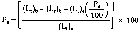
where (Lt)b and (Lr)b are the collective VOC solvent amounts pertaining to all the combined facilities.
(f) The owner or operator may choose to show compliance of the combined performance of existing and affected facilities controlled in common by the same solvent recovery system. A separate emission test for existing facilities is not required for this option. The combined performance is determined by one of the following procedures:
(1) If any of the combined facilities uses both waterborne and solvent-borne ink systems, the combined average VOC emission percentage must be determined on a direct mass basis according to paragraph (b) or (d) of this section, whichever applies, with the following equation:

(2) If all of the combined facilities use only solvent-borne ink systems, the owner or operator may choose to determine performance either on a direct mass basis or a density-corrected liquid volume basis according to paragraph (c) or (d) of this section, whichever applies. On a direct mass basis, the average VOC emission percentage is determined by the equation presented in article (i) of this paragraph. On a density-corrected liquid volume basis, the average VOC emission percentage is determined by the following equation:

(g) If all existing and affected facilities located within the same plant boundary use waterborne ink systems or solvent-borne ink systems with solvent recovery systems, the owner or operator may choose to show compliance on a plantwide basis for all the existing and affected facilities together. No separate emission tests on existing facilities and no temporary segregated liquid measurement procedures for affected facilities are required for this option. The plantwide performance is determined by one of the following procedures:
(1) If any of the facilities use waterborne ink systems, the total plant average VOC emission percentage must be determined on a direct mass basis according to paragraph (b) of this section with the following equation:

Where (Mt)f and (Mv)f are the collective VOC solvent and water amounts used at all the subject plant facilities during the performance test.
(2) If all of the plant facilities use only solvent-borne ink systems, the owner or operator may choose to determine performance either on a direct mass basis or a density-corrected liquid volume basis according to paragraph (c) of this section. On a direct mass basis, the total plant average VOC emission percentage is determined by the equation presented in article (i) of this paragraph. On a density-corrected liquid volume basis, the total plant average VOC emission percentage is determined by the following equation:

Where (Lt)f is the collective VOC solvent amount used at all the subject plant facilities during the performance test.
[47 FR 50649, Nov. 8, 1982, as amended at 65 FR 61761, Oct. 17, 2000]
§ 60.434 Monitoring of operations and recordkeeping.
(a) After completion of the performance test required under § 60.8, the owner or operator of any affected facility using waterborne ink systems or solvent-borne ink systems with solvent recovery systems shall record the amount of solvent and water used, solvent recovered, and estimated emission percentage for each performance averaging period and shall maintain these records for 2 years. The emission percentage is estimated as follows:
(1) The performance averaging period for monitoring of proper operation and maintenance is a calendar month or 4 consecutive weeks, at the option of the owner or operator.
(2) If affected facilities share the same raw ink storage/handling system with existing facilities, solvent and water used, solvent recovered, and emission percentages for the combined facilities may be documented. Separate emission percentages for only the affected facilities are not required in this case. The combined emission percentage is compared to the overall average for the existing and affected facilities' emission percentage determined during the most recent performance test.
(3) Except as provided in article (4) of this paragraph, temperatures and liquid densities determined during the most recent performance test are used to calculate corrected volumes and mass quantities.
(4) The owner or operator may choose to measure temperatures for determination of actual liquid densities during each performance averaging period. A different base temperature may be used for each performance averaging period if desired by the owner or operator.
(5) The emission percentage is calculated according to the procedures under § 60.433 (b) through (g), whichever applies, or by a comparable calculation which compares the total solvent recovered to the total solvent used at the affected facility.
§ 60.435 Test methods and procedures.
(a) The owner or operator of any affected facility using solvent-borne ink systems shall determine the VOC content of the raw inks and related coatings used at the affected facility by:
(1) Analysis using Method 24A of routine weekly samples of raw ink and related coatings in each respective storage tank; or
(2) Analysis using Method 24A of samples of each shipment of all purchased raw inks and related coatings; or
(3) Determination of the VOC content from the formulation data supplied by the ink manufacturer with each shipment of raw inks and related coatings used.
(b) The owner or operator of any affected facility using solvent-borne ink systems shall use the results of verification analyses by Method 24A to determine compliance when discrepancies with ink manufacturers' formulation data occur.
(c) The owner or operator of any affected facility using waterborne ink systems shall determine the VOC and water content of raw inks and related coatings used at the affected facility by:
(1) Determination of the VOC and water content from the formulation data supplied by the ink manufacturer with each shipment of purchased raw inks and related coatings used; or
(2) Analysis of samples of each shipment of purchased raw inks and related coatings using a test method approved by the Administrator in accordance with § 60.8(b).
(d) The owner or operator of any affected facility shall determine the density of raw inks, related coatings, and VOC solvents by:
(1) Making a total of three determinations for each liquid sample at specified temperatures using the procedure outlined in ASTM D1475-60, 80, or 90, which is incorporated by reference. It is available from the American Society of Testing and Materials, 1916 Race Street, Philadelphia, Pennsylvania 19103. It is also available for inspection at the National Archives and Records Administration (NARA). For information on the availability of this material at NARA, call 202-741-6030, or go to: http://www.archives.gov/federal_register/code_of_federal_regulations/ibr_locations.html. This incorporation by reference was approved by the Director of the Federal Register on November 8, 1982. This material is incorporated as it exists on the date of approval and a notice of any change in these materials will be published in the Federal Register. The temperature and density is recorded as the arithmetic average of the three determinations; or
(2) Using literature values, at specified temperatures, acceptable to the Administrator.
(e) If compliance is determined according to § 60.433 (e), (f), or (g), the existing as well as affected facilities are subject to the requirements of paragraphs (a) through (d) of this section.
[47 FR 50649, Nov. 8, 1982, as amended at 65 FR 61761, Oct. 17, 2000; 69 FR 18803, Apr. 9, 2004]
Subpart RR - Standards of Performance for Pressure Sensitive Tape and Label Surface Coating Operations
Source:
48 FR 48375, Oct. 18, 1983, unless otherwise noted.
§ 60.440 Applicability and designation of affected facility.
(a) The affected facility to which the provisions of this subpart apply is each coating line used in the manufacture of pressure sensitive tape and label materials.
(b) Any affected facility which inputs to the coating process 45 Mg (50 tons) of VOC or less per 12 month period is not subject to the emission limits of § 60.442(a), however, the affected facility is subject to the requirements of all other applicable sections of this subpart. If the amount of VOC input exceeds 45 Mg (50 tons) per 12 month period, the coating line will become subject to § 60.442(a) and all other sections of this subpart.
(c) This subpart applies to any affected facility which begins construction, modification, or reconstruction after December 30, 1980.
[48 FR 48375, Oct. 18, 1983, as amended at 65 FR 61761, Oct. 17, 2000]
§ 60.441 Definitions and symbols.
(a) Except as otherwise required by the context, terms used in this subpart are defined in the Act, in subpart A of this part, or in this section as follows:
Coating applicator means an apparatus used to apply a surface coating to a continuous web.
Coating line means any number or combination of adhesive, release, or precoat coating applicators, flashoff areas, and ovens which coat a continuous web, located between a web unwind station and a web rewind station, to produce pressure sensitive tape and label materials.
Coating solids applied means the solids content of the coated adhesive, release, or precoat as measured by Method 24.
Flashoff area means the portion of a coating line after the coating applicator and usually before the oven entrance.
Fugitive volatile organic compounds means any volatile organic compounds which are emitted from the coating applicator and flashoff areas and are not emitted in the oven.
Hood or enclosure means any device used to capture fugitive volatile organic compounds.
Oven means a chamber which uses heat or irradiation to bake, cure, polymerize, or dry a surface coating.
Precoat means a coating operation in which a coating other than an adhesive or release is applied to a surface during the production of a pressure sensitive tape or label product.
Solvent applied in the coating means all organic solvent contained in the adhesive, release, and precoat formulations that is metered into the coating applicator from the formulation area.
Total enclosure means a structure or building around the coating applicator and flashoff area or the entire coating line for the purpose of confining and totally capturing fugitive VOC emissions.
VOC means volatile organic compound.
(b) All symbols used in this subpart not defined below are given meaning in the Act or in subpart A of this part.
a = the gas stream vents exiting the emission control device.
b = the gas stream vents entering the emission control device.
Caj = the concentration of VOC (carbon equivalent) in each gas stream (j) exiting the emission control device, in parts per million by volume.
Cbi = the concentration of VOC (carbon equivalent) in each gas stream (i) entering the emission control device, in parts per million by volume.
Cfk = the concentration of VOC (carbon equivalent) in each gas stream (k) emitted directly to the atmosphere, in parts per million by volume.
G = the calculated weighted average mass (kg) of VOC per mass (kg) of coating solids applied each calendar month.
Mci = the total mass (kg) of each coating (i) applied during the calendar month as determined from facility records.
Mr = the total mass (kg) of solvent recovered for a calendar month.
Qaj = the volumetric flow rate of each effluent gas stream (j) exiting the emission control device, in dry standard cubic meters per hour.
Qbi = the volumetric flow rate of each effluent gas stream (i) entering the emission control device, in dry standard cubic meters per hour.
Qfk = the volumetric flow rate of each effluent gas stream (k) emitted to the atmosphere, in dry standard cubic meters per hour.
R = the overall VOC emission reduction achieved for a calendar month (in percent).
Rq = the required overall VOC emission reduction (in percent).
Woi = the weight fraction of organics applied of each coating (i) applied during a calendar month as determined from Method 24 or coating manufacturer's formulation data.
Wsi = the weight fraction of solids applied of each coating (i) applied during a calendar month as determined from Method 24 or coating manufacturer's formulation data.
[48 FR 48375, Oct. 18, 1983, as amended at 65 FR 61761, Oct. 17, 2000]
§ 60.442 Standard for volatile organic compounds.
(a) On and after the date on which the performance test required by § 60.8 has been completed each owner or operator subject to this subpart shall:
(1) Cause the discharge into the atmosphere from an affected facility not more than 0.20 kg VOC/kg of coating solids applied as calculated on a weighted average basis for one calendar month; or
(2) Demonstrate for each affected facility;
(i) A 90 percent overall VOC emission reduction as calculated over a calendar month; or
(ii) The percent overall VOC emission reduction specified in § 60.443(b) as calculated over a calendar month.
§ 60.443 Compliance provisions.
(a) To determine compliance with § 60.442 the owner or operator of the affected facility shall calculate a weighted average of the mass of solvent used per mass of coating solids applied for a one calendar month period according to the following procedures:
(1) Determine the weight fraction of organics and the weight fraction of solids of each coating applied by using Reference Method 24 or by the coating manufacturer's formulation data.
(2) Compute the weighted average by the following equation:

(3) For each affected facility where the value of G is less than or equal to 0.20 kg VOC per kg of coating solids applied, the affected facility is in compliance with § 60.442(a)(1).
(b) To determine compliance with § 60.442(a)(2), the owner or operator shall calculate the required overall VOC emission reduction according to the following equation:

If Rq is less than or equal to 90 percent, then the required overall VOC emission reduction is Rq. If Rq is greater than 90 percent, then the required overall VOC emission reduction is 90 percent.
(c) Where compliance with the emission limits specified in § 60.442(a)(2) is achieved through the use of a solvent recovery system, the owner or operator shall determine the overall VOC emission reduction for a one calendar month period by the following equation:

If the R value is equal to or greater than the Rq value specified in paragraph (b) of this section, then compliance with § 60.442(a)(2) is demonstrated.
(d) Where compliance with the emission limit specified in § 60.442(a)(2) is achieved through the use of a solvent destruction device, the owner or operator shall determine calendar monthly compliance by comparing the monthly required overall VOC emission reduction specified in paragraph (b) of this section to the overall VOC emission reduction demonstrated in the most recent performance test which complied with § 60.442(a)(2). If the monthly required overall VOC emission reduction is less than or equal to the overall VOC reduction of the most recent performance test, the affected facility is in compliance with § 60.442(a)(2).
(e) Where compliance with § 60.442(a)(2) is achieved through the use of a solvent destruction device, the owner or operator shall continuously record the destruction device combustion temperature during coating operations for thermal incineration destruction devices or the gas temperature upstream and downstream of the incinerator catalyst bed during coating operations for catalytic incineration destruction devices. For thermal incineration destruction devices the owner or operator shall record all 3-hour periods (during actual coating operations) during which the average temperature of the device is more than 28 °C (50 °F) below the average temperature of the device during the most recent performance test complying with § 60.442(a)(2). For catalytic incineration destruction devices, the owner or operator shall record all 3-hour periods (during actual coating operations) during which the average temperature of the device immediately before the catalyst bed is more than 28 °C (50 °F) below the average temperature of the device during the most recent performance test complying with § 60.442(a)(2), and all 3-hour periods (during actual coating operations) during which the average temperature difference across the catalyst bed is less than 80 percent of the average temperature difference of the device during the most recent performance test complying with § 60.442(a)(2).
(f) After the initial performance test required for all affected facilities under § 60.8, compliance with the VOC emission limitation and percentage reduction requirements under § 60.442 is based on the average emission reduction for one calendar month. A separate compliance test is completed at the end of each calendar month after the initial performance test, and a new calendar month's average VOC emission reduction is calculated to show compliance with the standard.
(g) If a common emission control device is used to recover or destroy solvent from more than one affected facility, the performance of that control device is assumed to be equal for each of the affected facilities. Compliance with § 60.442(a)(2) is determined by the methods specified in paragraphs (c) and (d) of this section and is performed simultaneously on all affected facilities.
(h) If a common emission control device is used to recover solvent from an existing facility (or facilities) as well as from an affected facility (or facilities), the overall VOC emission reduction for the affected facility (or facilities), for the purpose of compliance, shall be determined by the following procedures:
(1) The owner or operator of the existing facility (or facilities) shall determine the mass of solvent recovered for a calendar month period from the existing facility (or facilities) prior to the connection of the affected facility (or facilities) to the emission control device.
(2) The affected facility (or facilities) shall then be connected to the emission control device.
(3) The owner or operator shall determine the total mass of solvent recovered from both the existing and affected facilities over a calendar month period. The mass of solvent determined in paragraph (h)(1) of this section from the existing facility shall be subtracted from the total mass of recovered solvent to obtain the mass of solvent recovered from the affected facility (or facilities). The overall VOC emission reduction of the affected facility (or facilities) can then be determined as specified in paragraph (c) of this section.
(i) If a common emission control device(s) is used to destruct solvent from an existing facility (or facilities) as well as from an affected facility (or facilities), the overall VOC emission reduction for the affected facility (or facilities), for the purpose of compliance, shall be determined by the following procedures:
(1) The owner or operator shall operate the emission control device with both the existing and affected facilities connected.
(2) The concentration of VOC (in parts per million by volume) after the common emission control device shall be determined as specified in § 60.444(c). This concentration is used in the calculation of compliance for both the existing and affected facilities.
(3) The volumetric flow out of the common control device attributable to the affected facility (or facilities) shall be calculated by first determining the ratio of the volumetric flow entering the common control device attributable to the affected facility (facilities) to the total volumetric flow entering the common control device from both existing and affected facilities. The multiplication of this ratio by the total volumetric flow out of the common control device yields the flow attributable to the affected facility (facilities). Compliance is determined by the use of the equation specified in § 60.444(c).
(j) Startups and shutdowns are normal operation for this source category. Emissions from these operations are to be included when determining if the standard specified at § 60.442(a)(2) is being attained.
[48 FR 48375, Oct. 18, 1983, as amended at 65 FR 61761, Oct. 17, 2000]
§ 60.444 Performance test procedures.
(a) The performance test for affected facilities complying with § 60.442 without the use of add-on controls shall be identical to the procedures specified in § 60.443(a).
(b) The performance test for affected facilities controlled by a solvent recovery device shall be conducted as follows:
(1) The performance test shall be a one calendar month test and not the average of three runs as specified in § 60.8(f).
(2) The weighted average mass of VOC per mass of coating solids applied for a one calendar month period shall be determined as specified in § 60.443(a) (1) and (2).
(3) Calculate the required percent overall VOC emission reduction as specified in § 60.443(b).
(4) Inventory VOC usage and VOC recovery for a one calendar month period.
(5) Determine the percent overall VOC emission reduction as specified in § 60.443(c).
(c) The performance test for affected facilities controlled by a solvent destruction device shall be conducted as follows:
(1) The performance of the solvent destruction device shall be determined by averaging the results of three test runs as specified in § 60.8(f).
(2) Determine for each affected facility prior to each test run the weighted average mass of VOC per mass of coating solids applied being used at the facility. The weighted average shall be determined as specified in § 60.443(a). In this application the quantities of Woi, Wsi, and Mci shall be determined for the time period of each test run and not a calendar month as specified in § 60.441.
(3) Calculate the required percent overall VOC emission reduction as specified in § 60.443(b).
(4) Determine the percent overall VOC emission reduction of the solvent destruction device by the following equation and procedures:
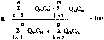
(i) The owner or operator of the affected facility shall construct the overall VOC emission reduction system so that all volumetric flow rates and total VOC emissions can be accurately determined by the applicable test methods and procedures specified in § 60.446(b).
(ii) The owner or operator of an affected facility shall construct a temporary total enclosure around the coating line applicator and flashoff area during the performance test for the purpose of capturing fugitive VOC emissions. If a permanent total enclosure exists in the affected facility prior to the performance test and the Administrator is satisfied that the enclosure is totally capturing fugitive VOC emissions, then no additional total enclosure will be required for the performance test.
(iii) For each affected facility where the value of R is greater than or equal to the value of Rq calculated in § 60.443(b), compliance with § 60.442(a)(2) is demonstrated.
§ 60.445 Monitoring of operations and recordkeeping.
(a) The owner or operator of an affected facility subject to this subpart shall maintain a calendar month record of all coatings used and the results of the reference test method specified in § 60.446(a) or the manufacturer's formulation data used for determining the VOC content of those coatings.
(b) The owner or operator of an affected facility controlled by a solvent recovery device shall maintain a calendar month record of the amount of solvent applied in the coating at each affected facility.
(c) The owner or operator of an affected facility controlled by a solvent recovery device shall install, calibrate, maintain, and operate a monitoring device for indicating the cumulative amount of solvent recovered by the device over a calendar month period. The monitoring device shall be accurate within ±2.0 percent. The owner or operator shall maintain a calendar month record of the amount of solvent recovered by the device.
(d) The owner or operator of an affected facility operating at the conditions specified in § 60.440(b) shall maintain a 12 month record of the amount of solvent applied in the coating at the facility.
(e) The owner or operator of an affected facility controlled by a thermal incineration solvent destruction device shall install, calibrate, maintain, and operate a monitoring device which continuously indicates and records the temperature of the solvent destruction device's exhaust gases. The monitoring device shall have an accuracy of the greater of ±0.75 percent of the temperature being measured expressed in degrees Celsius or ±2.5 °C.
(f) The owner or operator of an affected facility controlled by a catalytic incineration solvent destruction device shall install, calibrate, maintain, and operate a monitoring device which continuously indicates and records the gas temperature both upstream and downstream of the catalyst bed.
(g) The owner or operator of an affected facility controlled by a solvent destruction device which uses a hood or enclosure to capture fugitive VOC emissions shall install, calibrate, maintain, and operate a monitoring device which continuously indicates that the hood or enclosure is operating. No continuous monitor shall be required if the owner or operator can demonstrate that the hood or enclosure system is interlocked with the affected facility's oven recirculation air system.
§ 60.446 Test methods and procedures.
(a) The VOC content per unit of coating solids applied and compliance with § 60.422(a)(1) shall be determined by either Method 24 and the equations specified in § 60.443 or by manufacturers' formulation data. In the event of any inconsistency between a Method 24 test and manufacturers' formulation data, the Method 24 test will govern. The Administrator may require an owner or operator to perform Method 24 tests during such months as he deems appropriate. For Method 24, the coating sample must be a one liter sample taken into a one liter container at a point where the sample will be representative of the coating applied to the web substrate.
(b) Method 25 shall be used to determine the VOC concentration, in parts per million by volume, of each effluent gas stream entering and exiting the solvent destruction device or its equivalent, and each effluent gas stream emitted directly to the atmosphere. Methods 1, 2, 3, and 4 shall be used to determine the sampling location, volumetric flowrate, molecular weight, and moisture of all sampled gas streams. For Method 25, the sampling time for each of three runs must be at least 1 hour. The minimum sampling volume must be 0.003 dscm except that shorter sampling times or smaller volumes, when necessitated by process variables or other factors, may be approved by the Administrator.
(c) If the owner or operator can demonstrate to the Administrator's satisfaction that testing of representative stacks yields results comparable to those that would be obtained by testing all stacks, the Administrator will approve testing of representative stacks on a case-by-case basis.
[48 FR 48375, Oct. 18, 1983, as amended at 65 FR 61761, Oct. 17, 2000]
§ 60.447 Reporting requirements.
(a) For all affected facilities subject to compliance with § 60.442, the performance test data and results from the performance test shall be submitted to the Administrator as specified in § 60.8(a) of the General Provisions (40 CFR part 60, subpart A).
(b) Following the initial performance test, the owner or operator of each affected facility shall submit quarterly reports to the Administrator of exceedances of the VOC emission limits specified in § 60.442. If no such exceedances occur during a particular quarter, a report stating this shall be submitted to the Administrator semiannually.
(c) The owner or operator of each affected facility shall also submit reports at the frequency specified in § 60.7(c) when the incinerator temperature drops as defined under § 60.443(e). If no such periods occur, the owner or operator shall state this in the report.
(d) The requirements of this subsection remain in force until and unless EPA, in delegating enforcement authority to a State under section 111(c) of the Act, approves reporting requirements or an alternative means of compliance surveillance adopted by such States. In that event, affected sources within the State will be relieved of the obligation to comply with this subsection, provided that they comply with the requirements established by the State.
[48 FR 48375, Oct. 18, 1983, as amended at 55 FR 51383, Dec. 13, 1990]
Subpart SS - Standards of Performance for Industrial Surface Coating: Large Appliances
Source:
47 FR 47785, Oct. 27, 1982, unless otherwise noted.
§ 60.450 Applicability and designation of affected facility.
(a) The provisions of this subpart apply to each surface coating operation in a large appliance surface coating line.
(b) The provisions of this subpart apply to each affected facility identified in paragraph (a) of this section that commences construction, modification, or reconstruction after December 24, 1980.
§ 60.451 Definitions.
(a) All terms used in this subpart not defined below are given the meaning in the Act or in subpart A of this part.
Applied coating solids means the coating solids that adhere to the surface of the large appliance part being coated.
Coating application station means that portion of the large appliance surface coating operation where a prime coat or a top coat is applied to large appliance parts or products (e.g., dip tank, spray booth, or flow coating unit).
Curing oven means a device that uses heat to dry or cure the coating(s) applied to large appliance parts or products.
Electrodeposition (EDP) means a method of coating application in which the large appliance part or product is submerged in a tank filled with coating material suspended in water and an electrical potential is used to enhance deposition of the material on the part or product.
Flashoff area means the portion of a surface coating line between the coating application station and the curing oven.
Large appliance part means any organic surface-coated metal lid, door, casing, panel, or other interior or exterior metal part or accessory that is assembled to form a large appliance product. Parts subject to in-use temperatures in excess of 250 °F are not included in this definition.
Large appliance product means any organic surface-coated metal range, oven, microwave oven, refrigerator, freezer, washer, dryer, dishwasher, water heater, or trash compactor manufactured for household, commercial, or recreational use.
Large appliance surface coating line means that portion of a large appliance assembly plant engaged in the application and curing of organic surface coatings on large appliance parts or products.
Organic coating means any coating used in a surface coating operation, including dilution solvents, from which VOC emissions occur during the application or the curing process. For the purpose of this regulation, powder coatings are not included in this definition.
Powder coating means any surface coating that is applied as a dry powder and is fused into a continuous coating film through the use of heat.
Spray booth means the structure housing automatic or manual spray application equipment where a coating is applied to large appliance parts or products.
Surface coating operation means the system on a large appliance surface coating line used to apply and dry or cure an organic coating on the surface of large appliance parts or products. The surface coating operation may be a prime coat or a topcoat operation and includes the coating application station(s), flashoff area, and curing oven.
Transfer efficiency means the ratio of the amount of coating solids deposited onto the surface of a large appliance part or product to the total amount of coating solids used.
VOC content means the proportion of a coating that is volatile organic compounds (VOC's), expressed as kilograms of VOC's per liter of coating solids.
VOC emissions means the mass of volatile organic compounds (VOC's), expressed as kilograms of VOC's per liter of applied coating solids, emitted from a surface coating operation.
(b) All symbols used in this subpart not defined below are given the meaning in the Act or subpart A of this part.
Ca = the concentration of VOC's in a gas stream leaving a control device and entering the atmosphere (parts per million by volume, as carbon).
Cbthe concentration of VOC's in a gas stream entering a control device (parts per million by volume, as carbon).
Cfthe concentration of VOC's in a gas stream emitted directly to the atmosphere (parts per million by volume, as carbon).
Dcdensity of coating (or input stream), as received (kilograms per liter).
Dddensity of a VOC-solvent added to coatings (kilograms per liter).
Drdensity of a VOC-solvent recovered by an emission control device (kilograms per liter).
Ethe VOC destruction efficiency of a control device (fraction).
Fthe proportion of total VOC's emitted by an affected facility that enters a control device (fraction).
Gthe volume-weighted average mass of VOC's in coatings consumed in a calendar month per unit volume of applied coating solids (kilograms per liter).
Lcthe volume of coating consumed, as received (liters).
Ldthe volume of VOC-solvent added to coatings (liters).
Lrthe volume of VOC-solvent recovered by an emission control device (liters).
Lsthe volume of coating solids consumed (liters).
Mdthe mass of VOC-solvent added to coatings (kilograms).
Mothe mass of VOC's in coatings consumed, as received (kilograms).
Mrthe mass of VOC's recovered by an emission control device (kilograms).
Nthe volume-weighted average mass of VOC's emitted to the atmosphere per unit volume of applied coating solids (kilograms per liter).
Qathe volumetric flow rate of a gas stream leaving a control device and entering the atmosphere (dry standard cubic meters per hour).
Qbthe volumetric flow rate of a gas stream entering a control device (dry standard cubic meters per hour).
Qfthe volumetric flow rate of a gas stream emitted directly to the atmosphere (dry standard cubic meters per hour).
Rthe overall VOC emission reduction achieved for an affected facility (fraction).
Tthe transfer efficiency (fraction).
Vsthe proportion of solids in a coating (or input stream), as received (fraction by volume).
Wothe proportion of VOC's in a coating (or input stream), as received (fraction by weight).
§ 60.452 Standard for volatile organic compounds.
On or after the date on which the performance test required by § 60.8 is completed, no owner or operator of an affected facility subject to the provisions of this subpart shall discharge or cause the discharge of VOC emissions that exceed 0.90 kilogram of VOC's per liter of applied coating solids from any surface coating operation on a large appliance surface coating line.
§ 60.453 Performance test and compliance provisions.
(a) Sections 60.8 (d) and (f) do not apply to the performance test procedures required by this subpart.
(b) The owner or operator of an affected facility shall conduct an initial performance test as required under § 60.8(a) and thereafter a performance test each calendar month for each affected facility according to the procedures in this paragraph.
(1) An owner or operator shall use the following procedures for any affected facility that does not use a capture system and control device to comply with the emissions limit specified under § 60.452. The owner or operator shall determine the composition of the coatings by formulation data supplied by the coating manufacturer or by analysis of each coating, as received, using Method 24. The Administrator may require the owner or operator who uses formulation data supplied by the coating manufacturer to determine the VOC content of coatings using Method 24. The owner or operator shall determine the volume of coating and the mass of VOC-solvent used for thinning purposes from company records on a monthly basis. If a common coating distribution system serves more than one affected facility or serves both affected and existing facilities, the owner or operator shall estimate the volume of coatings used at each facility, by using the average dry weight of coating and the surface area coated by each affected and existing facility or by other procedures acceptable to the Administrator.
(i) Except as provided in paragraph (b)(1)(iv) of this section, the weighted average of the total mass of VOC's consumed per unit volume of coating solids applied each calendar month will be determined as follows.
(A) Calculate the mass of VOC's consumed (Mo + Md) during the calendar month for each affected facility by the following equation:

(ΣLdjDdj will be 0 if no VOC-solvent is added to the coatings, as received)
where:
n is the number of different coatings used during the calendar month, and
m is the number of different VOC-solvents added to coatings during the calendar month.
(B) Calculate the total volume of coating solids used (Ls) in the calendar month for each affected facility by the following equation:

where n is the number of different coatings used during the calendar month.
(C) Select the appropriate transfer efficiency from table 1. If the owner or operator can demonstrate to the satisfaction of the Administrator that transfer efficiencies other than those shown are appropriate, the Administrator will approve their use on a case-by-case basis. Transfer efficiencies for application methods not listed shall be determined by the Administrator on a case-by-case basis. An owner or operator must submit sufficient data for the Administrator to judge the accuracy of the transfer efficiency claims.
Table 1—Transfer Efficiencies
| Application method | Transfer efficiency (Tk) |
|---|---|
| Air-atomized spray | 0.40 |
| Airless spray | 0.45 |
| Manual electrostatic spray | 0.60 |
| Flow coat | 0.85 |
| Dip coat | 0.85 |
| Nonrotational automatic electrostatic spray | 0.85 |
| Rotating head automatic electrostatic spray | 0.90 |
| Electrodeposition | 0.95 |
Where more than one application method is used within a single surface coating operation, the owner or operator shall determine the composition and volume of each coating applied by each method through a means acceptable to the Administrator and compute the weighted average transfer efficiency by the following equation:

where:
n is the number of coatings (or input streams) used, and
m is the number of application methods used.
(D) Calculate the volume-weighted average mass of VOC's consumed per unit volume of coating solids applied (G) during the calendar month for each affected facility by the following equation:

(ii) Calculate the volume-weighted average of VOC emissions to the atmosphere (N) during the calendar month for each affected facility by the following equation:

(iii) Where the volume-weighted average mass of VOC's discharged to the atmosphere per unit volume of coating solids applied (N) is equal to or less than 0.90 kilogram per liter, the affected facility is in compliance.
(iv) If each individual coating used by an affected facility has a VOC content, as received, which when divided by the lowest transfer efficiency at which the coating is applied, results in a value equal to or less than 0.90 kilogram per liter, the affected facility is in compliance, provided no VOC's are added to the coating during distribution or application.
(2) An owner or operator shall use the following procedures for any affected facility that uses a capture system and a control device that destroys VOC's (e.g., incinerator) to comply with the emission limit specified under § 60.452.
(i) Determine the overall reduction efficiency (R) for the capture system and control device. For the initial performance test the overall reduction efficiency (R) shall be determined as prescribed in A, B, and C below. In subsequent months, the owner or operator may use the most recently determined overall reduction efficiency (R) for the performance test, providing control device and capture system operating conditions have not changed. The procedure in A, B, and C, below, shall be repeated when directed by the Administrator or when the owner or operator elects to operate the control device or capture system at conditions different from the initial performance test.
(A) Determine the fraction (F) of total VOC's emitted by an affected facility that enters the control device using the following equation:

where:
n is the number of gas streams entering the control device
p is the number of gas streams emitted directly to the atmosphere.

where:
n is the number of gas streams entering the control device, and
m is the number of gas streams leaving the control device and entering the atmosphere.
(B) Determine the destruction efficiency of the control device (E) using values of the volumetric flow rate of each of the gas streams and the VOC content (as carbon) of each of the gas streams in and out of the device by the following equation:
(C) Determine overall reduction efficiency (R) using the following equation:
R = EF (8)
(ii) Calculate the volume-weighted average of the total mass of VOC's per unit volume of applied coating solids (G) during each calendar month for each affected facility using equations (1), (2), (3) if applicable, and (4).
(iii) Calculate the volume-weighted average of VOC emissions to the atmosphere (N) during each calendar month by the following equation:
N = G(1−R) (9)
(iv) If the volume-weighted average mass of VOC's emitted to the atmosphere for each calendar month (N) is equal to or less than 0.90 kilogram per liter of applied coating solids, the affected facility is in compliance.
(3) An owner or operator shall use the following procedure for any affected facility that uses a control device for VOC recovery (e.g., carbon adsorber) to comply with the applicable emission limit specified under § 60.452.
(i) Calculate the total mass of VOC's consumed (Mo + Md) and the volume-weighted average of the total mass of VOC's per unit volume of applied coating solids (G) during each calendar month for each affected facility using equations (1), (2), (3) if applicable, and (4).
(ii) Calculate the total mass of VOC's recovered (Mr) during each calendar month using the following equation:
Mr = Lr Dr (10)
(iii) Calculate overall reduction efficiency of the control device (R) for each calendar month for each affected facility using the following equation:

(iv) Calculate the volume-weighted average mass of VOC's emitted to the atmosphere (N) for each calendar month for each affected facility using equation (9).
(v) If the volume-weighted average mass of VOC's emitted to the atmosphere for each calendar month (N) is equal to or less than 0.90 kilogram per liter of applied coating solids, the affected facility is in compliance. Each monthly calculation is considered a performance test.
[47 FR 47785, Oct. 27, 1982, as amended at 65 FR 61761, Oct. 17, 2000]
§ 60.454 Monitoring of emissions and operations.
(a) The owner or operator of an affected facility that uses a capture system and an incinerator to comply with the emission limits specified under § 60.452 shall install, calibrate, maintain, and operate temperature measurement devices as prescribed below:
(1) Where thermal incineration is used, a temperature measurement device shall be installed in the firebox. Where catalytic incineration is used, a temperature measurement device shall be installed in the gas stream immediately before and after the catalyst bed.
(2) Each temperature measurement device shall be installed, calibrated, and maintained according to the manufacturer's specifications. The device shall have an accuracy of 0.75 percent of the temperature being measured, expressed in degrees Celsius, or ±2.5 °C, whichever is greater.
(3) Each temperature measurement device shall be equipped with a recording device so that a permanent continuous record is produced.
[47 FR 47785, Oct. 27, 1982, as amended at 65 FR 61761, Oct. 17, 2000]
§ 60.455 Reporting and recordkeeping requirements.
(a) The reporting requirements of § 60.8(a) apply only to the initial performance test. Each owner or operator subject to the provisions of this subpart shall include the following data in the report of the initial performance test required under § 60.8(a):
(1) Except as provided in paragraph (a)(2) of this section, the volume-weighted average mass of VOC's emitted to the atmosphere per volume of applied coating solids (N) for a period of 1 calendar month from each affected facility.
(2) For each affected facility where compliance is determined under the provisions of § 60.453(b)(1)(iv), a list of the coatings used during a period of 1 calendar month, the VOC content of each coating calculated from data determined using Reference Method 24 or supplied by the coating manufacturer, and the minimum transfer efficiency of any coating application equipment used during the month.
(3) For each affected facility where compliance is achieved through use of an incineration system, the following additional information will be reported:
(i) The proportion of total VOC's emitted that enters the control device (F),
(ii) The VOC reduction efficiency of the control device (E),
(iii) The average combustion temperature (or the average temperature upstream and downstream of the catalyst bed), and
(iv) A description of the method used to establish the amount of VOC's captured and sent to the incinerator.
(4) For each affected facility where compliance is achieved through use of a solvent recovery system, the following additional information will be reported:
(i) The volume of VOC-solvent recovered (Lr), and
(ii) The overall VOC emission reduction achieved (R).
(b) Following the initial performance test, the owner or operator of an affected facility shall identify, record, and submit a written report to the Administrator every calendar quarter of each instance in which the volume-weighted average of the total mass of VOC's emitted to the atmosphere per volume of applied coating solids (N) is greater than the limit specified under § 60.452. If no such instances have occurred during a particular quarter, a report stating this shall be submitted to the Administrator semiannually.
(c) Following the initial performance test, the owner or operator of an affected facility shall identify, record, and submit at the frequency specified in § 60.7(c) the following:
(1) Where compliance with § 60.452 is achieved through use of thermal incineration, each 3-hour period of coating operation during which the average temperature of the device was more than 28 °C (50 °F) below the average temperature of the device during the most recent performance test at which destruction efficiency was determined as specified under § 60.453.
(2) Where compliance with § 60.452 is achieved through the use of catalytic incineration, each 3-hour period of coating operation during which the average temperature recorded immediately before the catalyst bed is more than 28 °C (50 °F) below the average temperature at the same location during the most recent performance test at which destruction efficiency was determined as specified under § 60.453. Additionally, all 3-hour periods of coating operation during which the average temperature difference across the catalyst bed is less than 80 percent of the average temperature difference across the catalyst bed during the most recent performance test at which destruction efficiency was determined as specified under § 60.453 will be recorded.
(3) For thermal and catalytic incinerators, if no such periods as described in paragraphs (c)(1) and (c)(2) of this section occur, the owner or operator shall state this in the report.
(d) Each owner or operator subject to the provisions of this subpart shall maintain at the source, for a period of at least 2 years, records of all data and calculations used to determine VOC emissions from each affected facility. Where compliance is achieved through the use of thermal incineration, each owner or operator shall maintain at the source daily records of the incinerator combustion chamber temperature. If catalytic incineration is used, the owner or operator shall maintain at the source daily records of the gas temperature, both upstream and downstream of the incinerator catalyst bed. Where compliance is achieved through the use of a solvent recovery system, the owner or operator shall maintain at the source daily records of the amount of solvent recovered by the system for each affected facility.
[47 FR 47785, Oct. 27, 1982, as amended at 55 FR 51383, Dec. 13, 1990; 65 FR 61761, Oct. 17, 2000]
§ 60.456 Test methods and procedures.
(a) The reference methods in appendix A to this part, except as provided under § 60.8(b), shall be used to determine compliance with § 60.452 as follows:
(1) Method 24 or formulation data supplied by the coating manufacturer to determine the VOC content of a coating. In the event of dispute, Method 24 shall be the reference method. For determining compliance only, results of Method 24 analyses of waterborne coatings shall be adjusted as described in Section 12.6 of Method 24. Procedures to determine VOC emissions are provided in § 60.453.
(2) Method 25 for the measurement of the VOC concentration in the gas stream vent.
(3) Method 1 for sample and velocity traverses.
(4) Method 2 for velocity and volumetric flow rate.
(5) Method 3 for gas analysis.
(6) Method 4 for stack gas moisture.
(b) For Method 24, the coating sample must be a 1-liter sample taken into a 1-liter container at a point where the sample will be representative of the coating material.
(c) For Method 25, the sample time for each of three runs is to be at least 60 minutes and the minimum sample volume is to be at least 0.003 dscm (0.1 dscf) except that shorter sampling times or smaller volumes, when necessitated by process variables or other factors, may be approved by the Administrator.
(d) The Administrator will approve sampling of representative stacks on a case-by-case basis if the owner or operator can demonstrate to the satisfaction of the Administrator that the testing of representative stacks would yield results comparable to those that would be obtained by testing all stacks.
[47 FR 47785, Oct. 27, 1982, as amended at 65 FR 61761, Oct. 17, 2000]
Subpart TT - Standards of Performance for Metal Coil Surface Coating
Source:
47 FR 49612, Nov. 1, 1982, unless otherwise noted.
§ 60.460 Applicability and designation of affected facility.
(a) The provisions of this subpart apply to the following affected facilities in a metal coil surface coating operation: each prime coat operation, each finish coat operation, and each prime and finish coat operation combined when the finish coat is applied wet on wet over the prime coat and both coatings are cured simultaneously.
(b) This subpart applies to any facility identified in paragraph (a) of this section that commences construction, modification, or reconstruction after January 5, 1981.
§ 60.461 Definitions.
(a) All terms used in this subpart not defined below are given the same meaning as in the Act or in subpart A of this part.
Coating means any organic material that is applied to the surface of metal coil.
Coating application station means that portion of the metal coil surface coating operation where the coating is applied to the surface of the metal coil. Included as part of the coating application station is the flashoff area between the coating application station and the curing oven.
Curing oven means the device that uses heat or radiation to dry or cure the coating applied to the metal coil.
Finish coat operation means the coating application station, curing oven, and quench station used to apply and dry or cure the final coating(s) on the surface of the metal coil. Where only a single coating is applied to the metal coil, that coating is considered a finish coat.
Metal coil surface coating operation means the application system used to apply an organic coating to the surface of any continuous metal strip with thickness of 0.15 millimeter (mm) (0.006 in.) or more that is packaged in a roll or coil.
Prime coat operation means the coating application station, curing oven, and quench station used to apply and dry or cure the initial coating(s) on the surface of the metal coil.
Quench station means that portion of the metal coil surface coating operation where the coated metal coil is cooled, usually by a water spray, after baking or curing.
VOC content means the quantity, in kilograms per liter of coating solids, of volatile organic compounds (VOC's) in a coating.
(b) All symbols used in this subpart not defined below are given the same meaning as in the Act and in subpart A of this part.
Ca = the VOC concentration in each gas stream leaving the control device and entering the atmosphere (parts per million by volume, as carbon).
Cb = the VOC concentration in each gas stream entering the control device (parts per million by volume, as carbon).
Cf = the VOC concentration in each gas steam emitted directly to the atmosphere (parts per million by volume, as carbon).
Dc = density of each coating, as received (kilograms per liter).
Dd = density of each VOC-solvent added to coatings (kilograms per liter).
Dr = density of VOC-solvent recovered by an emission control device (kilograms per liter).
E= VOC destruction efficiency of the control device (fraction).
F= the proportion of total VOC's emitted by an affected facility that enters the control device (fraction).
G= volume-weighted average mass of VOC's in coatings consumed in a calendar month per unit volume of coating solids applied (kilograms per liter).
Lc = the volume of each coating consumed, as received (liters).
Ld = the volume of each VOC-solvent added to coatings (liters).
Lr = the volume of VOC-solvent recovered by an emission control device (liters).
Ls = the volume of coating solids consumed (liters).
Md = the mass of VOC-solvent added to coatings (kilograms).
Mo = the mass of VOC's in coatings consumed, as received (kilograms).
Mr = the mass of VOC's recovered by an emission control device (kilograms).
N= the volume-weighted average mass of VOC emissions to the atmosphere per unit volume of coating solids applied (kilograms per liter).
Qa = the volumetric flow rate of each gas stream leaving the control device and entering the atmosphere (dry standard cubic meters per hour).
Qb = the volumetric flow rate of each gas stream entering the control device (dry standard cubic meters per hour).
Qf = the volumetric flow rate of each gas steam emitted directly to the atmosphere (dry standard cubic meters per hour).
R= the overall VOC emission reduction achieved for an affected facility (fraction).
S= the calculated monthly allowable emission limit (kilograms of VOC per liter of coating solids applied).
Vs = the proportion of solids in each coating, as received (fraction by volume).
Wo = the proportion of VOC's in each coating, as received (fraction by weight).
§ 60.462 Standards for volatile organic compounds.
(a) On and after the date on which § 60.8 requires a performance test to be completed, each owner or operator subject to this subpart shall not cause to be discharged into the atmosphere more than:
(1) 0.28 kilogram VOC per liter (kg VOC/l) of coating solids applied for each calendar month for each affected facility that does not use an emission control device(s); or
(2) 0.14 kg VOC/l of coating solids applied for each calendar month for each affected facility that continuously uses an emission control device(s) operated at the most recently demonstrated overall efficiency; or
(3) 10 percent of the VOC's applied for each calendar month (90 percent emission reduction) for each affected facility that continuously uses an emission control device(s) operated at the most recently demonstrated overall efficiency; or
(4) A value between 0.14 (or a 90-percent emission reduction) and 0.28 kg VOC/l of coating solids applied for each calendar month for each affected facility that intermittently uses an emission control device operated at the most recently demonstrated overall efficiency.
§ 60.463 Performance test and compliance provisions.
(a) Section 60.8(d) and (f) do not apply to the performance test.
(b) The owner or operator of an affected facility shall conduct an initial performance test as required under § 60.8(a) and thereafter a performance test for each calendar month for each affected facility according to the procedures in this section.
(c) The owner or operator shall use the following procedures for determining monthly volume-weighted average emissions of VOC's in kg/l of coating solids applied.
(1) An owner or operator shall use the following procedures for each affected facility that does not use a capture system and control device to comply with the emission limit specified under § 60.462(a)(1). The owner or operator shall determine the composition of the coatings by formulation data supplied by the manufacturer of the coating or by an analysisof each coating, as received, using Method 24. The Administrator may require the owner or operator who uses formulation data supplied by the manufacturer of the coatings to determine the VOC content of coatings using Method 24 or an equivalent or alternative method. The owner or operator shall determine the volume of coating and the mass of VOC-solvent added to coatings from company records on a monthly basis. If a common coating distribution system serves more than one affected facility or serves both affected and existing facilities, the owner or operator shall estimate the volume of coating used at each affected facility by using the average dry weight of coating and the surface area coated by each affected and existing facility or by other procedures acceptable to the Administrator.
(i) Calculate the volume-weighted average of the total mass of VOC's consumed per unit volume of coating solids applied during each calendar month for each affected facility, except as provided under paragraph (c)(1)(iv) of this section. The weighted average of the total mass of VOC's used per unit volume of coating solids applied each calendar month is determined by the following procedures.
(A) Calculate the mass of VOC's used (Mo + Md) during each calendar month for each affected facility by the following equation:

(ΣLdjDdj will be 0 if no VOC solvent is added to the coatings, as received)
where
n is the number of different coatings used during the calendar month, and
m is the number of different VOC solvents added to coatings used during the calendar month.
(B) Calculate the total volume of coating solids used (Ls) in each calendar month for each affected facility by the following equation:

Where:
n is the number of different coatings used during the calendar month.
(C) Calculate the volume-weighted average mass of VOC's used per unit volume of coating solids applied (G) during the calendar month for each affected facility by the following equation:

(ii) Calculate the volume-weighted average of VOC emissions to the atmosphere (N) during the calendar month for each affected facility by the following equation:

(iii) Where the volume-weighted average mass of VOC's discharged to the atmosphere per unit volume of coating solids applied (N) is equal to or less than 0.28 kg/l, the affected facility is in compliance.
(iv) If each individual coating used by an affected facility has a VOC content, as received, that is equal to or less than 0.28 kg/l of coating solids, the affected facility is in compliance provided no VOC's are added to the coatings during distribution or application.
(2) An owner or operator shall use the following procedures for each affected facility that continuously uses a capture system and a control device that destroys VOC's (e.g., incinerator) to comply with the emission limit specified under § 60.462(a) (2) or (3).
(i) Determine the overall reduction efficiency (R) for the capture system and control device.
For the initial performance test, the overall reduction efficiency (R) shall be determined as prescribed in paragraphs (c)(2)(i) (A), (B), and (C) of this section. In subsequent months, the owner or operator may use the most recently determined overall reduction efficiency (R) for the performance test, providing control device and capture system operating conditions have not changed. The procedure in paragraphs (c)(2)(i) (A), (B), and (C) of this section, shall be repeated when directed by the Administrator or when the owner or operator elects to operate the control device or capture system at conditions different from the initial performance test.
(A) Determine the fraction (F) of total VOC's emitted by an affected facility that enters the control device using the following equation:

Equation 5
Where:
l is the number of gas streams entering the control device, and
p is the number of gas streams emitted directly to the atmosphere.
(B) Determine the destruction efficiency of the control device (E) using values of the volumetric flow rate of each of the gas streams and the VOC content (as carbon) of each of the gas streams in and out of the device by the following equation:

Equation 6
Where:
n is the number of gas streams entering the control device, and
m is the number of gas streams leaving the control device and entering the atmosphere.
The owner or operator of the affected facility shall construct the VOC emission reduction system so that all volumetric flow rates and total VOC emissions can be accurately determined by the applicable test methods and procedures specified in § 60.466. The owner or operator of the affected facility shall construct a temporary enclosure around the coating applicator and flashoff area during the performance test for the purpose of evaluating the capture efficiency of the system. The enclosure must be maintained at a negative pressure to ensure that all VOC emissions are measurable. If a permanent enclosure exists in the affected facility prior to the performance test and the Administrator is satisfied that the enclosure is adequately containing VOC emissions, no additional enclosure is required for the performance test.
(C) Determine overall reduction efficiency (R) using the following equation:

If the overall reduction efficiency (R) is equal to or greater than 0.90, the affected facility is in compliance and no further computations are necessary. If the overall reduction efficiency (R) is less than 0.90, the average total VOC emissions to the atmosphere per unit volume of coating solids applied (N) shall be computed as follows.
(ii) Calculate the volume-weighted average of the total mass of VOC's per unit volume of coating solids applied (G) during each calendar month for each affected facility using equations in paragraphs (c)(1)(i) (A), (B), and (C) of this section.
(iii) Calculate the volume-weighted average of VOC emissions to the atmosphere (N) during each calendar month by the following equation:

(iv) If the volume-weighted average mass of VOC's emitted to the atmosphere for each calendar month (N) is less than or equal to 0.14 kg/l of coating solids applied, the affected facility is in compliance. Each monthly calculation is a performance test.
(3) An owner or operator shall use the following procedure for each affected facility that uses a control device that recovers the VOC's (e.g., carbon adsorber) to comply with the applicable emission limit specified under § 60.462(a) (2) or (3).
(i) Calculate the total mass of VOC's consumed (Mo + Md) during each calendar month for each affected facility using equation (1).
(ii) Calculate the total mass of VOC's recovered (Mr) during each calendar month using the following equation:

(iii) Calculate the overall reduction efficiency of the control device (R) for each calendar month for each affected facility using the following equation:

If the overall reduction efficiency (R) is equal to or greater than 0.90, the affected facility is in compliance and no further computations are necessary. If the overall reduction efficiency (R) is less than 0.90, the average total VOC emissions to the atmosphere per unit volume of coating solids applied (N) must be computed as follows.
(iv) Calculate the total volume of coating solids consumed (Ls) and the volume-weighted average of the total mass of VOC's per unit volume of coating solids applied (G) during each calendar month for each affected facility using equations in paragraphs (c)(1)(i) (B) and (C) of this section.
(v) Calculate the volume-weighted average mass of VOC's emitted to the atmosphere (N) for each calendar month for each affected facility using equation (8).
(vi) If the weighted average mass of VOC's emitted to the atmosphere for each calendar month (N) is less than or equal to 0.14 kg/l of coating solids applied, the affected facility is in compliance. Each monthly calculation is a performance test.
(4) An owner or operator shall use the following procedures for each affected facility that intermittently uses a capture system and a control device to comply with the emission limit specified in § 60.462(a)(4).
(i) Calculate the total volume of coating solids applied without the control device in operation (Lsn) during each calendar month for each affected facility using the following equation:

Where:
n is the number of coatings used during the calendar month without the control device in operation.
(ii) Calculate the total volume of coating solids applied with the control device in operation (Lsc) during each calendar month for each affected facility using the following equation:

Where:
n is the number of coatings used during the calendar month with the control device in operation.
(iii) Calculate the mass of VOC's used without the control device in operation (Mon + Mdn) during each calendar month for each affected facility using the following equation:

Where:
n is the number of different coatings used without the control device in operation during the calendar month, and
m is the number of different VOC-solvents added to coatings used without the control device in operation during the calendar month.
(iv) Calculate the volume-weighted average of the total mass of VOC's consumed per unit volume of coating solids applied without the control device in operation (Gn) during each calendar month for each affected facility using the following equation:

(v) Calculate the mass of VOC's used with the control device in operation (Moc + Mdc) during each calendar month for each affected facility using the following equation:

Where:
n is the number of different coatings used with the control device in operation during the calendar month, and
m is the number of different VOC-solvents added to coatings used with the control device in operation during the calendar month.
(vi) Calculate the volume-weighted average of the total mass of VOC's used per unit volume of coating solids applied with the control device in operation (Gc) during each calendar month for each affected facility using the following equation:

(vii) Determine the overall reduction efficiency (R) for the capture system and control device using the procedures in paragraphs (c)(2)(i) (A), (B), and (C) or paragraphs (c)(3) (i), (ii), and (iii) of this section, whichever is applicable.
(viii) Calculate the volume-weighted average of VOC emissions to the atmosphere (N) during each calendar month for each affected facility using the following equation:

Equation 17
(ix) Calculate the emission limit(s) for each calendar month for each affected facility using the following equation:

or

whichever is greater.
(x) If the volume-weighted average mass of VOC's emitted to the atmosphere for each calendar month (N) is less than or equal to the calculated emission limit (S) for the calendar month, the affected facility is in compliance. Each monthly calculation is a performance test.
[47 FR 49612, Nov. 1, 1982; 48 FR 1056, Jan. 10, 1983, as amended at 65 FR 61761, Oct. 17, 2000]
§ 60.464 Monitoring of emissions and operations.
(a) Where compliance with the numerical limit specified in § 60.462(a) (1) or (2) is achieved through the use of low VOC-content coatings without the use of emission control devices or through the use of higher VOC-content coatings in conjunction with emission control devices, the owner or operator shall compute and record the average VOC content of coatings applied during each calendar month for each affected facility, according to the equations provided in § 60.463.
(b) Where compliance with the limit specified in § 60.462(a)(4) is achieved through the intermittent use of emission control devices, the owner or operator shall compute and record for each affected facility the average VOC content of coatings applied during each calendar month according to the equations provided in § 60.463.
(c) If thermal incineration is used, each owner or operator subject to the provisions of this subpart shall install, calibrate, operate, and maintain a device that continuously records the combustion temperature of any effluent gases incinerated to achieve compliance with § 60.462(a)(2), (3), or (4). This device shall have an accuracy of ±2.5 °C. or ±0.75 percent of the temperature being measured expressed in degrees Celsius, whichever is greater. Each owner or operator shall also record all periods (during actual coating operations) in excess of 3 hours during which the average temperature in any thermal incinerator used to control emissions from an affected facility remains more than 28 °C (50 °F) below the temperature at which compliance with § 60.462(a)(2), (3), or (4) was demonstrated during the most recent measurement of incinerator efficiency required by § 60.8. The records required by § 60.7 shall identify each such occurrence and its duration. If catalytic incineration is used, the owner or operator shall install, calibrate, operate, and maintain a device to monitor and record continuously the gas temperature both upstream and downstream of the incinerator catalyst bed. This device shall have an accuracy of ±2.5 °C. or ±0.75 percent of the temperature being measured expressed in degrees Celsius, whichever is greater. During coating operations, the owner or operator shall record all periods in excess of 3 hours where the average difference between the temperature upstream and downstream of the incinerator catalyst bed remains below 80 percent of the temperature difference at which compliance was demonstrated during the most recent measurement of incinerator efficiency or when the inlet temperature falls more than 28 °C (50 °F) below the temperature at which compliance with § 60.462(a)(2), (3), or (4) was demonstrated during the most recent measurement of incinerator efficiency required by § 60.8. The records required by § 60.7 shall identify each such occurrence and its duration.
[47 FR 49612, Nov. 1, 1982; 48 FR 1056, Jan. 10, 1983, as amended at 65 FR 61761, Oct. 17, 2000]
§ 60.465 Reporting and recordkeeping requirements.
(a) Where compliance with the numerical limit specified in § 60.462(a) (1), (2), or (4) is achieved through the use of low VOC-content coatings without emission control devices or through the use of higher VOC-content coatings in conjunction with emission control devices, each owner or operator subject to the provisions of this subpart shall include in the initial compliance report required by § 60.8 the weighted average of the VOC content of coatings used during a period of one calendar month for each affected facility. Where compliance with § 60.462(a)(4) is achieved through the intermittent use of a control device, reports shall include separate values of the weighted average VOC content of coatings used with and without the control device in operation.
(b) Where compliance with § 60.462(a)(2), (3), or (4) is achieved through the use of an emission control device that destroys VOC's, each owner or operator subject to the provisions of this subpart shall include the following data in the initial compliance report required by § 60.8:
(1) The overall VOC destruction rate used to attain compliance with § 60.462(a)(2), (3), or (4) and the calculated emission limit used to attain compliance with § 60.462(a)(4); and
(2) The combustion temperature of the thermal incinerator or the gas temperature, both upstream and downstream of the incinerator catalyst bed, used to attain compliance with § 60.462(a)(2), (3), or (4).
(c) Following the initial performance test, the owner or operator of an affected facility shall identify, record, and submit a written report to the Administrator every calendar quarter of each instance in which the volume-weighted average of the local mass of VOC's emitted to the atmosphere per volume of applied coating solids (N) is greater than the limit specified under § 60.462. If no such instances have occurred during a particular quarter, a report stating this shall be submitted to the Administrator semiannually.
(d) The owner or operator of each affected facility shall also submit reports at the frequency specified in § 60.7(c) when the incinerator temperature drops as defined under § 60.464(c). If no such periods occur, the owner or operator shall state this in the report.
(e) Each owner or operator subject to the provisions of this subpart shall maintain at the source, for a period of at least 2 years, records of all data and calculations used to determine monthly VOC emissions from each affected facility and to determine the monthly emission limit, where applicable. Where compliance is achieved through the use of thermal incineration, each owner or operator shall maintain, at the source, daily records of the incinerator combustion temperature. If catalytic incineration is used, the owner or operator shall maintain at the source daily records of the gas temperature, both upstream and downstream of the incinerator catalyst bed.
[47 FR 49612, Nov. 1, 1982, as amended at 55 FR 51383, Dec. 13, 1990; 56 FR 20497, May 3, 1991; 65 FR 61761, Oct. 17, 2000]
§ 60.466 Test methods and procedures.
(a) The reference methods in appendix A to this part, except as provided under § 60.8(b), shall be used to determine compliance with § 60.462 as follows:
(1) Method 24, or data provided by the formulator of the coating, shall be used for determining the VOC content of each coating as applied to the surface of the metal coil. In the event of a dispute, Method 24 shall be the reference method. When VOC content of waterborne coatings, determined by Method 24, is used to determine compliance of affected facilities, the results of the Method 24 analysis shall be adjusted as described in Section 12.6 of Method 24;
(2) Method 25, both for measuring the VOC concentration in each gas stream entering and leaving the control device on each stack equipped with an emission control device and for measuring the VOC concentration in each gas stream emitted directly to the atmosphere;
(3) Method 1 for sample and velocity traverses;
(4) Method 2 for velocity and volumetric flow rate;
(5) Method 3 for gas analysis; and
(6) Method 4 for stack gas moisture.
(b) For Method 24, the coating sample must be at least a 1-liter sample taken at a point where the sample will be representative of the coating as applied to the surface of the metal coil.
(c) For Method 25, the sampling time for each of three runs is to be at least 60 minutes, and the minimum sampling volume is to be at least 0.003 dscm (0.11 dscf); however, shorter sampling times or smaller volumes, when necessitated by process variables or other factors, may be approved by the Administrator.
(d) The Administrator will approve testing of representative stacks on a case-by-case basis if the owner or operator can demonstrate to the satisfaction of the Administrator that testing of representative stacks yields results comparable to those that would be obtained by testing all stacks.
[47 FR 49612, Nov. 1, 1982, as amended at 51 FR 22938, June 24, 1986; 65 FR 61761, Oct. 17, 2000]
Subpart UU - Standards of Performance for Asphalt Processing and Asphalt Roofing Manufacture
Source:
47 FR 34143, Aug. 6, 1982, unless otherwise noted.
§ 60.470 Applicability and designation of affected facilities.
(a) The affected facilities to which this subpart applies are each saturator and each mineral handling and storage facility at asphalt roofing plants; and each asphalt storage tank and each blowing still at asphalt processing plants, petroleum refineries, and asphalt roofing plants.
(b) Any saturator or mineral handling and storage facility under paragraph (a) of this section that commences construction or modification after November 18, 1980, is subject to the requirements of this subpart. Any asphalt storage tank or blowing still that processes and/or stores asphalt used for roofing only or for roofing and other purposes, and that commences construction or modification after November 18, 1980, is subject to the requirements of this subpart.
Any asphalt storage tank or blowing still that processes and/or stores only nonroofing asphalts and that commences construction or modification after May 26, 1981, is subject to the requirements of this subpart.
§ 60.471 Definitions.
As used in this subpart, all terms not defined herein shall have the meaning given them in the Act and in subpart A of this part.
Afterburner (A/B) means an exhaust gas incinerator used to control emissions of particulate matter.
Asphalt processing means the storage and blowing of asphalt.
Asphalt processing plant means a plant which blows asphalt for use in the manufacture of asphalt products.
Asphalt roofing plant means a plant which produces asphalt roofing products (shingles, roll roofing, siding, or saturated felt).
Asphalt storage tank means any tank used to store asphalt at asphalt roofing plants, petroleum refineries, and asphalt processing plants. Storage tanks containing cutback asphalts (asphalts diluted with solvents to reduce viscosity for low temperature applications) and emulsified asphalts (asphalts dispersed in water with an emulsifying agent) are not subject to this regulation.
Blowing still means the equipment in which air is blown through asphalt flux to change the softening point and penetration rate.
Catalyst means a substance which, when added to asphalt flux in a blowing still, alters the penetrating-softening point relationship or increases the rate of oxidation of the flux.
Coating blow means the process in which air is blown through hot asphalt flux to produce coating asphalt. The coating blow starts when the air is turned on and stops when the air is turned off.
Electrostatic precipitator (ESP) means an air pollution control device in which solid or liquid particulates in a gas stream are charged as they pass through an electric field and precipitated on a collection suface.
High velocity air filter (HVAF) means an air pollution control filtration device for the removal of sticky, oily, or liquid aerosol particulate matter from exhaust gas streams.
Mineral handling and storage facility means the areas in asphalt roofing plants in which minerals are unloaded from a carrier, the conveyor transfer points between the carrier and the storage silos, and the storage silos.
Saturator means the equipment in which asphalt is applied to felt to make asphalt roofing products. The term saturator includes the saturator, wet looper, and coater.
[47 FR 34143, Aug. 6, 1982, as amended at 65 FR 61762, Oct. 17, 2000]
§ 60.472 Standards for particulate matter.
(a) On and after the date on which § 60.8(b) requires a performance test to be completed, no owner or operator subject to the provisions of this subpart shall cause to be discharged into the atmosphere from any saturator:
(1) Particulate matter in excess of:
(i) 0.04 kg/Mg (0.08 lb/ton) of asphalt shingle or mineral-surfaced roll roofing produced, or
(ii) 0.4 kg/Mg (0.8 lb/ton) of saturated felt or smooth-surfaced roll roofing produced;
(2) Exhaust gases with opacity greater than 20 percent; and
(3) Any visible emissions from a saturator capture system for more than 20 percent of any period of consecutive valid observations totaling 60 minutes. Saturators that were constructed before November 18, 1980, and that have not been reconstructed since that date and that become subject to these standards through modification are exempt from the visible emissions standard. Saturators that have been newly constructed or reconstructed since November 18, 1980 are subject to the visible emissions standard.
(b) On and after the date on which § 60.8(b) requires a performance test to be completed, no owner or operator subject to the provisions of this subpart shall cause to be discharged into the atmosphere from any blowing still:
(1) Particulate matter in excess of 0.67 kg/Mg (1.3 lb/ton) of asphalt charged to the still when a catalyst is added to the still; and
(2) Particulate matter in excess of 0.71 kg/Mg (1.4 lb/ton) of asphalt charged to the still when a catalyst is added to the still and when No. 6 fuel oil is fired in the afterburner; and
(3) Particulate matter in excess of 0.60 kg/Mg (1.2 lb/ton) of asphalt charged to the still during blowing without a catalyst; and
(4) Particulate matter in excess of 0.64 kg/Mg (1.3 lb/ton) of asphalt charged to the still during blowing without a catalyst and when No. 6 fuel oil is fired in the afterburner; and
(5) Exhaust gases with an opacity greater than 0 percent unless an opacity limit for the blowing still when fuel oil is used to fire the afterburner has been established by the Administrator in accordance with the procedures in § 60.474(g).
(c) Within 60 days after achieving the maximum production rate at which the affected facility will be operated, but not later than 180 days after initial startup of such facility, no owner or operator subject to the provisions of this subpart shall cause to be discharged into the atmosphere from any asphalt storage tank exhaust gases with opacity greater than 0 percent, except for one consecutive 15-minute period in any 24-hour period when the transfer lines are being blown for clearing. The control device shall not be bypassed during this 15-minute period. If, however, the emissions from any asphalt storage tank(s) are ducted to a control device for a saturator, the combined emissions shall meet the emission limit contained in paragraph (a) of this section during the time the saturator control device is operating. At any other time the asphalt storage tank(s) must meet the opacity limit specified above for storage tanks.
(d) Within 60 days after achieving the maximum production rate at which the affected facility will be operated, but not later than 180 days after initial startup of such facility, no owner or operator subject to the provisions of this subpart shall cause to be discharged into the atmosphere from any mineral handling and storage facility emissions with opacity greater than 1 percent.
[47 FR 34143, Aug. 6, 1982, as amended at 65 FR 61762, Oct. 17, 2000; 79 FR 11250, Feb. 27, 2014]
§ 60.473 Monitoring of operations.
(a) The owner or operator subject to the provisions of this subpart, and using either an electrostatic precipitator or a high velocity air filter to meet the emission limit in § 60.472(a)(1) and/or (b)(1) shall continuously monitor and record the temperature of the gas at the inlet of the control device. The temperature monitoring instrument shall have an accuracy of ±15 °C (±25 °F) over its range.
(b) The owner or operator subject to the provisions of this subpart and using an afterburner to meet the emission limit in § 60.472(a)(1) and/or (b)(1) shall continuously monitor and record the temperature in the combustion zone of the afterburner. The monitoring instrument shall have an accuracy of ±10 °C (±18 °F) over its range.
(c) An owner or operator subject to the provisions of this subpart and using a control device not mentioned in paragraphs (a) or (b) of this section shall provide to the Administrator information describing the operation of the control device and the process parameter(s) which would indicate proper operation and maintenance of the device. The Administrator may require continuous monitoring and will determine the process parameters to be monitored.
(d) The industry is exempted from the quarterly reports required under § 60.7(c). The owner/operator is required to record and report the operating temperature of the control device during the performance test and, as required by § 60.7(d), maintain a file of the temperature monitoring results for at least two years.
[47 FR 34143, Aug. 6, 1982, as amended at 65 FR 61762, Oct. 17, 2000]
§ 60.474 Test methods and procedures.
(a) For saturators, the owner or operator shall conduct performance tests required in § 60.8 as follows:
(1) If the final product is shingle or mineral-surfaced roll roofing, the tests shall be conducted while 106.6-kg (235-lb) shingle is being produced.
(2) If the final product is saturated felt or smooth-surfaced roll roofing, the tests shall be conducted while 6.8-kg (15-lb) felt is being produced.
(3) If the final product is fiberglass shingle, the test shall be conducted while a nominal 100-kg (220-lb) shingle is being produced.
(b) In conducting the performance tests required in § 60.8, the owner or operator shall use as reference methods and procedures the test methods in appendix A of this part or other methods and procedures as specified in this section, except as provided in § 60.8(b).
(c) The owner or operator shall determine compliance with the particulate matter standards in § 60.472 as follows:
(1) The emission rate (E) of particulate matter shall be computed for each run using the following equation:
E = (cs Qsd)/(PK)
where:
E = emission rate of particulate matter, kg/Mg (lb/ton).
cs = concentration of particulate matter, g/dscm (gr/dscf).
Qsd = volumetric flow rate of effluent gas, dscm/hr (dscf/hr).
P = asphalt roofing production rate or asphalt charging rate, Mg/hr (ton/hr).
K = conversion factor, 1000 g/kg [7000 (gr/lb)].
(2) Method 5A shall be used to determine the particulate matter concentration (cs) and volumetric flow rate (Qsd) of the effluent gas. For a saturator, the sampling time and sample volume for each run shall be at least 120 minutes and 3.00 dscm (106 dscf), and for the blowing still, at least 90 minutes or the duration of the coating blow or non-coating blow, whichever is greater, and 2.25 dscm (79.4 dscf).
(3) For the saturator, the asphalt roofing production rate (P) for each run shall be determined as follows: The amount of asphalt roofing produced on the shingle or saturated felt process lines shall be obtained by direct measurement. The asphalt roofing production rate is the amount produced divided by the time taken for the run.
(4) For the blowing still, the asphalt charging rate (P) shall be computed for each run using the following equation:
P = (Vd)/(K′ θ)
where:
P = asphalt charging rate to blowing still, Mg/hr (ton/hr).
V = volume of asphalt charged, m3 (ft3).
d = density of asphalt, kg/m3 (lb/ft3).
K′ = conversion factor, 1000 kg/Mg (2000 lb/ton).
θ = duration of test run, hr.
(i) The volume (V) of asphalt charged shall be measured by any means accurate to within 10 percent.
(ii) The density (d) of the asphalt shall be computed using the following equation:

Where:
d = Density of the asphalt, kg/m3 (lb/ft3)
K1 = 1056.1 kg/m3 (metric units)
= 64.70 lb/ft3 (English Units)
K2 = 0.6176 kg/(m3 °C) (metric units)
= 0.0694 lb/(ft3 °F) (English Units)
Ti = temperature at the start of the blow, °C ( deg;F)
(5) Method 9 and the procedures in § 60.11 shall be used to determine opacity.
(d) The Administrator will determine compliance with the standards in § 60.472(a)(3) by using Method 22, modified so that readings are recorded every 15 seconds for a period of consecutive observations during representative conditions (in accordance with § 60.8(c)) totaling 60 minutes. A performance test shall consist of one run.
(e) The owner or operator shall use the monitoring device in § 60.473 (a) or (b) to monitor and record continuously the temperature during the particulate matter run and shall report the results to the Administrator with the performance test results.
(f) If at a later date the owner or operator believes that the emission limits in § 60.472(a) and (b) are being met even though one of the conditions listed in this paragraph exist, he may submit a written request to the Administrator to repeat the performance test and procedure outlined in paragraph (c) of this section.
(1) The temperature measured in accordance with § 60.473(a) is exceeding that measured during the performance test.
(2) The temperature measured in accordance with § 60.473(b) is lower than that measured during the performance test.
(g) If fuel oil is to be used to fire an afterburner used to control emissions from a blowing still, the owner or operator may petition the Administrator in accordance with § 60.11(e) of the General Provisions to establish an opacity standard for the blowing still that will be the opacity standard when fuel oil is used to fire the afterburner. To obtain this opacity standard, the owner or operator must request the Administrator to determine opacity during an initial, or subsequent, performance test when fuel oil is used to fire the afterburner. Upon receipt of the results of the performance test, the Administrator will make a finding concerning compliance with the mass standard for the blowing still. If the Administrator finds that the facility was in compliance with the mass standard during the performance test but failed to meet the zero opacity standard, the Administrator will establish and promulgate in the Federal Register an opacity standard for the blowing still that will be the opacity standard when fuel oil is used to fire the afterburner. When the afterburner is fired with natural gas, the zero percent opacity remains the applicable opacity standard.
[54 FR 6677, Feb. 14, 1989, as amended 54 FR 27016, June 27, 1989; 65 FR 61762, Oct. 17, 2000]
Subpart VV - Standards of Performance for Equipment Leaks of VOC in the Synthetic Organic Chemicals Manufacturing Industry for which Construction, Reconstruction, or Modification Commenced After January 5, 1981, and on or Before November 7, 2006
Source:
48 FR 48335, Oct. 18, 1983, unless otherwise noted.
§ 60.480 Applicability and designation of affected facility.
(a)
(1) The provisions of this subpart apply to affected facilities in the synthetic organic chemicals manufacturing industry.
(2) The group of all equipment (defined in § 60.481) within a process unit is an affected facility.
(b) Any affected facility under paragraph (a) of this section that commences construction, reconstruction, or modification after January 5, 1981, and on or before November 7, 2006, shall be subject to the requirements of this subpart.
(c) Addition or replacement of equipment for the purpose of process improvement which is accomplished without a capital expenditure shall not by itself be considered a modification under this subpart.
(d)
(1) If an owner or operator applies for one or more of the exemptions in this paragraph, then the owner or operator shall maintain records as required in § 60.486(i).
(2) Any affected facility that has the design capacity to produce less than 1,000 Mg/yr (1,102 ton/yr) of a chemical listed in § 60.489 is exempt from §§ 60.482-1 through 60.482-10.
(3) If an affected facility produces heavy liquid chemicals only from heavy liquid feed or raw materials, then it is exempt from §§ 60.482-1 through 60.482-10.
(4) Any affected facility that produces beverage alcohol is exempt from §§ 60.482-1 through 60.482-10.
(5) Any affected facility that has no equipment in volatile organic compounds (VOC) service is exempt from §§ 60.482-1 through 60.482-10.
(e) Alternative means of compliance —
(1) Option to comply with part 65.
(i) Owners or operators may choose to comply with the provisions of 40 CFR part 65, subpart F, to satisfy the requirements of §§ 60.482 through 60.487 for an affected facility. When choosing to comply with 40 CFR part 65, subpart F, the requirements of §§ 60.485(d), (e), and (f) and 60.486(i) and (j) still apply. Other provisions applying to an owner or operator who chooses to comply with 40 CFR part 65 are provided in 40 CFR 65.1.
(ii) Part 60, subpart A. Owners or operators who choose to comply with 40 CFR part 65, subpart F must also comply with §§ 60.1, 60.2, 60.5, 60.6, 60.7(a)(1) and (4), 60.14, 60.15, and 60.16 for that equipment. All sections and paragraphs of subpart A of this part that are not mentioned in this paragraph (e)(1)(ii) do not apply to owners and operators of equipment subject to this subpart complying with 40 CFR part 65, subpart F, except that provisions required to be met prior to implementing 40 CFR part 65 still apply. Owners and operators who choose to comply with 40 CFR part 65, subpart F, must comply with 40 CFR part 65, subpart A.
(2) Subpart VVa. Owners or operators may choose to comply with the provisions of subpart VVa of this part 60 to satisfy the requirements of this subpart VV for an affected facility.
(f) Stay of standards. Owners or operators are not required to comply with the definition of “process unit” in § 60.481 and the requirements in § 60.482-1(g) of this subpart until the EPA takes final action to require compliance and publishes a document in the Federal Register. While the definition of “process unit” is stayed, owners or operators should use the following definition:
Process unit means components assembled to produce, as intermediate or final products, one or more of the chemicals listed in § 60.489 of this part. A process unit can operate independently if supplied with sufficient feed or raw materials and sufficient storage facilities for the product.
[48 FR 48335, Oct. 18, 1983, as amended at 49 FR 22607, May 30, 1984; 65 FR 61762, Oct. 17, 2000; 65 FR 78276, Dec. 14, 2000; 72 FR 64879, Nov. 16, 2007, 73 FR 31379, June 2, 2008; 73 FR 31375, June 2, 2008]
§ 60.481 Definitions.
As used in this subpart, all terms not defined herein shall have the meaning given them in the Act or in subpart A of part 60, and the following terms shall have the specific meanings given them.
Capital expenditure means, in addition to the definition in 40 CFR 60.2, an expenditure for a physical or operational change to an existing facility that:
(a) Exceeds P, the product of the facility's replacement cost, R, and an adjusted annual asset guideline repair allowance, A, as reflected by the following equation: P = R × A, where
(1) The adjusted annual asset guideline repair allowance, A, is the product of the percent of the replacement cost, Y, and the applicable basic annual asset guideline repair allowance, B, divided by 100 as reflected by the following equation:
A = Y × (B ÷ 100);
(2) The percent Y is determined from the following equation: Y = 1.0 − 0.575 log X, where X is 1982 minus the year of construction; and
(3) The applicable basic annual asset guideline repair allowance, B, is selected from the following table consistent with the applicable subpart:
Table for Determining Applicable Value for B
| Subpart applicable to facility | Value of B to be used in equation |
|---|---|
| VV | 12.5 |
| DDD | 12.5 |
| GGG | 7.0 |
| KKK | 4.5 |
Closed-loop system means an enclosed system that returns process fluid to the process.
Closed-purge system means a system or combination of systems and portable containers to capture purged liquids. Containers for purged liquids must be covered or closed when not being filled or emptied.
Closed vent system means a system that is not open to the atmosphere and that is composed of hard-piping, ductwork, connections, and, if necessary, flow-inducing devices that transport gas or vapor from a piece or pieces of equipment to a control device or back to a process.
Connector means flanged, screwed, or other joined fittings used to connect two pipe lines or a pipe line and a piece of process equipment or that close an opening in a pipe that could be connected to another pipe. Joined fittings welded completely around the circumference of the interface are not considered connectors for the purpose of this subpart.
Control device means an enclosed combustion device, vapor recovery system, or flare.
Distance piece means an open or enclosed casing through which the piston rod travels, separating the compressor cylinder from the crankcase.
Double block and bleed system means two block valves connected in series with a bleed valve or line that can vent the line between the two block valves.
Duct work means a conveyance system such as those commonly used for heating and ventilation systems. It is often made of sheet metal and often has sections connected by screws or crimping. Hard-piping is not ductwork.
Equipment means each pump, compressor, pressure relief device, sampling connection system, open-ended valve or line, valve, and flange or other connector in VOC service and any devices or systems required by this subpart.
First attempt at repair means to take action for the purpose of stopping or reducing leakage of organic material to the atmosphere using best practices.
Fuel gas means gases that are combusted to derive useful work or heat.
Fuel gas system means the offsite and onsite piping and flow and pressure control system that gathers gaseous stream(s) generated by onsite operations, may blend them with other sources of gas, and transports the gaseous stream for use as fuel gas in combustion devices or in-process combustion equipment, such as furnaces and gas turbines, either singly or in combination.
Hard-piping means pipe or tubing that is manufactured and properly installed using good engineering judgment and standards such as ASME B31.3, Process Piping (available from the American Society of Mechanical Engineers, PO Box 2300, Fairfield, NJ 07007-2300).
In gas/vapor service means that the piece of equipment contains process fluid that is in the gaseous state at operating conditions.
In heavy liquid service means that the piece of equipment is not in gas/vapor service or in light liquid service.
In light liquid service means that the piece of equipment contains a liquid that meets the conditions specified in § 60.485(e).
In-situ sampling systems means nonextractive samplers or in-line samplers.
In vacuum service means that equipment is operating at an internal pressure which is at least 5 kilopascals (kPa)(0.7 psia) below ambient pressure.
In VOC service means that the piece of equipment contains or contacts a process fluid that is at least 10 percent VOC by weight. (The provisions of § 60.485(d) specify how to determine that a piece of equipment is not in VOC service.)
Liquids dripping means any visible leakage from the seal including spraying, misting, clouding, and ice formation.
Open-ended valve or line means any valve, except safety relief valves, having one side of the valve seat in contact with process fluid and one side open to the atmosphere, either directly or through open piping.
Pressure release means the emission of materials resulting from system pressure being greater than set pressure of the pressure relief device.
Process improvement means routine changes made for safety and occupational health requirements, for energy savings, for better utility, for ease of maintenance and operation, for correction of design deficiencies, for bottleneck removal, for changing product requirements, or for environmental control.
Process unit means the components assembled and connected by pipes or ducts to process raw materials and to produce, as intermediate or final products, one or more of the chemicals listed in § 60.489. A process unit can operate independently if supplied with sufficient feed or raw materials and sufficient storage facilities for the product. For the purpose of this subpart, process unit includes any feed, intermediate and final product storage vessels (except as specified in § 60.482-1(g)), product transfer racks, and connected ducts and piping. A process unit includes all equipment as defined in this subpart.
Process unit shutdown means a work practice or operational procedure that stops production from a process unit or part of a process unit during which it is technically feasible to clear process material from a process unit or part of a process unit consistent with safety constraints and during which repairs can be accomplished. The following are not considered process unit shutdowns:
(1) An unscheduled work practice or operational procedure that stops production from a process unit or part of a process unit for less than 24 hours.
(2) An unscheduled work practice or operational procedure that would stop production from a process unit or part of a process unit for a shorter period of time than would be required to clear the process unit or part of the process unit of materials and start up the unit, and would result in greater emissions than delay of repair of leaking components until the next scheduled process unit shutdown.
(3) The use of spare equipment and technically feasible bypassing of equipment without stopping production.
Quarter means a 3-month period; the first quarter concludes on the last day of the last full month during the 180 days following initial startup.
Repaired means that equipment is adjusted, or otherwise altered, in order to eliminate a leak as defined in the applicable sections of this subpart and, except for leaks identified in accordance with §§ 60.482-2(b)(2)(ii) and (d)(6)(ii) and (iii), 60.482-3(f), and 60.482-10(f)(1)(ii), is re-monitored as specified in § 60.485(b) to verify that emissions from the equipment are below the applicable leak definition.
Replacement cost means the capital needed to purchase all the depreciable components in a facility.
Sampling connection system means an assembly of equipment within a process unit used during periods of representative operation to take samples of the process fluid. Equipment used to take nonroutine grab samples is not considered a sampling connection system.
Sensor means a device that measures a physical quantity or the change in a physical quantity such as temperature, pressure, flow rate, pH, or liquid level.
Storage vessel means a tank or other vessel that is used to store organic liquids that are used in the process as raw material feedstocks, produced as intermediates or final products, or generated as wastes. Storage vessel does not include vessels permanently attached to motor vehicles, such as trucks, railcars, barges, or ships.
Synthetic organic chemicals manufacturing industry means the industry that produces, as intermediates or final products, one or more of the chemicals listed in § 60.489.
Transfer rack means the collection of loading arms and loading hoses, at a single loading rack, that are used to fill tank trucks and/or railcars with organic liquids.
Volatile organic compounds or VOC means, for the purposes of this subpart, any reactive organic compounds as defined in § 60.2 Definitions.
[48 FR 48335, Oct. 18, 1983, as amended at 49 FR 22607, May 30, 1984; 49 FR 26738, June 29, 1984; 60 FR 43258, Aug. 18, 1995; 65 FR 61762, Oct. 17, 2000; 65 FR 78276, Dec. 14, 2000; 72 FR 64879, Nov. 16, 2007]
§ 60.482-1 Standards: General.
(a) Each owner or operator subject to the provisions of this subpart shall demonstrate compliance with the requirements of §§ 60.482-1 through 60.482-10 or § 60.480(e) for all equipment within 180 days of initial startup.
(b) Compliance with §§ 60.482-1 to 60.482-10 will be determined by review of records and reports, review of performance test results, and inspection using the methods and procedures specified in § 60.485.
(c)
(1) An owner or operator may request a determination of equivalence of a means of emission limitation to the requirements of §§ 60.482-2, 60.482-3, 60.482-5, 60.482-6, 60.482-7, 60.482-8, and 60.482-10 as provided in § 60.484.
(2) If the Administrator makes a determination that a means of emission limitation is at least equivalent to the requirements of § 60.482-2, § 60.482-3, § 60.482-5, § 60.482-6, § 60.482-7, § 60.482-8, or § 60.482-10, an owner or operator shall comply with the requirements of that determination.
(d) Equipment that is in vacuum service is excluded from the requirements of §§ 60.482-2 to 60.482-10 if it is identified as required in § 60.486(e)(5).
(e) Equipment that an owner or operator designates as being in VOC service less than 300 hours (hr)/yr is excluded from the requirements of §§ 60.482-2 through 60.482-10 if it is identified as required in § 60.486(e)(6) and it meets any of the conditions specified in paragraphs (e)(1) through (3) of this section.
(1) The equipment is in VOC service only during startup and shutdown, excluding startup and shutdown between batches of the same campaign for a batch process.
(2) The equipment is in VOC service only during process malfunctions or other emergencies.
(3) The equipment is backup equipment that is in VOC service only when the primary equipment is out of service.
(f)
(1) If a dedicated batch process unit operates less than 365 days during a year, an owner or operator may monitor to detect leaks from pumps and valves at the frequency specified in the following table instead of monitoring as specified in §§ 60.482-2, 60.482-7, and 60.483-2:
| Operating time (percent of hours during year) | Equivalent monitoring frequency time in use | ||
|---|---|---|---|
| Monthly | Quarterly | Semiannually | |
| 0 to <25 | Quarterly | Annually | Annually. |
| 25 to <50 | Quarterly | Semiannually | Annually. |
| 50 to <75 | Bimonthly | Three quarters | Semiannually. |
| 75 to 100 | Monthly | Quarterly | Semiannually. |
(2) Pumps and valves that are shared among two or more batch process units that are subject to this subpart may be monitored at the frequencies specified in paragraph (f)(1) of this section, provided the operating time of all such process units is considered.
(3) The monitoring frequencies specified in paragraph (f)(1) of this section are not requirements for monitoring at specific intervals and can be adjusted to accommodate process operations. An owner or operator may monitor at any time during the specified monitoring period (e.g., month, quarter, year), provided the monitoring is conducted at a reasonable interval after completion of the last monitoring campaign. Reasonable intervals are defined in paragraphs (f)(3)(i) through (iv) of this section.
(i) When monitoring is conducted quarterly, monitoring events must be separated by at least 30 calendar days.
(ii) When monitoring is conducted semiannually (i.e., once every 2 quarters), monitoring events must be separated by at least 60 calendar days.
(iii) When monitoring is conducted in 3 quarters per year, monitoring events must be separated by at least 90 calendar days.
(iv) When monitoring is conducted annually, monitoring events must be separated by at least 120 calendar days.
(g) If the storage vessel is shared with multiple process units, the process unit with the greatest annual amount of stored materials (predominant use) is the process unit the storage vessel is assigned to. If the storage vessel is shared equally among process units, and one of the process units has equipment subject to subpart VVa of this part, the storage vessel is assigned to that process unit. If the storage vessel is shared equally among process units, none of which have equipment subject to subpart VVa of this part, the storage vessel is assigned to any process unit subject to this subpart. If the predominant use of the storage vessel varies from year to year, then the owner or operator must estimate the predominant use initially and reassess every 3 years. The owner or operator must keep records of the information and supporting calculations that show how predominant use is determined. All equipment on the storage vessel must be monitored when in VOC service.
[48 FR 48335, Oct. 18, 1983, as amended at 49 FR 22608, May 30, 1984; 65 FR 78276, Dec. 14, 2000; 72 FR 64880, Nov. 16, 2007]
§ 60.482-2 Standards: Pumps in light liquid service.
(a)
(1) Each pump in light liquid service shall be monitored monthly to detect leaks by the methods specified in § 60.485(b), except as provided in § 60.482-1(c) and (f) and paragraphs (d), (e), and (f) of this section. A pump that begins operation in light liquid service after the initial startup date for the process unit must be monitored for the first time within 30 days after the end of its startup period, except for a pump that replaces a leaking pump and except as provided in § 60.482-1(c) and (f) and paragraphs (d), (e), and (f) of this section.
(2) Each pump in light liquid service shall be checked by visual inspection each calendar week for indications of liquids dripping from the pump seal, except as provided in § 60.482-1(f).
(b)
(1) If an instrument reading of 10,000 ppm or greater is measured, a leak is detected.
(2) If there are indications of liquids dripping from the pump seal, the owner or operator shall follow the procedure specified in either paragraph (b)(2)(i) or (ii) of this section. This requirement does not apply to a pump that was monitored after a previous weekly inspection if the instrument reading for that monitoring event was less than 10,000 ppm and the pump was not repaired since that monitoring event.
(i) Monitor the pump within 5 days as specified in § 60.485(b). If an instrument reading of 10,000 ppm or greater is measured, a leak is detected. The leak shall be repaired using the procedures in paragraph (c) of this section.
(ii) Designate the visual indications of liquids dripping as a leak, and repair the leak within 15 days of detection by eliminating the visual indications of liquids dripping.
(c)
(1) When a leak is detected, it shall be repaired as soon as practicable, but not later than 15 calendar days after it is detected, except as provided in § 60.482-9.
(2) A first attempt at repair shall be made no later than 5 calendar days after each leak is detected. First attempts at repair include, but are not limited to, the practices described in paragraphs (c)(2)(i) and (ii) of this section, where practicable.
(i) Tightening the packing gland nuts;
(ii) Ensuring that the seal flush is operating at design pressure and temperature.
(d) Each pump equipped with a dual mechanical seal system that includes a barrier fluid system is exempt from the requirements of paragraph (a) of this section, provided the requirements specified in paragraphs (d)(1) through (6) of this section are met.
(1) Each dual mechanical seal system is—
(i) Operated with the barrier fluid at a pressure that is at all times greater than the pump stuffing box pressure; or
(ii) Equipped with a barrier fluid degassing reservoir that is routed to a process or fuel gas system or connected by a closed vent system to a control device that complies with the requirements of § 60.482-10; or
(iii) Equipped with a system that purges the barrier fluid into a process stream with zero VOC emissions to the atmosphere.
(2) The barrier fluid system is in heavy liquid service or is not in VOC service.
(3) Each barrier fluid system is equipped with a sensor that will detect failure of the seal system, the barrier fluid system, or both.
(4)
(i) Each pump is checked by visual inspection, each calendar week, for indications of liquids dripping from the pump seals.
(ii) If there are indications of liquids dripping from the pump seal at the time of the weekly inspection, the owner or operator shall follow the procedure specified in either paragraph (d)(4)(ii)(A) or (B) of this section.
(A) Monitor the pump within 5 days as specified in § 60.485(b) to determine if there is a leak of VOC in the barrier fluid. If an instrument reading of 10,000 ppm or greater is measured, a leak is detected.
(B) Designate the visual indications of liquids dripping as a leak.
(5)
(i) Each sensor as described in paragraph (d)(3) of this section is checked daily or is equipped with an audible alarm.
(ii) The owner or operator determines, based on design considerations and operating experience, a criterion that indicates failure of the seal system, the barrier fluid system, or both.
(iii) If the sensor indicates failure of the seal system, the barrier fluid system, or both, based on the criterion established in paragraph (d)(5)(ii) of this section, a leak is detected.
(6)
(i) When a leak is detected pursuant to paragraph (d)(4)(ii)(A) of this section, it shall be repaired as specified in paragraph (c) of this section.
(ii) A leak detected pursuant to paragraph (d)(5)(iii) of this section shall be repaired within 15 days of detection by eliminating the conditions that activated the sensor.
(iii) A designated leak pursuant to paragraph (d)(4)(ii)(B) of this section shall be repaired within 15 days of detection by eliminating visual indications of liquids dripping.
(e) Any pump that is designated, as described in § 60.486(e)(1) and (2), for no detectable emissions, as indicated by an instrument reading of less than 500 ppm above background, is exempt from the requirements of paragraphs (a), (c), and (d) of this section if the pump:
(1) Has no externally actuated shaft penetrating the pump housing,
(2) Is demonstrated to be operating with no detectable emissions as indicated by an instrument reading of less than 500 ppm above background as measured by the methods specified in § 60.485(c), and
(3) Is tested for compliance with paragraph (e)(2) of this section initially upon designation, annually, and at other times requested by the Administrator.
(f) If any pump is equipped with a closed vent system capable of capturing and transporting any leakage from the seal or seals to a process or to a fuel gas system or to a control device that complies with the requirements of § 60.482-10, it is exempt from paragraphs (a) through (e) of this section.
(g) Any pump that is designated, as described in § 60.486(f)(1), as an unsafe-to-monitor pump is exempt from the monitoring and inspection requirements of paragraphs (a) and (d)(4) through (6) of this section if:
(1) The owner or operator of the pump demonstrates that the pump is unsafe-to-monitor because monitoring personnel would be exposed to an immediate danger as a consequence of complying with paragraph (a) of this section; and
(2) The owner or operator of the pump has a written plan that requires monitoring of the pump as frequently as practicable during safe-to-monitor times but not more frequently than the periodic monitoring schedule otherwise applicable, and repair of the equipment according to the procedures in paragraph (c) of this section if a leak is detected.
(h) Any pump that is located within the boundary of an unmanned plant site is exempt from the weekly visual inspection requirement of paragraphs (a)(2) and (d)(4) of this section, and the daily requirements of paragraph (d)(5) of this section, provided that each pump is visually inspected as often as practicable and at least monthly.
[48 FR 48335, Oct. 18, 1983, as amended at 65 FR 61762, Oct. 17, 2000; 65 FR 78276, Dec. 14, 2000; 72 FR 64880, Nov. 16, 2007]
§ 60.482-3 Standards: Compressors.
(a) Each compressor shall be equipped with a seal system that includes a barrier fluid system and that prevents leakage of VOC to the atmosphere, except as provided in § 60.482-1(c) and paragraphs (h), (i), and (j) of this section.
(b) Each compressor seal system as required in paragraph (a) shall be:
(1) Operated with the barrier fluid at a pressure that is greater than the compressor stuffing box pressure; or
(2) Equipped with a barrier fluid system degassing reservoir that is routed to a process or fuel gas system or connected by a closed vent system to a control device that complies with the requirements of § 60.482-10; or
(3) Equipped with a system that purges the barrier fluid into a process stream with zero VOC emissions to the atmosphere.
(c) The barrier fluid system shall be in heavy liquid service or shall not be in VOC service.
(d) Each barrier fluid system as described in paragraph (a) shall be equipped with a sensor that will detect failure of the seal system, barrier fluid system, or both.
(e)
(1) Each sensor as required in paragraph (d) shall be checked daily or shall be equipped with an audible alarm.
(2) The owner or operator shall determine, based on design considerations and operating experience, a criterion that indicates failure of the seal system, the barrier fluid system, or both.
(f) If the sensor indicates failure of the seal system, the barrier system, or both based on the criterion determined under paragraph (e)(2), a leak is detected.
(g)
(1) When a leak is detected, it shall be repaired as soon as practicable, but not later than 15 calendar days after it is detected, except as provided in § 60.482-9.
(2) A first attempt at repair shall be made no later than 5 calendar days after each leak is detected.
(h) A compressor is exempt from the requirements of paragraphs (a) and (b) of this section, if it is equipped with a closed vent system to capture and transport leakage from the compressor drive shaft back to a process or fuel gas system or to a control device that complies with the requirements of § 60.482-10, except as provided in paragraph (i) of this section.
(i) Any compressor that is designated, as described in § 60.486(e) (1) and (2), for no detectable emissions, as indicated by an instrument reading of less than 500 ppm above background, is exempt from the requirements of paragraphs (a)-(h) if the compressor:
(1) Is demonstrated to be operating with no detectable emissions, as indicated by an instrument reading of less than 500 ppm above background, as measured by the methods specified in § 60.485(c); and
(2) Is tested for compliance with paragraph (i)(1) of this section initially upon designation, annually, and at other times requested by the Administrator.
(j) Any existing reciprocating compressor in a process unit which becomes an affected facility under provisions of § 60.14 or § 60.15 is exempt from paragraphs (a) through (e) and (h) of this section, provided the owner or operator demonstrates that recasting the distance piece or replacing the compressor are the only options available to bring the compressor into compliance with the provisions of paragraphs (a) through (e) and (h) of this section.
[48 FR 48335, Oct. 18, 1983, as amended at 65 FR 61762, Oct. 17, 2000; 65 FR 78277, Dec. 14, 2000; 72 FR 64881, Nov. 16, 2007]
§ 60.482-4 Standards: Pressure relief devices in gas/vapor service.
(a) Except during pressure releases, each pressure relief device in gas/vapor service shall be operated with no detectable emissions, as indicated by an instrument reading of less than 500 ppm above background, as determined by the methods specified in § 60.485(c).
(b)
(1) After each pressure release, the pressure relief device shall be returned to a condition of no detectable emissions, as indicated by an instrument reading of less than 500 ppm above background, as soon as practicable, but no later than 5 calendar days after the pressure release, except as provided in § 60.482-9.
(2) No later than 5 calendar days after the pressure release, the pressure relief device shall be monitored to confirm the conditions of no detectable emissions, as indicated by an instrument reading of less than 500 ppm above background, by the methods specified in § 60.485(c).
(c) Any pressure relief device that is routed to a process or fuel gas system or equipped with a closed vent system capable of capturing and transporting leakage through the pressure relief device to a control device as described in § 60.482-10 is exempted from the requirements of paragraphs (a) and (b) of this section.
(d)
(1) Any pressure relief device that is equipped with a rupture disk upstream of the pressure relief device is exempt from the requirements of paragraphs (a) and (b) of this section, provided the owner or operator complies with the requirements in paragraph (d)(2) of this section.
(2) After each pressure release, a new rupture disk shall be installed upstream of the pressure relief device as soon as practicable, but no later than 5 calendar days after each pressure release, except as provided in § 60.482-9.
[48 FR 48335, Oct. 18, 1983, as amended at 65 FR 61762, Oct. 17, 2000; 65 FR 78277, Dec. 14, 2000]
§ 60.482-5 Standards: Sampling connection systems.
(a) Each sampling connection system shall be equipped with a closed-purge, closed-loop, or closed-vent system, except as provided in § 60.482-1(c) and paragraph (c) of this section.
(b) Each closed-purge, closed-loop, or closed-vent system as required in paragraph (a) of this section shall comply with the requirements specified in paragraphs (b)(1) through (4) of this section.
(1) Gases displaced during filling of the sample container are not required to be collected or captured.
(2) Containers that are part of a closed-purge system must be covered or closed when not being filled or emptied.
(3) Gases remaining in the tubing or piping between the closed-purge system valve(s) and sample container valve(s) after the valves are closed and the sample container is disconnected are not required to be collected or captured.
(4) Each closed-purge, closed-loop, or closed-vent system shall be designed and operated to meet requirements in either paragraph (b)(4)(i), (ii), (iii), or (iv) of this section.
(i) Return the purged process fluid directly to the process line.
(ii) Collect and recycle the purged process fluid to a process.
(iii) Capture and transport all the purged process fluid to a control device that complies with the requirements of § 60.482-10.
(iv) Collect, store, and transport the purged process fluid to any of the following systems or facilities:
(A) A waste management unit as defined in § 63.111, if the waste management unit is subject to and operated in compliance with the provisions of 40 CFR part 63, subpart G, applicable to Group 1 wastewater streams;
(B) A treatment, storage, or disposal facility subject to regulation under 40 CFR part 262, 264, 265, or 266;
(C) A facility permitted, licensed, or registered by a state to manage municipal or industrial solid waste, if the process fluids are not hazardous waste as defined in 40 CFR part 261;
(D) A waste management unit subject to and operated in compliance with the treatment requirements of § 61.348(a), provided all waste management units that collect, store, or transport the purged process fluid to the treatment unit are subject to and operated in compliance with the management requirements of §§ 61.343 through 61.347; or
(E) A device used to burn off-specification used oil for energy recovery in accordance with 40 CFR part 279, subpart G, provided the purged process fluid is not hazardous waste as defined in 40 CFR part 261.
(c) In situ sampling systems and sampling systems without purges are exempt from the requirements of paragraphs (a) and (b) of this section.
[60 FR 43258, Aug. 18, 1995, as amended at 65 FR 61762, Oct. 17, 2000; 65 FR 78277, Dec. 14, 2000; 72 FR 64881, Nov. 16, 2007]
§ 60.482-6 Standards: Open-ended valves or lines.
(a)
(1) Each open-ended valve or line shall be equipped with a cap, blind flange, plug, or a second valve, except as provided in § 60.482-1(c) and paragraphs (d) and (e) of this section.
(2) The cap, blind flange, plug, or second valve shall seal the open end at all times except during operations requiring process fluid flow through the open-ended valve or line.
(b) Each open-ended valve or line equipped with a second valve shall be operated in a manner such that the valve on the process fluid end is closed before the second valve is closed.
(c) When a double block-and-bleed system is being used, the bleed valve or line may remain open during operations that require venting the line between the block valves but shall comply with paragraph (a) at all other times.
(d) Open-ended valves or lines in an emergency shutdown system which are designed to open automatically in the event of a process upset are exempt from the requirements of paragraphs (a), (b) and (c) of this section.
(e) Open-ended valves or lines containing materials which would autocatalytically polymerize or would present an explosion, serious overpressure, or other safety hazard if capped or equipped with a double block and bleed system as specified in paragraphs (a) through (c) of this section are exempt from the requirements of paragraphs (a) through (c) of this section.
[48 FR 48335, Oct. 18, 1983, as amended at 49 FR 22607, May 30, 1984; 65 FR 78277, Dec. 14, 2000; 72 FR 64881, Nov. 16, 2007]
§ 60.482-7 Standards: Valves in gas/vapor service and in light liquid service.
(a)
(1) Each valve shall be monitored monthly to detect leaks by the methods specified in § 60.485(b) and shall comply with paragraphs (b) through (e) of this section, except as provided in paragraphs (f), (g), and (h) of this section, § 60.482-1(c) and (f), and §§ 60.483-1 and 60.483-2.
(2) A valve that begins operation in gas/vapor service or light liquid service after the initial startup date for the process unit must be monitored according to paragraphs (a)(2)(i) or (ii), except for a valve that replaces a leaking valve and except as provided in paragraphs (f), (g), and (h) of this section, § 60.482-1(c), and §§ 60.483-1 and 60.483-2.
(i) Monitor the valve as in paragraph (a)(1) of this section. The valve must be monitored for the first time within 30 days after the end of its startup period to ensure proper installation.
(ii) If the valves on the process unit are monitored in accordance with § 60.483-1 or § 60.483-2, count the new valve as leaking when calculating the percentage of valves leaking as described in § 60.483-2(b)(5). If less than 2.0 percent of the valves are leaking for that process unit, the valve must be monitored for the first time during the next scheduled monitoring event for existing valves in the process unit or within 90 days, whichever comes first.
(b) If an instrument reading of 10,000 ppm or greater is measured, a leak is detected.
(c)
(1)
(i) Any valve for which a leak is not detected for 2 successive months may be monitored the first month of every quarter, beginning with the next quarter, until a leak is detected.
(ii) As an alternative to monitoring all of the valves in the first month of a quarter, an owner or operator may elect to subdivide the process unit into 2 or 3 subgroups of valves and monitor each subgroup in a different month during the quarter, provided each subgroup is monitored every 3 months. The owner or operator must keep records of the valves assigned to each subgroup.
(2) If a leak is detected, the valve shall be monitored monthly until a leak is not detected for 2 successive months.
(d)
(1) When a leak is detected, it shall be repaired as soon as practicable, but no later than 15 calendar days after the leak is detected, except as provided in § 60.482-9.
(2) A first attempt at repair shall be made no later than 5 calendar days after each leak is detected.
(e) First attempts at repair include, but are not limited to, the following best practices where practicable:
(1) Tightening of bonnet bolts;
(2) Replacement of bonnet bolts;
(3) Tightening of packing gland nuts;
(4) Injection of lubricant into lubricated packing.
(f) Any valve that is designated, as described in § 60.486(e)(2), for no detectable emissions, as indicated by an instrument reading of less than 500 ppm above background, is exempt from the requirements of paragraph (a) if the valve:
(1) Has no external actuating mechanism in contact with the process fluid,
(2) Is operated with emissions less than 500 ppm above background as determined by the method specified in § 60.485(c), and
(3) Is tested for compliance with paragraph (f)(2) of this section initially upon designation, annually, and at other times requested by the Administrator.
(g) Any valve that is designated, as described in § 60.486(f)(1), as an unsafe-to-monitor valve is exempt from the requirements of paragraph (a) if:
(1) The owner or operator of the valve demonstrates that the valve is unsafe to monitor because monitoring personnel would be exposed to an immediate danger as a consequence of complying with paragraph (a), and
(2) The owner or operator of the valve adheres to a written plan that requires monitoring of the valve as frequently as practicable during safe-to-monitor times.
(h) Any valve that is designated, as described in § 60.486(f)(2), as a difficult-to-monitor valve is exempt from the requirements of paragraph (a) if:
(1) The owner or operator of the valve demonstrates that the valve cannot be monitored without elevating the monitoring personnel more than 2 meters above a support surface.
(2) The process unit within which the valve is located either becomes an affected facility through § 60.14 or § 60.15 or the owner or operator designates less than 3.0 percent of the total number of valves as difficult-to-monitor, and
(3) The owner or operator of the valve follows a written plan that requires monitoring of the valve at least once per calendar year.
[48 FR 48335, Oct. 18, 1983, as amended at 49 FR 22608, May 30, 1984; 65 FR 61762, Oct. 17, 2000; 72 FR 64881, Nov. 16, 2007]
§ 60.482-8 Standards: Pumps and valves in heavy liquid service, pressure relief devices in light liquid or heavy liquid service, and connectors.
(a) If evidence of a potential leak is found by visual, audible, olfactory, or any other detection method at pumps and valves in heavy liquid service, pressure relief devices in light liquid or heavy liquid service, and connectors, the owner or operator shall follow either one of the following procedures:
(1) The owner or operator shall monitor the equipment within 5 days by the method specified in § 60.485(b) and shall comply with the requirements of paragraphs (b) through (d) of this section.
(2) The owner or operator shall eliminate the visual, audible, olfactory, or other indication of a potential leak within 5 calendar days of detection.
(b) If an instrument reading of 10,000 ppm or greater is measured, a leak is detected.
(c)
(1) When a leak is detected, it shall be repaired as soon as practicable, but not later than 15 calendar days after it is detected, except as provided in § 60.482-9.
(2) The first attempt at repair shall be made no later than 5 calendar days after each leak is detected.
(d) First attempts at repair include, but are not limited to, the best practices described under §§ 60.482-2(c)(2) and 60.482-7(e).
[48 CFR 48335, Oct. 18, 1983, as amended at 65 FR 78277, Dec. 14, 2000; 72 FR 64882, Nov. 16, 2007]
§ 60.482-9 Standards: Delay of repair.
(a) Delay of repair of equipment for which leaks have been detected will be allowed if repair within 15 days is technically infeasible without a process unit shutdown. Repair of this equipment shall occur before the end of the next process unit shutdown. Monitoring to verify repair must occur within 15 days after startup of the process unit.
(b) Delay of repair of equipment will be allowed for equipment which is isolated from the process and which does not remain in VOC service.
(c) Delay of repair for valves will be allowed if:
(1) The owner or operator demonstrates that emissions of purged material resulting from immediate repair are greater than the fugitive emissions likely to result from delay of repair, and
(2) When repair procedures are effected, the purged material is collected and destroyed or recovered in a control device complying with § 60.482-10.
(d) Delay of repair for pumps will be allowed if:
(1) Repair requires the use of a dual mechanical seal system that includes a barrier fluid system, and
(2) Repair is completed as soon as practicable, but not later than 6 months after the leak was detected.
(e) Delay of repair beyond a process unit shutdown will be allowed for a valve, if valve assembly replacement is necessary during the process unit shutdown, valve assembly supplies have been depleted, and valve assembly supplies had been sufficiently stocked before the supplies were depleted. Delay of repair beyond the next process unit shutdown will not be allowed unless the next process unit shutdown occurs sooner than 6 months after the first process unit shutdown.
(f) When delay of repair is allowed for a leaking pump or valve that remains in service, the pump or valve may be considered to be repaired and no longer subject to delay of repair requirements if two consecutive monthly monitoring instrument readings are below the leak definition.
[48 FR 48335, Oct. 18, 1983, as amended at 65 FR 78277, Dec. 14, 2000; 72 FR 64882, Nov. 16, 2007]
§ 60.482-10 Standards: Closed vent systems and control devices.
(a) Owners or operators of closed vent systems and control devices used to comply with provisions of this subpart shall comply with the provisions of this section.
(b) Vapor recovery systems (for example, condensers and absorbers) shall be designed and operated to recover the VOC emissions vented to them with an efficiency of 95 percent or greater, or to an exit concentration of 20 parts per million by volume, whichever is less stringent.
(c) Enclosed combustion devices shall be designed and operated to reduce the VOC emissions vented to them with an efficiency of 95 percent or greater, or to an exit concentration of 20 parts per million by volume, on a dry basis, corrected to 3 percent oxygen, whichever is less stringent or to provide a minimum residence time of 0.75 seconds at a minimum temperature of 816 °C.
(d) Flares used to comply with this subpart shall comply with the requirements of § 60.18.
(e) Owners or operators of control devices used to comply with the provisions of this subpart shall monitor these control devices to ensure that they are operated and maintained in conformance with their designs.
(f) Except as provided in paragraphs (i) through (k) of this section, each closed vent system shall be inspected according to the procedures and schedule specified in paragraphs (f)(1) and (f)(2) of this section.
(1) If the vapor collection system or closed vent system is constructed of hard-piping, the owner or operator shall comply with the requirements specified in paragraphs (f)(1)(i) and (f)(1)(ii) of this section:
(i) Conduct an initial inspection according to the procedures in § 60.485(b); and
(ii) Conduct annual visual inspections for visible, audible, or olfactory indications of leaks.
(2) If the vapor collection system or closed vent system is constructed of ductwork, the owner or operator shall:
(i) Conduct an initial inspection according to the procedures in § 60.485(b); and
(ii) Conduct annual inspections according to the procedures in § 60.485(b).
(g) Leaks, as indicated by an instrument reading greater than 500 parts per million by volume above background or by visual inspections, shall be repaired as soon as practicable except as provided in paragraph (h) of this section.
(1) A first attempt at repair shall be made no later than 5 calendar days after the leak is detected.
(2) Repair shall be completed no later than 15 calendar days after the leak is detected.
(h) Delay of repair of a closed vent system for which leaks have been detected is allowed if the repair is technically infeasible without a process unit shutdown or if the owner or operator determines that emissions resulting from immediate repair would be greater than the fugitive emissions likely to result from delay of repair. Repair of such equipment shall be complete by the end of the next process unit shutdown.
(i) If a vapor collection system or closed vent system is operated under a vacuum, it is exempt from the inspection requirements of paragraphs (f)(1)(i) and (f)(2) of this section.
(j) Any parts of the closed vent system that are designated, as described in paragraph (l)(1) of this section, as unsafe to inspect are exempt from the inspection requirements of paragraphs (f)(1)(i) and (f)(2) of this section if they comply with the requirements specified in paragraphs (j)(1) and (j)(2) of this section:
(1) The owner or operator determines that the equipment is unsafe to inspect because inspecting personnel would be exposed to an imminent or potential danger as a consequence of complying with paragraphs (f)(1)(i) or (f)(2) of this section; and
(2) The owner or operator has a written plan that requires inspection of the equipment as frequently as practicable during safe-to-inspect times.
(k) Any parts of the closed vent system that are designated, as described in paragraph (l)(2) of this section, as difficult to inspect are exempt from the inspection requirements of paragraphs (f)(1)(i) and (f)(2) of this section if they comply with the requirements specified in paragraphs (k)(1) through (k)(3) of this section:
(1) The owner or operator determines that the equipment cannot be inspected without elevating the inspecting personnel more than 2 meters above a support surface; and
(2) The process unit within which the closed vent system is located becomes an affected facility through §§ 60.14 or 60.15, or the owner or operator designates less than 3.0 percent of the total number of closed vent system equipment as difficult to inspect; and
(3) The owner or operator has a written plan that requires inspection of the equipment at least once every 5 years. A closed vent system is exempt from inspection if it is operated under a vacuum.
(l) The owner or operator shall record the information specified in paragraphs (l)(1) through (l)(5) of this section.
(1) Identification of all parts of the closed vent system that are designated as unsafe to inspect, an explanation of why the equipment is unsafe to inspect, and the plan for inspecting the equipment.
(2) Identification of all parts of the closed vent system that are designated as difficult to inspect, an explanation of why the equipment is difficult to inspect, and the plan for inspecting the equipment.
(3) For each inspection during which a leak is detected, a record of the information specified in § 60.486(c).
(4) For each inspection conducted in accordance with § 60.485(b) during which no leaks are detected, a record that the inspection was performed, the date of the inspection, and a statement that no leaks were detected.
(5) For each visual inspection conducted in accordance with paragraph (f)(1)(ii) of this section during which no leaks are detected, a record that the inspection was performed, the date of the inspection, and a statement that no leaks were detected.
(m) Closed vent systems and control devices used to comply with provisions of this subpart shall be operated at all times when emissions may be vented to them.
[48 FR 48335, Oct. 18, 1983, as amended at 51 FR 2702, Jan. 21, 1986; 60 FR 43258, Aug. 18, 1995; 61 FR 29878, June 12, 1996; 65 FR 78277, Dec. 14, 2000]
§ 60.483-1 Alternative standards for valves—allowable percentage of valves leaking.
(a) An owner or operator may elect to comply with an allowable percentage of valves leaking of equal to or less than 2.0 percent.
(b) The following requirements shall be met if an owner or operator wishes to comply with an allowable percentage of valves leaking:
(1) An owner or operator must notify the Administrator that the owner or operator has elected to comply with the allowable percentage of valves leaking before implementing this alternative standard, as specified in § 60.487(d).
(2) A performance test as specified in paragraph (c) of this section shall be conducted initially upon designation, annually, and at other times requested by the Administrator.
(3) If a valve leak is detected, it shall be repaired in accordance with § 60.482-7(d) and (e).
(c) Performance tests shall be conducted in the following manner:
(1) All valves in gas/vapor and light liquid service within the affected facility shall be monitored within 1 week by the methods specified in § 60.485(b).
(2) If an instrument reading of 10,000 ppm or greater is measured, a leak is detected.
(3) The leak percentage shall be determined by dividing the number of valves for which leaks are detected by the number of valves in gas/vapor and light liquid service within the affected facility.
(d) Owners and operators who elect to comply with this alternative standard shall not have an affected facility with a leak percentage greater than 2.0 percent, determined as described in § 60.485(h).
[48 FR 48335, Oct. 18, 1983, as amended at 65 FR 61762, Oct. 17, 2000; 65 FR 78278, Dec. 14, 2000; 72 FR 64882, Nov. 16, 2007]
§ 60.483-2 Alternative standards for valves—skip period leak detection and repair.
(a)
(1) An owner or operator may elect to comply with one of the alternative work practices specified in paragraphs (b)(2) and (3) of this section.
(2) An owner or operator must notify the Administrator before implementing one of the alternative work practices, as specified in § 60.487(d).
(b)
(1) An owner or operator shall comply initially with the requirements for valves in gas/vapor service and valves in light liquid service, as described in § 60.482-7.
(2) After 2 consecutive quarterly leak detection periods with the percent of valves leaking equal to or less than 2.0, an owner or operator may begin to skip 1 of the quarterly leak detection periods for the valves in gas/vapor and light liquid service.
(3) After 5 consecutive quarterly leak detection periods with the percent of valves leaking equal to or less than 2.0, an owner or operator may begin to skip 3 of the quarterly leak detection periods for the valves in gas/vapor and light liquid service.
(4) If the percent of valves leaking is greater than 2.0, the owner or operator shall comply with the requirements as described in § 60.482-7 but can again elect to use this section.
(5) The percent of valves leaking shall be determined as described in § 60.485(h).
(6) An owner or operator must keep a record of the percent of valves found leaking during each leak detection period.
(7) A valve that begins operation in gas/vapor service or light liquid service after the initial startup date for a process unit following one of the alternative standards in this section must be monitored in accordance with § 60.482-7(a)(2)(i) or (ii) before the provisions of this section can be applied to that valve.
[48 FR 48335, Oct. 18, 1983, as amended at 65 FR 61762, Oct. 17, 2000; 65 FR 78278, Dec. 14, 2000; 72 FR 64882, Nov. 16, 2007]
§ 60.484 Equivalence of means of emission limitation.
(a) Each owner or operator subject to the provisions of this subpart may apply to the Administrator for determination of equivalence for any means of emission limitation that achieves a reduction in emissions of VOC at least equivalent to the reduction in emissions of VOC achieved by the controls required in this subpart.
(b) Determination of equivalence to the equipment, design, and operational requirements of this subpart will be evaluated by the following guidelines:
(1) Each owner or operator applying for an equivalence determination shall be responsible for collecting and verifying test data to demonstrate equivalence of means of emission limitation.
(2) The Administrator will compare test data for demonstrating equivalence of the means of emission limitation to test data for the equipment, design, and operational requirements.
(3) The Administrator may condition the approval of equivalence on requirements that may be necessary to assure operation and maintenance to achieve the same emission reduction as the equipment, design, and operational requirements.
(c) Determination of equivalence to the required work practices in this subpart will be evaluated by the following guidelines:
(1) Each owner or operator applying for a determination of equivalence shall be responsible for collecting and verifying test data to demonstrate equivalence of an equivalent means of emission limitation.
(2) For each affected facility for which a determination of equivalence is requested, the emission reduction achieved by the required work practice shall be demonstrated.
(3) For each affected facility, for which a determination of equivalence is requested, the emission reduction achieved by the equivalent means of emission limitation shall be demonstrated.
(4) Each owner or operator applying for a determination of equivalence shall commit in writing to work practice(s) that provide for emission reductions equal to or greater than the emission reductions achieved by the required work practice.
(5) The Administrator will compare the demonstrated emission reduction for the equivalent means of emission limitation to the demonstrated emission reduction for the required work practices and will consider the commitment in paragraph (c)(4).
(6) The Administrator may condition the approval of equivalence on requirements that may be necessary to assure operation and maintenance to achieve the same emission reduction as the required work practice.
(d) An owner or operator may offer a unique approach to demonstrate the equivalence of any equivalent means of emission limitation.
(e)
(1) After a request for determination of equivalence is received, the Administrator will publish a notice in the Federal Register and provide the opportunity for public hearing if the Administrator judges that the request may be approved.
(2) After notice and opportunity for public hearing, the Administrator will determine the equivalence of a means of emission limitation and will publish the determination in the Federal Register.
(3) Any equivalent means of emission limitations approved under this section shall constitute a required work practice, equipment, design, or operational standard within the meaning of section 111(h)(1) of the Clean Air Act.
(f)
(1) Manufacturers of equipment used to control equipment leaks of VOC may apply to the Administrator for determination of equivalence for any equivalent means of emission limitation that achieves a reduction in emissions of VOC achieved by the equipment, design, and operational requirements of this subpart.
(2) The Administrator will make an equivalence determination according to the provisions of paragraphs (b), (c), (d), and (e) of this section.
[48 FR 48335, Oct. 18, 1983, as amended at 65 FR 61762, Oct. 17, 2000; 72 FR 64882, Nov. 16, 2007]
§ 60.485 Test methods and procedures.
(a) In conducting the performance tests required in § 60.8, the owner or operator shall use as reference methods and procedures the test methods in appendix A of this part or other methods and procedures as specified in this section, except as provided in § 60.8(b).
(b) The owner or operator shall determine compliance with the standards in §§ 60.482-1 through 60.482-10, 60.483, and 60.484 as follows:
(1) Method 21 shall be used to determine the presence of leaking sources. The instrument shall be calibrated before use each day of its use by the procedures specified in Method 21. The following calibration gases shall be used:
(i) Zero air (less than 10 ppm of hydrocarbon in air); and
(ii) A mixture of methane or n-hexane and air at a concentration of about, but less than, 10,000 ppm methane or n-hexane.
(c) The owner or operator shall determine compliance with the no detectable emission standards in §§ 60.482-2(e), 60.482-3(i), 60.482-4, 60.482-7(f), and 60.482-10(e) as follows:
(1) The requirements of paragraph (b) shall apply.
(2) Method 21 shall be used to determine the background level. All potential leak interfaces shall be traversed as close to the interface as possible. The arithmetic difference between the maximum concentration indicated by the instrument and the background level is compared with 500 ppm for determining compliance.
(d) The owner or operator shall test each piece of equipment unless he demonstrates that a process unit is not in VOC service, i.e., that the VOC content would never be reasonably expected to exceed 10 percent by weight. For purposes of this demonstration, the following methods and procedures shall be used:
(1) Procedures that conform to the general methods in ASTM E260-73, 91, or 96, E168-67, 77, or 92, E169-63, 77, or 93 (incorporated by reference—see § 60.17) shall be used to determine the percent VOC content in the process fluid that is contained in or contacts a piece of equipment.
(2) Organic compounds that are considered by the Administrator to have negligible photochemical reactivity may be excluded from the total quantity of organic compounds in determining the VOC content of the process fluid.
(3) Engineering judgment may be used to estimate the VOC content, if a piece of equipment had not been shown previously to be in service. If the Administrator disagrees with the judgment, paragraphs (d) (1) and (2) of this section shall be used to resolve the disagreement.
(e) The owner or operator shall demonstrate that a piece of equipment is in light liquid service by showing that all the following conditions apply:
(1) The vapor pressure of one or more of the organic components is greater than 0.3 kPa at 20 °C (1.2 in. H2O at 68 °F). Standard reference texts or ASTM D2879-83, 96, or 97 (incorporated by reference—see § 60.17) shall be used to determine the vapor pressures.
(2) The total concentration of the pure organic components having a vapor pressure greater than 0.3 kPa at 20 °C (1.2 in. H2O at 68 °F) is equal to or greater than 20 percent by weight.
(3) The fluid is a liquid at operating conditions.
(f) Samples used in conjunction with paragraphs (d), (e), and (g) of this section shall be representative of the process fluid that is contained in or contacts the equipment or the gas being combusted in the flare.
(g) The owner or operator shall determine compliance with the standards of flares as follows:
(1) Method 22 shall be used to determine visible emissions.
(2) A thermocouple or any other equivalent device shall be used to monitor the presence of a pilot flame in the flare.
(3) The maximum permitted velocity for air assisted flares shall be computed using the following equation:

Where:
Vmax = Maximum permitted velocity, m/sec (ft/sec)
HT = Net heating value of the gas being combusted, MJ/scm (Btu/scf).
K1 = 8.706 m/sec (metric units)
= 28.56 ft/sec (English units)
K2 = 0.7084 m4/(MJ-sec) (metric units)
= 0.087 ft4/(Btu-sec) (English units)
(4) The net heating value (HT) of the gas being combusted in a flare shall be computed using the following equation:

Where:
K = Conversion constant, 1.740 × 10⁻⁷ (g-mole)(MJ)/(ppm-scm-kcal) (metric units) = 4.674 × 10⁻⁶ [(g-mole)(Btu)/(ppm-scf-kcal)] (English units)
Ci = Concentration of sample component “i,” ppm
Hi = Net heat of combustion of sample component “i” at 25 °C and 760 mm Hg (77 °F and 14.7 psi), kcal/g-mole
(5) Method 18 or ASTM D6420-99 (2004) (where the target compound(s) are those listed in Section 1.1 of ASTM D6420-99, and the target concentration is between 150 parts per billion by volume and 100 parts per million by volume) and ASTM D2504-67, 77 or 88 (Reapproved 1993) (incorporated by reference—see § 60.17) shall be used to determine the concentration of sample component “i.”
(6) ASTM D2382-76 or 88 or D4809-95 (incorporated by reference—see § 60.17) shall be used to determine the net heat of combustion of component “i” if published values are not available or cannot be calculated.
(7) Method 2, 2A, 2C, or 2D, as appropriate, shall be used to determine the actual exit velocity of a flare. If needed, the unobstructed (free) cross-sectional area of the flare tip shall be used.
(h) The owner or operator shall determine compliance with § 60.483-1 or § 60.483-2 as follows:
(1) The percent of valves leaking shall be determined using the following equation:
%VL = (VL/VT) * 100
Where:
%VL = Percent leaking valves
VL = Number of valves found leaking
VT = The sum of the total number of valves monitored
(2) The total number of valves monitored shall include difficult-to-monitor and unsafe-to-monitor valves only during the monitoring period in which those valves are monitored.
(3) The number of valves leaking shall include valves for which repair has been delayed.
(4) Any new valve that is not monitored within 30 days of being placed in service shall be included in the number of valves leaking and the total number of valves monitored for the monitoring period in which the valve is placed in service.
(5) If the process unit has been subdivided in accordance with § 60.482-7(c)(1)(ii), the sum of valves found leaking during a monitoring period includes all subgroups.
(6) The total number of valves monitored does not include a valve monitored to verify repair.
[54 FR 6678, Feb. 14, 1989, as amended at 54 FR 27016, June 27, 1989; 65 FR 61763, Oct. 17, 2000; 72 FR 64882, Nov. 16, 2007]
§ 60.486 Recordkeeping requirements.
(a)
(1) Each owner or operator subject to the provisions of this subpart shall comply with the recordkeeping requirements of this section.
(2) An owner or operator of more than one affected facility subject to the provisions of this subpart may comply with the recordkeeping requirements for these facilities in one recordkeeping system if the system identifies each record by each facility.
(b) When each leak is detected as specified in §§ 60.482-2, 60.482-3, 60.482-7, 60.482-8, and 60.483-2, the following requirements apply:
(1) A weatherproof and readily visible identification, marked with the equipment identification number, shall be attached to the leaking equipment.
(2) The identification on a valve may be removed after it has been monitored for 2 successive months as specified in § 60.482-7(c) and no leak has been detected during those 2 months.
(3) The identification on equipment except on a valve, may be removed after it has been repaired.
(c) When each leak is detected as specified in §§ 60.482-2, 60.482-3, 60.482-7, 60.482-8, and 60.483-2, the following information shall be recorded in a log and shall be kept for 2 years in a readily accessible location:
(1) The instrument and operator identification numbers and the equipment identification number.
(2) The date the leak was detected and the dates of each attempt to repair the leak.
(3) Repair methods applied in each attempt to repair the leak.
(4) “Above 10,000” if the maximum instrument reading measured by the methods specified in § 60.485(a) after each repair attempt is equal to or greater than 10,000 ppm.
(5) “Repair delayed” and the reason for the delay if a leak is not repaired within 15 calendar days after discovery of the leak.
(6) The signature of the owner or operator (or designate) whose decision it was that repair could not be effected without a process shutdown.
(7) The expected date of successful repair of the leak if a leak is not repaired within 15 days.
(8) Dates of process unit shutdowns that occur while the equipment is unrepaired.
(9) The date of successful repair of the leak.
(d) The following information pertaining to the design requirements for closed vent systems and control devices described in § 60.482-10 shall be recorded and kept in a readily accessible location:
(1) Detailed schematics, design specifications, and piping and instrumentation diagrams.
(2) The dates and descriptions of any changes in the design specifications.
(3) A description of the parameter or parameters monitored, as required in § 60.482-10(e), to ensure that control devices are operated and maintained in conformance with their design and an explanation of why that parameter (or parameters) was selected for the monitoring.
(4) Periods when the closed vent systems and control devices required in §§ 60.482-2, 60.482-3, 60.482-4, and 60.482-5 are not operated as designed, including periods when a flare pilot light does not have a flame.
(5) Dates of startups and shutdowns of the closed vent systems and control devices required in §§ 60.482-2, 60.482-3, 60.482-4, and 60.482-5.
(e) The following information pertaining to all equipment subject to the requirements in §§ 60.482-1 to 60.482-10 shall be recorded in a log that is kept in a readily accessible location:
(1) A list of identification numbers for equipment subject to the requirements of this subpart.
(2)
(i) A list of identification numbers for equipment that are designated for no detectable emissions under the provisions of §§ 60.482-2(e), 60.482-3(i) and 60.482-7(f).
(ii) The designation of equipment as subject to the requirements of § 60.482-2(e), § 60.482-3(i), or § 60.482-7(f) shall be signed by the owner or operator. Alternatively, the owner or operator may establish a mechanism with their permitting authority that satisfies this requirement.
(3) A list of equipment identification numbers for pressure relief devices required to comply with § 60.482-4.
(4)
(i) The dates of each compliance test as required in §§ 60.482-2(e), 60.482-3(i), 60.482-4, and 60.482-7(f).
(ii) The background level measured during each compliance test.
(iii) The maximum instrument reading measured at the equipment during each compliance test.
(5) A list of identification numbers for equipment in vacuum service.
(6) A list of identification numbers for equipment that the owner or operator designates as operating in VOC service less than 300 hr/yr in accordance with § 60.482-1(e), a description of the conditions under which the equipment is in VOC service, and rationale supporting the designation that it is in VOC service less than 300 hr/yr.
(f) The following information pertaining to all valves subject to the requirements of § 60.482-7(g) and (h) and to all pumps subject to the requirements of § 60.482-2(g) shall be recorded in a log that is kept in a readily accessible location:
(1) A list of identification numbers for valves and pumps that are designated as unsafe-to-monitor, an explanation for each valve or pump stating why the valve or pump is unsafe-to-monitor, and the plan for monitoring each valve or pump.
(2) A list of identification numbers for valves that are designated as difficult-to-monitor, an explanation for each valve stating why the valve is difficult-to-monitor, and the schedule for monitoring each valve.
(g) The following information shall be recorded for valves complying with § 60.483-2:
(1) A schedule of monitoring.
(2) The percent of valves found leaking during each monitoring period.
(h) The following information shall be recorded in a log that is kept in a readily accessible location:
(1) Design criterion required in §§ 60.482-2(d)(5) and 60.482-3(e)(2) and explanation of the design criterion; and
(2) Any changes to this criterion and the reasons for the changes.
(i) The following information shall be recorded in a log that is kept in a readily accessible location for use in determining exemptions as provided in § 60.480(d):
(1) An analysis demonstrating the design capacity of the affected facility,
(2) A statement listing the feed or raw materials and products from the affected facilities and an analysis demonstrating whether these chemicals are heavy liquids or beverage alcohol, and
(3) An analysis demonstrating that equipment is not in VOC service.
(j) Information and data used to demonstrate that a piece of equipment is not in VOC service shall be recorded in a log that is kept in a readily accessible location.
(k) The provisions of § 60.7 (b) and (d) do not apply to affected facilities subject to this subpart.
[48 FR 48335, Oct. 18, 1983, as amended at 65 FR 61763, Oct. 17, 2000; 65 FR 78278, Dec. 14, 2000; 72 FR 64883, Nov. 16, 2007]
§ 60.487 Reporting requirements.
(a) Each owner or operator subject to the provisions of this subpart shall submit semiannual reports to the Administrator beginning six months after the initial startup date.
(b) The initial semiannual report to the Administrator shall include the following information:
(1) Process unit identification.
(2) Number of valves subject to the requirements of § 60.482-7, excluding those valves designated for no detectable emissions under the provisions of § 60.482-7(f).
(3) Number of pumps subject to the requirements of § 60.482-2, excluding those pumps designated for no detectable emissions under the provisions of § 60.482-2(e) and those pumps complying with § 60.482-2(f).
(4) Number of compressors subject to the requirements of § 60.482-3, excluding those compressors designated for no detectable emissions under the provisions of § 60.482-3(i) and those compressors complying with § 60.482-3(h).
(c) All semiannual reports to the Administrator shall include the following information, summarized from the information in § 60.486:
(1) Process unit identification.
(2) For each month during the semiannual reporting period,
(i) Number of valves for which leaks were detected as described in § 60.482-7(b) or § 60.483-2,
(ii) Number of valves for which leaks were not repaired as required in § 60.482-7(d)(1),
(iii) Number of pumps for which leaks were detected as described in § 60.482-2(b), (d)(4)(ii)(A) or (B), or (d)(5)(iii),
(iv) Number of pumps for which leaks were not repaired as required in § 60.482-2(c)(1) and (d)(6),
(v) Number of compressors for which leaks were detected as described in § 60.482-3(f),
(vi) Number of compressors for which leaks were not repaired as required in § 60.482-3(g)(1), and
(vii) The facts that explain each delay of repair and, where appropriate, why a process unit shutdown was technically infeasible.
(3) Dates of process unit shutdowns which occurred within the semiannual reporting period.
(4) Revisions to items reported according to paragraph (b) if changes have occurred since the initial report or subsequent revisions to the initial report.
(d) An owner or operator electing to comply with the provisions of § 60.483-1 or § 60.483-2 shall notify the Administrator of the alternative standard selected 90 days before implementing either of the provisions.
(e) An owner or operator shall report the results of all performance tests in accordance with § 60.8 of the General Provisions. The provisions of § 60.8(d) do not apply to affected facilities subject to the provisions of this subpart except that an owner or operator must notify the Administrator of the schedule for the initial performance tests at least 30 days before the initial performance tests.
(f) The requirements of paragraphs (a) through (c) of this section remain in force until and unless EPA, in delegating enforcement authority to a State under section 111(c) of the Act, approves reporting requirements or an alternative means of compliance surveillance adopted by such State. In that event, affected sources within the State will be relieved of the obligation to comply with the requirements of paragraphs (a) through (c) of this section, provided that they comply with the requirements established by the State.
[48 FR 48335, Oct. 18, 1983, as amended at 49 FR 22608, May 30, 1984; 65 FR 61763, Oct. 17, 2000; 72 FR 64883, Nov. 16, 2007]
§ 60.488 Reconstruction.
For the purposes of this subpart:
(a) The cost of the following frequently replaced components of the facility shall not be considered in calculating either the “fixed capital cost of the new components” or the “fixed capital costs that would be required to construct a comparable new facility” under § 60.15: pump seals, nuts and bolts, rupture disks, and packings.
(b) Under § 60.15, the “fixed capital cost of new components” includes the fixed capital cost of all depreciable components (except components specified in § 60.488 (a)) which are or will be replaced pursuant to all continuous programs of component replacement which are commenced within any 2-year period following the applicability date for the appropriate subpart. (See the “Applicability and designation of affected facility” section of the appropriate subpart.) For purposes of this paragraph, “commenced” means that an owner or operator has undertaken a continuous program of component replacement or that an owner or operator has entered into a contractual obligation to undertake and complete, within a reasonable time, a continuous program of component replacement.
[49 FR 22608, May 30, 1984]
§ 60.489 List of chemicals produced by affected facilities.
The following chemicals are produced, as intermediates or final products, by process units covered under this subpart. The applicability date for process units producing one or more of these chemicals is January 5, 1981.
| CAS No.a | Chemical |
|---|---|
| 105-57-7 | Acetal. |
| 75-07-0 | Acetaldehyde. |
| 107-89-1 | Acetaldol. |
| 60-35-5 | Acetamide. |
| 103-84-4 | Acetanilide. |
| 64-19-7 | Acetic acid. |
| 108-24-7 | Acetic anhydride. |
| 67-64-1 | Acetone. |
| 75-86-5 | Acetone cyanohydrin. |
| 75-05-8 | Acetonitrile. |
| 98-86-2 | Acetophenone. |
| 75-36-5 | Acetyl chloride. |
| 74-86-2 | Acetylene. |
| 107-02-8 | Acrolein. |
| 79-06-1 | Acrylamide. |
| 79-10-7 | Acrylic acid. |
| 107-13-1 | Acrylonitrile. |
| 124-04-9 | Adipic acid. |
| 111-69-3 | Adiponitrile. |
| (b) | Alkyl naphthalenes. |
| 107-18-6 | Allyl alcohol. |
| 107-05-1 | Allyl chloride. |
| 1321-11-5 | Aminobenzoic acid. |
| 111-41-1 | Aminoethylethanolamine. |
| 123-30-8 | p-Aminophenol. |
| 628-63-7, 123-92-2 | Amyl acetates. |
| 71-41-0c | Amyl alcohols. |
| 110-58-7 | Amyl amine. |
| 543-59-9 | Amyl chloride. |
| 110-66-7c | Amyl mercaptans. |
| 1322-06-1 | Amyl phenol. |
| 62-53-3 | Aniline. |
| 142-04-1 | Aniline hydrochloride. |
| 29191-52-4 | Anisidine. |
| 100-66-3 | Anisole. |
| 118-92-3 | Anthranilic acid. |
| 84-65-1 | Anthraquinone. |
| 100-52-7 | Benzaldehyde. |
| 55-21-0 | Benzamide. |
| 71-43-2 | Benzene. |
| 98-48-6 | Benzenedisulfonic acid. |
| 98-11-3 | Benzenesulfonic acid. |
| 134-81-6 | Benzil. |
| 76-93-7 | Benzilic acid. |
| 65-85-0 | Benzoic acid. |
| 119-53-9 | Benzoin. |
| 100-47-0 | Benzonitrile. |
| 119-61-9 | Benzophenone. |
| 98-07-7 | Benzotrichloride. |
| 98-88-4 | Benzoyl chloride. |
| 100-51-6 | Benzyl alcohol. |
| 100-46-9 | Benzylamine. |
| 120-51-4 | Benzyl benzoate. |
| 100-44-7 | Benzyl chloride. |
| 98-87-3 | Benzyl dichloride. |
| 92-52-4 | Biphenyl. |
| 80-05-7 | Bisphenol A. |
| 10-86-1 | Bromobenzene. |
| 27497-51-4 | Bromonaphthalene. |
| 106-99-0 | Butadiene. |
| 106-98-9 | 1-butene. |
| 123-86-4 | n-butyl acetate. |
| 141-32-2 | n-butyl acrylate. |
| 71-36-3 | n-butyl alcohol. |
| 78-92-2 | s-butyl alcohol. |
| 75-65-0 | t-butyl alcohol. |
| 109-73-9 | n-butylamine. |
| 13952-84-6 | s-butylamine. |
| 75-64-9 | t-butylamine. |
| 98-73-7 | p-tert-butyl benzoic acid. |
| 107-88-0 | 1,3-butylene glycol. |
| 123-72-8 | n-butyraldehyde. |
| 107-92-6 | Butyric acid. |
| 106-31-0 | Butyric anhydride. |
| 109-74-0 | Butyronitrile. |
| 105-60-2 | Caprolactam. |
| 75-1-50 | Carbon disulfide. |
| 558-13-4 | Carbon tetrabromide. |
| 56-23-5 | Carbon tetrachloride. |
| 9004-35-7 | Cellulose acetate. |
| 79-11-8 | Chloroacetic acid. |
| 108-42-9 | m-chloroaniline. |
| 95-51-2 | o-chloroaniline. |
| 106-47-8 | p-chloroaniline. |
| 35913-09-8 | Chlorobenzaldehyde. |
| 108-90-7 | Chlorobenzene. |
| 118-91-2, 535-80-8, 74-11-3c | Chlorobenzoic acid. |
| 2136-81-4, 2136-89-2, 5216-25-1c | Chlorobenzotrichloride. |
| 1321-03-5 | Chlorobenzoyl chloride. |
| 25497-29-4 | Chlorodifluoromethane. |
| 75-45-6 | Chlorodifluoroethane. |
| 67-66-3 | Chloroform. |
| 25586-43-0 | Chloronaphthalene. |
| 88-73-3 | o-chloronitrobenzene. |
| 100-00-5 | p-chloronitrobenzene. |
| 25167-80-0 | Chlorophenols. |
| 126-99-8 | Chloroprene. |
| 7790-94-5 | Chlorosulfonic acid. |
| 108-41-8 | m-chlorotoluene. |
| 95-49-8 | o-chlorotoluene. |
| 106-43-4 | p-chlorotoluene. |
| 75-72-9 | Chlorotrifluoromethane. |
| 108-39-4 | m-cresol. |
| 95-48-7 | o-cresol. |
| 106-44-5 | p-cresol. |
| 1319-77-3 | Mixed cresols. |
| 1319-77-3 | Cresylic acid. |
| 4170-30-0 | Crotonaldehyde. |
| 3724-65-0 | Crotonic acid. |
| 98-82-8 | Cumene. |
| 80-15-9 | Cumene hydroperoxide. |
| 372-09-8 | Cyanoacetic acid. |
| 506-77-4 | Cyanogen chloride. |
| 108-80-5 | Cyanuric acid. |
| 108-77-0 | Cyanuric chloride. |
| 110-82-7 | Cyclohexane. |
| 108-93-0 | Cyclohexanol. |
| 108-94-1 | Cyclohexanone. |
| 110-83-8 | Cyclohexene. |
| 108-91-8 | Cyclohexylamine. |
| 111-78-4 | Cyclooctadiene. |
| 112-30-1 | Decanol. |
| 123-42-2 | Diacetone alcohol. |
| 27576-04-1 | Diaminobenzoic acid. |
| 95-76-1, 95-82-9, 554-00-7, 608-27-5, 608-31-1, 626-43-7, 27134-27-6, 57311-92-9c | Dichloroaniline. |
| 541-73-1 | m-dichlorobenzene. |
| 95-50-1 | o-dichlorobenzene. |
| 106-46-7 | p-dichlorobenzene. |
| 75-71-8 | Dichlorodifluoromethane. |
| 111-44-4 | Dichloroethyl ether. |
| 107-06-2 | 1,2-dichloroethane (EDC). |
| 96-23-1 | Dichlorohydrin. |
| 26952-23-8 | Dichloropropene. |
| 101-83-7 | Dicyclohexylamine. |
| 109-89-7 | Diethylamine. |
| 111-46-6 | Diethylene glycol. |
| 112-36-7 | Diethylene glycol diethyl ether. |
| 111-96-6 | Diethylene glycol dimethyl ether. |
| 112-34-5 | Diethylene glycol monobutyl ether. |
| 124-17-4 | Diethylene glycol monobutyl ether acetate. |
| 111-90-0 | Diethylene glycol monoethyl ether. |
| 112-15-2 | Diethylene glycol monoethyl ether acetate. |
| 111-77-3 | Diethylene glycol monomethyl ether. |
| 64-67-5 | Diethyl sulfate. |
| 75-37-6 | Difluoroethane. |
| 25167-70-8 | Diisobutylene. |
| 26761-40-0 | Diisodecyl phthalate. |
| 27554-26-3 | Diisooctyl phthalate. |
| 674-82-8 | Diketene. |
| 124-40-3 | Dimethylamine. |
| 121-69-7 | N,N-dimethylaniline. |
| 115-10-6 | N,N-dimethyl ether. |
| 68-12-2 | N,N-dimethylformamide. |
| 57-14-7 | Dimethylhydrazine. |
| 77-78-1 | Dimethyl sulfate. |
| 75-18-3 | Dimethyl sulfide. |
| 67-68-5 | Dimethyl sulfoxide. |
| 120-61-6 | Dimethyl terephthalate. |
| 99-34-3 | 3,5-dinitrobenzoic acid. |
| 51-28-5 | Dinitrophenol. |
| 25321-14-6 | Dinitrotoluene. |
| 123-91-1 | Dioxane. |
| 646-06-0 | Dioxilane. |
| 122-39-4 | Diphenylamine. |
| 101-84-8 | Diphenyl oxide. |
| 102-08-9 | Diphenyl thiourea. |
| 25265-71-8 | Dipropylene glycol. |
| 25378-22-7 | Dodecene. |
| 28675-17-4 | Dodecylaniline. |
| 27193-86-8 | Dodecylphenol. |
| 106-89-8 | Epichlorohydrin. |
| 64-17-5 | Ethanol. |
| 141-43-5c | Ethanolamines. |
| 141-78-6 | Ethyl acetate. |
| 141-97-9 | Ethyl acetoacetate. |
| 140-88-5 | Ethyl acrylate. |
| 75-04-7 | Ethylamine. |
| 100-41-4 | Ethylbenzene. |
| 74-96-4 | Ethyl bromide. |
| 9004-57-3 | Ethylcellulose. |
| 75-00-3 | Ethyl chloride. |
| 105-39-5 | Ethyl chloroacetate. |
| 105-56-6 | Ethylcyanoacetate. |
| 74-85-1 | Ethylene. |
| 96-49-1 | Ethylene carbonate. |
| 107-07-3 | Ethylene chlorohydrin. |
| 107-15-3 | Ethylenediamine. |
| 106-93-4 | Ethylene dibromide. |
| 107-21-1 | Ethylene glycol. |
| 111-55-7 | Ethylene glycol diacetate. |
| 110-71-4 | Ethylene glycol dimethyl ether. |
| 111-76-2 | Ethylene glycol monobutyl ether. |
| 112-07-2 | Ethylene glycol monobutyl ether acetate. |
| 110-80-5 | Ethylene glycol monoethyl ether. |
| 111-15-9 | Ethylene glycol monethyl ether acetate. |
| 109-86-4 | Ethylene glycol monomethyl ether. |
| 110-49-6 | Ethylene glycol monomethyl ether acetate. |
| 122-99-6 | Ethylene glycol monophenyl ether. |
| 2807-30-9 | Ethylene glycol monopropyl ether. |
| 75-21-8 | Ethylene oxide. |
| 60-29-7 | Ethyl ether |
| 104-76-7 | 2-ethylhexanol. |
| 122-51-0 | Ethyl orthoformate. |
| 95-92-1 | Ethyl oxalate. |
| 41892-71-1 | Ethyl sodium oxalacetate. |
| 50-00-0 | Formaldehyde. |
| 75-12-7 | Formamide. |
| 64-18-6 | Formic acid. |
| 110-17-8 | Fumaric acid. |
| 98-01-1 | Furfural. |
| 56-81-5 | Glycerol. |
| 26545-73-7 | Glycerol dichlorohydrin. |
| 25791-96-2 | Glycerol triether. |
| 56-40-6 | Glycine. |
| 107-22-2 | Glyoxal. |
| 118-74-1 | Hexachlorobenzene. |
| 67-72-1 | Hexachloroethane. |
| 36653-82-4 | Hexadecyl alcohol. |
| 124-09-4 | Hexamethylenediamine. |
| 629-11-8 | Hexamethylene glycol. |
| 100-97-0 | Hexamethylenetetramine. |
| 74-90-8 | Hydrogen cyanide. |
| 123-31-9 | Hydroquinone. |
| 99-96-7 | p-hydroxybenzoic acid. |
| 26760-64-5 | Isoamylene. |
| 78-83-1 | Isobutanol. |
| 110-19-0 | Isobutyl acetate. |
| 115-11-7 | Isobutylene. |
| 78-84-2 | Isobutyraldehyde. |
| 79-31-2 | Isobutyric acid. |
| 25339-17-7 | Isodecanol. |
| 26952-21-6 | Isooctyl alcohol. |
| 78-78-4 | Isopentane. |
| 78-59-1 | Isophorone. |
| 121-91-5 | Isophthalic acid. |
| 78-79-5 | Isoprene. |
| 67-63-0 | Isopropanol. |
| 108-21-4 | Isopropyl acetate. |
| 75-31-0 | Isopropylamine. |
| 75-29-6 | Isopropyl chloride. |
| 25168-06-3 | Isopropylphenol. |
| 463-51-4 | Ketene. |
| (b) | Linear alkyl sulfonate. |
| 123-01-3 | Linear alkylbenzene (linear dodecylbenzene). |
| 110-16-7 | Maleic acid. |
| 108-31-6 | Maleic anhydride. |
| 6915-15-7 | Malic acid. |
| 141-79-7 | Mesityl oxide. |
| 121-47-1 | Metanilic acid. |
| 79-41-4 | Methacrylic acid. |
| 563-47-3 | Methallyl chloride. |
| 67-56-1 | Methanol. |
| 79-20-9 | Methyl acetate. |
| 105-45-3 | Methyl acetoacetate. |
| 74-89-5 | Methylamine. |
| 100-61-8 | n-methylaniline. |
| 74-83-9 | Methyl bromide. |
| 37365-71-2 | Methyl butynol. |
| 74-87-3 | Methyl chloride. |
| 108-87-2 | Methylcyclohexane. |
| 1331-22-2 | Methylcyclohexanone. |
| 75-09-2 | Methylene chloride. |
| 101-77-9 | Methylene dianiline. |
| 101-68-8 | Methylene diphenyl diisocyanate. |
| 78-93-3 | Methyl ethyl ketone. |
| 107-31-3 | Methyl formate. |
| 108-11-2 | Methyl isobutyl carbinol. |
| 108-10-1 | Methyl isobutyl ketone. |
| 80-62-6 | Methyl methacrylate. |
| 77-75-8 | Methylpentynol. |
| 98-83-9 | a-methylstyrene. |
| 110-91-8 | Morpholine. |
| 85-47-2 | a-naphthalene sulfonic acid. |
| 120-18-3 | b-naphthalene sulfonic acid. |
| 90-15-3 | a-naphthol. |
| 135-19-3 | b-naphthol. |
| 75-98-9 | Neopentanoic acid. |
| 88-74-4 | o-nitroaniline. |
| 100-01-6 | p-nitroaniline. |
| 91-23-6 | o-nitroanisole. |
| 100-17-4 | p-nitroanisole. |
| 98-95-3 | Nitrobenzene. |
| 27178-83-2c | Nitrobenzoic acid (o,m, and p). |
| 79-24-3 | Nitroethane. |
| 75-52-5 | Nitromethane. |
| 88-75-5 | 2-Nitrophenol. |
| 25322-01-4 | Nitropropane. |
| 1321-12-6 | Nitrotoluene. |
| 27215-95-8 | Nonene. |
| 25154-52-3 | Nonylphenol. |
| 27193-28-8 | Octylphenol. |
| 123-63-7 | Paraldehyde. |
| 115-77-5 | Pentaerythritol. |
| 109-66-0 | n-pentane. |
| 109-67-1 | 1-pentene |
| 127-18-4 | Perchloroethylene. |
| 594-42-3 | Perchloromethyl mercaptan. |
| 94-70-2 | o-phenetidine. |
| 156-43-4 | p-phenetidine. |
| 108-95-2 | Phenol. |
| 98-67-9, 585-38-6, 609-46-1, 1333-39-7c | Phenolsulfonic acids. |
| 91-40-7 | Phenyl anthranilic acid. |
| (b) | Phenylenediamine. |
| 75-44-5 | Phosgene. |
| 85-44-9 | Phthalic anhydride. |
| 85-41-6 | Phthalimide. |
| 108-99-6 | b-picoline. |
| 110-85-0 | Piperazine. |
| 9003-29-6, 25036-29-7c | Polybutenes. |
| 25322-68-3 | Polyethylene glycol. |
| 25322-69-4 | Polypropylene glycol. |
| 123-38-6 | Propionaldehyde. |
| 79-09-4 | Propionic acid. |
| 71-23-8 | n-propyl alcohol. |
| 107-10-8 | Propylamine. |
| 540-54-5 | Propyl chloride. |
| 115-07-1 | Propylene. |
| 127-00-4 | Propylene chlorohydrin. |
| 78-87-5 | Propylene dichloride. |
| 57-55-6 | Propylene glycol. |
| 75-56-9 | Propylene oxide. |
| 110-86-1 | Pyridine. |
| 106-51-4 | Quinone. |
| 108-46-3 | Resorcinol. |
| 27138-57-4 | Resorcylic acid. |
| 69-72-7 | Salicylic acid. |
| 127-09-3 | Sodium acetate. |
| 532-32-1 | Sodium benzoate. |
| 9004-32-4 | Sodium carboxymethyl cellulose. |
| 3926-62-3 | Sodium chloroacetate. |
| 141-53-7 | Sodium formate. |
| 139-02-6 | Sodium phenate. |
| 110-44-1 | Sorbic acid. |
| 100-42-5 | Styrene. |
| 110-15-6 | Succinic acid. |
| 110-61-2 | Succinonitrile. |
| 121-57-3 | Sulfanilic acid. |
| 126-33-0 | Sulfolane. |
| 1401-55-4 | Tannic acid. |
| 100-21-0 | Terephthalic acid. |
| 79-34-5c | Tetrachloroethanes. |
| 117-08-8 | Tetrachlorophthalic anhydride. |
| 78-00-2 | Tetraethyl lead. |
| 119-64-2 | Tetrahydronaphthalene. |
| 85-43-8 | Tetrahydrophthalic anhydride. |
| 75-74-1 | Tetramethyl lead. |
| 110-60-1 | Tetramethylenediamine. |
| 110-18-9 | Tetramethylethylenediamine. |
| 108-88-3 | Toluene. |
| 95-80-7 | Toluene-2,4-diamine. |
| 584-84-9 | Toluene-2,4-diisocyanate. |
| 26471-62-5 | Toluene diisocyanates (mixture). |
| 1333-07-9 | Toluenesulfonamide. |
| 104-15-4c | Toluenesulfonic acids. |
| 98-59-9 | Toluenesulfonyl chloride. |
| 26915-12-8 | Toluidines. |
| 87-61-6, 108-70-3, 120-82-1c | Trichlorobenzenes. |
| 71-55-6 | 1,1,1-trichloroethane. |
| 79-00-5 | 1,1,2-trichloroethane. |
| 79-01-6 | Trichloroethylene. |
| 75-69-4 | Trichlorofluoromethane. |
| 96-18-4 | 1,2,3-trichloropropane. |
| 76-13-1 | 1,1,2-trichloro-1,2,2-trifluoroethane. |
| 121-44-8 | Triethylamine. |
| 112-27-6 | Triethylene glycol. |
| 112-49-2 | Triethylene glycol dimethyl ether. |
| 7756-94-7 | Triisobutylene. |
| 75-50-3 | Trimethylamine. |
| 57-13-6 | Urea. |
| 108-05-4 | Vinyl acetate. |
| 75-01-4 | Vinyl chloride. |
| 75-35-4 | Vinylidene chloride. |
| 25013-15-4 | Vinyl toluene. |
| 1330-20-7 | Xylenes (mixed). |
| 95-47-6 | o-xylene. |
| 106-42-3 | p-xylene. |
| 1300-71-6 | Xylenol. |
| 1300-73-8 | Xylidine. |
[48 FR 48335, Oct. 18, 1983, as amended at 65 FR 61763, Oct. 17, 2000]
Subpart VVa - Standards of Performance for Equipment Leaks of VOC in the Synthetic Organic Chemicals Manufacturing Industry for Which Construction, Reconstruction, or Modification Commenced After November 7, 2006
Source:
72 FR 64883, Nov. 16, 2007, unless otherwise noted.
§ 60.480a Applicability and designation of affected facility.
(a)
(1) The provisions of this subpart apply to affected facilities in the synthetic organic chemicals manufacturing industry.
(2) The group of all equipment (defined in § 60.481a) within a process unit is an affected facility.
(b) Any affected facility under paragraph (a) of this section that commences construction, reconstruction, or modification after November 7, 2006, shall be subject to the requirements of this subpart.
(c) Addition or replacement of equipment for the purpose of process improvement which is accomplished without a capital expenditure shall not by itself be considered a modification under this subpart.
(d)
(1) If an owner or operator applies for one or more of the exemptions in this paragraph, then the owner or operator shall maintain records as required in § 60.486a(i).
(2) Any affected facility that has the design capacity to produce less than 1,000 Mg/yr (1,102 ton/yr) of a chemical listed in § 60.489 is exempt from §§ 60.482-1a through 60.482-11a.
(3) If an affected facility produces heavy liquid chemicals only from heavy liquid feed or raw materials, then it is exempt from §§ 60.482-1a through 60.482-11a.
(4) Any affected facility that produces beverage alcohol is exempt from §§ 60.482-1a through 60.482-11a.
(5) Any affected facility that has no equipment in volatile organic compounds (VOC) service is exempt from §§ 60.482-1a through 60.482-11a.
(e) Alternative means of compliance —
(1) Option to comply with part 65.
(i) Owners or operators may choose to comply with the provisions of 40 CFR part 65, subpart F, to satisfy the requirements of §§ 60.482-1a through 60.487a for an affected facility. When choosing to comply with 40 CFR part 65, subpart F, the requirements of §§ 60.485a(d), (e), and (f), and 60.486a(i) and (j) still apply. Other provisions applying to an owner or operator who chooses to comply with 40 CFR part 65 are provided in 40 CFR 65.1.
(ii) Part 60, subpart A. Owners or operators who choose to comply with 40 CFR part 65, subpart F must also comply with §§ 60.1, 60.2, 60.5, 60.6, 60.7(a)(1) and (4), 60.14, 60.15, and 60.16 for that equipment. All sections and paragraphs of subpart A of this part that are not mentioned in this paragraph (e)(1)(ii) do not apply to owners or operators of equipment subject to this subpart complying with 40 CFR part 65, subpart F, except that provisions required to be met prior to implementing 40 CFR part 65 still apply. Owners and operators who choose to comply with 40 CFR part 65, subpart F, must comply with 40 CFR part 65, subpart A.
(2) Part 63, subpart H.
(i) Owners or operators may choose to comply with the provisions of 40 CFR part 63, subpart H, to satisfy the requirements of §§ 60.482-1a through 60.487a for an affected facility. When choosing to comply with 40 CFR part 63, subpart H, the requirements of § 60.485a(d), (e), and (f), and § 60.486a(i) and (j) still apply.
(ii) Part 60, subpart A. Owners or operators who choose to comply with 40 CFR part 63, subpart H must also comply with §§ 60.1, 60.2, 60.5, 60.6, 60.7(a)(1) and (4), 60.14, 60.15, and 60.16 for that equipment. All sections and paragraphs of subpart A of this part that are not mentioned in this paragraph (e)(2)(ii) do not apply to owners or operators of equipment subject to this subpart complying with 40 CFR part 63, subpart H, except that provisions required to be met prior to implementing 40 CFR part 63 still apply. Owners and operators who choose to comply with 40 CFR part 63, subpart H, must comply with 40 CFR part 63, subpart A.
(f) Stay of standards.
(1) Owners or operators that start a new, reconstructed, or modified affected source prior to November 16, 2007 are not required to comply with the requirements in this paragraph until EPA takes final action to require compliance and publishes a document in the Federal Register.
(i) The definition of “capital expenditure” in § 60.481a of this subpart. While the definition of “capital expenditure” is stayed, owners or operators should use the definition found in § 60.481 of subpart VV of this part.
(ii) [Reserved]
(2) Owners or operators are not required to comply with the requirements in this paragraph until EPA takes final action to require compliance and publishes a document in the Federal Register.
(i) The definition of “process unit” in § 60.481a of this subpart. While the definition of “process unit” is stayed, owners or operators should use the following definition:
Process unit means components assembled to produce, as intermediate or final products, one or more of the chemicals listed in § 60.489 of this part. A process unit can operate independently if supplied with sufficient feed or raw materials and sufficient storage facilities for the product.
(ii) The method of allocation of shared storage vessels in § 60.482-1a(g) of this subpart.
(iii) The standards for connectors in gas/vapor service and in light liquid service in § 60.482-11a of this subpart.
[72 FR 64883, Nov. 16, 2007, as amended at 73 FR 31375, June 2, 2008]
§ 60.481a Definitions.
As used in this subpart, all terms not defined herein shall have the meaning given them in the Clean Air Act (CAA) or in subpart A of part 60, and the following terms shall have the specific meanings given them.
Capital expenditure means, in addition to the definition in 40 CFR 60.2, an expenditure for a physical or operational change to an existing facility that:
(a) Exceeds P, the product of the facility's replacement cost, R, and an adjusted annual asset guideline repair allowance, A, as reflected by the following equation: P = R × A, where:
(1) The adjusted annual asset guideline repair allowance, A, is the product of the percent of the replacement cost, Y, and the applicable basic annual asset guideline repair allowance, B, divided by 100 as reflected by the following equation:
A = Y × (B ÷ 100);
(2) The percent Y is determined from the following equation: Y = 1.0 − 0.575 log X, where X is 2006 minus the year of construction; and
(3) The applicable basic annual asset guideline repair allowance, B, is selected from the following table consistent with the applicable subpart:
Table for Determining Applicable Value for B
| Subpart applicable to facility | Value of B to be used in equation |
|---|---|
| VVa | 12.5 |
| GGGa | 7.0 |
Closed-loop system means an enclosed system that returns process fluid to the process.
Closed-purge system means a system or combination of systems and portable containers to capture purged liquids. Containers for purged liquids must be covered or closed when not being filled or emptied.
Closed vent system means a system that is not open to the atmosphere and that is composed of hard-piping, ductwork, connections, and, if necessary, flow-inducing devices that transport gas or vapor from a piece or pieces of equipment to a control device or back to a process.
Connector means flanged, screwed, or other joined fittings used to connect two pipe lines or a pipe line and a piece of process equipment or that close an opening in a pipe that could be connected to another pipe. Joined fittings welded completely around the circumference of the interface are not considered connectors for the purpose of this regulation.
Control device means an enclosed combustion device, vapor recovery system, or flare.
Distance piece means an open or enclosed casing through which the piston rod travels, separating the compressor cylinder from the crankcase.
Double block and bleed system means two block valves connected in series with a bleed valve or line that can vent the line between the two block valves.
Duct work means a conveyance system such as those commonly used for heating and ventilation systems. It is often made of sheet metal and often has sections connected by screws or crimping. Hard-piping is not ductwork.
Equipment means each pump, compressor, pressure relief device, sampling connection system, open-ended valve or line, valve, and flange or other connector in VOC service and any devices or systems required by this subpart.
First attempt at repair means to take action for the purpose of stopping or reducing leakage of organic material to the atmosphere using best practices.
Fuel gas means gases that are combusted to derive useful work or heat.
Fuel gas system means the offsite and onsite piping and flow and pressure control system that gathers gaseous stream(s) generated by onsite operations, may blend them with other sources of gas, and transports the gaseous stream for use as fuel gas in combustion devices or in-process combustion equipment, such as furnaces and gas turbines, either singly or in combination.
Hard-piping means pipe or tubing that is manufactured and properly installed using good engineering judgment and standards such as ASME B31.3, Process Piping (available from the American Society of Mechanical Engineers, P.O. Box 2300, Fairfield, NJ 07007-2300).
In gas/vapor service means that the piece of equipment contains process fluid that is in the gaseous state at operating conditions.
In heavy liquid service means that the piece of equipment is not in gas/vapor service or in light liquid service.
In light liquid service means that the piece of equipment contains a liquid that meets the conditions specified in § 60.485a(e).
In-situ sampling systems means nonextractive samplers or in-line samplers.
In vacuum service means that equipment is operating at an internal pressure which is at least 5 kilopascals (kPa) (0.7 psia) below ambient pressure.
In VOC service means that the piece of equipment contains or contacts a process fluid that is at least 10 percent VOC by weight. (The provisions of § 60.485a(d) specify how to determine that a piece of equipment is not in VOC service.)
Initial calibration value means the concentration measured during the initial calibration at the beginning of each day required in § 60.485a(b)(1), or the most recent calibration if the instrument is recalibrated during the day (i.e., the calibration is adjusted) after a calibration drift assessment.
Liquids dripping means any visible leakage from the seal including spraying, misting, clouding, and ice formation.
Open-ended valve or line means any valve, except safety relief valves, having one side of the valve seat in contact with process fluid and one side open to the atmosphere, either directly or through open piping.
Pressure release means the emission of materials resulting from system pressure being greater than set pressure of the pressure relief device.
Process improvement means routine changes made for safety and occupational health requirements, for energy savings, for better utility, for ease of maintenance and operation, for correction of design deficiencies, for bottleneck removal, for changing product requirements, or for environmental control.
Process unit means the components assembled and connected by pipes or ducts to process raw materials and to produce, as intermediate or final products, one or more of the chemicals listed in § 60.489. A process unit can operate independently if supplied with sufficient feed or raw materials and sufficient storage facilities for the product. For the purpose of this subpart, process unit includes any feed, intermediate and final product storage vessels (except as specified in § 60.482-1a(g)), product transfer racks, and connected ducts and piping. A process unit includes all equipment as defined in this subpart.
Process unit shutdown means a work practice or operational procedure that stops production from a process unit or part of a process unit during which it is technically feasible to clear process material from a process unit or part of a process unit consistent with safety constraints and during which repairs can be accomplished. The following are not considered process unit shutdowns:
(1) An unscheduled work practice or operational procedure that stops production from a process unit or part of a process unit for less than 24 hours.
(2) An unscheduled work practice or operational procedure that would stop production from a process unit or part of a process unit for a shorter period of time than would be required to clear the process unit or part of the process unit of materials and start up the unit, and would result in greater emissions than delay of repair of leaking components until the next scheduled process unit shutdown.
(3) The use of spare equipment and technically feasible bypassing of equipment without stopping production.
Quarter means a 3-month period; the first quarter concludes on the last day of the last full month during the 180 days following initial startup.
Repaired means that equipment is adjusted, or otherwise altered, in order to eliminate a leak as defined in the applicable sections of this subpart and, except for leaks identified in accordance with §§ 60.482-2a(b)(2)(ii) and (d)(6)(ii) and (d)(6)(iii), 60.482-3a(f), and 60.482-10a(f)(1)(ii), is re-monitored as specified in § 60.485a(b) to verify that emissions from the equipment are below the applicable leak definition.
Replacement cost means the capital needed to purchase all the depreciable components in a facility.
Sampling connection system means an assembly of equipment within a process unit used during periods of representative operation to take samples of the process fluid. Equipment used to take nonroutine grab samples is not considered a sampling connection system.
Sensor means a device that measures a physical quantity or the change in a physical quantity such as temperature, pressure, flow rate, pH, or liquid level.
Storage vessel means a tank or other vessel that is used to store organic liquids that are used in the process as raw material feedstocks, produced as intermediates or final products, or generated as wastes. Storage vessel does not include vessels permanently attached to motor vehicles, such as trucks, railcars, barges or ships.
Synthetic organic chemicals manufacturing industry means the industry that produces, as intermediates or final products, one or more of the chemicals listed in § 60.489.
Transfer rack means the collection of loading arms and loading hoses, at a single loading rack, that are used to fill tank trucks and/or railcars with organic liquids.
Volatile organic compounds or VOC means, for the purposes of this subpart, any reactive organic compounds as defined in § 60.2 Definitions.
§ 60.482-1a Standards: General.
(a) Each owner or operator subject to the provisions of this subpart shall demonstrate compliance with the requirements of §§ 60.482-1a through 60.482-10a or § 60.480a(e) for all equipment within 180 days of initial startup.
(b) Compliance with §§ 60.482-1a to 60.482-10a will be determined by review of records and reports, review of performance test results, and inspection using the methods and procedures specified in § 60.485a.
(c)
(1) An owner or operator may request a determination of equivalence of a means of emission limitation to the requirements of §§ 60.482-2a, 60.482-3a, 60.482-5a, 60.482-6a, 60.482-7a, 60.482-8a, and 60.482-10a as provided in § 60.484a.
(2) If the Administrator makes a determination that a means of emission limitation is at least equivalent to the requirements of § 60.482-2a, § 60.482-3a, § 60.482-5a, § 60.482-6a, § 60.482-7a, § 60.482-8a, or § 60.482-10a, an owner or operator shall comply with the requirements of that determination.
(d) Equipment that is in vacuum service is excluded from the requirements of §§ 60.482-2a through 60.482-10a if it is identified as required in § 60.486a(e)(5).
(e) Equipment that an owner or operator designates as being in VOC service less than 300 hr/yr is excluded from the requirements of §§ 60.482-2a through 60.482-11a if it is identified as required in § 60.486a(e)(6) and it meets any of the conditions specified in paragraphs (e)(1) through (3) of this section.
(1) The equipment is in VOC service only during startup and shutdown, excluding startup and shutdown between batches of the same campaign for a batch process.
(2) The equipment is in VOC service only during process malfunctions or other emergencies.
(3) The equipment is backup equipment that is in VOC service only when the primary equipment is out of service.
(f)
(1) If a dedicated batch process unit operates less than 365 days during a year, an owner or operator may monitor to detect leaks from pumps, valves, and open-ended valves or lines at the frequency specified in the following table instead of monitoring as specified in §§ 60.482-2a, 60.482-7a, and 60.483.2a:
| Operating time (percent of hours during year) | Equivalent monitoring frequency time in use | ||
|---|---|---|---|
| Monthly | Quarterly | Semiannually | |
| 0 to <25 | Quarterly | Annually | Annually. |
| 25 to <50 | Quarterly | Semiannually | Annually. |
| 50 to <75 | Bimonthly | Three quarters | Semiannually. |
| 75 to 100 | Monthly | Quarterly | Semiannually. |
(2) Pumps and valves that are shared among two or more batch process units that are subject to this subpart may be monitored at the frequencies specified in paragraph (f)(1) of this section, provided the operating time of all such process units is considered.
(3) The monitoring frequencies specified in paragraph (f)(1) of this section are not requirements for monitoring at specific intervals and can be adjusted to accommodate process operations. An owner or operator may monitor at any time during the specified monitoring period (e.g., month, quarter, year), provided the monitoring is conducted at a reasonable interval after completion of the last monitoring campaign. Reasonable intervals are defined in paragraphs (f)(3)(i) through (iv) of this section.
(i) When monitoring is conducted quarterly, monitoring events must be separated by at least 30 calendar days.
(ii) When monitoring is conducted semiannually (i.e., once every 2 quarters), monitoring events must be separated by at least 60 calendar days.
(iii) When monitoring is conducted in 3 quarters per year, monitoring events must be separated by at least 90 calendar days.
(iv) When monitoring is conducted annually, monitoring events must be separated by at least 120 calendar days.
(g) If the storage vessel is shared with multiple process units, the process unit with the greatest annual amount of stored materials (predominant use) is the process unit the storage vessel is assigned to. If the storage vessel is shared equally among process units, and one of the process units has equipment subject to this subpart, the storage vessel is assigned to that process unit. If the storage vessel is shared equally among process units, none of which have equipment subject to this subpart of this part, the storage vessel is assigned to any process unit subject to subpart VV of this part. If the predominant use of the storage vessel varies from year to year, then the owner or operator must estimate the predominant use initially and reassess every 3 years. The owner or operator must keep records of the information and supporting calculations that show how predominant use is determined. All equipment on the storage vessel must be monitored when in VOC service.
§ 60.482-2a Standards: Pumps in light liquid service.
(a)
(1) Each pump in light liquid service shall be monitored monthly to detect leaks by the methods specified in § 60.485a(b), except as provided in § 60.482-1a(c) and (f) and paragraphs (d), (e), and (f) of this section. A pump that begins operation in light liquid service after the initial startup date for the process unit must be monitored for the first time within 30 days after the end of its startup period, except for a pump that replaces a leaking pump and except as provided in § 60.482-1a(c) and paragraphs (d), (e), and (f) of this section.
(2) Each pump in light liquid service shall be checked by visual inspection each calendar week for indications of liquids dripping from the pump seal, except as provided in § 60.482-1a(f).
(b)
(1) The instrument reading that defines a leak is specified in paragraphs (b)(1)(i) and (ii) of this section.
(i) 5,000 parts per million (ppm) or greater for pumps handling polymerizing monomers;
(ii) 2,000 ppm or greater for all other pumps.
(2) If there are indications of liquids dripping from the pump seal, the owner or operator shall follow the procedure specified in either paragraph (b)(2)(i) or (ii) of this section. This requirement does not apply to a pump that was monitored after a previous weekly inspection and the instrument reading was less than the concentration specified in paragraph (b)(1)(i) or (ii) of this section, whichever is applicable.
(i) Monitor the pump within 5 days as specified in § 60.485a(b). A leak is detected if the instrument reading measured during monitoring indicates a leak as specified in paragraph (b)(1)(i) or (ii) of this section, whichever is applicable. The leak shall be repaired using the procedures in paragraph (c) of this section.
(ii) Designate the visual indications of liquids dripping as a leak, and repair the leak using either the procedures in paragraph (c) of this section or by eliminating the visual indications of liquids dripping.
(c)
(1) When a leak is detected, it shall be repaired as soon as practicable, but not later than 15 calendar days after it is detected, except as provided in § 60.482-9a.
(2) A first attempt at repair shall be made no later than 5 calendar days after each leak is detected. First attempts at repair include, but are not limited to, the practices described in paragraphs (c)(2)(i) and (ii) of this section, where practicable.
(i) Tightening the packing gland nuts;
(ii) Ensuring that the seal flush is operating at design pressure and temperature.
(d) Each pump equipped with a dual mechanical seal system that includes a barrier fluid system is exempt from the requirements of paragraph (a) of this section, provided the requirements specified in paragraphs (d)(1) through (6) of this section are met.
(1) Each dual mechanical seal system is:
(i) Operated with the barrier fluid at a pressure that is at all times greater than the pump stuffing box pressure; or
(ii) Equipped with a barrier fluid degassing reservoir that is routed to a process or fuel gas system or connected by a closed vent system to a control device that complies with the requirements of § 60.482-10a; or
(iii) Equipped with a system that purges the barrier fluid into a process stream with zero VOC emissions to the atmosphere.
(2) The barrier fluid system is in heavy liquid service or is not in VOC service.
(3) Each barrier fluid system is equipped with a sensor that will detect failure of the seal system, the barrier fluid system, or both.
(4)
(i) Each pump is checked by visual inspection, each calendar week, for indications of liquids dripping from the pump seals.
(ii) If there are indications of liquids dripping from the pump seal at the time of the weekly inspection, the owner or operator shall follow the procedure specified in either paragraph (d)(4)(ii)(A) or (B) of this section prior to the next required inspection.
(A) Monitor the pump within 5 days as specified in § 60.485a(b) to determine if there is a leak of VOC in the barrier fluid. If an instrument reading of 2,000 ppm or greater is measured, a leak is detected.
(B) Designate the visual indications of liquids dripping as a leak.
(5)
(i) Each sensor as described in paragraph (d)(3) is checked daily or is equipped with an audible alarm.
(ii) The owner or operator determines, based on design considerations and operating experience, a criterion that indicates failure of the seal system, the barrier fluid system, or both.
(iii) If the sensor indicates failure of the seal system, the barrier fluid system, or both, based on the criterion established in paragraph (d)(5)(ii) of this section, a leak is detected.
(6)
(i) When a leak is detected pursuant to paragraph (d)(4)(ii)(A) of this section, it shall be repaired as specified in paragraph (c) of this section.
(ii) A leak detected pursuant to paragraph (d)(5)(iii) of this section shall be repaired within 15 days of detection by eliminating the conditions that activated the sensor.
(iii) A designated leak pursuant to paragraph (d)(4)(ii)(B) of this section shall be repaired within 15 days of detection by eliminating visual indications of liquids dripping.
(e) Any pump that is designated, as described in § 60.486a(e)(1) and (2), for no detectable emissions, as indicated by an instrument reading of less than 500 ppm above background, is exempt from the requirements of paragraphs (a), (c), and (d) of this section if the pump:
(1) Has no externally actuated shaft penetrating the pump housing;
(2) Is demonstrated to be operating with no detectable emissions as indicated by an instrument reading of less than 500 ppm above background as measured by the methods specified in § 60.485a(c); and
(3) Is tested for compliance with paragraph (e)(2) of this section initially upon designation, annually, and at other times requested by the Administrator.
(f) If any pump is equipped with a closed vent system capable of capturing and transporting any leakage from the seal or seals to a process or to a fuel gas system or to a control device that complies with the requirements of § 60.482-10a, it is exempt from paragraphs (a) through (e) of this section.
(g) Any pump that is designated, as described in § 60.486a(f)(1), as an unsafe-to-monitor pump is exempt from the monitoring and inspection requirements of paragraphs (a) and (d)(4) through (6) of this section if:
(1) The owner or operator of the pump demonstrates that the pump is unsafe-to-monitor because monitoring personnel would be exposed to an immediate danger as a consequence of complying with paragraph (a) of this section; and
(2) The owner or operator of the pump has a written plan that requires monitoring of the pump as frequently as practicable during safe-to-monitor times, but not more frequently than the periodic monitoring schedule otherwise applicable, and repair of the equipment according to the procedures in paragraph (c) of this section if a leak is detected.
(h) Any pump that is located within the boundary of an unmanned plant site is exempt from the weekly visual inspection requirement of paragraphs (a)(2) and (d)(4) of this section, and the daily requirements of paragraph (d)(5) of this section, provided that each pump is visually inspected as often as practicable and at least monthly.
§ 60.482-3a Standards: Compressors.
(a) Each compressor shall be equipped with a seal system that includes a barrier fluid system and that prevents leakage of VOC to the atmosphere, except as provided in § 60.482-1a(c) and paragraphs (h), (i), and (j) of this section.
(b) Each compressor seal system as required in paragraph (a) of this section shall be:
(1) Operated with the barrier fluid at a pressure that is greater than the compressor stuffing box pressure; or
(2) Equipped with a barrier fluid system degassing reservoir that is routed to a process or fuel gas system or connected by a closed vent system to a control device that complies with the requirements of § 60.482-10a; or
(3) Equipped with a system that purges the barrier fluid into a process stream with zero VOC emissions to the atmosphere.
(c) The barrier fluid system shall be in heavy liquid service or shall not be in VOC service.
(d) Each barrier fluid system as described in paragraph (a) shall be equipped with a sensor that will detect failure of the seal system, barrier fluid system, or both.
(e)
(1) Each sensor as required in paragraph (d) of this section shall be checked daily or shall be equipped with an audible alarm.
(2) The owner or operator shall determine, based on design considerations and operating experience, a criterion that indicates failure of the seal system, the barrier fluid system, or both.
(f) If the sensor indicates failure of the seal system, the barrier system, or both based on the criterion determined under paragraph (e)(2) of this section, a leak is detected.
(g)
(1) When a leak is detected, it shall be repaired as soon as practicable, but not later than 15 calendar days after it is detected, except as provided in § 60.482-9a.
(2) A first attempt at repair shall be made no later than 5 calendar days after each leak is detected.
(h) A compressor is exempt from the requirements of paragraphs (a) and (b) of this section, if it is equipped with a closed vent system to capture and transport leakage from the compressor drive shaft back to a process or fuel gas system or to a control device that complies with the requirements of § 60.482-10a, except as provided in paragraph (i) of this section.
(i) Any compressor that is designated, as described in § 60.486a(e)(1) and (2), for no detectable emissions, as indicated by an instrument reading of less than 500 ppm above background, is exempt from the requirements of paragraphs (a) through (h) of this section if the compressor:
(1) Is demonstrated to be operating with no detectable emissions, as indicated by an instrument reading of less than 500 ppm above background, as measured by the methods specified in § 60.485a(c); and
(2) Is tested for compliance with paragraph (i)(1) of this section initially upon designation, annually, and at other times requested by the Administrator.
(j) Any existing reciprocating compressor in a process unit which becomes an affected facility under provisions of § 60.14 or § 60.15 is exempt from paragraphs (a) through (e) and (h) of this section, provided the owner or operator demonstrates that recasting the distance piece or replacing the compressor are the only options available to bring the compressor into compliance with the provisions of paragraphs (a) through (e) and (h) of this section.
§ 60.482-4a Standards: Pressure relief devices in gas/vapor service.
(a) Except during pressure releases, each pressure relief device in gas/vapor service shall be operated with no detectable emissions, as indicated by an instrument reading of less than 500 ppm above background, as determined by the methods specified in § 60.485a(c).
(b)
(1) After each pressure release, the pressure relief device shall be returned to a condition of no detectable emissions, as indicated by an instrument reading of less than 500 ppm above background, as soon as practicable, but no later than 5 calendar days after the pressure release, except as provided in § 60.482-9a.
(2) No later than 5 calendar days after the pressure release, the pressure relief device shall be monitored to confirm the conditions of no detectable emissions, as indicated by an instrument reading of less than 500 ppm above background, by the methods specified in § 60.485a(c).
(c) Any pressure relief device that is routed to a process or fuel gas system or equipped with a closed vent system capable of capturing and transporting leakage through the pressure relief device to a control device as described in § 60.482-10a is exempted from the requirements of paragraphs (a) and (b) of this section.
(d)
(1) Any pressure relief device that is equipped with a rupture disk upstream of the pressure relief device is exempt from the requirements of paragraphs (a) and (b) of this section, provided the owner or operator complies with the requirements in paragraph (d)(2) of this section.
(2) After each pressure release, a new rupture disk shall be installed upstream of the pressure relief device as soon as practicable, but no later than 5 calendar days after each pressure release, except as provided in § 60.482-9a.
§ 60.482-5a Standards: Sampling connection systems.
(a) Each sampling connection system shall be equipped with a closed-purge, closed-loop, or closed-vent system, except as provided in § 60.482-1a(c) and paragraph (c) of this section.
(b) Each closed-purge, closed-loop, or closed-vent system as required in paragraph (a) of this section shall comply with the requirements specified in paragraphs (b)(1) through (4) of this section.
(1) Gases displaced during filling of the sample container are not required to be collected or captured.
(2) Containers that are part of a closed-purge system must be covered or closed when not being filled or emptied.
(3) Gases remaining in the tubing or piping between the closed-purge system valve(s) and sample container valve(s) after the valves are closed and the sample container is disconnected are not required to be collected or captured.
(4) Each closed-purge, closed-loop, or closed-vent system shall be designed and operated to meet requirements in either paragraph (b)(4)(i), (ii), (iii), or (iv) of this section.
(i) Return the purged process fluid directly to the process line.
(ii) Collect and recycle the purged process fluid to a process.
(iii) Capture and transport all the purged process fluid to a control device that complies with the requirements of § 60.482-10a.
(iv) Collect, store, and transport the purged process fluid to any of the following systems or facilities:
(A) A waste management unit as defined in 40 CFR 63.111, if the waste management unit is subject to and operated in compliance with the provisions of 40 CFR part 63, subpart G, applicable to Group 1 wastewater streams;
(B) A treatment, storage, or disposal facility subject to regulation under 40 CFR part 262, 264, 265, or 266;
(C) A facility permitted, licensed, or registered by a state to manage municipal or industrial solid waste, if the process fluids are not hazardous waste as defined in 40 CFR part 261;
(D) A waste management unit subject to and operated in compliance with the treatment requirements of 40 CFR 61.348(a), provided all waste management units that collect, store, or transport the purged process fluid to the treatment unit are subject to and operated in compliance with the management requirements of 40 CFR 61.343 through 40 CFR 61.347; or
(E) A device used to burn off-specification used oil for energy recovery in accordance with 40 CFR part 279, subpart G, provided the purged process fluid is not hazardous waste as defined in 40 CFR part 261.
(c) In-situ sampling systems and sampling systems without purges are exempt from the requirements of paragraphs (a) and (b) of this section.
§ 60.482-6a Standards: Open-ended valves or lines.
(a)
(1) Each open-ended valve or line shall be equipped with a cap, blind flange, plug, or a second valve, except as provided in § 60.482-1a(c) and paragraphs (d) and (e) of this section.
(2) The cap, blind flange, plug, or second valve shall seal the open end at all times except during operations requiring process fluid flow through the open-ended valve or line.
(b) Each open-ended valve or line equipped with a second valve shall be operated in a manner such that the valve on the process fluid end is closed before the second valve is closed.
(c) When a double block-and-bleed system is being used, the bleed valve or line may remain open during operations that require venting the line between the block valves but shall comply with paragraph (a) of this section at all other times.
(d) Open-ended valves or lines in an emergency shutdown system which are designed to open automatically in the event of a process upset are exempt from the requirements of paragraphs (a), (b), and (c) of this section.
(e) Open-ended valves or lines containing materials which would autocatalytically polymerize or would present an explosion, serious overpressure, or other safety hazard if capped or equipped with a double block and bleed system as specified in paragraphs (a) through (c) of this section are exempt from the requirements of paragraphs (a) through (c) of this section.
§ 60.482-7a Standards: Valves in gas/vapor service and in light liquid service.
(a)
(1) Each valve shall be monitored monthly to detect leaks by the methods specified in § 60.485a(b) and shall comply with paragraphs (b) through (e) of this section, except as provided in paragraphs (f), (g), and (h) of this section, § 60.482-1a(c) and (f), and §§ 60.483-1a and 60.483-2a.
(2) A valve that begins operation in gas/vapor service or light liquid service after the initial startup date for the process unit must be monitored according to paragraphs (a)(2)(i) or (ii), except for a valve that replaces a leaking valve and except as provided in paragraphs (f), (g), and (h) of this section, § 60.482-1a(c), and §§ 60.483-1a and 60.483-2a.
(i) Monitor the valve as in paragraph (a)(1) of this section. The valve must be monitored for the first time within 30 days after the end of its startup period to ensure proper installation.
(ii) If the existing valves in the process unit are monitored in accordance with § 60.483-1a or § 60.483-2a, count the new valve as leaking when calculating the percentage of valves leaking as described in § 60.483-2a(b)(5). If less than 2.0 percent of the valves are leaking for that process unit, the valve must be monitored for the first time during the next scheduled monitoring event for existing valves in the process unit or within 90 days, whichever comes first.
(b) If an instrument reading of 500 ppm or greater is measured, a leak is detected.
(c)
(1)
(i) Any valve for which a leak is not detected for 2 successive months may be monitored the first month of every quarter, beginning with the next quarter, until a leak is detected.
(ii) As an alternative to monitoring all of the valves in the first month of a quarter, an owner or operator may elect to subdivide the process unit into two or three subgroups of valves and monitor each subgroup in a different month during the quarter, provided each subgroup is monitored every 3 months. The owner or operator must keep records of the valves assigned to each subgroup.
(2) If a leak is detected, the valve shall be monitored monthly until a leak is not detected for 2 successive months.
(d)
(1) When a leak is detected, it shall be repaired as soon as practicable, but no later than 15 calendar days after the leak is detected, except as provided in § 60.482-9a.
(2) A first attempt at repair shall be made no later than 5 calendar days after each leak is detected.
(e) First attempts at repair include, but are not limited to, the following best practices where practicable:
(1) Tightening of bonnet bolts;
(2) Replacement of bonnet bolts;
(3) Tightening of packing gland nuts;
(4) Injection of lubricant into lubricated packing.
(f) Any valve that is designated, as described in § 60.486a(e)(2), for no detectable emissions, as indicated by an instrument reading of less than 500 ppm above background, is exempt from the requirements of paragraph (a) of this section if the valve:
(1) Has no external actuating mechanism in contact with the process fluid,
(2) Is operated with emissions less than 500 ppm above background as determined by the method specified in § 60.485a(c), and
(3) Is tested for compliance with paragraph (f)(2) of this section initially upon designation, annually, and at other times requested by the Administrator.
(g) Any valve that is designated, as described in § 60.486a(f)(1), as an unsafe-to-monitor valve is exempt from the requirements of paragraph (a) of this section if:
(1) The owner or operator of the valve demonstrates that the valve is unsafe to monitor because monitoring personnel would be exposed to an immediate danger as a consequence of complying with paragraph (a) of this section, and
(2) The owner or operator of the valve adheres to a written plan that requires monitoring of the valve as frequently as practicable during safe-to-monitor times.
(h) Any valve that is designated, as described in § 60.486a(f)(2), as a difficult-to-monitor valve is exempt from the requirements of paragraph (a) of this section if:
(1) The owner or operator of the valve demonstrates that the valve cannot be monitored without elevating the monitoring personnel more than 2 meters above a support surface.
(2) The process unit within which the valve is located either:
(i) Becomes an affected facility through § 60.14 or § 60.15 and was constructed on or before January 5, 1981; or
(ii) Has less than 3.0 percent of its total number of valves designated as difficult-to-monitor by the owner or operator.
(3) The owner or operator of the valve follows a written plan that requires monitoring of the valve at least once per calendar year.
§ 60.482-8a Standards: Pumps, valves, and connectors in heavy liquid service and pressure relief devices in light liquid or heavy liquid service.
(a) If evidence of a potential leak is found by visual, audible, olfactory, or any other detection method at pumps, valves, and connectors in heavy liquid service and pressure relief devices in light liquid or heavy liquid service, the owner or operator shall follow either one of the following procedures:
(1) The owner or operator shall monitor the equipment within 5 days by the method specified in § 60.485a(b) and shall comply with the requirements of paragraphs (b) through (d) of this section.
(2) The owner or operator shall eliminate the visual, audible, olfactory, or other indication of a potential leak within 5 calendar days of detection.
(b) If an instrument reading of 10,000 ppm or greater is measured, a leak is detected.
(c)
(1) When a leak is detected, it shall be repaired as soon as practicable, but not later than 15 calendar days after it is detected, except as provided in § 60.482-9a.
(2) The first attempt at repair shall be made no later than 5 calendar days after each leak is detected.
(d) First attempts at repair include, but are not limited to, the best practices described under §§ 60.482-2a(c)(2) and 60.482-7a(e).
§ 60.482-9a Standards: Delay of repair.
(a) Delay of repair of equipment for which leaks have been detected will be allowed if repair within 15 days is technically infeasible without a process unit shutdown. Repair of this equipment shall occur before the end of the next process unit shutdown. Monitoring to verify repair must occur within 15 days after startup of the process unit.
(b) Delay of repair of equipment will be allowed for equipment which is isolated from the process and which does not remain in VOC service.
(c) Delay of repair for valves and connectors will be allowed if:
(1) The owner or operator demonstrates that emissions of purged material resulting from immediate repair are greater than the fugitive emissions likely to result from delay of repair, and
(2) When repair procedures are effected, the purged material is collected and destroyed or recovered in a control device complying with § 60.482-10a.
(d) Delay of repair for pumps will be allowed if:
(1) Repair requires the use of a dual mechanical seal system that includes a barrier fluid system, and
(2) Repair is completed as soon as practicable, but not later than 6 months after the leak was detected.
(e) Delay of repair beyond a process unit shutdown will be allowed for a valve, if valve assembly replacement is necessary during the process unit shutdown, valve assembly supplies have been depleted, and valve assembly supplies had been sufficiently stocked before the supplies were depleted. Delay of repair beyond the next process unit shutdown will not be allowed unless the next process unit shutdown occurs sooner than 6 months after the first process unit shutdown.
(f) When delay of repair is allowed for a leaking pump, valve, or connector that remains in service, the pump, valve, or connector may be considered to be repaired and no longer subject to delay of repair requirements if two consecutive monthly monitoring instrument readings are below the leak definition.
§ 60.482-10a Standards: Closed vent systems and control devices.
(a) Owners or operators of closed vent systems and control devices used to comply with provisions of this subpart shall comply with the provisions of this section.
(b) Vapor recovery systems (for example, condensers and absorbers) shall be designed and operated to recover the VOC emissions vented to them with an efficiency of 95 percent or greater, or to an exit concentration of 20 parts per million by volume (ppmv), whichever is less stringent.
(c) Enclosed combustion devices shall be designed and operated to reduce the VOC emissions vented to them with an efficiency of 95 percent or greater, or to an exit concentration of 20 ppmv, on a dry basis, corrected to 3 percent oxygen, whichever is less stringent or to provide a minimum residence time of 0.75 seconds at a minimum temperature of 816 °C.
(d) Flares used to comply with this subpart shall comply with the requirements of § 60.18.
(e) Owners or operators of control devices used to comply with the provisions of this subpart shall monitor these control devices to ensure that they are operated and maintained in conformance with their designs.
(f) Except as provided in paragraphs (i) through (k) of this section, each closed vent system shall be inspected according to the procedures and schedule specified in paragraphs (f)(1) and (2) of this section.
(1) If the vapor collection system or closed vent system is constructed of hard-piping, the owner or operator shall comply with the requirements specified in paragraphs (f)(1)(i) and (ii) of this section:
(i) Conduct an initial inspection according to the procedures in § 60.485a(b); and
(ii) Conduct annual visual inspections for visible, audible, or olfactory indications of leaks.
(2) If the vapor collection system or closed vent system is constructed of ductwork, the owner or operator shall:
(i) Conduct an initial inspection according to the procedures in § 60.485a(b); and
(ii) Conduct annual inspections according to the procedures in § 60.485a(b).
(g) Leaks, as indicated by an instrument reading greater than 500 ppmv above background or by visual inspections, shall be repaired as soon as practicable except as provided in paragraph (h) of this section.
(1) A first attempt at repair shall be made no later than 5 calendar days after the leak is detected.
(2) Repair shall be completed no later than 15 calendar days after the leak is detected.
(h) Delay of repair of a closed vent system for which leaks have been detected is allowed if the repair is technically infeasible without a process unit shutdown or if the owner or operator determines that emissions resulting from immediate repair would be greater than the fugitive emissions likely to result from delay of repair. Repair of such equipment shall be complete by the end of the next process unit shutdown.
(i) If a vapor collection system or closed vent system is operated under a vacuum, it is exempt from the inspection requirements of paragraphs (f)(1)(i) and (f)(2) of this section.
(j) Any parts of the closed vent system that are designated, as described in paragraph (l)(1) of this section, as unsafe to inspect are exempt from the inspection requirements of paragraphs (f)(1)(i) and (f)(2) of this section if they comply with the requirements specified in paragraphs (j)(1) and (2) of this section:
(1) The owner or operator determines that the equipment is unsafe to inspect because inspecting personnel would be exposed to an imminent or potential danger as a consequence of complying with paragraphs (f)(1)(i) or (f)(2) of this section; and
(2) The owner or operator has a written plan that requires inspection of the equipment as frequently as practicable during safe-to-inspect times.
(k) Any parts of the closed vent system that are designated, as described in paragraph (l)(2) of this section, as difficult to inspect are exempt from the inspection requirements of paragraphs (f)(1)(i) and (f)(2) of this section if they comply with the requirements specified in paragraphs (k)(1) through (3) of this section:
(1) The owner or operator determines that the equipment cannot be inspected without elevating the inspecting personnel more than 2 meters above a support surface; and
(2) The process unit within which the closed vent system is located becomes an affected facility through §§ 60.14 or 60.15, or the owner or operator designates less than 3.0 percent of the total number of closed vent system equipment as difficult to inspect; and
(3) The owner or operator has a written plan that requires inspection of the equipment at least once every 5 years. A closed vent system is exempt from inspection if it is operated under a vacuum.
(l) The owner or operator shall record the information specified in paragraphs (l)(1) through (5) of this section.
(1) Identification of all parts of the closed vent system that are designated as unsafe to inspect, an explanation of why the equipment is unsafe to inspect, and the plan for inspecting the equipment.
(2) Identification of all parts of the closed vent system that are designated as difficult to inspect, an explanation of why the equipment is difficult to inspect, and the plan for inspecting the equipment.
(3) For each inspection during which a leak is detected, a record of the information specified in § 60.486a(c).
(4) For each inspection conducted in accordance with § 60.485a(b) during which no leaks are detected, a record that the inspection was performed, the date of the inspection, and a statement that no leaks were detected.
(5) For each visual inspection conducted in accordance with paragraph (f)(1)(ii) of this section during which no leaks are detected, a record that the inspection was performed, the date of the inspection, and a statement that no leaks were detected.
(m) Closed vent systems and control devices used to comply with provisions of this subpart shall be operated at all times when emissions may be vented to them.
§ 60.482-11a Standards: Connectors in gas/vapor service and in light liquid service.
(a) The owner or operator shall initially monitor all connectors in the process unit for leaks by the later of either 12 months after the compliance date or 12 months after initial startup. If all connectors in the process unit have been monitored for leaks prior to the compliance date, no initial monitoring is required provided either no process changes have been made since the monitoring or the owner or operator can determine that the results of the monitoring, with or without adjustments, reliably demonstrate compliance despite process changes. If required to monitor because of a process change, the owner or operator is required to monitor only those connectors involved in the process change.
(b) Except as allowed in § 60.482-1a(c), § 60.482-10a, or as specified in paragraph (e) of this section, the owner or operator shall monitor all connectors in gas and vapor and light liquid service as specified in paragraphs (a) and (b)(3) of this section.
(1) The connectors shall be monitored to detect leaks by the method specified in § 60.485a(b) and, as applicable, § 60.485a(c).
(2) If an instrument reading greater than or equal to 500 ppm is measured, a leak is detected.
(3) The owner or operator shall perform monitoring, subsequent to the initial monitoring required in paragraph (a) of this section, as specified in paragraphs (b)(3)(i) through (iii) of this section, and shall comply with the requirements of paragraphs (b)(3)(iv) and (v) of this section. The required period in which monitoring must be conducted shall be determined from paragraphs (b)(3)(i) through (iii) of this section using the monitoring results from the preceding monitoring period. The percent leaking connectors shall be calculated as specified in paragraph (c) of this section.
(i) If the percent leaking connectors in the process unit was greater than or equal to 0.5 percent, then monitor within 12 months (1 year).
(ii) If the percent leaking connectors in the process unit was greater than or equal to 0.25 percent but less than 0.5 percent, then monitor within 4 years. An owner or operator may comply with the requirements of this paragraph by monitoring at least 40 percent of the connectors within 2 years of the start of the monitoring period, provided all connectors have been monitored by the end of the 4-year monitoring period.
(iii) If the percent leaking connectors in the process unit was less than 0.25 percent, then monitor as provided in paragraph (b)(3)(iii)(A) of this section and either paragraph (b)(3)(iii)(B) or (b)(3)(iii)(C) of this section, as appropriate.
(A) An owner or operator shall monitor at least 50 percent of the connectors within 4 years of the start of the monitoring period.
(B) If the percent of leaking connectors calculated from the monitoring results in paragraph (b)(3)(iii)(A) of this section is greater than or equal to 0.35 percent of the monitored connectors, the owner or operator shall monitor as soon as practical, but within the next 6 months, all connectors that have not yet been monitored during the monitoring period. At the conclusion of monitoring, a new monitoring period shall be started pursuant to paragraph (b)(3) of this section, based on the percent of leaking connectors within the total monitored connectors.
(C) If the percent of leaking connectors calculated from the monitoring results in paragraph (b)(3)(iii)(A) of this section is less than 0.35 percent of the monitored connectors, the owner or operator shall monitor all connectors that have not yet been monitored within 8 years of the start of the monitoring period.
(iv) If, during the monitoring conducted pursuant to paragraphs (b)(3)(i) through (iii) of this section, a connector is found to be leaking, it shall be re-monitored once within 90 days after repair to confirm that it is not leaking.
(v) The owner or operator shall keep a record of the start date and end date of each monitoring period under this section for each process unit.
(c) For use in determining the monitoring frequency, as specified in paragraphs (a) and (b)(3) of this section, the percent leaking connectors as used in paragraphs (a) and (b)(3) of this section shall be calculated by using the following equation:
%CL = CL / Ct * 100
Where:
%CL = Percent of leaking connectors as determined through periodic monitoring required in paragraphs (a) and (b)(3)(i) through (iii) of this section.
CL = Number of connectors measured at 500 ppm or greater, by the method specified in § 60.485a(b).
Ct = Total number of monitored connectors in the process unit or affected facility.
(d) When a leak is detected pursuant to paragraphs (a) and (b) of this section, it shall be repaired as soon as practicable, but not later than 15 calendar days after it is detected, except as provided in § 60.482-9a. A first attempt at repair as defined in this subpart shall be made no later than 5 calendar days after the leak is detected.
(e) Any connector that is designated, as described in § 60.486a(f)(1), as an unsafe-to-monitor connector is exempt from the requirements of paragraphs (a) and (b) of this section if:
(1) The owner or operator of the connector demonstrates that the connector is unsafe-to-monitor because monitoring personnel would be exposed to an immediate danger as a consequence of complying with paragraphs (a) and (b) of this section; and
(2) The owner or operator of the connector has a written plan that requires monitoring of the connector as frequently as practicable during safe-to-monitor times but not more frequently than the periodic monitoring schedule otherwise applicable, and repair of the equipment according to the procedures in paragraph (d) of this section if a leak is detected.
(f) Inaccessible, ceramic, or ceramic-lined connectors.
(1) Any connector that is inaccessible or that is ceramic or ceramic-lined (e.g., porcelain, glass, or glass-lined), is exempt from the monitoring requirements of paragraphs (a) and (b) of this section, from the leak repair requirements of paragraph (d) of this section, and from the recordkeeping and reporting requirements of §§ 63.1038 and 63.1039. An inaccessible connector is one that meets any of the provisions specified in paragraphs (f)(1)(i) through (vi) of this section, as applicable:
(i) Buried;
(ii) Insulated in a manner that prevents access to the connector by a monitor probe;
(iii) Obstructed by equipment or piping that prevents access to the connector by a monitor probe;
(iv) Unable to be reached from a wheeled scissor-lift or hydraulic-type scaffold that would allow access to connectors up to 7.6 meters (25 feet) above the ground;
(v) Inaccessible because it would require elevating the monitoring personnel more than 2 meters (7 feet) above a permanent support surface or would require the erection of scaffold; or
(vi) Not able to be accessed at any time in a safe manner to perform monitoring. Unsafe access includes, but is not limited to, the use of a wheeled scissor-lift on unstable or uneven terrain, the use of a motorized man-lift basket in areas where an ignition potential exists, or access would require near proximity to hazards such as electrical lines, or would risk damage to equipment.
(2) If any inaccessible, ceramic, or ceramic-lined connector is observed by visual, audible, olfactory, or other means to be leaking, the visual, audible, olfactory, or other indications of a leak to the atmosphere shall be eliminated as soon as practical.
(g) Except for instrumentation systems and inaccessible, ceramic, or ceramic-lined connectors meeting the provisions of paragraph (f) of this section, identify the connectors subject to the requirements of this subpart. Connectors need not be individually identified if all connectors in a designated area or length of pipe subject to the provisions of this subpart are identified as a group, and the number of connectors subject is indicated.
§ 60.483-1a Alternative standards for valves—allowable percentage of valves leaking.
(a) An owner or operator may elect to comply with an allowable percentage of valves leaking of equal to or less than 2.0 percent.
(b) The following requirements shall be met if an owner or operator wishes to comply with an allowable percentage of valves leaking:
(1) An owner or operator must notify the Administrator that the owner or operator has elected to comply with the allowable percentage of valves leaking before implementing this alternative standard, as specified in § 60.487a(d).
(2) A performance test as specified in paragraph (c) of this section shall be conducted initially upon designation, annually, and at other times requested by the Administrator.
(3) If a valve leak is detected, it shall be repaired in accordance with § 60.482-7a(d) and (e).
(c) Performance tests shall be conducted in the following manner:
(1) All valves in gas/vapor and light liquid service within the affected facility shall be monitored within 1 week by the methods specified in § 60.485a(b).
(2) If an instrument reading of 500 ppm or greater is measured, a leak is detected.
(3) The leak percentage shall be determined by dividing the number of valves for which leaks are detected by the number of valves in gas/vapor and light liquid service within the affected facility.
(d) Owners and operators who elect to comply with this alternative standard shall not have an affected facility with a leak percentage greater than 2.0 percent, determined as described in § 60.485a(h).
§ 60.483-2a Alternative standards for valves—skip period leak detection and repair.
(a)
(1) An owner or operator may elect to comply with one of the alternative work practices specified in paragraphs (b)(2) and (3) of this section.
(2) An owner or operator must notify the Administrator before implementing one of the alternative work practices, as specified in § 60.487(d)a.
(b)
(1) An owner or operator shall comply initially with the requirements for valves in gas/vapor service and valves in light liquid service, as described in § 60.482-7a.
(2) After 2 consecutive quarterly leak detection periods with the percent of valves leaking equal to or less than 2.0, an owner or operator may begin to skip 1 of the quarterly leak detection periods for the valves in gas/vapor and light liquid service.
(3) After 5 consecutive quarterly leak detection periods with the percent of valves leaking equal to or less than 2.0, an owner or operator may begin to skip 3 of the quarterly leak detection periods for the valves in gas/vapor and light liquid service.
(4) If the percent of valves leaking is greater than 2.0, the owner or operator shall comply with the requirements as described in § 60.482-7a but can again elect to use this section.
(5) The percent of valves leaking shall be determined as described in § 60.485a(h).
(6) An owner or operator must keep a record of the percent of valves found leaking during each leak detection period.
(7) A valve that begins operation in gas/vapor service or light liquid service after the initial startup date for a process unit following one of the alternative standards in this section must be monitored in accordance with § 60.482-7a(a)(2)(i) or (ii) before the provisions of this section can be applied to that valve.
§ 60.484a Equivalence of means of emission limitation.
(a) Each owner or operator subject to the provisions of this subpart may apply to the Administrator for determination of equivalence for any means of emission limitation that achieves a reduction in emissions of VOC at least equivalent to the reduction in emissions of VOC achieved by the controls required in this subpart.
(b) Determination of equivalence to the equipment, design, and operational requirements of this subpart will be evaluated by the following guidelines:
(1) Each owner or operator applying for an equivalence determination shall be responsible for collecting and verifying test data to demonstrate equivalence of means of emission limitation.
(2) The Administrator will compare test data for demonstrating equivalence of the means of emission limitation to test data for the equipment, design, and operational requirements.
(3) The Administrator may condition the approval of equivalence on requirements that may be necessary to assure operation and maintenance to achieve the same emission reduction as the equipment, design, and operational requirements.
(c) Determination of equivalence to the required work practices in this subpart will be evaluated by the following guidelines:
(1) Each owner or operator applying for a determination of equivalence shall be responsible for collecting and verifying test data to demonstrate equivalence of an equivalent means of emission limitation.
(2) For each affected facility for which a determination of equivalence is requested, the emission reduction achieved by the required work practice shall be demonstrated.
(3) For each affected facility, for which a determination of equivalence is requested, the emission reduction achieved by the equivalent means of emission limitation shall be demonstrated.
(4) Each owner or operator applying for a determination of equivalence shall commit in writing to work practice(s) that provide for emission reductions equal to or greater than the emission reductions achieved by the required work practice.
(5) The Administrator will compare the demonstrated emission reduction for the equivalent means of emission limitation to the demonstrated emission reduction for the required work practices and will consider the commitment in paragraph (c)(4) of this section.
(6) The Administrator may condition the approval of equivalence on requirements that may be necessary to assure operation and maintenance to achieve the same emission reduction as the required work practice.
(d) An owner or operator may offer a unique approach to demonstrate the equivalence of any equivalent means of emission limitation.
(e)
(1) After a request for determination of equivalence is received, the Administrator will publish a notice in the Federal Register and provide the opportunity for public hearing if the Administrator judges that the request may be approved.
(2) After notice and opportunity for public hearing, the Administrator will determine the equivalence of a means of emission limitation and will publish the determination in the Federal Register.
(3) Any equivalent means of emission limitations approved under this section shall constitute a required work practice, equipment, design, or operational standard within the meaning of section 111(h)(1) of the CAA.
(f)
(1) Manufacturers of equipment used to control equipment leaks of VOC may apply to the Administrator for determination of equivalence for any equivalent means of emission limitation that achieves a reduction in emissions of VOC achieved by the equipment, design, and operational requirements of this subpart.
(2) The Administrator will make an equivalence determination according to the provisions of paragraphs (b), (c), (d), and (e) of this section.
§ 60.485a Test methods and procedures.
(a) In conducting the performance tests required in § 60.8, the owner or operator shall use as reference methods and procedures the test methods in appendix A of this part or other methods and procedures as specified in this section, except as provided in § 60.8(b).
(b) The owner or operator shall determine compliance with the standards in §§ 60.482-1a through 60.482-11a, 60.483a, and 60.484a as follows:
(1) Method 21 shall be used to determine the presence of leaking sources. The instrument shall be calibrated before use each day of its use by the procedures specified in Method 21 of appendix A-7 of this part. The following calibration gases shall be used:
(i) Zero air (less than 10 ppm of hydrocarbon in air); and
(ii) A mixture of methane or n-hexane and air at a concentration no more than 2,000 ppm greater than the leak definition concentration of the equipment monitored. If the monitoring instrument's design allows for multiple calibration scales, then the lower scale shall be calibrated with a calibration gas that is no higher than 2,000 ppm above the concentration specified as a leak, and the highest scale shall be calibrated with a calibration gas that is approximately equal to 10,000 ppm. If only one scale on an instrument will be used during monitoring, the owner or operator need not calibrate the scales that will not be used during that day's monitoring.
(2) A calibration drift assessment shall be performed, at a minimum, at the end of each monitoring day. Check the instrument using the same calibration gas(es) that were used to calibrate the instrument before use. Follow the procedures specified in Method 21 of appendix A-7 of this part, Section 10.1, except do not adjust the meter readout to correspond to the calibration gas value. Record the instrument reading for each scale used as specified in § 60.486a(e)(7). Calculate the average algebraic difference between the three meter readings and the most recent calibration value. Divide this algebraic difference by the initial calibration value and multiply by 100 to express the calibration drift as a percentage. If any calibration drift assessment shows a negative drift of more than 10 percent from the initial calibration value, then all equipment monitored since the last calibration with instrument readings below the appropriate leak definition and above the leak definition multiplied by (100 minus the percent of negative drift/divided by 100) must be re-monitored. If any calibration drift assessment shows a positive drift of more than 10 percent from the initial calibration value, then, at the owner/operator's discretion, all equipment since the last calibration with instrument readings above the appropriate leak definition and below the leak definition multiplied by (100 plus the percent of positive drift/divided by 100) may be re-monitored.
(c) The owner or operator shall determine compliance with the no-detectable-emission standards in §§ 60.482-2a(e), 60.482-3a(i), 60.482-4a, 60.482-7a(f), and 60.482-10a(e) as follows:
(1) The requirements of paragraph (b) shall apply.
(2) Method 21 of appendix A-7 of this part shall be used to determine the background level. All potential leak interfaces shall be traversed as close to the interface as possible. The arithmetic difference between the maximum concentration indicated by the instrument and the background level is compared with 500 ppm for determining compliance.
(d) The owner or operator shall test each piece of equipment unless he demonstrates that a process unit is not in VOC service, i.e., that the VOC content would never be reasonably expected to exceed 10 percent by weight. For purposes of this demonstration, the following methods and procedures shall be used:
(1) Procedures that conform to the general methods in ASTM E260-73, 91, or 96, E168-67, 77, or 92, E169-63, 77, or 93 (incorporated by reference—see § 60.17) shall be used to determine the percent VOC content in the process fluid that is contained in or contacts a piece of equipment.
(2) Organic compounds that are considered by the Administrator to have negligible photochemical reactivity may be excluded from the total quantity of organic compounds in determining the VOC content of the process fluid.
(3) Engineering judgment may be used to estimate the VOC content, if a piece of equipment had not been shown previously to be in service. If the Administrator disagrees with the judgment, paragraphs (d)(1) and (2) of this section shall be used to resolve the disagreement.
(e) The owner or operator shall demonstrate that a piece of equipment is in light liquid service by showing that all the following conditions apply:
(1) The vapor pressure of one or more of the organic components is greater than 0.3 kPa at 20 °C (1.2 in. H2O at 68 °F). Standard reference texts or ASTM D2879-83, 96, or 97 (incorporated by reference—see § 60.17) shall be used to determine the vapor pressures.
(2) The total concentration of the pure organic components having a vapor pressure greater than 0.3 kPa at 20 °C (1.2 in. H2O at 68 °F) is equal to or greater than 20 percent by weight.
(3) The fluid is a liquid at operating conditions.
(f) Samples used in conjunction with paragraphs (d), (e), and (g) of this section shall be representative of the process fluid that is contained in or contacts the equipment or the gas being combusted in the flare.
(g) The owner or operator shall determine compliance with the standards of flares as follows:
(1) Method 22 of appendix A-7 of this part shall be used to determine visible emissions.
(2) A thermocouple or any other equivalent device shall be used to monitor the presence of a pilot flame in the flare.
(3) The maximum permitted velocity for air assisted flares shall be computed using the following equation:
Vmax = K1 + K2HT
Where:
Vmax = Maximum permitted velocity, m/sec (ft/sec).
HT = Net heating value of the gas being combusted, MJ/scm (Btu/scf).
K1 = 8.706 m/sec (metric units) = 28.56 ft/sec (English units).
K2 = 0.7084 m4/(MJ-sec) (metric units) = 0.087 ft4/(Btu-sec) (English units).
(4) The net heating value (HT) of the gas being combusted in a flare shall be computed using the following equation:

Where:
K = Conversion constant, 1.740 × 10⁻⁷ (g-mole)(MJ)/(ppm-scm-kcal) (metric units) = 4.674 × 10⁻⁶ [(g-mole)(Btu)/(ppm-scf-kcal)] (English units).
Ci = Concentration of sample component “i,” ppm
Hi = net heat of combustion of sample component “i” at 25 °C and 760 mm Hg (77 °F and 14.7 psi), kcal/g-mole.
(5) Method 18 of appendix A-6 of this part or ASTM D6420-99 (2004) (where the target compound(s) are those listed in Section 1.1 of ASTM D6420-99, and the target concentration is between 150 parts per billion by volume and 100 ppmv) and ASTM D2504-67, 77, or 88 (Reapproved 1993) (incorporated by reference-see § 60.17) shall be used to determine the concentration of sample component “i.”
(6) ASTM D2382-76 or 88 or D4809-95 (incorporated by reference-see § 60.17) shall be used to determine the net heat of combustion of component “i” if published values are not available or cannot be calculated.
(7) Method 2, 2A, 2C, or 2D of appendix A-7 of this part, as appropriate, shall be used to determine the actual exit velocity of a flare. If needed, the unobstructed (free) cross-sectional area of the flare tip shall be used.
(h) The owner or operator shall determine compliance with § 60.483-1a or § 60.483-2a as follows:
(1) The percent of valves leaking shall be determined using the following equation:
%VL = (VL / VT) * 100
Where:
%VL = Percent leaking valves.
VL = Number of valves found leaking.
VT = The sum of the total number of valves monitored.
(2) The total number of valves monitored shall include difficult-to-monitor and unsafe-to-monitor valves only during the monitoring period in which those valves are monitored.
(3) The number of valves leaking shall include valves for which repair has been delayed.
(4) Any new valve that is not monitored within 30 days of being placed in service shall be included in the number of valves leaking and the total number of valves monitored for the monitoring period in which the valve is placed in service.
(5) If the process unit has been subdivided in accordance with § 60.482-7a(c)(1)(ii), the sum of valves found leaking during a monitoring period includes all subgroups.
(6) The total number of valves monitored does not include a valve monitored to verify repair.
§ 60.486a Recordkeeping requirements.
(a)
(1) Each owner or operator subject to the provisions of this subpart shall comply with the recordkeeping requirements of this section.
(2) An owner or operator of more than one affected facility subject to the provisions of this subpart may comply with the recordkeeping requirements for these facilities in one recordkeeping system if the system identifies each record by each facility.
(3) The owner or operator shall record the information specified in paragraphs (a)(3)(i) through (v) of this section for each monitoring event required by §§ 60.482-2a, 60.482-3a, 60.482-7a, 60.482-8a, 60.482-11a, and 60.483-2a.
(i) Monitoring instrument identification.
(ii) Operator identification.
(iii) Equipment identification.
(iv) Date of monitoring.
(v) Instrument reading.
(b) When each leak is detected as specified in §§ 60.482-2a, 60.482-3a, 60.482-7a, 60.482-8a, 60.482-11a, and 60.483-2a, the following requirements apply:
(1) A weatherproof and readily visible identification, marked with the equipment identification number, shall be attached to the leaking equipment.
(2) The identification on a valve may be removed after it has been monitored for 2 successive months as specified in § 60.482-7a(c) and no leak has been detected during those 2 months.
(3) The identification on a connector may be removed after it has been monitored as specified in § 60.482-11a(b)(3)(iv) and no leak has been detected during that monitoring.
(4) The identification on equipment, except on a valve or connector, may be removed after it has been repaired.
(c) When each leak is detected as specified in §§ 60.482-2a, 60.482-3a, 60.482-7a, 60.482-8a, 60.482-11a, and 60.483-2a, the following information shall be recorded in a log and shall be kept for 2 years in a readily accessible location:
(1) The instrument and operator identification numbers and the equipment identification number, except when indications of liquids dripping from a pump are designated as a leak.
(2) The date the leak was detected and the dates of each attempt to repair the leak.
(3) Repair methods applied in each attempt to repair the leak.
(4) Maximum instrument reading measured by Method 21 of appendix A-7 of this part at the time the leak is successfully repaired or determined to be nonrepairable, except when a pump is repaired by eliminating indications of liquids dripping.
(5) “Repair delayed” and the reason for the delay if a leak is not repaired within 15 calendar days after discovery of the leak.
(6) The signature of the owner or operator (or designate) whose decision it was that repair could not be effected without a process shutdown.
(7) The expected date of successful repair of the leak if a leak is not repaired within 15 days.
(8) Dates of process unit shutdowns that occur while the equipment is unrepaired.
(9) The date of successful repair of the leak.
(d) The following information pertaining to the design requirements for closed vent systems and control devices described in § 60.482-10a shall be recorded and kept in a readily accessible location:
(1) Detailed schematics, design specifications, and piping and instrumentation diagrams.
(2) The dates and descriptions of any changes in the design specifications.
(3) A description of the parameter or parameters monitored, as required in § 60.482-10a(e), to ensure that control devices are operated and maintained in conformance with their design and an explanation of why that parameter (or parameters) was selected for the monitoring.
(4) Periods when the closed vent systems and control devices required in §§ 60.482-2a, 60.482-3a, 60.482-4a, and 60.482-5a are not operated as designed, including periods when a flare pilot light does not have a flame.
(5) Dates of startups and shutdowns of the closed vent systems and control devices required in §§ 60.482-2a, 60.482-3a, 60.482-4a, and 60.482-5a.
(e) The following information pertaining to all equipment subject to the requirements in §§ 60.482-1a to 60.482-11a shall be recorded in a log that is kept in a readily accessible location:
(1) A list of identification numbers for equipment subject to the requirements of this subpart.
(2)
(i) A list of identification numbers for equipment that are designated for no detectable emissions under the provisions of §§ 60.482-2a(e), 60.482-3a(i), and 60.482-7a(f).
(ii) The designation of equipment as subject to the requirements of § 60.482-2a(e), § 60.482-3a(i), or § 60.482-7a(f) shall be signed by the owner or operator. Alternatively, the owner or operator may establish a mechanism with their permitting authority that satisfies this requirement.
(3) A list of equipment identification numbers for pressure relief devices required to comply with § 60.482-4a.
(4)
(i) The dates of each compliance test as required in §§ 60.482-2a(e), 60.482-3a(i), 60.482-4a, and 60.482-7a(f).
(ii) The background level measured during each compliance test.
(iii) The maximum instrument reading measured at the equipment during each compliance test.
(5) A list of identification numbers for equipment in vacuum service.
(6) A list of identification numbers for equipment that the owner or operator designates as operating in VOC service less than 300 hr/yr in accordance with § 60.482-1a(e), a description of the conditions under which the equipment is in VOC service, and rationale supporting the designation that it is in VOC service less than 300 hr/yr.
(7) The date and results of the weekly visual inspection for indications of liquids dripping from pumps in light liquid service.
(8) Records of the information specified in paragraphs (e)(8)(i) through (vi) of this section for monitoring instrument calibrations conducted according to sections 8.1.2 and 10 of Method 21 of appendix A-7 of this part and § 60.485a(b).
(i) Date of calibration and initials of operator performing the calibration.
(ii) Calibration gas cylinder identification, certification date, and certified concentration.
(iii) Instrument scale(s) used.
(iv) A description of any corrective action taken if the meter readout could not be adjusted to correspond to the calibration gas value in accordance with section 10.1 of Method 21 of appendix A-7 of this part.
(v) Results of each calibration drift assessment required by § 60.485a(b)(2) (i.e., instrument reading for calibration at end of monitoring day and the calculated percent difference from the initial calibration value).
(vi) If an owner or operator makes their own calibration gas, a description of the procedure used.
(9) The connector monitoring schedule for each process unit as specified in § 60.482-11a(b)(3)(v).
(10) Records of each release from a pressure relief device subject to § 60.482-4a.
(f) The following information pertaining to all valves subject to the requirements of § 60.482-7a(g) and (h), all pumps subject to the requirements of § 60.482-2a(g), and all connectors subject to the requirements of § 60.482-11a(e) shall be recorded in a log that is kept in a readily accessible location:
(1) A list of identification numbers for valves, pumps, and connectors that are designated as unsafe-to-monitor, an explanation for each valve, pump, or connector stating why the valve, pump, or connector is unsafe-to-monitor, and the plan for monitoring each valve, pump, or connector.
(2) A list of identification numbers for valves that are designated as difficult-to-monitor, an explanation for each valve stating why the valve is difficult-to-monitor, and the schedule for monitoring each valve.
(g) The following information shall be recorded for valves complying with § 60.483-2a:
(1) A schedule of monitoring.
(2) The percent of valves found leaking during each monitoring period.
(h) The following information shall be recorded in a log that is kept in a readily accessible location:
(1) Design criterion required in §§ 60.482-2a(d)(5) and 60.482-3a(e)(2) and explanation of the design criterion; and
(2) Any changes to this criterion and the reasons for the changes.
(i) The following information shall be recorded in a log that is kept in a readily accessible location for use in determining exemptions as provided in § 60.480a(d):
(1) An analysis demonstrating the design capacity of the affected facility,
(2) A statement listing the feed or raw materials and products from the affected facilities and an analysis demonstrating whether these chemicals are heavy liquids or beverage alcohol, and
(3) An analysis demonstrating that equipment is not in VOC service.
(j) Information and data used to demonstrate that a piece of equipment is not in VOC service shall be recorded in a log that is kept in a readily accessible location.
§ 60.487a Reporting requirements.
(a) Each owner or operator subject to the provisions of this subpart shall submit semiannual reports to the Administrator beginning 6 months after the initial startup date.
(b) The initial semiannual report to the Administrator shall include the following information:
(1) Process unit identification.
(2) Number of valves subject to the requirements of § 60.482-7a, excluding those valves designated for no detectable emissions under the provisions of § 60.482-7a(f).
(3) Number of pumps subject to the requirements of § 60.482-2a, excluding those pumps designated for no detectable emissions under the provisions of § 60.482-2a(e) and those pumps complying with § 60.482-2a(f).
(4) Number of compressors subject to the requirements of § 60.482-3a, excluding those compressors designated for no detectable emissions under the provisions of § 60.482-3a(i) and those compressors complying with § 60.482-3a(h).
(5) Number of connectors subject to the requirements of § 60.482-11a.
(c) All semiannual reports to the Administrator shall include the following information, summarized from the information in § 60.486a:
(1) Process unit identification.
(2) For each month during the semiannual reporting period,
(i) Number of valves for which leaks were detected as described in § 60.482-7a(b) or § 60.483-2a,
(ii) Number of valves for which leaks were not repaired as required in § 60.482-7a(d)(1),
(iii) Number of pumps for which leaks were detected as described in § 60.482-2a(b), (d)(4)(ii)(A) or (B), or (d)(5)(iii),
(iv) Number of pumps for which leaks were not repaired as required in § 60.482-2a(c)(1) and (d)(6),
(v) Number of compressors for which leaks were detected as described in § 60.482-3a(f),
(vi) Number of compressors for which leaks were not repaired as required in § 60.482-3a(g)(1),
(vii) Number of connectors for which leaks were detected as described in § 60.482-11a(b)
(viii) Number of connectors for which leaks were not repaired as required in § 60.482-11a(d), and
(ix)-(x) [Reserved]
(xi) The facts that explain each delay of repair and, where appropriate, why a process unit shutdown was technically infeasible.
(3) Dates of process unit shutdowns which occurred within the semiannual reporting period.
(4) Revisions to items reported according to paragraph (b) of this section if changes have occurred since the initial report or subsequent revisions to the initial report.
(d) An owner or operator electing to comply with the provisions of §§ 60.483-1a or 60.483-2a shall notify the Administrator of the alternative standard selected 90 days before implementing either of the provisions.
(e) An owner or operator shall report the results of all performance tests in accordance with § 60.8 of the General Provisions. The provisions of § 60.8(d) do not apply to affected facilities subject to the provisions of this subpart except that an owner or operator must notify the Administrator of the schedule for the initial performance tests at least 30 days before the initial performance tests.
(f) The requirements of paragraphs (a) through (c) of this section remain in force until and unless EPA, in delegating enforcement authority to a state under section 111(c) of the CAA, approves reporting requirements or an alternative means of compliance surveillance adopted by such state. In that event, affected sources within the state will be relieved of the obligation to comply with the requirements of paragraphs (a) through (c) of this section, provided that they comply with the requirements established by the state.
§ 60.488a Reconstruction.
For the purposes of this subpart:
(a) The cost of the following frequently replaced components of the facility shall not be considered in calculating either the “fixed capital cost of the new components” or the “fixed capital costs that would be required to construct a comparable new facility” under § 60.15: Pump seals, nuts and bolts, rupture disks, and packings.
(b) Under § 60.15, the “fixed capital cost of new components” includes the fixed capital cost of all depreciable components (except components specified in § 60.488a(a)) which are or will be replaced pursuant to all continuous programs of component replacement which are commenced within any 2-year period following the applicability date for the appropriate subpart. (See the “Applicability and designation of affected facility” section of the appropriate subpart.) For purposes of this paragraph, “commenced” means that an owner or operator has undertaken a continuous program of component replacement or that an owner or operator has entered into a contractual obligation to undertake and complete, within a reasonable time, a continuous program of component replacement.
§ 60.489a List of chemicals produced by affected facilities.
Process units that produce, as intermediates or final products, chemicals listed in § 60.489 are covered under this subpart. The applicability date for process units producing one or more of these chemicals is November 8, 2006.
Subpart WW - Standards of Performance for the Beverage Can Surface Coating Industry
Source:
48 FR 38737, Aug. 25, 1983, unless otherwise noted.
§ 60.490 Applicability and designation of affected facility.
(a) The provisions of this subpart apply to the following affected facilities in beverage can surface coating lines: each exterior base coat operation, each overvarnish coating operation, and each inside spray coating operation.
(b) The provisions of this subpart apply to each affected facility which is identified in paragraph (a) of this section and commences construction, modification, or reconstruction after November 26, 1980.
§ 60.491 Definitions.
(a) All terms which are used in this subpart and are not defined below are given the same meaning as in the Act and subpart A of this part.
(1) Beverage can means any two-piece steel or aluminum container in which soft drinks or beer, including malt liquor, are packaged. The definition does not include containers in which fruit or vegetable juices are packaged.
(2) Exterior base coating operation means the system on each beverage can surface coating line used to apply a coating to the exterior of a two-piece beverage can body. The exterior base coat provides corrosion resistance and a background for lithography or printing operations. The exterior base coat operation consists of the coating application station, flashoff area, and curing oven. The exterior base coat may be pigmented or clear (unpigmented).
(3) Inside spray coating operation means the system on each beverage can surface coating line used to apply a coating to the interior of a two-piece beverage can body. This coating provides a protective film between the contents of the beverage can and the metal can body. The inside spray coating operation consists of the coating application station, flashoff area, and curing oven. Multiple applications of an inside spray coating are considered to be a single coating operation.
(4) Overvarnish coating operation means the system on each beverage can surface coating line used to apply a coating over ink which reduces friction for automated beverage can filling equipment, provides gloss, and protects the finished beverage can body from abrasion and corrosion. The overvarnish coating is applied to two-piece beverage can bodies. The overvarnish coating operation consists of the coating application station, flashoff area, and curing oven.
(5) Two-piece can means any beverage can that consists of a body manufactured from a single piece of steel or aluminum and a top. Coatings for a two-piece can are usually applied after fabrication of the can body.
(6) VOC content means all volatile organic compounds (VOC) that are in a coating. VOC content is expressed in terms of kilograms of VOC per liter of coating solids.
(b) Notations used under § 60.493 of this subpart are defined below:
Ca = the VOC concentration in each gas stream leaving the control device and entering the atmosphere (parts per million as carbon)
Cb = the VOC concentration in each gas stream entering the control device (parts per million as carbon)
Dc = density of each coating, as received (kilograms per liter)
Dd = density of each VOC-solvent added to coatings (kilograms per liter)
Dr = density of VOC-solvent recovered by an emission control device (kilograms per liter)
E = VOC destruction efficiency of the control device (fraction)
F = the proportion of total VOC emitted by an affected facility which enters the control device to total emissions (fraction)
G = the volume-weighted average of VOC in coatings consumed in a calendar month per volume of coating solids applied (kilograms per liter of coating solids)
He = the fraction of VOC emitted at the coater and flashoff areas captured by a collection system
Hh = the fraction of VOC emitted at the cure oven captured by a collection system
Lc = the volume of each coating consumed, as received (liters)
Ld = the volume of each VOC-solvent added to coatings (liters)
Lr = the volume of VOC-solvent recovered by an emission control device (liters)
Ls = the volume of coating solids consumed (liters)
Md = the mass of VOC-solvent added to coatings (kilograms)
Mo = the mass of VOC-solvent in coatings consumed, as received (kilograms)
Mr = the mass of VOC-solvent recovered by emission control device (kilograms)
N = the volume-weighted average mass of VOC emissions to atmosphere per unit volume of coating solids applied (kilograms per liter of coating solids)
Qa = the volumetric flow rate of each gas stream leaving the control device and entering the atmosphere (dry standard cubic meters per hour)
Qb = the volumetric flow of each gas stream entering the control device (dry standard cubic meters per hour)
R = the overall emission reduction efficiency for an affected facility (fraction)
Se = the fraction of VOC in coating and diluent VOC-solvent emitted at the coater and flashoff area for a coating operation
Sh = the fraction of VOC in coating and diluent solvent emitted at the cure oven for a coating operation
Vs = the proportion of solids in each coating, as received (fraction by volume)
Wo = the proportion of VOC in each coating, as received (fraction by weight).
[48 FR 38737, Aug. 25, 1983, as amended at 65 FR 61763, Oct. 17, 2000]
§ 60.492 Standards for volatile organic compounds.
On or after the date on which the initial performance test required by § 60.8(a) is completed, no owner or operator subject to the provisions of this subpart shall discharge or cause the discharge of VOC emissions to the atmoshpere that exceed the following volume-weighted calendar-month average emissions:
(a) 0.29 kilogram of VOC per litre of coating solids from each two-piece can exterior base coating operation, except clear base coat;
(b) 0.46 kilogram of VOC per litre of coating solids from each two-piece can clear base coating operation and from each overvarnish coating operation; and
(c) 0.89 kilogram of VOC per litre of coating solids from each two-piece can inside spray coating operation.
§ 60.493 Performance test and compliance provisions.
(a) Section 60.8(d) does not apply to monthly performance tests and § 60.8(f) does not apply to the performance test procedures required by this subpart.
(b) The owner or operator of an affected facility shall conduct an initial performance test as required under § 60.8(a) and thereafter a performance test each calendar month for each affected facility.
(1) The owner or operator shall use the following procedures for each affected facility that does not use a capture system and a control device to comply with the emission limit specified under § 60.492. The owner or operator shall determine the VOC-content of the coatings from formulation data supplied by the manufacturer of the coating or by an analysis of each coating, as received, using Method 24. The Administrator may require the owner or operator who uses formulation data supplied by the manufacturer of the coating to determine the VOC content of coatings using Method 24 or an equivalent or alternative method. The owner or operator shall determine from company records the volume of coating and the mass of VOC-solvent added to coatings. If a common coating distribution system serves more than one affected facility or serves both affected and exiting facilities, the owner or operator shall estimate the volume of coating used at each facility by using the average dry weight of coating, number of cans, and size of cans being processed by each affected and existing facility or by other procedures acceptable to the Administrator.
(i) Calculate the volume-weighted average of the total mass of VOC per volume of coating solids used during the calendar month for each affected facility, except as provided under paragraph (b)(1)(iv) of this section. The volume-weighted average of the total mass of VOC per volume of coating solids used each calendar month will be determined by the following procedures.
(A) Calculate the mass of VOC used (Mo + Md) during the calendar month for the affected facility by the following equation:

[ΣLdjDdj will be 0 if no VOC solvent is added to the coatings, as received.] where n is the number of different coatings used during the calendar month and m is the number of different diluent VOC-solvents used during the calendar month.
(B) Calculate the total volume of coating solids used (Ls) in the calendar month for the affected facility by the following equation:

where n is the number of different coatings used during the calendar month.
(C) Calculate the volume-weighted average mass of VOC per volume of solids used (G) during the calendar month for the affected facility by the following equation:

(ii) Calculate the volume-weighted average of VOC emissions discharged to the atmosphere (N) during the calendar month for the affected facility by the following equation:

(iii) Where the value of the volume-weighted average mass of VOC per volume of solids discharged to the atmosphere (N) is equal to or less than the applicable emission limit specified under § 60.492, the affected facility is in compliance.
(iv) If each individual coating used by an affected facility has a VOC content equal to or less than the limit specified under § 60.492, the affected facility is in compliance provided no VOC-solvents are added to the coating during distribution or application.
(2) An owner or operator shall use the following procedures for each affected facility that uses a capture system and a control device that destroys VOC (e.g., incinerator) to comply with the emission limit specified under § 60.492.
(i) Determine the overall reduction efficiency (R) for the capture system and control device.
For the initial performance test, the overall reduction efficiency (R) shall be determined as prescribed in paragraphs (b)(2)(i) (A), (B), and (C) of this section. In subsequent months, the owner or operator may use the most recently determined overall reduction efficiency for the performance test providing control device and capture system operating conditions have not changed. The procedure in paragraphs (b)(2)(i), (A), (B), and (C) of this section, shall be repeated when directed by the Administrator or when the owner or operator elects to operate the control device or capture system at conditions different from the initial performance test.
(A) Determine the fraction (F) of total VOC used by the affected facility that enters the control device using the following equation:

where He an Hh shall be determined by a method that has been previously approved by the Administrator. The owner or operator may use the values of Se and Sh specified in table 1 or other values determined by a method that has been previously approved by the Administrator.
Table 1—Distribution of VOC Emissions
| Coating operation | Emission distribution | |
|---|---|---|
| Coater/flashoff (Se) | Curing oven (Sh) | |
| Two-piece aluminum or steel can: | ||
| Exterior base coat operation | 0.75 | 0.25 |
| Overvarnish coating operation | 0.75 | 0.25 |
| Inside spray coating operation | 0.80 | 0.20 |
(B) Determine the destruction efficiency of the control device (E) using values of the volumetric flow rate of each of the gas streams and the VOC content (as carbon) of each of the gas streams in and out of the device by the following equation:

where n is the number of vents before the control device, and m is the number of vents after the control device.
(C) Determine overall reduction efficiency (R) using the following equation:

(ii) Calculate the volume-weighted average of the total mass of VOC per volume of coating solids (G) used during the calendar month for the affected facility using equations (1), (2), and (3).
(iii) Calculate the volume-weighted average of VOC emissions discharged to the atmosphere (N) during the calendar month by the following equation:

(iv) If the volume-weighted average of mass of VOC emitted to the atmosphere for the calendar month (N) is equal to or less than the applicable emission limit specified under § 60.492, the affected facility is in compliance.
(3) An owner or operator shall use the following procedure for each affected facility that uses a capture system and a control device that recovers the VOC (e.g., carbon adsorber) to comply with the applicable emission limit specified under § 60.492.
(i) Calculate the volume-weighted average of the total mass of VOC per unit volume of coating solids applied (G) used during the calendar month for the affected facility using equations (1), (2), and (3).
(ii) Calculate the total mass of VOC recovered (Mr) during each calendar month using the following equation:

(iii) Calculate overall reduction efficiency of the control device (R) for the calendar month for the affected facility using the following equation:

(iv) Calculate the volume-weighted average mass of VOC discharged to the atmosphere (N) for the calendar month for the afffected facility using equation (8).
(v) If the weighted average of VOC emitted to the atmosphere for the calendar month (N) is equal to or less than the applicable emission limit specified under § 60.492, the affected facility is in compliance.
[48 FR 38737, Aug. 25, 1983, as amended at 65 FR 61763, Oct. 17, 2000]
§ 60.494 Monitoring of emissions and operations.
The owner or operator of an affected facility that uses a capture system and an incinerator to comply with the emission limits specified under § 60.492 shall install, calibrate, maintain, and operate temperature measurement devices as prescribed below.
(a) Where thermal incineration is used, a temperature measurement device shall be installed in the firebox. Where catalytic incineration is used, temperature measurement devices shall be installed in the gas stream immediately before and after the catalyst bed.
(b) Each temperature measurement device shall be installed, calibrated, and maintained according to the manufacturer's specifications. The device shall have an accuracy of 0.75 percent of the temperature being measured, expressed in degrees Celsius, or ±2.5 °C, whichever is greater.
(c) Each temperature measurement device shall be equipped with a recording device so that a permanent continuous record is produced.
[48 FR 38737, Aug. 25, 1983, as amended at 65 FR 61763, Oct. 17, 2000]
§ 60.495 Reporting and recordkeeping requirements.
(a) The owner or operator of an affected facility shall include the following data in the initial compliance report required under § 60.8(a).
(1) Where only coatings which individually have a VOC content equal to or less than the limits specified under § 60.492 are used, and no VOC is added to the coating during the application or distribution process, the owner or operator shall provide a list of the coatings used for each affected facility and the VOC content of each coating calculated from data determined using Method 24 or supplied by the manufacturers of the coatings.
(2) Where one or more coatings which individually have a VOC content greater than the limits specified under § 60.492 are used or where VOC are added or used in the coating process, the owner or operator shall report for each affected facility the volume-weighted average of the total mass of VOC per volume of coating solids.
(3) Where compliance is achieved through the use of incineration, the owner or operator shall include in the initial performance test required under § 60.8(a) the combustion temperature (or the gas temperature upstream and downstream of the catalyst bed), the total mass of VOC per volume of coating solids before and after the incinerator, capture efficiency, and the destruction efficiency of the incinerator used to attain compliance with the applicable emission limit specified under § 60.492. The owner or operator shall also include a description of the method used to establish the amount of VOC captured by the capture system and sent to the control device.
(b) Following the initial performance test, each owner or operator shall identify, record, and submit quarterly reports to the Administrator of each instance in which the volume-weighted average of the total mass of VOC per volume of coating solids, after the control device, if capture devices and control systems are used, is greater than the limit specified under § 60.492. If no such instances occur during a particular quarter, a report stating this shall be submitted to the Administrator semiannually.
(c) Following the initial performance test, the owner or operator of an affected facility shall identify, record, and submit at the frequency specified in § 60.7(c) the following:
(1) Where compliance with § 60.492 is achieved through the use of thermal incineration, each 3-hour period when cans are processed, during which the average temperature of the device was more than 28 °C below the average temperature of the device during the most recent performance test at which destruction efficiency was determined as specified under § 60.493.
(2) Where compliance with § 60.492 is achieved through the use of catalytic incineration, each 3-hour period when cans are being processed, during which the average temperature of the device immediately before the catalyst bed is more than 28 °C below the average temperature of the device immediately before the catalyst bed during the most recent performance test at which destruction efficiency was determined as specified under § 60.493 and all 3-hour periods, when cans are being processed, during which the average temperature difference across the catalyst bed is less than 80 percent of the average temperature difference across the catalyst bed during the most recent performance test at which destruction efficiency was determined as specified under § 60.494.
(3) For thermal and catalytic incinerators, if no such periods as described in paragraphs (c)(1) and (c)(2) of this section occur, the owner or operator shall state this in the report.
(d) Each owner or operator subject to the provisions of this subpart shall maintain at the source, for a period of at least 2 years, records of all data and calculations used to determine VOC emissions from each affected facility in the initial and monthly performance tests. Where compliance is achieved through the use of thermal incineration, each owner or operator shall maintain, at the source, daily records of the incinerator combustion chamber temperature. If catalytic incineration is used, the owner or operator shall maintain at the source daily records of the gas temperature, both upstream and downstream of the incinerator catalyst bed. Where compliance is achieved through the use of a solvent recovery system, the owner or operator shall maintain at the source daily records of the amount of solvent recovered by the system for each affected facility.
(e) The requirements of this section remain in force until and unless EPA, in delegating enforcement authority to a State under section 111(c) of the Act, approves reporting requirements or an alternative means of compliance surveillance adopted by such State. In that event, affected facilities within the State will be relieved of the obligation to comply with this subsection, provided that they comply with the requirements established by the State.
[47 FR 49612, Nov. 1, 1982, as amended at 55 FR 51384, Dec. 13, 1990; 65 FR 61763, Oct. 17, 2000]
§ 60.496 Test methods and procedures.
(a) The reference methods in appendix A to this part, except as provided in § 60.8, shall be used to conduct performance tests.
(1) Method 24, an equivalent or alternative method approved by the Administrator, or manufacturers' formulation data from which the VOC content of the coatings used for each affected facility can be calculated. In the event of a dispute, Method 24 data shall govern. When VOC content of water-borne coatings, determined from data generated by Method 24, is used to determine compliance of affected facilities, the results of the Method 24 analysis shall be adjusted as described in Section 12.6 of Method 24.
(2) Method 25 or an equivalent or alternative method for the determination of the VOC concentration in the effluent gas entering and leaving the control device for each stack equipped with an emission control device. The owner or operator shall notify the Administrator at least 30 days in advance of any State test using Method 25. The following reference methods are to be used in conjunction with Method 25:
(i) Method 1 for sample and velocity traverses,
(ii) Method 2 for velocity and volumetric flow rate,
(iii) Method 3 for gas analysis, and
(iv) Method 4 for stack gas moisture.
(b) For Method 24, the coating sample must be a 1-litre sample collected in a 1-litre container at a point where the sample will be representative of the coating material.
(c) For Method 25, the sampling time for each of three runs must be at least 1 hour. The minimum sample volume must be 0.003 dscm except that shorter sampling times or smaller volumes, when necessitated by process variables or other factors, may be approved by the Administrator. The Administrator will approve the sampling of representative stacks on a case-by-case basis if the owner or operator can demonstrate to the satisfaction of the Administrator that the testing of representative stacks would yield results comparable to those that would be obtained by testing all stacks.
[48 FR 38737, Aug. 25, 1983, as amended at 65 FR 61763, Oct. 17, 2000]
Subpart XX - Standards of Performance for Bulk Gasoline Terminals
Source:
48 FR 37590, Aug. 18, 1983, unless otherwise noted.
§ 60.500 Applicability and designation of affected facility.
(a) The affected facility to which the provisions of this subpart apply is the total of all the loading racks at a bulk gasoline terminal which deliver liquid product into gasoline tank trucks.
(b) Each facility under paragraph (a) of this section, the construction or modification of which is commenced after December 17, 1980, is subject to the provisions of this subpart.
(c) For purposes of this subpart, any replacement of components of an existing facility, described in paragraph (a) of this section, commenced before August 18, 1983 in order to comply with any emission standard adopted by a State or political subdivision thereof will not be considered a reconstruction under the provisions of 40 CFR 60.15.
The intent of these standards is to minimize the emissions of VOC through the application of best demonstrated technologies (BDT). The numerical emission limits in this standard are expressed in terms of total organic compounds. This emission limit reflects the performance of BDT.
§ 60.501 Definitions.
The terms used in this subpart are defined in the Clean Air Act, in § 60.2 of this part, or in this section as follows:
Bulk gasoline terminal means any gasoline facility which receives gasoline by pipeline, ship or barge, and has a gasoline throughput greater than 75,700 liters per day. Gasoline throughput shall be the maximum calculated design throughput as may be limited by compliance with an enforceable condition under Federal, State or local law and discoverable by the Administrator and any other person.
Continuous vapor processing system means a vapor processing system that treats total organic compounds vapors collected from gasoline tank trucks on a demand basis without intermediate accumulation in a vapor holder.
Existing vapor processing system means a vapor processing system [capable of achieving emissions to the atmosphere no greater than 80 milligrams of total organic compounds per liter of gasoline loaded], the construction or refurbishment of which was commenced before December 17, 1980, and which was not constructed or refurbished after that date.
Flare means a thermal oxidation system using an open (without enclosure) flame.
Gasoline means any petroleum distillate or petroleum distillate/alcohol blend having a Reid vapor pressure of 27.6 kilopascals or greater which is used as a fuel for internal combustion engines.
Gasoline tank truck means a delivery tank truck used at bulk gasoline terminals which is loading gasoline or which has loaded gasoline on the immediately previous load.
Intermittent vapor processing system means a vapor processing system that employs an intermediate vapor holder to accumulate total organic compounds vapors collected from gasoline tank trucks, and treats the accumulated vapors only during automatically controlled cycles.
Loading rack means the loading arms, pumps, meters, shutoff valves, relief valves, and other piping and valves necessary to fill delivery tank trucks.
Refurbishment means, with reference to a vapor processing system, replacement of components of, or addition of components to, the system within any 2-year period such that the fixed capital cost of the new components required for such component replacement or addition exceeds 50 percent of the cost of a comparable entirely new system.
Thermal oxidation system means a combustion device used to mix and ignite fuel, air pollutants, and air to provide a flame to heat and oxidize hazardous air pollutants. Auxiliary fuel may be used to heat air pollutants to combustion temperatures.
Total organic compounds means those compounds measured according to the procedures in § 60.503.
Vapor collection system means any equipment used for containing total organic compounds vapors displaced during the loading of gasoline tank trucks.
Vapor processing system means all equipment used for recovering or oxidizing total organic compounds vapors displaced from the affected facility.
Vapor-tight gasoline tank truck means a gasoline tank truck which has demonstrated within the 12 preceding months that its product delivery tank will sustain a pressure change of not more than 750 pascals (75 mm of water) within 5 minutes after it is pressurized to 4,500 pascals (450 mm of water). This capability is to be demonstrated using the pressure test procedure specified in Method 27.
[48 FR 37590, Aug. 18, 1983, as amended at 65 FR 61763, Oct. 17, 2000; 68 FR 70965, Dec. 19, 2003]
§ 60.502 Standard for Volatile Organic Compound (VOC) emissions from bulk gasoline terminals.
On and after the date on which § 60.8(a) requires a performance test to be completed, the owner or operator of each bulk gasoline terminal containing an affected facility shall comply with the requirements of this section.
(a) Each affected facility shall be equipped with a vapor collection system designed to collect the total organic compounds vapors displaced from tank trucks during product loading.
(b) The emissions to the atmosphere from the vapor collection system due to the loading of liquid product into gasoline tank trucks are not to exceed 35 milligrams of total organic compounds per liter of gasoline loaded, except as noted in paragraph (c) of this section.
(c) For each affected facility equipped with an existing vapor processing system, the emissions to the atmosphere from the vapor collection system due to the loading of liquid product into gasoline tank trucks are not to exceed 80 milligrams of total organic compounds per liter of gasoline loaded.
(d) Each vapor collection system shall be designed to prevent any total organic compounds vapors collected at one loading rack from passing to another loading rack.
(e) Loadings of liquid product into gasoline tank trucks shall be limited to vapor-tight gasoline tank trucks using the following procedures:
(1) The owner or operator shall obtain the vapor tightness documentation described in § 60.505(b) for each gasoline tank truck which is to be loaded at the affected facility.
(2) The owner or operator shall require the tank identification number to be recorded as each gasoline tank truck is loaded at the affected facility.
(3)
(i) The owner or operator shall cross-check each tank identification number obtained in paragraph (e)(2) of this section with the file of tank vapor tightness documentation within 2 weeks after the corresponding tank is loaded, unless either of the following conditions is maintained:
(A) If less than an average of one gasoline tank truck per month over the last 26 weeks is loaded without vapor tightness documentation then the documentation cross-check shall be performed each quarter; or
(B) If less than an average of one gasoline tank truck per month over the last 52 weeks is loaded without vapor tightness documentation then the documentation cross-check shall be performed semiannually.
(ii) If either the quarterly or semiannual cross-check provided in paragraphs (e)(3)(i) (A) through (B) of this section reveals that these conditions were not maintained, the source must return to biweekly monitoring until such time as these conditions are again met.
(4) The terminal owner or operator shall notify the owner or operator of each non-vapor-tight gasoline tank truck loaded at the affected facility within 1 week of the documentation cross-check in paragraph (e)(3) of this section.
(5) The terminal owner or operator shall take steps assuring that the nonvapor-tight gasoline tank truck will not be reloaded at the affected facility until vapor tightness documentation for that tank is obtained.
(6) Alternate procedures to those described in paragraphs (e)(1) through (5) of this section for limiting gasoline tank truck loadings may be used upon application to, and approval by, the Administrator.
(f) The owner or operator shall act to assure that loadings of gasoline tank trucks at the affected facility are made only into tanks equipped with vapor collection equipment that is compatible with the terminal's vapor collection system.
(g) The owner or operator shall act to assure that the terminal's and the tank truck's vapor collection systems are connected during each loading of a gasoline tank truck at the affected facility. Examples of actions to accomplish this include training drivers in the hookup procedures and posting visible reminder signs at the affected loading racks.
(h) The vapor collection and liquid loading equipment shall be designed and operated to prevent gauge pressure in the delivery tank from exceeding 4,500 pascals (450 mm of water) during product loading. This level is not to be exceeded when measured by the procedures specified in § 60.503(d).
(i) No pressure-vacuum vent in the bulk gasoline terminal's vapor collection system shall begin to open at a system pressure less than 4,500 pascals (450 mm of water).
(j) Each calendar month, the vapor collection system, the vapor processing system, and each loading rack handling gasoline shall be inspected during the loading of gasoline tank trucks for total organic compounds liquid or vapor leaks. For purposes of this paragraph, detection methods incorporating sight, sound, or smell are acceptable. Each detection of a leak shall be recorded and the source of the leak repaired within 15 calendar days after it is detected.
[48 FR 37590, Aug. 18, 1983; 48 FR 56580, Dec. 22, 1983, as amended at 54 FR 6678, Feb. 14, 1989; 64 FR 7466, Feb. 12, 1999]
§ 60.503 Test methods and procedures.
(a) In conducting the performance tests required in § 60.8, the owner or operator shall use as reference methods and procedures the test methods in appendix A of this part or other methods and procedures as specified in this section, except as provided in § 60.8(b). The three-run requirement of § 60.8(f) does not apply to this subpart.
(b) Immediately before the performance test required to determine compliance with § 60.502 (b), (c), and (h), the owner or operator shall use Method 21 to monitor for leakage of vapor all potential sources in the terminal's vapor collection system equipment while a gasoline tank truck is being loaded. The owner or operator shall repair all leaks with readings of 10,000 ppm (as methane) or greater before conducting the performance test.
(c) The owner or operator shall determine compliance with the standards in § 60.502 (b) and (c) as follows:
(1) The performance test shall be 6 hours long during which at least 300,000 liters of gasoline is loaded. If this is not possible, the test may be continued the same day until 300,000 liters of gasoline is loaded or the test may be resumed the next day with another complete 6-hour period. In the latter case, the 300,000-liter criterion need not be met. However, as much as possible, testing should be conducted during the 6-hour period in which the highest throughput normally occurs.
(2) If the vapor processing system is intermittent in operation, the performance test shall begin at a reference vapor holder level and shall end at the same reference point. The test shall include at least two startups and shutdowns of the vapor processor. If this does not occur under automatically controlled operations, the system shall be manually controlled.
(3) The emission rate (E) of total organic compounds shall be computed using the following equation:

where:
E = emission rate of total organic compounds, mg/liter of gasoline loaded.
Vesi = volume of air-vapor mixture exhausted at each interval “i”, scm.
Cei = concentration of total organic compounds at each interval “i”, ppm.
L = total volume of gasoline loaded, liters.
n = number of testing intervals.
i = emission testing interval of 5 minutes.
K = density of calibration gas, 1.83 × 10⁶ for propane and 2.41 × 10⁶ for butane, mg/scm.
(4) The performance test shall be conducted in intervals of 5 minutes. For each interval “i”, readings from each measurement shall be recorded, and the volume exhausted (Vesi) and the corresponding average total organic compounds concentration (Cei) shall be determined. The sampling system response time shall be considered in determining the average total organic compounds concentration corresponding to the volume exhausted.
(5) The following methods shall be used to determine the volume (Vesi) air-vapor mixture exhausted at each interval:
(i) Method 2B shall be used for combustion vapor processing systems.
(ii) Method 2A shall be used for all other vapor processing systems.
(6) Method 25A or 25B shall be used for determining the total organic compounds concentration (Cei) at each interval. The calibration gas shall be either propane or butane. The owner or operator may exclude the methane and ethane content in the exhaust vent by any method (e.g., Method 18) approved by the Administrator.
(7) To determine the volume (L) of gasoline dispensed during the performance test period at all loading racks whose vapor emissions are controlled by the processing system being tested, terminal records or readings from gasoline dispensing meters at each loading rack shall be used.
(d) The owner or operator shall determine compliance with the standard in § 60.502(h) as follows:
(1) A pressure measurement device (liquid manometer, magnehelic gauge, or equivalent instrument), capable of measuring up to 500 mm of water gauge pressure with ±2.5 mm of water precision, shall be calibrated and installed on the terminal's vapor collection system at a pressure tap located as close as possible to the connection with the gasoline tank truck.
(2) During the performance test, the pressure shall be recorded every 5 minutes while a gasoline truck is being loaded; the highest instantaneous pressure that occurs during each loading shall also be recorded. Every loading position must be tested at least once during the performance test.
(e) The performance test requirements of paragraph (c) of this section do not apply to flares defined in § 60.501 and meeting the requirements in § 60.18(b) through (f). The owner or operator shall demonstrate that the flare and associated vapor collection system is in compliance with the requirements in §§ 60.18(b) through (f) and 60.503(a), (b), and (d).
(f) The owner or operator shall use alternative test methods and procedures in accordance with the alternative test method provisions in § 60.8(b) for flares that do not meet the requirements in § 60.18(b).
[54 FR 6678, Feb. 14, 1989; 54 FR 21344, Feb. 14, 1989, as amended at 68 FR 70965, Dec. 19, 2003]
§ 60.504 [Reserved]
§ 60.505 Reporting and recordkeeping.
(a) The tank truck vapor tightness documentation required under § 60.502(e)(1) shall be kept on file at the terminal in a permanent form available for inspection.
(b) The documentation file for each gasoline tank truck shall be updated at least once per year to reflect current test results as determined by Method 27. This documentation shall include, as a minimum, the following information:
(1) Test title: Gasoline Delivery Tank Pressure Test—EPA Reference Method 27.
(2) Tank owner and address.
(3) Tank identification number.
(4) Testing location.
(5) Date of test.
(6) Tester name and signature.
(7) Witnessing inspector, if any: Name, signature, and affiliation.
(8) Test results: Actual pressure change in 5 minutes, mm of water (average for 2 runs).
(c) A record of each monthly leak inspection required under § 60.502(j) shall be kept on file at the terminal for at least 2 years. Inspection records shall include, as a minimum, the following information:
(1) Date of inspection.
(2) Findings (may indicate no leaks discovered; or location, nature, and severity of each leak).
(3) Leak determination method.
(4) Corrective action (date each leak repaired; reasons for any repair interval in excess of 15 days).
(5) Inspector name and signature.
(d) The terminal owner or operator shall keep documentation of all notifications required under § 60.502(e)(4) on file at the terminal for at least 2 years.
(e) As an alternative to keeping records at the terminal of each gasoline cargo tank test result as required in paragraphs (a), (c), and (d) of this section, an owner or operator may comply with the requirements in either paragraph (e)(1) or (2) of this section.
(1) An electronic copy of each record is instantly available at the terminal.
(i) The copy of each record in paragraph (e)(1) of this section is an exact duplicate image of the original paper record with certifying signatures.
(ii) The permitting authority is notified in writing that each terminal using this alternative is in compliance with paragraph (e)(1) of this section.
(2) For facilities that utilize a terminal automation system to prevent gasoline cargo tanks that do not have valid cargo tank vapor tightness documentation from loading (e.g., via a card lock-out system), a copy of the documentation is made available (e.g., via facsimile) for inspection by permitting authority representatives during the course of a site visit, or within a mutually agreeable time frame.
(i) The copy of each record in paragraph (e)(2) of this section is an exact duplicate image of the original paper record with certifying signatures.
(ii) The permitting authority is notified in writing that each terminal using this alternative is in compliance with paragraph (e)(2) of this section.
(f) The owner or operator of an affected facility shall keep records of all replacements or additions of components performed on an existing vapor processing system for at least 3 years.
[48 FR 37590, Aug. 18, 1983; 48 FR 56580, Dec. 22, 1983, as amended at 68 FR 70965, Dec. 19, 2003]
§ 60.506 Reconstruction.
For purposes of this subpart:
(a) The cost of the following frequently replaced components of the affected facility shall not be considered in calculating either the “fixed capital cost of the new components” or the “fixed capital costs that would be required to construct a comparable entirely new facility” under § 60.15: pump seals, loading arm gaskets and swivels, coupler gaskets, overfill sensor couplers and cables, flexible vapor hoses, and grounding cables and connectors.
(b) Under § 60.15, the “fixed capital cost of the new components” includes the fixed capital cost of all depreciable components (except components specified in § 60.506(a)) which are or will be replaced pursuant to all continuous programs of component replacement which are commenced within any 2-year period following December 17, 1980. For purposes of this paragraph, “commenced” means that an owner or operator has undertaken a continuous program of component replacement or that an owner or operator has entered into a contractual obligation to undertake and complete, within a reasonable time, a continuous program of component replacement.
Subpart AAA - Standards of Performance for New Residential Wood Heaters
Source:
80 FR 13702, Mar. 16, 2015, unless otherwise noted.
§ 60.530 Am I subject to this subpart?
(a) You are subject to this subpart if you manufacture, sell, offer for sale, import for sale, distribute, offer to distribute, introduce or deliver for introduction into commerce in the United States, or install or operate an affected wood heater specified in paragraphs (a)(1) or (a)(2) of this section, except as provided in paragraph (c) of this section.
(1) Each adjustable burn rate wood heater, single burn rate wood heater and pellet stove manufactured on or after July 1, 1988, with a current EPA certificate of compliance issued prior to May 15, 2015 according to the certification procedures in effect in this subpart at the time of certification is an affected wood heater.
(2) All other residential wood heaters as defined in § 60.531 manufactured or sold on or after May 15, 2015 are affected wood heaters, except as provided in paragraph (c) of this section.
(b) Each affected wood heater must comply with the provisions of this subpart unless exempted under paragraphs (b)(1) through (b)(6) of this section. These exemptions are determined by rule applicability and do not require EPA notification or public notice.
(1) Affected wood heaters manufactured in the United States for export are exempt from the applicable emission limits of § 60.532 and the requirements of § 60.533.
(2) Affected wood heaters used for research and development purposes that are never offered for sale or sold and that are not used for the purpose of providing heat are exempt from the applicable emission limits of § 60.532 and the requirements of § 60.533. No more than 50 wood heaters manufactured per model line can be exempted for this purpose.
(3) Appliances that do not burn wood or wood pellets (such as coal-only heaters that meet the definition in § 60.531 or corn-only pellet stoves) are exempt from the applicable emission limits of § 60.532 and the requirements of § 60.533 provided that all advertising and warranties exclude wood burning.
(4) Cook stoves as defined in § 60.531 are exempt from the applicable emission limits of § 60.532 and the requirements of § 60.533.
(5) Camp stoves as defined in § 60.531 are exempt from the applicable emission limits of § 60.532 and the requirements of § 60.533.
(6) Modification or reconstruction, as defined in §§ 60.14 and 60.15 of subpart A of this part does not, by itself, make a wood heater an affected facility under this subpart.
(c) The following are not affected wood heaters and are not subject to this subpart:
(1) Residential hydronic heaters and residential forced-air furnaces subject to subpart QQQQ of this part.
(2) Residential masonry heaters that meet the definition in § 60.531.
(3) Appliances that are not residential heating devices (for example, manufactured or site-built masonry fireplaces).
(4) Traditional Native American bake ovens that meet the definition in § 60.531.
§ 60.531 What definitions must I know?
As used in this subpart, all terms not defined herein have the meaning given them in the Clean Air Act and subpart A of this part.
Adjustable burn rate wood heater means a wood heater that is equipped with or installed with a damper or other mechanism to allow the operator to vary burn rate conditions, regardless of whether it is internal or external to the appliance. This definition does not distinguish between heaters that are free standing, built-in or fireplace inserts.
Approved test laboratory means a test laboratory that is approved for wood heater certification testing under § 60.535 or is an independent third-party test laboratory that is accredited under ISO-IEC Standard 17025 to perform testing using the test methods specified in § 60.534 by an accreditation body that is a full member signatory to the International Laboratory Accreditation Cooperation Mutual Recognition Arrangement and approved by the EPA for conducting testing under this subpart.
Camp stove (sometimes also called cylinder stove or wall tent stove) means a portable stove equipped with a pipe or chimney exhaust capable of burning wood or coal intended for use in a tent or other temporary structure used for hunting, camping, fishing or other outdoor recreation. The primary purpose of the stove is to provide space heating, although cooking and heating water may be additional functions.
Catalytic combustor means a device coated with a noble metal used in a wood heater to lower the temperature required for combustion.
Chip wood fuel means wood chipped into small pieces that are uniform in size, shape, moisture, density and energy content.
Coal-only heater means an enclosed, coal-burning appliance capable of space heating or space heating and domestic water heating, which is marketed and warranted solely as a coal-only heater and has all of the following characteristics:
(1) An opening for emptying ash that is located near the bottom or the side of the appliance;
(2) A system that admits air primarily up and through the fuel bed;
(3) A grate or other similar device for shaking or disturbing the fuel bed or a power-driven or mechanical stoker;
(4) Installation instructions, owner's manual and marketing information that state that the use of wood in the stove, except for coal ignition purposes, is prohibited by law; and
(5) A safety listing as a coal-only heater, except for coal ignition purposes, under accepted American or Canadian safety codes, as documented by a permanent label from a nationally recognized certification body.
Commercial owner means any person who owns or controls a wood heater in the course of the business of the manufacture, importation, distribution (including shipping and storage), or sale of the wood heater.
Cook stove means a wood-fired appliance that is designed, marketed and warranted primarily for cooking food and that has the following characteristics:
(1) An oven, with volume of 0.028 cubic meters (1 cubic foot) or greater, and an oven rack;
(2) A device for measuring oven temperatures;
(3) A flame path that is routed around the oven;
(4) An ash pan;
(5) An ash clean-out door below the oven;
(6) The absence of a fan or heat channels to dissipate heat from the appliance;
(7) A cooking surface with an area measured in square inches or square feet that is at least 1.5 times greater than the volume of firebox measured in cubic inches or cubic feet. Example: A cook stove with a firebox of 2 cubic feet must have a cooking surface of at least 3 square feet;
(8) A portion of at least four sides of the oven (which may include the bottom and/or top) is exposed to the flame path during the heating cycle of the oven. A flue gas bypass may exist for temperature control.
Fireplace means a wood-burning appliance intended to be used primarily for aesthetic enjoyment and not as a space heater. An appliance is a fireplace if it is in a model line that satisfies the requirements in paragraphs (1), (2) or (3) of this definition.
(1) The model line includes a safety listing under recognized American or Canadian safety standards, as documented by a permanent label from a nationally recognized certification body affixed on each unit sold, and that said safety listing only allows operation of the fireplace with doors fully open. Operation with any required safety screen satisfies this requirement.
(2) The model line has a safety listing that allows operation with doors closed, has no user-operated controls other than flue or outside air dampers that can only be adjusted to either a fully closed or fully opened position, and the requirements in either paragraph (2)(i) or (2)(ii) of this definition are satisfied.
(i) Appliances are sold with tempered glass panel doors only (either as standard or optional equipment), or
(ii) The fire viewing area is equal to or greater than 500 square inches.
(3)
(i) A model line that is clearly positioned in the marketplace as intended to be used primarily for aesthetic enjoyment and not as a room heater, as demonstrated by product literature (including owner's manuals), advertising targeted at the trade or public (including web-based promotional materials) or training materials is presumptively a fireplace model line.
(ii) The presumption in paragraph (3)(i) of this definition can be rebutted by test data from an EPA-approved test laboratory reviewed by an EPA-approved third-party certifier that were generated when operating the appliance with the door(s) closed, and that demonstrate an average stack gas carbon dioxide (CO2) concentration over the duration of the test run equal to or less than 5.00 percent and a ratio of the average stack gas CO2 to the average stack gas carbon monoxide (CO) equal to or greater than 15:1. The stack gas average CO2 and CO concentrations for the test run shall be determined in accordance with the requirements in CSA B415.1-10 (IBR, see § 60.17), clause 6.3, using a sampling interval no greater than 1 minute. The average stack gas CO2 and CO concentrations for purposes of this determination shall be the average of the stack gas concentrations from all sampling intervals over the full test run.
Manufactured means completed and ready for shipment (whether or not assembled or packaged) for purposes of determining the date of manufacture.
Manufacturer means any entity that constructs or imports into the United States a wood heater.
Model line means all wood heaters offered for sale by a single manufacturer that are similar in all material respects that would affect emissions as defined in this section.
Particulate matter (PM) means total particulate matter including coarse particulate (PM10) and fine particulate (PM2.5).
Pellet fuel means refined and densified fuel shaped into small pellets or briquettes that are uniform in size, shape, moisture, density and energy content.
Pellet stove (sometimes called pellet heater or pellet space heater) means an enclosed, pellet or chip fuel-burning device capable of and intended for residential space heating or space heating and domestic water heating. Pellet stoves include a fuel storage hopper or bin and a fuel feed system. Pellet stoves include, but are not limited to:
(1) Free-standing pellet stoves—pellet stoves that are installed on legs or on a pedestal or other supporting base. These stoves generally are safety listed under ASTM E1509, UL-1482, ULC S627 or ULC-ORD C1482.
(2) Pellet stove fireplace inserts—pellet stoves intended to be installed in masonry fireplace cavities or in other enclosures. These stoves generally are safety listed under ASTM E1509, UL-1482, ULC-S628 or ULC-ORD C1482.
(3) Built-in pellet stoves—pellet stoves intended to be recessed into the wall. These stoves generally are safety listed under ASTM E1509, UL-127, ULC-S610 or ULC-ORD C1482.
Representative affected wood heater means an individual wood heater that is similar in all material respects that would affect emissions to other wood heaters within the model line it represents.
Residential masonry heater means a factory-built or site-built wood-burning device in which the heat from intermittent fires burned rapidly in the firebox is stored in the refractory mass for slow release to building spaces. Masonry heaters are site-built (using local materials or a combination of local materials and manufactured components) or site-assembled (using factory-built components), solid fuel-burning heating appliances constructed mainly of refractory materials (e.g., masonry materials or soapstone. They typically have an interior construction consisting of a firebox and heat exchange channels built from refractory components, through which flue gases are routed. ASTM E-1602 “Standard Guide for Construction of Solid Fuel Burning Masonry Heaters” provides design and construction information for the range of masonry heaters most commonly built in the United States. The site-assembled models are generally listed to UL-1482.
Sale means the transfer of ownership or control, except that a transfer of control of an affected wood heater for research and development purposes within the scope of § 60.530(b)(2) is not a sale.
Similar in all material respects that would affect emissions means that the construction materials, exhaust and inlet air systems and other design features are within the allowed tolerances for components identified in § 60.533(k)(2), (3) and (4).
Single burn rate wood heater means a wood heater that is not equipped with or installed with a burn control device to allow the operator to vary burn rate conditions. Burn rate control devices include stack dampers that control the outflow of flue gases from the heater to the chimney, whether built into the appliance, sold with it, or recommended for use with the heater by the manufacturer, retailer or installer; and air control slides, gates or any other type of mechanisms that control combustion air flow into the heater.
Sold at retail means the sale by a commercial owner of a wood heater to the ultimate purchaser/user or noncommercial purchaser.
Third-party certifier (sometimes called third-party certifying body or product certifying body) means an independent third party that is accredited under ISO-IEC Standards 17025 and 17065 to perform certifications, inspections and audits by an accreditation body that is a full member signatory to the International Laboratory Accreditation Cooperation Mutual Recognition Arrangement and approved by the EPA for conducting certifications, inspections and audits under this subpart.
Traditional Native American bake oven means a wood or other solid fuel burning appliance that is designed primarily for use by Native Americans for food preparation, cooking, warming or for instructional, recreational, cultural or ceremonial purposes.
Unseasoned wood means wood with an average moisture content of 20 percent or more.
Valid certification test means a test that meets the following criteria:
(1) The Administrator was notified about the test in accordance with § 60.534(g);
(2) The test was conducted by an approved test laboratory as defined in this section;
(3) The test was conducted on a wood heater similar in all material respects that would affect emissions to other wood heaters of the model line that is to be certified; and
(4) The test was conducted in accordance with the test methods and procedures specified in § 60.534.
Wood heater means an enclosed, wood burning-appliance capable of and intended for residential space heating or space heating and domestic water heating. These devices include, but are not limited to, adjustable burn rate wood heaters, single burn rate wood heaters and pellet stoves. Wood heaters may or may not include air ducts to deliver some portion of the heat produced to areas other than the space where the wood heater is located. Wood heaters include, but are not limited to:
(1) Free-standing wood heaters—Wood heaters that are installed on legs, on a pedestal or suspended from the ceiling. These products generally are safety listed under UL-1482, UL-737 or ULC-S627.
(2) Fireplace insert wood heaters—Wood heaters intended to be installed in masonry fireplace cavities or in other enclosures. These appliances generally are safety listed under UL-1482, UL-737 or ULC-S628.
(3) Built-in wood heaters—Wood heaters that are intended to be recessed into the wall. These appliances generally are safety listed under UL-1482, UL-737, UL-127 or ULC-S610.
§ 60.532 What standards and associated requirements must I meet and by when?
(a) 2015 particulate matter emission standards. Unless exempted under § 60.530(b), each affected wood heater manufactured, imported into the United States, and/or sold at retail on or after May 15, 2015 must be certified to not discharge into the atmosphere any gases that contain particulate matter in excess of a weighted average of 4.5 g/hr (0.010 lb/hr), except that a wood heater manufactured before May 15, 2015 may be imported into the United States and/or sold at retail on or before December 31, 2015. Compliance for all heaters must be determined by the test methods and procedures in § 60.534.
(b) 2020 particulate matter emission standards. Unless exempted under § 60.530(b) or electing to use the cord wood alternative means of compliance option in paragraph (c) of the section, each affected wood heater manufactured or sold at retail for use in the United States on or after May 15, 2020 must not discharge into the atmosphere any gases that contain particulate matter in excess of a weighted average of 2.0 g/hr (0.0044 lb/hr). Compliance for all heaters must be determined by the test methods and procedures in § 60.534.
(c) 2020 cord wood alternative compliance option. Each affected wood heater manufactured or sold at retail for use in the United States on or after May 15, 2020 must not discharge into the atmosphere any gases that contain particulate matter in excess of a weighted average of 2.5 g/hr (0.0055 lb/hr). Compliance must be determined by a cord wood test method approved by the Administrator and the procedures in § 60.534.
(d) Chip wood fuel requirements. Operators of wood heaters that are certified to burn chip wood fuels must only burn chip wood fuels that have been specified in the owner's manual. The chip wood fuel must meet the following minimum requirements:
(1) Moisture content: less than 35 percent;
(2) Inorganic fines: less than or equal to 1 percent;
(3) Chlorides: less than or equal to 300 parts per million by weight;
(4) Ash content: no more than 2 percent;
(5) No demolition or construction waste; and
(6) Trace metals: less than 100 mg/kg.
(e) Pellet fuel requirements. Operators of wood heaters that are certified to burn pellet fuels may burn only pellets that have been specified in the owner's manual and graded under a licensing agreement with a third-party organization approved by the EPA (including a certification by the third-party organization that the pellets do not contain, and are not manufactured from, any of the prohibited fuels in paragraph (f) of this section). The Pellet Fuels Institute, ENplus, and CANplus are initially deemed to be approved third-party organizations for this purpose, and additional organizations may apply to the Administrator for approval.
(f) Prohibited fuel types. No person is permitted to burn any of the following materials in an affected wood heater:
(1) Residential or commercial garbage;
(2) Lawn clippings or yard waste;
(3) Materials containing rubber, including tires;
(4) Materials containing plastic;
(5) Waste petroleum products, paints or paint thinners, or asphalt products;
(6) Materials containing asbestos;
(7) Construction or demolition debris;
(8) Paper products, cardboard, plywood, or particleboard. The prohibition against burning these materials does not prohibit the use of fire starters made from paper, cardboard, sawdust, wax and similar substances for the purpose of starting a fire in an affected wood heater;
(9) Railroad ties, pressure-treated wood or pallets;
(10) Manure or animal remains;
(11) Salt water driftwood or other previously salt water saturated materials;
(12) Unseasoned wood;
(13) Any materials that are not included in the warranty and owner's manual for the subject wood heater; or
(14) Any materials that were not included in the certification tests for the subject wood heater.
(g) Operation of affected wood heaters. The user of an affected residential wood heater must operate the heater in a manner consistent with the owner's manual. The owner's manual must clearly specify that operation in a manner inconsistent with the owner's manual would void the warranty.
(h) Temperature sensor requirement. An affected wood heater equipped with a catalytic combustor must be equipped with a temperature sensor that can monitor combustor gas stream temperatures within or immediately downstream [within 2.54 centimeters (1 inch)] of the catalytic combustor surface.
[80 FR 13702, Mar. 16, 2015, as amended at 85 FR 18455, Apr. 2, 2020]
§ 60.533 What compliance and certification requirements must I meet and by when?
(a) Certification requirement. Each affected wood heater must be certified to be in compliance with the applicable emission standards and other requirements of this subpart. For each model line manufactured or sold by a single entity (e.g., company or manufacturer), compliance with applicable emission standards of § 60.532 must be determined based on testing of representative affected wood heaters within the model line. If one entity licenses a model line to another entity, each entity's model line must be certified. If an entity intends to change the name of the entity or the name of the model, the manufacturer must apply for a new certification 60 days before the intended name change.
(1) Except for model lines meeting the requirements of paragraph (h)(1) of this section, on or after May 15, 2015, the manufacturer must submit to the Administrator the information required in paragraph (b) of this section and follow either the certification process in paragraphs (c) through (e) of this section or the third-party certifier-based application process specified in paragraph (f) of this section.
(2) On or after May 16, 2016, the manufacturer must submit the information required in paragraph (b) of this section and follow the third-party certifier-based application process specified in paragraph (f) of this section.
(b) Application for a certificate of compliance. Any manufacturer of an affected wood heater must apply to the Administrator for a certificate of compliance for each model line. The application must be submitted to: WoodHeaterReports@epa.gov. The application must be signed by a responsible representative of the manufacturer or an authorized representative and must contain the following:
(1) The model name and design number. The model name and design number must clearly distinguish one model from another. The name and design number cannot include the EPA symbol or logo or name or derivatives such as “EPA.”
(2) Engineering drawings and specifications of components that may affect emissions (including specifications for each component listed in paragraph (k)(2), (3) and (4) of this section). Manufacturers may use assembly or design drawings that have been prepared for other purposes, but must designate on the drawings the dimensions of each component listed in paragraph (k) of this section. Manufacturers must identify tolerances of components listed in paragraph (k)(2) of this section that are different from those specified in that paragraph, and show that such tolerances cannot reasonably be anticipated to cause wood heaters in the model line to exceed the applicable emission limits. The drawings must identify how the emission-critical parts, such as air tubes and catalyst, can be readily inspected and replaced.
(3) A statement whether the firebox or any firebox component (including the materials listed in paragraph (k)(3) of this section) will be composed of material different from the material used for the firebox or firebox component in the wood heater on which certification testing was performed, a description of any such differences and demonstration that any such differences may not reasonably be anticipated to adversely affect emissions or efficiency.
(4) Clear identification of any claimed confidential business information (CBI). Submit such information under separate cover to the EPA CBI Office; Attn: Residential Wood Heater Compliance Program Lead, 1200 Pennsylvania Ave. NW., Washington, DC 20004. Note that all emissions data, including all information necessary to determine emission rates in the format of the standard, cannot be claimed as CBI.
(5) All documentation pertaining to a valid certification test, including the complete test report and, for all test runs: Raw data sheets, laboratory technician notes, calculations and test results. Documentation must include the items specified in the applicable test methods. Documentation must include discussion of each test run and its appropriateness and validity, and must include detailed discussion of all anomalies, whether all burn rate categories were achieved, any data not used in the calculations and, for any test runs not completed, the data collected during the test run and the reason(s) that the test run was not completed and why. The burn rate for the low burn rate category must be no greater than the rate that an operator can achieve in home use and no greater than is advertised by the manufacturer or retailer. The test report must include a summary table that clearly presents the individual and overall emission rates, efficiencies and heat outputs. Submit the test report and all associated required information, according to the procedures for electronic reporting specified in § 60.537(f).
(6) A copy of the warranties for the model line, which must include a statement that the warranties are void if the unit is used to burn materials for which the unit is not certified by the EPA and void if not operated according to the owner's manual.
(7) A statement that the manufacturer will conduct a quality assurance program for the model line that satisfies the requirements of paragraph (m) of this section.
(8) A statement describing how the tested unit was sealed by the laboratory after the completion of certification testing and asserting that such unit will be stored by the manufacturer in the sealed state until 5 years after the certification test.
(9) Statements that the wood heaters manufactured under this certificate will be—
(i) Similar in all material respects that would affect emissions as defined in § 60.531 to the wood heater submitted for certification testing, and
(ii) Labeled as prescribed in § 60.536.
(iii) Accompanied by an owner's manual that meets the requirements in § 60.536. In addition, a copy of the owner's manual must be submitted to the Administrator and be available to the public on the manufacturer's Web site.
(10) A statement that the manufacturer has entered into contracts with an approved laboratory and an approved third-party certifier that satisfy the requirements of paragraph (f) of this section.
(11) A statement that the approved laboratory and approved third-party certifier are allowed to submit information on behalf of the manufacturer, including any claimed to be CBI.
(12) A statement that the manufacturer will place a copy of the certification test report and summary on the manufacturer's Web site available to the public within 30 days after the Administrator issues a certificate of compliance.
(13) A statement of acknowledgment that the certificate of compliance cannot be transferred to another manufacturer or model line without written approval by the Administrator.
(14) A statement acknowledging that it is unlawful to sell, distribute or offer to sell or distribute an affected wood heater without a valid certificate of compliance.
(15) Contact information for the responsible representative of the manufacturer and all authorized representatives, including name, affiliation, physical address, telephone number and email address.
(c) Administrator approval process.
(1) The Administrator may issue a certificate of compliance for a model line if the Administrator determines, based on all information submitted by the applicant and any other relevant information available, that:
(i) A valid certification test demonstrates that the representative affected wood heater complies with the applicable emission standards in § 60.532;
(ii) Any tolerances or materials for components listed in paragraph (k)(2) or (3) of this section that are different from those specified in those paragraphs may not reasonably be anticipated to cause wood heaters in the model line to exceed the applicable emission limits; and
(iii) The requirements of paragraph (b) of this section have been met.
(2) The Administrator will deny certification if the Administrator determines that the criteria in paragraph (c)(1) of this section have not been satisfied. Upon denying certification under this paragraph, the Administrator will give written notice to the manufacturer setting forth the basis for this determination.
(d) Level of compliance certification. The Administrator will issue the certificate of compliance for the most stringent particulate matter emission standard that the tested representative wood heater meets under § 60.532.
(e) Conditional, temporary certificate of compliance. A conditional, temporary certificate of compliance may be granted by the Administrator until May 16, 2016 based on the manufacturer's submittal of a complete certification application meeting all the requirements in § 60.533(b). The application must include the full test report by an EPA-approved laboratory and all required compliance statements by the manufacturer with the exception of a certificate of conformity by an EPA-approved third-party certifier. The conditional, temporary certificate of compliance would allow manufacture and sales of the affected wood heater model line until May 16, 2016 or until the Administrator completes the review of the application, whichever is earlier. By May 16, 2016, the manufacturer must submit a certificate of conformity by an EPA-approved third-party certifier.
(f) Third-party certifier-based application process.
(1) Any manufacturer of an affected wood heater must apply to the Administrator for a certificate of compliance for each model line. The manufacturer must meet the following requirements:
(i) The manufacturer must contract with a third-party certifier for certification services. The contract must include regular (at least annual) unannounced audits under ISO-IEC Standard 17065 to ensure that the manufacturer's quality assurance plan is being implemented. The contract must also include a report for each audit under ISO-IEC Standard 17065 that fully documents the results of the audit. The contract must include authorization and requirement for the third-party certifier to submit all such reports to the Administrator and the manufacturer within 30 days of the audit. The audit report must identify deviations from the manufacturer's quality assurance plan and specify the corrective actions that need to be taken to address each identified deficiency.
(ii) The manufacturer must submit the materials specified in paragraph (b) of this section and a quality assurance plan that meets the requirements of paragraph (m) of this section to the third-party certifier. The quality assurance plan must ensure that units within a model line will be similar in all material respects that would affect emissions to the wood heater submitted for certification testing, and it must include design drawings for the model line.
(iii) The manufacturer must apply to the third-party certifier for a certification of conformity with the applicable requirements of this subpart for the model line.
(A) After testing by an approved test laboratory is complete, certification of conformity with the emission standards in § 60.532 must be performed by the manufacturer's contracted third-party certifier.
(B) The third-party certifier may certify conformity if the emission tests have been conducted per the appropriate guidelines; the test report is complete and accurate; the instrumentation used for the test was properly calibrated; the test report shows that the representative affected wood heater meets the applicable emission limits specified in § 60.532; the quality assurance plan is adequate to ensure that units within the model line will be similar in all material respects that would affect emissions to the wood heater submitted for certification testing; and that the affected heaters would meet all applicable requirements of this subpart.
(iv) The manufacturer must then submit to the Administrator an application for a certificate of compliance that includes the certification of conformity, quality assurance plan, test report and all supporting documentation specified in paragraph (b) of this section.
(v) The submission also must include a statement signed by a responsible official of the manufacturer or authorized representative that the manufacturer has complied with and will continue to comply with all requirements of this subpart for certificate of compliance and that the manufacturer remains responsible for compliance regardless of any error by the test laboratory or third-party certifier.
(2) The Administrator will issue to the manufacturer a certificate of compliance for a model line if it is determined, based on all of the information submitted in the application for certification and any other relevant information, that:
(i) A valid certification of conformity has demonstrated that the representative affected wood heater complies with the applicable emission standards in § 60.532;
(ii) Any tolerances or materials for components listed in paragraph (k)(2) or (3) of this section that are different from those specified in those paragraphs may not be reasonably anticipated to cause wood heaters in the model line to exceed the applicable emission limits;
(iii) The requirements of paragraph (b) of this section have been met; and
(iv) A valid certificate of conformity for the model line has been prepared and submitted.
(3) The Administrator will deny certification if the Administrator determines that the criteria in paragraph (f)(2) of this section have not been satisfied. Upon denying certification under this paragraph, the Administrator will give written notice to the manufacturer setting forth the basis for the determination.
(g) Waiver from submitting test results. An applicant for certification may apply for a potential waiver of the requirement to submit the results of a certification test pursuant to paragraph (b)(5) of this section, if the wood heater meets either of the following conditions:
(1) The wood heaters of the model line are similar in all material respects that would affect emissions, as defined in § 60.531, to another model line that has already been issued a certificate of compliance. A manufacturer that seeks a waiver of certification testing must identify the model line that has been certified, and must submit a copy of an agreement with the owner of the design permitting the applicant to produce wood heaters of that design.
(2) The manufacturer has previously conducted a valid certification test to demonstrate that the wood heaters of the model line meet the applicable standard specified in § 60.532.
(h) Certification period. Unless revoked sooner by the Administrator, a certificate of compliance will be valid for the following periods as applicable:
(1) For a model line that was previously certified as meeting the 1990 Phase II emission standards under the 1988 NSPS, in effect prior to May 15, 2015, at an emission level equal to or less than the 2015 emission standards in § 60.532(a), the model line is deemed to have a certificate of compliance for the 2015 emission standards in § 60.532(a), which is valid until the effective date for the 2020 standards in § 60.532(b) (i.e., until May 15, 2020).
(2) For a model line certified as meeting emission standards in § 60.532, a certificate of compliance will be valid for 5 years from the date of issuance or until a more stringent standard comes into effect, whichever is sooner.
(i) Renewal of certification.
(1) The manufacturer must request renewal of a model line's certificate of compliance or recertify the model line every 5 years, or the manufacturer may choose to no longer manufacture or sell that model line after the expiration date. If the manufacturer chooses to no longer manufacture that model line, then the manufacturer must submit a statement to the Administrator to that effect.
(2) A manufacturer of an affected wood heater model line may apply to the Administrator for potential renewal of its certificate of compliance by submitting the material specified in paragraph (b) and following the procedures specified in paragraph (f) of this section, or by affirming in writing that the wood heaters in the model line continue to be similar in all material respects that would affect emissions to the representative wood heater submitted for testing on which the original certificate of compliance was based and requesting a potential waiver from certification testing. The application must include a copy of the review of the draft application and approval by the third-party certifier.
(3) If the Administrator grants a renewal of certification, the Administrator will give written notice to the manufacturer setting forth the basis for the determination and issue a certification renewal.
(4) If the Administrator denies the request for a renewal of certification, the Administrator will give written notice to the manufacturer setting forth the basis for the determination.
(5) If the Administrator denies the request for a renewal of certification, the manufacturer and retailer must not manufacture or sell the previously-certified wood heaters after the expiration date of the certificate of compliance.
(j) [Reserved]
(k) Recertification.
(1) The manufacturer must recertify a model line whenever any change is made in the design submitted pursuant to paragraph (b)(2) of this section that affects or is presumed to affect the particulate matter emission rate for that model line. The manufacturer of an affected wood heater must apply to the Administrator for potential recertification by submitting the material specified in paragraph (b) and following the procedures specified in paragraph (f) of this section, or by affirming in writing that the change will not cause wood heaters in the model line to exceed applicable emission limits and requesting a potential waiver from certification testing. The application for recertification must be reviewed and approved by the contracted third-party certifier and a copy of the review and approval must be included. The Administrator may waive this requirement upon written request by the manufacturer, if the manufacturer presents adequate rationale and the Administrator determines that the change may not reasonably be anticipated to cause wood heaters in the model line to exceed the applicable emission limits. The granting of such a waiver does not relieve the manufacturer of any compliance obligations under this subpart.
(2) Any change in the design tolerances or actual dimensions of any of the following components (where such components are applicable) is presumed to affect particulate matter and carbon monoxide emissions and efficiency if that change exceeds ±0.64 cm (± 1⁄4 inch) for any linear dimension and ±5 percent for any cross-sectional area relating to air introduction systems and catalyst bypass gaps unless other dimensions and cross-sectional areas are previously approved by the Administrator under paragraph (c)(1)(ii) of this section:
(i) Firebox: Dimensions;
(ii) Air introduction systems: Cross-sectional area of restrictive air inlets and outlets, location and method of control;
(iii) Baffles: Dimensions and locations;
(iv) Refractory/insulation: Dimensions and location;
(v) Catalyst: Dimensions and location;
(vi) Catalyst bypass mechanism and catalyst bypass gap tolerances (when bypass mechanism is in closed position): Dimensions, cross-sectional area, and location;
(vii) Flue gas exit: Dimensions and location;
(viii) Door and catalyst bypass gaskets: Dimensions and fit;
(ix) Outer thermal shielding and thermal coverings: Dimensions and location;
(x) Fuel feed system: For wood heaters that are designed primarily to burn pellet fuel or wood chips and other wood heaters equipped with a fuel feed system, the fuel feed rate, auger motor design and power rating, and the angle of the auger to the firebox; and
(xi) Forced-air combustion system: For wood heaters so equipped, the location and horsepower of blower motors and the fan blade size.
(3) Any change in the materials used for the following components is presumed to affect particulate matter emissions and efficiency:
(i) Refractory/insulation; or
(ii) Door and catalyst bypass gaskets.
(4) A change in the make, model or composition of a catalyst is presumed to affect particulate matter and carbon monoxide emissions and efficiency, unless the change has been requested by the heater manufacturer and has been approved in advance by the Administrator, based on test data that demonstrate that the replacement catalyst is equivalent to or better than the original catalyst in terms of particulate matter emission reduction.
(l) Criteria for revocation of certification.
(1) The Administrator may revoke certification if it is determined that the wood heaters being manufactured or sold in that model line do not comply with the requirements of this subpart. Such a determination will be based on all available evidence, including but not limited to:
(i) Test data from a retesting of the original unit on which the certification test was conducted or a unit that is similar in all material respects that would affect emissions;
(ii) A finding that the certification test was not valid. The finding will be based on problems or irregularities with the certification test or its documentation, but may be supplemented by other information;
(iii) A finding that the labeling of the wood heater model line, the owner's manual or the associated marketing information does not comply with the requirements of § 60.536;
(iv) Failure by the manufacturer to comply with reporting and recordkeeping requirements under § 60.537;
(v) Physical examination showing that a significant percentage (as defined in the quality assurance plan approved pursuant to paragraph (m) of this section, but no larger than 1 percent) of production units inspected is not similar in all material respects that would affect emissions to the representative affected wood heater submitted for certification testing;
(vi) Failure of the manufacturer to conduct a quality assurance program in conformity with paragraph (m) of this section; or
(vii) Failure of the approved laboratory to test the wood heater using the methods specified in § 60.534.
(2) Revocation of certification under this paragraph (l) will not take effect until the manufacturer concerned has been given written notice by the Administrator setting forth the basis for the proposed determination and an opportunity to request a hearing under § 60.539.
(m) Quality assurance program. On or after May 16, 2016, for each certified model line, the manufacturer must conduct a quality assurance program that satisfies the requirements of paragraphs (m)(1) through (5) of this section. The quality assurance program requirements of this paragraph (m) supersede the quality assurance plan requirements previously specified in § 60.533(o) that was in effect prior to May 15, 2015. The manufacturer of a model line with a compliance certification under paragraph (h)(1) of this section must conduct a quality assurance program that satisfies the requirements of this paragraph (m) by May 16, 2016.
(1) The manufacturer must prepare and operate according to a quality assurance plan for each certified model line that includes specific inspection and testing requirements for ensuring that all units within a model line are similar in all material respects that would affect emissions to the wood heater submitted for certification testing and meet the emissions standards in § 60.532.
(2) The quality assurance plan must be approved by the third-party certifier as part of the certification of conformity process specified in paragraph (f) of this section.
(3) The quality assurance plan must include regular (at least annual) unannounced audits by the third-party certifier under ISO-IEC Standard 17065 to ensure that the manufacturer's quality assurance plan is being implemented.
(4) The quality assurance plan must include a report for each audit under ISO-IEC Standard 17065 that fully documents the results of the audit. The third-party certifier must be authorized and required to submit all such reports to the Administrator and the manufacturer within 30 days of the audit. The audit report must identify deviations from the manufacturer's quality assurance plan and specify the corrective actions that need to be taken to address each identified deficiency.
(5) Within 30 days after receiving each audit report, the manufacturer must report to the third-party certifier and to the Administrator its corrective actions and responses to any deficiencies identified in the audit report. No such report is required if an audit report did not identify any deficiencies.
(n) EPA compliance audit testing.
(1)
(i) The Administrator may select by written notice wood heaters or model lines for compliance audit testing to determine compliance with the emission standards in § 60.532.
(ii) The Administrator will transmit a written notification of the selected wood heaters or model line(s) to the manufacturer, which will include the name and address of the laboratory selected to perform the audit test and the model name and serial number of the wood heater(s) or model line(s) selected to undergo audit testing.
(2)
(i) The Administrator may test, or direct the manufacturer to have tested, a wood heater or a wood heater from the model line(s) selected under paragraph (n)(1)(i) of this section in a laboratory approved under § 60.535. The Administrator may select any approved test laboratory or federal laboratory for this audit testing.
(ii) The expense of the compliance audit test is the responsibility of the wood heater manufacturer.
(iii) The test must be conducted using the same test method used to obtain certification. If the certification test consisted of more than one particulate matter sampling test method, the Administrator may direct the manufacturer and test laboratory as to which of these methods to use for the purpose of audit testing. The Administrator will notify the manufacturer at least 30 days prior to any test under this paragraph, and allow the manufacturer and/or his authorized representatives to observe the test.
(3) Revocation of certification.
(i) If emissions from a wood heater tested under paragraph (n)(2) of this section exceed the applicable emission standard by more than 50 percent using the same test method used to obtain certification, the Administrator will notify the manufacturer that certification for that model line is suspended effective 72 hours from the receipt of the notice, unless the suspension notice is withdrawn by the Administrator. The suspension will remain in effect until withdrawn by the Administrator, or the date 30 days from its effective date if a revocation notice under paragraph (n)(3)(ii) of this section is not issued within that period, or the date of final agency action on revocation, whichever occurs earliest.
(ii)
(A) If emissions from a wood heater tested under paragraph (n)(2) of this section exceed the applicable emission limit, the Administrator will notify the manufacturer that certification is revoked for that model line.
(B) A revocation notice under paragraph (n)(3)(ii)(A) of this section will become final and effective 60 days after the date of written notification to the manufacturer, unless it is withdrawn, a hearing is requested under § 60.539(a)(2), or the deadline for requesting a hearing is extended.
(C) The Administrator may extend the deadline for requesting a hearing for up to 60 days for good cause.
(D) A manufacturer may extend the deadline for requesting a hearing for up to 6 months, by agreeing to a voluntary suspension of certification.
(iii) Any notification under paragraph (n)(3)(i) or (n)(3)(ii) of this section will include a copy of a preliminary test report from the approved test laboratory or federal test laboratory. The test laboratory must provide a preliminary test report to the Administrator within 14 days of the completion of testing, if a wood heater exceeds the applicable emission limit in § 60.532. The test laboratory must provide the Administrator and the manufacturer, within 30 days of the completion of testing, all documentation pertaining to the test, including the complete test report and raw data sheets, laboratory technician notes, and test results for all test runs.
(iv) Upon receiving notification of a test failure under paragraph (n)(3)(ii) of this section, the manufacturer may request that up to four additional wood heaters from the same model line be tested at the manufacturer's expense, at the test laboratory that performed the emissions test for the Administrator.
(v) Whether or not the manufacturer proceeds under paragraph (n)(3)(iv) of this section, the manufacturer may submit any relevant information to the Administrator, including any other test data generated pursuant to this subpart. The manufacturer must bear the expense of any additional testing.
(vi) The Administrator will withdraw any notice issued under paragraph (n)(3)(ii) of this section if tests under paragraph (n)(3)(iv) of this section show either—
(A) That exactly four additional wood heaters were tested for the manufacturer and all four met the applicable emission limits; or
(B) That exactly two additional wood heaters were tested for the manufacturer and each of them met the applicable emission limits and the average emissions of all three tested heaters (the original audit heater and the two additional heaters) met the applicable emission limits.
(vii) If the Administrator withdraws a notice pursuant to paragraph (n)(3)(vi) of this section, the Administrator will revise the certification values for the model line based on the test data and other relevant information. The manufacturer must then revise the model line's labels and marketing information accordingly.
(viii) The Administrator may withdraw any proposed revocation, if the Administrator finds that an audit test failure has been rebutted by information submitted by the manufacturer under paragraph (n)(3)(iv) of this section and/or (n)(3)(v) of this section or by any other relevant information available to the Administrator.
§ 60.534 What test methods and procedures must I use to determine compliance with the standards and requirements for certification?
Test methods and procedures specified in this section or in appendices of this part, except as provided under § 60.8(b), must be used to determine compliance with the standards and requirements for certification under §§ 60.532 and 60.533 and for reporting carbon monoxide emissions and efficiency as follows:
(a)
(1) For affected wood heaters subject to the 2015 and 2020 particulate matter emission standards of §§ 60.532(a) and (b), the manufacturer must have an EPA-approved test laboratory conduct testing according to paragraphs (a)(1)(i) or (ii) of this section. The manufacturer or manufacturer's authorized representative must submit a summary and the full test reports with all supporting information, including detailed discussion of all anomalies, whether all burn rate categories were properly achieved, any data not used in the calculations and, for any test runs not completed, the data that were collected and the reason that the test run was not completed. The burn rate for the low burn rate category must be no greater than the rate that an operator can achieve in home use and no greater than is advertised by the manufacturer or retailer. The manufacturer has the option of submitting test results obtained pursuant to either paragraph (a)(1)(i) or (ii) of this section to the Administrator as specified under § 60.537 as part of a request for a certification of compliance.
(i) Conduct testing with crib wood using EPA Method 28R of appendix A-8 of this part or an alternative crib wood test method approved by the Administrator or the ASTM E2779-10 (IBR, see § 60.17) pellet heater test method to establish the certification test conditions and the particulate matter emission values.
(ii) Conduct testing with cord wood using an alternative cord wood test method approved by the Administrator to establish the certification test conditions and the particulate matter emission values.
(2) For the 2020 cord wood alternative means of compliance option specified in § 60.532(c), the manufacturer must have an EPA-approved test laboratory conduct testing with cord wood using an alternative cord wood test method approved by the Administrator to establish the certification test conditions and the particulate matter emission values.
(b) [Reserved]
(c) For affected wood heaters subject to the 2015 and 2020 particulate matter emission standards specified in § 60.532(a), (b) and (c), particulate matter emission concentrations must be measured with ASTM E2515-11 (IBR, see § 60.17). Four-inch filters and Teflon membrane filters or Teflon-coated glass fiber filters may be used in ASTM E2515-11.
(d) For all tests conducted using ASTM E2515-11 (IBR, see § 60.17) pursuant to this section, the manufacturer and approved test laboratory must also measure the first hour of particulate matter emissions for each test run using a separate filter in one of the two parallel trains. The manufacturer and approved test laboratory must report the test results for the first hour separately and also include them in the total particulate matter emissions per run.
(e) The manufacturer must have the approved test laboratory measure the efficiency, heat output and carbon monoxide emissions of the tested wood heater using Canadian Standards Administration (CSA) Method B415.1-10 (IBR, see § 60.17), section 13.7.
(f) Douglas fir may be used in ASTM E2779-10, ASTM E2780-10 and CSA B415.1-10 (IBR, see § 60.17).
(g) The manufacturer of an affected wood heater model line must notify the Administrator of the date that certification testing is scheduled to begin by email to WoodHeaterReports@epa.gov. This notice must be received by the EPA at least 30 days before the start of testing. The notification of testing must include the manufacturer's name and physical and email addresses, the approved test laboratory's name and physical and email addresses, the third-party certifier name, the model name and number (or, if unavailable, some other way to distinguish between models), and the dates of testing. The laboratory may substitute certification testing of another affected wood heater on the original date in order to ensure regular laboratory testing operations.
(h) The approved test laboratory must allow the manufacturer, the manufacturer's approved third-party certifier, the EPA and delegated state regulatory agencies to observe certification testing. However, manufacturers must not involve themselves in the conduct of the test after the pretest burn has begun. Communications between the manufacturer and laboratory or third-party certifier personnel regarding operation of the wood heater must be limited to written communications transmitted prior to the first pretest burn of the certification test series. During certification tests, the manufacturer may communicate with the third-party certifier, and only in writing, to notify them that the manufacturer has observed a deviation from proper test procedures by the laboratory. All communications must be included in the test documentation required to be submitted pursuant to § 60.533(b)(5) and must be consistent with instructions provided in the owner's manual required under § 60.536(g).
[80 FR 13702, Mar. 16, 2015, as amended at 85 FR 63403, Oct. 7, 2020]
§ 60.535 What procedures must I use for EPA approval of a test laboratory or EPA approval of a third-party certifier?
(a) Test laboratory approval.
(1) A laboratory must apply to the Administrator for approval to test under this rule by submitting documentation that the laboratory is accredited by a nationally recognized accrediting entity under ISO-IEC Standard 17025 to perform testing using the test methods specified under § 60.534. Laboratories accredited by EPA prior to May 15, 2015 may have until March 16, 2018 to submit documentation that they have accreditation under ISO-IEC Standard 17025 to perform testing using the test methods specified under § 60.534. ISO accreditation is required for all other laboratories performing testing beginning on November 16, 2015.
(2) As part of the application, the test laboratory must:
(i) Agree to participate biennially in an independently operated proficiency testing program with no direct ties to the participating laboratories;
(ii) Agree to allow the Administrator, regulatory agencies and third-party certifiers access to observe certification testing;
(iii) Agree to comply with calibration, reporting and recordkeeping requirements that affect testing laboratories; and
(iv) Agree to perform a compliance audit test at the manufacturer's expense at the testing cost normally charged to such manufacturer if the laboratory is selected by the Administrator to conduct the compliance audit test of the manufacturer's model line. The test laboratory must provide a preliminary audit test report to the Administrator within 14 days of the completion of testing, if the tested wood heater exceeds the applicable emission limit in § 60.532. The test laboratory must provide the Administrator and the manufacturer, within 30 days of the completion of audit testing, all documentation pertaining to the test, including the complete test report and raw data sheets, laboratory technician notes, and test results for all test runs.
(v) Have no conflict of interest and receive no financial benefit from the outcome of certification testing conducted pursuant to § 60.533.
(vi) Agree to not perform initial certification tests on any models manufactured by a manufacturer for which the laboratory has conducted research and development design services within the last 5 years.
(vii) Agree to seal any wood heater on which it performed certification tests, immediately upon completion or suspension of certification testing, by using a laboratory-specific seal.
(viii) Agree to immediately notify the Administrator of any suspended tests through email and in writing, giving the date suspended, the reason(s) why, and the projected date for restarting. The laboratory must submit the operation and test data obtained, even if the test is not completed.
(3) If the EPA approves the laboratory, the Administrator will provide the test laboratory with a certificate of approval for testing under this rule. If the EPA does not approve the laboratory, the Administrator will give written notice to the laboratory setting forth the basis for the determination.
(b) Revocation of test laboratory approval.
(1) The Administrator may revoke the EPA laboratory approval if it is determined that the laboratory:
(i) Is no longer accredited by the accreditation body;
(ii) Does not follow required procedures or practices;
(iii) Has falsified data or otherwise misrepresented emission data;
(iv) Has failed to participate in a proficiency testing program, in accordance with its commitment under paragraph (a)(2)(i) of this section; or
(v) Has failed to seal a wood heater in accordance with paragraph (a)(2)(vii) of this section.
(2) Revocation of approval under this paragraph (b) will not take effect until the laboratory concerned has been given written notice by the Administrator setting forth the basis for the proposed determination and an opportunity for a hearing under § 60.539. However, if revocation is ultimately upheld, all tests conducted by the laboratory after written notice was given will, at the discretion of the Administrator, be declared invalid.
(c) Period of test laboratory approval
(1) With the exception of laboratories meeting the provisions of paragraph (c)(2) of this section, and unless revoked sooner, a certificate of approval for testing under this rule is valid for 5 years from the date of issuance.
(2) Laboratories accredited by the EPA by May 15, 2015, under the provisions of § 60.535 as in effect prior to that date may continue to be EPA accredited and deemed EPA approved for testing under this subpart until May 15, 2018, at which time the EPA accreditation and approval ends unless the laboratory has obtained accreditation under § 60.535 as in effect on that date.
(d) Third-party certifier approval.
(1) A third-party certifier may apply to the Administrator for approval to be an EPA-approved third-party certifier by submitting credentials demonstrating that it has been accredited by a nationally recognized accrediting entity to perform certifications and inspections under ISO-IEC Standard 17025, ISO-IEC Standard 17065 and ISO-IEC Standard 17020.
(2) As part of the application, the third-party certifier must:
(i) Agree to offer to contract with wood heater manufacturers to perform third-party certification activities according to the requirements of this subpart;
(ii) Agree to periodically conduct audits as described in § 60.533(m) and the manufacturer's quality assurance program;
(iii) Agree to comply with reporting and recordkeeping requirements that affect approved wood heater testing laboratories and third-party certifiers;
(iv) Have no conflict of interest and receive no financial benefit from the outcome of certification testing conducted pursuant to § 60.533;
(v) Agree to make available to the Administrator supporting documentation for each wood heater certification and audit; and
(vi) Agree to not perform initial certification reviews on any models manufactured by a manufacturer for which the third-party certifier has conducted research and development design services within the last 5 years.
(3) If approved, the Administrator will provide the third-party certifier with a certificate of approval. The approval will expire 5 years after being issued unless renewed by the third-party certifier. If the EPA denies the approval, the Administrator will give written notice to the third-party certifier for the basis for the determination.
(e) Revocation of third-party certifier approval.
(1) The Administrator will revoke a third-party certifier's EPA approval if it is determined that the certifier;
(i) Is no longer accredited by the accreditation body;
(ii) Does not follow required procedures or practices; or
(iii) Has falsified certification data or otherwise misrepresented emission data.
(2) Revocation of approval under this paragraph (e) will not take effect until the certifier concerned is given written notice by the Administrator setting forth the basis for the proposed determination and an opportunity for a hearing under § 60.539. However, if revocation is upheld, all certifications by the certifier after written notice was given will, at the discretion of the Administrator, be declared invalid.
§ 60.536 What requirements must I meet for permanent labels, temporary labels (hangtags), and owner's manuals?
(a) General permanent label requirements.
(1) Each affected wood heater manufactured on or after the date the applicable standards come into effect as specified in § 60.532, must have a permanent label affixed to it that meets the requirements of this section.
(2) Except for wood heaters subject to § 60.530(b)(1) through (5), the permanent label must contain the following information:
(i) Month and year of manufacture of the individual unit;
(ii) Model name or number;
(iii) Certification test emission value, test method and standard met (e.g., 2015, 2020 crib wood, or 2020 cord wood); and
(iv) Serial number.
(3) The permanent label must:
(i) Be affixed in a readily visible or readily accessible location in such a manner that it can be easily viewed before and after the appliance is installed (an easily-removable facade may be used for aesthetic purposes, however the bottom of a free-standing heater is not considered to be readily visible or readily accessible);
(ii) Be at least 8.9 cm long and 5.1 cm wide (31⁄2 inches long and 2 inches wide);
(iii) Be made of a material expected to last the lifetime of the wood heater;
(iv) Present the required information in a manner so that it is likely to remain legible for the lifetime of the wood heater; and
(v) Be affixed in such a manner that it cannot be removed from the appliance without damage to the label.
(4) The permanent label may be combined with any other label, as long as the required information is displayed, the integrity of the permanent label is not compromised, and the permanent label meets the requirements in § 60.536(a)(3).
(5) Any label statement under paragraph (b) or (c) of this section constitutes a representation by the manufacturer as to any wood heater that bears it:
(i) That a certification of compliance was in effect at the time the wood heater left the possession of the manufacturer;
(ii) That the manufacturer was, at the time the label was affixed, conducting a quality assurance program in conformity with § 60.533(m); and
(iii) That all wood heaters individually tested for emissions by the manufacturer under its quality assurance program pursuant to § 60.533(m) met the applicable emissions limits.
(b) Permanent label requirements for adjustable burn rate wood heaters and pellet stoves. If an adjustable burn rate wood heater or pellet stove belongs to a model line certified under § 60.533, and no wood heater in the model line has been found to exceed the applicable emission limits or tolerances through quality assurance testing, one of the following statements, as appropriate, must appear on the permanent label:
“U.S. ENVIRONMENTAL PROTECTION AGENCY Certified to comply with 2015 particulate emission standards. Not approved for sale after May 15, 2020.” or
“U.S. ENVIRONMENTAL PROTECTION AGENCY Certified to comply with 2020 particulate emission standards using crib wood.” or
“U.S. ENVIRONMENTAL PROTECTION AGENCY Certified to comply with 2020 particulate emission standards using cord wood.”
(c) Permanent label requirements for single burn rate wood heaters. If the single burn rate wood heater belongs to a model line certified under § 60.533, and no heater in the model line has been found to exceed the applicable emission limits or tolerances through quality assurance testing, one of the following statements, as appropriate, must appear on the permanent label:
“U.S. ENVIRONMENTAL PROTECTION AGENCY Certified to comply with 2015 particulate emission standards for single burn rate heaters. Not approved for sale after May 15, 2020. This single burn rate wood heater is not approved for use with a flue damper.” or
“U.S. ENVIRONMENTAL PROTECTION AGENCY Certified to comply with 2020 particulate emission standards for single burn rate heaters. This single burn rate wood heater is not approved for use with a flue damper.”
(d) Additional permanent label content. The permanent label for all certified wood heaters must also contain the following statement:
“This wood heater needs periodic inspection and repair for proper operation. Consult the owner's manual for further information. It is against federal regulations to operate this wood heater in a manner inconsistent with the operating instructions in the owner's manual.”
(e) Permanent label requirements for affected wood heaters with exemptions under § 60.530(b).
(1) If an affected wood heater is manufactured in the United States for export as provided in § 60.530(b)(1), the following statement must appear on the permanent label:
“U.S. ENVIRONMENTAL PROTECTION AGENCY Export stove. May not be sold or operated within the United States.”
(2) If an affected wood heater is manufactured for use for research and development purposes as provided in § 60.530(b)(2), the following statement must appear on the permanent label:
“U.S. ENVIRONMENTAL PROTECTION AGENCY Not certified. Research Stove. Not approved for sale or for operation other than for research.”
(3) If a wood heater is exclusively a non-wood-burning heater as provided § 60.530(b)(3), the following statement must appear on the permanent label:
“U.S. ENVIRONMENTAL PROTECTION AGENCY This heater is not certified for wood burning. Use of any wood fuel is a violation of federal regulations.”
(4) If an affected wood heater is a cook stove that meets the definition in § 60.531, the following statement must appear on the permanent label:
“U.S. ENVIRONMENTAL PROTECTION AGENCY This unit is not a certified residential wood heater. The primary use for this unit is for cooking or baking.”
(5) If an affected wood heater is a camp stove that meets the definition in § 60.531, the following statement must appear on the permanent label:
“U.S. ENVIRONMENTAL PROTECTION AGENCY This unit is not a certified residential wood heater. For portable and temporary use only.”
(f) Temporary label (hangtag) voluntary option.
(1) Each model certified to meet the 2020 particulate matter emission standards of § 60.532(b) prior May 15, 2020 may display the temporary labels (hangtags) specified in section 3 of appendix I of this part. The electronic template will be provided by the Administrator upon approval of the certification.
(2) The hangtags in paragraph (f)(1) of this section end on May 15, 2020.
(3) Each model certified to meet the 2020 Cord Wood Alternative Compliance Option of § 60.532(c) may display the cord wood temporary label specified in section 3 of appendix I of this part. The electronic template will be provided by the Administrator upon approval of the certification.
(g) Owner's manual requirements.
(1) Each affected wood heater offered for sale by a commercial owner must be accompanied by an owner's manual that must contain the information listed in paragraph (g)(2) of this section (pertaining to installation) and paragraph (g)(3) of this section (pertaining to operation and maintenance). Such information must be adequate to enable consumers to achieve optimal emissions performance. Such information must be consistent with the operating instructions provided by the manufacturer to the approved test laboratory for operating the wood heater during certification testing, except for details of the certification test that would not be relevant to the user. The commercial owner must also make current and historical owner's manuals available on the company Web site and upon request to the EPA.
(2) Guidance on proper installation, include stack height, location and achieving proper draft.
(3) Proper operation and maintenance information, including minimizing visible emissions:
(i) Fuel loading and re-loading procedures; recommendations on fuel selection and warnings on what fuels not to use, such as unseasoned wood, treated wood, colored paper, cardboard, solvents, trash and garbage;
(ii) Fire starting procedures;
(iii) Proper use of air controls, including how to establish good combustion and how to ensure good combustion at the lowest burn rate for which the heater is warranted;
(iv) Ash removal procedures;
(v) Instructions for replacement of gaskets, air tubes and other parts that are critical to the emissions performance of the unit, and other maintenance and repair instructions;
(vi) For catalytic or hybrid models, information on the following pertaining to the catalytic combustor: Procedures for achieving and maintaining catalyst activity, maintenance procedures, procedures for determining deterioration or failure, procedures for replacement and information on how to exercise warranty rights;
(vii) For catalytic or hybrid models, the following statement—
“This wood heater contains a catalytic combustor, which needs periodic inspection and replacement for proper operation. It is against federal regulations to operate this wood heater in a manner inconsistent with operating instructions in this manual, or if the catalytic element is deactivated or removed.”
(viii) For noncatalytic models, the following statement—
“This wood heater needs periodic inspection and repair for proper operation. It is against federal regulations to operate this wood heater in a manner inconsistent with operating instructions in this manual.”
(4) Any manufacturer using the EPA-recommended language contained in appendix I of this part to satisfy any requirement of this paragraph (g) will be considered to be in compliance with that requirement, provided that the particular language is printed in full, with only such changes as are necessary to ensure accuracy for the particular wood heater model line.
(h) Wood heaters that are affected by this subpart, but that have been owned and operated by a noncommercial owner, are not subject to paragraphs (f) and (g) of this section when offered for resale.
§ 60.537 What records must I keep and what reports must I submit?
(a)
(1) Each manufacturer who holds a certificate of compliance pursuant to § 60.533(c), (e) or (f) for a model line must maintain records containing the information required by paragraph (a)(2) through (4) of this section with respect to that model line for at least 5 years.
(2) All documentation pertaining to the certification test used to obtain certification, including the full test report and raw data sheets, laboratory technician notes, calculations, the test results for all test runs, and discussions of the appropriateness and validity of all test runs, including runs attempted but not completed. The retained certification test documentation must include, as applicable, detailed discussion of all anomalies, whether all burn rate categories were properly achieved, any data not used in the calculations and, for any test runs not completed, the data that were collected and the reason that the test run was not completed. The retained certification test also must include documentation that the burn rate for the low burn rate category was no greater than the rate that an operator can achieve in home use and no greater than is advertised by the manufacturer or retailer.
(3) Results of the quality assurance program inspections pursuant to § 60.533(m).
(4) For emissions tests conducted pursuant to the quality assurance program required by § 60.533(m), all test reports, data sheets, laboratory technician notes, calculations, and test results for all test runs, the corrective actions taken, if any, and any follow-up actions such as additional testing.
(b) Each approved test laboratory and third-party certifier must maintain records consisting of all documentation pertaining to each certification test, quality assurance program inspection and audit test, including the full test report and raw data sheets, technician notes, calculations, and the test results for all test runs. Each approved test laboratory must submit accreditation credentials and all proficiency test results to the Administrator. Each third-party certifier must submit each certification test, quality assurance program inspection report and ISO IEC accreditation credentials to the Administrator.
(c) Each manufacturer must retain each wood heater upon which certification tests were performed based upon which certification was granted under § 60.533(c) or (f) at the manufacturer's facility for a minimum of 5 years after the certification test. Each wood heater must remain sealed and unaltered. Any such wood heater must be made available to the Administrator upon request for inspection and testing.
(d) Each manufacturer of an affected wood heater model line certified under § 60.533(c) or (f) must submit a report to the Administrator every 2 years following issuance of a certificate of compliance for each model line. This report must include the sales for each model by state and certify that no changes in the design or manufacture of this model line have been made that require recertification under § 60.533(k).
(e)
(1) Unless otherwise specified, all records required under this section must be maintained by the manufacturer, commercial owner of the affected wood heater, approved test laboratory or third-party certifier for a period of no less than 5 years.
(2) Unless otherwise specified, all reports to the Administrator required under this subpart must be made to: WoodHeaterReports@epa.gov.
(f) Within 60 days after the date of completing each performance test, e.g., initial certification test, tests conducted for quality assurance, and tests for renewal or recertification, each manufacturer must submit the performance test data electronically to WoodHeaterReports@epa.gov. Owners or operators who claim that some of the information being submitted is CBI (e.g., design drawings) must submit a complete file, including the information claimed to be CBI, on a compact disk or other commonly used electronic storage media (including, but not limited to, flash drives) by mail, and the same file, with the CBI omitted, electronically. The compact disk must be clearly marked as CBI and mailed to U.S. EPA, OECA CBI Office, Attention: Residential Wood Heater Compliance Program Lead, 1200 Pennsylvania Avenue NW., Washington, DC 20004. Emission data, including all information necessary to determine compliance, except sensitive engineering drawings and sensitive detailed material specifications, may not be claimed as CBI.
(g) Within 30 days of receiving a certification of compliance for a model line, the manufacturer must make the full non-CBI test report and the summary of the test report available to the public on the manufacturer's Web site.
(h) Each manufacturer who uses the exemption for R&D heaters under § 60.530(b)(2) must maintain records for at least 5 years documenting where the heaters were located, that the heaters were never offered for sale or sold and that the heaters were not used for the purpose of heating.
§ 60.538 What activities are prohibited under this subpart?
(a) No person is permitted to advertise for sale, offer for sale, sell or operate an affected wood heater that does not have affixed to it a permanent label pursuant to § 60.536 (b) through (e), as applicable.
(b) No person is permitted to advertise for sale, offer for sale, or sell an affected wood heater labeled under § 60.536(e)(1) except for export. No person is permitted to operate an affected wood heater in the United States if it is labeled under § 60.536(e)(1).
(c)
(1) No commercial owner is permitted to advertise for sale, offer for sale or sell an affected wood heater permanently labeled under § 60.536 (b) through (d), as applicable, unless:
(i) The affected wood heater has been certified to comply with the 2015 or 2020 particulate matter emission standards pursuant to § 60.532, as applicable. This prohibition does not apply to wood heaters affected by this subpart that have been previously owned and operated by a noncommercial owner; and
(ii) The commercial owner provides any purchaser or transferee with an owner's manual that meets the requirements of § 60.536(g) and a copy of the warranty.
(2) No commercial owner is permitted to advertise for sale, offer for sale, or sell an affected wood heater permanently labeled under § 60.536(b) and (c), unless the affected wood heater has been certified to comply with the 2015 or 2020 particulate matter emission standards of § 60.532, as applicable.
(3) A commercial owner other than a manufacturer complies with the requirements of paragraph (c)(1) of this section if the commercial owner—
(i) Receives the required documentation from the manufacturer or a previous commercial owner; and
(ii) Provides that documentation unaltered to any person to whom the wood heater that it covers is sold or transferred.
(d)
(1) In any case in which the Administrator revokes a certificate of compliance either for the submission of false or inaccurate information or other fraudulent acts, or based on a finding under § 60.533(l)(1)(ii) that the certification test was not valid, the Administrator may give notice of that revocation and the grounds for it to all commercial owners.
(2) On and after the date of receipt of the notice given under paragraph (d)(1) of this section, no commercial owner is permitted to sell any wood heater covered by the revoked certificate (other than to the manufacturer) unless the model line has been recertified in accordance with this subpart.
(e) No person is permitted to install or operate an affected wood heater except in a manner consistent with the instructions on its permanent label and in the owner's manual pursuant to § 60.536(g), including only using fuels for which the unit is certified.
(f) No person is permitted to operate, sell or offer for sale an affected wood heater that was originally equipped with a catalytic combustor if the catalytic element is deactivated or removed.
(g) No person is permitted to operate, sell or offer for sale an affected wood heater that has been physically altered to exceed the tolerance limits of its certificate of compliance, pursuant to § 60.533(k).
(h) No person is permitted to alter, deface, or remove any permanent label required to be affixed pursuant to § 60.536(a) through (e), as applicable.
(i) If a temporary label is affixed to the wood heater, retailers may not sell or offer for sale that wood heater unless the temporary label affixed is in accordance with § 60.536(f), as applicable.
§ 60.539 What hearing and appeal procedures apply to me?
(a)
(1) The affected manufacturer, laboratory or third-party certifier may request a hearing under this section within 30 days following receipt of the required notification in any case where the Administrator—
(i) Denies an application for a certificate of compliance under § 60.533(c) or § 60.533(f);
(ii) Denies an application for a renewal of certification under § 60.533(i);
(iii) Issues a notice of revocation of certification under § 60.533(1);
(iv) Denies an application for laboratory approval under § 60.535(a);
(v) Issues a notice of revocation of laboratory approval under § 60.535(b);
(vi) Denies an application for third-party certifier approval under § 60.535(d); or
(vii) Issues a notice of revocation of third-party certifier approval under § 60.535(e).
(2) In any case where the Administrator issues a notice of revocation under § 60.533(n)(3)(ii), the manufacturer may request a hearing under this section with the time limits set out in § 60.533(n)(3)(ii).
(b) Any hearing request must be in writing, must be signed by an authorized representative of the petitioning manufacturer or laboratory and must include a statement setting forth with particularity the petitioner's objection to the Administrator's determination or proposed determination.
(c)
(1) Upon receipt of a request for a hearing under paragraph (a) of this section, the Administrator will request the Chief Administrative Law Judge to designate an Administrative Law Judge as Presiding Officer for the hearing. If the Chief Administrative Law Judge replies that no Administrative Law Judge is available to perform this function, the Administrator will designate a Presiding Officer who has not had any prior responsibility for the matter under review, and who is not subject to the direct control or supervision of someone who has had such responsibility.
(2) The hearing will commence as soon as practicable at a time and place fixed by the Presiding Officer.
(3)
(i) A motion for leave to intervene in any proceeding conducted under this section must set forth the grounds for the proposed intervention, the position and interest of the movant and the likely impact that intervention will have on the expeditious progress of the proceeding. Any person already a party to the proceeding may file an answer to a motion to intervene, making specific reference to the factors set forth in the foregoing sentence and paragraph (c)(3)(iii) of this section, within 10 days after service of the motion for leave to intervene.
(ii) A motion for leave to intervene in a proceeding must ordinarily be filed before the first prehearing conference or, in the absence of a prehearing conference, prior to the setting of a time and place for a hearing. Any motion filed after that time must include, in addition to the information set forth in paragraph (c)(3)(i) of this section, a statement of good cause for the failure to file in a timely manner. The intervener shall be bound by any agreements, arrangements and other matters previously made in the proceeding.
(iii) A motion for leave to intervene may be granted only if the movant demonstrates that his presence in the proceeding would not unduly prolong or otherwise prejudice the adjudication of the rights of the original parties, and that movant may be adversely affected by a final order. The intervener will become a full party to the proceeding upon the granting of leave to intervene.
(iv) Persons not parties to the proceeding may move for leave to file amicus curiae briefs. The movant must state his interest and the reasons why the proposed amicus brief is desirable. If the motion is granted, the Presiding Officer or Administrator will issue an order setting the time for filing such brief. An amicus curia may participate in any briefing after his motion is granted, and will be served with all briefs, reply briefs, motions and orders relating to issues to be briefed.
(4) In computing any period of time prescribed or allowed in this subpart, the day of the event from which the designated period begins to run will not be included. Saturdays, Sundays and federal legal holidays will be included. When a stated time expires on a Saturday, Sunday or legal holiday, the stated time period will be extended to include the next business day.
(d) (l) Upon his appointment, the Presiding Officer must establish a hearing file. The file will consist of the notice issued by the Administrator under § 60.533(c)(2), § 60.533(f)(3), § 60.533(i)(4), § 60.533(l)(2), § 60.533(n)(3)(ii)(A), § 60.535(a)(3), § 60.535(b)(2), § 60.535(d)(3) or § 60.535(e)(2) together with any accompanying material, the request for a hearing and the supporting data submitted therewith, and all documents relating to the request for certification or approval or the proposed revocation of either.
(2) The hearing file must be available for inspection by any party, to the extent authorized by law, at the office of the Presiding Officer, or other place designated by him.
(e) Any party may appear in person, or may be represented by counsel or by any other duly authorized representative.
(f)
(1) The Presiding Officer upon the request of any party, or at his discretion, may order a prehearing conference at a time and place specified by him to consider the following:
(i) Simplification of the issues,
(ii) Stipulations, admissions of fact, and the introduction of documents,
(iii) Limitation of the number of expert witnesses,
(iv) Possibility of agreement disposing of all or any of the issues in dispute,
(v) Such other matters as may aid in the disposition of the hearing, including such additional tests as may be agreed upon by the parties.
(2) The results of the conference must be reduced to writing by the Presiding Officer and made part of the record.
(g)
(1) Hearings will be conducted by the Presiding Officer in an informal but orderly and expeditious manner. The parties may offer oral or written evidence, subject to the exclusion by the Presiding Officer of irrelevant, immaterial and repetitious evidence.
(2) Witnesses will not be required to testify under oath. However, the Presiding Officer will call to the attention of witnesses that their statements may be subject to penalties under title 18 U.S.C. 1001 for knowingly making false statements or representations or using false documents in any matter within the jurisdiction of any department or agency of the United States.
(3) Any witness may be examined or cross-examined by the Presiding Officer, the parties or their representatives.
(4) Hearings must be recorded verbatim. Copies of transcripts of proceedings may be purchased by the applicant from the reporter.
(5) All written statements, charts, tabulations and similar data offered in evidence at the hearings must, upon a showing satisfactory to the Presiding Officer of their authenticity, relevancy and materiality, be received in evidence and will constitute a part of the record.
(h)
(1) The Presiding Officer will make an initial decision which must include written findings and conclusions and the reasons or basis therefor on all the material issues of fact, law or discretion presented on the record. The findings, conclusions and written decision must be provided to the parties and made a part of the record. The initial decision will become the decision of the Administrator without further proceedings unless there is an appeal to the Administrator or motion for review by the Administrator. Except as provided in paragraph (h)(3) of this section, any such appeal must be taken within 20 days of the date the initial decision was filed.
(2) On appeal from or review of the initial decision, the Administrator will have all the powers which he would have in making the initial decision including the discretion to require or allow briefs, oral argument, the taking of additional evidence or the remanding to the Presiding Officer for additional proceedings. The decision by the Administrator must include written findings and conclusions and the reasons or basis therefor on all the material issues of fact, law or discretion presented on the appeal or considered in the review.
(3) In any hearing requested under paragraph (a)(2) of this section the Presiding Officer must render the initial decision within 60 days of that request. Any appeal to the Administrator must be taken within 10 days of the initial decision, and the Administrator must render a decision in that appeal within 30 days of the filing of the appeal.
§ 60.539a Who implements and enforces this subpart?
(a) Under section 111(c) of the Clean Air Act, the Administrator may delegate the following implementation and enforcement authority to a state, local or tribal authority upon request:
(1) Enforcement of prohibitions on the installation and operation of affected wood heaters in a manner inconsistent with the installation and owner's manual;
(2) Enforcement of prohibitions on operation of catalytic wood heaters where the catalyst has been deactivated or removed;
(3) Enforcement of prohibitions on advertisement and/or sale of uncertified model lines;
(4) Enforcement of prohibitions on advertisement and/or sale of affected heaters that do not have required permanent label;
(5) Enforcement of proper labeling of affected wood heaters; and
(6) Enforcement of compliance with other labeling requirements for affected wood heaters.
(7) Enforcement of certification testing procedures;
(8) Enforcement of requirements for sealing of the tested heaters and meeting parameter limits; and
(9) Enforcement of compliance requirements of EPA-approved laboratories.
(b) Delegations shall not include:
(1) Decisions on certification;
(2) Revocation of certification;
(3) Establishment or revision of standards;
(4) Establishment or revision of test methods;
(5) Laboratory and third-party certifier approvals and revocations;
(6) Enforcing provisions governing content of owner's manuals; and
(7) Hearings and appeals procedures.
(c) Nothing in these delegations will prohibit the Administrator from enforcing any applicable requirements.
(d) Nothing in these delegations will limit delegated entities from using their authority under section 116 of the Clean Air Act to adopt or enforce more restrictive requirements.
§ 60.539b What parts of the General Provisions do not apply to me?
The following provisions of subpart A of part 60 do not apply to this subpart:
(a) Section 60.7;
(b) Section 60.8(a), (c), (d), (e), (f) and (g);
(c) Section 60.14; and
(c) Section 60.15(d).
Subpart BBB - Standards of Performance for the Rubber Tire Manufacturing Industry
Source:
52 FR 34874, Sept. 15, 1987, unless otherwise noted.
§ 60.540 Applicability and designation of affected facilities.
(a) The provisions of this subpart, except as provided in paragraph (b) of this section, apply to each of the following affected facilities in rubber tire manufacturing plants that commence construction, modification, or reconstruction after January 20, 1983: each undertread cementing operation, each sidewall cementing operation, each tread end cementing operation, each bead cementing operation, each green tire spraying operation, each Michelin-A operation, each Michelin-B operation, and each Michelin-C automatic operation.
(b) The owner or operator of each undertread cementing operation and each sidewall cementing operation in rubber tire manufacturing plants that commenced construction, modification, or reconstruction after January 20, 1983, and before September 15, 1987, shall have the option of complying with the alternate provisions in § 60.542a. This election shall be irreversible. The alternate provisions in § 60.542a do not apply to any undertread cementing operation or sidewall cementing operation that is modified or reconstructed after September 15, 1987. The affected facilities in this paragraph are subject to all applicable provisions of this subpart.
(c) Although the affected facilities listed under § 60.540(a) are defined in reference to the production of components of a “tire,” as defined under § 60.541(a), the percent emission reduction requirements and VOC use cutoffs specified under § 60.542(a)(1), (2), (6), (7)(iii), (7)(iv), (8), (9), and (10) refer to the total amount of VOC used (the amount allocated to the affected facility), including the VOC used in cements and organic solvent-based green tire spray materials for tire types not listed in the § 60.541(a) definition of “tire.”
[52 FR 34874, Sept. 15, 1987, as amended at 54 FR 38635, Sept. 19, 1989]
§ 60.541 Definitions.
(a) All terms that are used in this subpart and are not defined below are given the same meaning as in the Act and in subpart A of this part.
Bead means rubber-covered strands of wire, wound into a circular form, which ensure a seal between a tire and the rim of the wheel onto which the tire is mounted.
Bead cementing operation means the system that is used to apply cement to the bead rubber before or after it is wound into its final circular form. A bead cementing operation consists of a cement application station, such as a dip tank, spray booth and nozzles, cement trough and roller or swab applicator, and all other equipment necessary to apply cement to wound beads or bead rubber and to allow evaporation of solvent from cemented beads.
Component means a piece of tread, combined tread/sidewall, or separate sidewall rubber, or other rubber strip that is combined into the sidewall of a finished tire.
Drying area means the area where VOC from applied cement or green tire sprays is allowed to evaporate.
Enclosure means a structure that surrounds a VOC (cement, solvent, or spray) application area and drying area, and that captures and contains evaporated VOC and vents it to a control device. Enclosures may have permanent and temporary openings.
Green tire means an assembled, uncured tire.
Green tire spraying operation means the system used to apply a mold release agent and lubricant to the inside and/or outside of green tires to facilitate the curing process and to prevent rubber from sticking to the curing press. A green tire spraying operation consists of a booth where spraying is performed, the spray application station, and related equipment, such as the lubricant supply system.
Michelin-A operation means the operation identified as Michelin-A in the Emission Standards and Engineering Division confidential file as referenced in Docket A-80-9, Entry II-B-12.
Michelin-B operation means the operation identified as Michelin-B in the Emission Standards and Engineering Division confidential file as referenced in Docket A-80-9, Entry II-B-12.
Michelin-C-automatic operation means the operation identifed as Michelin-C-automatic in the Emission Standards and Engineering Division confidential file as referenced in Docket A-80-9, Entry II-B-12.
Month means a calendar month or a prespecified period of 28 days or 35 days (utilizing a 4-4-5-week recordkeeping and reporting schedule).
Organic solvent-based green tire spray means any mold release agent and lubricant applied to the inside or outside of green tires that contains more than 12 percent, by weight, of VOC as sprayed.
Permanent opening means an opening designed into an enclosure to allow tire components to pass through the enclosure by conveyor or other mechanical means, to provide access for permanent mechanical or electrical equipment, or to direct air flow into the enclosure. A permanent opening is not equipped with a door or other means of obstruction of air flow.
Sidewall cementing operation means the system used to apply cement to a continuous strip of sidewall component or any other continuous strip component (except combined tread/sidewall component) that is incorporated into the sidewall of a finished tire. A sidewall cementing operation consists of a cement application station and all other equipment, such as the cement supply system and feed and takeaway conveyors, necessary to apply cement to sidewall strips or other continuous strip component (except combined tread/sidewall component) and to allow evaporation of solvent from the cemented rubber.
Temporary opening means an opening into an enclosure that is equipped with a means of obstruction, such as a door, window, or port, that is normally closed.
Tire means any agricultural, airplane, industrial, mobile home, light-duty truck and/or passenger vehicle tire that has a bead diameter less than or equal to 0.5 meter (m) (19.7 inches) and a cross section dimension less than or equal to 0.325 m (12.8 in.), and that is mass produced in an assembly-line fashion.
Tread end cementing operation means the system used to apply cement to one or both ends of the tread or combined tread/sidewall component. A tread end cementing operation consists of a cement application station and all other equipment, such as the cement supply system and feed and takeaway conveyors, necessary to apply cement to tread ends and to allow evaporation of solvent from the cemented tread ends.
Undertread cementing operation means the system used to apply cement to a continuous strip of tread or combined tread/sidewall component. An undertread cementing operation consists of a cement application station and all other equipment, such as the cement supply system and feed and takeaway conveyors, necessary to apply cement to tread or combined tread/sidewall strips and to allow evaporation of solvent from the cemented tread or combined tread/sidewall.
VOC emission control device means equipment that destroys or recovers VOC.
VOC emission reduction system means a system composed of an enclosure, hood, or other device for containment and capture of VOC emissions and a VOC emission control device.
Water-based green tire spray means any mold release agent and lubricant applied to the inside or outside of green tires that contains 12 percent or less, by weight, of VOC as sprayed.
(b) Notations used under this subpart are defined below:
Bo = total number of beads cemented at a particular bead cementing affected facility for a month
Ca = concentration of VOC in gas stream in vents after a control device (parts per million by volume)
Cb = concentration of VOC in gas stream in vents before a control device (parts per million by volume)
Cf = concentration of VOC in each gas stream vented directly to the atmosphere from an affected facility or from a temporary enclosure around an affected facility (parts per million by volume)
Dc = density of cement or spray material (grams per liter (lb per gallon))
Dr = density of VOC recovered by an emission control device (grams per liter (lb per gallon))
E = emission control device efficiency, inlet versus outlet (fraction)
Fc = capture efficiency, VOC captured and routed to one control device versus total VOC used for an affected facility (fraction)
Fo = fraction of total mass of VOC used in a month by all facilities served by a common cement or spray material distribution system that is used by a particular affected facility served by the common distribution system
G = monthly average mass of VOC used per tire cemented or sprayed with a water-based green tire spray for a particular affected facility (grams (lb) per tire)
Gb = monthly average mass of VOC used per bead cemented for a particular bead cementing affected facility (grams (lb) per bead)
Lc = volume of cement or spray material used for a month (liters (gallons))
Lr = volume of VOC recovered by an emission control device for a month (liters (gallons))
M = total mass of VOC used for a month by all facilities served by a common cement or spray material distribution system (grams (lb))
Mo = total mass of VOC used at an affected facility for a month (grams (lb))
Mr = mass of VOC recovered by an emission control device for a month (grams (lb))
N = mass of VOC emitted to the atmosphere per tire cemented or sprayed with a water-based green tire spray for an affected facility for a month (grams (lb) per tire)
Nb = mass of VOC emitted per bead cemented for an affected facility for a month (grams (lb) per bead)
Qa = volumetric flow rate in vents after a control device (dry standard cubic meters (dry standard cubic feet) per hour)
Qb = volumetric flow rate in vents before a control device (dry standard cubic meters (dry standard cubic feet) per hour)
Qf = volumetric flow rate of each stream vented directly to the atmosphere from an affected facility or from a temporary enclosure around an affected facility (dry standard cubic meters (dry standard cubic feet) per hour)
R = overall efficiency of an emission reduction system (fraction)
Td = total number of days in monthly compliance period (days)
To = total number of tires cemented or sprayed with water-based green tire sprays at a particular affected facility for a month
Wo = weight fraction of VOC in a cement or spray material.
[52 FR 34874, Sept. 15, 1987, as amended at 65 FR 61764, Oct. 17, 2000]
§ 60.542 Standards for volatile organic compounds.
(a) On and after the date on which the initial performance test, required by § 60.8, is completed, but no later than 180 days after initial startup, each owner or operator subject to the provisions of this subpart shall comply with the following conditions:
(1) For each undertread cementing operation:
(i) Discharge into the atmosphere no more than 25 percent of the VOC used (75 percent emission reduction) for each month; or
(ii) Maintain total (uncontrolled) VOC use less than or equal to the levels specified below, depending upon the duration of the compliance period:
(A) 3,870 kg (8,531 lb) of VOC per 28 days,
(B) 4,010 kg (8,846 lb) of VOC per 29 days,
(C) 4,150 kg (9,149 lb) of VOC per 30 days,
(D) 4,280 kg (9,436 lb) of VOC per 31 days, or
(E) 4,840 kg (10,670 lb) of VOC per 35 days.
(2) For each sidewall cementing operation:
(i) Discharge into the atmosphere no more than 25 percent of the VOC used (75 percent emission reduction) for each month; or
(ii) Maintain total (uncontrolled) VOC use less than or equal to the levels specified below, depending upon the duration of the compliance period:
(A) 3,220 kg (7,099 lb) of VOC per 28 days,
(B) 3,340 kg (7,363 lb) of VOC per 29 days,
(C) 3,450 kg (7,606 lb) of VOC per 30 days,
(D) 3,570 kg (7,870 lb) of VOC per 31 days, or
(E) 4,030 kg (8,885 lb) of VOC per 35 days.
(3) For each tread end cementing operation: Discharge into the atmosphere no more than 10 grams (0.022 lb) of VOC per tire cemented for each month.
(4) For each bead cementing operation: Discharge into the atmosphere no more than 5 grams (0.011 lb) of VOC per bead cemented for each month.
(5) For each green tire spraying operation where only water-based sprays are used:
(i) Discharge into the atmosphere no more than 1.2 grams (0.0026 lb) of VOC per tire sprayed with an inside green tire spray for each month; and
(ii) Discharge into the atmosphere no more than 9.3 grams (0.021 lb) of VOC per tire sprayed with an outside green tire spray for each month.
(6) For each green tire spraying operation where only ogranic solvent-based sprays are used:
(i) Discharge into the atmosphere no more than 25 percent of the VOC used (75 percent emission reduction) for each month; or
(ii) Maintain total (uncontrolled) VOC use less than or equal to the levels specified below, depending upon the duration of the compliance period:
(A) 3,220 kg (7,099 lb) of VOC per 28 days,
(B) 3,340 kg (7,363 lb) of VOC per 29 days,
(C) 3,450 kg (7,606 lb) of VOC per 30 days,
(D) 3,570 kg (7,870 lb) of VOC per 31 days, or
(E) 4,030 kg (8,885 lb) of VOC per 35 days.
(7) For each green tire spraying operation where both water-based and organic solvent-based sprays are used:
(i) Discharge into the atmosphere no more than 1.2 grams (0.0026 lb) of VOC per tire sprayed with a water-based inside green tire spray for each month; and
(ii) Discharge into the atmosphere no more than 9.3 grams (0.021 lb) of VOC per tire sprayed with a water-based outside green tire spray for each month; and either
(iii) Discharge into the atmosphere no more than 25 percent of the VOC used in the organic solvent-based green tire sprays (75 percent emission reduction) for each month; or
(iv) Maintain total (uncontrolled) VOC use for all organic solvent-based green tire sprays less than or equal to the levels specified under paragraph (a)(6)(ii) of this section.
(8) For each Michelin-A operation:
(i) Discharge into the atmosphere no more than 35 percent of the VOC used (65 percent emission reduction) for each month; or
(ii) Maintain total (uncontrolled) VOC use less than or equal to the levels specified below, depending upon the duration of the compliance period:
(A) 1,570 kg (3,461 lb) of VOC per 28 days,
(B) 1,630 kg (3,593 lb) of VOC per 29 days,
(C) 1,690 kg (3,726 lb) of VOC per 30 days,
(D) 1,740 kg (3,836 lb) of VOC per 31 days, or
(E) 1,970 kg (4,343 lb) of VOC per 35 days.
(9) For each Michelin-B operation:
(i) Discharge into the atmosphere no more than 25 percent of the VOC used (75 percent emission reduction) for each month; or
(ii) Maintain total (uncontrolled) VOC use less than or equal to the levels specified below, depending upon the duration of the compliance period:
(A) 1,310 kg (2,888 lb) of VOC per 28 days,
(B) 1,360 kg (2,998 lb) of VOC per 29 days,
(C) 1,400 kg (3,086 lb) of VOC per 30 days,
(D) 1,450 kg (3,197 lb) of VOC per 31 days, or
(E) 1,640 kg (3,616 lb) of VOC per 35 days.
(10) For each Michelin-C-automatic operation:
(i) Discharge into the atmosphere no more than 35 percent of the VOC used (65 percent emission reduction) for each month; or
(ii) Maintain total (uncontrolled) VOC use less than or equal to the levels specified under paragraph (a)(8)(ii) of this section.
[52 FR 34874, Sept. 15, 1987, as amended at 65 FR 61764, Oct. 17, 2000]
§ 60.542a Alternate standard for volatile organic compounds.
(a) On and after the date on which the initial performance test, required by § 60.8, is completed, but no later than 180 days after September 19, 1989, each owner or operator subject to the provisions in § 60.540(b) shall not cause to be discharged into the atmosphere more than: 25 grams (0.055 lb) of VOC per tire processed for each month if the operation uses 25 grams (0.055 lb) or less of VOC per tire processed and does not employ a VOC emission reduction system.
(b) [Reserved]
[54 FR 38635, Sept. 19, 1989, as amended at 65 FR 61765, Oct. 17, 2000]
§ 60.543 Performance test and compliance provisions.
(a) Section 60.8(d) does not apply to the monthly performance test procedures required by this subpart. Section 60.8(d) does apply to initial performance tests and to the performance tests specified under paragraphs (b)(2) and (b)(3) of this section. Section 60.8(f) does not apply when Method 24 is used.
(b) Performance tests shall be conducted as follows:
(1) The owner or operator of an affected facility shall conduct an initial performance test, as required under § 60.8(a), except as described under paragraph (j) of this section. The owner or operator of an affected facility shall thereafter conduct a performance test each month, except as described under paragraphs (b)(4), (g)(1), and (j) of this section. Initial and monthly performance tests shall be conducted according to the procedures in this section.
(2) The owner or operator of an affected facility who elects to use a VOC emission reduction system with a control device that destroys VOC (e.g., incinerator), as described under paragraphs (f) and (g) of this section, shall repeat the performance test when directed by the Administrator or when the owner or operator elects to operate the capture system or control device at conditions different from the most recent determination of overall reduction efficiency. The performance test shall be conducted in accordance with the procedures described under paragraphs (f)(2) (i) through (iv) of this section.
(3) The owner or operator of an affected facility who seeks to comply with the equipment design and performance specifications, as described under paragraph (j) of this section, shall repeat the performance test when directed by the Administrator or when the owner or operator elects to operate the capture system or control device at conditions different from the most recent determination of control device efficiency or measurement of capture system retention time or face velocity. The performance test shall be conducted in accordance with the procedures described under paragraph (f)(2)(ii) of this section.
(4) The owner or operator of each tread end cementing operation and each green tire spraying operation using only water-based sprays (inside and/or outside) containing less than 1.0 percent, by weight, of VOC is not required to conduct a monthly performance test as described in paragraph (d) of this section. In lieu of conducting a monthly performance test, the owner or operator of each tread end cementing operation and each green tire spraying operation shall submit formulation data or the results of Method 24 analysis annually to verify the VOC content of each tread end cement and each green tire spray material, provided the spraying formulation has not changed during the previous 12 months. If the spray material formulation changes, formulation data or Method 24 analysis of the new spray shall be conducted to determine the VOC content of the spray and reported within 30 days as required under § 60.546(j).
(c) For each undertread cementing operation, each sidewall cementing operation, each green tire spraying operation where organic solvent-based sprays are used, each Michelin-A operation, each Michelin-B operation, and each Michelin-C-automatic operation where the owner or operator seeks to comply with the uncontrolled monthly VOC use limits, the owner or operator shall use the following procedure to determine compliance with the applicable (depending upon duration of compliance period) uncontrolled monthly VOC use limit specified under § 60.542(a) (1)(ii), (2)(ii), (6)(ii), (7)(iv), (8)(ii), (9)(ii), and (10)(ii). If both undertread cementing and sidewall cementing are performed at the same affected facility during a month, then the kg/mo limit specified under § 60.542(a)(1)(ii) shall apply for that month.
(1) Determine the density and weight fraction VOC (including dilution VOC) of each cement or green tire spray from its formulation or by analysis of the cement or green tire spray using Method 24. If a dispute arises, the Administrator may require an owner or operator who used formulation data to analyze the cement or green tire spray using Method 24.
(2) Calculate the total mass of VOC used at the affected facility for the month (Mo) by the following procedure:
(i) For each affected facility for which cement or green tire spray is delivered in batch or via a distribution system that serves only the affected facility:

Where:
“a” equals the number of different cements or green tire sprays used during the month that are delivered in batch or via a distribution system that serves only a single affected facility.
(ii) For each affected facility for which cement or green tire spray is delivered via a common distribution system that also serves other affected or existing facilities:
(A) Calculate the total mass of VOC used for all of the facilities served by the common distribution system for the month (M):

Where:
“b” equals the number of different cements or green tire sprays used during the month that are delivered via a common distribution system that also serves other affected or existing facilities.
(B) Determine the fraction (Fo) of M used at the affected facility by comparing the production records and process specifications for the material cemented or sprayed at the affected facility for the month to the production records and process specifications for the material cemented or sprayed at all other facilities served by the common distribution system for the month or by another procedure acceptable to the Administrator.
(C) Calculate the total monthly mass of VOC used at the affected facility for the month (Mo):
Mo = MFo
(3) Determine the time duration of the monthly compliance period (Td).
(d) For each tread end cementing operation and each green tire spraying operation where water-based cements or sprays containing 1.0 percent, by weight, of VOC or more are used (inside and/or outside) that do not use a VOC emission reduction system, the owner or operator shall use the following procedure to determine compliance with the VOC emission per tire limit specified under § 60.542 (a)(3), (a)(5)(i), (a)(5)(ii), (a)(7)(i), and (a)(7)(ii).
(1) Determine the density and weight fraction VOC as specified under paragraph (c)(1) of this section.
(2) Calculate the total mass of VOC used at the affected facility for the month (Mo) as specified under paragraph (c)(2) of this section.
(3) Determine the total number of tires cemented or sprayed at the affected facility for the month (To) by the following procedure:
(i) For a trend end cementing operation, To equals the number of tread or combined tread/sidewall components that receive an application of tread end cement for the month.
(ii) For a green tire spraying operation that uses water-based inside green tire sprays, To equals the number of green tires that receive an application of water-based inside green tire spray for the month.
(iii) For a green tire spraying operation that uses water-based outside green tire sprays, To equals the number of green tires that receive an application of water-based outside green tire spray for the month.
(4) Calculate the mass of VOC used per tire cemented or sprayed at the affected facility for the month (G):

(5) Calculate the mass of VOC emitted per tire cemented or sprayed at the affected facility for the month (N):
N = G
(e) For each bead cementing operation that does not use a VOC emission reduction system, the owner or operator shall use the following procedure to determine compliance with the VOC emission per bead limit specified under § 60.542(a)(4).
(1) Determine the density and weight fraction VOC as specified under paragraph (c)(1) of this section.
(2) Calculate the total mass of VOC used at the affected facility for the month (Mo) as specified under paragraph (c)(2) of this section.
(3) Determine the number of beads cemented at the affected facility during the month (Bo) using production records; Bo equals the number of beads that receive an application of cement for the month.
(4) Calculate the mass of VOC used per bead cemented at the affected facility for the month (Gb):

(5) Calculate the mass of VOC emitted per bead cemented at the affected facility for the month (Nb):
Nb = Gb
(f) For each tread end cementing operation and each bead cementing operation that uses a VOC emission reduction system with a control device that destroys VOC (e.g., incinerator), the owner or operator shall use the following procedure to determine compliance with the emission limit specified under § 60.542(a) (3) and (4).
(1) Calculate the mass of VOC used per tire cemented at the affected facility for the month (G), as specified under paragraphs (d) (1) through (4) of this section, or mass of VOC used per bead cemented at the affected facility for the month (Gb), as specified under paragraphs (e) (1) through (4) of this section.
(2) Calculate the mass of VOC emitted per tire cemented at the affected facility for the month (N) or mass of VOC emitted per bead cemented for the affected facility for the month (Nb):
N = G (1-R)
Nb = Gb (1-R)
For the initial performance test, the overall reduction efficiency (R) shall be determined as prescribed under paragraphs (f)(2) (i) through (iv) of this section. After the initial performance test, the owner or operator may use the most recently determined overall reduction efficiency (R) for the performance test. No monthly performance tests are required. The performance test shall be repeated during conditions described under paragraph (b)(2) of this section.
(i) The owner or operator of an affected facility shall construct a temporary enclosure around the application and drying areas during the performance test for the purpose of capturing fugitive VOC emissions. The enclosure must be maintained at a negative pressure to ensure that all evaporated VOC are measurable. Determine the fraction (Fc) of total VOC used at the affected facility that enters the control device:

Where:
“m” is the number of vents from the affected facility to the control device, and “n” is the number of vents from the affected facility to the atmosphere and from the temporary enclosure.
(ii) Determine the destruction efficiency of the control device (E) by using values of the volumetric flow rate of each of the gas streams and the VOC content (as carbon) of each of the gas streams in and out of the control device:

Where:
“m” is the number of vents from the affected facility to the control device, and “p” is the number of vents after the control device.
(iii) Determine the overall reduction efficiency (R):
R = EFc
(iv) The owner or operator of an affected facility shall have the option of substituting the following procedure as an acceptable alternative to the requirements prescribed under paragraph (f)(2)(i) of this section. This alternative procedure is acceptable only in cases where a single VOC is used and is present in the capture system. The average capture efficiency value derived from a minimum of three runs shall constitute a test.
(A) For each run, “i,” measure the mass of the material containing a single VOC used. This measurement shall be made using a scale that has both a calibration and a readability to within 1 percent of the mass used during the run. This measurement may be made by filling the direct supply reservoir (e.g., trough, tray, or drum that is integral to the operation) and related application equipment (e.g., rollers, pumps, hoses) to a marked level at the start of the run and then refilling to the same mark from a more easily weighed container (e.g., separate supply drum) at the end of the run. The change in mass of the supply drum would equal the mass of material used from the direct supply reservoir. Alternatively, this measurement may be made by weighing the direct supply reservoir at the start and end of the run or by weighing the direct supply reservoir and related application equipment at the start and end of the run. The change in mass would equal the mass of the material used in the run. If only the direct supply reservoir is weighed, the amount of material in or on the related application equipment must be the same at the start and end of the run. All additions of VOC containing material made to the direct supply reservoir during a run must be properly accounted for in determining the mass of material used during that run.
(B) For each run, “i,” measure the mass of the material containing a single VOC which is present in the direct supply reservoir and related application equipment at the start of the run, unless the ending weight fraction VOC in the material is greater than or equal to 98.5 percent of the starting weight fraction VOC in the material, in which case, this measurement is not required. This measurement may be made directly by emptying the direct supply reservoir and related application equipment and then filling them to a marked level from an easily weighed container (e.g. separate supply drum). The change in mass of the supply drum would equal the mass of material in the filled direct supply reservoir and related application equipment. Alternatively, this measurement may be made by weighing the direct supply reservoir and related application equipment at the start of the run and subtracting the mass of the empty direct supply reservoir and related application equipment (tare weight).
(C) For each run, “i,” the starting weight fraction VOC in the material shall be determined by Method 24 analysis of a sample taken from the direct supply reservoir at the beginning of the run.
(D) For each run, “i,” the ending weight fraction VOC in the material shall be determined by Method 24 analysis of a sample taken from the direct supply reservoir at the end of the run.
(E) For each run, “i,” in which the ending weight fraction VOC in the material is greater than or equal to 98.5 percent of the starting weight fraction VOC in the material, calculate the mass of the single VOC used (Mi) by multiplying the mass of the material used in the run by the starting weight fraction VOC of the material used in the run.
(F) For each run, “i,” in which the ending weight fraction VOC in the material is less than 98.5 percent of the starting weight fraction VOC in the material, calculate the mass of the single VOC used (Mi) as follows:
(1) Calculate the mass of VOC present in the direct supply reservoir and related application equipment at the start of the run by multiplying the mass of material in the direct supply reservoir and related application equipment at the start of the run by the starting weight fraction VOC in the material for that run.
(2) Calculate the mass of VOC present in the direct supply reservoir and related application equipment at the end of the run by multiplying the mass of material in the direct supply reservoir and related application equipment at the end of the run by the ending weight fraction VOC in the material for that run. The mass of material in the direct supply reservoir and related application equipment at the end of the run shall be calculated by subtracting the mass of material used in the run from the mass of material in the direct supply reservoir and related application equipment at the start of the run.
(3) The mass of the single VOC used (Mi) equals the mass of VOC present in the direct supply reservoir and related application equipment at the start of the run minus the mass of VOC present in the direct supply reservoir and related application equipment at the end of the run.
(G) If Method 25A is used to determine the concentration of the single VOC in the capture system, then calculate the capture efficiency (FCi) for each run, “i,” as follows:

Where:
Ci = Average concentration of the single VOC in the capture system during run “i” (parts per million by volume) corrected for background VOC (see § 60.547(a)(5)).
W = Molecular weight of the single VOC, mg/mg-mole (lb/lb-mole).
V = The volume occupied by one mole of ideal gas at standard conditions [20 °C, 760 mm Hg] on a wet basis, 2.405 × 10⁻⁵ m3/mg-mole (385.3 ft3/lb-mole).
Qi = Volumetric flow in the capture system during run i, on a wet basis, adjusted to standard conditions, m3 (ft3) (see § 60.547(a)(5)).
106 = ppm per unity.
Mi = Mass of the single VOC used during run i, mg (lb).
(H) If Method 25 is used to determine the concentration of the single VOC in the capture system, then calculate the capture efficiency (FCi) for each run, “i,” as follows:

Where: Ci = Average concentration of the single VOC in the capture system during run “i” (parts per million, as carbon, by volume) corrected for background VOC (see § 60.547(a)(5)).
W = Molecular weight of the single VOC, mg/mg-mole (lb/lb-mole).
V = The volume occupied by one mole of ideal gas at standard conditions [20 °C, 760 mm Hg] on a wet basis, 2.405 × 10⁻⁵ m3/mg-mole (385.3 ft3/lb-mole).
Qi = Volumetric flow in the capture system during run i, on a wet basis, adjusted to standard conditions, m3 (ft3) (see § 60.547(a)(5)).
106 = ppm per unity.
Mi = Mass of the single VOC used during run i, mg (lb).
NC = Number of carbon atoms in one molecule of the single VOC.
(I) Calculate the average capture efficiency value, Fc as follows:

Where:
“n” equals the number of runs made in the test (n ≥ 3). In cases where an alternative procedure in this paragraph is used, the requirements in paragraphs (f)(2) (ii) and (iii) of this section remain unchanged.
(g) For each undertread cementing operation, each sidewall cementing operation, each green tire spraying operation where organic solvent-based sprays are used, each Michelin-A operation, each Michelin-B operation, and each Michelin-C-automatic operation that uses a VOC emission reduction system with a control device that destroys VOC (e.g., incinerator), the owner or operator shall use the following procedure to determine compliance with the percent emission reduction requirement specified under § 60.542 (a) (1)(i), (2)(i), (6)(i), (7)(iii), (8)(i), (9)(i), and (10)(i).
(1) For the initial performance test, the overall reduction efficiency (R) shall be determined as prescribed under paragraphs (f)(2) (i) through (iii) of this section. The performance test shall be repeated during conditions described under paragraph (b)(2) of this section. No monthly performance tests are required.
(h) For each tread end cementing operation and each bead cementing operation that uses a VOC emission reduction system with a control device that recovers VOC (e.g., carbon adsorber), the owner or operator shall use the following procedure to determine compliance with the emission limit specified under § 60.542(a) (3) and (4).
(1) Calculate the mass of VOC used per tire cemented at the affected facility for the month (G), as specified under paragraphs (d) (1) through (4) of this section, or mass of VOC used per bead cemented at the affected facility for the month (Gb), as specified under paragraphs (e) (1) through (4) of this section.
(2) Calculate the total mass of VOC recovered from the affected facility for the month (Mr):
Mr = Lr Dr
(3) Calculate the overall reduction efficiency for the VOC emission reduction system (R) for the month:

(4) Calculate the mass of VOC emitted per tire cemented at the affected facility for the month (N) or mass of VOC emitted per bead cemeted at the affected facility for the month (Nb):
N = G (1-R)
Nb = Gb (1-R)
(i) For each undertread cementing operation, each sidewall cemeting operation, each green tire spraying operation where organic solvent-based sprays are used, each Michelin-A operation, each Michelin-B operation, and each Michelin-C-automatic operation that uses a VOC emission reduction system with a control device that recovers (VOC) (e.g., carbon adsorber), the owner or operator shall use the following procedure to determine compliance with the percent reduction requirement specified under § 60.542(a) (1)(i), (2)(i), (6)(i), (7)(iii), (8)(i), (9)(i), and (10)(i).
(1) Determine the density and weight fraction VOC as specified under paragraph (c)(1) of this section.
(2) Calculate the total mass of VOC used at the affected facility for the month (Mo) as described under paragraph (c)(2) of this section.
(3) Calculate the total mass of VOC recovered from the affected facility for the month (Mr) as described under paragraph (h)(2) of this section.
(4) Calculate the overall reduction efficiency for the VOC emission reduction system (R) for the month as described under paragraph (h)(3) of this section.
(j) Rather than seeking to demonstrate compliance with the provisions of § 60.542(a) (1)(i), (2)(i), (6)(i), (7)(iii), or (9)(i) using the performance test procedures described under paragraphs (g) and (i) of this section, an owner or operator of an undertread cementing operation, sidewall cementing operation, green tire spraying operation where organic solvent-based sprays are used, or Michelin-B operation that use a VOC emission reduction system may seek to demonstrate compliance by meeting the equipment design and performance specifications listed under paragraphs (j)(1), (2), and (4) through (6) or under paragraphs (j)(1) and (3) through (6) of this section, and by conducting a control device efficiency performance test to determine compliance as described under paragraph (j)(7) of this section. The owner or operator shall conduct this performance test of the control device efficiency no later than 180 days after initial startup of the affected facility, as specified under § 60.8(a). Meeting the capture system design and performance specifications, in conjunction with operating a 95 percent efficient control device, is an acceptable means of demonstrating compliance with the standard. Therefore, the requirement for the initial performance test on the enclosure, as specified under § 60.8(a), is waived. No monthly performance tests are required.
(1) For each undertread cementing operation, each sidewall cementing operation, and each Michelin-B operation, the cement application and drying area shall be contained in an enclosure that meets the criteria specified under paragraphs (j) (2), (4), and (5) of this section; for each green tire spraying operation where organic solvent-based sprays are used, the spray application and drying area shall be contained in an enclosure that meets the criteria specified under paragraphs (j) (3), (4), and (5) of this section.
(2) The drying area shall be enclosed between the application area and the water bath or to the extent necessary to contain all tire components for at least 30 seconds after cement application, whichever distance is less.
(3) Sprayed green tires shall remain in the enclosure for a minimum of 30 seconds after spray application.
(4) A minimum face velocity of 30.5 meters (100 feet) per minute shall be maintained continuously through each permanent opening into the enclosure when all temporary enclosure openings are closed. The cross-sectional area of each permanent opening shall be divided into at least 12 equal areas, and a velocity measurement shall be performed at the centroid of each equal area with an anemometer or similar velocity monitoring device; the face velocity of each permanent opening is the average value of the velocity measurements taken. The monitoring device shall be calibrated and operated according to the manufacturer's instructions.
Temporary enclosure openings shall remain closed at all times except when worker access is necessary.
(5) The total area of all permanent openings into the enclosure shall not exceed the area that would be necessary to maintain the VOC concentration of the exhaust gas stream at 25 percent of the lower explosive limit (LEL) under the following conditions:
(i) The facility is operating at the maximum solvent use rate;
(ii) The face velocity through each permanent opening is 30.5 meters (100 feet) per minute; and
(iii) All temporary openings are closed.
(6) All captured VOC are ducted to a VOC emission control device that is operated on a continuous basis and that achieves at least a 95 percent destruction or recovery efficiency.
(7) The efficiency of the control device (E) for the initial performance test is determined by using values of the volumetric flow rate of each of the gas streams and the VOC content (as carbon) of each of the gas streams in and out of the control device as described under paragraph (f)(2)(ii) of this section. The control device efficiency shall be redetermined during conditions specified under paragraph (b)(3) of this section.
(k) Each owner or operator of an affected facility who initially elected to be subject to the applicable percent emission reduction requirement specified under § 60.542(a)(1)(i), (2)(i), (6)(i), (7)(iii), (8)(i), (9)(i), or (10)(i) and who later seeks to comply with the applicable total (uncontrolled) monthly VOC use limit specified under § 60.542(a)(1)(ii), (2)(ii), (6)(ii), (7)(iv), (8)(ii), (9)(ii), or (10)(ii) shall demonstrate, using the procedures described under paragraph (c) of this section, that the total VOC use at the affected facility has not exceeded the applicable total (uncontrolled) monthly VOC use limit during each of the last 6 months of operation. The owner or operator shall be subject to the applicable percent emission reduction requirement until the conditions of this paragraph and § 60.546(h) are satisfied.
(l) In determining compliance for each undertread cementing operation, each sidewall cementing operation, each green tire spraying operation, each Michelin-A operation, each Michelin-B operation, and each Michelin-C-automatic operation, the owner or operator shall include all the VOC used, recovered, or destroyed from cements and organic solvent-based green tire sprays including those cements or sprays used for tires other than those defined under § 60.541(a).
(m) In determining compliance for each tread end cementing operation, each bead cementing operation, and each green tire spraying operation, the owner or operator shall include only those tires defined under § 60.541(a) when determining To and Bo.
(n) For each undertread cementing operation and each sidewall cementing operation that does not use a VOC emission reduction system, the owner or operator shall use the following procedure to determine compliance with the VOC emission per tire limit specified in § 60.542a:
(1) Calculate the total mass of VOC (Mo) used at the affected facility for the month by the following procedure.
(i) For each affected facility for which cement is delivered in batch or via a distribution system which serves only that affected facility:

Where: “n” equals the number of different cements or sprays used during the month.
(ii) For each affected facility for which cement is delivered via a common distribution system which also serves other affected or existing facilities.
(A) Calculate the total mass (M) of VOC used for all of the facilities served by the common distribution system for the month:

Where: “n” equals the number of different cements or sprays used during the month.
(B) Determine the fraction (Fo) of “M” used by the affected facility by comparing the production records and process specifications for the material cemented at the affected facility for the month to the production records and process specifications for the material cemented at all other facilities served by the common distribution system for the month or by another procedure acceptable to the Administrator.
(C) Calculate the total monthly mass of VOC(Mo) used at the affected facility:

(2) Determine the total number of tires (To) processed at the affected facility for the month by the following procedure.
(i) For undertread cementing, To equals the number of tread or combined tread/sidewall components which receive an application of undertread cement.
(ii) For sidewall cementing, To equals the number of sidewall components which receive an application of sidewall cement, divided by 2.
(3) Calculate the mass of VOC used per tire processed (G) by the affected facility for the month:

(4) Calculate the mass of VOC emitted per tire processed (N) for the affected facility for the month:

(5) Where the value of the mass of VOC emitted per tire processed (N) is less than or equal to the VOC emission per tire limit specified under § 60.542a, the affected facility is in compliance.
[52 FR 34874, Sept. 15, 1987; 52 FR 37874, Oct. 9, 1987, as amended at 54 FR 38635, Sept. 19, 1989; 65 FR 61765, Oct. 17, 2000]
§ 60.544 Monitoring of operations.
(a) Each owner or operator subject to the provisions of this subpart shall install, calibrate, maintain, and operate according to manufacturer's specifications the following equipment, unless alternative monitoring procedures or requirements are approved for that facility by the Administrator:
(1) Where a thermal incinerator is used for VOC emission reduction, a temperature monitoring device equipped with a continuous recorder for the temperature of the gas stream in the combustion zone of the incinerator. The temperature monitoring device shall have an accuracy of 1 percent of the temperature being measured in °C or ±0.5 °C, whichever is greater.
(2) Where a catalytic incinerator is used for VOC emission reduction, temperature monitoring devices, each equipped with a continuous recorder, for the temperature in the gas stream immediately before and after the catalyst bed of the incinerator. The temperature monitoring devices shall have an accuracy of 1 percent of the temperature being measured in °C or ±0.5 °C, whichever is greater.
(3) For an undertread cementing operation, sidewall cementing operation, green tire spraying operation where organic solvent-based sprays are used, or Michelin-B operation where a carbon adsorber is used to meet the performance requirements specified under § 60.543(j)(6), an organics monitoring device used to indicate the concentration level of organic compounds based on a detection principle such as infrared, photoionization, or thermal conductivity, equipped with a continous recorder, for the outlet of the carbon bed.
(b) An owner or operator of an undertread cementing operation, sidewall cementing operation, green tire spraying operation where organic solvent-based sprays are used, or Michelin-B operation where a VOC recovery device other than a carbon adsorber is used to meet the performance requirements specified under § 60.543(j)(6), shall provide to the Administrator information describing the operation of the control device and the process parameter(s) which would indicate proper operation and maintenance of the device. The Administrator may request further information and will specify appropriate monitoring procedures or requirements.
[52 FR 34874, Sept. 15, 1987, as amended at 65 FR 61765, Oct. 17, 2000]
§ 60.545 Recordkeeping requirements.
(a) Each owner or operator of an affected facility that uses a thermal incinerator shall maintain continuous records of the temperature of the gas stream in the combustion zone of the incinerator and records of all 3-hour periods of operation for which the average temperature of the gas stream in the combustion zone was more than 28 °C (50 °F) below the combustion zone temperature measured during the most recent determination of the destruction efficiency of the thermal incinerator that demonstrated that the affected facility was in compliance.
(b) Each owner or operator of an affected facility that uses a catalytic incinerator shall maintain continuous records of the temperature of the gas stream both upstream and downstream of the catalyst bed of the incinerator, records of all 3-hour periods of operation for which the average temperature measured before the catalyst bed is more than 28 °C (50 °F) below the gas stream temperature measured before the catalyst bed during the most recent determination of destruction efficiency of the catalytic incinerator that demonstrated that the affected facility was in compliance, and records of all 3-hour periods for which the average temperature difference across the catalyst bed is less than 80 percent of the temperature difference measured during the most recent determination of the destruction efficiency of the catalytic incinerator that demonstrated that the affected facility was in compliance.
(c) Each owner or operator of an undertread cementing operation, sidewall cementing operation, green tire spraying operation where organic solvent-based sprays are used, or Michelin-B operation that uses a carbon adsorber to meet the requirements specified under § 60.543(j)(6) shall maintain continuous records of all 3-hour periods of operation during which the average VOC concentration level or reading of organics in the exhaust gases is more than 20 percent greater than the exhaust gas concentration level or reading measured by the organics monitoring device during the most recent determination of the recovery efficiency of the carbon adsorber that demonstrated that the affected facility was in compliance.
(d) Each owner or operator of an undertread cementing operation, sidewall cementing operation, green tires spraying operation where organic solvent-based sprays are used, Michelin-A operation, Michelin-B operation, or Michelin-C-automatic operation who seeks to comply with a specified VOC monthly usage limit shall maintain records of monthly VOC use and the number of days in each compliance period.
(e) Each owner or operator that is required to conduct monthly performance tests, as specified under § 60.543(b)(1), shall maintain records of the results of all monthly tests.
(f) Each owner or operator of a tread end cementing operation and green tire spraying operation using water-based cements or sprays containing less than 1.0 percent by weight of VOC, as specified under § 60.543(b)(4), shall maintain records of formulation data or the results of Method 24 analysis conducted to verify the VOC content of the spray.
[52 FR 34874, Sept. 15, 1987, as amended at 54 FR 38637, Sept. 19, 1989; 65 FR 61765, Oct. 17, 2000]
§ 60.546 Reporting requirements.
(a) Each owner or operator subject to the provisions of this subpart, at the time of notification of the anticipated initial startup of an affected facility pursuant to § 60.7(a)(2), shall provide a written report to the Administrator declaring for each undertread cementing operation, each sidewall cementing operation, each green tire spraying operation where organic solvent-based sprays are used, each Michelin-A operation, each Michelin-B operation, and each Michelin-C automatic operation the emission limit he intends to comply with and the compliance method (where § 60.543(j) is applicable) to be employed.
(b) Each owner or operator subject to the provisions of this subpart, at the time of notification of the anticipated initial startup of an affected facility pursuant to § 60.7(a)(2), shall specify the monthly schedule (each calendar month or a 4-4-5-week schedule) to be used in making compliance determinations.
(c) Each owner or operator subject to the provisions of this subpart shall report the results of all initial performance tests, as required under § 60.8(a), and the results of the performance tests required under § 60.543 (b)(2) and (b)(3). The following data shall be included in the report for each of the above performance tests:
(1) For each affected facility for which the owner or operator seeks to comply with a VOC monthly usage limit specified under § 60.542(a): The monthly mass of VOC used (Mo) and the number of days in the compliance period (Td).
(2) For each affected facility that seeks to comply with a VOC emission limit per tire or per bead specified under § 60.542(a) without the use of a VOC emission reduction system: the mass of VOC used (Mo), the number of tires cemented or sprayed (To), the mass of VOC emitted per tire cemented or sprayed (N), the number of beads cemeted (Bo), and the mass of VOC emitted per bead cemented (Nb).
(3) For each affected facility that uses a VOC emission reduction system with a control device that destroys VOC (e.g., incinerator) to comply with a VOC emission limit per tire or per bead specified under § 60.542(a): The mass of VOC used (Mo), the number of tires cemented or sprayed (To), the mass of VOC emitted per tire cemented or sprayed (N), the number of beads cemented (Bo), the mass of VOC emitted per bead cemented (Nb), the mass of VOC used per tire cemented or sprayed (G), the mass of VOC per bead cemented (Gb), the emission control device efficiency (E), the capture system efficiency (Fc), the face velocity through each permanent opening for the capture system with the temporary openings closed, and the overall system emission reduction (R).
(4) For each affected facility that uses a VOC emission reduction system with a control device that destroys VOC (e.g., incinerator) to comply with a percent emission reduction requirement specified under § 60.542(a): The emission control device efficiency (E), the capture system efficiency (Fc), the face velocity through each permanent opening in the capture system with the temporary openings closed, and the overall system emission reduction (R).
(5) For each affected facility that uses a carbon adsorber to comply with a VOC emission limit per tire or per bead specified under § 60.542(a): The mass of VOC used (Mo), the number of tires cemented or sprayed (To), the mass of VOC used per tire cemented or sprayed (G), the number of beads cemented (Bo), the mass of VOC used per bead (Gb), the mass of VOC recovered (Mr), the overall system emission reduction (R), the mass of VOC emitted per tire cemented or sprayed (N), and the mass of VOC emitted per bead cemented (Nb).
(6) For each affected facility that uses a VOC emission reduction system with a control device that recovers VOC (e.g., carbon adsorber) to comply with a percent emission reduction requirement specified under § 60.542(a): The mass of VOC used (Mo), the mass of VOC recovered (Mr), and the overall system emission reduction (R).
(7) For each affected facility that elects to comply with the alternate limit specified under § 60.542a: The mass of VOC used (Mo), the number of tires processed (To), and the mass of VOC emitted per tire processed (N).
(d) Each owner or operator of an undertread cementing operation, sidewall cementing operation, green tire spraying operation where organic solvent-based sprays are used, or Michelin-B operation who seeks to comply with the requirements described under § 60.543(j) shall include in the initial compliance report a statement specifying, in detail, how each of the equipment design and performance specifications has been met. The initial compliance report also shall include the following data: The emission control device efficiency (E), the face velocity through each permanent enclosure opening with all temporary enclosure openings closed, the total area of all permanent enclosure openings, the total area of all temporary enclosure openings, the maximum solvent use rate (kg/hr or lb/hr), the type(s) of VOC used, the lower explosive limit (LEL) for each VOC used, and the length of time each component is enclosed after application of cement or spray material.
(e) Each owner or operator of an affected facility shall include the following data measured by the required monitoring device(s), as applicable, in the report for each performance test specified under paragraph (c) of this section.
(1) The average combustion temperature measured at least every 15 minutes and averaged over the performance test period of incinerator destruction efficiency for each thermal incinerator.
(2) The average temperature before and after the catalyst bed measured at least every 15 minutes and averaged over the performance test period of incinerator destruction efficiency for each catalytic incinerator.
(3) The concentration level or reading indicated by the organics monitoring device at the outlet of the adsorber, measured at least every 15 minutes and averaged over the performance test period of carbon adsorber recovery efficiency while the vent stream is normally routed and constituted.
(4) The appropriate data to be specified by the Administrator where a VOC recovery device other than a carbon adsorber is used.
(f) Once every 6 months each owner or operator subject to the provisions of § 60.545 shall report, as applicable:
(1) Each monthly average VOC emission rate that exceeds the VOC emission limit per tire or per bead specified under § 60.542(a), as applicable for the affected facility.
(2) Each monthly average VOC use rate that exceeds the monthly VOC usage limit specified under § 60.542(a), as applicable for the affected facility.
(3) Each monthly average VOC emission reduction efficiency for a VOC recovery device (e.g., carbon adsorber) less than the percent efficiency limit specified under § 60.542(a), as applicable for the affected facility.
(4) Each 3-hour period of operation for which the average temperature of the gas stream in the combustion zone of a thermal incinerator, as measured by the temperature monitoring device, is more than 28 °C (50 °F) below the combustion zone temperature measured during the most recent determination of the destruction efficiency of the thermal incinerator that demonstrated that the affected facility was in compliance.
(5) Each 3-hour period of operation for which the average temperature of the gas stream immediately before the catalyst bed of a catalytic incinerator, as measured by the temperature monitoring device, is more than 28 °C (50 °F) below the gas stream temperature measured before the catalyst bed during the most recent determination of the destruction efficiency of the catalyst incinerator that demonstrated that the affected facility was in compliance, and any 3-hour period for which the average temperature difference across the catalyst bed (i.e., the difference between the temperatures of the gas stream immediately before and after the catalyst bed), as measured by the temperature monitoring device, is less than 80 percent of the temperature difference measured during the most recent determination of the destruction efficiency of the catalytic incinerator that demonstrated that the affected facility was in compliance.
(6) Each 3-hour period of operation during which the average concentration level or reading of VOC's in the exhaust gases from a carbon adsorber is more than 20 percent greater than the exhaust gas concentration level or reading measured by the organics monitoring device during the most recent determination of the recovery efficiency of the carbon adsorber that demonstrated that the affected facility was in compliance.
(g) The requirements for semiannual reports remain in force until and unless EPA, in delegating enforcement authority to a State under Section 111(c) of the Act, approves reporting requirements or an alternative means of compliance surveillance adopted by such State. In that event, affected facilities within the State will be relieved of the obligation to comply with these requirements, provided that they comply with the requirements established by the State.
(h) Each owner or operator of an affected facility who initially elected to be subject to the applicable percent emission reduction requirement specified under § 60.542(a) and who later seeks to comply with the applicable total (uncontrolled) monthly VOC use limit specified under § 60.542(a) and who has satisfied the provisions specified under § 60.543(k) shall furnish the Administrator written notification no less than 30 days in advance of the date when he intends to be subject to the applicable VOC use limit instead of the applicable percent emission reduction requirement.
(i) The owner or operator of each undertread cementing operation and each sidewall cementing operation who qualifies for the alternate provisions as described in § 60.542a, shall furnish the Administrator written notification of the election no less than 60 days after September 19, 1989.
(j) The owner or operator of each tread end cementing operation and each green tire spraying (inside and/or outside) operation using water-based sprays containing less than 1.0 percent, by weight, of VOC as described in § 60.543(b)(1) shall furnish the Administrator, within 60 days initially and annually thereafter, formulation data or Method 24 results to verify the VOC content of the water-based sprays in use. If the spray formulation changes before the end of the 12-month period, formulation data or Method 24 results to verify the VOC content of the spray shall be reported within 30 days of the change.
[52 FR 34874, Sept. 15, 1987; 52 FR 37874, Oct. 9, 1987, as amended at 54 FR 38637, Sept. 19, 1989; 65 FR 61765, Oct. 17, 2000]
§ 60.547 Test methods and procedures.
(a) The test methods in appendix A to this part, except as provided under § 60.8(b), shall be used to determine compliance with § 60.542(a) as follows:
(1) Method 24 or formulation data for the determination of the VOC content of cements or green tire spray materials. In the event of dispute, Method 24 shall be the reference method. For Method 24, the cement or green tire spray sample shall be a 1-liter sample collected in a 1-liter container at a point where the sample will be representative of the material as applied in the affected facility.
(2) Method 25 as the reference method for the determination of the VOC concentrations in each stack, both entering and leaving an emission control device. The owner or operator shall notify the Administrator at least 30 days in advance of any test by Method 25. For Method 25, the sampling time for each of three runs shall be at least 1 hour. Method 1 shall be used to select the sampling site, and the sampling point shall be the centroid of the duct or at a point no closer to the walls than 1.0 meter (3.3 feet). The minimum sample volume shall be 0.003 dry standard cubic meter (dscm) (0.11 dry standard cubic feet (dscf)) except that shorter sampling times or smaller volumes, when necessitated by process variables or other factors, may be approved by the Administrator.
(3) Method 2, 2A, 2C, or 2D, as appropriate, as the reference method for determination of the flow rate of the stack gas. The measurement site shall be the same as for the Method 25 sampling. A velocity traverse shall be made once per run within the hour that the Method 25 sample is taken.
(4) Method 4 for determination of stack gas moisture.
(5) Method 25 or Method 25A for determination of the VOC concentration in a capture system prior to a control device when only a single VOC is present (see § 60.543 (f)(2)(iv)(G) and (f)(2)(iv)(H)). The owner or operator shall notify the Administrator at least 30 days in advance of any test by either Method 25 or Method 25A. Method 1 shall be used to select the sampling site and the sampling point shall be the centroid of the duct or at a point no closer to the walls than 1.0 meter (3.3 feet). Method 2, 2A, 2C, or 2D, as appropriate, shall be used as the test method for the concurrent determination of gas flow rate in the capture system.
(i) For Method 25, the sampling time for each run shall be at least 1 hour. For each run, a concurrent sample shall be taken immediately upwind of the application area to determine the background VOC concentration of air drawn into the capture system. Subtract this reading from the reading obtained in the capture system for that run. The minimum sample volume shall be 0.003 dry standard cubic meter (dscm) (0.11 dry standard cubic feet (dscf)) except that shorter sampling times or smaller volumes, when necessitated by process variable or other factors, may be approved by the Administrator. Use Method 3 to determine the moisture content of the stack gas.
(ii) For Method 25A, the sampling time for each run shall be at least 1 hour. Instrument calibration shall be performed by the procedure given in Method 25A using the single VOC present in the capture system. A different calibration gas may be used if the results are corrected using an experimentally determined response factor comparing the alternative calibration gas to the single VOC used in the process. After the instrument has been calibrated, determine the background VOC concentration of the air drawn into the capture system immediately upwind of the application area for each run. The instrument does not need to be recalibrated for the background measurement. Subtract this reading from the reading obtained in the capture system for that run. The Method 25A results shall only be used in the alternative procedure for determination of capture efficiency described under § 60.543(f)(2)(iv)(G).
[52 FR 34874, Sept. 15, 1987, as amended at 54 FR 38638, Sept. 19, 1989; 65 FR 61765, Oct. 17, 2000]
§ 60.548 Delegation of authority.
(a) In delegating implementation and enforcement authority to a State under section 111(c) of the Act, the authorities contained in paragraph (b) of this section shall be retained by the Administrator and not transferred to a State.
(b) Authority which will not be delegated to States: § 60.543(c)(2)(ii)(B).
Subpart CCC [Reserved]
Subpart DDD - Standards of Performance for Volatile Organic Compound (VOC) Emissions from the Polymer Manufacturing Industry
Source:
55 FR 51035, Dec. 11, 1990, unless otherwise noted.
§ 60.560 Applicability and designation of affected facilities.
(a) Affected facilities. The provisions of this subpart apply to affected facilities involved in the manufacture of polypropylene, polyethylene, polystyrene, or poly (ethylene terephthalate) as defined in § 60.561 of this subpart. The affected facilities designated below for polypropylene and polyethylene are inclusive of all equipment used in the manufacture of these polymers, beginning with raw materials preparation and ending with product storage, and cover all emissions emanating from such equipment.
(1) For process emissions from any polypropylene and polyethylene manufacturing process that uses a continuous process, the affected facilities are each of the following process sections: each raw materials preparation section, each polymerization reaction section, each material recovery section, each product finishing section, and each product storage section. These process sections are affected facilities for process emissions that are emitted continuously and for process emissions that are emitted intermittently.
(2) For process emissions from polystyrene manufacturing processes that use a continuous process, the affected facilities are each material recovery section. These process sections are affected facilities for only those process emissions that are emitted continuously.
(3) For process emissions from poly(ethylene terephthalate) manufacturing processes that use a continuous process, the affected facilities are each polymerization reaction section. If the process uses dimethyl terephthalate, then each material recovery section is also an affected facility. If the process uses terephthalic acid, then each raw materials preparation section is also an affected facility. These process sections are affected facilities for only those process emissions that are emitted continuously.
(4) For VOC emissions from equipment leaks from polypropylene, polyethylene, and polystyrene (including expandable polystyrene) manufacturing processes, the affected facilities are each group of fugitive emissions equipment (as defined in § 60.561) within any process unit (as defined in § 60.561). This subpart does not apply to VOC emissions from equipment leaks from poly(ethylene terephthalate) manufacturing processes.
(i) Affected facilities with a design capacity to produce less than 1,000 Mg/yr (1,102 ton/yr) shall be exempt from § 60.562-2.
(ii) Addition or replacement of equipment for the purposes of improvement which is accomplished without a capital expenditure shall not by itself be considered a modification under § 60.562-2.
(b) Applicability dates. The applicability date identifies when an affected facility becomes subject to a standard. Usually, a standard has a single applicability date. However, some polypropylene and polyethylene affected facilities have a September 30, 1987, applicability date and others have a January 10, 1989, applicability date. The following paragraphs identify the applicability dates for all affected facilities subject to this subpart.
(1) Polypropylene and polyethylene. Each process section in a polypropylene or polyethylene production process is a potential affected facility for both continuous and intermittent emissions. The applicability date depends on when the process section was constructed, modified, or reconstructed and, in some instances, on the type of production process.
(i) The applicability date for any polypropylene or polyethylene affected facility that is constructed, modified, or reconstructed after January 10, 1989, regardless of the type of production process being used, is January 10, 1989.
(ii) Only some polypropylene or polyethylene process sections that are constructed, modified, or reconstructed on or before January 10, 1989, but after September 30, 1987, are affected facilities. These process sections (and the type of emissions to be controlled) are identified by an “x” in table 1. The applicability date for the process sections (and the emissions to be controlled) that are identified by an “x” in table 1 is September 30, 1987. Since the affected facilities that have a September 30, 1987, applicability date are determined by the type of production process (e.g., liquid phase, gas phase), each owner or operator shall identify the particular production process that applies to his or her particular process.
| Polymer | Production
process(es) |
Process section | Emissions | |
|---|---|---|---|---|
| Continuous | Intermittent | |||
| Polypropylene | Liquid Phase | Raw Materials Preparation | X | |
| Polymerization Reaction | X | |||
| Material Recovery | X | X | ||
| Product Finishing | X | |||
| Product Storage | ||||
| Polypropylene | Gas Phase | Raw Materials Preparation | ||
| Polymerization Reaction | X | |||
| Material Recovery | X | |||
| Product Finishing | ||||
| Product Storage | ||||
| Low Density Polyethylene | High Pressure | Raw Materials Preparation | X | |
| Polymerization Reaction | X | |||
| Material Recovery | X | |||
| Product Finishing | X | |||
| Product Storage | X | |||
| Low Density Polyethylene | Low Pressure | Raw Materials Preparation | X | X |
| High Density Polyethylene | Gas Phase | Polymerization Reaction | X | |
| Material Recovery | ||||
| Product Finishing | X | |||
| Product Storage | ||||
| High Density Polyethylene | Liquid Phase Slurry | Raw Materials Preparation | X | |
| Polymerization Reaction | ||||
| Material Recovery | X | |||
| Product Finishing | X | |||
| Product Storage | ||||
| High Density Polyethylene | Liquid Phase Solution | Raw Materials Preparation | X | X |
| Polymerization Reaction | X | |||
| Material Recovery | X | X | ||
| Product Finishing | ||||
| Product Storage | ||||
(2) Polystyrene. The applicability date for each polystyrene affected facility is September 30, 1987.
(3) Poly(ethylene terephthalate). The applicability date for each poly(ethylene terephthalate) affected facility is September 30, 1987.
(c) Any facility under paragraph (a) of this section that commences construction, modification, or reconstruction after its applicability date as identified under paragraph (b) of this section is subject to the requirements of this subpart, except as provided in paragraphs (d) through (f) of this section.
(d) Any polypropylene or polyethylene affected facility with a September 30, 1987, applicability date that commenced construction, modification, or reconstruction after September 30, 1987, and on or before January 10, 1989, with an uncontrolled emission rate (as defined in footnote a to table 2) at or below those identified in table 2 is not subject to the requirements of § 60.562-1 unless and until its uncontrolled emission rate exceeds that rate listed for it in table 2 or it is modified or reconstructed after January 10, 1989. At such time, such facility becomes subject to § 60.562-1 and the procedures identified in § 60.562-1(a) shall be used to determine the control of emissions from the facility.
Table 2—Maximum Uncontrolled Threshold Emission Rates a
| Production process | Process section | Uncontrolled emission rate, kg TOC/Mg product (See associated footnote) |
|---|---|---|
| Polypropylene, liquid phase process | Raw Materials Preparation | 0.15b |
| Polymerization Reaction | 0.14b, 0.24c | |
| Material Recovery | 0.19b | |
| Product Finishing | 1.57b | |
| Polypropylene, gas phase process | Polymerization Reaction | 0.12c |
| Material Recovery | 0.02b | |
| Low Density Polyethylene, low pressure process | Raw Materials Preparation | 0.41d |
| Polymerization Reaction | (e) | |
| Material Recovery | (e) | |
| Product Finishing | (e) | |
| Product Storage | (e) | |
| Low Density Polythylene, low pressure process | Raw Materials Preparation | 0.05f |
| Polymerization Reaction | 0.03g | |
| Product Finishing | 0.01b | |
| High Density Polyethylene, liquid phase slurry process | Raw Materials Preparation | 0.25c |
| Material Recovery | 0.11b | |
| Product Finishing | 0.41b | |
| High Density Polyethylene, liquid phase solution process | Raw Materials Preparation | 0.24f |
| Polymerization Reaction | 0.16c | |
| Material Recovery | 1.68f | |
| High Density Polyethylene, gas phase process | Raw Materials Preparation | 0.05f |
| Polymerization Reaction | 0.03g | |
| Product Finishing | 0.01b | |
| Polystyrene, continuous process | Material Recovery | 0.05b h |
| Poly(ethylene terephalate), dimethyl terephthalate process | Material Recovery | 0.12b h |
| Polymerization Reaction | 1.80h i j | |
| Poly(ethlyene terephthalate), terephthalic acid process | Raw Materials Preparation | (l) |
| Polymerization Reaction | 1.80h j m | |
| 3.92h k m |
(e)
(1) Modified or reconstructed affected facilities at polystyrene and poly(ethylene terephthalate) plants with uncontrolled emission rates at or below those identified in table 2 are exempt from the requirements of § 60.562-1 unless and until its uncontrolled emission rate exceeds that rate listed for it in table 2. This exemption does not apply to new polystyrene or poly(ethylene terephthalate) affected facilities.
(2) Emissions from modified or reconstructed affected facilities that are controlled by an existing control device and that have uncontrolled emission rates greater than the uncontrolled threshold emission rates identified in table 2 are exempt from the requirements of § 60.562-1 unless and until the existing control device is modified, reconstructed, or replaced.
(f) No process section of an experimental process line is considered an affected facility for continuous or intermittent process emissions.
(g) Individual vent streams that emit continuous emissions with uncontrolled annual emissions of less than 1.6 Mg/yr (1.76 ton/yr) or with a weight percent TOC of less than 0.10 percent from a new, modified, or reconstructed polypropylene or polyethylene affected facility are exempt from the requirements of § 60.562-1(a)(1). If at a later date, an individual stream's uncontrolled annual emissions become 1.6 Mg/yr (1.76 ton/yr) or greater (if the stream was exempted on the basis of the uncontrolled annual emissions exemption) or VOC concentration becomes 0.10 weight percent or higher (if the stream was exempted on the basis of the VOC concentration exemption), then the stream is subject to the requirements of § 60.562-1.
(h) Emergency vent streams, as defined in § 60.561, from a new, modified, or reconstructed polypropylene or polyethylene affected facility are exempt from the requirements of § 60.562-1(a)(2).
(i) An owner or operator of a polypropylene or polyethylene affected facility that commenced construction, modification, or reconstruction after September 30, 1987, and on or before January 10, 1989, and that is in a process line in which more than one type of polyolefin (i.e., polypropylene, low density polyethylene, high density polyethylene, or their copolymers) is produced shall select one of the polymer/production process combinations in table 1 for purposes of determining applicable affected facilities and uncontrolled threshold emissions rates.
(j) Alternative means of compliance —
(1) Option to comply with part 65. Owners or operators may choose to comply with 40 CFR part 65, subpart G, for continuous process vents that are subject to this subpart, that choose to comply with § 60.562-1(a)(1)(i)(A), (B), or (C) as allowed in § 60.562-1(a)(1) and (b)(1)(iii). The requirements of 40 CFR part 65, subpart G, satisfy the requirements of paragraph (c) of this section and §§ 60.563 through 60.566, except for § 60.565(g)(1). Other provisions applying to owners or operators who choose to comply with 40 CFR part 65 are provided in 40 CFR 65.1.
(2) Part 60, subpart A. Owners or operators who choose to comply with 40 CFR part 65, subpart G, must also comply with §§ 60.1, 60.2, 60.5, 60.6, 60.7(a)(1) and (4), 60.14, 60.15, and 60.16 for those process vents. All sections and paragraphs of subpart A of this part that are not mentioned in this paragraph (j)(2) do not apply to owners or operators of process vents complying with 40 CFR part 65, subpart G, except that provisions required to be met prior to implementing 40 CFR part 65 still apply. Owners and operators who choose to comply with 40 CFR part 65, subpart G, must comply with 40 CFR part 65, subpart A.
(3) Initial startup notification. Each owner or operator subject to the provisions of this subpart that chooses to comply with 40 CFR part 65, subpart G, at initial startup shall notify the Administrator of the specific provisions of 40 CFR part 65, subpart G, with which the owner or operator has elected to comply. Notification shall be submitted with the notification of initial startup required by 40 CFR 65.5(b).
The numerical emission limits in these standards are expressed in terms of total organic compounds, measured as total organic compounds less methane and ethane.)
[55 FR 51035, Dec. 11, 1990; 56 FR 12299, Mar. 22, 1991, as amended at 65 FR 61765, Oct. 17, 2000; 65 FR 78278, Dec. 14, 2000]
§ 60.561 Definitions.
As used in this subpart, all terms not defined herein shall have the meaning given them in the Act, in subpart A of part 60, or in subpart VV of part 60, and the following terms shall have the specific meanings given them.
Boiler means any enclosed combustion device that extracts useful energy in the form of steam.
Capital expenditure means, in addition to the definition in 40 CFR 60.2, an expenditure for a physical or operational change to an existing facility that exceeds P, the product of the facility's replacement cost, R, and an adjusted annual asset guideline repair allowance, A, as reflected by the following equation: P = R × A, where
(a) The adjusted annual asset guideline repair allowance, A, is the product of the percent of the replacement cost, Y, and the applicable basic annual asset guideline repair allowance, B, as reflected by the following equation: A = Y × (B ÷ 100);
(b) The percent Y is determined from the following equation: Y = 1.0 − 0.57 log X, where X is 1986 minus the year of construction; and
(c) The applicable basic annual asset guideline repair allowance, B, is equal to 12.5.
Car-sealed means, for purposes of these standards, a seal that is placed on the device used to change the position of a valve (e.g., from opened to closed) such that the position of the valve cannot be changed without breaking the seal and requiring the replacement of the old seal once broken with a new seal.
Closed vent system means a system that is not open to the atmosphere and that is composed of piping, connections, and, if necessary, flow inducing devices that transport gas or vapor from a piece or pieces of equipment to a control device.
Continuous emissions means any gas stream containing VOC that is generated essentially continuously when the process line or any piece of equipment in the process line is operating.
Continuous process means a polymerization process in which reactants are introduced in a continuous manner and products are removed either continuously or intermittently at regular intervals so that the process can be operated and polymers produced essentially continuously.
Control device means an enclosed combustion device, vapor recovery system, or flare.
Copolymer means a polymer that has two different repeat units in its chain.
Decomposition means, for the purposes of these standards, an event in a polymerization reactor that advances to the point where the polymerization reaction becomes uncontrollable, the polymer begins to break down (decompose), and it becomes necessary to relieve the reactor instantaneously in order to avoid catastrophic equipment damage or serious adverse personnel safety consequences.
Decomposition emissions refers to those emissions released from a polymer production process as the result of a decomposition or during attempts to prevent a decomposition.
Emergency vent stream means, for the purposes of these standards, an intermittent emission that results from a decomposition, attempts to prevent decompositions, power failure, equipment failure, or other unexpected cause that requires immediate venting of gases from process equipment in order to avoid safety hazards or equipment damage. This includes intermittent vents that occur from process equipment where normal operating parameters (e.g., pressure or temperature) are exceeded such that the process equipment can not be returned to normal operating conditions using the design features of the system and venting must occur to avoid equipment failure or adverse safety personnel consequences and to minimize adverse effects of the runaway reaction. This does not include intermittent vents that are designed into the process to maintain normal operating conditions of process vessels including those vents that regulate normal process vessel pressure.
End finisher means a polymerization reaction vessel operated under very low pressures, typically at pressures of 2 mm Hg (1 in. H2O) or less, in order to produce high viscosity poly(ethylene terephthalate). An end finisher is preceded in a high viscosity poly(ethylene terephthalate) process line by one or more polymerization vessels operated under less severe vacuums, typically between 5 and 10 mm Hg (3 and 5 in. H2O). A high viscosity poly(ethylene terephthalate) process line may have one or more end finishers.
Existing control device means, for the purposes of these standards, an air pollution control device that has been in operation on or before September 30, 1987, or that has been in operation between September 30, 1987, and January 10, 1989, on those continuous or intermittent emissions from a process section that is marked by an “—” in table 1 of this subpart.
Existing control device is reconstructed means, for the purposes of these standards, the capital expenditure of at least 50 percent of the replacement cost of the existing control device.
Existing control device is replaced means, for the purposes of these standards, the replacement of an existing control device with another control device.
Expandable polystyrene means a polystyrene bead to which a blowing agent has been added using either an in-situ suspension process or a post-impregnation suspension process.
Experimental process line means a polymer or copolymer manufacturing process line with the sole purpose of operating to evaluate polymer manufacturing processes, technologies, or products. An experimental process line does not produce a polymer or resin that is sold or that is used as a raw material for nonexperimental process lines.
Flame zone means that portion of the combustion chamber in a boiler occupied by the flame envelope.
Fugitive emissions equipment means each pump, compressor, pressure relief device, sampling connection system, open-ended valve or line, valve, and flange or other connector in VOC service and any devices or systems required by subpart VV of this part.
Gas phase process means a polymerization process in which the polymerization reaction is carried out in the gas phase; i.e., the monomer(s) are gases in a fluidized bed of catalyst particles and granular polymer.
High density polyethylene (HDPE) means a thermoplastic polymer or copolymer comprised of at least 50 percent ethylene by weight and having a density of greater than 0.940 gm/cm33 (58.7 lb/ft3).
High pressure process means the conventional production process for the manufacture of low density polyethylene in which a reaction pressure of about 15,000 psig (103,000 kPa gauge) or greater is used.
High viscosity poly(ethylene terephthalate) means poly(ethylene terephthalate) that has an intrinsic viscosity of 0.9 or higher and is used in such applications as tire cord and seat belts.
Incinerator means an enclosed combustion device that is used for destroying VOC.
In-situ suspension process means a manufacturing process in which styrene, blowing agent, and other raw materials are added together within a reactor for the production of expandable polystyrene.
Intermittent emissions means those gas streams containing VOC that are generated at intervals during process line operation and includes both planned and emergency releases.
Liquid phase process means a polymerization process in which the polymerization reaction is carried out in the liquid phase; i.e., the monomer(s) and any catalyst are dissolved, or suspended in a liquid solvent.
Liquid phase slurry process means a liquid phase polymerization process in which the monomer(s) are in solution (completely dissolved) in a liquid solvent, but the polymer is in the form of solid particles suspended in the liquid reaction mixture during the polymerization reaction; sometimes called a particle form process.
Liquid phase solution process means a liquid phase polymerization process in which both the monomer(s) and polymer are in solution (completely dissolved) in the liquid reaction mixture.
Low density polyethylene (LDPE) means a thermoplastic polymer or copolymer comprised of at least 50 percent ethylene by weight and having a density of 0.940 g/cm3 (58.7 lb/ft3) or less.
Low pressure process means a production process for the manufacture of low density polyethylene in which a reaction pressure markedly below that used in a high pressure process is used. Reaction pressure of current low pressure processes typically go up to about 300 psig (2,070 kPa gauge).
Low viscosity poly(ethylene terephthalate) means a poly(ethylene terephthalate) that has an intrinsic viscosity of less than 0.75 and is used in such applications as clothing, bottle, and film production.
Material recovery section means the equipment that recovers unreacted or by-product materials from any process section for return to the process line, off-site purification or treatment, or sale. Equipment designed to separate unreacted or by-product material from the polymer product are to be included in this process section, provided at least some of the material is recovered for reuse in the process, off-site purification or treatment, or sale, at the time the process section becomes an affected facility. Otherwise such equipment are to be assigned to one of the other process sections, as appropriate. Equipment that treats recovered materials are to be included in this process section, but equipment that also treats raw materials are not to be included in this process section. The latter equipment are to be included in the raw materials preparation section. If equipment is used to return unreacted or by-product material directly to the same piece of process equipment from which it was emitted, then that equipment is considered part of the process section that contains the process equipment. If equipment is used to recover unreacted or by-product material from a process section and return it to another process section or a different piece of process equipment in the same process section or sends it off-site for purification, treatment, or sale, then such equipment are considered part of a material recovery section. Equipment used for the on-site recovery of ethylene glycol from poly(ethylene terephthalate) plants, however, are not included in the material recovery section, but are covered under the standards applicable to the polymerization reaction section (§ 60.562-1(c)(1)(ii)(A) or (2)(ii)(A)).
Operating day means, for the purposes of these standards, any calendar day during which equipment used in the manufacture of polymer was operating for at least 8 hours or one labor shift, whichever is shorter. Only operating days shall be used in determining compliance with the standards specified in § 60.562-1(c)(1)(ii)(B), (1)(ii)(C), (2)(ii)(B), and (2)(ii)(C). Any calendar day in which equipment is used for less than 8 hours or one labor shift, whichever is less, is not an “operating day” and shall not be used as part of the rolling 14-day period for determining compliance with the standards specified in § 60.562-1(c)(1)(ii)(B), (1)(ii)(C), (2)(ii)(B), and (2)(ii)(C).
Polyethylene means a thermoplastic polymer or copolymer comprised of at least 50 percent ethylene by weight; see low density polyethylene and high density polyethylene.
Poly(ethylene terephthalate) (PET) means a polymer or copolymer comprised of at least 50 percent bis-(2-hydroxyethyl)-terephthalate (BHET) by weight.
Poly(ethylene terephthalate) (PET) manufacture using dimethyl terephthalate means the manufacturing of poly(ethylene terephthalate) based on the esterification of dimethyl terephthalate (DMT) with ethylene glycol to form the intermediate monomer bis-(2-hydroxyethyl)-terephthalate (BHET) that is subsequently polymerized to form PET.
Poly(ethylene terephthalate) (PET) manufacture using terephthalic acid means the manufacturing of poly(ethylene terephthalate) based on the esterification reaction of terephthalic acid (TPA) with ethylene glycol to form the intermediate monomer bis-(2-hydroxyethyl)-terephthalate (BHET) that is subsequently polymerized to form PET.
Polymerization reaction section means the equipment designed to cause monomer(s) to react to form polymers, including equipment designed primarily to cause the formation of short polymer chains (oligomers or low polymers), but not including equipment designed to prepare raw materials for polymerization, e.g., esterification vessels. For the purposes of these standards, the polymerization reaction section begins with the equipment used to transfer the materials from the raw materials preparation section and ends with the last vessel in which polymerization occurs. Equipment used for the on-site recovery of ethylene glycol from poly(ethylene terephthalate) plants, however, are included in this process section, rather than in the material recovery process section.
Polypropylene (PP) means a thermoplastic polymer or copolymer comprised of at least 50 percent propylene by weight.
Polystyrene (PS) means a thermoplastic polymer or copolymer comprised of at least 80 percent styrene or para-methylstyrene by weight.
Post-impregnation suspension process means a manufacturing process in which polystyrene beads are first formed in a suspension process, washed, dried, or otherwise finished and then added with a blowing agent to another reactor in which the beads and blowing agent are reacted to produce expandable polystyrene.
Process heater means a device that transfers heat liberated by burning fuel to fluids contained in tubular coils, including all fluids except water that is heated to produce steam.
Process line means a group of equipment assembled that can operate independently if supplied with sufficient raw materials to produce polypropylene, polyethylene, polystyrene, (general purpose, crystal, or expandable) or poly(ethylene terephthalate) or one of their copolymers. A process line consists of the equipment in the following process sections (to the extent that these process sections are present at a plant): raw materials preparation, polymerization reaction, product finishing, product storage, and material recovery.
Process section means the equipment designed to accomplish a general but well-defined task in polymer production. Process sections include raw materials preparation, polymerization reaction, material recovery, product finishing, and product storage and may be dedicated to a single process line or common to more than one process line.
Process unit means equipment assembled to perform any of the physical and chemical operations in the production of polypropylene, polyethylene, polystyrene, (general purpose, crystal, or expandable), or poly(ethylene terephthalate) or one of their copolymers. A process unit can operate independently if supplied with sufficient feed or raw materials and sufficient storage facilities for the product. Examples of process units are raw materials handling and monomer recovery.
Product finishing section means the equipment that treats, shapes, or modifies the polymer or resin to produce the finished end product of the particular facility, including equipment that prepares the product for product finishing. For the purposes of these standards, the product finishing section begins with the equipment used to transfer the polymerized product from the polymerization reaction section and ends with the last piece of equipment that modifies the characteristics of the polymer. Product finishing equipment may accomplish product separation, extruding and pelletizing, cooling and drying, blending, additives introduction, curing, or annealing. Equipment used to separate unreacted or by-product material from the product are to be included in this process section, provided the material separated from the polymer product is not recovered at the time the process section becomes an affected facility. If the material is being recovered, then the separation equipment are to be included in the material recovery section. Product finishing does not include polymerization, the physical mixing of the pellets to obtain a homogenous mixture of the polymer (except as noted below), or the shaping (such as fiber spinning, molding, or fabricating) or modification (such as fiber stretching and crimping) of the finished end product. If physical mixing occurs in equipment located between product finishing equipment (i.e., before all the chemical and physical characteristics have been “set” by virtue of having passed through the last piece of equipment in the product finishing section), then such equipment are to be included in this process section. Equipment used to physically mix the finished product that are located after the last piece of equipment in the product finishing section are part of the product storage section.
Product storage section means the equipment that is designed to store the finished polymer or resin end product of the particular facility. For the purposes of these standards, the product storage section begins with the equipment used to transfer the finished product out of the product finishing section and ends with the containers used to store the final product. Any equipment used after the product finishing section to recover unreacted or by-product material are to be considered part of a material recovery section. Product storage does not include any intentional modification of the characteristics of any polymer or resin product, but does include equipment that provide a uniform mixture of product, provided such equipment are used after the last product finishing piece of equipment. This process section also does not include the shipment of a finished polymer or resin product to another facility for further finishing or fabrication.
Raw materials preparation section means the equipment located at a polymer manufacturing plant designed to prepare raw materials, such as monomers and solvents, for polymerization. For the purposes of these standards, this process section begins with the equipment used to transfer raw materials from storage and recovered material from material recovery process sections, and ends with the last piece of equipment that prepares the material for polymerization. The raw materials preparation section may include equipment that accomplishes purification, drying, or other treatment of raw materials or of raw and recovered materials together, activation of catalysts, and esterification including the formation of some short polymer chains (oligomers), but does not include equipment that is designed primarily to accomplish the formation of oligomers, the treatment of recovered materials alone, or the storage of raw materials.
Recovery system means an individual unit or series of material recovery units, such as absorbers, condensers, and carbon adsorbers, used for recovering volatile organic compounds.
Total organic compounds (TOC) means those compounds measured according to the procedures specified in § 60.564.
Vent stream means any gas stream released to the atmosphere directly from an emission source or indirectly either through another piece of process equipment or a material recovery device that constitutes part of the normal recovery operations in a polymer process line where potential emissions are recovered for recycle or resale, and any gas stream directed to an air pollution control device. The emissions released from an air pollution control device are not considered a vent stream unless, as noted above, the control device is part of the normal material recovery operations in a polymer process line where potential emissions are recovered for recycle or resale.
Volatile organic compounds (VOC) means, for the purposes of these standards, any reactive organic compounds as defined in § 60.2 Definitions.
[55 FR 51035, Dec. 11, 1990; 56 FR 9178, Mar. 5, 1991; 56 FR 12299, Mar. 22, 1991; 65 FR 61767, Oct. 17, 2000]
§ 60.562-1 Standards: Process emissions.
(a) Polypropylene, low density polyethylene, and high density polyethylene. Each owner or operator of a polypropylene, low density polyethylene, or high density polyethylene process line containing a process section subject to the provisions of this subpart shall comply with the provisions in this section on and after the date on which the initial performance test required by § 60.8 is completed, but not later than 60 days after achieving the maximum production rate at which the affected facility will be operated, or 180 days after initial startup whichever comes first.
(1) Continuous emissions. For each vent stream that emits continuous emissions from an affected facility as defined in § 60.560(a)(1), the owner or operator shall use the procedures identified in paragraphs (a)(1) (ii) and (iii) of this section for determining which continuous emissions are to be controlled and which level of control listed in paragraph (a)(1)(i) of this section is to be met. The owner or operator shall use the procedures identified in paragraphs (a)(1) (ii) and (iii) of this section each time a process section is constructed, modified, or reconstructed at the plant site.
(i) Level of control Continuous emission streams determined to be subject to control pursuant to the procedures identified in paragraphs (a)(1) (ii) and (iii) of this section, as applicable, shall meet one of the control levels identified in paragraphs (a)(1)(i) (A) through (D) of this section. The procedures in paragraphs (a)(1) (ii) and (iii) of this section identify which level of control may be met. The level of control identified in paragraph (a)(1)(i)(D) of this section is limited to certain continuous emission streams, which are identified through the procedures in paragraphs (a)(1) (ii) and (iii) of this section.
(A) Reduce emissions of total organic compounds (minus methane and ethane) (TOC) by 98 weight percent, or to a concentration of 20 parts per million by volume (ppmv) on a dry basis, whichever is less stringent. The TOC is expressed as the sum of the actual compounds, not carbon equivalents. If an owner or operator elects to comply with the 20 ppmv standard, the concentration shall include a correction to 3 percent oxygen only when supplemental combustion air is used to combust the vent stream.
(B) Combust the emissions in a boiler or process heater with a design heat input capacity of 150 million Btu/hour or greater by introducing the vent stream into the flame zone of the boiler or process heater. (Note: A boiler or process heater of lesser design heat capacity may be used, but must demonstrate compliance with paragraph (a)(1)(i)(A) of this section.)
(C) Combust the emissions in a flare that meets the conditions specified in § 60.18. If the flare is used to control both continuous and intermittent emissions, the flare shall meet the conditions specified in § 60.18 at all times (i.e., which controlling continuous emissions alone or when controlling both continuous and intermittent emissions).
(D) Vent the emissions to a control device located on the plant site.
(ii) Uncontrolled Continuous Emissions. For each vent stream that emits continuous emissions from an affected facility as defined in § 60.560(a)(1) and that is not controlled in an existing control device, the owner or operator shall use the procedures identified in table 3 to identify those continuous emissions from each constructed, modified, or reconstructed affected facility that are to be controlled. The owner shall include in the procedure all uncontrolled continuous vent streams from previously constructed, modified, or reconstructed affected facilities at the plant site each time a process section is constructed, modified, or reconstructed at the plant site. In applying the procedures shown in table 3, the stream characteristics may be either measured or calculated as specified in § 60.564(d). For modified or reconstructed affected facilities, these stream characteristics are to be determined after a modification or reconstruction determination has been made by the Administrator, but before any actual changes have been undertaken, and then again after the actual changes have been made. Figure 1 provides a summary overview of the control determination procedure described in table 3.
Table 3—Procedure for Determining Control and Applicable Standard for Continuous Emission Streams From New, Modified, or Reconstructed Polypropylene and Polyethylene Affected Facilities
| Procedurea | Applicable TOC weight percent range | Control/no control criteria | Applicable standard |
|---|---|---|---|
| 1. Sum all uncontrolled streams with TOC weight percent within the applicable weight percent range from all affected facilities at a plant site | 0.10 < 5.5 | 1. If total combined uncontrolled emissions are equal to or greater than the calculated threshold emissions (CTE)b, control | 1. § 60.562-1(a)(1)(i) (A), (B), or (C). |
| 2. Calculate total uncontrolled annual emissions for each weight percent range. For modified or affected facilities, use the total uncontrolled emissions after modification or reconstruction | 2. If total combined uncontrolled emission are less than the CTEb, control only individual streams with volume flow rates of 8 scfm or less | 2. § 60.562-1(a)(1)(i) (A) through (D). | |
| 3. Calculate composite TOC concentration (weight percent) for streams in the 0.10 to less than 5.5 weight percent range and for streams in the 5.5 to less than 20 weight percent range. For modified or reconstructed affected facilities, calculate the composite VOC concentration before and after modification and reconstruction | 5.5 < 20 | 1. If total combined uncontrolled emissions are equal to or greater than CTEb, control | 1. § 60.562-1(a)(1)(i) (A), (B), or (C)
2. If total combined uncontrolled emissions are less than the CTEb, control only individual streams with volume flow rates of 8 scfm or less. |
| 4. Select the higher of the two TOC concentrations for each weight percent range for vent streams from a modified or reconstructed affected facility | 20 to 100 | 1. If total combined uncontrolled emissions are equal to or greater than 18.2 Mg/yr, control | 1. § 60.562-1(a)(1)(i) (A), (B), or (C). |
| 5. Calculate the threshold emissions for the 0.10 to less than 5.5 weight percent range and for the 5.5 to less than 20 weight percent range using the respective composite TOC concentration selected above | 2. If total combined uncontrolled emissions are less than 18.2 Mg/yr, control | 2. § 60.562-1(a)(1)(i) (A) through (D). |
| If the percent composite TOC concentration is | Use this equation to calculate threshold emissions |
|---|---|
| 0.10<0.12 | (a × 7.5 × 10⁶) + 226 |
| 0.12<0.2 | (b × 58.3) + 116.8 |
| 0.2<0.3 | (c × 3020) + 71.8 |
| 0.3<0.4 | (d × 547) + 54.5 |
| 0.4<0.6 | 48.3 + 31 (0.6−weight percent TOC) |
| 0.6<5.5 | 48.3 |
where: a = (0.12 − weight percent TOC).2 5

c = (0.3−weight percent TOC)2
d = (0.4−weight percent TOC).1 5
For the 5.5 to less than 20 weight percent range, the following equations are used.
| If the percent composite TOC concentration is | Use this equation to calculate threshold emissions |
|---|---|
| 5.5<7.0 | (e × 740) + 31 |
| 7.0<9.0 | (f × 324) + 25.0 |
| 9.0<20 | (g × 125) + 18.2 |
where


(iii) Controlled Continuous Emissions. For each vent stream that emits continuous emissions from an affected facility as defined in § 60.560(a)(1) and that is controlled in an existing control device, each owner or operator shall determine whether the emissions entering the control device are greater than or equal to the calculated threshold emissions (CTE) level, which is to be calculated using the TOC concentration of the inlet vent stream and the equations in footnote b of table 3. If the inlet stream's TOC concentration is equal to or greater than 20 weight percent, the calculated threshold emissions level is 18.2 Mg/yr (20.1 ton/yr). If multiple emission streams are vented to the control device, the individual streams are not to be separated into individual weight percent ranges for calculation purposes as would be done for uncontrolled emission streams. Emissions vented to an existing control device are required to be controlled as described in paragraphs (a)(1)(iii) (A) and (B) of this section. Figure 2 illustrates the control determination procedure for controlled continuous emissions.

(A) If the annual emissions of the stream entering the control device are equal to or greater than the CTE levels, then compliance with one of the requirements identified in § 60.562-1(a)(1)(i) (A), (B), or (C) is required at such time the control device is reconstructed or replaced or has its operating conditions modified as a result of State or local regulations (including changes in the operating permit) including those instances where the control device is reconstructed, replaced, or modified in its operation at the same time the existing process section is modified or reconstructed and becomes an affected facility. If the existing control device already complies with one of the requirements identified in § 60.562-1(a)(1)(i) (A), (B), or (C), no further control is required.
(B) If the annual emissions of the stream entering the control device are less than the CTE level, then the requirements of § 60.562-1(a)(1)(i) (A), (B), or
(C) are not applicable at that time. However, if the control device is replaced, reconstructed, or modified at a later date, each owner or operator shall reevaluate the applicability of these standards. This is done by combining with the vent stream entering the control device any uncontrolled vent streams in the same weight percent range as the controlled vent stream and determining whether the annual emissions of the stream entering the control device plus the applicable uncontrolled vent streams are greater than or equal to the CTE level, which is based on the weighted TOC concentration of the controlled vent stream and the uncontrolled vent streams. If the annual emissions entering the control device (including the applicable uncontrolled vent streams) are greater than or equal to the CTE level, then compliance with one of the requirements identified in § 60.562-1(a)(1)(i) (A), (B), or (C) is required at that time for both the controlled and uncontrolled vent streams. If the annual emissions are less than the CTE level, compliance with these standards is again not required at such time. However, if the control device is again replaced, reconstructed, or modified, each owner or operator shall repeat this determination procedure.
(2) Intermittent emissions. The owner or operator shall control each vent stream that emits intermittent emissions from an affected facility as defined in § 60.560-1(a)(1) by meeting one of the control requirements specified in paragraphs (a)(2) (i) and (ii) of this section. If a vent stream that emits intermittent emissions is controlled in an existing flare, incinerator, boiler, or process heater, the requirements of this paragraph are waived until such time the control device is reconstructed or replaced or is modified in its operating conditions as a result of State or local regulation, including changes in the operating permit. This paragraph does not apply to emergency vent streams exempted by § 60.560(h) and as defined in § 60.561.
(i) Combust the emissions in a flare that is:
(A) Designed for and operated with no visible emissions, except for periods not to exceed a total of 5 minutes during any 2 consecutive hours,
(B) Operated with a flame present at all times, and
(C) Designed to maintain a stable flame.
(ii) Combust the emissions in an incinerator, boiler, or process heater. Such emissions shall be introduced into the flame zone of a boiler or process heater.
(b) Polystyrene. Each owner or operator of a polystyrene process line containing process sections subject to the provisions of this subpart shall comply with the provisions in this section on and after the date on which the initial performance test required by § 60.8 is completed, but not later than 60 days after achieving the maximum production rate at which the affected facility will be operated, or 180 days after initial startup, whichever comes first. Each owner or operator of a polystyrene process line using a continuous process shall:
(1) Limit the continuous TOC emissions from the material recovery section by complying with one of the following:
(i) Not allow continuous TOC emissions to be greater than 0.0036 kg TOC/Mg (0.0072 lb TOC/ton) product; or
(ii) Not allow the outlet gas stream temperature from each final condenser in the material recovery section to exceed −25 °C (−13 °F). For purposes of this standard, temperature excursions above this limit shall not be considered a violation when such excursions occur during periods of startup, shutdown, or malfunction; or
(iii) Comply with § 60.562-1(a)(1)(i) (A), (B), or (C).
(2) If continuous TOC emissions from the material recovery section are routed through an existing emergency vapor recovery system, then compliance with these standards is required when the emergency vapor recovery system undergoes modification, reconstruction, or replacement. In such instances, compliance with these standards shall be achieved no later than 180 days after completion of the modification, reconstruction, or replacement.
(c) Poly(ethylene terephthalate). Each owner or operator of a poly(ethylene terephthalate) process line containing process sections subject to the provisions of this subpart shall comply with the provisions in this section on and after the date on which the initial performance test required by § 60.8 is completed, but not later than 60 days after achieving the maximum production rate at which the affected facility will be operated, or 180 days after initial startup, whichever comes first.
(1) Each owner or operator of a PET process line using a dimethyl terephthalate process shall:
(i) Limit the continuous TOC emissions from the material recovery section (i.e., methanol recovery) by complying with one of the following:
(A) Not allow the continuous TOC emissions to be greater than 0.018 kg TOC/Mg (0.036 lb TOC/ton) product; or
(B) Not allow the outlet gas stream temperature from each final condenser in the material recovery section (i.e., methanol recovery) to exceed +3 °C (+37 °F). For purposes of this standard, temperature excursions above this limit shall not be considered a violation when such excursions occur during periods of startup, shutdown, or malfunction.
(ii) Limit the continuous TOC emissions and, if steam-jet ejectors are used to provide vacuum to the polymerization reactors, the ethylene glycol concentration from the polymerization reaction section by complying with the appropriate standard set forth below. The ethylene glycol concentration limits specified in paragraphs (c)(1)(ii) (B) and (C) of this section shall be determined by the procedures specified in § 60.564(j).
(A) Not allow continuous TOC emissions from the polymerization reaction section (including emissions from any equipment used to further recover the ethylene glycol, but excluding those emissions from the cooling tower) to be greater than 0.02 kg TOC/Mg (0.04 lb TOC/ton) product; and
(B) If steam-jet ejectors are used as vacuum producers and a low viscosity product is being produced using single or multiple end finishers or a high viscosity product is being produced using a single end finisher, maintain the concentration of ethylene glycol in the liquid effluent exiting the vacuum system servicing the polymerization reaction section at or below 0.35 percent by weight, averaged on a daily basis over a rolling 14-day period of operating days; or
(C) If steam-jet ejectors are used as vacuum producers and a high viscosity product is being produced using multiple end finishers, maintain an ethylene glycol concentration in the cooling tower at or below 6.0 percent by weight, averaged on a daily basis over a rolling 14-day period of operating days.
(2) Each owner or operator of a PET process line using a terephthalic acid process shall:
(i) Not allow the continuous TOC emissions from the esterification vessels in the raw materials preparation section to be greater than 0.04 kg TOC/Mg (0.08 lb TOC/ton) product.
(ii) Limit the continuous TOC emissions and, if steam-jet ejectors are used to provide vaccum to the polymerization reactors, the ethylene glycol concentration from the polymerization reaction section by complying with the appropriate standard set forth below. The ethylene glycol concentration limits specified in paragraphs (c)(2)(ii) (B) and (C) of this section shall be determined by the procedures specified in § 60.564(j).
(A) Not allow continuous TOC emissions from the polymerization reaction section (including emissions from any equipment used to further recover the ethylene glycol, but excluding those emissions from the cooling tower) to be greater than 0.02 kg TOC/Mg (0.04 lb TOC/ton) product; and
(B) If steam-jet ejectors are used as vacuum producers and a low viscosity product is being produced using single or multiple end finishers or a high viscosity product is being produced using a single end finisher, maintain the concentration of ethylene glycol in the liquid effluent exiting the vacuum system servicing the polymerization reaction section at or below 0.35 percent by weight, averaged on a daily basis over a rolling 14-day period of operating days; or
(C) If steam-jet ejectors are used as vacuum producers and a high viscosity product is being produced using multiple end finishers, maintain an ethylene glycol concentration in the cooling tower at or below 6.0 percent by weight, averaged on a daily basis over a rolling 14-day period of operating days.
(d) Closed vent systems and control devices used to comply with this subpart shall be operated at all times when emissions may be vented to them.
(e) Vent systems that contain valves that could divert a vent stream from a control device shall have car-sealed opened all valves in the vent system from the emission source to the control device and car-sealed closed all valves in vent system that would lead the vent stream to the atmosphere, either directly or indirectly, bypassing the control device.
[55 FR 51035, Dec. 11, 1990; 56 FR 9178, Mar. 5, 1991, as amended at 56 FR 12299, Mar. 22, 1991; 65 FR 61767, Oct. 17, 2000]
§ 60.562-2 Standards: Equipment leaks of VOC.
(a) Each owner or operator of an affected facility subject to the provisions of this subpart shall comply with the requirements specified in §§ 60.482-1 through 60.482-10 as soon as practicable, but no later than 180 days after initial startup, except that indications of liquids dripping from bleed ports in existing pumps in light liquid service are not considered to be a leak as defined in § 60.482-2(b)(2). For purposes of this standard, a “bleed port” is a technologically-required feature of the pump whereby polymer fluid used to provide lubrication and/or cooling of the pump shaft exits the pump, thereby resulting in a visible leak of fluid. This exemption expires when the existing pump is replaced or reconstructed.
(b) An owner or operator may elect to comply with the requirements specified in §§ 60.483-1 and 60.483-2.
(c) An owner or operator may apply to the Administrator for a determination of equivalency for any means of emission limitation that achieves a reduction in emissions of VOC at least equivalent to the reduction in emissions of VOC achieved by the controls required in this subpart. In doing so, the owner or operator shall comply with requirements specified in § 60.484.
(d) Each owner or operator subject to the provisions of this subpart shall comply with the provisions specified in § 60.485 except an owner or operator may use the following provision in addition to § 60.485(e): Equipment is in light liquid service if the percent evaporated is greater than 10 percent at 150 °C (302 °F) as determined by ASTM Method D86-78, 82, 90, 95, or 96 (incorporated by reference as specified in § 60.17).
(e) Each owner or operator subject to the provisions of this subpart shall comply with §§ 60.486 and 60.487.
[55 FR 51035, Dec. 11, 1990; 56 FR 12299, Mar. 22, 1991, as amended at 65 FR 61767, Oct. 17, 2000]
§ 60.563 Monitoring requirements.
(a) Whenever a particular item of monitoring equipment is specified in this section to be installed, the owner or operator shall install, calibrate, maintain, and operate according to manufacturer's specifications that item as follows:
(1) A temperature monitoring device to measure and record continuously the operating temperature to within 1 percent (relative to degrees Celsius) or ±0.5 °C (±0.9 °F), whichever is greater.
(2) A flame monitoring device, such as a thermocouple, an ultraviolet sensor, an infrared beam sensor, or similar device to indicate and record continuously whether a flare or pilot light flame is present, as specified.
(3) A flow monitoring indicator to indicate and record whether or not flow exists at least once every fifteen minutes.
(4) An organic monitoring device (based on a detection principle such as infrared, photoionization, or thermal conductivity) to indicate and record continuously the concentration level of organic compounds.
(5) A specific gravity monitoring device to measure and record continuously to within 0.02 specific gravity unit.
(b) The owner or operator shall install, as applicable, the monitoring equipment for the control means used to comply with § 60.562-1, except § 60.562-1(a)(1)(i)(D), as follows:
(1) If the control equipment is an incinerator:
(i) For a noncatalytic incinerator, a temperature monitoring device shall be installed in the firebox.
(ii) For a catalytic incinerator, temperature monitoring devices shall be installed in the gas stream immediately before and after the catalytic bed.
(2) If a flare is used:
(i) A flame monitoring device shall be installed to indicate the presence of a flare flame or a flame for each pilot light, if the flare is used to comply with § 60.562-1(a)(1), including those flares controlling both continuous and intermittent emissions.
(ii) A thermocouple or equivalent monitoring device to indicate the presence of a flame at each pilot light, if used to comply with § 60.562-1(a)(2).
(3) If a boiler or process heater is used:
(i) If the boiler or process heater has a heat input design capacity of less than 150 million Btu/hr, a temperature monitoring device shall be installed between the radiant section and the convection zone for watertube boilers and between the furnace (combustion zone) and the firetubes for firetube boilers.
(ii) If the boiler or process heater has a heat input design capacity of 150 million Btu/hr or greater, such records to indicate the periods of operation of the boiler or process heater shall be maintained. The records must be readily available for inspection.
(4) If an absorber is the final unit in a system:
(i) A temperature monitoring device and a specific gravity monitoring device for the scrubber liquid shall be installed, or
(ii) An organic monitoring device shall be installed at the outlet of the absorber.
(5) If a condenser is the final unit in a system:
(i) A temperature monitoring device shall be installed at the condenser exit (product side), or
(ii) An organic monitoring device shall be installed at the outlet of the condenser.
(6) If a carbon adsorber is the final unit in a system, an organic monitoring device shall be installed at the outlet of the carbon bed.
(c) Owners or operators of control devices used to comply with the provisions of this subpart, except § 60.562-1(a)(1)(i)(D), shall monitor these control devices to ensure that they are operated and maintained in conformance with their designs.
(d) Owners or operators using a vent system that contains valves that could divert a vent stream from a control device used to comply with the provisions of this subpart shall do one or a combination of the following:
(1) Install a flow indicator immediately downstream of each valve that if opened would allow a vent stream to bypass the control device and be emitted, either directly or indirectly, to the atmosphere. The flow indicator shall be capable of recording flow at least once every fifteen minutes.
(2) Monitor the valves once a month, checking the position of the valves and the condition of the car seal, and identify all times when the car seals have been broken and the valve position has been changed (i.e., from opened to closed for valves in the vent piping to the control device and from closed to open for valves that allow the stream to be vented directly or indirectly to the atmosphere).
(e) An owner or operator complying with the standards specified under § 60.562-1, except § 60.562-1(a)(1)(i)(D), with control devices other than an incinerator, boiler, process heater, flare, absorber, condenser, or carbon adsorber or by any other means shall provide to the Administrator information describing the operation of the control device and the process parameter(s) which would indicate proper operation and maintenance of the device. The Administrator may request further information and will specify appropriate monitoring procedures or requirements.
[55 FR 51035, Dec. 11, 1990; 56 FR 12299, Mar. 22, 1991]
§ 60.564 Test methods and procedures.
(a) In conducting the performance tests required in § 60.8, the owner or operator shall use as reference methods and procedures the test methods in appendix A of this part or other methods and procedures specified in this section, except as provided under § 60.8(b). Owners or operators complying with § 60.562-1(a)(1)(i)(D) need not perform a performance test on the control device, provided the control device is not used to comply with any other requirement of § 60.562-1(a).
(1) Whenever changes are made in production capacity, feedstock type or catalyst type, or whenever there is replacement, removal, or addition of a control device, each owner or operator shall conduct a performance test according to the procedures in this section as appropriate, in order to determine compliance with § 60.562-1.
(2) Where a boiler or process heater with a design heat input capacity of 150 million Btu/hour or greater is used, the requirement for an initial performance test is waived, in accordance with § 60.8(b). However, the Administrator reserves the option to require testing at such other times as may be required, as provided for in § 114 of the Act.
(3) The owner or operator shall determine the average organic concentration for each performance test run using the equipment described in § 60.563(a)(4). The average organic concentration shall be determined from measurements taken at least every 15 minutes during each performance test run. The average of the three runs shall be the base value for the monitoring program.
(4) When an absorber is the final unit in the system, the owner or operator shall determine the average specific gravity for each performance test run using specific gravity monitoring equipment described in § 60.563(a)(5). An average specific gravity shall be determined from measurements taken at least every 15 minutes during each performance test run. The average of the three runs shall be the base value for the monitoring program.
(5) When a condenser is the final unit in the system, the owner or operator shall determine the average outlet temperature for each performance test run using the temperature monitoring equipment described in § 60.563(a)(1). An average temperature shall be determined from measurements taken at least every 15 minutes during each performance test run while the vent stream is normally routed and constituted. The average of the three runs shall be the base value for the monitoring program.
(b) The owner or operator shall determine compliance with the emission concentration standard in § 60.562-1 (a)(1)(i)(A) or (b)(1)(iii) if applicable [if not, see paragraph (c) of this section] as follows:
(1) The TOC concentration is the sum of the individual components and shall be computed for each run using the following equation:

where:
CTOC = Concentration of TOC (minus methane and ethane), dry basis, ppmv.
Cj = the concentration of sample component j, ppm.
n = Number of components in the sample.
(i) Method 18 shall be used to determine the concentration of each individual organic component (Cj) in the gas stream. Method 1 or 1A, as appropriate, shall be used to determine the sampling site at the outlet of the control device. Method 4 shall be used to determine the moisture content, if necessary.
(ii) The sampling time for each run shall be 1 hour in which either an integrated sample or four grab samples shall be taken. If grab sampling is used, then the samples shall be taken at 15 minute intervals.
(2) If supplemental combustion air is used, the TOC concentration shall be corrected to 3 percent oxygen and shall be computed using the following equation:

where:
CCORR = Concentration of TOC corrected to 3 percent oxygen, dry basis, ppm by volume.
CMEAS = Concentration of TOC (minus methane and ethane), dry basis, ppm by volume, as calculated in paragraph (b)(1) of this section.
%O2d = Concentration of O2, dry basis, percent by volume.
The emission rate correction factor, integrated sampling and analysis procedure of Method 3 shall be used to determine the oxygen concentration (%O2d). The sampling site shall be the same as that of the TOC sample and the samples shall be taken during the same time that the TOC samples are taken.
(c) If paragraph (b) of this section is not applicable, then the owner or operator shall determine compliance with the percent emission reduction standard in § 60.562-1 (a)(1)(i)(A) or (b)(1)(iii) as follows:
(1) The emission reduction of TOC (minus methane and ethane) shall be determined using the following equation:

where:
P = Percent emission reduction, by weight.
Einlet = Mass rate of TOC entering the control device, kg TOC/hr (lb TOC/hr).
Eoutlet = Mass rate of TOC, discharged to the atmosphere, kg TOC/hr (lb TOC/hr).
(2) The mass rates of TOC (Ei, Eo) shall be computed using the following equations:


where:
Cij,Coj = Concentration of sample component “j” of the gas stream at the inlet and outlet of the control device, respectively, dry basis, ppmv.
Mij,Moj = Molecular weight of sample component “j” of the gas stream at the inlet and outlet of the control device respectively, g/g-mole (lb/lb-mole).
Qi,Qo = Flow rate of the gas stream at the inlet and outlet of the control device, respectively, dscm/hr (dscf/hr).
K1 = 4.157 × 10⁻⁸ [(kg)/g-mole)] / [(g)(ppm)(dscm)] {5.711 × 10⁻¹⁵ [(lb)/(lb-mole)] / (lb)(ppm)(dscf)]}
(i) Method 18 shall be used to determine the concentration of each individual organic component (Cij, Coj) in the gas stream. Method 1 or 1A, as appropriate, shall be used to determine the inlet and outlet sampling sites. The inlet site shall be before the inlet of the control device and after all product recovery units.
(ii) Method 2, 2A, 2C, or 2D, as appropriate, shall be used to determine the volumetric flow rates (Qi, Qo). If necessary, Method 4 shall be used to determine the moisture content. Both determinations shall be compatible with the Method 18 determinations.
(iii) Inlet and outlet samples shall be taken simultaneously. The sampling time for each run shall be 1 hour in which either an integrated sample or four grab samples shall be taken. If grab sampling is used, then the samples shall be taken at 15 minute intervals.
(d) An owner or operator shall determine compliance with the individual stream exemptions in § 60.560(g) and the procedures specified in table 3 for compliance with § 60.562-1(a)(1) as identified in paragraphs (d)(1) and (2) of this section. An owner or operator using the procedures specified in § 60.562-1(a)(1) for determining which continuous process emissions are to be controlled may use calculations demonstrated to be sufficiently accurate as to preclude the necessity of actual testing for purposes of calculating the uncontrolled annual emissions and weight percent of TOC. Owners or operators seeking to exempt streams under § 60.560(g) must use the appropriate test procedures specified in this section.
(1) The uncontrolled annual emissions of the individual vent stream shall be determined using the following equation:

Where:
Eunc = uncontrolled annual emissions, Mg/yr (ton/yr)
Cj = concentration of sample component j of the gas stream, dry basis, ppmv
Mj = molecular weight of sample component j of the gas stream, g/g-mole (lb/lb-mole)
Q = flow rate of the gas stream, dscm/hr (dscf/hr)
K2 = 4.157 × 10⁻¹¹ [(Mg)(g-mole)]/[(g)(ppm)(dscm)] (metric units)
= 1.298 × 10⁻¹² [(ton)(lb-mole)]/[(lb)(ppm)(dscf)] (English units)
8,600 = operating hours per year
(i) Method 18 shall be used to determine the concentration of each individual organic component (Cj) in the gas stream. Method 1 or 1A, as appropriate, shall be used to determine the sampling site. If the gas stream is controlled in an existing control device, the sampling site shall be before the inlet of the control device and after all product recovery units.
(ii) Method 2, 2A, 2C, or 2D, as appropriate, shall be used to determine the volumetric flow rate (Q). If necessary, Method 4 shall be used to determine the moisture content. Both determinations shall be compatible with the Method 18 determinations.
(iii) The sampling time for each run shall be 1 hour in which either an integrated sample or four grab samples shall be taken. If grab sampling is used, then the samples shall be taken at 15 minute intervals.
(2) The weight percent VOC of the uncontrolled individual vent stream shall be determined using the following equation:

where:
Cj = concentration of sample TOC component “j” of the gas stream, dry basis, ppmv.
Mj = Molecular weight of sample TOC component “j” of the gas stream, g/g-mole (1b/1b-mole).
MWgas = Average molecular weight of the entire gas stream, g/g-mole (1b/1b-mole).
(i) Method 18 shall be used to determine the concentration of each individual organic component (Cj) in the gas stream. Method 1 or 1A, as appropriate, shall be used to determine the sampling site. If the gas stream is controlled in an existing control device, the sampling site shall be before the inlet of the control device and after all product recovery units. If necessary, Method 4 shall be used to determine the moisture content. This determination shall be compatible with the Method 18 determinations.
(ii) The average molecular weight of the gas stream shall be determined using methods approved by the Administrator. If the carrier component of the gas stream is nitrogen, then an average molecular weight of 28 g/g-mole (lb/lb-mole) may be used in lieu of testing. If the carrier component of the gas stream is air, then an average molecular weight of 29 g/g-mole (lb/lb-mole) may be used in lieu of testing.
(iii) The sampling time for each run shall be 1 hour in which either an integrated sample or four grab samples shall be taken. If grab sampling is used, then the samples shall be taken at 15 minute intervals.
(e) The owner or operator shall determine compliance of flares with the visible emission and flare provisions in § 60.562-1 as follows:
(1) Method 22 shall be used to determine visible emissions. The observation period for each run shall be 2 hours.
(2) The monitoring device of § 60.563(b)(2) shall be used to determine whether a flame is present.
(f) The owner or operator shall determine compliance with the net heating value provisions in § 60.18 as referenced by § 60.562-1(a)(1)(i)(C). The net heating value of the process vent stream being combusted in a flare shall be computed as follows:

Where:
HT = Vent stream net heating value, MJ/scm (Btu/scf), where the net enthalpy per mole of offgas is based on combustion at 25 °C and 760 mm Hg (68 °F and 30 in. Hg), but the standard temperature for determining the volume corresponding to one mole is 20 °C (68 °F).
K3 = 1.74 × 10⁻⁷ (1/ppm)(g-mole/scm)(MJ/kcal) (metric units), where standard temperature for (g-mole/scm) is 20 °C.
= 4.67 × 10⁻⁶ (1/ppm)(lb-mole/scf)(Btu/kcal) (English units) where standard temperature for (lb/mole/scf) is 68 °F.
Cj = Concentration on a wet basis of compound j in ppm.
Hj = Net heat of combustion of compound j, kcal/(g-mole) (kcal/(lb-mole)), based on combustion at 25 °C and 760 mm Hg (77 °F and 30 in. Hg).
(1) Method 18 shall be used to determine the concentration of each individual organic component (Cj) in the gas stream. Method 1 or 1A, as appropriate, shall be used to determine the sampling site to the inlet of the flare. Using this same sample, ASTM D1946-77 or 90 (Reapproved 1994) (incorporated by reference—see § 60.17) shall be used to determine the hydrogen and carbon monoxide content.
(2) The sampling time for each run shall be 1 hour in which either an integrated sample or four grab samples shall be taken. If grab sampling is used, then the samples shall be taken at 15 minute intervals.
(3) Published or calculated values shall be used for the net heats of combustion of the sample components. If values are not published or cannot be calculated, ASTM D2382-76 or 88 or D4809-95 (incorporated by reference—see § 60.17) may be used to determine the net heat of combustion of component “j.”
(g) The owner or operator shall determine compliance with the exit velocity provisions in § 60.18 as referenced by § 60.562-1(a)(1)(i)(C) as follows:
(1) If applicable, the net heating value (HT) of the process vent shall be determined according to the procedures in paragraph (f) of this section to determine the applicable velocity requirements.
(2) If applicable, the maximum permitted velocity (Vmax) for steam-assisted and nonassisted flares shall be computed using the following equation:

Where:
Vmax = Maximum permitted velocity, m/sec (ft/sec)
K4 = 28.8 (metric units), 1212 (English units)
K5 = 31.7 (metric units), 850.8 (English units)
HT = The net heating value as determined in paragraph (f) of this section, MJ/scm (Btu/scf).
(3) The maximum permitted velocity, Vmax, for air-assisted flares shall be determined by the following equation:

Where:
Vmax = Maximum permitted velocity, m/sec (ft/sec).
K6 = 8.706 m/sec (metric units)
= 28.56 ft/sec (English units)
K7 = 0.7084 [(m/sec)/MJ/scm)] (metric units)
= 0.00245 [(ft/sec)/Btu/scf)] (English units)
HT = The net heating value as determined in paragraph (f) of this section, MJ/scm (Btu/scf).
(4) The actual exit velocity of a flare shall be determined by dividing the volumetric flow rate (in units of standard temperature and pressure), as determined by Method 2, 2A, 2C, or 2D as appropriate, by the unobstructed (free) cross sectional area of the flare tip.
(h) The owner or operator shall determine compliance with the mass emission per mass product standards in §§ 60.560(d) and (e) and in §§ 60.562-1(b)(1)(i), (c)(1)(i)(A), (c)(1)(ii)(A), (c)(2)(i), and (c)(2)(ii)(A).
(1) The emission rate of TOC shall be computed using the following equation:

Where:
ERTOC = Emission rate of total organic compounds (minus methane and ethane), kg TOC/Mg (lb TOC/ton) product
ETOC = Emission rate of total organic compounds (minus methane and ethane) in the sample, kg/hr (lb/hr)
Pp = The rate of polymer production, kg/hr (lb/hr)
K5 = 1,000 kg/Mg (metric units)
= 2,000 lb/ton (English units)
(2) The mass rate of TOC, ETOC, shall be determined according to the procedures, as appropriate, in paragraph (c)(2) of this section. The sampling site for determining compliance with §§ 60.560 (d) and (e) shall be before any add-on control devices and after all product recovery devices. Otherwise, the sampling site shall be at the outlet of the control device.
(3) The rate of polymer production, Pp, shall be determined by dividing the weight of polymer pulled (in kg (lb)) from the process line during the performance test by the number of hours taken to perform the performance test. The weight of polymer pulled shall be determined by direct measurement or, subject to prior approval by the Administrator, computed from materials balance by good engineering practice.
(i) The owner or operator shall determine continuous compliance with the temperature requirements in §§ 60.562-1(b)(1)(ii) and 60.562-1(c)(1)(i)(B) by using the temperature monitoring equipment described in § 60.563(a)(1). An average temperature shall be determined from measurements taken at least every 15 minutes every three hours while the vent stream is normally routed and constituted. Each three-hour period constitutes a performance test.
(j) For purposes of determining compliance with § 60.562-1(c) (1)(ii)(B), (1)(ii)(C), (2)(ii)(B), or (2)(ii)(C), the ethylene glycol concentration in either the cooling tower or the liquid effluent from steam-jet ejectors used to produce a vacuum in the polymerization reactors, whichever is applicable, shall be determined:
(1) Using procedures that conform to the methods described in ASTM D2908-74 or 91, “Standard Practice for Measuring Volatile Organic Matter in Water by Aqueous-Injection Gas Chromatography” (incorporated by reference—see § 60.17), except as provided in paragraph (j)(2) of this section:
(i) At least one sample per operating day shall be collected using the grab sampling procedures of ASTM D3370-76 or 96a, “Standard Practices for Sampling Water” (incorporated by reference—see § 60.17). An average ethylene glycol concentration by weight shall be calculated on a daily basis over a rolling 14-day period of operating days, except as provided in paragraphs (j)(1) (ii) and (iii) of this section. Each daily average ethylene glycol concentration so calculated constitutes a performance test. Exceedance of the standard during the reduced testing program specified in paragraphs (j)(1) (ii) and (iii) of this section is a violation of these standards.
(ii) For those determining compliance with § 60.562-1(c) (1)(ii)(B) or (2)(ii)(B), the owner or operator may elect to reduce the sampling program to any 14 consecutive day period once every two calendar months, if at least seventeen consecutive 14-day rolling average concentrations immediately preceding the reduced sampling program are each less than 0.10 weight percent ethylene glycol. If the average concentration obtained over the 14 day sampling during the reduced testing period exceeds the upper 95 percent confidence interval calculated from the most recent test results in which no one 14-day average exceeded 0.10 weight percent ethylene glycol, then the owner or operator shall reinstitute a daily sampling program. A reduced sampling program can be reinstituted if the requirements specified in this paragraph are met.
(iii) For those determining compliance with § 60.562-1(c)(1)(ii)(C) or (c)(2)(ii)(C), the owner or operator may elect to reduce the sampling program to any 14 consecutive day period once every two calendar months, if at least seventeen consecutive 14-day rolling average concentrations immediately preceding the reduced sampling program are each less than 1.8 weight percent ethylene glycol. If the average concentration obtained over the 14 day sampling during the reduced test period exceeds the upper 95 percent confidence interval calculated from the most recent test results in which no one 14-day average exceeded 1.8 weight percent ethylene glycol, then the owner or operator shall reinstitute a daily sampling program. A reduced program can be reinstituted if the requirements specified in this paragraph are met.
(iv) The upper 95 percent confidence interval shall be calculated using the equation:

Where:
Xi = daily ethylene glycol concentration for each day used to calculate the 14-day rolling average used in test results to justify implementing the reduced testing program.
n = number of ethylene glycol concentrations.
(2) Measuring an alternative parameter, such as carbon oxygen demand or biological oxygen demand, that is demonstrated to be directly proportional to the ethylene glycol concentration. Such parameter shall be measured during the initial 14-day performance test during which the facility is shown to be in compliance with the ethylene glycol concentration standard whereby the ethylene glycol concentration is determined using the procedures described in paragraph (j)(1) of this section. The alternative parameter shall be measured on a daily basis and the average value of the alternative parameter shall be calculated on a daily basis over a rolling 14-day period of operating days. Each daily average value of the alternative parameter constitutes a performance test.
[55 FR 51035, Dec. 11, 1990; 56 FR 9178, Mar. 5, 1991, as amended at 56 FR 12299, Mar. 22, 1991; 64 FR 11541, Mar. 9, 1999; 65 FR 61767, Oct. 17, 2000]
§ 60.565 Reporting and recordkeeping requirements.
(a) Each owner or operator subject to the provisions of this subpart shall keep an up-to-date, readily-accessible record of the following information measured during each performance test, and shall include the following information in the report of the initial performance test in addition to the written results of such performance tests as required under § 60.8. Where a control device is used to comply with § 60.562-1(a)(1)(i)(D) only, a report containing performance test data need not be submitted, but a report containing the information in § 60.565(a)(11) is required. Where a boiler or process heater with a design heat input capacity of 150 million Btu/hour or greater is used to comply with § 60.562-1(a), a report containing performance test data need not be submitted, but a report containing the information in § 60.565(a)(2)(i) is required. The same information specified in this section shall be submitted in the reports of all subsequently required performance tests where either the emission control efficiency of a combustion device or the outlet concentration of TOC (minus methane and ethane) is determined.
(1) When an incinerator is used to demonstrate compliance with § 60.562-1, except § 60.562-1(a)(2):
(i) The average firebox temperature of the incinerator (or the average temperature upstream and downstream of the catalyst bed), measured at least every 15 minutes and averaged over the performance test period, and
(ii) The percent reduction of TOC (minus methane and ethane) achieved by the incinerator, the concentration of TOC (minus methane and ethane) (ppmv, by compound) at the outlet of the control device on a dry basis, or the emission rate in terms of kg TOC (minus methane and ethane) per Mg (lb TOC/ton) of product at the outlet of the control device, whichever is appropriate. If supplemental combustion air is used, the TOC concentration corrected to 3 percent oxygen shall be recorded and reported.
(2) When a boiler or process heater is used to demonstrate compliance with § 60.562-1, except § 60.562-1(a)(2):
(i) A description of the location at which the vent stream is introduced into the boiler or process heater, and
(ii) For boilers or process heaters with a design heat input capacity of less than 150 million Btu/hr, all 3-hour periods of operation during which the average combustion temperature was more than 28 °C (50 °F) below the average combustion temperature during the most recent performance test at which compliance was determined.
(3) When a flare is used to demonstrate compliance with § 60.562-1, except § 60.562-1(a)(2):
(i) All visible emission readings, heat content determinations, flow rate measurements, and exit velocity determinations made during the performance test,
(ii) Continuous records of the pilot flame heat-sensing monitoring, and
(iii) Records of all periods of operations during which the pilot flame is absent.
(4) When an incinerator, boiler, or process heater is used to demonstrate compliance with § 60.562-1(a)(2), a description of the location at which the vent stream is introduced into the incinerator, boiler, or process heater.
(5) When a flare is used to demonstrate compliance with § 60.562-1(a)(2):
(i) All visible emission readings made during the performance test,
(ii) Continuous records of the pilot flame heat-sensing monitoring, and
(iii) Records of all periods of operation during which the pilot flame is absent.
(6) When an absorber is the final unit in a system to demonstrate compliance with § 60.562-1, except § 60.562-1(a)(2), the specific gravity (or alternative parameter that is a measure of the degree of absorbing liquid saturation, if approved by the Administrator), and average temperature, measured at least every 15 minutes and averaged over the performance test period, of the absorbing liquid (both measured while the vent stream is normally routed and constituted).
(7) When a condenser is the final unit in a system to demonstrate compliance with § 60.562-1, except § 60.562-1(a)(2), the average exit (product side) temperature, measured at least every 15 minutes and averaged over the performance test period while the vent stream is normally routed and constituted.
(8) Daily measurement and daily average 14-day rolling average of the ethylene glycol concentration in the liquid effluent exiting the vacuum system servicing the polymerization reaction section, if an owner or operator is subject to § 60.562-1(c) (1)(ii)(B) or (2)(ii)(B), or of the ethylene glycol concentration in the cooling water in the cooling tower, if subject to § 60.562-1(c) (2)(ii)(C) or (2)(iii)(C).
(9) When a carbon adsorber is the final unit in a system to demonstrate compliance with § 60.562-1, except § 60.562-1(a)(2): the concentration level or reading indicated by the organics monitoring device at the outlet of the adsorber, measured at least every 15 minutes and averaged over the performance test period while the vent stream is normally routed and constituted.
(10) When an owner or operator seeks to comply with the requirements of this subpart by complying with the uncontrolled threshold emission rate cutoff provision in §§ 60.560 (d) and (e) or with the individual stream exemptions in § 60.560(g), each process operation variable (e.g., pressure, temperature, type of catalyst) that may result in an increase in the uncontrolled emission rate, if § 60.560(d) or (e) is applicable, or in an increase in the uncontrolled annual emissions or the VOC weight percent, as appropriate, if § 60.560(g) is applicable, should such operating variable be changed.
(11) When an owner or operator uses a control device to comply with § 60.562-1(a)(1)(i)(D) alone: all periods when the control device is not operating.
(b)
(1) Each owner or operator subject to the provisions of this subpart shall submit with the initial performance test or, if complying with § 60.562-1(a)(1)(i)(D), as a separate report, an engineering report describing in detail the vent system used to vent each affected vent stream to a control device. This report shall include all valves and vent pipes that could vent the stream to the atmosphere, thereby bypassing the control device, and identify which valves are car-sealed opened and which valves are car-sealed closed.
(2) If a vent system containing valves that could divert the emission stream away from the control device is used, each owner or operator subject to the provisions of this subpart shall keep for at least two years up-to-date, readily accessible continuous records of:
(i) All periods when flow is indicated if flow indicators are installed under § 69.563(d)(1).
(ii) All times when maintenance is performed on car-sealed valves, when the car seal is broken, and when the valve position is changed (i.e., from open to closed for valves in the vent piping to the control device and from closed to open for valves that vent the stream directly or indirectly to the atmosphere bypassing the control device).
(c) Where an incinerator is used to comply with § 60.562-1, except §§ 60.562(a)(1)(i)(D) and (a)(2), each owner or operator subject to the provisions of this subpart shall keep for at least 2 years up-to-date, readily accessible continuous records of:
(1) The temperature measurements specified under § 60.563(b)(1).
(2) Records of periods of operation during which the parameter boundaries established during the most recent performance test are exceeded. Periods of operation during which the parameter boundaries established during the most recent performance test are exceeded are defined as follows:
(i) For noncatalytic incinerators, all 3-hour periods of operation during which the average combustion temperature was more than 28 °C (50 °F) below the average combustion temperature during the most recent performance test at which compliance was demonstrated.
(ii) For catalytic incinerators, all 3-hour periods of operation during which the average temperature of the vent stream immediately before the catalyst bed is more than 28 °C (50 °F) below the average temperature of the vent stream during the most recent performance test at which compliance was demonstrated. The owner or operator also shall record all 3-hour periods of operation during which the average temperature difference across the catalyst bed is less than 80 percent of the average temperature difference across the catalyst bed during the most recent performance test at which compliance was demonstrated.
(d) Where a boiler or process heater is used to comply with § 60.562-1, except §§ 60.562-1 (a)(1)(i)(D) and (a)(2), each owner or operator subject to the provisions of this subpart shall keep for at least 2 years up-to-date, readily accessible continuous records of:
(1) Where a boiler or process heater with a heat input design capacity of 150 million Btu/hr or greater is used, all periods of operation of the boiler or process heater. (Examples of such records could include records of steam use, fuel use, or monitoring data collected pursuant to other State or Federal regulatory requirements), and
(2) Where a boiler or process heater with a heat input design capacity of less than 150 million Btu/hr is used, all periods of operation during which the parameter boundaries established during the most recent performance test are exceeded. Periods of operation during which the parameter boundaries established during the most recent performance test are exceeded are defined as all 3-hour periods of operation during which the average combustion temperature was more than 28 °C (50 °F) below the average combustion temperature during the most recent performance test at which compliance was demonstrated.
(e) Where a flare is used to comply with § 60.562-1, except § 60.562-1(a)(1)(i)(D), each owner or operator subject to the provisions of this subpart shall keep for at least 2 years up-to-date, readily accessible continuous records of:
(1) The flare or pilot light flame heat sensing monitoring specified under § 60.563(b)(2), and
(2) All periods of operation in which the flare or pilot flame, as appropriate, is absent.
(f) Where an adsorber, condenser, absorber, or a control device other than a flare, incinerator, boiler, or process heater is used to comply with § 60.562-1, except § 60.562-1(a)(1)(i)(D), each owner or operator subject to the provisions of this subpart shall keep for at least 2 years up-to-date, readily-accessible continuous records of the periods of operation during which the parameter boundaries established during the most recent performance test are exceeded. Where an owner or operator seeks to comply with § 60.562-1, periods of operation during which the parameter boundaries established during the most recent performance tests are exceeded are defined as follows:
(1) Where an absorber is the final unit in a system:
(i) All 3-hour periods of operation during which the average absorbing liquid temperature was more than 11 °C (20 °F) above the average absorbing liquid temperature during the most recent performance test at which compliance was demonstrated, and
(ii) All 3-hour periods of operation during which the average absorbing liquid specific gravity was more than 0.1 unit above, or more than 0.1 unit below, the average absorbing liquid specific gravity during the most recent performance test at which compliance was demonstrated (unless monitoring of an alternative parameter that is a measure of the degree of absorbing liquid saturation is approved by the Administrator, in which case he or she will define appropriate parameter boundaries and periods of operation during which they are exceeded).
(2) Where a condenser is the final unit in a system, all 3-hour periods of operation during which the average condenser operating temperature was more than 6 °C (10 °F) above the average operating temperature during the most recent performance test at which compliance was demonstrated.
(3) Where a carbon adsorber is the final unit in a system, all 3-hour periods of operation during which the average organic concentration level in the carbon adsorber gases is more than 20 percent greater than the exhaust gas concentration level or reading measured by the organics monitoring system during the most recent performance test at which compliance was demonstrated.
(g) Each owner or operator of an affected facility subject to the provisions of this subpart and seeking to demonstrate compliance with § 60.560(j) or § 60.562-1 shall keep up-to-date, readily accessible records of:
(1) Any changes in production capacity, feedstock type, or catalyst type, or of any replacement, removal or addition of product recovery equipment; and
(2) The results of any performance test performed pursuant to the procedures specified by § 60.564.
(h) Each owner or operator of an affected facility that seeks to comply with the requirements of this subpart by complying with the uncontrolled threshold emission rate cutoff provision in §§ 60.560 (d) and (e) or with the individual stream exemptions in § 60.560(g) shall keep for at least 2 years up-to-date, readily accessible records of any change in process operation that increases the uncontrolled emission rate of the process line in which the affected facility is located, if § 60.560 (d) or (e) is applicable, or that increases the uncontrolled annual emissions or the VOC weight percent of the individual stream, if § 60.560(g) is applicable.
(i) Each owner and operator subject to the provisions of this subpart is exempt from § 60.7(c) of the General Provisions.
(j) The Administrator will specify appropriate reporting and recordkeeping requirements where the owner or operator of an affected facility complies with the standards specified under § 60.562-1 other than as provided under § 60.565 (a) through (e).
(k) Each owner or operator that seeks to comply with the requirements of this subpart by complying with the uncontrolled threshold emission rate cutoff provision of §§ 60.560 (d) and (e), the individual stream exemptions of § 60.560(g), or the requirements of § 60.562-1 shall submit to the Administrator semiannual reports of the following recorded information, as applicable. The initial report shall be submitted within 6 months after the initial start-up date.
(1) Exceedances of monitored parameters recorded under §§ 60.565 (c), (d)(2), and (f).
(2) All periods recorded under § 60.565(b) when the vent stream has been diverted from the control device.
(3) All periods recorded under § 60.565(d) when the boiler or process heater was not operating.
(4) All periods recorded under § 60.565(e) in which the flare or pilot flame was absent.
(5) All periods recorded under § 60.565(a)(8) when the 14-day rolling average exceeded the standard specified in § 60.562-1(c) (1)(ii)(B), (1)(ii)(C), (2)(ii)(B), or (2)(ii)(C), as applicable.
(6) Any change in process operations that increases the uncontrolled emission rate of the process line in which the affected facility is located, as recorded in § 60.565(h).
(7) Any change in process operations that increases the uncontrolled annual emissions or the VOC weight percent of the individual stream, as recorded in § 60.565(h).
(l) Each owner or operator subject to the provisions of this subpart shall notify the Administrator of the specific provisions of § 60.562, § 60.560(d), or § 60.560(e), as applicable, with which the owner or operator has elected to comply. Notification shall be submitted with the notification of initial startup required by § 60.7(a)(3). If an owner or operator elects at a later date to use an alternative provision of § 60.562 with which he or she will comply or becomes subject to § 60.562 for the first time (i.e., the owner or operator can no longer meet the requirements of this subpart by complying with the uncontrolled threshold emission rate cutoff provision in § 60.560 (d) or (e)), then the owner or operator shall notify the Administrator 90 days before implementing a change and, upon implementing a change, a performance test shall be performed as specified in § 60.564.
(m) The requirements of this subsection remain in force until and unless EPA, in delegating enforcement authority to a State under section 111(c) of the Act, approves alternative reporting requirements or means of compliance surveillance adopted by such State. In that event, affected sources within the State will be relieved of the obligation to comply with this subsection, provided that they comply with the requirements established by the State.
[55 FR 51035, Dec. 11, 1990; 56 FR 9178, Mar. 5, 1991, as amended at 56 FR 12299, Mar. 22, 1991; 65 FR 61768, Oct. 17, 2000; 65 FR 78278, Dec. 14, 2000]
§ 60.566 Delegation of authority.
(a) In delegating implementation and enforcement authority to a State under section 111(c) of the Act, the authority contained in paragraph (b) of this section shall be retained by the Administrator and not transferred to a State.
(b) Authority which will not be delegated to States: § 60.562-2(c).
Subpart EEE [Reserved]
Subpart FFF - Standards of Performance for Flexible Vinyl and Urethane Coating and Printing
Source:
49 FR 26892, June 29, 1984, unless otherwise noted.
§ 60.580 Applicability and designation of affected facility.
(a) The affected facility to which the provisions of this subpart apply is each rotogravure printing line used to print or coat flexible vinyl or urethane products.
(b) This subpart applies to any affected facility which begins construction, modification, or reconstruction after January 18, 1983.
(c) For facilities controlled by a solvent recovery emission control device, the provisions of § 60.584(a) requiring monitoring of operations will not apply until EPA has promulgated performance specifications under appendix B for the continuous monitoring system. After the promulgation of performance specifications, these provisions will apply to each affected facility under paragraph (b) of this section. Facilities controlled by a solvent recovery emission control device that become subject to the standard prior to promulgation of performance specifications must conduct performance tests in accordance with § 60.13(b) after performance specifications are promulgated.
§ 60.581 Definitions and symbols.
(a) All terms used in this subpart, not defined below, are given the same meaning as in the Act or in subpart A of this part.
Emission control device means any solvent recovery or solvent destruction device used to control volatile organic compounds (VOC) emissions from flexible vinyl and urethane rotogravure printing lines.
Emission control system means the combination of an emission control device and a vapor capture system for the purpose of reducing VOC emissions from flexible vinyl and urethane rotogravure printing lines.
Flexible vinyl and urethane products mean those products, except for resilient floor coverings (1977 Standard Industry Code 3996) and flexible packaging, that are more than 50 micrometers (0.002 inches) thick, and that consist of or contain a vinyl or urethane sheet or a vinyl or urethane coated web.
Gravure cylinder means a plated cylinder with a printing image consisting of minute cells or indentations, specifically engraved or etched into the cylinder's surface to hold ink when continuously revolved through a fountain of ink.
Ink means any mixture of ink, coating solids, organic solvents including dilution solvent, and water that is applied to the web of flexible vinyl or urethane on a rotogravure printing line.
Ink solids means the solids content of an ink as determined by Method 24, ink manufacturer's formulation data, or plant blending records.
Inventory system means a method of physically accounting for the quantity of ink, solvent, and solids used at one or more affected facilities during a time period. The system is based on plant purchase or inventory records.
Plant blending records means those records which document the weight fraction of organic solvents and solids used in the formulation or preparation of inks at the vinyl or urethane printing plant where they are used.
Rotogravure print station means any device designed to print or coat inks on one side of a continuous web or substrate using the intaglio printing process with a gravure cylinder.
Rotogravure printing line means any number of rotogravure print stations and associated dryers capable of printing or coating simultaneously on the same continuous vinyl or urethane web or substrate, which is fed from a continuous roll.
Vapor capture system means any device or combination of devices designed to contain, collect, and route organic solvent vapors emitted from the flexible vinyl or urethane rotogravure printing line.
(b) All symbols used in this subpart not defined below are given the same meaning as in the Act or in subpart A of this part.
a = the gas stream vents exiting the emission control device.
bthe gas stream vents entering the emission control device.
fthe gas stream vents which are not directed to an emission control device.
Caj = the concentration of VOC in each gas stream (j) for the time period exiting the emission control device, in parts per million by volume.
Cbi = the concentration of VOC in each gas stream (i) for the time period entering the emission control device, in parts per million by volume.
Cfk = the concentration of VOC in each gas stream (k) for the time period which is not directed to an emission control device, in parts per million by volume.
Gthe weighted average mass of VOC per mass of ink solids applied, in kilograms per kilogram.
Mci = the total mass of each ink (i) applied in the time period as determined from plant records, in kilograms.
Mdj = the total mass of each dilution solvent (j) added at the print line in the time period determined from plant records, in kilograms.
Qaj = the volumetric flow rate of each effluent gas stream (j) exiting the emission control device, in standard cubic meters per hour.
Qbi = the volumetric flow rate of each effluent gas stream (i) entering the emission control device, in standard cubic meters per hour.
Qfk = the volumetric flow rate of each effluent gas stream (k) not directed to an emission control device, in standard cubic meters per hour.
Ethe VOC emission reduction efficiency (as a fraction) of the emission control device during performance testing.
Fthe VOC emission capture efficiency (as a fraction) of the vapor capture system during performance testing.
Woi = the weight fraction of VOC in each ink (i) used in the time period as determined from Method 24, manufacturer's formulation data, or plant blending records, in kilograms per kilogram.
Wsi”means the weight fraction of solids in each ink (i) used in the time period as determined from Method 24, manufacturer's formulation data, or plant blending records, in kilograms per kilogram.
Woj = the weight fraction of VOC in each dilution solvent (j) added at the print line in the time period determined from Method 24, manufacturer's formulation data, or plant blending records, in kilograms per kilogram.
[49 FR 26892, June 29, 1984; 49 FR 32848, Aug. 17, 1984, as amended at 65 FR 61768, Oct. 17, 2000]
§ 60.582 Standard for volatile organic compounds.
(a) On and after the date on which the performance test required by § 60.8 has been completed, each owner or operator subject to this subpart shall either:
(1) Use inks with a weighted average VOC content less than 1.0 kilogram VOC per kilogram ink solids at each affected facility, or
(2) Reduce VOC emissions to the atmosphere by 85 percent from each affected facility.
(b) [Reserved]
§ 60.583 Test methods and procedures.
(a) Methods in appendix A of this part, except as provided under § 60.8(b), shall be used to determine compliance with § 60.582(a) as follows:
(1) Method 24 for analysis of inks. If nonphotochemically reactive solvents are used in the inks, standard gas chromatographic techniques may be used to identify and quantify these solvents. The results of Method 24 may be adjusted to subtract these solvents from the measured VOC content.
(2) Method 25A for VOC concentration (the calibration gas shall be propane);
(3) Method 1 for sample and velocity traverses;
(4) Method 2 for velocity and volumetric flow rates;
(5) Method 3 for gas analysis;
(6) Method 4 for stack gas moisture.
(b) To demonstrate compliance with § 60.582(a)(1), the owner or operator of an affected facility shall determine the weighted average VOC content of the inks according to the following procedures:
(1) Determine and record the VOC content and amount of each ink used at the print head, including the VOC content and amount of diluent solvent, for any time periods when VOC emission control equipment is not used.
(2) Compute the weighted average VOC content by the following equation:

(3) The weighted average VOC content of the inks shall be calculated over a period that does not exceed one calendar month, or four consecutive weeks. A facility that uses an accounting system based on quarters consisting of two 28 calendar day periods and one 35 calendar day period may use an averaging period of 35 calendar days four times per year, provided the use of such an accounting system is documented in the initial performance test.
(4) Each determination of the weighted average VOC content shall constitute a performance test for any period when VOC emission control equipment is not used. Results of the initial performance test must be reported to the Administrator. Method 24 or ink manufacturers' formulation data along with plant blending records (if plant blending is done) may be used to determine VOC content. The Administrator may require the use of Method 24 if there is a question concerning the accuracy of the ink manufacturer's data or plant blending records.
(5) If, during the time periods when emission control equipment is not used, all inks used contain less than 1.0 kilogram VOC per kilogram ink solids, the owner or operator is not required to calculate the weighted average VOC content, but must verify and record the VOC content of each ink (including any added dilution solvent) used as determined by Method 24, ink manufacturers' formulation data, or plant blending records.
(c) To demonstrate compliance with § 60.582(a)(1), the owner or operator may determine the weighted average VOC content using an inventory system.
(1) The inventory system shall accurately account to the nearest kilogram for the VOC content of all inks and dilution solvent used, recycled, and discarded for each affected facility during the averaging period. Separate records must be kept for each affected facility.
(2) To determine VOC content of inks and dilution solvent used or recycled, Method 24 or ink manufacturers' formulation data must be used in combination with plant blending records (if plant blending is done) or inventory records or purchase records for new inks or dilution solvent.
(3) For inks to be discarded, only Method 24 shall be used to determine the VOC content. Inks to be discarded may be combined prior to measurement of volume or weight and testing by Method 24.
(4) The Administrator may require the use of Method 24 if there is a question concerning the accuracy of the ink manufacturer's data or plant records.
(5) The Administrator shall approve the inventory system of accounting for VOC content prior to the initial performance test.
(d) To demonstrate compliance with § 60.582(a)(2), the owner or operator of an affected facility controlled by a solvent recovery emission control device or an incineration control device shall conduct a performance test to determine overall VOC emission control efficiency according to the following procedures:
(1) The performance test shall consist of three runs. Each test run must last a minimum of 30 minutes and shall continue until the printing operation is interrupted or until 180 minutes of continuous operation occurs. During each test run, the print line shall be printing continuously and operating normally. The VOC emission reduction efficiency achieved for each test run is averaged over the entire test run period.
(2) VOC concentration values at each site shall be measured simultaneously.
(3) The volumetric flow rate shall be determined from one Method 2 measurement for each test run conducted immediately prior to, during, or after that test run. Volumetric flow rates at each site do not need to be measured simultaneously.
(4) In order to determine capture efficiency from an affected facility, all fugitive VOC emissions from the affected facility shall be captured and vented through stacks suitable for measurement. During a performance test, the owner or operator of an affected facility located in an area with other sources of VOC shall isolate the affected facility from other sources of VOC. These two requirements shall be accomplished using one of the following methods:
(i) Build a permanent enclosure around the affected facility;
(ii) Build a temporary enclosure around the affected facility and duplicate, to an extent that is reasonably feasible, the ventilation conditions that are in effect when the affected facility is not enclosed (one way to do this is to divide the room exhaust rate by the volume of the room and then duplicate that quotient or 20 air changes per hour, whichever is smaller, in the temporary enclosure); or
(iii) Shut down all other sources of VOC and continue to exhaust fugitive emissions from the affected facility through any building ventilation system and other room exhausts such as print line ovens and embossers.
(5) For each affected facility, compliance with § 60.582(a)(2) has been demonstrated if the average value of the overall control efficiency (EF) for the three runs is equal to or greater than 85 percent. An overall control efficiency is calculated for each run as follows:
(i) For efficiency of the emission control device,

(ii) For efficiency of the vapor capture system,
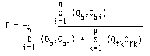
[49 FR 26892, June 29, 1984; 49 FR 32848, Aug. 17, 1984, as amended at 65 FR 61768, Oct. 17, 2000]
§ 60.584 Monitoring of operations and recordkeeping requirements.
(a) The owner or operator of an affected facility controlled by a solvent recovery emission control device shall install, calibrate, operate, and maintain a monitoring system which continuously measures and records the VOC concentration of the exhaust vent stream from the control device and shall comply with the following requirements:
(1) The continuous monitoring system shall be installed in a location that is representative of the VOC concentration in the exhaust vent, at least two equivalent stack diameters from the exhaust point, and protected from interferences due to wind, weather, or other processes.
(2) During the performance test, the owner or operator shall determine and record the average exhaust vent VOC concentration in parts per million by volume. After the performance test, the owner or operator shall determine and, in addition to the record made by the continuous monitoring device, record the average exhaust vent VOC concentration for each 3-hour clock period of printing operation when the average concentration is greater than 50 ppm and more than 20 percent greater than the average concentration value demonstrated during the most recent performance test.
(b) The owner or operator of an affected facility controlled by a thermal incineration emission control device shall install, calibrate, operate, and maintain a monitoring device that continuously measures and records the temperature of the control device exhaust gases and shall comply with the following requirements:
(1) The continuous monitoring device shall be calibrated annually and have an accuracy of ±0.75 percent of the temperature being measured, expressed in degrees Celsius, or ±2.5 °C, whichever is greater.
(2) During the performance test, the owner or operator shall determine and record the average temperature of the control device exhaust gases. After the performance test, the owner or operator shall determine and record, in addition to the record made by the continuous monitoring device, the average temperature for each 3-hour clock period of printing operation when the average temperature of the exhaust gases is more than 28 °C (50 °F) below the average temperature demonstrated during the most recent performance test.
(c) The owner or operator of an affected facility controlled by a catalytic incineration emission control device shall install, calibrate, operate, and maintain monitoring devices that continuously measure and record the gas temperatures both upstream and downstream of the catalyst bed and shall comply with the following requirements:
(1) Each continuous monitoring device shall be calibrated annually and have an accuracy of ±0.75 percent of the temperature being measured, expressed in degrees Celsius, or ±2.5 °C, whichever is greater.
(2) During the performance test, the owner or operator shall determine and record the average gas temperature both upstream and downstream of the catalyst bed. After the performance test, the owner or operator shall determine and record, in addition to the record made by the continuous monitoring device, the average temperatures for each 3-hour clock period of printing operation when the average temperature of the gas stream before the catalyst bed is more than 28 °C below the average temperature demonstrated during the most recent performance test or the average temperature difference across the catalyst bed is less than 80 percent of the average temperature difference of the device during the most recent performance test.
(d) The owner or operator of an affected facility shall record time periods of operation when an emission control device is not in use.
[49 FR 26892, June 29, 1984, as amended at 65 FR 61768, Oct. 17, 2000]
§ 60.585 Reporting requirements.
(a) For all affected facilities subject to compliance with § 60.582, the performance test data and results from the performance test shall be submitted to the Administrator as specified in § 60.8(a).
(b) The owner or operator of each affected facility shall submit semiannual reports to the Administrator of occurrences of the following:
(1) Exceedances of the weighted average VOC content specified in § 60.582(a)(1);
(2) Exceedances of the average value of the exhaust vent VOC concentration as defined under § 60.584(a)(2);
(3) Drops in the incinerator temperature as defined under § 60.584(b)(2); and
(4) Drops in the average temperature of the gas stream immediately before the catalyst bed or drops in the average temperature across the catalyst bed as defined under § 60.584(c)(2).
(c) The reports required under paragraph (b) shall be postmarked within 30 days following the end of the second and fourth calendar quarters.
(d) The requirements of this subsection remain in force until and unless the Agency, in delegating enforcement authority to a State under section 111(c) of the Act, approves reporting requirements or an alternative means of compliance surveillance adopted by such States. In that event, affected sources within the State will be relieved of the obligation to comply with this subsection, provided that they comply with requirements established by the State.
Subpart GGG - Standards of Performance for Equipment Leaks of VOC in Petroleum Refineries for which Construction, Reconstruction, or Modification Commenced After January 4, 1983, and on or Before November 7, 2006
Source:
49 FR 22606, May 30, 1984, unless otherwise noted.
§ 60.590 Applicability and designation of affected facility.
(a)
(1) The provisions of this subpart apply to affected facilities in petroleum refineries.
(2) A compressor is an affected facility.
(3) The group of all the equipment (defined in § 60.591) within a process unit is an affected facility.
(b) Any affected facility under paragraph (a) of this section that commences construction, reconstruction, or modification after January 4, 1983, and on or before November 7, 2006, is subject to the requirements of this subpart.
(c) Addition or replacement of equipment (defined in § 60.591) for the purpose of process improvement which is accomplished without a capital expenditure shall not by itself be considered a modification under this subpart.
(d) Facilities subject to subpart VV, subpart VVa, or subpart KKK of this part are excluded from this subpart.
(e) Stay of standards. Owners or operators are not required to comply with the definition of “process unit” in § 60.590 of this subpart until the EPA takes final action to require compliance and publishes a document in the Federal Register. While the definition of “process unit” is stayed, owners or operators should use the following definition:
Process unit means components assembled to produce intermediate or final products from petroleum, unfinished petroleum derivatives, or other intermediates; a process unit can operate independently if supplied with sufficient feed or raw materials and sufficient storage facilities for the product.
[49 FR 22606, May 30, 1984, as amended at 72 FR 64895, Nov. 16, 2007; 73 FR 31376, June 2, 2008]
§ 60.591 Definitions.
As used in this subpart, all terms not defined herein shall have the meaning given them in the act, in subpart A of part 60, or in subpart VV of part 60, and the following terms shall have the specific meanings given them.
Alaskan North Slope means the approximately 69,000 square mile area extending from the Brooks Range to the Arctic Ocean.
Asphalt (also known as Bitumen) is a black or dark brown solid or semi-solid thermo-plastic material possessing waterproofing and adhesive properties. It is a complex combination of higher molecular weight organic compounds containing a relatively high proportion of hydrocarbons having carbon numbers greater than C25 with a high carbon to hydrogen ratio. It is essentially non-volatile at ambient temperatures with closed cup flash point of 445 °F (230 °C) or greater.
Equipment means each valve, pump, pressure relief device, sampling connection system, open-ended valve or line, and flange or other connector in VOC service. For the purposes of recordkeeping and reporting only, compressors are considered equipment.
In hydrogen service means that a compressor contains a process fluid that meets the conditions specified in § 60.593(b).
In light liquid service means that the piece of equipment contains a liquid that meets the conditions specified in § 60.593(c).
Petroleum means the crude oil removed from the earth and the oils derived from tar sands, shale, and coal.
Petroleum refinery means any facility engaged in producing gasoline, kerosene, distillate fuel oils, residual fuel oils, lubricants, or other products through the distillation of petroleum, or through the redistillation, cracking, or reforming of unfinished petroleum derivatives.
Process unit means the components assembled and connected by pipes or ducts to process raw materials and to produce intermediate or final products from petroleum, unfinished petroleum derivatives, or other intermediates. A process unit can operate independently if supplied with sufficient feed or raw materials and sufficient storage facilities for the product. For the purpose of this subpart, process unit includes any feed, intermediate and final product storage vessels (except as specified in § 60.482-1(g)), product transfer racks, and connected ducts and piping. A process unit includes all equipment as defined in this subpart.
[49 FR 22606, May 30, 1984, as amended at 72 FR 64895, Nov. 16, 2007]
§ 60.592 Standards.
(a) Each owner or operator subject to the provisions of this subpart shall comply with the requirements of §§ 60.482-1 to 60.482-10 as soon as practicable, but no later than 180 days after initial startup.
(b) For a given process unit, an owner or operator may elect to comply with the requirements of paragraphs (b)(1), (2), or (3) of this section as an alternative to the requirements in § 60.482-7.
(1) Comply with § 60.483-1.
(2) Comply with § 60.483-2.
(3) Comply with the Phase III provisions in 40 CFR 63.168, except an owner or operator may elect to follow the provisions in § 60.482-7(f) instead of 40 CFR 63.168 for any valve that is designated as being leakless.
(c) An owner or operator may apply to the Administrator for a determination of equivalency for any means of emission limitation that achieves a reduction in emissions of VOC at least equivalent to the reduction in emissions of VOC achieved by the controls required in this subpart. In doing so, the owner or operator shall comply with requirements of § 60.484.
(d) Each owner or operator subject to the provisions of this subpart shall comply with the provisions of § 60.485 except as provided in § 60.593.
(e) Each owner or operator subject to the provisions of this subpart shall comply with the provisions of §§ 60.486 and 60.487.
[49 FR 22606, May 30, 1984, as amended at 72 FR 64896, Nov. 16, 2007]
§ 60.593 Exceptions.
(a) Each owner or operator subject to the provisions of this subpart may comply with the following exceptions to the provisions of subpart VV.
(b)
(1) Compressors in hydrogen service are exempt from the requirements of § 60.592 if an owner or operator demonstrates that a compressor is in hydrogen service.
(2) Each compressor is presumed not to be in hydrogen service unless an owner or operator demonstrates that the piece of equipment is in hydrogen service. For a piece of equipment to be considered in hydrogen service, it must be determined that the percent hydrogen content can be reasonably expected always to exceed 50 percent by volume. For purposes of determining the percent hydrogen content in the process fluid that is contained in or contacts a compressor, procedures that conform to the general method described in ASTM E260-73, 91, or 96, E168-67, 77, or 92, or E169-63, 77, or 93 (incorporated by reference as specified in § 60.17) shall be used.
(3)
(i) An owner or operator may use engineering judgment rather than procedures in paragraph (b)(2) of this section to demonstrate that the percent content exceeds 50 percent by volume, provided the engineering judgment demonstrates that the content clearly exceeds 50 percent by volume. When an owner or operator and the Administrator do not agree on whether a piece of equipment is in hydrogen service, however, the procedures in paragraph (b)(2) shall be used to resolve the disagreement.
(ii) If an owner or operator determines that a piece of equipment is in hydrogen service, the determination can be revised only after following the procedures in paragraph (b)(2).
(c) Any existing reciprocating compressor that becomes an affected facility under provisions of § 60.14 or § 60.15 is exempt from § 60.482-3(a), (b), (c), (d), (e), and (h) provided the owner or operator demonstrates that recasting the distance piece or replacing the compressor are the only options available to bring the compressor into compliance with the provisions of § 60.482-3(a), (b), (c), (d), (e), and (h).
(d) An owner or operator may use the following provision in addition to § 60.485(e): Equipment is in light liquid service if the percent evaporated is greater than 10 percent at 150 °C as determined by ASTM Method D86-78, 82, 90, 95, or 96 (incorporated by reference as specified in § 60.17).
(e) Pumps in light liquid service and valves in gas/vapor and light liquid service within a process unit that is located in the Alaskan North Slope are exempt from the requirements of §§ 60.482-2 and 60.482-7.
(f) Open-ended valves or lines containing asphalt as defined in § 60.591 are exempt from the requirements of § 60.482-6(a) through (c).
[49 FR 22606, May 30, 1984, as amended at 65 FR 61768, Oct. 17, 2000; 72 FR 64896, Nov. 16, 2007]
Subpart GGGa - Standards of Performance for Equipment Leaks of VOC in Petroleum Refineries for Which Construction, Reconstruction, or Modification Commenced After November 7, 2006
Source:
72 FR 64896, Nov. 16, 2007, unless otherwise noted.
§ 60.590a Applicability and designation of affected facility.
(a)
(1) The provisions of this subpart apply to affected facilities in petroleum refineries.
(2) A compressor is an affected facility.
(3) The group of all the equipment (defined in § 60.591a) within a process unit is an affected facility.
(b) Any affected facility under paragraph (a) of this section that commences construction, reconstruction, or modification after November 7, 2006, is subject to the requirements of this subpart.
(c) Addition or replacement of equipment (defined in § 60.591a) for the purpose of process improvement which is accomplished without a capital expenditure shall not by itself be considered a modification under this subpart.
(d) Facilities subject to subpart VV, subpart VVa, subpart GGG, or subpart KKK of this part are excluded from this subpart.
(e) Stay of standards. Owners or operators are not required to comply with the definition of “process unit” in § 60.590 of this subpart until the EPA takes final action to require compliance and publishes a document in the Federal Register. While the definition of “process unit” is stayed, owners or operators should use the following definition:
Process unit means components assembled to produce intermediate or final products from petroleum, unfinished petroleum derivatives, or other intermediates; a process unit can operate independently if supplied with sufficient feed or raw materials and sufficient storage facilities for the product.
[49 FR 22606, May 30, 1984, as amended at 73 FR 31376, June 2, 2008]
§ 60.591a Definitions.
As used in this subpart, all terms not defined herein shall have the meaning given them in the Clean Air Act, in subpart A of part 60, or in subpart VVa of this part, and the following terms shall have the specific meanings given them.
Alaskan North Slope means the approximately 69,000 square mile area extending from the Brooks Range to the Arctic Ocean.
Asphalt (also known as Bitumen) is a black or dark brown solid or semi-solid thermo-plastic material possessing waterproofing and adhesive properties. It is a complex combination of higher molecular weight organic compounds containing a relatively high proportion of hydrocarbons having carbon numbers greater than C25 with a high carbon to hydrogen ratio. It is essentially non-volatile at ambient temperatures with closed cup flash point of 445 °F (230 °C) or greater.
Equipment means each valve, pump, pressure relief device, sampling connection system, open-ended valve or line, and flange or other connector in VOC service. For the purposes of recordkeeping and reporting only, compressors are considered equipment.
In hydrogen service means that a compressor contains a process fluid that meets the conditions specified in § 60.593a(b).
In light liquid service means that the piece of equipment contains a liquid that meets the conditions specified in § 60.593a(c).
Petroleum means the crude oil removed from the earth and the oils derived from tar sands, shale, and coal.
Petroleum refinery means any facility engaged in producing gasoline, kerosene, distillate fuel oils, residual fuel oils, lubricants, or other products through the distillation of petroleum, or through the redistillation, cracking, or reforming of unfinished petroleum derivatives.
Process unit means the components assembled and connected by pipes or ducts to process raw materials and to produce intermediate or final products from petroleum, unfinished petroleum derivatives, or other intermediates. A process unit can operate independently if supplied with sufficient feed or raw materials and sufficient storage facilities for the product. For the purpose of this subpart, process unit includes any feed, intermediate and final product storage vessels (except as specified in § 60.482-1a(g)), product transfer racks, and connected ducts and piping. A process unit includes all equipment as defined in this subpart.
§ 60.592a Standards.
(a) Each owner or operator subject to the provisions of this subpart shall comply with the requirements of §§ 60.482-1a to 60.482-10a as soon as practicable, but no later than 180 days after initial startup.
(b) For a given process unit, an owner or operator may elect to comply with the requirements of paragraphs (b)(1), (2), or (3) of this section as an alternative to the requirements in § 60.482-7a.
(1) Comply with § 60.483-1a.
(2) Comply with § 60.483-2a.
(3) Comply with the Phase III provisions in § 63.168, except an owner or operator may elect to follow the provisions in § 60.482-7a(f) instead of § 63.168 for any valve that is designated as being leakless.
(c) An owner or operator may apply to the Administrator for a determination of equivalency for any means of emission limitation that achieves a reduction in emissions of VOC at least equivalent to the reduction in emissions of VOC achieved by the controls required in this subpart. In doing so, the owner or operator shall comply with requirements of § 60.484a.
(d) Each owner or operator subject to the provisions of this subpart shall comply with the provisions of § 60.485a except as provided in § 60.593a.
(e) Each owner or operator subject to the provisions of this subpart shall comply with the provisions of §§ 60.486a and 60.487a.
§ 60.593a Exceptions.
(a) Each owner or operator subject to the provisions of this subpart may comply with the following exceptions to the provisions of subpart VVa of this part.
(b)
(1) Compressors in hydrogen service are exempt from the requirements of § 60.592a if an owner or operator demonstrates that a compressor is in hydrogen service.
(2) Each compressor is presumed not to be in hydrogen service unless an owner or operator demonstrates that the piece of equipment is in hydrogen service. For a piece of equipment to be considered in hydrogen service, it must be determined that the percent hydrogen content can be reasonably expected always to exceed 50 percent by volume. For purposes of determining the percent hydrogen content in the process fluid that is contained in or contacts a compressor, procedures that conform to the general method described in ASTM E260-73, 91, or 96, E168-67, 77, or 92, or E169-63, 77, or 93 (incorporated by reference as specified in § 60.17) shall be used.
(3)
(i) An owner or operator may use engineering judgment rather than procedures in paragraph (b)(2) of this section to demonstrate that the percent content exceeds 50 percent by volume, provided the engineering judgment demonstrates that the content clearly exceeds 50 percent by volume. When an owner or operator and the Administrator do not agree on whether a piece of equipment is in hydrogen service, however, the procedures in paragraph (b)(2) of this section shall be used to resolve the disagreement.
(ii) If an owner or operator determines that a piece of equipment is in hydrogen service, the determination can be revised only after following the procedures in paragraph (b)(2).
(c) Any existing reciprocating compressor that becomes an affected facility under provisions of § 60.14 or § 60.15 is exempt from § 60.482-3a(a), (b), (c), (d), (e), and (h) provided the owner or operator demonstrates that recasting the distance piece or replacing the compressor are the only options available to bring the compressor into compliance with the provisions of § 60.482-3a(a), (b), (c), (d), (e), and (h).
(d) An owner or operator may use the following provision in addition to § 60.485a(e): Equipment is in light liquid service if the percent evaporated is greater than 10 percent at 150 °C as determined by ASTM Method D86-78, 82, 90, 93, 95, or 96 (incorporated by reference as specified in § 60.17).
(e) Pumps in light liquid service and valves in gas/vapor and light liquid service within a process unit that is located in the Alaskan North Slope are exempt from the requirements of §§ 60.482-2a and 60.482-7a.
(f) Open-ended valves or lines containing asphalt as defined in § 60.591a are exempt from the requirements of § 60.482-6a(a) through (c).
(g) Connectors in gas/vapor or light liquid service are exempt from the requirements in § 60.482-11a, provided the owner or operator complies with § 60.482-8a for all connectors, not just those in heavy liquid service.
Subpart HHH - Standards of Performance for Synthetic Fiber Production Facilities
Source:
49 FR 13651, Apr. 5, 1984, unless otherwise noted.
§ 60.600 Applicability and designation of affected facility.
(a) Except as provided in paragraph (b) of this section, the affected facility to which the provisions of this subpart apply is each solvent-spun synthetic fiber process that produces more than 500 Mg (551 ton) of fiber per year.
(b) The provisions of this subpart do not apply to any facility that uses the reaction spinning process to produce spandex fiber or the viscose process to produce rayon fiber.
(c) The provisions of this subpart apply to each facility as identified in paragraph (a) of this section and that commences construction or reconstruction after November 23, 1982. The provisions of this subpart do not apply to facilities that commence modification but not reconstruction after November 23, 1982.
[49 FR 22606, May 30, 1984, as amended at 65 FR 61768, Oct. 17, 2000]
§ 60.601 Definitions.
All terms that are used in this subpart and are not defined below are given the same meaning as in the Act and in subpart A of this part.
Acrylic fiber means a manufactured synthetic fiber in which the fiber-forming substance is any long-chain synthetic polymer composed of at least 85 percent by weight of acrylonitrile units.
Makeup solvent means the solvent introduced into the affected facility that compensates for solvent lost from the affected facility during the manufacturing process.
Nongaseous losses means the solvent that is not volatilized during fiber production, and that escapes the process and is unavailable for recovery, or is in a form or concentration unsuitable for economical recovery.
Polymer means any of the natural or synthetic compounds of usually high molecular weight that consist of many repeated links, each link being a relatively light and simple molecule.
Precipitation bath means the water, solvent, or other chemical bath into which the polymer or prepolymer (partially reacted material) solution is extruded, and that causes physical or chemical changes to occur in the extruded solution to result in a semihardened polymeric fiber.
Rayon fiber means a manufactured fiber composed of regenerated cellulose, as well as manufactured fibers composed of regenerated cellulose in which substituents have replaced not more than 15 percent of the hydrogens of the hydroxyl groups.
Reaction spinning process means the fiber-forming process where a prepolymer is extruded into a fluid medium and solidification takes place by chemical reaction to form the final polymeric material.
Recovered solvent means the solvent captured from liquid and gaseous process streams that is concentrated in a control device and that may be purified for reuse.
Solvent feed means the solvent introduced into the spinning solution preparation system or precipitation bath. This feed stream includes the combination of recovered solvent and makeup solvent.
Solvent inventory variation means the normal changes in the total amount of solvent contained in the affected facility.
Solvent recovery system means the equipment associated with capture, transportation, collection, concentration, and purification of organic solvents. It may include enclosures, hoods, ducting, piping, scrubbers, condensers, carbon adsorbers, distillation equipment, and associated storage vessels.
Solvent-spun synthetic fiber means any synthetic fiber produced by a process that uses an organic solvent in the spinning solution, the precipitation bath, or processing of the sun fiber.
Solvent-spun synthetic fiber process means the total of all equipment having a common spinning solution preparation system or a common solvent recovery system, and that is used in the manufacture of solvent-spun synthetic fiber. It includes spinning solution preparation, spinning, fiber processing and solvent recovery, but does not include the polymer production equipment.
Spandex fiber means a manufactured fiber in which the fiber-forming substance is a long chain synthetic polymer comprised of at least 85 percent of a segmented polyurethane.
Spinning solution means the mixture of polymer, prepolymer, or copolymer and additives dissolved in solvent. The solution is prepared at a viscosity and solvent-to-polymer ratio that is suitable for extrusion into fibers.
Spinning solution preparation system means the equipment used to prepare spinning solutions; the system includes equipment for mixing, filtering, blending, and storage of the spinning solutions.
Synthetic fiber means any fiber composed partially or entirely of materials made by chemical synthesis, or made partially or entirely from chemically-modified naturally-occurring materials.
Viscose process means the fiber forming process where cellulose and concentrated caustic soda are reacted to form soda or alkali cellulose. This reacts with carbon disulfide to form sodium cellulose xanthate, which is then dissolved in a solution of caustic soda. After ripening, the solution is spun into an acid coagulating bath. This precipitates the cellulose in the form of a regenerated cellulose filament.
[49 FR 13651, Apr. 5, 1984; 49 FR 18096, Apr. 27, 1984]
§ 60.602 Standard for volatile organic compounds.
On and after the date on which the initial performance test required to be conducted by § 60.8 is completed, no owner or operator subject to the provisions of this subpart shall cause the discharge into the atmosphere from any affected facility that produces acrylic fibers, VOC emissions that exceed 10 kg/Mg (20 lb/ton) solvent feed to the spinning solution preparation system or precipitation bath. VOC emissions from affected facilities that produce both acrylic and nonacrylic fiber types shall not exceed 10 kg/Mg (20 lb/ton) solvent feed. VOC emissions from affected facilities that produce only nonacrylic fiber types shall not exceed 17 kg/Mg (34 lb/ton) solvent feed. Compliance with the emission limitations is determined on a 6-month rolling average basis as described in § 60.603.
[49 FR 22606, May 30, 1984, as amended at 65 FR 61768, Oct. 17, 2000]
§ 60.603 Performance test and compliance provisions.
(a) Section 60.8(f) does not apply to the performance test procedures required by this subpart.
(b) Each owner or operator of an affected facility shall determine compliance with the applicable standard in § 60.602(a) by determining and recording monthly the VOC emissions per unit mass solvent feed from each affected facility for the current and preceding 5 consecutive calendar months and using these values to calculate the 6-month average emissions. Each calculation is considered a performance test. The owner or operator of an affected facility shall use the following procedure to determine VOC emissions for each calendar month;
(1) Install, calibrate, maintain, and operate monitoring devices that continuously measure and permanently record for each calendar month the amount of makeup solvent and solvent feed. These values shall be used in calculating VOC emissions according to paragraph (b)(2) of this section. All monitoring devices, meters, and peripheral equipment shall be calibrated and any error recorded. Total compounded error of the flow measuring and recording devices shall not exceed 1 percent accuracy over the operating range. As an alternative to measuring solvent feed, the owner or operator may:
(i) Measure the amount of recovered solvent returned to the solvent feed storage tanks, and use the following equation to determine the amount of solvent feed:
Solvent Feed = Makeup Solvent + Recovered
Solvent + Change in the Amount of Solvent
Contained in the Solvent Feed Holding Tank.
(ii) Measure and record the amount of polymer introduced into the affected facility and the solvent-to-polymer ratio of the spinning solutions, and use the following equation to determine the amount of solvent feed:

where subscript “i” denotes each particular spinning solution used during the test period; values of “i” vary from one to the total number of spinning solutions, “n,” used during the calendar month.
(2) VOC emissions shall be determined each calendar month by use of the following equations:

where all values are for the calendar month only and where
E = VOC Emissions, in kg/Mg (lb/ton) solvent;
SV = Measured or calculated volume of solvent feed, in liters (gallons);
SW = Weight of solvent feed, in Mg (ton);
MV = Measured volume of makeup solvent, in liters (gallons);
MW = Weight of makeup, in kg (lb);
N = Allowance for nongaseous losses, 13 kg/Mg (26 lb/ton) solvent feed;
SP = Fraction of measured volume that is actual solvent (excludes water);
D = Density of the solvent, in kg/liter (lb/gallon);
K = Conversion factor, 1,000 kg/Mg (2,000 lb/ton);
I = Allowance for solvent inventory variation or changes in the amount of solvent contained in the affected facility, in kg/Mg (lb/ton) solvent feed (may be positive or negative);
IS = Amount of solvent contained in the affected facility at the beginning of the test period, as determined by the owner or operator, in kg (lb);
IE = Amount of solvent contained in the affected facility at the close of the test period, as determined by the owner or operator, in kg (lb).
(3) N, as used in the equation in paragraph (b)(2) of this section, equals 13 kg/Mg (26 lb/ton) solvent feed to the spinning solution preparation system and precipitation bath. This value shall be used in all cases unless an owner or operator demonstrates to the satisfaction of the Administrator that greater nongaseous losses occur at the affected facility. In this case, the greater value may be substituted in the equation.
[49 FR 13651, Apr. 5, 1984; 49 FR 18096, Apr. 27, 1984, as amended at 65 FR 61769, Oct. 17, 2000]
§ 60.604 Reporting requirements.
(a) The owner or operator of an affected facility shall submit a written report to the Administrator of the following:
(1) The results of the initial performance test; and
(2) The results of subsequent performance tests that indicate that VOC emissions exceed the standards in § 60.602. These reports shall be submitted quarterly at 3-month intervals after the initial performance test. If no exceedances occur during a particular quarter, a report stating this shall be submitted to the Administrator semiannually.
(b) Solvent-spun synthetic fiber producing facilities exempted from these standards in § 60.600(a) (those producing less than 500 Mg (551 ton) annually) shall report to the Administrator within 30 days whenever extruded fiber for the preceding 12 calendar months exceeds 500 Mg (551 ton).
(c) The requirements of this section remain in force until and unless EPA, in delegating enforcement authority to a State under section 111(c) of the Act, approves reporting requirements or an alternate means of compliance surveillance adopted by such State. In that event, affected sources within the State will be relieved of the obligation to comply with this section, provided that they comply with the requirements established by the State.
[49 FR 13651, Apr. 5, 1984, as amended at 55 FR 51384, Dec. 13, 1990; 59 FR 32341, June 23, 1994; 65 FR 61769, Oct. 17, 2000]
Subpart III - Standards of Performance for Volatile Organic Compound (VOC) Emissions From the Synthetic Organic Chemical Manufacturing Industry (SOCMI) Air Oxidation Unit Processes
Source:
55 FR 26922, June 29, 1990, unless otherwise noted.
§ 60.610 Applicability and designation of affected facility.
(a) The provisions of this subpart apply to each affected facility designated in paragraph (b) of this section that produces any of the chemicals listed in § 60.617 as a product, co-product, by-product, or intermediate, except as provided in paragraph (c) of this section.
(b) The affected facility is any of the following for which construction, modification, or reconstruction commenced after October 21, 1983:
(1) Each air oxidation reactor not discharging its vent stream into a recovery system.
(2) Each combination of an air oxidation reactor and the recovery system into which its vent stream is discharged.
(3) Each combination of two or more air oxidation reactors and the common recovery system into which their vent streams are discharged.
(c) Each affected facility that has a total resource effectiveness (TRE) index value greater than 4.0 is exempt from all provisions of this subpart except for §§ 60.612, 60.614(f), 60.615(h), and 60.615(l).
(d) Alternative means of compliance —
(1) Option to comply with part 65. Owners or operators of process vents that are subject to this subpart may choose to comply with the provisions of 40 CFR part 65, subpart D, to satisfy the requirements of §§ 60.612 through 60.615 and 60.618. The provisions of 40 CFR part 65 also satisfy the criteria of paragraph (c) of this section. Other provisions applying to an owner or operator who chooses to comply with 40 CFR part 65 are provided in 40 CFR 65.1.
(2) Part 60, subpart A. Owners or operators who choose to comply with 40 CFR part 65, subpart D, must also comply with §§ 60.1, 60.2, 60.5, 60.6, 60.7(a)(1) and (4), 60.14, 60.15, and 60.16 for those process vents. All sections and paragraphs of subpart A of this part that are not mentioned in this paragraph (d)(2) do not apply to owners or operators of process vents complying with 40 CFR part 65, subpart D, except that provisions required to be met prior to implementing 40 CFR part 65 still apply. Owners and operators who choose to comply with 40 CFR part 65, subpart D, must comply with 40 CFR part 65, subpart A.
(3) Compliance date. Owners or operators who choose to comply with 40 CFR part 65, subpart D, at initial startup shall comply with paragraphs (d)(1) and (2) of this section for each vent stream on and after the date on which the initial performance test is completed, but not later than 60 days after achieving the maximum production rate at which the affected facility will be operated, or 180 days after the initial startup, whichever date comes first.
(4) Initial startup notification. Each owner or operator subject to the provisions of this subpart that chooses to comply with 40 CFR part 65, subpart D, at initial startup shall notify the Administrator of the specific provisions of 40 CFR 65.63(a)(1), (2), or (3) with which the owner or operator has elected to comply. Notification shall be submitted with the notifications of initial startup required by 40 CFR 65.5(b).
The intent of these standards is to minimize the emissions of VOC through the application of BDT. The numerical emission limits in these standards are expressed in terms of total organic compounds (TOC), measured as TOC minus methane and ethane. This emission limit reflects the performance of BDT.
[55 FR 26922, June 29, 1990, as amended at 65 FR 78278, Dec. 14, 2000]
§ 60.611 Definitions.
As used in this subpart, all terms not defined here shall have the meaning given them in the Act and in subpart A of part 60, and the following terms shall have the specific meanings given them.
Air Oxidation Reactor means any device or process vessel in which one or more organic reactants are combined with air, or a combination of air and oxygen, to produce one or more organic compounds. Ammoxidation and oxychlorination reactions are included in this definition.
Air Oxidation Reactor Recovery Train means an individual recovery system receiving the vent stream from at least one air oxidation reactor, along with all air oxidation reactors feeding vent streams into this system.
Air Oxidation Unit Process means a unit process, including ammoxidation and oxychlorination unit process, that uses air, or a combination of air and oxygen, as an oxygen source in combination with one or more organic reactants to produce one or more organic compounds.
Boilers means any enclosed combustion device that extracts useful energy in the form of steam.
By Compound means by individual stream components, not carbon equivalents.
Continuous recorder means a data recording device recording an instantaneous data value at least once every 15 minutes.
Flame zone means the portion of the combustion chamber in a boiler occupied by the flame envelope.
Flow indicator means a device which indicates whether gas flow is present in a vent stream.
Halogenated Vent Stream means any vent stream determined to have a total concentration (by volume) of compounds containing halogens of 20 ppmv (by compound) or greater.
Incinerator means any enclosed combustion device that is used for destroying organic compounds and does not extract energy in the form of steam or process heat.
Process Heater means a device that transfers heat liberated by burning fuel to fluids contained in tubes, including all fluids except water that is heated to produce steam.
Process Unit means equipment assembled and connected by pipes or ducts to produce, as intermediates or final products, one or more of the chemicals in § 60.617. A process unit can operate independently if supplied with sufficient fuel or raw materials and sufficient product storage facilities.
Product means any compound or chemical listed in § 60.617 that is produced for sale as a final product as that chemical or is produced for use in a process that needs that chemical for the production of other chemicals in another facility. By-products, co-products, and intermediates are considered to be products.
Recovery Device means an individual unit of equipment, such as an absorber, condenser, and carbon adsorber, capable of and used to recover chemicals for use, reuse or sale.
Recovery System means an individual recovery device or series of such devices applied to the same process stream.
Total organic compounds (TOC) means those compounds measured according to the procedures in § 60.614(b)(4). For the purposes of measuring molar composition as required in § 60.614(d)(2)(i), hourly emissions rate as required in § 60.614(d)(5) and § 60.614(e) and TOC concentration as required in § 60.615(b)(4) and § 60.615(g)(4), those compounds which the Administrator has determined do not contribute appreciably to the formation of ozone are to be excluded. The compounds to be excluded are identified in Environmental Protection Agency's statements on ozone abatement policy for SIP revisions (42 FR 35314; 44 FR 32042; 45 FR 32424; 45 FR 48942).
Total resource effectiveness (TRE) Index Value means a measure of the supplemental total resource requirement per unit reduction of TOC associated with an individual air oxidation vent stream, based on vent stream flow rate, emission rate of TOC, net heating value, and corrosion properties (whether or not the vent stream is halogenated), as quantified by the equation given under § 60.614(e).
Vent Stream means any gas stream, containing nitrogen which was introduced as air to the air oxidation reactor, released to the atmosphere directly from any air oxidation reactor recovery train or indirectly, after diversion through other process equipment. The vent stream excludes equipment leaks and relief valve discharges including, but not limited to, pumps, compressors, and valves.
[55 FR 26922, June 29, 1990; 55 FR 36932, Sept. 7, 1990]
§ 60.612 Standards.
Each owner or operator of any affected facility shall comply with paragraph (a), (b), or (c) of this section for each vent stream on and after the date on which the initial performance test required by §§ 60.8 and 60.614 is completed, but not later than 60 days after achieving the maximum production rate at which the affected facility will be operated, or 180 days after the initial start-up, whichever date comes first. Each owner or operator shall either:
(a) Reduce emissions of TOC (minus methane and ethane) by 98 weight-percent, or to a TOC (minus methane and ethane) concentration of 20 ppmv on a dry basis corrected to 3 percent oxygen, whichever is less stringent. If a boiler or process heater is used to comply with this paragraph, then the vent stream shall be introduced into the flame zone of the boiler or process heater; or
(b) Combust the emissions in a flare that meets the requirements of § 60.18; or
(c) Maintain a TRE index value greater than 1.0 without use of VOC emission control devices.
§ 60.613 Monitoring of emissions and operations.
(a) The owner or operator of an affected facility that uses an incinerator to seek to comply with the TOC emission limit specified under § 60.612(a) shall install, calibrate, maintain, and operate according to manufacturer's specifications the following equipment:
(1) A temperature monitoring device equipped with a continuous recorder and having an accuracy of ±1 percent of the temperature being monitored expressed in degrees Celsius or ±0.5 °C, whichever is greater.
(i) Where an incinerator other than a catalytic incinerator is used, a temperature monitoring device shall be installed in the firebox.
(ii) Where a catalytic incinerator is used, temperature monitoring devices shall be installed in the gas stream immediately before and after the catalyst bed.
(2) A flow indicator that provides a record of vent stream flow to the incinerator at least once every hour for each affected facility. The flow indicator shall be installed in the vent stream from each affected facility at a point closest to the inlet of each incinerator and before being joined with any other vent stream.
(b) The owner or operator of an affected facility that uses a flare to seek to comply with § 60.612(b) shall install, calibrate, maintain, and operate according to manufacturer's specifications the following equipment:
(1) A heat sensing device, such as an ultra-violet sensor or thermocouple, at the pilot light to indicate the continuous presence of a flame.
(2) A flow indicator that provides a record of vent stream flow to the flare at least once every hour for each affected facility. The flow indicator shall be installed in the vent stream from each affected facility at a point closest to the flare and before being joined with any other vent stream.
(c) The owner or operator of an affected facility that uses a boiler or process heater to seek to comply with § 60.612(a) shall install, calibrate, maintain and operate according to the manufacturer's specifications the following equipment:
(1) A flow indicator that provides a record of vent stream flow to the boiler or process heater at least once every hour for each affected facility. The flow indicator shall be installed in the vent stream from each air oxidation reactor within an affected facility at a point closest to the inlet of each boiler or process heater and before being joined with any other vent stream.
(2) A temperature monitoring device in the firebox equipped with a continuous recorder and having an accuracy of ±1 percent of the temperature being measured expressed in degrees Celsius or ±0.5 °C, whichever is greater, for boilers or process heaters of less than 44 MW (150 million Btu/hr) heat input design capacity.
(d) Monitor and record the periods of operation of the boiler or process heater if the design input capacity of the boiler is 44 MW (150 million Btu/hr) or greater. The records must be readily available for inspection.
(e) The owner or operator of an affected facility that seeks to demonstrate compliance with the TRE index value limit specified under § 60.612(c) shall install, calibrate, maintain, and operate according to manufacturer's specifications the following equipment, unless alternative monitoring procedures or requirements are approved for that facility by the Administrator:
(1) Where an absorber is the final recovery device in a recovery system:
(i) A scrubbing liquid temperature monitoring device having an accuracy of ±1 percent of the temperature being monitored expressed in degrees Celsius or 0.5 °C, whichever is greater, and a specific gravity monitoring device having an accuracy of 0.02 specific gravity units, each equipped with a continuous recorder;
(ii) An organic monitoring device used to indicate the concentration level of organic compounds exiting the recovery device based on a detection principle such as infra-red, photoionization, or thermal conductivity, each equipped with a continuous recorder.
(2) Where a condenser is the final recovery device in a recovery system:
(i) A condenser exit (product side) temperature monitoring device equipped with a continuous recorder and having an acuracy of ±1 percent of the temperature being monitored expressed in degrees Celsius or 0.5 °C, whichever is greater;
(ii) An organic monitoring device used to indicate the concentration level of organic compounds exiting the recovery device based on a detection principle such as infra-red, photoionization, or thermal conductivity, each equipped with a continuous recorder.
(3) Where a carbon adsorber is the final recovery device in a recovery system:
(i) An integrating steam flow monitoring device having an accuracy of 10 percent, and a carbon bed temperature monitoring device having an accuracy of ±1 percent of the temperature being monitored expressed in degrees Celsius or ±0.5 °C, whichever is greater, both equipped with a continuous recorder;
(ii) An organic monitoring device used to indicate the concentration level of organic compounds exiting the recovery device based on a detection principle such as infra-red, photoionization, or thermal conductivity, each equipped with a continuous recorder.
(f) An owner or operator of an affected facility seeking to demonstrate compliance with the standards specified under § 60.612 with control devices other than an incinerator, boiler, process heater, or flare; or recovery devices other than an absorber, condenser, or carbon adsorber shall provide to the Administrator information describing the operation of the control device or recovery device and the process parameter(s) which would indicate proper operation and maintenance of the device. The Administrator may request further information and will specify appropriate monitoring procedures or requirements.
[55 FR 26922, June 29, 1990, as amended at 65 FR 61769, Oct. 17, 2000]
§ 60.614 Test methods and procedures.
(a) For the purpose of demonstrating compliance with § 60.612, all affected facilities shall be run at full operating conditions and flow rates during any performance test.
(b) The following methods in appendix A to this part, except as provided under § 60.8(b) shall be used as reference methods to determine compliance with the emission limit or percent reduction efficiency specified under § 60.612(a).
(1) Method 1 or 1A, as appropriate, for selection of the sampling sites. The control device inlet sampling site for determination of vent stream molar composition or TOC (less methane and ethane) reduction efficiency shall be prior to the inlet of the control device and after the recovery system.
(2) Method 2, 2A, 2C, or 2D, as appropriate, for determination of the volumetric flow rates.
(3) The emission rate correction factor, integrated sampling and analysis procedure of Method 3 shall be used to determine the oxygen concentration (%O2d) for the purposes of determining compliance with the 20 ppmv limit. The sampling site shall be the same as that of the TOC samples and the samples shall be taken during the same time that the TOC samples are taken. The TOC concentration corrected to 3 percent O2 (Cc) shall be computed using the following equation:

where:
Cc = Concentration of TOC corrected to 3 percent 02, dry basis, ppm by volume.
CTOC = Concentration of TOC (minus methane and ethane), dry basis, ppm by volume.
%O2d = Concentration of O2, dry basis, percent by volume.
(4) Method 18 to determine concentration of TOC in the control device outlet and the concentration of TOC in the inlet when the reduction efficiency of the control device is to be determined.
(i) The sampling time for each run shall be 1 hour in which either an integrated sample or four grab samples shall be taken. If grab sampling is used then the samples shall be taken at 15-minute intervals.
(ii) The emission reduction (R) of TOC (minus methane and ethane) shall be determined using the following equation:

where:
R = Emission reduction, percent by weight.
Ei = Mass rate of TOC entering the control device, kg/hr (lb/hr).
Eo = Mass rate of TOC discharged to the atmosphere, kg/hr (lb/hr).
(iii) The mass rates of TOC (Ei, Eo) shall be computed using the following equations:

Where:
Cij, Coj = Concentration of sample component “j” of the gas stream at the inlet and outlet of the control device, respectively, dry basis ppm by volume.
Mij, Moj = Molecular weight of sample component “j“ of the gas stream at the inlet and outlet of the control device, respectively, g/g-mole (lb/lb-mole).
Qi, Qo = Flow rate of gas stream at the inlet and outlet of the control device, respectively, dscm/min (dscf/min).
K2 = 2.494 × 10⁻⁶ (1/ppm)(g-mole/scm)(kg/g)(min/hr) (metric units), where standard temperature for (g-mole/scm) is 20 °C.
= 1.557 × 10⁻⁷ (1/ppm)(lb-mole/scf)(min/hr) (English units), where standard temperature for (lb-mole/scf) is 68 °F.
(iv) The TOC concentration (CTOC) is the sum of the individual components and shall be computed for each run using the following equation:

where:
CTOC = Concentration of TOC (minus methane and ethane), dry basis, ppm by volume.
Cj = Concentration of sample components in the sample.
n = Number of components in the sample.
(c) When a boiler or process heater with a design heat input capacity of 44 MW (150 million Btu/hour) or greater is used to seek to comply with § 60.612(a), the requirement for an initial performance test is waived, in accordance with § 60.8(b). However, the Administrator reserves the option to require testing at such other times as may be required, as provided for in section 114 of the Act.
(d) When a flare is used to seek to comply with § 60.612(b), the flare shall comply with the requirements of § 60.18.
(e) The following test methods in appendix A to this part, except as provided under § 60.8(b), shall be used for determining the net heating value of the gas combusted to determine compliance under § 60.612(b) and for determining the process vent stream TRE index value to determine compliance under § 60.612(c).
(1)
(i) Method 1 or 1A, as appropriate, for selection of the sampling site. The sampling site for the vent stream flow rate and molar composition determination prescribed in § 60.614(e)(2) and (3) shall be, except for the situations outlined in paragraph (e)(1)(ii) of this section, prior to the inlet of any control device, prior to any post-reactor dilution of the stream with air, and prior to any post-reactor introduction of halogenated compounds into the vent stream. No transverse site selection method is needed for vents smaller than 10 centimeters (4 inches) in diameter.
(ii) If any gas stream other than the air oxidation vent stream from the affected facility is normally conducted through the final recovery device.
(A) The sampling site for vent stream flow rate and molar composition shall be prior to the final recovery device and prior to the point at which the nonair oxidation stream is introduced.
(B) The efficiency of the final recovery device is determined by measuring the TOC concentration using Method 18 at the inlet to the final recovery device after the introduction of any nonair oxidation vent stream and at the outlet of the final recovery device.
(C) This efficiency is applied to the TOC concentration measured prior to the final recovery device and prior to the introduction of the nonair oxidation stream to determine the concentration of TOC in the air oxidation stream from the final recovery device. This concentration of TOC is then used to perform the calculations outlined in § 60.614(e)(4) and (5).
(2) The molar composition of the process vent stream shall be determined as follows:
(i) Method 18 to measure the concentration of TOC including those containing halogens.
(ii) D1946-77, or 90 (Reapproved 1994) (incorporation by reference as specified in § 60.17 of this part) to measure the concentration of carbon monoxide and hydrogen.
(iii) Method 4 to measure the content of water vapor.
(3) The volumetric flow rate shall be determined using Method 2, 2A, 2C, or 2D, as appropriate.
(4) The net heating value of the vent stream shall be calculated using the following equation:

where:
HT = Net heating value of the sample, MJ/scm (Btu/scf), where the net enthalpy per mole of vent stream is based on combustion at 25 °C and 760 mm Hg (77 °F and 30 in. Hg), but the standard temperature for determining the volume corresponding to one mole is 20 °C (68 °F).
K1 = 1.74 × 10⁻⁷ (1/ppm)(g-mole/scm)(MJ/kcal) (metric units), where standard temperature for (g-mole/scm) is 20 °C.
= 1.03 × 10⁻¹¹ (1/ppm)(lb-mole/scf)(Btu/kcal) (English units) where standard temperature for (lb/mole/scf) is 68 °F.
Cj = Concentration on a wet basis of compound j in ppm, as measured for organics by Method 18 and measured for hydrogen and carbon monoxide by ASTM D1946-77, 90, or 94 (incorporation by reference as specified in § 60.17 of this part) as indicated in § 60.614(e)(2).
Hj = Net heat of combustion of compound j, kcal/(g-mole) [kcal/(lb-mole)], based on combustion at 25 °C and 760 mm Hg (77 °F and 30 in. Hg).
(5) The emission rate of TOC in the process vent stream shall be calculated using the following equation:

where:
ETOC = Measured emission rate of TOC, kg/hr (lb/hr).
K2 = 2.494 × 10⁻⁶ (1/ppm)(g-mole/scm)(kg/g)(min/hr) (metric units), where standard temperature for (g-mole/scm) is 20 °C.
= 1.557 × 10⁻⁷ (1/ppm)(lb-mole/scf)(min/hr) (English units), where standard temperature for (lb-mole/scf) is 68 °F.
Cj = Concentration on a wet basis of compound j in ppm, as measured by Method 18 as indicated in § 60.614(e)(2).
Mj = Molecular weight of sample j, g/g-mole (lb/lb-mole).
Qs = Vent stream flow rate, scm/hr (scf/hr), at a temperature of 20 °C (68 °F).
(6) The total process vent stream concentration (by volume) of compounds containing halogens (ppmv, by compound) shall be summed from the individual concentrations of compounds containing halogens which were measured by Method 18.
(f) For purposes of complying with § 60.612(c), the owner or operator of a facility affected by this subpart shall calculate the TRE index value of the vent stream using the equation for incineration in paragraph (e)(1) of this section for halogenated vent streams. The owner or operator of an affected facility with a nonhalogenated vent stream shall determine the TRE index value by calculating values using both the incinerator equation in paragraph (e)(1) of this section and the flare equation in paragraph (e)(2) of this section and selecting the lower of the two values.
(1) The TRE index value of the vent stream controlled by an incinerator shall be calculated using the following equation:

(i) Where for a vent stream flow rate that is greater than or equal to 14.2 scm/min (501 scf/min) at a standard temperature of 20 °C (68 °F):
TRE = TRE index value.
Qs = Vent stream flow rate, scm/min (scf/min), at a temperature of 20 °C (68 °F).
HT = Vent stream net heating value, MJ/scm (Btu/scf), where the net enthalpy per mole of vent stream is based on combustion at 25 °C and 760 mm Hg (68 °F and 30 in. Hg), but the standard temperature for determining the volume corresponding to one mole is 20 °C (68 °F) as in the definition of Qs.
Ys = Qs for all vent stream categories listed in table 1 except for Category E vent streams where Ys = QsHT/3.6.
ETOC = Hourly emissions of TOC, kg/hr (lb/hr). a, b, c, d, e, and f are coefficients.
The set of coefficients which apply to a vent stream shall be obtained from table 1.
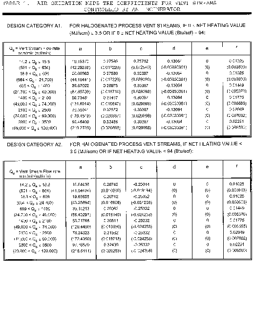
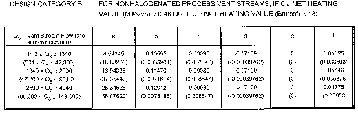
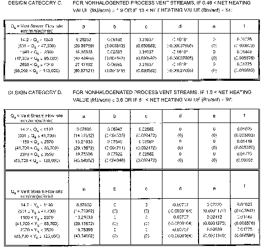
(ii) Where for a vent stream flow rate that is less than 14.2 scm/min (501 scf/min) at a standard temperature of 20 °C (68 °F):
TRE = TRE index value.
Qs = 14.2 scm/min (501 scf/min).
HT = (FLOW)(HVAL)/Qs.
Where the following inputs are used:
FLOW = Vent stream flow rate, scm/min (scf/min), at a temperature of 20 °C (68 °F).
HVAL = Vent stream net heating value, MJ/scm (Btu/scf), where the net enthalpy per mole of vent stream is based on combustion at 25 °C and 760 mm Hg (68 °F and 30 in. Hg), but the standard temperature for determining the volume corresponding to one mole is 20 °C (68 °F) as in the definition of Qs.
Ys = Qs for all vent stream categories listed in table 1 except for Category E vent streams where Ys = QsHT/3.6.
ETOC = Hourly emissions of TOC, kg/hr (lb/hr).
a, b, c, d, e, and f are coefficients.
The set of coefficients that apply to a vent stream can be obtained from table 1.
(2) The equation for calculating the TRE index value of a vent stream controlled by a flare is as follows:

where:
TRE = TRE index value.
ETOC = Hourly emissions of TOC, kg/hr (lb/hr).
Qs = Vent stream flow rate, scm/min (scf/min), at a standard temperature of 20 °C (68 °F).
HT = Vent stream net heating value, MJ/scm (Btu/scf), where the net enthalpy per mole of vent stream is based on combustion at 25 °C and 760 mm Hg (68 °F and 30 in. Hg), but the standard temperature for determining the volume corresponding to one mole is 20 °C (68 °F) as in the definition of Qs.
a, b, c, d, and e are coefficients.
The set of coefficients that apply to a vent stream shall be obtained from table 2.
Table 2—Air Oxidation Processes NSPS TRE Coefficients for Vent Streams Controlled by a Flare
| a | b | c | d | e | |
|---|---|---|---|---|---|
| HT < 11.2 MJ/scm | 2.25 | 0.288 | −0.193 | (−0.0051 | 2.08 |
| (HT < 301 Btu/scf) | (0.140) | (0.0367) | (−0.000448) | (−0.0051) | (4.59) |
| HT ≥ 11.2 MJ/scm | 0.309 | 0.0619 | −0.0043 | −0.0034 | 2.08 |
| HT ≥ 301 Btu/scf) | (0.0193) | (0.00788) | (−0.000010) | (−0.0034) | (4.59) |
(g) Each owner or operator of an affected facility seeking to comply with § 60.610(c) or § 60.612(c) shall recalculate the TRE index value for that affected facility whenever process changes are made. Some examples of process changes are changes in production capacity, feedstock type, or catalyst type, or whenever there is replacement, removal, or addition of recovery equipment. The TRE index value shall be recalculated based on test data, or on best engineering estimates of the effects of the change to the recovery system.
(1) Where the recalculated TRE index value is less than or equal to 1.0, the owner or operator shall notify the Administrator within 1 week of the recalculation and shall conduct a performance test according to the methods and procedures required by § 60.614 to determine compliance with § 60.612(a). Performance tests must be conducted as soon as possible after the process change but no later than 180 days from the time of the process change.
(2) Where the initial TRE index value is greater than 4.0 and the recalculated TRE index value is less than or equal to 4.0, but greater than 1.0, the owner or operator shall conduct a performance test in accordance with §§ 60.8 and 60.614 and shall comply with §§ 60.613, 60.614, and 60.615. Performance tests must be conducted as soon as possible after the process change but no later than 180 days from the time of the process change.
[55 FR 26922, June 29, 1990; 55 FR 36932, Sept. 7, 1990, as amended at 65 FR 61769, Oct. 17, 2000]
§ 60.615 Reporting and recordkeeping requirements.
(a) Each owner or operator subject to § 60.612 shall notify the Administrator of the specific provisions of § 60.612 (§ 60.612 (a) (b), or (c)) with which the owner or operator has elected to comply. Notification shall be submitted with the notification of initial start-up required by § 60.7(a)(3). If an owner or operator elects at a later date to use an alternative provision of § 60.612 with which he or she will comply, then the Administrator shall be notified by the owner or operator 90 days before implementing a change and, upon implementing the change, a performance test shall be performed as specified by § 60.614 within 180 days.
(b) Each owner or operator subject to the provisions of this subpart shall keep up-to-date, readily accessible records of the following data measured during each performance test, and also include the following data in the report of the initial performance test required under § 60.8. Where a boiler or process heater with a design heat input capacity of 44 MW (150 million Btu/hour) or greater is used to comply with § 60.612(a), a report containing performance test data need not be submitted, but a report containing the information of § 60.615(b)(2)(i) is required. The same data specified in this section shall be submitted in the reports of all subsequently required performance tests where either the emission control efficiency of a control device, outlet concentration of TOC, or the TRE index value of a vent stream from a recovery system is determined.
(1) Where an owner or operator subject to this subpart seeks to demonstrate compliance with § 60.612(a) through use of either a thermal or catalytic incinerator:
(i) The average firebox temperature of the incinerator (or the average temperature upstream and downstream of the catalyst bed for a catalytic incinerator), measured at least every 15 minutes and averaged over the same time period of the performance testing, and
(ii) The percent reduction of TOC determined as specified in § 60.614(b) achieved by the incinerator, or the concentration of TOC (ppmv, by compound) determined as specified in § 60.614(b) at the outlet of the control device on a dry basis corrected to 3 percent oxygen.
(2) Where an owner or operator subject to the provisions of this subpart seeks to demonstrate compliance with § 60.612(a) through use of a boiler or process heater:
(i) A description of the location at which the vent stream is introduced into the boiler or process heater, and
(ii) The average combustion temperature of the boiler or process heater with a design heat input capacity of less than 44 MW (150 million Btu/hr) measured at least every 15 minutes and averaged over the same time period of the performance testing.
(3) Where an owner or operator subject to the provisions of this subpart seeks to comply with § 60.612(b) through the use of a smokeless flare, flare design (i.e., steam-assisted, air-assisted, or nonassisted), all visible emission readings, heat content determinations, flow rate measurements, and exit velocity determinations made during the performance test, continuous records of the flare pilot flame monitoring, and records of all periods of operations during which the pilot flame is absent.
(4) Where an owner or operator seeks to demonstrate compliance with § 60.612(c):
(i) Where an absorber is the final recovery device in a recovery system, the exit specific gravity (or alternative parameter which is a measure of the degree of absorbing liquid saturation, if approved by the Administrator), and average exit temperature of the absorbing liquid, measured at least every 15 minutes and averaged over the same time period of the performance testing (both measured while the vent stream is normally routed and constituted), or
(ii) Where a condenser is the final recovery device in a recovery system, the average exit (product side) temperature, measured at least every 15 minutes and average over the same time period of the performance testing while the vent stream is normally routed and constituted.
(iii) Where a carbon adsorber is the final recovery device in a recovery system, the total steam mass flow measured at least every 15 minutes and averaged over the same time period of the performance test (full carbon bed cycle), temperature of the carbon bed after regeneration (and within 15 minutes of completion of any cooling cycle(s), and duration of the carbon bed steaming cycle (all measured while the vent stream is normally routed and constituted), or
(iv) As an alternative to § 60.615(b)(4)(i), (ii) or (iii), the concentration level or reading indicated by the organic monitoring device at the outlet of the absorber, condenser, or carbon adsorber measured at least every 15 minutes and averaged over the same time period of the performance testing while the vent stream is normally routed and constituted.
(v) All measurements and calculations performed to determine the TRE index value of the vent stream.
(c) Each owner or operator subject to the provisions of this subpart shall keep up-to-date, readily accessible continuous records of the equipment operating parameters specified to be monitored under § 60.613(a) and (c) as well as up-to-date, readily accessible records of periods of operation during which the parameter boundaries established during the most recent performance test are exceeded. The Administrator may at any time require a report of these data. Where a combustion device is used by an owner or operator seeking to demonstrate compliance with § 60.612(a) or (c), periods of operation during which the parameter boundaries established during the most recent performance tests are exceeded are defined as follows:
(1) For thermal incinerators, all 3-hour periods of operation during which the average combustion temperature was more than 28 °C (50 °F) below the average combustion temperature during the most recent performance test at which compliance with § 60.612(a) was determined.
(2) For catalytic incinerators, all 3-hour periods of operation during which the average temperature of the vent stream immediately before the catalyst bed is more than 28 °C (50 °F) below the average temperature of the vent stream during the most recent performance test at which compliance with § 60.612(a) was determined. The owner or operator also shall record all 3-hour periods of operation during which the average temperature difference across the catalyst bed is less than 80 percent of the average temperature difference of the device during the most recent performance test at which compliance with § 60.612(a) was determined.
(3) All 3-hour periods of operation during which the average combustion temperature was more than 28 °C (50 °F) below the average combustion temperature during the most recent performance test at which compliance with § 60.612(a) was determined for boilers or process heaters with a design heat input capacity of less than 44 MW (150 million Btu/hr).
(4) For boilers or process heaters, whenever there is a change in the location at which the vent stream is introduced into the flame zone as required under § 60.612(a).
(d) Each owner or operator subject to the provisions of this subpart shall keep up-to-date, readily accessible continuous records of the flow indication specified under § 60.613(a)(2), § 60.613(b)(2), and § 60.613(c)(1), as well as up-to-date, readily accessible records of all periods when the vent stream is diverted from the control device or has no flow rate.
(e) Each owner or operator subject to the provisions of this subpart who uses a boiler or process heater with a design heat input capacity of 44 MW (150 million Btu/hour) or greater to comply with § 60.612(a) shall keep an up-to-date, readily accessible record of all periods of operation of the boiler or process heater. (Examples of such records could include records of steam use, fuel use, or monitoring data collected pursuant to other State or Federal regulatory requirements).
(f) Each owner or operator subject to the provisions of this subpart shall keep up-to-date, readily accessible continuous records of the flare pilot flame monitoring specified in § 60.613(b), as well as up-to-date, readily accessible records of all periods of operations in which the pilot flame is absent.
(g) Each owner or operator subject to the provisions of this subpart shall keep up-to-date, readily accessible continuous records of the equipment operating parameters specified to be monitored under § 60.613(e) as well as up-to-date, readily accessible records of periods of operation during which the parameter boundaries established during the most recent performance test are exceeded. The Administrator may at any time require a report of these data. Where the owner or operator seeks to demonstrate compliance with § 60.612(c), periods of operation during which the parameter boundaries established during the most recent performance tests are exceeded are defined as follows:
(1) Where an absorber is the final recovery device in a recovery system, and where an organic monitoring device is not used:
(i) All 3-hour periods of operation during which the average absorbing liquid temperature was more than 11 °C (20 °F) above the average absorbing liquid temperature during the most recent performance test, or
(ii) All 3-hour periods of operation during which the average absorbing liquid specific gravity was more than 0.1 unit above, or more than 0.1 unit below, the average absorbing liquid specific gravity during the most recent performance test (unless monitoring of an alternative parameter, which is a measure of the degree of absorbing liquid saturation, is approved by the Administrator, in which case he or she will define appropriate parameter boundaries and periods of operation during which they are exceeded).
(2) When a condenser is the final recovery device in a recovery system, and where an organic monitoring device is not used, all 3-hour periods of operation during which the average exit (product side) condenser operating temperature was more than 6 °C (11 °F) above the average exit (product side) operating temperature during the most recent performance test.
(3) Where a carbon adsorber is the final recovery device in a recovery system and where an organic monitoring device is not used:
(i) All carbon bed regeneration cycles during which the total mass steam flow was more than 10 percent below the total mass steam flow during the most recent performance test, or
(ii) All carbon bed regeneration cycles during which the temperature of the carbon bed after regeneration (and after completion of any cooling cycle(s)) was more than 10 percent greater than the carbon bed temperature (in degrees Celsius) during the most recent performance test.
(4) Where an absorber, condenser, or carbon adsorber is the final recovery device in the recovery system and an organic monitoring device approved by the Administrator is used, all 3-hour periods of operation during which the average concentration level or reading of organic compounds in the exhaust gases is more than 20 percent greater than the exhaust gas organic compound concentration level or reading measured by the monitoring device during the most recent performance test.
(h) Each owner or operator subject to the provisions of this subpart and seeking to demonstrate compliance with § 60.612(c) shall keep up-to-date, readily accessible records of:
(1) Any changes in production capacity, feedstock type, or catalyst type, or of any replacement, removal or addition of recovery equipment or air oxidation reactors;
(2) Any recalculation of the TRE index value performed pursuant to § 60.614(f);
(3) The results of any performance test performed pursuant to the methods and procedures required by § 60.614(d).
(i) Each owner and operator subject to the provisions of this subpart is exempt from the quarterly reporting requirements contained in § 60.7(c) of the General Provisions.
(j) Each owner or operator that seeks to comply with the requirements of this subpart by complying with the requirements of § 60.612 shall submit to the Administrator semiannual reports of the following information. The initial report shall be submitted within 6 months after the initial start-up-date.
(1) Exceedances of monitored parameters recorded under § 60.615(c) and (g).
(2) All periods recorded under § 60.615(d) when the vent stream is diverted from the control device or has no flow rate.
(3) All periods recorded under § 60.615(e) when the boiler or process heater was not operating.
(4) All periods recorded under § 60.615(f) in which the pilot flame of the flare was absent.
(5) Any recalculation of the TRE index value, as recorded under § 60.615(h).
(k) The requirements of § 60.615(j) remain in force until and unless EPA, in delegating enforcement authority to a State under section 111(c) of the Act, approves reporting requirements or an alternative means of compliance surveillance adopted by such State. In that event, affected sources within the State will be relieved of the obligation to comply with § 60.615(j), provided that they comply with the requirements established by the State.
(l) The Administrator will specify appropriate reporting and recordkeeping requirements where the owner or operator of an affected facility seeks to demonstrate compliance with the standards specified under § 60.612 other than as provided under § 60.613(a), (b), (c), and (d).
[55 FR 26922, June 29, 1990; 55 FR 36932, Sept. 7, 1990, as amended at 65 FR 61773, Oct. 17, 2000]
§ 60.616 Reconstruction.
For purposes of this subpart “fixed capital cost of the new components,” as used in § 60.15, includes the fixed capital cost of all depreciable components which are or will be replaced pursuant to all continuous programs of component replacement which are commenced within any 2-year period following October 21, 1983. For purposes of this paragraph, “commenced” means that an owner or operator has undertaken a continuous program of component replacement or that an owner or operator has entered into a contractual obligation to undertake and complete, within a reasonable time, a continuous program of component replacement.
§ 60.617 Chemicals affected by subpart III.
| Chemical name | CAS No.* |
|---|---|
| Acetaldehyde | 75-07-0 |
| Acetic acid | 64-19-7 |
| Acetone | 67-64-1 |
| Acetonitrile | 75-05-8 |
| Acetophenone | 98-86-2 |
| Acrolein | 107-02-8 |
| Acrylic acid | 79-10-7 |
| Acrylonitrile | 107-13-1 |
| Anthraquinone | 84-65-1 |
| Benzaldehyde | 100-52-7 |
| Benzoic acid, tech | 65-85-0 |
| 1,3-Butadiene | 106-99-0 |
| p-t-Butyl benzoic acid | 98-73-7 |
| N-Butyric acid | 107-92-6 |
| Crotonic acid | 3724-65-0 |
| Cumene hydroperoxide | 80-15-9 |
| Cyclohexanol | 108-93-0 |
| Cyclohexanone | 108-94-1 |
| Dimethyl terephthalate | 120-61-6 |
| Ethylene dichloride | 107-06-2 |
| Ethylene oxide | 75-21-8 |
| Formaldehyde | 50-00-0 |
| Formic acid | 64-18-6 |
| Glyoxal | 107-22-2 |
| Hydrogen cyanide | 74-90-8 |
| Isobutyric acid | 79-31-2 |
| Isophthalic acid | 121-91-5 |
| Maleic anhydride | 108-31-6 |
| Methyl ethyl ketone | 78-93-3 |
| a-Methyl styrene | 98-83-9 |
| Phenol | 108-95-2 |
| Phthalic anhydride | 85-44-9 |
| Propionic acid | 79-09-4 |
| Propylene oxide | 75-56-9 |
| Styrene | 100-42-5 |
| Terephthalic acid | 100-21-0 |
§ 60.618 Delegation of authority.
(a) In delegating implementation and enforcement authority to a State under section 111(c) of the Act, the authorities contained in paragraph (b) of this section shall be retained by the Administrator and not transferred to a State.
(b) Authorities which will not be delegated to States: § 60.613(e).
Subpart JJJ - Standards of Performance for Petroleum Dry Cleaners
Source:
49 FR 37331, Sept. 21, 1984, unless otherwise noted.
§ 60.620 Applicability and designation of affected facility.
(a) The provisions of this subpart are applicable to the following affected facilities located at a petroleum dry cleaning plant with a total manufacturers' rated dryer capacity equal to or greater than 38 kilograms (84 pounds): Petroleum solvent dry cleaning dryers, washers, filters, stills, and settling tanks.
(1) When the affected facility is installed in an existing plant that is not expanding the manufacturers' rated capacity of its petroleum solvent dryer(s), the total manufacturers' rated dryer capacity is the summation of the manufacturers' rated capacity for each existing petroleum solvent dryer.
(2) When the affected facility is installed in a plant that is expanding the manufacturers' rated capacity of its petroleum solvent dryers, the total manufacturers' rated dryer capacity is the summation of the manufacturers' rated dryer capacity for each existing and proposed new petroleum solvent dryer.
(3) When the affected facilty is installed in a new plant, the total manufacturers' rated dryer capacity is the summation of the manufacturers' rated dryer capacity for each proposed new petroleum solvent dryer.
(4) The petroleum solvent dryers considered in the determination of the total manufacturers' rated dryer capacity are those new and existing dryers in the plant that will be in service at any time after the proposed new source or modification commences operation.
(b) Any facility under paragraph (a) of this section that commences construction or modification after December 14, 1982, is subject to the requirements of this subpart with the following exception. A dryer installed between December 14, 1982, and September 21, 1984, in a plant with an annual solvent consumption level of less than 17,791 liters (4,700 gallons), is exempt from the requirements of this subpart.
[49 FR 37331, Sept. 21, 1984, as amended at 50 FR 49026, Nov. 27, 1985; 65 FR 61773, Oct. 17, 2000]
§ 60.621 Definitions.
As used in this subpart, all terms not defined herein shall have the same meaning given them in the Act and in subpart A of this part.
Cartridge filter means a discrete filter unit containing both filter paper and activated carbon that traps and removes contaminants from petroleum solvent, together with the piping and ductwork used in the installation of this device.
Dryer means a machine used to remove petroleum solvent from articles of clothing or other textile or leather goods, after washing and removing of excess petroleum solvent, together with the piping and ductwork used in the installation of this device.
Manufacturers' rated dryer capacity means the dryer's rated capacity of articles, in pounds or kilograms of clothing articles per load, dry basis, that is typically found on each dryer on the manufacturer's name-plate or in the manufacturer's equipment specifications.
Perceptible leaks means any petroleum solvent vapor or liquid leaks that are conspicuous from visual observation or that bubble after application of a soap solution, such as pools or droplets of liquid, open containers or solvent, or solvent laden waste standing open to the atmosphere.
Petroleum dry cleaner means a dry cleaning facility that uses petroleum solvent in a combination of washers, dryers, filters, stills, and settling tanks.
Settling tank means a container that gravimetrically separates oils, grease, and dirt from petroleum solvent, together with the piping and ductwork used in the installation of this device.
Solvent filter means a discrete solvent filter unit containing a porous medium that traps and removes contaminants from petroleum solvent, together with the piping and ductwork used in the installation of this device.
Solvent recovery dryer means a class of dry cleaning dryers that employs a condenser to condense and recover solvent vapors evaporated in a closed-loop stream of heated air, together with the piping and ductwork used in the installation of this device.
Still means a device used to volatilize, separate, and recover petroleum solvent from contaminated solvent, together with the piping and ductwork used in the installation of this device.
Washer means a machine which agitates fabric articles in a petroleum solvent bath and spins the articles to remove the solvent, together with the piping and ductwork used in the installation of this device.
§ 60.622 Standards for volatile organic compounds.
(a) Each affected petroleum solvent dry cleaning dryer that is installed at a petroleum dry cleaning plant after December 14, 1982, shall be a solvent recovery dryer. The solvent recovery dryer(s) shall be properly installed, operated, and maintained.
(b) Each affected petroleum solvent filter that is installed at a petroleum dry cleaning plant after December 14, 1982, shall be a cartridge filter. Cartridge filters shall be drained in their sealed housings for at least 8 hours prior to their removal
(c) Each manufacturer of an affected petroleum solvent dryer shall include leak inspection and leak repair cycle information in the operating manual and on a clearly visible label posted on each affected facility. Such information should state:
To protect against fire hazards, loss of valuable solvents, and emissions of solvent to the atmosphere, periodic inspection of this equipment for evidence of leaks and prompt repair of any leaks is recommended. The U.S. Environmental Protection Agency recommends that the equipment be inspected every 15 days and all vapor or liquid leaks be repaired within the subsequent 15 day period.
[49 FR 37331, Sept. 21, 1984, as amended at 50 FR 49026, Nov. 27, 1985]
§ 60.623 Equivalent equipment and procedures.
(a) Upon written application from any person, the Administrator may approve the use of equipment or procedures that have been demonstrated to his satisfaction to be equivalent, in terms of reducing VOC emissions to the atmosphere, to those prescribed for compliance within a specified paragraph of this subpart. The application must contain a complete description of the equipment or procedure; the testing method; the date, time and location of the test; and a description of the test results. Written applications shall be submitted to the Administrator, U.S. Environmental Protection Agency, 1200 Pennsylvania Ave., NW., Washington, DC 20460.
(b) The Administrator will make a preliminary determination of whether or not the application for equivalency is approvable and will publish a notice of these findings in the Federal Register. After notice and opportunity for public hearing, the Administrator will publish the final determination in the Federal Register.
§ 60.624 Test methods and procedures.
Each owner or operator of an affected facility subject to the provisions of § 60.622(a) shall perform an initial test to verify that the flow rate of recovered solvent from the solvent recovery dryer at the termination of the recovery cycle is no greater than 0.05 liters per minute. This test shall be conducted for a duration of no less than 2 weeks during which no less than 50 percent of the dryer loads shall be monitored for their final recovered solvent flow rate. The suggested point for measuring the flow rate of recovered solvent is the outlet of the solvent-water separator. Near the end of the recovery cycle, the entire flow of recovered solvent should be diverted to a graduated cylinder. As the recovered solvent collects in the graduated cylinder, the elapsed time is monitored and recorded in periods of greater than or equal to 1 minute. At the same time, the volume of solvent in the graduated cylinder is monitored and recorded to determine the volume of recovered solvent that is collected during each time period. The recovered solvent flow rate is calculated by dividing the volume of solvent collected per period by the length of time elapsed during the period and converting the result with appropriate factors into units of liters per minute. The recovery cycle and the monitoring procedure should continue until the flow rate of solvent is less than or equal to 0.05 liter per minute. The type of articles cleaned and the total length of the cycle should then be recorded.
[49 FR 37331, Sept. 21, 1984, as amended at 65 FR 61773, Oct. 17, 2000]
§ 60.625 Recordkeeping requirements.
Each owner or operator of an affected facility subject to the provisions of this subpart shall maintain a record of the performance test required under § 60.624.
Subpart KKK - Standards of Performance for Equipment Leaks of VOC From Onshore Natural Gas Processing Plants for Which Construction, Reconstruction, or Modification Commenced After January 20, 1984, and on or Before August 23, 2011
Source:
50 FR 26124, June 24, 1985, unless otherwise noted.
§ 60.630 Applicability and designation of affected facility.
(a)
(1) The provisions of this subpart apply to affected facilities in onshore natural gas processing plants.
(2) A compressor in VOC service or in wet gas service is an affected facility.
(3) The group of all equipment except compressors (definied in § 60.631) within a process unit is an affected facility.
(b) Any affected facility under paragraph (a) of this section that commences construction, reconstruction, or modification after January 20, 1984, and on or before August 23, 2011, is subject to the requirements of this subpart.
(c) Addition or replacement of equipment (defined in § 60.631) for the purpose of process improvement that is accomplished without a capital expenditure shall not by itself be considered a modification under this subpart.
(d) Facilities covered by subpart VV or subpart GGG of 40 CFR part 60 are excluded from this subpart.
(e) A compressor station, dehydration unit, sweetening unit, underground storage tank, field gas gathering system, or liquefied natural gas unit is covered by this subpart if it is located at an onshore natural gas processing plant. If the unit is not located at the plant site, then it is exempt from the provisions of this subpart.
[50 FR 26124, June 24, 1985, as amended at 77 FR 49542, Aug. 16, 2012]
§ 60.631 Definitions.
As used in this subpart, all terms not defined herein shall have the meaning given them in the Act, in subpart A or subpart VV of part 60; and the following terms shall have the specific meanings given them.
Alaskan North Slope means the approximately 69,000 square-mile area extending from the Brooks Range to the Arctic Ocean.
Equipment means each pump, pressure relief device, open-ended valve or line, valve, compressor, and flange or other connector that is in VOC service or in wet gas service, and any device or system required by this subpart.
Field gas means feedstock gas entering the natural gas processing plant.
In light liquid service means that the piece of equipment contains a liquid that meets the conditions specified in § 60.485(e) or § 60.633(h)(2).
In wet gas service means that a piece of equipment contains or contacts the field gas before the extraction step in the process.
Natural gas liquids means the hydrocarbons, such as ethane, propane, butane, and pentane, that are extracted from field gas.
Natural gas processing plant (gas plant) means any processing site engaged in the extraction of natural gas liquids from field gas, fractionation of mixed natural gas liquids to natural gas products, or both.
Nonfractionating plant means any gas plant that does not fractionate mixed natural gas liquids into natural gas products.
Onshore means all facilities except those that are located in the territorial seas or on the outer continental shelf.
Process unit means equipment assembled for the extraction of natural gas liquids from field gas, the fractionation of the liquids into natural gas products, or other operations associated with the processing of natural gas products. A process unit can operate independently if supplied with sufficient feed or raw materials and sufficient storage facilities for the products.
Reciprocating compressor means a piece of equipment that increases the pressure of a process gas by positive displacement, employing linear movement of the driveshaft.
§ 60.632 Standards.
(a) Each owner or operator subject to the provisions of this subpart shall comply with the requirements of §§ 60.482-1 (a), (b), and (d) and 60.482-2 through 60.482-10, except as provided in § 60.633, as soon as practicable, but no later than 180 days after initial startup.
(b) An owner or operator may elect to comply with the requirements of §§ 60.483-1 and 60.483-2.
(c) An owner or operator may apply to the Administrator for permission to use an alternative means of emission limitation that achieves a reduction in emissions of VOC at least equivalent to that achieved by the controls required in this subpart. In doing so, the owner or operator shall comply with requirements of § 60.634 of this subpart.
(d) Each owner or operator subject to the provisions of this subpart shall comply with the provisions of § 60.485 except as provided in § 60.633(f) of this subpart.
(e) Each owner or operator subject to the provisions of this subpart shall comply with the provisions of §§ 60.486 and 60.487 except as provided in §§ 60.633, 60.635, and 60.636 of this subpart.
(f) An owner or operator shall use the following provision instead of § 60.485(d)(1): Each piece of equipment is presumed to be in VOC service or in wet gas service unless an owner or operator demonstrates that the piece of equipment is not in VOC service or in wet gas service. For a piece of equipment to be considered not in VOC service, it must be determined that the VOC content can be reasonably expected never to exceed 10.0 percent by weight. For a piece of equipment to be considered in wet gas service, it must be determined that it contains or contacts the field gas before the extraction step in the process. For purposes of determining the percent VOC content of the process fluid that is contained in or contacts a piece of equipment, procedures that conform to the methods described in ASTM E169-63, 77, or 93, E168-67, 77, or 92, or E260-73, 91, or 96 (incorporated by reference as specified in § 60.17) shall be used.
[50 FR 26124, June 24, 1985, as amended at 65 FR 61773, Oct. 17, 2000]
§ 60.633 Exceptions.
(a) Each owner or operator subject to the provisions of this subpart may comply with the following exceptions to the provisions of subpart VV.
(b)
(1) Each pressure relief device in gas/vapor service may be monitored quarterly and within 5 days after each pressure release to detect leaks by the methods specified in § 60.485(b) except as provided in §§ 60.632(c), paragraph (b)(4) of this section, and 60.482-4 (a) through (c) of subpart VV.
(2) If an instrument reading of 10,000 ppm or greater is measured, a leak is detected.
(3)
(i) When a leak is detected, it shall be repaired as soon as practicable, but no later than 15 calendar days after it is detected, except as provided in § 60.482-9.
(ii) A first attempt at repair shall be made no later than 5 calendar days after each leak is detected.
(4)
(i) Any pressure relief device that is located in a nonfractionating plant that is monitored only by nonplant personnel may be monitored after a pressure release the next time the monitoring personnel are on site, instead of within 5 days as specified in paragraph (b)(1) of this section and § 60.482-4(b)(1) of subpart VV.
(ii) No pressure relief device described in paragraph (b)(4)(i) of this section shall be allowed to operate for more than 30 days after a pressure release without monitoring.
(c) Sampling connection systems are exempt from the requirements of § 60.482-5.
(d) Pumps in light liquid service, valves in gas/vapor and light liquid service, and pressure relief devices in gas/vapor service that are located at a nonfractionating plant that does not have the design capacity to process 283,200 standard cubic meters per day (scmd) (10 million standard cubic feet per day) or more of field gas are exempt from the routine monitoring requirements of §§ 60.482-2(a)(1) and 60.482-7(a), and paragraph (b)(1) of this section.
(e) Pumps in light liquid service, valves in gas/vapor and light liquid service, and pressure relief devices in gas/vapor service within a process unit that is located in the Alaskan North Slope are exempt from the routine monitoring requirements of §§ 60.482-2(a)(1), 60.482-7(a), and paragraph (b)(1) of this section.
(f) Reciprocating compressors in wet gas service are exempt from the compressor control requirements of § 60.482-3.
(g) Flares used to comply with this subpart shall comply with the requirements of § 60.18.
(h) An owner or operator may use the following provisions instead of § 60.485(e):
(1) Equipment is in heavy liquid service if the weight percent evaporated is 10 percent or less at 150 °C (302 °F) as determined by ASTM Method D86-78, 82, 90, 95, or 96 (incorporated by reference as specified in § 60.17).
(2) Equipment is in light liquid service if the weight percent evaporated is greater than 10 percent at 150 °C (302 °F) as determined by ASTM Method D86-78, 82, 90, 95, or 96 (incorporated by reference as specified in § 60.17).
[50 FR 26124, June 24, 1985, as amended at 51 FR 2702, Jan. 21, 1986; 65 FR 61773, Oct. 17, 2000]
§ 60.634 Alternative means of emission limitation.
(a) If, in the Administrator's judgment, an alternative means of emission limitation will achieve a reduction in VOC emissions at least equivalent to the reduction in VOC emissions achieved under any design, equipment, work practice or operational standard, the Administrator will publish, in the Federal Register a notice permitting the use of that alternative means for the purpose of compliance with that standard. The notice may condition permission on requirements related to the operation and maintenance of the alternative means.
(b) Any notice under paragraph (a) of this section shall be published only after notice and an opportunity for a public hearing.
(c) The Administrator will consider applications under this section from either owners or operators of affected facilities, or manufacturers of control equipment.
(d) The Administrator will treat applications under this section according to the following criteria, except in cases where he concludes that other criteria are appropriate:
(1) The applicant must collect, verify and submit test data, covering a period of at least 12 months, necessary to support the finding in paragraph (a) of this section.
(2) If the applicant is an owner or operator of an affected facility, he must commit in writing to operate and maintain the alternative means so as to achieve a reduction in VOC emissions at least equivalent to the reduction in VOC emissions achieved under the design, equipment, work practice or operational standard.
§ 60.635 Recordkeeping requirements.
(a) Each owner or operator subject to the provisions of this subpart shall comply with the requirements of paragraphs (b) and (c) of this section in addition to the requirements of § 60.486.
(b) The following recordkeeping requirements shall apply to pressure relief devices subject to the requirements of § 60.633(b)(1) of this subpart.
(1) When each leak is detected as specified in § 60.633(b)(2), a weatherproof and readily visible identification, marked with the equipment identification number, shall be attached to the leaking equipment. The identification on the pressure relief device may be removed after it has been repaired.
(2) When each leak is detected as specified in § 60.633(b)(2), the following information shall be recorded in a log and shall be kept for 2 years in a readily accessible location:
(i) The instrument and operator identification numbers and the equipment identification number.
(ii) The date the leak was detected and the dates of each attempt to repair the leak.
(iii) Repair methods applied in each attempt to repair the leak.
(iv) “Above 10,000 ppm” if the maximum instrument reading measured by the methods specified in paragraph (a) of this section after each repair attempt is 10,000 ppm or greater.
(v) “Repair delayed” and the reason for the delay if a leak is not repaired within 15 calendar days after discovery of the leak.
(vi) The signature of the owner or operator (or designate) whose decision it was that repair could not be effected without a process shutdown.
(vii) The expected date of successful repair of the leak if a leak is not repaired within 15 days.
(viii) Dates of process unit shutdowns that occur while the equipment is unrepaired.
(ix) The date of successful repair of the leak.
(x) A list of identification numbers for equipment that are designated for no detectable emissions under the provisions of § 60.482-4(a). The designation of equipment subject to the provisions of § 60.482-4(a) shall be signed by the owner or operator.
(c) An owner or operator shall comply with the following requirement in addition to the requirement of § 60.486(j): Information and data used to demonstrate that a reciprocating compressor is in wet gas service to apply for the exemption in § 60.633(f) shall be recorded in a log that is kept in a readily accessible location.
§ 60.636 Reporting requirements.
(a) Each owner or operator subject to the provisions of this subpart shall comply with the requirements of paragraphs (b) and (c) of this section in addition to the requirements of § 60.487.
(b) An owner or operator shall include the following information in the initial semiannual report in addition to the information required in § 60.487(b)
(1)-(4) : Number of pressure relief devices subject to the requirements of § 60.633(b) except for those pressure relief devices designated for no detectable emissions under the provisions of § 60.482-4(a) and those pressure relief devices complying with § 60.482-4(c).
(c) An owner or operator shall include the following information in all semiannual reports in addition to the information required in § 60.487(c)(2) (i) through (vi):
(1) Number of pressure relief devices for which leaks were detected as required in § 60.633(b)(2) and
(2) Number of pressure relief devices for which leaks were not repaired as required in § 60.633(b)(3).
Subpart LLL - Standards of Performance for SO2 Emissions From Onshore Natural Gas Processing for Which Construction, Reconstruction, or Modification Commenced After January 20, 1984, and on or Before August 23, 2011
Source:
50 FR 40160, Oct. 1, 1985, unless otherwise noted.
§ 60.640 Applicability and designation of affected facilities.
(a) The provisions of this subpart are applicable to the following affected facilities that process natural gas: each sweetening unit, and each sweetening unit followed by a sulfur recovery unit.
(b) Facilities that have a design capacity less than 2 long tons per day (LT/D) of hydrogen sulfide (H2S) in the acid gas (expressed as sulfur) are required to comply with § 60.647(c) but are not required to comply with §§ 60.642 through 60.646.
(c) The provisions of this subpart are applicable to facilities located on land and include facilities located onshore which process natural gas produced from either onshore or offshore wells.
(d) The provisions of this subpart apply to each affected facility identified in paragraph (a) of this section which commences construction or modification after January 20, 1984, and on or before August 23, 2011.
(e) The provisions of this subpart do not apply to sweetening facilities producing acid gas that is completely reinjected into oil-or-gas-bearing geologic strata or that is otherwise not released to the atmosphere.
[50 FR 40160, Oct. 1, 1985, as amended at 77 FR 49542, Aug. 16, 2012]
§ 60.641 Definitions.
All terms used in this subpart not defined below are given the meaning in the Act and in subpart A of this part.
Acid gas means a gas stream of hydrogen sulfide (H2S) and carbon dioxide (CO2) that has been separated from sour natural gas by a sweetening unit.
Natural gas means a naturally occurring mixture of hydrocarbon and nonhydrocarbon gases found in geologic formations beneath the earth's surface. The principal hydrocarbon constituent is methane.
Onshore means all facilities except those that are located in the territorial seas or on the outercontinental shelf.
Reduced sulfur compounds means H2S, carbonyl sulfide (COS), and carbon disulfide (CS2).
Sulfur production rate means the rate of liquid sulfur accumulation from the sulfur recovery unit.
Sulfur recovery unit means a process device that recovers element sulfur from acid gas.
Sweetening unit means a process device that separates the H2S and CO2 contents from the sour natural gas stream.
Total SO2 equivalents means the sum of volumetric or mass concentrations of the sulfur compounds obtained by adding the quantity existing as SO2 to the quantity of SO2 that would be obtained if all reduced sulfur compounds were converted to SO2 (ppmv or kg/dscm (lb/dscf)).
EThe sulfur emission rate expressed as elemental sulfur, kilograms per hour (kg/hr) [pounds per hour (lb/hr)], rounded to one decimal place.
RThe sulfur emission reduction efficiency achieved in percent, carried to one decimal place.
SThe sulfur production rate, kilograms per hour (kg/hr) [pounds per hour (lb/hr)], rounded to one decimal place.
XThe sulfur feed rate from the sweetening unit (i.e., the H2S in the acid gas), expressed as sulfur, Mg/D(LT/D), rounded to one decimal place.
YThe sulfur content of the acid gas from the sweetening unit, expressed as mole percent H2S (dry basis) rounded to one decimal place.
ZThe minimum required sulfur dioxide (SO2) emission reduction efficiency, expressed as percent carried to one decimal place. Zi refers to the reduction efficiency required at the initial performance test. Zc refers to the reduction efficiency required on a continuous basis after compliance with Zi has been demonstrated.
[50 FR 40160, Oct. 1, 1985, as amended at 65 FR 61773, Oct. 17, 2000]
§ 60.642 Standards for sulfur dioxide.
(a) During the initial performance test required by § 60.8(b), each owner or operator shall achieve at a minimum, an SO2 emission reduction efficiency (Zi) to be determined from table 1 based on the sulfur feed rate (X) and the sulfur content of the acid gas (Y) of the affected facility.
(b) After demonstrating compliance with the provisions of paragraph (a) of this section, the owner or operator shall achieve at a minimum, an SO2 emission reduction efficiency (Zc) to be determined from table 2 based on the sulfur feed rate (X) and the sulfur content of the acid gas (Y) of the affected facility.
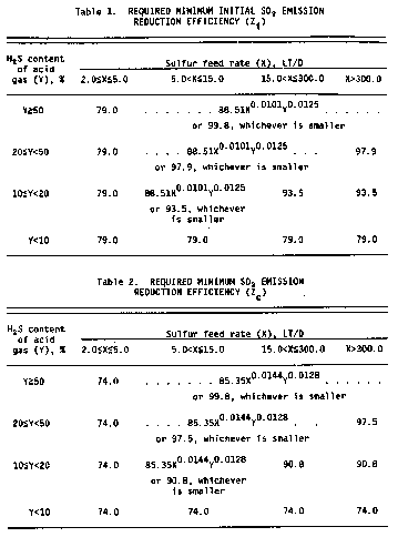
§ 60.643 Compliance provisions.
(a)
(1) To determine compliance with the standards for sulfur dioxide specified in § 60.642(a), during the initial performance test as required by § 60.8, the minimum required sulfur dioxide emission reduction efficiency (Z) is compared to the emission reduction efficiency (R) achieved by the sulfur recovery technology.
(i) If R ≥ Zi, the affected facility is in compliance.
(ii) If R < Zi, the affected facility is not in compliance.
(2) Following the initial determination of compliance as required by § 60.8, any subsequent compliance determinations that may be required by the Administrator would compare R to Zc.
(b) The emission reduction efficiency (R) achieved by the sulfur reduction technology shall be determined using the procedures in § 60.644(c)(1).
[50 FR 40160, Oct. 1, 1985, as amended at 54 FR 6679, Feb. 14, 1989]
§ 60.644 Test methods and procedures.
(a) In conducting the performance tests required in § 60.8, the owner or operator shall use as reference methods and procedures the test methods in appendix A of this part or other methods and procedures as specified in this section, except as provided in paragraph § 60.8(b).
(b) During a performance test required by § 60.8, the owner or operator shall determine the minimum required reduction efficiencies (Z) of SO2 emissions as required in § 60.642 (a) and (b) as follows:
(1) The average sulfur feed rate (X) shall be computed as follows:

Where:
X = average sulfur feed rate, Mg/D (LT/D).
Qa = average volumetric flow rate of acid gas from sweetening unit, dscm/day (dscf/day).
Y = average H2S concentration in acid gas feed from sweetening unit, percent by volume, expressed as a decimal.
K = (32 kg S/kg-mole)/((24.04 dscm/kg-mole)(1000 kg S/ Mg)) = 1.331 × 10⁻³ Mg/dscm, for metric units
= (32 lb S/lb-mole)/((385.36 dscf/lb-mole)(2240 lb S/long ton))
= 3.707 × 10⁻⁵ long ton/dscf, for English units.
(2) The continuous readings from the process flowmeter shall be used to determine the average volumetric flow rate (Qa) in dscm/day (dscf/day) of the acid gas from the sweetening unit for each run.
(3) The Tutwiler procedure in § 60.648 or a chromatographic procedure following ASTM E-260 (incorporated by reference—see § 60.17) shall be used to determine the H2S concentration in the acid gas feed from the sweetening unit. At least one sample per hour (at equally spaced intervals) shall be taken during each 4-hour run. The arithmetic mean of all samples shall be the average H2S concentration (Y) on a dry basis for the run. By multiplying the result from the Tutwiler procedure by 1.62 × 10⁻³, the units gr/100 scf are converted to volume percent.
(4) Using the information from paragraphs (b) (1) and (3), tables 1 and 2 shall be used to determine the required initial (Zi) and continuous (Zc) reduction efficiencies of SO2 emissions.
(c) The owner or operator shall determine compliance with the SO2 standards in § 60.642 (a) or (b) as follows:
(1) The emission reduction efficiency (R) achieved by the sulfur recovery technology shall be computed for each run using the following equation:
R = (100 S)/(S + E)
(2) The level indicators or manual soundings shall be used to measure the liquid sulfur accumulation rate in the product storage tanks. Readings taken at the beginning and end of each run, the tank geometry, sulfur density at the storage temperature, and sample duration shall be used to determine the sulfur production rate (S) in kg/hr (lb/hr) for each run.
(3) The emission rate of sulfur shall be computed for each run as follows:

Where:
E = emission rate of sulfur per run, kg/hr.
Ce = concentration of sulfur equivalent (SO2 + reduced sulfur), g/dscm (lb/dscf).
Qsd = volumetric flow rate of effluent gas, dscm/hr (dscf/hr).
K1 = conversion factor, 1000 g/kg (7000 gr/lb).
(4) The concentration (Ce) of sulfur equivalent shall be the sum of the SO2 and TRS concentrations, after being converted to sulfur equivalents. For each run and each of the test methods specified in this paragraph (c) of this section, the sampling time shall be at least 4 hours. Method 1 shall be used to select the sampling site. The sampling point in the duct shall be at the centroid of the cross-section if the area is less than 5 m2 (54 ft2) or at a point no closer to the walls than 1 m (39 in.) if the cross-sectional area is 5 m2 or more, and the centroid is more than 1 m (39 in.) from the wall.
(i) Method 6 shall be used to determine the SO2 concentration. Eight samples of 20 minutes each shall be taken at 30-minute intervals. The arithmetic average shall be the concentration for the run. The concentration shall be multiplied by 0.5 × 10⁻³ to convert the results to sulfur equivalent.
(ii) Method 15 shall be used to determine the TRS concentration from reduction-type devices or where the oxygen content of the effluent gas is less than 1.0 percent by volume. The sampling rate shall be at least 3 liters/min (0.1 ft3/min) to insure minimum residence time in the sample line. Sixteen samples shall be taken at 15-minute intervals. The arithmetic average of all the samples shall be the concentration for the run. The concentration in ppm reduced sulfur as sulfur shall be multiplied by 1.333 × 10⁻³ to convert the results to sulfur equivalent.
(iii) Method 16A or 15 shall be used to determine the reduced sulfur concentration from oxidation-type devices or where the oxygen content of the effluent gas is greater than 1.0 percent by volume. Eight samples of 20 minutes each shall be taken at 30-minute intervals. The arithmetic average shall be the concentration for the run. The concentration in ppm reduced sulfur as sulfur shall be multiplied by 1.333 × 10⁻³ to convert the results to sulfur equivalent.
(iv) Method 2 shall be used to determine the volumetric flow rate of the effluent gas. A velocity traverse shall be conducted at the beginning and end of each run. The arithmetic average of the two measurements shall be used to calculate the volumetric flow rate (Qsd) for the run. For the determination of the effluent gas molecular weight, a single integrated sample over the 4-hour period may be taken and analyzed or grab samples at 1-hour intervals may be taken, analyzed, and averaged. For the moisture content, two samples of at least 0.10 dscm (3.5 dscf) and 10 minutes shall be taken at the beginning of the 4-hour run and near the end of the time period. The arithmetic average of the two runs shall be the moisture content for the run.
(d) To comply with § 60.646(d), the owner or operator shall obtain the information required by using the monitoring devices in paragraph (b) or (c) of this section.
[54 FR 6679, Feb. 14, 1989, as amended at 65 FR 61773, Oct. 17, 2000]
§ 60.645 [Reserved]
§ 60.646 Monitoring of emissions and operations.
(a) The owner or operator subject to the provisions of § 60.642 (a) or (b) shall install, calibrate, maintain, and operate monitoring devices or perform measurements to determine the following operations information on a daily basis:
(1) The accumulation of sulfur product over each 24-hour period: The monitoring method may incorporate the use of an instrument to measure and record the liquid sulfur production rate, or may be a procedure for measuring and recording the sulfur liquid levels in the storage tanks with a level indicator or by manual soundings, with subsequent calculation of the sulfur production rate based on the tank geometry, stored sulfur density, and elapsed time between readings. The method shall be designed to be accurate within ±2 percent of the 24-hour sulfur accumulation.
(2) The H2S concentration in the acid gas from the sweetening unit for each 24-hour period: At least one sample per 24-hour period shall be collected and analyzed using the method specified in § 60.644(b)(1). The Administrator may require the owner or operator to demonstrate that the H2S concentration obtained from one or more samples over a 24-hour period is within ±20 percent of the average of 12 samples collected at equally spaced intervals during the 24-hour period. In instances where the H2S concentration of a single sample is not within ±20 percent of the average of the 12 equally spaced samples, the Administrator may require a more frequent sampling schedule.
(3) The average acid gas flow rate from the sweetening unit: The owner or operator shall install and operate a monitoring device to continuously measure the flow rate of acid gas. The monitoring device reading shall be recorded at least once per hour during each 24-hour period. The average acid gas flow rate shall be computed from the individual readings.
(4) The sulfur feed rate (X): For each 24-hour period, X shall be computed using the equation in § 60.644(b)(3).
(5) The required sulfur dioxide emission reduction efficiency for the 24-hour period: The sulfur feed rate and the H2S concentration in the acid gas for the 24-hour period as applicable, shall be used to determine the required reduction efficiency in accordance with the provisions of § 60.642(b).
(b) Where compliance is achieved through the use of an oxidation control system or a reduction control system followed by a continually operated incineration device, the owner or operator shall install, calibrate, maintain, and operate monitoring devices and continuous emission monitors as follows:
(1) A continuous monitoring system to measure the total sulfur emission rate (E) of SO2 in the gases discharged to the atmosphere. The SO2 emission rate shall be expressed in terms of equivalent sulfur mass flow rates (kg/hr (lb/hr)). The span of this monitoring system shall be set so that the equivalent emission limit of § 60.642(b) will be between 30 percent and 70 percent of the measurement range of the instrument system.
(2) Except as provided in paragraph (b)(3) of this section: A monitoring device to measure the temperature of the gas leaving the combustion zone of the incinerator, if compliance with § 60.642(a) is achieved through the use of an oxidation control system or a reduction control system followed by a continually operated incineration device. The monitoring device shall be certified by the manufacturer to be accurate to within ±1 percent of the temperature being measured.
When performance tests are conducted under the provision of § 60.8 to demonstrate compliance with the standards under § 60.642, the temperature of the gas leaving the incinerator combustion zone shall be determined using the monitoring device. If the volumetric ratio of sulfur dioxide to sulfur dioxide plus total reduced sulfur (expressed as SO2) in the gas leaving the incinerator is ≤0.98, then temperature monitoring may be used to demonstrate that sulfur dioxide emission monitoring is sufficient to determine total sulfur emissions. At all times during the operation of the facility, the owner or operator shall maintain the average temperature of the gas leaving the combustion zone of the incinerator at or above the appropriate level determined during the most recent performance test to ensure the sulfur compound oxidation criteria are met. Operation at lower average temperatures may be considered by the Administrator to be unacceptable operation and maintenance of the affected facility. The owner or operator may request that the minimum incinerator temperature be reestablished by conducting new performance tests under § 60.8.
(3) Upon promulgation of a performance specification of continuous monitoring systems for total reduced sulfur compounds at sulfur recovery plants, the owner or operator may, as an alternative to paragraph (b)(2) of this section, install, calibrate, maintain, and operate a continuous emission monitoring system for total reduced sulfur compounds as required in paragraph (d) of this section in addition to a sulfur dioxide emission monitoring system. The sum of the equivalent sulfur mass emission rates from the two monitoring systems shall be used to compute the total sulfur emission rate (E).
(c) Where compliance is achieved through the use of a reduction control system not followed by a continually operated incineration device, the owner or operator shall install, calibrate, maintain, and operate a continuous monitoring system to measure the emission rate of reduced sulfur compounds as SO2 equivalent in the gases discharged to the atmosphere. The SO2 equivalent compound emission rate shall be expressed in terms of equivalent sulfur mass flow rates (kg/hr (lb/hr)). The span of this monitoring system shall be set so that the equivalent emission limit of § 60.642(b) will be between 30 and 70 percent of the measurement range of the system. This requirement becomes effective upon promulgation of a performance specification for continuous monitoring systems for total reduced sulfur compounds at sulfur recovery plants.
(d) For those sources required to comply with paragraph (b) or (c) of this section, the average sulfur emission reduction efficiency achieved (R) shall be calculated for each 24-hour clock internal. The 24-hour interval may begin and end at any selected clock time, but must be consistent. The 24-hour average reduction efficiency (R) shall be computed based on the 24-hour average sulfur production rate (S) and sulfur emission rate (E), using the equation in § 60.644(c)(1).
(1) Data obtained from the sulfur production rate monitoring device specified in paragraph (a) of this section shall be used to determine S.
(2) Data obtained from the sulfur emission rate monitoring systems specified in paragraphs (b) or (c) of this section shall be used to calculate a 24-hour average for the sulfur emission rate (E). The monitoring system must provide at least one data point in each successive 15-minute interval. At least two data points must be used to calculate each 1-hour average. A minimum of 18 1-hour averages must be used to compute each 24-hour average.
(e) In lieu of complying with (b) or (c) of this section, those sources with a design capacity of less than 152 Mg/D (150 LT/D) of H2S expressed as sulfur may calculate the sulfur emission reduction efficiency achieved for each 24-hour period by:

Where:
R = The sulfur dioxide removal efficiency achieved during the 24-hour period, percent.
K2 = Conversion factor, 0.02400 Mg/D per kg/hr (0.01071 LT/D per lb/hr).
S = The sulfur production rate during the 24-hour period, kg/hr (lb/hr).
X = The sulfur feed rate in the acid gas, Mg/D (LT/D).
(f) The monitoring devices required in paragraphs (b)(1), (b)(3) and (c) of this section shall be calibrated at least annually according to the manufacturer's specifications, as required by § 60.13(b).
(g) The continuous emission monitoring systems required in paragraphs (b)(1), (b)(3), and (c) of this section shall be subject to the emission monitoring requirements of § 60.13 of the General Provisions. For conducting the continuous emission monitoring system performance evaluation required by § 60.13(c), Performance Specification 2 shall apply, and Method 6 shall be used for systems required by paragraph (b) of this section.
[50 FR 40160, Oct. 1, 1985, as amended at 54 FR 6680, Feb. 14, 1989; 65 FR 61774, Oct. 17, 2000]
§ 60.647 Recordkeeping and reporting requirements.
(a) Records of the calculations and measurements required in §§ 60.642 (a) and (b) and 60.646 (a) through (g) must be retained for at least 2 years following the date of the measurements by owners and operators subject to this subpart. This requirement is included under § 60.7(d) of the General Provisions.
(b) Each owner or operator shall submit a written report of excess emissions to the Administrator semiannually. For the purpose of these reports, excess emissions are defined as:
(1) Any 24-hour period (at consistent intervals) during which the average sulfur emission reduction efficiency (R) is less than the minimum required efficiency (Z).
(2) For any affected facility electing to comply with the provisions of § 60.646(b)(2), any 24-hour period during which the average temperature of the gases leaving the combustion zone of an incinerator is less than the appropriate operating temperature as determined during the most recent performance test in accordance with the provisions of § 60.646(b)(2). Each 24-hour period must consist of at least 96 temperature measurements equally spaced over the 24 hours.
(c) To certify that a facility is exempt from the control requirements of these standards, each owner or operator of a facility with a design capacity less that 2 LT/D of H2S in the acid gas (expressed as sulfur) shall keep, for the life of the facility, an analysis demonstrating that the facility's design capacity is less than 2 LT/D of H2S expressed as sulfur.
(d) Each owner or operator who elects to comply with § 60.646(e) shall keep, for the life of the facility, a record demonstrating that the facility's design capacity is less than 150 LT/D of H2S expressed as sulfur.
(e) The requirements of paragraph (b) of this section remain in force until and unless EPA, in delegating enforcement authority to a State under section 111(c) of the Act, approves reporting requirements or an alternative means of compliance surveillance adopted by such State. In that event, affected sources within the State will be relieved of obligation to comply with paragraph (b) of this section, provided that they comply with the requirements established by the State.
§ 60.648 Optional procedure for measuring hydrogen sulfide in acid gas—Tutwiler Procedure.[1]
(a) When an instantaneous sample is desired and H2S concentration is ten grains per 1000 cubic foot or more, a 100 ml Tutwiler burette is used. For concentrations less than ten grains, a 500 ml Tutwiler burette and more dilute solutions are used. In principle, this method consists of titrating hydrogen sulfide in a gas sample directly with a standard solution of iodine.
(b) Apparatus. (See Figure 1.) A 100 or 500 ml capacity Tutwiler burette, with two-way glass stopcock at bottom and three-way stopcock at top which connect either with inlet tubulature or glass-stoppered cylinder, 10 ml capacity, graduated in 0.1 ml subdivision; rubber tubing connecting burette with leveling bottle.
(c) Reagents.
(1) Iodine stock solution, 0.1N. Weight 12.7 g iodine, and 20 to 25 g cp potassium iodide for each liter of solution. Dissolve KI in as little water as necessary; dissolve iodine in concentrated KI solution, make up to proper volume, and store in glass-stoppered brown glass bottle.
(2) Standard iodine solution, 1 ml = 0.001771 g I. Transfer 33.7 ml of above 0.1N stock solution into a 250 ml volumetric flask; add water to mark and mix well. Then, for 100 ml sample of gas, 1 ml of standard iodine solution is equivalent to 100 grains H2S per cubic feet of gas.
(3) Starch solution. Rub into a thin paste about one teaspoonful of wheat starch with a little water; pour into about a pint of boiling water; stir; let cool and decant off clear solution. Make fresh solution every few days.
(d) Procedure. Fill leveling bulb with starch solution. Raise (L), open cock (G), open (F) to (A), and close (F) when solutions starts to run out of gas inlet. Close (G). Purge gas sampling line and connect with (A). Lower (L) and open (F) and (G). When liquid level is several ml past the 100 ml mark, close (G) and (F), and disconnect sampling tube. Open (G) and bring starch solution to 100 ml mark by raising (L); then close (G). Open (F) momentarily, to bring gas in burette to atmospheric pressure, and close (F). Open (G), bring liquid level down to 10 ml mark by lowering (L). Close (G), clamp rubber tubing near (E) and disconnect it from burette. Rinse graduated cylinder with a standard iodine solution (0.00171 g I per ml); fill cylinder and record reading. Introduce successive small amounts of iodine thru (F); shake well after each addition; continue until a faint permanent blue color is obtained. Record reading; subtract from previous reading, and call difference D.
(e) With every fresh stock of starch solution perform a blank test as follows: introduce fresh starch solution into burette up to 100 ml mark. Close (F) and (G). Lower (L) and open (G). When liquid level reaches the 10 ml mark, close (G). With air in burette, titrate as during a test and up to same end point. Call ml of iodine used C. Then,
Grains H2S per 100 cubic foot of gas = 100 (D—C)
(f) Greater sensitivity can be attained if a 500 ml capacity Tutwiler burette is used with a more dilute (0.001N) iodine solution. Concentrations less than 1.0 grains per 100 cubic foot can be determined in this way. Usually, the starch-iodine end point is much less distinct, and a blank determination of end point, with H2S-free gas or air, is required.
 Figure 1. Tutwiler burette (lettered items mentioned in text)
Subpart MMM [Reserved]
Subpart NNN - Standards of Performance for Volatile Organic Compound (VOC) Emissions From Synthetic Organic Chemical Manufacturing Industry (SOCMI) Distillation Operations
Source:
55 FR 26942, June 29, 1990, unless otherwise noted.
§ 60.660 Applicability and designation of affected facility.
(a) The provisions of this subpart apply to each affected facility designated in paragraph (b) of this section that is part of a process unit that produces any of the chemicals listed in § 60.667 as a product, co-product, by-product, or intermediate, except as provided in paragraph (c).
(b) The affected facility is any of the following for which construction, modification, or reconstruction commenced after December 30, 1983:
(1) Each distillation unit not discharging its vent stream into a recovery system.
(2) Each combination of a distillation unit and the recovery system into which its vent stream is discharged.
(3) Each combination of two or more distillation units and the common recovery system into which their vent streams are discharged.
(c) Exemptions from the provisions of paragraph (a) of this section are as follows:
(1) Any distillation unit operating as part of a process unit which produces coal tar or beverage alcohols, or which uses, contains, and produces no VOC is not an affected facility.
(2) Any distillation unit that is subject to the provisions of subpart DDD is not an affected facility.
(3) Any distillation unit that is designed and operated as a batch operation is not an affected facility.
(4) Each affected facility that has a total resource effectiveness (TRE) index value greater than 8.0 is exempt from all provisions of this subpart except for §§ 60.662; 60.664 (e), (f), and (g); and 60.665 (h) and (l).
(5) Each affected facility in a process unit with a total design capacity for all chemicals produced within that unit of less than one gigagram per year is exempt from all provisions of this subpart except for the recordkeeping and reporting requirements in paragraphs (j), (l)(6), and (n) of § 60.665.
(6) Each affected facility operated with a vent stream flow rate less than 0.008 scm/min is exempt from all provisions of this subpart except for the test method and procedure and the recordkeeping and reporting requirements in § 60.664(g) and paragraphs (i), (l)(5), and (o) of § 60.665.
(d) Alternative means of compliance —
(1) Option to comply with part 65. Owners or operators of process vents that are subject to this subpart may choose to comply with the provisions of 40 CFR part 65, subpart D, to satisfy the requirements of §§ 60.662 through 60.665 and 60.668. The provisions of 40 CFR part 65 also satisfy the criteria of paragraphs (c)(4) and (6) of this section. Other provisions applying to an owner or operator who chooses to comply with 40 CFR part 65 are provided in 40 CFR 65.1.
(2) Part 60, subpart A. Owners or operators who choose to comply with 40 CFR part 65, subpart D, must also comply with §§ 60.1, 60.2, 60.5, 60.6, 60.7(a)(1) and (4), 60.14, 60.15, and 60.16 for those process vents. All sections and paragraphs of subpart A of this part that are not mentioned in this paragraph (d)(2) do not apply to owners or operators of process vents complying with 40 CFR part 65, subpart D, except that provisions required to be met prior to implementing 40 CFR part 65 still apply. Owners and operators who choose to comply with 40 CFR part 65, subpart D, must comply with 40 CFR part 65, subpart A.
(3) Compliance date. Owners or operators who choose to comply with 40 CFR part 65, subpart D, at initial startup shall comply with paragraphs (d)(1) and (2) of this section for each vent stream on and after the date on which the initial performance test is completed, but not later than 60 days after achieving the maximum production rate at which the affected facility will be operated, or 180 days after the initial startup, whichever date comes first.
(4) Initial startup notification. Each owner or operator subject to the provisions of this subpart that chooses to comply with 40 CFR part 65, subpart D, at initial startup shall notify the Administrator of the specific provisions of 40 CFR 65.63(a)(1), (2), or (3), with which the owner or operator has elected to comply. Notification shall be submitted with the notifications of initial startup required by 40 CFR 65.5(b).
The intent of these standards is to minimize the emissions of VOC through the application of best demonstrated technology (BDT). The numerical emission limits in these standards are expressed in terms of total organic compounds (TOC), measured as TOC less methane and ethane. This emission limit reflects the performance of BDT.
[55 FR 26942, June 29, 2000, as amended at 65 FR 78279, Dec. 14, 2000; 79 FR 11251, Feb. 27, 2014]
§ 60.661 Definitions.
As used in this subpart, all terms not defined here shall have the meaning given them in the Act and in subpart A of part 60, and the following terms shall have the specific meanings given them.
Batch distillation operation means a noncontinuous distillation operation in which a discrete quantity or batch of liquid feed is charged into a distillation unit and distilled at one time. After the initial charging of the liquid feed, no additional liquid is added during the distillation operation.
Boiler means any enclosed combustion device that extracts useful energy in the form of steam.
By compound means by individual stream components, not carbon equivalents.
Continuous recorder means a data recording device recording an instantaneous data value at least once every 15 minutes.
Distillation operation means an operation separating one or more feed stream(s) into two or more exit stream(s), each exit stream having component concentrations different from those in the feed stream(s). The separation is achieved by the redistribution of the components between the liquid and vapor-phase as they approach equilibrium within the distillation unit.
Distillation unit means a device or vessel in which distillation operations occur, including all associated internals (such as trays or packing) and accessories (such as reboiler, condenser, vacuum pump, steam jet, etc.), plus any associated recovery system.
Flame zone means the portion of the combustion chamber in a boiler occupied by the flame envelope.
Flow indicator means a device which indicates whether gas flow is present in a vent stream.
Halogenated vent stream means any vent stream determined to have a total concentration (by volume) of compounds containing halogens of 20 ppmv (by compound) or greater.
Incinerator means any enclosed combustion device that is used for destroying organic compounds and does not extract energy in the form of steam or process heat.
Process heater means a device that transfers heat liberated by burning fuel to fluids contained in tubes, including all fluids except water that is heated to produce steam.
Process unit means equipment assembled and connected by pipes or ducts to produce, as intermediates or final products, one or more of the chemicals in § 60.667. A process unit can operate independently if supplied with sufficient fuel or raw materials and sufficient product storage facilities.
Product means any compound or chemical listed in § 60.667 that is produced for sale as a final product as that chemical, or for use in the production of other chemicals or compounds. By-products, co-products, and intermediates are considered to be products.
Recovery device means an individual unit of equipment, such as an absorber, carbon adsorber, or condenser, capable of and used for the purpose of recovering chemicals for use, reuse, or sale.
Recovery system means an individual recovery device or series of such devices applied to the same vent stream.
Total organic compounds (TOC) means those compounds measured according to the procedures in § 60.664(b)(4). For the purposes of measuring molar composition as required in § 60.664(d)(2)(i); hourly emissions rate as required in § 60.664(d)(5) and § 60.664(e); and TOC concentration as required in § 60.665(b)(4) and § 60.665(g)(4), those compounds which the Administrator has determined do not contribute appreciably to the formation of ozone are to be excluded. The compounds to be excluded are identified in Environmental Protection Agency's statements on ozone abatement policy for State Implementation Plans (SIP) revisions (42 FR 35314; 44 FR 32042; 45 FR 32424; 45 FR 48942).
TRE index value means a measure of the supplemental total resource requirement per unit reduction of TOC associated with an individual distillation vent stream, based on vent stream flow rate, emission rate of TOC net heating value, and corrosion properties (whether or not the vent stream is halogenated), as quantified by the equation given under § 60.664(e).
Vent stream means any gas stream discharged directly from a distillation facility to the atmosphere or indirectly to the atmosphere after diversion through other process equipment. The vent stream excludes relief valve discharges and equipment leaks including, but not limited to, pumps, compressors, and valves.
§ 60.662 Standards.
Each owner or operator of any affected facility shall comply with paragraph (a), (b), or (c) of this section for each vent stream on and after the date on which the initial performance test required by §§ 60.8 and 60.664 is completed, but not later than 60 days after achieving the maximum production rate at which the affected facility will be operated, or 180 days after the initial start-up, whichever date comes first. Each owner or operator shall either:
(a) Reduce emissions of TOC (less methane and ethane) by 98 weight-percent, or to a TOC (less methane and ethane) concentration of 20 ppmv, on a dry basis corrected to 3 percent oxygen, whichever is less stringent. If a boiler or process heater is used to comply with this paragraph, then the vent stream shall be introduced into the flame zone of the boiler or process heater; or
(b) Combust the emissions in a flare that meets the requirements of § 60.18; or
(c) Maintain a TRE index value greater than 1.0 without use of VOC emission control devices.
§ 60.663 Monitoring of emissions and operations.
(a) The owner or operator of an affected facility that uses an incinerator to seek to comply with the TOC emission limit specified under § 60.662(a) shall install, calibrate, maintain, and operate according to manufacturer's specifications the following equipment:
(1) A temperature monitoring device equipped with a continuous recorder and having an accuracy of ±1 percent of the temperature being monitored expressed in degrees Celsius or ±0.5 °C, whichever is greater.
(i) Where an incinerator other than a catalytic incinerator is used, a temperature monitoring device shall be installed in the firebox.
(ii) Where a catalytic incinerator is used, temperature monitoring devices shall be installed in the gas stream immediately before and after the catalyst bed.
(2) A flow indicator that provides a record of vent stream flow to the incinerator at least once every hour for each affected facility. The flow indicator shall be installed in the vent stream from each affected facility at a point closest to the inlet of each incinerator and before being joined with any other vent stream.
(b) The owner or operator of an affected facility that uses a flare to seek to comply with § 60.662(b) shall install, calibrate, maintain and operate according to manufacturer's specifications the following equipment:
(1) A heat sensing device, such as an ultra-violet beam sensor or thermocouple, at the pilot light to indicate the continuous presence of a flame.
(2) A flow indicator that provides a record of vent stream flow to the flare at least once every hour for each affected facility. The flow indicator shall be installed in the vent stream from each affected facility at a point closest to the flare and before being joined with any other vent stream.
(c) The owner or operator of an affected facility that uses a boiler or process heater to seek to comply with § 60.662(a) shall install, calibrate, maintain and operate according to the manufacturer's specifications the following equipment:
(1) A flow indicator that provides a record of vent stream flow to the boiler or process heater at least once every hour for each affected facility. The flow indicator shall be installed in the vent stream from each distillation unit within an affected facility at a point closest to the inlet of each boiler or process heater and before being joined with any other vent stream.
(2) A temperature monitoring device in the firebox equipped with a continuous recorder and having an accuracy of ±1 percent of the temperature being measured expressed in degrees Celsius or ±0.5 °C, whichever is greater, for boilers or process heaters of less than 44 MW (150 million Btu/hr) heat input design capacity.
(d) Monitor and record the periods of operation of the boiler or process heater if the design heat input capacity of the boiler or process heater is 44 MW (150 million Btu/hr) or greater. The records must be readily available for inspection.
(e) The owner or operator of an affected facility that seeks to comply with the TRE index value limit specified under § 60.662(c) shall install, calibrate, maintain, and operate according to manufacturer's specifications the following equipment, unless alternative monitoring procedures or requirements are approved for that facility by the Administrator:
(1) Where an absorber is the final recovery device in the recovery system:
(i) A scrubbing liquid temperature monitoring device having an accuracy of ±1 percent of the temperature being monitored expressed in degrees Celsius or ±0.5 °C, whichever is greater, and a specific gravity monitoring device having an accuracy of ±0.02 specific gravity units, each equipped with a continuous recorder, or
(ii) An organic monitoring device used to indicate the concentration level of organic compounds exiting the recovery device based on a detection principle such as infrared, photoionization, or thermal conductivity, each equipped with a continuous recorder.
(2) Where a condenser is the final recovery device in the recovery system:
(i) A condenser exit (product side) temperature monitoring device equipped with a continuous recorder and having an accuracy of ±1 percent of the temperature being monitored expressed in degrees Celsius or ±0.5 °C, whichever is greater, or
(ii) An organic monitoring device used to monitor organic compounds exiting the recovery device based on a detection principle such as infra-red, photoionization, or thermal conductivity, each equipped with a continuous recorder.
(3) Where a carbon adsorber is the final recovery device unit in the recovery system:
(i) An integrating steam flow monitoring device having an accuracy of ±10 percent, and a carbon bed temperature monitoring device having an accuracy of ±1 percent of the temperature being monitored expressed in degrees Celsius or ±0.5 °C, whichever is greater, both equipped with a continuous recorder, or
(ii) An organic monitoring device used to indicate the concentration level of organic compounds exiting the recovery device based on a detection principle such as infra-red, photoionization, or thermal conductivity, each equipped with a continuous recorder.
(f) An owner or operator of an affected facility seeking to demonstrate compliance with the standards specified under § 60.662 with control devices other than incinerator, boiler, process heater, or flare; or recovery device other than an absorber, condenser, or carbon adsorber shall provide to the Administrator information describing the operation of the control device or recovery device and the process parameter(s) which would indicate proper operation and maintenance of the device. The Administrator may request further information and will specify appropriate monitoring procedures or requirements.
[55 FR 26942, June 29, 1990, as amended at 65 FR 61774, Oct. 17, 2000]
§ 60.664 Test methods and procedures.
(a) For the purpose of demonstrating compliance with § 60.662, all affected facilities shall be run at full operating conditions and flow rates during any performance test.
(b) The following methods in appendix A to this part, except as provided under § 60.8(b), shall be used as reference methods to determine compliance with the emission limit or percent reduction efficiency specified under § 60.662(a).
(1) Method 1 or 1A, as appropriate, for selection of the sampling sites. The control device inlet sampling site for determination of vent stream molar composition or TOC (less methane and ethane) reduction efficiency shall be prior to the inlet of the control device and after the recovery system.
(2) Method 2, 2A, 2C, or 2D, as appropriate, for determination of the gas volumetric flow rates.
(3) The emission rate correction factor, integrated sampling and analysis procedure of Method 3 shall be used to determine the oxygen concentration (%O2d) for the purposes of determining compliance with the 20 ppmv limit. The sampling site shall be the same as that of the TOC samples, and the samples shall be taken during the same time that the TOC samples are taken.
The TOC concentration corrected to 3 percent 02 (Cc) shall be computed using the following equation:

where:
Cc = Concentration of TOC corrected to 3 percent O2, dry basis, ppm by volume.
CTOC = Concentration of TOC (minus methane and ethane), dry basis, ppm by volume.
%O2d = Concentration of O2, dry basis, percent by volume.
(4) Method 18 to determine the concentration of TOC in the control device outlet and the concentration of TOC in the inlet when the reduction efficiency of the control device is to be determined.
(i) The sampling time for each run shall be 1 hour in which either an integrated sample or four grab samples shall be taken. If grab sampling is used then the samples shall be taken at 15-minute intervals.
(ii) The emission reduction (R) of TOC (minus methane and ethane) shall be determined using the following equation:

where:
R = Emission reduction, percent by weight.
Ei = Mass rate of TOC entering the control device, kg/hr (lb/hr).
Eo = Mass rate of TOC discharged to the atmosphere, kg/hr (lb/hr).
(iii) The mass rates of TOC (Ei, Eo) shall be computed using the following equations:

where:
Cij, Coj = Concentration of sample component “j” of the gas stream at the inlet and outlet of the control device, respectively, dry basis, ppm by volume.
Mij, Moj = Molecular weight of sample component “j” of the gas stream at the inlet and outlet of the control device, respectively, g/g-mole (lb/lb-mole).
Qi, Qo = Flow rate of gas stream at the inlet and outlet of the control device, respectively, dscm/min (dscf/min).
K2 = 2.494 × 10⁻⁶ (1/ppm)(g-mole/scm) (kg/g) (min/hr) (metric units), where standard temperature for (g-mole/scm) is 20 °C.
= 1.557 × 10⁻⁷ (1/ppm) (lb-mole/scf) (min/hr) (English units), where standard temperature for (lb-mole/scf) is 68 °F.
(iv) The TOC concentration (CTOC) is the sum of the individual components and shall be computed for each run using the following equation:

where:
CTOC = Concentration of TOC (minus methane and ethane), dry basis, ppm by volume.
Cj = Concentration of sample components “j”, dry basis, ppm by volume.
n = Number of components in the sample.
(c) When a boiler or process heater with a design heat input capacity of 44 MW (150 million Btu/hour) or greater is used to seek to comply with § 60.662(a), the requirement for an initial performance test is waived, in accordance with § 60.8(b). However, the Administrator reserves the option to require testing at such other times as may be required, as provided for in section 114 of the Act.
(d) When a flare is used to seek to comply with § 60.662(b), the flare shall comply with the requirements of § 60.18.
(e) The following test methods in appendix A to this part, except as provided under § 60.8(b), shall be used for determining the net heating value of the gas combusted to determine compliance under § 60.662(b) and for determining the process vent stream TRE index value to determine compliance under § 60.662(c).
(1)
(i) Method 1 or 1A, as appropriate, for selection of the sampling site. The sampling site for the vent stream flow rate and molar composition determination prescribed in § 60.664(e)(2) and (3) shall be, except for the situations outlined in paragraph (e)(1)(ii) of this section, prior to the inlet of any control device, prior to any post-distillation dilution of the stream with air, and prior to any post-distillation introduction of halogenated compounds into the process vent stream. No transverse site selection method is needed for vents smaller than 10 centimeters (4 inches) in diameter.
(ii) If any gas stream other than the distillation vent stream from the affected facility is normally conducted through the final recovery device.
(A) The sampling site for vent stream flow rate and molar composition shall be prior to the final recovery device and prior to the point at which the nondistillation stream is introduced.
(B) The efficiency of the final recovery device is determined by measuring the TOC concentration using Method 18 at the inlet to the final recovery device after the introduction of any nondistillation vent stream and at the outlet of the final recovery device.
(C) This efficiency is applied to the TOC concentration measured prior to the final recovery device and prior to the introduction of the nondistillation stream to determine the concentration of TOC in the distillation vent stream from the final recovery device. This concentration of TOC is then used to perform the calculations outlined in § 60.664(e)(4) and (5).
(2) The molar composition of the process vent stream shall be determined as follows:
(i) Method 18 to measure the concentration of TOC including those containing halogens.
(ii) ASTM D1946-77 or 90 (Reapproved 1994) (incorporation by reference as specified in § 60.17 of this part) to measure the concentration of carbon monoxide and hydrogen.
(iii) Method 4 to measure the content of water vapor.
(3) The volumetric flow rate shall be determined using Method 2, 2A, 2C, or 2D, as appropriate.
(4) The net heating value of the vent stream shall be calculated using the following equation:

where:
HT = Net heating value of the sample, MJ/scm (Btu/scf), where the net enthalpy per mole of vent stream is based on combustion at 25 °C and 760 mm Hg (77 °F and 30 in. Hg), but the standard temperature for determining the volume corresponding to one mole is 20 °C (68 °F).
K1 = 1.74 × 10⁻⁷ (1/ppm) (g-mole/scm) (MJ/kcal) (metric units), where standard temperature for (g-mole/scm) is 20 °C.
= 1.03 × 10⁻¹¹ (1/ppm) (lb-mole/scf) (Btu/kcal) (English units) where standard temperature for (lb/mole/scf) is 68 °F.
Cj = Concentration on a wet basis of compound j in ppm, as measured for organics by Method 18 and measured for hydrogen and carbon monoxide by ASTM D1946-77 or 90 (Reapproved 1994) (incorporation by reference as specified in § 60.17 of this part) as indicated in § 60.664(e)(2).
Hj = Net heat of combustion of compound j, kcal/(g-mole) [kcal/(lb-mole)], based on combustion at 25 °C and 760 mm Hg (77 °F and 30 in. Hg).
The heats of combustion of vent stream components would be required to be determined using ASTM D2382-76 (incorporation by reference as specified in § 60.17 of this part) if published values are not available or cannot be calculated.
(5) The emission rate of TOC in the vent stream shall be calculated using the following equation:

where:
ETOC = Measured emission rate of TOC, kg/hr (lb/hr).
K2 = 2.494 × 10⁻⁶ (1/ppm) (g-mole/scm) (kg/g) (min/hr) (metric units), where standard temperature for (g-mole/scm) is 20 °C.
= 1.557 × 10⁻⁷ (1/ppm) (lb-mole/scf) (min/hr) (English units), where standard temperature for (lb-mole/scf) is 68 °F.
Cj = Concentration on a wet basis of compound j in ppm, as measured by Method 18 as indicated in § 60.664(e)(2).
Mj = Molecular weight of sample j, g/g-mole (lb/lb-mole).
Qs = Vent stream flow rate, scm/min (scf/min), at a temperature of 20 °C (68 °F).
(6) The total process vent stream concentration (by volume) of compounds containing halogens (ppmv, by compound) shall be summed from the individual concentrations of compounds containing halogens which were measured by Method 18.
(f) For purposes of complying with § 60.662(c) the owner or operator of a facility affected by this subpart shall calculate the TRE index value of the vent stream using the equation for incineration in paragraph (e)(1) of this section for halogenated vent streams. The owner or operator of an affected facility with a nonhalogenated vent stream shall determine the TRE index value by calculating values using both the incinerator equation in (e)(1) and the flare equation in (e)(2) of this section and selecting the lower of the two values.
(1) The equation for calculating the TRE index value of a vent stream controlled by an incinerator is as follows:

(i) Where for a vent stream flow rate that is greater than or equal to 14.2 scm/min (501 scf/min) at a standard temperature of 20 °C (68 °F):
TRE = TRE index value.
Qs = Vent stream flow rate, scm/min (scf/min), at a temperature of 20 °C (68 °F).
HT = Vent stream net heating value, MJ/scm (Btu/scf), where the net enthalpy per mole of vent stream is based on combustion at 25 °C and 760 mm Hg (68 °F and 30 in. Hg), but the standard temperature for determining the volume corresponding to one mole is 20 °C (68 °F) as in the definition of Qs.
Ys = Qs for all vent stream categories listed in table 1 except for Category E vent streams where Ys = QsHT/3.6.
ETOC = Hourly emissions of TOC, kg/hr (lb/hr).
a, b, c, d, e, and f are coefficients.
The set of coefficients that apply to a vent stream can be obtained from table 1.
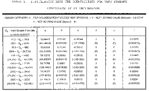
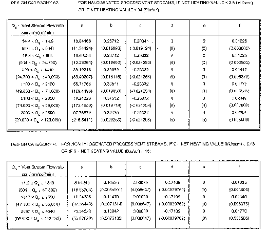
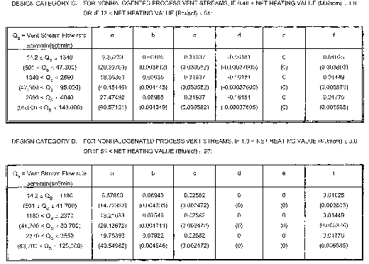

(ii) Where for a vent stream flow rate that is less than 14.2 scm/min (501 scf/min) at a standard temperature of 20 °C (68 °F):
TRE = TRE index value.
Qs = 14.2 scm/min (501 scf/min).
HT = (FLOW) (HVAL)/Qs.
Where the following inputs are used:
FLOW = Vent stream flow rate, scm/min (scf/min), at a temperature of 20 °C (68 °F).
HVAL = Vent stream net heating value, MJ/scm (Btu/scf), where the net enthalpy per mole of vent stream is based on combustion at 25 °C and 760 mm Hg (68 °F and 30 in. Hg), but the standard temperature for determining the volume corresponding to one mole is 20 °C (68 °F) as in the definition of Qs.
Ys = Qs for all vent stream categories listed in table 1 except for Category E vent streams where Ys = QsHT/3.6.
ETOC = Hourly emissions of TOC, kg/hr (lb/hr).
a, b, c, d, e, and f are coefficients
The set of coefficients that apply to a vent stream can be obtained from table 1.
(2) The equation for calculating the TRE index value of a vent stream controlled by a flare is as follows:

where:
TRE = TRE index value.
ETOC = Hourly emissions of TOC, kg/hr (lb/hr).
Qs = Vent stream flow rate, scm/min (scf/min), at a standard temperature of 20 °C (68 °F).
HT = Vent stream net heating value, MJ/scm (Btu/scf), where the net enthalpy per mole of vent stream is based on combustion at 25 °C and 760 mm Hg (68 °F and 30 in. Hg), but the standard temperature for determining the volume corresponding to one mole is 20 °C (68 °F) as in the definition of Qs.
a, b, c, d, and e are coefficients.
The set of coefficients that apply to a vent stream shall be obtained from table 2.
Table 2—Distillation NSPS TRE Coefficients for Vent Streams Controlled By a Flare
| a | b | c | d | e | |
|---|---|---|---|---|---|
| HT < 11.2 MJ/scm | 2.25 | 0.288 | −0.193 | −0.0051 | 2.08 |
| (HT < 301 Btu/scf) | (0.140) | (0.0367) | (−0.000448) | (−0.0051) | (4.59) |
| HT ≥ 11.2 MJ/scm | 0.309 | 0.0619 | −0.0043 | −0.0034 | 2.08 |
| (HT ≥ 301 Btu/scf) | (0.0193) | (0.00788) | (−0.0000010) | (−0.0034) | (4.59) |
(g) Each owner or operator of an affected facility seeking to comply with § 60.660(c)(4) or § 60.662(c) shall recalculate the TRE index value for that affected facility whenever process changes are made. Examples of process changes include changes in production capacity, feedstock type, or catalyst type, or whenever there is replacement, removal, or addition of recovery equipment. The TRE index value shall be recalculated based on test data, or on best engineering estimates of the effects of the change to the recovery system.
(1) Where the recalculated TRE index value is less than or equal to 1.0, the owner or operator shall notify the Administrator within 1 week of the recalculation and shall conduct a performance test according to the methods and procedures required by § 60.664 in order to determine compliance with § 60.662(a). Performance tests must be conducted as soon as possible after the process change but no later than 180 days from the time of the process change.
(2) Where the initial TRE index value is greater than 8.0 and the recalculated TRE index value is less than or equal to 8.0 but greater than 1.0, the owner or operator shall conduct a performance test in accordance with §§ 60.8 and 60.664 and shall comply with §§ 60.663, 60.664 and 60.665. Performance tests must be conducted as soon as possible after the process change but no later than 180 days from the time of the process change.
(h) Any owner or operator subject to the provisions of this subpart seeking to demonstrate compliance with § 60.660(c)(6) shall use Method 2, 2A, 2C, or 2D as appropriate, for determination of volumetric flow rate.
[55 FR 26942, June 29, 1990, as amended at 65 FR 61774, Oct. 17, 2000]
§ 60.665 Reporting and recordkeeping requirements.
(a) Each owner or operator subject to § 60.662 shall notify the Administrator of the specific provisions of § 60.662 (§ 60.662 (a), (b), or (c)) with which the owner or operator has elected to comply. Notification shall be submitted with the notification of initial start-up required by § 60.7(a)(3). If an owner or operator elects at a later date to use an alternative provision of § 60.662 with which he or she will comply, then the Administrator shall be notified by the owner or operator 90 days before implementing a change and, upon implementing the change, a performance test shall be performed as specified by § 60.664 within 180 days.
(b) Each owner or operator subject to the provisions of this subpart shall keep an up-to-date, readily accessible record of the following data measured during each performance test, and also include the following data in the report of the initial performance test required under § 60.8. Where a boiler or process heater with a design heat input capacity of 44 MW (150 million Btu/hour) or greater is used to comply with § 60.662(a), a report containing performance test data need not be submitted, but a report containing the information in § 60.665(b)(2)(i) is required. The same data specified in this section shall be submitted in the reports of all subsequently required performance tests where either the emission control efficiency of a control device, outlet concentration of TOC, or the TRE index value of a vent stream from a recovery system is determined.
(1) Where an owner or operator subject to the provisions of this subpart seeks to demonstrate compliance with § 60.662(a) through use of either a thermal or catalytic incinerator:
(i) The average firebox temperature of the incinerator (or the average temperature upstream and downstream of the catalyst bed for a catalytic incinerator), measured at least every 15 minutes and averaged over the same time period of the performance testing, and
(ii) The percent reduction of TOC determined as specified in § 60.664(b) achieved by the incinerator, or the concentration of TOC (ppmv, by compound) determined as specified in § 60.664(b) at the outlet of the control device on a dry basis corrected to 3 percent oxygen.
(2) Where an owner or operator subject to the provisions of this subpart seeks to demonstrate compliance with § 60.662(a) through use of a boiler or process heater:
(i) A description of the location at which the vent stream is introduced into the boiler or process heater, and
(ii) The average combustion temperature of the boiler or process heater with a design heat input capacity of less than 44 MW (150 million Btu/hr) measured at least every 15 minutes and averaged over the same time period of the performance testing.
(3) Where an owner or operator subject to the provisions of this subpart seeks to demonstrate compliance with § 60.662(b) through use of a smokeless flare, flare design (i.e., steam-assisted, air-assisted or nonassisted), all visible emission readings, heat content determinations, flow rate measurements, and exit velocity determinations made during the performance test, continuous records of the flare pilot flame monitoring, and records of all periods of operations during which the pilot flame is absent.
(4) Where an owner or operator subject to the provisions of this subpart seeks to demonstrate compliance with § 60.662(c):
(i) Where an absorber is the final recovery device in the recovery system, the exit specific gravity (or alternative parameter which is a measure of the degree of absorbing liquid saturation, if approved by the Administrator), and average exit temperature, of the absorbing liquid measured at least every 15 minutes and averaged over the same time period of the performance testing (both measured while the vent stream is normally routed and constituted), or
(ii) Where a condenser is the final recovery device in the recovery system, the average exit (product side) temperature measured at least every 15 minutes and averaged over the same time period of the performance testing while the vent stream is routed and constituted normally, or
(iii) Where a carbon adsorber is the final recovery device in the recovery system, the total steam mass flow measured at least every 15 minutes and averaged over the same time period of the performance test (full carbon bed cycle), temperature of the carbon bed after regeneration (and within 15 minutes of completion of any cooling cycle(s)), and duration of the carbon bed steaming cycle (all measured while the vent stream is routed and constituted normally), or
(iv) As an alternative to § 60.665(b)(4) ((i), (ii) or (iii), the concentration level or reading indicated by the organics monitoring device at the outlet of the absorber, condenser, or carbon adsorber, measured at least every 15 minutes and averaged over the same time period of the performance testing while the vent stream is normally routed and constituted.
(v) All measurements and calculations performed to determine the TRE index value of the vent stream.
(c) Each owner or operator subject to the provisions of this subpart shall keep up-to-date, readily accessible continuous records of the equipment operating parameters specified to be monitored under § 60.663 (a) and (c) as well as up-to-date, readily accessible records of periods of operation during which the parameter boundaries established during the most recent performance test are exceeded. The Administrator may at any time require a report of these data. Where a combustion device is used to comply with § 60.662(a), periods of operation during which the parameter boundaries established during the most recent performance tests are exceeded are defined as follows:
(1) For thermal incinerators, all 3-hour periods of operation during which the average combustion temperature was more than 28 °C (50 °F) below the average combustion temperature during the most recent performance test at which compliance with § 60.662(a) was determined.
(2) For catalytic incinerators, all 3-hour periods of operation during which the average temperature of the vent stream immediately before the catalyst bed is more than 28 °C (50 °F) below the average temperature of the vent stream during the most recent performance test at which compliance with § 60.662(a) was determined. The owner or operator also shall record all 3-hour periods of operation during which the average temperature difference across the catalyst bed is less than 80 percent of the average temperature difference of the device during the most recent performance test at which compliance with § 60.662(a) was determined.
(3) All 3-hour periods of operation during which the average combustion temperature was more than 28 °C (50 °F) below the average combustion temperature during the most recent performance test at which compliance with § 60.662(a) was determined for boilers or process heaters with a design heat input capacity of less than 44 MW (150 million Btu/hr).
(4) For boilers or process heaters, whenever there is a change in the location at which the vent stream is introduced into the flame zone as required under § 60.662(a).
(d) Each owner or operator subject to the provisions of this subpart shall keep up to date, readily accessible continuous records of the flow indication specified under § 60.663(a)(2), § 60.663(b)(2) and § 60.663(c)(1), as well as up-to-date, readily accessible records of all periods when the vent stream is diverted from the control device or has no flow rate.
(e) Each owner or operator subject to the provisions of this subpart who uses a boiler or process heater with a design heat input capacity of 44 MW (150 million Btu/hour) or greater to comply with § 60.662(a) shall keep an up-to-date, readily accessible record of all periods of operation of the boiler or process heater. (Examples of such records could include records of steam use, fuel use, or monitoring data collected pursuant to other State or Federal regulatory requirements.)
(f) Each owner or operator subject to the provisions of this subpart shall keep up-to-date, readily accessible continuous records of the flare pilot flame monitoring specified under § 60.663(b), as well as up-to-date, readily accessible records of all periods of operations in which the pilot flame is absent.
(g) Each owner or operator subject to the provisions of this subpart shall keep up-to-date, readily accessible continuous records of the equipment operating parameters specified to be monitored under § 60.663(e), as well as up-to-date, readily accessible records of periods of operation during which the parameter boundaries established during the most recent performance test are exceeded. The Administrator may at any time require a report of these data. Where an owner or operator seeks to comply with § 60.662(c), periods of operation during which the parameter boundaries established during the most recent performance tests are exceeded are defined as follows:
(1) Where an absorber is the final recovery device in a recovery system, and where an organic compound monitoring device is not used:
(i) All 3-hour periods of operation during which the average absorbing liquid temperature was more than 11 °C (20 °F) above the average absorbing liquid temperature during the most recent performance test, or
(ii) All 3-hour periods of operation during which the average absorbing liquid specific gravity was more than 0.1 unit above, or more than 0.1 unit below, the average absorbing liquid specific gravity during the most recent performance test (unless monitoring of an alternative parameter, which is a measure of the degree of absorbing liquid saturation, is approved by the Administrator, in which case he will define appropriate parameter boundaries and periods of operation during which they are exceeded).
(2) Where a condenser is the final recovery device in a system, and where an organic compound monitoring device is not used, all 3-hour periods of operation during which the average exit (product side) condenser operating temperature was more than 6 °C (1 1 °F) above the average exit (product side) operating temperature during the most recent performance test.
(3) Where a carbon adsorber is the final recovery device in a system, and where an organic compound monitoring device is not used:
(i) All carbon bed regeneration cycles during which the total mass steam flow was more than 10 percent below the total mass steam flow during the most recent performance test, or
(ii) All carbon bed regeneration cycles during which the temperature of the carbon bed after regeneration (and after completion of any cooling cycle(s)) was more than 10 percent greater than the carbon bed temperature (in degrees Celsius) during the most recent performance test.
(4) Where an absorber, condenser, or carbon adsorber is the final recovery device in the recovery system and where an organic compound monitoring device is used, all 3-hour periods of operation during which the average organic compound concentration level or reading of organic compounds in the exhaust gases is more than 20 percent greater than the exhaust gas organic compound concentration level or reading measured by the monitoring device during the most recent performance test.
(h) Each owner or operator of an affected facility subject to the provisions of this subpart and seeking to demonstrate compliance with § 60.662(c) shall keep up-to-date, readily accessible records of:
(1) Any changes in production capacity, feedstock type, or catalyst type, or of any replacement, removal or addition of recovery equipment or a distillation unit;
(2) Any recalculation of the TRE index value performed pursuant to § 60.664(g); and
(3) The results of any performance test performed pursuant to the methods and procedures required by § 60.664(e).
(i) Each owner or operator of an affected facility that seeks to comply with the requirements of this subpart by complying with the flow rate cutoff in § 60.660(c)(6) shall keep up-to-date, readily accessible records to indicate that the vent stream flow rate is less than 0.008 scm/min (0.3 scf/min) and of any change in equipment or process operation that increases the operating vent stream flow rate, including a measurement of the new vent stream flow rate.
(j) Each owner or operator of an affected facility that seeks to comply with the requirements of this subpart by complying with the design production capacity provision in § 60.660(c)(5) shall keep up-to-date, readily accessible records of any change in equipment or process operation that increases the design production capacity of the process unit in which the affected facility is located.
(k) Each owner and operator subject to the provisions of this subpart is exempt from the quarterly reporting requirements contained in § 60.7(c) of the General Provisions.
(l) Each owner or operator that seeks to comply with the requirements of this subpart by complying with the requirements of § 60.660 (c)(4), (c)(5), or (c)(6) or § 60.662 shall submit to the Administrator semiannual reports of the following recorded information. The initial report shall be submitted within 6 months after the initial start-up date.
(1) Exceedances of monitored parameters recorded under § 60.665 (c) and (g).
(2) All periods recorded under § 60.665(d) when the vent stream is diverted from the control device or has no flow rate.
(3) All periods recorded under § 60.665(e) when the boiler or process heater was not operating.
(4) All periods recorded under § 60.665(f) in which the pilot flame of the flare was absent.
(5) Any change in equipment or process operation that increases the operating vent stream flow rate above the low flow exemption level in § 60.660(c)(6), including a measurement of the new vent stream flow rate, as recorded under § 60.665(i). These must be reported as soon as possible after the change and no later than 180 days after the change. These reports may be submitted either in conjunction with semiannual reports or as a single separate report. A performance test must be completed with the same time period to verify the recalculated flow value and to obtain the vent stream characteristics of heating value and ETOC. The performance test is subject to the requirements of § 60.8 of the General Provisions. Unless the facility qualifies for an exemption under the low capacity exemption status in § 60.660(c)(5), the facility must begin compliance with the requirements set forth in § 60.662.
(6) Any change in equipment or process operation, as recorded under paragraph (j) of this section, that increases the design production capacity above the low capacity exemption level in § 60.660(c)(5) and the new capacity resulting from the change for the distillation process unit containing the affected facility. These must be reported as soon as possible after the change and no later than 180 days after the change. These reports may be submitted either in conjunction with semiannual reports or as a single separate report. A performance test must be completed within the same time period to obtain the vent stream flow rate, heating value, and ETOC. The performance test is subject to the requirements of § 60.8. The facility must begin compliance with the requirements set forth in § 60.660(d) or § 60.662. If the facility chooses to comply with § 60.662, the facility may qualify for an exemption in § 60.660(c)(4) or (6).
(7) Any recalculation of the TRE index value, as recorded under § 60.665(h).
(m) The requirements of § 60.665(l) remain in force until and unless EPA, in delegating enforcement authority to a State under section 111(c) of the Act, approves reporting requirements or an alternative means of compliance surveillance adopted by such State. In that event, affected sources within the State will be relieved of the obligation to comply with § 60.665(l), provided that they comply with the requirements established by the State.
(n) Each owner or operator that seeks to demonstrate compliance with § 60.660(c)(5) must submit to the Administrator an initial report detailing the design production capacity of the process unit.
(o) Each owner or operator that seeks to demonstrate compliance with § 60.660(c)(6) must submit to the Administrator an initial report including a flow rate measurement using the test methods specified in § 60.664.
(p) The Administrator will specify appropriate reporting and recordkeeping requirements where the owner or operator of an affected facility complies with the standards specified under § 60.662 other than as provided under § 60.663(a), (b), (c) and (d).
[55 FR 26922, June 29, 1990; 55 FR 36932, Sept. 7, 1990, as amended at 60 FR 58237, Nov. 27, 1995; 65 FR 61778, Oct. 17, 2000; 65 FR 78279, Dec. 14, 2000; 79 FR 11251, Feb. 27, 2014]
§ 60.666 Reconstruction.
For purposes of this subpart “fixed capital cost of the new components,” as used in § 60.15, includes the fixed capital cost of all depreciable components which are or will be replaced pursuant to all continuous programs of component replacement which are commenced within any 2-year period following December 30, 1983. For purposes of this paragraph, “commenced” means that an owner or operator has undertaken a continuous program of component replacement or that an owner or operator has entered into a contractual obligation to undertake and complete, within a reasonable time, a continuous program of component replacement.
§ 60.667 Chemicals affected by subpart NNN.
| Chemical name | CAS No.* |
|---|---|
| Acetaldehyde | 75-07-0 |
| Acetaldol | 107-89-1 |
| Acetic acid | 64-19-7 |
| Acetic anhydride | 108-24-7 |
| Acetone | 67-64-1 |
| Acetone cyanohydrin | 75-86-5 |
| Acetylene | 74-86-2 |
| Acrylic acid | 79-10-7 |
| Acrylonitrile | 107-13-1 |
| Adipic acid | 124-04-9 |
| Adiponitrile | 111-69-3 |
| Alcohols, C-11 or lower, mixtures | |
| Alcohols, C-12 or higher, mixtures | |
| Allyl chloride | 107-05-1 |
| Amylene | 513-35-9 |
| Amylenes, mixed | |
| Aniline | 62-53-3 |
| Benzene | 71-43-2 |
| Benzenesulfonic acid | 98-11-3 |
| Benzenesulfonic acid C10-16-alkyl derivatives, sodium salts | 68081-81-2 |
| Benzoic acid, tech | 65-85-0 |
| Benzyl chloride | 100-44-7 |
| Biphenyl | 92-52-4 |
| Bisphenol A | 80-05-7 |
| Brometone | 76-08-4 |
| 1,3-Butadiene | 106-99-0 |
| Butadiene and butene fractions | |
| n-Butane | 106-97-8 |
| 1,4-Butanediol | 110-63-4 |
| Butanes, mixed | |
| 1-Butene | 106-98-9 |
| 2-Butene | 25167-67-3 |
| Butenes, mixed | |
| n-Butyl acetate | 123-86-4 |
| Butyl acrylate | 141-32-2 |
| n-Butyl alcohol | 71-36-3 |
| sec-Butyl alcohol | 78-92-2 |
| tert-Butyl alcohol | 75-65-0 |
| Butylbenzyl phthalate | 85-68-7 |
| Butylene glycol | 107-88-0 |
| tert-Butyl hydroperoxide | 75-91-2 |
| 2-Butyne-1,4-diol | 110-65-6 |
| Butyraldehyde | 123-72-8 |
| Butyric anhydride | 106-31-0 |
| Caprolactam | 105-60-2 |
| Carbon disulfide | 75-15-0 |
| Carbon tetrabromide | 558-13-4 |
| Carbon tetrachloride | 56-23-5 |
| Chlorobenzene | 108-90-7 |
| 2-Chloro-4-(ethylamino)-6-(isopropylamino)-s-triazine | 1912-24-9 |
| Chloroform | 67-66-3 |
| p-Chloronitrobenzene | 100-00-5 |
| Chloroprene | 126-99-8 |
| Citric acid | 77-92-9 |
| Crotonaldehyde | 4170-30-0 |
| Crotonic acid | 3724-65-0 |
| Cumene | 98-82-8 |
| Cumene hydroperoxide | 80-15-9 |
| Cyanuric chloride | 108-77-0 |
| Cyclohexane | 110-82-7 |
| Cyclohexane, oxidized | 68512-15-2 |
| Cyclohexanol | 108-93-0 |
| Cyclohexanone | 108-94-1 |
| Cyclohexanone oxime | 100-64-1 |
| Cyclohexene | 110-83-8 |
| 1,3-Cyclopentadiene | 542-92-7 |
| Cyclopropane | 75-19-4 |
| Diacetone alcohol | 123-42-2 |
| Dibutanized aromatic concentrate | |
| 1,4-Dichlorobutene | 110-57-6 |
| 3,4-Dichloro-1-butene | 64037-54-3 |
| Dichlorodifluoromethane | 75-71-8 |
| Dichlorodimethylsilane | 75-78-5 |
| Dichlorofluoromethane | 75-43-4 |
| -Dichlorohydrin | 96-23-1 |
| Diethanolamine | 111-42-2 |
| Diethylbenzene | 25340-17-4 |
| Diethylene glycol | 111-46-6 |
| Di-n-heptyl-n-nonyl undecyl phthalate | 85-68-7 |
| Di-isodecyl phthalate | 26761-40-0 |
| Diisononyl phthalate | 28553-12-0 |
| Dimethylamine | 124-40-3 |
| Dimethyl terephthalate | 120-61-6 |
| 2,4-Dinitrotoluene | 121-14-2 |
| 2,4-(and 2,6)-dinitrotoluene | 121-14-2 |
| 606-20-2 | |
| Dioctyl phthalate | 117-81-7 |
| Dodecene | 25378-22-7 |
| Dodecylbenzene, non linear | |
| Dodecylbenzenesulfonic acid | 27176-87-0 |
| Dodecylbenzenesulfonic acid, sodium salt | 25155-30-0 |
| Epichlorohydrin | 106-89-8 |
| Ethanol | 64-17-5 |
| Ethanolamine | 141-43-5 |
| Ethyl acetate | 141-78-6 |
| Ethyl acrylate | 140-88-5 |
| Ethylbenzene | 100-41-4 |
| Ethyl chloride | 75-00-3 |
| Ethyl cyanide | 107-12-0 |
| Ethylene | 74-85-1 |
| Ethylene dibromide | 106-93-4 |
| Ethylene dichloride | 107-06-2 |
| Ethylene glycol | 107-21-1 |
| Ethylene glycol monobutyl | 111-76-2 |
| Ethylene glycol monoethyl ether | 110-80-5 |
| Ethylene glycol monoethyl ether acetate | 111-15-9 |
| Ethylene glycol monomethyl ether | 109-86-4 |
| Ethylene oxide | 75-21-8 |
| 2-Ethylhexanal | 26266-68-2 |
| 2-Ethylhexyl alcohol | 104-76-7 |
| (2-Ethylhexyl) amine | 104-75-6 |
| Ethylmethylbenzene | 25550-14-5 |
| 6-Ethyl-1,2,3,4-tetrahydro 9,10-anthracenedione | 15547-17-8 |
| Formaldehyde | 50-00-0 |
| Glycerol | 56-81-5 |
| n-Heptane | 142-82-5 |
| Heptenes (mixed) | |
| Hexadecyl chloride | |
| Hexamethylene diamine | 124-09-4 |
| Hexamethylene diamine adipate | 3323-53-3 |
| Hexamethylenetetramine | 100-97-0 |
| Hexane | 110-54-3 |
| 2-Hexenedinitrile | 13042-02-9 |
| 3-Hexenedinitrile | 1119-85-3 |
| Hydrogen cyanide | 74-90-8 |
| Isobutane | 75-28-5 |
| Isobutanol | 78-83-1 |
| Isobutylene | 115-11-7 |
| Isobutyraldehyde | 78-84-2 |
| Isodecyl alcohol | 25339-17-7 |
| Isooctyl alcohol | 26952-21-6 |
| Isopentane | 78-78-4 |
| Isophthalic acid | 121-91-5 |
| Isoprene | 78-79-5 |
| Isopropanol | 67-63-0 |
| Ketene | 463-51-4 |
| Linear alcohols, ethoxylated, mixed | |
| Linear alcohols, ethoxylated, and sulfated, sodium salt, mixed | |
| Linear alcohols, sulfated, sodium salt, mixed | |
| Linear alkylbenzene | 123-01-3 |
| Magnesium acetate | 142-72-3 |
| Maleic anhydride | 108-31-6 |
| Melamine | 108-78-1 |
| Mesityl oxide | 141-79-7 |
| Methacrylonitrile | 126-98-7 |
| Methanol | 67-56-1 |
| Methylamine | 74-89-5 |
| ar-Methylbenzenediamine | 25376-45-8 |
| Methyl chloride | 74-87-3 |
| Methylene chloride | 75-09-2 |
| Methyl ethyl ketone | 78-93-3 |
| Methyl iodide | 74-88-4 |
| Methyl isobutyl ketone | 108-10-1 |
| Methyl methacrylate | 80-62-6 |
| 2-Methylpentane | 107-83-5 |
| 1-Methyl-2-pyrrolidone | 872-50-4 |
| Methyl tert-butyl ether | |
| Naphthalene | 91-20-3 |
| Nitrobenzene | 98-95-3 |
| 1-Nonene | 27215-95-8 |
| Nonyl alcohol | 143-08-8 |
| Nonylphenol | 25154-52-3 |
| Nonylphenol, ethoxylated | 9016-45-9 |
| Octene | 25377-83-7 |
| Oil-soluble petroleum sulfonate, calcium salt | |
| Oil-soluble petroleum sulfonate, sodium salt | |
| Pentaerythritol | 115-77-5 |
| n-Pentane | 109-66-0 |
| 3-Pentenenitrile | 4635-87-4 |
| Pentenes, mixed | 109-67-1 |
| Perchloroethylene | 127-18-4 |
| Phenol | 108-95-2 |
| 1-Phenylethyl hydroperoxide | 3071-32-7 |
| Phenylpropane | 103-65-1 |
| Phosgene | 75-44-5 |
| Phthalic anhydride | 85-44-9 |
| Propane | 74-98-6 |
| Propionaldehyde | 123-38-6 |
| Propionic acid | 79-09-4 |
| Propyl alcohol | 71-23-8 |
| Propylene | 115-07-1 |
| Propylene chlorohydrin | 78-89-7 |
| Propylene glycol | 57-55-6 |
| Propylene oxide | 75-56-9 |
| Sodium cyanide | 143-33-9 |
| Sorbitol | 50-70-4 |
| Styrene | 100-42-5 |
| Terephthalic acid | 100-21-0 |
| 1,1,2,2-Tetrachloroethane | 79-34-5 |
| Tetraethyl lead | 78-00-2 |
| Tetrahydrofuran | 109-99-9 |
| Tetra (methyl-ethyl) lead | |
| Tetramethyl lead | 75-74-1 |
| Toluene | 108-88-3 |
| Toluene-2,4-diamine | 95-80-7 |
| Toluene-2,4-(and, 2,6)-diisocyanate (80/20 mixture) | 26471-62-5 |
| Tribromomethane | 75-25-2 |
| 1,1,1-Trichloroethane | 71-55-6 |
| 1,1,2-Trichloroethane | 79-00-5 |
| Trichloroethylene | 79-01-6 |
| Trichlorofluoromethane | 75-69-4 |
| 1,1,2-Trichloro-1,2,2-trifluoroethane | 76-13-1 |
| Triethanolamine | 102-71-6 |
| Triethylene glycol | 112-27-6 |
| Vinyl acetate | 108-05-4 |
| Vinyl chloride | 75-01-4 |
| Vinylidene chloride | 75-35-4 |
| m-Xylene | 108-38-3 |
| o-Xylene | 95-47-6 |
| p-Xylene | 106-42-3 |
| Xylenes (mixed) | 1330-20-7 |
| m-Xylenol | 576-26-1 |
[55 FR 26942, June 29, 1990, as amended at 60 FR 58237, 58238, Nov. 27, 1995]
§ 60.668 Delegation of authority.
(a) In delegating implementation and enforcement authority to a State under § 111(c) of the Act, the authorities contained in paragraph (b) of this section shall be retained by the Administrator and not transferred to a State.
(b) Authorities which will not be delegated to States: § 60.663(e).
Subpart OOO - Standards of Performance for Nonmetallic Mineral Processing Plants
Source:
74 FR 19309, Apr. 28, 2009, unless otherwise noted.
§ 60.670 Applicability and designation of affected facility.
(a)
(1) Except as provided in paragraphs (a)(2), (b), (c), and (d) of this section, the provisions of this subpart are applicable to the following affected facilities in fixed or portable nonmetallic mineral processing plants: each crusher, grinding mill, screening operation, bucket elevator, belt conveyor, bagging operation, storage bin, enclosed truck or railcar loading station. Also, crushers and grinding mills at hot mix asphalt facilities that reduce the size of nonmetallic minerals embedded in recycled asphalt pavement and subsequent affected facilities up to, but not including, the first storage silo or bin are subject to the provisions of this subpart.
(2) The provisions of this subpart do not apply to the following operations: All facilities located in underground mines; plants without crushers or grinding mills above ground; and wet material processing operations (as defined in § 60.671).
(b) An affected facility that is subject to the provisions of subparts F or I of this part or that follows in the plant process any facility subject to the provisions of subparts F or I of this part is not subject to the provisions of this subpart.
(c) Facilities at the following plants are not subject to the provisions of this subpart:
(1) Fixed sand and gravel plants and crushed stone plants with capacities, as defined in § 60.671, of 23 megagrams per hour (25 tons per hour) or less;
(2) Portable sand and gravel plants and crushed stone plants with capacities, as defined in § 60.671, of 136 megagrams per hour (150 tons per hour) or less; and
(3) Common clay plants and pumice plants with capacities, as defined in § 60.671, of 9 megagrams per hour (10 tons per hour) or less.
(d)
(1) When an existing facility is replaced by a piece of equipment of equal or smaller size, as defined in § 60.671, having the same function as the existing facility, and there is no increase in the amount of emissions, the new facility is exempt from the provisions of §§ 60.672, 60.674, and 60.675 except as provided for in paragraph (d)(3) of this section.
(2) An owner or operator complying with paragraph (d)(1) of this section shall submit the information required in § 60.676(a).
(3) An owner or operator replacing all existing facilities in a production line with new facilities does not qualify for the exemption described in paragraph (d)(1) of this section and must comply with the provisions of §§ 60.672, 60.674 and 60.675.
(e) An affected facility under paragraph (a) of this section that commences construction, modification, or reconstruction after August 31, 1983, is subject to the requirements of this part.
(f) Table 1 of this subpart specifies the provisions of subpart A of this part 60 that do not apply to owners and operators of affected facilities subject to this subpart or that apply with certain exceptions.
§ 60.671 Definitions.
All terms used in this subpart, but not specifically defined in this section, shall have the meaning given them in the Act and in subpart A of this part.
Bagging operation means the mechanical process by which bags are filled with nonmetallic minerals.
Belt conveyor means a conveying device that transports material from one location to another by means of an endless belt that is carried on a series of idlers and routed around a pulley at each end.
Bucket elevator means a conveying device of nonmetallic minerals consisting of a head and foot assembly which supports and drives an endless single or double strand chain or belt to which buckets are attached.
Building means any frame structure with a roof.
Capacity means the cumulative rated capacity of all initial crushers that are part of the plant.
Capture system means the equipment (including enclosures, hoods, ducts, fans, dampers, etc.) used to capture and transport particulate matter generated by one or more affected facilities to a control device.
Control device means the air pollution control equipment used to reduce particulate matter emissions released to the atmosphere from one or more affected facilities at a nonmetallic mineral processing plant.
Conveying system means a device for transporting materials from one piece of equipment or location to another location within a plant. Conveying systems include but are not limited to the following: Feeders, belt conveyors, bucket elevators and pneumatic systems.
Crush or Crushing means to reduce the size of nonmetallic mineral material by means of physical impaction of the crusher or grinding mill upon the material.
Crusher means a machine used to crush any nonmetallic minerals, and includes, but is not limited to, the following types: Jaw, gyratory, cone, roll, rod mill, hammermill, and impactor.
Enclosed truck or railcar loading station means that portion of a nonmetallic mineral processing plant where nonmetallic minerals are loaded by an enclosed conveying system into enclosed trucks or railcars.
Fixed plant means any nonmetallic mineral processing plant at which the processing equipment specified in § 60.670(a) is attached by a cable, chain, turnbuckle, bolt or other means (except electrical connections) to any anchor, slab, or structure including bedrock.
Fugitive emission means particulate matter that is not collected by a capture system and is released to the atmosphere at the point of generation.
Grinding mill means a machine used for the wet or dry fine crushing of any nonmetallic mineral. Grinding mills include, but are not limited to, the following types: Hammer, roller, rod, pebble and ball, and fluid energy. The grinding mill includes the air conveying system, air separator, or air classifier, where such systems are used.
Initial crusher means any crusher into which nonmetallic minerals can be fed without prior crushing in the plant.
Nonmetallic mineral means any of the following minerals or any mixture of which the majority is any of the following minerals:
(1) Crushed and Broken Stone, including Limestone, Dolomite, Granite, Traprock, Sandstone, Quartz, Quartzite, Marl, Marble, Slate, Shale, Oil Shale, and Shell.
(2) Sand and Gravel.
(3) Clay including Kaolin, Fireclay, Bentonite, Fuller's Earth, Ball Clay, and Common Clay.
(4) Rock Salt.
(5) Gypsum (natural or synthetic).
(6) Sodium Compounds, including Sodium Carbonate, Sodium Chloride, and Sodium Sulfate.
(7) Pumice.
(8) Gilsonite.
(9) Talc and Pyrophyllite.
(10) Boron, including Borax, Kernite, and Colemanite.
(11) Barite.
(12) Fluorospar.
(13) Feldspar.
(14) Diatomite.
(15) Perlite.
(16) Vermiculite.
(17) Mica.
(18) Kyanite, including Andalusite, Sillimanite, Topaz, and Dumortierite.
Nonmetallic mineral processing plant means any combination of equipment that is used to crush or grind any nonmetallic mineral wherever located, including lime plants, power plants, steel mills, asphalt concrete plants, portland cement plants, or any other facility processing nonmetallic minerals except as provided in § 60.670 (b) and (c).
Portable plant means any nonmetallic mineral processing plant that is mounted on any chassis or skids and may be moved by the application of a lifting or pulling force. In addition, there shall be no cable, chain, turnbuckle, bolt or other means (except electrical connections) by which any piece of equipment is attached or clamped to any anchor, slab, or structure, including bedrock that must be removed prior to the application of a lifting or pulling force for the purpose of transporting the unit.
Production line means all affected facilities (crushers, grinding mills, screening operations, bucket elevators, belt conveyors, bagging operations, storage bins, and enclosed truck and railcar loading stations) which are directly connected or are connected together by a conveying system.
Saturated material means, for purposes of this subpart, mineral material with sufficient surface moisture such that particulate matter emissions are not generated from processing of the material through screening operations, bucket elevators and belt conveyors. Material that is wetted solely by wet suppression systems is not considered to be “saturated” for purposes of this definition.
Screening operation means a device for separating material according to size by passing undersize material through one or more mesh surfaces (screens) in series, and retaining oversize material on the mesh surfaces (screens). Grizzly feeders associated with truck dumping and static (non-moving) grizzlies used anywhere in the nonmetallic mineral processing plant are not considered to be screening operations.
Seasonal shut down means shut down of an affected facility for a period of at least 45 consecutive days due to weather or seasonal market conditions.
Size means the rated capacity in tons per hour of a crusher, grinding mill, bucket elevator, bagging operation, or enclosed truck or railcar loading station; the total surface area of the top screen of a screening operation; the width of a conveyor belt; and the rated capacity in tons of a storage bin.
Stack emission means the particulate matter that is released to the atmosphere from a capture system.
Storage bin means a facility for storage (including surge bins) of nonmetallic minerals prior to further processing or loading.
Transfer point means a point in a conveying operation where the nonmetallic mineral is transferred to or from a belt conveyor except where the nonmetallic mineral is being transferred to a stockpile.
Truck dumping means the unloading of nonmetallic minerals from movable vehicles designed to transport nonmetallic minerals from one location to another. Movable vehicles include but are not limited to: Trucks, front end loaders, skip hoists, and railcars.
Vent means an opening through which there is mechanically induced air flow for the purpose of exhausting from a building air carrying particulate matter emissions from one or more affected facilities.
Wet material processing operation(s) means any of the following:
(1) Wet screening operations (as defined in this section) and subsequent screening operations, bucket elevators and belt conveyors in the production line that process saturated materials (as defined in this section) up to the first crusher, grinding mill or storage bin in the production line; or
(2) Screening operations, bucket elevators and belt conveyors in the production line downstream of wet mining operations (as defined in this section) that process saturated materials (as defined in this section) up to the first crusher, grinding mill or storage bin in the production line.
Wet mining operation means a mining or dredging operation designed and operated to extract any nonmetallic mineral regulated under this subpart from deposits existing at or below the water table, where the nonmetallic mineral is saturated with water.
Wet screening operation means a screening operation at a nonmetallic mineral processing plant which removes unwanted material or which separates marketable fines from the product by a washing process which is designed and operated at all times such that the product is saturated with water.
§ 60.672 Standard for particulate matter (PM).
(a) Affected facilities must meet the stack emission limits and compliance requirements in Table 2 of this subpart within 60 days after achieving the maximum production rate at which the affected facility will be operated, but not later than 180 days after initial startup as required under § 60.8. The requirements in Table 2 of this subpart apply for affected facilities with capture systems used to capture and transport particulate matter to a control device.
(b) Affected facilities must meet the fugitive emission limits and compliance requirements in Table 3 of this subpart within 60 days after achieving the maximum production rate at which the affected facility will be operated, but not later than 180 days after initial startup as required under § 60.11. The requirements in Table 3 of this subpart apply for fugitive emissions from affected facilities without capture systems and for fugitive emissions escaping capture systems.
(c) [Reserved]
(d) Truck dumping of nonmetallic minerals into any screening operation, feed hopper, or crusher is exempt from the requirements of this section.
(e) If any transfer point on a conveyor belt or any other affected facility is enclosed in a building, then each enclosed affected facility must comply with the emission limits in paragraphs (a) and (b) of this section, or the building enclosing the affected facility or facilities must comply with the following emission limits:
(1) Fugitive emissions from the building openings (except for vents as defined in § 60.671) must not exceed 7 percent opacity; and
(2) Vents (as defined in § 60.671) in the building must meet the applicable stack emission limits and compliance requirements in Table 2 of this subpart.
(f) Any baghouse that controls emissions from only an individual, enclosed storage bin is exempt from the applicable stack PM concentration limit (and associated performance testing) in Table 2 of this subpart but must meet the applicable stack opacity limit and compliance requirements in Table 2 of this subpart. This exemption from the stack PM concentration limit does not apply for multiple storage bins with combined stack emissions.
§ 60.673 Reconstruction.
(a) The cost of replacement of ore-contact surfaces on processing equipment shall not be considered in calculating either the “fixed capital cost of the new components” or the “fixed capital cost that would be required to construct a comparable new facility” under § 60.15. Ore-contact surfaces are crushing surfaces; screen meshes, bars, and plates; conveyor belts; and elevator buckets.
(b) Under § 60.15, the “fixed capital cost of the new components” includes the fixed capital cost of all depreciable components (except components specified in paragraph (a) of this section) which are or will be replaced pursuant to all continuous programs of component replacement commenced within any 2-year period following August 31, 1983.
§ 60.674 Monitoring of operations.
(a) The owner or operator of any affected facility subject to the provisions of this subpart which uses a wet scrubber to control emissions shall install, calibrate, maintain and operate the following monitoring devices:
(1) A device for the continuous measurement of the pressure loss of the gas stream through the scrubber. The monitoring device must be certified by the manufacturer to be accurate within ±250 pascals ±1 inch water gauge pressure and must be calibrated on an annual basis in accordance with manufacturer's instructions.
(2) A device for the continuous measurement of the scrubbing liquid flow rate to the wet scrubber. The monitoring device must be certified by the manufacturer to be accurate within ±5 percent of design scrubbing liquid flow rate and must be calibrated on an annual basis in accordance with manufacturer's instructions.
(b) The owner or operator of any affected facility for which construction, modification, or reconstruction commenced on or after April 22, 2008, that uses wet suppression to control emissions from the affected facility must perform monthly periodic inspections to check that water is flowing to discharge spray nozzles in the wet suppression system. The owner or operator must initiate corrective action within 24 hours and complete corrective action as expediently as practical if the owner or operator finds that water is not flowing properly during an inspection of the water spray nozzles. The owner or operator must record each inspection of the water spray nozzles, including the date of each inspection and any corrective actions taken, in the logbook required under § 60.676(b).
(1) If an affected facility relies on water carryover from upstream water sprays to control fugitive emissions, then that affected facility is exempt from the 5-year repeat testing requirement specified in Table 3 of this subpart provided that the affected facility meets the criteria in paragraphs (b)(1)(i) and (ii) of this section:
(i) The owner or operator of the affected facility conducts periodic inspections of the upstream water spray(s) that are responsible for controlling fugitive emissions from the affected facility. These inspections are conducted according to paragraph (b) of this section and § 60.676(b), and
(ii) The owner or operator of the affected facility designates which upstream water spray(s) will be periodically inspected at the time of the initial performance test required under § 60.11 of this part and § 60.675 of this subpart.
(2) If an affected facility that routinely uses wet suppression water sprays ceases operation of the water sprays or is using a control mechanism to reduce fugitive emissions other than water sprays during the monthly inspection (for example, water from recent rainfall), the logbook entry required under § 60.676(b) must specify the control mechanism being used instead of the water sprays.
(c) Except as specified in paragraph (d) or (e) of this section, the owner or operator of any affected facility for which construction, modification, or reconstruction commenced on or after April 22, 2008, that uses a baghouse to control emissions must conduct quarterly 30-minute visible emissions inspections using EPA Method 22 (40 CFR part 60, appendix A-7). The Method 22 (40 CFR part 60, appendix A-7) test shall be conducted while the baghouse is operating. The test is successful if no visible emissions are observed. If any visible emissions are observed, the owner or operator of the affected facility must initiate corrective action within 24 hours to return the baghouse to normal operation. The owner or operator must record each Method 22 (40 CFR part 60, appendix A-7) test, including the date and any corrective actions taken, in the logbook required under § 60.676(b). The owner or operator of the affected facility may establish a different baghouse-specific success level for the visible emissions test (other than no visible emissions) by conducting a PM performance test according to § 60.675(b) simultaneously with a Method 22 (40 CFR part 60, appendix A-7) to determine what constitutes normal visible emissions from that affected facility's baghouse when it is in compliance with the applicable PM concentration limit in Table 2 of this subpart. The revised visible emissions success level must be incorporated into the permit for the affected facility.
(d) As an alternative to the periodic Method 22 (40 CFR part 60, appendix A-7) visible emissions inspections specified in paragraph (c) of this section, the owner or operator of any affected facility for which construction, modification, or reconstruction commenced on or after April 22, 2008, that uses a baghouse to control emissions may use a bag leak detection system. The owner or operator must install, operate, and maintain the bag leak detection system according to paragraphs (d)(1) through (3) of this section.
(1) Each bag leak detection system must meet the specifications and requirements in paragraphs (d)(1)(i) through (viii) of this section.
(i) The bag leak detection system must be certified by the manufacturer to be capable of detecting PM emissions at concentrations of 1 milligram per dry standard cubic meter (0.00044 grains per actual cubic foot) or less.
(ii) The bag leak detection system sensor must provide output of relative PM loadings. The owner or operator shall continuously record the output from the bag leak detection system using electronic or other means (e.g., using a strip chart recorder or a data logger).
(iii) The bag leak detection system must be equipped with an alarm system that will sound when the system detects an increase in relative particulate loading over the alarm set point established according to paragraph (d)(1)(iv) of this section, and the alarm must be located such that it can be heard by the appropriate plant personnel.
(iv) In the initial adjustment of the bag leak detection system, the owner or operator must establish, at a minimum, the baseline output by adjusting the sensitivity (range) and the averaging period of the device, the alarm set points, and the alarm delay time.
(v) Following initial adjustment, the owner or operator shall not adjust the averaging period, alarm set point, or alarm delay time without approval from the Administrator or delegated authority except as provided in paragraph (d)(1)(vi) of this section.
(vi) Once per quarter, the owner or operator may adjust the sensitivity of the bag leak detection system to account for seasonal effects, including temperature and humidity, according to the procedures identified in the site-specific monitoring plan required by paragraph (d)(2) of this section.
(vii) The owner or operator must install the bag leak detection sensor downstream of the fabric filter.
(viii) Where multiple detectors are required, the system's instrumentation and alarm may be shared among detectors.
(2) The owner or operator of the affected facility must develop and submit to the Administrator or delegated authority for approval of a site-specific monitoring plan for each bag leak detection system. The owner or operator must operate and maintain the bag leak detection system according to the site-specific monitoring plan at all times. Each monitoring plan must describe the items in paragraphs (d)(2)(i) through (vi) of this section.
(i) Installation of the bag leak detection system;
(ii) Initial and periodic adjustment of the bag leak detection system, including how the alarm set-point will be established;
(iii) Operation of the bag leak detection system, including quality assurance procedures;
(iv) How the bag leak detection system will be maintained, including a routine maintenance schedule and spare parts inventory list;
(v) How the bag leak detection system output will be recorded and stored; and
(vi) Corrective action procedures as specified in paragraph (d)(3) of this section. In approving the site-specific monitoring plan, the Administrator or delegated authority may allow owners and operators more than 3 hours to alleviate a specific condition that causes an alarm if the owner or operator identifies in the monitoring plan this specific condition as one that could lead to an alarm, adequately explains why it is not feasible to alleviate this condition within 3 hours of the time the alarm occurs, and demonstrates that the requested time will ensure alleviation of this condition as expeditiously as practicable.
(3) For each bag leak detection system, the owner or operator must initiate procedures to determine the cause of every alarm within 1 hour of the alarm. Except as provided in paragraph (d)(2)(vi) of this section, the owner or operator must alleviate the cause of the alarm within 3 hours of the alarm by taking whatever corrective action(s) are necessary. Corrective actions may include, but are not limited to the following:
(i) Inspecting the fabric filter for air leaks, torn or broken bags or filter media, or any other condition that may cause an increase in PM emissions;
(ii) Sealing off defective bags or filter media;
(iii) Replacing defective bags or filter media or otherwise repairing the control device;
(iv) Sealing off a defective fabric filter compartment;
(v) Cleaning the bag leak detection system probe or otherwise repairing the bag leak detection system; or
(vi) Shutting down the process producing the PM emissions.
(e) As an alternative to the periodic Method 22 (40 CFR part 60, appendix A-7) visible emissions inspections specified in paragraph (c) of this section, the owner or operator of any affected facility that is subject to the requirements for processed stone handling operations in the Lime Manufacturing NESHAP (40 CFR part 63, subpart AAAAA) may follow the continuous compliance requirements in row 1 items (i) through (iii) of table 6 to subpart AAAAA of 40 CFR part 63.
§ 60.675 Test methods and procedures.
(a) In conducting the performance tests required in § 60.8, the owner or operator shall use as reference methods and procedures the test methods in appendices A-1 through A-7 of this part or other methods and procedures as specified in this section, except as provided in § 60.8(b). Acceptable alternative methods and procedures are given in paragraph (e) of this section.
(b) The owner or operator shall determine compliance with the PM standards in § 60.672(a) as follows:
(1) Except as specified in paragraphs (e)(3) and (4) of this section, Method 5 of appendix A-3 of this part or Method 17 of appendix A-6 of this part shall be used to determine the particulate matter concentration. The sample volume shall be at least 1.70 dscm (60 dscf). For Method 5 (40 CFR part 60, appendix A-3), if the gas stream being sampled is at ambient temperature, the sampling probe and filter may be operated without heaters. If the gas stream is above ambient temperature, the sampling probe and filter may be operated at a temperature high enough, but no higher than 121 °C (250 °F), to prevent water condensation on the filter.
(2) Method 9 of appendix A-4 of this part and the procedures in § 60.11 shall be used to determine opacity.
(c)
(1) In determining compliance with the particulate matter standards in § 60.672(b) or § 60.672(e)(1), the owner or operator shall use Method 9 of appendix A-4 of this part and the procedures in § 60.11, with the following additions:
(i) The minimum distance between the observer and the emission source shall be 4.57 meters (15 feet).
(ii) The observer shall, when possible, select a position that minimizes interference from other fugitive emission sources (e.g., road dust). The required observer position relative to the sun (Method 9 of appendix A-4 of this part, Section 2.1) must be followed.
(iii) For affected facilities using wet dust suppression for particulate matter control, a visible mist is sometimes generated by the spray. The water mist must not be confused with particulate matter emissions and is not to be considered a visible emission. When a water mist of this nature is present, the observation of emissions is to be made at a point in the plume where the mist is no longer visible.
(2)
(i) In determining compliance with the opacity of stack emissions from any baghouse that controls emissions only from an individual enclosed storage bin under § 60.672(f) of this subpart, using Method 9 (40 CFR part 60, appendix A-4), the duration of the Method 9 (40 CFR part 60, appendix A-4) observations shall be 1 hour (ten 6-minute averages).
(ii) The duration of the Method 9 (40 CFR part 60, appendix A-4) observations may be reduced to the duration the affected facility operates (but not less than 30 minutes) for baghouses that control storage bins or enclosed truck or railcar loading stations that operate for less than 1 hour at a time.
(3) When determining compliance with the fugitive emissions standard for any affected facility described under § 60.672(b) or § 60.672(e)(1) of this subpart, the duration of the Method 9 (40 CFR part 60, appendix A-4) observations must be 30 minutes (five 6-minute averages). Compliance with the applicable fugitive emission limits in Table 3 of this subpart must be based on the average of the five 6-minute averages.
(d) To demonstrate compliance with the fugitive emission limits for buildings specified in § 60.672(e)(1), the owner or operator must complete the testing specified in paragraph (d)(1) and (2) of this section. Performance tests must be conducted while all affected facilities inside the building are operating.
(1) If the building encloses any affected facility that commences construction, modification, or reconstruction on or after April 22, 2008, the owner or operator of the affected facility must conduct an initial Method 9 (40 CFR part 60, appendix A-4) performance test according to this section and § 60.11.
(2) If the building encloses only affected facilities that commenced construction, modification, or reconstruction before April 22, 2008, and the owner or operator has previously conducted an initial Method 22 (40 CFR part 60, appendix A-7) performance test showing zero visible emissions, then the owner or operator has demonstrated compliance with the opacity limit in § 60.672(e)(1). If the owner or operator has not conducted an initial performance test for the building before April 22, 2008, then the owner or operator must conduct an initial Method 9 (40 CFR part 60, appendix A-4) performance test according to this section and § 60.11 to show compliance with the opacity limit in § 60.672(e)(1).
(e) The owner or operator may use the following as alternatives to the reference methods and procedures specified in this section:
(1) For the method and procedure of paragraph (c) of this section, if emissions from two or more facilities continuously interfere so that the opacity of fugitive emissions from an individual affected facility cannot be read, either of the following procedures may be used:
(i) Use for the combined emission stream the highest fugitive opacity standard applicable to any of the individual affected facilities contributing to the emissions stream.
(ii) Separate the emissions so that the opacity of emissions from each affected facility can be read.
(2) A single visible emission observer may conduct visible emission observations for up to three fugitive, stack, or vent emission points within a 15-second interval if the following conditions are met:
(i) No more than three emission points may be read concurrently.
(ii) All three emission points must be within a 70 degree viewing sector or angle in front of the observer such that the proper sun position can be maintained for all three points.
(iii) If an opacity reading for any one of the three emission points equals or exceeds the applicable standard, then the observer must stop taking readings for the other two points and continue reading just that single point.
(3) Method 5I of appendix A-3 of this part may be used to determine the PM concentration as an alternative to the methods specified in paragraph (b)(1) of this section. Method 5I (40 CFR part 60, appendix A-3) may be useful for affected facilities that operate for less than 1 hour at a time such as (but not limited to) storage bins or enclosed truck or railcar loading stations.
(4) In some cases, velocities of exhaust gases from building vents may be too low to measure accurately with the type S pitot tube specified in EPA Method 2 of appendix A-1 of this part [i.e., velocity head <1.3 mm H2O (0.05 in. H2O)] and referred to in EPA Method 5 of appendix A-3 of this part. For these conditions, the owner or operator may determine the average gas flow rate produced by the power fans (e.g., from vendor-supplied fan curves) to the building vent. The owner or operator may calculate the average gas velocity at the building vent measurement site using Equation 1 of this section and use this average velocity in determining and maintaining isokinetic sampling rates.

Where:
Ve = average building vent velocity (feet per minute);
Qf = average fan flow rate (cubic feet per minute); and
Ae = area of building vent and measurement location (square feet).
(f) To comply with § 60.676(d), the owner or operator shall record the measurements as required in § 60.676(c) using the monitoring devices in § 60.674 (a)(1) and (2) during each particulate matter run and shall determine the averages.
(g) For performance tests involving only Method 9 (40 CFR part 60 appendix A-4) testing, the owner or operator may reduce the 30-day advance notification of performance test in § 60.7(a)(6) and 60.8(d) to a 7-day advance notification.
(h) [Reserved]
(i) If the initial performance test date for an affected facility falls during a seasonal shut down (as defined in § 60.671 of this subpart) of the affected facility, then with approval from the permitting authority, the owner or operator may postpone the initial performance test until no later than 60 calendar days after resuming operation of the affected facility.
§ 60.676 Reporting and recordkeeping.
(a) Each owner or operator seeking to comply with § 60.670(d) shall submit to the Administrator the following information about the existing facility being replaced and the replacement piece of equipment.
(1) For a crusher, grinding mill, bucket elevator, bagging operation, or enclosed truck or railcar loading station:
(i) The rated capacity in megagrams or tons per hour of the existing facility being replaced and
(ii) The rated capacity in tons per hour of the replacement equipment.
(2) For a screening operation:
(i) The total surface area of the top screen of the existing screening operation being replaced and
(ii) The total surface area of the top screen of the replacement screening operation.
(3) For a conveyor belt:
(i) The width of the existing belt being replaced and
(ii) The width of the replacement conveyor belt.
(4) For a storage bin:
(i) The rated capacity in megagrams or tons of the existing storage bin being replaced and
(ii) The rated capacity in megagrams or tons of replacement storage bins.
(b)
(1) Owners or operators of affected facilities (as defined in §§ 60.670 and 60.671) for which construction, modification, or reconstruction commenced on or after April 22, 2008, must record each periodic inspection required under § 60.674(b) or (c), including dates and any corrective actions taken, in a logbook (in written or electronic format). The owner or operator must keep the logbook onsite and make hard or electronic copies (whichever is requested) of the logbook available to the Administrator upon request.
(2) For each bag leak detection system installed and operated according to § 60.674(d), the owner or operator must keep the records specified in paragraphs (b)(2)(i) through (iii) of this section.
(i) Records of the bag leak detection system output;
(ii) Records of bag leak detection system adjustments, including the date and time of the adjustment, the initial bag leak detection system settings, and the final bag leak detection system settings; and
(iii) The date and time of all bag leak detection system alarms, the time that procedures to determine the cause of the alarm were initiated, the cause of the alarm, an explanation of the actions taken, the date and time the cause of the alarm was alleviated, and whether the cause of the alarm was alleviated within 3 hours of the alarm.
(3) The owner or operator of each affected facility demonstrating compliance according to § 60.674(e) by following the requirements for processed stone handling operations in the Lime Manufacturing NESHAP (40 CFR part 63, subpart AAAAA) must maintain records of visible emissions observations required by § 63.7132(a)(3) and (b) of 40 CFR part 63, subpart AAAAA.
(c) During the initial performance test of a wet scrubber, and daily thereafter, the owner or operator shall record the measurements of both the change in pressure of the gas stream across the scrubber and the scrubbing liquid flow rate.
(d) After the initial performance test of a wet scrubber, the owner or operator shall submit semiannual reports to the Administrator of occurrences when the measurements of the scrubber pressure loss and liquid flow rate decrease by more than 30 percent from the average determined during the most recent performance test.
(e) The reports required under paragraph (d) of this section shall be postmarked within 30 days following end of the second and fourth calendar quarters.
(f) The owner or operator of any affected facility shall submit written reports of the results of all performance tests conducted to demonstrate compliance with the standards set forth in § 60.672 of this subpart, including reports of opacity observations made using Method 9 (40 CFR part 60, appendix A-4) to demonstrate compliance with § 60.672(b), (e) and (f).
(g) The owner or operator of any wet material processing operation that processes saturated and subsequently processes unsaturated materials, shall submit a report of this change within 30 days following such change. At the time of such change, this screening operation, bucket elevator, or belt conveyor becomes subject to the applicable opacity limit in § 60.672(b) and the emission test requirements of § 60.11.
(h) The subpart A requirement under § 60.7(a)(1) for notification of the date construction or reconstruction commenced is waived for affected facilities under this subpart.
(i) A notification of the actual date of initial startup of each affected facility shall be submitted to the Administrator.
(1) For a combination of affected facilities in a production line that begin actual initial startup on the same day, a single notification of startup may be submitted by the owner or operator to the Administrator. The notification shall be postmarked within 15 days after such date and shall include a description of each affected facility, equipment manufacturer, and serial number of the equipment, if available.
(2) For portable aggregate processing plants, the notification of the actual date of initial startup shall include both the home office and the current address or location of the portable plant.
(j) The requirements of this section remain in force until and unless the Agency, in delegating enforcement authority to a State under section 111(c) of the Act, approves reporting requirements or an alternative means of compliance surveillance adopted by such States. In that event, affected facilities within the State will be relieved of the obligation to comply with the reporting requirements of this section, provided that they comply with requirements established by the State.
(k) Notifications and reports required under this subpart and under subpart A of this part to demonstrate compliance with this subpart need only to be sent to the EPA Region or the State which has been delegated authority according to § 60.4(b).
Table 1 to Subpart OOO of Part 60—Exceptions to Applicability of Subpart A to Subpart OOO
| Subpart A reference | Applies to
subpart OOO |
Explanation |
|---|---|---|
| 60.4, Address | Yes | Except in § 60.4(a) and (b) submittals need not be submitted to both the EPA Region and delegated State authority (§ 60.676(k)). |
| 60.7, Notification and recordkeeping | Yes | Except in (a)(1) notification of the date construction or reconstruction commenced (§ 60.676(h)). |
| Also, except in (a)(6) performance tests involving only Method 9 (40 CFR part 60, appendix A-4) require a 7-day advance notification instead of 30 days (§ 60.675(g)). | ||
| 60.8, Performance tests | Yes | Except in (d) performance tests involving only Method 9 (40 CFR part 60, appendix A-4) require a 7-day advance notification instead of 30 days (§ 60.675(g)). |
| 60.11, Compliance with standards and maintenance requirements | Yes | Except in (b) under certain conditions (§§ 60.675(c)), Method 9 (40 CFR part 60, appendix A-4) observation is reduced from 3 hours to 30 minutes for fugitive emissions. |
| 60.18, General control device | No | Flares will not be used to comply with the emission limits. |
Table 2 to Subpart OOO of Part 60—Stack Emission Limits for Affected Facilities With Capture Systems
| For * * * | The owner or operator must meet a PM limit of * * * | And the owner or operator must meet an opacity limit of * * * | The owner or operator must demonstrate compliance with these limits by conducting * * * |
|---|---|---|---|
| Affected facilities (as defined in §§ 60.670 and 60.671) that commenced construction, modification, or reconstruction after August 31, 1983 but before April 22, 2008 | 0.05 g/dscm (0.022 gr/dscf)a | 7 percent for dry control devicesb | An initial performance test according to § 60.8 of this part and § 60.675 of this subpart; and
Monitoring of wet scrubber parameters according to § 60.674(a) and § 60.676(c), (d), and (e). |
| Affected facilities (as defined in §§ 60.670 and 60.671) that commence construction, modification, or reconstruction on or after April 22, 2008 | 0.032 g/dscm (0.014 gr/dscf)a | Not applicable (except for individual enclosed storage bins)
7 percent for dry control devices on individual enclosed storage bins |
An initial performance test according to § 60.8 of this part and § 60.675 of this subpart; and
Monitoring of wet scrubber parameters according to § 60.674(a) and § 60.676(c), (d), and (e); and |
| Monitoring of baghouses according to § 60.674(c), (d), or (e) and § 60.676(b). |
Table 3 to Subpart OOO of Part 60—Fugitive Emission Limits
| For * * * | The owner or operator must meet the following fugitive emissions limit for grinding mills, screening operations, bucket elevators, transfer points on belt conveyors, bagging operations, storage bins, enclosed truck or railcar loading stations or from any other affected facility (as defined in §§ 60.670 and 60.671) * * * | The owner or operator must meet the following fugitive emissions limit for crushers at which a capture system is not used * * * | The owner or operator must demonstrate compliance with these limits by conducting * * * |
|---|---|---|---|
| Affected facilities (as defined in §§ 60.670 and 60.671) that commenced construction, modification, or reconstruction after August 31, 1983 but before April 22, 2008 | 10 percent opacity | 15 percent opacity | An initial performance test according to § 60.11 of this part and § 60.675 of this subpart. |
| Affected facilities (as defined in §§ 60.670 and 60.671) that commence construction, modification, or reconstruction on or after April 22, 2008 | 7 percent opacity | 12 percent opacity | An initial performance test according to § 60.11 of this part and § 60.675 of this subpart; and
Periodic inspections of water sprays according to § 60.674(b) and § 60.676(b); and |
| A repeat performance test according to § 60.11 of this part and § 60.675 of this subpart within 5 years from the previous performance test for fugitive emissions from affected facilities without water sprays. Affected facilities controlled by water carryover from upstream water sprays that are inspected according to the requirements in §§ 60.674(b) and 60.676(b) are exempt from this 5-year repeat testing requirement. |
Subpart PPP - Standard of Performance for Wool Fiberglass Insulation Manufacturing Plants
Source:
50 FR 7699, Feb. 25, 1985, unless otherwise noted.
§ 60.680 Applicability and designation of affected facility.
(a) The affected facility to which the provisions of this subpart apply is each rotary spin wool fiberglass insulation manufacturing line.
(b) The owner or operator of any facility under paragraph (a) of this section that commences construction, modification, or reconstruction after February 7, 1984, is subject to the requirements of this subpart.
§ 60.681 Definitions.
As used in this subpart, all terms not defined herein shall have the meaning given them in the Act and in subpart A of this part.
Glass pull rate means the mass of molten glass utilized in the manufacture of wool fiberglass insulation at a single manufacturing line in a specified time period.
Manufacturing line means the manufacturing equipment comprising the forming section, where molten glass is fiberized and a fiberglass mat is formed; the curing section, where the binder resin in the mat is thermally “set;” and the cooling section, where the mat is cooled.
Rotary spin means a process used to produce wool fiberglass insulation by forcing molten glass through numerous small orifices in the side wall of a spinner to form continuous glass fibers that are then broken into discrete lengths by high velocity air flow.
Wool fiberglass insulation means a thermal insulation material composed of glass fibers and made from glass produced or melted at the same facility where the manufacturing line is located.
§ 60.682 Standard for particulate matter.
On and after the date on which the performance test required to be conducted by § 60.8 is completed, no owner or operator subject to the provisions of this subpart shall cause to be discharged into the atmosphere from any affected facility any gases which contain particulate matter in excess of 5.5 kg/Mg (11.0 1b/ton) of glass pulled.
§ 60.683 Monitoring of operations.
(a) An owner or operator subject to the provisions of this subpart who uses a wet scrubbing control device to comply with the mass emission standard shall install, calibrate, maintain, and operate monitoring devices that measure the gas pressure drop across each scrubber and the scrubbing liquid flow rate to each scrubber. The pressure drop monitor is to be certified by its manufacturer to be accurate within ±250 pascals (±1 inch water gauge) over its operating range, and the flow rate monitor is to be certified by its manufacturer to be accurate within ±5 percent over its operating range.
(b) An owner or operator subject to the provisions of this subpart who uses a wet electrostatic precipitator control device to comply with the mass emission standard shall install, calibrate, maintain, and operate monitoring devices that measure the primary and secondary current (amperes) and voltage in each electrical field and the inlet water flow rate. In addition, the owner or operator shall determine the total residue (total solids) content of the water entering the control device once per day using Method 209A, “Total Residue Dried at 103-105 °C,” in Standard Methods for the Examination of Water and Wastewater, 15th Edition, 1980 (incorporated by reference—see § 60.17). Total residue shall be reported as percent by weight. All monitoring devices required under this paragraph are to be certified by their manufacturers to be accurate within ±5 percent over their operating range.
(c) All monitoring devices required under this section are to be recalibrated quarterly in accordance with procedures under § 60.13(b).
§ 60.684 Recordkeeping and reporting requirements.
(a) At 30-minute intervals during each 2-hour test run of each performance test of a wet scrubber control device and at least once every 4 hours thereafter, the owner or operator shall record the measurements required by § 60.683(a).
(b) At 30-minute intervals during each 2-hour test run of each performance test of a wet electrostatic precipitator control device and at least once every 4 hours thereafter, the owner or operator shall record the measurements required by § 60.683(b), except that the concentration of total residue in the water shall be recorded once during each performance test and once per day thereafter.
(c) Records of the measurements required in paragraphs (a) and (b) of this section must be retained for at least 2 years.
(d) Each owner or operator shall submit written semiannual reports of exceedances of control device operating parameters required to be monitored by paragraphs (a) and (b) of this section and written documentation of, and a report of corrective maintenance required as a result of, quarterly calibrations of the monitoring devices required in § 60.683(c). For the purpose of these reports, exceedances are defined as any monitoring data that are less than 70 percent of the lowest value or greater than 130 percent of the highest value of each operating parameter recorded during the most recent performance test.
(e) The requirements of this section remain in force until and unless the Agency, in delegating enforcement authority to a State under section 111(c) of the Act, approves reporting requirements or an alternative means of compliance surveillance adopted by such State. In that event, affected facilities within the State will be relieved of the obligation to comply with this section, provided that they comply with the requirements established by the State.
§ 60.685 Test methods and procedures.
(a) In conducting the performance tests required in § 60.8, the owner or operator shall use as reference methods and procedures the test methods in appendix A of this part or other methods and procedures as specified in this section, except as provided in § 60.8(b).
(b) The owner or operator shall conduct performance tests while the product with the highest loss on ignition (LOI) expected to be produced by the affected facility is being manufactured.
(c) The owner or operator shall determine compliance with the particulate matter standard in § 60.682 as follows:
(1) The emission rate (E) of particulate matter shall be computed for each run using the following equation:
E = (Ct Qsd)/(Pavg K)
where:
E = emission rate of particulate matter, kg/Mg (lb/ton).
Ct = concentration of particulate matter, g/dscm (gr/dscf).
Qsd = volumetric flow rate of effluent gas, dscm/hr (dscf/hr).
Pavg = average glass pull rate, Mg/hr (ton/hr).
K = 1,000 g/kg (7,000 gr/lb).
(2) Method 5E shall be used to determine the particulate matter concentration (Ct) and the volumetric flow rate (Qsd) of the effluent gas. The sampling time and sample volume shall be at least 120 minutes and 2.55 dscm (90.1 dscf).
(3) The average glass pull rate (Pavg) for the manufacturing line shall be the arithmetic average of three glass pull rate (Pi) determinations taken at intervals of at least 30 minutes during each run.
The individual glass pull rates (Pi) shall be computed using the following equation:
Pi = K′ Ls Wm M [1.0−(LOI/100)]
where:
Pi = glass pull rate at interval “i”, Mg/hr (ton/hr).
Ls = line speed, m/min (ft/min).
Wm = trimmed mat width, m (ft).
M = mat gram weight, g/m2 (lb/ft2).
LOI = loss on ignition, weight percent.
K′ = conversion factor, 6 × 10⁻⁵ (min-Mg)/(hr-g) [3 × 10⁻² (min-ton)/(hr-lb)].
(i) ASTM D2584-68 (Reapproved 1985) or 94 (incorporated by reference—see § 60.17), shall be used to determine the LOI for each run.
(ii) Line speed (Ls), trimmed mat width (Wm), and mat gram weight (M) shall be determined for each run from the process information or from direct measurements.
(d) To comply with § 60.684(d), the owner or operator shall record measurements as required in § 60.684 (a) and (b) using the monitoring devices in § 60.683 (a) and (b) during the particulate matter runs.
[54 FR 6680, Feb. 14, 1989, as amended at 65 FR 61778, Oct. 17, 2000]
Subpart QQQ - Standards of Performance for VOC Emissions From Petroleum Refinery Wastewater Systems
Source:
53 FR 47623, Nov. 23, 1988, unless otherwise noted.
§ 60.690 Applicability and designation of affected facility.
(a)
(1) The provisions of this subpart apply to affected facilities located in petroleum refineries for which construction, modification, or reconstruction is commenced after May 4, 1987.
(2) An individual drain system is a separate affected facility.
(3) An oil-water separator is a separate affected facility.
(4) An aggregate facility is a separate affected facility.
(b) Notwithstanding the provisions of 40 CFR 60.14(e)(2), the construction or installation of a new individual drain system shall constitute a modification to an affected facility described in § 60.690(a)(4). For purposes of this paragraph, a new individual drain system shall be limited to all process drains and the first common junction box.
§ 60.691 Definitions.
As used in this subpart, all terms not defined herein shall have the meaning given them in the Act or in subpart A of 40 CFR part 60, and the following terms shall have the specific meanings given them.
Active service means that a drain is receiving refinery wastewater from a process unit that will continuously maintain a water seal.
Aggregate facility means an individual drain system together with ancillary downstream sewer lines and oil-water separators, down to and including the secondary oil-water separator, as applicable.
Catch basin means an open basin which serves as a single collection point for stormwater runoff received directly from refinery surfaces and for refinery wastewater from process drains.
Closed vent system means a system that is not open to the atmosphere and that is composed of piping, connections, and, if necessary, flow-inducing devices that transport gas or vapor from an emission source to a control device. If gas or vapor from regulated equipment are routed to a process (e.g., to a petroleum refinery fuel gas system), the process shall not be considered a closed vent system and is not subject to the closed vent system standards.
Completely closed drain system means an individual drain system that is not open to the atmosphere and is equipped and operated with a closed vent system and control device complying with the requirements of § 60.692-5.
Control device means an enclosed combustion device, vapor recovery system or flare.
Fixed roof means a cover that is mounted to a tank or chamber in a stationary manner and which does not move with fluctuations in wastewater levels.
Floating roof means a pontoon-type or double-deck type cover that rests on the liquid surface.
Gas-tight means operated with no detectable emissions.
Individual drain system means all process drains connected to the first common downstream junction box. The term includes all such drains and common junction box, together with their associated sewer lines and other junction boxes, down to the receiving oil-water separator.
Junction box means a manhole or access point to a wastewater sewer system line.
No detectable emissions means less than 500 ppm above background levels, as measured by a detection instrument in accordance with Method 21 in appendix A of 40 CFR part 60.
Non-contact cooling water system means a once-through drain, collection and treatment system designed and operated for collecting cooling water which does not come into contact with hydrocarbons or oily wastewater and which is not recirculated through a cooling tower.
Oil-water separator means wastewater treatment equipment used to separate oil from water consisting of a separation tank, which also includes the forebay and other separator basins, skimmers, weirs, grit chambers, and sludge hoppers. Slop oil facilities, including tanks, are included in this term along with storage vessels and auxiliary equipment located between individual drain systems and the oil-water separator. This term does not include storage vessels or auxiliary equipment which do not come in contact with or store oily wastewater.
Oily wastewater means wastewater generated during the refinery process which contains oil, emulsified oil, or other hydrocarbons. Oily wastewater originates from a variety of refinery processes including cooling water, condensed stripping steam, tank draw-off, and contact process water.
Petroleum means the crude oil removed from the earth and the oils derived from tar sands, shale, and coal.
Petroleum refinery means any facility engaged in producing gasoline, kerosene, distillate fuel oils, residual fuel oils, lubricants, or other products through the distillation of petroleum, or through the redistillation of petroleum, cracking, or reforming unfinished petroleum derivatives.
Sewer line means a lateral, trunk line, branch line, ditch, channel, or other conduit used to convey refinery wastewater to downstream components of a refinery wastewater treatment system. This term does not include buried, below-grade sewer lines.
Slop oil means the floating oil and solids that accumulate on the surface of an oil-water separator.
Storage vessel means any tank, reservoir, or container used for the storage of petroleum liquids, including oily wastewater.
Stormwater sewer system means a drain and collection system designed and operated for the sole purpose of collecting stormwater and which is segregated from the process wastewater collection system.
Wastewater system means any component, piece of equipment, or installation that receives, treats, or processes oily wastewater from petroleum refinery process units.
Water seal controls means a seal pot, p-leg trap, or other type of trap filled with water that has a design capability to create a water barrier between the sewer and the atmosphere.
[53 FR 47623, Nov. 23, 1985, as amended at 60 FR 43259, Aug. 18, 1995]
§ 60.692-1 Standards: General.
(a) Each owner or operator subject to the provisions of this subpart shall comply with the requirements of §§ 60.692-1 to 60.692-5 and with §§ 60.693-1 and 60.693-2, except during periods of startup, shutdown, or malfunction.
(b) Compliance with §§ 60.692-1 to 60.692-5 and with §§ 60.693-1 and 60.693-2 will be determined by review of records and reports, review of performance test results, and inspection using the methods and procedures specified in § 60.696.
(c) Permission to use alternative means of emission limitation to meet the requirements of §§ 60.692-2 through 60.692-4 may be granted as provided in § 60.694.
(d)
(1) Stormwater sewer systems are not subject to the requirements of this subpart.
(2) Ancillary equipment, which is physically separate from the wastewater system and does not come in contact with or store oily wastewater, is not subject to the requirements of this subpart.
(3) Non-contact cooling water systems are not subject to the requirements of this subpart.
(4) An owner or operator shall demonstrate compliance with the exclusions in paragraphs (d)(1), (2), and (3) of this section as provided in § 60.697 (h), (i), and (j).
§ 60.692-2 Standards: Individual drain systems.
(a)
(1) Each drain shall be equipped with water seal controls.
(2) Each drain in active service shall be checked by visual or physical inspection initially and monthly thereafter for indications of low water levels or other conditions that would reduce the effectiveness of the water seal controls.
(3) Except as provided in paragraph (a)(4) of this section, each drain out of active service shall be checked by visual or physical inspection initially and weekly thereafter for indications of low water levels or other problems that could result in VOC emissions.
(4) As an alternative to the requirements in paragraph (a)(3) of this section, if an owner or operator elects to install a tightly sealed cap or plug over a drain that is out of service, inspections shall be conducted initially and semiannually to ensure caps or plugs are in place and properly installed.
(5) Whenever low water levels or missing or improperly installed caps or plugs are identified, water shall be added or first efforts at repair shall be made as soon as practicable, but not later than 24 hours after detection, except as provided in § 60.692-6.
(b)
(1) Junction boxes shall be equipped with a cover and may have an open vent pipe. The vent pipe shall be at least 90 cm (3 ft) in length and shall not exceed 10.2 cm (4 in) in diameter.
(2) Junction box covers shall have a tight seal around the edge and shall be kept in place at all times, except during inspection and maintenance.
(3) Junction boxes shall be visually inspected initially and semiannually thereafter to ensure that the cover is in place and to ensure that the cover has a tight seal around the edge.
(4) If a broken seal or gap is identified, first effort at repair shall be made as soon as practicable, but not later than 15 calendar days after the broken seal or gap is identified, except as provided in § 60.692-6.
(c)
(1) Sewer lines shall not be open to the atmosphere and shall be covered or enclosed in a manner so as to have no visual gaps or cracks in joints, seals, or other emission interfaces.
(2) The portion of each unburied sewer line shall be visually inspected initially and semiannually thereafter for indication of cracks, gaps, or other problems that could result in VOC emissions.
(3) Whenever cracks, gaps, or other problems are detected, repairs shall be made as soon as practicable, but not later than 15 calendar days after identification, except as provided in § 60.692-6.
(d) Except as provided in paragraph (e) of this section, each modified or reconstructed individual drain system that has a catch basin in the existing configuration prior to May 4, 1987 shall be exempt from the provisions of this section.
(e) Refinery wastewater routed through new process drains and a new first common downstream junction box, either as part of a new individual drain system or an existing individual drain system, shall not be routed through a downstream catch basin.
§ 60.692-3 Standards: Oil-water separators.
(a) Each oil-water separator tank, slop oil tank, storage vessel, or other auxiliary equipment subject to the requirements of this subpart shall be equipped and operated with a fixed roof, which meets the following specifications, except as provided in paragraph (d) of this section or in § 60.693-2.
(1) The fixed roof shall be installed to completely cover the separator tank, slop oil tank, storage vessel, or other auxiliary equipment with no separation between the roof and the wall.
(2) The vapor space under a fixed roof shall not be purged unless the vapor is directed to a control device.
(3) If the roof has access doors or openings, such doors or openings shall be gasketed, latched, and kept closed at all times during operation of the separator system, except during inspection and maintenance.
(4) Roof seals, access doors, and other openings shall be checked by visual inspection initially and semiannually thereafter to ensure that no cracks or gaps occur between the roof and wall and that access doors and other openings are closed and gasketed properly.
(5) When a broken seal or gasket or other problem is identified, first efforts at repair shall be made as soon as practicable, but not later than 15 calendar days after it is identified, except as provided in § 60.692-6.
(b) Each oil-water separator tank or auxiliary equipment with a design capacity to treat more than 16 liters per second (250 gallons per minute (gpm)) of refinery wastewater shall, in addition to the requirements in paragraph (a) of this section, be equipped and operated with a closed vent system and control device, which meet the requirements of § 60.692-5, except as provided in paragraph (c) of this section or in § 60.693-2.
(c)
(1) Each modified or reconstructed oil-water separator tank with a maximum design capacity to treat less than 38 liters per second (600 gpm) of refinery wastewater which was equipped and operated with a fixed roof covering the entire separator tank or a portion of the separator tank prior to May 4, 1987 shall be exempt from the requirements of paragraph (b) of this section, but shall meet the requirements of paragraph (a) of this section, or may elect to comply with paragraph (c)(2) of this section.
(2) The owner or operator may elect to comply with the requirements of paragraph (a) of this section for the existing fixed roof covering a portion of the separator tank and comply with the requirements for floating roofs in § 60.693-2 for the remainder of the separator tank.
(d) Storage vessels, including slop oil tanks and other auxiliary tanks that are subject to the standards in §§ 60.112, 60.112a, and 60.112b and associated requirements, 40 CFR part 60, subparts K, Ka, or Kb are not subject to the requirements of this section.
(e) Slop oil from an oil-water separator tank and oily wastewater from slop oil handling equipment shall be collected, stored, transported, recycled, reused, or disposed of in an enclosed system. Once slop oil is returned to the process unit or is disposed of, it is no longer within the scope of this subpart. Equipment used in handling slop oil shall be equipped with a fixed roof meeting the requirements of paragraph (a) of this section.
(f) Each oil-water separator tank, slop oil tank, storage vessel, or other auxiliary equipment that is required to comply with paragraph (a) of this section, and not paragraph (b) of this section, may be equipped with a pressure control valve as necessary for proper system operation. The pressure control valve shall be set at the maximum pressure necessary for proper system operation, but such that the value will not vent continuously.
[53 FR 47623, Nov. 23, 1985, as amended at 60 FR 43259, Aug. 18, 1995; 65 FR 61778, Oct. 17, 2000]
§ 60.692-4 Standards: Aggregate facility.
A new, modified, or reconstructed aggregate facility shall comply with the requirements of §§ 60.692-2 and 60.692-3.
§ 60.692-5 Standards: Closed vent systems and control devices.
(a) Enclosed combustion devices shall be designed and operated to reduce the VOC emissions vented to them with an efficiency of 95 percent or greater or to provide a minimum residence time of 0.75 seconds at a minimum temperature of 816 °C (1,500 °F).
(b) Vapor recovery systems (for example, condensers and adsorbers) shall be designed and operated to recover the VOC emissions vented to them with an efficiency of 95 percent or greater.
(c) Flares used to comply with this subpart shall comply with the requirements of 40 CFR 60.18.
(d) Closed vent systems and control devices used to comply with provisions of this subpart shall be operated at all times when emissions may be vented to them.
(e)
(1) Closed vent systems shall be designed and operated with no detectable emissions, as indicated by an instrument reading of less than 500 ppm above background, as determined during the initial and semiannual inspections by the methods specified in § 60.696.
(2) Closed vent systems shall be purged to direct vapor to the control device.
(3) A flow indicator shall be installed on a vent stream to a control device to ensure that the vapors are being routed to the device.
(4) All gauging and sampling devices shall be gas-tight except when gauging or sampling is taking place.
(5) When emissions from a closed system are detected, first efforts at repair to eliminate the emissions shall be made as soon as practicable, but not later than 30 calendar days from the date the emissions are detected, except as provided in § 60.692-6.
§ 60.692-6 Standards: Delay of repair.
(a) Delay of repair of facilities that are subject to the provisions of this subpart will be allowed if the repair is technically impossible without a complete or partial refinery or process unit shutdown.
(b) Repair of such equipment shall occur before the end of the next refinery or process unit shutdown.
§ 60.692-7 Standards: Delay of compliance.
(a) Delay of compliance of modified individual drain systems with ancillary downstream treatment components will be allowed if compliance with the provisions of this subpart cannot be achieved without a refinery or process unit shutdown.
(b) Installation of equipment necessary to comply with the provisions of this subpart shall occur no later than the next scheduled refinery or process unit shutdown.
§ 60.693-1 Alternative standards for individual drain systems.
(a) An owner or operator may elect to construct and operate a completely closed drain system.
(b) Each completely closed drain system shall be equipped and operated with a closed vent system and control device complying with the requirements of § 60.692-5.
(c) An owner or operator must notify the Administrator in the report required in 40 CFR 60.7 that the owner or operator has elected to construct and operate a completely closed drain system.
(d) If an owner or operator elects to comply with the provisions of this section, then the owner or operator does not need to comply with the provisions of § 60.692-2 or § 60.694.
(e)
(1) Sewer lines shall not be open to the atmosphere and shall be covered or enclosed in a manner so as to have no visual gaps or cracks in joints, seals, or other emission interfaces.
(2) The portion of each unburied sewer line shall be visually inspected initially and semiannually thereafter for indication of cracks, gaps, or other problems that could result in VOC emissions.
(3) Whenever cracks, gaps, or other problems are detected, repairs shall be made as soon as practicable, but not later than 15 calendar days after identification, except as provided in § 60.692-6.
§ 60.693-2 Alternative standards for oil-water separators.
(a) An owner or operator may elect to construct and operate a floating roof on an oil-water separator tank, slop oil tank, storage vessel, or other auxiliary equipment subject to the requirements of this subpart which meets the following specifications.
(1) Each floating roof shall be equipped with a closure device between the wall of the separator and the roof edge. The closure device is to consist of a primary seal and a secondary seal.
(i) The primary seal shall be a liquid-mounted seal or a mechanical shoe seal.
(A) A liquid-mounted seal means a foam- or liquid-filled seal mounted in contact with the liquid between the wall of the separator and the floating roof. A mechanical shoe seal means a metal sheet held vertically against the wall of the separator by springs or weighted levers and is connected by braces to the floating roof. A flexible coated fabric (envelope) spans the annular space between the metal sheet and the floating roof.
(B) The gap width between the primary seal and the separator wall shall not exceed 3.8 cm (1.5 in.) at any point.
(C) The total gap area between the primary seal and the separator wall shall not exceed 67 cm2/m (3.2 in.2/ft) of separator wall perimeter.
(ii) The secondary seal shall be above the primary seal and cover the annular space between the floating roof and the wall of the separator.
(A) The gap width between the secondary seal and the separator wall shall not exceed 1.3 cm (0.5 in.) at any point.
(B) The total gap area between the secondary seal and the separator wall shall not exceed 6.7 cm2/m (0.32 in.2/ft) of separator wall perimeter.
(iii) The maximum gap width and total gap area shall be determined by the methods and procedures specified in § 60.696(d).
(A) Measurement of primary seal gaps shall be performed within 60 calendar days after initial installation of the floating roof and introduction of refinery wastewater and once every 5 years thereafter.
(B) Measurement of secondary seal gaps shall be performed within 60 calendar days of initial introduction of refinery wastewater and once every year thereafter.
(iv) The owner or operator shall make necessary repairs within 30 calendar days of identification of seals not meeting the requirements listed in paragraphs (a)(1) (i) and (ii) of this section.
(2) Except as provided in paragraph (a)(4) of this section, each opening in the roof shall be equipped with a gasketed cover, seal, or lid, which shall be maintained in a closed position at all times, except during inspection and maintenance.
(3) The roof shall be floating on the liquid (i.e., off the roof supports) at all times except during abnormal conditions (i.e., low flow rate).
(4) The floating roof may be equipped with one or more emergency roof drains for removal of stormwater. Each emergency roof drain shall be fitted with a slotted membrane fabric cover that covers at least 90 percent of the drain opening area or a flexible fabric sleeve seal.
(5)
(i) Access doors and other openings shall be visually inspected initially and semiannually thereafter to ensure that there is a tight fit around the edges and to identify other problems that could result in VOC emissions.
(ii) When a broken seal or gasket on an access door or other opening is identified, it shall be repaired as soon as practicable, but not later than 30 calendar days after it is identified, except as provided in § 60.692-6.
(b) An owner or operator must notify the Administrator in the report required by 40 CFR 60.7 that the owner or operator has elected to construct and operate a floating roof under paragraph (a) of this section.
(c) For portions of the oil-water separator tank where it is infeasible to construct and operate a floating roof, such as the skimmer mechanism and weirs, a fixed roof meeting the requirements of § 60.692-3(a) shall be installed.
(d) Except as provided in paragraph (c) of this section, if an owner or operator elects to comply with the provisions of this section, then the owner or operator does not need to comply with the provisions of § 60.692-3 or § 60.694 applicable to the same facilities.
[53 FR 47623, Nov. 23, 1985, as amended at 60 FR 43259, Aug. 18, 1995]
§ 60.694 Permission to use alternative means of emission limitation.
(a) If, in the Administrator's judgment, an alternative means of emission limitation will achieve a reduction in VOC emissions at least equivalent to the reduction in VOC emissions achieved by the applicable requirement in § 60.692, the Administrator will publish in the Federal Register a notice permitting the use of the alternative means for purposes of compliance with that requirement. The notice may condition the permission on requirements related to the operation and maintenance of the alternative means.
(b) Any notice under paragraph (a) of this section shall be published only after notice and an opportunity for a hearing.
(c) Any person seeking permission under this section shall collect, verify, and submit to the Administrator information showing that the alternative means achieves equivalent emission reductions.
§ 60.695 Monitoring of operations.
(a) Each owner or operator subject to the provisions of this subpart shall install, calibrate, maintain, and operate according to manufacturer's specifications the following equipment, unless alternative monitoring procedures or requirements are approved for that facility by the Administrator.
(1) Where a thermal incinerator is used for VOC emission reduction, a temperature monitoring device equipped with a continuous recorder shall be used to measure the temperature of the gas stream in the combustion zone of the incinerator. The temperature monitoring device shall have an accuracy of ±1 percent of the temperature being measured, expressed in °C, or ±0.5 °C (0.9 °F), whichever is greater.
(2) Where a catalytic incinerator is used for VOC emission reduction, temperature monitoring devices, each equipped with a continuous recorder shall be used to measure the temperature in the gas stream immediately before and after the catalyst bed of the incinerator. The temperature monitoring devices shall have an accuracy of ±1 percent of the temperature being measured, expressed in °C, or ±0.5 °C (0.9 °F), whichever is greater.
(3) Where a carbon adsorber is used for VOC emissions reduction, a monitoring device that continuously indicates and records the VOC concentration level or reading of organics in the exhaust gases of the control device outlet gas stream or inlet and outlet gas stream shall be used.
(i) For a carbon adsorption system that regenerates the carbon bed directly onsite, a monitoring device that continuously indicates and records the volatile organic compound concentration level or reading of organics in the exhaust gases of the control device outlet gas stream or inlet and outlet gas stream shall be used.
(ii) For a carbon adsorption system that does not regenerate the carbon bed directly onsite in the control device (e.g., a carbon canister), the concentration level of the organic compounds in the exhaust vent stream from the carbon adsorption system shall be monitored on a regular schedule, and the existing carbon shall be replaced with fresh carbon immediately when carbon breakthrough is indicated. The device shall be monitored on a daily basis or at intervals no greater than 20 percent of the design carbon replacement interval, whichever is greater. As an alternative to conducting this monitoring, an owner or operator may replace the carbon in the carbon adsorption system with fresh carbon at a regular predetermined time interval that is less than the carbon replacement interval that is determined by the maximum design flow rate and organic concentration in the gas stream vented to the carbon adsorption system.
(4) Where a flare is used for VOC emission reduction, the owner or operator shall comply with the monitoring requirements of 40 CFR 60.18(f)(2).
(b) Where a VOC recovery device other than a carbon adsorber is used to meet the requirements specified in § 60.692-5(a), the owner or operator shall provide to the Administrator information describing the operation of the control device and the process parameter(s) that would indicate proper operation and maintenance of the device. The Administrator may request further information and will specify appropriate monitoring procedures or requirements.
(c) An alternative operational or process parameter may be monitored if it can be demonstrated that another parameter will ensure that the control device is operated in conformance with these standards and the control device's design specifications.
[53 FR 47623, Nov. 23, 1985, as amended at 60 FR 43259, Aug. 18, 1995; 65 FR 61778, Oct. 17, 2000]
§ 60.696 Performance test methods and procedures and compliance provisions.
(a) Before using any equipment installed in compliance with the requirements of § 60.692-2, § 60.692-3, § 60.692-4, § 60.692-5, or § 60.693, the owner or operator shall inspect such equipment for indications of potential emissions, defects, or other problems that may cause the requirements of this subpart not to be met. Points of inspection shall include, but are not limited to, seals, flanges, joints, gaskets, hatches, caps, and plugs.
(b) The owner or operator of each source that is equipped with a closed vent system and control device as required in § 60.692-5 (other than a flare) is exempt from § 60.8 of the General Provisions and shall use Method 21 to measure the emission concentrations, using 500 ppm as the no detectable emission limit. The instrument shall be calibrated each day before using. The calibration gases shall be:
(1) Zero air (less than 10 ppm of hydrocarbon in air), and
(2) A mixture of either methane or n-hexane and air at a concentration of approximately, but less than, 10,000 ppm methane or n-hexane.
(c) The owner or operator shall conduct a performance test initially, and at other times as requested by the Administrator, using the test methods and procedures in § 60.18(f) to determine compliance of flares.
(d) After installing the control equipment required to meet § 60.693-2(a) or whenever sources that have ceased to treat refinery wastewater for a period of 1 year or more are placed back into service, the owner or operator shall determine compliance with the standards in § 60.693-2(a) as follows:
(1) The maximum gap widths and maximum gap areas between the primary seal and the separator wall and between the secondary seal and the separator wall shall be determined individually within 60 calendar days of the initial installation of the floating roof and introduction of refinery wastewater or 60 calendar days after the equipment is placed back into service using the following procedure when the separator is filled to the design operating level and when the roof is floating off the roof supports.
(i) Measure seal gaps around the entire perimeter of the separator in each place where a 0.32 cm (0.125 in.) diameter uniform probe passes freely (without forcing or binding against seal) between the seal and the wall of the separator and measure the gap width and perimetrical distance of each such location.
(ii) The total surface area of each gap described in (d)(1)(i) of this section shall be determined by using probes of various widths to measure accurately the actual distance from the wall to the seal and multiplying each such width by its respective perimetrical distance.
(iii) Add the gap surface area of each gap location for the primary seal and the secondary seal individually, divide the sum for each seal by the nominal perimeter of the separator basin and compare each to the maximum gap area as specified in § 60.693-2.
(2) The gap widths and total gap area shall be determined using the procedure in paragraph (d)(1) of this section according to the following frequency:
(i) For primary seals, once every 5 years.
(ii) For secondary seals, once every year.
§ 60.697 Recordkeeping requirements.
(a) Each owner or operator of a facility subject to the provisions of this subpart shall comply with the recordkeeping requirements of this section. All records shall be retained for a period of 2 years after being recorded unless otherwise noted.
(b)
(1) For individual drain systems subject to § 60.692-2, the location, date, and corrective action shall be recorded for each drain when the water seal is dry or otherwise breached, when a drain cap or plug is missing or improperly installed, or other problem is identified that could result in VOC emissions, as determined during the initial and periodic visual or physical inspection.
(2) For junction boxes subject to § 60.692-2, the location, date, and corrective action shall be recorded for inspections required by § 60.692-2(b) when a broken seal, gap, or other problem is identified that could result in VOC emissions.
(3) For sewer lines subject to §§ 60.692-2 and 60.693-1(e), the location, date, and corrective action shall be recorded for inspections required by §§ 60.692-2(c) and 60.693-1(e) when a problem is identified that could result in VOC emissions.
(c) For oil-water separators subject to § 60.692-3, the location, date, and corrective action shall be recorded for inspections required by § 60.692-3(a) when a problem is identified that could result in VOC emissions.
(d) For closed vent systems subject to § 60.692-5 and completely closed drain systems subject to § 60.693-1, the location, date, and corrective action shall be recorded for inspections required by § 60.692-5(e) during which detectable emissions are measured or a problem is identified that could result in VOC emissions.
(e)
(1) If an emission point cannot be repaired or corrected without a process unit shutdown, the expected date of a successful repair shall be recorded.
(2) The reason for the delay as specified in § 60.692-6 shall be recorded if an emission point or equipment problem is not repaired or corrected in the specified amount of time.
(3) The signature of the owner or operator (or designee) whose decision it was that repair could not be effected without refinery or process shutdown shall be recorded.
(4) The date of successful repair or corrective action shall be recorded.
(f)
(1) A copy of the design specifications for all equipment used to comply with the provisions of this subpart shall be kept for the life of the source in a readily accessible location.
(2) The following information pertaining to the design specifications shall be kept.
(i) Detailed schematics, and piping and instrumentation diagrams.
(ii) The dates and descriptions of any changes in the design specifications.
(3) The following information pertaining to the operation and maintenance of closed drain systems and closed vent systems shall be kept in a readily accessible location.
(i) Documentation demonstrating that the control device will achieve the required control efficiency during maximum loading conditions shall be kept for the life of the facility. This documentation is to include a general description of the gas streams that enter the control device, including flow and volatile organic compound content under varying liquid level conditions (dynamic and static) and manufacturer's design specifications for the control device. If an enclosed combustion device with a minimum residence time of 0.75 seconds and a minimum temperature of 816 °C (1,500 °F) is used to meet the 95-percent requirement, documentation that those conditions exist is sufficient to meet the requirements of this paragraph.
(ii) For a carbon adsorption system that does not regenerate the carbon bed directly onsite in the control device such as a carbon canister, the design analysis shall consider the vent stream composition, constituent concentrations, flow rate, relative humidity, and temperature. The design analysis shall also establish the design exhaust vent stream organic compound concentration level, capacity of carbon bed, type and working capacity of activated carbon used for carbon bed, and design carbon replacement interval based on the total carbon working capacity of the control device and source operating schedule.
(iii) Periods when the closed vent systems and control devices required in § 60.692 are not operated as designed, including periods when a flare pilot does not have a flame shall be recorded and kept for 2 years after the information is recorded.
(iv) Dates of startup and shutdown of the closed vent system and control devices required in § 60.692 shall be recorded and kept for 2 years after the information is recorded.
(v) The dates of each measurement of detectable emissions required in § 60.692, § 60.693, or § 60.692-5 shall be recorded and kept for 2 years after the information is recorded.
(vi) The background level measured during each detectable emissions measurement shall be recorded and kept for 2 years after the information is recorded.
(vii) The maximum instrument reading measured during each detectable emission measurement shall be recorded and kept for 2 years after the information is recorded.
(viii) Each owner or operator of an affected facility that uses a thermal incinerator shall maintain continuous records of the temperature of the gas stream in the combustion zone of the incinerator and records of all 3-hour periods of operation during which the average temperature of the gas stream in the combustion zone is more than 28 °C (50 °F) below the design combustion zone temperature, and shall keep such records for 2 years after the information is recorded.
(ix) Each owner or operator of an affected facility that uses a catalytic incinerator shall maintain continuous records of the temperature of the gas stream both upstream and downstream of the catalyst bed of the incinerator, records of all 3-hour periods of operation during which the average temperature measured before the catalyst bed is more than 28 °C (50 °F) below the design gas stream temperature, and records of all 3-hour periods during which the average temperature difference across the catalyst bed is less than 80 percent of the design temperature difference, and shall keep such records for 2 years after the information is recorded.
(x) Each owner or operator of an affected facility that uses a carbon adsorber shall maintain continuous records of the VOC concentration level or reading of organics of the control device outlet gas stream or inlet and outlet gas stream and records of all 3-hour periods of operation during which the average VOC concentration level or reading of organics in the exhaust gases, or inlet and outlet gas stream, is more than 20 percent greater than the design exhaust gas concentration level, and shall keep such records for 2 years after the information is recorded.
(A) Each owner or operator of an affected facility that uses a carbon adsorber which is regenerated directly onsite shall maintain continuous records of the volatile organic compound concentration level or reading of organics of the control device outlet gas stream or inlet and outlet gas stream and records of all 3-hour periods of operation during which the average volatile organic compound concentration level or reading of organics in the exhaust gases, or inlet and outlet gas stream, is more than 20 percent greater than the design exhaust gas concentration level, and shall keep such records for 2 years after the information is recorded.
(B) If a carbon adsorber that is not regenerated directly onsite in the control device is used, then the owner or operator shall maintain records of dates and times when the control device is monitored, when breakthrough is measured, and shall record the date and time that the existing carbon in the control device is replaced with fresh carbon.
(g) If an owner or operator elects to install a tightly sealed cap or plug over a drain that is out of active service, the owner or operator shall keep for the life of a facility in a readily accessible location, plans or specifications which indicate the location of such drains.
(h) For stormwater sewer systems subject to the exclusion in § 60.692-1(d)(1), an owner or operator shall keep for the life of the facility in a readily accessible location, plans or specifications which demonstrate that no wastewater from any process units or equipment is directly discharged to the stormwater sewer system.
(i) For ancillary equipment subject to the exclusion in § 60.692-1(d)(2), an owner or operator shall keep for the life of a facility in a readily accessible location, plans or specifications which demonsrate that the ancillary equipment does not come in contact with or store oily wastewater.
(j) For non-contact cooling water systems subject to the exclusion in § 60.692-1(d)(3), an owner or operator shall keep for the life of the facility in a readily accessible location, plans or specifications which demonstrate that the cooling water does not contact hydrocarbons or oily wastewater and is not recirculated through a cooling tower.
(k) For oil-water separators subject to § 60.693-2, the location, date, and corrective action shall be recorded for inspections required by §§ 60.693-2(a)(1)(iii)(A) and (B), and shall be maintained for the time period specified in paragraphs (k)(1) and (2) of this section.
(1) For inspections required by § 60.693-2(a)(1)(iii)(A), ten years after the information is recorded.
(2) For inspections required by § 60.693-2(a)(1)(iii)(B), two years after the information is recorded.
[53 FR 47623, Nov. 23, 1985, as amended at 60 FR 43259, Aug. 18, 1995; 65 FR 61778, Oct. 17, 2000]
§ 60.698 Reporting requirements.
(a) An owner or operator electing to comply with the provisions of § 60.693 shall notify the Administrator of the alternative standard selected in the report required in § 60.7.
(b)
(1) Each owner or operator of a facility subject to this subpart shall submit to the Administrator within 60 days after initial startup a certification that the equipment necessary to comply with these standards has been installed and that the required initial inspections or tests of process drains, sewer lines, junction boxes, oil-water separators, and closed vent systems and control devices have been carried out in accordance with these standards. Thereafter, the owner or operator shall submit to the Administrator semiannually a certification that all of the required inspections have been carried out in accordance with these standards.
(2) Each owner or operator of an affected facility that uses a flare shall submit to the Administrator within 60 days after initial startup, as required under § 60.8(a), a report of the results of the performance test required in § 60.696(c).
(c) A report that summarizes all inspections when a water seal was dry or otherwise breached, when a drain cap or plug was missing or improperly installed, or when cracks, gaps, or other problems were identified that could result in VOC emissions, including information about the repairs or corrective action taken, shall be submitted initially and semiannually thereafter to the Administrator.
(d) As applicable, a report shall be submitted semiannually to the Administrator that indicates:
(1) Each 3-hour period of operation during which the average temperature of the gas stream in the combustion zone of a thermal incinerator, as measured by the temperature monitoring device, is more than 28 °C (50 °F) below the design combustion zone temperature,
(2) Each 3-hour period of operation during which the average temperature of the gas stream immediately before the catalyst bed of a catalytic incinerator, as measured by the temperature monitoring device, is more than 28 °C (50 °F) below the design gas stream temperature, and any 3-hour period during which the average temperature difference across the catalyst bed (i.e., the difference between the temperatures of the gas stream immediately before and after the catalyst bed), as measured by the temperature monitoring device, is less than 80 percent of the design temperature difference, or,
(3) Each 3-hour period of operation during which the average VOC concentration level or reading of organics in the exhaust gases from a carbon adsorber is more than 20 percent greater than the design exhaust gas concentration level or reading.
(i) Each 3-hour period of operation during which the average volatile organic compound concentration level or reading of organics in the exhaust gases from a carbon adsorber which is regenerated directly onsite is more than 20 percent greater than the design exhaust gas concentration level or reading.
(ii) Each occurrence when the carbon in a carbon adsorber system that is not regenerated directly onsite in the control device is not replaced at the predetermined interval specified in § 60.695(a)(3)(ii).
(e) If compliance with the provisions of this subpart is delayed pursuant to § 60.692-7, the notification required under 40 CFR 60.7(a)(4) shall include the estimated date of the next scheduled refinery or process unit shutdown after the date of notification and the reason why compliance with the standards is technically impossible without a refinery or process unit shutdown.
[53 FR 47623, Nov. 23, 1988, as amended at 60 FR 43260, Aug. 18, 1995]
§ 60.699 Delegation of authority.
(a) In delegating implementation and enforcement authority to a State under section 111(c) of the Act, the authorities contained in paragraph (b) of this section shall be retained by the Administrator and not transferred to a State.
(b) Authorities which will not be delegated to States:
§ 60.694 Permission to use alternative means of emission limitations.
[53 FR 47623, Nov. 23, 1985]
Subpart RRR - Standards of Performance for Volatile Organic Compound Emissions From Synthetic Organic Chemical Manufacturing Industry (SOCMI) Reactor Processes
Source:
58 FR 45962, Aug. 31, 1993, unless otherwise noted.
§ 60.700 Applicability and designation of affected facility.
(a) The provisions of this subpart apply to each affected facility designated in paragraph (b) of this section that is part of a process unit that produces any of the chemicals listed in § 60.707 as a product, co-product, by-product, or intermediate, except as provided in paragraph (c) of this section.
(b) The affected facility is any of the following for which construction, modification, or reconstruction commenced after June 29, 1990:
(1) Each reactor process not discharging its vent stream into a recovery system.
(2) Each combination of a reactor process and the recovery system into which its vent stream is discharged.
(3) Each combination of two or more reactor processes and the common recovery system into which their vent streams are discharged.
(c) Exemptions from the provisions of paragraph (a) of this section are as follows:
(1) Any reactor process that is designed and operated as a batch operation is not an affected facility.
(2) Each affected facility that has a total resource effectiveness (TRE) index value greater than 8.0 is exempt from all provisions of this subpart except for §§ 60.702(c); 60.704 (d), (e), and (f); and 60.705 (g), (l)(1), (l)(6), and (t).
(3) Each affected facility in a process unit with a total design capacity for all chemicals produced within that unit of less than 1 gigagram per year (1,100 tons per year) is exempt from all provisions of this subpart except for the recordkeeping and reporting requirements in § 60.705 (i), (l)(5), and (n).
(4) Each affected facility operated with a vent stream flow rate less than 0.011 scm/min is exempt from all provisions of this subpart except for the test method and procedure and the recordkeeping and reporting requirements in §§ 60.704(g) and 70.705 (h), (l)(4), and (o).
(5) If the vent stream from an affected facility is routed to a distillation unit subject to subpart NNN and has no other releases to the air except for a pressure relief valve, the facility is exempt from all provisions of this subpart except for § 60.705(r).
(6) Any reactor process operating as part of a process unit which produces beverage alcohols, or which uses, contains, and produces no VOC is not an affected facility.
(7) Any reactor process that is subject to the provisions of subpart DDD is not an affected facility.
(8) Each affected facility operated with a concentration of total organic compounds (TOC) (less methane and ethane) in the vent stream less than 300 ppmv as measured by Method 18 or a concentration of TOC in the vent stream less than 150 ppmv as measured by Method 25A is exempt from all provisions of this subpart except for the test method and procedure and the reporting and recordkeeping requirements in § 60.704(h) and paragraphs (j), (l)(8), and (p) of § 60.705.
(d) Alternative means of compliance —
(1) Option to comply with part 65. Owners or operators of process vents that are subject to this subpart may choose to comply with the provisions of 40 CFR part 65, subpart D, to satisfy the requirements of §§ 60.702 through 60.705 and 60.708. The provisions of 40 CFR part 65 also satisfy the criteria of paragraphs (c)(2), (4), and (8) of this section. Other provisions applying to an owner or operator who chooses to comply with 40 CFR part 65 are provided in 40 CFR 65.1.
(2) Part 60, subpart A. Owners or operators who choose to comply with 40 CFR part 65, subpart D, must also comply with §§ 60.1, 60.2, 60.5, 60.6, 60.7(a)(1) and (4), 60.14, 60.15, and 60.16 for those process vents. All sections and paragraphs of subpart A of this part that are not mentioned in this paragraph (d)(2) do not apply to owners or operators of process vents complying with 40 CFR part 65, subpart D, except that provisions required to be met prior to implementing 40 CFR part 65 still apply. Owners and operators who choose to comply with 40 CFR part 65, subpart D, must comply with 40 CFR part 65, subpart A.
(3) Compliance date. Owners or operators who choose to comply with 40 CFR part 65, subpart D at initial startup shall comply with paragraphs (d)(1) and (2) of this section for each vent stream on and after the date on which the initial performance test is completed, but not later than 60 days after achieving the maximum production rate at which the affected facility will be operated, or 180 days after the initial startup, whichever date comes first.
(4) Initial startup notification. Each owner or operator subject to the provisions of this subpart that chooses to comply with 40 CFR part 65, subpart D, at initial startup shall notify the Administrator of the specific provisions of 40 CFR 65.63(a)(1), (2), or (3), with which the owner or operator has elected to comply. Notification shall be submitted with the notifications of initial startup required by 40 CFR 65.5(b).
The intent of these standards is to minimize emissions of VOC through the application of best demonstrated technology (BDT). The numerical emission limits in these standards are expressed in terms of TOC, measured as TOC less methane and ethane. This emission limit reflects the performance of BDT.)
[58 FR 45962, Aug. 31, 1993, as amended at 60 FR 58238, Nov. 27, 1995; 65 FR 78279, Dec. 14, 2000]
§ 60.701 Definitions.
As used in this subpart, all terms not defined here shall have the meaning given them in the Act and in subpart A of part 60, and the following terms shall have the specific meanings given them.
Batch operation means any noncontinuous reactor process that is not characterized by steady-state conditions and in which reactants are not added and products are not removed simultaneously.
Boiler means any enclosed combustion device that extracts useful energy in the form of steam and is not an incinerator.
By compound means by individual stream components, not carbon equivalents.
Car-seal means a seal that is placed on a device that is used to change the position of a valve (e.g., from opened to closed) in such a way that the position of the valve cannot be changed without breaking the seal.
Combustion device means an individual unit of equipment, such as an incinerator, flare, boiler, or process heater, used for combustion of a vent stream discharged from the process vent.
Continuous recorder means a data recording device recording an instantaneous data value at least once every 15 minutes.
Flame zone means the portion of the combustion chamber in a boiler occupied by the flame envelope.
Flow indicator means a device which indicates whether gas flow is present in a line.
Halogenated vent stream means any vent stream determined to have a total concentration (by volume) of compounds containing halogens of 20 ppmv (by compound) or greater.
Incinerator means an enclosed combustion device that is used for destroying organic compounds. If there is energy recovery, the energy recovery section and the combustion chambers are not of integral design. That is, the energy recovery section and the combustion section are not physically formed into one manufactured or assembled unit but are joined by ducts or connections carrying flue gas.
Primary fuel means the fuel fired through a burner or a number of similar burners. The primary fuel provides the principal heat input to the device, and the amount of fuel is sufficient to sustain operation without the addition of other fuels.
Process heater means a device that transfers heat liberated by burning fuel directly to process streams or to heat transfer liquids other than water.
Process unit means equipment assembled and connected by pipes or ducts to produce, as intermediates or final products, one or more of the chemicals in § 60.707. A process unit can operate independently if supplied with sufficient feed or raw materials and sufficient product storage facilities.
Product means any compound or chemical listed in § 60.707 which is produced for sale as a final product as that chemical, or for use in the production of other chemicals or compounds. By-products, co-products, and intermediates are considered to be products.
Reactor processes are unit operations in which one or more chemicals, or reactants other than air, are combined or decomposed in such a way that their molecular structures are altered and one or more new organic compounds are formed.
Recovery device means an individual unit of equipment, such as an absorber, carbon adsorber, or condenser, capable of and used for the purpose of recovering chemicals for use, reuse, or sale.
Recovery system means an individual recovery device or series of such devices applied to the same vent stream.
Relief valve means a valve used only to release an unplanned, nonroutine discharge. A relief valve discharge results from an operator error, a malfunction such as a power failure or equipment failure, or other unexpected cause that requires immediate venting of gas from process equipment in order to avoid safety hazards or equipment damage.
Secondary fuel means a fuel fired through a burner other than a primary fuel burner. The secondary fuel may provide supplementary heat in addition to the heat provided by the primary fuel.
Total organic compounds or TOC means those compounds measured according to the procedures in § 60.704(b)(4). For the purposes of measuring molar composition as required in § 60.704(d)(2)(i) and § 60.704(d)(2)(ii), hourly emission rate as required in § 60.704(d)(5) and § 60.704(e), and TOC concentration as required in § 60.705(b)(4) and § 60.705(f)(4), those compounds which the Administrator has determined do not contribute appreciably to the formation of ozone are to be excluded.
Total resource effectiveness or TRE index value means a measure of the supplemental total resource requirement per unit reduction of TOC associated with a vent stream from an affected reactor process facility, based on vent stream flow rate, emission rate of TOC, net heating value, and corrosion properties (whether or not the vent stream contains halogenated compounds), as quantified by the equation given under § 60.704(e).
Vent stream means any gas stream discharged directly from a reactor process to the atmosphere or indirectly to the atmosphere after diversion through other process equipment. The vent stream excludes relief valve discharges and equipment leaks.
§ 60.702 Standards.
Each owner or operator of any affected facility shall comply with paragraph (a), (b), or (c) of this section for each vent stream on and after the date on which the initial performance test required by §§ 60.8 and 60.704 is completed, but not later than 60 days after achieving the maximum production rate at which the affected facility will be operated, or 180 days after the initial start-up, whichever date comes first. Each owner or operator shall either:
(a) Reduce emissions of TOC (less methane and ethane) by 98 weight-percent, or to a TOC (less methane and ethane) concentration of 20 ppmv, on a dry basis corrected to 3 percent oxygen, whichever is less stringent. If a boiler or process heater is used to comply with this paragraph, then the vent stream shall be introduced into the flame zone of the boiler or process heater; or
(b) Combust the emissions in a flare that meets the requirements of § 60.18; or
(c) Maintain a TRE index value greater than 1.0 without use of a VOC emission control device.
§ 60.703 Monitoring of emissions and operations.
(a) The owner or operator of an affected facility that uses an incinerator to seek to comply with the TOC emission limit specified under § 60.702(a) shall install, calibrate, maintain, and operate according to manufacturer's specifications the following equipment:
(1) A temperature monitoring device equipped with a continuous recorder and having an accuracy of ±1 percent of the temperature being monitored expressed in degrees Celsius or ±0.5 °C, whichever is greater.
(i) Where an incinerator other than a catalytic incinerator is used, a temperature monitoring device shall be installed in the firebox or in the ductwork immediately downstream of the firebox in a position before any substantial heat exchange is encountered.
(ii) Where a catalytic incinerator is used, temperature monitoring devices shall be installed in the gas stream immediately before and after the catalyst bed.
(2) A flow indicator that provides a record of vent stream flow diverted from being routed to the incinerator at least once every 15 minutes for each affected facility, except as provided in paragraph (a)(2)(ii) of this section.
(i) The flow indicator shall be installed at the entrance to any bypass line that could divert the vent stream from being routed to the incinerator, resulting in its emission to the atmosphere.
(ii) Where the bypass line valve is secured in the closed position with a car-seal or a lock-and-key type configuration, a flow indicator is not required. A visual inspection of the seal or closure mechanism shall be performed at least once every month to ensure that the valve is maintained in the closed position and the vent stream is not diverted through the bypass line.
(b) The owner or operator of an affected facility that uses a flare to seek to comply with § 60.702(b) shall install, calibrate, maintain, and operate according to manufacturer's specifications the following equipment:
(1) A heat sensing device, such as an ultraviolet beam sensor or thermocouple, at the pilot light to indicate the continuous presence of a flame.
(2) A flow indicator that provides a record of vent stream flow diverted from being routed to the flare at least once every 15 minutes for each affected facility, except as provided in paragraph (b)(2)(ii) of this section.
(i) The flow indicator shall be installed at the entrance to any bypass line that could divert the vent stream from being routed to the flare, resulting in its emission to the atmosphere.
(ii) Where the bypass line valve is secured in the closed position with a car-seal or a lock-and-key type configuration, a flow indicator is not required. A visual inspection of the seal or closure mechanism shall be performed at least once every month to ensure that the valve is maintained in the closed position and the vent stream is not diverted through the bypass line.
(c) The owner or operator of an affected facility that uses a boiler or process heater to seek to comply with § 60.702(a) shall install, calibrate, maintain and operate according to the manufacturer's specifications the following equipment:
(1) A flow indicator that provides a record of vent stream flow diverted from being routed to the boiler or process heater at least once every 15 minutes for each affected facility, except as provided in paragraph (c)(1)(ii) of this section.
(i) The flow indicator shall be installed at the entrance to any bypass line that could divert the vent stream from being routed to the boiler or process heater, resulting in its emission to the atmosphere.
(ii) Where the bypass line valve is secured in the closed position with a car-seal or a lock-and-key type configuration, a flow indicator is not required. A visual inspection of the seal or closure mechanism shall be performed at least once every month to ensure that the valve is maintained in the closed position and the vent stream is not diverted through the bypass line.
(2) A temperature monitoring device in the firebox equipped with a continuous recorder and having an accuracy of ±1 percent of the temperature being monitored expressed in degrees Celsius or ±0.5 °C, whichever is greater, for boilers or process heaters of less than 44 MW (150 million Btu/hr) design heat input capacity. Any vent stream introduced with primary fuel into a boiler or process heater is exempt from this requirement.
(d) The owner or operator of an affected facility that seeks to demonstrate compliance with the TRE index value limit specified under § 60.702(c) shall install, calibrate, maintain, and operate according to manufacturer's specifications the following equipment, unless alternative monitoring procedures or requirements are approved for that facility by the Administrator:
(1) Where an absorber is the final recovery device in the recovery system:
(i) A scrubbing liquid temperature monitoring device having an accuracy of ±1 percent of the temperature being monitored expressed in degrees Celsius or ±0.5 °C, whichever is greater, and a specific gravity monitoring device having an accuracy of ±0.02 specific gravity units, each equipped with a continuous recorder; or
(ii) An organic monitoring device used to indicate the concentration level of organic compounds exiting the recovery device based on a detection principle such as infra-red, photoionization, or thermal conductivity, each equipped with a continuous recorder.
(2) Where a condenser is the final recovery device in the recovery system:
(i) A condenser exit (product side) temperature monitoring device equipped with a continuous recorder and having an accuracy of ±1 percent of the temperature being monitored expressed in degrees Celsius or ±0.5 °C, whichever is greater; or
(ii) An organic monitoring device used to indicate the concentration level of organic compounds exiting the recovery device based on a detection principle such as infra-red, photoionization, or thermal conductivity, each equipped with a continuous recorder.
(3) Where a carbon adsorber is the final recovery device unit in the recovery system:
(i) An integrating steam flow monitoring device having an accuracy of ±10 percent, and a carbon bed temperature monitoring device having an accuracy of ±1 percent of the temperature being monitored expressed in degrees Celsius or ±0.5 °C, whichever is greater, both equipped with a continuous recorder; or
(ii) An organic monitoring device used to indicate the concentration level of organic compounds exiting the recovery device based on a detection principle such as infra-red, photoionization, or thermal conductivity, each equipped with a continuous recorder.
(e) An owner or operator of an affected facility seeking to demonstrate compliance with the standards specified under § 60.702 with a control device other than an incinerator, boiler, process heater, or flare; or a recovery device other than an absorber, condenser, or carbon adsorber, shall provide to the Administrator information describing the operation of the control device or recovery device and the process parameter(s) which would indicate proper operation and maintenance of the device. The Administrator may request further information and will specify appropriate monitoring procedures or requirements.
§ 60.704 Test methods and procedures.
(a) For the purpose of demonstrating compliance with § 60.702, all affected facilities shall be run at full operating conditions and flow rates during any performance test.
(b) The following methods in appendix A to this part, except as provided under § 60.8(b), shall be used as reference methods to determine compliance with the emission limit or percent reduction efficiency specified under § 60.702(a).
(1) Method 1 or 1A, as appropriate, for selection of the sampling sites. The control device inlet sampling site for determination of vent stream molar composition or TOC (less methane and ethane) reduction efficiency shall be prior to the inlet of the control device and after the recovery system.
(2) Method 2, 2A, 2C, or 2D, as appropriate, for determination of the gas volumetric flow rates.
(3) The emission rate correction factor, integrated sampling and analysis procedure of Method 3B shall be used to determine the oxygen concentration (%O2d) for the purposes of determining compliance with the 20 ppmv limit. The sampling site shall be the same as that of the TOC samples, and the samples shall be taken during the same time that the TOC samples are taken. The TOC concentration corrected to 3 percent O2 (Cc) shall be computed using the following equation:

where:
Cc = Concentration of TOC corrected to 3 percent O2, dry basis, ppm by volume.
CTOC = Concentration of TOC (minus methane and ethane), dry basis, ppm by volume.
%O2d = Concentration of O2, dry basis, percent by volume.
(4) Method 18 to determine the concentration of TOC in the control device outlet and the concentration of TOC in the inlet when the reduction efficiency of the control device is to be determined.
(i) The minimum sampling time for each run shall be 1 hour in which either an integrated sample or four grab samples shall be taken. If grab sampling is used, then the samples shall be taken at approximately 15-minute intervals.
(ii) The emission reduction (R) of TOC (minus methane and ethane) shall be determined using the following equation:

where:
R = Emission reduction, percent by weight.
Ei = Mass rate of TOC entering the control device, kg TOC/hr.
Eo = Mass rate of TOC discharged to the atmosphere, kg TOC/hr.
(iii) The mass rates of TOC (Ei, Eo) shall be computed using the following equations:

where:
Cij, Coj = Concentration of sample component “j” of the gas stream at the inlet and outlet of the control device, respectively, dry basis, ppm by volume.
Mij, Moj = Molecular weight of sample component “j” of the gas stream at the inlet and outlet of the control device, respectively, g/g-mole (lb/lb-mole).
Qi, Qo = Flow rate of gas stream at the inlet and outlet of the control device, respectively, dscm/min (dscf/hr).
K2 = Constant, 2.494 × 10⁻⁶ (l/ppm) (g-mole/scm) (kg/g) (min/hr), where standard temperature for (g-mole/scm) is 20 °C.
(iv) The TOC concentration (CTOC) is the sum of the individual components and shall be computed for each run using the following equation:

where:
CTOC = Concentration of TOC (minus methane and ethane), dry basis, ppm by volume.
Cj = Concentration of sample components “j”, dry basis, ppm by volume.
n = Number of components in the sample.
(5) The requirement for an initial performance test is waived, in accordance with § 60.8(b), for the following:
(i) When a boiler or process heater with a design heat input capacity of 44 MW (150 million Btu/hour) or greater is used to seek compliance with § 60.702(a).
(ii) When a vent stream is introduced into a boiler or process heater with the primary fuel.
(iii) The Administrator reserves the option to require testing at such other times as may be required, as provided for in section 114 of the Act.
(6) For purposes of complying with the 98 weight-percent reduction in § 60.702(a), if the vent stream entering a boiler or process heater with a design capacity less than 44 MW (150 million Btu/hour) is introduced with the combustion air or as secondary fuel, the weight-percent reduction of TOC (minus methane and ethane) across the combustion device shall be determined by comparing the TOC (minus methane and ethane) in all combusted vent streams, primary fuels, and secondary fuels with the TOC (minus methane and ethane) exiting the combustion device.
(c) When a flare is used to seek to comply with § 60.702(b), the flare shall comply with the requirements of § 60.18.
(d) The following test methods in appendix A to this part, except as provided under § 60.8(b), shall be used for determining the net heating value of the gas combusted to determine compliance under § 60.702(b) and for determining the process vent stream TRE index value to determine compliance under §§ 60.700(c)(2) and 60.702(c).
(1)
(i) Method 1 or 1A, as appropriate, for selection of the sampling site. The sampling site for the vent stream flow rate and molar composition determination prescribed in § 60.704 (d)(2) and (d)(3) shall be, except for the situations outlined in paragraph (d)(1)(ii) of this section, prior to the inlet of any control device, prior to any postreactor dilution of the stream with air, and prior to any postreactor introduction of halogenated compounds into the process vent stream. No traverse site selection method is needed for vents smaller than 4 inches in diameter.
(ii) If any gas stream other than the reactor vent stream is normally conducted through the final recovery device:
(A) The sampling site for vent stream flow rate and molar composition shall be prior to the final recovery device and prior to the point at which any nonreactor stream or stream from a nonaffected reactor process is introduced.
(B) The efficiency of the final recovery device is determined by measuring the TOC concentration using Method 18 at the inlet to the final recovery device after the introduction of any vent stream and at the outlet of the final recovery device.
(C) This efficiency of the final recovery device shall be applied to the TOC concentration measured prior to the final recovery device and prior to the introduction of any nonreactor stream or stream from a nonaffected reactor process to determine the concentration of TOC in the reactor process vent stream from the final recovery device. This concentration of TOC is then used to perform the calculations outlined in § 60.704(d) (4) and (5).
(2) The molar composition of the process vent stream shall be determined as follows:
(i) Method 18 to measure the concentration of TOC including those containing halogens.
(ii) ASTM D1946-77 or 90 (Reapproved 1994) (incorporation by reference as specified in § 60.17 of this part) to measure the concentration of carbon monoxide and hydrogen.
(iii) Method 4 to measure the content of water vapor.
(3) The volumetric flow rate shall be determined using Method 2, 2A, 2C, or 2D, as appropriate.
(4) The net heating value of the vent stream shall be calculated using the following equation:

where:
HT = Net heating value of the sample, MJ/scm, where the net enthalpy per mole of vent stream is based on combustion at 25 °C and 760 mm Hg, but the standard temperature for determining the volume corresponding to one mole is 20 °C, as in the definition of Qs (vent stream flow rate).
K1 = Constant, 1.740 × 10⁻⁷ (l/ppm) (g-mole/scm) (MJ/kcal), where standard temperature for (g-mole/scm) is 20 °C.
Cj = Concentration on a dry basis of compound j in ppm, as measured for organics by Method 18 and measured for hydrogen and carbon monoxide by ASTM D1946-77 or 90 (Reapproved 1994) (incorporation by reference as specified in § 60.17 of this part) as indicated in § 60.704(d)(2).
Hj = Net heat of combustion of compound j, kcal/g-mole, based on combustion at 25 °C and 760 mm Hg. The heats of combustion of vent stream components would be required to be determined using ASTM D2382-76 or 88 or D4809-95 (incorporation by reference as specified in § 60.17 of this part) if published values are not available or cannot be calculated.
Bws = Water vapor content of the vent stream, proportion by volume.
(5) The emission rate of TOC in the vent stream shall be calculated using the following equation:

where:
ETOC = Emission rate of TOC in the sample, kg/hr.
K2 = Constant, 2.494 × 10⁻⁶ (l/ppm) (g-mole/scm) (kg/g) (min/hr), where standard temperature for (g-mole/scm) is 20 °C.
Cj = Concentration on a dry basis of compound j in ppm as measured by Method 18 as indicated in § 60.704(d)(2).
Mj = Molecular weight of sample j, g/g-mole.
Qs = Vent stream flow rate (dscm/min) at a temperature of 20 °C.
(6) The total vent stream concentration (by volume) of compounds containing halogens (ppmv, by compound) shall be summed from the individual concentrations of compounds containing halogens which were measured by Method 18.
(e) For purposes of complying with §§ 60.700(c)(2) and 60.702(c), the owner or operator of a facility affected by this subpart shall calculate the TRE index value of the vent stream using the equation for incineration in paragraph (e)(1) of this section for halogenated vent streams. The owner or operator of an affected facility with a nonhalogenated vent stream shall determine the TRE index value by calculating values using both the incinerator equation in (e)(1) of this section and the flare equation in (e)(2) of this section and selecting the lower of the two values.
(1) The equation for calculating the TRE index value of a vent stream controlled by an incinerator is as follows:

(i) Where for a vent stream flow rate (scm/min) at a standard temperature of 20 °C that is greater than or equal to 14.2 scm/min:
TRE = TRE index value.
Qs = Vent stream flow rate (scm/min) at a standard temperature of 20 °C.
HT = Vent stream net heating value (MJ/scm), where the net enthalpy per mole of vent stream is based on combustion at 25 °C and 760 mm Hg, but the standard temperature for determining the volume corresponding to one mole is 20 °C as in the definition of Qs.
Ys = Qs for all vent stream categories listed in table 1 except for Category E vent streams where Ys = (Qs)(HT)/3.6.
ETOC = Hourly emissions of TOC reported in kg/hr.
a, b, c, d, e, and f are coefficients. The set of coefficients that apply to a vent stream can be obtained from table 1.
Table 1—Total Resource Effectiveness Coefficients for Vent Streams Controlled by an Incinerator Subject to the New Source Performance Standards for Reactor Processes
| a | b | c | d | e | f | |
|---|---|---|---|---|---|---|
| DESIGN CATEGORY A1. FOR HALOGENATED PROCESS VENT STREAMS, IF 0≤NET HEATING VALUE (MJ/scm)≤3.5: Qs = Vent Stream Flow Rate (scm/min) | ||||||
| 14.2≤Qs≤18.8 | 19.18370 | 0.27580 | 0.75762 | −0.13064 | 0 | 0.01025 |
| 18.8<Qs≤699 | 20.00563 | 0.27580 | 0.30387 | −0.13064 | 0 | 0.01025 |
| 699<Qs≤1,400 | 39.87022 | 0.29973 | 0.30387 | −0.13064 | 0 | 0.01449 |
| 1,400<Qs≤2,100 | 59.73481 | 0.31467 | 0.30387 | −0.13064 | 0 | 0.01775 |
| 2,100<Qs≤2,800 | 79.59941 | 0.32572 | 0.30387 | −0.13064 | 0 | 0.02049 |
| 2,800<Qs≤3,500 | 99.46400 | 0.33456 | 0.30387 | −0.13064 | 0 | 0.02291 |
| DESIGN CATEGORY A2. FOR HALOGENATED PROCESS VENT STREAMS, IF NET HEATING VALUE (MJ/scm)>3.5: Qs = Vent Stream Flow Rate (scm/min) | ||||||
| 14.2<Qs≤18.8 | 18.84466 | 0.26742 | −0.20044 | 0 | 0 | 0.01025 |
| 18.8<Qs≤699 | 19.66658 | 0.26742 | −0.25332 | 0 | 0 | 0.01025 |
| 699<Qs≤1,400 | 39.19213 | 0.29062 | −0.25332 | 0 | 0 | 0.01449 |
| 1,400<Qs≤2,100 | 58.71768 | 0.30511 | −0.25332 | 0 | 0 | 0.01775 |
| 2,100<Qs≤2,800 | 78.24323 | 0.31582 | −0 25332 | 0 | 0 | 0.02049 |
| 2,800<Qs≤3,500 | 97.76879 | 0.32439 | −0.25332 | 0 | 0 | 0.02291 |
| DESIGN CATEGORY B. FOR NONHALOGENATED PROCESS VENT STREAMS, IF 0≤NET HEATING VALUE (MJ/scm)≤0.48: Qs = Vent Stream Flow Rate (scm/min) | ||||||
| 14.2≤Qs≤1,340 | 8.54245 | 0.10555 | 0.09030 | −0.17109 | 0 | 0.01025 |
| 1,340<Qs≤2,690 | 16.94386 | 0.11470 | 0.09030 | −0.17109 | 0 | 0.01449 |
| 2,690<Qs≤4,040 | 25.34528 | 0.12042 | 0.09030 | −0.17109 | 0 | 0.01775 |
| DESIGN CATEGORY C. FOR NONHALOGENATED PROCESS VENT STREAMS, IF 0.48<NET HEATING VALUE (MJ/scm)≤1.9: Qs = Vent Stream Flow Rate (scm/min) | ||||||
| 14.2≤Qs≤1,340 | 9.25233 | 0.06105 | 0.31937 | −0.16181 | 0 | 0.01025 |
| 1,340<Qs≤2,690 | 18.36363 | 0.06635 | 0.31937 | −0.16181 | 0 | 0.01449 |
| 2,690<Qs≤4,040 | 27.47492 | 0.06965 | 0.31937 | −0.16181 | 0 | 0.01775 |
| DESIGN CATEGORY D. FOR NONHALOGENATED PROCESS VENT STREAMS, IF 1.9<NET HEATING VALUE (MJ/scm)≤3.6: Qs = Vent Stream Flow Rate (scm/min) | ||||||
| 14.2≤Qs≤1,180 | 6.67868 | 0.06943 | 0.02582 | 0 | 0 | 0.01025 |
| 1,180<Qs≤2,370 | 13.21633 | 0.07546 | 0.02582 | 0 | 0 | 0.01449 |
| 2,370<Qs≤3,550 | 19.75398 | 0.07922 | 0.02582 | 0 | 0 | 0.01755 |
| DESIGN CATEGORY E. FOR NONHALOGENATED PROCESS VENT STREAMS, IF NET HEATING VALUE (MJ/scm)>3.6: Ys = Dilution Flow Rate (scm/min) = (Qs) (HT)/3.6 | ||||||
| 14.2≤Ys≤1,180 | 6.67868 | 0 | 0 | −0.00707 | 0.02220 | 0.01025 |
| 1,180<Ys≤2,370 | 13.21633 | 0 | 0 | −0.00707 | 0.02412 | 0.01449 |
| 2,370<Ys≤3,550 | 19.75398 | 0 | 0 | −0.00707 | 0.02533 | 0.01755 |
(ii) For a vent stream flow rate (scm/min) at a standard temperature of 20 °C that is less than 14.2 scm/min:
TRE = TRE index value.
Qs = 14.2 scm/min.
HT = (FLOW)(HVAL)/14.2
where the following inputs are used:
FLOW = Vent stream flow rate (scm/min), at a standard temperature of 20 °C.
HVAL = Vent stream net heating value (MJ/scm), where the net enthalpy per mole of vent stream is based on combustion at 25 °C and 760 mm Hg, but the standard temperature for determining the volume corresponding to one mole is 20 °C as in definition of Qs.
Ys = 14.2 scm/min for all vent streams except for Category E vent streams, where Ys = (14.2)(HT)/3.6.
ETOC = Hourly emissions of TOC reported in kg/hr.
a, b, c, d, e, and f are coefficients. The set of coefficients that apply to a vent stream can be obtained from table 1.
(2) The equation for calculating the TRE index value of a vent stream controlled by a flare is as follows:

where:
TRE = TRE index value.
ETOC = Hourly emission rate of TOC reported in kg/hr.
Qs = Vent stream flow rate (scm/min) at a standard temperature of 20 °C.
HT = Vent stream net heating value (MJ/scm) where the net enthalpy per mole of offgas is based on combustion at 25 °C and 760 mm Hg, but the standard temperature for determining the volume corresponding to one mole is 20 °C as in the definition of Qs.
a, b, c, d, and e are coefficients. The set of coefficients that apply to a vent stream can be obtained from table 2.
Table 2—Total Resource Effectiveness Coefficients for Vent Streams Controlled by a Flare Subject to the New Source Performance Standards for Reactor Processes
| a | b | c | d | e | |
|---|---|---|---|---|---|
| HT<11.2 MJ/scm | 2.25 | 0.288 | −0.193 | −0.0051 | 2.08 |
| HT≥11.2 MJ/scm | 0.309 | 0.0619 | −0.0043 | −0.0034 | 2.08 |
(f) Each owner or operator of an affected facility seeking to comply with § 60.700(c)(2) or § 60.702(c) shall recalculate the TRE index value for that affected facility whenever process changes are made. Examples of process changes include changes in production capacity, feedstock type, or catalyst type, or whenever there is replacement, removal, or addition of recovery equipment. The TRE index value shall be recalculated based on test data, or on best engineering estimates of the effects of the change on the recovery system.
(1) Where the recalculated TRE index value is less than or equal to 1.0, the owner or operator shall notify the Administrator within 1 week of the recalculation and shall conduct a performance test according to the methods and procedures required by § 60.704 in order to determine compliance with § 60.702 (a) or (b). Performance tests must be conducted as soon as possible after the process change but no later than 180 days from the time of the process change.
(2) Where the recalculated TRE index value is less than or equal to 8.0 but greater than 1.0, the owner or operator shall conduct a performance test in accordance with §§ 60.8 and 60.704 and shall comply with §§ 60.703, 60.704 and 60.705. Performance tests must be conducted as soon as possible after the process change but no later than 180 days from the time of the process change.
(g) Any owner or operator subject to the provisions of this subpart seeking to demonstrate compliance with § 60.700(c)(4) shall use Method 2, 2A, 2C, or 2D of appendix A to 40 CFR part 60, as appropriate, for determination of volumetric flow rate.
(h) Each owner or operator seeking to demonstrate that a reactor process vent stream has a TOC concentration for compliance with the low concentration exemption in § 60.700(c)(8) shall conduct an initial test to measure TOC concentration.
(1) The sampling site shall be selected as specified in paragraph (d)(1)(i) of this section.
(2) Method 18 or Method 25A of part 60, appendix A shall be used to measure concentration.
(3) Where Method 18 is used to qualify for the low concentration exclusion in § 60.700(c)(8), the procedures in § 60.704(b)(4) (i) and (iv) shall be used to measure TOC concentration, and the procedures of § 60.704(b)(3) shall be used to correct the TOC concentration to 3 percent oxygen. To qualify for the exclusion, the results must demonstrate that the concentration of TOC, corrected to 3 percent oxygen, is below 300 ppm by volume.
(4) Where Method 25A is used, the following procedures shall be used to calculate ppm by volume TOC concentration, corrected to 3 percent oxygen:
(i) Method 25A shall be used only if a single organic compound is greater than 50 percent of total TOC, by volume, in the reactor process vent stream. This compound shall be the principal organic compound.
(ii) The principal organic compound may be determined by either process knowledge or test data collected using an appropriate EPA Reference Method. Examples of information that could constitute process knowledge include calculations based on material balances, process stoichiometry, or previous test results provided the results are still relevant to the current reactor process vent stream conditions.
(iii) The principal organic compound shall be used as the calibration gas for Method 25A.
(iv) The span value for Method 25A shall be 300 ppmv.
(v) Use of Method 25A is acceptable if the response from the high-level calibration gas is at least 20 times the standard deviation of the response from the zero calibration gas when the instrument is zeroed on the most sensitive scale.
(vi) The owner or operator shall demonstrate that the concentration of TOC including methane and ethane measured by Method 25A, corrected to 3 percent oxygen, is below 150 ppm by volume to qualify for the low concentration exclusion in § 60.700(c)(8).
(vii) The concentration of TOC shall be corrected to 3 percent oxygen using the procedures and equation in paragraph (b)(3) of this section.
[58 FR 45962, Aug. 31, 1993, as amended at 60 FR 58238, Nov. 27, 1995; 65 FR 61778, Oct. 17, 2000]
§ 60.705 Reporting and recordkeeping requirements.
(a) Each owner or operator subject to § 60.702 shall notify the Administrator of the specific provisions of § 60.702 (§ 60.702 (a), (b), or (c)) with which the owner or operator has elected to comply. Notification shall be submitted with the notification of initial start-up required by § 60.7(a)(3). If an owner or operator elects at a later date to use an alternative provision of § 60.702 with which he or she will comply, then the Administrator shall be notified by the owner or operator 90 days before implementing a change and, upon implementing the change, a performance test shall be performed as specified by § 60.704 no later than 180 days from initial start-up.
(b) Each owner or operator subject to the provisions of this subpart shall keep an up-to-date, readily accessible record of the following data measured during each performance test, and also include the following data in the report of the initial performance test required under § 60.8. Where a boiler or process heater with a design heat input capacity of 44 MW (150 million Btu/hour) or greater is used or where the reactor process vent stream is introduced as the primary fuel to any size boiler or process heater to comply with § 60.702(a), a report containing performance test data need not be submitted, but a report containing the information in § 60.705(b)(2)(i) is required. The same data specified in this section shall be submitted in the reports of all subsequently required performance tests where either the emission control efficiency of a combustion device, outlet concentration of TOC, or the TRE index value of a vent stream from a recovery system is determined.
(1) Where an owner or operator subject to the provisions of this subpart seeks to demonstrate compliance with § 60.702(a) through use of either a thermal or catalytic incinerator:
(i) The average firebox temperature of the incinerator (or the average temperature upstream and downstream of the catalyst bed for a catalytic incinerator), measured at least every 15 minutes and averaged over the same time period of the performance testing, and
(ii) The percent reduction of TOC determined as specified in § 60.704(b) achieved by the incinerator, or the concentration of TOC (ppmv, by compound) determined as specified in § 60.704(b) at the outlet of the control device on a dry basis corrected to 3 percent oxygen.
(2) Where an owner or operator subject to the provisions of this subpart seeks to demonstrate compliance with § 60.702(a) through use of a boiler or process heater:
(i) A description of the location at which the vent stream is introduced into the boiler or process heater, and
(ii) The average combustion temperature of the boiler or process heater with a design heat input capacity of less than 44 MW (150 million Btu/hr) measured at least every 15 minutes and averaged over the same time period of the performance testing.
(3) Where an owner or operator subject to the provisions of this subpart seeks to demonstrate compliance with § 60.702(b) through use of a smokeless flare, flare design (i.e., steam-assisted, air-assisted or nonassisted), all visible emission readings, heat content determinations, flow rate measurements, and exit velocity determinations made during the performance test, continuous records of the flare pilot flame monitoring, and records of all periods of operations during which the pilot flame is absent.
(4) Where an owner or operator subject to the provisions of this subpart seeks to demonstrate compliance with § 60.702(c):
(i) Where an absorber is the final recovery device in the recovery system, the exit specific gravity (or alternative parameter which is a measure of the degree of absorbing liquid saturation, if approved by the Administrator), and average exit temperature, of the absorbing liquid measured at least every 15 minutes and averaged over the same time period of the performance testing (both measured while the vent stream is normally routed and constituted); or
(ii) Where a condenser is the final recovery device in the recovery system, the average exit (product side) temperature measured at least every 15 minutes and averaged over the same time period of the performance testing while the vent stream is routed and constituted normally; or
(iii) Where a carbon adsorber is the final recovery device in the recovery system, the total steam mass flow measured at least every 15 minutes and averaged over the same time period of the performance test (full carbon bed cycle), temperature of the carbon bed after regeneration [and within 15 minutes of completion of any cooling cycle(s)], and duration of the carbon bed steaming cycle (all measured while the vent stream is routed and constituted normally); or
(iv) As an alternative to § 60.705(b)(4) (i), (ii) or (iii), the concentration level or reading indicated by the organics monitoring device at the outlet of the absorber, condenser, or carbon adsorber, measured at least every 15 minutes and averaged over the same time period of the performance testing while the vent stream is normally routed and constituted.
(v) All measurements and calculations performed to determine the TRE index value of the vent stream.
(c) Each owner or operator subject to the provisions of this subpart shall keep up-to-date, readily accessible continuous records of the equipment operating parameters specified to be monitored under § 60.703 (a) and (c) as well as up-to-date, readily accessible records of periods of operation during which the parameter boundaries established during the most recent performance test are exceeded. The Administrator may at any time require a report of these data. Where a combustion device is used to comply with § 60.702(a), periods of operation during which the parameter boundaries established during the most recent performance tests are exceeded are defined as follows:
(1) For thermal incinerators, all 3-hour periods of operation during which the average combustion temperature was more than 28 °C (50 °F) below the average combustion temperature during the most recent performance test at which compliance with § 60.702(a) was determined.
(2) For catalytic incinerators, all 3-hour periods of operation during which the average temperature of the vent stream immediately before the catalyst bed is more than 28 °C (50 °F) below the average temperature of the vent stream during the most recent performance test at which compliance with § 60.702(a) was determined. The owner or operator also shall record all 3-hour periods of operation during which the average temperature difference across the catalyst bed is less than 80 percent of the average temperature difference of the bed during the most recent performance test at which compliance with § 60.702(a) was determined.
(3) All 3-hour periods of operation during which the average combustion temperature was more than 28 °C (50 °F) below the average combustion temperature during the most recent performance test at which compliance with § 60.702(a) was determined for boilers or process heaters with a design heat input capacity of less than 44 MW (150 million Btu/hr) where the vent stream is introduced with the combustion air or as a secondary fuel.
(4) For boilers or process heaters, whenever there is a change in the location at which the vent stream is introduced into the flame zone as required under § 60.702(a).
(d) Each owner or operator subject to the provisions of this subpart shall keep records of the following:
(1) Up-to-date, readily accessible continuous records of the flow indication specified under § 60.703(a)(2)(i), § 60.703(b)(2)(i) and § 60.703(c)(1)(i), as well as up-to-date, readily accessible records of all periods and the duration when the vent stream is diverted from the control device.
(2) Where a seal mechanism is used to comply with § 60.703(a)(2)(ii), § 60.703(b)(2)(ii), and § 60.703(c)(1)(ii), a record of continuous flow is not required. In such cases, the owner or operator shall keep up-to-date, readily accessible records of all monthly visual inspections of the seals as well as readily accessible records of all periods and the duration when the seal mechanism is broken, the bypass line valve position has changed, the serial number of the broken car-seal has changed, or when the key for a lock-and-key type configuration has been checked out.
(e) Each owner or operator subject to the provisions of this subpart shall keep up-to-date, readily accessible continuous records of the flare pilot flame monitoring specified under § 60.703(b), as well as up-to-date, readily accessible records of all periods of operations in which the pilot flame is absent.
(f) Each owner or operator subject to the provisions of this subpart shall keep up-to-date, readily accessible continuous records of the equipment operating parameters specified to be monitored under § 60.703(d), as well as up-to-date, readily accessible records of periods of operation during which the parameter boundaries established during the most recent performance test are exceeded. The Administrator may at any time require a report of these data. Where an owner or operator seeks to comply with § 60.702(c), periods of operation during which the parameter boundaries established during the most recent performance tests are exceeded are defined as follows:
(1) Where an absorber is the final recovery device in a recovery system, and where an organic compound monitoring device is not used:
(i) All 3-hour periods of operation during which the average absorbing liquid temperature was more than 11 °C (20 °F) above the average absorbing liquid temperature during the most recent performance test, or
(ii) All 3-hour periods of operation during which the average absorbing liquid specific gravity was more than 0.1 unit above, or more than 0.1 unit below, the average absorbing liquid specific gravity during the most recent performance test (unless monitoring of an alternative parameter, which is a measure of the degree of absorbing liquid saturation, is approved by the Administrator, in which case he will define appropriate parameter boundaries and periods of operation during which they are exceeded).
(2) Where a condenser is the final recovery device in a system, and where an organic compound monitoring device is not used, all 3-hour periods of operation during which the average exit (product side) condenser operating temperature was more than 6 °C (11 °F) above the average exit (product side) operating temperature during the most recent performance test.
(3) Where a carbon adsorber is the final recovery device in a system, and where an organic compound monitoring device is not used:
(i) All carbon bed regeneration cycles during which the total mass steam flow was more than 10 percent below the total mass steam flow during the most recent performance test, or
(ii) All carbon bed regeneration cycles during which the temperature of the carbon bed after regeneration (and after completion of any cooling cycle(s)) was more than 10 percent or 5 °C greater, whichever is less stringent, than the carbon bed temperature (in degrees Celsius) during the most recent performance test.
(4) Where an absorber, condenser, or carbon adsorber is the final recovery device in the recovery system and where an organic compound monitoring device is used, all 3-hour periods of operation during which the average organic compound concentration level or reading of organic compounds in the exhaust gases is more than 20 percent greater than the exhaust gas organic compound concentration level or reading measured by the monitoring device during the most recent performance test.
(g) Each owner or operator of an affected facility subject to the provisions of this subpart and seeking to demonstrate compliance with § 60.702(c) shall keep up-to-date, readily accessible records of:
(1) Any changes in production capacity, feedstock type, or catalyst type, or of any replacement, removal or addition of recovery equipment or reactors;
(2) Any recalculation of the TRE index value performed pursuant to § 60.704(f); and
(3) The results of any performance test performed pursuant to the methods and procedures required by § 60.704(d).
(h) Each owner or operator of an affected facility that seeks to comply with the requirements of this subpart by complying with the flow rate cutoff in § 60.700(c)(4) shall keep up-to-date, readily accessible records to indicate that the vent stream flow rate is less than 0.011 scm/min and of any change in equipment or process operation that increases the operating vent stream flow rate, including a measurement of the new vent stream flow rate.
(i) Each owner or operator of an affected facility that seeks to comply with the requirements of this subpart by complying with the design production capacity provision in § 60.700(c)(3) shall keep up-to-date, readily accessible records of any change in equipment or process operation that increases the design production capacity of the process unit in which the affected facility is located.
(j) Each owner or operator of an affected facility that seeks to comply with the requirements of this subpart by complying with the low concentration exemption in § 60.700(c)(8) shall keep up-to-date, readily accessible records of any change in equipment or process operation that increases the concentration of the vent stream of the affected facility.
(k) Each owner or operator subject to the provisions of this subpart is exempt from the quarterly reporting requirements contained in § 60.7(c) of the General Provisions.
(l) Each owner or operator that seeks to comply with the requirements of this subpart by complying with the requirements of § 60.700 (c)(2), (c)(3), or (c)(4) or § 60.702 shall submit to the Administrator semiannual reports of the following recorded information. The initial report shall be submitted within 6 months after the initial start-up date.
(1) Exceedances of monitored parameters recorded under § 60.705 (c), (f), and (g).
(2) All periods and duration recorded under § 60.705(d) when the vent stream is diverted from the control device to the atmosphere.
(3) All periods recorded under § 60.705(f) in which the pilot flame of the flare was absent.
(4) Any change in equipment or process operation that increases the operating vent stream flow rate above the low flow exemption level in § 60.700(c)(4), including a measurement of the new vent stream flow rate, as recorded under § 60.705(i). These must be reported as soon as possible after the change and no later than 180 days after the change. These reports may be submitted either in conjunction with semiannual reports or as a single separate report. A performance test must be completed within the same time period to verify the recalculated flow value and to obtain the vent stream characteristics of heating value and ETOC. The performance test is subject to the requirements of § 60.8 of the General Provisions. Unless the facility qualifies for an exemption under any of the exemption provisions listed in § 60.700(c), except for the total resource effectiveness index greater than 8.0 exemption in § 60.700(c)(2), the facility must begin compliance with the requirements set forth in § 60.702.
(5) Any change in equipment or process operation, as recorded under paragraph (i) of this section, that increases the design production capacity above the low capacity exemption level in § 60.700(c)(3) and the new capacity resulting from the change for the reactor process unit containing the affected facility. These must be reported as soon as possible after the change and no later than 180 days after the change. These reports may be submitted either in conjunction with semiannual reports or as a single separate report. A performance test must be completed within the same time period to obtain the vent stream flow rate, heating value, and ETOC. The performance test is subject to the requirements of § 60.8. The facility must begin compliance with the requirements set forth in § 60.702 or § 60.700(d). If the facility chooses to comply with § 60.702, the facility may qualify for an exemption under § 60.700(c)(2), (4), or (8).
(6) Any recalculation of the TRE index value, as recorded under § 60.705(g).
(7) All periods recorded under § 60.705(d) in which the seal mechanism is broken or the by-pass line valve position has changed. A record of the serial number of the car-seal or a record to show that the key to unlock the bypass line valve was checked out must be maintained to demonstrate the period, the duration, and frequency in which the bypass line was operated.
(8) Any change in equipment or process operation that increases the vent stream concentration above the low concentration exemption level in § 60.700(c)(8), including a measurement of the new vent stream concentration, as recorded under § 60.705(j). These must be reported as soon as possible after the change and no later than 180 days after the change. These reports may be submitted either in conjunction with semiannual reports or as a single separate report. If the vent stream concentration is above 300 ppmv as measured using Method 18 or above 150 ppmv as measured using Method 25A, a performance test must be completed within the same time period to obtain the vent stream flow rate, heating value, and ETOC. The performance test is subject to the requirements of § 60.8 of the General Provisions. Unless the facility qualifies for an exemption under any of the exemption provisions listed in § 60.700(c), except for the TRE index greater than 8.0 exemption in § 60.700(c)(2), the facility must begin compliance with the requirements set forth in § 60.702.
(m) The requirements of § 60.705(l) remain in force until and unless EPA, in delegating enforcement authority to a State under section 111(c) of the Act, approves reporting requirements or an alternative means of compliance surveillance adopted by such State. In that event, affected sources within the State will be relieved of the obligation to comply with § 60.705(l), provided that they comply with the requirements established by the State.
(n) Each owner or operator that seeks to demonstrate compliance with § 60.700(c)(3) must submit to the Administrator an initial report detailing the design production capacity of the process unit.
(o) Each owner or operator that seeks to demonstrate compliance with § 60.700(c)(4) must submit to the Administrator an initial report including a flow rate measurement using the test methods specified in § 60.704.
(p) Each owner or operator that seeks to demonstrate compliance with § 60.700(c)(8) must submit to the Administrator an initial report including a concentration measurement using the test method specified in § 60.704.
(q) The Administrator will specify appropriate reporting and recordkeeping requirements where the owner or operator of an affected facility complies with the standards specified under § 60.702 other than as provided under § 60.703 (a), (b), (c), and (d).
(r) Each owner or operator whose reactor process vent stream is routed to a distillation unit subject to subpart NNN and who seeks to demonstrate compliance with § 60.700(c)(5) shall submit to the Administrator a process design description as part of the initial report. This process design description must be retained for the life of the process. No other records or reports would be required unless process changes are made.
(s) Each owner or operator who seeks to demonstrate compliance with § 60.702 (a) or (b) using a control device must maintain on file a schematic diagram of the affected vent streams, collection system(s), fuel systems, control devices, and bypass systems as part of the initial report. This schematic diagram must be retained for the life of the system.
(t) Each owner or operator that seeks to demonstrate compliance with § 60.700(c)(2) must maintain a record of the initial test for determining the total resource effectiveness index and the results of the initial total resource effectiveness index calculation.
[58 FR 45962, Aug. 31, 1993, as amended at 60 FR 58238, Nov. 27, 1995; 65 FR 78279, Dec. 14, 2000]
§ 60.706 Reconstruction.
(a) For purposes of this subpart “fixed capital cost of the new components,” as used in § 60.15, includes the fixed capital cost of all depreciable components which are or will be replaced pursuant to all continuous programs of component replacement which are commenced within any 2-year period following June 29, 1990. For purposes of this paragraph, “commenced” means that an owner or operator has undertaken a continuous program of component replacement or that an owner or operator has entered into a contractual obligation to undertake and complete, within a reasonable time, a continuous program of component replacement.
(b) [Reserved]
§ 60.707 Chemicals affected by subpart RRR.
| Chemical | CAS No.1 |
|---|---|
| Acetaldehyde | 75-07-0 |
| Acetic acid | 64-19-7 |
| Acetic anhydride | 108-24-7 |
| Acetone | 67-64-1 |
| Acetone cyanohydrin | 75-86-5 |
| Acetylene | 74-86-2 |
| Acrylic acid | 79-10-7 |
| Acrylonitrile | 107-13-1 |
| Adipic acid | 124-04-9 |
| Adiponitrile | 111-69-3 |
| Alcohols, C-11 or lower, mixtures | |
| Alcohols, C-12 or higher, mixtures | |
| Alcohols, C-12 or higher, unmixed | |
| Allyl chloride | 107-05-1 |
| Amylene | 513-35-9 |
| Amylenes, mixed | |
| Aniline | 62-53-3 |
| Benzene | 71-43-2 |
| Benzenesulfonic acid | 98-11-3 |
| Benzenesulfonic acid C10-16-alkyl derivatives, sodium salts | 68081-81-2 |
| Benzyl chloride | 100-44-7 |
| Bisphenol A | 80-05-7 |
| Brometone | 76-08-4 |
| 1,3-Butadiene | 106-99-0 |
| Butadiene and butene fractions | |
| n-Butane | 106-97-8 |
| 1,4-Butanediol | 110-63-4 |
| Butanes, mixed | |
| 1-Butene | 106-98-9 |
| 2-Butene | 25167-67-3 |
| Butenes, mixed | |
| n-Butyl acetate | 123-86-4 |
| Butyl acrylate | 141-32-2 |
| n-Butyl alcohol | 71-36-3 |
| sec-Butyl alcohol | 78-92-2 |
| tert-Butyl alcohol | 75-65-0 |
| Butylbenzyl phthalate | 85-68-7 |
| tert-Butyl hydroperoxide | 75-91-2 |
| 2-Butyne-1,4-diol | 110-65-6 |
| Butyraldehyde | 123-72-8 |
| Butyric anhydride | 106-31-0 |
| Caprolactam | 105-60-2 |
| Carbon disulfide | 75-15-0 |
| Carbon tetrachloride | 56-23-5 |
| Chloroacetic acid | 79-11-8 |
| Chlorobenzene | 108-90-7 |
| Chlorodifluoromethane | 75-45-6 |
| Chloroform | 67-66-3 |
| p-Chloronitrobenzene | 100-00-5 |
| Citric acid | 77-92-9 |
| Cumene | 98-82-8 |
| Cumene hydroperoxide | 80-15-9 |
| Cyanuric chloride | 108-77-0 |
| Cyclohexane | 110-82-7 |
| Cyclohexane, oxidized | 68512-15-2 |
| Cyclohexanol | 108-93-0 |
| Cyclohexanone | 108-94-1 |
| Cyclohexanone oxime | 100-64-1 |
| Cyclohexene | 110-83-8 |
| Cyclopropane | 75-19-4 |
| Diacetone alcohol | 123-42-2 |
| 1,4-Dichlorobutene | 110-57-6 |
| 3,4-Dichloro-1-butene | 64037-54-3 |
| Dichlorodifluoromethane | 75-71-8 |
| Dichlorodimethylsilane | 75-78-5 |
| Dichlorofluoromethane | 75-43-4 |
| Diethanolamine | 111-42-2 |
| Diethylbenzene | 25340-17-4 |
| Diethylene glycol | 111-46-6 |
| Di-isodecyl phthalate | 26761-40-0 |
| Dimethyl terephthalate | 120-61-6 |
| 2,4-(and 2,6)-dinitrotoluene | 121-14-2 |
| 606-20-2 | |
| Dioctyl phthalate | 117-81-7 |
| Dodecene | 25378-22-7 |
| Dodecylbenzene, nonlinear | |
| Dodecylbenzenesulfonic acid | 27176-87-0 |
| Dodecylbenzenesulfonic acid, sodium salt | 25155-30-0 |
| Epichlorohydrin | 106-89-8 |
| Ethanol | 64-17-5 |
| Ethanolamine | 141-43-5 |
| Ethyl acetate | 141-78-6 |
| Ethyl acrylate | 140-88-5 |
| Ethylbenzene | 100-41-4 |
| Ethyl chloride | 75-00-3 |
| Ethylene | 74-85-1 |
| Ethylene dibromide | 106-93-4 |
| Ethylene dichloride | 107-06-2 |
| Ethylene glycol | 107-21-1 |
| Ethylene glycol monobutyl ether | 111-76-2 |
| Ethylene glycol monoethyl ether acetate | 111-15-9 |
| Ethylene glycol monomethyl ether | 109-86-4 |
| Ethylene oxide | 75-21-8 |
| 2-Ethylhexyl alcohol | 104-76-7 |
| (2-Ethylhexyl) amine | 104-75-6 |
| 6-Ethyl-1,2,3,4-tetrahydro 9,10-anthracenedione | 15547-17-8 |
| Formaldehyde | 50-00-0 |
| Glycerol | 56-81-5 |
| n-Heptane | 142-82-5 |
| Heptenes (mixed) | |
| Hexamethylene diamine | 124-09-4 |
| Hexamethylene diamine adipate | 3323-53-3 |
| Hexamethylenetetramine | 100-97-0 |
| Hexane | 110-54-3 |
| Isobutane | 75-28-5 |
| Isobutanol | 78-83-1 |
| Isobutylene | 115-11-7 |
| Isobutyraldehyde | 78-84-2 |
| Isopentane | 78-78-4 |
| Isoprene | 78-79-5 |
| Isopropanol | 67-63-0 |
| Ketene | 463-51-4 |
| Linear alcohols, ethoxylated, mixed | |
| Linear alcohols, ethoxylated, and sulfated, sodium salt, mixed | |
| Linear alcohols, sulfated, sodium salt, mixed | |
| Linear alkylbenzene | 123-01-3 |
| Maleic anhydride | 108-31-6 |
| Mesityl oxide | 141-79-7 |
| Methanol | 67-56-1 |
| Methylamine | 74-39-5 |
| ar-Methylbenzenediamine | 25376-45-8 |
| Methyl chloride | 74-87-3 |
| Methylene chloride | 75-09-2 |
| Methyl ethyl ketone | 78-93-3 |
| Methyl isobutyl ketone | 108-10-1 |
| Methyl methacrylate | 80-62-6 |
| 1-Methyl-2-pyrrolidone | 872-50-4 |
| Methyl tert-butyl ether | |
| Naphthalene | 91-20-3 |
| Nitrobenzene | 98-95-3 |
| 1-Nonene | 27215-95-8 |
| Nonyl alcohol | 143-08-8 |
| Nonylphenol | 25154-52-3 |
| Nonylphenol, ethoxylated | 9016-45-9 |
| Octene | 25377-83-7 |
| Oil-soluble petroleum sulfonate, calcium salt | |
| Pentaerythritol | 115-77-5 |
| 3-Pentenenitrile | 4635-87-4 |
| Pentenes, mixed | 109-67-1 |
| Perchloroethylene | 127-18-4 |
| Phenol | 108-95-2 |
| 1-Phenylethyl hydroperoxide | 3071-32-7 |
| Phenylpropane | 103-65-1 |
| Phosgene | 75-44-5 |
| Phthalic anhydride | 85-44-9 |
| Propane | 74-98-6 |
| Propionaldehyde | 123-38-6 |
| Propyl alcohol | 71-23-8 |
| Propylene | 115-07-1 |
| Propylene glycol | 57-55-6 |
| Propylene oxide | 75-56-9 |
| Sorbitol | 50-70-4 |
| Styrene | 100-42-5 |
| Terephthalic acid | 100-21-0 |
| Tetraethyl lead | 78-00-2 |
| Tetrahydrofuran | 109-99-9 |
| Tetra (methyl-ethyl) lead | |
| Tetramethyl lead | 75-74-1 |
| Toluene | 108-88-3 |
| Toluene-2,4-diamine | 95-80-7 |
| Toluene-2,4-(and, 2,6)-diisocyanate (80/20 mixture) | 26471-62-5 |
| 1,1,1-Trichloroethane | 71-55-6 |
| 1,1,2-Trichloroethane | 79-00-5 |
| Trichloroethylene | 79-01-6 |
| Trichlorofluoromethane | 75-69-4 |
| 1,1,2-Trichloro-1,2,2-trifluoroethane | 76-13-1 |
| Triethanolamine | 102-71-6 |
| Triethylene glycol | 112-27-6 |
| Vinyl acetate | 108-05-4 |
| Vinyl chloride | 75-01-4 |
| Vinylidene chloride | 75-35-4 |
| m-Xylene | 108-38-3 |
| o-Xylene | 95-47-6 |
| p-Xylene | 106-42-3 |
| Xylenes (mixed) | 1330-20-7 |
[58 FR 45962, Aug. 31, 1993, as amended at 60 FR 58238, Nov. 27, 1995]
§ 60.708 Delegation of authority.
(a) In delegating implementation and enforcement authority to a State under section 111(c) of the Act, the authorities contained in paragraph (b) of this section shall be retained by the Administrator and not transferred to a State.
(b) Authorities which will not be delegated to States: § 60.703(e).
Subpart SSS - Standards of Performance for Magnetic Tape Coating Facilities
Source:
53 FR 38914, Oct. 3, 1988, unless otherwise noted.
§ 60.710 Applicability and designation of affected facility.
(a) The affected facilities to which the provisions of this subpart apply are:
(1) Each coating operation; and
(2) Each piece of coating mix preparation equipment.
(b) Any new coating operation that utilizes less than 38 m3 of solvent or any modified or reconstructed coating operation that utilizes less than 370 m3 of solvent for the manufacture of magnetic tape per calendar year is subject only to the requirements of §§ 60.714(a), 60.717(b), and 60.717(c). If the amount of solvent utilized for the manufacture of magnetic tape equals or exceeds these amounts in any calendar year, the facility is subject to § 60.712 and all other sections of this subpart. Once a facility has become subject to § 60.712 and all other sections of this subpart, it will remain subject to those requirements regardless of changes in annual solvent utilization.
(c) This subpart applies to any affected facility for which construction, modification, or reconstruction begins after January 22, 1986.
§ 60.711 Definitions, symbols, and cross reference tables.
(a) All terms used in this subpart that are not defined below have the meaning given to them in the Act and in subpart A of this part.
(1) Base film means the substrate that is coated to produce magnetic tape.
(2) Capture system means any device or combination of devices that contains or collects an airborne pollutant and directs it into a duct.
(3) Coating applicator means any apparatus used to apply a coating to a continuous base film.
(4) Coating mix preparation equipment means all mills, mixers, holding tanks, polishing tanks, and other equipment used in the preparation of the magnetic coating formulation but does not include those mills that do not emit VOC because they are closed, sealed, and operated under pressure.
(5) Coating operation means any coating applicator, flashoff area, and drying oven located between a base film unwind station and a base film rewind station that coat a continuous base film to produce magnetic tape.
(6) Common emission control device means a control device controlling emissions from the coating operation as well as from another emission source within the plant.
(7) Concurrent means construction of a control device is commenced or completed within the period beginning 6 months prior to the date construction of affected coating mix preparation equipment commences and ending 2 years after the date construction of affected coating mix preparation equipment is completed.
(8) Control device means any apparatus that reduces the quantity of a pollutant emitted to the air.
(9) Cover means, with respect to coating mix preparation equipment, a device that lies over the equipment opening to prevent VOC from escaping and that meets the requirements found in § 60.712(c)(1)-(5).
(10) Drying oven means a chamber in which heat is used to bake, cure, polymerize, or dry a surface coating.
(11) Equivalent diameter means four times the area of an opening divided by its perimeter.
(12) Flashoff area means the portion of a coating operation between the coating applicator and the drying oven where solvent begins to evaporate from the coated base film.
(13) Magnetic tape means any flexible substrate that is covered on one or both sides with a coating containing magnetic particles and that is used for audio or video recording or information storage.
(14) Natural draft opening means any opening in a room, building, or total enclosure that remains open during operation of the facility and that is not connected to a duct in which a fan is installed. The rate and direction of the natural draft across such an opening is a consequence of the difference in pressures on either side of the wall containing the opening.
(15) Nominal 1-month period means a calendar month or, if established prior to the performance test in a statement submitted with notification of anticipated startup pursuant to 40 CFR 60.7(a)(2), a similar monthly time period (e.g., 30-day month or accounting month).
(16) Temporary enclosure means a total enclosure that is constructed for the sole purpose of measuring the fugitive emissions from an affected facility. A temporary enclosure must be constructed and ventilated (through stacks suitable for testing) so that it has minimal impact on the performance of the permanent capture system. A temporary enclosure will be assumed to achieve total capture of fugitive VOC emissions if it conforms to the requirements found in § 60.713(b)(5)(i) and if all natural draft openings are at least four duct or hood equivalent diameters away from each exhaust duct or hood. Alternatively, the owner or operator may apply to the Administrator for approval of a temporary enclosure on a case-by-case basis.
(17) Total enclosure means a structure that is constructed around a source of emissions so that all VOC emissions are collected and exhausted through a stack or duct. With a total enclosure, there will be no fugitive emissions, only stack emissions. The only openings in a total enclosure are forced makeup air and exhaust ducts and any natural draft openings such as those that allow raw materials to enter and exit the enclosure for processing. All access doors or windows are closed during routine operation of the enclosed source. Brief, occasional openings of such doors or windows to accommodate process equipment adjustments are acceptable, but, if such openings are routine or if an access door remains open during the entire operation, the access door must be considered a natural draft opening. The average inward face velocity across the natural draft openings of the enclosure must be calculated including the area of such access doors. The drying oven itself may be part of the total enclosure. A permanent enclosure that meets the requirements found in § 60.713(b)(5)(i) is assumed to be a total enclosure. The owner or operator of a permanent enclosure that does not meet the requirements may apply to the Administrator for approval of the enclosure as a total enclosure on a case-by-case basis. Such approval shall be granted upon a demonstration to the satisfaction of the Administrator that all VOC emissions are contained and vented to the control device.
(18) Utilize refers to the use of solvent that is delivered to coating mix preparation equipment for the purpose of formulating coatings to be applied on an affected coating operation and any other solvent (e.g., dilution solvent) that is added at any point in the manufacturing process.
(19) VOC content of the coating applied means the product of Method 24 VOC analyses or formulation data (if the data are demonstrated to be equivalent to Method 24 results) and the total volume of coating fed to the coating applicator. This quantity is intended to include all VOC that actually are emitted from the coating operation in the gaseous phase. Thus, for purposes of the liquid-liquid VOC material balance in § 60.713(b)(1), any VOC (including dilution solvent) added to the coatings must be accounted for, and any VOC contained in waste coatings or retained in the final product may be measured and subtracted from the total. (These adjustments are not necessary for the gaseous emission test compliance provisions of § 60.713(b).)
(20) Volatile Organic Compounds or VOC means any organic compounds that participate in atmospheric photochemical reactions or that are measured by Method 18, 24, 25, or 25A or an equivalent or alternative method as defined in 40 CFR 60.2.
(b) The nomenclature used in this subpart has the following meaning:
(1) Ak = the area of each natural draft opening (k) in a total enclosure, in square meters.
(2) Caj = the concentration of VOC in each gas stream (j) exiting the emission control device, in parts per million by volume.
(3) Cbi = the concentration of VOC in each gas stream (i) entering the emission control device, in parts per million by volume.
(4) Cdi = the concentration of VOC in each gas stream (i) entering the emission control device from the affected coating operation, in parts per million by volume.
(5) Cfk = the concentration of VOC in each uncontrolled gas stream (k) emitted directly to the atmosphere from the affected coating operation, in parts per million by volume.
(6) Cgv = the concentration of VOC in the gas stream entering each individual carbon adsorber vessel (v), in parts per million by volume. For the purposes of calculating the efficiency of the individual adsorber vessel, Cgv may be measured in the carbon adsorption system's common inlet duct prior to the branching of individual inlet ducts.
(7) Chv = the concentration of VOC in the gas stream exiting each individual carbon adsorber vessel (v), in parts per million by volume.
(8) E = the control device efficiency achieved for the duration of the emission test (expressed as a fraction).
(9) F = the VOC emission capture efficiency of the VOC capture system achieved for the duration of the emission test (expressed as a fraction).
(10) FV = the average inward face velocity across all natural draft openings in a total enclosure, in meters per hour.
(11) G = the calculated weighted average mass of VOC per volume of coating solids (in kilograms per liter) applied each nominal 1-month period.
(12) Hv = the individual carbon adsorber vessel (v) efficiency achieved for the duration of the emission test (expressed as a fraction).
(13) Hsys = the carbon adsorption system efficiency calculated when each adsorber vessel has an individual exhaust stack.
(14) Lsi = the volume fraction of solids in each coating (i) applied during a nominal 1-month period as determined from the facility's formulation records.
(15) Mci = the total mass in kilograms of each coating (i) applied at an affected coating operation during a nominal 1-month period as determined from facility records. This quantity shall be determined at a time and location in the process after all ingredients (including any dilution solvent) have been added to the coating, or appropriate adjustments shall be made to account for any ingredients added after the mass of the coating has been determined.
(16) Mr = the total mass in kilograms of VOC recovered for a nominal 1-month period.
(17) Qaj = the volumetric flow rate of each gas stream (j) exiting the emission control device, in dry standard cubic meters per hour when Method 18 or 25 is used to measure VOC concentration or in standard cubic meters per hour (wet basis) when Method 25A is used to measure VOC concentration.
(18) Qbi = the volumetric flow rate of each gas stream (i) entering the emission control device, in dry standard cubic meters per hour when Method 18 or 25 is used to measure VOC concentration or in standard cubic meters per hour (wet basis) when Method 25A is used to measure VOC concentration.
(19) Qdi = the volumetric flow rate of each gas stream (i) entering the emission control device from the affected coating operation, in dry standard cubic meters per hour when Method 18 or 25 is used to measure VOC concentration or in standard cubic meters per hour (wet basis) when Method 25A is used to measure VOC concentration.
(20) Qfk = the volumetric flow rate of each uncontrolled gas stream (k) emitted directly to the atmosphere from the affected coating operation, in dry standard cubic meters per hour when Method 18 or 25 is used to measure VOC concentration or in standard cubic meters per hour (wet basis) when Method 25A is used to measure VOC concentration.
(21) Qgv = the volumetric flow rate of the gas stream entering each individual carbon adsorber vessel (v), in dry standard cubic meters per hour when Method 18 or 25 is used to measure VOC concentration or in standard cubic meters per hour (wet basis) when Method 25A is used to measure VOC concentration. For purposes of calculating the efficiency of the individual adsorber vessel, the value of Qgv can be assumed to equal the value of Qhv measured for that adsorber vessel.
(22) Qhv = the volumetric flow rate of the gas stream exiting each individual carbon adsorber vessel (v), in dry standard cubic meters per hour when Method 18 or 25 is used to measure VOC concentration or in standard cubic meters per hour (wet basis) when Method 25A is used to measure VOC concentration.
(23) Qini = the volumetric flow rate of each gas stream (i) entering the total enclosure through a forced makeup air duct, in standard cubic meters per hour (wet basis).
(24) Qoutj = the volumetric flow rate of each gas stream (j) exiting the total enclosure through an exhaust duct or hood, in standard cubic meters per hour (wet basis).
(25) R = the overall VOC emission reduction achieved for the duration of the emission test (expressed as a percentage).
(26) RSi = the total mass (kg) of VOC retained in the coated base film after oven drying for a given magnetic tape product.
(27) Vci = the total volume in liters of each coating (i) applied during a nominal 1-month period as determined from facility records.
(28) Woi = the weight fraction of VOC in each coating (i) applied at an affected coating operation during a nominal 1-month period as determined by Method 24. This value shall be determined at a time and location in the process after all ingredients (including any dilution solvent) have been added to the coating, or appropriate adjustments shall be made to account for any ingredients added after the weight fraction of VOC in the coating has been determined.
(c) tables 1a and 1b present a cross reference of the affected facility status and the relevant section(s) of the regulation.
Table 1a—Cross Reference a b
| Status | Standardc | Compliance provisionsd—§ 60.713 |
|---|---|---|
| A. Coating operation alone: | ||
| New | § 60.712(a): Recover or destroy at least 93 percent of the VOC applied | (b)(1), (b)(2), (b)(3), (b)(4), (b)(5), (c), (d) |
| Modified or reconstructed: | ||
| 1. If at least 90 percent of the VOC applied is recovered or destroyed prior to modification/reconstruction | § 60.712(b)(1): (i) Maintain demonstrated level of VOC control or 93 percent, whichever is lower
(ii) If the VOC control device is subsequently replaced, the new control device must be at least 95 percent efficient, a demonstration must be made that the overall level of VOC control is at least as high as required with the old control device (90 to 93 percent) and, if the demonstrated level is higher than the old level, maintain the higher level of control (up to 93 percent) |
(a)(1), (a)(3), (b)(1), (b)(2), (b)(3), (b)(4), (c), (d) |
| 2. If existing coating operation has a total enclosure vented to a control device that is at least 92 percent efficient | § 60.712(b)(2): (i) Continue to vent all VOC emissions to the control device and maintain control efficiency at or above the demonstrated level or 95 percent, whichever is lower
(ii) If the VOC control device is subsequently replaced, the new control device must be at least 95 percent efficient and all VOC emissions must be vented from the total enclosure to the new control device |
(a)(2), (b)(5), (c), (d) |
| 3. If existing coating operation is not in the previous two categories | § 60.712(b)(3): Recover or destroy at least 93 percent of the VOC applied | (b)(1), (b)(2), (b)(3), (b)(4), (b)(5), (c), (d) |
| B. Coating mix preparation equipment alone: | ||
| New: | ||
| 1. With concurrent construction of new VOC control device (other than a condenser) on the coating operation | § 60.712(c): Install and use covers and vent to a control device that is at least 95 percent efficiente | (b)(6) |
| 2. Without concurrent construction of new VOC control device on the coating operation or with concurrent construction of a condenser | § 60.712 (d)(1) or (d)(2): Install and use covers and vent to a control device or install and use coverse | (b)(7), (b)(8) |
| Modified or reconstructed | § 60.712 (d)(1) or (d)(2): Install and use covers and vent to a control device or install and use coverse | (b)(7), (b)(8) |
| C. Both coating operation and coating mix preparation equipment: New and modified or reconstructed | § 60.712(e): In lieu of standards in § 60.712(a)-(d), use coatings containing a maximum of 0.20 kg VOC per liter of coating solids | (b)(9) |
Table 1b—Cross Reference
| Compliance provisionsa—§ 60.713 | Test methods—§ 60.715 | Category/equipmentb | Installation of monitoring devices and recordkeeping—§ 60.714 | Reporting and monitoring requirementsc—§ 60.717 |
|---|---|---|---|---|
| A. Coating operation alone: | ||||
| (b)(1)—When emissions from only the affected coating operation are controlled by a solvent recovery device, perform a liquid-liquid VOC material balance | (a) | (b), (i), (k) | (a), (d)(1), (e), (h), (i) | |
| (b)(2)—When emissions from only the affected coating operation are controlled by an incinerator or when a common emission control device (other than a carbon adsorption system with individual exhaust stacks for each adsorber vessel) is used to control emissions from an affected coating operation as well as from other sources of VOC, perform a gaseous emission test | (b)-(g) | General
CA CO TI CI PE, TE |
(i), (k)
(c) (d) (e) (f) (g) |
(a), (e), (h), (i)
(d)(3), (d)(4) (d)(5) (d)(6) (d)(7) (d)(8) |
| (b)(3)—When emissions from both the affected coating operation and from other sources of VOC are controlled by a carbon adsorption system with individual exhaust stacks for each adsorber vessel, perform a gaseous emission test | (b)-(g) | General
CA PE, TE |
(i), (k)
(c) (g) |
(a), (e), (h), (i)
(d)(3), (d)(4) (d)(8) |
| (b)(4)—When emissions from more than one affected coating operation are vented through the same duct to a control device also controlling emissions from nonaffected sources that are vented separately from the affected coating operations, consider the combined affected coating operations as a single emission source and conduct a compliance test described in § 60.713(b)(2) or (3) | (b)-(g) | General
CA CO TI CI PE, TE |
(i), (k)
(c) (d) (e) (f) (g) |
(a), (e), (h), (i)
(d)(3), (d)(4) (d)(5) (d)(6) (d)(7) (d)(8) |
| (b)(5)—Alternative to § 60.713(b)(1)-(4): Demonstrate that a total enclosure is installed around the coating operation and that all VOC emissions are vented to a control device with the specified efficiency | (b)-(g) | General
CA CO TI CI TE |
(i), (k)
(c) (d) (e) (f) (h) |
(a), (e) (h), (i)
(d)(3), (d)(4) (d)(5) (d)(6) (d)(7) (d)(8) |
| B. Coating mix preparation equipment alone: | ||||
| (b)(6)—Demonstrate that covers meeting the requirements of § 60.712(c)(1)-(5) are installed and used properly; procedures detailing the proper use of covers are posted; the mix equipment is vented to a control device; and the control device efficiency is greater than or equal to 95 percent | (b)-(g) | General
CA TI CI |
(k)
(c) (e) (f) |
(a), (e), (h), (i)
(d)(3), (d)(4) (d)(6) (d)(7) |
| (b)(7)—Demonstrate that covers meeting the requirements of § 60.712(c)(1)-(5) are installed and used properly; procedures detailing the proper use of covers are posted; and the mix equipment is vented to a control device. | ||||
| (b)(8)—Demonstrate that covers meeting the requirement of § 60.712(c)(1)-(5) are installed and used properly and that procedures detailing the proper use of the covers are posted. | ||||
| C. Both coating operation and coating mix preparation equipment: (b)(9)—Determine that weighted average mass of VOC in the coating per volume of coating solids applied for each month | (a) | (i), (j) (k) | (d)(2), (e), (g), (h), (i) |
[53 FR 38914, Oct. 3, 1988; 53 FR 43799, Oct. 28, 1988, as amended at 53 FR 47955, Nov. 29, 1988; 53 FR 49822, Dec. 9, 1988]
§ 60.712 Standards for volatile organic compounds.
Each owner or operator of any affected facility that is subject to the requirements of this subpart shall comply with the emission limitations set forth in this section on and after the date on which the initial performance test required by § 60.8 is completed, but not later than 60 days after achieving the maximum production rate at which the affected facility will be operated or 180 days after initial startup, whichever date comes first.
(a) Each owner or operator shall control emissions from a new coating operation by recovering or destroying at least 93 percent of the VOC content of the coating applied at the coating applicator.
(b) Each owner or operator of a modified or reconstructed coating operation shall meet the appropriate standard set out in (b)(1), (2), or (3) of this section.
(1) For coating operations demonstrated prior to modification or reconstruction pursuant to § 60.713(a)(1) to have emissions controlled by the recovery or destruction of at least 90 percent of the VOC content of the coating applied at the coating applicator.
(i) Subject to the provisions of (b)(1)(ii) of this section, each owner or operator shall continue to control emissions from the coating operation to at least the demonstrated level or 93 percent, whichever is lower.
(ii) If the VOC control device in use during the emission reduction demonstration made pursuant to § 60.713(a)(1) is subsequently replaced, each owner or operator shall:
(A) Install a control device that is at least 95 percent efficient; and
(B) Control emissions from the coating operation to at least the level determined pursuant to § 60.713(a)(3)(ii).
(2) For coating operations demonstrated prior to modification or reconstruction pursuant to § 60.713(a)(2) to have a total enclosure installed around the coating operation and all VOC emissions ventilated to a control device that is at least 92 percent efficient.
(i) Subject to the provisions of (b)(2)(ii) of this section, each owner or operator shall continue to ventilate all VOC emissions from the total enclosure to the control device and maintain control device efficiency at or above the demonstrated level or 95 percent, whichever is lower.
(ii) If the VOC control device in use during the control device efficiency demonstration made pursuant to § 60.713(a)(2) is subsequently replaced, each owner or operator shall install a VOC control device that is at least 95 percent efficient and ventilate all VOC emissions from the total enclosure to the control device.
(3) For coating operations not subject to paragraph (b)(1) or (2) of this section, each owner or operator shall control emissions from the coating operation by recovering or destroying at least 93 percent of the VOC content of the coating applied at the coating applicator.
(c) Each owner or operator constructing new coating mix preparation equipment with concurrent construction of a new VOC control device (other than a condenser) on a magnetic tape coating operation shall control emissions from the coating mix preparation equipment by installing and using a cover on each piece of equipment and venting the equipment to a 95 percent efficient control device. Each cover shall meet the following specifications:
(1) Cover shall be closed at all times except when adding ingredients, withdrawing samples, transferring the contents, or making visual inspection when such activities cannot be carried out with cover in place. Such activities shall be carried out through ports of the minimum practical size.
(2) Cover shall extend at least 2 cm beyond the outer rim of the opening or shall be attached to the rim;
(3) Cover shall be of such design and construction that contact is maintained between cover and rim along the entire perimeter;
(4) Any breach in the cover (such as an opening for insertion of a mixer shaft or port for addition of ingredients) shall be covered consistent with (c)(2) and (3) of this section when not actively in use. An opening sufficient to allow safe clearance for a mixer shaft is acceptable during those periods when the shaft is in place; and
(5) A polyethylene or nonpermanent cover may be used provided it meets the requirements of (c)(2), (3), and (4) of this section. Such a cover shall not be reused after once being removed.
(d) Each owner or operator of affected coating mix preparation equipment not subject to § 60.712(c) shall control emissions from the coating mix preparation equipment by either:
(1) Installing and using a cover that meets the specifications in paragraphs (c)(1)-(5) of this section and venting VOC emissions from the equipment to a VOC control device; or
(2) Installing and using a cover that meets the specifications in paragraphs (c)(1)-(5) of this section.
(e) In lieu of complying with § 60.712(a) through (d), each owner or operator may use coatings that contain a maximum of 0.20 kg of VOC per liter of coating solids as calculated on a weighted average basis for each nominal 1-month period.
§ 60.713 Compliance provisions.
(a) Applicability of § 60.712(b)(1) and (2) (standards for modified or reconstructed coating operations) and determination of control level required in § 60.712(b)(1)(ii)(B).
(1) To establish applicability of § 60.712(b)(1), each owner or operator must demonstrate, prior to modification or reconstruction, that at least 90 percent of the VOC content of the coating applied at the coating applicator is recovered or destroyed. Such demonstration shall be made using the procedures of paragraph (b)(1), (b)(2), (b)(3), or (b)(4) of this section, as appropriate.
(2) To establish applicability of § 60.712(b)(2), each owner or operator must demonstrate, prior to modification or reconstruction, that a total enclosure is installed around the existing coating operation and that all VOC emissions are ventilated to a control device that is at least 92 percent efficient. Such demonstration shall be made using the procedures of § 60.713(b)(5).
(3) To determine the level of control required in § 60.712(b)(1)(ii)(B), the owner or operator must demonstrate:
(i) That the VOC control device subsequently installed is at least 95 percent efficient. Such demonstration shall be made using Equation (2) specified in paragraph (b)(2)(iv) of this section or Equations (4) and (5) specified in paragraphs (b)(3)(iv) and (v) of this section, as applicable, and the test methods and procedures specified in § 60.715(b)-(g); and
(ii) That the overall level of control after the VOC control device is installed is at least as high as the level demonstrated prior to modification or reconstruction pursuant to paragraph (a)(1) of this section. Such demonstrations shall be made using the procedures of paragraph (b)(1), (b)(2), (b)(3), or (b)(4) of this section, as appropriate. The required overall level of control subsequent to this demonstration shall be the level so demonstrated or 93 percent, whichever is lower.
(b) Compliance demonstrations for § 60.712(a), (b)(1), (b)(2), (b)(3), (c), (d), and (e).
(1) To demonstrate compliance with § 60.712(a), (b)(1), or (b)(3) (standards for coating operations) when emissions from only the affected coating operations are controlled by a dedicated solvent recovery device, each owner or operator of the affected coating operation shall perform a liquid-liquid VOC material balance over each and every nominal 1-month period. When demonstrating compliance by this procedure, § 60.8(f) of the General Provisions does not apply. The amount of liquid VOC applied and recovered shall be determined as discussed in paragraph (b)(1)(iii) of this section. The overall VOC emission reduction (R) is calculated using the following equation:
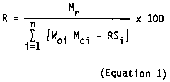
(i) The value of RSi is zero unless the owner or operator submits the following information to the Administrator for approval of a measured value of RSi that is greater than zero:
(A) Measurement techniques; and
(B) Documentation that the measured value of RSi exceeds zero.
(ii) The measurement techniques of paragraph (b)(1)(i)(A) of this section shall be submitted to the Administrator for approval with the notification of anticipated startup required under § 60.7(a)(2) of the General Provisions.
(iii) Each owner or operator demonstrating compliance by the test method described in paragraph (b)(1) of this section shall:
(A) Measure the amount of coating applied at the coating applicator;
(B) Determine the VOC content of all coatings applied using the test method specified in § 60.715(a);
(C) Install, calibrate, maintain, and operate, according to the manufacturer's specifications, a device that indicates the cumulative amount of VOC recovered by the solvent recovery device over each nominal 1-month period. The device shall be certified by the manufacturer to be accurate to within ±2.0 percent;
(D) Measure the amount of VOC recovered; and
(E) Calculate the overall VOC emission reduction (R) for each and every nominal 1-month period using Equation 1.
(iv) For facilities subject to § 60.712 (a) or (b)(3), compliance is demonstrated if the value of R is equal to or greater than 93 percent.
(v) Subject to the provisions of (b)(1)(vi) of this section, for facilities subject to § 60.712(b)(1), compliance is demonstrated if the value of R is equal to or greater than the percent reduction demonstrated pursuant to § 60.713(a)(1) prior to modification or reconstruction or 93 percent whichever is lower.
(vi) For facilities subject to § 60.712(b)(1)(ii), compliance is demonstrated if the value of E (control device efficiency) is greater than or equal to 0.95 and if the value of R is equal to or greater than the percent reduction demonstrated pursuant to § 60.713(a)(3) or 93 percent, whichever is lower.
(2) To demonstrate compliance with § 60.712(a), (b)(1), or (b)(3) (standards for coating operations) when the emissions from only an affected coating operation are controlled by a dedicated incinerator or when a common emission control device (other than a fixed-bed carbon adsorption system with individual exhaust stacks for each adsorber vessel) is used to control emissions from an affected coating operation as well as from other sources of VOC, each owner or operator of an affected coating operation shall perform a gaseous emission test using the following procedures:
(i) Construct the overall VOC emission reduction system so that all volumetric flow rates and total VOC emissions can be accurately determined by the applicable test methods and procedures specified in § 60.715(b) through (g);
(ii) Determine capture efficiency from the coating operation by capturing, venting, and measuring all VOC emissions from the operation. During a performance test, the owner or operator of an affected coating operation located in an area with other sources of VOC shall isolate the coating operation emissions from all other sources of VOC by one of the following methods:
(A) Build a temporary enclosure (see § 60.711(a)(16)) around the affected coating operation; or
(B) Shut down all other sources of VOC and continue to exhaust fugitive emissions from the affected coating operation through any building ventilation system and other room exhausts such as drying ovens. All ventilation air must be vented through stacks suitable for testing;
(iii) Operate the emission control device with all emission sources connected and operating;
(iv) Determine the efficiency (E) of the control device using the following equation:

(v) Determine the efficiency (F) of the VOC capture system using the following equation:
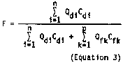
(vi) For each affected coating operation subject to § 60.712(a) or (b)(3), compliance is demonstrated if the product of (E) × (F) is equal to or greater than 0.93.
(vii) For each affected coating operation subject to § 60.712(b)(1)(i), compliance is demonstrated if the product of (E) × (F) is equal to or greater than the fractional reduction demonstrated pursuant to § 60.713(a)(1) prior to modification or reconstruction or 0.93, whichever is lower.
(viii) For each affected coating operation subject to § 60.712(b)(1)(ii), compliance is demonstrated if the value of E is greater than or equal to 0.95 and if the product of (E) × (F) is equal to or greater than the fractional reduction demonstrated pursuant to § 60.713(a)(3) or 0.93, whichever is lower.
(3) To demonstrate compliance with § 60.712(a), (b)(1), or (b)(3) (standards for coating operations) when a fixed-bed carbon adsorption system with individual exhaust stacks for each adsorber vessel is used to control emissions from an affected coating operation as well as from other sources of VOC, each owner or operator of an affected coating operation shall perform a gaseous emission test using the following procedures:
(i) Construct the overall VOC emission reduction system so that each volumetric flow rate and the total VOC emissions can be accurately determined by the applicable test methods and procedures specified in § 60.715(b) through (g);
(ii) Assure that all VOC emissions from the coating operation are segregated from other VOC sources and that the emissions can be captured for measurement, as described in § 60.713(b)(2)(ii)(A) and (B);
(iii) Operate the emission control device with all emission sources connected and operating;
(iv) Determine the efficiency (Hv) of each individual adsorber vessel (v) using the following equation:

(v) Determine the efficiency of the carbon adsorption system (Hsys) by computing the average efficiency of the adsorber vessels as weighted by the volumetric flow rate (Qhv) of each individual adsorber vessel (v) using the following equation:
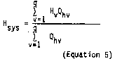
(vi) Determine the efficiency (F) of the VOC capture system using Equation (3).
(vii) For the affected coating operation subject to § 60.712(a) or (b)(3), compliance is demonstrated if the product of (Hsys) × (F) is equal to or greater than 0.93.
(viii) For the affected coating operation subject to § 60.712(b)(1)(i), compliance is demonstrated if the product of (Hsys) × (F) is equal to or greater than the fractional reduction demonstrated pursuant to § 60.713(a)(1) prior to modification or reconstruction or 0.93, whichever is lower.
(ix) For each affected coating operation subject to § 60.712(b)(1)(ii), compliance is demonstrated if the value of Hsys is greater than or equal to 0.95 and if the product of (Hsys) × (F) is equal to or greater than the fractional reduction demonstrated pursuant to § 60.713(a)(3) or 0.93, whichever is lower.
(4) To demonstrate compliance with § 60.712(a), (b)(1), or (b)(3) (standards for coating operations) when the VOC emissions from more than one affected coating operation are collected by a common capture system and are vented through a common duct to a control device that is also controlling emissions from nonaffected sources and the emissions from the nonaffected sources are vented separately from the affected coating operations, the owner or operator may:
(i) Consider the combined affected coating operations as a single emission source; and
(ii) Conduct a compliance test on this single source by the methods described in § 60.713(b)(2) or (3), as applicable.
(5) An alternative method of demonstrating compliance with § 60.712(a) or (b)(3) (standards for coating operations) and the sole method of demonstrating compliance with § 60.712(b)(2) (standards for modified or reconstructed coating operations) is the installation of a total enclosure around the coating operation and the ventilation of all VOC emissions from the total enclosure to a control device with the efficiency specified in paragraph (b)(5)(iii)(A) or (B) of this section, as applicable. If this method is selected, the compliance test methods described in paragraphs (b)(1), (b)(2), (b)(3), and (b)(4) of this section are not required. Instead, each owner or operator of an affected coating operation shall:
(i) Demonstrate that a total enclosure is installed. An enclosure that meets the requirements in paragraphs (b)(5)(i)(A) through (D) of this section shall be assumed to be a total enclosure. The owner or operator of an enclosed coating operation that does not meet the requirements may apply to the Administrator for approval of the enclosure as a total enclosure on a case-by-case basis. The enclosure shall be considered a total enclosure if it is demonstrated to the satisfaction of the Administrator that all VOC emissions from the affected coating operation are contained and vented to the control device. The requirements for automatic approval are as follows:
(A) Total area of all natural draft openings shall not exceed 5 percent of the total surface area of the total enclosure's walls, floor, and ceiling;
(B) All sources of emissions within the enclosure shall be a minimum of four equivalent diameters away from each natural draft opening;
(C) Average inward face velocity across all natural draft openings (FV) shall be a minimum of 3,600 meters per hour as determined by the following procedures:
(1) Construct all forced makeup air ducts and all exhaust ducts so that the volumetric flow rate in each can be accurately determined by the test methods and procedures specified in § 60.715(c) and (d). Volumetric flow rates shall be calculated without the adjustment normally made for moisture content; and
(2) Determine FV by the following equation:
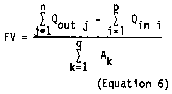
(D) The air passing through all natural draft openings shall flow into the enclosure continuously. If FV is less than or equal to 9,000 meters per hour, the continuous inward flow of air shall be verified by continuous observation using smoke tubes, streamers, tracer gases, or other means approved by the Administrator over the period that the volumetric flow rate tests required to determine FV are carried out. If FV is greater than 9,000 meters per hour, the direction of airflow through the natural draft openings shall be presumed to be inward at all times without verification.
(ii) Determine the control device efficiency using Equation (2) or Equations (4) and (5), as applicable, and the test methods and procedures specified in § 60.715(b) through (g).
(iii) Compliance is demonstrated if the installation of a total enclosure is demonstrated and the value of E determined from Equation (2) (or the value of Hsys determined from Equations (4) and (5), as applicable) is equal to or greater than the required efficiency as specified below:
(A) For coating operations subject to the standards of § 60.712(a), (b)(2)(ii), and (b)(3), 0.95 (95 percent); or
(B) For coating operations subject to the standards of § 60.712(b)(2)(i), the value of E determined from Equation (2) (or the value of Hsys determined from Equations (4) and (5), as applicable) pursuant to § 60.713(a)(2) prior to modification or reconstruction or 0.95 (95 percent), whichever is lower.
(6) To demonstrate compliance with § 60.712(c) (standard for new mix equipment with concurrent construction of a control device), each owner or operator of affected coating mix preparation equipment shall demonstrate upon inspection that:
(i) Covers satisfying the requirements of § 60.712(c)(1)-(5) have been installed and are being used properly;
(ii) Procedures detailing the proper use of covers, as specified in § 60.712(c)(1), have been posted in all areas where affected coating mix preparation equipment is used;
(iii) The coating mix preparation equipment is vented to a control device; and
(iv) The control device efficiency (E or Hsys, as applicable) determined using Equation (2) or Equations (4) and (5), respectively, and the test methods and procedures specified in § 60.715(b)-(g) is equal to or greater than 0.95.
(7) To demonstrate compliance with § 60.712(d)(1) (standard for mix equipment), each owner or operator of affected coating mix preparation equipment shall demonstrate upon inspection that:
(i) Covers satisfying the requirements of § 60.712(c)(1)-(5) have been installed and are being used properly;
(ii) Procedures detailing the proper use of covers, as specified in § 60.712(c)(1), have been posted in all areas where affected coating mix preparation equipment is used; and
(iii) The coating mix preparation equipment is vented to a control device.
(8) To demonstrate compliance with § 60.712(d)(2) (standard for mix equipment), each owner or operator of affected coating mix preparation equipment shall demonstrate upon inspection that both:
(i) Covers satisfying the requirements of § 60.712(c)(1)-(5) have been installed and are being used properly; and
(ii) Procedures detailing the proper use of covers, as specified in § 60.712(c)(1), have been posted in all areas where affected coating mix preparation equipment is used.
(9) To determine compliance with § 60.712(e) (high-solids coatings alternative standard), each owner or operator of an affected facility shall determine the weighted average mass of VOC contained in the coating per volume of coating solids applied for each and every nominal 1-month period according to the following procedures:
(i) Determine the weight fraction of VOC in each coating applied using Method 24 as specified in § 60.715(a);
(ii) Determine the volume of coating solids in each coating applied from the facility records; and
(iii) Compute the weighted average by the following equation:
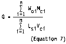
(iv) For each affected facility where the value of G is less than or equal to 0.20 kilogram of VOC per liter of coating solids applied, the facility is in compliance.
(c) Startups and shutdowns are normal operation for this source category. Emissions from these operations are to be included when determining if the standards for coating operations specified in § 60.712(a) and (b) are being attained.
(d) If a control device other than a carbon adsorber, condenser, or incinerator is used to control emissions from an affected facility, the necessary operating specifications for that device must be obtained from the Administrator. An example of such a device is a flare.
[53 FR 38914, Oct. 3, 1988; 53 FR 43799, Oct. 28, 1988, as amended at 53 FR 47955, Nov. 29, 1988]
§ 60.714 Installation of monitoring devices and recordkeeping.
All monitoring devices required under the provisions of this section shall be installed and calibrated, according to the manufacturer's specifications, prior to the initial performance tests in locations such that representative values of the monitored parameters will be obtained. The parameters to be monitored shall be continuously measured and recorded during all performance tests.
(a) Each owner or operator of an affected coating operation that utilizes less solvent annually than the applicable cutoff provided in § 60.710(b) and that is not subject to § 60.712 (standards for coating operations) shall maintain records of actual solvent use.
(b) Each owner or operator of an affected coating operation demonstrating compliance by the test method described in § 60.713(b)(1) (liquid material balance) shall maintain records of all the following for each and every nominal 1-month period:
(1) Amount of coating applied at the applicator;
(2) Results of the reference test method specified in § 60.715(a) for determining the VOC content of all coatings applied;
(3) Amount VOC recovered; and
(4) Calculation of the percent VOC recovered.
(c) Each owner or operator of an affected coating operation or affected coating mix preparation equipment controlled by a carbon adsorption system and demonstrating compliance by the procedures described in § 60.713(b)(2), (3), (4), (5), or (6) (which include control device efficiency determinations) shall carry out the monitoring and recordkeeping provisions of paragraph (c)(1) or (2) of this section, as appropriate.
(1) For carbon adsorption systems with a common exhaust stack for all the individual adsorber vessels, install, calibrate, maintain, and operate, according to the manufacturer's specifications, a monitoring device that continuously indicates and records the concentration level of organic compounds in either the control device outlet gas stream or in both the control device inlet and outlet gas streams. The outlet gas stream would be monitored if the percent increase in the concentration level of organic compounds is used as the basis for reporting, as described in § 60.717(d)(3). The inlet and outlet gas streams would be monitored if the percent control device efficiency is used as the basis for reporting, as described in § 60.717(d)(4).
(2) For carbon adsorption systems with individual exhaust stacks for each adsorber vessel, install, calibrate, maintain, and operate, according to the manufacturer's specifications, a monitoring device that continuously indicates and records the concentration level of organic compounds in the outlet gas stream for a minimum of one complete adsorption cycle per day for each adsorber vessel. The owner or operator may also monitor and record the concentration level of organic compounds in the common carbon adsorption system inlet gas stream or in each individual carbon adsorber vessel inlet stream. The outlet gas streams alone would be monitored if the percent increase in the concentration level of organic compounds is used as the basis for reporting, as described in § 60.717(d)(3). In this case, the owner or operator shall compute daily a 3-day rolling average concentration level of organics in the outlet gas stream from each individual adsorber vessel. The inlet and outlet gas streams would be monitored if the percent control device efficiency is used as the basis for reporting, as described in § 60.717(d)(4). In this case, the owner or operator shall compute daily a 3-day rolling average efficiency for each individual adsorber vessel.
(d) Each owner or operator of an affected coating operation controlled by a condensation system and demonstrating compliance by the procedures described in § 60.713(b)(2), (4), or (5) (which include control device efficiency determinations) shall install, calibrate, maintain, and operate, according to the manufacturer's specifications, a monitoring device that continuously indicates and records the temperature of the condenser exhaust stream.
(e) Each owner or operator of an affected coating operation or affected coating mix preparation equipment controlled by a thermal incinerator and demonstrating compliance by the procedures described in § 60.713(b)(2), (4), (5), or (6) (which include control device efficiency determinations) shall install, calibrate, maintain, and operate, according to the manufacturer's specifications, a monitoring device that continuously indicates and records the combustion temperature of the incinerator. The monitoring device shall have an accuracy within ±1 percent of the temperature being measured in Celsius degrees.
(f) Each owner or operator of an affected coating operation or affected coating mix preparation equipment controlled by a catalytic incinerator and demonstrating compliance by the procedures described in § 60.713(b)(2), (4), (5), or (6) (which include control device efficiency determinations) shall install, calibrate, maintain, and operate, according to the manufacturer's specifications, a monitoring device that continuously indicates and records the gas temperature both upstream and downstream of the catalyst bed. The monitoring device shall have an accuracy within ±1 percent of the temperature being measured in Celsius degrees.
(g) Each owner or operator of an affected coating operation demonstrating compliance pursuant to § 60.713(b)(2), (3), or (4) (which include VOC capture system efficiency determinations) shall submit a monitoring plan for the VOC capture system to the Administrator for approval along with the notification of anticipated startup required under § 60.7(a)(2) of the General Provisions. This plan shall identify the parameter to be monitored as an indicator of VOC capture system performance (e.g., the amperage to the exhaust fans or duct flow rates) and the method for monitoring the chosen parameter. The owner or operator shall install, calibrate, maintain, and operate, according to the manufacturer's specifications, a monitoring device that continuously indicates and records the value of the chosen parameter.
(h) Each owner or operator of an affected coating operation who uses the equipment alternative described in § 60.713(b)(5) to demonstrate compliance shall follow the procedures described in paragraph (g) of this section to establish a monitoring plan for the total enclosure.
(i) Each owner or operator of an affected coating operation shall record time periods of coating operations when an emission control device is not in use.
(j) Each owner or operator of an affected coating operation or affected coating mix preparation equipment complying with § 60.712(e) shall maintain records of the monthly weighted average mass of VOC contained in the coating per volume of coating solids applied for each coating, as described in § 60.713(b)(9)(i) through (iv).
(k) Records of the measurements and calculations required in §§ 60.713 and 60.714 must be retained for at least 2 years following the date of the measurements and calculations.
[53 FR 38914, Oct. 3, 1988, as amended at 64 FR 7467, Feb. 12, 1999]
§ 60.715 Test methods and procedures.
Methods in appendix A of this part, except as provided under § 60.8(b), shall be used to determine compliance as follows:
(a) Method 24 is used to determine the VOC content in coatings. If it is demonstrated to the satisfaction of the Administrator that plant coating formulation data are equivalent to Method 24 results, formulation data may be used. In the event of any inconsistency between a Method 24 test and a facility's formulation data, the Method 24 test will govern. For Method 24, the coating sample must be a 1-liter sample taken into a 1-liter container at a location and time such that the sample will be representative of the coating applied to the base film (i.e., the sample shall include any dilution solvent or other VOC added during the manufacturing process). The container must be tightly sealed immediately after the sample is taken. Any solvent or other VOC added after the sample is taken must be measured and accounted for in the calculations that use Method 24 results.
(b) Method 18, 25, or 25A, as appropriate to the conditions at the site, is used to determine VOC concentration. The owner or operator shall submit notice of the intended test method to the Administrator for approval along with the notification of the performance test required under § 60.8(d) of the General Provisions. Method selection shall be based on consideration of the diversity of organic species present and their total concentration and on consideration of the potential presence of interfering gases. Except as indicated in paragraphs (b)(1) and (2) of this section, the test shall consist of three separate runs, each lasting a minimum of 30 minutes.
(1) When the method is to be used in the determination of the efficiency of a fixed-bed carbon adsorption system with a common exhaust stack for all the individual adsorber vessels pursuant to § 60.713(b)(2), (4), (5), or (6), the test shall consist of three separate runs, each coinciding with one or more complete sequences through the adsorption cycles of all the individual adsorber vessels.
(2) When the method is to be used in the determination of the efficiency of a fixed-bed carbon adsorption system with individual exhaust stacks for each adsorber vessel pursuant to § 60.713(b)(3), (4), (5), or (6), each adsorber vessel shall be tested individually. The test for each adsorber vessel shall consist of three separate runs. Each run shall coincide with one or more complete adsorption cycles.
(c) Method 1 or 1A is used for sample and velocity traverses.
(d) Method 2, 2A, 2C, or 2D is used for velocity and volumetric flow rates.
(e) Method 3 is used for gas analysis.
(f) Method 4 is used for stack gas moisture.
(g) Methods 2, 2A, 2C, 2D, 3, and 4 shall be performed, as applicable, at least twice during each test period.
[53 FR 38914, Oct. 3, 1988; 53 FR 43799, Oct. 28, 1988]
§ 60.716 Permission to use alternative means of emission limitation.
(a) If, in the Administrator's judgment, an alternative means of emission limitation will achieve a reduction in emissions of VOC from any emission point subject to § 60.712(c) or (d) (standards for mix equipment) at least equivalent to that required by § 60.712 (c) or (d), respectively, the Administrator will publish in the Federal Register a notice permitting the use of the alternative means. The notice may condition permission on requirements related to the operation and maintenance of the alternative means.
(b) Any notice under paragraph (a) of this section shall be published only after public notice and an opportunity for a public hearing.
(c) Any person seeking permission under this section shall submit either results from an emission test that documents the collection and measurement of all VOC emissions from a given control device or an engineering evaluation that documents the determination of such emissions.
§ 60.717 Reporting and monitoring requirements.
(a) For all affected coating operations subject to § 60.712(a), (b)(1), (b)(2), or (b)(3) and all affected coating mix preparation equipment subject to § 60.712(c), the performance test data and results shall be submitted to the Administrator as specified in § 60.8(a) of the General Provisions (40 CFR part 60, subpart A). In addition, the average values of the monitored parameters measured at least every 15 minutes and averaged over the period of the performance test shall be submitted with the results of all performance tests.
(b) Each owner or operator of an affected coating operation claiming to utilize less than the applicable volume of solvent specified in § 60.710(b) in the first calendar year of operation shall submit to the Administrator, with the notification of projected startup, a material flow chart indicating projected solvent use. The owner or operator shall also submit actual solvent use records at the end of the initial calendar year.
(c) Each owner or operator of an affected coating operation initially utilizing less than the applicable volume of solvent specified in § 60.710(b) per calendar year shall report the first calendar year in which actual annual solvent use exceeds the applicable volume.
(d) Each owner or operator of an affected coating operation, or affected coating mix preparation equipment subject to § 60.712(c), shall submit semiannual reports to the Administrator documenting the following:
(1) The 1-month amount of VOC contained in the coating, the VOC recovered, and the percent emission reduction for months of noncompliance for any affected coating operation demonstrating compliance by the performance test method described in § 60.713(b)(1) (liquid material balance);
(2) The VOC contained in the coatings for the manufacture of magnetic tape for any 1-month period during which the weighted average solvent content (G) of the coatings exceeded 0.20 kilogram per liter of coating solids for those affected facilities complying with § 60.712(e) (high-solids coatings alternative standard);
(3) For those affected facilities monitoring only the carbon adsorption system outlet concentration levels of organic compounds, the periods (during actual coating operations) specified in paragraph (d)(3)(i) or (ii) of this section, as applicable.
(i) For carbon adsorption systems with a common exhaust stack for all the individual adsorber vessels, all periods of three consecutive adsorption cycles of all the individual adsorber vessels during which the average value of the concentration level of organic compounds in the common outlet gas stream is more than 20 percent greater than the average value measured during the most recent performance test that demonstrated compliance.
(ii) For carbon adsorption systems with individual exhaust stacks for each adsorber vessel, all 3-day rolling averages for each adsorber vessel when the concentration level of organic compounds in the individual outlet gas stream is more than 20 percent greater than the average value for that adsorber vessel measured during the most recent performance test that demonstrated compliance.
(4) For those affected facilities monitoring both the carbon adsorption system inlet and outlet concentration levels of organic compounds, the periods (during actual coating operations), specified in (d)(4)(i) or (ii) of this section, as applicable.
(i) For carbon adsorption systems with a common exhaust stack for all the individual adsorber vessels, all periods of three consecutive adsorption cycles of all the individual adsorber vessels during which the average carbon adsorption system efficiency falls below the applicable level as follows:
(A) For those affected facilities demonstrating compliance by the performance test method described in § 60.713(b)(2) or (4), the value of E determined using Equation (2) during the most recent performance test that demonstrated compliance.
(B) For those affected facilities demonstrating compliance pursuant to § 60.713(b)(5)(iii)(A) or § 60.713(b)(6), 0.95 (95 percent).
(C) For those affected facilities demonstrating compliance pursuant to § 60.713(b)(5)(iii)(B), the required value of E determined using Equation (2) pursuant to § 60.713(a)(2) prior to modification or reconstruction or 0.95 (95 percent), whichever is lower.
(ii) For carbon adsorption systems with individual exhaust stacks for each adsorber vessel, all 3-day rolling averages for each adsorber vessel when the efficiency falls below the applicable level as follows:
(A) For those affected facilities demonstrating compliance by the performance test method described in § 60.713(b)(3) or (4), the value of Hv determined using Equation (4) during the most recent performance test that demonstrated compliance.
(B) For those affected facilities demonstrating compliance pursuant to § 60.713(b)(5)(iii)(A) or § 60.713(b)(6), 0.95 (95 percent).
(C) For those affected facilities demonstrating compliance pursuant to § 60.713(b)(5)(iii)(B), the value of Hv determined using Equation 4 pursuant to § 60.713(a)(2) prior to modification or reconstruction.
(5) All 3-hour periods (during actual coating operations) during which the average exhaust temperature is 5 or more Celsius degrees above the average temperature measured during the most recent performance test that demonstrated compliance for those affected facilities monitoring condenser exhaust gas temperature;
(6) All 3-hour periods (during actual coating operations) during which the average combustion temperature is more than 28 Celsius degrees below the average combustion temperature during the most recent performance test that demonstrated compliance for those affected facilities monitoring thermal incinerator combustion gas temperature;
(7) All 3-hour periods (during actual coating operations) during which the average gas temperature immediately before the catalyst bed is more than 28 Celsius degrees below the average gas temperature during the most recent performance test that demonstrated compliance and all 3-hour periods (during actual coating operations) during which the average gas temperature difference across the catalyst bed is less than 80 percent of the average gas temperature difference during the most recent performance test that demonstrated compliance for those affected facilities monitoring catalytic incinerator catalyst bed temperature; and
(8) All 3-hour periods (during actual coating operations) during which the average total enclosure or VOC capture system monitoring device readings vary by 5 percent or more from the average value measured during the most recent performance test that demonstrated compliance for those affected facilities monitoring a total enclosure pursuant to § 60.714(h) or VOC capture system pursuant to § 60.714(g).
(e) Each owner or operator of an affected coating operation, or affected coating mix preparation equipment subject to § 60.712(c), not required to submit reports under § 60.717(d) because no reportable periods have occurred shall submit semiannual reports so affirming.
(f) Each owner or operator of affected coating mix preparation equipment that is constructed at a time when no affected coating operation is being constructed shall:
(1) Be exempt from the reporting requirements specified in § 60.7(a)(1), (2), and (4); and
(2) Submit the notification of actual startup specified in § 60.7(a)(3).
(g) The owner or operator of affected coating mix preparation equipment that is constructed at the same time as an affected coating operation shall include the affected coating mix preparation equipment in all the reporting requirements for the affected coating operation specified in § 60.7(a)(1) through (4).
(h) The reports required under paragraphs (b) through (e) of this section shall be postmarked within 30 days of the end of the reporting period.
(i) The requirements of this subsection remain in force until and unless EPA, in delegating enforcement authority to a State under section 111(c) of the Act, approves reporting requirements or an alternative means of compliance surveillance adopted by such States. In this event, affected sources within the State will be relieved of the obligation to comply with this subsection, provided that they comply with the requirements established by the State.
[53 FR 38914, Oct. 3, 1988; 53 FR 43799, Oct. 28, 1988, as amended at 53 FR 47955, Nov. 29, 1988; 64 FR 7467, Feb. 12, 1999]
§ 60.718 Delegation of authority.
(a) In delegating implementation and enforcement authority to a State under section 111(c) of the Act, the authorities contained in paragraph (b) of this section shall be retained by the Administrator and not transferred to a State.
(b) Authorities which will not be delegated to States:
§ 60.711(a)(16)
§ 60.713(b)(1)(i)
§ 60.713(b)(1)(ii)
§ 60.713(b)(5)(i)
§ 60.713(d)
§ 60.715(a)
§ 60.716
[53 FR 38914, Oct. 3, 1988; 53 FR 47955, Nov. 29, 1988]
Subpart TTT - Standards of Performance for Industrial Surface Coating: Surface Coating of Plastic Parts for Business Machines
Source:
53 FR 2676, Jan. 29, 1988, unless otherwise noted.
§ 60.720 Applicability and designation of affected facility.
(a) The provisions of this subpart apply to each spray booth in which plastic parts for use in the manufacture of business machines receive prime coats, color coats, texture coats, or touch-up coats.
(b) This subpart applies to any affected facility for which construction, modification, or reconstruction begins after January 8, 1986.
§ 60.721 Definitions.
(a) As used in this subpart, all terms not defined herein shall have the meaning given them in the Act or in subpart A of this part.
Business machine means a device that uses electronic or mechanical methods to process information, perform calculations, print or copy information, or convert sound into electrical impulses for transmission, such as:
(1) Products classified as typewriters under SIC Code 3572;
(2) Products classified as electronic computing devices under SIC Code 3573;
(3) Products classified as calculating and accounting machines under SIC Code 3574;
(4) Products classified as telephone and telegraph equipment under SIC Code 3661;
(5) Products classified as office machines, not elsewhere classified, under SIC Code 3579; and
(6) Photocopy machines, a subcategory of products classified as photographic equipment under SIC code 3861.
Coating operation means the use of a spray booth for the application of a single type of coating (e.g., prime coat); the use of the same spray booth for the application of another type of coating (e.g., texture coat) constitutes a separate coating operation for which compliance determinations are performed separately.
Coating solids applied means the coating solids that adhere to the surface of the plastic business machine part being coated.
Color coat means the coat applied to a part that affects the color and gloss of the part, not including the prime coat or texture coat. This definition includes fog coating, but does not include conductive sensitizers or electromagnetic interference/radio frequency interference shielding coatings.
Conductive sensitizer means a coating applied to a plastic substrate to render it conductive for purposes of electrostatic application of subsequent prime, color, texture, or touch-up coats.
Electromagnetic interference/radio frequency interference (EMI/RFI) shielding coating means a conductive coating that is applied to a plastic substrate to attenuate EMI/RFI signals.
Fog coating (also known as mist coating and uniforming) means a thin coating applied to plastic parts that have molded-in color or texture or both to improve color uniformity.
Nominal 1-month period means either a calendar month, 30-day month, accounting month, or similar monthly time period that is established prior to the performance test (i.e., in a statement submitted with notification of anticipated actual startup pursuant to 40 CFR 60.7(2)).
Plastic parts means panels, housings, bases, covers, and other business machine components formed of synthetic polymers.
Prime coat means the initial coat applied to a part when more than one coating is applied, not including conductive sensitizers or electromagnetic interference/radio frequency interference shielding coatings.
Spray booth means the structure housing automatic or manual spray application equipment where a coating is applied to plastic parts for business machines.
Texture coat means the rough coat that is characterized by discrete, raised spots on the exterior surface of the part. This definition does not include conductive sensitizers or EMI/RFI shielding coatings.
Touch-up coat means the coat applied to correct any imperfections in the finish after color or texture coats have been applied. This definition does not include conductive sensitizers or EMI/RFI shielding coatings.
Transfer efficiency means the ratio of the amount of coating solids deposited onto the surface of a plastic business machine part to the total amount of coating solids used.
VOC emissions means the mass of VOC's emitted from the surface coating of plastic parts for business machines expressed as kilograms of VOC's per liter of coating solids applied (i.e., deposited on the surface).
(b) All symbols used in this subpart not defined below are given meaning in the Act or subpart A of this part.
Dc = density of each coating as received (kilograms per liter)
Dd = density of each diluent VOC (kilograms per liter)
Lc = the volume of each coating consumed, as received (liters)
Ld = the volume of each diluent VOC added to coatings (liters)
Ls = the volume of coating solids consumed (liters)
Md = the mass of diluent VOC's consumed (kilograms)
Mo = the mass of VOC's in coatings consumed, as received (kilograms)
N = the volume-weighted average mass of VOC emissions to the atmosphere per unit volume of coating solids applied (kilograms per liter)
T = the transfer efficiency for each type of application equipment used at a coating operation (fraction)
Tavg = the volume-weighted average transfer efficiency for a coating operation (fraction)
Vs = the proportion of solids in each coating, as received (fraction by volume)
Wo = the proportion of VOC's in each coating, as received (fraction by weight)
[53 FR 2676, Jan. 29, 1988, as amended at 54 FR 25459, June 15, 1989]
§ 60.722 Standards for volatile organic compounds.
(a) Each owner or operator of any affected facility which is subject to the requirements of this subpart shall comply with the emission limitations set forth in this section on and after the date on which the initial performance test, required by §§ 60.8 and 60.723 is completed, but not later than 60 days after achieving the maximum production rate at which the affected facility will be operated, or 180 days after the initial startup, whichever date comes first. No affected facility shall cause the discharge into the atmosphere in excess of:
(1) 1.5 kilograms of VOC's per liter of coating solids applied from prime coating of plastic parts for business machines.
(2) 1.5 kilograms of VOC's per liter of coating solids applied from color coating of plastic parts for business machines.
(3) 2.3 kilograms of VOC's per liter of coating solids applied from texture coating of plastic parts for business machines.
(4) 2.3 kilograms of VOC's per liter of coatings solids applied from touch-up coating of plastic parts for business machines.
(b) All VOC emissions that are caused by coatings applied in each affected facility, regardless of the actual point of discharge of emissions into the atmosphere, shall be included in determining compliance with the emission limits in paragraph (a) of this section.
§ 60.723 Performance tests and compliance provisions.
(a) Section 60.8 (d) and (f) do not apply to the performance test procedures required by this section.
(b) The owner or operator of an affected facility shall conduct an initial performance test as required under § 60.8(a) and thereafter a performance test each nominal 1-month period for each affected facility according to the procedures in this section.
(1) The owner or operator shall determine the composition of coatings by analysis of each coating, as received, using Method 24, from data that have been determined by the coating manufacturer using Method 24, or by other methods approved by the Administrator.
(2) The owner or operator shall determine the volume of coating and the mass of VOC used for dilution of coatings from company records during each nominal 1-month period. If a common coating distribution system serves more than one affected facility or serves both affected and nonaffected spray booths, the owner or operator shall estimate the volume of coatings used at each facility by using procedures approved by the Administrator.
(i) The owner or operator shall calculate the volume-weighted average mass of VOC's in coatings emitted per unit volume of coating solids applied (N) at each coating operation [i.e., for each type of coating (prime, color, texture, and touch-up) used] during each nominal 1-month period for each affected facility. Each 1-month calculation is considered a performance test. Except as provided in paragraph (b)(2)(iii) of this section, N will be determined by the following procedures:
(A) Calculate the mass of VOC's used (Mo + Md) for each coating operation during each nominal 1-month period for each affected facility by the following equation:
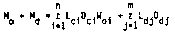
where n is the number of coatings of each type used during each nominal 1-month period and m is the number of different diluent VOC's used during each nominal 1-month period. (Σ Ldj Ddj will be 0 if no VOC's are added to the coatings, as received.)
(B) Calculate the total volume of coating solids consumed (Ls) in each nominal 1-month period for each coating operation for each affected facility by the following equation:

where n is the number of coatings of each type used during each nominal 1-month period.
(C) Select the appropriate transfer efficiency (T) from table 1 for each type of coating applications equipment used at each coating operation. If the owner or operator can demonstrate to the satisfaction of the Administrator that transfer efficiencies other than those shown are appropriate, the Administrator will approve their use on a case-by-case basis. Transfer efficiency values for application methods not listed below shall be approved by the Administrator on a case-by-case basis. An owner or operator must submit sufficient data for the Administrator to judge the validity of the transfer efficiency claims.
(D) Where more than one application method is used within a single coating operation, the owner or operator shall determine the volume of each coating applied by each method through a means acceptable to the Administrator and compute the volume-weighted average transfer efficiency by the following equation:

Table 1 - Transfer Efficiencies
| Application methods | Transfer efficiency | Type of coating |
|---|---|---|
| Air atomized spray | 0.25 | Prime, color, texture, touch-up, and fog coats. |
| Air-assistd airless spray | .40 | Prime and color coats. |
| Electrostatic air spray | .40 | Do. |
where n is the number of coatings of each type used and p is the number of application methods used.
(E) Calculate the volume-weighted average mass of VOC's emitted per unit volume of coating solids applied (N) during each nominal 1-month period for each coating operation for each affected facility by the folowing equation:

(Tavg = T when only one type of coating operation occurs).
(ii) Where the volume-weighted average mass of VOC's emitted to the atmosphere per unit volume of coating solids applied (N) is less than or equal to 1.5 kilograms per liter for prime coats, is less than or equal to 1.5 kilograms per liter for color coats, is less than or equal to 2.3 kilograms per liter for texture coats, and is less than or equal to 2.3 kilograms per liter for touch-up coats, the affected facility is in compliance.
(iii) If each individual coating used by an affected facility has a VOC content (kg VOC/l of solids), as received, which when divided by the lowest transfer efficiency at which the coating is applied for each coating operation results in a value equal to or less than 1.5 kilograms per liter for prime and color coats and equal to or less than 2.3 kilograms per liter for texture and touch-up coats, the affected facility is in compliance provided that no VOC's are added to the coatings during distribution or application.
(iv) If an affected facility uses add-on controls to control VOC emissions and if the owner or operator can demonstrate to the Administrator that the volume-weighted average mass of VOC's emitted to the atmosphere during each nominal 1-month period per unit volume of coating solids applied (N) is within each of the applicable limits expressed in paragraph (b)(2)(ii) of this section because of this equipment, the affected facility is in compliance. In such cases, compliance will be determined by the Administrator or a case-by-case basis.
[53 FR 2676, Jan. 29, 1988, as amended at 65 FR 61778, Oct. 17, 2000]
§ 60.724 Reporting and recordkeeping requirements.
(a) The reporting requirements of § 60.8(a) apply only to the initial performance test. Each owner or operator subject to the provisions of this subpart shall include the following data in the report of the initial performance test required under § 60.8(a):
(1) Except as provided for in paragraph (a)(2) of this section, the volume-weighted average mass of VOC's emitted to the atmosphere per volume of applied coating solids (N) for the initial nominal 1-month period for each coating operation from each affected facility.
(2) For each affected facility where compliance is determined under the provisions of § 60.723(b)(2)(iii), a list of the coatings used during the initial nominal 1-month period, the VOC content of each coating calculated from data determined using Method 24, and the lowest transfer efficiency at which each coating is applied during the initial nominal 1-month period.
(b) Following the initial report, each owner or operator shall:
(1) Report the volume-weighted average mass of VOC's per unit volume of coating solids applied for each coating operation for each affected facility during each nominal 1-month period in which the facility is not in compliance with the applicable emission limits specified in § 60.722. Reports of noncompliance shall be submitted on a quarterly basis, occurring every 3 months following the initial report; and
(2) Submit statements that each affected facility has been in compliance with the applicable emission limits specified in § 60.722 during each nominal 1-month period. Statements of compliance shall be submitted on a semiannual basis.
(c) These reports shall be postmarked not later than 10 days after the end of the periods specified in § 60.724(b)(1) and § 60.724(b)(2).
(d) Each owner or operator subject to the provisions of this subpart shall maintain at the source, for a period of at least 2 years, records of all data and calculations used to determine monthly VOC emissions from each coating operation for each affected facility as specified in 40 CFR 60.7(d).
(e) Reporting and recordkeeping requirements for facilities using add-on controls will be determined by the Administrator on a case-by-case basis.
[53 FR 2676, Jan. 29, 1988, as amended at 65 FR 61778, Oct. 17, 2000]
§ 60.725 Test methods and procedures.
(a) The reference methods in appendix A to this part except as provided under § 60.8(b) shall be used to determine compliance with § 60.722 as follows:
(1) Method 24 for determination of VOC content of each coating as received.
(2) For Method 24, the sample must be at least a 1-liter sample in a 1-liter container.
(b) Other methods may be used to determine the VOC content of each coating if approved by the Administrator before testing.
§ 60.726 Delegation of authority.
(a) In delegating implementation and enforcement authority to a State under section 111(c) of the Act, the authorities contained in paragraph (b) of this section shall be retained by the Administrator and not transferred to a State.
(b) Authorities which will not be delegated to the States:
Section 60.723(b)(1)
Section 60.723(b)(2)(i)(C)
Section 60.723(b)(2)(iv)
Section 60.724(e)
Section 60.725(b)
[53 FR 2676, Jan. 29, 1988, as amended at 53 FR 19300, May 27, 1988]
Subpart UUU - Standards of Performance for Calciners and Dryers in Mineral Industries
Source:
57 FR 44503, Sept. 28, 1992, unless otherwise noted.
§ 60.730 Applicability and designation of affected facility.
(a) The affected facility to which the provisions of this subpart apply is each calciner and dryer at a mineral processing plant. Feed and product conveyors are not considered part of the affected facility. For the brick and related clay products industry, only the calcining and drying of raw materials prior to firing of the brick are covered.
(b) An affected facility that is subject to the provisions of subpart LL, Metallic Mineral Processing Plants, is not subject to the provisions of this subpart. Also, the following processes and process units used at mineral processing plants are not subject to the provisions of this subpart: vertical shaft kilns in the magnesium compounds industry; the chlorination-oxidation process in the titanium dioxide industry; coating kilns, mixers, and aerators in the roofing granules industry; and tunnel kilns, tunnel dryers, apron dryers, and grinding equipment that also dries the process material used in any of the 17 mineral industries (as defined in § 60.731, “Mineral processing plant”).
(c) The owner or operator of any facility under paragraph (a) of this section that commences construction, modification, or reconstruction after April 23, 1986, is subject to the requirements of this subpart.
§ 60.731 Definitions.
As used in this subpart, all terms not defined herein shall have the meaning given them in the Clean Air Act and in subpart A of this part.
Calciner means the equipment used to remove combined (chemically bound) water and/or gases from mineral material through direct or indirect heating. This definition includes expansion furnaces and multiple hearth furnaces.
Control device means the air pollution control equipment used to reduce particulate matter emissions released to the atmosphere from one or more affected facilities.
Dryer means the equipment used to remove uncombined (free) water from mineral material through direct or indirect heating.
Installed in series means a calciner and dryer installed such that the exhaust gases from one flow through the other and then the combined exhaust gases are discharged to the atmosphere.
Mineral processing plant means any facility that processes or produces any of the following minerals, their concentrates or any mixture of which the majority (>50 percent) is any of the following minerals or a combination of these minerals: alumina, ball clay, bentonite, diatomite, feldspar, fire clay, fuller's earth, gypsum, industrial sand, kaolin, lightweight aggregate, magnesium compounds, perlite, roofing granules, talc, titanium dioxide, and vermiculite.
§ 60.732 Standards for particulate matter.
Each owner or operator of any affected facility that is subject to the requirements of this subpart shall comply with the emission limitations set forth in this section on and after the date on which the initial performance test required by § 60.8 is completed, but not later than 180 days after the initial startup, whichever date comes first. No emissions shall be discharged into the atmosphere from any affected facility that:
(a) Contains particulate matter in excess of 0.092 gram per dry standard cubic meter (g/dscm) [0.040 grain per dry standard cubic foot (gr/dscf)] for calciners and for calciners and dryers installed in series and in excess of 0.057 g/dscm (0.025 gr/dscf) for dryers; and
(b) Exhibits greater than 10 percent opacity, unless the emissions are discharged from an affected facility using a wet scrubbing control device.
[57 FR 44503, Sept. 28, 1992, as amended at 65 FR 61778, Oct. 17, 2000]
§ 60.733 Reconstruction.
The cost of replacement of equipment subject to high temperatures and abrasion on processing equipment shall not be considered in calculating either the “fixed capital cost of the new components” or the “fixed capital cost that would be required to construct a comparable new facility” under § 60.15. Calciner and dryer equipment subject to high temperatures and abrasion are: end seals, flights, and refractory lining.
§ 60.734 Monitoring of emissions and operations.
(a) With the exception of the process units described in paragraphs (b), (c), and (d) of this section, the owner or operator of an affected facility subject to the provisions of this subpart who uses a dry control device to comply with the mass emission standard shall install, calibrate, maintain, and operate a continuous monitoring system to measure and record the opacity of emissions discharged into the atmosphere from the control device.
(b) In lieu of a continuous opacity monitoring system, the owner or operator of a ball clay vibrating grate dryer, a bentonite rotary dryer, a diatomite flash dryer, a diatomite rotary calciner, a feldspar rotary dryer, a fire clay rotary dryer, an industrial sand fluid bed dryer, a kaolin rotary calciner, a perlite rotary dryer, a roofing granules fluid bed dryer, a roofing granules rotary dryer, a talc rotary calciner, a titanium dioxide spray dryer, a titanium dioxide fluid bed dryer, a vermiculite fluid bed dryer, or a vermiculite rotary dryer who uses a dry control device may have a certified visible emissions observer measure and record three 6-minute averages of the opacity of visible emissions to the atmosphere each day of operation in accordance with Method 9 of appendix A of part 60.
(c) The owner or operator of a ball clay rotary dryer, a diatomite rotary dryer, a feldspar fluid bed dryer, a fuller's earth rotary dryer, a gypsum rotary dryer, a gypsum flash calciner, gypsum kettle calciner, an industrial sand rotary dryer, a kaolin rotary dryer, a kaolin multiple hearth furnace, a perlite expansion furnace, a talc flash dryer, a talc rotary dryer, a titanium dioxide direct or indirect rotary dryer or a vermiculite expansion furnace who uses a dry control device is exempt from the monitoring requirements of this section.
(d) The owner or operator of an affected facility subject to the provisions of this subpart who uses a wet scrubber to comply with the mass emission standard for any affected facility shall install, calibrate, maintain, and operate monitoring devices that continuously measure and record the pressure loss of the gas stream through the scrubber and the scrubbing liquid flow rate to the scrubber. The pressure loss monitoring device must be certified by the manufacturer to be accurate within 5 percent of water column gauge pressure at the level of operation. The liquid flow rate monitoring device must be certified by the manufacturer to be accurate within 5 percent of design scrubbing liquid flow rate.
§ 60.735 Recordkeeping and reporting requirements.
(a) Records of the measurements required in § 60.734 of this subpart shall be retained for at least 2 years.
(b) Each owner or operator who uses a wet scrubber to comply with § 60.732 shall determine and record once each day, from the recordings of the monitoring devices in § 60.734(d), an arithmetic average over a 2-hour period of both the change in pressure of the gas stream across the scrubber and the flowrate of the scrubbing liquid.
(c) Each owner or operator shall submit written reports semiannually of exceedances of control device operating parameters required to be monitored by § 60.734 of this subpart. For the purpose of these reports, exceedances are defined as follows:
(1) All 6-minute periods during which the average opacity from dry control devices is greater than 10 percent; or
(2) Any daily 2-hour average of the wet scrubber pressure drop determined as described in § 60.735(b) that is less than 90 percent of the average value recorded according to § 60.736(c) during the most recent performance test that demonstrated compliance with the particulate matter standard; or
(3) Each daily wet scrubber liquid flow rate recorded as described in § 60.735(b) that is less than 80 percent or greater than 120 percent of the average value recorded according to § 60.736(c) during the most recent performance test that demonstrated compliance with the particulate matter standard.
(d) The requirements of this section remain in force until and unless the Agency, in delegating enforcement authority to a State under section 111(c) of the Clean Air Act, approves reporting requirements or an alternative means of compliance surveillance adopted by such State. In that event, affected facilities within the State will be relieved of the obligation to comply with this section provided that they comply with the requirements established by the State.
[57 FR 44503, Sept. 28, 1992, as amended at 58 FR 40591, July 29, 1993]
§ 60.736 Test methods and procedures.
(a) In conducting the performance tests required in § 60.8, the owner or operator shall use the test methods in appendix A of this part or other methods and procedures as specified in this section, except as provided in § 60.8(b).
(b) The owner or operator shall determine compliance with the particulate matter standards in § 60.732 as follows:
(1) Method 5 shall be used to determine the particulate matter concentration. The sampling time and volume for each test run shall be at least 2 hours and 1.70 dscm.
(2) Method 9 and the procedures in § 60.11 shall be used to determine opacity from stack emissions.
(c) During the initial performance test of a wet scrubber, the owner or operator shall use the monitoring devices of § 60.734(d) to determine the average change in pressure of the gas stream across the scrubber and the average flowrate of the scrubber liquid during each of the particulate matter runs. The arithmetic averages of the three runs shall be used as the baseline average values for the purposes of § 60.735(c).
§ 60.737 Delegation of authority.
(a) In delegating implementation and enforcement authority to a State under section 111(c) of the Act, the authorities contained in paragraph (b) of this section shall be retained by the Administrator and not transferred to a State.
(b) Authorities which will not be delegated to States: No restrictions.
Subpart VVV - Standards of Performance for Polymeric Coating of Supporting Substrates Facilities
Source:
54 FR 37551, Sept. 11, 1989, unless otherwise noted.
§ 60.740 Applicability and designation of affected facility.
(a) The affected facility to which the provisions of this subpart apply is each coating operation and any onsite coating mix preparation equipment used to prepare coatings for the polymeric coating of supporting substrates.
(b) Any affected facility for which the amount of VOC used is less than 95 Mg per 12-month period is subject only to the requirements of §§ 60.744(b), 60.747(b), and 60.747(c). If the amount of VOC used is 95 Mg or greater per 12-month period, the facility is subject to all the requirements of this subpart. Once a facility has become subject to the requirements of this subpart, it will remain subject to those requirements regardless of changes in annual VOC use.
(c) This subpart applies to any affected facility for which construction, modification, or reconstruction begins after April 30, 1987, except for the facilities specified in paragraph (d) of this section.
(d) This subpart does not apply to the following:
(1) Coating mix preparation equipment used to manufacture coatings at one plant for shipment to another plant for use in an affected facility (coating operation) or for sale to another company for use in an affected facility (coating operation);
(2) Coating mix preparation equipment or coating operations during those times they are used to prepare or apply waterborne coatings so long as the VOC content of the coating does not exceed 9 percent by weight of the volatile fraction;
(3) Web coating operations that print an image on the surface of the substrate or any coating applied on the same printing line that applies the image.
§ 60.741 Definitions, symbols, and cross-reference tables.
(a) All terms used in this subpart not defined below have the meaning given to them in the Act and in subpart A of this part.
Coating applicator means any apparatus used to apply a coating to a continuous substrate.
Coating mix preparation equipment means all mixing vessels in which solvent and other materials are blended to prepare polymeric coatings.
Coating operation means any coating applicator(s), flashoff area(s), and drying oven(s) located between a substrate unwind station and a rewind station that coats a continuous web to produce a substrate with a polymeric coating. Should the coating process not employ a rewind station, the end of the coating operation is after the last drying oven in the process.
Common emission control device means a device controlling emissions from an affected coating operation as well as from any other emission source.
Concurrent means the period of time in which construction of an emission control device serving an affected facility is commenced or completed, beginning 6 months prior to the date that construction of the affected facility commences and ending 2 years after the date that construction of the affected facility is completed.
Control device means any apparatus that reduces the quantity of a pollutant emitted to the air.
Cover means, with respect to coating mix preparation equipment, a device that fits over the equipment opening to prevent emissions of volatile organic compounds (VOC) from escaping.
Drying oven means a chamber within which heat is used to dry a surface coating; drying may be the only process or one of multiple processes performed in the chamber.
Equivalent diameter means four times the area of an opening divided by its perimeter.
Flashoff area means the portion of a coating operation between the coating applicator and the drying oven where VOC begins to evaporate from the coated substrate.
Natural draft opening means any opening in a room, building, or total enclosure that remains open during operation of the facility and that is not connected to a duct in which a fan is installed. The rate and direction of the natural draft across such an opening is a consequence of the difference in pressures on either side of the wall or barrier containing the opening.
Nominal 1-month period means a calendar month or, if established prior to the performance test in a statement submitted with notification of anticipated startup pursuant to 40 CFR 60.7(a)(2), a similar monthly time period (e.g., 30-day month or accounting month).
Onsite coating mix preparation equipment means those pieces of coating mix preparation equipment located at the same plant as the coating operation they serve.
Polymeric coating of supporting substrates means a web coating process that applies elastomers, polymers, or prepolymers to a supporting web other than paper, plastic film, metallic foil, or metal coil.
Substrate means the surface to which a coating is applied.
Temporary enclosure means a total enclosure that is constructed for the sole purpose of measuring the fugitive VOC emissions from an affected facility.
Total enclosure means a structure that is constructed around a source of emissions and operated so that all VOC emissions are collected and exhausted through a stack or duct. With a total enclosure, there will be no fugitive emissions, only stack emissions. The drying oven itself may be part of the total enclosure.
Vapor capture system means any device or combination of devices designed to contain, collect, and route solvent vapors released from the coating mix preparation equipment or coating operation.
VOC in the applied coating means the product of Method 24 VOC analyses or formulation data (if those data are demonstrated to be equivalent to Method 24 results) and the total volume of coating fed to the coating applicator.
VOC used means the amount of VOC delivered to the coating mix preparation equipment of the affected facility (including any contained in premixed coatings or other coating ingredients prepared off the plant site) for the formulation of polymeric coatings to be applied to supporting substrates at the coating operation, plus any solvent added after initial formulation is complete (e.g., dilution solvent added at the coating operation). If premixed coatings that require no mixing at the plant site are used, “VOC used” means the amount of VOC delivered to the coating applicator(s) of the affected facility.
Volatile organic compounds or VOC means any organic compounds that participate in atmospheric photochemical reactions; or that are measured by a reference method, an equivalent method, an alternative method, or that are determined by procedures specified under any subpart.
Waterborne coating means a coating which contains more than 5 weight percent water in its volatile fraction.
Web coating means the coating of products, such as fabric, paper, plastic film, metallic foil, metal coil, cord, and yarn, that are flexible enough to be unrolled from a large roll; and coated as a continuous substrate by methods including, but not limited to, knife coating, roll coating, dip coating, impregnation, rotogravure, and extrusion.
(b) The nomenclature used in this subpart has the following meaning:
Ak = the area of each natural draft opening (k) in a total enclosure, in square meters.
Caj = the concentration of VOC in each gas stream (j) exiting the emission control device, in parts per million by volume.
Cbi = the concentration of VOC in each gas stream (i) entering the emission control device, in parts per million by volume.
Cdi = the concentration of VOC in each gas stream (i) entering the emission control device from the affected coating operation, in parts per million by volume.
Cfk = the concentration of VOC in each uncontrolled gas stream (k) emitted directly to the atmosphere from the affected coating operation, in parts per million by volume.
Cgv = the concentration of VOC in the gas stream entering each individual carbon adsorber vessel (v), in parts per million by volume. For purposes of calculating the efficiency of the individual adsorber vessel, Cgv may be measured in the carbon adsorption system's common inlet duct prior to the branching of individual inlet ducts.
Chv = the concentration of VOC in the gas stream exiting each individual carbon adsorber vessel (v), in parts per million by volume.
E = the control device efficiency achieved for the duration of the emission test (expressed as a fraction).
F = the VOC emission capture efficiency of the vapor capture system achieved for the duration of the emission test (expressed as a fraction).
FV = the average inward face velocity across all natural draft openings in a total enclosure, in meters per hour.
Hv = the individual carbon adsorber vessel (v) efficiency achieved for the duration of the emission test (expressed as a fraction).
Hsys = the carbon adsorption system efficiency calculated when each adsorber vessel has an individual exhaust stack.
Mci = the total mass (kg) of each coating (i) applied to the substrate at an affected coating operation during a nominal 1-month period as determined from facility records.
Mr = the total mass (kg) of VOC recovered for a nominal 1-month period.
Qaj = the volumetric flow rate of each gas stream (j) exiting the emission control device, in dry standard cubic meters per hour when Method 18 or 25 is used to measure VOC concentration or in standard cubic meters per hour (wet basis) when Method 25A is used to measure VOC concentration.
Qbi = the volumetric flow rate of each gas stream (i) entering the emission control device, in dry standard cubic meters per hour when Method 18 or 25 is used to measure VOC concentration or in standard cubic meters per hour (wet basis) when Method 25A is used to measure VOC concentration.
Qdi = the volumetric flow rate of each gas stream (i) entering the emission control device from the affected coating operation, in dry standard cubic meters per hour when Method 18 or 25 is used to measure VOC concentration or in standard cubic meters per hour (wet basis) when Method 25A is used to measure VOC concentration.
Qfk = the volumetric flow rate of each uncontrolled gas stream (k) emitted directly to the atmosphere from the affected coating operation, in dry standard cubic meters per hour when Method 18 or 25 is used to measure VOC concentration or in standard cubic meters per hour (wet basis) when Method 25A is used to measure VOC concentration.
Qgv = the volumetric flow rate of the gas stream entering each individual carbon adsorber vessel (v), in dry standard cubic meters per hour when Method 18 or 25 is used to measure VOC concentration or in standard cubic meters per hour (wet basis) when Method 25A is used to measure VOC concentration. For purposes of calculating the efficiency of the individual adsorber vessel, the value of Qgv can be assumed to equal the value of Qhv measured for that adsorber vessel.
Qhv = the volumetric flow rate of the gas stream exiting each individual carbon adsorber vessel (v), in dry standard cubic meters per hour when Method 18 or 25 is used to measure VOC concentration or in standard cubic meters per hour (wet basis) when Method 25A is used to measure VOC concentration.
Qini = the volumetric flow rate of each gas stream (i) entering the total enclosure through a forced makeup air duct, in standard cubic meters per hour (wet basis).
Qoutj = the volumetric flow rate of each gas stream (j) exiting the total enclosure through an exhaust duct or hood, in standard cubic meters per hour (wet basis).
R = the overall VOC emission reduction achieved for the duration of the emission test (expressed as a fraction).
RSi = the total mass (kg) of VOC retained on the coated substrate after oven drying or contained in waste coating for a given combination of coating and substrate.
Woi = the weight fraction of VOC in each coating (i) applied at an affected coating operation during a nominal 1-month period as determined by Method 24.
(c) Tables 1a and 1b present a cross reference of the affected facility status and the relevant section(s) of the regulation.
Table 1a—Cross Reference a b
| Status | Standard | Compliance provisions § 60.743 |
|---|---|---|
| A. Coating operation: | ||
| 1. If projected VOC use is <95 Mg/yr | § 60.740(b): Monitor VOC use | Not applicable. |
| 2. If projected VOC use is ≥95 Mg/yr | § 60.742(b)(1): Reduce VOC emissions to the atmosphere from the coating operation by at least 90 percent; or | (a)(1), (a)(2), (a)(3), or (a)(4); |
| § 60.742(b)(2): Install, operate, and maintain a total enclosure around the coating operation and vent the captured VOC emissions from the total enclosure to a control device that is at least 95 percent efficient | (b), (e). | |
| B. Coating mix preparation equipment: | ||
| 1. If projected VOC use is ≥95 Mg/yr but <130 Mg/yr | § 60.742(c)(3): (i) Install, operate, and maintain a cover on each piece of affected equipment; or (ii) install, operate, and maintain a cover on each piece of affected equipment and vent VOC emissions to a VOC control device | (d), (e). |
| 2. If projected VOC use is ≥130 Mg/yr but there is no concurrent construction of a control device | § 60.742(c)(2): (i) Install, operate, and maintain a cover on each piece of affected equipment; or (ii) install, operate, and maintain a cover on each piece of affected equipment and vent VOC emissions to a VOC control device | (d). |
| 3. If projected VOC use is ≥130 Mg/yr and there is concurrent construction of a control device | § 60.742(c)(1): Install, operate, and maintain a cover on each piece of affected equipment and vent VOC emissions from the covered equipment to a 95 percent efficient control device while preparation of the coating is taking place within the vessel | (c), (e). |
Table 1b—Cross Reference
| Compliance provisions—§ 60.743 | Test methods—§ 60.745 | Category/equipmenta | Monitoring requirements—§ 60.744 | Reporting and recordkeeping requirements—§ 60.747 |
|---|---|---|---|---|
| A. Coating operation: | ||||
| (a)(1)—Gaseous emission test for coating operations not using carbon adsorption beds with individual exhausts | (b)-(g) | General, CA, CO, TI, CI, PE, TE | (a), (i), (j), (k), (c)(1), (d), (e), (f), (g) | (a), (d)(7), (f), (g), (h), (d)(1)(i), (d)(2)(i), (d)(3), (d)(4), (d)(5), (d)(6). |
| (a)(2)—Gaseous emission test for coating operations using carbon adsorption beds with individual exhausts | (b)-(g) | General, CA, PE, TE | (a), (i), (j), (k), (c)(2), (g) | (a), (d)(7), (f), (g), (h), (d)(1)(ii), (d)(2)(ii), (d)(6). |
| (a)(3)—Monthly liquid material balance—can be used only when a VOC recovery device controls only those emissions from one affected coating operation | (a) | VOC recovery | (i), (k) | (e), (f), (g), (h). |
| (a)(4)—Short-term (3 to 7 day) liquid material balance—may be used as an alternative to (a)(3) | (a) | General, CA, CO, PE, TE | (a), (i), (j), (k), (c)(1), (c)(2), (d), (g) | (a), (d)(7), (f), (g), (h), (d)(1), (d)(2), (d)(3), (d)(6). |
| (b)—Alternative standard for coating operation—demonstrate use of approved total enclosure and emissions vented to a 95 percent efficient control device | (b)-(g) | General, CA, CO, TI, CI, PE, TE | (a), (i), (j), (k), (c)(1), (c)(2), (d), (e), (f), (h) | (a), (d)(7), (f), (g), (h), (d)(1), (d)(2), (d)(3), (d)(4), (d)(5), (d)(6). |
| B. Coating mix preparation equipment: | ||||
| (c)—Standard for equipment servicing a coating operation with concurrent construction of a control device that uses at least 130 Mg/yr of VOC—demonstrate that covers meeting specifications are installed and used properly; procedures detailing proper use are posted; the mix equipment is vented to a 95 percent efficient control device | (b)-(g) | General, CA, TI, CI | (a), (i), (j), (k), (c)(1), (c)(2), (e), (f) | (a), (d)(7), (f), (g), (h), (d)(1), (d)(2), (d)(4), (d)(5). |
| (d)—Standard for equipment servicing a coating operation that does not have concurrent construction of a control device but uses at least 130 Mg/yr of VOC or for equipment servicing a coating operation that uses <130 Mg/yr but ≥95 Mg/yr of VOC—demonstrate that covers meeting specifications are installed and used properly; procedures detailing proper use are posted; the mix equipment is vented to a control device (optional) | No other requirements apply |
§ 60.742 Standards for volatile organic compounds.
(a) Each owner or operator of an affected facility that is subject to the requirements of this subpart shall comply with the emissions limitations set forth in this section on and after the date on which the initial performance test required by § 60.8 is completed, but not later than 60 days after achieving the maximum production rate at which the affected facility will be operated or 180 days after initial startup, whichever date comes first.
(b) For the coating operation, each owner or operator of an affected facility shall either:
(1) Reduce VOC emissions to the atmosphere from the coating operation by at least 90 percent (“emission reduction” standard); or
(2) Install, operate, and maintain a total enclosure around the coating operation and vent the captured VOC emissions from the total enclosure to a control device that is at least 95 percent effecient (alternative standard).
(c) For the onsite coating mix preparation equipment of an affected facility, the owner or operator shall comply with the following requirements, as applicable:
(1) For an affected facility that has concurrent construction of a control device and uses at least 130 Mg of VOC per 12-month period, the owner or operator shall install, operate, and maintain a cover on each piece of affected coating mix preparation equipment and vent VOC emissions from the covered mix equipment to a 95 percent efficient control device while preparation of the coating is taking place within the vessel.
(2) For an affected facility that does not have concurrent construction of a control device but uses at least 130 Mg of VOC per 12-month period, the owner or operator shall either:
(i) Install, operate, and maintain a cover on each piece of affected coating mix preparation equipment; or
(ii) Install, operate, and maintain a cover on each piece of affected coating mix preparation equipment and vent VOC emissions to a VOC control device.
(3) For an affected facility that uses at least 95 Mg but less than 130 Mg of VOC per 12-month period, the owner or operator shall either.
(i) Install, operate, and maintain a cover on each piece of affected coating mix preparation equipment; or
(ii) Install, operate, and maintain a cover on each piece of affected coating mix preparation equipment and vent VOC emissions to a VOC control device.
§ 60.743 Compliance provisions.
(a) To demonstrate compliance with the emission reduction standard for coating operations specified in § 60.742(b)(1), the owner or operator of the affected facility shall use one of the following methods.
(1) Gaseous emission test for coating operations not using carbon adsorption beds with individual exhausts. This method is applicable when the emissions from any affected coating operation are controlled by a control device other than a fixed-bed carbon adsorption system with individual exhaust stacks for each adsorber vessel. The owner or operator using this method shall comply with the following procedures:
(i) Construct the vapor capture system and control device so that all gaseous volumetric flow rates and total VOC emissions can be accurately determined by the applicable test methods and procedures specified in § 60.745(b) through (g);
(ii) Determine capture efficiency from the coating operation by capturing, venting, and measuring all VOC emissions from the coating operation. During a performance test, the owner or operator of an affected coating operation located in an area with other sources of VOC shall isolate the coating operation emissions from all other sources of VOC by one of the following methods:
(A) Build a temporary enclosure, as defined in § 60.741(a) and conforming to the requirements of § 60.743(b)(1), around the affected coating operation. The temporary enclosure must be constructed and ventilated (through stacks suitable for testing) so that it has minimal impact on performance of the capture system; or
(B) Shut down all other sources of VOC and continue to exhaust fugitive emissions from the affected coating operation through any building ventilation system and other room exhausts such as those on drying ovens. All such ventilation air must be vented through stacks suitable for testing because the VOC content in each must be determined.
(iii) Operate the emission control device with all emission sources connected and operating.
(iv) Determine the efficiency (E) of the control device by Equation 1:

(v) Determine the efficiency (F) of the vapor capture system by Equation 2:

(vi) For each affected coating operation subject to § 60.742(b)(1) (emission reduction standard for coating operations), compliance is demonstrated if the product of (E)x(F) is equal to or greater than 0.90.
(2) Gaseous emission test for coating operations using carbon adsorption beds with individual exhausts. This method is applicable when emissions from any affected coating operation are controlled by a fixed-bed carbon adsorption system with individual exhaust stacks for each adsorber vessel. The owner or operator using this method shall comply with the following procedures:
(i) Construct the vapor capture system and control device so that each volumetric flow rate and the total VOC emissions can be accurately determined by the applicable test methods and procedures specified in § 60.745 (b) through (g);
(ii) Assure that all VOC emissions from the coating operation are segregated from other VOC sources and that the emissions can be captured for measurement, as described in § 60.743(a)(1)(ii) (A) and (B);
(iii) Operate the emission control device with all emission sources connected and operating;
(iv) Determine the efficiency (Hv) of each individual adsorber vessel (v) using Equation 3:

(v) Determine the efficiency of the carbon adsorption system (Hsys) by computing the average efficiency of the adsorber vessels as weighted by the volumetric flow rate (Qhv) of each individual adsorber vessel (v) using Equation 4:

(vi) Determine the efficiency (F) of the vapor capture system using Equation (2).
(vii) For each affected coating operation subject to § 60.742(b)(1) (emission reduction standard for coating operations), compliance is demonstrated if the product of (Hsys)x(F) is equal to or greater than 0.90.
(3) Monthly liquid material balance. This method can be used only when a VOC recovery device controls only those emissions from one affected coating operation. It may not be used if the VOC recovery device controls emissions from any other VOC emission sources. When demonstrating compliance by this method, § 60.8(f) (Performance Tests) of this part does not apply. The owner or operator using this method shall comply with the following procedures to determine the VOC emission reduction for each nominal 1-month period:
(i) Measure the amount of coating applied at the coating applicator. This quantity shall be determined at a time and location in the process after all ingredients (including any dilution solvent) have been added to the coating, or appropriate adjustments shall be made to account for any ingredients added after the amount of coating has been determined;
(ii) Determine the VOC content of all coatings applied using the test method specified in § 60.745(a). This value shall be determined at a time and location in the process after all ingredients (including any dilution solvent) have been added to the coating, or appropriate adjustments shall be made to account for any ingredients added after the VOC content in the coating has been determined;
(iii) Install, calibrate, maintain, and operate, according to the manufacturer's specifications, a device that indicates the cumulative amount of VOC recovered by the control device over each nominal 1-month period. The device shall be certified by the manufacturer to be accurate to within ±2.0 percent;
(iv) Measure the amount of VOC recovered; and
(v) Calculate the overall VOC emission reduction (R) for each and every nominal 1-month period using Equation 5. Emissions during startups and shutdowns are to be included when determining R because startups and shutdowns are part of normal operation for this source category.

If the value of R is equal to or greater than 0.90, compliance with § 60.742(b)(1) is demonstrated.
(A) The value of RSi is zero unless the owner or operator submits the following information to the Administrator for approval of a measured value of RSi that is greater than zero but less than or equal to 6 percent by weight of the liquid VOC applied:
(1) Measurement techniques; and
(2) Documentation that the measured value of RSi exceeds zero but is less than or equal to 6 percent by weight of the liquid VOC applied.
(B) For those facilities not subject to paragraph (a)(3)(v)(A) of this section, the value of RSi is zero unless the owner or operator submits the following information to the Administrator for approval of a measured value of RSi that is greater than 6 percent by weight of the liquid VOC applied.
(1) Measurement techniques;
(2) Documentation that the measured value of RSi exceeds 6 percent by weight of the liquid VOC applied; and
(3) Either documentation of customer specifications requiring higher values or documentation that the desired properties of the product make it necessary for RSi to exceed 6 percent by weight of the liquid VOC applied and that such properties cannot be achieved by other means.
(C) The measurement techniques of paragraphs (a)(3)(v)(A)(1) and (a)(3)(v)(B)(1) of this section shall be submitted to the Administrator for approval with the notification of anticipated startup required under § 60.7(a)(2).
(vi) The point at which Mr is to be measured shall be established when the compliance procedures are approved. The presumptive point of measurement shall be prior to separation/ purification; a point after separation/purification may be adopted for enhanced convenience or accuracy.
(4) Short-term liquid material balance. This method may be used as an alternative to the monthly liquid material balance described in paragraph (a)(3) of this section. The owner or operator using this method shall comply with the following procedures to determine VOC emission reduction for a 3- to 7-day period and shall continuously monitor VOC emissions as specified in § 60.744.
(i) Use the procedures described in paragraphs (a)(3) (i) through (vi) of this section to determine the overall emission reduction, R. Compliance is demonstrated if the value of R is equal to or greater than 0.90.
(ii) The number of days for the performance test (3 to 7) is to be based on the affected facility's representative performance consistent with the requirements of § 60.8(c). Data demonstrating that the chosen test period is representative shall be submitted to the Administrator for approval with the notification of anticipated startup required under § 60.7(a)(2).
(b) Each owner or operator of an affected coating operation subject to the standard specified in § 60.742(b)(2) (alternative standard for coating operations) shall:
(1) Demonstrate that a total enclosure is installed. The total enclosure shall either be approved by the Administrator in accordance with the provisions of § 60.746, or meet the requirements in paragraphs (b)(1) (i) through (vi) of this section, as follows:
(i) The only openings in the enclosure are forced makeup air and exhaust ducts and natural draft openings such as those through which raw materials enter and exist the coating operation;
(ii) Total area of all natural draft openings does not exceed 5 percent of the total surface area of the total enclosure's walls, floor, and ceiling;
(iii) All access doors and windows are closed during normal operation of the enclosed coating operation, except for brief, occasional openings to accommodate process equipment adjustments. If such openings are frequent, or if the access door or window remains open for a significant amount of time during the process operation, it must be considered a natural draft opening. Access doors used routinely by workers to enter and exit the enclosed area shall be equipped with automatic closure devices;
(iv) Average inward face velocity (FV) across all natural draft openings is a minimum of 3,600 meters per hour as determined by the following procedures:
(A) Construct all forced makeup air ducts and all exhaust ducts so that the volumetric flow rate in each can be accurately determined by the test methods and procedures specified in § 60.745 (c) and (d). Volumetric flow rates shall be calculated without the adjustment normally made for moisture content; and
(B) Determine FV by Equation 6:

(v) The air passing through all natural draft openings flows into the enclosure continuously. If FV is less than or equal to 9,000 meters per hour, the continuous inward airflow shall be verified by continuous observation using smoke tubes, streamers, tracer gases, or other means approved by the Administrator over the period that the volumetric flow rate tests required to determine FV are carried out. If FV is greater than 9,000 meters per hour, the direction of airflow thourgh the natural draft openings shall be presumed to be inward at all times without verification.
(vi) All sources of emissions within the enclosure shall be a minimum of four equivalent diameters away from each natural draft opening.
(2) Determine the control device efficiency using Equation (1) or Equations (3) and (4), as applicable, and the test methods and procedures specified in § 60.745 (b) through (g).
(3) Compliance is demonstrated if the installation of a total enclosure is demonstrated and the value of E determined from Equation (1) or the value of Hsys determined from Equations (3) and (4), as applicable, is equal to or greater than 0.95.
(c) To demonstrate compliance with § 60.742(c)(1) (standard for coating mix preparation equipment servicing a coating operation with concurrent construction of a control device that uses at least 130 Mg per year of VOC), each owner or operator of affected coating mix preparation equipment shall demonstrate that:
(1) Covers meeting the following specifications have been installed and are being used properly:
(i) Cover shall be closed at all times except when adding ingredients, withdrawing samples, transferring the contents, or making visual inspection when such activities cannot be carried out with cover in place. Such activities shall be carried out through ports of the minimum practical size;
(ii) Cover shall extend at least 2 centimeters beyond the outer rim of the opening or shall be attached to the rim;
(iii) Cover shall be of such design and construction that contact is maintained between cover and rim along the entire perimeter;
(iv) Any breach in the cover (such as a slit for insertion of a mixer shaft or port for addition of ingredients) shall be covered consistent with paragraphs (c)(1) (i), (ii), and (iii) of this section when not actively in use. An opening sufficient to allow safe clearance for a mixer shaft is acceptable during those periods when the shaft is in place; and
(v) A polyehtylene or nonpermanent cover may be used provided it meets the requirements of paragraphs (c)(1) (ii), (iii), and (iv) of this section. Such a cover shall not be reused after once being removed.
(2) Procedures detailing the proper use of covers, as specified in paragraph (c)(1)(i) of this section, have been posted in all areas where affected coatings mix preparation equipment is used;
(3) The coating mix preparation equipment is vented to a control device while preparation of the coating is taking place within the vessel; and
(4) The control device efficiency (E or Hsys, as applicable) determined using Equation (1) or Equations (3) and (4), respectively, and the test methods and procedures specified in § 60.745 (b) through (g) is equal to or greater than 0.95.
(d) To demonstrate compliance with § 60.742(c)(2) (standard for coating mix preparation equipment servicing a coating operation that does not have concurrent construction of a control device but uses at least 130 Mg of VOC per year) or § 60.742(c)(3) (standard for coating mix preparation equipment servicing a coating operation that uses at least 95 Mg but less than 130 Mg of VOC per year), each owner or operator of affected coating mix preparation equipment shall demonstrate upon inspection that:
(1) Covers satisfying the specifications in paragraphs (c)(1) (i) through (v) of this section have been installed and are being properly operated and maintained; and
(2) Procedures detailing the proper use of covers, as specified in paragraph (c)(1)(i) of this section, have been posted in all areas where affected coating mix preparation equipment is used.
(3) Owners or operators meeting the standard specified in § 60.742 (c)(2)(ii) or (c)(3)(ii) shall also demonstrate that the coating mix preparation equipment is vented to a control device.
(e) If a control device other than a carbon adsorber, condenser, or incinerator is used to control emissions from an affected facility, the necessary operating specifications for that device must be approved by the Administrator. An example of such a device is a flare.
§ 60.744 Monitoring requirements.
(a) Each owner or operator of an affected facility shall install and calibrate all monitoring devices required under the provisions of this section according to the manufacturer's specifications, prior to the initial performance test in locations such that representative values of the monitored parameters will be obtained. The parameters to be monitored shall be continuously measured and recorded during each performance test.
(b) Each owner or operator of an affected facility that uses less than 95 Mg of VOC per year and each owner or operator of an affected facility subject to the provisions specified in § 60.742(c)(3) shall:
(1) Make semiannual estimates of the projected annual amount of VOC to be used for the manufacture of polymeric coated substrate at the affected coating operation in that year; and
(2) Maintain records of actual VOC use.
(c) Each owner or operator of an affected facility controlled by a carbon adsorption system and demonstrating compliance by the procedures described in § 60.743 (a)(1), (2), (b), or (c) (which include control device efficiency determinations) or § 60.743(a)(4) (short-term liquid material balance) shall carry out the monitoring provisions of paragraph (c)(1) or (2) of this section, as appropriate.
(1) For carbon adsorption systems with a common exhaust stack for all the individual adsorber vessels, install, calibrate, maintain, and operate, according to the manufacturer's specifications, a monitoring device that continuously indicates and records the concentration level of organic compounds in either the control device outlet gas stream or in both the control device inlet and outlet gas streams. The outlet gas stream shall be monitored if the percent increase in the concentration level of organic compounds is used as the basis for reporting, as described in § 60.747(d)(1)(i). The inlet and outlet gas streams shall be monitored if the percent control device efficiency is used as the basis for reporting, as described in § 60.747(d)(2)(i).
(2) For carbon adsorption systems with individual exhaust stacks for each adsorber vessel, install, calibrate, maintain, and operate, according to the manufacturer's specifications, a monitoring device that continuously indicates and records the concentration level of organic compounds in the outlet gas stream for a minimum of one complete adsorption cycle per day for each adsorber vessel. The owner or operator may also monitor and record the concentration level of organic compounds in the common carbon adsorption system inlet gas stream or in each individual carbon adsorber vessel inlet stream. The outlet gas streams shall be monitored if the percent increase in the concentration level of organic compounds is used as the basis for reporting, as described in § 60.747(d)(1)(ii). In this case, the owner or operator shall compute daily a 3-day rolling average concentration level of organics in the outlet gas stream from each individual adsorber vessel. The inlet and outlet gas streams shall be monitored if the percent control device efficiency is used as the basis for reporting, as described in § 60.747(d)(2)(ii). In this case, the owner or operator shall compute daily a 3-day rolling average efficiency for each individual adsorber vessel.
(d) Each owner or operator of an affected facility controlled by a condensation system and demonstrating compliance by the test methods described in § 60.743 (a)(1), (2), (b), or (c) (which include control device efficiency determinations) or § 60.743(a)(4) (short-term liquid material balance) shall install, calibrate, maintain, and operate, according to the manufacturer's specifications, a monitoring device that continuously indicates and records the temperature of the condenser exhaust stream.
(e) Each owner or operator of an affected facility controlled by a thermal incinerator and demonstrating compliance by the test methods described in § 60.743 (a)(1), (2), (b), or (c) (which include control device efficiency determinations) shall install, calibrate, maintain, and operate, according to the manufacturer's specifications, a monitoring device that continuously indicates and records the combustion temperature of the incinerator. The monitoring device shall have an accuracy within ±1 percent of the temperature being measured in Celsius degrees.
(f) Each owner or operator of an affected facility controlled by a catalytic incinerator and demonstrating compliance by the test methods described in § 60.743 (a)(1), (2), (b), or (c) (which include control device efficiency determinations) shall install, calibrate, maintain, and operate, according to the manufacturer's specifications, a monitoring device that continuously indicates and records the gas temperature both upstream and downstream of the catalyst bed. The monitoring device shall have an accuracy within ±1 percent of the temperature being measured in Celsius degrees.
(g) Each owner or operator of an affected facility who demonstrates compliance by the test methods described in § 60.743(a)(1) or (2) (which include vapor capture system efficiency determinations) or § 60.743(a)(4) (short-term liquid material balance) shall submit a monitoring plan for the vapor capture system to the Administrator for approval with the notification of anticipated startup required under § 60.7(a)(2) of the General Provisions. This plan shall identify the parameter to be monitored as an indicator of vapor capture system performance (e.g., the amperage to the exhaust fans or duct flow rates) and the method for monitoring the chosen parameter. The owner or operator shall install, calibrate, maintain, and operate, according to the manufacturer's specifications, a monitoring device that continuously indicates and records the value of the chosen parameter.
(h) Each owner or operator of an affected facility who demonstrates compliance as described in § 60.743(b) shall follow the procedures described in paragraph (g) of this section to establish a monitoring system for the total enclosure.
(i) Each owner or operator of an affected facility shall record time periods of mixing or coating operations when the emission control device is malfunctioning or not in use.
(j) Each owner or operator of an affected facility shall record time periods of mixing or coating operations when each monitoring device is malfunctioning or not in use.
§ 60.745 Test methods and procedures.
Methods in appendix A of this part, except as provided under § 60.8(b), shall be used to determine compliance as follows:
(a) Method 24 is used to determine the VOC content in coatings. If it is demonstrated to the satisfaction of the Administrator that coating formulation data are equivalent to Method 24 results, formulation data may be used. In the event of any inconsistency between a Method 24 test and a facility's formulation data, the Method 24 test will govern. For Method 24, the coating sample must be a 1-liter sample collected in a 1-liter container at a point in the process where the sample will be representative of the coating applied to the substrate (i.e., the sample shall include any dilution solvent or other VOC added during the manufacturing process). The container must be tightly sealed immediately after the sample is collected. Any solvent or other VOC added after the sample is taken must be measured and accounted for in the calculations that use Method 24 results.
(b) Method 25 shall be used to determine VOC concentrations from incinerator gas streams. Alternative Methods (18 or 25A), may be used as explained in the applicability section of Method 25 in cases where use of Method 25 is demonstrated to be technically infeasible. The owner or operator shall submit notice of the intended test method to the Administrator for approval along with the notification of the performance test required under § 60.8(d) of the General Provisions. Except as indicated in paragraphs (b)(1) and (b)(2) of this section, the test shall consist of three separate runs, each lasting a minimum of 30 minutes.
(1) When the method is to be used in the determination of the efficiency of a fixed-bed carbon adsorption system with a common exhaust stack for all the individual adsorber vessels pursuant to § 60.743 (a)(1), (b), or (c), the test shall consist of three separate runs, each coinciding with one or more complete system rotations through the adsorption cycles of all the individual adsorber vessels.
(2) When the method is to be used in the determination of the efficiency of a fixed-bed carbon adsorption system with individual exhaust stacks for each adsorber vessel pursuant to § 60.743 (a)(2), (b), or (c), each adsorber vessel shall be tested individually. Each test shall consist of three separate runs, each coinciding with one or more complete adsorption cycles.
(c) Method 1 or 1A is used for sample and velocity traverses;
(d) Method 2, 2A, 2C, or 2D is used for velocity and volumetric flow rates;
(e) Method 3 is used for gas analysis;
(f) Method 4 is used for stack gas moisture;
(g) Methods 2, 2A, 2C, or 2D; 3; and 4 shall be performed, as applicable, at least twice during each test run.
§ 60.746 Permission to use alternative means of emission limitation.
(a) If, in the Administrator's judgment, an alternative means of emission limitation will achieve a reduction in emissions of VOC from any emission point subject to § 60.742(c) at least equivalent to that required by § 60.742(b)(2) or § 60.742(c), respectively, the Administrator will publish in the Federal Register a notice permitting the use of the alternative means. The Administrator may condition permission on requirements that may be necessary to ensure operation and maintenance to achieve the same emission reduction as specified in § 60.742(b)(2) or § 60.742(c), respectively.
(b) Any notice under paragraph (a) of this section shall be published only after public notice and an opportunity for a public hearing.
(c) Any person seeking permission under this section shall submit to the Administrator either results from an emission test that accurately collects and measures all VOC emissions from a given control device or an engineering evaluation that accurately determines such emissions.
§ 60.747 Reporting and recordkeeping requirements.
(a) For each affected facility subject to the requirements of § 60.742(b) and (c), the owner or operator shall submit the performance test data and results to the Administrator as specified in § 60.8(a) of this part. In addition, the average values of the monitored parameters measured at least every 15 minutes and averaged over the period of the performance test shall be submitted with the results of all performance tests.
(b) Each owner or operator of an affected facility subject to the provisions specified in § 60.742(c)(3) and claiming to use less than 130 Mg of VOC in the first year of operation and each owner or operator of an affected facility claiming to use less than 95 Mg of VOC in the first year of operation shall submit to the Administrator, with the notification of anticipated startup required under § 60.7(a)(2) of the General Provisions, a material flow chart indicating projected VOC use. The owner or operator shall also submit actual VOC use records at the end of the initial year.
(c) Each owner or operator of an affected facility subject to the provisions of § 60.742(c)(3) and initially using less than 130 Mg of VOC per year and each owner or operator of an affected facility initially using less than 95 Mg of VOC per year shall:
(1) Record semiannual estimates of projected VOC use and actual 12-month VOC use;
(2) Report the first semiannual estimate in which projected annual VOC use exceeds the applicable cutoff; and
(3) Report the first 12-month period in which the actual VOC use exceeds the applicable cutoff.
(d) Each owner or operator of an affected facility demonstrating compliance by the methods described in § 60.743(a)(1), (2), (4), (b), or (c) shall maintain records and submit quarterly reports to the Administrator documenting the following:
(1) For those affected facilities monitoring only the carbon adsorption system outlet concentration levels of organic compounds, the periods (during actual coating operations) specified in paragraph (d)(1)(i) or (ii) of this section, as applicable.
(i) For carbon adsorption systems with a common exhaust stack for all the individual adsorber vessels, all periods of three consecutive system rotations through the adsorption cycles of all the individual adsorber vessels during which the average value of the concentration level of organic compounds in the common outlet gas stream is more than 20 percent greater than the average value measured during the most recent performance test that demonstrated compliance.
(ii) For carbon adsorption systems with individual exhaust stacks for each adsorber vessel, all 3-day rolling averages for each adsorber vessel when the concentration level of organic compounds in the individual outlet gas stream is more than 20 percent greater than the average value for that adsorber vessel measured during the most recent performance test that demonstrated compliance.
(2) For those affected facilities monitoring both the carbon adsorption system inlet and outlet concentration levels of organic compounds, the periods (during actual coating operations), specified in paragraph (d)(2)(i) or (ii) of this section, as applicable.
(i) For carbon adsorption systems with a common exhaust stack for all the individual adsorber vessels, all periods of three consecutive adsorption cycles of all the individual adsorber vessels during which the average carbon adsorption system efficiency falls below the applicable level as follows:
(A) For those affected facilities demonstrating compliance by the performance test method described in § 60.743(a)(1), the value of E determined using Equation (1) during the most recent performance test that demonstrated compliance.
(B) For those affected facilities demonstrating compliance by the performance test described in § 60.743(a)(4), the average value of the system efficiency measured with the monitor during the most recent performance test that demonstrated compliance.
(C) For those affected facilities demonstrating compliance pursuant to § 60.743(b) or (c), 0.95.
(ii) For carbon adsorption systems with individual exhaust stacks for each adsorber vessel, all 3-day rolling averages for each adsorber vessel during which the average carbon adsorber vessel efficiency falls below the applicable level as follows:
(A) For those affected facilities demonstrating compliance by the performance test method described in § 60.743(a)(2), (b), or (c), the value of Hv determined using Equation (3) during the most recent performance test that demonstrated compliance.
(B) For those affected facilities demonstrating compliance by the performance test described in § 60.743(a)(4), the average efficiency for that adsorber vessel measured with the monitor during the most recent performance test that demonstrated compliance.
(3) For those affected facilities monitoring condenser exhaust gas temperature, all 3-hour periods (during actual coating operations) during which the average exhaust temperature is 5 or more Celsius degrees above the average temperature measured during the most recent performance test that demonstrated compliance;
(4) For those affected facilities monitoring thermal incinerator combustion gas temperature, all 3-hour periods (during actual coating operations) during which the average combustion temperature of the device is more than 28 Celsius degrees below the average combustion temperature of the device during the most recent performance test that demonstrated compliance;
(5) For those affected facilities monitoring catalytic incinerator catalyst bed temperature, all 3-hour periods (during actual coating operations) during which the average gas temperature immediately before the catalyst bed is more than 28 Celsius degrees below the average gas temperature during the most recent performance test that demonstrated compliance and all 3-hour periods (during actual coating operations) during which the average gas temperature difference across the catalyst bed is less than 80 percent of the average gas temperature difference during the most recent performance test that demonstrated compliance;
(6) For each affected facility monitoring a total enclosure pursuant to § 60.744(h) or vapor capture system pursuant to § 60.744(g), all 3-hour periods (during actual coating operations) during which the average total enclosure or vapor capture system monitor readings vary by 5 percent or more from the average value measured during the most recent performance test that demonstrated compliance.
(7) Each owner or operator of an affected coating operation not required to submit reports under paragraphs (d)(1) through (6) of this section because no reportable periods have occurred shall submit semiannual statements clarifying this fact.
(e) Each owner or operator of an affected coating operation, demonstrating compliance by the test methods described in § 60.743(a)(3) (liquid-liquid material balance) shall submit the following:
(1) For months of compliance, semiannual reports to the Administrator stating that the affected coating operation was in compliance for each 1-month period; and
(2) For months of noncompliance, quarterly reports to the Administrator documenting the 1-month amount of VOC contained in the coatings, the 1-month amount of VOC recovered, and the percent emission reduction for each month.
(f) Each owner or operator of an affected coating operation, either by itself or with associated coating mix preparation equipment, shall submit the following with the reports required under paragraphs (d) and (e) of this section:
(1) All periods during actual mixing or coating operations when a required monitoring device (if any) was malfunctioning or not operating; and
(2) All periods during actual mixing or coating operations when the control device was malfunctioning or not operating.
(g) The reports required under paragraphs (b), (c), (d), and (e) of this section shall be postmarked within 30 days of the end of the reporting period.
(h) Records required in § 60.747 must be retained for at least 2 years.
(i) The requirements of this section remain in force until and unless EPA, in delegating enforcement authority to a State under section 111(c) of the Act, approves reporting requirements or an alternative means of compliance surveillance adopted by such States. In this event, affected sources within the State will be relieved of the obligation to comply with this subsection, provided that they comply with the requirements established by the State.
§ 60.748 Delegation of authority.
(a) In delegating implementation and enforcement authority to a State under section 111(c) of the Act, the authorities contained in paragraph (b) of this section shall be retained by the Administrator and not transferred to a State.
(b) Authorities that will not be delegated to States: §§ 60.743(a)(3)(v) (A) and (B); 60.743(e); 60.745(a); 60.746.
Subpart WWW - Standards of Performance for Municipal Solid Waste Landfills That Commenced Construction, Reconstruction, or Modification on or After May 30, 1991, but Before July 18, 2014
Source:
61 FR 9919, Mar. 12, 1996, unless otherwise noted.
§ 60.750 Applicability, designation of affected facility, and delegation of authority.
(a) The provisions of this subpart apply to each municipal solid waste landfill that commenced construction, reconstruction, or modification on or after May 30, 1991, but before July 18, 2014.
(b) The following authorities shall be retained by the Administrator and not transferred to the State: § 60.754(a)(5).
(c) Activities required by or conducted pursuant to a CERCLA, RCRA, or State remedial action are not considered construction, reconstruction, or modification for purposes of this subpart.
(d) An affected municipal solid waste landfill must continue to comply with this subpart until it:
(1) Becomes subject to the more stringent requirements in an approved and effective state or federal plan that implements subpart Cf of this part, or
(2) Modifies or reconstructs after July 17, 2014, and thus becomes subject to subpart XXX of this part.
[61 FR 9919, Mar. 12, 1996, as amended at 63 FR 32750, June 16, 1998; 85 FR 17260, Mar. 26, 2020]
§ 60.751 Definitions.
As used in this subpart, all terms not defined herein shall have the meaning given them in the Act or in subpart A of this part.
Active collection system means a gas collection system that uses gas mover equipment.
Active landfill means a landfill in which solid waste is being placed or a landfill that is planned to accept waste in the future.
Closed landfill means a landfill in which solid waste is no longer being placed, and in which no additional solid wastes will be placed without first filing a notification of modification as prescribed under § 60.7(a)(4). Once a notification of modification has been filed, and additional solid waste is placed in the landfill, the landfill is no longer closed.
Closure means that point in time when a landfill becomes a closed landfill.
Commercial solid waste means all types of solid waste generated by stores, offices, restaurants, warehouses, and other nonmanufacturing activities, excluding residential and industrial wastes.
Controlled landfill means any landfill at which collection and control systems are required under this subpart as a result of the nonmethane organic compounds emission rate. The landfill is considered controlled at the time a collection and control system design plan is submitted in compliance with § 60.752(b)(2)(i).
Design capacity means the maximum amount of solid waste a landfill can accept, as indicated in terms of volume or mass in the most recent permit issued by the State, local, or Tribal agency responsible for regulating the landfill, plus any in-place waste not accounted for in the most recent permit. If the owner or operator chooses to convert the design capacity from volume to mass or from mass to volume to demonstrate its design capacity is less than 2.5 million megagrams or 2.5 million cubic meters, the calculation must include a site specific density, which must be recalculated annually.
Disposal facility means all contiguous land and structures, other appurtenances, and improvements on the land used for the disposal of solid waste.
Emission rate cutoff means the threshold annual emission rate to which a landfill compares its estimated emission rate to determine if control under the regulation is required.
Enclosed combustor means an enclosed firebox which maintains a relatively constant limited peak temperature generally using a limited supply of combustion air. An enclosed flare is considered an enclosed combustor.
Flare means an open combustor without enclosure or shroud.
Gas mover equipment means the equipment (i.e., fan, blower, compressor) used to transport landfill gas through the header system.
Household waste means any solid waste (including garbage, trash, and sanitary waste in septic tanks) derived from households (including, but not limited to, single and multiple residences, hotels and motels, bunkhouses, ranger stations, crew quarters, campgrounds, picnic grounds, and day-use recreation areas).
Industrial solid waste means solid waste generated by manufacturing or industrial processes that is not a hazardous waste regulated under Subtitle C of the Resource Conservation and Recovery Act, parts 264 and 265 of this title. Such waste may include, but is not limited to, waste resulting from the following manufacturing processes: electric power generation; fertilizer/agricultural chemicals; food and related products/by-products; inorganic chemicals; iron and steel manufacturing; leather and leather products; nonferrous metals manufacturing/foundries; organic chemicals; plastics and resins manufacturing; pulp and paper industry; rubber and miscellaneous plastic products; stone, glass, clay, and concrete products; textile manufacturing; transportation equipment; and water treatment. This term does not include mining waste or oil and gas waste.
Interior well means any well or similar collection component located inside the perimeter of the landfill waste. A perimeter well located outside the landfilled waste is not an interior well.
Landfill means an area of land or an excavation in which wastes are placed for permanent disposal, and that is not a land application unit, surface impoundment, injection well, or waste pile as those terms are defined under § 257.2 of this title.
Lateral expansion means a horizontal expansion of the waste boundaries of an existing MSW landfill. A lateral expansion is not a modification unless it results in an increase in the design capacity of the landfill.
Modification means an increase in the permitted volume design capacity of the landfill by either horizontal or vertical expansion based on its permitted design capacity as of May 30, 1991. Modification does not occur until the owner or operator commences construction on the horizontal or vertical expansion.
Municipal solid waste landfill or MSW landfill means an entire disposal facility in a contiguous geographical space where household waste is placed in or on land. An MSW landfill may also receive other types of RCRA Subtitle D wastes (§ 257.2 of this title) such as commercial solid waste, nonhazardous sludge, conditionally exempt small quantity generator waste, and industrial solid waste. Portions of an MSW landfill may be separated by access roads. An MSW landfill may be publicly or privately owned. An MSW landfill may be a new MSW landfill, an existing MSW landfill, or a lateral expansion.
Municipal solid waste landfill emissions or MSW landfill emissions means gas generated by the decomposition of organic waste deposited in an MSW landfill or derived from the evolution of organic compounds in the waste.
NMOC means nonmethane organic compounds, as measured according to the provisions of § 60.754.
Nondegradable waste means any waste that does not decompose through chemical breakdown or microbiological activity. Examples are, but are not limited to, concrete, municipal waste combustor ash, and metals.
Passive collection system means a gas collection system that solely uses positive pressure within the landfill to move the gas rather than using gas mover equipment.
Sludge means any solid, semisolid, or liquid waste generated from a municipal, commercial, or industrial wastewater treatment plant, water supply treatment plant, or air pollution control facility, exclusive of the treated effluent from a wastewater treatment plant.
Solid waste means any garbage, sludge from a wastewater treatment plant, water supply treatment plant, or air pollution control facility and other discarded material, including solid, liquid, semisolid, or contained gaseous material resulting from industrial, commercial, mining, and agricultural operations, and from community activities, but does not include solid or dissolved material in domestic sewage, or solid or dissolved materials in irrigation return flows or industrial discharges that are point sources subject to permits under 33 U.S.C. 1342, or source, special nuclear, or by-product material as defined by the Atomic Energy Act of 1954, as amended (42 U.S.C 2011 et seq.).
Sufficient density means any number, spacing, and combination of collection system components, including vertical wells, horizontal collectors, and surface collectors, necessary to maintain emission and migration control as determined by measures of performance set forth in this part.
Sufficient extraction rate means a rate sufficient to maintain a negative pressure at all wellheads in the collection system without causing air infiltration, including any wellheads connected to the system as a result of expansion or excess surface emissions, for the life of the blower.
[61 FR 9919, Mar. 12, 1996, as amended at 63 FR 32750, June 16, 1998; 64 FR 9262, Feb. 24, 1999]
§ 60.752 Standards for air emissions from municipal solid waste landfills.
(a) Each owner or operator of an MSW landfill having a design capacity less than 2.5 million megagrams by mass or 2.5 million cubic meters by volume shall submit an initial design capacity report to the Administrator as provided in § 60.757(a). The landfill may calculate design capacity in either megagrams or cubic meters for comparison with the exemption values. Any density conversions shall be documented and submitted with the report. Submittal of the initial design capacity report shall fulfill the requirements of this subpart except as provided for in paragraphs (a)(1) and (a)(2) of this section.
(1) The owner or operator shall submit to the Administrator an amended design capacity report, as provided for in § 60.757(a)(3).
(2) When an increase in the maximum design capacity of a landfill exempted from the provisions of §§ 60.752(b) through 60.759 of this subpart on the basis of the design capacity exemption in paragraph (a) of this section results in a revised maximum design capacity equal to or greater than 2.5 million megagrams and 2.5 million cubic meters, the owner or operator shall comply with the provision of paragraph (b) of this section.
(b) Each owner or operator of an MSW landfill having a design capacity equal to or greater than 2.5 million megagrams and 2.5 million cubic meters, shall either comply with paragraph (b)(2) of this section or calculate an NMOC emission rate for the landfill using the procedures specified in § 60.754. The NMOC emission rate shall be recalculated annually, except as provided in § 60.757(b)(1)(ii) of this subpart. The owner or operator of an MSW landfill subject to this subpart with a design capacity greater than or equal to 2.5 million megagrams and 2.5 million cubic meters is subject to part 70 or 71 permitting requirements.
(1) If the calculated NMOC emission rate is less than 50 megagrams per year, the owner or operator shall:
(i) Submit an annual emission report to the Administrator, except as provided for in § 60.757(b)(1)(ii); and
(ii) Recalculate the NMOC emission rate annually using the procedures specified in § 60.754(a)(1) until such time as the calculated NMOC emission rate is equal to or greater than 50 megagrams per year, or the landfill is closed.
(A) If the NMOC emission rate, upon recalculation required in paragraph (b)(1)(ii) of this section, is equal to or greater than 50 megagrams per year, the owner or operator shall install a collection and control system in compliance with paragraph (b)(2) of this section.
(B) If the landfill is permanently closed, a closure notification shall be submitted to the Administrator as provided for in § 60.757(d).
(2) If the calculated NMOC emission rate is equal to or greater than 50 megagrams per year, the owner or operator shall:
(i) Submit a collection and control system design plan prepared by a professional engineer to the Administrator within 1 year:
(A) The collection and control system as described in the plan shall meet the design requirements of paragraph (b)(2)(ii) of this section.
(B) The collection and control system design plan shall include any alternatives to the operational standards, test methods, procedures, compliance measures, monitoring, recordkeeping or reporting provisions of §§ 60.753 through 60.758 proposed by the owner or operator.
(C) The collection and control system design plan shall either conform with specifications for active collection systems in § 60.759 or include a demonstration to the Administrator's satisfaction of the sufficiency of the alternative provisions to § 60.759.
(D) The Administrator shall review the information submitted under paragraphs (b)(2)(i) (A),(B) and (C) of this section and either approve it, disapprove it, or request that additional information be submitted. Because of the many site-specific factors involved with landfill gas system design, alternative systems may be necessary. A wide variety of system designs are possible, such as vertical wells, combination horizontal and vertical collection systems, or horizontal trenches only, leachate collection components, and passive systems.
(ii) Install a collection and control system that captures the gas generated within the landfill as required by paragraphs (b)(2)(ii)(A) or (B) and (b)(2)(iii) of this section within 30 months after the first annual report in which the emission rate equals or exceeds 50 megagrams per year, unless Tier 2 or Tier 3 sampling demonstrates that the emission rate is less than 50 megagrams per year, as specified in § 60.757(c)(1) or (2).
(A) An active collection system shall:
(1) Be designed to handle the maximum expected gas flow rate from the entire area of the landfill that warrants control over the intended use period of the gas control or treatment system equipment;
(2) Collect gas from each area, cell, or group of cells in the landfill in which the initial solid waste has been placed for a period of:
(i) 5 years or more if active; or
(ii) 2 years or more if closed or at final grade.
(3) Collect gas at a sufficient extraction rate;
(4) Be designed to minimize off-site migration of subsurface gas.
(B) A passive collection system shall:
(1) Comply with the provisions specified in paragraphs (b)(2)(ii)(A)(1), (2), and (2)(ii)(A)(4) of this section.
(2) Be installed with liners on the bottom and all sides in all areas in which gas is to be collected. The liners shall be installed as required under § 258.40.
(iii) Route all the collected gas to a control system that complies with the requirements in either paragraph (b)(2)(iii) (A), (B) or (C) of this section.
(A) An open flare designed and operated in accordance with § 60.18 except as noted in § 60.754(e);
(B) A control system designed and operated to reduce NMOC by 98 weight-percent, or, when an enclosed combustion device is used for control, to either reduce NMOC by 98 weight percent or reduce the outlet NMOC concentration to less than 20 parts per million by volume, dry basis as hexane at 3 percent oxygen. The reduction efficiency or parts per million by volume shall be established by an initial performance test to be completed no later than 180 days after the initial startup of the approved control system using the test methods specified in § 60.754(d).
(1) If a boiler or process heater is used as the control device, the landfill gas stream shall be introduced into the flame zone.
(2) The control device shall be operated within the parameter ranges established during the initial or most recent performance test. The operating parameters to be monitored are specified in § 60.756;
(C) Route the collected gas to a treatment system that processes the collected gas for subsequent sale or use. All emissions from any atmospheric vent from the gas treatment system shall be subject to the requirements of paragraph (b)(2)(iii) (A) or (B) of this section.
(iv) Operate the collection and control device installed to comply with this subpart in accordance with the provisions of §§ 60.753, 60.755 and 60.756.
(v) The collection and control system may be capped or removed provided that all the conditions of paragraphs (b)(2)(v) (A), (B), and (C) of this section are met:
(A) The landfill shall be a closed landfill as defined in § 60.751 of this subpart. A closure report shall be submitted to the Administrator as provided in § 60.757(d);
(B) The collection and control system shall have been in operation a minimum of 15 years; and
(C) Following the procedures specified in § 60.754(b) of this subpart, the calculated NMOC gas produced by the landfill shall be less than 50 megagrams per year on three successive test dates. The test dates shall be no less than 90 days apart, and no more than 180 days apart.
(c) For purposes of obtaining an operating permit under title V of the Act, the owner or operator of a MSW landfill subject to this subpart with a design capacity less than 2.5 million megagrams or 2.5 million cubic meters is not subject to the requirement to obtain an operating permit for the landfill under part 70 or 71 of this chapter, unless the landfill is otherwise subject to either part 70 or 71. For purposes of submitting a timely application for an operating permit under part 70 or 71, the owner or operator of a MSW landfill subject to this subpart with a design capacity greater than or equal to 2.5 million megagrams and 2.5 million cubic meters, and not otherwise subject to either part 70 or 71, becomes subject to the requirements of §§ 70.5(a)(1)(i) or 71.5(a)(1)(i) of this chapter, regardless of when the design capacity report is actually submitted, no later than:
(1) June 10, 1996 for MSW landfills that commenced construction, modification, or reconstruction on or after May 30, 1991 but before March 12, 1996;
(2) Ninety days after the date of commenced construction, modification, or reconstruction for MSW landfills that commence construction, modification, or reconstruction on or after March 12, 1996.
(d) When a MSW landfill subject to this subpart is closed, the owner or operator is no longer subject to the requirement to maintain an operating permit under part 70 or 71 of this chapter for the landfill if the landfill is not otherwise subject to the requirements of either part 70 or 71 and if either of the following conditions are met:
(1) The landfill was never subject to the requirement for a control system under paragraph (b)(2) of this section; or
(2) The owner or operator meets the conditions for control system removal specified in paragraph (b)(2)(v) of this section.
[61 FR 9919, Mar. 12, 1996, as amended at 63 FR 32751, June 16, 1998; 65 FR 18908, Apr. 10, 2000; 71 FR 55127, Sept. 21, 2006]
§ 60.753 Operational standards for collection and control systems.
Each owner or operator of an MSW landfill with a gas collection and control system used to comply with the provisions of § 60.752(b)(2)(ii) of this subpart shall:
(a) Operate the collection system such that gas is collected from each area, cell, or group of cells in the MSW landfill in which solid waste has been in place for:
(1) 5 years or more if active; or
(2) 2 years or more if closed or at final grade;
(b) Operate the collection system with negative pressure at each wellhead except under the following conditions:
(1) A fire or increased well temperature. The owner or operator shall record instances when positive pressure occurs in efforts to avoid a fire. These records shall be submitted with the annual reports as provided in § 60.757(f)(1);
(2) Use of a geomembrane or synthetic cover. The owner or operator shall develop acceptable pressure limits in the design plan;
(3) A decommissioned well. A well may experience a static positive pressure after shut down to accommodate for declining flows. All design changes shall be approved by the Administrator;
(c) Operate each interior wellhead in the collection system with a landfill gas temperature less than 55 °C and with either a nitrogen level less than 20 percent or an oxygen level less than 5 percent. The owner or operator may establish a higher operating temperature, nitrogen, or oxygen value at a particular well. A higher operating value demonstration shall show supporting data that the elevated parameter does not cause fires or significantly inhibit anaerobic decomposition by killing methanogens.
(1) The nitrogen level shall be determined using Method 3C, unless an alternative test method is established as allowed by § 60.752(b)(2)(i) of this subpart.
(2) Unless an alternative test method is established as allowed by § 60.752(b)(2)(i) of this subpart, the oxygen shall be determined by an oxygen meter using Method 3A or 3C except that:
(i) The span shall be set so that the regulatory limit is between 20 and 50 percent of the span;
(ii) A data recorder is not required;
(iii) Only two calibration gases are required, a zero and span, and ambient air may be used as the span;
(iv) A calibration error check is not required;
(v) The allowable sample bias, zero drift, and calibration drift are ±10 percent.
(d) Operate the collection system so that the methane concentration is less than 500 parts per million above background at the surface of the landfill. To determine if this level is exceeded, the owner or operator shall conduct surface testing around the perimeter of the collection area and along a pattern that traverses the landfill at 30 meter intervals and where visual observations indicate elevated concentrations of landfill gas, such as distressed vegetation and cracks or seeps in the cover. The owner or operator may establish an alternative traversing pattern that ensures equivalent coverage. A surface monitoring design plan shall be developed that includes a topographical map with the monitoring route and the rationale for any site-specific deviations from the 30 meter intervals. Areas with steep slopes or other dangerous areas may be excluded from the surface testing.
(e) Operate the system such that all collected gases are vented to a control system designed and operated in compliance with § 60.752(b)(2)(iii). In the event the collection or control system is inoperable, the gas mover system shall be shut down and all valves in the collection and control system contributing to venting of the gas to the atmosphere shall be closed within 1 hour; and
(f) Operate the control or treatment system at all times when the collected gas is routed to the system.
(g) If monitoring demonstrates that the operational requirements in paragraphs (b), (c), or (d) of this section are not met, corrective action shall be taken as specified in § 60.755(a)(3) through (5) or § 60.755(c) of this subpart. If corrective actions are taken as specified in § 60.755, the monitored exceedance is not a violation of the operational requirements in this section.
[61 FR 9919, Mar. 12, 1996, as amended at 63 FR 32751, June 16, 1998; 65 FR 61778, Oct. 17, 2000]
§ 60.754 Test methods and procedures.
(a)
(1) The landfill owner or operator shall calculate the NMOC emission rate using either the equation provided in paragraph (a)(1)(i) of this section or the equation provided in paragraph (a)(1)(ii) of this section. Both equations may be used if the actual year-to-year solid waste acceptance rate is known, as specified in paragraph (a)(1)(i), for part of the life of the landfill and the actual year-to-year solid waste acceptance rate is unknown, as specified in paragraph (a)(1)(ii), for part of the life of the landfill. The values to be used in both equations are 0.05 per year for k, 170 cubic meters per megagram for LO, and 4,000 parts per million by volume as hexane for the CNMOC. For landfills located in geographical areas with a thirty year annual average precipitation of less than 25 inches, as measured at the nearest representative official meteorologic site, the k value to be used is 0.02 per year.
(i) The following equation shall be used if the actual year-to-year solid waste acceptance rate is known.

where,
MNMOC = Total NMOC emission rate from the landfill, megagrams per year
k = methane generation rate constant, year−1
Lo = methane generation potential, cubic meters per megagram solid waste
Mi = mass of solid waste in the ith section, megagrams
ti = age of the ith section, years
CNMOC = concentration of NMOC, parts per million by volume as hexane
3.6 × 10−9 = conversion factor
The mass of nondegradable solid waste may be subtracted from the total mass of solid waste in a particular section of the landfill when calculating the value for Mi if documentation of the nature and amount of such wastes is maintained
(ii) The following equation shall be used if the actual year-to-year solid waste acceptance rate is unknown.
MNMOC = 2Lo R (e−kc−e−kt) CNMOC (3.6 × 10⁻⁹)
Where:
MNMOC = mass emission rate of NMOC, megagrams per year
Lo = methane generation potential, cubic meters per megagram solid waste
R = average annual acceptance rate, megagrams per year
k = methane generation rate constant, year−1
t = age of landfill, years
CNMOC = concentration of NMOC, parts per million by volume as hexane
c = time since closure, years; for active landfill c = O and e−kc1
3.6 × 10−9 = conversion factor
The mass of nondegradable solid waste may be subtracted from the total mass of solid waste in a particular section of the landfill when calculating the value of R, if documentation of the nature and amount of such wastes is maintained.
(2) Tier 1. The owner or operator shall compare the calculated NMOC mass emission rate to the standard of 50 megagrams per year.
(i) If the NMOC emission rate calculated in paragraph (a)(1) of this section is less than 50 megagrams per year, then the landfill owner shall submit an emission rate report as provided in § 60.757(b)(1), and shall recalculate the NMOC mass emission rate annually as required under § 60.752(b)(1).
(ii) If the calculated NMOC emission rate is equal to or greater than 50 megagrams per year, then the landfill owner shall either comply with § 60.752(b)(2), or determine a site-specific NMOC concentration and recalculate the NMOC emission rate using the procedures provided in paragraph (a)(3) of this section.
(3) Tier 2. The landfill owner or operator shall determine the NMOC concentration using the following sampling procedure. The landfill owner or operator shall install at least two sample probes per hectare of landfill surface that has retained waste for at least 2 years. If the landfill is larger than 25 hectares in area, only 50 samples are required. The sample probes should be located to avoid known areas of nondegradable solid waste. The owner or operator shall collect and analyze one sample of landfill gas from each probe to determine the NMOC concentration using Method 25 or 25C of appendix A of this part. Method 18 of appendix A of this part may be used to analyze the samples collected by the Method 25 or 25C sampling procedure. Taking composite samples from different probes into a single cylinder is allowed; however, equal sample volumes must be taken from each probe. For each composite, the sampling rate, collection times, beginning and ending cylinder vacuums, or alternative volume measurements must be recorded to verify that composite volumes are equal. Composite sample volumes should not be less than one liter unless evidence can be provided to substantiate the accuracy of smaller volumes. Terminate compositing before the cylinder approaches ambient pressure where measurement accuracy diminishes. If using Method 18, the owner or operator must identify all compounds in the sample and, as a minimum, test for those compounds published in the most recent Compilation of Air Pollutant Emission Factors (AP-42), minus carbon monoxide, hydrogen sulfide, and mercury. As a minimum, the instrument must be calibrated for each of the compounds on the list. Convert the concentration of each Method 18 compound to CNMOC as hexane by multiplying by the ratio of its carbon atoms divided by six. If more than the required number of samples are taken, all samples must be used in the analysis. The landfill owner or operator must divide the NMOC concentration from Method 25 or 25C of appendix A of this part by six to convert from CNMOC as carbon to CNMOC as hexane. If the landfill has an active or passive gas removal system in place, Method 25 or 25C samples may be collected from these systems instead of surface probes provided the removal system can be shown to provide sampling as representative as the two sampling probe per hectare requirement. For active collection systems, samples may be collected from the common header pipe before the gas moving or condensate removal equipment. For these systems, a minimum of three samples must be collected from the header pipe.
(i) The landfill owner or operator shall recalculate the NMOC mass emission rate using the equations provided in paragraph (a)(1)(i) or (a)(1)(ii) of this section and using the average NMOC concentration from the collected samples instead of the default value in the equation provided in paragraph (a)(1) of this section.
(ii) If the resulting mass emission rate calculated using the site-specific NMOC concentration is equal to or greater than 50 megagrams per year, then the landfill owner or operator shall either comply with § 60.752(b)(2), or determine the site-specific methane generation rate constant and recalculate the NMOC emission rate using the site-specific methane generation rate using the procedure specified in paragraph (a)(4) of this section.
(iii) If the resulting NMOC mass emission rate is less than 50 megagrams per year, the owner or operator shall submit a periodic estimate of the emission rate report as provided in § 60.757(b)(1) and retest the site-specific NMOC concentration every 5 years using the methods specified in this section.
(4) Tier 3. The site-specific methane generation rate constant shall be determined using the procedures provided in Method 2E of appendix A of this part. The landfill owner or operator shall estimate the NMOC mass emission rate using equations in paragraph (a)(1)(i) or (a)(1)(ii) of this section and using a site-specific methane generation rate constant k, and the site-specific NMOC concentration as determined in paragraph (a)(3) of this section instead of the default values provided in paragraph (a)(1) of this section. The landfill owner or operator shall compare the resulting NMOC mass emission rate to the standard of 50 megagrams per year.
(i) If the NMOC mass emission rate as calculated using the site-specific methane generation rate and concentration of NMOC is equal to or greater than 50 megagrams per year, the owner or operator shall comply with § 60.752(b)(2).
(ii) If the NMOC mass emission rate is less than 50 megagrams per year, then the owner or operator shall submit a periodic emission rate report as provided in § 60.757(b)(1) and shall recalculate the NMOC mass emission rate annually, as provided in § 60.757(b)(1) using the equations in paragraph (a)(1) of this section and using the site-specific methane generation rate constant and NMOC concentration obtained in paragraph (a)(3) of this section. The calculation of the methane generation rate constant is performed only once, and the value obtained from this test shall be used in all subsequent annual NMOC emission rate calculations.
(5) The owner or operator may use other methods to determine the NMOC concentration or a site-specific k as an alternative to the methods required in paragraphs (a)(3) and (a)(4) of this section if the method has been approved by the Administrator.
(b) After the installation of a collection and control system in compliance with § 60.755, the owner or operator shall calculate the NMOC emission rate for purposes of determining when the system can be removed as provided in § 60.752(b)(2)(v), using the following equation:
MNMOC = 1.89 × 10⁻³ QLFG CNMOC
where,
MNMOC = mass emission rate of NMOC, megagrams per year
QLFG = flow rate of landfill gas, cubic meters per minute
CNMOC = NMOC concentration, parts per million by volume as hexane
(1) The flow rate of landfill gas, QLFG, shall be determined by measuring the total landfill gas flow rate at the common header pipe that leads to the control device using a gas flow measuring device calibrated according to the provisions of section 4 of Method 2E of appendix A of this part.
(2) The average NMOC concentration, CNMOC, shall be determined by collecting and analyzing landfill gas sampled from the common header pipe before the gas moving or condensate removal equipment using the procedures in Method 25C or Method 18 of appendix A of this part. If using Method 18 of appendix A of this part, the minimum list of compounds to be tested shall be those published in the most recent Compilation of Air Pollutant Emission Factors (AP-42). The sample location on the common header pipe shall be before any condensate removal or other gas refining units. The landfill owner or operator shall divide the NMOC concentration from Method 25C of appendix A of this part by six to convert from CNMOC as carbon to CNMOC as hexane.
(3) The owner or operator may use another method to determine landfill gas flow rate and NMOC concentration if the method has been approved by the Administrator.
(c) When calculating emissions for PSD purposes, the owner or operator of each MSW landfill subject to the provisions of this subpart shall estimate the NMOC emission rate for comparison to the PSD major source and significance levels in §§ 51.166 or 52.21 of this chapter using AP-42 or other approved measurement procedures.
(d) For the performance test required in § 60.752(b)(2)(iii)(B), Method 25, 25C, or Method 18 of appendix A of this part must be used to determine compliance with the 98 weight-percent efficiency or the 20 ppmv outlet concentration level, unless another method to demonstrate compliance has been approved by the Administrator as provided by § 60.752(b)(2)(i)(B). Method 3 or 3A shall be used to determine oxygen for correcting the NMOC concentration as hexane to 3 percent. In cases where the outlet concentration is less than 50 ppm NMOC as carbon (8 ppm NMOC as hexane), Method 25A should be used in place of Method 25. If using Method 18 of appendix A of this part, the minimum list of compounds to be tested shall be those published in the most recent Compilation of Air Pollutant Emission Factors (AP-42). The following equation shall be used to calculate efficiency:
Control Efficiency = (NMOCin − NMOCout)/(NMOCin)
where,
NMOCin = mass of NMOC entering control device
NMOCout = mass of NMOC exiting control device
(e) For the performance test required in § 60.752(b)(2)(iii)(A), the net heating value of the combusted landfill gas as determined in § 60.18(f)(3) is calculated from the concentration of methane in the landfill gas as measured by Method 3C. A minimum of three 30-minute Method 3C samples are determined. The measurement of other organic components, hydrogen, and carbon monoxide is not applicable. Method 3C may be used to determine the landfill gas molecular weight for calculating the flare gas exit velocity under § 60.18(f)(4).
[61 FR 9919, Mar. 12, 1996, as amended at 63 FR 32751, June 16, 1998; 65 FR 18908, Apr. 10, 2000; 65 FR 61778, Oct. 17, 2000; 71 FR 55127, Sept. 21, 2006]
§ 60.755 Compliance provisions.
(a) Except as provided in § 60.752(b)(2)(i)(B), the specified methods in paragraphs (a)(1) through (a)(6) of this section shall be used to determine whether the gas collection system is in compliance with § 60.752(b)(2)(ii).
(1) For the purposes of calculating the maximum expected gas generation flow rate from the landfill to determine compliance with § 60.752(b)(2)(ii)(A)(1), one of the following equations shall be used. The k and Lo kinetic factors should be those published in the most recent Compilation of Air Pollutant Emission Factors (AP-42) or other site specific values demonstrated to be appropriate and approved by the Administrator. If k has been determined as specified in § 60.754(a)(4), the value of k determined from the test shall be used. A value of no more than 15 years shall be used for the intended use period of the gas mover equipment. The active life of the landfill is the age of the landfill plus the estimated number of years until closure.
(i) For sites with unknown year-to-year solid waste acceptance rate:
Qm = 2Lo R (e−kc − e−kt)
where,
Qm = maximum expected gas generation flow rate, cubic meters per year
Lo = methane generation potential, cubic meters per megagram solid waste
R = average annual acceptance rate, megagrams per year
k = methane generation rate constant, year−1
t = age of the landfill at equipment installation plus the time the owner or operator intends to use the gas mover equipment or active life of the landfill, whichever is less. If the equipment is installed after closure, t is the age of the landfill at installation, years
c = time since closure, years (for an active landfill c = O and e−kc = 1)
(ii) For sites with known year-to-year solid waste acceptance rate:

where,
QM = maximum expected gas generation flow rate, cubic meters per year
k = methane generation rate constant, year−1
Lo = methane generation potential, cubic meters per megagram solid waste
Mi = mass of solid waste in the ith section, megagrams
ti = age of the ith section, years
(iii) If a collection and control system has been installed, actual flow data may be used to project the maximum expected gas generation flow rate instead of, or in conjunction with, the equations in paragraphs (a)(1) (i) and (ii) of this section. If the landfill is still accepting waste, the actual measured flow data will not equal the maximum expected gas generation rate, so calculations using the equations in paragraphs (a)(1) (i) or (ii) or other methods shall be used to predict the maximum expected gas generation rate over the intended period of use of the gas control system equipment.
(2) For the purposes of determining sufficient density of gas collectors for compliance with § 60.752(b)(2)(ii)(A)(2), the owner or operator shall design a system of vertical wells, horizontal collectors, or other collection devices, satisfactory to the Administrator, capable of controlling and extracting gas from all portions of the landfill sufficient to meet all operational and performance standards.
(3) For the purpose of demonstrating whether the gas collection system flow rate is sufficient to determine compliance with § 60.752(b)(2)(ii)(A)(3), the owner or operator shall measure gauge pressure in the gas collection header at each individual well, monthly. If a positive pressure exists, action shall be initiated to correct the exceedance within 5 calendar days, except for the three conditions allowed under § 60.753(b). If negative pressure cannot be achieved without excess air infiltration within 15 calendar days of the first measurement, the gas collection system shall be expanded to correct the exceedance within 120 days of the initial measurement of positive pressure. Any attempted corrective measure shall not cause exceedances of other operational or performance standards. An alternative timeline for correcting the exceedance may be submitted to the Administrator for approval.
(4) Owners or operators are not required to expand the system as required in paragraph (a)(3) of this section during the first 180 days after gas collection system startup.
(5) For the purpose of identifying whether excess air infiltration into the landfill is occurring, the owner or operator shall monitor each well monthly for temperature and nitrogen or oxygen as provided in § 60.753(c). If a well exceeds one of these operating parameters, action shall be initiated to correct the exceedance within 5 calendar days. If correction of the exceedance cannot be achieved within 15 calendar days of the first measurement, the gas collection system shall be expanded to correct the exceedance within 120 days of the initial exceedance. Any attempted corrective measure shall not cause exceedances of other operational or performance standards. An alternative timeline for correcting the exceedance may be submitted to the Administrator for approval.
(6) An owner or operator seeking to demonstrate compliance with § 60.752(b)(2)(ii)(A)(4) through the use of a collection system not conforming to the specifications provided in § 60.759 shall provide information satisfactory to the Administrator as specified in § 60.752(b)(2)(i)(C) demonstrating that off-site migration is being controlled.
(b) For purposes of compliance with § 60.753(a), each owner or operator of a controlled landfill shall place each well or design component as specified in the approved design plan as provided in § 60.752(b)(2)(i). Each well shall be installed no later than 60 days after the date on which the initial solid waste has been in place for a period of:
(1) 5 years or more if active; or
(2) 2 years or more if closed or at final grade.
(c) The following procedures shall be used for compliance with the surface methane operational standard as provided in § 60.753(d).
(1) After installation of the collection system, the owner or operator shall monitor surface concentrations of methane along the entire perimeter of the collection area and along a pattern that traverses the landfill at 30 meter intervals (or a site-specific established spacing) for each collection area on a quarterly basis using an organic vapor analyzer, flame ionization detector, or other portable monitor meeting the specifications provided in paragraph (d) of this section.
(2) The background concentration shall be determined by moving the probe inlet upwind and downwind outside the boundary of the landfill at a distance of at least 30 meters from the perimeter wells.
(3) Surface emission monitoring shall be performed in accordance with section 4.3.1 of Method 21 of appendix A of this part, except that the probe inlet shall be placed within 5 to 10 centimeters of the ground. Monitoring shall be performed during typical meteorological conditions.
(4) Any reading of 500 parts per million or more above background at any location shall be recorded as a monitored exceedance and the actions specified in paragraphs (c)(4) (i) through (v) of this section shall be taken. As long as the specified actions are taken, the exceedance is not a violation of the operational requirements of § 60.753(d).
(i) The location of each monitored exceedance shall be marked and the location recorded.
(ii) Cover maintenance or adjustments to the vacuum of the adjacent wells to increase the gas collection in the vicinity of each exceedance shall be made and the location shall be re-monitored within 10 calendar days of detecting the exceedance.
(iii) If the re-monitoring of the location shows a second exceedance, additional corrective action shall be taken and the location shall be monitored again within 10 days of the second exceedance. If the re-monitoring shows a third exceedance for the same location, the action specified in paragraph (c)(4)(v) of this section shall be taken, and no further monitoring of that location is required until the action specified in paragraph (c)(4)(v) has been taken.
(iv) Any location that initially showed an exceedance but has a methane concentration less than 500 ppm methane above background at the 10-day re-monitoring specified in paragraph (c)(4) (ii) or (iii) of this section shall be re-monitored 1 month from the initial exceedance. If the 1-month remonitoring shows a concentration less than 500 parts per million above background, no further monitoring of that location is required until the next quarterly monitoring period. If the 1-month remonitoring shows an exceedance, the actions specified in paragraph (c)(4) (iii) or (v) shall be taken.
(v) For any location where monitored methane concentration equals or exceeds 500 parts per million above background three times within a quarterly period, a new well or other collection device shall be installed within 120 calendar days of the initial exceedance. An alternative remedy to the exceedance, such as upgrading the blower, header pipes or control device, and a corresponding timeline for installation may be submitted to the Administrator for approval.
(5) The owner or operator shall implement a program to monitor for cover integrity and implement cover repairs as necessary on a monthly basis.
(d) Each owner or operator seeking to comply with the provisions in paragraph (c) of this section shall comply with the following instrumentation specifications and procedures for surface emission monitoring devices:
(1) The portable analyzer shall meet the instrument specifications provided in section 3 of Method 21 of appendix A of this part, except that “methane” shall replace all references to VOC.
(2) The calibration gas shall be methane, diluted to a nominal concentration of 500 parts per million in air.
(3) To meet the performance evaluation requirements in section 3.1.3 of Method 21 of appendix A of this part, the instrument evaluation procedures of section 4.4 of Method 21 of appendix A of this part shall be used.
(4) The calibration procedures provided in section 4.2 of Method 21 of appendix A of this part shall be followed immediately before commencing a surface monitoring survey.
(e) The provisions of this subpart apply at all times, except during periods of start-up, shutdown, or malfunction, provided that the duration of start-up, shutdown, or malfunction shall not exceed 5 days for collection systems and shall not exceed 1 hour for treatment or control devices.
[61 FR 9919, Mar. 12, 1996, as amended at 63 FR 32752, June 16, 1998]
§ 60.756 Monitoring of operations.
Except as provided in § 60.752(b)(2)(i)(B),
(a) Each owner or operator seeking to comply with § 60.752(b)(2)(ii)(A) for an active gas collection system shall install a sampling port and a thermometer, other temperature measuring device, or an access port for temperature measurements at each wellhead and:
(1) Measure the gauge pressure in the gas collection header on a monthly basis as provided in § 60.755(a)(3); and
(2) Monitor nitrogen or oxygen concentration in the landfill gas on a monthly basis as provided in § 60.755(a)(5); and
(3) Monitor temperature of the landfill gas on a monthly basis as provided in § 60.755(a)(5).
(b) Each owner or operator seeking to comply with § 60.752(b)(2)(iii) using an enclosed combustor shall calibrate, maintain, and operate according to the manufacturer's specifications, the following equipment.
(1) A temperature monitoring device equipped with a continuous recorder and having a minimum accuracy of ±1 percent of the temperature being measured expressed in degrees Celsius or ±0.5 degrees Celsius, whichever is greater. A temperature monitoring device is not required for boilers or process heaters with design heat input capacity equal to or greater than 44 megawatts.
(2) A device that records flow to or bypass of the control device. The owner or operator shall either:
(i) Install, calibrate, and maintain a gas flow rate measuring device that shall record the flow to the control device at least every 15 minutes; or
(ii) Secure the bypass line valve in the closed position with a car-seal or a lock-and-key type configuration. A visual inspection of the seal or closure mechanism shall be performed at least once every month to ensure that the valve is maintained in the closed position and that the gas flow is not diverted through the bypass line.
(c) Each owner or operator seeking to comply with § 60.752(b)(2)(iii) using an open flare shall install, calibrate, maintain, and operate according to the manufacturer's specifications the following equipment:
(1) A heat sensing device, such as an ultraviolet beam sensor or thermocouple, at the pilot light or the flame itself to indicate the continuous presence of a flame.
(2) A device that records flow to or bypass of the flare. The owner or operator shall either:
(i) Install, calibrate, and maintain a gas flow rate measuring device that shall record the flow to the control device at least every 15 minutes; or
(ii) Secure the bypass line valve in the closed position with a car-seal or a lock-and-key type configuration. A visual inspection of the seal or closure mechanism shall be performed at least once every month to ensure that the valve is maintained in the closed position and that the gas flow is not diverted through the bypass line.
(d) Each owner or operator seeking to demonstrate compliance with § 60.752(b)(2)(iii) using a device other than an open flare or an enclosed combustor shall provide information satisfactory to the Administrator as provided in § 60.752(b)(2)(i)(B) describing the operation of the control device, the operating parameters that would indicate proper performance, and appropriate monitoring procedures. The Administrator shall review the information and either approve it, or request that additional information be submitted. The Administrator may specify additional appropriate monitoring procedures.
(e) Each owner or operator seeking to install a collection system that does not meet the specifications in § 60.759 or seeking to monitor alternative parameters to those required by §§ 60.753 through 60.756 shall provide information satisfactory to the Administrator as provided in § 60.752(b)(2)(i) (B) and (C) describing the design and operation of the collection system, the operating parameters that would indicate proper performance, and appropriate monitoring procedures. The Administrator may specify additional appropriate monitoring procedures.
(f) Each owner or operator seeking to demonstrate compliance with § 60.755(c), shall monitor surface concentrations of methane according to the instrument specifications and procedures provided in § 60.755(d). Any closed landfill that has no monitored exceedances of the operational standard in three consecutive quarterly monitoring periods may skip to annual monitoring. Any methane reading of 500 ppm or more above background detected during the annual monitoring returns the frequency for that landfill to quarterly monitoring.
[61 FR 9919, Mar. 12, 1996, as amended at 63 FR 32752, June 16, 1998; 65 FR 18909, Apr. 10, 2000]
§ 60.757 Reporting requirements.
Except as provided in § 60.752(b)(2)(i)(B),
(a) Each owner or operator subject to the requirements of this subpart shall submit an initial design capacity report to the Administrator.
(1) The initial design capacity report shall fulfill the requirements of the notification of the date construction is commenced as required by § 60.7(a)(1) and shall be submitted no later than:
(i) June 10, 1996, for landfills that commenced construction, modification, or reconstruction on or after May 30, 1991 but before March 12, 1996 or
(ii) Ninety days after the date of commenced construction, modification, or reconstruction for landfills that commence construction, modification, or reconstruction on or after March 12, 1996.
(2) The initial design capacity report shall contain the following information:
(i) A map or plot of the landfill, providing the size and location of the landfill, and identifying all areas where solid waste may be landfilled according to the permit issued by the State, local, or tribal agency responsible for regulating the landfill.
(ii) The maximum design capacity of the landfill. Where the maximum design capacity is specified in the permit issued by the State, local, or tribal agency responsible for regulating the landfill, a copy of the permit specifying the maximum design capacity may be submitted as part of the report. If the maximum design capacity of the landfill is not specified in the permit, the maximum design capacity shall be calculated using good engineering practices. The calculations shall be provided, along with the relevant parameters as part of the report. The State, Tribal, local agency or Administrator may request other reasonable information as may be necessary to verify the maximum design capacity of the landfill.
(3) An amended design capacity report shall be submitted to the Administrator providing notification of an increase in the design capacity of the landfill, within 90 days of an increase in the maximum design capacity of the landfill to or above 2.5 million megagrams and 2.5 million cubic meters. This increase in design capacity may result from an increase in the permitted volume of the landfill or an increase in the density as documented in the annual recalculation required in § 60.758(f).
(b) Each owner or operator subject to the requirements of this subpart shall submit an NMOC emission rate report to the Administrator initially and annually thereafter, except as provided for in paragraphs (b)(1)(ii) or (b)(3) of this section. The Administrator may request such additional information as may be necessary to verify the reported NMOC emission rate.
(1) The NMOC emission rate report shall contain an annual or 5-year estimate of the NMOC emission rate calculated using the formula and procedures provided in § 60.754(a) or (b), as applicable.
(i) The initial NMOC emission rate report may be combined with the initial design capacity report required in paragraph (a) of this section and shall be submitted no later than indicated in paragraphs (b)(1)(i)(A) and (B) of this section. Subsequent NMOC emission rate reports shall be submitted annually thereafter, except as provided for in paragraphs (b)(1)(ii) and (b)(3) of this section.
(A) June 10, 1996, for landfills that commenced construction, modification, or reconstruction on or after May 30, 1991, but before March 12, 1996, or
(B) Ninety days after the date of commenced construction, modification, or reconstruction for landfills that commence construction, modification, or reconstruction on or after March 12, 1996.
(ii) If the estimated NMOC emission rate as reported in the annual report to the Administrator is less than 50 megagrams per year in each of the next 5 consecutive years, the owner or operator may elect to submit an estimate of the NMOC emission rate for the next 5-year period in lieu of the annual report. This estimate shall include the current amount of solid waste-in-place and the estimated waste acceptance rate for each year of the 5 years for which an NMOC emission rate is estimated. All data and calculations upon which this estimate is based shall be provided to the Administrator. This estimate shall be revised at least once every 5 years. If the actual waste acceptance rate exceeds the estimated waste acceptance rate in any year reported in the 5-year estimate, a revised 5-year estimate shall be submitted to the Administrator. The revised estimate shall cover the 5-year period beginning with the year in which the actual waste acceptance rate exceeded the estimated waste acceptance rate.
(2) The NMOC emission rate report shall include all the data, calculations, sample reports and measurements used to estimate the annual or 5-year emissions.
(3) Each owner or operator subject to the requirements of this subpart is exempted from the requirements of paragraphs (b)(1) and (2) of this section, after the installation of a collection and control system in compliance with § 60.752(b)(2), during such time as the collection and control system is in operation and in compliance with §§ 60.753 and 60.755.
(c) Each owner or operator subject to the provisions of § 60.752(b)(2)(i) shall submit a collection and control system design plan to the Administrator within 1 year of the first report required under paragraph (b) of this section in which the emission rate equals or exceeds 50 megagrams per year, except as follows:
(1) If the owner or operator elects to recalculate the NMOC emission rate after Tier 2 NMOC sampling and analysis as provided in § 60.754(a)(3) and the resulting rate is less than 50 megagrams per year, annual periodic reporting shall be resumed, using the Tier 2 determined site-specific NMOC concentration, until the calculated emission rate is equal to or greater than 50 megagrams per year or the landfill is closed. The revised NMOC emission rate report, with the recalculated emission rate based on NMOC sampling and analysis, shall be submitted within 180 days of the first calculated exceedance of 50 megagrams per year.
(2) If the owner or operator elects to recalculate the NMOC emission rate after determining a site-specific methane generation rate constant (k), as provided in Tier 3 in § 60.754(a)(4), and the resulting NMOC emission rate is less than 50 Mg/yr, annual periodic reporting shall be resumed. The resulting site-specific methane generation rate constant (k) shall be used in the emission rate calculation until such time as the emissions rate calculation results in an exceedance. The revised NMOC emission rate report based on the provisions of § 60.754(a)(4) and the resulting site-specific methane generation rate constant (k) shall be submitted to the Administrator within 1 year of the first calculated emission rate exceeding 50 megagrams per year.
(d) Each owner or operator of a controlled landfill shall submit a closure report to the Administrator within 30 days of waste acceptance cessation. The Administrator may request additional information as may be necessary to verify that permanent closure has taken place in accordance with the requirements of 40 CFR 258.60. If a closure report has been submitted to the Administrator, no additional wastes may be placed into the landfill without filing a notification of modification as described under § 60.7(a)(4).
(e) Each owner or operator of a controlled landfill shall submit an equipment removal report to the Administrator 30 days prior to removal or cessation of operation of the control equipment.
(1) The equipment removal report shall contain all of the following items:
(i) A copy of the closure report submitted in accordance with paragraph (d) of this section;
(ii) A copy of the initial performance test report demonstrating that the 15 year minimum control period has expired; and
(iii) Dated copies of three successive NMOC emission rate reports demonstrating that the landfill is no longer producing 50 megagrams or greater of NMOC per year.
(2) The Administrator may request such additional information as may be necessary to verify that all of the conditions for removal in § 60.752(b)(2)(v) have been met.
(f) Each owner or operator of a landfill seeking to comply with § 60.752(b)(2) using an active collection system designed in accordance with § 60.752(b)(2)(ii) shall submit to the Administrator annual reports of the recorded information in (f)(1) through (f)(6) of this paragraph. The initial annual report shall be submitted within 180 days of installation and start-up of the collection and control system, and shall include the initial performance test report required under § 60.8. For enclosed combustion devices and flares, reportable exceedances are defined under § 60.758(c).
(1) Value and length of time for exceedance of applicable parameters monitored under § 60.756(a), (b), (c), and (d).
(2) Description and duration of all periods when the gas stream is diverted from the control device through a bypass line or the indication of bypass flow as specified under § 60.756.
(3) Description and duration of all periods when the control device was not operating for a period exceeding 1 hour and length of time the control device was not operating.
(4) All periods when the collection system was not operating in excess of 5 days.
(5) The location of each exceedance of the 500 parts per million methane concentration as provided in § 60.753(d) and the concentration recorded at each location for which an exceedance was recorded in the previous month.
(6) The date of installation and the location of each well or collection system expansion added pursuant to paragraphs (a)(3), (b), and (c)(4) of § 60.755.
(g) Each owner or operator seeking to comply with § 60.752(b)(2)(iii) shall include the following information with the initial performance test report required under § 60.8:
(1) A diagram of the collection system showing collection system positioning including all wells, horizontal collectors, surface collectors, or other gas extraction devices, including the locations of any areas excluded from collection and the proposed sites for the future collection system expansion;
(2) The data upon which the sufficient density of wells, horizontal collectors, surface collectors, or other gas extraction devices and the gas mover equipment sizing are based;
(3) The documentation of the presence of asbestos or nondegradable material for each area from which collection wells have been excluded based on the presence of asbestos or nondegradable material;
(4) The sum of the gas generation flow rates for all areas from which collection wells have been excluded based on nonproductivity and the calculations of gas generation flow rate for each excluded area; and
(5) The provisions for increasing gas mover equipment capacity with increased gas generation flow rate, if the present gas mover equipment is inadequate to move the maximum flow rate expected over the life of the landfill; and
(6) The provisions for the control of off-site migration.
[61 FR 9919, Mar. 12, 1996, as amended at 63 FR 32752, June 16, 1998; 65 FR 18909, Apr. 10, 2000]
§ 60.758 Recordkeeping requirements.
(a) Except as provided in § 60.752(b)(2)(i)(B), each owner or operator of an MSW landfill subject to the provisions of § 60.752(b) shall keep for at least 5 years up-to-date, readily accessible, on-site records of the design capacity report which triggered § 60.752(b), the current amount of solid waste in-place, and the year-by-year waste acceptance rate. Off-site records may be maintained if they are retrievable within 4 hours. Either paper copy or electronic formats are acceptable.
(b) Except as provided in § 60.752(b)(2)(i)(B), each owner or operator of a controlled landfill shall keep up-to-date, readily accessible records for the life of the control equipment of the data listed in paragraphs (b)(1) through (b)(4) of this section as measured during the initial performance test or compliance determination. Records of subsequent tests or monitoring shall be maintained for a minimum of 5 years. Records of the control device vendor specifications shall be maintained until removal.
(1) Where an owner or operator subject to the provisions of this subpart seeks to demonstrate compliance with § 60.752(b)(2)(ii):
(i) The maximum expected gas generation flow rate as calculated in § 60.755(a)(1). The owner or operator may use another method to determine the maximum gas generation flow rate, if the method has been approved by the Administrator.
(ii) The density of wells, horizontal collectors, surface collectors, or other gas extraction devices determined using the procedures specified in § 60.759(a)(1).
(2) Where an owner or operator subject to the provisions of this subpart seeks to demonstrate compliance with § 60.752(b)(2)(iii) through use of an enclosed combustion device other than a boiler or process heater with a design heat input capacity equal to or greater than 44 megawatts:
(i) The average combustion temperature measured at least every 15 minutes and averaged over the same time period of the performance test.
(ii) The percent reduction of NMOC determined as specified in § 60.752(b)(2)(iii)(B) achieved by the control device.
(3) Where an owner or operator subject to the provisions of this subpart seeks to demonstrate compliance with § 60.752(b)(2)(iii)(B)(1) through use of a boiler or process heater of any size: a description of the location at which the collected gas vent stream is introduced into the boiler or process heater over the same time period of the performance testing.
(4) Where an owner or operator subject to the provisions of this subpart seeks to demonstrate compliance with § 60.752(b)(2)(iii)(A) through use of an open flare, the flare type (i.e., steam-assisted, air-assisted, or nonassisted), all visible emission readings, heat content determination, flow rate or bypass flow rate measurements, and exit velocity determinations made during the performance test as specified in § 60.18; continuous records of the flare pilot flame or flare flame monitoring and records of all periods of operations during which the pilot flame of the flare flame is absent.
(c) Except as provided in § 60.752(b)(2)(i)(B), each owner or operator of a controlled landfill subject to the provisions of this subpart shall keep for 5 years up-to-date, readily accessible continuous records of the equipment operating parameters specified to be monitored in § 60.756 as well as up-to-date, readily accessible records for periods of operation during which the parameter boundaries established during the most recent performance test are exceeded.
(1) The following constitute exceedances that shall be recorded and reported under § 60.757(f):
(i) For enclosed combustors except for boilers and process heaters with design heat input capacity of 44 megawatts (150 million British thermal unit per hour) or greater, all 3-hour periods of operation during which the average combustion temperature was more than 28 oC below the average combustion temperature during the most recent performance test at which compliance with § 60.752(b)(2)(iii) was determined.
(ii) For boilers or process heaters, whenever there is a change in the location at which the vent stream is introduced into the flame zone as required under paragraph (b)(3) of this section.
(2) Each owner or operator subject to the provisions of this subpart shall keep up-to-date, readily accessible continuous records of the indication of flow to the control device or the indication of bypass flow or records of monthly inspections of car-seals or lock-and-key configurations used to seal bypass lines, specified under § 60.756.
(3) Each owner or operator subject to the provisions of this subpart who uses a boiler or process heater with a design heat input capacity of 44 megawatts or greater to comply with § 60.752(b)(2)(iii) shall keep an up-to-date, readily accessible record of all periods of operation of the boiler or process heater. (Examples of such records could include records of steam use, fuel use, or monitoring data collected pursuant to other State, local, Tribal, or Federal regulatory requirements.)
(4) Each owner or operator seeking to comply with the provisions of this subpart by use of an open flare shall keep up-to-date, readily accessible continuous records of the flame or flare pilot flame monitoring specified under § 60.756(c), and up-to-date, readily accessible records of all periods of operation in which the flame or flare pilot flame is absent.
(d) Except as provided in § 60.752(b)(2)(i)(B), each owner or operator subject to the provisions of this subpart shall keep for the life of the collection system an up-to-date, readily accessible plot map showing each existing and planned collector in the system and providing a unique identification location label for each collector.
(1) Each owner or operator subject to the provisions of this subpart shall keep up-to-date, readily accessible records of the installation date and location of all newly installed collectors as specified under § 60.755(b).
(2) Each owner or operator subject to the provisions of this subpart shall keep readily accessible documentation of the nature, date of deposition, amount, and location of asbestos-containing or nondegradable waste excluded from collection as provided in § 60.759(a)(3)(i) as well as any nonproductive areas excluded from collection as provided in § 60.759(a)(3)(ii).
(e) Except as provided in § 60.752(b)(2)(i)(B), each owner or operator subject to the provisions of this subpart shall keep for at least 5 years up-to-date, readily accessible records of all collection and control system exceedances of the operational standards in § 60.753, the reading in the subsequent month whether or not the second reading is an exceedance, and the location of each exceedance.
(f) Landfill owners or operators who convert design capacity from volume to mass or mass to volume to demonstrate that landfill design capacity is less than 2.5 million megagrams or 2.5 million cubic meters, as provided in the definition of “design capacity”, shall keep readily accessible, on-site records of the annual recalculation of site-specific density, design capacity, and the supporting documentation. Off-site records may be maintained if they are retrievable within 4 hours. Either paper copy or electronic formats are acceptable.
[61 FR 9919, Mar. 12, 1996, as amended at 63 FR 32752, June 16, 1998; 65 FR 18909, Apr. 10, 2000]
§ 60.759 Specifications for active collection systems.
(a) Each owner or operator seeking to comply with § 60.752(b)(2)(i) shall site active collection wells, horizontal collectors, surface collectors, or other extraction devices at a sufficient density throughout all gas producing areas using the following procedures unless alternative procedures have been approved by the Administrator as provided in § 60.752(b)(2)(i)(C) and (D):
(1) The collection devices within the interior and along the perimeter areas shall be certified to achieve comprehensive control of surface gas emissions by a professional engineer. The following issues shall be addressed in the design: depths of refuse, refuse gas generation rates and flow characteristics, cover properties, gas system expandibility, leachate and condensate management, accessibility, compatibility with filling operations, integration with closure end use, air intrusion control, corrosion resistance, fill settlement, and resistance to the refuse decomposition heat.
(2) The sufficient density of gas collection devices determined in paragraph (a)(1) of this section shall address landfill gas migration issues and augmentation of the collection system through the use of active or passive systems at the landfill perimeter or exterior.
(3) The placement of gas collection devices determined in paragraph (a)(1) of this section shall control all gas producing areas, except as provided by paragraphs (a)(3)(i) and (a)(3)(ii) of this section.
(i) Any segregated area of asbestos or nondegradable material may be excluded from collection if documented as provided under § 60.758(d). The documentation shall provide the nature, date of deposition, location and amount of asbestos or nondegradable material deposited in the area, and shall be provided to the Administrator upon request.
(ii) Any nonproductive area of the landfill may be excluded from control, provided that the total of all excluded areas can be shown to contribute less than 1 percent of the total amount of NMOC emissions from the landfill. The amount, location, and age of the material shall be documented and provided to the Administrator upon request. A separate NMOC emissions estimate shall be made for each section proposed for exclusion, and the sum of all such sections shall be compared to the NMOC emissions estimate for the entire landfill. Emissions from each section shall be computed using the following equation:
Qi = 2 k Lo Mi (e-kt i) (CNMOC) (3.6 × 10⁻⁹)
where,
Qi = NMOC emission rate from the ith section, megagrams per year
k = methane generation rate constant, year−1
Lo = methane generation potential, cubic meters per megagram solid waste
Mi = mass of the degradable solid waste in the ith section, megagram
ti = age of the solid waste in the ith section, years
CNMOC = concentration of nonmethane organic compounds, parts per million by volume
3.6 × 10−9 = conversion factor
(iii) The values for k and CNMOC determined in field testing shall be used if field testing has been performed in determining the NMOC emission rate or the radii of influence (this distance from the well center to a point in the landfill where the pressure gradient applied by the blower or compressor approaches zero). If field testing has not been performed, the default values for k, LO and CNMOC provided in § 60.754(a)(1) or the alternative values from § 60.754(a)(5) shall be used. The mass of nondegradable solid waste contained within the given section may be subtracted from the total mass of the section when estimating emissions provided the nature, location, age, and amount of the nondegradable material is documented as provided in paragraph (a)(3)(i) of this section.
(b) Each owner or operator seeking to comply with § 60.752(b)(2)(i)(A) shall construct the gas collection devices using the following equipment or procedures:
(1) The landfill gas extraction components shall be constructed of polyvinyl chloride (PVC), high density polyethylene (HDPE) pipe, fiberglass, stainless steel, or other nonporous corrosion resistant material of suitable dimensions to: convey projected amounts of gases; withstand installation, static, and settlement forces; and withstand planned overburden or traffic loads. The collection system shall extend as necessary to comply with emission and migration standards. Collection devices such as wells and horizontal collectors shall be perforated to allow gas entry without head loss sufficient to impair performance across the intended extent of control. Perforations shall be situated with regard to the need to prevent excessive air infiltration.
(2) Vertical wells shall be placed so as not to endanger underlying liners and shall address the occurrence of water within the landfill. Holes and trenches constructed for piped wells and horizontal collectors shall be of sufficient cross-section so as to allow for their proper construction and completion including, for example, centering of pipes and placement of gravel backfill. Collection devices shall be designed so as not to allow indirect short circuiting of air into the cover or refuse into the collection system or gas into the air. Any gravel used around pipe perforations should be of a dimension so as not to penetrate or block perforations.
(3) Collection devices may be connected to the collection header pipes below or above the landfill surface. The connector assembly shall include a positive closing throttle valve, any necessary seals and couplings, access couplings and at least one sampling port. The collection devices shall be constructed of PVC, HDPE, fiberglass, stainless steel, or other nonporous material of suitable thickness.
(c) Each owner or operator seeking to comply with § 60.752(b)(2)(i)(A) shall convey the landfill gas to a control system in compliance with § 60.752(b)(2)(iii) through the collection header pipe(s). The gas mover equipment shall be sized to handle the maximum gas generation flow rate expected over the intended use period of the gas moving equipment using the following procedures:
(1) For existing collection systems, the flow data shall be used to project the maximum flow rate. If no flow data exists, the procedures in paragraph (c)(2) of this section shall be used.
(2) For new collection systems, the maximum flow rate shall be in accordance with § 60.755(a)(1).
[61 FR 9919, Mar. 12, 1996, as amended at 63 FR 32753, June 16, 1998; 64 FR 9262, Feb. 24, 1999; 65 FR 18909, Apr. 10, 2000]
Subpart XXX - Standards of Performance for Municipal Solid Waste Landfills That Commenced Construction, Reconstruction, or Modification After July 17, 2014
Source:
81 FR 59368, Aug. 29, 2016, unless otherwise noted.
§ 60.760 Applicability, designation of affected source, and delegation of authority.
(a) The provisions of this subpart apply to each municipal solid waste landfill that commenced construction, reconstruction, or modification after July 17, 2014. Physical or operational changes made to an MSW landfill solely to comply with subparts Cc, Cf, or WWW of this part are not considered construction, reconstruction, or modification for the purposes of this section.
(b) The following authorities are retained by the Administrator and are not transferred to the state: § 60.764(a)(5).
(c) Activities required by or conducted pursuant to a Comprehensive Environmental Response, Compensation, and Liability Act (CERCLA), Resource Conservation and Recovery Act (RCRA), or state remedial action are not considered construction, reconstruction, or modification for purposes of this subpart.
§ 60.761 Definitions.
As used in this subpart, all terms not defined herein have the meaning given them in the Act or in subpart A of this part.
Active collection system means a gas collection system that uses gas mover equipment.
Active landfill means a landfill in which solid waste is being placed or a landfill that is planned to accept waste in the future.
Closed area means a separately lined area of an MSW landfill in which solid waste is no longer being placed. If additional solid waste is placed in that area of the landfill, that landfill area is no longer closed. The area must be separately lined to ensure that the landfill gas does not migrate between open and closed areas.
Closed landfill means a landfill in which solid waste is no longer being placed, and in which no additional solid wastes will be placed without first filing a notification of modification as prescribed under § 60.7(a)(4). Once a notification of modification has been filed, and additional solid waste is placed in the landfill, the landfill is no longer closed.
Closure means that point in time when a landfill becomes a closed landfill.
Commercial solid waste means all types of solid waste generated by stores, offices, restaurants, warehouses, and other nonmanufacturing activities, excluding residential and industrial wastes.
Controlled landfill means any landfill at which collection and control systems are required under this subpart as a result of the nonmethane organic compounds emission rate. The landfill is considered controlled at the time a collection and control system design plan is submitted in compliance with § 60.762(b)(2)(i).
Corrective action analysis means a description of all reasonable interim and long-term measures, if any, that are available, and an explanation of why the selected corrective action(s) is/are the best alternative(s), including, but not limited to, considerations of cost effectiveness, technical feasibility, safety, and secondary impacts.
Design capacity means the maximum amount of solid waste a landfill can accept, as indicated in terms of volume or mass in the most recent permit issued by the state, local, or tribal agency responsible for regulating the landfill, plus any in-place waste not accounted for in the most recent permit. If the owner or operator chooses to convert the design capacity from volume to mass or from mass to volume to demonstrate its design capacity is less than 2.5 million megagrams or 2.5 million cubic meters, the calculation must include a site-specific density, which must be recalculated annually.
Disposal facility means all contiguous land and structures, other appurtenances, and improvements on the land used for the disposal of solid waste.
Emission rate cutoff means the threshold annual emission rate to which a landfill compares its estimated emission rate to determine if control under the regulation is required.
Enclosed combustor means an enclosed firebox which maintains a relatively constant limited peak temperature generally using a limited supply of combustion air. An enclosed flare is considered an enclosed combustor.
Flare means an open combustor without enclosure or shroud.
Gas mover equipment means the equipment (i.e., fan, blower, compressor) used to transport landfill gas through the header system.
Gust means the highest instantaneous wind speed that occurs over a 3-second running average.
Household waste means any solid waste (including garbage, trash, and sanitary waste in septic tanks) derived from households (including, but not limited to, single and multiple residences, hotels and motels, bunkhouses, ranger stations, crew quarters, campgrounds, picnic grounds, and day-use recreation areas). Household waste does not include fully segregated yard waste. Segregated yard waste means vegetative matter resulting exclusively from the cutting of grass, the pruning and/or removal of bushes, shrubs, and trees, the weeding of gardens, and other landscaping maintenance activities. Household waste does not include construction, renovation, or demolition wastes, even if originating from a household.
Industrial solid waste means solid waste generated by manufacturing or industrial processes that is not a hazardous waste regulated under Subtitle C of the Resource Conservation and Recovery Act, parts 264 and 265 of this chapter. Such waste may include, but is not limited to, waste resulting from the following manufacturing processes: Electric power generation; fertilizer/agricultural chemicals; food and related products/by-products; inorganic chemicals; iron and steel manufacturing; leather and leather products; nonferrous metals manufacturing/foundries; organic chemicals; plastics and resins manufacturing; pulp and paper industry; rubber and miscellaneous plastic products; stone, glass, clay, and concrete products; textile manufacturing; transportation equipment; and water treatment. This term does not include mining waste or oil and gas waste.
Interior well means any well or similar collection component located inside the perimeter of the landfill waste. A perimeter well located outside the landfilled waste is not an interior well.
Landfill means an area of land or an excavation in which wastes are placed for permanent disposal, and that is not a land application unit, surface impoundment, injection well, or waste pile as those terms are defined under § 257.2 of this title.
Lateral expansion means a horizontal expansion of the waste boundaries of an existing MSW landfill. A lateral expansion is not a modification unless it results in an increase in the design capacity of the landfill.
Leachate recirculation means the practice of taking the leachate collected from the landfill and reapplying it to the landfill by any of one of a variety of methods, including pre-wetting of the waste, direct discharge into the working face, spraying, infiltration ponds, vertical injection wells, horizontal gravity distribution systems, and pressure distribution systems.
Modification means an increase in the permitted volume design capacity of the landfill by either lateral or vertical expansion based on its permitted design capacity as of July 17, 2014. Modification does not occur until the owner or operator commences construction on the lateral or vertical expansion.
Municipal solid waste landfill or MSW landfill means an entire disposal facility in a contiguous geographical space where household waste is placed in or on land. An MSW landfill may also receive other types of RCRA Subtitle D wastes (§ 257.2 of this title) such as commercial solid waste, nonhazardous sludge, conditionally exempt small quantity generator waste, and industrial solid waste. Portions of an MSW landfill may be separated by access roads. An MSW landfill may be publicly or privately owned. An MSW landfill may be a new MSW landfill, an existing MSW landfill, or a lateral expansion.
Municipal solid waste landfill emissions or MSW landfill emissions means gas generated by the decomposition of organic waste deposited in an MSW landfill or derived from the evolution of organic compounds in the waste.
NMOC means nonmethane organic compounds, as measured according to the provisions of § 60.764.
Nondegradable waste means any waste that does not decompose through chemical breakdown or microbiological activity. Examples are, but are not limited to, concrete, municipal waste combustor ash, and metals.
Passive collection system means a gas collection system that solely uses positive pressure within the landfill to move the gas rather than using gas mover equipment.
Root cause analysis means an assessment conducted through a process of investigation to determine the primary cause, and any other contributing causes, of positive pressure at a wellhead.
Segregated yard waste means vegetative matter resulting exclusively from the cutting of grass, the pruning and/or removal of bushes, shrubs, and trees, the weeding of gardens, and other landscaping maintenance activities.
Sludge means the term sludge as defined in 40 CFR 258.2.
Solid waste means the term solid waste as defined in 40 CFR 258.2.
Sufficient density means any number, spacing, and combination of collection system components, including vertical wells, horizontal collectors, and surface collectors, necessary to maintain emission and migration control as determined by measures of performance set forth in this part.
Sufficient extraction rate means a rate sufficient to maintain a negative pressure at all wellheads in the collection system without causing air infiltration, including any wellheads connected to the system as a result of expansion or excess surface emissions, for the life of the blower.
Treated landfill gas means landfill gas processed in a treatment system as defined in this subpart.
Treatment system means a system that filters, de-waters, and compresses landfill gas for sale or beneficial use.
Untreated landfill gas means any landfill gas that is not treated landfill gas.
§ 60.762 Standards for air emissions from municipal solid waste landfills.
(a) Each owner or operator of an MSW landfill having a design capacity less than 2.5 million megagrams by mass or 2.5 million cubic meters by volume must submit an initial design capacity report to the Administrator as provided in § 60.767(a). The landfill may calculate design capacity in either megagrams or cubic meters for comparison with the exemption values. Any density conversions must be documented and submitted with the report. Submittal of the initial design capacity report fulfills the requirements of this subpart except as provided for in paragraphs (a)(1) and (2) of this section.
(1) The owner or operator must submit to the Administrator an amended design capacity report, as provided for in § 60.767(a)(3).
(2) When an increase in the maximum design capacity of a landfill exempted from the provisions of §§ 60.762(b) through 60.769 on the basis of the design capacity exemption in paragraph (a) of this section results in a revised maximum design capacity equal to or greater than 2.5 million megagrams and 2.5 million cubic meters, the owner or operator must comply with the provisions of paragraph (b) of this section.
(b) Each owner or operator of an MSW landfill having a design capacity equal to or greater than 2.5 million megagrams and 2.5 million cubic meters, must either comply with paragraph (b)(2) of this section or calculate an NMOC emission rate for the landfill using the procedures specified in § 60.764. The NMOC emission rate must be recalculated annually, except as provided in § 60.767(b)(1)(ii). The owner or operator of an MSW landfill subject to this subpart with a design capacity greater than or equal to 2.5 million megagrams and 2.5 million cubic meters is subject to part 70 or 71 permitting requirements.
(1) If the calculated NMOC emission rate is less than 34 megagrams per year, the owner or operator must:
(i) Submit an annual NMOC emission rate emission report to the Administrator, except as provided for in § 60.767(b)(1)(ii); and
(ii) Recalculate the NMOC emission rate annually using the procedures specified in § 60.764(a)(1) until such time as the calculated NMOC emission rate is equal to or greater than 34 megagrams per year, or the landfill is closed.
(A) If the calculated NMOC emission rate, upon initial calculation or annual recalculation required in paragraph (b) of this section, is equal to or greater than 34 megagrams per year, the owner or operator must either: Comply with paragraph (b)(2) of this section; calculate NMOC emissions using the next higher tier in § 60.764; or conduct a surface emission monitoring demonstration using the procedures specified in § 60.764(a)(6).
(B) If the landfill is permanently closed, a closure report must be submitted to the Administrator as provided for in § 60.767(e).
(2) If the calculated NMOC emission rate is equal to or greater than 34 megagrams per year using Tier 1, 2, or 3 procedures, the owner or operator must either:
(i) Calculated NMOC Emission Rate. Submit a collection and control system design plan prepared by a professional engineer to the Administrator within 1 year as specified in § 60.767(c); calculate NMOC emissions using the next higher tier in § 60.764; or conduct a surface emission monitoring demonstration using the procedures specified in § 60.764(a)(6). The collection and control system must meet the requirements in paragraphs (b)(2)(ii) and (iii) of this section.
(ii) Collection system. Install and start up a collection and control system that captures the gas generated within the landfill as required by paragraphs (b)(2)(ii)(C) or (D) and (b)(2)(iii) of this section within 30 months after:
(A) The first annual report in which the NMOC emission rate equals or exceeds 34 megagrams per year, unless Tier 2 or Tier 3 sampling demonstrates that the NMOC emission rate is less than 34 megagrams per year, as specified in § 60.767(c)(4); or
(B) The most recent NMOC emission rate report in which the NMOC emission rate equals or exceeds 34 megagrams per year based on Tier 2, if the Tier 4 surface emissions monitoring shows a surface methane emission concentration of 500 parts per million methane or greater as specified in § 60.767(c)(4)(iii).
(C) An active collection system must:
(1) Be designed to handle the maximum expected gas flow rate from the entire area of the landfill that warrants control over the intended use period of the gas control system equipment;
(2) Collect gas from each area, cell, or group of cells in the landfill in which the initial solid waste has been placed for a period of 5 years or more if active; or 2 years or more if closed or at final grade.
(3) Collect gas at a sufficient extraction rate;
(4) Be designed to minimize off-site migration of subsurface gas.
(D) A passive collection system must:
(1) Comply with the provisions specified in paragraphs (b)(2)(ii)(C)(1), (2), and (3) of this section.
(2) Be installed with liners on the bottom and all sides in all areas in which gas is to be collected. The liners must be installed as required under 40 CFR 258.40.
(iii) Control system. Route all the collected gas to a control system that complies with the requirements in either paragraph (b)(2)(iii)(A), (B), or (C) of this section.
(A) A non-enclosed flare designed and operated in accordance with the parameters established in § 60.18 except as noted in § 60.764(e); or
(B) A control system designed and operated to reduce NMOC by 98 weight-percent, or, when an enclosed combustion device is used for control, to either reduce NMOC by 98 weight percent or reduce the outlet NMOC concentration to less than 20 parts per million by volume, dry basis as hexane at 3 percent oxygen. The reduction efficiency or parts per million by volume must be established by an initial performance test to be completed no later than 180 days after the initial startup of the approved control system using the test methods specified in § 60.764(d). The performance test is not required for boilers and process heaters with design heat input capacities equal to or greater than 44 megawatts that burn landfill gas for compliance with this subpart.
(1) If a boiler or process heater is used as the control device, the landfill gas stream must be introduced into the flame zone.
(2) The control device must be operated within the parameter ranges established during the initial or most recent performance test. The operating parameters to be monitored are specified in § 60.766;
(C) Route the collected gas to a treatment system that processes the collected gas for subsequent sale or beneficial use such as fuel for combustion, production of vehicle fuel, production of high-Btu gas for pipeline injection, or use as a raw material in a chemical manufacturing process. Venting of treated landfill gas to the ambient air is not allowed. If the treated landfill gas cannot be routed for subsequent sale or beneficial use, then the treated landfill gas must be controlled according to either paragraph (b)(2)(iii)(A) or (B) of this section.
(D) All emissions from any atmospheric vent from the gas treatment system are subject to the requirements of paragraph (b)(2)(iii)(A) or (B) of this section. For purposes of this subpart, atmospheric vents located on the condensate storage tank are not part of the treatment system and are exempt from the requirements of paragraph (b)(2)(iii)(A) or (B) of this section.
(iv) Operation. Operate the collection and control device installed to comply with this subpart in accordance with the provisions of §§ 60.763, 60.765, and 60.766; or the provisions of §§ 63.1958, 63.1960, and 63.1961 of this chapter. Once the owner or operator begins to comply with the provisions of §§ 63.1958, 63.1960, and 63.1961 of this chapter, the owner or operator must continue to operate the collection and control device according to those provisions and cannot return to the provisions of §§ 60.763, 60.765, and 60.766.
(v) Removal criteria. The collection and control system may be capped, removed, or decommissioned if the following criteria are met:
(A) The landfill is a closed landfill (as defined in § 60.761). A closure report must be submitted to the Administrator as provided in § 60.767(e).
(B) The collection and control system has been in operation a minimum of 15 years or the landfill owner or operator demonstrates that the GCCS will be unable to operate for 15 years due to declining gas flow.
(C) Following the procedures specified in § 60.764(b), the calculated NMOC emission rate at the landfill is less than 34 megagrams per year on three successive test dates. The test dates must be no less than 90 days apart, and no more than 180 days apart.
(c) For purposes of obtaining an operating permit under title V of the Clean Air Act, the owner or operator of an MSW landfill subject to this subpart with a design capacity less than 2.5 million megagrams or 2.5 million cubic meters is not subject to the requirement to obtain an operating permit for the landfill under part 70 or 71 of this chapter, unless the landfill is otherwise subject to either part 70 or 71. For purposes of submitting a timely application for an operating permit under part 70 or 71, the owner or operator of an MSW landfill subject to this subpart with a design capacity greater than or equal to 2.5 million megagrams and 2.5 million cubic meters, and not otherwise subject to either part 70 or 71, becomes subject to the requirements of § 70.5(a)(1)(i) or § 71.5(a)(1)(i) of this chapter, regardless of when the design capacity report is actually submitted, no later than:
(1) November 28, 2016 for MSW landfills that commenced construction, modification, or reconstruction after July 17, 2014 but before August 29, 2016;
(2) Ninety days after the date of commenced construction, modification, or reconstruction for MSW landfills that commence construction, modification, or reconstruction after August 29, 2016.
(d) When an MSW landfill subject to this subpart is closed as defined in this subpart, the owner or operator is no longer subject to the requirement to maintain an operating permit under part 70 or 71 of this chapter for the landfill if the landfill is not otherwise subject to the requirements of either part 70 or 71 and if either of the following conditions are met:
(1) The landfill was never subject to the requirement for a control system under paragraph (b)(2) of this section; or
(2) The owner or operator meets the conditions for control system removal specified in paragraph (b)(2)(v) of this section.
[81 FR 59368, Aug. 29, 2016, as amended at 85 FR 17261, Mar. 26, 2020]
§ 60.763 Operational standards for collection and control systems.
Each owner or operator of an MSW landfill with a gas collection and control system used to comply with the provisions of § 60.762(b)(2) must:
(a) Operate the collection system such that gas is collected from each area, cell, or group of cells in the MSW landfill in which solid waste has been in place for:
(1) 5 years or more if active; or
(2) 2 years or more if closed or at final grade;
(b) Operate the collection system with negative pressure at each wellhead except under the following conditions:
(1) A fire or increased well temperature. The owner or operator must record instances when positive pressure occurs in efforts to avoid a fire. These records must be submitted with the annual reports as provided in § 60.767(g)(1);
(2) Use of a geomembrane or synthetic cover. The owner or operator must develop acceptable pressure limits in the design plan;
(3) A decommissioned well. A well may experience a static positive pressure after shut down to accommodate for declining flows. All design changes must be approved by the Administrator as specified in § 60.767(c);
(c) Operate each interior wellhead in the collection system with a landfill gas temperature less than 55 degrees Celsius (131 degrees Fahrenheit). The owner or operator may establish a higher operating temperature value at a particular well. A higher operating value demonstration must be submitted to the Administrator for approval and must include supporting data demonstrating that the elevated parameter neither causes fires nor significantly inhibits anaerobic decomposition by killing methanogens. The demonstration must satisfy both criteria in order to be approved (i.e., neither causing fires nor killing methanogens is acceptable).
(d) Operate the collection system so that the methane concentration is less than 500 parts per million above background at the surface of the landfill. To determine if this level is exceeded, the owner or operator must conduct surface testing using an organic vapor analyzer, flame ionization detector, or other portable monitor meeting the specifications provided in § 60.765(d). The owner or operator must conduct surface testing around the perimeter of the collection area and along a pattern that traverses the landfill at no more than 30-meter intervals and where visual observations indicate elevated concentrations of landfill gas, such as distressed vegetation and cracks or seeps in the cover and all cover penetrations. Thus, the owner or operator must monitor any openings that are within an area of the landfill where waste has been placed and a gas collection system is required. The owner or operator may establish an alternative traversing pattern that ensures equivalent coverage. A surface monitoring design plan must be developed that includes a topographical map with the monitoring route and the rationale for any site-specific deviations from the 30-meter intervals. Areas with steep slopes or other dangerous areas may be excluded from the surface testing.
(e) Operate the system such that all collected gases are vented to a control system designed and operated in compliance with § 60.762(b)(2)(iii). In the event the collection or control system is not operating, the gas mover system must be shut down and all valves in the collection and control system contributing to venting of the gas to the atmosphere must be closed within 1 hour of the collection or control system not operating; and
(f) Operate the control system at all times when the collected gas is routed to the system.
(g) If monitoring demonstrates that the operational requirements in paragraphs (b), (c), or (d) of this section are not met, corrective action must be taken as specified in § 60.765(a)(3) and (5) or (c). If corrective actions are taken as specified in § 60.765, the monitored exceedance is not a violation of the operational requirements in this section.
§ 60.764 Test methods and procedures.
(a)
(1) NMOC emission rate. The landfill owner or operator must calculate the NMOC emission rate using either Equation 1 provided in paragraph (a)(1)(i) of this section or Equation 2 provided in paragraph (a)(1)(ii) of this section. Both Equation 1 and Equation 2 may be used if the actual year-to-year solid waste acceptance rate is known, as specified in paragraph (a)(1)(i) of this section, for part of the life of the landfill and the actual year-to-year solid waste acceptance rate is unknown, as specified in paragraph (a)(1)(ii) of this section, for part of the life of the landfill. The values to be used in both Equation 1 and Equation 2 are 0.05 per year for k, 170 cubic meters per megagram for Lo, and 4,000 parts per million by volume as hexane for the CNMOC. For landfills located in geographical areas with a 30-year annual average precipitation of less than 25 inches, as measured at the nearest representative official meteorologic site, the k value to be used is 0.02 per year.
(i)
(A) Equation 1 must be used if the actual year-to-year solid waste acceptance rate is known.

Where:
MNMOC = Total NMOC emission rate from the landfill, megagrams per year.
k = Methane generation rate constant, year−1.
Lo = Methane generation potential, cubic meters per megagram solid waste.
Mi = Mass of solid waste in the ith section, megagrams.
ti = Age of the ith section, years.
CNMOC = Concentration of NMOC, parts per million by volume as hexane.
3.6 × 10−9 = Conversion factor.
(B) The mass of nondegradable solid waste may be subtracted from the total mass of solid waste in a particular section of the landfill when calculating the value for Mi if documentation of the nature and amount of such wastes is maintained.
(ii)
(A) Equation 2 must be used if the actual year-to-year solid waste acceptance rate is unknown.

Where:
MNMOC = Mass emission rate of NMOC, megagrams per year.
Lo = Methane generation potential, cubic meters per megagram solid waste.
R = Average annual acceptance rate, megagrams per year.
k = Methane generation rate constant, year−1.
t = Age of landfill, years.
CNMOC = Concentration of NMOC, parts per million by volume as hexane.
c = Time since closure, years; for active landfill c = 0 and e−kc = 1.
3.6 × 10−9 = Conversion factor.
(B) The mass of nondegradable solid waste may be subtracted from the total mass of solid waste in a particular section of the landfill when calculating the value of R, if documentation of the nature and amount of such wastes is maintained.
(2) Tier 1. The owner or operator must compare the calculated NMOC mass emission rate to the standard of 34 megagrams per year.
(i) If the NMOC emission rate calculated in paragraph (a)(1) of this section is less than 34 megagrams per year, then the landfill owner or operator must submit an NMOC emission rate report according to § 60.767(b), and must recalculate the NMOC mass emission rate annually as required under § 60.762(b).
(ii) If the calculated NMOC emission rate as calculated in paragraph (a)(1) of this section is equal to or greater than 34 megagrams per year, then the landfill owner must either:
(A) Submit a gas collection and control system design plan within 1 year as specified in § 60.767(c) and install and operate a gas collection and control system within 30 months according to § 60.762(b)(2)(ii) and (iii);
(B) Determine a site-specific NMOC concentration and recalculate the NMOC emission rate using the Tier 2 procedures provided in paragraph (a)(3) of this section; or
(C) Determine a site-specific methane generation rate constant and recalculate the NMOC emission rate using the Tier 3 procedures provided in paragraph (a)(4) of this section.
(3) Tier 2. The landfill owner or operator must determine the site-specific NMOC concentration using the following sampling procedure. The landfill owner or operator must install at least two sample probes per hectare, evenly distributed over the landfill surface that has retained waste for at least 2 years. If the landfill is larger than 25 hectares in area, only 50 samples are required. The probes should be evenly distributed across the sample area. The sample probes should be located to avoid known areas of nondegradable solid waste. The owner or operator must collect and analyze one sample of landfill gas from each probe to determine the NMOC concentration using Method 25 or 25C of appendix A of this part. Taking composite samples from different probes into a single cylinder is allowed; however, equal sample volumes must be taken from each probe. For each composite, the sampling rate, collection times, beginning and ending cylinder vacuums, or alternative volume measurements must be recorded to verify that composite volumes are equal. Composite sample volumes should not be less than one liter unless evidence can be provided to substantiate the accuracy of smaller volumes. Terminate compositing before the cylinder approaches ambient pressure where measurement accuracy diminishes. If more than the required number of samples are taken, all samples must be used in the analysis. The landfill owner or operator must divide the NMOC concentration from Method 25 or 25C of appendix A of this part by six to convert from CNMOC as carbon to CNMOC as hexane. If the landfill has an active or passive gas removal system in place, Method 25 or 25C samples may be collected from these systems instead of surface probes provided the removal system can be shown to provide sampling as representative as the two sampling probe per hectare requirement. For active collection systems, samples may be collected from the common header pipe. The sample location on the common header pipe must be before any gas moving, condensate removal, or treatment system equipment. For active collection systems, a minimum of three samples must be collected from the header pipe.
(i) Within 60 days after the date of completing each performance test (as defined in § 60.8), the owner or operator must submit the results according to § 60.767(i)(1).
(ii) The landfill owner or operator must recalculate the NMOC mass emission rate using Equation 1 or Equation 2 provided in paragraph (a)(1)(i) or (a)(1)(ii) of this section and using the average site-specific NMOC concentration from the collected samples instead of the default value provided in paragraph (a)(1) of this section.
(iii) If the resulting NMOC mass emission rate is less than 34 megagrams per year, then the owner or operator must submit a periodic estimate of NMOC emissions in an NMOC emission rate report according to § 60.767(b)(1), and must recalculate the NMOC mass emission rate annually as required under § 60.762(b). The site-specific NMOC concentration must be retested every 5 years using the methods specified in this section.
(iv) If the NMOC mass emission rate as calculated using the Tier 2 site-specific NMOC concentration is equal to or greater than 34 megagrams per year, the landfill owner or operator must either:
(A) Submit a gas collection and control system design plan within 1 year as specified in § 60.767(c) and install and operate a gas collection and control system within 30 months according to § 60.762(b)(2)(ii) and (iii);
(B) Determine a site-specific methane generation rate constant and recalculate the NMOC emission rate using the site-specific methane generation rate using the Tier 3 procedures specified in paragraph (a)(4) of this section; or
(C) Conduct a surface emission monitoring demonstration using the Tier 4 procedures specified in paragraph (a)(6) of this section.
(4) Tier 3. The site-specific methane generation rate constant must be determined using the procedures provided in Method 2E of appendix A of this part. The landfill owner or operator must estimate the NMOC mass emission rate using Equation 1 or Equation 2 in paragraph (a)(1)(i) or (ii) of this section and using a site-specific methane generation rate constant, and the site-specific NMOC concentration as determined in paragraph (a)(3) of this section instead of the default values provided in paragraph (a)(1) of this section. The landfill owner or operator must compare the resulting NMOC mass emission rate to the standard of 34 megagrams per year.
(i) If the NMOC mass emission rate as calculated using the Tier 2 site-specific NMOC concentration and Tier 3 site-specific methane generation rate is equal to or greater than 34 megagrams per year, the owner or operator must either:
(A) Submit a gas collection and control system design plan within 1 year as specified in § 60.767(c) and install and operate a gas collection and control system within 30 months according to § 60.762(b)(2)(ii) and (iii); or
(B) Conduct a surface emission monitoring demonstration using the Tier 4 procedures specified in paragraph (a)(6) of this section.
(ii) If the NMOC mass emission rate is less than 34 megagrams per year, then the owner or operator must recalculate the NMOC mass emission rate annually using Equation 1 or Equation 2 in paragraph (a)(1) of this section and using the site-specific Tier 2 NMOC concentration and Tier 3 methane generation rate constant and submit a periodic NMOC emission rate report as provided in § 60.767(b)(1). The calculation of the methane generation rate constant is performed only once, and the value obtained from this test must be used in all subsequent annual NMOC emission rate calculations.
(5) Other methods. The owner or operator may use other methods to determine the NMOC concentration or a site-specific methane generation rate constant as an alternative to the methods required in paragraphs (a)(3) and (4) of this section if the method has been approved by the Administrator.
(6) Tier 4. The landfill owner or operator must demonstrate that surface methane emissions are below 500 parts per million. Surface emission monitoring must be conducted on a quarterly basis using the following procedures. Tier 4 is allowed only if the landfill owner or operator can demonstrate that NMOC emissions are greater than or equal to 34 Mg/yr but less than 50 Mg/yr using Tier 1 or Tier 2. If both Tier 1 and Tier 2 indicate NMOC emissions are 50 Mg/yr or greater, then Tier 4 cannot be used. In addition, the landfill must meet the criteria in paragraph (a)(6)(viii) of this section.
(i) The owner or operator must measure surface concentrations of methane along the entire perimeter of the landfill and along a pattern that traverses the landfill at no more than 30-meter intervals using an organic vapor analyzer, flame ionization detector, or other portable monitor meeting the specifications provided in § 60.765(d).
(ii) The background concentration must be determined by moving the probe inlet upwind and downwind at least 30 meters from the waste mass boundary of the landfill.
(iii) Surface emission monitoring must be performed in accordance with section 8.3.1 of Method 21 of appendix A of this part, except that the probe inlet must be placed no more than 5 centimeters above the landfill surface; the constant measurement of distance above the surface should be based on a mechanical device such as with a wheel on a pole, except as described in paragraph (a)(6)(iii)(A) of this section.
(A) The owner or operator must use a wind barrier, similar to a funnel, when onsite average wind speed exceeds 4 miles per hour or 2 meters per second or gust exceeding 10 miles per hour. Average on-site wind speed must also be determined in an open area at 5-minute intervals using an on-site anemometer with a continuous recorder and data logger for the entire duration of the monitoring event. The wind barrier must surround the SEM monitor, and must be placed on the ground, to ensure wind turbulence is blocked. SEM cannot be conducted if average wind speed exceeds 25 miles per hour.
(B) Landfill surface areas where visual observations indicate elevated concentrations of landfill gas, such as distressed vegetation and cracks or seeps in the cover, and all cover penetrations must also be monitored using a device meeting the specifications provided in § 60.765(d).
(iv) Each owner or operator seeking to comply with the Tier 4 provisions in paragraph (a)(6) of this section must maintain records of surface emission monitoring as provided in § 60.768(g) and submit a Tier 4 surface emissions report as provided in § 60.767(c)(4)(iii).
(v) If there is any measured concentration of methane of 500 parts per million or greater from the surface of the landfill, the owner or operator must submit a gas collection and control system design plan within 1 year of the first measured concentration of methane of 500 parts per million or greater from the surface of the landfill according to § 60.767(c) and install and operate a gas collection and control system according to § 60.762(b)(2)(ii) and (iii) within 30 months of the most recent NMOC emission rate report in which the NMOC emission rate equals or exceeds 34 megagrams per year based on Tier 2.
(vi) If after four consecutive quarterly monitoring periods at a landfill, other than a closed landfill, there is no measured concentration of methane of 500 parts per million or greater from the surface of the landfill, the owner or operator must continue quarterly surface emission monitoring using the methods specified in this section.
(vii) If after four consecutive quarterly monitoring periods at a closed landfill there is no measured concentration of methane of 500 parts per million or greater from the surface of the landfill, the owner or operator must conduct annual surface emission monitoring using the methods specified in this section.
(viii) If a landfill has installed and operates a collection and control system that is not required by this subpart, then the collection and control system must meet the following criteria:
(A) The gas collection and control system must have operated for 6,570 out of 8,760 hours preceding the Tier 4 surface emissions monitoring demonstration.
(B) During the Tier 4 surface emissions monitoring demonstration, the gas collection and control system must operate as it normally would to collect and control as much landfill gas as possible.
(b) After the installation and startup of a collection and control system in compliance with this subpart, the owner or operator must calculate the NMOC emission rate for purposes of determining when the system can be capped, removed or decommissioned as provided in § 60.762(b)(2)(v), using Equation 3:

Where:
MNMOC = Mass emission rate of NMOC, megagrams per year.
QLFG = Flow rate of landfill gas, cubic meters per minute.
CNMOC = NMOC concentration, parts per million by volume as hexane.
(1) The flow rate of landfill gas, QLFG, must be determined by measuring the total landfill gas flow rate at the common header pipe that leads to the control system using a gas flow measuring device calibrated according to the provisions of section 10 of Method 2E of appendix A of this part.
(2) The average NMOC concentration, CNMOC, must be determined by collecting and analyzing landfill gas sampled from the common header pipe before the gas moving or condensate removal equipment using the procedures in Method 25 or Method 25C. The sample location on the common header pipe must be before any condensate removal or other gas refining units. The landfill owner or operator must divide the NMOC concentration from Method 25 or Method 25C of appendix A of this part by six to convert from CNMOC as carbon to CNMOC as hexane.
(3) The owner or operator may use another method to determine landfill gas flow rate and NMOC concentration if the method has been approved by the Administrator.
(i) Within 60 days after the date of completing each performance test (as defined in § 60.8), the owner or operator must submit the results of the performance test, including any associated fuel analyses, according to § 60.767(i)(1).
(ii) [Reserved]
(c) When calculating emissions for Prevention of Significant Deterioration purposes, the owner or operator of each MSW landfill subject to the provisions of this subpart must estimate the NMOC emission rate for comparison to the Prevention of Significant Deterioration major source and significance levels in §§ 51.166 or 52.21 of this chapter using Compilation of Air Pollutant Emission Factors, Volume I: Stationary Point and Area Sources (AP-42) or other approved measurement procedures.
(d) For the performance test required in § 60.762(b)(2)(iii)(B), Method 25 or 25C (Method 25C may be used at the inlet only) of appendix A of this part must be used to determine compliance with the 98 weight-percent efficiency or the 20 parts per million by volume outlet concentration level, unless another method to demonstrate compliance has been approved by the Administrator as provided by § 60.767(c)(2). Method 3, 3A, or 3C must be used to determine oxygen for correcting the NMOC concentration as hexane to 3 percent. In cases where the outlet concentration is less than 50 ppm NMOC as carbon (8 ppm NMOC as hexane), Method 25A should be used in place of Method 25. Method 18 may be used in conjunction with Method 25A on a limited basis (compound specific, e.g., methane) or Method 3C may be used to determine methane. The methane as carbon should be subtracted from the Method 25A total hydrocarbon value as carbon to give NMOC concentration as carbon. The landowner or operator must divide the NMOC concentration as carbon by 6 to convert from the CNMOC as carbon to CNMOC as hexane. Equation 4 must be used to calculate efficiency:

Where:
NMOCin = Mass of NMOC entering control device.
NMOCout = Mass of NMOC exiting control device.
(e) For the performance test required in § 60.762(b)(2)(iii)(A), the net heating value of the combusted landfill gas as determined in § 60.18(f)(3) is calculated from the concentration of methane in the landfill gas as measured by Method 3C. A minimum of three 30-minute Method 3C samples are determined. The measurement of other organic components, hydrogen, and carbon monoxide is not applicable. Method 3C may be used to determine the landfill gas molecular weight for calculating the flare gas exit velocity under § 60.18(f)(4).
(1) Within 60 days after the date of completing each performance test (as defined in § 60.8), the owner or operator must submit the results of the performance tests, including any associated fuel analyses, required by § 60.764(b) or (d) according to § 60.767(i)(1).
(2) [Reserved]
§ 60.765 Compliance provisions.
(a) Except as provided in § 60.767(c)(2), the specified methods in paragraphs (a)(1) through (6) of this section must be used to determine whether the gas collection system is in compliance with § 60.762(b)(2)(ii).
(1) For the purposes of calculating the maximum expected gas generation flow rate from the landfill to determine compliance with § 60.762(b)(2)(ii)(C)(1), either Equation 5 or Equation 6 must be used. The methane generation rate constant (k) and methane generation potential (Lo) kinetic factors should be those published in the most recent Compilation of Air Pollutant Emission Factors (AP-42) or other site specific values demonstrated to be appropriate and approved by the Administrator. If k has been determined as specified in § 60.764(a)(4), the value of k determined from the test must be used. A value of no more than 15 years must be used for the intended use period of the gas mover equipment. The active life of the landfill is the age of the landfill plus the estimated number of years until closure.
(i) For sites with unknown year-to-year solid waste acceptance rate:

Where:
Qm = Maximum expected gas generation flow rate, cubic meters per year.
Lo = Methane generation potential, cubic meters per megagram solid waste.
R = Average annual acceptance rate, megagrams per year.
k = Methane generation rate constant, year−1.
t = Age of the landfill at equipment installation plus the time the owner or operator intends to use the gas mover equipment or active life of the landfill, whichever is less. If the equipment is installed after closure, t is the age of the landfill at installation, years.
c = Time since closure, years (for an active landfill c = 0 and e−kc = 1).
(ii) For sites with known year-to-year solid waste acceptance rate:

Where:
QM = Maximum expected gas generation flow rate, cubic meters per year.
k = Methane generation rate constant, year−1.
Lo = Methane generation potential, cubic meters per megagram solid waste.
Mi = Mass of solid waste in the ith section, megagrams.
ti = Age of the ith section, years.
(iii) If a collection and control system has been installed, actual flow data may be used to project the maximum expected gas generation flow rate instead of, or in conjunction with, Equation 5 or Equation 6 in paragraphs (a)(1)(i) and (ii) of this section. If the landfill is still accepting waste, the actual measured flow data will not equal the maximum expected gas generation rate, so calculations using Equation 5 or Equation 6 in paragraphs (a)(1)(i) or (ii) of this section or other methods must be used to predict the maximum expected gas generation rate over the intended period of use of the gas control system equipment.
(2) For the purposes of determining sufficient density of gas collectors for compliance with § 60.762(b)(2)(ii)(C)(2), the owner or operator must design a system of vertical wells, horizontal collectors, or other collection devices, satisfactory to the Administrator, capable of controlling and extracting gas from all portions of the landfill sufficient to meet all operational and performance standards.
(3) For the purpose of demonstrating whether the gas collection system flow rate is sufficient to determine compliance with § 60.762(b)(2)(ii)(C)(3), the owner or operator must measure gauge pressure in the gas collection header applied to each individual well, monthly. If a positive pressure exists, action must be initiated to correct the exceedance within 5 calendar days, except for the three conditions allowed under § 60.763(b). Any attempted corrective measure must not cause exceedances of other operational or performance standards.
(i) If negative pressure cannot be achieved without excess air infiltration within 15 calendar days of the first measurement of positive pressure, the owner or operator must conduct a root cause analysis and correct the exceedance as soon as practicable, but no later than 60 days after positive pressure was first measured. The owner or operator must keep records according to § 60.768(e)(3).
(ii) If corrective actions cannot be fully implemented within 60 days following the positive pressure measurement for which the root cause analysis was required, the owner or operator must also conduct a corrective action analysis and develop an implementation schedule to complete the corrective action(s) as soon as practicable, but no more than 120 days following the positive pressure measurement. The owner or operator must submit the items listed in § 60.767(g)(7) as part of the next annual report. The owner or operator must keep records according to § 60.768(e)(4).
(iii) If corrective action is expected to take longer than 120 days to complete after the initial exceedance, the owner or operator must submit the root cause analysis, corrective action analysis, and corresponding implementation timeline to the Administrator, according to § 60.767(g)(7) and § 60.767(j). The owner or operator must keep records according to § 60.768(e)(5).
(4) [Reserved]
(5) For the purpose of identifying whether excess air infiltration into the landfill is occurring, the owner or operator must monitor each well monthly for temperature as provided in § 60.763(c). If a well exceeds the operating parameter for temperature, action must be initiated to correct the exceedance within 5 calendar days. Any attempted corrective measure must not cause exceedances of other operational or performance standards.
(i) If a landfill gas temperature less than 55 degrees Celsius (131 degrees Fahrenheit) cannot be achieved within 15 calendar days of the first measurement of landfill gas temperature greater than 55 degrees Celsius (131 degrees Fahrenheit), the owner or operator must conduct a root cause analysis and correct the exceedance as soon as practicable, but no later than 60 days after a landfill gas temperature greater than 55 degrees Celsius (131 degrees Fahrenheit) was first measured. The owner or operator must keep records according to § 60.768(e)(3).
(ii) If corrective actions cannot be fully implemented within 60 days following the positive pressure or elevated temperature measurement for which the root cause analysis was required, the owner or operator must also conduct a corrective action analysis and develop an implementation schedule to complete the corrective action(s) as soon as practicable, but no more than 120 days following the measurement of landfill gas temperature greater than 55 degrees Celsius (131 degrees Fahrenheit) or positive pressure. The owner or operator must submit the items listed in § 60.767(g)(7) as part of the next annual report. The owner or operator must keep records according to § 60.768(e)(4).
(iii) If corrective action is expected to take longer than 120 days to complete after the initial exceedance, the owner or operator must submit the root cause analysis, corrective action analysis, and corresponding implementation timeline to the Administrator, according to § 60.767(g)(7) and § 60.767(j). The owner or operator must keep records according to § 60.768(e)(5).
(6) An owner or operator seeking to demonstrate compliance with § 60.762(b)(2)(ii)(C)(4) through the use of a collection system not conforming to the specifications provided in § 60.769 must provide information satisfactory to the Administrator as specified in § 60.767(c)(3) demonstrating that off-site migration is being controlled.
(b) For purposes of compliance with § 60.763(a), each owner or operator of a controlled landfill must place each well or design component as specified in the approved design plan as provided in § 60.767(c). Each well must be installed no later than 60 days after the date on which the initial solid waste has been in place for a period of:
(1) Five (5) years or more if active; or
(2) Two (2) years or more if closed or at final grade.
(c) The following procedures must be used for compliance with the surface methane operational standard as provided in § 60.763(d).
(1) After installation and startup of the gas collection system, the owner or operator must monitor surface concentrations of methane along the entire perimeter of the collection area and along a pattern that traverses the landfill at 30 meter intervals (or a site-specific established spacing) for each collection area on a quarterly basis using an organic vapor analyzer, flame ionization detector, or other portable monitor meeting the specifications provided in paragraph (d) of this section.
(2) The background concentration must be determined by moving the probe inlet upwind and downwind outside the boundary of the landfill at a distance of at least 30 meters from the perimeter wells.
(3) Surface emission monitoring must be performed in accordance with section 8.3.1 of Method 21 of appendix A of this part, except that the probe inlet must be placed within 5 to 10 centimeters of the ground. Monitoring must be performed during typical meteorological conditions.
(4) Any reading of 500 parts per million or more above background at any location must be recorded as a monitored exceedance and the actions specified in paragraphs (c)(4)(i) through (v) of this section must be taken. As long as the specified actions are taken, the exceedance is not a violation of the operational requirements of § 60.763(d).
(i) The location of each monitored exceedance must be marked and the location and concentration recorded.
(ii) Cover maintenance or adjustments to the vacuum of the adjacent wells to increase the gas collection in the vicinity of each exceedance must be made and the location must be re-monitored within 10 calendar days of detecting the exceedance.
(iii) If the re-monitoring of the location shows a second exceedance, additional corrective action must be taken and the location must be monitored again within 10 days of the second exceedance. If the re-monitoring shows a third exceedance for the same location, the action specified in paragraph (c)(4)(v) of this section must be taken, and no further monitoring of that location is required until the action specified in paragraph (c)(4)(v) of this section has been taken.
(iv) Any location that initially showed an exceedance but has a methane concentration less than 500 ppm methane above background at the 10-day re-monitoring specified in paragraph (c)(4)(ii) or (iii) of this section must be re-monitored 1 month from the initial exceedance. If the 1-month re-monitoring shows a concentration less than 500 parts per million above background, no further monitoring of that location is required until the next quarterly monitoring period. If the 1-month re-monitoring shows an exceedance, the actions specified in paragraph (c)(4)(iii) or (v) of this section must be taken.
(v) For any location where monitored methane concentration equals or exceeds 500 parts per million above background three times within a quarterly period, a new well or other collection device must be installed within 120 calendar days of the initial exceedance. An alternative remedy to the exceedance, such as upgrading the blower, header pipes or control device, and a corresponding timeline for installation may be submitted to the Administrator for approval.
(5) The owner or operator must implement a program to monitor for cover integrity and implement cover repairs as necessary on a monthly basis.
(d) Each owner or operator seeking to comply with the provisions in paragraph (c) of this section or § 60.764(a)(6) must comply with the following instrumentation specifications and procedures for surface emission monitoring devices:
(1) The portable analyzer must meet the instrument specifications provided in section 6 of Method 21 of appendix A of this part, except that “methane” replaces all references to “VOC”.
(2) The calibration gas must be methane, diluted to a nominal concentration of 500 parts per million in air.
(3) To meet the performance evaluation requirements in section 8.1 of Method 21 of appendix A of this part, the instrument evaluation procedures of section 8.1 of Method 21 of appendix A of this part must be used.
(4) The calibration procedures provided in sections 8 and 10 of Method 21 of appendix A of this part must be followed immediately before commencing a surface monitoring survey.
(e) The provisions of this subpart apply at all times, including periods of startup, shutdown or malfunction. During periods of startup, shutdown, and malfunction, you must comply with the work practice specified in § 60.763(e) in lieu of the compliance provisions in § 60.765.
[81 FR 59368, Aug. 29, 2016, as amended at 85 FR 17261, Mar. 26, 2020]
§ 60.766 Monitoring of operations.
Except as provided in § 60.767(c)(2):
(a) Each owner or operator seeking to comply with § 60.762(b)(2)(ii)(C) for an active gas collection system must install a sampling port and a thermometer, other temperature measuring device, or an access port for temperature measurements at each wellhead and:
(1) Measure the gauge pressure in the gas collection header on a monthly basis as provided in § 60.765(a)(3); and
(2) Monitor nitrogen or oxygen concentration in the landfill gas on a monthly basis as follows:
(i) The nitrogen level must be determined using Method 3C, unless an alternative test method is established as allowed by § 60.767(c)(2).
(ii) Unless an alternative test method is established as allowed by § 60.767(c)(2), the oxygen level must be determined by an oxygen meter using Method 3A, 3C, or ASTM D6522-11 (incorporated by reference, see § 60.17). Determine the oxygen level by an oxygen meter using Method 3A, 3C, or ASTM D6522-11 (if sample location is prior to combustion) except that:
(A) The span must be set between 10 and 12 percent oxygen;
(B) A data recorder is not required;
(C) Only two calibration gases are required, a zero and span;
(D) A calibration error check is not required;
(E) The allowable sample bias, zero drift, and calibration drift are ±10 percent.
(iii) A portable gas composition analyzer may be used to monitor the oxygen levels provided:
(A) The analyzer is calibrated; and
(B) The analyzer meets all quality assurance and quality control requirements for Method 3A or ASTM D6522-11 (incorporated by reference, see § 60.17).
(3) Monitor temperature of the landfill gas on a monthly basis as provided in 60.765(a)(5). The temperature measuring device must be calibrated annually using the procedure in 40 CFR part 60, appendix A-1, Method 2, section 10.3 such that a minimum of two temperature points, bracket within 10 percent of all landfill absolute temperature measurements or two fixed points of ice bath and boiling water, corrected for barometric pressure, are used.
(b) Each owner or operator seeking to comply with § 60.762(b)(2)(iii) using an enclosed combustor must calibrate, maintain, and operate according to the manufacturer's specifications, the following equipment:
(1) A temperature monitoring device equipped with a continuous recorder and having a minimum accuracy of ±1 percent of the temperature being measured expressed in degrees Celsius or ±0.5 degrees Celsius, whichever is greater. A temperature monitoring device is not required for boilers or process heaters with design heat input capacity equal to or greater than 44 megawatts.
(2) A device that records flow to the control device and bypass of the control device (if applicable). The owner or operator must:
(i) Install, calibrate, and maintain a gas flow rate measuring device that must record the flow to the control device at least every 15 minutes; and
(ii) Secure the bypass line valve in the closed position with a car-seal or a lock-and-key type configuration. A visual inspection of the seal or closure mechanism must be performed at least once every month to ensure that the valve is maintained in the closed position and that the gas flow is not diverted through the bypass line.
(c) Each owner or operator seeking to comply with § 60.762(b)(2)(iii) using a non-enclosed flare must install, calibrate, maintain, and operate according to the manufacturer's specifications the following equipment:
(1) A heat sensing device, such as an ultraviolet beam sensor or thermocouple, at the pilot light or the flame itself to indicate the continuous presence of a flame.
(2) A device that records flow to the flare and bypass of the flare (if applicable). The owner or operator must:
(i) Install, calibrate, and maintain a gas flow rate measuring device that records the flow to the control device at least every 15 minutes; and
(ii) Secure the bypass line valve in the closed position with a car-seal or a lock-and-key type configuration. A visual inspection of the seal or closure mechanism must be performed at least once every month to ensure that the valve is maintained in the closed position and that the gas flow is not diverted through the bypass line.
(d) Each owner or operator seeking to demonstrate compliance with § 60.762(b)(2)(iii) using a device other than a non-enclosed flare or an enclosed combustor or a treatment system must provide information satisfactory to the Administrator as provided in § 60.767(c)(2) describing the operation of the control device, the operating parameters that would indicate proper performance, and appropriate monitoring procedures. The Administrator must review the information and either approve it, or request that additional information be submitted. The Administrator may specify additional appropriate monitoring procedures.
(e) Each owner or operator seeking to install a collection system that does not meet the specifications in § 60.769 or seeking to monitor alternative parameters to those required by §§ 60.763 through 60.766 must provide information satisfactory to the Administrator as provided in § 60.767(c)(2) and (3) describing the design and operation of the collection system, the operating parameters that would indicate proper performance, and appropriate monitoring procedures. The Administrator may specify additional appropriate monitoring procedures.
(f) Each owner or operator seeking to demonstrate compliance with the 500 parts per million surface methane operational standard in § 60.763(d) must monitor surface concentrations of methane according to the procedures in § 60.765(c) and the instrument specifications in § 60.765(d). Any closed landfill that has no monitored exceedances of the operational standard in three consecutive quarterly monitoring periods may skip to annual monitoring. Any methane reading of 500 ppm or more above background detected during the annual monitoring returns the frequency for that landfill to quarterly monitoring.
(g) Each owner or operator seeking to demonstrate compliance with § 60.762(b)(2)(iii) using a landfill gas treatment system must maintain and operate all monitoring systems associated with the treatment system in accordance with the site-specific treatment system monitoring plan required in § 60.768(b)(5)(ii) and must calibrate, maintain, and operate according to the manufacturer's specifications a device that records flow to the treatment system and bypass of the treatment system (if applicable). The owner or operator must:
(1) Install, calibrate, and maintain a gas flow rate measuring device that records the flow to the treatment system at least every 15 minutes; and
(2) Secure the bypass line valve in the closed position with a car-seal or a lock-and-key type configuration. A visual inspection of the seal or closure mechanism must be performed at least once every month to ensure that the valve is maintained in the closed position and that the gas flow is not diverted through the bypass line.
(h) The monitoring requirements of paragraphs (b), (c) (d) and (g) of this section apply at all times the affected source is operating, except for periods of monitoring system malfunctions, repairs associated with monitoring system malfunctions, and required monitoring system quality assurance or quality control activities. A monitoring system malfunction is any sudden, infrequent, not reasonably preventable failure of the monitoring system to provide valid data. Monitoring system failures that are caused in part by poor maintenance or careless operation are not malfunctions. You are required to complete monitoring system repairs in response to monitoring system malfunctions and to return the monitoring system to operation as expeditiously as practicable.
[81 FR 59368, Aug. 29, 2016, as amended at 85 FR 63403, Oct. 7, 2020]
§ 60.767 Reporting requirements.
(a) Design capacity report. Each owner or operator subject to the requirements of this subpart must submit an initial design capacity report to the Administrator.
(1) Submission. The initial design capacity report fulfills the requirements of the notification of the date construction is commenced as required by § 60.7(a)(1) and must be submitted no later than:
(i) November 28, 2016, for landfills that commenced construction, modification, or reconstruction after July 17, 2014 but before August 29, 2016; or
(ii) Ninety days after the date of commenced construction, modification, or reconstruction for landfills that commence construction, modification, or reconstruction after August 29, 2016.
(2) Initial design capacity report. The initial design capacity report must contain the following information:
(i) A map or plot of the landfill, providing the size and location of the landfill, and identifying all areas where solid waste may be landfilled according to the permit issued by the state, local, or tribal agency responsible for regulating the landfill.
(ii) The maximum design capacity of the landfill. Where the maximum design capacity is specified in the permit issued by the state, local, or tribal agency responsible for regulating the landfill, a copy of the permit specifying the maximum design capacity may be submitted as part of the report. If the maximum design capacity of the landfill is not specified in the permit, the maximum design capacity must be calculated using good engineering practices. The calculations must be provided, along with the relevant parameters as part of the report. The landfill may calculate design capacity in either megagrams or cubic meters for comparison with the exemption values. If the owner or operator chooses to convert the design capacity from volume to mass or from mass to volume to demonstrate its design capacity is less than 2.5 million megagrams or 2.5 million cubic meters, the calculation must include a site-specific density, which must be recalculated annually. Any density conversions must be documented and submitted with the design capacity report. The state, tribal, local agency or Administrator may request other reasonable information as may be necessary to verify the maximum design capacity of the landfill.
(3) Amended design capacity report. An amended design capacity report must be submitted to the Administrator providing notification of an increase in the design capacity of the landfill, within 90 days of an increase in the maximum design capacity of the landfill to meet or exceed 2.5 million megagrams and 2.5 million cubic meters. This increase in design capacity may result from an increase in the permitted volume of the landfill or an increase in the density as documented in the annual recalculation required in § 60.768(f).
(b) NMOC emission rate report. Each owner or operator subject to the requirements of this subpart must submit an NMOC emission rate report following the procedure specified in paragraph (i)(2) of this section to the Administrator initially and annually thereafter, except as provided for in paragraph (b)(1)(ii) of this section. The Administrator may request such additional information as may be necessary to verify the reported NMOC emission rate.
(1) The NMOC emission rate report must contain an annual or 5-year estimate of the NMOC emission rate calculated using the formula and procedures provided in § 60.764(a) or (b), as applicable.
(i) The initial NMOC emission rate report may be combined with the initial design capacity report required in paragraph (a) of this section and must be submitted no later than indicated in paragraphs (b)(1)(i)(A) and (B) of this section. Subsequent NMOC emission rate reports must be submitted annually thereafter, except as provided for in paragraph (b)(1)(ii) of this section.
(A) November 28, 2016, for landfills that commenced construction, modification, or reconstruction after July 17, 2014, but before August 29, 2016, or
(B) Ninety days after the date of commenced construction, modification, or reconstruction for landfills that commence construction, modification, or reconstruction after August 29, 2016.
(ii) If the estimated NMOC emission rate as reported in the annual report to the Administrator is less than 34 megagrams per year in each of the next 5 consecutive years, the owner or operator may elect to submit, following the procedure specified in paragraph (i)(2) of this section, an estimate of the NMOC emission rate for the next 5-year period in lieu of the annual report. This estimate must include the current amount of solid waste-in-place and the estimated waste acceptance rate for each year of the 5 years for which an NMOC emission rate is estimated. All data and calculations upon which this estimate is based must be provided to the Administrator. This estimate must be revised at least once every 5 years. If the actual waste acceptance rate exceeds the estimated waste acceptance rate in any year reported in the 5-year estimate, a revised 5-year estimate must be submitted to the Administrator. The revised estimate must cover the 5-year period beginning with the year in which the actual waste acceptance rate exceeded the estimated waste acceptance rate.
(2) The NMOC emission rate report must include all the data, calculations, sample reports and measurements used to estimate the annual or 5-year emissions.
(3) Each owner or operator subject to the requirements of this subpart is exempted from the requirements to submit an NMOC emission rate report, after installing a collection and control system that complies with § 60.762(b)(2), during such time as the collection and control system is in operation and in compliance with §§ 60.763 and 60.765.
(c) Collection and control system design plan. Each owner or operator subject to the provisions of § 60.762(b)(2) must submit a collection and control system design plan to the Administrator for approval according to the schedule in paragraph (c)(4) of this section. The collection and control system design plan must be prepared and approved by a professional engineer and must meet the following requirements:
(1) The collection and control system as described in the design plan must meet the design requirements in § 60.762(b)(2).
(2) The collection and control system design plan must include any alternatives to the operational standards, test methods, procedures, compliance measures, monitoring, recordkeeping or reporting provisions of §§ 60.763 through 60.768 proposed by the owner or operator.
(3) The collection and control system design plan must either conform with specifications for active collection systems in § 60.769 or include a demonstration to the Administrator's satisfaction of the sufficiency of the alternative provisions to § 60.769.
(4) Each owner or operator of an MSW landfill having a design capacity equal to or greater than 2.5 million megagrams and 2.5 million cubic meters must submit a collection and control system design plan to the Administrator for approval within 1 year of the first NMOC emission rate report in which the NMOC emission rate equals or exceeds 34 megagrams per year, except as follows:
(i) If the owner or operator elects to recalculate the NMOC emission rate after Tier 2 NMOC sampling and analysis as provided in § 60.764(a)(3) and the resulting rate is less than 34 megagrams per year, annual periodic reporting must be resumed, using the Tier 2 determined site-specific NMOC concentration, until the calculated emission rate is equal to or greater than 34 megagrams per year or the landfill is closed. The revised NMOC emission rate report, with the recalculated emission rate based on NMOC sampling and analysis, must be submitted, following the procedures in paragraph (i)(2) of this section, within 180 days of the first calculated exceedance of 34 megagrams per year.
(ii) If the owner or operator elects to recalculate the NMOC emission rate after determining a site-specific methane generation rate constant k, as provided in Tier 3 in § 60.764(a)(4), and the resulting NMOC emission rate is less than 34 Mg/yr, annual periodic reporting must be resumed. The resulting site-specific methane generation rate constant k must be used in the emission rate calculation until such time as the emissions rate calculation results in an exceedance. The revised NMOC emission rate report based on the provisions of § 60.764(a)(4) and the resulting site-specific methane generation rate constant k must be submitted, following the procedure specified in paragraph (i)(2) of this section, to the Administrator within 1 year of the first calculated emission rate equaling or exceeding 34 megagrams per year.
(iii) If the owner or operator elects to demonstrate that site-specific surface methane emissions are below 500 parts per million methane, based on the provisions of § 60.764(a)(6), then the owner or operator must submit annually a Tier 4 surface emissions report as specified in this paragraph following the procedure specified in paragraph (i)(2) of this section until a surface emissions readings of 500 parts per million methane or greater is found. If the Tier 4 surface emissions report shows no surface emissions readings of 500 parts per million methane or greater for four consecutive quarters at a closed landfill, then the landfill owner or operator may reduce Tier 4 monitoring from a quarterly to an annual frequency. The Administrator may request such additional information as may be necessary to verify the reported instantaneous surface emission readings. The Tier 4 surface emissions report must clearly identify the location, date and time (to nearest second), average wind speeds including wind gusts, and reading (in parts per million) of any value 500 parts per million methane or greater, other than non-repeatable, momentary readings. For location, you must determine the latitude and longitude coordinates using an instrument with an accuracy of at least 4 meters. The coordinates must be in decimal degrees with at least five decimal places. The Tier 4 surface emission report must also include the results of the most recent Tier 1 and Tier 2 results in order to verify that the landfill does not exceed 50 Mg/yr of NMOC.
(A) The initial Tier 4 surface emissions report must be submitted annually, starting within 30 days of completing the fourth quarter of Tier 4 surface emissions monitoring that demonstrates that site-specific surface methane emissions are below 500 parts per million methane, and following the procedure specified in paragraph (i)(2) of this section.
(B) The Tier 4 surface emissions report must be submitted within 1 year of the first measured surface exceedance of 500 parts per million methane, following the procedure specified in paragraph (i)(2) of this section.
(5) The landfill owner or operator must notify the Administrator that the design plan is completed and submit a copy of the plan's signature page. The Administrator has 90 days to decide whether the design plan should be submitted for review. If the Administrator chooses to review the plan, the approval process continues as described in paragraph (c)(6) of this section. However, if the Administrator indicates that submission is not required or does not respond within 90 days, the landfill owner or operator can continue to implement the plan with the recognition that the owner or operator is proceeding at their own risk. In the event that the design plan is required to be modified to obtain approval, the owner or operator must take any steps necessary to conform any prior actions to the approved design plan and any failure to do so could result in an enforcement action.
(6) Upon receipt of an initial or revised design plan, the Administrator must review the information submitted under paragraphs (c)(1) through (3) of this section and either approve it, disapprove it, or request that additional information be submitted. Because of the many site-specific factors involved with landfill gas system design, alternative systems may be necessary. A wide variety of system designs are possible, such as vertical wells, combination horizontal and vertical collection systems, or horizontal trenches only, leachate collection components, and passive systems. If the Administrator does not approve or disapprove the design plan, or does not request that additional information be submitted within 90 days of receipt, then the owner or operator may continue with implementation of the design plan, recognizing they would be proceeding at their own risk.
(7) If the owner or operator chooses to demonstrate compliance with the emission control requirements of this subpart using a treatment system as defined in this subpart, then the owner or operator must prepare a site-specific treatment system monitoring plan as specified in § 60.768(b)(5).
(d) Revised design plan. The owner or operator who has already been required to submit a design plan under paragraph (c) of this section must submit a revised design plan to the Administrator for approval as follows:
(1) At least 90 days before expanding operations to an area not covered by the previously approved design plan.
(2) Prior to installing or expanding the gas collection system in a way that is not consistent with the design plan that was submitted to the Administrator according to paragraph (c) of this section.
(e) Closure report. Each owner or operator of a controlled landfill must submit a closure report to the Administrator within 30 days of waste acceptance cessation. The Administrator may request additional information as may be necessary to verify that permanent closure has taken place in accordance with the requirements of 40 CFR 258.60. If a closure report has been submitted to the Administrator, no additional wastes may be placed into the landfill without filing a notification of modification as described under § 60.7(a)(4).
(f) Equipment removal report. Each owner or operator of a controlled landfill must submit an equipment removal report to the Administrator 30 days prior to removal or cessation of operation of the control equipment.
(1) The equipment removal report must contain all of the following items:
(i) A copy of the closure report submitted in accordance with paragraph (e) of this section;
(ii) A copy of the initial performance test report demonstrating that the 15-year minimum control period has expired, unless the report of the results of the performance test has been submitted to the EPA via the EPA's CDX, or information that demonstrates that the GCCS will be unable to operate for 15 years due to declining gas flows. In the equipment removal report, the process unit(s) tested, the pollutant(s) tested, and the date that such performance test was conducted may be submitted in lieu of the performance test report if the report has been previously submitted to the EPA's CDX; and
(iii) Dated copies of three successive NMOC emission rate reports demonstrating that the landfill is no longer producing 34 megagrams or greater of NMOC per year, unless the NMOC emission rate reports have been submitted to the EPA via the EPA's CDX. If the NMOC emission rate reports have been previously submitted to the EPA's CDX, a statement that the NMOC emission rate reports have been submitted electronically and the dates that the reports were submitted to the EPA's CDX may be submitted in the equipment removal report in lieu of the NMOC emission rate reports.
(2) The Administrator may request such additional information as may be necessary to verify that all of the conditions for removal in § 60.762(b)(2)(v) have been met.
(g) Annual report. The owner or operator of a landfill seeking to comply with § 60.762(b)(2) using an active collection system designed in accordance with § 60.762(b)(2)(ii) must submit to the Administrator, following the procedure specified in paragraph (i)(2) of this section, annual reports of the recorded information in paragraphs (g)(1) through (7) of this section. The initial annual report must be submitted within 180 days of installation and startup of the collection and control system and must include the initial performance test report required under § 60.8, as applicable, unless the report of the results of the performance test has been submitted to the EPA via the EPA's CDX. In the initial annual report, the process unit(s) tested, the pollutant(s) tested, and the date that such performance test was conducted may be submitted in lieu of the performance test report if the report has been previously submitted to the EPA's CDX. For enclosed combustion devices and flares, reportable exceedances are defined under § 60.768(c). If complying with the operational provisions of §§ 63.1958, 63.1960, and 63.1961 of this chapter, as allowed at § 60.762(b)(2)(iv), the owner or operator must follow the semi-annual reporting requirements in § 63.1981(h) of this chapter in lieu of this paragraph.
(1) Value and length of time for exceedance of applicable parameters monitored under § 60.766(a), (b), (c), (d), and (g).
(2) Description and duration of all periods when the gas stream was diverted from the control device or treatment system through a bypass line or the indication of bypass flow as specified under § 60.766.
(3) Description and duration of all periods when the control device or treatment system was not operating and length of time the control device or treatment system was not operating.
(4) All periods when the collection system was not operating.
(5) The location of each exceedance of the 500 parts per million methane concentration as provided in § 60.763(d) and the concentration recorded at each location for which an exceedance was recorded in the previous month. For location, you must determine the latitude and longitude coordinates using an instrument with an accuracy of at least 4 meters. The coordinates must be in decimal degrees with at least five decimal places.
(6) The date of installation and the location of each well or collection system expansion added pursuant to § 60.765(a)(3), (a)(5), (b), and (c)(4).
(7) For any corrective action analysis for which corrective actions are required in § 60.765(a)(3) or (5) and that take more than 60 days to correct the exceedance, the root cause analysis conducted, including a description of the recommended corrective action(s), the date for corrective action(s) already completed following the positive pressure or elevated temperature reading, and, for action(s) not already completed, a schedule for implementation, including proposed commencement and completion dates.
(h) Initial performance test report. Each owner or operator seeking to comply with § 60.762(b)(2)(iii) must include the following information with the initial performance test report required under § 60.8:
(1) A diagram of the collection system showing collection system positioning including all wells, horizontal collectors, surface collectors, or other gas extraction devices, including the locations of any areas excluded from collection and the proposed sites for the future collection system expansion;
(2) The data upon which the sufficient density of wells, horizontal collectors, surface collectors, or other gas extraction devices and the gas mover equipment sizing are based;
(3) The documentation of the presence of asbestos or nondegradable material for each area from which collection wells have been excluded based on the presence of asbestos or nondegradable material;
(4) The sum of the gas generation flow rates for all areas from which collection wells have been excluded based on nonproductivity and the calculations of gas generation flow rate for each excluded area; and
(5) The provisions for increasing gas mover equipment capacity with increased gas generation flow rate, if the present gas mover equipment is inadequate to move the maximum flow rate expected over the life of the landfill; and
(6) The provisions for the control of off-site migration.
(i) Electronic reporting. The owner or operator must submit reports electronically according to paragraphs (i)(1) and (2) of this section.
(1) Within 60 days after the date of completing each performance test (as defined in § 60.8), the owner or operator must submit the results of each performance test according to the following procedures:
(i) For data collected using test methods supported by the EPA's Electronic Reporting Tool (ERT) as listed on the EPA's ERT Web site (https://www3.epa.gov/ttn/chief/ert/ert__info.html) at the time of the test, you must submit the results of the performance test to the EPA via the Compliance and Emissions Data Reporting Interface (CEDRI). CEDRI can be accessed through the EPA's Central Data Exchange (CDX) (https://cdx.epa.gov/). Performance test data must be submitted in a file format generated through the use of the EPA's ERT or an alternative file format consistent with the extensible markup language (XML) schema listed on the EPA's ERT Web site, once the XML schema is available. If you claim that some of the performance test information being submitted is confidential business information (CBI), you must submit a complete file generated through the use of the EPA's ERT or an alternate electronic file consistent with the XML schema listed on the EPA's ERT Web site, including information claimed to be CBI, on a compact disc, flash drive or other commonly used electronic storage media to the EPA. The electronic media must be clearly marked as CBI and mailed to U.S. EPA/OAQPS/CORE CBI Office, Attention: Group Leader, Measurement Policy Group, MD C404-02, 4930 Old Page Rd., Durham, NC 27703. The same ERT or alternate file with the CBI omitted must be submitted to the EPA via the EPA's CDX as described earlier in this paragraph.
(ii) For data collected using test methods that are not supported by the EPA's ERT as listed on the EPA's ERT Web site at the time of the test, you must submit the results of the performance test to the Administrator at the appropriate address listed in § 60.4.
(2) Each owner or operator required to submit reports following the procedure specified in this paragraph must submit reports to the EPA via the CEDRI. (CEDRI can be accessed through the EPA's CDX.) The owner or operator must use the appropriate electronic report in CEDRI for this subpart or an alternate electronic file format consistent with the XML schema listed on the CEDRI Web site (https://www3.epa.gov/ttn/chief/cedri/index.html). If the reporting form specific to this subpart is not available in CEDRI at the time that the report is due, the owner or operator must submit the report to the Administrator at the appropriate address listed in § 60.4. Once the form has been available in CEDRI for 90 calendar days, the owner or operator must begin submitting all subsequent reports via CEDRI. The reports must be submitted by the deadlines specified in this subpart, regardless of the method in which the reports are submitted.
(j) Corrective action and the corresponding timeline. The owner or operator must submit according to paragraphs (j)(1) and (2) of this section. If complying with the operational provisions of §§ 63.1958, 63.1960, and 63.1961 of this chapter, as allowed at § 60.762(b)(2)(iv), the owner or operator must follow the corrective action and the corresponding timeline requirements in § 63.1981(j) of this chapter in lieu of this paragraph.
(1) For corrective action that is required according to § 60.765(a)(3)(iii) or (a)(5)(iii) and is expected to take longer than 120 days after the initial exceedance to complete, you must submit the root cause analysis, corrective action analysis, and corresponding implementation timeline to the Administrator as soon as practicable but no later than 75 days after the first measurement of positive pressure or temperature monitoring value of 55 degrees Celsius (131 degrees Fahrenheit). The Administrator must approve the plan for corrective action and the corresponding timeline.
(2) For corrective action that is required according to § 60.765(a)(3)(iii) or (a)(5)(iii) and is not completed within 60 days after the initial exceedance, you must submit a notification to the Administrator as soon as practicable but no later than 75 days after the first measurement of positive pressure or temperature exceedance.
(k) Liquids addition. The owner or operator of an affected landfill with a design capacity equal to or greater than 2.5 million megagrams and 2.5 million cubic meters that has employed leachate recirculation or added liquids based on a Research, Development, and Demonstration permit (issued through Resource Conservation and Recovery Act, subtitle D, part 258) within the last 10 years must submit to the Administrator, annually, following the procedure specified in paragraph (i)(2) of this section, the following information:
(1) Volume of leachate recirculated (gallons per year) and the reported basis of those estimates (records or engineering estimates).
(2) Total volume of all other liquids added (gallons per year) and the reported basis of those estimates (records or engineering estimates).
(3) Surface area (acres) over which the leachate is recirculated (or otherwise applied).
(4) Surface area (acres) over which any other liquids are applied.
(5) The total waste disposed (megagrams) in the areas with recirculated leachate and/or added liquids based on on-site records to the extent data are available, or engineering estimates and the reported basis of those estimates.
(6) The annual waste acceptance rates (megagrams per year) in the areas with recirculated leachate and/or added liquids, based on on-site records to the extent data are available, or engineering estimates.
(7) The initial report must contain items in paragraph (k)(1) through (6) of this section per year for the initial annual reporting period as well as for each of the previous 10 years, to the extent historical data are available in on-site records, and the report must be submitted no later than:
(i) September 27, 2017, for landfills that commenced construction, modification, or reconstruction after July 17, 2014 but before August 29, 2016 containing data for the first 12 months after August 29, 2016; or
(ii) Thirteen (13) months after the date of commenced construction, modification, or reconstruction for landfills that commence construction, modification, or reconstruction after August 29, 2016 containing data for the first 12 months after August 29, 2016.
(8) Subsequent annual reports must contain items in paragraph (k)(1) through (6) of this section for the 365-day period following the 365-day period included in the previous annual report, and the report must be submitted no later than 365 days after the date the previous report was submitted.
(9) Landfills may cease annual reporting of items in paragraphs (k)(1) through (7) of this section once they have submitted the closure report in paragraph (e) of this section.
(l) Tier 4 notification.
(1) The owner or operator of an affected landfill with a design capacity equal to or greater than 2.5 million megagrams and 2.5 million cubic meters must provide a notification of the date(s) upon which it intends to demonstrate site-specific surface methane emissions are below 500 parts per million methane, based on the Tier 4 provisions of § 60.764(a)(6). The landfill must also include a description of the wind barrier to be used during the SEM in the notification. Notification must be postmarked not less than 30 days prior to such date.
(2) If there is a delay to the scheduled Tier 4 SEM date due to weather conditions, including not meeting the wind requirements in § 60.764(a)(6)(iii)(A), the owner or operator of a landfill shall notify the Administrator by email or telephone no later than 48 hours before any delay or cancellation in the original test date, and arrange an updated date with the Administrator by mutual agreement.
(m) Each owner or operator that chooses to comply with the provisions in §§ 63.1958, 63.1960, and 63.1961, as allowed at § 60.762(b)(2)(iv), must submit the 24-hour high temperature report according to § 63.1981(k) of this chapter.
[81 FR 59368, Aug. 29, 2016, as amended at 85 FR 17261, Mar. 26, 2020]
§ 60.768 Recordkeeping requirements.
(a) Except as provided in § 60.767(c)(2), each owner or operator of an MSW landfill subject to the provisions of § 60.762(b)(2)(ii) and (iii) must keep for at least 5 years up-to-date, readily accessible, on-site records of the design capacity report that triggered § 60.762(b), the current amount of solid waste in-place, and the year-by-year waste acceptance rate. Off-site records may be maintained if they are retrievable within 4 hours. Either paper copy or electronic formats are acceptable.
(b) Except as provided in § 60.767(c)(2), each owner or operator of a controlled landfill must keep up-to-date, readily accessible records for the life of the control system equipment of the data listed in paragraphs (b)(1) through (5) of this section as measured during the initial performance test or compliance determination. Records of subsequent tests or monitoring must be maintained for a minimum of 5 years. Records of the control device vendor specifications must be maintained until removal.
(1) Where an owner or operator subject to the provisions of this subpart seeks to demonstrate compliance with § 60.762(b)(2)(ii):
(i) The maximum expected gas generation flow rate as calculated in § 60.765(a)(1). The owner or operator may use another method to determine the maximum gas generation flow rate, if the method has been approved by the Administrator.
(ii) The density of wells, horizontal collectors, surface collectors, or other gas extraction devices determined using the procedures specified in § 60.769(a)(1).
(2) Where an owner or operator subject to the provisions of this subpart seeks to demonstrate compliance with § 60.762(b)(2)(iii) through use of an enclosed combustion device other than a boiler or process heater with a design heat input capacity equal to or greater than 44 megawatts:
(i) The average temperature measured at least every 15 minutes and averaged over the same time period of the performance test.
(ii) The percent reduction of NMOC determined as specified in § 60.762(b)(2)(iii)(B) achieved by the control device.
(3) Where an owner or operator subject to the provisions of this subpart seeks to demonstrate compliance with § 60.762(b)(2)(iii)(B)(1) through use of a boiler or process heater of any size: A description of the location at which the collected gas vent stream is introduced into the boiler or process heater over the same time period of the performance testing.
(4) Where an owner or operator subject to the provisions of this subpart seeks to demonstrate compliance with § 60.762(b)(2)(iii)(A) through use of a non-enclosed flare, the flare type (i.e., steam-assisted, air-assisted, or nonassisted), all visible emission readings, heat content determination, flow rate or bypass flow rate measurements, and exit velocity determinations made during the performance test as specified in § 60.18; continuous records of the flare pilot flame or flare flame monitoring and records of all periods of operations during which the pilot flame of the flare flame is absent.
(5) Where an owner or operator subject to the provisions of this subpart seeks to demonstrate compliance with § 60.762(b)(2)(iii) through use of a landfill gas treatment system:
(i) Bypass records. Records of the flow of landfill gas to, and bypass of, the treatment system.
(ii) Site-specific treatment monitoring plan, to include:
(A) Monitoring records of parameters that are identified in the treatment system monitoring plan and that ensure the treatment system is operating properly for each intended end use of the treated landfill gas. At a minimum, records should include records of filtration, de-watering, and compression parameters that ensure the treatment system is operating properly for each intended end use of the treated landfill gas.
(B) Monitoring methods, frequencies, and operating ranges for each monitored operating parameter based on manufacturer's recommendations or engineering analysis for each intended end use of the treated landfill gas.
(C) Documentation of the monitoring methods and ranges, along with justification for their use.
(D) Identify who is responsible (by job title) for data collection.
(E) Processes and methods used to collect the necessary data.
(F) Description of the procedures and methods that are used for quality assurance, maintenance, and repair of all continuous monitoring systems.
(c) Except as provided in § 60.767(c)(2), each owner or operator of a controlled landfill subject to the provisions of this subpart must keep for 5 years up-to-date, readily accessible continuous records of the equipment operating parameters specified to be monitored in § 60.766 as well as up-to-date, readily accessible records for periods of operation during which the parameter boundaries established during the most recent performance test are exceeded.
(1) The following constitute exceedances that must be recorded and reported under § 60.767(g):
(i) For enclosed combustors except for boilers and process heaters with design heat input capacity of 44 megawatts (150 million British thermal units per hour) or greater, all 3-hour periods of operation during which the average temperature was more than 28 degrees Celsius (82 degrees Fahrenheit) below the average combustion temperature during the most recent performance test at which compliance with § 60.762(b)(2)(iii) was determined.
(ii) For boilers or process heaters, whenever there is a change in the location at which the vent stream is introduced into the flame zone as required under paragraph (b)(3) of this section.
(2) Each owner or operator subject to the provisions of this subpart must keep up-to-date, readily accessible continuous records of the indication of flow to the control system and the indication of bypass flow or records of monthly inspections of car-seals or lock-and-key configurations used to seal bypass lines, specified under § 60.766.
(3) Each owner or operator subject to the provisions of this subpart who uses a boiler or process heater with a design heat input capacity of 44 megawatts or greater to comply with § 60.762(b)(2)(iii) must keep an up-to-date, readily accessible record of all periods of operation of the boiler or process heater. (Examples of such records could include records of steam use, fuel use, or monitoring data collected pursuant to other state, local, tribal, or federal regulatory requirements.)
(4) Each owner or operator seeking to comply with the provisions of this subpart by use of a non-enclosed flare must keep up-to-date, readily accessible continuous records of the flame or flare pilot flame monitoring specified under § 60.766(c), and up-to-date, readily accessible records of all periods of operation in which the flame or flare pilot flame is absent.
(5) Each owner or operator of a landfill seeking to comply with § 60.762(b)(2) using an active collection system designed in accordance with § 60.762(b)(2)(ii) must keep records of periods when the collection system or control device is not operating.
(d) Except as provided in § 60.767(c)(2), each owner or operator subject to the provisions of this subpart must keep for the life of the collection system an up-to-date, readily accessible plot map showing each existing and planned collector in the system and providing a unique identification location label for each collector.
(1) Each owner or operator subject to the provisions of this subpart must keep up-to-date, readily accessible records of the installation date and location of all newly installed collectors as specified under § 60.765(b).
(2) Each owner or operator subject to the provisions of this subpart must keep readily accessible documentation of the nature, date of deposition, amount, and location of asbestos-containing or nondegradable waste excluded from collection as provided in § 60.769(a)(3)(i) as well as any nonproductive areas excluded from collection as provided in § 60.769(a)(3)(ii).
(e) Except as provided in § 60.767(c)(2), each owner or operator subject to the provisions of this subpart must keep for at least 5 years up-to-date, readily accessible records of the items in paragraphs (e)(1) through (5) of this section. Each owner or operator that chooses to comply with the provisions in §§ 63.1958, 63.1960, and 63.1961 of this chapter, as allowed at § 60.762(b)(2)(iv), must keep the records in paragraph (e)(6) of this section and must keep records according to §§ 63.1983(e)(1) through (5) of this chapter in lieu of paragraphs (e)(1) through (5) of this section.
(1) All collection and control system exceedances of the operational standards in § 60.763, the reading in the subsequent month whether or not the second reading is an exceedance, and the location of each exceedance.
(2) Each owner or operator subject to the provisions of this subpart must also keep records of each wellhead temperature monitoring value of 55 degrees Celsius (131 degrees Fahrenheit) or above, each wellhead nitrogen level at or above 20 percent, and each wellhead oxygen level at or above 5 percent.
(3) For any root cause analysis for which corrective actions are required in § 60.765(a)(3)(i) or (a)(5)(i), keep a record of the root cause analysis conducted, including a description of the recommended corrective action(s) taken, and the date(s) the corrective action(s) were completed.
(4) For any root cause analysis for which corrective actions are required in § 60.765(a)(3)(ii) or (a)(5)(ii), keep a record of the root cause analysis conducted, the corrective action analysis, the date for corrective action(s) already completed following the positive pressure reading or high temperature reading, and, for action(s) not already completed, a schedule for implementation, including proposed commencement and completion dates.
(5) For any root cause analysis for which corrective actions are required in § 60.765(a)(3)(iii) or (a)(5)(iii), keep a record of the root cause analysis conducted, the corrective action analysis, the date for corrective action(s) already completed following the positive pressure reading or high temperature reading, for action(s) not already completed, a schedule for implementation, including proposed commencement and completion dates, and a copy of any comments or final approval on the corrective action analysis or schedule from the regulatory agency.
(6) Each owner or operator that chooses to comply with the provisions in §§ 63.1958, 63.1960, and 63.1961 of this chapter, as allowed at § 60.762(b)(2)(iv), must keep records of the date upon which the owner or operator started complying with the provisions in §§ 63.1958, 63.1960, and 63.1961.
(f) Landfill owners or operators who convert design capacity from volume to mass or mass to volume to demonstrate that landfill design capacity is less than 2.5 million megagrams or 2.5 million cubic meters, as provided in the definition of “design capacity”, must keep readily accessible, on-site records of the annual recalculation of site-specific density, design capacity, and the supporting documentation. Off-site records may be maintained if they are retrievable within 4 hours. Either paper copy or electronic formats are acceptable.
(g) Landfill owners or operators seeking to demonstrate that site-specific surface methane emissions are below 500 parts per million by conducting surface emission monitoring under the Tier 4 procedures specified in § 60.764(a)(6) must keep for at least 5 years up-to-date, readily accessible records of all surface emissions monitoring and information related to monitoring instrument calibrations conducted according to sections 8 and 10 of Method 21 of appendix A of this part, including all of the following items:
(1) Calibration records:
(i) Date of calibration and initials of operator performing the calibration.
(ii) Calibration gas cylinder identification, certification date, and certified concentration.
(iii) Instrument scale(s) used.
(iv) A description of any corrective action taken if the meter readout could not be adjusted to correspond to the calibration gas value.
(v) If an owner or operator makes their own calibration gas, a description of the procedure used.
(2) Digital photographs of the instrument setup, including the wind barrier. The photographs must be time and date-stamped and taken at the first sampling location prior to sampling and at the last sampling location after sampling at the end of each sampling day, for the duration of the Tier 4 monitoring demonstration.
(3) Timestamp of each surface scan reading:
(i) Timestamp should be detailed to the nearest second, based on when the sample collection begins.
(ii) A log for the length of time each sample was taken using a stopwatch (e.g., the time the probe was held over the area).
(4) Location of each surface scan reading. The owner or operator must determine the coordinates using an instrument with an accuracy of at least 4 meters. Coordinates must be in decimal degrees with at least five decimal places.
(5) Monitored methane concentration (parts per million) of each reading.
(6) Background methane concentration (parts per million) after each instrument calibration test.
(7) Adjusted methane concentration using most recent calibration (parts per million).
(8) For readings taken at each surface penetration, the unique identification location label matching the label specified in paragraph (d) of this section.
(9) Records of the operating hours of the gas collection system for each destruction device.
(h) Except as provided in § 60.767(c)(2), each owner or operator subject to the provisions of this subpart must keep for at least 5 years up-to-date, readily accessible records of all collection and control system monitoring data for parameters measured in § 60.766(a)(1), (2), and (3).
(i) Any records required to be maintained by this subpart that are submitted electronically via the EPA's CDX may be maintained in electronic format.
(j) For each owner or operator reporting leachate or other liquids addition under § 60.767(k), keep records of any engineering calculations or company records used to estimate the quantities of leachate or liquids added, the surface areas for which the leachate or liquids were applied, and the estimates of annual waste acceptance or total waste in place in the areas where leachate or liquids were applied.
[81 FR 59368, Aug. 29, 2016, as amended at 85 FR 17261, Mar. 26, 2020]
§ 60.769 Specifications for active collection systems.
(a) Each owner or operator seeking to comply with § 60.762(b)(2)(i) must site active collection wells, horizontal collectors, surface collectors, or other extraction devices at a sufficient density throughout all gas producing areas using the following procedures unless alternative procedures have been approved by the Administrator as provided in § 60.767(c)(2) and (3):
(1) The collection devices within the interior must be certified to achieve comprehensive control of surface gas emissions by a professional engineer. The following issues must be addressed in the design: Depths of refuse, refuse gas generation rates and flow characteristics, cover properties, gas system expandability, leachate and condensate management, accessibility, compatibility with filling operations, integration with closure end use, air intrusion control, corrosion resistance, fill settlement, resistance to the refuse decomposition heat, and ability to isolate individual components or sections for repair or troubleshooting without shutting down entire collection system.
(2) The sufficient density of gas collection devices determined in paragraph (a)(1) of this section must address landfill gas migration issues and augmentation of the collection system through the use of active or passive systems at the landfill perimeter or exterior.
(3) The placement of gas collection devices determined in paragraph (a)(1) of this section must control all gas producing areas, except as provided by paragraphs (a)(3)(i) and (ii) of this section.
(i) Any segregated area of asbestos or nondegradable material may be excluded from collection if documented as provided under § 60.768(d). The documentation must provide the nature, date of deposition, location and amount of asbestos or nondegradable material deposited in the area, and must be provided to the Administrator upon request.
(ii) Any nonproductive area of the landfill may be excluded from control, provided that the total of all excluded areas can be shown to contribute less than 1 percent of the total amount of NMOC emissions from the landfill. The amount, location, and age of the material must be documented and provided to the Administrator upon request. A separate NMOC emissions estimate must be made for each section proposed for exclusion, and the sum of all such sections must be compared to the NMOC emissions estimate for the entire landfill.
(A) The NMOC emissions from each section proposed for exclusion must be computed using Equation 7:

Where:
Qi = NMOC emission rate from the ith section, megagrams per year.
k = Methane generation rate constant, year−1.
Lo = Methane generation potential, cubic meters per megagram solid waste.
Mi = Mass of the degradable solid waste in the ith section, megagram.
ti = Age of the solid waste in the ith section, years.
CNMOC = Concentration of nonmethane organic compounds, parts per million by volume.
3.6 × 10−9 = Conversion factor.
(B) If the owner/operator is proposing to exclude, or cease gas collection and control from, nonproductive physically separated (e.g., separately lined) closed areas that already have gas collection systems, NMOC emissions from each physically separated closed area must be computed using either Equation 3 in § 60.764(b) or Equation 7 in paragraph (a)(3)(ii)(A) of this section.
(iii) The values for k and CNMOC determined in field testing must be used if field testing has been performed in determining the NMOC emission rate or the radii of influence (this distance from the well center to a point in the landfill where the pressure gradient applied by the blower or compressor approaches zero). If field testing has not been performed, the default values for k, Lo and CNMOC provided in § 60.764(a)(1) or the alternative values from § 60.764(a)(5) must be used. The mass of nondegradable solid waste contained within the given section may be subtracted from the total mass of the section when estimating emissions provided the nature, location, age, and amount of the nondegradable material is documented as provided in paragraph (a)(3)(i) of this section.
(b) Each owner or operator seeking to comply with § 60.762(b)(2)(ii)(A) construct the gas collection devices using the following equipment or procedures:
(1) The landfill gas extraction components must be constructed of polyvinyl chloride (PVC), high density polyethylene (HDPE) pipe, fiberglass, stainless steel, or other nonporous corrosion resistant material of suitable dimensions to: Convey projected amounts of gases; withstand installation, static, and settlement forces; and withstand planned overburden or traffic loads. The collection system must extend as necessary to comply with emission and migration standards. Collection devices such as wells and horizontal collectors must be perforated to allow gas entry without head loss sufficient to impair performance across the intended extent of control. Perforations must be situated with regard to the need to prevent excessive air infiltration.
(2) Vertical wells must be placed so as not to endanger underlying liners and must address the occurrence of water within the landfill. Holes and trenches constructed for piped wells and horizontal collectors must be of sufficient cross-section so as to allow for their proper construction and completion including, for example, centering of pipes and placement of gravel backfill. Collection devices must be designed so as not to allow indirect short circuiting of air into the cover or refuse into the collection system or gas into the air. Any gravel used around pipe perforations should be of a dimension so as not to penetrate or block perforations.
(3) Collection devices may be connected to the collection header pipes below or above the landfill surface. The connector assembly must include a positive closing throttle valve, any necessary seals and couplings, access couplings and at least one sampling port. The collection devices must be constructed of PVC, HDPE, fiberglass, stainless steel, or other nonporous material of suitable thickness.
(c) Each owner or operator seeking to comply with § 60.762(b)(2)(iii) must convey the landfill gas to a control system in compliance with § 60.762(b)(2)(iii) through the collection header pipe(s). The gas mover equipment must be sized to handle the maximum gas generation flow rate expected over the intended use period of the gas moving equipment using the following procedures:
(1) For existing collection systems, the flow data must be used to project the maximum flow rate. If no flow data exists, the procedures in paragraph (c)(2) of this section must be used.
(2) For new collection systems, the maximum flow rate must be in accordance with § 60.765(a)(1).
Subparts YYY-ZZZ [Reserved]
Subpart AAAA - Standards of Performance for Small Municipal Waste Combustion Units for Which Construction is Commenced After August 30, 1999 or for Which Modification or Reconstruction is Commenced After June 6, 2001
Source:
65 FR 76355, Dec. 6, 2000, unless otherwise noted.
Introduction
§ 60.1000 What does this subpart do?
This subpart establishes new source performance standards for new small municipal waste combustion units.
§ 60.1005 When does this subpart become effective?
This subpart takes effect June 6, 2001. Some of the requirements in this subpart apply to municipal waste combustion unit planning and must be completed before construction is commenced on the municipal waste combustion unit. In particular, the preconstruction requirements in §§ 60.1050 through 60.1150 must be completed prior to commencing construction. Other requirements (such as the emission limits) apply when the municipal waste combustion unit begins operation.
Applicability
§ 60.1010 Does this subpart apply to my municipal waste combustion unit?
Yes, if your municipal waste combustion unit meets two criteria:
(a) Your municipal waste combustion unit is a new municipal waste combustion unit.
(b) Your municipal waste combustion unit has the capacity to combust at least 35 tons per day but no more than 250 tons per day of municipal solid waste or refuse-derived fuel.
§ 60.1015 What is a new municipal waste combustion unit?
(a) A new municipal waste combustion unit is a municipal waste combustion unit that meets either of two criteria:
(1) Commenced construction after August 30, 1999.
(2) Commenced reconstruction or modification after June 6, 2001.
(b) This subpart does not apply to your municipal waste combustion unit if you make physical or operational changes to an existing municipal waste combustion unit primarily to comply with the emission guidelines in subpart BBBB of this part. Such changes do not qualify as reconstruction or modification under this subpart.
§ 60.1020 Does this subpart allow any exemptions?
(a) Small municipal waste combustion units that combust less than 11 tons per day. You are exempt from this subpart if you meet four requirements:
(1) Your municipal waste combustion unit is subject to a federally enforceable permit limiting the amount of municipal solid waste combusted to less than 11 tons per day.
(2) You notify the Administrator that the unit qualifies for the exemption.
(3) You provide the Administrator with a copy of the federally enforceable permit.
(4) You keep daily records of the amount of municipal solid waste combusted.
(b) Small power production facilities. You are exempt from this subpart if you meet four requirements:
(1) Your unit qualifies as a small power production facility under section 3(17)(C) of the Federal Power Act (16 U.S.C. 796(17)(C)).
(2) Your unit combusts homogeneous waste (excluding refuse-derived fuel) to produce electricity.
(3) You notify the Administrator that the unit qualifies for the exemption.
(4) You provide the Administrator with documentation that the unit qualifies for the exemption.
(c) Cogeneration facilities. You are exempt from this subpart if you meet four requirements:
(1) Your unit qualifies as a cogeneration facility under section 3(18)(B) of the Federal Power Act (16 U.S.C. 796(18)(B)).
(2) Your unit combusts homogeneous waste (excluding refuse-derived fuel) to produce electricity and steam or other forms of energy used for industrial, commercial, heating, or cooling purposes.
(3) You notify the Administrator that the unit qualifies for the exemption.
(4) You provide the Administrator with documentation that the unit qualifies for the exemption.
(d) Municipal waste combustion units that combust only tires. You are exempt from this subpart if you meet three requirements:
(1) Your municipal waste combustion unit combusts a single-item waste stream of tires and no other municipal waste (the unit can co-fire coal, fuel oil, natural gas, or other nonmunicipal solid waste).
(2) You notify the Administrator that the unit qualifies for the exemption.
(3) You provide the Administrator with documentation that the unit qualifies for the exemption.
(e) Hazardous waste combustion units. You are exempt from this subpart if you get a permit for your unit under section 3005 of the Solid Waste Disposal Act.
(f) Materials recovery units. You are exempt from this subpart if your unit combusts waste mainly to recover metals. Primary and secondary smelters qualify for the exemption.
(g) Co-fired combustors. You are exempt from this subpart if you meet four requirements:
(1) Your unit has a federally enforceable permit limiting the combustion of municipal solid waste to 30 percent of the total fuel input by weight.
(2) You notify the Administrator that the unit qualifies for the exemption.
(3) You provide the Administrator with a copy of the federally enforceable permit.
(4) You record the weights, each quarter, of municipal solid waste and of all other fuels combusted.
(h) Plastics/rubber recycling units. You are exempt from this subpart if you meet four requirements:
(1) Your pyrolysis/combustion unit is an integrated part of a plastics/rubber recycling unit as defined under “Definitions” (§ 60.1465).
(2) You record the weights, each quarter, of plastics, rubber, and rubber tires processed.
(3) You record the weights, each quarter, of feed stocks produced and marketed from chemical plants and petroleum refineries.
(4) You keep the name and address of the purchaser of those feed stocks.
(i) Units that combust fuels made from products of plastics/rubber recycling plants. You are exempt from this subpart if you meet two requirements:
(1) Your unit combusts gasoline, diesel fuel, jet fuel, fuel oils, residual oil, refinery gas, petroleum coke, liquified petroleum gas, propane, or butane produced by chemical plants or petroleum refineries that use feedstocks produced by plastics/rubber recycling units.
(2) Your unit does not combust any other municipal solid waste.
(j) Cement kilns. You are exempt from this subpart if your cement kiln combusts municipal solid waste.
(k) Air curtain incinerators. If your air curtain incinerator (see § 60.1465 for definition) combusts 100 percent yard waste, you must meet only the requirements under “Air Curtain Incinerators That Burn 100 Percent Yard Waste” (§§ 60.1435 through 60.1455).
§ 60.1025 Do subpart E new source performance standards also apply to my municipal waste combustion unit?
If this subpart AAAA applies to your municipal waste combustion unit, then subpart E of this part does not apply to your municipal waste combustion unit.
§ 60.1030 Can the Administrator delegate authority to enforce these Federal new source performance standards to a State agency?
Yes, the Administrator can delegate all authorities in all sections of this subpart to the State for direct State enforcement.
§ 60.1035 How are these new source performance standards structured?
These new source performance standards contain five major components:
(a) Preconstruction requirements.
(1) Materials separation plan.
(2) Siting analysis.
(b) Good combustion practices.
(1) Operator training.
(2) Operator certification.
(3) Operating requirements.
(c) Emission limits.
(d) Monitoring and stack testing.
(e) Recordkeeping and reporting.
§ 60.1040 Do all five components of these new source performance standards apply at the same time?
No, you must meet the preconstruction requirements before you commence construction of the municipal waste combustion unit. After the municipal waste combustion unit begins operation, you must meet all of the good combustion practices, emission limits, monitoring, stack testing, and most recordkeeping and reporting requirements.
§ 60.1045 Are there different subcategories of small municipal waste combustion units within this subpart?
(a) Yes, this subpart subcategorizes small municipal waste combustion units into two groups based on the aggregate capacity of the municipal waste combustion plant as follows:
(1) Class I Units. Class I units are small municipal waste combustion units that are located at municipal waste combustion plants with an aggregate plant combustion capacity greater than 250 tons per day of municipal solid waste. (See the definition of “municipal waste combustion plant capacity” in § 60.1465 for specification of which units at a plant are included in the aggregate capacity calculation.)
(2) Class II Units. Class II units are small municipal waste combustion units that are located at municipal waste combustion plants with an aggregate plant combustion capacity less than or equal to 250 tons per day of municipal solid waste. (See the definition of “municipal waste combustion plant capacity” in § 60.1465 for specification of which units at a plant are included in the aggregate capacity calculation.)
(b) The requirements for Class I and Class II units are identical except for two items:
(1) Class I units have a nitrogen oxides emission limit. Class II units do not have a nitrogen oxides emission limit (see table 1 of this subpart). Additionally, Class I units have continuous emission monitoring, recordkeeping, and reporting requirements for nitrogen oxides.
(2) Class II units are eligible for the reduced testing option provided in § 60.1305.
Preconstruction Requirements: Materials Separation Plan
§ 60.1050 Who must submit a materials separation plan?
(a) You must prepare a materials separation plan for your municipal waste combustion unit if you commence construction of a new small municipal waste combustion unit after December 6, 2000.
(b) If you commence construction of your municipal waste combustion unit after August 30, 1999 but before December 6, 2000, you are not required to prepare the materials separation plan specified in this subpart.
(c) You must prepare a materials separation plan if you are required to submit an initial application for a construction permit, under 40 CFR part 51, subpart I, or part 52, as applicable, for the reconstruction or modification of your municipal waste combustion unit.
§ 60.1055 What is a materials separation plan?
The plan identifies a goal and an approach for separating certain components of municipal solid waste for a given service area prior to waste combustion and making them available for recycling.
§ 60.1060 What steps must I complete for my materials separation plan?
(a) For your materials separation plan, you must complete nine steps:
(1) Prepare a draft materials separation plan.
(2) Make your draft plan available to the public.
(3) Hold a public meeting on your draft plan.
(4) Prepare responses to public comments received during the public comment period on your draft plan.
(5) Prepare a revised materials separation plan.
(6) Discuss the revised plan at the public meeting for review of the siting analysis.
(7) Prepare responses to public comments received on your revised plan.
(8) Prepare a final materials separation plan.
(9) Submit the final materials separation plan.
(b) You may use analyses conducted under the requirements of 40 CFR part 51, subpart I, or part 52, to comply with some of the materials separation requirements of this subpart.
§ 60.1065 What must I include in my draft materials separation plan?
(a) You must prepare and submit a draft materials separation plan for your municipal waste combustion unit and its service area.
(b) Your draft materials separation plan must identify a goal and an approach for separating certain components of municipal solid waste for a given service area prior to waste combustion and making them available for recycling. A materials separation plan may include such elements as dropoff facilities, buy-back or deposit-return incentives, programs for curbside pickup, and centralized systems for mechanical separation.
(c) Your materials separation plan may include different goals or approaches for different subareas in the service area.
(d) Your materials separation plan may exclude materials separation activities for certain subareas or, if warranted, the entire service area.
§ 60.1070 How do I make my draft materials separation plan available to the public?
(a) Distribute your draft materials separation plan to the main public libraries in the area where you will construct the municipal waste combustion unit.
(b) Publish a notice of a public meeting in the main newspapers that serve two areas:
(1) The area where you will construct the municipal waste combustion unit.
(2) The areas where the waste that your municipal waste combustion unit combusts will be collected.
(c) Include six items in your notice of the public meeting:
(1) The date of the public meeting.
(2) The time of the public meeting.
(3) The location of the public meeting.
(4) The location of the public libraries where the public can find your materials separation plan. Include the normal business hours of each library.
(5) An agenda of the topics that will be discussed at the public meeting.
(6) The beginning and ending dates of the public comment period on your draft materials separation plan.
§ 60.1075 When must I accept comments on the materials separation plan?
(a) You must accept verbal comments at the public meeting.
(b) You must accept written comments anytime during the period that begins on the date the document is distributed to the main public libraries and ends 30 days after the date of the public meeting.
§ 60.1080 Where and when must I hold a public meeting on my draft materials separation plan?
(a) You must hold a public meeting and accept comments on your draft materials separation plan.
(b) You must hold the public meeting in the county where you will construct the municipal waste combustion unit.
(c) You must schedule the public meeting to occur at least 30 days after you make your draft materials separation plan available to the public.
(d) You may combine the public meeting with any other public meeting required as part of any other Federal, State, or local permit review. However, you may not combine it with the public meeting required for the siting analysis under “Preconstruction Requirements: Siting Analysis” (§ 60.1140).
(e) You are encouraged to address eight topics at the public meeting for your draft materials separation plan:
(1) Expected size of the service area for your municipal waste combustion unit.
(2) Amount of waste you will collect in the service area.
(3) Types and estimated amounts of materials proposed for separation.
(4) Methods proposed for materials separation.
(5) Amount of residual waste for disposal.
(6) Alternate disposal methods for handling the residual waste.
(7) Where your responses to public comments on the draft materials separation plan will be available for inspection.
(8) Where your revised materials separation plan will be available for inspection.
(f) You must prepare a transcript of the public meeting on your draft materials separation plan.
§ 60.1085 What must I do with any public comments I receive during the public comment period on my draft materials separation plan?
You must do three steps:
(a) Prepare written responses to any public comments you received during the public comment period. Summarize the responses to public comments in a document that is separate from your revised materials separation plan.
(b) Make the comment response document available to the public in the service area where you will construct your municipal waste combustion unit. You must distribute the document at least to the main public libraries used to announce the public meeting.
(c) Prepare a revised materials separation plan for the municipal waste combustion unit that includes, as appropriate, changes made in response to any public comments you received during the public comment period.
§ 60.1090 What must I do with my revised materials separation plan?
You must do two tasks:
(a) As specified under “Reporting” (§ 60.1375), submit five items to the Administrator by the date you submit the application for a construction permit under 40 CFR part 51, subpart I, or part 52. (If you are not required to submit an application for a construction permit under 40 CFR part 51, subpart I, or part 52, submit five items to the Administrator by the date of your notice of construction under § 60.1380):
(1) Your draft materials separation plan.
(2) Your revised materials separation plan.
(3) Your notice of the public meeting for your draft materials separation plan.
(4) A transcript of the public meeting on your draft materials separation plan.
(5) The document that summarizes your responses to the public comments you received during the public comment period on your draft materials separation plan.
(b) Make your revised materials separation plan available to the public as part of the siting analysis procedures under “Preconstruction Requirements: Siting Analysis” (§ 60.1130).
§ 60.1095 What must I include in the public meeting on my revised materials separation plan?
As part of the public meeting for review of the siting analysis, as specified under “Preconstruction Requirements: Siting Analysis” (§ 60.1140), you must discuss two areas:
(a) Differences between your revised materials separation plan and your draft materials separation plan discussed at the first public meeting (§ 60.1080).
(b) Questions about your revised materials separation plan.
§ 60.1100 What must I do with any public comments I receive on my revised materials separation plan?
(a) Prepare written responses to any public comments and include them in the document that summarizes your responses to public comments on the siting analysis.
(b) Prepare a final materials separation plan that includes, as appropriate, changes made in response to any public comments you received on your revised materials separation plan.
§ 60.1105 How do I submit my final materials separation plan?
As specified under “Reporting” (§ 60.1380), submit your final materials separation plan to the Administrator as part of the notice of construction for the municipal waste combustion unit.
Preconstruction Requirements: Siting Analysis
§ 60.1110 Who must submit a siting analysis?
(a) You must prepare a siting analysis if you commence construction of a small municipal waste combustion unit after December 6, 2000.
(b) If you commence construction on your municipal waste combustion unit after August 30, 1999, but before December 6, 2000, you are not required to prepare the siting analysis specified in this subpart.
(c) You must prepare a siting analysis if you are required to submit an initial application for a construction permit, under 40 CFR part 51, subpart I, or part 52, as applicable, for the reconstruction or modification of your municipal waste combustion unit.
§ 60.1115 What is a siting analysis?
The siting analysis addresses how your municipal waste combustion unit affects ambient air quality, visibility, soils, vegetation, and other relevant factors. The analysis can be used to determine whether the benefits of your proposed facility significantly outweigh the environmental and social costs resulting from its location and construction. The analysis must also consider other major industrial facilities near the proposed site.
§ 60.1120 What steps must I complete for my siting analysis?
(a) For your siting analysis, you must complete five steps:
(1) Prepare an analysis.
(2) Make your analysis available to the public.
(3) Hold a public meeting on your analysis.
(4) Prepare responses to public comments received on your analysis.
(5) Submit your analysis.
(b) You may use analyses conducted under the requirements of 40 CFR part 51, subpart I, or part 52, to comply with some of the siting analysis requirements of this subpart.
§ 60.1125 What must I include in my siting analysis?
(a) Include an analysis of how your municipal waste combustion unit affects four areas:
(1) Ambient air quality.
(2) Visibility.
(3) Soils.
(4) Vegetation.
(b) Include an analysis of alternatives for controlling air pollution that minimize potential risks to the public health and the environment.
§ 60.1130 How do I make my siting analysis available to the public?
(a) Distribute your siting analysis and revised materials separation plan to the main public libraries in the area where you will construct your municipal waste combustion unit.
(b) Publish a notice of a public meeting in the main newspapers that serve two areas:
(1) The area where you will construct your municipal waste combustion unit.
(2) The areas where the waste that your municipal waste combustion unit combusts will be collected.
(c) Include six items in your notice of the public meeting:
(1) The date of the public meeting.
(2) The time of the public meeting.
(3) The location of the public meeting.
(4) The location of the public libraries where the public can find your siting analysis and revised materials separation plan. Include the normal business hours of each library.
(5) An agenda of the topics that will be discussed at the public meeting.
(6) The beginning and ending dates of the public comment period on your siting analysis and revised materials separation plan.
§ 60.1135 When must I accept comments on the siting analysis and revised materials separation plan?
(a) You must accept verbal comments at the public meeting.
(b) You must accept written comments anytime during the period that begins on the date the document is distributed to the main public libraries and ends 30 days after the date of the public meeting.
§ 60.1140 Where and when must I hold a public meeting on the siting analysis?
(a) You must hold a public meeting to discuss and accept comments on your siting analysis and your revised materials separation plan.
(b) You must hold the public meeting in the county where you will construct your municipal waste combustion unit.
(c) You must schedule the public meeting to occur at least 30 days after you make your siting analysis and revised materials separation plan available to the public.
(d) You must prepare a transcript of the public meeting on your siting analysis.
§ 60.1145 What must I do with any public comments I receive during the public comment period on my siting analysis?
You must do three things:
(a) Prepare written responses to any public comments on your siting analysis and the revised materials separation plan you received during the public comment period. Summarize the responses to public comments in a document that is separate from your materials separation plan and siting analysis.
(b) Make the comment response document available to the public in the service area where you will construct your municipal waste combustion unit. You must distribute the document at least to the main public libraries used to announce the public meeting for the siting analysis.
(c) Prepare a revised siting analysis for the municipal waste combustion unit that includes, as appropriate, changes made in response to any public comments you received during the public comment period.
§ 60.1150 How do I submit my siting analysis?
As specified under “Reporting” (§ 60.1380), submit four items as part of the notice of construction:
(a) Your siting analysis.
(b) Your notice of the public meeting on your siting analysis.
(c) A transcript of the public meeting on your siting analysis.
(d) The document that summarizes your responses to the public comments you received during the public comment period.
Good Combustion Practices: Operator Training
§ 60.1155 What types of training must I do?
There are two types of required training:
(a) Training of operators of municipal waste combustion units using the U.S. Environmental Protection Agency (EPA) or a State-approved training course.
(b) Training of plant personnel using a plant-specific training course.
§ 60.1160 Who must complete the operator training course? By when?
(a) Three types of employees must complete the EPA or State-approved operator training course:
(1) Chief facility operators.
(2) Shift supervisors.
(3) Control room operators.
(b) Those employees must complete the operator training course by the later of three dates:
(1) Six months after your municipal waste combustion unit initial startup.
(2) December 6, 2001.
(3) The date before an employee assumes responsibilities that affect operation of the municipal waste combustion unit.
§ 60.1165 Who must complete the plant-specific training course?
All employees with responsibilities that affect how a municipal waste combustion unit operates must complete the plant-specific training course. Include at least six types of employees:
(a) Chief facility operators.
(b) Shift supervisors.
(c) Control room operators.
(d) Ash handlers.
(e) Maintenance personnel.
(f) Crane or load handlers.
§ 60.1170 What plant-specific training must I provide?
For plant-specific training, you must do four things:
(a) For training at a particular plant, develop a specific operating manual for that plant by the later of two dates:
(1) Six months after your municipal waste combustion unit initial startup.
(2) December 6, 2001.
(b) Establish a program to review the plant-specific operating manual with people whose responsibilities affect the operation of your municipal waste combustion unit. Complete the initial review by the later of three dates:
(1) Six months after your municipal waste combustion unit initial startup.
(2) December 6, 2001.
(3) The date before an employee assumes responsibilities that affect operation of the municipal waste combustion unit.
(c) Update your manual annually.
(d) Review your manual with staff annually.
§ 60.1175 What information must I include in the plant-specific operating manual?
You must include 11 items in the operating manual for your plant:
(a) A summary of all applicable requirements in this subpart.
(b) A description of the basic combustion principles that apply to municipal waste combustion units.
(c) Procedures for receiving, handling, and feeding municipal solid waste.
(d) Procedures to be followed during periods of startup, shutdown, and malfunction of the municipal waste combustion unit.
(e) Procedures for maintaining a proper level of combustion air supply.
(f) Procedures for operating the municipal waste combustion unit in compliance with the requirements contained in this subpart.
(g) Procedures for responding to periodic upset or off-specification conditions.
(h) Procedures for minimizing carryover of particulate matter.
(i) Procedures for handling ash.
(j) Procedures for monitoring emissions from the municipal waste combustion unit.
(k) Procedures for recordkeeping and reporting.
§ 60.1180 Where must I keep the plant-specific operating manual?
You must keep your operating manual in an easily accessible location at your plant. It must be available for review or inspection by all employees who must review it and by the Administrator.
Good Combustion Practices: Operator Certification
§ 60.1185 What types of operator certification must the chief facility operator and shift supervisor obtain and by when must they obtain it?
(a) Each chief facility operator and shift supervisor must obtain and keep a current provisional operator certification from the American Society of Mechanical Engineers (QRO-1-1994) (incorporated by reference in § 60.17(h)(1)) or a current provisional operator certification from your State certification program.
(b) Each chief facility operator and shift supervisor must obtain a provisional certification by the later of three dates:
(1) Six months after the municipal waste combustion unit initial startup.
(2) December 6, 2001.
(3) Six months after they transfer to the municipal waste combustion unit or 6 months after they are hired to work at the municipal waste combustion unit.
(c) Each chief facility operator and shift supervisor must take one of three actions:
(1) Obtain a full certification from the American Society of Mechanical Engineers or a State certification program in your State.
(2) Schedule a full certification exam with the American Society of Mechanical Engineers (QRO-1-1994) (incorporated by reference in § 60.17(h)(1)).
(3) Schedule a full certification exam with your State certification program.
(d) The chief facility operator and shift supervisor must obtain the full certification or be scheduled to take the certification exam by the later of three dates:
(1) Six months after the municipal waste combustion unit initial startup.
(2) December 6, 2001.
(3) Six months after they transfer to the municipal waste combustion unit or 6 months after they are hired to work at the municipal waste combustion unit.
§ 60.1190 After the required date for operator certification, who may operate the municipal waste combustion unit?
After the required date for full or provisional certifications, you must not operate your municipal waste combustion unit unless one of four employees is on duty:
(a) A fully certified chief facility operator.
(b) A provisionally certified chief facility operator who is scheduled to take the full certification exam.
(c) A fully certified shift supervisor.
(d) A provisionally certified shift supervisor who is scheduled to take the full certification exam.
§ 60.1195 What if all the certified operators must be temporarily offsite?
If the certified chief facility operator and certified shift supervisor both are unavailable, a provisionally certified control room operator at the municipal waste combustion unit may fulfill the certified operator requirement. Depending on the length of time that a certified chief facility operator and certified shift supervisor are away, you must meet one of three criteria:
(a) When the certified chief facility operator and certified shift supervisor are both offsite for 12 hours or less, and no other certified operator is onsite, the provisionally certified control room operator may perform those duties without notice to, or approval by, the Administrator.
(b) When the certified chief facility operator and certified shift supervisor are offsite for more than 12 hours, but for 2 weeks or less, and no other certified operator is onsite, the provisionally certified control room operator may perform those duties without notice to, or approval by, the Administrator. However, you must record the period when the certified chief facility operator and certified shift supervisor are offsite and include that information in the annual report as specified under § 60.1410(l).
(c) When the certified chief facility operator and certified shift supervisor are offsite for more than 2 weeks, and no other certified operator is onsite, the provisionally certified control room operator may perform those duties without notice to, or approval by, the Administrator. However, you must take two actions:
(1) Notify the Administrator in writing. In the notice, state what caused the absence and what you are doing to ensure that a certified chief facility operator or certified shift supervisor is onsite.
(2) Submit a status report and corrective action summary to the Administrator every 4 weeks following the initial notification. If the Administrator notifies you that your status report or corrective action summary is disapproved, the municipal waste combustion unit may continue operation for 90 days, but then must cease operation. If corrective actions are taken in the 90-day period such that the Administrator withdraws the disapproval, municipal waste combustion unit operation may continue.
Good Combustion Practices: Operating Requirements
§ 60.1200 What are the operating practice requirements for my municipal waste combustion unit?
(a) You must not operate your municipal waste combustion unit at loads greater than 110 percent of the maximum demonstrated load of the municipal waste combustion unit (4-hour block average), as specified under “Definitions” (§ 60.1465).
(b) You must not operate your municipal waste combustion unit so that the temperature at the inlet of the particulate matter control device exceeds 17 °C above the maximum demonstrated temperature of the particulate matter control device (4-hour block average), as specified under “Definitions” (§ 60.1465).
(c) If your municipal waste combustion unit uses activated carbon to control dioxins/furans or mercury emissions, you must maintain an 8-hour block average carbon feed rate at or above the highest average level established during the most recent dioxins/furans or mercury test.
(d) If your municipal waste combustion unit uses activated carbon to control dioxins/furans or mercury emissions, you must evaluate total carbon usage for each calendar quarter. The total amount of carbon purchased and delivered to your municipal waste combustion plant must be at or above the required quarterly usage of carbon. At your option, you may choose to evaluate required quarterly carbon usage on a municipal waste combustion unit basis for each individual municipal waste combustion unit at your plant. Calculate the required quarterly usage of carbon using equation 4 or 5 in § 60.1460(f).
(e) Your municipal waste combustion unit is exempt from limits on load level, temperature at the inlet of the particulate matter control device, and carbon feed rate during any of five situations:
(1) During your annual tests for dioxins/furans.
(2) During your annual mercury tests (for carbon feed rate requirements only).
(3) During the 2 weeks preceding your annual tests for dioxins/furans.
(4) During the 2 weeks preceding your annual mercury tests (for carbon feed rate requirements only).
(5) Whenever the Administrator or delegated State authority permits you to do any of five activities:
(i) Evaluate system performance.
(ii) Test new technology or control technologies.
(iii) Perform diagnostic testing.
(iv) Perform other activities to improve the performance of your municipal waste combustion unit.
(v) Perform other activities to advance the state of the art for emission controls for your municipal waste combustion unit.
§ 60.1205 What happens to the operating requirements during periods of startup, shutdown, and malfunction?
(a) The operating requirements of this subpart apply at all times except during periods of municipal waste combustion unit startup, shutdown, or malfunction.
(b) Each startup, shutdown, or malfunction must not last for longer than 3 hours.
Emission Limits
§ 60.1210 What pollutants are regulated by this subpart?
Eleven pollutants, in four groupings, are regulated:
(a) Organics. Dioxins/furans.
(b) Metals.
(1) Cadmium.
(2) Lead.
(3) Mercury.
(4) Opacity.
(5) Particulate matter.
(c) Acid gases.
(1) Hydrogen chloride.
(2) Nitrogen oxides.
(3) Sulfur dioxide.
(d) Other.
(1) Carbon monoxide.
(2) Fugitive ash.
§ 60.1215 What emission limits must I meet? By when?
You must meet the emission limits specified in tables 1 and 2 of this subpart. You must meet the limits 60 days after your municipal waste combustion unit reaches the maximum load level but no later than 180 days after its initial startup.
§ 60.1220 What happens to the emission limits during periods of startup, shutdown, and malfunction?
(a) The emission limits of this subpart apply at all times except during periods of municipal waste combustion unit startup, shutdown, or malfunction.
(b) Each startup, shutdown, or malfunction must not last for longer than 3 hours.
(c) A maximum of 3 hours of test data can be dismissed from compliance calculations during periods of startup, shutdown, or malfunction.
(d) During startup, shutdown, or malfunction periods longer than 3 hours, emissions data cannot be discarded from compliance calculations and all provisions under § 60.11(d) apply.
Continuous Emission Monitoring
§ 60.1225 What types of continuous emission monitoring must I perform?
To continuously monitor emissions, you must perform four tasks:
(a) Install continuous emission monitoring systems for certain gaseous pollutants.
(b) Make sure your continuous emission monitoring systems are operating correctly.
(c) Make sure you obtain the minimum amount of monitoring data.
(d) Install a continuous opacity monitoring system.
§ 60.1230 What continuous emission monitoring systems must I install for gaseous pollutants?
(a) You must install, calibrate, maintain, and operate continuous emission monitoring systems for oxygen (or carbon dioxide), sulfur dioxide, and carbon monoxide. If you operate a Class I municipal waste combustion unit, you must also install, calibrate, maintain, and operate a continuous emission monitoring system for nitrogen oxides. Install the continuous emission monitoring systems for sulfur dioxide, nitrogen oxides, and oxygen (or carbon dioxide) at the outlet of the air pollution control device.
(b) You must install, evaluate, and operate each continuous emission monitoring system according to the “Monitoring Requirements” in § 60.13.
(c) You must monitor the oxygen (or carbon dioxide) concentration at each location where you monitor sulfur dioxide and carbon monoxide. Additionally, if you operate a Class I municipal waste combustion unit, you must also monitor the oxygen (or carbon dioxide) concentration at the location where you monitor nitrogen oxides.
(d) You may choose to monitor carbon dioxide instead of oxygen as a diluent gas. If you choose to monitor carbon dioxide, then an oxygen monitor is not required, and you must follow the requirements in § 60.1255.
(e) If you choose to demonstrate compliance by monitoring the percent reduction of sulfur dioxide, you must also install continuous emission monitoring systems for sulfur dioxide and oxygen (or carbon dioxide) at the inlet of the air pollution control device.
(f) If you prefer to use an alternative sulfur dioxide monitoring method, such as parametric monitoring, or cannot monitor emissions at the inlet of the air pollution control device to determine percent reduction, you can apply to the Administrator for approval to use an alternative monitoring method under § 60.13(i).
§ 60.1235 How are the data from the continuous emission monitoring systems used?
You must use data from the continuous emission monitoring systems for sulfur dioxide, nitrogen oxides, and carbon monoxide to demonstrate continuous compliance with the emission limits specified in tables 1 and 2 of this subpart. To demonstrate compliance for dioxins/furans, cadmium, lead, mercury, particulate matter, opacity, hydrogen chloride, and fugitive ash, see § 60.1290.
§ 60.1240 How do I make sure my continuous emission monitoring systems are operating correctly?
(a) Conduct initial, daily, quarterly, and annual evaluations of your continuous emission monitoring systems that measure oxygen (or carbon dioxide), sulfur dioxide, nitrogen oxides (Class I municipal waste combustion units only), and carbon monoxide.
(b) Complete your initial evaluation of the continuous emission monitoring systems within 60 days after your municipal waste combustion unit reaches the maximum load level at which it will operate, but no later than 180 days after its initial startup.
(c) For initial and annual evaluations, collect data concurrently (or within 30 to 60 minutes) using your oxygen (or carbon dioxide) continuous emission monitoring system, your sulfur dioxide, nitrogen oxides, or carbon monoxide continuous emission monitoring systems, as appropriate, and the appropriate test methods specified in table 3 of this subpart. Collect the data during each initial and annual evaluation of your continuous emission monitoring systems following the applicable performance specifications in appendix B of this part. table 4 of this subpart shows the performance specifications that apply to each continuous emission monitoring system.
(d) Follow the quality assurance procedures in Procedure 1 of appendix F of this part for each continuous emission monitoring system. The procedures include daily calibration drift and quarterly accuracy determinations.
§ 60.1245 Am I exempt from any appendix B or appendix F requirements to evaluate continuous emission monitoring systems?
Yes, the accuracy tests for your sulfur dioxide continuous emission monitoring system require you to also evaluate your oxygen (or carbon dioxide) continuous emission monitoring system. Therefore, your oxygen (or carbon dioxide) continuous emission monitoring system is exempt from two requirements:
(a) Section 2.3 of Performance Specification 3 in appendix B of this part (relative accuracy requirement).
(b) Section 5.1.1 of appendix F of this part (relative accuracy test audit).
§ 60.1250 What is my schedule for evaluating continuous emission monitoring systems?
(a) Conduct annual evaluations of your continuous emission monitoring systems no more than 13 months after the previous evaluation was conducted.
(b) Evaluate your continuous emission monitoring systems daily and quarterly as specified in appendix F of this part.
§ 60.1255 What must I do if I choose to monitor carbon dioxide instead of oxygen as a diluent gas?
You must establish the relationship between oxygen and carbon dioxide during the initial evaluation of your continuous emission monitoring systems. You may reestablish the relationship during annual evaluations. To establish the relationship use three procedures:
(a) Use EPA Reference Method 3A or 3B in appendix A of this part to determine oxygen concentration at the location of your carbon dioxide monitor.
(b) Conduct at least three test runs for oxygen. Make sure each test run represents a 1-hour average and that sampling continues for at least 30 minutes in each hour.
(c) Use the fuel-factor equation in EPA Reference Method 3B in appendix A of this part to determine the relationship between oxygen and carbon dioxide.
§ 60.1260 What is the minimum amount of monitoring data I must collect with my continuous emission monitoring systems and is the data collection requirement enforceable?
(a) Where continuous emission monitoring systems are required, obtain 1-hour arithmetic averages. Make sure the averages for sulfur dioxide, nitrogen oxides, and carbon monoxide are in parts per million by dry volume at 7 percent oxygen (or the equivalent carbon dioxide level). Use the 1-hour averages of oxygen (or carbon dioxide) data from your continuous emission monitoring system to determine the actual oxygen (or carbon dioxide) level and to calculate emissions at 7 percent oxygen (or the equivalent carbon dioxide level).
(b) Obtain at least two data points per hour in order to calculate a valid 1-hour arithmetic average. Section 60.13(e)(2) requires your continuous emission monitoring systems to complete at least one cycle of operation (sampling, analyzing, and data recording) for each 15-minute period.
(c) Obtain valid 1-hour averages for 75 percent of the operating hours per day for 90 percent of the operating days per calendar quarter. An operating day is any day the unit combusts any municipal solid waste or refuse-derived fuel.
(d) If you do not obtain the minimum data required in paragraphs (a) through (c) of this section, you are in violation of the data collection requirement regardless of the emission level monitored, and you must notify the Administrator according to § 60.1410(e).
(e) If you do not obtain the minimum data required in paragraphs (a) through (c) of this section, you must still use all valid data from the continuous emission monitoring systems in calculating emission concentrations and percent reductions in accordance with § 60.1265.
§ 60.1265 How do I convert my 1-hour arithmetic averages into the appropriate averaging times and units?
(a) Use the equation in § 60.1460(a) to calculate emissions at 7 percent oxygen.
(b) Use EPA Reference Method 19 in appendix A of this part, section 4.3, to calculate the daily geometric average concentrations of sulfur dioxide emissions. If you are monitoring the percent reduction of sulfur dioxide, use EPA Reference Method 19 in appendix A of this part, section 5.4, to determine the daily geometric average percent reduction of potential sulfur dioxide emissions.
(c) If you operate a Class I municipal waste combustion unit, use EPA Reference Method 19 in appendix A of this part, section 4.1, to calculate the daily arithmetic average for concentrations of nitrogen oxides.
(d) Use EPA Reference Method 19 in appendix A of this part, section 4.1, to calculate the 4-hour or 24-hour daily block averages (as applicable) for concentrations of carbon monoxide.
§ 60.1270 What is required for my continuous opacity monitoring system and how are the data used?
(a) Install, calibrate, maintain, and operate a continuous opacity monitoring system.
(b) Install, evaluate, and operate each continuous opacity monitoring system according to § 60.13.
(c) Complete an initial evaluation of your continuous opacity monitoring system according to Performance Specification 1 in appendix B of this part. Complete the evaluation within 60 days after your municipal waste combustion unit reaches the maximum load level at which it will operate, but no more than 180 days after its initial startup.
(d) Complete each annual evaluation of your continuous opacity monitoring system no more than 13 months after the previous evaluation.
(e) Use tests conducted according to EPA Reference Method 9 in appendix A of this part, as specified in § 60.1300, to determine compliance with the opacity limit in table 1 of this subpart. The data obtained from your continuous opacity monitoring system are not used to determine compliance with the opacity limit.
§ 60.1275 What additional requirements must I meet for the operation of my continuous emission monitoring systems and continuous opacity monitoring system?
Use the required span values and applicable performance specifications in table 4 of this subpart.
§ 60.1280 What must I do if any of my continuous emission monitoring systems are temporarily unavailable to meet the data collection requirements?
Refer to table 4 of this subpart. It shows alternate methods for collecting data when systems malfunction or when repairs, calibration checks, or zero and span checks keep you from collecting the minimum amount of data.
Stack Testing
§ 60.1285 What types of stack tests must I conduct?
Conduct initial and annual stack tests to measure the emission levels of dioxins/furans, cadmium, lead, mercury, particulate matter, opacity, hydrogen chloride, and fugitive ash.
§ 60.1290 How are the stack test data used?
You must use results of stack tests for dioxins/furans, cadmium, lead, mercury, particulate matter, opacity, hydrogen chloride, and fugitive ash to demonstrate compliance with the emission limits in table 1 of this subpart. To demonstrate compliance for carbon monoxide, nitrogen oxides, and sulfur dioxide, see § 60.1235.
§ 60.1295 What schedule must I follow for the stack testing?
(a) Conduct initial stack tests for the pollutants listed in § 60.1285 within 60 days after your municipal waste combustion unit reaches the maximum load level at which it will operate, but no later than 180 days after its initial startup.
(b) Conduct annual stack tests for the same pollutants after the initial stack test. Conduct each annual stack test no later than 13 months after the previous stack test.
§ 60.1300 What test methods must I use to stack test?
(a) Follow table 5 of this subpart to establish the sampling location and to determine pollutant concentrations, number of traverse points, individual test methods, and other specific testing requirements for the different pollutants.
(b) Make sure that stack tests for all the pollutants consist of at least three test runs, as specified in § 60.8. Use the average of the pollutant emission concentrations from the three test runs to determine compliance with the emission limits in table 1 of this subpart.
(c) Obtain an oxygen (or carbon dioxide) measurement at the same time as your pollutant measurements to determine diluent gas levels, as specified in § 60.1230.
(d) Use the equations in § 60.1460(a) to calculate emission levels at 7 percent oxygen (or an equivalent carbon dioxide basis), the percent reduction in potential hydrogen chloride emissions, and the reduction efficiency for mercury emissions. See the individual test methods in table 5 of this subpart for other required equations.
(e) You can apply to the Administrator for approval under § 60.8(b) to use a reference method with minor changes in methodology, use an equivalent method, use an alternative method the results of which the Administrator has determined are adequate for demonstrating compliance, waive the requirement for a performance test because you have demonstrated by other means that you are in compliance, or use a shorter sampling time or smaller sampling volume.
§ 60.1305 May I conduct stack testing less often?
(a) You may test less often if you own or operate a Class II municipal waste combustion unit and if all stack tests for a given pollutant over 3 consecutive years show you comply with the emission limit. In that case, you are not required to conduct a stack test for that pollutant for the next 2 years. However, you must conduct another stack test within 36 months of the anniversary date of the third consecutive stack test that shows you comply with the emission limit. Thereafter, you must perform stack tests every 3rd year but no later than 36 months following the previous stack tests. If a stack test shows noncompliance with an emission limit, you must conduct annual stack tests for that pollutant until all stack tests over 3 consecutive years show compliance with the emission limit for that pollutant. The provision applies to all pollutants subject to stack testing requirements: dioxins/furans, cadmium, lead, mercury, particulate matter, opacity, hydrogen chloride, and fugitive ash.
(b) You can test less often for dioxins/furans emissions if you own or operate a municipal waste combustion plant that meets two conditions. First, you have multiple municipal waste combustion units onsite that are subject to this subpart. Second, all those municipal waste combustion units have demonstrated levels of dioxins/furans emissions less than or equal to 7 nanograms per dry standard cubic meter (total mass) for 2 consecutive years. In that case, you may choose to conduct annual stack tests on only one municipal waste combustion unit per year at your plant. The provision only applies to stack testing for dioxins/furans emissions.
(1) Conduct the stack test no more than 13 months following a stack test on any municipal waste combustion unit subject to this subpart at your plant. Each year, test a different municipal waste combustion unit subject to this subpart and test all municipal waste combustion units subject to this subpart in a sequence that you determine. Once you determine a testing sequence, it must not be changed without approval by the Administrator.
(2) If each annual stack test shows levels of dioxins/furans emissions less than or equal to 7 nanograms per dry standard cubic meter (total mass), you may continue stack tests on only one municipal waste combustion unit subject to this subpart per year.
(3) If any annual stack test indicates levels of dioxins/furans emissions greater than 7 nanograms per dry standard cubic meter (total mass), conduct subsequent annual stack tests on all municipal waste combustion units subject to this subpart at your plant. You may return to testing one municipal waste combustion unit subject to this subpart per year if you can demonstrate dioxins/furans emission levels less than or equal to 7 nanograms per dry standard cubic meter (total mass) for all municipal waste combustion units at your plant subject to this subpart for 2 consecutive years.
§ 60.1310 May I deviate from the 13-month testing schedule if unforeseen circumstances arise?
You may not deviate from the 13-month testing schedules specified in §§ 60.1295(b) and 60.1305(b)(1) unless you apply to the Administrator for an alternative schedule, and the Administrator approves your request for alternate scheduling prior to the date on which you would otherwise have been required to conduct the next stack test.
Other Monitoring Requirements
§ 60.1315 Must I meet other requirements for continuous monitoring?
You must also monitor three operating parameters:
(a) Load level of each municipal waste combustion unit.
(b) Temperature of flue gases at the inlet of your particulate matter air pollution control device.
(c) Carbon feed rate if activated carbon is used to control dioxins/furans or mercury emissions.
§ 60.1320 How do I monitor the load of my municipal waste combustion unit?
(a) If your municipal waste combustion unit generates steam, you must install, calibrate, maintain, and operate a steam flowmeter or a feed water flowmeter and meet five requirements:
(1) Continuously measure and record the measurements of steam (or feed water) in kilograms (or pounds) per hour.
(2) Calculate your steam (or feed water) flow in 4-hour block averages.
(3) Calculate the steam (or feed water) flow rate using the method in “American Society of Mechanical Engineers Power Test Codes: Test Code for Steam Generating Units, Power Test Code 4.1—1964 (R1991),” section 4 (incorporated by reference in § 60.17(h)(2)).
(4) Design, construct, install, calibrate, and use nozzles or orifices for flow rate measurements, using the recommendations in “American Society of Mechanical Engineers Interim Supplement 19.5 on Instruments and Apparatus: Application, part II of Fluid Meters,” 6th Edition (1971), chapter 4 (incorporated by reference in § 60.17(h)(3)).
(5) Before each dioxins/furans stack test, or at least once a year, calibrate all signal conversion elements associated with steam (or feed water) flow measurements according to the manufacturer instructions.
(b) If your municipal waste combustion unit does not generate steam, or, if your municipal waste combustion units have shared steam systems and steam load cannot be estimated per unit, you must determine, to the satisfaction of the Administrator, one or more operating parameters that can be used to continuously estimate load level (for example, the feed rate of municipal solid waste or refuse-derived fuel). You must continuously monitor the selected parameters.
§ 60.1325 How do I monitor the temperature of flue gases at the inlet of my particulate matter control device?
You must install, calibrate, maintain, and operate a device to continuously measure the temperature of the flue gas stream at the inlet of each particulate matter control device.
§ 60.1330 How do I monitor the injection rate of activated carbon?
If your municipal waste combustion unit uses activated carbon to control dioxins/furans or mercury emissions, you must meet three requirements:
(a) Select a carbon injection system operating parameter that can be used to calculate carbon feed rate (for example, screw feeder speed).
(b) During each dioxins/furans and mercury stack test, determine the average carbon feed rate in kilograms (or pounds) per hour. Also, determine the average operating parameter level that correlates to the carbon feed rate. Establish a relationship between the operating parameter and the carbon feed rate in order to calculate the carbon feed rate based on the operating parameter level.
(c) Continuously monitor the selected operating parameter during all periods when the municipal waste combustion unit is operating and combusting waste, and calculate the 8-hour block average carbon feed rate in kilograms (or pounds) per hour, based on the selected operating parameter. When calculating the 8-hour block average, do two things:
(1) Exclude hours when the municipal waste combustion unit is not operating.
(2) Include hours when the municipal waste combustion unit is operating but the carbon feed system is not working correctly.
§ 60.1335 What is the minimum amount of monitoring data I must collect with my continuous parameter monitoring systems and is the data collection requirement enforceable?
(a) Where continuous parameter monitoring systems are used, obtain 1-hour arithmetic averages for three parameters:
(1) Load level of the municipal waste combustion unit.
(2) Temperature of the flue gases at the inlet of your particulate matter control device.
(3) Carbon feed rate if activated carbon is used to control dioxins/furans or mercury emissions.
(b) Obtain at least two data points per hour in order to calculate a valid 1-hour arithmetic average.
(c) Obtain valid 1-hour averages for at least 75 percent of the operating hours per day for 90 percent of the operating days per calendar quarter. An operating day is any day the unit combusts any municipal solid waste or refuse-derived fuel.
(d) If you do not obtain the minimum data required in paragraphs (a) through (c) of this section, you are in violation of the data collection requirement and you must notify the Administrator according to § 60.1410(e).
Recordkeeping
§ 60.1340 What records must I keep?
You must keep five types of records:
(a) Materials separation plan and siting analysis.
(b) Operator training and certification.
(c) Stack tests.
(d) Continuously monitored pollutants and parameters.
(e) Carbon feed rate.
§ 60.1345 Where must I keep my records and for how long?
(a) Keep all records onsite in paper copy or electronic format unless the Administrator approves another format.
(b) Keep all records on each municipal waste combustion unit for at least 5 years.
(c) Make all records available for submittal to the Administrator, or for onsite review by an inspector.
§ 60.1350 What records must I keep for the materials separation plan and siting analysis?
You must keep records of five items:
(a) The date of each record.
(b) The final materials separation plan.
(c) The siting analysis.
(d) A record of the location and date of the public meetings.
(e) Your responses to the public comments received during the public comment periods.
§ 60.1355 What records must I keep for operator training and certification?
You must keep records of six items:
(a) Records of provisional certifications. Include three items:
(1) For your municipal waste combustion plant, names of the chief facility operator, shift supervisors, and control room operators who are provisionally certified by the American Society of Mechanical Engineers or an equivalent State-approved certification program.
(2) Dates of the initial provisional certifications.
(3) Documentation showing current provisional certifications.
(b) Records of full certifications. Include three items:
(1) For your municipal waste combustion plant, names of the chief facility operator, shift supervisors, and control room operators who are fully certified by the American Society of Mechanical Engineers or an equivalent State-approved certification program.
(2) Dates of initial and renewal full certifications.
(3) Documentation showing current full certifications.
(c) Records showing completion of the operator training course. Include three items:
(1) For your municipal waste combustion plant, names of the chief facility operator, shift supervisors, and control room operators who have completed the EPA or State municipal waste combustion operator training course.
(2) Dates of completion of the operator training course.
(3) Documentation showing completion of the operator training course.
(d) Records of reviews for plant-specific operating manuals. Include three items:
(1) Names of persons who have reviewed the operating manual.
(2) Date of the initial review.
(3) Dates of subsequent annual reviews.
(e) Records of when a certified operator is temporarily offsite. Include two main items:
(1) If the certified chief facility operator and certified shift supervisor are offsite for more than 12 hours, but for 2 weeks or less, and no other certified operator is onsite, record the dates that the certified chief facility operator and certified shift supervisor were offsite.
(2) When the certified chief facility operator and certified shift supervisor are offsite for more than 2 weeks and no other certified operator is onsite, keep records of four items:
(i) Your notice that all certified persons are offsite.
(ii) The conditions that cause those people to be offsite.
(iii) The corrective actions you are taking to ensure a certified chief facility operator or certified shift supervisor is onsite.
(iv) Copies of the written reports submitted every 4 weeks that summarize the actions taken to ensure that a certified chief facility operator or certified shift supervisor will be onsite.
(f) Records of calendar dates. Include the calendar date on each record.
§ 60.1360 What records must I keep for stack tests?
For stack tests required under § 60.1285, you must keep records of four items:
(a) The results of the stack tests for eight pollutants or parameters recorded in the appropriate units of measure specified in table 1 of this subpart:
(1) Dioxins/furans.
(2) Cadmium.
(3) Lead.
(4) Mercury.
(5) Opacity.
(6) Particulate matter.
(7) Hydrogen chloride.
(8) Fugitive ash.
(b) Test reports including supporting calculations that document the results of all stack tests.
(c) The maximum demonstrated load of your municipal waste combustion units and maximum temperature at the inlet of your particulate matter control device during all stack tests for dioxins/furans emissions.
(d) The calendar date of each record.
§ 60.1365 What records must I keep for continuously monitored pollutants or parameters?
You must keep records of eight items:
(a) Records of monitoring data. Document six parameters measured using continuous monitoring systems:
(1) All 6-minute average levels of opacity.
(2) All 1-hour average concentrations of sulfur dioxide emissions.
(3) For Class I municipal waste combustion units only, all 1-hour average concentrations of nitrogen oxides emissions.
(4) All 1-hour average concentrations of carbon monoxide emissions.
(5) All 1-hour average load levels of your municipal waste combustion unit.
(6) All 1-hour average flue gas temperatures at the inlet of the particulate matter control device.
(b) Records of average concentrations and percent reductions. Document five parameters:
(1) All 24-hour daily block geometric average concentrations of sulfur dioxide emissions or average percent reductions of sulfur dioxide emissions.
(2) For Class I municipal waste combustion units only, all 24-hour daily arithmetic average concentrations of nitrogen oxides emissions.
(3) All 4-hour block or 24-hour daily block arithmetic average concentrations of carbon monoxide emissions.
(4) All 4-hour block arithmetic average load levels of your municipal waste combustion unit.
(5) All 4-hour block arithmetic average flue gas temperatures at the inlet of the particulate matter control device.
(c) Records of exceedances. Document three items:
(1) Calendar dates whenever any of the five pollutant or parameter levels recorded in paragraph (b) of this section or the opacity level recorded in paragraph (a)(1) of this section did not meet the emission limits or operating levels specified in this subpart.
(2) Reasons you exceeded the applicable emission limits or operating levels.
(3) Corrective actions you took, or are taking, to meet the emission limits or operating levels.
(d) Records of minimum data. Document three items:
(1) Calendar dates for which you did not collect the minimum amount of data required under §§ 60.1260 and 60.1335. Record the dates for five types of pollutants and parameters:
(i) Sulfur dioxide emissions.
(ii) For Class I municipal waste combustion units only, nitrogen oxides emissions.
(iii) Carbon monoxide emissions.
(iv) Load levels of your municipal waste combustion unit.
(v) Temperatures of the flue gases at the inlet of the particulate matter control device.
(2) Reasons you did not collect the minimum data.
(3) Corrective actions you took, or are taking, to obtain the required amount of data.
(e) Records of exclusions. Document each time you have excluded data from your calculation of averages for any of the following five pollutants or parameters and the reasons the data were excluded:
(1) Sulfur dioxide emissions.
(2) For Class I municipal waste combustion units only, nitrogen oxides emissions.
(3) Carbon monoxide emissions.
(4) Load levels of your municipal waste combustion unit.
(5) Temperatures of the flue gases at the inlet of the particulate matter control device.
(f) Records of drift and accuracy. Document the results of your daily drift tests and quarterly accuracy determinations according to Procedure 1 of appendix F of this part. Keep the records for the sulfur dioxide, nitrogen oxides (Class I municipal waste combustion units only), and carbon monoxide continuous emissions monitoring systems.
(g) Records of the relationship between oxygen and carbon dioxide. If you choose to monitor carbon dioxide instead of oxygen as a diluent gas, document the relationship between oxygen and carbon dioxide, as specified in § 60.1255.
(h) Records of calendar dates. Include the calendar date on each record.
§ 60.1370 What records must I keep for municipal waste combustion units that use activated carbon?
For municipal waste combustion units that use activated carbon to control dioxins/furans or mercury emissions, you must keep records of five items:
(a) Records of average carbon feed rate. Document five items:
(1) Average carbon feed rate in kilograms (or pounds) per hour during all stack tests for dioxins/furans and mercury emissions. Include supporting calculations in the records.
(2) For the operating parameter chosen to monitor carbon feed rate, average operating level during all stack tests for dioxins/furans and mercury emissions. Include supporting data that document the relationship between the operating parameter and the carbon feed rate.
(3) All 8-hour block average carbon feed rates in kilograms (or pounds) per hour calculated from the monitored operating parameter.
(4) Total carbon purchased and delivered to the municipal waste combustion plant for each calendar quarter. If you choose to evaluate total carbon purchased and delivered on a municipal waste combustion unit basis, record the total carbon purchased and delivered for each individual municipal waste combustion unit at your plant. Include supporting documentation.
(5) Required quarterly usage of carbon for the municipal waste combustion plant, calculated using equation 4 or 5 in § 60.1460(f). If you choose to evaluate required quarterly usage for carbon on a municipal waste combustion unit basis, record the required quarterly usage for each municipal waste combustion unit at your plant. Include supporting calculations.
(b) Records of low carbon feed rates. Document three items:
(1) The calendar dates when the average carbon feed rate over an 8-hour block was less than the average carbon feed rates determined during the most recent stack test for dioxins/furans or mercury emissions (whichever has a higher feed rate).
(2) Reasons for the low carbon feed rates.
(3) Corrective actions you took or are taking to meet the 8-hour average carbon feed rate requirement.
(c) Records of minimum carbon feed rate data. Document three items:
(1) Calendar dates for which you did not collect the minimum amount of carbon feed rate data required under § 60.1335.
(2) Reasons you did not collect the minimum data.
(3) Corrective actions you took or are taking to get the required amount of data.
(d) Records of exclusions. Document each time you have excluded data from your calculation of average carbon feed rates and the reasons the data were excluded.
(e) Records of calendar dates. Include the calendar date on each record.
Reporting
§ 60.1375 What reports must I submit before I submit my notice of construction?
(a) If you are required to submit an application for a construction permit under 40 CFR part 51, subpart I, or 40 CFR part 52, you must submit five items by the date you submit your application.
(1) Your draft materials separation plan, as specified in § 60.1065.
(2) Your revised materials separation plan, as specified in § 60.1085(c).
(3) Your notice of the initial public meeting for your draft materials separation plan, as specified in § 60.1070(b).
(4) A transcript of the initial public meeting, as specified in § 60.1080(f).
(5) The document that summarizes your responses to the public comments you received during the initial public comment period, as specified in § 60.1085(a).
(b) If you are not required to submit an application for a construction permit under 40 CFR part 51, subpart I, or 40 CFR part 52, you must submit the items in paragraph (a) of this section with your notice of construction.
§ 60.1380 What must I include in my notice of construction?
(a) Include ten items:
(1) A statement of your intent to construct the municipal waste combustion unit.
(2) The planned initial startup date of your municipal waste combustion unit.
(3) The types of fuels you plan to combust in your municipal waste combustion unit.
(4) The capacity of your municipal waste combustion unit including supporting capacity calculations, as specified in § 60.1460(d) and (e).
(5) Your siting analysis, as specified in § 60.1125.
(6) Your final materials separation plan, as specified in § 60.1100(b).
(7) Your notice of the second public meeting (siting analysis meeting), as specified in § 60.1130(b).
(8) A transcript of the second public meeting, as specified in § 60.1140(d).
(9) A copy of the document that summarizes your responses to the public comments you received during the second public comment period, as specified in § 60.1145(a).
(10) Your final siting analysis, as specified in § 60.1145(c).
(b) Submit your notice of construction no later than 30 days after you commence construction, reconstruction, or modification of your municipal waste combustion unit.
§ 60.1385 What reports must I submit after I submit my notice of construction and in what form?
(a) Submit an initial report and annual reports, plus semiannual reports for any emission or parameter level that does not meet the limits specified in this subpart.
(b) Submit all reports on paper, postmarked on or before the submittal dates in §§ 60.1395, 60.1405, and 60.1420. If the Administrator agrees, you may submit electronic reports.
(c) Keep a copy of all reports required by §§ 60.1400, 60.1410, and 60.1425 onsite for 5 years.
§ 60.1390 What are the appropriate units of measurement for reporting my data?
See tables 1 and 2 of this subpart for appropriate units of measurement.
§ 60.1395 When must I submit the initial report?
As specified in § 60.7(c), submit your initial report within 60 days after your municipal waste combustion unit reaches the maximum load level at which it will operate, but no later than 180 days after its initial startup.
§ 60.1400 What must I include in my initial report?
You must include seven items:
(a) The emission levels measured on the date of the initial evaluation of your continuous emission monitoring systems for all of the following five pollutants or parameters as recorded in accordance with § 60.1365(b).
(1) The 24-hour daily geometric average concentration of sulfur dioxide emissions or the 24-hour daily geometric percent reduction of sulfur dioxide emissions.
(2) For Class I municipal waste combustion units only, the 24-hour daily arithmetic average concentration of nitrogen oxides emissions.
(3) The 4-hour block or 24-hour daily arithmetic average concentration of carbon monoxide emissions.
(4) The 4-hour block arithmetic average load level of your municipal waste combustion unit.
(5) The 4-hour block arithmetic average flue gas temperature at the inlet of the particulate matter control device.
(b) The results of the initial stack tests for eight pollutants or parameters (use appropriate units as specified in table 2 of this subpart):
(1) Dioxins/furans.
(2) Cadmium.
(3) Lead.
(4) Mercury.
(5) Opacity.
(6) Particulate matter.
(7) Hydrogen chloride.
(8) Fugitive ash.
(c) The test report that documents the initial stack tests including supporting calculations.
(d) The initial performance evaluation of your continuous emissions monitoring systems. Use the applicable performance specifications in appendix B of this part in conducting the evaluation.
(e) The maximum demonstrated load of your municipal waste combustion unit and the maximum demonstrated temperature of the flue gases at the inlet of the particulate matter control device. Use values established during your initial stack test for dioxins/furans emissions and include supporting calculations.
(f) If your municipal waste combustion unit uses activated carbon to control dioxins/furans or mercury emissions, the average carbon feed rates that you recorded during the initial stack tests for dioxins/furans and mercury emissions. Include supporting calculations as specified in § 60.1370(a)(1) and (2).
(g) If you choose to monitor carbon dioxide instead of oxygen as a diluent gas, documentation of the relationship between oxygen and carbon dioxide, as specified in § 60.1255.
§ 60.1405 When must I submit the annual report?
Submit the annual report no later than February 1 of each year that follows the calendar year in which you collected the data. If you have an operating permit for any unit under title V of the Clean Air Act (CAA), the permit may require you to submit semiannual reports. Parts 70 and 71 of this chapter contain program requirements for permits.
§ 60.1410 What must I include in my annual report?
Summarize data collected for all pollutants and parameters regulated under this subpart. Your summary must include twelve items:
(a) The results of the annual stack test, using appropriate units, for eight pollutants, as recorded under § 60.1360(a):
(1) Dioxins/furans.
(2) Cadmium.
(3) Lead.
(4) Mercury.
(5) Particulate matter.
(6) Opacity.
(7) Hydrogen chloride.
(8) Fugitive ash.
(b) A list of the highest average levels recorded, in the appropriate units. List the values for five pollutants or parameters:
(1) Sulfur dioxide emissions.
(2) For Class I municipal waste combustion units only, nitrogen oxides emissions.
(3) Carbon monoxide emissions.
(4) Load level of the municipal waste combustion unit.
(5) Temperature of the flue gases at the inlet of the particulate matter air pollution control device (4-hour block average).
(c) The highest 6-minute opacity level measured. Base the value on all 6-minute average opacity levels recorded by your continuous opacity monitoring system (§ 60.1365(a)(1)).
(d) For municipal waste combustion units that use activated carbon for controlling dioxins/furans or mercury emissions, include four records:
(1) The average carbon feed rates recorded during the most recent dioxins/furans and mercury stack tests.
(2) The lowest 8-hour block average carbon feed rate recorded during the year.
(3) The total carbon purchased and delivered to the municipal waste combustion plant for each calendar quarter. If you choose to evaluate total carbon purchased and delivered on a municipal waste combustion unit basis, record the total carbon purchased and delivered for each individual municipal waste combustion unit at your plant.
(4) The required quarterly carbon usage of your municipal waste combustion plant calculated using equation 4 or 5 in § 60.1460(f). If you choose to evaluate required quarterly usage for carbon on a municipal waste combustion unit basis, record the required quarterly usage for each municipal waste combustion unit at your plant.
(e) The total number of days that you did not obtain the minimum number of hours of data for six pollutants or parameters. Include the reasons you did not obtain the data and corrective actions that you have taken to obtain the data in the future. Include data on:
(1) Sulfur dioxide emissions.
(2) For Class I municipal waste combustion units only, nitrogen oxides emissions.
(3) Carbon monoxide emissions.
(4) Load level of the municipal waste combustion unit.
(5) Temperature of the flue gases at the inlet of the particulate matter air pollution control device.
(6) Carbon feed rate.
(f) The number of hours you have excluded data from the calculation of average levels (include the reasons for excluding it). Include data for six pollutants or parameters:
(1) Sulfur dioxide emissions.
(2) For Class I municipal waste combustion units only, nitrogen oxides emissions.
(3) Carbon monoxide emissions.
(4) Load level of the municipal waste combustion unit.
(5) Temperature of the flue gases at the inlet of the particulate matter air pollution control device.
(6) Carbon feed rate.
(g) A notice of your intent to begin a reduced stack testing schedule for dioxins/furans emissions during the following calendar year, if you are eligible for alternative scheduling (§ 60.1305(a) or (b)).
(h) A notice of your intent to begin a reduced stack testing schedule for other pollutants during the following calendar year if you are eligible for alternative scheduling (§ 60.1305(a)).
(i) A summary of any emission or parameter level that did not meet the limits specified in this subpart.
(j) A summary of the data in paragraphs (a) through (d) of this section from the year preceding the reporting year which gives the Administrator a summary of the performance of the municipal waste combustion unit over a 2-year period.
(k) If you choose to monitor carbon dioxide instead of oxygen as a diluent gas, documentation of the relationship between oxygen and carbon dioxide, as specified in § 60.1255.
(l) Documentation of periods when all certified chief facility operators and certified shift supervisors are offsite for more than 12 hours.
§ 60.1415 What must I do if I am out of compliance with the requirements of this subpart?
You must submit a semiannual report on any recorded emission or parameter level that does not meet the requirements specified in this subpart.
§ 60.1420 If a semiannual report is required, when must I submit it?
(a) For data collected during the first half of a calendar year, submit your semiannual report by August 1 of that year.
(b) For data you collected during the second half of the calendar year, submit your semiannual report by February 1 of the following year.
§ 60.1425 What must I include in the semiannual out-of-compliance reports?
You must include three items in the semiannual report:
(a) For any of the following six pollutants or parameters that exceeded the limits specified in this subpart, include the calendar date they exceeded the limits, the averaged and recorded data for that date, the reasons for exceeding the limits, and your corrective actions:
(1) Concentration or percent reduction of sulfur dioxide emissions.
(2) For Class I municipal waste combustion units only, concentration of nitrogen oxides emissions.
(3) Concentration of carbon monoxide emissions.
(4) Load level of your municipal waste combustion unit.
(5) Temperature of the flue gases at the inlet of your particulate matter air pollution control device.
(6) Average 6-minute opacity level. The data obtained from your continuous opacity monitoring system are not used to determine compliance with the limit on opacity emissions.
(b) If the results of your annual stack tests (as recorded in § 60.1360(a)) show emissions above the limits specified in table 1 of this subpart for dioxins/furans, cadmium, lead, mercury, particulate matter, opacity, hydrogen chloride, and fugitive ash, include a copy of the test report that documents the emission levels and your corrective actions.
(c) For municipal waste combustion units that apply activated carbon to control dioxins/furans or mercury emissions, include two items:
(1) Documentation of all dates when the 8-hour block average carbon feed rate (calculated from the carbon injection system operating parameter) is less than the highest carbon feed rate established during the most recent mercury and dioxins/furans stack test (as specified in § 60.1370(a)(1)). Include four items:
(i) Eight-hour average carbon feed rate.
(ii) Reasons for occurrences of low carbon feed rates.
(iii) The corrective actions you have taken to meet the carbon feed rate requirement.
(iv) The calendar date.
(2) Documentation of each quarter when total carbon purchased and delivered to the municipal waste combustion plant is less than the total required quarterly usage of carbon. If you choose to evaluate total carbon purchased and delivered on a municipal waste combustion unit basis, record the total carbon purchased and delivered for each individual municipal waste combustion unit at your plant. Include five items:
(i) Amount of carbon purchased and delivered to the plant.
(ii) Required quarterly usage of carbon.
(iii) Reasons for not meeting the required quarterly usage of carbon.
(iv) The corrective actions you have taken to meet the required quarterly usage of carbon.
(v) The calendar date.
§ 60.1430 Can reporting dates be changed?
(a) If the Administrator agrees, you may change the semiannual or annual reporting dates.
(b) See § 60.19(c) for procedures to seek approval to change your reporting date.
Air Curtain Incinerators that Burn 100 Percent Yard Waste
§ 60.1435 What is an air curtain incinerator?
An air curtain incinerator operates by forcefully projecting a curtain of air across an open chamber or open pit in which combustion occurs. Incinerators of that type can be constructed above or below ground and with or without refractory walls and floor.
§ 60.1440 What is yard waste?
Yard waste is grass, grass clippings, bushes, shrubs, and clippings from bushes and shrubs. They come from residential, commercial/retail, institutional, or industrial sources as part of maintaining yards or other private or public lands. Yard waste does not include two items:
(a) Construction, renovation, and demolition wastes that are exempt from the definition of “municipal solid waste” in § 60.1465.
(b) Clean wood that is exempt from the definition of “municipal solid waste” in § 60.1465.
§ 60.1445 What are the emission limits for air curtain incinerators that burn 100 percent yard waste?
If your air curtain incinerator combusts 100 percent yard waste, you must meet only the emission limits in this section.
(a) Within 60 days after your air curtain incinerator reaches the maximum load level at which it will operate, but no later than 180 days after its initial startup, you must meet two limits:
(1) The opacity limit is 10 percent (6-minute average) for air curtain incinerators that can combust at least 35 tons per day of municipal solid waste and no more than 250 tons per day of municipal solid waste.
(2) The opacity limit is 35 percent (6-minute average) during the startup period that is within the first 30 minutes of operation.
(b) Except during malfunctions, the requirements of this subpart apply at all times. Each malfunction must not exceed 3 hours.
§ 60.1450 How must I monitor opacity for air curtain incinerators that burn 100 percent yard waste?
(a) Use EPA Reference Method 9 in appendix A of this part to determine compliance with the opacity limit.
(b) Conduct an initial test for opacity as specified in § 60.8.
(c) After the initial test for opacity, conduct annual tests no more than 13 calendar months following the date of your previous test.
§ 60.1455 What are the recordkeeping and reporting requirements for air curtain incinerators that burn 100 percent yard waste?
(a) Provide a notice of construction that includes four items:
(1) Your intent to construct the air curtain incinerator.
(2) Your planned initial startup date.
(3) Types of fuels you plan to combust in your air curtain incinerator.
(4) The capacity of your incinerator, including supporting capacity calculations, as specified in § 60.1460(d) and (e).
(b) Keep records of results of all opacity tests onsite in either paper copy or electronic format unless the Administrator approves another format.
(c) Keep all records for each incinerator for at least 5 years.
(d) Make all records available for submittal to the Administrator or for onsite review by an inspector.
(e) Submit the results (each 6-minute average) of the opacity tests by February 1 of the year following the year of the opacity emission test.
(f) Submit reports as a paper copy on or before the applicable submittal date. If the Administrator agrees, you may submit reports on electronic media.
(g) If the Administrator agrees, you may change the annual reporting dates (see § 60.19(c)).
(h) Keep a copy of all reports onsite for a period of 5 years.
Equations
§ 60.1460 What equations must I use?
(a) Concentration correction to 7 percent oxygen. Correct any pollutant concentration to 7 percent oxygen using equation 1 of this section:
C7% = Cunc * (13.9) * (1/(20.9−CO2)) (Eq.1)
Where:
C7% = concentration corrected to 7 percent oxygen.
Cunc = uncorrected pollutant concentration.
CO2 = concentration of oxygen (percent).
(b) Percent reduction in potential mercury emissions. Calculate the percent reduction in potential mercury emissions (%PHg) using equation 2 of this section:
%PHg = (Ei−o) * (100/Ei) (Eq. 2)
Where:
%PHg = percent reduction of potential mercury emissions
Ei = mercury emission concentration as measured at the air pollution control device inlet, corrected to 7 percent oxygen, dry basis
Eo = mercury emission concentration as measured at the air pollution control device outlet, corrected to 7 percent oxygen, dry basis
(c) Percent reduction in potential hydrogen chloride emissions. Calculate the percent reduction in potential hydrogen chloride emissions (%PHC1) using equation 3 of this section:
%PHC1 = (Ei−o) * (100/Ei) (Eq. 3)
Where:
%PHC1 = percent reduction of the potential hydrogen chloride emissions
EI = hydrogen chloride emission concentration as measured at the air pollution control device inlet, corrected to 7 percent oxygen, dry basis
EO = hydrogen chloride emission concentration as measured at the air pollution control device outlet, corrected to 7 percent oxygen, dry basis
(d) Capacity of a municipal waste combustion unit. For a municipal waste combustion unit that can operate continuously for 24-hour periods, calculate the municipal waste combustion unit capacity based on 24 hours of operation at the maximum charge rate. To determine the maximum charge rate, use one of two methods:
(1) For municipal waste combustion units with a design based on heat input capacity, calculate the maximum charging rate based on the maximum heat input capacity and one of two heating values:
(i) If your municipal waste combustion unit combusts refuse-derived fuel, use a heating value of 12,800 kilojoules per kilogram (5,500 British thermal units per pound).
(ii) If your municipal waste combustion unit combusts municipal solid waste, use a heating value of 10,500 kilojoules per kilogram (4,500 British thermal units per pound).
(2) For municipal waste combustion units with a design not based on heat input capacity, use the maximum designed charging rate.
(e) Capacity of a batch municipal waste combustion unit. Calculate the capacity of a batch municipal waste combustion unit as the maximum design amount of municipal solid waste they can charge per batch multiplied by the maximum number of batches they can process in 24 hours. Calculate the maximum number of batches by dividing 24 by the number of hours needed to process one batch. Retain fractional batches in the calculation. For example, if one batch requires 16 hours, the municipal waste combustion unit can combust 24/16, or 1.5 batches, in 24 hours.
(f) Quarterly carbon usage. If you use activated carbon to comply with the dioxins/furans or mercury limits, calculate the required quarterly usage of carbon using equation 4 of this section for plant basis or equation 5 of this section for unit basis:
(1) Plant basis.

Where:
C = required quarterly carbon usage for the plant in kilograms (or pounds).
fi = required carbon feed rate for the municipal waste combustion unit in kilograms (or pounds) per hour. That is the average carbon feed rate during the most recent mercury or dioxins/furans stack tests (whichever has a higher feed rate).
hi = number of hours the municipal waste combustion unit was in operation during the calendar quarter (hours).
n = number of municipal waste combustion units, i, located at your plant.
(2) Unit basis.

Where:
C = required quarterly carbon usage for the unit in kilograms (or pounds).
f = required carbon feed rate for the municipal waste combustion unit in kilograms (or pounds) per hour. That is the average carbon feed rate during the most recent mercury or dioxins/furans stack tests (whichever has a higher feed rate).
h = number of hours the municipal waste combustion unit was in operation during the calendar quarter (hours).
Definitions
§ 60.1465 What definitions must I know?
Terms used but not defined in this section are defined in the CAA and in subparts A and B of this part.
Administrator means the Administrator of the U.S. Environmental Protection Agency or his/her authorized representative or the Administrator of a State Air Pollution Control Agency.
Air curtain incinerator means an incinerator that operates by forcefully projecting a curtain of air across an open chamber or pit in which combustion occurs. Incinerators of that type can be constructed above or below ground and with or without refractory walls and floor.
Batch municipal waste combustion unit means a municipal waste combustion unit designed so it cannot combust municipal solid waste continuously 24 hours per day because the design does not allow waste to be fed to the unit or ash to be removed during combustion.
Calendar quarter means three consecutive months (nonoverlapping) beginning on: January 1, April 1, July 1, or October 1.
Calendar year means 365 (or 366 consecutive days for leap years) consecutive days starting on January 1 and ending on December 31.
Chief facility operator means the person in direct charge and control of the operation of a municipal waste combustion unit. That person is responsible for daily onsite supervision, technical direction, management, and overall performance of the municipal waste combustion unit.
Class I units mean small municipal waste combustion units subject to this subpart that are located at municipal waste combustion plants with an aggregate plant combustion capacity greater than 250 tons per day of municipal solid waste. See the definition in this section of “municipal waste combustion plant capacity” for specification of which units at a plant site are included in the aggregate capacity calculation.
Class II units mean small municipal waste combustion units subject to this subpart that are located at municipal waste combustion plants with an aggregate plant combustion capacity less than or equal to 250 tons per day of municipal solid waste. See the definition in this section of “municipal waste combustion plant capacity” for specification of which units at a plant site are included in the aggregate capacity calculation.
Clean wood means untreated wood or untreated wood products including clean untreated lumber, tree stumps (whole or chipped), and tree limbs (whole or chipped). Clean wood does not include two items:
(1) “Yard waste,” which is defined elsewhere in this section.
(2) Construction, renovation, or demolition wastes (for example, railroad ties and telephone poles) that are exempt from the definition of “municipal solid waste” in this section.
Co-fired combustion unit means a unit that combusts municipal solid waste with nonmunicipal solid waste fuel (for example, coal, industrial process waste). To be considered a co-fired combustion unit, the unit must be subject to a federally enforceable permit that limits it to combusting a fuel feed stream which is 30 percent or less (by weight) municipal solid waste as measured each calendar quarter.
Continuous burning means the continuous, semicontinuous, or batch feeding of municipal solid waste to dispose of the waste, produce energy, or provide heat to the combustion system in preparation for waste disposal or energy production. Continuous burning does not mean the use of municipal solid waste solely to thermally protect the grate or hearth during the startup period when municipal solid waste is not fed to the grate or hearth.
Continuous emission monitoring system means a monitoring system that continuously measures the emissions of a pollutant from a municipal waste combustion unit.
Dioxins/furans mean tetra- through octachlorinated dibenzo-p-dioxins and dibenzofurans.
Eight-hour block average means the average of all hourly emission concentrations or parameter levels when the municipal waste combustion unit operates and combusts municipal solid waste measured over any of three 8-hour periods of time:
(1) 12:00 midnight to 8:00 a.m.
(2) 8:00 a.m. to 4:00 p.m.
(3) 4:00 p.m. to 12:00 midnight.
Federally enforceable means all limits and conditions the Administrator can enforce (including the requirements of 40 CFR parts 60, 61, and 63), requirements in a State's implementation plan, and any permit requirements established under 40 CFR 52.21 or under 40 CFR 51.18 and 40 CFR 51.24.
First calendar half means the period that starts on January 1 and ends on June 30 in any year.
Fluidized bed combustion unit means a unit where municipal waste is combusted in a fluidized bed of material. The fluidized bed material may remain in the primary combustion zone or may be carried out of the primary combustion zone and returned through a recirculation loop.
Four-hour block average or 4-hour block average means the average of all hourly emission concentrations or parameter levels when the municipal waste combustion unit operates and combusts municipal solid waste measured over any of six 4-hour periods:
(1) 12:00 midnight to 4:00 a.m.
(2) 4:00 a.m. to 8:00 a.m.
(3) 8:00 a.m. to 12:00 noon.
(4) 12:00 noon to 4:00 p.m.
(5) 4:00 p.m. to 8:00 p.m.
(6) 8:00 p.m. to 12:00 midnight.
Mass burn refractory municipal waste combustion unit means a field-erected municipal waste combustion unit that combusts municipal solid waste in a refractory wall furnace. Unless otherwise specified, that includes municipal waste combustion units with a cylindrical rotary refractory wall furnace.
Mass burn rotary waterwall municipal waste combustion unit means a field-erected municipal waste combustion unit that combusts municipal solid waste in a cylindrical rotary waterwall furnace.
Mass burn waterwall municipal waste combustion unit means a field-erected municipal waste combustion unit that combusts municipal solid waste in a waterwall furnace.
Materials separation plan means a plan that identifies a goal and an approach for separating certain components of municipal solid waste for a given service area in order to make the separated materials available for recycling. A materials separation plan may include three items:
(1) Elements such as dropoff facilities, buy-back or deposit-return incentives, curbside pickup programs, or centralized mechanical separation systems.
(2) Different goals or approaches for different subareas in the service area.
(3) No materials separation activities for certain subareas or, if warranted, the entire service area.
Maximum demonstrated load of a municipal waste combustion unit means the highest 4-hour block arithmetic average municipal waste combustion unit load achieved during 4 consecutive hours in the course of the most recent dioxins/furans stack test that demonstrates compliance with the applicable emission limit for dioxins/furans specified in this subpart.
Maximum demonstrated temperature of the particulate matter control device means the highest 4-hour block arithmetic average flue gas temperature measured at the inlet of the particulate matter control device during 4 consecutive hours in the course of the most recent stack test for dioxins/furans emissions that demonstrates compliance with the limits specified in this subpart.
Medical/infectious waste means any waste meeting the definition of “medical/infectious waste” in § 60.51c of subpart E, of this part.
Mixed fuel-fired (pulverized coal/refuse-derived fuel) combustion unit means a combustion unit that combusts coal and refuse-derived fuel simultaneously, in which pulverized coal is introduced into an air stream that carries the coal to the combustion chamber of the unit where it is combusted in suspension. That includes both conventional pulverized coal and micropulverized coal.
Modification or modified municipal waste combustion unit means a municipal waste combustion unit you have changed after June 6, 2001 and that meets one of two criteria:
(1) The cumulative cost of the changes over the life of the unit exceeds 50 percent of the original cost of building and installing the unit (not including the cost of land) updated to current costs.
(2) Any physical change in the municipal waste combustion unit or change in the method of operating it that increases the emission level of any air pollutant for which new source performance standards have been established under section 129 or section 111 of the CAA. Increases in the emission level of any air pollutant are determined when the municipal waste combustion unit operates at 100 percent of its physical load capability and are measured downstream of all air pollution control devices. Load restrictions based on permits or other nonphysical operational restrictions cannot be considered in the determination.
Modular excess-air municipal waste combustion unit means a municipal waste combustion unit that combusts municipal solid waste, is not field-erected, and has multiple combustion chambers, all of which are designed to operate at conditions with combustion air amounts in excess of theoretical air requirements.
Modular starved-air municipal waste combustion unit means a municipal waste combustion unit that combusts municipal solid waste, is not field-erected, and has multiple combustion chambers in which the primary combustion chamber is designed to operate at substoichiometric conditions.
Municipal solid waste or municipal-type solid waste means household, commercial/retail, or institutional waste. Household waste includes material discarded by residential dwellings, hotels, motels, and other similar permanent or temporary housing. Commercial/retail waste includes material discarded by stores, offices, restaurants, warehouses, nonmanufacturing activities at industrial facilities, and other similar establishments or facilities. Institutional waste includes materials discarded by schools, by hospitals (nonmedical), by nonmanufacturing activities at prisons and government facilities, and other similar establishments or facilities. Household, commercial/retail, and institutional waste does include yard waste and refuse-derived fuel. Household, commercial/retail, and institutional waste does not include used oil; sewage sludge; wood pallets; construction, renovation, and demolition wastes (which include railroad ties and telephone poles); clean wood; industrial process or manufacturing wastes; medical waste; or motor vehicles (including motor vehicle parts or vehicle fluff).
Municipal waste combustion plant means one or more municipal waste combustion units at the same location as specified under Applicability (§ 60.1015(a)and (b)).
Municipal waste combustion plant capacity means the aggregate municipal waste combustion capacity of all municipal waste combustion units at the plant that are subject to subparts Ea or Eb of this part, or this subpart.
Municipal waste combustion unit means any setting or equipment that combusts solid, liquid, or gasified municipal solid waste including, but not limited to, field-erected combustion units (with or without heat recovery), modular combustion units (starved-air or excess-air), boilers (for example, steam generating units), furnaces (whether suspension-fired, grate-fired, mass-fired, air curtain incinerators, or fluidized bed-fired), and pyrolysis/combustion units. Two criteria further define municipal waste combustion units:
(1) Municipal waste combustion units do not include pyrolysis or combustion units located at a plastics or rubber recycling unit as specified under Applicability (§ 60.1020(h) and (i)). Municipal waste combustion units also do not include cement kilns that combust municipal solid waste as specified under Applicability (§ 60.1020(j)). Municipal waste combustion units also do not include internal combustion engines, gas turbines, or other combustion devices that combust landfill gases collected by landfill gas collection systems.
(2) The boundaries of a municipal waste combustion unit are defined as follows. The municipal waste combustion unit includes, but is not limited to, the municipal solid waste fuel feed system, grate system, flue gas system, bottom ash system, and the combustion unit water system. The municipal waste combustion unit does not include air pollution control equipment, the stack, water treatment equipment, or the turbine-generator set. The municipal waste combustion unit boundary starts at the municipal solid waste pit or hopper and extends through three areas:
(i) The combustion unit flue gas system, which ends immediately after the heat recovery equipment or, if there is no heat recovery equipment, immediately after the combustion chamber.
(ii) The combustion unit bottom ash system, which ends at the truck loading station or similar equipment that transfers the ash to final disposal. It includes all ash handling systems connected to the bottom ash handling system.
(iii) The combustion unit water system, which starts at the feed water pump and ends at the piping that exits the steam drum or superheater.
Particulate matter means total particulate matter emitted from municipal waste combustion units as measured using EPA Reference Method 5 in appendix A of this part and the procedures specified in § 60.1300.
Plastics or rubber recycling unit means an integrated processing unit for which plastics, rubber, or rubber tires are the only feed materials (incidental contaminants may be in the feed materials). The feed materials are processed and marketed to become input feed stock for chemical plants or petroleum refineries. The following three criteria further define a plastics or rubber recycling unit:
(1) Each calendar quarter, the combined weight of the feed stock that a plastics or rubber recycling unit produces must be more than 70 percent of the combined weight of the plastics, rubber, and rubber tires that recycling unit processes.
(2) The plastics, rubber, or rubber tires fed to the recycling unit may originate from separating or diverting plastics, rubber, or rubber tires from municipal or industrial solid waste. The feed materials may include manufacturing scraps, trimmings, and off-specification plastics, rubber, and rubber tire discards.
(3) The plastics, rubber, and rubber tires fed to the recycling unit may contain incidental contaminants (for example, paper labels on plastic bottles or metal rings on plastic bottle caps).
Potential hydrogen chloride emissions means the level of emissions from a municipal waste combustion unit that would occur from combusting municipal solid waste without emission controls for acid gases.
Potential mercury emissions means the level of emissions from a municipal waste combustion unit that would occur from combusting municipal solid waste without controls for mercury emissions.
Potential sulfur dioxide emissions means the level of emissions from a municipal waste combustion unit that would occur from combusting municipal solid waste without emission controls for acid gases.
Pyrolysis/combustion unit means a unit that produces gases, liquids, or solids by heating municipal solid waste. The gases, liquids, or solids produced are combusted and the emissions vented to the atmosphere.
Reconstruction means rebuilding a municipal waste combustion unit and meeting two criteria:
(1) The reconstruction begins after June 6, 2001.
(2) The cumulative cost of the construction over the life of the unit exceeds 50 percent of the original cost of building and installing the municipal waste combustion unit (not including land) updated to current costs (current dollars). To determine what systems are within the boundary of the municipal waste combustion unit used to calculate those costs, see the definition in this section of “municipal waste combustion unit.”
Refractory unit or refractory wall furnace means a municipal waste combustion unit that has no energy recovery (such as through a waterwall) in the furnace of the municipal waste combustion unit.
Refuse-derived fuel means a type of municipal solid waste produced by processing municipal solid waste through shredding and size classification. That includes all classes of refuse-derived fuel including two fuels:
(1) Low-density fluff refuse-derived fuel through densified refuse-derived fuel.
(2) Pelletized refuse-derived fuel.
Same location means the same or contiguous properties under common ownership or control, including those separated only by a street, road, highway, or other public right-of-way. Common ownership or control includes properties that are owned, leased, or operated by the same entity, parent entity, subsidiary, subdivision, or any combination thereof. Entities may include a municipality, other governmental unit, or any quasi-governmental authority (for example, a public utility district or regional authority for waste disposal).
Second calendar half means the period that starts on July 1 and ends on December 31 in any year.
Shift supervisor means the person who is in direct charge and control of operating a municipal waste combustion unit and who is responsible for onsite supervision, technical direction, management, and overall performance of the municipal waste combustion unit during an assigned shift.
Spreader stoker, mixed fuel-fired (coal/refuse-derived fuel) combustion unit means a municipal waste combustion unit that combusts coal and refuse-derived fuel simultaneously, in which coal is introduced to the combustion zone by a mechanism that throws the fuel onto a grate from above. Combustion takes place both in suspension and on the grate.
Standard conditions when referring to units of measure mean a temperature of 20 °C and a pressure of 101.3 kilopascals.
Startup period means the period when a municipal waste combustion unit begins the continuous combustion of municipal solid waste. It does not include any warmup period during which the municipal waste combustion unit combusts fossil fuel or other solid waste fuel but receives no municipal solid waste.
Stoker (refuse-derived fuel) combustion unit means a steam generating unit that combusts refuse-derived fuel in a semisuspension combusting mode, using air-fed distributors.
Total mass dioxins/furans or total mass means the total mass of tetra-through octachlorinated dibenzo-p-dioxins and dibenzofurans as determined using EPA Reference Method 23 in appendix A of this part and the procedures specified in § 60.1300.
Twenty-four hour daily average or 24-hour daily average means either the arithmetic mean or geometric mean (as specified) of all hourly emission concentrations when the municipal waste combustion unit operates and combusts municipal solid waste measured during the 24 hours between 12:00 midnight and the following midnight.
Untreated lumber means wood or wood products that have been cut or shaped and include wet, air-dried, and kiln-dried wood products. Untreated lumber does not include wood products that have been painted, pigment-stained, or pressure-treated by compounds such as chromate copper arsenate, pentachlorophenol, and creosote.
Waterwall furnace means a municipal waste combustion unit that has energy (heat) recovery in the furnace (for example, radiant heat transfer section) of the combustion unit.
Yard waste means grass, grass clippings, bushes, shrubs, and clippings from bushes and shrubs. They come from residential, commercial/retail, institutional, or industrial sources as part of maintaining yards or other private or public lands. Yard waste does not include two items:
(1) Construction, renovation, and demolition wastes that are exempt from the definition of “municipal solid waste” in this section.
(2) Clean wood that is exempt from the definition of “municipal solid waste” in this section.
Table 1 to Subpart AAAA of Part 60—Emission Limits for New Small Municipal Waste Combustion Units
| For the following pollutants | You must meet the
following emission limitsa |
Using the following
averaging times |
And determine compliance by the following methods |
|---|---|---|---|
| 1. Organics | |||
| Dioxins/Furans (total mass basis) | 13 nanograms per dry standard cubic meter | 3-run average (minimum run duration is 4 hours) | Stack test. |
| 2. Metals: | |||
| Cadmium | 0.020 milligrams per dry standard cubic meter | 3-run average (run duration specified in test method) | Stack test. |
| Lead | 0.20 milligrams per dry standard cubic meter | 3-run average (run duration specified in test method) | Stack test. |
| Mercury | 0.080 milligrams per dry standard cubic meter or 85 percent reduction of potential mercury emissions | 3-run average (run duration specified in test method) | Stack test. |
| Opacity | 10 percent | Thirty 6-minute averages | Stack test. |
| Particulate Matter | 24 milligrams per dry standard cubic meter | 3-run average (run duration specified in test method) | Stack test. |
| 3. Acid Gases: | |||
| Hydrogen Chloride | 25 parts per million by dry volume or 95 percent reduction of potential hydrogen chloride emissions | 3-run average (minimum run duration is 1 hour) | Stack test |
| Nitrogen Oxides (Class I units)b | 150 (180 for 1st year of operation) parts per million by dry volume | 24-hour daily block arithmetic average concentration | Continuous emission monitoring system. |
| Nitrogen Oxides (Class II units)c | 500 parts per million by dry volume | See footnoted | See footnoted |
| Sulfur Dioxide | 30 parts per million by dry volume or 80 percent reduction of potential sulfur dioxide emissions | 24-hour daily block geometric average concentration or percent reduction | Continuous monitoring emission system. |
| 4. Other: | |||
| Fugitive Ash | Visible emissions for no more than 5 percent of hourly observation period | Three 1-hour observation periods | Visible emission test. |
Table 2 to Subpart AAAA of Part 60—Carbon Monoxide Emission Limits for New Small Municipal Waste Combustion Units
| For the following municipal waste combustion units | You must meet the following
carbon monoxide limitsa |
Using the following averaging timesb |
|---|---|---|
| 1. Fluidized-bed | 100 parts per million by dry volume | 4-hour. |
| 2. Fluidized bed, mixed fuel, (wood/refuse-derived fuel) | 200 parts per million by dry volume | 24-hour.c |
| 3. Mass burn rotary refractory | 100 parts per million by dry volume | 4-hour. |
| 4. Mass burn rotary waterwall | 100 parts per million by dry volume | 24-hour. |
| 5. Mass burn waterwall and refractory | 100 parts per million by dry volume | 4-hour. |
| 6. Mixed fuel-fired (pulverized coal/refuse-derived fuel) | 150 parts per million by dry volume | 4-hour. |
| 7. Modular starved-air and excess air | 50 parts per million by dry volume | 4-hour. |
| 8. Spreader stoker, mixed fuel-fired (coal/refuse-derived fuel) | 150 parts per million by dry volume | 24-hour daily. |
| 9. Stoker, refuse-derived fuel | 150 parts per million by dry volume | 24-hour daily. |
Table 3 to Subpart AAAA of Part 60—Requirements for Validating Continuous Emission Monitoring Systems (CEMS)
| For the following continuous emission monitoring systems | Use the following methods in appendix A of this part to validate pollutant concentration levels | Use the following methods in appendix A of this part to measure oxygen (or carbon dioxide) |
|---|---|---|
| 1. Nitrogen Oxides (Class I units only)a | Method 7, 7A, 7B, 7C, 7D, or 7E | Method 3 or 3A. |
| 2. Sulfur Dioxide | Method 6 or 6C | Method 3 or 3A. |
| 3. Carbon Monoxide | Method 10, 10A, or 10B | Method 3 or 3A. |
Table 4 to Subpart AAAA of Part 60—Requirements for Continuous Emission Monitoring Systems (CEMS)
| For the following pollutants | Use the following span values for your CEMS | Use the following performance specifications in appendix B of this part for your CEMS | If needed to meet minimum
data requirements, use the following alternate methods in appendix A of this part to collect data |
|---|---|---|---|
| 1. Opacity | 100 percent opacity | P.S. 1 | Method 9. |
| 2. Nitrogen Oxides (Class I units only)a | Control device outlet: 125 percent of the maximum expected hourly potential nitrogen oxides emissions of the municipal waste combustion unit | P.S. 2 | Method 7E. |
| 3. Sulfur Dioxide | Inlet to control device: 125 percent of the maximum expected sulfur dioxide emissions of the municipal waste combustion unit. Control device outlet: 50 percent of the maximum expected hourly potential sulfur dioxide emissions of the municipal waste combustion unit | P.S. 2 | Method 6C. |
| 4. Carbon Monoxide | 125 percent of the maximum expected hourly potential carbon with monoxide emissions of the municipal waste combustion unit | P.S. 4A | Method 10 alternative interference trap. |
| 5. Oxygen or Carbon Dioxide | 25 percent oxygen or 25 percent carbon dioxide | P.S. 3 | Method 3A or 3B. |
Table 5 to Subpart AAAA of Part 60—Requirements for Stack Tests
| To measure the following pollutants | Use the following methods in appendix A of this part to determine the sampling location | Use the methods in appendix A of this part to measure pollutant concentration | Also note the following additional information |
|---|---|---|---|
| 1. Organics: | |||
| Dioxins/Furans | Method 1 | Method 23a | The minimum sampling time must be 4 hours per test run while the municipal waste combustion unit is operating at full load. |
| 2. Metals: | |||
| Cadmium | Method 1 | Method 29a | Compliance testing must be performed while the municipal waste combustion unit is operating at full load. |
| Lead | Method 1 | Method 29a | Compliance testing must be performed while the municipal waste combustion unit is operating at full load. |
| Mercury | Method 1 | Method 29a | Compliance testing must be performed while the municipal waste combustion unit is operating at full load. |
| Opacity | Method 9 | Method 9 | Use Method 9 to determine compliance with opacity limit. 3-hour observation period (thirty 6-minute averages). |
| Particulate Matter | Method 1 | Method 5a | The minimum sample Matter volume must be 1.0 cubic meters. The probe and filter holder heating systems in the sample train must be set to provide a gas temperature no greater than 160 ±14 °C. The minimum sampling time is 1 hour. |
| 3. Acid Gases:b | |||
| Hydrogen Chloride | Method 1 | Method 26 or 26Aa | Test runs must be at least 1 hour long while the municipal waste combustion unit is operating at full load. |
| 4. Other:b | |||
| Fugitive Ash | Not applicable | Method 22 (visible emissions) | The three 1-hour observation period must include periods when the facility transfers fugitive ash from the municipal waste combustion unit to the area where the fugitive ash is stored or loaded into containers or trucks. |
Subpart BBBB - Emission Guidelines and Compliance Times for Small Municipal Waste Combustion Units Constructed on or Before August 30, 1999
Source:
65 FR 76384, Dec. 6, 2000, unless otherwise noted.
Introduction
§ 60.1500 What is the purpose of this subpart?
This subpart establishes emission guidelines and compliance schedules for the control of emissions from existing small municipal waste combustion units. The pollutants addressed by the emission guidelines are listed in tables 2, 3, 4, and 5 of this subpart. The emission guidelines are developed in accordance with sections 111(d) and 129 of the Clean Air Act (CAA) and subpart B of this part.
§ 60.1505 Am I affected by this subpart?
(a) If you are the Administrator of an air quality program in a State or United States protectorate with one or more existing small municipal waste combustion units that commenced construction on or before August 30, 1999, you must submit a State plan to the U.S. Environmental Protection Agency (EPA) that implements the emission guidelines contained in this subpart.
(b) You must submit the State plan to EPA by December 6, 2001.
§ 60.1510 Is a State plan required for all States?
No, you are not required to submit a State plan if there are no existing small municipal waste combustion units in your State and you submit a negative declaration letter in place of the State plan.
§ 60.1515 What must I include in my State plan?
(a) Include nine items:
(1) Inventory of affected municipal waste combustion units, including those that have ceased operation but have not been dismantled.
(2) Inventory of emissions from affected municipal waste combustion units in your State.
(3) Compliance schedules for each affected municipal waste combustion unit.
(4) Good combustion practices and emission limits for affected municipal waste ombustion units that are at least as protective as the emission guidelines contained in this subpart.
(5) Stack testing, continuous emission monitoring, recordkeeping, and reporting requirements.
(6) Certification that the hearing on the State plan was held, a list of witnesses and their organizational affiliations, if any, appearing at the hearing, and a brief written summary of each presentation or written submission.
(7) Provision for State progress reports to EPA.
(8) Identification of enforceable State mechanisms that you selected for implementing the emission guidelines of this subpart.
(9) Demonstration of your State's legal authority to carry out the CAA sections 111(d) and 129 State plan.
(b) Your State plan can deviate from the format and content of the emission guidelines contained in this subpart. However, if your State plan does deviate, you must demonstrate that your State plan is as protective as the emission guidelines contained in this subpart. Your State plan must address regulatory applicability, increments of progress for retrofit, operator training and certification, operating practice, emission limits, continuous emission monitoring, stack testing, recordkeeping, reporting, and air curtain incinerator requirements.
(c) Follow the requirements of subpart B of this part in your State plan.
§ 60.1520 Is there an approval process for my State plan?
The EPA will review your State plan according to § 60.27.
§ 60.1525 What if my State plan is not approvable?
If you do not submit an approvable State plan (or a negative declaration letter), EPA will develop a Federal plan, according to § 60.27 to implement the emission guidelines contained in this subpart. Owners and operators of municipal waste combustion units not covered by an approved and currently effective State plan must comply with the Federal plan. The Federal plan is an interim action and, by its own terms, will cease to apply when your State plan is approved and becomes effective.
§ 60.1530 Is there an approval process for a negative declaration letter?
No, the EPA has no formal review process for negative declaration letters. Once your negative declaration letter has been received, EPA will place a copy in the public docket and publish a notice in the Federal Register. If, at a later date, an existing small municipal waste combustion unit is identified in your State, the Federal plan implementing the emission guidelines contained in this subpart will automatically apply to that municipal waste combustion unit until your State plan is approved.
§ 60.1535 What compliance schedule must I include in my State plan?
(a) Your State plan must include compliance schedules that require small municipal waste combustion units to achieve final compliance or cease operation as expeditiously as practicable but not later than the earlier of two dates:
(1) December 6, 2005.
(2) Three years after the effective date of State plan approval.
(b) For compliance schedules longer than 1 year after the effective date of State plan approval, State plans must include two items:
(1) Dates for enforceable increments of progress as specified in § 60.1590.
(c) Class I units that commenced construction after June 26, 1987 must comply with the dioxins/furans and mercury limits specified in tables 2 and 3 of this subpart by the later of two dates:
(1) One year after the effective date of State plan approval.
(2) One year following the issuance of a revised construction or operation permit, if a permit modification is required.
§ 60.1540 Are there any State plan requirements for this subpart that supersede the requirements specified in subpart B?
Subpart B of this part establishes general requirements for developing and processing CAA section 111(d) plans. This subpart applies instead of the requirements in subpart B of this part, for two items:
(a) Option for case-by-case less stringent emission standards and longer compliance schedules. State plans developed to implement this subpart must be as protective as the emission guidelines contained in this subpart. State plans must require all municipal waste combustion units to comply no later than December 6, 2005. That requirement applies instead of the option for case-by-case less stringent emission standards and longer compliance schedules in § 60.24(f).
(b) Increments of progress requirements. For Class II units (see definition in § 60.1940), a State plan must include at least two increments of progress for the affected municipal waste combustion units. The two minimum increments are the final control plan submittal date and final compliance date in § 60.21(h)(1) and (5). That requirement applies instead of the requirement of § 60.24(e)(1) that would require a State plan to include all five increments of progress for all municipal waste combustion units. For Class I units under this subpart, the final control plan must contain the five increments of progress in § 60.24(e)(1).
§ 60.1545 Does this subpart directly affect municipal waste combustion unit owners and operators in my State?
(a) No, this subpart does not directly affect municipal waste combustion unit owners and operators in your State. However, municipal waste combustion unit owners and operators must comply with the State plan you developed to implement the emission guidelines contained in this subpart. Some States may incorporate the emission guidelines contained in this subpart into their State plans by direct incorporation by reference. Others may include the model rule text directly in their State plan.
(b) All municipal waste combustion units must be in compliance with the requirements established in this subpart by December 6, 2005, whether the municipal waste combustion unit is regulated under a State or Federal plan.
Applicability of State Plans
§ 60.1550 What municipal waste combustion units must I address in my State plan?
(a) Your State plan must address all existing small municipal waste combustion units in your State that meet two criteria:
(1) The municipal waste combustion unit has the capacity to combust at least 35 tons per day of municipal solid waste but no more than 250 tons per day of municipal solid waste or refuse-derived fuel.
(2) The municipal waste combustion unit commenced construction on or before August 30, 1999.
(b) If an owner or operator of a municipal waste combustion unit makes changes that meet the definition of modification or reconstruction after June 6, 2001 for subpart AAAA of this part, the municipal waste combustion unit becomes subject to subpart AAAA of this part and the State plan no longer applies to that unit.
(c) If an owner or operator of a municipal waste combustion unit makes physical or operational changes to an existing municipal waste combustion unit primarily to comply with your State plan, subpart AAAA of this part (New Source Performance Standards for New Small Municipal Waste Combustion Units) does not apply to that unit. Such changes do not constitute modifications or reconstructions under subpart AAAA of this part.
§ 60.1555 Are any small municipal waste combustion units exempt from my State plan?
(a) Small municipal waste combustion units that combust less than 11 tons per day. Units are exempt from your State plan if four requirements are met:
(1) The municipal waste combustion unit is subject to a federally enforceable permit limiting the amount of municipal solid waste combusted to less than 11 tons per day.
(2) You are notified by the owner or operator that the unit qualifies for the exemption.
(3) You receive from the owner or operator of the unit a copy of the federally enforceable permit.
(4) The owner or operator of the unit keeps daily records of the amount of municipal solid waste combusted.
(b) Small power production units. Units are exempt from your State plan if four requirements are met:
(1) The unit qualifies as a small power production facility under section 3(17)(C) of the Federal Power Act (16 U.S.C. 796(17)(C)).
(2) The unit combusts homogeneous waste (excluding refuse-derived fuel) to produce electricity.
(3) You are notified by the owner or operator that the unit qualifies for the exemption.
(4) You receive documentation from the owner or operator that the unit qualifies for the exemption.
(c) Cogeneration units. Units are exempt from your State plan if four requirements are met:
(1) The unit qualifies as a cogeneration facility under section 3(18)(B) of the Federal Power Act (16 U.S.C. 796(18)(B)).
(2) The unit combusts homogeneous waste (excluding refuse-derived fuel) to produce electricity and steam or other forms of energy used for industrial, commercial, heating, or cooling purposes.
(3) You are notified by the owner or operator that the unit qualifies for the exemption.
(4) You receive documentation from the owner or operator that the unit qualifies for the exemption.
(d) Municipal waste combustion units that combust only tires. Units are exempt from your State plan if three requirements are met:
(1) The municipal waste combustion unit combusts a single-item waste stream of tires and no other municipal waste (the unit can co-fire coal, fuel oil, natural gas, or other nonmunicipal solid waste).
(2) You are notified by the owner or operator that the unit qualifies for the exemption.
(3) You receive documentation from the owner or operator that the unit qualifies for the exemption.
(e) Hazardous waste combustion units. Units are exempt from your State plan if the units have received a permit under section 3005 of the Solid Waste Disposal Act.
(f) Materials recovery units. Units are exempt from your State plan if the units combust waste mainly to recover metals. Primary and secondary smelters may qualify for the exemption.
(g) Co-fired units. Units are exempt from your State plan if four requirements are met:
(1) The unit has a federally enforceable permit limiting municipal solid waste combustion to 30 percent of the total fuel input by weight.
(2) You are notified by the owner or operator that the unit qualifies for the exemption.
(3) You receive from the owner or operator of the unit a copy of the federally enforceable permit.
(4) The owner or operator records the weights, each quarter, of municipal solid waste and of all other fuels combusted.
(h) Plastics/rubber recycling units. Units are exempt from your State plan if four requirements are met:
(1) The pyrolysis/combustion unit is an integrated part of a plastics/rubber recycling unit as defined under “Definitions” (§ 60.1940).
(2) The owner or operator of the unit records the weight, each quarter, of plastics, rubber, and rubber tires processed.
(3) The owner or operator of the unit records the weight, each quarter, of feed stocks produced and marketed from chemical plants and petroleum refineries.
(4) The owner or operator of the unit keeps the name and address of the purchaser of the feed stocks.
(i) Units that combust fuels made from products of plastics/rubber recycling plants. Units are exempt from your State plan if two requirements are met:
(1) The unit combusts gasoline, diesel fuel, jet fuel, fuel oils, residual oil, refinery gas, petroleum coke, liquified petroleum gas, propane, or butane produced by chemical plants or petroleum refineries that use feed stocks produced by plastics/rubber recycling units.
(2) The unit does not combust any other municipal solid waste.
(j) Cement kilns. Cement kilns that combust municipal solid waste are exempt from your State plan.
(k) Air curtain incinerators. If an air curtain incinerator (see § 60.1940 for definition) combusts 100 percent yard waste, then those units must only meet the requirements under “Model Rule—Air Curtain Incinerators That Burn 100 Percent Yard Waste” (§§ 60.1910 through 60.1930).
§ 60.1560 Can an affected municipal waste combustion unit reduce its capacity to less than 35 tons per day rather than comply with my State plan?
(a) Yes, an owner or operator of an affected municipal waste combustion unit may choose to reduce, by your final compliance date, the maximum combustion capacity of the unit to less than 35 tons per day of municipal solid waste rather than comply with your State plan. They must submit a final control plan and the notifications of achievement of increments of progress as specified in § 60.1610.
(b) The final control plan must, at a minimum, include two items:
(1) A description of the physical changes that will be made to accomplish the reduction.
(2) Calculations of the current maximum combustion capacity and the planned maximum combustion capacity after the reduction. Use the equations specified under § 60.1935(d) and (e) to calculate the combustion capacity of a municipal waste combustion unit.
(c) A permit restriction or a change in the method of operation does not qualify as a reduction in capacity. Use the equations specified under § 60.1935(d) and (e) to calculate the combustion capacity of a municipal waste combustion unit.
§ 60.1565 What subcategories of small municipal waste combustion units must I include in my State plan?
This subpart specifies different requirements for different subcategories of municipal waste combustion units. You must use those same two subcategories in your State plan. Those two subcategories are based on the aggregate capacity of the municipal waste combustion plant as follows:
(a) Class I units. Class I units are small municipal waste combustion units that are located at municipal waste combustion plants with an aggregate plant combustion capacity greater than 250 tons per day of municipal solid waste. (See the definition of “municipal waste combustion plant capacity” in § 60.1940 for specification of which units at a plant are included in the aggregate capacity calculation.)
(b) Class II units. Class II units are small municipal waste combustion units that are located at municipal waste combustion plants with an aggregate plant combustion capacity less than or equal to 250 tons per day of municipal solid waste. (See the definition of “municipal waste combustion plant capacity” in § 60.1940 for specification of which units at a plant are included in the aggregate capacity calculation.)
Use of Model Rule
§ 60.1570 What is the “model rule” in this subpart?
(a) The model rule is the portion of the emission guidelines (§§ 60.1585 through 60.1905) that addresses the regulatory requirements applicable to small municipal waste combustion units. The model rule provides the requirements in a regulation format.
(b) In the model rule, “you” means the owner or operator of a small municipal waste combustion unit.
§ 60.1575 How does the model rule relate to the required elements of my State plan?
The model rule may be used to satisfy the State plan requirements specified in § 60.1515(a)(4) and (5). Alternative language may be used in your State plan, but only if you can demonstrate that the alternative language is as protective as the model rule.
§ 60.1580 What are the principal components of the model rule?
The model rule contains five major components:
(a) Increments of progress toward compliance.
(b) Good combustion practices:
(1) Operator training.
(2) Operator certification.
(3) Operating requirements.
(c) Emission limits.
(d) Monitoring and stack testing.
(e) Recordkeeping and reporting.
Model Rule - Increments of Progress
§ 60.1585 What are my requirements for meeting increments of progress and achieving final compliance?
(a) Class I units. If you plan to achieve compliance more than 1 year following the effective date of State plan approval and a permit modification is not required, or more than 1 year following the date of issuance of a revised construction or operation permit if a permit modification is required, you must meet five increments of progress:
(1) Submit a final control plan.
(2) Submit a notification of retrofit contract award.
(3) Initiate onsite construction.
(4) Complete onsite construction.
(5) Achieve final compliance.
(b) Class II units. If you plan to achieve compliance more than 1 year following the effective date of State plan approval and a permit modification is not required, or more than 1 year following the date of issuance of a revised construction or operation permit if a permit modification is required, you must meet two increments of progress:
(1) Submit a final control plan.
(2) Achieve final compliance.
§ 60.1590 When must I complete each increment of progress?
Table 1 of this subpart specifies compliance dates for each of the increments of progress for Class I and II units. (See § 60.1940 for definitions of classes.)
§ 60.1595 What must I include in the notifications of achievement of my increments of progress?
Your notification of achievement of increments of progress must include three items:
(a) Notification that the increment of progress has been achieved.
(b) Any items required to be submitted with the increment of progress (§§ 60.1610 through 60.1630).
(c) The notification must be signed by the owner or operator of the municipal waste combustion unit.
§ 60.1600 When must I submit the notifications of achievement of increments of progress?
Notifications of the achievement of increments of progress must be postmarked no later than 10 days after the compliance date for the increment.
§ 60.1605 What if I do not meet an increment of progress?
If you fail to meet an increment of progress, you must submit a notification to the Administrator postmarked within 10 business days after the specified date in table 1 of this subpart for achieving that increment of progress. The notification must inform the Administrator that you did not meet the increment. You must include in the notification an explanation of why the increment of progress was not met and your plan for meeting the increment as expeditiously as possible. You must continue to submit reports each subsequent month until the increment of progress is met.
§ 60.1610 How do I comply with the increment of progress for submittal of a control plan?
For your control plan increment of progress, you must complete two items:
(a) Submit the final control plan, including a description of the devices for air pollution control and process changes that you will use to comply with the emission limits and other requirements of this subpart.
(b) You must maintain an onsite copy of the final control plan.
§ 60.1615 How do I comply with the increment of progress for awarding contracts?
You must submit a signed copy of the contracts awarded to initiate onsite construction, initiate onsite installation of emission control equipment, and incorporate process changes. Submit the copy of the contracts with the notification that the increment of progress has been achieved. You do not need to include documents incorporated by reference or the attachments to the contracts.
§ 60.1620 How do I comply with the increment of progress for initiating onsite construction?
You must initiate onsite construction and installation of emission control equipment and initiate the process changes outlined in the final control plan.
§ 60.1625 How do I comply with the increment of progress for completing onsite construction?
You must complete onsite construction and installation of emission control equipment and complete process changes outlined in the final control plan.
§ 60.1630 How do I comply with the increment of progress for achieving final compliance?
For the final compliance increment of progress, you must complete two items:
(a) Complete all process changes and complete retrofit construction as specified in the final control plan.
(b) Connect the air pollution control equipment with the municipal waste combustion unit identified in the final control plan and complete process changes to the municipal waste combustion unit so that if the affected municipal waste combustion unit is brought online, all necessary process changes and air pollution control equipment are operating as designed.
§ 60.1635 What must I do if I close my municipal waste combustion unit and then restart my municipal waste combustion unit?
(a) If you close your municipal waste combustion unit but will reopen it prior to the final compliance date in your State plan, you must meet the increments of progress specified in § 60.1585.
(b) If you close your municipal waste combustion unit but will restart it after your final compliance date, you must complete emission control retrofit and meet the emission limits and good combustion practices on the date your municipal waste combustion unit restarts operation.
§ 60.1640 What must I do if I plan to permanently close my municipal waste combustion unit and not restart it?
(a) If you plan to close your municipal waste combustion unit rather than comply with the State plan, you must submit a closure notification, including the date of closure, to the Administrator by the date your final control plan is due.
(b) If the closure date is later than 1 year after the effective date of State plan approval, you must enter into a legally binding closure agreement with the Administrator by the date your final control plan is due. The agreement must specify the date by which operation will cease.
Model Rule - Good Combustion Practices: Operator Training
§ 60.1645 What types of training must I do?
There are two types of required training:
(a) Training of operators of municipal waste combustion units using the EPA or a State-approved training course.
(b) Training of plant personnel using a plant-specific training course.
§ 60.1650 Who must complete the operator training course? By when?
(a) Three types of employees must complete the EPA or State-approved operator training course:
(1) Chief facility operators.
(2) Shift supervisors.
(3) Control room operators.
(b) Those employees must complete the operator training course by the later of three dates:
(1) One year after the effective date of State plan approval.
(2) Six months after your municipal waste combustion unit starts up.
(3) The date before an employee assumes responsibilities that affect operation of the municipal waste combustion unit.
(c) The requirement in paragraph (a) of this section does not apply to chief facility operators, shift supervisors, and control room operators who have obtained full certification from the American Society of Mechanical Engineers on or before the effective date of State plan approval.
(d) You may request that the EPA Administrator waive the requirement in paragraph (a) of this section for chief facility operators, shift supervisors, and control room operators who have obtained provisional certification from the American Society of Mechanical Engineers on or before the effective date of State plan approval.
§ 60.1655 Who must complete the plant-specific training course?
All employees with responsibilities that affect how a municipal waste combustion unit operates must complete the plant-specific training course. Include at least six types of employees:
(a) Chief facility operators.
(b) Shift supervisors.
(c) Control room operators.
(d) Ash handlers.
(e) Maintenance personnel.
(f) Crane or load handlers.
§ 60.1660 What plant-specific training must I provide?
For plant-specific training, you must do four things:
(a) For training at a particular plant, develop a specific operating manual for that plant by the later of two dates:
(1) Six months after your municipal waste combustion unit starts up.
(2) One year after the effective date of State plan approval.
(b) Establish a program to review the plant-specific operating manual with people whose responsibilities affect the operation of your municipal waste combustion unit. Complete the initial review by the later of three dates:
(1) One year after the effective date of State plan approval.
(2) Six months after your municipal waste combustion unit starts up.
(3) The date before an employee assumes responsibilities that affect operation of the municipal waste combustion unit.
(c) Update your manual annually.
(d) Review your manual with staff annually.
§ 60.1665 What information must I include in the plant-specific operating manual?
You must include 11 items in the operating manual for your plant:
(a) A summary of all applicable requirements in this subpart.
(b) A description of the basic combustion principles that apply to municipal waste combustion units.
(c) Procedures for receiving, handling, and feeding municipal solid waste.
(d) Procedures to be followed during periods of startup, shutdown, and malfunction of the municipal waste combustion unit.
(e) Procedures for maintaining a proper level of combustion air supply.
(f) Procedures for operating the municipal waste combustion unit in compliance with the requirements contained in this subpart.
(g) Procedures for responding to periodic upset or off-specification conditions.
(h) Procedures for minimizing carryover of particulate matter.
(i) Procedures for handling ash.
(j) Procedures for monitoring emissions from the municipal waste combustion unit.
(k) Procedures for recordkeeping and reporting.
§ 60.1670 Where must I keep the plant-specific operating manual?
You must keep your operating manual in an easily accessible location at your plant. It must be available for review or inspection by all employees who must review it and by the Administrator.
Model Rule - Good Combustion Practices: Operator Certification
§ 60.1675 What types of operator certification must the chief facility operator and shift supervisor obtain and by when must they obtain it?
(a) Each chief facility operator and shift supervisor must obtain and keep a current provisional operator certification from the American Society of Mechanical Engineers (QRO-1-1994) (incorporated by reference in § 60.17(h)(1)) or a current provisional operator certification from your State certification program.
(b) Each chief facility operator and shift supervisor must obtain a provisional certification by the later of three dates:
(1) For Class I units, 12 months after the effective date of State plan approval. For Class II units, 18 months after the effective date of State plan approval.
(2) Six months after the municipal waste combustion unit starts up.
(3) Six months after they transfer to the municipal waste combustion unit or 6 months after they are hired to work at the municipal waste combustion unit.
(c) Each chief facility operator and shift supervisor must take one of three actions:
(1) Obtain a full certification from the American Society of Mechanical Engineers or a State certification program in your State.
(2) Schedule a full certification exam with the American Society of Mechanical Engineers (QRO-1-1994) (incorporated by reference in § 60.17(h)(1)).
(3) Schedule a full certification exam with your State certification program.
(d) The chief facility operator and shift supervisor must obtain the full certification or be scheduled to take the certification exam by the later of the following dates:
(1) For Class I units, 12 months after the effective date of State plan approval. For Class II units, 18 months after the effective date of State plan approval.
(2) Six months after the municipal waste combustion unit starts up.
(3) Six months after they transfer to the municipal waste combustion unit or 6 months after they are hired to work at the municipal waste combustion unit.
§ 60.1680 After the required date for operator certification, who may operate the municipal waste combustion unit?
After the required date for full or provisional certification, you must not operate your municipal waste combustion unit unless one of four employees is on duty:
(a) A fully certified chief facility operator.
(b) A provisionally certified chief facility operator who is scheduled to take the full certification exam.
(c) A fully certified shift supervisor.
(d) A provisionally certified shift supervisor who is scheduled to take the full certification exam.
§ 60.1685 What if all the certified operators must be temporarily offsite?
If the certified chief facility operator and certified shift supervisor both are unavailable, a provisionally certified control room operator at the municipal waste combustion unit may fulfill the certified operator requirement. Depending on the length of time that a certified chief facility operator and certified shift supervisor are away, you must meet one of three criteria:
(a) When the certified chief facility operator and certified shift supervisor are both offsite for 12 hours or less and no other certified operator is onsite, the provisionally certified control room operator may perform those duties without notice to, or approval by, the Administrator.
(b) When the certified chief facility operator and certified shift supervisor are offsite for more than 12 hours, but for 2 weeks or less, and no other certified operator is onsite, the provisionally certified control room operator may perform those duties without notice to, or approval by, the Administrator. However, you must record the periods when the certified chief facility operator and certified shift supervisor are offsite and include the information in the annual report as specified under § 60.1885(l).
(c) When the certified chief facility operator and certified shift supervisor are offsite for more than 2 weeks, and no other certified operator is onsite, the provisionally certified control room operator may perform those duties without notice to, or approval by, the Administrator. However, you must take two actions:
(1) Notify the Administrator in writing. In the notice, state what caused the absence and what you are doing to ensure that a certified chief facility operator or certified shift supervisor is onsite.
(2) Submit a status report and corrective action summary to the Administrator every 4 weeks following the initial notification. If the Administrator notifies you that your status report or corrective action summary is disapproved, the municipal waste combustion unit may continue operation for 90 days, but then must cease operation. If corrective actions are taken in the 90-day period such that the Administrator withdraws the disapproval, municipal waste combustion unit operation may continue.
Model Rule - Good Combustion Practices: Operating Requirements
§ 60.1690 What are the operating practice requirements for my municipal waste combustion unit?
(a) You must not operate your municipal waste combustion unit at loads greater than 110 percent of the maximum demonstrated load of the municipal waste combustion unit (4-hour block average), as specified under “Definitions” (§ 60.1940).
(b) You must not operate your municipal waste combustion unit so that the temperature at the inlet of the particulate matter control device exceeds 17 °C above the maximum demonstrated temperature of the particulate matter control device (4-hour block average), as specified under “Definitions” (§ 60.1940).
(c) If your municipal waste combustion unit uses activated carbon to control dioxins/furans or mercury emissions, you must maintain an 8-hour block average carbon feed rate at or above the highest average level established during the most recent dioxins/furans or mercury test.
(d) If your municipal waste combustion unit uses activated carbon to control dioxins/furans or mercury emissions, you must evaluate total carbon usage for each calendar quarter. The total amount of carbon purchased and delivered to your municipal waste combustion plant must be at or above the required quarterly usage of carbon. At your option, you may choose to evaluate required quarterly carbon usage on a municipal waste combustion unit basis for each individual municipal waste combustion unit at your plant. Calculate the required quarterly usage of carbon using equation 4 or 5 in § 60.1935(f).
(e) Your municipal waste combustion unit is exempt from limits on load level, temperature at the inlet of the particulate matter control device, and carbon feed rate during any of five situations:
(1) During your annual tests for dioxins/furans.
(2) During your annual mercury tests (for carbon feed rate requirements only).
(3) During the 2 weeks preceding your annual tests for dioxins/furans.
(4) During the 2 weeks preceding your annual mercury tests (for carbon feed rate requirements only).
(5) Whenever the Administrator or delegated State authority permits you to do any of five activities:
(i) Evaluate system performance.
(ii) Test new technology or control technologies.
(iii) Perform diagnostic testing.
(iv) Perform other activities to improve the performance of your municipal waste combustion unit.
(v) Perform other activities to advance the state of the art for emission controls for your municipal waste combustion unit.
§ 60.1695 What happens to the operating requirements during periods of startup, shutdown, and malfunction?
(a) The operating requirements of this subpart apply at all times except during periods of municipal waste combustion unit startup, shutdown, or malfunction.
(b) Each startup, shutdown, or malfunction must not last for longer than 3 hours.
Model Rule - Emission Limits
§ 60.1700 What pollutants are regulated by this subpart?
Eleven pollutants, in four groupings, are regulated:
(a) Organics. Dioxins/furans.
(b) Metals.
(1) Cadmium.
(2) Lead.
(3) Mercury.
(4) Opacity.
(5) Particulate matter.
(c) Acid gases.
(1) Hydrogen chloride.
(2) Nitrogen oxides.
(3) Sulfur dioxide.
(d) Other.
(1) Carbon monoxide.
(2) Fugitive ash.
§ 60.1705 What emission limits must I meet? By when?
(a) After the date the initial stack test and continuous emission monitoring system evaluation are required or completed (whichever is earlier), you must meet the applicable emission limits specified in the four tables of this subpart:
(1) For Class I units, see tables 2 and 3 of this subpart.
(2) For Class II units, see table 4 of this subpart.
(3) For carbon monoxide emission limits for both classes of units, see table 5 of this subpart.
(b) If your Class I municipal waste combustion unit began construction, reconstruction, or modification after June 26, 1987, then you must comply with the dioxins/furans and mercury emission limits specified in table 2 of this subpart as applicable by the later of the following two dates:
(1) One year after the effective date of State plan approval.
(2) One year after the issuance of a revised construction or operating permit, if a permit modification is required. Final compliance with the dioxins/furans limits must be achieved no later than December 6, 2005, even if the date 1 year after the issuance of a revised construction or operation permit is later than December 6, 2005.
§ 60.1710 What happens to the emission limits during periods of startup, shutdown, and malfunction?
(a) The emission limits of this subpart apply at all times except during periods of municipal waste combustion unit startup, shutdown, or malfunction.
(b) Each startup, shutdown, or malfunction must not last for longer than 3 hours.
(c) A maximum of 3 hours of test data can be dismissed from compliance calculations during periods of startup, shutdown, or malfunction.
(d) During startup, shutdown, or malfunction periods longer than 3 hours, emissions data cannot be discarded from compliance calculations and all provisions under § 60.11(d) apply.
Model Rule - Continuous Emission Monitoring
§ 60.1715 What types of continuous emission monitoring must I perform?
To continuously monitor emissions, you must perform four tasks:
(a) Install continuous emission monitoring systems for certain gaseous pollutants.
(b) Make sure your continuous emission monitoring systems are operating correctly.
(c) Make sure you obtain the minimum amount of monitoring data.
(d) Install a continuous opacity monitoring system.
§ 60.1720 What continuous emission monitoring systems must I install for gaseous pollutants?
(a) You must install, calibrate, maintain, and operate continuous emission monitoring systems for oxygen (or carbon dioxide), sulfur dioxide, and carbon monoxide. If you operate a Class I municipal waste combustion unit, also install, calibrate, maintain, and operate a continuous emission monitoring system for nitrogen oxides. Install the continuous emission monitoring systems for sulfur dioxide, nitrogen oxides, and oxygen (or carbon dioxide) at the outlet of the air pollution control device.
(b) You must install, evaluate, and operate each continuous emission monitoring system according to the “Monitoring Requirements” in § 60.13.
(c) You must monitor the oxygen (or carbon dioxide) concentration at each location where you monitor sulfur dioxide and carbon monoxide. Additionally, if you operate a Class I municipal waste combustion unit, you must also monitor the oxygen (or carbon dioxide) concentration at the location where you monitor nitrogen oxides.
(d) You may choose to monitor carbon dioxide instead of oxygen as a diluent gas. If you choose to monitor carbon dioxide, then an oxygen monitor is not required and you must follow the requirements in § 60.1745.
(e) If you choose to demonstrate compliance by monitoring the percent reduction of sulfur dioxide, you must also install continuous emission monitoring systems for sulfur dioxide and oxygen (or carbon dioxide) at the inlet of the air pollution control device.
(f) If you prefer to use an alternative sulfur dioxide monitoring method, such as parametric monitoring, or cannot monitor emissions at the inlet of the air pollution control device to determine percent reduction, you can apply to the Administrator for approval to use an alternative monitoring method under § 60.13(i).
§ 60.1725 How are the data from the continuous emission monitoring systems used?
You must use data from the continuous emission monitoring systems for sulfur dioxide, nitrogen oxides, and carbon monoxide to demonstrate continuous compliance with the applicable emission limits specified in tables 2, 3, 4, and 5 of this subpart. To demonstrate compliance for dioxins/furans, cadmium, lead, mercury, particulate matter, opacity, hydrogen chloride, and fugitive ash, see § 60.1780.
§ 60.1730 How do I make sure my continuous emission monitoring systems are operating correctly?
(a) Conduct initial, daily, quarterly, and annual evaluations of your continuous emission monitoring systems that measure oxygen (or carbon dioxide), sulfur dioxide, nitrogen oxides (Class I municipal waste combustion units only), and carbon monoxide.
(b) Complete your initial evaluation of the continuous emission monitoring systems within 180 days after your final compliance date.
(c) For initial and annual evaluations, collect data concurrently (or within 30 to 60 minutes) using your oxygen (or carbon dioxide) continuous emission monitoring system, your sulfur dioxide, nitrogen oxides, or carbon monoxide continuous emission monitoring systems, as appropriate, and the appropriate test methods specified in table 6 of this subpart. Collect the data during each initial and annual evaluation of your continuous emission monitoring systems following the applicable performance specifications in appendix B of this part. table 7 of this subpart shows the performance specifications that apply to each continuous emission monitoring system.
(d) Follow the quality assurance procedures in Procedure 1 of appendix F of this part for each continuous emission monitoring system. The procedures include daily calibration drift and quarterly accuracy determinations.
§ 60.1735 Am I exempt from any appendix B or appendix F requirements to evaluate continuous emission monitoring systems?
Yes, the accuracy tests for your sulfur dioxide continuous emission monitoring system require you to also evaluate your oxygen (or carbon dioxide) continuous emission monitoring system. Therefore, your oxygen (or carbon dioxide) continuous emission monitoring system is exempt from two requirements:
(a) Section 2.3 of Performance Specification 3 in appendix B of this part (relative accuracy requirement).
(b) Section 5.1.1 of appendix F of this part (relative accuracy test audit).
§ 60.1740 What is my schedule for evaluating continuous emission monitoring systems?
(a) Conduct annual evaluations of your continuous emission monitoring systems no more than 13 months after the previous evaluation was conducted.
(b) Evaluate your continuous emission monitoring systems daily and quarterly as specified in appendix F of this part.
§ 60.1745 What must I do if I choose to monitor carbon dioxide instead of oxygen as a diluent gas?
You must establish the relationship between oxygen and carbon dioxide during the initial evaluation of your continuous emission monitoring systems. You may reestablish the relationship during annual evaluations. To establish the relationship use three procedures:
(a) Use EPA Reference Method 3A or 3B in appendix A of this part to determine oxygen concentration at the location of your carbon dioxide monitor.
(b) Conduct at least three test runs for oxygen. Make sure each test run represents a 1-hour average and that sampling continues for at least 30 minutes in each hour.
(c) Use the fuel-factor equation in EPA Reference Method 3B in appendix A of this part to determine the relationship between oxygen and carbon dioxide.
§ 60.1750 What is the minimum amount of monitoring data I must collect with my continuous emission monitoring systems and is the data collection requirement enforceable?
(a) Where continuous emission monitoring systems are required, obtain 1-hour arithmetic averages. Make sure the averages for sulfur dioxide, nitrogen oxides (Class I municipal waste combustion units only), and carbon monoxide are in parts per million by dry volume at 7 percent oxygen (or the equivalent carbon dioxide level). Use the 1-hour averages of oxygen (or carbon dioxide) data from your continuous emission monitoring system to determine the actual oxygen (or carbon dioxide) level and to calculate emissions at 7 percent oxygen (or the equivalent carbon dioxide level).
(b) Obtain at least two data points per hour in order to calculate a valid 1-hour arithmetic average. Section 60.13(e)(2) requires your continuous emission monitoring systems to complete at least one cycle of operation (sampling, analyzing, and data recording) for each 15-minute period.
(c) Obtain valid 1-hour averages for 75 percent of the operating hours per day for 90 percent of the operating days per calendar quarter. An operating day is any day the unit combusts any municipal solid waste or refuse-derived fuel.
(d) If you do not obtain the minimum data required in paragraphs (a) through (c) of this section, you are in violation of the data collection requirement regardless of the emission level monitored, and you must notify the Administrator according to § 60.1885(e).
(e) If you do not obtain the minimum data required in paragraphs (a) through (c) of this section, you must still use all valid data from the continuous emission monitoring systems in calculating emission concentrations and percent reductions in accordance with § 60.1755.
§ 60.1755 How do I convert my 1-hour arithmetic averages into appropriate averaging times and units?
(a) Use the equation in § 60.1935(a) to calculate emissions at 7 percent oxygen.
(b) Use EPA Reference Method 19 in appendix A of this part, section 4.3, to calculate the daily geometric average concentrations of sulfur dioxide emissions. If you are monitoring the percent reduction of sulfur dioxide, use EPA Reference Method 19 in appendix A of this part, section 5.4, to determine the daily geometric average percent reduction of potential sulfur dioxide emissions.
(c) If you operate a Class I municipal waste combustion unit, use EPA Reference Method 19 in appendix A of this part, section 4.1, to calculate the daily arithmetic average for concentrations of nitrogen oxides.
(d) Use EPA Reference Method 19 in appendix A of this part, section 4.1, to calculate the 4-hour or 24-hour daily block averages (as applicable) for concentrations of carbon monoxide.
§ 60.1760 What is required for my continuous opacity monitoring system and how are the data used?
(a) Install, calibrate, maintain, and operate a continuous opacity monitoring system.
(b) Install, evaluate, and operate each continuous opacity monitoring system according to § 60.13.
(c) Complete an initial evaluation of your continuous opacity monitoring system according to Performance Specification 1 in appendix B of this part. Complete the evaluation by 180 days after your final compliance date.
(d) Complete each annual evaluation of your continuous opacity monitoring system no more than 13 months after the previous evaluation.
(e) Use tests conducted according to EPA Reference Method 9 in appendix A of this part, as specified in § 60.1790, to determine compliance with the opacity limit in table 2 or 4 of this subpart. The data obtained from your continuous opacity monitoring system are not used to determine compliance with the opacity limit.
§ 60.1765 What additional requirements must I meet for the operation of my continuous emission monitoring systems and continuous opacity monitoring system?
Use the required span values and applicable performance specifications in table 8 of this subpart.
§ 60.1770 What must I do if any of my continuous emission monitoring systems are temporarily unavailable to meet the data collection requirements?
Refer to table 8 of this subpart. It shows alternate methods for collecting data when systems malfunction or when repairs, calibration checks, or zero and span checks keep you from collecting the minimum amount of data.
Model Rule - Stack Testing
§ 60.1775 What types of stack tests must I conduct?
Conduct initial and annual stack tests to measure the emission levels of dioxins/furans, cadmium, lead, mercury, particulate matter, opacity, hydrogen chloride, and fugitive ash.
§ 60.1780 How are the stack test data used?
You must use results of stack tests for dioxins/furans, cadmium, lead, mercury, particulate matter, opacity, hydrogen chloride, and fugitive ash to demonstrate compliance with the applicable emission limits in tables 2 and 4 of this subpart. To demonstrate compliance for carbon monoxide, nitrogen oxides, and sulfur dioxide, see § 60.1725.
§ 60.1785 What schedule must I follow for the stack testing?
(a) Conduct initial stack tests for the pollutants listed in § 60.1775 by 180 days after your final compliance date.
(b) Conduct annual stack tests for the same pollutants after the initial stack test. Conduct each annual stack test no later than 13 months after the previous stack test.
§ 60.1790 What test methods must I use to stack test?
(a) Follow table 8 of this subpart to establish the sampling location and to determine pollutant concentrations, number of traverse points, individual test methods, and other specific testing requirements for the different pollutants.
(b) Make sure that stack tests for all the pollutants consist of at least three test runs, as specified in § 60.8. Use the average of the pollutant emission concentrations from the three test runs to determine compliance with the applicable emission limits in tables 2 and 4 of this subpart.
(c) Obtain an oxygen (or carbon dioxide) measurement at the same time as your pollutant measurements to determine diluent gas levels, as specified in § 60.1720.
(d) Use the equations in § 60.1935(a) to calculate emission levels at 7 percent oxygen (or an equivalent carbon dioxide basis), the percent reduction in potential hydrogen chloride emissions, and the reduction efficiency for mercury emissions. See the individual test methods in table 6 of this subpart for other required equations.
(e) You can apply to the Administrator for approval under § 60.8(b) to use a reference method with minor changes in methodology, use an equivalent method, use an alternative method the results of which the Administrator has determined are adequate for demonstrating compliance, waive the requirement for a performance test because you have demonstrated by other means that you are in compliance, or use a shorter sampling time or smaller sampling volume.
§ 60.1795 May I conduct stack testing less often?
(a) You may test less often if you own or operate a Class II municipal waste combustion unit and if all stack tests for a given pollutant over 3 consecutive years show you comply with the emission limit. In that case, you are not required to conduct a stack test for that pollutant for the next 2 years. However, you must conduct another stack test within 36 months of the anniversary date of the third consecutive stack test that shows you comply with the emission limit. Thereafter, you must perform stack tests every 3rd year but no later than 36 months following the previous stack tests. If a stack test shows noncompliance with an emission limit, you must conduct annual stack tests for that pollutant until all stack tests over 3 consecutive years show compliance with the emission limit for that pollutant. The provision applies to all pollutants subject to stack testing requirements: dioxins/furans, cadmium, lead, mercury, particulate matter, opacity, hydrogen chloride, and fugitive ash.
(b) You can test less often for dioxins/furans emissions if you own or operate a municipal waste combustion plant that meets two conditions. First, you have multiple municipal waste combustion units onsite that are subject to this subpart. Second, all those municipal waste combustion units have demonstrated levels of dioxins/furans emissions less than or equal to 15 nanograms per dry standard cubic meter (total mass) for Class I units, or 30 nanograms per dry standard cubic meter (total mass) for Class II units, for 2 consecutive years. In that case, you may choose to conduct annual stack tests on only one municipal waste combustion unit per year at your plant. The provision only applies to stack testing for dioxins/furans emissions.
(1) Conduct the stack test no more than 13 months following a stack test on any municipal waste combustion unit subject to this subpart at your plant. Each year, test a different municipal waste combustion unit subject to this subpart and test all municipal waste combustion units subject to this subpart in a sequence that you determine. Once you determine a testing sequence, it must not be changed without approval by the Administrator.
(2) If each annual stack test shows levels of dioxins/furans emissions less than or equal to 15 nanograms per dry standard cubic meter (total mass) for Class I units, or 30 nanograms per dry standard cubic meter (total mass) for Class II units, you may continue stack tests on only one municipal waste combustion unit subject to this subpart per year.
(3) If any annual stack test indicates levels of dioxins/furans emissions greater than 15 nanograms per dry standard cubic meter (total mass) for Class I units, or 30 nanograms per dry standard cubic meter (total mass) for Class II units, conduct subsequent annual stack tests on all municipal waste combustion units subject to this subpart at your plant. You may return to testing one municipal waste combustion unit subject to this subpart per year if you can demonstrate dioxins/furans emissions levels less than or equal to 15 nanograms per dry standard cubic meter (total mass) for Class I units, or 30 nanograms per dry standard cubic meter (total mass) for Class II units, for all municipal waste combustion units at your plant subject to this subpart for 2 consecutive years.
§ 60.1800 May I deviate from the 13-month testing schedule if unforeseen circumstances arise?
You may not deviate from the 13-month testing schedules specified in §§ 60.1785(b) and 60.1795(b)(1) unless you apply to the Administrator for an alternative schedule, and the Administrator approves your request for alternate scheduling prior to the date on which you would otherwise have been required to conduct the next stack test.
Model Rule - Other Monitoring Requirements
§ 60.1805 Must I meet other requirements for continuous monitoring?
You must also monitor three operating parameters:
(a) Load level of each municipal waste combustion unit.
(b) Temperature of flue gases at the inlet of your particulate matter air pollution control device.
(c) Carbon feed rate if activated carbon is used to control dioxins/furans or mercury emissions.
§ 60.1810 How do I monitor the load of my municipal waste combustion unit?
(a) If your municipal waste combustion unit generates steam, you must install, calibrate, maintain, and operate a steam flowmeter or a feed water flowmeter and meet five requirements:
(1) Continuously measure and record the measurements of steam (or feed water) in kilograms (or pounds) per hour.
(2) Calculate your steam (or feed water) flow in 4-hour block averages.
(3) Calculate the steam (or feed water) flow rate using the method in “American Society of Mechanical Engineers Power Test Codes: Test Code for Steam Generating Units, Power Test Code 4.1—1964 (R1991),” section 4 (incorporated by reference in § 60.17(h)(2)).
(4) Design, construct, install, calibrate, and use nozzles or orifices for flow rate measurements, using the recommendations in “American Society of Mechanical Engineers Interim Supplement 19.5 on Instruments and Apparatus: Application, part II of Fluid Meters,” 6th Edition (1971), chapter 4 (incorporated by reference in § 60.17(h)(3)).
(5) Before each dioxins/furans stack test, or at least once a year, calibrate all signal conversion elements associated with steam (or feed water) flow measurements according to the manufacturer instructions.
(b) If your municipal waste combustion units do not generate steam, or, if your municipal waste combustion units have shared steam systems and steam load cannot be estimated per unit, you must determine, to the satisfaction of the Administrator, one or more operating parameters that can be used to continuously estimate load level (for example, the feed rate of municipal solid waste or refuse-derived fuel). You must continuously monitor the selected parameters.
§ 60.1815 How do I monitor the temperature of flue gases at the inlet of my particulate matter control device?
You must install, calibrate, maintain, and operate a device to continuously measure the temperature of the flue gas stream at the inlet of each particulate matter control device.
§ 60.1820 How do I monitor the injection rate of activated carbon?
If your municipal waste combustion unit uses activated carbon to control dioxins/furans or mercury emissions, you must meet three requirements:
(a) Select a carbon injection system operating parameter that can be used to calculate carbon feed rate (for example, screw feeder speed).
(b) During each dioxins/furans and mercury stack test, determine the average carbon feed rate in kilograms (or pounds) per hour. Also, determine the average operating parameter level that correlates to the carbon feed rate. Establish a relationship between the operating parameter and the carbon feed rate in order to calculate the carbon feed rate based on the operating parameter level.
(c) Continuously monitor the selected operating parameter during all periods when the municipal waste combustion unit is operating and combusting waste and calculate the 8-hour block average carbon feed rate in kilograms (or pounds) per hour, based on the selected operating parameter. When calculating the 8-hour block average, do two things:
(1) Exclude hours when the municipal waste combustion unit is not operating.
(2) Include hours when the municipal waste combustion unit is operating but the carbon feed system is not working correctly.
§ 60.1825 What is the minimum amount of monitoring data I must collect with my continuous parameter monitoring systems and is the data collection requirement enforceable?
(a) Where continuous parameter monitoring systems are used, obtain 1-hour arithmetic averages for three parameters:
(1) Load level of the municipal waste combustion unit.
(2) Temperature of the flue gases at the inlet of your particulate matter control device.
(3) Carbon feed rate if activated carbon is used to control dioxins/furans or mercury emissions.
(b) Obtain at least two data points per hour in order to calculate a valid 1-hour arithmetic average.
(c) Obtain valid 1-hour averages for at least 75 percent of the operating hours per day for 90 percent of the operating days per calendar quarter. An operating day is any day the unit combusts any municipal solid waste or refuse-derived fuel.
(d) If you do not obtain the minimum data required in paragraphs (a) through (c) of this section, you are in violation of the data collection requirement, and you must notify the Administrator according to § 60.1885(e).
Model Rule - Recordkeeping
§ 60.1830 What records must I keep?
You must keep four types of records:
(a) Operator training and certification.
(b) Stack tests.
(c) Continuously monitored pollutants and parameters.
(d) Carbon feed rate.
§ 60.1835 Where must I keep my records and for how long?
(a) Keep all records onsite in paper copy or electronic format unless the Administrator approves another format.
(b) Keep all records on each municipal waste combustion unit for at least 5 years.
(c) Make all records available for submittal to the Administrator, or for onsite review by an inspector.
§ 60.1840 What records must I keep for operator training and certification?
You must keep records of six items:
(a) Records of provisional certifications. Include three items:
(1) For your municipal waste combustion plant, names of the chief facility operator, shift supervisors, and control room operators who are provisionally certified by the American Society of Mechanical Engineers or an equivalent State-approved certification program.
(2) Dates of the initial provisional certifications.
(3) Documentation showing current provisional certifications.
(b) Records of full certifications. Include three items:
(1) For your municipal waste combustion plant, names of the chief facility operator, shift supervisors, and control room operators who are fully certified by the American Society of Mechanical Engineers or an equivalent State-approved certification program.
(2) Dates of initial and renewal full certifications.
(3) Documentation showing current full certifications.
(c) Records showing completion of the operator training course. Include three items:
(1) For your municipal waste combustion plant, names of the chief facility operator, shift supervisors, and control room operators who have completed the EPA or State municipal waste combustion operator training course.
(2) Dates of completion of the operator training course.
(3) Documentation showing completion of operator training course.
(d) Records of reviews for plant-specific operating manuals. Include three items:
(1) Names of persons who have reviewed the operating manual.
(2) Date of the initial review.
(3) Dates of subsequent annual reviews.
(e) Records of when a certified operator is temporarily offsite. Include two main items:
(1) If the certified chief facility operator and certified shift supervisor are offsite for more than 12 hours, but for 2 weeks or less, and no other certified operator is onsite, record the dates that the certified chief facility operator and certified shift supervisor were offsite.
(2) When all certified chief facility operators and certified shift supervisors are offsite for more than 2 weeks and no other certified operator is onsite, keep records of four items:
(i) Your notice that all certified persons are offsite.
(ii) The conditions that cause those people to be offsite.
(iii) The corrective actions you are taking to ensure a certified chief facility operator or certified shift supervisor is onsite.
(iv) Copies of the written reports submitted every 4 weeks that summarize the actions taken to ensure that a certified chief facility operator or certified shift supervisor will be onsite.
(f) Records of calendar dates. Include the calendar date on each record.
§ 60.1845 What records must I keep for stack tests?
For stack tests required under § 60.1775, you must keep records of four items:
(a) The results of the stack tests for eight pollutants or parameters recorded in the appropriate units of measure specified in table 2 or 4 of this subpart:
(1) Dioxins/furans.
(2) Cadmium.
(3) Lead.
(4) Mercury.
(5) Opacity.
(6) Particulate matter.
(7) Hydrogen chloride.
(8) Fugitive ash.
(b) Test reports including supporting calculations that document the results of all stack tests.
(c) The maximum demonstrated load of your municipal waste combustion units and maximum temperature at the inlet of your particulate matter control device during all stack tests for dioxins/furans emissions.
(d) The calendar date of each record.
§ 60.1850 What records must I keep for continuously monitored pollutants or parameters?
You must keep records of eight items.
(a) Records of monitoring data. Document six parameters measured using continuous monitoring systems:
(1) All 6-minute average levels of opacity.
(2) All 1-hour average concentrations of sulfur dioxide emissions.
(3) For Class I municipal waste combustion units only, all 1-hour average concentrations of nitrogen oxides emissions.
(4) All 1-hour average concentrations of carbon monoxide emissions.
(5) All 1-hour average load levels of your municipal waste combustion unit.
(6) All 1-hour average flue gas temperatures at the inlet of the particulate matter control device.
(b) Records of average concentrations and percent reductions. Document five parameters:
(1) All 24-hour daily block geometric average concentrations of sulfur dioxide emissions or average percent reductions of sulfur dioxide emissions.
(2) For Class I municipal waste combustion units only, all 24-hour daily arithmetic average concentrations of nitrogen oxides emissions.
(3) All 4-hour block or 24-hour daily block arithmetic average concentrations of carbon monoxide emissions.
(4) All 4-hour block arithmetic average load levels of your municipal waste combustion unit.
(5) All 4-hour block arithmetic average flue gas temperatures at the inlet of the particulate matter control device.
(c) Records of exceedances. Document three items:
(1) Calendar dates whenever any of the five pollutant or parameter levels recorded in paragraph (b) of this section or the opacity level recorded in paragraph (a)(1) of this section did not meet the emission limits or operating levels specified in this subpart.
(2) Reasons you exceeded the applicable emission limits or operating levels.
(3) Corrective actions you took, or are taking, to meet the emission limits or operating levels.
(d) Records of minimum data. Document three items:
(1) Calendar dates for which you did not collect the minimum amount of data required under §§ 60.1750 and 60.1825. Record those dates for five types of pollutants and parameters:
(i) Sulfur dioxide emissions.
(ii) For Class I municipal waste combustion units only, nitrogen oxides emissions.
(iii) Carbon monoxide emissions.
(iv) Load levels of your municipal waste combustion unit.
(v) Temperatures of the flue gases at the inlet of the particulate matter control device.
(2) Reasons you did not collect the minimum data.
(3) Corrective actions you took or are taking to obtain the required amount of data.
(e) Records of exclusions. Document each time you have excluded data from your calculation of averages for any of the following five pollutants or parameters and the reasons the data were excluded:
(1) Sulfur dioxide emissions.
(2) For Class I municipal waste combustion units only, nitrogen oxides emissions.
(3) Carbon monoxide emissions.
(4) Load levels of your municipal waste combustion unit.
(5) Temperatures of the flue gases at the inlet of the particulate matter control device.
(f) Records of drift and accuracy. Document the results of your daily drift tests and quarterly accuracy determinations according to Procedure 1 of appendix F of this part. Keep those records for the sulfur dioxide, nitrogen oxides (Class I municipal waste combustion units only), and carbon monoxide continuous emissions monitoring systems.
(g) Records of the relationship between oxygen and carbon dioxide. If you choose to monitor carbon dioxide instead of oxygen as a diluent gas, document the relationship between oxygen and carbon dioxide, as specified in § 60.1745.
(h) Records of calendar dates. Include the calendar date on each record.
§ 60.1855 What records must I keep for municipal waste combustion units that use activated carbon?
For municipal waste combustion units that use activated carbon to control dioxins/furans or mercury emissions, you must keep records of five items:
(a) Records of average carbon feed rate. Document five items:
(1) Average carbon feed rate in kilograms (or pounds) per hour during all stack tests for dioxins/furans and mercury emissions. Include supporting calculations in the records.
(2) For the operating parameter chosen to monitor carbon feed rate, average operating level during all stack tests for dioxins/furans and mercury emissions. Include supporting data that document the relationship between the operating parameter and the carbon feed rate.
(3) All 8-hour block average carbon feed rates in kilograms (or pounds) per hour calculated from the monitored operating parameter.
(4) Total carbon purchased and delivered to the municipal waste combustion plant for each calendar quarter. If you choose to evaluate total carbon purchased and delivered on a municipal waste combustion unit basis, record the total carbon purchased and delivered for each individual municipal waste combustion unit at your plant. Include supporting documentation.
(5) Required quarterly usage of carbon for the municipal waste combustion plant, calculated using equation 4 or 5 in § 60.1935(f). If you choose to evaluate required quarterly usage for carbon on a municipal waste combustion unit basis, record the required quarterly usage for each municipal waste combustion unit at your plant. Include supporting calculations.
(b) Records of low carbon feed rates. Document three items:
(1) The calendar dates when the average carbon feed rate over an 8-hour block was less than the average carbon feed rates determined during the most recent stack test for dioxins/furans or mercury emissions (whichever has a higher feed rate).
(2) Reasons for the low carbon feed rates.
(3) Corrective actions you took or are taking to meet the 8-hour average carbon feed rate requirement.
(c) Records of minimum carbon feed rate data. Document three items:
(1) Calendar dates for which you did not collect the minimum amount of carbon feed rate data required under § 60.1825.
(2) Reasons you did not collect the minimum data.
(3) Corrective actions you took or are taking to get the required amount of data.
(d) Records of exclusions. Document each time you have excluded data from your calculation of average carbon feed rates and the reasons the data were excluded.
(e) Records of calendar dates. Include the calendar date on each record.
Model Rule - Reporting
§ 60.1860 What reports must I submit and in what form?
(a) Submit an initial report and annual reports, plus semiannual reports for any emission or parameter level that does not meet the limits specified in this subpart.
(b) Submit all reports on paper, postmarked on or before the submittal dates in §§ 60.1870, 60.1880, and 60.1895. If the Administrator agrees, you may submit electronic reports.
(c) Keep a copy of all reports required by §§ 60.1875, 60.1885, and 60.1900 onsite for 5 years.
§ 60.1865 What are the appropriate units of measurement for reporting my data?
See tables 2, 3, 4 and 5 of this subpart for appropriate units of measurement.
§ 60.1870 When must I submit the initial report?
As specified in § 60.7(c), submit your initial report by 180 days after your final compliance date.
§ 60.1875 What must I include in my initial report?
You must include seven items:
(a) The emission levels measured on the date of the initial evaluation of your continuous emission monitoring systems for all of the following five pollutants or parameters as recorded in accordance with § 60.1850(b).
(1) The 24-hour daily geometric average concentration of sulfur dioxide emissions or the 24-hour daily geometric percent reduction of sulfur dioxide emissions.
(2) For Class I municipal waste combustion units only, the 24-hour daily arithmetic average concentration of nitrogen oxides emissions.
(3) The 4-hour block or 24-hour daily arithmetic average concentration of carbon monoxide emissions.
(4) The 4-hour block arithmetic average load level of your municipal waste combustion unit.
(5) The 4-hour block arithmetic average flue gas temperature at the inlet of the particulate matter control device.
(b) The results of the initial stack tests for eight pollutants or parameters (use appropriate units as specified in table 2 or 4 of this subpart):
(1) Dioxins/furans.
(2) Cadmium.
(3) Lead.
(4) Mercury.
(5) Opacity.
(6) Particulate matter.
(7) Hydrogen chloride.
(8) Fugitive ash.
(c) The test report that documents the initial stack tests including supporting calculations.
(d) The initial performance evaluation of your continuous emissions monitoring systems. Use the applicable performance specifications in appendix B of this part in conducting the evaluation.
(e) The maximum demonstrated load of your municipal waste combustion unit and the maximum demonstrated temperature of the flue gases at the inlet of the particulate matter control device. Use values established during your initial stack test for dioxins/furans emissions and include supporting calculations.
(f) If your municipal waste combustion unit uses activated carbon to control dioxins/furans or mercury emissions, the average carbon feed rates that you recorded during the initial stack tests for dioxins/furans and mercury emissions. Include supporting calculations as specified in § 60.1855(a)(1) and (2).
(g) If you choose to monitor carbon dioxide instead of oxygen as a diluent gas, documentation of the relationship between oxygen and carbon dioxide, as specified in § 60.1745.
§ 60.1880 When must I submit the annual report?
Submit the annual report no later than February 1 of each year that follows the calendar year in which you collected the data. If you have an operating permit for any unit under title V of the CAA, the permit may require you to submit semiannual reports. Parts 70 and 71 of this chapter contain program requirements for permits.
§ 60.1885 What must I include in my annual report?
Summarize data collected for all pollutants and parameters regulated under this subpart. Your summary must include twelve items:
(a) The results of the annual stack test, using appropriate units, for eight pollutants, as recorded under § 60.1845(a):
(1) Dioxins/furans.
(2) Cadmium.
(3) Lead
(4) Mercury.
(5) Opacity.
(6) Particulate matter.
(7) Hydrogen chloride.
(8) Fugitive ash.
(b) A list of the highest average levels recorded, in the appropriate units. List those values for five pollutants or parameters:
(1) Sulfur dioxide emissions.
(2) For Class I municipal waste combustion units only, nitrogen oxides emissions.
(3) Carbon monoxide emissions.
(4) Load level of the municipal waste combustion unit.
(5) Temperature of the flue gases at the inlet of the particulate matter air pollution control device (4-hour block average).
(c) The highest 6-minute opacity level measured. Base the value on all 6-minute average opacity levels recorded by your continuous opacity monitoring system (§ 60.1850(a)(1)).
(d) For municipal waste combustion units that use activated carbon for controlling dioxins/furans or mercury emissions, include four records:
(1) The average carbon feed rates recorded during the most recent dioxins/furans and mercury stack tests.
(2) The lowest 8-hour block average carbon feed rate recorded during the year.
(3) The total carbon purchased and delivered to the municipal waste combustion plant for each calendar quarter. If you choose to evaluate total carbon purchased and delivered on a municipal waste combustion unit basis, record the total carbon purchased and delivered for each individual municipal waste combustion unit at your plant.
(4) The required quarterly carbon usage of your municipal waste combustion plant calculated using equation 4 or 5 in § 60.1935(f). If you choose to evaluate required quarterly usage for carbon on a municipal waste combustion unit basis, record the required quarterly usage for each municipal waste combustion unit at your plant.
(e) The total number of days that you did not obtain the minimum number of hours of data for six pollutants or parameters. Include the reasons you did not obtain the data and corrective actions that you have taken to obtain the data in the future. Include data on:
(1) Sulfur dioxide emissions.
(2) For Class I municipal waste combustion units only, nitrogen oxides emissions.
(3) Carbon monoxide emissions.
(4) Load level of the municipal waste combustion unit.
(5) Temperature of the flue gases at the inlet of the particulate matter air pollution control device.
(6) Carbon feed rate.
(f) The number of hours you have excluded data from the calculation of average levels (include the reasons for excluding it). Include data for six pollutants or parameters:
(1) Sulfur dioxide emissions.
(2) For Class I municipal waste combustion units only, nitrogen oxides emissions.
(3) Carbon monoxide emissions.
(4) Load level of the municipal waste combustion unit.
(5) Temperature of the flue gases at the inlet of the particulate matter air pollution control device.
(6) Carbon feed rate.
(g) A notice of your intent to begin a reduced stack testing schedule for dioxins/furans emissions during the following calendar year if you are eligible for alternative scheduling (§ 60.1795(a) or (b)).
(h) A notice of your intent to begin a reduced stack testing schedule for other pollutants during the following calendar year if you are eligible for alternative scheduling (§ 60.1795(a)).
(i) A summary of any emission or parameter level that did not meet the limits specified in this subpart.
(j) A summary of the data in paragraphs (a) through (d) of this section from the year preceding the reporting year which gives the Administrator a summary of the performance of the municipal waste combustion unit over a 2-year period.
(k) If you choose to monitor carbon dioxide instead of oxygen as a diluent gas, documentation of the relationship between oxygen and carbon dioxide, as specified in § 60.1745.
(l) Documentation of periods when all certified chief facility operators and certified shift supervisors are offsite for more than 12 hours.
§ 60.1890 What must I do if I am out of compliance with the requirements of this subpart?
You must submit a semiannual report on any recorded emission or parameter level that does not meet the requirements specified in this subpart.
§ 60.1895 If a semiannual report is required, when must I submit it?
(a) For data collected during the first half of a calendar year, submit your semiannual report by August 1 of that year.
(b) For data you collected during the second half of the calendar year, submit your semiannual report by February 1 of the following year.
§ 60.1900 What must I include in the semiannual out-of-compliance reports?
You must include three items in the semiannual report:
(a) For any of the following six pollutants or parameters that exceeded the limits specified in this subpart, include the calendar date they exceeded the limits, the averaged and recorded data for that date, the reasons for exceeding the limits, and your corrective actions:
(1) Concentration or percent reduction of sulfur dioxide emissions.
(2) For Class I municipal waste combustion units only, concentration of nitrogen oxides emissions.
(3) Concentration of carbon monoxide emissions.
(4) Load level of your municipal waste combustion unit.
(5) Temperature of the flue gases at the inlet of your particulate matter air pollution control device.
(6) Average 6-minute opacity level. The data obtained from your continuous opacity monitoring system are not used to determine compliance with the limit on opacity emissions.
(b) If the results of your annual stack tests (as recorded in § 60.1845(a)) show emissions above the limits specified in table 2 or 4 of this subpart as applicable for dioxins/furans, cadmium, lead, mercury, particulate matter, opacity, hydrogen chloride, and fugitive ash, include a copy of the test report that documents the emission levels and your corrective actions.
(c) For municipal waste combustion units that apply activated carbon to control dioxins/furans or mercury emissions, include two items:
(1) Documentation of all dates when the 8-hour block average carbon feed rate (calculated from the carbon injection system operating parameter) is less than the highest carbon feed rate established during the most recent mercury and dioxins/furans stack test (as specified in § 60.1855(a)(1)). Include four items:
(i) Eight-hour average carbon feed rate.
(ii) Reasons for occurrences of low carbon feed rates.
(iii) The corrective actions you have taken to meet the carbon feed rate requirement.
(iv) The calendar date.
(2) Documentation of each quarter when total carbon purchased and delivered to the municipal waste combustion plant is less than the total required quarterly usage of carbon. If you choose to evaluate total carbon purchased and delivered on a municipal waste combustion unit basis, record the total carbon purchased and delivered for each individual municipal waste combustion unit at your plant. Include five items:
(i) Amount of carbon purchased and delivered to the plant.
(ii) Required quarterly usage of carbon.
(iii) Reasons for not meeting the required quarterly usage of carbon.
(iv) The corrective actions you have taken to meet the required quarterly usage of carbon.
(v) The calendar date.
§ 60.1905 Can reporting dates be changed?
(a) If the Administrator agrees, you may change the semiannual or annual reporting dates.
(b) See § 60.19(c) for procedures to seek approval to change your reporting date.
Model Rule - Air Curtain Incinerators That Burn 100 Percent Yard Waste
§ 60.1910 What is an air curtain incinerator?
An air curtain incinerator operates by forcefully projecting a curtain of air across an open chamber or open pit in which combustion occurs. Incinerators of that type can be constructed above or below ground and with or without refractory walls and floor.
§ 60.1915 What is yard waste?
Yard waste is grass, grass clippings, bushes, shrubs, and clippings from bushes and shrubs. They come from residential, commercial/retail, institutional, or industrial sources as part of maintaining yards or other private or public lands. Yard waste does not include two items:
(a) Construction, renovation, and demolition wastes that are exempt from the definition of “municipal solid waste” in § 60.1940.
(b) Clean wood that is exempt from the definition of “municipal solid waste” in § 60.1940.
§ 60.1920 What are the emission limits for air curtain incinerators that burn 100 percent yard waste?
If your air curtain incinerator combusts 100 percent yard waste, you must only meet the emission limits in this section.
(a) By 180 days after your final compliance date, you must meet two limits:
(1) The opacity limit is 10 percent (6-minute average) for air curtain incinerators that can combust at least 35 tons per day of municipal solid waste and no more than 250 tons per day of municipal solid waste.
(2) The opacity limit is 35 percent (6-minute average) during the startup period that is within the first 30 minutes of operation.
(b) Except during malfunctions, the requirements of this subpart apply at all times. Each malfunction must not exceed 3 hours.
§ 60.1925 How must I monitor opacity for air curtain incinerators that burn 100 percent yard waste?
(a) Use EPA Reference Method 9 in appendix A of this part to determine compliance with the opacity limit.
(b) Conduct an initial test for opacity as specified in § 60.8.
(c) After the initial test for opacity, conduct annual tests no more than 13 calendar months following the date of your previous test.
§ 60.1930 What are the recordkeeping and reporting requirements for air curtain incinerators that burn 100 percent yard waste?
(a) Provide a notice of construction that includes four items:
(1) Your intent to construct the air curtain incinerator.
(2) Your planned initial startup date.
(3) Types of fuels you plan to combust in your air curtain incinerator.
(4) The capacity of your incinerator, including supporting capacity calculations, as specified in § 60.1935(d) and (e).
(b) Keep records of results of all opacity tests onsite in either paper copy or electronic format unless the Administrator approves another format.
(c) Keep all records for each incinerator for at least 5 years.
(d) Make all records available for submittal to the Administrator or for onsite review by an inspector.
(e) Submit the results (each 6-minute average) of the opacity tests by February 1 of the year following the year of the opacity emission test.
(f) Submit reports as a paper copy on or before the applicable submittal date. If the Administrator agrees, you may submit reports on electronic media.
(g) If the Administrator agrees, you may change the annual reporting dates (see § 60.19(c)).
(h) Keep a copy of all reports onsite for a period of 5 years.
Equations
§ 60.1935 What equations must I use?
(a) Concentration correction to 7 percent oxygen. Correct any pollutant concentration to 7 percent oxygen using equation 1 of this section:

Where:
C7% = concentration corrected to 7 percent oxygen.
Cunc = uncorrected pollutant concentration.
CO2 = concentration of oxygen (percent).
(b) Percent reduction in potential mercury emissions. Calculate the percent reduction in potential mercury emissions (%PHg) using equation 2 of this section:

Where:
%PHg = percent reduction of potential mercury emissions
Ei = mercury emission concentration as measured at the air pollution control device inlet, corrected to 7 percent oxygen, dry basis
Eo = mercury emission concentration as measured at the air pollution control device outlet, corrected to 7 percent oxygen, dry basis
(c) Percent reduction in potential hydrogen chloride emissions. Calculate the percent reduction in potential hydrogen chloride emissions (%PHC1) using equation 3 of this section:

Where:
%PHC1 = percent reduction of the potential hydrogen chloride emissions
Ei = hydrogen chloride emission concentration as measured at the air pollution control device inlet, corrected to 7 percent oxygen, dry basis
Eo = hydrogen chloride emission concentration as measured at the air pollution control device outlet, corrected to 7 percent oxygen, dry basis
(d) Capacity of a municipal waste combustion unit. For a municipal waste combustion unit that can operate continuously for 24-hour periods, calculate the municipal waste combustion unit capacity based on 24 hours of operation at the maximum charge rate. To determine the maximum charge rate, use one of two methods:
(1) For municipal waste combustion units with a design based on heat input capacity, calculate the maximum charging rate based on the maximum heat input capacity and one of two heating values:
(i) If your municipal waste combustion unit combusts refuse-derived fuel, use a heating value of 12,800 kilojoules per kilogram (5,500 British thermal units per pound).
(ii) If your municipal waste combustion unit combusts municipal solid waste, use a heating value of 10,500 kilojoules per kilogram (4,500 British thermal units per pound).
(2) For municipal waste combustion units with a design not based on heat input capacity, use the maximum designed charging rate.
(e) Capacity of a batch municipal waste combustion unit. Calculate the capacity of a batch municipal waste combustion unit as the maximum design amount of municipal solid waste they can charge per batch multiplied by the maximum number of batches they can process in 24 hours. Calculate the maximum number of batches by dividing 24 by the number of hours needed to process one batch. Retain fractional batches in the calculation. For example, if one batch requires 16 hours, the municipal waste combustion unit can combust 24/16, or 1.5 batches, in 24 hours.
(f) Quarterly carbon usage. If you use activated carbon to comply with the dioxins/furans or mercury limits, calculate the required quarterly usage of carbon using equation 4 of this section for plant basis or equation 5 of this section for unit basis:
(1) Plant basis.

Where:
C = required quarterly carbon usage for the plant in kilograms (or pounds).
fi = required carbon feed rate for the municipal waste combustion unit in kilograms (or pounds) per hour. That is the average carbon feed rate during the most recent mercury or dioxins/furans stack tests (whichever has a higher feed rate).
hi = number of hours the municipal waste combustion unit was in operation during the calendar quarter (hours).
n = number of municipal waste combustion units, i, located at your plant.
(2) Unit basis.

Where:
C = required quarterly carbon usage for the unit in kilograms (or pounds).
f = required carbon feed rate for the municipal waste combustion unit in kilograms (or pounds) per hour. That is the average carbon feed rate during the most recent mercury or dioxins/furans stack tests (whichever has a higher feed rate).
h = number of hours the municipal waste combustion unit was in operation during the calendar quarter (hours).
Definitions
§ 60.1940 What definitions must I know?
Terms used but not defined in this section are defined in the CAA and in subparts A and B of this part.
Administrator means the Administrator of the U.S. Environmental Protection Agency or his/her authorized representative or the Administrator of a State Air Pollution Control Agency.
Air curtain incinerator means an incinerator that operates by forcefully projecting a curtain of air across an open chamber or pit in which combustion occurs. Incinerators of that type can be constructed above or below ground and with or without refractory walls and floor.
Batch municipal waste combustion unit means a municipal waste combustion unit designed so it cannot combust municipal solid waste continuously 24 hours per day because the design does not allow waste to be fed to the unit or ash to be removed during combustion.
Calendar quarter means three consecutive months (nonoverlapping) beginning on: January 1, April 1, July 1, or October 1.
Calendar year means 365 (or 366 consecutive days in leap years) consecutive days starting on January 1 and ending on December 31.
Chief facility operator means the person in direct charge and control of the operation of a municipal waste combustion unit. That person is responsible for daily onsite supervision, technical direction, management, and overall performance of the municipal waste combustion unit.
Class I units mean small municipal waste combustion units subject to this subpart that are located at municipal waste combustion plants with an aggregate plant combustion capacity greater than 250 tons per day of municipal solid waste. See the definition in this section of “municipal waste combustion plant capacity” for specification of which units at a plant site are included in the aggregate capacity calculation.
Class II units mean small municipal combustion units subject to this subpart that are located at municipal waste combustion plants with aggregate plant combustion capacity less than or equal to 250 tons per day of municipal solid waste. See the definition in this section of “municipal waste combustion plant capacity” for specification of which units at a plant site are included in the aggregate capacity calculation.
Clean wood means untreated wood or untreated wood products including clean untreated lumber, tree stumps (whole or chipped), and tree limbs (whole or chipped). Clean wood does not include two items:
(1) “Yard waste,” which is defined elsewhere in this section.
(2) Construction, renovation, or demolition wastes (for example, railroad ties and telephone poles) that are exempt from the definition of “municipal solid waste” in this section.
Co-fired combustion unit means a unit that combusts municipal solid waste with nonmunicipal solid waste fuel (for example, coal, industrial process waste). To be considered a co-fired combustion unit, the unit must be subject to a federally enforceable permit that limits it to combusting a fuel feed stream which is 30 percent or less (by weight) municipal solid waste as measured each calendar quarter.
Continuous burning means the continuous, semicontinuous, or batch feeding of municipal solid waste to dispose of the waste, produce energy, or provide heat to the combustion system in preparation for waste disposal or energy production. Continuous burning does not mean the use of municipal solid waste solely to thermally protect the grate or hearth during the startup period when municipal solid waste is not fed to the grate or hearth.
Continuous emission monitoring system means a monitoring system that continuously measures the emissions of a pollutant from a municipal waste combustion unit.
Dioxins/furans mean tetra-through octachlorinated dibenzo-p-dioxins and dibenzofurans.
Effective date of State plan approval means the effective date that the EPA approves the State plan. The Federal Register specifies the date in the notice that announces EPA's approval of the State plan.
Eight-hour block average means the average of all hourly emission concentrations or parameter levels when the municipal waste combustion unit operates and combusts municipal solid waste measured over any of three 8-hour periods of time:
(1) 12:00 midnight to 8:00 a.m.
(2) 8:00 a.m. to 4:00 p.m.
(3) 4:00 p.m. to 12:00 midnight.
Federally enforceable means all limits and conditions the Administrator can enforce (including the requirements of 40 CFR parts 60, 61, and 63), requirements in a State's implementation plan, and any permit requirements established under 40 CFR 52.21 or under 40 CFR 51.18 and 40 CFR 51.24.
First calendar half means the period that starts on January 1 and ends on June 30 in any year.
Fluidized bed combustion unit means a unit where municipal waste is combusted in a fluidized bed of material. The fluidized bed material may remain in the primary combustion zone or may be carried out of the primary combustion zone and returned through a recirculation loop.
Four-hour block average or 4-hour block average means the average of all hourly emission concentrations or parameter levels when the municipal waste combustion unit operates and combusts municipal solid waste measured over any of six 4-hour periods:
(1) 12:00 midnight to 4:00 a.m.
(2) 4:00 a.m. to 8:00 a.m.
(3) 8:00 a.m. to 12:00 noon.
(4) 12:00 noon to 4:00 p.m.
(5) 4:00 p.m. to 8:00 p.m.
(6) 8:00 p.m. to 12:00 midnight.
Mass burn refractory municipal waste combustion unit means a field-erected municipal waste combustion unit that combusts municipal solid waste in a refractory wall furnace. Unless otherwise specified, that includes municipal waste combustion units with a cylindrical rotary refractory wall furnace.
Mass burn rotary waterwall municipal waste combustion unit means a field-erected municipal waste combustion unit that combusts municipal solid waste in a cylindrical rotary waterwall furnace.
Mass burn waterwall municipal waste combustion unit means a field-erected municipal waste combustion unit that combusts municipal solid waste in a waterwall furnace.
Maximum demonstrated load of a municipal waste combustion unit means the highest 4-hour block arithmetic average municipal waste combustion unit load achieved during 4 consecutive hours in the course of the most recent dioxins/furans stack test that demonstrates compliance with the applicable emission limit for dioxins/furans specified in this subpart.
Maximum demonstrated temperature of the particulate matter control device means the highest 4-hour block arithmetic average flue gas temperature measured at the inlet of the particulate matter control device during 4 consecutive hours in the course of the most recent stack test for dioxins/furans emissions that demonstrates compliance with the limits specified in this subpart.
Medical/infectious waste means any waste meeting the definition of “medical/infectious waste” in § 60.51c.
Mixed fuel-fired (pulverized coal/refuse-derived fuel) combustion unit means a combustion unit that combusts coal and refuse-derived fuel simultaneously, in which pulverized coal is introduced into an air stream that carries the coal to the combustion chamber of the unit where it is combusted in suspension. That includes both conventional pulverized coal and micropulverized coal.
Modification or modified municipal waste combustion unit means a municipal waste combustion unit you have changed after June 6, 2001 and that meets one of two criteria:
(1) The cumulative cost of the changes over the life of the unit exceeds 50 percent of the original cost of building and installing the unit (not including the cost of land) updated to current costs.
(2) Any physical change in the municipal waste combustion unit or change in the method of operating it that increases the emission level of any air pollutant for which new source performance standards have been established under section 129 or section 111 of the CAA. Increases in the emission level of any air pollutant are determined when the municipal waste combustion unit operates at 100 percent of its physical load capability and are measured downstream of all air pollution control devices. Load restrictions based on permits or other nonphysical operational restrictions cannot be considered in the determination.
Modular excess-air municipal waste combustion unit means a municipal waste combustion unit that combusts municipal solid waste, is not field-erected, and has multiple combustion chambers, all of which are designed to operate at conditions with combustion air amounts in excess of theoretical air requirements.
Modular starved-air municipal waste combustion unit means a municipal waste combustion unit that combusts municipal solid waste, is not field-erected, and has multiple combustion chambers in which the primary combustion chamber is designed to operate at substoichiometric conditions.
Municipal solid waste or municipal-type solid waste means household, commercial/retail, or institutional waste. Household waste includes material discarded by residential dwellings, hotels, motels, and other similar permanent or temporary housing. Commercial/retail waste includes material discarded by stores, offices, restaurants, warehouses, nonmanufacturing activities at industrial facilities, and other similar establishments or facilities. Institutional waste includes materials discarded by schools, by hospitals (nonmedical), by nonmanufacturing activities at prisons and government facilities, and other similar establishments or facilities. Household, commercial/retail, and institutional waste does include yard waste and refuse-derived fuel. Household, commercial/retail, and institutional waste does not include used oil; sewage sludge; wood pallets; construction, renovation, and demolition wastes (which include railroad ties and telephone poles); clean wood; industrial process or manufacturing wastes; medical waste; or motor vehicles (including motor vehicle parts or vehicle fluff).
Municipal waste combustion plant means one or more municipal waste combustion units at the same location as specified under Applicability of State Plans (§ 60.1550(a)).
Municipal waste combustion plant capacity means the aggregate municipal waste combustion capacity of all municipal waste combustion units at the plant that are not subject to subparts Ea, Eb, or AAAA of this part.
Municipal waste combustion unit means any setting or equipment that combusts solid, liquid, or gasified municipal solid waste including, but not limited to, field-erected combustion units (with or without heat recovery), modular combustion units (starved-air or excess-air), boilers (for example, steam generating units), furnaces (whether suspension-fired, grate-fired, mass-fired, air curtain incinerators, or fluidized bed-fired), and pyrolysis/combustion units. Two criteria further define municipal waste combustion units:
(1) Municipal waste combustion units do not include pyrolysis or combustion units located at a plastics or rubber recycling unit as specified under Applicability of State Plans (§ 60.1555(h) and (i)). Municipal waste combustion units do not include cement kilns that combust municipal solid waste as specified under Applicability of State Plans (§ 60.1555(j)). Municipal waste combustion units also do not include internal combustion engines, gas turbines, or other combustion devices that combust landfill gases collected by landfill gas collection systems.
(2) The boundaries of a municipal waste combustion unit are defined as follows. The municipal waste combustion unit includes, but is not limited to, the municipal solid waste fuel feed system, grate system, flue gas system, bottom ash system, and the combustion unit water system. The municipal waste combustion unit does not include air pollution control equipment, the stack, water treatment equipment, or the turbine-generator set. The municipal waste combustion unit boundary starts at the municipal solid waste pit or hopper and extends through three areas:
(i) The combustion unit flue gas system, which ends immediately after the heat recovery equipment or, if there is no heat recovery equipment, immediately after the combustion chamber.
(ii) The combustion unit bottom ash system, which ends at the truck loading station or similar equipment that transfers the ash to final disposal. It includes all ash handling systems connected to the bottom ash handling system.
(iii) The combustion unit water system, which starts at the feed water pump and ends at the piping that exits the steam drum or superheater.
Particulate matter means total particulate matter emitted from municipal waste combustion units as measured using EPA Reference Method 5 in appendix A of this part and the procedures specified in § 60.1790.
Plastics or rubber recycling unit means an integrated processing unit for which plastics, rubber, or rubber tires are the only feed materials (incidental contaminants may be in the feed materials). The feed materials are processed and marketed to become input feed stock for chemical plants or petroleum refineries. The following three criteria further define a plastics or rubber recycling unit:
(1) Each calendar quarter, the combined weight of the feed stock that a plastics or rubber recycling unit produces must be more than 70 percent of the combined weight of the plastics, rubber, and rubber tires that recycling unit processes.
(2) The plastics, rubber, or rubber tires fed to the recycling unit may originate from separating or diverting plastics, rubber, or rubber tires from municipal or industrial solid waste. The feed materials may include manufacturing scraps, trimmings, and off-specification plastics, rubber, and rubber tire discards.
(3) The plastics, rubber, and rubber tires fed to the recycling unit may contain incidental contaminants (for example, paper labels on plastic bottles or metal rings on plastic bottle caps).
Potential hydrogen chloride emissions means the level of emissions from a municipal waste combustion unit that would occur from combusting municipal solid waste without emission controls for acid gases.
Potential mercury emissions means the level of emissions from a municipal waste combustion unit that would occur from combusting municipal solid waste without controls for mercury emissions.
Potential sulfur dioxide emissions means the level of emissions from a municipal waste combustion unit that would occur from combusting municipal solid waste without emission controls for acid gases.
Pyrolysis/combustion unit means a unit that produces gases, liquids, or solids by heating municipal solid waste. The gases, liquids, or solids produced are combusted and the emissions vented to the atmosphere.
Reconstruction means rebuilding a municipal waste combustion unit and meeting two criteria:
(1) The reconstruction begins after June 6, 2001.
(2) The cumulative cost of the construction over the life of the unit exceeds 50 percent of the original cost of building and installing the municipal waste combustion unit (not including land) updated to current costs (current dollars). To determine what systems are within the boundary of the municipal waste combustion unit used to calculate the costs, see the definition in this section of “municipal waste combustion unit.”
Refractory unit or refractory wall furnace means a municipal waste combustion unit that has no energy recovery (such as through a waterwall) in the furnace of the municipal waste combustion unit.
Refuse-derived fuel means a type of municipal solid waste produced by processing municipal solid waste through shredding and size classification. That includes all classes of refuse-derived fuel including two fuels:
(1) Low-density fluff refuse-derived fuel through densified refuse-derived fuel.
(2) Pelletized refuse-derived fuel.
Same location means the same or contiguous properties under common ownership or control, including those separated only by a street, road, highway, or other public right-of-way. Common ownership or control includes properties that are owned, leased, or operated by the same entity, parent entity, subsidiary, subdivision, or any combination thereof. Entities may include a municipality, other governmental unit, or any quasi-governmental authority (for example, a public utility district or regional authority for waste disposal).
Second calendar half means the period that starts on July 1 and ends on December 31 in any year.
Shift supervisor means the person who is in direct charge and control of operating a municipal waste combustion unit and who is responsible for onsite supervision, technical direction, management, and overall performance of the municipal waste combustion unit during an assigned shift.
Spreader stoker, mixed fuel-fired (coal/refuse-derived fuel) combustion unit means a municipal waste combustion unit that combusts coal and refuse-derived fuel simultaneously, in which coal is introduced to the combustion zone by a mechanism that throws the fuel onto a grate from above. Combustion takes place both in suspension and on the grate.
Standard conditions when referring to units of measure mean a temperature of 20 °C and a pressure of 101.3 kilopascals.
Startup period means the period when a municipal waste combustion unit begins the continuous combustion of municipal solid waste. It does not include any warmup period during which the municipal waste combustion unit combusts fossil fuel or other solid waste fuel but receives no municipal solid waste.
State means any of the 50 United States and the protectorates of the United States.
State plan means a plan submitted pursuant to sections 111(d) and 129(b)(2) of the CAA and subpart B of this part, that implements and enforces this subpart.
Stoker (refuse-derived fuel) combustion unit means a steam generating unit that combusts refuse-derived fuel in a semisuspension combusting mode, using air-fed distributors.
Total mass dioxins/furans or total mass means the total mass of tetra-through octachlorinated dibenzo-p-dioxins and dibenzofurans as determined using EPA Reference Method 23 in appendix A of this part and the procedures specified in § 60.1790.
Twenty-four hour daily average or 24-hour daily average means either the arithmetic mean or geometric mean (as specified) of all hourly emission concentrations when the municipal waste combustion unit operates and combusts municipal solid waste measured during the 24 hours between 12:00 midnight and the following midnight.
Untreated lumber means wood or wood products that have been cut or shaped and include wet, air-dried, and kiln-dried wood products. Untreated lumber does not include wood products that have been painted, pigment-stained, or pressure-treated by compounds such as chromate copper arsenate, pentachlorophenol, and creosote.
Waterwall furnace means a municipal waste combustion unit that has energy (heat) recovery in the furnace (for example, radiant heat transfer section) of the combustion unit.
Yard waste means grass, grass clippings, bushes, shrubs, and clippings from bushes and shrubs. They come from residential, commercial/retail, institutional, or industrial sources as part of maintaining yards or other private or public lands. Yard waste does not include two items:
(1) Construction, renovation, and demolition wastes that are exempt from the definition of “municipal solid waste” in this section.
(2) Clean wood that is exempt from the definition of “municipal solid waste” in this section.
Table 1 to Subpart BBBB of Part 60—Model Rule—Compliance Schedules and Increments of Progress
| Affected units | Increment 1 (Submit final control plan) | Increment 2 (Award contracts) | Increment 3 (Begin onsite construction) | Increment 4 (Complete onsite construction) | Increment 5 (Final compliance) |
|---|---|---|---|---|---|
| 1. All Class I unitsa b | (Dates to be specified in State plan) | (Dates to be specified in State plan) | (Dates to be specified in State plan) | (Dates to be specified in State plan) | (Dates to be specified in State plan).c d |
| 2. All Class II unitsa e | (Dates to be specified in State plan) | Not applicable | Not applicable | Not applicable | (Dates to be specified in State plan).c |
Table 2 to Subpart BBBB of Part 60—Model Rule—Class I Emission Limits for Existing Small Municipal Waste Combustion Unitsa
| For the following pollutants | You must meet the following emission limitsb | Using the following averaging times | And determine compliance by the following methods |
|---|---|---|---|
| 1. Organics: | |||
| Dioxins/Furans (total mass basis) | 30 nanograms per dry standard cubic meter for municipal waste combustion units that do not employ an electrostatic precipitator-based emission control system -or- | 3-run average (minimum run duration is 4 hours) | Stack test. |
| 60 nanograms per dry standard cubic meter for municipal waste combustion units that employ an electrostatic precipitator-based emission control system | |||
| 2. Metals: | |||
| Cadmium | 0.040 milligrams per dry standard cubic meter | 3-run average (run duration specified in test method) | Stack test. |
| Lead | 0.490 milligrams per dry standard cubic meter | 3-run average (run duration specified in test method) | Stack test. |
| Mercury | 0.080 milligrams per dry standard cubic meter | 3-run average (run duration specified in test method) | Stack test. |
| 85 percent reduction of potential mercury emissions | |||
| Opacity | 10 percent | Thirty 6-minute averages | Stack test. |
| Particulate Matter | 27 milligrams per dry standard cubic meter | 3-run average (run duration specified in test method) | Stack test. |
| 3. Acid Gases: | |||
| Hydrogen Chloride | 31 parts per million by dry volume 95 percent reduction of potential hydrogen chloride emissions | 3-run average (minimum run duration is 1 hour) | Stack test. |
| Sulfur Dioxide | 31 parts per million by dry volume 75 percent reduction of potential sulfur dioxide emissions | 24-hour daily block geometric average concentration percent reduction | Continuous emission monitoring system. |
| 4. Other: | |||
| Fugitive Ash | Visible emissions for no more than 5 percent of hourly observation period | Three 1-hour observation periods | Visible emission test. |
Table 3 to Subpart BBBB of Part 60—Model Rule—Class I Nitrogen Oxides Emission Limits for Existing Small Municipal Waste Combustion Unitsa b c
| Municipal waste combustion technology | Limits for class I municipal waste combustion units |
|---|---|
| 1. Mass burn waterwall | 200 parts per million by dry volume. |
| 2. Mass burn rotary waterwall | 170 parts per million by dry volume. |
| 3. Refuse-derived fuel | 250 parts per million by dry volume. |
| 4. Fluidized bed | 220 parts per million by dry volume. |
| 5. Mass burn refractory | 350 parts per million by dry volume. |
| 6. Modular excess air | 190 parts per million by dry volume. |
| 7. Modular starved air | 380 parts per million by dry volume. |
Table 4 to Subpart BBBB of Part 60—Model Rule—Class II Emission Limits for Existing Small Municipal Waste Combustion Unita
| For the following pollutants | You must meet the following emission following determine limitsb | Using the following averaging times | And determine compliance by the following methods |
|---|---|---|---|
| 1. Organics: | |||
| Dioxins/Furans (total mass basis) | 125 nanorgrams per dry standard cubic meter | 3-run average (minimum run duration is 4 hours) | Stack test. |
| 2. Metals: | |||
| Cadmium | 0.10 milligrams per dry standard cubic meter | 3-run average (run duration specified in test method) | Stack test. |
| Lead | 1.6 milligrams per dry standard cubic meter | 3-run average (run duration specified in test method) | Stack test. |
| Mercury | 0.080 milligrams per dry standard cubic meter | 3-run average (run duration specified in test method) | Stack test. |
| 85 percent reduction of potential mercury emissions | |||
| Opacity | 10 percent | Thirty 6-minute average | Stack test. |
| Particulate Matter | 70 milligrams per dry standard cubic meter | 3-run average (run duration specified in test method) | Stack test. |
| 3. Acid Gases: | |||
| Hydrogen Chloride | 250 parts per million by volume -or- | 3-run average (minimum run duration is 1 hour) | Stack test. |
| 50 percent reduction of potential hydrogen chloride emissions | |||
| Sulfur Dioxide | 77 parts per million by dry volume -or-
50 percent reduction of potential sulfur dioxides emissions |
24-hour daily block geometric average concentration -or- percent reduction | Continuous emission monitoring system. |
| 4. Other: | |||
| Fugitive Ash | Visible emissions for no more than 5 percent of hourly observation period | Three 1-hour observation periods | Visible emission test. |
Table 5 to Subpart BBBB of Part 60—Model Rule—Carbon Monoxide Emission Limits for Existing Small Municipal Waste Combustion Units
| For the following municipal waste combustion units | You must meet the following carbon monoxide limitsa | Using the following averaging timesb |
|---|---|---|
| 1. Fluidized bed | 100 parts per million by dry volume | 4-hour. |
| 2. Fluidized bed, mixed fuel, (wood/refuse-derived fuel) | 200 parts per million by dry volume | 24-hourc. |
| 3. Mass burn rotary refractory | 100 parts per million by dry volume | 4-hour. |
| 4. Mass burn rotary waterwall | 250 parts per million by dry volume | 24-hour. |
| 5. Mass burn waterwall and refractory | 100 parts per million by dry volume | 4-hour. |
| 6. Mixed fuel-fired, (pulverized coal/refuse-derived fuel) | 150 parts per million by dry volume | 4-hour. |
| 7. Modular starved-air and excess air | 50 parts per million by dry volume | 4-hour. |
| 8. Spreader stoker, mixed fuel-fired (coal/refuse-derived fuel) | 200 parts per million by dry volume | 24-hour daily. |
| 9. Stoker, refuse-derived fuel | 200 parts per million by dry volume | 24-hour daily. |
Table 6 to Subpart BBBB of Part 60—Model Rule—Requirements for Validating Continuous Emission Monitoring Systems (CEMS)
| For the following continuous emission monitoring systems | Use the following methods in appendix A of this part to validate poollutant concentratin levels | Use the following methods in appendix A of this part to measure oxygen (or carbon dioxide) |
|---|---|---|
| 1. Nitrogen Oxides (Class I units only)a | Method 7, 7A, 7B,7C, 7D, or 7E | Method 3 or 3A. |
| 2. Sulfur Dioxide | Method 6 or 6C | Method 3 or 3A. |
| 3. Carbon Monoxide | Method 10, 10A, or 10B | Method 3 or 3A. |
Table 7 to Subpart BBBB of Part 60—Model Rule—Requirements for Continuous Emission Monitoring Systems (CEMS)
| For the following pollutants | Use the following span values for CEMS | Use the following performance specifications in appendix B of this part for your CEMS | If needed to meet minimum data requirements, use the following alternate methods in appendix A of this part to collect data |
|---|---|---|---|
| 1. Opacity | 100 percent opacity | P.S. 1 | Method 9. |
| 2. Nitrogen Oxides (Class I units only) | Control device outlet: 125 percent of the maximum expected hourly potential nitrogen oxides emissions of the municipal waste combustion unit | P.S. 2 | Method 7E. |
| 3. Sulfur Dioxide | Inlet to control device: 125 percent of the maximum expected hourly potential sulfur dioxide emissions of the municipal waste combustion unit | P.S. 2 | Method 6C. |
| Control device outlet: 50 percent of the maximum expected hourly potential sulfur dioxide emissions of the municipal waste combustion unit | |||
| 4. Carbon Monoxide | 125 percent of the maximum expected hourly potential carbon monoxide emissions of the municipal waste combustion unit | P.S. 4A | Method 10 with alternative interference trap. |
| 5. Oxygen or Carbon Dioxide | 25 percent oxygen or 25 percent carbon dioxide | P.S. 3 | Method 3A or 3B. |
Table 8 to Subpart BBBB of Part 60—Model Rule—Requirements for Stack Tests
| To measure the following pollutants | Use the following methods in appendix A of this part to determine the sampling location | Use the following methods in appendix A of this part to measure pollutant concentration | Also note the following additional information |
|---|---|---|---|
| 1. Organics | |||
| Dioxins/Furans | Method 1 | Method 23a | The minimum sampling time must be 4 hours per test run while the municipal waste combustion unit is operating at full load. |
| 2. Metals | |||
| Cadmium | Method 1 | Method 29a | Compliance testing must be performed while the municipal waste combustion unit is operating at full load. |
| Lead | Method 1 | Method 29a | Compliance testing must be performed while the municipal waste combustion unit is operating at full load. |
| Mercury | Method 1 | Method 29a | Compliance testing must be performed while the municipal waste combustion unit is operating at full load. |
| Opacity | Method 9 | Method 9 | Use Method 9 to determine compliance with opacity limits. 3-hour observation period (thirty 6-minute averages). |
| Particulate Matter | Method 1 | Method 5 or 29 | The minimum sample volume must be 1.0 cubic meters. The probe and filter holder heating systems in the sample train must be set to provide a gas temperature no greater than 160 ±14 °C. The minimum sampling time is 1 hour. |
| 3. Acid Gasesb | |||
| Hydrogen Chloride | Method 1 | Method 26 or 26Aa | Test runs must be at least 1 hour long while the municipal waste combustion unit is operating at full load. |
| 4. Otherb | |||
| Fugitive Ash | Not applicable | Method 22 (visible emissions) | The three 1-hour observation period must include periods when the facility transfers fugitive ash from the municipal waste combustion unit to the area where the fugitive ash is stored or loaded into containers or trucks. |
Subpart CCCC - Standards of Performance for Commercial and Industrial Solid Waste Incineration Units
Source:
84 FR 15853, Apr. 16, 2019, unless otherwise noted.
Introduction
§ 60.2000 What does this subpart do?
This subpart establishes new source performance standards for commercial and industrial solid waste incineration units (CISWIs) and air curtain incinerators (ACIs).
§ 60.2005 When did this subpart become effective?
This subpart became effective on August 7, 2013. Some of the requirements in this subpart apply to planning the CISWI or ACI (i.e., the preconstruction requirements in §§ 60.2045 and 60.2050). Other requirements such as the emission limitations and operating limits apply after the CISWI or ACI begins operation.
Applicability
§ 60.2010 Does this subpart apply to my incineration unit?
Yes, this subpart applies if your incineration unit meets all the requirements specified in paragraphs (a) through (c) of this section:
(a) Your incineration unit is a new incineration unit as defined in § 60.2015;
(b) Your incineration unit is a CISWI as defined in § 60.2265, or an ACI as defined in § 60.2265; and
(c) Your incineration unit is not exempt under § 60.2020.
§ 60.2015 What is a new incineration unit?
(a) A new incineration unit is an incineration unit that meets any of the criteria specified in paragraphs (a)(1) through (3) of this section:
(1) A CISWI or ACI that commenced construction after June 4, 2010;
(2) A CISWI or ACI that commenced reconstruction or modification after August 7, 2013; and
(3) Incinerators and ACIs, as defined in this subpart, that commenced construction after November 30, 1999, but no later than June 4, 2010, or that commenced reconstruction or modification on or after June 1, 2001, but no later than August 7, 2013, are considered new incineration units and remain subject to the applicable requirements of this subpart until the units become subject to the requirements of an approved state plan or federal plan that implements subpart DDDD of this part (Emission Guidelines and Compliance Times for Commercial and Industrial Solid Waste Incineration Units).
(b) This subpart does not affect your CISWI or ACI if you make physical or operational changes to your incineration unit primarily to comply with subpart DDDD of this part (Emission Guidelines and Compliance Times for Commercial and Industrial Solid Waste Incineration Units). Such changes do not qualify as reconstruction or modification under this subpart.
§ 60.2020 What combustion units are exempt from this subpart?
This subpart exempts the types of units described in paragraphs (a) through (j) of this section, but some units are required to provide notifications.
(a) Pathological waste incineration units. Incineration units burning 90 percent or more by weight (on a calendar quarter basis and excluding the weight of auxiliary fuel and combustion air) of pathological waste, low-level radioactive waste, and/or chemotherapeutic waste as defined in § 60.2265 are not subject to this subpart if you meet the two requirements specified in paragraphs (a)(1) and (2) of this section:
(1) Notify the Administrator that the unit meets these criteria; and
(2) Keep records on a calendar quarter basis of the weight of pathological waste, low-level radioactive waste, and/or chemotherapeutic waste burned, and the weight of all other fuels and wastes burned in the unit.
(b) Municipal waste combustion units. Incineration units that are subject to subpart Ea of this part (Standards of Performance for Municipal Waste Combustors); subpart Eb of this part (Standards of Performance for Large Municipal Waste Combustors); subpart Cb of this part (Emission Guidelines and Compliance Time for Large Municipal Combustors); subpart AAAA of this part (Standards of Performance for Small Municipal Waste Combustion Units); or subpart BBBB of this part (Emission Guidelines for Small Municipal Waste Combustion Units).
(c) Medical waste incineration units. Incineration units regulated under subpart Ec of this part (Standards of Performance for Hospital/Medical/Infectious Waste Incinerators for Which Construction is Commenced After June 20, 1996) or subpart Ce of this part (Emission Guidelines and Compliance Times for Hospital/Medical/Infectious Waste Incinerators).
(d) Small power production facilities. Units that meet the four requirements specified in paragraphs (d)(1) through (4) of this section:
(1) The unit qualifies as a small power-production facility under section 3(17)(C) of the Federal Power Act (16 U.S.C. 796(17)(C));
(2) The unit burns homogeneous waste (not including refuse-derived fuel) to produce electricity;
(3) You submit documentation to the Administrator notifying the EPA that the qualifying small power production facility is combusting homogenous waste; and
(4) You maintain the records specified in § 60.2175(w).
(e) Cogeneration facilities. Units that meet the four requirements specified in paragraphs (e)(1) through (4) of this section:
(1) The unit qualifies as a cogeneration facility under section 3(18)(B) of the Federal Power Act (16 U.S.C. 796(18)(B));
(2) The unit burns homogeneous waste (not including refuse-derived fuel) to produce electricity and steam or other forms of energy used for industrial, commercial, heating, or cooling purposes;
(3) You submit documentation to the Administrator notifying the Agency that the qualifying cogeneration facility is combusting homogenous waste; and
(4) You maintain the records specified in § 60.2175(x).
(f) Hazardous waste combustion units. Units for which you are required to get a permit under section 3005 of the Solid Waste Disposal Act.
(g) Materials recovery units. Units that combust waste for the primary purpose of recovering metals, such as primary and secondary smelters.
(h) Sewage treatment plants. Incineration units regulated under subpart O of this part (Standards of Performance for Sewage Treatment Plants).
(i) Sewage sludge incineration units. Incineration units combusting sewage sludge for the purpose of reducing the volume of the sewage sludge by removing combustible matter that are subject to subpart LLLL of this part (Standards of Performance for New Sewage Sludge Incineration Units) or subpart MMMM of this part (Emission Guidelines and Compliance Times for Existing Sewage Sludge Incineration Units).
(j) Other solid waste incineration units. Incineration units that are subject to subpart EEEE of this part (Standards of Performance for Other Solid Waste Incineration Units for Which Construction is Commenced After December 9, 2004, or for Which Modification or Reconstruction is Commenced on or After June 16, 2006) or subpart FFFF of this part (Emission Guidelines and Compliance Times for Other Solid Waste Incineration Units That Commenced Construction On or Before December 9, 2004).
§ 60.2030 Who implements and enforces this subpart?
(a) This subpart can be implemented and enforced by the U.S. Environmental Protection Agency (EPA), or a delegated authority such as your state, local, or tribal agency. If the EPA Administrator has delegated authority to your state, local, or tribal agency, then that agency (as well as EPA) has the authority to implement and enforce this subpart. You should contact your EPA Regional Office to find out if this subpart is delegated to your state, local, or tribal agency.
(b) In delegating implementation and enforcement authority of this subpart to a state, local, or tribal agency, the authorities contained in paragraph (c) of this section are retained by the EPA Administrator and are not transferred to the state, local, or tribal agency.
(c) The authorities that will not be delegated to state, local, or tribal agencies are specified in paragraphs (c)(1) through (9) of this section:
(1) Approval of alternatives to the emission limitations in tables 1, 5, 6, 7, and 8 of this subpart and operating limits established under § 60.2110;
(2) Approval of major alternatives to test methods;
(3) Approval of major alternatives to monitoring;
(4) Approval of major alternatives to recordkeeping and reporting;
(5) The requirements in § 60.2115;
(6) The requirements in § 60.2100(b)(2);
(7) Approval of alternative opacity emission limits in § 60.2105 under § 60.11(e)(6) through (8);
(8) Performance test and data reduction waivers under § 60.8(b)(4) and (5);
(9) Approval of an alternative to any electronic reporting to the EPA required by this subpart.
§ 60.2035 How are these new source performance standards structured?
These new source performance standards contain the eleven major components listed in paragraphs (a) through (k) of this section:
(a) Preconstruction siting analysis;
(b) Waste management plan;
(c) Operator training and qualification;
(d) Emission limitations and operating limits;
(e) Performance testing;
(f) Initial compliance requirements;
(g) Continuous compliance requirements;
(h) Monitoring;
(i) Recordkeeping and reporting;
(j) Definitions; and
(k) Tables.
§ 60.2040 Do all eleven components of these new source performance standards apply at the same time?
No. You must meet the preconstruction siting analysis and waste management plan requirements before you commence construction of the CISWI. The operator training and qualification, emission limitations, operating limits, performance testing and compliance, monitoring, and most recordkeeping and reporting requirements are met after the CISWI begins operation.
Preconstruction Siting Analysis
§ 60.2045 Who must prepare a siting analysis?
(a) You must prepare a siting analysis if you plan to commence construction of an incinerator after December 1, 2000.
(b) You must prepare a siting analysis for CISWIs that commenced construction after June 4, 2010, or that commenced reconstruction or modification after August 7, 2013.
(c) You must prepare a siting analysis if you are required to submit an initial application for a construction permit under 40 CFR part 51, subpart I, or 40 CFR part 52, as applicable, for the reconstruction or modification of your CISWI.
§ 60.2050 What is a siting analysis?
(a) The siting analysis must consider air pollution control alternatives that minimize, on a site-specific basis, to the maximum extent practicable, potential risks to public health or the environment. In considering such alternatives, the analysis may consider costs, energy impacts, nonair environmental impacts, or any other factors related to the practicability of the alternatives.
(b) Analyses of your CISWI's impacts that are prepared to comply with state, local, or other federal regulatory requirements may be used to satisfy the requirements of this section, provided they include the consideration of air pollution control alternatives specified in paragraph (a) of this section.
(c) You must complete and submit the siting requirements of this section as required under § 60.2190(c) prior to commencing construction.
Waste Management Plan
§ 60.2055 What is a waste management plan?
A waste management plan is a written plan that identifies both the feasibility and the methods used to reduce or separate certain components of solid waste from the waste stream in order to reduce or eliminate toxic emissions from incinerated waste.
§ 60.2060 When must I submit my waste management plan?
(a) You must submit a waste management plan prior to commencing construction.
(b) For CISWIs that commence reconstruction or modification after August 7, 2013, you must submit a waste management plan prior to the commencement of modification or reconstruction.
§ 60.2065 What should I include in my waste management plan?
A waste management plan must include consideration of the reduction or separation of waste-stream elements such as paper, cardboard, plastics, glass, batteries, or metals; or the use of recyclable materials. The plan must identify any additional waste management measures and implement those measures the source considers practical and feasible, considering the effectiveness of waste management measures already in place, the costs of additional measures, the emissions reductions expected to be achieved, and any other environmental or energy impacts they might have.
Operator Training and Qualification
§ 60.2070 What are the operator training and qualification requirements?
(a) No CISWI can be operated unless a fully trained and qualified CISWI operator is accessible, either at the facility or can be at the facility within 1 hour. The trained and qualified CISWI operator may operate the CISWI directly or be the direct supervisor of one or more other plant personnel who operate the unit. If all qualified CISWI operators are temporarily not accessible, you must follow the procedures in § 60.2100.
(b) Operator training and qualification must be obtained through a state-approved program or by completing the requirements included in paragraph (c) of this section.
(c) Training must be obtained by completing an incinerator operator training course that includes, at a minimum, the three elements described in paragraphs (c)(1) through (3) of this section:
(1) Training on the eleven subjects listed in paragraphs (c)(1)(i) through (xi) of this section;
(i) Environmental concerns, including types of emissions;
(ii) Basic combustion principles, including products of combustion;
(iii) Operation of the specific type of incinerator to be used by the operator, including proper startup, waste charging, and shutdown procedures;
(iv) Combustion controls and monitoring;
(v) Operation of air pollution control equipment and factors affecting performance (if applicable);
(vi) Inspection and maintenance of the incinerator and air pollution control devices;
(vii) Actions to prevent and correct malfunctions or to prevent conditions that may lead to malfunctions;
(viii) Bottom and fly ash characteristics and handling procedures;
(ix) Applicable federal, state, and local regulations, including Occupational Safety and Health Administration workplace standards;
(x) Pollution prevention; and
(xi) Waste management practices.
(2) An examination designed and administered by the instructor.
(3) Written material covering the training course topics that may serve as reference material following completion of the course.
§ 60.2075 When must the operator training course be completed?
The operator training course must be completed by the later of the three dates specified in paragraphs (a) through (c) of this section:
(a) Six months after your CISWI startup;
(b) December 3, 2001; and
(c) The date before an employee assumes responsibility for operating the CISWI or assumes responsibility for supervising the operation of the CISWI.
§ 60.2080 How do I obtain my operator qualification?
(a) You must obtain operator qualification by completing a training course that satisfies the criteria under § 60.2070(b).
(b) Qualification is valid from the date on which the training course is completed and the operator successfully passes the examination required under § 60.2070(c)(2).
§ 60.2085 How do I maintain my operator qualification?
To maintain qualification, you must complete an annual review or refresher course covering, at a minimum, the five topics described in paragraphs (a) through (e) of this section:
(a) Update of regulations;
(b) Incinerator operation, including startup and shutdown procedures, waste charging, and ash handling;
(c) Inspection and maintenance;
(d) Prevention and correction of malfunctions or conditions that may lead to malfunction; and
(e) Discussion of operating problems encountered by attendees.
§ 60.2090 How do I renew my lapsed operator qualification?
You must renew a lapsed operator qualification by one of the two methods specified in paragraphs (a) and (b) of this section:
(a) For a lapse of less than 3 years, you must complete a standard annual refresher course described in § 60.2085; and
(b) For a lapse of 3 years or more, you must repeat the initial qualification requirements in § 60.2080(a).
§ 60.2095 What site-specific documentation is required?
(a) Documentation must be available at the facility and readily accessible for all CISWI operators that addresses the ten topics described in paragraphs (a)(1) through (10) of this section. You must maintain this information and the training records required by paragraph (c) of this section in a manner that they can be readily accessed and are suitable for inspection upon request:
(1) Summary of the applicable standards under this subpart;
(2) Procedures for receiving, handling, and charging waste;
(3) Incinerator startup, shutdown, and malfunction procedures;
(4) Procedures for maintaining proper combustion air supply levels;
(5) Procedures for operating the incinerator and associated air pollution control systems within the standards established under this subpart;
(6) Monitoring procedures for demonstrating compliance with the incinerator operating limits;
(7) Reporting and recordkeeping procedures;
(8) The waste management plan required under §§ 60.2055 through 60.2065;
(9) Procedures for handling ash; and
(10) A list of the wastes burned during the performance test.
(b) You must establish a program for reviewing the information listed in paragraph (a) of this section with each incinerator operator:
(1) The initial review of the information listed in paragraph (a) of this section must be conducted within 6 months after the effective date of this subpart or prior to an employee's assumption of responsibilities for operation of the CISWI, whichever date is later; and
(2) Subsequent annual reviews of the information listed in paragraph (a) of this section must be conducted no later than 12 months following the previous review.
(c) You must also maintain the information specified in paragraphs (c)(1) through (3) of this section:
(1) Records showing the names of CISWI operators who have completed review of the information in § 60.2095(a) as required by § 60.2095(b), including the date of the initial review and all subsequent annual reviews;
(2) Records showing the names of the CISWI operators who have completed the operator training requirements under § 60.2070, met the criteria for qualification under § 60.2080, and maintained or renewed their qualification under § 60.2085 or § 60.2090. Records must include documentation of training, the dates of the initial and refresher training, and the dates of their qualification and all subsequent renewals of such qualifications; and
(3) For each qualified operator, the phone and/or pager number at which they can be reached during operating hours.
§ 60.2100 What if all the qualified operators are temporarily not accessible?
If all qualified operators are temporarily not accessible (i.e., not at the facility and not able to be at the facility within 1 hour), you must meet one of the two criteria specified in paragraphs (a) and (b) of this section, depending on the length of time that a qualified operator is not accessible:
(a) When all qualified operators are not accessible for more than 8 hours, but less than 2 weeks, the CISWI may be operated by other plant personnel familiar with the operation of the CISWI who have completed a review of the information specified in § 60.2095(a) within the past 12 months. However, you must record the period when all qualified operators were not accessible and include this deviation in the annual report as specified under § 60.2210; and
(b) When all qualified operators are not accessible for 2 weeks or more, you must take the two actions that are described in paragraphs (b)(1) and (2) of this section:
(1) Notify the Administrator of this deviation in writing within 10 days. In the notice, state what caused this deviation, what you are doing to ensure that a qualified operator is accessible, and when you anticipate that a qualified operator will be accessible; and
(2) Submit a status report to the Administrator every 4 weeks outlining what you are doing to ensure that a qualified operator is accessible, stating when you anticipate that a qualified operator will be accessible and requesting approval from the Administrator to continue operation of the CISWI. You must submit the first status report 4 weeks after you notify the Administrator of the deviation under paragraph (b)(1) of this section. If the Administrator notifies you that your request to continue operation of the CISWI is disapproved, the CISWI may continue operation for 90 days, then must cease operation. Operation of the unit may resume if you meet the two requirements in paragraphs (b)(2)(i) and (ii) of this section:
(i) A qualified operator is accessible as required under § 60.2070(a); and
(ii) You notify the Administrator that a qualified operator is accessible and that you are resuming operation.
Emission Limitations and Operating Limits
§ 60.2105 What emission limitations must I meet and by when?
(a) You must meet the emission limitations for each CISWI, including bypass stack or vent, specified in table 1 of this subpart or tables 5 through 8 of this subpart by the applicable date in § 60.2140. You must be in compliance with the emission limitations of this subpart that apply to you at all times.
(b) A CISWI or ACI that commenced construction after November 30, 1999, but no later than June 4, 2010, or that commenced reconstruction or modification on or after June 1, 2001 but no later than August 7, 2013, must continue to meet the emission limits in table 1 of this subpart for units in the incinerator subcategory and § 60.2250 for ACIs until the units become subject to the requirements of an approved state plan or federal plan that implements subpart DDDD of this part (Emission Guidelines and Compliance Times for Commercial and Industrial Solid Waste Incineration Units).
§ 60.2110 What operating limits must I meet and by when?
(a) If you use a wet scrubber(s) to comply with the emission limitations, you must establish operating limits for up to four operating parameters (as specified in table 2 of this subpart) as described in paragraphs (a)(1) through (4) of this section during the initial performance test:
(1) Maximum charge rate, calculated using one of the two different procedures in paragraph (a)(1)(i) or (ii) of this section, as appropriate:
(i) For continuous and intermittent units, maximum charge rate is 110 percent of the average charge rate measured during the most recent performance test demonstrating compliance with all applicable emission limitations; and
(ii) For batch units, maximum charge rate is 110 percent of the daily charge rate measured during the most recent performance test demonstrating compliance with all applicable emission limitations.
(2) Minimum pressure drop across the wet particulate matter scrubber, which is calculated as the lowest 1-hour average pressure drop across the wet scrubber measured during the most recent performance test demonstrating compliance with the particulate matter emission limitations; or minimum amperage to the wet scrubber, which is calculated as the lowest 1-hour average amperage to the wet scrubber measured during the most recent performance test demonstrating compliance with the particulate matter emission limitations;
(3) Minimum scrubber liquid flow rate, which is calculated as the lowest 1-hour average liquid flow rate at the inlet to the wet acid gas or particulate matter scrubber measured during the most recent performance test demonstrating compliance with all applicable emission limitations; and
(4) Minimum scrubber liquor pH, which is calculated as the lowest 1-hour average liquor pH at the inlet to the wet acid gas scrubber measured during the most recent performance test demonstrating compliance with the hydrogen chloride (HCl) emission limitation.
(b) You must meet the operating limits established during the initial performance test 60 days after your CISWI reaches the charge rate at which it will operate, but no later than 180 days after its initial startup.
(c) If you use a fabric filter to comply with the emission limitations and you do not use a particulate matter (PM) continuous parameter monitoring system (CPMS) for monitoring PM compliance, you must operate each fabric filter system such that the bag leak detection system alarm does not sound more than 5 percent of the operating time during a 6-month period. In calculating this operating time percentage, if inspection of the fabric filter demonstrates that no corrective action is required, no alarm time is counted. If corrective action is required, each alarm shall be counted as a minimum of 1 hour. If you take longer than 1 hour to initiate corrective action, the alarm time shall be counted as the actual amount of time taken by you to initiate corrective action.
(d) If you use an electrostatic precipitator to comply with the emission limitations and you do not use a PM CPMS for monitoring PM compliance, you must measure the (secondary) voltage and amperage of the electrostatic precipitator collection plates during the particulate matter performance test. Calculate the average electric power value (secondary voltage × secondary current = secondary electric power) for each test run. The operating limit for the electrostatic precipitator is calculated as the lowest 1-hour average secondary electric power measured during the most recent performance test demonstrating compliance with the particulate matter emission limitations.
(e) If you use activated carbon sorbent injection to comply with the emission limitations, you must measure the sorbent flow rate during the performance testing. The operating limit for the carbon sorbent injection is calculated as the lowest 1-hour average sorbent flow rate measured during the most recent performance test demonstrating compliance with the mercury emission limitations. For energy recovery units, when your unit operates at lower loads, multiply your sorbent injection rate by the load fraction, as defined in this subpart, to determine the required injection rate (e.g., for 50 percent load, multiply the injection rate operating limit by 0.5).
(f) If you use selective noncatalytic reduction to comply with the emission limitations, you must measure the charge rate, the secondary chamber temperature (if applicable to your CISWI), and the reagent flow rate during the nitrogen oxides performance testing. The operating limits for the selective noncatalytic reduction are calculated as the highest 1-hour average charge rate, lower secondary chamber temperature, and lowest reagent flow rate measured during the most recent performance test demonstrating compliance with the nitrogen oxides emission limitations.
(g) If you use a dry scrubber to comply with the emission limitations, you must measure the injection rate of each sorbent during the performance testing. The operating limit for the injection rate of each sorbent is calculated as the lowest 1-hour average injection rate for each sorbent measured during the most recent performance test demonstrating compliance with the hydrogen chloride emission limitations. For energy recovery units, when your unit operates at lower loads, multiply your sorbent injection rate by the load fraction, as defined in this subpart, to determine the required injection rate (e.g., for 50 percent load, multiply the injection rate operating limit by 0.5).
(h) If you do not use a wet scrubber, electrostatic precipitator, or fabric filter to comply with the emission limitations, and if you do not determine compliance with your particulate matter emission limitation with either a particulate matter CEMS or a particulate matter CPMS, you must maintain opacity to less than or equal to 10 percent opacity (1-hour block average).
(i) If you use a PM CPMS to demonstrate continuing compliance, you must establish your PM CPMS operating limit and determine compliance with it according to paragraphs (i)(1) through (5) of this section:
(1) Determine your operating limit as the average PM CPMS output value recorded during the performance test or at a PM CPMS output value corresponding to 75 percent of the emission limit if your PM performance test demonstrates compliance below 75 percent of the emission limit. You must verify an existing or establish a new operating limit after each repeated performance test. You must repeat the performance test annually and reassess and adjust the site-specific operating limit in accordance with the results of the performance test:
(i) Your PM CPMS must provide a 4-20 milliamp output, or digital equivalent, and the establishment of its relationship to manual reference method measurements must be determined in units of milliamps;
(ii) Your PM CPMS operating range must be capable of reading PM concentrations from zero to a level equivalent to at least two times your allowable emission limit. If your PM CPMS is an auto-ranging instrument capable of multiple scales, the primary range of the instrument must be capable of reading PM concentration from zero to a level equivalent to two times your allowable emission limit; and
(iii) During the initial performance test or any such subsequent performance test that demonstrates compliance with the PM limit, record and average all milliamp output values, or their digital equivalent, from the PM CPMS for the periods corresponding to the compliance test runs (e.g., average all your PM CPMS output values for three corresponding Method 5 or Method 29 test runs).
(2) If the average of your three PM performance test runs are below 75 percent of your PM emissions limit, you must calculate an operating limit by establishing a relationship of PM CPMS signal to PM concentration using the PM CPMS instrument zero, the average PM CPMS output values corresponding to the three compliance test runs, and the average PM concentration from the Method 5 or Method 29 performance test with the procedures in (i)(1) through (5) of this section:
(i) Determine your instrument zero output with one of the following procedures:
(A) Zero point data for in-situ instruments should be obtained by removing the instrument from the stack and monitoring ambient air on a test bench;
(B) Zero point data for extractive instruments should be obtained by removing the extractive probe from the stack and drawing in clean ambient air;
(C) The zero point can also can be established obtained by performing manual reference method measurements when the flue gas is free of PM emissions or contains very low PM concentrations (e.g., when your process is not operating, but the fans are operating or your source is combusting only natural gas) and plotting these with the compliance data to find the zero intercept; and
(D) If none of the steps in paragraphs (i)(2)(i)(A) through (C) of this section are possible, you must use a zero output value provided by the manufacturer.
(ii) Determine your PM CPMS instrument average in milliamps, or the digital equivalent, and the average of your corresponding three PM compliance test runs, using equation 1:

Where:
X1 = the PM CPMS output data points for the three runs constituting the performance test,
Y1 = the PM concentration value for the three runs constituting the performance test, and
n = the number of data points.
(iii) With your instrument zero expressed in milliamps, or the digital equivalent, your three run average PM CPMS milliamp value, or its digital equivalent, and your three run average PM concentration from your three compliance tests, determine a relationship of mg/dscm per milliamp or digital signal equivalent with equation 2:
Where:
R = the relative mg/dscm per milliamp or digital equivalent for your PM CPMS,
Y1 = the three run average mg/dscm PM concentration,
X1 = the three run average milliamp or digital signal output from you PM CPMS, and
z = the milliamp or digital signal equivalent of your instrument zero determined from paragraph (2)(i) of this section.
(iv) Determine your source specific 30-day rolling average operating limit using the mg/dscm per milliamp or digital value from equation 2 in equation 3, below. This sets your operating limit at the PM CPMS output value corresponding to 75 percent of your emission limit:
Where:
Ol = the operating limit for your PM CPMS on a 30-day rolling average, in milliamps or their digital signal equivalent,
L = your source emission limit expressed in mg/dscm,
z = your instrument zero in milliamps or the digital equivalent, determined from paragraph (2)(i) of this secction, and
R = the relative mg/dscm per milliamp or digital signal output equivalent for your PM CPMS, from equation 2.
(3) If the average of your three PM compliance test runs is at or above 75 percent of your PM emission limit you must determine your operating limit by averaging the PM CPMS milliamp or digital signal output corresponding to your three PM performance test runs that demonstrate compliance with the emission limit using equation 4 and you must submit all compliance test and PM CPMS data according to the reporting requirements in paragraph (i)(5) of this section:
Where:
X1 = the PM CPMS data points for all runs i,
n = the number of data points, and
Oh = your site specific operating limit, in milliamps or digital signal equivalent.
(4) To determine continuous compliance, you must record the PM CPMS output data for all periods when the process is operating and the PM CPMS is not out-of-control. You must demonstrate continuous compliance by using all quality-assured hourly average data collected by the PM CPMS for all operating hours to calculate the arithmetic average operating parameter in units of the operating limit (e.g., milliamps or digital signal bits, PM concentration, raw data signal) on a 30-day rolling average basis.
(5) For PM performance test reports used to set a PM CPMS operating limit, the electronic submission of the test report must also include the make and model of the PM CPMS instrument, serial number of the instrument, analytical principle of the instrument (e.g., beta attenuation), span of the instruments primary analytical range, milliamp or digital signal value equivalent to the instrument zero output, technique by which this zero value was determined, and the average milliamp or digital signals corresponding to each PM compliance test run.
[85 FR 15853, Apr. 16, 2019, as amended at 85 FR 63403, Oct. 7, 2020]
§ 60.2115 What if I do not use a wet scrubber, fabric filter, activated carbon injection, selective noncatalytic reduction, an electrostatic precipitator, or a dry scrubber to comply with the emission limitations?
If you use an air pollution control device other than a wet scrubber, activated carbon injection, selective noncatalytic reduction, fabric filter, an electrostatic precipitator, or a dry scrubber or limit emissions in some other manner, including material balances, to comply with the emission limitations under § 60.2105, you must petition the EPA Administrator for specific operating limits to be established during the initial performance test and continuously monitored thereafter. You must submit the petition at least sixty days before the performance test is scheduled to begin. Your petition must include the five items listed in paragraphs (a) through (e) of this section:
(a) Identification of the specific parameters you propose to use as additional operating limits;
(b) A discussion of the relationship between these parameters and emissions of regulated pollutants, identifying how emissions of regulated pollutants change with changes in these parameters and how limits on these parameters will serve to limit emissions of regulated pollutants;
(c) A discussion of how you will establish the upper and/or lower values for these parameters which will establish the operating limits on these parameters;
(d) A discussion identifying the methods you will use to measure and the instruments you will use to monitor these parameters, as well as the relative accuracy and precision of these methods and instruments; and
(e) A discussion identifying the frequency and methods for recalibrating the instruments you will use for monitoring these parameters.
Performance Testing
§ 60.2125 How do I conduct the initial and annual performance test?
(a) All performance tests must consist of a minimum of three test runs conducted under conditions representative of normal operations.
(b) You must document that the waste burned during the performance test is representative of the waste burned under normal operating conditions by maintaining a log of the quantity of waste burned (as required in § 60.2175(b)(1)) and the types of waste burned during the performance test.
(c) All performance tests must be conducted using the minimum run duration specified in table 1 of this subpart or tables 5 through 8 of this subpart.
(d) Method 1 of appendix A of this part must be used to select the sampling location and number of traverse points.
(e) Method 3A or 3B of appendix A of this part must be used for gas composition analysis, including measurement of oxygen concentration. Method 3A or 3B of appendix A of this part must be used simultaneously with each method (except when using Method 9 and Method 22).
(f) All pollutant concentrations, except for opacity, must be adjusted to 7 percent oxygen using equation 5 of this section:

Where:
Cadj = pollutant concentration adjusted to 7 percent oxygen;
Cmeas = pollutant concentration measured on a dry basis;
(20.9-7) = 20.9 percent oxygen−7 percent oxygen (defined oxygen correction basis);
20.9 = oxygen concentration in air, percent; and
%O2 = oxygen concentration measured on a dry basis, percent.
(g) You must determine dioxins/furans toxic equivalency by following the procedures in paragraphs (g)(1) through (4) of this section:
(1) Measure the concentration of each dioxin/furan tetra-through octa-chlorinated isomer emitted using EPA Method 23 at 40 CFR part 60, appendix A-7;
(2) Quantify isomers meeting identification criteria 2, 3, 4, and 5 in Section 5.3.2.5 of Method 23, regardless of whether the isomers meet identification criteria 1 and 7. You must quantify the isomers per Section 9.0 of Method 23. (Note: You may reanalyze the sample aliquot or split to reduce the number of isomers not meeting identification criteria 1 or 7 of Section 5.3.2.5.);
(3) For each dioxin/furan (tetra-through octa-chlorinated) isomer measured in accordance with paragraphs (g)(1) and (2) of this section, multiply the isomer concentration by its corresponding toxic equivalency factor specified in table 3 of this subpart; and
(4) Sum the products calculated in accordance with paragraph (g)(3) of this section to obtain the total concentration of dioxins/furans emitted in terms of toxic equivalency.
(h) Method 22 at 40 CFR part 60, appendix A-7 of this part must be used to determine compliance with the fugitive ash emission limit in table 1 of this subpart or tables 5 through 8 of this subpart.
(i) If you have an applicable opacity operating limit, you must determine compliance with the opacity limit using Method 9 at 40 CFR part 60, appendix A-4, based on three 1-hour blocks consisting of ten 6-minute average opacity values, unless you are required to install a continuous opacity monitoring system, consistent with §§ 60.2145 and 60.2165.
(j) You must determine dioxins/furans total mass basis by following the procedures in paragraphs (j)(1) through (3) of this section:
(1) Measure the concentration of each dioxin/furan tetra-through octa-chlorinated isomer emitted using EPA Method 23 at 40 CFR part 60, appendix A-7;
(2) Quantify isomers meeting identification criteria 2, 3, 4, and 5 in Section 5.3.2.5 of Method 23, regardless of whether the isomers meet identification criteria 1 and 7. You must quantify the isomers per Section 9.0 of Method 23. (Note: You may reanalyze the sample aliquot or split to reduce the number of isomers not meeting identification criteria 1 or 7 of Section 5.3.2.5.); and
(3) Sum the quantities measured in accordance with paragraphs (j)(1) and (2) of this section to obtain the total concentration of dioxins/furans emitted in terms of total mass basis.
§ 60.2130 How are the performance test data used?
You use results of performance tests to demonstrate compliance with the emission limitations in table 1 of this subpart or tables 5 through 8 of this subpart.
Initial Compliance Requirements
§ 60.2135 How do I demonstrate initial compliance with the emission limitations and establish the operating limits?
(a) You must conduct a performance test, as required under §§ 60.2125 and 60.2105to determine compliance with the emission limitations in table 1 of this subpart or tables 5 through 8 of this subpart, to establish compliance with any opacity operating limit in § 60.2110, to establish the kiln-specific emission limit in § 60.2145(y), as applicable, and to establish operating limits using the procedures in § 60.2110 or § 60.2115. The performance test must be conducted using the test methods listed in table 1 of this subpart or tables 5 through 8 of this subpart and the procedures in § 60.2125. The use of the bypass stack during a performance test shall invalidate the performance test.
(b) As an alternative to conducting a performance test, as required under §§ 60.2125 and 60.2105, you may use a 30-day rolling average of the 1-hour arithmetic average CEMS data, including CEMS data during startup and shutdown as defined in this subpart, to determine compliance with the emission limitations in Table 1 of this subpart or tables 5 through 8 of this subpart. You must conduct a performance evaluation of each continuous monitoring system within 180 days of installation of the monitoring system. The initial performance evaluation must be conducted prior to collecting CEMS data that will be used for the initial compliance demonstration.
§ 60.2140 By what date must I conduct the initial performance test?
(a) The initial performance test must be conducted within 60 days after your CISWI reaches the charge rate at which it will operate, but no later than 180 days after its initial startup.
(b) If you commence or recommence combusting a solid waste at an existing combustion unit at any commercial or industrial facility, and you conducted a test consistent with the provisions of this subpart while combusting the solid waste within the 6 months preceding the reintroduction of that solid waste in the combustion chamber, you do not need to retest until 6 months from the date you reintroduce that solid waste.
(c) If you commence or recommence combusting a solid waste at an existing combustion unit at any commercial or industrial facility and you have not conducted a performance test consistent with the provisions of this subpart while combusting the solid waste within the 6 months preceding the reintroduction of that solid waste in the combustion chamber, you must conduct a performance test within 60 days from the date you reintroduce that solid waste.
§ 60.2141 By what date must I conduct the initial air pollution control device inspection?
(a) The initial air pollution control device inspection must be conducted within 60 days after installation of the control device and the associated CISWI reaches the charge rate at which it will operate, but no later than 180 days after the device's initial startup.
(b) Within 10 operating days following an air pollution control device inspection, all necessary repairs must be completed unless the owner or operator obtains written approval from the state agency establishing a date whereby all necessary repairs of the designated facility must be completed.
Continuous Compliance Requirements
§ 60.2145 How do I demonstrate continuous compliance with the emission limitations and the operating limits?
(a) General compliance with standards, considering some units may be able to switch between solid waste and non-waste fuel combustion, is specified in paragraph (a)(1) through (6) of this section.
(1) The emission standards and operating requirements set forth in this subpart apply at all times;
(2) If you cease combusting solid waste, you may opt to remain subject to the provisions of this subpart. Consistent with the definition of CISWI, you are subject to the requirements of this subpart at least 6 months following the last date of solid waste combustion. Solid waste combustion is ceased when solid waste is not in the combustion chamber (i.e., the solid waste feed to the combustor has been cut off for a period of time not less than the solid waste residence time);
(3) If you cease combusting solid waste, you must be in compliance with any newly applicable standards on the effective date of the waste-to-fuel switch. The effective date of the waste-to-fuel switch is a date selected by you, that must be at least 6 months from the date that you ceased combusting solid waste, consistent with § 60.2145(a)(2). Your source must remain in compliance with this subpart until the effective date of the waste-to-fuel switch;
(4) If you own or operate an existing commercial or industrial combustion unit that combusted a fuel or non-waste material, and you commence or recommence combustion of solid waste, you are subject to the provisions of this subpart as of the first day you introduce or reintroduce solid waste to the combustion chamber, and this date constitutes the effective date of the fuel-to-waste switch. You must complete all initial compliance demonstrations for any section 112 standards that are applicable to your facility before you commence or recommence combustion of solid waste. You must provide 30 days prior notice of the effective date of the waste-to-fuel switch. The notification must identify:
(i) The name of the owner or operator of the CISWI, the location of the source, the emissions unit(s) that will cease burning solid waste, and the date of the notice;
(ii) The currently applicable subcategory under this subpart, and any 40 CFR part 63 subpart and subcategory that will be applicable after you cease combusting solid waste;
(iii) The fuel(s), non-waste material(s) and solid waste(s) the CISWI is currently combusting and has combusted over the past 6 months, and the fuel(s) or non-waste materials the unit will commence combusting;
(iv) The date on which you became subject to the currently applicable emission limits; and
(v) The date upon which you will cease combusting solid waste, and the date (if different) that you intend for any new requirements to become applicable (i.e., the effective date of the waste-to-fuel switch), consistent with paragraphs (a)(2) and (3) of this section.
(5) All air pollution control equipment necessary for compliance with any newly applicable emissions limits which apply as a result of the cessation or commencement or recommencement of combusting solid waste must be installed and operational as of the effective date of the waste-to-fuel, or fuel-to-waste switch.
(6) All monitoring systems necessary for compliance with any newly applicable monitoring requirements which apply as a result of the cessation or commencement or recommencement of combusting solid waste must be installed and operational as of the effective date of the waste-to-fuel, or fuel-to-waste switch. All calibration and drift checks must be performed as of the effective date of the waste-to-fuel, or fuel-to-waste switch. Relative accuracy tests must be performed as of the performance test deadline for PM CEMS (if PM CEMS are elected to demonstrate continuous compliance with the particulate matter emission limits). Relative accuracy testing for other CEMS need not be repeated if that testing was previously performed consistent with Clean Air Act section 112 monitoring requirements or monitoring requirements under this subpart.
(b) You must conduct an annual performance test for the pollutants listed in table 1 of this subpart or tables 5 through 8 of this subpart and opacity for each CISWI as required under § 60.2125. The annual performance test must be conducted using the test methods listed in table 1 of this subpart or tables 5 through 8 of this subpart and the procedures in § 60.2125. Annual performance tests are not required if you use CEMS or continuous opacity monitoring systems to determine compliance.
(c) You must continuously monitor the operating parameters specified in § 60.2110 or established under § 60.2115 and as specified in § 60.2170. Use 3-hour block average values to determine compliance (except for baghouse leak detection system alarms) unless a different averaging period is established under § 60.2115 or, for energy recovery units, where the averaging time for each operating parameter is a 30-day rolling, calculated each hour as the average of the previous 720 operating hours. Operation above the established maximum, below the established minimum, or outside the allowable range of operating limits specified in paragraph (a) of this section constitutes a deviation from your operating limits established under this subpart, except during performance tests conducted to determine compliance with the emission and operating limits or to establish new operating limits. Operating limits are confirmed or reestablished during performance tests.
(d) You must burn only the same types of waste and fuels used to establish subcategory applicability (for energy recovery units) and operating limits during the performance test.
(e) For energy recovery units, incinerators, and small remote units, you must perform an annual visual emissions test for ash handling.
(f) For energy recovery units, you must conduct an annual performance test for opacity (except where particulate matter CEMS or continuous opacity monitoring systems are used are used) and the pollutants listed in table 6 of this subpart.
(g) You may elect to demonstrate initial and continuous compliance with the carbon monoxide emission limit using a carbon monoxide CEMS, as described in § 60.2165(o).
(h) Coal and liquid/gas energy recovery units with average annual heat input rates greater than or equal to 250 million British thermal units/hour (MMBtu/hr) may elect to demonstrate initial and continuous compliance with the particulate matter emissions limit using a particulate matter CEMS according to the procedures in § 60.2165(n) instead of the PM CPMS specified in § 60.2145. Coal and liquid/gas energy recovery units with annual average heat input rates less than 250 MMBtu/hr, incinerators, and small remote incinerators may also elect to demonstrate initial and continuous compliance using a particulate matter CEMS according to the procedures in § 60.2165(n) instead of particulate matter testing with EPA Method 5 at 40 CFR part 60, appendix A-3 and, if applicable, the continuous opacity monitoring requirements in paragraph (i) of this section.
(i) For energy recovery units with annual average heat input rates greater than or equal to 10 MMBtu/hr and less than 250 MMBtu/hr that do not use a wet scrubber, fabric filter with bag leak detection system, an electrostatic precipitator, particulate matter CEMS, or particulate matter CPMS, you must install, operate, certify and maintain a continuous opacity monitoring system (COMS) according to the procedures in § 60.2165(m).
(j) For waste-burning kilns, you must conduct an annual performance test for particulate matter, cadmium, lead, carbon monoxide, dioxins/furans and hydrogen chloride as listed in Table 7 of this subpart, unless you choose to demonstrate initial and continuous compliance using CEMS, as allowed in paragraph (u) of this section. If you do not use an acid gas wet scrubber or dry scrubber, you must determine compliance with the hydrogen chloride emissions limit using a HCl CEMS according to the requirements in paragraph (j)(1) of this section. You must determine compliance with the mercury emissions limit using a mercury CEMS or an integrated sorbent trap monitoring system according to paragraph (j)(2) of this section. You must determine compliance with nitrogen oxides and sulfur dioxide using CEMS. You must determine continuing compliance with the particulate matter emissions limit using a PM CPMS according to paragraph (x) of this section.
(1) If you monitor compliance with the HCl emissions limit by operating an HCl CEMS, you must do so in accordance with Performance Specification 15 (PS 15) of appendix B to 40 CFR part 60 or PS 18 of appendix B to 40 CFR part 60. You must operate, maintain, and quality assure a HCl CEMS installed and certified under PS 15 according to the quality assurance requirements in Procedure 1 of appendix F to 40 CFR part 60 except that the Relative Accuracy Test Audit requirements of Procedure 1 must be replaced with the validation requirements and criteria of sections 11.1.1 and 12.0 of PS 15. You must operate, maintain and quality assure a HCl CEMS installed and certified under PS 18 according to the quality assurance requirements in Procedure 6 of appendix F to 40 CFR part 60. For any performance specification that you use, you must use Method 321 of appendix A to 40 CFR part 63 as the reference test method for conducting relative accuracy testing. The span value and calibration requirements in paragraphs (j)(1)(i) and (ii) of this section apply to all HCl CEMS used under this subpart:
(i) You must use a measurement span value for any HCl CEMS of 0-10 ppmvw unless the monitor is installed on a kiln without an inline raw mill. Kilns without an inline raw mill may use a higher span value sufficient to quantify all expected emissions concentrations. The HCl CEMS data recorder output range must include the full range of expected HCl concentration values which would include those expected during “mill off” conditions. The corresponding data recorder range shall be documented in the site-specific monitoring plan and associated records;
(ii) In order to quality assure data measured above the span value, you must use one of the three options in paragraphs (j)(1)(ii)(A) through (C) of this section:
(A) Include a second span that encompasses the HCl emission concentrations expected to be encountered during “mill off” conditions. This second span may be rounded to a multiple of 5 ppm of total HCl. The requirements of the appropriate HCl monitor performance specification shall be followed for this second span with the exception that a RATA with the mill off is not required;
(B) Quality assure any data above the span value by proving instrument linearity beyond the span value established in paragraph (j)(1)(i) of this section using the following procedure. Conduct a weekly “above span linearity” calibration challenge of the monitoring system using a reference gas with a certified value greater than your highest expected hourly concentration or greater than 75% of the highest measured hourly concentration. The “above span” reference gas must meet the requirements of the applicable performance specification and must be introduced to the measurement system at the probe. Record and report the results of this procedure as you would for a daily calibration. The “above span linearity” challenge is successful if the value measured by the HCl CEMS falls within 10 percent of the certified value of the reference gas. If the value measured by the HCl CEMS during the above span linearity challenge exceeds 10 percent of the certified value of the reference gas, the monitoring system must be evaluated and repaired and a new “above span linearity” challenge met before returning the HCl CEMS to service, or data above span from the HCl CEMS must be subject to the quality assurance procedures established in (j)(1)(ii)(D) of this section. In this manner values measured by the HCl CEMS during the above span linearity challenge exceeding ±20 percent of the certified value of the reference gas must be normalized using equation 6;
(C) Quality assure any data above the span value established in paragraph (j)(1)(i) of this section using the following procedure. Any time two consecutive one-hour average measured concentration of HCl exceeds the span value you must, within 24 hours before or after, introduce a higher, “above span” HCl reference gas standard to the HCl CEMS. The “above span” reference gas must meet the requirements of the applicable performance specification and target a concentration level between 50 and 150 percent of the highest expected hourly concentration measured during the period of measurements above span, and must be introduced at the probe. While this target represents a desired concentration range that is not always achievable in practice, it is expected that the intent to meet this range is demonstrated by the value of the reference gas. Expected values may include above span calibrations done before or after the above-span measurement period. Record and report the results of this procedure as you would for a daily calibration. The “above span” calibration is successful if the value measured by the HCl CEMS is within 20 percent of the certified value of the reference gas. If the value measured by the HCl CEMS is not within 20 percent of the certified value of the reference gas, then you must normalize the stack gas values measured above span as described in paragraph (j)(1)(ii)(D) of this section. If the “above span” calibration is conducted during the period when measured emissions are above span and there is a failure to collect the one data point in an hour due to the calibration duration, then you must determine the emissions average for that missed hour as the average of hourly averages for the hour preceding the missed hour and the hour following the missed hour. In an hour where an “above span” calibration is being conducted and one or more data points are collected, the emissions average is represented by the average of all valid data points collected in that hour;
(D) In the event that the “above span” calibration is not successful (i.e., the HCl CEMS measured value is not within 20 percent of the certified value of the reference gas), then you must normalize the one-hour average stack gas values measured above the span during the 24-hour period preceding or following the “above span” calibration for reporting based on the HCl CEMS response to the reference gas as shown in equation 6:

Only one “above span” calibration is needed per 24-hour period.
(2) Compliance with the mercury emissions limit must be determined using a mercury CEMS or integrated sorbent trap monitoring system according to the following requirements:
(i) You must operate a mercury CEMS system in accordance with performance specification 12A of 40 CFR part 60, appendix B or an integrated sorbent trap monitoring system in accordance with performance specification 12B of 40 CFR part 60, appendix B; these monitoring systems must be quality assured according to procedure 5 of 40 CFR 60, appendix F. For the purposes of emissions calculations when using an integrated sorbent trap monitoring system, the mercury concentration determined for each sampling period must be assigned to each hour during the sampling period. If you choose to comply with the production-rate based mercury limit for your waste-burning kiln, you must also monitor hourly clinker production and determine the hourly mercury emissions rate in pounds per million ton of clinker produced. You must demonstrate compliance with the mercury emissions limit using a 30-day rolling average of these 1-hour mercury concentrations or mass emissions rates, including CEMS and integerated sorbent trap monitoring system data during startup and shutdown as defined in this subpart, calculated using equation 19-19 in section 12.4.1 of EPA Reference Method 19 at 40 CFR part 60, appendix A-7 of this part. Integerated sorbent trap monitoring system and CEMS data during startup and shutdown, as defined in this subpart, are not corrected to 7 percent oxygen, and are measured at stack oxygen content;
(ii) Owners or operators using a mercury CEMS or integrated sorbent trap monitoring system to determine mass emission rate must install, operate, calibrate, and maintain an instrument for continuously measuring and recording the mercury mass emissions rate to the atmosphere according to the requirements of performance specification 6 of 40 CFR part 60, appendix B, and conducting an annual relative accuracy test of the continuous emission rate monitoring system according to section 8.2 of performance specification 6; and
(iii) The owner or operator of a waste-burning kiln must demonstrate initial compliance by operating a mercury CEMS or integrated sorbent trap monitoring system while the raw mill of the in-line kiln/raw mill is operating under normal conditions and including at least one period when the raw mill is off.
(k) If you use an air pollution control device to meet the emission limitations in this subpart, you must conduct an initial and annual inspection of the air pollution control device. The inspection must include, at a minimum, the following:
(1) Inspect air pollution control device(s) for proper operation; and
(2) Develop a site-specific monitoring plan according to the requirements in paragraph (l) of this section. This requirement also applies to you if you petition the EPA Administrator for alternative monitoring parameters under § 60.13(i).
(l) For each continuous monitoring system required in this section, you must develop and submit to the EPA Administrator for approval a site-specific monitoring plan according to the requirements of this paragraph (l) that addresses paragraphs (l)(1)(i) through (vi) of this section:
(1) You must submit this site-specific monitoring plan at least 60 days before your initial performance evaluation of your continuous monitoring system:
(i) Installation of the continuous monitoring system sampling probe or other interface at a measurement location relative to each affected process unit such that the measurement is representative of control of the exhaust emissions (e.g., on or downstream of the last control device);
(ii) Performance and equipment specifications for the sample interface, the pollutant concentration or parametric signal analyzer and the data collection and reduction systems.
(iii) Performance evaluation procedures and acceptance criteria (e.g., calibrations);
(iv) Ongoing operation and maintenance procedures in accordance with the general requirements of § 60.11(d);
(v) Ongoing data quality assurance procedures in accordance with the general requirements of § 60.13; and
(2) You must conduct a performance evaluation of each continuous monitoring system in accordance with your site-specific monitoring plan.
(3) You must operate and maintain the continuous monitoring system in continuous operation according to the site-specific monitoring plan.
(m) If you have an operating limit that requires the use of a flow monitoring system, you must meet the requirements in paragraphs (l) and (m)(1) through (4) of this section:
(1) Install the flow sensor and other necessary equipment in a position that provides a representative flow;
(2) Use a flow sensor with a measurement sensitivity at full scale of no greater than 2 percent;
(3) Minimize the effects of swirling flow or abnormal velocity distributions due to upstream and downstream disturbances; and
(4) Conduct a flow monitoring system performance evaluation in accordance with your monitoring plan at the time of each performance test but no less frequently than annually.
(n) If you have an operating limit that requires the use of a pressure monitoring system, you must meet the requirements in paragraphs (l) and (n)(1) through (6) of this section:
(1) Install the pressure sensor(s) in a position that provides a representative measurement of the pressure (e.g., PM scrubber pressure drop);
(2) Minimize or eliminate pulsating pressure, vibration, and internal and external corrosion;
(3) Use a pressure sensor with a minimum tolerance of 1.27 centimeters of water or a minimum tolerance of 1 percent of the pressure monitoring system operating range, whichever is less;
(4) Perform checks at the frequency outlined in your site-specific monitoring plan to ensure pressure measurements are not obstructed (e.g., check for pressure tap plugging daily);
(5) Conduct a performance evaluation of the pressure monitoring system in accordance with your monitoring plan at the time of each performance test but no less frequently than annually; and
(6) If at any time the measured pressure exceeds the manufacturer's specified maximum operating pressure range, conduct a performance evaluation of the pressure monitoring system in accordance with your monitoring plan and confirm that the pressure monitoring system continues to meet the performance requirements in your monitoring plan. Alternatively, install and verify the operation of a new pressure sensor.
(o) If you have an operating limit that requires a pH monitoring system, you must meet the requirements in paragraphs (l) and (o)(1) through (4) of this section:
(1) Install the pH sensor in a position that provides a representative measurement of scrubber effluent pH;
(2) Ensure the sample is properly mixed and representative of the fluid to be measured;
(3) Conduct a performance evaluation of the pH monitoring system in accordance with your monitoring plan at least once each process operating day; and
(4) Conduct a performance evaluation (including a two-point calibration with one of the two buffer solutions having a pH within 1 of the pH of the operating limit) of the pH monitoring system in accordance with your monitoring plan at the time of each performance test but no less frequently than quarterly.
(p) If you have an operating limit that requires a secondary electric power monitoring system for an electrostatic precipitator, you must meet the requirements in paragraphs (l) and (p)(1) and (2) of this section:
(1) Install sensors to measure (secondary) voltage and current to the precipitator collection plates; and
(2) Conduct a performance evaluation of the electric power monitoring system in accordance with your monitoring plan at the time of each performance test but no less frequently than annually.
(q) If you have an operating limit that requires the use of a monitoring system to measure sorbent injection rate (e.g., weigh belt, weigh hopper, or hopper flow measurement device), you must meet the requirements in paragraphs (l) and (q)(1) and (2) of this section:
(1) Install the system in a position(s) that provides a representative measurement of the total sorbent injection rate; and
(2) Conduct a performance evaluation of the sorbent injection rate monitoring system in accordance with your monitoring plan at the time of each performance test but no less frequently than annually.
(r) If you elect to use a fabric filter bag leak detection system to comply with the requirements of this subpart, you must install, calibrate, maintain, and continuously operate a bag leak detection system as specified in paragraphs (l) and (r)(1) through (5) of this section:
(1) Install a bag leak detection sensor(s) in a position(s) that will be representative of the relative or absolute particulate matter loadings for each exhaust stack, roof vent, or compartment (e.g., for a positive pressure fabric filter) of the fabric filter;
(2) Use a bag leak detection system certified by the manufacturer to be capable of detecting particulate matter emissions at concentrations of 10 milligrams per actual cubic meter or less;
(3) Conduct a performance evaluation of the bag leak detection system in accordance with your monitoring plan and consistent with the guidance provided in EPA-454/R-98-015 (incorporated by reference, see § 60.17);
(4) Use a bag leak detection system equipped with a device to continuously record the output signal from the sensor; and
(5) Use a bag leak detection system equipped with a system that will sound an alarm when an increase in relative particulate matter emissions over a preset level is detected. The alarm must be located where it is observed readily by plant operating personnel.
(s) For facilities using a CEMS to demonstrate initial and continuous compliance with the sulfur dioxide emission limit, compliance with the sulfur dioxide emission limit may be demonstrated by using the CEMS specified in § 60.2165(l) to measure sulfur dioxide. The sulfur dioxide CEMS must follow the procedures and methods specified in paragraph (s) of this section. For sources that have actual inlet emissions less than 100 parts per million dry volume, the relative accuracy criterion for inlet sulfur dioxide CEMS should be no greater than 20 percent of the mean value of the reference method test data in terms of the units of the emission standard, or 5 parts per million dry volume absolute value of the mean difference between the reference method and the CEMS, whichever is greater:
(1) During each relative accuracy test run of the CEMS required by performance specification 2 in appendix B of this part, collect sulfur dioxide and oxygen (or carbon dioxide) data concurrently (or within a 30- to 60-minute period) with both the CEMS and the test methods specified in paragraphs (s)(1)(i) and (ii) of this section:
(i) For sulfur dioxide, EPA Reference Method 6 or 6C, or as an alternative ANSI/ASME PTC 19.10-1981 (incorporated by reference, see § 60.17) must be used; and
(ii) For oxygen (or carbon dioxide), EPA Reference Method 3A or 3B, or as an alternative ANSI/ASME PTC 19.10-1981 (incorporated by reference, see § 60.17), must be used.
(2) The span value of the CEMS at the inlet to the sulfur dioxide control device must be 125 percent of the maximum estimated hourly potential sulfur dioxide emissions of the unit subject to this subpart. The span value of the CEMS at the outlet of the sulfur dioxide control device must be 50 percent of the maximum estimated hourly potential sulfur dioxide emissions of the unit subject to this subpart.
(3) Conduct accuracy determinations quarterly and calibration drift tests daily in accordance with procedure 1 in appendix F of this part.
(t) For facilities using a CEMS to demonstrate initial and continuous compliance with the nitrogen oxides emission limit, compliance with the nitrogen oxides emission limit may be demonstrated by using the CEMS specified in § 60.2165 to measure nitrogen oxides. The nitrogen oxides CEMS must follow the procedures and methods specified in paragraphs (t)(1) through (4) of this section:
(1) During each relative accuracy test run of the CEMS required by performance specification 2 of appendix B of this part, collect nitrogen oxides and oxygen (or carbon dioxide) data concurrently (or within a 30- to 60-minute period) with both the CEMS and the test methods specified in paragraphs (t)(1)(i) and (ii) of this section:
(i) For nitrogen oxides, EPA Reference Method 7 or 7E at 40 CFR part 60, appendix A-4 must be used; and
(ii) For oxygen (or carbon dioxide), EPA Reference Method 3A or 3B at 40 CFR part 60, appendix A-3, or as an alternative ANSI/ASME PTC 19-10.1981 (incorporated by reference, see § 60.17), as applicable, must be used.
(2) The span value of the continuous emission monitoring system must be 125 percent of the maximum estimated hourly potential nitrogen oxide emissions of the unit.
(3) Conduct accuracy determinations quarterly and calibration drift tests daily in accordance with procedure 1 in appendix F of this part.
(4) The owner or operator of an affected facility may request that compliance with the nitrogen oxides emission limit be determined using carbon dioxide measurements corrected to an equivalent of 7 percent oxygen. If carbon dioxide is selected for use in diluent corrections, the relationship between oxygen and carbon dioxide levels must be established during the initial performance test according to the procedures and methods specified in paragraphs (t)(4)(i) through (iv) of this section. This relationship may be re-established during performance compliance tests:
(i) The fuel factor equation in Method 3B must be used to determine the relationship between oxygen and carbon dioxide at a sampling location. Method 3A or 3B, or as an alternative ANSI/ASME PTC 19.10-1981 (incorporated by reference, see § 60.17), as applicable, must be used to determine the oxygen concentration at the same location as the carbon dioxide monitor;
(ii) Samples must be taken for at least 30 minutes in each hour;
(iii) Each sample must represent a 1-hour average; and
(iv) A minimum of three runs must be performed.
(u) For facilities using a CEMS or an integrated sorbent trap monitoring system for mercury to demonstrate initial and continuouscompliance with any of the emission limits of this subpart, you must complete the following:
(1) Demonstrate compliance with the appropriate emission limit(s) using a 30-day rolling average of 1-hour arithmetic average emission concentrations, including CEMS or integrated sorbent trap monitoring systems data during startup and shutdown as defined in this subpart, calculated using equation 19-19 in section 12.4.1 of EPA Reference Method 19 at appendix A-7 of this part. The 1-hour arithmetic averages for CEMS must be calculated using the data points required under § 60.13(e)(2). Except for CEMS or integrated sorbent trap monitoring systems data during startup and shutdown, the 1-hour arithmetic averages used to calculate the 30-day rolling average emission concentrations must be corrected to 7 percent oxygen (dry basis). Integrated sorbent trap monitoring systems or CEMS data during startup and shutdown, as defined in the subpart, are not corrected to 7 percent oxygen, and are measured at stack oxygen content; and
(2) Operate all CEMS and integrated sorbent trap monitoring systems in accordance with the applicable procedures under appendices B and F of this part.
(v) Use of the bypass stack at any time is an emissions standards deviation for PM, HCl, lead, cadmium, mercury, nitrogen oxides, sulfur dioxide, and dioxin/furans.
(w) For energy recovery units with a design heat input capacity of 100 MMBtu/hr or greater that do not use a carbon monoxide CEMS, you must install, operate, and maintain a oxygen analyzer system as defined in § 60.2265 according to the procedures in paragraphs (w)(1) through (4) of this section:
(1) The oxygen analyzer system must be installed by the initial performance test date specified in § 60.2140;
(2) You must operate the oxygen trim system within compliance with paragraph (w)(3) of this section at all times;
(3) You must maintain the oxygen level such that the 30-day rolling average that is established as the operating limit for oxygen is not below the lowest hourly average oxygen concentration measured during the most recent CO performance test; and
(4) You must calculate and record a 30-day rolling average oxygen concentration using equation 19-19 in section 12.4.1 of EPA Reference Method 19 of appendix A-7 of this part.
(x) For energy recovery units with annual average heat input rates greater than or equal to 250 MMBtu/hr and waste-burning kilns, you must install, calibrate, maintain, and operate a PM CPMS and record the output of the system as specified in paragraphs (x)(1) through (8) of this section. For other energy recovery units, you may elect to use PM CPMS operated in accordance with this section. PM CPMS are suitable in lieu of using other CMS for monitoring PM compliance (e.g., bag leak detectors, ESP secondary power, PM scrubber pressure):
(1) Install, calibrate, operate, and maintain your PM CPMS according to the procedures in your approved site-specific monitoring plan developed in accordance with paragraphs (l) and (x)(1)(i) through (iii) of this section:
(i) The operating principle of the PM CPMS must be based on in-stack or extractive light scatter, light scintillation, beta attenuation, or mass accumulation detection of the exhaust gas or representative sample. The reportable measurement output from the PM CPMS must be expressed as milliamps or the digital signal equivalent;
(ii) The PM CPMS must have a cycle time (i.e., period required to complete sampling, measurement, and reporting for each measurement) no longer than 60 minutes; and
(iii) The PM CPMS must be capable of detecting and responding to particulate matter concentrations increments no greater than 0.5 mg/actual cubic meter.
(2) During the initial performance test or any such subsequent performance test that demonstrates compliance with the PM limit, you must adjust the site-specific operating limit in accordance with the results of the performance test according to the procedures specified in § 60.2110.
(3) Collect PM CPMS hourly average output data for all energy recovery unit or waste-burning kiln operating hours. Express the PM CPMS output as milliamps.
(4) Calculate the arithmetic 30-day rolling average of all of the hourly average PM CPMS output collected during all energy recovery unit or waste-burning kiln operating hours data (milliamps or their digital equivalent).
(5) You must collect data using the PM CPMS at all times the energy recovery unit or waste-burning kiln is operating and at the intervals specified in paragraph (x)(1)(ii) of this section, except for periods of monitoring system malfunctions, repairs associated with monitoring system malfunctions, required monitoring system quality assurance or quality control activities (including, as applicable, calibration checks and required zero and span adjustments), and any scheduled maintenance as defined in your site-specific monitoring plan.
(6) You must use all the data collected during all energy recovery unit or waste-burning kiln operating hours in assessing the compliance with your operating limit except:
(i) Any data collected during monitoring system malfunctions, repairs associated with monitoring system malfunctions, or required monitoring system quality assurance or quality control activities conducted during monitoring system malfunctions are not used in calculations (report any such periods in your annual deviation report);
(ii) Any data collected during periods when the monitoring system is out of control as specified in your site-specific monitoring plan, repairs associated with periods when the monitoring system is out of control, or required monitoring system quality assurance or quality control activities conducted during out-of-control periods are not used in calculations (report emissions or operating levels and report any such periods in your annual deviation report);
(iii) Any PM CPMS data recorded during periods of CEMS data during startup and shutdown, as defined in this subpart.
(7) You must record and make available upon request results of PM CPMS system performance audits, as well as the dates and duration of periods from when the PM CPMS is out of control until completion of the corrective actions necessary to return the PM CPMS to operation consistent with your site-specific monitoring plan.
(8) For any deviation of the 30-day rolling average PM CPMS average value from the established operating parameter limit, you must:
(i) Within 48 hours of the deviation, visually inspect the air pollution control device;
(ii) If inspection of the air pollution control device identifies the cause of the deviation, take corrective action as soon as possible and return the PM CPMS measurement to within the established value;
(iii) Within 30 days of the deviation or at the time of the annual compliance test, whichever comes first, conduct a PM emissions compliance test to determine compliance with the PM emissions limit. Within 45 days of the deviation, you must re-establish the CPMS operating limit. You are not required to conduct additional testing for any deviations that occur between the time of the original deviation and the PM emissions compliance test required under paragraph (x) of this section; and
(iv) PM CPMS deviations leading to more than four required performance tests in a 12-month process operating period (rolling monthly) constitute a violation of this subpart.
(y) When there is an alkali bypass and/or an in-line coal mill that exhaust emissions through a separate stack(s), the combined emissions are subject to the emission limits applicable to waste-burning kilns. To determine the kiln-specific emission limit for demonstrating compliance, you must:
(1) Calculate a kiln-specific emission limit using equation 7:

Where:
Cks = Kiln stack concentration (ppmvd, mg/dscm, ng/dscm, depending on pollutant. Each corrected to 7% O2.)
Qab = Alkali bypass flow rate (volume/hr)
Cab = Alkali bypass concentration (ppmvd, mg/dscm, ng/dscm, depending on pollutant. Each corrected to 7% O2.)
Qcm = In-line coal mill flow rate (volume/hr)
Ccm = In-line coal mill concentration (ppmvd, mg/dscm, ng/dscm, depending on pollutant. Each corrected to 7% O2.)
Qks = Kiln stack flow rate (volume/hr)
(2) Particulate matter concentration must be measured downstream of the in-line coal mill. All other pollutant concentrations must be measured either upstream or downstream of the in-line coal mill; and
(3) For purposes of determining the combined emissions from kilns equipped with an alkali bypass or that exhaust kiln gases to a coal mill that exhausts through a separate stack, instead of installing a CEMS or PM CPMS on the alkali bypass stack or in-line coal mill stack, the results of the initial and subsequent performance test can be used to demonstrate compliance with the relevant emissions limit. A performance test must be conducted on an annual basis (no later than 13 calendar months following the previous performance test).
[84 FR 15853, Apr. 16, 2019, as amended at 85 FR 63404, Oct. 7, 2020]
§ 60.2150 By what date must I conduct the annual performance test?
You must conduct annual performance tests no later than 13 calendar months following the previous performance test.
[85 FR 63404, Oct. 7, 2020]
§ 60.2151 By what date must I conduct the annual air pollution control device inspection?
On an annual basis (no more than 12 months following the previous annual air pollution control device inspection), you must complete the air pollution control device inspection as described in § 60.2141.
§ 60.2155 May I conduct performance testing less often?
(a) You must conduct annual performance tests according to the schedule specified in § 60.2150, with the following exceptions:
(1) You may conduct a repeat performance test at any time to establish new values for the operating limits, as specified in § 60.2160. New operating limits become effective on the date that the performance test report is submitted to the EPA's Central Data Exchange or postmarked, per the requirements of § 60.2235(b). The Administrator may request a repeat performance test at any time;
(2) You must repeat the performance test within 60 days of a process change, as defined in § 60.2265;
(3) You can conduct performance tests less often if you meet the following conditions: your performance tests for the pollutant for at least 2 consecutive performance tests demonstrates that the emission level for the pollutant is no greater than the emission level specified in paragraph (a)(3)(i) or (ii) of this section, as applicable; there are no changes in the operation of the affected source or air pollution control equipment that could increase emissions; and you are not required to conduct a performance test for the pollutant in response to a request by the Administrator in paragraph (a)(1) of this section or a process change in paragraph (a)(2) of this section. In this case, you do not have to conduct a performance test for that pollutant for the next 2 years. You must conduct a performance test for the pollutant no more than 37 months following the previous performance test for the pollutant. If the emission level for your CISWI continues to meet the emission level specified in paragraph (a)(3)(i) or (ii) of this section, as applicable, you may choose to conduct performance tests for the pollutant every third year, as long as there are no changes in the operation of the affected source or air pollution control equipment that could increase emissions. Each such performance test must be conducted no more than 37 months after the previous performance test.
(i) For particulate matter, hydrogen chloride, mercury, nitrogen oxides, sulfur dioxide, cadmium, lead and dioxins/furans, the emission level equal to 75 percent of the applicable emission limit in table 1 or tables 5 through 8 of this subpart, as applicable; and
(ii) For fugitive emissions, visible emissions (of combustion ash from the ash conveying system) for 2 percent of the time during each of the three 1-hour observations periods.
(4) If you are conducting less frequent testing for a pollutant as provided in paragraph (a)(3) of this section and a subsequent performance test for the pollutant indicates that your CISWI does not meet the emission level specified in paragraph (a)(3)(i) or (ii) of this section, as applicable, you must conduct annual performance tests for the pollutant according to the schedule specified in paragraph (a) of this section until you qualify for less frequent testing for the pollutant as specified in paragraph (a)(3) of this section.
(b) [Reserved]
§ 60.2160 May I conduct a repeat performance test to establish new operating limits?
(a) Yes. You may conduct a repeat performance test at any time to establish new values for the operating limits. The Administrator may request a repeat performance test at any time.
(b) You must repeat the performance test if your feed stream is different than the feed streams used during any performance test used to demonstrate compliance.
Monitoring
§ 60.2165 What monitoring equipment must I install and what parameters must I monitor?
(a) If you are using a wet scrubber to comply with the emission limitation under § 60.2105, you must install, calibrate (to manufacturers' specifications), maintain, and operate devices (or establish methods) for monitoring the value of the operating parameters used to determine compliance with the operating limits listed in table 2 of this subpart. These devices (or methods) must measure and record the values for these operating parameters at the frequencies indicated in table 2 of this subpart at all times except as specified in § 60.2170(a).
(b) If you use a fabric filter to comply with the requirements of this subpart and you do not use a PM CPMS or PM CEMS for monitoring PM compliance, you must install, calibrate, maintain, and continuously operate a bag leak detection system as specified in paragraphs (b)(1) through (8) of this section:
(1) You must install and operate a bag leak detection system for each exhaust stack of the fabric filter;
(2) Each bag leak detection system must be installed, operated, calibrated, and maintained in a manner consistent with the manufacturer's written specifications and recommendations;
(3) The bag leak detection system must be certified by the manufacturer to be capable of detecting particulate matter emissions at concentrations of 10 milligrams per actual cubic meter or less;
(4) The bag leak detection system sensor must provide output of relative or absolute particulate matter loadings;
(5) The bag leak detection system must be equipped with a device to continuously record the output signal from the sensor;
(6) The bag leak detection system must be equipped with an alarm system that will alert automatically an operator when an increase in relative particulate matter emissions over a preset level is detected. The alarm must be located where it is observed easily by plant operating personnel;
(7) For positive pressure fabric filter systems, a bag leak detection system must be installed in each baghouse compartment or cell. For negative pressure or induced air fabric filters, the bag leak detector must be installed downstream of the fabric filter; and
(8) Where multiple detectors are required, the system's instrumentation and alarm may be shared among detectors.
(c) If you are using something other than a wet scrubber, activated carbon, selective non-catalytic reduction, an electrostatic precipitator, or a dry scrubber to comply with the emission limitations under § 60.2105, you must install, calibrate (to the manufacturers' specifications), maintain, and operate the equipment necessary to monitor compliance with the site-specific operating limits established using the procedures in § 60.2115.
(d) If you use activated carbon injection to comply with the emission limitations in this subpart, you must measure the minimum mercury sorbent flow rate once per hour.
(e) If you use selective noncatalytic reduction to comply with the emission limitations, you must complete the following:
(1) Following the date on which the initial performance test is completed or is required to be completed under § 60.2125, whichever date comes first, ensure that the affected facility does not operate above the maximum charge rate, or below the minimum secondary chamber temperature (if applicable to your CISWI) or the minimum reagent flow rate measured as 3-hour block averages at all times; and
(2) Operation of the affected facility above the maximum charge rate, below the minimum secondary chamber temperature and below the minimum reagent flow rate simultaneously constitute a violation of the nitrogen oxides emissions limit.
(f) If you use an electrostatic precipitator to comply with the emission limits of this subpart and you do not use a PM CPMS for monitoring PM compliance, you must monitor the secondary power to the electrostatic precipitator collection plates and maintain the 3-hour block averages at or above the operating limits established during the mercury or particulate matter performance test.
(g) For waste-burning kilns not equipped with a wet scrubber or dry scrubber, you must install, calibrate, maintain, and operate a CEMS for monitoring hydrogen chloride emissions discharged to the atmosphere, as specified in § 60.2145(j), and record the output of the system. You may substitute use of a HCl CEMS for conducting the HCl initial and annual testing with EPA Method 321 at 40 CFR part 63, appendix A. For units other than waste-burning kilns not equipped with a wet scrubber or dry scrubber, a facility may substitute use of a hydrogen chloride CEMS for conducting the hydrogen chloride initial and annual performance test. For units equipped with a hydrogen chloride CEMS, you are not required to monitor the minimum hydrogen chloride sorbent flow rate, the minimum scrubber liquor pH, or the monitoring minimum injection rate.
(h) To demonstrate compliance with the particulate matter emissions limit, a facility may substitute use of a particulate matter CEMS for conducting the PM initial and annual performance test. For units equipped with a particulate matter CEMS, you are not required to use other CMS for monitoring PM compliance (e.g., bag leak detectors, ESP secondary power, PM scrubber pressure).
(i) To demonstrate initial and continuous compliance with the dioxin/furan emissions limit, a facility may substitute use of a continuous automated sampling system for the dioxin/furan initial and annual performance tests. You must record the output of the system and analyze the sample according to EPA Method 23 at 40 CFR part 60, appendix A-7 of this part. This option to use a continuous automated sampling system takes effect on the date a final performance specification applicable to dioxin/furan from continuous monitors is published in the Federal Register. The owner or operator who elects to continuously sample dioxin/furan emissions instead of sampling and testing using EPA Method 23 at 40 CFR part 60, appendix A-7 must install, calibrate, maintain, and operate a continuous automated sampling system and must comply with the requirements specified in § 60.58b(p) and (q). A facility may substitute continuous dioxin/furan monitoring for the minimum sorbent flow rate, if activated carbon sorbent injection is used solely for compliance with the dioxin/furan emission limit.
(j) To demonstrate initial and continuous compliance with the mercury emissions limit, a facility may substitute use of a mercury CEMS or an integrated sorbent trap monitoring system for the mercury initial and annual performance test. The owner or operator who elects to continuously measure mercury emissions instead of sampling and testing using EPA Reference Method 29 or 30B at 40 CFR part 60, appendix A-8, ASTM D6784-02 (Reapproved 2008) (incorporated by reference, see § 60.17), or an approved alternative method for measuring mercury emissions, must install, calibrate, maintain, and operate the mercury CEMS or integrated sorbent trap monitoring system and must comply with performance specification 12A or performance specification 12B, respectively, and quality assurance procedure 5. For the purposes of emissions calculations when using an integrated sorbent trap monitoring system, the mercury concentration determined for each sampling period must be assigned to each hour during the sampling period. Waste-burning kilns must install, calibrate, maintain, and operate a mercury CEMS or an integrated sorbent trap monitoring system as specified in § 60.2145(j). For units equipped with a mercury CEMS or an integrated sorbent trap monitoring system, you are not required to monitor the minimum sorbent flow rate, if activated carbon sorbent injection is used solely for compliance with the mercury emission limit.
(k) To demonstrate initial and continuous compliance with the nitrogen oxides emissions limit, a facility may substitute use of a CEMS for the nitrogen oxides initial and annual performance test to demonstrate compliance with the nitrogen oxides emissions limits. For units equipped with a nitrogen oxides CEMS, you are not required to monitor the charge rate, secondary chamber temperature, and reagent flow for selective noncatalytic reduction, if applicable:
(1) Install, calibrate, maintain, and operate a CEMS for measuring nitrogen oxides emissions discharged to the atmosphere and record the output of the system. The requirements under performance specification 2 of appendix B of this part, the quality assurance procedure 1 of appendix F of this part and the procedures under § 60.13 must be followed for installation, evaluation, and operation of the CEMS; and
(2) Compliance with the emission limit for nitrogen oxides must be determined based on the 30-day rolling average of the hourly emission concentrations using CEMS outlet data, as outlined in § 60.2145(u).
(l) To demonstrate initial and continuous compliance with the sulfur dioxide emissions limit, a facility may substitute use of a CEMS for the sulfur dioxide initial and annual performance test to demonstrate compliance with the sulfur dioxide emissions limits:
(1) Install, calibrate, maintain, and operate a CEMS for measuring sulfur dioxide emissions discharged to the atmosphere and record the output of the system. The requirements under performance specification 2 of appendix B of this part, the quality assurance requirements of procedure one of appendix F of this part and procedures under § 60.13 must be followed for installation, evaluation, and operation of the CEMS; and
(2) Compliance with the sulfur dioxide emission limit shall be determined based on the 30-day rolling average of the hourly arithmetic average emission concentrations using CEMS outlet data, as outlined in § 60.2145(u).
(m) For energy recovery units over 10 MMBtu/hr but less than 250 MMBtu/hr annual average heat input rates that do not use a wet scrubber, fabric filter with bag leak detection system, an electrostatic precipitator, particulate matter CEMS, or particulate matter CPMS you must install, operate, certify, and maintain a continuous opacity monitoring system according to the procedures in paragraphs (m)(1) through (5) of this section by the compliance date specified in § 60.2105. Energy recovery units that use a CEMS to demonstrate initial and continuing compliance according to the procedures in § 60.2165(n) are not required to install a continuous opacity monitoring system and must perform the annual performance tests for the opacity consistent with § 60.2145(f):
(1) Install, operate, and maintain each continuous opacity monitoring system according to performance specification 1 of 40 CFR part 60, appendix B;
(2) Conduct a performance evaluation of each continuous opacity monitoring system according to the requirements in § 60.13 and according to PS-1 of 40 CFR part 60, appendix B;
(3) As specified in § 60.13(e)(1), each continuous opacity monitoring system must complete a minimum of one cycle of sampling and analyzing for each successive 10-second period and one cycle of data recording for each successive 6-minute period;
(4) Reduce the continuous opacity monitoring system data as specified in § 60.13(h)(1); and
(5) Determine and record all the 6-minute averages (and 1-hour block averages as applicable) collected.
(n) For coal and liquid/gas energy recovery units, incinerators, and small remote incinerators, an owner or operator may elect to install, calibrate, maintain, and operate a CEMS for monitoring particulate matter emissions discharged to the atmosphere and record the output of the system. The owner or operator of an affected facility who continuously monitors particulate matter emissions instead of conducting performance testing using EPA Method 5 at 40 CFR part 60, appendix A-3 or monitoring with a particulate matter CPMS according to paragraph (r) of this section, must install, calibrate, maintain, and operate a PM CEMS and must comply with the requirements specified in paragraphs (n)(1) through (10) of this section:
(1) The PM CEMS must be installed, evaluated, and operated in accordance with the requirements of performance specification 11 of appendix B of this part and quality assurance requirements of procedure 2 of appendix F of this part and § 60.13. Use Method 5 or Method 5I of appendix A of this part for the PM CEMS correlation testing;
(2) The initial performance evaluation must be completed no later than 180 days after the date of initial startup of the affected facility, as specified under § 60.2125 or within 180 days of notification to the Administrator of use of the continuous monitoring system if the owner or operator was previously determining compliance by Method 5 performance tests, whichever is later;
(3) The owner or operator of an affected facility may request that compliance with the particulate matter emission limit be determined using carbon dioxide measurements corrected to an equivalent of 7 percent oxygen. The relationship between oxygen and carbon dioxide levels for the affected facility must be established according to the procedures and methods specified in § 60.2145(t)(4)(i) through (iv);
(4) The owner or operator of an affected facility must conduct an initial performance test for particulate matter emissions. If PM CEMS are elected for demonstrating compliance, and the initial performance test has not yet been conducted, then initial compliance must be determined by using the CEMS specified in paragraph (n) of this section to measure particulate matter. You must calculate a 30-day rolling average of 1-hour arithmetic average emission concentrations, including CEMS data during startup and shutdown, as defined in this subpart, using equation 19-19 in section 12.4.1 of EPA Reference Method 19 at 40 CFR part 60, appendix A-7;
(5) Continuous compliance with the particulate matter emission limit must be determined based on the 30-day rolling average calculated using equation 19-19 in section 12.4.1 of EPA Reference Method 19 at 40 CFR part 60, appendix A-7 from the 1-hour arithmetic average CEMS outlet data;
(6) At a minimum, valid continuous monitoring system hourly averages must be obtained as specified in § 60.2170(e);
(7) The 1-hour arithmetic averages required under paragraph (n)(5) of this section must be expressed in milligrams per dry standard cubic meter corrected to 7 percent oxygen (dry basis) and must be used to calculate the 30-day rolling average emission concentrations. CEMS data during startup and shutdown, as defined in this subpart, are not corrected to 7 percent oxygen, and are measured at stack oxygen content. The 1-hour arithmetic averages must be calculated using the data points required under § 60.13(e)(2);
(8) All valid CEMS data must be used in calculating average emission concentrations even if the minimum CEMS data requirements of paragraph (n)(6) of this section are not met.
(9) The CEMS must be operated according to performance specification 11 in appendix B of this part; and,
(10) Quarterly and yearly accuracy audits and daily drift, system optics, and sample volume checks must be performed in accordance with procedure 2 in appendix F of this part.
(o) To demonstrate initial and continuous compliance with the carbon monoxide emissions limit, you may substitute use of a CEMS for the carbon monoxide initial and annual performance test:
(1) Install, calibrate, maintain, and operate a CEMS for measuring carbon monoxide emissions discharged to the atmosphere and record the output of the system. The requirements under performance specification 4A or 4B of appendix B of this part, the quality assurance procedure 1 of appendix F of this part and the procedures under § 60.13 must be followed for installation, evaluation, and operation of the CEMS; and
(2) Compliance with the carbon monoxide emission limit shall be determined based on the 30-day rolling average of the hourly arithmetic average emission concentrations, including CEMS data during startup and shutdown as defined in this subpart, using CEMS outlet data, as outlined in § 60.2145(u).
(p) The owner/operator of an affected source with a bypass stack shall install, calibrate (to manufacturers' specifications), maintain, and operate a device or method for measuring the use of the bypass stack including date, time and duration.
(q) For energy recovery units with a design heat input capacity of 100 MMBtu/hr or greater that do not use a carbon monoxide CEMS, you must install, operate, and maintain a oxygen analyzer system as defined in § 60.2265 according to the procedures in paragraphs (q)(1) through (4) of this section:
(1) The oxygen analyzer system must be installed by the initial performance test date specified in § 60.2140;
(2) You must operate the oxygen trim system within compliance with paragraph (q)(3) of this section at all times;
(3) You must maintain the oxygen level such that the 30-day rolling average that is established as the operating limit for oxygen according to paragraph (q)(4) of this section is not below the lowest hourly average oxygen concentration measured during the most recent CO performance test; and
(4) You must calculate and record a 30-day rolling average oxygen concentration using equation 19-19 in section 12.4.1 of EPA Reference Method 19 of appendix A-7 of this part.
(r) For energy recovery units with annual average heat input rates greater than or equal to 250 MMBtu/hr and waste-burning kilns, you must install, calibrate, maintain, and operate a PM CPMS and record the output of the system as specified in paragraphs (r)(1) through (8) of this section. If you elect to use a particulate matter CEMS as specified in paragraph (n) of this section, you are not required to use a PM CPMS to monitor particulate matter emissions. For other energy recovery units, you may elect to use PM CPMS operated in accordance with this section. PM CPMS are suitable in lieu of using other CMS for monitoring PM compliance (e.g., bag leak detectors, ESP secondary power, PM scrubber pressure):
(1) Install, calibrate, operate, and maintain your PM CPMS according to the procedures in your approved site-specific monitoring plan developed in accordance with § 60.2145(l) and paragraphs (r)(1)(i) through (iii) of this section:
(i) The operating principle of the PM CPMS must be based on in-stack or extractive light scatter, light scintillation, beta attenuation, or mass accumulation detection of PM in the exhaust gas or representative sample. The reportable measurement output from the PM CPMS must be expressed as milliamps or a digital signal equivalent;
(ii) The PM CPMS must have a cycle time (i.e., period required to complete sampling, measurement, and reporting for each measurement) no longer than 60 minutes; and
(iii) The PM CPMS must be capable of detecting and responding to particulate matter concentration increments no greater than 0.5 mg/actual cubic meter.
(2) During the initial performance test or any such subsequent performance test that demonstrates compliance with the PM limit, you must adjust the site-specific operating limit in accordance with the results of the performance test according to the procedures specified in § 60.2110.
(3) Collect PM CPMS hourly average output data for all energy recovery unit or waste-burning kiln operating hours. Express the PM CPMS output as milliamps or the digital signal equivalent.
(4) Calculate the arithmetic 30-day rolling average of all of the hourly average PM CPMS output collected during all energy recovery unit or waste-burning kiln operating hours data (milliamps or digital bits).
(5) You must collect data using the PM CPMS at all times the energy recovery unit or waste-burning kiln is operating and at the intervals specified in paragraph (r)(1)(ii) of this section, except for periods of monitoring system malfunctions, repairs associated with monitoring system malfunctions, required monitoring system quality assurance or quality control activities (including, as applicable, calibration checks and required zero and span adjustments), and any scheduled maintenance as defined in your site-specific monitoring plan.
(6) You must use all the data collected during all energy recovery unit or waste-burning kiln operating hours in assessing the compliance with your operating limit except:
(i) Any data collected during monitoring system malfunctions, repairs associated with monitoring system malfunctions, or required monitoring system quality assurance or quality control activities conducted during monitoring system malfunctions are not used in calculations (report any such periods in your annual deviation report);
(ii) Any data collected during periods when the monitoring system is out of control as specified in your site-specific monitoring plan, repairs associated with periods when the monitoring system is out of control, or required monitoring system quality assurance or quality control activities conducted during out-of-control periods are not used in calculations (report emissions or operating levels and report any such periods in your annual deviation report); and
(iii) Any PM CPMS data recorded during periods of CEMS data during startup and shutdown, as defined in this subpart.
(7) You must record and make available upon request results of PM CPMS system performance audits, as well as the dates and duration of periods from when the PM CPMS is out of control until completion of the corrective actions necessary to return the PM CPMS to operation consistent with your site-specific monitoring plan.
(8) For any deviation of the 30-day rolling average PM CPMS average value from the established operating parameter limit, you must:
(i) Within 48 hours of the deviation, visually inspect the air pollution control device;
(ii) If inspection of the air pollution control device identifies the cause of the deviation, take corrective action as soon as possible and return the PM CPMS measurement to within the established value;
(iii) Within 30 days of the deviation or at the time of the annual compliance test, whichever comes first, conduct a PM emissions compliance test to determine compliance with the PM emissions limit and to verify the operation of the emissions control device(s). Within 45 days of the deviation, you must re-establish the CPMS operating limit. You are not required to conduct additional testing for any deviations that occur between the time of the original deviation and the PM emissions compliance test required under this paragraph; and
(iv) PM CPMS deviations leading to more than four required performance tests in a 12-month process operating period (rolling monthly) constitute a violation of this subpart.
(s) If you use a dry scrubber to comply with the emission limits of this subpart, you must monitor the injection rate of each sorbent and maintain the 3-hour block averages at or above the operating limits established during the hydrogen chloride performance test.
(t) If you are required to monitor clinker production because you comply with the production-rate based mercury limit for your waste-burning kiln, you must:
(1) Determine hourly clinker production by one of two methods:
(i) Install, calibrate, maintain, and operate a permanent weigh scale system to measure and record weight rates in tons-mass per hour of the amount of clinker produced. The system of measuring hourly clinker production must be maintained within ±5 percent accuracy, or
(ii) Install, calibrate, maintain, and operate a permanent weigh scale system to measure and record weight rates in tons-mass per hour of the amount of feed to the kiln. The system of measuring feed must be maintained within ±5 percent accuracy. Calculate your hourly clinker production rate using a kiln-specific feed to clinker ratio based on reconciled clinker production determined for accounting purposes and recorded feed rates. Update this ratio monthly. Note that if this ratio changes at clinker reconciliation, you must use the new ratio going forward, but you do not have to retroactively change clinker production rates previously estimated.
(2) Determine the accuracy of the system of measuring hourly clinker production (or feed mass flow if applicable) before the effective date and during each quarter of source operation.
(3) Conduct accuracy checks in accordance with the procedures outlined in your site-specific monitoring plan under § 60.2145(l).
§ 60.2170 Is there a minimum amount of monitoring data I must obtain?
For each continuous monitoring system required or optionally allowed under § 60.2165, you must collect data according to this section:
(a) You must operate the monitoring system and collect data at all required intervals at all times compliance is required except for periods of monitoring system malfunctions or out-of-control periods, repairs associated with monitoring system malfunctions or out-of-control periods (as specified in 60.2210(o)), and required monitoring system quality assurance or quality control activities (including, as applicable, calibration checks and required zero and span adjustments). A monitoring system malfunction is any sudden, infrequent, not reasonably preventable failure of the monitoring system to provide valid data. Monitoring system failures that are caused in part by poor maintenance or careless operation are not malfunctions. You are required to effect monitoring system repairs in response to monitoring system malfunctions or out-of-control periods and to return the monitoring system to operation as expeditiously as practicable;
(b) You may not use data recorded during monitoring system malfunctions or out-of-control periods, repairs associated with monitoring system malfunctions or out-of-control periods, or required monitoring system quality assurance or control activities in calculations used to report emissions or operating levels. You must use all the data collected during all other periods, including data normalized for above scale readings, in assessing the operation of the control device and associated control system; and
(c) Except for periods of monitoring system malfunctions or out-of-control periods, repairs associated with monitoring system malfunctions or out-of-control periods, and required monitoring system quality assurance or quality control activities including, as applicable, calibration checks and required zero and span adjustments, failure to collect required data is a deviation of the monitoring requirements.
Recordkeeping and Reporting
§ 60.2175 What records must I keep?
You must maintain the items (as applicable) as specified in paragraphs (a), (b), and (e) through (x) of this section for a period of at least 5 years:
(a) Calendar date of each record; and
(b) Records of the data described in paragraphs (b)(1) through (7) of this section:
(1) The CISWI charge dates, times, weights, and hourly charge rates;
(2) Liquor flow rate to the wet scrubber inlet every 15 minutes of operation, as applicable;
(3) Pressure drop across the wet scrubber system every 15 minutes of operation or amperage to the wet scrubber every 15 minutes of operation, as applicable;
(4) Liquor pH as introduced to the wet scrubber every 15 minutes of operation, as applicable;
(5) For affected CISWIs that establish operating limits for controls other than wet scrubbers under § 60.2110(d) through (g) or § 60.2115, you must maintain data collected for all operating parameters used to determine compliance with the operating limits. For energy recovery units using activated carbon injection or a dry scrubber, you must also maintain records of the load fraction and corresponding sorbent injection rate records;
(6) If a fabric filter is used to comply with the emission limitations, you must record the date, time, and duration of each alarm and the time corrective action was initiated and completed, and a brief description of the cause of the alarm and the corrective action taken. You must also record the percent of operating time during each 6-month period that the alarm sounds, calculated as specified in § 60.2110(c);
(7) If you monitor clinker production in accordance with § 60.2165(t):
(i) Hourly clinker rate produced if clinker production is measured directly;
(ii) Hourly measured kiln feed rates and calculated clinker production rates if clinker production is not measured directly;
(iii) 30-day rolling averages for mercury in pounds per million tons of clinker produced;
(iv) The initial and quarterly accuracy of the system of measruing hourly clinker production (or feed mass flow).
(c)-(d) [Reserved]
(e) Identification of calendar dates and times for which data show a deviation from the operating limits in table 2 of this subpart or a deviation from other operating limits established under § 60.2110(d) through (g) or § 60.2115 with a description of the deviations, reasons for such deviations, and a description of corrective actions taken;
(f) The results of the initial, annual, and any subsequent performance tests conducted to determine compliance with the emission limits and/or to establish operating limits, as applicable. Retain a copy of the complete test report including calculations;
(g) All documentation produced as a result of the siting requirements of §§ 60.2045 and 60.2050;
(h) Records showing the names of CISWI operators who have completed review of the information in § 60.2095(a) as required by § 60.2095(b), including the date of the initial review and all subsequent annual reviews;
(i) Records showing the names of the CISWI operators who have completed the operator training requirements under § 60.2070, met the criteria for qualification under § 60.2080, and maintained or renewed their qualification under § 60.2085 or § 60.2090. Records must include documentation of training, the dates of the initial and refresher training, and the dates of their qualification and all subsequent renewals of such qualifications;
(j) For each qualified operator, the phone and/or pager number at which they can be reached during operating hours;
(k) Records of calibration of any monitoring devices as required under § 60.2165;
(l) Equipment vendor specifications and related operation and maintenance requirements for the incinerator, emission controls, and monitoring equipment;
(m) The information listed in § 60.2095(a);
(n) On a daily basis, keep a log of the quantity of waste burned and the types of waste burned (always required);
(o) Maintain records of the annual air pollution control device inspections that are required for each CISWI subject to the emissions limits in table 1 of this subpart or tables 5 through 8 of this subpart, any required maintenance, and any repairs not completed within 10 days of an inspection or the timeframe established by the state regulatory agency;
(p) For continuously monitored pollutants or parameters, you must document and keep a record of the following parameters measured using continuous monitoring systems. If you monitor emissions with a CEMS, you must indicate which data are CEMS data during startup and shutdown:
(1) All 6-minute average levels of opacity;
(2) All 1-hour average concentrations of sulfur dioxide emissions;
(3) All 1-hour average concentrations of nitrogen oxides emissions;
(4) All 1-hour average concentrations of carbon monoxide emissions;
(5) All 1-hour average concentrations of particulate matter emissions;
(6) All 1-hour average concentrations of mercury emissions;
(7) All 1-hour average concentrations of HCl CEMS outputs;
(8) All 1-hour average percent oxygen concentrations; and
(9) All 1-hour average PM CPMS readings or particulate matter CEMS outputs;
(q) Records indicating use of the bypass stack, including dates, times, and durations.
(r) If you choose to stack test less frequently than annually, consistent with § 60.2155(a) through (c), you must keep annual records that document that your emissions in the previous stack test(s) were less than 75 percent of the applicable emission limit and document that there was no change in source operations including fuel composition and operation of air pollution control equipment that would cause emissions of the relevant pollutant to increase within the past year.
(s) Records of the occurrence and duration of each malfunction of operation (i.e., process equipment) or the air pollution control and monitoring equipment.
(t) Records of all required maintenance performed on the air pollution control and monitoring equipment.
(u) Records of actions taken during periods of malfunction to minimize emissions in accordance with § 60.11(d), including corrective actions to restore malfunctioning process and air pollution control and monitoring equipment to its normal or usual manner of operation.
(v) For operating units that combust non-hazardous secondary materials that have been determined not to be solid waste pursuant to § 241.3(b)(1) of this chapter, you must keep a record which documents how the secondary material meets each of the legitimacy criteria under § 241.3(d)(1). If you combust a fuel that has been processed from a discarded non-hazardous secondary material pursuant to § 241.3(b)(4) of this chapter, you must keep records as to how the operations that produced the fuel satisfies the definition of processing in § 241.2 and each of the legitimacy criteria of § 241.3(d)(1) of this chapter. If the fuel received a non-waste determination pursuant to the petition process submitted under § 241.3(c) of this chapter, you must keep a record that documents how the fuel satisfies the requirements of the petition process. For operating units that combust non-hazardous secondary materials as fuel per § 241.4, you must keep records documenting that the material is a listed non-waste under § 241.4(a).
(w) Records of the criteria used to establish that the unit qualifies as a small power production facility under section 3(17)(C) of the Federal Power Act (16 U.S.C. 796(17)(C)) and that the waste material the unit is proposed to burn is homogeneous.
(x) Records of the criteria used to establish that the unit qualifies as a cogeneration facility under section 3(18)(B) of the Federal Power Act (16 U.S.C. 796(18)(B)) and that the waste material the unit is proposed to burn is homogeneous.
§ 60.2180 Where and in what format must I keep my records?
All records must be available onsite in either paper copy or computer-readable format that can be printed upon request, unless an alternative format is approved by the Administrator.
§ 60.2185 What reports must I submit?
See table 4 of this subpart for a summary of the reporting requirements.
§ 60.2190 What must I submit prior to commencing construction?
You must submit a notification prior to commencing construction that includes the five items listed in paragraphs (a) through (e) of this section:
(a) A statement of intent to construct;
(b) The anticipated date of commencement of construction;
(c) All documentation produced as a result of the siting requirements of § 60.2050;
(d) The waste management plan as specified in §§ 60.2055 through 60.2065; and
(e) Anticipated date of initial startup.
§ 60.2195 What information must I submit prior to initial startup?
You must submit the information specified in paragraphs (a) through (e) of this section prior to initial startup:
(a) The type(s) of waste to be burned;
(b) The maximum design waste burning capacity;
(c) The anticipated maximum charge rate;
(d) If applicable, the petition for site-specific operating limits under § 60.2115; and
(e) The anticipated date of initial startup.
§ 60.2200 What information must I submit following my initial performance test?
You must submit the information specified in paragraphs (a) through (c) of this section no later than 60 days following the initial performance test. All reports must be signed by the facilities manager:
(a) The complete test report for the initial performance test results obtained under § 60.2135, as applicable;
(c) If you are using a fabric filter to comply with the emission limitations, documentation that a bag leak detection system has been installed and is being operated, calibrated, and maintained as required by § 60.2165(b).
§ 60.2205 When must I submit my annual report?
You must submit an annual report no later than 12 months following the submission of the information in § 60.2200. You must submit subsequent reports no more than 12 months following the previous report. (If the unit is subject to permitting requirements under title V of the Clean Air Act, you may be required by the permit to submit these reports more frequently.)
§ 60.2210 What information must I include in my annual report?
The annual report required under § 60.2205 must include the items listed in paragraphs (a) through (p) of this section. If you have a deviation from the operating limits or the emission limitations, you must also submit deviation reports as specified in §§ 60.2215, 60.2220, and 60.2225:
(a) Company name and address;
(b) Statement by a responsible official, with that official's name, title, and signature, certifying the accuracy of the content of the report;
(c) Date of report and beginning and ending dates of the reporting period;
(e) If no deviation from any emission limitation or operating limit that applies to you has been reported, a statement that there was no deviation from the emission limitations or operating limits during the reporting period;
(f) The highest recorded 3-hour average and the lowest recorded 3-hour average (30-day average for energy recovery units), as applicable, for each operating parameter recorded for the calendar year being reported;
(g) Information recorded under § 60.2175(b)(6) and (c) through (e) for the calendar year being reported;
(h) For each performance test conducted during the reporting period, if any performance test is conducted, the process unit(s) tested, the pollutant(s) tested and the date that such performance test was conducted. Submit, following the procedure specified in § 60.2235(b)(1), the performance test report no later than the date that you submit the annual report;
(i) If you met the requirements of § 60.2155(a) or (b), and did not conduct a performance test during the reporting period, you must state that you met the requirements of § 60.2155(a) or (b), and, therefore, you were not required to conduct a performance test during the reporting period;
(j) Documentation of periods when all qualified CISWI operators were unavailable for more than 8 hours, but less than 2 weeks;
(k) If you had a malfunction during the reporting period, the compliance report must include the number, duration, and a brief description for each type of malfunction that occurred during the reporting period and that caused or may have caused any applicable emission limitation to be exceeded. The report must also include a description of actions taken by an owner or operator during a malfunction of an affected source to minimize emissions in accordance with § 60.11(d), including actions taken to correct a malfunction;
(l) For each deviation from an emission or operating limitation that occurs for a CISWI for which you are not using a continuous monitoring system to comply with the emission or operating limitations in this subpart, the annual report must contain the following information:
(1) The total operating time of the CISWI at which the deviation occurred during the reporting period; and
(2) Information on the number, duration, and cause of deviations (including unknown cause, if applicable), as applicable, and the corrective action taken.
(m) If there were periods during which the continuous monitoring system, including the CEMS, was out of control as specified in paragraph (o) of this section, the annual report must contain the following information for each deviation from an emission or operating limitation occurring for a CISWI for which you are using a continuous monitoring system to comply with the emission and operating limitations in this subpart:
(1) The date and time that each malfunction started and stopped;
(2) The date, time, and duration that each CMS was inoperative, except for zero (low-level) and high-level checks;
(3) The date, time, and duration that each continuous monitoring system was out-of-control, including start and end dates and hours and descriptions of corrective actions taken;
(4) The date and time that each deviation started and stopped, and whether each deviation occurred during a period of malfunction or during another period;
(5) A summary of the total duration of the deviation during the reporting period, and the total duration as a percent of the total source operating time during that reporting period;
(6) A breakdown of the total duration of the deviations during the reporting period into those that are due to control equipment problems, process problems, other known causes, and other unknown causes;
(7) A summary of the total duration of continuous monitoring system downtime during the reporting period, and the total duration of continuous monitoring system downtime as a percent of the total operating time of the CISWI at which the continuous monitoring system downtime occurred during that reporting period;
(8) An identification of each parameter and pollutant that was monitored at the CISWI;
(9) A brief description of the CISWI;
(10) A brief description of the continuous monitoring system;
(11) The date of the latest continuous monitoring system certification or audit; and
(12) A description of any changes in continuous monitoring system, processes, or controls since the last reporting period.
(n) If there were periods during which the continuous monitoring system, including the CEMS, was not out of control as specified in paragraph (o) of this section, a statement that there were not periods during which the continuous monitoring system was out of control during the reporting period.
(o) A continuous monitoring system is out of control in accordance with the procedure in 40 CFR part 60, appendix F of this part, as if any of the following occur:
(1) The zero (low-level), mid-level (if applicable), or high-level calibration drift exceeds two times the applicable calibration drift specification in the applicable performance specification or in the relevant standard;
(2) The continuous monitoring system fails a performance test audit (e.g., cylinder gas audit), relative accuracy audit, relative accuracy test audit, or linearity test audit; and
(3) The continuous opacity monitoring system calibration drift exceeds two times the limit in the applicable performance specification in the relevant standard.
(p) For energy recovery units, include the annual heat input and average annual heat input rate of all fuels being burned in the unit to verify which subcategory of energy recovery unit applies.
[84 FR 15853, Apr. 16, 2019, as amended at 85 FR 63404, Oct. 7, 2020]
§ 60.2215 What else must I report if I have a deviation from the operating limits or the emission limitations?
(a) You must submit a deviation report if any recorded 3-hour average (30-day average for energy recovery units or for PM CPMS) parameter level is above the maximum operating limit or below the minimum operating limit established under this subpart, if the bag leak detection system alarm sounds for more than 5 percent of the operating time for the 6-month reporting period, if a performance test was conducted that deviated from any emission limitation, if a 30-day average measured using CEMS deviated from any emission limitation.
(b) The deviation report must be submitted by August 1 of that year for data collected during the first half of the calendar year (January 1 to June 30), and by February 1 of the following year for data you collected during the second half of the calendar year (July 1 to December 31).
§ 60.2220 What must I include in the deviation report?
In each report required under § 60.2215, for any pollutant or parameter that deviated from the emission limitations or operating limits specified in this subpart, include the six items described in paragraphs (a) through (d) of this section:
(a) The calendar dates and times your unit deviated from the emission limitations or operating limit requirements;
(b) The averaged and recorded data for those dates;
(c) Durations and causes of the following:
(1) Each deviation from emission limitations or operating limits and your corrective actions;
(2) Bypass events and your corrective actions; and
(d) A copy of the operating limit monitoring data during each deviation and for any test report that documents the emission levels the process unit(s) tested, the pollutant(s) tested and the date that the performance test was conducted. Submit, following the procedure specified in § 60.2235(b)(1), the performance test report no later than the date that you submit the deviation report.
§ 60.2225 What else must I report if I have a deviation from the requirement to have a qualified operator accessible?
(a) If all qualified operators are not accessible for 2 weeks or more, you must take the two actions in paragraphs (a)(1) and (2) of this section:
(1) Submit a notification of the deviation within 10 days that includes the three items in paragraphs (a)(1)(i) through (iii) of this section:
(i) A statement of what caused the deviation;
(ii) A description of what you are doing to ensure that a qualified operator is accessible; and
(iii) The date when you anticipate that a qualified operator will be available.
(2) Submit a status report to the Administrator every 4 weeks that includes the three items in paragraphs (a)(2)(i) through (iii) of this section:
(i) A description of what you are doing to ensure that a qualified operator is accessible;
(ii) The date when you anticipate that a qualified operator will be accessible; and
(iii) Request approval from the Administrator to continue operation of the CISWI.
(b) If your unit was shut down by the Administrator, under the provisions of § 60.2100(b)(2), due to a failure to provide an accessible qualified operator, you must notify the Administrator that you are resuming operation once a qualified operator is accessible.
§ 60.2230 Are there any other notifications or reports that I must submit?
(a) Yes. You must submit notifications as provided by § 60.7.
(b) If you cease combusting solid waste but continue to operate, you must provide 30 days prior notice of the effective date of the waste-to-fuel switch, consistent with 60.2145(a). The notification must identify:
(1) The name of the owner or operator of the CISWI, the location of the source, the emissions unit(s) that will cease burning solid waste, and the date of the notice;
(2) The currently applicable subcategory under this subpart, and any 40 CFR part 63 subpart and subcategory that will be applicable after you cease combusting solid waste;
(3) The fuel(s), non-waste material(s) and solid waste(s) the CISWI is currently combusting and has combusted over the past 6 months, and the fuel(s) or non-waste materials the unit will commence combusting;
(4) The date on which you became subject to the currently applicable emission limits; and
(5) The date upon which you will cease combusting solid waste, and the date (if different) that you intend for any new requirements to become applicable (i.e., the effective date of the waste-to-fuel switch), consistent with paragraphs (b)(2) and (3) of this section.
§ 60.2235 In what form can I submit my reports?
(a) Submit initial, annual and deviation reports electronically or in paper format, postmarked on or before the submittal due dates. Beginning on April 16, 2021 or once the reporting form has been available in CEDRI for 1 year, whichever is later, you must submit subsequent reports on or before the submittal dates to the EPA via the Compliance and Emissions Data Reporting Interface (CEDRI),which can be accessed through the EPA's Central Data Exchange (CDX) (https://cdx.epa.gov/). Use the appropriate electronic report in CEDRI for this subpart or an alternate electronic file format consistent with the extensible markup language (XML) schema listed on the CEDRI website (https://www3.epa.gov/ttn/chief/cedri/index.html). The date forms become available in CEDRI will be listed on the CEDRI website. The reports must be submitted by the deadlines specified in this subpart, regardless of the method in which the report is submitted.
(b) Submit results of each performance test and CEMS performance evaluation required by this subpart as follows:
(1) Within 60 days after the date of completing each performance test (see § 60.8) required by this subpart, you must submit the results of the performance test following the procedure specified in either paragraph (b)(1)(i) or (b)(1)(ii) of this section:
(i) For data collected using test methods supported by the EPA's Electronic Reporting Tool (ERT) as listed on the EPA's ERT website (https://www3.epa.gov/ttn/chief/ert/ert__info.html) at the time of the test, you must submit the results of the performance test to the EPA via the CEDRI. (CEDRI can be accessed through the EPA's CDX (https://cdx.epa.gov/).) Performance test data must be submitted in a file format generated through the use of the EPA's ERT or an alternate electronic file format consistent with the XML schema listed on the EPA's ERT website. If you claim that some of the performance test information being submitted is confidential business information (CBI), you must submit a complete file generated through the use of the EPA's ERT or an alternate electronic file consistent with the XML schema listed on the EPA's ERT website, including information claimed to be CBI, on a compact disc, flash drive, or other commonly used electronic storage media to the EPA. The electronic media must be clearly marked as CBI and mailed to U.S. EPA/OAQPS/CORE CBI Office, Attention: Group Leader, Measurement Policy Group, MD C404-02, 4930 Old Page Rd., Durham, NC 27703. The same ERT or alternate file with the CBI omitted must be submitted to the EPA via the EPA's CDX as described earlier in this paragraph; and
(ii) For data collected using test methods that are not supported by the EPA's ERT as listed on the EPA's ERT website at the time of the test, you must submit the results of the performance test to the Administrator at the appropriate address listed in § 60.4.
(2) Within 60 days after the date of completing each continuous emissions monitoring system performance evaluation you must submit the results of the performance evaluation following the procedure specified in either paragraph (b)(2)(i) or (b)(2)(ii) of this section:
(i) For performance evaluations of continuous monitoring systems measuring relative accuracy test audit (RATA) pollutants that are supported by the EPA's ERT as listed on the EPA's ERT website at the time of the evaluation, you must submit the results of the performance evaluation to the EPA via the CEDRI. (CEDRI can be accessed through the EPA's CDX.) Performance evaluation data must be submitted in a file format generated through the use of the EPA's ERT or an alternate file format consistent with the XML schema listed on the EPA's ERT website. If you claim that some of the performance evaluation information being submitted is CBI, you must submit a complete file generated through the use of the EPA's ERT or an alternate electronic file consistent with the XML schema listed on the EPA's ERT website, including information claimed to be CBI, on a compact disc, flash drive, or other commonly used electronic storage media to the EPA. The electronic storage media must be clearly marked as CBI and mailed to U.S. EPA/OAQPS/CORE CBI Office, Attention: Group Leader, Measurement Policy Group, MD C404-02, 4930 Old Page Rd., Durham, NC 27703. The same ERT or alternate file with the CBI omitted must be submitted to the EPA via the EPA's CDX as described earlier in this paragraph; and
(ii) For any performance evaluations of continuous monitoring systems measuring RATA pollutants that are not supported by the EPA's ERT as listed on the EPA's ERT website at the time of the evaluation, you must submit the results of the performance evaluation to the Administrator at the appropriate address listed in § 60.4.
(c) If you are required to electronically submit a report through the Compliance and Emissions Data Reporting Interface (CEDRI) in the EPA's Central Data Exchange (CDX), and due to a planned or actual outage of either the EPA's CEDRI or CDX systems within the period of time beginning 5 business days prior to the date that the submission is due, you will be or are precluded from accessing CEDRI or CDX and submitting a required report within the time prescribed, you may assert a claim of EPA system outage for failure to timely comply with the reporting requirement. You must submit notification to the Administrator in writing as soon as possible following the date you first knew, or through due diligence should have known, that the event may cause or caused a delay in reporting. You must provide to the Administrator a written description identifying the date, time and length of the outage; a rationale for attributing the delay in reporting beyond the regulatory deadline to the EPA system outage; describe the measures taken or to be taken to minimize the delay in reporting; and identify a date by which you propose to report, or if you have already met the reporting requirement at the time of the notification, the date you reported. In any circumstance, the report must be submitted electronically as soon as possible after the outage is resolved. The decision to accept the claim of EPA system outage and allow an extension to the reporting deadline is solely within the discretion of the Administrator.
(d) If you are required to electronically submit a report through CEDRI in the EPA's CDX and a force majeure event is about to occur, occurs, or has occurred or there are lingering effects from such an event within the period of time beginning 5 business days prior to the date the submission is due, the owner or operator may assert a claim of force majeure for failure to timely comply with the reporting requirement. For the purposes of this section, a force majeure event is defined as an event that will be or has been caused by circumstances beyond the control of the affected facility, its contractors, or any entity controlled by the affected facility that prevents you from complying with the requirement to submit a report electronically within the time period prescribed. Examples of such events are acts of nature (e.g., hurricanes, earthquakes, or floods), acts of war or terrorism, or equipment failure or safety hazard beyond the control of the affected facility (e.g., large scale power outage). If you intend to assert a claim of force majeure, you must submit notification to the Administrator in writing as soon as possible following the date you first knew, or through due diligence should have known, that the event may cause or caused a delay in reporting. You must provide to the Administrator a written description of the force majeure event and a rationale for attributing the delay in reporting beyond the regulatory deadline to the force majeure event; describe the measures taken or to be taken to minimize the delay in reporting; and identify a date by which you propose to report, or if you have already met the reporting requirement at the time of the notification, the date you reported. In any circumstance, the reporting must occur as soon as possible after the force majeure event occurs. The decision to accept the claim of force majeure and allow an extension to the reporting deadline is solely within the discretion of the Administrator.
§ 60.2240 Can reporting dates be changed?
If the Administrator agrees, you may change the semiannual or annual reporting dates. See § 60.19(c) for procedures to seek approval to change your reporting date.
Title V Operating Permits
§ 60.2242 Am I required to apply for and obtain a Title V operating permit for my unit?
Yes. Each CISWI and ACI subject to standards under this subpart must operate pursuant to a permit issued under Section 129(e) and Title V of the Clean Air Act.
Air Curtain Incinerators (ACIs)
§ 60.2245 What is an air curtain incinerator?
(a) An ACI operates by forcefully projecting a curtain of air across an open chamber or open pit in which combustion occurs. Incinerators of this type can be constructed above or below ground and with or without refractory walls and floor. Air curtain incinerators are not to be confused with conventional combustion devices with enclosed fireboxes and controlled air technology such as mass burn, modular, and fluidized bed combustors.
(b) Air curtain incinerators that burn only the materials listed in paragraphs (b)(1) through (3) of this section are only required to meet the requirements under § 60.2242 and under “Air Curtain Incinerators” (§§ 60.2245 through 60.2260):
(1) 100 percent wood waste;
(2) 100 percent clean lumber; and
(3) 100 percent mixture of only wood waste, clean lumber, and/or yard waste.
§ 60.2250 What are the emission limitations for air curtain incinerators?
Within 60 days after your ACI reaches the charge rate at which it will operate, but no later than 180 days after its initial startup, you must meet the two limitations specified in paragraphs (a) and (b) of this section:
(a) Maintain opacity to less than or equal to 10 percent opacity (as determined by the average of three 1-hour blocks consisting of ten 6-minute average opacity values), except as described in paragraph (b) of this section; and
(b) Maintain opacity to less than or equal to 35 percent opacity (as determined by the average of three 1-hour blocks consisting of ten 6-minute average opacity values) during the startup period that is within the first 30 minutes of operation.
§ 60.2255 How must I monitor opacity for air curtain incinerators?
(a) Use Method 9 of appendix A of this part to determine compliance with the opacity limitation.
(b) Conduct an initial test for opacity as specified in § 60.8.
(c) After the initial test for opacity, conduct annual tests no more than 12 calendar months following the date of your previous test.
§ 60.2260 What are the recordkeeping and reporting requirements for air curtain incinerators?
(a) Prior to commencing construction on your ACI, submit the three items described in paragraphs (a)(1) through (3) of this section:
(1) Notification of your intent to construct the ACI;
(2) Your planned initial startup date; and
(3) Types of materials you plan to burn in your ACI.
(b) Keep records of results of all initial and annual opacity tests onsite in either paper copy or electronic format, unless the Administrator approves another format, for at least 5 years.
(c) Make all records available for submittal to the Administrator or for an inspector's onsite review.
(d) You must submit the results (as determined by the average of three 1-hour blocks consisting of ten 6-minute average opacity values) of the initial opacity tests no later than 60 days following the initial test. Submit annual opacity test results within 12 months following the previous report.
(e) Submit initial and annual opacity test reports as electronic or paper copy on or before the applicable submittal date.
(f) Keep a copy of the initial and annual reports onsite for a period of 5 years.
Definitions
§ 60.2265 What definitions must I know?
Terms used but not defined in this subpart are defined in the Clean Air Act and subpart A (General Provisions) of this part.
30-day rolling average means the arithmetic mean of the previous 720 hours of valid operating data. Valid data excludes periods when this unit is not operating. The 720 hours should be consecutive, but not necessarily continuous if operations are intermittent.
Administrator means the Administrator of the U.S. Environmental Protection Agency or his/her authorized representative or Administrator of a State Air Pollution Control Agency.
Air curtain incinerator (ACI) means an incinerator that operates by forcefully projecting a curtain of air across an open chamber or pit in which combustion occurs. Incinerators of this type can be constructed above or below ground and with or without refractory walls and floor. Air curtain incinerators are not to be confused with conventional combustion devices with enclosed fireboxes and controlled air technology such as mass burn, modular, and fluidized bed combustors.
Annual heat input means the heat input for the 12 months preceding the compliance demonstration.
Auxiliary fuel means natural gas, liquified petroleum gas, fuel oil, or diesel fuel.
Average annual heat input rate means annual heat input divided by the hours of operation for the 12 months preceding the compliance demonstration.
Bag leak detection system means an instrument that is capable of monitoring particulate matter loadings in the exhaust of a fabric filter (i.e., baghouse) in order to detect bag failures. A bag leak detection system includes, but is not limited to, an instrument that operates on triboelectric, light scattering, light transmittance, or other principle to monitor relative particulate matter loadings.
Burn-off oven means any rack reclamation unit, part reclamation unit, or drum reclamation unit. A burn-off oven is not an incinerator, waste-burning kiln, an energy recovery unit or a small, remote incinerator under this subpart.
Bypass stack means a device used for discharging combustion gases to avoid severe damage to the air pollution control device or other equipment.
Calendar quarter means three consecutive months (nonoverlapping) beginning on: January 1, April 1, July 1, or October 1.
Calendar year means 365 consecutive days starting on January 1 and ending on December 31.
CEMS data during startup and shutdown means the following:
(1) For incinerators and small remote incinerators: CEMS data collected during the first hours of a CISWI startup from a cold start until waste is fed to the unit and the hours of operation following the cessation of waste material being fed to the CISWI during a unit shutdown. For each startup event, the length of time that CEMS data may be claimed as being CEMS data during startup must be 48 operating hours or less. For each shutdown event, the length of time that CEMS data may be claimed as being CEMS data during shutdown must be 24 operating hours or less;
(2) For energy recovery units: CEMS data collected during the startup or shutdown periods of operation. Startup begins with either the first-ever firing of fuel in a boiler or process heater for the purpose of supplying useful thermal energy (such as steam or heat) for heating, cooling or process purposes, or producing electricity, or the firing of fuel in a boiler or process heater for any purpose after a shutdown event. Startup ends four hours after when the boiler or process heater makes useful thermal energy (such as heat or steam) for heating, cooling, or process purposes, or generates electricity, whichever is earlier. Shutdown begins when the boiler or process heater no longer makes useful thermal energy (such as heat or steam) for heating, cooling, or process purposes and/or generates electricity or when no fuel is being fed to the boiler or process heater, whichever is earlier. Shutdown ends when the boiler or process heater no longer makes useful thermal energy (such as steam or heat) for heating, cooling, or process purposes and/or generates electricity, and no fuel is being combusted in the boiler or process heater; and
(3) For waste-burning kilns: CEMS data collected during the periods of kiln operation that do not include normal operations. Startup means the time from when a shutdown kiln first begins firing fuel until it begins producing clinker. Startup begins when a shutdown kiln turns on the induced draft fan and begins firing fuel in the main burner. Startup ends when feed is being continuously introduced into the kiln for at least 120 minutes or when the feed rate exceeds 60 percent of the kiln design limitation rate, whichever occurs first. Shutdown means the cessation of kiln operation. Shutdown begins when feed to the kiln is halted and ends when continuous kiln rotation ceases.
Chemical recovery unit means combustion units burning materials to recover chemical constituents or to produce chemical compounds where there is an existing commercial market for such recovered chemical constituents or compounds. A chemical recovery unit is not an incinerator, a waste-burning kiln, an energy recovery unit or a small, remote incinerator under this subpart. The following seven types of units are considered chemical recovery units:
(1) Units burning only pulping liquors (i.e., black liquor) that are reclaimed in a pulping liquor recovery process and reused in the pulping process;
(2) Units burning only spent sulfuric acid used to produce virgin sulfuric acid;
(3) Units burning only wood or coal feedstock for the production of charcoal;
(4) Units burning only manufacturing byproduct streams/residue containing catalyst metals that are reclaimed and reused as catalysts or used to produce commercial grade catalysts;
(5) Units burning only coke to produce purified carbon monoxide that is used as an intermediate in the production of other chemical compounds;
(6) Units burning only hydrocarbon liquids or solids to produce hydrogen, carbon monoxide, synthesis gas, or other gases for use in other manufacturing processes; and
(7) Units burning only photographic film to recover silver.
Chemotherapeutic waste means waste material resulting from the production or use of antineoplastic agents used for the purpose of stopping or reversing the growth of malignant cells.
Clean lumber means wood or wood products that have been cut or shaped and include wet, air-dried, and kiln-dried wood products. Clean lumber does not include wood products that have been painted, pigment-stained, or pressure-treated by compounds such as chromate copper arsenate, pentachlorophenol, and creosote.
Commercial and industrial solid waste incineration unit (CISWI) means any distinct operating unit of any commercial or industrial facility that combusts, or has combusted in the preceding 6 months, any solid waste as that term is defined in 40 CFR part 241. If the operating unit burns materials other than traditional fuels as defined in § 241.2 that have been discarded, and you do not keep and produce records as required by § 60.2175(v), the operating unit is a CISWI. While not all CISWIs will include all of the following components, a CISWI includes, but is not limited to, the solid waste feed system, grate system, flue gas system, waste heat recovery equipment, if any, and bottom ash system. The CISWI does not include air pollution control equipment or the stack. The CISWI boundary starts at the solid waste hopper (if applicable) and extends through two areas: The combustion unit flue gas system, which ends immediately after the last combustion chamber or after the waste heat recovery equipment, if any; and the combustion unit bottom ash system, which ends at the truck loading station or similar equipment that transfers the ash to final disposal. The CISWI includes all ash handling systems connected to the bottom ash handling system.
Contained gaseous material means gases that are in a container when that container is combusted.
Continuous emission monitoring system (CEMS) means the total equipment that may be required to meet the data acquisition and availability requirements of this subpart, used to sample, condition (if applicable), analyze, and provide a record of emissions.
Continuous monitoring system (CMS) means the total equipment, required under the emission monitoring sections in applicable subparts, used to sample and condition (if applicable), to analyze, and to provide a permanent record of emissions or process parameters. A particulate matter continuous parameter monitoring system (PM CPMS) is a type of CMS.
Cyclonic burn barrel means a combustion device for waste materials that is attached to a 55 gallon, open-head drum. The device consists of a lid, which fits onto and encloses the drum, and a blower that forces combustion air into the drum in a cyclonic manner to enhance the mixing of waste material and air. A cyclonic burn barrel is not an incinerator, a waste-burning kiln, an energy recovery unit or a small, remote incinerator under this subpart.
Deviation means any instance in which an affected source subject to this subpart, or an owner or operator of such a source:
(1) Fails to meet any requirement or obligation established by this subpart, including but not limited to any emission limitation, operating limit, or operator qualification and accessibility requirements; and
(2) Fails to meet any term or condition that is adopted to implement an applicable requirement in this subpart and that is included in the operating permit for any affected source required to obtain such a permit.
Dioxins/furans means tetra- through octa-chlorinated dibenzo-p-dioxins and dibenzofurans.
Discard means, for purposes of this subpart and 40 CFR part 60, subpart DDDD, only, burned in an incineration unit without energy recovery.
Drum reclamation unit means a unit that burns residues out of drums (e.g., 55 gallon drums) so that the drums can be reused.
Dry scrubber means an add-on air pollution control system that injects dry alkaline sorbent (dry injection) or sprays an alkaline sorbent (spray dryer) to react with and neutralize acid gas in the exhaust stream forming a dry powder material. Sorbent injection systems in fluidized bed boilers and process heaters are included in this definition. A dry scrubber is a dry control system.
Energy recovery means the process of recovering thermal energy from combustion for useful purposes such as steam generation or process heating.
Energy recovery unit means a combustion unit combusting solid waste (as that term is defined by the Administrator in 40 CFR part 241) for energy recovery. Energy recovery units include units that would be considered boilers and process heaters if they did not combust solid waste.
Energy recovery unit designed to burn biomass (Biomass) means an energy recovery unit that burns solid waste, biomass, and non-coal solid materials but less than 10 percent coal, on a heat input basis on an annual average, either alone or in combination with liquid waste, liquid fuel or gaseous fuels.
Energy recovery unit designed to burn coal (Coal) means an energy recovery unit that burns solid waste and at least 10 percent coal on a heat input basis on an annual average, either alone or in combination with liquid waste, liquid fuel or gaseous fuels.
Energy recovery unit designed to burn liquid waste materials and gas (Liquid/gas) means an energy recovery unit that burns a liquid waste with liquid or gaseous fuels not combined with any solid fuel or waste materials.
Energy recovery unit designed to burn solid materials (Solids) includes energy recovery units designed to burn coal and energy recovery units designed to burn biomass.
Fabric filter means an add-on air pollution control device used to capture particulate matter by filtering gas streams through filter media, also known as a baghouse.
Foundry sand thermal reclamation unit means a type of part reclamation unit that removes coatings that are on foundry sand. A foundry sand thermal reclamation unit is not an incinerator, a waste-burning kiln, an energy recovery unit or a small, remote incinerator under this subpart.
Incinerator means any furnace used in the process of combusting solid waste (as that term is defined by the Administrator in 40 CFR part 241) for the purpose of reducing the volume of the waste by removing combustible matter. Incinerator designs include single chamber and two-chamber.
In-line coal mill means those coal mills using kiln exhaust gases in their process. Coal mills with a heat source other than the kiln or coal mills using exhaust gases from the clinker cooler alone are not an in-line coal mill.
In-line kiln/raw mill means a system in a Portland Cement production process where a dry kiln system is integrated with the raw mill so that all or a portion of the kiln exhaust gases are used to perform the drying operation of the raw mill, with no auxiliary heat source used. In this system the kiln is capable of operating without the raw mill operating, but the raw mill cannot operate without the kiln gases, and consequently, the raw mill does not generate a separate exhaust gas stream.
Kiln means an oven or furnace, including any associated preheater or precalciner devices, in-line raw mills, in-line coal mills or alkali bypasses used for processing a substance by burning, firing or drying. Kilns include cement kilns that produce clinker by heating limestone and other materials for subsequent production of Portland Cement. Because the alkali bypass, in-line raw mill and in-line coal mill are considered an integral part of the kiln, the kiln emissions limits also apply to the exhaust of the alkali bypass, in-line raw mill and in-line coal mill.
Laboratory analysis unit means units that burn samples of materials for the purpose of chemical or physical analysis. A laboratory analysis unit is not an incinerator, waste-burning kiln, an energy recovery unit or a small, remote incinerator under this subpart.
Load fraction means the actual heat input of an energy recovery unit divided by heat input during the performance test that established the minimum sorbent injection rate or minimum activated carbon injection rate, expressed as a fraction (e.g., for 50 percent load the load fraction is 0.5).
Low-level radioactive waste means waste material which contains radioactive nuclides emitting primarily beta or gamma radiation, or both, in concentrations or quantities that exceed applicable federal or state standards for unrestricted release. Low-level radioactive waste is not high-level radioactive waste, spent nuclear fuel, or byproduct material as defined by the Atomic Energy Act of 1954 (42 U.S.C. 2014(e)(2)).
Malfunction means any sudden, infrequent, and not reasonably preventable failure of air pollution control equipment, process equipment, or a process to operate in a normal or usual manner. Failures that are caused, in part, by poor maintenance or careless operation are not malfunctions.
Minimum voltage or amperage means 90 percent of the lowest test-run average voltage or amperage to the electrostatic precipitator measured during the most recent particulate matter or mercury performance test demonstrating compliance with the applicable emission limits.
Modification or modified CISWI means a CISWI that has been changed later than August 7, 2013 and that meets one of two criteria:
(1) The cumulative cost of the changes over the life of the unit exceeds 50 percent of the original cost of building and installing the CISWI (not including the cost of land) updated to current costs (current dollars). To determine what systems are within the boundary of the CISWI used to calculate these costs, see the definition of CISWI; and
(2) Any physical change in the CISWI or change in the method of operating it that increases the amount of any air pollutant emitted for which section 129 or section 111 of the Clean Air Act has established standards.
Municipal solid waste or municipal-type solid waste means household, commercial/retail, or institutional waste. Household waste includes material discarded by residential dwellings, hotels, motels, and other similar permanent or temporary housing. Commercial/retail waste includes material discarded by stores, offices, restaurants, warehouses, nonmanufacturing activities at industrial facilities, and other similar establishments or facilities. Institutional waste includes materials discarded by schools, by hospitals (nonmedical), by nonmanufacturing activities at prisons and government facilities, and other similar establishments or facilities. Household, commercial/retail, and institutional waste does include yard waste and refuse-derived fuel. Household, commercial/retail, and institutional waste does not include used oil; sewage sludge; wood pallets; construction, renovation, and demolition wastes (which include railroad ties and telephone poles); clean wood; industrial process or manufacturing wastes; medical waste; or motor vehicles (including motor vehicle parts or vehicle fluff).
Opacity means the degree to which emissions reduce the transmission of light and obscure the view of an object in the background.
Operating day means a 24-hour period between 12 midnight and the following midnight during which any amount of solid waste is combusted at any time in the CISWI.
Oxygen analyzer system means all equipment required to determine the oxygen content of a gas stream and used to monitor oxygen in the boiler or process heater flue gas, boiler or process heater, firebox, or other appropriate location. This definition includes oxygen trim systems and certified oxygen CEMS. The source owner or operator is responsible to install, calibrate, maintain, and operate the oxygen analyzer system in accordance with the manufacturer's recommendations.
Oxygen trim system means a system of monitors that is used to maintain excess air at the desired level in a combustion device over its operating range. A typical system consists of a flue gas oxygen and/or carbon monoxide monitor that automatically provides a feedback signal to the combustion air controller or draft controller.
Part reclamation unit means a unit that burns coatings off parts (e.g., tools, equipment) so that the parts can be reconditioned and reused.
Particulate matter means total particulate matter emitted from CISWIs as measured by Method 5 or Method 29 of appendix A of this part.
Pathological waste means waste material consisting of only human or animal remains, anatomical parts, and/or tissue, the bags/containers used to collect and transport the waste material, and animal bedding (if applicable).
Performance evaluation means the conduct of relative accuracy testing, calibration error testing, and other measurements used in validating the continuous monitoring system data.
Performance test means the collection of data resulting from the execution of a test method (usually three emission test runs) used to demonstrate compliance with a relevant emission standard as specified in the performance test section of the relevant standard.
Process change means any of the following physical or operational changes:
(1) A physical change (maintenance activities excluded) to the CISWI which may increase the emission rate of any air pollutant to which a standard applies;
(2) An operational change to the CISWI where a new type of non-hazardous secondary material is being combusted;
(3) A physical change (maintenance activities excluded) to the air pollution control devices used to comply with the emission limits for the CISWI (e.g., replacing an electrostatic precipitator with a fabric filter); and
(4) An operational change to the air pollution control devices used to comply with the emission limits for the affected CISWI (e.g., change in the sorbent injection rate used for activated carbon injection).
Rack reclamation unit means a unit that burns the coatings off racks used to hold small items for application of a coating. The unit burns the coating overspray off the rack so the rack can be reused.
Raw mill means a ball or tube mill, vertical roller mill or other size reduction equipment, that is not part of an in-line kiln/raw mill, used to grind feed to the appropriate size. Moisture may be added or removed from the feed during the grinding operation. If the raw mill is used to remove moisture from feed materials, it is also, by definition, a raw material dryer. The raw mill also includes the air separator associated with the raw mill.
Reconstruction means rebuilding a CISWI and meeting two criteria:
(1) The reconstruction begins on or after August 7, 2013; and
(2) The cumulative cost of the construction over the life of the incineration unit exceeds 50 percent of the original cost of building and installing the CISWI (not including land) updated to current costs (current dollars). To determine what systems are within the boundary of the CISWI used to calculate these costs, see the definition of CISWI.
Refuse-derived fuel means a type of municipal solid waste produced by processing municipal solid waste through shredding and size classification. This includes all classes of refuse-derived fuel including two fuels:
(1) Low-density fluff refuse-derived fuel through densified refuse-derived fuel; and
(2) Pelletized refuse-derived fuel.
Responsible official means one of the following:
(1) For a corporation: A president, secretary, treasurer, or vice-president of the corporation in charge of a principal business function, or any other person who performs similar policy or decision-making functions for the corporation, or a duly authorized representative of such person if the representative is responsible for the overall operation of one or more manufacturing, production, or operating facilities applying for or subject to a permit and either:
(i) The facilities employ more than 250 persons or have gross annual sales or expenditures exceeding $25 million (in second quarter 1980 dollars); or
(ii) The delegation of authority to such representatives is approved in advance by the permitting authority;
(2) For a partnership or sole proprietorship: A general partner or the proprietor, respectively;
(3) For a municipality, state, federal, or other public agency: Either a principal executive officer or ranking elected official. For the purposes of this part, a principal executive officer of a federal agency includes the chief executive officer having responsibility for the overall operations of a principal geographic unit of the agency (e.g., a Regional Administrator of EPA); or
(4) For affected facilities:
(i) The designated representative in so far as actions, standards, requirements, or prohibitions under Title IV of the Clean Air Act or the regulations promulgated thereunder are concerned; or
(ii) The designated representative for any other purposes under part 60.
Shutdown means, for incinerators and small, remote incinerators, the period of time after all waste has been combusted in the primary chamber.
Small, remote incinerator means an incinerator that combusts solid waste (as that term is defined by the Administrator in 40 CFR part 241) and combusts 3 tons per day or less solid waste and is more than 25 miles driving distance to the nearest municipal solid waste landfill.
Soil treatment unit means a unit that thermally treats petroleum-contaminated soils for the sole purpose of site remediation. A soil treatment unit may be direct-fired or indirect fired. A soil treatment unit is not an incinerator, a waste-burning kiln, an energy recovery unit or a small, remote incinerator under this subpart.
Solid waste means the term solid waste as defined in 40 CFR 241.2.
Solid waste incineration unit means a distinct operating unit of any facility which combusts any solid waste (as that term is defined by the Administrator in 40 CFR part 241) material from commercial or industrial establishments or the general public (including single and multiple residences, hotels and motels). Such term does not include incinerators or other units required to have a permit under section 3005 of the Solid Waste Disposal Act. The term “solid waste incineration unit” does not include:
(1) Materials recovery facilities (including primary or secondary smelters) which combust waste for the primary purpose of recovering metals;
(2) Qualifying small power production facilities, as defined in section 3(17)(C) of the Federal Power Act (16 U.S.C. 769(17)(C)), or qualifying cogeneration facilities, as defined in section 3(18)(B) of the Federal Power Act (16 U.S.C. 796(18)(B)), which burn homogeneous waste (such as units which burn tires or used oil, but not including refuse-derived fuel) for the production of electric energy or in the case of qualifying cogeneration facilities which burn homogeneous waste for the production of electric energy and steam or forms of useful energy (such as heat) which are used for industrial, commercial, heating or cooling purposes; or
(3) Air curtain incineratorsprovided that such incinerators only burn wood wastes, yard wastes, and clean lumber and that such ACIs comply with opacity limitations to be established by the Administrator by rule.
Space heater means a unit that meets the requirements of 40 CFR 279.23. A space heater is not an incinerator, a waste-burning kiln, an energy recovery unit or a small, remote incinerator under this subpart.
Standard conditions, when referring to units of measure, means a temperature of 68 °F (20 °C) and a pressure of 1 atmosphere (101.3 kilopascals).
Startup period means, for incinerators and small, remote incinerators, the period of time between the activation of the system and the first charge to the unit.
Useful thermal energy means energy (i.e., steam, hot water, or process heat) that meets the minimum operating temperature and/or pressure required by any energy use system that uses energy provided by the affected energy recovery unit.
Waste-burning kiln means a kiln that is heated, in whole or in part, by combusting solid waste (as that term is defined by the Administrator in 40 CFR part 241). Secondary materials used in Portland cement kilns shall not be deemed to be combusted unless they are introduced into the flame zone in the hot end of the kiln or mixed with the precalciner fuel.
Wet scrubber means an add-on air pollution control device that uses an aqueous or alkaline scrubbing liquor to collect particulate matter (including nonvaporous metals and condensed organics) and/or to absorb and neutralize acid gases.
Wood waste means untreated wood and untreated wood products, including tree stumps (whole or chipped), trees, tree limbs (whole or chipped), bark, sawdust, chips, scraps, slabs, millings, and shavings. Wood waste does not include:
(1) Grass, grass clippings, bushes, shrubs, and clippings from bushes and shrubs from residential, commercial/retail, institutional, or industrial sources as part of maintaining yards or other private or public lands;
(2) Construction, renovation, or demolition wastes; and
(3) Clean lumber.
Table 1 to Subpart CCCC of Part 60—Emission Limitations for Incinerators for Which Construction is Commenced After November 30, 1999, But no Later Than June 4, 2010, or for Which Modification or Reconstruction is Commenced on or After June 1, 2001, But no Later Than August 7, 2013
| For the air pollutant | You must meet this
emission limitation1 |
Using this averaging time2 | And determining compliance
using this method2 |
|---|---|---|---|
| Cadmium | 0.004 milligrams per dry standard cubic meter | 3-run average (1 hour minimum sample time per run) | Performance test (Method 29 of appendix A of this part). |
| Carbon monoxide | 157 parts per million by dry volume | 3-run average (1 hour minimum sample time per run) | Performance test (Method 10 at 40 CFR part 60, appendix A-4). |
| Dioxin/Furan (toxic equivalency basis) | 0.41 nanograms per dry standard cubic meter | 3-run average (collect a minimum volume of 4 dry standard cubic meters per run) | Performance test (Method 23 of appendix A-7 of this part). |
| Hydrogen chloride | 62 parts per million by dry volume | 3-run average (For Method 26, collect a minimum volume of 120 liters per run. For Method 26A, collect a minimum volume of 1 dry standard cubic meter per run) | Performance test (Method 26 or 26A at 40 CFR part 60, appendix A-8). |
| Lead | 0.04 milligrams per dry standard cubic meter | 3-run average (1 hour minimum sample time per run) | Performance test (Method 29 of appendix A of this part). |
| Mercury | 0.47 milligrams per dry standard cubic meter | 3-run average (1 hour minimum sample time per run) | Performance test (Method 29 of appendix A of this part). |
| Nitrogen oxides | 388 parts per million by dry volume | 3-run average (for Method 7E, 1 hour minimum sample time per run) | Performance test (Method 7 or 7E at 40 CFR part 60, appendix A-4). |
| Opacity | 10 percent | 6-minute averages | Performance test (Method 9 of appendix A of this part). |
| Particulate matter | 70 milligrams per dry standard cubic meter | 3-run average (1 hour minimum sample time per run) | Performance test (Method 5 or 29 of appendix A of this part). |
| Sulfur dioxide | 20 parts per million by dry volume | 3-run average (For Method 6, collect a minimum volume of 20 liters per run. For Method 6C, collect sample for a minimum duration of 1 hour per run) | Performance test (Method 6 or 6C at 40 CFR part 60, appendix A-4). |
Table 2 to Subpart CCCC of Part 60—Operating Limits for Wet Scrubbers
| For these operating parameters | You must establish these operating limits | And monitoring using these minimum frequencies | ||
|---|---|---|---|---|
| Data measurement | Data recording | Averaging time | ||
| Charge rate | Maximum charge rate | Continuous | Every hour | Daily (batch units) 3-hour rolling (continuous and intermittent units).1 |
| Pressure drop across the wet scrubber or amperage to wet scrubber | Minimum pressure drop or amperage | Continuous | Every 15 minutes | 3-hour rolling.1 |
| Scrubber liquor flow rate | Minimum flow rate | Continuous | Every 15 minutes | 3-hour rolling.1 |
| Scrubber liquor pH | Minimum pH | Continuous | Every 15 minutes | 3-hour rolling.1 |
Table 3 to Subpart CCCC of Part 60—Toxic Equivalency Factors
| Dioxin/furan congener | Toxic
equivalency factor |
|---|---|
| 2,3,7,8-tetrachlorinated dibenzo-p-dioxin | 1 |
| 1,2,3,7,8-pentachlorinated dibenzo-p-dioxin | 0.5 |
| 1,2,3,4,7,8-hexachlorinated dibenzo-p-dioxin | 0.1 |
| 1,2,3,7,8,9-hexachlorinated dibenzo-p-dioxin | 0.1 |
| 1,2,3,6,7,8-hexachlorinated dibenzo-p-dioxin | 0.1 |
| 1,2,3,4,6,7,8-heptachlorinated dibenzo-p-dioxin | 0.01 |
| octachlorinated dibenzo-p-dioxin | 0.001 |
| 2,3,7,8-tetrachlorinated dibenzofuran | 0.1 |
| 2,3,4,7,8-pentachlorinated dibenzofuran | 0.5 |
| 1,2,3,7,8-pentachlorinated dibenzofuran | 0.05 |
| 1,2,3,4,7,8-hexachlorinated dibenzofuran | 0.1 |
| 1,2,3,6,7,8-hexachlorinated dibenzofuran | 0.1 |
| 1,2,3,7,8,9-hexachlorinated dibenzofuran | 0.1 |
| 2,3,4,6,7,8-hexachlorinated dibenzofuran | 0.1 |
| 1,2,3,4,6,7,8-heptachlorinated dibenzofuran | 0.01 |
| 1,2,3,4,7,8,9-heptachlorinated dibenzofuran | 0.01 |
| octachlorinated dibenzofuran | 0.001 |
Table 4 to Subpart CCCC of Part 60—Summary of Reporting Requirements1
| Report | Due date | Contents | Reference |
|---|---|---|---|
| Preconstruction report | Prior to commencing construction | • Statement of intent to construct | § 60.2190. |
| • Anticipated date of commencement of construction
• Documentation for siting requirements • Waste management plan • Anticipated date of initial startup |
|||
| Startup notification | Prior to initial startup | • Type of waste to be burned | § 60.2195. |
| • Maximum design waste burning capacity
• Anticipated maximum charge rate • If applicable, the petition for site-specific operating limits |
|||
| Initial test report | No later than 60 days following the initial performance test | • Complete test report for the initial performance test
• The values for the site-specific operating limits |
§ 60.2200. |
| • Installation of bag leak detection system for fabric filter | |||
| Annual report | No later than 12 months following the submission of the initial test report. Subsequent reports are to be submitted no more than 12 months following the previous report | • Name and address
• Statement and signature by responsible official • Date of report • Values for the operating limits |
§§ 60.2205 and 60.2210. |
| • Highest recorded 3-hour average and the lowest 3-hour average, as applicable, (or 30-day average, if applicable) for each operating parameter recorded for the calendar year being reported
• For each performance test conducted during the reporting period, if any performance test is conducted, the process unit(s) tested, the pollutant(s) tested, and the date that such performance test was conducted • If a performance test was not conducted during the reporting period, a statement that the requirements of § 60.2155(a) were met • Documentation of periods when all qualified CISWI operators were unavailable for more than 8 hours but less than 2 weeks • If you are conducting performance tests once every 3 years consistent with § 60.2155(a), the date of the last 2 performance tests, a comparison of the emission level you achieved in the last 2 performance tests to the 75 percent emission limit threshold required in § 60.2155(a) and a statement as to whether there have been any operational changes since the last performance test that could increase emissions • Any malfunction, deviation, or continuous monitoring system out of control periods information as specified in § 60.2210(k) through (o) |
|||
| Emission limitation or operating limit deviation report | By August 1 of that year for data collected during the first half of the calendar year. By February 1 of the following year for data collected during the second half of the calendar year | • Dates and times of deviation
• Averaged and recorded data for those dates • Duration and causes of each deviation and the corrective actions taken • Copy of operating limit monitoring data and, if any performance test was conducted that documents emission levels, the process unit(s) tested, the pollutant(s) tested, and the date that such performance test was conducted |
§ 60.2215 and 60.2220. |
| • Dates, times and causes for monitor downtime incidents | |||
| Qualified operator deviation notification | Within 10 days of deviation | • Statement of cause of deviation
• Description of efforts to have an accessible qualified operator |
§ 60.2225(a)(1). |
| • The date a qualified operator will be accessible | |||
| Qualified operator deviation status report | Every 4 weeks following deviation | • Description of efforts to have an accessible qualified operator | § 60.2225(a)(2). |
| • The date a qualified operator will be accessible
• Request for approval to continue operation |
|||
| Qualified operator deviation notification of resumed operation | Prior to resuming operation | • Notification that you are resuming operation | § 60.2225(b). |
Table 5 to Subpart CCCC of Part 60—Emission Limitations for Incinerators That Commenced Construction After June 4, 2010, or That Commenced Reconstruction or Modification After August 7, 2013
| For the air pollutant | You must meet this emission limitation1 | Using this averaging time2 | And determining compliance using
this method2 |
|---|---|---|---|
| Cadmium | 0.0023 milligrams per dry standard cubic meter | 3-run average (collect a minimum volume of 4 dry standard cubic meter per run) | Performance test (Method 29 at 40 CFR part 60, appendix A-8 of this part). Use ICPMS for the analytical finish. |
| Carbon monoxide | 17 parts per million by dry volume | 3-run average (1 hour minimum sample time per run) | Performance test (Method 10 at 40 CFR part 60, appendix A-4). |
| Dioxin/furan (Total Mass Basis) | 0.58 nanograms per dry standard cubic meter | 3-run average (collect a minimum volume of 4 dry standard cubic meters per run) | Performance test (Method 23 at 40 CFR part 60, appendix A-7). |
| Dioxin/furan (toxic equivalency basis) | 0.13 nanograms per dry standard cubic meter | 3-run average (collect a minimum volume of 4 dry standard cubic meter per run) | Performance test (Method 23 at 40 CFR part 60, appendix A-7). |
| Fugitive ash | Visible emissions for no more than 5 percent of the hourly observation period | Three 1-hour observation periods | Visible emission test (Method 22 at 40 CFR part 60, appendix A-7). |
| Hydrogen chloride | 0.091 parts per million by dry volume | 3-run average (For Method 26, collect a minimum volume of 360 liters per run. For Method 26A, collect a minimum volume of 3 dry standard cubic meters per run) | Performance test (Method 26 or 26A at 40 CFR part 60, appendix A-8). |
| Lead | 0.015 milligrams per dry standard cubic meter | 3-run average (collect a minimum volume of 4 dry standard cubic meters per run) | Performance test (Method 29 of appendix A-8 at 40 CFR part 60). Use ICPMS for the analytical finish. |
| Mercury | 0.00084 milligrams per dry standard cubic meter | 3-run average (collect enough volume to meet a detection limit data quality objective of 0.03 ug/dry standard cubic meter) | Performance test (Method 29 or 30B at 40 CFR part 60, appendix A-8) or ASTM D6784-02 (Reapproved 2008).3 |
| Nitrogen oxides | 23 parts per million dry volume | 3-run average (for Method 7E, 1 hour minimum sample time per run) | Performance test (Method 7 or 7E at 40 CFR part 60, appendix A-4). |
| Particulate matter (filterable) | 18 milligrams per dry standard cubic meter | 3-run average (collect a minimum volume of 2 dry standard cubic meters per run) | Performance test (Method 5 or 29 at 40 CFR part 60, appendix A-3 or appendix A-8 at 40 CFR part 60). |
| Sulfur dioxide | 11 parts per million dry volume | 3-run average (1 hour minimum sample time per run) | Performance test (Method 6 or 6C at 40 CFR part 60, appendix A-4). |
Table 6 to Subpart CCCC of Part 60—Emission Limitations for Energy Recovery Units That Commenced Construction After June 4, 2010, or That Commenced Reconstruction or Modification After August 7, 2013
| For the air pollutant | You must meet this emission limitation1 | Using this averaging time2 | And determining compliance using this method2 | |
|---|---|---|---|---|
| Liquid/gas | Solids | |||
| Cadmium | 0.023 milligrams per dry standard cubic meter | Biomass—0.0014 milligrams per dry standard cubic meter. Coal—0.0017 milligrams per dry standard cubic meter | 3-run average (collect a minimum volume of 4 dry standard cubic meters per run) | Performance test (Method 29 at 40 CFR part 60, appendix A-8). Use ICPMS for the analytical finish. |
| Carbon monoxide | 35 parts per million dry volume | Biomass—240 parts per million dry volume. Coal—95 parts per million dry volume | 3-run average (1 hour minimum sample time per run) | Performance test (Method 10 at 40 CFR part 60, appendix A-4). |
| Dioxin/furans (Total Mass Basis) | No Total Mass Basis limit, must meet the toxic equivalency basis limit below | Biomass—0.52 nanograms per dry standard cubic meter. Coal—5.1 nanograms per dry standard cubic meter | 3-run average (collect a minimum volume of 4 dry standard cubic meters) | Performance test (Method 23 at 40 CFR part 60, appendix A-7). |
| Dioxins/furans (toxic equivalency basis) | 0.093 nanograms per dry standard cubic meter | Biomass—0.076 nanograms per dry standard cubic meter.3 Coal—0.075 nanograms per dry standard cubic meter | 3-run average (collect a minimum volume of 4 dry standard cubic meters per run) | Performance test (Method 23 of appendix A-7 of this part). |
| Fugitive ash | Visible emissions for no more than 5 percent of the hourly observation period | Three 1-hour observation periods | Visible emission test (Method 22 at 40 CFR part 60, appendix A-7) | Fugitive ash. |
| Hydrogen chloride | 14 parts per million dry volume | Biomass—0.20 parts per million dry volume. Coal—58 parts per million dry volume | 3-run average (For Method 26, collect a minimum volume of 360 liters per run. For Method 26A, collect a minimum volume of 3 dry standard cubic meters per run) | Performance test (Method 26 or 26A at 40 CFR part 60, appendix A-8). |
| Lead | 0.096 milligrams per dry standard cubic meter | Biomass—0.014 milligrams per dry standard cubic meter. Coal—0.057 milligrams per dry standard cubic meter | 3-run average (collect a minimum volume of 4 dry standard cubic meters per run) | Performance test (Method 29 at 40 CFR part 60, appendix A-8). Use ICPMS for the analytical finish. |
| Mercury | 0.00056 milligrams per dry standard cubic meter | Biomass—0.0022 milligrams per dry standard cubic meter. Coal—0.013 milligrams per dry standard cubic meter | 3-run average (collect enough volume to meet an in-stack detection limit data quality objective of 0.03 ug/dscm) | Performance test (Method 29 or 30B at 40 CFR part 60, appendix A-8) or ASTM D6784-02 (Reapproved 2008).3 |
| Nitrogen oxides | 76 parts per million dry volume | Biomass—290 parts per million dry volume. Coal—460 parts per million dry volume | 3-run average (for Method 7E, 1 hour minimum sample time per run) | Performance test (Method 7 or 7E at 40 CFR part 60, appendix A-4). |
| Particulate matter (filterable) | 110 milligrams per dry standard cubic meter | Biomass—5.1 milligrams per dry standard cubic meter. Coal—130 milligrams per dry standard cubic meter | 3-run average (collect a minimum volume of 1 dry standard cubic meter per run) | Performance test (Method 5 or 29 at 40 CFR part 60, appendix A-3 or appendix A-8). |
| Sulfur dioxide | 720 parts per million dry volume | Biomass—7.3 parts per million dry volume. Coal—850 parts per million dry volume | 3-run average (for Method 6, collect a minimum of 60 liters, for Method 6C, 1 hour minimum sample time per run) | Performance test (Method 6 or 6C at 40 CFR part 60, appendix A-4). |
[85 FR 63404, Oct. 7, 2020]
Table 7 to Subpart CCCC of Part 60—Emission Limitations for Waste-Burning Kilns That Commenced Construction After June 4, 2010, or Reconstruction or Modification After August 7, 2013
| For the air pollutant | You must meet this emission limitation1 | Using this averaging time2 | And determining compliance using this method 2, 3 |
|---|---|---|---|
| Cadmium | 0.0014 milligrams per dry standard cubic meter | 3-run average (collect a minimum volume of 4 dry standard cubic meters per run) | Performance test (Method 29 at 40 CFR part 60, appendix A-8). Use ICPMS for the analytical finish. |
| Carbon monoxide | 90 (long kilns)/190 (preheater/precalciner) parts per million dry volume | 3-run average (1 hour minimum sample time per run) | Performance test (Method 10 at 40 CFR part 60, appendix A-4). |
| Dioxins/furans (total mass basis) | 0.51 nanograms per dry standard cubic meter | 3-run average (collect a minimum volume of 4 dry standard cubic meters per run) | Performance test (Method 23 at 40 CFR part 60, appendix A-7). |
| Dioxins/furans (toxic equivalency basis) | 0.075 nanograms per dry standard cubic meter | 3-run average (collect a minimum volume of 4 dry standard cubic meters) | Performance test (Method 23 at 40 CFR part 60, appendix A-7). |
| Hydrogen chloride | 3.0 parts per million dry volume | 3-run average (1 hour minimum sample time per run) or 30-day rolling average if HCl CEMS is being used | If a wet scrubber or dry scrubber is used, performance test (Method 321 at 40 CFR part 63, appendix A). If a wet scrubber or dry scrubber is not used, HCl CEMS as specified in § 60.2145(j). |
| Lead | 0.014 milligrams per dry standard cubic meter | 3-run average (collect a minimum volume of 4 dry standard cubic meters) | Performance test (Method 29 at 40 CFR part 60, appendix A-8). Use ICPMS for the analytical finish. |
| Mercury | 0.0037 milligrams per dry standard cubic meter. Or 21 pounds/million tons of clinker3 | 30-day rolling average | Mercury CEMS or integrated sorbent trap monitoring system (performance specification 12A or 12B, respectively, of appendix B and procedure 5 of appendix F of this part), as specified in § 60.2145(j). |
| Nitrogen oxides | 200 parts per million dry volume | 30-day rolling average | Nitrogen oxides CEMS (performance specification 2 of appendix B and procedure 1 of appendix F of this part). |
| Particulate matter (filterable) | 4.9 milligrams per dry standard cubic meter | 3-run average (collect a minimum volume of 2 dry standard cubic meters) | Performance test (Method 5 or 29 at 40 CFR part 60, appendix A-3 or appendix-8). |
| Sulfur dioxide | 28 parts per million dry volume | 30-day rolling average | Sulfur dioxide CEMS (performance specification 2 of appendix B and procedure 1 of appendix F of this part). |
[85 FR 63405, Oct. 7, 2020]
Table 8 to Subpart CCCC of Part 60—Emission Limitations for Small, Remote Incinerators That Commenced Construction After June 4, 2010, or That Commenced Reconstruction or Modification After August 7, 2013
| For the air pollutant | You must meet this
emission limitation1 |
Using this averaging time2 | And determining compliance
using this method2 |
|---|---|---|---|
| Cadmium | 0.67 milligrams per dry standard cubic meter | 3-run average (collect a minimum volume of 1 dry standard cubic meters per run) | Performance test (Method 29 at 40 CFR part 60, appendix A-8). |
| Carbon monoxide | 13 parts per million dry volume | 3-run average (1 hour minimum sample time per run) | Performance test (Method 10 at 40 CFR part 60, appendix A-4). |
| Dioxins/furans (total mass basis) | 1,800 nanograms per dry standard cubic meter | 3-run average (collect a minimum volume of 1 dry standard cubic meters per run) | Performance test (Method 23 at 40 CFR part 60, appendix A-7). |
| Dioxins/furans (toxic equivalency basis) | 31 nanograms per dry standard cubic meter | 3-run average (collect a minimum volume of 1 dry standard cubic meters) | Performance test (Method 23 at 40 CFR part 60, appendix A-7). |
| Fugitive ash | Visible emissions for no more than 5 percent of the hourly observation period | Three 1-hour observation periods | Visible emissions test (Method 22 at 40 CFR part 60, appendix A-7). |
| Hydrogen chloride | 200 parts per million by dry volume | 3-run average (For Method 26, collect a minimum volume of 60 liters per run. For Method 26A, collect a minimum volume of 1 dry standard cubic meter per run) | Performance test (Method 26 or 26A at 40 CFR part 60, appendix A-8). |
| Lead | 2.0 milligrams per dry standard cubic meter | 3-run average (collect a minimum volume of 1 dry standard cubic meters) | Performance test (Method 29 at 40 CFR part 60, appendix A-8). Use ICPMS for the analytical finish. |
| Mercury | 0.0035 milligrams per dry standard cubic meter | 3-run average (For Method 29 and ASTM D6784-02 (Reapproved 2008)2, collect a minimum volume of 2 dry standard cubic meters per run. For Method 30B, collect a minimum volume as specified in Method 30B at 40 CFR part 60, appendix A) | Performance test (Method 29 or 30B at 40 CFR part 60, appendix A-8) or ASTM D6784-02 (Reapproved 2008).3 |
| Nitrogen oxides | 170 parts per million dry volume | 3-run average (for Method 7E, 1 hour minimum sample time per run) | Performance test (Method 7 or 7E at 40 CFR part 60, appendix A-4). |
| Particulate matter (filterable) | 270 milligrams per dry standard cubic meter | 3-run average (collect a minimum volume of 1 dry standard cubic meters) | Performance test (Method 5 or 29 at 40 CFR part 60, appendix A-3 or appendix A-8). |
| Sulfur dioxide | 1.2 parts per million dry volume | 3-run average (1 hour minimum sample time per run) | Performance test (Method 6 or 6c at 40 CFR part 60, appendix A-4). |
Subpart DDDD - Emissions Guidelines and Compliance Times for Commercial and Industrial Solid Waste Incineration Units
Source:
84 FR 15884, Apr. 16, 2019, unless otherwise noted.
Introduction
§ 60.2500 What is the purpose of this subpart?
This subpart establishes emission guidelines and compliance schedules for the control of emissions from commercial and industrial solid waste incineration units (CISWIs) and air curtain incinerators (ACIs). The pollutants addressed by these emission guidelines are listed in table 2 of this subpart and tables 6 through 9 of this subpart. These emission guidelines are developed in accordance with sections 111(d) and 129 of the Clean Air Act and subpart B of this part.
§ 60.2505 Am I affected by this subpart?
(a) If you are the Administrator of an air quality program in a state or United States protectorate with one or more existing CISWIs that meet the criteria in paragraphs (b) through (d) of this section, you must submit a state plan to U.S. Environmental Protection Agency (EPA) that implements the emission guidelines contained in this subpart.
(b) You must submit a state plan to EPA by December 3, 2001 for incinerator units that commenced construction on or before November 30, 1999 and that were not modified or reconstructed after June 1, 2001.
(c) You must submit a state plan that meets the requirements of this subpart and contains the more stringent emission limit for the respective pollutant in table 6 of this subpart or table 1 of subpart CCCC of this part to EPA by February 7, 2014 for incinerators that commenced construction after November 30, 1999, but no later than June 4, 2010, or commenced modification or reconstruction after June 1, 2001 but no later than August 7, 2013.
(d) You must submit a state plan to EPA that meets the requirements of this subpart and contains the emission limits in tables 7 through 9 of this subpart by February 7, 2014, for CISWIs other than incinerator units that commenced construction on or before June 4, 2010, or commenced modification or reconstruction after June 4, 2010 but no later than August 7, 2013.
§ 60.2510 Is a state plan required for all states?
No. You are not required to submit a state plan if there are no existing CISWIs in your state, and you submit a negative declaration letter in place of the state plan.
§ 60.2515 What must I include in my state plan?
(a) You must include the nine items described in paragraphs (a)(1) through (9) of this section in your state plan:
(1) Inventory of affected CISWIs, including those that have ceased operation but have not been dismantled;
(2) Inventory of emissions from affected CISWIs in your state;
(3) Compliance schedules for each affected CISWI;
(4) Emission limitations, operator training and qualification requirements, a waste management plan, and operating limits for affected CISWIs that are at least as protective as the emission guidelines contained in this subpart;
(5) Performance testing, recordkeeping, and reporting requirements;
(6) Certification that the hearing on the state plan was held, a list of witnesses and their organizational affiliations, if any, appearing at the hearing, and a brief written summary of each presentation or written submission;
(7) Provision for state progress reports to EPA;
(8) Identification of enforceable state mechanisms that you selected for implementing the emission guidelines of this subpart; and
(9) Demonstration of your state's legal authority to carry out the sections 111(d) and 129 state plan.
(b) Your state plan may deviate from the format and content of the emission guidelines contained in this subpart. However, if your state plan does deviate in content, you must demonstrate that your state plan is at least as protective as the emission guidelines contained in this subpart. Your state plan must address regulatory applicability, increments of progress for retrofit, operator training and qualification, a waste management plan, emission limitations, performance testing, operating limits, monitoring, recordkeeping and reporting, and ACI requirements.
(c) You must follow the requirements of subpart B of this part (Adoption and Submittal of State Plans for Designated Facilities) in your state plan.
§ 60.2520 Is there an approval process for my state plan?
Yes. The EPA will review your state plan according to § 60.27.
§ 60.2525 What if my state plan is not approvable?
(a) If you do not submit an approvable state plan (or a negative declaration letter) by December 2, 2002, EPA will develop a federal plan according to § 60.27 to implement the emission guidelines contained in this subpart. Owners and operators of CISWIs not covered by an approved state plan must comply with the federal plan. The federal plan is an interim action and will be automatically withdrawn when your state plan is approved.
(b) If you do not submit an approvable state plan (or a negative declaration letter) to EPA that meets the requirements of this subpart and contains the emission limits in tables 6 through 9 of this subpart for CISWIs that commenced construction on or before June 4, 2010 and incinerator or ACIs that commenced reconstruction or modification on or after June 1, 2001 but no later than August 7, 2013, then EPA will develop a federal plan according to § 60.27 to implement the emission guidelines contained in this subpart. Owners and operators of CISWIs not covered by an approved state plan must comply with the federal plan. The federal plan is an interim action and will be automatically withdrawn when your state plan is approved.
§ 60.2530 Is there an approval process for a negative declaration letter?
No. The EPA has no formal review process for negative declaration letters. Once your negative declaration letter has been received, EPA will place a copy in the public docket and publish a document in the Federal Register. If, at a later date, an existing CISWI is found in your state, the federal plan implementing the emission guidelines contained in this subpart would automatically apply to that CISWI until your state plan is approved.
§ 60.2535 What compliance schedule must I include in my state plan?
(a) For CISWIs in the incinerator subcategory and ACIs that commenced construction on or before November 30, 1999, your state plan must include compliance schedules that require CISWIs in the incinerator subcategory and ACIs to achieve final compliance as expeditiously as practicable after approval of the state plan but not later than the earlier of the two dates specified in paragraphs (a)(1) and (2) of this section:
(1) December 1, 2005; and
(2) Three years after the effective date of state plan approval.
(b) For CISWIs in the incinerator subcategory and ACIs that commenced construction after November 30, 1999, but on or before June 4, 2010 or that commenced reconstruction or modification on or after June 1, 2001 but no later than August 7, 2013, and for CISWIs in the small remote incinerator, energy recovery unit, and waste-burning kiln subcategories that commenced construction before June 4, 2010, your state plan must include compliance schedules that require CISWIs to achieve final compliance as expeditiously as practicable after approval of the state plan but not later than the earlier of the two dates specified in paragraphs (b)(1) and (2) of this section:
(1) February 7, 2018; and
(2) Three years after the effective date of State plan approval.
(c) For compliance schedules more than 1 year following the effective date of State plan approval, State plans must include dates for enforceable increments of progress as specified in § 60.2580.
§ 60.2540 Are there any state plan requirements for this subpart that apply instead of the requirements specified in subpart B?
Yes. Subpart B establishes general requirements for developing and processing section 111(d) plans. This subpart applies instead of the requirements in subpart B of this part for paragraphs (a) and (b) of this section:
(a) State plans developed to implement this subpart must be as protective as the emission guidelines contained in this subpart. State plans must require all CISWIs to comply by the dates specified in § 60.2535. This applies instead of the option for case-by-case less stringent emission standards and longer compliance schedules in § 60.24(f); and
(b) State plans developed to implement this subpart are required to include two increments of progress for the affected CISWIs. These two minimum increments are the final control plan submittal date and final compliance date in § 60.21(h)(1) and (5). This applies instead of the requirement of § 60.24(e)(1) that would require a state plan to include all five increments of progress for all CISWIs.
§ 60.2541 In lieu of a state plan submittal, are there other acceptable option(s) for a state to meet its Clean Air Act section 111(d)/129(b)(2) obligations?
Yes, a state may meet its Clean Air Act section 111(d)/129 obligations by submitting an acceptable written request for delegation of the federal plan that meets the requirements of this section. This is the only other option for a state to meet its Clean Air Act section 111(d)/129 obligations.
(a) An acceptable federal plan delegation request must include the following:
(1) A demonstration of adequate resources and legal authority to administer and enforce the federal plan;
(2) The items under § 60.2515(a)(1), (2) and (7);
(3) Certification that the hearing on the state delegation request, similar to the hearing for a state plan submittal, was held, a list of witnesses and their organizational affiliations, if any, appearing at the hearing, and a brief written summary of each presentation or written submission; and
(4) A commitment to enter into a Memorandum of Agreement with the Regional Administrator who sets forth the terms, conditions, and effective date of the delegation and that serves as the mechanism for the transfer of authority. Additional guidance and information is given in EPA's Delegation Manual, Item 7-139, Implementation and Enforcement of 111(d)(2) and 111(d)/(2)/129(b)(3) federal plans.
(b) A state with an already approved CISWI Clean Air Act section 111(d)/129 state plan is not precluded from receiving EPA approval of a delegation request for the revised federal plan, providing the requirements of paragraph (a) of this section are met, and at the time of the delegation request, the state also requests withdrawal of EPA's previous state plan approval.
(c) A state's Clean Air Act section 111(d)/129 obligations are separate from its obligations under Title V of the Clean Air Act.
§ 60.2542 What authorities will not be delegated to state, local, or tribal agencies?
The authorities that will not be delegated to state, local, or tribal agencies are specified in paragraphs (a) through (i) of this section:
(a) Approval of alternatives to the emission limitations in tables 2, 6, 7, 8, and 9 of this subpart and operating limits established under § 60.2675;
(b) Approval of major alternatives to test methods;
(c) Approval of major alternatives to monitoring;
(d) Approval of major alternatives to recordkeeping and reporting;
(e) The requirements in § 60.2680;
(f) The requirements in § 60.2665(b)(2);
(g) Approval of alternative opacity emission limits in § 60.2670 under § 60.11(e)(6) through (8);
(h) Performance test and data reduction waivers under § 60.8(b)(4) and (5); and
(i) Approval of an alternative to any electronic reporting to the EPA required by this subpart.
§ 60.2545 Does this subpart directly affect CISWI owners and operators in my state?
(a) No. This subpart does not directly affect CISWI owners and operators in your state. However, CISWI owners and operators must comply with the state plan you develop to implement the emission guidelines contained in this subpart. States may choose to incorporate the model rule text directly in their state plan.
(b) If you do not submit an approvable plan to implement and enforce the guidelines contained in this subpart for CISWIs that commenced construction before November 30, 1999 by December 2, 2002, EPA will implement and enforce a federal plan, as provided in § 60.2525, to ensure that each unit within your state reaches compliance with all the provisions of this subpart by December 1, 2005.
(c) If you do not submit an approvable plan to implement and enforce the guidelines contained in this subpart by February 7, 2014, for CISWIs that commenced construction on or before June 4, 2010, EPA will implement and enforce a federal plan, as provided in § 60.2525, to ensure that each unit within your state that commenced construction on or before June 4, 2010, reaches compliance with all the provisions of this subpart by February 7, 2018.
Applicability of State Plans
§ 60.2550 What CISWIs must I address in my state plan?
(a) Your state plan must address incineration units that meet all three criteria described in paragraphs (a)(1) through (3) of this section:
(1) Commercial and industrial solid waste incineration units and ACIs in your state that commenced construction on or before June 4, 2010, or commenced modification or reconstruction after June 4, 2010 but no later than August 7, 2013;
(2) Incineration units that meet the definition of a CISWI as defined in § 60.2875 or an ACI as defined in § 60.2875; and
(3) Incineration units not exempt under § 60.2555.
(b) If the owner or operator of a CISWI or ACI makes changes that meet the definition of modification or reconstruction after August 7, 2013, the CISWI or ACI becomes subject to subpart CCCC of this part and the state plan no longer applies to that unit.
(c) If the owner or operator of a CISWI or ACI makes physical or operational changes to an existing CISWI or ACI primarily to comply with your state plan, subpart CCCC of this part does not apply to that unit. Such changes do not qualify as modifications or reconstructions under subpart CCCC of this part.
§ 60.2555 What combustion units are exempt from my state plan?
This subpart exempts the types of units described in paragraphs (a) through (j) of this section, but some units are required to provide notifications.
(a) Pathological waste incineration units. Incineration units burning 90 percent or more by weight (on a calendar quarter basis and excluding the weight of auxiliary fuel and combustion air) of pathological waste, low-level radioactive waste, and/or chemotherapeutic waste as defined in § 60.2875 are not subject to this subpart if you meet the two requirements specified in paragraphs (a)(1) and (2) of this section:
(1) Notify the Administrator that the unit meets these criteria; and
(2) Keep records on a calendar quarter basis of the weight of pathological waste, low-level radioactive waste, and/or chemotherapeutic waste burned, and the weight of all other fuels and wastes burned in the unit.
(b) Municipal waste combustion units. Incineration units that are subject to subpart Ea of this part (Standards of Performance for Municipal Waste Combustors); subpart Eb of this part (Standards of Performance for Large Municipal Waste Combustors); subpart Cb of this part (Emission Guidelines and Compliance Time for Large Municipal Combustors); AAAA of this part (Standards of Performance for Small Municipal Waste Combustion Units); or subpart BBBB of this part (Emission Guidelines for Small Municipal Waste Combustion Units).
(c) Medical waste incineration units. Incineration units regulated under subpart Ec of this part (Standards of Performance for Hospital/Medical/Infectious Waste Incinerators for Which Construction is Commenced After June 20, 1996) or subpart Ca of this part (Emission Guidelines and Compliance Times for Hospital/Medical/Infectious Waste Incinerators).
(d) Small power production facilities. Units that meet the four requirements specified in paragraphs (d)(1) through (4) of this section:
(1) The unit qualifies as a small power-production facility under section 3(17)(C) of the Federal Power Act (16 U.S.C. 796(17)(C));
(2) The unit burns homogeneous waste (not including refuse-derived fuel) to produce electricity;
(3) You submit documentation to the Administrator notifying the Agency that the qualifying small power production facility is combusting homogenous waste; and
(4) You maintain the records specified in § 60.2740(v).
(e) Cogeneration facilities. Units that meet the four requirements specified in paragraphs (e)(1) through (4) of this section:
(1) The unit qualifies as a cogeneration facility under section 3(18)(B) of the Federal Power Act (16 U.S.C. 796(18)(B));
(2) The unit burns homogeneous waste (not including refuse-derived fuel) to produce electricity and steam or other forms of energy used for industrial, commercial, heating, or cooling purposes;
(3) You submit documentation to the Administrator notifying the Agency that the qualifying cogeneration facility is combusting homogenous waste; and
(4) You maintain the records specified in § 60.2740(w).
(f) Hazardous waste combustion units. Units for which you are required to get a permit under section 3005 of the Solid Waste Disposal Act.
(g) Materials recovery units. Units that combust waste for the primary purpose of recovering metals, such as primary and secondary smelters.
(h) Sewage treatment plants. Incineration units regulated under subpart O of this part (Standards of Performance for Sewage Treatment Plants).
(i) Sewage sludge incineration units. Incineration units combusting sewage sludge for the purpose of reducing the volume of the sewage sludge by removing combustible matter that are subject to subpart LLLL of this part (Standards of Performance for New Sewage Sludge Incineration Units) or subpart MMMM of this part (Emission Guidelines and Compliance Times for Existing Sewage Sludge Incineration Units).
(j) Other solid waste incineration units. Incineration units that are subject to subpart EEEE of this part (Standards of Performance for Other Solid Waste Incineration Units for Which Construction is Commenced After December 9, 2004, or for Which Modification or Reconstruction is Commenced on or After June 16, 2006) or subpart FFFF of this part (Emission Guidelines and Compliance Times for Other Solid Waste Incineration Units That Commenced Construction On or Before December 9, 2004).
Use of Model Rule
§ 60.2560 What is the “model rule” in this subpart?
(a) The model rule is the portion of these emission guidelines (§§ 60.2575 through 60.2875 of this part) that addresses the regulatory requirements applicable to CISWIs. The model rule provides these requirements in regulation format. You must develop a state plan that is at least as protective as the model rule. You may use the model rule language as part of your state plan. Alternative language may be used in your state plan if you demonstrate that the alternative language is at least as protective as the model rule contained in this subpart.
(b) In the model rule of §§ 60.2575 to 60.2875, “you” means the owner or operator of a CISWI.
§ 60.2565 How does the model rule relate to the required elements of my state plan?
Use the model rule to satisfy the state plan requirements specified in § 60.2515(a)(4) and (5) of this part.
§ 60.2570 What are the principal components of the model rule?
The model rule contains the eleven major components listed in paragraphs (a) through (k) of this section:
(a) Increments of progress toward compliance;
(b) Waste management plan;
(c) Operator training and qualification;
(d) Emission limitations and operating limits;
(e) Performance testing;
(f) Initial compliance requirements;
(g) Continuous compliance requirements;
(h) Monitoring;
(i) Recordkeeping and reporting;
(j) Definitions; and
(k) Tables.
Model Rule - Increments of Progress
§ 60.2575 What are my requirements for meeting increments of progress and achieving final compliance?
If you plan to achieve compliance more than 1 year following the effective date of state plan approval, you must meet the two increments of progress specified in paragraphs (a) and (b) of this section:
(a) Submit a final control plan; and
(b) Achieve final compliance.
§ 60.2580 When must I complete each increment of progress?
Table 1 of this subpart specifies compliance dates for each of the increments of progress.
§ 60.2585 What must I include in the notifications of achievement of increments of progress?
Your notification of achievement of increments of progress must include the three items specified in paragraphs (a) through (c) of this section:
(a) Notification that the increment of progress has been achieved;
(b) Any items required to be submitted with each increment of progress; and
(c) Signature of the owner or operator of the CISWI.
§ 60.2590 When must I submit the notifications of achievement of increments of progress?
Notifications for achieving increments of progress must be postmarked no later than 10 business days after the compliance date for the increment.
§ 60.2595 What if I do not meet an increment of progress?
If you fail to meet an increment of progress, you must submit a notification to the Administrator postmarked within 10 business days after the date for that increment of progress in table 1 of this subpart. You must inform the Administrator that you did not meet the increment, and you must continue to submit reports each subsequent calendar month until the increment of progress is met.
§ 60.2600 How do I comply with the increment of progress for submittal of a control plan?
For your control plan increment of progress, you must satisfy the two requirements specified in paragraphs (a) and (b) of this section:
(a) Submit the final control plan that includes the five items described in paragraphs (a)(1) through (5) of this section:
(1) A description of the devices for air pollution control and process changes that you will use to comply with the emission limitations and other requirements of this subpart;
(2) The type(s) of waste to be burned;
(3) The maximum design waste burning capacity;
(4) The anticipated maximum charge rate; and
(5) If applicable, the petition for site-specific operating limits under § 60.2680.
(b) Maintain an onsite copy of the final control plan.
§ 60.2605 How do I comply with the increment of progress for achieving final compliance?
For the final compliance increment of progress, you must complete all process changes and retrofit construction of control devices, as specified in the final control plan, so that, if the affected CISWI is brought online, all necessary process changes and air pollution control devices would operate as designed.
§ 60.2610 What must I do if I close my CISWI and then restart it?
(a) If you close your CISWI but will restart it prior to the final compliance date in your state plan, you must meet the increments of progress specified in § 60.2575.
(b) If you close your CISWI but will restart it after your final compliance date, you must complete emission control retrofits and meet the emission limitations and operating limits on the date your unit restarts operation.
§ 60.2615 What must I do if I plan to permanently close my CISWI and not restart it?
If you plan to close your CISWI rather than comply with the state plan, submit a closure notification, including the date of closure, to the Administrator by the date your final control plan is due.
Model Rule - Waste Management Plan
§ 60.2620 What is a waste management plan?
A waste management plan is a written plan that identifies both the feasibility and the methods used to reduce or separate certain components of solid waste from the waste stream in order to reduce or eliminate toxic emissions from incinerated waste.
§ 60.2625 When must I submit my waste management plan?
You must submit a waste management plan no later than the date specified in table 1 of this subpart for submittal of the final control plan.
§ 60.2630 What should I include in my waste management plan?
A waste management plan must include consideration of the reduction or separation of waste-stream elements such as paper, cardboard, plastics, glass, batteries, or metals; or the use of recyclable materials. The plan must identify any additional waste management measures, and the source must implement those measures considered practical and feasible, based on the effectiveness of waste management measures already in place, the costs of additional measures, the emissions reductions expected to be achieved, and any other environmental or energy impacts they might have.
Model Rule - Operator Training and Qualification
§ 60.2635 What are the operator training and qualification requirements?
(a) No CISWI can be operated unless a fully trained and qualified CISWI operator is accessible, either at the facility or can be at the facility within 1 hour. The trained and qualified CISWI operator may operate the CISWI directly or be the direct supervisor of one or more other plant personnel who operate the unit. If all qualified CISWI operators are temporarily not accessible, you must follow the procedures in § 60.2665.
(b) Operator training and qualification must be obtained through a state-approved program or by completing the requirements included in paragraph (c) of this section.
(c) Training must be obtained by completing an incinerator operator training course that includes, at a minimum, the three elements described in paragraphs (c)(1) through (3) of this section:
(1) Training on the eleven subjects listed in paragraphs (c)(1)(i) through (xi) of this section:
(i) Environmental concerns, including types of emissions;
(ii) Basic combustion principles, including products of combustion;
(iii) Operation of the specific type of incinerator to be used by the operator, including proper startup, waste charging, and shutdown procedures;
(iv) Combustion controls and monitoring;
(v) Operation of air pollution control equipment and factors affecting performance (if applicable);
(vi) Inspection and maintenance of the incinerator and air pollution control devices;
(vii) Actions to prevent and correct malfunctions or to prevent conditions that may lead to malfunctions;
(viii) Bottom and fly ash characteristics and handling procedures;
(ix) Applicable federal, state, and local regulations, including Occupational Safety and Health Administration workplace standards;
(x) Pollution prevention; and
(xi) Waste management practices.
(2) An examination designed and administered by the instructor.
(3) Written material covering the training course topics that can serve as reference material following completion of the course.
§ 60.2640 When must the operator training course be completed?
The operator training course must be completed by the later of the three dates specified in paragraphs (a) through (c) of this section:
(a) The final compliance date (Increment 2);
(b) Six months after CISWI startup; and
(c) Six months after an employee assumes responsibility for operating the CISWI or assumes responsibility for supervising the operation of the CISWI.
§ 60.2645 How do I obtain my operator qualification?
(a) You must obtain operator qualification by completing a training course that satisfies the criteria under § 60.2635(b).
(b) Qualification is valid from the date on which the training course is completed and the operator successfully passes the examination required under § 60.2635(c)(2).
§ 60.2650 How do I maintain my operator qualification?
To maintain qualification, you must complete an annual review or refresher course covering, at a minimum, the five topics described in paragraphs (a) through (e) of this section:
(a) Update of regulations;
(b) Incinerator operation, including startup and shutdown procedures, waste charging, and ash handling;
(c) Inspection and maintenance;
(d) Prevention and correction of malfunctions or conditions that may lead to malfunction; and
(e) Discussion of operating problems encountered by attendees.
§ 60.2655 How do I renew my lapsed operator qualification?
You must renew a lapsed operator qualification by one of the two methods specified in paragraphs (a) and (b) of this section:
(a) For a lapse of less than 3 years, you must complete a standard annual refresher course described in § 60.2650; and
(b) For a lapse of 3 years or more, you must repeat the initial qualification requirements in § 60.2645(a).
§ 60.2660 What site-specific documentation is required?
(a) Documentation must be available at the facility and readily accessible for all CISWI operators that addresses the ten topics described in paragraphs (a)(1) through (10) of this section. You must maintain this information and the training records required by paragraph (c) of this section in a manner that they can be readily accessed and are suitable for inspection upon request:
(1) Summary of the applicable standards under this subpart;
(2) Procedures for receiving, handling, and charging waste;
(3) Incinerator startup, shutdown, and malfunction procedures;
(4) Procedures for maintaining proper combustion air supply levels;
(5) Procedures for operating the incinerator and associated air pollution control systems within the standards established under this subpart;
(6) Monitoring procedures for demonstrating compliance with the incinerator operating limits;
(7) Reporting and recordkeeping procedures;
(8) The waste management plan required under §§ 60.2620 through 60.2630;
(9) Procedures for handling ash; and
(10) A list of the wastes burned during the performance test.
(b) You must establish a program for reviewing the information listed in paragraph (a) of this section with each incinerator operator:
(1) The initial review of the information listed in paragraph (a) of this section must be conducted by the later of the three dates specified in paragraphs (b)(1)(i) through (iii) of this section:
(i) The final compliance date (Increment 2);
(ii) Six months after CISWI startup; and
(iii) Six months after being assigned to operate the CISWI.
(2) Subsequent annual reviews of the information listed in paragraph (a) of this section must be conducted no later than 12 months following the previous review.
(c) You must also maintain the information specified in paragraphs (c)(1) through (3) of this section:
(1) Records showing the names of CISWI operators who have completed review of the information in § 60.2660(a) as required by § 60.2660(b), including the date of the initial review and all subsequent annual reviews;
(2) Records showing the names of the CISWI operators who have completed the operator training requirements under § 60.2635, met the criteria for qualification under § 60.2645, and maintained or renewed their qualification under § 60.2650 or § 60.2655. Records must include documentation of training, the dates of the initial refresher training, and the dates of their qualification and all subsequent renewals of such qualifications; and
(3) For each qualified operator, the phone and/or pager number at which they can be reached during operating hours.
§ 60.2665 What if all the qualified operators are temporarily not accessible?
If all qualified operators are temporarily not accessible (i.e., not at the facility and not able to be at the facility within 1 hour), you must meet one of the two criteria specified in paragraphs (a) and (b) of this section, depending on the length of time that a qualified operator is not accessible:
(a) When all qualified operators are not accessible for more than 8 hours, but less than 2 weeks, the CISWI may be operated by other plant personnel familiar with the operation of the CISWI who have completed a review of the information specified in § 60.2660(a) within the past 12 months. However, you must record the period when all qualified operators were not accessible and include this deviation in the annual report as specified under § 60.2770;
(b) When all qualified operators are not accessible for 2 weeks or more, you must take the two actions that are described in paragraphs (b)(1) and (2) of this section:
(1) Notify the Administrator of this deviation in writing within 10 days. In the notice, state what caused this deviation, what you are doing to ensure that a qualified operator is accessible, and when you anticipate that a qualified operator will be accessible; and
(2) Submit a status report to the Administrator every 4 weeks outlining what you are doing to ensure that a qualified operator is accessible, stating when you anticipate that a qualified operator will be accessible and requesting approval from the Administrator to continue operation of the CISWI. You must submit the first status report 4 weeks after you notify the Administrator of the deviation under paragraph (b)(1) of this section. If the Administrator notifies you that your request to continue operation of the CISWI is disapproved, the CISWI may continue operation for 90 days, then must cease operation. Operation of the unit may resume if you meet the two requirements in paragraphs (b)(2)(i) and (ii) of this section:
(i) A qualified operator is accessible as required under § 60.2635(a); and
(ii) You notify the Administrator that a qualified operator is accessible and that you are resuming operation.
Model Rule - Emission Limitations and Operating Limits
§ 60.2670 What emission limitations must I meet and by when?
(a) You must meet the emission limitations for each CISWI, including bypass stack or vent, specified in table 2 of this subpart or tables 6 through 9 of this subpart by the final compliance date under the approved state plan, federal plan, or delegation, as applicable. The emission limitations apply at all times the unit is operating including and not limited to startup, shutdown, or malfunction.
(b) Units that do not use wet scrubbers must maintain opacity to less than or equal to the percent opacity (three 1-hour blocks consisting of ten 6-minute average opacity values) specified in table 2 of this subpart, as applicable.
§ 60.2675 What operating limits must I meet and by when?
(a) If you use a wet scrubber(s) to comply with the emission limitations, you must establish operating limits for up to four operating parameters (as specified in table 3 of this subpart) as described in paragraphs (a)(1) through (4) of this section during the initial performance test:
(1) Maximum charge rate, calculated using one of the two different procedures in paragraph (a)(1)(i) or (ii) of this section, as appropriate:
(i) For continuous and intermittent units, maximum charge rate is 110 percent of the average charge rate measured during the most recent performance test demonstrating compliance with all applicable emission limitations; and
(ii) For batch units, maximum charge rate is 110 percent of the daily charge rate measured during the most recent performance test demonstrating compliance with all applicable emission limitations.
(2) Minimum pressure drop across the wet particulate matter scrubber, which is calculated as the lowest 1-hour average pressure drop across the wet scrubber measured during the most recent performance test demonstrating compliance with the particulate matter emission limitations; or minimum amperage to the wet scrubber, which is calculated as the lowest 1-hour average amperage to the wet scrubber measured during the most recent performance test demonstrating compliance with the particulate matter emission limitations.
(3) Minimum scrubber liquid flow rate, which is calculated as the lowest 1-hour average liquid flow rate at the inlet to the wet acid gas or particulate matter scrubber measured during the most recent performance test demonstrating compliance with all applicable emission limitations.
(4) Minimum scrubber liquor pH, which is calculated as the lowest 1-hour average liquor pH at the inlet to the wet acid gas scrubber measured during the most recent performance test demonstrating compliance with the hydrogen chloride (HCl) emission limitation.
(b) You must meet the operating limits established on the date that the performance test report is submitted to the EPA's Central Data Exchange or postmarked, per the requirements of § 60.2795(b).
(c) If you use a fabric filter to comply with the emission limitations and you do not use a particulate matter (PM) continuous parameter monitoring system (CPMS) for monitoring PM compliance, you must operate each fabric filter system such that the bag leak detection system alarm does not sound more than 5 percent of the operating time during a 6-month period. In calculating this operating time percentage, if inspection of the fabric filter demonstrates that no corrective action is required, no alarm time is counted. If corrective action is required, each alarm shall be counted as a minimum of 1 hour. If you take longer than 1 hour to initiate corrective action, the alarm time shall be counted as the actual amount of time taken by you to initiate corrective action.
(d) If you use an electrostatic precipitator to comply with the emission limitations and you do not use a PM CPMS for monitoring PM compliance, you must measure the (secondary) voltage and amperage of the electrostatic precipitator collection plates during the particulate matter performance test. Calculate the average electric power value (secondary voltage × secondary current = secondary electric power) for each test run. The operating limit for the electrostatic precipitator is calculated as the lowest 1-hour average secondary electric power measured during the most recent performance test demonstrating compliance with the particulate matter emission limitations.
(e) If you use activated carbon sorbent injection to comply with the emission limitations, you must measure the sorbent flow rate during the performance testing. The operating limit for the carbon sorbent injection is calculated as the lowest 1-hour average sorbent flow rate measured during the most recent performance test demonstrating compliance with the mercury emission limitations. For energy recovery units, when your unit operates at lower loads, multiply your sorbent injection rate by the load fraction, as defined in this subpart, to determine the required injection rate (e.g., for 50 percent load, multiply the injection rate operating limit by 0.5).
(f) If you use selective noncatalytic reduction to comply with the emission limitations, you must measure the charge rate, the secondary chamber temperature (if applicable to your CISWI), and the reagent flow rate during the nitrogen oxides performance testing. The operating limits for the selective noncatalytic reduction are calculated as the highest 1-hour average charge rate, lowest secondary chamber temperature, and lowest reagent flow rate measured during the most recent performance test demonstrating compliance with the nitrogen oxides emission limitations.
(g) If you use a dry scrubber to comply with the emission limitations, you must measure the injection rate of each sorbent during the performance testing. The operating limit for the injection rate of each sorbent is calculated as the lowest 1-hour average injection rate of each sorbent measured during the most recent performance test demonstrating compliance with the hydrogen chloride emission limitations. For energy recovery units, when your unit operates at lower loads, multiply your sorbent injection rate by the load fraction, as defined in this subpart, to determine the required injection rate (e.g., for 50 percent load, multiply the injection rate operating limit by 0.5).
(h) If you do not use a wet scrubber, electrostatic precipitator, or fabric filter to comply with the emission limitations, and if you do not determine compliance with your particulate matter emission limitation with either a particulate matter CEMS or a particulate matter CPMS, you must maintain opacity to less than or equal to ten percent opacity (1-hour block average).
(i) If you use a PM CPMS to demonstrate continuing compliance, you must establish your PM CPMS operating limit and determine compliance with it according to paragraphs (i)(1) through (5) of this section:
(1) During the initial performance test or any such subsequent performance test that demonstrates compliance with the PM limit, record all hourly average output values (milliamps, or the digital signal equivalent) from the PM CPMS for the periods corresponding to the test runs (e.g., three 1-hour average PM CPMS output values for three 1-hour test runs):
(i) Your PM CPMS must provide a 4-20 milliamp output, or the digital signal equivalent, and the establishment of its relationship to manual reference method measurements must be determined in units of milliamps or digital bits;
(ii) Your PM CPMS operating range must be capable of reading PM concentrations from zero to a level equivalent to at least two times your allowable emission limit. If your PM CPMS is an auto-ranging instrument capable of multiple scales, the primary range of the instrument must be capable of reading PM concentration from zero to a level equivalent to two times your allowable emission limit; and
(iii) During the initial performance test or any such subsequent performance test that demonstrates compliance with the PM limit, record and average all milliamp output values, or their digital equivalent, from the PM CPMS for the periods corresponding to the compliance test runs (e.g., average all your PM CPMS output values for the three corresponding Method 5 or Method 29 p.m. test runs).
(2) If the average of your three PM performance test runs are below 75 percent of your PM emission limit, you must calculate an operating limit by establishing a relationship of PM CPMS signal to PM concentration using the PM CPMS instrument zero, the average PM CPMS output values corresponding to the three compliance test runs, and the average PM concentration from the Method 5 or Method 29 performance test with the procedures in (i)(1)through (5) of this section:
(i) Determine your instrument zero output with one of the following procedures:
(A) Zero point data for in-situ instruments should be obtained by removing the instrument from the stack and monitoring ambient air on a test bench;
(B) Zero point data for extractive instruments should be obtained by removing the extractive probe from the stack and drawing in clean ambient air;
(C) The zero point can also can be established obtained by performing manual reference method measurements when the flue gas is free of PM emissions or contains very low PM concentrations (e.g., when your process is not operating, but the fans are operating or your source is combusting only natural gas) and plotting these with the compliance data to find the zero intercept; and
(D) If none of the steps in paragraphs (i)(2)(i)(A) through (C) of this section are possible, you must use a zero output value provided by the manufacturer.
(ii) Determine your PM CPMS instrument average in milliamps, or the digital equivalent, and the average of your corresponding three PM compliance test runs, using equation 1:
Where:
X1 = the PM CPMS output data points for the three runs constituting the performance test,
Y1 = the PM concentration value for the three runs constituting the performance test, and
n = the number of data points.
(iii) With your instrument zero expressed in milliamps, or the digital equivalent, your three run average PM CPMS milliamp value, or its digital equivalent, and your three run average PM concentration from your three compliance tests, determine a relationship of mg/dscm per milliamp or digital signal equivalent, with equation 2:

Where:
R = the relative mg/dscm per milliamp, or the digital equivalent, for your PM CPMS,
Y1 = the three run average mg/dscm PM concentration,
X1 = the three run average milliamp output, or the digital equivalent, from you PM CPMS, and
z = the milliamp or digital signal equivalent of your instrument zero determined from paragraph (i)(2)(i) of this section.
(iv) Determine your source specific 30-day rolling average operating limit using the mg/dscm per milliamp value, or per digital signal equivalent, from equation 2 in equation 3, below. This sets your operating limit at the PM CPMS output value corresponding to 75 percent of your emission limit:
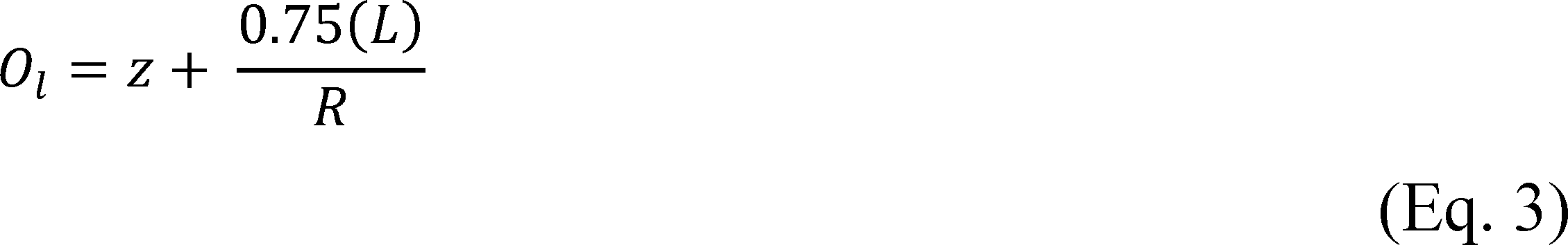
Where:
Ol = the operating limit for your PM CPMS on a 30-day rolling average, in milliamps or their digital signal equivalent,
L = your source emission limit expressed in mg/dscm,
z = your instrument zero in milliamps or digital equivalent, determined from paragraph (i)(2)(i) of this section, and
R = the relative mg/dscm per milliamp, or per digital signal output equivalent, for your PM CPMS, from equation 2.
(3) If the average of your three PM compliance test runs is at or above 75 percent of your PM emission limit you must determine your operating limit by averaging the PM CPMS milliamp or digital signal output corresponding to your three PM performance test runs that demonstrate compliance with the emission limit using equation 4 and you must submit all compliance test and PM CPMS data according to the reporting requirements in paragraph (i)(5) of this section:
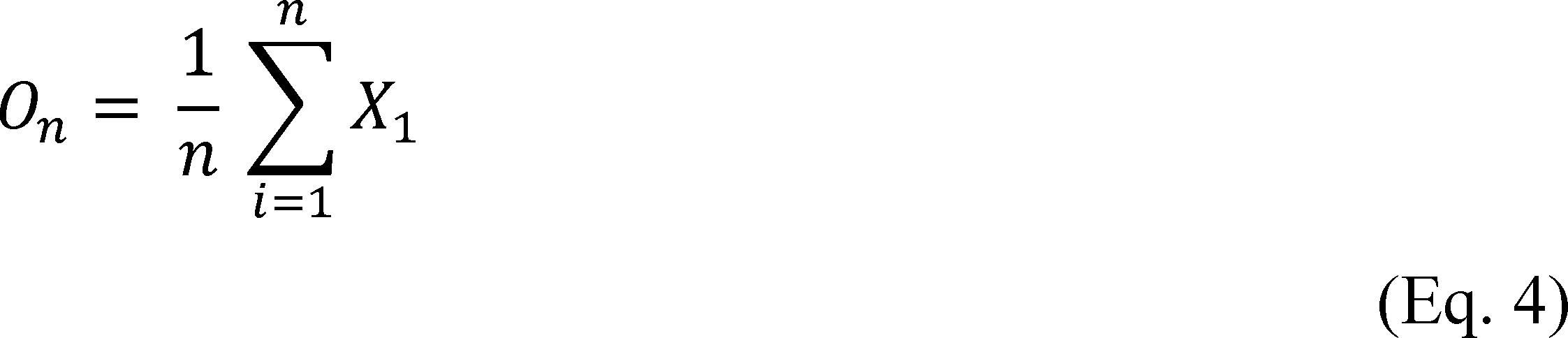
Where:
X1 = the PM CPMS data points for all runs i,
n = the number of data points, and
Oh = your site specific operating limit, in milliamps or digital signal equivalent.
(4) To determine continuous compliance, you must record the PM CPMS output data for all periods when the process is operating and the PM CPMS is not out-of-control. You must demonstrate continuous compliance by using all quality-assured hourly average data collected by the PM CPMS for all operating hours to calculate the arithmetic average operating parameter in units of the operating limit (e.g., milliamps or digital signal bits, PM concentration, raw data signal) on a 30-day rolling average basis.
(5) For PM performance test reports used to set a PM CPMS operating limit, the electronic submission of the test report must also include the make and model of the PM CPMS instrument, serial number of the instrument, analytical principle of the instrument (e.g., beta attenuation), span of the instruments primary analytical range, milliamp or digital signal value equivalent to the instrument zero output, technique by which this zero value was determined, and the average milliamp or digital signals corresponding to each PM compliance test run.
[84 FR 15884, Apr. 16, 2019, as amended at 85 FR 63406, Oct. 7, 2020]
§ 60.2680 What if I do not use a wet scrubber, fabric filter, activated carbon injection, selective noncatalytic reduction, an electrostatic precipitator, or a dry scrubber to comply with the emission limitations?
(a) If you use an air pollution control device other than a wet scrubber, activated carbon injection, selective noncatalytic reduction, fabric filter, an electrostatic precipitator, or a dry scrubber or limit emissions in some other manner, including mass balances, to comply with the emission limitations under § 60.2670, you must petition the EPA Administrator for specific operating limits to be established during the initial performance test and continuously monitored thereafter. You must submit the petition at least sixty days before the performance test is scheduled to begin. Your petition must include the five items listed in paragraphs (a)(1) through (5) of this section:
(1) Identification of the specific parameters you propose to use as additional operating limits;
(2) A discussion of the relationship between these parameters and emissions of regulated pollutants, identifying how emissions of regulated pollutants change with changes in these parameters and how limits on these parameters will serve to limit emissions of regulated pollutants;
(3) A discussion of how you will establish the upper and/or lower values for these parameters which will establish the operating limits on these parameters;
(4) A discussion identifying the methods you will use to measure and the instruments you will use to monitor these parameters, as well as the relative accuracy and precision of these methods and instruments; and
(5) A discussion identifying the frequency and methods for recalibrating the instruments you will use for monitoring these parameters.
(b) [Reserved]
Model Rule - Performance Testing
§ 60.2690 How do I conduct the initial and annual performance test?
(a) All performance tests must consist of a minimum of three test runs conducted under conditions representative of normal operations.
(b) You must document that the waste burned during the performance test is representative of the waste burned under normal operating conditions by maintaining a log of the quantity of waste burned (as required in § 60.2740(b)(1)) and the types of waste burned during the performance test.
(c) All performance tests must be conducted using the minimum run duration specified in tables 2 and 6 through 9 of this subpart.
(d) Method 1 of appendix A of this part must be used to select the sampling location and number of traverse points.
(e) Method 3A or 3B of appendix A of this part must be used for gas composition analysis, including measurement of oxygen concentration. Method 3A or 3B of appendix A of this part must be used simultaneously with each method (except when using Method 9 and Method 22).
(f) All pollutant concentrations, except for opacity, must be adjusted to 7 percent oxygen using equation 5 of this section:

Where:
Cadj = pollutant concentration adjusted to 7 percent oxygen;
Cmeas = pollutant concentration measured on a dry basis;
(20.9−7) = 20.9 percent oxygen−7 percent oxygen (defined oxygen correction basis);
20.9 = oxygen concentration in air, percent; and
%O2 = oxygen concentration measured on a dry basis, percent.
(g) You must determine dioxins/furans toxic equivalency by following the procedures in paragraphs (g)(1) through (4) of this section:
(1) Measure the concentration of each dioxin/furan tetra- through octa-isomer emitted using EPA Method 23 at 40 CFR part 60, appendix A;
(2) Quantify isomers meeting identification criteria 2, 3, 4, and 5 in Section 5.3.2.5 of Method 23, regardless of whether the isomers meet identification criteria 1 and 7. You must quantify the isomers per Section 9.0 of Method 23. [Note: You may reanalyze the sample aliquot or split to reduce the number of isomers not meeting identification criteria 1 or 7 of Section 5.3.2.5.];
(3) For each dioxin/furan (tetra- through octa-chlorinated) isomer measured in accordance with paragraph (g)(1) and (2) of this section, multiply the isomer concentration by its corresponding toxic equivalency factor specified in table 4 of this subpart; and
(4) Sum the products calculated in accordance with paragraph (g)(3) of this section to obtain the total concentration of dioxins/furans emitted in terms of toxic equivalency.
(h) Method 22 at 40 CFR part 60, appendix A-7 must be used to determine compliance with the fugitive ash emission limit in table 2 of this subpart or tables 6 through 9 of this subpart.
(i) If you have an applicable opacity operating limit, you must determine compliance with the opacity limit using Method 9 at 40 CFR part 60, appendix A-4, based on three 1-hour blocks consisting of ten 6-minute average opacity values, unless you are required to install a continuous opacity monitoring system, consistent with § 60.2710 and § 60.2730.
(j) You must determine dioxins/furans total mass basis by following the procedures in paragraphs (j)(1) through (3) of this section:
(1) Measure the concentration of each dioxin/furan tetra- through octa-chlorinated isomer emitted using EPA Method 23 at 40 CFR part 60, appendix A-7;
(2) Quantify isomers meeting identification criteria 2, 3, 4, and 5 in Section 5.3.2.5 of Method 23, regardless of whether the isomers meet identification criteria 1 and 7. You must quantify the isomers per Section 9.0 of Method 23. (Note: You may reanalyze the sample aliquot or split to reduce the number of isomers not meeting identification criteria 1 or 7 of Section 5.3.2.5.); and
(3) Sum the quantities measured in accordance with paragraphs (j)(1) and (2) of this section to obtain the total concentration of dioxins/furans emitted in terms of total mass basis.
§ 60.2695 How are the performance test data used?
You use results of performance tests to demonstrate compliance with the emission limitations in table 2 of this subpart or tables 6 through 9 of this subpart.
Model Rule - Initial Compliance Requirements
§ 60.2700 How do I demonstrate initial compliance with the amended emission limitations and establish the operating limits?
(a) You must conduct a performance test, as required under §§ 60.2670 and 60.2690, to determine compliance with the emission limitations in table 2 of this subpart and tables 6 through 9 of this subpart, to establish compliance with any opacity operating limits in § 60.2675, to establish the kiln-specific emission limit in § 60.2710(y), as applicable, and to establish operating limits using the procedures in § 60.2675 or § 60.2680. The performance test must be conducted using the test methods listed in table 2 of this subpart and tables 6 through 9 of this subpart and the procedures in § 60.2690. The use of the bypass stack during a performance test shall invalidate the performance test.
(b) As an alternative to conducting a performance test, as required under §§ 60.2690 and 60.2670, you may use a 30-day rolling average of the 1-hour arithmetic average CEMS data, including CEMS data during startup and shutdown as defined in this subpart, to determine compliance with the emission limitations in Table 1 of this subpart or Tables 5 through 8 of this subpart. You must conduct a performance evaluation of each continuous monitoring system within 180 days of installation of the monitoring system. The initial performance evaluation must be conducted prior to collecting CEMS data that will be used for the initial compliance demonstration.
§ 60.2705 By what date must I conduct the initial performance test?
(a) The initial performance test must be conducted no later than 180 days after your final compliance date. Your final compliance date is specified in table 1 of this subpart.
(b) If you commence or recommence combusting a solid waste at an existing combustion unit at any commercial or industrial facility and you conducted a test consistent with the provisions of this subpart while combusting the given solid waste within the 6 months preceding the reintroduction of that solid waste in the combustion chamber, you do not need to retest until 6 months from the date you reintroduce that solid waste.
(c) If you commence or recommence combusting a solid waste at an existing combustion unit at any commercial or industrial facility and you have not conducted a performance test consistent with the provisions of this subpart while combusting the given solid waste within the 6 months preceding the reintroduction of that solid waste in the combustion chamber, you must conduct a performance test within 60 days from the date you reintroduce solid waste.
§ 60.2706 By what date must I conduct the initial air pollution control device inspection?
(a) The initial air pollution control device inspection must be conducted within 60 days after installation of the control device and the associated CISWI reaches the charge rate at which it will operate, but no later than 180 days after the final compliance date for meeting the amended emission limitations.
(b) Within 10 operating days following an air pollution control device inspection, all necessary repairs must be completed unless the owner or operator obtains written approval from the state agency establishing a date whereby all necessary repairs of the designated facility must be completed.
Model Rule - Continuous Compliance Requirements
§ 60.2710 How do I demonstrate continuous compliance with the amended emission limitations and the operating limits?
(a) General compliance with standards, considering some units may be able to switch between solid waste and non-waste fuel combustion, is specified in paragraph (a)(1) through (6) of this section.
(1) The emission standards and operating requirements set forth in this subpart apply at all times.
(2) If you cease combusting solid waste you may opt to remain subject to the provisions of this subpart. Consistent with the definition of CISWI, you are subject to the requirements of this subpart at least 6 months following the last date of solid waste combustion. Solid waste combustion is ceased when solid waste is not in the combustion chamber (i.e., the solid waste feed to the combustor has been cut off for a period of time not less than the solid waste residence time).
(3) If you cease combusting solid waste you must be in compliance with any newly applicable standards on the effective date of the waste-to-fuel switch. The effective date of the waste-to-fuel switch is a date selected by you, that must be at least 6 months from the date that you ceased combusting solid waste, consistent with § 60.2710(a)(2). Your source must remain in compliance with this subpart until the effective date of the waste-to-fuel switch.
(4) If you own or operate an existing commercial or industrial combustion unit that combusted a fuel or non-waste material, and you commence or recommence combustion of solid waste, you are subject to the provisions of this subpart as of the first day you introduce or reintroduce solid waste to the combustion chamber, and this date constitutes the effective date of the fuel-to-waste switch. You must complete all initial compliance demonstrations for any Section 112 standards that are applicable to your facility before you commence or recommence combustion of solid waste. You must provide 30 days prior notice of the effective date of the waste-to-fuel switch. The notification must identify:
(i) The name of the owner or operator of the CISWI, the location of the source, the emissions unit(s) that will cease burning solid waste, and the date of the notice;
(ii) The currently applicable subcategory under this subpart, and any 40 CFR part 63 subpart and subcategory that will be applicable after you cease combusting solid waste;
(iii) The fuel(s), non-waste material(s) and solid waste(s) the CISWI is currently combusting and has combusted over the past 6 months, and the fuel(s) or non-waste materials the unit will commence combusting;
(iv) The date on which you became subject to the currently applicable emission limits;
(v) The date upon which you will cease combusting solid waste, and the date (if different) that you intend for any new requirements to become applicable (i.e., the effective date of the waste-to-fuel switch), consistent with paragraphs (a)(2) and (3) of this section.
(5) All air pollution control equipment necessary for compliance with any newly applicable emissions limits which apply as a result of the cessation or commencement or recommencement of combusting solid waste must be installed and operational as of the effective date of the waste-to-fuel, or fuel-to-waste switch.
(6) All monitoring systems necessary for compliance with any newly applicable monitoring requirements which apply as a result of the cessation or commencement or recommencement of combusting solid waste must be installed and operational as of the effective date of the waste-to-fuel, or fuel-to-waste switch. All calibration and drift checks must be performed as of the effective date of the waste-to-fuel, or fuel-to-waste switch. Relative accuracy tests must be performed as of the performance test deadline for PM CEMS (if PM CEMS are elected to demonstrate continuous compliance with the particulate matter emission limits). Relative accuracy testing for other CEMS need not be repeated if that testing was previously performed consistent with section 112 monitoring requirements or monitoring requirements under this subpart.
(b) You must conduct an annual performance test for the pollutants listed in table 2 of this subpart or tables 6 through 9 of this subpart and opacity for each CISWI as required under § 60.2690. The annual performance test must be conducted using the test methods listed in table 2 of this subpart or tables 6 through 9 of this subpart and the procedures in § 60.2690. Opacity must be measured using EPA Reference Method 9 at 40 CFR part 60. Annual performance tests are not required if you use CEMS or continuous opacity monitoring systems to determine compliance.
(c) You must continuously monitor the operating parameters specified in § 60.2675 or established under § 60.2680 and as specified in § 60.2735. Operation above the established maximum or below the established minimum operating limits constitutes a deviation from the established operating limits. Three-hour block average values are used to determine compliance (except for baghouse leak detection system alarms) unless a different averaging period is established under § 60.2680 or, for energy recovery units, where the averaging time for each operating parameter is a 30-day rolling, calculated each hour as the average of the previous 720 operating hours. Operation above the established maximum, below the established minimum, or outside the allowable range of the operating limits specified in paragraph (a) of this section constitutes a deviation from your operating limits established under this subpart, except during performance tests conducted to determine compliance with the emission and operating limits or to establish new operating limits. Operating limits are confirmed or reestablished during performance tests.
(d) You must burn only the same types of waste and fuels used to establish subcategory applicability (for ERUs) and operating limits during the performance test.
(e) For energy recovery units, incinerators, and small remote units, you must perform annual visual emissions test for ash handling.
(f) For energy recovery units, you must conduct an annual performance test for opacity using EPA Reference Method 9 at 40 CFR part 60 (except where particulate matter continuous monitoring system or CPMS are used) and the pollutants listed in table 7 of this subpart.
(g) For facilities using a CEMS to demonstrate compliance with the carbon monoxide emission limit, compliance with the carbon monoxide emission limit may be demonstrated by using the CEMS, as described in § 60.2730(o).
(h) Coal and liquid/gas energy recovery units with annual average heat input rates greater than 250 MMBtu/hr may elect to demonstrate continuous compliance with the particulate matter emissions limit using a particulate matter CEMS according to the procedures in § 60.2730(n) instead of the CPMS specified in § 60.2710(i). Coal and liquid/gas energy recovery units with annual average heat input rates less than 250 MMBtu/hr, incinerators, and small remote incinerators may also elect to demonstrate compliance using a particulate matter CEMS according to the procedures in § 60.2730(n) instead of particulate matter testing with EPA Method 5 at 40 CFR part 60, appendix A-3 and, if applicable, the continuous opacity monitoring requirements in paragraph (i) of this section.
(i) For energy recovery units with annual average heat input rates greater than or equal to 10 MMBtu/hr but less than 250 MMBtu/hr that do not use a wet scrubber, fabric filter with bag leak detection system, an electrostatic precipitator, particulate matter CEMS, or particulate matter CPMS, you must install, operate, certify and maintain a continuous opacity monitoring system (COMS) according to the procedures in § 60.2730(m).
(j) For waste-burning kilns, you must conduct an annual performance test for the pollutants (except mercury and hydrogen chloride if no acid gas wet scrubber or dry scrubber is used) listed in Table 8 of this subpart, unless you choose to demonstrate initial and continuous compliance using CEMS, as allowed in paragraph (u) of this section. If you do not use an acid gas wet scrubber or dry scrubber, you must determine compliance with the hydrogen chloride emissions limit using a HCl CEMS according to the requirements in paragraph (j)(1) of this section. You must determine compliance with the mercury emissions limit using a mercury CEMS or an integrated sorbent trap monitoring system according to paragraph (j)(2) of this section. You must determine continuing compliance with particulate matter using a PM CPMS according to paragraph (x) of this section.
(1) If you monitor compliance with the HCl emissions limit by operating an HCl CEMS, you must do so in accordance with Performance Specification 15 (PS 15) of appendix B to 40 CFR part 60, or, PS 18 of appendix B to 40 CFR part 60. You must operate, maintain, and quality assure a HCl CEMS installed and certified under PS 15 according to the quality assurance requirements in Procedure 1 of appendix F to 40 CFR part 60 except that the Relative Accuracy Test Audit requirements of Procedure 1 must be replaced with the validation requirements and criteria of sections 11.1.1 and 12.0 of PS 15. You must operate, maintain and quality assure a HCl CEMS installed and certified under PS 18 according to the quality assurance requirements in Procedure 6 of appendix F to 40 CFR part 60. For any performance specification that you use, you must use Method 321 of appendix A to 40 CFR part 63 as the reference test method for conducting relative accuracy testing. The span value and calibration requirements in paragraphs (j)(1)(i) and (ii) of this section apply to all HCl CEMS used under this subpart:
(i) You must use a measurement span value for any HCl CEMS of 0-10 ppmvw unless the monitor is installed on a kiln without an inline raw mill. Kilns without an inline raw mill may use a higher span value sufficient to quantify all expected emissions concentrations. The HCl CEMS data recorder output range must include the full range of expected HCl concentration values which would include those expected during “mill off” conditions. The corresponding data recorder range shall be documented in the site-specific monitoring plan and associated records; and
(ii) In order to quality assure data measured above the span value, you must use one of the three options in paragraphs (j)(1)(ii)(A) through (C) of this section:
(A) Include a second span that encompasses the HCl emission concentrations expected to be encountered during “mill off” conditions. This second span may be rounded to a multiple of 5 ppm of total HCl. The requirements of the appropriate HCl monitor performance specification shall be followed for this second span with the exception that a RATA with the mill off is not required;
(B) Quality assure any data above the span value by proving instrument linearity beyond the span value established in paragraph (j)(1)(i) of this section using the following procedure. Conduct a weekly “above span linearity” calibration challenge of the monitoring system using a reference gas with a certified value greater than your highest expected hourly concentration or greater than 75% of the highest measured hourly concentration. The “above span” reference gas must meet the requirements of the applicable performance specification and must be introduced to the measurement system at the probe. Record and report the results of this procedure as you would for a daily calibration. The “above span linearity” challenge is successful if the value measured by the HCl CEMS falls within 10 percent of the certified value of the reference gas. If the value measured by the HCl CEMS during the above span linearity challenge exceeds 10 percent of the certified value of the reference gas, the monitoring system must be evaluated and repaired and a new “above span linearity” challenge met before returning the HCl CEMS to service, or data above span from the HCl CEMS must be subject to the quality assurance procedures established in (j)(1)(ii)(D) of this section. In this manner values measured by the HCl CEMS during the above span linearity challenge exceeding ±20 percent of the certified value of the reference gas must be normalized using equation 6;
(C) Quality assure any data above the span value established in paragraph (j)(1)(i) of this section using the following procedure. Any time two consecutive one-hour average measured concentration of HCl exceeds the span value you must, within 24 hours before or after, introduce a higher, “above span” HCl reference gas standard to the HCl CEMS. The “above span” reference gas must meet the requirements of the applicable performance specification and target a concentration level between 50 and 150 percent of the highest expected hourly concentration measured during the period of measurements above span, and must be introduced at the probe. While this target represents a desired concentration range that is not always achievable in practice, it is expected that the intent to meet this range is demonstrated by the value of the reference gas. Expected values may include above span calibrations done before or after the above-span measurement period. Record and report the results of this procedure as you would for a daily calibration. The “above span” calibration is successful if the value measured by the HCl CEMS is within 20 percent of the certified value of the reference gas. If the value measured by the HCl CEMS is not within 20 percent of the certified value of the reference gas, then you must normalize the stack gas values measured above span as described in paragraph (j)(1)(ii)(D) of this section. If the “above span” calibration is conducted during the period when measured emissions are above span and there is a failure to collect the one data point in an hour due to the calibration duration, then you must determine the emissions average for that missed hour as the average of hourly averages for the hour preceding the missed hour and the hour following the missed hour. In an hour where an “above span” calibration is being conducted and one or more data points are collected, the emissions average is represented by the average of all valid data points collected in that hour; and
(D) In the event that the “above span” calibration is not successful (i.e., the HCl CEMS measured value is not within 20 percent of the certified value of the reference gas), then you must normalize the one-hour average stack gas values measured above the span during the 24-hour period preceding or following the “above span” calibration for reporting based on the HCl CEMS response to the reference gas as shown in equation 6:

Only one “above span” calibration is needed per 24-hour period.
(2) Compliance with the mercury emissions limit must be determined using a mercury CEMS or integrated sorbent trap monitoring system according to the following requirements:
(i) You must operate a mercury CEMS in accordance with performance specification 12A at 40 CFR part 60, appendix B or an integrated sorbent trap monitoring system in accordance with performance specification 12B at 40 CFR part 60, appendix B; these monitoring systems must be quality assured according to procedure 5 of 40 CFR 60, appendix F. For the purposes of emissions calculations when using an integrated sorbent trap monitoring system, the mercury concentration determined for each sampling period must be assigned to each hour during the sampling period. If you choose to comply with the production-rate based mercury limit for your waste-burning kiln, you must also monitor hourly clinker production and determine the hourly mercury emissions rate in pounds per million ton of clinker produced. You must demonstrate compliance with the mercury emissions limit using a 30-day rolling average of these 1-hour mercury concentrations or mass emissions rates, including CEMS data during startup and shutdown as defined in this subpart, calculated using equation 19-19 in section 12.4.1 of EPA Reference Method 19 at 40 CFR part 60, appendix A-7 of this part. CEMS data during startup and shutdown, as defined in this subpart, are not corrected to 7 percent oxygen, and are measured at stack oxygen content;
(ii) Owners or operators using a mercury CEMS or integrated sorbent trap monitoring system to determine mass emission rate must install, operate, calibrate and maintain an instrument for continuously measuring and recording the mercury mass emissions rate to the atmosphere according to the requirements of performance specification 6 at 40 CFR part 60, appendix B and conducting an annual relative accuracy test of the continuous emission rate monitoring system according to section 8.2 of performance specification 6; and
(iii) The owner or operator of a waste-burning kiln must demonstrate initial compliance by operating a mercury CEMS or integrated sorbent trap monitoring system while the raw mill of the in-line kiln/raw mill is operating under normal conditions and including at least one period when the raw mill is off.
(k) If you use an air pollution control device to meet the emission limitations in this subpart, you must conduct an initial and annual inspection of the air pollution control device. The inspection must include, at a minimum, the following:
(1) Inspect air pollution control device(s) for proper operation; and
(2) Develop a site-specific monitoring plan according to the requirements in paragraph (l) of this section. This requirement also applies to you if you petition the EPA Administrator for alternative monitoring parameters under § 60.13(i).
(l) For each CMS required in this section, you must develop and submit to the EPA Administrator for approval a site-specific monitoring plan according to the requirements of this paragraph (l) that addresses paragraphs (l)(1)(i) through (vi) of this section:
(1) You must submit this site-specific monitoring plan at least 60 days before your initial performance evaluation of your continuous monitoring system:
(i) Installation of the continuous monitoring system sampling probe or other interface at a measurement location relative to each affected process unit such that the measurement is representative of control of the exhaust emissions (e.g., on or downstream of the last control device);
(ii) Performance and equipment specifications for the sample interface, the pollutant concentration or parametric signal analyzer and the data collection and reduction systems;
(iii) Performance evaluation procedures and acceptance criteria (e.g., calibrations);
(iv) Ongoing operation and maintenance procedures in accordance with the general requirements of § 60.11(d);
(v) Ongoing data quality assurance procedures in accordance with the general requirements of § 60.13; and
(2) You must conduct a performance evaluation of each continuous monitoring system in accordance with your site-specific monitoring plan.
(3) You must operate and maintain the continuous monitoring system in continuous operation according to the site-specific monitoring plan.
(m) If you have an operating limit that requires the use of a flow monitoring system, you must meet the requirements in paragraphs (l) and (m)(1) through (4) of this section:
(1) Install the flow sensor and other necessary equipment in a position that provides a representative flow;
(2) Use a flow sensor with a measurement sensitivity at full scale of no greater than 2 percent;
(3) Minimize the effects of swirling flow or abnormal velocity distributions due to upstream and downstream disturbances; and
(4) Conduct a flow monitoring system performance evaluation in accordance with your monitoring plan at the time of each performance test but no less frequently than annually.
(n) If you have an operating limit that requires the use of a pressure monitoring system, you must meet the requirements in paragraphs (l) and (n)(1) through (6) of this section:
(1) Install the pressure sensor(s) in a position that provides a representative measurement of the pressure (e.g., PM scrubber pressure drop);
(2) Minimize or eliminate pulsating pressure, vibration, and internal and external corrosion;
(3) Use a pressure sensor with a minimum tolerance of 1.27 centimeters of water or a minimum tolerance of 1 percent of the pressure monitoring system operating range, whichever is less;
(4) Perform checks at the frequency outlined in your site-specific monitoring plan to ensure pressure measurements are not obstructed (e.g., check for pressure tap plugging daily);
(5) Conduct a performance evaluation of the pressure monitoring system in accordance with your monitoring plan at the time of each performance test but no less frequently than annually; and
(6) If at any time the measured pressure exceeds the manufacturer's specified maximum operating pressure range, conduct a performance evaluation of the pressure monitoring system in accordance with your monitoring plan and confirm that the pressure monitoring system continues to meet the performance requirements in your monitoring plan. Alternatively, install and verify the operation of a new pressure sensor.
(o) If you have an operating limit that requires a pH monitoring system, you must meet the requirements in paragraphs (l) and (o)(1) through (4) of this section:
(1) Install the pH sensor in a position that provides a representative measurement of scrubber effluent pH;
(2) Ensure the sample is properly mixed and representative of the fluid to be measured;
(3) Conduct a performance evaluation of the pH monitoring system in accordance with your monitoring plan at least once each process operating day; and
(4) Conduct a performance evaluation (including a two-point calibration with one of the two buffer solutions having a pH within 1 of the pH of the operating limit) of the pH monitoring system in accordance with your monitoring plan at the time of each performance test but no less frequently than quarterly.
(p) If you have an operating limit that requires a secondary electric power monitoring system for an electrostatic precipitator, you must meet the requirements in paragraphs (l) and (p)(1) and (2) of this section:
(1) Install sensors to measure (secondary) voltage and current to the precipitator collection plates; and
(2) Conduct a performance evaluation of the electric power monitoring system in accordance with your monitoring plan at the time of each performance test but no less frequently than annually.
(q) If you have an operating limit that requires the use of a monitoring system to measure sorbent injection rate (e.g., weigh belt, weigh hopper, or hopper flow measurement device), you must meet the requirements in paragraphs (l) and (q)(1) and (2) of this section:
(1) Install the system in a position(s) that provides a representative measurement of the total sorbent injection rate; and
(2) Conduct a performance evaluation of the sorbent injection rate monitoring system in accordance with your monitoring plan at the time of each performance test but no less frequently than annually.
(r) If you elect to use a fabric filter bag leak detection system to comply with the requirements of this subpart, you must install, calibrate, maintain, and continuously operate a bag leak detection system as specified in paragraphs (l) and (r)(1) through (5) of this section:
(1) Install a bag leak detection sensor(s) in a position(s) that will be representative of the relative or absolute particulate matter loadings for each exhaust stack, roof vent, or compartment (e.g., for a positive pressure fabric filter) of the fabric filter;
(2) Use a bag leak detection system certified by the manufacturer to be capable of detecting particulate matter emissions at concentrations of 10 milligrams per actual cubic meter or less;
(3) Conduct a performance evaluation of the bag leak detection system in accordance with your monitoring plan and consistent with the guidance provided in EPA-454/R-98-015 (incorporated by reference, see § 60.17);
(4) Use a bag leak detection system equipped with a device to continuously record the output signal from the sensor; and
(5) Use a bag leak detection system equipped with a system that will sound an alarm when an increase in relative particulate matter emissions over a preset level is detected. The alarm must be located where it is observed readily by plant operating personnel.
(s) For facilities using a CEMS to demonstrate initial and continuous compliance with the sulfur dioxide emission limit, compliance with the sulfur dioxide emission limit may be demonstrated by using the CEMS specified in § 60.2730(l) to measure sulfur dioxide. The sulfur dioxide CEMS must follow the procedures and methods specified in paragraph (s) of this section. For sources that have actual inlet emissions less than 100 parts per million dry volume, the relative accuracy criterion for inlet sulfur dioxide CEMS should be no greater than 20 percent of the mean value of the reference method test data in terms of the units of the emission standard, or 5 parts per million dry volume absolute value of the mean difference between the reference method and the CEMS, whichever is greater:
(1) During each relative accuracy test run of the CEMS required by performance specification 2 in appendix B of this part, collect sulfur dioxide and oxygen (or carbon dioxide) data concurrently (or within a 30- to 60-minute period) with both the CEMS and the test methods specified in paragraphs (s)(1)(i) and (ii) of this section:
(i) For sulfur dioxide, EPA Reference Method 6 or 6C, or as an alternative ANSI/ASME PTC 19.10-1981 (incorporated by reference, see § 60.17) must be used; and
(ii) For oxygen (or carbon dioxide), EPA Reference Method 3A or 3B, or as an alternative ANSI/ASME PTC 19.10-1981 (incorporated by reference, see § 60.17), as applicable, must be used.
(2) The span value of the CEMS at the inlet to the sulfur dioxide control device must be 125 percent of the maximum estimated hourly potential sulfur dioxide emissions of the unit subject to this subpart. The span value of the CEMS at the outlet of the sulfur dioxide control device must be 50 percent of the maximum estimated hourly potential sulfur dioxide emissions of the unit subject to this subpart.
(3) Conduct accuracy determinations quarterly and calibration drift tests daily in accordance with procedure 1 in appendix F of this part.
(t) For facilities using a CEMS to demonstrate initial and continuous compliance with the nitrogen oxides emission limit, compliance with the nitrogen oxides emission limit may be demonstrated by using the CEMS specified in § 60.2730 to measure nitrogen oxides. The nitrogen oxides CEMS must follow the procedures and methods specified in paragraphs (t)(1) through (4) of this section:
(1) During each relative accuracy test run of the CEMS required by performance specification 2 of appendix B of this part, collect nitrogen oxides and oxygen (or carbon dioxide) data concurrently (or within a 30- to 60-minute period) with both the CEMS and the test methods specified in paragraphs (t)(1)(i) and (ii) of this section:
(i) For nitrogen oxides, EPA Reference Method 7 or 7E at 40 CFR part 60, appendix A-4 must be used; and
(ii) For oxygen (or carbon dioxide), EPA Reference Method 3A or 3B, or as an alternative ANSI/ASME PTC 19.10-1981 (incorporated by reference, see § 60.17), as applicable, must be used.
(2) The span value of the CEMS must be 125 percent of the maximum estimated hourly potential nitrogen oxide emissions of unit.
(3) Conduct accuracy determinations quarterly and calibration drift tests daily in accordance with procedure 1 in appendix F of this part.
(4) The owner or operator of an affected facility may request that compliance with the nitrogen oxides emission limit be determined using carbon dioxide measurements corrected to an equivalent of 7 percent oxygen. If carbon dioxide is selected for use in diluent corrections, the relationship between oxygen and carbon dioxide levels must be established during the initial performance test according to the procedures and methods specified in paragraphs (t)(4)(i) through (iv) of this section. This relationship may be reestablished during performance compliance tests:
(i) The fuel factor equation in Method 3B must be used to determine the relationship between oxygen and carbon dioxide at a sampling location. Method 3A, 3B, or as an alternative ANSI/ASME PTC 19.10-1981 (incorporated by reference, see § 60.17), as applicable, must be used to determine the oxygen concentration at the same location as the carbon dioxide monitor;
(ii) Samples must be taken for at least 30 minutes in each hour;
(iii) Each sample must represent a 1-hour average; and
(iv) A minimum of 3 runs must be performed.
(u) For facilities using a CEMS or an integrated sorbent trap monitoring system for mercury to demonstrate initial and continuous compliance with any of the emission limits of this subpart, you must complete the following:
(1) Demonstrate compliance with the appropriate emission limit(s) using a 30-day rolling average of 1-hour arithmetic average emission concentrations, including CEMS or an integrated sorbent trap monitoring system data during startup and shutdown, as defined in this subpart, calculated using equation 19-19 in section 12.4.1 of EPA Reference Method 19 at appendix A-7 of this part. The 1-hour arithmetic averages for CEMS must be calculated using the data points required under § 60.13(e)(2). Except for CEMS or an integrated sorbent trap monitoring system data during startup and shutdown, the 1-hour arithmetic averages used to calculate the 30-day rolling average emission concentrations must be corrected to 7 percent oxygen (dry basis). Integrated sorbent trap monitoring system or CEMS data during startup and shutdown, as defined in this subpart, are not corrected to 7 percent oxygen, and are measured at stack oxygen content; and
(2) Operate all CEMS and integrated sorbent trap monitoring systems in accordance with the applicable procedures under appendices B and F of this part.
(v) Use of the bypass stack at any time is an emissions standards deviation for PM, HCl, lead, cadmium, mercury, nitrogen oxides, sulfur dioxide, and dioxin/furans.
(w) For energy recovery units with a design heat input capacity of 100 MMBtu/hr or greater that do not use a carbon monoxide CEMS, you must install, operate, and maintain an oxygen analyzer system as defined in § 60.2875 according to the procedures in paragraphs (w)(1) through (4) of this section:
(1) The oxygen analyzer system must be installed by the initial performance test date specified in § 60.2675;
(2) You must operate the oxygen trim system within compliance with paragraph (w)(3) of this section at all times;
(3) You must maintain the oxygen level such that the 30-day rolling average that is established as the operating limit for oxygen is not below the lowest hourly average oxygen concentration measured during the most recent CO performance test; and
(4) You must calculate and record a 30-day rolling average oxygen concentration using equation 19-19 in section 12.4.1 of EPA Reference Method 19 of appendix A-7 of this part.
(x) For energy recovery units with annual average heat input rates greater than or equal to 250 MMBtu/hr and waste-burning kilns, you must install, calibrate, maintain, and operate a PM CPMS and record the output of the system as specified in paragraphs (x)(1) through (8) of this section. For other energy recovery units, you may elect to use PM CPMS operated in accordance with this section. PM CPMS are suitable in lieu of using other CMS for monitoring PM compliance (e.g., bag leak detectors, ESP secondary power, PM scrubber pressure):
(1) Install, calibrate, operate, and maintain your PM CPMS according to the procedures in your approved site-specific monitoring plan developed in accordance with paragraphs (l) and (x)(1)(i) through (iii) of this section:
(i) The operating principle of the PM CPMS must be based on in-stack or extractive light scatter, light scintillation, beta attenuation, or mass accumulation of the exhaust gas or representative sample. The reportable measurement output from the PM CPMS must be expressed as milliamps or the digital signal equivalent;
(ii) The PM CPMS must have a cycle time (i.e., period required to complete sampling, measurement, and reporting for each measurement) no longer than 60 minutes; and
(iii) The PM CPMS must be capable of detecting and responding to particulate matter concentrations increments no greater than 0.5 mg/actual cubic meter.
(2) During the initial performance test or any such subsequent performance test that demonstrates compliance with the PM limit, you must adjust the site-specific operating limit in accordance with the results of the performance test according to the procedures specified in § 60.2675.
(3) Collect PM CPMS hourly average output data for all energy recovery unit or waste-burning kiln operating hours. Express the PM CPMS output as milliamps or the digital signal equivalent.
(4) Calculate the arithmetic 30-day rolling average of all of the hourly average PM CPMS output collected during all energy recovery unit or waste-burning kiln operating hours data (milliamps or their digital equivalent).
(5) You must collect data using the PM CPMS at all times the energy recovery unit or waste-burning kiln is operating and at the intervals specified in paragraph (x)(1)(ii) of this section, except for periods of monitoring system malfunctions, repairs associated with monitoring system malfunctions, required monitoring system quality assurance or quality control activities (including, as applicable, calibration checks and required zero and span adjustments), and any scheduled maintenance as defined in your site-specific monitoring plan.
(6) You must use all the data collected during all energy recovery unit or waste-burning kiln operating hours in assessing the compliance with your operating limit except:
(i) Any data collected during monitoring system malfunctions, repairs associated with monitoring system malfunctions, or required monitoring system quality assurance or quality control activities conducted during monitoring system malfunctions are not used in calculations (report any such periods in your annual deviation report);
(ii) Any data collected during periods when the monitoring system is out of control as specified in your site-specific monitoring plan, repairs associated with periods when the monitoring system is out of control, or required monitoring system quality assurance or quality control activities conducted during out-of-control periods are not used in calculations (report emissions or operating levels and report any such periods in your annual deviation report);
(iii) Any PM CPMS data recorded during periods of CEMS data during startup and shutdown, as defined in this subpart.
(7) You must record and make available upon request results of PM CPMS system performance audits, as well as the dates and duration of periods from when the PM CPMS is out of control until completion of the corrective actions necessary to return the PM CPMS to operation consistent with your site-specific monitoring plan.
(8) For any deviation of the 30-day rolling average PM CPMS average value from the established operating parameter limit, you must:
(i) Within 48 hours of the deviation, visually inspect the air pollution control device;
(ii) If inspection of the air pollution control device identifies the cause of the deviation, take corrective action as soon as possible and return the PM CPMS measurement to within the established value;
(iii) Within 30 days of the deviation or at the time of the annual compliance test, whichever comes first, conduct a PM emissions compliance test to determine compliance with the PM emissions limit. Within 45 days of the deviation, you must re-establish the CPMS operating limit. You are not required to conduct additional testing for any deviations that occur between the time of the original deviation and the PM emissions compliance test required under paragraph (x) of this section; and
(iv) PM CPMS deviations leading to more than four required performance tests in a 12-month process operating period (rolling monthly) constitute a violation of this subpart.
(y) When there is an alkali bypass and/or an in-line coal mill that exhaust emissions through a separate stack(s), the combined emissions are subject to the emission limits applicable to waste-burning kilns. To determine the kiln-specific emission limit for demonstrating compliance, you must:
(1) Calculate a kiln-specific emission limit using equation 7:

Where:
Cks = Kiln stack concentration (ppmvd, mg/dscm, ng/dscm, depending on pollutant. Each corrected to 7% O2.)
Qab = Alkali bypass flow rate (volume/hr)
Cab = Alkali bypass concentration (ppmvd, mg/dscm, ng/dscm, depending on pollutant. Each corrected to 7% O2.)
Qcm = In-line coal mill flow rate (volume/hr)
Ccm = In-line coal mill concentration (ppmvd, mg/dscm, ng/dscm, depending on pollutant. Each corrected to 7% O2.)
Qks = Kiln stack flow rate (volume/hr)
(2) Particulate matter concentration must be measured downstream of the in-line coal mill. All other pollutant concentrations must be measured either upstream or downstream of the in-line coal mill.
(3) For purposes of determining the combined emissions from kilns equipped with an alkali bypass or that exhaust kiln gases to a coal mill that exhausts through a separate stack, instead of installing a CEMS or PM CPMS on the alkali bypass stack or in-line coal mill stack, the results of the initial and subsequent performance test can be used to demonstrate compliance with the relevant emissions limit. A performance test must be conducted on an annual basis (no later than 13 calendar months following the previous performance test).
[84 FR 15884, Apr. 16, 2019, as amended at 85 FR 63406, Oct. 7, 2020]
§ 60.2715 By what date must I conduct the annual performance test?
You must conduct annual performance tests no later than 13 calendar months following the previous performance test.
[85 FR 63406, Oct. 7, 2020]
§ 60.2716 By what date must I conduct the annual air pollution control device inspection?
On an annual basis (no more than 12 months following the previous annual air pollution control device inspection), you must complete the air pollution control device inspection as described in § 60.2706.
§ 60.2720 May I conduct performance testing less often?
(a) You must conduct annual performance tests according to the schedule specified in § 60.2715, with the following exceptions:
(1) You may conduct a repeat performance test at any time to establish new values for the operating limits, as specified in § 60.2725. New operating limits become effective on the date that the performance test report is submitted to the EPA's Central Data Exchange or postmarked, per the requirements of § 60.2795(b). The Administrator may request a repeat performance test at any time;
(2) You must repeat the performance test within 60 days of a process change, as defined in § 60.2875; and
(3) You can conduct performance tests less often if you meet the following conditions: Your performance tests for the pollutant for at least 2 consecutive performance tests demonstrates that the emission level for the pollutant is no greater than the emission level specified in paragraph (a)(3)(i) or (ii) of this section, as applicable; there are no changes in the operation of the affected source or air pollution control equipment that could increase emissions; and you are not required to conduct a performance test for the pollutant in response to a request by the Administrator in paragraph (a)(1) of this section or a process change in paragraph (a)(2) of this section. In this case, you do not have to conduct a performance test for that pollutant for the next 2 years. You must conduct a performance test for the pollutant no more than 37 months following the previous performance test for the pollutant. If the emission level for your CISWI continues to meet the emission level specified in paragraph (a)(3)(i) or (ii) of this section, as applicable, you may choose to conduct performance tests for the pollutant every third year, as long as there are no changes in the operation of the affected source or air pollution control equipment that could increase emissions. Each such performance test must be conducted no more than 37 months after the previous performance test.
(i) For particulate matter, hydrogen chloride, mercury, carbon monoxide, nitrogen oxides, sulfur dioxide, cadmium, lead, and dioxins/furans, the emission level equal to 75 percent of the applicable emission limit in table 2 or tables 6 through 9 of this subpart, as applicable; and
(ii) For fugitive emissions, visible emissions (of combustion ash from the ash conveying system) for 2 percent of the time during each of the three 1-hour observation periods.
(4) If you are conducting less frequent testing for a pollutant as provided in paragraph (a)(3) of this section and a subsequent performance test for the pollutant indicates that your CISWI does not meet the emission level specified in paragraph (a)(3)(i) or (a)(3)(ii) of this section, as applicable, you must conduct annual performance tests for the pollutant according to the schedule specified in paragraph (a) of this section until you qualify for less frequent testing for the pollutant as specified in paragraph (a)(3) of this section.
(b) [Reserved]
§ 60.2725 May I conduct a repeat performance test to establish new operating limits?
(a) Yes. You may conduct a repeat performance test at any time to establish new values for the operating limits. The Administrator may request a repeat performance test at any time.
(b) You must repeat the performance test if your feed stream is different than the feed streams used during any performance test used to demonstrate compliance.
Model Rule - Monitoring
§ 60.2730 What monitoring equipment must I install and what parameters must I monitor?
(a) If you are using a wet scrubber to comply with the emission limitation under § 60.2670, you must install, calibrate (to manufacturers' specifications), maintain, and operate devices (or establish methods) for monitoring the value of the operating parameters used to determine compliance with the operating limits listed in table 3 of this subpart. These devices (or methods) must measure and record the values for these operating parameters at the frequencies indicated in table 3 of this subpart at all times except as specified in § 60.2735(a).
(b) If you use a fabric filter to comply with the requirements of this subpart and you do not use a PM CPMS or PM CEMS for monitoring PM compliance, you must install, calibrate, maintain, and continuously operate a bag leak detection system as specified in paragraphs (b)(1) through (8) of this section:
(1) You must install and operate a bag leak detection system for each exhaust stack of the fabric filter;
(2) Each bag leak detection system must be installed, operated, calibrated, and maintained in a manner consistent with the manufacturer's written specifications and recommendations;
(3) The bag leak detection system must be certified by the manufacturer to be capable of detecting particulate matter emissions at concentrations of 10 milligrams per actual cubic meter or less;
(4) The bag leak detection system sensor must provide output of relative or absolute particulate matter loadings;
(5) The bag leak detection system must be equipped with a device to continuously record the output signal from the sensor;
(6) The bag leak detection system must be equipped with an alarm system that will alert automatically an operator when an increase in relative particulate matter emission over a preset level is detected. The alarm must be located where it is observed easily by plant operating personnel;
(7) For positive pressure fabric filter systems, a bag leak detection system must be installed in each baghouse compartment or cell. For negative pressure or induced air fabric filters, the bag leak detector must be installed downstream of the fabric filter; and
(8) Where multiple detectors are required, the system's instrumentation and alarm may be shared among detectors.
(c) If you are using something other than a wet scrubber, activated carbon, selective non-catalytic reduction, an electrostatic precipitator, or a dry scrubber to comply with the emission limitations under § 60.2670, you must install, calibrate (to the manufacturers' specifications), maintain, and operate the equipment necessary to monitor compliance with the site-specific operating limits established using the procedures in § 60.2680.
(d) If you use activated carbon injection to comply with the emission limitations in this subpart, you must measure the minimum sorbent flow rate once per hour.
(e) If you use selective noncatalytic reduction to comply with the emission limitations, you must complete the following:
(1) Following the date on which the initial performance test is completed or is required to be completed under § 60.2690, whichever date comes first, ensure that the affected facility does not operate above the maximum charge rate, or below the minimum secondary chamber temperature (if applicable to your CISWI) or the minimum reagent flow rate measured as 3-hour block averages at all times; and
(2) Operation of the affected facility above the maximum charge rate, below the minimum secondary chamber temperature and below the minimum reagent flow rate simultaneously constitute a violation of the nitrogen oxides emissions limit.
(f) If you use an electrostatic precipitator to comply with the emission limits of this subpart and you do not use a PM CPMS for monitoring PM compliance, you must monitor the secondary power to the electrostatic precipitator collection plates and maintain the 3-hour block averages at or above the operating limits established during the mercury or particulate matter performance test.
(g) For waste-burning kilns not equipped with a wet scrubber or dry scrubber, you must install, calibrate, maintain, and operate a CEMS for monitoring hydrogen chloride emissions discharged to the atmosphere, as specified in § 60.2710(j), and record the output of the system. You may substitute use of a HCl CEMS for conducting the HCl initial and annual testing with EPA Method 321 at 40 CFR part 63, appendix A. For units other than waste-burning kilns not equipped with a wet scrubber or dry scrubber, a facility may substitute use of a hydrogen chloride CEMS for conducting the hydrogen chloride initial and annual performance test. For units equipped with a hydrogen chloride CEMS, you are not required to monitor the minimum hydrogen chloride sorbent flow rate, monitoring the minimum scrubber liquor pH, and monitoring minimum injection rate.
(h) To demonstrate continuous compliance with the particulate matter emissions limit, a facility may substitute use of either a particulate matter CEMS or a particulate matter CPMS for conducting the particulate matter annual performance test. For units equipped with a particulate matter CEMS, you are not required to use other CMS monitoring for PM compliance (e.g., bag leak detectors, ESP secondary power, PM scrubber pressure). A facility may also substitute use of a particulate matter CEMS for conducting the PM initial performance test.
(i) To demonstrate initial and continuous compliance with the dioxin/furan emissions limit, a facility may substitute use of a continuous automated sampling system for the dioxin/furan initial and annual performance test. You must record the output of the system and analyze the sample according to EPA Method 23 at 40 CFR part 60, appendix A-7. This option to use a continuous automated sampling system takes effect on the date a final performance specification applicable to dioxin/furan from continuous monitors is published in the Federal Register. The owner or operator who elects to continuously sample dioxin/furan emissions instead of sampling and testing using EPA Method 23 at 40 CFR part 60, appendix A-7 must install, calibrate, maintain and operate a continuous automated sampling system and must comply with the requirements specified in § 60.58b(p) and (q). A facility may substitute continuous dioxin/furan monitoring for the minimum sorbent flow rate, if activated carbon sorbent injection is used solely for compliance with the dioxin/furan emission limit.
(j) To demonstrate initial and continuous compliance with the mercury emissions limit, a facility may substitute use of a mercury CEMS or and integrated sorbent trap monitoring system for the mercury initial and annual performance test. The owner or operator who elects to continuously measure mercury emissions instead of sampling and testing using EPA Method 29 or 30B at 40 CFR part 60, appendix A-8, ASTM D6784-02 (Reapproved 2008) (incorporated by reference, see § 60.17), or an approved alternative method for measuring mercury emissions, must install, calibrate, maintain and operate the mercury CEMS or integrated sorbent trap monitoringsystem and must comply with performance specification 12A or performance specification 12B, respectively, and quality assurance procedure 5. For the purposes of emissions calculations when using an integrated sorbent trap monitoring system, the mercury concentration determined for each sampling period must be assigned to each hour during the sampling period. For units equipped with a mercury CEMS or an integrated sorbent trap monitoring system, you are not required to monitor the minimum sorbent flow rate, if activated carbon sorbent injection is used solely for compliance with the mercury emission limit. Waste-burning kilns must install, calibrate, maintain, and operate a mercury CEMS or an integrated sorbent trap monitoring system as specified in § 60.2710(j).
(k) To demonstrate initial and continuous compliance with the nitrogen oxides emissions limit, a facility may substitute use of a CEMS for the nitrogen oxides initial and annual performance test to demonstrate compliance with the nitrogen oxides emissions limits. For units equipped with a nitrogen xides CEMS, you are not required to monitor the charge rate, secondary chamber temperature and reagent flow for selective noncatalytic reduction, if applicable:
(1) Install, calibrate, maintain and operate a CEMS for measuring nitrogen oxides emissions discharged to the atmosphere and record the output of the system. The requirements under performance specification 2 of appendix B of this part, the quality assurance procedure 1 of appendix F of this part and the procedures under § 60.13 must be followed for installation, evaluation and operation of the CEMS; and
(2) Compliance with the emission limit for nitrogen oxides must be determined based on the 30-day rolling average of the hourly emission concentrations using CEMS outlet data, as outlined in § 60.2710(u).
(l) To demonstrate initial and continuous compliance with the sulfur dioxide emissions limit, a facility may substitute use of a CEMS for the sulfur dioxide initial and annual performance test to demonstrate compliance with the sulfur dioxide emissions limits:
(1) Install, calibrate, maintain and operate a CEMS for measuring sulfur dioxide emissions discharged to the atmosphere and record the output of the system. The requirements under performance specification 2 of appendix B of this part, the quality assurance requirements of procedure 1 of appendix F of this part and the procedures under § 60.13 must be followed for installation, evaluation and operation of the CEMS; and
(2) Compliance with the sulfur dioxide emission limit shall be determined based on the 30-day rolling average of the hourly arithmetic average emission concentrations using CEMS outlet data, as outlined in § 60.2710(u).
(m) For energy recovery units over 10 MMBtu/hr but less than 250 MMBtu/hr annual average heat input rates that do not use a wet scrubber, fabric filter with bag leak detection system, an electrostatic precipitator, particulate matter CEMS, or particulate matter CPMS, you must install, operate, certify and maintain a continuous opacity monitoring system according to the procedures in paragraphs (m)(1) through (5) of this section by the compliance date specified in § 60.2670. Energy recovery units that use a particulate matter CEMS to demonstrate initial and continuing compliance according to the procedures in § 60.2730(n) are not required to install a continuous opacity monitoring system and must perform the annual performance tests for opacity consistent with § 60.2710(f):
(1) Install, operate and maintain each continuous opacity monitoring system according to performance specification 1 at 40 CFR part 60, appendix B;
(2) Conduct a performance evaluation of each continuous opacity monitoring system according to the requirements in § 60.13 and according to performance specification 1 at 40 CFR part 60, appendix B;
(3) As specified in § 60.13(e)(1), each continuous opacity monitoring system must complete a minimum of one cycle of sampling and analyzing for each successive 10-second period and one cycle of data recording for each successive 6-minute period;
(4) Reduce the continuous opacity monitoring system data as specified in § 60.13(h)(1); and
(5) Determine and record all the 6-minute averages (and 1-hour block averages as applicable) collected.
(n) For coal and liquid/gas energy recovery units, incinerators, and small remote incinerators, an owner or operator may elect to install, calibrate, maintain and operate a CEMS for monitoring particulate matter emissions discharged to the atmosphere and record the output of the system. The owner or operator of an affected facility who continuously monitors particulate matter emissions instead of conducting performance testing using EPA Method 5 at 40 CFR part 60, appendix A-3 or monitoring with a particulate matter CPMS according to paragraph (r) of this section, must install, calibrate, maintain and operate a PM CEMS and must comply with the requirements specified in paragraphs (n)(1) through (10) of this section:
(1) The PM CEMS must be installed, evaluated and operated in accordance with the requirements of performance specification 11 of appendix B of this part and quality assurance requirements of procedure 2 of appendix F of this part and § 60.13;
(2) The initial performance evaluation must be completed no later than 180 days after the final compliance date for meeting the amended emission limitations, as specified under § 60.2690 or within 180 days of notification to the Administrator of use of the continuous monitoring system if the owner or operator was previously determining compliance by Method 5 at 40 CFR part 60, appendix A-3 performance tests, whichever is later;
(3) The owner or operator of an affected facility may request that compliance with the particulate matter emission limit be determined using carbon dioxide measurements corrected to an equivalent of 7 percent oxygen. The relationship between oxygen and carbon dioxide levels for the affected facility must be established according to the procedures and methods specified in § 60.2710(t)(4)(i) through (iv);
(4) The owner or operator of an affected facility must conduct an initial performance test for particulate matter emissions. If PM CEMS are elected for demonstrating compliance, and the initial performance test has not yet been conducted, then initial compliance must be determined by using the CEMS specified in paragraph (n) of this section to measure particulate matter. You must calculate a 30-day rolling average of 1-hour arithmetic average emission concentrations, including CEMS data during startup and shutdown, as defined in this subpart, using equation 19-19 in section 12.4.1 of EPA Reference Method 19 at 40 CFR part 60, appendix A-7 of this part;
(5) Continuous compliance with the particulate matter emission limit must be determined based on the 30-day rolling average calculated using equation 19-19 in section 12.4.1 of EPA Reference Method 19 at 40 CFR part 60, appendix A-7 of the part from the 1-hour arithmetic average of the CEMS outlet data.
(6) At a minimum, valid continuous monitoring system hourly averages must be obtained as specified § 60.2735;
(7) The 1-hour arithmetic averages required under paragraph (n)(5) of this section must be expressed in milligrams per dry standard cubic meter corrected to 7 percent oxygen (or carbon dioxide)(dry basis) and must be used to calculate the 30-day rolling average emission concentrations. CEMS data during startup and shutdown, as defined in this subpart, are not corrected to 7 percent oxygen, and are measured at stack oxygen content. The 1-hour arithmetic averages must be calculated using the data points required under § 60.13(e)(2);
(8) All valid CEMS data must be used in calculating average emission concentrations even if the minimum CEMS data requirements of paragraph (n)(6) of this section are not met;
(9) The CEMS must be operated according to performance specification 11 in appendix B of this part; and,
(10) Quarterly and yearly accuracy audits and daily drift, system optics, and sample volume checks must be performed in accordance with procedure 2 in appendix F of this part.
(o) To demonstrate initial and continuous compliance with the carbon monoxide emissions limit, a facility may substitute use of a CEMS for the carbon monoxide initial and annual performance test to demonstrate compliance with the carbon monoxide emissions limits:
(1) Install, calibrate, maintain, and operate a CEMS for measuring carbon monoxide emissions discharged to the atmosphere and record the output of the system. The requirements under performance specification 4A or 4B of appendix B of this part, the quality assurance procedure 1 of appendix F of this part and the procedures under § 60.13 must be followed for installation, evaluation, and operation of the CEMS; and
(2) Compliance with the carbon monoxide emission limit shall be determined based on the 30-day rolling average of the hourly arithmetic average emission concentrations, including CEMS data during startup and shutdown as defined in this subpart, using CEMS outlet data, as outlined in § 60.2710(u).
(p) The owner/operator of an affected source with a bypass stack shall install, calibrate (to manufacturers' specifications), maintain and operate a device or method for measuring the use of the bypass stack including date, time and duration.
(q) For energy recovery units with a heat input capacity of 100 MMBtu/hr or greater that do not use a carbon monoxide CEMS, you must install, operate and maintain the continuous oxygen monitoring system as defined in § 60.2875 according to the procedures in paragraphs (q)(1) through (4) of this section:
(1) The oxygen analyzer system must be installed by the initial performance test date specified in § 60.2675;
(2) You must operate the oxygen trim system within compliance with paragraph (q)(3) of this section at all times;
(3) You must maintain the oxygen level such that the 30-day rolling average that is established as the operating limit for oxygen according to paragraph (q)(4) of this section is not below the lowest hourly average oxygen concentration measured during the most recent CO performance test; and
(4) You must calculate and record a 30-day rolling average oxygen concentration using equation 19-19 in section 12.4.1 of EPA Reference Method 19 of appendix A-7 of this part.
(r) For energy recovery units with annual average heat input rates greater than or equal to 250 MMBtu/hr and waste-burning kilns, you must install, calibrate, maintain, and operate a PM CPMS and record the output of the system as specified in paragraphs (r)(1) through (8) of this section. For other energy recovery units, you may elect to use PM CPMS operated in accordance with this section. PM CPMS are suitable in lieu of using other CMS for monitoring PM compliance (e.g., bag leak detectors, ESP secondary power, PM scrubber pressure):
(1) Install, calibrate, operate, and maintain your PM CPMS according to the procedures in your approved site-specific monitoring plan developed in accordance with § 60.2710(l) and (r)(1)(i) through (iii) of this section:
(i) The operating principle of the PM CPMS must be based on in-stack or extractive light scatter, light scintillation, beta attenuation, or mass accumulation of the exhaust gas or representative sample. The reportable measurement output from the PM CPMS must be expressed as milliamps or the digital signal equivalent;
(ii) The PM CPMS must have a cycle time (i.e., period required to complete sampling, measurement, and reporting for each measurement) no longer than 60 minutes; and
(iii) The PM CPMS must be capable of detecting and responding to particulate matter concentrations increments no greater than 0.5 mg/actual cubic meter.
(2) During the initial performance test or any such subsequent performance test that demonstrates compliance with the PM limit, you must adjust the site-specific operating limit in accordance with the results of the performance test according to the procedures specified in § 60.2675.
(3) Collect PM CPMS hourly average output data for all energy recovery unit or waste-burning kiln operating hours. Express the PM CPMS output as milliamps or the digital signal equivalent.
(4) Calculate the arithmetic 30-day rolling average of all of the hourly average PM CPMS output collected during all energy recovery unit or waste-burning kiln operating hours data (milliamps or digital bits).
(5) You must collect data using the PM CPMS at all times the energy recovery unit or waste-burning kiln is operating and at the intervals specified in paragraph (r)(1)(ii) of this section, except for periods of monitoring system malfunctions, repairs associated with monitoring system malfunctions, required monitoring system quality assurance or quality control activities (including, as applicable, calibration checks and required zero and span adjustments), and any scheduled maintenance as defined in your site-specific monitoring plan.
(6) You must use all the data collected during all energy recovery unit or waste-burning kiln operating hours in assessing the compliance with your operating limit except:
(i) Any data collected during monitoring system malfunctions, repairs associated with monitoring system malfunctions, or required monitoring system quality assurance or quality control activities conducted during monitoring system malfunctions are not used in calculations (report any such periods in your annual deviation report);
(ii) Any data collected during periods when the monitoring system is out of control as specified in your site-specific monitoring plan, repairs associated with periods when the monitoring system is out of control, or required monitoring system quality assurance or quality control activities conducted during out-of-control periods are not used in calculations (report emissions or operating levels and report any such periods in your annual deviation report); and
(iii) Any PM CPMS data recorded during periods of CEMS data during startup and shutdown, as defined in this subpart.
(7) You must record and make available upon request results of PM CPMS system performance audits, as well as the dates and duration of periods from when the PM CPMS is out of control until completion of the corrective actions necessary to return the PM CPMS to operation consistent with your site-specific monitoring plan.
(8) For any deviation of the 30-day rolling average PM CPMS average value from the established operating parameter limit, you must:
(i) Within 48 hours of the deviation, visually inspect the air pollution control device;
(ii) If inspection of the air pollution control device identifies the cause of the deviation, take corrective action as soon as possible and return the PM CPMS measurement to within the established value;
(iii) Within 30 days of the deviation or at the time of the annual compliance test, whichever comes first, conduct a PM emissions compliance test to determine compliance with the PM emissions limit and to verify the operation of the emissions control device(s). Within 45 days of the deviation, you must re-establish the CPMS operating limit. You are not required to conduct additional testing for any deviations that occur between the time of the original deviation and the PM emissions compliance test required under this paragraph; and
(iv) PM CPMS deviations leading to more than four required performance tests in a 12-month process operating period (rolling monthly) constitute a violation of this subpart.
(s) If you use a dry scrubber to comply with the emission limits of this subpart, you must monitor the injection rate of each sorbent and maintain the 3-hour block averages at or above the operating limits established during the hydrogen chloride performance test.
(t) If you are required to monitor clinker production because you comply with the production-rate based mercury limit for your waste-burning kiln, you must:
(1) Determine hourly clinker production by one of two methods:
(i) Install, calibrate, maintain, and operate a permanent weigh scale system to measure and record weight rates in tons-mass per hour of the amount of clinker produced. The system of measuring hourly clinker production must be maintained within ±5 percent accuracy, or
(ii) Install, calibrate, maintain, and operate a permanent weigh scale system to measure and record weight rates in tons-mass per hour of the amount of feed to the kiln. The system of measuring feed must be maintained within ±5 percent accuracy. Calculate your hourly clinker production rate using a kiln-specific feed to clinker ratio based on reconciled clinker production determined for accounting purposes and recorded feed rates. Update this ratio monthly. Note that if this ratio changes at clinker reconciliation, you must use the new ratio going forward, but you do not have to retroactively change clinker production rates previously estimated.
(2) Determine the accuracy of the system of measuring hourly clinker production (or feed mass flow if applicable) before the final compliance date of this rule and during each quarter of source operation.
(3) Conduct accuracy checks in accordance with the procedures outlined in your site-specific monitoring plan under § 60.2710(l).
§ 60.2735 Is there a minimum amount of monitoring data I must obtain?
For each continuous monitoring system required or optionally allowed under § 60.2730, you must monitor and collect data according to this section:
(a) You must operate the monitoring system and collect data at all required intervals at all times compliance is required except for periods of monitoring system malfunctions or out-of-control periods, repairs associated with monitoring system malfunctions or out-of-control periods (as specified in § 60.2770(o)), and required monitoring system quality assurance or quality control activities including, as applicable, calibration checks and required zero and span adjustments. A monitoring system malfunction is any sudden, infrequent, not reasonably preventable failure of the monitoring system to provide valid data. Monitoring system failures that are caused in part by poor maintenance or careless operation are not malfunctions. You are required to effect monitoring system repairs in response to monitoring system malfunctions or out-of-control periods and to return the monitoring system to operation as expeditiously as practicable.
(b) You may not use data recorded during the monitoring system malfunctions, repairs associated with monitoring system malfunctions or out-of control periods, or required monitoring system quality assurance or control activities in calculations used to report emissions or operating levels. You must use all the data collected during all other periods, including data normalized for above scale readings, in assessing the operation of the control device and associated control system.
(c) Except for periods of monitoring system malfunctions or out-of-control periods, repairs associated with monitoring system malfunctions or out-of-control periods, and required monitoring system quality assurance or quality control activities including, as applicable, calibration checks and required zero and span adjustments, failure to collect required data is a deviation of the monitoring requirements.
Model Rule - Recordkeeping and Reporting
§ 60.2740 What records must I keep?
You must maintain the items (as applicable) as specified in paragraphs (a), (b), and (e) through (w) of this section for a period of at least 5 years:
(a) Calendar date of each record;
(b) Records of the data described in paragraphs (b)(1) through (7) of this section:
(1) The CISWI charge dates, times, weights, and hourly charge rates;
(2) Liquor flow rate to the wet scrubber inlet every 15 minutes of operation, as applicable;
(3) Pressure drop across the wet scrubber system every 15 minutes of operation or amperage to the wet scrubber every 15 minutes of operation, as applicable;
(4) Liquor pH as introduced to the wet scrubber every 15 minutes of operation, as applicable;
(5) For affected CISWIs that establish operating limits for controls other than wet scrubbers under § 60.2675(d) through (g) or § 60.2680, you must maintain data collected for all operating parameters used to determine compliance with the operating limits. For energy recovery units using activated carbon injection or a dry scrubber, you must also maintain records of the load fraction and corresponding sorbent injection rate records; and
(6) If a fabric filter is used to comply with the emission limitations, you must record the date, time, and duration of each alarm and the time corrective action was initiated and completed, and a brief description of the cause of the alarm and the corrective action taken. You must also record the percent of operating time during each 6-month period that the alarm sounds, calculated as specified in § 60.2675(c).
(7) If you monitor clinker production in accordance with § 60.2730(t):
(i) Hourly clinker rate produced if clinker production is measured directly;
(ii) Hourly measured kiln feed rates and calculated clinker production rates if clinker production is not measured directly;
(iii) 30-day rolling averages for mercury in pounds per million tons of clinker produced;
(iv) The initial and quarterly accuracy of the system of measruing hourly clinker production (or feed mass flow).
(c)-(d) [Reserved]
(e) Identification of calendar dates and times for which data show a deviation from the operating limits in table 3 of this subpart or a deviation from other operating limits established under § 60.2675(d) through (g) or § 60.2680 with a description of the deviations, reasons for such deviations, and a description of corrective actions taken.
(f) The results of the initial, annual, and any subsequent performance tests conducted to determine compliance with the emission limits and/or to establish operating limits, as applicable. Retain a copy of the complete test report including calculations.
(g) Records showing the names of CISWI operators who have completed review of the information in § 60.2660(a) as required by § 60.2660(b), including the date of the initial review and all subsequent annual reviews.
(h) Records showing the names of the CISWI operators who have completed the operator training requirements under § 60.2635, met the criteria for qualification under § 60.2645, and maintained or renewed their qualification under § 60.2650 or § 60.2655. Records must include documentation of training, the dates of the initial and refresher training, and the dates of their qualification and all subsequent renewals of such qualifications.
(i) For each qualified operator, the phone and/or pager number at which they can be reached during operating hours.
(j) Records of calibration of any monitoring devices as required under § 60.2730.
(k) Equipment vendor specifications and related operation and maintenance requirements for the incinerator, emission controls, and monitoring equipment.
(l) The information listed in § 60.2660(a).
(m) On a daily basis, keep a log of the quantity of waste burned and the types of waste burned (always required).
(n) Maintain records of the annual air pollution control device inspections that are required for each CISWI subject to the emissions limits in table 2 of this subpart or tables 6 through 9 of this subpart, any required maintenance and any repairs not completed within 10 days of an inspection or the timeframe established by the state regulatory agency.
(o) For continuously monitored pollutants or parameters, you must document and keep a record of the following parameters measured using continuous monitoring systems. If you monitor emissions with a CEMS, you must indicate which data are CEMS data during startup and shutdown:
(1) All 6-minute average levels of opacity;
(2) All 1-hour average concentrations of sulfur dioxide emissions;
(3) All 1-hour average concentrations of nitrogen oxides emissions;
(4) All 1-hour average concentrations of carbon monoxide emissions;
(5) All 1-hour average concentrations of particulate matter emissions;
(6) All 1-hour average concentrations of mercury emissions;
(7) All 1-hour average concentrations of HCl CEMS outputs;
(8) All 1-hour average percent oxygen concentrations; and
(9) All 1-hour average PM CPMS readings or particulate matter CEMS outputs.
(p) Records indicating use of the bypass stack, including dates, times and durations.
(q) If you choose to stack test less frequently than annually, consistent with § 60.2720(a) through (c), you must keep annual records that document that your emissions in the previous stack test(s) were less than 75 percent of the applicable emission limit and document that there was no change in source operations including fuel composition and operation of air pollution control equipment that would cause emissions of the relevant pollutant to increase within the past year.
(r) Records of the occurrence and duration of each malfunction of operation (i.e., process equipment) or the air pollution control and monitoring equipment.
(s) Records of all required maintenance performed on the air pollution control and monitoring equipment.
(t) Records of actions taken during periods of malfunction to minimize emissions in accordance with § 60.11(d), including corrective actions to restore malfunctioning process and air pollution control and monitoring equipment to its normal or usual manner of operation.
(u) For operating units that combust non-hazardous secondary materials that have been determined not to be solid waste pursuant to § 241.3(b)(1) of this chapter, you must keep a record which documents how the secondary material meets each of the legitimacy criteria under § 241.3(d)(1). If you combust a fuel that has been processed from a discarded non-hazardous secondary material pursuant to § 241.3(b)(4), you must keep records as to how the operations that produced the fuel satisfies the definition of processing in § 241.2 and each of the legitimacy criteria in § 241.3(d)(1) of this chapter. If the fuel received a non-waste determination pursuant to the petition process submitted under § 241.3(c), you must keep a record that documents how the fuel satisfies the requirements of the petition process. For operating units that combust non-hazardous secondary materials as fuel per § 241.4, you must keep records documenting that the material is a listed non-waste under § 241.4(a).
(v) Records of the criteria used to establish that the unit qualifies as a small power production facility under section 3(17)(C) of the Federal Power Act (16 U.S.C. 796(17)(C)) and that the waste material the unit is proposed to burn is homogeneous.
(w) Records of the criteria used to establish that the unit qualifies as a cogeneration facility under section 3(18)(B) of the Federal Power Act (16 U.S.C. 796(18)(B)) and that the waste material the unit is proposed to burn is homogeneous.
§ 60.2745 Where and in what format must I keep my records?
All records must be available onsite in either paper copy or computer-readable format that can be printed upon request, unless an alternative format is approved by the Administrator.
§ 60.2750 What reports must I submit?
See table 5 of this subpart for a summary of the reporting requirements.
§ 60.2755 When must I submit my waste management plan?
You must submit the waste management plan no later than the date specified in table 1 of this subpart for submittal of the final control plan.
§ 60.2760 What information must I submit following my initial performance test?
You must submit the information specified in paragraphs (a) through (c) of this section no later than 60 days following the initial performance test. All reports must be signed by the facilities manager:
(a) The complete test report for the initial performance test results obtained under § 60.2700, as applicable;
(c) If you are using a fabric filter to comply with the emission limitations, documentation that a bag leak detection system has been installed and is being operated, calibrated, and maintained as required by § 60.2730(b).
§ 60.2765 When must I submit my annual report?
You must submit an annual report no later than 12 months following the submission of the information in § 60.2760. You must submit subsequent reports no more than 12 months following the previous report. (If the unit is subject to permitting requirements under title V of the Clean Air Act, you may be required by the permit to submit these reports more frequently.)
§ 60.2770 What information must I include in my annual report?
The annual report required under § 60.2765 must include the items listed in paragraphs (a) through (p) of this section. If you have a deviation from the operating limits or the emission limitations, you must also submit deviation reports as specified in §§ 60.2775, 60.2780, and 60.2785:
(a) Company name and address;
(b) Statement by a responsible official, with that official's name, title, and signature, certifying the accuracy of the content of the report;
(c) Date of report and beginning and ending dates of the reporting period;
(e) If no deviation from any emission limitation or operating limit that applies to you has been reported, a statement that there was no deviation from the emission limitations or operating limits during the reporting period;
(f) The highest recorded 3-hour average and the lowest recorded 3-hour average (30-day average for energy recovery units), as applicable, for each operating parameter recorded for the calendar year being reported;
(g) Information recorded under § 60.2740(b)(6) and (c) through (e) for the calendar year being reported;
(h) For each performance test conducted during the reporting period, if any performance test is conducted, the process unit(s) tested, the pollutant(s) tested and the date that such performance test was conducted. Submit, following the procedure specified in § 60.2795(b)(1), the performance test report no later than the date that you submit the annual report;
(i) If you met the requirements of § 60.2720(a) or (b), and did not conduct a performance test during the reporting period, you must state that you met the requirements of § 60.2720(a) or (b), and, therefore, you were not required to conduct a performance test during the reporting period;
(j) Documentation of periods when all qualified CISWI operators were unavailable for more than 8 hours, but less than 2 weeks;
(k) If you had a malfunction during the reporting period, the compliance report must include the number, duration, and a brief description for each type of malfunction that occurred during the reporting period and that caused or may have caused any applicable emission limitation to be exceeded. The report must also include a description of actions taken by an owner or operator during a malfunction of an affected source to minimize emissions in accordance with § 60.11(d), including actions taken to correct a malfunction;
(l) For each deviation from an emission or operating limitation that occurs for a CISWI for which you are not using a CMS to comply with the emission or operating limitations in this subpart, the annual report must contain the following information:
(1) The total operating time of the CISWI at which the deviation occurred during the reporting period; and
(2) Information on the number, duration, and cause of deviations (including unknown cause, if applicable), as applicable, and the corrective action taken.
(m) If there were periods during which the continuous monitoring system, including the CEMS, was out of control as specified in paragraph (o) of this section, the annual report must contain the following information for each deviation from an emission or operating limitation occurring for a CISWI for which you are using a continuous monitoring system to comply with the emission and operating limitations in this subpart:
(1) The date and time that each malfunction started and stopped;
(2) The date, time, and duration that each CMS was inoperative, except for zero (low-level) and high-level checks;
(3) The date, time, and duration that each continuous monitoring system was out-of-control, including start and end dates and hours and descriptions of corrective actions taken;
(4) The date and time that each deviation started and stopped, and whether each deviation occurred during a period of malfunction or during another period;
(5) A summary of the total duration of the deviation during the reporting period, and the total duration as a percent of the total source operating time during that reporting period;
(6) A breakdown of the total duration of the deviations during the reporting period into those that are due to control equipment problems, process problems, other known causes, and other unknown causes;
(7) A summary of the total duration of continuous monitoring system downtime during the reporting period, and the total duration of continuous monitoring system downtime as a percent of the total operating time of the CISWI at which the continuous monitoring system downtime occurred during that reporting period;
(8) An identification of each parameter and pollutant that was monitored at the CISWI;
(9) A brief description of the CISWI;
(10) A brief description of the continuous monitoring system;
(11) The date of the latest continuous monitoring system certification or audit; and
(12) A description of any changes in continuous monitoring system, processes, or controls since the last reporting period.
(n) If there were periods during which the continuous monitoring system, including the CEMS, was not out of control as specified in paragraph (o) of this section, a statement that there were not periods during which the continuous monitoring system was out of control during the reporting period.
(o) A continuous monitoring system is out of control if any of the following occur:
(1) The zero (low-level), mid-level (if applicable), or high-level calibration drift exceeds two times the applicable calibration drift specification in the applicable performance specification or in the relevant standard;
(2) The continuous monitoring system fails a performance test audit (e.g., cylinder gas audit), relative accuracy audit, relative accuracy test audit, or linearity test audit; and
(3) The continuous opacity monitoring system calibration drift exceeds two times the limit in the applicable performance specification in the relevant standard.
(p) For energy recovery units, include the annual heat input and average annual heat input rate of all fuels being burned in the unit to verify which subcategory of energy recovery unit applies.
§ 60.2775 What else must I report if I have a deviation from the operating limits or the emission limitations?
(a) You must submit a deviation report if any recorded 3-hour average (30-day average for energy recovery units or for PM CPMS) parameter level is above the maximum operating limit or below the minimum operating limit established under this subpart, if the bag leak detection system alarm sounds for more than 5 percent of the operating time for the 6-month reporting period, if a performance test was conducted that deviated from any emission limitation, if a 30-day average measured using a CEMS deviated from any emission limitation.
(b) The deviation report must be submitted by August 1 of that year for data collected during the first half of the calendar year (January 1 to June 30), and by February 1 of the following year for data you collected during the second half of the calendar year (July 1 to December 31).
§ 60.2780 What must I include in the deviation report?
In each report required under § 60.2775, for any pollutant or parameter that deviated from the emission limitations or operating limits specified in this subpart, include the four items described in paragraphs (a) through (d) of this section:
(a) The calendar dates and times your unit deviated from the emission limitations or operating limit requirements;
(b) The averaged and recorded data for those dates;
(c) Durations and causes of the following:
(1) Each deviation from emission limitations or operating limits and your corrective actions; and
(2) Bypass events and your corrective actions.
(d) A copy of the operating limit monitoring data during each deviation and for any test report that documents the emission levels the process unit(s) tested, the pollutant(s) tested and the date that the performance test was conducted. Submit, following the procedure specified in § 60.2795(b)(1), the performance test report no later than the date that you submit the deviation report.
§ 60.2785 What else must I report if I have a deviation from the requirement to have a qualified operator accessible?
(a) If all qualified operators are not accessible for 2 weeks or more, you must take the two actions in paragraphs (a)(1) and (2) of this section:
(1) Submit a notification of the deviation within 10 days that includes the three items in paragraphs (a)(1)(i) through (iii) of this section:
(i) A statement of what caused the deviation;
(ii) A description of what you are doing to ensure that a qualified operator is accessible; and
(iii) The date when you anticipate that a qualified operator will be available.
(2) Submit a status report to the Administrator every 4 weeks that includes the three items in paragraphs (a)(2)(i) through (iii) of this section:
(i) A description of what you are doing to ensure that a qualified operator is accessible;
(ii) The date when you anticipate that a qualified operator will be accessible; and
(iii) Request approval from the Administrator to continue operation of the CISWI.
(b) If your unit was shut down by the Administrator, under the provisions of § 60.2665(b)(2), due to a failure to provide an accessible qualified operator, you must notify the Administrator that you are resuming operation once a qualified operator is accessible.
§ 60.2790 Are there any other notifications or reports that I must submit?
(a) Yes. You must submit notifications as provided by § 60.7.
(b) If you cease combusting solid waste but continue to operate, you must provide 30 days prior notice of the effective date of the waste-to-fuel switch, consistent with § 60.2710(a). The notification must identify:
(1) The name of the owner or operator of the CISWI, the location of the source, the emissions unit(s) that will cease burning solid waste, and the date of the notice;
(2) The currently applicable subcategory under this subpart, and any 40 CFR part 63 subpart and subcategory that will be applicable after you cease combusting solid waste;
(3) The fuel(s), non-waste material(s) and solid waste(s) the CISWI is currently combusting and has combusted over the past 6 months, and the fuel(s) or non-waste materials the unit will commence combusting;
(4) The date on which you became subject to the currently applicable emission limits; and
(5) The date upon which you will cease combusting solid waste, and the date (if different) that you intend for any new requirements to become applicable (i.e., the effective date of the waste-to-fuel switch), consistent with paragraphs (b)(2) and (3) of this section.
§ 60.2795 In what form can I submit my reports?
(a) Submit initial, annual and deviation reports electronically or in paper format, postmarked on or before the submittal due dates. Beginning on April 16, 2021 or once the reporting form has been available in CEDRI for 1 year, whichever is later, you must submit subsequent reports on or before the submittal dates to the EPA via the Compliance and Emissions Data Reporting Interface (CEDRI), which CEDRI can be accessed through the EPA's Central Data Exchange (CDX) (https://cdx.epa.gov/). Use the appropriate electronic report in CEDRI for this subpart or an alternate electronic file format consistent with the extensible markup language (XML) schema listed on the CEDRI website (https://www3.epa.gov/ttn/chief/cedri/index.html). When the date forms become available in CEDRI will be listed on the CEDRI website. The reports must be submitted by the deadlines specified in this subpart, regardless of the method in which the report is submitted.
(b) Submit results of each performance test and CEMS performance evaluation required by this subpart as follows:
(1) Within 60 days after the date of completing each performance test (see § 60.8) required by this subpart, you must submit the results of the performance test following the procedure specified in either paragraph (b)(1)(i) or (b)(1)(ii) of this section:
(i) For data collected using test methods supported by the EPA's Electronic Reporting Tool (ERT) as listed on the EPA's ERT website (https://www3.epa.gov/ttn/chief/ert/ert__info.html) at the time of the test, you must submit the results of the performance test to the EPA via the CEDRI. (CEDRI can be accessed through the EPA's CDX (https://cdx.epa.gov/).) Performance test data must be submitted in a file format generated through the use of the EPA's ERT or an alternate electronic file format consistent with the XML schema listed on the EPA's ERT website. If you claim that some of the performance test information being submitted is confidential business information (CBI), you must submit a complete file generated through the use of the EPA's ERT or an alternate electronic file consistent with the XML schema listed on the EPA's ERT website, including information claimed to be CBI, on a compact disc, flash drive, or other commonly used electronic storage media to the EPA. The electronic media must be clearly marked as CBI and mailed to U.S. EPA/OAQPS/CORE CBI Office, Attention: Group Leader, Measurement Policy Group, MD C404-02, 4930 Old Page Rd., Durham, NC 27703. The same ERT or alternate file with the CBI omitted must be submitted to the EPA via the EPA's CDX as described earlier in this paragraph; and
(ii) For data collected using test methods that are not supported by the EPA's ERT as listed on the EPA's ERT website at the time of the test, you must submit the results of the performance test to the Administrator at the appropriate address listed in § 60.4.
(2) Within 60 days after the date of completing each continuous emissions monitoring system performance evaluation you must submit the results of the performance evaluation following the procedure specified in either paragraph (b)(1) or (2) of this section:
(i) For performance evaluations of continuous monitoring systems measuring relative accuracy test audit (RATA) pollutants that are supported by the EPA's ERT as listed on the EPA's ERT website at the time of the evaluation, you must submit the results of the performance evaluation to the EPA via the CEDRI. CEDRI can be accessed through the EPA's CDX. Performance evaluation data must be submitted in a file format generated through the use of the EPA's ERT or an alternate file format consistent with the XML schema listed on the EPA's ERT website. If you claim that some of the performance evaluation information being submitted is CBI, you must submit a complete file generated through the use of the EPA's ERT or an alternate electronic file consistent with the XML schema listed on the EPA's ERT website, including information claimed to be CBI, on a compact disc, flash drive, or other commonly used electronic storage media to the EPA. The electronic storage media must be clearly marked as CBI and mailed to U.S. EPA/OAQPS/CORE CBI Office, Attention: Group Leader, Measurement Policy Group, MD C404-02, 4930 Old Page Rd., Durham, NC 27703. The same ERT or alternate file with the CBI omitted must be submitted to the EPA via the EPA's CDX as described earlier in this paragraph; and
(ii) For any performance evaluations of continuous monitoring systems measuring RATA pollutants that are not supported by the EPA's ERT as listed on the EPA's ERT website at the time of the evaluation, you must submit the results of the performance evaluation to the Administrator at the appropriate address listed in § 60.4.
(c) If you are required to electronically submit a report through the Compliance and Emissions Data Reporting Interface (CEDRI) in the EPA's Central Data Exchange (CDX), and due to a planned or actual outage of either the EPA's CEDRI or CDX systems within the period of time beginning 5 business days prior to the date that the submission is due, you will be or are precluded from accessing CEDRI or CDX and submitting a required report within the time prescribed, you may assert a claim of EPA system outage for failure to timely comply with the reporting requirement. You must submit notification to the Administrator in writing as soon as possible following the date you first knew, or through due diligence should have known, that the event may cause or caused a delay in reporting. You must provide to the Administrator a written description identifying the date, time and length of the outage; a rationale for attributing the delay in reporting beyond the regulatory deadline to the EPA system outage; describe the measures taken or to be taken to minimize the delay in reporting; and identify a date by which you propose to report, or if you have already met the reporting requirement at the time of the notification, the date you reported. In any circumstance, the report must be submitted electronically as soon as possible after the outage is resolved. The decision to accept the claim of EPA system outage and allow an extension to the reporting deadline is solely within the discretion of the Administrator.
(d) If you are required to electronically submit a report through CEDRI in the EPA's CDX and a force majeure event is about to occur, occurs, or has occurred or there are lingering effects from such an event within the period of time beginning 5 business days prior to the date the submission is due, the owner or operator may assert a claim of force majeure for failure to timely comply with the reporting requirement. For the purposes of this section, a force majeure event is defined as an event that will be or has been caused by circumstances beyond the control of the affected facility, its contractors, or any entity controlled by the affected facility that prevents you from complying with the requirement to submit a report electronically within the time period prescribed. Examples of such events are acts of nature (e.g., hurricanes, earthquakes, or floods), acts of war or terrorism, or equipment failure or safety hazard beyond the control of the affected facility (e.g., large scale power outage). If you intend to assert a claim of force majeure, you must submit notification to the Administrator in writing as soon as possible following the date you first knew, or through due diligence should have known, that the event may cause or caused a delay in reporting. You must provide to the Administrator a written description of the force majeure event and a rationale for attributing the delay in reporting beyond the regulatory deadline to the force majeure event; describe the measures taken or to be taken to minimize the delay in reporting; and identify a date by which you propose to report, or if you have already met the reporting requirement at the time of the notification, the date you reported. In any circumstance, the reporting must occur as soon as possible after the force majeure event occurs. The decision to accept the claim of force majeure and allow an extension to the reporting deadline is solely within the discretion of the Administrator.
§ 60.2800 Can reporting dates be changed?
If the Administrator agrees, you may change the semiannual or annual reporting dates. See § 60.19(c) for procedures to seek approval to change your reporting date.
Model Rule - Title V Operating Permits
§ 60.2805 Am I required to apply for and obtain a Title V operating permit for my unit?
Yes. Each CISWI and ACI subject to standards under this subpart must operate pursuant to a permit issued under Clean Air Act sections 129(e) and Title V.
Model Rule - Air Curtain Incinerators (ACIs)
§ 60.2810 What is an air curtain incinerator?
(a) An ACI operates by forcefully projecting a curtain of air across an open chamber or open pit in which combustion occurs. Incinerators of this type can be constructed above or below ground and with or without refractory walls and floor. Air curtain incinerators are not to be confused with conventional combustion devices with enclosed fireboxes and controlled air technology such as mass burn, modular, and fluidized bed combustors.
(b) Air curtain incinerators that burn only the materials listed in paragraphs (b)(1) through (3) of this section are only required to meet the requirements under § 60.2805 and under “Air Curtain Incinerators” (§§ 60.2810 through 60.2870):
(1) 100 percent wood waste;
(2) 100 percent clean lumber; and
(3) 100 percent mixture of only wood waste, clean lumber, and/or yard waste.
§ 60.2815 What are my requirements for meeting increments of progress and achieving final compliance?
If you plan to achieve compliance more than 1 year following the effective date of state plan approval, you must meet the two increments of progress specified in paragraphs (a) and (b) of this section:
(a) Submit a final control plan; and
(b) Achieve final compliance.
§ 60.2820 When must I complete each increment of progress?
Table 1 of this subpart specifies compliance dates for each of the increments of progress.
§ 60.2825 What must I include in the notifications of achievement of increments of progress?
Your notification of achievement of increments of progress must include the three items described in paragraphs (a) through (c) of this section:
(a) Notification that the increment of progress has been achieved;
(b) Any items required to be submitted with each increment of progress (see § 60.2840); and
(c) Signature of the owner or operator of the incinerator.
§ 60.2830 When must I submit the notifications of achievement of increments of progress?
Notifications for achieving increments of progress must be postmarked no later than 10 business days after the compliance date for the increment.
§ 60.2835 What if I do not meet an increment of progress?
If you fail to meet an increment of progress, you must submit a notification to the Administrator postmarked within 10 business days after the date for that increment of progress in table 1 of this subpart. You must inform the Administrator that you did not meet the increment, and you must continue to submit reports each subsequent calendar month until the increment of progress is met.
§ 60.2840 How do I comply with the increment of progress for submittal of a control plan?
For your control plan increment of progress, you must satisfy the two requirements specified in paragraphs (a) and (b) of this section:
(a) Submit the final control plan, including a description of any devices for air pollution control and any process changes that you will use to comply with the emission limitations and other requirements of this subpart; and
(b) Maintain an onsite copy of the final control plan.
§ 60.2845 How do I comply with the increment of progress for achieving final compliance?
For the final compliance increment of progress, you must complete all process changes and retrofit construction of control devices, as specified in the final control plan, so that, if the affected incinerator is brought online, all necessary process changes and air pollution control devices would operate as designed.
§ 60.2850 What must I do if I close my air curtain incinerator and then restart it?
(a) If you close your incinerator but will reopen it prior to the final compliance date in your state plan, you must meet the increments of progress specified in § 60.2815.
(b) If you close your incinerator but will restart it after your final compliance date, you must complete emission control retrofits and meet the emission limitations on the date your incinerator restarts operation.
§ 60.2855 What must I do if I plan to permanently close my air curtain incinerator and not restart it?
If you plan to close your incinerator rather than comply with the state plan, submit a closure notification, including the date of closure, to the Administrator by the date your final control plan is due.
§ 60.2860 What are the emission limitations for air curtain incinerators?
After the date the initial stack test is required or completed (whichever is earlier), you must meet the limitations in paragraphs (a) and (b) of this section:
(a) Maintain opacity to less than or equal to 10 percent opacity (as determined by the average of three 1-hour blocks consisting of ten 6-minute average opacity values), except as described in paragraph (b) of this section; and
(b) Maintain opacity to less than or equal to 35 percent opacity (as determined by the average of three 1-hour blocks consisting of ten 6-minute average opacity values) during the startup period that is within the first 30 minutes of operation.
§ 60.2865 How must I monitor opacity for air curtain incinerators?
(a) Use Method 9 of appendix A of this part to determine compliance with the opacity limitation.
(b) Conduct an initial test for opacity as specified in § 60.8 no later than 180 days after your final compliance date.
(c) After the initial test for opacity, conduct annual tests no more than 12 calendar months following the date of your previous test.
§ 60.2870 What are the recordkeeping and reporting requirements for air curtain incinerators?
(a) Keep records of results of all initial and annual opacity tests onsite in either paper copy or electronic format, unless the Administrator approves another format, for at least 5 years.
(b) Make all records available for submittal to the Administrator or for an inspector's onsite review.
(c) Submit an initial report no later than 60 days following the initial opacity test that includes the information specified in paragraphs (c)(1) and (2) of this section:
(1) The types of materials you plan to combust in your ACI; and
(2) The results (as determined by the average of three 1-hour blocks consisting of ten 6-minute average opacity values) of the initial opacity tests.
(d) Submit annual opacity test results within 12 months following the previous report.
(e) Submit initial and annual opacity test reports as electronic or paper copy on or before the applicable submittal date and keep a copy onsite for a period of 5 years.
Model Rule - Definitions
§ 60.2875 What definitions must I know?
Terms used but not defined in this subpart are defined in the Clean Air Act and subparts A and B of this part.
30-day rolling average means the arithmetic mean of the previous 720 hours of valid operating data. Valid data excludes periods when this unit is not operating. The 720 hours should be consecutive, but not necessarily continuous if operations are intermittent.
Administrator means the Administrator of the U.S. Environmental Protection Agency or his/her authorized representative or Administrator of a State Air Pollution Control Agency.
Agricultural waste means vegetative agricultural materials such as nut and grain hulls and chaff (e.g., almond, walnut, peanut, rice, and wheat), bagasse, orchard prunings, corn stalks, coffee bean hulls and grounds, and other vegetative waste materials generated as a result of agricultural operations.
Air curtain incinerator (ACI) means an incinerator that operates by forcefully projecting a curtain of air across an open chamber or pit in which combustion occurs. Incinerators of this type can be constructed above or below ground and with or without refractory walls and floor. Air curtain incinerators are not to be confused with conventional combustion devices with enclosed fireboxes and controlled air technology such as mass burn, modular, and fluidized bed combustors.
Annual heat input means the heat input for the 12 months preceding the compliance demonstration.
Auxiliary fuel means natural gas, liquified petroleum gas, fuel oil, or diesel fuel.
Average annual heat input rate means annual heat input divided by the hours of operation for the 12 months preceding the compliance demonstration.
Bag leak detection system means an instrument that is capable of monitoring particulate matter loadings in the exhaust of a fabric filter (i.e., baghouse) in order to detect bag failures. A bag leak detection system includes, but is not limited to, an instrument that operates on triboelectric, light scattering, light transmittance, or other principle to monitor relative particulate matter loadings.
Burn-off oven means any rack reclamation unit, part reclamation unit, or drum reclamation unit. A burn-off oven is not an incinerator, waste-burning kiln, an energy recovery unit or a small, remote incinerator under this subpart.
Bypass stack means a device used for discharging combustion gases to avoid severe damage to the air pollution control device or other equipment.
Calendar quarter means three consecutive months (nonoverlapping) beginning on: January 1, April 1, July 1, or October 1.
Calendar year means 365 consecutive days starting on January 1 and ending on December 31.
CEMS data during startup and shutdown means the following:
(1) For incinerators and small remote incinerators: CEMS data collected during the first hours of operation of a CISWI startup from a cold start until waste is fed into the unit and the hours of operation following the cessation of waste material being fed to the CISWI during a unit shutdown. For each startup event, the length of time that CEMS data may be claimed as being CEMS data during startup must be 48 operating hours or less. For each shutdown event, the length of time that CEMS data may be claimed as being CEMS data during shutdown must be 24 operating hours or less;
(2) For energy recovery units: CEMS data collected during the startup or shutdown periods of operation. Startup begins with either the first-ever firing of fuel in a boiler or process heater for the purpose of supplying useful thermal energy (such as steam or heat) for heating, cooling or process purposes, or producing electricity, or the firing of fuel in a boiler or process heater for any purpose after a shutdown event. Startup ends four hours after when the boiler or process heater makes useful thermal energy (such as heat or steam) for heating, cooling, or process purposes, or generates electricity, whichever is earlier. Shutdown begins when the boiler or process heater no longer makes useful thermal energy (such as heat or steam) for heating, cooling, or process purposes and/or generates electricity or when no fuel is being fed to the boiler or process heater, whichever is earlier. Shutdown ends when the boiler or process heater no longer makes useful thermal energy (such as steam or heat) for heating, cooling, or process purposes and/or generates electricity, and no fuel is being combusted in the boiler or process heater; and
(3) For waste-burning kilns: CEMS data collected during the periods of kiln operation that do not include normal operations. Startup means the time from when a shutdown kiln first begins firing fuel until it begins producing clinker. Startup begins when a shutdown kiln turns on the induced draft fan and begins firing fuel in the main burner. Startup ends when feed is being continuously introduced into the kiln for at least 120 minutes or when the feed rate exceeds 60 percent of the kiln design limitation rate, whichever occurs first. Shutdown means the cessation of kiln operation. Shutdown begins when feed to the kiln is halted and ends when continuous kiln rotation ceases.
Chemical recovery unit means combustion units burning materials to recover chemical constituents or to produce chemical compounds where there is an existing commercial market for such recovered chemical constituents or compounds. A chemical recovery unit is not an incinerator, a waste-burning kiln, an energy recovery unit or a small, remote incinerator under this subpart. The following seven types of units are considered chemical recovery units:
(1) Units burning only pulping liquors (i.e., black liquor) that are reclaimed in a pulping liquor recovery process and reused in the pulping process;
(2) Units burning only spent sulfuric acid used to produce virgin sulfuric acid;
(3) Units burning only wood or coal feedstock for the production of charcoal;
(4) Units burning only manufacturing byproduct streams/residue containing catalyst metals that are reclaimed and reused as catalysts or used to produce commercial grade catalysts;
(5) Units burning only coke to produce purified carbon monoxide that is used as an intermediate in the production of other chemical compounds;
(6) Units burning only hydrocarbon liquids or solids to produce hydrogen, carbon monoxide, synthesis gas, or other gases for use in other manufacturing processes; and
(7) Units burning only photographic film to recover silver.
Chemotherapeutic waste means waste material resulting from the production or use of antineoplastic agents used for the purpose of stopping or reversing the growth of malignant cells.
Clean lumber means wood or wood products that have been cut or shaped and include wet, air-dried, and kiln-dried wood products. Clean lumber does not include wood products that have been painted, pigment-stained, or pressure-treated by compounds such as chromate copper arsenate, pentachlorophenol, and creosote.
Commercial and industrial solid waste incineration unit (CISWI) means any distinct operating unit of any commercial or industrial facility that combusts, or has combusted in the preceding 6 months, any solid waste as that term is defined in 40 CFR part 241. If the operating unit burns materials other than traditional fuels as defined in § 241.2 that have been discarded, and you do not keep and produce records as required by § 60.2740(u), the operating unit is a CISWI. While not all CISWIs will include all of the following components, a CISWI includes, but is not limited to, the solid waste feed system, grate system, flue gas system, waste heat recovery equipment, if any, and bottom ash system. The CISWI does not include air pollution control equipment or the stack. The CISWI boundary starts at the solid waste hopper (if applicable) and extends through two areas: The combustion unit flue gas system, which ends immediately after the last combustion chamber or after the waste heat recovery equipment, if any; and the combustion unit bottom ash system, which ends at the truck loading station or similar equipment that transfers the ash to final disposal. The CISWI includes all ash handling systems connected to the bottom ash handling system.
Contained gaseous material means gases that are in a container when that container is combusted.
Continuous emission monitoring system (CEMS) means the total equipment that may be required to meet the data acquisition and availability requirements of this subpart, used to sample, condition (if applicable), analyze, and provide a record of emissions.
Continuous monitoring system (CMS) means the total equipment, required under the emission monitoring sections in applicable subparts, used to sample and condition (if applicable), to analyze, and to provide a permanent record of emissions or process parameters. A particulate matter continuous parameter monitoring system (PM CPMS) is a type of CMS.
Cyclonic burn barrel means a combustion device for waste materials that is attached to a 55 gallon, open-head drum. The device consists of a lid, which fits onto and encloses the drum, and a blower that forces combustion air into the drum in a cyclonic manner to enhance the mixing of waste material and air. A cyclonic burn barrel is not an incinerator, a waste-burning kiln, an energy recovery unit or a small, remote incinerator under this subpart.
Deviation means any instance in which an affected source subject to this subpart, or an owner or operator of such a source:
(1) Fails to meet any requirement or obligation established by this subpart, including but not limited to any emission limitation, operating limit, or operator qualification and accessibility requirements; and
(2) Fails to meet any term or condition that is adopted to implement an applicable requirement in this subpart and that is included in the operating permit for any affected source required to obtain such a permit.
Dioxins/furans means tetra-through octachlorinated dibenzo-p-dioxins and dibenzofurans.
Discard means, for purposes of this subpart and 40 CFR part 60, subpart DDDD, only, burned in an incineration unit without energy recovery.
Drum reclamation unit means a unit that burns residues out of drums (e.g., 55 gallon drums) so that the drums can be reused.
Dry scrubber means an add-on air pollution control system that injects dry alkaline sorbent (dry injection) or sprays an alkaline sorbent (spray dryer) to react with and neutralize acid gas in the exhaust stream forming a dry powder material. Sorbent injection systems in fluidized bed boilers and process heaters are included in this definition. A dry scrubber is a dry control system.
Energy recovery means the process of recovering thermal energy from combustion for useful purposes such as steam generation or process heating.
Energy recovery unit means a combustion unit combusting solid waste (as that term is defined by the Administrator in 40 CFR part 241) for energy recovery. Energy recovery units include units that would be considered boilers and process heaters if they did not combust solid waste.
Energy recovery unit designed to burn biomass (Biomass) means an energy recovery unit that burns solid waste, biomass, and non-coal solid materials but less than 10 percent coal, on a heat input basis on an annual average, either alone or in combination with liquid waste, liquid fuel or gaseous fuels.
Energy recovery unit designed to burn coal (Coal) means an energy recovery unit that burns solid waste and at least 10 percent coal on a heat input basis on an annual average, either alone or in combination with liquid waste, liquid fuel or gaseous fuels.
Energy recovery unit designed to burn liquid waste materials and gas (Liquid/gas) means an energy recovery unit that burns a liquid waste with liquid or gaseous fuels not combined with any solid fuel or waste materials.
Energy recovery unit designed to burn solid materials (Solids) includes energy recovery units designed to burn coal and energy recovery units designed to burn biomass.
Fabric filter means an add-on air pollution control device used to capture particulate matter by filtering gas streams through filter media, also known as a baghouse.
Foundry sand thermal reclamation unit means a type of part reclamation unit that removes coatings that are on foundry sand. A foundry sand thermal reclamation unit is not an incinerator, a waste-burning kiln, an energy recovery unit or a small, remote incinerator under this subpart.
Incinerator means any furnace used in the process of combusting solid waste (as that term is defined by the Administrator in 40 CFR part 241) for the purpose of reducing the volume of the waste by removing combustible matter. Incinerator designs include single chamber and two-chamber.
In-line coal mill means those coal mills using kiln exhaust gases in their process. Coal mills with a heat source other than the kiln or coal mills using exhaust gases from the clinker cooler alone are not an in-line coal mill.
In-line kiln/raw mill means a system in a Portland Cement production process where a dry kiln system is integrated with the raw mill so that all or a portion of the kiln exhaust gases are used to perform the drying operation of the raw mill, with no auxiliary heat source used. In this system the kiln is capable of operating without the raw mill operating, but the raw mill cannot operate without the kiln gases, and consequently, the raw mill does not generate a separate exhaust gas stream.
Kiln means an oven or furnace, including any associated preheater or precalciner devices, in-line raw mills, in-line coal mills or alkali bypasses used for processing a substance by burning, firing or drying. Kilns include cement kilns that produce clinker by heating limestone and other materials for subsequent production of Portland Cement. Because the alkali bypass, in-line raw mill and in-line coal mill are considered an integral part of the kiln, the kiln emissions limits also apply to the exhaust of the alkali bypass, in-line raw mill and in-line coal mill.
Laboratory analysis unit means units that burn samples of materials for the purpose of chemical or physical analysis. A laboratory analysis unit is not an incinerator, waste-burning kiln, an energy recovery unit or a small, remote incinerator under this subpart.
Load fraction means the actual heat input of an energy recovery unit divided by heat input during the performance test that established the minimum sorbent injection rate or minimum activated carbon injection rate, expressed as a fraction (e.g., for 50 percent load the load fraction is 0.5).
Low-level radioactive waste means waste material which contains radioactive nuclides emitting primarily beta or gamma radiation, or both, in concentrations or quantities that exceed applicable federal or state standards for unrestricted release. Low-level radioactive waste is not high-level radioactive waste, spent nuclear fuel, or by-product material as defined by the Atomic Energy Act of 1954 (42 U.S.C. 2014(e)(2)).
Malfunction means any sudden, infrequent, and not reasonably preventable failure of air pollution control equipment, process equipment, or a process to operate in a normal or usual manner. Failures that are caused, in part, by poor maintenance or careless operation are not malfunctions.
Minimum voltage or amperage means 90 percent of the lowest test-run average voltage or amperage to the electrostatic precipitator measured during the most recent particulate matter or mercury performance test demonstrating compliance with the applicable emission limits.
Modification or modified CISWI means a CISWI that has been changed later than August 7, 2013, and that meets one of two criteria:
(1) The cumulative cost of the changes over the life of the unit exceeds 50 percent of the original cost of building and installing the CISWI (not including the cost of land) updated to current costs (current dollars). To determine what systems are within the boundary of the CISWI used to calculate these costs, see the definition of CISWI; and
(2) Any physical change in the CISWI or change in the method of operating it that increases the amount of any air pollutant emitted for which section 129 or section 111 of the Clean Air Act has established standards.
Municipal solid waste or municipal-type solid waste means household, commercial/retail, or institutional waste. Household waste includes material discarded by residential dwellings, hotels, motels, and other similar permanent or temporary housing. Commercial/retail waste includes material discarded by stores, offices, restaurants, warehouses, nonmanufacturing activities at industrial facilities, and other similar establishments or facilities. Institutional waste includes materials discarded by schools, by hospitals (nonmedical), by nonmanufacturing activities at prisons and government facilities, and other similar establishments or facilities. Household, commercial/retail, and institutional waste does include yard waste and refuse-derived fuel. Household, commercial/retail, and institutional waste does not include used oil; sewage sludge; wood pallets; construction, renovation, and demolition wastes (which include railroad ties and telephone poles); clean wood; industrial process or manufacturing wastes; medical waste; or motor vehicles (including motor vehicle parts or vehicle fluff).
Opacity means the degree to which emissions reduce the transmission of light and obscure the view of an object in the background.
Operating day means a 24-hour period between 12:00 midnight and the following midnight during which any amount of solid waste is combusted at any time in the CISWI.
Oxygen analyzer system means all equipment required to determine the oxygen content of a gas stream and used to monitor oxygen in the boiler or process heater flue gas, boiler/process heater, firebox, or other appropriate location. This definition includes oxygen trim systems and certified oxygen CEMS. The source owner or operator is responsible to install, calibrate, maintain, and operate the oxygen analyzer system in accordance with the manufacturer's recommendations.
Oxygen trim system means a system of monitors that is used to maintain excess air at the desired level in a combustion device over its operating range. A typical system consists of a flue gas oxygen and/or carbon monoxide monitor that automatically provides a feedback signal to the combustion air controller or draft controller.
Part reclamation unit means a unit that burns coatings off parts (e.g., tools, equipment) so that the parts can be reconditioned and reused.
Particulate matter means total particulate matter emitted from CISWIs as measured by Method 5 or Method 29 of appendix A of this part.
Pathological waste means waste material consisting of only human or animal remains, anatomical parts, and/or tissue, the bags/containers used to collect and transport the waste material, and animal bedding (if applicable).
Performance evaluation means the conduct of relative accuracy testing, calibration error testing, and other measurements used in validating the continuous monitoring system data.
Performance test means the collection of data resulting from the execution of a test method (usually three emission test runs) used to demonstrate compliance with a relevant emission standard as specified in the performance test section of the relevant standard.
Process change means any of the following physical or operational changes:
(1) A physical change (maintenance activities excluded) to the CISWI which may increase the emission rate of any air pollutant to which a standard applies;
(2) An operational change to the CISWI where a new type of non-hazardous secondary material is being combusted;
(3) A physical change (maintenance activities excluded) to the air pollution control devices used to comply with the emission limits for the CISWI (e.g., replacing an electrostatic precipitator with a fabric filter); and
(4) An operational change to the air pollution control devices used to comply with the emission limits for the affected CISWI (e.g., change in the sorbent injection rate used for activated carbon injection).
Rack reclamation unit means a unit that burns the coatings off racks used to hold small items for application of a coating. The unit burns the coating overspray off the rack so the rack can be reused.
Raw mill means a ball or tube mill, vertical roller mill or other size reduction equipment, that is not part of an in-line kiln/raw mill, used to grind feed to the appropriate size. Moisture may be added or removed from the feed during the grinding operation. If the raw mill is used to remove moisture from feed materials, it is also, by definition, a raw material dryer. The raw mill also includes the air separator associated with the raw mill.
Reconstruction means rebuilding a CISWI and meeting two criteria:
(1) The reconstruction begins on or after August 7, 2013; and
(2) The cumulative cost of the construction over the life of the incineration unit exceeds 50 percent of the original cost of building and installing the CISWI (not including land) updated to current costs (current dollars). To determine what systems are within the boundary of the CISWI used to calculate these costs, see the definition of CISWI.
Refuse-derived fuel means a type of municipal solid waste produced by processing municipal solid waste through shredding and size classification. This includes all classes of refuse-derived fuel including two fuels:
(1) Low-density fluff refuse-derived fuel through densified refuse-derived fuel; and
(2) Pelletized refuse-derived fuel.
Responsible official means one of the following:
(1) For a corporation: A president, secretary, treasurer, or vice-president of the corporation in charge of a principal business function, or any other person who performs similar policy or decision-making functions for the corporation, or a duly authorized representative of such person if the representative is responsible for the overall operation of one or more manufacturing, production, or operating facilities applying for or subject to a permit and either:
(i) The facilities employ more than 250 persons or have gross annual sales or expenditures exceeding $25 million (in second quarter 1980 dollars); or
(ii) The delegation of authority to such representatives is approved in advance by the permitting authority;
(2) For a partnership or sole proprietorship: a general partner or the proprietor, respectively;
(3) For a municipality, state, federal, or other public agency: Either a principal executive officer or ranking elected official. For the purposes of this part, a principal executive officer of a Federal agency includes the chief executive officer having responsibility for the overall operations of a principal geographic unit of the agency (e.g., a Regional Administrator of EPA); or
(4) For affected facilities:
(i) The designated representative in so far as actions, standards, requirements, or prohibitions under Title IV of the Clean Air Act or the regulations promulgated thereunder are concerned; or
(ii) The designated representative for any other purposes under part 60.
Shutdown means, for incinerators and small, remote incinerators, the period of time after all waste has been combusted in the primary chamber.
Small, remote incinerator means an incinerator that combusts solid waste (as that term is defined by the Administrator in 40 CFR part 241) and combusts 3 tons per day or less solid waste and is more than 25 miles driving distance to the nearest municipal solid waste landfill.
Soil treatment unit means a unit that thermally treats petroleum-contaminated soils for the sole purpose of site remediation. A soil treatment unit may be direct-fired or indirect fired. A soil treatment unit is not an incinerator, a waste-burning kiln, an energy recovery unit or a small, remote incinerator under this subpart.
Solid waste means the term solid waste as defined in 40 CFR 241.2.
Solid waste incineration unit means a distinct operating unit of any facility which combusts any solid waste (as that term is defined by the Administrator in 40 CFR part 241) material from commercial or industrial establishments or the general public (including single and multiple residences, hotels and motels). Such term does not include incinerators or other units required to have a permit under section 3005 of the Solid Waste Disposal Act. The term “solid waste incineration unit” does not include:
(1) Materials recovery facilities (including primary or secondary smelters) which combust waste for the primary purpose of recovering metals;
(2) Qualifying small power production facilities, as defined in section 3(17)(C) of the Federal Power Act (16 U.S.C. 769(17)(C)), or qualifying cogeneration facilities, as defined in section 3(18)(B) of the Federal Power Act (16 U.S.C. 796(18)(B)), which burn homogeneous waste (such as units which burn tires or used oil, but not including refuse-derived fuel) for the production of electric energy or in the case of qualifying cogeneration facilities which burn homogeneous waste for the production of electric energy and steam or forms of useful energy (such as heat) which are used for industrial, commercial, heating or cooling purposes; or
(3) Air curtain incinerators provided that such incinerators only burn wood wastes, yard wastes and clean lumber and that such air curtain incinerators comply with opacity limitations to be established by the Administrator by rule.
Space heater means a unit that meets the requirements of 40 CFR 279.23. A space heater is not an incinerator, a waste-burning kiln, an energy recovery unit or a small, remote incinerator under this subpart.
Standard conditions, when referring to units of measure, means a temperature of 68 °F (20 °C) and a pressure of 1 atmosphere (101.3 kilopascals).
Startup period means, for incinerators and small, remote incinerators, the period of time between the activation of the system and the first charge to the unit.
Useful thermal energy means energy (i.e., steam, hot water, or process heat) that meets the minimum operating temperature and/or pressure required by any energy use system that uses energy provided by the affected energy recovery unit.
Waste-burning kiln means a kiln that is heated, in whole or in part, by combusting solid waste (as the term is defined by the Administrator in 40 CFR part 241). Secondary materials used in Portland cement kilns shall not be deemed to be combusted unless they are introduced into the flame zone in the hot end of the kiln or mixed with the precalciner fuel.
Wet scrubber means an add-on air pollution control device that uses an aqueous or alkaline scrubbing liquor to collect particulate matter (including nonvaporous metals and condensed organics) and/or to absorb and neutralize acid gases.
Wood waste means untreated wood and untreated wood products, including tree stumps (whole or chipped), trees, tree limbs (whole or chipped), bark, sawdust, chips, scraps, slabs, millings, and shavings. Wood waste does not include:
(1) Grass, grass clippings, bushes, shrubs, and clippings from bushes and shrubs from residential, commercial/retail, institutional, or industrial sources as part of maintaining yards or other private or public lands;
(2) Construction, renovation, or demolition wastes; or
(3) Clean lumber.
Table 1 to Subpart DDDD of Part 60—Model Rule—Increments of Progress and Compliance Schedules
| Comply with these increments of progress | By these dates1 |
|---|---|
| Increment 1-Submit final control plan | (Dates to be specified in state plan). |
| Increment 2-Final compliance | (Dates to be specified in state plan).2 |
Table 2 to Subpart DDDD of Part 60—Model Rule—Emission Limitations That Apply to Incinerators Before [Date To Be Specified in State Plan]1
| For the air pollutant | You must meet this
emission limitation2 |
Using this averaging time3 | And determining compliance using this method3 |
|---|---|---|---|
| Cadmium | 0.004 milligrams per dry standard cubic meter | 3-run average (1 hour minimum sample time per run) | Performance test (Method 29 of appendix A of this part). |
| Carbon monoxide | 157 parts per million by dry volume | 3-run average (1 hour minimum sample time per run) | Performance test (Method 10, 10A, or 10B, of appendix A of this part). |
| Dioxins/furans (toxic equivalency basis) | 0.41 nanograms per dry standard cubic meter | 3-run average (1 hour minimum sample time per run) | Performance test (Method 23 of appendix A of this part). |
| Hydrogen chloride | 62 parts per million by dry volume | 3-run average (For Method 26, collect a minimum volume of 120 liters per run. For Method 26A, collect a minimum volume of 1 dry standard cubic meter per run) | Performance test (Method 26 or 26A at 40 CFR part 60, appendix A-8). |
| Lead | 0.04 milligrams per dry standard cubic meter | 3-run average (1 hour minimum sample time per run) | Performance test (Method 29 of appendix A of this part). |
| Mercury | 0.47 milligrams per dry standard cubic meter | 3-run average (1 hour minimum sample time per run) | Performance test (Method 29 or 30B at 40 CFR part 60, appendix A-8) or ASTM D6784-02 (Reapproved 2008).4 |
| Opacity | 10 percent | Three 1-hour blocks consisting of ten 6-minute average opacity values | Performance test (Method 9 at 40 CFR part 60, appendix A-4). |
| Nitrogen oxides | 388 parts per million by dry volume | 3-run average (1 hour minimum sample time per run) | Performance test (Methods 7 or 7E at 40 CFR part 60, appendix A-4). |
| Particulate matter | 70 milligrams per dry standard cubic meter | 3-run average (1 hour minimum sample time per run) | Performance test (Method 5 or 29 of appendix A of this part). |
| Sulfur dioxide | 20 parts per million by dry volume | 3-run average (1 hour minimum sample time per run) | Performance test (Method 6 or 6c of appendix A of this part). |
Table 3 to Subpart DDDD of Part 60—Model Rule—Operating Limits for Wet Scrubbers
| For these operating
parameters |
You must establish these operating limits | And monitor using these minimum frequencies | ||
|---|---|---|---|---|
| Data
measurement |
Data
recording |
Averaging time | ||
| Charge rate | Maximum charge rate | Continuous | Every hour | Daily (batch units). 3-hour rolling (continuous and intermittent units).1 |
| Pressure drop across the wet scrubber or amperage to wet scrubber | Minimum pressure drop or amperage | Continuous | Every 15 minutes | 3-hour rolling.1 |
| Scrubber liquor flow rate | Minimum flow rate | Continuous | Every 15 minutes | 3-hour rolling.1 |
| Scrubber liquor pH | Minimum pH | Continuous | Every 15 minutes | 3-hour rolling.1 |
Table 4 to Subpart DDDD of Part 60—Model Rule—Toxic Equivalency Factors
| Dioxin/furan isomer | Toxic
equivalency factor |
|---|---|
| 2,3,7,8-tetrachlorinated dibenzo-p-dioxin | 1 |
| 1,2,3,7,8-pentachlorinated dibenzo-p-dioxin | 0.5 |
| 1,2,3,4,7,8-hexachlorinated dibenzo-p-dioxin | 0.1 |
| 1,2,3,7,8,9-hexachlorinated dibenzo-p-dioxin | 0.1 |
| 1,2,3,6,7,8-hexachlorinated dibenzo-p-dioxin | 0.1 |
| 1,2,3,4,6,7,8-heptachlorinated dibenzo-p-dioxin | 0.01 |
| octachlorinated dibenzo-p-dioxin | 0.001 |
| 2,3,7,8-tetrachlorinated dibenzofuran | 0.1 |
| 2,3,4,7,8-pentachlorinated dibenzofuran | 0.5 |
| 1,2,3,7,8-pentachlorinated dibenzofuran | 0.05 |
| 1,2,3,4,7,8-hexachlorinated dibenzofuran | 0.1 |
| 1,2,3,6,7,8-hexachlorinated dibenzofuran | 0.1 |
| 1,2,3,7,8,9-hexachlorinated dibenzofuran | 0.1 |
| 2,3,4,6,7,8-hexachlorinated dibenzofuran | 0.1 |
| 1,2,3,4,6,7,8-heptachlorinated dibenzofuran | 0.01 |
| 1,2,3,4,7,8,9-heptachlorinated dibenzofuran | 0.01 |
| octachlorinated dibenzofuran | 0.001 |
Table 5 to Subpart DDDD of Part 60—Model Rule—Summary of Reporting Requirements1
| Report | Due date | Contents | Reference |
|---|---|---|---|
| Waste Management Plan | No later than the date specified in table 1 for submittal of the final control plan | • Waste management plan | § 60.2755. |
| Initial Test Report | No later than 60 days following the initial performance test | • Complete test report for the initial performance test
• The values for the site-specific operating limits • Installation of bag leak detection systems for fabric filters |
§ 60.2760. |
| Annual report | No later than 12 months following the submission of the initial test report. Subsequent reports are to be submitted no more than 12 months following the previous report | • Name and address
• Statement and signature by responsible official • Date of report • Values for the operating limits • Highest recorded 3-hour average and the lowest 3-hour average, as applicable, (or 30-day average, if applicable) for each operating parameter recorded for the calendar year being reported • If a performance test was conducted during the reporting period, the results of the test • If a performance test was not conducted during the reporting period, a statement that the requirements of § 60.2720(a) were met • Documentation of periods when all qualified CISWI operators were unavailable for more than 8 hours but less than 2 weeks • If you are conducting performance tests once every 3 years consistent with § 60.2720(a), the date of the last 2 performance tests, a comparison of the emission level you achieved in the last 2 performance tests to the 75 percent emission limit threshold required in § 60.2720(a) and a statement as to whether there have been any operational changes since the last performance test that could increase emissions • Any malfunction, deviation, or continuous monitoring system out of control periods information as specified in § 60.2770(k) through (o) • Fuel input information for energy recovery unit subcategory verification as specified in § 60.2770(p) |
§§ 60.2765 and 60.2770. |
| Emission limitation or operating limit deviation report | By August 1 of that year for data collected during the first half of the calendar year. By February 1 of the following year for data collected during the second half of the calendar year | • Dates and times of deviation
• Averaged and recorded data for those dates • Duration and causes of each deviation and the corrective actions taken • Copy of operating limit monitoring data and any test reports • Dates, times and causes for monitor downtime incidents |
§ 60.2775 and 60.2780. |
| Qualified Operator Deviation Notification | Within 10 days of deviation | • Statement of cause of deviation
• Description of efforts to have an accessible qualified operator • The date a qualified operator will be accessible |
§ 60.2785(a)(1). |
| Qualified Operator Deviation Status Report | Every 4 weeks following deviation | • Description of efforts to have an accessible qualified operator
• The date a qualified operator will be accessible • Request for approval to continue operation |
§ 60.2785(a)(2). |
| Qualified Operator Deviation Notification of Resumed Operation | Prior to resuming operation | • Notification that you are resuming operation | § 60.2785(b). |
Table 6 to Subpart DDDD of Part 60—Model Rule—Emission Limitations That Apply to Incinerators on and After [Date To Be Specified in State Plan]1
| For the air pollutant | You must meet this
emission limitation2 |
Using this averaging time3 | And determining compliance using this method3 |
|---|---|---|---|
| Cadmium | 0.0026 milligrams per dry standard cubic meter | 3-run average (collect a minimum volume of 2 dry standard cubic meters) | Performance test (Method 29 at 40 CFR part 60, appendix A-8). Use ICPMS for the analytical finish. |
| Carbon monoxide | 17 parts per million dry volume | 3-run average (1 hour minimum sample time per run) | Performance test (Method 10 at 40 CFR part 60, appendix A-4). |
| Dioxins/furans (total mass basis) | 4.6 nanograms per dry standard cubic meter | 3-run average (collect a minimum volume of 2 dry standard cubic meters) | Performance test (Method 23 at 40 CFR part 60, appendix A-7). |
| Dioxins/furans (toxic equivalency basis) | 0.13 nanograms per dry standard cubic meter | 3-run average (collect a minimum volume of 2 dry standard cubic meters) | Performance test (Method 23 at 40 CFR part 60, appendix A-7). |
| Hydrogen chloride | 29 parts per million dry volume | 3-run average (For Method 26, collect a minimum volume of 60 liters per run. For Method 26A, collect a minimum volume of 1 dry standard cubic meter per run) | Performance test (Method 26 or 26A at 40 CFR part 60, appendix A-8). |
| Lead | 0.015 milligrams per dry standard cubic meter | 3-run average (collect a minimum volume of 2 dry standard cubic meters) | Performance test (Method 29 at 40 CFR part 60, appendix A-8). Use ICPMS for the analytical finish. |
| Mercury | 0.0048 milligrams per dry standard cubic meter | 3-run average (For Method 29 an ASTM D6784-02 (Reapproved 2008),4 collect a minimum volume of 2 dry standard cubic meters per run. For Method 30B, collect a minimum sample as specified in Method 30B at 40 CFR part 60, appendix A) | Performance test (Method 29 or 30B at 40 CFR part 60, appendix A-8) or ASTM D6784-02 (Reapproved 2008).4 |
| Nitrogen oxides | 53 parts per million dry volume | 3-run average (for Method 7E, 1 hour minimum sample time per run) | Performance test (Method 7 or 7E at 40 CFR part 60, appendix A-4). |
| Particulate matter filterable | 34 milligrams per dry standard cubic meter | 3-run average (collect a minimum volume of 1 dry standard cubic meter) | Performance test (Method 5 or 29 at 40 CFR part 60, appendix A-3 or appendix A-8). |
| Sulfur dioxide | 11 parts per million dry volume | 3-run average (1 hour minimum sample time per run) | Performance test (Method 6 or 6c at 40 CFR part 60, appendix A-4). |
| Fugitive ash | Visible emissions for no more than 5% of the hourly observation period | Three 1-hour observation periods | Visible emission test (Method 22 at 40 CFR part 60, appendix A-7). |
Table 7 to Subpart DDDD of Part 60—Model Rule—Emission Limitations That Apply to Energy Recovery Units After May 20, 2011
[Date to be specified in state plan] 1
| For the air pollutant | You must meet this emission limitation2 | Using this averaging time3 | And determining compliance using this method3 | |
|---|---|---|---|---|
| Liquid/gas | Solids | |||
| Cadmium | 0.023 milligrams per dry standard cubic meter | Biomass—0.0014 milligrams per dry standard cubic meter. Coal—0.0017 milligrams per dry standard cubic meter | 3-run average (collect a minimum volume of 2 dry standard cubic meters) | Performance test (Method 29 at 40 CFR part 60, appendix A-8). Use ICPMS for the analytical finish. |
| Carbon monoxide | 35 parts per million dry volume | Biomass—260 parts per million dry volume. Coal—95 parts per million dry volume | 3-run average (1 hour minimum sample time per run) | Performance test (Method 10 at 40 CFR part 60, appendix A-4). |
| Dioxins/furans (total mass basis) | 2.9 nanograms per dry standard cubic meter | Biomass—0.52 nanograms per dry standard cubic meter. Coal—5.1 nanograms per dry standard cubic meter | 3-run average (collect a minimum volume of 4 dry standard cubic meter) | Performance test (Method 23 at 40 CFR part 60, appendix A-7). |
| Dioxins/furans (toxic equivalency basis) | 0.32 nanograms per dry standard cubic meter | Biomass—0.12 nanograms per dry standard cubic meter. Coal—0.075 nanograms per dry standard cubic meter | 3-run average (collect a minimum volume of 4 dry standard cubic meters) | Performance test (Method 23 at 40 CFR part 60, appendix A-7). |
| Hydrogen chloride | 14 parts per million dry volume | Biomass—0.20 parts per million dry volume. Coal—58 parts per million dry volume | 3-run average (for Method 26, collect a minimum of 120 liters; for Method 26A, collect a minimum volume of 1 dry standard cubic meter) | Performance test (Method 26 or 26A at 40 CFR part 60, appendix A-8). |
| Lead | 0.096 milligrams per dry standard cubic meter | Biomass—0.014 milligrams per dry standard cubic meter. Coal—0.057 milligrams per dry standard cubic meter | 3-run average (collect a minimum volume of 2 dry standard cubic meters) | Performance test (Method 29 at 40 CFR part 60, appendix A-8). Use ICPMS for the analytical finish. |
| Mercury | 0.0024 milligrams per dry standard cubic meter | Biomass—0.0022 milligrams per dry standard cubic meter. Coal—0.013 milligrams per dry standard cubic meter | 3-run average (For Method 29 and ASTM D6784-02 (Reapproved 2008)4, collect a minimum volume of 2 dry standard cubic meters per run. For Method 30B, collect a minimum sample as specified in Method 30B at 40 CFR part 60, appendix A) | Performance test (Method 29 or 30B at 40 CFR part 60, appendix A-8) or ASTM D6784-02 (Reapproved 2008).4 |
| Nitrogen oxides | 76 parts per million dry volume | Biomass—290 parts per million dry volume. Coal—460 parts per million dry volume | 3-run average (for Method 7E, 1 hour minimum sample time per run) | Performance test (Method 7 or 7E at 40 CFR part 60, appendix A-4). |
| Particulate matter filterable | 110 milligrams per dry standard cubic meter | Biomass—11 milligrams per dry standard cubic meter. Coal—130 milligrams per dry standard cubic meter | 3-run average (collect a minimum volume of 1 dry standard cubic meter) | Performance test (Method 5 or 29 at 40 CFR part 60, appendix A-3 or appendix A-8). |
| Sulfur dioxide | 720 parts per million dry volume | Biomass—7.3 parts per million dry volume. Coal—850 parts per million dry volume | 3-run average (1 hour minimum sample time per run) | Performance test (Method 6 or 6c at 40 CFR part 60, appendix A-4). |
| Fugitive ash | Visible emissions for no more than 5 percent of the hourly observation period | Visible emissions for no more than 5 percent of the hourly observation period | Three 1-hour observation periods | Visible emission test (Method 22 at 40 CFR part 60, appendix A-7). |
[85 FR 63406, Oct. 7, 2020]
Table 8 to Subpart DDDD of Part 60—Model Rule—Emission Limitations That Apply to Waste-Burning Kilns After May 20, 2011
[Date to be specified in state plan] 1
| For the air pollutant | You must meet this emission limitation2 | Using this averaging time3 | And determining compliance using this method 3 4 |
|---|---|---|---|
| Cadmium | 0.0014 milligrams per dry standard cubic meter | 3-run average (collect a minimum volume of 2 dry standard cubic meters) | Performance test (Method 29 at 40 CFR part 60, appendix A-8). |
| Carbon monoxide | 110 (long kilns)/790 (preheater/precalciner) parts per million dry volume | 3-run average (1 hour minimum sample time per run) | Performance test (Method 10 at 40 CFR part 60, appendix A-4). |
| Dioxins/furans (total mass basis) | 1.3 nanograms per dry standard cubic meter | 3-run average (collect a minimum volume of 4 dry standard cubic meters) | Performance test (Method 23 at 40 CFR part 60, appendix A-7). |
| Dioxins/furans (toxic equivalency basis) | 0.075 nanograms per dry standard cubic meter | 3-run average (collect a minimum volume of 4 dry standard cubic meters) | Performance test (Method 23 at 40 CFR part 60, appendix A-7). |
| Hydrogen chloride | 3.0 parts per million dry volume | 3-run average (collect a minimum volume of 1 dry standard cubic meter), or 30-day rolling average if HCl CEMS is being used | If a wet scrubber or dry scrubber is used, performance test (Method 321 at 40 CFR part 63, appendix A of this part). If a wet scrubber or dry scrubber is not used, HCl CEMS as specified in § 60.2710(j). |
| Lead | 0.014 milligrams per dry standard cubic meter | 3-run average (collect a minimum volume of 2 dry standard cubic meters) | Performance test (Method 29 at 40 CFR part 60, appendix A-8). |
| Mercury | 0.011 milligrams per dry standard cubic meter. Or 58 pounds/million tons of clinker | 30-day rolling average | Mercury CEMS or integrated sorbent trap monitoring system (performance specification 12A or 12B, respectively, of appendix B and procedure 5 of appendix F of this part), as specified in § 60.2710(j). |
| Nitrogen oxides | 630 parts per million dry volume | 3-run average (for Method 7E, 1 hour minimum sample time per run) | Performance test (Method 7 or 7E at 40 CFR part 60, appendix A-4). |
| Particulate matter filterable | 13.5 milligrams per dry standard cubic meter | 3-run average (collect a minimum volume of 1 dry standard cubic meter) | Performance test (Method 5 or 29 at 40 CFR part 60, appendix A-3 or appendix-8). |
| Sulfur dioxide | 600 parts per million dry volume | 3-run average (for Method 6, collect a minimum of 20 liters; for Method 6C, 1 hour minimum sample time per run) | Performance test (Method 6 or 6c at 40 CFR part 60, appendix A-4). |
[85 FR 63407, Oct. 7, 2020]
Table 9 to Subpart DDDD of Part 60—Model Rule—Emission Limitations That Apply to Small, Remote Incinerators After May 20, 2011 [Date To Be Specified in State Plan]1
| For the air pollutant | You must meet this
emission limitation2 |
Using this averaging time3 | And determining compliance using this method3 |
|---|---|---|---|
| Cadmium | 0.95 milligrams per dry standard cubic meter | 3-run average (collect a minimum volume of 1 dry standard cubic meters per run) | Performance test (Method 29 at 40 CFR part 60, appendix A-8). |
| Carbon monoxide | 64 parts per million dry volume | 3-run average (1 hour minimum sample time per run) | Performance test (Method 10 at 40 CFR part 60, appendix A-4). |
| Dioxins/furans (total mass basis) | 4,400 nanograms per dry standard cubic meter | 3-run average (collect a minimum volume of 1 dry standard cubic meters per run) | Performance test (Method 23 at 40 CFR part 60, appendix A-7). |
| Dioxins/furans (toxic equivalency basis) | 180 nanograms per dry standard cubic meter | 3-run average (collect a minimum volume of 1 dry standard cubic meters) | Performance test (Method 23 at 40 CFR part 60, appendix A-7). |
| Fugitive ash | Visible emissions for no more than 5 percent of the hourly observation period | Three 1-hour observation periods | Visible emissions test (Method 22 at 40 CFR part 60, appendix A-7). |
| Hydrogen chloride | 300 parts per million dry volume | 3-run average (For Method 26, collect a minimum volume of 120 liters per run. For Method 26A, collect a minimum volume of 1 dry standard cubic meter per run) | Performance test (Method 26 or 26A at 40 CFR part 60, appendix A-8). |
| Lead | 2.1 milligrams per dry standard cubic meter | 3-run average (collect a minimum volume of 1 dry standard cubic meters) | Performance test (Method 29 at 40 CFR part 60, appendix A-8). Use ICPMS for the analytical finish. |
| Mercury | 0.0053 milligrams per dry standard cubic meter | 3-run average (For Method 29 and ASTM D6784-02 (Reapproved 2008),3 collect a minimum volume of 2 dry standard cubic meters per run. For Method 30B, collect a minimum sample as specified in Method 30B at 40 CFR part 60, appendix A) | Performance test (Method 29 or 30B at 40 CFR part 60, appendix A-8) or ASTM D6784-02 (Reapproved 2008).4 |
| Nitrogen oxides | 190 parts per million dry volume | 3-run average (for Method 7E, 1 hour minimum sample time per run) | Performance test (Method 7 or 7E at 40 CFR part 60, appendix A-4). |
| Particulate matter (filterable) | 270 milligrams per dry standard cubic meter | 3-run average (collect a minimum volume of 1 dry standard cubic meters) | Performance test (Method 5 or 29 at 40 CFR part 60, appendix A-3 or appendix A-8). |
| Sulfur dioxide | 150 parts per million dry volume | 3-run average (for Method 6, collect a minimum of 20 liters per run; for Method 6C, 1 hour minimum sample time per run) | Performance test (Method 6 or 6c at 40 CFR part 60, appendix A-4). |
Subpart EEEE - Standards of Performance for Other Solid Waste Incineration Units for Which Construction is Commenced After December 9, 2004, or for Which Modification or Reconstruction is Commenced on or After June 16, 2006
Source:
70 FR 74892, Dec. 16, 2005, unless otherwise noted.
Introduction
§ 60.2880 What does this subpart do?
This subpart establishes new source performance standards for other solid waste incineration (OSWI) units. Other solid waste incineration units are very small municipal waste combustion units and institutional waste incineration units.
§ 60.2881 When does this subpart become effective?
This subpart takes effect June 16, 2006. Some of the requirements in this subpart apply to planning the incineration unit and must be completed even before construction is initiated on the unit (i.e., the preconstruction requirements in §§ 60.2894 and 60.2895). Other requirements such as the emission limitations and operating limits apply when the unit begins operation.
Applicability
§ 60.2885 Does this subpart apply to my incineration unit?
Yes, if your incineration unit meets all the requirements specified in paragraphs (a) through (c) of this section.
(a) Your incineration unit is a new incineration unit as defined in § 60.2886.
(b) Your incineration unit is an OSWI unit as defined in § 60.2977 or an air curtain incinerator subject to this subpart as described in § 60.2888(b). Other solid waste incineration units are very small municipal waste combustion units and institutional waste incineration units as defined in § 60.2977.
(c) Your incineration unit is not excluded under § 60.2887.
§ 60.2886 What is a new incineration unit?
(a) A new incineration unit is an incineration unit subject to this subpart that meets either of the two criteria specified in paragraphs (a)(1) or (2) of this section.
(1) Commenced construction after December 9, 2004.
(2) Commenced reconstruction or modification on or after June 16, 2006.
(b) This subpart does not affect your incineration unit if you make physical or operational changes to your incineration unit primarily to comply with the emission guidelines in subpart FFFF of this part. Such changes do not qualify as reconstruction or modification under this subpart.
§ 60.2887 What combustion units are excluded from this subpart?
This subpart excludes the types of units described in paragraphs (a) through (q) of this section, as long as you meet the requirements of this section.
(a) Cement kilns. Your unit is excluded if it is regulated under subpart LLL of part 63 of this chapter (National Emission Standards for Hazardous Air Pollutants from the Portland Cement Manufacturing Industry).
(b) Co-fired combustors. Your unit, that would otherwise be considered a very small municipal waste combustion unit, is excluded if it meets the five requirements specified in paragraphs (b)(1) through (5) of this section.
(1) The unit has a Federally enforceable permit limiting the combustion of municipal solid waste to 30 percent of the total fuel input by weight.
(2) You notify the Administrator that the unit qualifies for the exclusion.
(3) You provide the Administrator with a copy of the Federally enforceable permit.
(4) You record the weights, each calendar quarter, of municipal solid waste and of all other fuels combusted.
(5) You keep each report for 5 years. These records must be kept on site for at least 2 years. You may keep the records off site for the remaining 3 years.
(c) Cogeneration facilities. Your unit is excluded if it meets the three requirements specified in paragraphs (c)(1) through (3) of this section.
(1) The unit qualifies as a cogeneration facility under section 3(18)(B) of the Federal Power Act (16 U.S.C. 796(18)(B)).
(2) The unit burns homogeneous waste (not including refuse-derived fuel) to produce electricity and steam or other forms of energy used for industrial, commercial, heating, or cooling purposes.
(3) You notify the Administrator that the unit meets all of these criteria.
(d) Commercial and industrial solid waste incineration units. Your unit is excluded if it is regulated under subparts CCCC or DDDD of this part and is required to meet the emission limitations established in those subparts.
(e) Hazardous waste combustion units. Your unit is excluded if it meets either of the two criteria specified in paragraph (e)(1) or (2) of this section.
(1) You are required to get a permit for your unit under section 3005 of the Solid Waste Disposal Act.
(2) Your unit is regulated under 40 CFR part 63, subpart EEE (National Emission Standards for Hazardous Air Pollutants from Hazardous Waste Combustors).
(f) Hospital/medical/infectious waste incinerators. Your unit is excluded if it is regulated under subparts Ce or Ec of this part (New Source Performance Standards and Emission Guidelines for Hospital/Medical/Infectious Waste Incinerators).
(g) Incinerators and air curtain incinerators in isolated areas of Alaska. Your incineration unit is excluded if it is used at a solid waste disposal site in Alaska that is classified as a Class II or Class III municipal solid waste landfill, as defined in § 60.2977.
(h) Rural institutional waste incinerators. Your incineration unit is excluded if it is an institutional waste incineration unit, as defined in § 60.2977, and the application for exclusion described in paragraphs (h)(1) and (2) of this section has been approved by the Administrator.
(1) Prior to initial startup, an application and supporting documentation demonstrating that the institutional waste incineration unit meets the two requirements specified in paragraphs (h)(1)(i) and (ii) of this section must be submitted to and approved by the Administrator.
(i) The unit is located more than 50 miles from the boundary of the nearest Metropolitan Statistical Area,
(ii) Alternative disposal options are not available or are economically infeasible.
(2) The application described in paragraph (h)(1) of this section must be revised and resubmitted to the Administrator for approval every 5 years following the initial approval of the exclusion for your unit.
(3) If you re-applied for an exclusion pursuant to paragraph (h)(2) of this section and were denied exclusion by the Administrator, you have 3 years from the expiration date of the current exclusion to comply with the emission limits and all other applicable requirements of this subpart.
(i) Institutional boilers and process heaters. Your unit is excluded if it is regulated under 40 CFR part 63, subpart DDDDD (National Emission Standards for Hazardous Air Pollutants for Industrial, Commercial, and Institutional Boilers and Process Heaters).
(j) Laboratory Analysis Units. Your unit is excluded if it burns samples of materials only for the purpose of chemical or physical analysis.
(k) Materials recovery units. Your unit is excluded if it combusts waste for the primary purpose of recovering metals. Examples include primary and secondary smelters.
(l) Pathological waste incineration units. Your institutional waste incineration unit or very small municipal waste combustion unit is excluded from this subpart if it burns 90 percent or more by weight (on a calendar quarter basis and excluding the weight of auxiliary fuel and combustion air) of pathological waste, low-level radioactive waste, and/or chemotherapeutic waste as defined in § 60.2977 and you notify the Administrator that the unit meets these criteria.
(m) Small or large municipal waste combustion units. Your unit is excluded if it is regulated under subparts AAAA, BBBB, Ea, Eb, or Cb, of this part and is required to meet the emission limitations established in those subparts.
(n) Small power production facilities. Your unit is excluded if it meets the three requirements specified in paragraphs (n)(1) through (3) of this section.
(1) The unit qualifies as a small power-production facility under section 3(17)(C) of the Federal Power Act (16 U.S.C. 796(17)(C)).
(2) The unit burns homogeneous waste (not including refuse-derived fuel) to produce electricity.
(3) You notify the Administrator that the unit meets all of these criteria.
(o) Temporary-use incinerators and air curtain incinerators used in disaster recovery. Your incineration unit is excluded if it is used on a temporary basis to combust debris from a disaster or emergency such as a tornado, hurricane, flood, ice storm, high winds, or act of bioterrorism and you comply with the requirements in § 60.2969.
(p) Units that combust contraband or prohibited goods. Your incineration unit is excluded if the unit is owned or operated by a government agency such as police, customs, agricultural inspection, or a similar agency to destroy only illegal or prohibited goods such as illegal drugs, or agricultural food products that can not be transported into the country or across State lines to prevent biocontamination. The exclusion does not apply to items either confiscated or incinerated by private, industrial, or commercial entities.
(q) Incinerators used for national security. Your incineration unit is excluded if it meets the requirements specified in either (q)(1) or (2) of this section.
(1) The incineration unit is used solely during military training field exercises to destroy national security materials integral to the field exercises.
(2) The incineration unit is used solely to incinerate national security materials, its use is necessary to safeguard national security, you follow the exclusion request requirements in paragraphs (q)(2)(i) and (ii) of this section, and the Administrator has approved your request for exclusion.
(i) The request for exclusion and supporting documentation must demonstrate both that the incineration unit is used solely to destroy national security materials and that a reliable alternative to incineration that ensures acceptable destruction of national security materials is unavailable, on either a permanent or temporary basis.
(ii) The request for exclusion must be submitted to and approved by the Administrator prior to initial startup.
§ 60.2888 Are air curtain incinerators regulated under this subpart?
(a) Air curtain incinerators that burn less than 35 tons per day of municipal solid waste or air curtain incinerators located at institutional facilities burning any amount of institutional waste generated at that facility are subject to all requirements of this subpart, including the emission limitations specified in table 1 of this subpart.
(b) Air curtain incinerators that burn only less than 35 tons per day of the materials listed in paragraphs (b)(1) through (4) of this section collected from the general public and from residential, commercial, institutional, and industrial sources; or, air curtain incinerators located at institutional facilities that burn only the materials listed in paragraphs (b)(1) through (4) of this section generated at that facility, are required to meet only the requirements in §§ 60.2970 through 60.2974 and are exempt from all other requirements of this subpart.
(1) 100 percent wood waste.
(2) 100 percent clean lumber.
(3) 100 percent yard waste.
(4) 100 percent mixture of only wood waste, clean lumber, and/or yard waste.
§ 60.2889 Who implements and enforces this subpart?
(a) This subpart can be implemented and enforced by the U.S. Environmental Protection Agency (EPA), or a delegated authority such as your State, local, or tribal agency. If EPA has delegated authority to your State, local, or tribal agency, then that agency (as well as EPA) has the authority to implement and enforce this subpart. You should contact your EPA Regional Office to find out if this subpart is delegated to your State, local, or tribal agency.
(b) In delegating implementation and enforcement authority of this subpart to a State, local, or tribal agency, the authorities contained in paragraphs (b)(1) through (6) of this section are retained by EPA and are not transferred to the State, local, or tribal agency.
(1) Approval of alternatives to the emission limitations in table 1 of this subpart and operating limits established under § 60.2916 and table 2 of this subpart.
(2) Approval of petitions for specific operating limits in § 60.2917.
(3) Approval of major alternatives to test methods.
(4) Approval of major alternatives to monitoring.
(5) Approval of major alternatives to recordkeeping and reporting.
(6) The status report requirements in § 60.2911(c)(2).
§ 60.2890 How are these new source performance standards structured?
These new source performance standards contain nine major components, as follows:
(a) Preconstruction siting analysis.
(b) Waste management plan.
(c) Operator training and qualification.
(d) Emission limitations and operating limits.
(e) Performance testing.
(f) Initial compliance requirements.
(g) Continuous compliance requirements.
(h) Monitoring.
(i) Recordkeeping and reporting.
§ 60.2891 Do all components of these new source performance standards apply at the same time?
No, you must meet the preconstruction siting analysis and waste management plan requirements before you commence construction, reconstruction, or modification of the OSWI unit. The operator training and qualification, emission limitations, operating limits, performance testing and compliance, monitoring, and most recordkeeping and reporting requirements are met after the OSWI unit begins operation.
Preconstruction Siting Analysis
§ 60.2894 Who must prepare a siting analysis?
(a) You must prepare a siting analysis if you commence construction, reconstruction, or modification of an OSWI unit after June 16, 2006.
(b) If you commence construction, reconstruction, or modification of an OSWI unit after December 9, 2004, but before June 16, 2006, you are not required to prepare the siting analysis specified in this subpart.
§ 60.2895 What is a siting analysis?
(a) The siting analysis must consider air pollution control alternatives that minimize, on a site-specific basis, to the maximum extent practicable, potential risks to public health or the environment. In considering such alternatives, you may consider costs, energy impacts, nonair environmental impacts, or any other factors related to the practicability of the alternatives.
(b) Analyses of your OSWI unit's impacts that are prepared to comply with State, local, or other Federal regulatory requirements may be used to satisfy the requirements of this section, provided they include the consideration of air pollution control alternatives specified in paragraph (a) of this section.
(c) You must complete and submit the siting requirements of this section as required under § 60.2952(c) prior to commencing construction, reconstruction, or modification.
Waste Management Plan
§ 60.2899 What is a waste management plan?
A waste management plan is a written plan that identifies both the feasibility and the methods used to reduce or separate certain components of solid waste from the waste stream in order to reduce or eliminate toxic emissions from incinerated waste.
§ 60.2900 When must I submit my waste management plan?
You must submit a waste management plan prior to commencing construction, reconstruction, or modification.
§ 60.2901 What should I include in my waste management plan?
A waste management plan must include consideration of the reduction or separation of waste-stream elements such as paper, cardboard, plastics, glass, batteries, or metals; or the use of recyclable materials. The plan must identify any additional waste management measures and implement those measures the source considers practical and feasible, considering the effectiveness of waste management measures already in place, the costs of additional measures, the emissions reductions expected to be achieved, and any other environmental or energy impacts they might have.
Operator Training and Qualification
§ 60.2905 What are the operator training and qualification requirements?
(a) No OSWI unit can be operated unless a fully trained and qualified OSWI unit operator is accessible, either at the facility or can be at the facility within 1 hour. The trained and qualified OSWI unit operator may operate the OSWI unit directly or be the direct supervisor of one or more other plant personnel who operate the unit. If all qualified OSWI unit operators are temporarily not accessible, you must follow the procedures in § 60.2911.
(b) Operator training and qualification must be obtained through a State-approved program or by completing the requirements included in paragraph (c) of this section.
(c) Training must be obtained by completing an incinerator operator training course that includes, at a minimum, the three elements described in paragraphs (c)(1) through (3) of this section.
(1) Training on the thirteen subjects listed in paragraphs (c)(1)(i) through (xiii) of this section.
(i) Environmental concerns, including types of emissions.
(ii) Basic combustion principles, including products of combustion.
(iii) Operation of the specific type of incinerator to be used by the operator, including proper startup, waste charging, and shutdown procedures.
(iv) Combustion controls and monitoring.
(v) Operation of air pollution control equipment and factors affecting performance (if applicable).
(vi) Inspection and maintenance of the incinerator and air pollution control devices.
(vii) Methods to monitor pollutants (including monitoring of incinerator and control device operating parameters) and monitoring equipment calibration procedures, where applicable.
(viii) Actions to correct malfunctions or conditions that may lead to malfunction.
(ix) Bottom and fly ash characteristics and handling procedures.
(x) Applicable Federal, State, and local regulations, including Occupational Safety and Health Administration workplace standards.
(xi) Pollution prevention.
(xii) Waste management practices.
(xiii) Recordkeeping requirements.
(2) An examination designed and administered by the instructor.
(3) Written material covering the training course topics that may serve as reference material following completion of the course.
§ 60.2906 When must the operator training course be completed?
The operator training course must be completed by the latest of the three dates specified in paragraphs (a) through (c) of this section.
(a) Six months after your OSWI unit startup.
(b) December 18, 2006.
(c) The date before an employee assumes responsibility for operating the OSWI unit or assumes responsibility for supervising the operation of the OSWI unit.
§ 60.2907 How do I obtain my operator qualification?
(a) You must obtain operator qualification by completing a training course that satisfies the criteria under § 60.2905(c).
(b) Qualification is valid from the date on which the training course is completed and the operator successfully passes the examination required under § 60.2905(c)(2).
§ 60.2908 How do I maintain my operator qualification?
To maintain qualification, you must complete an annual review or refresher course covering, at a minimum, the five topics described in paragraphs (a) through (e) of this section.
(a) Update of regulations.
(b) Incinerator operation, including startup and shutdown procedures, waste charging, and ash handling.
(c) Inspection and maintenance.
(d) Responses to malfunctions or conditions that may lead to malfunction.
(e) Discussion of operating problems encountered by attendees.
§ 60.2909 How do I renew my lapsed operator qualification?
You must renew a lapsed operator qualification by one of the two methods specified in paragraphs (a) and (b) of this section.
(a) For a lapse of less than 3 years, you must complete a standard annual refresher course described in § 60.2908.
(b) For a lapse of 3 years or more, you must repeat the initial qualification requirements in § 60.2907(a).
§ 60.2910 What site-specific documentation is required?
(a) Documentation must be available at the facility and readily accessible for all OSWI unit operators that addresses the nine topics described in paragraphs (a)(1) through (9) of this section. You must maintain this information and the training records required by paragraph (c) of this section in a manner that they can be readily accessed and are suitable for inspection upon request.
(1) Summary of the applicable standards under this subpart.
(2) Procedures for receiving, handling, and charging waste.
(3) Incinerator startup, shutdown, and malfunction procedures.
(4) Procedures for maintaining proper combustion air supply levels.
(5) Procedures for operating the incinerator and associated air pollution control systems within the standards established under this subpart.
(6) Monitoring procedures for demonstrating compliance with the operating limits established under this subpart.
(7) Reporting and recordkeeping procedures.
(8) The waste management plan required under §§ 60.2899 through 60.2901.
(9) Procedures for handling ash.
(b) You must establish a program for reviewing the information listed in paragraph (a) of this section with each incinerator operator.
(1) The initial review of the information listed in paragraph (a) of this section must be conducted by December 18, 2006 or prior to an employee's assumption of responsibilities for operation of the OSWI unit, whichever date is later.
(2) Subsequent annual reviews of the information listed in paragraph (a) of this section must be conducted not later than 12 months following the previous review.
(c) You must also maintain the information specified in paragraphs (c)(1) through (3) of this section.
(1) Records showing the names of OSWI unit operators who have completed review of the information in paragraph (a) of this section as required by paragraph (b) of this section, including the date of the initial review and all subsequent annual reviews.
(2) Records showing the names of the OSWI unit operators who have completed the operator training requirements under § 60.2905, met the criteria for qualification under § 60.2907, and maintained or renewed their qualification under § 60.2908 or § 60.2909. Records must include documentation of training, the dates of the initial and refresher training, and the dates of their qualification and all subsequent renewals of such qualifications.
(3) For each qualified operator, the phone and/or pager number at which they can be reached during operating hours.
§ 60.2911 What if all the qualified operators are temporarily not accessible?
If all qualified operators are temporarily not accessible (i.e., not at the facility and not able to be at the facility within 1 hour), you must meet one of the three criteria specified in paragraphs (a) through (c) of this section, depending on the length of time that a qualified operator is not accessible.
(a) When all qualified operators are not accessible for 12 hours or less, the OSWI unit may be operated by other plant personnel familiar with the operation of the OSWI unit who have completed review of the information specified in § 60.2910(a) within the past 12 months. You do not need to notify the Administrator or include this as a deviation in your annual report.
(b) When all qualified operators are not accessible for more than 12 hours, but less than 2 weeks, the OSWI unit may be operated by other plant personnel familiar with the operation of the OSWI unit who have completed a review of the information specified in § 60.2910(a) within the past 12 months. However, you must record the period when all qualified operators were not accessible and include this deviation in the annual report as specified under § 60.2956.
(c) When all qualified operators are not accessible for 2 weeks or more, you must take the two actions that are described in paragraphs (c)(1) and (2) of this section.
(1) Notify the Administrator of this deviation in writing within 10 days. In the notice, state what caused this deviation, what you are doing to ensure that a qualified operator is accessible, and when you anticipate that a qualified operator will be accessible.
(2) Submit a status report to EPA every 4 weeks outlining what you are doing to ensure that a qualified operator is accessible, stating when you anticipate that a qualified operator will be accessible and requesting approval from EPA to continue operation of the OSWI unit. You must submit the first status report 4 weeks after you notify the Administrator of the deviation under paragraph (c)(1) of this section. If EPA notifies you that your request to continue operation of the OSWI unit is disapproved, the OSWI unit may continue operation for 90 days, then must cease operation. Operation of the unit may resume if you meet the two requirements in paragraphs (c)(2)(i) and (ii) of this section.
(i) A qualified operator is accessible as required under § 60.2905(a).
(ii) You notify EPA that a qualified operator is accessible and that you are resuming operation.
Emission Limitations and Operating Limits
§ 60.2915 What emission limitations must I meet and by when?
You must meet the emission limitations specified in table 1 of this subpart 60 days after your OSWI unit reaches the charge rate at which it will operate, but no later than 180 days after its initial startup.
§ 60.2916 What operating limits must I meet and by when?
(a) If you use a wet scrubber to comply with the emission limitations, you must establish operating limits for four operating parameters (as specified in table 2 of this subpart) as described in paragraphs (a)(1) through (4) of this section during the initial performance test.
(1) Maximum charge rate, calculated using one of the two different procedures in paragraphs (a)(1)(i) or (ii) of this section, as appropriate.
(i) For continuous and intermittent units, maximum charge rate is the average charge rate measured during the most recent performance test demonstrating compliance with all applicable emission limitations.
(ii) For batch units, maximum charge rate is the charge rate measured during the most recent performance test demonstrating compliance with all applicable emission limitations.
(2) Minimum pressure drop across the wet scrubber, which is calculated as the average pressure drop across the wet scrubber measured during the most recent performance test demonstrating compliance with the particulate matter emission limitations; or minimum amperage to the wet scrubber, which is calculated as the average amperage to the wet scrubber measured during the most recent performance test demonstrating compliance with the particulate matter emission limitations.
(3) Minimum scrubber liquor flow rate, which is calculated as the average liquor flow rate at the inlet to the wet scrubber measured during the most recent performance test demonstrating compliance with all applicable emission limitations.
(4) Minimum scrubber liquor pH, which is calculated as the average liquor pH at the inlet to the wet scrubber measured during the most recent performance test demonstrating compliance with the hydrogen chloride and sulfur dioxide emission limitations.
(b) You must meet the operating limits established during the initial performance test 60 days after your OSWI unit reaches the charge rate at which it will operate, but no later than 180 days after its initial startup.
§ 60.2917 What if I do not use a wet scrubber to comply with the emission limitations?
If you use an air pollution control device other than a wet scrubber or limit emissions in some other manner to comply with the emission limitations under § 60.2915, you must petition EPA for specific operating limits, the values of which are to be established during the initial performance test and then continuously monitored thereafter. You must not conduct the initial performance test until after the petition has been approved by EPA. Your petition must include the five items listed in paragraphs (a) through (e) of this section.
(a) Identification of the specific parameters you propose to use as operating limits.
(b) A discussion of the relationship between these parameters and emissions of regulated pollutants, identifying how emissions of regulated pollutants change with changes in these parameters, and how limits on these parameters will serve to limit emissions of regulated pollutants.
(c) A discussion of how you will establish the upper and/or lower values for these parameters that will establish the operating limits on these parameters.
(d) A discussion identifying the methods you will use to measure and the instruments you will use to monitor these parameters, as well as the relative accuracy and precision of these methods and instruments.
(e) A discussion identifying the frequency and methods for recalibrating the instruments you will use for monitoring these parameters.
§ 60.2918 What happens during periods of startup, shutdown, and malfunction?
The emission limitations and operating limits apply at all times except during OSWI unit startups, shutdowns, or malfunctions.
Performance Testing
§ 60.2922 How do I conduct the initial and annual performance test?
(a) All performance tests must consist of a minimum of three test runs conducted under conditions representative of normal operations.
(b) All performance tests must be conducted using the methods in table 1 of this subpart.
(c) All performance tests must be conducted using the minimum run duration specified in table 1 of this subpart.
(d) Method 1 of appendix A of this part must be used to select the sampling location and number of traverse points.
(e) Method 3A or 3B of appendix A of this part must be used for gas composition analysis, including measurement of oxygen concentration. Method 3A or 3B of appendix A of this part must be used simultaneously with each method.
(f) All pollutant concentrations, except for opacity, must be adjusted to 7 percent oxygen using Equation 1 in “60.2975.
(g) Method 26A of appendix A of this part must be used for hydrogen chloride concentration analysis, with the additional requirements specified in paragraphs (g)(1) through (3) of this section.
(1) The probe and filter must be conditioned prior to sampling using the procedure described in paragraphs (g)(1)(i) through (iii) of this section.
(i) Assemble the sampling train(s) and conduct a conditioning run by collecting between 14 liters per minute (0.5 cubic feet per minute) and 30 liters per minute (1.0 cubic feet per minute) of gas over a one-hour period. Follow the sampling procedures outlined in section 8.1.5 of Method 26A of appendix A of this part. For the conditioning run, water can be used as the impinger solution.
(ii) Remove the impingers from the sampling train and replace with a fresh impinger train for the sampling run, leaving the probe and filter (and cyclone, if used) in position. Do not recover the filter or rinse the probe before the first run. Thoroughly rinse the impingers used in the preconditioning run with deionized water and discard these rinses.
(iii) The probe and filter assembly are conditioned by the stack gas and are not recovered or cleaned until the end of testing.
(2) For the duration of sampling, a temperature around the probe and filter (and cyclone, if used) between 120 °C (248 °F) and 134 °C (273 °F) must be maintained.
(3) If water droplets are present in the sample gas stream, the requirements specified in paragraphs (g)(3)(i) and (ii) of this section must be met.
(i) The cyclone described in section 6.1.4 of Method 26A of appendix A of this part must be used.
(ii) The post-test moisture removal procedure described in section 8.1.6 of Method 26A of appendix A of this part must be used.
§ 60.2923 How are the performance test data used?
You use results of performance tests to demonstrate compliance with the emission limitations in table 1 of this subpart.
Initial Compliance Requirements
§ 60.2927 How do I demonstrate initial compliance with the emission limitations and establish the operating limits?
You must conduct an initial performance test, as required under § 60.8, to determine compliance with the emission limitations in table 1 of this subpart and to establish operating limits using the procedure in § 60.2916 or § 60.2917. The initial performance test must be conducted using the test methods listed in table 1 of this subpart and the procedures in § 60.2922.
§ 60.2928 By what date must I conduct the initial performance test?
The initial performance test must be conducted within 60 days after your OSWI unit reaches the charge rate at which it will operate, but no later than 180 days after its initial startup.
Continuous Compliance Requirements
§ 60.2932 How do I demonstrate continuous compliance with the emission limitations and the operating limits?
(a) You must conduct an annual performance test for all of the pollutants in table 1 of this subpart for each OSWI unit to determine compliance with the emission limitations. The annual performance test must be conducted using the test methods listed in table 1 of this subpart and the procedures in 60.2922.
(b) You must continuously monitor carbon monoxide emissions to determine compliance with the carbon monoxide emissions limitation. Twelve-hour rolling average values are used to determine compliance. A 12-hour rolling average value above the carbon monoxide emission limit in table 1 of this subpart constitutes a deviation from the emission limitation.
(c) You must continuously monitor the operating parameters specified in § 60.2916 or established under § 60.2917. Three-hour rolling average values are used to determine compliance with the operating limits unless a different averaging period is established under § 60.2917. A 3-hour rolling average value (unless a different averaging period is established under § 60.2917) above the established maximum or below the established minimum operating limits constitutes a deviation from the established operating limits. Operating limits do not apply during performance tests.
§ 60.2933 By what date must I conduct the annual performance test?
You must conduct annual performance tests within 12 months following the initial performance test. Conduct subsequent annual performance tests within 12 months following the previous one.
§ 60.2934 May I conduct performance testing less often?
(a) You can test less often for a given pollutant if you have test data for at least three consecutive annual tests, and all performance tests for the pollutant over that period show that you comply with the emission limitation. In this case, you do not have to conduct a performance test for that pollutant for the next 2 years. You must conduct a performance test during the 3rd year and no more than 36 months following the previous performance test.
(b) If your OSWI unit continues to meet the emission limitation for the pollutant, you may choose to conduct performance tests for that pollutant every 3rd year, but each test must be within 36 months of the previous performance test.
(c) If a performance test shows a deviation from an emission limitation for any pollutant, you must conduct annual performance tests for that pollutant until three consecutive annual performance tests for that pollutant all show compliance.
§ 60.2935 May I conduct a repeat performance test to establish new operating limits?
Yes, you may conduct a repeat performance test at any time to establish new values for the operating limits. The Administrator may request a repeat performance test at any time.
Monitoring
§ 60.2939 What continuous emission monitoring systems must I install?
(a) You must install, calibrate, maintain, and operate continuous emission monitoring systems for carbon monoxide and for oxygen. You must monitor the oxygen concentration at each location where you monitor carbon monoxide.
(b) You must install, evaluate, and operate each continuous emission monitoring system according to the “Monitoring Requirements” in § 60.13.
§ 60.2940 How do I make sure my continuous emission monitoring systems are operating correctly?
(a) Conduct initial, daily, quarterly, and annual evaluations of your continuous emission monitoring systems that measure carbon monoxide and oxygen.
(b) Complete your initial evaluation of the continuous emission monitoring systems within 60 days after your OSWI unit reaches the maximum load level at which it will operate, but no later than 180 days after its initial startup.
(c) For initial and annual evaluations, collect data concurrently (or within 30 to 60 minutes) using your carbon monoxide and oxygen continuous emission monitoring systems. To validate carbon monoxide concentration levels, use EPA Method 10, 10A, or 10B of appendix A of this part. Use EPA Method 3 or 3A to measure oxygen. Collect the data during each initial and annual evaluation of your continuous emission monitoring systems following the applicable performance specifications in appendix B of this part. table 3 of this subpart shows the required span values and performance specifications that apply to each continuous emission monitoring system.
(d) Follow the quality assurance procedures in Procedure 1 of appendix F of this part for each continuous emission monitoring system. The procedures include daily calibration drift and quarterly accuracy determinations.
§ 60.2941 What is my schedule for evaluating continuous emission monitoring systems?
(a) Conduct annual evaluations of your continuous emission monitoring systems no more than 12 months after the previous evaluation was conducted.
(b) Evaluate your continuous emission monitoring systems daily and quarterly as specified in appendix F of this part.
§ 60.2942 What is the minimum amount of monitoring data I must collect with my continuous emission monitoring systems, and is the data collection requirement enforceable?
(a) Where continuous emission monitoring systems are required, obtain 1-hour arithmetic averages. Make sure the averages for carbon monoxide are in parts per million by dry volume at 7 percent oxygen. Use the 1-hour averages of oxygen data from your continuous emission monitoring system to determine the actual oxygen level and to calculate emissions at 7 percent oxygen.
(b) Obtain at least two data points per hour in order to calculate a valid 1-hour arithmetic average. Section 60.13(e)(2) requires your continuous emission monitoring systems to complete at least one cycle of operation (sampling, analyzing, and data recording) for each 15-minute period.
(c) Obtain valid 1-hour averages for at least 75 percent of the operating hours per day for at least 90 percent of the operating days per calendar quarter. An operating day is any day the unit combusts any municipal or institutional solid waste.
(d) If you do not obtain the minimum data required in paragraphs (a) through (c) of this section, you have deviated from the data collection requirement regardless of the emission level monitored.
(e) If you do not obtain the minimum data required in paragraphs (a) through (c) of this section, you must still use all valid data from the continuous emission monitoring systems in calculating emission concentrations.
(f) If continuous emission monitoring systems are temporarily unavailable to meet the data collection requirements, refer to table 3 of this subpart. It shows alternate methods for collecting data when systems malfunction or when repairs, calibration checks, or zero and span checks keep you from collecting the minimum amount of data.
§ 60.2943 How do I convert my 1-hour arithmetic averages into the appropriate averaging times and units?
(a) Use Equation 1 in § 60.2975 to calculate emissions at 7 percent oxygen.
(b) Use Equation 2 in § 60.2975 to calculate the 12-hour rolling averages for concentrations of carbon monoxide.
§ 60.2944 What operating parameter monitoring equipment must I install, and what operating parameters must I monitor?
(a) If you are using a wet scrubber to comply with the emission limitations under § 60.2915, you must install, calibrate (to manufacturers' specifications), maintain, and operate devices (or establish methods) for monitoring the value of the operating parameters used to determine compliance with the operating limits listed in table 2 of this subpart. These devices (or methods) must measure and record the values for these operating parameters at the frequencies indicated in table 2 of this subpart at all times.
(b) You must install, calibrate (to manufacturers' specifications), maintain, and operate a device or method for measuring the use of any stack that could be used to bypass the control device. The measurement must include the date, time, and duration of the use of the bypass stack.
(c) If you are using a method or air pollution control device other than a wet scrubber to comply with the emission limitations under § 60.2915, you must install, calibrate (to the manufacturers' specifications), maintain, and operate the equipment necessary to monitor compliance with the site-specific operating limits established using the procedures in § 60.2917.
§ 60.2945 Is there a minimum amount of operating parameter monitoring data I must obtain?
(a) Except for monitor malfunctions, associated repairs, and required quality assurance or quality control activities (including, as applicable, calibration checks and required zero and span adjustments of the monitoring system), you must conduct all monitoring at all times the OSWI unit is operating.
(b) You must obtain valid monitoring data for at least 75 percent of the operating hours per day for at least 90 percent of the operating days per calendar quarter. An operating day is any day the unit combusts any municipal or institutional solid waste.
(c) If you do not obtain the minimum data required in paragraphs (a) and (b) of this section, you have deviated from the data collection requirement regardless of the operating parameter level monitored.
(d) Do not use data recorded during monitor malfunctions, associated repairs, and required quality assurance or quality control activities for meeting the requirements of this subpart, including data averages and calculations. You must use all the data collected during all other periods in assessing compliance with the operating limits.
Recordkeeping and Reporting
§ 60.2949 What records must I keep?
You must maintain the 15 items (as applicable) as specified in paragraphs (a) through (o) of this section for a period of at least 5 years.
(a) Calendar date of each record.
(b) Records of the data described in paragraphs (b)(1) through (8) of this section.
(1) The OSWI unit charge dates, times, weights, and hourly charge rates.
(2) Liquor flow rate to the wet scrubber inlet every 15 minutes of operation, as applicable.
(3) Pressure drop across the wet scrubber system every 15 minutes of operation or amperage to the wet scrubber every 15 minutes of operation, as applicable.
(4) Liquor pH as introduced to the wet scrubber every 15 minutes of operation, as applicable.
(5) For OSWI units that establish operating limits for controls other than wet scrubbers under § 60.2917, you must maintain data collected for all operating parameters used to determine compliance with the operating limits.
(6) All 1-hour average concentrations of carbon monoxide emissions.
(7) All 12-hour rolling average values of carbon monoxide emissions and all 3-hour rolling average values of continuously monitored operating parameters.
(8) Records of the dates, times, and durations of any bypass of the control device.
(c) Identification of calendar dates and times for which continuous emission monitoring systems or monitoring systems used to monitor operating limits were inoperative, inactive, malfunctioning, or out of control (except for downtime associated with zero and span and other routine calibration checks). Identify the pollutant emissions or operating parameters not measured, the duration, reasons for not obtaining the data, and a description of corrective actions taken.
(d) Identification of calendar dates, times, and durations of malfunctions, and a description of the malfunction and the corrective action taken.
(e) Identification of calendar dates and times for which monitoring data show a deviation from the carbon monoxide emissions limit in table 1 of this subpart or a deviation from the operating limits in table 2 of this subpart or a deviation from other operating limits established under § 60.2917 with a description of the deviations, reasons for such deviations, and a description of corrective actions taken.
(f) Calendar dates when continuous monitoring systems did not collect the minimum amount of data required under §§ 60.2942 and 60.2945.
(g) For carbon monoxide continuous emissions monitoring systems, document the results of your daily drift tests and quarterly accuracy determinations according to Procedure 1 of appendix F of this part.
(h) Records of the calibration of any monitoring devices required under § 60.2944.
(i) The results of the initial, annual, and any subsequent performance tests conducted to determine compliance with the emission limits and/or to establish operating limits, as applicable. Retain a copy of the complete test report including calculations and a description of the types of waste burned during the test.
(j) All documentation produced as a result of the siting requirements of §§ 60.2894 and 60.2895.
(k) Records showing the names of OSWI unit operators who have completed review of the information in § 60.2910(a) as required by § 60.2910(b), including the date of the initial review and all subsequent annual reviews.
(l) Records showing the names of the OSWI unit operators who have completed the operator training requirements under § 60.2905, met the criteria for qualification under § 60.2907, and maintained or renewed their qualification under § 60.2908 or § 60.2909. Records must include documentation of training, the dates of the initial and refresher training, and the dates of their qualification and all subsequent renewals of such qualifications.
(m) For each qualified operator, the phone and/or pager number at which they can be reached during operating hours.
(n) Equipment vendor specifications and related operation and maintenance requirements for the incinerator, emission controls, and monitoring equipment.
(o) The information listed in § 60.2910(a).
§ 60.2950 Where and in what format must I keep my records?
(a) You must keep each record on site for at least 2 years. You may keep the records off site for the remaining 3 years.
(b) All records must be available in either paper copy or computer-readable format that can be printed upon request, unless an alternative format is approved by the Administrator.
§ 60.2951 What reports must I submit?
See table 4 of this subpart for a summary of the reporting requirements.
§ 60.2952 What must I submit prior to commencing construction?
You must submit a notification prior to commencing construction that includes the five items listed in paragraphs (a) through (e) of this section.
(a) A statement of intent to construct.
(b) The anticipated date of commencement of construction.
(c) All documentation produced as a result of the siting requirements of § 60.2895.
(d) The waste management plan as specified in §§ 60.2899 through 60.2901.
(e) Anticipated date of initial startup.
§ 60.2953 What information must I submit prior to initial startup?
You must submit the information specified in paragraphs (a) through (e) of this section prior to initial startup.
(a) The type(s) of waste to be burned.
(b) The maximum design waste burning capacity.
(c) The anticipated maximum charge rate.
(d) If applicable, the petition for site-specific operating limits under § 60.2917.
(e) The anticipated date of initial startup.
§ 60.2954 What information must I submit following my initial performance test?
You must submit the information specified in paragraphs (a) and (b) of this section no later than 60 days following the initial performance test. All reports must be signed by the facilities manager.
(a) The complete test report for the initial performance test results obtained under § 60.2927, as applicable.
§ 60.2955 When must I submit my annual report?
You must submit an annual report no later than 12 months following the submission of the information in § 60.2954. You must submit subsequent reports no more than 12 months following the previous report.
§ 60.2956 What information must I include in my annual report?
The annual report required under § 60.2955 must include the ten items listed in paragraphs (a) through (j) of this section. If you have a deviation from the operating limits or the emission limitations, you must also submit deviation reports as specified in §§ 60.2957 through 60.2959.
(a) Company name and address.
(b) Statement by the owner or operator, with their name, title, and signature, certifying the truth, accuracy, and completeness of the report. Such certifications must also comply with the requirements of 40 CFR 70.5(d) or 40 CFR 71.5(d).
(c) Date of report and beginning and ending dates of the reporting period.
(e) If no deviation from any emission limitation or operating limit that applies to you has been reported, a statement that there was no deviation from the emission limitations or operating limits during the reporting period, and that no monitoring system used to determine compliance with the emission limitations or operating limits was inoperative, inactive, malfunctioning or out of control.
(f) The highest recorded 12-hour average and the lowest recorded 12-hour average, as applicable, for carbon monoxide emissions and the highest recorded 3-hour average and the lowest recorded 3-hour average, as applicable, for each operating parameter recorded for the calendar year being reported.
(g) Information recorded under § 60.2949(b)(6) and (c) through (e) for the calendar year being reported.
(h) If a performance test was conducted during the reporting period, the results of that test.
(i) If you met the requirements of § 60.2934(a) or (b), and did not conduct a performance test during the reporting period, you must state that you met the requirements of § 60.2934(a) or (b), and, therefore, you were not required to conduct a performance test during the reporting period.
(j) Documentation of periods when all qualified OSWI unit operators were unavailable for more than 12 hours, but less than 2 weeks.
§ 60.2957 What else must I report if I have a deviation from the operating limits or the emission limitations?
(a) You must submit a deviation report if any recorded 3-hour average parameter level is above the maximum operating limit or below the minimum operating limit established under this subpart, if any recorded 12-hour average carbon monoxide emission rate is above the emission limitation, if the control device was bypassed, or if a performance test was conducted that showed a deviation from any emission limitation.
(b) The deviation report must be submitted by August 1 of that year for data collected during the first half of the calendar year (January 1 to June 30), and by February 1 of the following year for data you collected during the second half of the calendar year (July 1 to December 31).
§ 60.2958 What must I include in the deviation report?
In each report required under § 60.2957, for any pollutant or operating parameter that deviated from the emission limitations or operating limits specified in this subpart, include the seven items described in paragraphs (a) through (g) of this section.
(a) The calendar dates and times your unit deviated from the emission limitations or operating limit requirements.
(b) The averaged and recorded data for those dates.
(c) Durations and causes of each deviation from the emission limitations or operating limits and your corrective actions.
(d) A copy of the operating limit monitoring data during each deviation and any test report that documents the emission levels.
(e) The dates, times, number, duration, and causes for monitor downtime incidents (other than downtime associated with zero, span, and other routine calibration checks).
(f) Whether each deviation occurred during a period of startup, shutdown, or malfunction, or during another period.
(g) The dates, times, and durations of any bypass of the control device.
§ 60.2959 What else must I report if I have a deviation from the requirement to have a qualified operator accessible?
(a) If all qualified operators are not accessible for 2 weeks or more, you must take the two actions in paragraphs (a)(1) and (2) of this section.
(1) Submit a notification of the deviation within 10 days that includes the three items in paragraphs (a)(1)(i) through (iii) of this section.
(i) A statement of what caused the deviation.
(ii) A description of what you are doing to ensure that a qualified operator is accessible.
(iii) The date when you anticipate that a qualified operator will be available.
(2) Submit a status report to EPA every 4 weeks that includes the three items in paragraphs (a)(2)(i) through (iii) of this section.
(i) A description of what you are doing to ensure that a qualified operator is accessible.
(ii) The date when you anticipate that a qualified operator will be accessible.
(iii) Request approval from EPA to continue operation of the OSWI unit.
(b) If your unit was shut down by EPA, under the provisions of § 60.2911(c)(2), due to a failure to provide an accessible qualified operator, you must notify EPA that you are resuming operation once a qualified operator is accessible.
§ 60.2960 Are there any other notifications or reports that I must submit?
Yes, you must submit notifications as provided by § 60.7.
§ 60.2961 In what form can I submit my reports?
Submit initial, annual, and deviation reports electronically or in paper format, postmarked on or before the submittal due dates.
§ 60.2962 Can reporting dates be changed?
If the Administrator agrees, you may change the semiannual or annual reporting dates. See § 60.19(c) for procedures to seek approval to change your reporting date.
Title V Operating Permits
§ 60.2966 Am I required to apply for and obtain a title V operating permit for my unit?
Yes, if you are subject to this subpart, you are required to apply for and obtain a title V operating permit unless you meet the relevant requirements for an exemption specified in § 60.2887.
§ 60.2967 When must I submit a title V permit application for my new unit?
(a) If your new unit subject to this subpart is not subject to an earlier permit application deadline, a complete title V permit application must be submitted on or before one of the dates specified in paragraphs (a)(1) or (2) of this section. (See section 503(c) of the Clean Air Act and 40 CFR 70.5(a)(1)(i) and 40 CFR 71.5(a)(1)(i).)
(1) For a unit that commenced operation as a new source as of December 16, 2005, then a complete title V permit application must be submitted not later than December 18, 2006.
(2) For a unit that does not commence operation as a new source until after December 16, 2005, then a complete title V permit application must be submitted not later than 12 months after the date the unit commences operation as a new source.
(b) If your new unit subject to this subpart is subject to title V as a result of some triggering requirement(s) other than this subpart (for example, a unit subject to this subpart may be a major source or part of a major source), then your unit may be required to apply for a title V permit prior to the deadlines specified in paragraph (a) of this section. If more than one requirement triggers a source's obligation to apply for a title V permit, the 12-month timeframe for filing a title V permit application is triggered by the requirement that first causes the source to be subject to title V. (See section 503(c) of the Clean Air Act and 40 CFR 70.3(a) and (b), 40 CFR 70.5(a)(1)(i), 40 CFR 71.3(a) and (b), and 40 CFR 71.5(a)(1)(i).)
(c) A “complete” title V permit application is one that has been determined or deemed complete by the relevant permitting authority under section 503(d) of the Clean Air Act and 40 CFR 70.5(a)(2) or 40 CFR 71.5(a)(2). You must submit a complete permit application by the relevant application deadline in order to operate after this date in compliance with Federal law. (See sections 503(d) and 502(a) of the Clean Air Act and 40 CFR 70.7(b) and 40 CFR 71.7(b).)
Temporary-Use Incinerators and Air Curtain Incinerators Used in Disaster Recovery
§ 60.2969 What are the requirements for temporary-use incinerators and air curtain incinerators used in disaster recovery?
Your incinerator or air curtain incinerator is excluded from the requirements of this subpart if it is used on a temporary basis to combust debris from a disaster or emergency such as a tornado, hurricane, flood, ice storm, high winds, or act of bioterrorism. To qualify for this exclusion, the incinerator or air curtain incinerator must be used to combust debris in an area declared a State of Emergency by a local or State government, or the President, under the authority of the Stafford Act, has declared that an emergency or a major disaster exists in the area, and you must follow the requirements specified in paragraphs (a) through (c) of this section.
(a) If the incinerator or air curtain incinerator is used during a period that begins on the date the unit started operation and lasts 8 weeks or less within the boundaries of the same emergency or disaster declaration area, then it is excluded from the requirements of this subpart. You do not need to notify the Administrator of its use or meet the emission limitations or other requirements of this subpart.
(b) If the incinerator or air curtain incinerator will be used during a period that begins on the date the unit started operation and lasts more than 8 weeks within the boundaries of the same emergency or disaster declaration area, you must notify the Administrator that the temporary-use incinerator or air curtain incinerator will be used for more than 8 weeks and request permission to continue to operate the unit as specified in paragraphs (b)(1) and (2) of this section.
(1) The notification must be submitted in writing by the date 8 weeks after you start operation of the temporary-use incinerator or air curtain incinerator within the boundaries of the current emergency or disaster declaration area.
(2) The notification must contain the date the incinerator or air curtain incinerator started operation within the boundaries of the current emergency or disaster declaration area, identification of the disaster or emergency for which the incinerator or air curtain incinerator is being used, a description of the types of materials being burned in the incinerator or air curtain incinerator, a brief description of the size and design of the unit (for example, an air curtain incinerator or a modular starved-air incinerator), the reasons the incinerator or air curtain incinerator must be operated for more than 8 weeks, and the amount of time for which you request permission to operate including the date you expect to cease operation of the unit.
(c) If you submitted the notification containing the information in paragraph (b)(2) by the date specified in paragraph (b)(1), you may continue to operate the incinerator or air curtain incinerator for another 8 weeks, which is a total of 16 weeks from the date the unit started operation within the boundaries of the current emergency or disaster declaration area. You do not have to meet the emission limitations or other requirements of this subpart during this period.
(1) At the end of 16 weeks from the date the incinerator or air curtain incinerator started operation within the boundaries of the current emergency or disaster declaration area, you must cease operation of the unit or comply with all requirements of this subpart, unless the Administrator has approved in writing your request to continue operation.
(2) If the Administrator has approved in writing your request to continue operation, then you may continue to operate the incinerator or air curtain incinerator within the boundaries of the current emergency or disaster declaration area until the date specified in the approval, and you do not need to comply with any other requirements of this subpart during the approved time period.
Air Curtain Incinerators That Burn Only Wood Waste, Clean Lumber, and Yard Waste
§ 60.2970 What is an air curtain incinerator?
(a) An air curtain incinerator operates by forcefully projecting a curtain of air across an open, integrated combustion chamber (fire box) or open pit or trench (trench burner) in which combustion occurs. For the purpose of this subpart and subpart FFFF of this part only, air curtain incinerators include both firebox and trench burner units.
(b) Air curtain incinerators that burn only the materials listed in paragraphs (b)(1) through (4) of this section are required to meet only the requirements in §§ 60.2970 through 60.2974 and are exempt from all other requirements of this subpart.
(1) 100 percent wood waste.
(2) 100 percent clean lumber.
(3) 100 percent yard waste.
(4) 100 percent mixture of only wood waste, clean lumber, and/or yard waste.
§ 60.2971 What are the emission limitations for air curtain incinerators that burn only wood waste, clean lumber, and yard waste?
(a) Within 60 days after your air curtain incinerator reaches the charge rate at which it will operate, but no later than 180 days after its initial startup, you must meet the two limitations specified in paragraphs (a)(1) and (2) of this section.
(1) The opacity limitation is 10 percent (6-minute average), except as described in paragraph (a)(2) of this section.
(2) The opacity limitation is 35 percent (6-minute average) during the startup period that is within the first 30 minutes of operation.
(b) The limitations in paragraph (a) of this section apply at all times except during malfunctions.
§ 60.2972 How must I monitor opacity for air curtain incinerators that burn only wood waste, clean lumber, and yard waste?
(a) Use Method 9 of appendix A of this part to determine compliance with the opacity limitation.
(b) Conduct an initial test for opacity as specified in § 60.8.
(c) After the initial test for opacity, conduct annual tests no more than 12 months following the date of your previous test.
(d) If the air curtain incinerator has been out of operation for more than 12 months following the date of the previous test, then you must conduct a test for opacity upon startup of the unit.
§ 60.2973 What are the recordkeeping and reporting requirements for air curtain incinerators that burn only wood waste, clean lumber, and yard waste?
(a) Prior to commencing construction on your air curtain incinerator, submit the three items described in paragraphs (a)(1) through (3) of this section.
(1) Notification of your intent to construct the air curtain incinerator.
(2) Your planned initial startup date.
(3) Types of materials you plan to burn in your air curtain incinerator.
(b) Keep records of results of all initial and annual opacity tests in either paper copy or computer-readable format that can be printed upon request, unless the Administrator approves another format, for at least 5 years. You must keep each record on site for at least 2 years. You may keep the records off site for the remaining 3 years.
(c) Make all records available for submittal to the Administrator or for an inspector's review.
(d) You must submit the results (each 6-minute average) of the initial opacity tests no later than 60 days following the initial test. Submit annual opacity test results within 12 months following the previous report.
(e) Submit initial and annual opacity test reports as electronic or paper copy on or before the applicable submittal date.
(f) Keep a copy of the initial and annual reports on site for a period of 5 years. You must keep each report on site for at least 2 years. You may keep the reports off site for the remaining 3 years.
§ 60.2974 Am I required to apply for and obtain a title V operating permit for my air curtain incinerator that burns only wood waste, clean lumber, and yard waste?
Yes, if your air curtain incinerator is subject to this subpart, you are required to apply for and obtain a title V operating permit as specified in §§ 60.2966 and 60.2967.
Equations
§ 60.2975 What equations must I use?
(a) Percent oxygen. Adjust all pollutant concentrations to 7 percent oxygen using equation 1 of this section.

Where:
Cadj = pollutant concentration adjusted to 7 percent oxygen
Cmeas = pollutant concentration measured on a dry basis
(20.9-7) = 20.9 percent oxygen-7 percent oxygen (defined oxygen correction basis)
20.9 = oxygen concentration in air, percent
%O2 = oxygen concentration measured on a dry basis, percent
(b) Capacity of a very small municipal waste combustion unit. For very small municipal waste combustion units that can operate continuously for 24-hour periods, calculate the unit capacity based on 24 hours of operation at the maximum charge rate. To determine the maximum charge rate, use one of two methods:
(1) For very small municipal waste combustion units with a design based on heat input capacity, calculate the maximum charging rate based on the maximum heat input capacity and one of two heating values:
(i) If your very small municipal waste combustion unit combusts refuse-derived fuel, use a heating value of 12,800 kilojoules per kilogram (5,500 British thermal units per pound).
(ii) If your very small municipal waste combustion unit combusts municipal solid waste, use a heating value of 10,500 kilojoules per kilogram (4,500 British thermal units per pound).
(2) For very small municipal waste combustion units with a design not based on heat input capacity, use the maximum design charging rate.
(c) Capacity of a batch very small municipal waste combustion unit. Calculate the capacity of a batch OSWI unit as the maximum design amount of municipal solid waste it can charge per batch multiplied by the maximum number of batches it can process in 24 hours. Calculate the maximum number of batches by dividing 24 by the number of hours needed to process one batch. Retain fractional batches in the calculation. For example, if one batch requires 16 hours, the unit can combust 24/16, or 1.5 batches, in 24 hours.
(d) Carbon monoxide pollutant rate. When hourly average pollutant rates (Eh) are obtained (e.g., CEMS values), compute the rolling average carbon monoxide pollutant rate (Ea) for each 12-hour period using the following equation:

Where:
Ea = Average carbon monoxide pollutant rate for the 12-hour period, ppm corrected to 7 percent O2.
Ehj = Hourly arithmetic average pollutant rate for hour “j,” ppm corrected to 7 percent O2.
Definitions
§ 60.2977 What definitions must I know?
Terms used but not defined in this subpart are defined in the Clean Air Act and subpart A (General Provisions) of this part.
Administrator means:
(1) For approved and effective State section 111(d)/129 plans, the Director of the State air pollution control agency, or his or her delegatee;
(2) For Federal section 111(d)/129 plans, the Administrator of the EPA, an employee of the EPA, the Director of the State air pollution control agency, or employee of the State air pollution control agency to whom the authority has been delegated by the Administrator of the EPA to perform the specified task; and
(3) For NSPS, the Administrator of the EPA, an employee of the EPA, the Director of the State air pollution control agency, or employee of the State air pollution control agency to whom the authority has been delegated by the Administrator of the EPA to perform the specified task.
Air curtain incinerator means an incineration unit operating by forcefully projecting a curtain of air across an open, integrated combustion chamber (fire box) or open pit or trench (trench burner) in which combustion occurs. For the purpose of this subpart and subpart FFFF of this part only, air curtain incinerators include both firebox and trench burner units.
Auxiliary fuel means natural gas, liquified petroleum gas, fuel oil, or diesel fuel.
Batch OSWI unit means an OSWI unit that is designed such that neither waste charging nor ash removal can occur during combustion.
Calendar quarter means three consecutive months (nonoverlapping) beginning on: January 1, April 1, July 1, or October 1.
Calendar year means 365 consecutive days starting on January 1 and ending on December 31.
Chemotherapeutic waste means waste material resulting from the production or use of anti-neoplastic agents used for the purpose of stopping or reversing the growth of malignant cells.
Class II municipal solid waste landfill means a landfill that meets four criteria:
(1) Accepts, for incineration or disposal, less than 20 tons per day of municipal solid waste or other solid wastes based on an annual average;
(2) Is located on a site where there is no evidence of groundwater pollution caused or contributed to by the landfill;
(3) Is not connected by road to a Class I municipal solid waste landfill, as defined by Alaska regulatory code 18 AAC 60.300(c) or, if connected by road, is located more than 50 miles from a Class I municipal solid waste landfill; and
(4) Serves a community that meets one of two criteria:
(i) Experiences for at least three months each year, an interruption in access to surface transportation, preventing access to a Class I municipal solid waste landfill; or
(ii) Has no practicable waste management alternative, with a landfill located in an area that annually receives 25 inches or less of precipitation.
Class III municipal solid waste landfill is a landfill that is not connected by road to a Class I municipal solid waste landfill, as defined by Alaska regulatory code 18 AAC 60.300(c) or, if connected by road, is located more than 50 miles from a Class I municipal solid waste landfill, and that accepts, for disposal, either of the following two criteria:
(1) Ash from incinerated municipal waste in quantities less than 1 ton per day on an annual average, which ash must be free of food scraps that might attract animals; or
(2) Less than 5 tons per day of municipal solid waste, based on an annual average, and is not located in a place that meets either of the following criteria:
(i) Where public access is restricted, including restrictions on the right to move to the place and reside there; or
(ii) That is provided by an employer and that is populated totally by persons who are required to reside there as a condition of employment and who do not consider the place to be their permanent residence.
Clean lumber means wood or wood products that have been cut or shaped and include wet, air-dried, and kiln-dried wood products. Clean lumber does not include wood products that have been painted, pigment-stained, or pressure-treated by compounds such as chromate copper arsenate, pentachlorophenol, and creosote, or manufactured wood products that contain adhesives or resins (e.g., plywood, particle board, flake board, and oriented strand board).
Collected from means the transfer of material from the site at which the material is generated to a separate site where the material is burned.
Contained gaseous material means gases that are in a container when that container is combusted.
Continuous emission monitoring system or CEMS means a monitoring system for continuously measuring and recording the emissions of a pollutant from an OSWI unit.
Continuous OSWI unit means an OSWI unit that is designed to allow waste charging and ash removal during combustion.
Deviation means any instance in which a unit that meets the requirements in § 60.2885, or an owner or operator of such a source:
(1) Fails to meet any requirement or obligation established by this subpart, including but not limited to any emission limitation, operating limit, or operator qualification and accessibility requirements;
(2) Fails to meet any term or condition that is adopted to implement an applicable requirement in this subpart and that is included in the operating permit for any unit that meets the requirements in § 60.2885 and is required to obtain such a permit; or
(3) Fails to meet any emission limitation, operating limit, or operator qualification and accessibility requirement in this subpart during startup, shutdown, or malfunction, regardless of whether or not such failure is allowed by this subpart.
Dioxins/furans means tetra- through octachlorinated dibenzo-p-dioxins and dibenzofurans.
Energy recovery means the process of recovering thermal energy from combustion for useful purposes such as steam generation or process heating.
EPA means the Administrator of the EPA or employee of the EPA that is delegated the authority to perform the specified task.
Institutional facility means a land-based facility owned and/or operated by an organization having a governmental, educational, civic, or religious purpose such as a school, hospital, prison, military installation, church, or other similar establishment or facility.
Institutional waste means solid waste (as defined in this subpart) that is combusted at any institutional facility using controlled flame combustion in an enclosed, distinct operating unit: whose design does not provide for energy recovery (as defined in this subpart); operated without energy recovery (as defined in this subpart); or operated with only waste heat recovery (as defined in this subpart). Institutional waste also means solid waste (as defined in this subpart) combusted on site in an air curtain incinerator that is a distinct operating unit of any institutional facility.
Institutional waste incineration unit means any combustion unit that combusts institutional waste (as defined in this subpart) and is a distinct operating unit of the institutional facility that generated the waste. Institutional waste incineration units include field-erected, modular, cyclonic burn barrel, and custom built incineration units operating with starved or excess air, and any air curtain incinerator that is a distinct operating unit of the institutional facility that generated the institutional waste (except those air curtain incinerators listed in § 60.2888(b)).
Intermittent OSWI unit means an OSWI unit that is designed to allow waste charging, but not ash removal, during combustion.
Low-level radioactive waste means waste material that contains radioactive nuclides emitting primarily beta or gamma radiation, or both, in concentrations or quantities that exceed applicable Federal or State standards for unrestricted release. Low-level radioactive waste is not high-level radioactive waste, spent nuclear fuel, or byproduct material as defined by the Atomic Energy Act of 1954 (42 U.S.C. 2014(e)(2)).
Malfunction means any sudden, infrequent, and not reasonably preventable failure of air pollution control equipment, process equipment, or a process to operate in a normal or usual manner. Failures that are caused, in part, by poor maintenance or careless operation are not malfunctions.
Metropolitan Statistical Area means any areas listed as metropolitan statistical areas in OMB Bulletin No. 05-02 entitled “Update of Statistical Area Definitions and Guidance on Their Uses” dated February 22, 2005 (available on the Web at http://www.whitehouse.gov/omb/bulletins/).
Modification or modified unit means an incineration unit you have changed on or after June 16, 2006 and that meets one of two criteria:
(1) The cumulative cost of the changes over the life of the unit exceeds 50 percent of the original cost of building and installing the unit (not including the cost of land) updated to current costs (current dollars). For an OSWI unit, to determine what systems are within the boundary of the unit used to calculate these costs, see the definition of OSWI unit.
(2) Any physical change in the unit or change in the method of operating it that increases the amount of any air pollutant emitted for which section 129 or section 111 of the Clean Air Act has established standards.
Municipal solid waste means refuse (and refuse-derived fuel) collected from the general public and from residential, commercial, institutional, and industrial sources consisting of paper, wood, yard wastes, food wastes, plastics, leather, rubber, and other combustible materials and non-combustible materials such as metal, glass and rock, provided that:
(1) the term does not include industrial process wastes or medical wastes that are segregated from such other wastes; and
(2) an incineration unit shall not be considered to be combusting municipal solid waste for purposes of this subpart if it combusts a fuel feed stream, 30 percent or less of the weight of which is comprised, in aggregate, of municipal solid waste, as determined by § 60.2887(b).
Municipal waste combustion unit means, for the purpose of this subpart and subpart FFFF of this part, any setting or equipment that combusts municipal solid waste (as defined in this subpart) including, but not limited to, field-erected, modular, cyclonic burn barrel, and custom built incineration units (with or without energy recovery) operating with starved or excess air, boilers, furnaces, pyrolysis/combustion units, and air curtain incinerators (except those air curtain incinerators listed in § 60.2888(b)).
Other solid waste incineration (OSWI) unit means either a very small municipal waste combustion unit or an institutional waste incineration unit, as defined in this subpart. Unit types listed in § 60.2887 as being excluded from the subpart are not OSWI units subject to this subpart. While not all OSWI units will include all of the following components, an OSWI unit includes, but is not limited to, the municipal or institutional solid waste feed system, grate system, flue gas system, waste heat recovery equipment, if any, and bottom ash system. The OSWI unit does not include air pollution control equipment or the stack. The OSWI unit boundary starts at the municipal or institutional waste hopper (if applicable) and extends through two areas:
(1) The combustion unit flue gas system, which ends immediately after the last combustion chamber or after the waste heat recovery equipment, if any; and
(2) The combustion unit bottom ash system, which ends at the truck loading station or similar equipment that transfers the ash to final disposal. The OSWI unit includes all ash handling systems connected to the bottom ash handling system.
Particulate matter means total particulate matter emitted from OSWI units as measured by Method 5 or Method 29 of appendix A of this part.
Pathological waste means waste material consisting of only human or animal remains, anatomical parts, and/or tissue, the bags/containers used to collect and transport the waste material, and animal bedding (if applicable).
Reconstruction means rebuilding an incineration unit and meeting two criteria:
(1) The reconstruction begins on or after June 16, 2006.
(2) The cumulative cost of the construction over the life of the incineration unit exceeds 50 percent of the original cost of building and installing the unit (not including land) updated to current costs (current dollars). For an OSWI unit, to determine what systems are within the boundary of the unit used to calculate these costs, see the definition of OSWI unit.
Refuse-derived fuel means a type of municipal solid waste produced by processing municipal solid waste through shredding and size classification. This includes all classes of refuse-derived fuel including two fuels:
(1) Low-density fluff refuse-derived fuel through densified refuse-derived fuel.
(2) Pelletized refuse-derived fuel.
Shutdown means the period of time after all waste has been combusted in the primary chamber. For continuous OSWI, shutdown shall commence no less than 2 hours after the last charge to the incinerator. For intermittent OSWI, shutdown shall commence no less than 4 hours after the last charge to the incinerator. For batch OSWI, shutdown shall commence no less than 5 hours after the high-air phase of combustion has been completed.
Solid waste means any garbage, refuse, sludge from a waste treatment plant, water supply treatment plant, or air pollution control facility and other discarded material, including solid, liquid, semisolid, or contained gaseous material resulting from industrial, commercial, mining, agricultural operations, and from community activities, but does not include solid or dissolved material in domestic sewage, or solid or dissolved materials in irrigation return flows or industrial discharges that are point sources subject to permits under section 402 of the Federal Water Pollution Control Act, as amended (33 U.S.C. 1342), or source, special nuclear, or byproduct material as defined by the Atomic Energy Act of 1954, as amended (42 U.S.C. 2014).
Standard conditions, when referring to units of measure, means a temperature of 68 °F (20 °C) and a pressure of 1 atmosphere (101.3 kilopascals).
Startup period means the period of time between the activation of the system and the first charge to the OSWI unit. For batch OSWI, startup means the period of time between activation of the system and ignition of the waste.
Very small municipal waste combustion unit means any municipal waste combustion unit that has the capacity to combust less than 35 tons per day of municipal solid waste or refuse-derived fuel, as determined by the calculations in § 60.2975.
Waste heat recovery means the process of recovering heat from the combustion flue gases outside of the combustion firebox by convective heat transfer only.
Wet scrubber means an add-on air pollution control device that utilizes an aqueous or alkaline scrubbing liquor to collect particulate matter (including nonvaporous metals and condensed organics) and/or to absorb and neutralize acid gases.
Wood waste means untreated wood and untreated wood products, including tree stumps (whole or chipped), trees, tree limbs (whole or chipped), bark, sawdust, chips, scraps, slabs, millings, and shavings. Wood waste does not include:
(1) Grass, grass clippings, bushes, shrubs, and clippings from bushes and shrubs from residential, commercial/retail, institutional, or industrial sources as part of maintaining yards or other private or public lands.
(2) Construction, renovation, or demolition wastes.
(3) Clean lumber.
(4) Treated wood and treated wood products, including wood products that have been painted, pigment-stained, or pressure treated by compounds such as chromate copper arsenate, pentachlorophenol, and creosote, or manufactured wood products that contain adhesives or resins (e.g., plywood, particle board, flake board, and oriented strand board).
Yard waste means grass, grass clippings, bushes, shrubs, and clippings from bushes and shrubs. Yard waste comes from residential, commercial/retail, institutional, or industrial sources as part of maintaining yards or other private or public lands. Yard waste does not include two items:
(1) Construction, renovation, and demolition wastes.
(2) Clean lumber.
Table 1 to Subpart EEEE of Part 60—Emission Limitations
As stated in § 60.2915, you must comply with the following:
| For the air pollutant | You must meet this emission
limitationa |
Using this averaging time | And determining
compliance using this method |
|---|---|---|---|
| 1. Cadmium | 18 micrograms per dry standard cubic meter | 3-run average (1 hour minimum sample time per run) | Method 29 of appendix A of this part. |
| 2. Carbon monoxide | 40 parts per million by dry volume | 3-run average (1 hour minimum sample time per run during performance test), and 12-hour rolling averages measured using CEMS.b | Method 10, 10A, or 10B of appendix A of this part and CEMS. |
| 3. Dioxins/furans (total basis) | 33 nanograms per dry standard cubic meter | 3-run average (1 hour minimum sample meter time per run) | Method 23 of appendix A of this part. |
| 4. Hydrogen chloride | 15 parts per million by dry volume | 3-run average (1 hour minimum sample time per run) | Method 26A of appendix A of this part. |
| 5. Lead | 226 micrograms per dry standard cubic meter | 3-run average (1 hour minimum sample time per run) | Method 29 of appendix A of this part. |
| 6. Mercury | 74 micrograms per dry standard cubic meter | 3-run average (1 hour minimum sample time per run) | Method 29 of appendix A of this part. |
| 7. Opacity | 10 percent | 6-minute average (observe over three 1-hour test runs; i.e., thirty 6-minute averages) | Method 9 of appendix A of this part. |
| 8. Oxides of nitrogen | 103 parts per million by dry volume | 3-run average (1 hour minimum sample time per run) | Method 7, 7A, 7C, 7D, or 7E of appendix A of this part, or ANSI/ASME PTC 19.10-1981 (IBR, see § 60.17(h)) in lieu of Methods 7 and 7C only. |
| 9. Particulate matter | 0.013 grains per dry standard cubic foot | 3-run average (1 hour minimum sample time per run) | Method 5 or 29 of appendix A of this part. |
| 10. Sulfur dioxide | 3.1 parts per million by dry volume | 3-run average (1 hour minimum sample time per run) | Method 6 or 6C of appendix A of this part, or ANSI/ASME PTC 19.10-1981 (IBR, see § 60.17(h)) in lieu of Method 6 only. |
Table 2 to Subpart EEEE of Part 60—Operating Limits for Incinerators and Wet Scrubbers
As stated in § 60.2916, you must comply with the following:
| For these operating
parameters |
You must establish these operating limits | And monitoring using these minimum frequencies | ||
|---|---|---|---|---|
| Data measurement | Data recording | Averaging time | ||
| 1. Charge rate | Maximum charge rate | Continuous | Every hour | Daily for batch units. 3-hour rolling for continuous and intermittent unitsa. |
| 2. Pressure drop across the wet scrubber or amperage to wet scrubber | Minimum pressure drop or amperage | Continuous | Every 15 minutes | 3-hour rollinga. |
| 3. Scrubber liquor flow rate | Minimum flow rate | Continuous | Every 15 minutes | 3-hour rollinga. |
| 4. Scrubber liquor pH | Minimum pH | Continuous | Every 15 minutes | 3-hour rollinga. |
Table 3 to Subpart EEEE of Part 60—Requirements for Continuous Emission Monitoring Systems (CEMS)
As stated in § 60.2940, you must comply with the following:
| For the following
pollutants |
Use the following span values for your CEMS | Use the following performance specifications (P.S.) in appendix B of this part for your CEMS | If needed to meet minimum data requirements, use the following alternate methods in appendix A of this part to collect data |
|---|---|---|---|
| 1. Carbon Monoxide | 125 percent of the maximum hourly potential carbon monoxide emissions of the waste combustion unit | P.S.4A | Method 10. |
| 2. Oxygen | 25 percent oxygen | P.S.3 | Method 3A or 3B, or ANSI/ASME PTC 19.10-1981 (IBR, see § 60.17(h)) in lieu of Method 3B only. |
Table 4 to Subpart EEEE of Part 60—Summary of Reporting Requirements
As stated in § 60.2951, you must comply with the following:
| Report | Due date | Contents | Reference |
|---|---|---|---|
| 1. Preconstruction report | a. Prior to commencing construction | i. Statement of intent to construct;
ii. Anticipated date of commencement of onstruction; |
§ 60.2952.
§ 60.2952. |
| iii. Documentation for siting requirements; | § 60.2952. | ||
| iv. Waste management plan; and | § 60.2952. | ||
| v. Anticipated date of initial startup. | § 60.2952. | ||
| 2. Startup notification | a. Prior to initial startup | i. Types of waste to be burned;
ii. Maximum design waste burning capacity; |
§ 60.2953.
§ 60.2953. |
| iii. Anticipated maximum charge rate; | § 60.2953. | ||
| iv. If applicable, the petition for site-specific operating limits; and | § 60.2953. | ||
| v. Anticipated date of initial startup. | § 60.2953. | ||
| 3. Initial test report | a. No later than 60 days following the initial performance test | i. Complete test report for the initial performance test; and
ii. The values for the site-specific operating limits |
§ 60.2954.
§ 60.2954. |
| 4. Annual report | a. No later than 12 months following the submission of the initial test report. Subsequent reports are to be submitted no more than 12 months following the previous report | i. Company Name and address;
ii. Statement and signature by the owner or operator; iii. Date of report; iv. Values for the operating limits; v. If no deviations or malfunctions were reported, a statement that no deviations occurred during the reporting period; |
§§ 60.2955 and 60.2956.
§§ 60.2955 and 60.2956. §§ 60.2955 and 60.2956. §§ 60.2955 and 60.2956. §§ 60.2955 and 60.2956. |
| vi. Highest and lowest recorded 12-hour averages, as applicable, for carbon monoxide emissions and highest and lowest recorded 3-hour averages, as applicable, for each operating parameter recorded for the calendar year being reported; | §§ 60.2955 and 60.2956. | ||
| vii. Information for deviations or malfunctions recorded under § 60.2949(b)(6) and (c) through (e); | §§ 60.2955 and 60.2956. | ||
| viii. If a performance test was conducted during the reporting period, the results of the test; | §§ 60.2955 and 60.2956. | ||
| ix. If a performance test was not conducted during the reporting period, a statement that the requirements of § 60.2934 (a) or (b) were met; and | §§ 60.2955 and 60.2956. | ||
| x. Documentation of periods when all qualified OSWI unit operators were unavailable for more than 12 hours but less than 2 weeks. | §§ 60.2955 and 60.2956. | ||
| 5. Emission limitation or operating limit deviation report | a. By August 1 of that year for data collected during the first half of the calendar year. By February 1 of the following year for data collected during the second half of the calendar year | i. Dates and times of deviation;
ii. Averaged and recorded data for those dates; iii. Duration and causes of each deviation and the corrective actions taken; iv. Copy of operating limit monitoring data and any test reports; v. Dates, times, and causes for monitor downtimes incidents; vi. Whether each deviation occurred during a period of startup, shutdown, or malfunction; and |
§§ 60.2957 and 60.2958.
§§ 60.2957 and 60.2958. §§ 60.2957 and 60.2958. §§ 60.2957 and 60.2958. §§ 60.2957 and 60.2958. §§ 60.2957 and 60.2958. |
| vii. Dates, times, and durations of any bypass of the control device. | §§ 60.2957 and 60.2958. | ||
| 6. Qualified operator deviation notification | a. Within 10 days of deviation | i. Statement of cause of deviation;
ii. Description of efforts to have an accessible qualified operator; and |
§ 60.2959(a)(1).
§ 60.2959(a)(1) |
| iii. The date a qualified operator will be accessible | § 60.2959(a)(1). | ||
| 7. Qualified operation deviation status report | a. Every 4 weeks following deviation | i. Description of efforts to have an accessible qualified operator;
ii. The date a qualified operator will be accessible; and |
§ 60.2959(a)(2).
§ 60.2959(a)(2). |
| iii. Request to continue operation | § 60.2959(a)(2). | ||
| 8. Qualified operator deviation notification of resumed operation | a. Prior to resuming operation | i. Notification that you are resuming operation | § 60.2959(b). |
[70 FR 74892, Dec. 16, 2005, as amended at 71 FR 67806, Nov. 24, 2006]
Subpart FFFF - Emission Guidelines and Compliance Times for Other Solid Waste Incineration Units That Commenced Construction On or Before December 9, 2004
Source:
70 FR 74907, Dec. 16, 2005, unless otherwise noted.
Introduction
§ 60.2980 What is the purpose of this subpart?
This subpart establishes emission guidelines and compliance schedules for the control of emissions from other solid waste incineration (OSWI) units. The pollutants addressed by these emission guidelines are listed in table 2 of this subpart. These emission guidelines are developed in accordance with sections 111(d) and 129 of the Clean Air Act and subpart B of this part.
§ 60.2981 Am I affected by this subpart?
(a) If you are the Administrator of an air quality program in a State or United States protectorate with one or more existing OSWI units or air curtain incinerators subject to this subpart as described in § 60.2994(b) that commenced construction on or before December 9, 2004, you must submit a State plan to the U.S. Environmental Protection Agency (EPA) that implements the emission guidelines contained in this subpart.
(b) You must submit the State plan to EPA by December 18, 2006.
§ 60.2982 Is a State plan required for all States?
No, you are not required to submit a State plan if there are no existing OSWI units or air curtain incinerators subject to this subpart as described in § 60.2994(b) in your State and you submit a negative declaration letter in place of the State plan.
§ 60.2983 What must I include in my State plan?
(a) You must include the following nine items in your State plan:
(1) Inventory of affected incineration units, including those that have ceased operation but have not been dismantled.
(2) Inventory of emissions from affected incineration units in your State.
(3) Compliance schedules for each affected incineration unit.
(4) For each affected incineration unit, emission limitations, operator training and qualification requirements, a waste management plan, and operating parameter requirements that are at least as protective as the emission guidelines contained in this subpart.
(5) Stack testing, recordkeeping, and reporting requirements.
(6) Transcript of the public hearing on the State plan.
(7) Provision for State progress reports to EPA.
(8) Identification of enforceable State mechanisms that you selected for implementing the emission guidelines of this subpart.
(9) Demonstration of your State's legal authority to carry out the sections 111(d) and 129 in your State plan.
(b) Your State plan may deviate from the format and content of the emission guidelines contained in this subpart. However, if your State plan does deviate, you must demonstrate that your State plan is at least as protective as the emission guidelines contained in this subpart. Your State plan must address regulatory applicability, compliance schedule, operator training and qualification, a waste management plan, emission limitations, stack testing, operating parameter requirements, monitoring, recordkeeping and reporting, and air curtain incinerator requirements.
(c) You must follow the requirements of subpart B of this part (Adoption and Submittal of State Plans for Designated Facilities) in your State plan.
§ 60.2984 Is there an approval process for my State plan?
Yes, EPA will review your State plan according to § 60.27.
§ 60.2985 What if my State plan is not approvable?
If you do not submit an approvable State plan (or a negative declaration letter) by December 17, 2007, EPA will develop a Federal plan according to § 60.27 to implement the emission guidelines contained in this subpart. Owners and operators of incineration units not covered by an approved State plan must comply with the Federal plan. The Federal plan is an interim action and applies to units until a State plan covering those units is approved and becomes effective.
§ 60.2986 Is there an approval process for a negative declaration letter?
No, EPA has no formal review process for negative declaration letters. Once we receive your negative declaration letter, we will place a copy in the public docket and publish a notice in the Federal Register. If, at a later date, an existing incineration unit is found in your State, the Federal plan implementing the emission guidelines contained in this subpart would automatically apply to that unit until your State plan is approved.
§ 60.2987 What compliance schedule must I include in my State plan?
Your State plan must include compliance schedules that require OSWI units and air curtain incinerators subject to this subpart as described in § 60.2994(b) to achieve final compliance as expeditiously as practicable after approval of the State plan but not later than the earlier of the following two dates:
(a) December 16, 2010.
(b) Three years after the effective date of State plan approval.
§ 60.2988 Are there any State plan requirements for this subpart that apply instead of the requirements specified in subpart B of this part?
Yes, subpart B of this part establishes general requirements for developing and processing section 111(d) plans. This subpart applies instead of the requirements in subpart B of this part for the following:
(a) State plans developed to implement this subpart must be as protective as the emission guidelines contained in this subpart. State plans must require all OSWI units and air curtain incinerators subject to this subpart as described in § 60.2994(b) to comply by December 16, 2010 or 3 years after the effective date of State plan approval, whichever is sooner. This applies instead of the option for case-by-case less stringent emission standards and longer compliance schedules in § 60.24(f).
(b) State plans developed to implement this subpart are required to include only one increment of progress for the affected incineration units. This increment is the final compliance date in § 60.21(h)(5). This applies instead of the requirement of § 60.24(e)(1).
§ 60.2989 Does this subpart directly affect incineration unit owners and operators in my State?
(a) No, this subpart does not directly affect incineration unit owners and operators in your State. However, unit owners and operators must comply with the State plan you develop to implement the emission guidelines contained in this subpart.
(b) If you do not submit an approvable plan to implement and enforce the guidelines contained in this subpart by December 17, 2007, EPA will implement and enforce a Federal plan, as provided in § 60.2985, to ensure that each unit within your State reaches compliance with all the provisions of this subpart by December 16, 2010.
§ 60.2990 What Authorities are withheld by EPA?
The following authorities are withheld by EPA and not transferred to the State, local or tribal agency:
(1) Approval of alternatives to the emission limitations in table 2 of this subpart and operating limits established under § 60.3023 and table 3 of this subpart.
(2) Approval of petitions for specific operating limits in § 60.3024.
(3) Approval of major alternatives to test methods.
(4) Approval of major alternatives to monitoring.
(5) Approval of major alternatives to recordkeeping and reporting.
(6) The status report requirements in § 60.3020(c)(2).
Applicability of State Plans
§ 60.2991 What incineration units must I address in my State plan?
Your State plan must address all incineration units in your State that meet all the requirements specified in paragraphs (a) through (c) of this section.
(a) The incineration unit is an existing incineration unit as defined in § 60.2992.
(b) The incineration unit is an OSWI unit as defined in § 60.3078 or an air curtain incinerator subject to this subpart as described in § 60.2994(b). OSWI units are very small municipal waste combustion units and institutional waste incineration units as defined in § 60.3078.
(c) The incineration unit is not excluded under § 60.2993.
§ 60.2992 What is an existing incineration unit?
An existing incineration unit is an OSWI unit or air curtain incinerator subject to this subpart that commenced construction on or before December 9, 2004, except as provided in paragraph (a) of this section.
(a) If the owner or operator of an incineration unit makes changes that meet the definition of modification or reconstruction on or after June 16, 2006, the unit becomes subject to subpart EEEE of this part (New Source Performance Standards for Other Solid Waste Incineration Units) and the State plan no longer applies to that unit.
(b) If the owner or operator of an existing incineration unit makes physical or operational changes to the unit primarily to comply with the State plan, then subpart EEEE of this part does not apply to that unit. Such changes do not qualify as modifications or reconstructions under subpart EEEE of this part.
§ 60.2993 Are any combustion units excluded from my State plan?
This subpart excludes the types of units described in paragraphs (a) through (q) of this section, as long as the owner/operator meets the requirements of this section.
(a) Cement kilns. The unit is excluded if it is regulated under subpart LLL of part 63 of this chapter (National Emission Standards for Hazardous Air Pollutants from the Portland Cement Manufacturing Industry).
(b) Co-fired combustors. The unit, that would otherwise be considered a very small municipal waste combustion unit, is excluded if the owner/operator of the unit meets the five requirements specified in paragraphs (b)(1) through (5) of this section.
(1) Has a Federally enforceable permit limiting the combustion of municipal solid waste to 30 percent of the total fuel input by weight.
(2) Notifies the Administrator that the unit qualifies for the exclusion.
(3) Provides the Administrator with a copy of the Federally enforceable permit.
(4) Records the weights, each calendar quarter, of municipal solid waste and of all other fuels combusted.
(5) Keeps each report for 5 years. These records must be kept on site for at least 2 years, but may be kept off site for the remaining 3 years.
(c) Cogeneration facilities. The unit is excluded if it meets the three requirements specified in paragraphs (c)(1) through (3) of this section.
(1) The unit qualifies as a cogeneration facility under section 3(18)(B) of the Federal Power Act (16 U.S.C. 796(18)(B)).
(2) The unit burns homogeneous waste (not including refuse-derived fuel) to produce electricity and steam or other forms of energy used for industrial, commercial, heating, or cooling purposes.
(3) The owner/operator of the unit notifies the Administrator that the unit meets all of these criteria.
(d) Commercial and industrial solid waste incineration units. The unit is excluded if it is regulated under subparts CCCC or DDDD of this part or subpart III of part 62 and is required to meet the emission limitations established in those subparts.
(e) Hazardous waste combustion units. The unit is excluded if it meets either of the two criteria specified in paragraph (e)(1) or (2) of this section.
(1) The owner/operator of the unit is required to get a permit for the unit under section 3005 of the Solid Waste Disposal Act.
(2) The unit is regulated under 40 CFR part 63, subpart EEE (National Emission Standards for Hazardous Air Pollutants from Hazardous Waste Combustors).
(f) Hospital/medical/infectious waste incinerators. The unit is excluded if it is regulated under subparts Ce or Ec of this part (New Source Performance Standards and Emission Guidelines for Hospital/Medical/Infectious Waste Incinerators) or subpart HHH of part 62 (Federal Plan for Hospital/Medical/Infectious Waste Incinerators constructed on or before June 20, 1996).
(g) Incinerators and air curtain incinerators in isolated areas of Alaska. The incineration unit is excluded if it is used at a solid waste disposal site in Alaska that is classified as a Class II or Class III municipal solid waste landfill, as defined in § 60.3078.
(h) Rural institutional waste incinerators. The incineration unit is excluded if it is an institutional waste incinerator, as defined in § 60.3078, and the application for exclusion described in paragraphs (h)(1) and (2) of this section has been approved by the Administrator.
(1) Prior to 1 year before the final compliance date, an application and supporting documentation demonstrating that the institutional waste incineration unit meets the two requirements specified in paragraphs (h)(1)(i) and (ii) of this section must be submitted to the Administrator for approval.
(i) The unit is located more than 50 miles from the boundary of the nearest Metropolitan Statistical Area,
(ii) Alternative disposal options are not available or are economically infeasible.
(2) The application described in paragraph (h)(1) of this section must be revised and resubmitted to the Administrator for approval every 5 years following the initial approval of the exclusion for your unit.
(3) If you re-applied for an exclusion pursuant to paragraph (h)(2) of this section and were denied exclusion by the Administrator, you have 3 years from the expiration date of the current exclusion to comply with the emission limits and all other applicable requirements of this subpart.
(i) Institutional boilers and process heaters. The unit is excluded if it is regulated under 40 CFR part 63, subpart DDDDD (National Emission Standards for Hazardous Air Pollutants for Industrial, Commercial, and Institutional Boilers and Process Heaters).
(j) Laboratory Analysis Units. The unit is excluded if it burns samples of materials only for the purpose of chemical or physical analysis.
(k) Materials recovery units. The unit is excluded if it combusts waste for the primary purpose of recovering metals. Examples include primary and secondary smelters.
(l) Pathological waste incineration units. The institutional waste incineration unit or very small municipal waste combustion unit is excluded from this subpart if it burns 90 percent or more by weight (on a calendar quarter basis and excluding the weight of auxiliary fuel and combustion air) of pathological waste, low-level radioactive waste, and/or chemotherapeutic waste as defined in § 60.3078 and the owner/operator of the unit notifies the Administrator that the unit meets these criteria.
(m) Small or large municipal waste combustion units. The unit is excluded if it is regulated under subparts AAAA, BBBB, Ea, Eb, or Cb, of this part or subparts FFF or JJJ of part 62 and is required to meet the emission limitations established in those subparts.
(n) Small power production facilities. The unit is excluded if it meets the three requirements specified in paragraphs (n)(1) through (3) of this section.
(1) The unit qualifies as a small power-production facility under section 3(17)(C) of the Federal Power Act (16 U.S.C. 796(17)(C)).
(2) The unit burns homogeneous waste (not including refuse-derived fuel) to produce electricity.
(3) The owner/operator of the unit notifies the Administrator that the unit meets all of these criteria.
(o) Temporary-use incinerators and air curtain incinerators used in disaster recovery. The incineration unit is excluded if it is used on a temporary basis to combust debris from a disaster or emergency such as a tornado, hurricane, flood, ice storm, high winds, or act of bioterrorism and you comply with the requirements in § 60.3061.
(p) Units that combust contraband or prohibited goods. The incineration unit is excluded if the unit is owned or operated by a government agency such as police, customs, agricultural inspection, or a similar agency to destroy only illegal or prohibited goods such as illegal drugs, or agricultural food products that can not be transported into the country or across state lines to prevent biocontamination. The exclusion does not apply to items either confiscated or incinerated by private, industrial, or commercial entities.
(q) Incinerators used for national security. Your incineration unit is excluded if it meets the requirements specified in either (q)(1) or (2) of this section.
(1) The incineration unit is used solely during military training field exercises to destroy national security materials integral to the field exercises.
(2) The incineration unit is used solely to incinerate national security materials, its use is necessary to safeguard national security, you follow the exclusion request requirements in paragraphs (q)(2)(i) and (ii) of this section, and the Administrator has approved your request for exclusion.
(i) The request for exclusion and supporting documentation must demonstrate both that the incineration unit is used solely to destroy national security materials and that a reliable alternative to incineration that ensures acceptable destruction of national security materials is unavailable, on either a permanent or temporary basis.
(ii) The request for exclusion must be submitted to the Administrator prior to 1 year before the final compliance date.
§ 60.2994 Are air curtain incinerators regulated under this subpart?
(a) Air curtain incinerators that burn less than 35 tons per day of municipal solid waste or air curtain incinerators located at institutional facilities burning any amount of institutional waste generated at that facility are subject to all requirements of this subpart, including the emission limitations specified in table 2 of this subpart.
(b) Air curtain incinerators that burn only less than 35 tons per day of the materials listed in paragraphs (b)(1) through (4) of this section collected from the general public and from residential, commercial, institutional, and industrial sources; or, air curtain incinerators located at institutional facilities that burn only the materials listed in paragraphs (b)(1) through (4) of this section generated at that facility, are required to meet only the requirements in §§ 60.3062 through 60.3069 and are exempt from all other requirements of this subpart.
(1) 100 percent wood waste.
(2) 100 percent clean lumber.
(3) 100 percent yard waste.
(4) 100 percent mixture of only wood waste, clean lumber, and/or yard waste.
Model Rule - Use of Model Rule
§ 60.2996 What is the purpose of the “model rule” in this subpart?
(a) The model rule provides the emission guidelines requirements in a standard regulation format. You must develop a State plan that is at least as protective as the model rule. You may use the model rule language as part of your State plan. Alternative language may be used in your State plan if you demonstrate that the alternative language is at least as protective as the model rule contained in this subpart.
(b) In the “model rule” of §§ 60.3000 through 60.3078, “you” means the owner or operator of an OSWI unit or air curtain incinerator subject to this subpart.
§ 60.2997 How does the model rule relate to the required elements of my State plan?
Use the model rule to satisfy the State plan requirements specified in § 60.2983(a)(4) and (5).
§ 60.2998 What are the principal components of the model rule?
The model rule contains nine major components, as follows:
(a) Compliance schedule.
(b) Waste management plan.
(c) Operator training and qualification.
(d) Emission limitations and operating limits.
(e) Performance testing.
(f) Initial compliance requirements.
(g) Continuous compliance requirements.
(h) Monitoring.
(i) Recordkeeping and reporting.
Model Rule - Compliance Schedule
§ 60.3000 When must I comply?
Table 1 of this subpart specifies the final compliance date. You must submit a notification to the Administrator stating whether final compliance has been achieved, postmarked within 10 business days after the final compliance date in table 1 of this subpart.
§ 60.3001 What must I do if I close my OSWI unit and then restart it?
(a) If you close your OSWI unit but will reopen it prior to the final compliance date in your State plan, you must meet the final compliance date specified in table 1 of this subpart.
(b) If you close your OSWI unit but will restart it after your final compliance date, you must complete emission control retrofit and meet the emission limitations on the date your OSWI unit restarts operation. You must conduct your initial performance test within 30 days of restarting your OSWI unit.
§ 60.3002 What must I do if I plan to permanently close my OSWI unit and not restart it?
You must close the unit before the final compliance date specified in table 1 of this subpart.
Model Rule - Waste Management Plan
§ 60.3010 What is a waste management plan?
A waste management plan is a written plan that identifies both the feasibility and the methods used to reduce or separate certain components of solid waste from the waste stream in order to reduce or eliminate toxic emissions from incinerated waste.
§ 60.3011 When must I submit my waste management plan?
You must submit a waste management plan no later than 60 days following the initial performance test as specified in table 5 of this subpart. Section 60.3031 specifies the date by which you are required to conduct your performance test.
§ 60.3012 What should I include in my waste management plan?
A waste management plan must include consideration of the reduction or separation of waste-stream elements such as paper, cardboard, plastics, glass, batteries, or metals; or the use of recyclable materials. The plan must identify any additional waste management measures and implement those measures the source considers practical and feasible, considering the effectiveness of waste management measures already in place, the costs of additional measures, the emissions reductions expected to be achieved, and any other environmental or energy impacts they might have.
Model Rule - Operator Training and Qualification
§ 60.3014 What are the operator training and qualification requirements?
(a) No OSWI unit can be operated unless a fully trained and qualified OSWI unit operator is accessible, either at the facility or can be at the facility within 1 hour. The trained and qualified OSWI unit operator may operate the OSWI unit directly or be the direct supervisor of one or more other plant personnel who operate the unit. If all qualified OSWI unit operators are temporarily not accessible, you must follow the procedures in § 60.3020.
(b) Operator training and qualification must be obtained through a State-approved program or by completing the requirements included in paragraph (c) of this section.
(c) Training must be obtained by completing an incinerator operator training course that includes, at a minimum, the three elements described in paragraphs (c)(1) through (3) of this section.
(1) Training on the 13 subjects listed in paragraphs (c)(1)(i) through (xiii) of this section.
(i) Environmental concerns, including types of emissions.
(ii) Basic combustion principles, including products of combustion.
(iii) Operation of the specific type of incinerator to be used by the operator, including proper startup, waste charging, and shutdown procedures.
(iv) Combustion controls and monitoring.
(v) Operation of air pollution control equipment and factors affecting performance (if applicable).
(vi) Inspection and maintenance of the incinerator and air pollution control devices.
(vii) Methods to monitor pollutants (including monitoring of incinerator and control device operating parameters) and monitoring equipment calibration procedures, where applicable.
(viii) Actions to correct malfunctions or conditions that may lead to malfunction.
(ix) Bottom and fly ash characteristics and handling procedures.
(x) Applicable Federal, State, and local regulations, including Occupational Safety and Health Administration workplace standards.
(xi) Pollution prevention.
(xii) Waste management practices.
(xiii) Recordkeeping requirements.
(2) An examination designed and administered by the instructor.
(3) Written material covering the training course topics that may serve as reference material following completion of the course.
§ 60.3015 When must the operator training course be completed?
The operator training course must be completed by the latest of the three dates specified in paragraphs (a) through (c) of this section.
(a) The final compliance date specified in table 1 of this subpart.
(b) Six months after your OSWI unit startup.
(c) Six months after an employee assumes responsibility for operating the OSWI unit or assumes responsibility for supervising the operation of the OSWI unit.
§ 60.3016 How do I obtain my operator qualification?
(a) You must obtain operator qualification by completing a training course that satisfies the criteria under § 60.3014(c).
(b) Qualification is valid from the date on which the training course is completed and the operator successfully passes the examination required under § 60.3014(c)(2).
§ 60.3017 How do I maintain my operator qualification?
To maintain qualification, you must complete an annual review or refresher course covering, at a minimum, the five topics described in paragraphs (a) through (e) of this section.
(a) Update of regulations.
(b) Incinerator operation, including startup and shutdown procedures, waste charging, and ash handling.
(c) Inspection and maintenance.
(d) Responses to malfunctions or conditions that may lead to malfunction.
(e) Discussion of operating problems encountered by attendees.
§ 60.3018 How do I renew my lapsed operator qualification?
You must renew a lapsed operator qualification by one of the two methods specified in paragraphs (a) and (b) of this section.
(a) For a lapse of less than 3 years, you must complete a standard annual refresher course described in § 60.3017.
(b) For a lapse of 3 years or more, you must repeat the initial qualification requirements in § 60.3016(a).
§ 60.3019 What site-specific documentation is required?
(a) Documentation must be available at the facility and readily accessible for all OSWI unit operators that addresses the nine topics described in paragraphs (a)(1) through (9) of this section. You must maintain this information and the training records required by paragraph (c) of this section in a manner that they can be readily accessed and are suitable for inspection upon request.
(1) Summary of the applicable standards under this subpart.
(2) Procedures for receiving, handling, and charging waste.
(3) Incinerator startup, shutdown, and malfunction procedures.
(4) Procedures for maintaining proper combustion air supply levels.
(5) Procedures for operating the incinerator and associated air pollution control systems within the standards established under this subpart.
(6) Monitoring procedures for demonstrating compliance with the operating limits established under this subpart.
(7) Reporting and recordkeeping procedures.
(8) The waste management plan required under §§ 60.3010 through 60.3012.
(9) Procedures for handling ash.
(b) You must establish a program for reviewing the information listed in paragraph (a) of this section with each incinerator operator.
(1) The initial review of the information listed in paragraph (a) of this section must be conducted by the latest of three dates specified in paragraphs (b)(1)(i) through (iii) of this section.
(i) The final compliance date specified in table 1 of this subpart.
(ii) Six months after your OSWI unit startup.
(iii) Six months after an employee assumes responsibility for operating the OSWI unit or assumes responsibility for supervising the operation of the OSWI unit.
(2) Subsequent annual reviews of the information listed in paragraph (a) of this section must be conducted not later than 12 months following the previous review.
(c) You must also maintain the information specified in paragraphs (c)(1) through (3) of this section.
(1) Records showing the names of OSWI unit operators who have completed review of the information in paragraph (a) of this section as required by paragraph (b) of this section, including the date of the initial review and all subsequent annual reviews.
(2) Records showing the names of the OSWI unit operators who have completed the operator training requirements under § 60.3014, met the criteria for qualification under § 60.3016, and maintained or renewed their qualification under § 60.3017 or § 60.3018. Records must include documentation of training, the dates of the initial and refresher training, and the dates of their qualification and all subsequent renewals of such qualifications.
(3) For each qualified operator, the phone and/or pager number at which they can be reached during operating hours.
§ 60.3020 What if all the qualified operators are temporarily not accessible?
If all qualified operators are temporarily not accessible (i.e., not at the facility and not able to be at the facility within 1 hour), you must meet one of the three criteria specified in paragraphs (a) through (c) of this section, depending on the length of time that a qualified operator is not accessible.
(a) When all qualified operators are not accessible for 12 hours or less, the OSWI unit may be operated by other plant personnel familiar with the operation of the OSWI unit who have completed review of the information specified in § 60.3019(a) within the past 12 months. You do not need to notify the Administrator or include this as a deviation in your annual report.
(b) When all qualified operators are not accessible for more than 12 hours, but less than 2 weeks, the OSWI unit may be operated by other plant personnel familiar with the operation of the OSWI unit who have completed a review of the information specified in § 60.3019(a) within the past 12 months. However, you must record the period when all qualified operators were not accessible and include this deviation in the annual report as specified under § 60.3051.
(c) When all qualified operators are not accessible for 2 weeks or more, you must take the two actions that are described in paragraphs (c)(1) and (2) of this section.
(1) Notify the Administrator of this deviation in writing within 10 days. In the notice, state what caused this deviation, what you are doing to ensure that a qualified operator is accessible, and when you anticipate that a qualified operator will be accessible.
(2) Submit a status report to EPA every 4 weeks outlining what you are doing to ensure that a qualified operator is accessible, stating when you anticipate that a qualified operator will be accessible and requesting approval from EPA to continue operation of the OSWI unit. You must submit the first status report 4 weeks after you notify the Administrator of the deviation under paragraph (c)(1) of this section. If EPA notifies you that your request to continue operation of the OSWI unit is disapproved, the OSWI unit may continue operation for 90 days, then must cease operation. Operation of the unit may resume if you meet the two requirements in paragraphs (c)(2)(i) and (ii) of this section.
(i) A qualified operator is accessible as required under § 60.3014(a).
(ii) You notify EPA that a qualified operator is accessible and that you are resuming operation.
Model Rule - Emission Limitations and Operating Limits
§ 60.3022 What emission limitations must I meet and by when?
You must meet the emission limitations specified in table 2 of this subpart on the date the initial performance test is required or completed (whichever is earlier). Section 60.3031 specifies the date by which you are required to conduct your performance test.
§ 60.3023 What operating limits must I meet and by when?
(a) If you use a wet scrubber to comply with the emission limitations, you must establish operating limits for four operating parameters (as specified in table 3 of this subpart) as described in paragraphs (a)(1) through (4) of this section during the initial performance test.
(1) Maximum charge rate, calculated using one of the two different procedures in paragraphs (a)(1)(i) or (ii) of this section, as appropriate.
(i) For continuous and intermittent units, maximum charge rate is the average charge rate measured during the most recent performance test demonstrating compliance with all applicable emission limitations.
(ii) For batch units, maximum charge rate is the charge rate measured during the most recent performance test demonstrating compliance with all applicable emission limitations.
(2) Minimum pressure drop across the wet scrubber, which is calculated as the average pressure drop across the wet scrubber measured during the most recent performance test demonstrating compliance with the particulate matter emission limitations; or minimum amperage to the wet scrubber, which is calculated as the average amperage to the wet scrubber measured during the most recent performance test demonstrating compliance with the particulate matter emission limitations.
(3) Minimum scrubber liquor flow rate, which is calculated as the average liquor flow rate at the inlet to the wet scrubber measured during the most recent performance test demonstrating compliance with all applicable emission limitations.
(4) Minimum scrubber liquor pH, which is calculated as the average liquor pH at the inlet to the wet scrubber measured during the most recent performance test demonstrating compliance with the hydrogen chloride and sulfur dioxide emission limitations.
(b) You must meet the operating limits established during the initial performance test beginning on the date 180 days after your final compliance date in table 1 of this subpart.
§ 60.3024 What if I do not use a wet scrubber to comply with the emission limitations?
If you use an air pollution control device other than a wet scrubber or limit emissions in some other manner to comply with the emission limitations under § 60.3022, you must petition EPA for specific operating limits, the values of which are to be established during the initial performance test and then continuously monitored thereafter. You must not conduct the initial performance test until after the petition has been approved by EPA. Your petition must include the five items listed in paragraphs (a) through (e) of this section.
(a) Identification of the specific parameters you propose to use as operating limits.
(b) A discussion of the relationship between these parameters and emissions of regulated pollutants, identifying how emissions of regulated pollutants change with changes in these parameters, and how limits on these parameters will serve to limit emissions of regulated pollutants.
(c) A discussion of how you will establish the upper and/or lower values for these parameters that will establish the operating limits on these parameters.
(d) A discussion identifying the methods you will use to measure and the instruments you will use to monitor these parameters, as well as the relative accuracy and precision of these methods and instruments.
(e) A discussion identifying the frequency and methods for recalibrating the instruments you will use for monitoring these parameters.
§ 60.3025 What happens during periods of startup, shutdown, and malfunction?
The emission limitations and operating limits apply at all times except during OSWI unit startups, shutdowns, or malfunctions.
Model Rule - Performance Testing
§ 60.3027 How do I conduct the initial and annual performance test?
(a) All performance tests must consist of a minimum of three test runs conducted under conditions representative of normal operations.
(b) All performance tests must be conducted using the methods in table 2 of this subpart.
(c) All performance tests must be conducted using the minimum run duration specified in table 2 of this subpart.
(d) Method 1 of appendix A of this part must be used to select the sampling location and number of traverse points.
(e) Method 3A or 3B of appendix A of this part must be used for gas composition analysis, including measurement of oxygen concentration. Method 3A or 3B of appendix A of this part must be used simultaneously with each method.
(f) All pollutant concentrations, except for opacity, must be adjusted to 7 percent oxygen using Equation 1 in § 60.3076.
(g) Method 26A of appendix A of this part must be used for hydrogen chloride concentration analysis, with the additional requirements specified in paragraphs (g)(1) through (3) of this section.
(1) The probe and filter must be conditioned prior to sampling using the procedure described in paragraphs (g)(1)(i) through (iii) of this section.
(i) Assemble the sampling train(s) and conduct a conditioning run by collecting between 14 liters per minute (0.5 cubic feet per minute) and 30 liters per minute (1.0 cubic feet per minute) of gas over a 1-hour period. Follow the sampling procedures outlined in section 8.1.5 of Method 26A of appendix A of this part. For the conditioning run, water can be used as the impinger solution.
(ii) Remove the impingers from the sampling train and replace with a fresh impinger train for the sampling run, leaving the probe and filter (and cyclone, if used) in position. Do not recover the filter or rinse the probe before the first run. Thoroughly rinse the impingers used in the preconditioning run with deionized water and discard these rinses.
(iii) The probe and filter assembly are conditioned by the stack gas and are not recovered or cleaned until the end of testing.
(2) For the duration of sampling, a temperature around the probe and filter (and cyclone, if used) between 120 °C (248 °F) and 134 °C (273 °F) must be maintained.
(3) If water droplets are present in the sample gas stream, the requirements specified in paragraphs (g)(3)(i) and (ii) of this section must be met.
(i) The cyclone described in section 6.1.4 of Method 26A of appendix A of this part must be used.
(ii) The post-test moisture removal procedure described in section 8.1.6 of Method 26A of appendix A of this part must be used.
§ 60.3028 How are the performance test data used?
You use results of performance tests to demonstrate compliance with the emission limitations in table 2 of this subpart.
Model Rule - Initial Compliance Requirements
§ 60.3030 How do I demonstrate initial compliance with the emission limitations and establish the operating limits?
You must conduct an initial performance test, as required under § 60.8, to determine compliance with the emission limitations in table 2 of this subpart and to establish operating limits using the procedure in § 60.3023 or § 60.3024. The initial performance test must be conducted using the test methods listed in table 2 of this subpart and the procedures in § 60.3027.
§ 60.3031 By what date must I conduct the initial performance test?
The initial performance test must be conducted no later than 180 days after your final compliance date. Your final compliance date is specified in table 1 of this subpart.
Model Rule - Continuous Compliance Requirements
§ 60.3033 How do I demonstrate continuous compliance with the emission limitations and the operating limits?
(a) You must conduct an annual performance test for all of the pollutants in table 2 of this subpart for each OSWI unit to determine compliance with the emission limitations. The annual performance test must be conducted using the test methods listed in table 2 of this subpart and the procedures in § 60.3027.
(b) You must continuously monitor carbon monoxide emissions to determine compliance with the carbon monoxide emissions limitation. Twelve-hour rolling average values are used to determine compliance. A 12-hour rolling average value above the carbon monoxide emission limit in table 2 constitutes a deviation from the emission limitation.
(c) You must continuously monitor the operating parameters specified in § 60.3023 or established under § 60.3024. Three-hour rolling average values are used to determine compliance with the operating limits unless a different averaging period is established under § 60.3024. A 3-hour rolling average value (unless a different averaging period is established under § 60.3024) above the established maximum or below the established minimum operating limits constitutes a deviation from the established operating limits. Operating limits do not apply during performance tests.
§ 60.3034 By what date must I conduct the annual performance test?
You must conduct annual performance tests within 12 months following the initial performance test. Conduct subsequent annual performance tests within 12 months following the previous one.
§ 60.3035 May I conduct performance testing less often?
(a) You can test less often for a given pollutant if you have test data for at least three consecutive annual tests, and all performance tests for the pollutant over that period show that you comply with the emission limitation. In this case, you do not have to conduct a performance test for that pollutant for the next 2 years. You must conduct a performance test during the 3rd year and no more than 36 months following the previous performance test.
(b) If your OSWI unit continues to meet the emission limitation for the pollutant, you may choose to conduct performance tests for that pollutant every 3rd year, but each test must be within 36 months of the previous performance test.
(c) If a performance test shows a deviation from an emission limitation for any pollutant, you must conduct annual performance tests for that pollutant until three consecutive annual performance tests for that pollutant all show compliance.
§ 60.3036 May I conduct a repeat performance test to establish new operating limits?
Yes, you may conduct a repeat performance test at any time to establish new values for the operating limits. The Administrator may request a repeat performance test at any time.
Model Rule - Monitoring
§ 60.3038 What continuous emission monitoring systems must I install?
(a) You must install, calibrate, maintain, and operate continuous emission monitoring systems for carbon monoxide and for oxygen. You must monitor the oxygen concentration at each location where you monitor carbon monoxide.
(b) You must install, evaluate, and operate each continuous emission monitoring system according to the “Monitoring Requirements” in § 60.13.
§ 60.3039 How do I make sure my continuous emission monitoring systems are operating correctly?
(a) Conduct initial, daily, quarterly, and annual evaluations of your continuous emission monitoring systems that measure carbon monoxide and oxygen.
(b) Complete your initial evaluation of the continuous emission monitoring systems within 180 days after your final compliance date in table 1 of this subpart.
(c) For initial and annual evaluations, collect data concurrently (or within 30 to 60 minutes) using your carbon monoxide and oxygen continuous emission monitoring systems. To validate carbon monoxide concentration levels, use EPA Method 10, 10A, or 10B of appendix A of this part. Use EPA Method 3 or 3A to measure oxygen. Collect the data during each initial and annual evaluation of your continuous emission monitoring systems following the applicable performance specifications in appendix B of this part. table 4 of this subpart shows the required span values and performance specifications that apply to each continuous emission monitoring system.
(d) Follow the quality assurance procedures in Procedure 1 of appendix F of this part for each continuous emission monitoring system. The procedures include daily calibration drift and quarterly accuracy determinations.
§ 60.3040 What is my schedule for evaluating continuous emission monitoring systems?
(a) Conduct annual evaluations of your continuous emission monitoring systems no more than 12 months after the previous evaluation was conducted.
(b) Evaluate your continuous emission monitoring systems daily and quarterly as specified in appendix F of this part.
§ 60.3041 What is the minimum amount of monitoring data I must collect with my continuous emission monitoring systems, and is the data collection requirement enforceable?
(a) Where continuous emission monitoring systems are required, obtain 1-hour arithmetic averages. Make sure the averages for carbon monoxide are in parts per million by dry volume at 7 percent oxygen. Use the 1-hour averages of oxygen data from your continuous emission monitoring system to determine the actual oxygen level and to calculate emissions at 7 percent oxygen.
(b) Obtain at least two data points per hour in order to calculate a valid 1-hour arithmetic average. Section 60.13(e)(2) requires your continuous emission monitoring systems to complete at least one cycle of operation (sampling, analyzing, and data recording) for each 15-minute period.
(c) Obtain valid 1-hour averages for at least 75 percent of the operating hours per day for at least 90 percent of the operating days per calendar quarter. An operating day is any day the unit combusts any municipal or institutional solid waste.
(d) If you do not obtain the minimum data required in paragraphs (a) through (c) of this section, you have deviated from the data collection requirement regardless of the emission level monitored.
(e) If you do not obtain the minimum data required in paragraphs (a) through (c) of this section, you must still use all valid data from the continuous emission monitoring systems in calculating emission concentrations.
(f) If continuous emission monitoring systems are temporarily unavailable to meet the data collection requirements, refer to table 4 of this subpart. It shows alternate methods for collecting data when systems malfunction or when repairs, calibration checks, or zero and span checks keep you from collecting the minimum amount of data.
§ 60.3042 How do I convert my 1-hour arithmetic averages into the appropriate averaging times and units?
(a) Use Equation 1 in § 60.3076 to calculate emissions at 7 percent oxygen.
(b) Use Equation 2 in § 60.3076 to calculate the 12-hour rolling averages for concentrations of carbon monoxide.
§ 60.3043 What operating parameter monitoring equipment must I install, and what operating parameters must I monitor?
(a) If you are using a wet scrubber to comply with the emission limitations under § 60.3022, you must install, calibrate (to manufacturers' specifications), maintain, and operate devices (or establish methods) for monitoring the value of the operating parameters used to determine compliance with the operating limits listed in table 3 of this subpart. These devices (or methods) must measure and record the values for these operating parameters at the frequencies indicated in table 3 of this subpart at all times.
(b) You must install, calibrate (to manufacturers' specifications), maintain, and operate a device or method for measuring the use of any stack that could be used to bypass the control device. The measurement must include the date, time, and duration of the use of the bypass stack.
(c) If you are using a method or air pollution control device other than a wet scrubber to comply with the emission limitations under § 60.3022, you must install, calibrate (to the manufacturers' specifications), maintain, and operate the equipment necessary to monitor compliance with the site-specific operating limits established using the procedures in § 60.3024.
§ 60.3044 Is there a minimum amount of operating parameter monitoring data I must obtain?
(a) Except for monitor malfunctions, associated repairs, and required quality assurance or quality control activities (including, as applicable, calibration checks and required zero and span adjustments of the monitoring system), you must conduct all monitoring at all times the OSWI unit is operating.
(b) You must obtain valid monitoring data for at least 75 percent of the operating hours per day for at least 90 percent of the operating days per calendar quarter. An operating day is any day the unit combusts any municipal or institutional solid waste.
(c) If you do not obtain the minimum data required in paragraphs (a) and (b) of this section, you have deviated from the data collection requirement regardless of the operating parameter level monitored.
(d) Do not use data recorded during monitor malfunctions, associated repairs, and required quality assurance or quality control activities for meeting the requirements of this subpart, including data averages and calculations. You must use all the data collected during all other periods in assessing compliance with the operating limits.
Model Rule - Recordkeeping and Reporting
§ 60.3046 What records must I keep?
You must maintain the 14 items (as applicable) as specified in paragraphs (a) through (n) of this section for a period of at least 5 years.
(a) Calendar date of each record.
(b) Records of the data described in paragraphs (b)(1) through (8) of this section.
(1) The OSWI unit charge dates, times, weights, and hourly charge rates.
(2) Liquor flow rate to the wet scrubber inlet every 15 minutes of operation, as applicable.
(3) Pressure drop across the wet scrubber system every 15 minutes of operation or amperage to the wet scrubber every 15 minutes of operation, as applicable.
(4) Liquor pH as introduced to the wet scrubber every 15 minutes of operation, as applicable.
(5) For OSWI units that establish operating limits for controls other than wet scrubbers under § 60.3024, you must maintain data collected for all operating parameters used to determine compliance with the operating limits.
(6) All 1-hour average concentrations of carbon monoxide emissions.
(7) All 12-hour rolling average values of carbon monoxide emissions and all 3-hour rolling average values of continuously monitored operating parameters.
(8) Records of the dates, times, and durations of any bypass of the control device.
(c) Identification of calendar dates and times for which continuous emission monitoring systems or monitoring systems used to monitor operating limits were inoperative, inactive, malfunctioning, or out of control (except for downtime associated with zero and span and other routine calibration checks). Identify the pollutant emissions or operating parameters not measured, the duration, reasons for not obtaining the data, and a description of corrective actions taken.
(d) Identification of calendar dates, times, and durations of malfunctions, and a description of the malfunction and the corrective action taken.
(e) Identification of calendar dates and times for which monitoring data show a deviation from the carbon monoxide emissions limit in table 2 of this subpart or a deviation from the operating limits in table 3 of this subpart or a deviation from other operating limits established under § 60.3024 with a description of the deviations, reasons for such deviations, and a description of corrective actions taken.
(f) Calendar dates when continuous monitoring systems did not collect the minimum amount of data required under §§ 60.3041 and 60.3044.
(g) For carbon monoxide continuous emissions monitoring systems, document the results of your daily drift tests and quarterly accuracy determinations according to Procedure 1 of appendix F of this part.
(h) Records of the calibration of any monitoring devices required under § 60.3043.
(i) The results of the initial, annual, and any subsequent performance tests conducted to determine compliance with the emission limits and/or to establish operating limits, as applicable. Retain a copy of the complete test report including calculations and a description of the types of waste burned during the test.
(j) Records showing the names of OSWI unit operators who have completed review of the information in § 60.3019(a) as required by § 60.3019(b), including the date of the initial review and all subsequent annual reviews.
(k) Records showing the names of the OSWI unit operators who have completed the operator training requirements under § 60.3014, met the criteria for qualification under § 60.3016, and maintained or renewed their qualification under § 60.3017 or § 60.3018. Records must include documentation of training, the dates of the initial and refresher training, and the dates of their qualification and all subsequent renewals of such qualifications.
(l) For each qualified operator, the phone and/or pager number at which they can be reached during operating hours.
(m) Equipment vendor specifications and related operation and maintenance requirements for the incinerator, emission controls, and monitoring equipment.
(n) The information listed in § 60.3019(a).
§ 60.3047 Where and in what format must I keep my records?
(a) You must keep each record on site for at least 2 years. You may keep the records off site for the remaining 3 years.
(b) All records must be available in either paper copy or computer-readable format that can be printed upon request, unless an alternative format is approved by the Administrator.
§ 60.3048 What reports must I submit?
See table 5 of this subpart for a summary of the reporting requirements.
§ 60.3049 What information must I submit following my initial performance test?
You must submit the information specified in paragraphs (a) through (c) of this section no later than 60 days following the initial performance test. All reports must be signed by the facilities manager.
(a) The complete test report for the initial performance test results obtained under § 60.3030, as applicable.
(c) The waste management plan, as specified in §§ 60.3010 through 60.3012.
§ 60.3050 When must I submit my annual report?
You must submit an annual report no later than 12 months following the submission of the information in § 60.3049. You must submit subsequent reports no more than 12 months following the previous report.
§ 60.3051 What information must I include in my annual report?
The annual report required under § 60.3050 must include the ten items listed in paragraphs (a) through (j) of this section. If you have a deviation from the operating limits or the emission limitations, you must also submit deviation reports as specified in §§ 60.3052 through 60.3054.
(a) Company name and address.
(b) Statement by the owner or operator, with their name, title, and signature, certifying the truth, accuracy, and completeness of the report. Such certifications must also comply with the requirements of 40 CFR 70.5(d) or 40 CFR 71.5(d).
(c) Date of report and beginning and ending dates of the reporting period.
(e) If no deviation from any emission limitation or operating limit that applies to you has been reported, a statement that there was no deviation from the emission limitations or operating limits during the reporting period, and that no monitoring system used to determine compliance with the emission limitations or operating limits was inoperative, inactive, malfunctioning or out of control.
(f) The highest recorded 12-hour average and the lowest recorded 12-hour average, as applicable, for carbon monoxide emissions and the highest recorded 3-hour average and the lowest recorded 3-hour average, as applicable, for each operating parameter recorded for the calendar year being reported.
(g) Information recorded under § 60.3046(b)(6) and (c) through (e) for the calendar year being reported.
(h) If a performance test was conducted during the reporting period, the results of that test.
(i) If you met the requirements of § 60.3035(a) or (b), and did not conduct a performance test during the reporting period, you must state that you met the requirements of § 60.3035(a) or (b), and, therefore, you were not required to conduct a performance test during the reporting period.
(j) Documentation of periods when all qualified OSWI unit operators were unavailable for more than 12 hours, but less than 2 weeks.
§ 60.3052 What else must I report if I have a deviation from the operating limits or the emission limitations?
(a) You must submit a deviation report if any recorded 3-hour average parameter level is above the maximum operating limit or below the minimum operating limit established under this subpart, if any recorded 12-hour average carbon monoxide emission rate is above the emission limitation, if the control device was bypassed, or if a performance test was conducted that showed a deviation from any emission limitation.
(b) The deviation report must be submitted by August 1 of that year for data collected during the first half of the calendar year (January 1 to June 30), and by February 1 of the following year for data you collected during the second half of the calendar year (July 1 to December 31).
§ 60.3053 What must I include in the deviation report?
In each report required under § 60.3052, for any pollutant or operating parameter that deviated from the emission limitations or operating limits specified in this subpart, include the seven items described in paragraphs (a) through (g) of this section.
(a) The calendar dates and times your unit deviated from the emission limitations or operating limit requirements.
(b) The averaged and recorded data for those dates.
(c) Durations and causes of each deviation from the emission limitations or operating limits and your corrective actions.
(d) A copy of the operating limit monitoring data during each deviation and any test report that documents the emission levels.
(e) The dates, times, number, duration, and causes for monitor downtime incidents (other than downtime associated with zero, span, and other routine calibration checks).
(f) Whether each deviation occurred during a period of startup, shutdown, or malfunction, or during another period.
(g) The dates, times, and durations of any bypass of the control device.
§ 60.3054 What else must I report if I have a deviation from the requirement to have a qualified operator accessible?
(a) If all qualified operators are not accessible for 2 weeks or more, you must take the two actions in paragraphs (a)(1) and (2) of this section.
(1) Submit a notification of the deviation within 10 days that includes the three items in paragraphs (a)(1)(i) through (iii) of this section.
(i) A statement of what caused the deviation.
(ii) A description of what you are doing to ensure that a qualified operator is accessible.
(iii) The date when you anticipate that a qualified operator will be available.
(2) Submit a status report to EPA every 4 weeks that includes the three items in paragraphs (a)(2)(i) through (iii) of this section.
(i) A description of what you are doing to ensure that a qualified operator is accessible.
(ii) The date when you anticipate that a qualified operator will be accessible.
(iii) Request approval from EPA to continue operation of the OSWI unit.
(b) If your unit was shut down by EPA, under the provisions of § 60.3020(c)(2), due to a failure to provide an accessible qualified operator, you must notify EPA that you are resuming operation once a qualified operator is accessible.
§ 60.3055 Are there any other notifications or reports that I must submit?
Yes, you must submit notifications as provided by § 60.7.
§ 60.3056 In what form can I submit my reports?
Submit initial, annual, and deviation reports electronically or in paper format, postmarked on or before the submittal due dates.
§ 60.3057 Can reporting dates be changed?
If the Administrator agrees, you may change the semiannual or annual reporting dates. See § 60.19(c) for procedures to seek approval to change your reporting date.
Model Rule - Title V Operating Permits
§ 60.3059 Am I required to apply for and obtain a title V operating permit for my unit?
Yes, if you are subject to an applicable EPA-approved and effective Clean Air Act section 111(d)/129 State or Tribal plan or an applicable and effective Federal plan, you are required to apply for and obtain a title V operating permit unless you meet the relevant requirements for an exemption specified in § 60.2993.
§ 60.3060 When must I submit a title V permit application for my existing unit?
(a)
(1) If your existing unit is not subject to an earlier permit application deadline, a complete title V permit application must be submitted on or before the earlier of the dates specified in paragraphs (a)(1)(i) through (iii) of this section. (See sections 129(e), 503(c), 503(d), and 502(a) of the Clean Air Act and 40 CFR 70.5(a)(1)(i) and 40 CFR 71.5(a)(1)(i).)
(i) 12 months after the effective date of any applicable EPA-approved Clean Air Act section 111(d)/129 State or Tribal plan.
(ii) 12 months after the effective date of any applicable Federal plan.
(iii) December 16, 2008.
(2) For any existing unit not subject to an earlier permit application deadline, the application deadline of 36 months after the promulgation of 40 CFR part 60, subpart FFFF, applies regardless of whether or when any applicable Federal plan is effective, or whether or when any applicable Clean Air Act section 111(d)/129 State or Tribal plan is approved by EPA and becomes effective.
(b) If your existing unit is subject to title V as a result of some triggering requirement(s) other than those specified in paragraph (a) of this section (for example, a unit may be a major source or part of a major source), then your unit may be required to apply for a title V permit prior to the deadlines specified in paragraph (a). If more than one requirement triggers a source's obligation to apply for a title V permit, the 12-month timeframe for filing a title V permit application is triggered by the requirement which first causes the source to be subject to title V. (See section 503(c) of the Clean Air Act and 40 CFR 70.3(a) and (b), 40 CFR 70.5(a)(1)(i), 40 CFR 71.3(a) and (b), and 40 CFR 71.5(a)(1)(i).)
(c) A “complete” title V permit application is one that has been determined or deemed complete by the relevant permitting authority under section 503(d) of the Clean Air Act and 40 CFR 70.5(a)(2) or 40 CFR 71.5(a)(2). You must submit a complete permit application by the relevant application deadline in order to operate after this date in compliance with Federal law. (See sections 503(d) and 502(a) of the Clean Air Act and 40 CFR 70.7(b) and 40 CFR 71.7(b).)
Model Rule - Temporary-Use Incinerators and Air Curtain Incinerators Used in Disaster Recovery
§ 60.3061 What are the requirements for temporary-use incinerators and air curtain incinerators used in disaster recovery?
Your incinerator or air curtain incinerator is excluded from the requirements of this subpart if it is used on a temporary basis to combust debris from a disaster or emergency such as a tornado, hurricane, flood, ice storm, high winds, or act of bioterrorism. To qualify for this exclusion, the incinerator or air curtain incinerator must be used to combust debris in an area declared a State of Emergency by a local or State government, or the President, under the authority of the Stafford Act, has declared that an emergency or a major disaster exists in the area, and you must follow the requirements specified in paragraphs (a) through (c) of this section.
(a) If the incinerator or air curtain incinerator is used during a period that begins on the date the unit started operation and lasts 8 weeks or less within the boundaries of the same emergency or disaster declaration area, then it is excluded from the requirements of this subpart. You do not need to notify the Administrator of its use or meet the emission limitations or other requirements of this subpart.
(b) If the incinerator or air curtain incinerator will be used during a period that begins on the date the unit started operation and lasts more than 8 weeks within the boundaries of the same emergency or disaster declaration area, you must notify the Administrator that the temporary-use incinerator or air curtain incinerator will be used for more than 8 weeks and request permission to continue to operate the unit as specified in paragraphs (b)(1) and (2) of this section.
(1) The notification must be submitted in writing by the date 8 weeks after you start operation of the temporary-use incinerator or air curtain incinerator within the boundaries of the current emergency or disaster declaration area.
(2) The notification must contain the date the incinerator or air curtain incinerator started operation within the boundaries of the current emergency or disaster declaration area, identification of the disaster or emergency for which the incinerator or air curtain incinerator is being used, a description of the types of materials being burned in the incinerator or air curtain incinerator, a brief description of the size and design of the unit (for example, an air curtain incinerator or a modular starved-air incinerator), the reasons the incinerator or air curtain incinerator must be operated for more than 8 weeks, and the amount of time for which you request permission to operate including the date you expect to cease operation of the unit.
(c) If you submitted the notification containing the information in paragraph (b)(2) by the date specified in paragraph (b)(1), you may continue to operate the incinerator or air curtain incinerator for another 8 weeks, which is a total of 16 weeks from the date the unit started operation within the boundaries of the current emergency or disaster declaration area. You do not have to meet the emission limitations or other requirements of this subpart during this period.
(1) At the end of 16 weeks from the date the incinerator or air curtain incinerator started operation within the boundaries of the current emergency or disaster declaration area, you must cease operation of the unit or comply with all requirements of this subpart, unless the Administrator has approved in writing your request to continue operation.
(2) If the Administrator has approved in writing your request to continue operation, then you may continue to operate the incinerator or air curtain incinerator within the boundaries of the current emergency or disaster declaration area until the date specified in the approval, and you do not need to comply with any other requirements of this subpart during the approved time period.
Model Rule - Air Curtain Incinerators That Burn Only Wood Waste, Clean Lumber, and Yard Waste
§ 60.3062 What is an air curtain incinerator?
(a) An air curtain incinerator operates by forcefully projecting a curtain of air across an open, integrated combustion chamber (fire box) or open pit or trench (trench burner) in which combustion occurs. For the purpose of this subpart and subpart EEEE of this part only, air curtain incinerators include both firebox and trench burner units.
(b) Air curtain incinerators that burn only the materials listed in paragraphs (b)(1) through (4) of this section are required to meet only the requirements in §§ 60.3062 through 60.3069 and are exempt from all other requirements of this subpart.
(1) 100 percent wood waste.
(2) 100 percent clean lumber.
(3) 100 percent yard waste.
(4) 100 percent mixture of only wood waste, clean lumber, and/or yard waste.
§ 60.3063 When must I comply if my air curtain incinerator burns only wood waste, clean lumber, and yard waste?
Table 1 of this subpart specifies the final compliance date. You must submit a notification to the Administrator postmarked within 10 business days after the final compliance date in table 1 of this subpart.
§ 60.3064 What must I do if I close my air curtain incinerator that burns only wood waste, clean lumber, and yard waste and then restart it?
(a) If you close your incinerator but will reopen it prior to the final compliance date in your State plan, you must meet the final compliance date specified in table 1 of this subpart.
(b) If you close your incinerator but will restart it after your final compliance date, you must meet the emission limitations on the date your incinerator restarts operation.
§ 60.3065 What must I do if I plan to permanently close my air curtain incinerator that burns only wood waste, clean lumber, and yard waste and not restart it?
You must close the unit before the final compliance date specified in table 1 of this subpart.
§ 60.3066 What are the emission limitations for air curtain incinerators that burn only wood waste, clean lumber, and yard waste?
(a) Within 180 days after your final compliance date in table 1 of this subpart, you must meet the two limitations specified in paragraphs (a)(1) and (2) of this section.
(1) The opacity limitation is 10 percent (6-minute average), except as described in paragraph (a)(2) of this section.
(2) The opacity limitation is 35 percent (6-minute average) during the startup period that is within the first 30 minutes of operation.
(b) The limitations in paragraph (a) of this section apply at all times except during malfunctions.
§ 60.3067 How must I monitor opacity for air curtain incinerators that burn only wood waste, clean lumber, and yard waste?
(a) Use Method 9 of appendix A of this part to determine compliance with the opacity limitation.
(b) Conduct an initial test for opacity as specified in § 60.8 within 180 days after the final compliance date in table 1 of this subpart.
(c) After the initial test for opacity, conduct annual tests no more than 12 months following the date of your previous test.
(d) If the air curtain incinerator has been out of operation for more than 12 months following the date of your previous test, then you must conduct a test for opacity upon startup of the unit.
§ 60.3068 What are the recordkeeping and reporting requirements for air curtain incinerators that burn only wood waste, clean lumber, and yard waste?
(a) Keep records of results of all initial and annual opacity tests in either paper copy or computer-readable format that can be printed upon request, unless the Administrator approves another format, for at least 5 years. You must keep each record on site for at least 2 years. You may keep the records off site for the remaining 3 years.
(b) Make all records available for submittal to the Administrator or for an inspector's review.
(c) You must submit the results (each 6-minute average) of the initial opacity tests no later than 60 days following the initial test. Submit annual opacity test results within 12 months following the previous report.
(d) Submit initial and annual opacity test reports as electronic or paper copy on or before the applicable submittal date.
(e) Keep a copy of the initial and annual reports for a period of 5 years. You must keep each report on site for at least 2 years. You may keep the reports off site for the remaining 3 years.
§ 60.3069 Am I required to apply for and obtain a title V operating permit for my air curtain incinerator that burns only wood waste, clean lumber, and yard waste?
Yes, if your air curtain incinerator is subject to this subpart, you are required to apply for and obtain a title V operating permit as specified in §§ 60.3059 and 60.3060.
Model Rule - Equations
§ 60.3076 What equations must I use?
(a) Percent oxygen. Adjust all pollutant concentrations to 7 percent oxygen using Equation 1 of this section.

Where:
Cadj = pollutant concentration adjusted to 7 percent oxygen
Cmeas = pollutant concentration measured on a dry basis
(20.9-7) = 20.9 percent oxygen-7 percent oxygen (defined oxygen correction basis)
20.9 = oxygen concentration in air, percent
%O2 = oxygen concentration measured on a dry basis, percent
(b) Capacity of a very small municipal waste combustion unit. For very small municipal waste combustion units that can operate continuously for 24-hour periods, calculate the unit capacity based on 24 hours of operation at the maximum charge rate. To determine the maximum charge rate, use one of two methods:
(1) For very small municipal waste combustion units with a design based on heat input capacity, calculate the maximum charging rate based on the maximum heat input capacity and one of two heating values:
(i) If your very small municipal waste combustion unit combusts refuse-derived fuel, use a heating value of 12,800 kilojoules per kilogram (5,500 British thermal units per pound).
(ii) If your very small municipal waste combustion unit combusts municipal solid waste, use a heating value of 10,500 kilojoules per kilogram (4,500 British thermal units per pound).
(2) For very small municipal waste combustion units with a design not based on heat input capacity, use the maximum design charging rate.
(c) Capacity of a batch very small municipal waste combustion unit. Calculate the capacity of a batch OSWI unit as the maximum design amount of municipal solid waste it can charge per batch multiplied by the maximum number of batches it can process in 24 hours. Calculate the maximum number of batches by dividing 24 by the number of hours needed to process one batch. Retain fractional batches in the calculation. For example, if one batch requires 16 hours, the OSWI unit can combust 24/16, or 1.5 batches, in 24 hours.
(d) Carbon monoxide pollutant rate. When hourly average pollutant rates (Eh) are obtained (e.g., CEMS values), compute the rolling average carbon monoxide pollutant rate (Ea) for each 12-hour period using the following equation:

Where:
Ea = Average carbon monoxide pollutant rate for the 12-hour period, ppm corrected to 7 percent O2.
Ehj = Hourly arithmetic average pollutant rate for hour “j,” ppm corrected to 7 percent O2.
Model Rule - Definitions
§ 60.3078 What definitions must I know?
Terms used but not defined in this subpart are defined in the Clean Air Act and subpart A (General Provisions) of this part.
Administrator means:
(1) For approved and effective State section 111(d)/129 plans, the Director of the State air pollution control agency, or his or her delegatee;
(2) For Federal section 111(d)/129 plans, the Administrator of the EPA, an employee of the EPA, the Director of the State air pollution control agency, or employee of the State air pollution control agency to whom the authority has been delegated by the Administrator of the EPA to perform the specified task; and
(3) For NSPS, the Administrator of the EPA, an employee of the EPA, the Director of the State air pollution control agency, or employee of the State air pollution control agency to whom the authority has been delegated by the Administrator of the EPA to perform the specified task.
Air curtain incinerator means an incineration unit operating by forcefully projecting a curtain of air across an open, integrated combustion chamber (fire box) or open pit or trench (trench burner) in which combustion occurs. For the purpose of this subpart and subpart EEEE only, air curtain incinerators include both firebox and trench burner units.
Auxiliary fuel means natural gas, liquified petroleum gas, fuel oil, or diesel fuel.
Batch OSWI unit means an OSWI unit that is designed such that neither waste charging nor ash removal can occur during combustion.
Calendar quarter means three consecutive months (nonoverlapping) beginning on: January 1, April 1, July 1, or October 1.
Calendar year means 365 consecutive days starting on January 1 and ending on December 31.
Chemotherapeutic waste means waste material resulting from the production or use of anti-neoplastic agents used for the purpose of stopping or reversing the growth of malignant cells.
Class II municipal solid waste landfill means a landfill that meets four criteria:
(1) Accepts, for incineration or disposal, less than 20 tons per day of municipal solid waste or other solid wastes based on an annual average;
(2) Is located on a site where there is no evidence of groundwater pollution caused or contributed to by the landfill;
(3) Is not connected by road to a Class I municipal solid waste landfill, as defined by Alaska regulatory code 18 AAC 60.300(c) or, if connected by road, is located more than 50 miles from a Class I municipal solid waste landfill; and
(4) Serves a community that meets one of two criteria:
(i) Experiences for at least three months each year, an interruption in access to surface transportation, preventing access to a Class I municipal solid waste landfill; or
(ii) Has no practicable waste management alternative, with a landfill located in an area that annually receives 25 inches or less of precipitation.
Class III municipal solid waste landfill is a landfill that is not connected by road to a Class I municipal solid waste landfill, as defined by Alaska regulatory code 18 AAC 60.300(c) or, if connected by road, is located more than 50 miles from a Class I municipal solid waste landfill, and that accepts, for disposal, either of the following two criteria:
(1) Ash from incinerated municipal waste in quantities less than one ton per day on an annual average, which ash must be free of food scraps that might attract animals; or
(2) Less than five tons per day of municipal solid waste, based on an annual average, and is not located in a place that meets either of the following criteria:
(i) Where public access is restricted, including restrictions on the right to move to the place and reside there; or
(ii) That is provided by an employer and that is populated totally by persons who are required to reside there as a condition of employment and who do not consider the place to be their permanent residence.
Clean lumber means wood or wood products that have been cut or shaped and include wet, air-dried, and kiln-dried wood products. Clean lumber does not include wood products that have been painted, pigment-stained, or pressure-treated by compounds such as chromate copper arsenate, pentachlorophenol, and creosote, or manufactured wood products that contain adhesives or resins (e.g., plywood, particle board, flake board, and oriented strand board).
Collected from means the transfer of material from the site at which the material is generated to a separate site where the material is burned.
Contained gaseous material means gases that are in a container when that container is combusted.
Continuous emission monitoring system or CEMS means a monitoring system for continuously measuring and recording the emissions of a pollutant from an OSWI unit.
Continuous OSWI unit means an OSWI unit that is designed to allow waste charging and ash removal during combustion.
Deviation means any instance in which a unit that meets the requirements in § 60.2991, or an owner or operator of such a source:
(1) Fails to meet any requirement or obligation established by this subpart, including but not limited to any emission limitation, operating limit, or operator qualification and accessibility requirements;
(2) Fails to meet any term or condition that is adopted to implement an applicable requirement in this subpart and that is included in the operating permit for any unit that meets requirements in § 60.2991 and is required to obtain such a permit; or
(3) Fails to meet any emission limitation, operating limit, or operator qualification and accessibility requirement in this subpart during startup, shutdown, or malfunction, regardless of whether or not such failure is allowed by this subpart.
Dioxins/furans means tetra-through octachlorinated dibenzo-p-dioxins and dibenzofurans.
Energy recovery means the process of recovering thermal energy from combustion for useful purposes such as steam generation or process heating.
EPA means the Administrator of the EPA or employee of the EPA that is delegated the authority to perform the specified task.
Institutional facility means a land-based facility owned and/or operated by an organization having a governmental, educational, civic, or religious purpose such as a school, hospital, prison, military installation, church, or other similar establishment or facility.
Institutional waste means solid waste (as defined in this subpart) that is combusted at any institutional facility using controlled flame combustion in an enclosed, distinct operating unit: Whose design does not provide for energy recovery (as defined in this subpart); operated without energy recovery (as defined in this subpart); or operated with only waste heat recovery (as defined in this subpart). Institutional waste also means solid waste (as defined in this subpart) combusted on site in an air curtain incinerator that is a distinct operating unit of any institutional facility.
Institutional waste incineration unit means any combustion unit that combusts institutional waste (as defined in this subpart) and is a distinct operating unit of the institutional facility that generated the waste. Institutional waste incineration units include field-erected, modular, cyclonic burn barrel, and custom built incineration units operating with starved or excess air, and any air curtain incinerator that is a distinct operating unit of the institutional facility that generated the institutional waste (except those air curtain incinerators listed in § 60.2994(b)).
Intermittent OSWI unit means an OSWI unit that is designed to allow waste charging, but not ash removal, during combustion.
Low-level radioactive waste means waste material that contains radioactive nuclides emitting primarily beta or gamma radiation, or both, in concentrations or quantities that exceed applicable Federal or State standards for unrestricted release. Low-level radioactive waste is not high-level radioactive waste, spent nuclear fuel, or byproduct material as defined by the Atomic Energy Act of 1954 (42 U.S.C. 2014(e)(2)).
Malfunction means any sudden, infrequent, and not reasonably preventable failure of air pollution control equipment, process equipment, or a process to operate in a normal or usual manner. Failures that are caused, in part, by poor maintenance or careless operation are not malfunctions.
Metropolitan Statistical Area means any areas listed as metropolitan statistical areas in OMB Bulletin No. 05-02 entitled “Update of Statistical Area Definitions and Guidance on Their Uses” dated February 22, 2005 (available on the Web at http://www.whitehouse.gov/omb/bulletins/).
Modification or modified unit means an incineration unit you have changed on or after June 16, 2006 and that meets one of two criteria:
(1) The cumulative cost of the changes over the life of the unit exceeds 50 percent of the original cost of building and installing the unit (not including the cost of land) updated to current costs (current dollars). For an OSWI unit, to determine what systems are within the boundary of the unit used to calculate these costs, see the definition of OSWI unit.
(2) Any physical change in the OSWI unit or change in the method of operating it that increases the amount of any air pollutant emitted for which section 129 or section 111 of the Clean Air Act has established standards.
Municipal solid waste means refuse (and refuse-derived fuel) collected from the general public and from residential, commercial, institutional, and industrial sources consisting of paper, wood, yard wastes, food wastes, plastics, leather, rubber, and other combustible materials and non-combustible materials such as metal, glass and rock, provided that:
(1) The term does not include industrial process wastes or medical wastes that are segregated from such other wastes; and
(2) an incineration unit shall not be considered to be combusting municipal solid waste for purposes of this subpart if it combusts a fuel feed stream, 30 percent or less of the weight of which is comprised, in aggregate, of municipal solid waste, as determined by § 60.2993(b).
Municipal waste combustion unit means, for the purpose of this subpart and subpart EEEE, any setting or equipment that combusts municipal solid waste (as defined in this subpart) including, but not limited to, field-erected, modular, cyclonic burn barrel, and custom built incineration units (with or without energy recovery) operating with starved or excess air, boilers, furnaces, pyrolysis/combustion units, and air curtain incinerators (except those air curtain incinerators listed in § 60.2994(b)).
Other solid waste incineration (OSWI) unit means either a very small municipal waste combustion unit or an institutional waste incineration unit, as defined in this subpart. Unit types listed in § 60.2993 as being excluded from the subpart are not OSWI units subject to this subpart. While not all OSWI units will include all of the following components, an OSWI unit includes, but is not limited to, the municipal or institutional solid waste feed system, grate system, flue gas system, waste heat recovery equipment, if any, and bottom ash system. The OSWI unit does not include air pollution control equipment or the stack. The OSWI unit boundary starts at the municipal or institutional waste hopper (if applicable) and extends through two areas:
(1) The combustion unit flue gas system, which ends immediately after the last combustion chamber or after the waste heat recovery equipment, if any; and
(2) The combustion unit bottom ash system, which ends at the truck loading station or similar equipment that transfers the ash to final disposal. The OSWI unit includes all ash handling systems connected to the bottom ash handling system.
Particulate matter means total particulate matter emitted from OSWI units as measured by Method 5 or Method 29 of appendix A of this part.
Pathological waste means waste material consisting of only human or animal remains, anatomical parts, and/or tissue, the bags/containers used to collect and transport the waste material, and animal bedding (if applicable).
Reconstruction means rebuilding an incineration unit and meeting two criteria:
(1) The reconstruction begins on or after June 16, 2006.
(2) The cumulative cost of the construction over the life of the incineration unit exceeds 50 percent of the original cost of building and installing the unit (not including land) updated to current costs (current dollars). For an OSWI unit, to determine what systems are within the boundary of the unit used to calculate these costs, see the definition of OSWI unit.
Refuse-derived fuel means a type of municipal solid waste produced by processing municipal solid waste through shredding and size classification. This includes all classes of refuse-derived fuel including two fuels:
(1) Low-density fluff refuse-derived fuel through densified refuse-derived fuel.
(2) Pelletized refuse-derived fuel.
Shutdown means the period of time after all waste has been combusted in the primary chamber. For continuous OSWI, shutdown shall commence no less than 2 hours after the last charge to the incinerator. For intermittent OSWI, shutdown shall commence no less than 4 hours after the last charge to the incinerator. For batch OSWI, shutdown shall commence no less than 5 hours after the high-air phase of combustion has been completed.
Solid waste means any garbage, refuse, sludge from a waste treatment plant, water supply treatment plant, or air pollution control facility and other discarded material, including solid, liquid, semisolid, or contained gaseous material resulting from industrial, commercial, mining, agricultural operations, and from community activities, but does not include solid or dissolved material in domestic sewage, or solid or dissolved materials in irrigation return flows or industrial discharges that are point sources subject to permits under section 402 of the Federal Water Pollution Control Act, as amended (33 U.S.C. 1342), or source, special nuclear, or byproduct material as defined by the Atomic Energy Act of 1954, as amended (42 U.S.C. 2014).
Standard conditions, when referring to units of measure, means a temperature of 68 °F (20 °C) and a pressure of 1 atmosphere (101.3 kilopascals).
Startup period means the period of time between the activation of the system and the first charge to the OSWI unit. For batch OSWI, startup means the period of time between activation of the system and ignition of the waste.
Very small municipal waste combustion unit means any municipal waste combustion unit that has the capacity to combust less than 35 tons per day of municipal solid waste or refuse-derived fuel, as determined by the calculations in § 60.3076.
Waste heat recovery means the process of recovering heat from the combustion flue gases outside of the combustion firebox by convective heat transfer only.
Wet scrubber means an add-on air pollution control device that utilizes an aqueous or alkaline scrubbing liquor to collect particulate matter (including nonvaporous metals and condensed organics) and/or to absorb and neutralize acid gases.
Wood waste means untreated wood and untreated wood products, including tree stumps (whole or chipped), trees, tree limbs (whole or chipped), bark, sawdust, chips, scraps, slabs, millings, and shavings. Wood waste does not include:
(1) Grass, grass clippings, bushes, shrubs, and clippings from bushes and shrubs from residential, commercial/retail, institutional, or industrial sources as part of maintaining yards or other private or public lands.
(2) Construction, renovation, or demolition wastes.
(3) Clean lumber.
(4) Treated wood and treated wood products, including wood products that have been painted, pigment-stained, or pressure treated by compounds such as chromate copper arsenate, pentachlorophenol, and creosote, or manufactured wood products that contain adhesives or resins (e.g., plywood, particle board, flake board, and oriented strand board).
Yard waste means grass, grass clippings, bushes, shrubs, and clippings from bushes and shrubs. Yard waste comes from residential, commercial/retail, institutional, or industrial sources as part of maintaining yards or other private or public lands. Yard waste does not include two items:
(1) Construction, renovation, and demolition wastes.
(2) Clean lumber.
Table 1 to Subpart FFFF of Part 60—Model Rule—Compliance Schedule
As stated in § 60.3000, you must comply with the following:
| Complete this action | By this datea |
|---|---|
| Final complianceb | (Dates to be specified in State plan)c. |
Table 2 to Subpart FFFF of Part 60—Model Rule—Emission Limitations
As stated in § 60.3022, you must comply with the following:
| For the air pollutant | You must meet this emission limitationa | Using this averaging time | And determining compliance using this
method |
|---|---|---|---|
| 1. Cadmium | 18 micrograms per dry standard cubic meter | 3-run average (1 hour minimum sample time per run) | Method 29 of appendix A of this part. |
| 2. Carbon monoxide | 40 parts per million by dry volume | 3-run average (1 hour minimum sample time per run during performance test), and 12-hour rolling averages measured using CEMSb | Method 10, 10A, or 10B of appendix A of this part and CEMS. |
| 3. Dioxins/furans (total basis) | 33 nanograms per dry standard cubic meter | 3-run average (1 hour minimum sample time per run) | Method 23 of appendix A of this part. |
| 4. Hydrogen chloride | 15 parts per million by dry volume | 3-run average (1 hour minimum sample time per run) | Method 26A of appendix A of this part. |
| 5. Lead | 226 micrograms per dry standard cubic meter | 3-run average (1 hour minimum sample time per run) | Method 29 of appendix A of this part. |
| 6. Mercury | 74 micrograms per dry standard cubic meter | 3-run average (1 hour minimum sample time per run) | Method 29 of appendix A of this part. |
| 7. Opacity | 10 percent | 6-minute average (observe over three 1-hour test runs; i.e., thirty 6-minute averages) | Method 9 of appendix A of this part. |
| 8. Oxides of nitrogen | 103 parts per million by dry volume | 3-run average (1 hour minimum sample time per run) | Method 7, 7A, 7C, 7D, or 7E of appendix A of this part, or ANSI/ASME PTC 19.10-1981 (IBR, see § 60.17(h)) in lieu of Methods 7 and 7C only. |
| 9. Particulate matter | 0.013 grains per dry standard cubic foot | 3-run average (1 hour minimum sample time per run) | Method 5 or 29 of appendix A of this part. |
| 10. Sulfur dioxide | 3.1 parts per million by dry volume | 3-run average (1 hour minimum sample time per run) | Method 6 or 6C of appendix A of this part, or ANSI/ASME PTC 19.10-1981 (IBR, see § 60.17(h)) in lieu of Method 6 only. |
Table 3 to Subpart FFFF of Part 60—Model Rule—Operating Limits for Incinerators and Wet Scrubbers
As stated in § 60.3023, you must comply with the following:
| For these operating parameters | You must establish operating limits | And monitoring using these minimum frequencies | ||
|---|---|---|---|---|
| Data measurement | Data recording | Averaging time | ||
| 1. Charge rate | Maximum charge rate | Continuous | Every hour | Daily for batch units. 3-hour rolling for continuous and intermittent units.a |
| 2. Pressure drop across the wet scrubber or amperage to wet scrubber | Minimum pressure drop or amperage | Continuous | Every 15 minutes | 3-hour rolling.a |
| 3. Scrubber liquor flow rate | Minimum flow rate | Continuous | Every 15 minutes | 3-hour rolling.a |
| 4. Scrubber liquor pH | Minimum pH | Continuous | Every 15 minutes | 3-hour rolling.a |
Table 4 to Subpart FFFF of Part 60—Model Rule—Requirements for Continuous Emission Monitoring Systems (CEMS)
As stated in § 60.3039, you must comply with the following:
| For the following pollutants | Use the following span values for your CEMS | Use the following performance specifications (P.S.) in appendix B of this part for your CEMS | If needed to meet minimum data requirements, use the following alternate methods in appendix A of this part to collect data |
|---|---|---|---|
| 1. Carbon Monoxide | 125 percent of the maximum hourly potential carbon monoxide emissions of the waste combustion unit | P.S.4A | Method 10. |
| 2. Oxygen | 25 percent oxygen | P.S.3 | Method 3A or 3B, or ANSI/ASME PTC 19.10-1981 (IBR, see § 60.17(h)) in lieu of Method 3B only. |
Table 5 to Subpart FFFF of Part 60—Model Rule—Summary of Reporting Requirements
As stated in § 60.3048, you must comply with the following:
| Report | Due date | Contents | Reference |
|---|---|---|---|
| 1. Initial test report | a. No later than 60 days following the initial performance test | i. Complete test report for the initial performance test; and | § 60.3049. |
| ii. The values for the site-specific operating limits | § 60.3049. | ||
| 2. Waste management plan | a. No later than 60 days following the initial performance test | i. Reduction or separation of recyclable materials; and | §§ 60.3010 through 60.3012. |
| ii. Identification of additional waste management measures and how they will be implemented | §§ 60.3010 through 60.3012. | ||
| 3. Annual Report | a. No later than 12 months following the submission of the initial test report. Subsequent reports are to be submitted no more than 12 months following the previous report | i. Company Name and address; | §§ 60.3050 and 60.3051. |
| ii. Statement and signature by the owner or operator; | §§ 60.3050 and 60.3051. | ||
| iii. Date of report; | §§ 60.3050 and 60.3051. | ||
| iv. Values for the operation limits; | §§ 60.3050 and 60.3051. | ||
| v. If no deviations or malfunctions were reported, a statement that no deviations occurred during the reporting period; | §§ 60.3050 and 60.3051. | ||
| vi. Highest and lowest recorded 12-hour averages, as applicable, for carbon monoxide emissions and highest and lowest recorded 3-hour averages, as applicable, for each operating parameter recorded for the calendar year being reported; | §§ 60.3050 and 60.3051. | ||
| vii. Information for deviations or malfunctions recorded under § 60.2949(b)(6) and (c) through (e); | §§ 60.3050 and 60.3051. | ||
| viii. If a performance test was conducted during the reporting period, the results of the test; | §§ 60.3050 and 60.3051. | ||
| ix. If a performance test was not conducted during the reporting period, a statement that the requirements of § 60.2934(a) or (b) were met; and | §§ 60.3050 and 60.3051. | ||
| x. Documentation of periods when all qualified OSWI unit operators were unavailable for more than 12 hours but less than 2 weeks | §§ 60.3050 and 60.3051. | ||
| 4. Emission limitation or operating limit deviation report | a. By August 1 of that year for data collected during the first half of the calendar year. By February 1 of the following year for data collected during the second half of the calendar year | i. Dates and times of deviation; | §§ 60.3052 and 60.3053. |
| ii. Averaged and recorded data for those dates; | §§ 60.3052 and 60.3053. | ||
| iii. Duration and causes of each deviation and the corrective actions taken. | §§ 60.3052 and 60.3053. | ||
| iv. Copy of operating limit monitoring data and any test reports; | §§ 60.3052 and 60.3053. | ||
| v. Dates, times, and causes for monitor downtime incidents; | §§ 60.3052 and 60.3053. | ||
| vi. Whether each deviation occurred during a period of startup, shutdown, or malfunction; and | §§ 60.3052 and 60.3053. | ||
| vii. Dates, times, and duration of any bypass of the control device | §§ 60.3052 and 60.3053. | ||
| 5. Qualified operator deviation notification | a. Within 10 days of deviation | i. Statement of cause of deviation; | § 60.3054(a)(1). |
| ii. Description of efforts to have an accessible qualified operator; and | § 60.3054(a)(1). | ||
| iii. The date a qualified operator will be accessible | § 60.3054(a)(1). | ||
| 6. Qualified operation deviation status report | a. Every 4 weeks following deviation | i. Description of efforts to have an accessible qualified operator; | § 60.3054(a)(2). |
| ii. The date a qualified operator will be accessible; and | § 60.3054(a)(2). | ||
| iii. Request to continue operation | § 60.3054(a)(2). | ||
| 7. Qualified operator deviation notification of resumed operation | a. Prior to resuming operation | i. Notification that you are resuming operation | § 60.3054(b). |
[70 FR 74907, Dec. 16, 2005, as amended at 71 FR 67806, Nov. 24, 2006]
Subparts GGGG-HHHH [Reserved]
Subpart IIII - Standards of Performance for Stationary Compression Ignition Internal Combustion Engines
Source:
71 FR 39172, July 11, 2006, unless otherwise noted.
What This Subpart Covers
§ 60.4200 Am I subject to this subpart?
(a) The provisions of this subpart are applicable to manufacturers, owners, and operators of stationary compression ignition (CI) internal combustion engines (ICE) and other persons as specified in paragraphs (a)(1) through (4) of this section. For the purposes of this subpart, the date that construction commences is the date the engine is ordered by the owner or operator.
(1) Manufacturers of stationary CI ICE with a displacement of less than 30 liters per cylinder where the model year is:
(i) 2007 or later, for engines that are not fire pump engines;
(ii) The model year listed in Table 3 to this subpart or later model year, for fire pump engines.
(2) Owners and operators of stationary CI ICE that commence construction after July 11, 2005, where the stationary CI ICE are:
(i) Manufactured after April 1, 2006, and are not fire pump engines, or
(ii) Manufactured as a certified National Fire Protection Association (NFPA) fire pump engine after July 1, 2006.
(3) Owners and operators of any stationary CI ICE that are modified or reconstructed after July 11, 2005 and any person that modifies or reconstructs any stationary CI ICE after July 11, 2005.
(4) The provisions of § 60.4208 of this subpart are applicable to all owners and operators of stationary CI ICE that commence construction after July 11, 2005.
(b) The provisions of this subpart are not applicable to stationary CI ICE being tested at a stationary CI ICE test cell/stand.
(c) If you are an owner or operator of an area source subject to this subpart, you are exempt from the obligation to obtain a permit under 40 CFR part 70 or 40 CFR part 71, provided you are not required to obtain a permit under 40 CFR 70.3(a) or 40 CFR 71.3(a) for a reason other than your status as an area source under this subpart. Notwithstanding the previous sentence, you must continue to comply with the provisions of this subpart applicable to area sources.
(d) Stationary CI ICE may be eligible for exemption from the requirements of this subpart as described in 40 CFR part 1068, subpart C, except that owners and operators, as well as manufacturers, may be eligible to request an exemption for national security.
(e) Owners and operators of facilities with CI ICE that are acting as temporary replacement units and that are located at a stationary source for less than 1 year and that have been properly certified as meeting the standards that would be applicable to such engine under the appropriate nonroad engine provisions, are not required to meet any other provisions under this subpart with regard to such engines.
[71 FR 39172, July 11, 2006, as amended at 76 FR 37967, June 28, 2011; 86 FR 34357, June 29, 2021]
Emission Standards for Manufacturers
§ 60.4201 What emission standards must I meet for non-emergency engines if I am a stationary CI internal combustion engine manufacturer?
(a) Stationary CI internal combustion engine manufacturers must certify their 2007 model year and later non-emergency stationary CI ICE with a maximum engine power less than or equal to 2,237 kilowatt (KW) (3,000 horsepower (HP)) and a displacement of less than 10 liters per cylinder to the certification emission standards for new nonroad CI engines in 40 CFR 1039.101, 1039.102, 1039.104, 1039.105, 1039.107, and 1039.115 and 40 CFR part 1039, appendix I, as applicable, for all pollutants, for the same model year and maximum engine power.
(b) Stationary CI internal combustion engine manufacturers must certify their 2007 through 2010 model year non-emergency stationary CI ICE with a maximum engine power greater than 2,237 KW (3,000 HP) and a displacement of less than 10 liters per cylinder to the emission standards in table 1 to this subpart, for all pollutants, for the same maximum engine power.
(c) Stationary CI internal combustion engine manufacturers must certify their 2011 model year and later non-emergency stationary CI ICE with a maximum engine power greater than 2,237 KW (3,000 HP) and a displacement of less than 10 liters per cylinder to the certification emission standards for new nonroad CI engines in 40 CFR 1039.101, 40 CFR 1039.102, 40 CFR 1039.104, 40 CFR 1039.105, 40 CFR 1039.107, and 40 CFR 1039.115, as applicable, for all pollutants, for the same maximum engine power.
(d) Stationary CI internal combustion engine manufacturers must certify the following non-emergency stationary CI ICE to the appropriate Tier 2 emission standards for new marine CI engines as described in 40 CFR part 1042, appendix I, for all pollutants, for the same displacement and rated power:
(1) Their 2007 model year through 2012 non-emergency stationary CI ICE with a displacement of greater than or equal to 10 liters per cylinder and less than 30 liters per cylinder;
(2) Their 2013 model year non-emergency stationary CI ICE with a maximum engine power greater than or equal to 3,700 KW (4,958 HP) and a displacement of greater than or equal to 10 liters per cylinder and less than 15 liters per cylinder; and
(3) Their 2013 model year non-emergency stationary CI ICE with a displacement of greater than or equal to 15 liters per cylinder and less than 30 liters per cylinder.
(e) Stationary CI internal combustion engine manufacturers must certify the following non-emergency stationary CI ICE to the certification emission standards and other requirements for new marine CI engines in 40 CFR 1042.101, 40 CFR 1042.107, 40 CFR 1042.110, 40 CFR 1042.115, 40 CFR 1042.120, and 40 CFR 1042.145, as applicable, for all pollutants, for the same displacement and maximum engine power:
(1) Their 2013 model year non-emergency stationary CI ICE with a maximum engine power less than 3,700 KW (4,958 HP) and a displacement of greater than or equal to 10 liters per cylinder and less than 15 liters per cylinder; and
(2) Their 2014 model year and later non-emergency stationary CI ICE with a displacement of greater than or equal to 10 liters per cylinder and less than 30 liters per cylinder.
(f) Notwithstanding the requirements in paragraphs (a) through (c) of this section, stationary non-emergency CI ICE identified in paragraphs (a) and (c) of this section may be certified to the provisions of 40 CFR part 1042 for commercial engines that are applicable for the engine's model year, displacement, power density, and maximum engine power if the engines will be used solely in either or both of the following locations:
(1) Remote areas of Alaska; and
(2) Marine offshore installations.
(g) Notwithstanding the requirements in paragraphs (a) through (f) of this section, stationary CI internal combustion engine manufacturers are not required to certify reconstructed engines; however manufacturers may elect to do so. The reconstructed engine must be certified to the emission standards specified in paragraphs (a) through (e) of this section that are applicable to the model year, maximum engine power, and displacement of the reconstructed stationary CI ICE.
(h) Stationary CI ICE certified to the standards in 40 CFR part 1039 and equipped with auxiliary emission control devices (AECDs) as specified in 40 CFR 1039.665 must meet the Tier 1 certification emission standards for new nonroad CI engines in 40 CFR part 1039, appendix I, while the AECD is activated during a qualified emergency situation. A qualified emergency situation is defined in 40 CFR 1039.665. When the qualified emergency situation has ended and the AECD is deactivated, the engine must resume meeting the otherwise applicable emission standard specified in this section.
[71 FR 39172, July 11, 2006, as amended at 76 FR 37967, June 28, 2011; 81 FR 44219, July 7, 2016; 86 FR 34357, June 29, 2021]
§ 60.4202 What emission standards must I meet for emergency engines if I am a stationary CI internal combustion engine manufacturer?
(a) Stationary CI internal combustion engine manufacturers must certify their 2007 model year and later emergency stationary CI ICE with a maximum engine power less than or equal to 2,237 KW (3,000 HP) and a displacement of less than 10 liters per cylinder that are not fire pump engines to the emission standards specified in paragraphs (a)(1) through (2) of this section.
(1) For engines with a maximum engine power less than 37 KW (50 HP):
(i) The Tier 2 emission standards for new nonroad CI engines for the appropriate rated power as described in 40 CFR part 1039, appendix I, for all pollutants and the smoke standards as specified in 40 CFR 1039.105 for model year 2007 engines; and
(ii) The certification emission standards for new nonroad CI engines in 40 CFR 1039.104, 40 CFR 1039.105, 40 CFR 1039.107, 40 CFR 1039.115, and table 2 to this subpart, for 2008 model year and later engines.
(2) For engines with a rated power greater than or equal to 37 KW (50 HP), the Tier 2 or Tier 3 emission standards for new nonroad CI engines for the same rated power as described in 40 CFR part 1039, appendix I, for all pollutants and the smoke standards as specified in 40 CFR 1039.105 beginning in model year 2007.
(b) Stationary CI internal combustion engine manufacturers must certify their 2007 model year and later emergency stationary CI ICE with a maximum engine power greater than 2,237 KW (3,000 HP) and a displacement of less than 10 liters per cylinder that are not fire pump engines to the emission standards specified in paragraphs (b)(1) through (2) of this section.
(1) For 2007 through 2010 model years, the emission standards in table 1 to this subpart, for all pollutants, for the same maximum engine power.
(2) For 2011 model year and later, the Tier 2 emission standards as described in 40 CFR part 1039, appendix I, for all pollutants and the smoke standards as specified in 40 CFR 1039.105.
(c) [Reserved]
(d) Beginning with the model years in table 3 to this subpart, stationary CI internal combustion engine manufacturers must certify their fire pump stationary CI ICE to the emission standards in table 4 to this subpart, for all pollutants, for the same model year and NFPA nameplate power.
(e) Stationary CI internal combustion engine manufacturers must certify the following emergency stationary CI ICE that are not fire pump engines to the appropriate Tier 2 emission standards for new marine CI engines as described in 40 CFR part 1042, appendix I, for all pollutants, for the same displacement and rated power:
(1) Their 2007 model year through 2012 emergency stationary CI ICE with a displacement of greater than or equal to 10 liters per cylinder and less than 30 liters per cylinder;
(2) Their 2013 model year and later emergency stationary CI ICE with a maximum engine power greater than or equal to 3,700 KW (4,958 HP) and a displacement of greater than or equal to 10 liters per cylinder and less than 15 liters per cylinder;
(3) Their 2013 model year emergency stationary CI ICE with a displacement of greater than or equal to 15 liters per cylinder and less than 30 liters per cylinder; and
(4) Their 2014 model year and later emergency stationary CI ICE with a maximum engine power greater than or equal to 2,000 KW (2,682 HP) and a displacement of greater than or equal to 15 liters per cylinder and less than 30 liters per cylinder.
(f) Stationary CI internal combustion engine manufacturers must certify the following emergency stationary CI ICE to the certification emission standards and other requirements applicable to Tier 3 new marine CI engines in 40 CFR 1042.101, 40 CFR 1042.107, 40 CFR 1042.115, 40 CFR 1042.120, and 40 CFR 1042.145, for all pollutants, for the same displacement and maximum engine power:
(1) Their 2013 model year and later emergency stationary CI ICE with a maximum engine power less than 3,700 KW (4,958 HP) and a displacement of greater than or equal to 10 liters per cylinder and less than 15 liters per cylinder; and
(2) Their 2014 model year and later emergency stationary CI ICE with a maximum engine power less than 2,000 KW (2,682 HP) and a displacement of greater than or equal to 15 liters per cylinder and less than 30 liters per cylinder.
(g) Notwithstanding the requirements in paragraphs (a) through (d) of this section, stationary emergency CI ICE identified in paragraphs (a) and (c) of this section may be certified to the provisions of 40 CFR part 1042 for commercial engines that are applicable for the engine's model year, displacement, power density, and maximum engine power if the engines will be used solely in either or both of the locations identified in paragraphs (g)(1) and (2) of this section. Engines that would be subject to the Tier 4 standards in 40 CFR part 1042 that are used solely in either or both of the locations identified in paragraphs (g)(1) and (2) of this section may instead continue to be certified to the appropriate Tier 3 standards in 40 CFR part 1042.
(1) Remote areas of Alaska; and
(2) Marine offshore installations.
(h) Notwithstanding the requirements in paragraphs (a) through (f) of this section, stationary CI internal combustion engine manufacturers are not required to certify reconstructed engines; however manufacturers may elect to do so. The reconstructed engine must be certified to the emission standards specified in paragraphs (a) through (f) of this section that are applicable to the model year, maximum engine power and displacement of the reconstructed emergency stationary CI ICE.
[71 FR 39172, July 11, 2006, as amended at 76 FR 37968, June 28, 2011; 81 FR 44219, July 7, 2016; 86 FR 34358, June 29, 2021]
§ 60.4203 How long must my engines meet the emission standards if I am a manufacturer of stationary CI internal combustion engines?
Engines manufactured by stationary CI internal combustion engine manufacturers must meet the emission standards as required in §§ 60.4201 and 60.4202 during the certified emissions life of the engines.
[76 FR 37968, June 28, 2011]
Emission Standards for Owners and Operators
§ 60.4204 What emission standards must I meet for non-emergency engines if I am an owner or operator of a stationary CI internal combustion engine?
(a) Owners and operators of pre-2007 model year non-emergency stationary CI ICE with a displacement of less than 10 liters per cylinder must comply with the emission standards in table 1 to this subpart. Owners and operators of pre-2007 model year non-emergency stationary CI ICE with a displacement of greater than or equal to 10 liters per cylinder and less than 30 liters per cylinder must comply with the Tier 1 emission standards in 40 CFR part 1042, appendix I.
(b) Owners and operators of 2007 model year and later non-emergency stationary CI ICE with a displacement of less than 30 liters per cylinder must comply with the emission standards for new CI engines in § 60.4201 for their 2007 model year and later stationary CI ICE, as applicable.
(c) Owners and operators of non-emergency stationary CI engines with a displacement of greater than or equal to 30 liters per cylinder must meet the following requirements:
(1) For engines installed prior to January 1, 2012, limit the emissions of NOX in the stationary CI internal combustion engine exhaust to the following:
(i) 17.0 grams per kilowatt-hour (g/KW-hr) (12.7 grams per horsepower-hr (g/HP-hr)) when maximum engine speed is less than 130 revolutions per minute (rpm);
(ii) 45 · n−0.2 g/KW-hr (34 · n−0.2 g/HP-hr) when maximum engine speed is 130 or more but less than 2,000 rpm, where n is maximum engine speed; and
(iii) 9.8 g/KW-hr (7.3 g/HP-hr) when maximum engine speed is 2,000 rpm or more.
(2) For engines installed on or after January 1, 2012 and before January 1, 2016, limit the emissions of NOX in the stationary CI internal combustion engine exhaust to the following:
(i) 14.4 g/KW-hr (10.7 g/HP-hr) when maximum engine speed is less than 130 rpm;
(ii) 44 · n−0.23 g/KW-hr (33 · n−0.23 g/HP-hr) when maximum engine speed is greater than or equal to 130 but less than 2,000 rpm and where n is maximum engine speed; and
(iii) 7.7 g/KW-hr (5.7 g/HP-hr) when maximum engine speed is greater than or equal to 2,000 rpm.
(3) For engines installed on or after January 1, 2016, limit the emissions of NOX in the stationary CI internal combustion engine exhaust to the following:
(i) 3.4 g/KW-hr (2.5 g/HP-hr) when maximum engine speed is less than 130 rpm;
(ii) 9.0 · n−0.20 g/KW-hr (6.7 · n−0.20 g/HP-hr) where n (maximum engine speed) is 130 or more but less than 2,000 rpm; and
(iii) 2.0 g/KW-hr (1.5 g/HP-hr) where maximum engine speed is greater than or equal to 2,000 rpm.
(4) Reduce particulate matter (PM) emissions by 60 percent or more, or limit the emissions of PM in the stationary CI internal combustion engine exhaust to 0.15 g/KW-hr (0.11 g/HP-hr).
(d) Owners and operators of non-emergency stationary CI ICE with a displacement of less than 30 liters per cylinder who conduct performance tests in-use must meet the not-to-exceed (NTE) standards as indicated in § 60.4212.
(e) Owners and operators of any modified or reconstructed non-emergency stationary CI ICE subject to this subpart must meet the emission standards applicable to the model year, maximum engine power, and displacement of the modified or reconstructed non-emergency stationary CI ICE that are specified in paragraphs (a) through (d) of this section.
(f) Owners and operators of stationary CI ICE certified to the standards in 40 CFR part 1039 and equipped with AECDs as specified in 40 CFR 1039.665 must meet the Tier 1 certification emission standards for new nonroad CI engines in 40 CFR part 1039, appendix I, while the AECD is activated during a qualified emergency situation. A qualified emergency situation is defined in 40 CFR 1039.665. When the qualified emergency situation has ended and the AECD is deactivated, the engine must resume meeting the otherwise applicable emission standard specified in this section.
[71 FR 39172, July 11, 2006, as amended at 76 FR 37968, June 28, 2011; 81 FR 44219, July 7, 2016; 86 FR 34358, June 29, 2021]
§ 60.4205 What emission standards must I meet for emergency engines if I am an owner or operator of a stationary CI internal combustion engine?
(a) Owners and operators of pre-2007 model year emergency stationary CI ICE with a displacement of less than 10 liters per cylinder that are not fire pump engines must comply with the emission standards in Table 1 to this subpart. Owners and operators of pre-2007 model year emergency stationary CI ICE with a displacement of greater than or equal to 10 liters per cylinder and less than 30 liters per cylinder that are not fire pump engines must comply with the Tier 1 emission standards in 40 CFR part 1042, appendix I.
(b) Owners and operators of 2007 model year and later emergency stationary CI ICE with a displacement of less than 30 liters per cylinder that are not fire pump engines must comply with the emission standards for new nonroad CI engines in § 60.4202, for all pollutants, for the same model year and maximum engine power for their 2007 model year and later emergency stationary CI ICE.
(c) Owners and operators of fire pump engines with a displacement of less than 30 liters per cylinder must comply with the emission standards in table 4 to this subpart, for all pollutants.
(d) Owners and operators of emergency stationary CI engines with a displacement of greater than or equal to 30 liters per cylinder must meet the requirements in this section.
(1) For engines installed prior to January 1, 2012, limit the emissions of NOX in the stationary CI internal combustion engine exhaust to the following:
(i) 17.0 g/KW-hr (12.7 g/HP-hr) when maximum engine speed is less than 130 rpm;
(ii) 45 · n−0.2 g/KW-hr (34 · n−0.2 g/HP-hr) when maximum engine speed is 130 or more but less than 2,000 rpm, where n is maximum engine speed; and
(iii) 9.8 g/kW-hr (7.3 g/HP-hr) when maximum engine speed is 2,000 rpm or more.
(2) For engines installed on or after January 1, 2012, limit the emissions of NOX in the stationary CI internal combustion engine exhaust to the following:
(i) 14.4 g/KW-hr (10.7 g/HP-hr) when maximum engine speed is less than 130 rpm;
(ii) 44 · n−0.23 g/KW-hr (33 · n−0.23 g/HP-hr) when maximum engine speed is greater than or equal to 130 but less than 2,000 rpm and where n is maximum engine speed; and
(iii) 7.7 g/KW-hr (5.7 g/HP-hr) when maximum engine speed is greater than or equal to 2,000 rpm.
(3) Limit the emissions of PM in the stationary CI internal combustion engine exhaust to 0.40 g/KW-hr (0.30 g/HP-hr).
(e) Owners and operators of emergency stationary CI ICE with a displacement of less than 30 liters per cylinder who conduct performance tests in-use must meet the NTE standards as indicated in § 60.4212.
(f) Owners and operators of any modified or reconstructed emergency stationary CI ICE subject to this subpart must meet the emission standards applicable to the model year, maximum engine power, and displacement of the modified or reconstructed CI ICE that are specified in paragraphs (a) through (e) of this section.
[71 FR 39172, July 11, 2006, as amended at 76 FR 37969, June 28, 2011; 86 FR 34358, June 29, 2021]
§ 60.4206 How long must I meet the emission standards if I am an owner or operator of a stationary CI internal combustion engine?
Owners and operators of stationary CI ICE must operate and maintain stationary CI ICE that achieve the emission standards as required in §§ 60.4204 and 60.4205 over the entire life of the engine.
[76 FR 37969, June 28, 2011]
Fuel Requirements for Owners and Operators
§ 60.4207 What fuel requirements must I meet if I am an owner or operator of a stationary CI internal combustion engine subject to this subpart?
(a) [Reserved]
(b) Beginning October 1, 2010, owners and operators of stationary CI ICE subject to this subpart with a displacement of less than 30 liters per cylinder that use diesel fuel must use diesel fuel that meets the requirements of 40 CFR 1090.305 for nonroad diesel fuel, except that any existing diesel fuel purchased (or otherwise obtained) prior to October 1, 2010, may be used until depleted.
(c) [Reserved]
(d) Beginning June 1, 2012, owners and operators of stationary CI ICE subject to this subpart with a displacement of greater than or equal to 30 liters per cylinder must use diesel fuel that meets a maximum per-gallon sulfur content of 1,000 parts per million (ppm).
(e) Stationary CI ICE that have a national security exemption under § 60.4200(d) are also exempt from the fuel requirements in this section.
[71 FR 39172, July 11, 2006, as amended at 76 FR 37969, June 28, 2011; 78 FR 6695, Jan. 30, 2013; 85 FR 78463, Dec. 4, 2020]
Other Requirements for Owners and Operators
§ 60.4208 What is the deadline for importing or installing stationary CI ICE produced in previous model years?
(a) After December 31, 2008, owners and operators may not install stationary CI ICE (excluding fire pump engines) that do not meet the applicable requirements for 2007 model year engines.
(b) After December 31, 2009, owners and operators may not install stationary CI ICE with a maximum engine power of less than 19 KW (25 HP) (excluding fire pump engines) that do not meet the applicable requirements for 2008 model year engines.
(c) After December 31, 2014, owners and operators may not install non-emergency stationary CI ICE with a maximum engine power of greater than or equal to 19 KW (25 HP) and less than 56 KW (75 HP) that do not meet the applicable requirements for 2013 model year non-emergency engines.
(d) After December 31, 2013, owners and operators may not install non-emergency stationary CI ICE with a maximum engine power of greater than or equal to 56 KW (75 HP) and less than 130 KW (175 HP) that do not meet the applicable requirements for 2012 model year non-emergency engines.
(e) After December 31, 2012, owners and operators may not install non-emergency stationary CI ICE with a maximum engine power of greater than or equal to 130 KW (175 HP), including those above 560 KW (750 HP), that do not meet the applicable requirements for 2011 model year non-emergency engines.
(f) After December 31, 2016, owners and operators may not install non-emergency stationary CI ICE with a maximum engine power of greater than or equal to 560 KW (750 HP) that do not meet the applicable requirements for 2015 model year non-emergency engines.
(g) After December 31, 2018, owners and operators may not install non-emergency stationary CI ICE with a maximum engine power greater than or equal to 600 KW (804 HP) and less than 2,000 KW (2,680 HP) and a displacement of greater than or equal to 10 liters per cylinder and less than 30 liters per cylinder that do not meet the applicable requirements for 2017 model year non-emergency engines.
(h) In addition to the requirements specified in §§ 60.4201, 60.4202, 60.4204, and 60.4205, it is prohibited to import stationary CI ICE with a displacement of less than 30 liters per cylinder that do not meet the applicable requirements specified in paragraphs (a) through (g) of this section after the dates specified in paragraphs (a) through (g) of this section.
(i) The requirements of this section do not apply to owners or operators of stationary CI ICE that have been modified, reconstructed, and do not apply to engines that were removed from one existing location and reinstalled at a new location.
[71 FR 39172, July 11, 2006, as amended at 76 FR 37969, June 28, 2011]
§ 60.4209 What are the monitoring requirements if I am an owner or operator of a stationary CI internal combustion engine?
If you are an owner or operator, you must meet the monitoring requirements of this section. In addition, you must also meet the monitoring requirements specified in § 60.4211.
(a) If you are an owner or operator of an emergency stationary CI internal combustion engine that does not meet the standards applicable to non-emergency engines, you must install a non-resettable hour meter prior to startup of the engine.
(b) If you are an owner or operator of a stationary CI internal combustion engine equipped with a diesel particulate filter to comply with the emission standards in § 60.4204, the diesel particulate filter must be installed with a backpressure monitor that notifies the owner or operator when the high backpressure limit of the engine is approached.
[71 FR 39172, July 11, 2006, as amended at 76 FR 37969, June 28, 2011]
Compliance Requirements
§ 60.4210 What are my compliance requirements if I am a stationary CI internal combustion engine manufacturer?
(a) Stationary CI internal combustion engine manufacturers must certify their stationary CI ICE with a displacement of less than 10 liters per cylinder to the emission standards specified in §§ 60.4201(a) through (c) and 60.4202(a), (b), and (d) using the certification procedures required in 40 CFR part 1039, subpart C, and must test their engines as specified in 40 CFR part 1039. For the purposes of this subpart, engines certified to the standards in Table 1 to this subpart shall be subject to the same certification procedures required for engines certified to the Tier 1 standards in 40 CFR part 1039, appendix I. For the purposes of this subpart, engines certified to the standards in Table 4 to this subpart shall be subject to the same certification procedures required for engines certified to the Tier 1 standards in 40 CFR part 1039, appendix I, except that engines with NFPA nameplate power of less than 37 KW (50 HP) certified to model year 2011 or later standards shall be subject to the same requirements as engines certified to the standards in 40 CFR part 1039.
(b) Stationary CI internal combustion engine manufacturers must certify their stationary CI ICE with a displacement of greater than or equal to 10 liters per cylinder and less than 30 liters per cylinder to the emission standards specified in §§ 60.4201(d) and (e) and 60.4202(e) and (f) using the certification procedures required in 40 CFR part 1042, subpart C, and must test their engines as specified in 40 CFR part 1042.
(c) Stationary CI internal combustion engine manufacturers must meet the requirements of 40 CFR 1039.120, 1039.125, 1039.130, and 1039.135 and 40 CFR part 1068 for engines that are certified to the emission standards in 40 CFR part 1039. Stationary CI internal combustion engine manufacturers must meet the corresponding provisions of 40 CFR part 1042 for engines that would be covered by that part if they were nonroad (including marine) engines. Labels on such engines must refer to stationary engines, rather than or in addition to nonroad or marine engines, as appropriate. Stationary CI internal combustion engine manufacturers must label their engines according to paragraphs (c)(1) through (3) of this section.
(1) Stationary CI internal combustion engines manufactured from January 1, 2006 to March 31, 2006 (January 1, 2006 to June 30, 2006 for fire pump engines), other than those that are part of certified engine families under the nonroad CI engine regulations, must be labeled according to 40 CFR 1039.20.
(2) Stationary CI internal combustion engines manufactured from April 1, 2006 to December 31, 2006 (or, for fire pump engines, July 1, 2006 to December 31 of the year preceding the year listed in table 3 to this subpart) must be labeled according to paragraphs (c)(2)(i) through (iii) of this section:
(i) Stationary CI internal combustion engines that are part of certified engine families under the nonroad regulations must meet the labeling requirements for nonroad CI engines, but do not have to meet the labeling requirements in 40 CFR 1039.20.
(ii) Stationary CI internal combustion engines that meet Tier 1 requirements (or requirements for fire pumps) under this subpart, but do not meet the requirements applicable to nonroad CI engines must be labeled according to 40 CFR 1039.20. The engine manufacturer may add language to the label clarifying that the engine meets Tier 1 requirements (or requirements for fire pumps) of this subpart.
(iii) Stationary CI internal combustion engines manufactured after April 1, 2006 that do not meet Tier 1 requirements of this subpart, or fire pumps engines manufactured after July 1, 2006 that do not meet the requirements for fire pumps under this subpart, may not be used in the U.S. If any such engines are manufactured in the U.S. after April 1, 2006 (July 1, 2006 for fire pump engines), they must be exported or must be brought into compliance with the appropriate standards prior to initial operation. The export provisions of 40 CFR 1068.230 would apply to engines for export and the manufacturers must label such engines according to 40 CFR 1068.230.
(3) Stationary CI internal combustion engines manufactured after January 1, 2007 (for fire pump engines, after January 1 of the year listed in table 3 to this subpart, as applicable) must be labeled according to paragraphs (c)(3)(i) through (iii) of this section.
(i) Stationary CI internal combustion engines that meet the requirements of this subpart and the corresponding requirements for nonroad (including marine) engines of the same model year and HP must be labeled according to the provisions in 40 CFR part 1039 or 1042, as appropriate.
(ii) Stationary CI internal combustion engines that meet the requirements of this subpart, but are not certified to the standards applicable to nonroad (including marine) engines of the same model year and HP must be labeled according to the provisions in 40 CFR part 1039 or 1042, as appropriate, but the words “stationary” must be included instead of “nonroad” or “marine” on the label. In addition, such engines must be labeled according to 40 CFR 1039.20.
(iii) Stationary CI internal combustion engines that do not meet the requirements of this subpart must be labeled according to 40 CFR 1068.230 and must be exported under the provisions of 40 CFR 1068.230.
(d) An engine manufacturer certifying an engine family or families to standards under this subpart that are identical to standards applicable under 40 CFR part 1039 or 1042 for that model year may certify any such family that contains both nonroad (including marine) and stationary engines as a single engine family and/or may include any such family containing stationary engines in the averaging, banking, and trading provisions applicable for such engines under those parts.
(e) Manufacturers of engine families discussed in paragraph (d) of this section may meet the labeling requirements referred to in paragraph (c) of this section for stationary CI ICE by either adding a separate label containing the information required in paragraph (c) of this section or by adding the words “and stationary” after the word “nonroad” or “marine,” as appropriate, to the label.
(f) Starting with the model years shown in table 5 to this subpart, stationary CI internal combustion engine manufacturers must add a permanent label stating that the engine is for stationary emergency use only to each new emergency stationary CI internal combustion engine greater than or equal to 19 KW (25 HP) that meets all the emission standards for emergency engines in § 60.4202 but does not meet all the emission standards for non-emergency engines in § 60.4201. The label must be added according to the labeling requirements specified in 40 CFR 1039.135(b). Engine manufacturers must specify in the owner's manual that operation of emergency engines is limited to emergency operations and required maintenance and testing.
(g) Manufacturers of fire pump engines may use the test cycle in table 6 to this subpart for testing fire pump engines and may test at the NFPA certified nameplate HP, provided that the engine is labeled as “Fire Pump Applications Only”.
(h) Engine manufacturers, including importers, may introduce into commerce uncertified engines or engines certified to earlier standards that were manufactured before the new or changed standards took effect until inventories are depleted, as long as such engines are part of normal inventory. For example, if the engine manufacturers' normal industry practice is to keep on hand a one-month supply of engines based on its projected sales, and a new tier of standards starts to apply for the 2009 model year, the engine manufacturer may manufacture engines based on the normal inventory requirements late in the 2008 model year, and sell those engines for installation. The engine manufacturer may not circumvent the provisions of § 60.4201 or § 60.4202 by stockpiling engines that are built before new or changed standards take effect. Stockpiling of such engines beyond normal industry practice is a violation of this subpart.
(i) The replacement engine provisions of 40 CFR 1068.240 are applicable to stationary CI engines replacing existing equipment that is less than 15 years old.
(j) Stationary CI ICE manufacturers may equip their stationary CI internal combustion engines certified to the emission standards in 40 CFR part 1039 with AECDs for qualified emergency situations according to the requirements of 40 CFR 1039.665. Manufacturers of stationary CI ICE equipped with AECDs as allowed by 40 CFR 1039.665 must meet all the requirements in 40 CFR 1039.665 that apply to manufacturers. Manufacturers must document that the engine complies with the Tier 1 standard in 40 CFR part 1039, appendix I, when the AECD is activated. Manufacturers must provide any relevant testing, engineering analysis, or other information in sufficient detail to support such statement when applying for certification (including amending an existing certificate) of an engine equipped with an AECD as allowed by 40 CFR 1039.665.
(k) Manufacturers of any size may certify their emergency stationary CI internal combustion engines under this section using assigned deterioration factors established by EPA, consistent with 40 CFR 1039.240 and 1042.240.
[71 FR 39172, July 11, 2006, as amended at 76 FR 37969, June 28, 2011; 81 FR 44219, July 7, 2016; 86 FR 34358, June 29, 2021]
§ 60.4211 What are my compliance requirements if I am an owner or operator of a stationary CI internal combustion engine?
(a) If you are an owner or operator and must comply with the emission standards specified in this subpart, you must do all of the following, except as permitted under paragraph (g) of this section:
(1) Operate and maintain the stationary CI internal combustion engine and control device according to the manufacturer's emission-related written instructions;
(2) Change only those emission-related settings that are permitted by the manufacturer; and
(3) Meet the requirements of 40 CFR part 1068, as they apply to you.
(b) If you are an owner or operator of a pre-2007 model year stationary CI internal combustion engine and must comply with the emission standards specified in § 60.4204(a) or § 60.4205(a), or if you are an owner or operator of a CI fire pump engine that is manufactured prior to the model years in table 3 to this subpart and must comply with the emission standards specified in § 60.4205(c), you must demonstrate compliance according to one of the methods specified in paragraphs (b)(1) through (5) of this section.
(1) Purchasing an engine certified to emission standards for the same model year and maximum engine power as described in 40 CFR parts 1039 and 1042, as applicable. The engine must be installed and configured according to the manufacturer's specifications.
(2) Keeping records of performance test results for each pollutant for a test conducted on a similar engine. The test must have been conducted using the same methods specified in this subpart and these methods must have been followed correctly.
(3) Keeping records of engine manufacturer data indicating compliance with the standards.
(4) Keeping records of control device vendor data indicating compliance with the standards.
(5) Conducting an initial performance test to demonstrate compliance with the emission standards according to the requirements specified in § 60.4212, as applicable.
(c) If you are an owner or operator of a 2007 model year and later stationary CI internal combustion engine and must comply with the emission standards specified in § 60.4204(b) or § 60.4205(b), or if you are an owner or operator of a CI fire pump engine that is manufactured during or after the model year that applies to your fire pump engine power rating in table 3 to this subpart and must comply with the emission standards specified in § 60.4205(c), you must comply by purchasing an engine certified to the emission standards in § 60.4204(b), or § 60.4205(b) or (c), as applicable, for the same model year and maximum (or in the case of fire pumps, NFPA nameplate) engine power. The engine must be installed and configured according to the manufacturer's emission-related specifications, except as permitted in paragraph (g) of this section.
(d) If you are an owner or operator and must comply with the emission standards specified in § 60.4204(c) or § 60.4205(d), you must demonstrate compliance according to the requirements specified in paragraphs (d)(1) through (3) of this section.
(1) Conducting an initial performance test to demonstrate initial compliance with the emission standards as specified in § 60.4213.
(2) Establishing operating parameters to be monitored continuously to ensure the stationary internal combustion engine continues to meet the emission standards. The owner or operator must petition the Administrator for approval of operating parameters to be monitored continuously. The petition must include the information described in paragraphs (d)(2)(i) through (v) of this section.
(i) Identification of the specific parameters you propose to monitor continuously;
(ii) A discussion of the relationship between these parameters and NOX and PM emissions, identifying how the emissions of these pollutants change with changes in these parameters, and how limitations on these parameters will serve to limit NOX and PM emissions;
(iii) A discussion of how you will establish the upper and/or lower values for these parameters which will establish the limits on these parameters in the operating limitations;
(iv) A discussion identifying the methods and the instruments you will use to monitor these parameters, as well as the relative accuracy and precision of these methods and instruments; and
(v) A discussion identifying the frequency and methods for recalibrating the instruments you will use for monitoring these parameters.
(3) For non-emergency engines with a displacement of greater than or equal to 30 liters per cylinder, conducting annual performance tests to demonstrate continuous compliance with the emission standards as specified in § 60.4213.
(e) If you are an owner or operator of a modified or reconstructed stationary CI internal combustion engine and must comply with the emission standards specified in § 60.4204(e) or § 60.4205(f), you must demonstrate compliance according to one of the methods specified in paragraphs (e)(1) or (2) of this section.
(1) Purchasing, or otherwise owning or operating, an engine certified to the emission standards in § 60.4204(e) or § 60.4205(f), as applicable.
(f) If you own or operate an emergency stationary ICE, you must operate the emergency stationary ICE according to the requirements in paragraphs (f)(1) through (3) of this section. In order for the engine to be considered an emergency stationary ICE under this subpart, any operation other than emergency operation, maintenance and testing, emergency demand response, and operation in non-emergency situations for 50 hours per year, as described in paragraphs (f)(1) through (3) of this section, is prohibited. If you do not operate the engine according to the requirements in paragraphs (f)(1) through (3) of this section, the engine will not be considered an emergency engine under this subpart and must meet all requirements for non-emergency engines.
(1) There is no time limit on the use of emergency stationary ICE in emergency situations.
(2) You may operate your emergency stationary ICE for any combination of the purposes specified in paragraphs (f)(2)(i) through (iii) of this section for a maximum of 100 hours per calendar year. Any operation for non-emergency situations as allowed by paragraph (f)(3) of this section counts as part of the 100 hours per calendar year allowed by this paragraph (f)(2).
(i) Emergency stationary ICE may be operated for maintenance checks and readiness testing, provided that the tests are recommended by federal, state or local government, the manufacturer, the vendor, the regional transmission organization or equivalent balancing authority and transmission operator, or the insurance company associated with the engine. The owner or operator may petition the Administrator for approval of additional hours to be used for maintenance checks and readiness testing, but a petition is not required if the owner or operator maintains records indicating that federal, state, or local standards require maintenance and testing of emergency ICE beyond 100 hours per calendar year.
(ii) Emergency stationary ICE may be operated for emergency demand response for periods in which the Reliability Coordinator under the North American Electric Reliability Corporation (NERC) Reliability Standard EOP-002-3, Capacity and Energy Emergencies (incorporated by reference, see § 60.17), or other authorized entity as determined by the Reliability Coordinator, has declared an Energy Emergency Alert Level 2 as defined in the NERC Reliability Standard EOP-002-3.
(iii) Emergency stationary ICE may be operated for periods where there is a deviation of voltage or frequency of 5 percent or greater below standard voltage or frequency.
(3) Emergency stationary ICE may be operated for up to 50 hours per calendar year in non-emergency situations. The 50 hours of operation in non-emergency situations are counted as part of the 100 hours per calendar year for maintenance and testing and emergency demand response provided in paragraph (f)(2) of this section. Except as provided in paragraph (f)(3)(i) of this section, the 50 hours per calendar year for non-emergency situations cannot be used for peak shaving or non-emergency demand response, or to generate income for a facility to an electric grid or otherwise supply power as part of a financial arrangement with another entity.
(i) The 50 hours per year for non-emergency situations can be used to supply power as part of a financial arrangement with another entity if all of the following conditions are met:
(A) The engine is dispatched by the local balancing authority or local transmission and distribution system operator;
(B) The dispatch is intended to mitigate local transmission and/or distribution limitations so as to avert potential voltage collapse or line overloads that could lead to the interruption of power supply in a local area or region.
(C) The dispatch follows reliability, emergency operation or similar protocols that follow specific NERC, regional, state, public utility commission or local standards or guidelines.
(D) The power is provided only to the facility itself or to support the local transmission and distribution system.
(E) The owner or operator identifies and records the entity that dispatches the engine and the specific NERC, regional, state, public utility commission or local standards or guidelines that are being followed for dispatching the engine. The local balancing authority or local transmission and distribution system operator may keep these records on behalf of the engine owner or operator.
(ii) [Reserved]
(g) If you do not install, configure, operate, and maintain your engine and control device according to the manufacturer's emission-related written instructions, or you change emission-related settings in a way that is not permitted by the manufacturer, you must demonstrate compliance as follows:
(1) If you are an owner or operator of a stationary CI internal combustion engine with maximum engine power less than 100 HP, you must keep a maintenance plan and records of conducted maintenance to demonstrate compliance and must, to the extent practicable, maintain and operate the engine in a manner consistent with good air pollution control practice for minimizing emissions. In addition, if you do not install and configure the engine and control device according to the manufacturer's emission-related written instructions, or you change the emission-related settings in a way that is not permitted by the manufacturer, you must conduct an initial performance test to demonstrate compliance with the applicable emission standards within 1 year of such action.
(2) If you are an owner or operator of a stationary CI internal combustion engine greater than or equal to 100 HP and less than or equal to 500 HP, you must keep a maintenance plan and records of conducted maintenance and must, to the extent practicable, maintain and operate the engine in a manner consistent with good air pollution control practice for minimizing emissions. In addition, you must conduct an initial performance test to demonstrate compliance with the applicable emission standards within 1 year of startup, or within 1 year after an engine and control device is no longer installed, configured, operated, and maintained in accordance with the manufacturer's emission-related written instructions, or within 1 year after you change emission-related settings in a way that is not permitted by the manufacturer.
(3) If you are an owner or operator of a stationary CI internal combustion engine greater than 500 HP, you must keep a maintenance plan and records of conducted maintenance and must, to the extent practicable, maintain and operate the engine in a manner consistent with good air pollution control practice for minimizing emissions. In addition, you must conduct an initial performance test to demonstrate compliance with the applicable emission standards within 1 year of startup, or within 1 year after an engine and control device is no longer installed, configured, operated, and maintained in accordance with the manufacturer's emission-related written instructions, or within 1 year after you change emission-related settings in a way that is not permitted by the manufacturer. You must conduct subsequent performance testing every 8,760 hours of engine operation or 3 years, whichever comes first, thereafter to demonstrate compliance with the applicable emission standards.
(h) The requirements for operators and prohibited acts specified in 40 CFR 1039.665 apply to owners or operators of stationary CI ICE equipped with AECDs for qualified emergency situations as allowed by 40 CFR 1039.665.
[71 FR 39172, July 11, 2006, as amended at 76 FR 37970, June 28, 2011; 78 FR 6695, Jan. 30, 2013; 81 FR 44219, July 7, 2016; 86 FR 34359, June 29, 2021]
Testing Requirements for Owners and Operators
§ 60.4212 What test methods and other procedures must I use if I am an owner or operator of a stationary CI internal combustion engine with a displacement of less than 30 liters per cylinder?
Owners and operators of stationary CI ICE with a displacement of less than 30 liters per cylinder who conduct performance tests pursuant to this subpart must do so according to paragraphs (a) through (e) of this section.
(a) The performance test must be conducted according to the in-use testing procedures in 40 CFR part 1039, subpart F, for stationary CI ICE with a displacement of less than 10 liters per cylinder, and according to 40 CFR part 1042, subpart F, for stationary CI ICE with a displacement of greater than or equal to 10 liters per cylinder and less than 30 liters per cylinder. Alternatively, stationary CI ICE that are complying with Tier 2 or Tier 3 emission standards as described in 40 CFR part 1039, appendix I, or with Tier 2 emission standards as described in 40 CFR part 1042, appendix I, may follow the testing procedures specified in § 60.4213, as appropriate.
(b) Exhaust emissions from stationary CI ICE that are complying with the emission standards for new CI engines in 40 CFR part 1039 must not exceed the not-to-exceed (NTE) standards for the same model year and maximum engine power as required in 40 CFR 1039.101(e) and 40 CFR 1039.102(g)(1), except as specified in 40 CFR 1039.104(d). This requirement starts when NTE requirements take effect for nonroad diesel engines under 40 CFR part 1039.
(c) Exhaust emissions from stationary CI ICE subject to Tier 2 or Tier 3 emission standards as described in 40 CFR part 1039, appendix I, or Tier 2 emission standards as described in 40 CFR part 1042, appendix I, must not exceed the NTE numerical requirements, rounded to the same number of decimal places as the applicable standard, determined from the following equation:

Where:
STD = The standard specified for that pollutant in 40 CFR part 1039 or 1042, as applicable.
(d) Exhaust emissions from stationary CI ICE that are complying with the emission standards for pre-2007 model year engines in § 60.4204(a), § 60.4205(a), or § 60.4205(c) must not exceed the NTE numerical requirements, rounded to the same number of decimal places as the applicable standard in § 60.4204(a), § 60.4205(a), or § 60.4205(c), determined from the equation in paragraph (c) of this section.
Where:
STD = The standard specified for that pollutant in § 60.4204(a), § 60.4205(a), or § 60.4205(c).
Alternatively, stationary CI ICE that are complying with the emission standards for pre-2007 model year engines in § 60.4204(a), § 60.4205(a), or § 60.4205(c) may follow the testing procedures specified in § 60.4213, as appropriate.
(e) Exhaust emissions from stationary CI ICE that are complying with the emission standards for new CI engines in 40 CFR part 1042 must not exceed the NTE standards for the same model year and maximum engine power as required in 40 CFR 1042.101(c).
[71 FR 39172, July 11, 2006, as amended at 76 FR 37971, June 28, 2011; 86 FR 34359, June 29, 2021]
§ 60.4213 What test methods and other procedures must I use if I am an owner or operator of a stationary CI internal combustion engine with a displacement of greater than or equal to 30 liters per cylinder?
Owners and operators of stationary CI ICE with a displacement of greater than or equal to 30 liters per cylinder must conduct performance tests according to paragraphs (a) through (f) of this section.
(a) Each performance test must be conducted according to the requirements in § 60.8 and under the specific conditions that this subpart specifies in table 7. The test must be conducted within 10 percent of 100 percent peak (or the highest achievable) load.
(b) You may not conduct performance tests during periods of startup, shutdown, or malfunction, as specified in § 60.8(c).
(c) You must conduct three separate test runs for each performance test required in this section, as specified in § 60.8(f). Each test run must last at least 1 hour.
(d) To determine compliance with the percent reduction requirement, you must follow the requirements as specified in paragraphs (d)(1) through (3) of this section.
(1) You must use Equation 2 of this section to determine compliance with the percent reduction requirement:

Where:
Ci = concentration of NOX or PM at the control device inlet,
Co = concentration of NOX or PM at the control device outlet, and
R = percent reduction of NOX or PM emissions.
(2) You must normalize the NOX or PM concentrations at the inlet and outlet of the control device to a dry basis and to 15 percent oxygen (O2) using Equation 3 of this section, or an equivalent percent carbon dioxide (CO2) using the procedures described in paragraph (d)(3) of this section.

Where:
Cadj = Calculated NOX or PM concentration adjusted to 15 percent O2.
Cd = Measured concentration of NOX or PM, uncorrected.
5.9 = 20.9 percent O2−15 percent O2, the defined O2 correction value, percent.
%O2 = Measured O2 concentration, dry basis, percent.
(3) If pollutant concentrations are to be corrected to 15 percent O2 and CO2 concentration is measured in lieu of O2 concentration measurement, a CO2 correction factor is needed. Calculate the CO2 correction factor as described in paragraphs (d)(3)(i) through (iii) of this section.
(i) Calculate the fuel-specific Fo value for the fuel burned during the test using values obtained from Method 19, Section 5.2, and the following equation:

Where:
Fo = Fuel factor based on the ratio of O2 volume to the ultimate CO2 volume produced by the fuel at zero percent excess air.
0.209 = Fraction of air that is O2, percent/100.
Fd = Ratio of the volume of dry effluent gas to the gross calorific value of the fuel from Method 19, dsm3/J (dscf/106 Btu).
Fc = Ratio of the volume of CO2 produced to the gross calorific value of the fuel from Method 19, dsm3/J (dscf/106 Btu).
(ii) Calculate the CO2 correction factor for correcting measurement data to 15 percent O2, as follows:

Where:
XCO2 = CO2 correction factor, percent.
5.9 = 20.9 percent O2−15 percent O2, the defined O2 correction value, percent.
(iii) Calculate the NOX and PM gas concentrations adjusted to 15 percent O2 using CO2 as follows:

Where:
Cadj = Calculated NOX or PM concentration adjusted to 15 percent O2.
Cd = Measured concentration of NOX or PM, uncorrected.
%CO2 = Measured CO2 concentration, dry basis, percent.
(e) To determine compliance with the NOX mass per unit output emission limitation, convert the concentration of NOX in the engine exhaust using Equation 7 of this section:

Where:
ER = Emission rate in grams per KW-hour.
Cd = Measured NOX concentration in ppm.
1.912x10−3 = Conversion constant for ppm NOX to grams per standard cubic meter at 25 degrees Celsius.
Q = Stack gas volumetric flow rate, in standard cubic meter per hour.
T = Time of test run, in hours.
KW-hour = Brake work of the engine, in KW-hour.
(f) To determine compliance with the PM mass per unit output emission limitation, convert the concentration of PM in the engine exhaust using Equation 8 of this section:

Where:
ER = Emission rate in grams per KW-hour.
Cadj = Calculated PM concentration in grams per standard cubic meter.
Q = Stack gas volumetric flow rate, in standard cubic meter per hour.
T = Time of test run, in hours.
KW-hour = Energy output of the engine, in KW.
[71 FR 39172, July 11, 2006, as amended at 76 FR 37971, June 28, 2011]
Notification, Reports, and Records for Owners and Operators
§ 60.4214 What are my notification, reporting, and recordkeeping requirements if I am an owner or operator of a stationary CI internal combustion engine?
(a) Owners and operators of non-emergency stationary CI ICE that are greater than 2,237 KW (3,000 HP), or have a displacement of greater than or equal to 10 liters per cylinder, or are pre-2007 model year engines that are greater than 130 KW (175 HP) and not certified, must meet the requirements of paragraphs (a)(1) and (2) of this section.
(1) Submit an initial notification as required in § 60.7(a)(1). The notification must include the information in paragraphs (a)(1)(i) through (v) of this section.
(i) Name and address of the owner or operator;
(ii) The address of the affected source;
(iii) Engine information including make, model, engine family, serial number, model year, maximum engine power, and engine displacement;
(iv) Emission control equipment; and
(v) Fuel used.
(2) Keep records of the information in paragraphs (a)(2)(i) through (iv) of this section.
(i) All notifications submitted to comply with this subpart and all documentation supporting any notification.
(ii) Maintenance conducted on the engine.
(iii) If the stationary CI internal combustion is a certified engine, documentation from the manufacturer that the engine is certified to meet the emission standards.
(iv) If the stationary CI internal combustion is not a certified engine, documentation that the engine meets the emission standards.
(b) If the stationary CI internal combustion engine is an emergency stationary internal combustion engine, the owner or operator is not required to submit an initial notification. Starting with the model years in table 5 to this subpart, if the emergency engine does not meet the standards applicable to non-emergency engines in the applicable model year, the owner or operator must keep records of the operation of the engine in emergency and non-emergency service that are recorded through the non-resettable hour meter. The owner must record the time of operation of the engine and the reason the engine was in operation during that time.
(c) If the stationary CI internal combustion engine is equipped with a diesel particulate filter, the owner or operator must keep records of any corrective action taken after the backpressure monitor has notified the owner or operator that the high backpressure limit of the engine is approached.
(d) If you own or operate an emergency stationary CI ICE with a maximum engine power more than 100 HP that operates or is contractually obligated to be available for more than 15 hours per calendar year for the purposes specified in § 60.4211(f)(2)(ii) and (iii) or that operates for the purposes specified in § 60.4211(f)(3)(i), you must submit an annual report according to the requirements in paragraphs (d)(1) through (3) of this section.
(1) The report must contain the following information:
(i) Company name and address where the engine is located.
(ii) Date of the report and beginning and ending dates of the reporting period.
(iii) Engine site rating and model year.
(iv) Latitude and longitude of the engine in decimal degrees reported to the fifth decimal place.
(v) Hours operated for the purposes specified in § 60.4211(f)(2)(ii) and (iii), including the date, start time, and end time for engine operation for the purposes specified in § 60.4211(f)(2)(ii) and (iii).
(vi) Number of hours the engine is contractually obligated to be available for the purposes specified in § 60.4211(f)(2)(ii) and (iii).
(vii) Hours spent for operation for the purposes specified in § 60.4211(f)(3)(i), including the date, start time, and end time for engine operation for the purposes specified in § 60.4211(f)(3)(i). The report must also identify the entity that dispatched the engine and the situation that necessitated the dispatch of the engine.
(2) The first annual report must cover the calendar year 2015 and must be submitted no later than March 31, 2016. Subsequent annual reports for each calendar year must be submitted no later than March 31 of the following calendar year.
(3) The annual report must be submitted electronically using the subpart specific reporting form in the Compliance and Emissions Data Reporting Interface (CEDRI) that is accessed through EPA's Central Data Exchange (CDX) (www.epa.gov/cdx). However, if the reporting form specific to this subpart is not available in CEDRI at the time that the report is due, the written report must be submitted to the Administrator at the appropriate address listed in § 60.4.
(e) Owners or operators of stationary CI ICE equipped with AECDs pursuant to the requirements of 40 CFR 1039.665 must report the use of AECDs as required by 40 CFR 1039.665(e).
[71 FR 39172, July 11, 2006, as amended at 78 FR 6696, Jan. 30, 2013; 81 FR 44219, July 7, 2016]
Special Requirements
§ 60.4215 What requirements must I meet for engines used in Guam, American Samoa, or the Commonwealth of the Northern Mariana Islands?
(a) Stationary CI ICE with a displacement of less than 30 liters per cylinder that are used in Guam, American Samoa, or the Commonwealth of the Northern Mariana Islands are required to meet the applicable emission standards in §§ 60.4202 and 60.4205.
(b) Stationary CI ICE that are used in Guam, American Samoa, or the Commonwealth of the Northern Mariana Islands are not required to meet the fuel requirements in § 60.4207.
(c) Stationary CI ICE with a displacement of greater than or equal to 30 liters per cylinder that are used in Guam, American Samoa, or the Commonwealth of the Northern Mariana Islands are required to meet the following emission standards:
(1) For engines installed prior to January 1, 2012, limit the emissions of NOX in the stationary CI internal combustion engine exhaust to the following:
(i) 17.0 g/KW-hr (12.7 g/HP-hr) when maximum engine speed is less than 130 rpm;
(ii) 45 · n−0.2 g/KW-hr (34 · n−0.2 g/HP-hr) when maximum engine speed is 130 or more but less than 2,000 rpm, where n is maximum engine speed; and
(iii) 9.8 g/KW-hr (7.3 g/HP-hr) when maximum engine speed is 2,000 rpm or more.
(2) For engines installed on or after January 1, 2012, limit the emissions of NOX in the stationary CI internal combustion engine exhaust to the following:
(i) 14.4 g/KW-hr (10.7 g/HP-hr) when maximum engine speed is less than 130 rpm;
(ii) 44 · n−0.23 g/KW-hr (33 · n−0.23 g/HP-hr) when maximum engine speed is greater than or equal to 130 but less than 2,000 rpm and where n is maximum engine speed; and
(iii) 7.7 g/KW-hr (5.7 g/HP-hr) when maximum engine speed is greater than or equal to 2,000 rpm.
(3) Limit the emissions of PM in the stationary CI internal combustion engine exhaust to 0.40 g/KW-hr (0.30 g/HP-hr).
[71 FR 39172, July 11, 2006, as amended at 76 FR 37971, June 28, 2011]
§ 60.4216 What requirements must I meet for engines used in Alaska?
(a) Prior to December 1, 2010, owners and operators of stationary CI ICE with a displacement of less than 30 liters per cylinder located in areas of Alaska not accessible by the FAHS should refer to 40 CFR part 69 to determine the diesel fuel requirements applicable to such engines.
(b) Except as indicated in paragraph (c) of this section, manufacturers, owners and operators of stationary CI ICE with a displacement of less than 10 liters per cylinder located in remote areas of Alaska may meet the requirements of this subpart by manufacturing and installing engines meeting the Tier 2 or Tier 3 emission standards described in 40 CFR part 1042 for the same model year, displacement, and maximum engine power, as appropriate, rather than the otherwise applicable requirements of 40 CFR part 1039, as indicated in §§ 60.4201(f) and 60.4202(g).
(c) Manufacturers, owners, and operators of stationary CI ICE that are located in remote areas of Alaska may choose to meet the applicable emission standards for emergency engines in §§ 60.4202 and 60.4205, and not those for non-emergency engines in §§ 60.4201 and 60.4204, except that for 2014 model year and later nonemergency CI ICE, the owner or operator of any such engine must have that engine certified as meeting at least the Tier 3 PM standards identified in appendix I of 40 CFR part 1039 or in 40 CFR 1042.101.
(d) The provisions of § 60.4207 do not apply to owners and operators of pre-2014 model year stationary CI ICE subject to this subpart that are located in remote areas of Alaska.
(e) The provisions of § 60.4208(a) do not apply to owners and operators of stationary CI ICE subject to this subpart that are located in areas of Alaska not accessible by the FAHS until after December 31, 2009.
(f) The provisions of this section and § 60.4207 do not prevent owners and operators of stationary CI ICE subject to this subpart that are located in remote areas of Alaska from using fuels mixed with used lubricating oil, in volumes of up to 1.75 percent of the total fuel. The sulfur content of the used lubricating oil must be less than 200 parts per million. The used lubricating oil must meet the on-specification levels and properties for used oil in 40 CFR 279.11.
[76 FR 37971, June 28, 2011, as amended at 81 FR 44219, July 7, 2016; 86 FR 34359, June 29, 2021]
§ 60.4217 What emission standards must I meet if I am an owner or operator of a stationary internal combustion engine using special fuels?
Owners and operators of stationary CI ICE that do not use diesel fuel may petition the Administrator for approval of alternative emission standards, if they can demonstrate that they use a fuel that is not the fuel on which the manufacturer of the engine certified the engine and that the engine cannot meet the applicable standards required in § 60.4204 or § 60.4205 using such fuels and that use of such fuel is appropriate and reasonably necessary, considering cost, energy, technical feasibility, human health and environmental, and other factors, for the operation of the engine.
[76 FR 37972, June 28, 2011]
General Provisions
Definitions
§ 60.4219 What definitions apply to this subpart?
As used in this subpart, all terms not defined herein shall have the meaning given them in the CAA and in subpart A of this part.
Alaska Railbelt Grid means the service areas of the six regulated public utilities that extend from Fairbanks to Anchorage and the Kenai Peninsula. These utilities are Golden Valley Electric Association; Chugach Electric Association; Matanuska Electric Association; Homer Electric Association; Anchorage Municipal Light & Power; and the City of Seward Electric System.
Certified emissions life means the period during which the engine is designed to properly function in terms of reliability and fuel consumption, without being remanufactured, specified as a number of hours of operation or calendar years, whichever comes first. The values for certified emissions life for stationary CI ICE with a displacement of less than 10 liters per cylinder are given in 40 CFR 1039.101(g). The values for certified emissions life for stationary CI ICE with a displacement of greater than or equal to 10 liters per cylinder and less than 30 liters per cylinder are given in 40 CFR 1042.101(e).
Combustion turbine means all equipment, including but not limited to the turbine, the fuel, air, lubrication and exhaust gas systems, control systems (except emissions control equipment), and any ancillary components and sub-components comprising any simple cycle combustion turbine, any regenerative/recuperative cycle combustion turbine, the combustion turbine portion of any cogeneration cycle combustion system, or the combustion turbine portion of any combined cycle steam/electric generating system.
Compression ignition means relating to a type of stationary internal combustion engine that is not a spark ignition engine.
Date of manufacture means one of the following things:
(1) For freshly manufactured engines and modified engines, date of manufacture means the date the engine is originally produced.
(2) For reconstructed engines, date of manufacture means the date the engine was originally produced, except as specified in paragraph (3) of this definition.
(3) Reconstructed engines are assigned a new date of manufacture if the fixed capital cost of the new and refurbished components exceeds 75 percent of the fixed capital cost of a comparable entirely new facility. An engine that is produced from a previously used engine block does not retain the date of manufacture of the engine in which the engine block was previously used if the engine is produced using all new components except for the engine block. In these cases, the date of manufacture is the date of reconstruction or the date the new engine is produced.
Diesel fuel means any liquid obtained from the distillation of petroleum with a boiling point of approximately 150 to 360 degrees Celsius. One commonly used form is number 2 distillate oil.
Diesel particulate filter means an emission control technology that reduces PM emissions by trapping the particles in a flow filter substrate and periodically removes the collected particles by either physical action or by oxidizing (burning off) the particles in a process called regeneration.
Emergency stationary internal combustion engine means any stationary reciprocating internal combustion engine that meets all of the criteria in paragraphs (1) through (3) of this definition. All emergency stationary ICE must comply with the requirements specified in § 60.4211(f) in order to be considered emergency stationary ICE. If the engine does not comply with the requirements specified in § 60.4211(f), then it is not considered to be an emergency stationary ICE under this subpart.
(1) The stationary ICE is operated to provide electrical power or mechanical work during an emergency situation. Examples include stationary ICE used to produce power for critical networks or equipment (including power supplied to portions of a facility) when electric power from the local utility (or the normal power source, if the facility runs on its own power production) is interrupted, or stationary ICE used to pump water in the case of fire or flood, etc.
(2) The stationary ICE is operated under limited circumstances for situations not included in paragraph (1) of this definition, as specified in § 60.4211(f).
(3) The stationary ICE operates as part of a financial arrangement with another entity in situations not included in paragraph (1) of this definition only as allowed in § 60.4211(f)(2)(ii) or (iii) and § 60.4211(f)(3)(i).
Engine manufacturer means the manufacturer of the engine. See the definition of “manufacturer” in this section.
Fire pump engine means an emergency stationary internal combustion engine certified to NFPA requirements that is used to provide power to pump water for fire suppression or protection.
Freshly manufactured engine means an engine that has not been placed into service. An engine becomes freshly manufactured when it is originally produced.
Installed means the engine is placed and secured at the location where it is intended to be operated.
Manufacturer has the meaning given in section 216(1) of the Act. In general, this term includes any person who manufactures a stationary engine for sale in the United States or otherwise introduces a new stationary engine into commerce in the United States. This includes importers who import stationary engines for sale or resale.
Maximum engine power means maximum engine power as defined in 40 CFR 1039.801.
Model year means the calendar year in which an engine is manufactured (see “date of manufacture”), except as follows:
(1) Model year means the annual new model production period of the engine manufacturer in which an engine is manufactured (see “date of manufacture”), if the annual new model production period is different than the calendar year and includes January 1 of the calendar year for which the model year is named. It may not begin before January 2 of the previous calendar year and it must end by December 31 of the named calendar year.
(2) For an engine that is converted to a stationary engine after being placed into service as a nonroad or other non-stationary engine, model year means the calendar year or new model production period in which the engine was manufactured (see “date of manufacture”).
Other internal combustion engine means any internal combustion engine, except combustion turbines, which is not a reciprocating internal combustion engine or rotary internal combustion engine.
Reciprocating internal combustion engine means any internal combustion engine which uses reciprocating motion to convert heat energy into mechanical work.
Remote areas of Alaska means areas of Alaska that meet either paragraph (1) or (2) of this definition.
(1) Areas of Alaska that are not accessible by the Federal Aid Highway System (FAHS).
(2) Areas of Alaska that meet all of the following criteria:
(i) The only connection to the FAHS is through the Alaska Marine Highway System, or the stationary CI ICE operation is within an isolated grid in Alaska that is not connected to the statewide electrical grid referred to as the Alaska Railbelt Grid.
(ii) At least 10 percent of the power generated by the stationary CI ICE on an annual basis is used for residential purposes.
(iii) The generating capacity of the source is less than 12 megawatts, or the stationary CI ICE is used exclusively for backup power for renewable energy.
Rotary internal combustion engine means any internal combustion engine which uses rotary motion to convert heat energy into mechanical work.
Spark ignition means relating to a gasoline, natural gas, or liquefied petroleum gas fueled engine or any other type of engine with a spark plug (or other sparking device) and with operating characteristics significantly similar to the theoretical Otto combustion cycle. Spark ignition engines usually use a throttle to regulate intake air flow to control power during normal operation. Dual-fuel engines in which a liquid fuel (typically diesel fuel) is used for CI and gaseous fuel (typically natural gas) is used as the primary fuel at an annual average ratio of less than 2 parts diesel fuel to 100 parts total fuel on an energy equivalent basis are spark ignition engines.
Stationary internal combustion engine means any internal combustion engine, except combustion turbines, that converts heat energy into mechanical work and is not mobile. Stationary ICE differ from mobile ICE in that a stationary internal combustion engine is not a nonroad engine as defined at 40 CFR 1068.30 (excluding paragraph (2)(ii) of that definition), and is not used to propel a motor vehicle, aircraft, or a vehicle used solely for competition. Stationary ICE include reciprocating ICE, rotary ICE, and other ICE, except combustion turbines.
Subpart means 40 CFR part 60, subpart IIII.
[71 FR 39172, July 11, 2006, as amended at 76 FR 37972, June 28, 2011; 78 FR 6696, Jan. 30, 2013; 81 FR 44219, July 7, 2016; 86 FR 34360, June 29, 2021]
Table 1 to Subpart IIII of Part 60—Emission Standards for Stationary Pre-2007 Model Year Engines With a Displacement of <10 Liters per Cylinder and 2007-2010 Model Year Engines >2,237 KW (3,000 HP) and With a Displacement of <10 Liters per Cylinder
[As stated in §§ 60.4201(b), 60.4202(b), 60.4204(a), and 60.4205(a), you must comply with the following emission standards]
| Maximum engine power | Emission standards for stationary pre-2007 model year engines with a displacement of <10 liters per cylinder and 2007-2010 model year engines >2,237 KW (3,000 HP) and with a displacement of <10 liters per cylinder in g/KW-hr (g/HP-hr) | ||||
|---|---|---|---|---|---|
| NMHC + NOX | HC | NOX | CO | PM | |
| KW<8 (HP<11) | 10.5 (7.8) | 8.0 (6.0) | 1.0 (0.75) | ||
| 8≤KW<19 (11≤HP<25) | 9.5 (7.1) | 6.6 (4.9) | 0.80 (0.60) | ||
| 19≤KW<37 (25≤HP<50) | 9.5 (7.1) | 5.5 (4.1) | 0.80 (0.60) | ||
| 37≤KW<56 (50≤HP<75) | 9.2 (6.9) | ||||
| 56≤KW<75 (75≤HP<100) | 9.2 (6.9) | ||||
| 75≤KW<130 (100≤HP<175) | 9.2 (6.9) | ||||
| 130≤KW<225 (175≤HP<300) | 1.3 (1.0) | 9.2 (6.9) | 11.4 (8.5) | 0.54 (0.40) | |
| 225≤KW<450 (300≤HP<600) | 1.3 (1.0) | 9.2 (6.9) | 11.4 (8.5) | 0.54 (0.40) | |
| 450≤KW≤560 (600≤HP≤750) | 1.3 (1.0) | 9.2 (6.9) | 11.4 (8.5) | 0.54 (0.40) | |
| KW>560 (HP>750) | 1.3 (1.0) | 9.2 (6.9) | 11.4 (8.5) | 0.54 (0.40) | |
Table 2 to Subpart IIII of Part 60—Emission Standards for 2008 Model Year and Later Emergency Stationary CI ICE <37 KW (50 HP) With a Displacement of <10 Liters per Cylinder
[As stated in § 60.4202(a)(1), you must comply with the following emission standards]
| Engine power | Emission standards for 2008 model year and later emergency stationary CI ICE <37 KW (50 HP) with a displacement of <10 liters per cylinder in g/KW-hr (g/HP-hr) | |||
|---|---|---|---|---|
| Model year(s) | NOX + NMHC | CO | PM | |
| KW<8 (HP<11) | 2008 + | 7.5 (5.6) | 8.0 (6.0) | 0.40 (0.30) |
| 8≤KW<19 (11≤HP<25) | 2008 + | 7.5 (5.6) | 6.6 (4.9) | 0.40 (0.30) |
| 19≤KW<37 (25≤HP<50) | 2008 + | 7.5 (5.6) | 5.5 (4.1) | 0.30 (0.22) |
Table 3 to Subpart IIII of Part 60—Certification Requirements for Stationary Fire Pump Engines
As stated in § 60.4202(d), you must certify new stationary fire pump engines beginning with the following model years:
| Engine
power |
Starting model year engine manufacturers must certify
new stationary fire pump engines according to § 60.4202(d)1 |
|---|---|
| KW<75
(HP<100) |
2011 |
| 75≤KW<130
(100≤HP<175) |
2010 |
| 130≤KW≤560
(175≤HP≤750) |
2009 |
| KW>560
(HP>750) |
2008 |
[71 FR 39172, July 11, 2006, as amended at 76 FR 37972, June 28, 2011]
Table 4 to Subpart IIII of Part 60—Emission Standards for Stationary Fire Pump Engines
[As stated in §§ 60.4202(d) and 60.4205(c), you must comply with the following emission standards for stationary fire pump engines]
| Maximum engine power | Model year(s) | NMHC + NOX | CO | PM |
|---|---|---|---|---|
| KW<8 (HP<11) | 2010 and earlier | 10.5 (7.8) | 8.0 (6.0) | 1.0 (0.75) |
| 2011 + | 7.5 (5.6) | 0.40 (0.30) | ||
| 8≤KW<19 (11≤HP<25) | 2010 and earlier | 9.5 (7.1) | 6.6 (4.9) | 0.80 (0.60) |
| 2011 + | 7.5 (5.6) | 0.40 (0.30) | ||
| 19≤KW<37 (25≤HP<50) | 2010 and earlier | 9.5 (7.1) | 5.5 (4.1) | 0.80 (0.60) |
| 2011 + | 7.5 (5.6) | 0.30 (0.22) | ||
| 37≤KW<56 (50≤HP<75) | 2010 and earlier | 10.5 (7.8) | 5.0 (3.7) | 0.80 (0.60) |
| 2011 +1 | 4.7 (3.5) | 0.40 (0.30) | ||
| 56≤KW<75 (75≤HP<100) | 2010 and earlier | 10.5 (7.8) | 5.0 (3.7) | 0.80 (0.60) |
| 2011 +1 | 4.7 (3.5) | 0.40 (0.30) | ||
| 75≤KW<130 (100≤HP<175) | 2009 and earlier | 10.5 (7.8) | 5.0 (3.7) | 0.80 (0.60) |
| 2010 +2 | 4.0 (3.0) | 0.30 (0.22) | ||
| 130≤KW<225 (175≤HP<300) | 2008 and earlier | 10.5 (7.8) | 3.5 (2.6) | 0.54 (0.40) |
| 2009 +3 | 4.0 (3.0) | 0.20 (0.15) | ||
| 225≤KW<450 (300≤HP<600) | 2008 and earlier | 10.5 (7.8) | 3.5 (2.6) | 0.54 (0.40) |
| 2009 +3 | 4.0 (3.0) | 0.20 (0.15) | ||
| 450≤KW≤560 (600≤HP≤750) | 2008 and earlier | 10.5 (7.8) | 3.5 (2.6) | 0.54 (0.40) |
| 2009 + | 4.0 (3.0) | 0.20 (0.15) | ||
| KW>560 (HP>750) | 2007 and earlier | 10.5 (7.8) | 3.5 (2.6) | 0.54 (0.40) |
| 2008 + | 6.4 (4.8) | 0.20 (0.15) |
Table 5 to Subpart IIII of Part 60—Labeling and Recordkeeping Requirements for New Stationary Emergency Engines
[You must comply with the labeling requirements in § 60.4210(f) and the recordkeeping requirements in § 60.4214(b) for new emergency stationary CI ICE beginning in the following model years:]
| Engine power | Starting model year |
|---|---|
| 19≤KW<56 (25≤HP<75) | 2013 |
| 56≤KW<130 (75≤HP<175) | 2012 |
| KW≥130 (HP≥175) | 2011 |
Table 6 to Subpart IIII of Part 60—Optional 3-Mode Test Cycle for Stationary Fire Pump Engines
[As stated in § 60.4210(g), manufacturers of fire pump engines may use the following test cycle for testing fire pump engines:]
| Mode No. | Engine speed1 | Torque
(percent)2 |
Weighting
factors |
|---|---|---|---|
| 1 | Rated | 100 | 0.30 |
| 2 | Rated | 75 | 0.50 |
| 3 | Rated | 50 | 0.20 |
Table 7 to Subpart IIII of Part 60—Requirements for Performance Tests for Stationary CI ICE With a Displacement of ≥30 Liters per Cylinder
As stated in § 60.4213, you must comply with the following requirements for performance tests for stationary CI ICE with a displacement of ≥30 liters per cylinder:
| Each | Complying with the requirement to | You must | Using | According to the following requirements |
|---|---|---|---|---|
| 1. Stationary CI internal combustion engine with a displacement of ≥ 30 liters per cylinder | a. Reduce NOX emissions by 90 percent or more; | i. Select the sampling port location and number/location of traverse points at the inlet and outlet of the control device; | (a) For NOX, O2, and moisture measurement, ducts ≤6 inches in diameter may be sampled at a single point located at the duct centroid and ducts >6 and ≤12 inches in diameter may be sampled at 3 traverse points located at 16.7, 50.0, and 83.3% of the measurement line ('3-point long line'). If the duct is >12 inches in diameter and the sampling port location meets the two and half-diameter criterion of Section 11.1.1 of Method 1 of 40 CFR part 60, appendix A-1, the duct may be sampled at '3-point long line'; otherwise, conduct the stratification testing and select sampling points according to Section 8.1.2 of Method 7E of 40 CFR part 60, appendix A-4. | |
| ii. Measure O2 at the inlet and outlet of the control device; | (1) Method 3, 3A, or 3B of 40 CFR part 60, appendix A-2 | (b) Measurements to determine O2 concentration must be made at the same time as the measurements for NOX concentration. | ||
| iii. If necessary, measure moisture content at the inlet and outlet of the control device; and | (2) Method 4 of 40 CFR part 60, appendix A-3, Method 320 of 40 CFR part 63, appendix A, or ASTM D 6348-03 (incorporated by reference, see § 60.17) | (c) Measurements to determine moisture content must be made at the same time as the measurements for NOX concentration. | ||
| iv. Measure NOX at the inlet and outlet of the control device. | (3) Method 7E of 40 CFR part 60, appendix A-4, Method 320 of 40 CFR part 63, appendix A, or ASTM D 6348-03 (incorporated by reference, see § 60.17) | (d) NOX concentration must be at 15 percent O2, dry basis. Results of this test consist of the average of the three 1-hour or longer runs. | ||
| b. Limit the concentration of NOX in the stationary CI internal combustion engine exhaust. | i. Select the sampling port location and number/location of traverse points at the exhaust of the stationary internal combustion engine; | (a) For NOX, O2, and moisture measurement, ducts ≤6 inches in diameter may be sampled at a single point located at the duct centroid and ducts >6 and ≤12 inches in diameter may be sampled at 3 traverse points located at 16.7, 50.0, and 83.3% of the measurement line ('3-point long line'). If the duct is >12 inches in diameter and the sampling port location meets the two and half-diameter criterion of Section 11.1.1 of Method 1 of 40 CFR part 60, appendix A-1, the duct may be sampled at '3-point long line'; otherwise, conduct the stratification testing and select sampling points according to Section 8.1.2 of Method 7E of 40 CFR part 60, appendix A-4. | ||
| ii. Determine the O2 concentration of the stationary internal combustion engine exhaust at the sampling port location; | (1) Method 3, 3A, or 3B of 40 CFR part 60, appendix A-2 | (b) Measurements to determine O2 concentration must be made at the same time as the measurement for NOX concentration. | ||
| iii. If necessary, measure moisture content of the stationary internal combustion engine exhaust at the sampling port location; and | (2) Method 4 of 40 CFR part 60, appendix A-3, Method 320 of 40 CFR part 63, appendix A, or ASTM D 6348-03 (incorporated by reference, see § 60.17) | (c) Measurements to determine moisture content must be made at the same time as the measurement for NOX concentration. | ||
| iv. Measure NOX at the exhaust of the stationary internal combustion engine; if using a control device, the sampling site must be located at the outlet of the control device. | (3) Method 7E of 40 CFR part 60, appendix A-4, Method 320 of 40 CFR part 63, appendix A, or ASTM D 6348-03 (incorporated by reference, see § 60.17) | (d) NOX concentration must be at 15 percent O2, dry basis. Results of this test consist of the average of the three 1-hour or longer runs. | ||
| c. Reduce PM emissions by 60 percent or more | i. Select the sampling port location and the number of traverse points; | (1) Method 1 or 1A of 40 CFR part 60, appendix A-1 | (a) Sampling sites must be located at the inlet and outlet of the control device. | |
| ii. Measure O2 at the inlet and outlet of the control device; | (2) Method 3, 3A, or 3B of 40 CFR part 60, appendix A-2 | (b) Measurements to determine O2 concentration must be made at the same time as the measurements for PM concentration. | ||
| iii. If necessary, measure moisture content at the inlet and outlet of the control device; and | (3) Method 4 of 40 CFR part 60, appendix A-3 | (c) Measurements to determine and moisture content must be made at the same time as the measurements for PM concentration. | ||
| iv. Measure PM at the inlet and outlet of the control device. | (4) Method 5 of 40 CFR part 60, appendix A-3 | (d) PM concentration must be at 15 percent O2, dry basis. Results of this test consist of the average of the three 1-hour or longer runs. | ||
| d. Limit the concentration of PM in the stationary CI internal combustion engine exhaust | i. Select the sampling port location and the number of traverse points; | (1) Method 1 or 1A of 40 CFR part 60, appendix A-1 | (a) If using a control device, the sampling site must be located at the outlet of the control device. | |
| ii. Determine the O2 concentration of the stationary internal combustion engine exhaust at the sampling port location; | (2) Method 3, 3A, or 3B of 40 CFR part 60, appendix A-2 | (b) Measurements to determine O2 concentration must be made at the same time as the measurements for PM concentration. | ||
| iii. If necessary, measure moisture content of the stationary internal combustion engine exhaust at the sampling port location; and | (3) Method 4 of 40 CFR part 60, appendix A-3 | (c) Measurements to determine moisture content must be made at the same time as the measurements for PM concentration. | ||
| iv. Measure PM at the exhaust of the stationary internal combustion engine. | (4) Method 5 of 40 CFR part 60, appendix A-3 | (d) PM concentration must be at 15 percent O2, dry basis. Results of this test consist of the average of the three 1-hour or longer runs. |
[79 FR 11251, Feb. 27, 2014]
Table 8 to Subpart IIII of Part 60—Applicability of General Provisions to Subpart IIII
[As stated in § 60.4218, you must comply with the following applicable General Provisions:]
| General Provisions
citation |
Subject of citation | Applies
to subpart |
Explanation |
|---|---|---|---|
| § 60.1 | General applicability of the General Provisions | Yes | |
| § 60.2 | Definitions | Yes | Additional terms defined in § 60.4219. |
| § 60.3 | Units and abbreviations | Yes | |
| § 60.4 | Address | Yes | |
| § 60.5 | Determination of construction or modification | Yes | |
| § 60.6 | Review of plans | Yes | |
| § 60.7 | Notification and Recordkeeping | Yes | Except that § 60.7 only applies as specified in § 60.4214(a). |
| § 60.8 | Performance tests | Yes | Except that § 60.8 only applies to stationary CI ICE with a displacement of (≥30 liters per cylinder and engines that are not certified. |
| § 60.9 | Availability of information | Yes | |
| § 60.10 | State Authority | Yes | |
| § 60.11 | Compliance with standards and maintenance requirements | No | Requirements are specified in subpart IIII. |
| § 60.12 | Circumvention | Yes | |
| § 60.13 | Monitoring requirements | Yes | Except that § 60.13 only applies to stationary CI ICE with a displacement of (≥30 liters per cylinder. |
| § 60.14 | Modification | Yes | |
| § 60.15 | Reconstruction | Yes | |
| § 60.16 | Priority list | Yes | |
| § 60.17 | Incorporations by reference | Yes | |
| § 60.18 | General control device requirements | No | |
| § 60.19 | General notification and reporting requirements | Yes |
Subpart JJJJ - Standards of Performance for Stationary Spark Ignition Internal Combustion Engines
Source:
73 FR 3591, Jan. 18, 2008, unless otherwise noted.
What This Subpart Covers
§ 60.4230 Am I subject to this subpart?
(a) The provisions of this subpart are applicable to manufacturers, owners, and operators of stationary spark ignition (SI) internal combustion engines (ICE) as specified in paragraphs (a)(1) through (6) of this section. For the purposes of this subpart, the date that construction commences is the date the engine is ordered by the owner or operator.
(1) Manufacturers of stationary SI ICE with a maximum engine power less than or equal to 19 kilowatt (KW) (25 horsepower (HP)) that are manufactured on or after July 1, 2008.
(2) Manufacturers of stationary SI ICE with a maximum engine power greater than 19 KW (25 HP) that are gasoline fueled or that are rich burn engines fueled by liquefied petroleum gas (LPG), where the date of manufacture is:
(i) On or after July 1, 2008; or
(ii) On or after January 1, 2009, for emergency engines.
(3) Manufacturers of stationary SI ICE with a maximum engine power greater than 19 KW (25 HP) that are not gasoline fueled and are not rich burn engines fueled by LPG, where the manufacturer participates in the voluntary manufacturer certification program described in this subpart and where the date of manufacture is:
(i) On or after July 1, 2007, for engines with a maximum engine power greater than or equal to 500 HP (except lean burn engines with a maximum engine power greater than or equal to 500 HP and less than 1,350 HP);
(ii) On or after January 1, 2008, for lean burn engines with a maximum engine power greater than or equal to 500 HP and less than 1,350 HP;
(iii) On or after July 1, 2008, for engines with a maximum engine power less than 500 HP; or
(iv) On or after January 1, 2009, for emergency engines.
(4) Owners and operators of stationary SI ICE that commence construction after June 12, 2006, where the stationary SI ICE are manufactured:
(i) On or after July 1, 2007, for engines with a maximum engine power greater than or equal to 500 HP (except lean burn engines with a maximum engine power greater than or equal to 500 HP and less than 1,350 HP);
(ii) on or after January 1, 2008, for lean burn engines with a maximum engine power greater than or equal to 500 HP and less than 1,350 HP;
(iii) on or after July 1, 2008, for engines with a maximum engine power less than 500 HP; or
(iv) on or after January 1, 2009, for emergency engines with a maximum engine power greater than 19 KW (25 HP).
(5) Owners and operators of stationary SI ICE that are modified or reconstructed after June 12, 2006, and any person that modifies or reconstructs any stationary SI ICE after June 12, 2006.
(6) The provisions of § 60.4236 of this subpart are applicable to all owners and operators of stationary SI ICE that commence construction after June 12, 2006.
(b) The provisions of this subpart are not applicable to stationary SI ICE being tested at an engine test cell/stand.
(c) If you are an owner or operator of an area source subject to this subpart, you are exempt from the obligation to obtain a permit under 40 CFR part 70 or 40 CFR part 71, provided you are not required to obtain a permit under 40 CFR 70.3(a) or 40 CFR 71.3(a) for a reason other than your status as an area source under this subpart. Notwithstanding the previous sentence, you must continue to comply with the provisions of this subpart as applicable.
(d) For the purposes of this subpart, stationary SI ICE using alcohol-based fuels are considered gasoline engines.
(e) Stationary SI ICE may be eligible for exemption from the requirements of this subpart as described in 40 CFR part 1068, subpart C (or the exemptions described in 40 CFR parts 1048 and 1054, for engines that would need to be certified to standards in those parts), except that owners and operators, as well as manufacturers, may be eligible to request an exemption for national security.
(f) Owners and operators of facilities with internal combustion engines that are acting as temporary replacement units and that are located at a stationary source for less than 1 year and that have been properly certified as meeting the standards that would be applicable to such engine under the appropriate nonroad engine provisions, are not required to meet any other provisions under this subpart with regard to such engines.
[73 FR 3591, Jan. 18, 2008, as amended at 76 FR 37972, June 28, 2011; 86 FR 34360, June 29, 2021]
Emission Standards for Manufacturers
§ 60.4231 What emission standards must I meet if I am a manufacturer of stationary SI internal combustion engines or equipment containing such engines?
(a) Stationary SI internal combustion engine manufacturers must certify their stationary SI ICE with a maximum engine power less than or equal to 19 KW (25 HP) manufactured on or after July 1, 2008 to the certification emission standards and other requirements for new nonroad SI engines in 40 CFR part 1054, as follows:
| If engine displacement is . . . | and manufacturing dates are . . . | the engine must meet the following non-handheld emission standards identified in 40 CFR part 1054 and related requirements: |
|---|---|---|
| (1) Below 225 cc | July 1, 2008 to December 31, 2011 | Phase 2. |
| (2) Below 225 cc | January 1, 2012 or later | Phase 3. |
| (3) At or above 225 cc | July 1, 2008 to December 31, 2010 | Phase 2. |
| (4) At or above 225 cc | January 1, 2011 or later | Phase 3. |
(b) Stationary SI internal combustion engine manufacturers must certify their stationary SI ICE with a maximum engine power greater than 19 KW (25 HP) (except emergency stationary ICE with a maximum engine power greater than 25 HP and less than 130 HP) that use gasoline and that are manufactured on or after the applicable date in § 60.4230(a)(2), or manufactured on or after the applicable date in § 60.4230(a)(4) for emergency stationary ICE with a maximum engine power greater than or equal to 130 HP, to the certification emission standards and other requirements for new nonroad SI engines in 40 CFR part 1048. Stationary SI internal combustion engine manufacturers must certify their emergency stationary SI ICE with a maximum engine power greater than 25 HP and less than 130 HP that use gasoline and that are manufactured on or after the applicable date in § 60.4230(a)(4) to the Phase 1 emission standards in 40 CFR part 1054, appendix I, applicable to class II engines, and other requirements for new nonroad SI engines in 40 CFR part 1054. Stationary SI internal combustion engine manufacturers may certify their stationary SI ICE with a maximum engine power less than or equal to 30 KW (40 HP) with a total displacement less than or equal to 1,000 cubic centimeters (cc) that use gasoline to the certification emission standards and other requirements as appropriate for new nonroad SI engines in 40 CFR part 1054.
(c) Stationary SI internal combustion engine manufacturers must certify their stationary SI ICE with a maximum engine power greater than 19 KW (25 HP) (except emergency stationary ICE with a maximum engine power greater than 25 HP and less than 130 HP) that are rich burn engines that use LPG and that are manufactured on or after the applicable date in § 60.4230(a)(2), or manufactured on or after the applicable date in § 60.4230(a)(4) for emergency stationary ICE with a maximum engine power greater than or equal to 130 HP, to the certification emission standards and other requirements for new nonroad SI engines in 40 CFR part 1048. Stationary SI internal combustion engine manufacturers must certify their emergency stationary SI ICE greater than 25 HP and less than 130 HP that are rich burn engines that use LPG and that are manufactured on or after the applicable date in § 60.4230(a)(4) to the Phase 1 emission standards in 40 CFR part 1054, appendix I, applicable to class II engines, and other requirements for new nonroad SI engines in 40 CFR part 1054. Stationary SI internal combustion engine manufacturers may certify their stationary SI ICE with a maximum engine power less than or equal to 30 KW (40 HP) with a total displacement less than or equal to 1,000 cc that are rich burn engines that use LPG to the certification emission standards and other requirements as appropriate for new nonroad SI engines in 40 CFR part 1054.
(d) Stationary SI internal combustion engine manufacturers who choose to certify their stationary SI ICE with a maximum engine power greater than 19 KW (25 HP) and less than 75 KW (100 HP) (except gasoline and rich burn engines that use LPG and emergency stationary ICE with a maximum engine power greater than 25 HP and less than 130 HP) under the voluntary manufacturer certification program described in this subpart must certify those engines to the certification emission standards for new nonroad SI engines in 40 CFR part 1048. Stationary SI internal combustion engine manufacturers who choose to certify their emergency stationary SI ICE greater than 25 HP and less than 130 HP (except gasoline and rich burn engines that use LPG), must certify those engines to the Phase 1 emission standards in 40 CFR part 1054, appendix I, applicable to class II engines, for new nonroad SI engines in 40 CFR part 1054. Stationary SI internal combustion engine manufacturers may certify their stationary SI ICE with a maximum engine power less than or equal to 30 KW (40 HP) with a total displacement less than or equal to 1,000 cc (except gasoline and rich burn engines that use LPG) to the certification emission standards and other requirements as appropriate for new nonroad SI engines in 40 CFR part 1054. For stationary SI ICE with a maximum engine power greater than 19 KW (25 HP) and less than 75 KW (100 HP) (except gasoline and rich burn engines that use LPG and emergency stationary ICE with a maximum engine power greater than 25 HP and less than 130 HP) manufactured prior to January 1, 2011, manufacturers may choose to certify these engines to the standards in Table 1 to this subpart applicable to engines with a maximum engine power greater than or equal to 100 HP and less than 500 HP.
(e) Stationary SI internal combustion engine manufacturers who choose to certify their stationary SI ICE with a maximum engine power greater than or equal to 75 KW (100 HP) (except gasoline and rich burn engines that use LPG) under the voluntary manufacturer certification program described in this subpart must certify those engines to the emission standards in Table 1 to this subpart. Stationary SI internal combustion engine manufacturers may certify their stationary SI ICE with a maximum engine power greater than or equal to 75 KW (100 HP) that are lean burn engines that use LPG to the certification emission standards for new nonroad SI engines in 40 CFR part 1048. For stationary SI ICE with a maximum engine power greater than or equal to 100 HP (75 KW) and less than 500 HP (373 KW) manufactured prior to January 1, 2011, and for stationary SI ICE with a maximum engine power greater than or equal to 500 HP (373 KW) manufactured prior to July 1, 2010, manufacturers may choose to certify these engines to the certification emission standards for new nonroad SI engines in 40 CFR part 1048 applicable to engines that are not severe duty engines.
(f) Manufacturers of equipment containing stationary SI internal combustion engines meeting the provisions of 40 CFR part 1054 must meet the provisions of 40 CFR part 1060, to the extent they apply to equipment manufacturers.
(g) Notwithstanding the requirements in paragraphs (a) through (c) of this section, stationary SI internal combustion engine manufacturers are not required to certify reconstructed engines; however manufacturers may elect to do so. The reconstructed engine must be certified to the emission standards specified in paragraphs (a) through (e) of this section that are applicable to the model year, maximum engine power and displacement of the reconstructed stationary SI ICE.
[73 FR 3591, Jan. 18, 2008, as amended at 73 FR 59175, Oct. 8, 2008; 76 FR 37973, June 28, 2011; 78 FR 6697, Jan. 30, 2013; 86 FR 34360, June 29, 2021]
§ 60.4232 How long must my engines meet the emission standards if I am a manufacturer of stationary SI internal combustion engines?
Engines manufactured by stationary SI internal combustion engine manufacturers must meet the emission standards as required in § 60.4231 during the certified emissions life of the engines.
Emission Standards for Owners and Operators
§ 60.4233 What emission standards must I meet if I am an owner or operator of a stationary SI internal combustion engine?
(a) Owners and operators of stationary SI ICE with a maximum engine power less than or equal to 19 KW (25 HP) manufactured on or after July 1, 2008, must comply with the emission standards in § 60.4231(a) for their stationary SI ICE.
(b) Owners and operators of stationary SI ICE with a maximum engine power greater than 19 KW (25 HP) manufactured on or after the applicable date in § 60.4230(a)(4) that use gasoline must comply with the emission standards in § 60.4231(b) for their stationary SI ICE.
(c) Owners and operators of stationary SI ICE with a maximum engine power greater than 19 KW (25 HP) manufactured on or after the applicable date in § 60.4230(a)(4) that are rich burn engines that use LPG must comply with the emission standards in § 60.4231(c) for their stationary SI ICE.
(d) Owners and operators of stationary SI ICE with a maximum engine power greater than 19 KW (25 HP) and less than 75 KW (100 HP) (except gasoline and rich burn engines that use LPG) must comply with the emission standards for field testing in 40 CFR 1048.101(c) for their non-emergency stationary SI ICE and with the emission standards in Table 1 to this subpart for their emergency stationary SI ICE. Owners and operators of stationary SI ICE with a maximum engine power greater than 19 KW (25 HP) and less than 75 KW (100 HP) manufactured prior to January 1, 2011, that were certified to the standards in Table 1 to this subpart applicable to engines with a maximum engine power greater than or equal to 100 HP and less than 500 HP, may optionally choose to meet those standards.
(e) Owners and operators of stationary SI ICE with a maximum engine power greater than or equal to 75 KW (100 HP) (except gasoline and rich burn engines that use LPG) must comply with the emission standards in Table 1 to this subpart for their stationary SI ICE. For owners and operators of stationary SI ICE with a maximum engine power greater than or equal to 100 HP (except gasoline and rich burn engines that use LPG) manufactured prior to January 1, 2011 that were certified to the certification emission standards in 40 CFR part 1048 applicable to engines that are not severe duty engines, if such stationary SI ICE was certified to a carbon monoxide (CO) standard above the standard in Table 1 to this subpart, then the owners and operators may meet the CO certification (not field testing) standard for which the engine was certified.
(f) Owners and operators of any modified or reconstructed stationary SI ICE subject to this subpart must meet the requirements as specified in paragraphs (f)(1) through (5) of this section.
(1) Owners and operators of stationary SI ICE with a maximum engine power less than or equal to 19 KW (25 HP), that are modified or reconstructed after June 12, 2006, must comply with emission standards in § 60.4231(a) for their stationary SI ICE. Engines with a date of manufacture prior to July 1, 2008 must comply with the emission standards specified in § 60.4231(a) applicable to engines manufactured on July 1, 2008.
(2) Owners and operators of stationary SI ICE with a maximum engine power greater than 19 KW (25 HP) that are gasoline engines and are modified or reconstructed after June 12, 2006, must comply with the emission standards in § 60.4231(b) for their stationary SI ICE. Engines with a date of manufacture prior to July 1, 2008 (or January 1, 2009 for emergency engines) must comply with the emission standards specified in § 60.4231(b) applicable to engines manufactured on July 1, 2008 (or January 1, 2009 for emergency engines).
(3) Owners and operators of stationary SI ICE with a maximum engine power greater than 19 KW (25 HP) that are rich burn engines that use LPG, that are modified or reconstructed after June 12, 2006, must comply with the same emission standards as those specified in § 60.4231(c). Engines with a date of manufacture prior to July 1, 2008 (or January 1, 2009 for emergency engines) must comply with the emission standards specified in § 60.4231(c) applicable to engines manufactured on July 1, 2008 (or January 1, 2009 for emergency engines).
(4) Owners and operators of stationary SI natural gas and lean burn LPG engines with a maximum engine power greater than 19 KW (25 HP), that are modified or reconstructed after June 12, 2006, must comply with the same emission standards as those specified in paragraph (d) or (e) of this section, except that such owners and operators of non-emergency engines and emergency engines greater than or equal to 130 HP must meet a nitrogen oxides (NOX) emission standard of 3.0 grams per HP-hour (g/HP-hr), a CO emission standard of 4.0 g/HP-hr (5.0 g/HP-hr for non-emergency engines less than 100 HP), and a volatile organic compounds (VOC) emission standard of 1.0 g/HP-hr, or a NOX emission standard of 250 ppmvd at 15 percent oxygen (O2), a CO emission standard 540 ppmvd at 15 percent O2 (675 ppmvd at 15 percent O2 for non-emergency engines less than 100 HP), and a VOC emission standard of 86 ppmvd at 15 percent O2, where the date of manufacture of the engine is:
(i) Prior to July 1, 2007, for non-emergency engines with a maximum engine power greater than or equal to 500 HP (except lean burn natural gas engines and LPG engines with a maximum engine power greater than or equal to 500 HP and less than 1,350 HP);
(ii) Prior to July 1, 2008, for non-emergency engines with a maximum engine power less than 500 HP;
(iii) Prior to January 1, 2009, for emergency engines;
(iv) Prior to January 1, 2008, for non-emergency lean burn natural gas engines and LPG engines with a maximum engine power greater than or equal to 500 HP and less than 1,350 HP.
(5) Owners and operators of stationary SI landfill/digester gas ICE engines with a maximum engine power greater than 19 KW (25 HP), that are modified or reconstructed after June 12, 2006, must comply with the same emission standards as those specified in paragraph (e) of this section for stationary landfill/digester gas engines. Engines with maximum engine power less than 500 HP and a date of manufacture prior to July 1, 2008 must comply with the emission standards specified in paragraph (e) of this section for stationary landfill/digester gas ICE with a maximum engine power less than 500 HP manufactured on July 1, 2008. Engines with a maximum engine power greater than or equal to 500 HP (except lean burn engines greater than or equal to 500 HP and less than 1,350 HP) and a date of manufacture prior to July 1, 2007 must comply with the emission standards specified in paragraph (e) of this section for stationary landfill/digester gas ICE with a maximum engine power greater than or equal to 500 HP (except lean burn engines greater than or equal to 500 HP and less than 1,350 HP) manufactured on July 1, 2007. Lean burn engines greater than or equal to 500 HP and less than 1,350 HP with a date of manufacture prior to January 1, 2008 must comply with the emission standards specified in paragraph (e) of this section for stationary landfill/digester gas ICE that are lean burn engines greater than or equal to 500 HP and less than 1,350 HP and manufactured on January 1, 2008.
(g) Owners and operators of stationary SI wellhead gas ICE engines may petition the Administrator for approval on a case-by-case basis to meet emission standards no less stringent than the emission standards that apply to stationary emergency SI engines greater than 25 HP and less than 130 HP due to the presence of high sulfur levels in the fuel, as specified in Table 1 to this subpart. The request must, at a minimum, demonstrate that the fuel has high sulfur levels that prevent the use of aftertreatment controls and also that the owner has reasonably made all attempts possible to obtain an engine that will meet the standards without the use of aftertreatment controls. The petition must request the most stringent standards reasonably applicable to the engine using the fuel.
(h) Owners and operators of stationary SI ICE that are required to meet standards that reference 40 CFR 1048.101 must, if testing their engines in use, meet the standards in that section applicable to field testing, except as indicated in paragraph (e) of this section.
[73 FR 3591, Jan. 18, 2008, as amended at 76 FR 37973, June 28, 2011]
§ 60.4234 How long must I meet the emission standards if I am an owner or operator of a stationary SI internal combustion engine?
Owners and operators of stationary SI ICE must operate and maintain stationary SI ICE that achieve the emission standards as required in § 60.4233 over the entire life of the engine.
Other Requirements for Owners and Operators
§ 60.4235 What fuel requirements must I meet if I am an owner or operator of a stationary SI gasoline fired internal combustion engine subject to this subpart?
Owners and operators of stationary SI ICE subject to this subpart that use gasoline must use gasoline that meets the per gallon sulfur limit in 40 CFR 1090.205.
[73 FR 3591, Jan. 18, 2008, as amended at 85 FR 78463, Dec. 4, 2020]
§ 60.4236 What is the deadline for importing or installing stationary SI ICE produced in previous model years?
(a) After July 1, 2010, owners and operators may not install stationary SI ICE with a maximum engine power of less than 500 HP that do not meet the applicable requirements in § 60.4233.
(b) After July 1, 2009, owners and operators may not install stationary SI ICE with a maximum engine power of greater than or equal to 500 HP that do not meet the applicable requirements in § 60.4233, except that lean burn engines with a maximum engine power greater than or equal to 500 HP and less than 1,350 HP that do not meet the applicable requirements in § 60.4233 may not be installed after January 1, 2010.
(c) For emergency stationary SI ICE with a maximum engine power of greater than 19 KW (25 HP), owners and operators may not install engines that do not meet the applicable requirements in § 60.4233 after January 1, 2011.
(d) In addition to the requirements specified in §§ 60.4231 and 60.4233, it is prohibited to import stationary SI ICE less than or equal to 19 KW (25 HP), stationary rich burn LPG SI ICE, and stationary gasoline SI ICE that do not meet the applicable requirements specified in paragraphs (a), (b), and (c) of this section, after the date specified in paragraph (a), (b), and (c) of this section.
(e) The requirements of this section do not apply to owners and operators of stationary SI ICE that have been modified or reconstructed, and they do not apply to engines that were removed from one existing location and reinstalled at a new location.
§ 60.4237 What are the monitoring requirements if I am an owner or operator of an emergency stationary SI internal combustion engine?
(a) Starting on July 1, 2010, if the emergency stationary SI internal combustion engine that is greater than or equal to 500 HP that was built on or after July 1, 2010, does not meet the standards applicable to non-emergency engines, the owner or operator must install a non-resettable hour meter.
(b) Starting on January 1, 2011, if the emergency stationary SI internal combustion engine that is greater than or equal to 130 HP and less than 500 HP that was built on or after January 1, 2011, does not meet the standards applicable to non-emergency engines, the owner or operator must install a non-resettable hour meter.
(c) If you are an owner or operator of an emergency stationary SI internal combustion engine that is less than 130 HP, was built on or after July 1, 2008, and does not meet the standards applicable to non-emergency engines, you must install a non-resettable hour meter upon startup of your emergency engine.
Compliance Requirements for Manufacturers
§ 60.4238 What are my compliance requirements if I am a manufacturer of stationary SI internal combustion engines ≤19 KW (25 HP) or a manufacturer of equipment containing such engines?
Stationary SI internal combustion engine manufacturers who are subject to the emission standards specified in § 60.4231(a) must certify their stationary SI ICE using the certification and testing procedures required in 40 CFR part 1054, subparts C and F. Manufacturers of equipment containing stationary SI internal combustion engines meeting the provisions of 40 CFR part 1054 must meet the provisions of 40 CFR part 1060, subpart C, to the extent they apply to equipment manufacturers.
[86 FR 34361, June 29, 2021]
§ 60.4239 What are my compliance requirements if I am a manufacturer of stationary SI internal combustion engines >19 KW (25 HP) that use gasoline or a manufacturer of equipment containing such engines?
Stationary SI internal combustion engine manufacturers who are subject to the emission standards specified in § 60.4231(b) must certify their stationary SI ICE using the certification procedures required in 40 CFR part 1048, subpart C, and must test their engines as specified in that part. Stationary SI internal combustion engine manufacturers who certify their stationary SI ICE with a maximum engine power less than or equal to 30 KW (40 HP) with a total displacement less than or equal to 1,000 cc to the certification emission standards and other requirements for new nonroad SI engines in 40 CFR part 1054, and manufacturers of stationary SI emergency engines that are greater than 25 HP and less than 130 HP who meet the Phase 1 emission standards in 40 CFR part 1054, appendix I, applicable to class II engines, must certify their stationary SI ICE using the certification and testing procedures required in 40 CFR part 1054, subparts C and F. Manufacturers of equipment containing stationary SI internal combustion engines meeting the provisions of 40 CFR part 1054 must meet the provisions of 40 CFR part 1060, subpart C, to the extent they apply to equipment manufacturers.
[86 FR 34361, June 29, 2021]
§ 60.4240 What are my compliance requirements if I am a manufacturer of stationary SI internal combustion engines >19 KW (25 HP) that are rich burn engines that use LPG or a manufacturer of equipment containing such engines?
Stationary SI internal combustion engine manufacturers who are subject to the emission standards specified in § 60.4231(c) must certify their stationary SI ICE using the certification procedures required in 40 CFR part 1048, subpart C, and must test their engines as specified in that part. Stationary SI internal combustion engine manufacturers who certify their stationary SI ICE with a maximum engine power less than or equal to 30 KW (40 HP) with a total displacement less than or equal to 1,000 cc to the certification emission standards and other requirements for new nonroad SI engines in 40 CFR part 1054, and manufacturers of stationary SI emergency engines that are greater than 25 HP and less than 130 HP who meet the Phase 1 emission standards in 40 CFR part 1054, appendix I, applicable to class II engines, must certify their stationary SI ICE using the certification and testing procedures required in 40 CFR part 1054, subparts C and F. Manufacturers of equipment containing stationary SI internal combustion engines meeting the provisions of 40 CFR part 1054 must meet the provisions of 40 CFR part 1060, subpart C, to the extent they apply to equipment manufacturers.
[86 FR 34361, June 29, 2021]
§ 60.4241 What are my compliance requirements if I am a manufacturer of stationary SI internal combustion engines participating in the voluntary certification program or a manufacturer of equipment containing such engines?
(a) Manufacturers of stationary SI internal combustion engines with a maximum engine power greater than 19 KW (25 HP) that do not use gasoline and are not rich burn engines that use LPG can choose to certify their engines to the emission standards in § 60.4231(d) or (e), as applicable, under the voluntary certification program described in this subpart. Manufacturers who certify their engines under the voluntary certification program must meet the requirements as specified in paragraphs (b) through (g) of this section. In addition, manufacturers of stationary SI internal combustion engines who choose to certify their engines under the voluntary certification program, must also meet the requirements as specified in § 60.4247. Manufacturers of stationary SI internal combustion engines who choose not to certify their engines under this section must notify the ultimate purchaser that testing requirements apply as described in § 60.4243(b)(2); manufacturers must keep a copy of this notification for five years after shipping each engine and make those documents available to EPA upon request.
(b) Manufacturers of engines other than those certified to standards in 40 CFR part 1054 must certify their stationary SI ICE using the certification procedures required in 40 CFR part 1048, subpart C, and must follow the same test procedures that apply to Large SI nonroad engines under 40 CFR part 1048, but must use the D-1 cycle of International Organization for Standardization 8178-4: 1996(E) (incorporated by reference, see § 60.17) or the test cycle requirements specified in Table 3 to 40 CFR 1048.505, except that Table 3 of 40 CFR 1048.505 applies to high load engines only. Manufacturers of any size may certify their stationary emergency engines at or above 130 hp using assigned deterioration factors established by EPA, consistent with 40 CFR 1048.240. Stationary SI internal combustion engine manufacturers who certify their stationary SI ICE with a maximum engine power less than or equal to 30 KW (40 HP) with a total displacement less than or equal to 1,000 cc to the certification emission standards and other requirements for new nonroad SI engines in 40 CFR part 1054, and manufacturers of emergency engines that are greater than 25 HP and less than 130 HP who meet the Phase 1 standards in 40 CFR part 1054, appendix I, applicable to class II engines, must certify their stationary SI ICE using the certification and testing procedures required in 40 CFR part 1054, subparts C and F. Manufacturers of equipment containing stationary SI internal combustion engines meeting the provisions of 40 CFR part 1054 must meet the provisions of 40 CFR part 1060, subpart C, to the extent they apply to equipment manufacturers.
(c) Certification of stationary SI ICE to the emission standards specified in § 60.4231(d) or (e), as applicable, is voluntary, but manufacturers who decide to certify are subject to all of the requirements indicated in this subpart with regard to the engines included in their certification. Manufacturers must clearly label their stationary SI engines as certified or non-certified engines.
(d) Manufacturers of natural gas fired stationary SI ICE who conduct voluntary certification of stationary SI ICE to the emission standards specified in § 60.4231(d) or (e), as applicable, must certify their engines for operation using fuel that meets the definition of pipeline-quality natural gas. The fuel used for certifying stationary SI natural gas engines must meet the definition of pipeline-quality natural gas as described in § 60.4248. In addition, the manufacturer must provide information to the owner and operator of the certified stationary SI engine including the specifications of the pipeline-quality natural gas to which the engine is certified and what adjustments the owner or operator must make to the engine when installed in the field to ensure compliance with the emission standards.
(e) Manufacturers of stationary SI ICE that are lean burn engines fueled by LPG who conduct voluntary certification of stationary SI ICE to the emission standards specified in § 60.4231(d) or (e), as applicable, must certify their engines for operation using fuel that meets the specifications in 40 CFR 1065.720.
(f) Manufacturers may certify their engines for operation using gaseous fuels in addition to pipeline-quality natural gas; however, the manufacturer must specify the properties of that fuel and provide testing information showing that the engine will meet the emission standards specified in § 60.4231(d) or (e), as applicable, when operating on that fuel. The manufacturer must also provide instructions for configuring the stationary engine to meet the emission standards on fuels that do not meet the pipeline-quality natural gas definition. The manufacturer must also provide information to the owner and operator of the certified stationary SI engine regarding the configuration that is most conducive to reduced emissions where the engine will be operated on gaseous fuels with different quality than the fuel that it was certified to.
(g) A stationary SI engine manufacturer may certify an engine family solely to the standards applicable to landfill/digester gas engines as specified in § 60.4231(d) or (e), as applicable, but must certify their engines for operation using landfill/digester gas and must add a permanent label stating that the engine is for use only in landfill/digester gas applications. The label must be added according to the labeling requirements specified in 40 CFR 1048.135(b).
(h) For purposes of this subpart, when calculating emissions of volatile organic compounds, emissions of formaldehyde should not be included.
(i) For engines being certified to the voluntary certification standards in Table 1 of this subpart, the VOC measurement shall be made by following the procedures in 40 CFR part 1065, subpart C, to determine the total NMHC emissions. As an alternative, manufacturers may measure ethane, as well as methane, for excluding such levels from the total VOC measurement.
[73 FR 3591, Jan. 18, 2008, as amended at 73 FR 59176, Oct. 8, 2008; 76 FR 37974, June 28, 2011; 86 FR 34361, June 29, 2021]
§ 60.4242 What other requirements must I meet if I am a manufacturer of stationary SI internal combustion engines or equipment containing stationary SI internal combustion engines or a manufacturer of equipment containing such engines?
(a) Stationary SI internal combustion engine manufacturers must meet the provisions of 40 CFR parts 1048, 1054, and 1068, as applicable, except that engines certified pursuant to the voluntary certification procedures in § 60.4241 are subject only to the provisions indicated in § 60.4247 and are permitted to provide instructions to owners and operators allowing for deviations from certified configurations, if such deviations are consistent with the provisions of § 60.4241(c) through (f). Manufacturers of equipment containing stationary SI internal combustion engines meeting the provisions of 40 CFR part 1054 must meet the provisions of 40 CFR part 1060, as applicable. Labels on engines certified to 40 CFR part 1048 must refer to stationary engines, rather than or in addition to nonroad engines, as appropriate.
(b) An engine manufacturer certifying an engine family or families to standards under this subpart that are identical to standards identified in 40 CFR part 1048 or 1054 for that model year may certify any such family that contains both nonroad and stationary engines as a single engine family and/or may include any such family containing stationary engines in the averaging, banking and trading provisions applicable for such engines under those parts. This paragraph (b) also applies to equipment or component manufacturers certifying to standards under 40 CFR part 1060.
(c) Manufacturers of engine families certified to 40 CFR part 1048 may meet the labeling requirements referred to in paragraph (a) of this section for stationary SI ICE by either adding a separate label containing the information required in paragraph (a) of this section or by adding the words “and stationary” after the word “nonroad” to the label.
(d) For all engines manufactured on or after January 1, 2011, and for all engines with a maximum engine power greater than 25 HP and less than 130 HP manufactured on or after July 1, 2008, a stationary SI engine manufacturer that certifies an engine family solely to the standards applicable to emergency engines must add a permanent label stating that the engines in that family are for emergency use only. The label must be added according to the labeling requirements specified in 40 CFR 1048.135(b).
(e) All stationary SI engines subject to mandatory certification that do not meet the requirements of this subpart must be labeled and exported according to 40 CFR 1068.230. Manufacturers of stationary engines with a maximum engine power greater than 25 HP that are not certified to standards and other requirements under 40 CFR part 1048 are subject to the labeling provisions of 40 CFR 1048.20 pertaining to excluded stationary engines.
(f) For manufacturers of gaseous-fueled stationary engines required to meet the warranty provisions in 40 CFR 1054.120, we may establish an hour-based warranty period equal to at least the certified emissions life of the engines (in engine operating hours) if we determine that these engines are likely to operate for a number of hours greater than the applicable useful life within 24 months. We will not approve an alternate warranty under this paragraph (f) for nonroad engines. An alternate warranty period approved under this paragraph (f) will be the specified number of engine operating hours or two years, whichever comes first. The engine manufacturer shall request this alternate warranty period in its application for certification or in an earlier submission. We may approve an alternate warranty period for an engine family subject to the following conditions:
(1) The engines must be equipped with non-resettable hour meters.
(2) The engines must be designed to operate for a number of hours substantially greater than the applicable certified emissions life.
(3) The emission-related warranty for the engines may not be shorter than any published warranty offered by the manufacturer without charge for the engines. Similarly, the emission-related warranty for any component shall not be shorter than any published warranty offered by the manufacturer without charge for that component.
[86 FR 34362, June 29, 2021]
Compliance Requirements for Owners and Operators
§ 60.4243 What are my compliance requirements if I am an owner or operator of a stationary SI internal combustion engine?
(a) If you are an owner or operator of a stationary SI internal combustion engine that is manufactured after July 1, 2008, and must comply with the emission standards specified in § 60.4233(a) through (c), you must comply by purchasing an engine certified to the emission standards in § 60.4231(a) through (c), as applicable, for the same engine class and maximum engine power. In addition, you must meet one of the requirements specified in (a)(1) and (2) of this section.
(1) If you operate and maintain the certified stationary SI internal combustion engine and control device according to the manufacturer's emission-related written instructions, you must keep records of conducted maintenance to demonstrate compliance, but no performance testing is required if you are an owner or operator. You must also meet the requirements as specified in 40 CFR part 1068, subparts A through D, as they apply to you. If you adjust engine settings according to and consistent with the manufacturer's instructions, your stationary SI internal combustion engine will not be considered out of compliance.
(2) If you do not operate and maintain the certified stationary SI internal combustion engine and control device according to the manufacturer's emission-related written instructions, your engine will be considered a non-certified engine, and you must demonstrate compliance according to (a)(2)(i) through (iii) of this section, as appropriate.
(i) If you are an owner or operator of a stationary SI internal combustion engine less than 100 HP, you must keep a maintenance plan and records of conducted maintenance to demonstrate compliance and must, to the extent practicable, maintain and operate the engine in a manner consistent with good air pollution control practice for minimizing emissions, but no performance testing is required if you are an owner or operator.
(ii) If you are an owner or operator of a stationary SI internal combustion engine greater than or equal to 100 HP and less than or equal to 500 HP, you must keep a maintenance plan and records of conducted maintenance and must, to the extent practicable, maintain and operate the engine in a manner consistent with good air pollution control practice for minimizing emissions. In addition, you must conduct an initial performance test within 1 year of engine startup to demonstrate compliance.
(iii) If you are an owner or operator of a stationary SI internal combustion engine greater than 500 HP, you must keep a maintenance plan and records of conducted maintenance and must, to the extent practicable, maintain and operate the engine in a manner consistent with good air pollution control practice for minimizing emissions. In addition, you must conduct an initial performance test within 1 year of engine startup and conduct subsequent performance testing every 8,760 hours or 3 years, whichever comes first, thereafter to demonstrate compliance.
(b) If you are an owner or operator of a stationary SI internal combustion engine and must comply with the emission standards specified in § 60.4233(d) or (e), you must demonstrate compliance according to one of the methods specified in paragraphs (b)(1) and (2) of this section.
(1) Purchasing an engine certified according to procedures specified in this subpart, for the same model year and demonstrating compliance according to one of the methods specified in paragraph (a) of this section.
(2) Purchasing a non-certified engine and demonstrating compliance with the emission standards specified in § 60.4233(d) or (e) and according to the requirements specified in § 60.4244, as applicable, and according to paragraphs (b)(2)(i) and (ii) of this section.
(i) If you are an owner or operator of a stationary SI internal combustion engine greater than 25 HP and less than or equal to 500 HP, you must keep a maintenance plan and records of conducted maintenance and must, to the extent practicable, maintain and operate the engine in a manner consistent with good air pollution control practice for minimizing emissions. In addition, you must conduct an initial performance test to demonstrate compliance.
(ii) If you are an owner or operator of a stationary SI internal combustion engine greater than 500 HP, you must keep a maintenance plan and records of conducted maintenance and must, to the extent practicable, maintain and operate the engine in a manner consistent with good air pollution control practice for minimizing emissions. In addition, you must conduct an initial performance test and conduct subsequent performance testing every 8,760 hours or 3 years, whichever comes first, thereafter to demonstrate compliance.
(c) If you are an owner or operator of a stationary SI internal combustion engine that must comply with the emission standards specified in § 60.4233(f), you must demonstrate compliance according paragraph (b)(2)(i) or (ii) of this section, except that if you comply according to paragraph (b)(2)(i) of this section, you demonstrate that your non-certified engine complies with the emission standards specified in § 60.4233(f).
(d) If you own or operate an emergency stationary ICE, you must operate the emergency stationary ICE according to the requirements in paragraphs (d)(1) through (3) of this section. In order for the engine to be considered an emergency stationary ICE under this subpart, any operation other than emergency operation, maintenance and testing, emergency demand response, and operation in non-emergency situations for 50 hours per year, as described in paragraphs (d)(1) through (3) of this section, is prohibited. If you do not operate the engine according to the requirements in paragraphs (d)(1) through (3) of this section, the engine will not be considered an emergency engine under this subpart and must meet all requirements for non-emergency engines.
(1) There is no time limit on the use of emergency stationary ICE in emergency situations.
(2) You may operate your emergency stationary ICE for any combination of the purposes specified in paragraphs (d)(2)(i) through (iii) of this section for a maximum of 100 hours per calendar year. Any operation for non-emergency situations as allowed by paragraph (d)(3) of this section counts as part of the 100 hours per calendar year allowed by this paragraph (d)(2).
(i) Emergency stationary ICE may be operated for maintenance checks and readiness testing, provided that the tests are recommended by federal, state or local government, the manufacturer, the vendor, the regional transmission organization or equivalent balancing authority and transmission operator, or the insurance company associated with the engine. The owner or operator may petition the Administrator for approval of additional hours to be used for maintenance checks and readiness testing, but a petition is not required if the owner or operator maintains records indicating that federal, state, or local standards require maintenance and testing of emergency ICE beyond 100 hours per calendar year.
(ii) Emergency stationary ICE may be operated for emergency demand response for periods in which the Reliability Coordinator under the North American Electric Reliability Corporation (NERC) Reliability Standard EOP-002-3, Capacity and Energy Emergencies (incorporated by reference, see § 60.17), or other authorized entity as determined by the Reliability Coordinator, has declared an Energy Emergency Alert Level 2 as defined in the NERC Reliability Standard EOP-002-3.
(iii) Emergency stationary ICE may be operated for periods where there is a deviation of voltage or frequency of 5 percent or greater below standard voltage or frequency.
(3) Emergency stationary ICE may be operated for up to 50 hours per calendar year in non-emergency situations. The 50 hours of operation in non-emergency situations are counted as part of the 100 hours per calendar year for maintenance and testing and emergency demand response provided in paragraph (d)(2) of this section. Except as provided in paragraph (d)(3)(i) of this section, the 50 hours per year for non-emergency situations cannot be used for peak shaving or non-emergency demand response, or to generate income for a facility to an electric grid or otherwise supply power as part of a financial arrangement with another entity.
(i) The 50 hours per year for non-emergency situations can be used to supply power as part of a financial arrangement with another entity if all of the following conditions are met:
(A) The engine is dispatched by the local balancing authority or local transmission and distribution system operator;
(B) The dispatch is intended to mitigate local transmission and/or distribution limitations so as to avert potential voltage collapse or line overloads that could lead to the interruption of power supply in a local area or region.
(C) The dispatch follows reliability, emergency operation or similar protocols that follow specific NERC, regional, state, public utility commission or local standards or guidelines.
(D) The power is provided only to the facility itself or to support the local transmission and distribution system.
(E) The owner or operator identifies and records the entity that dispatches the engine and the specific NERC, regional, state, public utility commission or local standards or guidelines that are being followed for dispatching the engine. The local balancing authority or local transmission and distribution system operator may keep these records on behalf of the engine owner or operator.
(ii) [Reserved]
(e) Owners and operators of stationary SI natural gas fired engines may operate their engines using propane for a maximum of 100 hours per year as an alternative fuel solely during emergency operations, but must keep records of such use. If propane is used for more than 100 hours per year in an engine that is not certified to the emission standards when using propane, the owners and operators are required to conduct a performance test to demonstrate compliance with the emission standards of § 60.4233.
(f) If you are an owner or operator of a stationary SI internal combustion engine that is less than or equal to 500 HP and you purchase a non-certified engine or you do not operate and maintain your certified stationary SI internal combustion engine and control device according to the manufacturer's written emission-related instructions, you are required to perform initial performance testing as indicated in this section, but you are not required to conduct subsequent performance testing unless the stationary engine undergoes rebuild, major repair or maintenance. Engine rebuilding means to overhaul an engine or to otherwise perform extensive service on the engine (or on a portion of the engine or engine system). For the purpose of this paragraph (f), perform extensive service means to disassemble the engine (or portion of the engine or engine system), inspect and/or replace many of the parts, and reassemble the engine (or portion of the engine or engine system) in such a manner that significantly increases the service life of the resultant engine.
(g) It is expected that air-to-fuel ratio controllers will be used with the operation of three-way catalysts/non-selective catalytic reduction. The AFR controller must be maintained and operated appropriately in order to ensure proper operation of the engine and control device to minimize emissions at all times.
(h) If you are an owner/operator of an stationary SI internal combustion engine with maximum engine power greater than or equal to 500 HP that is manufactured after July 1, 2007 and before July 1, 2008, and must comply with the emission standards specified in sections 60.4233(b) or (c), you must comply by one of the methods specified in paragraphs (h)(1) through (h)(4) of this section.
(1) Purchasing an engine certified according to 40 CFR part 1048. The engine must be installed and configured according to the manufacturer's specifications.
(2) Keeping records of performance test results for each pollutant for a test conducted on a similar engine. The test must have been conducted using the same methods specified in this subpart and these methods must have been followed correctly.
(3) Keeping records of engine manufacturer data indicating compliance with the standards.
(4) Keeping records of control device vendor data indicating compliance with the standards.
(i) If you are an owner or operator of a modified or reconstructed stationary SI internal combustion engine and must comply with the emission standards specified in § 60.4233(f), you must demonstrate compliance according to one of the methods specified in paragraphs (i)(1) or (2) of this section.
(1) Purchasing, or otherwise owning or operating, an engine certified to the emission standards in § 60.4233(f), as applicable.
(2) Conducting a performance test to demonstrate initial compliance with the emission standards according to the requirements specified in § 60.4244. The test must be conducted within 60 days after the engine commences operation after the modification or reconstruction.
[73 FR 3591, Jan. 18, 2008, as amended at 76 FR 37974, June 28, 2011; 78 FR 6697, Jan. 30, 2013; 86 FR 34362, June 29, 2021]
Testing Requirements for Owners and Operators
§ 60.4244 What test methods and other procedures must I use if I am an owner or operator of a stationary SI internal combustion engine?
Owners and operators of stationary SI ICE who conduct performance tests must follow the procedures in paragraphs (a) through (f) of this section.
(a) Each performance test must be conducted within 10 percent of 100 percent peak (or the highest achievable) load and according to the requirements in § 60.8 and under the specific conditions that are specified by Table 2 to this subpart.
(b) You may not conduct performance tests during periods of startup, shutdown, or malfunction, as specified in § 60.8(c). If your stationary SI internal combustion engine is non-operational, you do not need to startup the engine solely to conduct a performance test; however, you must conduct the performance test immediately upon startup of the engine.
(c) You must conduct three separate test runs for each performance test required in this section, as specified in § 60.8(f). Each test run must be conducted within 10 percent of 100 percent peak (or the highest achievable) load and last at least 1 hour.
(d) To determine compliance with the NOX mass per unit output emission limitation, convert the concentration of NOX in the engine exhaust using Equation 1 of this section:

Where:
ER = Emission rate of NOX in g/HP-hr.
Cd = Measured NOX concentration in parts per million by volume (ppmv).
1.912 × 10−3 = Conversion constant for ppm NOX to grams per standard cubic meter at 20 degrees Celsius.
Q = Stack gas volumetric flow rate, in standard cubic meter per hour, dry basis.
T = Time of test run, in hours.
HP-hr = Brake work of the engine, horsepower-hour (HP-hr).
(e) To determine compliance with the CO mass per unit output emission limitation, convert the concentration of CO in the engine exhaust using Equation 2 of this section:

Where:
ER = Emission rate of CO in g/HP-hr.
Cd = Measured CO concentration in ppmv.
1.164 × 10−3 = Conversion constant for ppm CO to grams per standard cubic meter at 20 degrees Celsius.
Q = Stack gas volumetric flow rate, in standard cubic meters per hour, dry basis.
T = Time of test run, in hours.
HP-hr = Brake work of the engine, in HP-hr.
(f) For purposes of this subpart, when calculating emissions of VOC, emissions of formaldehyde should not be included. To determine compliance with the VOC mass per unit output emission limitation, convert the concentration of VOC in the engine exhaust using Equation 3 of this section:

Where:
ER = Emission rate of VOC in g/HP-hr.
Cd = VOC concentration measured as propane in ppmv.
1.833 × 10−3 = Conversion constant for ppm VOC measured as propane, to grams per standard cubic meter at 20 degrees Celsius.
Q = Stack gas volumetric flow rate, in standard cubic meters per hour, dry basis.
T = Time of test run, in hours.
HP-hr = Brake work of the engine, in HP-hr.
(g) If the owner/operator chooses to measure VOC emissions using either Method 18 of 40 CFR part 60, appendix A, or Method 320 of 40 CFR part 63, appendix A, then it has the option of correcting the measured VOC emissions to account for the potential differences in measured values between these methods and Method 25A. The results from Method 18 and Method 320 can be corrected for response factor differences using Equations 4 and 5 of this section. The corrected VOC concentration can then be placed on a propane basis using Equation 6 of this section.

Where:
RFi = Response factor of compound i when measured with EPA Method 25A.
CMi = Measured concentration of compound i in ppmv as carbon.
CAi = True concentration of compound i in ppmv as carbon.

Where:
Cicorr = Concentration of compound i corrected to the value that would have been measured by EPA Method 25A, ppmv as carbon.
Cimeas = Concentration of compound i measured by EPA Method 320, ppmv as carbon.

Where:
CPeq = Concentration of compound i in mg of propane equivalent per DSCM.
Notification, Reports, and Records for Owners and Operators
§ 60.4245 What are my notification, reporting, and recordkeeping requirements if I am an owner or operator of a stationary SI internal combustion engine?
Owners or operators of stationary SI ICE must meet the following notification, reporting and recordkeeping requirements.
(a) Owners and operators of all stationary SI ICE must keep records of the information in paragraphs (a)(1) through (4) of this section.
(1) All notifications submitted to comply with this subpart and all documentation supporting any notification.
(2) Maintenance conducted on the engine.
(3) If the stationary SI internal combustion engine is a certified engine, documentation from the manufacturer that the engine is certified to meet the emission standards and information as required in 40 CFR parts 1048, 1054, and 1060, as applicable.
(4) If the stationary SI internal combustion engine is not a certified engine or is a certified engine operating in a non-certified manner and subject to § 60.4243(a)(2), documentation that the engine meets the emission standards.
(b) For all stationary SI emergency ICE greater than or equal to 500 HP manufactured on or after July 1, 2010, that do not meet the standards applicable to non-emergency engines, the owner or operator of must keep records of the hours of operation of the engine that is recorded through the non-resettable hour meter. For all stationary SI emergency ICE greater than or equal to 130 HP and less than 500 HP manufactured on or after July 1, 2011 that do not meet the standards applicable to non-emergency engines, the owner or operator of must keep records of the hours of operation of the engine that is recorded through the non-resettable hour meter. For all stationary SI emergency ICE greater than 25 HP and less than 130 HP manufactured on or after July 1, 2008, that do not meet the standards applicable to non-emergency engines, the owner or operator of must keep records of the hours of operation of the engine that is recorded through the non-resettable hour meter. The owner or operator must document how many hours are spent for emergency operation, including what classified the operation as emergency and how many hours are spent for non-emergency operation.
(c) Owners and operators of stationary SI ICE greater than or equal to 500 HP that have not been certified by an engine manufacturer to meet the emission standards in § 60.4231 must submit an initial notification as required in § 60.7(a)(1). The notification must include the information in paragraphs (c)(1) through (5) of this section.
(1) Name and address of the owner or operator;
(2) The address of the affected source;
(3) Engine information including make, model, engine family, serial number, model year, maximum engine power, and engine displacement;
(4) Emission control equipment; and
(5) Fuel used.
(d) Owners and operators of stationary SI ICE that are subject to performance testing must submit a copy of each performance test as conducted in § 60.4244 within 60 days after the test has been completed. Performance test reports using EPA Method 18, EPA Method 320, or ASTM D6348-03 (incorporated by reference - see 40 CFR 60.17) to measure VOC require reporting of all QA/QC data. For Method 18, report results from sections 8.4 and 11.1.1.4; for Method 320, report results from sections 8.6.2, 9.0, and 13.0; and for ASTM D6348-03 report results of all QA/QC procedures in Annexes 1-7.
(e) If you own or operate an emergency stationary SI ICE with a maximum engine power more than 100 HP that operates or is contractually obligated to be available for more than 15 hours per calendar year for the purposes specified in § 60.4243(d)(2)(ii) and (iii) or that operates for the purposes specified in § 60.4243(d)(3)(i), you must submit an annual report according to the requirements in paragraphs (e)(1) through (3) of this section.
(1) The report must contain the following information:
(i) Company name and address where the engine is located.
(ii) Date of the report and beginning and ending dates of the reporting period.
(iii) Engine site rating and model year.
(iv) Latitude and longitude of the engine in decimal degrees reported to the fifth decimal place.
(v) Hours operated for the purposes specified in § 60.4243(d)(2)(ii) and (iii), including the date, start time, and end time for engine operation for the purposes specified in § 60.4243(d)(2)(ii) and (iii).
(vi) Number of hours the engine is contractually obligated to be available for the purposes specified in § 60.4243(d)(2)(ii) and (iii).
(vii) Hours spent for operation for the purposes specified in § 60.4243(d)(3)(i), including the date, start time, and end time for engine operation for the purposes specified in § 60.4243(d)(3)(i). The report must also identify the entity that dispatched the engine and the situation that necessitated the dispatch of the engine.
(2) The first annual report must cover the calendar year 2015 and must be submitted no later than March 31, 2016. Subsequent annual reports for each calendar year must be submitted no later than March 31 of the following calendar year.
(3) The annual report must be submitted electronically using the subpart specific reporting form in the Compliance and Emissions Data Reporting Interface (CEDRI) that is accessed through EPA's Central Data Exchange (CDX) (www.epa.gov/cdx). However, if the reporting form specific to this subpart is not available in CEDRI at the time that the report is due, the written report must be submitted to the Administrator at the appropriate address listed in § 60.4.
[73 FR 3591, Jan. 18, 2008, as amended at 73 FR 59177, Oct. 8, 2008; 78 FR 6697, Jan. 30, 2013; 81 FR 59809, Aug. 30, 2016; 86 FR 34362, June 29, 2021]
General Provisions
Mobile Source Provisions
§ 60.4247 What parts of the mobile source provisions apply to me if I am a manufacturer of stationary SI internal combustion engines or a manufacturer of equipment containing such engines?
(a) Manufacturers certifying to emission standards in 40 CFR part 1054 must meet the provisions of 40 CFR part 1054. Note that 40 CFR part 1054, appendix I, describes various provisions that do not apply for engines meeting Phase 1 standards in 40 CFR part 1054. Manufacturers of equipment containing stationary SI internal combustion engines meeting the provisions of 40 CFR part 1054 must meet the provisions of 40 CFR part 1060 to the extent they apply to equipment manufacturers.
(b) Manufacturers required to certify to emission standards in 40 CFR part 1048 must meet the provisions of 40 CFR part 1048. Manufacturers certifying to emission standards in 40 CFR part 1048 pursuant to the voluntary certification program must meet the requirements in Table 4 to this subpart as well as the standards in 40 CFR 1048.101.
(c) For manufacturers of stationary SI internal combustion engines participating in the voluntary certification program and certifying engines to Table 1 to this subpart, Table 4 to this subpart shows which parts of the mobile source provisions in 40 CFR parts 1048, 1065, and 1068 apply to you. Compliance with the deterioration factor provisions under 40 CFR 1048.205(n) and 1048.240 will be required for engines built new on and after January 1, 2010. Prior to January 1, 2010, manufacturers of stationary internal combustion engines participating in the voluntary certification program have the option to develop their own deterioration factors based on an engineering analysis.
[73 FR 3591, Jan. 18, 2008, as amended at 73 FR 59177, Oct. 8, 2008; 86 FR 34362, June 29, 2021]
Definitions
§ 60.4248 What definitions apply to this subpart?
As used in this subpart, all terms not defined herein shall have the meaning given them in the CAA and in subpart A of this part.
Certified emissions life means the period during which the engine is designed to properly function in terms of reliability and fuel consumption, without being remanufactured, specified as a number of hours of operation or calendar years, whichever comes first. The values for certified emissions life for stationary SI ICE with a maximum engine power less than or equal to 19 KW (25 HP) are given in 40 CFR 1054.107 and 1060.101, as appropriate. The values for certified emissions life for stationary SI ICE with a maximum engine power greater than 19 KW (25 HP) certified to 40 CFR part 1048 are given in 40 CFR 1048.101(g). The certified emissions life for stationary SI ICE with a maximum engine power greater than 75 KW (100 HP) certified under the voluntary manufacturer certification program of this subpart is 5,000 hours or 7 years, whichever comes first. You may request in your application for certification that we approve a shorter certified emissions life for an engine family. We may approve a shorter certified emissions life, in hours of engine operation but not in years, if we determine that these engines will rarely operate longer than the shorter certified emissions life. If engines identical to those in the engine family have already been produced and are in use, your demonstration must include documentation from such in-use engines. In other cases, your demonstration must include an engineering analysis of information equivalent to such in-use data, such as data from research engines or similar engine models that are already in production. Your demonstration must also include any overhaul interval that you recommend, any mechanical warranty that you offer for the engine or its components, and any relevant customer design specifications. Your demonstration may include any other relevant information. The certified emissions life value may not be shorter than any of the following:
(1) 1,000 hours of operation.
(2) Your recommended overhaul interval.
(3) Your mechanical warranty for the engine.
Certified stationary internal combustion engine means an engine that belongs to an engine family that has a certificate of conformity that complies with the emission standards and requirements in this part, or of 40 CFR part 1048 or 1054, as appropriate.
Combustion turbine means all equipment, including but not limited to the turbine, the fuel, air, lubrication and exhaust gas systems, control systems (except emissions control equipment), and any ancillary components and sub-components comprising any simple cycle combustion turbine, any regenerative/recuperative cycle combustion turbine, the combustion turbine portion of any cogeneration cycle combustion system, or the combustion turbine portion of any combined cycle steam/electric generating system.
Compression ignition means relating to a type of stationary internal combustion engine that is not a spark ignition engine.
Date of manufacture means one of the following things:
(1) For freshly manufactured engines and modified engines, date of manufacture means the date the engine is originally produced.
(2) For reconstructed engines, date of manufacture means the date the engine was originally produced, except as specified in paragraph (3) of this definition.
(3) Reconstructed engines are assigned a new date of manufacture if the fixed capital cost of the new and refurbished components exceeds 75 percent of the fixed capital cost of a comparable entirely new facility. An engine that is produced from a previously used engine block does not retain the date of manufacture of the engine in which the engine block was previously used if the engine is produced using all new components except for the engine block. In these cases, the date of manufacture is the date of reconstruction or the date the new engine is produced.
Diesel fuel means any liquid obtained from the distillation of petroleum with a boiling point of approximately 150 to 360 degrees Celsius. One commonly used form is number 2 distillate oil.
Digester gas means any gaseous by-product of wastewater treatment typically formed through the anaerobic decomposition of organic waste materials and composed principally of methane and carbon dioxide (CO2).
Emergency stationary internal combustion engine means any stationary reciprocating internal combustion engine that meets all of the criteria in paragraphs (1) through (3) of this definition. All emergency stationary ICE must comply with the requirements specified in § 60.4243(d) in order to be considered emergency stationary ICE. If the engine does not comply with the requirements specified in § 60.4243(d), then it is not considered to be an emergency stationary ICE under this subpart.
(1) The stationary ICE is operated to provide electrical power or mechanical work during an emergency situation. Examples include stationary ICE used to produce power for critical networks or equipment (including power supplied to portions of a facility) when electric power from the local utility (or the normal power source, if the facility runs on its own power production) is interrupted, or stationary ICE used to pump water in the case of fire or flood, etc.
(2) The stationary ICE is operated under limited circumstances for situations not included in paragraph (1) of this definition, as specified in § 60.4243(d).
(3) The stationary ICE operates as part of a financial arrangement with another entity in situations not included in paragraph (1) of this definition only as allowed in § 60.4243(d)(2)(ii) or (iii) and § 60.4243(d)(3)(i).
Engine manufacturer means the manufacturer of the engine. See the definition of “manufacturer” in this section.
Four-stroke engine means any type of engine which completes the power cycle in two crankshaft revolutions, with intake and compression strokes in the first revolution and power and exhaust strokes in the second revolution.
Freshly manufactured engine means an engine that has not been placed into service. An engine becomes freshly manufactured when it is originally produced.
Gasoline means any fuel sold in any State for use in motor vehicles and motor vehicle engines, or nonroad or stationary engines, and commonly or commercially known or sold as gasoline.
Installed means the engine is placed and secured at the location where it is intended to be operated.
Landfill gas means a gaseous by-product of the land application of municipal refuse typically formed through the anaerobic decomposition of waste materials and composed principally of methane and CO2.
Lean burn engine means any two-stroke or four-stroke spark ignited engine that does not meet the definition of a rich burn engine.
Liquefied petroleum gas means any liquefied hydrocarbon gas obtained as a by-product in petroleum refining or natural gas production.
Manufacturer has the meaning given in section 216(1) of the Clean Air Act. In general, this term includes any person who manufactures a stationary engine for sale in the United States or otherwise introduces a new stationary engine into commerce in the United States. This includes importers who import stationary engines for resale.
Maximum engine power means maximum engine power as defined in 40 CFR 1048.801.
Model year means the calendar year in which an engine is manufactured (see “date of manufacture”), except as follows:
(1) Model year means the annual new model production period of the engine manufacturer in which an engine is manufactured (see “date of manufacture”), if the annual new model production period is different than the calendar year and includes January 1 of the calendar year for which the model year is named. It may not begin before January 2 of the previous calendar year and it must end by December 31 of the named calendar year.
(2) For an engine that is converted to a stationary engine after being placed into service as a nonroad or other non-stationary engine, model year means the calendar year or new model production period in which the engine was manufactured (see “date of manufacture”).
Natural gas means a naturally occurring mixture of hydrocarbon and non-hydrocarbon gases found in geologic formations beneath the Earth's surface, of which the principal constituent is methane. Natural gas may be field or pipeline quality.
Other internal combustion engine means any internal combustion engine, except combustion turbines, which is not a reciprocating internal combustion engine or rotary internal combustion engine.
Pipeline-quality natural gas means a naturally occurring fluid mixture of hydrocarbons (e.g., methane, ethane, or propane) produced in geological formations beneath the Earth's surface that maintains a gaseous state at standard atmospheric temperature and pressure under ordinary conditions, and which is provided by a supplier through a pipeline. Pipeline-quality natural gas must either be composed of at least 70 percent methane by volume or have a gross calorific value between 950 and 1,100 British thermal units per standard cubic foot.
Rich burn engine means any four-stroke spark ignited engine where the manufacturer's recommended operating air/fuel ratio divided by the stoichiometric air/fuel ratio at full load conditions is less than or equal to 1.1. Engines originally manufactured as rich burn engines, but modified prior to June 12, 2006, with passive emission control technology for NOX (such as pre-combustion chambers) will be considered lean burn engines. Also, existing engines where there are no manufacturer's recommendations regarding air/fuel ratio will be considered a rich burn engine if the excess oxygen content of the exhaust at full load conditions is less than or equal to 2 percent.
Rotary internal combustion engine means any internal combustion engine which uses rotary motion to convert heat energy into mechanical work.
Spark ignition means relating to either: a gasoline-fueled engine; or any other type of engine with a spark plug (or other sparking device) and with operating characteristics significantly similar to the theoretical Otto combustion cycle. Spark ignition engines usually use a throttle to regulate intake air flow to control power during normal operation. Dual-fuel engines in which a liquid fuel (typically diesel fuel) is used for compression ignition and gaseous fuel (typically natural gas) is used as the primary fuel at an annual average ratio of less than 2 parts diesel fuel to 100 parts total fuel on an energy equivalent basis are spark ignition engines.
Stationary internal combustion engine means any internal combustion engine, except combustion turbines, that converts heat energy into mechanical work and is not mobile. Stationary ICE differ from mobile ICE in that a stationary internal combustion engine is not a nonroad engine as defined at 40 CFR 1068.30 (excluding paragraph (2)(ii) of that definition), and is not used to propel a motor vehicle, aircraft, or a vehicle used solely for competition. Stationary ICE include reciprocating ICE, rotary ICE, and other ICE, except combustion turbines.
Stationary internal combustion engine test cell/stand means an engine test cell/stand, as defined in 40 CFR part 63, subpart PPPPP, that tests stationary ICE.
Stoichiometric means the theoretical air-to-fuel ratio required for complete combustion.
Subpart means 40 CFR part 60, subpart JJJJ.
Two-stroke engine means a type of engine which completes the power cycle in single crankshaft revolution by combining the intake and compression operations into one stroke and the power and exhaust operations into a second stroke. This system requires auxiliary scavenging and inherently runs lean of stoichiometric.
Volatile organic compounds means volatile organic compounds as defined in 40 CFR 51.100(s).
Voluntary certification program means an optional engine certification program that manufacturers of stationary SI internal combustion engines with a maximum engine power greater than 19 KW (25 HP) that do not use gasoline and are not rich burn engines that use LPG can choose to participate in to certify their engines to the emission standards in § 60.4231(d) or (e), as applicable.
[73 FR 3591, Jan. 18, 2008, as amended at 73 FR 59177, Oct. 8, 2008; 76 FR 37974, June 28, 2011; 78 FR 6698, Jan. 30, 2013; 86 FR 34363, June 29, 2021]
Table 1 to Subpart JJJJ of Part 60—NOX, CO, and VOC Emission Standards for Stationary Non-Emergency SI Engines ≥100 HP (Except Gasoline and Rich Burn LPG), Stationary SI Landfill/Digester Gas Engines, and Stationary Emergency Engines >25 HP
| Engine type
and fuel |
Maximum
engine power |
Manufacture
date |
Emission standardsa | |||||
|---|---|---|---|---|---|---|---|---|
| g/HP-hr | ppmvd at 15% O2 | |||||||
| NOX | CO | VOCd | NOX | CO | VOCd | |||
| Non-Emergency SI Natural Gasb and Non-Emergency SI Lean Burn LPGb | 100≤HP<500 | 7/1/2008 | 2.0 | 4.0 | 1.0 | 160 | 540 | 86 |
| 1/1/2011 | 1.0 | 2.0 | 0.7 | 82 | 270 | 60 | ||
| Non-Emergency SI Lean Burn Natural Gas and LPG | 500≤HP<1,350 | 1/1/2008 | 2.0 | 4.0 | 1.0 | 160 | 540 | 86 |
| 7/1/2010 | 1.0 | 2.0 | 0.7 | 82 | 270 | 60 | ||
| Non-Emergency SI Natural Gas and Non-Emergency SI Lean Burn LPG (except lean burn 500≤HP<1,350) | HP≥500 | 7/1/2007 | 2.0 | 4.0 | 1.0 | 160 | 540 | 86 |
| HP≥500 | 7/1/2010 | 1.0 | 2.0 | 0.7 | 82 | 270 | 60 | |
| Landfill/Digester Gas (except lean burn 500≤HP<1,350) | HP<500 | 7/1/2008 | 3.0 | 5.0 | 1.0 | 220 | 610 | 80 |
| 1/1/2011 | 2.0 | 5.0 | 1.0 | 150 | 610 | 80 | ||
| HP≥500 | 7/1/2007 | 3.0 | 5.0 | 1.0 | 220 | 610 | 80 | |
| 7/1/2010 | 2.0 | 5.0 | 1.0 | 150 | 610 | 80 | ||
| Landfill/Digester Gas Lean Burn | 500≤HP<1,350 | 1/1/2008 | 3.0 | 5.0 | 1.0 | 220 | 610 | 80 |
| 7/1/2010 | 2.0 | 5.0 | 1.0 | 150 | 610 | 80 | ||
| Emergency | 25<HP<130 | 1/1/2009 | c 10 | 387 | N/A | N/A | N/A | N/A |
| HP≥130 | 2.0 | 4.0 | 1.0 | 160 | 540 | 86 | ||
[76 FR 37975, June 28, 2011]
Table 2 to Subpart JJJJ of Part 60—Requirements for Performance Tests
As stated in § 60.4244, you must comply with the following requirements for performance tests within 10 percent of 100 percent peak (or the highest achievable) load].
| For each | Complying with the
requirement to |
You must | Using | According to the following
requirements |
|---|---|---|---|---|
| 1. Stationary SI internal combustion engine demonstrating compliance according to § 60.4244 | a. Limit the concentration of NOX in the stationary SI internal combustion engine exhaust | i. Select the sampling port location and the number/location of traverse points at the exhaust of the stationary internal combustion engine; | (1) Method 1 or 1A of 40 CFR part 60, appendix A-1, if measuring flow rate | (a) Alternatively, for NOX, O2, and moisture measurement, ducts ≤6 inches in diameter may be sampled at a single point located at the duct centroid and ducts >6 and ≤12 inches in diameter may be sampled at 3 traverse points located at 16.7, 50.0, and 83.3% of the measurement line (`3-point long line'). If the duct is >12 inches in diameterand the sampling port location meets the two and half-diameter criterion of Section 11.1.1 of Method 1 of 40 CFR part 60, Appendix A, the duct may be sampled at `3-point long line'; otherwise, conduct the stratification testing and select sampling points according to Section 8.1.2 of Method 7E of 40 CFR part 60, Appendix A. |
| ii. Determine the O2 concentration of the stationary internal combustion engine exhaust at the sampling port location; | (2) Method 3, 3A, or 3Bb of 40 CFR part 60, appendix A-2 or ASTM Method D6522-00 (Reapproved 2005) a d | (b) Measurements to determine O2 concentration must be made at the same time as the measurements for NOX concentration. | ||
| iii. If necessary, determine the exhaust flowrate of the stationary internal combustion engine exhaust; | (3) Method 2 or 2C of 40 CFR part 60, appendix A-1 or Method 19 of 40 CFR part 60, appendix A-7 | (c) Measurements to determine the exhaust flowrate must be made (1) at the same time as the measurement for NOX concentration or, alternatively (2) according to the option in Section 11.1.2 of Method 1A of 40 CFR part 60, Appendix A-1, if applicable. | ||
| iv. If necessary, measure moisture content of the stationary internal combustion engine exhaust at the sampling port location; and | (4) Method 4 of 40 CFR part 60, appendix A-3, Method 320 of 40 CFR part 63, appendix A,e or ASTM Method D6348-03 d e | (d) Measurements to determine moisture must be made at the same time as the measurement for NOX concentration. | ||
| v. Measure NOX at the exhaust of the stationary internal combustion engine; if using a control device, the sampling site must be located at the outlet of the control device | (5) Method 7E of 40 CFR part 60, appendix A-4, ASTM Method D6522-00 (Reapproved 2005),a d Method 320 of 40 CFR part 63, appendix A,e or ASTM Method D6348-03 d e | (e) Results of this test consist of the average of the three 1-hour or longer runs. | ||
| b. Limit the concentration of CO in the stationary SI internal combustion engine exhaust | i. Select the sampling port location and the number/location of traverse points at the exhaust of the stationary internal combustion engine; | (1) Method 1 or 1A of 40 CFR part 60, appendix A-1, if measuring flow rate | (a) Alternatively, for CO, O2, and moisture measurement, ducts ≤6 inches in diameter may be sampled at a single point located at the duct centroid and ducts >6 and ≤12 inches in diameter may be sampled at 3 traverse points located at 16.7, 50.0, and 83.3% of the measurement line (`3-point long line'). If the duct is >12 inches in diameterand the sampling port location meets the two and half-diameter criterion of Section 11.1.1 of Method 1 of 40 CFR part 60, Appendix A, the duct may be sampled at `3-point long line'; otherwise, conduct the stratification testing and select sampling points according to Section 8.1.2 of Method 7E of 40 CFR part 60, Appendix A. | |
| ii. Determine the O2 concentration of the stationary internal combustion engine exhaust at the sampling port location; | (2) Method 3, 3A, or 3Bb of 40 CFR part 60, appendix A-2 or ASTM Method D6522-00 (Reapproved 2005) a d | (b) Measurements to determine O2 concentration must be made at the same time as the measurements for CO concentration. | ||
| iii. If necessary, determine the exhaust flowrate of the stationary internal combustion engine exhaust; | (3) Method 2 or 2C of 40 CFR 60, appendix A-1 or Method 19 of 40 CFR part 60, appendix A-7 | (c) Measurements to determine the exhaust flowrate must be made (1) at the same time as the measurement for CO concentration or, alternatively (2) according to the option in Section 11.1.2 of Method 1A of 40 CFR part 60, Appendix A-1, if applicable. | ||
| iv. If necessary, measure moisture content of the stationary internal combustion engine exhaust at the sampling port location; and | (4) Method 4 of 40 CFR part 60, appendix A-3, Method 320 of 40 CFR part 63, appendix A,e or ASTM Method D6348-03 d e | (d) Measurements to determine moisture must be made at the same time as the measurement for CO concentration. | ||
| v. Measure CO at the exhaust of the stationary internal combustion engine; if using a control device, the sampling site must be located at the outlet of the control device | (5) Method 10 of 40 CFR part 60, appendix A4, ASTM Method D6522-00 (Reapproved 2005),a d e Method 320 of 40 CFR part 63, appendix A,e or ASTM Method D6348-03 d e | (e) Results of this test consist of the average of the three 1-hour or longer runs. | ||
| c. Limit the concentration of VOC in the stationary SI internal combustion engine exhaust | i. Select the sampling port location and the number/location of traverse points at the exhaust of the stationary internal combustion engine; | (1) Method 1 or 1A of 40 CFR part 60, appendix A-1, if measuring flow rate | (a) Alternatively, for VOC, O2, and moisture measurement, ducts ≤6 inches in diameter may be sampled at a single point located at the duct centroid and ducts >6 and ≤12 inches in diameter may be sampled at 3 traverse points located at 16.7, 50.0, and 83.3% of the measurement line (`3-point long line'). If the duct is >12 inches in diameterand the sampling port location meets the two and half-diameter criterion of Section 11.1.1 of Method 1 of 40 CFR part 60, Appendix A, the duct may be sampled at `3-point long line'; otherwise, conduct the stratification testing and select sampling points according to Section 8.1.2 of Method 7E of 40 CFR part 60, Appendix A. | |
| ii. Determine the O2 concentration of the stationary internal combustion engine exhaust at the sampling port location; | (2) Method 3, 3A, or 3Bb of 40 CFR part 60, appendix A-2 or ASTM Method D6522-00 (Reapproved 2005) a d | (b) Measurements to determine O2 concentration must be made at the same time as the measurements for VOC concentration. | ||
| iii. If necessary, determine the exhaust flowrate of the stationary internal combustion engine exhaust; | (3) Method 2 or 2C of 40 CFR 60, appendix A-1 or Method 19 of 40 CFR part 60, appendix A-7 | (c) Measurements to determine the exhaust flowrate must be made (1) at the same time as the measurement for VOC concentration or, alternatively (2) according to the option in Section 11.1.2 of Method 1A of 40 CFR part 60, Appendix A-1, if applicable. | ||
| iv. If necessary, measure moisture content of the stationary internal combustion engine exhaust at the sampling port location; and | (4) Method 4 of 40 CFR part 60, appendix A-3, Method 320 of 40 CFR part 63, appendix A,e or ASTM Method D6348-03 d e | (d) Measurements to determine moisture must be made at the same time as the measurement for VOC concentration. | ||
| v. Measure VOC at the exhaust of the stationary internal combustion engine; if using a control device, the sampling site must be located at the outlet of the control device | (5) Methods 25A and 18 of 40 CFR part 60, appendices A-6 and A-7, Method 25A with the use of a hydrocarbon cutter as described in 40 CFR 1065.265, Method 18 of 40 CFR part 60, appendix A-6,c e Method 320 of 40 CFR part 63, appendix A,e or ASTM Method D6348-03 d e | (e) Results of this test consist of the average of the three 1-hour or longer runs. |
[85 FR 63408, Oct. 7, 2020]
Table 3 to Subpart JJJJ of Part 60—Applicability of General Provisions to Subpart JJJJ
[As stated in § 60.4246, you must comply with the following applicable General Provisions]
| General provisions citation | Subject of citation | Applies to subpart | Explanation |
|---|---|---|---|
| § 60.1 | General applicability of the General Provisions | Yes | |
| § 60.2 | Definitions | Yes | Additional terms defined in § 60.4248. |
| § 60.3 | Units and abbreviations | Yes | |
| § 60.4 | Address | Yes | |
| § 60.5 | Determination of construction or modification | Yes | |
| § 60.6 | Review of plans | Yes | |
| § 60.7 | Notification and Recordkeeping | Yes | Except that § 60.7 only applies as specified in § 60.4245. |
| § 60.8 | Performance tests | Yes | Except that § 60.8 only applies to owners and operators who are subject to performance testing in subpart JJJJ. |
| § 60.9 | Availability of information | Yes | |
| § 60.10 | State Authority | Yes | |
| § 60.11 | Compliance with standards and maintenance requirements | Yes | Requirements are specified in subpart JJJJ. |
| § 60.12 | Circumvention | Yes | |
| § 60.13 | Monitoring requirements | No | |
| § 60.14 | Modification | Yes | |
| § 60.15 | Reconstruction | Yes | |
| § 60.16 | Priority list | Yes | |
| § 60.17 | Incorporations by reference | Yes | |
| § 60.18 | General control device requirements | No | |
| § 60.19 | General notification and reporting requirements | Yes |
Table 4 to Subpart JJJJ of Part 60—Applicability of Mobile Source Provisions for Manufacturers Participating in the Voluntary Certification Program and Certifying Stationary SI ICE to Emission Standards in Table 1 of Subpart JJJJ
[As stated in § 60.4247, you must comply with the following applicable mobile source provisions if you are a manufacturer participating in the voluntary certification program and certifying stationary SI ICE to emission standards in Table 1 of subpart JJJJ]
| Mobile source provisions citation | Subject of citation | Applies to subpart | Explanation |
|---|---|---|---|
| 1048 subpart A | Overview and Applicability | Yes | |
| 1048 subpart B | Emission Standards and Related Requirements | Yes | Except for the specific sections below. |
| 1048.101 | Exhaust Emission Standards | No | |
| 1048.105 | Evaporative Emission Standards | No | |
| 1048.110 | Diagnosing Malfunctions | No | |
| 1048.140 | Certifying Blue Sky Series Engines | No | |
| 1048.145 | Interim Provisions | No | |
| 1048 subpart C | Certifying Engine Families | Yes | Except for the specific sections below. |
| 1048.205(b) | AECD reporting | Yes | |
| 1048.205(c) | OBD Requirements | No | |
| 1048.205(n) | Deterioration Factors | Yes | Except as indicated in 60.4247(c). |
| 1048.205(p)(1) | Deterioration Factor Discussion | Yes | |
| 1048.205(p)(2) | Liquid Fuels as they require | No | |
| 1048.240(b)(c)(d) | Deterioration Factors | Yes | |
| 1048 subpart D | Testing Production-Line Engines | Yes | |
| 1048 subpart E | Testing In-Use Engines | No | |
| 1048 subpart F | Test Procedures | Yes | |
| 1065.5(a)(4) | Raw sampling (refers reader back to the specific emissions regulation for guidance) | Yes | |
| 1048 subpart G | Compliance Provisions | Yes | |
| 1048 subpart H | Reserved | ||
| 1048 subpart I | Definitions and Other Reference Information | Yes | |
| 1048 appendix I and II | Yes | ||
| 1065 (all subparts) | Engine Testing Procedures | Yes | Except for the specific section below. |
| 1065.715 | Test Fuel Specifications for Natural Gas | No | |
| 1068 (all subparts) | General Compliance Provisions for Nonroad Programs | Yes | Except for the specific sections below. |
| 1068.245 | Hardship Provisions for Unusual Circumstances | No | |
| 1068.250 | Hardship Provisions for Small-Volume Manufacturers | No | |
| 1068.255 | Hardship Provisions for Equipment Manufacturers and Secondary Engine Manufacturers | No |
Subpart KKKK - Standards of Performance for Stationary Combustion Turbines
Source:
71 FR 38497, July 6, 2006, unless otherwise noted.
Introduction
§ 60.4300 What is the purpose of this subpart?
This subpart establishes emission standards and compliance schedules for the control of emissions from stationary combustion turbines that commenced construction, modification or reconstruction after February 18, 2005.
Applicability
§ 60.4305 Does this subpart apply to my stationary combustion turbine?
(a) If you are the owner or operator of a stationary combustion turbine with a heat input at peak load equal to or greater than 10.7 gigajoules (10 MMBtu) per hour, based on the higher heating value of the fuel, which commenced construction, modification, or reconstruction after February 18, 2005, your turbine is subject to this subpart. Only heat input to the combustion turbine should be included when determining whether or not this subpart is applicable to your turbine. Any additional heat input to associated heat recovery steam generators (HRSG) or duct burners should not be included when determining your peak heat input. However, this subpart does apply to emissions from any associated HRSG and duct burners.
(b) Stationary combustion turbines regulated under this subpart are exempt from the requirements of subpart GG of this part. Heat recovery steam generators and duct burners regulated under this subpart are exempted from the requirements of subparts Da, Db, and Dc of this part.
§ 60.4310 What types of operations are exempt from these standards of performance?
(a) Emergency combustion turbines, as defined in § 60.4420(i), are exempt from the nitrogen oxides (NOX) emission limits in § 60.4320.
(b) Stationary combustion turbines engaged by manufacturers in research and development of equipment for both combustion turbine emission control techniques and combustion turbine efficiency improvements are exempt from the NOX emission limits in § 60.4320 on a case-by-case basis as determined by the Administrator.
(c) Stationary combustion turbines at integrated gasification combined cycle electric utility steam generating units that are subject to subpart Da of this part are exempt from this subpart.
(d) Combustion turbine test cells/stands are exempt from this subpart.
Emission Limits
§ 60.4315 What pollutants are regulated by this subpart?
The pollutants regulated by this subpart are nitrogen oxide (NOX) and sulfur dioxide (SO2).
§ 60.4320 What emission limits must I meet for nitrogen oxides (NOX)?
(a) You must meet the emission limits for NOX specified in Table 1 to this subpart.
(b) If you have two or more turbines that are connected to a single generator, each turbine must meet the emission limits for NOX.
§ 60.4325 What emission limits must I meet for NOX if my turbine burns both natural gas and distillate oil (or some other combination of fuels)?
You must meet the emission limits specified in Table 1 to this subpart. If your total heat input is greater than or equal to 50 percent natural gas, you must meet the corresponding limit for a natural gas-fired turbine when you are burning that fuel. Similarly, when your total heat input is greater than 50 percent distillate oil and fuels other than natural gas, you must meet the corresponding limit for distillate oil and fuels other than natural gas for the duration of the time that you burn that particular fuel.
§ 60.4330 What emission limits must I meet for sulfur dioxide (SO2?
(a) If your turbine is located in a continental area, you must comply with either paragraph (a)(1), (a)(2), or (a)(3) of this section. If your turbine is located in Alaska, you do not have to comply with the requirements in paragraph (a) of this section until January 1, 2008.
(1) You must not cause to be discharged into the atmosphere from the subject stationary combustion turbine any gases which contain SO2 in excess of 110 nanograms per Joule (ng/J) (0.90 pounds per megawatt-hour (lb/MWh)) gross output;
(2) You must not burn in the subject stationary combustion turbine any fuel which contains total potential sulfur emissions in excess of 26 ng SO2/J (0.060 lb SO2/MMBtu) heat input. If your turbine simultaneously fires multiple fuels, each fuel must meet this requirement; or
(3) For each stationary combustion turbine burning at least 50 percent biogas on a calendar month basis, as determined based on total heat input, you must not cause to be discharged into the atmosphere from the affected source any gases that contain SO2 in excess of 65 ng SO2/J (0.15 lb SO2/MMBtu) heat input.
(b) If your turbine is located in a noncontinental area or a continental area that the Administrator determines does not have access to natural gas and that the removal of sulfur compounds would cause more environmental harm than benefit, you must comply with one or the other of the following conditions:
(1) You must not cause to be discharged into the atmosphere from the subject stationary combustion turbine any gases which contain SO2 in excess of 780 ng/J (6.2 lb/MWh) gross output, or
(2) You must not burn in the subject stationary combustion turbine any fuel which contains total sulfur with potential sulfur emissions in excess of 180 ng SO2/J (0.42 lb SO2/MMBtu) heat input. If your turbine simultaneously fires multiple fuels, each fuel must meet this requirement.
[71 FR 38497, July 6, 2006, as amended at 74 FR 11861, Mar. 20, 2009]
General Compliance Requirements
§ 60.4333 What are my general requirements for complying with this subpart?
(a) You must operate and maintain your stationary combustion turbine, air pollution control equipment, and monitoring equipment in a manner consistent with good air pollution control practices for minimizing emissions at all times including during startup, shutdown, and malfunction.
(b) When an affected unit with heat recovery utilizes a common steam header with one or more combustion turbines, the owner or operator shall either:
(1) Determine compliance with the applicable NOX emissions limits by measuring the emissions combined with the emissions from the other unit(s) utilizing the common heat recovery unit; or
(2) Develop, demonstrate, and provide information satisfactory to the Administrator on methods for apportioning the combined gross energy output from the heat recovery unit for each of the affected combustion turbines. The Administrator may approve such demonstrated substitute methods for apportioning the combined gross energy output measured at the steam turbine whenever the demonstration ensures accurate estimation of emissions related under this part.
Monitoring
§ 60.4335 How do I demonstrate compliance for NOX if I use water or steam injection?
(a) If you are using water or steam injection to control NOX emissions, you must install, calibrate, maintain and operate a continuous monitoring system to monitor and record the fuel consumption and the ratio of water or steam to fuel being fired in the turbine when burning a fuel that requires water or steam injection for compliance.
(b) Alternatively, you may use continuous emission monitoring, as follows:
(1) Install, certify, maintain, and operate a continuous emission monitoring system (CEMS) consisting of a NOX monitor and a diluent gas (oxygen (O2) or carbon dioxide (CO2)) monitor, to determine the hourly NOX emission rate in parts per million (ppm) or pounds per million British thermal units (lb/MMBtu); and
(2) For units complying with the output-based standard, install, calibrate, maintain, and operate a fuel flow meter (or flow meters) to continuously measure the heat input to the affected unit; and
(3) For units complying with the output-based standard, install, calibrate, maintain, and operate a watt meter (or meters) to continuously measure the gross electrical output of the unit in megawatt-hours; and
(4) For combined heat and power units complying with the output-based standard, install, calibrate, maintain, and operate meters for useful recovered energy flow rate, temperature, and pressure, to continuously measure the total thermal energy output in British thermal units per hour (Btu/h).
§ 60.4340 How do I demonstrate continuous compliance for NOX if I do not use water or steam injection?
(a) If you are not using water or steam injection to control NOX emissions, you must perform annual performance tests in accordance with § 60.4400 to demonstrate continuous compliance. If the NOX emission result from the performance test is less than or equal to 75 percent of the NOX emission limit for the turbine, you may reduce the frequency of subsequent performance tests to once every 2 years (no more than 26 calendar months following the previous performance test). If the results of any subsequent performance test exceed 75 percent of the NOX emission limit for the turbine, you must resume annual performance tests.
(b) As an alternative, you may install, calibrate, maintain and operate one of the following continuous monitoring systems:
(1) Continuous emission monitoring as described in §§ 60.4335(b) and 60.4345, or
(2) Continuous parameter monitoring as follows:
(i) For a diffusion flame turbine without add-on selective catalytic reduction (SCR) controls, you must define parameters indicative of the unit's NOX formation characteristics, and you must monitor these parameters continuously.
(ii) For any lean premix stationary combustion turbine, you must continuously monitor the appropriate parameters to determine whether the unit is operating in low-NOX mode.
(iii) For any turbine that uses SCR to reduce NOX emissions, you must continuously monitor appropriate parameters to verify the proper operation of the emission controls.
(iv) For affected units that are also regulated under part 75 of this chapter, with state approval you can monitor the NOX emission rate using the methodology in appendix E to part 75 of this chapter, or the low mass emissions methodology in § 75.19, the requirements of this paragraph (b) may be met by performing the parametric monitoring described in section 2.3 of part 75 appendix E or in § 75.19(c)(1)(iv)(H).
§ 60.4345 What are the requirements for the continuous emission monitoring system equipment, if I choose to use this option?
If the option to use a NOX CEMS is chosen:
(a) Each NOX diluent CEMS must be installed and certified according to Performance Specification 2 (PS 2) in appendix B to this part, except the 7-day calibration drift is based on unit operating days, not calendar days. With state approval, Procedure 1 in appendix F to this part is not required. Alternatively, a NOX diluent CEMS that is installed and certified according to appendix A of part 75 of this chapter is acceptable for use under this subpart. The relative accuracy test audit (RATA) of the CEMS shall be performed on a lb/MMBtu basis.
(b) As specified in § 60.13(e)(2), during each full unit operating hour, both the NOX monitor and the diluent monitor must complete a minimum of one cycle of operation (sampling, analyzing, and data recording) for each 15-minute quadrant of the hour, to validate the hour. For partial unit operating hours, at least one valid data point must be obtained with each monitor for each quadrant of the hour in which the unit operates. For unit operating hours in which required quality assurance and maintenance activities are performed on the CEMS, a minimum of two valid data points (one in each of two quadrants) are required for each monitor to validate the NOX emission rate for the hour.
(c) Each fuel flowmeter shall be installed, calibrated, maintained, and operated according to the manufacturer's instructions. Alternatively, with state approval, fuel flowmeters that meet the installation, certification, and quality assurance requirements of appendix D to part 75 of this chapter are acceptable for use under this subpart.
(d) Each watt meter, steam flow meter, and each pressure or temperature measurement device shall be installed, calibrated, maintained, and operated according to manufacturer's instructions.
(e) The owner or operator shall develop and keep on-site a quality assurance (QA) plan for all of the continuous monitoring equipment described in paragraphs (a), (c), and (d) of this section. For the CEMS and fuel flow meters, the owner or operator may, with state approval, satisfy the requirements of this paragraph by implementing the QA program and plan described in section 1 of appendix B to part 75 of this chapter.
§ 60.4350 How do I use data from the continuous emission monitoring equipment to identify excess emissions?
For purposes of identifying excess emissions:
(a) All CEMS data must be reduced to hourly averages as specified in § 60.13(h).
(b) For each unit operating hour in which a valid hourly average, as described in § 60.4345(b), is obtained for both NOX and diluent monitors, the data acquisition and handling system must calculate and record the hourly NOX emission rate in units of ppm or lb/MMBtu, using the appropriate equation from method 19 in appendix A of this part. For any hour in which the hourly average O2 concentration exceeds 19.0 percent O2 (or the hourly average CO2 concentration is less than 1.0 percent CO2), a diluent cap value of 19.0 percent O2 or 1.0 percent CO2 (as applicable) may be used in the emission calculations.
(c) Correction of measured NOX concentrations to 15 percent O2 is not allowed.
(d) If you have installed and certified a NOX diluent CEMS to meet the requirements of part 75 of this chapter, states can approve that only quality assured data from the CEMS shall be used to identify excess emissions under this subpart. Periods where the missing data substitution procedures in subpart D of part 75 are applied are to be reported as monitor downtime in the excess emissions and monitoring performance report required under § 60.7(c).
(e) All required fuel flow rate, steam flow rate, temperature, pressure, and megawatt data must be reduced to hourly averages.
(f) Calculate the hourly average NOX emission rates, in units of the emission standards under § 60.4320, using either ppm for units complying with the concentration limit or the following equation for units complying with the output based standard:
(1) For simple-cycle operation:

Where:
E = hourly NOX emission rate, in lb/MWh,
(NOX)h = hourly NOX emission rate, in lb/MMBtu,
(HI)h = hourly heat input rate to the unit, in MMBtu/h, measured using the fuel flowmeter(s), e.g., calculated using Equation D-15a in appendix D to part 75 of this chapter, and
P = gross energy output of the combustion turbine in MW.
(2) For combined-cycle and combined heat and power complying with the output-based standard, use Equation 1 of this subpart, except that the gross energy output is calculated as the sum of the total electrical and mechanical energy generated by the combustion turbine, the additional electrical or mechanical energy (if any) generated by the steam turbine following the heat recovery steam generator, and 100 percent of the total useful thermal energy output that is not used to generate additional electricity or mechanical output, expressed in equivalent MW, as in the following equations:

Where:
P = gross energy output of the stationary combustion turbine system in MW.
(Pe)t = electrical or mechanical energy output of the combustion turbine in MW,
(Pe)c = electrical or mechanical energy output (if any) of the steam turbine in MW, and

Where:
Ps = useful thermal energy of the steam, measured relative to ISO conditions, not used to generate additional electric or mechanical output, in MW,
Q = measured steam flow rate in lb/h,
H = enthalpy of the steam at measured temperature and pressure relative to ISO conditions, in Btu/lb, and 3.413 × 106 = conversion from Btu/h to MW.
Po = other useful heat recovery, measured relative to ISO conditions, not used for steam generation or performance enhancement of the combustion turbine.
(3) For mechanical drive applications complying with the output-based standard, use the following equation:

Where:
E = NOX emission rate in lb/MWh,
(NOX)m = NOX emission rate in lb/h,
BL = manufacturer's base load rating of turbine, in MW, and
AL = actual load as a percentage of the base load.
(g) For simple cycle units without heat recovery, use the calculated hourly average emission rates from paragraph (f) of this section to assess excess emissions on a 4-hour rolling average basis, as described in § 60.4380(b)(1).
(h) For combined cycle and combined heat and power units with heat recovery, use the calculated hourly average emission rates from paragraph (f) of this section to assess excess emissions on a 30 unit operating day rolling average basis, as described in § 60.4380(b)(1).
§ 60.4355 How do I establish and document a proper parameter monitoring plan?
(a) The steam or water to fuel ratio or other parameters that are continuously monitored as described in §§ 60.4335 and 60.4340 must be monitored during the performance test required under § 60.8, to establish acceptable values and ranges. You may supplement the performance test data with engineering analyses, design specifications, manufacturer's recommendations and other relevant information to define the acceptable parametric ranges more precisely. You must develop and keep on-site a parameter monitoring plan which explains the procedures used to document proper operation of the NOX emission controls. The plan must:
(1) Include the indicators to be monitored and show there is a significant relationship to emissions and proper operation of the NOX emission controls,
(2) Pick ranges (or designated conditions) of the indicators, or describe the process by which such range (or designated condition) will be established,
(3) Explain the process you will use to make certain that you obtain data that are representative of the emissions or parameters being monitored (such as detector location, installation specification if applicable),
(4) Describe quality assurance and control practices that are adequate to ensure the continuing validity of the data,
(5) Describe the frequency of monitoring and the data collection procedures which you will use (e.g., you are using a computerized data acquisition over a number of discrete data points with the average (or maximum value) being used for purposes of determining whether an exceedance has occurred), and
(6) Submit justification for the proposed elements of the monitoring. If a proposed performance specification differs from manufacturer recommendation, you must explain the reasons for the differences. You must submit the data supporting the justification, but you may refer to generally available sources of information used to support the justification. You may rely on engineering assessments and other data, provided you demonstrate factors which assure compliance or explain why performance testing is unnecessary to establish indicator ranges. When establishing indicator ranges, you may choose to simplify the process by treating the parameters as if they were correlated. Using this assumption, testing can be divided into two cases:
(i) All indicators are significant only on one end of range (e.g., for a thermal incinerator controlling volatile organic compounds (VOC) it is only important to insure a minimum temperature, not a maximum). In this case, you may conduct your study so that each parameter is at the significant limit of its range while you conduct your emissions testing. If the emissions tests show that the source is in compliance at the significant limit of each parameter, then as long as each parameter is within its limit, you are presumed to be in compliance.
(ii) Some or all indicators are significant on both ends of the range. In this case, you may conduct your study so that each parameter that is significant at both ends of its range assumes its extreme values in all possible combinations of the extreme values (either single or double) of all of the other parameters. For example, if there were only two parameters, A and B, and A had a range of values while B had only a minimum value, the combinations would be A high with B minimum and A low with B minimum. If both A and B had a range, the combinations would be A high and B high, A low and B low, A high and B low, A low and B high. For the case of four parameters all having a range, there are 16 possible combinations.
(b) For affected units that are also subject to part 75 of this chapter and that have state approval to use the low mass emissions methodology in § 75.19 or the NOX emission measurement methodology in appendix E to part 75, you may meet the requirements of this paragraph by developing and keeping on-site (or at a central location for unmanned facilities) a QA plan, as described in § 75.19(e)(5) or in section 2.3 of appendix E to part 75 of this chapter and section 1.3.6 of appendix B to part 75 of this chapter.
§ 60.4360 How do I determine the total sulfur content of the turbine's combustion fuel?
You must monitor the total sulfur content of the fuel being fired in the turbine, except as provided in § 60.4365. The sulfur content of the fuel must be determined using total sulfur methods described in § 60.4415. Alternatively, if the total sulfur content of the gaseous fuel during the most recent performance test was less than half the applicable limit, ASTM D4084, D4810, D5504, or D6228, or Gas Processors Association Standard 2377 (all of which are incorporated by reference, see § 60.17), which measure the major sulfur compounds, may be used.
§ 60.4365 How can I be exempted from monitoring the total sulfur content of the fuel?
You may elect not to monitor the total sulfur content of the fuel combusted in the turbine, if the fuel is demonstrated not to exceed potential sulfur emissions of 26 ng SO2/J (0.060 lb SO2/MMBtu) heat input for units located in continental areas and 180 ng SO2/J (0.42 lb SO2/MMBtu) heat input for units located in noncontinental areas or a continental area that the Administrator determines does not have access to natural gas and that the removal of sulfur compounds would cause more environmental harm than benefit. You must use one of the following sources of information to make the required demonstration:
(a) The fuel quality characteristics in a current, valid purchase contract, tariff sheet or transportation contract for the fuel, specifying that the maximum total sulfur content for oil use in continental areas is 0.05 weight percent (500 ppmw) or less and 0.4 weight percent (4,000 ppmw) or less for noncontinental areas, the total sulfur content for natural gas use in continental areas is 20 grains of sulfur or less per 100 standard cubic feet and 140 grains of sulfur or less per 100 standard cubic feet for noncontinental areas, has potential sulfur emissions of less than less than 26 ng SO2/J (0.060 lb SO2/MMBtu) heat input for continental areas and has potential sulfur emissions of less than less than 180 ng SO2/J (0.42 lb SO2/MMBtu) heat input for noncontinental areas; or
(b) Representative fuel sampling data which show that the sulfur content of the fuel does not exceed 26 ng SO2/J (0.060 lb SO2/MMBtu) heat input for continental areas or 180 ng SO2/J (0.42 lb SO2/MMBtu) heat input for noncontinental areas. At a minimum, the amount of fuel sampling data specified in section 2.3.1.4 or 2.3.2.4 of appendix D to part 75 of this chapter is required.
§ 60.4370 How often must I determine the sulfur content of the fuel?
The frequency of determining the sulfur content of the fuel must be as follows:
(a) Fuel oil. For fuel oil, use one of the total sulfur sampling options and the associated sampling frequency described in sections 2.2.3, 2.2.4.1, 2.2.4.2, and 2.2.4.3 of appendix D to part 75 of this chapter (i.e., flow proportional sampling, daily sampling, sampling from the unit's storage tank after each addition of fuel to the tank, or sampling each delivery prior to combining it with fuel oil already in the intended storage tank).
(b) Gaseous fuel. If you elect not to demonstrate sulfur content using options in § 60.4365, and the fuel is supplied without intermediate bulk storage, the sulfur content value of the gaseous fuel must be determined and recorded once per unit operating day.
(c) Custom schedules. Notwithstanding the requirements of paragraph (b) of this section, operators or fuel vendors may develop custom schedules for determination of the total sulfur content of gaseous fuels, based on the design and operation of the affected facility and the characteristics of the fuel supply. Except as provided in paragraphs (c)(1) and (c)(2) of this section, custom schedules shall be substantiated with data and shall be approved by the Administrator before they can be used to comply with the standard in § 60.4330.
(1) The two custom sulfur monitoring schedules set forth in paragraphs (c)(1)(i) through (iv) and in paragraph (c)(2) of this section are acceptable, without prior Administrative approval:
(i) The owner or operator shall obtain daily total sulfur content measurements for 30 consecutive unit operating days, using the applicable methods specified in this subpart. Based on the results of the 30 daily samples, the required frequency for subsequent monitoring of the fuel's total sulfur content shall be as specified in paragraph (c)(1)(ii), (iii), or (iv) of this section, as applicable.
(ii) If none of the 30 daily measurements of the fuel's total sulfur content exceeds half the applicable standard, subsequent sulfur content monitoring may be performed at 12-month intervals. If any of the samples taken at 12-month intervals has a total sulfur content greater than half but less than the applicable limit, follow the procedures in paragraph (c)(1)(iii) of this section. If any measurement exceeds the applicable limit, follow the procedures in paragraph (c)(1)(iv) of this section.
(iii) If at least one of the 30 daily measurements of the fuel's total sulfur content is greater than half but less than the applicable limit, but none exceeds the applicable limit, then:
(A) Collect and analyze a sample every 30 days for 3 months. If any sulfur content measurement exceeds the applicable limit, follow the procedures in paragraph (c)(1)(iv) of this section. Otherwise, follow the procedures in paragraph (c)(1)(iii)(B) of this section.
(B) Begin monitoring at 6-month intervals for 12 months. If any sulfur content measurement exceeds the applicable limit, follow the procedures in paragraph (c)(1)(iv) of this section. Otherwise, follow the procedures in paragraph (c)(1)(iii)(C) of this section.
(C) Begin monitoring at 12-month intervals. If any sulfur content measurement exceeds the applicable limit, follow the procedures in paragraph (c)(1)(iv) of this section. Otherwise, continue to monitor at this frequency.
(iv) If a sulfur content measurement exceeds the applicable limit, immediately begin daily monitoring according to paragraph (c)(1)(i) of this section. Daily monitoring shall continue until 30 consecutive daily samples, each having a sulfur content no greater than the applicable limit, are obtained. At that point, the applicable procedures of paragraph (c)(1)(ii) or (iii) of this section shall be followed.
(2) The owner or operator may use the data collected from the 720-hour sulfur sampling demonstration described in section 2.3.6 of appendix D to part 75 of this chapter to determine a custom sulfur sampling schedule, as follows:
(i) If the maximum fuel sulfur content obtained from the 720 hourly samples does not exceed 20 grains/100 scf, no additional monitoring of the sulfur content of the gas is required, for the purposes of this subpart.
(ii) If the maximum fuel sulfur content obtained from any of the 720 hourly samples exceeds 20 grains/100 scf, but none of the sulfur content values (when converted to weight percent sulfur) exceeds half the applicable limit, then the minimum required sampling frequency shall be one sample at 12 month intervals.
(iii) If any sample result exceeds half the applicable limit, but none exceeds the applicable limit, follow the provisions of paragraph (c)(1)(iii) of this section.
(iv) If the sulfur content of any of the 720 hourly samples exceeds the applicable limit, follow the provisions of paragraph (c)(1)(iv) of this section.
Reporting
§ 60.4375 What reports must I submit?
(a) For each affected unit required to continuously monitor parameters or emissions, or to periodically determine the fuel sulfur content under this subpart, you must submit reports of excess emissions and monitor downtime, in accordance with § 60.7(c). Excess emissions must be reported for all periods of unit operation, including start-up, shutdown, and malfunction.
(b) For each affected unit that performs annual performance tests in accordance with § 60.4340(a), you must submit a written report of the results of each performance test before the close of business on the 60th day following the completion of the performance test.
§ 60.4380 How are excess emissions and monitor downtime defined for NOX?
For the purpose of reports required under § 60.7(c), periods of excess emissions and monitor downtime that must be reported are defined as follows:
(a) For turbines using water or steam to fuel ratio monitoring:
(1) An excess emission is any unit operating hour for which the 4-hour rolling average steam or water to fuel ratio, as measured by the continuous monitoring system, falls below the acceptable steam or water to fuel ratio needed to demonstrate compliance with § 60.4320, as established during the performance test required in § 60.8. Any unit operating hour in which no water or steam is injected into the turbine when a fuel is being burned that requires water or steam injection for NOX control will also be considered an excess emission.
(2) A period of monitor downtime is any unit operating hour in which water or steam is injected into the turbine, but the essential parametric data needed to determine the steam or water to fuel ratio are unavailable or invalid.
(3) Each report must include the average steam or water to fuel ratio, average fuel consumption, and the combustion turbine load during each excess emission.
(b) For turbines using continuous emission monitoring, as described in §§ 60.4335(b) and 60.4345:
(1) An excess emissions is any unit operating period in which the 4-hour or 30-day rolling average NOX emission rate exceeds the applicable emission limit in § 60.4320. For the purposes of this subpart, a “4-hour rolling average NOX emission rate” is the arithmetic average of the average NOX emission rate in ppm or ng/J (lb/MWh) measured by the continuous emission monitoring equipment for a given hour and the three unit operating hour average NOX emission rates immediately preceding that unit operating hour. Calculate the rolling average if a valid NOX emission rate is obtained for at least 3 of the 4 hours. For the purposes of this subpart, a “30-day rolling average NOX emission rate” is the arithmetic average of all hourly NOX emission data in ppm or ng/J (lb/MWh) measured by the continuous emission monitoring equipment for a given day and the twenty-nine unit operating days immediately preceding that unit operating day. A new 30-day average is calculated each unit operating day as the average of all hourly NOX emissions rates for the preceding 30 unit operating days if a valid NOX emission rate is obtained for at least 75 percent of all operating hours.
(2) A period of monitor downtime is any unit operating hour in which the data for any of the following parameters are either missing or invalid: NOX concentration, CO2 or O2 concentration, fuel flow rate, steam flow rate, steam temperature, steam pressure, or megawatts. The steam flow rate, steam temperature, and steam pressure are only required if you will use this information for compliance purposes.
(3) For operating periods during which multiple emissions standards apply, the applicable standard is the average of the applicable standards during each hour. For hours with multiple emissions standards, the applicable limit for that hour is determined based on the condition that corresponded to the highest emissions standard.
(c) For turbines required to monitor combustion parameters or parameters that document proper operation of the NOX emission controls:
(1) An excess emission is a 4-hour rolling unit operating hour average in which any monitored parameter does not achieve the target value or is outside the acceptable range defined in the parameter monitoring plan for the unit.
(2) A period of monitor downtime is a unit operating hour in which any of the required parametric data are either not recorded or are invalid.
§ 60.4385 How are excess emissions and monitoring downtime defined for SO2?
If you choose the option to monitor the sulfur content of the fuel, excess emissions and monitoring downtime are defined as follows:
(a) For samples of gaseous fuel and for oil samples obtained using daily sampling, flow proportional sampling, or sampling from the unit's storage tank, an excess emission occurs each unit operating hour included in the period beginning on the date and hour of any sample for which the sulfur content of the fuel being fired in the combustion turbine exceeds the applicable limit and ending on the date and hour that a subsequent sample is taken that demonstrates compliance with the sulfur limit.
(b) If the option to sample each delivery of fuel oil has been selected, you must immediately switch to one of the other oil sampling options (i.e., daily sampling, flow proportional sampling, or sampling from the unit's storage tank) if the sulfur content of a delivery exceeds 0.05 weight percent. You must continue to use one of the other sampling options until all of the oil from the delivery has been combusted, and you must evaluate excess emissions according to paragraph (a) of this section. When all of the fuel from the delivery has been burned, you may resume using the as-delivered sampling option.
(c) A period of monitor downtime begins when a required sample is not taken by its due date. A period of monitor downtime also begins on the date and hour of a required sample, if invalid results are obtained. The period of monitor downtime ends on the date and hour of the next valid sample.
§ 60.4390 What are my reporting requirements if I operate an emergency combustion turbine or a research and development turbine?
(a) If you operate an emergency combustion turbine, you are exempt from the NOX limit and must submit an initial report to the Administrator stating your case.
(b) Combustion turbines engaged by manufacturers in research and development of equipment for both combustion turbine emission control techniques and combustion turbine efficiency improvements may be exempted from the NOX limit on a case-by-case basis as determined by the Administrator. You must petition for the exemption.
§ 60.4395 When must I submit my reports?
All reports required under § 60.7(c) must be postmarked by the 30th day following the end of each 6-month period.
Performance Tests
§ 60.4400 How do I conduct the initial and subsequent performance tests, regarding NOX?
(a) You must conduct an initial performance test, as required in § 60.8. Subsequent NOX performance tests shall be conducted on an annual basis (no more than 14 calendar months following the previous performance test).
(1) There are two general methodologies that you may use to conduct the performance tests. For each test run:
(i) Measure the NOX concentration (in parts per million (ppm)), using EPA Method 7E or EPA Method 20 in appendix A of this part. For units complying with the output based standard, concurrently measure the stack gas flow rate, using EPA Methods 1 and 2 in appendix A of this part, and measure and record the electrical and thermal output from the unit. Then, use the following equation to calculate the NOX emission rate:

Where:
E = NOX emission rate, in lb/MWh
1.194 × 10−7 = conversion constant, in lb/dscf-ppm
(NOX)c = average NOX concentration for the run, in ppm
Qstd = stack gas volumetric flow rate, in dscf/hr
P = gross electrical and mechanical energy output of the combustion turbine, in MW (for simple-cycle operation), for combined-cycle operation, the sum of all electrical and mechanical output from the combustion and steam turbines, or, for combined heat and power operation, the sum of all electrical and mechanical output from the combustion and steam turbines plus all useful recovered thermal output not used for additional electric or mechanical generation, in MW, calculated according to § 60.4350(f)(2); or
(ii) Measure the NOX and diluent gas concentrations, using either EPA Methods 7E and 3A, or EPA Method 20 in appendix A of this part. Concurrently measure the heat input to the unit, using a fuel flowmeter (or flowmeters), and measure the electrical and thermal output of the unit. Use EPA Method 19 in appendix A of this part to calculate the NOX emission rate in lb/MMBtu. Then, use Equations 1 and, if necessary, 2 and 3 in § 60.4350(f) to calculate the NOX emission rate in lb/MWh.
(2) Sampling traverse points for NOX and (if applicable) diluent gas are to be selected following EPA Method 20 or EPA Method 1 (non-particulate procedures), and sampled for equal time intervals. The sampling must be performed with a traversing single-hole probe, or, if feasible, with a stationary multi-hole probe that samples each of the points sequentially. Alternatively, a multi-hole probe designed and documented to sample equal volumes from each hole may be used to sample simultaneously at the required points.
(3) Notwithstanding paragraph (a)(2) of this section, you may test at fewer points than are specified in EPA Method 1 or EPA Method 20 in appendix A of this part if the following conditions are met:
(i) You may perform a stratification test for NOX and diluent pursuant to
(A) [Reserved], or
(B) The procedures specified in section 6.5.6.1(a) through (e) of appendix A of part 75 of this chapter.
(ii) Once the stratification sampling is completed, you may use the following alternative sample point selection criteria for the performance test:
(A) If each of the individual traverse point NOX concentrations is within ±10 percent of the mean concentration for all traverse points, or the individual traverse point diluent concentrations differs by no more than ±5ppm or ±0.5 percent CO2 (or O2) from the mean for all traverse points, then you may use three points (located either 16.7, 50.0 and 83.3 percent of the way across the stack or duct, or, for circular stacks or ducts greater than 2.4 meters (7.8 feet) in diameter, at 0.4, 1.2, and 2.0 meters from the wall). The three points must be located along the measurement line that exhibited the highest average NOX concentration during the stratification test; or
(B) For turbines with a NOX standard greater than 15 ppm @ 15% O2, you may sample at a single point, located at least 1 meter from the stack wall or at the stack centroid if each of the individual traverse point NOX concentrations is within ±5 percent of the mean concentration for all traverse points, or the individual traverse point diluent concentrations differs by no more than ±3ppm or ±0.3 percent CO2 (or O2) from the mean for all traverse points; or
(C) For turbines with a NOX standard less than or equal to 15 ppm @ 15% O2, you may sample at a single point, located at least 1 meter from the stack wall or at the stack centroid if each of the individual traverse point NOX concentrations is within ±2.5 percent of the mean concentration for all traverse points, or the individual traverse point diluent concentrations differs by no more than ±1ppm or ±0.15 percent CO2 (or O2) from the mean for all traverse points.
(b) The performance test must be done at any load condition within plus or minus 25 percent of 100 percent of peak load. You may perform testing at the highest achievable load point, if at least 75 percent of peak load cannot be achieved in practice. You must conduct three separate test runs for each performance test. The minimum time per run is 20 minutes.
(1) If the stationary combustion turbine combusts both oil and gas as primary or backup fuels, separate performance testing is required for each fuel.
(2) For a combined cycle and CHP turbine systems with supplemental heat (duct burner), you must measure the total NOX emissions after the duct burner rather than directly after the turbine. The duct burner must be in operation during the performance test.
(3) If water or steam injection is used to control NOX with no additional post-combustion NOX control and you choose to monitor the steam or water to fuel ratio in accordance with § 60.4335, then that monitoring system must be operated concurrently with each EPA Method 20 or EPA Method 7E run and must be used to determine the fuel consumption and the steam or water to fuel ratio necessary to comply with the applicable § 60.4320 NOX emission limit.
(4) Compliance with the applicable emission limit in § 60.4320 must be demonstrated at each tested load level. Compliance is achieved if the three-run arithmetic average NOX emission rate at each tested level meets the applicable emission limit in § 60.4320.
(5) If you elect to install a CEMS, the performance evaluation of the CEMS may either be conducted separately or (as described in § 60.4405) as part of the initial performance test of the affected unit.
(6) The ambient temperature must be greater than 0 °F during the performance test.
§ 60.4405 How do I perform the initial performance test if I have chosen to install a NOX-diluent CEMS?
If you elect to install and certify a NOX-diluent CEMS under § 60.4345, then the initial performance test required under § 60.8 may be performed in the following alternative manner:
(a) Perform a minimum of nine RATA reference method runs, with a minimum time per run of 21 minutes, at a single load level, within plus or minus 25 percent of 100 percent of peak load. The ambient temperature must be greater than 0 °F during the RATA runs.
(b) For each RATA run, concurrently measure the heat input to the unit using a fuel flow meter (or flow meters) and measure the electrical and thermal output from the unit.
(c) Use the test data both to demonstrate compliance with the applicable NOX emission limit under § 60.4320 and to provide the required reference method data for the RATA of the CEMS described under § 60.4335.
(d) Compliance with the applicable emission limit in § 60.4320 is achieved if the arithmetic average of all of the NOX emission rates for the RATA runs, expressed in units of ppm or lb/MWh, does not exceed the emission limit.
§ 60.4410 How do I establish a valid parameter range if I have chosen to continuously monitor parameters?
If you have chosen to monitor combustion parameters or parameters indicative of proper operation of NOX emission controls in accordance with § 60.4340, the appropriate parameters must be continuously monitored and recorded during each run of the initial performance test, to establish acceptable operating ranges, for purposes of the parameter monitoring plan for the affected unit, as specified in § 60.4355.
§ 60.4415 How do I conduct the initial and subsequent performance tests for sulfur?
(a) You must conduct an initial performance test, as required in § 60.8. Subsequent SO2 performance tests shall be conducted on an annual basis (no more than 14 calendar months following the previous performance test). There are four methodologies that you may use to conduct the performance tests.
(1) The use of a current, valid purchase contract, tariff sheet, or transportation contract for the fuel specifying the maximum total sulfur content of all fuels combusted in the affected facility. Alternately, the fuel sampling data specified in section 2.3.1.4 or 2.3.2.4 of appendix D to part 75 of this chapter may be used.
(2) Periodically determine the sulfur content of the fuel combusted in the turbine, a representative fuel sample may be collected either by an automatic sampling system or manually. For automatic sampling, follow ASTM D5287 (incorporated by reference, see § 60.17) for gaseous fuels or ASTM D4177 (incorporated by reference, see § 60.17) for liquid fuels. For manual sampling of gaseous fuels, follow API Manual of Petroleum Measurement Standards, Chapter 14, Section 1, GPA 2166, or ISO 10715 (all incorporated by reference, see § 60.17). For manual sampling of liquid fuels, follow GPA 2174 or the procedures for manual pipeline sampling in section 14 of ASTM D4057 (both incorporated by reference, see § 60.17). The fuel analyses of this section may be performed either by you, a service contractor retained by you, the fuel vendor, or any other qualified agency. Analyze the samples for the total sulfur content of the fuel using:
(i) For liquid fuels, ASTM D129, or alternatively D1266, D1552, D2622, D4294, D5453, D5623, or D7039 (all incorporated by reference, see § 60.17); or
(ii) For gaseous fuels, ASTM D1072, or alternatively D3246, D4084, D4468, D4810, D6228, D6667, or GPA 2140, 2261, or 2377 (all incorporated by reference, see § 60.17).
(3) Measure the SO2 concentration (in parts per million (ppm)), using EPA Methods 6, 6C, 8, or 20 in appendix A of this part. In addition, the American Society of Mechanical Engineers (ASME) standard, ASME PTC 19-10-1981-Part 10, “Flue and Exhaust Gas Analyses,” manual methods for sulfur dioxide (incorporated by reference, see § 60.17) can be used instead of EPA Methods 6 or 20. For units complying with the output based standard, concurrently measure the stack gas flow rate, using EPA Methods 1 and 2 in appendix A of this part, and measure and record the electrical and thermal output from the unit. Then use the following equation to calculate the SO2 emission rate:

Where:
E = SO2 emission rate, in lb/MWh
1.664 × 10−7 = conversion constant, in lb/dscf-ppm
(SO2)c = average SO2 concentration for the run, in ppm
Qstd = stack gas volumetric flow rate, in dscf/hr
P = gross electrical and mechanical energy output of the combustion turbine, in MW (for simple-cycle operation), for combined-cycle operation, the sum of all electrical and mechanical output from the combustion and steam turbines, or, for combined heat and power operation, the sum of all electrical and mechanical output from the combustion and steam turbines plus all useful recovered thermal output not used for additional electric or mechanical generation, in MW, calculated according to § 60.4350(f)(2); or
(4) Measure the SO2 and diluent gas concentrations, using either EPA Methods 6, 6C, or 8 and 3A, or 20 in appendix A of this part. In addition, you may use the manual methods for sulfur dioxide ASME PTC 19-10-1981-Part 10 (incorporated by reference, see § 60.17). Concurrently measure the heat input to the unit, using a fuel flowmeter (or flowmeters), and measure the electrical and thermal output of the unit. Use EPA Method 19 in appendix A of this part to calculate the SO2 emission rate in lb/MMBtu. Then, use Equations 1 and, if necessary, 2 and 3 in § 60.4350(f) to calculate the SO2 emission rate in lb/MWh.
(b) [Reserved]
[71 FR 38497, July 6, 2006, as amended at 85 FR 63410, Oct. 7, 2020]
Definitions
§ 60.4420 What definitions apply to this subpart?
As used in this subpart, all terms not defined herein will have the meaning given them in the Clean Air Act and in subpart A (General Provisions) of this part.
Biogas means gas produced by the anaerobic digestion or fermentation of organic matter including manure, sewage sludge, municipal solid waste, biodegradable waste, or any other biodegradable feedstock, under anaerobic conditions. Biogas is comprised primarily of methane and CO2.
Combined cycle combustion turbine means any stationary combustion turbine which recovers heat from the combustion turbine exhaust gases to generate steam that is only used to create additional power output in a steam turbine.
Combined heat and power combustion turbine means any stationary combustion turbine which recovers heat from the exhaust gases to heat water or another medium, generate steam for useful purposes other than additional electric generation, or directly uses the heat in the exhaust gases for a useful purpose.
Combustion turbine model means a group of combustion turbines having the same nominal air flow, combustor inlet pressure, combustor inlet temperature, firing temperature, turbine inlet temperature and turbine inlet pressure.
Combustion turbine test cell/stand means any apparatus used for testing uninstalled stationary or uninstalled mobile (motive) combustion turbines.
Diffusion flame stationary combustion turbine means any stationary combustion turbine where fuel and air are injected at the combustor and are mixed only by diffusion prior to ignition.
Duct burner means a device that combusts fuel and that is placed in the exhaust duct from another source, such as a stationary combustion turbine, internal combustion engine, kiln, etc., to allow the firing of additional fuel to heat the exhaust gases before the exhaust gases enter a heat recovery steam generating unit.
Efficiency means the combustion turbine manufacturer's rated heat rate at peak load in terms of heat input per unit of power output—based on the higher heating value of the fuel.
Emergency combustion turbine means any stationary combustion turbine which operates in an emergency situation. Examples include stationary combustion turbines used to produce power for critical networks or equipment, including power supplied to portions of a facility, when electric power from the local utility is interrupted, or stationary combustion turbines used to pump water in the case of fire or flood, etc. Emergency stationary combustion turbines do not include stationary combustion turbines used as peaking units at electric utilities or stationary combustion turbines at industrial facilities that typically operate at low capacity factors. Emergency combustion turbines may be operated for the purpose of maintenance checks and readiness testing, provided that the tests are required by the manufacturer, the vendor, or the insurance company associated with the turbine. Required testing of such units should be minimized, but there is no time limit on the use of emergency combustion turbines.
Excess emissions means a specified averaging period over which either
(1) the NOX emissions are higher than the applicable emission limit in § 60.4320;
(2) the total sulfur content of the fuel being combusted in the affected facility exceeds the limit specified in § 60.4330; or
(3) the recorded value of a particular monitored parameter is outside the acceptable range specified in the parameter monitoring plan for the affected unit.
Gross useful output means the gross useful work performed by the stationary combustion turbine system. For units using the mechanical energy directly or generating only electricity, the gross useful work performed is the gross electrical or mechanical output from the turbine/generator set. For combined heat and power units, the gross useful work performed is the gross electrical or mechanical output plus the useful thermal output (i.e., thermal energy delivered to a process).
Heat recovery steam generating unit means a unit where the hot exhaust gases from the combustion turbine are routed in order to extract heat from the gases and generate steam, for use in a steam turbine or other device that utilizes steam. Heat recovery steam generating units can be used with or without duct burners.
Integrated gasification combined cycle electric utility steam generating unit means a coal-fired electric utility steam generating unit that burns a synthetic gas derived from coal in a combined-cycle gas turbine. No solid coal is directly burned in the unit during operation.
ISO conditions means 288 Kelvin, 60 percent relative humidity and 101.3 kilopascals pressure.
Lean premix stationary combustion turbine means any stationary combustion turbine where the air and fuel are thoroughly mixed to form a lean mixture before delivery to the combustor. Mixing may occur before or in the combustion chamber. A lean premixed turbine may operate in diffusion flame mode during operating conditions such as startup and shutdown, extreme ambient temperature, or low or transient load.
Natural gas means a naturally occurring fluid mixture of hydrocarbons (e.g., methane, ethane, or propane) produced in geological formations beneath the Earth's surface that maintains a gaseous state at standard atmospheric temperature and pressure under ordinary conditions. Additionally, natural gas must either be composed of at least 70 percent methane by volume or have a gross calorific value between 950 and 1,100 British thermal units (Btu) per standard cubic foot. Natural gas does not include the following gaseous fuels: landfill gas, digester gas, refinery gas, sour gas, blast furnace gas, coal-derived gas, producer gas, coke oven gas, or any gaseous fuel produced in a process which might result in highly variable sulfur content or heating value.
Noncontinental area means the State of Hawaii, the Virgin Islands, Guam, American Samoa, the Commonwealth of Puerto Rico, the Northern Mariana Islands, or offshore platforms.
Peak load means 100 percent of the manufacturer's design capacity of the combustion turbine at ISO conditions.
Regenerative cycle combustion turbine means any stationary combustion turbine which recovers heat from the combustion turbine exhaust gases to preheat the inlet combustion air to the combustion turbine.
Simple cycle combustion turbine means any stationary combustion turbine which does not recover heat from the combustion turbine exhaust gases to preheat the inlet combustion air to the combustion turbine, or which does not recover heat from the combustion turbine exhaust gases for purposes other than enhancing the performance of the combustion turbine itself.
Stationary combustion turbine means all equipment, including but not limited to the turbine, the fuel, air, lubrication and exhaust gas systems, control systems (except emissions control equipment), heat recovery system, and any ancillary components and sub-components comprising any simple cycle stationary combustion turbine, any regenerative/recuperative cycle stationary combustion turbine, any combined cycle combustion turbine, and any combined heat and power combustion turbine based system. Stationary means that the combustion turbine is not self propelled or intended to be propelled while performing its function. It may, however, be mounted on a vehicle for portability.
Unit operating day means a 24-hour period between 12 midnight and the following midnight during which any fuel is combusted at any time in the unit. It is not necessary for fuel to be combusted continuously for the entire 24-hour period.
Unit operating hour means a clock hour during which any fuel is combusted in the affected unit. If the unit combusts fuel for the entire clock hour, it is considered to be a full unit operating hour. If the unit combusts fuel for only part of the clock hour, it is considered to be a partial unit operating hour.
Useful thermal output means the thermal energy made available for use in any industrial or commercial process, or used in any heating or cooling application, i.e., total thermal energy made available for processes and applications other than electrical or mechanical generation. Thermal output for this subpart means the energy in recovered thermal output measured against the energy in the thermal output at 15 degrees Celsius and 101.325 kilopascals of pressure.
[71 FR 38497, July 6, 2006, as amended at 74 FR 11861, Mar. 20, 2009]
Table 1 to Subpart KKKK of Part 60—Nitrogen Oxide Emission Limits for New Stationary Combustion Turbines
| Combustion turbine type | Combustion turbine heat input at peak load
(HHV) |
NOX emission standard |
|---|---|---|
| New turbine firing natural gas, electric generating | ≤ 50 MMBtu/h | 42 ppm at 15 percent O2 or 290 ng/J of useful output (2.3 lb/MWh). |
| New turbine firing natural gas, mechanical drive | ≤ 50 MMBtu/h | 100 ppm at 15 percent O2 or 690 ng/J of useful output (5.5 lb/MWh). |
| New turbine firing natural gas | > 50 MMBtu/h and ≤ 850 MMBtu/h | 25 ppm at 15 percent O2 or 150 ng/J of useful output (1.2 lb/MWh). |
| New, modified, or reconstructed turbine firing natural gas | > 850 MMBtu/h | 15 ppm at 15 percent O2 or 54 ng/J of useful output (0.43 lb/MWh) |
| New turbine firing fuels other than natural gas, electric generating | ≤ 50 MMBtu/h | 96 ppm at 15 percent O2 or 700 ng/J of useful output (5.5 lb/MWh). |
| New turbine firing fuels other than natural gas, mechanical drive | ≤ 50 MMBtu/h | 150 ppm at 15 percent O2 or 1,100 ng/J of useful output (8.7 lb/MWh). |
| New turbine firing fuels other than natural gas | > 50 MMBtu/h and ≤ 850 MMBtu/h | 74 ppm at 15 percent O2 or 460 ng/J of useful output (3.6 lb/MWh). |
| New, modified, or reconstructed turbine firing fuels other than natural gas | > 850 MMBtu/h | 42 ppm at 15 percent O2 or 160 ng/J of useful output (1.3 lb/MWh). |
| Modified or reconstructed turbine | ≤ 50 MMBtu/h | 150 ppm at 15 percent O2 or 1,100 ng/J of useful output (8.7 lb/MWh). |
| Modified or reconstructed turbine firing natural gas | > 50 MMBtu/h and ≤ 850 MMBtu/h | 42 ppm at 15 percent O2 or 250 ng/J of useful output (2.0 lb/MWh). |
| Modified or reconstructed turbine firing fuels other than natural gas | > 50 MMBtu/h and ≤ 850 MMBtu/h | 96 ppm at 15 percent O2 or 590 ng/J of useful output (4.7 lb/MWh). |
| Turbines located north of the Arctic Circle (latitude 66.5 degrees north), turbines operating at less than 75 percent of peak load, modified and reconstructed offshore turbines, and turbine operating at temperatures less than 0 °F | ≤ 30 MW output | 150 ppm at 15 percent O2 or 1,100 ng/J of useful output (8.7 lb/MWh). |
| Turbines located north of the Arctic Circle (latitude 66.5 degrees north), turbines operating at less than 75 percent of peak load, modified and reconstructed offshore turbines, and turbine operating at temperatures less than 0 °F | > 30 MW output | 96 ppm at 15 percent O2 or 590 ng/J of useful output (4.7 lb/MWh). |
| Heat recovery units operating independent of the combustion turbine | All sizes | 54 ppm at 15 percent O2 or 110 ng/J of useful output (0.86 lb/MWh). |
Subpart LLLL - Standards of Performance for New Sewage Sludge Incineration Units
Source:
76 FR 15404, Mar. 21, 2011, unless otherwise noted.
Introduction
§ 60.4760 What does this subpart do?
This subpart establishes new source performance standards for sewage sludge incineration (SSI) units. To the extent any requirement of this subpart is inconsistent with the requirements of subpart A of this part, the requirements of this subpart will apply.
§ 60.4765 When does this subpart become effective?
This subpart takes effect on September 21, 2011. Some of the requirements in this subpart apply to planning a SSI unit and must be completed even before construction is initiated on a SSI unit (i.e., the preconstruction requirements in §§ 60.4800 and 60.4805). Other requirements such as the emission limits, emission standards, and operating limits apply after the SSI unit begins operation.
Applicability and Delegation of Authority
§ 60.4770 Does this subpart apply to my sewage sludge incineration unit?
Yes, your SSI unit is an affected source if it meets all the criteria specified in paragraphs (a) through (c) of this section.
(a) Your SSI unit is a SSI unit for which construction commenced after October 14, 2010 or for which modification commenced after September 21, 2011.
(b) Your SSI unit is a SSI unit as defined in § 60.4930.
(c) Your SSI unit is not exempt under § 60.4780.
§ 60.4775 What is a new sewage sludge incineration unit?
(a) A new SSI unit is a SSI unit that meets either of the two criteria specified in paragraph (a)(1) or (a)(2) of this section.
(1) Commenced construction after October 14, 2010.
(2) Commenced modification after September 21, 2011.
(b) Physical or operational changes made to your SSI unit to comply with the emission guidelines in subpart MMMM of this part (Emission Guidelines and Compliance Times for Existing Sewage Sludge Incineration Units) do not qualify as a modification under this subpart.
§ 60.4780 What sewage sludge incineration units are exempt from this subpart?
This subpart exempts combustion units that incinerate sewage sludge and are not located at a wastewater treatment facility designed to treat domestic sewage sludge. These units may be subject to another subpart of this part (e.g., subpart CCCC of this part). The owner or operator of such a combustion unit must notify the Administrator of an exemption claim under this section.
§ 60.4785 Who implements and enforces this subpart?
(a) This subpart can be implemented and enforced by the Administrator, as defined in § 60.2, or a delegated authority such as your state, local, or tribal agency. If the Administrator has delegated authority to your state, local, or tribal agency, then that agency (as well as the Administrator) has the authority to implement and enforce this subpart. You should contact your EPA Regional Office to find out if this subpart is delegated to your state, local, or tribal agency.
(b) In delegating implementation and enforcement authority of this subpart to a state, local, or tribal agency, the authorities contained in paragraph (c) of this section are retained by the Administrator and are not transferred to the state, local, or tribal agency.
(c) The authorities that will not be delegated to state, local, or tribal agencies are specified in paragraphs (c)(1) through (c)(8) of this section.
(1) Approval of alternatives to the emission limits and standards in Tables 1 and 2 to this subpart and operating limits established under § 60.4850.
(2) Approval of major alternatives to test methods.
(3) Approval of major alternatives to monitoring.
(4) Approval of major alternatives to recordkeeping and reporting.
(5) The requirements in § 60.4855.
(6) The requirements in § 60.4835(b)(2).
(7) Performance test and data reduction waivers under § 60.8(b).
(8) Preconstruction siting analysis in §§ 60.4800 and 60.4805.
§ 60.4790 How are these new source performance standards structured?
These new source performance standards contain the nine major components listed in paragraphs (a) through (i) of this section.
(a) Preconstruction siting analysis.
(b) Operator training and qualification.
(c) Emission limits, emission standards, and operating limits.
(d) Initial compliance requirements.
(e) Continuous compliance requirements.
(f) Performance testing, monitoring, and calibration requirements.
(g) Recordkeeping and reporting.
(h) Definitions.
(i) Tables.
§ 60.4795 Do all nine components of these new source performance standards apply at the same time?
No. You must meet the preconstruction siting analysis requirements before you commence construction of the SSI unit. The operator training and qualification, emission limits, emission standards, operating limits, performance testing, and compliance, monitoring, and most recordkeeping and reporting requirements are met after the SSI unit begins operation.
Preconstruction Siting Analysis
§ 60.4800 Who must prepare a siting analysis?
(a) You must prepare a siting analysis if you plan to commence construction of a SSI unit after October 14, 2010.
(b) You must prepare a siting analysis if you are required to submit an initial application for a construction permit under 40 CFR part 51, subpart I, or 40 CFR part 52, as applicable, for the modification of your SSI unit.
§ 60.4805 What is a siting analysis?
(a) The siting analysis must consider air pollution control alternatives that minimize, on a site-specific basis, to the maximum extent practicable, potential risks to public health or the environment, including impacts of the affected SSI unit on ambient air quality, visibility, soils, and vegetation. In considering such alternatives, the analysis may consider costs, energy impacts, nonair environmental impacts, or any other factors related to the practicability of the alternatives.
(b) Analyses of your SSI unit's impacts that are prepared to comply with state, local, or other Federal regulatory requirements may be used to satisfy the requirements of this section, provided they include the consideration of air pollution control alternatives specified in paragraph (a) of this section.
(c) You must complete and submit the siting requirements of this section as required under § 60.4915(a)(3) prior to commencing construction.
Operator Training and Qualification
§ 60.4810 What are the operator training and qualification requirements?
(a) A SSI unit cannot be operated unless a fully trained and qualified SSI unit operator is accessible, either at the facility or can be at the facility within 1 hour. The trained and qualified SSI unit operator may operate the SSI unit directly or be the direct supervisor of one or more other plant personnel who operate the unit. If all qualified SSI unit operators are temporarily not accessible, you must follow the procedures in § 60.4835.
(b) Operator training and qualification must be obtained through a state-approved program or by completing the requirements included in paragraph (c) of this section.
(c) Training must be obtained by completing an incinerator operator training course that includes, at a minimum, the three elements described in paragraphs (c)(1) through (c)(3) of this section.
(1) Training on the 10 subjects listed in paragraphs (c)(1)(i) through (c)(1)(x) of this section.
(i) Environmental concerns, including types of emissions.
(ii) Basic combustion principles, including products of combustion.
(iii) Operation of the specific type of incinerator to be used by the operator, including proper startup, sewage sludge feeding, and shutdown procedures.
(iv) Combustion controls and monitoring.
(v) Operation of air pollution control equipment and factors affecting performance (if applicable).
(vi) Inspection and maintenance of the incinerator and air pollution control devices.
(vii) Actions to prevent malfunctions or to prevent conditions that may lead to malfunctions.
(viii) Bottom and fly ash characteristics and handling procedures.
(ix) Applicable Federal, State, and local regulations, including Occupational Safety and Health Administration workplace standards.
(x) Pollution prevention.
(2) An examination designed and administered by the state-approved program.
(3) Written material covering the training course topics that may serve as reference material following completion of the course.
§ 60.4815 When must the operator training course be completed?
The operator training course must be completed by the later of the two dates specified in paragraphs (a) and (b) of this section.
(a) Six months after your SSI unit startup.
(b) The date before an employee assumes responsibility for operating the SSI unit or assumes responsibility for supervising the operation of the SSI unit.
§ 60.4820 How do I obtain my operator qualification?
(a) You must obtain operator qualification by completing a training course that satisfies the criteria under § 60.4810(b).
(b) Qualification is valid from the date on which the training course is completed and the operator successfully passes the examination required under § 60.4810(c)(2).
§ 60.4825 How do I maintain my operator qualification?
To maintain qualification, you must complete an annual review or refresher course covering, at a minimum, the five topics described in paragraphs (a) through (e) of this section.
(a) Update of regulations.
(b) Incinerator operation, including startup and shutdown procedures, sewage sludge feeding, and ash handling.
(c) Inspection and maintenance.
(d) Prevention of malfunctions or conditions that may lead to malfunction.
(e) Discussion of operating problems encountered by attendees.
§ 60.4830 How do I renew my lapsed operator qualification?
You must renew a lapsed operator qualification before you begin operation of a SSI unit by one of the two methods specified in paragraphs (a) and (b) of this section.
(a) For a lapse of less than 3 years, you must complete a standard annual refresher course described in § 60.4825.
(b) For a lapse of 3 years or more, you must repeat the initial qualification requirements in § 60.4820(a).
§ 60.4835 What if all the qualified operators are temporarily not accessible?
If a qualified operator is not at the facility and cannot be at the facility within 1 hour, you must meet the criteria specified in either paragraph (a) or (b) of this section, depending on the length of time that a qualified operator is not accessible.
(a) When a qualified operator is not accessible for more than 8 hours, the SSI unit may be operated for less than 2 weeks by other plant personnel who are familiar with the operation of the SSI unit and who have completed a review of the information specified in § 60.4840 within the past 12 months. However, you must record the period when a qualified operator was not accessible and include this deviation in the annual report as specified under § 60.4915(d).
(b) When a qualified operator is not accessible for 2 weeks or more, you must take the two actions that are described in paragraphs (b)(1) and (b)(2) of this section.
(1) Notify the Administrator of this deviation in writing within 10 days. In the notice, state what caused this deviation, what you are doing to ensure that a qualified operator is accessible, and when you anticipate that a qualified operator will be accessible.
(2) Submit a status report to the Administrator every 4 weeks outlining what you are doing to ensure that a qualified operator is accessible, stating when you anticipate that a qualified operator will be accessible, and requesting approval from the Administrator to continue operation of the SSI unit. You must submit the first status report 4 weeks after you notify the Administrator of the deviation under paragraph (b)(1) of this section.
(i) If the Administrator notifies you that your request to continue operation of the SSI unit is disapproved, the SSI unit may continue operation for 30 days, and then must cease operation.
(ii) Operation of the unit may resume if a qualified operator is accessible as required under § 60.4810(a). You must notify the Administrator within 5 days of having resumed operations and of having a qualified operator accessible.
§ 60.4840 What site-specific documentation is required and how often must it be reviewed by qualified operators and plant personnel?
(a) You must maintain at the facility the documentation of the operator training procedures specified under § 60.4910(c)(1) and make the documentation readily accessible to all SSI unit operators.
(b) You must establish a program for reviewing the information listed in § 60.4910(c)(1) with each qualified incinerator operator and other plant personnel who may operate the unit according to the provisions of § 60.4835(a), according to the following schedule:
(1) The initial review of the information listed in § 60.4910(c)(1) must be conducted within 6 months after the effective date of this subpart or prior to an employee's assumption of responsibilities for operation of the SSI unit, whichever date is later.
(2) Subsequent annual reviews of the information listed in § 60.4910(c)(1) must be conducted no later than 12 months following the previous review.
Emission Limits, Emission Standards, and Operating Limits and Requirements
§ 60.4845 What emission limits and standards must I meet and by when?
You must meet the emission limits and standards specified in Table 1 or 2 to this subpart within 60 days after your SSI unit reaches the feed rate at which it will operate or within 180 days after its initial startup, whichever comes first. The emission limits and standards apply at all times the unit is operating, and during periods of malfunction. The emission limits and standards apply to emissions from a bypass stack or vent while sewage sludge is in the combustion chamber (i.e., until the sewage sludge feed to the combustor has been cut off for a period of time not less than the sewage sludge incineration residence time).
§ 60.4850 What operating limits and requirements must I meet and by when?
You must meet, as applicable, the operating limits and requirements specified in paragraphs (a) through (d) and (h) of this section, according to the schedule specified in paragraph (e) of this section. The operating parameters for which you will establish operating limits for a wet scrubber, fabric filter, electrostatic precipitator, or activated carbon injection are listed in Table 3 to this subpart. You must comply with the operating requirements in paragraph (f) of this section and the requirements in paragraph (g) of this section for meeting any new operating limits, re-established in § 60.4890. The operating limits apply at all times that sewage sludge is in the combustion chamber (i.e., until the sewage sludge feed to the combustor has been cut off for a period of time not less than the sewage sludge incineration residence time).
(a) You must meet a site-specific operating limit for minimum operating temperature of the combustion chamber (or afterburner combustion chamber) that you establish in § 60.4890(a)(2)(i).
(b) If you use a wet scrubber, electrostatic precipitator, or activated carbon injection to comply with an emission limit, you must meet the site-specific operating limits that you establish in § 60.4870 for each operating parameter associated with each air pollution control device.
(c) If you use a fabric filter to comply with the emission limits, you must install the bag leak detection system specified in §§ 60.4880(b) and 60.4905(b)(3)(i) and operate the bag leak detection system such that the alarm does not sound more than 5 percent of the operating time during a 6-month period. You must calculate the alarm time as specified in § 60.4870.
(d) You must meet the operating requirements in your site-specific fugitive emission monitoring plan, submitted as specified in § 60.4880(d) to ensure that your ash handling system will meet the emission standard for fugitive emissions from ash handling.
(e) You must meet the operating limits and requirements specified in paragraphs (a) through (d) of this section 60 days after your SSI unit reaches the feed rate at which it will operate, or within 180 days after its initial startup, whichever comes first.
(f) You must monitor the feed rate and moisture content of the sewage sludge fed to the sewage sludge incinerator, as specified in paragraphs (f)(1) and (f)(2) of this section.
(1) Continuously monitor the sewage sludge feed rate and calculate a daily average for all hours of operation during each 24-hour period. Keep a record of the daily average feed rate, as specified in § 60.4910(f)(3)(ii).
(2) Take at least one grab sample per day of the sewage sludge fed to the sewage sludge incinerator. If you take more than one grab sample in a day, calculate the daily average for the grab samples. Keep a record of the daily average moisture content, as specified in § 60.4910(f)(3)(ii).
(g) For the operating limits and requirements specified in paragraphs (a) through (d) and (h) of this section, you must meet any new operating limits and requirements, re-established according to § 60.4890(d).
(h) If you use an air pollution control device other than a wet scrubber, fabric filter, electrostatic precipitator, or activated carbon injection to comply with the emission limits in Table 1 or 2 to this subpart, you must meet any site-specific operating limits or requirements that you establish as required in § 60.4855.
§ 60.4855 How do I establish operating limits if I do not use a wet scrubber, fabric filter, electrostatic precipitator, or activated carbon injection, or if I limit emissions in some other manner, to comply with the emission limits?
If you use an air pollution control device other than a wet scrubber, fabric filter, electrostatic precipitator, or activated carbon injection, or limit emissions in some other manner (e.g., materials balance) to comply with the emission limits in § 60.4845, you must meet the requirements in paragraphs (a) and (b) of this section.
(a) Meet the applicable operating limits and requirements in § 60.4850, and establish applicable operating limits according to § 60.4870.
(b) Petition the Administrator for specific operating parameters, operating limits, and averaging periods to be established during the initial performance test and to be monitored continuously thereafter.
(1) You are responsible for submitting any supporting information in a timely manner to enable the Administrator to consider the application prior to the performance test. You must not conduct the initial performance test until after the petition has been approved by the Administrator, and you must comply with the operating limits as written, pending approval by the Administrator. Neither submittal of an application, nor the Administrator's failure to approve or disapprove the application relieves you of the responsibility to comply with any provision of this subpart.
(2) Your petition must include the five items listed in paragraphs (b)(2)(i) through (b)(2)(v) of this section.
(i) Identification of the specific parameters you propose to monitor.
(ii) A discussion of the relationship between these parameters and emissions of regulated pollutants, identifying how emissions of regulated pollutants change with changes in these parameters, and how limits on these parameters will serve to limit emissions of regulated pollutants.
(iii) A discussion of how you will establish the upper and/or lower values for these parameters that will establish the operating limits on these parameters, including a discussion of the averaging periods associated with those parameters for determining compliance.
(iv) A discussion identifying the methods you will use to measure and the instruments you will use to monitor these parameters, as well as the relative accuracy and precision of these methods and instruments.
(v) A discussion identifying the frequency and methods for recalibrating the instruments you will use for monitoring these parameters.
§ 60.4860 Do the emission limits, emission standards, and operating limits apply during periods of startup, shutdown, and malfunction?
The emission limits and standards apply at all times and during periods of malfunction. The operating limits apply at all times that sewage sludge is in the combustion chamber (i.e., until the sewage sludge feed to the combustor has been cut off for a period of time not less than the sewage sludge incineration residence time).
§ 60.4861 How do I establish an affirmative defense for exceedance of an emission limit or standard during malfunction?
In response to an action to enforce the numerical emission standards set forth in paragraph § 60.4845, you may assert an affirmative defense to a claim for civil penalties for exceedances of emission limits that are caused by malfunction, as defined in § 60.2. Appropriate penalties may be assessed, however, if you fail to meet your burden of proving all of the requirements in the affirmative defense. The affirmative defense shall not be available for claims for injunctive relief.
(a) To establish the affirmative defense in any action to enforce such a limit, you must timely meet the notification requirements in paragraph (b) of this section, and must prove by a preponderance of evidence that the conditions in paragraphs (a)(1) through (a)(9) of this section are met.
(1) The excess emissions meet:
(i) Were caused by a sudden, infrequent, and unavoidable failure of air pollution control and monitoring equipment, process equipment, or a process to operate in a normal or usual manner, and
(ii) Could not have been prevented through careful planning, proper design or better operation and maintenance practices, and
(iii) Did not stem from any activity or event that could have been foreseen and avoided, or planned for, and
(iv) Were not part of a recurring pattern indicative of inadequate design, operation, or maintenance, and (2) Repairs were made as expeditiously as possible when the applicable emission limits were being exceeded. Off-shift and overtime labor were used, to the extent practicable to make these repairs, and
(3) The frequency, amount and duration of the excess emissions (including any bypass) were minimized to the maximum extent practicable during periods of such emissions, and
(4) If the excess emissions resulted from a bypass of control equipment or a process, then the bypass was unavoidable to prevent loss of life, personal injury, or severe property damage, and
(5) All possible steps were taken to minimize the impact of the excess emissions on ambient air quality, the environment and human health, and
(6) All emissions monitoring and control systems were kept in operation if at all possible consistent with safety and good air pollution control practices, and
(7) All of the actions in response to the excess emissions were documented by properly signed, contemporaneous operating logs, and
(8) At all times, the affected facility was operated in a manner consistent with good practices for minimizing emissions, and
(9) A written root cause analysis has been prepared the purpose of which is to determine, correct, and eliminate the primary causes of the malfunction and the excess emissions resulting from the malfunction event at issue. The analysis shall also specify, using best monitoring methods and engineering judgment, the amount of excess emissions that were the result of the malfunction.
(b) The owner or operator of the SSI unit experiencing an exceedance of its emission limit(s) during a malfunction, shall notify the Administrator by telephone or facsimile (fax) transmission as soon as possible, but no later than 2 business days after the initial occurrence of the malfunction, if it wishes to avail itself of an affirmative defense to civil penalties for that malfunction. The owner or operator seeking to assert an affirmative defense shall also submit a written report to the Administrator within 45 days of the initial occurrence of the exceedance of the standard in § 60.4845 to demonstrate, with all necessary supporting documentation, that it has met the requirements set forth in paragraph (a) of this section. The owner or operator may seek an extension of this deadline for up to 30 additional days by submitting a written request to the Administrator before the expiration of the 45 day period. Until a request for an extension has been approved by the Administrator, the owner or operator is subject to the requirement to submit such report within 45 days of the initial occurrence of the exceedance.
Initial Compliance Requirements
§ 60.4865 How and when do I demonstrate initial compliance with the emission limits and standards?
To demonstrate initial compliance with the emission limits and standards in Table 1 or 2 to this subpart, use the procedures specified in paragraph (a) of this section for particulate matter, hydrogen chloride, dioxins/furans (total mass basis or toxic equivalency basis), mercury, nitrogen oxides, sulfur dioxide, cadmium, lead, and fugitive emissions from ash handling, and follow the procedures specified in paragraph (b) of this section for carbon monoxide. In lieu of using the procedures specified in paragraph (a) of this section, you also have the option to demonstrate initial compliance using the procedures specified in paragraph (b) of this section for particulate matter, hydrogen chloride, dioxins/furans (total mass basis or toxic equivalency basis), mercury, nitrogen oxides, sulfur dioxide, cadmium, and lead. You must meet the requirements of paragraphs (a) or (b) of this section, as applicable, and paragraphs (c) and (d) of this section, according to the performance testing, monitoring, and calibration requirements in § 60.4900(a) and (b). Except as provided in paragraph (e) of this section, within 60 days after your SSI unit reaches the feed rate at which it will operate, or within 180 days after its initial startup, whichever comes first, you must demonstrate that your SSI unit meets the emission limits and standards specified in Table 1 or 2 to this subpart.
(a) Demonstrate initial compliance using the performance test required in § 60.8. You must demonstrate that your SSI unit meets the emission limits and standards specified in Table 1 or 2 to this subpart for particulate matter, hydrogen chloride, dioxins/furans (total mass basis or toxic equivalency basis), mercury, nitrogen oxides, sulfur dioxide, cadmium, lead, and fugitive emissions from ash handling using the performance test. The initial performance test must be conducted using the test methods, averaging methods, and minimum sampling volumes or durations specified in Table 1 or 2 to this subpart and according to the testing, monitoring, and calibration requirements specified in § 60.4900(a).
(b) Demonstrate initial compliance using a continuous emissions monitoring system or continuous automated sampling system. The option to use a continuous emissions monitoring system for hydrogen chloride, dioxins/furans, cadmium, or lead takes effect on the date a final performance specification applicable to hydrogen chloride, dioxins/furans, cadmium, or lead is published in the Federal Register. The option to use a continuous automated sampling system for dioxins/furans takes effect on the date a final performance specification for such a continuous automated sampling system is published in the Federal Register. Collect data as specified in § 60.4900(b)(6) and use the following procedures:
(1) To demonstrate initial compliance with the carbon monoxide emission limit specified in Table 1 or 2 to this subpart, you must use the carbon monoxide continuous emissions monitoring system specified in § 60.4900(b). For determining compliance with the carbon monoxide concentration limit using carbon monoxide CEMS, the correction to 7 percent oxygen does not apply during periods of startup or shutdown. Use the measured carbon monoxide concentration without correcting for oxygen concentration in averaging with other carbon monoxide concentrations (corrected to 7 percent oxygen) to determine the 24-hour average value.
(2) To demonstrate initial compliance with the emission limits specified in Table 1 or 2 to this subpart for particulate matter, hydrogen chloride, dioxins/furans (total mass basis or toxic equivalency basis), mercury, nitrogen oxides, sulfur dioxide, cadmium, and lead, you may substitute the use of a continuous monitoring system in lieu of conducting the initial performance test required in paragraph (a) of this section, as follows:
(i) You may substitute the use of a continuous emissions monitoring system for any pollutant specified in paragraph (b)(2) of this section in lieu of conducting the initial performance test for that pollutant in paragraph (a) of this section.
(ii) You may substitute the use of a continuous automated sampling system for mercury or dioxins/furans in lieu of conducting the initial mercury or dioxin/furan performance test in paragraph (a) of this section.
(3) If you use a continuous emissions monitoring system to demonstrate compliance with an applicable emission limit in Table 1 or 2 to this subpart, as described in paragraph (b)(1) or (b)(2) of this section, you must use the continuous emissions monitoring system and follow the requirements specified in § 60.4900(b). You must measure emissions according to § 60.13 to calculate 1-hour arithmetic averages, corrected to 7 percent oxygen (or carbon dioxide). You must demonstrate initial compliance using a 24-hour block average of these 1-hour arithmetic average emission concentrations, calculated using Equation 19-19 in section 12.4.1 of Method 19 of 40 CFR part 60, appendix A-7.
(4) If you use a continuous automated sampling system to demonstrate compliance with an applicable emission limit in Table 1 or 2 to this subpart, as described in paragraph (b)(2) of this section, you must:
(i) Use the continuous automated sampling system specified in § 60.58b(p) and (q), and measure and calculate average emissions corrected to 7 percent oxygen (or carbon dioxide) according to § 60.58b(p) and your monitoring plan.
(A) Use the procedures specified in § 60.58b(p) to calculate 24-hour block averages to determine compliance with the mercury emission limit in Table 1 or 2 to this subpart.
(B) Use the procedures specified in § 60.58b(p) to calculate 2-week block averages to determine compliance with the dioxin/furan (total mass basis or toxic equivalency basis) emission limits in Table 1 or 2 to this subpart.
(ii) Comply with the provisions in § 60.58b(q) to develop a monitoring plan. For mercury continuous automated sampling systems, you must use Performance Specification 12B of appendix B of part 75 and Procedure 5 of appendix F of this part.
(5) Except as provided in paragraph (e) of this section, you must complete your initial performance evaluations required under your monitoring plan for any continuous emissions monitoring system and continuous automated sampling systems according to the provisions of § 60.4880. Your performance evaluation must be conducted using the procedures and acceptance criteria specified in § 60.4880(a)(3).
(c) To demonstrate initial compliance with the dioxins/furans toxic equivalency emission limit in Table 1 or 2 to this subpart, determine dioxins/furans toxic equivalency as follows:
(1) Measure the concentration of each dioxin/furan tetra- through octachlorinated-isomer emitted using Method 23 at 40 CFR part 60, appendix A-7.
(2) Multiply the concentration of each dioxin/furan (tetra- through octa-chlorinated) isomer by its corresponding toxic equivalency factor specified in Table 4 to this subpart.
(3) Sum the products calculated in accordance with paragraph (c)(2) of this section to obtain the total concentration of dioxins/furans emitted in terms of toxic equivalency.
(d) Submit an initial compliance report, as specified in § 60.4915(c).
(e) If you demonstrate initial compliance using the performance test specified in paragraph (a) of this section, then the provisions of this paragraph (e) apply. If a force majeure is about to occur, occurs, or has occurred for which you intend to assert a claim of force majeure, you must notify the Administrator in writing as specified in § 60.4915(g). You must conduct the initial performance test as soon as practicable after the force majeure occurs. The Administrator will determine whether or not to grant the extension to the initial performance test deadline, and will notify you in writing of approval or disapproval of the request for an extension as soon as practicable. Until an extension of the performance test deadline has been approved by the Administrator, you remain strictly subject to the requirements of this subpart.
§ 60.4870 How do I establish my operating limits?
(a) You must establish the site-specific operating limits specified in paragraphs (b) through (h) of this section or established in § 60.4855, as applicable, during your initial performance tests required in § 60.4865. You must meet the requirements in § 60.4890(d) to confirm these operating limits or re-establish new operating limits using operating data recorded during any performance tests or performance evaluations required in § 60.4885. You must follow the data measurement and recording frequencies and data averaging times specified in Table 3 to this subpart or as established in § 60.4855, and you must follow the testing, monitoring, and calibration requirements specified in §§ 60.4900 and 60.4905 or established in § 60.4855. You are not required to establish operating limits for the operating parameters listed in Table 3 to this subpart for a control device if you use a continuous monitoring system to demonstrate compliance with the emission limits in Table 1 or 2 to this subpart for the applicable pollutants, as follows:
(1) For a scrubber designed to control emissions of hydrogen chloride or sulfur dioxide, you are not required to establish an operating limit and monitor, scrubber liquid flow rate or scrubber liquid pH if you use the continuous monitoring system specified in §§ 60.4865(b) and 60.4885(b) to demonstrate compliance with the emission limit for hydrogen chloride or sulfur dioxide.
(2) For a scrubber designed to control emissions of particulate matter, cadmium, and lead, you are not required to establish an operating limit and monitor pressure drop across the scrubber or scrubber liquid flow rate if you use the continuous monitoring system specified in §§ 60.4865(b) and 60.4885(b) to demonstrate compliance with the emission limit for particulate matter, cadmium, and lead.
(3) For an electrostatic precipitator designed to control emissions of particulate matter, cadmium, and lead, you are not required to establish an operating limit and monitor secondary voltage of the collection plates, secondary amperage of the collection plates, or effluent water flow rate at the outlet of the electrostatic precipitator if you use the continuous monitoring system specified in §§ 60.4865(b) and 60.4885(b) to demonstrate compliance with the emission limit for particulate matter, cadmium, and lead.
(4) For an activated carbon injection system designed to control emissions of mercury, you are not required to establish an operating limit and monitor sorbent injection rate and carrier gas flow rate (or carrier gas pressure drop) if you use the continuous monitoring system specified in §§ 60.4865(b) and 60.4885(b) to demonstrate compliance with the emission limit for mercury.
(5) For an activated carbon injection system designed to control emissions of dioxins/furans, you are not required to establish an operating limit and monitor sorbent injection rate and carrier gas flow rate (or carrier gas pressure drop) if you use the continuous monitoring system specified in §§ 60.4865(b) and 60.4885(b) to demonstrate compliance with the emission limit for dioxins/furans (total mass basis or toxic equivalency basis).
(b) Minimum pressure drop across each wet scrubber used to meet the particulate matter, lead, and cadmium emission limits in Table 1 or 2 to this subpart, equal to the lowest 4-hour average pressure drop across each such wet scrubber measured during the most recent performance test demonstrating compliance with the particulate matter, lead, and cadmium emission limits.
(c) Minimum scrubber liquid flow rate (measured at the inlet to each wet scrubber), equal to the lowest 4-hour average liquid flow rate measured during the most recent performance test demonstrating compliance with all applicable emission limits.
(d) Minimum scrubber liquid pH for each wet scrubber used to meet the sulfur dioxide or hydrogen chloride emission limits in Table 1 or 2 to this subpart, equal to the lowest 1-hour average scrubber liquid pH measured during the most recent performance test demonstrating compliance with the sulfur dioxide and hydrogen chloride emission limits.
(e) Minimum combustion chamber operating temperature (or minimum afterburner temperature), equal to the lowest 4-hour average combustion chamber operating temperature (or afterburner temperature) measured during the most recent performance test demonstrating compliance with all applicable emission limits.
(f) Minimum power input to the electrostatic precipitator collection plates, equal to the lowest 4-hour average power measured during the most recent performance test demonstrating compliance with the particulate matter, lead, and cadmium emission limits. Power input must be calculated as the product of the secondary voltage and secondary amperage to the electrostatic precipitator collection plates. Both the secondary voltage and secondary amperage must be recorded during the performance test.
(g) Minimum effluent water flow rate at the outlet of the electrostatic precipitator, equal to the lowest 4-hour average effluent water flow rate at the outlet of the electrostatic precipitator measured during the most recent performance test demonstrating compliance with the particulate matter, lead, and cadmium emission limits.
(h) For activated carbon injection, establish the site-specific operating limits specified in paragraphs (h)(1) through (h)(3) of this section.
(1) Minimum mercury sorbent injection rate, equal to the lowest 4-hour average mercury sorbent injection rate measured during the most recent performance test demonstrating compliance with the mercury emission limit.
(2) Minimum dioxin/furan sorbent injection rate, equal to the lowest 4-hour average dioxin/furan sorbent injection rate measured during the most recent performance test demonstrating compliance with the dioxin/furan (total mass basis or toxic equivalency basis) emission limit.
(3) Minimum carrier gas flow rate or minimum carrier gas pressure drop, as follows:
(i) Minimum carrier gas flow rate, equal to the lowest 4-hour average carrier gas flow rate measured during the most recent performance test demonstrating compliance with the applicable emission limit.
(ii) Minimum carrier gas pressure drop, equal to the lowest 4-hour average carrier gas flow rate measured during the most recent performance test demonstrating compliance with the applicable emission limit.
§ 60.4875 By what date must I conduct the initial air pollution control device inspection and make any necessary repairs?
(a) You must conduct an air pollution control device inspection according to § 60.4900(c) within 60 days of installing an air pollution control device or within 180 days of startup of the SSI unit using the air pollution control device, whichever comes first.
(b) Within 10 operating days following the air pollution control device inspection under paragraph (a) of this section, all necessary repairs must be completed unless you obtain written approval from the Administrator establishing a date whereby all necessary repairs of the SSI unit must be completed.
§ 60.4880 How do I develop a site-specific monitoring plan for my continuous monitoring, bag leak detection, and ash handling systems, and by what date must I conduct an initial performance evaluation?
You must develop and submit to the Administrator for approval a site-specific monitoring plan for each continuous monitoring system required under this subpart, according to the requirements in paragraphs (a) through (d) of this section. This requirement also applies to you if you petition the Administrator for alternative monitoring parameters under § 60.13(i) and paragraph (e) of this section. If you use a continuous automated sampling system to comply with the mercury or dioxin/furan (total mass basis or toxic equivalency basis) emission limit, you must develop your monitoring plan as specified in § 60.58b(q), and you are not required to meet the requirements in paragraphs (a) and (b) of this section. You must also submit a site-specific monitoring plan for your ash handling system, as specified in paragraph (d) of this section. You must submit and update your monitoring plans as specified in paragraphs (f) through (h) of this section.
(a) For each continuous monitoring system, your monitoring plan must address the elements and requirements specified in paragraphs (a)(1) through (a)(8) of this section. You must operate and maintain the continuous monitoring system in continuous operation according to the site-specific monitoring plan.
(1) Installation of the continuous monitoring system sampling probe or other interface at a measurement location relative to each affected process unit such that the measurement is representative of control of the exhaust emissions (e.g., on or downstream of the last control device).
(2) Performance and equipment specifications for the sample interface, the pollutant concentration or parametric signal analyzer and the data collection and reduction systems.
(3) Performance evaluation procedures and acceptance criteria (e.g., calibrations).
(i) For continuous emissions monitoring systems, your performance evaluation and acceptance criteria must include, but is not limited to, the following:
(A) The applicable requirements for continuous emissions monitoring systems specified in § 60.13.
(B) The applicable performance specifications (e.g., relative accuracy tests) in appendix B of this part.
(C) The applicable procedures (e.g., quarterly accuracy determinations and daily calibration drift tests) in appendix F of this part.
(D) A discussion of how the occurrence and duration of out-of-control periods will affect the suitability of CEMS data, where out-of-control has the meaning given in section (a)(7)(i) of this section.
(ii) For continuous parameter monitoring systems, your performance evaluation and acceptance criteria must include, but is not limited to the following:
(A) If you have an operating limit that requires the use of a flow monitoring system, you must meet the requirements in paragraphs (a)(3)(ii)(A)(1) through (4) of this section.
(1) Install the flow sensor and other necessary equipment in a position that provides a representative flow.
(2) Use a flow sensor with a measurement sensitivity of no greater than 2 percent of the expected process flow rate.
(3) Minimize the effects of swirling flow or abnormal velocity distributions due to upstream and downstream disturbances.
(4) Conduct a flow monitoring system performance evaluation in accordance with your monitoring plan at the time of each performance test but no less frequently than annually.
(B) If you have an operating limit that requires the use of a pressure monitoring system, you must meet the requirements in paragraphs (a)(3)(ii)(B)(1) through (6) of this section.
(1) Install the pressure sensor(s) in a position that provides a representative measurement of the pressure (e.g., particulate matter scrubber pressure drop).
(2) Minimize or eliminate pulsating pressure, vibration, and internal and external corrosion.
(3) Use a pressure sensor with a minimum tolerance of 1.27 centimeters of water or a minimum tolerance of 1 percent of the pressure monitoring system operating range, whichever is less.
(4) Perform checks at least once each process operating day to ensure pressure measurements are not obstructed (e.g., check for pressure tap pluggage daily).
(5) Conduct a performance evaluation of the pressure monitoring system in accordance with your monitoring plan at the time of each performance test but no less frequently than annually.
(6) If at any time the measured pressure exceeds the manufacturer's specified maximum operating pressure range, conduct a performance evaluation of the pressure monitoring system in accordance with your monitoring plan and confirm that the pressure monitoring system continues to meet the performance requirements in your monitoring plan. Alternatively, install and verify the operation of a new pressure sensor.
(C) If you have an operating limit that requires a pH monitoring system, you must meet the requirements in paragraphs (a)(3)(ii)(C)(1) through (4) of this section.
(1) Install the pH sensor in a position that provides a representative measurement of scrubber effluent pH.
(2) Ensure the sample is properly mixed and representative of the fluid to be measured.
(3) Conduct a performance evaluation of the pH monitoring system in accordance with your monitoring plan at least once each process operating day.
(4) Conduct a performance evaluation (including a two-point calibration with one of the two buffer solutions having a pH within 1 of the pH of the operating limit) of the pH monitoring system in accordance with your monitoring plan at the time of each performance test but no less frequently than quarterly.
(D) If you have an operating limit that requires the use of a temperature measurement device, you must meet the requirements in paragraphs (a)(3)(ii)(D)(1) through (4) of this section.
(1) Install the temperature sensor and other necessary equipment in a position that provides a representative temperature.
(2) Use a temperature sensor with a minimum tolerance of 2.8 degrees Celsius (5 degrees Fahrenheit), or 1.0 percent of the temperature value, whichever is larger, for a noncryogenic temperature range.
(3) Use a temperature sensor with a minimum tolerance of 2.8 degrees Celsius (5 degrees Fahrenheit), or 2.5 percent of the temperature value, whichever is larger, for a cryogenic temperature range.
(4) Conduct a temperature measurement device performance evaluation at the time of each performance test but no less frequently than annually.
(E) If you have an operating limit that requires a secondary electric power monitoring system for an electrostatic precipitator, you must meet the requirements in paragraphs (a)(3)(ii)(E)(1) and (2) of this section.
(1) Install sensors to measure (secondary) voltage and current to the electrostatic precipitator collection plates.
(2) Conduct a performance evaluation of the electric power monitoring system in accordance with your monitoring plan at the time of each performance test but no less frequently than annually.
(F) If you have an operating limit that requires the use of a monitoring system to measure sorbent injection rate (e.g., weigh belt, weigh hopper, or hopper flow measurement device), you must meet the requirements in paragraphs (a)(3)(ii)(F)(1) and (2) of this section.
(1) Install the system in a position(s) that provides a representative measurement of the total sorbent injection rate.
(2) Conduct a performance evaluation of the sorbent injection rate monitoring system in accordance with your monitoring plan at the time of each performance test but no less frequently than annually.
(4) Ongoing operation and maintenance procedures in accordance with the general requirements of § 60.11(d).
(5) Ongoing data quality assurance procedures in accordance with the general requirements of § 60.13.
(6) Ongoing recordkeeping and reporting procedures in accordance with the general requirements of § 60.7(b), (c), (c)(1), (c)(4), (d), (e), (f) and (g).
(7) Provisions for periods when the continuous monitoring system is out of control, as follows:
(i) A continuous monitoring system is out of control if the conditions of paragraph (a)(7)(i)(A) or (a)(7)(i)(B) of this section are met.
(A) The zero (low-level), mid-level (if applicable), or high-level calibration drift exceeds two times the applicable calibration drift specification in the applicable performance specification or in the relevant standard.
(B) The continuous monitoring system fails a performance test audit (e.g., cylinder gas audit), relative accuracy audit, relative accuracy test audit, or linearity test audit.
(ii) When the continuous monitoring system is out of control as specified in paragraph (a)(7)(i) of this section, you must take the necessary corrective action and must repeat all necessary tests that indicate that the system is out of control. You must take corrective action and conduct retesting until the performance requirements are below the applicable limits. The beginning of the out-of-control period is the hour you conduct a performance check (e.g., calibration drift) that indicates an exceedance of the performance requirements established under this part. The end of the out-of-control period is the hour following the completion of corrective action and successful demonstration that the system is within the allowable limits.
(8) Schedule for conducting initial and periodic performance evaluations.
(b) If a bag leak detection system is used, your monitoring plan must include a description of the following items:
(1) Installation of the bag leak detection system in accordance with paragraphs (b)(1)(i) and (ii) of this section.
(i) Install the bag leak detection sensor(s) in a position(s) that will be representative of the relative or absolute particulate matter loadings for each exhaust stack, roof vent, or compartment (e.g., for a positive pressure fabric filter) of the fabric filter.
(ii) Use a bag leak detection system certified by the manufacturer to be capable of detecting particulate matter emissions at concentrations of 10 milligrams per actual cubic meter or less.
(2) Initial and periodic adjustment of the bag leak detection system, including how the alarm set-point will be established. Use a bag leak detection system equipped with a system that will sound an alarm when the system detects an increase in relative particulate matter emissions over a preset level. The alarm must be located where it is observed readily and any alert is detected and recognized easily by plant operating personnel.
(3) Evaluations of the performance of the bag leak detection system, performed in accordance with your monitoring plan and consistent with the guidance provided in Fabric Filter Bag Leak Detection Guidance, EPA-454/R-98-015, September 1997 (incorporated by reference, see § 60.17).
(4) Operation of the bag leak detection system, including quality assurance procedures.
(5) Maintenance of the bag leak detection system, including a routine maintenance schedule and spare parts inventory list.
(6) Recordkeeping (including record retention) of the bag leak detection system data. Use a bag leak detection system equipped with a device to continuously record the output signal from the sensor.
(c) You must conduct an initial performance evaluation of each continuous monitoring system and bag leak detection system, as applicable, in accordance with your monitoring plan and § 60.13(c). For the purposes of this subpart, the provisions of § 60.13(c) also apply to the bag leak detection system. You must conduct the initial performance evaluation of each continuous monitoring system within 60 days of installation of the monitoring system.
(d) You must submit a monitoring plan specifying the ash handling system operating procedures that you will follow to ensure that you meet the fugitive emissions limit specified in Table 1 or 2 to this subpart.
(e) You may submit an application to the Administrator for approval of alternate monitoring requirements to demonstrate compliance with the standards of this subpart, subject to the provisions of paragraphs (e)(1) through (e)(6) of this section.
(1) The Administrator will not approve averaging periods other than those specified in this section, unless you document, using data or information, that the longer averaging period will ensure that emissions do not exceed levels achieved over the duration of three performance test runs.
(2) If the application to use an alternate monitoring requirement is approved, you must continue to use the original monitoring requirement until approval is received to use another monitoring requirement.
(3) You must submit the application for approval of alternate monitoring requirements no later than the notification of performance test. The application must contain the information specified in paragraphs (e)(3)(i) through (e)(3)(iii) of this section:
(i) Data or information justifying the request, such as the technical or economic infeasibility, or the impracticality of using the required approach.
(ii) A description of the proposed alternative monitoring requirement, including the operating parameter to be monitored, the monitoring approach and technique, the averaging period for the limit, and how the limit is to be calculated.
(iii) Data or information documenting that the alternative monitoring requirement would provide equivalent or better assurance of compliance with the relevant emission standard.
(4) The Administrator will notify you of the approval or denial of the application within 90 calendar days after receipt of the original request, or within 60 calendar days of the receipt of any supplementary information, whichever is later. The Administrator will not approve an alternate monitoring application unless it would provide equivalent or better assurance of compliance with the relevant emission standard. Before disapproving any alternate monitoring application, the Administrator will provide the following:
(i) Notice of the information and findings upon which the intended disapproval is based.
(ii) Notice of opportunity for you to present additional supporting information before final action is taken on the application. This notice will specify how much additional time is allowed for you to provide additional supporting information.
(5) You are responsible for submitting any supporting information in a timely manner to enable the Administrator to consider the application prior to the performance test. Neither submittal of an application, nor the Administrator's failure to approve or disapprove the application relieves you of the responsibility to comply with any provision of this subpart.
(6) The Administrator may decide at any time, on a case-by-case basis, that additional or alternative operating limits, or alternative approaches to establishing operating limits, are necessary to demonstrate compliance with the emission standards of this subpart.
(f) You must submit your monitoring plans required in paragraphs (a) and (b) of this section at least 60 days before your initial performance evaluation of your continuous monitoring system(s).
(g) You must submit your monitoring plan for your ash handling system, as required in paragraph (d) of this section, at least 60 days before your initial compliance test date.
(h) You must update and resubmit your monitoring plan if there are any changes or potential changes in your monitoring procedures or if there is a process change, as defined in § 60.4930.
Continuous Compliance Requirements
§ 60.4885 How and when do I demonstrate continuous compliance with the emission limits and standards?
To demonstrate continuous compliance with the emission limits and standards specified in Table 1 or 2 to this subpart, use the procedures specified in paragraph (a) of this section for particulate matter, hydrogen chloride, dioxins/furans (total mass basis or toxic equivalency basis), mercury, nitrogen oxides, sulfur dioxide, cadmium, lead, and fugitive emissions from ash handling, and follow the procedures specified in paragraph (b) of this section for carbon monoxide. In lieu of using the procedures specified in paragraph (a) of this section, you also have the option to demonstrate continuous compliance using the procedures specified in paragraph (b) of this section for particulate matter, hydrogen chloride, dioxins/furans (total mass basis or toxic equivalency basis), mercury, nitrogen oxides, sulfur dioxide, cadmium, and lead. You must meet the requirements of paragraphs (a) and (b) of this section, as applicable, and paragraphs (c) through (e) of this section, according to the performance testing, monitoring, and calibration requirements in § 60.4900(a) and (b). You may also petition the Administrator for alternative monitoring parameters as specified in paragraph (f) of this section.
(a) Demonstrate continuous compliance using a performance test. Except as provided in paragraphs (a)(3) and (e) of this section, following the date that the initial performance test for each pollutant in Table 1 or 2 to this subpart except carbon monoxide is completed, you must conduct a performance test for each such pollutant on an annual basis (between 11 and 13 calendar months following the previous performance test). The performance test must be conducted using the test methods, averaging methods, and minimum sampling volumes or durations specified in Table 1 or 2 to this subpart and according to the testing, monitoring, and calibration requirements specified in § 60.4900(a).
(1) You may conduct a repeat performance test at any time to establish new values for the operating limits to apply from that point forward. The Administrator may request a repeat performance test at any time.
(2) You must repeat the performance test within 60 days of a process change, as defined in § 60.4930.
(3) Except as specified in paragraphs (a)(1) and (2) of this section, you can conduct performance tests less often for a given pollutant, as specified in paragraphs (a)(3)(i) through (iii) of this section.
(i) You can conduct performance tests less often if your performance tests for the pollutant for at least 2 consecutive years show that your emissions are at or below 75 percent of the emission limit specified in Table 2 or 3 to this subpart, and there are no changes in the operation of the affected source or air pollution control equipment that could increase emissions. In this case, you do not have to conduct a performance test for that pollutant for the next 2 years. You must conduct a performance test during the third year and no more than 37 months after the previous performance test.
(ii) If your SSI unit continues to meet the emission limit for the pollutant, you may choose to conduct performance tests for the pollutant every third year if your emissions are at or below 75 percent of the emission limit, and if there are no changes in the operation of the affected source or air pollution control equipment that could increase emissions, but each such performance test must be conducted no more than 37 months after the previous performance test.
(iii) If a performance test shows emissions exceeded 75 percent of the emission limit for a pollutant, you must conduct annual performance tests for that pollutant until all performance tests over 2 consecutive years show compliance.
(b) Demonstrate continuous compliance using a continuous emissions monitoring system or continuous automated sampling system. The option to use a continuous emissions monitoring system for hydrogen chloride, dioxins/furans, cadmium, or lead takes effect on the date a final performance specification applicable to hydrogen chloride, dioxins/furans, cadmium, or lead is published in the Federal Register. The option to use a continuous automated sampling system for dioxins/furans takes effect on the date a final performance specification for such a continuous automated sampling system is published in the Federal Register. Collect data as specified in § 60.4900(b)(6) and use the following procedures:
(1) To demonstrate continuous compliance with the carbon monoxide emission limit, you must use the carbon monoxide continuous emissions monitoring system specified in § 60.4900(b). For determining compliance with the carbon monoxide concentration limit using carbon monoxide CEMS, the correction to 7 percent oxygen does not apply during periods of startup or shutdown. Use the measured carbon monoxide concentration without correcting for oxygen concentration in averaging with other carbon monoxide concentrations (corrected to 7 percent oxygen) to determine the 24-hour average value.
(2) To demonstrate continuous compliance with the emission limits for particulate matter, hydrogen chloride, dioxins/furans (total mass basis or toxic equivalency basis), mercury, nitrogen oxides, sulfur dioxide, cadmium, and lead, you may substitute the use of a continuous monitoring system in lieu of conducting the annual performance test required in paragraph (a) of this section, as follows:
(i) You may substitute the use of a continuous emissions monitoring system for any pollutant specified in paragraph (b)(2) of this section in lieu of conducting the annual performance test for that pollutant in paragraph (a) of this section.
(ii) You may substitute the use of a continuous automated sampling system for mercury or dioxins/furans in lieu of conducting the annual mercury or dioxin/furan performance test in paragraph (a) of this section.
(3) If you use a continuous emissions monitoring system to demonstrate compliance with an applicable emission limit in either paragraph (b)(1) or (b)(2) of this section, you must use the continuous emissions monitoring system and follow the requirements specified in § 60.4900(b). You must measure emissions according to § 60.13 to calculate 1-hour arithmetic averages, corrected to 7 percent oxygen (or carbon dioxide). You must demonstrate initial compliance using a 24-hour block average of these 1-hour arithmetic average emission concentrations, calculated using Equation 19-19 in section 12.4.1 of Method 19 of 40 CFR part 60, appendix A-7.
(4) If you use a continuous automated sampling system to demonstrate compliance with an applicable emission limit in paragraph (b)(2) of this section, you must:
(i) Use the continuous automated sampling system specified in § 60.58b(p) and (q), and measure and calculate average emissions corrected to 7 percent oxygen (or carbon dioxide) according to § 60.58b(p) and your monitoring plan.
(A) Use the procedures specified in § 60.58b(p) to calculate 24-hour averages to determine compliance with the mercury emission limit in Table 1 or 2 to this subpart.
(B) Use the procedures specified in § 60.58b(p) to calculate 2-week averages to determine compliance with the dioxin/furan emission limit (total mass basis or toxic equivalency basis) in Table 1 or 2 to this subpart.
(ii) Update your monitoring plan as specified in § 60.4880(e). For mercury continuous automated sampling systems, you must use Performance Specification 12B of appendix B of part 75 and Procedure 5 of appendix F of this part.
(5) Except as provided in paragraph (e) of this section, you must complete your periodic performance evaluations required under your monitoring plan for any continuous emissions monitoring system and continuous automated sampling systems, according to the schedule specified in your monitoring plan. If you were previously determining compliance by conducting an annual performance test (or according to the less frequent testing for a pollutant as provided in paragraph (a)(3) of this section), you must complete the initial performance evaluation required in your monitoring plan in § 60.4880 for the continuous monitoring system prior to using the continuous emissions monitoring system to demonstrate compliance or continuous automated sampling system. Your performance evaluation must be conducted using the procedures and acceptance criteria specified in § 60.4880(a)(3).
(c) To demonstrate compliance with the dioxins/furans toxic equivalency emission limit in paragraph (a) or (b) of this section, you must determine dioxins/furans toxic equivalency as follows:
(1) Measure the concentration of each dioxin/furan tetra- through octa-chlorinated isomer emitted using EPA Method 23.
(2) For each dioxin/furan (tetra- through octa-chlorinated) isomer measured in accordance with paragraph (c)(1) of this section, multiply the isomer concentration by its corresponding toxic equivalency factor specified in Table 4 to this subpart.
(3) Sum the products calculated in accordance with paragraph (c)(2) of this section to obtain the total concentration of dioxins/furans emitted in terms of toxic equivalency.
(d) You must submit the annual compliance report specified in § 60.4915(d). You must submit the deviation report specified in § 60.4915(e) for each instance that you did not meet each emission limit in Table 1 or 2 to this subpart.
(e) If you demonstrate continuous compliance using a performance test, as specified in paragraph (a) of this section, then the provisions of this paragraph (e) apply. If a force majeure is about to occur, occurs, or has occurred for which you intend to assert a claim of force majeure, you must notify the Administrator in writing as specified in § 60.4915(g). You must conduct the performance test as soon as practicable after the force majeure occurs. The Administrator will determine whether or not to grant the extension to the performance test deadline, and will notify you in writing of approval or disapproval of the request for an extension as soon as practicable. Until an extension of the performance test deadline has been approved by the Administrator, you remain strictly subject to the requirements of this subpart.
(f) After any initial requests in § 60.4880 for alternative monitoring requirements for initial compliance, you may subsequently petition the Administrator for alternative monitoring parameters as specified in §§ 60.13(i) and 60.4880(e).
§ 60.4890 How do I demonstrate continuous compliance with my operating limits?
You must continuously monitor your operating parameters as specified in paragraph (a) of this section and meet the requirements of paragraphs (b) and (c) of this section, according to the monitoring and calibration requirements in § 60.4905. You must confirm and re-establish your operating limits as specified in paragraph (d) of this section.
(a) You must continuously monitor the operating parameters specified in paragraphs (a)(1) and (a)(2) of this section using the continuous monitoring equipment and according to the procedures specified in § 60.4905 or established in § 60.4855. To determine compliance, you must use the data averaging period specified in Table 3 to this subpart (except for alarm time of the baghouse leak detection system) unless a different averaging period is established under § 60.4855.
(1) You must demonstrate that the SSI unit meets the operating limits established according to §§ 60.4855 and 60.4870 and paragraph (d) of this section for each applicable operating parameter.
(2) You must demonstrate that the SSI unit meets the operating limit for bag leak detection systems as follows:
(i) For a bag leak detection system, you must calculate the alarm time as follows:
(A) If inspection of the fabric filter demonstrates that no corrective action is required, no alarm time is counted.
(B) If corrective action is required, each alarm time shall be counted as a minimum of 1 hour.
(C) If you take longer than 1 hour to initiate corrective action, each alarm time (i.e., time that the alarm sounds) is counted as the actual amount of time taken by you to initiate corrective action.
(ii) Your maximum alarm time is equal to 5 percent of the operating time during a 6-month period, as specified in § 60.4850(c).
(b) Operation above the established maximum, below the established minimum, or outside the allowable range of the operating limits specified in paragraph (a) of this section constitutes a deviation from your operating limits established under this subpart, except during performance tests conducted to determine compliance with the emission and operating limits or to establish new operating limits. You must submit the deviation report specified in § 60.4915(e) for each instance that you did not meet one of your operating limits established under this subpart.
(c) You must submit the annual compliance report specified in § 60.4915(d) to demonstrate continuous compliance.
(d) You must confirm your operating limits according to paragraph (d)(1) of this section or re-establish operating limits according to paragraph (d)(2) of this section. Your operating limits must be established so as to assure ongoing compliance with the emission limits. These requirements also apply to your operating requirements in your fugitive emissions monitoring plan specified in § 60.4850(d).
(1) Your operating limits must be based on operating data recorded during any performance test required in § 60.4885(a) or any performance evaluation required in § 60.4885(b)(5).
(2) You may conduct a repeat performance test at any time to establish new values for the operating limits to apply from that point forward.
§ 60.4895 By what date must I conduct annual air pollution control device inspections and make any necessary repairs?
(a) You must conduct an annual inspection of each air pollution control device used to comply with the emission limits, according to § 60.4900(c), no later than 12 months following the previous annual air pollution control device inspection.
(b) Within 10 operating days following an air pollution control device inspection, all necessary repairs must be completed unless you obtain written approval from the Administrator establishing a date whereby all necessary repairs of the affected SSI unit must be completed.
Performance Testing, Monitoring, and Calibration Requirements
§ 60.4900 What are the performance testing, monitoring, and calibration requirements for compliance with the emission limits and standards?
You must meet, as applicable, the performance testing requirements specified in paragraph (a) of this section, the monitoring requirements specified in paragraph (b) of this section, the air pollution control device inspections requirements specified in paragraph (c) of this section, and the bypass stack provisions specified in paragraph (d) of this section.
(a) Performance testing requirements.
(1) All performance tests must consist of a minimum of three test runs conducted under conditions representative of normal operations, as specified in § 60.8(c). Emissions in excess of the emission limits or standards during periods of startup, shutdown, and malfunction are considered deviations from the applicable emission limits or standards.
(2) You must document that the dry sludge burned during the performance test is representative of the sludge burned under normal operating conditions by:
(i) Maintaining a log of the quantity of sewage sludge burned during the performance test by continuously monitoring and recording the average hourly rate that sewage sludge is fed to the incinerator.
(ii) Maintaining a log of the moisture content of the sewage sludge burned during the performance test by taking grab samples of the sewage sludge fed to the incinerator for each 8 hour period that testing is conducted.
(3) All performance tests must be conducted using the test methods, minimum sampling volume, observation period, and averaging methods specified in Table 1 or 2 to this subpart.
(4) Method 1 at 40 CFR part 60, appendix A-1 must be used to select the sampling location and number of traverse points.
(5) Method 3A or 3B at 40 CFR part 60, appendix A-2 must be used for gas composition analysis, including measurement of oxygen concentration. Method 3A or 3B at 40 CFR part 60, appendix A-2 must be used simultaneously with each method.
(6) All pollutant concentrations must be adjusted to 7 percent oxygen using Equation 1 of this section:

Where:
Cadj = Pollutant concentration adjusted to 7 percent oxygen.
Cmeas = Pollutant concentration measured on a dry basis.
(20.9-7) = 20.9 percent oxygen−7 percent oxygen (defined oxygen correction basis).
20.9 = Oxygen concentration in air, percent.
%O2 = Oxygen concentration measured on a dry basis, percent.
(7) Performance tests must be conducted and data reduced in accordance with the test methods and procedures contained in this subpart unless the Administrator does one of the following.
(i) Specifies or approves, in specific cases, the use of a method with minor changes in methodology.
(ii) Approves the use of an equivalent method.
(iii) Approves the use of an alternative method the results of which he has determined to be adequate for indicating whether a specific source is in compliance.
(iv) Waives the requirement for performance tests because you have demonstrated by other means to the Administrator's satisfaction that the affected SSI unit is in compliance with the standard.
(v) Approves shorter sampling times and smaller sample volumes when necessitated by process variables or other factors. Nothing in this paragraph is construed to abrogate the Administrator's authority to require testing under section 114 of the Clean Air Act.
(8) You must provide the Administrator at least 30 days prior notice of any performance test, except as specified under other subparts, to afford the Administrator the opportunity to have an observer present. If after 30 days notice for an initially scheduled performance test, there is a delay (due to operational problems, etc.) in conducting the scheduled performance test, you must notify the Administrator as soon as possible of any delay in the original test date, either by providing at least 7 days prior notice of the rescheduled date of the performance test, or by arranging a rescheduled date with the Administrator by mutual agreement.
(9) You must provide, or cause to be provided, performance testing facilities as follows:
(i) Sampling ports adequate for the test methods applicable to the SSI unit, as follows:
(A) Constructing the air pollution control system such that volumetric flow rates and pollutant emission rates can be accurately determined by applicable test methods and procedures.
(B) Providing a stack or duct free of cyclonic flow during performance tests, as demonstrated by applicable test methods and procedures.
(ii) Safe sampling platform(s).
(iii) Safe access to sampling platform(s).
(iv) Utilities for sampling and testing equipment.
(10) Unless otherwise specified in this subpart, each performance test must consist of three separate runs using the applicable test method. Each run must be conducted for the time and under the conditions specified in the applicable standard. Compliance with each emission limit must be determined by calculating the arithmetic mean of the three runs. In the event that a sample is accidentally lost or conditions occur in which one of the three runs must be discontinued because of forced shutdown, failure of an irreplaceable portion of the sample train, extreme meteorological conditions, or other circumstances, beyond your control, compliance may, upon the Administrator's approval, be determined using the arithmetic mean of the results of the two other runs.
(11) During each test run specified in paragraph (a)(1) of this section, you must operate your sewage sludge incinerator at a minimum of 85 percent of your maximum permitted capacity.
(b) Continuous monitor requirements. You must meet the following requirements, as applicable, when using a continuous monitoring system to demonstrate compliance with the emission limits in Table 1 or 2 to this subpart. The option to use a continuous emissions monitoring system for hydrogen chloride, dioxins/furans, cadmium, or lead takes effect on the date a final performance specification applicable to hydrogen chloride, dioxins/furans, cadmium, or lead is published in the Federal Register. If you elect to use a continuous emissions monitoring system instead of conducting annual performance testing, you must meet the requirements of paragraphs (b)(1) through (b)(6) of this section. If you elect to use a continuous automated sampling system instead of conducting annual performance testing, you must meet the requirements of paragraph (b)(7) of this section. The option to use a continuous automated sampling system for dioxins/furans takes effect on the date a final performance specification for such a continuous automated sampling system is published in the Federal Register.
(1) You must notify the Administrator one month before starting use of the continuous monitoring system.
(2) You must notify the Administrator one month before stopping use of the continuous monitoring system, in which case you must also conduct a performance test prior to ceasing operation of the system.
(3) You must install, operate, calibrate, and maintain an instrument for continuously measuring and recording the emissions to the atmosphere in accordance with the following:
(i) Section 60.13 of subpart A of this part.
(ii) The following performance specifications of appendix B of this part, as applicable:
(A) For particulate matter, Performance Specification 11 of appendix B of this part.
(B) For hydrogen chloride, Performance Specification 15 of appendix B of this part.
(C) For carbon monoxide, Performance Specification 4B of appendix B of this part with the modifications shown in Tables 1 and 2 to this subpart.
(D) [Reserved]
(E) For mercury, Performance Specification 12A of appendix B of this part.
(F) For nitrogen oxides, Performance Specification 2 of appendix B of this part.
(G) For sulfur dioxide, Performance Specification 2 of appendix B of this part.
(iii) For continuous emissions monitoring systems, the quality assurance procedures (e.g., quarterly accuracy determinations and daily calibration drift tests) of appendix F of this part specified in paragraphs (b)(3)(iii)(A) through (b)(3)(iii)(G) of this section. For each pollutant, the span value of the continuous emissions monitoring system is two times the applicable emission limit, expressed as a concentration.
(A) For particulate matter, Procedure 2 in appendix F of this part.
(B) For hydrogen chloride, Procedure 1 in appendix F of this part except that the Relative Accuracy Test Audit requirements of Procedure 1 shall be replaced with the validation requirements and criteria of sections 11.1.1 and 12.0 of Performance Specification 15 of appendix B of this part.
(C) For carbon monoxide, Procedure 1 in appendix F of this part.
(D) [Reserved]
(E) For mercury, Procedures 5 in appendix F of this part.
(F) For nitrogen oxides, Procedure 1 in appendix F of this part.
(G) For sulfur dioxide, Procedure 1 in appendix F of this part.
(iv) If your monitoring system has a malfunction or out-of-control period, you must complete repairs and resume operation of your monitoring system as expeditiously as possible.
(4) During each relative accuracy test run of the continuous emissions monitoring system using the performance specifications in paragraph (b)(3)(ii) of this section, emission data for each regulated pollutant and oxygen (or carbon dioxide as established in paragraph (b)(5) of this section) must be collected concurrently (or within a 30- to 60-minute period) by both the continuous emissions monitoring systems and the test methods specified in paragraphs (b)(4)(i) through (b)(4)(viii) of this section. Relative accuracy testing must be at representative operating conditions while the SSI unit is charging sewage sludge.
(i) For particulate matter, Method 5 at 40 CFR part 60, appendix A-3 or Method 26A or 29 at 40 CFR part 60, appendix A-8 shall be used.
(ii) For hydrogen chloride, Method 26 or 26A at 40 CFR part 60, appendix A-8, shall be used as specified in Tables 2 and 3 to this subpart.
(iii) For carbon monoxide, Method 10, 10A, or 10B at 40 CFR part 60, appendix A-4, shall be used.
(iv) For dioxins/furans, Method 23 at 40 CFR part 60, appendix A-7, shall be used.
(v) For mercury, cadmium, and lead, Method 29 at 40 CFR part 60, appendix A-8 shall be used. Alternatively for mercury, Method 30B at 40 CFR part 60, appendix A-8 or ASTM D6784-02 (Reapproved 2008) (incorporated by reference, see § 60.17), may be used.
(vi) For nitrogen oxides, Method 7 or 7E at 40 CFR part 60, appendix A-4, shall be used.
(vii) For sulfur dioxide, Method 6 or 6C at 40 CFR part 60, appendix A-4, or as an alternative ANSI/ASME PTC 19.10-1981 (incorporated by reference, see § 60.17) must be used. For sources that have actual inlet emissions less than 100 parts per million dry volume, the relative accuracy criterion for inlet sulfur dioxide continuous emissions monitoring system should be no greater than 20 percent of the mean value of the method test data in terms of the units of the emission standard, or 5 parts per million dry volume absolute value of the mean difference between the method and the continuous emissions monitoring system, whichever is greater.
(viii) For oxygen (or carbon dioxide as established in (b)(5) of this section), Method 3A or 3B at 40 CFR part 60, appendix A-2, or as an alternative ANSI/ASME PTC 19.10-1981 (incorporated by reference, see § 60.17), as applicable, must be used.
(5) You may request that compliance with the emission limits be determined using carbon dioxide measurements corrected to an equivalent of 7 percent oxygen. If carbon dioxide is selected for use in diluent corrections, the relationship between oxygen and carbon dioxide levels must be established during the initial performance test according to the procedures and methods specified in paragraphs (b)(5)(i) through (b)(5)(iv) of this section. This relationship may be re-established during subsequent performance tests.
(i) The fuel factor equation in Method 3B at 40 CFR part 60, appendix A-2 must be used to determine the relationship between oxygen and carbon dioxide at a sampling location. Method 3A or 3B at 50 CFR part 60, appendix A-2, or as an alternative ANSI/ASME PTC 19.10-1981 (incorporated by reference, see § 60.17), as applicable, must be used to determine the oxygen concentration at the same location as the carbon dioxide monitor.
(ii) Samples must be taken for at least 30 minutes in each hour.
(iii) Each sample must represent a 1-hour average.
(iv) A minimum of three runs must be performed.
(6) You must operate the continuous monitoring system and collect data with the continuous monitoring system as follows:
(i) You must collect data using the continuous monitoring system at all times the affected SSI unit is operating and at the intervals specified in paragraph (b)(6)(ii) of this section, except for periods of monitoring system malfunctions that occur during periods specified in § 60.4880(a)(7)(i), repairs associated with monitoring system malfunctions, and required monitoring system quality assurance or quality control activities (including, as applicable, calibration checks and required zero and span adjustments). Any such periods that you do not collect data using the continuous monitoring system constitute a deviation from the monitoring requirements and must be reported in a deviation report.
(ii) You must collect continuous emissions monitoring system data in accordance with § 60.13(e)(2).
(iii) Any data collected during monitoring system malfunctions, repairs associated with monitoring system malfunctions, or required monitoring system quality assurance or control activities conducted during monitoring system malfunctions must not be included in calculations used to report emissions or operating levels. Any such periods must be reported in a deviation report.
(iv) Any data collected during periods when the monitoring system is out of control as specified in § 60.4880(a)(7)(i), repairs associated with periods when the monitoring system is out of control, or required monitoring system quality assurance or control activities conducted during out-of-control periods must not be included in calculations used to report emissions or operating levels. Any such periods that do not coincide with a monitoring system malfunction constitute a deviation from the monitoring requirements and must be reported in a deviation report.
(v) You must use all the data collected during all periods except those periods specified in paragraphs (b)(6)(iii) and (b)(6)(iv) of this section in assessing the operation of the control device and associated control system.
(7) If you elect to use a continuous automated sampling system instead of conducting annual performance testing, you must:
(i) Install, calibrate, maintain, and operate a continuous automated sampling system according to the site-specific monitoring plan developed in § 60.58b(p)(1) through (p)(6), (p)(9), (p)(10), and (q).
(ii) Collect data according to § 60.58b(p)(5) and paragraph (b)(6) of this section.
(c) Air pollution control device inspections. You must conduct air pollution control device inspections that include, at a minimum, the following:
(1) Inspect air pollution control device(s) for proper operation.
(2) Generally observe that the equipment is maintained in good operating condition.
(3) Develop a site-specific monitoring plan according to the requirements in § 60.4880. This requirement also applies to you if you petition the EPA Administrator for alternative monitoring parameters under § 60.13(i).
(d) Bypass stack. Use of the bypass stack at any time that sewage sludge is being charged to the SSI unit is an emissions standards deviation for all pollutants listed in Table 1 or 2 to this subpart. The use of the bypass stack during a performance test invalidates the performance test.
§ 60.4905 What are the monitoring and calibration requirements for compliance with my operating limits?
(a) You must install, operate, calibrate, and maintain the continuous parameter monitoring systems according to the requirements in paragraphs (a)(1) and (2) of this section.
(1) Meet the following general requirements for flow, pressure, pH, and operating temperature measurement devices:
(i) You must collect data using the continuous monitoring system at all times the affected SSI unit is operating and at the intervals specified in paragraph (a)(1)(ii) of this section, except for periods of monitoring system malfunctions that occur during periods specified in § 60.4880(a)(7)(i), repairs associated with monitoring system malfunctions, and required monitoring system quality assurance or quality control activities (including, as applicable, calibration checks and required zero and span adjustments). Any such periods that you do not collect data using the continuous monitoring system constitute a deviation from the monitoring requirements and must be reported in a deviation report.
(ii) You must collect continuous parameter monitoring system data in accordance with § 60.13(e)(2).
(iii) Any data collected during monitoring system malfunctions, repairs associated with monitoring system malfunctions, or required monitoring system quality assurance or control activities conducted during monitoring system malfunctions must not be included in calculations used to report emissions or operating levels. Any such periods must be reported in your annual deviation report.
(iv) Any data collected during periods when the monitoring system is out of control as specified in § 60.4880(a)(7)(i), repairs associated with periods when the monitoring system is out of control, or required monitoring system quality assurance or control activities conducted during out-of-control periods must not be included in calculations used to report emissions or operating levels. Any such periods that do not coincide with a monitoring system malfunction, as defined in § 60.4930, constitute a deviation from the monitoring requirements and must be reported in a deviation report.
(v) You must use all the data collected during all periods except those periods specified in paragraphs (a)(1)(iii) and (a)(1)(iv) of this section in assessing the operation of the control device and associated control system.
(vi) Record the results of each inspection, calibration, and validation check.
(2) Operate and maintain your continuous monitoring system according to your monitoring plan required under § 60.4880. Additionally:
(i) For carrier gas flow rate monitors (for activated carbon injection), during the performance test conducted pursuant to § 60.4885, you must demonstrate that the system is maintained within ±5 percent accuracy, according to the procedures in appendix A to part 75 of this chapter.
(ii) For carrier gas pressure drop monitors (for activated carbon injection), during the performance test conducted pursuant to § 60.4885, you must demonstrate that the system is maintained within ±5 percent accuracy.
(b) You must operate and maintain your bag leak detection system in continuous operation according to your monitoring plan required under § 60.4880. Additionally:
(1) For positive pressure fabric filter systems that do not duct all compartments of cells to a common stack, a bag leak detection system must be installed in each baghouse compartment or cell.
(2) Where multiple bag leak detectors are required, the system's instrumentation and alarm may be shared among detectors.
(3) You must initiate procedures to determine the cause of every alarm within 8 hours of the alarm, and you must alleviate the cause of the alarm within 24 hours of the alarm by taking whatever corrective action(s) are necessary. Corrective actions may include, but are not limited to the following:
(i) Inspecting the fabric filter for air leaks, torn or broken bags or filter media, or any other condition that may cause an increase in particulate matter emissions.
(ii) Sealing off defective bags or filter media.
(iii) Replacing defective bags or filter media or otherwise repairing the control device.
(iv) Sealing off a defective fabric filter compartment.
(v) Cleaning the bag leak detection system probe or otherwise repairing the bag leak detection system.
(vi) Shutting down the process producing the particulate matter emissions.
(c) You must operate and maintain the continuous parameter monitoring systems specified in paragraphs (a) and (b) of this section in continuous operation according to your monitoring plan required under § 60.4880.
(d) If your SSI unit has a bypass stack, you must install, calibrate (to manufacturers' specifications), maintain, and operate a device or method for measuring the use of the bypass stack including date, time, and duration.
Recordkeeping and Reporting
§ 60.4910 What records must I keep?
You must maintain the items (as applicable) specified in paragraphs (a) through (n) of this section for a period of at least 5 years. All records must be available on site in either paper copy or computer-readable format that can be printed upon request, unless an alternative format is approved by the Administrator.
(a) Date. Calendar date of each record.
(b) Siting. All documentation produced as a result of the siting requirements of §§ 60.4800 and 60.4805.
(c) Operator Training. Documentation of the operator training procedures and records specified in paragraphs (c)(1) through (c)(4) of this section. You must make available and readily accessible at the facility at all times for all SSI unit operators the documentation specified in paragraph (c)(1) of this section.
(1) Documentation of the following operator training procedures and information:
(i) Summary of the applicable standards under this subpart.
(ii) Procedures for receiving, handling, and feeding sewage sludge.
(iii) Incinerator startup, shutdown, and malfunction preventative and corrective procedures.
(iv) Procedures for maintaining proper combustion air supply levels.
(v) Procedures for operating the incinerator and associated air pollution control systems within the standards established under this subpart.
(vi) Monitoring procedures for demonstrating compliance with the incinerator operating limits.
(vii) Reporting and recordkeeping procedures.
(viii) Procedures for handling ash.
(ix) A list of the materials burned during the performance test, if in addition to sewage sludge.
(x) For each qualified operator and other plant personnel who may operate the unit according to the provisions of § 60.4835(a), the phone and/or pager number at which they can be reached during operating hours.
(2) Records showing the names of SSI unit operators and other plant personnel who may operate the unit according to the provisions of § 60.4835(a), as follows:
(i) Records showing the names of SSI unit operators and other plant personnel who have completed review of the information in paragraph (c)(1) of this section as required by § 60.4840(b), including the date of the initial review and all subsequent annual reviews.
(ii) Records showing the names of the SSI operators who have completed the operator training requirements under § 60.4810, met the criteria for qualification under § 60.4820, and maintained or renewed their qualification under § 60.4825 or § 60.4830. Records must include documentation of training, including the dates of their initial qualification and all subsequent renewals of such qualifications.
(3) Records showing the periods when no qualified operators were accessible for more than 8 hours, but less than 2 weeks, as required in § 60.4835(a).
(4) Records showing the periods when no qualified operators were accessible for 2 weeks or more along with copies of reports submitted as required in § 60.4835(b).
(d) Air pollution control device inspections. Records of the results of initial and annual air pollution control device inspections conducted as specified in §§ 60.4875 and 60.4900(c), including any required maintenance and any repairs not completed within 10 days of an inspection or the timeframe established by the Administrator.
(e) Performance test reports.
(1) The results of the initial, annual, and any subsequent performance tests conducted to determine compliance with the emission limits and standards and/or to establish operating limits, as applicable.
(2) Retain a copy of the complete performance test report, including calculations.
(3) Keep a record of the hourly dry sludge feed rate measured during performance test runs, as specified in § 60.4900(a)(2)(i).
(4) Keep any necessary records to demonstrate that the performance test was conducted under conditions representative of normal operations, including a record of the moisture content measured as required in § 60.4900(a)(2)(ii) for each grab sample taken of the sewage sludge burned during the performance test.
(f) Continuous monitoring data. Records of the following data, as applicable:
(1) For continuous emissions monitoring systems, all 1-hour average concentrations of particulate matter, hydrogen chloride, carbon monoxide, dioxins/furans total mass basis, mercury, nitrogen oxides, sulfur dioxide, cadmium, and lead emissions.
(2) For continuous automated sampling systems, all average concentrations measured for mercury and dioxins/furans total mass basis at the frequencies specified in your monitoring plan.
(3) For continuous parameter monitoring systems:
(i) All 1-hour average values recorded for the following operating parameters, as applicable:
(A) Combustion chamber operating temperature (or afterburner temperature).
(B) If a wet scrubber is used to comply with the rule, pressure drop across each wet scrubber system, liquid flow rate to each wet scrubber used to comply with the emission limit in Table 1 or 2 to this subpart for particulate matter, cadmium, or lead, and scrubber liquid flow rate and scrubber liquid pH for each wet scrubber used to comply with an emission limit in Table 1 or 2 to this subpart for sulfur dioxide or hydrogen chloride.
(C) If an electrostatic precipitator is used to comply with the rule, secondary voltage and secondary amperage of the electrostatic precipitator collection plates, and effluent water flow rate at the outlet of the wet electrostatic precipitator.
(D) If activated carbon injection is used to comply with the rule, sorbent flow rate and carrier gas flow rate or pressure drop, as applicable.
(ii) All daily average values recorded for the feed rate and moisture content of the sewage sludge fed to the sewage sludge incinerator, monitored and calculated as specified in § 60.4850(f).
(iii) If a fabric filter is used to comply with the rule, the date, time, and duration of each alarm and the time corrective action was initiated and completed, and a brief description of the cause of the alarm and the corrective action taken. You must also record the percent of operating time during each 6-month period that the alarm sounds, calculated as specified in § 60.4890.
(iv) For other control devices for which you must establish operating limits under § 60.4855, you must maintain data collected for all operating parameters used to determine compliance with the operating limits, at the frequencies specified in your monitoring plan.
(g) Other records for continuous monitoring systems. You must keep the following records, as applicable:
(1) Keep records of any notifications to the Administrator in § 60.4915(h)(1) of starting or stopping use of a continuous monitoring system for determining compliance with any emissions limit.
(2) Keep records of any requests under § 60.4900(b)(5) that compliance with the emission limits be determined using carbon dioxide measurements corrected to an equivalent of 7 percent oxygen.
(3) If activated carbon injection is used to comply with the rule, the type of sorbent used and any changes in the type of sorbent used.
(h) Deviation Reports. Records of any deviation reports submitted under § 60.4915(e) and (f).
(i) Equipment specifications and operation and maintenance requirements. Equipment specifications and related operation and maintenance requirements received from vendors for the incinerator, emission controls, and monitoring equipment.
(j) Inspections, calibrations, and validation checks of monitoring devices. Records of inspections, calibrations, and validations checks of any monitoring devices as required under §§ 60.4900 and 60.4905.
(k) Monitoring plan and performance evaluations for continuous monitoring systems. Records of the monitoring plans required under § 60.4880, and records of performance evaluations required under § 60.4885(b)(5).
(l) Less frequent testing. If, consistent with 60.4885(a)(3), you elect to conduct performance tests less frequently than annually, you must keep annual records that document that your emissions in the 2 previous consecutive years were at or below 75 percent of the applicable emission limit in Table 1 or 2 to this subpart, and document that there were no changes in source operations or air pollution control equipment that would cause emissions of the relevant pollutant to increase within the past 2 years.
(m) Use of bypass stack. Records indicating use of the bypass stack, including dates, times, and durations as required under § 60.4905(d).
(n) If a malfunction occurs, you must keep a record of the information submitted in your annual report in § 60.4915(d)(16).
§ 60.4915 What reports must I submit?
You must submit the reports specified in paragraphs (a) through (j) of this section. See Table 5 to this subpart for a summary of these reports.
(a) Notification of construction. You must submit a notification prior to commencing construction that includes the four items listed in paragraphs (a)(1) through (a)(4) of this section:
(1) A statement of intent to construct.
(2) The anticipated date of commencement of construction.
(3) All documentation produced as a result of the siting requirements of § 60.4805.
(4) Anticipated date of initial startup.
(b) Notification of initial startup. You must submit the information specified in paragraphs (b)(1) through (b)(5) of this section prior to initial startup:
(1) The maximum design dry sludge burning capacity.
(2) The anticipated and permitted maximum dry sludge feed rate.
(3) If applicable, the petition for site-specific operating limits specified in § 60.4855.
(4) The anticipated date of initial startup.
(5) The site-specific monitoring plan required under § 60.4880, at least 60 days before your initial performance evaluation of your continuous monitoring system.
(6) The site-specific monitoring plan for your ash handling system required under § 60.4880, at least 60 days before your initial performance test to demonstrate compliance with your fugitive ash emission limit.
(c) Initial compliance report. You must submit the following information no later than 60 days following the initial performance test.
(1) Company name, physical address, and mailing address.
(2) Statement by a responsible official, with that official's name, title, and signature, certifying the accuracy of the content of the report.
(3) Date of report.
(4) The complete test report for the initial performance test results obtained by using the test methods specified in Table 1 or 2 to this subpart.
(5) If an initial performance evaluation of a continuous monitoring system was conducted, the results of that initial performance evaluation.
(6) The values for the site-specific operating limits established pursuant to §§ 60.4850 and 60.4855 and the calculations and methods, as applicable, used to establish each operating limit.
(7) If you are using a fabric filter to comply with the emission limits, documentation that a bag leak detection system has been installed and is being operated, calibrated, and maintained as required by § 60.4850(b).
(8) The results of the initial air pollution control device inspection required in § 60.4875, including a description of repairs.
(d) Annual compliance report. You must submit an annual compliance report that includes the items listed in paragraphs (d)(1) through (d)(16) of this section for the reporting period specified in paragraph (d)(3) of this section. You must submit your first annual compliance report no later than 12 months following the submission of the initial compliance report in paragraph (c) of this section. You must submit subsequent annual compliance reports no more than 12 months following the previous annual compliance report. (You may be required to submit these reports (or additional compliance information) more frequently by the title V operating permit required in § 60.4920.)
(1) Company name, physical address, and mailing address.
(2) Statement by a responsible official, with that official's name, title, and signature, certifying the accuracy of the content of the report.
(3) Date of report and beginning and ending dates of the reporting period.
(4) If a performance test was conducted during the reporting period, the results of that performance test.
(i) If operating limits were established during the performance test, include the value for each operating limit and, as applicable, the method used to establish each operating limit, including calculations.
(ii) If activated carbon is used during the performance test, include the type of activated carbon used.
(5) For each pollutant and operating parameter recorded using a continuous monitoring system, the highest average value and lowest average value recorded during the reporting period, as follows:
(i) For continuous emission monitoring systems and continuous automated sampling systems, report the highest and lowest 24-hour average emission value.
(ii) For continuous parameter monitoring systems, report the following values:
(A) For all operating parameters except scrubber liquid pH, the highest and lowest 12-hour average values.
(B) For scrubber liquid pH, the highest and lowest 3-hour average values.
(6) If there are no deviations during the reporting period from any emission limit, emission standard, or operating limit that applies to you, a statement that there were no deviations from the emission limits, emission standard, or operating limits.
(7) Information for bag leak detection systems recorded under § 60.4910(f)(3)(iii).
(8) If a performance evaluation of a continuous monitoring system was conducted, the results of that performance evaluation. If new operating limits were established during the performance evaluation, include your calculations for establishing those operating limits.
(9) If you elect to conduct performance tests less frequently as allowed in § 60.4885(a)(3) and did not conduct a performance test during the reporting period, you must include the dates of the last two performance tests, a comparison of the emission level you achieved in the last two performance tests to the 75 percent emission limit threshold specified in § 60.4885(a)(3), and a statement as to whether there have been any process changes and whether the process change resulted in an increase in emissions.
(10) Documentation of periods when all qualified SSI unit operators were unavailable for more than 8 hours, but less than 2 weeks.
(11) Results of annual air pollution control device inspections recorded under § 60.4910(d) for the reporting period, including a description of repairs.
(12) If there were no periods during the reporting period when your continuous monitoring systems had a malfunction, a statement that there were no periods during which your continuous monitoring systems had a malfunction.
(13) If there were no periods during the reporting period when a continuous monitoring system was out of control, a statement that there were no periods during which your continuous monitoring system was out of control.
(14) If there were no operator training deviations, a statement that there were no such deviations during the reporting period.
(15) If you did not make revisions to your site-specific monitoring plan during the reporting period, a statement that you did not make any revisions to your site-specific monitoring plan during the reporting period. If you made revisions to your site-specific monitoring plan during the reporting period, a copy of the revised plan.
(16) If you had a malfunction during the reporting period, the compliance report must include the number, duration, and a brief description for each type of malfunction that occurred during the reporting period and that caused or may have caused any applicable emission limitation to be exceeded. The report must also include a description of actions taken by an owner or operator during a malfunction of an affected source to minimize emissions in accordance with § 60.11(d), including actions taken to correct a malfunction.
(e) Deviation reports.
(1) You must submit a deviation report if:
(i) Any recorded operating parameter level, based on the averaging time specified in Table 3 to this subpart, is above the maximum operating limit or below the minimum operating limit established under this subpart.
(ii) The bag leak detection system alarm sounds for more than 5 percent of the operating time for the 6-month reporting period.
(iii) Any recorded 24-hour block average emissions level is above the emission limit, if a continuous monitoring system is used to comply with an emission limit.
(iv) There are visible emissions of combustion ash from an ash conveying system for more than 5 percent of the hourly observation period.
(v) A performance test was conducted that deviated from any emission limit in Table 1 or 2 to this subpart.
(vi) A continuous monitoring system was out of control.
(vii) You had a malfunction (e.g., continuous monitoring system malfunction) that caused or may have caused any applicable emission limit to be exceeded.
(2) The deviation report must be submitted by August 1 of that year for data collected during the first half of the calendar year (January 1 to June 30), and by February 1 of the following year for data you collected during the second half of the calendar year (July 1 to December 31).
(3) For each deviation where you are using a continuous monitoring system to comply with an associated emission limit or operating limit, report the items described in paragraphs (e)(3)(i) through (e)(3)(viii) of this section.
(i) Company name, physical address, and mailing address.
(ii) Statement by a responsible official, with that official's name, title, and signature, certifying the accuracy of the content of the report.
(iii) The calendar dates and times your unit deviated from the emission limits, emission standards, or operating limits requirements.
(iv) The averaged and recorded data for those dates.
(v) Duration and cause of each deviation from the following:
(A) Emission limits, emission standards, operating limits, and your corrective actions.
(B) Bypass events and your corrective actions.
(vi) Dates, times, and causes for monitor downtime incidents.
(vii) A copy of the operating parameter monitoring data during each deviation and any test report that documents the emission levels.
(viii) If there were periods during which the continuous monitoring system malfunctioned or was out of control, you must include the following information for each deviation from an emission limit or operating limit:
(A) The date and time that each malfunction started and stopped.
(B) The date, time, and duration that each continuous monitoring system was inoperative, except for zero (low-level) and high-level checks.
(C) The date, time, and duration that each continuous monitoring system was out of control, including start and end dates and hours and descriptions of corrective actions taken.
(D) The date and time that each deviation started and stopped, and whether each deviation occurred during a period of malfunction, during a period when the system as out of control, or during another period.
(E) A summary of the total duration of the deviation during the reporting period, and the total duration as a percent of the total source operating time during that reporting period.
(F) A breakdown of the total duration of the deviations during the reporting period into those that are due to control equipment problems, process problems, other known causes, and other unknown causes.
(G) A summary of the total duration of continuous monitoring system downtime during the reporting period, and the total duration of continuous monitoring system downtime as a percent of the total operating time of the SSI unit at which the continuous monitoring system downtime occurred during that reporting period.
(H) An identification of each parameter and pollutant that was monitored at the SSI unit.
(I) A brief description of the SSI unit.
(J) A brief description of the continuous monitoring system.
(K) The date of the latest continuous monitoring system certification or audit.
(L) A description of any changes in continuous monitoring system, processes, or controls since the last reporting period.
(4) For each deviation where you are not using a continuous monitoring system to comply with the associated emission limit or operating limit, report the following items:
(i) Company name, physical address, and mailing address.
(ii) Statement by a responsible official with that official's name, title, and signature, certifying the accuracy of the content of the report.
(iii) The total operating time of each affected SSI during the reporting period.
(iv) The calendar dates and times your unit deviated from the emission limits, emission standards, or operating limits requirements.
(v) The averaged and recorded data for those dates.
(vi) Duration and cause of each deviation from the following:
(A) Emission limits, emission standard, and operating limits, and your corrective actions.
(B) Bypass events and your corrective actions.
(vii) A copy of any performance test report that showed a deviation from the emission limits or standard.
(viii) A brief description of any malfunction reported in paragraph (e)(1)(vii) of this section, including a description of actions taken during the malfunction to minimize emissions in accordance with 60.11(d) and to correct the malfunction.
(f) Qualified operator deviation.
(1) If all qualified operators are not accessible for 2 weeks or more, you must take the two actions in paragraphs (f)(1)(i) and (f)(1)(ii) of this section.
(i) Submit a notification of the deviation within 10 days that includes the three items in paragraphs (f)(1)(i)(A) through (f)(1)(i)(C) of this section.
(A) A statement of what caused the deviation.
(B) A description of actions taken to ensure that a qualified operator is accessible.
(C) The date when you anticipate that a qualified operator will be available.
(ii) Submit a status report to the Administrator every 4 weeks that includes the three items in paragraphs (f)(1)(ii)(A) through (f)(1)(ii)(C) of this section.
(A) A description of actions taken to ensure that a qualified operator is accessible.
(B) The date when you anticipate that a qualified operator will be accessible.
(C) Request for approval from the Administrator to continue operation of the SSI unit.
(2) If your unit was shut down by the Administrator, under the provisions of § 60.4835(b)(2)(i), due to a failure to provide an accessible qualified operator, you must notify the Administrator within 5 days of meeting § 60.4835(b)(2)(ii) that you are resuming operation.
(g) Notification of a force majeure. If a force majeure is about to occur, occurs, or has occurred for which you intend to assert a claim of force majeure:
(1) You must notify the Administrator, in writing as soon as practicable following the date you first knew, or through due diligence should have known that the event may cause or caused a delay in conducting a performance test beyond the regulatory deadline, but the notification must occur before the performance test deadline unless the initial force majeure or a subsequent force majeure event delays the notice, and in such cases, the notification must occur as soon as practicable.
(2) You must provide to the Administrator a written description of the force majeure event and a rationale for attributing the delay in conducting the performance test beyond the regulatory deadline to the force majeure; describe the measures taken or to be taken to minimize the delay; and identify a date by which you propose to conduct the performance test.
(h) Other notifications and reports required. You must submit other notifications as provided by § 60.7 and as follows:
(1) You must notify the Administrator 1 month before starting or stopping use of a continuous monitoring system for determining compliance with any emission limit.
(2) You must notify the Administrator at least 30 days prior to any performance test conducted to comply with the provisions of this subpart, to afford the Administrator the opportunity to have an observer present.
(3) As specified in § 60.4900(a)(8), you must notify the Administrator at least 7 days prior to the date of a rescheduled performance test for which notification was previously made in paragraph (h)(2) of this section.
(i) Report submission form.
(1) Submit initial, annual, and deviation reports electronically or in paper format, postmarked on or before the submittal due dates.
(2) As of January 1, 2012 and within 60 days after the date of completing each performance test, as defined in § 63.2, conducted to demonstrate compliance with this subpart, you must submit relative accuracy test audit (i.e., reference method) data and performance test (i.e., compliance test) data, except opacity data, electronically to EPA's Central Data Exchange (CDX) by using the Electronic Reporting Tool (ERT) (see http://www.epa.gov/ttn/chief/ert/ert__tool.html/) or other compatible electronic spreadsheet. Only data collected using test methods compatible with ERT are subject to this requirement to be submitted electronically into EPA's WebFIRE database.
(j) Changing report dates. If the Administrator agrees, you may change the semi-annual or annual reporting dates. See § 60.19(c) for procedures to seek approval to change your reporting date.
Title V Operating Permits
§ 60.4920 Am I required to apply for and obtain a title V operating permit for my unit?
Yes, if you are subject to this subpart, you are required to apply for and obtain a Title V operating permit unless you meet the relevant requirements for an exemption specified in § 60.4780.
§ 60.4925 When must I submit a title V permit application for my new SSI unit?
(a) If your new SSI unit subject to this subpart is not subject to an earlier permit application deadline, a complete Title V permit application must be submitted on or before one of the dates specified in paragraph (a)(1) or (a)(2) of this section. (See section 503(c) of the Clean Air Act and 40 CFR 70.5(a)(1)(i) and 40 CFR 71.5(a)(1)(i)).
(1) For a SSI unit that commenced operation as a new SSI unit as of March 21, 2011, then a complete title V permit application must be submitted not later than March 21, 2012.
(2) For a SSI unit that does not commence operation as a new SSI unit until after March 21, 2011, then a complete title V permit application must be submitted not later than 12 months after the date the unit commences operation as a new source.
(b) If your new SSI unit subject to this subpart is subject to title V as a result of some triggering requirement(s) other than this subpart (for example, a unit subject to this subpart may be a major source or part of a major source), then your unit may be required to apply for a title V permit prior to the deadlines specified in paragraph (a) of this section. If more than one requirement triggers a source's obligation to apply for a title V permit, the 12-month timeframe for filing a title V permit application is triggered by the requirement that first causes the source to be subject to title V. (See section 503(c) of the Clean Air Act and 40 CFR 70.3(a) and (b), 40 CFR 70.5(a)(1)(i), 40 CFR 71.3(a) and (b), and 40 CFR 71.5(a)(1)(i).)
(c) A “complete” title V permit application is one that has been determined or deemed complete by the relevant permitting authority under section 503(d) of the Clean Air Act and 40 CFR 70.5(a)(2) or 40 CFR 71.5(a)(2). You must submit a complete permit application by the relevant application deadline in order to operate after this date in compliance with Federal law. (See sections 503(d) and 502(a) of the Clean Air Act and 40 CFR 70.7(b) and 40 CFR 71.7(b).)
Definitions
§ 60.4930 What definitions must I know?
Terms used but not defined in this subpart are defined in the Clean Air Act and § 60.2.
Affected source means a sewage sludge incineration unit as defined in § 60.4930.
Affirmative defense means, in the context of an enforcement proceeding, a response or defense put forward by a defendant, regarding which the defendant has the burden of proof, and the merits of which are independently and objectively evaluated in a judicial or administrative proceeding.
Auxiliary fuel means natural gas, liquefied petroleum gas, fuel oil, or diesel fuel.
Bag leak detection system means an instrument that is capable of monitoring particulate matter loadings in the exhaust of a fabric filter (i.e., baghouse) in order to detect bag failures. A bag leak detection system includes, but is not limited to, an instrument that operates on triboelectric, light scattering, light transmittance, or other principle to monitor relative particulate matter loadings.
Bypass stack means a device used for discharging combustion gases to avoid severe damage to the air pollution control device or other equipment.
Calendar year means 365 consecutive days starting on January 1 and ending on December 31.
Continuous automated sampling system means the total equipment and procedures for automated sample collection and sample recovery/analysis to determine a pollutant concentration or emission rate by collecting a single integrated sample(s) or multiple integrated sample(s) of the pollutant (or diluent gas) for subsequent on- or off-site analysis; integrated sample(s) collected are representative of the emissions for the sample time as specified by the applicable requirement.
Continuous emissions monitoring system means a monitoring system for continuously measuring and recording the emissions of a pollutant from an affected facility.
Continuous monitoring system (CMS) means a continuous emissions monitoring system, continuous automated sampling system, continuous parameter monitoring system, or other manual or automatic monitoring that is used for demonstrating compliance with an applicable regulation on a continuous basis as defined by this subpart. The term refers to the total equipment used to sample and condition (if applicable), to analyze, and to provide a permanent record of emissions or process parameters.
Continuous parameter monitoring system means a monitoring system for continuously measuring and recording operating conditions associated with air pollution control device systems (e.g., operating temperature, pressure, and power).
Deviation means any instance in which an affected source subject to this subpart, or an owner or operator of such a source:
(1) Fails to meet any requirement or obligation established by this subpart, including but not limited to any emission limit, operating limit, or operator qualification and accessibility requirements.
(2) Fails to meet any term or condition that is adopted to implement an applicable requirement in this subpart and that is included in the operating permit for any affected source required to obtain such a permit.
Dioxins/furans means tetra- through octachlorinated dibenzo-p-dioxins and dibenzofurans.
Electrostatic precipitator or wet electrostatic precipitator means an air pollution control device that uses both electrical forces and, if applicable, water to remove pollutants in the exit gas from a sewage sludge incinerator stack.
Existing sewage sludge incineration unit means a sewage sludge incineration unit the construction of which is commenced on or before October 14, 2010.
Fabric filter means an add-on air pollution control device used to capture particulate matter by filtering gas streams through filter media, also known as a baghouse.
Fluidized bed incinerator means an enclosed device in which organic matter and inorganic matter in sewage sludge are combusted in a bed of particles suspended in the combustion chamber gas.
Malfunction means any sudden, infrequent, and not reasonably preventable failure of air pollution control and monitoring equipment, process equipment, or a process to operate in a normal or usual manner. Failures that are caused, in part, by poor maintenance or careless operation are not malfunctions.
Modification means a change to an existing SSI unit later than September 21, 2011 and that meets one of two criteria:
(1) The cumulative cost of the changes over the life of the unit exceeds 50 percent of the original cost of building and installing the SSI unit (not including the cost of land) updated to current costs (current dollars). To determine what systems are within the boundary of the SSI unit used to calculate these costs, see the definition of SSI unit.
(2) Any physical change in the SSI unit or change in the method of operating it that increases the amount of any air pollutant emitted for which section 129 or section 111 of the Clean Air Act has established standards.
Modified sewage sludge incineration (SSI) unit means an existing SSI unit that undergoes a modification, as defined in this section.
Multiple hearth incinerator means a circular steel furnace that contains a number of solid refractory hearths and a central rotating shaft; rabble arms that are designed to slowly rake the sludge on the hearth are attached to the rotating shaft. Dewatered sludge enters at the top and proceeds downward through the furnace from hearth to hearth, pushed along by the rabble arms.
New sewage sludge incineration unit means a SSI unit the construction of which is commenced after October 14, 2010 which would be applicable to such unit or a modified solid waste incineration unit.
Operating day means a 24-hour period between 12:00 midnight and the following midnight during which any amount of sewage sludge is combusted at any time in the SSI unit.
Particulate matter means filterable particulate matter emitted from SSI units as measured by Method 5 at 40 CFR part 60, appendix A-3 or Methods 26A or 29 at 40 CFR part 60, appendix A-8.
Power input to the electrostatic precipitator means the product of the test-run average secondary voltage and the test-run average secondary amperage to the electrostatic precipitator collection plates.
Process change means a significant permit revision, but only with respect to those pollutant-specific emission units for which the proposed permit revision is applicable, including but not limited to:
(1) A change in the process employed at the wastewater treatment facility associated with the affected SSI unit (e.g., the addition of tertiary treatment at the facility, which changes the method used for disposing of process solids and processing of the sludge prior to incineration).
(2) A change in the air pollution control devices used to comply with the emission limits for the affected SSI unit (e.g., change in the sorbent used for activated carbon injection).
Sewage sludge means solid, semi-solid, or liquid residue generated during the treatment of domestic sewage in a treatment works. Sewage sludge includes, but is not limited to, domestic septage; scum or solids removed in primary, secondary, or advanced wastewater treatment processes; and a material derived from sewage sludge. Sewage sludge does not include ash generated during the firing of sewage sludge in a sewage sludge incineration unit or grit and screenings generated during preliminary treatment of domestic sewage in a treatment works.
Sewage sludge feed rate means the rate at which sewage sludge is fed into the incinerator unit.
Sewage sludge incineration (SSI) unit means an incineration unit combusting sewage sludge for the purpose of reducing the volume of the sewage sludge by removing combustible matter. Sewage sludge incineration unit designs include fluidized bed and multiple hearth. A SSI unit also includes, but is not limited to, the sewage sludge feed system, auxiliary fuel feed system, grate system, flue gas system, waste heat recovery equipment, if any, and bottom ash system. The SSI unit includes all ash handling systems connected to the bottom ash handling system. The combustion unit bottom ash system ends at the truck loading station or similar equipment that transfers the ash to final disposal. The SSI unit does not include air pollution control equipment or the stack.
Shutdown means the period of time after all sewage sludge has been combusted in the primary chamber.
Solid waste means any garbage, refuse, sewage sludge from a waste treatment plant, water supply treatment plant, or air pollution control facility and other discarded material, including solid, liquid, semisolid, or contained gaseous material resulting from industrial, commercial, mining, agricultural operations, and from community activities, but does not include solid or dissolved material in domestic sewage, or solid or dissolved materials in irrigation return flows or industrial discharges which are point sources subject to permits under section 402 of the Federal Water Pollution Control Act, as amended (33 U.S.C. 1342), or source, special nuclear, or byproduct material as defined by the Atomic Energy Act of 1954, as amended (42 U.S.C. 2014).
Standard conditions, when referring to units of measure, means a temperature of 68 °F (20 °C) and a pressure of 1 atmosphere (101.3 kilopascals).
Startup means the period of time between the activation, including the firing of fuels (e.g., natural gas or distillate oil), of the system and the first feed to the unit.
Toxic equivalency means the product of the concentration of an individual dioxin isomer in an environmental mixture and the corresponding estimate of the compound-specific toxicity relative to tetrachlorinated dibenzo-p-dioxin, referred to as the toxic equivalency factor for that compound. Table 4 to this subpart lists the toxic equivalency factors.
Wet scrubber means an add-on air pollution control device that utilizes an aqueous or alkaline scrubbing liquid to collect particulate matter (including nonvaporous metals and condensed organics) and/or to absorb and neutralize acid gases.
You means the owner or operator of a SSI unit that meets the criteria in § 60.4770.
Table 1 to Subpart LLLL of Part 60—Emission Limits and Standards for New Fluidized Bed Sewage Sludge Incineration Units
| For the air pollutant | You must meet this emission limita | Using these
averaging methods and minimum sampling volumes or durations |
And determining
compliance using this method |
|---|---|---|---|
| Particulate matter | 9.6 milligrams per dry standard cubic meter | 3-run average (collect a minimum volume of 1 dry standard cubic meters per run) | Performance test (Method 5 at 40 CFR part 60, appendix A-3; Method 26A or Method 29 at 40 CFR part 60, appendix A-8). |
| Hydrogen chloride | 0.24 parts per million by dry volume | 3-run average (Collect a minimum volume of 1 dry standard cubic meters per run) | Performance test (Method 26A at 40 CFR part 60, appendix A-8). |
| Carbon monoxide | 27 parts per million by dry volume | 24-hour block average (using 1-hour averages of data). For determining compliance with the carbon monoxide concentration limit using carbon monoxide CEMS, the correction to 7 percent oxygen does not apply during periods of startup or shutdown. Use the measured carbon monoxide concentration without correcting for oxygen concentration in averaging with other carbon monoxide concentrations (corrected to 7 percent oxygen) to determine the 24-hour average value | Continuous emissions monitoring system. (Performance Specification 4B of this part, using a low-range span of 100 ppm and a high-range span of 1000 ppm, and a RA of 0.5 ppm instead of 5 ppm specified in section 13.2. For the cylinder gas audit of Procedure 1, ±15% or 0.5 whichever is greater). |
| Dioxins/furans (total mass basis); or
Dioxins/furans (toxic equivalency basis)b |
0.013 nanograms per dry standard cubic meter (total mass basis); or
0.0044 nanograms per dry standard cubic meter (toxic equivalency basis) |
3-run average (collect a minimum volume of 3 dry standard cubic meters per run) | Performance test (Method 23 at 40 CFR part 60, appendix A-7). |
| Mercury | 0.0010 milligrams per dry standard cubic meter | 3-run average (For Method 29 and ASTM D6784-02 (Reapproved 2008),c collect a minimum volume of 3 dry standard cubic meters per run. For Method 30B, collect a minimum sample as specified in Method 30B at 40 CFR part 60, appendix A-8) | Performance test (Method 29 at 40 CFR part 60, appendix A-8; Method 30B at 40 CFR part 60, appendix A-8; or ASTM D6784-02 (Reapproved 2008).c |
| Oxides of nitrogen | 30 parts per million by dry volume | 3-run average (Collect sample for a minimum duration of one hour per run) | Performance test (Method 7 or 7E at 40 CFR part 60, appendix A-4). |
| Sulfur dioxide | 5.3 parts per million by dry volume | 3-run average (For Method 6, collect a minimum volume of 100 liters per run. For Method 6C, sample for a minimum duration of one hour per run) | Performance test (Method 6 or 6C at 40 CFR part 40, appendix A-4; or ANSI/ASME PTC 19.10-1981.c |
| Cadmium | 0.0011 milligrams per dry standard cubic meter | 3-run average (collect a minimum volume of 1 dry standard cubic meters per run) | Performance test (Method 29 at 40 CFR part 60, appendix A-8). Use GFAAS or ICP/MS for the analytical finish. |
| Lead | 0.00062 milligrams per dry standard cubic meter | 3-run average (collect a minimum volume of 3 dry standard cubic meters per run) | Performance test (Method 29 at 40 CFR part 60, appendix A-8. Use GFAAS or ICP/MS for the analytical finish. |
| Fugitive emissions from ash handling | Visible emissions of combustion ash from an ash conveying system (including conveyor transfer points) for no more than 5 percent of the hourly observation period | Three 1-hour observation periods | Visible emission test (Method 22 of appendix A-7 of this part). |
Table 2 to Subpart LLLL of Part 60—Emission Limits and Standards for New Multiple Hearth Sewage Sludge Incineration Units
| For the air pollutant | You must meet this emission limita | Using these averaging methods and minimum sampling volumes or durations | And determining compliance using this method |
|---|---|---|---|
| Particulate matter | 60 milligrams per dry standard cubic meter | 3-run average (collect a minimum volume of 0.75 dry standard cubic meters per run) | Performance test (Method 5 at 40 CFR part 60, appendix A-3; Method 26A or Method 29 at 40 CFR part 60, appendix A-8). |
| Hydrogen chloride | 1.2 parts per million by dry volume | 3-run average (For Method 26, collect a minimum volume of 200 liters per run. For Method 26A, collect a minimum volume of 1 dry standard cubic meters per run) | Performance test (Method 26 or 26A at 40 CFR part 60, appendix A-8). |
| Carbon monoxide | 52 parts per million by dry volume | 24-hour block average (using 1-hour averages of data) | Continuous emissions monitoring system. (Performance Specification 4B of this part, using a low-range span of 100 ppm and a high-range span of 1000 ppm, and a relative accuracy of 0.5 ppm instead of 5 ppm specified in section 13.2. For the cylinder gas audit of Procedure 1, ±15% or 0.5 whichever is greater). |
| Dioxins/furans (total mass basis); or
Dioxins/furans (toxic equivalency basis)b |
0.045 nanograms per dry standard cubic meter (total mass basis); or
0.0022 nanograms per dry standard cubic meter (toxic equivalency basis) |
3-run average (collect a minimum volume of 3 dry standard cubic meters per run) | Performance test (Method 23 at 40 CFR part 60, appendix A-7). |
| Mercury | 0.15 milligrams per dry standard cubic meter | 3-run average (For Method 29 and ASTM D6784-02 (Reapproved 2008),c collect a minimum volume of 1 dry standard cubic meters per run. For Method 30B, collect a minimum sample as specified in Method 30B at 40 CFR part 60, appendix A-8) | Performance test (Method 29 at 40 CFR part 60, appendix A-8; Method 30B at 40 CFR part 60, appendix A-8; or ASTM D6784-02 (Reapproved 2008).c |
| Oxides of nitrogen | 210 parts per million by dry volume | 3-run average (Collect sample for a minimum duration of one hour per run) | Performance test (Method 7 or 7E at 40 CFR part 60, appendix A-4). |
| Sulfur dioxide | 26 parts per million by dry volume | 3-run average (For Method 6, collect a minimum volume of 200 liters per run. For Method 6C, collect sample for a minimum duration of one hour per run) | Performance test (Method 6 or 6C at 40 CFR part 40, appendix A-4; or ANSI/ASME PTC 19.10-1981.c |
| Cadmium | 0.0024 milligrams per dry standard cubic meter | 3-run average (collect a minimum volume of 1 dry standard cubic meters per run) | Performance test (Method 29 at 40 CFR part 60, appendix A-8). Use GFAAS or ICP/MS for the analytical finish. |
| Lead | 0.0035 milligrams per dry standard cubic meter | 3-run average (collect a minimum volume of 1 dry standard cubic meters per run) | Performance test (Method 29 at 40 CFR part 60, appendix A-8. Use GFAAS or ICP/MS for the analytical finish. |
| Fugitive emissions from ash handling | Visible emissions of combustion ash from an ash conveying system (including conveyor transfer points) for no more than 5 percent of the hourly observation period | Three 1-hour observation periods | Visible emission test (Method 22 of appendix A-7 of this part). |
Table 3 to Subpart LLLL of Part 60—Operating Parameters for New Sewage Sludge Incineration Unitsa
| For these operating parameters | You must establish these operating limits | And monitor using these minimum frequencies | ||
|---|---|---|---|---|
| Data measurement | Data
recordingb |
Data
averaging period for compliance |
||
| All sewage sludge incineration units | ||||
| Combustion chamber operating temperature or afterburner temperature | Minimum combustion chamber operating temperature or afterburner temperature | Continuous | Every 15 minutes | 12-hour block. |
| Fugitive emissions from ash handling | Site-specific operating requirements | Not applicable | Not applicable | Not applicable. |
| Scrubber | ||||
| Pressure drop across each wet scrubber | Minimum pressure drop | Continuous | Every 15 minutes | 12-hour block. |
| Scrubber liquid flow rate | Minimum flow rate | Continuous | Every 15 minutes | 12-hour block. |
| Scrubber liquid pH | Minimum pH | Continuous | Every 15 minutes | 3-hour block. |
| Fabric Filter | ||||
| Alarm time of the bag leak detection system alarm | Maximum alarm time of the bag leak detection system alarm (this operating limit is provided in § 60.4850 and is not established on a site-specific basis). | |||
| Electrostatic precipitator | ||||
| Secondary voltage of the electrostatic precipitator collection plates | Minimum power input to the electrostatic precipitator collection plates | Continuous | Hourly | 12-hour block. |
| Secondary amperage of the electrostatic precipitator collection plates | ||||
| Effluent water flow rate at the outlet of the electrostatic precipitator | Minimum effluent water flow rate at the outlet of the electrostatic precipitator | Hourly | Hourly | 12-hour block. |
| Activated carbon injection | ||||
| Mercury sorbent injection rate | Minimum mercury sorbent injection rate | Hourly | Hourly | 12-hour block. |
| Dioxin/furan sorbent injection rate | Minimum dioxin/furan sorbent injection rate | |||
| Carrier gas flow rate or carrier gas pressure drop | Minimum carrier gas flow rate or minimum carrier gas pressure drop | Continuous | Every 15 minutes | 12-hour block. |
Table 4 to Subpart LLLL of Part 60—Toxic Equivalency Factors
| Dioxin/furan isomer | Toxic
equivalency factor |
|---|---|
| 2,3,7,8-tetrachlorinated dibenzo-p-dioxin | 1 |
| 1,2,3,7,8-pentachlorinated dibenzo-p-dioxin | 1 |
| 1,2,3,4,7,8-hexachlorinated dibenzo-p-dioxin | 0.1 |
| 1,2,3,7,8,9-hexachlorinated dibenzo-p-dioxin | 0.1 |
| 1,2,3,6,7,8-hexachlorinated dibenzo-p-dioxin | 0.1 |
| 1,2,3,4,6,7,8-heptachlorinated dibenzo-p-dioxin | 0.01 |
| octachlorinated dibenzo-p-dioxin | 0.0003 |
| 2,3,7,8-tetrachlorinated dibenzofuran | 0.1 |
| 2,3,4,7,8-pentachlorinated dibenzofuran | 0.3 |
| 1,2,3,7,8-pentachlorinated dibenzofuran | 0.03 |
| 1,2,3,4,7,8-hexachlorinated dibenzofuran | 0.1 |
| 1,2,3,6,7,8-hexachlorinated dibenzofuran | 0.1 |
| 1,2,3,7,8,9-hexachlorinated dibenzofuran | 0.1 |
| 2,3,4,6,7,8-hexachlorinated dibenzofuran | 0.1 |
| 1,2,3,4,6,7,8-heptachlorinated dibenzofuran | 0.01 |
| 1,2,3,4,7,8,9-heptachlorinated dibenzofuran | 0.01 |
| octachlorinated dibenzofuran | 0.0003 |
Table 5 to Subpart LLLL of Part 60—Summary of Reporting Requirements for New Sewage Sludge Incineration Unitsa
| Report | Due date | Contents | Reference |
|---|---|---|---|
| Notification of construction | Prior to commencing construction | 1. Statement of intent to construct
2. Anticipated date of commencement of construction. 3. Documentation for siting requirements. 4. Anticipated date of initial startup. |
§ 60.4915(a). |
| Notification of initial startup | Prior to initial startup | 1. Maximum design dry sewage sludge burning capacity
2. Anticipated and permitted maximum feed rate. 3. If applicable, the petition for site-specific operating limits. 4. Anticipated date of initial startup. 5. Site-specific monitoring plan. 6. The site-specific monitoring plan for your ash handling system. |
§ 60.4915(b). |
| Initial compliance report | No later than 60 days following the initial performance test | 1. Company name and address
2. Statement by a responsible official, with that official's name, title, and signature, certifying the accuracy of the content of the report. 3. Date of report. 4. Complete test report for the initial performance test. 5. Results of CMSb performance evaluation. 6. The values for the site-specific operating limits and the calculations and methods, as applicable, used to establish each operating limit. 7. Documentation of installation of bag leak detection system for fabric filter. 8. Results of initial air pollution control device inspection, including a description of repairs. |
§ 60.4915(c). |
| Annual compliance report | No later than 12 months following the submission of the initial compliance report; subsequent reports are to be submitted no more than 12 months following the previous report | 1. Company name and address
2. Statement and signature by responsible official. 3. Date and beginning and ending dates of report. 4. If a performance test was conducted during the reporting period, the results of the test, including any new operating limits and associated calculations and the type of activated carbon used, if applicable. 5. For each pollutant and operating parameter recorded using a CMS, the highest recorded 3-hour average and the lowest recorded 3-hour average, as applicable. 6. If no deviations from emission limits, emission standards, or operating limits occurred, a statement that no deviations occurred. 7. If a fabric filter is used, the date, time, and duration of alarms. 8. If a performance evaluation of a CMS was conducted, the results, including any new operating limits and their associated calculations. 9. If you met the requirements of § 60.4885(a)(3) and did not conduct a performance test, include the dates of the last three performance tests, a comparison to the 50 percent emission limit threshold of the emission level achieved in the last three performance tests, and a statement as to whether there have been any process changes. 10. Documentation of periods when all qualified SSI unit operators were unavailable for more than 8 hours but less than 2 weeks. 11. Results of annual pollutions control device inspections, including description of repairs. 12. If there were no periods during which your CMSs had malfunctions, a statement that there were no periods during which your CMSs had malfunctions. 13. If there were no periods during which your CMSs were out of control, a statement that there were no periods during which your CMSs were out of control. 14. If there were no operator training deviations, a statement that there were no such deviations. 15. Information on monitoring plan revisions, including a copy of any revised monitoring plan. |
§§ 60.4915(d). |
| Deviation report (deviations from emission limits, emission standards, or operating limits, as specified in § 60.4915(e)(1)) | By August 1 of a calendar year for data collected during the first half of the calendar year; by February 1 of a calendar year for data collected during the second half of the calendar year |
If using a CMS: 1. Company name and address
2. Statement by a responsible official. 3. The calendar dates and times your unit deviated from the emission limits or operating limits. 4. The averaged and recorded data for those dates. 5. Duration and cause of each deviation. 6. Dates, times, and causes for monitor downtime incidents. 7. A copy of the operating parameter monitoring data during each deviation and any test report that documents the emission levels. 8. For periods of CMS malfunction or when a CMS was out of control, you must include the information specified in § 60.4915(e)(3)(viii). If not using a CMS: 1. Company name and address 2. Statement by a responsible official. 3. The total operating time of each affected SSI. 4. The calendar dates and times your unit deviated from the emission limits, emission standard, or operating limits. 5. The averaged and recorded data for those dates. 6. Duration and cause of each deviation. 7. A copy of any performance test report that showed a deviation from the emission limits or standards. 8. A brief description of any malfunction, a description of actions taken during the malfunction to minimize emissions, and corrective action taken. |
§ 60.4915(e). |
| Notification of qualified operator deviation (if all qualified operators are not accessible for 2 weeks or more) | Within 10 days of deviation | 1. Statement of cause of deviation
2. Description of actions taken to ensure that a qualified operator will be available 3. The date when a qualified operator will be accessible. |
§ 60.4915(f). |
| Notification of status of qualified operator deviation | Every 4 weeks following notification of deviation | 1. Description of actions taken to ensure that a qualified operator is accessible
2. The date when you anticipate that a qualified operator will be accessible. 3. Request for approval to continue operation. |
§ 60.4915(f). |
| Notification of resumed operation following shutdown (due to qualified operator deviation and as specified in § 60.4835(b)(2)(i) | Within 5 days of obtaining a qualified operator and resuming operation | 1. Notification that you have obtained a qualified operator and are resuming operation | § 60.4915(f). |
| Notification of a force majeure | As soon as practicable following the date you first knew, or through due diligence should have known that the event may cause or caused a delay in conducting a performance test beyond the regulatory deadline; the notification must occur before the performance test deadline unless the initial force majeure or a subsequent force majeure event delays the notice, and in such cases, the notification must occur as soon as practicable | 1. Description of the force majeure event
2. Rationale for attributing the delay in conducting the performance test beyond the regulatory deadline to the force majeure. 3. Description of the measures taken or to be taken to minimize the delay. 4. Identification of the date by which you propose to conduct the performance test. |
§ 60.4915(g). |
| Notification of intent to start or stop use of a CMS | 1 month before starting or stopping use of a CMS | 1. Intent to start or stop use of a CMS | § 60.4915(h). |
| Notification of intent to conduct a performance test | At least 30 days prior to the performance test | 1. Intent to conduct a performance test to comply with this subpart | |
| Notification of intent to conduct a rescheduled performance test | At least 7 days prior to the date of a rescheduled performance test | 1. Intent to conduct a rescheduled performance test to comply with this subpart |
Subpart MMMM - Emission Guidelines and Compliance Times for Existing Sewage Sludge Incineration Units
Source:
76 FR 15404, Mar. 21, 2011, unless otherwise noted.
Introduction
§ 60.5000 What is the purpose of this subpart?
This subpart establishes emission guidelines and compliance schedules for the control of emissions from sewage sludge incineration (SSI) units. The pollutants addressed by these emission guidelines are listed in Tables 2 and 3 to this subpart. These emission guidelines are developed in accordance with sections 111(d) and 129 of the Clean Air Act and subpart B of this part. To the extent any requirement of this subpart is inconsistent with the requirements of subpart A of this part, the requirements of this subpart will apply.
§ 60.5005 Am I affected by this subpart?
(a) If you are the Administrator of an air quality program in a state or United States protectorate with one or more SSI units that commenced construction on or before October 14, 2010, you must submit a state plan to U.S. Environmental Protection Agency (EPA) that implements the emission guidelines contained in this subpart.
(b) You must submit the state plan to EPA by March 21, 2012.
§ 60.5010 Is a state plan required for all states?
No. You are not required to submit a state plan if there are no SSI units for which construction commenced on or before October 14, 2010 in your state, and you submit a negative declaration letter in place of the state plan.
§ 60.5015 What must I include in my state plan?
(a) You must include the nine items described in paragraphs (a)(1) through (a)(9) of this section in your state plan.
(1) Inventory of affected SSI units, including those that have ceased operation but have not been dismantled.
(2) Inventory of emissions from affected SSI units in your state.
(3) Compliance schedules for each affected SSI unit.
(4) Emission limits, emission standards, operator training and qualification requirements, and operating limits for affected SSI units that are at least as protective as the emission guidelines contained in this subpart.
(5) Performance testing, recordkeeping, and reporting requirements.
(6) Certification that the hearing on the state plan was held, a list of witnesses and their organizational affiliations, if any, appearing at the hearing, and a brief written summary of each presentation or written submission.
(7) Provision for state progress reports to EPA.
(8) Identification of enforceable state mechanisms that you selected for implementing the emission guidelines of this subpart.
(9) Demonstration of your state's legal authority to carry out the sections 111(d) and 129 state plan.
(b) Your state plan may deviate from the format and content of the emission guidelines contained in this subpart. However, if your state plan does deviate in content, you must demonstrate that your state plan is at least as protective as the emission guidelines contained in this subpart. Your state plan must address regulatory applicability, increments of progress for retrofit, operator training and qualification, emission limits and standards, performance testing, operating limits, monitoring, and recordkeeping and reporting.
(c) You must follow the requirements of subpart B of this part (Adoption and Submittal of state plans for Designated Facilities) in your state plan.
§ 60.5020 Is there an approval process for my state plan?
Yes. The EPA will review your state plan according to § 60.27.
§ 60.5025 What if my state plan is not approvable?
If you do not submit an approvable state plan (or a negative declaration letter) by March 21, 2013, EPA will develop a Federal plan according to § 60.27 to implement the emission guidelines contained in this subpart. Owners and operators of SSI units not covered by an approved state plan must comply with the Federal plan. The Federal plan is an interim action and will be automatically withdrawn when your state plan is approved.
§ 60.5030 Is there an approval process for a negative declaration letter?
No. The EPA has no formal review process for negative declaration letters. Once your negative declaration letter has been received, EPA will place a copy in the public docket and publish a notice in the Federal Register. If, at a later date, a SSI unit for which construction commenced on or before October 14, 2010 is found in your state, the Federal plan implementing the emission guidelines contained in this subpart would automatically apply to that SSI unit until your state plan is approved.
§ 60.5035 What compliance schedule must I include in my state plan?
(a) For SSI units that commenced construction on or before October 14, 2010, your state plan must include compliance schedules that require SSI units to achieve final compliance as expeditiously as practicable after approval of the state plan but not later than the earlier of the two dates specified in paragraphs (a)(1) and (a)(2) of this section.
(1) March 21, 2016.
(2) Three years after the effective date of state plan approval.
(b) For compliance schedules that extend more than 1 year following the effective date of state plan approval, state plans must include dates for enforceable increments of progress as specified in § 60.5090.
§ 60.5040 Are there any state plan requirements for this subpart that apply instead of the requirements specified in subpart B?
Yes. Subpart B establishes general requirements for developing and processing section 111(d) state plans. This subpart applies instead of the requirements in subpart B of this part, as specified in paragraphs (a) and (b) of this section:
(a) State plans developed to implement this subpart must be as protective as the emission guidelines contained in this subpart. State plans must require all SSI units to comply by the dates specified in § 60.5035. This applies instead of the option for case-by-case less stringent emission standards and longer compliance schedules in § 60.24(f).
(b) State plans developed to implement this subpart are required to include two increments of progress for the affected SSI units. These two minimum increments are the final control plan submittal date and final compliance date in § 60.21(h)(1) and (5). This applies instead of the requirement of § 60.24(e)(1) that would require a state plan to include all five increments of progress for all SSI units.
§ 60.5045 In lieu of a state plan submittal, are there other acceptable option(s) for a state to meet its section 111(d)/129 (b)(2) obligations?
Yes, a state may meet its Clean Air Act section 111(d)/129 obligations by submitting an acceptable written request for delegation of the Federal plan that meets the requirements of this section. This is the only other option for a state to meet its section 111(d)/129 obligations.
(a) An acceptable Federal plan delegation request must include the following:
(1) A demonstration of adequate resources and legal authority to administer and enforce the Federal plan.
(2) The items under § 60.5015(a)(1), (a)(2), and (a)(7).
(3) Certification that the hearing on the state delegation request, similar to the hearing for a state plan submittal, was held, a list of witnesses and their organizational affiliations, if any, appearing at the hearing, and a brief written summary of each presentation or written submission.
(4) A commitment to enter into a Memorandum of Agreement with the Regional Administrator that sets forth the terms, conditions, and effective date of the delegation and that serves as the mechanism for the transfer of authority. Additional guidance and information is given in EPA's Delegation Manual, Item 7-139, Implementation and Enforcement of 111(d)(2) and 111(d)/(2)/129 (b)(3) Federal plans.
(b) A state with an already approved SSI Clean Air Act section 111(d)/129 state plan is not precluded from receiving EPA approval of a delegation request for the revised Federal plan, provided the requirements of paragraph (a) of this section are met, and at the time of the delegation request, the state also requests withdrawal of EPA's previous state plan approval.
(c) A state's Clean Air Act section 111(d)/129 obligations are separate from its obligations under title V of the Clean Air Act.
§ 60.5050 What authorities will not be delegated to state, local, or tribal agencies?
The authorities that will not be delegated to state, local, or tribal agencies are specified in paragraphs (a) through (g) of this section.
(a) Approval of alternatives to the emission limits and standards in Tables 2 and 3 to this subpart and operating limits established under § 60.5175 or § 60.5190.
(b) Approval of major alternatives to test methods.
(c) Approval of major alternatives to monitoring.
(d) Approval of major alternatives to recordkeeping and reporting.
(e) The requirements in § 60.5175.
(f) The requirements in § 60.5155(b)(2).
(g) Performance test and data reduction waivers under § 60.8(b).
§ 60.5055 Does this subpart directly affect SSI unit owners and operators in my state?
(a) No. This subpart does not directly affect SSI unit owners and operators in your state. However, SSI unit owners and operators must comply with the state plan you develop to implement the emission guidelines contained in this subpart. States may choose to incorporate the model rule text directly in their state plan.
(b) If you do not submit an approvable plan to implement and enforce the guidelines contained in this subpart by March 21, 2012, EPA will implement and enforce a Federal plan, as provided in § 60.5025, to ensure that each unit within your state that commenced construction on or before October 14, 2010 reaches compliance with all the provisions of this subpart by the dates specified in § 60.5035.
Applicability of State Plans
§ 60.5060 What SSI units must I address in my state plan?
(a) Your state plan must address SSI units that meet all three criteria described in paragraphs (a)(1) through (3) of this section.
(1) SSI units in your state that commenced construction on or before October 14, 2010.
(2) SSI units that meet the definition of a SSI unit as defined in § 60.5250.
(3) SSI units not exempt under § 60.5065.
(b) If the owner or operator of a SSI unit makes changes that meet the definition of modification after September 21, 2011, the SSI unit becomes subject to subpart LLLL of this part and the state plan no longer applies to that unit.
(c) If the owner or operator of a SSI unit makes physical or operational changes to a SSI unit for which construction commenced on or before September 21, 2011 primarily to comply with your state plan, subpart LLLL of this part does not apply to that unit. Such changes do not qualify as modifications under subpart LLLL of this part.
§ 60.5065 What SSI units are exempt from my state plan?
This subpart exempts combustion units that incinerate sewage sludge and are not located at a wastewater treatment facility designed to treat domestic sewage sludge. These units may be subject to another subpart of this part (e.g., subpart CCCC of this part). The owner or operator of such a combustion unit must notify the Administrator of an exemption claim under this section.
Use of Model Rule
§ 60.5070 What is the “model rule” in this subpart?
(a) The model rule is the portion of these emission guidelines (§§ 60.5085 through 60.5250) that addresses the regulatory requirements applicable to SSI units. The model rule provides these requirements in regulation format. You must develop a state plan that is at least as protective as the model rule. You may use the model rule language as part of your state plan. Alternative language may be used in your state plan if you demonstrate that the alternative language is at least as protective as the model rule contained in this subpart.
(b) In the model rule of §§ 60.5085 through 60.5250, “you” and “Administrator” have the meaning specified in § 60.5250.
§ 60.5075 How does the model rule relate to the required elements of my state plan?
Use the model rule to satisfy the state plan requirements specified in § 60.5015(a)(3) through (a)(5).
§ 60.5080 What are the principal components of the model rule?
The model rule contains the nine major components listed in paragraphs (a) through (i) of this section.
(a) Increments of progress toward compliance.
(b) Operator training and qualification.
(c) Emission limits, emission standards, and operating limits.
(d) Initial compliance requirements.
(e) Continuous compliance requirements.
(f) Performance testing, monitoring, and calibration requirements.
(g) Recordkeeping and reporting.
(h) Definitions.
(i) Tables.
Model Rule - Increments of Progress
§ 60.5085 What are my requirements for meeting increments of progress and achieving final compliance?
If you plan to achieve compliance more than 1 year following the effective date of state plan approval, you must meet the two increments of progress specified in paragraphs (a) and (b) of this section.
(a) Submit a final control plan.
(b) Achieve final compliance.
§ 60.5090 When must I complete each increment of progress?
Table 1 to this subpart specifies compliance dates for each increment of progress.
§ 60.5095 What must I include in the notifications of achievement of increments of progress?
Your notification of achievement of increments of progress must include the three items specified in paragraphs (a) through (c) of this section.
(a) Notification that the increment of progress has been achieved.
(b) Any items required to be submitted with each increment of progress.
(c) Signature of the owner or operator of the SSI unit.
§ 60.5100 When must I submit the notifications of achievement of increments of progress?
Notifications for achieving increments of progress must be postmarked no later than 10 business days after the compliance date for the increment.
§ 60.5105 What if I do not meet an increment of progress?
If you fail to meet an increment of progress, you must submit a notification to the Administrator postmarked within 10 business days after the date for that increment of progress in Table 1 to this subpart. You must inform the Administrator that you did not meet the increment, and you must continue to submit reports each subsequent calendar month until the increment of progress is met.
§ 60.5110 How do I comply with the increment of progress for submittal of a control plan?
For your control plan increment of progress, you must satisfy the two requirements specified in paragraphs (a) and (b) of this section.
(a) Submit the final control plan that includes the four items described in paragraphs (a)(1) through (a)(4) of this section.
(1) A description of the devices for air pollution control and process changes that you will use to comply with the emission limits and standards and other requirements of this subpart.
(2) The type(s) of waste to be burned, if waste other than sewage sludge is burned in the unit.
(3) The maximum design sewage sludge burning capacity.
(4) If applicable, the petition for site-specific operating limits under § 60.5175.
(b) Maintain an onsite copy of the final control plan.
§ 60.5115 How do I comply with the increment of progress for achieving final compliance?
For the final compliance increment of progress, you must complete all process changes and retrofit construction of control devices, as specified in the final control plan, so that, if the affected SSI unit is brought online, all necessary process changes and air pollution control devices would operate as designed.
§ 60.5120 What must I do if I close my SSI unit and then restart it?
(a) If you close your SSI unit but will restart it prior to the final compliance date in your state plan, you must meet the increments of progress specified in § 60.5085.
(b) If you close your SSI unit but will restart it after your final compliance date, you must complete emission control retrofits and meet the emission limits, emission standards, and operating limits on the date your unit restarts operation.
§ 60.5125 What must I do if I plan to permanently close my SSI unit and not restart it?
If you plan to close your SSI unit rather than comply with the state plan, submit a closure notification, including the date of closure, to the Administrator by the date your final control plan is due.
Model Rule - Operator Training and Qualification
§ 60.5130 What are the operator training and qualification requirements?
(a) A SSI unit cannot be operated unless a fully trained and qualified SSI unit operator is accessible, either at the facility or can be at the facility within 1 hour. The trained and qualified SSI unit operator may operate the SSI unit directly or be the direct supervisor of one or more other plant personnel who operate the unit. If all qualified SSI unit operators are temporarily not accessible, you must follow the procedures in § 60.5155.
(b) Operator training and qualification must be obtained through a state-approved program or by completing the requirements included in paragraph (c) of this section.
(c) Training must be obtained by completing an incinerator operator training course that includes, at a minimum, the three elements described in paragraphs (c)(1) through (c)(3) of this section.
(1) Training on the 10 subjects listed in paragraphs (c)(1)(i) through (c)(1)(x) of this section.
(i) Environmental concerns, including types of emissions.
(ii) Basic combustion principles, including products of combustion.
(iii) Operation of the specific type of incinerator to be used by the operator, including proper startup, sewage sludge feeding, and shutdown procedures.
(iv) Combustion controls and monitoring.
(v) Operation of air pollution control equipment and factors affecting performance (if applicable).
(vi) Inspection and maintenance of the incinerator and air pollution control devices.
(vii) Actions to prevent malfunctions or to prevent conditions that may lead to malfunctions.
(viii) Bottom and fly ash characteristics and handling procedures.
(ix) Applicable Federal, State, and local regulations, including Occupational Safety and Health Administration workplace standards.
(x) Pollution prevention.
(2) An examination designed and administered by the state-approved program.
(3) Written material covering the training course topics that may serve as reference material following completion of the course.
§ 60.5135 When must the operator training course be completed?
The operator training course must be completed by the later of the three dates specified in paragraphs (a) through (c) of this section.
(a) The final compliance date (Increment 2).
(b) Six months after your SSI unit startup.
(c) Six months after an employee assumes responsibility for operating the SSI unit or assumes responsibility for supervising the operation of the SSI unit.
§ 60.5140 How do I obtain my operator qualification?
(a) You must obtain operator qualification by completing a training course that satisfies the criteria under § 60.5130(b).
(b) Qualification is valid from the date on which the training course is completed and the operator successfully passes the examination required under § 60.5130(c)(2).
§ 60.5145 How do I maintain my operator qualification?
To maintain qualification, you must complete an annual review or refresher course covering, at a minimum, the five topics described in paragraphs (a) through (e) of this section.
(a) Update of regulations.
(b) Incinerator operation, including startup and shutdown procedures, sewage sludge feeding, and ash handling.
(c) Inspection and maintenance.
(d) Prevention of malfunctions or conditions that may lead to malfunction.
(e) Discussion of operating problems encountered by attendees.
§ 60.5150 How do I renew my lapsed operator qualification?
You must renew a lapsed operator qualification before you begin operation of a SSI unit by one of the two methods specified in paragraphs (a) and (b) of this section.
(a) For a lapse of less than 3 years, you must complete a standard annual refresher course described in § 60.5145.
(b) For a lapse of 3 years or more, you must repeat the initial qualification requirements in § 60.5140(a).
§ 60.5155 What if all the qualified operators are temporarily not accessible?
If a qualified operator is not at the facility and cannot be at the facility within 1 hour, you must meet the criteria specified in either paragraph (a) or (b) of this section, depending on the length of time that a qualified operator is not accessible.
(a) When a qualified operator is not accessible for more than 8 hours, the SSI unit may be operated for less than 2 weeks by other plant personnel who are familiar with the operation of the SSI unit and who have completed a review of the information specified in § 60.5160 within the past 12 months. However, you must record the period when a qualified operator was not accessible and include this deviation in the annual report as specified under § 60.5235(d).
(b) When a qualified operator is not accessible for 2 weeks or more, you must take the two actions that are described in paragraphs (b)(1) and (b)(2) of this section.
(1) Notify the Administrator of this deviation in writing within 10 days. In the notice, state what caused this deviation, what you are doing to ensure that a qualified operator is accessible, and when you anticipate that a qualified operator will be accessible.
(2) Submit a status report to the Administrator every 4 weeks outlining what you are doing to ensure that a qualified operator is accessible, stating when you anticipate that a qualified operator will be accessible, and requesting approval from the Administrator to continue operation of the SSI unit. You must submit the first status report 4 weeks after you notify the Administrator of the deviation under paragraph (b)(1) of this section.
(i) If the Administrator notifies you that your request to continue operation of the SSI unit is disapproved, the SSI unit may continue operation for 30 days, and then must cease operation.
(ii) Operation of the unit may resume if a qualified operator is accessible as required under § 60.5130(a). You must notify the Administrator within 5 days of having resumed operations and of having a qualified operator accessible.
§ 60.5160 What site-specific documentation is required and how often must it be reviewed by qualified operators and plant personnel?
(a) You must maintain at the facility the documentation of the operator training procedures specified under § 60.5230(c)(1) and make the documentation readily accessible to all SSI unit operators.
(b) You must establish a program for reviewing the information listed in § 60.5230(c)(1) with each qualified incinerator operator and other plant personnel who may operate the unit according to the provisions of § 60.5155(a), according to the following schedule:
(1) The initial review of the information listed in § 60.5230(c)(1) must be conducted within 6 months after the effective date of this subpart or prior to an employee's assumption of responsibilities for operation of the SSI unit, whichever date is later.
(2) Subsequent annual reviews of the information listed in § 60.5230(c)(1) must be conducted no later than 12 months following the previous review.
Model Rule - Emission Limits, Emission Standards, and Operating Limits and Requirements
§ 60.5165 What emission limits and standards must I meet and by when?
You must meet the emission limits and standards specified in Table 2 or 3 to this subpart by the final compliance date under the approved state plan, Federal plan, or delegation, as applicable. The emission limits and standards apply at all times the unit is operating and during periods of malfunction. The emission limits and standards apply to emissions from a bypass stack or vent while sewage sludge is in the combustion chamber (i.e., until the sewage sludge feed to the combustor has been cut off for a period of time not less than the sewage sludge incineration residence time).
§ 60.5170 What operating limits and requirements must I meet and by when?
You must meet, as applicable, the operating limits and requirements specified in paragraphs (a) through (d) and (h) of this section, according to the schedule specified in paragraph (e) of this section. The operating parameters for which you will establish operating limits for a wet scrubber, fabric filter, electrostatic precipitator, or activated carbon injection are listed in Table 4 to this subpart. You must comply with the operating requirements in paragraph (f) of this section and the requirements in paragraph (g) of this section for meeting any new operating limits, re-established in § 60.5210. The operating limits apply at all times that sewage sludge is in the combustion chamber (i.e., until the sewage sludge feed to the combustor has been cut off for a period of time not less than the sewage sludge incineration residence time).
(a) You must meet a site-specific operating limit for minimum operating temperature of the combustion chamber (or afterburner combustion chamber) that you establish in § 60.5190.
(b) If you use a wet scrubber, electrostatic precipitator, activated carbon injection, or afterburner to comply with an emission limit, you must meet the site-specific operating limits that you establish in § 60.5190 for each operating parameter associated with each air pollution control device.
(c) If you use a fabric filter to comply with the emission limits, you must install the bag leak detection system specified in §§ 60.5200(b) and 60.5225(b)(3)(i) and operate the bag leak detection system such that the alarm does not sound more than 5 percent of the operating time during a 6-month period. You must calculate the alarm time as specified in § 60.5210(a)(2)(i).
(d) You must meet the operating requirements in your site-specific fugitive emission monitoring plan, submitted as specified in § 60.5200(d) to ensure that your ash handling system will meet the emission standard for fugitive emissions from ash handling.
(e) You must meet the operating limits and requirements specified in paragraphs (a) through (d) of this section by the final compliance date under the approved state plan, Federal plan, or delegation, as applicable.
(f) You must monitor the feed rate and moisture content of the sewage sludge fed to the sewage sludge incinerator, as specified in paragraphs (f)(1) and (f)(2) of this section.
(1) Continuously monitor the sewage sludge feed rate and calculate a daily average for all hours of operation during each 24-hour period. Keep a record of the daily average feed rate, as specified in § 60.5230(f)(3)(ii).
(2) Take at least one grab sample per day of the sewage sludge fed to the sewage sludge incinerator. If you take more than one grab sample in a day, calculate the daily average for the grab samples. Keep a record of the daily average moisture content, as specified in § 60.5230(f)(3)(ii).
(g) For the operating limits and requirements specified in paragraphs (a) through (d) and (h) of this section, you must meet any new operating limits and requirements, re-established according to § 60.5210(d).
(h) If you use an air pollution control device other than a wet scrubber, fabric filter, electrostatic precipitator, or activated carbon injection to comply with the emission limits in Table 2 or 3 to this subpart, you must meet any site-specific operating limits or requirements that you establish as required in § 60.5175.
§ 60.5175 How do I establish operating limits if I do not use a wet scrubber, fabric filter, electrostatic precipitator, activated carbon injection, or afterburner, or if I limit emissions in some other manner, to comply with the emission limits?
If you use an air pollution control device other than a wet scrubber, fabric filter, electrostatic precipitator, activated carbon injection, or afterburner, or limit emissions in some other manner (e.g., materials balance) to comply with the emission limits in § 60.5165, you must meet the requirements in paragraphs (a) and (b) of this section.
(a) Meet the applicable operating limits and requirements in § 60.4850, and establish applicable operating limits according to § 60.5190.
(b) Petition the Administrator for specific operating parameters, operating limits, and averaging periods to be established during the initial performance test and to be monitored continuously thereafter.
(1) You are responsible for submitting any supporting information in a timely manner to enable the Administrator to consider the application prior to the performance test. You must not conduct the initial performance test until after the petition has been approved by the Administrator, and you must comply with the operating limits as written, pending approval by the Administrator. Neither submittal of an application, nor the Administrator's failure to approve or disapprove the application relieves you of the responsibility to comply with any provision of this subpart.
(2) Your petition must include the five items listed in paragraphs (b)(2)(i) through (b)(2)(v) of this section.
(i) Identification of the specific parameters you propose to monitor.
(ii) A discussion of the relationship between these parameters and emissions of regulated pollutants, identifying how emissions of regulated pollutants change with changes in these parameters, and how limits on these parameters will serve to limit emissions of regulated pollutants.
(iii) A discussion of how you will establish the upper and/or lower values for these parameters that will establish the operating limits on these parameters, including a discussion of the averaging periods associated with those parameters for determining compliance.
(iv) A discussion identifying the methods you will use to measure and the instruments you will use to monitor these parameters, as well as the relative accuracy and precision of these methods and instruments.
(v) A discussion identifying the frequency and methods for recalibrating the instruments you will use for monitoring these parameters.
§ 60.5180 Do the emission limits, emission standards, and operating limits apply during periods of startup, shutdown, and malfunction?
The emission limits and standards apply at all times and during periods of malfunction. The operating limits apply at all times that sewage sludge is in the combustion chamber (i.e., until the sewage sludge feed to the combustor has been cut off for a period of time not less than the sewage sludge incineration residence time). For determining compliance with the CO concentration limit using CO CEMS, the correction to 7 percent oxygen does not apply during periods of startup or shutdown. Use the measured CO concentration without correcting for oxygen concentration in averaging with other CO concentrations (corrected to 7 percent O2) to determine the 24-hour average value.
§ 60.5181 How do I establish an affirmative defense for exceedance of an emission limit or standard during malfunction?
In response to an action to enforce the numerical emission standards set forth in paragraph § 60.5165, you may assert an affirmative defense to a claim for civil penalties for exceedances of emission limits that are caused by malfunction, as defined in § 60.2. Appropriate penalties may be assessed however, if you fail to meet your burden of proving all of the requirements in the affirmative defense. The affirmative defense shall not be available for claims for injunctive relief.
(a) To establish the affirmative defense in any action to enforce such a limit, you must timely meet the notification requirements in paragraph (b) of this section, and must prove by a preponderance of evidence that the conditions in paragraphs (a)(1) through (a)(9) of this section are met.
(1) The excess emissions:
(i) Were caused by a sudden, infrequent, and unavoidable failure of air pollution control and monitoring equipment, process equipment, or a process to operate in a normal or usual manner, and
(ii) Could not have been prevented through careful planning, proper design or better operation and maintenance practices, and
(iii) Did not stem from any activity or event that could have been foreseen and avoided, or planned for, and
(iv) Were not part of a recurring pattern indicative of inadequate design, operation, or maintenance, and
(2) Repairs were made as expeditiously as possible when the applicable emission limits were being exceeded. Off-shift and overtime labor were used, to the extent practicable to make these repairs, and
(3) The frequency, amount and duration of the excess emissions (including any bypass) were minimized to the maximum extent practicable during periods of such emissions, and
(4) If the excess emissions resulted from a bypass of control equipment or a process, then the bypass was unavoidable to prevent loss of life, personal injury, or severe property damage, and
(5) All possible steps were taken to minimize the impact of the excess emissions on ambient air quality, the environment and human health, and
(6) All emissions monitoring and control systems were kept in operation if at all possible consistent with safety and good air pollution control practices, and
(7) All of the actions in response to the excess emissions were documented by properly signed, contemporaneous operating logs, and
(8) At all times, the affected facility was operated in a manner consistent with good practices for minimizing emissions, and
(9) A written root cause analysis has been prepared the purpose of which is to determine, correct, and eliminate the primary causes of the malfunction and the excess emissions resulting from the malfunction event at issue. The analysis shall also specify, using best monitoring methods and engineering judgment, the amount of excess emissions that were the result of the malfunction.
(b) The owner or operator of the SSI unit experiencing an exceedance of its emission limit(s) during a malfunction, shall notify the Administrator by telephone or facsimile (fax) transmission as soon as possible, but no later than 2 business days after the initial occurrence of the malfunction, if it wishes to avail itself of an affirmative defense to civil penalties for that malfunction. The owner or operator seeking to assert an affirmative defense shall also submit a written report to the Administrator within 45 days of the initial occurrence of the exceedance of the standard in § 60.5165 to demonstrate, with all necessary supporting documentation, that it has met the requirements set forth in paragraph (a) of this section. The owner or operator may seek an extension of this deadline for up to 30 additional days by submitting a written request to the Administrator before the expiration of the 45 day period. Until a request for an extension has been approved by the Administrator, the owner or operator is subject to the requirement to submit such report within 45 days of the initial occurrence of the exceedance.
Model Rule - Initial Compliance Requirements
§ 60.5185 How and when do I demonstrate initial compliance with the emission limits and standards?
To demonstrate initial compliance with the emission limits and standards in Table 2 or 3 to this subpart, use the procedures specified in paragraph (a) of this section. In lieu of using the procedures specified in paragraph (a) of this section, you have the option to demonstrate initial compliance using the procedures specified in paragraph (b) of this section for particulate matter, hydrogen chloride, carbon monoxide, dioxins/furans (total mass basis or toxic equivalency basis), mercury, nitrogen oxides, sulfur dioxide, cadmium, lead, and fugitive emissions from ash handling. You must meet the requirements of paragraphs (a) and (b) of this section, as applicable, and paragraphs (c) through (e) of this section, according to the performance testing, monitoring, and calibration requirements in § 60.5220(a) and (b).
(a) Demonstrate initial compliance using the performance test required in § 60.8. You must demonstrate that your SSI unit meets the emission limits and standards specified in Table 2 or 3 to this subpart for particulate matter, hydrogen chloride, carbon monoxide, dioxins/furans (total mass basis or toxic equivalency basis), mercury, nitrogen oxides, sulfur dioxide, cadmium, lead, and fugitive emissions from ash handling using the performance test. The initial performance test must be conducted using the test methods, averaging methods, and minimum sampling volumes or durations specified in Table 2 or 3 to this subpart and according to the testing, monitoring, and calibration requirements specified in § 60.5220(a).
(1) Except as provided in paragraph (e) of this section, you must demonstrate that your SSI unit meets the emission limits and standards specified in Table 2 or 3 to this subpart by your final compliance date (see Table 1 to this subpart).
(2) You may use the results from a performance test conducted within the 2 previous years that was conducted under the same conditions and demonstrated compliance with the emission limits and standards in Table 2 or 3 to this subpart, provided no process changes have been made since you conducted that performance test. However, you must continue to meet the operating limits established during the most recent performance test that demonstrated compliance with the emission limits and standards in Table 2 or 3 to this subpart. The performance test must have used the test methods specified in Table 2 or 3 to this subpart.
(b) Demonstrate initial compliance using a continuous emissions monitoring system or continuous automated sampling system. The option to use a continuous emissions monitoring system for hydrogen chloride, dioxins/furans, cadmium, or lead takes effect on the date a final performance specification applicable to hydrogen chloride, dioxins/furans, cadmium, or lead is published in the Federal Register. The option to use a continuous automated sampling system for dioxins/furans takes effect on the date a final performance specification for such a continuous automated sampling system is published in the Federal Register. Collect data as specified in § 60.5220(b)(6) and use the following procedures:
(1) To demonstrate initial compliance with the emission limits specified in Table 2 or 3 to this subpart for particulate matter, hydrogen chloride, carbon monoxide, dioxins/furans (total mass basis or toxic equivalency basis), mercury, nitrogen oxides, sulfur dioxide, cadmium, and lead, you may substitute the use of a continuous monitoring system in lieu of conducting the initial performance test required in paragraph (a) of this section, as follows:
(i) You may substitute the use of a continuous emissions monitoring system for any pollutant specified in paragraph (b)(1) of this section in lieu of conducting the initial performance test for that pollutant in paragraph (a) of this section. For determining compliance with the carbon monoxide concentration limit using carbon monoxide CEMS, the correction to 7 percent oxygen does not apply during periods of startup or shutdown. Use the measured carbon monoxide concentration without correcting for oxygen concentration in averaging with other carbon monoxide concentrations (corrected to 7 percent oxygen) to determine the 24-hour average value.
(ii) You may substitute the use of a continuous automated sampling system for mercury or dioxins/furans in lieu of conducting the annual mercury or dioxin/furan performance test in paragraph (a) of this section.
(2) If you use a continuous emissions monitoring system to demonstrate compliance with an applicable emission limit in Table 2 or 3 to this subpart, as described in paragraph (b)(1) of this section, you must use the continuous emissions monitoring system and follow the requirements specified in § 60.5220(b). You must measure emissions according to § 60.13 to calculate 1-hour arithmetic averages, corrected to 7 percent oxygen (or carbon dioxide). You must demonstrate initial compliance using a 24-hour block average of these 1-hour arithmetic average emission concentrations, calculated using Equation 19-19 in section 12.4.1 of Method 19 of 40 CFR part 60, appendix A-7.
(3) If you use a continuous automated sampling system to demonstrate compliance with an applicable emission limit in Table 2 or 3 to this subpart, as described in paragraph (b)(1) of this section, you must:
(i) Use the continuous automated sampling system specified in § 60.58b(p) and (q), and measure and calculate average emissions corrected to 7 percent oxygen (or carbon dioxide) according to § 60.58b(p) and your monitoring plan.
(A) Use the procedures specified in § 60.58b(p) to calculate 24-hour block averages to determine compliance with the mercury emission limit in Table 2 to this subpart.
(B) Use the procedures specified in § 60.58b(p) to calculate 2-week block averages to determine compliance with the dioxin/furan (total mass basis or toxic equivalency basis) emission limit in Table 2 to this subpart.
(ii) Comply with the provisions in § 60.58b(q) to develop a monitoring plan. For mercury continuous automated sampling systems, you must use Performance Specification 12B of appendix B of part 75 and Procedure 5 of appendix F of this part.
(4) Except as provided in paragraph (e) of this section, you must complete your initial performance evaluations required under your monitoring plan for any continuous emissions monitoring systems and continuous automated sampling systems by your final compliance date (see Table 1 to this subpart). Your performance evaluation must be conducted using the procedures and acceptance criteria specified in § 60.5200(a)(3).
(c) To demonstrate initial compliance with the dioxins/furans toxic equivalency emission limit in Table 2 or 3 to this subpart, determine dioxins/furans toxic equivalency as follows:
(1) Measure the concentration of each dioxin/furan tetra- through octachlorinated-isomer emitted using EPA Method 23 at 40 CFR part 60, appendix A-7.
(2) Multiply the concentration of each dioxin/furan (tetra- through octa-chlorinated) isomer by its corresponding toxic equivalency factor specified in Table 5 to this subpart.
(3) Sum the products calculated in accordance with paragraph (c)(2) of this section to obtain the total concentration of dioxins/furans emitted in terms of toxic equivalency.
(d) Submit an initial compliance report, as specified in § 60.5235(b).
(e) If you demonstrate initial compliance using the performance test specified in paragraph (a) of this section, then the provisions of this paragraph (e) apply. If a force majeure is about to occur, occurs, or has occurred for which you intend to assert a claim of force majeure, you must notify the Administrator in writing as specified in § 60.5235(g). You must conduct the initial performance test as soon as practicable after the force majeure occurs. The Administrator will determine whether or not to grant the extension to the initial performance test deadline, and will notify you in writing of approval or disapproval of the request for an extension as soon as practicable. Until an extension of the performance test deadline has been approved by the Administrator, you remain strictly subject to the requirements of this subpart.
§ 60.5190 How do I establish my operating limits?
(a) You must establish the site-specific operating limits specified in paragraphs (b) through (h) of this section or established in § 60.5175, as applicable, during your initial performance tests required in § 60.5185. You must meet the requirements in § 60.5210(d) to confirm these operating limits or re-establishre-establish new operating limits using operating data recorded during any performance tests or performance evaluations required in § 60.5205. You must follow the data measurement and recording frequencies and data averaging times specified in Table 4 to this subpart or as established in § 60.5175, and you must follow the testing, monitoring, and calibration requirements specified in §§ 60.5220 and 60.5225 or established in § 60.5175. You are not required to establish operating limits for the operating parameters listed in Table 4 to this subpart for a control device if you use a continuous monitoring system to demonstrate compliance with the emission limits in Table 2 or 3 to this subpart for the applicable pollutants, as follows:
(1) For a scrubber designed to control emissions of hydrogen chloride or sulfur dioxide, you are not required to establish an operating limit and monitor scrubber liquid flow rate or scrubber liquid pH if you use the continuous monitoring system specified in §§ 60.4865(b) and 60.4885(b) to demonstrate compliance with the emission limit for hydrogen chloride or sulfur dioxide.
(2) For a scrubber designed to control emissions of particulate matter, cadmium, and lead, you are not required to establish an operating limit and monitor pressure drop across the scrubber or scrubber liquid flow rate if you use the continuous monitoring system specified in §§ 60.4865(b) and 60.4885(b) to demonstrate compliance with the emission limit for particulate matter, cadmium, and lead.
(3) For an electrostatic precipitator designed to control emissions of particulate matter, cadmium, and lead, you are not required to establish an operating limit and monitor secondary voltage of the collection plates, secondary amperage of the collection plates, or effluent water flow rate at the outlet of the electrostatic precipitator if you use the continuous monitoring system specified in §§ 60.4865(b) and 60.4885(b) to demonstrate compliance with the emission limit for particulate matter, lead, and cadmium.
(4) For an activated carbon injection system designed to control emissions of mercury, you are not required to establish an operating limit and monitor sorbent injection rate and carrier gas flow rate (or carrier gas pressure drop) if you use the continuous monitoring system specified in §§ 60.4865(b) and 60.4885(b) to demonstrate compliance with the emission limit for mercury.
(5) For an activated carbon injection system designed to control emissions of dioxins/furans, you are not required to establish an operating limit and monitor sorbent injection rate and carrier gas flow rate (or carrier gas pressure drop) if you use the continuous monitoring system specified in §§ 60.4865(b) and 60.4885(b) to demonstrate compliance with the emission limit for dioxins/furans (total mass basis or toxic equivalency basis).
(b) Minimum pressure drop across each wet scrubber used to meet the particulate matter, lead, and cadmium emission limits in Table 2 or 3 to this subpart, equal to the lowest 4-hour average pressure drop across each such wet scrubber measured during the most recent performance test demonstrating compliance with the particulate matter, lead, and cadmium emission limits.
(c) Minimum scrubber liquid flow rate (measured at the inlet to each wet scrubber), equal to the lowest 4-hour average liquid flow rate measured during the most recent performance test demonstrating compliance with all applicable emission limits.
(d) Minimum scrubber liquid pH for each wet scrubber used to meet the sulfur dioxide or hydrogen chloride emission limits in Table 2 or 3 to this subpart, equal to the lowest 1-hour average scrubber liquid pH measured during the most recent performance test demonstrating compliance with the sulfur dioxide and hydrogen chloride emission limits.
(e) Minimum combustion chamber operating temperature (or minimum afterburner temperature), equal to the lowest 4-hour average combustion chamber operating temperature (or afterburner temperature) measured during the most recent performance test demonstrating compliance with all applicable emission limits.
(f) Minimum power input to the electrostatic precipitator collection plates, equal to the lowest 4-hour average secondary electric power measured during the most recent performance test demonstrating compliance with the particulate matter, lead, and cadmium emission limits. Power input must be calculated as the product of the secondary voltage and secondary amperage to the electrostatic precipitator collection plates. Both the secondary voltage and secondary amperage must be recorded during the performance test.
(g) Minimum effluent water flow rate at the outlet of the electrostatic precipitator, equal to the lowest 4-hour average effluent water flow rate at the outlet of the electrostatic precipitator measured during the most recent performance test demonstrating compliance with the particulate matter, lead, and cadmium emission limits. (h) For activated carbon injection, establish the site-specific operating limits specified in paragraphs (h)(1) through (h)(3) of this section.
(1) Minimum mercury sorbent injection rate, equal to the lowest 4-hour average mercury sorbent injection rate measured during the most recent performance test demonstrating compliance with the mercury emission limit.
(2) Minimum dioxin/furan sorbent injection rate, equal to the lowest 4-hour average dioxin/furan sorbent injection rate measured during the most recent performance test demonstrating compliance with the dioxin/furan (total mass basis or toxic equivalency basis) emission limit.
(3) Minimum carrier gas flow rate or minimum carrier gas pressure drop, as follows:
(i) Minimum carrier gas flow rate, equal to the lowest 4-hour average carrier gas flow rate measured during the most recent performance test demonstrating compliance with the applicable emission limit.
(ii) Minimum carrier gas pressure drop, equal to the lowest 4-hour average carrier gas flow rate measured during the most recent performance test demonstrating compliance with the applicable emission limit.
§ 60.5195 By what date must I conduct the initial air pollution control device inspection and make any necessary repairs?
(a) You must conduct an air pollution control device inspection according to § 60.5220(c) by the final compliance date under the approved state plan, Federal plan, or delegation, as applicable. For air pollution control devices installed after the final compliance date, you must conduct the air pollution control device inspection within 60 days after installation of the control device.
(b) Within 10 operating days following the air pollution control device inspection under paragraph (a) of this section, all necessary repairs must be completed unless you obtain written approval from the Administrator establishing a date whereby all necessary repairs of the SSI unit must be completed.
§ 60.5200 How do I develop a site-specific monitoring plan for my continuous monitoring, bag leak detection, and ash handling systems, and by what date must I conduct an initial performance evaluation?
You must develop and submit to the Administrator for approval a site-specific monitoring plan for each continuous monitoring system required under this subpart, according to the requirements in paragraphs (a) through (c) of this section. This requirement also applies to you if you petition the Administrator for alternative monitoring parameters under § 60.13(i) and paragraph (e) of this section. If you use a continuous automated sampling system to comply with the mercury or dioxin/furan (total mass basis or toxic equivalency basis) emission limits, you must develop your monitoring plan as specified in § 60.58b(q), and you are not required to meet the requirements in paragraphs (a) and (b) of this section. You must also submit a site-specific monitoring plan for your ash handling system, as specified in paragraph (d) of this section. You must submit and update your monitoring plans as specified in paragraphs (f) through (h) of this section.
(a) For each continuous monitoring system, your monitoring plan must address the elements and requirements specified in paragraphs (a)(1) through (a)(8) of this section. You must operate and maintain the continuous monitoring system in continuous operation according to the site-specific monitoring plan.
(1) Installation of the continuous monitoring system sampling probe or other interface at a measurement location relative to each affected process unit such that the measurement is representative of control of the exhaust emissions (e.g., on or downstream of the last control device).
(2) Performance and equipment specifications for the sample interface, the pollutant concentration or parametric signal analyzer and the data collection and reduction systems.
(3) Performance evaluation procedures and acceptance criteria (e.g., calibrations).
(i) For continuous emissions monitoring systems, your performance evaluation and acceptance criteria must include, but is not limited to, the following:
(A) The applicable requirements for continuous emissions monitoring systems specified in § 60.13.
(B) The applicable performance specifications (e.g., relative accuracy tests) in appendix B of this part.
(C) The applicable procedures (e.g., quarterly accuracy determinations and daily calibration drift tests) in appendix F of this part.
(D) A discussion of how the occurrence and duration of out-of-control periods will affect the suitability of CEMS data, where out-of-control has the meaning given in section (a)(7)(i) of this section.
(ii) For continuous parameter monitoring systems, your performance evaluation and acceptance criteria must include, but is not limited to, the following:
(A) If you have an operating limit that requires the use of a flow monitoring system, you must meet the requirements in paragraphs (a)(3)(ii)(A)(1) through (4) of this section.
(1) Install the flow sensor and other necessary equipment in a position that provides a representative flow.
(2) Use a flow sensor with a measurement sensitivity of no greater than 2 percent of the expected process flow rate.
(3) Minimize the effects of swirling flow or abnormal velocity distributions due to upstream and downstream disturbances.
(4) Conduct a flow monitoring system performance evaluation in accordance with your monitoring plan at the time of each performance test but no less frequently than annually.
(B) If you have an operating limit that requires the use of a pressure monitoring system, you must meet the requirements in paragraphs (a)(3)(ii)(B)(1) through (6) of this section.
(1) Install the pressure sensor(s) in a position that provides a representative measurement of the pressure (e.g., particulate matter scrubber pressure drop).
(2) Minimize or eliminate pulsating pressure, vibration, and internal and external corrosion.
(3) Use a pressure sensor with a minimum tolerance of 1.27 centimeters of water or a minimum tolerance of 1 percent of the pressure monitoring system operating range, whichever is less.
(4) Perform checks at least once each process operating day to ensure pressure measurements are not obstructed (e.g., check for pressure tap pluggage daily).
(5) Conduct a performance evaluation of the pressure monitoring system in accordance with your monitoring plan at the time of each performance test but no less frequently than annually.
(6) If at any time the measured pressure exceeds the manufacturer's specified maximum operating pressure range, conduct a performance evaluation of the pressure monitoring system in accordance with your monitoring plan and confirm that the pressure monitoring system continues to meet the performance requirements in your monitoring plan. Alternatively, install and verify the operation of a new pressure sensor.
(C) If you have an operating limit that requires a pH monitoring system, you must meet the requirements in paragraphs (a)(3)(ii)(C)(1) through (4) of this section.
(1) Install the pH sensor in a position that provides a representative measurement of scrubber effluent pH.
(2) Ensure the sample is properly mixed and representative of the fluid to be measured.
(3) Conduct a performance evaluation of the pH monitoring system in accordance with your monitoring plan at least once each process operating day.
(4) Conduct a performance evaluation (including a two-point calibration with one of the two buffer solutions having a pH within 1 of the operating limit pH level) of the pH monitoring system in accordance with your monitoring plan at the time of each performance test but no less frequently than quarterly.
(D) If you have an operating limit that requires the use of a temperature measurement device, you must meet the requirements in paragraphs (a)(3)(ii)(D)(1) through (4) of this section.
(1) Install the temperature sensor and other necessary equipment in a position that provides a representative temperature.
(2) Use a temperature sensor with a minimum tolerance of 2.8 degrees Celsius (5 degrees Fahrenheit), or 1.0 percent of the temperature value, whichever is larger, for a noncryogenic temperature range.
(3) Use a temperature sensor with a minimum tolerance of 2.8 degrees Celsius (5 degrees Fahrenheit), or 2.5 percent of the temperature value, whichever is larger, for a cryogenic temperature range.
(4) Conduct a temperature measurement device performance evaluation at the time of each performance test but no less frequently than annually.
(E) If you have an operating limit that requires a secondary electric power monitoring system for an electrostatic precipitator, you must meet the requirements in paragraphs (a)(3)(ii)(E)(1) and (2) of this section.
(1) Install sensors to measure (secondary) voltage and current to the electrostatic precipitator collection plates.
(2) Conduct a performance evaluation of the electric power monitoring system in accordance with your monitoring plan at the time of each performance test but no less frequently than annually.
(F) If you have an operating limit that requires the use of a monitoring system to measure sorbent injection rate (e.g., weigh belt, weigh hopper, or hopper flow measurement device), you must meet the requirements in paragraphs (a)(3)(ii)(F)(1) and (2) of this section.
(1) Install the system in a position(s) that provides a representative measurement of the total sorbent injection rate.
(2) Conduct a performance evaluation of the sorbent injection rate monitoring system in accordance with your monitoring plan at the time of each performance test but no less frequently than annually.
(4) Ongoing operation and maintenance procedures in accordance with the general requirements of § 60.11(d).
(5) Ongoing data quality assurance procedures in accordance with the general requirements of § 60.13.
(6) Ongoing recordkeeping and reporting procedures in accordance with the general requirements of § 60.7(b), (c), (c)(1), (c)(4), (d), (e), (f) and (g).
(7) Provisions for periods when the continuous monitoring system is out of control, as follows:
(i) A continuous monitoring system is out of control if the conditions of paragraph (a)(7)(i)(A) or (a)(7)(i)(B) of this section are met.
(A) The zero (low-level), mid-level (if applicable), or high-level calibration drift exceeds two times the applicable calibration drift specification in the applicable performance specification or in the relevant standard.
(B) The continuous monitoring system fails a performance test audit (e.g., cylinder gas audit), relative accuracy audit, relative accuracy test audit, or linearity test audit.
(ii) When the continuous monitoring system is out of control as specified in paragraph (a)(7)(i) of this section, you must take the necessary corrective action and must repeat all necessary tests that indicate that the system is out of control. You must take corrective action and conduct retesting until the performance requirements are below the applicable limits. The beginning of the out-of-control period is the hour you conduct a performance check (e.g., calibration drift) that indicates an exceedance of the performance requirements established under this part. The end of the out-of-control period is the hour following the completion of corrective action and successful demonstration that the system is within the allowable limits.
(8) Schedule for conducting initial and periodic performance evaluations of your continuous monitoring systems.
(b) If a bag leak detection system is used, your monitoring plan must include a description of the following items:
(1) Installation of the bag leak detection system in accordance with paragraphs (b)(1)(i) and (ii) of this section.
(i) Install the bag leak detection sensor(s) in a position(s) that will be representative of the relative or absolute particulate matter loadings for each exhaust stack, roof vent, or compartment (e.g., for a positive pressure fabric filter) of the fabric filter.
(ii) Use a bag leak detection system certified by the manufacturer to be capable of detecting particulate matter emissions at concentrations of 10 milligrams per actual cubic meter or less.
(2) Initial and periodic adjustment of the bag leak detection system, including how the alarm set-point will be established. Use a bag leak detection system equipped with a system that will sound an alarm when the system detects an increase in relative particulate matter emissions over a preset level. The alarm must be located where it is observed readily and any alert is detected and recognized easily by plant operating personnel.
(3) Evaluations of the performance of the bag leak detection system, performed in accordance with your monitoring plan and consistent with the guidance provided in Fabric Filter Bag Leak Detection Guidance, EPA-454/R-98-015, September 1997 (incorporated by reference, see § 60.17).
(4) Operation of the bag leak detection system, including quality assurance procedures.
(5) Maintenance of the bag leak detection system, including a routine maintenance schedule and spare parts inventory list.
(6) Recordkeeping (including record retention) of the bag leak detection system data. Use a bag leak detection system equipped with a device to continuously record the output signal from the sensor. (c) You must conduct an initial performance evaluation of each continuous monitoring system and bag leak detection system, as applicable, in accordance with your monitoring plan and to § 60.13(c). For the purpose of this subpart, the provisions of § 60.13(c) also apply to the bag leak detection system. You must conduct the initial performance evaluation of each continuous monitoring system within 60 days of installation of the monitoring system
(d) You must submit a monitoring plan specifying the ash handling system operating procedures that you will follow to ensure that you meet the fugitive emissions limit specified in Table 2 or 3 to this subpart.
(e) You may submit an application to the Administrator for approval of alternate monitoring requirements to demonstrate compliance with the standards of this subpart, subject to the provisions of paragraphs (e)(1) through (e)(6) of this section.
(1) The Administrator will not approve averaging periods other than those specified in this section, unless you document, using data or information, that the longer averaging period will ensure that emissions do not exceed levels achieved over the duration of three performance test runs.
(2) If the application to use an alternate monitoring requirement is approved, you must continue to use the original monitoring requirement until approval is received to use another monitoring requirement.
(3) You must submit the application for approval of alternate monitoring requirements no later than the notification of performance test. The application must contain the information specified in paragraphs (e)(3)(i) through (e)(3)(iii) of this section:
(i) Data or information justifying the request, such as the technical or economic infeasibility, or the impracticality of using the required approach.
(ii) A description of the proposed alternative monitoring requirement, including the operating parameter to be monitored, the monitoring approach and technique, the averaging period for the limit, and how the limit is to be calculated.
(iii) Data or information documenting that the alternative monitoring requirement would provide equivalent or better assurance of compliance with the relevant emission standard.
(4) The Administrator will notify you of the approval or denial of the application within 90 calendar days after receipt of the original request, or within 60 calendar days of the receipt of any supplementary information, whichever is later. The Administrator will not approve an alternate monitoring application unless it would provide equivalent or better assurance of compliance with the relevant emission standard. Before disapproving any alternate monitoring application, the Administrator will provide the following:
(i) Notice of the information and findings upon which the intended disapproval is based.
(ii) Notice of opportunity for you to present additional supporting information before final action is taken on the application. This notice will specify how much additional time is allowed for you to provide additional supporting information.
(5) You are responsible for submitting any supporting information in a timely manner to enable the Administrator to consider the application prior to the performance test. Neither submittal of an application, nor the Administrator's failure to approve or disapprove the application relieves you of the responsibility to comply with any provision of this subpart.
(6) The Administrator may decide at any time, on a case-by-case basis, that additional or alternative operating limits, or alternative approaches to establishing operating limits, are necessary to demonstrate compliance with the emission standards of this subpart.
(f) You must submit your monitoring plans required in paragraphs (a) and (b) of this section at least 60 days before your initial performance evaluation of your continuous monitoring system(s).
(g) You must submit your monitoring plan for your ash handling system, as required in paragraph (d) of this section, at least 60 days before your initial compliance test date.
(h) You must update and resubmit your monitoring plan if there are any changes or potential changes in your monitoring procedures or if there is a process change, as defined in § 60.5250.
Model Rule - Continuous Compliance Requirements
§ 60.5205 How and when do I demonstrate continuous compliance with the emission limits and standards?
To demonstrate continuous compliance with the emission limits and standards specified in Table 2 or 3 to this subpart, use the procedures specified in paragraph (a) of this section. In lieu of using the procedures specified in paragraph (a) of this section, you have the option to demonstrate initial compliance using the procedures specified in paragraph (b) of this section for particulate matter, hydrogen chloride, carbon monoxide, dioxins/furans (total mass basis or toxic equivalency basis), mercury, nitrogen oxides, sulfur dioxide, cadmium, lead, and fugitive emissions from ash handling. You must meet the requirements of paragraphs (a) and (b) of this section, as applicable, and paragraphs (c) through (e) of this section, according to the performance testing, monitoring, and calibration requirements in § 60.5220(a) and (b). You may also petition the Administrator for alternative monitoring parameters as specified in paragraph (f) of this section.
(a) Demonstrate continuous compliance using a performance test. Except as provided in paragraphs (a)(3) and (e) of this section, following the date that the initial performance test for each pollutant in Table 2 or 3 to this subpart is completed, you must conduct a performance test for each such pollutant on an annual basis (between 11 and 13 calendar months following the previous performance test). The performance test must be conducted using the test methods, averaging methods, and minimum sampling volumes or durations specified in Table 2 or 3 to this subpart and according to the testing, monitoring, and calibration requirements specified in § 60.5220(a).
(1) You may conduct a repeat performance test at any time to establish new values for the operating limits to apply from that point forward. The Administrator may request a repeat performance test at any time.
(2) You must repeat the performance test within 60 days of a process change, as defined in § 60.5250.
(3) Except as specified in paragraphs (a)(1) and (2) of this section, you can conduct performance tests less often for a given pollutant, as specified in paragraphs (a)(3)(i) through (iii) of this section.
(i) You can conduct performance tests less often if your performance tests for the pollutant for at least 2 consecutive years show that your emissions are at or below 75 percent of the emission limit specified in Table 2 or 3 to this subpart, and there are no changes in the operation of the affected source or air pollution control equipment that could increase emissions. In this case, you do not have to conduct a performance test for that pollutant for the next 2 years. You must conduct a performance test during the third year and no more than 37 months after the previous performance test.
(ii) If your SSI unit continues to meet the emission limit for the pollutant, you may choose to conduct performance tests for the pollutant every third year if your emissions are at or below 75 percent of the emission limit, and if there are no changes in the operation of the affected source or air pollution control equipment that could increase emissions, but each such performance test must be conducted no more than 37 months after the previous performance test.
(iii) If a performance test shows emissions exceeded 75 percent of the emission limit for a pollutant, you must conduct annual performance tests for that pollutant until all performance tests over 2 consecutive years show compliance.
(b) Demonstrate continuous compliance using a continuous emissions monitoring system or continuous automated sampling system. The option to use a continuous emissions monitoring system for hydrogen chloride, dioxins/furans, cadmium, or lead takes effect on the date a final performance specification applicable to hydrogen chloride, dioxins/furans, cadmium, or lead is published in the Federal Register. The option to use a continuous automated sampling system for dioxins/furans takes effect on the date a final performance specification for such a continuous automated sampling system is published in the Federal Register. Collect data as specified in § 60.5220(b)(6) and use the following procedures:
(1) To demonstrate continuous compliance with the emission limits for particulate matter, hydrogen chloride, carbon monoxide, dioxins/furans (total mass basis or toxic equivalency basis), mercury, nitrogen oxides, sulfur dioxide, cadmium, and lead, you may substitute the use of a continuous monitoring system in lieu of conducting the annual performance test required in paragraph (a) of this section, as follows:
(i) You may substitute the use of a continuous emissions monitoring system for any pollutant specified in paragraph (b)(1) of this section in lieu of conducting the annual performance test for that pollutant in paragraph (a) of this section. For determining compliance with the carbon monoxide concentration limit using carbon monoxide CEMS, the correction to 7 percent oxygen does not apply during periods of startup or shutdown. Use the measured carbon monoxide concentration without correcting for oxygen concentration in averaging with other carbon monoxide concentrations (corrected to 7 percent oxygen) to determine the 24-hour average value.
(ii) You may substitute the use of a continuous automated sampling system for mercury or dioxins/furans in lieu of conducting the annual mercury or dioxin/furan performance test in paragraph (a) of this section.
(2) If you use a continuous emissions monitoring system to demonstrate compliance with an applicable emission limit in paragraph (b)(1) of this section, you must use the continuous emissions monitoring system and follow the requirements specified in § 60.5220(b). You must measure emissions according to § 60.13 to calculate 1-hour arithmetic averages, corrected to 7 percent oxygen (or carbon dioxide). You must demonstrate initial compliance using a 24-hour block average of these 1-hour arithmetic average emission concentrations, calculated using Equation 19-19 in section 12.4.1 of Method 19 of 40 CFR part 60, appendix A-7.
(3) If you use a continuous automated sampling system to demonstrate compliance with an applicable emission limit in paragraph (b)(1) of this section, you must:
(i) Use the continuous automated sampling system specified in § 60.58b(p) and (q), and measure and calculate average emissions corrected to 7 percent oxygen (or carbon dioxide) according to § 60.58b(p) and your monitoring plan.
(A) Use the procedures specified in § 60.58b(p) to calculate 24-hour averages to determine compliance with the mercury emission limit in Table 2 to this subpart.
(B) Use the procedures specified in § 60.58b(p) to calculate 2-week averages to determine compliance with the dioxin/furan (total mass basis or toxic equivalency basis) emission limits in Table 2 to this subpart.
(ii) Update your monitoring plan as specified in § 60.4880(e). For mercury continuous automated sampling systems, you must use Performance Specification 12B of appendix B of part 75 and Procedure 5 of appendix F of this part.
(4) Except as provided in paragraph (e) of this section, you must complete your periodic performance evaluations required in your monitoring plan for any continuous emissions monitoring systems and continuous automated sampling systems, according to the schedule specified in your monitoring plan. If you were previously determining compliance by conducting an annual performance test (or according to the less frequent testing for a pollutant as provided in paragraph (a)(3) of this section), you must complete the initial performance evaluation required under your monitoring plan in § 60.5200 for the continuous monitoring system prior to using the continuous emissions monitoring system to demonstrate compliance or continuous automated sampling system. Your performance evaluation must be conducted using the procedures and acceptance criteria specified in § 60.5200(a)(3).
(c) To demonstrate compliance with the dioxins/furans toxic equivalency emission limit in paragraph (a) or (b) of this section, you must determine dioxins/furans toxic equivalency as follows:
(1) Measure the concentration of each dioxin/furan tetra- through octachlorinated-isomer emitted using Method 23 at 40 CFR part 60, appendix A-7.
(2) For each dioxin/furan (tetra- through octachlorinated) isomer measured in accordance with paragraph (c)(1) of this section, multiply the isomer concentration by its corresponding toxic equivalency factor specified in Table 5 to this subpart.
(3) Sum the products calculated in accordance with paragraph (c)(2) of this section to obtain the total concentration of dioxins/furans emitted in terms of toxic equivalency.
(d) You must submit an annual compliance report as specified in § 60.5235(c). You must submit a deviation report as specified in § 60.5235(d) for each instance that you did not meet each emission limit in Table 2 to this subpart.
(e) If you demonstrate continuous compliance using a performance test, as specified in paragraph (a) of this section, then the provisions of this paragraph (e) apply. If a force majeure is about to occur, occurs, or has occurred for which you intend to assert a claim of force majeure, you must notify the Administrator in writing as specified in § 60.5235(g). You must conduct the performance test as soon as practicable after the force majeure occurs. The Administrator will determine whether or not to grant the extension to the performance test deadline, and will notify you in writing of approval or disapproval of the request for an extension as soon as practicable. Until an extension of the performance test deadline has been approved by the Administrator, you remain strictly subject to the requirements of this subpart.
(f) After any initial requests in § 60.5200 for alternative monitoring requirements for initial compliance, you may subsequently petition the Administrator for alternative monitoring parameters as specified in §§ 60.13(i) and 60.5200(e).
§ 60.5210 How do I demonstrate continuous compliance with my operating limits?
You must continuously monitor your operating parameters as specified in paragraph (a) of this section and meet the requirements of paragraphs (b) and (c) of this section, according to the monitoring and calibration requirements in § 60.5225. You must confirm and re-establish your operating limits as specified in paragraph (d) of this section.
(a) You must continuously monitor the operating parameters specified in paragraphs (a)(1) and (a)(2) of this section using the continuous monitoring equipment and according to the procedures specified in § 60.5225 or established in § 60.5175. To determine compliance, you must use the data averaging period specified in Table 4 to this subpart (except for alarm time of the baghouse leak detection system) unless a different averaging period is established under § 60.5175.
(1) You must demonstrate that the SSI unit meets the operating limits established according to §§ 60.5175 and 60.5190 and paragraph (d) of this section for each applicable operating parameter.
(2) You must demonstrate that the SSI unit meets the operating limit for bag leak detection systems as follows:
(i) For a bag leak detection system, you must calculate the alarm time as follows:
(A) If inspection of the fabric filter demonstrates that no corrective action is required, no alarm time is counted.
(B) If corrective action is required, each alarm time shall be counted as a minimum of 1 hour.
(C) If you take longer than 1 hour to initiate corrective action, each alarm time (i.e., time that the alarm sounds) is counted as the actual amount of time taken by you to initiate corrective action.
(ii) Your maximum alarm time is equal to 5 percent of the operating time during a 6-month period, as specified in § 60.5170(c).
(b) Operation above the established maximum, below the established minimum, or outside the allowable range of the operating limits specified in paragraph (a) of this section constitutes a deviation from your operating limits established under this subpart, except during performance tests conducted to determine compliance with the emission and operating limits or to establish new operating limits. You must submit the deviation report specified in § 60.5235(d) for each instance that you did not meet one of your operating limits established under this subpart.
(c) You must submit the annual compliance report specified in § 60.5235(c) to demonstrate continuous compliance.
(d) You must confirm your operating limits according to paragraph (d)(1) of this section or re-establish operating limits according to paragraph (d)(2) of this section. Your operating limits must be established so as to assure ongoing compliance with the emission limits. These requirements also apply to your operating requirements in your fugitive emissions monitoring plan specified in § 60.5170(d).
(1) Your operating limits must be based on operating data recorded during any performance test required in § 60.5205(a) or any performance evaluation required in § 60.5205(b)(4).
(2) You may conduct a repeat performance test at any time to establish new values for the operating limits to apply from that point forward.
§ 60.5215 By what date must I conduct annual air pollution control device inspections and make any necessary repairs?
(a) You must conduct an annual inspection of each air pollution control device used to comply with the emission limits, according to § 60.5220(c), no later than 12 months following the previous annual air pollution control device inspection.
(b) Within 10 operating days following an air pollution control device inspection, all necessary repairs must be completed unless you obtain written approval from the Administrator establishing a date whereby all necessary repairs of the affected SSI unit must be completed.
Model Rule - Performance Testing, Monitoring, and Calibration Requirements
§ 60.5220 What are the performance testing, monitoring, and calibration requirements for compliance with the emission limits and standards?
You must meet, as applicable, the performance testing requirements specified in paragraph (a) of this section, the monitoring requirements specified in paragraph (b) of this section, the air pollution control device inspections requirements specified in paragraph (c) of this section, and the bypass stack provisions specified in paragraph (d) of this section.
(a) Performance testing requirements.
(1) All performance tests must consist of a minimum of three test runs conducted under conditions representative of normal operations, as specified in § 60.8(c). Emissions in excess of the emission limits or standards during periods of startup, shutdown, and malfunction are considered deviations from the applicable emission limits or standards.
(2) You must document that the dry sludge burned during the performance test is representative of the sludge burned under normal operating conditions by:
(i) Maintaining a log of the quantity of sewage sludge burned during the performance test by continuously monitoring and recording the average hourly rate that sewage sludge is fed to the incinerator.
(ii) Maintaining a log of the moisture content of the sewage sludge burned during the performance test by taking grab samples of the sewage sludge fed to the incinerator for each 8 hour period that testing is conducted.
(3) All performance tests must be conducted using the test methods, minimum sampling volume, observation period, and averaging method specified in Table 2 or 3 to this subpart.
(4) Method 1 at 40 CFR part 60, appendix A must be used to select the sampling location and number of traverse points.
(5) Method 3A or 3B at 40 CFR part 60, appendix A-2 must be used for gas composition analysis, including measurement of oxygen concentration. Method 3A or 3B at 40 CFR part 60, appendix A-2 must be used simultaneously with each method.
(6) All pollutant concentrations must be adjusted to 7 percent oxygen using Equation 1 of this section:

Where:
Cadj = Pollutant concentration adjusted to 7 percent oxygen.
Cmeas = Pollutant concentration measured on a dry basis.
(20.9 − 7) = 20.9 percent oxygen − 7 percent oxygen (defined oxygen correction basis).
20.9 = Oxygen concentration in air, percent.
%O2 = Oxygen concentration measured on a dry basis, percent.
(7) Performance tests must be conducted and data reduced in accordance with the test methods and procedures contained in this subpart unless the Administrator does one of the following.
(i) Specifies or approves, in specific cases, the use of a method with minor changes in methodology.
(ii) Approves the use of an equivalent method.
(iii) Approves the use of an alternative method the results of which he has determined to be adequate for indicating whether a specific source is in compliance.
(iv) Waives the requirement for performance tests because you have demonstrated by other means to the Administrator's satisfaction that the affected SSI unit is in compliance with the standard.
(v) Approves shorter sampling times and smaller sample volumes when necessitated by process variables or other factors. Nothing in this paragraph is construed to abrogate the Administrator's authority to require testing under section 114 of the Clean Air Act.
(8) You must provide the Administrator at least 30 days prior notice of any performance test, except as specified under other subparts, to afford the Administrator the opportunity to have an observer present. If after 30 days notice for an initially scheduled performance test, there is a delay (due to operational problems, etc.) in conducting the scheduled performance test, you must notify the Administrator as soon as possible of any delay in the original test date, either by providing at least 7 days prior notice of the rescheduled date of the performance test, or by arranging a rescheduled date with the Administrator by mutual agreement.
(9) You must provide, or cause to be provided, performance testing facilities as follows:
(i) Sampling ports adequate for the test methods applicable to the SSI unit, as follows:
(A) Constructing the air pollution control system such that volumetric flow rates and pollutant emission rates can be accurately determined by applicable test methods and procedures.
(B) Providing a stack or duct free of cyclonic flow during performance tests, as demonstrated by applicable test methods and procedures.
(ii) Safe sampling platform(s).
(iii) Safe access to sampling platform(s).
(iv) Utilities for sampling and testing equipment.
(10) Unless otherwise specified in this subpart, each performance test must consist of three separate runs using the applicable test method. Each run must be conducted for the time and under the conditions specified in the applicable standard. Compliance with each emission limit must be determined by calculating the arithmetic mean of the three runs. In the event that a sample is accidentally lost or conditions occur in which one of the three runs must be discontinued because of forced shutdown, failure of an irreplaceable portion of the sample train, extreme meteorological conditions, or other circumstances, beyond your control, compliance may, upon the Administrator's approval, be determined using the arithmetic mean of the results of the two other runs.
(11) During each test run specified in paragraph (a)(1) of this section, you must operate your sewage sludge incinerator at a minimum of 85 percent of your maximum permitted capacity.
(b) Continuous monitor requirements. You must meet the following requirements, as applicable, when using a continuous monitoring system to demonstrate compliance with the emission limits in Table 2 or 3 to this subpart. The option to use a continuous emissions monitoring system for hydrogen chloride, dioxins/furans, cadmium, or lead takes effect on the date a final performance specification applicable to hydrogen chloride, dioxins/furans, cadmium, or lead is published in the Federal Register. If you elect to use a continuous emissions monitoring system instead of conducting annual performance testing, you must meet the requirements of paragraphs (b)(1) through (b)(6) of this section. If you elect to use a continuous automated sampling system instead of conducting annual performance testing, you must meet the requirements of paragraph (b)(7) of this section. The option to use a continuous automated sampling system for dioxins/furans takes effect on the date a final performance specification for such a continuous automated sampling system is published in the Federal Register.
(1) You must notify the Administrator 1 month before starting use of the continuous emissions monitoring system.
(2) You must notify the Administrator 1 month before stopping use of the continuous emissions monitoring system, in which case you must also conduct a performance test within prior to ceasing operation of the system.
(3) You must install, operate, calibrate, and maintain an instrument for continuously measuring and recording the emissions to the atmosphere in accordance with the following:
(i) Section 60.13 of subpart A of this part.
(ii) The following performance specifications of appendix B of this part, as applicable:
(A) For particulate matter, Performance Specification 11 of appendix B of this part.
(B) For hydrogen chloride, Performance Specification 15 of appendix B of this part.
(C) For carbon monoxide, Performance Specification 4B of appendix B of this part with spans appropriate to the applicable emission limit.
(D) [Reserved]
(E) For mercury, Performance Specification 12A of appendix B of this part.
(F) For nitrogen oxides, Performance Specification 2 of appendix B of this part.
(G) For sulfur dioxide, Performance Specification 2 of appendix B of this part.
(iii) For continuous emissions monitoring systems, the quality assurance procedures (e.g., quarterly accuracy determinations and daily calibration drift tests) of appendix F of this part specified in paragraphs (b)(3)(iii)(A) through (b)(3)(iii)(G) of this section. For each pollutant, the span value of the continuous emissions monitoring system is two times the applicable emission limit, expressed as a concentration.
(A) For particulate matter, Procedure 2 in appendix F of this part.
(B) For hydrogen chloride, Procedure 1 in appendix F of this part except that the Relative Accuracy Test Audit requirements of Procedure 1 shall be replaced with the validation requirements and criteria of sections 11.1.1 and 12.0 of Performance Specification 15 of appendix B of this part.
(C) For carbon monoxide, Procedure 1 in appendix F of this part.
(D) [Reserved]
(E) For mercury, Procedures 5 in appendix F of this part.
(F) For nitrogen oxides, Procedure 1 in appendix F of this part.
(G) For sulfur dioxide, Procedure 1 in appendix F of this part.
(iv) If your monitoring system has a malfunction or out-of-control period, you must complete repairs and resume operation of your monitoring system as expeditiously as possible.
(4) During each relative accuracy test run of the continuous emissions monitoring system using the performance specifications in paragraph (b)(3)(ii) of this section, emission data for each regulated pollutant and oxygen (or carbon dioxide as established in (b)(5) of this section) must be collected concurrently (or within a 30- to 60-minute period) by both the continuous emissions monitoring systems and the test methods specified in paragraph (b)(4)(i) through (b)(4)(viii) of this section. Relative accuracy testing must be at representative operating conditions while the SSI unit is charging sewage sludge.
(i) For particulate matter, Method 5 at 40 CFR part 60, appendix A-3 or Method 26A or 29 at 40 CFR part 60, appendix A-8 shall be used.
(ii) For hydrogen chloride, Method 26 or 26A at 40 CFR part 60, appendix A-8, shall be used, as specified in Tables 1 and 2 to this subpart.
(iii) For carbon monoxide, Method 10, 10A, or 10B at 40 CFR part 60, appendix A-4, shall be used.
(iv) For dioxins/furans, Method 23 at 40 CFR part 60, appendix A-7, shall be used.
(v) For mercury, cadmium, and lead, Method 29 at 40 CFR part 60, appendix A-8, shall be used. Alternatively for mercury, either Method 30B at 40 CFR part 60, appendix A-8 or ASTM D6784-02 (Reapproved 2008) (incorporated by reference, see § 60.17), may be used.
(vi) For nitrogen oxides, Method 7 or 7E at 40 CFR part 60, appendix A-4, shall be used.
(vii) For sulfur dioxide, Method 6 or 6C at 40 CFR part 60, appendix A-4, or as an alternative ANSI/ASME PTC 19.10-1981 (incorporated by reference, see § 60.17) must be used. For sources that have actual inlet emissions less than 100 parts per million dry volume, the relative accuracy criterion for the inlet of the sulfur dioxide continuous emissions monitoring system should be no greater than 20 percent of the mean value of the method test data in terms of the units of the emission standard, or 5 parts per million dry volume absolute value of the mean difference between the method and the continuous emissions monitoring system, whichever is greater.
(viii) For oxygen (or carbon dioxide as established in (b)(5) of this section), Method 3A or 3B at 40 CFR part 60, appendix A-2, or as an alternative ANSI/ASME PTC 19.10-1981 (incorporated by reference, see § 60.17), as applicable, must be used.
(5) You may request that compliance with the emission limits be determined using carbon dioxide measurements corrected to an equivalent of 7 percent oxygen. If carbon dioxide is selected for use in diluent corrections, the relationship between oxygen and carbon dioxide levels must be established during the initial performance test according to the procedures and methods specified in paragraphs (b)(5)(i) through (b)(5)(iv) of this section. This relationship may be re-established during subsequent performance tests.
(i) The fuel factor equation in Method 3B at 40 CFR part 60, appendix A-2 must be used to determine the relationship between oxygen and carbon dioxide at a sampling location. Method 3A or 3B at 50 CFR part 60, appendix A-2, or as an alternative ANSI/ASME PTC 19.10-1981 (incorporated by reference, see § 60.17), as applicable, must be used to determine the oxygen concentration at the same location as the carbon dioxide monitor.
(ii) Samples must be taken for at least 30 minutes in each hour.
(iii) Each sample must represent a 1-hour average.
(iv) A minimum of three runs must be performed.
(6) You must operate the continuous monitoring system and collect data with the continuous monitoring system as follows:
(i) You must collect data using the continuous monitoring system at all times the affected SSI unit is operating and at the intervals specified in paragraph (b)(6)(ii) of this section, except for periods of monitoring system malfunctions that occur during periods specified in § 60.5200(a)(7)(i), repairs associated with monitoring system malfunctions, and required monitoring system quality assurance or quality control activities (including, as applicable, calibration checks and required zero and span adjustments). Any such periods that you do not collect data using the continuous monitoring system constitute a deviation from the monitoring requirements and must be reported in a deviation report.
(ii) You must collect continuous emissions monitoring system data in accordance with § 60.13(e)(2).
(iii) Any data collected during monitoring system malfunctions, repairs associated with monitoring system malfunctions, or required monitoring system quality assurance or control activities must not be included in calculations used to report emissions or operating levels. Any such periods must be reported in a deviation report.
(iv) Any data collected during periods when the monitoring system is out of control as specified in § 60.4880(a)(7)(i), repairs associated with periods when the monitoring system is out of control, or required monitoring system quality assurance or control activities conducted during out-of-control periods must not be included in calculations used to report emissions or operating levels. Any such periods that do not coincide with a monitoring system malfunction as defined in § 60.5250, constitute a deviation from the monitoring requirements and must be reported in a deviation report.
(v) You must use all the data collected during all periods except those periods specified in paragraphs (b)(6)(iii) and (b)(6)(iv) of this section in assessing the operation of the control device and associated control system.
(7) If you elect to use a continuous automated sampling system instead of conducting annual performance testing, you must:
(i) Install, calibrate, maintain, and operate a continuous automated sampling system according to the site-specific monitoring plan developed in § 60.58b(p)(1) through (p)(6), (p)(9), (p)(10), and (q).
(ii) Collect data according to § 60.58b(p)(5) and paragraph (b)(6) of this section.
(c) Air pollution control device inspections. You must conduct air pollution control device inspections that include, at a minimum, the following:
(1) Inspect air pollution control device(s) for proper operation.
(2) Generally observe that the equipment is maintained in good operating condition.
(3) Develop a site-specific monitoring plan according to the requirements in § 60.5200. This requirement also applies to you if you petition the EPA Administrator for alternative monitoring parameters under § 60.13(i). (d) Bypass stack. Use of the bypass stack at any time that sewage sludge is being charged to the SSI unit is an emissions standards deviation for all pollutants listed in Table 2 or 3 to this subpart. The use of the bypass stack during a performance test invalidates the performance test.
§ 60.5225 What are the monitoring and calibration requirements for compliance with my operating limits?
(a) You must install, operate, calibrate, and maintain the continuous parameter monitoring systems according to the requirements in paragraphs (a)(1) and (2) of this section.
(1) Meet the following general requirements for flow, pressure, pH, and operating temperature measurement devices:
(i) You must collect data using the continuous monitoring system at all times the affected SSI unit is operating and at the intervals specified in paragraph (a)(1)(ii) of this section, except for periods of monitoring system malfunctions that occur during periods specified defined in § 60.5200(a)(7)(i), repairs associated with monitoring system malfunctions, and required monitoring system quality assurance or quality control activities (including, as applicable, calibration checks and required zero and span adjustments). Any such periods that you do not collect data using the continuous monitoring system constitute a deviation from the monitoring requirements and must be reported in a deviation report.
(ii) You must collect continuous parameter monitoring system data in accordance with § 60.13(e)(2).
(iii) Any data collected during monitoring system malfunctions, repairs associated with monitoring system malfunctions, or required monitoring system quality assurance or control activities must not be included in calculations used to report emissions or operating levels. Any such periods must be reported in your annual deviation report.
(iv) Any data collected during periods when the monitoring system is out of control as specified in § 60.5200(a)(7)(i) must not be included in calculations used to report emissions or operating levels. Any such periods that do not coincide with a monitoring system malfunction, as defined in § 60.5250, constitute a deviation from the monitoring requirements and must be reported in a deviation report.
(v) You must use all the data collected during all periods except those periods specified in paragraphs (a)(1)(iii) and (a)(1)(iv) of this section in assessing the operation of the control device and associated control system.
(vi) Record the results of each inspection, calibration, and validation check.
(2) Operate and maintain your continuous monitoring system according to your monitoring plan required under § 60.4880. Additionally:
(i) For carrier gas flow rate monitors (for activated carbon injection), during the performance test conducted pursuant to § 60.4885, you must demonstrate that the system is maintained within ±5 percent accuracy, according to the procedures in appendix A to part 75 of this chapter.
(ii) For carrier gas pressure drop monitors (for activated carbon injection), during the performance test conducted pursuant to § 60.4885, you must demonstrate that the system is maintained within ±5 percent accuracy.
(b) You must operate and maintain your bag leak detection system in continuous operation according to your monitoring plan required under § 60.4880. Additionally:
(1) For positive pressure fabric filter systems that do not duct all compartments of cells to a common stack, a bag leak detection system must be installed in each baghouse compartment or cell.
(2) Where multiple bag leak detectors are required, the system's instrumentation and alarm may be shared among detectors.
(3) You must initiate procedures to determine the cause of every alarm within 8 hours of the alarm, and you must alleviate the cause of the alarm within 24 hours of the alarm by taking whatever corrective action(s) are necessary. Corrective actions may include, but are not limited to the following:
(i) Inspecting the fabric filter for air leaks, torn or broken bags or filter media, or any other condition that may cause an increase in particulate matter emissions.
(ii) Sealing off defective bags or filter media.
(iii) Replacing defective bags or filter media or otherwise repairing the control device.
(iv) Sealing off a defective fabric filter compartment.
(v) Cleaning the bag leak detection system probe or otherwise repairing the bag leak detection system.
(vi) Shutting down the process producing the particulate matter emissions.
(c) You must operate and maintain the continuous parameter monitoring systems specified in paragraphs (a) and (b) of this section in continuous operation according to your monitoring plan required under § 60.4880.
(d) If your SSI unit has a bypass stack, you must install, calibrate (to manufacturers' specifications), maintain, and operate a device or method for measuring the use of the bypass stack including date, time, and duration.
Model Rule - Recordkeeping and Reporting
§ 60.5230 What records must I keep?
You must maintain the items (as applicable) specified in paragraphs (a) through (n) of this section for a period of at least 5 years. All records must be available on site in either paper copy or computer-readable format that can be printed upon request, unless an alternative format is approved by the Administrator.
(a) Date. Calendar date of each record.
(b) Increments of progress. Copies of the final control plan and any additional notifications, reported under § 60.5235.
(c) Operator Training. Documentation of the operator training procedures and records specified in paragraphs (c)(1) through (c)(4) of this section. You must make available and readily accessible at the facility at all times for all SSI unit operators the documentation specified in paragraph (c)(1) of this section.
(1) Documentation of the following operator training procedures and information:
(i) Summary of the applicable standards under this subpart.
(ii) Procedures for receiving, handling, and feeding sewage sludge.
(iii) Incinerator startup, shutdown, and malfunction preventative and corrective procedures.
(iv) Procedures for maintaining proper combustion air supply levels.
(v) Procedures for operating the incinerator and associated air pollution control systems within the standards established under this subpart.
(vi) Monitoring procedures for demonstrating compliance with the incinerator operating limits.
(vii) Reporting and recordkeeping procedures.
(viii) Procedures for handling ash.
(ix) A list of the materials burned during the performance test, if in addition to sewage sludge.
(x) For each qualified operator and other plant personnel who may operate the unit according to the provisions of § 60.5155(a), the phone and/or pager number at which they can be reached during operating hours.
(2) Records showing the names of SSI unit operators and other plant personnel who may operate the unit according to the provisions of § 60.5155(a), as follows:
(i) Records showing the names of SSI unit operators and other plant personnel who have completed review of the information in paragraph (c)(1) of this section as required by § 60.5160(b), including the date of the initial review and all subsequent annual reviews.
(ii) Records showing the names of the SSI operators who have completed the operator training requirements under § 60.5130, met the criteria for qualification under § 60.5140, and maintained or renewed their qualification under § 60.5145 or § 60.5150. Records must include documentation of training, including the dates of their initial qualification and all subsequent renewals of such qualifications.
(3) Records showing the periods when no qualified operators were accessible for more than 8 hours, but less than 2 weeks, as required in § 60.5155(a).
(4) Records showing the periods when no qualified operators were accessible for 2 weeks or more along with copies of reports submitted as required in § 60.5155(b).
(d) Air pollution control device inspections. Records of the results of initial and annual air pollution control device inspections conducted as specified in §§ 60.5195 and 60.5220(c), including any required maintenance and any repairs not completed within 10 days of an inspection or the timeframe established by the Administrator.
(e) Performance test reports.
(1) The results of the initial, annual, and any subsequent performance tests conducted to determine compliance with the emission limits and standards and/or to establish operating limits, as applicable.
(2) Retain a copy of the complete performance test report, including calculations.
(3) Keep a record of the hourly dry sludge feed rate measured during performance test runs as specified in § 60.5220(a)(2)(i).
(4) Keep any necessary records to demonstrate that the performance test was conducted under conditions representative of normal operations, including a record of the moisture content measured as required in § 60.5220(a)(2)(ii) for each grab sample taken of the sewage sludge burned during the performance test.
(f) Continuous monitoring data. Records of the following data, as applicable:
(1) For continuous emissions monitoring systems, all 1-hour average concentrations of particulate matter, hydrogen chloride, carbon monoxide, dioxins/furans total mass basis, mercury, nitrogen oxides, sulfur dioxide, cadmium, and lead emissions.
(2) For continuous automated sampling systems, all average concentrations measured for mercury and dioxins/furans total mass basis at the frequencies specified in your monitoring plan.
(3) For continuous parameter monitoring systems:
(i) All 1-hour average values recorded for the following operating parameters, as applicable:
(A) Combustion chamber operating temperature (or afterburner temperature).
(B) If a wet scrubber is used to comply with the rule, pressure drop across each wet scrubber system and liquid flow rate to each wet scrubber used to comply with the emission limit in Table 2 or 3 to this subpart for particulate matter, cadmium, or lead, and scrubber liquid flow rate and scrubber liquid pH for each wet scrubber used to comply with an emission limit in Table 2 or 3 to this subpart for sulfur dioxide or hydrogen chloride.
(C) If an electrostatic precipitator is used to comply with the rule, secondary voltage of the electrostatic precipitator collection plates and secondary amperage of the electrostatic precipitator collection plates, and effluent water flow rate at the outlet of the wet electrostatic precipitator.
(D) If activated carbon injection is used to comply with the rule, sorbent flow rate and carrier gas flow rate or pressure drop, as applicable.
(ii) All daily average values recorded for the feed rate and moisture content of the sewage sludge fed to the sewage sludge incinerator, monitored and calculated as specified in § 60.5170(f).
(iii) If a fabric filter is used to comply with the rule, the date, time, and duration of each alarm and the time corrective action was initiated and completed, and a brief description of the cause of the alarm and the corrective action taken. You must also record the percent of operating time during each 6-month period that the alarm sounds, calculated as specified in § 60.5210.
(iv) For other control devices for which you must establish operating limits under § 60.5175, you must maintain data collected for all operating parameters used to determine compliance with the operating limits, at the frequencies specified in your monitoring plan.
(g) Other records for continuous monitoring systems. You must keep the following records, as applicable:
(1) Keep records of any notifications to the Administrator in § 60.4915(h)(1) of starting or stopping use of a continuous monitoring system for determining compliance with any emissions limit.
(2) Keep records of any requests under § 60.5220(b)(5) that compliance with the emission limits be determined using carbon dioxide measurements corrected to an equivalent of 7 percent oxygen.
(3) If activated carbon injection is used to comply with the rule, the type of sorbent used and any changes in the type of sorbent used.
(h) Deviation Reports. Records of any deviation reports submitted under § 60.5235(e) and (f).
(i) Equipment specifications and operation and maintenance requirements. Equipment specifications and related operation and maintenance requirements received from vendors for the incinerator, emission controls, and monitoring equipment.
(j) Inspections, calibrations, and validation checks of monitoring devices. Records of inspections, calibration, and validation checks of any monitoring devices as required under §§ 60.5220 and 60.5225.
(k) Monitoring plan and performance evaluations for continuous monitoring systems. Records of the monitoring plans required under § 60.5200, and records of performance evaluations required under § 60.5205(b)(5).
(l) Less frequent testing. If, consistent with 60.5205(a)(3), you elect to conduct performance tests less frequently than annually, you must keep annual records that document that your emissions in the two previous consecutive years were at or below 75 percent of the applicable emission limit in Table 1 or 2 to this subpart, and document that there were no changes in source operations or air pollution control equipment that would cause emissions of the relevant pollutant to increase within the past 2 years.
(m) Use of bypass stack. Records indicating use of the bypass stack, including dates, times, and durations as required under § 60.5225(d).
(n) If a malfunction occurs, you must keep a record of the information submitted in your annual report in § 60.5235(c)(16).
§ 60.5235 What reports must I submit?
You must submit the reports specified in paragraphs (a) through (i) of this section. See Table 6 to this subpart for a summary of these reports.
(a) Increments of progress report. If you plan to achieve compliance more than 1 year following the effective date of state plan approval, you must submit the following reports, as applicable:
(1) A final control plan as specified in §§ 60.5085(a) and 60.5110.
(2) You must submit your notification of achievement of increments of progress no later than 10 business days after the compliance date for the increment as specified in §§ 60.5095 and 60.5100.
(3) If you fail to meet an increment of progress, you must submit a notification to the Administrator postmarked within 10 business days after the date for that increment, as specified in § 60.5105.
(4) If you plan to close your SSI unit rather than comply with the state plan, submit a closure notification as specified in § 60.5125.
(b) Initial compliance report. You must submit the following information no later than 60 days following the initial performance test.
(1) Company name, physical address, and mailing address.
(2) Statement by a responsible official, with that official's name, title, and signature, certifying the accuracy of the content of the report.
(3) Date of report.
(4) The complete test report for the initial performance test results obtained by using the test methods specified in Table 2 or 3 to this subpart.
(5) If an initial performance evaluation of a continuous monitoring system was conducted, the results of that initial performance evaluation.
(6) The values for the site-specific operating limits established pursuant to §§ 60.5170 and 60.5175 and the calculations and methods, as applicable, used to establish each operating limit.
(7) If you are using a fabric filter to comply with the emission limits, documentation that a bag leak detection system has been installed and is being operated, calibrated, and maintained as required by § 60.5170(b).
(8) The results of the initial air pollution control device inspection required in § 60.5195, including a description of repairs.
(9) The site-specific monitoring plan required under § 60.5200, at least 60 days before your initial performance evaluation of your continuous monitoring system.
(10) The site-specific monitoring plan for your ash handling system required under § 60.5200, at least 60 days before your initial performance test to demonstrate compliance with your fugitive ash emission limit.
(c) Annual compliance report. You must submit an annual compliance report that includes the items listed in paragraphs (c)(1) through (c)(16) of this section for the reporting period specified in paragraph (c)(3) of this section. You must submit your first annual compliance report no later than 12 months following the submission of the initial compliance report in paragraph (b) of this section. You must submit subsequent annual compliance reports no more than 12 months following the previous annual compliance report. (You may be required to submit these reports (or additional compliance information) more frequently by the title V operating permit required in § 60.5240.)
(1) Company name, physical address, and mailing address.
(2) Statement by a responsible official, with that official's name, title, and signature, certifying the accuracy of the content of the report.
(3) Date of report and beginning and ending dates of the reporting period.
(4) If a performance test was conducted during the reporting period, the results of that performance test.
(i) If operating limits were established during the performance test, include the value for each operating limit and, as applicable, the method used to establish each operating limit, including calculations.
(ii) If activated carbon is used during the performance test, include the type of activated carbon used.
(5) For each pollutant and operating parameter recorded using a continuous monitoring system, the highest average value and lowest average value recorded during the reporting period, as follows:
(i) For continuous emission monitoring systems and continuous automated sampling systems, report the highest and lowest 24-hour average emission value.
(ii) For continuous parameter monitoring systems, report the following values:
(A) For all operating parameters except scrubber liquid pH, the highest and lowest 12-hour average values.
(B) For scrubber liquid pH, the highest and lowest 3-hour average values.
(6) If there are no deviations during the reporting period from any emission limit, emission standard, or operating limit that applies to you, a statement that there were no deviations from the emission limits, emission standard, or operating limits.
(7) Information for bag leak detection systems recorded under § 60.5230(f)(3)(iii).
(8) If a performance evaluation of a continuous monitoring system was conducted, the results of that performance evaluation. If new operating limits were established during the performance evaluation, include your calculations for establishing those operating limits.
(9) If you elect to conduct performance tests less frequently as allowed in § 60.5205(a)(3) and did not conduct a performance test during the reporting period, you must include the dates of the last two performance tests, a comparison of the emission level you achieved in the last two performance tests to the 75 percent emission limit threshold specified in § 60.5205(a)(3), and a statement as to whether there have been any process changes and whether the process change resulted in an increase in emissions.
(10) Documentation of periods when all qualified sewage sludge incineration unit operators were unavailable for more than 8 hours, but less than 2 weeks.
(11) Results of annual air pollution control device inspections recorded under § 60.5230(d) for the reporting period, including a description of repairs.
(12) If there were no periods during the reporting period when your continuous monitoring systems had a malfunction, a statement that there were no periods during which your continuous monitoring systems had a malfunction.
(13) If there were no periods during the reporting period when a continuous monitoring system was out of control, a statement that there were no periods during which your continuous monitoring systems were out of control.
(14) If there were no operator training deviations, a statement that there were no such deviations during the reporting period.
(15) If you did not make revisions to your site-specific monitoring plan during the reporting period, a statement that you did not make any revisions to your site-specific monitoring plan during the reporting period. If you made revisions to your site-specific monitoring plan during the reporting period, a copy of the revised plan.
(16) If you had a malfunction during the reporting period, the compliance report must include the number, duration, and a brief description for each type of malfunction that occurred during the reporting period and that caused or may have caused any applicable emission limitation to be exceeded. The report must also include a description of actions taken by an owner or operator during a malfunction of an affected source to minimize emissions in accordance with § 60.11(d), including actions taken to correct a malfunction.
(d) Deviation reports.
(1) You must submit a deviation report if:
(i) Any recorded operating parameter level, based on the averaging time specified in Table 4 to this subpart, is above the maximum operating limit or below the minimum operating limit established under this subpart.
(ii) The bag leak detection system alarm sounds for more than 5 percent of the operating time for the 6-month reporting period.
(iii) Any recorded 24-hour block average emissions level is above the emission limit, if a continuous monitoring system is used to comply with an emission limit.
(iv) There are visible emissions of combustion ash from an ash conveying system for more than 5 percent of the hourly observation period.
(v) A performance test was conducted that deviated from any emission limit in Table 2 or 3 to this subpart.
(vi) A continuous monitoring system was out of control.
(vii) You had a malfunction (e.g., continuous monitoring system malfunction) that caused or may have caused any applicable emission limit to be exceeded.
(2) The deviation report must be submitted by August 1 of that year for data collected during the first half of the calendar year (January 1 to June 30), and by February 1 of the following year for data you collected during the second half of the calendar year (July 1 to December 31).
(3) For each deviation where you are using a continuous monitoring system to comply with an associated emission limit or operating limit, report the items described in paragraphs (d)(3)(i) through (d)(3)(viii) of this section.
(i) Company name, physical address, and mailing address.
(ii) Statement by a responsible official, with that official's name, title, and signature, certifying the accuracy of the content of the report.
(iii) The calendar dates and times your unit deviated from the emission limits, emission standards, or operating limits requirements.
(iv) The averaged and recorded data for those dates.
(v) Duration and cause of each deviation from the following:
(A) Emission limits, emission standards, operating limits, and your corrective actions.
(B) Bypass events and your corrective actions.
(vi) Dates, times, and causes for monitor downtime incidents.
(vii) A copy of the operating parameter monitoring data during each deviation and any test report that documents the emission levels.
(viii) If there were periods during which the continuous monitoring system malfunctioned or was out of control, you must include the following information for each deviation from an emission limit or operating limit:
(A) The date and time that each malfunction started and stopped.
(B) The date, time, and duration that each continuous monitoring system was inoperative, except for zero (low-level) and high-level checks.
(C) The date, time, and duration that each continuous monitoring system was out of control, including start and end dates and hours and descriptions of corrective actions taken.
(D) The date and time that each deviation started and stopped, and whether each deviation occurred during a period of malfunction, during a period when the system as out of control, or during another period.
(E) A summary of the total duration of the deviation during the reporting period, and the total duration as a percent of the total source operating time during that reporting period.
(F) A breakdown of the total duration of the deviations during the reporting period into those that are due to control equipment problems, process problems, other known causes, and other unknown causes.
(G) A summary of the total duration of continuous monitoring system downtime during the reporting period, and the total duration of continuous monitoring system downtime as a percent of the total operating time of the SSI unit at which the continuous monitoring system downtime occurred during that reporting period.
(H) An identification of each parameter and pollutant that was monitored at the SSI unit.
(I) A brief description of the SSI unit.
(J) A brief description of the continuous monitoring system.
(K) The date of the latest continuous monitoring system certification or audit.
(L) A description of any changes in continuous monitoring system, processes, or controls since the last reporting period.
(4) For each deviation where you are not using a continuous monitoring system to comply with the associated emission limit or operating limit, report the following items:
(i) Company name, physical address, and mailing address.
(ii) Statement by a responsible official, with that official's name, title, and signature, certifying the accuracy of the content of the report.
(iii) The total operating time of each affected source during the reporting period.
(iv) The calendar dates and times your unit deviated from the emission limits, emission standards, or operating limits requirements.
(v) The averaged and recorded data for those dates.
(vi) Duration and cause of each deviation from the following:
(A) Emission limits, emission standards, operating limits, and your corrective actions.
(B) Bypass events and your corrective actions.
(vii) A copy of any performance test report that showed a deviation from the emission limits or standards.
(viii) A brief description of any malfunction reported in paragraph (d)(1)(vii) of this section, including a description of actions taken during the malfunction to minimize emissions in accordance with § 60.11(d) and to correct the malfunction.
(e) Qualified operator deviation.
(1) If all qualified operators are not accessible for 2 weeks or more, you must take the two actions in paragraphs (e)(1)(i) and (e)(1)(ii) of this section.
(i) Submit a notification of the deviation within 10 days that includes the three items in paragraphs (e)(1)(i)(A) through (e)(1)(i)(C) of this section.
(A) A statement of what caused the deviation.
(B) A description of actions taken to ensure that a qualified operator is accessible.
(C) The date when you anticipate that a qualified operator will be available.
(ii) Submit a status report to the Administrator every 4 weeks that includes the three items in paragraphs (e)(1)(ii)(A) through (e)(1)(ii)(C) of this section.
(A) A description of actions taken to ensure that a qualified operator is accessible.
(B) The date when you anticipate that a qualified operator will be accessible.
(C) Request for approval from the Administrator to continue operation of the SSI unit.
(2) If your unit was shut down by the Administrator, under the provisions of § 60.5155(b)(2)(i), due to a failure to provide an accessible qualified operator, you must notify the Administrator within five days of meeting § 60.5155(b)(2)(ii) that you are resuming operation.
(f) Notification of a force majeure. If a force majeure is about to occur, occurs, or has occurred for which you intend to assert a claim of force majeure:
(1) You must notify the Administrator, in writing as soon as practicable following the date you first knew, or through due diligence, should have known that the event may cause or caused a delay in conducting a performance test beyond the regulatory deadline, but the notification must occur before the performance test deadline unless the initial force majeure or a subsequent force majeure event delays the notice, and in such cases, the notification must occur as soon as practicable.
(2) You must provide to the Administrator a written description of the force majeure event and a rationale for attributing the delay in conducting the performance test beyond the regulatory deadline to the force majeure; describe the measures taken or to be taken to minimize the delay; and identify a date by which you propose to conduct the performance test.
(g) Other notifications and reports required. You must submit other notifications as provided by § 60.7 and as follows:
(1) You must notify the Administrator 1 month before starting or stopping use of a continuous monitoring system for determining compliance with any emission limit.
(2) You must notify the Administrator at least 30 days prior to any performance test conducted to comply with the provisions of this subpart, to afford the Administrator the opportunity to have an observer present.
(3) As specified in § 60.5220(a)(8), you must notify the Administrator at least 7 days prior to the date of a rescheduled performance test for which notification was previously made in paragraph (g)(2) of this section.
(h) Report submission form.
(1) Submit initial, annual, and deviation reports electronically or in paper format, postmarked on or before the submittal due dates.
(2) As of January 1, 2012 and within 60 days after the date of completing each performance test, as defined in § 63.2, conducted to demonstrate compliance with this subpart, you must submit relative accuracy test audit (i.e., reference method) data and performance test (i.e., compliance test) data, except opacity data, electronically to EPA's Central Data Exchange (CDX) by using the Electronic Reporting Tool (ERT) (see http://www.epa.gov/ttn/chief/ert/ert__tool.html/) or other compatible electronic spreadsheet. Only data collected using test methods compatible with ERT are subject to this requirement to be submitted electronically into EPA's WebFIRE database.
(i) Changing report dates. If the Administrator agrees, you may change the semiannual or annual reporting dates. See § 60.19(c) for procedures to seek approval to change your reporting date.
Model Rule - Title V Operating Permits
§ 60.5240 Am I required to apply for and obtain a Title V operating permit for my existing SSI unit?
Yes, if you are subject to an applicable EPA-approved and effective CAA section 111(d)/129 state or tribal plan or an applicable and effective Federal plan, you are required to apply for and obtain a Title V operating permit for your existing SSI unit unless you meet the relevant requirements for an exemption specified in § 60.5065.
§ 60.5245 When must I submit a title V permit application for my existing SSI unit?
(a) If your existing SSI unit is not subject to an earlier permit application deadline, a complete title V permit application must be submitted on or before the earlier of the dates specified in paragraphs (a)(1) through (a)(3) of this section. (See sections 129 (e), 503(c), 503(d), and 502(a) of the Clean Air Act and 40 CFR 70.5(a)(1)(i) and 40 CFR 71.5(a)(1)(i)).
(1) 12 months after the effective date of any applicable EPA-approved Clean Air Act section 111(d)/129 state or tribal plan.
(2) 12 months after the effective date of any applicable Federal plan.
(3) March 21, 2014.
(b) For any existing unit not subject to an earlier permit application deadline, the application deadline of 36 months after the promulgation of this subpart applies regardless of whether or when any applicable Federal plan is effective, or whether or when any applicable Clean Air Act section 111(d)/129 state or tribal plan is approved by EPA and becomes effective.
(c) If your existing unit is subject to title V as a result of some triggering requirement(s) other than those specified in paragraphs (a) and (b) of this section (for example, a unit may be a major source or part of a major source), then your unit may be required to apply for a title V permit prior to the deadlines specified in paragraphs (a) and (b). If more than one requirement triggers a source's obligation to apply for a title V permit, the 12-month timeframe for filing a title V permit application is triggered by the requirement which first causes the source to be subject to title V. (See section 503(c) of the Clean Air Act and 40 CFR 70.3(a) and (b), 40 CFR 70.5(a)(1)(i), 40 CFR 71.3(a) and (b), and 40 CFR 71.5(a)(1)(i).)
(d) A “complete” title V permit application is one that has been determined or deemed complete by the relevant permitting authority under section 503(d) of the Clean Air Act and 40 CFR 70.5(a)(2) or 40 CFR 71.5(a)(2). You must submit a complete permit application by the relevant application deadline in order to operate after this date in compliance with Federal law. (See sections 503(d) and 502(a) of the Clean Air Act and 40 CFR 70.7(b) and 40 CFR 71.7(b).)
Model Rule-Definitions
§ 60.5250 What definitions must I know?
Terms used but not defined in this subpart are defined in the Clean Air Act and § 60.2.
Administrator means:
(1) For units covered by the Federal plan, the Administrator of the EPA or his/her authorized representative.
(2) For units covered by an approved state plan, the director of the state air pollution control agency or his/her authorized representative.
Affected source means a sewage sludge incineration unit as defined in § 60.5250.
Affirmative defense means, in the context of an enforcement proceeding, a response or defense put forward by a defendant, regarding which the defendant has the burden of proof, and the merits of which are independently and objectively evaluated in a judicial or administrative proceeding.
Auxiliary fuel means natural gas, liquefied petroleum gas, fuel oil, or diesel fuel.
Bag leak detection system means an instrument that is capable of monitoring particulate matter loadings in the exhaust of a fabric filter (i.e., baghouse) in order to detect bag failures. A bag leak detection system includes, but is not limited to, an instrument that operates on triboelectric, light scattering, light transmittance, or other principle to monitor relative particulate matter loadings.
Bypass stack means a device used for discharging combustion gases to avoid severe damage to the air pollution control device or other equipment.
Calendar year means 365 consecutive days starting on January 1 and ending on December 31.
Continuous automated sampling system means the total equipment and procedures for automated sample collection and sample recovery/analysis to determine a pollutant concentration or emission rate by collecting a single integrated sample(s) or multiple integrated sample(s) of the pollutant (or diluent gas) for subsequent on- or off-site analysis; integrated sample(s) collected are representative of the emissions for the sample time as specified by the applicable requirement.
Continuous emissions monitoring system means a monitoring system for continuously measuring and recording the emissions of a pollutant from an affected facility.
Continuous monitoring system (CMS) means a continuous emissions monitoring system, continuous automated sampling system, continuous parameter monitoring system or other manual or automatic monitoring that is used for demonstrating compliance with an applicable regulation on a continuous basis as defined by this subpart. The term refers to the total equipment used to sample and condition (if applicable), to analyze, and to provide a permanent record of emissions or process parameters.
Continuous parameter monitoring system means a monitoring system for continuously measuring and recording operating conditions associated with air pollution control device systems (e.g., operating temperature, pressure, and power).
Deviation means any instance in which an affected source subject to this subpart, or an owner or operator of such a source:
(1) Fails to meet any requirement or obligation established by this subpart, including but not limited to any emission limit, operating limit, or operator qualification and accessibility requirements.
(2) Fails to meet any term or condition that is adopted to implement an applicable requirement in this subpart and that is included in the operating permit for any affected source required to obtain such a permit.
Dioxins/furans means tetra- through octa-chlorinated dibenzo-p-dioxins and dibenzofurans.
Electrostatic precipitator or wet electrostatic precipitator means an air pollution control device that uses both electrical forces and, if applicable, water to remove pollutants in the exit gas from a sewage sludge incinerator stack.
Existing sewage sludge incineration unit means a sewage sludge incineration unit the construction of which is commenced on or before October 14, 2010.
Fabric filter means an add-on air pollution control device used to capture particulate matter by filtering gas streams through filter media, also known as a baghouse.
Fluidized bed incinerator means an enclosed device in which organic matter and inorganic matter in sewage sludge are combusted in a bed of particles suspended in the combustion chamber gas.
Malfunction means any sudden, infrequent, and not reasonably preventable failure of air pollution control and monitoring equipment, process equipment, or a process to operate in a normal or usual manner. Failures that are caused, in part, by poor maintenance or careless operation are not malfunctions.
Modification means a change to an existing SSI unit later than September 21, 2011 and that meets one of two criteria:
(1) The cumulative cost of the changes over the life of the unit exceeds 50 percent of the original cost of building and installing the SSI unit (not including the cost of land) updated to current costs (current dollars). To determine what systems are within the boundary of the SSI unit used to calculate these costs, see the definition of SSI unit.
(2) Any physical change in the SSI unit or change in the method of operating it that increases the amount of any air pollutant emitted for which section 129 or section 111 of the Clean Air Act has established standards.
Modified sewage sludge incineration unit means an existing SSI unit that undergoes a modification, as defined in this section.
Multiple hearth incinerator means a circular steel furnace that contains a number of solid refractory hearths and a central rotating shaft; rabble arms that are designed to slowly rake the sludge on the hearth are attached to the rotating shaft. Dewatered sludge enters at the top and proceeds downward through the furnace from hearth to hearth, pushed along by the rabble arms.
Operating day means a 24-hour period between 12:00 midnight and the following midnight during which any amount of sewage sludge is combusted at any time in the SSI unit.
Particulate matter means filterable particulate matter emitted from SSI units as measured by Method 5 at 40 CFR part 60, appendix A-3 or Methods 26A or 29 at 40 CFR part 60, appendix A-8.
Power input to the electrostatic precipitator means the product of the test-run average secondary voltage and the test-run average secondary amperage to the electrostatic precipitator collection plates.
Process change means a significant permit revision, but only with respect to those pollutant-specific emission units for which the proposed permit revision is applicable, including but not limited to:
(1) A change in the process employed at the wastewater treatment facility associated with the affected SSI unit (e.g., the addition of tertiary treatment at the facility, which changes the method used for disposing of process solids and processing of the sludge prior to incineration).
(2) A change in the air pollution control devices used to comply with the emission limits for the affected SSI unit (e.g., change in the sorbent used for activated carbon injection).
Sewage sludge means solid, semi-solid, or liquid residue generated during the treatment of domestic sewage in a treatment works. Sewage sludge includes, but is not limited to, domestic septage; scum or solids removed in primary, secondary, or advanced wastewater treatment processes; and a material derived from sewage sludge. Sewage sludge does not include ash generated during the firing of sewage sludge in a sewage sludge incineration unit or grit and screenings generated during preliminary treatment of domestic sewage in a treatment works.
Sewage sludge feed rate means the rate at which sewage sludge is fed into the incinerator unit.
Sewage sludge incineration (SSI) unit means an incineration unit combusting sewage sludge for the purpose of reducing the volume of the sewage sludge by removing combustible matter. Sewage sludge incineration unit designs include fluidized bed and multiple hearth. A SSI unit also includes, but is not limited to, the sewage sludge feed system, auxiliary fuel feed system, grate system, flue gas system, waste heat recovery equipment, if any, and bottom ash system. The SSI unit includes all ash handling systems connected to the bottom ash handling system. The combustion unit bottom ash system ends at the truck loading station or similar equipment that transfers the ash to final disposal. The SSI unit does not include air pollution control equipment or the stack.
Shutdown means the period of time after all sewage sludge has been combusted in the primary chamber.
Solid waste means any garbage, refuse, sewage sludge from a waste treatment plant, water supply treatment plant, or air pollution control facility and other discarded material, including solid, liquid, semisolid, or contained gaseous material resulting from industrial, commercial, mining, agricultural operations, and from community activities, but does not include solid or dissolved material in domestic sewage, or solid or dissolved materials in irrigation return flows or industrial discharges which are point sources subject to permits under section 402 of the Federal Water Pollution Control Act, as amended (33 U.S.C. 1342), or source, special nuclear, or byproduct material as defined by the Atomic Energy Act of 1954, as amended (42 U.S.C. 2014).
Standard conditions, when referring to units of measure, means a temperature of 68 °F (20 °C) and a pressure of 1 atmosphere (101.3 kilopascals).
Startup means the period of time between the activation, including the firing of fuels (e.g., natural gas or distillate oil), of the system and the first feed to the unit.
Toxic equivalency means the product of the concentration of an individual dioxin isomer in an environmental mixture and the corresponding estimate of the compound-specific toxicity relative to tetrachlorinated dibenzo-p-dioxin, referred to as the toxic equivalency factor for that compound. Table 5 to this subpart lists the toxic equivalency factors.
Wet scrubber means an add-on air pollution control device that utilizes an aqueous or alkaline scrubbing liquid to collect particulate matter (including nonvaporous metals and condensed organics) and/or to absorb and neutralize acid gases.
You means the owner or operator of an affected SSI unit.
Table 1 to Subpart MMMM of Part 60—Model Rule—Increments of Progress and Compliance Schedules for Existing Sewage Sludge Incineration Units
| Comply with these increments of progress | By these datesa |
|---|---|
| Increment 1—Submit final control plan | (Dates to be specified in state plan) |
| Increment 2—Final compliance | (Dates to be specified in state plan)b |
Table 2 to Subpart MMMM of Part 60—Model Rule—Emission Limits and Standards for Existing Fluidized Bed Sewage Sludge Incineration Units
| For the air pollutant | You must meet this emission limita | Using these averaging methods and minimum sampling volumes or
durations |
And determining compliance using this method |
|---|---|---|---|
| Particulate matter | 18 milligrams per dry standard cubic meter | 3-run average (collect a minimum volume of 1 dry standard cubic meters sample per run) | Performance test (Method 5 at 40 CFR part 60, appendix A-3; Method 26A or Method 29 at 40 CFR part 60, appendix A-8). |
| Hydrogen chloride | 0.51 parts per million by dry volume | 3-run average (Collect a minimum volume of 1 dry standard cubic meters per run) | Performance test (Method 26A at 40 CFR part 60, appendix A-8). |
| Carbon monoxide | 64 parts per million by dry volume | 3-run average (collect sample for a minimum duration of one hour per run) | Performance test (Method 10, 10A, or 10B at 40 CFR part 60, appendix A-4). |
| Dioxins/furans (total mass basis); or
Dioxins/furans (toxic equivalency basis)b |
1.2 nanograms per dry standard cubic meter (total mass basis); or
0.10 nanograms per dry standard cubic meter (toxic equivalency basis) |
3-run average (collect a minimum volume of 1 dry standard cubic meters per run) | Performance test (Method 23 at 40 CFR part 60, appendix A-7). |
| Mercury | 0.037 milligrams per dry standard cubic meter | 3-run average (For Method 29 and ASTM D6784-02 (Reapproved 2008)c, collect a minimum volume of 1 dry standard cubic meters per run. For Method 30B, collect a minimum sample as specified in Method 30B at 40 CFR part 60, appendix A-8) | Performance test (Method 29 at 40 CFR part 60, appendix A-8; Method 30B at 40 CFR part 60, appendix A-8; or ASTM D6784-02 (Reapproved 2008).c |
| Oxides of nitrogen | 150 parts per million by dry volume | 3-run average (Collect sample for a minimum duration of one hour per run) | Performance test (Method 7 or 7E at 40 CFR part 60, appendix A-4). |
| Sulfur dioxide | 15 parts per million by dry volume | 3-run average (For Method 6, collect a minimum volume of 60 liters per run. For Method 6C, collect sample for a minimum duration of one hour per run) | Performance test (Method 6 or 6C at 40 CFR part 40, appendix A-4; or ANSI/ASME PTC-19.10-1981.c |
| Cadmium | 0.0016 milligrams per dry standard cubic meter | 3-run average (collect a minimum volume of 1 dry standard cubic meters per run) | Performance test (Method 29 at 40 CFR part 60, appendix A-8). Use GFAAS or ICP/MS for the analytical finish. |
| Lead | 0.0074 milligrams per dry standard cubic meter | 3-run average (collect a minimum volume of 1 dry standard cubic meters sample per run) | Performance test (Method 29 at 40 CFR part 60, appendix A-8. Use GFAAS or ICP/MS for the analytical finish. |
| Fugitive emissions from ash handling | Visible emissions of combustion ash from an ash conveying system (including conveyor transfer points) for no more than 5 percent of the hourly observation period | Three 1-hour observation periods | Visible emission test (Method 22 of appendix A-7 of this part). |
Table 3 to Subpart MMMM of Part 60—Model Rule—Emission Limits and Standards for Existing Multiple Hearth Sewage Sludge Incineration Units
| For the air pollutant | You must meet this emission limita | Using these averaging methods and
minimum sampling volumes or durations |
And determining compliance using this
method |
|---|---|---|---|
| Particulate matter | 80 milligrams per dry standard cubic meter | 3-run average (collect a minimum volume of 0.75 dry standard cubic meters per run) | Performance test (Method 5 at 40 CFR part 60, appendix A-3; Method 26A or Method 29 at 40 CFR part 60, appendix A-8). |
| Hydrogen chloride | 1.2 parts per million by dry volume | 3-run average (For Method 26, collect a minimum volume of 200 liters per run. For Method 26A, collect a minimum volume of 1 dry standard cubic meters per run) | Performance test (Method 26 or 26A at 40 CFR part 60, appendix A-8). |
| Carbon monoxide | 3,800 parts per million by dry volume | 3-run average (collect sample for a minimum duration of one hour per run) | Performance test (Method 10, 10A, or 10B at 40 CFR part 60, appendix A-4). |
| Dioxins/furans (total mass basis) | 5.0 nanograms per dry standard cubic meter; or | 3-run average (collect a minimum volume of 1 dry standard cubic meters per run) | Performance test (Method 23 at 40 CFR part 60, appendix A-7). |
| Dioxins/furans (toxic equivalency basis)b | 0.32 nanograms per dry standard cubic meter | ||
| Mercury | 0.28 milligrams per dry standard cubic meter | 3-run average (For Method 29 and ASTM D6784-02 (Reapproved 2008),c collect a minimum volume of 1 dry standard cubic meters per run. For Method 30B, collect a minimum sample as specified in Method 30B at 40 CFR part 60, appendix A-8) | Performance test (Method 29 at 40 CFR part 60, appendix A-8; Method 30B at 40 CFR part 60, appendix A-8; or ASTM D6784-02 (Reapproved 2008)).c |
| Oxides of nitrogen | 220 parts per million by dry volume | 3-run average (Collect sample for a minimum duration of one hour per run) | Performance test (Method 7 or 7E at 40 CFR part 60, appendix A-4). |
| Sulfur dioxide | 26 parts per million by dry volume | 3-run average (For Method 6, collect a minimum volume of 200 liters per run. For Method 6C, collect sample for a minimum duration of one hour per run) | Performance test (Method 6 or 6C at 40 CFR part 40, appendix A-4; or ANSI/ASME PTC 19.10-1981).c |
| Cadmium | 0.095 milligrams per dry standard cubic meter | 3-run average (collect a minimum volume of 1 dry standard cubic meters per run) | Performance test (Method 29 at 40 CFR part 60, appendix A-8). |
| Lead | 0.30 milligrams per dry standard cubic meter | 3-run average (collect a minimum volume of 1 dry standard cubic meters per run) | Performance test (Method 29 at 40 CFR part 60, appendix A-8). |
| Fugitive emissions from ash handling | Visible emissions of combustion ash from an ash conveying system (including conveyor transfer points) for no more than 5 percent of the hourly observation period | Three 1-hour observation periods | Visible emission test (Method 22 of appendix A-7 of this part). |
Table 4 to Subpart MMMM of Part 60—Model Rule—Operating Parameters for Existing Sewage Sludge Incineration Unitsa
| For these operating parameters | You must establish these operating limits | And monitor using these minimum frequencies | ||
|---|---|---|---|---|
| Data measurement | Data recordingb | Data averaging
period for compliance |
||
| All sewage sludge incineration units | ||||
| Combustion chamber operating temperature (not required if afterburner temperature is monitored) | Minimum combustion chamber operating temperature or afterburner temperature | Continuous | Every 15 minutes | 12-hour block. |
| Fugitive emissions from ash handling | Site-specific operating requirements | Not applicable | No applicable | Not applicable. |
| Scrubber | ||||
| Pressure drop across each wet scrubber | Minimum pressure drop | Continuous | Every 15 minutes | 12-hour block. |
| Scrubber liquid flow rate | Minimum flow rate | Continuous | Every 15 minutes | 12-hour block. |
| Scrubber liquid pH | Minimum pH | Continuous | Every 15 minutes | 3-hour block. |
| Fabric Filter | ||||
| Alarm time of the bag leak detection system alarm | Maximum alarm time of the bag leak detection system alarm (this operating limit is provided in § 60.4850 and is not established on a site-specific basis) | |||
| Electrostatic precipitator | ||||
| Secondary voltage of the electrostatic precipitator collection plates | Minimum power input to the electrostatic precipitator collection plates | Continuous | Hourly | 12-hour block. |
| Secondary amperage of the electrostatic precipitator collection plates | ||||
| Effluent water flow rate at the outlet of the electrostatic precipitator | Minimum effluent water flow rate at the outlet of the electrostatic precipitator | Hourly | Hourly | 12-hour block. |
| Activated carbon injection | ||||
| Mercury sorbent injection rate | Minimum mercury sorbent injection rate | Hourly | Hourly | 12-hour block. |
| Dioxin/furan sorbent injection rate | Minimum dioxin/furan sorbent injection rate | |||
| Carrier gas flow rate or carrier gas pressure drop | Minimum carrier gas flow rate or minimum carrier gas pressure drop | Continuous | Every 15 minutes | 12-hour block. |
| Afterburner | ||||
| Temperature of the afterburner combustion chamber | Minimum temperature of the afterburner combustion chamber | Continuous | Every 15 minutes | 12-hour block. |
Table 5 to Subpart MMMM of Part 60—Model Rule—Toxic Equivalency Factors
| Dioxin/furan isomer | Toxic
equivalency factor |
|---|---|
| 2,3,7,8-tetrachlorinated dibenzo-p-dioxin | 1 |
| 1,2,3,7,8-pentachlorinated dibenzo-p-dioxin | 1 |
| 1,2,3,4,7,8-hexachlorinated dibenzo-p-dioxin | 0.1 |
| 1,2,3,7,8,9-hexachlorinated dibenzo-p-dioxin | 0.1 |
| 1,2,3,6,7,8-hexachlorinated dibenzo-p-dioxin | 0.1 |
| 1,2,3,4,6,7,8-heptachlorinated dibenzo-p-dioxin | 0.01 |
| octachlorinated dibenzo-p-dioxin | 0.0003 |
| 2,3,7,8-tetrachlorinated dibenzofuran | 0.1 |
| 2,3,4,7,8-pentachlorinated dibenzofuran | 0.3 |
| 1,2,3,7,8-pentachlorinated dibenzofuran | 0.03 |
| 1,2,3,4,7,8-hexachlorinated dibenzofuran | 0.1 |
| 1,2,3,6,7,8-hexachlorinated dibenzofuran | 0.1 |
| 1,2,3,7,8,9-hexachlorinated dibenzofuran | 0.1 |
| 2,3,4,6,7,8-hexachlorinated dibenzofuran | 0.1 |
| 1,2,3,4,6,7,8-heptachlorinated dibenzofuran | 0.01 |
| 1,2,3,4,7,8,9-heptachlorinated dibenzofuran | 0.01 |
| octachlorinated dibenzofuran | 0.0003 |
Table 6 to Subpart MMMM of Part 60—Model Rule—Summary of Reporting Requirements for Existing Sewage Sludge Incineration Unitsa
| Report | Due date | Contents | Reference |
|---|---|---|---|
| Increments of progress report | No later than 10 business days after the compliance date for the increment | 1. Final control plan including air pollution control device descriptions, process changes, type of waste to be burned, and the maximum design sewage sludge burning capacity
2. Notification of any failure to meet an increment of progress. 3. Notification of any closure. |
§ 60.5235(a). |
| Initial compliance report | No later than 60 days following the initial performance test | 1. Company name and address
2. Statement by a responsible official, with that official's name, title, and signature, certifying the accuracy of the content of the report |
§ 60.5235(b). |
| 3. Date of report | |||
| 4. Complete test report for the initial performance test | |||
| 5. Results of CMSb performance evaluation | |||
| 6. The values for the site-specific operating limits and the calculations and methods used to establish each operating limit | |||
| 7. Documentation of installation of bag leak detection system for fabric filter | |||
| 8. Results of initial air pollution control device inspection, including a description of repairs | |||
| 9. The site-specific monitoring plan required under § 60.5200 | |||
| 10. The site-specific monitoring plan for your ash handling system required under § 60.5200 | |||
| Annual compliance report | No later than 12 months following the submission of the initial compliance report; subsequent reports are to be submitted no more than 12 months following the previous report | 1. Company name and address
2. Statement and signature by responsible official. 3. Date and beginning and ending dates of report. 4. If a performance test was conducted during the reporting period, the results of the test, including any new operating limits and associated calculations and the type of activated carbon used, if applicable. |
§ 60.5235(c). |
| 5. For each pollutant and operating parameter recorded using a CMS, the highest recorded 3-hour average and the lowest recorded 3-hour average, as applicable | |||
| 6. If no deviations from emission limits, emission standards, or operating limits occurred, a statement that no deviations occurred | |||
| 7. If a fabric filter is used, the date, time, and duration of alarms | |||
| 8. If a performance evaluation of a CMS was conducted, the results, including any new operating limits and their associated calculations | |||
| 9. If you met the requirements of § 60.5205(a)(3) and did not conduct a performance test, include the dates of the last three performance tests, a comparison to the 50 percent emission limit threshold of the emission level achieved in the last three performance tests, and a statement as to whether there have been any process changes | |||
| 10. Documentation of periods when all qualified SSI unit operators were unavailable for more than 8 hours but less than 2 weeks | |||
| 11. Results of annual pollutions control device inspections, including description of repairs | |||
| 12. If there were no periods during which your CMSs had malfunctions, a statement that there were no periods during which your CMSs had malfunctions | |||
| 13. If there were no periods during which your CMSs were out of control, a statement that there were no periods during which your CMSs were out of control | |||
| 14. If there were no operator training deviations, a statement that there were no such deviations | |||
| 15. Information on monitoring plan revisions, including a copy of any revised monitoring plan | |||
| Deviation report (deviations from emission limits, emission standards, or operating limits, as specified in § 60.5235(e)(1)) | By August 1 of a calendar year for data collected during the first half of the calendar year; by February 1 of a calendar year for data collected during the second half of the calendar year |
If using a CMS:
1. Company name and address. 2. Statement by a responsible official. 3. The calendar dates and times your unit deviated from the emission limits or operating limits. 4. The averaged and recorded data for those dates. 5. Duration and cause of each deviation. |
§ 60.5235(d). |
| 6. Dates, times, and causes for monitor downtime incidents | |||
| 7. A copy of the operating parameter monitoring data during each deviation and any test report that documents the emission levels | |||
| 8. For periods of CMS malfunction or when a CMS was out of control, you must include the information specified in § 60.5235(d)(3)(viii) | |||
| If not using a CMS: | |||
| 1. Company name and address | |||
| 2. Statement by a responsible official | |||
| 3. The total operating time of each affected SSI | |||
| 4. The calendar dates and times your unit deviated from the emission limits, emission standard, or operating limits | |||
| 5. The averaged and recorded data for those dates | |||
| 6. Duration and cause of each deviation | |||
| 7. A copy of any performance test report that showed a deviation from the emission limits or standards | |||
| 8. A brief description of any malfunction, a description of actions taken during the malfunction to minimize emissions, and corrective action taken | |||
| Notification of qualified operator deviation (if all qualified operators are not accessible for 2 weeks or more) | Within 10 days of deviation | 1. Statement of cause of deviation
2. Description of actions taken to ensure that a qualified operator will be available. 3. The date when a qualified operator will be accessible. |
§ 60.5235(e). |
| Notification of status of qualified operator deviation | Every 4 weeks following notification of deviation | 1. Description of actions taken to ensure that a qualified operator is accessible
2. The date when you anticipate that a qualified operator will be accessible. 3. Request for approval to continue operation. |
§ 60.5235(e). |
| Notification of resumed operation following shutdown (due to qualified operator deviation and as specified in § 60.5155(b)(2)(i) | Within five days of obtaining a qualified operator and resuming operation | 1. Notification that you have obtained a qualified operator and are resuming operation | § 60.5235(e). |
| Notification of a force majeure | As soon as practicable following the date you first knew, or through due diligence should have known that the event may cause or caused a delay in conducting a performance test beyond the regulatory deadline; the notification must occur before the performance test deadline unless the initial force majeure or a subsequent force majeure event delays the notice, and in such cases, the notification must occur as soon as practicable | 1. Description of the force majeure event
2. Rationale for attributing the delay in conducting the performance test beyond the regulatory deadline to the force majeure 3. Description of the measures taken or to be taken to minimize the delay. 4. Identification of the date by which you propose to conduct the performance test. |
§ 60.5235(f). |
| Notification of intent to start or stop use of a CMS | 1 month before starting or stopping use of a CMS | 1. Intent to start or stop use of a CMS | § 60.5235(g). |
| Notification of intent to conduct a performance test | At least 30 days prior to the performance test | 1. Intent to conduct a performance test to comply with this subpart | |
| Notification of intent to conduct a rescheduled performance test | At least 7 days prior to the date of a rescheduled performance test | 1. Intent to conduct a rescheduled performance test to comply with this subpart |
Subpart NNNN [Reserved]
Subpart OOOO - Standards of Performance for Crude Oil and Natural Gas Facilities for Which Construction, Modification, or Reconstruction Commenced After August 23, 2011, and on or Before September 18, 2015
Source:
77 FR 49542, Aug. 16, 2012, unless otherwise noted.
§ 60.5360 What is the purpose of this subpart?
This subpart establishes emission standards and compliance schedules for the control of volatile organic compounds (VOC) and sulfur dioxide (SO2) emissions from affected facilities in the crude oil and natural gas production source category that commence construction, modification, or reconstruction after August 23, 2011, and on or before September 18, 2015.
[85 FR 57069, Sept. 14, 2020]
§ 60.5365 Am I subject to this subpart?
You are subject to the applicable provisions of this subpart if you are the owner or operator of one or more of the onshore affected facilities listed in paragraphs (a) through (g) of this section that is located within the Crude Oil and Natural Gas Production source category, as defined in § 60.5430 for which you commence construction, modification, or reconstruction after August 23, 2011, and on or before September 18, 2015.
(a) Each gas well affected facility, which is a single natural gas well.
(b) Each centrifugal compressor affected facility, which is a single centrifugal compressor using wet seals. A centrifugal compressor located at a well site, or an adjacent well site and servicing more than one well site, is not an affected facility under this subpart.
(c) Each reciprocating compressor affected facility, which is a single reciprocating compressor. A reciprocating compressor located at a well site, or an adjacent well site and servicing more than one well site, is not an affected facility under this subpart.
(d)
(1) For the oil and natural gas production segment, each pneumatic controller affected facility, which is a single continuous bleed natural gas-driven pneumatic controller operating at a natural gas bleed rate greater than 6 standard cubic feet per hour.
(2) [Reserved]
(3) For natural gas processing plants, each pneumatic controller affected facility, which is a single continuous bleed natural gas-driven pneumatic controller.
(e) Each storage vessel affected facility, which is a single storage vessel, and has the potential for VOC emissions equal to or greater than 6 tons per year (tpy) as determined according to this section by October 15, 2013, for Group 1 storage vessels and by April 15, 2014, or 30 days after startup (whichever is later) for Group 2 storage vessels, except as provided in paragraphs (e)(1) through (4) of this section. The potential for VOC emissions must be calculated using a generally accepted model or calculation methodology, based on the maximum average daily throughput determined for a 30-day period of production prior to the applicable emission determination deadline specified in this section. The determination may take into account requirements under a legally and practically enforceable limit in an operating permit or other requirement established under a Federal, State, local or tribal authority.
(1) For each new, modified or reconstructed storage vessel receiving liquids pursuant to the standards for gas well affected facilities in § 60.5375, including wells subject to § 60.5375(f), you must determine the potential for VOC emissions within 30 days after startup of production.
(2) A storage vessel affected facility that subsequently has its potential for VOC emissions decrease to less than 6 tpy shall remain an affected facility under this subpart.
(3) For storage vessels not subject to a legally and practically enforceable limit in an operating permit or other requirement established under Federal, state, local or tribal authority, any vapor from the storage vessel that is recovered and routed to a process through a VRU designed and operated as specified in this section is not required to be included in the determination of VOC potential to emit for purposes of determining affected facility status, provided you comply with the requirements in paragraphs (e)(3)(i) through (iv) of this section.
(i) You meet the cover requirements specified in § 60.5411(b).
(ii) You meet the closed vent system requirements specified in § 60.5411(c).
(iii) You maintain records that document compliance with paragraphs (e)(3)(i) and (ii) of this section.
(iv) In the event of removal of apparatus that recovers and routes vapor to a process, or operation that is inconsistent with the conditions specified in paragraphs (e)(3)(i) and (ii) of this section, you must determine the storage vessel's potential for VOC emissions according to this section within 30 days of such removal or operation.
(4) The following requirements apply immediately upon startup, startup of production, or return to service. A storage vessel affected facility that is reconnected to the original source of liquids is a storage vessel affected facility subject to the same requirements that applied before being removed from service. Any storage vessel that is used to replace any storage vessel affected facility is subject to the same requirements that apply to the storage vessel affected facility being replaced.
(5) A storage vessel with a capacity greater than 100,000 gallons used to recycle water that has been passed through two stage separation is not a storage vessel affected facility.
(f) The group of all equipment, except compressors, within a process unit is an affected facility.
(1) Addition or replacement of equipment for the purpose of process improvement that is accomplished without a capital expenditure shall not by itself be considered a modification under this subpart.
(2) Equipment associated with a compressor station, dehydration unit, sweetening unit, underground storage vessel, field gas gathering system, or liquefied natural gas unit is covered by §§ 60.5400, 60.5401, 60.5402, 60.5421, and 60.5422 of this subpart if it is located at an onshore natural gas processing plant. Equipment not located at the onshore natural gas processing plant site is exempt from the provisions of §§ 60.5400, 60.5401, 60.5402, 60.5421, and 60.5422 of this subpart.
(3) The equipment within a process unit of an affected facility located at onshore natural gas processing plants and described in paragraph (f) of this section are exempt from this subpart if they are subject to and controlled according to subparts VVa, GGG or GGGa of this part.
(g) Sweetening units located at onshore natural gas processing plants that process natural gas produced from either onshore or offshore wells.
(1) Each sweetening unit that processes natural gas is an affected facility; and
(2) Each sweetening unit that processes natural gas followed by a sulfur recovery unit is an affected facility.
(3) Facilities that have a design capacity less than 2 long tons per day (LT/D) of hydrogen sulfide (H2S) in the acid gas (expressed as sulfur) are required to comply with recordkeeping and reporting requirements specified in § 60.5423(c) but are not required to comply with §§ 60.5405 through 60.5407 and §§ 60.5410(g) and 60.5415(g) of this subpart.
(4) Sweetening facilities producing acid gas that is completely reinjected into oil-or-gas-bearing geologic strata or that is otherwise not released to the atmosphere are not subject to §§ 60.5405 through 60.5407, 60.5410(g), 60.5415(g), and 60.5423 of this subpart.
(h) The following provisions apply to gas well facilities that are hydraulically refractured.
(1) A gas well facility that conducts a well completion operation following hydraulic refracturing is not an affected facility, provided that the requirements of § 60.5375 are met. For purposes of this provision, the dates specified in § 60.5375(a) do not apply, and such facilities, as of October 15, 2012, must meet the requirements of § 60.5375(a)(1) through (4).
(2) A well completion operation following hydraulic refracturing at a gas well facility not conducted pursuant to § 60.5375 is a modification to the gas well affected facility.
(3) Refracturing of a gas well facility does not affect the modification status of other equipment, process units, storage vessels, compressors, or pneumatic controllers located at the well site.
(4) A gas well facility initially constructed after August 23, 2011, and on or before September 18, 2015 is considered an affected facility regardless of this provision.
[77 FR 49542, Aug. 16, 2012, as amended at 78 FR 58435, Sept. 23, 2013; 79 FR 79036, Dec. 31, 2014; 80 FR 48268, Aug. 12, 2015; 81 FR 35896, June 3, 2016; 85 FR 57069, Sept. 14, 2020]
§ 60.5370 When must I comply with this subpart?
(a) You must be in compliance with the standards of this subpart no later than October 15, 2012 or upon startup, whichever is later.
(b) At all times, including periods of startup, shutdown, and malfunction, owners and operators shall maintain and operate any affected facility including associated air pollution control equipment in a manner consistent with good air pollution control practice for minimizing emissions. Determination of whether acceptable operating and maintenance procedures are being used will be based on information available to the Administrator which may include but is not limited to, monitoring results, opacity observations, review of operating and maintenance procedures, and inspection of the source.
(c) You are exempt from the obligation to obtain a permit under 40 CFR part 70 or 40 CFR part 71, provided you are not otherwise required by law to obtain a permit under 40 CFR 70.3(a) or 40 CFR 71.3(a). Notwithstanding the previous sentence, you must continue to comply with the provisions of this subpart.
(d) You are deemed to be in compliance with this subpart if you are in compliance with all applicable provisions of subpart OOOOa of this part.
[77 FR 49542, Aug. 16, 2012, as amended at 81 FR 35896, June 3, 2016]
§ 60.5375 What standards apply to gas well affected facilities?
If you are the owner or operator of a gas well affected facility, you must comply with paragraphs (a) through (f) of this section.
(a) Except as provided in paragraph (f) of this section, for each well completion operation with hydraulic fracturing begun prior to January 1, 2015, you must comply with the requirements of paragraphs (a)(3) and (4) of this section unless a more stringent state or local emission control requirement is applicable; optionally, you may comply with the requirements of paragraphs (a)(1) through (4) of this section. For each new well completion operation with hydraulic fracturing begun on or after January 1, 2015, you must comply with the requirements in paragraphs (a)(1) through (4) of this section. You must maintain a log as specified in paragraph (b).
(1) For each stage of the well completion operation, as defined in § 60.5430, follow the requirements specified in paragraph (a)(1)(i) and (ii) of this section.
(i) During the initial flowback stage, route the flowback into one or more well completion vessels or storage vessels and commence operation of a separator unless it is technically infeasible for a separator to function. Any gas present in the initial flowback stage is not subject to control under this section.
(ii) During the separation flowback stage, route all recovered liquids from the separator to one or more well completion vessels or storage vessels, re-inject the liquids into the well or another well or route the recovered liquids to a collection system. Route the recovered gas from the separator into a gas flow line or collection system, re-inject the recovered gas into the well or another well, use the recovered gas as an on-site fuel source, or use the recovered gas for another useful purpose that a purchased fuel or raw material would serve. If it is infeasible to route the recovered gas as required above, follow the requirements in paragraph (a)(3) of this section. If, at any time during the separation flowback stage, it is not technically feasible for a separator to function, you must comply with (a)(1)(i) of this section.
(2) All salable quality recovered gas must be routed to the gas flow line as soon as practicable. In cases where salable quality gas cannot be directed to the flow line, you must follow the requirements in paragraph (a)(3) of this section.
(3) You must capture and direct recovered gas to a completion combustion device, except in conditions that may result in a fire hazard or explosion, or where high heat emissions from a completion combustion device may negatively impact tundra, permafrost or waterways. Completion combustion devices must be equipped with a reliable continuous ignition source.
(4) You have a general duty to safely maximize resource recovery and minimize releases to the atmosphere during flowback and subsequent recovery.
(b) You must maintain a log for each well completion operation at each gas well affected facility. The log must be completed on a daily basis for the duration of the well completion operation and must contain the records specified in § 60.5420(c)(1)(iii).
(c) You must demonstrate initial compliance with the standards that apply to gas well affected facilities as required by § 60.5410.
(d) You must demonstrate continuous compliance with the standards that apply to gas well affected facilities as required by § 60.5415.
(e) You must perform the required notification, recordkeeping and reporting as required by § 60.5420.
(f)
(1) For each gas well affected facility specified in paragraphs (f)(1)(i) and (ii) of this section, you must comply with the requirements of paragraphs (f)(2) and (3) of this section.
(i) Each well completion operation with hydraulic fracturing at a wildcat or delineation well.
(ii) Each well completion operation with hydraulic fracturing at a non-wildcat low pressure gas well or non-delineation low pressure gas well.
(2) Route the flowback into one or more well completion vessels and commence operation of a separator unless it is technically infeasible for a separator to function. Any gas present in the flowback before the separator can function is not subject to control under this section. You must capture and direct recovered gas to a completion combustion device, except in conditions that may result in a fire hazard or explosion, or where high heat emissions from a completion combustion device may negatively impact tundra, permafrost or waterways. Completion combustion devices must be equipped with a reliable continuous ignition source. You must also comply with paragraphs (a)(4) and (b) through (e) of this section.
(3) You must maintain records specified in § 60.5420(c)(1)(iii) for wildcat, delineation and low pressure gas wells.
[77 FR 49542, Aug. 16, 2012, as amended at 79 FR 79037, Dec. 31, 2014]
§ 60.5380 What standards apply to centrifugal compressor affected facilities?
You must comply with the standards in paragraphs (a) through (d) of this section for each centrifugal compressor affected facility.
(a)
(1) You must reduce VOC emissions from each centrifugal compressor wet seal fluid degassing system by 95.0 percent or greater.
(2) If you use a control device to reduce emissions, you must equip the wet seal fluid degassing system with a cover that meets the requirements of § 60.5411(b), that is connected through a closed vent system that meets the requirements of § 60.5411(a) and routed to a control device that meets the conditions specified in § 60.5412(a), (b) and (c). As an alternative to routing the closed vent system to a control device, you may route the closed vent system to a process.
(b) You must demonstrate initial compliance with the standards that apply to centrifugal compressor affected facilities as required by § 60.5410(b).
(c) You must demonstrate continuous compliance with the standards that apply to centrifugal compressor affected facilities as required by § 60.5415(b).
(d) You must perform the required notification, recordkeeping, and reporting as required by § 60.5420.
[77 FR 49542, Aug. 16, 2012, as amended at 78 FR 58436, Sept. 23, 2013]
§ 60.5385 What standards apply to reciprocating compressor affected facilities?
You must comply with the standards in paragraphs (a) through (d) of this section for each reciprocating compressor affected facility.
(a) You must replace the reciprocating compressor rod packing according to either paragraph (a)(1) or (2) of this section or you must comply with paragraph (a)(3) of this section.
(1) Before the compressor has operated for 26,000 hours. The number of hours of operation must be continuously monitored beginning upon initial startup of your reciprocating compressor affected facility, or October 15, 2012, or the date of the most recent reciprocating compressor rod packing replacement, whichever is later.
(2) Prior to 36 months from the date of the most recent rod packing replacement, or 36 months from the date of startup for a new reciprocating compressor for which the rod packing has not yet been replaced.
(3) Collect the emissions from the rod packing using a rod packing emissions collection system which operates under negative pressure and route the rod packing emissions to a process through a closed vent system that meets the requirements of § 60.5411(a).
(b) You must demonstrate initial compliance with standards that apply to reciprocating compressor affected facilities as required by § 60.5410.
(c) You must demonstrate continuous compliance with standards that apply to reciprocating compressor affected facilities as required by § 60.5415.
(d) You must perform the required notification, recordkeeping, and reporting as required by § 60.5420.
[77 FR 49542, Aug. 16, 2012, as amended at 79 FR 79037, Dec. 31, 2014]
§ 60.5390 What standards apply to pneumatic controller affected facilities?
For each pneumatic controller affected facility you must comply with the VOC standards, based on natural gas as a surrogate for VOC, in either paragraph (b)(1) or (c)(1) of this section, as applicable. Pneumatic controllers meeting the conditions in paragraph (a) of this section are exempt from this requirement.
(a) The requirements of paragraph (b)(1) or (c)(1) of this section are not required if you determine that the use of a pneumatic controller affected facility with a bleed rate greater than the applicable standard is required based on functional needs, including but not limited to response time, safety and positive actuation. However, you must tag such pneumatic controller with the month and year of installation, reconstruction or modification, and identification information that allows traceability to the records for that pneumatic controller, as required in § 60.5420(c)(4)(ii).
(b)
(1) Each pneumatic controller affected facility at a natural gas processing plant must have a bleed rate of zero.
(2) Each pneumatic controller affected facility at a natural gas processing plant must be tagged with the month and year of installation, reconstruction or modification, and identification information that allows traceability to the records for that pneumatic controller as required in § 60.5420(c)(4)(iv).
(c)
(1) Each pneumatic controller affected facility constructed, modified or reconstructed on or after October 15, 2013, at a location between the wellhead and a natural gas processing plant or the point of custody transfer to an oil pipeline must have a bleed rate less than or equal to 6 standard cubic feet per hour.
(2) Each pneumatic controller affected facility constructed, modified or reconstructed on or after October 15, 2013, at a location between the wellhead and a natural gas processing plant or the point of custody transfer to an oil pipeline must be tagged with the month and year of installation, reconstruction or modification, and identification information that allows traceability to the records for that controller as required in § 60.5420(c)(4)(iii).
(d) You must demonstrate initial compliance with standards that apply to pneumatic controller affected facilities as required by § 60.5410.
(e) You must demonstrate continuous compliance with standards that apply to pneumatic controller affected facilities as required by § 60.5415.
(f) You must perform the required notification, recordkeeping, and reporting as required by § 60.5420, except that you are not required to submit the notifications specified in § 60.5420(a).
[77 FR 49542, Aug. 16, 2012, as amended at 78 FR 58436, Sept. 23, 2013; 79 FR 79038, Dec. 31, 2014]
§ 60.5395 What standards apply to storage vessel affected facilities?
Except as provided in paragraph (h) of this section, you must comply with the standards in this section for each storage vessel affected facility.
(a)
(1) If you are the owner or operator of a Group 1 storage vessel affected facility, you must comply with paragraph (b) of this section.
(2) If you are the owner or operator of a Group 2 storage vessel affected facility, you must comply with paragraph (c) of this section.
(b) Requirements for Group 1 storage vessel affected facilities. If you are the owner or operator of a Group 1 storage vessel affected facility, you must comply with paragraphs (b)(1) and (2) of this section.
(1) You must submit a notification identifying each Group 1 storage vessel affected facility, including its location, with your initial annual report as specified in § 60.5420(b)(6)(iv).
(2) You must comply with paragraphs (d) through (g) of this section.
(c) Requirements for Group 2 storage vessel affected facilities. If you are the owner or operator of a Group 2 storage vessel affected facility, you must comply with paragraphs (d) through (g) of this section.
(d) You must comply with the control requirements of paragraph (d)(1) of this section unless you meet the conditions specified in paragraph (d)(2) of this section.
(1) Reduce VOC emissions by 95.0 percent according to the schedule specified in (d)(1)(i) and (ii) of this section.
(i) For each Group 2 storage vessel affected facility, you must achieve the required emissions reductions by April 15, 2014, or within 60 days after startup, whichever is later, except as otherwise provided below in paragraph (f) of this section. For storage vessel affected facilities receiving liquids pursuant to the standards for gas well affected facilities in § 60.5375, you must achieve the required emissions reductions within 60 days after startup of production as defined in § 60.5430.
(ii) For each Group 1 storage vessel affected facility, you must achieve the required emissions reductions by April 15, 2015.
(2) Maintain the uncontrolled actual VOC emissions from the storage vessel affected facility at less than 4 tpy without considering control. Prior to using the uncontrolled actual VOC emission rate for compliance purposes, you must demonstrate that the uncontrolled actual VOC emissions have remained less than 4 tpy as determined monthly for 12 consecutive months. After such demonstration, you must determine the uncontrolled actual VOC emission rate each month. The uncontrolled actual VOC emissions must be calculated using a generally accepted model or calculation methodology. Monthly calculations must be based on the average throughput for the month. Monthly calculations must be separated by at least 14 days. You must comply with paragraph (d)(1) of this section if your storage vessel affected facility meets the conditions specified in paragraphs (d)(2)(i) or (ii) of this section.
(i) If a well feeding the storage vessel affected facility undergoes fracturing or refracturing, you must comply with paragraph (d)(1) of this section as soon as liquids from the well following fracturing or refracturing are routed to the storage vessel affected facility.
(ii) If the monthly emissions determination required in this section indicates that VOC emissions from your storage vessel affected facility increase to 4 tpy or greater and the increase is not associated with fracturing or refracturing of a well feeding the storage vessel affected facility, you must comply with paragraph (d)(1) of this section within 30 days of the monthly calculation.
(e) Control requirements.
(1) Except as required in paragraph (e)(2) of this section, if you use a control device to reduce emissions from your storage vessel affected facility, you must equip the storage vessel with a cover that meets the requirements of § 60.5411(b) and is connected through a closed vent system that meets the requirements of § 60.5411(c), and you must route emissions to a control device that meets the conditions specified in § 60.5412(c) and (d). As an alternative to routing the closed vent system to a control device, you may route the closed vent system to a process.
(2) If you use a floating roof to reduce emissions, you must meet the requirements of § 60.112b(a)(1) or (2) and the relevant monitoring, inspection, recordkeeping, and reporting requirements in 40 CFR part 60, subpart Kb.
(f) Requirements for Group 1 and Group 2 storage vessel affected facilities that are removed from service or returned to service. If you remove a Group 1 or Group 2 storage vessel affected facility from service, you must comply with paragraphs (f)(1) through (3) of this section. A Group 1 or Group 2 storage vessel is not an affected facility under this subpart for the period that it is removed from service.
(1) For a storage vessel affected facility to be removed from service, you must comply with the requirements of paragraph (f)(1)(i) and (ii) of this section.
(i) You must completely empty and degas the storage vessel, such that the storage vessel no longer contains crude oil, condensate, produced water or intermediate hydrocarbon liquids. A storage vessel where liquid is left on walls, as bottom clingage or in pools due to floor irregularity is considered to be completely empty.
(ii) You must submit a notification as required in § 60.5420(b)(6)(vi) in your next annual report, identifying each storage vessel affected facility removed from service during the reporting period and the date of its removal from service.
(2) If a storage vessel identified in paragraph (f)(1)(ii) of this section is returned to service, you must determine its affected facility status as provided in § 60.5365(e).
(3) For each storage vessel affected facility returned to service during the reporting period, you must submit a notification in your next annual report as required in § 60.5420(b)(6)(vii), identifying each storage vessel affected facility and the date of its return to service.
(g) Compliance, notification, recordkeeping, and reporting. You must comply with paragraphs (g)(1) through (3) of this section.
(1) You must demonstrate initial compliance with standards as required by § 60.5410(h) and (i).
(2) You must demonstrate continuous compliance with standards as required by § 60.5415(e)(3).
(3) You must perform the required notification, recordkeeping and reporting as required by § 60.5420.
(h) Exemptions. This subpart does not apply to storage vessels subject to and controlled in accordance with the requirements for storage vessels in 40 CFR part 60, subpart Kb, 40 CFR part 63, subparts G, CC, HH, or WW.
[78 FR 58436, Sept. 23, 2013, as amended at 79 FR 79038, Dec. 31, 2014]
§ 60.5400 What equipment leak standards apply to affected facilities at an onshore natural gas processing plant?
This section applies to the group of all equipment, except compressors, within a process unit.
(a) You must comply with the requirements of §§ 60.482-1a(a), (b), and (d), 60.482-2a, and 60.482-4a through 60.482-11a, except as provided in § 60.5401.
(b) You may elect to comply with the requirements of §§ 60.483-1a and 60.483-2a, as an alternative.
(c) You may apply to the Administrator for permission to use an alternative means of emission limitation that achieves a reduction in emissions of VOC at least equivalent to that achieved by the controls required in this subpart according to the requirements of § 60.5402 of this subpart.
(d) You must comply with the provisions of § 60.485a of this part except as provided in paragraph (f) of this section.
(e) You must comply with the provisions of §§ 60.486a and 60.487a of this part except as provided in §§ 60.5401, 60.5421, and 60.5422 of this part.
(f) You must use the following provision instead of § 60.485a(d)(1): Each piece of equipment is presumed to be in VOC service or in wet gas service unless an owner or operator demonstrates that the piece of equipment is not in VOC service or in wet gas service. For a piece of equipment to be considered not in VOC service, it must be determined that the VOC content can be reasonably expected never to exceed 10.0 percent by weight. For a piece of equipment to be considered in wet gas service, it must be determined that it contains or contacts the field gas before the extraction step in the process. For purposes of determining the percent VOC content of the process fluid that is contained in or contacts a piece of equipment, procedures that conform to the methods described in ASTM E169-93, E168-92, or E260-96 (incorporated by reference as specified in § 60.17) must be used.
§ 60.5401 What are the exceptions to the equipment leak standards for affected facilities at onshore natural gas processing plants?
(a) You may comply with the following exceptions to the provisions of § 60.5400(a) and (b).
(b)
(1) Each pressure relief device in gas/vapor service may be monitored quarterly and within 5 days after each pressure release to detect leaks by the methods specified in § 60.485a(b) except as provided in § 60.5400(c) and in paragraph (b)(4) of this section, and § 60.482-4a(a) through (c) of subpart VVa.
(2) If an instrument reading of 500 ppm or greater is measured, a leak is detected.
(3)
(i) When a leak is detected, it must be repaired as soon as practicable, but no later than 15 calendar days after it is detected, except as provided in § 60.482-9a.
(ii) A first attempt at repair must be made no later than 5 calendar days after each leak is detected.
(4)
(i) Any pressure relief device that is located in a nonfractionating plant that is monitored only by non-plant personnel may be monitored after a pressure release the next time the monitoring personnel are on-site, instead of within 5 days as specified in paragraph (b)(1) of this section and § 60.482-4a(b)(1) of subpart VVa.
(ii) No pressure relief device described in paragraph (b)(4)(i) of this section must be allowed to operate for more than 30 days after a pressure release without monitoring.
(c) Sampling connection systems are exempt from the requirements of § 60.482-5a.
(d) Pumps in light liquid service, valves in gas/vapor and light liquid service, pressure relief devices in gas/vapor service, and connectors in gas/vapor service and in light liquid service that are located at a nonfractionating plant that does not have the design capacity to process 283,200 standard cubic meters per day (scmd) (10 million standard cubic feet per day) or more of field gas are exempt from the routine monitoring requirements of §§ 60.482-2a(a)(1), 60.482-7a(a), 60.482-11a(a), and paragraph (b)(1) of this section.
(e) Pumps in light liquid service, valves in gas/vapor and light liquid service, pressure relief devices in gas/vapor service, and connectors in gas/vapor service and in light liquid service within a process unit that is located in the Alaskan North Slope are exempt from the routine monitoring requirements of §§ 60.482-2a(a)(1), 60.482-7a(a), 60.482-11a(a), and paragraph (b)(1) of this section.
(f) An owner or operator may use the following provisions instead of § 60.485a(e):
(1) Equipment is in heavy liquid service if the weight percent evaporated is 10 percent or less at 150 °C (302 °F) as determined by ASTM Method D86-96 (incorporated by reference as specified in § 60.17).
(2) Equipment is in light liquid service if the weight percent evaporated is greater than 10 percent at 150 °C (302 °F) as determined by ASTM Method D86-96 (incorporated by reference as specified in § 60.17).
(g) An owner or operator may use the following provisions instead of § 60.485a(b)(2): A calibration drift assessment shall be performed, at a minimum, at the end of each monitoring day. Check the instrument using the same calibration gas(es) that were used to calibrate the instrument before use. Follow the procedures specified in Method 21 of appendix A-7 of this part, Section 10.1, except do not adjust the meter readout to correspond to the calibration gas value. Record the instrument reading for each scale used as specified in § 60.486a(e)(8). Divide these readings by the initial calibration values for each scale and multiply by 100 to express the calibration drift as a percentage. If any calibration drift assessment shows a negative drift of more than 10 percent from the initial calibration value, then all equipment monitored since the last calibration with instrument readings below the appropriate leak definition and above the leak definition multiplied by (100 minus the percent of negative drift/divided by 100) must be re-monitored. If any calibration drift assessment shows a positive drift of more than 10 percent from the initial calibration value, then, at the owner/operator's discretion, all equipment since the last calibration with instrument readings above the appropriate leak definition and below the leak definition multiplied by (100 plus the percent of positive drift/divided by 100) may be re-monitored.
[77 FR 49542, Aug. 16, 2012, as amended at 79 FR 79038, Dec. 31, 2014]
§ 60.5402 What are the alternative emission limitations for equipment leaks from onshore natural gas processing plants?
(a) If, in the Administrator's judgment, an alternative means of emission limitation will achieve a reduction in VOC emissions at least equivalent to the reduction in VOC emissions achieved under any design, equipment, work practice or operational standard, the Administrator will publish, in the Federal Register, a notice permitting the use of that alternative means for the purpose of compliance with that standard. The notice may condition permission on requirements related to the operation and maintenance of the alternative means.
(b) Any notice under paragraph (a) of this section must be published only after notice and an opportunity for a public hearing.
(c) The Administrator will consider applications under this section from either owners or operators of affected facilities, or manufacturers of control equipment.
(d) The Administrator will treat applications under this section according to the following criteria, except in cases where the Administrator concludes that other criteria are appropriate:
(1) The applicant must collect, verify and submit test data, covering a period of at least 12 months, necessary to support the finding in paragraph (a) of this section.
(2) If the applicant is an owner or operator of an affected facility, the applicant must commit in writing to operate and maintain the alternative means so as to achieve a reduction in VOC emissions at least equivalent to the reduction in VOC emissions achieved under the design, equipment, work practice or operational standard.
§ 60.5405 What standards apply to sweetening units at onshore natural gas processing plants?
(a) During the initial performance test required by § 60.8(b), you must achieve at a minimum, an SO2 emission reduction efficiency (Zi) to be determined from Table 1 of this subpart based on the sulfur feed rate (X) and the sulfur content of the acid gas (Y) of the affected facility.
(b) After demonstrating compliance with the provisions of paragraph (a) of this section, you must achieve at a minimum, an SO2 emission reduction efficiency (Zc) to be determined from Table 2 of this subpart based on the sulfur feed rate (X) and the sulfur content of the acid gas (Y) of the affected facility.
§ 60.5406 What test methods and procedures must I use for my sweetening units affected facilities at onshore natural gas processing plants?
(a) In conducting the performance tests required in § 60.8, you must use the test methods in appendix A of this part or other methods and procedures as specified in this section, except as provided in paragraph § 60.8(b).
(b) During a performance test required by § 60.8, you must determine the minimum required reduction efficiencies (Z) of SO2 emissions as required in § 60.5405(a) and (b) as follows:
(1) The average sulfur feed rate (X) must be computed as follows:

Where:
X = average sulfur feed rate, Mg/D (LT/D).
Qa = average volumetric flow rate of acid gas from sweetening unit, dscm/day (dscf/day).
Y = average H2S concentration in acid gas feed from sweetening unit, percent by volume, expressed as a decimal.
K = (32 kg S/kg-mole)/((24.04 dscm/kg-mole)(1000 kg S/Mg)).
= 1.331 × 10⁻³Mg/dscm, for metric units.
= (32 lb S/lb-mole)/((385.36 dscf/lb-mole)(2240 lb S/long ton)).
= 3.707 × 10⁻⁵ long ton/dscf, for English units.
(2) You must use the continuous readings from the process flowmeter to determine the average volumetric flow rate (Qa) in dscm/day (dscf/day) of the acid gas from the sweetening unit for each run.
(3) You must use the Tutwiler procedure in § 60.5408 or a chromatographic procedure following ASTM E260-96 (incorporated by reference as specified in § 60.17) to determine the H2S concentration in the acid gas feed from the sweetening unit (Y). At least one sample per hour (at equally spaced intervals) must be taken during each 4-hour run. The arithmetic mean of all samples must be the average H2S concentration (Y) on a dry basis for the run. By multiplying the result from the Tutwiler procedure by 1.62 × 10⁻³, the units gr/100 scf are converted to volume percent.
(4) Using the information from paragraphs (b)(1) and (b)(3) of this section, Tables 1 and 2 of this subpart must be used to determine the required initial (Zi) and continuous (Zc) reduction efficiencies of SO2 emissions.
(c) You must determine compliance with the SO2 standards in § 60.5405(a) or (b) as follows:
(1) You must compute the emission reduction efficiency (R) achieved by the sulfur recovery technology for each run using the following equation:
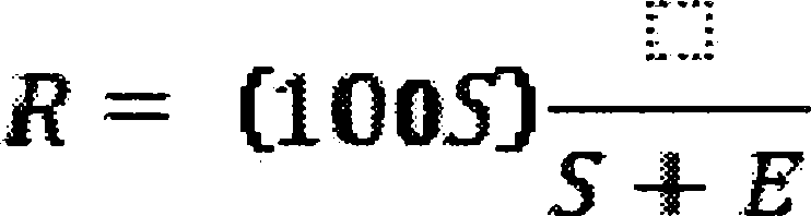
(2) You must use the level indicators or manual soundings to measure the liquid sulfur accumulation rate in the product storage vessels. You must use readings taken at the beginning and end of each run, the tank geometry, sulfur density at the storage temperature, and sample duration to determine the sulfur production rate (S) in kg/hr (lb/hr) for each run.
(3) You must compute the emission rate of sulfur for each run as follows:
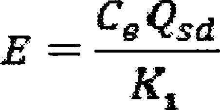
Where:
E = emission rate of sulfur per run, kg/hr.
Ce = concentration of sulfur equivalent (SO2+ reduced sulfur), g/dscm (lb/dscf).
Qsd = volumetric flow rate of effluent gas, dscm/hr (dscf/hr).
K1 = conversion factor, 1000 g/kg (7000 gr/lb).
(4) The concentration (Ce) of sulfur equivalent must be the sum of the SO2 and TRS concentrations, after being converted to sulfur equivalents. For each run and each of the test methods specified in this paragraph (c) of this section, you must use a sampling time of at least 4 hours. You must use Method 1 of appendix A to part 60 of this chapter to select the sampling site. The sampling point in the duct must be at the centroid of the cross-section if the area is less than 5 m2 (54 ft2) or at a point no closer to the walls than 1 m (39 in) if the cross-sectional area is 5 m2 or more, and the centroid is more than 1 m (39 in.) from the wall.
(i) You must use Method 6 of appendix A to part 60 of this chapter to determine the SO2 concentration. You must take eight samples of 20 minutes each at 30-minute intervals. The arithmetic average must be the concentration for the run. The concentration must be multiplied by 0.5 × 10⁻³ to convert the results to sulfur equivalent.
(ii) You must use Method 15 of appendix A to part 60 of this chapter to determine the TRS concentration from reduction-type devices or where the oxygen content of the effluent gas is less than 1.0 percent by volume. The sampling rate must be at least 3 liters/min (0.1 ft3/min) to insure minimum residence time in the sample line. You must take sixteen samples at 15-minute intervals. The arithmetic average of all the samples must be the concentration for the run. The concentration in ppm reduced sulfur as sulfur must be multiplied by 1.333 × 10⁻³ to convert the results to sulfur equivalent.
(iii) You must use Method 16A or Method 15 of appendix A to part 60 of this chapter or ANSI/ASME PTC 19.10-1981, Part 10 (manual portion only) (incorporated by reference as specified in § 60.17) to determine the reduced sulfur concentration from oxidation-type devices or where the oxygen content of the effluent gas is greater than 1.0 percent by volume. You must take eight samples of 20 minutes each at 30-minute intervals. The arithmetic average must be the concentration for the run. The concentration in ppm reduced sulfur as sulfur must be multiplied by 1.333 × 10⁻³ to convert the results to sulfur equivalent.
(iv) You must use Method 2 of appendix A to part 60 of this chapter to determine the volumetric flow rate of the effluent gas. A velocity traverse must be conducted at the beginning and end of each run. The arithmetic average of the two measurements must be used to calculate the volumetric flow rate (Qsd) for the run. For the determination of the effluent gas molecular weight, a single integrated sample over the 4-hour period may be taken and analyzed or grab samples at 1-hour intervals may be taken, analyzed, and averaged. For the moisture content, you must take two samples of at least 0.10 dscm (3.5 dscf) and 10 minutes at the beginning of the 4-hour run and near the end of the time period. The arithmetic average of the two runs must be the moisture content for the run.
§ 60.5407 What are the requirements for monitoring of emissions and operations from my sweetening unit affected facilities at onshore natural gas processing plants?
(a) If your sweetening unit affected facility is located at an onshore natural gas processing plant and is subject to the provisions of § 60.5405(a) or (b) you must install, calibrate, maintain, and operate monitoring devices or perform measurements to determine the following operations information on a daily basis:
(1) The accumulation of sulfur product over each 24-hour period. The monitoring method may incorporate the use of an instrument to measure and record the liquid sulfur production rate, or may be a procedure for measuring and recording the sulfur liquid levels in the storage vessels with a level indicator or by manual soundings, with subsequent calculation of the sulfur production rate based on the tank geometry, stored sulfur density, and elapsed time between readings. The method must be designed to be accurate within ±2 percent of the 24-hour sulfur accumulation.
(2) The H2S concentration in the acid gas from the sweetening unit for each 24-hour period. At least one sample per 24-hour period must be collected and analyzed using the equation specified in § 60.5406(b)(1). The Administrator may require you to demonstrate that the H2S concentration obtained from one or more samples over a 24-hour period is within ±20 percent of the average of 12 samples collected at equally spaced intervals during the 24-hour period. In instances where the H2S concentration of a single sample is not within ±20 percent of the average of the 12 equally spaced samples, the Administrator may require a more frequent sampling schedule.
(3) The average acid gas flow rate from the sweetening unit. You must install and operate a monitoring device to continuously measure the flow rate of acid gas. The monitoring device reading must be recorded at least once per hour during each 24-hour period. The average acid gas flow rate must be computed from the individual readings.
(4) The sulfur feed rate (X). For each 24-hour period, you must compute X using the equation specified in § 60.5406(b)(1).
(5) The required sulfur dioxide emission reduction efficiency for the 24-hour period. You must use the sulfur feed rate and the H2S concentration in the acid gas for the 24-hour period, as applicable, to determine the required reduction efficiency in accordance with the provisions of § 60.5405(b).
(b) Where compliance is achieved through the use of an oxidation control system or a reduction control system followed by a continually operated incineration device, you must install, calibrate, maintain, and operate monitoring devices and continuous emission monitors as follows:
(1) A continuous monitoring system to measure the total sulfur emission rate (E) of SO2 in the gases discharged to the atmosphere. The SO2 emission rate must be expressed in terms of equivalent sulfur mass flow rates (kg/hr (lb/hr)). The span of this monitoring system must be set so that the equivalent emission limit of § 60.5405(b) will be between 30 percent and 70 percent of the measurement range of the instrument system.
(2) Except as provided in paragraph (b)(3) of this section: A monitoring device to measure the temperature of the gas leaving the combustion zone of the incinerator, if compliance with § 60.5405(a) is achieved through the use of an oxidation control system or a reduction control system followed by a continually operated incineration device. The monitoring device must be certified by the manufacturer to be accurate to within ±1 percent of the temperature being measured.
(3) When performance tests are conducted under the provision of § 60.8 to demonstrate compliance with the standards under § 60.5405, the temperature of the gas leaving the incinerator combustion zone must be determined using the monitoring device. If the volumetric ratio of sulfur dioxide to sulfur dioxide plus total reduced sulfur (expressed as SO2) in the gas leaving the incinerator is equal to or less than 0.98, then temperature monitoring may be used to demonstrate that sulfur dioxide emission monitoring is sufficient to determine total sulfur emissions. At all times during the operation of the facility, you must maintain the average temperature of the gas leaving the combustion zone of the incinerator at or above the appropriate level determined during the most recent performance test to ensure the sulfur compound oxidation criteria are met. Operation at lower average temperatures may be considered by the Administrator to be unacceptable operation and maintenance of the affected facility. You may request that the minimum incinerator temperature be reestablished by conducting new performance tests under § 60.8.
(4) Upon promulgation of a performance specification of continuous monitoring systems for total reduced sulfur compounds at sulfur recovery plants, you may, as an alternative to paragraph (b)(2) of this section, install, calibrate, maintain, and operate a continuous emission monitoring system for total reduced sulfur compounds as required in paragraph (d) of this section in addition to a sulfur dioxide emission monitoring system. The sum of the equivalent sulfur mass emission rates from the two monitoring systems must be used to compute the total sulfur emission rate (E).
(c) Where compliance is achieved through the use of a reduction control system not followed by a continually operated incineration device, you must install, calibrate, maintain, and operate a continuous monitoring system to measure the emission rate of reduced sulfur compounds as SO2 equivalent in the gases discharged to the atmosphere. The SO2 equivalent compound emission rate must be expressed in terms of equivalent sulfur mass flow rates (kg/hr (lb/hr)). The span of this monitoring system must be set so that the equivalent emission limit of § 60.5405(b) will be between 30 and 70 percent of the measurement range of the system. This requirement becomes effective upon promulgation of a performance specification for continuous monitoring systems for total reduced sulfur compounds at sulfur recovery plants.
(d) For those sources required to comply with paragraph (b) or (c) of this section, you must calculate the average sulfur emission reduction efficiency achieved (R) for each 24-hour clock interval. The 24-hour interval may begin and end at any selected clock time, but must be consistent. You must compute the 24-hour average reduction efficiency (R) based on the 24-hour average sulfur production rate (S) and sulfur emission rate (E), using the equation in § 60.5406(c)(1).
(1) You must use data obtained from the sulfur production rate monitoring device specified in paragraph (a) of this section to determine S.
(2) You must use data obtained from the sulfur emission rate monitoring systems specified in paragraphs (b) or (c) of this section to calculate a 24-hour average for the sulfur emission rate (E). The monitoring system must provide at least one data point in each successive 15-minute interval. You must use at least two data points to calculate each 1-hour average. You must use a minimum of 18 1-hour averages to compute each 24-hour average.
(e) In lieu of complying with paragraphs (b) or (c) of this section, those sources with a design capacity of less than 152 Mg/D (150 LT/D) of H2S expressed as sulfur may calculate the sulfur emission reduction efficiency achieved for each 24-hour period by:
Where:
R = The sulfur dioxide removal efficiency achieved during the 24-hour period, percent.
K2 = Conversion factor, 0.02400 Mg/D per kg/hr (0.01071 LT/D per lb/hr).
S = The sulfur production rate during the 24-hour period, kg/hr (lb/hr).
X = The sulfur feed rate in the acid gas, Mg/D (LT/D).
(f) The monitoring devices required in paragraphs (b)(1), (b)(3) and (c) of this section must be calibrated at least annually according to the manufacturer's specifications, as required by § 60.13(b).
(g) The continuous emission monitoring systems required in paragraphs (b)(1), (b)(3), and (c) of this section must be subject to the emission monitoring requirements of § 60.13 of the General Provisions. For conducting the continuous emission monitoring system performance evaluation required by § 60.13(c), Performance Specification 2 of appendix B to part 60 of this chapter must apply, and Method 6 must be used for systems required by paragraph (b) of this section.
§ 60.5408 What is an optional procedure for measuring hydrogen sulfide in acid gas—Tutwiler Procedure?
The Tutwiler procedure may be found in the Gas Engineers Handbook, Fuel Gas Engineering practices, The Industrial Press, 93 Worth Street, New York, NY, 1966, First Edition, Second Printing, page 6/25 (Docket A-80-20-A, Entry II-I-67).
(a) When an instantaneous sample is desired and H2S concentration is ten grains per 1000 cubic foot or more, a 100 ml Tutwiler burette is used. For concentrations less than ten grains, a 500 ml Tutwiler burette and more dilute solutions are used. In principle, this method consists of titrating hydrogen sulfide in a gas sample directly with a standard solution of iodine.
(b) Apparatus. (See Figure 1 of this subpart) A 100 or 500 ml capacity Tutwiler burette, with two-way glass stopcock at bottom and three-way stopcock at top which connect either with inlet tubulature or glass-stoppered cylinder, 10 ml capacity, graduated in 0.1 ml subdivision; rubber tubing connecting burette with leveling bottle.
(c) Reagents.
(1) Iodine stock solution, 0.1N. Weight 12.7 g iodine, and 20 to 25 g cp potassium iodide for each liter of solution. Dissolve KI in as little water as necessary; dissolve iodine in concentrated KI solution, make up to proper volume, and store in glass-stoppered brown glass bottle.
(2) Standard iodine solution, 1 ml = 0.001771 g I. Transfer 33.7 ml of above 0.1N stock solution into a 250 ml volumetric flask; add water to mark and mix well. Then, for 100 ml sample of gas, 1 ml of standard iodine solution is equivalent to 100 grains H2S per cubic feet of gas.
(3) Starch solution. Rub into a thin paste about one teaspoonful of wheat starch with a little water; pour into about a pint of boiling water; stir; let cool and decant off clear solution. Make fresh solution every few days.
(d) Procedure. Fill leveling bulb with starch solution. Raise (L), open cock (G), open (F) to (A), and close (F) when solutions starts to run out of gas inlet. Close (G). Purge gas sampling line and connect with (A). Lower (L) and open (F) and (G). When liquid level is several ml past the 100 ml mark, close (G) and (F), and disconnect sampling tube. Open (G) and bring starch solution to 100 ml mark by raising (L); then close (G). Open (F) momentarily, to bring gas in burette to atmospheric pressure, and close (F). Open (G), bring liquid level down to 10 ml mark by lowering (L). Close (G), clamp rubber tubing near (E) and disconnect it from burette. Rinse graduated cylinder with a standard iodine solution (0.00171 g I per ml); fill cylinder and record reading. Introduce successive small amounts of iodine thru (F); shake well after each addition; continue until a faint permanent blue color is obtained. Record reading; subtract from previous reading, and call difference D.
(e) With every fresh stock of starch solution perform a blank test as follows: Introduce fresh starch solution into burette up to 100 ml mark. Close (F) and (G). Lower (L) and open (G). When liquid level reaches the 10 ml mark, close (G). With air in burette, titrate as during a test and up to same end point. Call ml of iodine used C. Then, Grains H2S per 100 cubic foot of gas = 100(D-C)
(f) Greater sensitivity can be attained if a 500 ml capacity Tutwiler burette is used with a more dilute (0.001N) iodine solution. Concentrations less than 1.0 grains per 100 cubic foot can be determined in this way. Usually, the starch-iodine end point is much less distinct, and a blank determination of end point, with H2S-free gas or air, is required.

§ 60.5410 How do I demonstrate initial compliance with the standards for my gas well affected facility, my centrifugal compressor affected facility, my reciprocating compressor affected facility, my pneumatic controller affected facility, my storage vessel affected facility, and my equipment leaks and sweetening unit affected facilities at onshore natural gas processing plants?
You must determine initial compliance with the standards for each affected facility using the requirements in paragraphs (a) through (i) of this section. The initial compliance period begins on October 15, 2012, or upon initial startup, whichever is later, and ends no later than one year after the initial startup date for your affected facility or no later than one year after October 15, 2012. The initial compliance period may be less than one full year.
(a) To achieve initial compliance with the standards for each well completion operation conducted at your gas well affected facility you must comply with paragraphs (a)(1) through (a)(4) of this section.
(1) You must submit the notification required in § 60.5420(a)(2).
(2) You must submit the initial annual report for your well affected facility as required in § 60.5420(b).
(3) You must maintain a log of records as specified in § 60.5420(c)(1)(i) through (iv) for each well completion operation conducted during the initial compliance period.
(4) For each gas well affected facility subject to both § 60.5375(a)(1) and (3), as an alternative to retaining the records specified in § 60.5420(c)(1)(i) through (iv), you may maintain records of one or more digital photographs with the date the photograph was taken and the latitude and longitude of the well site imbedded within or stored with the digital file showing the equipment for storing or re-injecting recovered liquid, equipment for routing recovered gas to the gas flow line and the completion combustion device (if applicable) connected to and operating at each gas well completion operation that occurred during the initial compliance period. As an alternative to imbedded latitude and longitude within the digital photograph, the digital photograph may consist of a photograph of the equipment connected and operating at each well completion operation with a photograph of a separately operating GIS device within the same digital picture, provided the latitude and longitude output of the GIS unit can be clearly read in the digital photograph.
(b)
(1) To achieve initial compliance with standards for your centrifugal compressor affected facility you must reduce VOC emissions from each centrifugal compressor wet seal fluid degassing system by 95.0 percent or greater as required by § 60.5380 and as demonstrated by the requirements of § 60.5413.
(2) If you use a control device to reduce emissions, you must equip the wet seal fluid degassing system with a cover that meets the requirements of § 60.5411(b) that is connected through a closed vent system that meets the requirements of § 60.5411(a) and is routed to a control device that meets the conditions specified in § 60.5412(a), (b) and (c). As an alternative to routing the closed vent system to a control device, you may route the closed vent system to a process.
(3) You must conduct an initial performance test as required in § 60.5413 within 180 days after initial startup or by October 15, 2012, whichever is later, and you must comply with the continuous compliance requirements in § 60.5415(b)(1) through (3).
(4) You must conduct the initial inspections required in § 60.5416(a) and (b).
(5) You must install and operate the continuous parameter monitoring systems in accordance with § 60.5417(a) through (g), as applicable.
(6) [Reserved]
(7) You must submit the initial annual report for your centrifugal compressor affected facility as required in § 60.5420(b)(3) for each centrifugal compressor affected facility.
(8) You must maintain the records as specified in § 60.5420(c)(2).
(c) To achieve initial compliance with the standards for each reciprocating compressor affected facility you must comply with paragraphs (c)(1) through (4) of this section.
(1) If complying with § 60.5385(a)(1) or (2), during the initial compliance period, you must continuously monitor the number of hours of operation or track the number of months since the last rod packing replacement.
(2) If complying with § 60.5385(a)(3), you must operate the rod packing emissions collection system under negative pressure and route emissions to a process through a closed vent system that meets the requirements of § 60.5411(a).
(3) You must submit the initial annual report for your reciprocating compressor as required in § 60.5420(b).
(4) You must maintain the records as specified in § 60.5420(c)(3) for each reciprocating compressor affected facility.
(d) To achieve initial compliance with emission standards for your pneumatic controller affected facility you must comply with the requirements specified in paragraphs (d)(1) through (6) of this section, as applicable.
(1) You must demonstrate initial compliance by maintaining records as specified in § 60.5420(c)(4)(ii) of your determination that the use of a pneumatic controller affected facility with a bleed rate greater than 6 standard cubic feet of gas per hour is required as specified in § 60.5390(a).
(2) You own or operate a pneumatic controller affected facility located at a natural gas processing plant and your pneumatic controller is driven by a gas other than natural gas and therefore emits zero natural gas.
(3) You own or operate a pneumatic controller affected facility located between the wellhead and a natural gas processing plant and the manufacturer's design specifications indicate that the controller emits less than or equal to 6 standard cubic feet of gas per hour.
(4) You must tag each new pneumatic controller affected facility according to the requirements of § 60.5390(b)(2) or (c)(2).
(5) You must include the information in paragraph (d)(1) of this section and a listing of the pneumatic controller affected facilities specified in paragraphs (d)(2) and (3) of this section in the initial annual report submitted for your pneumatic controller affected facilities constructed, modified or reconstructed during the period covered by the annual report according to the requirements of § 60.5420(b).
(6) You must maintain the records as specified in § 60.5420(c)(4) for each pneumatic controller affected facility.
(e) [Reserved]
(f) For affected facilities at onshore natural gas processing plants, initial compliance with the VOC requirements is demonstrated if you are in compliance with the requirements of § 60.5400.
(g) For sweetening unit affected facilities at onshore natural gas processing plants, initial compliance is demonstrated according to paragraphs (g)(1) through (3) of this section.
(1) To determine compliance with the standards for SO2 specified in § 60.5405(a), during the initial performance test as required by § 60.8, the minimum required sulfur dioxide emission reduction efficiency (Zi) is compared to the emission reduction efficiency (R) achieved by the sulfur recovery technology as specified in paragraphs (g)(1)(i) and (ii) of this section.
(i) If R ≥ Zi, your affected facility is in compliance.
(ii) If R < Zi, your affected facility is not in compliance.
(2) The emission reduction efficiency (R) achieved by the sulfur reduction technology must be determined using the procedures in § 60.5406(c)(1).
(3) You have submitted the results of paragraphs (g)(1) and (2) of this section in the initial annual report submitted for your sweetening unit affected facilities at onshore natural gas processing plants.
(h) For each storage vessel affected facility, you must comply with paragraphs (h)(1) through (5) of this section. For a Group 1 storage vessel affected facility, you must demonstrate initial compliance by April 15, 2015, except as otherwise provided in paragraph (i) of this section. For a Group 2 storage vessel affected facility, you must demonstrate initial compliance by April 15, 2014, or within 60 days after startup, whichever is later.
(1) You must determine the potential VOC emission rate as specified in § 60.5365(e).
(2) You must reduce VOC emissions in accordance with § 60.5395(d).
(3) If you use a control device to reduce emissions, or if you route emissions to a process, you must demonstrate initial compliance by meeting the requirements in § 60.5395(e).
(4) You must submit the information required for your storage vessel affected facility as specified in § 60.5420(b).
(5) You must maintain the records required for your storage vessel affected facility, as specified in § 60.5420(c)(5) through (8) and § 60.5420(c)(12) and (13) for each storage vessel affected facility.
(i) For each Group 1 storage vessel affected facility, you must submit the notification specified in § 60.5395(b)(2) with the initial annual report specified in § 60.5420(b)(6).
[77 FR 49542, Aug. 16, 2012, as amended at 78 FR 58437, Sept. 23, 2013; 79 FR 79038, Dec. 31, 2014; 81 FR 35896, June 3, 2016]
§ 60.5411 What additional requirements must I meet to determine initial compliance for my covers and closed vent systems routing materials from storage vessels, reciprocating compressors and centrifugal compressor wet seal degassing systems?
You must meet the applicable requirements of this section for each cover and closed vent system used to comply with the emission standards for your storage vessel, reciprocating compressor or centrifugal compressor affected facility.
(a) Closed vent system requirements for reciprocating compressors and for centrifugal compressor wet seal degassing systems.
(1) You must design the closed vent system to route all gases, vapors, and fumes emitted from the material in the reciprocating compressor rod packing emissions collection system or the wet seal fluid degassing system to a control device or to a process that meets the requirements specified in § 60.5412(a) through (c).
(2) You must design and operate the closed vent system with no detectable emissions as demonstrated by § 60.5416(b).
(3) You must meet the requirements specified in paragraphs (a)(3)(i) and (ii) of this section if the closed vent system contains one or more bypass devices that could be used to divert all or a portion of the gases, vapors, or fumes from entering the control device.
(i) Except as provided in paragraph (a)(3)(ii) of this section, you must comply with either paragraph (a)(3)(i)(A) or (B) of this section for each bypass device.
(A) You must properly install, calibrate, maintain, and operate a flow indicator at the inlet to the bypass device that could divert the stream away from the control device or process to the atmosphere that is capable of taking periodic readings as specified in § 60.5416(a)(4) and either sounds an alarm, or initiates notification via remote alarm to the nearest field office, when the bypass device is open such that the stream is being, or could be, diverted away from the control device or process to the atmosphere. You must maintain records of each time the alarm is activated according to § 60.5420(c)(8).
(B) You must secure the bypass device valve installed at the inlet to the bypass device in the non-diverting position using a car-seal or a lock-and-key type configuration.
(ii) Low leg drains, high point bleeds, analyzer vents, open-ended valves or lines, and safety devices are not subject to the requirements of paragraph (a)(3)(i) of this section.
(b) Cover requirements for storage vessels and centrifugal compressor wet seal degassing systems.
(1) The cover and all openings on the cover (e.g., access hatches, sampling ports, pressure relief valves and gauge wells) shall form a continuous impermeable barrier over the entire surface area of the liquid in the storage vessel or wet seal fluid degassing system.
(2) Each cover opening shall be secured in a closed, sealed position (e.g., covered by a gasketed lid or cap) whenever material is in the unit on which the cover is installed except during those times when it is necessary to use an opening as follows:
(i) To add material to, or remove material from the unit (this includes openings necessary to equalize or balance the internal pressure of the unit following changes in the level of the material in the unit);
(ii) To inspect or sample the material in the unit;
(iii) To inspect, maintain, repair, or replace equipment located inside the unit; or
(iv) To vent liquids, gases, or fumes from the unit through a closed-vent system designed and operated in accordance with the requirements of paragraph (a) or (c) of this section to a control device or to a process.
(3) Each storage vessel thief hatch shall be equipped, maintained and operated with a weighted mechanism or equivalent, to ensure that the lid remains properly seated. You must select gasket material for the hatch based on composition of the fluid in the storage vessel and weather conditions.
(c) Closed vent system requirements for storage vessel affected facilities using a control device or routing emissions to a process.
(1) You must design the closed vent system to route all gases, vapors, and fumes emitted from the material in the storage vessel to a control device that meets the requirements specified in § 60.5412(c) and (d), or to a process.
(2) You must design and operate a closed vent system with no detectable emissions, as determined using olfactory, visual and auditory inspections. Each closed vent system that routes emissions to a process must be operational 95 percent of the year or greater.
(3) You must meet the requirements specified in paragraphs (c)(3)(i) and (ii) of this section if the closed vent system contains one or more bypass devices that could be used to divert all or a portion of the gases, vapors, or fumes from entering the control device or to a process.
(i) Except as provided in paragraph (c)(3)(ii) of this section, you must comply with either paragraph (c)(3)(i)(A) or (B) of this section for each bypass device.
(A) You must properly install, calibrate, maintain, and operate a flow indicator at the inlet to the bypass device that could divert the stream away from the control device or process to the atmosphere and that either sounds an alarm, or initiates notification via remote alarm to the nearest field office, when the bypass device is open such that the stream is being, or could be, diverted away from the control device or process to the atmosphere. You must maintain records of each time the alarm is activated according to § 60.5420(c)(8).
(B) You must secure the bypass device valve installed at the inlet to the bypass device in the non-diverting position using a car-seal or a lock-and-key type configuration.
(ii) Low leg drains, high point bleeds, analyzer vents, open-ended valves or lines, and safety devices are not subject to the requirements of paragraph (c)(3)(i) of this section.
[77 FR 49542, Aug. 16, 2012, as amended at 78 FR 58438, Sept. 23, 2013; 79 FR 79038, Dec. 31, 2014; 81 FR 35896, June 3, 2016]
§ 60.5412 What additional requirements must I meet for determining initial compliance with control devices used to comply with the emission standards for my storage vessel or centrifugal compressor affected facility?
You must meet the applicable requirements of this section for each control device used to comply with the emission standards for your storage vessel or centrifugal compressor affected facility.
(a) Each control device used to meet the emission reduction standard in § 60.5380(a)(1) for your centrifugal compressor affected facility must be installed according to paragraphs (a)(1) through (3) of this section. As an alternative, you may install a control device model tested under § 60.5413(d), which meets the criteria in § 60.5413(d)(11) and § 60.5413(e).
(1) Each combustion device (e.g., thermal vapor incinerator, catalytic vapor incinerator, boiler, or process heater) must be designed and operated in accordance with one of the performance requirements specified in paragraphs (a)(1)(i) through (iv) of this section.
(i) You must reduce the mass content of VOC in the gases vented to the device by 95.0 percent by weight or greater as determined in accordance with the requirements of § 60.5413.
(ii) You must reduce the concentration of TOC in the exhaust gases at the outlet to the device to a level equal to or less than 275 parts per million by volume as propane on a wet basis corrected to 3 percent oxygen as determined in accordance with the requirements of § 60.5413.
(iii) You must operate at a minimum temperature of 760 °C for a control device that can demonstrate a uniform combustion zone temperature during the performance test conducted under § 60.5413.
(iv) If a boiler or process heater is used as the control device, then you must introduce the vent stream into the flame zone of the boiler or process heater.
(2) Each vapor recovery device (e.g., carbon adsorption system or condenser) or other non-destructive control device must be designed and operated to reduce the mass content of VOC in the gases vented to the device by 95.0 percent by weight or greater as determined in accordance with the requirements of § 60.5413. As an alternative to the performance testing requirements, you may demonstrate initial compliance by conducting a design analysis for vapor recovery devices according to the requirements of § 60.5413(c).
(3) You must design and operate a flare in accordance with the requirements of § 60.5413.
(b) You must operate each control device installed on your centrifugal compressor affected facility in accordance with the requirements specified in paragraphs (b)(1) and (2) of this section.
(1) You must operate each control device used to comply with this subpart at all times when gases, vapors, and fumes are vented from the wet seal fluid degassing system affected facility, as required under § 60.5380(a), through the closed vent system to the control device. You may vent more than one affected facility to a control device used to comply with this subpart.
(2) For each control device monitored in accordance with the requirements of § 60.5417(a) through (g), you must demonstrate compliance according to the requirements of § 60.5415(b)(2), as applicable.
(c) For each carbon adsorption system used as a control device to meet the requirements of paragraph (a)(2) or (d)(2) of this section, you must manage the carbon in accordance with the requirements specified in paragraphs (c)(1) or (2) of this section.
(1) Following the initial startup of the control device, you must replace all carbon in the control device with fresh carbon on a regular, predetermined time interval that is no longer than the carbon service life established according to § 60.5413(c)(2) or (3) or according to the design required in paragraph (d)(2) of this section, for the carbon adsorption system. You must maintain records identifying the schedule for replacement and records of each carbon replacement as required in § 60.5420(c)(10) and (12).
(2) You must either regenerate, reactivate, or burn the spent carbon removed from the carbon adsorption system in one of the units specified in paragraphs (c)(2)(i) through (vii) of this section.
(i) Regenerate or reactivate the spent carbon in a thermal treatment unit for which you have been issued a final permit under 40 CFR part 270 that implements the requirements of 40 CFR part 264, subpart X.
(ii) Regenerate or reactivate the spent carbon in a thermal treatment unit equipped with and operating air emission controls in accordance with this section.
(iii) Regenerate or reactivate the spent carbon in a thermal treatment unit equipped with and operating organic air emission controls in accordance with an emissions standard for VOC under another subpart in 40 CFR part 60 or this part.
(iv) Burn the spent carbon in a hazardous waste incinerator for which the owner or operator has been issued a final permit under 40 CFR part 270 that implements the requirements of 40 CFR part 264, subpart O.
(v) Burn the spent carbon in a hazardous waste incinerator which you have designed and operated in accordance with the requirements of 40 CFR part 265, subpart O.
(vi) Burn the spent carbon in a boiler or industrial furnace for which you have been issued a final permit under 40 CFR part 270 that implements the requirements of 40 CFR part 266, subpart H.
(vii) Burn the spent carbon in a boiler or industrial furnace that you have designed and operated in accordance with the interim status requirements of 40 CFR part 266, subpart H.
(d) Each control device used to meet the emission reduction standard in § 60.5395(d) for your storage vessel affected facility must be installed according to paragraphs (d)(1) through (3) of this section, as applicable. As an alternative to paragraph (d)(1) of this section, you may install a control device model tested under § 60.5413(d), which meets the criteria in § 60.5413(d)(11) and § 60.5413(e).
(1) Each enclosed combustion device (e.g., thermal vapor incinerator, catalytic vapor incinerator, boiler, or process heater) must be designed to reduce the mass content of VOC emissions by 95.0 percent or greater. Each flare must be designed and operated in accordance with the requirements of § 60.5413(a)(1). You must follow the requirements in paragraphs (d)(1)(i) through (iv) of this section.
(i) Ensure that each enclosed combustion device is maintained in a leak free condition.
(ii) Install and operate a continuous burning pilot flame.
(iii) Operate the enclosed combustion device with no visible emissions, except for periods not to exceed a total of one minute during any 15 minute period. A visible emissions test using section 11 of EPA Method 22, 40 CFR part 60, appendix A, must be performed at least once every calendar month, separated by at least 15 days between each test. The observation period shall be 15 minutes. Devices failing the visible emissions test must follow manufacturer's repair instructions, if available, or best combustion engineering practice as outlined in the unit inspection and maintenance plan, to return the unit to compliant operation. All inspection, repair and maintenance activities for each unit must be recorded in a maintenance and repair log and must be available for inspection. Following return to operation from maintenance or repair activity, each device must pass a Method 22, 40 CFR part 60, appendix A, visual observation as described in this paragraph.
(iv) Each enclosed combustion control device (e.g., thermal vapor incinerator, catalytic vapor incinerator, boiler, or process heater) must be designed and operated in accordance with one of the performance requirements specified in paragraphs (d)(1)(iv)(A) through (D) of this section.
(A) You must reduce the mass content of VOC in the gases vented to the device by 95.0 percent by weight or greater as determined in accordance with the requirements of § 60.5413.
(B) You must reduce the concentration of TOC in the exhaust gases at the outlet to the device to a level equal to or less than 275 parts per million by volume as propane on a wet basis corrected to 3 percent oxygen as determined in accordance with the requirements of § 60.5413.
(C) You must operate at a minimum temperature of 760 °Celsius, provided the control device has demonstrated, during the performance test conducted under § 60.5413, that combustion zone temperature is an indicator of destruction efficiency.
(D) If a boiler or process heater is used as the control device, then you must introduce the vent stream into the flame zone of the boiler or process heater.
(2) Each vapor recovery device (e.g., carbon adsorption system or condenser) or other non-destructive control device must be designed and operated to reduce the mass content of VOC in the gases vented to the device by 95.0 percent by weight or greater. A carbon replacement schedule must be included in the design of the carbon adsorption system.
(3) You must operate each control device used to comply with this subpart at all times when gases, vapors, and fumes are vented from the storage vessel affected facility through the closed vent system to the control device. You may vent more than one affected facility to a control device used to comply with this subpart.
[77 FR 49542, Aug. 16, 2012, as amended at 78 FR 58438, Sept. 23, 2013; 79 FR 79039, Dec. 31, 2014; 81 FR 35897, June 3, 2016]
§ 60.5413 What are the performance testing procedures for control devices used to demonstrate compliance at my storage vessel or centrifugal compressor affected facility?
This section applies to the performance testing of control devices used to demonstrate compliance with the emissions standards for your centrifugal compressor affected facility. You must demonstrate that a control device achieves the performance requirements of § 60.5412(a) using the performance test methods and procedures specified in this section. For condensers, you may use a design analysis as specified in paragraph (c) of this section in lieu of complying with paragraph (b) of this section. In addition, this section contains the requirements for enclosed combustion device performance tests conducted by the manufacturer applicable to both storage vessel and centrifugal compressor affected facilities.
(a) Performance test exemptions. You are exempt from the requirements to conduct performance tests and design analyses if you use any of the control devices described in paragraphs (a)(1) through (7) of this section.
(1) A flare that is designed and operated in accordance with § 60.18(b). You must conduct the compliance determination using Method 22 at 40 CFR part 60, appendix A-7, to determine visible emissions.
(2) A boiler or process heater with a design heat input capacity of 44 megawatts or greater.
(3) A boiler or process heater into which the vent stream is introduced with the primary fuel or is used as the primary fuel.
(4) A boiler or process heater burning hazardous waste for which you have either been issued a final permit under 40 CFR part 270 and comply with the requirements of 40 CFR part 266, subpart H; or you have certified compliance with the interim status requirements of 40 CFR part 266, subpart H.
(5) A hazardous waste incinerator for which you have been issued a final permit under 40 CFR part 270 and comply with the requirements of 40 CFR part 264, subpart O; or you have certified compliance with the interim status requirements of 40 CFR part 265, subpart O.
(6) A performance test is waived in accordance with § 60.8(b).
(7) A control device whose model can be demonstrated to meet the performance requirements of § 60.5412(a) through a performance test conducted by the manufacturer, as specified in paragraph (d) of this section.
(b) Test methods and procedures. You must use the test methods and procedures specified in paragraphs (b)(1) through (5) of this section, as applicable, for each performance test conducted to demonstrate that a control device meets the requirements of § 60.5412(a). You must conduct the initial and periodic performance tests according to the schedule specified in paragraph (b)(5) of this section.
(1) You must use Method 1 or 1A at 40 CFR part 60, appendix A-1, as appropriate, to select the sampling sites specified in paragraphs (b)(1)(i) and (ii) of this section. Any references to particulate mentioned in Methods 1 and 1A do not apply to this section.
(i) Sampling sites must be located at the inlet of the first control device, and at the outlet of the final control device, to determine compliance with the control device percent reduction requirement specified in § 60.5412(a)(1)(i) or (a)(2).
(ii) The sampling site must be located at the outlet of the combustion device to determine compliance with the enclosed combustion device total TOC concentration limit specified in § 60.5412(a)(1)(ii).
(2) You must determine the gas volumetric flowrate using Method 2, 2A, 2C, or 2D at 40 CFR part 60, appendix A-2, as appropriate.
(3) To determine compliance with the control device percent reduction performance requirement in § 60.5412(a)(1)(i) or (a)(2), you must use Method 25A at 40 CFR part 60, appendix A-7. You must use the procedures in paragraphs (b)(3)(i) through (iv) of this section to calculate percent reduction efficiency.
(i) For each run, you must take either an integrated sample or a minimum of four grab samples per hour. If grab sampling is used, then the samples must be taken at approximately equal intervals in time, such as 15-minute intervals during the run.
(ii) You must compute the mass rate of TOC (minus methane and ethane) using the equations and procedures specified in paragraphs (b)(3)(ii)(A) and (B) of this section.
(A) You must use the following equations:
Where:
Ei, Eo = Mass rate of TOC (minus methane and ethane) at the inlet and outlet of the control device, respectively, dry basis, kilogram per hour.
K2 = Constant, 2.494 × 10⁻⁶ (parts per million) (gram-mole per standard cubic meter) (kilogram/gram) (minute/hour), where standard temperature (gram-mole per standard cubic meter) is 20 °C.
Cij, Coj = Concentration of sample component j of the gas stream at the inlet and outlet of the control device, respectively, dry basis, parts per million by volume.
Mij, Moj = Molecular weight of sample component j of the gas stream at the inlet and outlet of the control device, respectively, gram/gram-mole.
Qi, Qo = Flowrate of gas stream at the inlet and outlet of the control device, respectively, dry standard cubic meter per minute.
n = Number of components in sample.
(B) When calculating the TOC mass rate, you must sum all organic compounds (minus methane and ethane) measured by Method 25A at 40 CFR part 60, appendix A-7 using the equations in paragraph (b)(3)(ii)(A) of this section.
(iii) You must calculate the percent reduction in TOC (minus methane and ethane) as follows:
Where:
Rcd = Control efficiency of control device, percent.
Ei = Mass rate of TOC (minus methane and ethane) at the inlet to the control device as calculated under paragraph (b)(3)(ii) of this section, kilograms TOC per hour or kilograms HAP per hour.
Eo = Mass rate of TOC (minus methane and ethane) at the outlet of the control device, as calculated under paragraph (b)(3)(ii) of this section, kilograms TOC per hour per hour.
(iv) If the vent stream entering a boiler or process heater with a design capacity less than 44 megawatts is introduced with the combustion air or as a secondary fuel, you must determine the weight-percent reduction of total TOC (minus methane and ethane) across the device by comparing the TOC (minus methane and ethane) in all combusted vent streams and primary and secondary fuels with the TOC (minus methane and ethane) exiting the device, respectively.
(4) You must use Method 25A at 40 CFR part 60, appendix A-7 to measure TOC (minus methane and ethane) to determine compliance with the enclosed combustion device total VOC concentration limit specified in § 60.5412(a)(1)(ii). You must calculate parts per million by volume concentration and correct to 3 percent oxygen, using the procedures in paragraphs (b)(4)(i) through (iii) of this section.
(i) For each run, you must take either an integrated sample or a minimum of four grab samples per hour. If grab sampling is used, then the samples must be taken at approximately equal intervals in time, such as 15-minute intervals during the run.
(ii) You must calculate the TOC concentration for each run as follows:
Where:
CTOC = Concentration of total organic compounds minus methane and ethane, dry basis, parts per million by volume.
Cji = Concentration of sample component j of sample i, dry basis, parts per million by volume.
n = Number of components in the sample.
x = Number of samples in the sample run.
(iii) You must correct the TOC concentration to 3 percent oxygen as specified in paragraphs (b)(4)(iii)(A) and (B) of this section.
(A) You must use the emission rate correction factor for excess air, integrated sampling and analysis procedures of Method 3A or 3B at 40 CFR part 60, appendix A, ASTM D6522-00 (Reapproved 2005), or ANSI/ASME PTC 19.10-1981, Part 10 (manual portion only) (incorporated by reference as specified in § 60.17) to determine the oxygen concentration. The samples must be taken during the same time that the samples are taken for determining TOC concentration.
(B) You must correct the TOC concentration for percent oxygen as follows:
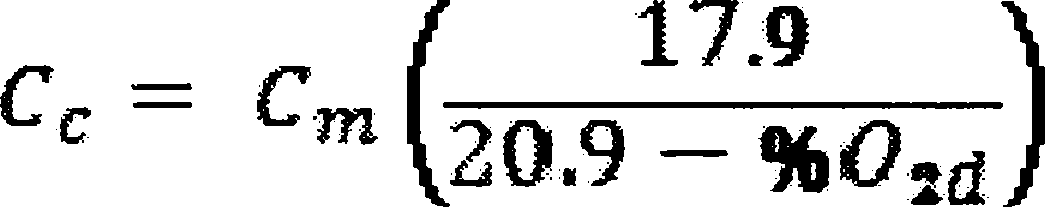
Where:
Cc = TOC concentration corrected to 3 percent oxygen, dry basis, parts per million by volume.
Cm = TOC concentration, dry basis, parts per million by volume.
%O2d = Concentration of oxygen, dry basis, percent by volume.
(5) You must conduct performance tests according to the schedule specified in paragraphs (b)(5)(i) and (ii) of this section.
(i) You must conduct an initial performance test within 180 days after initial startup for your affected facility. You must submit the performance test results as required in § 60.5420(b)(7).
(ii) You must conduct periodic performance tests for all control devices required to conduct initial performance tests except as specified in paragraphs (b)(5)(ii)(A) and (B) of this section. You must conduct the first periodic performance test no later than 60 months after the initial performance test required in paragraph (b)(5)(i) of this section. You must conduct subsequent periodic performance tests at intervals no longer than 60 months following the previous periodic performance test or whenever you desire to establish a new operating limit. You must submit the periodic performance test results as specified in § 60.5420(b)(7). Combustion control devices meeting the criteria in either paragraph (b)(5)(ii)(A) or (B) of this section are not required to conduct periodic performance tests.
(A) A control device whose model is tested under, and meets the criteria of paragraph (d) of this section.
(B) A combustion control device tested under paragraph (b) of this section that meets the outlet TOC performance level specified in § 60.5412(a)(1)(ii) and that establishes a correlation between firebox or combustion chamber temperature and the TOC performance level.
(c) Control device design analysis to meet the requirements of § 60.5412(a).
(1) For a condenser, the design analysis must include an analysis of the vent stream composition, constituent concentrations, flowrate, relative humidity, and temperature, and must establish the design outlet organic compound concentration level, design average temperature of the condenser exhaust vent stream, and the design average temperatures of the coolant fluid at the condenser inlet and outlet.
(2) For a regenerable carbon adsorption system, the design analysis shall include the vent stream composition, constituent concentrations, flowrate, relative humidity, and temperature, and shall establish the design exhaust vent stream organic compound concentration level, adsorption cycle time, number and capacity of carbon beds, type and working capacity of activated carbon used for the carbon beds, design total regeneration stream flow over the period of each complete carbon bed regeneration cycle, design carbon bed temperature after regeneration, design carbon bed regeneration time, and design service life of the carbon.
(3) For a nonregenerable carbon adsorption system, such as a carbon canister, the design analysis shall include the vent stream composition, constituent concentrations, flowrate, relative humidity, and temperature, and shall establish the design exhaust vent stream organic compound concentration level, capacity of the carbon bed, type and working capacity of activated carbon used for the carbon bed, and design carbon replacement interval based on the total carbon working capacity of the control device and source operating schedule. In addition, these systems will incorporate dual carbon canisters in case of emission breakthrough occurring in one canister.
(4) If you and the Administrator do not agree on a demonstration of control device performance using a design analysis, then you must perform a performance test in accordance with the requirements of paragraph (b) of this section to resolve the disagreement. The Administrator may choose to have an authorized representative observe the performance test.
(d) Performance testing for combustion control devices—manufacturers' performance test.
(1) This paragraph applies to the performance testing of a combustion control device conducted by the device manufacturer. The manufacturer must demonstrate that a specific model of control device achieves the performance requirements in paragraph (d)(11) of this section by conducting a performance test as specified in paragraphs (d)(2) through (10) of this section. You must submit a test report for each combustion control device in accordance with the requirements in paragraph (d)(12) of this section.
(2) Performance testing must consist of three one-hour (or longer) test runs for each of the four firing rate settings specified in paragraphs (d)(2)(i) through (iv) of this section, making a total of 12 test runs per test. Propene (propylene) gas must be used for the testing fuel. All fuel analyses must be performed by an independent third-party laboratory (not affiliated with the control device manufacturer or fuel supplier).
(i) 90-100 percent of maximum design rate (fixed rate).
(ii) 70-100-70 percent (ramp up, ramp down). Begin the test at 70 percent of the maximum design rate. During the first 5 minutes, incrementally ramp the firing rate to 100 percent of the maximum design rate. Hold at 100 percent for 5 minutes. In the 10-15 minute time range, incrementally ramp back down to 70 percent of the maximum design rate. Repeat three more times for a total of 60 minutes of sampling.
(iii) 30-70-30 percent (ramp up, ramp down). Begin the test at 30 percent of the maximum design rate. During the first 5 minutes, incrementally ramp the firing rate to 70 percent of the maximum design rate. Hold at 70 percent for 5 minutes. In the 10-15 minute time range, incrementally ramp back down to 30 percent of the maximum design rate. Repeat three more times for a total of 60 minutes of sampling.
(iv) 0-30-0 percent (ramp up, ramp down). Begin the test at the minimum firing rate. During the first 5 minutes, incrementally ramp the firing rate to 30 percent of the maximum design rate. Hold at 30 percent for 5 minutes. In the 10-15 minute time range, incrementally ramp back down to the minimum firing rate. Repeat three more times for a total of 60 minutes of sampling.
(3) All models employing multiple enclosures must be tested simultaneously and with all burners operational. Results must be reported for each enclosure individually and for the average of the emissions from all interconnected combustion enclosures/chambers. Control device operating data must be collected continuously throughout the performance test using an electronic Data Acquisition System. A graphic presentation or strip chart of the control device operating data and emissions test data must be included in the test report in accordance with paragraph (d)(12) of this section. Inlet fuel meter data may be manually recorded provided that all inlet fuel data readings are included in the final report.
(4) Inlet testing must be conducted as specified in paragraphs (d)(4)(i) through (ii) of this section.
(i) The inlet gas flow metering system must be located in accordance with Method 2A, 40 CFR part 60, appendix A-1, (or other approved procedure) to measure inlet gas flow rate at the control device inlet location. You must position the fitting for filling fuel sample containers a minimum of eight pipe diameters upstream of any inlet gas flow monitoring meter.
(ii) Inlet flow rate must be determined using Method 2A, 40 CFR part 60, appendix A-1. Record the start and stop reading for each 60-minute THC test. Record the gas pressure and temperature at 5-minute intervals throughout each 60-minute test.
(5) Inlet gas sampling must be conducted as specified in paragraphs (d)(5)(i) through (ii) of this section.
(i) At the inlet gas sampling location, securely connect a Silonite-coated stainless steel evacuated canister fitted with a flow controller sufficient to fill the canister over a 3-hour period. Filling must be conducted as specified in paragraphs (d)(5)(i)(A) through (C) of this section.
(A) Open the canister sampling valve at the beginning of each test run, and close the canister at the end of each test run.
(B) Fill one canister across the three test runs such that one composite fuel sample exists for each test condition.
(C) Label the canisters individually and record sample information on a chain of custody form.
(ii) Analyze each inlet gas sample using the methods in paragraphs (d)(5)(ii)(A) through (C) of this section. You must include the results in the test report required by paragraph (d)(12) of this section.
(A) Hydrocarbon compounds containing between one and five atoms of carbon plus benzene using ASTM D1945-03.
(B) Hydrogen (H2), carbon monoxide (CO), carbon dioxide (CO2), nitrogen (N2), oxygen (O2) using ASTM D1945-03.
(C) Higher heating value using ASTM D3588-98 or ASTM D4891-89.
(6) Outlet testing must be conducted in accordance with the criteria in paragraphs (d)(6)(i) through (v) of this section.
(i) Sample and flow rate must be measured in accordance with paragraphs (d)(6)(i)(A) through (B) of this section.
(A) The outlet sampling location must be a minimum of four equivalent stack diameters downstream from the highest peak flame or any other flow disturbance, and a minimum of one equivalent stack diameter upstream of the exit or any other flow disturbance. A minimum of two sample ports must be used.
(B) Flow rate must be measured using Method 1, 40 CFR part 60, appendix A-1 for determining flow measurement traverse point location, and Method 2, 40 CFR part 60, appendix A-1 for measuring duct velocity. If low flow conditions are encountered (i.e., velocity pressure differentials less than 0.05 inches of water) during the performance test, a more sensitive manometer must be used to obtain an accurate flow profile.
(ii) Molecular weight and excess air must be determined as specified in paragraph (d)(7) of this section.
(iii) Carbon monoxide must be determined as specified in paragraph (d)(8) of this section.
(iv) THC must be determined as specified in paragraph (d)(9) of this section.
(v) Visible emissions must be determined as specified in paragraph (d)(10) of this section.
(7) Molecular weight and excess air determination must be performed as specified in paragraphs (d)(7)(i) through (iii) of this section.
(i) An integrated bag sample must be collected during the Method 4, 40 CFR part 60, appendix A-3, moisture test following the procedure specified in (d)(7)(i)(A) through (B) of this section. Analyze the bag sample using a gas chromatograph-thermal conductivity detector (GC-TCD) analysis meeting the criteria in paragraphs (d)(7)(i)(C) through (D) of this section.
(A) Collect the integrated sample throughout the entire test, and collect representative volumes from each traverse location.
(B) Purge the sampling line with stack gas before opening the valve and beginning to fill the bag. Clearly label each bag and record sample information on a chain of custody form.
(C) The bag contents must be vigorously mixed prior to the gas chromatograph analysis.
(D) The GC-TCD calibration procedure in Method 3C, 40 CFR part 60, appendix A, must be modified by using EPA Alt-045 as follows: For the initial calibration, triplicate injections of any single concentration must agree within 5 percent of their mean to be valid. The calibration response factor for a single concentration re-check must be within 10 percent of the original calibration response factor for that concentration. If this criterion is not met, repeat the initial calibration using at least three concentration levels.
(ii) Calculate and report the molecular weight of oxygen, carbon dioxide, methane, and nitrogen in the integrated bag sample and include in the test report specified in paragraph (d)(12) of this section. Moisture must be determined using Method 4, 40 CFR part 60, appendix A-3. Traverse both ports with the Method 4, 40 CFR part 60, appendix A-3, sampling train during each test run. Ambient air must not be introduced into the Method 3C, 40 CFR part 60, appendix A-2, integrated bag sample during the port change.
(iii) Excess air must be determined using resultant data from the EPA Method 3C tests and EPA Method 3B, 40 CFR part 60, appendix A, equation 3B-1.
(8) Carbon monoxide must be determined using Method 10, 40 CFR part 60, appendix A. Run the test simultaneously with Method 25A, 40 CFR part 60, appendix A-7 using the same sampling points. An instrument range of 0-10 parts per million by volume-dry (ppmvd) is recommended.
(9) Total hydrocarbon determination must be performed as specified by in paragraphs (d)(9)(i) through (vii) of this section.
(i) Conduct THC sampling using Method 25A, 40 CFR part 60, appendix A-7, except that the option for locating the probe in the center 10 percent of the stack is not allowed. The THC probe must be traversed to 16.7 percent, 50 percent, and 83.3 percent of the stack diameter during each test run.
(ii) A valid test must consist of three Method 25A, 40 CFR part 60, appendix A-7, tests, each no less than 60 minutes in duration.
(iii) A 0-10 parts per million by volume-wet (ppmvw) (as propane) measurement range is preferred; as an alternative a 0-30 ppmvw (as carbon) measurement range may be used.
(iv) Calibration gases must be propane in air and be certified through EPA Protocol 1—“EPA Traceability Protocol for Assay and Certification of Gaseous Calibration Standards,” (incorporated by reference as specified in § 60.17).
(v) THC measurements must be reported in terms of ppmvw as propane.
(vi) THC results must be corrected to 3 percent CO2, as measured by Method 3C, 40 CFR part 60, appendix A-2. You must use the following equation for this diluent concentration correction:

Where:
Cmeas = The measured concentration of the pollutant.
CO2meas = The measured concentration of the CO2 diluent.
3 = The corrected reference concentration of CO2 diluent.
Ccorr = The corrected concentration of the pollutant.
(vii) Subtraction of methane or ethane from the THC data is not allowed in determining results.
(10) Visible emissions must be determined using Method 22, 40 CFR part 60, appendix A. The test must be performed continuously during each test run. A digital color photograph of the exhaust point, taken from the position of the observer and annotated with date and time, must be taken once per test run and the 12 photos included in the test report specified in paragraph (d)(12) of this section.
(11) Performance test criteria.
(i) The control device model tested must meet the criteria in paragraphs (d)(11)(i)(A) through (D) of this section. These criteria must be reported in the test report required by paragraph (d)(12) of this section.
(A) Method 22, 40 CFR part 60, appendix A, results under paragraph (d)(10) of this section with no indication of visible emissions.
(B) Average Method 25A, 40 CFR part 60, appendix A, results under paragraph (d)(9) of this section equal to or less than 10.0 ppmvw THC as propane corrected to 3.0 percent CO2.
(C) Average CO emissions determined under paragraph (d)(8) of this section equal to or less than 10 parts ppmvd, corrected to 3.0 percent CO2.
(D) Excess combustion air determined under paragraph (d)(7) of this section equal to or greater than 150 percent.
(ii) The manufacturer must determine a maximum inlet gas flow rate which must not be exceeded for each control device model to achieve the criteria in paragraph (d)(11)(iii) of this section. The maximum inlet gas flow rate must be included in the test report required by paragraph (d)(12) of this section.
(iii) A control device meeting the criteria in paragraph (d)(11)(i)(A) through (D) of this section must demonstrate a destruction efficiency of 95 percent for VOC regulated under this subpart.
(12) The owner or operator of a combustion control device model tested under this paragraph must submit the information listed in paragraphs (d)(12)(i) through (vi) in the test report required by this section in accordance with § 60.5420(b)(8).
(i) A full schematic of the control device and dimensions of the device components.
(ii) The maximum net heating value of the device.
(iii) The test fuel gas flow range (in both mass and volume). Include the maximum allowable inlet gas flow rate.
(iv) The air/stream injection/assist ranges, if used.
(v) The test conditions listed in paragraphs (d)(12)(v)(A) through (O) of this section, as applicable for the tested model.
(A) Fuel gas delivery pressure and temperature.
(B) Fuel gas moisture range.
(C) Purge gas usage range.
(D) Condensate (liquid fuel) separation range.
(E) Combustion zone temperature range. This is required for all devices that measure this parameter.
(F) Excess combustion air range.
(G) Flame arrestor(s).
(H) Burner manifold.
(I) Pilot flame indicator.
(J) Pilot flame design fuel and calculated or measured fuel usage.
(K) Tip velocity range.
(L) Momentum flux ratio.
(M) Exit temperature range.
(N) Exit flow rate.
(O) Wind velocity and direction.
(vi) The test report must include all calibration quality assurance/quality control data, calibration gas values, gas cylinder certification, strip charts, or other graphic presentations of the data annotated with test times and calibration values.
(e) Continuous compliance for combustion control devices tested by the manufacturer in accordance with paragraph (d) of this section. This paragraph applies to the demonstration of compliance for a combustion control device tested under the provisions in paragraph (d) of this section. Owners or operators must demonstrate that a control device achieves the performance requirements in (d)(11) of this section by installing a device tested under paragraph (d) of this section and complying with the criteria specified in paragraphs (e)(1) through (7) of this section.
(1) The inlet gas flow rate must be equal to or less than the maximum specified by the manufacturer.
(2) A pilot flame must be present at all times of operation.
(3) Devices must be operated with no visible emissions, except for periods not to exceed a total of 1 minute during any 15-minute period. A visible emissions test conducted according to section 11 of EPA Method 22, 40 CFR part 60, appendix A, must be performed at least once every calendar month, separated by at least 15 days between each test. The observation period shall be 15 minutes.
(4) Devices failing the visible emissions test must follow manufacturer's repair instructions, if available, or best combustion engineering practice as outlined in the unit inspection and maintenance plan, to return the unit to compliant operation. All repairs and maintenance activities for each unit must be recorded in a maintenance and repair log and must be available for inspection.
(5) Following return to operation from maintenance or repair activity, each device must pass an EPA Method 22, 40 CFR part 60, appendix A, visual observation as described in paragraph (e)(3) of this section.
(6) If the owner or operator operates a combustion control device model tested under this section, an electronic copy of the performance test results required by this section shall be submitted via email to Oil__and__Gas__PT@EPA.GOV unless the test results for that model of combustion control device are posted at the following Web site: epa.gov/airquality/oilandgas/.
(7) Ensure that each enclosed combustion device is maintained in a leak free condition.
[77 FR 49542, Aug. 16, 2012, as amended at 78 FR 58439, Sept. 23, 2013; 79 FR 79039, Dec. 31, 2014; 81 FR 35897, June 3, 2016]
§ 60.5415 How do I demonstrate continuous compliance with the standards for my gas well affected facility, my centrifugal compressor affected facility, my stationary reciprocating compressor affected facility, my pneumatic controller affected facility, my storage vessel affected facility, and my affected facilities at onshore natural gas processing plants?
(a) For each gas well affected facility, you must demonstrate continuous compliance by submitting the reports required by § 60.5420(b) and maintaining the records for each completion operation specified in § 60.5420(c)(1).
(b) For each centrifugal compressor affected facility, you must demonstrate continuous compliance according to paragraphs (b)(1) through (3) of this section.
(1) You must reduce VOC emissions from the wet seal fluid degassing system by 95.0 percent or greater.
(2) For each control device used to reduce emissions, you must demonstrate continuous compliance with the performance requirements of § 60.5412(a) using the procedures specified in paragraphs (b)(2)(i) through (vii) of this section. If you use a condenser as the control device to achieve the requirements specified in § 60.5412(a)(2), you must demonstrate compliance according to paragraph (b)(2)(viii) of this section. You may switch between compliance with paragraphs (b)(2)(i) through (vii) of this section and compliance with paragraph (b)(2)(viii) of this section only after at least 1 year of operation in compliance with the selected approach. You must provide notification of such a change in the compliance method in the next annual report, as required in § 60.5420(b), following the change.
(i) You must operate below (or above) the site specific maximum (or minimum) parameter value established according to the requirements of § 60.5417(f)(1).
(ii) You must calculate the daily average of the applicable monitored parameter in accordance with § 60.5417(e) except that the inlet gas flow rate to the control device must not be averaged.
(iii) Compliance with the operating parameter limit is achieved when the daily average of the monitoring parameter value calculated under paragraph (b)(2)(ii) of this section is either equal to or greater than the minimum monitoring value or equal to or less than the maximum monitoring value established under paragraph (b)(2)(i) of this section. When performance testing of a combustion control device is conducted by the device manufacturer as specified in § 60.5413(d), compliance with the operating parameter limit is achieved when the criteria in § 60.5413(e) are met.
(iv) You must operate the continuous monitoring system required in § 60.5417 at all times the affected source is operating, except for periods of monitoring system malfunctions, repairs associated with monitoring system malfunctions, and required monitoring system quality assurance or quality control activities (including, as applicable, system accuracy audits and required zero and span adjustments). A monitoring system malfunction is any sudden, infrequent, not reasonably preventable failure of the monitoring system to provide valid data. Monitoring system failures that are caused in part by poor maintenance or careless operation are not malfunctions. You are required to complete monitoring system repairs in response to monitoring system malfunctions and to return the monitoring system to operation as expeditiously as practicable.
(v) You may not use data recorded during monitoring system malfunctions, repairs associated with monitoring system malfunctions, or required monitoring system quality assurance or control activities in calculations used to report emissions or operating levels. You must use all the data collected during all other required data collection periods to assess the operation of the control device and associated control system.
(vi) Failure to collect required data is a deviation of the monitoring requirements, except for periods of monitoring system malfunctions, repairs associated with monitoring system malfunctions, and required quality monitoring system quality assurance or quality control activities (including, as applicable, system accuracy audits and required zero and span adjustments).
(vii) If you use a combustion control device to meet the requirements of § 60.5412(a) and you demonstrate compliance using the test procedures specified in § 60.5413(b), you must comply with paragraphs (b)(2)(vii)(A) through (D) of this section.
(A) A pilot flame must be present at all times of operation.
(B) Devices must be operated with no visible emissions, except for periods not to exceed a total of 1 minute during any 15-minute period. A visible emissions test conducted according to section 11 of Method 22, 40 CFR part 60, appendix A, must be performed at least once every calendar month, separated by at least 15 days between each test. The observation period shall be 15 minutes.
(C) Devices failing the visible emissions test must follow manufacturer's repair instructions, if available, or best combustion engineering practice as outlined in the unit inspection and maintenance plan, to return the unit to compliant operation. All repairs and maintenance activities for each unit must be recorded in a maintenance and repair log and must be available for inspection.
(D) Following return to operation from maintenance or repair activity, each device must pass a Method 22, 40 CFR part 60, appendix A, visual observation as described in paragraph (b)(2)(vii)(B) of this section.
(viii) If you use a condenser as the control device to achieve the percent reduction performance requirements specified in § 60.5412(a)(2), you must demonstrate compliance using the procedures in paragraphs (b)(2)(viii)(A) through (E) of this section.
(A) You must establish a site-specific condenser performance curve according to § 60.5417(f)(2).
(B) You must calculate the daily average condenser outlet temperature in accordance with § 60.5417(e).
(C) You must determine the condenser efficiency for the current operating day using the daily average condenser outlet temperature calculated under paragraph (b)(2)(viii)(B) of this section and the condenser performance curve established under paragraph (b)(2)(viii)(A) of this section.
(D) Except as provided in paragraphs (b)(2)(viii)(D)(1) and (2) of this section, at the end of each operating day, you must calculate the 365-day rolling average TOC emission reduction, as appropriate, from the condenser efficiencies as determined in paragraph (b)(2)(viii)(C) of this section.
(1) After the compliance dates specified in § 60.5370, if you have less than 120 days of data for determining average TOC emission reduction, you must calculate the average TOC emission reduction for the first 120 days of operation after the compliance dates. You have demonstrated compliance with the overall 95.0 percent reduction requirement if the 120-day average TOC emission reduction is equal to or greater than 95.0 percent.
(2) After 120 days and no more than 364 days of operation after the compliance date specified in § 60.5370, you must calculate the average TOC emission reduction as the TOC emission reduction averaged over the number of days between the current day and the applicable compliance date. You have demonstrated compliance with the overall 95.0 percent reduction requirement, if the average TOC emission reduction is equal to or greater than 95.0 percent.
(E) If you have data for 365 days or more of operation, you have demonstrated compliance with the TOC emission reduction if the rolling 365-day average TOC emission reduction calculated in paragraph (b)(2)(viii)(D) of this section is equal to or greater than 95.0 percent.
(3) You must submit the annual report required by 60.5420(b) and maintain the records as specified in § 60.5420(c)(2).
(c) For each reciprocating compressor affected facility complying with § 60.5385(a)(1) or (2), you must demonstrate continuous compliance according to paragraphs (c)(1) through (3) of this section. For each reciprocating compressor affected facility complying with § 60.5385(a)(3), you must demonstrate continuous compliance according to paragraph (c)(4) of this section.
(1) You must continuously monitor the number of hours of operation for each reciprocating compressor affected facility or track the number of months since initial startup, or October 15, 2012, or the date of the most recent reciprocating compressor rod packing replacement, whichever is later.
(2) You must submit the annual report as required in § 60.5420(b) and maintain records as required in § 60.5420(c)(3).
(3) You must replace the reciprocating compressor rod packing before the total number of hours of operation reaches 26,000 hours or the number of months since the most recent rod packing replacement reaches 36 months.
(4) You must operate the rod packing emissions collection system under negative pressure and continuously comply with the closed vent requirements in § 60.5416(a) and (b).
(d) For each pneumatic controller affected facility, you must demonstrate continuous compliance according to paragraphs (d)(1) through (3) of this section.
(1) You must continuously operate the pneumatic controllers as required in § 60.5390(a), (b), or (c).
(2) You must submit the annual report as required in § 60.5420(b).
(3) You must maintain records as required in § 60.5420(c)(4).
(e) You must demonstrate continuous compliance according to paragraph (e)(3) of this section for each storage vessel affected facility, for which you are using a control device or routing emissions to a process to meet the requirement of § 60.5395(d)(1).
(1)-(2) [Reserved]
(3) For each storage vessel affected facility, you must comply with paragraphs (e)(3)(i) and (ii) of this section.
(i) You must reduce VOC emissions as specified in § 60.5395(d).
(ii) For each control device installed to meet the requirements of § 60.5395(d), you must demonstrate continuous compliance with the performance requirements of § 60.5412(d) for each storage vessel affected facility using the procedure specified in paragraph (e)(3)(ii)(A) and either (e)(3)(ii)(B) or (e)(3)(ii)(C) of this section.
(A) You must comply with § 60.5416(c) for each cover and closed vent system.
(B) You must comply with § 60.5417(h) for each control device.
(C) Each closed vent system that routes emissions to a process must be operated as specified in § 60.5411(c)(2).
(f) For affected facilities at onshore natural gas processing plants, continuous compliance with VOC requirements is demonstrated if you are in compliance with the requirements of § 60.5400.
(g) For each sweetening unit affected facility at onshore natural gas processing plants, you must demonstrate continuous compliance with the standards for SO2 specified in § 60.5405(b) according to paragraphs (g)(1) and (2) of this section.
(1) The minimum required SO2 emission reduction efficiency (Zc) is compared to the emission reduction efficiency (R) achieved by the sulfur recovery technology.
(i) If R ≥ Zc, your affected facility is in compliance.
(ii) If R < Zc, your affected facility is not in compliance.
(2) The emission reduction efficiency (R) achieved by the sulfur reduction technology must be determined using the procedures in § 60.5406(c)(1).
[77 FR 49542, Aug. 16, 2012, as amended at 78 FR 58442, Sept. 23, 2013; 79 FR 79039, Dec. 31, 2014; 81 FR 35897, June 3, 2016]
§ 60.5416 What are the initial and continuous cover and closed vent system inspection and monitoring requirements for my storage vessel, centrifugal compressor and reciprocating compressor affected facilities?
For each closed vent system or cover at your storage vessel, centrifugal compressor and reciprocating compressor affected facility, you must comply with the applicable requirements of paragraphs (a) through (c) of this section.
(a) Inspections for closed vent systems and covers installed on each centrifugal compressor or reciprocating compressor affected facility. Except as provided in paragraphs (b)(11) and (12) of this section, you must inspect each closed vent system according to the procedures and schedule specified in paragraphs (a)(1) and (2) of this section, inspect each cover according to the procedures and schedule specified in paragraph (a)(3) of this section, and inspect each bypass device according to the procedures of paragraph (a)(4) of this section.
(1) For each closed vent system joint, seam, or other connection that is permanently or semi-permanently sealed (e.g., a welded joint between two sections of hard piping or a bolted and gasketed ducting flange), you must meet the requirements specified in paragraphs (a)(1)(i) and (ii) of this section.
(i) Conduct an initial inspection according to the test methods and procedures specified in paragraph (b) of this section to demonstrate that the closed vent system operates with no detectable emissions. You must maintain records of the inspection results as specified in § 60.5420(c)(6).
(ii) Conduct annual visual inspections for defects that could result in air emissions. Defects include, but are not limited to, visible cracks, holes, or gaps in piping; loose connections; liquid leaks; or broken or missing caps or other closure devices. You must monitor a component or connection using the test methods and procedures in paragraph (b) of this section to demonstrate that it operates with no detectable emissions following any time the component is repaired or replaced or the connection is unsealed. You must maintain records of the inspection results as specified in § 60.5420(c)(6).
(2) For closed vent system components other than those specified in paragraph (a)(1) of this section, you must meet the requirements of paragraphs (a)(2)(i) through (iii) of this section.
(i) Conduct an initial inspection according to the test methods and procedures specified in paragraph (b) of this section to demonstrate that the closed vent system operates with no detectable emissions. You must maintain records of the inspection results as specified in § 60.5420(c)(6).
(ii) Conduct annual inspections according to the test methods and procedures specified in paragraph (b) of this section to demonstrate that the components or connections operate with no detectable emissions. You must maintain records of the inspection results as specified in § 60.5420(c)(6).
(iii) Conduct annual visual inspections for defects that could result in air emissions. Defects include, but are not limited to, visible cracks, holes, or gaps in ductwork; loose connections; liquid leaks; or broken or missing caps or other closure devices. You must maintain records of the inspection results as specified in § 60.5420(c)(6).
(3) For each cover, you must meet the requirements in paragraphs (a)(3)(i) and (ii) of this section.
(i) Conduct visual inspections for defects that could result in air emissions. Defects include, but are not limited to, visible cracks, holes, or gaps in the cover, or between the cover and the separator wall; broken, cracked, or otherwise damaged seals or gaskets on closure devices; and broken or missing hatches, access covers, caps, or other closure devices. In the case where the storage vessel is buried partially or entirely underground, you must inspect only those portions of the cover that extend to or above the ground surface, and those connections that are on such portions of the cover (e.g., fill ports, access hatches, gauge wells, etc.) and can be opened to the atmosphere.
(ii) You must initially conduct the inspections specified in paragraph (a)(3)(i) of this section following the installation of the cover. Thereafter, you must perform the inspection at least once every calendar year, except as provided in paragraphs (b)(11) and (12) of this section. You must maintain records of the inspection results as specified in § 60.5420(c)(7).
(4) For each bypass device, except as provided for in § 60.5411, you must meet the requirements of paragraphs (a)(4)(i) or (ii) of this section.
(i) Set the flow indicator to take a reading at least once every 15 minutes at the inlet to the bypass device that could divert the steam away from the control device to the atmosphere.
(ii) If the bypass device valve installed at the inlet to the bypass device is secured in the non-diverting position using a car-seal or a lock-and-key type configuration, visually inspect the seal or closure mechanism at least once every month to verify that the valve is maintained in the non-diverting position and the vent stream is not diverted through the bypass device. You must maintain records of the inspections according to § 60.5420(c)(8).
(b) No detectable emissions test methods and procedures. If you are required to conduct an inspection of a closed vent system or cover at your centrifugal compressor or reciprocating compressor affected facility as specified in paragraphs (a)(1), (2), or (3) of this section, you must meet the requirements of paragraphs (b)(1) through (13) of this section.
(1) You must conduct the no detectable emissions test procedure in accordance with Method 21 at 40 CFR part 60, appendix A-7.
(2) The detection instrument must meet the performance criteria of Method 21 at 40 CFR part 60, appendix A-7, except that the instrument response factor criteria in section 3.1.2(a) of Method 21 must be for the average composition of the fluid and not for each individual organic compound in the stream.
(3) You must calibrate the detection instrument before use on each day of its use by the procedures specified in Method 21 at 40 CFR part 60, appendix A-7.
(4) Calibration gases must be as specified in paragraphs (b)(4)(i) and (ii) of this section.
(i) Zero air (less than 10 parts per million by volume hydrocarbon in air).
(ii) A mixture of methane in air at a concentration less than 10,000 parts per million by volume.
(5) You may choose to adjust or not adjust the detection instrument readings to account for the background organic concentration level. If you choose to adjust the instrument readings for the background level, you must determine the background level value according to the procedures in Method 21 at 40 CFR part 60, appendix A-7.
(6) Your detection instrument must meet the performance criteria specified in paragraphs (b)(6)(i) and (ii) of this section.
(i) Except as provided in paragraph (b)(6)(ii) of this section, the detection instrument must meet the performance criteria of Method 21 at 40 CFR part 60, appendix A-7, except the instrument response factor criteria in section 3.1.2(a) of Method 21 must be for the average composition of the process fluid, not each individual volatile organic compound in the stream. For process streams that contain nitrogen, air, or other inerts that are not organic hazardous air pollutants or volatile organic compounds, you must calculate the average stream response factor on an inert-free basis.
(ii) If no instrument is available that will meet the performance criteria specified in paragraph (b)(6)(i) of this section, you may adjust the instrument readings by multiplying by the average response factor of the process fluid, calculated on an inert-free basis, as described in paragraph (b)(6)(i) of this section.
(7) You must determine if a potential leak interface operates with no detectable emissions using the applicable procedure specified in paragraph (b)(7)(i) or (ii) of this section.
(i) If you choose not to adjust the detection instrument readings for the background organic concentration level, then you must directly compare the maximum organic concentration value measured by the detection instrument to the applicable value for the potential leak interface as specified in paragraph (b)(8) of this section.
(ii) If you choose to adjust the detection instrument readings for the background organic concentration level, you must compare the value of the arithmetic difference between the maximum organic concentration value measured by the instrument and the background organic concentration value as determined in paragraph (b)(5) of this section with the applicable value for the potential leak interface as specified in paragraph (b)(8) of this section.
(8) A potential leak interface is determined to operate with no detectable organic emissions if the organic concentration value determined in paragraph (b)(7) of this section is less than 500 parts per million by volume.
(9) Repairs. In the event that a leak or defect is detected, you must repair the leak or defect as soon as practicable according to the requirements of paragraphs (b)(9)(i) and (ii) of this section, except as provided in paragraph (b)(10) of this section.
(i) A first attempt at repair must be made no later than 5 calendar days after the leak is detected.
(ii) Repair must be completed no later than 15 calendar days after the leak is detected.
(10) Delay of repair. Delay of repair of a closed vent system or cover for which leaks or defects have been detected is allowed if the repair is technically infeasible without a shutdown, or if you determine that emissions resulting from immediate repair would be greater than the fugitive emissions likely to result from delay of repair. You must complete repair of such equipment by the end of the next shutdown.
(11) Unsafe to inspect requirements. You may designate any parts of the closed vent system or cover as unsafe to inspect if the requirements in paragraphs (b)(11)(i) and (ii) of this section are met. Unsafe to inspect parts are exempt from the inspection requirements of paragraphs (a)(1) through (3) of this section.
(i) You determine that the equipment is unsafe to inspect because inspecting personnel would be exposed to an imminent or potential danger as a consequence of complying with paragraphs (a)(1), (2), or (3) of this section.
(ii) You have a written plan that requires inspection of the equipment as frequently as practicable during safe-to-inspect times.
(12) Difficult to inspect requirements. You may designate any parts of the closed vent system or cover as difficult to inspect, if the requirements in paragraphs (b)(12)(i) and (ii) of this section are met. Difficult to inspect parts are exempt from the inspection requirements of paragraphs (a)(1) through (3) of this section.
(i) You determine that the equipment cannot be inspected without elevating the inspecting personnel more than 2 meters above a support surface.
(ii) You have a written plan that requires inspection of the equipment at least once every 5 years.
(13) Records. Records shall be maintained as specified in this section and in § 60.5420(c)(9).
(c) Cover and closed vent system inspections for storage vessel affected facilities. If you install a control device or route emissions to a process, you must inspect each closed vent system according to the procedures and schedule specified in paragraphs (c)(1) of this section, inspect each cover according to the procedures and schedule specified in paragraph (c)(2) of this section, and inspect each bypass device according to the procedures of paragraph (c)(3) of this section. You must also comply with the requirements of (c)(4) through (7) of this section.
(1) For each closed vent system, you must conduct an inspection at least once every calendar month as specified in paragraphs (c)(1)(i) through (iii) of this section.
(i) You must maintain records of the inspection results as specified in § 60.5420(c)(6).
(ii) Conduct olfactory, visual and auditory inspections for defects that could result in air emissions. Defects include, but are not limited to, visible cracks, holes, or gaps in piping; loose connections; liquid leaks; or broken or missing caps or other closure devices.
(iii) Monthly inspections must be separated by at least 14 calendar days.
(2) For each cover, you must conduct inspections at least once every calendar month as specified in paragraphs (c)(2)(i) through (iii) of this section.
(i) You must maintain records of the inspection results as specified in § 60.5420(c)(7).
(ii) Conduct olfactory, visual and auditory inspections for defects that could result in air emissions. Defects include, but are not limited to, visible cracks, holes, or gaps in the cover, or between the cover and the separator wall; broken, cracked, or otherwise damaged seals or gaskets on closure devices; and broken or missing hatches, access covers, caps, or other closure devices. In the case where the storage vessel is buried partially or entirely underground, you must inspect only those portions of the cover that extend to or above the ground surface, and those connections that are on such portions of the cover (e.g., fill ports, access hatches, gauge wells, etc.) and can be opened to the atmosphere.
(iii) Monthly inspections must be separated by at least 14 calendar days.
(3) For each bypass device, except as provided for in § 60.5411(c)(3)(ii), you must meet the requirements of paragraphs (c)(3)(i) or (ii) of this section.
(i) You must properly install, calibrate and maintain a flow indicator at the inlet to the bypass device that could divert the stream away from the control device or process to the atmosphere. Set the flow indicator to trigger an audible alarm, or initiate notification via remote alarm to the nearest field office, when the bypass device is open such that the stream is being, or could be, diverted away from the control device or process to the atmosphere. You must maintain records of each time the alarm is activated according to § 60.5420(c)(8).
(ii) If the bypass device valve installed at the inlet to the bypass device is secured in the non-diverting position using a car-seal or a lock-and-key type configuration, visually inspect the seal or closure mechanism at least once every month to verify that the valve is maintained in the non-diverting position and the vent stream is not diverted through the bypass device. You must maintain records of the inspections and records of each time the key is checked out, if applicable, according to § 60.5420(c)(8).
(4) Repairs. In the event that a leak or defect is detected, you must repair the leak or defect as soon as practicable according to the requirements of paragraphs (c)(4)(i) through (iii) of this section, except as provided in paragraph (c)(5) of this section.
(i) A first attempt at repair must be made no later than 5 calendar days after the leak is detected.
(ii) Repair must be completed no later than 30 calendar days after the leak is detected.
(iii) Grease or another applicable substance must be applied to deteriorating or cracked gaskets to improve the seal while awaiting repair.
(5) Delay of repair. Delay of repair of a closed vent system or cover for which leaks or defects have been detected is allowed if the repair is technically infeasible without a shutdown, or if you determine that emissions resulting from immediate repair would be greater than the fugitive emissions likely to result from delay of repair. You must complete repair of such equipment by the end of the next shutdown.
(6) Unsafe to inspect requirements. You may designate any parts of the closed vent system or cover as unsafe to inspect if the requirements in paragraphs (c)(6)(i) and (ii) of this section are met. Unsafe to inspect parts are exempt from the inspection requirements of paragraphs (c)(1) and (2) of this section.
(i) You determine that the equipment is unsafe to inspect because inspecting personnel would be exposed to an imminent or potential danger as a consequence of complying with paragraphs (c)(1) or (2) of this section.
(ii) You have a written plan that requires inspection of the equipment as frequently as practicable during safe-to-inspect times.
(7) Difficult to inspect requirements. You may designate any parts of the closed vent system or cover as difficult to inspect, if the requirements in paragraphs (c)(7)(i) and (ii) of this section are met. Difficult to inspect parts are exempt from the inspection requirements of paragraphs (c)(1) and (2) of this section.
(i) You determine that the equipment cannot be inspected without elevating the inspecting personnel more than 2 meters above a support surface.
(ii) You have a written plan that requires inspection of the equipment at least once every 5 years.
[77 FR 49542, Aug. 16, 2012, as amended at 78 FR 58443, Sept. 23, 2013; 79 FR 79039, Dec. 31, 2014; 81 FR 35897, June 3, 2016]
§ 60.5417 What are the continuous control device monitoring requirements for my storage vessel or centrifugal compressor affected facility?
You must meet the applicable requirements of this section to demonstrate continuous compliance for each control device used to meet emission standards for your storage vessel or centrifugal compressor affected facility.
(a) For each control device used to comply with the emission reduction standard for centrifugal compressor affected facilities in § 60.5380, you must install and operate a continuous parameter monitoring system for each control device as specified in paragraphs (c) through (g) of this section, except as provided for in paragraph (b) of this section. If you install and operate a flare in accordance with § 60.5412(a)(3), you are exempt from the requirements of paragraphs (e) and (f) of this section.
(b) You are exempt from the monitoring requirements specified in paragraphs (c) through (g) of this section for the control devices listed in paragraphs (b)(1) and (2) of this section.
(1) A boiler or process heater in which all vent streams are introduced with the primary fuel or is used as the primary fuel.
(2) A boiler or process heater with a design heat input capacity equal to or greater than 44 megawatts.
(c) If you are required to install a continuous parameter monitoring system, you must meet the specifications and requirements in paragraphs (c)(1) through (4) of this section.
(1) Each continuous parameter monitoring system must measure data values at least once every hour and record the parameters in paragraphs (c)(1)(i) or (ii) of this section.
(i) Each measured data value.
(ii) Each block average value for each 1-hour period or shorter periods calculated from all measured data values during each period. If values are measured more frequently than once per minute, a single value for each minute may be used to calculate the hourly (or shorter period) block average instead of all measured values.
(2) You must prepare a site-specific monitoring plan that addresses the monitoring system design, data collection, and the quality assurance and quality control elements outlined in paragraphs (c)(2)(i) through (v) of this section. You must install, calibrate, operate, and maintain each continuous parameter monitoring system in accordance with the procedures in your approved site-specific monitoring plan.
(i) The performance criteria and design specifications for the monitoring system equipment, including the sample interface, detector signal analyzer, and data acquisition and calculations.
(ii) Sampling interface (e.g., thermocouple) location such that the monitoring system will provide representative measurements.
(iii) Equipment performance checks, system accuracy audits, or other audit procedures.
(iv) Ongoing operation and maintenance procedures in accordance with provisions in § 60.13(b).
(3) You must conduct the continuous parameter monitoring system equipment performance checks, system accuracy audits, or other audit procedures specified in the site-specific monitoring plan at least once every 12 months.
(4) You must conduct a performance evaluation of each continuous parameter monitoring system in accordance with the site-specific monitoring plan.
(d) You must install, calibrate, operate, and maintain a device equipped with a continuous recorder to measure the values of operating parameters appropriate for the control device as specified in either paragraph (d)(1), (2), or (3) of this section.
(1) A continuous monitoring system that measures the operating parameters in paragraphs (d)(1)(i) through (viii) of this section, as applicable.
(i) For a thermal vapor incinerator that demonstrates during the performance test conducted under § 60.5413 that combustion zone temperature is an accurate indicator of performance, a temperature monitoring device equipped with a continuous recorder. The monitoring device must have a minimum accuracy of ±1 percent of the temperature being monitored in °C, or ±2.5 °C, whichever value is greater. You must install the temperature sensor at a location representative of the combustion zone temperature.
(ii) For a catalytic vapor incinerator, a temperature monitoring device equipped with a continuous recorder. The device must be capable of monitoring temperature at two locations and have a minimum accuracy of ±1 percent of the temperature being monitored in °C, or ±2.5 °C, whichever value is greater. You must install one temperature sensor in the vent stream at the nearest feasible point to the catalyst bed inlet, and you must install a second temperature sensor in the vent stream at the nearest feasible point to the catalyst bed outlet.
(iii) For a flare, a heat sensing monitoring device equipped with a continuous recorder that indicates the continuous ignition of the pilot flame.
(iv) For a boiler or process heater, a temperature monitoring device equipped with a continuous recorder. The temperature monitoring device must have a minimum accuracy of ±1 percent of the temperature being monitored in °C, or ±2.5 °C, whichever value is greater. You must install the temperature sensor at a location representative of the combustion zone temperature.
(v) For a condenser, a temperature monitoring device equipped with a continuous recorder. The temperature monitoring device must have a minimum accuracy of ±1 percent of the temperature being monitored in °C, or ±2.8 °C, whichever value is greater. You must install the temperature sensor at a location in the exhaust vent stream from the condenser.
(vi) For a regenerative-type carbon adsorption system, a continuous monitoring system that meets the specifications in paragraphs (d)(1)(vi)(A) and (B) of this section.
(A) The continuous parameter monitoring system must measure and record the average total regeneration stream mass flow or volumetric flow during each carbon bed regeneration cycle. The flow sensor must have a measurement sensitivity of 5 percent of the flow rate or 10 cubic feet per minute, whichever is greater. You must check the mechanical connections for leakage at least every month, and you must perform a visual inspection at least every 3 months of all components of the flow continuous parameter monitoring system for physical and operational integrity and all electrical connections for oxidation and galvanic corrosion if your flow continuous parameter monitoring system is not equipped with a redundant flow sensor; and
(B) The continuous parameter monitoring system must measure and record the average carbon bed temperature for the duration of the carbon bed steaming cycle and measure the actual carbon bed temperature after regeneration and within 15 minutes of completing the cooling cycle. The temperature monitoring device must have a minimum accuracy of ±1 percent of the temperature being monitored in °C, or ±2.5 °C, whichever value is greater.
(vii) For a nonregenerative-type carbon adsorption system, you must monitor the design carbon replacement interval established using a performance test performed as specified in § 60.5413(b). The design carbon replacement interval must be based on the total carbon working capacity of the control device and source operating schedule.
(viii) For a combustion control device whose model is tested under § 60.5413(d), a continuous monitoring system meeting the requirements of paragraphs (d)(1)(viii)(A) and (B) of this section.
(A) The continuous monitoring system must measure gas flow rate at the inlet to the control device. The monitoring instrument must have an accuracy of ±2 percent or better. The flow rate at the inlet to the combustion device must not exceed the maximum or minimum flow rate determined by the manufacturer.
(B) A monitoring device that continuously indicates the presence of the pilot flame while emissions are routed to the control device.
(2) An organic monitoring device equipped with a continuous recorder that measures the concentration level of organic compounds in the exhaust vent stream from the control device. The monitor must meet the requirements of Performance Specification 8 or 9 of 40 CFR part 60, appendix B. You must install, calibrate, and maintain the monitor according to the manufacturer's specifications.
(3) A continuous monitoring system that measures operating parameters other than those specified in paragraph (d)(1) or (2) of this section, upon approval of the Administrator as specified in § 60.13(i).
(e) You must calculate the daily average value for each monitored operating parameter for each operating day, using the data recorded by the monitoring system, except for inlet gas flow rate. If the emissions unit operation is continuous, the operating day is a 24-hour period. If the emissions unit operation is not continuous, the operating day is the total number of hours of control device operation per 24-hour period. Valid data points must be available for 75 percent of the operating hours in an operating day to compute the daily average.
(f) For each operating parameter monitor installed in accordance with the requirements of paragraph (d) of this section, you must comply with paragraph (f)(1) of this section for all control devices. When condensers are installed, you must also comply with paragraph (f)(2) of this section.
(1) You must establish a minimum operating parameter value or a maximum operating parameter value, as appropriate for the control device, to define the conditions at which the control device must be operated to continuously achieve the applicable performance requirements of § 60.5412(a). You must establish each minimum or maximum operating parameter value as specified in paragraphs (f)(1)(i) through (iii) of this section.
(i) If you conduct performance tests in accordance with the requirements of § 60.5413(b) to demonstrate that the control device achieves the applicable performance requirements specified in § 60.5412(a), then you must establish the minimum operating parameter value or the maximum operating parameter value based on values measured during the performance test and supplemented, as necessary, by a condenser design analysis or control device manufacturer recommendations or a combination of both.
(ii) If you use a condenser design analysis in accordance with the requirements of § 60.5413(c) to demonstrate that the control device achieves the applicable performance requirements specified in § 60.5412(a), then you must establish the minimum operating parameter value or the maximum operating parameter value based on the condenser design analysis and supplemented, as necessary, by the condenser manufacturer's recommendations.
(iii) If you operate a control device where the performance test requirement was met under § 60.5413(d) to demonstrate that the control device achieves the applicable performance requirements specified in § 60.5412(a), then your control device inlet gas flow rate must not exceed the maximum or minimum inlet gas flow rate determined by the manufacturer.
(2) If you use a condenser as specified in paragraph (d)(1)(v) of this section, you must establish a condenser performance curve showing the relationship between condenser outlet temperature and condenser control efficiency, according to the requirements of paragraphs (f)(2)(i) and (ii) of this section.
(i) If you conduct a performance test in accordance with the requirements of § 60.5413(b) to demonstrate that the condenser achieves the applicable performance requirements in § 60.5412(a), then the condenser performance curve must be based on values measured during the performance test and supplemented as necessary by control device design analysis, or control device manufacturer's recommendations, or a combination or both.
(ii) If you use a control device design analysis in accordance with the requirements of § 60.5413(c)(1) to demonstrate that the condenser achieves the applicable performance requirements specified in § 60.5412(a), then the condenser performance curve must be based on the condenser design analysis and supplemented, as necessary, by the control device manufacturer's recommendations.
(g) A deviation for a given control device is determined to have occurred when the monitoring data or lack of monitoring data result in any one of the criteria specified in paragraphs (g)(1) through (g)(6) of this section being met. If you monitor multiple operating parameters for the same control device during the same operating day and more than one of these operating parameters meets a deviation criterion specified in paragraphs (g)(1) through (6) of this section, then a single excursion is determined to have occurred for the control device for that operating day.
(1) A deviation occurs when the daily average value of a monitored operating parameter is less than the minimum operating parameter limit (or, if applicable, greater than the maximum operating parameter limit) established in paragraph (f)(1) of this section.
(2) If you meet § 60.5412(a)(2), a deviation occurs when the 365-day average condenser efficiency calculated according to the requirements specified in § 60.5415(e)(8)(iv) is less than 95.0 percent.
(3) If you meet § 60.5412(a)(2) and you have less than 365 days of data, a deviation occurs when the average condenser efficiency calculated according to the procedures specified in § 60.5415(e)(8)(iv)(A) or (B) is less than 90.0 percent.
(4) A deviation occurs when the monitoring data are not available for at least 75 percent of the operating hours in a day.
(5) If the closed vent system contains one or more bypass devices that could be used to divert all or a portion of the gases, vapors, or fumes from entering the control device, a deviation occurs when the requirements of paragraphs (g)(5)(i) and (ii) of this section are met.
(i) For each bypass line subject to § 60.5411(a)(3)(i)(A), the flow indicator indicates that flow has been detected and that the stream has been diverted away from the control device to the atmosphere.
(ii) For each bypass line subject to § 60.5411(a)(3)(i)(B), if the seal or closure mechanism has been broken, the bypass line valve position has changed, the key for the lock-and-key type lock has been checked out, or the car-seal has broken.
(6) For a combustion control device whose model is tested under § 60.5413(d), a deviation occurs when the conditions of paragraphs (g)(6)(i) or (ii) are met.
(i) The inlet gas flow rate exceeds the maximum established during the test conducted under § 60.5413(d).
(ii) Failure of the quarterly visible emissions test conducted under § 60.5413(e)(3) occurs.
(h) For each control device used to comply with the emission reduction standard in § 60.5395(d)(1) for your storage vessel affected facility, you must demonstrate continuous compliance according to paragraphs (h)(1) through (h)(3) of this section. You are exempt from the requirements of this paragraph if you install a control device model tested in accordance with § 60.5413(d)(2) through (10), which meets the criteria in § 60.5413(d)(11), the reporting requirement in § 60.5413(d)(12), and meet the continuous compliance requirement in § 60.5413(e).
(1) For each combustion device you must conduct inspections at least once every calendar month according to paragraphs (h)(1)(i) through (iv) of this section. Monthly inspections must be separated by at least 14 calendar days.
(i) Conduct visual inspections to confirm that the pilot is lit when vapors are being routed to the combustion device and that the continuous burning pilot flame is operating properly.
(ii) Conduct inspections to monitor for visible emissions from the combustion device using section 11 of EPA Method 22, 40 CFR part 60, appendix A. The observation period shall be 15 minutes. Devices must be operated with no visible emissions, except for periods not to exceed a total of 1 minute during any 15 minute period.
(iii) Conduct olfactory, visual and auditory inspections of all equipment associated with the combustion device to ensure system integrity.
(iv) For any absence of pilot flame, or other indication of smoking or improper equipment operation (e.g., visual, audible, or olfactory), you must ensure the equipment is returned to proper operation as soon as practicable after the event occurs. At a minimum, you must perform the procedures specified in paragraphs (h)(1)(iv)(A) and (B) of this section.
(A) You must check the air vent for obstruction. If an obstruction is observed, you must clear the obstruction as soon as practicable.
(B) You must check for liquid reaching the combustor.
(2) For each vapor recovery device, you must conduct inspections at least once every calendar month to ensure physical integrity of the control device according to the manufacturer's instructions. Monthly inspections must be separated by at least 14 calendar days.
(3) Each control device must be operated following the manufacturer's written operating instructions, procedures and maintenance schedule to ensure good air pollution control practices for minimizing emissions. Records of the manufacturer's written operating instructions, procedures, and maintenance schedule must be available for inspection as specified in § 60.5420(c)(13).
[77 FR 49542, Aug. 16, 2012, as amended at 78 FR 58443, Sept. 23, 2013]
§ 60.5420 What are my notification, reporting, and recordkeeping requirements?
(a) You must submit the notifications according to paragraphs (a)(1) and (2) of this section if you own or operate one or more of the affected facilities specified in § 60.5365 that was constructed, modified, or reconstructed during the reporting period.
(1) If you own or operate a gas well, pneumatic controller, centrifugal compressor, reciprocating compressor or storage vessel affected facility you are not required to submit the notifications required in § 60.7(a)(1), (3), and (4).
(2)
(i) If you own or operate a gas well affected facility, you must submit a notification to the Administrator no later than 2 days prior to the commencement of each well completion operation listing the anticipated date of the well completion operation. The notification shall include contact information for the owner or operator; the API well number, the latitude and longitude coordinates for each well in decimal degrees to an accuracy and precision of five (5) decimals of a degree using the North American Datum of 1983; and the planned date of the beginning of flowback. You may submit the notification in writing or in electronic format.
(ii) If you are subject to state regulations that require advance notification of well completions and you have met those notification requirements, then you are considered to have met the advance notification requirements of paragraph (a)(2)(i) of this section.
(b) Reporting requirements. You must submit annual reports containing the information specified in paragraphs (b)(1) through (6) of this section to the Administrator and performance test reports as specified in paragraph (b)(7) or (8) of this section. The initial annual report is due no later than 90 days after the end of the initial compliance period as determined according to § 60.5410. Subsequent annual reports are due no later than same date each year as the initial annual report. If you own or operate more than one affected facility, you may submit one report for multiple affected facilities provided the report contains all of the information required as specified in paragraphs (b)(1) through (6) of this section. Annual reports may coincide with title V reports as long as all the required elements of the annual report are included. You may arrange with the Administrator a common schedule on which reports required by this part may be submitted as long as the schedule does not extend the reporting period.
(1) The general information specified in paragraphs (b)(1)(i) through (iv) of this section.
(i) The company name and address of the affected facility.
(ii) An identification of each affected facility being included in the annual report.
(iii) Beginning and ending dates of the reporting period.
(iv) A certification by a certifying official of truth, accuracy, and completeness. This certification shall state that, based on information and belief formed after reasonable inquiry, the statements and information in the document are true, accurate, and complete.
(2) For each gas well affected facility, the information in paragraphs (b)(2)(i) through (ii) of this section.
(i) Records of each well completion operation as specified in paragraph (c)(1)(i) through (iv) of this section for each gas well affected facility conducted during the reporting period. In lieu of submitting the records specified in paragraph (c)(1)(i) through (iv), the owner or operator may submit a list of the well completions with hydraulic fracturing completed during the reporting period and the records required by paragraph (c)(1)(v) of this section for each well completion.
(ii) Records of deviations specified in paragraph (c)(1)(ii) of this section that occurred during the reporting period.
(3) For each centrifugal compressor affected facility, the information specified in paragraphs (b)(3)(i) and (ii) of this section.
(i) An identification of each centrifugal compressor using a wet seal system constructed, modified or reconstructed during the reporting period.
(ii) Records of deviations specified in paragraph (c)(2) of this section that occurred during the reporting period.
(iii) If required to comply with § 60.5380(a)(1), the records specified in paragraphs (c)(6) through (11) of this section.
(4) For each reciprocating compressor affected facility, the information specified in paragraphs (b)(4)(i) through (ii) of this section.
(i) The cumulative number of hours of operation or the number of months since initial startup, since October 15, 2012, or since the previous reciprocating compressor rod packing replacement, whichever is later.
(ii) Records of deviations specified in paragraph (c)(3)(iii) of this section that occurred during the reporting period.
(5) For each pneumatic controller affected facility, the information specified in paragraphs (b)(5)(i) through (iii) of this section.
(i) An identification of each pneumatic controller constructed, modified or reconstructed during the reporting period, including the identification information specified in § 60.5390(b)(2) or (c)(2).
(ii) If applicable, documentation that the use of pneumatic controller affected facilities with a natural gas bleed rate greater than 6 standard cubic feet per hour are required and the reasons why.
(iii) Records of deviations specified in paragraph (c)(4)(v) of this section that occurred during the reporting period.
(6) For each storage vessel affected facility, the information in paragraphs (b)(6)(i) through (vii) of this section.
(i) An identification, including the location, of each storage vessel affected facility for which construction, modification or reconstruction commenced during the reporting period. The location of the storage vessel shall be in latitude and longitude coordinates in decimal degrees to an accuracy and precision of five (5) decimals of a degree using the North American Datum of 1983.
(ii) Documentation of the VOC emission rate determination according to § 60.5365(e) for each storage vessel that became an affected facility during the reporting period or is returned to service during the reporting period.
(iii) Records of deviations specified in paragraph (c)(5)(iii) of this section that occurred during the reporting period.
(iv) You must submit a notification identifying each Group 1 storage vessel affected facility in your initial annual report. You must include the location of the storage vessel, in latitude and longitude coordinates in decimal degrees to an accuracy and precision of five (5) decimals of a degree using the North American Datum of 1983.
(v) A statement that you have met the requirements specified in § 60.5410(h)(2) and (3).
(vi) You must identify each storage vessel affected facility that is removed from service during the reporting period as specified in § 60.5395(f)(1)(ii), including the date the storage vessel affected facility was removed from service.
(vii) You must identify each storage vessel affected facility returned to service during the reporting period as specified in § 60.5395(f)(3), including the date the storage vessel affected facility was returned to service.
(7)
(i) Within 60 days after the date of completing each performance test (see § 60.8 of this part) as required by this subpart, except testing conducted by the manufacturer as specified in § 60.5413(d), you must submit the results of the performance tests required by this subpart to the EPA as follows. You must use the latest version of the EPA's Electronic Reporting Tool (ERT) (see http://www.epa.gov/ttn/chief/ert/index.html) existing at the time of the performance test to generate a submission package file, which documents the performance test. You must then submit the file generated by the ERT through the EPA's Compliance and Emissions Data Reporting Interface (CEDRI), which can be accessed by logging in to the EPA's Central Data Exchange (CDX) (https://cdx.epa.gov/). Only data collected using test methods supported by the ERT as listed on the ERT Web site are subject to this requirement for submitting reports electronically. Owners or operators who claim that some of the information being submitted for performance tests is confidential business information (CBI) must submit a complete ERT file including information claimed to be CBI on a compact disk or other commonly used electronic storage media (including, but not limited to, flash drives) to EPA. The electronic media must be clearly marked as CBI and mailed to U.S. EPA/OAPQS/CORE CBI Office, Attention: WebFIRE Administrator, MD C404-02, 4930 Old Page Rd., Durham, NC 27703. The same ERT file with the CBI omitted must be submitted to EPA via CDX as described earlier in this paragraph. At the discretion of the delegated authority, you must also submit these reports, including the confidential business information, to the delegated authority in the format specified by the delegated authority. For any performance test conducted using test methods that are not listed on the ERT Web site, the owner or operator shall submit the results of the performance test to the Administrator at the appropriate address listed in § 60.4.
(ii) All reports, except as specified in paragraph (b)(8) of this section, required by this subpart not subject to the requirements in paragraph (a)(2)(i) of this section must be sent to the Administrator at the appropriate address listed in § 60.4 of this part. The Administrator or the delegated authority may request a report in any form suitable for the specific case (e.g., by commonly used electronic media such as Excel spreadsheet, on CD or hard copy).
(8) For enclosed combustors tested by the manufacturer in accordance with § 60.5413(d), an electronic copy of the performance test results required by § 60.5413(d) shall be submitted via email to Oil____and____Gas____PT@EPA.GOV unless the test results for that model of combustion control device are posted at the following Web site: epa.gov/airquality/oilandgas/.
(c) Recordkeeping requirements. You must maintain the records identified as specified in § 60.7(f) and in paragraphs (c)(1) through (14) of this section. All records required by this subpart must be maintained either onsite or at the nearest local field office for at least 5 years.
(1) The records for each gas well affected facility as specified in paragraphs (c)(1)(i) through (v) of this section.
(i) Records identifying each well completion operation for each gas well affected facility;
(ii) Records of deviations in cases where well completion operations with hydraulic fracturing were not performed in compliance with the requirements specified in § 60.5375.
(iii) Records required in § 60.5375(b) or (f) for each well completion operation conducted for each gas well affected facility that occurred during the reporting period. You must maintain the records specified in paragraphs (c)(1)(iii)(A) and (B) of this section.
(A) For each gas well affected facility required to comply with the requirements of § 60.5375(a), you must record: The location of the well; the API well number; the date and time of the onset of flowback following hydraulic fracturing or refracturing; the date and time of each attempt to direct flowback to a separator as required in § 60.5375(a)(1)(i); the date and time of each occurrence of returning to the initial flowback stage under § 60.5375(a)(1)(i); and the date and time that the well was shut in and the flowback equipment was permanently disconnected, or the startup of production; the duration of flowback; duration of recovery to the flow line; duration of combustion; duration of venting; and specific reasons for venting in lieu of capture or combustion. The duration must be specified in hours of time.
(B) For each gas well affected facility required to comply with the requirements of § 60.5375(f), you must maintain the records specified in paragraph (c)(1)(iii)(A) of this section except that you do not have to record the duration of recovery to the flow line.
(iv) For each gas well facility for which you claim an exception under § 60.5375(a)(3), you must record: The location of the well; the API well number; the specific exception claimed; the starting date and ending date for the period the well operated under the exception; and an explanation of why the well meets the claimed exception.
(v) For each gas well affected facility required to comply with both § 60.5375(a)(1) and (3), if you are using a digital photograph in lieu of the records required in paragraphs (c)(1)(i) through (iv) of this section, you must retain the records of the digital photograph as specified in § 60.5410(a)(4).
(2) For each centrifugal compressor affected facility, you must maintain records of deviations in cases where the centrifugal compressor was not operated in compliance with the requirements specified in § 60.5380.
(3) For each reciprocating compressors affected facility, you must maintain the records in paragraphs (c)(3)(i) through (iii) of this section.
(i) Records of the cumulative number of hours of operation or number of months since initial startup or October 15, 2012, or the previous replacement of the reciprocating compressor rod packing, whichever is later.
(ii) Records of the date and time of each reciprocating compressor rod packing replacement, or date of installation of a rod packing emissions collection system and closed vent system as specified in § 60.5385(a)(3).
(iii) Records of deviations in cases where the reciprocating compressor was not operated in compliance with the requirements specified in § 60.5385.
(4) For each pneumatic controller affected facility, you must maintain the records identified in paragraphs (c)(4)(i) through (v) of this section.
(i) Records of the date, location and manufacturer specifications for each pneumatic controller constructed, modified or reconstructed.
(ii) Records of the demonstration that the use of pneumatic controller affected facilities with a natural gas bleed rate greater than the applicable standard are required and the reasons why.
(iii) If the pneumatic controller is not located at a natural gas processing plant, records of the manufacturer's specifications indicating that the controller is designed such that natural gas bleed rate is less than or equal to 6 standard cubic feet per hour.
(iv) If the pneumatic controller is located at a natural gas processing plant, records of the documentation that the natural gas bleed rate is zero.
(v) Records of deviations in cases where the pneumatic controller was not operated in compliance with the requirements specified in § 60.5390.
(5) Except as specified in paragraph (c)(5)(v) of this section, for each storage vessel affected facility, you must maintain the records identified in paragraphs (c)(5)(i) through (iv) of this section.
(i) If required to reduce emissions by complying with § 60.5395(d)(1), the records specified in §§ 60.5420(c)(6) through (8), 60.5416(c)(6)(ii), and 60.6516(c)(7)(ii) of this subpart.
(ii) Records of each VOC emissions determination for each storage vessel affected facility made under § 60.5365(e) including identification of the model or calculation methodology used to calculate the VOC emission rate.
(iii) Records of deviations in cases where the storage vessel was not operated in compliance with the requirements specified in §§ 60.5395, 60.5411, 60.5412, and 60.5413, as applicable.
(iv) For storage vessels that are skid-mounted or permanently attached to something that is mobile (such as trucks, railcars, barges, or ships), records indicating the number of consecutive days that the vessel is located at the site. If a storage vessel is removed from the site and, within 30 days, is either returned to or replaced by another storage vessel at the site to serve the same or similar function, then the entire period since the original storage vessel was first located at the site, including the days when the storage vessel was removed, will be added to the count towards the number of consecutive days.
(v) You must maintain records of the identification and location of each storage vessel affected facility.
(6) Records of each closed vent system inspection required under § 60.5416(a)(1) and (2) for centrifugal or reciprocating compressors or § 60.5416(c)(1) for storage vessels.
(7) A record of each cover inspection required under § 60.5416(a)(3) for centrifugal or reciprocating compressors or § 60.5416(c)(2) for storage vessels.
(8) If you are subject to the bypass requirements of § 60.5416(a)(4) for centrifugal or reciprocating compressors or § 60.5416(c)(3) for storage vessels, a record of each inspection or a record each time the key is checked out or a record of each time the alarm is sounded.
(9) If you are subject to the closed vent system no detectable emissions requirements of § 60.5416(b) for centrifugal or reciprocating compressors, a record of the monitoring conducted in accordance with § 60.5416(b).
(10) For each centrifugal compressor affected facility, records of the schedule for carbon replacement (as determined by the design analysis requirements of § 60.5413(c)(2) or (3)) and records of each carbon replacement as specified in § 60.5412(c)(1).
(11) For each centrifugal compressor subject to the control device requirements of § 60.5412(a), (b), and (c), records of minimum and maximum operating parameter values, continuous parameter monitoring system data, calculated averages of continuous parameter monitoring system data, results of all compliance calculations, and results of all inspections.
(12) For each carbon adsorber installed on storage vessel affected facilities, records of the schedule for carbon replacement (as determined by the design analysis requirements of § 60.5412(d)(2)) and records of each carbon replacement as specified in § 60.5412(c)(1).
(13) For each storage vessel affected facility subject to the control device requirements of § 60.5412(c) and (d), you must maintain records of the inspections, including any corrective actions taken, the manufacturers' operating instructions, procedures and maintenance schedule as specified in § 60.5417(h). You must maintain records of EPA Method 22, 40 CFR part 60, appendix A, section 11 results, which include: company, location, company representative (name of the person performing the observation), sky conditions, process unit (type of control device), clock start time, observation period duration (in minutes and seconds), accumulated emission time (in minutes and seconds), and clock end time. You may create your own form including the above information or use Figure 22-1 in EPA Method 22, 40 CFR part 60, appendix A. Manufacturer's operating instructions, procedures and maintenance schedule must be available for inspection.
(14) A log of records as specified in §§ 60.5412(d)(1)(iii) and 60.5413(e)(4) for all inspection, repair and maintenance activities for each control device failing the visible emissions test.
[77 FR 49542, Aug. 16, 2012, as amended at 78 FR 58445, Sept. 23, 2013; 79 FR 79039, Dec. 31, 2014; 81 FR 35897, June 3, 2016; 85 FR 57069, Sept. 14, 2020]
§ 60.5421 What are my additional recordkeeping requirements for my affected facility subject to VOC requirements for onshore natural gas processing plants?
(a) You must comply with the requirements of paragraph (b) of this section in addition to the requirements of § 60.486a.
(b) The following recordkeeping requirements apply to pressure relief devices subject to the requirements of § 60.5401(b)(1) of this subpart.
(1) When each leak is detected as specified in § 60.5401(b)(2), a weatherproof and readily visible identification, marked with the equipment identification number, must be attached to the leaking equipment. The identification on the pressure relief device may be removed after it has been repaired.
(2) When each leak is detected as specified in § 60.5401(b)(2), the following information must be recorded in a log and shall be kept for 2 years in a readily accessible location:
(i) The instrument and operator identification numbers and the equipment identification number.
(ii) The date the leak was detected and the dates of each attempt to repair the leak.
(iii) Repair methods applied in each attempt to repair the leak.
(iv) “Above 500 ppm” if the maximum instrument reading measured by the methods specified in paragraph (a) of this section after each repair attempt is 500 ppm or greater.
(v) “Repair delayed” and the reason for the delay if a leak is not repaired within 15 calendar days after discovery of the leak.
(vi) The signature of the owner or operator (or designate) whose decision it was that repair could not be effected without a process shutdown.
(vii) The expected date of successful repair of the leak if a leak is not repaired within 15 days.
(viii) Dates of process unit shutdowns that occur while the equipment is unrepaired.
(ix) The date of successful repair of the leak.
(x) A list of identification numbers for equipment that are designated for no detectable emissions under the provisions of § 60.482-4a(a). The designation of equipment subject to the provisions of § 60.482-4a(a) must be signed by the owner or operator.
§ 60.5422 What are my additional reporting requirements for my affected facility subject to VOC requirements for onshore natural gas processing plants?
(a) You must comply with the requirements of paragraphs (b) and (c) of this section in addition to the requirements of § 60.487a(a), (b), (c)(2)(i) through (iv), and (c)(2)(vii) through (viii).
(b) An owner or operator must include the following information in the initial semiannual report in addition to the information required in § 60.487a(b)(1) through (4): Number of pressure relief devices subject to the requirements of § 60.5401(b) except for those pressure relief devices designated for no detectable emissions under the provisions of § 60.482-4a(a) and those pressure relief devices complying with § 60.482-4a(c).
(c) An owner or operator must include the following information in all semiannual reports in addition to the information required in § 60.487a(c)(2)(i) through (vi):
(1) Number of pressure relief devices for which leaks were detected as required in § 60.5401(b)(2); and
(2) Number of pressure relief devices for which leaks were not repaired as required in § 60.5401(b)(3).
§ 60.5423 What additional recordkeeping and reporting requirements apply to my sweetening unit affected facilities at onshore natural gas processing plants?
(a) You must retain records of the calculations and measurements required in §§ 60.5405(a) and (b) and 60.5407(a) through (g) for at least 2 years following the date of the measurements. This requirement is included under § 60.7(d) of the General Provisions.
(b) You must submit a report of excess emissions to the Administrator in your annual report if you had excess emissions during the reporting period. For the purpose of these reports, excess emissions are defined as:
(1) Any 24-hour period (at consistent intervals) during which the average sulfur emission reduction efficiency (R) is less than the minimum required efficiency (Z).
(2) For any affected facility electing to comply with the provisions of § 60.5407(b)(2), any 24-hour period during which the average temperature of the gases leaving the combustion zone of an incinerator is less than the appropriate operating temperature as determined during the most recent performance test in accordance with the provisions of § 60.5407(b)(2). Each 24-hour period must consist of at least 96 temperature measurements equally spaced over the 24 hours.
(c) To certify that a facility is exempt from the control requirements of these standards, for each facility with a design capacity less that 2 LT/D of H2S in the acid gas (expressed as sulfur) you must keep, for the life of the facility, an analysis demonstrating that the facility's design capacity is less than 2 LT/D of H2S expressed as sulfur.
(d) If you elect to comply with § 60.5407(e) you must keep, for the life of the facility, a record demonstrating that the facility's design capacity is less than 150 LT/D of H2S expressed as sulfur.
(e) The requirements of paragraph (b) of this section remain in force until and unless the EPA, in delegating enforcement authority to a state under section 111(c) of the Act, approves reporting requirements or an alternative means of compliance surveillance adopted by such state. In that event, affected sources within the state will be relieved of obligation to comply with paragraph (b) of this section, provided that they comply with the requirements established by the state.
§ 60.5425 What part of the General Provisions apply to me?
Table 3 to this subpart shows which parts of the General Provisions in §§ 60.1 through 60.19 apply to you.
§ 60.5430 What definitions apply to this subpart?
As used in this subpart, all terms not defined herein shall have the meaning given them in the Act, in subpart A or subpart VVa of part 60; and the following terms shall have the specific meanings given them.
Acid gas means a gas stream of hydrogen sulfide (H2S) and carbon dioxide (CO2) that has been separated from sour natural gas by a sweetening unit.
Alaskan North Slope means the approximately 69,000 square-mile area extending from the Brooks Range to the Arctic Ocean.
API Gravity means the weight per unit volume of hydrocarbon liquids as measured by a system recommended by the American Petroleum Institute (API) and is expressed in degrees.
Bleed rate means the rate in standard cubic feet per hour at which natural gas is continuously vented (bleeds) from a pneumatic controller.
Capital expenditure means, in addition to the definition in 40 CFR 60.2, an expenditure for a physical or operational change to an existing facility that:
(1) Exceeds P, the product of the facility's replacement cost, R, and an adjusted annual asset guideline repair allowance, A, as reflected by the following equation: P = R × A, where
(i) The adjusted annual asset guideline repair allowance, A, is the product of the percent of the replacement cost, Y, and the applicable basic annual asset guideline repair allowance, B, divided by 100 as reflected by the following equation:
A = Y × (B ÷ 100);
(ii) The percent Y is determined from the following equation: Y = 1.0 − 0.575 log X, where X is 2011 minus the year of construction; and
(iii) The applicable basic annual asset guideline repair allowance, B, is 4.5.
(2) [Reserved]
Centrifugal compressor means any machine for raising the pressure of a natural gas by drawing in low pressure natural gas and discharging significantly higher pressure natural gas by means of mechanical rotating vanes or impellers. Screw, sliding vane, and liquid ring compressors are not centrifugal compressors for the purposes of this subpart.
Certifying official means one of the following:
(1) For a corporation: A president, secretary, treasurer, or vice-president of the corporation in charge of a principal business function, or any other person who performs similar policy or decision-making functions for the corporation, or a duly authorized representative of such person if the representative is responsible for the overall operation of one or more manufacturing, production, or operating facilities applying for or subject to a permit and either:
(i) The facilities employ more than 250 persons or have gross annual sales or expenditures exceeding $25 million (in second quarter 1980 dollars); or
(ii) The Administrator is notified of such delegation of authority prior to the exercise of that authority. The Administrator reserves the right to evaluate such delegation;
(2) For a partnership (including but not limited to general partnerships, limited partnerships, and limited liability partnerships) or sole proprietorship: A general partner or the proprietor, respectively. If a general partner is a corporation, the provisions of paragraph (1) of this definition apply;
(3) For a municipality, State, Federal, or other public agency: Either a principal executive officer or ranking elected official. For the purposes of this part, a principal executive officer of a Federal agency includes the chief executive officer having responsibility for the overall operations of a principal geographic unit of the agency (e.g., a Regional Administrator of EPA); or
(4) For affected facilities:
(i) The designated representative in so far as actions, standards, requirements, or prohibitions under title IV of the Clean Air Act or the regulations promulgated thereunder are concerned; or
(ii) The designated representative for any other purposes under part 60.
City gate means the delivery point at which natural gas is transferred from a transmission pipeline to the local gas utility.
Collection system means any infrastructure that conveys gas or liquids from the well site to another location for treatment, storage, processing, recycling, disposal or other handling.
Completion combustion device means any ignition device, installed horizontally or vertically, used in exploration and production operations to combust otherwise vented emissions from completions.
Compressor station means any permanent combination of one or more compressors that move natural gas at increased pressure from fields, in transmission pipelines, or into storage.
Condensate means hydrocarbon liquid separated from natural gas that condenses due to changes in the temperature, pressure, or both, and remains liquid at standard conditions.
Continuous bleed means a continuous flow of pneumatic supply natural gas to the process control device (e.g., level control, temperature control, pressure control) where the supply gas pressure is modulated by the process condition, and then flows to the valve controller where the signal is compared with the process set-point to adjust gas pressure in the valve actuator.
Crude Oil and Natural Gas Production source category means:
(1) Crude oil production, which includes the well and extends to the point of custody transfer to the crude oil transmission pipeline or any other forms of transportation; and
(2) Natural gas production and processing, which includes the well and extends to, but does not include, the point of custody transfer to the natural gas transmission and storage segment.
Custody transfer means the transfer of crude oil or natural gas after processing and/or treatment in the producing operations, or from storage vessels or automatic transfer facilities or other such equipment, including product loading racks, to pipelines or any other forms of transportation.
Dehydrator means a device in which an absorbent directly contacts a natural gas stream and absorbs water in a contact tower or absorption column (absorber).
Deviation means any instance in which an affected source subject to this subpart, or an owner or operator of such a source:
(1) Fails to meet any requirement or obligation established by this subpart including, but not limited to, any emission limit, operating limit, or work practice standard;
(2) Fails to meet any term or condition that is adopted to implement an applicable requirement in this subpart and that is included in the operating permit for any affected source required to obtain such a permit; or
(3) Fails to meet any emission limit, operating limit, or work practice standard in this subpart during startup, shutdown, or malfunction, regardless of whether or not such failure is permitted by this subpart.
Delineation well means a well drilled in order to determine the boundary of a field or producing reservoir.
Equipment, as used in the standards and requirements in this subpart relative to the equipment leaks of VOC from onshore natural gas processing plants, means each pump, pressure relief device, open-ended valve or line, valve, and flange or other connector that is in VOC service or in wet gas service, and any device or system required by those same standards and requirements in this subpart.
Field gas means feedstock gas entering the natural gas processing plant.
Field gas gathering means the system used transport field gas from a field to the main pipeline in the area.
Flare means a thermal oxidation system using an open (without enclosure) flame. Completion combustion devices as defined in this section are not considered flares.
Flow line means a pipeline used to transport oil and/or gas to a processing facility, a mainline pipeline, re-injection, or routed to a process or other useful purpose.
Flowback means the process of allowing fluids and entrained solids to flow from a natural gas well following a treatment, either in preparation for a subsequent phase of treatment or in preparation for cleanup and returning the well to production. The term flowback also means the fluids and entrained solids that emerge from a natural gas well during the flowback process. The flowback period begins when material introduced into the well during the treatment returns to the surface following hydraulic fracturing or refracturing. The flowback period ends when either the well is shut in and permanently disconnected from the flowback equipment or at the startup of production. The flowback period includes the initial flowback stage and the separation flowback stage.
Gas processing plant process unit means equipment assembled for the extraction of natural gas liquids from field gas, the fractionation of the liquids into natural gas products, or other operations associated with the processing of natural gas products. A process unit can operate independently if supplied with sufficient feed or raw materials and sufficient storage facilities for the products.
Gas well or natural gas well means an onshore well drilled principally for production of natural gas.
Group 1 storage vessel means a storage vessel, as defined in this section, for which construction, modification or reconstruction has commenced after August 23, 2011, and on or before April 12, 2013.
Group 2 storage vessel means a storage vessel, as defined in this section, for which construction, modification or reconstruction has commenced after April 12, 2013, and on or before September 18, 2015.
Hydraulic fracturing or refracturing means the process of directing pressurized fluids containing any combination of water, proppant, and any added chemicals to penetrate tight formations, such as shale or coal formations, that subsequently require high rate, extended flowback to expel fracture fluids and solids during completions.
Hydraulic refracturing means conducting a subsequent hydraulic fracturing operation at a well that has previously undergone a hydraulic fracturing operation.
In light liquid service means that the piece of equipment contains a liquid that meets the conditions specified in § 60.485a(e) or § 60.5401(g)(2) of this part.
In wet gas service means that a compressor or piece of equipment contains or contacts the field gas before the extraction step at a gas processing plant process unit.
Initial flowback stage means the period during a well completion operation which begins at the onset of flowback and ends at the separation flowback stage.
Intermediate hydrocarbon liquid means any naturally occurring, unrefined petroleum liquid.
Intermittent/snap-action pneumatic controller means a pneumatic controller that vents non-continuously.
Liquefied natural gas unit means a unit used to cool natural gas to the point at which it is condensed into a liquid which is colorless, odorless, non-corrosive and non-toxic.
Local distribution company (LDC) custody transfer station means a metering station where the LDC receives a natural gas supply from an upstream supplier, which may be an interstate transmission pipeline or a local natural gas producer, for delivery to customers through the LDC's intrastate transmission or distribution lines.
Low pressure gas well means a well with reservoir pressure and vertical well depth such that 0.445 times the reservoir pressure (in psia) minus 0.038 times the true vertical well depth (in feet) minus 67.578 psia is less than the flow line pressure at the sales meter.
Maximum average daily throughput means the earliest calculation of daily average throughput during the 30-day PTE evaluation period employing generally accepted methods.
Natural gas-driven pneumatic controller means a pneumatic controller powered by pressurized natural gas.
Natural gas liquids means the hydrocarbons, such as ethane, propane, butane, and pentane that are extracted from field gas.
Natural gas processing plant (gas plant) means any processing site engaged in the extraction of natural gas liquids from field gas, fractionation of mixed natural gas liquids to natural gas products, or both. A Joule-Thompson valve, a dew point depression valve, or an isolated or standalone Joule-Thompson skid is not a natural gas processing plant.
Natural gas transmission means the pipelines used for the long distance transport of natural gas (excluding processing). Specific equipment used in natural gas transmission includes the land, mains, valves, meters, boosters, regulators, storage vessels, dehydrators, compressors, and their driving units and appurtenances, and equipment used for transporting gas from a production plant, delivery point of purchased gas, gathering system, storage area, or other wholesale source of gas to one or more distribution area(s).
Natural gas transmission and storage segment means the transport or storage of natural gas prior to delivery to a “local distribution company custody transfer station” (as defined in this section) or to a final end user (if there is no local distribution company custody transfer station). For the purposes of this subpart, natural gas enters the natural gas transmission and storage segment after the natural gas processing plant, when present. If no natural gas processing plant is present, natural gas enters the natural gas transmission and storage segment after the point of “custody transfer” (as defined in this section). A compressor station that transports natural gas prior to the point of “custody transfer” or to a natural gas processing plant (if present) is not considered a part of the natural gas transmission and storage segment.
Nonfractionating plant means any gas plant that does not fractionate mixed natural gas liquids into natural gas products.
Non-natural gas-driven pneumatic controller means an instrument that is actuated using other sources of power than pressurized natural gas; examples include solar, electric, and instrument air.
Onshore means all facilities except those that are located in the territorial seas or on the outer continental shelf.
Pneumatic controller means an automated instrument used for maintaining a process condition such as liquid level, pressure, delta-pressure and temperature.
Pressure vessel means a storage vessel that is used to store liquids or gases and is designed not to vent to the atmosphere as a result of compression of the vapor headspace in the pressure vessel during filling of the pressure vessel to its design capacity.
Process unit means components assembled for the extraction of natural gas liquids from field gas, the fractionation of the liquids into natural gas products, or other operations associated with the processing of natural gas products. A process unit can operate independently if supplied with sufficient feed or raw materials and sufficient storage facilities for the products.
Produced water means water that is extracted from the earth from an oil or natural gas production well, or that is separated from crude oil, condensate, or natural gas after extraction.
Reciprocating compressor means a piece of equipment that increases the pressure of a process gas by positive displacement, employing linear movement of the driveshaft.
Reciprocating compressor rod packing means a series of flexible rings in machined metal cups that fit around the reciprocating compressor piston rod to create a seal limiting the amount of compressed natural gas that escapes to the atmosphere.
Recovered gas means gas recovered through the separation process during flowback.
Recovered liquids means any crude oil, condensate or produced water recovered through the separation process during flowback.
Reduced emissions completion means a well completion following fracturing or refracturing where gas flowback that is otherwise vented is captured, cleaned, and routed to the flow line or collection system, re-injected into the well or another well, used as an on-site fuel source, or used for other useful purpose that a purchased fuel or raw material would serve, with no direct release to the atmosphere.
Reduced sulfur compounds means H2S, carbonyl sulfide (COS), and carbon disulfide (CS2).
Removed from service means that a storage vessel affected facility has been physically isolated and disconnected from the process for a purpose other than maintenance in accordance with § 60.5395(f)(1).
Responsible official means one of the following:
(1) For a corporation: A president, secretary, treasurer, or vice-president of the corporation in charge of a principal business function, or any other person who performs similar policy or decision-making functions for the corporation, or a duly authorized representative of such person if the representative is responsible for the overall operation of one or more manufacturing, production, or operating facilities applying for or subject to a permit and either:
(i) The facilities employ more than 250 persons or have gross annual sales or expenditures exceeding $25 million (in second quarter 1980 dollars); or
(ii) The delegation of authority to such representatives is approved in advance by the permitting authority;
(2) For a partnership or sole proprietorship: A general partner or the proprietor, respectively;
(3) For a municipality, State, Federal, or other public agency: Either a principal executive officer or ranking elected official. For the purposes of this part, a principal executive officer of a Federal agency includes the chief executive officer having responsibility for the overall operations of a principal geographic unit of the agency (e.g., a Regional Administrator of EPA); or
(4) For affected facilities:
(i) The designated representative in so far as actions, standards, requirements, or prohibitions under title IV of the Clean Air Act or the regulations promulgated thereunder are concerned; or
(ii) The designated representative for any other purposes under part 60.
Returned to service means that a Group 1 or Group 2 storage vessel affected facility that was removed from service has been:
(1) Reconnected to the original source of liquids or has been used to replace any storage vessel affected facility; or
(2) Installed in any location covered by this subpart and introduced with crude oil, condensate, intermediate hydrocarbon liquids or produced water.
Routed to a process or route to a process means the emissions are conveyed via a closed vent system to any enclosed portion of a process where the emissions are predominantly recycled and/or consumed in the same manner as a material that fulfills the same function in the process and/or transformed by chemical reaction into materials that are not regulated materials and/or incorporated into a product; and/or recovered.
Salable quality gas means natural gas that meets the flow line or collection system operator specifications, regardless of whether such gas is sold.
Separation flowback stage means the period during a well completion operation when it is technically feasible for a separator to function. The separation flowback stage ends either at the startup of production, or when the well is shut in and permanently disconnected from the flowback equipment.
Startup of production means the beginning of initial flow following the end of flowback when there is continuous recovery of salable quality gas and separation and recovery of any crude oil, condensate or produced water.
Storage vessel means a tank or other vessel that contains an accumulation of crude oil, condensate, intermediate hydrocarbon liquids, or produced water, and that is constructed primarily of nonearthen materials (such as wood, concrete, steel, fiberglass, or plastic) which provide structural support. A well completion vessel that receives recovered liquids from a well after startup of production following flowback for a period which exceeds 60 days is considered a storage vessel under this subpart. A tank or other vessel shall not be considered a storage vessel if it has been removed from service in accordance with the requirements of § 60.5395(f) until such time as such tank or other vessel has been returned to service. A tank or other vessel shall not be considered a storage vessel if it has been removed from service in accordance with the requirements of § 60.5395(f) until such time as such tank or other vessel has been returned to service. For the purposes of this subpart, the following are not considered storage vessels:
(1) Vessels that are skid-mounted or permanently attached to something that is mobile (such as trucks, railcars, barges or ships), and are intended to be located at a site for less than 180 consecutive days. If you do not keep or are not able to produce records, as required by § 60.5420(c)(5)(iv), showing that the vessel has been located at a site for less than 180 consecutive days, the vessel described herein is considered to be a storage vessel from the date the original vessel was first located at the site. This exclusion does not apply to a well completion vessel as described above.
(2) Process vessels such as surge control vessels, bottoms receivers or knockout vessels.
(3) Pressure vessels designed to operate in excess of 204.9 kilopascals and without emissions to the atmosphere.
Sulfur production rate means the rate of liquid sulfur accumulation from the sulfur recovery unit.
Sulfur recovery unit means a process device that recovers element sulfur from acid gas.
Surface site means any combination of one or more graded pad sites, gravel pad sites, foundations, platforms, or the immediate physical location upon which equipment is physically affixed.
Sweetening unit means a process device that removes hydrogen sulfide and/or carbon dioxide from the sour natural gas stream.
Total Reduced Sulfur (TRS) means the sum of the sulfur compounds hydrogen sulfide, methyl mercaptan, dimethyl sulfide, and dimethyl disulfide as measured by Method 16 of appendix A to part 60 of this chapter.
Total SO2 equivalents means the sum of volumetric or mass concentrations of the sulfur compounds obtained by adding the quantity existing as SO2 to the quantity of SO2 that would be obtained if all reduced sulfur compounds were converted to SO2 (ppmv or kg/dscm (lb/dscf)).
Underground storage vessel means a storage vessel stored below ground.
Well means an oil or gas well, a hole drilled for the purpose of producing oil or gas, or a well into which fluids are injected.
Well completion means the process that allows for the flowback of petroleum or natural gas from newly drilled wells to expel drilling and reservoir fluids and tests the reservoir flow characteristics, which may vent produced hydrocarbons to the atmosphere via an open pit or tank.
Well completion operation means any well completion with hydraulic fracturing or refracturing occurring at a gas well affected facility.
Well completion vessel means a vessel that contains flowback during a well completion operation following hydraulic fracturing or refracturing. A well completion vessel may be a lined earthen pit, a tank or other vessel that is skid-mounted or portable. A well completion vessel that receives recovered liquids from a well after startup of production following flowback for a period which exceeds 60 days is considered a storage vessel under this subpart.
Well site means one or more areas that are directly disturbed during the drilling and subsequent operation of, or affected by, production facilities directly associated with any oil well, gas well, or injection well and its associated well pad.
Wellhead means the piping, casing, tubing and connected valves protruding above the earth's surface for an oil and/or natural gas well. The wellhead ends where the flow line connects to a wellhead valve. The wellhead does not include other equipment at the well site except for any conveyance through which gas is vented to the atmosphere.
Wildcat well means a well outside known fields or the first well drilled in an oil or gas field where no other oil and gas production exists.
[77 FR 49542, Aug. 16, 2012, as amended at 78 FR 58447, Sept. 23, 2013; 79 FR 79040, Dec. 31, 2014; 80 FR 48268, Aug. 12, 2015; 81 FR 35898, June 3, 2016; 85 FR 57069, Sept. 14, 2020]
Table 1 to Subpart OOOO of Part 60—Required Minimum Initial SO2 Emission Reduction Efficiency (Zi)
| H2S content of acid gas (Y), % | Sulfur feed rate (X), LT/D | |||
|---|---|---|---|---|
| 2.0 ≤ X ≤ 5.0 | 5.0 < X ≤ 15.0 | 15.0 < X ≤ 300.0 | X > 300.0 | |
| Y ≥ 50 | 79.0 | 88.51X0.0101Y0.0125 or 99.9, whichever is smaller. | ||
| 20 ≤ Y < 50 | 79.0 | 88.51X0.0101Y0.0125 or 97.9, whichever is smaller | 97.9 | |
| 10 ≤ Y < 20 | 79.0 | 88.51X0.0101Y0.0125 or 93.5, whichever is smaller | 93.5 | 93.5 |
| Y < 10 | 79.0 | 79.0 | 79.0 | 79.0 |
[78 FR 58447, Sept. 23, 2013]
Table 2 to Subpart OOOO of Part 60—Required Minimum SO2 Emission Reduction Efficiency (Zc)
| H2S content of acid gas (Y), % | Sulfur feed rate (X), LT/D | |||
|---|---|---|---|---|
| 2.0 ≤ X ≤ 5.0 | 5.0 < X ≤ 15.0 | 15.0 < X ≤ 300.0 | X > 300.0 | |
| Y ≥ 50 | 74.0 | 85.35X0.0144Y0.0128 or 99.9, whichever is smaller. | ||
| 20 ≤ Y < 50 | 74.0 | 85.35X0.0144Y0.0128 or 97.5, whichever is smaller | 97.5 | |
| 10 ≤ Y < 20 | 74.0 | 85.35X0.0144Y0.0128 or 90.8, whichever is smaller | 90.8 | 90.8 |
| Y < 10 | 74.0 | 74.0 | 74.0 | 74.0 |
[78 FR 58447, Sept. 23, 2013]
Table 3 to Subpart OOOO of Part 60—Applicability of General Provisions to Subpart OOOO
As stated in § 60.5425, you must comply with the following applicable General Provisions:
| General
provisions citation |
Subject of citation | Applies to
subpart? |
Explanation |
|---|---|---|---|
| § 60.1 | General applicability of the General Provisions | Yes. | |
| § 60.2 | Definitions | Yes | Additional terms defined in § 60.5430. |
| § 60.3 | Units and abbreviations | Yes. | |
| § 60.4 | Address | Yes. | |
| § 60.5 | Determination of construction or modification | Yes. | |
| § 60.6 | Review of plans | Yes. | |
| § 60.7 | Notification and record keeping | Yes | Except that § 60.7 only applies as specified in § 60.5420(a). |
| § 60.8 | Performance tests | Yes | Performance testing is required for control devices used on storage vessels and centrifugal compressors. |
| § 60.9 | Availability of information | Yes. | |
| § 60.10 | State authority | Yes. | |
| § 60.11 | Compliance with standards and maintenance requirements | No | Requirements are specified in subpart OOOO. |
| § 60.12 | Circumvention | Yes. | |
| § 60.13 | Monitoring requirements | Yes | Continuous monitors are required for storage vessels. |
| § 60.14 | Modification | Yes. | |
| § 60.15 | Reconstruction | Yes. | Except that § 60.15(d) does not apply to gas wells, pneumatic controllers, centrifugal compressors, reciprocating compressors or storage vessels. |
| § 60.16 | Priority list | Yes. | |
| § 60.17 | Incorporations by reference | Yes. | |
| § 60.18 | General control device requirements | Yes | Except that the period of visible emissions shall not exceed a total of 1 minute during any 15-minute period instead of 5 minutes during any 2 consecutive hours as required in § 60.18(c). |
| § 60.19 | General notification and reporting requirement | Yes. |
[77 FR 49542, Aug. 16, 2012, as amended at 81 FR 35898, June 3, 2016]
Subpart OOOOa - Standards of Performance for Crude Oil and Natural Gas Facilities for which Construction, Modification or Reconstruction Commenced After September 18, 2015
Source:
81 FR 35898, June 3, 2016, unless otherwise noted.
§ 60.5360a What is the purpose of this subpart?
(a) This subpart establishes emission standards and compliance schedules for the control of volatile organic compounds (VOC) and sulfur dioxide (SO2) emissions from affected facilities in the crude oil and natural gas production source category that commence construction, modification, or reconstruction after September 18, 2015.
(b) [Reserved]
[85 FR 57070, Sept. 14, 2020, as amended at 85 FR 57438, Sept. 15, 2020]
§ 60.5365a Am I subject to this subpart?
You are subject to the applicable provisions of this subpart if you are the owner or operator of one or more of the onshore affected facilities listed in paragraphs (a) through (j) of this section, that is located within the Crude Oil and Natural Gas Production source category, as defined in § 60.5430a, for which you commence construction, modification, or reconstruction after September 18, 2015.
(a) Each well affected facility, which is a single well that conducts a well completion operation following hydraulic fracturing or refracturing. The provisions of this paragraph do not affect the affected facility status of well sites for the purposes of § 60.5397a. The provisions of paragraphs (a)(1) through (4) of this section apply to wells that are hydraulically refractured:
(1) A well that conducts a well completion operation following hydraulic refracturing is not an affected facility, provided that the requirements of § 60.5375a(a)(1) through (4) are met. However, hydraulic refracturing of a well constitutes a modification of the well site for purposes of paragraph (i)(3)(iii) of this section, regardless of affected facility status of the well itself.
(2) A well completion operation following hydraulic refracturing not conducted pursuant to § 60.5375a(a)(1) through (4) is a modification to the well.
(3) Except as provided in § 60.5365a(i)(3)(iii), refracturing of a well, by itself, does not affect the modification status of other equipment, process units, storage vessels, compressors, pneumatic pumps, or pneumatic controllers.
(4) A well initially constructed after September 18, 2015, that conducts a well completion operation following hydraulic refracturing is considered an affected facility regardless of this provision.
(b) Each centrifugal compressor affected facility, which is a single centrifugal compressor using wet seals. A centrifugal compressor located at a well site, or an adjacent well site and servicing more than one well site, is not an affected facility under this subpart.
(c) Each reciprocating compressor affected facility, which is a single reciprocating compressor. A reciprocating compressor located at a well site, or an adjacent well site and servicing more than one well site, is not an affected facility under this subpart.
(d) Each pneumatic controller affected facility:
(1) Each pneumatic controller affected facility not located at a natural gas processing plant, which is a single continuous bleed natural gas-driven pneumatic controller operating at a natural gas bleed rate greater than 6 scfh.
(2) Each pneumatic controller affected facility located at a natural gas processing plant, which is a single continuous bleed natural gas-driven pneumatic controller.
(e) Each storage vessel affected facility, which is a single storage vessel as specified in paragraph (e)(1), (2), or (3) of this section.
(1) A single storage vessel that commenced construction, reconstruction, or modification after September 18, 2015, and on or before November 16, 2020, is a storage vessel affected facility if its potential for VOC emissions is equal to or greater than 6 tons per year (tpy) as determined according to this paragraph (e)(1). The potential for VOC emissions must be calculated using a generally accepted model or calculation methodology, based on the maximum average daily throughput (as defined in § 60.5430a) determined for a 30-day period prior to the applicable emission determination deadline specified in paragraphs (e)(2)(i) and (ii) of this section, except as provided in paragraph (e)(5)(iv). The determination may take into account requirements under a legally and practicably enforceable limit in an operating permit or other requirement established under a Federal, state, local, or tribal authority.
(2) Except as specified in paragraph (e)(3) of this section, a single storage vessel that commenced construction, reconstruction or modification after November 16, 2020, is a storage vessel affected facility if the potential for VOC emissions is equal to or greater than 6 tpy as determined according to paragraph (e)(2)(i) or (ii) of this section, except as provided in paragraph (e)(5)(iv) of this section. The determination may take into account requirements under a legally and practicably enforceable limit in an operating permit or other requirement established under a Federal, state, local, or tribal authority. The potential for VOC emissions is calculated on an individual storage vessel basis and is not averaged across the number of storage vessels at the site.
(i) For each storage vessel receiving liquids pursuant to the standards for well affected facilities in § 60.5375a, including wells subject to § 60.5375a(f), you must determine the potential for VOC emissions within 30 days after startup of production of the well, except as provided in paragraph (e)(5)(iv) of this section. The potential for VOC emissions must be calculated for each individual storage vessel using a generally accepted model or calculation methodology, based on the maximum average daily throughput, as defined in § 60.5430a, determined for a 30-day period of production.
(ii) For each storage vessel located at a compressor station or onshore natural gas processing plant, you must determine the potential for VOC emissions prior to startup of the compressor station or onshore natural gas processing plant using either method described in paragraph (e)(2)(ii)(A) or (B) of this section.
(A) Determine the potential for VOC emissions using a generally accepted model or calculation methodology and based on the throughput established in a legally and practicably enforceable limit in an operating permit or other requirement established under a Federal, state, local, or tribal authority; or
(B) Determine the potential for VOC emissions using a generally accepted model or calculation methodology and based on projected maximum average daily throughput. Maximum average daily throughput is determined using a generally accepted engineering model (e.g., volumetric condensate rates from the storage vessels based on the maximum gas throughput capacity of each producing facility) to project the maximum average daily throughput for the storage vessel.
(3) If a storage vessel battery, which consists of two or more storage vessels, meets all of the design and operational criteria specified in paragraphs (e)(3)(i) through (iv) of this section through legally and practicably enforceable standards in a permit or other requirement established under Federal, state, local, or tribal authority, then each storage vessel in such storage vessel battery is a storage vessel affected facility.
(i) The storage vessels must be manifolded together with piping such that all vapors are shared among the headspaces of the storage vessels;
(ii) The storage vessels must be equipped with a closed vent system that is designed, operated, and maintained to route the vapors back to the process or to a control device;
(iii) The vapors collected in paragraph (e)(3)(i) of this section must be routed back to the process or to a control device that reduces VOC emissions by at least 95.0 percent; and
(iv) The VOC emissions, averaged across the number of storage vessels in the battery meeting all of the criteria of paragraphs (e)(3)(i) through (iii) of this section, are equal to or greater than 6 tpy.
(v) If a storage vessel battery meeting all of the criteria specified in paragraphs (e)(3)(i) through (iii) of this section through legally and practicably enforceable standards in a permit or other requirements established under Federal, state, local, or tribal authority, emits less than 6 tpy of VOC emissions averaged across the number of storage vessels in the battery, none of the storage vessels in the battery are storage vessel affected facilities.
(4) A storage vessel affected facility that subsequently has its potential for VOC emissions decrease to less than 6 tpy shall remain an affected facility under this subpart.
(5) For storage vessels not subject to a legally and practicably enforceable limit in an operating permit or other requirement established under Federal, state, local, or tribal authority, any vapor from the storage vessel that is recovered and routed to a process through a VRU designed and operated as specified in this section is not required to be included in the determination of potential for VOC emissions for purposes of determining affected facility status, provided you comply with the requirements in paragraphs (e)(5)(i) through (iv) of this section.
(i) You meet the cover requirements specified in § 60.5411a(b).
(ii) You meet the closed vent system requirements specified in § 60.5411a(c) and (d).
(iii) You must maintain records that document compliance with paragraphs (e)(5)(i) and (ii) of this section.
(iv) In the event of removal of apparatus that recovers and routes vapor to a process, or operation that is inconsistent with the conditions specified in paragraphs (e)(5)(i) and (ii) of this section, you must determine the storage vessel's potential for VOC emissions according to this section within 30 days of such removal or operation.
(6) The requirements of this paragraph (e)(6) apply to each storage vessel affected facility immediately upon startup, startup of production, or return to service. A storage vessel affected facility that is reconnected to the original source of liquids is a storage vessel affected facility subject to the same requirements that applied before being removed from service. Any storage vessel that is used to replace any storage vessel affected facility is subject to the same requirements that applied to the storage vessel affected facility being replaced.
(7) A storage vessel with a capacity greater than 100,000 gallons used to recycle water that has been passed through two stage separation is not a storage vessel affected facility.
(f) The group of all equipment within a process unit at an onshore natural gas processing plant is an affected facility.
(1) Addition or replacement of equipment for the purpose of process improvement that is accomplished without a capital expenditure shall not by itself be considered a modification under this subpart.
(2) Equipment associated with a compressor station, dehydration unit, sweetening unit, underground storage vessel, field gas gathering system, or liquefied natural gas unit is covered by §§ 60.5400a, 60.5401a, 60.5402a, 60.5421a, and 60.5422a if it is located at an onshore natural gas processing plant. Equipment not located at the onshore natural gas processing plant site is exempt from the provisions of §§ 60.5400a, 60.5401a, 60.5402a, 60.5421a, and 60.5422a.
(3) The equipment within a process unit of an affected facility located at onshore natural gas processing plants and described in paragraph (f) of this section are exempt from this subpart if they are subject to and controlled according to subparts VVa, GGG, or GGGa of this part.
(g) Sweetening units located at onshore natural gas processing plants that commenced construction, modification, or reconstruction after September 18, 2015, and on or before November 16, 2020, and sweetening units that commence construction, modification, or reconstruction after November 16, 2020.
(1) Each sweetening unit that processes natural gas produced from either onshore or offshore wells is an affected facility; and
(2) Each sweetening unit that processes natural gas followed by a sulfur recovery unit is an affected facility.
(3) Facilities that have a design capacity less than 2 long tons per day (LT/D) of hydrogen sulfide (H2S) in the acid gas (expressed as sulfur) are required to comply with recordkeeping and reporting requirements specified in § 60.5423a(c) but are not required to comply with §§ 60.5405a through 60.5407a and §§ 60.5410a(g) and 60.5415a(g).
(4) Sweetening facilities producing acid gas that is completely re-injected into oil-or-gas-bearing geologic strata or that is otherwise not released to the atmosphere are not subject to §§ 60.5405a through 60.5407a, 60.5410a(g), 60.5415a(g), and 60.5423a.
(h) Each pneumatic pump affected facility:
(1) For natural gas processing plants, each pneumatic pump affected facility, which is a single natural gas-driven diaphragm pump.
(2) For well sites, each pneumatic pump affected facility, which is a single natural gas-driven diaphragm pump. A single natural gas-driven diaphragm pump that is in operation less than 90 days per calendar year is not an affected facility under this subpart provided the owner/operator keeps records of the days of operation each calendar year and submits such records to the EPA Administrator (or delegated enforcement authority) upon request. For the purposes of this section, any period of operation during a calendar day counts toward the 90 calendar day threshold.
(i) Except as provided in § 60.5365a(i)(2), the collection of fugitive emissions components at a well site, as defined in § 60.5430a, is an affected facility.
(1) [Reserved]
(2) A well site that only contains one or more wellheads is not an affected facility under this subpart. The affected facility status of a separate tank battery surface site has no effect on the affected facility status of a well site that only contains one or more wellheads.
(3) For purposes of § 60.5397a, a “modification” to a well site occurs when:
(i) A new well is drilled at an existing well site;
(ii) A well at an existing well site is hydraulically fractured; or
(iii) A well at an existing well site is hydraulically refractured.
(4) For purposes of § 60.5397a, a “modification” to an existing source separate tank battery surface site occurs when:
(i) Any of the actions in paragraphs (i)(3)(i) through (iii) of this section occurs at an existing source separate tank battery surface site;
(ii) A well sending production to an existing source separate tank battery site is modified, as defined in paragraphs (i)(3)(i) through (iii) of this section; or
(iii) A well site subject to the requirements in § 60.5397a removes all major production and processing equipment, as defined in § 60.5430a, such that it becomes a wellhead only well site and sends production to an existing source separate tank battery surface site.
(j) The collection of fugitive emissions components at a compressor station, as defined in § 60.5430a, is an affected facility. For purposes of § 60.5397a, a “modification” to a compressor station occurs when:
(1) An additional compressor is installed at a compressor station; or
(2) One or more compressors at a compressor station is replaced by one or more compressors of greater total horsepower than the compressor(s) being replaced. When one or more compressors is replaced by one or more compressors of an equal or smaller total horsepower than the compressor(s) being replaced, installation of the replacement compressor(s) does not trigger a modification of the compressor station for purposes of § 60.5397a.
[81 FR 35898, June 3, 2016, as amended at 85 FR 57070, Sept. 14, 2020; 85 FR 57438, Sept. 15, 2020]
§ 60.5370a When must I comply with this subpart?
(a) You must be in compliance with the standards of this subpart no later than August 2, 2016 or upon startup, whichever is later.
(b) At all times, including periods of startup, shutdown, and malfunction, owners and operators shall maintain and operate any affected facility including associated air pollution control equipment in a manner consistent with good air pollution control practice for minimizing emissions. Determination of whether acceptable operating and maintenance procedures are being used will be based on information available to the Administrator which may include, but is not limited to, monitoring results, opacity observations, review of operating and maintenance procedures, and inspection of the source. The provisions for exemption from compliance during periods of startup, shutdown and malfunctions provided for in 40 CFR 60.8(c) do not apply to this subpart.
(c) You are exempt from the obligation to obtain a permit under 40 CFR part 70 or 40 CFR part 71, provided you are not otherwise required by law to obtain a permit under 40 CFR 70.3(a) or 40 CFR 71.3(a). Notwithstanding the previous sentence, you must continue to comply with the provisions of this subpart.
§ 60.5375a What VOC standards apply to well affected facilities?
If you are the owner or operator of a well affected facility as described in § 60.5365a(a) that also meets the criteria for a well affected facility in § 60.5365(a) (in subpart OOOO of this part), you must reduce VOC emissions by complying with paragraphs (a) through (g) of this section. If you own or operate a well affected facility as described in § 60.5365a(a) that does not meet the criteria for a well affected facility in § 60.5365(a) (in subpart OOOO of this part), you must reduce VOC emissions by complying with paragraphs (f)(3) and (4) or paragraph (g) of this section for each well completion operation with hydraulic fracturing prior to November 30, 2016, and you must comply with paragraphs (a) through (g) of this section for each well completion operation with hydraulic fracturing on or after November 30, 2016.
(a) Except as provided in paragraph (f) and (g) of this section, for each well completion operation with hydraulic fracturing you must comply with the requirements in paragraphs (a)(1) through (4) of this section. You must maintain a log as specified in paragraph (b) of this section.
(1) For each stage of the well completion operation, as defined in § 60.5430a, follow the requirements specified in paragraphs (a)(1)(i) through (iii) of this section.
(i) During the initial flowback stage, route the flowback into one or more well completion vessels or storage vessels and commence operation of a separator unless it is technically infeasible for a separator to function. The separator may be a production separator, but the production separator also must be designed to accommodate flowback. Any gas present in the initial flowback stage is not subject to control under this section.
(ii) During the separation flowback stage, route all recovered liquids from the separator to one or more well completion vessels or storage vessels, re-inject the recovered liquids into the well or another well, or route the recovered liquids to a collection system. Route the recovered gas from the separator into a gas flow line or collection system, re-inject the recovered gas into the well or another well, use the recovered gas as an onsite fuel source, or use the recovered gas for another useful purpose that a purchased fuel or raw material would serve. If it is technically infeasible to route the recovered gas as required above, follow the requirements in paragraph (a)(3) of this section. If, at any time during the separation flowback stage, it is technically infeasible for a separator to function, you must comply with paragraph (a)(1)(i) of this section.
(iii) You must have the separator onsite or otherwise available for use at a centralized facility or well pad that services the well affected facility during well completions. The separator must be available and ready for use to comply with paragraph (a)(1)(ii) of this section during the entirety of the flowback period, except as provided in paragraphs (a)(1)(iii)(A) through (C) of this section.
(A) A well that is not hydraulically fractured or refractured with liquids, or that does not generate condensate, intermediate hydrocarbon liquids, or produced water such that there is no liquid collection system at the well site is not required to have a separator onsite.
(B) If conditions allow for liquid collection, then the operator must immediately stop the well completion operation, install a separator, and restart the well completion operation in accordance with § 60.5375a(a)(1).
(C) The owner or operator of a well that meets the criteria of paragraph (a)(1)(iii)(A) or (B) of this section must submit the report in § 60.5420a(b)(2) and maintain the records in § 60.5420a(c)(1)(iii).
(2) [Reserved]
(3) If it is technically infeasible to route the recovered gas as required in § 60.5375a(a)(1)(ii), then you must capture and direct recovered gas to a completion combustion device, except in conditions that may result in a fire hazard or explosion, or where high heat emissions from a completion combustion device may negatively impact tundra, permafrost or waterways. Completion combustion devices must be equipped with a reliable continuous pilot flame.
(4) You have a general duty to safely maximize resource recovery and minimize releases to the atmosphere during flowback and subsequent recovery.
(b) You must maintain a log for each well completion operation at each well affected facility. The log must be completed on a daily basis for the duration of the well completion operation and must contain the records specified in § 60.5420a(c)(1)(iii).
(c) You must demonstrate initial compliance with the standards that apply to well affected facilities as required by § 60.5410a(a).
(d) You must demonstrate continuous compliance with the standards that apply to well affected facilities as required by § 60.5415a(a).
(e) You must perform the required notification, recordkeeping and reporting as required by § 60.5420a(a)(2), (b)(1) and (2), and (c)(1).
(f) For each well affected facility specified in paragraphs (f)(1) and (2) of this section, you must comply with the requirements of paragraphs (f)(3) and (4) of this section.
(1) Each well completion operation with hydraulic fracturing at a wildcat or delineation well.
(2) Each well completion operation with hydraulic fracturing at a non-wildcat low pressure well or non-delineation low pressure well.
(3) You must comply with either paragraph (f)(3)(i) or (f)(3)(ii) of this section, unless you meet the requirements in paragraph (g) of this section. You must also comply with paragraph (b) of this section.
(i) Route all flowback to a completion combustion device, except in conditions that may result in a fire hazard or explosion, or where high heat emissions from a completion combustion device may negatively impact tundra, permafrost or waterways. Completion combustion devices must be equipped with a reliable continuous pilot flame.
(ii) Route all flowback into one or more well completion vessels and commence operation of a separator unless it is technically infeasible for a separator to function. Any gas present in the flowback before the separator can function is not subject to control under this section. Capture and direct recovered gas to a completion combustion device, except in conditions that may result in a fire hazard or explosion, or where high heat emissions from a completion combustion device may negatively impact tundra, permafrost, or waterways. Completion combustion devices must be equipped with a reliable continuous pilot flame.
(4) You must submit the notification as specified in § 60.5420a(a)(2), submit annual reports as specified in § 60.5420a(b)(1) and (2) and maintain records specified in § 60.5420a(c)(1)(iii) for each wildcat and delineation well. You must submit the notification as specified in § 60.5420a(a)(2), submit annual reports as specified in § 60.5420a(b)(1) and (2), and maintain records as specified in § 60.5420a(c)(1)(iii) and (vii) for each low pressure well.
(g) For each well affected facility with less than 300 scf of gas per stock tank barrel of oil produced, you must comply with paragraphs (g)(1) and (2) of this section.
(1) You must maintain records specified in § 60.5420a(c)(1)(vi).
(2) You must submit reports specified in § 60.5420a(b)(1) and (2).
[81 FR 35898, June 3, 2016, as amended at 85 FR 57070, Sept. 14, 2020; 85 FR 57439, Sept. 15, 2020]
§ 60.5380a What VOC standards apply to centrifugal compressor affected facilities?
You must comply with the VOC standards in paragraphs (a) through (d) of this section for each centrifugal compressor affected facility.
(a)
(1) You must reduce VOC emissions from each centrifugal compressor wet seal fluid degassing system by 95.0 percent.
(2) If you use a control device to reduce emissions, you must equip the wet seal fluid degassing system with a cover that meets the requirements of § 60.5411a(b). The cover must be connected through a closed vent system that meets the requirements of § 60.5411a(a) and (d) and the closed vent system must be routed to a control device that meets the conditions specified in § 60.5412a(a), (b) and (c). As an alternative to routing the closed vent system to a control device, you may route the closed vent system to a process.
(b) You must demonstrate initial compliance with the standards that apply to centrifugal compressor affected facilities as required by § 60.5410a(b).
(c) You must demonstrate continuous compliance with the standards that apply to centrifugal compressor affected facilities as required by § 60.5415a(b).
(d) You must perform the reporting as required by § 60.5420a(b)(1) and (3), and the recordkeeping as required by § 60.5420a(c)(2), (6) through (11), and (17), as applicable.
[81 FR 35898, June 3, 2016, as amended at 85 FR 57070, Sept. 14, 2020]
§ 60.5385a What VOC standards apply to reciprocating compressor affected facilities?
You must reduce VOC emissions by complying with the standards in paragraphs (a) through (d) of this section for each reciprocating compressor affected facility.
(a) You must replace the reciprocating compressor rod packing according to either paragraph (a)(1) or (2) of this section, or you must comply with paragraph (a)(3) of this section.
(1) On or before the compressor has operated for 26,000 hours. The number of hours of operation must be continuously monitored beginning upon initial startup of your reciprocating compressor affected facility, August 2, 2016, or the date of the most recent reciprocating compressor rod packing replacement, whichever is latest.
(2) Prior to 36 months from the date of the most recent rod packing replacement, or 36 months from the date of startup for a new reciprocating compressor for which the rod packing has not yet been replaced.
(3) Collect the VOC emissions from the rod packing using a rod packing emissions collection system that operates under negative pressure and route the rod packing emissions to a process through a closed vent system that meets the requirements of § 60.5411a(a) and (d).
(b) You must demonstrate initial compliance with standards that apply to reciprocating compressor affected facilities as required by § 60.5410a(c).
(c) You must demonstrate continuous compliance with standards that apply to reciprocating compressor affected facilities as required by § 60.5415a(c).
(d) You must perform the reporting as required by § 60.5420a(b)(1) and (4) and the recordkeeping as required by § 60.5420a(c)(3), (6) through (9), and (17), as applicable.
[81 FR 35898, June 3, 2016, as amended at 85 FR 57070, Sept. 14, 2020; 85 FR 57439, Sept. 15, 2020]
§ 60.5390a What VOC standards apply to pneumatic controller affected facilities?
For each pneumatic controller affected facility you must comply with the VOC standards, based on natural gas as a surrogate for VOC, in either paragraph (b)(1) or (c)(1) of this section, as applicable. Pneumatic controllers meeting the conditions in paragraph (a) of this section are exempt from the requirements in paragraph (b)(1) or (c)(1) of this section.
(a) The requirements of paragraph (b)(1) or (c)(1) of this section are not required if you determine that the use of a pneumatic controller affected facility with a bleed rate greater than the applicable standard is required based on functional needs, including but not limited to response time, safety and positive actuation. However, you must tag such pneumatic controller with the month and year of installation, reconstruction or modification, and identification information that allows traceability to the records for that pneumatic controller, as required in § 60.5420a(c)(4)(ii).
(b)
(1) Each pneumatic controller affected facility at a natural gas processing plant must have a bleed rate of zero.
(2) Each pneumatic controller affected facility at a natural gas processing plant must be tagged with the month and year of installation, reconstruction or modification, and identification information that allows traceability to the records for that pneumatic controller as required in § 60.5420a(c)(4)(iv).
(c)
(1) Each pneumatic controller affected facility at a location other than at a natural gas processing plant must have a bleed rate less than or equal to 6 standard cubic feet per hour.
(2) Each pneumatic controller affected facility at a location other than at a natural gas processing plant must be tagged with the month and year of installation, reconstruction or modification, and identification information that allows traceability to the records for that controller as required in § 60.5420a(c)(4)(iii).
(d) You must demonstrate initial compliance with standards that apply to pneumatic controller affected facilities as required by § 60.5410a(d).
(e) You must demonstrate continuous compliance with standards that apply to pneumatic controller affected facilities as required by § 60.5415a(d).
(f) You must perform the reporting as required by § 60.5420a(b)(1) and (5) and the recordkeeping as required by § 60.5420a(c)(4).
[81 FR 35898, June 3, 2016, as amended at 85 FR 57070, Sept. 14, 2020]
§ 60.5393a What VOC standards apply to pneumatic pump affected facilities?
For each pneumatic pump affected facility you must comply with the VOC standards, based on natural gas as a surrogate for VOC, in either paragraph (a) or (b) of this section, as applicable, on or after November 30, 2016.
(a) Each pneumatic pump affected facility at a natural gas processing plant must have a natural gas emission rate of zero.
(b) For each pneumatic pump affected facility at a well site you must reduce natural gas emissions by 95.0 percent, except as provided in paragraphs (b)(3), (4), and (5) of this section.
(1)-(2) [Reserved]
(3) You are not required to install a control device solely for the purpose of complying with the 95.0 percent reduction requirement of paragraph (b) of this section. If you do not have a control device installed on site by the compliance date and you do not have the ability to route to a process, then you must comply instead with the provisions of paragraphs (b)(3)(i) and (ii) of this section. For the purposes of this section, boilers and process heaters are not considered control devices. In addition, routing emissions from pneumatic pump discharges to boilers and process heaters is not considered routing to a process.
(i) Submit a certification in accordance with § 60.5420a(b)(8)(i)(A) in your next annual report, certifying that there is no available control device or process on site and maintain the records in § 60.5420a(c)(16)(i) and (ii).
(ii) If you subsequently install a control device or have the ability to route to a process, you are no longer required to comply with paragraph (b)(3)(i) of this section and must submit the information in § 60.5420a(b)(8)(ii) in your next annual report and maintain the records in § 60.5420a(c)(16)(i), (ii), and
(iii) . You must be in compliance with the requirements of paragraph (b) of this section within 30 days of startup of the control device or within 30 days of the ability to route to a process.
(4) If the control device available on site is unable to achieve a 95-percent reduction and there is no ability to route the emissions to a process, you must still route the pneumatic pump affected facility's emissions to that control device. If you route the pneumatic pump affected facility to a control device installed on site that is designed to achieve less than a 95-percent reduction, you must submit the information specified in § 60.5420a(b)(8)(i)(C) in your next annual report and maintain the records in § 60.5420a(c)(16)(iii).
(5) If an owner or operator determines, through an engineering assessment, that routing a pneumatic pump to a control device or a process is technically infeasible, the requirements specified in paragraphs (b)(5)(i) through (iv) of this section must be met.
(i) The owner or operator shall conduct the assessment of technical infeasibility in accordance with the criteria in paragraph (b)(5)(iii) of this section and have it certified by either a qualified professional engineer or an in-house engineer with expertise on the design and operation of the pneumatic pump in accordance with paragraph (b)(5)(ii) of this section.
(ii) The following certification, signed and dated by the qualified professional engineer or in-house engineer, shall state: “I certify that the assessment of technical infeasibility was prepared under my direction or supervision. I further certify that the assessment was conducted and this report was prepared pursuant to the requirements of § 60.5393a(b)(5)(iii). Based on my professional knowledge and experience, and inquiry of personnel involved in the assessment, the certification submitted herein is true, accurate, and complete.”
(iii) The assessment of technical infeasibility to route emissions from the pneumatic pump to an existing control device onsite or to a process shall include, but is not limited to, safety considerations, distance from the control device or process, pressure losses and differentials in the closed vent system, and the ability of the control device or process to handle the pneumatic pump emissions which are routed to them. The assessment of technical infeasibility shall be prepared under the direction or supervision of the qualified professional engineer or in-house engineer who signs the certification in accordance with paragraph (b)(5)(ii) of this section.
(iv) The owner or operator shall maintain the records specified in § 60.5420a(c)(16)(iv).
(6) If the pneumatic pump is routed to a control device or a process and the control device or process is subsequently removed from the location or is no longer available, you are no longer required to be in compliance with the requirements of paragraph (b) of this section, and instead must comply with paragraph (b)(3) of this section and report the change in the next annual report in accordance with § 60.5420a(b)(8)(ii).
(c) If you use a control device or route to a process to reduce emissions, you must connect the pneumatic pump affected facility through a closed vent system that meets the requirements of §§ 60.5411a(d) and (e), 60.5415a(b)(3), and 60.5416a(d).
(d) You must demonstrate initial compliance with standards that apply to pneumatic pump affected facilities as required by § 60.5410a(e).
(e) You must perform the reporting as required by § 60.5420a(b)(1) and (8) and the recordkeeping as required by § 60.5420a(c)(6) through (10), (16), and (17), as applicable.
[81 FR 35898, June 3, 2016, as amended at 82 FR 25733, June 5, 2017; 85 FR 57070, Sept. 14, 2020; 85 FR 57439, Sept. 15, 2020]
§ 60.5395a What VOC standards apply to storage vessel affected facilities?
Each storage vessel affected facility must comply with the VOC standards in this section, except as provided in paragraph (e) of this section.
(a) You must comply with the requirements of paragraphs (a)(1) and (2) of this section. After 12 consecutive months of compliance with paragraph (a)(2) of this section, you may continue to comply with paragraph (a)(2) of this section, or you may comply with paragraph (a)(3) of this section, if applicable. If you choose to meet the requirements in paragraph (a)(3) of this section, you are not required to comply with the requirements of paragraph (a)(2) of this section except as provided in paragraphs (a)(3)(i) and (ii) of this section.
(1) Determine the potential for VOC emissions in accordance with § 60.5365a(e).
(2) Reduce VOC emissions by 95.0 percent within 60 days after startup. For storage vessel affected facilities receiving liquids pursuant to the standards for well affected facilities in § 60.5375a(a)(1)(i) or (ii), you must achieve the required emissions reductions within 60 days after startup of production as defined in § 60.5430a.
(3) Maintain the uncontrolled actual VOC emissions from the storage vessel affected facility at less than 4 tpy without considering control. Prior to using the uncontrolled actual VOC emission rate for compliance purposes, you must demonstrate that the uncontrolled actual VOC emissions have remained less than 4 tpy as determined monthly for 12 consecutive months. After such demonstration, you must determine the uncontrolled actual VOC emission rate each month. The uncontrolled actual VOC emissions must be calculated using a generally accepted model or calculation methodology, and the calculations must be based on the average throughput for the month. You may no longer comply with this paragraph and must instead comply with paragraph (a)(2) of this section if your storage vessel affected facility meets the conditions specified in paragraphs (a)(3)(i) or (ii) of this section.
(i) If a well feeding the storage vessel affected facility undergoes fracturing or refracturing, you must comply with paragraph (a)(2) of this section as soon as liquids from the well following fracturing or refracturing are routed to the storage vessel affected facility.
(ii) If the monthly emissions determination required in this section indicates that VOC emissions from your storage vessel affected facility increase to 4 tpy or greater and the increase is not associated with fracturing or refracturing of a well feeding the storage vessel affected facility, you must comply with paragraph (a)(2) of this section within 30 days of the monthly determination.
(b) Control requirements.
(1) Except as required in paragraph (b)(2) of this section, if you use a control device to reduce VOC emissions from your storage vessel affected facility, you must equip the storage vessel with a cover that meets the requirements of § 60.5411a(b) and is connected through a closed vent system that meets the requirements of § 60.5411a(c) and (d), and you must route emissions to a control device that meets the conditions specified in § 60.5412a(c) or (d). As an alternative to routing the closed vent system to a control device, you may route the closed vent system to a process.
(2) If you use a floating roof to reduce emissions, you must meet the requirements of § 60.112b(a)(1) or (2) and the relevant monitoring, inspection, recordkeeping, and reporting requirements in 40 CFR part 60, subpart Kb.
(c) Requirements for storage vessel affected facilities that are removed from service or returned to service. If you remove a storage vessel affected facility from service, you must comply with paragraphs (c)(1) through (3) of this section. A storage vessel is not an affected facility under this subpart for the period that it is removed from service.
(1) For a storage vessel affected facility to be removed from service, you must comply with the requirements of paragraphs (c)(1)(i) and (ii) of this section.
(i) You must completely empty and degas the storage vessel, such that the storage vessel no longer contains crude oil, condensate, produced water or intermediate hydrocarbon liquids. A storage vessel where liquid is left on walls, as bottom clingage or in pools due to floor irregularity is considered to be completely empty.
(ii) You must submit a notification as required in § 60.5420a(b)(6)(v) in your next annual report, identifying each storage vessel affected facility removed from service during the reporting period and the date of its removal from service.
(2) If a storage vessel identified in paragraph (c)(1)(ii) of this section is returned to service, you must determine its affected facility status as provided in § 60.5365a(e).
(3) For each storage vessel affected facility returned to service during the reporting period, you must submit a notification in your next annual report as required in § 60.5420a(b)(6)(vi), identifying each storage vessel affected facility and the date of its return to service.
(d) Compliance, notification, recordkeeping, and reporting. You must comply with paragraphs (d)(1) through (3) of this section.
(1) You must demonstrate initial compliance with standards as required by § 60.5410a(h) and (i).
(2) You must demonstrate continuous compliance with standards as required by § 60.5415a(e)(3).
(3) You must perform the required reporting as required by § 60.5420a(b)(1) and (6) and the recordkeeping as required by § 60.5420a(c)(5) through (8), (12) through (14), and (17), as applicable.
(e) Exemptions. This subpart does not apply to storage vessels subject to and controlled in accordance with the requirements for storage vessels in 40 CFR part 60, subpart Kb, and 40 CFR part 63, subparts G, CC, HH, or WW.
[77 FR 49542, Aug. 16, 2012, as amended at 85 FR 57440, Sept. 15, 2020]
§ 60.5397a What fugitive emissions VOC standards apply to the affected facility which is the collection of fugitive emissions components at a well site and the affected facility which is the collection of fugitive emissions components at a compressor station?
For each affected facility under § 60.5365a(i) and (j), you must reduce VOC emissions by complying with the requirements of paragraphs (a) through (j) of this section. The requirements in this section are independent of the closed vent system and cover requirements in § 60.5411a.
(a) You must comply with paragraph (a)(1) of this section, unless your affected facility under § 60.5365a(i) (i.e., the collection of fugitive emissions components at a well site) meets the conditions specified in either paragraph (a)(1)(i) or (ii) of this section. If your affected facility under § 60.5365a(i) (i.e., the collection of fugitive emissions components at a well site) meets the conditions specified in either paragraph (a)(1)(i) or (ii) of this section, you must comply with either paragraph (a)(1) or (2) of this section.
(1) You must monitor all fugitive emission components, as defined in § 60.5430a, in accordance with paragraphs (b) through (g) of this section. You must repair all sources of fugitive emissions in accordance with paragraph (h) of this section. You must keep records in accordance with paragraph (i) of this section and report in accordance with paragraph (j) of this section. For purposes of this section, fugitive emissions are defined as any visible emission from a fugitive emissions component observed using optical gas imaging or an instrument reading of 500 parts per million (ppm) or greater using Method 21 of appendix A-7 to this part.
(i) First 30-day production. For the collection of fugitive emissions components at a well site, where the total production of the well site is at or below 15 barrels of oil equivalent (boe) per day for the first 30 days of production, according to § 60.5415a(j), you must comply with the provisions of either paragraph (a)(1) or (2) of this section. Except as provided in this paragraph (a)(1)(i), the calculation must be performed within 45 days of the end of the first 30 days of production. To convert gas production to equivalent barrels of oil, divide the cubic feet of gas produced by 6,000. For well sites that commenced construction, reconstruction, or modification between October 15, 2019, and November 16, 2020, the owner or operator may use the records of the first 30 days of production after becoming subject to this subpart, if available, to determine if the total well site production is at or below 15 boe per day, provided this determination is completed by December 14, 2020.
(ii) Well site production decline. For the collection of fugitive emissions components at a well site, where, at any time, the total production of the well site is at or below 15 boe per day based on a rolling 12-month average, you must comply with the provisions of either paragraph (a)(1) or (2) of this section. To convert gas production to equivalent barrels of oil, divide the cubic feet of gas produced by 6,000.
(2) You must maintain the total production for the well site at or below 15 boe per day based on a rolling 12-month average, according to §§ 60.5410a(k) and 60.5415a(i), comply with the reporting requirements in § 60.5420a(b)(7)(i)(C), and the recordkeeping requirements in § 60.5420a(c)(15)(ii), until such time that you perform any of the actions in paragraphs (a)(2)(i) through (v) of this section. If any of the actions listed in paragraphs (a)(2)(i) through (v) of this section occur, you must comply with paragraph (a)(3) of this section.
(i) A new well is drilled at the well site;
(ii) A well at the well site is hydraulically fractured;
(iii) A well at the well site is hydraulically refractured;
(iv) A well at the well site is stimulated in any manner for the purpose of increasing production, including well workovers; or
(v) A well at the well site is shut-in for the purpose of increasing production from the well.
(3) You must determine the total production for the well site for the first 30 days after any of the actions listed in paragraphs (a)(2)(i) through (v) of this section is completed, according to § 60.5415a(j), comply with paragraph (a)(3)(i) or (ii) of this section, the reporting requirements in § 60.5420a(b)(7)(i)(C), and the recordkeeping requirements in § 60.5420a(c)(15)(iii).
(i) If the total production for the well site is at or below 15 boe per day for the first 30 days after the action is completed, according to § 60.5415a(j), you must either continue to comply with paragraph (a)(2) of this section or comply with paragraph (a)(1) of this section.
(ii) If the total production for the well site is greater than 15 boe per day for the first 30 days after the action is completed, according to § 60.5415a(j), you must comply with paragraph (a)(1) of this section and conduct an initial monitoring survey for the collection of fugitive emissions components at the well site in accordance with the same schedule as for modified well sites as specified in § 60.5397a(f)(1).
(b) You must develop an emissions monitoring plan that covers the collection of fugitive emissions components at well sites and compressor stations within each company-defined area in accordance with paragraphs (c) and (d) of this section.
(c) Fugitive emissions monitoring plans must include the elements specified in paragraphs (c)(1) through (8) of this section, at a minimum.
(1) Frequency for conducting surveys. Surveys must be conducted at least as frequently as required by paragraphs (f) and (g) of this section.
(2) Technique for determining fugitive emissions (i.e., Method 21 of appendix A-7 to this part or optical gas imaging meeting the requirements in paragraphs (c)(7)(i) through (vii) of this section).
(3) Manufacturer and model number of fugitive emissions detection equipment to be used.
(4) Procedures and timeframes for identifying and repairing fugitive emissions components from which fugitive emissions are detected, including timeframes for fugitive emission components that are unsafe to repair. Your repair schedule must meet the requirements of paragraph (h) of this section at a minimum.
(5) Procedures and timeframes for verifying fugitive emission component repairs.
(6) Records that will be kept and the length of time records will be kept.
(7) If you are using optical gas imaging, your plan must also include the elements specified in paragraphs (c)(7)(i) through (vii) of this section.
(i) Verification that your optical gas imaging equipment meets the specifications of paragraphs (c)(7)(i)(A) and (B) of this section. This verification is an initial verification, and may either be performed by the facility, by the manufacturer, or by a third party. For the purposes of complying with the fugitive emissions monitoring program with optical gas imaging, a fugitive emission is defined as any visible emissions observed using optical gas imaging.
(A) Your optical gas imaging equipment must be capable of imaging gases in the spectral range for the compound of highest concentration in the potential fugitive emissions.
(B) Your optical gas imaging equipment must be capable of imaging a gas that is half methane, half propane at a concentration of 10,000 ppm at a flow rate of ≤60g/hr from a quarter inch diameter orifice.
(ii) Procedure for a daily verification check.
(iii) Procedure for determining the operator's maximum viewing distance from the equipment and how the operator will ensure that this distance is maintained.
(iv) Procedure for determining maximum wind speed during which monitoring can be performed and how the operator will ensure monitoring occurs only at wind speeds below this threshold.
(v) Procedures for conducting surveys, including the items specified in paragraphs (c)(7)(v)(A) through (C) of this section.
(A) How the operator will ensure an adequate thermal background is present in order to view potential fugitive emissions.
(B) How the operator will deal with adverse monitoring conditions, such as wind.
(C) How the operator will deal with interferences (e.g., steam).
(vi) Training and experience needed prior to performing surveys.
(vii) Procedures for calibration and maintenance. At a minimum, procedures must comply with those recommended by the manufacturer.
(8) If you are using Method 21 of appendix A-7 of this part, your plan must also include the elements specified in paragraphs (c)(8)(i) through (iii) of this section. For the purposes of complying with the fugitive emissions monitoring program using Method 21 of appendix A-7 of this part a fugitive emission is defined as an instrument reading of 500 ppm or greater.
(i) Verification that your monitoring equipment meets the requirements specified in Section 6.0 of Method 21 at 40 CFR part 60, appendix A-7. For purposes of instrument capability, the fugitive emissions definition shall be 500 ppm or greater methane using a FID-based instrument. If you wish to use an analyzer other than a FID-based instrument, you must develop a site-specific fugitive emission definition that would be equivalent to 500 ppm methane using a FID-based instrument (e.g., 10.6 eV PID with a specified isobutylene concentration as the fugitive emission definition would provide equivalent response to your compound of interest).
(ii) Procedures for conducting surveys. At a minimum, the procedures shall ensure that the surveys comply with the relevant sections of Method 21 at 40 CFR part 60, appendix A-7, including Section 8.3.1.
(iii) Procedures for calibration. The instrument must be calibrated before use each day of its use by the procedures specified in Method 21 of appendix A-7 of this part. At a minimum, you must also conduct precision tests at the interval specified in Method 21 of appendix A-7 of this part, Section 8.1.2, and a calibration drift assessment at the end of each monitoring day. The calibration drift assessment must be conducted as specified in paragraph (c)(8)(iii)(A) of this section. Corrective action for drift assessments is specified in paragraphs (c)(8)(iii)(B) and (C) of this section.
(A) Check the instrument using the same calibration gas that was used to calibrate the instrument before use. Follow the procedures specified in Method 21 of appendix A-7 of this part, Section 10.1, except do not adjust the meter readout to correspond to the calibration gas value. If multiple scales are used, record the instrument reading for each scale used. Divide the arithmetic difference of the initial and post-test calibration response by the corresponding calibration gas value for each scale and multiply by 100 to express the calibration drift as a percentage.
(B) If a calibration drift assessment shows a negative drift of more than 10 percent, then all equipment with instrument readings between the fugitive emission definition multiplied by (100 minus the percent of negative drift/divided by 100) and the fugitive emission definition that was monitored since the last calibration must be re-monitored.
(C) If any calibration drift assessment shows a positive drift of more than 10 percent from the initial calibration value, then, at the owner/operator's discretion, all equipment with instrument readings above the fugitive emission definition and below the fugitive emission definition multiplied by (100 plus the percent of positive drift/divided by 100) monitored since the last calibration may be re-monitored.
(d) Each fugitive emissions monitoring plan must include the elements specified in paragraphs (d)(1) through (3) of this section, at a minimum, as applicable.
(1) If you are using optical gas imaging, your plan must include procedures to ensure that all fugitive emissions components are monitored during each survey. Example procedures include, but are not limited to, a sitemap with an observation path, a written narrative of where the fugitive emissions components are located and how they will be monitored, or an inventory of fugitive emissions components.
(2) If you are using Method 21 of appendix A-7 of this part, your plan must include a list of fugitive emissions components to be monitored and method for determining the location of fugitive emissions components to be monitored in the field (e.g., tagging, identification on a process and instrumentation diagram, etc.).
(3) Your fugitive emissions monitoring plan must include the written plan developed for all of the fugitive emissions components designated as difficult-to-monitor in accordance with paragraph (g)(3) of this section, and the written plan for fugitive emissions components designated as unsafe-to-monitor in accordance with paragraph (g)(4) of this section.
(e) Each monitoring survey shall observe each fugitive emissions component, as defined in § 60.5430a, for fugitive emissions.
(f)
(1) You must conduct an initial monitoring survey within 90 days of the startup of production, as defined in § 60.5430a, for each collection of fugitive emissions components at a new well site or by June 3, 2017, whichever is later. For a modified collection of fugitive emissions components at a well site, the initial monitoring survey must be conducted within 90 days of the startup of production for each collection of fugitive emissions components after the modification or by June 3, 2017, whichever is later. Notwithstanding the preceding deadlines, for each collection of fugitive emissions components at a well site located on the Alaskan North Slope, as defined in § 60.5430a, that starts up production between September and March, you must conduct an initial monitoring survey within 6 months of the startup of production for a new well site, within 6 months of the first day of production after a modification of the collection of fugitive emission components, or by the following June 30, whichever is latest.
(2) You must conduct an initial monitoring survey within 90 days of the startup of a new compressor station for each collection of fugitive emissions components at the new compressor station or by June 3, 2017, whichever is later. For a modified collection of fugitive emissions components at a compressor station, the initial monitoring survey must be conducted within 90 days of the modification or by June 3, 2017, whichever is later. Notwithstanding the preceding deadlines, for each collection of fugitive emissions components at a new compressor station located on the Alaskan North Slope that starts up between September and March, you must conduct an initial monitoring survey within 6 months of the startup date for new compressor stations, within 6 months of the modification, or by the following June 30, whichever is latest.
(g) A monitoring survey of each collection of fugitive emissions components at a well site or at a compressor station must be performed at the frequencies specified in paragraphs (g)(1) and (2) of this section, with the exceptions noted in paragraphs (g)(3) through (5) of this section.
(1) Except as provided in this paragraph (g)(1), a monitoring survey of each collection of fugitive emissions components at a well site must be conducted at least semiannually after the initial survey. Consecutive semiannual monitoring surveys must be conducted at least 4 months apart and no more than 7 months apart. A monitoring survey of each collection of fugitive emissions components at a well site located on the Alaskan North Slope must be conducted at least annually. Consecutive annual monitoring surveys must be conducted at least 9 months apart and no more than 13 months apart.
(2) Except as provided in this paragraph (g)(2), a monitoring survey of the collection of fugitive emissions components at a compressor station must be conducted at least semiannually after the initial survey. Consecutive semiannual monitoring surveys must be conducted at least 4 months apart and no more than 7 months apart. A monitoring survey of the collection of fugitive emissions components at a compressor station located on the Alaskan North Slope must be conducted at least annually. Consecutive annual monitoring surveys must be conducted at least 9 months apart and no more than 13 months apart.
(3) Fugitive emissions components that cannot be monitored without elevating the monitoring personnel more than 2 meters above the surface may be designated as difficult-to-monitor. Fugitive emissions components that are designated difficult-to-monitor must meet the specifications of paragraphs (g)(3)(i) through (iv) of this section.
(i) A written plan must be developed for all of the fugitive emissions components designated difficult-to-monitor. This written plan must be incorporated into the fugitive emissions monitoring plan required by paragraphs (b), (c), and (d) of this section.
(ii) The plan must include the identification and location of each fugitive emissions component designated as difficult-to-monitor.
(iii) The plan must include an explanation of why each fugitive emissions component designated as difficult-to-monitor is difficult-to-monitor.
(iv) The plan must include a schedule for monitoring the difficult-to-monitor fugitive emissions components at least once per calendar year.
(4) Fugitive emissions components that cannot be monitored because monitoring personnel would be exposed to immediate danger while conducting a monitoring survey may be designated as unsafe-to-monitor. Fugitive emissions components that are designated unsafe-to-monitor must meet the specifications of paragraphs (g)(4)(i) through (iv) of this section.
(i) A written plan must be developed for all of the fugitive emissions components designated unsafe-to-monitor. This written plan must be incorporated into the fugitive emissions monitoring plan required by paragraphs (b), (c), and (d) of this section.
(ii) The plan must include the identification and location of each fugitive emissions component designated as unsafe-to-monitor.
(iii) The plan must include an explanation of why each fugitive emissions component designated as unsafe-to-monitor is unsafe-to-monitor.
(iv) The plan must include a schedule for monitoring the fugitive emissions components designated as unsafe-to-monitor.
(5) You are no longer required to comply with the requirements of paragraph (g)(1) of this section when the owner or operator removes all major production and processing equipment, as defined in § 60.5430a, such that the well site becomes a wellhead only well site. If any major production and processing equipment is subsequently added to the well site, then the owner or operator must comply with the requirements in paragraphs (f)(1) and (g)(1) of this section.
(h) Each identified source of fugitive emissions shall be repaired, as defined in § 60.5430a, in accordance with paragraphs (h)(1) and (2) of this section.
(1) A first attempt at repair shall be made no later than 30 calendar days after detection of the fugitive emissions.
(2) Repair shall be completed as soon as practicable, but no later than 30 calendar days after the first attempt at repair as required in paragraph (h)(1) of this section.
(3) If the repair is technically infeasible, would require a vent blowdown, a compressor station shutdown, a well shutdown or well shut-in, or would be unsafe to repair during operation of the unit, the repair must be completed during the next scheduled compressor station shutdown for maintenance, scheduled well shutdown, scheduled well shut-in, after a scheduled vent blowdown, or within 2 years, whichever is earliest. For purposes of this paragraph (h)(3), a vent blowdown is the opening of one or more blowdown valves to depressurize major production and processing equipment, other than a storage vessel.
(4) Each identified source of fugitive emissions must be resurveyed to complete repair according to the requirements in paragraphs (h)(4)(i) through (iv) of this section, to ensure that there are no fugitive emissions.
(i) The operator may resurvey the fugitive emissions components to verify repair using either Method 21 of appendix A-7 of this part or optical gas imaging.
(ii) For each repair that cannot be made during the monitoring survey when the fugitive emissions are initially found, a digital photograph must be taken of that component or the component must be tagged during the monitoring survey when the fugitives were initially found for identification purposes and subsequent repair. The digital photograph must include the date that the photograph was taken and must clearly identify the component by location within the site (e.g., the latitude and longitude of the component or by other descriptive landmarks visible in the picture).
(iii) Operators that use Method 21 of appendix A-7 of this part to resurvey the repaired fugitive emissions components are subject to the resurvey provisions specified in paragraphs (h)(4)(iii)(A) and (B) of this section.
(A) A fugitive emissions component is repaired when the Method 21 instrument indicates a concentration of less than 500 ppm above background or when no soap bubbles are observed when the alternative screening procedures specified in section 8.3.3 of Method 21 of appendix A-7 of this part are used.
(B) Operators must use the Method 21 monitoring requirements specified in paragraph (c)(8)(ii) of this section or the alternative screening procedures specified in section 8.3.3 of Method 21 of appendix A-7 of this part.
(iv) Operators that use optical gas imaging to resurvey the repaired fugitive emissions components, are subject to the resurvey provisions specified in paragraphs (h)(4)(iv)(A) and (B) of this section.
(A) A fugitive emissions component is repaired when the optical gas imaging instrument shows no indication of visible emissions.
(B) Operators must use the optical gas imaging monitoring requirements specified in paragraph (c)(7) of this section.
(i) Records for each monitoring survey shall be maintained as specified § 60.5420a(c)(15).
(j) Annual reports shall be submitted for each collection of fugitive emissions components at a well site and each collection of fugitive emissions components at a compressor station that include the information specified in § 60.5420a(b)(7). Multiple collection of fugitive emissions components at a well site or at a compressor station may be included in a single annual report.
[81 FR 35898, June 3, 2016, as amended at 83 FR 10638, Mar. 12, 2018; 85 FR 57070, Sept. 14, 2020; 85 FR 57440, Sept. 15, 2020]
§ 60.5398a What are the alternative means of emission limitations for VOC from well completions, reciprocating compressors, the collection of fugitive emissions components at a well site and the collection of fugitive emissions components at a compressor station?
(a) If, in the Administrator's judgment, an alternative means of emission limitation will achieve a reduction in VOC emissions at least equivalent to the reduction in VOC emissions achieved under § 60.5375a, § 60.5385a, or § 60.5397a, the Administrator will publish, in the Federal Register, a notice permitting the use of that alternative means for the purpose of compliance with § 60.5375a, § 60.5385a, or § 60.5397a. The authority to approve an alternative means of emission limitation is retained by the Administrator and shall not be delegated to States under section 111(c) of the Clean Air Act (CAA).
(b) Any notice under paragraph (a) of this section must be published only after notice and an opportunity for a public hearing.
(c) Determination of equivalence to the design, equipment, work practice, or operational requirements of this section will be evaluated by the following guidelines:
(1) The applicant must provide information that is sufficient for demonstrating the alternative means of emission limitation achieves emission reductions that are at least equivalent to the emission reductions that would be achieved by complying with the relevant standards. At a minimum, the application must include the following information:
(i) Details of the specific equipment or components that would be included in the alternative.
(ii) A description of the alternative work practice, including, as appropriate, the monitoring method, monitoring instrument or measurement technology, and the data quality indicators for precision and bias.
(iii) The method detection limit of the technology, technique, or process and a description of the procedures used to determine the method detection limit. At a minimum, the applicant must collect, verify, and submit field data encompassing seasonal variations to support the determination of the method detection limit. The field data may be supplemented with modeling analyses, controlled test site data, or other documentation.
(iv) Any initial and ongoing quality assurance/quality control measures necessary for maintaining the technology, technique, or process, and the timeframes for conducting such measures.
(v) Frequency of measurements. For continuous monitoring techniques, the minimum data availability.
(vi) Any restrictions for using the technology, technique, or process.
(vii) Initial and continuous compliance procedures, including recordkeeping and reporting, if the compliance procedures are different than those specified in this subpart.
(2) For each technology, technique, or process for which a determination of equivalency is requested, the application must provide a demonstration that the emission reduction achieved by the alternative means of emission limitation is at least equivalent to the emission reduction that would be achieved by complying with the relevant standards in this subpart.
(d) Any alternative means of emission limitations approved under this section shall constitute a required work practice, equipment, design, or operational standard within the meaning of section 111(h)(1) of the CAA.
[85 FR 57442, Sept. 15, 2020]
§ 60.5399a What alternative fugitive emissions standards apply to the affected facility which is the collection of fugitive emissions components at a well site and the affected facility which is the collection of fugitive emissions components at a compressor station: Equivalency with state, local, and tribal programs?
This section provides alternative fugitive emissions standards based on programs under state, local, or tribal authorities for the collection of fugitive emissions components, as defined in § 60.5430a, located at well sites and compressor stations. Paragraphs (a) through (e) of this section outline the procedure for submittal and approval of alternative fugitive emissions standards. Paragraphs (f) through (n) provide approved alternative fugitive emissions standards. The terms “fugitive emissions components” and “repaired” are defined in § 60.5430a and must be applied to the alternative fugitive emissions standards in this section. The requirements for a monitoring plan as specified in § 60.5397a(c) and (d) apply to the alternative fugitive emissions standards in this section.
(a) Alternative fugitive emissions standards. If, in the Administrator's judgment, an alternative fugitive emissions standard will achieve a reduction in VOC emissions at least equivalent to the reductions achieved under § 60.5397a, the Administrator will publish, in the Federal Register, a notice permitting use of the alternative fugitive emissions standard for the purpose of compliance with § 60.5397a. The authority to approve alternative fugitive emissions standards is retained by the Administrator and shall not be delegated to States under section 111(c) of the CAA.
(b) Notice. Any notice under paragraph (a) of this section will be published only after notice and an opportunity for public hearing.
(c) Evaluation guidelines. Determination of alternative fugitive emissions standards to the design, equipment, work practice, or operational requirements of § 60.5397a will be evaluated by the following guidelines:
(1) The monitoring instrument, including the monitoring procedure;
(2) The monitoring frequency;
(3) The fugitive emissions definition;
(4) The repair requirements; and
(5) The recordkeeping and reporting requirements.
(d) Approval of alternative fugitive emissions standard. Any alternative fugitive emissions standard approved under this section shall:
(1) Constitute a required design, equipment, work practice, or operational standard within the meaning of section 111(h)(1) of the CAA; and
(2) Be made available for use by any owner or operator in meeting the relevant standards and requirements established for affected facilities under § 60.5397a.
(e) Notification.
(1) An owner or operator must notify the Administrator of adoption of the alternative fugitive emissions standards within the first annual report following implementation of the alternative fugitive emissions standard, as specified in § 60.5420a(a)(3).
(2) An owner or operator implementing one of the alternative fugitive emissions standards must submit the reports specified in § 60.5420a(b)(7)(iii). An owner or operator must also maintain the records specified by the specific alternative fugitive emissions standard for a period of at least 5 years.
(f) Alternative fugitive emissions requirements for the collection of fugitive emissions components located at a well site or a compressor station in the State of California. An affected facility, which is the collection of fugitive emissions components, as defined in § 60.5430a, located at a well site or a compressor station in the State of California may elect to reduce VOC emissions through compliance with the monitoring, repair, and recordkeeping requirements in the California Code of Regulations, title 17, sections 95665-95667, effective January 1, 2020, as an alternative to complying with the requirements in § 60.5397a(f)(1) and (2), (g)(1) through (4), (h), and (i). The information specified in § 60.5420a(b)(7)(iii)(A) and the information specified in either § 60.5420a(b)(7)(iii)(B) or (C) may be provided as an alternative to the requirements in § 60.5397a(j).
(g) Alternative fugitive emissions requirements for the collection of fugitive emissions components located at a well site or a compressor station in the State of Colorado. An affected facility, which is the collection of fugitive emissions components, as defined in § 60.5430a, located at a well site or a compressor station in the State of Colorado may elect to comply with the monitoring, repair, and recordkeeping requirements in Colorado Regulation 7, Part D, section I.L or II.E, effective February 14, 2020, for well sites and compressor stations, as an alternative to complying with the requirements in § 60.5397a(f)(1) and (2), (g)(1) through (4), (h), and (i), provided the monitoring instrument used is an optical gas imaging or a Method 21 instrument (see appendix A-7 of this part). Monitoring must be conducted on at least a semiannual basis for well sites and compressor stations. If using the alternative in this paragraph (g), the information specified in § 60.5420a(b)(7)(iii)(A) and (C) must be provided in lieu of the requirements in § 60.5397a(j).
(h) Alternative fugitive emissions requirements for the collection of fugitive emissions components located at a well site in the State of Ohio. An affected facility, which is the collection of fugitive emissions components, as defined in § 60.5430a, located at a well site in the State of Ohio may elect to comply with the monitoring, repair, and recordkeeping requirements in Ohio General Permits 12.1, Section C.5 and 12.2, Section C.5, effective April 14, 2014, as an alternative to complying with the requirements in § 60.5397a(f)(1), (g)(1), (3), and (4), (h), and (i), provided the monitoring instrument used is optical gas imaging or a Method 21 instrument (see appendix A-7 of this part) with a leak definition and reading of 500 ppm or greater. Monitoring must be conducted on at least a semiannual basis and skip periods cannot be applied. The information specified in § 60.5420a(b)(7)(iii)(A) and the information specified in either § 60.5420a(b)(7)(iii)(B) or (C) may be provided as an alternative to the requirements in § 60.5397a(j).
(i) Alternative fugitive emissions requirements for the collection of fugitive emissions components located at a compressor station in the State of Ohio. An affected facility, which is the collection of fugitive emissions components, as defined in § 60.5430a, located at a compressor station in the State of Ohio may elect to comply with the monitoring, repair, and recordkeeping requirements in Ohio General Permit 18.1, effective February 7, 2017, as an alternative to complying with the requirements in § 60.5397a(f)(2), (g)(2) through (4), (h), and (i), provided the monitoring instrument used is optical gas imaging or a Method 21 instrument (see appendix A-7 of this part) with a leak definition and reading of 500 ppm or greater. Monitoring must be conducted on at least a semiannual basis and skip periods cannot be applied. The information specified in § 60.5420a(b)(7)(iii)(A) and the information specified in either § 60.5420a(b)(7)(iii)(B) or (C) may be provided as an alternative to the requirements in § 60.5397a(j).
(j) Alternative fugitive emissions requirements for the collection of fugitive emissions components located at a well site in the State of Pennsylvania. An affected facility, which is the collection of fugitive emissions components, as defined in § 60.5430a, located at a well site in the State of Pennsylvania may elect to comply with the monitoring, repair, and recordkeeping requirements in Pennsylvania General Permit 5A, section G, effective August 8, 2018, as an alternative to complying with the requirements in § 60.5397a(f)(2), (g)(2) through (4), (h), and (i), provided the monitoring instrument used is an optical gas imaging or a Method 21 instrument (see appendix A-7 of this part). The information specified in § 60.5420a(b)(7)(iii)(A) and the information specified in either § 60.5420a(b)(7)(iii)(B) or (C) may be provided as an alternative to the requirements in § 60.5397a(j).
(k) Alternative fugitive emissions requirements for the collection of fugitive emissions components located at a compressor station in the State of Pennsylvania. An affected facility, which is the collection of fugitive emissions components, as defined in § 60.5430a, located at a compressor station in the State of Pennsylvania may elect to comply with the monitoring, repair, and recordkeeping requirements in Pennsylvania General Permit 5, section G, effective August 8, 2018, as an alternative to complying with the requirements in § 60.5397a(f)(2), (g)(2) through (4), (h), and (i), provided the monitoring instrument used is an optical gas imaging or a Method 21 instrument (see appendix A-7 of this part). The information specified in § 60.5420a(b)(7)(iii)(A) and the information specified in either § 60.5420a(b)(7)(iii)(B) or (C) may be provided as an alternative to the requirements in § 60.5397a(j).
(l) Alternative fugitive emissions requirements for the collection of fugitive emissions components located at a well site in the State of Texas. An affected facility, which is the collection of fugitive emissions components, as defined in § 60.5430a, located at a well site in the State of Texas may elect to comply with the monitoring, repair, and recordkeeping requirements in the Air Quality Standard Permit for Oil and Gas Handling and Production Facilities, section (e)(6), effective November 8, 2012, or at 30 Texas Administrative Code section 116.620, effective September 4, 2000, as an alternative to complying with the requirements in § 60.5397a(f)(2), (g)(2) through (4), (h), and (i), provided the monitoring instrument used is optical gas imaging or a Method 21 instrument (see appendix A-7 of this part) with a leak definition and reading of 500 ppm or greater. Monitoring must be conducted on at least a semiannual basis and skip periods may not be applied. If using the requirement in this paragraph (l), the information specified in § 60.5420a(b)(7)(iii)(A) and (C) must be provided in lieu of the requirements in § 60.5397a(j).
(m) Alternative fugitive emissions requirements for the collection of fugitive emissions components located at a compressor station in the State of Texas. An affected facility, which is the collection of fugitive emissions components, as defined in § 60.5430a, located at a compressor in the State of Texas may elect to comply with the monitoring, repair, and recordkeeping requirements in the Air Quality Standard Permit for Oil and Gas Handling and Production Facilities, section (e)(6), effective November 8, 2012, or at 30 Texas Administrative Code section 116.620, effective September 4, 2000, as an alternative to complying with the requirements in § 60.5397a(f)(2), (g)(2) through (4), (h), and (i), provided the monitoring instrument used is optical gas imaging or a Method 21 instrument (see appendix A-7 of this part) with a leak definition and reading of 500 ppm or greater. Monitoring must be conducted on at least a semiannual basis and skip periods may not be applied. If using the alternative in this paragraph (m), the information specified in § 60.5420a(b)(7)(iii)(A) and (C) must be provided in lieu of the requirements in § 60.5397a(j).
(n) Alternative fugitive emissions requirements for the collection of fugitive emissions components located at a well site in the State of Utah. An affected facility, which is the collection of fugitive emissions components, as defined in § 60.5430a, and is required to control emissions in accordance with Utah Administrative Code R307-506 and R307-507, located at a well site in the State of Utah may elect to comply with the monitoring, repair, and recordkeeping requirements in the Utah Administrative Code R307-509, effective March 2, 2018, as an alternative to complying with the requirements in § 60.5397a(f)(2), (g)(2) through (4), (h), and (i). If using the alternative in this paragraph (n), the information specified in § 60.5420a(b)(7)(iii)(A) and (C) must be provided in lieu of the requirements in § 60.5397a(j).
[85 FR 57443, Sept. 15, 2020]
§ 60.5400a What equipment leak VOC standards apply to affected facilities at an onshore natural gas processing plant?
This section applies to the group of all equipment, except compressors, within a process unit located at an onshore natural gas processing plant.
(a) You must comply with the requirements of §§ 60.482-1a(a), (b), (d), and (e), 60.482-2a, and 60.482-4a through 60.482-11a, except as provided in § 60.5401a, as soon as practicable but no later than 180 days after the initial startup of the process unit.
(b) You may elect to comply with the requirements of §§ 60.483-1a and 60.483-2a, as an alternative.
(c) You may apply to the Administrator for permission to use an alternative means of emission limitation that achieves a reduction in emissions of VOC at least equivalent to that achieved by the controls required in this subpart according to the requirements of § 60.5402a.
(d) You must comply with the provisions of § 60.485a except as provided in paragraph (f) of this section.
(e) You must comply with the provisions of §§ 60.486a and 60.487a except as provided in §§ 60.5401a, 60.5421a, and 60.5422a.
(f) You must use the following provision instead of § 60.485a(d)(1): Each piece of equipment is presumed to be in VOC service or in wet gas service unless an owner or operator demonstrates that the piece of equipment is not in VOC service or in wet gas service. For a piece of equipment to be considered not in VOC service, it must be determined that the VOC content can be reasonably expected never to exceed 10.0 percent by weight. For a piece of equipment to be considered in wet gas service, it must be determined that it contains or contacts the field gas before the extraction step in the process. For purposes of determining the percent VOC content of the process fluid that is contained in or contacts a piece of equipment, procedures that conform to the methods described in ASTM E169-93, E168-92, or E260-96 (incorporated by reference as specified in § 60.17) must be used.
[81 FR 35898, June 3, 2016, as amended at 85 FR 57071, Sept. 14, 2020; 85 FR 57445, Sept. 15, 2020]
§ 60.5401a What are the exceptions to the equipment leak VOC standards for affected facilities at onshore natural gas processing plants?
(a) You may comply with the following exceptions to the provisions of § 60.5400a(a) and (b).
(b)
(1) Each pressure relief device in gas/vapor service may be monitored quarterly and within 5 days after each pressure release to detect leaks by the methods specified in § 60.485a(b) except as provided in §§ 60.5400a(c) and in paragraph (b)(4) of this section, and 60.482-4a(a) through (c) of subpart VVa of this part.
(2) If an instrument reading of 500 ppm or greater is measured, a leak is detected.
(3)
(i) When a leak is detected, it must be repaired as soon as practicable, but no later than 15 calendar days after it is detected, except as provided in § 60.482-9a.
(ii) A first attempt at repair must be made no later than 5 calendar days after each leak is detected.
(4)
(i) Any pressure relief device that is located in a nonfractionating plant that is monitored only by non-plant personnel may be monitored after a pressure release the next time the monitoring personnel are onsite, instead of within 5 days as specified in paragraph (b)(1) of this section and § 60.482-4a(b)(1).
(ii) No pressure relief device described in paragraph (b)(4)(i) of this section may be allowed to operate for more than 30 days after a pressure release without monitoring.
(c) Sampling connection systems are exempt from the requirements of § 60.482-5a.
(d) Pumps in light liquid service, valves in gas/vapor and light liquid service, pressure relief devices in gas/vapor service, and connectors in gas/vapor service and in light liquid service that are located at a nonfractionating plant that does not have the design capacity to process 283,200 standard cubic meters per day (scmd) (10 million standard cubic feet per day) or more of field gas are exempt from the routine monitoring requirements of §§ 60.482-2a(a)(1), 60.482-7a(a), 60.482-11a(a), and paragraph (b)(1) of this section.
(e) Pumps in light liquid service, valves in gas/vapor and light liquid service, pressure relief devices in gas/vapor service, and connectors in gas/vapor service and in light liquid service within a process unit that is located in the Alaskan North Slope are exempt from the monitoring requirements of §§ 60.482-2a(a)(1), 60.482-7a(a), and 60.482-11a(a) and paragraph (b)(1) of this section.
(f) An owner or operator may use the following provisions instead of § 60.485a(e):
(1) Equipment is in heavy liquid service if the weight percent evaporated is 10 percent or less at 150 °Celsius (302 °Fahrenheit) as determined by ASTM Method D86-96 (incorporated by reference as specified in § 60.17).
(2) Equipment is in light liquid service if the weight percent evaporated is greater than 10 percent at 150 °Celsius (302 °Fahrenheit) as determined by ASTM Method D86-96 (incorporated by reference as specified in § 60.17).
(g) An owner or operator may use the following provisions instead of § 60.485a(b)(2): A calibration drift assessment shall be performed, at a minimum, at the end of each monitoring day. Check the instrument using the same calibration gas(es) that were used to calibrate the instrument before use. Follow the procedures specified in Method 21 of appendix A-7 of this part, Section 10.1, except do not adjust the meter readout to correspond to the calibration gas value. Record the instrument reading for each scale used as specified in § 60.486a(e)(8). For each scale, divide the arithmetic difference of the most recent calibration and the post-test calibration response by the corresponding calibration gas value, and multiply by 100 to express the calibration drift as a percentage. If any calibration drift assessment shows a negative drift of more than 10 percent from the most recent calibration response, then all equipment monitored since the last calibration with instrument readings below the appropriate leak definition and above the leak definition multiplied by (100 minus the percent of negative drift/divided by 100) must be re-monitored. If any calibration drift assessment shows a positive drift of more than 10 percent from the most recent calibration response, then, at the owner/operator's discretion, all equipment since the last calibration with instrument readings above the appropriate leak definition and below the leak definition multiplied by (100 plus the percent of positive drift/divided by 100) may be re-monitored.
[77 FR 49542, Aug. 16, 2012, as amended at 85 FR 57445, Sept. 15, 2020]
§ 60.5402a What are the alternative means of emission limitations for VOC equipment leaks from onshore natural gas processing plants?
(a) If, in the Administrator's judgment, an alternative means of emission limitation will achieve a reduction in VOC emissions at least equivalent to the reduction in VOC emissions achieved under any design, equipment, work practice or operational standard, the Administrator will publish, in the Federal Register, a notice permitting the use of that alternative means for the purpose of compliance with that standard. The notice may condition permission on requirements related to the operation and maintenance of the alternative means.
(b) Any notice under paragraph (a) of this section must be published only after notice and an opportunity for a public hearing.
(c) The Administrator will consider applications under this section from either owners or operators of affected facilities, or manufacturers of control equipment.
(d) An application submitted under paragraph (c) of this section must meet the following criteria:
(1) The applicant must collect, verify and submit test data, covering a period of at least 12 months, necessary to support the finding in paragraph (a) of this section.
(2) The application must include operation, maintenance, and other provisions necessary to assure reduction in VOC emissions at least equivalent to the reduction in VOC emissions achieved under the design, equipment, work practice or operational standard in paragraph (a) of this section by including the information specified in paragraphs (d)(2)(i) through (x) of this section.
(i) A description of the technology or process.
(ii) The monitoring instrument and measurement technology or process.
(iii) A description of performance based procedures (i.e. method) and data quality indicators for precision and bias; the method detection limit of the technology or process.
(iv) The action criteria and level at which a fugitive emission exists.
(v) Any initial and ongoing quality assurance/quality control measures.
(vi) Timeframes for conducting ongoing quality assurance/quality control.
(vii) Field data verifying viability and detection capabilities of the technology or process.
(viii) Frequency of measurements.
(ix) Minimum data availability.
(x) Any restrictions for using the technology or process.
(3) The application must include initial and continuous compliance procedures including recordkeeping and reporting.
[81 FR 35898, June 3, 2016, as amended at 85 FR 57071, Sept. 14, 2020]
§ 60.5405a What standards apply to sweetening unit affected facilities?
(a) During the initial performance test required by § 60.8(b), you must achieve at a minimum, an SO2 emission reduction efficiency (Zi) to be determined from Table 1 of this subpart based on the sulfur feed rate (X) and the sulfur content of the acid gas (Y) of the affected facility.
(b) After demonstrating compliance with the provisions of paragraph (a) of this section, you must achieve at a minimum, an SO2 emission reduction efficiency (Zc) to be determined from Table 2 of this subpart based on the sulfur feed rate (X) and the sulfur content of the acid gas (Y) of the affected facility.
§ 60.5406a What test methods and procedures must I use for my sweetening unit affected facilities?
(a) In conducting the performance tests required in § 60.8, you must use the test methods in appendix A of this part or other methods and procedures as specified in this section, except as provided in § 60.8(b).
(b) During a performance test required by § 60.8, you must determine the minimum required reduction efficiencies (Z) of SO2 emissions as required in § 60.5405a(a) and (b) as follows:
(1) The average sulfur feed rate (X) must be computed as follows:
X = KQaY
Where:
X = average sulfur feed rate, Mg/D (LT/D).
Qa = average volumetric flow rate of acid gas from sweetening unit, dscm/day (dscf/day).
Y = average H2S concentration in acid gas feed from sweetening unit, percent by volume, expressed as a decimal.
K = (32 kg S/kg-mole)/((24.04 dscm/kg-mole)(1000 kg S/Mg)).
= 1.331 × 10⁻³Mg/dscm, for metric units.
= (32 lb S/lb-mole)/((385.36 dscf/lb-mole)(2240 lb S/long ton)).
= 3.707 × 10⁻⁵ long ton/dscf, for English units.
(2) You must use the continuous readings from the process flowmeter to determine the average volumetric flow rate (Qa) in dscm/day (dscf/day) of the acid gas from the sweetening unit for each run.
(3) You must use the Tutwiler procedure in § 60.5408a or a chromatographic procedure following ASTM E260-96 (incorporated by reference as specified in § 60.17) to determine the H2S concentration in the acid gas feed from the sweetening unit (Y). At least one sample per hour (at equally spaced intervals) must be taken during each 4-hour run. The arithmetic mean of all samples must be the average H2S concentration (Y) on a dry basis for the run. By multiplying the result from the Tutwiler procedure by 1.62 × 10⁻³, the units gr/100 scf are converted to volume percent.
(4) Using the information from paragraphs (b)(1) and (3) of this section, Tables 1 and 2 of this subpart must be used to determine the required initial (Zi) and continuous (Zc) reduction efficiencies of SO2 emissions.
(c) You must determine compliance with the SO2 standards in § 60.5405a(a) or (b) as follows:
(1) You must compute the emission reduction efficiency (R) achieved by the sulfur recovery technology for each run using the following equation:
R = (100S)/(S + E)
(2) You must use the level indicators or manual soundings to measure the liquid sulfur accumulation rate in the product storage vessels. You must use readings taken at the beginning and end of each run, the tank geometry, sulfur density at the storage temperature, and sample duration to determine the sulfur production rate (S) in kg/hr (lb/hr) for each run.
(3) You must compute the emission rate of sulfur for each run as follows:
E = CeQsd/K1
Where:
E = emission rate of sulfur per run, kg/hr.
Ce = concentration of sulfur equivalent (SO2+ reduced sulfur), g/dscm (lb/dscf).
Qsd = volumetric flow rate of effluent gas, dscm/hr (dscf/hr).
K1 = conversion factor, 1000 g/kg (7000 gr/lb).
(4) The concentration (Ce) of sulfur equivalent must be the sum of the SO2 and TRS concentrations, after being converted to sulfur equivalents. For each run and each of the test methods specified in this paragraph (c) of this section, you must use a sampling time of at least 4 hours. You must use Method 1 of appendix A-1 of this part to select the sampling site. The sampling point in the duct must be at the centroid of the cross-section if the area is less than 5 m2 (54 ft2) or at a point no closer to the walls than 1 m (39 in) if the cross-sectional area is 5 m2 or more, and the centroid is more than 1 m (39 in) from the wall.
(i) You must use Method 6 of appendix A-4 of this part to determine the SO2 concentration. You must take eight samples of 20 minutes each at 30-minute intervals. The arithmetic average must be the concentration for the run. The concentration must be multiplied by 0.5 × 10⁻³ to convert the results to sulfur equivalent. In place of Method 6 of appendix A of this part, you may use ANSI/ASME PTC 19.10-1981, Part 10 (manual portion only) (incorporated by reference as specified in § 60.17).
(ii) You must use Method 15 of appendix A-5 of this part to determine the TRS concentration from reduction-type devices or where the oxygen content of the effluent gas is less than 1.0 percent by volume. The sampling rate must be at least 3 liters/min (0.1 ft3/min) to insure minimum residence time in the sample line. You must take sixteen samples at 15-minute intervals. The arithmetic average of all the samples must be the concentration for the run. The concentration in ppm reduced sulfur as sulfur must be multiplied by 1.333 × 10⁻³ to convert the results to sulfur equivalent.
(iii) You must use Method 16A of appendix A-6 of this part or Method 15 of appendix A-5 of this part or ANSI/ASME PTC 19.10-1981, Part 10 (manual portion only) (incorporated by reference as specified in § 60.17) to determine the reduced sulfur concentration from oxidation-type devices or where the oxygen content of the effluent gas is greater than 1.0 percent by volume. You must take eight samples of 20 minutes each at 30-minute intervals. The arithmetic average must be the concentration for the run. The concentration in ppm reduced sulfur as sulfur must be multiplied by 1.333 × 10⁻³ to convert the results to sulfur equivalent.
(iv) You must use Method 2 of appendix A-1 of this part to determine the volumetric flow rate of the effluent gas. A velocity traverse must be conducted at the beginning and end of each run. The arithmetic average of the two measurements must be used to calculate the volumetric flow rate (Qsd) for the run. For the determination of the effluent gas molecular weight, a single integrated sample over the 4-hour period may be taken and analyzed or grab samples at 1-hour intervals may be taken, analyzed, and averaged. For the moisture content, you must take two samples of at least 0.10 dscm (3.5 dscf) and 10 minutes at the beginning of the 4-hour run and near the end of the time period. The arithmetic average of the two runs must be the moisture content for the run.
§ 60.5407a What are the requirements for monitoring of emissions and operations from my sweetening unit affected facilities?
(a) If your sweetening unit affected facility is subject to the provisions of § 60.5405a(a) or (b) you must install, calibrate, maintain, and operate monitoring devices or perform measurements to determine the following operations information on a daily basis:
(1) The accumulation of sulfur product over each 24-hour period. The monitoring method may incorporate the use of an instrument to measure and record the liquid sulfur production rate, or may be a procedure for measuring and recording the sulfur liquid levels in the storage vessels with a level indicator or by manual soundings, with subsequent calculation of the sulfur production rate based on the tank geometry, stored sulfur density, and elapsed time between readings. The method must be designed to be accurate within ±2 percent of the 24-hour sulfur accumulation.
(2) The H2S concentration in the acid gas from the sweetening unit for each 24-hour period. At least one sample per 24-hour period must be collected and analyzed using the equation specified in § 60.5406a(b)(1). The Administrator may require you to demonstrate that the H2S concentration obtained from one or more samples over a 24-hour period is within ±20 percent of the average of 12 samples collected at equally spaced intervals during the 24-hour period. In instances where the H2S concentration of a single sample is not within ±20 percent of the average of the 12 equally spaced samples, the Administrator may require a more frequent sampling schedule.
(3) The average acid gas flow rate from the sweetening unit. You must install and operate a monitoring device to continuously measure the flow rate of acid gas. The monitoring device reading must be recorded at least once per hour during each 24-hour period. The average acid gas flow rate must be computed from the individual readings.
(4) The sulfur feed rate (X). For each 24-hour period, you must compute X using the equation specified in § 60.5406a(b)(1).
(5) The required sulfur dioxide emission reduction efficiency for the 24-hour period. You must use the sulfur feed rate and the H2S concentration in the acid gas for the 24-hour period, as applicable, to determine the required reduction efficiency in accordance with the provisions of § 60.5405a(b).
(b) Where compliance is achieved through the use of an oxidation control system or a reduction control system followed by a continually operated incineration device, you must install, calibrate, maintain, and operate monitoring devices and continuous emission monitors as follows:
(1) A continuous monitoring system to measure the total sulfur emission rate (E) of SO2 in the gases discharged to the atmosphere. The SO2 emission rate must be expressed in terms of equivalent sulfur mass flow rates (kg/hr (lb/hr)). The span of this monitoring system must be set so that the equivalent emission limit of § 60.5405a(b) will be between 30 percent and 70 percent of the measurement range of the instrument system.
(2) Except as provided in paragraph (b)(3) of this section: A monitoring device to measure the temperature of the gas leaving the combustion zone of the incinerator, if compliance with § 60.5405a(a) is achieved through the use of an oxidation control system or a reduction control system followed by a continually operated incineration device. The monitoring device must be certified by the manufacturer to be accurate to within ±1 percent of the temperature being measured.
(3) When performance tests are conducted under the provision of § 60.8 to demonstrate compliance with the standards under § 60.5405a, the temperature of the gas leaving the incinerator combustion zone must be determined using the monitoring device. If the volumetric ratio of sulfur dioxide to sulfur dioxide plus total reduced sulfur (expressed as SO2) in the gas leaving the incinerator is equal to or less than 0.98, then temperature monitoring may be used to demonstrate that sulfur dioxide emission monitoring is sufficient to determine total sulfur emissions. At all times during the operation of the facility, you must maintain the average temperature of the gas leaving the combustion zone of the incinerator at or above the appropriate level determined during the most recent performance test to ensure the sulfur compound oxidation criteria are met. Operation at lower average temperatures may be considered by the Administrator to be unacceptable operation and maintenance of the affected facility. You may request that the minimum incinerator temperature be reestablished by conducting new performance tests under § 60.8.
(4) Upon promulgation of a performance specification of continuous monitoring systems for total reduced sulfur compounds at sulfur recovery plants, you may, as an alternative to paragraph (b)(2) of this section, install, calibrate, maintain, and operate a continuous emission monitoring system for total reduced sulfur compounds as required in paragraph (d) of this section in addition to a sulfur dioxide emission monitoring system. The sum of the equivalent sulfur mass emission rates from the two monitoring systems must be used to compute the total sulfur emission rate (E).
(c) Where compliance is achieved through the use of a reduction control system not followed by a continually operated incineration device, you must install, calibrate, maintain, and operate a continuous monitoring system to measure the emission rate of reduced sulfur compounds as SO2 equivalent in the gases discharged to the atmosphere. The SO2 equivalent compound emission rate must be expressed in terms of equivalent sulfur mass flow rates (kg/hr (lb/hr)). The span of this monitoring system must be set so that the equivalent emission limit of § 60.5405a(b) will be between 30 and 70 percent of the measurement range of the system. This requirement becomes effective upon promulgation of a performance specification for continuous monitoring systems for total reduced sulfur compounds at sulfur recovery plants.
(d) For those sources required to comply with paragraph (b) or (c) of this section, you must calculate the average sulfur emission reduction efficiency achieved (R) for each 24-hour clock interval. The 24-hour interval may begin and end at any selected clock time, but must be consistent. You must compute the 24-hour average reduction efficiency (R) based on the 24-hour average sulfur production rate (S) and sulfur emission rate (E), using the equation in § 60.5406a(c)(1).
(1) You must use data obtained from the sulfur production rate monitoring device specified in paragraph (a) of this section to determine S.
(2) You must use data obtained from the sulfur emission rate monitoring systems specified in paragraphs (b) or (c) of this section to calculate a 24-hour average for the sulfur emission rate (E). The monitoring system must provide at least one data point in each successive 15-minute interval. You must use at least two data points to calculate each 1-hour average. You must use a minimum of 18 1-hour averages to compute each 24-hour average.
(e) In lieu of complying with paragraphs (b) or (c) of this section, those sources with a design capacity of less than 152 Mg/D (150 LT/D) of H2S expressed as sulfur may calculate the sulfur emission reduction efficiency achieved for each 24-hour period by:

Where:
R = The sulfur dioxide removal efficiency achieved during the 24-hour period, percent.
K2 = Conversion factor, 0.02400 Mg/D per kg/hr (0.01071 LT/D per lb/hr).
S = The sulfur production rate during the 24-hour period, kg/hr (lb/hr).
X = The sulfur feed rate in the acid gas, Mg/D (LT/D).
(f) The monitoring devices required in paragraphs (b)(1), (b)(3) and (c) of this section must be calibrated at least annually according to the manufacturer's specifications, as required by § 60.13(b).
(g) The continuous emission monitoring systems required in paragraphs (b)(1), (b)(3), and (c) of this section must be subject to the emission monitoring requirements of § 60.13 of the General Provisions. For conducting the continuous emission monitoring system performance evaluation required by § 60.13(c), Performance Specification 2 of appendix B of this part must apply, and Method 6 of appendix A-4 of this part must be used for systems required by paragraph (b) of this section. In place of Method 6 of appendix A-4 of this part, ASME PTC 19.10-1981 (incorporated by reference—see § 60.17) may be used.
[81 FR 35898, June 3, 2016, as amended at 85 FR 57445, Sept. 15, 2020]
§ 60.5408a What is an optional procedure for measuring hydrogen sulfide in acid gas—Tutwiler Procedure?
The Tutwiler procedure may be found in the Gas Engineers Handbook, Fuel Gas Engineering practices, The Industrial Press, 93 Worth Street, New York, NY, 1966, First Edition, Second Printing, page 6/25 (Docket A-80-20-A, Entry II-I-67).
(a) When an instantaneous sample is desired and H2S concentration is 10 grains per 1000 cubic foot or more, a 100 ml Tutwiler burette is used. For concentrations less than 10 grains, a 500 ml Tutwiler burette and more dilute solutions are used. In principle, this method consists of titrating hydrogen sulfide in a gas sample directly with a standard solution of iodine.
(b) Apparatus. (See Figure 1 of this subpart.) A 100 or 500 ml capacity Tutwiler burette, with two-way glass stopcock at bottom and three-way stopcock at top that connect either with inlet tubulature or glass-stoppered cylinder, 10 ml capacity, graduated in 0.1 ml subdivision; rubber tubing connecting burette with leveling bottle.
(c) Reagents.
(1) Iodine stock solution, 0.1N. Weight 12.7 g iodine, and 20 to 25 g cp potassium iodide (KI) for each liter of solution. Dissolve KI in as little water as necessary; dissolve iodine in concentrated KI solution, make up to proper volume, and store in glass-stoppered brown glass bottle.
(2) Standard iodine solution, 1 ml=0.001771 g I. Transfer 33.7 ml of above 0.1N stock solution into a 250 ml volumetric flask; add water to mark and mix well. Then, for 100 ml sample of gas, 1 ml of standard iodine solution is equivalent to 100 grains H2S per cubic feet of gas.
(3) Starch solution. Rub into a thin paste about one teaspoonful of wheat starch with a little water; pour into about a pint of boiling water; stir; let cool and decant off clear solution. Make fresh solution every few days.
(d) Procedure. Fill leveling bulb with starch solution. Raise (L), open cock (G), open (F) to (A), and close (F) when solutions starts to run out of gas inlet. Close (G). Purge gas sampling line and connect with (A). Lower (L) and open (F) and (G). When liquid level is several ml past the 100 ml mark, close (G) and (F), and disconnect sampling tube. Open (G) and bring starch solution to 100 ml mark by raising (L); then close (G). Open (F) momentarily, to bring gas in burette to atmospheric pressure, and close (F). Open (G), bring liquid level down to 10 ml mark by lowering (L). Close (G), clamp rubber tubing near (E) and disconnect it from burette. Rinse graduated cylinder with a standard iodine solution (0.00171 g I per ml); fill cylinder and record reading. Introduce successive small amounts of iodine through (F); shake well after each addition; continue until a faint permanent blue color is obtained. Record reading; subtract from previous reading, and call difference D.
(e) With every fresh stock of starch solution perform a blank test as follows: Introduce fresh starch solution into burette up to 100 ml mark. Close (F) and (G). Lower (L) and open (G). When liquid level reaches the 10 ml mark, close (G). With air in burette, titrate as during a test and up to same end point. Call ml of iodine used C. Then,
Grains H2S per 100 cubic foot of gas = 100 (D-C)
(f) Greater sensitivity can be attained if a 500 ml capacity Tutwiler burette is used with a more dilute (0.001N) iodine solution. Concentrations less than 1.0 grains per 100 cubic foot can be determined in this way. Usually, the starch-iodine end point is much less distinct, and a blank determination of end point, with H2S-free gas or air, is required.

§ 60.5410a How do I demonstrate initial compliance with the standards for my well, centrifugal compressor, reciprocating compressor, pneumatic controller, pneumatic pump, storage vessel, collection of fugitive emissions components at a well site, collection of fugitive emissions components at a compressor station, and equipment leaks at onshore natural gas processing plants and sweetening unit affected facilities?
You must determine initial compliance with the standards for each affected facility using the requirements in paragraphs (a) through (k) of this section. Except as otherwise provided in this section, the initial compliance period begins on August 2, 2016, or upon initial startup, whichever is later, and ends no later than 1 year after the initial startup date for your affected facility or no later than 1 year after August 2, 2016. The initial compliance period may be less than 1 full year.
(a) To achieve initial compliance with the VOC standards for each well completion operation conducted at your well affected facility you must comply with paragraphs (a)(1) through (4) of this section.
(1) You must submit the notification required in § 60.5420a(a)(2).
(2) You must submit the initial annual report for your well affected facility as required in § 60.5420a(b)(1) and (2).
(3) You must maintain a log of records as specified in § 60.5420a(c)(1)(i) through (iv), as applicable, for each well completion operation conducted during the initial compliance period. If you meet the exemption for wells with a GOR less than 300 scf per stock barrel of oil produced, you do not have to maintain the records in § 60.5420a(c)(1)(i) through (iv) and must maintain the record in § 60.5420a(c)(1)(vi).
(4) For each well affected facility subject to both § 60.5375a(a)(1) and (3), as an alternative to retaining the records specified in § 60.5420a(c)(1)(i) through (iv), you may maintain records in accordance with § 60.5420a(c)(1)(v) of one or more digital photographs with the date the photograph was taken and the latitude and longitude of the well site imbedded within or stored with the digital file showing the equipment for storing or re-injecting recovered liquid, equipment for routing recovered gas to the gas flow line and the completion combustion device (if applicable) connected to and operating at each well completion operation that occurred during the initial compliance period. As an alternative to imbedded latitude and longitude within the digital photograph, the digital photograph may consist of a photograph of the equipment connected and operating at each well completion operation with a photograph of a separately operating GPS device within the same digital picture, provided the latitude and longitude output of the GPS unit can be clearly read in the digital photograph.
(b)
(1) To achieve initial compliance with standards for your centrifugal compressor affected facility you must reduce VOC emissions from each centrifugal compressor wet seal fluid degassing system by 95.0 percent or greater as required by § 60.5380a(a) and as demonstrated by the requirements of § 60.5413a.
(2) If you use a control device to reduce emissions, you must equip the wet seal fluid degassing system with a cover that meets the requirements of § 60.5411a(b) that is connected through a closed vent system that meets the requirements of § 60.5411a(a) and (d) and is routed to a control device that meets the conditions specified in § 60.5412a(a), (b) and (c). As an alternative to routing the closed vent system to a control device, you may route the closed vent system to a process.
(3) You must conduct an initial performance test as required in § 60.5413a within 180 days after initial startup or by August 2, 2016, whichever is later, and you must comply with the continuous compliance requirements in § 60.5415a(b).
(4) You must conduct the initial inspections required in § 60.5416a(a) and (b).
(5) You must install and operate the continuous parameter monitoring systems in accordance with § 60.5417a(a) through (g), as applicable.
(6) [Reserved]
(7) You must submit the initial annual report for your centrifugal compressor affected facility as required in § 60.5420a(b)(1) and (3).
(8) You must maintain the records as specified in § 60.5420a(c)(2), (6) through (11), and (17), as applicable.
(c) To achieve initial compliance with the standards for each reciprocating compressor affected facility you must comply with paragraphs (c)(1) through (4) of this section.
(1) If complying with § 60.5385a(a)(1) or (2), during the initial compliance period, you must continuously monitor the number of hours of operation or track the number of months since initial startup, since August 2, 2016, or since the last rod packing replacement, whichever is latest.
(2) If complying with § 60.5385a(a)(3), you must operate the rod packing emissions collection system under negative pressure and route emissions to a process through a closed vent system that meets the requirements of § 60.5411a(a) and (d).
(3) You must submit the initial annual report for your reciprocating compressor as required in § 60.5420a(b)(1) and (4).
(4) You must maintain the records as specified in § 60.5420a(c)(3) for each reciprocating compressor affected facility.
(d) To achieve initial compliance with VOC emission standards for your pneumatic controller affected facility you must comply with the requirements specified in paragraphs (d)(1) through (6) of this section, as applicable.
(1) You must demonstrate initial compliance by maintaining records as specified in § 60.5420a(c)(4)(ii) of your determination that the use of a pneumatic controller affected facility with a bleed rate greater than the applicable standard is required as specified in § 60.5390a(b)(1) or (c)(1).
(2) If you own or operate a pneumatic controller affected facility located at a natural gas processing plant, your pneumatic controller must be driven by a gas other than natural gas, resulting in zero natural gas emissions.
(3) If you own or operate a pneumatic controller affected facility located other than at a natural gas processing plant, the controller manufacturer's design specifications for the controller must indicate that the controller emits less than or equal to 6 standard cubic feet of gas per hour.
(4) You must tag each new pneumatic controller affected facility according to the requirements of § 60.5390a(b)(2) or (c)(2).
(5) You must include the information in paragraph (d)(1) of this section and a listing of the pneumatic controller affected facilities specified in paragraphs (d)(2) and (3) of this section in the initial annual report submitted for your pneumatic controller affected facilities constructed, modified or reconstructed during the period covered by the annual report according to the requirements of § 60.5420a(b)(1) and (5).
(6) You must maintain the records as specified in § 60.5420a(c)(4) for each pneumatic controller affected facility.
(e) To achieve initial compliance with emission standards for your pneumatic pump affected facility you must comply with the requirements specified in paragraphs (e)(1) through (7) of this section, as applicable.
(1) If you own or operate a pneumatic pump affected facility located at a natural gas processing plant, your pneumatic pump must be driven by a gas other than natural gas, resulting in zero natural gas emissions.
(2) If you own or operate a pneumatic pump affected facility located at a well site, you must reduce emissions in accordance with § 60.5393a(b)(1) or (2), and you must collect the pneumatic pump emissions through a closed vent system that meets the requirements of § 60.5411a(d) and (e).
(3) If you own or operate a pneumatic pump affected facility located at a well site and there is no control device or process available on site, you must submit the certification in § 60.5420a(b)(8)(i)(A).
(4) If you own or operate a pneumatic pump affected facility located at a well site, and you are unable to route to an existing control device or to a process due to technical infeasibility, you must submit the certification in § 60.5420a(b)(8)(i)(B).
(5) If you own or operate a pneumatic pump affected facility located at a well site and you reduce emissions in accordance with § 60.5393a(b)(4), you must collect the pneumatic pump emissions through a closed vent system that meets the requirements of § 60.5411a(d) and (e).
(6) You must submit the initial annual report for your pneumatic pump affected facility required in § 60.5420a(b)(1) and (8).
(7) You must maintain the records as specified in § 60.5420a(c)(6), (8) through (10), (16), and (17), as applicable, for each pneumatic pump affected facility.
(f) For affected facilities at onshore natural gas processing plants, initial compliance with the VOC standards is demonstrated if you are in compliance with the requirements of § 60.5400a.
(g) For sweetening unit affected facilities, initial compliance is demonstrated according to paragraphs (g)(1) through (3) of this section.
(1) To determine compliance with the standards for SO2 specified in § 60.5405a(a), during the initial performance test as required by § 60.8, the minimum required sulfur dioxide emission reduction efficiency (Zi) is compared to the emission reduction efficiency (R) achieved by the sulfur recovery technology as specified in paragraphs (g)(1)(i) and (ii) of this section.
(i) If R ≥ Zi, your affected facility is in compliance.
(ii) If R < Zi, your affected facility is not in compliance.
(2) The emission reduction efficiency (R) achieved by the sulfur reduction technology must be determined using the procedures in § 60.5406a(c)(1).
(3) You must submit the results of paragraphs (g)(1) and (2) of this section in the initial annual report submitted for your sweetening unit affected facilities.
(h) For each storage vessel affected facility you must comply with paragraphs (h)(1) through (6) of this section. Except as otherwise provided in this paragraph (h), you must demonstrate initial compliance by August 2, 2016, or within 60 days after startup, whichever is later.
(1) You must determine the potential VOC emission rate as specified in § 60.5365a(e).
(2) You must reduce VOC emissions in accordance with § 60.5395a(a).
(3) If you use a control device to reduce emissions, you must equip the storage vessel with a cover that meets the requirements of § 60.5411a(b) and is connected through a closed vent system that meets the requirements of § 60.5411a(c) and (d) to a control device that meets the conditions specified in § 60.5412a(d) within 60 days after startup for storage vessels constructed, modified, or reconstructed at well sites with no other wells in production, or upon startup for storage vessels constructed, modified, or reconstructed at well sites with one or more wells already in production.
(4) You must conduct an initial performance test as required in § 60.5413a within 180 days after initial startup or within 180 days of August 2, 2016, whichever is later, and you must comply with the continuous compliance requirements in § 60.5415a(e).
(5) You must submit the information required for your storage vessel affected facility in your initial annual report as specified in § 60.5420a(b)(1) and (6).
(6) You must maintain the records required for your storage vessel affected facility, as specified in § 60.5420a(c)(5) through (8), (12) through (14), and (17), as applicable, for each storage vessel affected facility.
(i) For each storage vessel affected facility that complies by using a floating roof, you must submit a statement that you are complying with § 60.112(b)(a)(1) or (2) in accordance with § 60.5395a(b)(2) with the initial annual report specified in § 60.5420a(b).
(j) To achieve initial compliance with the fugitive emission standards for each collection of fugitive emissions components at a well site and each collection of fugitive emissions components at a compressor station you must comply with paragraphs (j)(1) through (5) of this section.
(1) You must develop a fugitive emissions monitoring plan as required in § 60.5397a(b), (c), and (d).
(2) You must conduct an initial monitoring survey as required in § 60.5397a(f).
(3) You must maintain the records specified in § 60.5420a(c)(15).
(4) You must repair each identified source of fugitive emissions for each affected facility as required in § 60.5397a(h).
(5) You must submit the initial annual report for each collection of fugitive emissions components at a well site and each collection of fugitive emissions components at a compressor station compressor station as required in § 60.5420a(b)(1) and (7).
(k) To demonstrate initial compliance with the requirement to maintain the total well site production at or below 15 boe per day based on a rolling 12-month average, as specified in § 60.5397a(a)(2), you must comply with paragraphs (k)(1) through (3) of this section.
(1) You must demonstrate that the total daily combined oil and natural gas production for all wells at the well site is at or below 15 boe per day, based on a 12-month average from the previous 12 months of operation, according to paragraphs (k)(1)(i) through (iii) of this section within 45 days of the end of each month. The rolling 12-month average of the total well site production determined according to paragraph (k)(1)(iii) of this section must be at or below 15 boe per day.
(i) Determine the daily combined oil and natural gas production for each individual well at the well site for the month. To convert gas production to equivalent barrels of oil, divide the cubic feet of gas produced by 6,000.
(ii) Sum the daily production for each individual well at the well site to determine the total well site production and divide by the number of days in the month. This is the average daily total well site production for the month.
(iii) Use the result determined in paragraph (k)(1)(ii) of this section and average with the daily total well site production values determined for each of the preceding 11 months to calculate the rolling 12-month average of the total well site production.
(2) You must maintain records as specified in § 60.5420a(c)(15)(ii).
(3) You must submit compliance information in the initial and subsequent annual reports as specified in § 60.5420a(b)(7)(i)(C) and (b)(7)(iv).
[81 FR 35898, June 3, 2016, as amended at 82 FR 25733, June 5, 2017; 85 FR 57071, Sept. 14, 2020; 85 FR 57445, Sept. 15, 2020]
§ 60.5411a What additional requirements must I meet to determine initial compliance for my covers and closed vent systems routing emissions from centrifugal compressor wet seal fluid degassing systems, reciprocating compressors, pneumatic pumps and storage vessels?
You must meet the applicable requirements of this section for each cover and closed vent system used to comply with the emission standards for your centrifugal compressor wet seal degassing systems, reciprocating compressors, pneumatic pumps, and storage vessels.
(a) Closed vent system requirements for reciprocating compressors and centrifugal compressor wet seal degassing systems.
(1) You must design the closed vent system to route all gases, vapors, and fumes emitted from the reciprocating compressor rod packing emissions collection system to a process. You must design the closed vent system to route all gases, vapors, and fumes emitted from the centrifugal compressor wet seal fluid degassing system to a process or a control device that meets the requirements specified in § 60.5412a(a) through (c).
(2) You must design and operate the closed vent system with no detectable emissions as demonstrated by § 60.5416a(b).
(3) You must meet the requirements specified in paragraphs (a)(3)(i) and (ii) of this section if the closed vent system contains one or more bypass devices that could be used to divert all or a portion of the gases, vapors, or fumes from entering the control device.
(i) Except as provided in paragraph (a)(3)(ii) of this section, you must comply with either paragraph (a)(3)(i)(A) or (B) of this section for each bypass device.
(A) You must properly install, calibrate, maintain, and operate a flow indicator at the inlet to the bypass device that could divert the stream away from the control device or process to the atmosphere that is capable of taking periodic readings as specified in § 60.5416a(a)(4)(i) and sounds an alarm, or initiates notification via remote alarm to the nearest field office, when the bypass device is open such that the stream is being, or could be, diverted away from the control device or process to the atmosphere. You must maintain records of each time the alarm is activated according to § 60.5420a(c)(8).
(B) You must secure the bypass device valve installed at the inlet to the bypass device in the non-diverting position using a car-seal or a lock-and-key type configuration.
(ii) Low leg drains, high point bleeds, analyzer vents, open-ended valves or lines, and safety devices are not subject to the requirements of paragraph (a)(3)(i) of this section.
(b) Cover requirements for storage vessels and centrifugal compressor wet seal fluid degassing systems.
(1) The cover and all openings on the cover (e.g., access hatches, sampling ports, pressure relief devices and gauge wells) shall form a continuous impermeable barrier over the entire surface area of the liquid in the storage vessel or wet seal fluid degassing system.
(2) Each cover opening shall be secured in a closed, sealed position (e.g., covered by a gasketed lid or cap) whenever material is in the unit on which the cover is installed except during those times when it is necessary to use an opening as follows:
(i) To add material to, or remove material from the unit (this includes openings necessary to equalize or balance the internal pressure of the unit following changes in the level of the material in the unit);
(ii) To inspect or sample the material in the unit;
(iii) To inspect, maintain, repair, or replace equipment located inside the unit; or
(iv) To vent liquids, gases, or fumes from the unit through a closed vent system designed and operated in accordance with the requirements of paragraph (a) or (c), and (d), of this section to a control device or to a process.
(3) Each storage vessel thief hatch shall be equipped, maintained and operated with a weighted mechanism or equivalent, to ensure that the lid remains properly seated and sealed under normal operating conditions, including such times when working, standing/breathing, and flash emissions may be generated. You must select gasket material for the hatch based on composition of the fluid in the storage vessel and weather conditions.
(c) Closed vent system requirements for storage vessel affected facilities using a control device or routing emissions to a process.
(1) You must design the closed vent system to route all gases, vapors, and fumes emitted from the material in the storage vessel affected facility to a control device that meets the requirements specified in § 60.5412a(c) and (d), or to a process.
(2) You must design and operate a closed vent system with no detectable emissions, as determined using olfactory, visual, and auditory inspections or optical gas imaging inspections as specified in § 60.5416a(c).
(3) You must meet the requirements specified in paragraphs (c)(3)(i) and (ii) of this section if the closed vent system contains one or more bypass devices that could be used to divert all or a portion of the gases, vapors, or fumes from entering the control device or to a process.
(i) Except as provided in paragraph (c)(3)(ii) of this section, you must comply with either paragraph (c)(3)(i)(A) or (B) of this section for each bypass device.
(A) You must properly install, calibrate, maintain, and operate a flow indicator at the inlet to the bypass device that could divert the stream away from the control device or process to the atmosphere that sounds an alarm, or initiates notification via remote alarm to the nearest field office, when the bypass device is open such that the stream is being, or could be, diverted away from the control device or process to the atmosphere. You must maintain records of each time the alarm is activated according to § 60.5420a(c)(8).
(B) You must secure the bypass device valve installed at the inlet to the bypass device in the non-diverting position using a car-seal or a lock-and-key type configuration.
(ii) Low leg drains, high point bleeds, analyzer vents, open-ended valves or lines, and safety devices are not subject to the requirements of paragraph (c)(3)(i) of this section.
(d) Closed vent systems requirements for centrifugal compressor wet seal fluid degassing systems, reciprocating compressors, pneumatic pumps and storage vessels using a control device or routing emissions to a process.
(1) You must conduct an assessment that the closed vent system is of sufficient design and capacity to ensure that all emissions from the affected facility are routed to the control device and that the control device is of sufficient design and capacity to accommodate all emissions from the affected facility, and have it certified by a qualified professional engineer or an in-house engineer with expertise on the design and operation of the closed vent system in accordance with paragraphs (d)(1)(i) and (ii) of this section.
(i) You must provide the following certification, signed and dated by a qualified professional engineer or an in-house engineer: “I certify that the closed vent system design and capacity assessment was prepared under my direction or supervision. I further certify that the closed vent system design and capacity assessment was conducted and this report was prepared pursuant to the requirements of subpart OOOOa of 40 CFR part 60. Based on my professional knowledge and experience, and inquiry of personnel involved in the assessment, the certification submitted herein is true, accurate, and complete.”
(ii) The assessment shall be prepared under the direction or supervision of a qualified professional engineer or an in-house engineer who signs the certification in paragraph (d)(1)(i) of this section.
(2) [Reserved]
(e) Closed vent system requirements for pneumatic pump affected facilities using a control device or routing emissions to a process.
(1) You must design the closed vent system to route all gases, vapors, and fumes emitted from the pneumatic pump to a control device or a process.
(2) You must design and operate a closed vent system with no detectable emissions, as demonstrated by § 60.5416a(b), olfactory, visual, and auditory inspections or optical gas imaging inspections as specified in § 60.5416a(d).
(3) You must meet the requirements specified in paragraphs (e)(3)(i) and (ii) of this section if the closed vent system contains one or more bypass devices that could be used to divert all or a portion of the gases, vapors, or fumes from entering the control device or to a process.
(i) Except as provided in paragraph (e)(3)(ii) of this section, you must comply with either paragraph (e)(3)(i)(A) or (B) of this section for each bypass device.
(A) You must properly install, calibrate, maintain, and operate a flow indicator at the inlet to the bypass device that could divert the stream away from the control device or process to the atmosphere that sounds an alarm, or initiates notification via remote alarm to the nearest field office, when the bypass device is open such that the stream is being, or could be, diverted away from the control device or process to the atmosphere. You must maintain records of each time the alarm is activated according to § 60.5420a(c)(8).
(B) You must secure the bypass device valve installed at the inlet to the bypass device in the non-diverting position using a car-seal or a lock-and-key type configuration.
(ii) Low leg drains, high point bleeds, analyzer vents, open-ended valves or lines, and safety devices are not subject to the requirements of paragraph (e)(3)(i) of this section.
[81 FR 35898, June 3, 2016, as amended at 82 FR 25733, June 5, 2017; 85 FR 57446, Sept. 15, 2020]
§ 60.5412a What additional requirements must I meet for determining initial compliance with control devices used to comply with the emission standards for my centrifugal compressor, and storage vessel affected facilities?
You must meet the applicable requirements of this section for each control device used to comply with the emission standards for your centrifugal compressor affected facility, or storage vessel affected facility.
(a) Each control device used to meet the emission reduction standard in § 60.5380a(a)(1) for your centrifugal compressor affected facility must be installed according to paragraphs (a)(1) through (3) of this section. As an alternative, you may install a control device model tested under § 60.5413a(d), which meets the criteria in § 60.5413a(d)(11) and meet the continuous compliance requirements in § 60.5413a(e).
(1) Each combustion device (e.g., thermal vapor incinerator, catalytic vapor incinerator, boiler, or process heater) must be designed and operated in accordance with one of the performance requirements specified in paragraphs (a)(1)(i) through (iv) of this section. If a boiler or process heater is used as the control device, then you must introduce the vent stream into the flame zone of the boiler or process heater.
(i) You must reduce the mass content of VOC in the gases vented to the device by 95.0 percent by weight or greater as determined in accordance with the requirements of § 60.5413a(b), with the exceptions noted in § 60.5413a(a).
(ii) You must reduce the concentration of TOC in the exhaust gases at the outlet to the device to a level equal to or less than 275 parts per million by volume as propane on a wet basis corrected to 3 percent oxygen as determined in accordance with the applicable requirements of § 60.5413a(b), with the exceptions noted in § 60.5413a(a).
(iii) You must operate at a minimum temperature of 760 °Celsius, provided the control device has demonstrated, during the performance test conducted under § 60.5413a(b), that combustion zone temperature is an indicator of destruction efficiency.
(iv) You must introduce the vent stream with the primary fuel or use the vent stream as the primary fuel in a boiler or process heater.
(2) Each vapor recovery device (e.g., carbon adsorption system or condenser) or other non-destructive control device must be designed and operated to reduce the mass content of VOC in the gases vented to the device by 95.0 percent by weight or greater as determined in accordance with the requirements of § 60.5413a(b). As an alternative to the performance testing requirements in § 60.5413a(b), you may demonstrate initial compliance by conducting a design analysis for vapor recovery devices according to the requirements of § 60.5413a(c).
(3) You must design and operate a flare in accordance with the requirements of § 60.18(b), and you must conduct the compliance determination using Method 22 of appendix A-7 of this part to determine visible emissions.
(b) You must operate each control device installed on your centrifugal compressor affected facility in accordance with the requirements specified in paragraphs (b)(1) and (2) of this section.
(1) You must operate each control device used to comply with this subpart at all times when gases, vapors, and fumes are vented from the wet seal fluid degassing system affected facility as required under § 60.5380a(a)(1) through the closed vent system to the control device. You may vent more than one affected facility to a control device used to comply with this subpart.
(2) For each control device monitored in accordance with the requirements of § 60.5417a(a) through (g), you must demonstrate compliance according to the requirements of § 60.5415a(b)(2), as applicable.
(c) For each carbon adsorption system used as a control device to meet the requirements of paragraph (a)(2) or (d)(2) of this section, you must manage the carbon in accordance with the requirements specified in paragraphs (c)(1) and (2) of this section.
(1) Following the initial startup of the control device, you must replace all carbon in the control device with fresh carbon on a regular, predetermined time interval that is no longer than the carbon service life established according to § 60.5413a(c)(2) or (3) or according to the design required in paragraph (d)(2) of this section, for the carbon adsorption system. You must maintain records identifying the schedule for replacement and records of each carbon replacement as required in § 60.5420a(c)(10) and (12).
(2) You must either regenerate, reactivate, or burn the spent carbon removed from the carbon adsorption system in one of the units specified in paragraphs (c)(2)(i) through (vi) of this section.
(i) Regenerate or reactivate the spent carbon in a unit for which you have been issued a final permit under 40 CFR part 270 that implements the requirements of 40 CFR part 264, subpart X.
(ii) Regenerate or reactivate the spent carbon in a unit equipped with an operating organic air emission controls in accordance with an emissions standard for VOC under another subpart in 40 CFR part 63 or this part.
(iii) Burn the spent carbon in a hazardous waste incinerator for which the owner or operator complies with the requirements of 40 CFR part 63, subpart EEE and has submitted a Notification of Compliance under 40 CFR 63.1207(j).
(iv) Burn the spent carbon in a hazardous waste boiler or industrial furnace for which the owner or operator complies with the requirements of 40 CFR part 63, subpart EEE and has submitted a Notification of Compliance under 40 CFR 63.1207(j).
(v) Burn the spent carbon in an industrial furnace for which you have been issued a final permit under 40 CFR part 270 that implements the requirements of 40 CFR part 266, subpart H.
(vi) Burn the spent carbon in an industrial furnace that you have designed and operated in accordance with the interim status requirements of 40 CFR part 266, subpart H.
(d) Each control device used to meet the emission reduction standard in § 60.5395a(a)(2) for your storage vessel affected facility must be installed according to paragraphs (d)(1) through (4) of this section, as applicable. As an alternative to paragraph (d)(1) of this section, you may install a control device model tested under § 60.5413a(d), which meets the criteria in § 60.5413a(d)(11) and meet the continuous compliance requirements in § 60.5413a(e).
(1) For each combustion control device (e.g., thermal vapor incinerator, catalytic vapor incinerator, boiler, or process heater) you must meet the requirements in paragraphs (d)(1)(i) through (iv) of this section.
(i) Ensure that each enclosed combustion control device is maintained in a leak free condition.
(ii) Install and operate a continuous burning pilot flame.
(iii) Operate the combustion control device with no visible emissions, except for periods not to exceed a total of 1 minute during any 15 minute period. A visible emissions test using section 11 of EPA Method 22 of appendix A-7 of this part must be performed at least once every calendar month, separated by at least 15 days between each test. The observation period shall be 15 minutes. Devices failing the visible emissions test must follow manufacturer's repair instructions, if available, or best combustion engineering practice as outlined in the unit inspection and maintenance plan, to return the unit to compliant operation. All inspection, repair and maintenance activities for each unit must be recorded in a maintenance and repair log and must be available for inspection. Following return to operation from maintenance or repair activity, each device must pass a Method 22 of appendix A-7 of this part visual observation as described in this paragraph.
(iv) Each enclosed combustion control device (e.g., thermal vapor incinerator, catalytic vapor incinerator, boiler, or process heater) must be designed and operated in accordance with one of the performance requirements specified in paragraphs (d)(1)(iv)(A) through (D) of this section. If a boiler or process heater is used as the control device, then you must introduce the vent stream into the flame zone of the boiler or process heater.
(A) You must reduce the mass content of VOC in the gases vented to the device by 95.0 percent by weight or greater as determined in accordance with the requirements of § 60.5413a(b).
(B) You must reduce the concentration of TOC in the exhaust gases at the outlet to the device to a level equal to or less than 275 parts per million by volume as propane on a wet basis corrected to 3 percent oxygen as determined in accordance with the applicable requirements of § 60.5413a(b).
(C) You must operate at a minimum temperature of 760 °Celsius, provided the control device has demonstrated, during the performance test conducted under § 60.5413a(b), that combustion zone temperature is an indicator of destruction efficiency.
(D) You must introduce the vent stream with the primary fuel or use the vent stream as the primary fuel in a boiler or process heater.
(2) Each vapor recovery device (e.g., carbon adsorption system or condenser) or other non-destructive control device must be designed and operated to reduce the mass content of VOC in the gases vented to the device by 95.0 percent by weight or greater. A carbon replacement schedule must be included in the design of the carbon adsorption system.
(3) You must design and operate a flare in accordance with the requirements of § 60.18(b), and you must conduct the compliance determination using Method 22 of appendix A-7 of this part to determine visible emissions.
(4) You must operate each control device used to comply with this subpart at all times when gases, vapors, and fumes are vented from the storage vessel affected facility through the closed vent system to the control device. You may vent more than one affected facility to a control device used to comply with this subpart.
[81 FR 35898, June 3, 2016, as amended at 85 FR 57071, Sept. 14, 2020; 85 FR 57447, Sept. 15, 2020]
§ 60.5413a What are the performance testing procedures for control devices used to demonstrate compliance at my centrifugal compressor and storage vessel affected facilities?
This section applies to the performance testing of control devices used to demonstrate compliance with the emissions standards for your centrifugal compressor affected facility or storage vessel affected facility. You must demonstrate that a control device achieves the performance requirements of § 60.5412a(a)(1) or (2) or (d)(1) or (2) using the performance test methods and procedures specified in this section. For condensers and carbon adsorbers, you may use a design analysis as specified in paragraph (c) of this section in lieu of complying with paragraph (b) of this section. In addition, this section contains the requirements for enclosed combustion control device performance tests conducted by the manufacturer applicable to storage vessel and centrifugal compressor affected facilities.
(a) Performance test exemptions. You are exempt from the requirements to conduct performance tests and design analyses if you use any of the control devices described in paragraphs (a)(1) through (7) of this section.
(1) A flare that is designed and operated in accordance with § 60.18(b). You must conduct the compliance determination using Method 22 of appendix A-7 of this part to determine visible emissions.
(2) A boiler or process heater with a design heat input capacity of 44 megawatts or greater.
(3) A boiler or process heater into which the vent stream is introduced with the primary fuel or is used as the primary fuel.
(4) A boiler or process heater burning hazardous waste for which you have been issued a final permit under 40 CFR part 270 and comply with the requirements of 40 CFR part 266, subpart H; you have certified compliance with the interim status requirements of 40 CFR part 266, subpart H; you have submitted a Notification of Compliance under 40 CFR 63.1207(j) and comply with the requirements of 40 CFR part 63, subpart EEE; or you comply with 40 CFR part 63, subpart EEE and will submit a Notification of Compliance under 40 CFR 63.1207(j) by the date specified in § 60.5420(b)(9) for submitting the initial performance test report.
(5) A hazardous waste incinerator for which you have submitted a Notification of Compliance under 40 CFR 63.1207(j), or for which you will submit a Notification of Compliance under 40 CFR 63.1207(j) by the date specified in § 60.5420a(b)(9) for submitting the initial performance test report, and you comply with the requirements of 40 CFR part 63, subpart EEE.
(6) A performance test is waived in accordance with § 60.8(b).
(7) A control device whose model can be demonstrated to meet the performance requirements of § 60.5412a(a)(1) or (d)(1) through a performance test conducted by the manufacturer, as specified in paragraph (d) of this section.
(b) Test methods and procedures. You must use the test methods and procedures specified in paragraphs (b)(1) through (5) of this section, as applicable, for each performance test conducted to demonstrate that a control device meets the requirements of § 60.5412a(a)(1) or (2) or (d)(1) or (2). You must conduct the initial and periodic performance tests according to the schedule specified in paragraph (b)(5) of this section. Each performance test must consist of a minimum of 3 test runs. Each run must be at least 1 hour long.
(1) You must use Method 1 or 1A of appendix A-1 of this part, as appropriate, to select the sampling sites specified in paragraphs (b)(1)(i) and (ii) of this section. Any references to particulate mentioned in Methods 1 and 1A do not apply to this section.
(i) Sampling sites must be located at the inlet of the first control device and at the outlet of the final control device to determine compliance with a control device percent reduction requirement.
(ii) The sampling site must be located at the outlet of the combustion device to determine compliance with a TOC exhaust gas concentration limit.
(2) You must determine the gas volumetric flowrate using Method 2, 2A, 2C, or 2D of appendix A-2 of this part, as appropriate.
(3) To determine compliance with the control device percent reduction performance requirement in § 60.5412a(a)(1)(i), (a)(2) or (d)(1)(iv)(A), you must use Method 25A of appendix A-7 of this part. You must use Method 4 of appendix A-3 of this part to convert the Method 25A results to a dry basis. You must use the procedures in paragraphs (b)(3)(i) through (iii) of this section to calculate percent reduction efficiency.
(i) You must compute the mass rate of TOC using the following equations:
Ei = K2CiMpQi
Eo = K2CoMpQo
Where:
Ei, Eo = Mass rate of TOC at the inlet and outlet of the control device, respectively, dry basis, kilograms per hour.
K2 = Constant, 2.494 × 10⁻⁶ (parts per million) (gram-mole per standard cubic meter) (kilogram/gram) (minute/hour), where standard temperature (gram-mole per standard cubic meter) is 20 °Celsius.
Ci, Co = Concentration of TOC, as propane, of the gas stream as measured by Method 25A at the inlet and outlet of the control device, respectively, dry basis, parts per million by volume.
Mp = Molecular weight of propane, 44.1 gram/gram-mole.
Qi, Qo = Flowrate of gas stream at the inlet and outlet of the control device, respectively, dry standard cubic meter per minute.
(ii) You must calculate the percent reduction in TOC as follows:

Where:
Rcd = Control efficiency of control device, percent.
Ei, = Mass rate of TOC at the inlet to the control device as calculated under paragraph (b)(3)(i) of this section, kilograms per hour.
Eo = Mass rate of TOC at the outlet of the control device, as calculated under paragraph (b)(3)(i) of this section, kilograms per hour.
(iii) If the vent stream entering a boiler or process heater with a design capacity less than 44 megawatts is introduced with the combustion air or as a secondary fuel, you must determine the weight-percent reduction of total TOC across the device by comparing the TOC in all combusted vent streams and primary and secondary fuels with the TOC exiting the device, respectively.
(4) You must use Method 25A of appendix A-7 of this part to measure TOC, as propane, to determine compliance with the TOC exhaust gas concentration limit specified in § 60.5412a(a)(1)(ii) or (d)(1)(iv)(B). You may also use Method 18 of appendix A-6 of this part to measure methane and ethane. You may subtract the measured concentration of methane and ethane from the Method 25A measurement to demonstrate compliance with the concentration limit. You must determine the concentration in parts per million by volume on a wet basis and correct it to 3 percent oxygen, using the procedures in paragraphs (b)(4)(i) through (iii) of this section.
(i) If you use Method 18 to determine methane and ethane, you must take either an integrated sample or a minimum of four grab samples per hour. If grab sampling is used, then the samples must be taken at approximately equal intervals in time, such as 15-minute intervals during the run. You must determine the average methane and ethane concentration per run. The samples must be taken during the same time as the Method 25A sample.
(ii) You may subtract the concentration of methane and ethane from the Method 25A TOC, as propane, concentration for each run.
(iii) You must correct the TOC concentration (minus methane and ethane, if applicable) to 3 percent oxygen as specified in paragraphs (b)(4)(iii)(A) and (B) of this section.
(A) You must use the emission rate correction factor for excess air, integrated sampling and analysis procedures of Method 3A or 3B of appendix A-2 of this part, ASTM D6522-00 (Reapproved 2005), or ANSI/ASME PTC 19.10-1981, Part 10 (manual portion only) (incorporated by reference as specified in § 60.17) to determine the oxygen concentration. The samples must be taken during the same time that the samples are taken for determining TOC concentration.
(B) You must correct the TOC concentration for percent oxygen as follows:

Where:
Cc = TOC concentration, as propane, corrected to 3 percent oxygen, parts per million by volume on a wet basis.
Cm = TOC concentration, as propane, (minus methane and ethane, if applicable), parts per million by volume on a wet basis.
%O2m = Concentration of oxygen, percent by volume as measured, wet.
(5) You must conduct performance tests according to the schedule specified in paragraphs (b)(5)(i) and (ii) of this section.
(i) You must conduct an initial performance test within 180 days after initial startup for your affected facility. You must submit the performance test results as required in § 60.5420a(b)(9).
(ii) You must conduct periodic performance tests for all control devices required to conduct initial performance tests except as specified in paragraphs (b)(5)(ii)(A) and (B) of this section. You must conduct the first periodic performance test no later than 60 months after the initial performance test required in paragraph (b)(5)(i) of this section. You must conduct subsequent periodic performance tests at intervals no longer than 60 months following the previous periodic performance test or whenever you desire to establish a new operating limit. You must submit the periodic performance test results as specified in § 60.5420a(b)(9).
(A) A control device whose model is tested under, and meets the criteria of paragraph (d) of this section. For centrifugal compressor affected facilities, if you do not continuously monitor the gas flow rate in accordance with § 60.5417a(d)(1)(viii), then you must comply with the periodic performance testing requirements of paragraph (b)(5)(ii).
(B) A combustion control device tested under paragraph (b) of this section that meets the outlet TOC performance level specified in § 60.5412a(a)(1)(ii) or (d)(1)(iv)(B) and that establishes a correlation between firebox or combustion chamber temperature and the TOC performance level. For centrifugal compressor affected facilities, you must establish a limit on temperature in accordance with § 60.5417a(f) and continuously monitor the temperature as required by § 60.5417a(d).
(c) Control device design analysis to meet the requirements of § 60.5412a(a)(2) or (d)(2). (1) For a condenser, the design analysis must include an analysis of the vent stream composition, constituent concentrations, flowrate, relative humidity and temperature and must establish the design outlet organic compound concentration level, design average temperature of the condenser exhaust vent stream and the design average temperatures of the coolant fluid at the condenser inlet and outlet.
(2) For a regenerable carbon adsorption system, the design analysis shall include the vent stream composition, constituent concentrations, flowrate, relative humidity and temperature and shall establish the design exhaust vent stream organic compound concentration level, adsorption cycle time, number and capacity of carbon beds, type and working capacity of activated carbon used for the carbon beds, design total regeneration stream flow over the period of each complete carbon bed regeneration cycle, design carbon bed temperature after regeneration, design carbon bed regeneration time and design service life of the carbon.
(3) For a nonregenerable carbon adsorption system, such as a carbon canister, the design analysis shall include the vent stream composition, constituent concentrations, flowrate, relative humidity and temperature and shall establish the design exhaust vent stream organic compound concentration level, capacity of the carbon bed, type and working capacity of activated carbon used for the carbon bed and design carbon replacement interval based on the total carbon working capacity of the control device and source operating schedule. In addition, these systems shall incorporate dual carbon canisters in case of emission breakthrough occurring in one canister.
(4) If you and the Administrator do not agree on a demonstration of control device performance using a design analysis, then you must perform a performance test in accordance with the requirements of paragraph (b) of this section to resolve the disagreement. The Administrator may choose to have an authorized representative observe the performance test.
(d) Performance testing for combustion control devices—manufacturers' performance test.
(1) This paragraph (d) applies to the performance testing of a combustion control device conducted by the device manufacturer. The manufacturer must demonstrate that a specific model of control device achieves the performance requirements in paragraph (d)(11) of this section by conducting a performance test as specified in paragraphs (d)(2) through (10) of this section. You must submit a test report for each combustion control device in accordance with the requirements in paragraph (d)(12) of this section.
(2) Performance testing must consist of three 1-hour (or longer) test runs for each of the four firing rate settings specified in paragraphs (d)(2)(i) through (iv) of this section, making a total of 12 test runs per test. Propene (propylene) gas must be used for the testing fuel. All fuel analyses must be performed by an independent third-party laboratory (not affiliated with the control device manufacturer or fuel supplier).
(i) 90-100 percent of maximum design rate (fixed rate).
(ii) 70-100-70 percent (ramp up, ramp down). Begin the test at 70 percent of the maximum design rate. During the first 5 minutes, incrementally ramp the firing rate to 100 percent of the maximum design rate. Hold at 100 percent for 5 minutes. In the 10-15 minute time range, incrementally ramp back down to 70 percent of the maximum design rate. Repeat three more times for a total of 60 minutes of sampling.
(iii) 30-70-30 percent (ramp up, ramp down). Begin the test at 30 percent of the maximum design rate. During the first 5 minutes, incrementally ramp the firing rate to 70 percent of the maximum design rate. Hold at 70 percent for 5 minutes. In the 10-15 minute time range, incrementally ramp back down to 30 percent of the maximum design rate. Repeat three more times for a total of 60 minutes of sampling.
(iv) 0-30-0 percent (ramp up, ramp down). Begin the test at the minimum firing rate. During the first 5 minutes, incrementally ramp the firing rate to 30 percent of the maximum design rate. Hold at 30 percent for 5 minutes. In the 10-15 minute time range, incrementally ramp back down to the minimum firing rate. Repeat three more times for a total of 60 minutes of sampling.
(3) All models employing multiple enclosures must be tested simultaneously and with all burners operational. Results must be reported for each enclosure individually and for the average of the emissions from all interconnected combustion enclosures/chambers. Control device operating data must be collected continuously throughout the performance test using an electronic Data Acquisition System. A graphic presentation or strip chart of the control device operating data and emissions test data must be included in the test report in accordance with paragraph (d)(12) of this section. Inlet fuel meter data may be manually recorded provided that all inlet fuel data readings are included in the final report.
(4) Inlet testing must be conducted as specified in paragraphs (d)(4)(i) and (ii) of this section.
(i) The inlet gas flow metering system must be located in accordance with Method 2A of appendix A-1 of this part (or other approved procedure) to measure inlet gas flow rate at the control device inlet location. You must position the fitting for filling fuel sample containers a minimum of eight pipe diameters upstream of any inlet gas flow monitoring meter.
(ii) Inlet flow rate must be determined using Method 2A of appendix A-1 of this part. Record the start and stop reading for each 60-minute THC test. Record the gas pressure and temperature at 5-minute intervals throughout each 60-minute test.
(5) Inlet gas sampling must be conducted as specified in paragraphs (d)(5)(i) and (ii) of this section.
(i) At the inlet gas sampling location, securely connect a fused silica-coated stainless steel evacuated canister fitted with a flow controller sufficient to fill the canister over a 3-hour period. Filling must be conducted as specified in paragraphs (d)(5)(i)(A) through (C) of this section.
(A) Open the canister sampling valve at the beginning of each test run, and close the canister at the end of each test run.
(B) Fill one canister across the three test runs such that one composite fuel sample exists for each test condition.
(C) Label the canisters individually and record sample information on a chain of custody form.
(ii) Analyze each inlet gas sample using the methods in paragraphs (d)(5)(ii)(A) through (C) of this section. You must include the results in the test report required by paragraph (d)(12) of this section.
(A) Hydrocarbon compounds containing between one and five atoms of carbon plus benzene using ASTM D1945-03 (incorporated by reference as specified in § 60.17).
(B) Hydrogen (H2), carbon monoxide (CO), carbon dioxide (CO2), nitrogen (N2), oxygen (O2) using ASTM D1945-03 (incorporated by reference as specified in § 60.17).
(C) Higher heating value using ASTM D3588-98 or ASTM D4891-89 (incorporated by reference as specified in § 60.17).
(6) Outlet testing must be conducted in accordance with the criteria in paragraphs (d)(6)(i) through (v) of this section.
(i) Sample and flow rate must be measured in accordance with paragraphs (d)(6)(i)(A) and (B) of this section.
(A) The outlet sampling location must be a minimum of four equivalent stack diameters downstream from the highest peak flame or any other flow disturbance, and a minimum of one equivalent stack diameter upstream of the exit or any other flow disturbance. A minimum of two sample ports must be used.
(B) Flow rate must be measured using Method 1 of appendix A-1 of this part for determining flow measurement traverse point location, and Method 2 of appendix A-1 of this part for measuring duct velocity. If low flow conditions are encountered (i.e., velocity pressure differentials less than 0.05 inches of water) during the performance test, a more sensitive manometer must be used to obtain an accurate flow profile.
(ii) Molecular weight and excess air must be determined as specified in paragraph (d)(7) of this section.
(iii) Carbon monoxide must be determined as specified in paragraph (d)(8) of this section.
(iv) THC must be determined as specified in paragraph (d)(9) of this section.
(v) Visible emissions must be determined as specified in paragraph (d)(10) of this section.
(7) Molecular weight and excess air determination must be performed as specified in paragraphs (d)(7)(i) through (iii) of this section.
(i) An integrated bag sample must be collected during the moisture test required by Method 4 of appendix A-3 of this part following the procedure specified in (d)(7)(i)(A) and (B) of this section. Analyze the bag sample using a gas chromatograph-thermal conductivity detector (GC-TCD) analysis meeting the criteria in paragraphs (d)(7)(i)(C) and (D) of this section.
(A) Collect the integrated sample throughout the entire test, and collect representative volumes from each traverse location.
(B) Purge the sampling line with stack gas before opening the valve and beginning to fill the bag. Clearly label each bag and record sample information on a chain of custody form.
(C) The bag contents must be vigorously mixed prior to the gas chromatograph analysis.
(D) The GC-TCD calibration procedure in Method 3C of appendix A-2 of this part must be modified by using EPA Alt-045 as follows: For the initial calibration, triplicate injections of any single concentration must agree within 5 percent of their mean to be valid. The calibration response factor for a single concentration re-check must be within 10 percent of the original calibration response factor for that concentration. If this criterion is not met, repeat the initial calibration using at least three concentration levels.
(ii) Calculate and report the molecular weight of oxygen, carbon dioxide, methane and nitrogen in the integrated bag sample and include in the test report specified in paragraph (d)(12) of this section. Moisture must be determined using Method 4 of appendix A-3 of this part. Traverse both ports with the sampling train required by Method 4 of appendix A-3 of this part during each test run. Ambient air must not be introduced into the integrated bag sample required by Method 3C of appendix A-2 of this part during the port change.
(iii) Excess air must be determined using resultant data from the EPA Method 3C tests and EPA Method 3B of appendix A-2 of this part, equation 3B-1, or ANSI/ASME PTC 19.10-1981, Part 10 (manual portion only) (incorporated by reference as specified in § 60.17).
(8) Carbon monoxide must be determined using Method 10 of appendix A-4 of this part. Run the test simultaneously with Method 25A of appendix A-7 of this part using the same sampling points. An instrument range of 0-10 parts per million by volume-dry (ppmvd) is recommended.
(9) Total hydrocarbon determination must be performed as specified by in paragraphs (d)(9)(i) through (vii) of this section.
(i) Conduct THC sampling using Method 25A of appendix A-7 of this part, except that the option for locating the probe in the center 10 percent of the stack is not allowed. The THC probe must be traversed to 16.7 percent, 50 percent, and 83.3 percent of the stack diameter during each test run.
(ii) A valid test must consist of three Method 25A tests, each no less than 60 minutes in duration.
(iii) A 0-10 parts per million by volume-wet (ppmvw) (as propane) measurement range is preferred; as an alternative a 0-30 ppmvw (as propane) measurement range may be used.
(iv) Calibration gases must be propane in air and be certified through EPA Protocol 1—“EPA Traceability Protocol for Assay and Certification of Gaseous Calibration Standards,” (incorporated by reference as specified in § 60.17).
(v) THC measurements must be reported in terms of ppmvw as propane.
(vi) THC results must be corrected to 3 percent CO2, as measured by Method 3C of appendix A-2 of this part. You must use the following equation for this diluent concentration correction:

Where:
Cmeas = The measured concentration of the pollutant.
CO2meas = The measured concentration of the CO2 diluent.
3 = The corrected reference concentration of CO2 diluent.
Ccorr = The corrected concentration of the pollutant.
(vii) Subtraction of methane or ethane from the THC data is not allowed in determining results.
(10) Visible emissions must be determined using Method 22 of appendix A-7 of this part. The test must be performed continuously during each test run. A digital color photograph of the exhaust point, taken from the position of the observer and annotated with date and time, must be taken once per test run and the 12 photos included in the test report specified in paragraph (d)(12) of this section.
(11) Performance test criteria.
(i) The control device model tested must meet the criteria in paragraphs (d)(11)(i)(A) through (D) of this section. These criteria must be reported in the test report required by paragraph (d)(12) of this section.
(A) Results from Method 22 of appendix A-7 of this part determined under paragraph (d)(10) of this section with no indication of visible emissions.
(B) Average results from Method 25A of appendix A-7 of this part determined under paragraph (d)(9) of this section equal to or less than 10.0 ppmvw THC as propane corrected to 3.0 percent CO2.
(C) Average CO emissions determined under paragraph (d)(8) of this section equal to or less than 10 parts ppmvd, corrected to 3.0 percent CO2.
(D) Excess air determined under paragraph (d)(7) of this section equal to or greater than 150 percent.
(ii) The manufacturer must determine a maximum inlet gas flow rate which must not be exceeded for each control device model to achieve the criteria in paragraph (d)(11)(iii) of this section. The maximum inlet gas flow rate must be included in the test report required by paragraph (d)(12) of this section.
(iii) A manufacturer must demonstrate a destruction efficiency of at least 95 percent for THC, as propane. A control device model that demonstrates a destruction efficiency of 95 percent for THC, as propane, will meet the control requirement for 95-percent destruction of VOC (if applicable) required under this subpart.
(12) The owner or operator of a combustion control device model tested under this paragraph (d)(12) must submit the information listed in paragraphs (d)(12)(i) through (vi) of this section for each test run in the test report required by this section in accordance with § 60.5420a(b)(10). Owners or operators who claim that any of the performance test information being submitted is confidential business information (CBI) must submit a complete file including information claimed to be CBI, on a compact disc, flash drive, or other commonly used electronic storage media to the EPA. The electronic media must be clearly marked as CBI and mailed to Attn: CBI Document Control Officer; Office of Air Quality Planning and Standards (OAQPS), Room 521; 109 T.W. Alexander Drive; Research Triangle Park, NC 27711. The same file with the CBI omitted must be submitted to Oil__and__Gas__PT@EPA.GOV.
(i) A full schematic of the control device and dimensions of the device components.
(ii) The maximum net heating value of the device.
(iii) The test fuel gas flow range (in both mass and volume). Include the maximum allowable inlet gas flow rate.
(iv) The air/stream injection/assist ranges, if used.
(v) The test conditions listed in paragraphs (d)(12)(v)(A) through (O) of this section, as applicable for the tested model.
(A) Fuel gas delivery pressure and temperature.
(B) Fuel gas moisture range.
(C) Purge gas usage range.
(D) Condensate (liquid fuel) separation range.
(E) Combustion zone temperature range. This is required for all devices that measure this parameter.
(F) Excess air range.
(G) Flame arrestor(s).
(H) Burner manifold.
(I) Pilot flame indicator.
(J) Pilot flame design fuel and calculated or measured fuel usage.
(K) Tip velocity range.
(L) Momentum flux ratio.
(M) Exit temperature range.
(N) Exit flow rate.
(O) Wind velocity and direction.
(vi) The test report must include all calibration quality assurance/quality control data, calibration gas values, gas cylinder certification, strip charts, or other graphic presentations of the data annotated with test times and calibration values.
(e) Continuous compliance for combustion control devices tested by the manufacturer in accordance with paragraph (d) of this section. This paragraph (e) applies to the demonstration of compliance for a combustion control device tested under the provisions in paragraph (d) of this section. Owners or operators must demonstrate that a control device achieves the performance criteria in paragraph (d)(11) of this section by installing a device tested under paragraph (d) of this section, complying with the criteria specified in paragraphs (e)(1) through (8) of this section, maintaining the records specified in § 60.5420a(c)(2) or (c)(5)(vi) and submitting the report specified in § 60.5420a(b)(10).
(1) The inlet gas flow rate must be equal to or less than the maximum specified by the manufacturer.
(2) A pilot flame must be present at all times of operation.
(3) Devices must be operated with no visible emissions, except for periods not to exceed a total of 1 minute during any 15-minute period. A visible emissions test conducted according to section 11 of EPA Method 22 of appendix A-7 of this part must be performed at least once every calendar month, separated by at least 15 days between each test. The observation period shall be 15 minutes.
(4) Devices failing the visible emissions test must follow manufacturer's repair instructions, if available, or best combustion engineering practice as outlined in the unit inspection and maintenance plan, to return the unit to compliant operation. All repairs and maintenance activities for each unit must be recorded in a maintenance and repair log and must be available for inspection.
(5) Following return to operation from maintenance or repair activity, each device must pass a visual observation according to EPA Method 22 of appendix A-7 of this part as described in paragraph (e)(3) of this section.
(6) If the owner or operator operates a combustion control device model tested under this section, an electronic copy of the performance test results required by this section shall be submitted via email to Oil____and____Gas____PT@EPA.GOV unless the test results for that model of combustion control device are posted at the following Web site: epa.gov/airquality/oilandgas/.
(7) Ensure that each enclosed combustion control device is maintained in a leak free condition.
(8) Operate each control device following the manufacturer's written operating instructions, procedures and maintenance schedule to ensure good air pollution control practices for minimizing emissions.
[81 FR 35898, June 3, 2016, as amended at 85 FR 57071, Sept. 14, 2020; 85 FR 57447, Sept. 15, 2020]
§ 60.5415a How do I demonstrate continuous compliance with the standards for my well, centrifugal compressor, reciprocating compressor, pneumatic controller, pneumatic pump, storage vessel, collection of fugitive emissions components at a well site, and collection of fugitive emissions components at a compressor station affected facilities, equipment leaks at onshore natural gas processing plants and sweetening unit affected facilities?
(a) For each well affected facility, you must demonstrate continuous compliance by submitting the reports required by § 60.5420a(b)(1) and (2) and maintaining the records for each completion operation specified in § 60.5420a(c)(1).
(b) For each centrifugal compressor affected facility and each pneumatic pump affected facility, you must demonstrate continuous compliance according to paragraph (b)(3) of this section. For each centrifugal compressor affected facility, you also must demonstrate continuous compliance according to paragraphs (b)(1) and (2) of this section.
(1) You must reduce VOC emissions from the wet seal fluid degassing system by 95.0 percent or greater.
(2) For each control device used to reduce emissions, you must demonstrate continuous compliance with the performance requirements of § 60.5412a(a) using the procedures specified in paragraphs (b)(2)(i) through (vii) of this section. If you use a condenser as the control device to achieve the requirements specified in § 60.5412a(a)(2), you may demonstrate compliance according to paragraph (b)(2)(viii) of this section. You may switch between compliance with paragraphs (b)(2)(i) through (vii) of this section and compliance with paragraph (b)(2)(viii) of this section only after at least 1 year of operation in compliance with the selected approach. You must provide notification of such a change in the compliance method in the next annual report, following the change.
(i) You must operate below (or above) the site specific maximum (or minimum) parameter value established according to the requirements of § 60.5417a(f)(1).
(ii) You must calculate the daily average of the applicable monitored parameter in accordance with § 60.5417a(e) except that the inlet gas flow rate to the control device must not be averaged.
(iii) Compliance with the operating parameter limit is achieved when the daily average of the monitoring parameter value calculated under paragraph (b)(2)(ii) of this section is either equal to or greater than the minimum monitoring value or equal to or less than the maximum monitoring value established under paragraph (b)(2)(i) of this section. When performance testing of a combustion control device is conducted by the device manufacturer as specified in § 60.5413a(d), compliance with the operating parameter limit is achieved when the criteria in § 60.5413a(e) are met.
(iv) You must operate the continuous monitoring system required in § 60.5417a(a) at all times the affected source is operating, except for periods of monitoring system malfunctions, repairs associated with monitoring system malfunctions and required monitoring system quality assurance or quality control activities (including, as applicable, system accuracy audits and required zero and span adjustments). A monitoring system malfunction is any sudden, infrequent, not reasonably preventable failure of the monitoring system to provide valid data. Monitoring system failures that are caused in part by poor maintenance or careless operation are not malfunctions. You are required to complete monitoring system repairs in response to monitoring system malfunctions and to return the monitoring system to operation as expeditiously as practicable.
(v) You may not use data recorded during monitoring system malfunctions, repairs associated with monitoring system malfunctions, or required monitoring system quality assurance or control activities in calculations used to report emissions or operating levels. You must use all the data collected during all other required data collection periods to assess the operation of the control device and associated control system.
(vi) Failure to collect required data is a deviation of the monitoring requirements, except for periods of monitoring system malfunctions, repairs associated with monitoring system malfunctions and required quality monitoring system quality assurance or quality control activities (including, as applicable, system accuracy audits and required zero and span adjustments).
(vii) If you use a combustion control device to meet the requirements of § 60.5412a(a)(1) and you demonstrate compliance using the test procedures specified in § 60.5413a(b), or you use a flare designed and operated in accordance with § 60.18(b), you must comply with paragraphs (b)(2)(vii)(A) through (D) of this section.
(A) A pilot flame must be present at all times of operation.
(B) Devices must be operated with no visible emissions, except for periods not to exceed a total of 1 minute during any 15-minute period. A visible emissions test conducted according to section 11 of EPA Method 22, 40 CFR part 60, appendix A, must be performed at least once every calendar month, separated by at least 15 days between each test. The observation period shall be 15 minutes.
(C) Devices failing the visible emissions test must follow manufacturer's repair instructions, if available, or best combustion engineering practice as outlined in the unit inspection and maintenance plan, to return the unit to compliant operation. All repairs and maintenance activities for each unit must be recorded in a maintenance and repair log and must be available for inspection.
(D) Following return to operation from maintenance or repair activity, each device must pass a Method 22 of appendix A-7 of this part visual observation as described in paragraph (b)(2)(vii)(B) of this section.
(viii) If you use a condenser as the control device to achieve the percent reduction performance requirements specified in § 60.5412a(a)(2), you must demonstrate compliance using the procedures in paragraphs (b)(2)(viii)(A) through (E) of this section.
(A) You must establish a site-specific condenser performance curve according to § 60.5417a(f)(2).
(B) You must calculate the daily average condenser outlet temperature in accordance with § 60.5417a(e).
(C) You must determine the condenser efficiency for the current operating day using the daily average condenser outlet temperature calculated under paragraph (b)(2)(viii)(B) of this section and the condenser performance curve established under paragraph (b)(2)(viii)(A) of this section.
(D) Except as provided in paragraphs (b)(2)(viii)(D)(1) and (2) of this section, at the end of each operating day, you must calculate the 365-day rolling average TOC emission reduction, as appropriate, from the condenser efficiencies as determined in paragraph (b)(2)(viii)(C) of this section.
(1) After the compliance dates specified in § 60.5370a(a), if you have less than 120 days of data for determining average TOC emission reduction, you must calculate the average TOC emission reduction for the first 120 days of operation after the compliance date. You have demonstrated compliance with the overall 95.0 percent reduction requirement if the 120-day average TOC emission reduction is equal to or greater than 95.0 percent.
(2) After 120 days and no more than 364 days of operation after the compliance date specified in § 60.5370a(a), you must calculate the average TOC emission reduction as the TOC emission reduction averaged over the number of days between the current day and the applicable compliance date. You have demonstrated compliance with the overall 95.0 percent reduction requirement if the average TOC emission reduction is equal to or greater than 95.0 percent.
(E) If you have data for 365 days or more of operation, you have demonstrated compliance with the TOC emission reduction if the rolling 365-day average TOC emission reduction calculated in paragraph (b)(2)(viii)(D) of this section is equal to or greater than 95.0 percent.
(3) You must submit the annual reports required by § 60.5420a(b)(1), (3), and (8) and maintain the records as specified in § 60.5420a(c)(2), (6) through (11), (16), and (17), as applicable.
(c) For each reciprocating compressor affected facility complying with § 60.5385a(a)(1) or (2), you must demonstrate continuous compliance according to paragraphs (c)(1) through (3) of this section. For each reciprocating compressor affected facility complying with § 60.5385a(a)(3), you must demonstrate continuous compliance according to paragraph (c)(4) of this section.
(1) You must continuously monitor the number of hours of operation for each reciprocating compressor affected facility or track the number of months since initial startup, since August 2, 2016, or since the date of the most recent reciprocating compressor rod packing replacement, whichever is latest.
(2) You must submit the annual reports as required in § 60.5420a(b)(1) and (4) and maintain records as required in § 60.5420a(c)(3).
(3) You must replace the reciprocating compressor rod packing on or before the total number of hours of operation reaches 26,000 hours or the number of months since the most recent rod packing replacement reaches 36 months.
(4) You must operate the rod packing emissions collection system under negative pressure and continuously comply with the cover and closed vent requirements in § 60.5416a(a) and (b).
(d) For each pneumatic controller affected facility, you must demonstrate continuous compliance according to paragraphs (d)(1) through (3) of this section.
(1) You must continuously operate the pneumatic controllers as required in § 60.5390a(a), (b), or (c).
(2) You must submit the annual reports as required in § 60.5420a(b)(1) and (5).
(3) You must maintain records as required in § 60.5420a(c)(4).
(e) You must demonstrate continuous compliance according to paragraph (e)(3) of this section for each storage vessel affected facility, for which you are using a control device or routing emissions to a process to meet the requirement of § 60.5395a(a)(2).
(1)-(2) [Reserved]
(3) For each storage vessel affected facility, you must comply with paragraphs (e)(3)(i) and (ii) of this section.
(i) You must reduce VOC emissions as specified in § 60.5395a(a)(2).
(ii) For each control device installed to meet the requirements of § 60.5395a(a)(2), you must demonstrate continuous compliance with the performance requirements of § 60.5412a(d) for each storage vessel affected facility using the procedure specified in paragraph (e)(3)(ii)(A) and either (e)(3)(ii)(B) or (e)(3)(ii)(C) of this section.
(A) You must comply with § 60.5416a(c) for each cover and closed vent system.
(B) You must comply with § 60.5417a(h) for each control device.
(C) Each closed vent system that routes emissions to a process must be operated as specified in § 60.5411a(c)(2) and (3).
(f) For affected facilities at onshore natural gas processing plants, continuous compliance with VOC requirements is demonstrated if you are in compliance with the requirements of § 60.5400a.
(g) For each sweetening unit affected facility, you must demonstrate continuous compliance with the standards for SO2 specified in § 60.5405a(b) according to paragraphs (g)(1) and (2) of this section.
(1) The minimum required SO2 emission reduction efficiency (Zc) is compared to the emission reduction efficiency (R) achieved by the sulfur recovery technology.
(i) If R ≥ Zc, your affected facility is in compliance.
(ii) If R < Zc, your affected facility is not in compliance.
(2) The emission reduction efficiency (R) achieved by the sulfur reduction technology must be determined using the procedures in § 60.5406a(c)(1).
(h) For each collection of fugitive emissions components at a well site and each collection of fugitive emissions components at a compressor station, you must demonstrate continuous compliance with the fugitive emission standards specified in § 60.5397a(a)(1) according to paragraphs (h)(1) through (4) of this section.
(1) You must conduct periodic monitoring surveys as required in § 60.5397a(g).
(2) You must repair each identified source of fugitive emissions as required in § 60.5397a(h).
(3) You must maintain records as specified in § 60.5420a(c)(15).
(4) You must submit annual reports for collection of fugitive emissions components at a well site and each collection of fugitive emissions components at a compressor station as required in § 60.5420a(b)(1) and (7).
(i) For each collection of fugitive emissions components at a well site complying with § 60.5397a(a)(2), you must demonstrate continuous compliance according to paragraphs (i)(1) through (4) of this section. You must perform the calculations shown in paragraphs (i)(1) through (4) of this section within 45 days of the end of each month. The rolling 12-month average of the total well site production determined according to paragraph (i)(4) of this section must be at or below 15 boe per day.
(1) Begin with the most recent 12-month average.
(2) Determine the daily combined oil and natural gas production of each individual well at the well site for the month. To convert gas production to equivalent barrels of oil, divide the cubic feet of gas produced by 6,000.
(3) Sum the daily production for each individual well at the well site and divide by the number of days in the month. This is the average daily total well site production for the month.
(4) Use the result determined in paragraph (i)(3) of this section and average with the daily total well site production values determined for each of the preceding 11 months to calculate the rolling 12-month average of the total well site production.
(j) To demonstrate that the well site produced at or below 15 boe per day for the first 30 days after startup of production as specified in § 60.5397a(3), you must calculate the daily production for each individual well at the well site during the first 30 days of production after completing any action listed in § 60.5397a(a)(2)(i) through (v) and sum the individual well production values to obtain the total well site production. The calculation must be performed within 45 days of the end of the first 30 days of production after completing any action listed in § 60.5397a(a)(2)(i) through (v). To convert gas production to equivalent barrels of oil, divide cubic feet of gas produced by 6,000.
[81 FR 35898, June 3, 2016, as amended at 82 FR 25733, June 5, 2017; 85 FR 57071, Sept. 14, 2020; 85 FR 57447, Sept. 15, 2020]
§ 60.5416a What are the initial and continuous cover and closed vent system inspection and monitoring requirements for my centrifugal compressor, reciprocating compressor, pneumatic pump, and storage vessel affected facilities?
For each closed vent system or cover at your centrifugal compressor, reciprocating compressor, pneumatic pump, and storage vessel affected facilities, you must comply with the applicable requirements of paragraphs (a) through (d) of this section.
(a) Inspections for closed vent systems and covers installed on each centrifugal compressor or reciprocating compressor affected facility. Except as provided in paragraphs (b)(11) and (12) of this section, you must inspect each closed vent system according to the procedures and schedule specified in paragraphs (a)(1) and (2) of this section, inspect each cover according to the procedures and schedule specified in paragraph (a)(3) of this section, and inspect each bypass device according to the procedures of paragraph (a)(4) of this section.
(1) For each closed vent system joint, seam, or other connection that is permanently or semi-permanently sealed (e.g., a welded joint between two sections of hard piping or a bolted and gasketed ducting flange), you must meet the requirements specified in paragraphs (a)(1)(i) and (ii) of this section.
(i) Conduct an initial inspection according to the test methods and procedures specified in paragraph (b) of this section to demonstrate that the closed vent system operates with no detectable emissions. You must maintain records of the inspection results as specified in § 60.5420a(c)(6).
(ii) Conduct annual visual inspections for defects that could result in air emissions. Defects include, but are not limited to, visible cracks, holes, or gaps in piping; loose connections; liquid leaks; or broken or missing caps or other closure devices. You must monitor a component or connection using the test methods and procedures in paragraph (b) of this section to demonstrate that it operates with no detectable emissions following any time the component is repaired or replaced or the connection is unsealed. You must maintain records of the inspection results as specified in § 60.5420a(c)(6).
(2) For closed vent system components other than those specified in paragraph (a)(1) of this section, you must meet the requirements of paragraphs (a)(2)(i) through (iii) of this section.
(i) Conduct an initial inspection according to the test methods and procedures specified in paragraph (b) of this section to demonstrate that the closed vent system operates with no detectable emissions. You must maintain records of the inspection results as specified in § 60.5420a(c)(6).
(ii) Conduct annual inspections according to the test methods and procedures specified in paragraph (b) of this section to demonstrate that the components or connections operate with no detectable emissions. You must maintain records of the inspection results as specified in § 60.5420a(c)(6).
(iii) Conduct annual visual inspections for defects that could result in air emissions. Defects include, but are not limited to, visible cracks, holes, or gaps in ductwork; loose connections; liquid leaks; or broken or missing caps or other closure devices. You must maintain records of the inspection results as specified in § 60.5420a(c)(6).
(3) For each cover, you must meet the requirements in paragraphs (a)(3)(i) and (ii) of this section.
(i) Conduct visual inspections for defects that could result in air emissions. Defects include, but are not limited to, visible cracks, holes, or gaps in the cover, or between the cover and the separator wall; broken, cracked, or otherwise damaged seals or gaskets on closure devices; and broken or missing hatches, access covers, caps, or other closure devices. In the case where the storage vessel is buried partially or entirely underground, you must inspect only those portions of the cover that extend to or above the ground surface, and those connections that are on such portions of the cover (e.g., fill ports, access hatches, gauge wells, etc.) and can be opened to the atmosphere.
(ii) You must initially conduct the inspections specified in paragraph (a)(3)(i) of this section following the installation of the cover. Thereafter, you must perform the inspection at least once every calendar year, except as provided in paragraphs (b)(11) and (12) of this section. You must maintain records of the inspection results as specified in § 60.5420a(c)(7).
(4) For each bypass device, except as provided for in § 60.5411a(a)(3)(ii), you must meet the requirements of paragraph (a)(4)(i) or (ii) of this section.
(i) Set the flow indicator to take a reading at least once every 15 minutes at the inlet to the bypass device that could divert the steam away from the control device to the atmosphere.
(ii) If the bypass device valve installed at the inlet to the bypass device is secured in the non-diverting position using a car-seal or a lock-and-key type configuration, visually inspect the seal or closure mechanism at least once every month to verify that the valve is maintained in the non-diverting position and the vent stream is not diverted through the bypass device. You must maintain records of the inspections according to § 60.5420a(c)(8).
(b) No detectable emissions test methods and procedures. If you are required to conduct an inspection of a closed vent system or cover at your centrifugal compressor or reciprocating compressor affected facility as specified in paragraph (a)(1), (2), or (3) of this section, you must meet the requirements of paragraphs (b)(1) through (13) of this section.
(1) You must conduct the no detectable emissions test procedure in accordance with Method 21 of appendix A-7 of this part.
(2) The detection instrument must meet the performance criteria of Method 21 of appendix A-7 of this part, except that the instrument response factor criteria in section 8.1.1 of Method 21 must be for the average composition of the fluid and not for each individual organic compound in the stream.
(3) You must calibrate the detection instrument before use on each day of its use by the procedures specified in Method 21 of appendix A-7 of this part.
(4) Calibration gases must be as specified in paragraphs (b)(4)(i) and (ii) of this section.
(i) Zero air (less than 10 parts per million by volume hydrocarbon in air).
(ii) A mixture of methane in air at a concentration less than 10,000 parts per million by volume.
(5) You may choose to adjust or not adjust the detection instrument readings to account for the background organic concentration level. If you choose to adjust the instrument readings for the background level, you must determine the background level value according to the procedures in Method 21 of appendix A-7 of this part.
(6) Your detection instrument must meet the performance criteria specified in paragraphs (b)(6)(i) and (ii) of this section.
(i) Except as provided in paragraph (b)(6)(ii) of this section, the detection instrument must meet the performance criteria of Method 21 of appendix A-7 of this part, except the instrument response factor criteria in section 8.1.1 of Method 21 must be for the average composition of the process fluid, not each individual volatile organic compound in the stream. For process streams that contain nitrogen, air, or other inerts that are not organic hazardous air pollutants or volatile organic compounds, you must calculate the average stream response factor on an inert-free basis.
(ii) If no instrument is available that will meet the performance criteria specified in paragraph (b)(6)(i) of this section, you may adjust the instrument readings by multiplying by the average response factor of the process fluid, calculated on an inert-free basis, as described in paragraph (b)(6)(i) of this section.
(7) You must determine if a potential leak interface operates with no detectable emissions using the applicable procedure specified in paragraph (b)(7)(i) or (ii) of this section.
(i) If you choose not to adjust the detection instrument readings for the background organic concentration level, then you must directly compare the maximum organic concentration value measured by the detection instrument to the applicable value for the potential leak interface as specified in paragraph (b)(8) of this section.
(ii) If you choose to adjust the detection instrument readings for the background organic concentration level, you must compare the value of the arithmetic difference between the maximum organic concentration value measured by the instrument and the background organic concentration value as determined in paragraph (b)(5) of this section with the applicable value for the potential leak interface as specified in paragraph (b)(8) of this section.
(8) A potential leak interface is determined to operate with no detectable organic emissions if the organic concentration value determined in paragraph (b)(7) of this section is less than 500 parts per million by volume.
(9) Repairs. In the event that a leak or defect is detected, you must repair the leak or defect as soon as practicable according to the requirements of paragraphs (b)(9)(i) and (ii) of this section, except as provided in paragraph (b)(10) of this section.
(i) A first attempt at repair must be made no later than 5 calendar days after the leak is detected.
(ii) Repair must be completed no later than 15 calendar days after the leak is detected.
(10) Delay of repair. Delay of repair of a closed vent system or cover for which leaks or defects have been detected is allowed if the repair is technically infeasible without a shutdown, or if you determine that emissions resulting from immediate repair would be greater than the fugitive emissions likely to result from delay of repair. You must complete repair of such equipment by the end of the next shutdown.
(11) Unsafe to inspect requirements. You may designate any parts of the closed vent system or cover as unsafe to inspect if the requirements in paragraphs (b)(11)(i) and (ii) of this section are met. Unsafe to inspect parts are exempt from the inspection requirements of paragraphs (a)(1) through (3) of this section.
(i) You determine that the equipment is unsafe to inspect because inspecting personnel would be exposed to an imminent or potential danger as a consequence of complying with paragraphs (a)(1), (2), or (3) of this section.
(ii) You have a written plan that requires inspection of the equipment as frequently as practicable during safe-to-inspect times.
(12) Difficult to inspect requirements. You may designate any parts of the closed vent system or cover as difficult to inspect, if the requirements in paragraphs (b)(12)(i) and (ii) of this section are met. Difficult to inspect parts are exempt from the inspection requirements of paragraphs (a)(1) through (3) of this section.
(i) You determine that the equipment cannot be inspected without elevating the inspecting personnel more than 2 meters above a support surface.
(ii) You have a written plan that requires inspection of the equipment at least once every 5 years.
(13) Records. Records shall be maintained as specified in this section and in § 60.5420a(c)(9).
(c) Cover and closed vent system inspections for storage vessel affected facilities. If you install a control device or route emissions to a process, you must comply with the inspection and recordkeeping requirements for each closed vent system and cover as specified in paragraphs (c)(1) and (2) of this section. You must also comply with the requirements of paragraphs (c)(3) through (7) of this section.
(1) Closed vent system inspections. For each closed vent system, you must conduct an inspection as specified in paragraphs (c)(1)(i) through (iii) or paragraph (c)(1)(iv) of this section.
(i) You must maintain records of the inspection results as specified in § 60.5420a(c)(6).
(ii) Conduct olfactory, visual, and auditory inspections at least once every calendar month for defects that could result in air emissions. Defects include, but are not limited to, visible cracks, holes, or gaps in piping; loose connections; liquid leaks; or broken or missing caps or other closure devices.
(iii) Monthly inspections must be separated by at least 14 calendar days.
(iv) Conduct optical gas imaging inspections for any visible emissions at the same frequency as the frequency for the collection of fugitive emissions components located at the same type of site, as specified in § 60.5397a(g)(1).
(2) Cover inspections. For each cover, you must conduct inspections as specified in paragraphs (c)(2)(i) through (iii) or paragraph (c)(2)(iv) of this section.
(i) You must maintain records of the inspection results as specified in § 60.5420a(c)(7).
(ii) Conduct olfactory, visual and auditory inspections for defects that could result in air emissions. Defects include, but are not limited to, visible cracks, holes, or gaps in the cover, or between the cover and the separator wall; broken, cracked, or otherwise damaged seals or gaskets on closure devices; and broken or missing hatches, access covers, caps, or other closure devices. In the case where the storage vessel is buried partially or entirely underground, you must inspect only those portions of the cover that extend to or above the ground surface, and those connections that are on such portions of the cover (e.g., fill ports, access hatches, gauge wells, etc.) and can be opened to the atmosphere.
(iii) Monthly inspections must be separated by at least 14 calendar days.
(iv) Conduct optical gas imaging inspections for any visible emissions at the same frequency as the frequency for the collection of fugitive emissions components located at the same type of site, as specified in § 60.5397a(g)(1).
(3) For each bypass device, except as provided for in § 60.5411a(c)(3)(ii), you must meet the requirements of paragraphs (c)(3)(i) or (ii) of this section.
(i) You must properly install, calibrate and maintain a flow indicator at the inlet to the bypass device that could divert the stream away from the control device or process to the atmosphere. Set the flow indicator to trigger an audible alarm, or initiate notification via remote alarm to the nearest field office, when the bypass device is open such that the stream is being, or could be, diverted away from the control device or process to the atmosphere. You must maintain records of each time the alarm is sounded according to § 60.5420a(c)(8).
(ii) If the bypass device valve installed at the inlet to the bypass device is secured in the non-diverting position using a car-seal or a lock-and-key type configuration, visually inspect the seal or closure mechanism at least once every month to verify that the valve is maintained in the non-diverting position and the vent stream is not diverted through the bypass device. You must maintain records of the inspections and records of each time the key is checked out, if applicable, according to § 60.5420a(c)(8).
(4) Repairs. In the event that a leak or defect is detected, you must repair the leak or defect as soon as practicable according to the requirements of paragraphs (c)(4)(i) through (iii) of this section, except as provided in paragraph (c)(5) of this section.
(i) A first attempt at repair must be made no later than 5 calendar days after the leak is detected.
(ii) Repair must be completed no later than 30 calendar days after the leak is detected.
(iii) Grease or another applicable substance must be applied to deteriorating or cracked gaskets to improve the seal while awaiting repair.
(5) Delay of repair. Delay of repair of a closed vent system or cover for which leaks or defects have been detected is allowed if the repair is technically infeasible without a shutdown, or if you determine that emissions resulting from immediate repair would be greater than the fugitive emissions likely to result from delay of repair. You must complete repair of such equipment by the end of the next shutdown.
(6) Unsafe to inspect requirements. You may designate any parts of the closed vent system or cover as unsafe to inspect if the requirements in paragraphs (c)(6)(i) and (ii) of this section are met. Unsafe to inspect parts are exempt from the inspection requirements of paragraphs (c)(1) and (2) of this section.
(i) You determine that the equipment is unsafe to inspect because inspecting personnel would be exposed to an imminent or potential danger as a consequence of complying with paragraphs (c)(1) or (2) of this section.
(ii) You have a written plan that requires inspection of the equipment as frequently as practicable during safe-to-inspect times.
(7) Difficult to inspect requirements. You may designate any parts of the closed vent system or cover as difficult to inspect, if the requirements in paragraphs (c)(7)(i) and (ii) of this section are met. Difficult to inspect parts are exempt from the inspection requirements of paragraphs (c)(1) and (2) of this section.
(i) You determine that the equipment cannot be inspected without elevating the inspecting personnel more than 2 meters above a support surface.
(ii) You have a written plan that requires inspection of the equipment at least once every 5 years.
(d) Closed vent system inspections for pneumatic pump affected facilities. If you install a control device or route emissions to a process, you must comply with the inspection and recordkeeping requirements for each closed vent system as specified in paragraph (d)(1) of this section. You must also comply with the requirements of paragraphs (c)(3) through (7) of this section.
(1) For each closed vent system, you must conduct an inspection as specified in paragraphs (d)(1)(i) through (iii), paragraph (d)(1)(iv), or paragraph (d)(1)(v) of this section.
(i) You must maintain records of the inspection results as specified in § 60.5420a(c)(6).
(ii) Conduct olfactory, visual, and auditory inspections at least once every calendar month for defects that could result in air emissions. Defects include, but are not limited to, visible cracks, holes, or gaps in piping; loose connections; liquid leaks; or broken or missing caps or other closure devices.
(iii) Monthly inspections must be separated by at least 14 calendar days.
(iv) Conduct optical gas imaging inspections for any visible emissions at the same frequency as the frequency for the collection of fugitive components located at the same type of site, as specified in § 60.5397a(g)(1).
(v) Conduct inspections as specified in paragraphs (a)(1) and (2) of this section.
(2) [Reserved]
[81 FR 35898, June 3, 2016, as amended at 82 FR 25733, June 5, 2017; 85 FR 57448, Sept. 15, 2020]
§ 60.5417a What are the continuous control device monitoring requirements for my centrifugal compressor and storage vessel affected facilities?
You must meet the applicable requirements of this section to demonstrate continuous compliance for each control device used to meet emission standards for your storage vessel affected facility or centrifugal compressor affected facility.
(a) For each control device used to comply with the emission reduction standard for centrifugal compressor affected facilities in § 60.5380a(a)(1), you must install and operate a continuous parameter monitoring system for each control device as specified in paragraphs (c) through (g) of this section, except as provided for in paragraph (b) of this section. If you install and operate a flare in accordance with § 60.5412a(a)(3), you are exempt from the requirements of paragraphs (e) and (f) of this section. If you install and operate an enclosed combustion device or control device which is not specifically listed in paragraph (d) of this section, you must demonstrate continuous compliance according to paragraphs (h)(1) through (4) of this section.
(b) You are exempt from the monitoring requirements specified in paragraphs (c) through (g) of this section for the control devices listed in paragraphs (b)(1) and (2) of this section.
(1) A boiler or process heater in which all vent streams are introduced with the primary fuel or are used as the primary fuel.
(2) A boiler or process heater with a design heat input capacity equal to or greater than 44 megawatts.
(c) If you are required to install a continuous parameter monitoring system, you must meet the specifications and requirements in paragraphs (c)(1) through (4) of this section.
(1) Each continuous parameter monitoring system must measure data values at least once every hour and record the parameters in paragraphs (c)(1)(i) or (ii) of this section.
(i) Each measured data value.
(ii) Each block average value for each 1-hour period or shorter periods calculated from all measured data values during each period. If values are measured more frequently than once per minute, a single value for each minute may be used to calculate the hourly (or shorter period) block average instead of all measured values.
(2) You must prepare a site-specific monitoring plan that addresses the monitoring system design, data collection, and the quality assurance and quality control elements outlined in paragraphs (c)(2)(i) through (v) of this section. You must install, calibrate, operate, and maintain each continuous parameter monitoring system in accordance with the procedures in your approved site-specific monitoring plan. Heat sensing monitoring devices that indicate the continuous ignition of a pilot flame are exempt from the calibration, quality assurance and quality control requirements in this section.
(i) The performance criteria and design specifications for the monitoring system equipment, including the sample interface, detector signal analyzer, and data acquisition and calculations.
(ii) Sampling interface (e.g., thermocouple) location such that the monitoring system will provide representative measurements.
(iii) Equipment performance checks, system accuracy audits, or other audit procedures.
(iv) Ongoing operation and maintenance procedures in accordance with provisions in § 60.13(b).
(3) You must conduct the continuous parameter monitoring system equipment performance checks, system accuracy audits, or other audit procedures specified in the site-specific monitoring plan at least once every 12 months.
(4) You must conduct a performance evaluation of each continuous parameter monitoring system in accordance with the site-specific monitoring plan. Heat sensing monitoring devices that indicate the continuous ignition a pilot flame are exempt from the calibration, quality assurance and quality control requirements in this section.
(d) You must install, calibrate, operate, and maintain a device equipped with a continuous recorder to measure the values of operating parameters appropriate for the control device as specified in paragraph (d)(1), (2), or (3) of this section.
(1) A continuous monitoring system that measures the operating parameters in paragraphs (d)(1)(i) through (viii) of this section, as applicable.
(i) For a thermal vapor incinerator that demonstrates during the performance test conducted under § 60.5413a(b) that combustion zone temperature is an accurate indicator of performance, a temperature monitoring device equipped with a continuous recorder. The monitoring device must have a minimum accuracy of ±1 percent of the temperature being monitored in °Celsius, or ±2.5 °Celsius, whichever value is greater. You must install the temperature sensor at a location representative of the combustion zone temperature.
(ii) For a catalytic vapor incinerator, a temperature monitoring device equipped with a continuous recorder. The device must be capable of monitoring temperature at two locations and have a minimum accuracy of ±1 percent of the temperature being monitored in °Celsius, or ±2.5 °Celsius, whichever value is greater. You must install one temperature sensor in the vent stream at the nearest feasible point to the catalyst bed inlet, and you must install a second temperature sensor in the vent stream at the nearest feasible point to the catalyst bed outlet.
(iii) For a flare, a heat sensing monitoring device equipped with a continuous recorder that indicates the continuous ignition of the pilot flame. The heat sensing monitoring device is exempt from the calibration requirements of this section.
(iv) For a boiler or process heater, a temperature monitoring device equipped with a continuous recorder. The temperature monitoring device must have a minimum accuracy of ±1 percent of the temperature being monitored in °Celsius, or ±2.5 °Celsius, whichever value is greater. You must install the temperature sensor at a location representative of the combustion zone temperature.
(v) For a condenser, a temperature monitoring device equipped with a continuous recorder. The temperature monitoring device must have a minimum accuracy of ±1 percent of the temperature being monitored in °Celsius, or ±2.5 °Celsius, whichever value is greater. You must install the temperature sensor at a location in the exhaust vent stream from the condenser.
(vi) For a regenerative-type carbon adsorption system, a continuous monitoring system that meets the specifications in paragraphs (d)(1)(vi)(A) and (B) of this section.
(A) The continuous parameter monitoring system must measure and record the average total regeneration stream mass flow or volumetric flow during each carbon bed regeneration cycle. The flow sensor must have a measurement sensitivity of 5 percent of the flow rate or 10 cubic feet per minute, whichever is greater. You must check the mechanical connections for leakage at least every month, and you must perform a visual inspection at least every 3 months of all components of the flow continuous parameter monitoring system for physical and operational integrity and all electrical connections for oxidation and galvanic corrosion if your flow continuous parameter monitoring system is not equipped with a redundant flow sensor; and
(B) The continuous parameter monitoring system must measure and record the average carbon bed temperature for the duration of the carbon bed steaming cycle and measure the actual carbon bed temperature after regeneration and within 15 minutes of completing the cooling cycle. The temperature monitoring device must have a minimum accuracy of ±1 percent of the temperature being monitored in °Celsius, or ±2.5 °Celsius, whichever value is greater.
(vii) For a nonregenerative-type carbon adsorption system, you must monitor the design carbon replacement interval established using a design analysis performed as specified in § 60.5413a(c)(3). The design carbon replacement interval must be based on the total carbon working capacity of the control device and source operating schedule.
(viii) For a combustion control device whose model is tested under § 60.5413a(d), a continuous monitoring system meeting the requirements of paragraphs (d)(1)(viii)(A) and (B) of this section. If you comply with the periodic testing requirements of § 60.5413a(b)(5)(ii), you are not required to continuously monitor the gas flow rate under paragraph (d)(1)(viii)(A) of this section.
(A) The continuous monitoring system must measure gas flow rate at the inlet to the control device. The monitoring instrument must have an accuracy of ±2 percent or better at the maximum expected flow rate. The flow rate at the inlet to the combustion device must not exceed the maximum flow rate determined by the manufacturer.
(B) A monitoring device that continuously indicates the presence of the pilot flame while emissions are routed to the control device.
(2) An organic monitoring device equipped with a continuous recorder that measures the concentration level of organic compounds in the exhaust vent stream from the control device. The monitor must meet the requirements of Performance Specification 8 or 9 of appendix B of this part. You must install, calibrate, and maintain the monitor according to the manufacturer's specifications.
(3) A continuous monitoring system that measures operating parameters other than those specified in paragraph (d)(1) or (2) of this section, upon approval of the Administrator as specified in § 60.13(i).
(e) You must calculate the daily average value for each monitored operating parameter for each operating day, using the data recorded by the monitoring system, except for inlet gas flow rate and data from the heat sensing devices that indicate the presence of a pilot flame. If the emissions unit operation is continuous, the operating day is a 24-hour period. If the emissions unit operation is not continuous, the operating day is the total number of hours of control device operation per 24-hour period. Valid data points must be available for 75 percent of the operating hours in an operating day to compute the daily average.
(f) For each operating parameter monitor installed in accordance with the requirements of paragraph (d) of this section, you must comply with paragraph (f)(1) of this section for all control devices. When condensers are installed, you must also comply with paragraph (f)(2) of this section.
(1) You must establish a minimum operating parameter value or a maximum operating parameter value, as appropriate for the control device, to define the conditions at which the control device must be operated to continuously achieve the applicable performance requirements of § 60.5412a(a)(1) or (2). You must establish each minimum or maximum operating parameter value as specified in paragraphs (f)(1)(i) through (iii) of this section.
(i) If you conduct performance tests in accordance with the requirements of § 60.5413a(b) to demonstrate that the control device achieves the applicable performance requirements specified in § 60.5412a(a)(1) or (2), then you must establish the minimum operating parameter value or the maximum operating parameter value based on values measured during the performance test and supplemented, as necessary, by a condenser design analysis or control device manufacturer recommendations or a combination of both.
(ii) If you use a condenser design analysis in accordance with the requirements of § 60.5413a(c) to demonstrate that the control device achieves the applicable performance requirements specified in § 60.5412a(a)(2), then you must establish the minimum operating parameter value or the maximum operating parameter value based on the condenser design analysis and supplemented, as necessary, by the condenser manufacturer's recommendations.
(iii) If you operate a control device where the performance test requirement was met under § 60.5413a(d) to demonstrate that the control device achieves the applicable performance requirements specified in § 60.5412a(a)(1), then your control device inlet gas flow rate must not exceed the maximum inlet gas flow rate determined by the manufacturer.
(2) If you use a condenser as specified in paragraph (d)(1)(v) of this section, you must establish a condenser performance curve showing the relationship between condenser outlet temperature and condenser control efficiency, according to the requirements of paragraphs (f)(2)(i) and (ii) of this section.
(i) If you conduct a performance test in accordance with the requirements of § 60.5413a(b) to demonstrate that the condenser achieves the applicable performance requirements in § 60.5412a(a)(2), then the condenser performance curve must be based on values measured during the performance test and supplemented as necessary by control device design analysis, or control device manufacturer's recommendations, or a combination or both.
(ii) If you use a control device design analysis in accordance with the requirements of § 60.5413a(c)(1) to demonstrate that the condenser achieves the applicable performance requirements specified in § 60.5412a(a)(2), then the condenser performance curve must be based on the condenser design analysis and supplemented, as necessary, by the control device manufacturer's recommendations.
(g) A deviation for a given control device is determined to have occurred when the monitoring data or lack of monitoring data result in any one of the criteria specified in paragraphs (g)(1) through (6) of this section being met. If you monitor multiple operating parameters for the same control device during the same operating day and more than one of these operating parameters meets a deviation criterion specified in paragraphs (g)(1) through (6) of this section, then a single excursion is determined to have occurred for the control device for that operating day.
(1) A deviation occurs when the daily average value of a monitored operating parameter is less than the minimum operating parameter limit (or, if applicable, greater than the maximum operating parameter limit) established in paragraph (f)(1) of this section or when the heat sensing device indicates that there is no pilot flame present.
(2) If you are subject to § 60.5412a(a)(2), a deviation occurs when the 365-day average condenser efficiency calculated according to the requirements specified in § 60.5415a(b)(2)(viii)(D) is less than 95.0 percent.
(3) If you are subject to § 60.5412a(a)(2) and you have less than 365 days of data, a deviation occurs when the average condenser efficiency calculated according to the procedures specified in § 60.5415a(b)(2)(viii)(D)(1) or (2) is less than 95.0 percent.
(4) A deviation occurs when the monitoring data are not available for at least 75 percent of the operating hours in a day.
(5) If the closed vent system contains one or more bypass devices that could be used to divert all or a portion of the gases, vapors, or fumes from entering the control device, a deviation occurs when the requirements of paragraph (g)(5)(i) or (ii) of this section are met.
(i) For each bypass line subject to § 60.5411a(a)(3)(i)(A), the flow indicator indicates that flow has been detected and that the stream has been diverted away from the control device to the atmosphere.
(ii) For each bypass line subject to § 60.5411a(a)(3)(i)(B), if the seal or closure mechanism has been broken, the bypass line valve position has changed, the key for the lock-and-key type lock has been checked out, or the car-seal has broken.
(6) For a combustion control device whose model is tested under § 60.5413a(d), a deviation occurs when the conditions of paragraphs (g)(6)(i) or (ii) of this section are met.
(i) The inlet gas flow rate exceeds the maximum established during the test conducted under § 60.5413a(d).
(ii) Failure of the monthly visible emissions test conducted under § 60.5413a(e)(3) occurs.
(h) For each control device used to comply with the emission reduction standard in § 60.5395a(a)(2) for your storage vessel affected facility, you must demonstrate continuous compliance according to paragraphs (h)(1) through (h)(4) of this section. You are exempt from the requirements of this paragraph if you install a control device model tested in accordance with § 60.5413a(d)(2) through (10), which meets the criteria in § 60.5413a(d)(11), the reporting requirement in § 60.5413a(d)(12), and meet the continuous compliance requirement in § 60.5413a(e).
(1) For each combustion device you must conduct inspections at least once every calendar month according to paragraphs (h)(1)(i) through (iv) of this section. Monthly inspections must be separated by at least 14 calendar days.
(i) Conduct visual inspections to confirm that the pilot is lit when vapors are being routed to the combustion device and that the continuous burning pilot flame is operating properly.
(ii) Conduct inspections to monitor for visible emissions from the combustion device using section 11 of EPA Method 22 of appendix A of this part. The observation period shall be 15 minutes. Devices must be operated with no visible emissions, except for periods not to exceed a total of 1 minute during any 15 minute period.
(iii) Conduct olfactory, visual and auditory inspections of all equipment associated with the combustion device to ensure system integrity.
(iv) For any absence of the pilot flame, or other indication of smoking or improper equipment operation (e.g., visual, audible, or olfactory), you must ensure the equipment is returned to proper operation as soon as practicable after the event occurs. At a minimum, you must perform the procedures specified in paragraphs (h)(1)(iv)(A) and (B) of this section.
(A) You must check the air vent for obstruction. If an obstruction is observed, you must clear the obstruction as soon as practicable.
(B) You must check for liquid reaching the combustor.
(2) For each vapor recovery device, you must conduct inspections at least once every calendar month to ensure physical integrity of the control device according to the manufacturer's instructions. Monthly inspections must be separated by at least 14 calendar days.
(3) Each control device must be operated following the manufacturer's written operating instructions, procedures and maintenance schedule to ensure good air pollution control practices for minimizing emissions. Records of the manufacturer's written operating instructions, procedures, and maintenance schedule must be available for inspection as specified in § 60.5420a(c)(13).
(4) Conduct a periodic performance test no later than 60 months after the initial performance test as specified in § 60.5413a(b)(5)(ii) and conduct subsequent periodic performance tests at intervals no longer than 60 months following the previous periodic performance test.
[81 FR 35898, June 3, 2016, as amended at 85 FR 57449, Sept. 15, 2020]
§ 60.5420a What are my notification, reporting, and recordkeeping requirements?
(a) Notifications. You must submit the notifications according to paragraphs (a)(1) and (2) of this section if you own or operate one or more of the affected facilities specified in § 60.5365a that was constructed, modified, or reconstructed during the reporting period.
(1) If you own or operate an affected facility that is the group of all equipment within a process unit at an onshore natural gas processing plant, or a sweetening unit, you must submit the notifications required in §§ 60.7(a)(1), (3), and (4) and 60.15(d). If you own or operate a well, centrifugal compressor, reciprocating compressor, pneumatic controller, pneumatic pump, storage vessel, collection of fugitive emissions components at a well site, or collection of fugitive emissions components at a compressor station, you are not required to submit the notifications required in §§ 60.7(a)(1), (3), and (4) and 60.15(d).
(2)
(i) If you own or operate a well affected facility, you must submit a notification to the Administrator no later than 2 days prior to the commencement of each well completion operation listing the anticipated date of the well completion operation. The notification shall include contact information for the owner or operator; the United States Well Number; the latitude and longitude coordinates for each well in decimal degrees to an accuracy and precision of five (5) decimals of a degree using the North American Datum of 1983; and the planned date of the beginning of flowback. You may submit the notification in writing or in electronic format.
(ii) If you are subject to state regulations that require advance notification of well completions and you have met those notification requirements, then you are considered to have met the advance notification requirements of paragraph (a)(2)(i) of this section.
(3) An owner or operator electing to comply with the provisions of § 60.5399a shall notify the Administrator of the alternative fugitive emissions standard selected within the annual report, as specified in paragraph (b)(7) of this section.
(b) Reporting requirements. You must submit annual reports containing the information specified in paragraphs (b)(1) through (8) and (12) of this section and performance test reports as specified in paragraph (b)(9) or (10) of this section, if applicable. You must submit annual reports following the procedure specified in paragraph (b)(11) of this section. The initial annual report is due no later than 90 days after the end of the initial compliance period as determined according to § 60.5410a. Subsequent annual reports are due no later than same date each year as the initial annual report. If you own or operate more than one affected facility, you may submit one report for multiple affected facilities provided the report contains all of the information required as specified in paragraphs (b)(1) through (8) and (12) of this section. Annual reports may coincide with title V reports as long as all the required elements of the annual report are included. You may arrange with the Administrator a common schedule on which reports required by this part may be submitted as long as the schedule does not extend the reporting period.
(1) The general information specified in paragraphs (b)(1)(i) through (iv) of this section is required for all reports.
(i) The company name, facility site name associated with the affected facility, U.S. Well ID or U.S. Well ID associated with the affected facility, if applicable, and address of the affected facility. If an address is not available for the site, include a description of the site location and provide the latitude and longitude coordinates of the site in decimal degrees to an accuracy and precision of five (5) decimals of a degree using the North American Datum of 1983.
(ii) An identification of each affected facility being included in the annual report.
(iii) Beginning and ending dates of the reporting period.
(iv) A certification by a certifying official of truth, accuracy, and completeness. This certification shall state that, based on information and belief formed after reasonable inquiry, the statements and information in the document are true, accurate, and complete.
(2) For each well affected facility that is subject to § 60.5375a(a) or (f), the records of each well completion operation conducted during the reporting period, including the information specified in paragraphs (b)(2)(i) through (xiv) of this section, if applicable. In lieu of submitting the records specified in paragraphs (b)(2)(i) through (xiv) of this section, the owner or operator may submit a list of each well completion with hydraulic fracturing completed during the reporting period, and the digital photograph required by paragraph (c)(1)(v) of this section for each well completion. For each well affected facility that routes flowback entirely through one or more production separators, only the records specified in paragraphs (b)(2)(i) through (iv) and (vi) of this section are required to be reported. For periods where salable gas is unable to be separated, the records specified in paragraphs (b)(2)(iv) and (viii) through (xii) of this section must also be reported, as applicable. For each well affected facility that is subject to § 60.5375a(g), the record specified in paragraph (b)(2)(xv) of this section is required to be reported.
(i) Well Completion ID.
(ii) Latitude and longitude of the well in decimal degrees to an accuracy and precision of five (5) decimals of a degree using North American Datum of 1983.
(iii) U.S. Well ID.
(iv) The date and time of the onset of flowback following hydraulic fracturing or refracturing or identification that the well immediately starts production.
(v) The date and time of each attempt to direct flowback to a separator as required in § 60.5375a(a)(1)(ii).
(vi) The date and time that the well was shut in and the flowback equipment was permanently disconnected, or the startup of production.
(vii) The duration (in hours) of flowback.
(viii) The duration (in hours) of recovery and disposition of recovery (i.e., routed to the gas flow line or collection system, re-injected into the well or another well, used as an onsite fuel source, or used for another useful purpose that a purchased fuel or raw material would serve).
(ix) The duration (in hours) of combustion.
(x) The duration (in hours) of venting.
(xi) The specific reasons for venting in lieu of capture or combustion.
(xii) For any deviations recorded as specified in paragraph (c)(1)(ii) of this section, the date and time the deviation began, the duration of the deviation, and a description of the deviation.
(xiii) For each well affected facility subject to § 60.5375a(f), a record of the well type (i.e., wildcat well, delineation well, or low pressure well (as defined § 60.5430a)) and supporting inputs and calculations, if applicable.
(xiv) For each well affected facility for which you claim an exception under § 60.5375a(a)(3), the specific exception claimed and reasons why the well meets the claimed exception.
(xv) For each well affected facility with less than 300 scf of gas per stock tank barrel of oil produced, the supporting analysis that was performed in order the make that claim, including but not limited to, GOR values for established leases and data from wells in the same basin and field.
(3) For each centrifugal compressor affected facility, the information specified in paragraphs (b)(3)(i) through (v) of this section.
(i) An identification of each centrifugal compressor using a wet seal system constructed, modified, or reconstructed during the reporting period.
(ii) For each deviation that occurred during the reporting period and recorded as specified in paragraph (c)(2) of this section, the date and time the deviation began, the duration of the deviation, and a description of the deviation.
(iii) If required to comply with § 60.5380a(a)(2), the information in paragraphs (b)(3)(iii)(A) through (C) of this section.
(A) Dates of each inspection required under § 60.5416a(a) and (b);
(B) Each defect or leak identified during each inspection, date of repair or the date of anticipated repair if the repair is delayed; and
(C) Date and time of each bypass alarm or each instance the key is checked out if you are subject to the bypass requirements of § 60.5416a(a)(4).
(iv) If complying with § 60.5380a(a)(1) with a control device tested under § 60.5413a(d) which meets the criteria in § 60.5413a(d)(11) and (e), the information in paragraphs (b)(3)(iv)(A) through (D) of this section.
(A) Identification of the compressor with the control device.
(B) Make, model, and date of purchase of the control device.
(C) For each instance where the inlet gas flow rate exceeds the manufacturer's listed maximum gas flow rate, where there is no indication of the presence of a pilot flame, or where visible emissions exceeded 1 minute in any 15-minute period, include the date and time the deviation began, the duration of the deviation, and a description of the deviation.
(D) For each visible emissions test following return to operation from a maintenance or repair activity, the date of the visible emissions test, the length of the test, and the amount of time for which visible emissions were present.
(v) If complying with § 60.5380a(a)(1) with a control device not tested under § 60.5413a(d), identification of the compressor with the tested control device, the date the performance test was conducted, and pollutant(s) tested. Submit the performance test report following the procedures specified in paragraph (b)(9) of this section.
(4) For each reciprocating compressor affected facility, the information specified in paragraphs (b)(4)(i) through (iii) of this section.
(i) The cumulative number of hours of operation or the number of months since initial startup, since August 2, 2016, or since the previous reciprocating compressor rod packing replacement, whichever is latest. Alternatively, a statement that emissions from the rod packing are being routed to a process through a closed vent system under negative pressure.
(ii) If applicable, for each deviation that occurred during the reporting period and recorded as specified in paragraph (c)(3)(iii) of this section, the date and time the deviation began, duration of the deviation and a description of the deviation.
(iii) If required to comply with § 60.5385a(a)(3), the information in paragraphs (b)(4)(iii)(A) through (C) of this section.
(A) Dates of each inspection required under § 60.5416a(a) and (b);
(B) Each defect or leak identified during each inspection, and date of repair or date of anticipated repair if repair is delayed; and
(C) Date and time of each bypass alarm or each instance the key is checked out if you are subject to the bypass requirements of § 60.5416a(a)(4).
(5) For each pneumatic controller affected facility, the information specified in paragraphs (b)(5)(i) through (iii) of this section.
(i) An identification of each pneumatic controller constructed, modified, or reconstructed during the reporting period, including the month and year of installation, reconstruction or modification and identification information that allows traceability to the records required in paragraph (c)(4)(iii) or (iv) of this section.
(ii) If applicable, reason why the use of pneumatic controller affected facilities with a natural gas bleed rate greater than the applicable standard are required.
(iii) For each instance where the pneumatic controller was not operated in compliance with the requirements specified in § 60.5390a, a description of the deviation, the date and time the deviation began, and the duration of the deviation.
(6) For each storage vessel affected facility, the information in paragraphs (b)(6)(i) through (ix) of this section.
(i) An identification, including the location, of each storage vessel affected facility for which construction, modification, or reconstruction commenced during the reporting period. The location of the storage vessel shall be in latitude and longitude coordinates in decimal degrees to an accuracy and precision of five (5) decimals of a degree using the North American Datum of 1983.
(ii) Documentation of the VOC emission rate determination according to § 60.5365a(e)(1) for each storage vessel that became an affected facility during the reporting period or is returned to service during the reporting period.
(iii) For each deviation that occurred during the reporting period and recorded as specified in paragraph (c)(5) of this section, the date and time the deviation began, duration of the deviation and a description of the deviation.
(iv) A statement that you have met the requirements specified in § 60.5410a(h)(2) and (3).
(v) For each storage vessel constructed, modified, reconstructed, or returned to service during the reporting period complying with § 60.5395a(a)(2) with a control device tested under § 60.5413a(d) which meets the criteria in § 60.5413a(d)(11) and (e), the information in paragraphs (b)(6)(v)(A) through (D) of this section.
(A) Identification of the storage vessel with the control device.
(B) Make, model, and date of purchase of the control device.
(C) For each instance where the inlet gas flow rate exceeds the manufacturer's listed maximum gas flow rate, where there is no indication of the presence of a pilot flame, or where visible emissions exceeded 1 minute in any 15-minute period, include the date and time the deviation began, the duration of the deviation, and a description of the deviation.
(D) For each visible emissions test following return to operation from a maintenance or repair activity, the date of the visible emissions test, the length of the test, and the amount of time for which visible emissions were present.
(vi) If complying with § 60.5395a(a)(2) with a control device not tested under § 60.5413a(d), identification of the storage vessel with the tested control device, the date the performance test was conducted, and pollutant(s) tested. Submit the performance test report following the procedures specified in paragraph (b)(9) of this section.
(vii) If required to comply with § 60.5395a(b)(1), the information in paragraphs (b)(6)(vii)(A) through (C) of this section.
(A) Dates of each inspection required under § 60.5416a(c);
(B) Each defect or leak identified during each inspection, and date of repair or date of anticipated repair if repair is delayed; and
(C) Date and time of each bypass alarm or each instance the key is checked out if you are subject to the bypass requirements of § 60.5416a(c)(3).
(viii) You must identify each storage vessel affected facility that is removed from service during the reporting period as specified in § 60.5395a(c)(1)(ii), including the date the storage vessel affected facility was removed from service.
(ix) You must identify each storage vessel affected facility returned to service during the reporting period as specified in § 60.5395a(c)(3), including the date the storage vessel affected facility was returned to service.
(7) For the collection of fugitive emissions components at each well site and the collection of fugitive emissions components at each compressor station, report the information specified in paragraphs (b)(7)(i) through (iii) of this section, as applicable.
(i)
(A) Designation of the type of site (i.e., well site or compressor station) at which the collection of fugitive emissions components is located.
(B) For each collection of fugitive emissions components at a well site that became an affected facility during the reporting period, you must include the date of the startup of production or the date of the first day of production after modification. For each collection of fugitive emissions components at a compressor station that became an affected facility during the reporting period, you must include the date of startup or the date of modification.
(C) For each collection of fugitive emissions components at a well site that meets the conditions specified in either § 60.5397a(a)(1)(i) or (ii), you must specify the well site is a low production well site and submit the total production for the well site.
(D) For each collection of fugitive emissions components at a well site where during the reporting period you complete the removal of all major production and processing equipment such that the well site contains only one or more wellheads, you must include the date of the change to status as a wellhead only well site.
(E) For each collection of fugitive emissions components at a well site where you previously reported under paragraph (b)(7)(i)(C) of this section the removal of all major production and processing equipment and during the reporting period major production and processing equipment is added back to the well site, the date that the first piece of major production and processing equipment is added back to the well site.
(ii) For each fugitive emissions monitoring survey performed during the annual reporting period, the information specified in paragraphs (b)(7)(ii)(A) through (G) of this section.
(A) Date of the survey.
(B) Monitoring instrument used.
(C) Any deviations from the monitoring plan elements under § 60.5397a(c)(1), (2), and (7) and (c)(8)(i) or a statement that there were no deviations from these elements of the monitoring plan.
(D) Number and type of components for which fugitive emissions were detected.
(E) Number and type of fugitive emissions components that were not repaired as required in § 60.5397a(h).
(F) Number and type of fugitive emission components (including designation as difficult-to-monitor or unsafe-to-monitor, if applicable) on delay of repair and explanation for each delay of repair.
(G) Date of planned shutdown(s) that occurred during the reporting period if there are any components that have been placed on delay of repair.
(iii) For each collection of fugitive emissions components at a well site or collection of fugitive emissions components at a compressor station complying with an alternative fugitive emissions standard under § 60.5399a, in lieu of the information specified in paragraphs (b)(7)(i) and (ii) of this section, you must provide the information specified in paragraphs (b)(7)(iii)(A) through (C) of this section.
(A) The alternative standard with which you are complying.
(B) The site-specific reports specified by the specific alternative fugitive emissions standard, submitted in the format in which they were submitted to the state, local, or tribal authority. If the report is in hard copy, you must scan the document and submit it as an electronic attachment to the annual report required in paragraph (b) of this section.
(C) If the report specified by the specific alternative fugitive emissions standard is not site-specific, you must submit the information specified in paragraphs (b)(7)(i) and (ii) of this section for each individual site complying with the alternative standard.
(8) For each pneumatic pump affected facility, the information specified in paragraphs (b)(8)(i) through (iv) of this section.
(i) For each pneumatic pump that is constructed, modified or reconstructed during the reporting period, you must provide certification that the pneumatic pump meets one of the conditions described in paragraph (b)(8)(i)(A), (B), or (C) of this section.
(A) No control device or process is available on site.
(B) A control device or process is available on site and the owner or operator has determined in accordance with § 60.5393a(b)(5) that it is technically infeasible to capture and route the emissions to the control device or process.
(C) Emissions from the pneumatic pump are routed to a control device or process. If the control device is designed to achieve less than 95 percent emissions reduction, specify the percent emissions reductions the control device is designed to achieve.
(ii) For any pneumatic pump affected facility which has been previously reported as required under paragraph (b)(8)(i) of this section and for which a change in the reported condition has occurred during the reporting period, provide the identification of the pneumatic pump affected facility and the date it was previously reported and a certification that the pneumatic pump meets one of the conditions described in paragraph (b)(8)(ii)(A), (B), (C), or (D) of this section.
(A) A control device has been added to the location and the pneumatic pump now reports according to paragraph (b)(8)(i)(C) of this section.
(B) A control device has been added to the location and the pneumatic pump affected facility now reports according to paragraph (b)(8)(i)(B) of this section.
(C) A control device or process has been removed from the location or otherwise is no longer available and the pneumatic pump affected facility now report according to paragraph (b)(8)(i)(A) of this section.
(D) A control device or process has been removed from the location or is otherwise no longer available and the owner or operator has determined in accordance with § 60.5393a(b)(5) through an engineering evaluation that it is technically infeasible to capture and route the emissions to another control device or process.
(iii) For each deviation that occurred during the reporting period and recorded as specified in paragraph (c)(16)(ii) of this section, the date and time the deviation began, duration of the deviation, and a description of the deviation.
(iv) If required to comply with § 60.5393a(b), the information in paragraphs (b)(8)(iv)(A) through (C) of this section.
(A) Dates of each inspection required under § 60.5416a(d);
(B) Each defect or leak identified during each inspection, and date of repair or date of anticipated repair if repair is delayed; and
(C) Date and time of each bypass alarm or each instance the key is checked out if you are subject to the bypass requirements of § 60.5416a(c)(3).
(9) Within 60 days after the date of completing each performance test (see § 60.8) required by this subpart, except testing conducted by the manufacturer as specified in § 60.5413a(d), you must submit the results of the performance test following the procedure specified in either paragraph (b)(9)(i) or (ii) of this section.
(i) For data collected using test methods supported by the EPA's Electronic Reporting Tool (ERT) as listed on the EPA's ERT website (https://www.epa.gov/electronic-reporting-air-emissions/electronic-reporting-tool-ert) at the time of the test, you must submit the results of the performance test to the EPA via the Compliance and Emissions Data Reporting Interface (CEDRI), except as outlined in this paragraph (b)(9)(i). (CEDRI can be accessed through the EPA's Central Data Exchange (CDX) (https://cdx.epa.gov/).) The EPA will make all the information submitted through CEDRI available to the public without further notice to you. Do not use CEDRI to submit information you claim as confidential business information (CBI). Anything submitted using CEDRI cannot later be claimed CBI. Performance test data must be submitted in a file format generated through the use of the EPA's ERT or an alternate electronic file format consistent with the extensible markup language (XML) schema listed on the EPA's ERT website. Although we do not expect persons to assert a claim of CBI, if you wish to assert a CBI claim, you must submit a complete file generated through the use of the EPA's ERT or an alternate electronic file consistent with the XML schema listed on the EPA's ERT website, including information claimed to be CBI, on a compact disc, flash drive, or other commonly used electronic storage media to the EPA. The electronic media must be clearly marked as CBI and mailed to U.S. EPA/OAQPS/CORE CBI Office, Attention: Group Leader, Measurement Policy Group, MD C404-02, 4930 Old Page Rd., Durham, NC 27703. The same ERT or alternate file with the CBI omitted must be submitted to the EPA via the EPA's CDX as described earlier in this paragraph (b)(9)(i). All CBI claims must be asserted at the time of submission. Furthermore, under CAA section 114(c), emissions data is not entitled to confidential treatment, and the EPA is required to make emissions data available to the public. Thus, emissions data will not be protected as CBI and will be made publicly available.
(ii) For data collected using test methods that are not supported by the EPA's ERT as listed on the EPA's ERT website at the time of the test, you must submit the results of the performance test to the Administrator at the appropriate address listed in § 60.4.
(10) For combustion control devices tested by the manufacturer in accordance with § 60.5413a(d), an electronic copy of the performance test results required by § 60.5413a(d) shall be submitted via email to Oil__and__Gas__PT@EPA.GOV unless the test results for that model of combustion control device are posted at the following website: epa.gov/airquality/oilandgas/.
(11) You must submit reports to the EPA via CEDRI, except as outlined in this paragraph (b)(11). (CEDRI can be accessed through the EPA's CDX (https://cdx.epa.gov/).) The EPA will make all the information submitted through CEDRI available to the public without further notice to you. Do not use CEDRI to submit information you claim as CBI. Anything submitted using CEDRI cannot later be claimed CBI. You must use the appropriate electronic report in CEDRI for this subpart or an alternate electronic file format consistent with the extensible markup language (XML) schema listed on the CEDRI website (https://www.epa.gov/electronic-reporting-air-emissions/cedri/). If the reporting form specific to this subpart is not available in CEDRI at the time that the report is due, you must submit the report to the Administrator at the appropriate address listed in § 60.4. Once the form has been available in CEDRI for at least 90 calendar days, you must begin submitting all subsequent reports via CEDRI. The reports must be submitted by the deadlines specified in this subpart, regardless of the method in which the reports are submitted. Although we do not expect persons to assert a claim of CBI, if you wish to assert a CBI claim, submit a complete report generated using the appropriate form in CEDRI or an alternate electronic file consistent with the XML schema listed on the EPA's CEDRI website, including information claimed to be CBI, on a compact disc, flash drive, or other commonly used electronic storage medium to the EPA. The electronic medium shall be clearly marked as CBI and mailed to U.S. EPA/OAQPS/CORE CBI Office, Attention: Group Leader, Fuels and Incineration Group, MD C404-02, 4930 Old Page Rd., Durham, NC 27703. The same file with the CBI omitted shall be submitted to the EPA via CEDRI. All CBI claims must be asserted at the time of submission. Furthermore, under CAA section 114(c), emissions data is not entitled to confidential treatment, and the EPA is required to make emissions data available to the public. Thus, emissions data will not be protected as CBI and will be made publicly available.
(12) You must submit the certification signed by the qualified professional engineer or in-house engineer according to § 60.5411a(d) for each closed vent system routing to a control device or process.
(13) If you are required to electronically submit a report through CEDRI in the EPA's CDX, you may assert a claim of EPA system outage for failure to timely comply with the reporting requirement. To assert a claim of EPA system outage, you must meet the requirements outlined in paragraphs (b)(13)(i) through (vii) of this section.
(i) You must have been or will be precluded from accessing CEDRI and submitting a required report within the time prescribed due to an outage of either the EPA's CEDRI or CDX systems.
(ii) The outage must have occurred within the period of time beginning 5 business days prior to the date that the submission is due.
(iii) The outage may be planned or unplanned.
(iv) You must submit notification to the Administrator in writing as soon as possible following the date you first knew, or through due diligence should have known, that the event may cause or caused a delay in reporting.
(v) You must provide to the Administrator a written description identifying:
(A) The date(s) and time(s) when CDX or CEDRI was accessed and the system was unavailable;
(B) A rationale for attributing the delay in reporting beyond the regulatory deadline to the EPA system outage;
(C) Measures taken or to be taken to minimize the delay in reporting; and
(D) The date by which you propose to report, or if you have already met the reporting requirement at the time of the notification, the date you reported.
(vi) The decision to accept the claim of EPA system outage and allow an extension to the reporting deadline is solely within the discretion of the Administrator.
(vii) In any circumstance, the report must be submitted electronically as soon as possible after the outage is resolved.
(14) If you are required to electronically submit a report through CEDRI in the EPA's CDX, the owner or operator may assert a claim of force majeure for failure to timely comply with the reporting requirement. To assert a claim of force majeure, you must meet the requirements outlined in paragraphs (b)(14)(i) through (v) of this section.
(i) You may submit a claim if a force majeure event is about to occur, occurs, or has occurred or there are lingering effects from such an event within the period of time beginning 5 business days prior to the date the submission is due. For the purposes of this section, a force majeure event is defined as an event that will be or has been caused by circumstances beyond the control of the affected facility, its contractors, or any entity controlled by the affected facility that prevents you from complying with the requirement to submit a report electronically within the time period prescribed. Examples of such events are acts of nature (e.g., hurricanes, earthquakes, or floods), acts of war or terrorism, or equipment failure or safety hazard beyond the control of the affected facility (e.g., large scale power outage).
(ii) You must submit notification to the Administrator in writing as soon as possible following the date you first knew, or through due diligence should have known, that the event may cause or caused a delay in reporting.
(iii) You must provide to the Administrator:
(A) A written description of the force majeure event;
(B) A rationale for attributing the delay in reporting beyond the regulatory deadline to the force majeure event;
(C) Measures taken or to be taken to minimize the delay in reporting; and
(D) The date by which you propose to report, or if you have already met the reporting requirement at the time of the notification, the date you reported.
(iv) The decision to accept the claim of force majeure and allow an extension to the reporting deadline is solely within the discretion of the Administrator.
(v) In any circumstance, the reporting must occur as soon as possible after the force majeure event occurs.
(c) Recordkeeping requirements. You must maintain the records identified as specified in § 60.7(f) and in paragraphs (c)(1) through (18) of this section. All records required by this subpart must be maintained either onsite or at the nearest local field office for at least 5 years. Any records required to be maintained by this subpart that are submitted electronically via the EPA's CDX may be maintained in electronic format.
(1) The records for each well affected facility as specified in paragraphs (c)(1)(i) through (vii) of this section, as applicable. For each well affected facility for which you make a claim that the well affected facility is not subject to the requirements for well completions pursuant to § 60.5375a(g), you must maintain the record in paragraph (c)(1)(vi) of this section, only. For each well affected facility that routes flowback entirely through one or more production separators that are designed to accommodate flowback, only records of the United States Well Number, the latitude and longitude of the well in decimal degrees to an accuracy and precision of five (5) decimals of a degree using North American Datum of 1983, the Well Completion ID, and the date and time of startup of production are required. For periods where salable gas is unable to be separated, records of the date and time of onset of flowback, the duration and disposition of recovery, the duration of combustion and venting (if applicable), reasons for venting (if applicable), and deviations are required.
(i) Records identifying each well completion operation for each well affected facility.
(ii) Records of deviations in cases where well completion operations with hydraulic fracturing were not performed in compliance with the requirements specified in § 60.5375a, including the date and time the deviation began, the duration of the deviation, and a description of the deviation.
(iii) You must maintain the records specified in paragraphs (c)(1)(iii)(A) through (C) of this section.
(A) For each well affected facility required to comply with the requirements of § 60.5375a(a), you must record: The latitude and longitude of the well in decimal degrees to an accuracy and precision of five (5) decimals of a degree using North American Datum of 1983; the United States Well Number; the date and time of the onset of flowback following hydraulic fracturing or refracturing; the date and time of each attempt to direct flowback to a separator as required in § 60.5375a(a)(1)(ii); the date and time of each occurrence of returning to the initial flowback stage under § 60.5375a(a)(1)(i); and the date and time that the well was shut in and the flowback equipment was permanently disconnected, or the startup of production; the duration of flowback; duration of recovery and disposition of recovery (i.e., routed to the gas flow line or collection system, re-injected into the well or another well, used as an onsite fuel source, or used for another useful purpose that a purchased fuel or raw material would serve); duration of combustion; duration of venting; and specific reasons for venting in lieu of capture or combustion. The duration must be specified in hours. In addition, for wells where it is technically infeasible to route the recovered gas as specified in § 60.5375a(a)(1)(ii), you must record the reasons for the claim of technical infeasibility with respect to all four options provided in § 60.5375a(a)(1)(ii).
(B) For each well affected facility required to comply with the requirements of § 60.5375a(f), you must record: Latitude and longitude of the well in decimal degrees to an accuracy and precision of five (5) decimals of a degree using North American Datum of 1983; the United States Well Number; the date and time of the onset of flowback following hydraulic fracturing or refracturing; the date and time that the well was shut in and the flowback equipment was permanently disconnected, or the startup of production; the duration of flowback; duration of recovery and disposition of recovery (i.e., routed to the gas flow line or collection system, re-injected into the well or another well, used as an onsite fuel source, or used for another useful purpose that a purchased fuel or raw material would serve); duration of combustion; duration of venting; and specific reasons for venting in lieu of capture or combustion. The duration must be specified in hours.
(C) For each well affected facility for which you make a claim that it meets the criteria of § 60.5375a(a)(1)(iii)(A), you must maintain the following:
(1) The latitude and longitude of the well in decimal degrees to an accuracy and precision of five (5) decimals of a degree using North American Datum of 1983; the United States Well Number; the date and time of the onset of flowback following hydraulic fracturing or refracturing; the date and time that the well was shut in and the flowback equipment was permanently disconnected, or the startup of production; the duration of flowback; duration of recovery and disposition of recovery (i.e., routed to the gas flow line or collection system, re-injected into the well or another well, used as an onsite fuel source, or used for another useful purpose that a purchased fuel or raw material would serve); duration of combustion; duration of venting; and specific reasons for venting in lieu of capture or combustion. The duration must be specified in hours.
(2) If applicable, records that the conditions of § 60.5375a(a)(1)(iii)(A) are no longer met and that the well completion operation has been stopped and a separator installed. The records shall include the date and time the well completion operation was stopped and the date and time the separator was installed.
(3) A record of the claim signed by the certifying official that no liquids collection is at the well site. The claim must include a certification by a certifying official of truth, accuracy, and completeness. This certification shall state that, based on information and belief formed after reasonable inquiry, the statements and information in the document are true, accurate, and complete.
(iv) For each well affected facility for which you claim an exception under § 60.5375a(a)(3), you must record: The latitude and longitude of the well in decimal degrees to an accuracy and precision of five (5) decimals of a degree using North American Datum of 1983; the United States Well Number; the specific exception claimed; the starting date and ending date for the period the well operated under the exception; and an explanation of why the well meets the claimed exception.
(v) For each well affected facility required to comply with both § 60.5375a(a)(1) and (3), if you are using a digital photograph in lieu of the records required in paragraphs (c)(1)(i) through (iv) of this section, you must retain the records of the digital photograph as specified in § 60.5410a(a)(4).
(vi) For each well affected facility for which you make a claim that the well affected facility is not subject to the well completion standards according to § 60.5375a(g), you must maintain:
(A) A record of the analysis that was performed in order the make that claim, including but not limited to, GOR values for established leases and data from wells in the same basin and field;
(B) the latitude and longitude of the well in decimal degrees to an accuracy and precision of five (5) decimals of a degree using North American Datum of 1983; the United States Well Number;
(C) A record of the claim signed by the certifying official. The claim must include a certification by a certifying official of truth, accuracy, and completeness. This certification shall state that, based on information and belief formed after reasonable inquiry, the statements and information in the document are true, accurate, and complete.
(vii) For each well affected facility subject to § 60.5375a(f), a record of the well type (i.e., wildcat well, delineation well, or low pressure well (as defined § 60.5430a)) and supporting inputs and calculations, if applicable.
(2) For each centrifugal compressor affected facility, you must maintain records of deviations in cases where the centrifugal compressor was not operated in compliance with the requirements specified in § 60.5380a, including a description of each deviation, the date and time each deviation began and the duration of each deviation. Except as specified in paragraph (c)(2)(viii) of this section, you must maintain the records in paragraphs (c)(2)(i) through (vii) of this section for each control device tested under § 60.5413a(d) which meets the criteria in § 60.5413a(d)(11) and (e) and used to comply with § 60.5380a(a)(1) for each centrifugal compressor.
(i) Make, model, and serial number of purchased device.
(ii) Date of purchase.
(iii) Copy of purchase order.
(iv) Location of the centrifugal compressor and control device in latitude and longitude coordinates in decimal degrees to an accuracy and precision of five (5) decimals of a degree using the North American Datum of 1983.
(v) Inlet gas flow rate.
(vi) Records of continuous compliance requirements in § 60.5413a(e) as specified in paragraphs (c)(2)(vi)(A) through (E) of this section.
(A) Records that the pilot flame is present at all times of operation.
(B) Records that the device was operated with no visible emissions except for periods not to exceed a total of 1 minute during any 15-minute period.
(C) Records of the maintenance and repair log.
(D) Records of the visible emissions test following return to operation from a maintenance or repair activity, including the date of the visible emissions test, the length of the test, and the amount of time for which visible emissions were present.
(E) Records of the manufacturer's written operating instructions, procedures, and maintenance schedule to ensure good air pollution control practices for minimizing emissions.
(vii) Records of deviations for instances where the inlet gas flow rate exceeds the manufacturer's listed maximum gas flow rate, where there is no indication of the presence of a pilot flame, or where visible emissions exceeded 1 minute in any 15-minute period, including a description of the deviation, the date and time the deviation began, and the duration of the deviation.
(viii) As an alternative to the requirements of paragraph (c)(2)(iv) of this section, you may maintain records of one or more digital photographs with the date the photograph was taken and the latitude and longitude of the centrifugal compressor and control device imbedded within or stored with the digital file. As an alternative to imbedded latitude and longitude within the digital photograph, the digital photograph may consist of a photograph of the centrifugal compressor and control device with a photograph of a separately operating GPS device within the same digital picture, provided the latitude and longitude output of the GPS unit can be clearly read in the digital photograph.
(3) For each reciprocating compressor affected facility, you must maintain the records in paragraphs (c)(3)(i) through (iii) of this section.
(i) Records of the cumulative number of hours of operation or number of months since initial startup, since August 2, 2016, or since the previous replacement of the reciprocating compressor rod packing, whichever is latest. Alternatively, a statement that emissions from the rod packing are being routed to a process through a closed vent system under negative pressure.
(ii) Records of the date and time of each reciprocating compressor rod packing replacement, or date of installation of a rod packing emissions collection system and closed vent system as specified in § 60.5385a(a)(3).
(iii) Records of deviations in cases where the reciprocating compressor was not operated in compliance with the requirements specified in § 60.5385a, including the date and time the deviation began, duration of the deviation, and a description of the deviation.
(4) For each pneumatic controller affected facility, you must maintain the records identified in paragraphs (c)(4)(i) through (v) of this section, as applicable.
(i) Records of the month and year of installation, reconstruction, or modification, location in latitude and longitude coordinates in decimal degrees to an accuracy and precision of five (5) decimals of a degree using the North American Datum of 1983, identification information that allows traceability to the records required in paragraph (c)(4)(iii) or (iv) of this section and manufacturer specifications for each pneumatic controller constructed, modified, or reconstructed.
(ii) Records of the demonstration that the use of pneumatic controller affected facilities with a natural gas bleed rate greater than the applicable standard are required and the reasons why.
(iii) If the pneumatic controller is not located at a natural gas processing plant, records of the manufacturer's specifications indicating that the controller is designed such that natural gas bleed rate is less than or equal to 6 standard cubic feet per hour.
(iv) If the pneumatic controller is located at a natural gas processing plant, records of the documentation that the natural gas bleed rate is zero.
(v) For each instance where the pneumatic controller was not operated in compliance with the requirements specified in § 60.5390a, a description of the deviation, the date and time the deviation began, and the duration of the deviation.
(5) For each storage vessel affected facility, you must maintain the records identified in paragraphs (c)(5)(i) through (vii) of this section.
(i) If required to reduce emissions by complying with § 60.5395a(a)(2), the records specified in §§ 60.5420a(c)(6) through (8) and 60.5416a(c)(6)(ii) and (c)(7)(ii). You must maintain the records in paragraph (c)(5)(vi) of this section for each control device tested under § 60.5413a(d) which meets the criteria in § 60.5413a(d)(11) and (e) and used to comply with § 60.5395a(a)(2) for each storage vessel.
(ii) Records of each VOC emissions determination for each storage vessel affected facility made under § 60.5365a(e) including identification of the model or calculation methodology used to calculate the VOC emission rate.
(iii) For each instance where the storage vessel was not operated in compliance with the requirements specified in §§ 60.5395a, 60.5411a, 60.5412a, and 60.5413a, as applicable, a description of the deviation, the date and time each deviation began, and the duration of the deviation.
(iv) For storage vessels that are skid-mounted or permanently attached to something that is mobile (such as trucks, railcars, barges or ships), records indicating the number of consecutive days that the vessel is located at a site in the crude oil and natural gas production source category. If a storage vessel is removed from a site and, within 30 days, is either returned to the site or replaced by another storage vessel at the site to serve the same or similar function, then the entire period since the original storage vessel was first located at the site, including the days when the storage vessel was removed, will be added to the count towards the number of consecutive days.
(v) You must maintain records of the identification and location in latitude and longitude coordinates in decimal degrees to an accuracy and precision of five (5) decimals of a degree using the North American Datum of 1983 of each storage vessel affected facility.
(vi) Except as specified in paragraph (c)(5)(vi)(G) of this section, you must maintain the records specified in paragraphs (c)(5)(vi)(A) through (H) of this section for each control device tested under § 60.5413a(d) which meets the criteria in § 60.5413a(d)(11) and (e) and used to comply with § 60.5395a(a)(2) for each storage vessel.
(A) Make, model, and serial number of purchased device.
(B) Date of purchase.
(C) Copy of purchase order.
(D) Location of the control device in latitude and longitude coordinates in decimal degrees to an accuracy and precision of five (5) decimals of a degree using the North American Datum of 1983.
(E) Inlet gas flow rate.
(F) Records of continuous compliance requirements in § 60.5413a(e) as specified in paragraphs (c)(5)(vi)(F)(1) through (5) of this section.
(1) Records that the pilot flame is present at all times of operation.
(2) Records that the device was operated with no visible emissions except for periods not to exceed a total of 1 minute during any 15-minute period.
(3) Records of the maintenance and repair log.
(4) Records of the visible emissions test following return to operation from a maintenance or repair activity, including the date of the visible emissions test, the length of the test, and the amount of time for which visible emissions were present.
(5) Records of the manufacturer's written operating instructions, procedures, and maintenance schedule to ensure good air pollution control practices for minimizing emissions.
(G) Records of deviations for instances where the inlet gas flow rate exceeds the manufacturer's listed maximum gas flow rate, where there is no indication of the presence of a pilot flame, or where visible emissions exceeded 1 minute in any 15-minute period, including a description of the deviation, the date and time the deviation began, and the duration of the deviation.
(H) As an alternative to the requirements of paragraph (c)(5)(vi)(D) of this section, you may maintain records of one or more digital photographs with the date the photograph was taken and the latitude and longitude of the storage vessel and control device imbedded within or stored with the digital file. As an alternative to imbedded latitude and longitude within the digital photograph, the digital photograph may consist of a photograph of the storage vessel and control device with a photograph of a separately operating GPS device within the same digital picture, provided the latitude and longitude output of the GPS unit can be clearly read in the digital photograph.
(vii) Records of the date that each storage vessel affected facility is removed from service and returned to service, as applicable.
(6) Records of each closed vent system inspection required under § 60.5416a(a)(1) and (2) and (b) for centrifugal compressors and reciprocating compressors, § 60.5416a(c)(1) for storage vessels, or § 60.5416a(e) for pneumatic pumps as required in paragraphs (c)(6)(i) through (iii) of this section.
(i) A record of each closed vent system inspection or no detectable emissions monitoring survey. You must include an identification number for each closed vent system (or other unique identification description selected by you) and the date of the inspection.
(ii) For each defect or leak detected during inspections required by § 60.5416a(a)(1) and (2), (b), (c)(1), or (d), you must record the location of the defect or leak, a description of the defect or the maximum concentration reading obtained if using Method 21 of appendix A-7 of this part, the date of detection, and the date the repair to correct the defect or leak is completed.
(iii) If repair of the defect is delayed as described in § 60.5416a(b)(10), you must record the reason for the delay and the date you expect to complete the repair.
(7) A record of each cover inspection required under § 60.5416a(a)(3) for centrifugal or reciprocating compressors or § 60.5416a(c)(2) for storage vessels as required in paragraphs (c)(7)(i) through (iii) of this section.
(i) A record of each cover inspection. You must include an identification number for each cover (or other unique identification description selected by you) and the date of the inspection.
(ii) For each defect detected during inspections required by § 60.5416a(a)(3) or (c)(2), you must record the location of the defect, a description of the defect, the date of detection, the corrective action taken the repair the defect, and the date the repair to correct the defect is completed.
(iii) If repair of the defect is delayed as described in § 60.5416a(b)(10) or (c)(5), you must record the reason for the delay and the date you expect to complete the repair.
(8) If you are subject to the bypass requirements of § 60.5416a(a)(4) for centrifugal compressors or reciprocating compressors, or § 60.5416a(c)(3) for storage vessels or pneumatic pumps, you must prepare and maintain a record of each inspection or a record of each time the key is checked out or a record of each time the alarm is sounded.
(9) [Reserved]
(10) For each centrifugal compressor or pneumatic pump affected facility, records of the schedule for carbon replacement (as determined by the design analysis requirements of § 60.5413a(c)(2) or (3)) and records of each carbon replacement as specified in § 60.5412a(c)(1).
(11) For each centrifugal compressor affected facility subject to the control device requirements of § 60.5412a(a), (b), and (c), records of minimum and maximum operating parameter values, continuous parameter monitoring system data, calculated averages of continuous parameter monitoring system data, results of all compliance calculations, and results of all inspections.
(12) For each carbon adsorber installed on storage vessel affected facilities, records of the schedule for carbon replacement (as determined by the design analysis requirements of § 60.5412a(d)(2)) and records of each carbon replacement as specified in § 60.5412a(c)(1).
(13) For each storage vessel affected facility subject to the control device requirements of § 60.5412a(c) and (d), you must maintain records of the inspections, including any corrective actions taken, the manufacturers' operating instructions, procedures and maintenance schedule as specified in § 60.5417a(h)(3). You must maintain records of EPA Method 22 of appendix A-7 of this part, section 11 results, which include: Company, location, company representative (name of the person performing the observation), sky conditions, process unit (type of control device), clock start time, observation period duration (in minutes and seconds), accumulated emission time (in minutes and seconds), and clock end time. You may create your own form including the above information or use Figure 22-1 in EPA Method 22 of appendix A-7 of this part. Manufacturer's operating instructions, procedures and maintenance schedule must be available for inspection.
(14) A log of records as specified in § 60.5412a(d)(1)(iii), for all inspection, repair, and maintenance activities for each control device failing the visible emissions test.
(15) For each collection of fugitive emissions components at a well site and each collection of fugitive emissions components at a compressor station, maintain the records identified in paragraphs (c)(15)(i) through (viii) of this section.
(i) The date of the startup of production or the date of the first day of production after modification for each collection of fugitive emissions components at a well site and the date of startup or the date of modification for each collection of fugitive emissions components at a compressor station.
(ii) For each collection of fugitive emissions components at a well site complying with § 60.5397a(a)(2), you must maintain records of the daily production and calculations demonstrating that the rolling 12-month average is at or below 15 boe per day no later than 12 months before complying with § 60.5397a(a)(2).
(iii) For each collection of fugitive emissions components at a well site complying with § 60.5397a(a)(3)(i), you must keep records of daily production and calculations for the first 30 days after completion of any action listed in § 60.5397a(a)(2)(i) through (v) demonstrating that total production from the well site is at or below 15 boe per day, or maintain records demonstrating the rolling 12-month average total production for the well site is at or below 15 boe per day.
(iv) For each collection of fugitive emissions components at a well site complying with § 60.5397a(a)(3)(ii), you must keep the records specified in paragraphs (c)(15)(i), (vi), and (vii) of this section.
(v) For each collection of fugitive emissions components at a well site where you complete the removal of all major production and processing equipment such that the well site contains only one or more wellheads, record the date the well site completes the removal of all major production and processing equipment from the well site, and, if the well site is still producing, record the well ID or separate tank battery ID receiving the production from the well site. If major production and processing equipment is subsequently added back to the well site, record the date that the first piece of major production and processing equipment is added back to the well site.
(vi) The fugitive emissions monitoring plan as required in § 60.5397a(b), (c), and (d).
(vii) The records of each monitoring survey as specified in paragraphs (c)(15)(vii)(A) through (I) of this section.
(A) Date of the survey.
(B) Beginning and end time of the survey.
(C) Name of operator(s), training, and experience of the operator(s) performing the survey.
(D) Monitoring instrument used.
(E) Fugitive emissions component identification when Method 21 of appendix A-7 of this part is used to perform the monitoring survey.
(F) Ambient temperature, sky conditions, and maximum wind speed at the time of the survey. For compressor stations, operating mode of each compressor (i.e., operating, standby pressurized, and not operating-depressurized modes) at the station at the time of the survey.
(G) Any deviations from the monitoring plan or a statement that there were no deviations from the monitoring plan.
(H) Records of calibrations for the instrument used during the monitoring survey.
(I) Documentation of each fugitive emission detected during the monitoring survey, including the information specified in paragraphs (c)(15)(vii)(I)(1) through (8) of this section.
(1) Location of each fugitive emission identified.
(2) Type of fugitive emissions component, including designation as difficult-to-monitor or unsafe-to-monitor, if applicable.
(3) If Method 21 of appendix A-7 of this part is used for detection, record the component ID and instrument reading.
(4) For each repair that cannot be made during the monitoring survey when the fugitive emissions are initially found, a digital photograph or video must be taken of that component or the component must be tagged for identification purposes. The digital photograph must include the date that the photograph was taken and must clearly identify the component by location within the site (e.g., the latitude and longitude of the component or by other descriptive landmarks visible in the picture). The digital photograph or identification (e.g., tag) may be removed after the repair is completed, including verification of repair with the resurvey.
(5) The date of first attempt at repair of the fugitive emissions component(s).
(6) The date of successful repair of the fugitive emissions component, including the resurvey to verify repair and instrument used for the resurvey.
(7) Identification of each fugitive emission component placed on delay of repair and explanation for each delay of repair
(8) Date of planned shutdowns that occur while there are any components that have been placed on delay of repair.
(viii) For each collection of fugitive emissions components at a well site or collection of fugitive emissions components at a compressor station complying with an alternative means of emissions limitation under § 60.5399a, you must maintain the records specified by the specific alternative fugitive emissions standard for a period of at least 5 years.
(16) For each pneumatic pump affected facility, you must maintain the records identified in paragraphs (c)(16)(i) through (v) of this section.
(i) Records of the date, location, and manufacturer specifications for each pneumatic pump constructed, modified, or reconstructed.
(ii) Records of deviations in cases where the pneumatic pump was not operated in compliance with the requirements specified in § 60.5393a, including the date and time the deviation began, duration of the deviation, and a description of the deviation.
(iii) Records on the control device used for control of emissions from a pneumatic pump including the installation date, and manufacturer's specifications. If the control device is designed to achieve less than 95-percent emission reduction, maintain records of the design evaluation or manufacturer's specifications which indicate the percentage reduction the control device is designed to achieve.
(iv) Records substantiating a claim according to § 60.5393a(b)(5) that it is technically infeasible to capture and route emissions from a pneumatic pump to a control device or process; including the certification according to § 60.5393a(b)(5)(ii) and the records of the engineering assessment of technical infeasibility performed according to § 60.5393a(b)(5)(iii).
(v) You must retain copies of all certifications, engineering assessments, and related records for a period of five years and make them available if directed by the implementing agency.
(17) For each closed vent system routing to a control device or process, the records of the assessment conducted according to § 60.5411a(d):
(i) A copy of the assessment conducted according to § 60.5411a(d)(1);
(ii) A copy of the certification according to § 60.5411a(d)(1)(i); and
(iii) The owner or operator shall retain copies of all certifications, assessments, and any related records for a period of 5 years, and make them available if directed by the delegated authority.
(18) A copy of each performance test submitted under paragraph (b)(9) of this section.
[85 FR 57449, Sept. 15, 2020]
§ 60.5421a What are my additional recordkeeping requirements for my affected facility subject to VOC requirements for onshore natural gas processing plants?
(a) You must comply with the requirements of paragraph (b) of this section in addition to the requirements of § 60.486a.
(b) The following recordkeeping requirements apply to pressure relief devices subject to the requirements of § 60.5401a(b)(1).
(1) When each leak is detected as specified in § 60.5401a(b)(2), a weatherproof and readily visible identification, marked with the equipment identification number, must be attached to the leaking equipment. The identification on the pressure relief device may be removed after it has been repaired.
(2) When each leak is detected as specified in § 60.5401a(b)(2), the information specified in paragraphs (b)(2)(i) through (x) of this section must be recorded in a log and shall be kept for 2 years in a readily accessible location:
(i) The instrument and operator identification numbers and the equipment identification number.
(ii) The date the leak was detected and the dates of each attempt to repair the leak.
(iii) Repair methods applied in each attempt to repair the leak.
(iv) “Above 500 ppm” if the maximum instrument reading measured by the methods specified in § 60.5400a(d) after each repair attempt is 500 ppm or greater.
(v) “Repair delayed” and the reason for the delay if a leak is not repaired within 15 calendar days after discovery of the leak.
(vi) The signature of the owner or operator (or designate) whose decision it was that repair could not be effected without a process shutdown.
(vii) The expected date of successful repair of the leak if a leak is not repaired within 15 days.
(viii) Dates of process unit shutdowns that occur while the equipment is unrepaired.
(ix) The date of successful repair of the leak.
(x) A list of identification numbers for equipment that are designated for no detectable emissions under the provisions of § 60.482-4a(a). The designation of equipment subject to the provisions of § 60.482-4a(a) must be signed by the owner or operator.
§ 60.5422a What are my additional reporting requirements for my affected facility subject to VOC requirements for onshore natural gas processing plants?
(a) You must comply with the requirements of paragraphs (b) and (c) of this section in addition to the requirements of § 60.487a(a), (b)(1) through (3) and (5), and (c)(2)(i) through (iv) and (vii) through (viii). You must submit semiannual reports to the EPA via the Compliance and Emissions Data Reporting Interface (CEDRI). (CEDRI can be accessed through the EPA's Central Data Exchange (CDX) (https://cdx.epa.gov/).) Use the appropriate electronic report in CEDRI for this subpart or an alternate electronic file format consistent with the extensible markup language (XML) schema listed on the CEDRI website (https://www3.epa.gov/ttn/chief/cedri/). If the reporting form specific to this subpart is not available in CEDRI at the time that the report is due, submit the report to the Administrator at the appropriate address listed in § 60.4. Once the form has been available in CEDRI for at least 90 days, you must begin submitting all subsequent reports via CEDRI. The report must be submitted by the deadline specified in this subpart, regardless of the method in which the report is submitted.
(b) An owner or operator must include the following information in the initial semiannual report in addition to the information required in § 60.487a(b)(1) through (3) and (5): Number of pressure relief devices subject to the requirements of § 60.5401a(b) except for those pressure relief devices designated for no detectable emissions under the provisions of § 60.482-4a(a) and those pressure relief devices complying with § 60.482-4a(c).
(c) An owner or operator must include the information specified in paragraphs (c)(1) and (2) of this section in all semiannual reports in addition to the information required in § 60.487a(c)(2)(i) through (iv) and (vii) through (viii):
(1) Number of pressure relief devices for which leaks were detected as required in § 60.5401a(b)(2); and
(2) Number of pressure relief devices for which leaks were not repaired as required in § 60.5401a(b)(3).
[81 FR 35898, June 3, 2016, as amended at 85 FR 57457, Sept. 15, 2020]
§ 60.5423a What additional recordkeeping and reporting requirements apply to my sweetening unit affected facilities?
(a) You must retain records of the calculations and measurements required in §§ 60.5405a(a) and (b) and 60.5407a(a) through (g) for at least 2 years following the date of the measurements. This requirement is included under § 60.7(f) of the General Provisions.
(b) You must submit a report of excess emissions to the Administrator in your annual report if you had excess emissions during the reporting period. The procedures for submitting annual reports are located in § 60.5420a(b). For the purpose of these reports, excess emissions are defined as specified in paragraphs (b)(1) and (2) of this section. The report must contain the information specified in paragraph (b)(3) of this section.
(1) Any 24-hour period (at consistent intervals) during which the average sulfur emission reduction efficiency (R) is less than the minimum required efficiency (Z).
(2) For any affected facility electing to comply with the provisions of § 60.5407a(b)(2), any 24-hour period during which the average temperature of the gases leaving the combustion zone of an incinerator is less than the appropriate operating temperature as determined during the most recent performance test in accordance with the provisions of § 60.5407a(b)(3). Each 24-hour period must consist of at least 96 temperature measurements equally spaced over the 24 hours.
(3) For each period of excess emissions during the reporting period, include the following information in your report:
(i) The date and time of commencement and completion of each period of excess emissions;
(ii) The required minimum efficiency (Z) and the actual average sulfur emissions reduction (R) for periods defined in paragraph (b)(1) of this section; and
(iii) The appropriate operating temperature and the actual average temperature of the gases leaving the combustion zone for periods defined in paragraph (b)(2) of this section.
(c) To certify that a facility is exempt from the control requirements of these standards, for each facility with a design capacity less than 2 LT/D of H2S in the acid gas (expressed as sulfur) you must keep, for the life of the facility, an analysis demonstrating that the facility's design capacity is less than 2 LT/D of H2S expressed as sulfur.
(d) If you elect to comply with § 60.5407a(e) you must keep, for the life of the facility, a record demonstrating that the facility's design capacity is less than 150 LT/D of H2S expressed as sulfur.
(e) The requirements of paragraph (b) of this section remain in force until and unless the EPA, in delegating enforcement authority to a state under section 111(c) of the Act, approves reporting requirements or an alternative means of compliance surveillance adopted by such state. In that event, affected sources within the state will be relieved of obligation to comply with paragraph (b) of this section, provided that they comply with the requirements established by the state. Electronic reporting to the EPA cannot be waived, and as such, the provisions of this paragraph do not relieve owners or operators of affected facilities of the requirement to submit the electronic reports required in this section to the EPA.
[81 FR 35898, June 3, 2016, as amended at 85 FR 57458, Sept. 15, 2020]
§ 60.5425a What parts of the General Provisions apply to me?
Table 3 to this subpart shows which parts of the General Provisions in §§ 60.1 through 60.19 apply to you.
§ 60.5430a What definitions apply to this subpart?
As used in this subpart, all terms not defined herein shall have the meaning given them in the Act, in subpart A or subpart VVa of part 60; and the following terms shall have the specific meanings given them.
Acid gas means a gas stream of hydrogen sulfide (H2S) and carbon dioxide (CO2) that has been separated from sour natural gas by a sweetening unit.
Alaskan North Slope means the approximately 69,000 square-mile area extending from the Brooks Range to the Arctic Ocean.
API Gravity means the weight per unit volume of hydrocarbon liquids as measured by a system recommended by the American Petroleum Institute (API) and is expressed in degrees.
Artificial lift equipment means mechanical pumps including, but not limited to, rod pumps and electric submersible pumps used to flowback fluids from a well.
Bleed rate means the rate in standard cubic feet per hour at which natural gas is continuously vented (bleeds) from a pneumatic controller.
Capital expenditure means, in addition to the definition in 40 CFR 60.2, an expenditure for a physical or operational change to an existing facility that:
(1) Exceeds P, the product of the facility's replacement cost, R, and an adjusted annual asset guideline repair allowance, A, as reflected by the following equation: P = R × A, where:
(i) The adjusted annual asset guideline repair allowance, A, is the product of the percent of the replacement cost, Y, and the applicable basic annual asset guideline repair allowance, B, divided by 100 as reflected by the following equation: A = Y × (B ÷ 100);
(ii) The percent Y is determined from the following equation: Y = (CPI of date of construction/most recently available CPI of date of project), where the “CPI-U, U.S. city average, all items” must be used for each CPI value; and
(iii) The applicable basic annual asset guideline repair allowance, B, is 4.5.
(2) [Reserved]
Centrifugal compressor means any machine for raising the pressure of a natural gas by drawing in low pressure natural gas and discharging significantly higher pressure natural gas by means of mechanical rotating vanes or impellers. Screw, sliding vane, and liquid ring compressors are not centrifugal compressors for the purposes of this subpart.
Certifying official means one of the following:
(1) For a corporation: A president, secretary, treasurer, or vice-president of the corporation in charge of a principal business function, or any other person who performs similar policy or decision-making functions for the corporation, or a duly authorized representative of such person if the representative is responsible for the overall operation of one or more manufacturing, production, or operating facilities with an affected facility subject to this subpart and either:
(i) The facilities employ more than 250 persons or have gross annual sales or expenditures exceeding $25 million (in second quarter 1980 dollars); or
(ii) The Administrator is notified of such delegation of authority prior to the exercise of that authority. The Administrator reserves the right to evaluate such delegation;
(2) For a partnership (including but not limited to general partnerships, limited partnerships, and limited liability partnerships) or sole proprietorship: A general partner or the proprietor, respectively. If a general partner is a corporation, the provisions of paragraph (1) of this definition apply;
(3) For a municipality, State, Federal, or other public agency: Either a principal executive officer or ranking elected official. For the purposes of this part, a principal executive officer of a Federal agency includes the chief executive officer having responsibility for the overall operations of a principal geographic unit of the agency (e.g., a Regional Administrator of EPA); or
(4) For affected facilities:
(i) The designated representative in so far as actions, standards, requirements, or prohibitions under title IV of the CAA or the regulations promulgated thereunder are concerned; or
(ii) The designated representative for any other purposes under this part.
Coil tubing cleanout means the process where an operator runs a string of coil tubing to the packed proppant within a well and jets the well to dislodge the proppant and provide sufficient lift energy to flow it to the surface. Coil tubing cleanout includes mechanical methods to remove solids and/or debris from a wellbore.
Collection system means any infrastructure that conveys gas or liquids from the well site to another location for treatment, storage, processing, recycling, disposal or other handling.
Completion combustion device means any ignition device, installed horizontally or vertically, used in exploration and production operations to combust otherwise vented emissions from completions. Completion combustion devices include pit flares.
Compressor station means any permanent combination of one or more compressors that move natural gas at increased pressure through gathering pipelines. This includes, but is not limited to, gathering and boosting stations. The combination of one or more compressors located at a well site, or located at an onshore natural gas processing plant, is not a compressor station for purposes of § 60.5397a.
Condensate means hydrocarbon liquid separated from natural gas that condenses due to changes in the temperature, pressure, or both, and remains liquid at standard conditions.
Continuous bleed means a continuous flow of pneumatic supply natural gas to a pneumatic controller.
Crude Oil and Natural Gas Production source category means:
(1) Crude oil production, which includes the well and extends to the point of custody transfer to the crude oil transmission pipeline or any other forms of transportation; and
(2) Natural gas production and processing, which includes the well and extends to, but does not include, the point of custody transfer to the natural gas transmission and storage segment.
Custody meter means the meter where natural gas or hydrocarbon liquids are measured for sales, transfers, and/or royalty determination.
Custody meter assembly means an assembly of fugitive emissions components, including the custody meter, valves, flanges, and connectors necessary for the proper operation of the custody meter.
Custody transfer means the transfer of crude oil or natural gas after processing and/or treatment in the producing operations, or from storage vessels or automatic transfer facilities or other such equipment, including product loading racks, to pipelines or any other forms of transportation.
Dehydrator means a device in which an absorbent directly contacts a natural gas stream and absorbs water in a contact tower or absorption column (absorber).
Delineation well means a well drilled in order to determine the boundary of a field or producing reservoir.
Deviation means any instance in which an affected source subject to this subpart, or an owner or operator of such a source:
(1) Fails to meet any requirement or obligation established by this subpart including, but not limited to, any emission limit, operating limit, or work practice standard;
(2) Fails to meet any term or condition that is adopted to implement an applicable requirement in this subpart and that is included in the operating permit for any affected source required to obtain such a permit; or
(3) Fails to meet any emission limit, operating limit, or work practice standard in this subpart during startup, shutdown, or malfunction, regardless of whether or not such failure is permitted by this subpart.
Equipment, as used in the standards and requirements in this subpart relative to the equipment leaks of VOC from onshore natural gas processing plants, means each pump, pressure relief device, open-ended valve or line, valve, and flange or other connector that is in VOC service or in wet gas service, and any device or system required by those same standards and requirements in this subpart.
Field gas means feedstock gas entering the natural gas processing plant.
Field gas gathering means the system used transport field gas from a field to the main pipeline in the area.
First attempt at repair means, for the purposes of fugitive emissions components, an action taken for the purpose of stopping or reducing fugitive emissions to the atmosphere. First attempts at repair include, but are not limited to, the following practices where practicable and appropriate: Tightening bonnet bolts; replacing bonnet bolts; tightening packing gland nuts; or injecting lubricant into lubricated packing.
Flare means a thermal oxidation system using an open (without enclosure) flame. Completion combustion devices as defined in this section are not considered flares.
Flow line means a pipeline used to transport oil and/or gas to a processing facility or a mainline pipeline.
Flowback means the process of allowing fluids and entrained solids to flow from a well following a treatment, either in preparation for a subsequent phase of treatment or in preparation for cleanup and returning the well to production. The term flowback also means the fluids and entrained solids that emerge from a well during the flowback process. The flowback period begins when material introduced into the well during the treatment returns to the surface following hydraulic fracturing or refracturing. The flowback period ends when either the well is shut in and permanently disconnected from the flowback equipment or at the startup of production. The flowback period includes the initial flowback stage and the separation flowback stage. Screenouts, coil tubing cleanouts, and plug drill-outs are not considered part of the flowback process.
Fugitive emissions component means any component that has the potential to emit fugitive emissions of VOC at a well site or compressor station, including valves, connectors, pressure relief devices, open-ended lines, flanges, covers and closed vent systems not subject to § 60.5411 or § 60.5411a, thief hatches or other openings on a controlled storage vessel not subject to § 60.5395 or § 60.5395a, compressors, instruments, and meters. Devices that vent as part of normal operations, such as natural gas-driven pneumatic controllers or natural gas-driven pumps, are not fugitive emissions components, insofar as the natural gas discharged from the device's vent is not considered a fugitive emission. Emissions originating from other than the device's vent, such as the thief hatch on a controlled storage vessel, would be considered fugitive emissions.
Gas to oil ratio (GOR) means the ratio of the volume of gas at standard temperature and pressure that is produced from a volume of oil when depressurized to standard temperature and pressure.
Hydraulic fracturing means the process of directing pressurized fluids containing any combination of water, proppant, and any added chemicals to penetrate tight formations, such as shale or coal formations, that subsequently require high rate, extended flowback to expel fracture fluids and solids during completions.
Hydraulic refracturing means conducting a subsequent hydraulic fracturing operation at a well that has previously undergone a hydraulic fracturing operation.
In light liquid service means that the piece of equipment contains a liquid that meets the conditions specified in § 60.485a(e) or § 60.5401a(f)(2).
In wet gas service means that a compressor or piece of equipment contains or contacts the field gas before the extraction step at a gas processing plant process unit.
Initial flowback stage means the period during a well completion operation which begins at the onset of flowback and ends at the separation flowback stage.
Intermediate hydrocarbon liquid means any naturally occurring, unrefined petroleum liquid.
Intermittent/snap-action pneumatic controller means a pneumatic controller that is designed to vent non-continuously.
Liquefied natural gas unit means a unit used to cool natural gas to the point at which it is condensed into a liquid which is colorless, odorless, non-corrosive and non-toxic.
Liquid collection system means tankage and/or lines at a well site to contain liquids from one or more wells or to convey liquids to another site.
Local distribution company (LDC) custody transfer station means a metering station where the LDC receives a natural gas supply from an upstream supplier, which may be an interstate transmission pipeline or a local natural gas producer, for delivery to customers through the LDC's intrastate transmission or distribution lines.
Low pressure well means a well that satisfies at least one of the following conditions:
(1) The static pressure at the wellhead following fracturing but prior to the onset of flowback is less than the flow line pressure;
(2) The pressure of flowback fluid immediately before it enters the flow line, as determined under § 60.5432a, is less than the flow line pressure; or
(3) Flowback of the fracture fluids will not occur without the use of artificial lift equipment.
Major production and processing equipment means reciprocating or centrifugal compressors, glycol dehydrators, heater/treaters, separators, and storage vessels collecting crude oil, condensate, intermediate hydrocarbon liquids, or produced water, for the purpose of determining whether a well site is a wellhead only well site.
Maximum average daily throughput means the following:
(1) For storage vessels that commenced construction, reconstruction, or modification after September 18, 2015, and on and before November 16, 2020, maximum average daily throughput means the earliest calculation of daily average throughput during the 30-day PTE evaluation period employing generally accepted methods.
(2) For storage vessels that commenced construction, reconstruction, or modification after November 16, 2020, maximum average daily throughput means the earliest calculation of daily average throughput, determined as described in paragraph (3) or (4) of this definition, to an individual storage vessel over the days that production is routed to that storage vessel during the 30-day PTE evaluation period employing generally accepted methods specified in § 60.5365a(e)(1).
(3) If throughput to the individual storage vessel is measured on a daily basis (e.g., via level gauge automation or daily manual gauging), the maximum average daily throughput is the average of all daily throughputs for days on which throughput was routed to that storage vessel during the 30-day evaluation period; or
(4) If throughput to the individual storage vessel is not measured on a daily basis (e.g., via manual gauging at the start and end of loadouts), the maximum average daily throughput is the highest, of the average daily throughputs, determined for any production period to that storage vessel during the 30-day evaluation period, as determined by averaging total throughput to that storage vessel over each production period. A production period begins when production begins to be routed to a storage vessel and ends either when throughput is routed away from that storage vessel or when a loadout occurs from that storage vessel, whichever happens first. Regardless of the determination methodology, operators must not include days during which throughput is not routed to an individual storage vessel when calculating maximum average daily throughput for that storage vessel.
Natural gas-driven diaphragm pump means a positive displacement pump powered by pressurized natural gas that uses the reciprocating action of flexible diaphragms in conjunction with check valves to pump a fluid. A pump in which a fluid is displaced by a piston driven by a diaphragm is not considered a diaphragm pump for purposes of this subpart. A lean glycol circulation pump that relies on energy exchange with the rich glycol from the contactor is not considered a diaphragm pump.
Natural gas-driven pneumatic controller means a pneumatic controller powered by pressurized natural gas.
Natural gas liquids means the hydrocarbons, such as ethane, propane, butane, and pentane that are extracted from field gas.
Natural gas processing plant (gas plant) means any processing site engaged in the extraction of natural gas liquids from field gas, fractionation of mixed natural gas liquids to natural gas products, or both. A Joule-Thompson valve, a dew point depression valve, or an isolated or standalone Joule-Thompson skid is not a natural gas processing plant.
Natural gas transmission means the pipelines used for the long distance transport of natural gas (excluding processing). Specific equipment used in natural gas transmission includes the land, mains, valves, meters, boosters, regulators, storage vessels, dehydrators, compressors, and their driving units and appurtenances, and equipment used for transporting gas from a production plant, delivery point of purchased gas, gathering system, storage area, or other wholesale source of gas to one or more distribution area(s).
Natural gas transmission and storage segment means the transport or storage of natural gas prior to delivery to a “local distribution company custody transfer station” (as defined in this section) or to a final end user (if there is no local distribution company custody transfer station). For the purposes of this subpart, natural gas enters the natural gas transmission and storage segment after the natural gas processing plant, when present. If no natural gas processing plant is present, natural gas enters the natural gas transmission and storage segment after the point of “custody transfer” (as defined in this section). A compressor station that transports natural gas prior to the point of “custody transfer” or to a natural gas processing plant (if present) is not considered a part of the natural gas transmission and storage segment.
Nonfractionating plant means any gas plant that does not fractionate mixed natural gas liquids into natural gas products.
Non-natural gas-driven pneumatic controller means an instrument that is actuated using other sources of power than pressurized natural gas; examples include solar, electric, and instrument air.
Onshore means all facilities except those that are located in the territorial seas or on the outer continental shelf.
Plug drill-out means the removal of a plug (or plugs) that was used to isolate different sections of the well.
Pneumatic controller means an automated instrument used for maintaining a process condition such as liquid level, pressure, delta-pressure and temperature.
Pressure vessel means a storage vessel that is used to store liquids or gases and is designed not to vent to the atmosphere as a result of compression of the vapor headspace in the pressure vessel during filling of the pressure vessel to its design capacity.
Process unit means components assembled for the extraction of natural gas liquids from field gas, the fractionation of the liquids into natural gas products, or other operations associated with the processing of natural gas products. A process unit can operate independently if supplied with sufficient feed or raw materials and sufficient storage facilities for the products.
Produced water means water that is extracted from the earth from an oil or natural gas production well, or that is separated from crude oil, condensate, or natural gas after extraction.
Qualified Professional Engineer means an individual who is licensed by a state as a Professional Engineer to practice one or more disciplines of engineering and who is qualified by education, technical knowledge and experience to make the specific technical certifications required under this subpart. Professional engineers making these certifications must be currently licensed in at least one state in which the certifying official is located.
Reciprocating compressor means a piece of equipment that increases the pressure of a process gas by positive displacement, employing linear movement of the driveshaft.
Reciprocating compressor rod packing means a series of flexible rings in machined metal cups that fit around the reciprocating compressor piston rod to create a seal limiting the amount of compressed natural gas that escapes to the atmosphere, or other mechanism that provides the same function.
Recovered gas means gas recovered through the separation process during flowback.
Recovered liquids means any crude oil, condensate or produced water recovered through the separation process during flowback.
Reduced emissions completion means a well completion following fracturing or refracturing where gas flowback that is otherwise vented is captured, cleaned, and routed to the gas flow line or collection system, re-injected into the well or another well, used as an onsite fuel source, or used for other useful purpose that a purchased fuel or raw material would serve, with no direct release to the atmosphere.
Reduced sulfur compounds means H2S, carbonyl sulfide (COS), and carbon disulfide (CS2).
Removed from service means that a storage vessel affected facility has been physically isolated and disconnected from the process for a purpose other than maintenance in accordance with § 60.5395a(c)(1).
Repaired means, for the purposes of fugitive emissions components, that fugitive emissions components are adjusted, replaced, or otherwise altered, in order to eliminate fugitive emissions as defined in § 60.5397a and resurveyed as specified in § 60.5397a(h)(4) and it is verified that emissions from the fugitive emissions components are below the applicable fugitive emissions definition.
Returned to service means that a storage vessel affected facility that was removed from service has been:
(1) Reconnected to the original source of liquids or has been used to replace any storage vessel affected facility; or
(2) Installed in any location covered by this subpart and introduced with crude oil, condensate, intermediate hydrocarbon liquids or produced water.
Routed to a process or route to a process means the emissions are conveyed via a closed vent system to any enclosed portion of a process that is operational where the emissions are predominantly recycled and/or consumed in the same manner as a material that fulfills the same function in the process and/or transformed by chemical reaction into materials that are not regulated materials and/or incorporated into a product; and/or recovered.
Salable quality gas means natural gas that meets the flow line or collection system operator specifications, regardless of whether such gas is sold.
Screenout means an attempt to clear proppant from the wellbore to dislodge the proppant out of the well.
Separation flowback stage means the period during a well completion operation when it is technically feasible for a separator to function. The separation flowback stage ends either at the startup of production, or when the well is shut in and permanently disconnected from the flowback equipment.
Startup of production means the beginning of initial flow following the end of flowback when there is continuous recovery of salable quality gas and separation and recovery of any crude oil, condensate, or produced water, except as otherwise provided in this definition. For the purposes of the fugitive monitoring requirements of § 60.5397a, startup of production means the beginning of the continuous recovery of salable quality gas and separation and recovery of any crude oil, condensate, or produced water.
Storage vessel means a tank or other vessel that contains an accumulation of crude oil, condensate, intermediate hydrocarbon liquids, or produced water, and that is constructed primarily of nonearthen materials (such as wood, concrete, steel, fiberglass, or plastic) which provide structural support. A well completion vessel that receives recovered liquids from a well after startup of production following flowback for a period which exceeds 60 days is considered a storage vessel under this subpart. A tank or other vessel shall not be considered a storage vessel if it has been removed from service in accordance with the requirements of § 60.5395a(c)(1) until such time as such tank or other vessel has been returned to service. For the purposes of this subpart, the following are not considered storage vessels:
(1) Vessels that are skid-mounted or permanently attached to something that is mobile (such as trucks, railcars, barges or ships), and are intended to be located at a site for less than 180 consecutive days. If you do not keep or are not able to produce records, as required by § 60.5420a(c)(5)(iv), showing that the vessel has been located at a site for less than 180 consecutive days, the vessel described herein is considered to be a storage vessel from the date the original vessel was first located at the site. This exclusion does not apply to a well completion vessel as described above.
(2) Process vessels such as surge control vessels, bottoms receivers or knockout vessels.
(3) Pressure vessels designed to operate in excess of 204.9 kilopascals and without emissions to the atmosphere.
Sulfur production rate means the rate of liquid sulfur accumulation from the sulfur recovery unit.
Sulfur recovery unit means a process device that recovers element sulfur from acid gas.
Surface site means any combination of one or more graded pad sites, gravel pad sites, foundations, platforms, or the immediate physical location upon which equipment is physically affixed.
Sweetening unit means a process device that removes hydrogen sulfide and/or carbon dioxide from the sour natural gas stream.
Total Reduced Sulfur (TRS) means the sum of the sulfur compounds hydrogen sulfide, methyl mercaptan, dimethyl sulfide, and dimethyl disulfide as measured by Method 16 of appendix A-6 of this part.
Total SO2 equivalents means the sum of volumetric or mass concentrations of the sulfur compounds obtained by adding the quantity existing as SO2 to the quantity of SO2 that would be obtained if all reduced sulfur compounds were converted to SO2 (ppmv or kg/dscm (lb/dscf)).
UIC Class I oilfield disposal well means a well with a UIC Class I permit that meets the definition in 40 CFR 144.6(a)(2) and receives eligible fluids from oil and natural gas exploration and production operations.
UIC Class II oilfield disposal well means a well with a UIC Class II permit where wastewater resulting from oil and natural gas production operations is injected into underground porous rock formations not productive of oil or gas, and sealed above and below by unbroken, impermeable strata.
Underground storage vessel means a storage vessel stored below ground.
Well means a hole drilled for the purpose of producing oil or natural gas, or a well into which fluids are injected.
Well completion means the process that allows for the flowback of petroleum or natural gas from newly drilled wells to expel drilling and reservoir fluids and tests the reservoir flow characteristics, which may vent produced hydrocarbons to the atmosphere via an open pit or tank.
Well completion operation means any well completion with hydraulic fracturing or refracturing occurring at a well affected facility.
Well completion vessel means a vessel that contains flowback during a well completion operation following hydraulic fracturing or refracturing. A well completion vessel may be a lined earthen pit, a tank or other vessel that is skid-mounted or portable. A well completion vessel that receives recovered liquids from a well after startup of production following flowback for a period which exceeds 60 days is considered a storage vessel under this subpart.
Well site means one or more surface sites that are constructed for the drilling and subsequent operation of any oil well, natural gas well, or injection well. For purposes of the fugitive emissions standards at § 60.5397a, well site also means a separate tank battery surface site collecting crude oil, condensate, intermediate hydrocarbon liquids, or produced water from wells not located at the well site (e.g., centralized tank batteries). Also, for the purposes of the fugitive emissions standards at § 60.5397a, a well site does not include:
(1) UIC Class II oilfield disposal wells and disposal facilities;
(2) UIC Class I oilfield disposal wells; and
(3) The flange immediately upstream of the custody meter assembly and equipment, including fugitive emissions components, located downstream of this flange.
Wellhead means the piping, casing, tubing and connected valves protruding above the earth's surface for an oil and/or natural gas well. The wellhead ends where the flow line connects to a wellhead valve. The wellhead does not include other equipment at the well site except for any conveyance through which gas is vented to the atmosphere.
Wellhead only well site means, for the purposes of the fugitive emissions standards at § 60.5397a, a well site that contains one or more wellheads and no major production and processing equipment.
Wildcat well means a well outside known fields or the first well drilled in an oil or gas field where no other oil and gas production exists.
[81 FR 35898, June 3, 2016, as amended at 85 FR 57072, Sept. 14, 2020; 85 FR 57458, Sept. 15, 2020]
§ 60.5432a How do I determine whether a well is a low pressure well using the low pressure well equation?
(a) To determine that your well is a low pressure well subject to § 60.5375a(f), you must determine whether the characteristics of the well are such that the well meets the definition of low pressure well in § 60.5430a. To determine that the well meets the definition of low pressure well in § 60.5430a, you must use the low pressure well equation below:
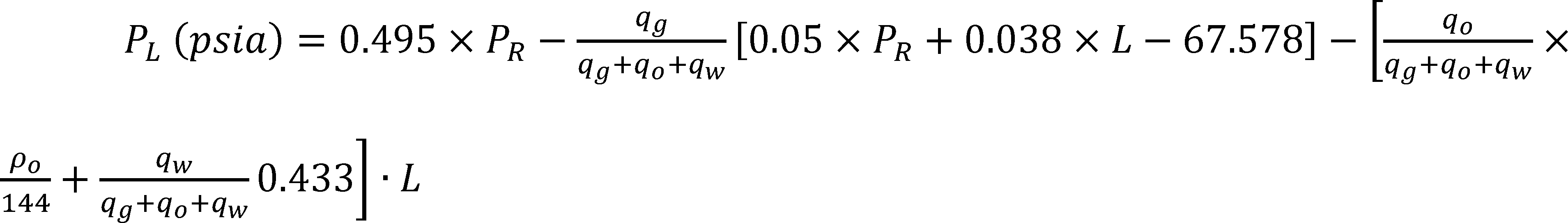
Where:
(1) PL is the pressure of flowback fluid immediately before it enters the flow line, expressed in pounds force per square inch (psia), and is to be calculated using the equation above;
(2) PR is the pressure of the reservoir containing oil, gas, and water at the well site, expressed in psia;
(3) Lis the true vertical depth of the well, expressed in feet (ft);
(4) qo is the flow rate of oil in the well, expressed in cubic feet/second (cu ft/sec);
(5) qg is the flow rate of gas in the well, expressed in cu ft/sec;
(6) qw is the flow rate of water in the well, expressed in cu ft/sec;
(7) ρo is the density of oil in the well, expressed in pounds mass per cubic feet (lbm/cu ft).
(b) You must determine the four values in paragraphs (a)(4) through (7) of this section, using the calculations in paragraphs (b)(1) through (b)(15) of this section.
(1) Determine the value of the bottom hole pressure, PBH (psia), based on available information at the well site, or by calculating it using the reservoir pressure, PR (psia), in the following equation:

(2) Determine the value of the bottom hole temperature, TBH (F), based on available information at the well site, or by calculating it using the true vertical depth of the well, L (ft), in the following equation:
TBH (F) = (0.014 × L) + 79.081
(3) Calculate the value of the applicable natural gas specific gravity that would result from a separator pressure of 100 psig, γgs, using the following equation with: Separator at standard conditions (pressure, p = 14.7 (psia), temperature, T = 60 (F)); the oil API gravity at the well site, γ0; and the gas specific gravity at the separator under standard conditions, γgp = 0.75:
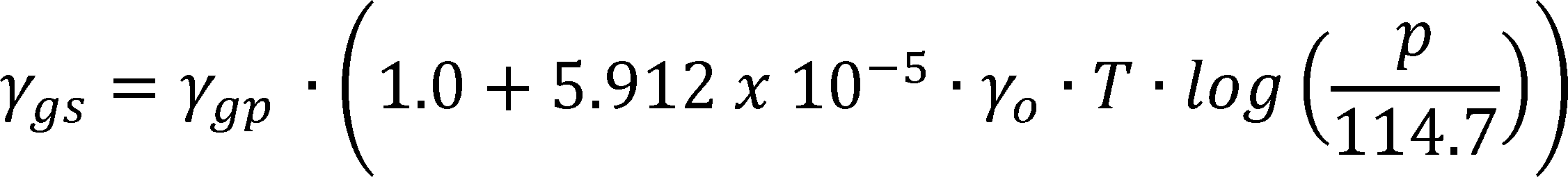
(4) Calculate the value of the applicable dissolved GOR, Rs (scf/STBO), using the following equation with: The bottom hole pressure, PBH (psia), determined in (b)(1) of this section; the bottom hole temperature, TBH (F), determined in (b)(2) of this section; the gas gravity at separator pressure of 100 psig, γgs, calculated in (b)(3) of this section; the oil API gravity, γo, at the well site; and the constants, C1, C2, and C3, found in Table A:
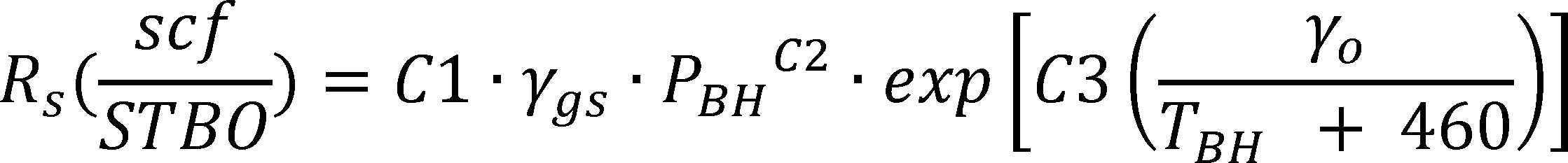
Table A—Coefficients for the correlation for Rs
| Constant | γAPI ≤ 30 | γAPI > 30 |
|---|---|---|
| C1 | 0.0362 | 0.0178 |
| C2 | 1.0937 | 1.1870 |
| C3 | 25.7240 | 23.931 |
(5) Calculate the value of the oil formation volume factor, Bo (bbl/STBO), using the following equation with: the bottom hole temperature, TBH (F), determined in paragraph (b)(2) of this section; the gas gravity at separator pressure of 100 psig, γgs, calculated in paragraph (b)(3) of this section; the dissolved GOR, Rs (scf/STBO), calculated in paragraph (b)(4) of this section; the oil API gravity, γo, at the well site; and the constants, C1, C2, and C3, found in Table B:

Table B—Coefficients for the Correlation for Bo
| Constant | γAPI ≤ 30 | γAPI > 30 |
|---|---|---|
| C1 | 4.677 × 10⁻⁴ | 4.670 × 10⁻⁴ |
| C2 | 1.751 × 10⁻⁵ | 1.100 × 10⁻⁵ |
| C3 | −1.811 × 10⁻⁸ | 1.337 × 10⁻⁹ |
(6) Calculate the density of oil at the wellhead,
using the following equation with the value of the oil API gravity, γo, at the well site:
(7) Calculate the density of oil at bottom hole conditions,

using the following equation with: the dissolved GOR, Rs (scf/STBO), calculated in paragraph (b)(4) of this section; the oil formation volume factor, Bo (bbl/STBO), calculated in paragraph (b)(5) of this section; the oil density at the wellhead,

calculated in paragraph (b)(6) of this section; and the dissolved gas gravity, γgd = 0.77:
(8) Calculate the density of oil in the well,

using the following equation with the density of oil at the wellhead,

calculated in paragraph (b)(6) of this section; and the density of oil at bottom hole conditions,

calculated in paragraph (b)(7) of this section:

(9) Calculate the oil flow rate, qo (cu ft/sec,) using the following equation with: the oil formation volume factor, Bo (bbl/STBO), as calculated in paragraph (b)(5) of this section; and the estimated oil production rate at the well head, Qo (STBO/day):

(10) Calculate the critical pressure, Pc (psia), and critical temperature, Tc (R), using the equations below with: Gas gravity at standard conditions (pressure, P = 14.7 (psia), temperature, T = 60 (F)), γ = 0.75; and where the mole fractions of nitrogen, carbon dioxide and hydrogen sulfide in the gas are XN2 = 0.168225, XCO2 = 0.013163, and XH2S = 0.013680, respectively:
Pc(psia) = 678 − 50 · (γg − 0.5) − 206.7 · XN2 + 440 · XCO2 + 606.7 · XH2S
Tc(R) = 326 + 315.7 · (γg − 0.5) − 240 · XN2 − 88.3 · XCO2 + 133.3 · XH2S
(11) Calculate reduced pressure, Pr, and reduced temperature, Tr, using the following equations with: the bottom hole pressure, PBH, as determined in paragraph (b)(1) of this section; the bottom hole temperature, TBH (F), as determined in paragraph (b)(2) of this section in the following equations:


(12)
(i) Calculate the gas compressibility factor, Z, using the following equation with the reduced pressure, Pr, calculated in paragraph (b)(11) of this section:

(ii) The values for A, B, C, D in the above equation, are calculated using the following equations with the reduced pressure, Pr, and reduced temperature, Tr, calculated in paragraph (b)(11) of this section:
(13) Calculate the gas formation volume factor,

using the bottom hole pressure, PBH (psia), as determined in paragraph (b)(1) of this section; and the bottom hole temperature, TBH (F), as determined in paragraph (b)(2) of this section:
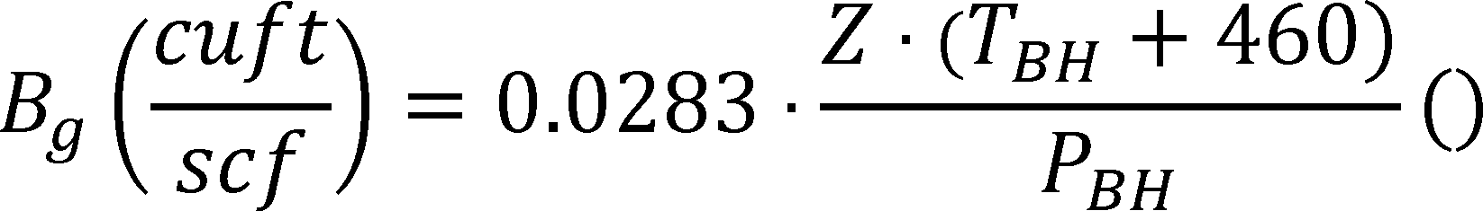
(14) Calculate the gas flow rate,

using the following equation with: the value of gas formation volume factor,

calculated in paragraph (b)(13) of this section; the estimated gas production rate, Qg (scf/day); the estimated oil production rate, Qo (STBO/day); and the dissolved GOR, Rs (scf/STBO), as calculated in paragraph (b)(4) of this section:
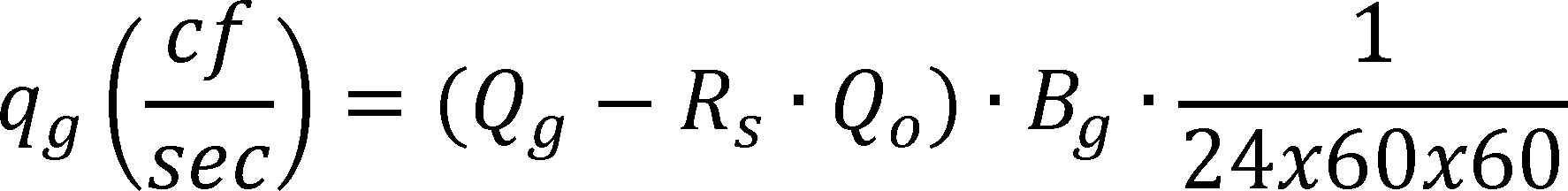
(15) Calculate the flow rate of water in the well, qw (cu ft/sec), using the following equation with the water production rate Qw (bbl/day) at the well site:

§§ 60.5433a-60.5439a [Reserved]
Table 1 to Subpart OOOOa of Part 60—Required Minimum Initial SO2 Emission Reduction Efficiency (Zi)
| H2S content of acid gas (Y), % | Sulfur feed rate (X), LT/D | |||
|---|---|---|---|---|
| 2.0 < X < 5.0 | 5.0 < X < 15.0 | 15.0 < X < 300.0 | X > 300.0 | |
| Y > 50 | 79.0 | 88.51X0.0101Y0.0125 or 99.9, whichever is smaller. | ||
| 20 < Y < 50 | 79.0 | 88.51X0.0101Y0.0125 or 97.9, whichever is smaller | 97.9 | |
| 10 < Y < 20 | 79.0 | 88.51X0.0101Y0.0125 or 93.5, whichever is smaller | 93.5 | 93.5 |
| Y < 10 | 79.0 | 79.0 | 79.0 | 79.0 |
Table 2 to Subpart OOOOa of Part 60—Required Minimum SO2 Emission Reduction Efficiency (Zc)
| H2S content of acid gas (Y), % | Sulfur feed rate (X), LT/D | |||
|---|---|---|---|---|
| 2.0 < X < 5.0 | 5.0 < X < 15.0 | 15.0 < X < 300.0 | X > 300.0 | |
| Y > 50 | 74.0 | 85.35X0.0144Y0.0128 or 99.9, whichever is smaller. | ||
| 20 < Y < 50 | 74.0 | 85.35X0.0144Y0.0128 or 97.5, whichever is smaller | 97.5 | |
| 10 < Y < 20 | 74.0 | 85.35X0.0144Y0.0128 or 90.8, whichever is smaller | 90.8 | 90.8 |
| Y < 10 | 74.0 | 74.0 | 74.0 | 74.0 |
X = The sulfur feed rate from the sweetening unit (i.e., the H2S in the acid gas), expressed as sulfur, Mg/D(LT/D), rounded to one decimal place.
Y = The sulfur content of the acid gas from the sweetening unit, expressed as mole percent H2S (dry basis) rounded to one decimal place.
Z = The minimum required sulfur dioxide (SO2) emission reduction efficiency, expressed as percent carried to one decimal place. Zi refers to the reduction efficiency required at the initial performance test. Zc refers to the reduction efficiency required on a continuous basis after compliance with Zi has been demonstrated.
As stated in § 60.5425a, you must comply with the following applicable General Provisions:
Table 3 to Subpart OOOOa of Part 60—Applicability of General Provisions to Subpart OOOOa
| General provisions
citation |
Subject of citation | Applies to subpart? | Explanation |
|---|---|---|---|
| § 60.1 | General applicability of the General Provisions | Yes | |
| § 60.2 | Definitions | Yes | Additional terms defined in § 60.5430a. |
| § 60.3 | Units and abbreviations | Yes | |
| § 60.4 | Address | Yes | |
| § 60.5 | Determination of construction or modification | Yes | |
| § 60.6 | Review of plans | Yes | |
| § 60.7 | Notification and record keeping | Yes | Except that § 60.7 only applies as specified in § 60.5420a(a). |
| § 60.8 | Performance tests | Yes | Except that the format of performance test reports is described in § 60.5420a(b). Performance testing is required for control devices used on storage vessels, centrifugal compressors, and pneumatic pumps, except that performance testing is not required for a control device used solely on pneumatic pump(s). |
| § 60.9 | Availability of information | Yes | |
| § 60.10 | State authority | Yes | |
| § 60.11 | Compliance with standards and maintenance requirements | No | Requirements are specified in subpart OOOOa. |
| § 60.12 | Circumvention | Yes | |
| § 60.13 | Monitoring requirements | Yes | Continuous monitors are required for storage vessels. |
| § 60.14 | Modification | Yes | To the extent any provision in § 60.14 conflicts with specific provisions in subpart OOOOa, it is superseded by subpart OOOOa provisions. |
| § 60.15 | Reconstruction | Yes | Except that § 60.15(d) does not apply to wells, pneumatic controllers, pneumatic pumps, centrifugal compressors, reciprocating compressors, storage vessels, or the collection of fugitive emissions components at a well site or the collection of fugitive emissions components at a compressor station. |
| § 60.16 | Priority list | Yes | |
| § 60.17 | Incorporations by reference | Yes | |
| § 60.18 | General control device and work practice requirements | Yes | |
| § 60.19 | General notification and reporting requirement | Yes |
[81 FR 35898, June 3, 2016, as amended at 85 FR 57460, Sept. 15, 2020]
Subpart PPPP [Reserved]
Subpart QQQQ - Standards of Performance for New Residential Hydronic Heaters and Forced-Air Furnaces
Source:
80 FR 13715, Mar. 16, 2015, unless otherwise noted.
§ 60.5472 Am I subject to this subpart?
(a) You are subject to this subpart if you manufacture, sell, offer for sale, import for sale, distribute, offer to distribute, introduce or deliver for introduction into commerce in the United States, or install or operate a residential hydronic heater, forced-air furnace or other central heater manufactured on or after May 15, 2015, except as provided in paragraph (c) of this section.
(b) Each residential hydronic heater, forced-air furnace or other central heater must comply with the provisions of this subpart unless exempted under paragraphs (b)(1) through (b)(3) of this section. These exemptions are determined by rule applicability and do not require additional EPA notification or public notice.
(1) Affected residential hydronic heaters, forced-air furnaces or other central heaters manufactured in the United States for export are exempt from the applicable emission limits of § 60.5474 and the requirements of § 60.5475.
(2) Affected residential hydronic heaters, forced-air furnaces or other central heaters used for research and development purposes that are never offered for sale or sold and that are not used to provide heat are exempt from the applicable emission limits of § 60.5474 and the requirements of § 60.5475. No more than 12 affected residential central heaters manufactured per model line may be exempted for this purpose.
(3) Appliances that do not burn wood or wood pellets or wood chips (such as coal-only central heaters that meet the definition in § 60.5473 or corn-only central heaters) are exempt from the applicable emission limits of § 60.5474 and the requirements of § 60.5475 provided that all advertising and warranties clearly denote that wood burning is prohibited in these appliances.
(c) The following are not affected central heaters and are not subject to this subpart:
(1) Residential wood heaters subject to subpart AAA of this part.
(2) Residential masonry heaters as defined in § 60.5473.
§ 60.5473 What definitions must I know?
As used in this subpart, all terms not defined herein have the same meaning given them in the Clean Air Act and subpart A of this part.
Approved test laboratory means a test laboratory that is approved for central heater certification testing under § 60.5477 or is an independent third-party test laboratory that is accredited under ISO-IEC Standard 17025 to perform testing using the test methods specified in § 60.5476 by an accreditation body that is a full member signatory to the International Laboratory Accreditation Cooperation Mutual Recognition Arrangement and approved by the EPA for conducting testing under this subpart.
Catalytic combustor means a device coated with a noble metal used in a wood heater to lower the temperature required for combustion.
Central heater means a fuel-burning device designed to burn wood or wood pellet fuel that warms spaces other than the space where the device is located, by the distribution of air heated by the furnace through ducts or liquid heated in the device and distributed typically through pipes. Unless otherwise specified, these devices include, but are not limited to, residential forced-air furnaces (small and large) and residential hydronic heaters.
Chip wood fuel means wood chipped into small pieces that are uniform in size, shape, moisture, density and energy content.
Coal-only hydronic heater or forced-air furnace means an enclosed, coal-burning appliance capable of space heating or domestic water heating that has all of the following characteristics:
(1) Installation instructions, owner's manual and marketing information that state that the use of wood in the appliance, except for coal ignition purposes, is prohibited by law; and
(2) The model is listed by a nationally recognized safety-testing laboratory for coal use only, except for coal ignition purposes.
Commercial owner means any person who owns or controls a residential hydronic heater, forced-air furnace or other affected central heater in the course of the business of the manufacture, importation, distribution, or sale of the unit.
Large residential forced-air furnace means a residential forced-air furnace that is capable of a heat output of 65,000 BTU per hour or greater.
Manufactured means completed and ready for shipment (whether or not assembled or packaged) for purposes of determining the date of manufacture.
Manufacturer means any entity that constructs or imports into the United States a central heater.
Model line means all central heaters offered for sale by a single manufacturer that are similar in all material respects that would affect emissions as defined in this section.
Particulate matter (PM) means total particulate matter including coarse particulate (PM10) and fine particulate (PM2.5).
Pellet fuel means refined and densified solid wood shaped into small pellets or briquettes that are uniform in size, shape, moisture, density and energy content.
Representative affected wood or central heater means an individual heater that is similar in all material respects that would affect emissions as defined in this section to other heaters within the model line it represents.
Residential forced-air furnace means a fuel burning device designed to burn wood or wood pellet fuel that warms spaces other than the space where the furnace is located, by the distribution of air heated by the furnace through ducts.
Residential hydronic heater means a fuel burning device designed to burn wood or wood pellet fuel for the purpose of heating building space and/or water through the distribution, typically through pipes, of a fluid heated in the device, typically water or a water and antifreeze mixture.
Residential masonry heater means a factory-built or site-built wood-burning device in which the heat from intermittent fires burned rapidly in the firebox is stored in the refractory mass for slow release to building spaces. Masonry heaters are site-built (using local materials or a combination of local materials and manufactured components) or site-assembled (using factory-built components), solid fuel-burning heating appliances constructed mainly of refractory materials (e.g., masonry materials or soapstone. They typically have an interior construction consisting of a firebox and heat exchange channels built from refractory components, through which flue gases are routed. ASTM E1602 “Standard Guide for Construction of Solid Fuel Burning Masonry Heaters” provides design and construction information for the range of masonry heaters most commonly built in the United States. The site-assembled models are generally listed to UL-1482.
Sale means the transfer of ownership or control, except that a transfer of control of an affected central heater for research and development purposes within the scope of § 60.5472(b)(2) is not a sale.
Similar in all material respects that would affect emissions means that the construction materials, exhaust and inlet air system, and other design features are within the allowed tolerances for components identified in § 60.5475(k).
Small residential forced-air furnace means a residential forced-air furnace that is only capable of a maximum heat output of less than 65,000 BTU per hour.
Sold at retail means the sale by a commercial owner of a central heater to the ultimate purchaser/user or noncommercial purchaser.
Third-party certifier (sometimes called third-party certifying body or product certifying body) means an independent third party that is accredited under ISO-IEC Standards 17025 and 17065 to perform certifications, inspections and audits by an accreditation body that is a full member signatory to the International Laboratory Accreditation Cooperation Mutual Recognition Arrangement and approved by the EPA for conducting certifications, inspections and audits under this subpart.
Unseasoned wood means wood with an average moisture content of 20 percent or more.
Valid certification test means a test that meets the following criteria:
(1) The Administrator was notified about the test in accordance with § 60.5476(h);
(2) The test was conducted by an approved test laboratory as defined in this section;
(3) The test was conducted on a central heater similar in all material respects that would affect emissions as defined in this section to other central heaters of the model line that is to be certified; and
(4) The test was conducted in accordance with the test methods and procedures specified in § 60.5476.
Wood heater under this subpart means an enclosed, wood burning-appliance capable of and intended for residential central heating or central heating and domestic water heating. Unless otherwise specified, these devices include, but are not limited to, hydronic heaters and forced-air furnaces.
§ 60.5474 What standards and requirements must I meet and by when?
(a) Standards. Unless exempted under § 60.5472, no person is permitted to:
(1) On or after May 15, 2015, manufacture, import into the United States or sell at retail a residential hydronic heater unless it has been certified to meet the 2015 particulate matter emission limits in paragraph (b)(1) of this section, except that a residential hydronic heater that was manufactured on or before May 15, 2015 may be imported into the United States and/or sold at retail on or before December 31, 2015.
(2) On or after May 15, 2020 manufacture or sell at retail a residential hydronic heater unless it has been certified to meet the 2020 particulate matter emission limit in paragraph (b)(2) or (b)(3) of this section.
(3) On or after May 15, 2015, manufacture or sell at retail a residential forced-air furnace unless it complies with the work practice and operating standards in paragraphs (d), (e), (f) and (g) of this section and the owner's manual requirements in appendix I.
(4) On or after May 16, 2016, manufacture or sell at retail a small residential forced-air furnace unless it has been certified to meet the 2016 particulate matter emission limits in paragraph (b)(4) of this section
(5) On or after May 15, 2017 manufacture or sell at retail a large forced-air furnace unless it has been certified to meet the 2017 particulate matter emission limits in paragraph (b)(5) of this section.
(6) On or after May 15, 2020 manufacture or sell at retail a small or large residential forced-air furnace unless it has been certified to meet the 2020 particulate matter emission limit in paragraph (b)(6) of this section.
(b) (1) 2015 residential hydronic heater particulate matter emission limit: A weighted average of 0.32 lb/mmBtu (0.137 g/MJ) heat output and a maximum per individual burn rate of 18.0 g/hr (0.041 lb/hr) as determined by the test methods and procedures in § 60.5476 or an alternative crib wood or cord wood test method approved by the Administrator.
(2) 2020 residential hydronic heater particulate matter emission limit: 0.10 lb/mmBtu (0.026 g/MJ) heat output per individual burn rate as determined by the crib wood test methods and procedures in § 60.5476 or an alternative crib wood test method approved by the Administrator .
(3) 2020 residential hydronic heater cord wood alternative compliance option for particulate matter emission limit: 0.15 lb/mmBtu (0.026 g/MJ) heat output per individual burn rate as determined by the cord wood test methods and procedures in § 60.5476 or an alternative cord wood test method approved by the Administrator.
(4) 2016 small forced-air furnace particulate matter emission limit: A weighted average of 0.93 lb/mmBtu (0.40 g/MJ) heat output as determined by the test methods and procedures in § 60.5476.
(5) 2017 large forced-air furnace particulate matter emission limit: A weighted average of 0.93 lb/mmBtu (0.40 g/MJ) heat output as determined by the test methods and procedures in § 60.5476.
(6) 2020 forced-air furnace particulate matter emission limit: 0.15 lb/mmBtu (0.026 g/MJ) heat output per individual burn rate as determined by the cord wood test methods and procedures in § 60.5476 or cord wood test methods approved by the Administrator.
(c) [Reserved]
(d) Chip wood fuel requirements. Operators of wood central heaters, including hydronic heaters and forced-air furnaces, that are certified to burn chip wood fuels may only burn wood chips that have been specified in the owner's manual. The chip wood fuel must meet the following minimum requirements:
(1) Moisture content: Less than 35 percent,
(2) Inorganic fines: Less than or equal to 1 percent;
(3) Chlorides: Less than or equal to 300 parts per million by weight;
(4) Ash content: No more than 2 percent;
(5) No demolition or construction waste; and
(6) Trace metals: Less than 100 mg/kg.
(e) Pellet fuel requirements. Operators of wood central heaters, including outdoor residential hydronic heaters, indoor residential hydronic heaters, and residential forced-air furnaces, that are certified to burn pellet fuels may burn only pellets that have been specified in the owner's manual and graded under a licensing agreement with a third-party organization approved by the EPA (including a certification by the third-party organization that the pellets do not contain, and are not manufactured from, any of the prohibited fuels in paragraph (f) of this section). The Pellet Fuels Institute, ENplus, and CANplus are initially deemed to be approved third-party organizations for this purpose, and additional organizations may apply to the Administrator for approval.
(f) Prohibited fuel types. No person is permitted to burn any of the following materials in an outdoor residential hydronic heater, indoor residential hydronic heater, residential forced-air furnace or other affected central heater:
(1) Residential or commercial garbage;
(2) Lawn clippings or yard waste;
(3) Materials containing rubber, including tires;
(4) Materials containing plastic;
(5) Waste petroleum products, paints or paint thinners, or asphalt products;
(6) Materials containing asbestos;
(7) Construction or demolition debris;
(8) Paper products; cardboard, plywood or particleboard. The prohibition against burning these materials does not prohibit the use of fire starters made from paper, cardboard, saw dust, wax and similar substances for the purpose of starting a fire in an affected central heater;
(9) Railroad ties or pressure treated lumber;
(10) Manure or animal remains;
(11) Salt water driftwood or other or other previously salt water saturated materials;
(12) Unseasoned wood;
(13) Any materials that are not included in the warranty and owner's manual for the subject heater or furnace; or
(14) Any materials that were not included in the certification tests for the subject heater or furnace.
(g) Operation of affected wood heaters. A user must operate an outdoor residential hydronic heater, indoor residential hydronic heater, residential forced-air furnace or other affected central heater in a manner consistent with the owner's manual. The owner's manual must clearly specify that operation in a manner inconsistent with the owner's manual would void the warranty.
(h) Temperature sensor requirement. An affected wood heater equipped with a catalytic combustor must be equipped with a temperature sensor that can monitor combustor gas stream temperatures within or immediately downstream [within 2.54 centimeters (1 inch)] of the catalytic combustor surface.
[80 FR 13715, Mar. 16, 2015, as amended at 85 FR 18455, Apr. 2, 2020]
§ 60.5475 What compliance and certification requirements must I meet and by when?
(a) Certification requirement.
(1) Each affected residential hydronic heater, forced-air furnace and other central heater must be certified to be in compliance with the applicable emission standards and other requirements of this subpart. For each model line manufactured or sold by a single entity, e.g., company or manufacturer, compliance with applicable emission standards of § 60.5474 must be determined based on testing of representative affected central heaters within the model line. If one entity licenses a model line to another entity, each entity's model line must be certified. If an entity intends to change the name of the entity or the name of the model, the manufacturer must apply for a new certification 60 days before making the change.
(2) The manufacturer of each model line must submit the information required in paragraph (b) of this section and follow either the certification process in paragraphs (c) through (e) of this section (for forced-air furnaces) or the certification procedure specified in paragraph (f) of this section.
(3) Models qualified as meeting the Phase 2 emission levels under the 2011 EPA hydronic heater partnership agreement are automatically deemed to have a certificate of compliance for the 2015 particulate matter emission standards and be valid until the effective date for the 2020 particulate matter emission standards.
(4) Models certified by the New York State Department of Environment and Conservation to meet the emission levels in § 60.5474(b) are automatically deemed to have a certificate of compliance for the 2015 particulate matter emission standards and be valid until the effective date for the 2020 particulate matter emission standards.
(5) Models approved by the New York State Energy Research and Development Authority under the Renewable Heat New York (RHNY) Biomass Boiler Program are automatically deemed to have a certificate of compliance for the 2015 particulate matter emission standards and be valid until the effective date for the 2020 particulate matter emission standards provided that they comply with the thermal storage requirements in the RHNY program.
(6) Small forced-air furnace models that are certified under CSA B415.1-10 (IBR, see § 60.17), by an EPA approved third-party certifier, to meet the 2016 particulate matter emission level will be automatically deemed to have a certificate of compliance for the 2016 particulate matter emission standards and be valid until the effective date for the 2020 particulate matter emission standards.
(7) Large forced-air furnace models that are certified under CSA B415.1-10 (IBR, see § 60.17), by an EPA approved third-party certifier, to meet the 2017 particulate matter emission level will be automatically deemed to have a certificate of compliance for the 2017 particulate matter emission standards and be valid until the effective date of the 2020 particulate matter emission standards.
(b) Application for a certificate of compliance. Any manufacturer of an affected residential hydronic heater or forced-air furnace or other central heater must apply to the Administrator for a certificate of compliance for each model line. The application must be submitted to: WoodHeaterReports@epa.gov. The application must be signed by a responsible representative of the manufacturer or an authorized representative and must contain the following:
(1) The model name and/or design number. The model name and/or design number must clearly distinguish one model from another. The name and/or design number cannot include the EPA symbol or logo or name or derivatives such as “EPA.”
(2) Engineering drawings and specifications of components that may affect emissions (including specifications for each component listed in paragraph (k) of this section). Manufacturers may use assembly or design drawings that have been prepared for other purposes, but must designate on the drawings the dimensions of each component listed in paragraph (k) of this section. Manufacturers must identify dimensions of components listed in paragraph (k)(2) of this section that are different from those specified in that paragraph, and show that such differences cannot reasonably be anticipated to cause central heaters in the model line to exceed the applicable emission limits. The drawings must identify how the emission critical parts, such as air tubes and catalyst, can be readily inspected and replaced.
(3) A statement whether the firebox or any firebox component (including the materials listed in paragraph (k)(3) of this section) will be composed of material different from the material used for the firebox or firebox component in the central heater on which certification testing was performed and a description of any such differences and demonstration that any such differences may not reasonably be anticipated to adversely affect emissions or efficiency.
(4) Clear identification of any claimed confidential business information (CBI). Submit such information under separate cover to the EPA CBI Office; Attn: Residential Wood Heater Compliance Program Lead, 1200 Pennsylvania Ave. NW., Washington, DC 20004. Note that all emissions data, including all information necessary to determine emission rates in the format of the standard, cannot be claimed as CBI.
(5) All documentation pertaining to a valid certification test, including the complete test report and, for all test runs: Raw data sheets, laboratory technician notes, calculations and test results. Documentation must include the items specified in the applicable test methods. Documentation must include discussion of each test run and its appropriateness and validity, and must include detailed discussion of all anomalies, whether all burn rate categories were achieved, any data not used in the calculations and, for any test runs not completed, the data collected during the test run and the reason(s) that the test run was not completed. The documentation must show that the burn rate for the low burn rate category is no greater than the rate that an operator can achieve in home use and no greater than is advertised by the manufacturer or retailer. The test report must include a summary table that clearly presents the individual and overall emission rates, efficiencies and heat outputs. Submit the test report and all associated required information according to the procedures for electronic reporting specified in § 60.5479(f).
(6) A copy of the warranties for the model line, which must include a statement that the warranties are void if the unit is used to burn materials for which the unit is not certified by the EPA and void if not operated according to the owner's manual.
(7) A statement that the manufacturer will conduct a quality assurance program for the model line that satisfies the requirements of paragraph (m) of this section.
(8) A statement describing how the tested unit was sealed by the laboratory after the completion of certification testing and asserting that such unit will be stored by the manufacturer in the sealed state until 5 years after the certification test.
(9) Statements that the central heater manufactured under this certificate will be—
(i) Similar in all material respects that would affect emissions as defined in this subpart to the central heater submitted for certification testing, and
(ii) Labeled as prescribed in § 60.5478.
(iii) Accompanied by an owner's manual that meets the requirements in § 60.5478. In addition, a copy of the owner's manual must be submitted to the EPA and be available to the public on the manufacturer's Web site.
(10) A statement that the manufacturer has entered into contracts with an approved laboratory and an approved third-party certifier that satisfy the requirements of paragraph (f) of this section.
(11) A statement that the approved laboratory and approved third-party certifier are allowed to submit information on behalf of the manufacturer, including any claimed to be CBI.
(12) A statement that the manufacturer will place a copy of the certification test report and summary on the manufacturer's Web site available to the public within 30 days after the Administrator issues a certificate of compliance.
(13) A statement of acknowledgment that the certificate of compliance cannot be transferred to another manufacturer or model line without written approval by the Administrator.
(14) A statement acknowledging that it is unlawful to sell, distribute, or offer to sell or distribute an affected wood heater without a valid certificate of compliance.
(15) Contact information for the responsible representative of the manufacturer and all authorized representatives, including name, affiliation, physical address, telephone number and email address.
(c) Administrator approval process.
(1) The Administrator may issue a certificate of compliance for a model line if the Administrator determines, based on all information submitted by the applicant and any other relevant information available, that:
(i) A valid certification test demonstrates that the representative affected central heater complies with the applicable emission standards in § 60.5474;
(ii) Any tolerances or materials for components listed in paragraph (k)(2) or (3) of this section that are different from those specified in those paragraphs may not reasonably be anticipated to cause central heaters in the model line to exceed the applicable emission limits; and
(iii) The requirements of paragraph (b) of this section have been met.
(2) The Administrator will deny certification if the Administrator determines that the criteria in paragraph (c)(1) of this section have not been satisfied. Upon denying certification under this paragraph, the Administrator will give written notice to the manufacturer setting forth the basis for this determination.
(d) Level of compliance certification. The Administrator will issue the certificate of compliance for the most stringent particulate matter emission standard that the tested representative central heater meets under § 60.5474.
(e) Conditional, temporary certificate of compliance. A conditional, temporary certificate of compliance with the Step 1 p.m. emission standards may be granted by the Administrator until May 16, 2016 for small or large forced-air furnaces based on the manufacturer's submittal of a complete certification application meeting all requirements in § 60.5475(b). The application must include the full test report by an EPA-approved laboratory and all required compliance statements by the manufacturer with the exception of a certificate of conformity by an EPA approved third-party certifier. The conditional, temporary approval would allow early marketing of forced-air furnaces as having a conditional, temporary certificate of compliance with the Step 1 p.m. emission standards until May 16, 2016 or until the Administrator completes the review of the application, whichever is earlier.
(f) Third-party certifier-based application process.
(1) Any manufacturer of an affected central heater must apply to the Administrator for a certificate of compliance for each model line. The manufacturer must meet the following requirements:
(i) The manufacturer must contract with a third-party certifier for certification services. The contract must include regular (at least annual) unannounced audits under ISO-IEC Standard 17065 to ensure that the manufacturer's quality assurance plan is being implemented. The contract must also include a report for each audit under ISO-IEC Standard 17065 that fully documents the results of the audit. The contract must include authorization and requirement for the third-party certifier to submit all such reports to the Administrator and the manufacturer within 30 days of the audit. The audit report must identify deviations from the manufacturer's quality assurance plan and specify the corrective actions that need to be taken to address each identified deficiency.
(ii) The manufacturer must submit the materials specified in paragraph (b) of this section and a quality assurance plan that meets the requirements of paragraph (m) of this section to the third-party certifier. The quality assurance plan must ensure that units within a model line will be similar in all material respects that would affect emissions to the wood heater submitted for certification testing, and it must include design drawings for the model line.
(iii) The manufacturer must apply to the third-party certifier for a certification of conformity with the applicable requirements of this subpart for the model line.
(A) After testing by an approved test laboratory is complete, certification of conformity with the emission standards in § 60.5474 must be performed by the manufacturer's contracted third-party certifier.
(B) The third-party certifier may certify conformity if the emission tests have been conducted per the appropriate guidelines: The test report is complete and accurate; the instrumentation used for the test was properly calibrated; the test report shows that the representative affected central heater meets the applicable emission limits specified in § 60.5474; and the quality assurance plan is adequate to ensure that units within the model line will be similar in all material respects that would affect emissions to the central heater submitted for certification testing, and that the affected heaters would meet all applicable requirements of this subpart.
(iv) The manufacturer must then submit to the Administrator an application for a certificate of compliance that includes the certification of conformity, quality assurance plan, test report and all supporting documentation specified in paragraph (b) of this section.
(v) The submission also must include a statement signed by a responsible official of the manufacturer or authorized representative that the manufacturer has complied with and will continue to comply with all requirements of this subpart for certificate of compliance and that the manufacturer remains responsible for compliance regardless of any error by the test laboratory or third-party certifier.
(2) The Administrator will issue to the manufacturer a certificate of compliance for a model line if it is determined, based on all of the information submitted in the application for certification and any other relevant information, that:
(i) A valid certification of conformity has demonstrated that the representative affected central heater complies with the applicable emission standards in § 60.5474;
(ii) Any tolerances or materials for components listed in paragraph (k)(2) or (3) of this section that are different from those specified in those paragraphs may not be reasonably anticipated to cause central heaters in the model line to exceed the applicable emission limits;
(iii) The requirements of paragraphs (b) of this section have been met; and
(iv) A valid certificate of conformity for the model line has been prepared and submitted.
(3) The Administrator will deny certification if the Administrator determines that the criteria in paragraph (f)(2) of this section have not been satisfied. Upon denying certification under this paragraph, the Administrator will give written notice to the manufacturer setting forth the basis for the determination.
(g) Waiver from submitting test results. An applicant for certification may apply for a potential waiver of the requirement to submit the results of a certification test pursuant to paragraph (b) of this section, if the central heater meets either of the following conditions:
(1) The central heaters of the model line are similar in all material respects that would affect emissions, as defined in § 60.5473 and paragraph (k) of this section, to another model line that has already been issued a certificate of compliance. A manufacturer that seeks a waiver of certification testing must identify the model line that has been certified, and must submit a copy of an agreement with the owner of the design permitting the applicant to produce central heaters of that design.
(2) The manufacturer has previously conducted a valid certification test to demonstrate that the central heaters of the model line meet the applicable standard specified in § 60.5474.
(h) Certification period. Unless revoked sooner by the Administrator, a certificate of compliance will be valid for 5 years from the date of issuance or until a more stringent standard comes into effect, whichever is sooner.
(i) Renewal of certification.
(1) The manufacturer must renew a model line's certificate of compliance or recertify the model line every 5 years, or the manufacturer may choose to no longer manufacture or sell that model line after the expiration date. If the manufacturer chooses to no longer manufacture that model line, then the manufacturer must submit a statement to the Administrator to that effect.
(2) A manufacturer of an affected residential hydronic heater or forced-air furnace or other central heater may apply to the Administrator for potential renewal of its certificate of compliance by submitting the material specified in paragraph (b) and following the procedures specified in paragraph (f) of this section, or by affirming in writing that the central heaters in the model line continue to be similar in all material respects that would affect emissions to the representative central heater submitted for testing on which the original certificate of compliance was based and requesting a potential waiver from certification testing. The application must include a copy of the review of the draft application and approval by the third-party certifier.
(3) If the Administrator grants a renewal of certification, the Administrator will give written notice to the manufacturer setting forth the basis for the determination and issue a certification renewal.
(4) If the Administrator denies the request for a renewal of certification, the Administrator will give written notice to the manufacturer setting forth the basis for the determination.
(5) If the Administrator denies the request for a renewal of certification, the manufacturer and retailer must not manufacture or sell the previously-certified central heaters after the expiration date of the certificate of compliance.
(j) [Reserved]
(k) Recertification.
(1) The manufacturer must recertify a model line whenever any change is made in the design submitted pursuant to paragraph (k)(2) of this section that affects or is presumed to affect the particulate matter emission rate for that model line. The manufacturer of an affected central heater must apply to the Administrator for potential recertification by submitting the material specified in paragraph (b) of this section and following the procedures specified in paragraph (f) of this section or by affirming in writing that the change will not cause the central heaters in the model line to exceed applicable emission limits and requesting a waiver from certification testing. The application for recertification must be reviewed and approved by the contracted third-party certifier and a copy of the review and approval must be included. The Administrator may waive this requirement upon written request by the manufacturer, if the manufacturer presents adequate rationale and the Administrator determines that the change may not reasonably be anticipated to cause central heaters in the model line to exceed the applicable emission limits. The granting of such a waiver does not relieve the manufacturer of any compliance obligations under this subpart.
(2) Any change in the design tolerances of any of the following components (where such components are applicable) is presumed to affect particulate matter and carbon monoxide emissions and efficiency if that change exceeds ±0.64 cm (±1/4 inch) for any linear dimension and ±5 percent for any cross-sectional area relating to air introduction systems and catalyst bypass gaps unless other dimensions and cross-sectional areas are previously approved by the Administrator under paragraph (c)(1)(ii) of this section:
(i) Firebox: Dimensions;
(ii) Air introduction systems: Cross-sectional area of restrictive air inlets and outlets, location and method of control;
(iii) Baffles: Dimensions and locations;
(iv) Refractory/insulation: Dimensions and location;
(v) Catalyst: Dimensions and location;
(vi) Catalyst bypass mechanism and catalyst bypass gap tolerances (when bypass mechanism is in closed position): Dimensions, cross-sectional area, and location;
(vii) Flue gas exit: Dimensions and location;
(viii) Door and catalyst bypass gaskets: Dimensions and fit;
(ix) Outer thermal shielding and thermal coverings: Dimensions and location;
(x) Fuel feed system: For central heaters that are designed primarily to burn wood pellet fuel or wood chips and other central heaters equipped with a fuel feed system, the fuel feed rate, auger motor design and power rating, and the angle of the auger to the firebox; and
(xi) Forced air combustion system: For central heaters so equipped, the location and horsepower of blower motors and the fan blade size.
(3) Any change in the materials used for the following components is presumed to affect particulate matter emissions and efficiency:
(i) Refractory/insulation; or
(ii) Door and catalyst bypass gaskets.
(4) A change in the make, model, or composition of a catalyst is presumed to affect particulate matter and carbon monoxide emissions and efficiency, unless the change has been requested by the central heater manufacturer and has been approved in advance by the Administrator, based on test data that demonstrate that the replacement catalyst is equivalent to or better than the original catalyst in terms of particulate matter emission reduction.
(l) Criteria for revocation of certification.
(1) The Administrator may revoke certification of a product line if it is determined that the central heaters being manufactured or sold in that model line do not comply with the requirements of this subpart. Such a determination will be based on all available evidence, including but not limited to:
(i) Test data from retesting of the original unit on which the certification test was conducted on a unit that is similar in all material respects that would affect emissions;
(ii) A finding that the certification test was not valid. The finding will be based on problems or irregularities with the certification test or its documentation, but may be supplemented by other information;
(iii) A finding that the labeling of the central heater model line or the owner's manual or the associated marketing information does not comply with the requirements of § 60.5478;
(iv) Failure by the manufacturer to comply with the reporting and recordkeeping requirements of § 60.5479;
(v) Physical examination showing that a significant percentage (as defined in the quality assurance plan approved pursuant to paragraph (m) of this section, but no larger than 1 percent) of production units inspected is not similar in all material respects that would affect emissions to the representative affected central heater submitted for certification testing; or
(vi) Failure of the manufacturer to conduct a quality assurance program in conformity with paragraph (m).
(vii) Failure of the approved laboratory to test the central heater using the methods specified in § 60.5476.
(2) Revocation of certification under this paragraph (l) of this section will not take effect until the manufacturer concerned has been given written notice by the Administrator setting forth the basis for the proposed determination and an opportunity to request a hearing under § 60.5481.
(m) Quality assurance program. On or after May 16, 2016, for each certified model line, the manufacturer must conduct a quality assurance program that satisfies the requirements of paragraphs (m)(1) through (5) of this section.
(1) The manufacturer must prepare and operate according to a quality assurance plan for each certified model line that includes specific inspection and testing requirements for ensuring that all units within a model line are similar in all material respects that would affect emissions to the central heater submitted for certification testing and meet the emissions standards in § 60.5474.
(2) The quality assurance plan must be approved by the third-party certifier as part of the certification of conformity process specified in paragraph (f) of this section.
(3) The quality assurance plan must include regular (at least annual) unannounced audits by the third-party certifier under ISO-IEC Standard 17065 to ensure that the manufacturer's quality assurance plan is being implemented.
(4) The quality assurance plan must include a report for each audit under ISO-IEC Standard 17065 that fully documents the results of the audit. The third-party certifier must be authorized and required to submit all such reports to the Administrator within 30 days of the audit. The audit report must identify deviations from the manufacturer's quality assurance plan and specify the corrective actions that need to be taken to address each identified deficiency.
(5) Within 30 days after receiving each audit report, the manufacturer must report to the third-party certifier and to the Administrator its corrective actions and responses to any deficiencies identified in the audit report. No such report is required if an audit report did not identify any deficiencies.
(n) EPA compliance audit testing.
(1)
(i) The Administrator may select by written notice central heaters or model lines for compliance audit testing to determine compliance with the emission standards in § 60.5474.
(ii) The Administrator will transmit a written notification of the selected central heaters or model line(s) to the manufacturer, which will include the name and address of the laboratory selected to perform the audit test and the model name and serial number of the central heater(s) or central heater model line(s) selected to undergo audit testing.
(2)
(i) The Administrator may test, or direct the manufacturer to have tested, the central heater(s) from the model line(s) selected under paragraph (n)(1)(i) of this section in a laboratory approved under § 60.5477. The Administrator may select any approved test laboratory or federal laboratory for this audit testing.
(ii) The expense of the compliance audit test is the responsibility of the central heater manufacturer.
(iii) The test must be conducted using the same test method used to obtain certification. If the certification test consisted of more than one particulate matter sampling test method, the Administrator may direct the manufacturer and test laboratory as to which of these methods to use for the purpose of audit testing. The Administrator will notify the manufacturer at least 30 days prior to any test under this paragraph, and allow the manufacturer and/or his authorized representatives to observe the test.
(3) Revocation of certification.
(i) If emissions from a central heater tested under paragraph (n)(2) of this section exceed the applicable emission standard by more than 50 percent using the same test method used to obtain certification, the Administrator will notify the manufacturer that certification for that model line is suspended effective 72 hours from the receipt of the notice, unless the suspension notice is withdrawn by the Administrator. The suspension will remain in effect until withdrawn by the Administrator, or the date 30 days from its effective date if a revocation notice under paragraph (n)(3)(ii) of this section is not issued within that period, or the date of final agency action on revocation, whichever occurs earliest.
(ii)
(A) If emissions from a central heater tested under paragraph (n)(2) of this section exceed the applicable emission limit, the Administrator will notify the manufacturer that certification is revoked for that model line.
(B) A notice under paragraph (n)(3)(ii)(A) of this section will become final and effective 60 days after the date of written notification to the manufacturer, unless it is withdrawn, a hearing is requested under § 60.5481(a)(2), or the deadline for requesting a hearing is extended.
(C) The Administrator may extend the deadline for requesting a hearing for up to 60 days for good cause.
(D) A manufacturer may extend the deadline for requesting a hearing for up to 6 months, by agreeing to a voluntary suspension of certification.
(iii) Any notification under paragraph (n)(3)(i) or (ii) of this section will include a copy of a preliminary test report from the approved test laboratory or federal test laboratory. The test laboratory must provide a preliminary test report to the Administrator within 14 days of the completion of testing, if a central heater exceeds the applicable emission limit in § 60.5474. The test laboratory must provide the Administrator and the manufacturer, within 30 days of the completion of testing, all documentation pertaining to the test, including the complete test report and raw data sheets, laboratory technician notes, and test results for all test runs.
(iv) Upon receiving notification of a test failure under paragraph (n)(3)(ii) of this section, the manufacturer may request that up to four additional central heaters from the same model line be tested at the manufacturer's expense, at the test laboratory that performed the emissions test for the Administrator.
(v) Whether or not the manufacturer proceeds under paragraph (n)(3)(iv) of this section, the manufacturer may submit any relevant information to the Administrator, including any other test data generated pursuant to this subpart. The manufacturer must bear the expense of any additional testing.
(vi) The Administrator will withdraw any notice issued under paragraph (n)(3)(ii) of this section if tests under paragraph (n)(3)(iv) of this section show either—
(A) That exactly four additional central heaters were tested for the manufacturer and all four met the applicable emission limits; or
(B) That exactly two additional central heaters were tested for the manufacturer and each of them met the applicable emission limits and the average emissions of all three tested heaters (the original audit heater and the two additional heaters) met the applicable emission limits.
(vii) If the Administrator withdraws a notice pursuant to paragraph (n)(3)(vi) of this section, the Administrator will revise the certification values for the model line based on the test data and other relevant information. The manufacturer must then revise the labels and marketing information accordingly.
(viii) The Administrator may withdraw any proposed revocation, if the Administrator finds that an audit test failure has been rebutted by information submitted by the manufacturer under paragraph (n)(3)(iv) of this section and/or (n)(3)(v) of this section or by any other relevant information available to the Administrator.
§ 60.5476 What test methods and procedures must I use to determine compliance with the standards and requirements for certification?
Test methods and procedures specified in this section or in appendices of this part, except as provided under § 60.8(b), must be used to determine compliance with the standards and requirements for certification under §§ 60.5474 and 60.5475 and for reporting carbon monoxide emissions and efficiency. The EPA will post all approved alternative test methods on the EPA Web site. The manufacturer or the manufacturer's authorized representative must submit a summary and the full test report with all supporting information, including detailed discussion of all anomalies, whether all burn rate categories were properly achieved, any data not used in the calculations and, for any test runs not completed, the data that were collected and the reason that the test run was not completed. The burn rate for the low burn rate category must be no greater than the rate that an operator can achieve in home use and no greater than is advertised by the manufacturer or retailer.
(a) Canadian Standards Administration (CSA) Method B415.1-10, sections 13.7-13.10 (IBR, see § 60.17), must be used to measure the thermal efficiency and CO emissions of outdoor and indoor residential hydronic heaters and forced-air furnaces, except that the burn rates specified in Method 28WHH must be used for hydronic heaters.
(b) Testing conducted with continuously fed biomass as the fuel(s) must be conducted according to the relevant section of the ASTM E2618-13 (IBR, see § 60.17) or adaptations approved by EPA. The EPA will post all approved alternative test methods on the EPA Web site.
(c)
(1) For outdoor and indoor residential hydronic heaters to be tested under the 2015 particulate matter emission standards in § 60.5474(b)(1), the manufacturer must have an EPA-approved test laboratory use:
(i) Method 28WHH;
(ii) Method 28WHH PTS;
(iii) ASTM E2618-13 (IBR, see § 60.17) (using crib wood); or
(iv) EN 303-5 (IBR, see § 60.17), only for units sold with thermal storage.
(2) For outdoor and indoor residential hydronic heaters to be tested under the 2020 particulate matter emission standards in § 60.5474(b)(2), the manufacturer must have an EPA-approved test laboratory use:
(i) Method 28WHH;
(ii) Method 28WHH PTS; or
(iii) ASTM E2618-13 (IBR, see § 60.17) (using crib wood).
(3) If the heater is equipped with full or partial heat storage, the manufacturer, retailer and installer must not sell or install the heater with less heat storage capacity than is used in the certification test.
(4) The manufacturer and approved laboratory must make the following adjustments to the methods listed in paragraphs (a), (c)(1) and (2) of this section:
(i) For ASTM E2618-13 (IBR, see § 60.17), the burn rate categories specified in Method 28WHH must be used;
(ii) For EN 303-5 (IBR, see § 60.17), the organic compounds must be included as part of the PM.
(iii) For ASTM 2618-13 (IBR, see § 60.17) Appendix A1 for full thermal storage certification tests, the test must use the large scale as required in the test method unless the manufacturer requests a variance, in advance of testing, contingent upon measuring flue gas temperature, oxygen and CO, using a simple electronic spreadsheet calculator to estimate efficiency and conducting a comparison to the delivered efficiency to determine if a more detailed examination should be made.
(5) For particulate matter emission concentrations measured with ASTM E2515-11 (IBR, see § 60.17), four-inch filters and Teflon membrane filters or Teflon-coated glass fiber filters may be used.
(6) For all tests conducted using ASTM 2515-11 (IBR, see § 60.17) pursuant to this section, the manufacturer and approved test laboratory must also measure the first hour of particulate matter emissions for each test run using a separate filter in one of the two parallel trains. The manufacturer and approved test laboratory must report the test results for the first hour separately and also include them in the total particulate matter emissions per run.
(d)
(1) For hydronic heaters subject to the 2020 cord wood alternative compliance option specified in § 60.5474(b)(3), the manufacturers must have the approved laboratory conduct cord wood testing using the test methods listed below:
(i) Method 28WHH;
(ii) Method 28WHH PTS; or
(iii) ASTM E2618-13 (IBR, see § 60.17) (using cord wood).
(2) If the heater is equipped with full or partial heat storage, the manufacturer, retailer and installer must not sell or install the heater with less heat storage capacity than is used in the certification test.
(3) The manufacturer and approved laboratory must make the following adjustments to the methods listed in (d)(1) of this section:
(i) For ASTM E2618-13 (IBR, see § 60.17), use the burn rate categories specified in Method 28WHH;
(ii) For all methods, report the results separately per burn rate category.
(e) For forced-air furnaces, use CSA Method B415.1-10 (IBR, see § 60.17) to measure the heat output (mmBtu/hr) and particulate matter emission rate (lb/mmBtu heat output), except use the burn rate categories in Method 28WHH for the 2020 particulate matter emission standards. For the 2020 particulate matter emission standards, report the particulate matter, efficiency and CO emission results separately per burn rate category.
(f) For affected wood heaters subject to the particulate matter emission standards, emission concentrations must be measured with ASTM E2515-11 (IBR, see § 60.17), except for the 2015 certification tests using EN303-5 (IBR, see § 60.17). As required in paragraph (c)(4)(ii) of this section, the manufacturer and approved laboratory must add the organic gases to the PM for EN 303-5. Four-inch filters and Teflon membrane filters or Teflon-coated glass fiber filters may be used in ASTM E2515-11. Method 5H is not allowed for certification testing.
(g) Douglas fir may be used in ASTM E2618-13 and CSA B415.1-10 (IBR, see § 60.17).
(h) The manufacturer of an affected central heater model line must notify the Administrator of the date that certification testing is to begin, by email, to WoodHeaterReports@epa.gov. This notice must be at least 30 days before the start of testing. The notification of testing must include the manufacturer's name and physical and email addresses, the approved test laboratory's name and physical and email addresses, third-party certifier name, the model name and number (or, if unavailable, some other way to distinguish between models), and the dates of testing. The laboratory may substitute certification testing of another affected central heater on the original date in order to ensure regular laboratory testing operations.
(i) The approved test laboratory must allow the manufacturer, the manufacturer's approved third-party certifier, the EPA and delegated state regulatory agencies to observe certification testing. However, manufacturers must not involve themselves in the conduct of the test after the pretest burn has begun. Communications between the manufacturer and laboratory or third-party certifier personnel regarding operation of the central heater must be limited to written communications transmitted prior to the first pretest burn of the certification test series. During certification tests, the manufacturer may communicate with the third-party certifier, and only in writing to notify them that the manufacturer has observed a deviation from proper test procedures by the laboratory. All communications must be included in the test documentation required to be submitted pursuant to § 60.5475(b)(5) and must be consistent with instructions provided in the owner's manual required under § 60.5478(f).
[80 FR 13715, Mar. 16, 2015, as amended at 85 FR 63410, Oct. 7, 2020]
§ 60.5477 What procedures must I use for EPA approval of a test laboratory or EPA approval of a third-party certifier?
(a) Test laboratory approval.
(1) A laboratory must apply to the Administrator for approval to test under this rule by submitting documentation that the laboratory is accredited by a nationally recognized accrediting entity under ISO-IEC Standard 17025 to perform testing using the test methods specified under § 60.5476. Laboratories accredited by EPA prior to May 15, 2015 may have until May 15, 2018 to submit documentation that they have accreditation under ISO-IEC Standard 17025 to perform testing using the test methods specified under § 60.5476. ISO accreditation is required for all other laboratories performing hydronic heater testing beginning on May 15, 2015, and performing forced-air furnace testing beginning on November 16, 2015.
(2) As part of the application, the test laboratory must:
(i) Agree to participate biennially in an independently operated proficiency testing program with no direct ties to the laboratories participating;
(ii) Agree to allow the Administrator, regulatory agencies and certifying bodies access to observe certification testing;
(iii) Agree to comply with calibration, reporting and recordkeeping requirements that affect testing laboratories; and
(iv) Agree to perform a compliance audit test at the manufacturer's expense at the testing cost normally charged to such manufacturer if the laboratory is selected by the Administrator to conduct the compliance audit test of the manufacturer's model line. The test laboratory must provide a preliminary audit test report to the Administrator within 14 days of the completion of testing, if a central heater exceeds the applicable emission limit in § 60.5474. The test laboratory must provide the Administrator and the manufacturer, within 30 days of the completion of audit testing, all documentation pertaining to the test, including the complete test report and raw data sheets, laboratory technician notes, and test results for all test runs.
(v) Have no conflict of interest and receive no financial benefit from the outcome of certification testing conducted pursuant to § 60.5475.
(vi) Agree to not perform initial certification tests on any models manufactured by a manufacturer for which the laboratory has conducted research and development design services within the last 5 years.
(vii) Agree to seal any wood heater on which it performed certification tests, immediately upon completion or suspension of certification testing, by using a laboratory-specific seal.
(viii) Agree to immediately notify the Administrator of any suspended tests through email and in writing, giving the date suspended, the reason(s) why, and the projected date for restarting. The laboratory must submit the operation and test data obtained, even if the test is not completed.
(3) If the EPA approves the laboratory, the Administrator will provide the test laboratory with a certificate of approval for testing under this rule. If the EPA does not approve the laboratory, the Administrator will give written notice to the laboratory setting forth the basis for the determination.
(b) Revocation of test laboratory approval.
(1) The Administrator may revoke the EPA laboratory approval if it is determined that the laboratory:
(i) Is no longer accredited by the accreditation body;
(ii) Does not follow required procedures or practices;
(iii) Has falsified data or otherwise misrepresented emission data;
(iv) Failed to participate in a proficiency testing program, in accordance with its commitment under paragraph (a)(2)(i) of this section; or
(v) Failed to seal the central heater in accordance with paragraph (a)(2)(vii) of this section.
(2) Revocation of approval under this paragraph (b) will not take effect until the laboratory concerned has been given written notice by the Administrator setting forth the basis for the proposed determination and an opportunity for a hearing under § 60.5481. However, if revocation is ultimately upheld, all tests conducted by the laboratory after written notice was given will, at the discretion of the Administrator, be declared invalid.
(c) Period of test laboratory approval.
(1) With the exception of laboratories meeting the provisions of paragraph (c)(2) of this section, and unless revoked sooner, a certificate of approval for testing under this rule is valid for 5 years from the date of issuance.
(2) Laboratories accredited by the EPA by May 15, 2015, under the provisions of § 60.535 as in effect prior to that date may continue to be EPA accredited and deemed EPA approved for testing under this subpart until May 15, 2018, at which time the EPA accreditation and approval ends unless the laboratory has obtained accreditation under § 60.5477 as in effect on that date.
(d) Third-party certifier approval.
(1) A Third-party certifier may apply to the Administrator for approval to be an EPA-approved third-party certifier by submitting credentials demonstrating that it has been accredited by a nationally recognized accrediting entity to perform certifications and inspections under ISO-IEC Standard 17025, ISO-IEC Standard 17065 and ISO-IEC Standard 17020.
(2) As part of the application, the third-party certifier must:
(i) Agree to offer to contract with central heater manufacturers to perform third-party certification activities according to the requirements set out in this subpart.
(ii) Agree to periodically conduct audits as described in § 60.5475(m) and the manufacturer's quality assurance program;
(iii) Agree to comply with reporting and recordkeeping requirements that affect approved central heater testing laboratories and third-party certifiers;
(iv) Have no conflict of interest and receive no financial benefit from the outcome of certification testing conducted pursuant to § 60.5475;
(v) Agree to make available to the Administrator supporting documentation for each central heater certification and audit; and
(vi) Agree to not perform initial certification reviews on any models manufactured by a manufacturer for which the third-party certifier has conducted research and development design services within the last 5 years.
(3) If approved, the Administrator will provide the third-party certifier with a certificate of approval. The approval will expire 5 years after being issued unless renewed by the third-party certifier. If the EPA denies the approval, the Administrator will give written notice to the third-party certifier for the basis for the determination.
(e) Revocation of third-party certifier approval.
(1) The Administrator will revoke the third-party certifier's EPA approval if it is determined that the certifier:
(i) Is no longer accredited by the accreditation body;
(ii) Does not follow required procedures or practices; or
(iii) Has falsified certification data or otherwise misrepresented emission data.
(2) Revocation of approval under this paragraph (e) will not take effect until the certifier concerned is given written notice by the Administrator setting forth the basis for the proposed determination and an opportunity for a hearing under § 60.5481. However, if revocation is upheld, all certifications by the certifier after written notice was given will, at the discretion of the Administrator, be declared invalid.
§ 60.5478 What requirements must I meet for permanent labels, temporary labels (hangtags), and owner's manuals?
(a) General permanent label requirements.
(1) Each affected central heater manufactured or sold on or after the date the applicable standards come into effect as specified in § 60.5474, must have a permanent label affixed to it that meets the requirements of this section.
(2) The permanent label must contain the following information:
(i) Month and year of manufacture of the individual unit;
(ii) Model name and number;
(iii) Certification test emission value, test method, and standard met; and
(iv) Serial number.
(3) The permanent label must:
(i) Be affixed in a readily visible or accessible location in such a manner that it can be easily viewed before and after the appliance is installed (a easily removable façade can be used for aesthetic purposes);
(ii) Be at least 8.9 cm long and 5.1 cm wide (3 1⁄2 inches long and 2 inches wide);
(iii) Be made of a material expected to last the lifetime of the central heater;
(iv) Present the required information in a manner so that it is likely to remain legible for the lifetime of the central heater; and
(v) Be affixed in such a manner that it cannot be removed without damage to the label.
(4) The permanent label may be combined with any other label, as long as the required information is displayed, the integrity of the permanent label is not compromised, and the permanent label meets the requirements of § 60.5478(a)(3).
(5) Any label statement under paragraph (b) of this section constitutes a representation by the manufacturer as to any central heater that bears it:
(i) That a certification of compliance was in effect at the time the central heater left the possession of the manufacturer;
(ii) That the manufacturer was, at the time the label was affixed, conducting a quality assurance program in conformity with § 60.5475(m); and
(iii) That all the central heaters individually tested for emissions by the manufacturer under its quality assurance program pursuant to § 60.5475(m) met the applicable emissions limit.
(b) Permanent label requirements for central heaters. If a central heater belongs to a model line certified under § 60.5475, and no unit in the model line has been found to exceed the applicable emission limits or tolerances through quality assurance testing, one of the following statements, as appropriate, must appear on the permanent label:
“U.S. ENVIRONMENTAL PROTECTION AGENCY Certified to comply with the 2015 particulate emission standards. Not approved for sale after May 15, 2020” or
“U.S. ENVIRONMENTAL PROTECTION AGENCY Certified to comply with the 2016 particulate emission standards. Not approved for sale after May 15, 2020” or
“U.S. ENVIRONMENTAL PROTECTION AGENCY Certified to comply with the 2017 particulate emission standards. Not approved for sale after May 15, 2020” or
“U.S. ENVIRONMENTAL PROTECTION AGENCY Certified to comply with the 2020 particulate emission standards using crib wood.” or
“U.S. ENVIRONMENTAL PROTECTION AGENCY Certified to comply with the 2020 particulate emission standards using cord wood.”
(c) Additional permanent label content. The permanent label for all certified central heaters must also contain the following statement on the permanent label:
“This appliance needs periodic inspection and repair for proper operation. Consult owner's manual for further information. It is against federal regulations to operate this appliance in a manner inconsistent with operating instructions in the owner's manual.”
(d) Permanent label requirements for affected wood heaters with exemptions under § 60.5472(b).
(1) If an affected central heater is manufactured in the United States for export as provided in § 60.5472(b)(1), the following statement must appear on the permanent label:
“U.S. ENVIRONMENTAL PROTECTION AGENCY Export appliance. May not be sold or operated in the United States.”
(2) If an affected central heater is manufactured for use for research and development purposes as provided in § 60.5472(b)(2), the following statement must appear on the permanent label:
“U.S. ENVIRONMENTAL PROTECTION AGENCY Not certified. Research Appliance. Not approved for sale or for operation other than for research.”
(3) If an affected central heater is a non wood-burning central heater exclusively as provided in § 60.5472(b)(3), the following statement must appear on the permanent label:
“U.S. ENVIRONMENTAL PROTECTION AGENCY This appliance is not certified for wood burning. Use of any wood fuel is a violation of federal regulations.”
(e) Temporary label (hangtag) voluntary options.
(1) Each model line certified to meet the 2020 particulate emission standards prior to May 15, 2020 may display the hangtags specified in section 3 of appendix I of this part. The electronic template will be provided by the Administrator upon approval of the certification.
(2) The hangtags in paragraph (e)(1) of this section end upon May 15, 2020.
(3) Each model certified to meet the 2020 Cord Wood Alternative Compliance Option may display the cord wood temporary label specified in section 3 of appendix I of this part. The electronic template will be provided by the Administrator upon approval of the certification.
(f) Owner's manual requirements.
(1) Each affected central heater offered for sale by a commercial owner must be accompanied by an owner's manual that must contain the information listed in paragraph (f)(2) of this section (pertaining to installation), and paragraph (f)(3) of this section (pertaining to operation and maintenance). Such information must be adequate to enable consumers to achieve optimal emissions performance. Such information must be consistent with the operating instructions provided by the manufacturer to the approved test laboratory for operating the central heater during certification testing, except for details of the certification test that would not be relevant to the ultimate user. The commercial owner must also make current and historical owner's manuals available on the company Web site and upon request to the EPA.
(2) Guidance on proper installation information, including stack height, heater location and achieving proper draft.
(3) Proper operation and maintenance information, including minimizing visible emissions.
(i) Fuel loading and re-loading procedures, recommendations on fuel selection and warnings on what fuels not to use, such as unseasoned wood, treated wood, colored paper, cardboard, solvents, trash and garbage;
(ii) Fire starting procedures;
(iii) Proper use of air controls, including how to establish good combustion and how to ensure good combustion at the lowest burn rate for which the heater is warranted;
(iv) Ash removal procedures;
(v) Instructions for replacement of gaskets and other parts that are critical to the emissions performance of the unit and other maintenance and repair instructions;
(vi) For catalytic models, information on the following pertaining to the catalytic combustor: Procedures for achieving and maintaining catalyst activity, maintenance procedures, procedures for determining deterioration or failure, procedures for replacement and information on how to exercise warranty rights;
(vii) For catalytic models, the following statement—
“This wood heater contains a catalytic combustor, which needs periodic inspection and replacement for proper operation. It is against federal regulations to operate this wood heater in a manner inconsistent with operating instructions in this manual, or if the catalytic element is deactivated or removed”; and
(viii) For noncatalytic models, the following statement—
“This wood heater needs periodic inspection and repair for proper operation. It is against federal regulations to operate this wood heater in a manner inconsistent with operating instructions in this manual.”
(4) Any manufacturer using the EPA-recommended language contained in appendix I of this part to satisfy any requirement of this paragraph (f) will be considered to be in compliance with that requirement, provided that the particular model language is printed in full, with only such changes as are necessary to ensure accuracy for the particular model line.
(g) Central heaters that are affected by this subpart, but that have been owned and operated by a noncommercial owner, are not subject to paragraphs (e) and (f) of this section when offered for resale.
§ 60.5479 What records must I keep and what reports must I submit?
(a)
(1) Each manufacturer who holds a certificate of compliance pursuant to § 60.5475(a)(2) for a model line must maintain records containing the information required by paragraphs (a)(2) through (4) of this section with respect to that model line for at least 5 years.
(2) All documentation pertaining to the certification test used to obtain certification, including the full test report and raw data sheets, laboratory technician notes, calculations, and the test results for all test runs, and discussions of the appropriateness and validity of all test runs, including runs attempted but not completed. The retained certification test documentation must include, as applicable, detailed discussions of all anomalies, whether all burn rate categories were properly achieved, any data not used in the calculations and, for any test runs not completed, the data that were collected and the reason that the test run was not completed. The retained certification test also must include documentation that the burn rate for the low burn category was no greater than the rate that an operator can achieve in home use and no greater than is advertised by the manufacturer or retailer.
(3) Results of the quality assurance program inspections required pursuant to § 60.5475(m).
(4) For emissions tests conducted pursuant to the quality assurance program required by § 60.5475(m), all test reports, data sheets, laboratory technician notes, calculations, and test results for all test runs, the corrective actions taken, if any, and any follow-up actions such as additional testing.
(b) Each approved test laboratory and third-party certifier must maintain records consisting of all documentation pertaining to each certification test, quality assurance program inspection and audit test, including the full test report and raw data sheets, technician notes, calculations, the test results for all test runs. Each approved test laboratory must submit accreditation credentials and all proficiency test results to the Administrator. Each third-party certifier must submit each certification test, quality assurance program inspection report and ISO-IEC accreditation credentials to the Administrator.
(c) Each manufacturer must retain each central heater upon which certification tests were performed and certification granted under § 60.5475(a)(2) at the manufacturer's facility for 5 years after the certification test. Each central heater must remain sealed and unaltered. Any such central heater must be made available upon request to the Administrator for inspection and testing.
(d) Each manufacturer of an affected central heater model line certified pursuant to § 60.5475(a)(2) must submit a report to the Administrator every 2 years following issuance of a certificate of compliance for each model line. This report must include the sales for each model by state and certify that no changes in the design or manufacture of the model line have been made that require recertification pursuant to § 60.5475(k).
(e)
(1) Unless otherwise specified, all records required under this section must be maintained by the manufacturer, commercial owner of the affected central heater, approved test laboratory or third-party certifier for a period of no less than 5 years.
(2) Unless otherwise specified, all reports to the Administrator required under this subpart must be made to: WoodHeaterReports@epa.gov.
(f) Within 60 days after the date of completing each performance test (e.g., initial certification test, tests conducted for quality assurance and tests for renewal or recertification), each manufacturer must submit performance test data electronically to WoodHeaterReports@epa.gov. Owners or operators who claim that some of the information being submitted for performance tests is CBI (e.g., design drawings) must submit a complete file, including information claimed to be CBI on a compact disk or other commonly used electronic storage media (including, but not limited to, flash drives), by mail, and the same file with the CBI omitted, electronically. The compact disk must be clearly marked as CBI and mailed to U.S. EPA, OECA CBI Office, Attention: Residential Wood Heater Compliance Program, Washington, DC 20004. Emission data and all information necessary to determine compliance, except sensitive engineering drawings and sensitive detailed material specifications, cannot be claimed as CBI.
(g) Within 30 days of receiving a certification of compliance for a model line, the manufacturer must make the full non-CBI test report and the summary of the test report available on the manufacturer's Web site.
(h) Each manufacturer who uses the exemption for R&D heaters under § 60.5472(b)(2) must maintain records for at least 5 years documenting where the heaters were located, that the heaters were never offered for sale or sold and that the heaters were not used for the purpose of heating.
§ 60.5480 What activities are prohibited under this subpart?
(a) No person is permitted to advertise for sale, offer for sale, sell or operate an affected residential hydronic heater or forced-air furnace or other central heater that does not have affixed to it a permanent label pursuant to § 60.5478(b) through (d), as applicable.
(b) No person is permitted to advertise for sale, offer for sale, or sell an affected central heater labeled under § 60.5478(d)(1) except for export. No person is permitted to operate an affected central heater in the United States if it is labeled under § 60.5478(d)(1).
(c)
(1) No commercial owner is permitted to advertise for sale, offer for sale, or sell an affected central heater permanently labeled under § 60.5478(b) unless:
(i) The affected appliance has been certified to comply with the particulate emission standards pursuant to § 60.5474 as applicable; and
(ii) The commercial owner provides any purchaser or transferee with an owner's manual that meets the requirements of § 60.5478(f), a copy of the warranty and a moisture meter.
(2) A commercial owner other than a manufacturer complies with the requirements of paragraph (c)(1) of this section if the commercial owner:
(i) Receives the required documentation from the manufacturer or a previous commercial owner; and
(ii) Provides that documentation unaltered to any person to whom the central heater that it covers is sold or transferred.
(d)
(1) In any case in which the Administrator revokes a certificate of compliance either for the knowing submission of false or inaccurate information or other fraudulent acts, or based on a finding under § 60.5475(l)(1)(ii) that the certification test was not valid, the Administrator may give notice of that revocation and the grounds for it to all commercial owners.
(2) On and after the date of receipt of the notice given under paragraph (d)(1) of this section, no commercial owner is permitted to sell any central heater covered by the revoked certificate (other than to the manufacturer) unless the model line has been recertified in accordance with this subpart.
(e) No person is permitted to install or operate an affected central heater except in a manner consistent with the instructions on its permanent label and in the owner's manual pursuant to § 60.5478(f), including only using fuels for which the unit is certified.
(f) No person is permitted to operate, sell or offer for sale an affected central heater that was originally equipped with a catalytic combustor if the catalytic element is deactivated or removed.
(g) No person is permitted to operate, sell or offer for sale an affected central heater that has been physically altered to exceed the tolerance limits of its certificate of compliance, pursuant to § 60.5475(k).
(h) No person is permitted to alter, deface, or remove any permanent label required to be affixed pursuant to § 60.5478(a) through (d), as applicable.
(i) If a temporary label is affixed to the central heater, retailers may not sell or offer for sale that central heater unless the temporary label affixed is in accordance with § 60.5478(e), as applicable.
§ 60.5481 What hearing and appeal procedures apply to me?
(a)
(1) The affected manufacturer, laboratory or third-party certifier may request a hearing under this section within 30 days following receipt of the required notification in any case where the Administrator—
(i) Denies an application for a certificate of compliance under § 60.5475 (a)(2);
(ii) Denies an application for a renewal of certification under § 60.5475(i);
(iii) Issues a notice of revocation of certification under § 60.5475(l);
(iv) Denies an application for laboratory approval under § 60.5477(a);
(v) Issues a notice of revocation of laboratory approval under § 60.5477(b).
(vi) Denies an application for third-party certifier approval under § 60.5477(d); or
(vii) Issues a notice of revocation of third-party certifier approval under § 60.5477(e).
(2) In any case where the Administrator issues a notice of revocation under § 60.5475(n)(3)(ii), the manufacturer may request a hearing under this section with the time limits set out in § 60.5475(n)(3)(ii).
(b) Any hearing request must be in writing, must be signed by an authorized representative of the petitioning manufacturer or laboratory, and must include a statement setting forth with particularity the petitioner's objection to the Administrator's determination or proposed determination.
(c)
(1) Upon receipt of a request for a hearing under paragraph (a) of this section, the Administrator will request the Chief Administrative Law Judge to designate an Administrative Law Judge as Presiding Officer for the hearing. If the Chief Administrative Law Judge replies that no Administrative Law Judge is available to perform this function, the Administrator will designate a Presiding Officer who has not had any prior responsibility for the matter under review, and who is not subject to the direct control or supervision of someone who has had such responsibility.
(2) The hearing will commence as soon as practicable at a time and place fixed by the Presiding Officer.
(3)
(i) A motion for leave to intervene in any proceeding conducted under this section must set forth the grounds for the proposed intervention, the position and interest of the movant and the likely impact that intervention will have on the expeditious progress of the proceeding. Any person already a party to the proceeding may file an answer to a motion to intervene, making specific reference to the factors set forth in the foregoing sentence and paragraph (c)(3)(iii) of this section within 10 days after service of the motion for leave to intervene.
(ii) A motion for leave to intervene in a proceeding must ordinarily be filed before the first prehearing conference or, in the absence of a prehearing conference, prior to the setting of a time and place for a hearing. Any motion filed after that time must include, in addition to the information set forth in paragraph (c)(3)(i) of this section, a statement of good cause for the failure to file in a timely manner. The intervener shall be bound by any agreements, arrangements and other matters previously made in the proceeding.
(iii) A motion for leave to intervene may be granted only if the movant demonstrates that his presence in the proceeding would not unduly prolong or otherwise prejudice the adjudication of the rights of the original parties, and that movant may be adversely affected by a final order. The intervener will become a full party to the proceeding upon the granting of leave to intervene.
(iv) Persons not parties to the proceeding may move for leave to file amicus curiae briefs. The movant must state his interest and the reasons why the proposed amicus brief is desirable. If the motion is granted, the Presiding Officer or Administrator will issue an order setting the time for filing such brief. An amicus curia may participate in any briefing after his motion is granted, and will be served with all briefs, reply briefs, motions, and orders relating to issues to be briefed.
(4) In computing any period of time prescribed or allowed in this subpart, the day of the event from which the designated period begins to run will not be included. Saturdays, Sundays, and federal legal holidays will be included. When a stated time expires on a Saturday, Sunday or legal holiday, the stated time period will be extended to include the next business day.
(d)
(1) Upon his appointment the Presiding Officer must establish a hearing file. The file will consist of the notice issued by the Administrator under § 60.5475(c)(2), § 60.5475(f)(3), § 60.5475(i)(4), § 60.5475(l)(2), § 60.5475(n)(3)(ii)(A), § 60.5477(a)(3), § 60.5477(b)(2), § 60.5477(d)(3) or § 60.5477(e)(2), together with any accompanying material, the request for a hearing and the supporting data submitted therewith, and all documents relating to the request for certification or approval, or the proposed revocation of either.
(2) The hearing file must be available for inspection by any party, to the extent authorized by law, at the office of the Presiding Officer, or other place designated by him.
(e) Any party may appear in person, or may be represented by counsel or by any other duly authorized representative.
(f)
(1) The Presiding Officer, upon the request of any party, or at his discretion, may order a prehearing conference at a time and place specified by him to consider the following:
(i) Simplification of the issues;
(ii) Stipulations, admissions of fact, and the introduction of documents;
(iii) Limitation of the number of expert witnesses;
(iv) Possibility of agreement disposing of all or any of the issues in dispute; and
(v) Such other matters as may aid in the disposition of the hearing, including such additional tests as may be agreed upon by the parties.
(2) The results of the conference must be reduced to writing by the Presiding Officer and made part of the record.
(g)
(1) Hearings shall be conducted by the Presiding Officer in an informal but orderly and expeditious manner. The parties may offer oral or written evidence, subject to the exclusion by the Presiding Officer of irrelevant, immaterial and repetitious evidence.
(2) Witnesses will not be required to testify under oath. However, the Presiding Officer will call to the attention of witnesses that their statements may be subject to penalties under title 18 U.S.C. 1001 for knowingly making false statements or representations or using false documents in any matter within the jurisdiction of any department or agency of the United States.
(3) Any witness may be examined or cross-examined by the Presiding Officer, the parties, or their representatives.
(4) Hearings must be recorded verbatim. Copies of transcripts of proceedings may be purchased by the applicant from the reporter.
(5) All written statements, charts, tabulations and similar data offered in evidence at the hearings must, upon a showing satisfactory to the Presiding Officer of their authenticity, relevancy and materiality, be received in evidence and will constitute a part of the record.
(h)
(1) The Presiding Officer will make an initial decision which must include written findings and conclusions and the reasons or basis therefor on all the material issues of fact, law, or discretion presented on the record. The findings, conclusions and written decision must be provided to the parties and made a part of the record. The initial decision will become the decision of the Administrator without further proceedings unless there is an appeal to the Administrator or motion for review by the Administrator. Except as provided in paragraph (h)(3) of this section, any such appeal must be taken within 20 days of the date the initial decision was filed.
(2) On appeal from or review of the initial decision the Administrator will have all the powers which he would have in making the initial decision including the discretion to require or allow briefs, oral argument, the taking of additional evidence or the remanding to the Presiding Officer for additional proceedings. The decision by the Administrator must include written findings and conclusions and the reasons or basis therefor on all the material issues of fact, law, or discretion presented on the appeal or considered in the review.
(3) In any hearing requested under paragraph (a)(2) of this section the Presiding Officer must render the initial decision within 60 days of that request. Any appeal to the Administrator must be taken within 10 days of the initial decision, and the Administrator must render a decision in that appeal within 30 days of the filing of the appeal.
§ 60.5482 Who implements and enforces this subpart?
(a) Under section 111(c) of the Clean Air Act, the Administrator may delegate the following implementation and enforcement authority to a state, local or tribal authority upon request:
(1) Enforcement of prohibitions on the installation and operation of affected central heaters in a manner inconsistent with the installation and owner's manual;
(2) Enforcement of prohibitions on operation of catalytic central heaters where the catalyst has been deactivated or removed;
(3) Enforcement of prohibitions on advertisement and/or sale of uncertified model lines;
(4) Enforcement of prohibitions on advertisement and/or sale of affected central heaters that do not have required permanent label;
(5) Enforcement of proper labeling of affected central heaters;
(6) Enforcement of compliance with other labeling requirements for affected central heaters.
(7) Enforcement of certification testing procedures;
(8) Enforcement of requirements for sealing of the tested central heaters and meeting parameter limits; and
(9) Enforcement of compliance requirements of EPA-approved laboratories.
(b) Delegations shall not include:
(1) Decisions on certification;
(2) Revocation of certification;
(3) Establishment or revision of standards;
(4) Establishment or revision of test methods;
(5) Laboratory and third-party certifier approvals and revocations;
(6) Enforcing provisions governing content of owner's manuals; and
(7) Hearings and appeals procedures.
(c) Nothing in these delegations will prohibit the Administrator from enforcing any applicable requirements.
(d) Nothing in these delegations will limit delegated entities from using their authority under section 116 of the Clean Air Act to adopt or enforce more restrictive requirements.
§ 60.5483 What parts of the General Provisions do not apply to me?
The following provisions of subpart A of part 60 do not apply to this subpart:
(a) Section 60.7;
(b) Section 60.8(a), (c), (d), (e), (f) and (g); and
(c) Section 60.15(d).
Subpart TTTT - Standards of Performance for Greenhouse Gas Emissions for Electric Generating Units
Source:
80 FR 64648, Oct. 23, 2015, unless otherwise noted.
Applicability
§ 60.5508 What is the purpose of this subpart?
This subpart establishes emission standards and compliance schedules for the control of greenhouse gas (GHG) emissions from a steam generating unit, IGCC, or a stationary combustion turbine that commences construction after January 8, 2014 or commences modification or reconstruction after June 18, 2014. An affected steam generating unit, IGCC, or stationary combustion turbine shall, for the purposes of this subpart, be referred to as an affected EGU.
§ 60.5509 Am I subject to this subpart?
(a) Except as provided for in paragraph (b) of this section, the GHG standards included in this subpart apply to any steam generating unit, IGCC, or stationary combustion turbine that commenced construction after January 8, 2014 or commenced reconstruction after June 18, 2014 that meets the relevant applicability conditions in paragraphs (a)(1) and (2) of this section. The GHG standards included in this subpart also apply to any steam generating unit or IGCC that commenced modification after June 18, 2014 that meets the relevant applicability conditions in paragraphs (a)(1) and (2) of this section.
(1) Has a base load rating greater than 260 GJ/h (250 MMBtu/h) of fossil fuel (either alone or in combination with any other fuel); and
(2) Serves a generator or generators capable of selling greater than 25 MW of electricity to a utility power distribution system.
(b) You are not subject to the requirements of this subpart if your affected EGU meets any of the conditions specified in paragraphs (b)(1) through (10) of this section.
(1) Your EGU is a steam generating unit or IGCC that is currently and always has been subject to a federally enforceable permit condition limiting annual net-electric sales to no more than one-third of its potential electric output or 219,000 MWh, whichever is greater.
(2) Your EGU is capable of combusting 50 percent or more non-fossil fuel and is also subject to a federally enforceable permit condition limiting the annual capacity factor for all fossil fuels combined of 10 percent (0.10) or less.
(3) Your EGU is a combined heat and power unit that is subject to a federally enforceable permit condition limiting annual net-electric sales to no more than either 219,000 MWh or the product of the design efficiency and the potential electric output, whichever is greater.
(4) Your EGU serves a generator along with other steam generating unit(s), IGCC, or stationary combustion turbine(s) where the effective generation capacity (determined based on a prorated output of the base load rating of each steam generating unit, IGCC, or stationary combustion turbine) is 25 MW or less.
(5) Your EGU is a municipal waste combustor that is subject to subpart Eb of this part.
(6) Your EGU is a commercial or industrial solid waste incineration unit that is subject to subpart CCCC of this part.
(7) Your EGU is a steam generating unit or IGCC that undergoes a modification resulting in an hourly increase in CO2 emissions (mass per hour) of 10 percent or less (2 significant figures). Modified units that are not subject to the requirements of this subpart pursuant to this subsection continue to be existing units under section 111 with respect to CO2 emissions standards.
(8) Your EGU is a stationary combustion turbine that is not capable of combusting natural gas (e.g., not connected to a natural gas pipeline).
(9) The proposed Washington County EGU project described in Air Quality Permit No. 4911-303-0051-P-01-0 issued by the Georgia Department of Natural Resources, Environmental Protection Division, Air Protection Branch, effective April 8, 2010, provided that construction had not commenced for NSPS purposes as of January 8, 2014.
(10) The proposed Holcomb EGU project described in Air Emission Source Construction Permit 0550023 issued by the Kansas Department of Health and Environment, Division of Environment, effective December 16, 2010, provided that construction had not commenced for NSPS purposes as of January 8, 2014.
Emission Standards
§ 60.5515 Which pollutants are regulated by this subpart?
(a) The pollutants regulated by this subpart are greenhouse gases. The greenhouse gas standard in this subpart is in the form of a limitation on emission of carbon dioxide.
(b) PSD and title V thresholds for greenhouse gases.
(1) For the purposes of 40 CFR 51.166(b)(49)(ii), with respect to GHG emissions from affected facilities, the “pollutant that is subject to the standard promulgated under section 111 of the Act” shall be considered to be the pollutant that otherwise is subject to regulation under the Act as defined in § 51.166(b)(48) of this chapter and in any SIP approved by the EPA that is interpreted to incorporate, or specifically incorporates, § 51.166(b)(48).
(2) For the purposes of 40 CFR 52.21(b)(50)(ii), with respect to GHG emissions from affected facilities, the “pollutant that is subject to the standard promulgated under section 111 of the Act” shall be considered to be the pollutant that otherwise is subject to regulation under the Act as defined in § 52.21(b)(49) of this chapter.
(3) For the purposes of 40 CFR 70.2, with respect to greenhouse gas emissions from affected facilities, the “pollutant that is subject to any standard promulgated under section 111 of the Act” shall be considered to be the pollutant that otherwise is “subject to regulation” as defined in 40 CFR 70.2.
(4) For the purposes of 40 CFR 71.2, with respect to greenhouse gas emissions from affected facilities, the “pollutant that is subject to any standard promulgated under section 111 of the Act” shall be considered to be the pollutant that otherwise is “subject to regulation” as defined in 40 CFR 71.2.
§ 60.5520 What CO2 emissions standard must I meet?
(a) For each affected EGU subject to this subpart, you must not discharge from the affected EGU any gases that contain CO2 in excess of the applicable CO2 emission standard specified in table 1 or 2 of this subpart, consistent with paragraphs (b), (c), and (d) of this section, as applicable.
(b) Except as specified in paragraphs (c) and (d) of this section, you must comply with the applicable gross energy output standard, and your operating permit must include monitoring, recordkeeping, and reporting methodologies based on the applicable gross energy output standard. For the remainder of this subpart (for sources that do not qualify under paragraphs (c) and (d) of this section), where the term “gross or net energy output” is used, the term that applies to you is “gross energy output.”
(c) As an alternate to meeting the requirements in paragraph (b) of this section, an owner or operator of a stationary combustion turbine may petition the Administrator in writing to comply with the alternate applicable net energy output standard. If the Administrator grants the petition, beginning on the date the Administrator grants the petition, the affected EGU must comply with the applicable net energy output-based standard included in this subpart. Your operating permit must include monitoring, recordkeeping, and reporting methodologies based on the applicable net energy output standard. For the remainder of this subpart, where the term “gross or net energy output” is used, the term that applies to you is “net energy output.” Owners or operators complying with the net output-based standard must petition the Administrator to switch back to complying with the gross energy output-based standard.
(d) Stationary combustion turbines subject to a heat input-based standard in table 2 of this subpart that are only permitted to burn one or more uniform fuels, as described in paragraph (d)(1) of this section, are only subject to the monitoring requirements in paragraph (d)(1). All other stationary combustion turbines subject to a heat input based standard in table 2 are subject to the requirements in paragraph (d)(2) of this section.
(1) Stationary combustion turbines that are only permitted to burn fuels with a consistent chemical composition (i.e., uniform fuels) that result in a consistent emission rate of 160 lb CO2/MMBtu or less are not subject to any monitoring or reporting requirements under this subpart. These fuels include, but are not limited to, natural gas, methane, butane, butylene, ethane, ethylene, propane, naphtha, propylene, jet fuel kerosene, No. 1 fuel oil, No. 2 fuel oil, and biodiesel. Stationary combustion turbines qualifying under this paragraph are only required to maintain purchase records for permitted fuels.
(2) Stationary combustion turbines permitted to burn fuels that do not have a consistent chemical composition or that do not have an emission rate of 160 lb CO2/MMBtu or less (e.g., non-uniform fuels such as residual oil and non-jet fuel kerosene) must follow the monitoring, recordkeeping, and reporting requirements necessary to complete the heat input-based calculations under this subpart.
General Compliance Requirements
§ 60.5525 What are my general requirements for complying with this subpart?
Combustion turbines qualifying under § 60.5520(d)(1) are not subject to any requirements in this section other than the requirement to maintain fuel purchase records for permitted fuel(s). For all other affected sources, compliance with the applicable CO2 emission standard of this subpart shall be determined on a 12-operating-month rolling average basis. See table 1 or 2 of this subpart for the applicable CO2 emission standards.
(a) You must be in compliance with the emission standards in this subpart that apply to your affected EGU at all times. However, you must determine compliance with the emission standards only at the end of the applicable operating month, as provided in paragraph (a)(1) of this section.
(1) For each affected EGU subject to a CO2 emissions standard based on a 12-operating-month rolling average, you must determine compliance monthly by calculating the average CO2 emissions rate for the affected EGU at the end of the initial and each subsequent 12-operating-month period.
(2) Consistent with § 60.5520(d)(2), if your affected stationary combustion turbine is subject to an input-based CO2 emissions standard, you must determine the total heat input in million Btus (MMBtu) from natural gas (HTIPng) and the total heat input from all other fuels combined (HTIPo) using one of the methods under § 60.5535(d)(2). You must then use the following equation to determine the applicable emissions standard during the compliance period:

Where:
CO2 emission standard = the emission standard during the compliance period in units of lb/MMBtu.
HTIPng = the heat input in MMBtu from natural gas.
HTIPo = the heat input in MMBtu from all fuels other than natural gas.
120 = allowable emission rate in lb of CO2/MMBtu for heat input derived from natural gas.
160 = allowable emission rate in lb of CO2/MMBtu for heat input derived from all fuels other than natural gas.
(b) At all times you must operate and maintain each affected EGU, including associated equipment and monitors, in a manner consistent with safety and good air pollution control practice. The Administrator will determine if you are using consistent operation and maintenance procedures based on information available to the Administrator that may include, but is not limited to, fuel use records, monitoring results, review of operation and maintenance procedures and records, review of reports required by this subpart, and inspection of the EGU.
(c) Within 30 days after the end of the initial compliance period (i.e., no more than 30 days after the first 12-operating-month compliance period), you must make an initial compliance determination for your affected EGU(s) with respect to the applicable emissions standard in table 1 or 2 of this subpart, in accordance with the requirements in this subpart. The first operating month included in the initial 12-operating-month compliance period shall be determined as follows:
(1) For an affected EGU that commences commercial operation (as defined in § 72.2 of this chapter) on or after October 23, 2015, the first month of the initial compliance period shall be the first operating month (as defined in § 60.5580) after the calendar month in which emissions reporting is required to begin under:
(i) Section 63.5555(c)(3)(i), for units subject to the Acid Rain Program; or
(ii) Section 63.5555(c)(3)(ii)(A), for units that are not in the Acid Rain Program.
(2) For an affected EGU that has commenced COMMERCIAL operation (as defined in § 72.2 of this chapter) prior to October 23, 2015:
(i) If the date on which emissions reporting is required to begin under § 75.64(a) of this chapter has passed prior to October 23, 2015, emissions reporting shall begin according to § 63.5555(c)(3)(i) (for Acid Rain program units), or according to § 63.5555(c)(3)(ii)(B) (for units that are not subject to the Acid Rain Program). The first month of the initial compliance period shall be the first operating month (as defined in § 60.5580) after the calendar month in which the rule becomes effective; or
(ii) If the date on which emissions reporting is required to begin under § 75.64(a) of this chapter occurs on or after October 23, 2015, then the first month of the initial compliance period shall be the first operating month (as defined in § 60.5580) after the calendar month in which emissions reporting is required to begin under § 63.5555(c)(3)(ii)(A).
(3) For a modified or reconstructed EGU that becomes subject to this subpart, the first month of the initial compliance period shall be the first operating month (as defined in § 60.5580) after the calendar month in which emissions reporting is required to begin under § 63.5555(c)(3)(iii).
Monitoring and Compliance Determination Procedures
§ 60.5535 How do I monitor and collect data to demonstrate compliance?
(a) Combustion turbines qualifying under § 60.5520(d)(1) are not subject to any requirements in this section other than the requirement to maintain fuel purchase records for permitted fuel(s). If your combustion turbine uses non-uniform fuels as specified under § 60.5520(d)(2), you must monitor heat input in accordance with paragraph (c)(1) of this section, and you must monitor CO2 emissions in accordance with either paragraph (b), (c)(2), or (c)(5) of this section. For all other affected sources, you must prepare a monitoring plan to quantify the hourly CO2 mass emission rate (tons/h), in accordance with the applicable provisions in § 75.53(g) and (h) of this chapter. The electronic portion of the monitoring plan must be submitted using the ECMPS Client Tool and must be in place prior to reporting emissions data and/or the results of monitoring system certification tests under this subpart. The monitoring plan must be updated as necessary. Monitoring plan submittals must be made by the Designated Representative (DR), the Alternate DR, or a delegated agent of the DR (see § 60.5555(c)).
(b) You must determine the hourly CO2 mass emissions in kilograms (kg) from your affected EGU(s) according to paragraphs (b)(1) through (5) of this section, or, if applicable, as provided in paragraph (c) of this section.
(1) For an affected coal-fired EGU or for an IGCC unit you must, and for all other affected EGUs you may, install, certify, operate, maintain, and calibrate a CO2 continuous emission monitoring system (CEMS) to directly measure and record hourly average CO2 concentrations in the affected EGU exhaust gases emitted to the atmosphere, and a flow monitoring system to measure hourly average stack gas flow rates, according to § 75.10(a)(3)(i) of this chapter. As an alternative to direct measurement of CO2 concentration, provided that your EGU does not use carbon separation (e.g., carbon capture and storage), you may use data from a certified oxygen (O2) monitor to calculate hourly average CO2 concentrations, in accordance with § 75.10(a)(3)(iii) of this chapter. If you measure CO2 concentration on a dry basis, you must also install, certify, operate, maintain, and calibrate a continuous moisture monitoring system, according to § 75.11(b) of this chapter. Alternatively, you may either use an appropriate fuel-specific default moisture value from § 75.11(b) or submit a petition to the Administrator under § 75.66 of this chapter for a site-specific default moisture value.
(2) For each continuous monitoring system that you use to determine the CO2 mass emissions, you must meet the applicable certification and quality assurance procedures in § 75.20 of this chapter and appendices A and B to part 75 of this chapter.
(3) You must use only unadjusted exhaust gas volumetric flow rates to determine the hourly CO2 mass emissions rate from the affected EGU; you must not apply the bias adjustment factors described in Section 7.6.5 of appendix A to part 75 of this chapter to the exhaust gas flow rate data.
(4) You must select an appropriate reference method to setup (characterize) the flow monitor and to perform the on-going RATAs, in accordance with part 75 of this chapter. If you use a Type-S pitot tube or a pitot tube assembly for the flow RATAs, you must calibrate the pitot tube or pitot tube assembly; you may not use the 0.84 default Type-S pitot tube coefficient specified in Method 2.
(5) Calculate the hourly CO2 mass emissions (kg) as described in paragraphs (b)(5)(i) through (iv) of this section. Perform this calculation only for “valid operating hours”, as defined in § 60.5540(a)(1).
(i) Begin with the hourly CO2 mass emission rate (tons/h), obtained either from Equation F-11 in appendix F to part 75 of this chapter (if CO2 concentration is measured on a wet basis), or by following the procedure in section 4.2 of appendix F to part 75 of this chapter (if CO2 concentration is measured on a dry basis).
(ii) Next, multiply each hourly CO2 mass emission rate by the EGU or stack operating time in hours (as defined in § 72.2 of this chapter), to convert it to tons of CO2.
(iii) Finally, multiply the result from paragraph (b)(5)(ii) of this section by 909.1 to convert it from tons of CO2 to kg. Round off to the nearest kg.
(iv) The hourly CO2 tons/h values and EGU (or stack) operating times used to calculate CO2 mass emissions are required to be recorded under § 75.57(e) of this chapter and must be reported electronically under § 75.64(a)(6) of this chapter. You must use these data to calculate the hourly CO2 mass emissions.
(c) If your affected EGU exclusively combusts liquid fuel and/or gaseous fuel, as an alternative to complying with paragraph (b) of this section, you may determine the hourly CO2 mass emissions according to paragraphs (c)(1) through (4) of this section. If you use non-uniform fuels as specified in § 60.5520(d)(2), you may determine CO2 mass emissions during the compliance period according to paragraph (c)(5) of this section.
(1) If you are subject to an output-based standard and you do not install CEMS in accordance with paragraph (b) of this section, you must implement the applicable procedures in appendix D to part 75 of this chapter to determine hourly EGU heat input rates (MMBtu/h), based on hourly measurements of fuel flow rate and periodic determinations of the gross calorific value (GCV) of each fuel combusted.
(2) For each measured hourly heat input rate, use Equation G-4 in appendix G to part 75 of this chapter to calculate the hourly CO2 mass emission rate (tons/h). You may determine site-specific carbon-based F-factors (Fc) using Equation F-7b in section 3.3.6 of appendix F to part 75 of this chapter, and you may use these Fc values in the emissions calculations instead of using the default Fc values in the Equation G-4 nomenclature.
(3) For each “valid operating hour” (as defined in § 60.5540(a)(1), multiply the hourly tons/h CO2 mass emission rate from paragraph (c)(2) of this section by the EGU or stack operating time in hours (as defined in § 72.2 of this chapter), to convert it to tons of CO2. Then, multiply the result by 909.1 to convert from tons of CO2 to kg. Round off to the nearest two significant figures.
(4) The hourly CO2 tons/h values and EGU (or stack) operating times used to calculate CO2 mass emissions are required to be recorded under § 75.57(e) of this chapter and must be reported electronically under § 75.64(a)(6) of this chapter. You must use these data to calculate the hourly CO2 mass emissions.
(5) If you operate a combustion turbine firing non-uniform fuels, as an alternative to following paragraphs (c)(1) through (4) of this section, you may determine CO2 emissions during the compliance period using one of the following methods:
(i) Units firing fuel gas may determine the heat input during the compliance period following the procedure under § 60.107a(d) and convert this heat input to CO2 emissions using Equation G-4 in appendix G to part 75 of this chapter.
(ii) You may use the procedure for determining CO2 emissions during the compliance period based on the use of the Tier 3 methodology under § 98.33(a)(3) of this chapter.
(d) Consistent with § 60.5520, you must determine the basis of the emissions standard that applies to your affected source in accordance with either paragraph (d)(1) or (2) of this section, as applicable:
(1) If you operate a source subject to an emissions standard established on an output basis (e.g., lb of CO2 per gross or net MWh of energy output), you must install, calibrate, maintain, and operate a sufficient number of watt meters to continuously measure and record the hourly gross electric output or net electric output, as applicable, from the affected EGU(s). These measurements must be performed using 0.2 class electricity metering instrumentation and calibration procedures as specified under ANSI Standards No. C12.20 (incorporated by reference, see § 60.17). For a combined heat and power (CHP) EGU, as defined in § 60.5580, you must also install, calibrate, maintain, and operate meters to continuously (i.e., hour-by-hour) determine and record the total useful thermal output. For process steam applications, you will need to install, calibrate, maintain, and operate meters to continuously determine and record the hourly steam flow rate, temperature, and pressure. Your plan shall ensure that you install, calibrate, maintain, and operate meters to record each component of the determination, hour-by-hour.
(2) If you operate a source subject to an emissions standard established on a heat-input basis (e.g., lb CO2/MMBtu) and your affected source uses non-uniform heating value fuels as delineated under § 60.5520(d), you must determine the total heat input for each fuel fired during the compliance period in accordance with one of the following procedures:
(i) Appendix D to part 75 of this chapter;
(ii) The procedures for monitoring heat input under § 60.107a(d);
(iii) If you monitor CO2 emissions in accordance with the Tier 3 methodology under § 98.33(a)(3) of this chapter, you may convert your CO2 emissions to heat input using the appropriate emission factor in table C-1 of part 98 of this chapter. If your fuel is not listed in table C-1, you must determine a fuel-specific carbon-based F-factor (Fc) in accordance with section 12.3.2 of EPA Method 19 of appendix A-7 to this part, and you must convert your CO2 emissions to heat input using Equation G-4 in appendix G to part 75 of this chapter.
(e) Consistent with § 60.5520, if two or more affected EGUs serve a common electric generator, you must apportion the combined hourly gross or net energy output to the individual affected EGUs according to the fraction of the total steam load contributed by each EGU. Alternatively, if the EGUs are identical, you may apportion the combined hourly gross or net electrical load to the individual EGUs according to the fraction of the total heat input contributed by each EGU.
(f) In accordance with §§ 60.13(g) and 60.5520, if two or more affected EGUs that implement the continuous emission monitoring provisions in paragraph (b) of this section share a common exhaust gas stack and are subject to the same emissions standard in Table 1 or 2 of this subpart, you may monitor the hourly CO2 mass emissions at the common stack in lieu of monitoring each EGU separately. If you choose this option, the hourly gross or net energy output (electric, thermal, and/or mechanical, as applicable) must be the sum of the hourly loads for the individual affected EGUs and you must express the operating time as “stack operating hours” (as defined in § 72.2 of this chapter). If you attain compliance with the applicable emissions standard in § 60.5520 at the common stack, each affected EGU sharing the stack is in compliance.
(g) In accordance with §§ 60.13(g) and 60.5520 if the exhaust gases from an affected EGU that implements the continuous emission monitoring provisions in paragraph (b) of this section are emitted to the atmosphere through multiple stacks (or if the exhaust gases are routed to a common stack through multiple ducts and you elect to monitor in the ducts), you must monitor the hourly CO2 mass emissions and the “stack operating time” (as defined in § 72.2 of this chapter) at each stack or duct separately. In this case, you must determine compliance with the applicable emissions standard in Table 1 or 2 of this subpart by summing the CO2 mass emissions measured at the individual stacks or ducts and dividing by the total gross or net energy output for the affected EGU.
§ 60.5540 How do I demonstrate compliance with my CO2 emissions standard and determine excess emissions?
(a) In accordance with § 60.5520, if you are subject to an output-based emission standard or you burn non-uniform fuels as specified in § 60.5520(d)(2), you must demonstrate compliance with the applicable CO2 emission standard in table 1 or 2 of this subpart as required in this section. For the initial and each subsequent 12-operating-month rolling average compliance period, you must follow the procedures in paragraphs (a)(1) through (7) of this section to calculate the CO2 mass emissions rate for your affected EGU(s) in units of the applicable emissions standard (i.e., either kg/MWh or lb/MMBtu). You must use the hourly CO2 mass emissions calculated under § 60.5535(b) or (c), as applicable, and either the generating load data from § 60.5535(d)(1) for output-based calculations or the heat input data from § 60.5535(d)(2) for heat-input-based calculations. Combustion turbines firing non-uniform fuels that contain CO2 prior to combustion (e.g., blast furnace gas or landfill gas) may sample the fuel stream to determine the quantity of CO2 present in the fuel prior to combustion and exclude this portion of the CO2 mass emissions from compliance determinations.
(1) Each compliance period shall include only “valid operating hours” in the compliance period, i.e., operating hours for which:
(i) “Valid data” (as defined in § 60.5580) are obtained for all of the parameters used to determine the hourly CO2 mass emissions (kg) and, if a heat input-based standard applies, all the parameters used to determine total heat input for the hour are also obtained; and
(ii) The corresponding hourly gross or net energy output value is also valid data (Note: For hours with no useful output, zero is considered to be a valid value).
(2) You must exclude operating hours in which:
(i) The substitute data provisions of part 75 of this chapter are applied for any of the parameters used to determine the hourly CO2 mass emissions or, if a heat input-based standard applies, for any parameters used to determine the hourly heat input; or
(ii) An exceedance of the full-scale range of a continuous emission monitoring system occurs for any of the parameters used to determine the hourly CO2 mass emissions or, if applicable, to determine the hourly heat input; or
(iii) The total gross or net energy output (Pgross/net) or, if applicable, the total heat input is unavailable.
(3) For each compliance period, at least 95 percent of the operating hours in the compliance period must be valid operating hours, as defined in paragraph (a)(1) of this section.
(4) You must calculate the total CO2 mass emissions by summing the valid hourly CO2 mass emissions values from § 60.5535 for all of the valid operating hours in the compliance period.
(5) Sources subject to output based standards. For each valid operating hour of the compliance period that was used in paragraph (a)(4) of this section to calculate the total CO2 mass emissions, you must determine Pgross/net (the corresponding hourly gross or net energy output in MWh) according to the procedures in paragraphs (a)(3)(i) and (ii) of this section, as appropriate for the type of affected EGU(s). For an operating hour in which a valid CO2 mass emissions value is determined according to paragraph (a)(1)(i) of this section, if there is no gross or net electrical output, but there is mechanical or useful thermal output, you must still determine the gross or net energy output for that hour. In addition, for an operating hour in which a valid CO2 mass emissions value is determined according to paragraph (a)(1)(i) of this section, but there is no (i.e., zero) gross electrical, mechanical, or useful thermal output, you must use that hour in the compliance determination. For hours or partial hours where the gross electric output is equal to or less than the auxiliary loads, net electric output shall be counted as zero for this calculation.
(i) Calculate Pgross/net for your affected EGU using the following equation. All terms in the equation must be expressed in units of megawatt-hours (MWh). To convert each hourly gross or net energy output (consistent with § 60.5520) value reported under part 75 of this chapter to MWh, multiply by the corresponding EGU or stack operating time.

Where:
Pgross/net = In accordance with § 60.5520, gross or net energy output of your affected EGU for each valid operating hour (as defined in § 60.5540(a)(1)) in MWh.
(Pe)ST = Electric energy output plus mechanical energy output (if any) of steam turbines in MWh.
(Pe)CT = Electric energy output plus mechanical energy output (if any) of stationary combustion turbine(s) in MWh.
(Pe)IE = Electric energy output plus mechanical energy output (if any) of your affected EGU's integrated equipment that provides electricity or mechanical energy to the affected EGU or auxiliary equipment in MWh.
(Pe)FW = Electric energy used to power boiler feedwater pumps at steam generating units in MWh. Not applicable to stationary combustion turbines, IGCC EGUs, or EGUs complying with a net energy output based standard.
(Pe)A = Electric energy used for any auxiliary loads in MWh. Not applicable for determining Pgross.
(Pt)PS = Useful thermal output of steam (measured relative to SATP conditions, as applicable) that is used for applications that do not generate additional electricity, produce mechanical energy output, or enhance the performance of the affected EGU. This is calculated using the equation specified in paragraph (a)(5)(ii) of this section in MWh.
(Pt)HR = Non steam useful thermal output (measured relative to SATP conditions, as applicable) from heat recovery that is used for applications other than steam generation or performance enhancement of the affected EGU in MWh.
(Pt)IE = Useful thermal output (relative to SATP conditions, as applicable) from any integrated equipment is used for applications that do not generate additional steam, electricity, produce mechanical energy output, or enhance the performance of the affected EGU in MWh.
TDF = Electric Transmission and Distribution Factor of 0.95 for a combined heat and power affected EGU where at least on an annual basis 20.0 percent of the total gross or net energy output consists of electric or direct mechanical output and 20.0 percent of the total gross or net energy output consists of useful thermal output on a 12-operating-month rolling average basis, or 1.0 for all other affected EGUs.
(ii) If applicable to your affected EGU (for example, for combined heat and power), you must calculate (Pt)PS using the following equation:

Where:
Qm = Measured steam flow in kilograms (kg) (or pounds (lb)) for the operating hour.
H = Enthalpy of the steam at measured temperature and pressure (relative to SATP conditions or the energy in the condensate return line, as applicable) in Joules per kilogram (J/kg) (or Btu/lb).
CF = Conversion factor of 3.6 × 10⁹ J/MWh or 3.413 × 10⁶ Btu/MWh.
(6) Calculation of annual basis for standard. Sources complying with energy output-based standards must calculate the basis (i.e., denominator) of their actual annual emission rate in accordance with paragraph (a)(6)(i) of this section. Sources complying with heat input based standards must calculate the basis of their actual annual emission rate in accordance with paragraph (a)(6)(ii) of this section.
(i) In accordance with § 60.5520 if you are subject to an output-based standard, you must calculate the total gross or net energy output for the affected EGU's compliance period by summing the hourly gross or net energy output values for the affected EGU that you determined under paragraph (a)(5) of this section for all of the valid operating hours in the applicable compliance period.
(ii) If you are subject to a heat input-based standard, you must calculate the total heat input for each fuel fired during the compliance period. The calculation of total heat input for each individual fuel must include all valid operating hours and must also be consistent with any fuel-specific procedures specified within your selected monitoring option under § 60.5535(d)(2).
(7) If you are subject to an output-based standard, you must calculate the CO2 mass emissions rate for the affected EGU(s) (kg/MWh) by dividing the total CO2 mass emissions value calculated according to the procedures in paragraph (a)(4) of this section by the total gross or net energy output value calculated according to the procedures in paragraph (a)(6)(i) of this section. Round off the result to two significant figures if the calculated value is less than 1,000; round the result to three significant figures if the calculated value is greater than 1,000. If you are subject to a heat input-based standard, you must calculate the CO2 mass emissions rate for the affected EGU(s) (lb/MMBtu) by dividing the total CO2 mass emissions value calculated according to the procedures in paragraph (a)(4) of this section by the total heat input calculated according to the procedures in paragraph (a)(6)(ii) of this section. Round off the result to two significant figures.
(b) In accordance with § 60.5520, to demonstrate compliance with the applicable CO2 emission standard, for the initial and each subsequent 12-operating-month compliance period, the CO2 mass emissions rate for your affected EGU must be determined according to the procedures specified in paragraph (a)(1) through (7) of this section and must be less than or equal to the applicable CO2 emissions standard in table 1 or 2 of this part, or the emissions standard calculated in accordance with § 60.5525(a)(2).
Notification, Reports, and Records
§ 60.5550 What notifications must I submit and when?
(a) You must prepare and submit the notifications specified in §§ 60.7(a)(1) and (3) and 60.19, as applicable to your affected EGU(s) (see table 3 of this subpart).
(b) You must prepare and submit notifications specified in § 75.61 of this chapter, as applicable, to your affected EGUs.
§ 60.5555 What reports must I submit and when?
(a) You must prepare and submit reports according to paragraphs (a) through (d) of this section, as applicable.
(1) For affected EGUs that are required by § 60.5525 to conduct initial and on-going compliance determinations on a 12-operating-month rolling average basis, you must submit electronic quarterly reports as follows. After you have accumulated the first 12-operating months for the affected EGU, you must submit a report for the calendar quarter that includes the twelfth operating month no later than 30 days after the end of that quarter. Thereafter, you must submit a report for each subsequent calendar quarter, no later than 30 days after the end of the quarter.
(2) In each quarterly report you must include the following information, as applicable:
(i) Each rolling average CO2 mass emissions rate for which the last (twelfth) operating month in a 12-operating-month compliance period falls within the calendar quarter. You must calculate each average CO2 mass emissions rate for the compliance period according to the procedures in § 60.5540. You must report the dates (month and year) of the first and twelfth operating months in each compliance period for which you performed a CO2 mass emissions rate calculation. If there are no compliance periods that end in the quarter, you must include a statement to that effect;
(ii) If one or more compliance periods end in the quarter, you must identify each operating month in the calendar quarter where your EGU violated the applicable CO2 emission standard;
(iii) If one or more compliance periods end in the quarter and there are no violations for the affected EGU, you must include a statement indicating this in the report;
(iv) The percentage of valid operating hours in each 12-operating-month compliance period described in paragraph (a)(1)(i) of this section (i.e., the total number of valid operating hours (as defined in § 60.5540(a)(1)) in that period divided by the total number of operating hours in that period, multiplied by 100 percent);
(v) Consistent with § 60.5520, the CO2 emissions standard (as identified in table 1 or 2 of this part) with which your affected EGU must comply; and
(vi) Consistent with § 60.5520, an indication whether or not the hourly gross or net energy output (Pgross/net) values used in the compliance determinations are based solely upon gross electrical load.
(3) In the final quarterly report of each calendar year, you must include the following:
(i) Consistent with § 60.5520, gross energy output or net energy output sold to an electric grid, as applicable to the units of your emission standard, over the four quarters of the calendar year; and
(ii) The potential electric output of the EGU.
(b) You must submit all electronic reports required under paragraph (a) of this section using the Emissions Collection and Monitoring Plan System (ECMPS) Client Tool provided by the Clean Air Markets Division in the Office of Atmospheric Programs of EPA.
(c)
(1) For affected EGUs under this subpart that are also subject to the Acid Rain Program, you must meet all applicable reporting requirements and submit reports as required under subpart G of part 75 of this chapter.
(2) For affected EGUs under this subpart that are not in the Acid Rain Program, you must also meet the reporting requirements and submit reports as required under subpart G of part 75 of this chapter, to the extent that those requirements and reports provide applicable data for the compliance demonstrations required under this subpart.
(3)
(i) For all newly-constructed affected EGUs under this subpart that are also subject to the Acid Rain Program, you must begin submitting the quarterly electronic emissions reports described in paragraph (c)(1) of this section in accordance with § 75.64(a) of this chapter, i.e., beginning with data recorded on and after the earlier of:
(A) The date of provisional certification, as defined in § 75.20(a)(3) of this chapter; or
(B) 180 days after the date on which the EGU commences commercial operation (as defined in § 72.2 of this chapter).
(ii) For newly-constructed affected EGUs under this subpart that are not subject to the Acid Rain Program, you must begin submitting the quarterly electronic reports described in paragraph (c)(2) of this section, beginning with data recorded on and after:
(A) The date on which reporting is required to begin under § 75.64(a) of this chapter, if that date occurs on or after October 23, 2015; or
(B) October 23, 2015, if the date on which reporting would ordinarily be required to begin under § 75.64(a) of this chapter has passed prior to October 23, 2015.
(iii) For reconstructed or modified units, reporting of emissions data shall begin at the date on which the EGU becomes an affected unit under this subpart, provided that the ECMPS Client Tool is able to receive and process net energy output data on that date. Otherwise, emissions data reporting shall be on a gross energy output basis until the date that the Client Tool is first able to receive and process net energy output data.
(4) If any required monitoring system has not been provisionally certified by the applicable date on which emissions data reporting is required to begin under paragraph (c)(3) of this section, the maximum (or in some cases, minimum) potential value for the parameter measured by the monitoring system shall be reported until the required certification testing is successfully completed, in accordance with § 75.4(j) of this chapter, § 75.37(b) of this chapter, or section 2.4 of appendix D to part 75 of this chapter (as applicable). Operating hours in which CO2 mass emission rates are calculated using maximum potential values are not “valid operating hours” (as defined in § 60.5540(a)(1)), and shall not be used in the compliance determinations under § 60.5540.
(d) For affected EGUs subject to the Acid Rain Program, the reports required under paragraphs (a) and (c)(1) of this section shall be submitted by:
(1) The person appointed as the Designated Representative (DR) under § 72.20 of this chapter; or
(2) The person appointed as the Alternate Designated Representative (ADR) under § 72.22 of this chapter; or
(3) A person (or persons) authorized by the DR or ADR under § 72.26 of this chapter to make the required submissions.
(e) For affected EGUs that are not subject to the Acid Rain Program, the owner or operator shall appoint a DR and (optionally) an ADR to submit the reports required under paragraphs (a) and (c)(2) of this section. The DR and ADR must register with the Clean Air Markets Division (CAMD) Business System. The DR may delegate the authority to make the required submissions to one or more persons.
(f) If your affected EGU captures CO2 to meet the applicable emission limit, you must report in accordance with the requirements of 40 CFR part 98, subpart PP and either:
(1) Report in accordance with the requirements of 40 CFR part 98, subpart RR, if injection occurs on-site, or
(2) Transfer the captured CO2 to an EGU or facility that reports in accordance with the requirements of 40 CFR part 98, subpart RR, if injection occurs off-site.
(3) Transfer the captured CO2 to a facility that has received an innovative technology waiver from EPA pursuant to paragraph (g) of this section.
(g) Any person may request the Administrator to issue a waiver of the requirement that captured CO2 from an affected EGU be transferred to a facility reporting under 40 CFR part 98, subpart RR. To receive a waiver, the applicant must demonstrate to the Administrator that its technology will store captured CO2 as effectively as geologic sequestration, and that the proposed technology will not cause or contribute to an unreasonable risk to public health, welfare, or safety. In making this determination, the Administrator shall consider (among other factors) operating history of the technology, whether the technology will increase emissions or other releases of any pollutant other than CO2, and permanence of the CO2 storage. The Administrator may test the system itself, or require the applicant to perform any tests considered by the Administrator to be necessary to show the technology's effectiveness, safety, and ability to store captured CO2 without release. The Administrator may grant conditional approval of a technology, with the approval conditioned on monitoring and reporting of operations. The Administrator may also withdraw approval of the waiver on evidence of releases of CO2 or other pollutants. The Administrator will provide notice to the public of any application under this provision and provide public notice of any proposed action on a petition before the Administrator takes final action.
§ 60.5560 What records must I maintain?
(a) You must maintain records of the information you used to demonstrate compliance with this subpart as specified in § 60.7(b) and (f).
(b)
(1) For affected EGUs subject to the Acid Rain Program, you must follow the applicable recordkeeping requirements and maintain records as required under subpart F of part 75 of this chapter.
(2) For affected EGUs that are not subject to the Acid Rain Program, you must also follow the recordkeeping requirements and maintain records as required under subpart F of part 75 of this chapter, to the extent that those records provide applicable data for the compliance determinations required under this subpart. Regardless of the prior sentence, at a minimum, the following records must be kept, as applicable to the types of continuous monitoring systems used to demonstrate compliance under this subpart:
(i) Monitoring plan records under § 75.53(g) and (h) of this chapter;
(ii) Operating parameter records under § 75.57(b)(1) through (4) of this chapter;
(iii) The records under § 75.57(c)(2) of this chapter, for stack gas volumetric flow rate;
(iv) The records under § 75.57(c)(3) of this chapter for continuous moisture monitoring systems;
(v) The records under § 75.57(e)(1) of this chapter, except for paragraph (e)(1)(x), for CO2 concentration monitoring systems or O2 monitors used to calculate CO2 concentration;
(vi) The records under § 75.58(c)(1) of this chapter, specifically paragraphs (c)(1)(i), (ii), and (viii) through (xiv), for oil flow meters;
(vii) The records under § 75.58(c)(4) of this chapter, specifically paragraphs (c)(4)(i), (ii), (iv), (v), and (vii) through (xi), for gas flow meters;
(viii) The quality-assurance records under § 75.59(a) of this chapter, specifically paragraphs (a)(1) through (12) and (15), for CEMS;
(ix) The quality-assurance records under § 75.59(a) of this chapter, specifically paragraphs (b)(1) through (4), for fuel flow meters; and
(x) Records of data acquisition and handling system (DAHS) verification under § 75.59(e) of this chapter.
(c) You must keep records of the calculations you performed to determine the hourly and total CO2 mass emissions (tons) for:
(1) Each operating month (for all affected EGUs); and
(2) Each compliance period, including, each 12-operating-month compliance period.
(d) Consistent with § 60.5520, you must keep records of the applicable data recorded and calculations performed that you used to determine your affected EGU's gross or net energy output for each operating month.
(e) You must keep records of the calculations you performed to determine the percentage of valid CO2 mass emission rates in each compliance period.
(f) You must keep records of the calculations you performed to assess compliance with each applicable CO2 mass emissions standard in Table 1 or 2 of this subpart.
(g) You must keep records of the calculations you performed to determine any site-specific carbon-based F-factors you used in the emissions calculations (if applicable).
§ 60.5565 In what form and how long must I keep my records?
(a) Your records must be in a form suitable and readily available for expeditious review.
(b) You must maintain each record for 3 years after the date of conclusion of each compliance period.
(c) You must maintain each record on site for at least 2 years after the date of each occurrence, measurement, maintenance, corrective action, report, or record, according to § 60.7. Records that are accessible from a central location by a computer or other means that instantly provide access at the site meet this requirement. You may maintain the records off site for the remaining year(s) as required by this subpart.
Other Requirements and Information
§ 60.5570 What parts of the general provisions apply to my affected EGU?
Notwithstanding any other provision of this chapter, certain parts of the general provisions in §§ 60.1 through 60.19, listed in table 3 to this subpart, do not apply to your affected EGU.
§ 60.5575 Who implements and enforces this subpart?
(a) This subpart can be implemented and enforced by the EPA, or a delegated authority such as your state, local, or tribal agency. If the Administrator has delegated authority to your state, local, or tribal agency, then that agency (as well as the EPA) has the authority to implement and enforce this subpart. You should contact your EPA Regional Office to find out if this subpart is delegated to your state, local, or tribal agency.
(b) In delegating implementation and enforcement authority of this subpart to a state, local, or tribal agency, the Administrator retains the authorities listed in paragraphs (b)(1) through (5) of this section and does not transfer them to the state, local, or tribal agency. In addition, the EPA retains oversight of this subpart and can take enforcement actions, as appropriate.
(1) Approval of alternatives to the emission standards.
(2) Approval of major alternatives to test methods.
(3) Approval of major alternatives to monitoring.
(4) Approval of major alternatives to recordkeeping and reporting.
(5) Performance test and data reduction waivers under § 60.8(b).
§ 60.5580 What definitions apply to this subpart?
As used in this subpart, all terms not defined herein will have the meaning given them in the Clean Air Act and in subpart A (general provisions of this part).
Annual capacity factor means the ratio between the actual heat input to an EGU during a calendar year and the potential heat input to the EGU had it been operated for 8,760 hours during a calendar year at the base load rating.
Base load rating means the maximum amount of heat input (fuel) that an EGU can combust on a steady state basis, as determined by the physical design and characteristics of the EGU at ISO conditions. For a stationary combustion turbine, base load rating includes the heat input from duct burners.
Coal means all solid fuels classified as anthracite, bituminous, subbituminous, or lignite by ASTM International in ASTM D388-99 (Reapproved 2004)ε1 (incorporated by reference, see § 60.17), coal refuse, and petroleum coke. Synthetic fuels derived from coal for the purpose of creating useful heat, including, but not limited to, solvent-refined coal, gasified coal (not meeting the definition of natural gas), coal-oil mixtures, and coal-water mixtures are included in this definition for the purposes of this subpart.
Combined cycle unit means an electric generating unit that uses a stationary combustion turbine from which the heat from the turbine exhaust gases is recovered by a heat recovery steam generating unit (HRSG) to generate additional electricity.
Combined heat and power unit or CHP unit, ( also known as “cogeneration”) means an electric generating unit that that use a steam generating unit or stationary combustion turbine to simultaneously produce both electric (or mechanical) and useful thermal output from the same primary energy source.
Design efficiency means the rated overall net efficiency (e.g., electric plus useful thermal output) on a lower heating value basis at the base load rating, at ISO conditions, and at the maximum useful thermal output (e.g., CHP unit with condensing steam turbines would determine the design efficiency at the maximum level of extraction and/or bypass). Design efficiency shall be determined using one of the following methods: ASME PTC 22 Gas Turbines (incorporated by reference, see § 60.17), ASME PTC 46 Overall Plant Performance (incorporated by reference, see § 60.17) or ISO 2314 Gas turbines—acceptance tests (incorporated by reference, see § 60.17).
Distillate oil means fuel oils that comply with the specifications for fuel oil numbers 1 and 2, as defined by ASTM International in ASTM D396-98 (incorporated by reference, see § 60.17); diesel fuel oil numbers 1 and 2, as defined by ASTM International in ASTM D975-08a (incorporated by reference, see § 60.17); kerosene, as defined by ASTM International in ASTM D3699 (incorporated by reference, see § 60.17); biodiesel as defined by ASTM International in ASTM D6751 (incorporated by reference, see § 60.17); or biodiesel blends as defined by ASTM International in ASTM D7467 (incorporated by reference, see § 60.17).
Electric Generating units or EGU means any steam generating unit, IGCC unit, or stationary combustion turbine that is subject to this rule (i.e., meets the applicability criteria)
Fossil fuel means natural gas, petroleum, coal, and any form of solid, liquid, or gaseous fuel derived from such material for the purpose of creating useful heat.
Gaseous fuel means any fuel that is present as a gas at ISO conditions and includes, but is not limited to, natural gas, refinery fuel gas, process gas, coke-oven gas, synthetic gas, and gasified coal.
Gross energy output means:
(1) For stationary combustion turbines and IGCC, the gross electric or direct mechanical output from both the EGU (including, but not limited to, output from steam turbine(s), combustion turbine(s), and gas expander(s)) plus 100 percent of the useful thermal output.
(2) For steam generating units, the gross electric or mechanical output from the affected EGU(s) (including, but not limited to, output from steam turbine(s), combustion turbine(s), and gas expander(s)) minus any electricity used to power the feedwater pumps plus 100 percent of the useful thermal output;
(3) For combined heat and power facilities where at least 20.0 percent of the total gross energy output consists of electric or direct mechanical output and 20.0 percent of the total gross energy output consists of useful thermal output on a 12-operating-month rolling average basis, the gross electric or mechanical output from the affected EGU (including, but not limited to, output from steam turbine(s), combustion turbine(s), and gas expander(s)) minus any electricity used to power the feedwater pumps (the electric auxiliary load of boiler feedwater pumps is not applicable to IGCC facilities), that difference divided by 0.95, plus 100 percent of the useful thermal output.
Heat recovery steam generating unit (HRSG) means an EGU in which hot exhaust gases from the combustion turbine engine are routed in order to extract heat from the gases and generate useful output. Heat recovery steam generating units can be used with or without duct burners.
Integrated gasification combined cycle facility or IGCC means a combined cycle facility that is designed to burn fuels containing 50 percent (by heat input) or more solid-derived fuel not meeting the definition of natural gas, plus any integrated equipment that provides electricity or useful thermal output to the affected EGU or auxiliary equipment. The Administrator may waive the 50 percent solid-derived fuel requirement during periods of the gasification system construction, startup and commissioning, shutdown, or repair. No solid fuel is directly burned in the EGU during operation.
ISO conditions means 288 Kelvin (15 °C), 60 percent relative humidity and 101.3 kilopascals pressure.
Liquid fuel means any fuel that is present as a liquid at ISO conditions and includes, but is not limited to, distillate oil and residual oil.
Mechanical output means the useful mechanical energy that is not used to operate the affected EGU(s), generate electricity and/or thermal energy, or to enhance the performance of the affected EGU. Mechanical energy measured in horsepower hour should be converted into MWh by multiplying it by 745.7 then dividing by 1,000,000.
Natural gas means a fluid mixture of hydrocarbons (e.g., methane, ethane, or propane), composed of at least 70 percent methane by volume or that has a gross calorific value between 35 and 41 megajoules (MJ) per dry standard cubic meter (950 and 1,100 Btu per dry standard cubic foot), that maintains a gaseous state under ISO conditions. Finally, natural gas does not include the following gaseous fuels: Landfill gas, digester gas, refinery gas, sour gas, blast furnace gas, coal-derived gas, producer gas, coke oven gas, or any gaseous fuel produced in a process which might result in highly variable CO2 content or heating value.
Net-electric output means the amount of gross generation the generator(s) produces (including, but not limited to, output from steam turbine(s), combustion turbine(s), and gas expander(s)), as measured at the generator terminals, less the electricity used to operate the plant (i.e., auxiliary loads); such uses include fuel handling equipment, pumps, fans, pollution control equipment, other electricity needs, and transformer losses as measured at the transmission side of the step up transformer (e.g., the point of sale).
Net-electric sales means:
(1) The gross electric sales to the utility power distribution system minus purchased power; or
(2) For combined heat and power facilities where at least 20.0 percent of the total gross energy output consists of electric or direct mechanical output and at least 20.0 percent of the total gross energy output consists of useful thermal output on an annual basis, the gross electric sales to the utility power distribution system minus purchased power of the thermal host facility or facilities.
(3) Electricity supplied to other facilities that produce electricity to offset auxiliary loads are included when calculating net-electric sales.
(4) Electric sales that that result from a system emergency are not included when calculating net-electric sales.
Net energy output means:
(1) The net electric or mechanical output from the affected EGU plus 100 percent of the useful thermal output; or
(2) For combined heat and power facilities where at least 20.0 percent of the total gross or net energy output consists of electric or direct mechanical output and at least 20.0 percent of the total gross or net energy output consists of useful thermal output on a 12-operating-month rolling average basis, the net electric or mechanical output from the affected EGU divided by 0.95, plus 100 percent of the useful thermal output.
Operating month means a calendar month during which any fuel is combusted in the affected EGU at any time.
Petroleum means crude oil or a fuel derived from crude oil, including, but not limited to, distillate and residual oil.
Potential electric output means 33 percent or the base load rating design efficiency at the maximum electric production rate (e.g., CHP units with condensing steam turbines will operate at maximum electric production), whichever is greater, multiplied by the base load rating (expressed in MMBtu/h) of the EGU, multiplied by 106 Btu/MMBtu, divided by 3,413 Btu/KWh, divided by 1,000 kWh/MWh, and multiplied by 8,760 h/yr (e.g., a 35 percent efficient affected EGU with a 100 MW (341 MMBtu/h) fossil fuel heat input capacity would have a 306,000 MWh 12-month potential electric output capacity).
Solid fuel means any fuel that has a definite shape and volume, has no tendency to flow or disperse under moderate stress, and is not liquid or gaseous at ISO conditions. This includes, but is not limited to, coal, biomass, and pulverized solid fuels.
Standard ambient temperature and pressure (SATP) conditions means 298.15 Kelvin (25 °C, 77 °F) and 100.0 kilopascals (14.504 psi, 0.987 atm) pressure. The enthalpy of water at SATP conditions is 50 Btu/lb.
Stationary combustion turbine means all equipment including, but not limited to, the turbine engine, the fuel, air, lubrication and exhaust gas systems, control systems (except emissions control equipment), heat recovery system, fuel compressor, heater, and/or pump, post-combustion emission control technology, and any ancillary components and sub-components comprising any simple cycle stationary combustion turbine, any combined cycle combustion turbine, and any combined heat and power combustion turbine based system plus any integrated equipment that provides electricity or useful thermal output to the combustion turbine engine, heat recovery system or auxiliary equipment. Stationary means that the combustion turbine is not self-propelled or intended to be propelled while performing its function. It may, however, be mounted on a vehicle for portability. A stationary combustion turbine that burns any solid fuel directly is considered a steam generating unit.
Steam generating unit means any furnace, boiler, or other device used for combusting fuel and producing steam (nuclear steam generators are not included) plus any integrated equipment that provides electricity or useful thermal output to the affected EGU(s) or auxiliary equipment.
System emergency means any abnormal system condition that the Regional Transmission Organizations (RTO), Independent System Operators (ISO) or control area Administrator determines requires immediate automatic or manual action to prevent or limit loss of transmission facilities or generators that could adversely affect the reliability of the power system and therefore call for maximum generation resources to operate in the affected area, or for the specific affected EGU to operate to avert loss of load.
Useful thermal output means the thermal energy made available for use in any heating application (e.g., steam delivered to an industrial process for a heating application, including thermal cooling applications) that is not used for electric generation, mechanical output at the affected EGU, to directly enhance the performance of the affected EGU (e.g., economizer output is not useful thermal output, but thermal energy used to reduce fuel moisture is considered useful thermal output), or to supply energy to a pollution control device at the affected EGU. Useful thermal output for affected EGU(s) with no condensate return (or other thermal energy input to the affected EGU(s)) or where measuring the energy in the condensate (or other thermal energy input to the affected EGU(s)) would not meaningfully impact the emission rate calculation is measured against the energy in the thermal output at SATP conditions. Affected EGU(s) with meaningful energy in the condensate return (or other thermal energy input to the affected EGU) must measure the energy in the condensate and subtract that energy relative to SATP conditions from the measured thermal output.
Valid data means quality-assured data generated by continuous monitoring systems that are installed, operated, and maintained according to part 75 of this chapter. For CEMS, the initial certification requirements in § 75.20 of this chapter and appendix A to part 75 of this chapter must be met before quality-assured data are reported under this subpart; for on-going quality assurance, the daily, quarterly, and semiannual/annual test requirements in sections 2.1, 2.2, and 2.3 of appendix B to part 75 of this chapter must be met and the data validation criteria in sections 2.1.5, 2.2.3, and 2.3.2 of appendix B to part 75 of this chapter apply. For fuel flow meters, the initial certification requirements in section 2.1.5 of appendix D to part 75 of this chapter must be met before quality-assured data are reported under this subpart (except for qualifying commercial billing meters under section 2.1.4.2 of appendix D to part 75), and for on-going quality assurance, the provisions in section 2.1.6 of appendix D to part 75 apply (except for qualifying commercial billing meters).
Violation means a specified averaging period over which the CO2 emissions rate is higher than the applicable emissions standard located in table 1 or 2 of this subpart.
Table 1 of Subpart TTTT of Part 60—CO2 Emission Standards for Affected Steam Generating Units and Integrated Gasification Combined Cycle Facilities That Commenced Construction After January 8, 2014 and Reconstruction or Modification After June 18, 2014
[Note: Numerical values of 1,000 or greater have a minimum of 3 significant figures and numerical values of less than 1,000 have a minimum of 2 significant figures]
| Affected EGU | CO2 Emission standard |
|---|---|
| Newly constructed steam generating unit or integrated gasification combined cycle (IGCC) | 640 kg CO2/MWh of gross energy output (1,400 lb CO2/MWh). |
| Reconstructed steam generating unit or IGCC that has base load rating of 2,100 GJ/h (2,000 MMBtu/h) or less | 910 kg of CO2 per MWh of gross energy output (2,000 lb CO2/MWh). |
| Reconstructed steam generating unit or IGCC that has a base load rating greater than 2,100 GJ/h (2,000 MMBtu/h) | 820 kg of CO2 per MWh of gross energy output (1,800 lb CO2/MWh). |
| Modified steam generating unit or IGCC | A unit-specific emission limit determined by the unit's best historical annual CO2 emission rate (from 2002 to the date of the modification); the emission limit will be no lower than: |
| 1. 1,800 lb CO2/MWh-gross for units with a base load rating greater than 2,000 MMBtu/h; or | |
| 2. 2,000 lb CO2/MWh-gross for units with a base load rating of 2,000 MMBtu/h or less. |
Table 2 of Subpart TTTT of Part 60—CO2 Emission Standards for Affected Stationary Combustion Turbines That Commenced Construction After January 8, 2014 and Reconstruction After June 18, 2014 (Net Energy Output-Based Standards Applicable as Approved by the Administrator)
[Note: Numerical values of 1,000 or greater have a minimum of 3 significant figures and numerical values of less than 1,000 have a minimum of 2 significant figures]
| Affected EGU | CO2 Emission standard |
|---|---|
| Newly constructed or reconstructed stationary combustion turbine that supplies more than its design efficiency or 50 percent, whichever is less, times its potential electric output as net-electric sales on both a 12-operating month and a 3-year rolling average basis and combusts more than 90% natural gas on a heat input basis on a 12-operating-month rolling average basis | 450 kg of CO2 per MWh of gross energy output (1,000 lb CO2/MWh); or
470 kilograms (kg) of CO2 per megawatt-hour (MWh) of net energy output (1,030 lb/MWh). |
| Newly constructed or reconstructed stationary combustion turbine that supplies its design efficiency or 50 percent, whichever is less, times its potential electric output or less as net-electric sales on either a 12-operating month or a 3-year rolling average basis and combusts more than 90% natural gas on a heat input basis on a 12-operating-month rolling average basis | 50 kg CO2 per gigajoule (GJ) of heat input (120 lb CO2/MMBtu). |
| Newly constructed and reconstructed stationary combustion turbine that combusts 90% or less natural gas on a heat input basis on a 12-operating-month rolling average basis | 50 kg CO2/GJ of heat input (120 lb/MMBtu) to 69 kg CO2/GJ of heat input (160 lb/MMBtu) as determined by the procedures in § 60.5525. |
Table 3 to Subpart TTTT of Part 60—Applicability of Subpart A of Part 60 (General Provisions) to Subpart TTTT
| General
provisions citation |
Subject of citation | Applies to subpart TTTT | Explanation |
|---|---|---|---|
| § 60.1 | Applicability | Yes | |
| § 60.2 | Definitions | Yes | Additional terms defined in § 60.5580. |
| § 60.3 | Units and Abbreviations | Yes | |
| § 60.4 | Address | Yes | Does not apply to information reported electronically through ECMPS. Duplicate submittals are not required. |
| § 60.5 | Determination of construction or modification | Yes | |
| § 60.6 | Review of plans | Yes | |
| § 60.7 | Notification and Recordkeeping | Yes | Only the requirements to submit the notifications in § 60.7(a)(1) and (3) and to keep records of malfunctions in § 60.7(b), if applicable. |
| § 60.8 | Performance tests | No | |
| § 60.9 | Availability of Information | Yes | |
| § 60.10 | State authority | Yes | |
| § 60.11 | Compliance with standards and maintenance requirements | No | |
| § 60.12 | Circumvention | Yes | |
| § 60.13 | Monitoring requirements | No | All monitoring is done according to part 75. |
| § 60.14 | Modification | Yes (steam generating units and IGCC facilities)
No (stationary combustion turbines) |
|
| § 60.15 | Reconstruction | Yes | |
| § 60.16 | Priority list | No | |
| § 60.17 | Incorporations by reference | Yes | |
| § 60.18 | General control device requirements | No | |
| § 60.19 | General notification and reporting requirements | Yes | Does not apply to notifications under § 75.61 or to information reported through ECMPS. |
Subpart UUUUa - Emission Guidelines for Greenhouse Gas Emissions From Existing Electric Utility Generating Units
Source:
84 FR 32579, July 8, 2019, unless otherwise noted.
Introduction
§ 60.5700a What is the purpose of this subpart?
This subpart establishes emission guidelines and approval criteria for State plans that establish standards of performance limiting greenhouse gas (GHG) emissions from an affected steam generating unit. An affected steam generating unit for the purposes of this subpart, is referred to as a designated facility. These emission guidelines are developed in accordance with section 111(d) of the Clean Air Act and subpart Ba of this part. To the extent any requirement of this subpart is inconsistent with the requirements of subpart A or Ba of this part, the requirements of this subpart will apply.
§ 60.5705a Which pollutants are regulated by this subpart?
(a) The pollutants regulated by this subpart are greenhouse gases. The emission guidelines for greenhouse gases established in this subpart are heat rate improvements which target achieving lower carbon dioxide (CO2) emission rates at designated facilities.
(b) PSD and Title V Thresholds for Greenhouse Gases.
(1) For the purposes of § 51.166(b)(49)(ii) of this chapter, with respect to GHG emissions from facilities, the “pollutant that is subject to the standard promulgated under section 111 of the Act” shall be considered to be the pollutant that otherwise is subject to regulation under the Act as defined in § 51.166(b)(48) of this chapter and in any State Implementation Plan (SIP) approved by the EPA that is interpreted to incorporate, or specifically incorporates, § 51.166(b)(48) of this chapter.
(2) For the purposes of § 52.21(b)(50)(ii) of this chapter, with respect to GHG emissions from facilities regulated in the plan, the “pollutant that is subject to the standard promulgated under section 111 of the Act” shall be considered to be the pollutant that otherwise is subject to regulation under the Act as defined in § 52.21(b)(49) of this chapter.
(3) For the purposes of § 70.2 of this chapter, with respect to greenhouse gas emissions from facilities regulated in the plan, the “pollutant that is subject to any standard promulgated under section 111 of the Act” shall be considered to be the pollutant that otherwise is “subject to regulation” as defined in § 70.2 of this chapter.
(4) For the purposes of § 71.2 of this chapter, with respect to greenhouse gas emissions from facilities regulated in the plan, the “pollutant that is subject to any standard promulgated under section 111 of the Act” shall be considered to be the pollutant that otherwise is “subject to regulation” as defined in § 71.2 of this chapter.
§ 60.5710a Am I affected by this subpart?
If you are the Governor of a State in the contiguous United States with one or more designated facilities that commenced construction on or before January 8, 2014, you are subject to this action and you must submit a State plan to the U.S. Environmental Protection Agency (EPA) that implements the emission guidelines contained in this subpart. If you are the Governor of a State in the contiguous United States with no designated facilities for which construction commenced on or before January 8, 2014, in your State, you must submit a negative declaration letter in place of the State plan.
§ 60.5715a What is the review and approval process for my plan?
The EPA will review your plan according to § 60.27a to approve or disapprove such plan or revision or each portion thereof.
§ 60.5720a What if I do not submit a plan, my plan is incomplete, or my plan is not approvable?
(a) If you do not submit a complete or an approvable plan the EPA will develop a Federal plan for your State according to § 60.27a. The Federal plan will implement the emission guidelines contained in this subpart. Owners and operators of designated facilities not covered by an approved plan must comply with a Federal plan implemented by the EPA for the State.
(b) After a Federal plan has been implemented in your State, it will be withdrawn when your State submits, and the EPA approves, a plan.
§ 60.5725a In lieu of a State plan submittal, are there other acceptable option(s) for a State to meet its CAA section 111(d) obligations?
A State may meet its CAA section 111(d) obligations only by submitting a State plan submittal or a negative declaration letter (if applicable).
§ 60.5730a Is there an approval process for a negative declaration letter?
The EPA has no formal review process for negative declaration letters. Once your negative declaration letter has been received, the EPA will place a copy in the public docket and publish a notice in the Federal Register. If, at a later date, a designated facility for which construction commenced on or before January 8, 2014 is found in your State, you will be found to have failed to submit a plan as required, and a Federal plan implementing the emission guidelines contained in this subpart, when promulgated by the EPA, will apply to that designated facility until you submit, and the EPA approves, a State plan.
State Plan Requirements
§ 60.5735a What must I include in my federally enforceable State plan?
(a) You must include the components described in paragraphs (a)(1) through (4) of this section in your plan submittal. The final plan must meet the requirements of, and include the information required under, § 60.5740a.
(1) Identification of designated facilities. Consistent with § 60.25a(a), you must identify the designated facilities covered by your plan and all designated facilities in your State that meet the applicability criteria in § 60.5775a. In addition, you must include an inventory of CO2 emissions from the designated facilities during the most recent calendar year for which data is available prior to the submission of the plan.
(2) Standards of performance. You must provide a standard of performance for each designated facility according to § 60.5755a and compliance periods for each standard of performance according to § 60.5750a. Each standard of performance must reflect the degree of emission limitation achievable through application of the heat rate improvements described in § 60.5740a. In applying the heat rate improvements described in § 60.5740a, a state may consider remaining useful life and other factors, as provided for in § 60.24a(e).
(3) Identification of applicable monitoring, reporting, and recordkeeping requirements for each designated facility. You must include in your plan all applicable monitoring, reporting and recordkeeping requirements for each designated facility and the requirements must be consistent with or no less stringent than the requirements specified in § 60.5785a.
(4) State reporting. Your plan must include a description of the process, contents, and schedule for State reporting to the EPA about plan implementation and progress, including information required under § 60.5795a.
(b) You must follow the requirements of subpart Ba of this part and demonstrate that they were met in your State plan.
§ 60.5740a What must I include in my plan submittal?
(a) In addition to the components of the plan listed in § 60.5735a, a state plan submittal to the EPA must include the information in paragraphs (a)(1) through (8) of this section. This information must be submitted to the EPA as part of your plan submittal but will not be codified as part of the federally enforceable plan upon approval by EPA.
(1) You must include a summary of how you determined each standard of performance for each designated facility according to § 60.5755a(a). You must include in the summary an evaluation of the applicability of each of the following heat rate improvements to each designated facility:
(i) Neural network/intelligent sootblowers;
(ii) Boiler feed pumps;
(iii) Air heater and duct leakage control;
(iv) Variable frequency drives;
(v) Blade path upgrades for steam turbines;
(vi) Redesign or replacement of economizer; and
(vii) Improved operating and maintenance practices.
(2)
(i) As part of the summary under paragraph (a)(1) of this section regarding the applicability of each heat rate improvement to each designated facility, you must include an evaluation of the following degree of emission limitation achievable through application of the heat rate improvements:
Table 1 to Paragraph (a)(2)(i)—Most Impactful HRI Measures and Range of Their HRI Potential (%) by EGU Size
| HRI Measure | < 200 MW | 200-500 MW | >500 MW | |||
|---|---|---|---|---|---|---|
| Min | Max | Min | Max | Min | Max | |
| Neural Network/Intelligent Sootblowers | 0.5 | 1.4 | 0.3 | 1.0 | 0.3 | 0.9 |
| Boiler Feed Pumps | 0.2 | 0.5 | 0.2 | 0.5 | 0.2 | 0.5 |
| Air Heater & Duct Leakage Control | 0.1 | 0.4 | 0.1 | 0.4 | 0.1 | 0.4 |
| Variable Frequency Drives | 0.2 | 0.9 | 0.2 | 1.0 | 0.2 | 1.0 |
| Blade Path Upgrade (Steam Turbine) | 0.9 | 2.7 | 1.0 | 2.9 | 1.0 | 2.9 |
| Redesign/Replace Economizer | 0.5 | 0.9 | 0.5 | 1.0 | 0.5 | 1.0 |
| Improved Operating and Maintenance (O&M) Practices | Can range from 0 to > 2.0% depending on the unit's historical O&M practices. | |||||
(ii) In applying a standard of performance, if you consider remaining useful life and other factors for a designated facility as provided in § 60.24a(e), you must include a summary of the application of the relevant factors in deriving a standard of performance.
(3) You must include a demonstration that each designated facility's standard of performance is quantifiable, permanent, verifiable, and enforceable according to § 60.5755a.
(4) Your plan demonstration must include the information listed in paragraphs (a)(4)(i) through (v) of this section as applicable.
(i) A summary of each designated facility's anticipated future operation characteristics, including:
(A) Annual generation;
(B) CO2 emissions;
(C) Fuel use, fuel prices, fuel carbon content;
(D) Fixed and variable operations and maintenance costs;
(E) Heat rates; and
(F) Electric generation capacity and capacity factors.
(ii) A timeline for implementation.
(iii) All wholesale electricity prices.
(iv) A time period of analysis, which must extend through at least 2035.
(v) A demonstration that each standard of performance included in your plan meets the requirements of § 60.5755a.
(5) Your plan submittal must include certification that a hearing required under § 60.23a(c)on the State plan was held, a list of witnesses and their organizational affiliations, if any, appearing at the hearing, and a brief written summary of each presentation or written submission, pursuant to the requirements of § 60.23a(g).
(6) Your plan submittal must include supporting material for your plan including:
(i) Materials demonstrating the State's legal authority to implement and enforce each component of its plan, including standards of performance, pursuant to the requirements of §§ 60.26a and 60.5740a(a)(6);
(ii) Materials supporting calculations for designated facility's standards of performance according to § 60.5755a; and
(iii) Any other materials necessary to support evaluation of the plan by the EPA.
(b) You must submit your final plan to the EPA according to § 60.5800a.
§ 60.5745a What are the timing requirements for submitting my plan?
You must submit a plan with the information required under § 60.5740a by July 8, 2022.
§ 60.5750a What schedules and compliance periods must I include in my plan?
The EPA is superseding the requirement at § 60.22a(b)(5) for EPA to provide compliance timelines in the emission guidelines. Each standard of performance for designated facilities regulated under the plan must include a compliance period that ensures the standard of performance reflects the degree of emission limitation achievable though application of the heat rate improvements used to calculate the standard. The schedules and compliance periods included in a plan must follow the requirements of § 60.24a.
§ 60.5755a What standards of performance must I include in my plan?
(a) You must set a standard of performance for each designated facility within the state.
(1) The standard of performance must be an emission performance rate relating mass of CO2 emitted per unit of energy (e.g. pounds of CO2 emitted per MWh).
(2) In establishing any standard of performance, you must consider the applicability of each of the heat rate improvements and associated degree of emission limitation achievable included in § 60.5740a(a)(1) and (2) to the designated facility. You must include a demonstration in your plan submission for how you considered each heat rate improvement and associated degree of emission limitation achievable in calculating each standard of performance.
(i) In applying a standard of performance to any designated facility, you may consider the source-specific factors included in § 60.24a(e).
(ii) If you consider source-specific factors to apply a standard of performance, you must include a demonstration in your plan submission for how you considered such factors.
(b) Standards of performance for designated facilities included under your plan must be demonstrated to be quantifiable, verifiable, permanent, and enforceable with respect to each designated facility. The plan submittal must include the methods by which each standard of performance meets each of the requirements in paragraphs (c) through (f) of this section.
(c) A designated facility's standard of performance is quantifiable if it can be reliably measured in a manner that can be replicated.
(d) A designated facility's standard of performance is verifiable if adequate monitoring, recordkeeping and reporting requirements are in place to enable the State and the Administrator to independently evaluate, measure, and verify compliance with the standard of performance.
(e) A designated facility's standard of performance is permanent if the standard of performance must be met for each compliance period, unless it is replaced by another standard of performance in an approved plan revision.
(f) A designated facility's standard of performance is enforceable if:
(1) A technically accurate limitation or requirement and the time period for the limitation or requirement are specified;
(2) Compliance requirements are clearly defined;
(3) The designated facility responsible for compliance and liable for violations can be identified;
(4) Each compliance activity or measure is enforceable as a practical matter; and
(5) The Administrator, the State, and third parties maintain the ability to enforce against violations (including if a designated facility does not meet its standard of performance based on its emissions) and secure appropriate corrective actions, in the case of the Administrator pursuant to CAA sections 113(a) through (h), in the case of a State, pursuant to its plan, State law or CAA section 304, as applicable, and in the case of third parties, pursuant to CAA section 304.
§ 60.5760a What is the procedure for revising my plan?
EPA-approved plans can be revised only with approval by the Administrator. The Administrator will approve a plan revision if it is satisfactory with respect to the applicable requirements of this subpart and any applicable requirements of subpart Ba of this part, including the requirements in § 60.5740a. If one (or more) of the elements of the plan set in § 60.5735a require revision, a request must be submitted to the Administrator indicating the proposed revisions to the plan.
§ 60.5765a What must I do to meet my plan obligations?
To meet your plan obligations, you must demonstrate that your designated facilities are complying with their standards of performance as specified in § 60.5755a.
Applicability of Plans to Designated Facilities
§ 60.5770a Does this subpart directly affect EGU owners or operators in my State?
(a) This subpart does not directly affect EGU owners or operators in your State. However, designated facility owners or operators must comply with the plan that a State develops to implement the emission guidelines contained in this subpart.
(b) If a State does not submit a plan to implement and enforce the emission guidelines contained in this subpart by July 8, 2022, or the date that EPA disapproves a final plan, the EPA will implement and enforce a Federal plan, as provided in § 60.27a(c), applicable to each designated facility within the State that commenced construction on or before January 8, 2014.
§ 60.5775a What designated facilities must I address in my State plan?
(a) The EGUs that must be addressed by your plan are any designated facility that commenced construction on or before January 8, 2014.
(b) A designated facility is a steam generating unit that meets the relevant applicability conditions specified in paragraphs (b)(1) through (3) of this section, as applicable, of this section except as provided in § 60.5780a.
(1) Serves a generator connected to a utility power distribution system with a nameplate capacity greater than 25 MW-net (i.e., capable of selling greater than 25 MW of electricity).
(2) Has a base load rating (i.e., design heat input capacity) greater than 260 GJ/hr (250 MMBtu/hr) heat input of fossil fuel (either alone or in combination with any other fuel).
(3) Is an electric utility steam generating unit that burns coal for more than 10.0 percent of the average annual heat input during the 3 previous calendar years.
§ 60.5780a What EGUs are excluded from being designated facilities?
(a) An EGU that is excluded from being a designated facility is:
(1) An EGU that is subject to subpart TTTT of this part as a result of commencing construction, reconstruction or modification after the subpart TTTT applicability date;
(2) A steam generating unit that is subject to a federally enforceable permit limiting annual net-electric sales to one-third or less of its potential electric output, or 219,000 MWh or less;
(3) A stationary combustion turbine that meets the definition of a simple cycle stationary combustion turbine, a combined cycle stationary combustion turbine, or a combined heat and power combustion turbine;
(4) An IGCC unit;
(5) A non-fossil unit (i.e., a unit that is capable of combusting 50 percent or more non-fossil fuel) that has always limited the use of fossil fuels to 10 percent or less of the annual capacity factor or is subject to a federally enforceable permit limiting fossil fuel use to 10 percent or less of the annual capacity factor;
(6) An EGU that serves a generator along with other steam generating unit(s), IGCC(s), or stationary combustion turbine(s) where the effective generation capacity (determined based on a prorated output of the base load rating of each steam generating unit, IGCC, or stationary combustion turbine) is 25 MW or less;
(7) An EGU that is a municipal waste combustor unit that is subject to subpart Eb of this part;
(8) An EGU that is a commercial or industrial solid waste incineration unit that is subject to subpart CCCC of this part; or
(9) A steam generating unit that fires more than 50 percent non-fossil fuels.
(b) [Reserved]
§ 60.5785a What applicable monitoring, recordkeeping, and reporting requirements do I need to include in my plan for designated facilities?
(a) Your plan must include monitoring, recordkeeping, and reporting requirements for designated facilities. To satisfy this requirement, you have the option of either:
(1) Specifying that sources must report emission and electricity generation data according to part 75 of this chapter; or
(2) Including an alternative monitoring, recordkeeping, and reporting program that includes specifications for the following program elements:
(i) Monitoring plans that specify the monitoring methods, systems, and formulas that will be used to measure CO2 emissions;
(ii) Monitoring methods to continuously and accurately measure all CO2 emissions, CO2 emission rates, and other data necessary to determine compliance or assure data quality;
(iii) Quality assurance test requirements to ensure monitoring systems provide reliable and accurate data for assessing and verifying compliance;
(iv) Recordkeeping requirements;
(v) Electronic reporting procedures and systems; and
(vi) Data validation procedures for ensuring data are complete and calculated consistent with program rules, including procedures for determining substitute data in instances where required data would otherwise be incomplete.
(b) [Reserved]
Recordkeeping and Reporting Requirements
§ 60.5790a What are my recordkeeping requirements?
(a) You must keep records of all information relied upon in support of any demonstration of plan components, plan requirements, supporting documentation, and the status of meeting the plan requirements defined in the plan. After the effective date of the plan, States must keep records of all information relied upon in support of any continued demonstration that the final standards of performance are being achieved.
(b) You must keep records of all data submitted by the owner or operator of each designated facility that is used to determine compliance with each designated facility emissions standard or requirements in an approved State plan, consistent with the designated facility requirements listed in § 60.5785a.
(c) If your State has a requirement for all hourly CO2 emissions and generation information to be used to calculate compliance with an annual emissions standard for designated facilities, any information that is submitted by the owners or operators of designated facilities to the EPA electronically pursuant to requirements in part 75 of this chapter meets the recordkeeping requirement of this section and you are not required to keep records of information that would be in duplicate of paragraph (b) of this section.
(d) You must keep records at a minimum for 5 years from the date the record is used to determine compliance with a standard of performance or plan requirement. Each record must be in a form suitable and readily available for expeditious review.
§ 60.5795a What are my reporting and notification requirements?
You must submit an annual report as required under § 60.25a(e) and (f).
§ 60.5800a How do I submit information required by these Emission Guidelines to the EPA?
(a) You must submit to the EPA the information required by these emission guidelines following the procedures in paragraphs (b) through (e) of this section unless you submit through the procedure described in paragraph (f) of this section.
(b) All negative declarations, State plan submittals, supporting materials that are part of a State plan submittal, any plan revisions, and all State reports required to be submitted to the EPA by the State plan may be reported through EPA's electronic reporting system to be named and made available at a later date.
(c) Only a submittal by the Governor or the Governor's designee by an electronic submission through SPeCS shall be considered an official submittal to the EPA under this subpart. If the Governor wishes to designate another responsible official the authority to submit a State plan, the EPA must be notified via letter from the Governor prior to the July 8, 2022, deadline for plan submittal so that the official will have the ability to submit a plan in the SPeCS. If the Governor has previously delegated authority to make CAA submittals on the Governor's behalf, a State may submit documentation of the delegation in lieu of a letter from the Governor. The letter or documentation must identify the designee to whom authority is being designated and must include the name and contact information for the designee and also identify the State plan preparers who will need access to the EPA electronic reporting system. A State may also submit the names of the State plan preparers via a separate letter prior to the designation letter from the Governor in order to expedite the State plan administrative process. Required contact information for the designee and preparers includes the person's title, organization, and email address.
(d) The submission of the information by the authorized official must be in a non-editable format. In addition to the non-editable version all plan components designated as federally enforceable must also be submitted in an editable version.
(e) You must provide the EPA with non-editable and editable copies of any submitted revision to existing approved federally enforceable plan components. The editable copy of any such submitted plan revision must indicate the changes made at the State level, if any, to the existing approved federally enforceable plan components, using a mechanism such as redline/strikethrough. These changes are not part of the State plan until formal approval by EPA.
(f) If, in lieu of the requirements described in paragraphs (b) through (e) of this section, you choose to submit a paper copy or an electronic version by other means you must confer with your EPA Regional Office regarding the additional guidelines for submitting your plan.
Definitions
§ 60.5805a What definitions apply to this subpart?
As used in this subpart, all terms not defined herein will have the meaning given them in the Clean Air Act and in subparts TTTT, A, and Ba of this part.
Air Heater means a device that recovers heat from the flue gas for use in pre-heating the incoming combustion air and potentially for other uses such as coal drying.
Annual capacity factor means the ratio between the actual heat input to an EGU during a calendar year and the potential heat input to the EGU had it been operated for 8,760 hours during a calendar year at the base load rating.
Base load rating means the maximum amount of heat input (fuel) that an EGU can combust on a steady-state basis, as determined by the physical design and characteristics of the EGU at ISO conditions.
Boiler feed pump (or boiler feedwater pump) means a device used to pump feedwater into a steam boiler at an EGU. The water may be either freshly supplied or returning condensate produced from condensing steam produced by the boiler.
CO2 emission rate means for a designated facility, the reported CO2 emission rate of a designated facility used by a designated facility to demonstrate compliance with its CO2 standard of performance.
Combined cycle unit means an electric generating unit that uses a stationary combustion turbine from which the heat from the turbine exhaust gases is recovered by a heat recovery steam generating unit to generate additional electricity.
Combined heat and power unit or CHP unit (also known as “cogeneration”) means an electric generating unit that uses a steam-generating unit or stationary combustion turbine to simultaneously produce both electric (or mechanical) and useful thermal output from the same primary energy source.
Compliance period means a discrete time period for a designated facility to comply with a standard of performance.
Designated facility means a steam generating unit that meets the relevant applicability conditions in section § 60.5775a, except as provided in § 60.5780a.
Economizer means a heat exchange device used to capture waste heat from boiler flue gas which is then used to heat the boiler feedwater.
Fossil fuel means natural gas, petroleum, coal, and any form of solid fuel, liquid fuel, or gaseous fuel derived from such material to create useful heat.
Integrated gasification combined cycle facility or IGCC means a combined cycle facility that is designed to burn fuels containing 50 percent (by heat input) or more solid-derived fuel not meeting the definition of natural gas plus any integrated equipment that provides electricity or useful thermal output to either the affected facility or auxiliary equipment. The Administrator may waive the 50 percent solid-derived fuel requirement during periods of the gasification system construction, startup and commissioning, shutdown, or repair. No solid fuel is directly burned in the unit during operation.
Intelligent sootblower means an automated system that use process measurements to monitor the heat transfer performance and strategically allocate steam to specific areas to remove ash buildup at a steam generating unit.
ISO conditions means 288 Kelvin (15 °C), 60 percent relative humidity and 101.3 kilopascals pressure.
Nameplate capacity means, starting from the initial installation, the maximum electrical generating output that a generator, prime mover, or other electric power production equipment under specific conditions designated by the manufacturer is capable of producing (in MWe, rounded to the nearest tenth) on a steady-state basis and during continuous operation (when not restricted by seasonal or other deratings) as of such installation as specified by the manufacturer of the equipment, or starting from the completion of any subsequent physical change resulting in an increase in the maximum electrical generating output that the equipment is capable of producing on a steady-state basis and during continuous operation (when not restricted by seasonal or other deratings), such increased maximum amount (in MWe, rounded to the nearest tenth) as of such completion as specified by the person conducting the physical change.
Natural gas means a fluid mixture of hydrocarbons (e.g., methane, ethane, or propane), composed of at least 70 percent methane by volume or that has a gross calorific value between 35 and 41 megajoules (MJ) per dry standard cubic meter (950 and 1,100 Btu per dry standard cubic foot), that maintains a gaseous State under ISO conditions. In addition, natural gas contains 20.0 grains or less of total sulfur per 100 standard cubic feet. Finally, natural gas does not include the following gaseous fuels: Landfill gas, digester gas, refinery gas, sour gas, blast furnace gas, coal-derived gas, producer gas, coke oven gas, or any gaseous fuel produced in a process which might result in highly variable sulfur content or heating value.
Net electric output means the amount of gross generation the generator(s) produce (including, but not limited to, output from steam turbine(s), combustion turbine(s), and gas expander(s)), as measured at the generator terminals, less the electricity used to operate the plant (i.e., auxiliary loads); such uses include fuel handling equipment, pumps, fans, pollution control equipment, other electricity needs, and transformer losses as measured at the transmission side of the step up transformer (e.g., the point of sale).
Net energy output means:
(1) The net electric or mechanical output from the affected facility, plus 100 percent of the useful thermal output measured relative to SATP conditions that is not used to generate additional electric or mechanical output or to enhance the performance of the unit (e.g., steam delivered to an industrial process for a heating application).
(2) For combined heat and power facilities where at least 20.0 percent of the total gross or net energy output consists of electric or direct mechanical output and at least 20.0 percent of the total gross or net energy output consists of useful thermal output on a 12-operating month rolling average basis, the net electric or mechanical output from the designated facility divided by 0.95, plus 100 percent of the useful thermal output; (e.g., steam delivered to an industrial process for a heating application).
Neural network means a computer model that can be used to optimize combustion conditions, steam temperatures, and air pollution at steam generating unit.
Simple cycle combustion turbine means any stationary combustion turbine which does not recover heat from the combustion turbine engine exhaust gases for purposes other than enhancing the performance of the stationary combustion turbine itself.
Standard ambient temperature and pressure (SATP) conditions means 298.15 Kelvin (25 °C, 77 °F) and 100.0 kilopascals (14.504 psi, 0.987 atm) pressure. The enthalpy of water at SATP conditions is 50 Btu/lb.
State agent means an entity acting on behalf of the State, with the legal authority of the State.
Stationary combustion turbine means all equipment, including but not limited to the turbine engine, the fuel, air, lubrication and exhaust gas systems, control systems (except emissions control equipment), heat recovery system, fuel compressor, heater, and/or pump, post-combustion emissions control technology, and any ancillary components and sub-components comprising any simple cycle stationary combustion turbine, any combined cycle combustion turbine, and any combined heat and power combustion turbine based system plus any integrated equipment that provides electricity or useful thermal output to the combustion turbine engine, heat recovery system or auxiliary equipment. Stationary means that the combustion turbine is not self-propelled or intended to be propelled while performing its function. It may, however, be mounted on a vehicle for portability. If a stationary combustion turbine burns any solid fuel directly it is considered a steam generating unit.
Steam generating unit means any furnace, boiler, or other device used for combusting fuel and producing steam (nuclear steam generators are not included) plus any integrated equipment that provides electricity or useful thermal output to the affected facility or auxiliary equipment.
Useful thermal output means the thermal energy made available for use in any heating application (e.g., steam delivered to an industrial process for a heating application, including thermal cooling applications) that is not used for electric generation, mechanical output at the designated facility, to directly enhance the performance of the designated facility (e.g., economizer output is not useful thermal output, but thermal energy used to reduce fuel moisture is considered useful thermal output), or to supply energy to a pollution control device at the designated facility. Useful thermal output for designated facility(s) with no condensate return (or other thermal energy input to the designated facility(s)) or where measuring the energy in the condensate (or other thermal energy input to the designated facility(s)) would not meaningfully impact the emission rate calculation is measured against the energy in the thermal output at SATP conditions. Designated facility(s) with meaningful energy in the condensate return (or other thermal energy input to the designated facility) must measure the energy in the condensate and subtract that energy relative to SATP conditions from the measured thermal output.
Variable frequency drive means an adjustable-speed drive used on induced draft fans and boiler feed pumps to control motor speed and torque by varying motor input frequency and voltage.
Appendix A-1 to Part 60 - Test Methods 1 through 2F
Method 1 - Sample and velocity traverses for stationary sources
Method 1A - Sample and velocity traverses for stationary sources with small stacks or ducts
Method 2 - Determination of stack gas velocity and volumetric flow rate (Type S pitot tube)
Method 2A - Direct measurement of gas volume through pipes and small ducts
Method 2B - Determination of exhaust gas volume flow rate from gasoline vapor incinerators
Method 2C - Determination of gas velocity and volumetric flow rate in small stacks or ducts (standard pitot tube)
Method 2D - Measurement of gas volume flow rates in small pipes and ducts
Method 2E - Determination of landfill gas production flow rate
Method 2F - Determination of Stack Gas Velocity and Volumetric Flow Rate With Three-Dimensional Probes
The test methods in this appendix are referred to in § 60.8 (Performance Tests) and § 60.11 (Compliance With Standards and Maintenance Requirements) of 40 CFR part 60, subpart A (General Provisions). Specific uses of these test methods are described in the standards of performance contained in the subparts, beginning with Subpart D.
Within each standard of performance, a section title “Test Methods and Procedures” is provided to: (1) Identify the test methods to be used as reference methods to the facility subject to the respective standard and (2) identify any special instructions or conditions to be followed when applying a method to the respective facility. Such instructions (for example, establish sampling rates, volumes, or temperatures) are to be used either in addition to, or as a substitute for procedures in a test method. Similarly, for sources subject to emission monitoring requirements, specific instructions pertaining to any use of a test method as a reference method are provided in the subpart or in appendix B.
Inclusion of methods in this appendix is not intended as an endorsement or denial of their applicability to sources that are not subject to standards of performance. The methods are potentially applicable to other sources; however, applicability should be confirmed by careful and appropriate evaluation of the conditions prevalent at such sources.
The approach followed in the formulation of the test methods involves specifications for equipment, procedures, and performance. In concept, a performance specification approach would be preferable in all methods because this allows the greatest flexibility to the user. In practice, however, this approach is impractical in most cases because performance specifications cannot be established. Most of the methods described herein, therefore, involve specific equipment specifications and procedures, and only a few methods in this appendix rely on performance criteria.
Minor changes in the test methods should not necessarily affect the validity of the results and it is recognized that alternative and equivalent methods exist. section 60.8 provides authority for the Administrator to specify or approve (1) equivalent methods, (2) alternative methods, and (3) minor changes in the methodology of the test methods. It should be clearly understood that unless otherwise identified all such methods and changes must have prior approval of the Administrator. An owner employing such methods or deviations from the test methods without obtaining prior approval does so at the risk of subsequent disapproval and retesting with approved methods.
Within the test methods, certain specific equipment or procedures are recognized as being acceptable or potentially acceptable and are specifically identified in the methods. The items identified as acceptable options may be used without approval but must be identified in the test report. The potentially approvable options are cited as “subject to the approval of the Administrator” or as “or equivalent.” Such potentially approvable techniques or alternatives may be used at the discretion of the owner without prior approval. However, detailed descriptions for applying these potentially approvable techniques or alternatives are not provided in the test methods. Also, the potentially approvable options are not necessarily acceptable in all applications. Therefore, an owner electing to use such potentially approvable techniques or alternatives is responsible for: (1) assuring that the techniques or alternatives are in fact applicable and are properly executed; (2) including a written description of the alternative method in the test report (the written method must be clear and must be capable of being performed without additional instruction, and the degree of detail should be similar to the detail contained in the test methods); and (3) providing any rationale or supporting data necessary to show the validity of the alternative in the particular application. Failure to meet these requirements can result in the Administrator's disapproval of the alternative.
Method 1 - Sample and Velocity Traverses for Stationary Sources
This method does not include all of the specifications (e.g., equipment and supplies) and procedures (e.g., sampling) essential to its performance. Some material is incorporated by reference from other methods in this part. Therefore, to obtain reliable results, persons using this method should have a thorough knowledge of at least the following additional test method: Method 2.
1.0 Scope and Application
1.1 Measured Parameters. The purpose of the method is to provide guidance for the selection of sampling ports and traverse points at which sampling for air pollutants will be performed pursuant to regulations set forth in this part. Two procedures are presented: a simplified procedure, and an alternative procedure (see section 11.5). The magnitude of cyclonic flow of effluent gas in a stack or duct is the only parameter quantitatively measured in the simplified procedure.
1.2 Applicability. This method is applicable to gas streams flowing in ducts, stacks, and flues. This method cannot be used when:
(1) the flow is cyclonic or swirling; or
(2) a stack is smaller than 0.30 meter (12 in.) in diameter, or 0.071 m2 (113 in.2) in cross-sectional area. The simplified procedure cannot be used when the measurement site is less than two stack or duct diameters downstream or less than a half diameter upstream from a flow disturbance.
1.3 Data Quality Objectives. Adherence to the requirements of this method will enhance the quality of the data obtained from air pollutant sampling methods.
The requirements of this method must be considered before construction of a new facility from which emissions are to be measured; failure to do so may require subsequent alterations to the stack or deviation from the standard procedure. Cases involving variants are subject to approval by the Administrator.
2.0 Summary of Method
2.1 This method is designed to aid in the representative measurement of pollutant emissions and/or total volumetric flow rate from a stationary source. A measurement site where the effluent stream is flowing in a known direction is selected, and the cross-section of the stack is divided into a number of equal areas. Traverse points are then located within each of these equal areas.
3.0 Definitions [Reserved]
4.0 Interferences [Reserved]
5.0 Safety
5.1 Disclaimer. This method may involve hazardous materials, operations, and equipment. This test method may not address all of the safety problems associated with its use. It is the responsibility of the user of this test method to establish appropriate safety and health practices and determine the applicability of regulatory limitations prior to performing this test method.
6.0 Equipment and Supplies.
6.1 Apparatus. The apparatus described below is required only when utilizing the alternative site selection procedure described in section 11.5 of this method.
6.1.1 Directional Probe. Any directional probe, such as United Sensor Type DA Three-Dimensional Directional Probe, capable of measuring both the pitch and yaw angles of gas flows is acceptable. Before using the probe, assign an identification number to the directional probe, and permanently mark or engrave the number on the body of the probe. The pressure holes of directional probes are susceptible to plugging when used in particulate-laden gas streams. Therefore, a procedure for cleaning the pressure holes by “back-purging” with pressurized air is required.
6.1.2 Differential Pressure Gauges. Inclined manometers, U-tube manometers, or other differential pressure gauges (e.g., magnehelic gauges) that meet the specifications described in Method 2, section 6.2.
If the differential pressure gauge produces both negative and positive readings, then both negative and positive pressure readings shall be calibrated at a minimum of three points as specified in Method 2, section 6.2.
7.0 Reagents and Standards [Reserved]
8.0 Sample Collection, Preservation, Storage, and Transport [Reserved]
9.0 Quality Control [Reserved]
10.0 Calibration and Standardization [Reserved]
11.0 Procedure
11.1 Selection of Measurement Site.
11.1.1 Sampling and/or velocity measurements are performed at a site located at least eight stack or duct diameters downstream and two diameters upstream from any flow disturbance such as a bend, expansion, or contraction in the stack, or from a visible flame. If necessary, an alternative location may be selected, at a position at least two stack or duct diameters downstream and a half diameter upstream from any flow disturbance.
11.1.2 An alternative procedure is available for determining the acceptability of a measurement location not meeting the criteria above. This procedure described in section 11.5 allows for the determination of gas flow angles at the sampling points and comparison of the measured results with acceptability criteria.
11.2 Determining the Number of Traverse Points.
11.2.1 Particulate Traverses.
11.2.1.1 When the eight- and two-diameter criterion can be met, the minimum number of traverse points shall be:
(1) twelve, for circular or rectangular stacks with diameters (or equivalent diameters) greater than 0.61 meter (24 in.);
(2) eight, for circular stacks with diameters between 0.30 and 0.61 meter (12 and 24 in.); and
(3) nine, for rectangular stacks with equivalent diameters between 0.30 and 0.61 meter (12 and 24 in.).
11.2.1.2 When the eight- and two-diameter criterion cannot be met, the minimum number of traverse points is determined from Figure 1-1. Before referring to the figure, however, determine the distances from the measurement site to the nearest upstream and downstream disturbances, and divide each distance by the stack diameter or equivalent diameter, to determine the distance in terms of the number of duct diameters. Then, determine from Figure 1-1 the minimum number of traverse points that corresponds:
(1) To the number of duct diameters upstream; and
(2) To the number of diameters downstream. Select the higher of the two minimum numbers of traverse points, or a greater value, so that for circular stacks, the number is a multiple of 4, and for rectangular stacks, the number is one of those shown in Table 1-1.
11.2.2 Velocity (Non-Particulate) Traverses. When velocity or volumetric flow rate is to be determined (but not particulate matter), the same procedure as that used for particulate traverses (Section 11.2.1) is followed, except that Figure 1-2 may be used instead of Figure 1-1.
11.3 Cross-Sectional Layout and Location of Traverse Points.
11.3.1 Circular Stacks.
11.3.1.1 Locate the traverse points on two perpendicular diameters according to Table 1-2 and the example shown in Figure 1-3. Any equation (see examples in References 2 and 3 in section 16.0) that gives the same values as those in Table 1-2 may be used in lieu of Table 1-2.
11.3.1.2 For particulate traverses, one of the diameters must coincide with the plane containing the greatest expected concentration variation (e.g., after bends); one diameter shall be congruent to the direction of the bend. This requirement becomes less critical as the distance from the disturbance increases; therefore, other diameter locations may be used, subject to the approval of the Administrator.
11.3.1.3 In addition, for elliptical stacks having unequal perpendicular diameters, separate traverse points shall be calculated and located along each diameter. To determine the cross-sectional area of the elliptical stack, use the following equation:
Square Area = D1 × D2 × 0.7854
Where: D1 = Stack diameter 1
D2 = Stack diameter 2
11.3.1.4 In addition, for stacks having diameters greater than 0.61 m (24 in.), no traverse points shall be within 2.5 centimeters (1.00 in.) of the stack walls; and for stack diameters equal to or less than 0.61 m (24 in.), no traverse points shall be located within 1.3 cm (0.50 in.) of the stack walls. To meet these criteria, observe the procedures given below.
11.3.2 Stacks With Diameters Greater Than 0.61 m (24 in.).
11.3.2.1 When any of the traverse points as located in section 11.3.1 fall within 2.5 cm (1.0 in.) of the stack walls, relocate them away from the stack walls to:
(1) a distance of 2.5 cm (1.0 in.); or
(2) a distance equal to the nozzle inside diameter, whichever is larger. These relocated traverse points (on each end of a diameter) shall be the “adjusted” traverse points.
11.3.2.2 Whenever two successive traverse points are combined to form a single adjusted traverse point, treat the adjusted point as two separate traverse points, both in the sampling and/or velocity measurement procedure, and in recording of the data.
11.3.3 Stacks With Diameters Equal To or Less Than 0.61 m (24 in.). Follow the procedure in section 11.3.1.1, noting only that any “adjusted” points should be relocated away from the stack walls to:
(1) a distance of 1.3 cm (0.50 in.); or
(2) a distance equal to the nozzle inside diameter, whichever is larger.
11.3.4 Rectangular Stacks.
11.3.4.1 Determine the number of traverse points as explained in sections 11.1 and 11.2 of this method. From Table 1-1, determine the grid configuration. Divide the stack cross-section into as many equal rectangular elemental areas as traverse points, and then locate a traverse point at the centroid of each equal area according to the example in Figure 1-4.
11.3.4.2 To use more than the minimum number of traverse points, expand the “minimum number of traverse points” matrix (see Table 1-1) by adding the extra traverse points along one or the other or both legs of the matrix; the final matrix need not be balanced. For example, if a 4 × 3 “minimum number of points” matrix were expanded to 36 points, the final matrix could be 9 × 4 or 12 × 3, and would not necessarily have to be 6 × 6. After constructing the final matrix, divide the stack cross-section into as many equal rectangular, elemental areas as traverse points, and locate a traverse point at the centroid of each equal area.
11.3.4.3 The situation of traverse points being too close to the stack walls is not expected to arise with rectangular stacks. If this problem should ever arise, the Administrator must be contacted for resolution of the matter.
11.4 Verification of Absence of Cyclonic Flow.
11.4.1 In most stationary sources, the direction of stack gas flow is essentially parallel to the stack walls. However, cyclonic flow may exist
(1) after such devices as cyclones and inertial demisters following venturi scrubbers, or
(2) in stacks having tangential inlets or other duct configurations which tend to induce swirling; in these instances, the presence or absence of cyclonic flow at the sampling location must be determined. The following techniques are acceptable for this determination.
11.4.2 Level and zero the manometer. Connect a Type S pitot tube to the manometer and leak-check system. Position the Type S pitot tube at each traverse point, in succession, so that the planes of the face openings of the pitot tube are perpendicular to the stack cross-sectional plane; when the Type S pitot tube is in this position, it is at “0° reference.” Note the differential pressure (Δp) reading at each traverse point. If a null (zero) pitot reading is obtained at 0° reference at a given traverse point, an acceptable flow condition exists at that point. If the pitot reading is not zero at 0° reference, rotate the pitot tube (up to ±90° yaw angle), until a null reading is obtained. Carefully determine and record the value of the rotation angle (α) to the nearest degree. After the null technique has been applied at each traverse point, calculate the average of the absolute values of α; assign α values of 0° to those points for which no rotation was required, and include these in the overall average. If the average value of α is greater than 20°, the overall flow condition in the stack is unacceptable, and alternative methodology, subject to the approval of the Administrator, must be used to perform accurate sample and velocity traverses.
11.5 The alternative site selection procedure may be used to determine the rotation angles in lieu of the procedure outlined in section 11.4.
11.5.1 Alternative Measurement Site Selection Procedure. This alternative applies to sources where measurement locations are less than 2 equivalent or duct diameters downstream or less than one-half duct diameter upstream from a flow disturbance. The alternative should be limited to ducts larger than 24 in. in diameter where blockage and wall effects are minimal. A directional flow-sensing probe is used to measure pitch and yaw angles of the gas flow at 40 or more traverse points; the resultant angle is calculated and compared with acceptable criteria for mean and standard deviation.
Both the pitch and yaw angles are measured from a line passing through the traverse point and parallel to the stack axis. The pitch angle is the angle of the gas flow component in the plane that INCLUDES the traverse line and is parallel to the stack axis. The yaw angle is the angle of the gas flow component in the plane PERPENDICULAR to the traverse line at the traverse point and is measured from the line passing through the traverse point and parallel to the stack axis.
11.5.2 Traverse Points. Use a minimum of 40 traverse points for circular ducts and 42 points for rectangular ducts for the gas flow angle determinations. Follow the procedure outlined in section 11.3 and Table 1-1 or 1-2 for the location and layout of the traverse points. If the measurement location is determined to be acceptable according to the criteria in this alternative procedure, use the same traverse point number and locations for sampling and velocity measurements.
11.5.3 Measurement Procedure.
11.5.3.1 Prepare the directional probe and differential pressure gauges as recommended by the manufacturer. Capillary tubing or surge tanks may be used to dampen pressure fluctuations. It is recommended, but not required, that a pretest leak check be conducted. To perform a leak check, pressurize or use suction on the impact opening until a reading of at least 7.6 cm (3 in.) H2O registers on the differential pressure gauge, then plug the impact opening. The pressure of a leak-free system will remain stable for at least 15 seconds.
11.5.3.2 Level and zero the manometers. Since the manometer level and zero may drift because of vibrations and temperature changes, periodically check the level and zero during the traverse.
11.5.3.3 Position the probe at the appropriate locations in the gas stream, and rotate until zero deflection is indicated for the yaw angle pressure gauge. Determine and record the yaw angle. Record the pressure gauge readings for the pitch angle, and determine the pitch angle from the calibration curve. Repeat this procedure for each traverse point. Complete a “back-purge” of the pressure lines and the impact openings prior to measurements of each traverse point.
11.5.3.4 A post-test check as described in section 11.5.3.1 is required. If the criteria for a leak-free system are not met, repair the equipment, and repeat the flow angle measurements.
11.5.4 Calibration. Use a flow system as described in sections 10.1.2.1 and 10.1.2.2 of Method 2. In addition, the flow system shall have the capacity to generate two test-section velocities: one between 365 and 730 m/min (1,200 and 2,400 ft/min) and one between 730 and 1,100 m/min (2,400 and 3,600 ft/min).
11.5.4.1 Cut two entry ports in the test section. The axes through the entry ports shall be perpendicular to each other and intersect in the centroid of the test section. The ports should be elongated slots parallel to the axis of the test section and of sufficient length to allow measurement of pitch angles while maintaining the pitot head position at the test-section centroid. To facilitate alignment of the directional probe during calibration, the test section should be constructed of plexiglass or some other transparent material. All calibration measurements should be made at the same point in the test section, preferably at the centroid of the test section.
11.5.4.2 To ensure that the gas flow is parallel to the central axis of the test section, follow the procedure outlined in section 11.4 for cyclonic flow determination to measure the gas flow angles at the centroid of the test section from two test ports located 90° apart. The gas flow angle measured in each port must be ±2° of 0°. Straightening vanes should be installed, if necessary, to meet this criterion.
11.5.4.3 Pitch Angle Calibration. Perform a calibration traverse according to the manufacturer's recommended protocol in 5° increments for angles from −60° to + 60° at one velocity in each of the two ranges specified above. Average the pressure ratio values obtained for each angle in the two flow ranges, and plot a calibration curve with the average values of the pressure ratio (or other suitable measurement factor as recommended by the manufacturer) versus the pitch angle. Draw a smooth line through the data points. Plot also the data values for each traverse point. Determine the differences between the measured data values and the angle from the calibration curve at the same pressure ratio. The difference at each comparison must be within 2° for angles between 0° and 40° and within 3° for angles between 40° and 60°.
11.5.4.4 Yaw Angle Calibration. Mark the three-dimensional probe to allow the determination of the yaw position of the probe. This is usually a line extending the length of the probe and aligned with the impact opening. To determine the accuracy of measurements of the yaw angle, only the zero or null position need be calibrated as follows: Place the directional probe in the test section, and rotate the probe until the zero position is found. With a protractor or other angle measuring device, measure the angle indicated by the yaw angle indicator on the three-dimensional probe. This should be within 2° of 0°. Repeat this measurement for any other points along the length of the pitot where yaw angle measurements could be read in order to account for variations in the pitot markings used to indicate pitot head positions.
12.0 Data Analysis and Calculations
12.1 Nomenclature.
L = length.
n = total number of traverse points.
Pi = pitch angle at traverse point i, degree.
Ravg = average resultant angle, degree.
Ri = resultant angle at traverse point i, degree.
Sd = standard deviation, degree.
W = width.
Yi = yaw angle at traverse point i, degree.
12.2 For a rectangular cross section, an equivalent diameter (De) shall be calculated using the following equation, to determine the upstream and downstream distances:

12.3 If use of the alternative site selection procedure (Section 11.5 of this method) is required, perform the following calculations using the equations below: the resultant angle at each traverse point, the average resultant angle, and the standard deviation. Complete the calculations retaining at least one extra significant figure beyond that of the acquired data. Round the values after the final calculations.
12.3.1 Calculate the resultant angle at each traverse point:

12.3.2 Calculate the average resultant for the measurements:

12.3.3 Calculate the standard deviations:

12.3.4 Acceptability Criteria. The measurement location is acceptable if Ravg ≤20° and Sd ≤10°.
13.0 Method Performance [Reserved]
14.0 Pollution Prevention [Reserved]
15.0 Waste Management [Reserved]
16.0 References
1. Determining Dust Concentration in a Gas Stream, ASME Performance Test Code No. 27. New York. 1957.
2. DeVorkin, Howard, et al. Air Pollution Source Testing Manual. Air Pollution Control District. Los Angeles, CA. November 1963.
3. Methods for Determining of Velocity, Volume, Dust and Mist Content of Gases. Western Precipitation Division of Joy Manufacturing Co. Los Angeles, CA. Bulletin WP-50. 1968.
4. Standard Method for Sampling Stacks for Particulate Matter. In: 1971 Book of ASTM Standards, Part 23. ASTM Designation D 2928-71. Philadelphia, PA. 1971.
5. Hanson, H.A., et al. Particulate Sampling Strategies for Large Power Plants Including Nonuniform Flow. USEPA, ORD, ESRL, Research Triangle Park, NC. EPA-600/2-76-170. June 1976.
6. Entropy Environmentalists, Inc. Determination of the Optimum Number of Sampling Points: An Analysis of Method 1 Criteria. Environmental Protection Agency. Research Triangle Park, NC. EPA Contract No. 68-01-3172, Task 7.
7. Hanson, H.A., R.J. Davini, J.K. Morgan, and A.A. Iversen. Particulate Sampling Strategies for Large Power Plants Including Nonuniform Flow. USEPA, Research Triangle Park, NC. Publication No. EPA-600/2-76-170. June 1976. 350 pp.
8. Brooks, E.F., and R.L. Williams. Flow and Gas Sampling Manual. U.S. Environmental Protection Agency. Research Triangle Park, NC. Publication No. EPA-600/2-76-203. July 1976. 93 pp.
9. Entropy Environmentalists, Inc. Traverse Point Study. EPA Contract No. 68-02-3172. June 1977. 19 pp.
10. Brown, J. and K. Yu. Test Report: Particulate Sampling Strategy in Circular Ducts. Emission Measurement Branch. U.S. Environmental Protection Agency, Research Triangle Park, NC 27711. July 31, 1980. 12 pp.
11. Hawksley, P.G.W., S. Badzioch, and J.H. Blackett. Measurement of Solids in Flue Gases. Leatherhead, England, The British Coal Utilisation Research Association. 1961. pp. 129-133.
12. Knapp, K.T. The Number of Sampling Points Needed for Representative Source Sampling. In: Proceedings of the Fourth National Conference on Energy and Environment. Theodore, L. et al. (ed). Dayton, Dayton section of the American Institute of Chemical Engineers. October 3-7, 1976. pp. 563-568.
13. Smith, W.S. and D.J. Grove. A Proposed Extension of EPA Method 1 Criteria. Pollution Engineering. XV (8):36-37. August 1983.
14. Gerhart, P.M. and M.J. Dorsey. Investigation of Field Test Procedures for Large Fans. University of Akron. Akron, OH. (EPRI Contract CS-1651). Final Report (RP-1649-5). December 1980.
15. Smith, W.S. and D.J. Grove. A New Look at Isokinetic Sampling - Theory and Applications. Source Evaluation Society Newsletter. VIII (3):19-24. August 1983.
17.0 Tables, Diagrams, Flowcharts, and Validation Data
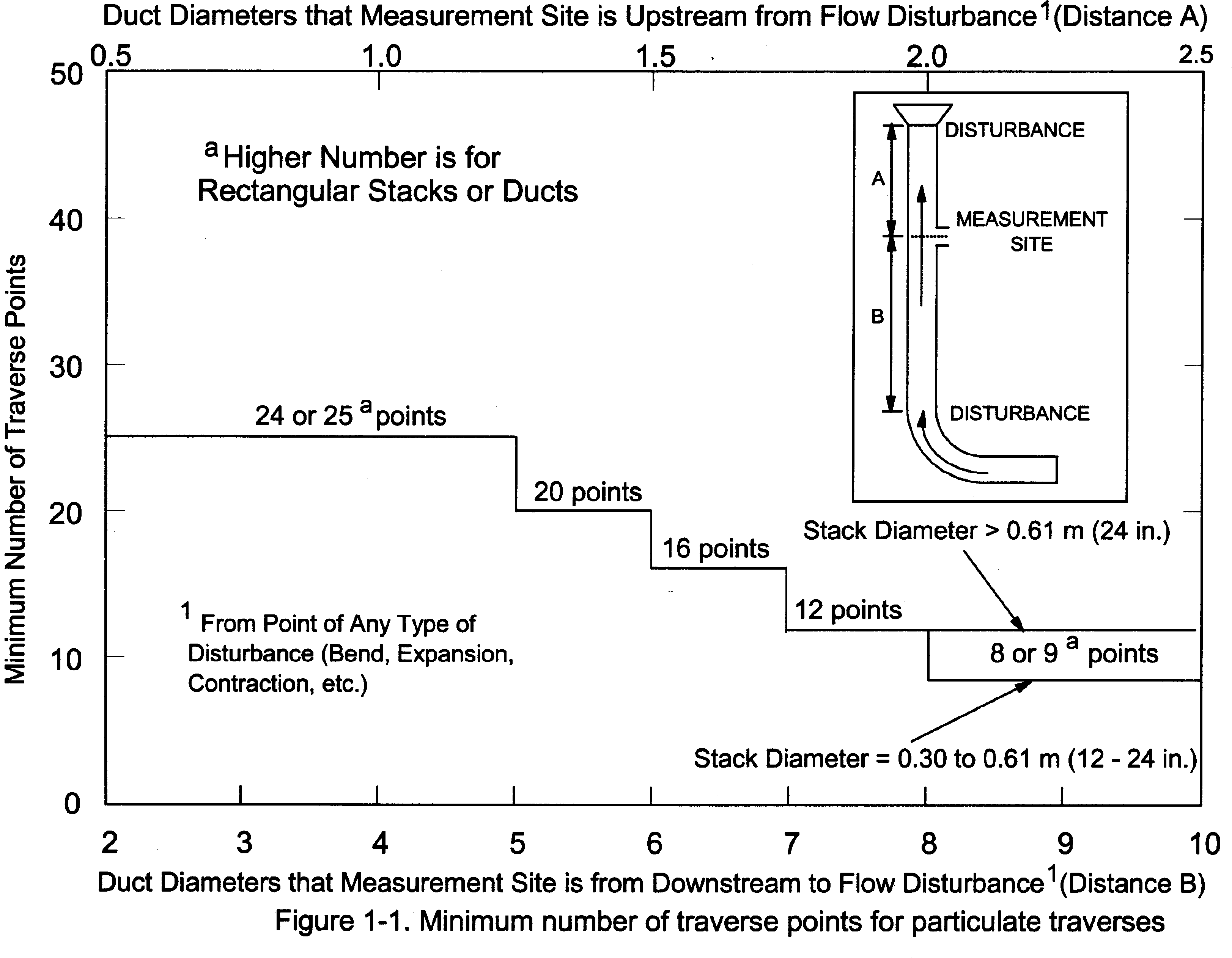
Table 1-1 Cross-Section Layout for Rectangular Stacks
| Number of tranverse points layout | Matrix |
|---|---|
| 9 | 3 × 3 |
| 12 | 4 × 3 |
| 16 | 4 × 4 |
| 20 | 5 × 4 |
| 25 | 5 × 5 |
| 30 | 6 × 5 |
| 36 | 6 × 6 |
| 42 | 7 × 6 |
| 49 | 7 × 7 |
Table 1-2 - Location of Traverse Points in Circular Stacks
[Percent of stack diameter from inside wall to tranverse point]
| Traverse
point number on a diameter |
Number of traverse points on a diameter | |||||||||||
|---|---|---|---|---|---|---|---|---|---|---|---|---|
| 2 | 4 | 6 | 8 | 10 | 12 | 14 | 16 | 18 | 20 | 22 | 24 | |
| 1 | 14.6 | 6.7 | 4.4 | 3.2 | 2.6 | 2.1 | 1.8 | 1.6 | 1.4 | 1.3 | 1.1 | 1.1 |
| 2 | 85.4 | 25.0 | 14.6 | 10.5 | 8.2 | 6.7 | 5.7 | 4.9 | 4.4 | 3.9 | 3.5 | 3.2 |
| 3 | 75.0 | 29.6 | 19.4 | 14.6 | 11.8 | 9.9 | 8.5 | 7.5 | 6.7 | 6.0 | 5.5 | |
| 4 | 93.3 | 70.4 | 32.3 | 22.6 | 17.7 | 14.6 | 12.5 | 10.9 | 9.7 | 8.7 | 7.9 | |
| 5 | 85.4 | 67.7 | 34.2 | 25.0 | 20.1 | 16.9 | 14.6 | 12.9 | 11.6 | 10.5 | ||
| 6 | 95.6 | 80.6 | 65.8 | 35.6 | 26.9 | 22.0 | 18.8 | 16.5 | 14.6 | 13.2 | ||
| 7 | 89.5 | 77.4 | 64.4 | 36.6 | 28.3 | 23.6 | 20.4 | 18.0 | 16.1 | |||
| 8 | 96.8 | 85.4 | 75.0 | 63.4 | 37.5 | 29.6 | 25.0 | 21.8 | 19.4 | |||
| 9 | 91.8 | 82.3 | 73.1 | 62.5 | 38.2 | 30.6 | 26.2 | 23.0 | ||||
| 10 | 97.4 | 88.2 | 79.9 | 71.7 | 61.8 | 38.8 | 31.5 | 27.2 | ||||
| 11 | 93.3 | 85.4 | 78.0 | 70.4 | 61.2 | 39.3 | 32.3 | |||||
| 12 | 97.9 | 90.1 | 83.1 | 76.4 | 69.4 | 60.7 | 39.8 | |||||
| 13 | 94.3 | 87.5 | 81.2 | 75.0 | 68.5 | 60.2 | ||||||
| 14 | 98.2 | 91.5 | 85.4 | 79.6 | 73.8 | 67.7 | ||||||
| 15 | 95.1 | 89.1 | 83.5 | 78.2 | 72.8 | |||||||
| 16 | 98.4 | 92.5 | 87.1 | 82.0 | 77.0 | |||||||
| 17 | 95.6 | 90.3 | 85.4 | 80.6 | ||||||||
| 18 | 98.6 | 93.3 | 88.4 | 83.9 | ||||||||
| 19 | 96.1 | 91.3 | 86.8 | |||||||||
| 20 | 98.7 | 94.0 | 89.5 | |||||||||
| 21 | 96.5 | 92.1 | ||||||||||
| 22 | 98.9 | 94.5 | ||||||||||
| 23 | 96.8 | |||||||||||
| 24 | 99.9 | |||||||||||
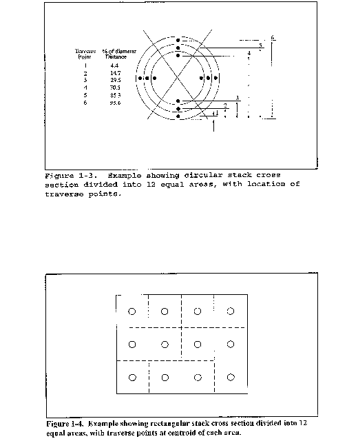
Method 1A - Sample and Velocity Traverses for Stationary Sources With Small Stacks or Ducts
This method does not include all of the specifications (e.g., equipment and supplies) and procedures (e.g., sampling) essential to its performance. Some material is incorporated by reference from other methods in this part. Therefore, to obtain reliable results, persons using this method should have a thorough knowledge of at least the following additional test method: Method 1.
1.0 Scope and Application
1.1 Measured Parameters. The purpose of the method is to provide guidance for the selection of sampling ports and traverse points at which sampling for air pollutants will be performed pursuant to regulations set forth in this part.
1.2 Applicability. The applicability and principle of this method are identical to Method 1, except its applicability is limited to stacks or ducts. This method is applicable to flowing gas streams in ducts, stacks, and flues of less than about 0.30 meter (12 in.) in diameter, or 0.071 m2 (113 in.2) in cross-sectional area, but equal to or greater than about 0.10 meter (4 in.) in diameter, or 0.0081 m2 (12.57 in.2) in cross-sectional area. This method cannot be used when the flow is cyclonic or swirling.
1.3 Data Quality Objectives. Adherence to the requirements of this method will enhance the quality of the data obtained from air pollutant sampling methods.
2.0 Summary of Method
2.1 The method is designed to aid in the representative measurement of pollutant emissions and/or total volumetric flow rate from a stationary source. A measurement site or a pair of measurement sites where the effluent stream is flowing in a known direction is (are) selected. The cross-section of the stack is divided into a number of equal areas. Traverse points are then located within each of these equal areas.
2.2 In these small diameter stacks or ducts, the conventional Method 5 stack assembly (consisting of a Type S pitot tube attached to a sampling probe, equipped with a nozzle and thermocouple) blocks a significant portion of the cross-section of the duct and causes inaccurate measurements. Therefore, for particulate matter (PM) sampling in small stacks or ducts, the gas velocity is measured using a standard pitot tube downstream of the actual emission sampling site. The straight run of duct between the PM sampling and velocity measurement sites allows the flow profile, temporarily disturbed by the presence of the sampling probe, to redevelop and stabilize.
3.0 Definitions [Reserved]
4.0 Interferences [Reserved]
5.0 Safety
5.1 Disclaimer. This method may involve hazardous materials, operations, and equipment. This test method may not address all of the safety problems associated with its use. It is the responsibility of the user of this test method to establish appropriate safety and health practices and determine the applicability of regulatory limitations prior to performing this test method.
6.0 Equipment and Supplies [Reserved]
7.0 Reagents and Standards [Reserved]
8.0 Sample Collection, Preservation, Storage, and Transport [Reserved]
9.0 Quality Control [Reserved]
10.0 Calibration and Standardization [Reserved]
11.0 Procedure
11.1 Selection of Measurement Site.
11.1.1 Particulate Measurements - Steady or Unsteady Flow. Select a particulate measurement site located preferably at least eight equivalent stack or duct diameters downstream and 10 equivalent diameters upstream from any flow disturbances such as bends, expansions, or contractions in the stack, or from a visible flame. Next, locate the velocity measurement site eight equivalent diameters downstream of the particulate measurement site (see Figure 1A-1). If such locations are not available, select an alternative particulate measurement location at least two equivalent stack or duct diameters downstream and two and one-half diameters upstream from any flow disturbance. Then, locate the velocity measurement site two equivalent diameters downstream from the particulate measurement site. (See section 12.2 of Method 1 for calculating equivalent diameters for a rectangular cross-section.)
11.1.2 PM Sampling (Steady Flow) or Velocity (Steady or Unsteady Flow) Measurements. For PM sampling when the volumetric flow rate in a duct is constant with respect to time, section 11.1.1 of Method 1 may be followed, with the PM sampling and velocity measurement performed at one location. To demonstrate that the flow rate is constant (within 10 percent) when PM measurements are made, perform complete velocity traverses before and after the PM sampling run, and calculate the deviation of the flow rate derived after the PM sampling run from the one derived before the PM sampling run. The PM sampling run is acceptable if the deviation does not exceed 10 percent.
11.2 Determining the Number of Traverse Points.
11.2.1 Particulate Measurements (Steady or Unsteady Flow). Use Figure 1-1 of Method 1 to determine the number of traverse points to use at both the velocity measurement and PM sampling locations. Before referring to the figure, however, determine the distances between both the velocity measurement and PM sampling sites to the nearest upstream and downstream disturbances. Then divide each distance by the stack diameter or equivalent diameter to express the distances in terms of the number of duct diameters. Then, determine the number of traverse points from Figure 1-1 of Method 1 corresponding to each of these four distances. Choose the highest of the four numbers of traverse points (or a greater number) so that, for circular ducts the number is a multiple of four; and for rectangular ducts, the number is one of those shown in Table 1-1 of Method 1. When the optimum duct diameter location criteria can be satisfied, the minimum number of traverse points required is eight for circular ducts and nine for rectangular ducts.
11.2.2 PM Sampling (Steady Flow) or only Velocity (Non-Particulate) Measurements. Use Figure 1-2 of Method 1 to determine number of traverse points, following the same procedure used for PM sampling as described in section 11.2.1 of Method 1. When the optimum duct diameter location criteria can be satisfied, the minimum number of traverse points required is eight for circular ducts and nine for rectangular ducts.
11.3 Cross-sectional Layout, Location of Traverse Points, and Verification of the Absence of Cyclonic Flow. Same as Method 1, sections 11.3 and 11.4, respectively.
12.0 Data Analysis and Calculations [Reserved]
13.0 Method Performance [Reserved]
14.0 Pollution Prevention [Reserved]
15.0 Waste Management [Reserved]
16.0 References
Same as Method 1, section 16.0, References 1 through 6, with the addition of the following:
1. Vollaro, Robert F. Recommended Procedure for Sample Traverses in Ducts Smaller Than 12 Inches in Diameter. U.S. Environmental Protection Agency, Emission Measurement Branch, Research Triangle Park, North Carolina. January 1977.
17.0 Tables, Diagrams, Flowcharts, and Validation Data
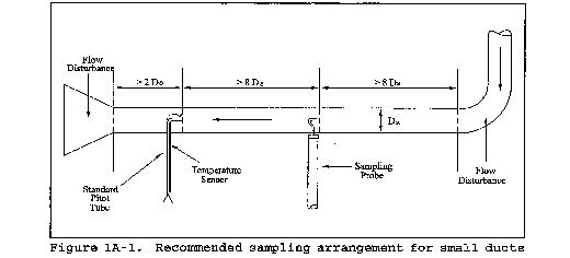
Method 2 - Determination of Stack Gas Velocity and Volumetric Flow Rate (Type S Pitot Tube)
This method does not include all of the specifications (e.g., equipment and supplies) and procedures (e.g., sampling) essential to its performance. Some material is incorporated by reference from other methods in this part. Therefore, to obtain reliable results, persons using this method should have a thorough knowledge of at least the following additional test method: Method 1.
1.0 Scope and Application.
1.1 This method is applicable for the determination of the average velocity and the volumetric flow rate of a gas stream.
1.2 This method is not applicable at measurement sites that fail to meet the criteria of Method 1, section 11.1. Also, the method cannot be used for direct measurement in cyclonic or swirling gas streams; section 11.4 of Method 1 shows how to determine cyclonic or swirling flow conditions. When unacceptable conditions exist, alternative procedures, subject to the approval of the Administrator, must be employed to produce accurate flow rate determinations. Examples of such alternative procedures are:
(1) to install straightening vanes;
(2) to calculate the total volumetric flow rate stoichiometrically, or
(3) to move to another measurement site at which the flow is acceptable.
1.3 Data Quality Objectives. Adherence to the requirements of this method will enhance the quality of the data obtained from air pollutant sampling methods.
2.0 Summary of Method.
2.1 The average gas velocity in a stack is determined from the gas density and from measurement of the average velocity head with a Type S (Stausscheibe or reverse type) pitot tube.
3.0 Definitions [Reserved]
4.0 Interferences [Reserved]
5.0 Safety
5.1 Disclaimer. This method may involve hazardous materials, operations, and equipment. This test method may not address all of the safety problems associated with its use. It is the responsibility of the user of this test method to establish appropriate safety and health practices and determine the applicability of regulatory limitations prior to performing this test method.
6.0 Equipment and Supplies
Specifications for the apparatus are given below. Any other apparatus that has been demonstrated (subject to approval of the Administrator) to be capable of meeting the specifications will be considered acceptable.
6.1 Type S Pitot Tube.
6.1.1 Pitot tube made of metal tubing (e.g., stainless steel) as shown in Figure 2-1. It is recommended that the external tubing diameter (dimension Dt, Figure 2-2b) be between 0.48 and 0.95 cm (3⁄16 and 3⁄8 inch). There shall be an equal distance from the base of each leg of the pitot tube to its face-opening plane (dimensions PA and PB, Figure 2-2b); it is recommended that this distance be between 1.05 and 1.50 times the external tubing diameter. The face openings of the pitot tube shall, preferably, be aligned as shown in Figure 2-2; however, slight misalignments of the openings are permissible (see Figure 2-3).
6.1.2 The Type S pitot tube shall have a known coefficient, determined as outlined in section 10.0. An identification number shall be assigned to the pitot tube; this number shall be permanently marked or engraved on the body of the tube. A standard pitot tube may be used instead of a Type S, provided that it meets the specifications of sections 6.7 and 10.2. Note, however, that the static and impact pressure holes of standard pitot tubes are susceptible to plugging in particulate-laden gas streams. Therefore, whenever a standard pitot tube is used to perform a traverse, adequate proof must be furnished that the openings of the pitot tube have not plugged up during the traverse period. This can be accomplished by comparing the velocity head (Δp) measurement recorded at a selected traverse point (readable Δp value) with a second Δp measurement recorded after “back purging” with pressurized air to clean the impact and static holes of the standard pitot tube. If the before and after Δp measurements are within 5 percent, then the traverse data are acceptable. Otherwise, the data should be rejected and the traverse measurements redone. Note that the selected traverse point should be one that demonstrates a readable Δp value. If “back purging” at regular intervals is part of a routine procedure, then comparative Δp measurements shall be conducted as above for the last two traverse points that exhibit suitable Δp measurements.
6.2 Differential Pressure Gauge. An inclined manometer or equivalent device. Most sampling trains are equipped with a 10 in. (water column) inclined-vertical manometer, having 0.01 in. H20 divisions on the 0 to 1 in. inclined scale, and 0.1 in. H20 divisions on the 1 to 10 in. vertical scale. This type of manometer (or other gauge of equivalent sensitivity) is satisfactory for the measurement of Δp values as low as 1.27 mm (0.05 in.) H2
0. However, a differential pressure gauge of greater sensitivity shall be used (subject to the approval of the Administrator), if any of the following is found to be true:
(1) the arithmetic average of all Δp readings at the traverse points in the stack is less than 1.27 mm (0.05 in.) H20;
(2) for traverses of 12 or more points, more than 10 percent of the individual Δp readings are below 1.27 mm (0.05 in.) H20; or
(3) for traverses of fewer than 12 points, more than one Δp reading is below 1.27 mm (0.05 in.) H20. Reference 18 (see section 17.0) describes commercially available instrumentation for the measurement of low-range gas velocities.
6.2.1 As an alternative to criteria
(1) through (3) above, Equation 2-1 (Section 12.2) may be used to determine the necessity of using a more sensitive differential pressure gauge. If T is greater than 1.05, the velocity head data are unacceptable and a more sensitive differential pressure gauge must be used.
If differential pressure gauges other than inclined manometers are used (e.g., magnehelic gauges), their calibration must be checked after each test series. To check the calibration of a differential pressure gauge, compare Δp readings of the gauge with those of a gauge-oil manometer at a minimum of three points, approximately representing the range of Δp values in the stack. If, at each point, the values of Δp as read by the differential pressure gauge and gauge-oil manometer agree to within 5 percent, the differential pressure gauge shall be considered to be in proper calibration. Otherwise, the test series shall either be voided, or procedures to adjust the measured Δp values and final results shall be used, subject to the approval of the Administrator.
6.3 Temperature Sensor. A thermocouple, liquid-filled bulb thermometer, bimetallic thermometer, mercury-in-glass thermometer, or other gauge capable of measuring temperatures to within 1.5 percent of the minimum absolute stack temperature. The temperature sensor shall be attached to the pitot tube such that the sensor tip does not touch any metal; the gauge shall be in an interference-free arrangement with respect to the pitot tube face openings (see Figure 2-1 and Figure 2-4). Alternative positions may be used if the pitot tube-temperature gauge system is calibrated according to the procedure of section 10.0. Provided that a difference of not more than 1 percent in the average velocity measurement is introduced, the temperature gauge need not be attached to the pitot tube. This alternative is subject to the approval of the Administrator.
6.4 Pressure Probe and Gauge. A piezometer tube and mercury- or water-filled U-tube manometer capable of measuring stack pressure to within 2.5 mm (0.1 in.) Hg. The static tap of a standard type pitot tube or one leg of a Type S pitot tube with the face opening planes positioned parallel to the gas flow may also be used as the pressure probe.
6.5 Barometer. A mercury, aneroid, or other barometer capable of measuring atmospheric pressure to within 2.54 mm (0.1 in.) Hg.
The barometric pressure reading may be obtained from a nearby National Weather Service station. In this case, the station value (which is the absolute barometric pressure) shall be requested and an adjustment for elevation differences between the weather station and sampling point shall be made at a rate of minus 2.5 mm (0.1 in.) Hg per 30 m (100 ft) elevation increase or plus 2.5 mm (0.1 in.) Hg per 30 m (100 ft.) for elevation decrease.
6.6 Gas Density Determination Equipment. Method 3 equipment, if needed (see section 8.6), to determine the stack gas dry molecular weight, and Method 4 (reference method) or Method 5 equipment for moisture content determination. Other methods may be used subject to approval of the Administrator.
6.7 Calibration Pitot Tube. Calibration of the Type S pitot tube requires a standard pitot tube for a reference. When calibration of the Type S pitot tube is necessary (see Section 10.1), a standard pitot tube shall be used for a reference. The standard pitot tube shall, preferably, have a known coefficient, obtained directly from the National Institute of Standards and Technology (NIST), Gaithersburg, MD 20899, (301) 975-2002; or by calibration against another standard pitot tube with a NIST-traceable coefficient. Alternatively, a standard pitot tube designed according to the criteria given in sections 6.7.1 through 6.7.5 below and illustrated in Figure 2-5 (see also References 7, 8, and 17 in section 17.0) may be used. Pitot tubes designed according to these specifications will have baseline coefficients of 0.99 ±0.01.
6.7.1 Standard Pitot Design.
6.7.1.1 Hemispherical (shown in Figure 2-5), ellipsoidal, or conical tip.
6.7.1.2 A minimum of six diameters straight run (based upon D, the external diameter of the tube) between the tip and the static pressure holes.
6.7.1.3 A minimum of eight diameters straight run between the static pressure holes and the centerline of the external tube, following the 90° bend.
6.7.1.4 Static pressure holes of equal size (approximately 0.1 D), equally spaced in a piezometer ring configuration.
6.7.1.5 90° bend, with curved or mitered junction.
6.8 Differential Pressure Gauge for Type S Pitot Tube Calibration. An inclined manometer or equivalent. If the single-velocity calibration technique is employed (see section 10.1.2.3), the calibration differential pressure gauge shall be readable to the nearest 0.127 mm (0.005 in.) H20. For multivelocity calibrations, the gauge shall be readable to the nearest 0.127 mm (0.005 in.) H20 for Δp values between 1.27 and 25.4 mm (0.05 and 1.00 in.) H20, and to the nearest 1.27 mm (0.05 in.) H20 for Δp values above 25.4 mm (1.00 in.) H20. A special, more sensitive gauge will be required to read Δp values below 1.27 mm (0.05 in.) H20 (see Reference 18 in section 16.0).
7.0 Reagents and Standards [Reserved]
8.0 Sample Collection and Analysis
8.1 Set up the apparatus as shown in Figure 2-1. Capillary tubing or surge tanks installed between the manometer and pitot tube may be used to dampen ΔP fluctuations. It is recommended, but not required, that a pretest leak-check be conducted as follows:
(1) blow through the pitot impact opening until at least 7.6 cm (3.0 in.) H2O velocity head registers on the manometer; then, close off the impact opening. The pressure shall remain stable (±2.5 mm H2O, ±0.10 in. H2O) for at least 15 seconds;
(2) do the same for the static pressure side, except using suction to obtain the minimum of 7.6 cm (3.0 in.) H2O. Other leak-check procedures, subject to the approval of the Administrator, may be used.
8.2 Level and zero the manometer. Because the manometer level and zero may drift due to vibrations and temperature changes, make periodic checks during the traverse (at least once per hour). Record all necessary data on a form similar to that shown in Figure 2-6.
8.3 Measure the velocity head and temperature at the traverse points specified by Method 1. Ensure that the proper differential pressure gauge is being used for the range of Δp values encountered (see section 6.2). If it is necessary to change to a more sensitive gauge, do so, and remeasure the Δp and temperature readings at each traverse point. Conduct a post-test leak-check (mandatory), as described in section 8.1 above, to validate the traverse run.
8.4 Measure the static pressure in the stack. One reading is usually adequate.
8.5 Determine the atmospheric pressure.
8.6 Determine the stack gas dry molecular weight. For combustion processes or processes that emit essentially CO2, O2, CO, and N2, use Method 3. For processes emitting essentially air, an analysis need not be conducted; use a dry molecular weight of 29.0. For other processes, other methods, subject to the approval of the Administrator, must be used.
8.7 Obtain the moisture content from Method 4 (reference method, or equivalent) or from Method 5.
8.8 Determine the cross-sectional area of the stack or duct at the sampling location. Whenever possible, physically measure the stack dimensions rather than using blueprints. Do not assume that stack diameters are equal. Measure each diameter distance to verify its dimensions.
9.0 Quality Control
| Section | Quality control measure | Effect |
|---|---|---|
| 10.1-10.4 | Sampling equipment calibration | Ensure accurate measurement of stack gas flow rate, sample volume. |
10.0 Calibration and Standardization
10.1 Type S Pitot Tube. Before its initial use, carefully examine the Type S pitot tube top, side, and end views to verify that the face openings of the tube are aligned within the specifications illustrated in Figures 2-2 and 2-3. The pitot tube shall not be used if it fails to meet these alignment specifications. After verifying the face opening alignment, measure and record the following dimensions of the pitot tube: (a) the external tubing diameter (dimension Dt, Figure 2-2b); and (b) the base-to-opening plane distances (dimensions PA and PB, Figure 2-2b). If Dt is between 0.48 and 0.95 cm 3⁄16 and 3⁄8 in.), and if PA and PB are equal and between 1.05 and 1.50 Dt, there are two possible options: (1) the pitot tube may be calibrated according to the procedure outlined in sections 10.1.2 through 10.1.5, or (2) a baseline (isolated tube) coefficient value of 0.84 may be assigned to the pitot tube. Note, however, that if the pitot tube is part of an assembly, calibration may still be required, despite knowledge of the baseline coefficient value (see section 10.1.1). If Dt, PA, and PB are outside the specified limits, the pitot tube must be calibrated as outlined in sections 10.1.2 through 10.1.5.
10.1.1 Type S Pitot Tube Assemblies. During sample and velocity traverses, the isolated Type S pitot tube is not always used; in many instances, the pitot tube is used in combination with other source-sampling components (e.g., thermocouple, sampling probe, nozzle) as part of an “assembly.” The presence of other sampling components can sometimes affect the baseline value of the Type S pitot tube coefficient (Reference 9 in section 17.0); therefore, an assigned (or otherwise known) baseline coefficient value may or may not be valid for a given assembly. The baseline and assembly coefficient values will be identical only when the relative placement of the components in the assembly is such that aerodynamic interference effects are eliminated. Figures 2-4, 2-7, and 2-8 illustrate interference-free component arrangements for Type S pitot tubes having external tubing diameters between 0.48 and 0.95 cm (3⁄16 and 3⁄8 in.). Type S pitot tube assemblies that fail to meet any or all of the specifications of Figures 2-4, 2-7, and 2-8 shall be calibrated according to the procedure outlined in sections 10.1.2 through 10.1.5, and prior to calibration, the values of the intercomponent spacings (pitot-nozzle, pitot-thermocouple, pitot-probe sheath) shall be measured and recorded.
Do not use a Type S pitot tube assembly that is constructed such that the impact pressure opening plane of the pitot tube is below the entry plane of the nozzle (see Figure 2-7B).
10.1.2 Calibration Setup. If the Type S pitot tube is to be calibrated, one leg of the tube shall be permanently marked A, and the other, B. Calibration shall be performed in a flow system having the following essential design features:
10.1.2.1 The flowing gas stream must be confined to a duct of definite cross-sectional area, either circular or rectangular. For circular cross sections, the minimum duct diameter shall be 30.48 cm (12 in.); for rectangular cross sections, the width (shorter side) shall be at least 25.4 cm (10 in.).
10.1.2.2 The cross-sectional area of the calibration duct must be constant over a distance of 10 or more duct diameters. For a rectangular cross section, use an equivalent diameter, calculated according to Equation 2-2 (see section 12.3), to determine the number of duct diameters. To ensure the presence of stable, fully developed flow patterns at the calibration site, or “test section,” the site must be located at least eight diameters downstream and two diameters upstream from the nearest disturbances.
The eight- and two-diameter criteria are not absolute; other test section locations may be used (subject to approval of the Administrator), provided that the flow at the test site has been demonstrated to be or found stable and parallel to the duct axis.
10.1.2.3 The flow system shall have the capacity to generate a test-section velocity around 910 m/min (3,000 ft/min). This velocity must be constant with time to guarantee constant and steady flow during the entire period of calibration. A centrifugal fan is recommended for this purpose, as no flow rate adjustment for back pressure of the fan is allowed during the calibration process. Note that Type S pitot tube coefficients obtained by single-velocity calibration at 910 m/min (3,000 ft/min) will generally be valid to ±3 percent for the measurement of velocities above 300 m/min (1,000 ft/min) and to ±6 percent for the measurement of velocities between 180 and 300 m/min (600 and 1,000 ft/min). If a more precise correlation between the pitot tube coefficient (Cp) and velocity is desired, the flow system should have the capacity to generate at least four distinct, time-invariant test-section velocities covering the velocity range from 180 to 1,500 m/min (600 to 5,000 ft/min), and calibration data shall be taken at regular velocity intervals over this range (see References 9 and 14 in section 17.0 for details).
10.1.2.4 Two entry ports, one for each of the standard and Type S pitot tubes, shall be cut in the test section. The standard pitot entry port shall be located slightly downstream of the Type S port, so that the standard and Type S impact openings will lie in the same cross-sectional plane during calibration. To facilitate alignment of the pitot tubes during calibration, it is advisable that the test section be constructed of PlexiglasTM or some other transparent material.
10.1.3 Calibration Procedure. Note that this procedure is a general one and must not be used without first referring to the special considerations presented in section 10.1.5. Note also that this procedure applies only to single-velocity calibration. To obtain calibration data for the A and B sides of the Type S pitot tube, proceed as follows:
10.1.3.1 Make sure that the manometer is properly filled and that the oil is free from contamination and is of the proper density. Inspect and leak-check all pitot lines; repair or replace if necessary.
10.1.3.2 Level and zero the manometer. Switch on the fan, and allow the flow to stabilize. Seal the Type S pitot tube entry port.
10.1.3.3 Ensure that the manometer is level and zeroed. Position the standard pitot tube at the calibration point (determined as outlined in section 10.1.5.1), and align the tube so that its tip is pointed directly into the flow. Particular care should be taken in aligning the tube to avoid yaw and pitch angles. Make sure that the entry port surrounding the tube is properly sealed.
10.1.3.4 Read Δpstd, and record its value in a data table similar to the one shown in Figure 2-9. Remove the standard pitot tube from the duct, and disconnect it from the manometer. Seal the standard entry port. Make no adjustment to the fan speed or other wind tunnel volumetric flow control device between this reading and the corresponding Type S pitot reading.
10.1.3.5 Connect the Type S pitot tube to the manometer and leak-check. Open the Type S tube entry port. Check the manometer level and zero. Insert and align the Type S pitot tube so that its A side impact opening is at the same point as was the standard pitot tube and is pointed directly into the flow. Make sure that the entry port surrounding the tube is properly sealed.
10.1.3.6 Read Δps, and enter its value in the data table. Remove the Type S pitot tube from the duct, and disconnect it from the manometer.
10.1.3.7 Repeat Steps 10.1.3.3 through 10.1.3.6 until three pairs of Δp readings have been obtained for the A side of the Type S pitot tube, with all the paired observations conducted at a constant fan speed (no changes to fan velocity between observed readings).
10.1.3.8 Repeat Steps 10.1.3.3 through 10.1.3.7 for the B side of the Type S pitot tube.
10.1.3.9 Perform calculations as described in section 12.4. Use the Type S pitot tube only if the values of σA and σB are less than or equal to 0.01 and if the absolute value of the difference between C̄p(A) and C̄p(B) is 0.01 or less.
10.1.4 Special Considerations.
10.1.4.1 Selection of Calibration Point.
10.1.4.1.1 When an isolated Type S pitot tube is calibrated, select a calibration point at or near the center of the duct, and follow the procedures outlined in section 10.1.3. The Type S pitot coefficients measured or calculated, (i.e., C̄p(A) and C̄p(B)) will be valid, so long as either:
(1) the isolated pitot tube is used; or
(2) the pitot tube is used with other components (nozzle, thermocouple, sample probe) in an arrangement that is free from aerodynamic interference effects (see Figures 2-4, 2-7, and 2-8).
10.1.4.1.2 For Type S pitot tube-thermocouple combinations (without probe assembly), select a calibration point at or near the center of the duct, and follow the procedures outlined in section 10.1.3. The coefficients so obtained will be valid so long as the pitot tube-thermocouple combination is used by itself or with other components in an interference-free arrangement (Figures 2-4, 2-7, and 2-8).
10.1.4.1.3 For Type S pitot tube combinations with complete probe assemblies, the calibration point should be located at or near the center of the duct; however, insertion of a probe sheath into a small duct may cause significant cross-sectional area interference and blockage and yield incorrect coefficient values (Reference 9 in section 17.0). Therefore, to minimize the blockage effect, the calibration point may be a few inches off-center if necessary, but no closer to the outer wall of the wind tunnel than 4 inches. The maximum allowable blockage, as determined by a projected-area model of the probe sheath, is 2 percent or less of the duct cross-sectional area (Figure 2-10a). If the pitot and/or probe assembly blocks more than 2 percent of the cross-sectional area at an insertion point only 4 inches inside the wind tunnel, the diameter of the wind tunnel must be increased.
10.1.4.2 For those probe assemblies in which pitot tube-nozzle interference is a factor (i.e., those in which the pitot-nozzle separation distance fails to meet the specifications illustrated in Figure 2-7A), the value of Cp(s) depends upon the amount of free space between the tube and nozzle and, therefore, is a function of nozzle size. In these instances, separate calibrations shall be performed with each of the commonly used nozzle sizes in place. Note that the single-velocity calibration technique is acceptable for this purpose, even though the larger nozzle sizes (>0.635 cm or 1⁄4 in.) are not ordinarily used for isokinetic sampling at velocities around 910 m/min (3,000 ft/min), which is the calibration velocity. Note also that it is not necessary to draw an isokinetic sample during calibration (see Reference 19 in section 17.0).
10.1.4.3 For a probe assembly constructed such that its pitot tube is always used in the same orientation, only one side of the pitot tube needs to be calibrated (the side which will face the flow). The pitot tube must still meet the alignment specifications of Figure 2-2 or 2-3, however, and must have an average deviation (σ) value of 0.01 or less (see section 12.4.4).
10.1.5 Field Use and Recalibration.
10.1.5.1 Field Use.
10.1.5.1.1 When a Type S pitot tube (isolated or in an assembly) is used in the field, the appropriate coefficient value (whether assigned or obtained by calibration) shall be used to perform velocity calculations. For calibrated Type S pitot tubes, the A side coefficient shall be used when the A side of the tube faces the flow, and the B side coefficient shall be used when the B side faces the flow. Alternatively, the arithmetic average of the A and B side coefficient values may be used, irrespective of which side faces the flow.
10.1.5.1.2 When a probe assembly is used to sample a small duct, 30.5 to 91.4 cm (12 to 36 in.) in diameter, the probe sheath sometimes blocks a significant part of the duct cross-section, causing a reduction in the effective value of Cp(s). Consult Reference 9 (see section 17.0) for details. Conventional pitot-sampling probe assemblies are not recommended for use in ducts having inside diameters smaller than 30.5 cm (12 in.) (see Reference 16 in section 17.0).
10.1.5.2 Recalibration.
10.1.5.2.1 Isolated Pitot Tubes. After each field use, the pitot tube shall be carefully reexamined in top, side, and end views. If the pitot face openings are still aligned within the specifications illustrated in Figure 2-2 and Figure 2-3, it can be assumed that the baseline coefficient of the pitot tube has not changed. If, however, the tube has been damaged to the extent that it no longer meets the specifications of Figure 2-2 and Figure 2-3, the damage shall either be repaired to restore proper alignment of the face openings, or the tube shall be discarded.
10.1.5.2.2 Pitot Tube Assemblies. After each field use, check the face opening alignment of the pitot tube, as in section 10.1.5.2.1. Also, remeasure the intercomponent spacings of the assembly. If the intercomponent spacings have not changed and the face opening alignment is acceptable, it can be assumed that the coefficient of the assembly has not changed. If the face opening alignment is no longer within the specifications of Figure 2-2 and Figure 2-3, either repair the damage or replace the pitot tube (calibrating the new assembly, if necessary). If the intercomponent spacings have changed, restore the original spacings, or recalibrate the assembly.
10.2 Standard Pitot Tube (if applicable). If a standard pitot tube is used for the velocity traverse, the tube shall be constructed according to the criteria of section 6.7 and shall be assigned a baseline coefficient value of 0.99. If the standard pitot tube is used as part of an assembly, the tube shall be in an interference-free arrangement (subject to the approval of the Administrator).
10.3 Temperature Sensors.
10.3.1 After each field use, calibrate dial thermometers, liquid-filled bulb thermometers, thermocouple-potentiometer systems, and other sensors at a temperature within 10 percent of the average absolute stack temperature. For temperatures up to 405 °C (761 °F), use an ASTM mercury-in-glass reference thermometer, or equivalent, as a reference. Alternatively, either a reference thermocouple and potentiometer (calibrated against NIST standards) or thermometric fixed points (e.g., ice bath and boiling water, corrected for barometric pressure) may be used. For temperatures above 405 °C (761 °F), use a reference thermocouple-potentiometer system calibrated against NIST standards or an alternative reference, subject to the approval of the Administrator.
10.3.2 The temperature data recorded in the field shall be considered valid. If, during calibration, the absolute temperature measured with the sensor being calibrated and the reference sensor agree within 1.5 percent, the temperature data taken in the field shall be considered valid. Otherwise, the pollutant emission test shall either be considered invalid or adjustments (if appropriate) of the test results shall be made, subject to the approval of the Administrator.
10.4 Barometer. Calibrate the barometer used against a mercury barometer or NIST-traceable barometer prior to each field test.
11.0 Analytical Procedure
Sample collection and analysis are concurrent for this method (see section 8.0).
12.0 Data Analysis and Calculations
Carry out calculations, retaining at least one extra significant figure beyond that of the acquired data. Round off figures after final calculation.
12.1 Nomenclature.
A = Cross-sectional area of stack, m2 (ft2).
Bws = Water vapor in the gas stream (from Method 4 (reference method) or Method 5), proportion by volume.
Cp = Pitot tube coefficient, dimensionless.
Cp(s) = Type S pitot tube coefficient, dimensionless.
Cp(std) = Standard pitot tube coefficient; use 0.99 if the coefficient is unknown and the tube is designed according to the criteria of sections 6.7.1 to 6.7.5 of this method.
De = Equivalent diameter.
K = 0.127 mm H2O (metric units). 0.005 in. H2O (English units).
Kp = Velocity equation constant.
L = Length.
Md = Molecular weight of stack gas, dry basis (see section 8.6), g/g-mole (lb/lb-mole).
Ms = Molecular weight of stack gas, wet basis, g/g-mole (lb/lb-mole).
n = Total number of traverse points.
Pbar = Barometric pressure at measurement site, mm Hg (in. Hg).
Pg = Stack static pressure, mm Hg (in. Hg).
Ps = Absolute stack pressure (Pbar + Pg), mm Hg (in. Hg),
Pstd = Standard absolute pressure, 760 mm Hg (29.92 in. Hg).
Qsd = Dry volumetric stack gas flow rate corrected to standard conditions, dscm/hr (dscf/hr).
T = Sensitivity factor for differential pressure gauges.
Ts(abavg) = Average absolute stack temperature, °K (°R).
= 273 + Ts for metric units,
= 460 + Ts for English units.
Ts = Stack temperature, °C (°F).
= 273 + Ts for metric units,
= 460 + Ts for English units.
Tstd = Standard absolute temperature, 293 °K (528 °R).
Vs = Average stack gas velocity, m/sec (ft/sec).
W = Width.
Δp = Velocity head of stack gas, mm H2O (in. H20).
Δpi = Individual velocity head reading at traverse point “i”, mm (in.) H2O.
Δpstd = Velocity head measured by the standard pitot tube, cm (in.) H2O.
Δps = Velocity head measured by the Type S pitot tube, cm (in.) H2O.
3600 = Conversion Factor, sec/hr.
18.0 = Molecular weight of water, g/g-mole (lb/lb-mole).
12.2 Calculate T as follows:

12.3 Calculate De as follows:

12.4 Calibration of Type S Pitot Tube.
12.4.1 For each of the six pairs of Δp readings (i.e., three from side A and three from side B) obtained in section 10.1.3, calculate the value of the Type S pitot tube coefficient according to Equation 2-3:
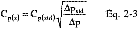
12.4.2 Calculate C̄p(A), the mean A-side coefficient, and C̄p(B), the mean B-side coefficient. Calculate the difference between these two average values.
12.4.3 Calculate the deviation of each of the three A-side values of Cp(s) from C̄p(A), and the deviation of each of the three B-side values of Cp(s) from C̄p(B), using Equation 2-4:

12.4.4 Calculate σ the average deviation from the mean, for both the A and B sides of the pitot tube. Use Equation 2-5:

12.5 Molecular Weight of Stack Gas.

12.6 Average Stack Gas Velocity.

12.7 Average Stack Gas Dry Volumetric Flow Rate.

13.0 Method Performance [Reserved]
14.0 Pollution Prevention [Reserved]
15.0 Waste Management [Reserved]
16.0 References
1. Mark, L.S. Mechanical Engineers' Handbook. New York. McGraw-Hill Book Co., Inc. 1951.
2. Perry, J.H., ed. Chemical Engineers' Handbook. New York. McGraw-Hill Book Co., Inc. 1960.
3. Shigehara, R.T., W.F. Todd, and W.S. Smith. Significance of Errors in Stack Sampling Measurements. U.S. Environmental Protection Agency, Research Triangle Park, N.C. (Presented at the Annual Meeting of the Air Pollution Control Association, St. Louis, MO., June 14-19, 1970).
4. Standard Method for Sampling Stacks for Particulate Matter. In: 1971 Book of ASTM Standards, Part 23. Philadelphia, PA. 1971. ASTM Designation D 2928-71.
5. Vennard, J.K. Elementary Fluid Mechanics. New York. John Wiley and Sons, Inc. 1947.
6. Fluid Meters - Their Theory and Application. American Society of Mechanical Engineers, New York, N.Y. 1959.
7. ASHRAE Handbook of Fundamentals. 1972. p. 208.
8. Annual Book of ASTM Standards, Part 26. 1974. p. 648.
9. Vollaro, R.F. Guidelines for Type S Pitot Tube Calibration. U.S. Environmental Protection Agency, Research Triangle Park, N.C. (Presented at 1st Annual Meeting, Source Evaluation Society, Dayton, OH, September 18, 1975.)
10. Vollaro, R.F. A Type S Pitot Tube Calibration Study. U.S. Environmental Protection Agency, Emission Measurement Branch, Research Triangle Park, N.C. July 1974.
11. Vollaro, R.F. The Effects of Impact Opening Misalignment on the Value of the Type S Pitot Tube Coefficient. U.S. Environmental Protection Agency, Emission Measurement Branch, Research Triangle Park, NC. October 1976.
12. Vollaro, R.F. Establishment of a Baseline Coefficient Value for Properly Constructed Type S Pitot Tubes. U.S. Environmental Protection Agency, Emission Measurement Branch, Research Triangle Park, NC. November 1976.
13. Vollaro, R.F. An Evaluation of Single-Velocity Calibration Technique as a Means of Determining Type S Pitot Tube Coefficients. U.S. Environmental Protection Agency, Emission Measurement Branch, Research Triangle Park, NC. August 1975.
14. Vollaro, R.F. The Use of Type S Pitot Tubes for the Measurement of Low Velocities. U.S. Environmental Protection Agency, Emission Measurement Branch, Research Triangle Park, NC. November 1976.
15. Smith, Marvin L. Velocity Calibration of EPA Type Source Sampling Probe. United Technologies Corporation, Pratt and Whitney Aircraft Division, East Hartford, CT. 1975.
16. Vollaro, R.F. Recommended Procedure for Sample Traverses in Ducts Smaller than 12 Inches in Diameter. U.S. Environmental Protection Agency, Emission Measurement Branch, Research Triangle Park, NC. November 1976.
17. Ower, E. and R.C. Pankhurst. The Measurement of Air Flow, 4th Ed. London, Pergamon Press. 1966.
18. Vollaro, R.F. A Survey of Commercially Available Instrumentation for the Measurement of Low-Range Gas Velocities. U.S. Environmental Protection Agency, Emission Measurement Branch, Research Triangle Park, NC. November 1976. (Unpublished Paper).
19. Gnyp,
A. W., et al. An Experimental Investigation of the Effect of Pitot Tube-Sampling Probe Configurations on the Magnitude of the S Type Pitot Tube Coefficient for Commercially Available Source Sampling Probes. Prepared by the University of Windsor for the Ministry of the Environment, Toronto, Canada. February 1975.
17.0 Tables, Diagrams, Flowcharts, and Validation Data
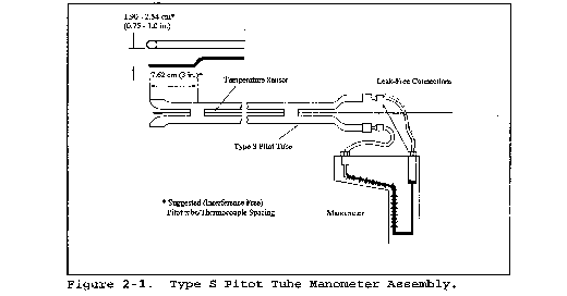


PLANT
DATE
RUN NO.
STACK DIA. OR DIMENSIONS, m (in.)
BAROMETRIC PRESS., mm Hg (in. Hg)
CROSS SECTIONAL AREA, m2 (ft2)
OPERATORS
PITOT TUBE I.D. NO.
AVG. COEFFICIENT, Cp =
LAST DATE CALIBRATED
SCHEMATIC OF STACK CROSS SECTION
| Traverse
Pt. No. |
Vel. Hd.,
Δp mm (in.) H2O |
Stack
temperature |
Pg
mm Hg (in. Hg) |
(Δp) 1⁄2 | |
|---|---|---|---|---|---|
| Ts,
°C ( °F) |
Ts,
°K (°R) |
||||
| Average(1) | |||||
Figure 2-6. Velocity Traverse Data


PITOT TUBE IDENTIFICATION NUMBER:
DATE:
CALIBRATED BY:
“A” Side Calibration
| Run No. | ΔPstd
cm H2O (in H2O) |
ΔP(s)
cm H2O (in H2O) |
Cp(s) | Deviation
Cp(s) - Cp(A) |
|---|---|---|---|---|
| 1 | ||||
| 2 | ||||
| 3 | ||||
| Cp, avg
(SIDE A) |
“B” Side Calibration
| Run No. | ΔPstd
cm H2O (in H2O) |
ΔP(s)
cm H2O (in H2O) |
Cp(s) | Deviation
Cp(s) - Cp(B) |
|---|---|---|---|---|
| 1 | ||||
| 2 | ||||
| 3 | ||||
| Cp, avg
(SIDE B) |

[Cp, avg (side A) - Cp, avg (side B)]*
*Must be less than or equal to 0.01
Figure 2-9. Pitot Tube Calibration Data

Method 2A - Direct Measurement of Gas Volume Through Pipes and Small Ducts
This method does not include all of the specifications (e.g., equipment and supplies) and procedures (e.g., sampling) essential to its performance. Some material is incorporated by reference from other methods in this part. Therefore, to obtain reliable results, persons using this method should have a thorough knowledge of at least the following additional test methods: Method 1, Method 2.
1.0 Scope and Application
1.1 This method is applicable for the determination of gas flow rates in pipes and small ducts, either in-line or at exhaust positions, within the temperature range of 0 to 50 °C (32 to 122 °F).
1.2 Data Quality Objectives. Adherence to the requirements of this method will enhance the quality of the data obtained from air pollutant sampling methods.
2.0 Summary of Method
2.1 A gas volume meter is used to measure gas volume directly. Temperature and pressure measurements are made to allow correction of the volume to standard conditions.
3.0 Definitions [Reserved]
4.0 Interferences [Reserved]
5.0 Safety
5.1 Disclaimer. This method may involve hazardous materials, operations, and equipment. This test method may not address all of the safety problems associated with its use. It is the responsibility of the user of this test method to establish appropriate safety and health practices and determine the applicability of regulatory limitations prior to performing this test method.
6.0 Equipment and Supplies
Specifications for the apparatus are given below. Any other apparatus that has been demonstrated (subject to approval of the Administrator) to be capable of meeting the specifications will be considered acceptable.
6.1 Gas Volume Meter. A positive displacement meter, turbine meter, or other direct measuring device capable of measuring volume to within 2 percent. The meter shall be equipped with a temperature sensor (accurate to within ±2 percent of the minimum absolute temperature) and a pressure gauge (accurate to within ±2.5 mm Hg). The manufacturer's recommended capacity of the meter shall be sufficient for the expected maximum and minimum flow rates for the sampling conditions. Temperature, pressure, corrosive characteristics, and pipe size are factors necessary to consider in selecting a suitable gas meter.
6.2 Barometer. A mercury, aneroid, or other barometer capable of measuring atmospheric pressure to within ±2.5 mm Hg.
In many cases, the barometric reading may be obtained from a nearby National Weather Service station, in which case the station value (which is the absolute barometric pressure) shall be requested and an adjustment for elevation differences between the weather station and sampling point shall be applied at a rate of minus 2.5 mm (0.1 in.) Hg per 30 m (100 ft) elevation increase or vice versa for elevation decrease.
6.3 Stopwatch. Capable of measurement to within 1 second.
7.0 Reagents and Standards [Reserved]
8.0 Sample Collection and Analysis
8.1 Installation. As there are numerous types of pipes and small ducts that may be subject to volume measurement, it would be difficult to describe all possible installation schemes. In general, flange fittings should be used for all connections wherever possible. Gaskets or other seal materials should be used to assure leak-tight connections. The volume meter should be located so as to avoid severe vibrations and other factors that may affect the meter calibration.
8.2 Leak Test.
8.2.1 A volume meter installed at a location under positive pressure may be leak-checked at the meter connections by using a liquid leak detector solution containing a surfactant. Apply a small amount of the solution to the connections. If a leak exists, bubbles will form, and the leak must be corrected.
8.2.2 A volume meter installed at a location under negative pressure is very difficult to test for leaks without blocking flow at the inlet of the line and watching for meter movement. If this procedure is not possible, visually check all connections to assure leak-tight seals.
8.3 Volume Measurement.
8.3.1 For sources with continuous, steady emission flow rates, record the initial meter volume reading, meter temperature(s), meter pressure, and start the stopwatch. Throughout the test period, record the meter temperatures and pressures so that average values can be determined. At the end of the test, stop the timer, and record the elapsed time, the final volume reading, meter temperature, and pressure. Record the barometric pressure at the beginning and end of the test run. Record the data on a table similar to that shown in Figure 2A-1.
8.3.2 For sources with noncontinuous, non-steady emission flow rates, use the procedure in section 8.3.1 with the addition of the following: Record all the meter parameters and the start and stop times corresponding to each process cyclical or noncontinuous event.
9.0 Quality Control
| Section | Quality control measure | Effect |
|---|---|---|
| 10.1-10.4 | Sampling equipment calibration | Ensure accurate measurement of stack gas flow rate, sample volume. |
10.0 Calibration and Standardization
10.1 Volume Meter.
10.1.1 The volume meter is calibrated against a standard reference meter prior to its initial use in the field. The reference meter is a spirometer or liquid displacement meter with a capacity consistent with that of the test meter.
10.1.2 Alternatively, a calibrated, standard pitot may be used as the reference meter in conjunction with a wind tunnel assembly. Attach the test meter to the wind tunnel so that the total flow passes through the test meter. For each calibration run, conduct a 4-point traverse along one stack diameter at a position at least eight diameters of straight tunnel downstream and two diameters upstream of any bend, inlet, or air mover. Determine the traverse point locations as specified in Method 1. Calculate the reference volume using the velocity values following the procedure in Method 2, the wind tunnel cross-sectional area, and the run time.
10.1.3 Set up the test meter in a configuration similar to that used in the field installation (i.e., in relation to the flow moving device). Connect the temperature sensor and pressure gauge as they are to be used in the field. Connect the reference meter at the inlet of the flow line, if appropriate for the meter, and begin gas flow through the system to condition the meters. During this conditioning operation, check the system for leaks.
10.1.4 The calibration shall be performed during at least three different flow rates. The calibration flow rates shall be about 0.3, 0.6, and 0.9 times the rated maximum flow rate of the test meter.
10.1.5 For each calibration run, the data to be collected include: reference meter initial and final volume readings, the test meter initial and final volume reading, meter average temperature and pressure, barometric pressure, and run time. Repeat the runs at each flow rate at least three times.
10.1.6 Calculate the test meter calibration coefficient as indicated in section 12.2.
10.1.7 Compare the three Ym values at each of the flow rates tested and determine the maximum and minimum values. The difference between the maximum and minimum values at each flow rate should be no greater than 0.030. Extra runs may be required to complete this requirement. If this specification cannot be met in six successive runs, the test meter is not suitable for use. In addition, the meter coefficients should be between 0.95 and 1.05. If these specifications are met at all the flow rates, average all the Ym values from runs meeting the specifications to obtain an average meter calibration coefficient, Ym.
10.1.8 The procedure above shall be performed at least once for each volume meter. Thereafter, an abbreviated calibration check shall be completed following each field test. The calibration of the volume meter shall be checked with the meter pressure set at the average value encountered during the field test. Three calibration checks (runs) shall be performed using this average flow rate value. Calculate the average value of the calibration factor. If the calibration has changed by more than 5 percent, recalibrate the meter over the full range of flow as described above.
If the volume meter calibration coefficient values obtained before and after a test series differ by more than 5 percent, the test series shall either be voided, or calculations for the test series shall be performed using whichever meter coefficient value (i.e., before or after) gives the greater value of pollutant emission rate.
10.2 Temperature Sensor. After each test series, check the temperature sensor at ambient temperature. Use an American Society for Testing and Materials (ASTM) mercury-in-glass reference thermometer, or equivalent, as a reference. If the sensor being checked agrees within 2 percent (absolute temperature) of the reference, the temperature data collected in the field shall be considered valid. Otherwise, the test data shall be considered invalid or adjustments of the results shall be made, subject to the approval of the Administrator.
10.3 Barometer. Calibrate the barometer used against a mercury barometer or NIST-traceable barometer prior to the field test.
11.0 Analytical Procedure
Sample collection and analysis are concurrent for this method (see section 8.0).
12.0 Data Analysis and Calculations
Carry out calculations, retaining at least one extra decimal figure beyond that of the acquired data. Round off figures after final calculation.
12.1 Nomenclature.
f = Final reading.
i = Initial reading.
Pbar = Barometric pressure, mm Hg.
Pg = Average static pressure in volume meter, mm Hg.
Qs = Gas flow rate, m3/min, standard conditions.
s = Standard conditions, 20 °C and 760 mm Hg.
Tr = Reference meter average temperature, °K (°R).
Tm = Test meter average temperature, °K (°R).
Vr = Reference meter volume reading, m3.
Vm = Test meter volume reading, m3.
Ym = Test meter calibration coefficient, dimensionless.
θ = Elapsed test period time, min.
12.2 Test Meter Calibration Coefficient.

12.3 Volume.

12.4 Gas Flow Rate.

13.0 Method Performance [Reserved]
14.0 Pollution Prevention [Reserved]
15.0 Waste Management [Reserved]
16.0 References
1. Rom, Jerome J. Maintenance, Calibration, and Operation of Isokinetic Source Sampling Equipment. U.S. Environmental Protection Agency, Research Triangle Park, NC. Publication No. APTD-0576. March 1972.
2. Wortman, Martin, R. Vollaro, and P.R. Westlin. Dry Gas Volume Meter Calibrations. Source Evaluation Society Newsletter. Vol. 2, No. 2. May 1977.
3. Westlin, P.R., and R.T. Shigehara. Procedure for Calibrating and Using Dry Gas Volume Meters as Calibration Standards. Source Evaluation Society Newsletter. Vol. 3, No. 1. February 1978.
17.0 Tables, Diagrams, Flowcharts, and Validation Data [Reserved]
Method 2B - Determination of Exhaust Gas Volume Flow Rate From Gasoline Vapor Incinerators
This method does not include all of the specifications (e.g., equipment and supplies) and procedures (e.g., sampling and analytical) essential to its performance. Some material is incorporated by reference from other methods in this part. Therefore, to obtain reliable results, persons using this method should also have a thorough knowledge of at least the following additional test methods: Method 1, Method 2, Method 2A, Method 10, Method 25A, Method 25B.
1.0 Scope and Application
1.1 This method is applicable for the determination of exhaust volume flow rate from incinerators that process gasoline vapors consisting primarily of alkanes, alkenes, and/or arenes (aromatic hydrocarbons). It is assumed that the amount of auxiliary fuel is negligible.
1.2 Data Quality Objectives. Adherence to the requirements of this method will enhance the quality of the data obtained from air pollutant sampling methods.
2.0 Summary of Method
2.1 Organic carbon concentration and volume flow rate are measured at the incinerator inlet using either Method 25A or Method 25B and Method 2A, respectively. Organic carbon, carbon dioxide (CO2), and carbon monoxide (CO) concentrations are measured at the outlet using either Method 25A or Method 25B and Method 10, respectively. The ratio of total carbon at the incinerator inlet and outlet is multiplied by the inlet volume to determine the exhaust volume flow rate.
3.0 Definitions
Same as section 3.0 of Method 10 and Method 25A.
4.0 Interferences
Same as section 4.0 of Method 10.
5.0 Safety
5.1 This method may involve hazardous materials, operations, and equipment. This test method may not address all of the safety problems associated with its use. It is the responsibility of the user of this test method to establish appropriate safety and health practices and determine the applicability of regulatory limitations prior to performing this test method.
6.0 Equipment and Supplies
Same as section 6.0 of Method 2A, Method 10, and Method 25A and/or Method 25B as applicable, with the addition of the following:
6.1 This analyzer must meet the specifications set forth in section 6.1.2 of Method 10, except that the span shall be 15 percent CO2 by volume.
7.0 Reagents and Standards
Same as section 7.0 of Method 10 and Method 25A, with the following addition and exceptions:
7.1 Carbon Dioxide Analyzer Calibration. CO2 gases meeting the specifications set forth in section 7 of Method 6C are required.
7.2 Hydrocarbon Analyzer Calibration. Methane shall not be used as a calibration gas when performing this method.
7.3 Fuel Gas. If Method 25B is used to measure the organic carbon concentrations at both the inlet and exhaust, no fuel gas is required.
8.0 Sample Collection and Analysis
8.1 Pre-test Procedures. Perform all pre-test procedures (e.g., system performance checks, leak checks) necessary to determine gas volume flow rate and organic carbon concentration in the vapor line to the incinerator inlet and to determine organic carbon, carbon monoxide, and carbon dioxide concentrations at the incinerator exhaust, as outlined in Method 2A, Method 10, and Method 25A and/or Method 25B as applicable.
8.2 Sampling. At the beginning of the test period, record the initial parameters for the inlet volume meter according to the procedures in Method 2A and mark all of the recorder strip charts to indicate the start of the test. Conduct sampling and analysis as outlined in Method 2A, Method 10, and Method 25A and/or Method 25B as applicable. Continue recording inlet organic and exhaust CO2, CO, and organic concentrations throughout the test. During periods of process interruption and halting of gas flow, stop the timer and mark the recorder strip charts so that data from this interruption are not included in the calculations. At the end of the test period, record the final parameters for the inlet volume meter and mark the end on all of the recorder strip charts.
8.3 Post-test Procedures. Perform all post-test procedures (e.g., drift tests, leak checks), as outlined in Method 2A, Method 10, and Method 25A and/or Method 25B as applicable.
9.0 Quality Control
Same as section 9.0 of Method 2A, Method 10, and Method 25A.
10.0 Calibration and Standardization
Same as section 10.0 of Method 2A, Method 10, and Method 25A.
If a manifold system is used for the exhaust analyzers, all the analyzers and sample pumps must be operating when the analyzer calibrations are performed.
10.1 If an analyzer output does not meet the specifications of the method, invalidate the test data for the period. Alternatively, calculate the exhaust volume results using initial calibration data and using final calibration data and report both resulting volumes. Then, for emissions calculations, use the volume measurement resulting in the greatest emission rate or concentration.
11.0 Analytical Procedure
Sample collection and analysis are concurrent for this method (see section 8.0).
12.0 Data Analysis and Calculations
Carry out the calculations, retaining at least one extra decimal figure beyond that of the acquired data. Round off figures after the final calculation.
12.1 Nomenclature.
COe = Mean carbon monoxide concentration in system exhaust, ppm.
(CO2)a = Ambient carbon dioxide concentration, ppm (if not measured during the test period, may be assumed to equal the global monthly mean CO2 concentration posted at http://www.esrl.noaa.gov/gmd/ccgg/trends/global.html#global_data).
(CO2)e = Mean carbon dioxide concentration in system exhaust, ppm.
HCe = Mean organic concentration in system exhaust as defined by the calibration gas, ppm.
Hci = Mean organic concentration in system inlet as defined by the calibration gas, ppm.
Ke = Hydrocarbon calibration gas factor for the exhaust hydrocarbon analyzer, unitless [equal to the number of carbon atoms per molecule of the gas used to calibrate the analyzer (2 for ethane, 3 for propane, etc.)].
Ki = Hydrocarbon calibration gas factor for the inlet hydrocarbon analyzer, unitless.
Ves = Exhaust gas volume, m3.
Vis = Inlet gas volume, m3.
Qes = Exhaust gas volume flow rate, m3/min.
Qis = Inlet gas volume flow rate, m3/min.
θ = Sample run time, min.
S = Standard conditions: 20 °C, 760 mm Hg.
12.2 Concentrations. Determine mean concentrations of inlet organics, outlet CO2, outlet CO, and outlet organics according to the procedures in the respective methods and the analyzers' calibration curves, and for the time intervals specified in the applicable regulations.
12.3 Exhaust Gas Volume. Calculate the exhaust gas volume as follows:

12.4 Exhaust Gas Volume Flow Rate. Calculate the exhaust gas volume flow rate as follows:

13.0 Method Performance [Reserved]
14.0 Pollution Prevention [Reserved]
15.0 Waste Management [Reserved]
16.0 References
Same as section 16.0 of Method 2A, Method 10, and Method 25A.
17.0 Tables, Diagrams, Flowcharts, and Validation Data [Reserved]
Method 2C - Determination of Gas Velocity and Volumetric Flow Rate in Small Stacks or Ducts (Standard Pitot Tube)
This method does not include all of the specifications (e.g., equipment and supplies) and procedures (e.g., sampling) essential to its performance. Some material is incorporated by reference from other methods in this part. Therefore, to obtain reliable results, persons using this method should also have a thorough knowledge of at least the following additional test methods: Method 1, Method 2.
1.0 Scope and Application
1.1 This method is applicable for the determination of average velocity and volumetric flow rate of gas streams in small stacks or ducts. Limits on the applicability of this method are identical to those set forth in Method 2, section 1.0, except that this method is limited to stationary source stacks or ducts less than about 0.30 meter (12 in.) in diameter, or 0.071 m2 (113 in.2) in cross-sectional area, but equal to or greater than about 0.10 meter (4 in.) in diameter, or 0.0081 m2 (12.57 in.2) in cross-sectional area.
1.2 Data Quality Objectives. Adherence to the requirements of this method will enhance the quality of the data obtained from air pollutant sampling methods.
2.0 Summary of Method
2.1 The average gas velocity in a stack or duct is determined from the gas density and from measurement of velocity heads with a standard pitot tube.
3.0 Definitions [Reserved]
4.0 Interferences [Reserved]
5.0 Safety
5.1 This method may involve hazardous materials, operations, and equipment. This test method may not address all of the safety problems associated with its use. It is the responsibility of the user of this test method to establish appropriate safety and health practices and determine the applicability of regulatory limitations prior to performing this test method.
6.0 Equipment and Supplies
Same as Method 2, section 6.0, with the exception of the following:
6.1 Standard Pitot Tube (instead of Type S). A standard pitot tube which meets the specifications of section 6.7 of Method 2. Use a coefficient of 0.99 unless it is calibrated against another standard pitot tube with a NIST-traceable coefficient (see section 10.2 of Method 2).
6.2 Alternative Pitot Tube. A modified hemispherical-nosed pitot tube (see Figure 2C-1), which features a shortened stem and enlarged impact and static pressure holes. Use a coefficient of 0.99 unless it is calibrated as mentioned in section 6.1 above. This pitot tube is useful in particulate liquid droplet-laden gas streams when a “back purge” is ineffective.
7.0 Reagents and Standards [Reserved]
8.0 Sample Collection and Analysis
8.1 Follow the general procedures in section 8.0 of Method 2, except conduct the measurements at the traverse points specified in Method 1A. The static and impact pressure holes of standard pitot tubes are susceptible to plugging in particulate-laden gas streams. Therefore, adequate proof that the openings of the pitot tube have not plugged during the traverse period must be furnished; this can be done by taking the velocity head (Δp) heading at the final traverse point, cleaning out the impact and static holes of the standard pitot tube by “back-purging” with pressurized air, and then taking another Δp reading. If the Δp readings made before and after the air purge are the same (within ±5 percent) the traverse is acceptable. Otherwise, reject the run. Note that if the Δp at the final traverse point is unsuitably low, another point may be selected. If “back purging” at regular intervals is part of the procedure, then take comparative Δp readings, as above, for the last two back purges at which suitably high Δp readings are observed.
9.0 Quality Control
| Section | Quality control measure | Effect |
|---|---|---|
| 10.0 | Sampling equipment calibration | Ensure accurate measurement of stack gas velocity head. |
10.0 Calibration and Standardization
Same as Method 2, sections 10.2 through 10.4.
11.0 Analytical Procedure
Sample collection and analysis are concurrent for this method (see section 8.0).
12.0 Calculations and Data Analysis
Same as Method 2, section 12.0.
13.0 Method Performance [Reserved]
14.0 Pollution Prevention [Reserved]
15.0 Waste Management [Reserved]
16.0 References
Same as Method 2, section 16.0.
17.0 Tables, Diagrams, Flowcharts, and Validation Data
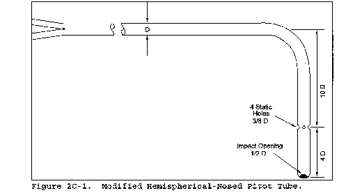
Method 2D - Measurement of Gas Volume Flow Rates in Small Pipes and Ducts
This method does not include all of the specifications (e.g., equipment and supplies) and procedures (e.g., sampling) essential to its performance. Some material is incorporated by reference from other methods in this part. Therefore, to obtain reliable results, persons using this method should also have a thorough knowledge of at least the following additional test methods: Method 1, Method 2, and Method 2A.
1.0 Scope and Application
1.1 This method is applicable for the determination of the volumetric flow rates of gas streams in small pipes and ducts. It can be applied to intermittent or variable gas flows only with particular caution.
1.2 Data Quality Objectives. Adherence to the requirements of this method will enhance the quality of the data obtained from air pollutant sampling methods.
2.0 Summary of Method
2.1 All the gas flow in the pipe or duct is directed through a rotameter, orifice plate or similar device to measure flow rate or pressure drop. The device has been previously calibrated in a manner that insures its proper calibration for the gas being measured. Absolute temperature and pressure measurements are made to allow correction of volumetric flow rates to standard conditions.
3.0 Definitions [Reserved]
4.0 Interferences [Reserved]
5.0 Safety
5.1 This method may involve hazardous materials, operations, and equipment. This test method may not address all of the safety problems associated with its use. It is the responsibility of the user of this test method to establish appropriate safety and health practices and determine the applicability of regulatory limitations prior to performing this test method.
6.0 Equipment and Supplies
Specifications for the apparatus are given below. Any other apparatus that has been demonstrated (subject to approval of the Administrator) to be capable of meeting the specifications will be considered acceptable.
6.1 Gas Metering Rate or Flow Element Device. A rotameter, orifice plate, or other volume rate or pressure drop measuring device capable of measuring the stack flow rate to within ±5 percent. The metering device shall be equipped with a temperature gauge accurate to within ±2 percent of the minimum absolute stack temperature and a pressure gauge (accurate to within ±5 mm Hg). The capacity of the metering device shall be sufficient for the expected maximum and minimum flow rates at the stack gas conditions. The magnitude and variability of stack gas flow rate, molecular weight, temperature, pressure, dewpoint, and corrosive characteristics, and pipe or duct size are factors to consider in choosing a suitable metering device.
6.2 Barometer. Same as Method 2, section 6.5.
6.3 Stopwatch. Capable of measurement to within 1 second.
7.0 Reagents and Standards [Reserved]
8.0 Sample Collection and Analysis
8.1 Installation and Leak Check. Same as Method 2A, sections 8.1 and 8.2, respectively.
8.2 Volume Rate Measurement.
8.2.1 Continuous, Steady Flow. At least once an hour, record the metering device flow rate or pressure drop reading, and the metering device temperature and pressure. Make a minimum of 12 equally spaced readings of each parameter during the test period. Record the barometric pressure at the beginning and end of the test period. Record the data on a table similar to that shown in Figure 2D-1.
8.2.2 Noncontinuous and Nonsteady Flow. Use volume rate devices with particular caution. Calibration will be affected by variation in stack gas temperature, pressure and molecular weight. Use the procedure in section 8.2.1 with the addition of the following: Record all the metering device parameters on a time interval frequency sufficient to adequately profile each process cyclical or noncontinuous event. A multichannel continuous recorder may be used.
9.0 Quality Control
| Section | Quality control measure | Effect |
|---|---|---|
| 10.0 | Sampling equipment calibration | Ensure accurate measurement of stack gas flow rate or sample volume. |
10.0 Calibration and Standardization
Same as Method 2A, section 10.0, with the following exception:
10.1 Gas Metering Device. Same as Method 2A, section 10.1, except calibrate the metering device with the principle stack gas to be measured (examples: air, nitrogen) against a standard reference meter. A calibrated dry gas meter is an acceptable reference meter. Ideally, calibrate the metering device in the field with the actual gas to be metered. For metering devices that have a volume rate readout, calculate the test metering device calibration coefficient, Ym, for each run shown in Equation 2D-2 section 12.3.
10.2 For metering devices that do not have a volume rate readout, refer to the manufacturer's instructions to calculate the Vm2 corresponding to each Vr.
10.3 Temperature Gauge. Use the procedure and specifications in Method 2A, section 10.2. Perform the calibration at a temperature that approximates field test conditions.
10.4 Barometer. Calibrate the barometer used against a mercury barometer or NIST-traceable barometer prior to the field test.
11.0 Analytical Procedure.
Sample collection and analysis are concurrent for this method (see section 8.0).
12.0 Data Analysis and Calculations
12.1 Nomenclature.
Pbar = Barometric pressure, mm Hg (in. Hg).
Pm = Test meter average static pressure, mm Hg (in. Hg).
Qr = Reference meter volume flow rate reading, m3/min (ft3/min).
Qm = Test meter volume flow rate reading, m3/min (ft3/min).
Tr = Absolute reference meter average temperature, °K (°R).
Tm = Absolute test meter average temperature, °K (°R).
Kl = 0.3855 °K/mm Hg for metric units, = 17.65 °R/in. Hg for English units.
12.2 Gas Flow Rate.

12.3 Test Meter Device Calibration Coefficient. Calculation for testing metering device calibration coefficient, Ym.

13.0 Method Performance [Reserved]
14.0 Pollution Prevention [Reserved]
15.0 Waste Management [Reserved]
16.0 References
1. Spink, L.K. Principles and Practice of Flowmeter Engineering. The Foxboro Company. Foxboro, MA. 1967.
2. Benedict, R.P. Fundamentals of Temperature, Pressure, and Flow Measurements. John Wiley & Sons, Inc. New York, NY. 1969.
3. Orifice Metering of Natural Gas. American Gas Association. Arlington, VA. Report No. 3. March 1978. 88 pp.
17.0 Tables, Diagrams, Flowcharts, and Validation Data
Plant
Date
Run No.
Sample location
Barometric pressure (mm Hg):
Start
Finish
Operators
Metering device No.
Calibration coefficient
Calibration gas
Date to recalibrate
| Time | Flow rate
reading |
Static Pressure
[mm Hg (in. Hg)] |
Temperature | |
|---|---|---|---|---|
| °C (°F) | °K (°R) | |||
| Average | ||||
Figure 2D-1. Volume Flow Rate Measurement Data
Method 2E - Determination of Landfill Gas Production Flow Rate
This method does not include all of the specifications (e.g., equipment and supplies) and procedures (e.g., sampling and analytical) essential to its performance. Some material is incorporated by reference from other methods in this part. Therefore, to obtain reliable results, persons using this method should also have a thorough knowledge of at least the following additional test methods: Methods 2 and 3C.
1.0 Scope and Application
1.1 Applicability. This method applies to the measurement of landfill gas (LFG) production flow rate from municipal solid waste landfills and is used to calculate the flow rate of nonmethane organic compounds (NMOC) from landfills.
1.2 Data Quality Objectives. Adherence to the requirements of this method will enhance the quality of the data obtained from air pollutant sampling methods.
2.0 Summary of Method
2.1 Extraction wells are installed either in a cluster of three or at five dispersed locations in the landfill. A blower is used to extract LFG from the landfill. LFG composition, landfill pressures, and orifice pressure differentials from the wells are measured and the landfill gas production flow rate is calculated.
3.0 Definitions [Reserved]
4.0 Interferences [Reserved]
5.0 Safety
5.1 Since this method is complex, only experienced personnel should perform the test. Landfill gas contains methane, therefore explosive mixtures may exist at or near the landfill. It is advisable to take appropriate safety precautions when testing landfills, such as refraining from smoking and installing explosion-proof equipment.
6.0 Equipment and Supplies
6.1 Well Drilling Rig. Capable of boring a 0.61 m (24 in.) diameter hole into the landfill to a minimum of 75 percent of the landfill depth. The depth of the well shall not extend to the bottom of the landfill or the liquid level.
6.2 Gravel. No fines. Gravel diameter should be appreciably larger than perforations stated in sections 6.10 and 8.2.
6.3 Bentonite.
6.4 Backfill Material. Clay, soil, and sandy loam have been found to be acceptable.
6.5 Extraction Well Pipe. Minimum diameter of 3 in., constructed of polyvinyl chloride (PVC), high density polyethylene (HDPE), fiberglass, stainless steel, or other suitable nonporous material capable of transporting landfill gas.
6.6 Above Ground Well Assembly. Valve capable of adjusting gas flow, such as a gate, ball, or butterfly valve; sampling ports at the well head and outlet; and a flow measuring device, such as an in-line orifice meter or pitot tube. A schematic of the aboveground well head assembly is shown in Figure 2E-1.
6.7 Cap. Constructed of PVC or HDPE.
6.8 Header Piping. Constructed of PVC or HDPE.
6.9 Auger. Capable of boring a 0.15-to 0.23-m (6-to 9-in.) diameter hole to a depth equal to the top of the perforated section of the extraction well, for pressure probe installation.
6.10 Pressure Probe. Constructed of PVC or stainless steel (316), 0.025-m (1-in.). Schedule 40 pipe. Perforate the bottom two-thirds. A minimum requirement for perforations is slots or holes with an open area equivalent to four 0.006-m (1⁄4-in.) diameter holes spaced 90° apart every 0.15 m (6 in.).
6.11 Blower and Flare Assembly. Explosion-proof blower, capable of extracting LFG at a flow rate of 8.5 m3/min (300 ft3/min), a water knockout, and flare or incinerator.
6.12 Standard Pitot Tube and Differential Pressure Gauge for Flow Rate Calibration with Standard Pitot. Same as Method 2, sections 6.7 and 6.8.
6.13 Orifice Meter. Orifice plate, pressure tabs, and pressure measuring device to measure the LFG flow rate.
6.14 Barometer. Same as Method 4, section 6.1.5.
6.15 Differential Pressure Gauge. Water-filled U-tube manometer or equivalent, capable of measuring within 0.02 mm Hg (0.01 in. H2O), for measuring the pressure of the pressure probes.
7.0 Reagents and Standards. Not Applicable
8.0 Sample Collection, Preservation, Storage, and Transport
8.1 Placement of Extraction Wells. The landfill owner or operator may install a single cluster of three extraction wells in a test area or space five equal-volume wells over the landfill. The cluster wells are recommended but may be used only if the composition, age of the refuse, and the landfill depth of the test area can be determined.
8.1.1 Cluster Wells. Consult landfill site records for the age of the refuse, depth, and composition of various sections of the landfill. Select an area near the perimeter of the landfill with a depth equal to or greater than the average depth of the landfill and with the average age of the refuse between 2 and 10 years old. Avoid areas known to contain nondecomposable materials, such as concrete and asbestos. Locate the cluster wells as shown in Figure 2E-2.
8.1.1.1 The age of the refuse in a test area will not be uniform, so calculate a weighted average age of the refuse as shown in section 12.2.
8.1.2 Equal Volume Wells. Divide the sections of the landfill that are at least 2 years old into five areas representing equal volumes. Locate an extraction well near the center of each area.
8.2 Installation of Extraction Wells. Use a well drilling rig to dig a 0.6 m (24 in.) diameter hole in the landfill to a minimum of 75 percent of the landfill depth, not to extend to the bottom of the landfill or the liquid level. Perforate the bottom two thirds of the extraction well pipe. A minimum requirement for perforations is holes or slots with an open area equivalent to 0.01-m (0.5-in.) diameter holes spaced 90° apart every 0.1 to 0.2 m (4 to 8 in.). Place the extraction well in the center of the hole and backfill with gravel to a level 0.30 m (1 ft) above the perforated section. Add a layer of backfill material 1.2 m (4 ft) thick. Add a layer of bentonite 0.9 m (3 ft) thick, and backfill the remainder of the hole with cover material or material equal in permeability to the existing cover material. The specifications for extraction well installation are shown in Figure 2E-3.
8.3 Pressure Probes. Shallow pressure probes are used in the check for infiltration of air into the landfill, and deep pressure probes are use to determine the radius of influence. Locate pressure probes along three radial arms approximately 120° apart at distances of 3, 15, 30, and 45 m (10, 50, 100, and 150 ft) from the extraction well. The tester has the option of locating additional pressure probes at distances every 15 m (50 feet) beyond 45 m (150 ft). Example placements of probes are shown in Figure 2E-4. The 15-, 30-, and 45-m, (50-, 100-, and 150-ft) probes from each well, and any additional probes located along the three radial arms (deep probes), shall extend to a depth equal to the top of the perforated section of the extraction wells. All other probes (shallow probes) shall extend to a depth equal to half the depth of the deep probes.
8.3.1 Use an auger to dig a hole, 0.15- to 0.23-m (6-to 9-in.) in diameter, for each pressure probe. Perforate the bottom two thirds of the pressure probe. A minimum requirement for perforations is holes or slots with an open area equivalent to four 0.006-m (0.25-in.) diameter holes spaced 90° apart every 0.15 m (6 in.). Place the pressure probe in the center of the hole and backfill with gravel to a level 0.30 m (1 ft) above the perforated section. Add a layer of backfill material at least 1.2 m (4 ft) thick. Add a layer of bentonite at least 0.3 m (1 ft) thick, and backfill the remainder of the hole with cover material or material equal in permeability to the existing cover material. The specifications for pressure probe installation are shown in Figure 2E-5.
8.4 LFG Flow Rate Measurement. Place the flow measurement device, such as an orifice meter, as shown in Figure 2E-1. Attach the wells to the blower and flare assembly. The individual wells may be ducted to a common header so that a single blower, flare assembly, and flow meter may be used. Use the procedures in section 10.1 to calibrate the flow meter.
8.5 Leak-Check. A leak-check of the above ground system is required for accurate flow rate measurements and for safety. Sample LFG at the well head sample port and at the outlet sample port. Use Method 3C to determine nitrogen (N2) concentrations. Determine the difference between the well head and outlet N2 concentrations using the formula in section 12.3. The system passes the leak-check if the difference is less than 10,000 ppmv.
8.6 Static Testing. Close the control valves on the well heads during static testing. Measure the gauge pressure (Pg) at each deep pressure probe and the barometric pressure (Pbar) every 8 hours (hr) for 3 days. Convert the gauge pressure of each deep pressure probe to absolute pressure using the equation in section 12.4. Record as Pi (initial absolute pressure).
8.6.1 For each probe, average all of the 8-hr deep pressure probe readings (Pi) and record as Pia (average absolute pressure). Pia is used in section 8.7.5 to determine the maximum radius of influence.
8.6.2 Measure the static flow rate of each well once during static testing.
8.7 Short-Term Testing. The purpose of short-term testing is to determine the maximum vacuum that can be applied to the wells without infiltration of ambient air into the landfill. The short-term testing is performed on one well at a time. Burn all LFG with a flare or incinerator.
8.7.1 Use the blower to extract LFG from a single well at a rate at least twice the static flow rate of the respective well measured in section 8.6.2. If using a single blower and flare assembly and a common header system, close the control valve on the wells not being measured. Allow 24 hr for the system to stabilize at this flow rate.
8.7.2 Test for infiltration of air into the landfill by measuring the gauge pressures of the shallow pressure probes and using Method 3C to determine the LFG N2 concentration. If the LFG N2 concentration is less than 5 percent and all of the shallow probes have a positive gauge pressure, increase the blower vacuum by 3.7 mm Hg (2 in. H2O), wait 24 hr, and repeat the tests for infiltration. Continue the above steps of increasing blower vacuum by 3.7 mm Hg (2 in. H2O), waiting 24 hr, and testing for infiltration until the concentration of N2 exceeds 5 percent or any of the shallow probes have a negative gauge pressure. When this occurs,reduce the blower vacuum to the maximum setting at which the N2 concentration was less than 5 percent and the gauge pressures of the shallow probes are positive.
8.7.3 At this blower vacuum, measure atmospheric pressure (Pbar) every 8 hr for 24 hr, and record the LFG flow rate (Qs) and the probe gauge pressures (Pf) for all of the probes. Convert the gauge pressures of the deep probes to absolute pressures for each 8-hr reading at Qs as shown in section 12.4.
8.7.4 For each probe, average the 8-hr deep pressure probe absolute pressure readings and record as Pfa (the final average absolute pressure).
8.7.5 For each probe, compare the initial average pressure (Pia) from section 8.6.1 to the final average pressure (Pfa). Determine the furthermost point from the well head along each radial arm where Pfa ≤Pia. This distance is the maximum radius of influence (Rm), which is the distance from the well affected by the vacuum. Average these values to determine the average maximum radius of influence (Rma).
8.7.6 Calculate the depth (Dst) affected by the extraction well during the short term test as shown in section 12.6. If the computed value of Dst exceeds the depth of the landfill, set Dst equal to the landfill depth.
8.7.7 Calculate the void volume (V) for the extraction well as shown in section 12.7.
8.7.8 Repeat the procedures in section 8.7 for each well.
8.8 Calculate the total void volume of the test wells (Vv) by summing the void volumes (V) of each well.
8.9 Long-Term Testing. The purpose of long-term testing is to extract two void volumes of LFG from the extraction wells. Use the blower to extract LFG from the wells. If a single Blower and flare assembly and common header system are used, open all control valves and set the blower vacuum equal to the highest stabilized blower vacuum demonstrated by any individual well in section 8.7. Every 8 hr, sample the LFG from the well head sample port, measure the gauge pressures of the shallow pressure probes, the blower vacuum, the LFG flow rate, and use the criteria for infiltration in section 8.7.2 and Method 3C to test for infiltration. If infiltration is detected, do not reduce the blower vacuum, instead reduce the LFG flow rate from the well by adjusting the control valve on the well head. Adjust each affected well individually. Continue until the equivalent of two total void volumes (Vv) have been extracted, or until Vt = 2Vv.
8.9.1 Calculate Vt, the total volume of LFG extracted from the wells, as shown in section 12.8.
8.9.2 Record the final stabilized flow rate as Qf and the gauge pressure for each deep probe. If, during the long term testing, the flow rate does not stabilize, calculate Qf by averaging the last 10 recorded flow rates.
8.9.3 For each deep probe, convert each gauge pressure to absolute pressure as in section 12.4. Average these values and record as Psa. For each probe, compare Pia to Psa. Determine the furthermost point from the well head along each radial arm where Psa ≤Pia. This distance is the stabilized radius of influence. Average these values to determine the average stabilized radius of influence (Rsa).
8.10 Determine the NMOC mass emission rate using the procedures in section 12.9 through 12.15.
9.0 Quality Control
9.1 Miscellaneous Quality Control Measures.
| Section | Quality control measure | Effect |
|---|---|---|
| 10.1 | LFG flow rate meter calibration | Ensures accurate measurement of LFG flow rate and sample volume |
10.0 Calibration and Standardization
10.1 LFG Flow Rate Meter (Orifice) Calibration Procedure. Locate a standard pitot tube in line with an orifice meter. Use the procedures in section 8, 12.5, 12.6, and 12.7 of Method 2 to determine the average dry gas volumetric flow rate for at least five flow rates that bracket the expected LFG flow rates, except in section 8.1, use a standard pitot tube rather than a Type S pitot tube. Method 3C may be used to determine the dry molecular weight. It may be necessary to calibrate more than one orifice meter in order to bracket the LFG flow rates. Construct a calibration curve by plotting the pressure drops across the orifice meter for each flow rate versus the average dry gas volumetric flow rate in m3/min of the gas.
11.0 Procedures [Reserved]
12.0 Data Analysis and Calculations
12.1 Nomenclature.
A = Age of landfill, yr.
Aavg = Average age of the refuse tested, yr.
Ai = Age of refuse in the ith fraction, yr.
Ar = Acceptance rate, Mg/yr.
CNMOC = NMOC concentration, ppmv as hexane (CNMOC = Ct/6).
Co = Concentration of N2 at the outlet, ppmv.
Ct = NMOC concentration, ppmv (carbon equivalent) from Method 25C.
Cw = Concentration of N2 at the wellhead, ppmv.
D = Depth affected by the test wells, m.
Dst = Depth affected by the test wells in the short-term test, m.
e = Base number for natural logarithms (2.718).
f = Fraction of decomposable refuse in the landfill.
fi = Fraction of the refuse in the ith section.
k = Landfill gas generation constant, yr−1.
Lo = Methane generation potential, m3/Mg.
Lo′ = Revised methane generation potential to account for the amount of nondecomposable material in the landfill, m3/Mg.
Mi = Mass of refuse in the ith section, Mg.
Mr = Mass of decomposable refuse affected by the test well, Mg.
Pbar = Atmospheric pressure, mm Hg.
Pf = Final absolute pressure of the deep pressure probes during short-term testing, mm Hg.
Pfa = Average final absolute pressure of the deep pressure probes during short-term testing, mm Hg.
Pgf = final gauge pressure of the deep pressure probes, mm Hg.
Pgi = Initial gauge pressure of the deep pressure probes, mm Hg.
Pi = Initial absolute pressure of the deep pressure probes during static testing, mm Hg.
Pia = Average initial absolute pressure of the deep pressure probes during static testing, mm Hg.
Ps = Final absolute pressure of the deep pressure probes during long-term testing, mm Hg.
Psa = Average final absolute pressure of the deep pressure probes during long-term testing, mm Hg.
Qf = Final stabilized flow rate, m3/min.
Qi = LFG flow rate measured at orifice meter during the ith interval, m3/min.
Qs = Maximum LFG flow rate at each well determined by short-term test, m3/min.
Qt = NMOC mass emission rate, m3/min.
Rm = Maximum radius of influence, m.
Rma = Average maximum radius of influence, m.
Rs = Stabilized radius of influence for an individual well, m.
Rsa = Average stabilized radius of influence, m.
ti = Age of section i, yr.
tt = Total time of long-term testing, yr.
tvi = Time of the ith interval (usually 8), hr.
V = Void volume of test well, m3.
Vr = Volume of refuse affected by the test well, m3.
Vt = Total volume of refuse affected by the long-term testing, m3.
Vv = Total void volume affected by test wells, m3.
WD = Well depth, m.
ρ = Refuse density, Mg/m3 (Assume 0.64 Mg/m3 if data are unavailable).
12.2 Use the following equation to calculate a weighted average age of landfill refuse.

12.3 Use the following equation to determine the difference in N2 concentrations (ppmv) at the well head and outlet location.

12.4 Use the following equation to convert the gauge pressure (Pg) of each initial deep pressure probe to absolute pressure (Pi).

12.5 Use the following equation to convert the gauge pressures of the deep probes to absolute pressures for each 8-hr reading at Qs.

12.6 Use the following equation to calculate the depth (Dst) affected by the extraction well during the short-term test.

12.7 Use the following equation to calculate the void volume for the extraction well (V).

12.8 Use the following equation to calculate Vt, the total volume of LFG extracted from the wells.

12.9 Use the following equation to calculate the depth affected by the test well. If using cluster wells, use the average depth of the wells for WD. If the value of D is greater than the depth of the landfill, set D equal to the landfill depth.

12.10 Use the following equation to calculate the volume of refuse affected by the test well.

12.11 Use the following equation to calculate the mass affected by the test well.

12.12 Modify Lo to account for the nondecomposable refuse in the landfill.

12.13 In the following equation, solve for k (landfill gas generation constant) by iteration. A suggested procedure is to select a value for k, calculate the left side of the equation, and if not equal to zero, select another value for k. Continue this process until the left hand side of the equation equals zero, ±0.001.

12.14 Use the following equation to determine landfill NMOC mass emission rate if the yearly acceptance rate of refuse has been consistent (10 percent) over the life of the landfill.

12.15 Use the following equation to determine landfill NMOC mass emission rate if the acceptance rate has not been consistent over the life of the landfill.

13.0 Method Performance [Reserved]
14.0 Pollution Prevention [Reserved]
15.0 Waste Management [Reserved]
16.0 References
1. Same as Method 2, Appendix A, 40 CFR Part 60.
2. Emcon Associates, Methane Generation and Recovery from Landfills. Ann Arbor Science, 1982.
3. The Johns Hopkins University, Brown Station Road Landfill Gas Resource Assessment, Volume 1: Field Testing and Gas Recovery Projections. Laurel, Maryland: October 1982.
4. Mandeville and Associates, Procedure Manual for Landfill Gases Emission Testing.
5. Letter and attachments from Briggum, S., Waste Management of North America, to Thorneloe, S., EPA. Response to July 28, 1988 request for additional information. August 18, 1988.
6. Letter and attachments from Briggum, S., Waste Management of North America, to Wyatt, S., EPA. Response to December 7, 1988 request for additional information. January 16, 1989.
17.0 Tables, Diagrams, Flowcharts, and Validation Data


Method 2F - Determination of Stack Gas Velocity And Volumetric Flow Rate With Three-Dimensional Probes
This method does not include all of the specifications (e.g., equipment and supplies) and procedures (e.g., sampling) essential to its performance. Some material has been incorporated from other methods in this part. Therefore, to obtain reliable results, those using this method should have a thorough knowledge of at least the following additional test methods: Methods 1, 2, 3 or 3A, and 4.
1.0 Scope and Application
1.1 This method is applicable for the determination of yaw angle, pitch angle, axial velocity and the volumetric flow rate of a gas stream in a stack or duct using a three-dimensional (3-D) probe. This method may be used only when the average stack or duct gas velocity is greater than or equal to 20 ft/sec. When the above condition cannot be met, alternative procedures, approved by the Administrator, U.S. Environmental Protection Agency, shall be used to make accurate flow rate determinations.
2.0 Summary of Method
2.1 A 3-D probe is used to determine the velocity pressure and the yaw and pitch angles of the flow velocity vector in a stack or duct. The method determines the yaw angle directly by rotating the probe to null the pressure across a pair of symmetrically placed ports on the probe head. The pitch angle is calculated using probe-specific calibration curves. From these values and a determination of the stack gas density, the average axial velocity of the stack gas is calculated. The average gas volumetric flow rate in the stack or duct is then determined from the average axial velocity.
3.0 Definitions
3.1. Angle-measuring Device Rotational Offset (RADO). The rotational position of an angle-measuring device relative to the reference scribe line, as determined during the pre-test rotational position check described in section 8.3.
3.2 Axial Velocity. The velocity vector parallel to the axis of the stack or duct that accounts for the yaw and pitch angle components of gas flow. The term “axial” is used herein to indicate that the velocity and volumetric flow rate results account for the measured yaw and pitch components of flow at each measurement point.
3.3 Calibration Pitot Tube. The standard (Prandtl type) pitot tube used as a reference when calibrating a 3-D probe under this method.
3.4 Field Test. A set of measurements conducted at a specific unit or exhaust stack/duct to satisfy the applicable regulation (e.g., a three-run boiler performance test, a single-or multiple-load nine-run relative accuracy test).
3.5 Full Scale of Pressure-measuring Device. Full scale refers to the upper limit of the measurement range displayed by the device. For bi-directional pressure gauges, full scale includes the entire pressure range from the lowest negative value to the highest positive value on the pressure scale.
3.6 Main probe. Refers to the probe head and that section of probe sheath directly attached to the probe head. The main probe sheath is distinguished from probe extensions, which are sections of sheath added onto the main probe to extend its reach.
3.7 “May,” “Must,” “Shall,” “Should,” and the imperative form of verbs.
3.7.1 “May” is used to indicate that a provision of this method is optional.
3.7.2 “Must,” “Shall,” and the imperative form of verbs (such as “record” or “enter”) are used to indicate that a provision of this method is mandatory.
3.7.3 “Should” is used to indicate that a provision of this method is not mandatory, but is highly recommended as good practice.
3.8 Method 1. Refers to 40 CFR part 60, appendix A, “Method 1 - Sample and velocity traverses for stationary sources.”
3.9 Method 2. Refers to 40 CFR part 60, appendix A, “Method 2 - Determination of stack gas velocity and volumetric flow rate (Type S pitot tube).”
3.10 Method 2G. Refers to 40 CFR part 60, appendix A, “Method 2G - Determination of stack gas velocity and volumetric flow rate with two-dimensional probes.”
3.11 Nominal Velocity. Refers to a wind tunnel velocity setting that approximates the actual wind tunnel velocity to within ±1.5 m/sec (±5 ft/sec).
3.12 Pitch Angle. The angle between the axis of the stack or duct and the pitch component of flow, i.e., the component of the total velocity vector in a plane defined by the traverse line and the axis of the stack or duct. (Figure 2F-1 illustrates the “pitch plane.”) From the standpoint of a tester facing a test port in a vertical stack, the pitch component of flow is the vector of flow moving from the center of the stack toward or away from that test port. The pitch angle is the angle described by this pitch component of flow and the vertical axis of the stack.
3.13 Readability. For the purposes of this method, readability for an analog measurement device is one half of the smallest scale division. For a digital measurement device, it is the number of decimals displayed by the device.
3.14 Reference Scribe Line. A line permanently inscribed on the main probe sheath (in accordance with section 6.1.6.1) to serve as a reference mark for determining yaw angles.
3.15 Reference Scribe Line Rotational Offset (RSLO). The rotational position of a probe's reference scribe line relative to the probe's yaw-null position, as determined during the yaw angle calibration described in section 10.5.
3.16 Response Time. The time required for the measurement system to fully respond to a change from zero differential pressure and ambient temperature to the stable stack or duct pressure and temperature readings at a traverse point.
3.17 Tested Probe. A 3-D probe that is being calibrated.
3.18 Three-dimensional (3-D) Probe. A directional probe used to determine the velocity pressure and yaw and pitch angles in a flowing gas stream.
3.19 Traverse Line. A diameter or axis extending across a stack or duct on which measurements of differential pressure and flow angles are made.
3.20 Wind Tunnel Calibration Location. A point, line, area, or volume within the wind tunnel test section at, along, or within which probes are calibrated. At a particular wind tunnel velocity setting, the average velocity pressures at specified points at, along, or within the calibration location shall vary by no more than 2 percent or 0.3 mm H2O (0.01 in. H2O), whichever is less restrictive, from the average velocity pressure at the calibration pitot tube location. Air flow at this location shall be axial, i.e., yaw and pitch angles within ±3°. Compliance with these flow criteria shall be demonstrated by performing the procedures prescribed in sections 10.1.1 and 10.1.2. For circular tunnels, no part of the calibration location may be closer to the tunnel wall than 10.2 cm (4 in.) or 25 percent of the tunnel diameter, whichever is farther from the wall. For elliptical or rectangular tunnels, no part of the calibration location may be closer to the tunnel wall than 10.2 cm (4 in.) or 25 percent of the applicable cross-sectional axis, whichever is farther from the wall.
3.21 Wind Tunnel with Documented Axial Flow. A wind tunnel facility documented as meeting the provisions of sections 10.1.1 (velocity pressure cross-check) and 10.1.2 (axial flow verification) using the procedures described in these sections or alternative procedures determined to be technically equivalent.
3.22 Yaw Angle. The angle between the axis of the stack or duct and the yaw component of flow, i.e., the component of the total velocity vector in a plane perpendicular to the traverse line at a particular traverse point. (Figure 2F-1 illustrates the “yaw plane.”) From the standpoint of a tester facing a test port in a vertical stack, the yaw component of flow is the vector of flow moving to the left or right from the center of the stack as viewed by the tester. (This is sometimes referred to as “vortex flow,” i.e., flow around the centerline of a stack or duct.) The yaw angle is the angle described by this yaw component of flow and the vertical axis of the stack. The algebraic sign convention is illustrated in Figure 2F-2.
3.23 Yaw Nulling. A procedure in which a probe is rotated about its axis in a stack or duct until a zero differential pressure reading (“yaw null”) is obtained. When a 3-D probe is yaw-nulled, its impact pressure port (P1) faces directly into the direction of flow in the stack or duct and the differential pressure between pressure ports P2 and P3 is zero.
4.0 Interferences [Reserved]
5.0 Safety
5.1 This test method may involve hazardous operations and the use of hazardous materials or equipment. This method does not purport to address all of the safety problems associated with its use. It is the responsibility of the user to establish and implement appropriate safety and health practices and to determine the applicability of regulatory limitations before using this test method.
6.0 Equipment and Supplies
6.1 Three-dimensional Probes. The 3-D probes as specified in subsections 6.1.1 through 6.1.3 below qualify for use based on comprehensive wind tunnel and field studies involving both inter-and intra-probe comparisons by multiple test teams. Other types of probes shall not be used unless approved by the Administrator. Each 3-D probe shall have a unique identification number or code permanently marked on the main probe sheath. The minimum recommended diameter of the sensing head of any probe used under this method is 2.5 cm (1 in.). Each probe shall be calibrated prior to use according to the procedures in section 10. Manufacturer-supplied calibration data shall be used as example information only, except when the manufacturer calibrates the 3-D probe as specified in section 10 and provides complete documentation.
6.1.1 Five-hole prism-shaped probe. This type of probe consists of five pressure taps in the flat facets of a prism-shaped sensing head. The pressure taps are numbered 1 through 5, with the pressures measured at each hole referred to as P1, P2, P3, P4, and P5, respectively. Figure 2F-3 is an illustration of the placement of pressure taps on a commonly available five-hole prism-shaped probe, the 2.5-cm (1-in.) DAT probe. (Note: Mention of trade names or specific products does not constitute endorsement by the U.S. Environmental Protection Agency.) The numbering arrangement for the prism-shaped sensing head presented in Figure 2F-3 shall be followed for correct operation of the probe. A brief description of the probe measurements involved is as follows: the differential pressure P2-P3 is used to yaw null the probe and determine the yaw angle; the differential pressure P4-P5 is a function of pitch angle; and the differential pressure P1-P2 is a function of total velocity.
6.1.2 Five-hole spherical probe. This type of probe consists of five pressure taps in a spherical sensing head. As with the prism-shaped probe, the pressure taps are numbered 1 through 5, with the pressures measured at each hole referred to as P1, P2, P3, P4, and P5, respectively. However, the P4 and P5 pressure taps are in the reverse location from their respective positions on the prism-shaped probe head. The differential pressure P2-P3 is used to yaw null the probe and determine the yaw angle; the differential pressure P4-P5 is a function of pitch angle; and the differential pressure P1-P2 is a function of total velocity. A diagram of a typical spherical probe sensing head is presented in Figure 2F-4. Typical probe dimensions are indicated in the illustration.
6.1.3 A manual 3-D probe refers to a five-hole prism-shaped or spherical probe that is positioned at individual traverse points and yaw nulled manually by an operator. An automated 3-D probe refers to a system that uses a computer-controlled motorized mechanism to position the five-hole prism-shaped or spherical head at individual traverse points and perform yaw angle determinations.
6.1.4 Other three-dimensional probes. [Reserved]
6.1.5 Probe sheath. The probe shaft shall include an outer sheath to:
(1) provide a surface for inscribing a permanent reference scribe line,
(2) accommodate attachment of an angle-measuring device to the probe shaft, and
(3) facilitate precise rotational movement of the probe for determining yaw angles. The sheath shall be rigidly attached to the probe assembly and shall enclose all pressure lines from the probe head to the farthest position away from the probe head where an angle-measuring device may be attached during use in the field. The sheath of the fully assembled probe shall be sufficiently rigid and straight at all rotational positions such that, when one end of the probe shaft is held in a horizontal position, the fully extended probe meets the horizontal straightness specifications indicated in section 8.2 below.
6.1.6 Scribe lines.
6.1.6.1 Reference scribe line. A permanent line, no greater than 1.6 mm (1/16 in.) in width, shall be inscribed on each manual probe that will be used to determine yaw angles of flow. This line shall be placed on the main probe sheath in accordance with the procedures described in section 10.4 and is used as a reference position for installation of the yaw angle-measuring device on the probe. At the discretion of the tester, the scribe line may be a single line segment placed at a particular position on the probe sheath (e.g., near the probe head), multiple line segments placed at various locations along the length of the probe sheath (e.g., at every position where a yaw angle-measuring device may be mounted), or a single continuous line extending along the full length of the probe sheath.
6.1.6.2 Scribe line on probe extensions. A permanent line may also be inscribed on any probe extension that will be attached to the main probe in performing field testing. This allows a yaw angle-measuring device mounted on the extension to be readily aligned with the reference scribe line on the main probe sheath.
6.1.6.3 Alignment specifications. This specification shall be met separately, using the procedures in section 10.4.1, on the main probe and on each probe extension. The rotational position of the scribe line or scribe line segments on the main probe or any probe extension must not vary by more than 2°. That is, the difference between the minimum and maximum of all of the rotational angles that are measured along the full length of the main probe or the probe extension must not exceed 2°.
6.1.7 Probe and system characteristics to ensure horizontal stability.
6.1.7.1 For manual probes, it is recommended that the effective length of the probe (coupled with a probe extension, if necessary) be at least 0.9 m (3 ft.) longer than the farthest traverse point mark on the probe shaft away from the probe head. The operator should maintain the probe's horizontal stability when it is fully inserted into the stack or duct. If a shorter probe is used, the probe should be inserted through a bushing sleeve, similar to the one shown in Figure 2F-5, that is installed on the test port; such a bushing shall fit snugly around the probe and be secured to the stack or duct entry port in such a manner as to maintain the probe's horizontal stability when fully inserted into the stack or duct.
6.1.7.2 An automated system that includes an external probe casing with a transport system shall have a mechanism for maintaining horizontal stability comparable to that obtained by manual probes following the provisions of this method. The automated probe assembly shall also be constructed to maintain the alignment and position of the pressure ports during sampling at each traverse point. The design of the probe casing and transport system shall allow the probe to be removed from the stack or duct and checked through direct physical measurement for angular position and insertion depth.
6.1.8 The tubing that is used to connect the probe and the pressure-measuring device should have an inside diameter of at least 3.2 mm (1/8 in.), to reduce the time required for pressure equilibration, and should be as short as practicable.
6.2 Yaw Angle-measuring Device. One of the following devices shall be used for measurement of the yaw angle of flow.
6.2.1 Digital inclinometer. This refers to a digital device capable of measuring and displaying the rotational position of the probe to within ±1°. The device shall be able to be locked into position on the probe sheath or probe extension, so that it indicates the probe's rotational position throughout the test. A rotational position collar block that can be attached to the probe sheath (similar to the collar shown in Figure 2F-6) may be required to lock the digital inclinometer into position on the probe sheath.
6.2.2 Protractor wheel and pointer assembly. This apparatus, similar to that shown in Figure 2F-7, consists of the following components.
6.2.2.1 A protractor wheel that can be attached to a port opening and set in a fixed rotational position to indicate the yaw angle position of the probe's scribe line relative to the longitudinal axis of the stack or duct. The protractor wheel must have a measurement ring on its face that is no less than 17.8 cm (7 in.) in diameter, shall be able to be rotated to any angle and then locked into position on the stack or duct port, and shall indicate angles to a resolution of 1°.
6.2.2.2 A pointer assembly that includes an indicator needle mounted on a collar that can slide over the probe sheath and be locked into a fixed rotational position on the probe sheath. The pointer needle shall be of sufficient length, rigidity, and sharpness to allow the tester to determine the probe's angular position to within 1° from the markings on the protractor wheel. Corresponding to the position of the pointer, the collar must have a scribe line to be used in aligning the pointer with the scribe line on the probe sheath.
6.2.3 Other yaw angle-measuring devices. Other angle-measuring devices with a manufacturer's specified precision of 1° or better may be used, if approved by the Administrator.
6.3 Probe Supports and Stabilization Devices. When probes are used for determining flow angles, the probe head should be kept in a stable horizontal position. For probes longer than 3.0 m (10 ft.), the section of the probe that extends outside the test port shall be secured. Three alternative devices are suggested for maintaining the horizontal position and stability of the probe shaft during flow angle determinations and velocity pressure measurements:
(1) Monorails installed above each port,
(2) probe stands on which the probe shaft may be rested, or
(3) bushing sleeves of sufficient length secured to the test ports to maintain probes in a horizontal position. Comparable provisions shall be made to ensure that automated systems maintain the horizontal position of the probe in the stack or duct. The physical characteristics of each test platform may dictate the most suitable type of stabilization device. Thus, the choice of a specific stabilization device is left to the judgment of the testers.
6.4 Differential Pressure Gauges. The pressure (ΔP) measuring devices used during wind tunnel calibrations and field testing shall be either electronic manometers (e.g., pressure transducers), fluid manometers, or mechanical pressure gauges (e.g., MagnehelicΔ gauges). Use of electronic manometers is recommended. Under low velocity conditions, use of electronic manometers may be necessary to obtain acceptable measurements.
6.4.1 Differential pressure-measuring device. This refers to a device capable of measuring pressure differentials and having a readability of ±1 percent of full scale. The device shall be capable of accurately measuring the maximum expected pressure differential. Such devices are used to determine the following pressure measurements: velocity pressure, static pressure, yaw-null pressure, and pitch-angle pressure. For an inclined-vertical manometer, the readability specification of ±1 percent shall be met separately using the respective full-scale upper limits of the inclined and vertical portions of the scales. To the extent practicable, the device shall be selected such that most of the pressure readings are between 10 and 90 percent of the device's full-scale measurement range (as defined in section 3.5). Typical velocity pressure (P1-P2) ranges for both the prism-shaped probe and the spherical probe are 0 to 1.3 cm H2O (0 to 0.5 in. H2O), 0 to 5.1 cm H2O (0 to 2 in. H2O), and 0 to 12.7 cm H2O (0 to 5 in. H2O). The pitch angle (P4-P5) pressure range is typically −6.4 to + 6.4 mm H2O (−0.25 to + 0.25 in. H2O) or −12.7 to + 12.7 mm H2O (−0.5 to + 0.5 in. H2O) for the prism-shaped probe, and −12.7 to + 12.7 mm H2O (−0.5 to + 0.5 in. H2O) or −5.1 to + 5.1 cm H2O (−2 to + 2 in. H2O) for the spherical probe. The pressure range for the yaw null (P2-P3) readings is typically −12.7 to + 12.7 mm H2O (−0.5 to + 0.5 in. H2O) for both probe types. In addition, pressure-measuring devices should be selected such that the zero does not drift by more than 5 percent of the average expected pressure readings to be encountered during the field test. This is particularly important under low pressure conditions.
6.4.2 Gauge used for yaw nulling. The differential pressure-measuring device chosen for yaw nulling the probe during the wind tunnel calibrations and field testing shall be bi-directional, i.e., capable of reading both positive and negative differential pressures. If a mechanical, bi-directional pressure gauge is chosen, it shall have a full-scale range no greater than 2.6 cm H2O (1 in. H2O) [i.e., −1.3 to + 1.3 cm H2O (−0.5 in. to + 0.5 in.)].
6.4.3 Devices for calibrating differential pressure-measuring devices. A precision manometer (e.g., a U-tube, inclined, or inclined-vertical manometer, or micromanometer) or NIST (National Institute of Standards and Technology) traceable pressure source shall be used for calibrating differential pressure-measuring devices. The device shall be maintained under laboratory conditions or in a similar protected environment (e.g., a climate-controlled trailer). It shall not be used in field tests. The precision manometer shall have a scale gradation of 0.3 mm H2O (0.01 in. H2O), or less, in the range of 0 to 5.1 cm H2O (0 to 2 in. H2O) and 2.5 mm H2O (0.1 in. H2O), or less, in the range of 5.1 to 25.4 cm H2O (2 to 10 in. H2O). The manometer shall have manufacturer's documentation that it meets an accuracy specification of at least 0.5 percent of full scale. The NIST-traceable pressure source shall be recertified annually.
6.4.4 Devices used for post-test calibration check. A precision manometer meeting the specifications in section 6.4.3, a pressure-measuring device or pressure source with a documented calibration traceable to NIST, or an equivalent device approved by the Administrator shall be used for the post-test calibration check. The pressure-measuring device shall have a readability equivalent to or greater than the tested device. The pressure source shall be capable of generating pressures between 50 and 90 percent of the range of the tested device and known to within ±1 percent of the full scale of the tested device. The pressure source shall be recertified annually.
6.5 Data Display and Capture Devices. Electronic manometers (if used) shall be coupled with a data display device (such as a digital panel meter, personal computer display, or strip chart) that allows the tester to observe and validate the pressure measurements taken during testing. They shall also be connected to a data recorder (such as a data logger or a personal computer with data capture software) that has the ability to compute and retain the appropriate average value at each traverse point, identified by collection time and traverse point.
6.6 Temperature Gauges. For field tests, a thermocouple or resistance temperature detector (RTD) capable of measuring temperature to within ±3 °C (±5 °F) of the stack or duct temperature shall be used. The thermocouple shall be attached to the probe such that the sensor tip does not touch any metal and is located on the opposite side of the probe head from the pressure ports so as not to interfere with the gas flow around the probe head. The position of the thermocouple relative to the pressure port face openings shall be in the same configuration as used for the probe calibrations in the wind tunnel. Temperature gauges used for wind tunnel calibrations shall be capable of measuring temperature to within ±0.6 °C (±1 °F) of the temperature of the flowing gas stream in the wind tunnel.
6.7 Stack or Duct Static Pressure Measurement. The pressure-measuring device used with the probe shall be as specified in section 6.4 of this method. The static tap of a standard (Prandtl type) pitot tube or one leg of a Type S pitot tube with the face opening planes positioned parallel to the gas flow may be used for this measurement. Also acceptable is the pressure differential reading of P1-Pbar from a five-hole prism-shaped probe (e.g., Type DA or DAT probe) with the P1 pressure port face opening positioned parallel to the gas flow in the same manner as the Type S probe. However, the spherical probe, as specified in section 6.1.2, is unable to provide this measurement and shall not be used to take static pressure measurements. Static pressure measurement is further described in section 8.11.
6.8 Barometer. Same as Method 2, section 2.5.
6.9 Gas Density Determination Equipment. Method 3 or 3A shall be used to determine the dry molecular weight of the stack gas. Method 4 shall be used for moisture content determination and computation of stack gas wet molecular weight. Other methods may be used, if approved by the Administrator.
6.10 Calibration Pitot Tube. Same as Method 2, section 2.7.
6.11 Wind Tunnel for Probe Calibration. Wind tunnels used to calibrate velocity probes must meet the following design specifications.
6.11.1 Test section cross-sectional area. The flowing gas stream shall be confined within a circular, rectangular, or elliptical duct. The cross-sectional area of the tunnel must be large enough to ensure fully developed flow in the presence of both the calibration pitot tube and the tested probe. The calibration site, or “test section,” of the wind tunnel shall have a minimum diameter of 30.5 cm (12 in.) for circular or elliptical duct cross-sections or a minimum width of 30.5 cm (12 in.) on the shorter side for rectangular cross-sections. Wind tunnels shall meet the probe blockage provisions of this section and the qualification requirements prescribed in section 10.1. The projected area of the portion of the probe head, shaft, and attached devices inside the wind tunnel during calibration shall represent no more than 4 percent of the cross-sectional area of the tunnel. The projected area shall include the combined area of the calibration pitot tube and the tested probe if both probes are placed simultaneously in the same cross-sectional plane in the wind tunnel, or the larger projected area of the two probes if they are placed alternately in the wind tunnel.
6.11.2 Velocity range and stability. The wind tunnel should be capable of maintaining velocities between 6.1 m/sec and 30.5 m/sec (20 ft/sec and 100 ft/sec). The wind tunnel shall produce fully developed flow patterns that are stable and parallel to the axis of the duct in the test section.
6.11.3 Flow profile at the calibration location. The wind tunnel shall provide axial flow within the test section calibration location (as defined in section 3.20). Yaw and pitch angles in the calibration location shall be within ±3° of 0°. The procedure for determining that this requirement has been met is described in section 10.1.2.
6.11.4 Entry ports in the wind tunnel test section.
6.11.4.1 Port for tested probe. A port shall be constructed for the tested probe. The port should have an elongated slot parallel to the axis of the duct at the test section. The elongated slot should be of sufficient length to allow attaining all the pitch angles at which the probe will be calibrated for use in the field. To facilitate alignment of the probe during calibration, the test section should include a window constructed of a transparent material to allow the tested probe to be viewed. This port shall be located to allow the head of the tested probe to be positioned within the calibration location (as defined in section 3.20) at all pitch angle settings.
6.11.4.2 Port for verification of axial flow. Depending on the equipment selected to conduct the axial flow verification prescribed in section 10.1.2, a second port, located 90° from the entry port for the tested probe, may be needed to allow verification that the gas flow is parallel to the central axis of the test section. This port should be located and constructed so as to allow one of the probes described in section 10.1.2.2 to access the same test point(s) that are accessible from the port described in section 6.11.4.1.
6.11.4.3 Port for calibration pitot tube. The calibration pitot tube shall be used in the port for the tested probe or a separate entry port. In either case, all measurements with the calibration pitot tube shall be made at the same point within the wind tunnel over the course of a probe calibration. The measurement point for the calibration pitot tube shall meet the same specifications for distance from the wall and for axial flow as described in section 3.20 for the wind tunnel calibration location.
6.11.5 Pitch angle protractor plate. A protractor plate shall be attached directly under the port used with the tested probe and set in a fixed position to indicate the pitch angle position of the probe relative to the longitudinal axis of the wind tunnel duct (similar to Figure 2F-8). The protractor plate shall indicate angles in 5° increments with a minimum resolution of ±2°. The tested probe shall be able to be locked into position at the desired pitch angle delineated on the protractor. The probe head position shall be maintained within the calibration location (as defined in section 3.20) in the test section of the wind tunnel during all tests across the range of pitch angles.
7.0 Reagents and Standards [Reserved]
8.0 Sample Collection and Analysis
8.1 Equipment Inspection and Set-Up
8.1.1 All probes, differential pressure-measuring devices, yaw angle-measuring devices, thermocouples, and barometers shall have a current, valid calibration before being used in a field test. (See sections 10.3.3, 10.3.4, and 10.5 through10.10 for the applicable calibration requirements.)
8.1.2 Before each field use of a 3-D probe, perform a visual inspection to verify the physical condition of the probe head according to the procedures in section 10.2. Record the inspection results on a form similar to Table 2F-1. If there is visible damage to the 3-D probe, the probe shall not be used until it is recalibrated.
8.1.3 After verifying that the physical condition of the probe head is acceptable, set up the apparatus using lengths of flexible tubing that are as short as practicable. Surge tanks installed between the probe and pressure-measuring device may be used to dampen pressure fluctuations provided that an adequate measurement response time (see section 8.8) is maintained.
8.2 Horizontal Straightness Check. A horizontal straightness check shall be performed before the start of each field test, except as otherwise specified in this section. Secure the fully assembled probe (including the probe head and all probe shaft extensions) in a horizontal position using a stationary support at a point along the probe shaft approximating the location of the stack or duct entry port when the probe is sampling at the farthest traverse point from the stack or duct wall. The probe shall be rotated to detect bends. Use an angle-measuring device or trigonometry to determine the bend or sag between the probe head and the secured end. (See Figure 2F-9.) Probes that are bent or sag by more than 5° shall not be used. Although this check does not apply when the probe is used for a vertical traverse, care should be taken to avoid the use of bent probes when conducting vertical traverses. If the probe is constructed of a rigid steel material and consists of a main probe without probe extensions, this check need only be performed before the initial field use of the probe, when the probe is recalibrated, when a change is made to the design or material of the probe assembly, and when the probe becomes bent. With such probes, a visual inspection shall be made of the fully assembled probe before each field test to determine if a bend is visible. The probe shall be rotated to detect bends. The inspection results shall be documented in the field test report. If a bend in the probe is visible, the horizontal straightness check shall be performed before the probe is used.
8.3 Rotational Position Check. Before each field test, and each time an extension is added to the probe during a field test, a rotational position check shall be performed on all manually operated probes (except as noted in section 8.3.5, below) to ensure that, throughout testing, the angle-measuring device is either: aligned to within ±1° of the rotational position of the reference scribe line; or is affixed to the probe such that the rotational offset of the device from the reference scribe line is known to within ±1°. This check shall consist of direct measurements of the rotational positions of the reference scribe line and angle-measuring device sufficient to verify that these specifications are met. Annex A in section 18 of this method gives recommended procedures for performing the rotational position check, and Table 2F-2 gives an example data form. Procedures other than those recommended in Annex A in section 18 may be used, provided they demonstrate whether the alignment specification is met and are explained in detail in the field test report.
8.3.1 Angle-measuring device rotational offset. The tester shall maintain a record of the angle-measuring device rotational offset, RADO, as defined in section 3.1. Note that RADO is assigned a value of 0° when the angle-measuring device is aligned to within ±1° of the rotational position of the reference scribe line. The RADO shall be used to determine the yaw angle of flow in accordance with section 8.9.4.
8.3.2 Sign of angle-measuring device rotational offset. The sign of RADO is positive when the angle-measuring device (as viewed from the “tail” end of the probe) is positioned in a clockwise direction from the reference scribe line and negative when the device is positioned in a counterclockwise direction from the reference scribe line.
8.3.3 Angle-measuring devices that can be independently adjusted (e.g., by means of a set screw), after being locked into position on the probe sheath, may be used. However, the RADO must also take into account this adjustment.
8.3.4 Post-test check. If probe extensions remain attached to the main probe throughout the field test, the rotational position check shall be repeated, at a minimum, at the completion of the field test to ensure that the angle-measuring device has remained within ±2° of its rotational position established prior to testing. At the discretion of the tester, additional checks may be conducted after completion of testing at any sample port or after any test run. If the ±2° specification is not met, all measurements made since the last successful rotational position check must be repeated. section 18.1.1.3 of Annex A provides an example procedure for performing the post-test check.
8.3.5 Exceptions.
8.3.5.1 A rotational position check need not be performed if, for measurements taken at all velocity traverse points, the yaw angle-measuring device is mounted and aligned directly on the reference scribe line specified in sections 6.1.6.1 and 6.1.6.3 and no independent adjustments, as described in section 8.3.3, are made to the device's rotational position.
8.3.5.2 If extensions are detached and re-attached to the probe during a field test, a rotational position check need only be performed the first time an extension is added to the probe, rather than each time the extension is re-attached, if the probe extension is designed to be locked into a mechanically fixed rotational position (e.g., through use of interlocking grooves) that can re-establish the initial rotational position to within ±1°.
8.4 Leak Checks. A pre-test leak check shall be conducted before each field test. A post-test check shall be performed at the end of the field test, but additional leak checks may be conducted after any test run or group of test runs. The post-test check may also serve as the pre-test check for the next group of test runs. If any leak check is failed, all runs since the last passed leak check are invalid. While performing the leak check procedures, also check each pressure device's responsiveness to the changes in pressure.
8.4.1 To perform the leak check, pressurize the probe's P1 pressure port until at least 7.6 cm H2O (3 in. H2O) pressure, or a pressure corresponding to approximately 75 percent of the pressure-measuring device's measurement scale, whichever is less, registers on the device; then, close off the pressure port. The pressure shall remain stable [±2.5 mm H2O (±0.10 in. H2O)] for at least 15 seconds. Check the P2, P3, P4, and P5 pressure ports in the same fashion. Other leak-check procedures may be used, if approved by the Administrator.
8.5 Zeroing the Differential Pressure-measuring Device. Zero each differential pressure-measuring device, including the device used for yaw nulling, before each field test. At a minimum, check the zero after each field test. A zero check may also be performed after any test run or group of test runs. For fluid manometers and mechanical pressure gauges (e.g., MagnehelicΔ gauges), the zero reading shall not deviate from zero by more than ±0.8 mm H2O (±0.03 in. H2O) or one minor scale division, whichever is greater, between checks. For electronic manometers, the zero reading shall not deviate from zero between checks by more than: ±0.3 mm H2O (±0.01 in. H2O), for full scales less than or equal to 5.1 cm H2O (2.0 in. H2O); or ±0.8 mm H2O (±0.03 in. H2O), for full scales greater than 5.1 cm H2O (2.0 in. H2O). (Note: If negative zero drift is not directly readable, estimate the reading based on the position of the gauge oil in the manometer or of the needle on the pressure gauge.) In addition, for all pressure-measuring devices except those used exclusively for yaw nulling, the zero reading shall not deviate from zero by more than 5 percent of the average measured differential pressure at any distinct process condition or load level. If any zero check is failed at a specific process condition or load level, all runs conducted at that process condition or load level since the last passed zero check are invalid.
8.6 Traverse Point Verification. The number and location of the traverse points shall be selected based on Method 1 guidelines. The stack or duct diameter and port nipple lengths, including any extension of the port nipples into stack or duct, shall be verified the first time the test is performed; retain and use this information for subsequent field tests, updating it as required. Physically measure the stack or duct dimensions or use a calibrated laser device; do not use engineering drawings of the stack or duct. The probe length necessary to reach each traverse point shall be recorded to within ±6.4 mm (±1/4 in.) and, for manual probes, marked on the probe sheath. In determining these lengths, the tester shall take into account both the distance that the port flange projects outside of the stack and the depth that any port nipple extends into the gas stream. The resulting point positions shall reflect the true distances from the inside wall of the stack or duct, so that when the tester aligns any of the markings with the outside face of the stack port, the probe's impact port shall be located at the appropriate distance from the inside wall for the respective Method 1 traverse point. Before beginning testing at a particular location, an out-of-stack or duct verification shall be performed on each probe that will be used to ensure that these position markings are correct. The distances measured during the verification must agree with the previously calculated distances to within ±1/4 in. For manual probes, the traverse point positions shall be verified by measuring the distance of each mark from the probe's P1 pressure port. A comparable out-of-stack test shall be performed on automated probe systems. The probe shall be extended to each of the prescribed traverse point positions. Then, the accuracy of the positioning for each traverse point shall be verified by measuring the distance between the port flange and the probe's P1 pressure port.
8.7 Probe Installation. Insert the probe into the test port. A solid material shall be used to seal the port.
8.8 System Response Time. Determine the response time of the probe measurement system. Insert and position the “cold” probe (at ambient temperature and pressure) at any Method 1 traverse point. Read and record the probe's P1-P2 differential pressure, temperature, and elapsed time at 15-second intervals until stable readings for both pressure and temperature are achieved. The response time is the longer of these two elapsed times. Record the response time.
8.9 Sampling.
8.9.1 Yaw angle measurement protocol. With manual probes, yaw angle measurements may be obtained in two alternative ways during the field test, either by using a yaw angle-measuring device (e.g., digital inclinometer) affixed to the probe, or using a protractor wheel and pointer assembly. For horizontal traversing, either approach may be used. For vertical traversing, i.e., when measuring from on top or into the bottom of a horizontal duct, only the protractor wheel and pointer assembly may be used. With automated probes, curve-fitting protocols may be used to obtain yaw-angle measurements.
8.9.1.1 If a yaw angle-measuring device affixed to the probe is to be used, lock the device on the probe sheath, aligning it either on the reference scribe line or in the rotational offset position established under section 8.3.1.
8.9.1.2 If a protractor wheel and pointer assembly is to be used, follow the procedures in Annex B of this method.
8.9.1.3 Other yaw angle-determination procedures. If approved by the Administrator, other procedures for determining yaw angle may be used, provided that they are verified in a wind tunnel to be able to perform the yaw angle calibration procedure as described in section 10.5.
8.9.2 Sampling strategy. At each traverse point, first yaw-null the probe, as described in section 8.9.3, below. Then, with the probe oriented into the direction of flow, measure and record the yaw angle, the differential pressures and the temperature at the traverse point, after stable readings are achieved, in accordance with sections 8.9.4 and 8.9.5. At the start of testing in each port (i.e., after a probe has been inserted into the flue gas stream), allow at least the response time to elapse before beginning to take measurements at the first traverse point accessed from that port. Provided that the probe is not removed from the flue gas stream, measurements may be taken at subsequent traverse points accessed from the same test port without waiting again for the response time to elapse.
8.9.3 Yaw-nulling procedure. In preparation for yaw angle determination, the probe must first be yaw nulled. After positioning the probe at the appropriate traverse point, perform the following procedures.
8.9.3.1 Rotate the probe until a null differential pressure reading (the difference in pressures across the P2 and P3 pressure ports is zero, i.e., P2 = P3) is indicated by the yaw angle pressure gauge. Read and record the angle displayed by the angle-measuring device.
8.9.3.2 Sign of the measured angle. The angle displayed on the angle-measuring device is considered positive when the probe's impact pressure port (as viewed from the “tail” end of the probe) is oriented in a clockwise rotational position relative to the stack or duct axis and is considered negative when the probe's impact pressure port is oriented in a counterclockwise rotational position (see Figure 2F-10).
8.9.4 Yaw angle determination. After performing the yaw-nulling procedure in section 8.9.3, determine the yaw angle of flow according to one of the following procedures. Special care must be observed to take into account the signs of the recorded angle and all offsets.
8.9.4.1 Direct-reading. If all rotational offsets are zero or if the angle-measuring device rotational offset (RADO) determined in section 8.3 exactly compensates for the scribe line rotational offset (RSLO) determined in section 10.5, then the magnitude of the yaw angle is equal to the displayed angle-measuring device reading from section 8.9.3.1. The algebraic sign of the yaw angle is determined in accordance with section 8.9.3.2.
Under certain circumstances (e.g., testing of horizontal ducts), a 90° adjustment to the angle-measuring device readings may be necessary to obtain the correct yaw angles.
8.9.4.2 Compensation for rotational offsets during data reduction. When the angle-measuring device rotational offset does not compensate for reference scribe line rotational offset, the following procedure shall be used to determine the yaw angle:
(a) Enter the reading indicated by the angle-measuring device from section 8.9.3.1.
(b) Associate the proper algebraic sign from section 8.9.3.2 with the reading in step (a).
(c) Subtract the reference scribe line rotational offset, RSLO, from the reading in step (b).
(d) Subtract the angle-measuring device rotational offset, RADO, if any, from the result obtained in step (c).
(e) The final result obtained in step (d) is the yaw angle of flow.
It may be necessary to first apply a 90° adjustment to the reading in step (a), in order to obtain the correct yaw angle.
8.9.4.3 Record the yaw angle measurements on a form similar to Table 2F-3.
8.9.5 Velocity determination. Maintain the probe rotational position established during the yaw angle determination. Then, begin recording the pressure-measuring device readings for the impact pressure (P1-P2) and pitch angle pressure (P4-P5). These pressure measurements shall be taken over a sampling period of sufficiently long duration to ensure representative readings at each traverse point. If the pressure measurements are determined from visual readings of the pressure device or display, allow sufficient time to observe the pulsation in the readings to obtain a sight-weighted average, which is then recorded manually. If an automated data acquisition system (e.g., data logger, computer-based data recorder, strip chart recorder) is used to record the pressure measurements, obtain an integrated average of all pressure readings at the traverse point. Stack or duct gas temperature measurements shall be recorded, at a minimum, once at each traverse point. Record all necessary data as shown in the example field data form (Table 2F-3).
8.9.6 Alignment check. For manually operated probes, after the required yaw angle and differential pressure and temperature measurements have been made at each traverse point, verify (e.g., by visual inspection) that the yaw angle-measuring device has remained in proper alignment with the reference scribe line or with the rotational offset position established in section 8.3. If, for a particular traverse point, the angle-measuring device is found to be in proper alignment, proceed to the next traverse point; otherwise, re-align the device and repeat the angle and differential pressure measurements at the traverse point. In the course of a traverse, if a mark used to properly align the angle-measuring device (e.g., as described in section 18.1.1.1) cannot be located, re-establish the alignment mark before proceeding with the traverse.
8.10 Probe Plugging. Periodically check for plugging of the pressure ports by observing the responses on pressure differential readouts. Plugging causes erratic results or sluggish responses. Rotate the probe to determine whether the readouts respond in the expected direction. If plugging is detected, correct the problem and repeat the affected measurements.
8.11 Static Pressure. Measure the static pressure in the stack or duct using the equipment described in section 6.7.
8.11.1 If a Type DA or DAT probe is used for this measurement, position the probe at or between any traverse point(s) and rotate the probe until a null differential pressure reading is obtained at P2-P3. Rotate the probe 90°. Disconnect the P2 pressure side of the probe and read the pressure P1-Pbar and record as the static pressure. (Note: The spherical probe, specified in section 6.1.2, is unable to provide this measurement and shall not be used to take static pressure measurements.)
8.11.2 If a Type S probe is used for this measurement, position the probe at or between any traverse point(s) and rotate the probe until a null differential pressure reading is obtained. Disconnect the tubing from one of the pressure ports; read and record the ΔP. For pressure devices with one-directional scales, if a deflection in the positive direction is noted with the negative side disconnected, then the static pressure is positive. Likewise, if a deflection in the positive direction is noted with the positive side disconnected, then the static pressure is negative.
8.12 Atmospheric Pressure. Determine the atmospheric pressure at the sampling elevation during each test run following the procedure described in section 2.5 of Method 2.
8.13 Molecular Weight. Determine the stack gas dry molecular weight. For combustion processes or processes that emit essentially CO2, O2, CO, and N2, use Method 3 or 3A. For processes emitting essentially air, an analysis need not be conducted; use a dry molecular weight of 29.0. Other methods may be used, if approved by the Administrator.
8.14 Moisture. Determine the moisture content of the stack gas using Method 4 or equivalent.
8.15 Data Recording and Calculations. Record all required data on a form similar to Table 2F-3.
8.15.1 Selection of appropriate calibration curves. Choose the appropriate pair of F1 and F2 versus pitch angle calibration curves, created as described in section 10.6.
8.15.2 Pitch angle derivation. Use the appropriate calculation procedures in section 12.2 to find the pitch angle ratios that are applicable at each traverse point. Then, find the pitch angles corresponding to these pitch angle ratios on the “F1 versus pitch angle” curve for the probe.
8.15.3 Velocity calibration coefficient derivation. Use the pitch angle obtained following the procedures described in section 8.15.2 to find the corresponding velocity calibration coefficients from the “F2 versus pitch angle” calibration curve for the probe.
8.15.4 Calculations. Calculate the axial velocity at each traverse point using the equations presented in section 12.2 to account for the yaw and pitch angles of flow. Calculate the test run average stack gas velocity by finding the arithmetic average of the point velocity results in accordance with sections 12.3 and 12.4, and calculate the stack gas volumetric flow rate in accordance with section 12.5 or 12.6, as applicable.
9.0 Quality Control
9.1 Quality Control Activities. In conjunction with the yaw angle determination and the pressure and temperature measurements specified in section 8.9, the following quality control checks should be performed.
9.1.1 Range of the differential pressure gauge. In accordance with the specifications in section 6.4, ensure that the proper differential pressure gauge is being used for the range of ΔP values encountered. If it is necessary to change to a more sensitive gauge, replace the gauge with a gauge calibrated according to section 10.3.3, perform the leak check described in section 8.4 and the zero check described in section 8.5, and repeat the differential pressure and temperature readings at each traverse point.
9.1.2 Horizontal stability check. For horizontal traverses of a stack or duct, visually check that the probe shaft is maintained in a horizontal position prior to taking a pressure reading. Periodically, during a test run, the probe's horizontal stability should be verified by placing a carpenter's level, a digital inclinometer, or other angle-measuring device on the portion of the probe sheath that extends outside of the test port. A comparable check should be performed by automated systems.
10.0 Calibration
10.1 Wind Tunnel Qualification Checks. To qualify for use in calibrating probes, a wind tunnel shall have the design features specified in section 6.11 and satisfy the following qualification criteria. The velocity pressure cross-check in section 10.1.1 and axial flow verification in section 10.1.2 shall be performed before the initial use of the wind tunnel and repeated immediately after any alteration occurs in the wind tunnel's configuration, fans, interior surfaces, straightening vanes, controls, or other properties that could reasonably be expected to alter the flow pattern or velocity stability in the tunnel. The owner or operator of a wind tunnel used to calibrate probes according to this method shall maintain records documenting that the wind tunnel meets the requirements of sections 10.1.1 and 10.1.2 and shall provide these records to the Administrator upon request.
10.1.1 Velocity pressure cross-check. To verify that the wind tunnel produces the same velocity at the tested probe head as at the calibration pitot tube impact port, perform the following cross-check. Take three differential pressure measurements at the fixed calibration pitot tube location, using the calibration pitot tube specified in section 6.10, and take three measurements with the calibration pitot tube at the wind tunnel calibration location, as defined in section 3.20. Alternate the measurements between the two positions. Perform this procedure at the lowest and highest velocity settings at which the probes will be calibrated. Record the values on a form similar to Table 2F-4. At each velocity setting, the average velocity pressure obtained at the wind tunnel calibration location shall be within ±2 percent or 2.5 mm H2O (0.01 in. H2O), whichever is less restrictive, of the average velocity pressure obtained at the fixed calibration pitot tube location. This comparative check shall be performed at 2.5-cm (1-in.), or smaller, intervals across the full length, width, and depth (if applicable) of the wind tunnel calibration location. If the criteria are not met at every tested point, the wind tunnel calibration location must be redefined, so that acceptable results are obtained at every point. Include the results of the velocity pressure cross-check in the calibration data section of the field test report. (See section 16.1.4.)
10.1.2 Axial flow verification. The following procedures shall be performed to demonstrate that there is fully developed axial flow within the calibration location and at the calibration pitot tube location. Two testing options are available to conduct this check.
10.1.2.1 Using a calibrated 3-D probe. A 3-D probe that has been previously calibrated in a wind tunnel with documented axial flow (as defined in section 3.21) may be used to conduct this check. Insert the calibrated 3-D probe into the wind tunnel test section using the tested probe port. Following the procedures in sections 8.9 and 12.2 of this method, determine the yaw and pitch angles at all the point(s) in the test section where the velocity pressure cross-check, as specified in section 10.1.1, is performed. This includes all the points in the calibration location and the point where the calibration pitot tube will be located. Determine the yaw and pitch angles at each point. Repeat these measurements at the highest and lowest velocities at which the probes will be calibrated. Record the values on a form similar to Table 2F-5. Each measured yaw and pitch angle shall be within ±3° of 0°. Exceeding the limits indicates unacceptable flow in the test section. Until the problem is corrected and acceptable flow is verified by repetition of this procedure, the wind tunnel shall not be used for calibration of probes. Include the results of the axial flow verification in the calibration data section of the field test report. (See section 16.1.4.)
10.1.2.2 Using alternative probes. Axial flow verification may be performed using an uncalibrated prism-shaped 3-D probe (e.g., DA or DAT probe) or an uncalibrated wedge probe. (Figure 2F-11 illustrates a typical wedge probe.) This approach requires use of two ports: the tested probe port and a second port located 90° from the tested probe port. Each port shall provide access to all the points within the wind tunnel test section where the velocity pressure cross-check, as specified in section 10.1.1, is conducted. The probe setup shall include establishing a reference yaw-null position on the probe sheath to serve as the location for installing the angle-measuring device. Physical design features of the DA, DAT, and wedge probes are relied on to determine the reference position. For the DA or DAT probe, this reference position can be determined by setting a digital inclinometer on the flat facet where the P1 pressure port is located and then identifying the rotational position on the probe sheath where a second angle-measuring device would give the same angle reading. The reference position on a wedge probe shaft can be determined either geometrically or by placing a digital inclinometer on each side of the wedge and rotating the probe until equivalent readings are obtained. With the latter approach, the reference position is the rotational position on the probe sheath where an angle-measuring device would give a reading of 0°. After installing the angle-measuring device in the reference yaw-null position on the probe sheath, determine the yaw angle from the tested port. Repeat this measurement using the 90° offset port, which provides the pitch angle of flow. Determine the yaw and pitch angles at all the point(s) in the test section where the velocity pressure cross-check, as specified in section 10.1.1, is performed. This includes all the points in the wind tunnel calibration location and the point where the calibration pitot tube will be located. Perform this check at the highest and lowest velocities at which the probes will be calibrated. Record the values on a form similar to Table 2F-5. Each measured yaw and pitch angle shall be within ±3° of 0°. Exceeding the limits indicates unacceptable flow in the test section. Until the problem is corrected and acceptable flow is verified by repetition of this procedure, the wind tunnel shall not be used for calibration of probes. Include the results in the probe calibration report.
10.1.3 Wind tunnel audits.
10.1.3.1 Procedure. Upon the request of the Administrator, the owner or operator of a wind tunnel shall calibrate a 3-D audit probe in accordance with the procedures described in sections 10.3 through 10.6. The calibration shall be performed at two velocities and over a pitch angle range that encompasses the velocities and pitch angles typically used for this method at the facility. The resulting calibration data and curves shall be submitted to the Agency in an audit test report. These results shall be compared by the Agency to reference calibrations of the audit probe at the same velocity and pitch angle settings obtained at two different wind tunnels.
10.1.3.2 Acceptance criteria. The audited tunnel's calibration is acceptable if all of the following conditions are satisfied at each velocity and pitch setting for the reference calibration obtained from at least one of the wind tunnels. For pitch angle settings between −15° and + 15°, no velocity calibration coefficient (i.e., F2) may differ from the corresponding reference value by more than 3 percent. For pitch angle settings outside of this range (i.e., less than −15° and greater than + 15°), no velocity calibration coefficient may differ by more than 5 percent from the corresponding reference value. If the acceptance criteria are not met, the audited wind tunnel shall not be used to calibrate probes for use under this method until the problems are resolved and acceptable results are obtained upon completion of a subsequent audit.
10.2 Probe Inspection. Before each calibration of a 3-D probe, carefully examine the physical condition of the probe head. Particular attention shall be paid to the edges of the pressure ports and the surfaces surrounding these ports. Any dents, scratches, or asymmetries on the edges of the pressure ports and any scratches or indentations on the surfaces surrounding the pressure ports shall be noted because of the potential effect on the probe's pressure readings. If the probe has been previously calibrated, compare the current condition of the probe's pressure ports and surfaces to the results of the inspection performed during the probe's most recent wind tunnel calibration. Record the results of this inspection on a form and in diagrams similar to Table 2F-1. The information in Table 2F-1 will be used as the basis for comparison during the probe head inspections performed before each subsequent field use.
10.3 Pre-Calibration Procedures. Prior to calibration, a scribe line shall have been placed on the probe in accordance with section 10.4. The yaw angle and velocity calibration procedures shall not begin until the pre-test requirements in sections 10.3.1 through 10.3.4 have been met.
10.3.1 Perform the horizontal straightness check described in section 8.2 on the probe assembly that will be calibrated in the wind tunnel.
10.3.2 Perform a leak check in accordance with section 8.4.
10.3.3 Except as noted in section 10.3.3.3, calibrate all differential pressure-measuring devices to be used in the probe calibrations, using the following procedures. At a minimum, calibrate these devices on each day that probe calibrations are performed.
10.3.3.1 Procedure. Before each wind tunnel use, all differential pressure-measuring devices shall be calibrated against the reference device specified in section 6.4.3 using a common pressure source. Perform the calibration at three reference pressures representing 30, 60, and 90 percent of the full-scale range of the pressure-measuring device being calibrated. For an inclined-vertical manometer, perform separate calibrations on the inclined and vertical portions of the measurement scale, considering each portion of the scale to be a separate full-scale range. [For example, for a manometer with a 0- to 2.5-cm H2O (0- to 1-in. H2O) inclined scale and a 2.5- to 12.7-cm H2O (1- to 5-in. H2O) vertical scale, calibrate the inclined portion at 7.6, 15.2, and 22.9 mm H2O (0.3, 0.6, and 0.9 in. H2O), and calibrate the vertical portion at 3.8, 7.6, and 11.4 cm H2O (1.5, 3.0, and 4.5 in. H2O).] Alternatively, for the vertical portion of the scale, use three evenly spaced reference pressures, one of which is equal to or higher than the highest differential pressure expected in field applications.
10.3.3.2 Acceptance criteria. At each pressure setting, the two pressure readings made using the reference device and the pressure-measuring device being calibrated shall agree to within ±2 percent of full scale of the device being calibrated or 0.5 mm H2O (0.02 in. H2O), whichever is less restrictive. For an inclined-vertical manometer, these requirements shall be met separately using the respective full-scale upper limits of the inclined and vertical portions of the scale. Differential pressure-measuring devices not meeting the #2 percent of full scale or 0.5 mm H2O (0.02 in. H2O) calibration requirement shall not be used.
10.3.3.3 Exceptions. Any precision manometer that meets the specifications for a reference device in section 6.4.3 and that is not used for field testing does not require calibration, but must be leveled and zeroed before each wind tunnel use. Any pressure device used exclusively for yaw nulling does not require calibration, but shall be checked for responsiveness to rotation of the probe prior to each wind tunnel use.
10.3.4 Calibrate digital inclinometers on each day of wind tunnel or field testing (prior to beginning testing) using the following procedures. Calibrate the inclinometer according to the manufacturer's calibration procedures. In addition, use a triangular block (illustrated in Figure 2F-12) with a known angle, θ independently determined using a protractor or equivalent device, between two adjacent sides to verify the inclinometer readings.
If other angle-measuring devices meeting the provisions of section 6.2.3 are used in place of a digital inclinometer, comparable calibration procedures shall be performed on such devices.)
Secure the triangular block in a fixed position. Place the inclinometer on one side of the block (side A) to measure the angle of inclination (R1). Repeat this measurement on the adjacent side of the block (side B) using the inclinometer to obtain a second angle reading (R2). The difference of the sum of the two readings from 180° (i.e., 180° −R1 −R2) shall be within ±2° of the known angle, Θ
10.4 Placement of Reference Scribe Line. Prior to the first calibration of a probe, a line shall be permanently inscribed on the main probe sheath to serve as a reference mark for determining yaw angles. Annex C in section 18 of this method gives a guideline for placement of the reference scribe line.
10.4.1 This reference scribe line shall meet the specifications in sections 6.1.6.1 and 6.1.6.3 of this method. To verify that the alignment specification in section 6.1.6.3 is met, secure the probe in a horizontal position and measure the rotational angle of each scribe line and scribe line segment using an angle-measuring device that meets the specifications in section 6.2.1 or 6.2.3. For any scribe line that is longer than 30.5 cm (12 in.), check the line's rotational position at 30.5-cm (12-in.) intervals. For each line segment that is 30.5 cm (12 in.) or less in length, check the rotational position at the two endpoints of the segment. To meet the alignment specification in section 6.1.6.3, the minimum and maximum of all of the rotational angles that are measured along the full length of the main probe must not differ by more than 2°.
A short reference scribe line segment [e.g., 15.2 cm (6 in.) or less in length] meeting the alignment specifications in section 6.1.6.3 is fully acceptable under this method. See section 18.1.1.1 of Annex A for an example of a probe marking procedure, suitable for use with a short reference scribe line.
10.4.2 The scribe line should be placed on the probe first and then its offset from the yaw-null position established (as specified in section 10.5). The rotational position of the reference scribe line relative to the yaw-null position of the probe, as determined by the yaw angle calibration procedure in section 10.5, is defined as the reference scribe line rotational offset, RSLO. The reference scribe line rotational offset shall be recorded and retained as part of the probe's calibration record.
10.4.3 Scribe line for automated probes. A scribe line may not be necessary for an automated probe system if a reference rotational position of the probe is built into the probe system design. For such systems, a “flat” (or comparable, clearly identifiable physical characteristic) should be provided on the probe casing or flange plate to ensure that the reference position of the probe assembly remains in a vertical or horizontal position. The rotational offset of the flat (or comparable, clearly identifiable physical characteristic) needed to orient the reference position of the probe assembly shall be recorded and maintained as part of the automated probe system's specifications.
10.5 Yaw Angle Calibration Procedure. For each probe used to measure yaw angles with this method, a calibration procedure shall be performed in a wind tunnel meeting the specifications in section 10.1 to determine the rotational position of the reference scribe line relative to the probe's yaw-null position. This procedure shall be performed on the main probe with all devices that will be attached to the main probe in the field [such as thermocouples or resistance temperature detectors (RTDs)] that may affect the flow around the probe head. Probe shaft extensions that do not affect flow around the probe head need not be attached during calibration. At a minimum, this procedure shall include the following steps.
10.5.1 Align and lock the angle-measuring device on the reference scribe line. If a marking procedure (such as that described in section 18.1.1.1) is used, align the angle-measuring device on a mark within ±1° of the rotational position of the reference scribe line. Lock the angle-measuring device onto the probe sheath at this position.
10.5.2 Zero the pressure-measuring device used for yaw nulling.
10.5.3 Insert the probe assembly into the wind tunnel through the entry port, positioning the probe's impact port at the calibration location. Check the responsiveness of the pressure-measurement device to probe rotation, taking corrective action if the response is unacceptable.
10.5.4 Ensure that the probe is in a horizontal position, using a carpenter's level.
10.5.5 Rotate the probe either clockwise or counterclockwise until a yaw null (P2 = P3) is obtained.
10.5.6 Use the reading displayed by the angle-measuring device at the yaw-null position to determine the magnitude of the reference scribe line rotational offset, RSLO, as defined in section 3.15. Annex D in section 18 of this method provides a recommended procedure for determining the magnitude of RSLO with a digital inclinometer and a second procedure for determining the magnitude of RSLO with a protractor wheel and pointer device. Table 2F-6 presents an example data form and Table 2F-7 is a look-up table with the recommended procedure. Procedures other than those recommended in Annex D in section 18 may be used, if they can determine RSLO to within ±1° and are explained in detail in the field test report. The algebraic sign of RSLO will either be positive, if the rotational position of the reference scribe line (as viewed from the “tail” end of the probe) is clockwise, or negative, if counterclockwise with respect to the probe's yaw-null position. (This is illustrated in Figure 2F-13.)
10.5.7 The steps in sections 10.5.3 through 10.5.6 shall be performed twice at each of the velocities at which the probe will be calibrated (in accordance with section 10.6). Record the values of RSLO.
10.5.8 The average of all of the RSLO values shall be documented as the reference scribe line rotational offset for the probe.
10.5.9 Use of reference scribe line offset. The reference scribe line rotational offset shall be used to determine the yaw angle of flow in accordance with section 8.9.4.
10.6 Pitch Angle and Velocity Pressure Calibrations. Use the procedures in sections 10.6.1 through 10.6.16 to generate an appropriate set (or sets) of pitch angle and velocity pressure calibration curves for each probe. The calibration procedure shall be performed on the main probe and all devices that will be attached to the main probe in the field (e.g., thermocouple or RTDs) that may affect the flow around the probe head. Probe shaft extensions that do not affect flow around the probe head need not be attached during calibration. (Note: If a sampling nozzle is part of the assembly, a wind tunnel demonstration shall be performed that shows the probe's ability to measure velocity and yaw null is not impaired when the nozzle is drawing a sample.) The calibration procedure involves generating two calibration curves, F1 versus pitch angle and F2 versus pitch angle. To generate these two curves, F1 and F2 shall be derived using Equations 2F-1 and 2F-2, below. Table 2F-8 provides an example wind tunnel calibration data sheet, used to log the measurements needed to derive these two calibration curves.
10.6.1 Calibration velocities. The tester may calibrate the probe at two nominal wind tunnel velocity settings of 18.3 m/sec and 27.4 m/sec (60 ft/sec and 90 ft/sec) and average the results of these calibrations, as described in section 10.6.16.1, in order to generate a set of calibration curves. If this option is selected, this single set of calibration curves may be used for all field applications over the entire velocity range allowed by the method. Alternatively, the tester may customize the probe calibration for a particular field test application (or for a series of applications), based on the expected average velocity(ies) at the test site(s). If this option is selected, generate each set of calibration curves by calibrating the probe at two nominal wind tunnel velocity settings, at least one of which is greater than or equal to the expected average velocity(ies) for the field application(s), and average the results as described in section 10.6.16.1. Whichever calibration option is selected, the probe calibration coefficients (F2 values) obtained at the two nominal calibration velocities shall, for the same pitch angle setting, meet the conditions specified in section 10.6.16.
10.6.2 Pitch angle calibration curve (F1 versus pitch angle). The pitch angle calibration involves generating a calibration curve of calculated F1 values versus tested pitch angles, where F1 is the ratio of the pitch pressure to the velocity pressure, i.e.,

See Figure 2F-14 for an example F1 versus pitch angle calibration curve.
10.6.3 Velocity calibration curve (F2 versus pitch angle). The velocity calibration involves generating a calibration curve of the 3-D probe's F2 coefficient against the tested pitch angles, where

and
Cp = calibration pitot tube coefficient, and
ΔPstd = velocity pressure from the calibration pitot tube.
See Figure 2F-15 for an example F2 versus pitch angle calibration curve.
10.6.4 Connect the tested probe and calibration pitot probe to their respective pressure-measuring devices. Zero the pressure-measuring devices. Inspect and leak-check all pitot lines; repair or replace, if necessary. Turn on the fan, and allow the wind tunnel air flow to stabilize at the first of the two selected nominal velocity settings.
10.6.5 Position the calibration pitot tube at its measurement location (determined as outlined in section 6.11.4.3), and align the tube so that its tip is pointed directly into the flow. Ensure that the entry port surrounding the tube is properly sealed. The calibration pitot tube may either remain in the wind tunnel throughout the calibration, or be removed from the wind tunnel while measurements are taken with the probe being calibrated.
10.6.6 Set up the pitch protractor plate on the tested probe's entry port to establish the pitch angle positions of the probe to within ±2°.
10.6.7 Check the zero setting of each pressure-measuring device.
10.6.8 Insert the tested probe into the wind tunnel and align it so that its P1 pressure port is pointed directly into the flow and is positioned within the calibration location (as defined in section 3.20). Secure the probe at the 0° pitch angle position. Ensure that the entry port surrounding the probe is properly sealed.
10.6.9 Read the differential pressure from the calibration pitot tube (ΔPstd), and record its value. Read the barometric pressure to within ±2.5 mm Hg (±0.1 in. Hg) and the temperature in the wind tunnel to within 0.6 °C (1 °F). Record these values on a data form similar to Table 2F-8.
10.6.10 After the tested probe's differential pressure gauges have had sufficient time to stabilize, yaw null the probe, then obtain differential pressure readings for (P1-P2) and (P4-P5). Record the yaw angle and differential pressure readings. After taking these readings, ensure that the tested probe has remained at the yaw-null position.
10.6.11 Either take paired differential pressure measurements with both the calibration pitot tube and tested probe (according to sections 10.6.9 and 10.6.10) or take readings only with the tested probe (according to section 10.6.10) in 5° increments over the pitch-angle range for which the probe is to be calibrated. The calibration pitch-angle range shall be symmetric around 0° and shall exceed the largest pitch angle expected in the field by 5°. At a minimum, probes shall be calibrated over the range of −15° to + 15°. If paired calibration pitot tube and tested probe measurements are not taken at each pitch angle setting, the differential pressure from the calibration pitot tube shall be read, at a minimum, before taking the tested probe's differential pressure reading at the first pitch angle setting and after taking the tested probe's differential pressure readings at the last pitch angle setting in each replicate.
10.6.12 Perform a second replicate of the procedures in sections 10.6.5 through 10.6.11 at the same nominal velocity setting.
10.6.13 For each replicate, calculate the F1 and F2 values at each pitch angle. At each pitch angle, calculate the percent difference between the two F2 values using Equation 2F-3.

If the percent difference is less than or equal to 2 percent, calculate an average F1 value and an average F2 value at that pitch angle. If the percent difference is greater than 2 percent and less than or equal to 5 percent, perform a third repetition at that angle and calculate an average F1 value and an average F2 value using all three repetitions. If the percent difference is greater than 5 percent, perform four additional repetitions at that angle and calculate an average F1 value and an average F2 value using all six repetitions. When additional repetitions are required at any pitch angle, move the probe by at least 5° and then return to the specified pitch angle before taking the next measurement. Record the average values on a form similar to Table 2F-9.
10.6.14 Repeat the calibration procedures in sections 10.6.5 through 10.6.13 at the second selected nominal wind tunnel velocity setting.
10.6.15 Velocity drift check. The following check shall be performed, except when paired calibration pitot tube and tested probe pressure measurements are taken at each pitch angle setting. At each velocity setting, calculate the percent difference between consecutive differential pressure measurements made with the calibration pitot tube. If a measurement differs from the previous measurement by more than 2 percent or 0.25 mm H2O (0.01 in. H2O), whichever is less restrictive, the calibration data collected between these calibration pitot tube measurements may not be used, and the measurements shall be repeated.
10.6.16 Compare the averaged F2 coefficients obtained from the calibrations at the two selected nominal velocities, as follows. At each pitch angle setting, use Equation 2F-3 to calculate the difference between the corresponding average F2 values at the two calibration velocities. At each pitch angle in the −15° to + 15° range, the percent difference between the average F2 values shall not exceed 3.0 percent. For pitch angles outside this range (i.e., less than −15°0 and greater than + 15°), the percent difference shall not exceed 5.0 percent.
10.6.16.1 If the applicable specification in section 10.6.16 is met at each pitch angle setting, average the results obtained at the two nominal calibration velocities to produce a calibration record of F1 and F2 at each pitch angle tested. Record these values on a form similar to Table 2F-9. From these values, generate one calibration curve representing F1 versus pitch angle and a second curve representing F2 versus pitch angle. Computer spreadsheet programs may be used to graph the calibration data and to develop polynomial equations that can be used to calculate pitch angles and axial velocities.
10.6.16.2 If the applicable specification in section 10.6.16 is exceeded at any pitch angle setting, the probe shall not be used unless:
(1) the calibration is repeated at that pitch angle and acceptable results are obtained or
(2) values of F1 and F2 are obtained at two nominal velocities for which the specifications in section 10.6.16 are met across the entire pitch angle range.
10.7 Recalibration. Recalibrate the probe using the procedures in section 10 either within 12 months of its first field use after its most recent calibration or after 10 field tests (as defined in section 3.4), whichever occurs later. In addition, whenever there is visible damage to the 3-D head, the probe shall be recalibrated before it is used again.
10.8 Calibration of pressure-measuring devices used in field tests. Before its initial use in a field test, calibrate each pressure-measuring device (except those used exclusively for yaw nulling) using the three-point calibration procedure described in section 10.3.3. The device shall be recalibrated according to the procedure in section 10.3.3 no later than 90 days after its first field use following its most recent calibration. At the discretion of the tester, more frequent calibrations (e.g., after a field test) may be performed. No adjustments, other than adjustments to the zero setting, shall be made to the device between calibrations.
10.8.1 Post-test calibration check. A single-point calibration check shall be performed on each pressure-measuring device after completion of each field test. At the discretion of the tester, more frequent single-point calibration checks (e.g., after one or more field test runs) may be performed. It is recommended that the post-test check be performed before leaving the field test site. The check shall be performed at a pressure between 50 and 90 percent of full scale by taking a common pressure reading with the tested device and a reference pressure-measuring device (as described in section 6.4.4) or by challenging the tested device with a reference pressure source (as described in section 6.4.4) or by performing an equivalent check using a reference device approved by the Administrator.
10.8.2 Acceptance criterion. At the selected pressure setting, the pressure readings made using the reference device and the tested device shall agree to within 3 percent of full scale of the tested device or 0.8 mm H2O (0.03 in. H2O), whichever is less restrictive. If this specification is met, the test data collected during the field test are valid. If the specification is not met, all test data collected since the last successful calibration or calibration check are invalid and shall be repeated using a pressure-measuring device with a current, valid calibration. Any device that fails the calibration check shall not be used in a field test until a successful recalibration is performed according to the procedures in section 10.3.3.
10.9 Temperature Gauges. Same as Method 2, section 4.3. The alternative thermocouple calibration procedures outlined in Emission Measurement Center (EMC) Approved Alternative Method (ALT-011) “Alternative Method 2 Thermocouple Calibration Procedure” may be performed. Temperature gauges shall be calibrated no more than 30 days prior to the start of a field test or series of field tests and recalibrated no more than 30 days after completion of a field test or series of field tests.
10.10 Barometer. Same as Method 2, section 4.4. The barometer shall be calibrated no more than 30 days prior to the start of a field test or series of field tests.
11.0 Analytical Procedure
Sample collection and analysis are concurrent for this method (see section 8.0).
12.0 Data Analysis and Calculations
These calculations use the measured yaw angle, derived pitch angle, and the differential pressure and temperature measurements at individual traverse points to derive the axial flue gas velocity (va(i)) at each of those points. The axial velocity values at all traverse points that comprise a full stack or duct traverse are then averaged to obtain the average axial flue gas velocity (va (avg)). Round off figures only in the final calculation of reported values.
12.1 Nomenclature
A = Cross-sectional area of stack or duct, m2 (ft2).
Bws = Water vapor in the gas stream (from Method 4 or alternative), proportion by volume.
Kp Conversion factor (a constant),

for the metric system, and

for the English system.
Md = Molecular weight of stack or duct gas, dry basis (see section 8.13), g/g-mole (lb/lb-mole).
Ms = Molecular weight of stack or duct gas, wet basis, g/g-mole (lb/lb-mole).

Pbar = Barometric pressure at measurement site, mm Hg (in. Hg).
Pg = Stack or duct static pressure, mm H2O (in. H2O).
Ps = Absolute stack or duct pressure, mm Hg (in. Hg),

Pstd = Standard absolute pressure, 760 mm Hg (29.92 in. Hg).
13.6 = Conversion from mm H2O (in. H2O) to mm Hg (in. Hg).
Qsd = Average dry-basis volumetric stack or duct gas flow rate corrected to standard conditions, dscm/hr (dscf/hr).
Qsw = Average wet-basis volumetric stack or duct gas flow rate corrected to standard conditions, wscm/hr (wscf/hr).
Ts(avg) = Average absolute stack or duct gas temperature across all traverse points.
ts(i) = Stack or duct gas temperature, C (F), at traverse point i.
Ts(i) = Absolute stack or duct gas temperature, K (R), at traverse point i,

for the metric system, and

for the English system.
Tstd = Standard absolute temperature, 293 °K (528 °R).
F1(i) = Pitch angle ratio, applicable at traverse point i, dimensionless.
F2(i) = 3-D probe velocity calibration coefficient, applicable at traverse point i, dimensionless.
(P4-P5)i = Pitch differential pressure of stack or duct gas flow, mm H2O (in. H2O), at traverse point i.
(P1-P2)i = Velocity head (differential pressure) of stack or duct gas flow, mm H2O (in. H2O), at traverse point i.
va(i) = Reported stack or duct gas axial velocity, m/sec (ft/sec), at traverse point i.
va(avg) = Average stack or duct gas axial velocity, m/sec (ft/sec), across all traverse points.
3,600 = Conversion factor, sec/hr.
18.0 = Molecular weight of water, g/g-mole (lb/lb-mole).
θy(i) = Yaw angle, degrees, at traverse point i.
θp(i) = Pitch angle, degrees, at traverse point i.
n = Number of traverse points.
12.2 Traverse Point Velocity Calculations. Perform the following calculations from the measurements obtained at each traverse point.
12.2.1 Selection of calibration curves. Select calibration curves as described in section 10.6.1.
12.2.2 Traverse point pitch angle ratio. Use Equation 2F-1, as described in section 10.6.2, to calculate the pitch angle ratio, F1(i), at each traverse point.
12.2.3 Pitch angle. Use the pitch angle ratio, F1(i), to derive the pitch angle, θp(i), at traverse point i from the F1 versus pitch angle calibration curve generated under section 10.6.16.1.
12.2.4 Velocity calibration coefficient. Use the pitch angle, θp(i), to obtain the probe velocity calibration coefficient, F2(i), at traverse point i from the “velocity pressure calibration curve,” i.e., the F2 versus pitch angle calibration curve generated under section 10.6.16.1.
12.2.5 Axial velocity. Use the following equation to calculate the axial velocity, va(i), from the differential pressure (P1-P2)i and yaw angle, θy(i), measured at traverse point i and the previously calculated values for the velocity calibration coefficient, F2(i), absolute stack or duct standard temperature, Ts(i), absolute stack or duct pressure, Ps, molecular weight, Ms, and pitch angle, “θp(i).

12.2.6 Handling multiple measurements at a traverse point. For pressure or temperature devices that take multiple measurements at a traverse point, the multiple measurements (or where applicable, their square roots) may first be averaged and the resulting average values used in the equations above. Alternatively, the individual measurements may be used in the equations above and the resulting multiple calculated values may then be averaged to obtain a single traverse point value. With either approach, all of the individual measurements recorded at a traverse point must be used in calculating the applicable traverse point value.
12.3 Average Axial Velocity in Stack or Duct. Use the reported traverse point axial velocity in the following equation.

12.4 Acceptability of Results. The test results are acceptable and the calculated value of va(avg) may be reported as the average axial velocity for the test run if the conditions in either section 12.4.1 or 12.4.2 are met.
12.4.1 The calibration curves were generated at nominal velocities of 18.3 m/sec and 27.4 m/sec (60 ft/sec and 90 ft/sec).
12.4.2 The calibration curves were generated at nominal velocities other than 18.3 m/sec and 27.4 m/sec (60 ft/sec and 90 ft/sec), and the value of va(avg) obtained using Equation 2F-9 is less than or equal to at least one of the nominal velocities used to derive the F1 and F2 calibration curves.
12.4.3 If the conditions in neither section 12.4.1 nor section 12.4.2 are met, the test results obtained in Equation 2F-9 are not acceptable, and the steps in sections 12.2 and 12.3 must be repeated using a set of F1 and F2 calibration curves that satisfies the conditions specified in section 12.4.1 or 12.4.2.
12.5 Average Gas Wet Volumetric Flow Rate in Stack or Duct. Use the following equation to compute the average volumetric flow rate on a wet basis.

12.6 Average Gas Dry Volumetric Flow Rate in Stack or Duct. Use the following equation to compute the average volumetric flow rate on a dry basis.

13.0 Method Performance [Reserved]
14.0 Pollution Prevention [Reserved]
15.0 Waste Management [Reserved]
16.0 Reporting
16.1 Field Test Reports. Field test reports shall be submitted to the Agency according to applicable regulatory requirements. Field test reports should, at a minimum, include the following elements.
16.1.1 Description of the source. This should include the name and location of the test site, descriptions of the process tested, a description of the combustion source, an accurate diagram of stack or duct cross-sectional area at the test site showing the dimensions of the stack or duct, the location of the test ports, and traverse point locations and identification numbers or codes. It should also include a description and diagram of the stack or duct layout, showing the distance of the test location from the nearest upstream and downstream disturbances and all structural elements (including breachings, baffles, fans, straighteners, etc.) affecting the flow pattern. If the source and test location descriptions have been previously submitted to the Agency in a document (e.g., a monitoring plan or test plan), referencing the document in lieu of including this information in the field test report is acceptable.
16.1.2 Field test procedures. These should include a description of test equipment and test procedures. Testing conventions, such as traverse point numbering and measurement sequence (e.g., sampling from center to wall, or wall to center), should be clearly stated. Test port identification and directional reference for each test port should be included on the appropriate field test data sheets.
16.1.3 Field test data.
16.1.3.1 Summary of results. This summary should include the dates and times of testing and the average axial gas velocity and the average flue gas volumetric flow results for each run and tested condition.
16.1.3.2 Test data. The following values for each traverse point should be recorded and reported:
(a) P1-P2 and P4-P5 differential pressures
(b) Stack or duct gas temperature at traverse point i (ts(i))
(c) Absolute stack or duct gas temperature at traverse point i (Ts(i))
(d) Yaw angle at each traverse point i (θy(i))
(e) Pitch angle at each traverse point i (θp(i))
(f) Stack or duct gas axial velocity at traverse point i (va(i))
16.1.3.3 The following values should be reported once per run:
(a) Water vapor in the gas stream (from Method 4 or alternative), proportion by volume (Bws), measured at the frequency specified in the applicable regulation
(b) Molecular weight of stack or duct gas, dry basis (Md)
(c) Molecular weight of stack or duct gas, wet basis (Ms)
(d) Stack or duct static pressure (Pg)
(e) Absolute stack or duct pressure (Ps)
(f) Carbon dioxide concentration in the flue gas, dry basis (0⁄0d CO2)
(g) Oxygen concentration in the flue gas, dry basis (0⁄0d O2)
(h) Average axial stack or duct gas velocity (va(avg)) across all traverse points
(i) Gas volumetric flow rate corrected to standard conditions, dry or wet basis as required by the applicable regulation (Qsd or Qsw)
16.1.3.4 The following should be reported once per complete set of test runs:
(a) Cross-sectional area of stack or duct at the test location (A)
(b) Measurement system response time (sec)
(c) Barometric pressure at measurement site (Pbar)
16.1.4 Calibration data. The field test report should include calibration data for all probes and test equipment used in the field test. At a minimum, the probe calibration data reported to the Agency should include the following:
(a) Date of calibration
(b) Probe type
(c) Probe identification number(s) or code(s)
(d) Probe inspection sheets
(e) Pressure measurements and intermediate calculations of F1 and F2 at each pitch angle used to obtain calibration curves in accordance with section 10.6 of this method
(f) Calibration curves (in graphic or equation format) obtained in accordance with sections 10.6.11 of this method
(g) Description and diagram of wind tunnel used for the calibration, including dimensions of cross-sectional area and position and size of the test section
(h) Documentation of wind tunnel qualification tests performed in accordance with section 10.1 of this method
16.1.5 Quality Assurance. Specific quality assurance and quality control procedures used during the test should be described.
17.0 Bibliography
(1) 40 CFR Part 60, Appendix A, Method 1 - Sample and velocity traverses for stationary sources.
(2) 40 CFR Part 60, Appendix A, Method 2H - Determination of stack gas velocity taking into account velocity decay near the stack wall.
(3) 40 CFR Part 60, Appendix A, Method 2 - Determination of stack gas velocity and volumetric flow rate (Type S pitot tube).
(4) 40 CFR Part 60, Appendix A, Method 3 - Gas analysis for carbon dioxide, oxygen, excess air, and dry molecular weight.
(5) 40 CFR Part 60, Appendix A, Method 3A - Determination of oxygen and carbon dioxide concentrations in emissions from stationary sources (instrumental analyzer procedure).
(6) 40 CFR Part 60, Appendix A, Method 4 - Determination of moisture content in stack gases.
(7) Emission Measurement Center (EMC) Approved Alternative Method (ALT-011) “Alternative Method 2 Thermocouple Calibration Procedure.”
(8) Electric Power Research Institute, Interim Report EPRI TR-106698, “Flue Gas Flow Rate Measurement Errors,” June 1996.
(9) Electric Power Research Institute, Final Report EPRI TR-108110, “Evaluation of Heat Rate Discrepancy from Continuous Emission Monitoring Systems,” August 1997.
(10) Fossil Energy Research Corporation, Final Report, “Velocity Probe Tests in Non-axial Flow Fields,” November 1998, Prepared for the U.S. Environmental Protection Agency.
(11) Fossil Energy Research Corporation, “Additional Swirl Tunnel Tests: E-DAT and T-DAT Probes,” February 24, 1999, Technical Memorandum Prepared for U.S. Environmental Protection Agency, P.O. No. 7W-1193-NALX.
(12) Massachusetts Institute of Technology, Report WBWT-TR-1317, “Calibration of Eight Wind Speed Probes Over a Reynolds Number Range of 46,000 to 725,000 Per Foot, Text and Summary Plots,” Plus appendices, October 15, 1998, Prepared for The Cadmus Group, Inc.
(13) National Institute of Standards and Technology, Special Publication 250, “NIST Calibration Services Users Guide 1991,” Revised October 1991, U.S. Department of Commerce, p. 2.
(14) National Institute of Standards and Technology, 1998, “Report of Special Test of Air Speed Instrumentation, Four Prandtl Probes, Four S-Type Probes, Four French Probes, Four Modified Kiel Probes,” Prepared for the U.S. Environmental Protection Agency under IAG #DW13938432-01-0.
(15) National Institute of Standards and Technology, 1998, “Report of Special Test of Air Speed Instrumentation, Five Autoprobes,” Prepared for the U.S. Environmental Protection Agency under IAG #DW13938432-01-0.
(16) National Institute of Standards and Technology, 1998, “Report of Special Test of Air Speed Instrumentation, Eight Spherical Probes,” Prepared for the U.S. Environmental Protection Agency under IAG #DW13938432-01-0.
(17) National Institute of Standards and Technology, 1998, “Report of Special Test of Air Speed Instrumentation, Four DAT Probes,” Prepared for the U.S. Environmental Protection Agency under IAG #DW13938432-01-0.
(18) Norfleet, S.K., “An Evaluation of Wall Effects on Stack Flow Velocities and Related Overestimation Bias in EPA's Stack Flow Reference Methods,” EPRI CEMS User's Group Meeting, New Orleans, Louisiana, May 13-15, 1998.
(19) Page, J.J., E.A. Potts, and R.T. Shigehara, “3-D Pitot Tube Calibration Study,” EPA Contract No. 68-D1-0009, Work Assignment No. I-121, March 11, 1993.
(20) Shigehara, R.T., W.F. Todd, and W.S. Smith, “Significance of Errors in Stack Sampling Measurements,” Presented at the Annual Meeting of the Air Pollution Control Association, St. Louis, Missouri, June 14-19, 1970.
(21) The Cadmus Group, Inc., May 1999, “EPA Flow Reference Method Testing and Analysis: Findings Report,” EPA/430-R-99-009.
(22) The Cadmus Group, Inc., 1998, “EPA Flow Reference Method Testing and Analysis: Data Report, Texas Utilities, DeCordova Steam Electric Station, Volume I: Test Description and Appendix A (Data Distribution Package),” EPA/430-R-98-015a.
(23) The Cadmus Group, Inc., 1998, “EPA Flow Reference Method Testing and Analysis: Data Report, Texas Utilities, Lake Hubbard Steam Electric Station, Volume I: Test Description and Appendix A (Data Distribution Package),” EPA/430-R-98-017a.
(24) The Cadmus Group, Inc., 1998, “EPA Flow Reference Method Testing and Analysis: Data Report, Pennsylvania Electric Co., G.P.U. Genco Homer City Station: Unit 1, Volume I: Test Description and Appendix A (Data Distribution Package),” EPA/430-R-98-018a.
(25) The Cadmus Group, Inc., 1997, “EPA Flow Reference Method Testing and Analysis: Wind Tunnel Experimental Results,” EPA/430-R-97-013.
18.0 Annexes
Annex A, C, and D describe recommended procedures for meeting certain provisions in sections 8.3, 10.4, and 10.5 of this method. Annex B describes procedures to be followed when using the protractor wheel and pointer assembly to measure yaw angles, as provided under section 8.9.1.
18.1 Annex A - Rotational Position Check. The following are recommended procedures that may be used to satisfy the rotational position check requirements of section 8.3 of this method and to determine the angle-measuring device rotational offset RADO.
18.1.1 Rotational position check with probe outside stack. Where physical constraints at the sampling location allow full assembly of the probe outside the stack and insertion into the test port, the following procedures should be performed before the start of testing. Two angle-measuring devices that meet the specifications in section 6.2.1 or 6.2.3 are required for the rotational position check. An angle measuring device whose position can be independently adjusted (e.g., by means of a set screw) after being locked into position on the probe sheath shall not be used for this check unless the independent adjustment is set so that the device performs exactly like a device without the capability for independent adjustment. That is, when aligned on the probe such a device must give the same reading as a device that does not have the capability of being independently adjusted. With the fully assembled probe (including probe shaft extensions, if any) secured in a horizontal position, affix one yaw angle-measuring device to the probe sheath and lock it into position on the reference scribe line specified in section 6.1.6.1. Position the second angle-measuring device using the procedure in section 18.1.1.1 or 18.1.1.2.
18.1.1.1 Marking procedure. The procedures in this section should be performed at each location on the fully assembled probe where the yaw angle-measuring device will be mounted during the velocity traverse. Place the second yaw angle-measuring device on the main probe sheath (or extension) at the position where a yaw angle will be measured during the velocity traverse. Adjust the position of the second angle-measuring device until it indicates the same angle (±1°) as the reference device, and affix the second device to the probe sheath (or extension). Record the angles indicated by the two angle-measuring devices on a form similar to Table 2F-2. In this position, the second angle-measuring device is considered to be properly positioned for yaw angle measurement. Make a mark, no wider than 1.6 mm (1/16 in.), on the probe sheath (or extension), such that the yaw angle-measuring device can be re-affixed at this same properly aligned position during the velocity traverse.
18.1.1.2 Procedure for probe extensions with scribe lines. If, during a velocity traverse the angle-measuring device will be affixed to a probe extension having a scribe line as specified in section 6.1.6.2, the following procedure may be used to align the extension's scribe line with the reference scribe line instead of marking the extension as described in section 18.1.1.1. Attach the probe extension to the main probe. Align and lock the second angle-measuring device on the probe extension's scribe line. Then, rotate the extension until both measuring devices indicate the same angle (±1°). Lock the extension at this rotational position. Record the angles indicated by the two angle-measuring devices on a form similar to Table 2F-2. An angle-measuring device may be aligned at any position on this scribe line during the velocity traverse, if the scribe line meets the alignment specification in section 6.1.6.3.
18.1.1.3 Post-test rotational position check. If the fully assembled probe includes one or more extensions, the following check should be performed immediately after the completion of a velocity traverse. At the discretion of the tester, additional checks may be conducted after completion of testing at any sample port. Without altering the alignment of any of the components of the probe assembly used in the velocity traverse, secure the fully assembled probe in a horizontal position. Affix an angle-measuring device at the reference scribe line specified in section 6.1.6.1. Use the other angle-measuring device to check the angle at each location where the device was checked prior to testing. Record the readings from the two angle-measuring devices.
18.1.2 Rotational position check with probe in stack. This section applies only to probes that, due to physical constraints, cannot be inserted into the test port as fully assembled with all necessary extensions needed to reach the inner-most traverse point(s).
18.1.2.1 Perform the out-of-stack procedure in section 18.1.1 on the main probe and any attached extensions that will be initially inserted into the test port.
18.1.2.2 Use the following procedures to perform additional rotational position check(s) with the probe in the stack, each time a probe extension is added. Two angle-measuring devices are required. The first of these is the device that was used to measure yaw angles at the preceding traverse point, left in its properly aligned measurement position. The second angle-measuring device is positioned on the added probe extension. Use the applicable procedures in section 18.1.1.1 or 18.1.1.2 to align, adjust, lock, and mark (if necessary) the position of the second angle-measuring device to within ±1° of the first device. Record the readings of the two devices on a form similar to Table 2F-2.
18.1.2.3 The procedure in section 18.1.2.2 should be performed at the first port where measurements are taken. The procedure should be repeated each time a probe extension is re-attached at a subsequent port, unless the probe extensions are designed to be locked into a mechanically fixed rotational position (e.g., through use of interlocking grooves), which can be reproduced from port to port as specified in section 8.3.5.2.
18.2 Annex B - Angle Measurement Protocol for Protractor Wheel and Pointer Device. The following procedure shall be used when a protractor wheel and pointer assembly, such as the one described in section 6.2.2 and illustrated in Figure 2F-7 is used to measure the yaw angle of flow. With each move to a new traverse point, unlock, re-align, and re-lock the probe, angle-pointer collar, and protractor wheel to each other. At each such move, particular attention is required to ensure that the scribe line on the angle pointer collar is either aligned with the reference scribe line on the main probe sheath or is at the rotational offset position established under section 8.3.1. The procedure consists of the following steps:
18.2.1 Affix a protractor wheel to the entry port for the test probe in the stack or duct.
18.2.2 Orient the protractor wheel so that the 0° mark corresponds to the longitudinal axis of the stack or duct. For stacks, vertical ducts, or ports on the side of horizontal ducts, use a digital inclinometer meeting the specifications in section 6.2.1 to locate the 0° orientation. For ports on the top or bottom of horizontal ducts, identify the longitudinal axis at each test port and permanently mark the duct to indicate the 0° orientation. Once the protractor wheel is properly aligned, lock it into position on the test port.
18.2.3 Move the pointer assembly along the probe sheath to the position needed to take measurements at the first traverse point. Align the scribe line on the pointer collar with the reference scribe line or at the rotational offset position established under section 8.3.1. Maintaining this rotational alignment, lock the pointer device onto the probe sheath. Insert the probe into the entry port to the depth needed to take measurements at the first traverse point.
18.2.4 Perform the yaw angle determination as specified in sections 8.9.3 and 8.9.4 and record the angle as shown by the pointer on the protractor wheel. Then, take velocity pressure and temperature measurements in accordance with the procedure in section 8.9.5. Perform the alignment check described in section 8.9.6.
18.2.5 After taking velocity pressure measurements at that traverse point, unlock the probe from the collar and slide the probe through the collar to the depth needed to reach the next traverse point.
18.2.6 Align the scribe line on the pointer collar with the reference scribe line on the main probe or at the rotational offset position established under section 8.3.1. Lock the collar onto the probe.
18.2.7 Repeat the steps in sections 18.2.4 through 18.2.6 at the remaining traverse points accessed from the current stack or duct entry port.
18.2.8 After completing the measurement at the last traverse point accessed from a port, verify that the orientation of the protractor wheel on the test port has not changed over the course of the traverse at that port. For stacks, vertical ducts, or ports on the side of horizontal ducts, use a digital inclinometer meeting the specifications in section 6.2.1 to check the rotational position of the 0° mark on the protractor wheel. For ports on the top or bottom of horizontal ducts, observe the alignment of the angle wheel 0° mark relative to the permanent 0° mark on the duct at that test port. If these observed comparisons exceed ±2° of 0°, all angle and pressure measurements taken at that port since the protractor wheel was last locked into position on the port shall be repeated.
18.2.9 Move to the next stack or duct entry port and repeat the steps in sections 18.2.1 through 18.2.8.
18.3 Annex C - Guideline for Reference Scribe Line Placement. Use of the following guideline is recommended to satisfy the requirements of section 10.4 of this method. The rotational position of the reference scribe line should be either 90° or 180° from the probe's impact pressure port.
18.4 Annex D - Determination of Reference Scribe Line Rotational Offset. The following procedures are recommended for determining the magnitude and sign of a probe's reference scribe line rotational offset, RSLO. Separate procedures are provided for two types of angle-measuring devices: digital inclinometers and protractor wheel and pointer assemblies.
18.4.1 Perform the following procedures on the main probe with all devices that will be attached to the main probe in the field [such as thermocouples or resistance temperature detectors (RTDs)] that may affect the flow around the probe head. Probe shaft extensions that do not affect flow around the probe head need not be attached during calibration.
18.4.2 The procedures below assume that the wind tunnel duct used for probe calibration is horizontal and that the flow in the calibration wind tunnel is axial as determined by the axial flow verification check described in section 10.1.2. Angle-measuring devices are assumed to display angles in alternating 0° to 90° and 90° to 0° intervals. If angle-measuring devices with other readout conventions are used or if other calibration wind tunnel duct configurations are used, make the appropriate calculational corrections.
18.4.2.1 Position the angle-measuring device in accordance with one of the following procedures.
18.4.2.1.1 If using a digital inclinometer, affix the calibrated digital inclinometer to the probe. If the digital inclinometer can be independently adjusted after being locked into position on the probe sheath (e.g., by means of a set screw), the independent adjustment must be set so that the device performs exactly like a device without the capability for independent adjustment. That is, when aligned on the probe the device must give the same readings as a device that does not have the capability of being independently adjusted. Either align it directly on the reference scribe line or on a mark aligned with the scribe line determined according to the procedures in section 18.1.1.1. Maintaining this rotational alignment, lock the digital inclinometer onto the probe sheath.
18.4.2.1.2 If using a protractor wheel and pointer device, orient the protractor wheel on the test port so that the 0° mark is aligned with the longitudinal axis of the wind tunnel duct. Maintaining this alignment, lock the wheel into place on the wind tunnel test port. Align the scribe line on the pointer collar with the reference scribe line or with a mark aligned with the reference scribe line, as determined under section 18.1.1.1. Maintaining this rotational alignment, lock the pointer device onto the probe sheath.
18.4.2.2 Zero the pressure-measuring device used for yaw nulling.
18.4.2.3 Insert the probe assembly into the wind tunnel through the entry port, positioning the probe's impact port at the calibration location. Check the responsiveness of the pressure-measuring device to probe rotation, taking corrective action if the response is unacceptable.
18.4.2.4 Ensure that the probe is in a horizontal position using a carpenter's level.
18.4.2.5 Rotate the probe either clockwise or counterclockwise until a yaw null (P2 = P3) is obtained.
18.4.2.6 Read and record the value of θnull, the angle indicated by the angle-measuring device at the yaw-null position. Record the angle reading on a form similar to Table 2F-6. Do not associate an algebraic sign with this reading.
18.4.2.7 Determine the magnitude and algebraic sign of the reference scribe line rotational offset, RSLO. The magnitude of RSLO will be equal to either θnull or (90°−θnull), depending on the angle-measuring device used. (See Table 2F-7 for a summary.) The algebraic sign of RSLO will either be positive, if the rotational position of the reference scribe line is clockwise, or negative, if counterclockwise with respect to the probe's yaw-null position. Figure 2F-13 illustrates how the magnitude and sign of RSLO are determined.
18.4.2.8 Perform the steps in sections 18.4.2.3 through 18.4.2.7 twice at each of the two calibration velocities selected for the probe under section 10.6. Record the values of RSLO in a form similar to Table 2F-6.
18.4.2.9 The average of all RSLO values is the reference scribe line rotational offset for the probe.


[36 FR 24877, Dec. 23, 1971]
Appendix A-2 to Part 60—Test Methods 2G through 3C
Method 2G—Determination of Stack Gas Velocity and Volumetric Flow Rate With Two-Dimensional Probes
Method 2H—Determination of Stack Gas Velocity Taking Into Account Velocity Decay Near the Stack Wall
Method 3—Gas analysis for the determination of dry molecular weight
Method 3A—Determination of Oxygen and Carbon Dioxide Concentrations in Emissions From Stationary Sources (Instrumental Analyzer Procedure)
Method 3B—Gas analysis for the determination of emission rate correction factor or excess air
Method 3C—Determination of carbon dioxide, methane, nitrogen, and oxygen from stationary sources
The test methods in this appendix are referred to in § 60.8 (Performance Tests) and § 60.11 (Compliance With Standards and Maintenance Requirements) of 40 CFR part 60, subpart A (General Provisions). Specific uses of these test methods are described in the standards of performance contained in the subparts, beginning with Subpart D.
Within each standard of performance, a section title “Test Methods and Procedures” is provided to: (1) Identify the test methods to be used as reference methods to the facility subject to the respective standard and (2) identify any special instructions or conditions to be followed when applying a method to the respective facility. Such instructions (for example, establish sampling rates, volumes, or temperatures) are to be used either in addition to, or as a substitute for procedures in a test method. Similarly, for sources subject to emission monitoring requirements, specific instructions pertaining to any use of a test method as a reference method are provided in the subpart or in Appendix B.
Inclusion of methods in this appendix is not intended as an endorsement or denial of their applicability to sources that are not subject to standards of performance. The methods are potentially applicable to other sources; however, applicability should be confirmed by careful and appropriate evaluation of the conditions prevalent at such sources.
The approach followed in the formulation of the test methods involves specifications for equipment, procedures, and performance. In concept, a performance specification approach would be preferable in all methods because this allows the greatest flexibility to the user. In practice, however, this approach is impractical in most cases because performance specifications cannot be established. Most of the methods described herein, therefore, involve specific equipment specifications and procedures, and only a few methods in this appendix rely on performance criteria.
Minor changes in the test methods should not necessarily affect the validity of the results and it is recognized that alternative and equivalent methods exist. section 60.8 provides authority for the Administrator to specify or approve (1) equivalent methods, (2) alternative methods, and (3) minor changes in the methodology of the test methods. It should be clearly understood that unless otherwise identified all such methods and changes must have prior approval of the Administrator. An owner employing such methods or deviations from the test methods without obtaining prior approval does so at the risk of subsequent disapproval and retesting with approved methods.
Within the test methods, certain specific equipment or procedures are recognized as being acceptable or potentially acceptable and are specifically identified in the methods. The items identified as acceptable options may be used without approval but must be identified in the test report. The potentially approvable options are cited as “subject to the approval of the Administrator” or as “or equivalent.” Such potentially approvable techniques or alternatives may be used at the discretion of the owner without prior approval. However, detailed descriptions for applying these potentially approvable techniques or alternatives are not provided in the test methods. Also, the potentially approvable options are not necessarily acceptable in all applications. Therefore, an owner electing to use such potentially approvable techniques or alternatives is responsible for: (1) assuring that the techniques or alternatives are in fact applicable and are properly executed; (2) including a written description of the alternative method in the test report (the written method must be clear and must be capable of being performed without additional instruction, and the degree of detail should be similar to the detail contained in the test methods); and (3) providing any rationale or supporting data necessary to show the validity of the alternative in the particular application. Failure to meet these requirements can result in the Administrator's disapproval of the alternative.
Method 2G—Determination of Stack Gas Velocity and Volumetric Flow Rate With Two-Dimensional Probes
This method does not include all of the specifications (e.g., equipment and supplies) and procedures (e.g., sampling) essential to its performance. Some material has been incorporated from other methods in this part. Therefore, to obtain reliable results, those using this method should have a thorough knowledge of at least the following additional test methods: Methods 1, 2, 3 or 3A, and 4.
1.0 Scope and Application
1.1 This method is applicable for the determination of yaw angle, near-axial velocity, and the volumetric flow rate of a gas stream in a stack or duct using a two-dimensional (2-D) probe.
2.0 Summary of Method
2.1 A 2-D probe is used to measure the velocity pressure and the yaw angle of the flow velocity vector in a stack or duct. Alternatively, these measurements may be made by operating one of the three-dimensional (3-D) probes described in Method 2F, in yaw determination mode only. From these measurements and a determination of the stack gas density, the average near-axial velocity of the stack gas is calculated. The near-axial velocity accounts for the yaw, but not the pitch, component of flow. The average gas volumetric flow rate in the stack or duct is then determined from the average near-axial velocity.
3.0 Definitions
3.1. Angle-measuring Device Rotational Offset (RADO). The rotational position of an angle-measuring device relative to the reference scribe line, as determined during the pre-test rotational position check described in section 8.3.
3.2 Calibration Pitot Tube. The standard (Prandtl type) pitot tube used as a reference when calibrating a probe under this method.
3.3 Field Test. A set of measurements conducted at a specific unit or exhaust stack/duct to satisfy the applicable regulation (e.g., a three-run boiler performance test, a single-or multiple-load nine-run relative accuracy test).
3.4 Full Scale of Pressure-measuring Device. Full scale refers to the upper limit of the measurement range displayed by the device. For bi-directional pressure gauges, full scale includes the entire pressure range from the lowest negative value to the highest positive value on the pressure scale.
3.5 Main probe. Refers to the probe head and that section of probe sheath directly attached to the probe head. The main probe sheath is distinguished from probe extensions, which are sections of sheath added onto the main probe to extend its reach.
3.6 “May,” “Must,” “Shall,” “Should,” and the imperative form of verbs.
3.6.1 “May” is used to indicate that a provision of this method is optional.
3.6.2 “Must,” “Shall,” and the imperative form of verbs (such as “record” or “enter”) are used to indicate that a provision of this method is mandatory.
3.6.3 “Should” is used to indicate that a provision of this method is not mandatory, but is highly recommended as good practice.
3.7 Method 1. Refers to 40 CFR part 60, appendix A, “Method 1—Sample and velocity traverses for stationary sources.”
3.8 Method 2. Refers to 40 CFR part 60, appendix A, “Method 2—Determination of stack gas velocity and volumetric flow rate (Type S pitot tube).”
3.9 Method 2F. Refers to 40 CFR part 60, appendix A, “Method 2F—Determination of stack gas velocity and volumetric flow rate with three-dimensional probes.”
3.10 Near-axial Velocity. The velocity vector parallel to the axis of the stack or duct that accounts for the yaw angle component of gas flow. The term “near-axial” is used herein to indicate that the velocity and volumetric flow rate results account for the measured yaw angle component of flow at each measurement point.
3.11 Nominal Velocity. Refers to a wind tunnel velocity setting that approximates the actual wind tunnel velocity to within ±1.5 m/sec (±5 ft/sec).
3.12 Pitch Angle. The angle between the axis of the stack or duct and the pitch component of flow, i.e., the component of the total velocity vector in a plane defined by the traverse line and the axis of the stack or duct. (Figure 2G-1 illustrates the “pitch plane.”) From the standpoint of a tester facing a test port in a vertical stack, the pitch component of flow is the vector of flow moving from the center of the stack toward or away from that test port. The pitch angle is the angle described by this pitch component of flow and the vertical axis of the stack.
3.13 Readability. For the purposes of this method, readability for an analog measurement device is one half of the smallest scale division. For a digital measurement device, it is the number of decimals displayed by the device.
3.14 Reference Scribe Line. A line permanently inscribed on the main probe sheath (in accordance with section 6.1.5.1) to serve as a reference mark for determining yaw angles.
3.15 Reference Scribe Line Rotational Offset (RSLO). The rotational position of a probe's reference scribe line relative to the probe's yaw-null position, as determined during the yaw angle calibration described in section 10.5.
3.16 Response Time. The time required for the measurement system to fully respond to a change from zero differential pressure and ambient temperature to the stable stack or duct pressure and temperature readings at a traverse point.
3.17 Tested Probe. A probe that is being calibrated.
3.18 Three-dimensional (3-D) Probe. A directional probe used to determine the velocity pressure and the yaw and pitch angles in a flowing gas stream.
3.19 Two-dimensional (2-D) Probe. A directional probe used to measure velocity pressure and yaw angle in a flowing gas stream.
3.20 Traverse Line. A diameter or axis extending across a stack or duct on which measurements of velocity pressure and flow angles are made.
3.21 Wind Tunnel Calibration Location. A point, line, area, or volume within the wind tunnel test section at, along, or within which probes are calibrated. At a particular wind tunnel velocity setting, the average velocity pressures at specified points at, along, or within the calibration location shall vary by no more than 2 percent or 0.3 mm H20 (0.01 in. H2O), whichever is less restrictive, from the average velocity pressure at the calibration pitot tube location. Air flow at this location shall be axial, i.e., yaw and pitch angles within ±3° of 0°. Compliance with these flow criteria shall be demonstrated by performing the procedures prescribed in sections 10.1.1 and 10.1.2. For circular tunnels, no part of the calibration location may be closer to the tunnel wall than 10.2 cm (4 in.) or 25 percent of the tunnel diameter, whichever is farther from the wall. For elliptical or rectangular tunnels, no part of the calibration location may be closer to the tunnel wall than 10.2 cm (4 in.) or 25 percent of the applicable cross-sectional axis, whichever is farther from the wall.
3.22 Wind Tunnel with Documented Axial Flow. A wind tunnel facility documented as meeting the provisions of sections 10.1.1 (velocity pressure cross-check) and 10.1.2 (axial flow verification) using the procedures described in these sections or alternative procedures determined to be technically equivalent.
3.23 Yaw Angle. The angle between the axis of the stack or duct and the yaw component of flow, i.e., the component of the total velocity vector in a plane perpendicular to the traverse line at a particular traverse point. (Figure 2G-1 illustrates the “yaw plane.”) From the standpoint of a tester facing a test port in a vertical stack, the yaw component of flow is the vector of flow moving to the left or right from the center of the stack as viewed by the tester. (This is sometimes referred to as “vortex flow,” i.e., flow around the centerline of a stack or duct.) The yaw angle is the angle described by this yaw component of flow and the vertical axis of the stack. The algebraic sign convention is illustrated in Figure 2G-2.
3.24 Yaw Nulling. A procedure in which a Type-S pitot tube or a 3-D probe is rotated about its axis in a stack or duct until a zero differential pressure reading (“yaw null”) is obtained. When a Type S probe is yaw-nulled, the rotational position of its impact port is 90° from the direction of flow in the stack or duct and the ΔP reading is zero. When a 3-D probe is yaw-nulled, its impact pressure port (P1) faces directly into the direction of flow in the stack or duct and the differential pressure between pressure ports P2 and P3 is zero.
4.0 Interferences [Reserved]
5.0 Safety
5.1 This test method may involve hazardous operations and the use of hazardous materials or equipment. This method does not purport to address all of the safety problems associated with its use. It is the responsibility of the user to establish and implement appropriate safety and health practices and to determine the applicability of regulatory limitations before using this test method.
6.0 Equipment and Supplies
6.1 Two-dimensional Probes. Probes that provide both the velocity pressure and the yaw angle of the flow vector in a stack or duct, as listed in sections 6.1.1 and 6.1.2, qualify for use based on comprehensive wind tunnel and field studies involving both inter-and intra-probe comparisons by multiple test teams. Each 2-D probe shall have a unique identification number or code permanently marked on the main probe sheath. Each probe shall be calibrated prior to use according to the procedures in section 10. Manufacturer-supplied calibration data shall be used as example information only, except when the manufacturer calibrates the probe as specified in section 10 and provides complete documentation.
6.1.1 Type S (Stausscheibe or reverse type) pitot tube. This is the same as specified in Method 2, section 2.1, except for the following additional specifications that enable the pitot tube to accurately determine the yaw component of flow. For the purposes of this method, the external diameter of the tubing used to construct the Type S pitot tube (dimension Dt in Figure 2-2 of Method 2) shall be no less than 9.5 mm (3/8 in.). The pitot tube shall also meet the following alignment specifications. The angles α1, α2, β1, and β2, as shown in Method 2, Figure 2-3, shall not exceed ±2°. The dimensions w and z, shown in Method 2, Figure 2-3 shall not exceed 0.5 mm (0.02 in.).
6.1.1.1 Manual Type S probe. This refers to a Type S probe that is positioned at individual traverse points and yaw nulled manually by an operator.
6.1.1.2 Automated Type S probe. This refers to a system that uses a computer-controlled motorized mechanism to position the Type S pitot head at individual traverse points and perform yaw angle determinations.
6.1.2 Three-dimensional probes used in 2-D mode. A 3-D probe, as specified in sections 6.1.1 through 6.1.3 of Method 2F, may, for the purposes of this method, be used in a two-dimensional mode (i.e., measuring yaw angle, but not pitch angle). When the 3-D probe is used as a 2-D probe, only the velocity pressure and yaw-null pressure are obtained using the pressure taps referred to as P1, P2, and P3. The differential pressure P1-P2 is a function of total velocity and corresponds to the ΔP obtained using the Type S probe. The differential pressure P2-P3 is used to yaw null the probe and determine the yaw angle. The differential pressure P4-P5, which is a function of pitch angle, is not measured when the 3-D probe is used in 2-D mode.
6.1.3 Other probes. [Reserved]
6.1.4 Probe sheath. The probe shaft shall include an outer sheath to:
(1) provide a surface for inscribing a permanent reference scribe line,
(2) accommodate attachment of an angle-measuring device to the probe shaft, and
(3) facilitate precise rotational movement of the probe for determining yaw angles. The sheath shall be rigidly attached to the probe assembly and shall enclose all pressure lines from the probe head to the farthest position away from the probe head where an angle-measuring device may be attached during use in the field. The sheath of the fully assembled probe shall be sufficiently rigid and straight at all rotational positions such that, when one end of the probe shaft is held in a horizontal position, the fully extended probe meets the horizontal straightness specifications indicated in section 8.2 below.
6.1.5 Scribe lines.
6.1.5.1 Reference scribe line. A permanent line, no greater than 1.6 mm (1/16 in.) in width, shall be inscribed on each manual probe that will be used to determine yaw angles of flow. This line shall be placed on the main probe sheath in accordance with the procedures described in section 10.4 and is used as a reference position for installation of the yaw angle-measuring device on the probe. At the discretion of the tester, the scribe line may be a single line segment placed at a particular position on the probe sheath (e.g., near the probe head), multiple line segments placed at various locations along the length of the probe sheath (e.g., at every position where a yaw angle-measuring device may be mounted), or a single continuous line extending along the full length of the probe sheath.
6.1.5.2 Scribe line on probe extensions. A permanent line may also be inscribed on any probe extension that will be attached to the main probe in performing field testing. This allows a yaw angle-measuring device mounted on the extension to be readily aligned with the reference scribe line on the main probe sheath.
6.1.5.3 Alignment specifications. This specification shall be met separately, using the procedures in section 10.4.1, on the main probe and on each probe extension. The rotational position of the scribe line or scribe line segments on the main probe or any probe extension must not vary by more than 2°. That is, the difference between the minimum and maximum of all of the rotational angles that are measured along the full length of the main probe or the probe extension must not exceed 2°.
6.1.6 Probe and system characteristics to ensure horizontal stability.
6.1.6.1 For manual probes, it is recommended that the effective length of the probe (coupled with a probe extension, if necessary) be at least 0.9 m (3 ft.) longer than the farthest traverse point mark on the probe shaft away from the probe head. The operator should maintain the probe's horizontal stability when it is fully inserted into the stack or duct. If a shorter probe is used, the probe should be inserted through a bushing sleeve, similar to the one shown in Figure 2G-3, that is installed on the test port; such a bushing shall fit snugly around the probe and be secured to the stack or duct entry port in such a manner as to maintain the probe's horizontal stability when fully inserted into the stack or duct.
6.1.6.2 An automated system that includes an external probe casing with a transport system shall have a mechanism for maintaining horizontal stability comparable to that obtained by manual probes following the provisions of this method. The automated probe assembly shall also be constructed to maintain the alignment and position of the pressure ports during sampling at each traverse point. The design of the probe casing and transport system shall allow the probe to be removed from the stack or duct and checked through direct physical measurement for angular position and insertion depth.
6.1.7 The tubing that is used to connect the probe and the pressure-measuring device should have an inside diameter of at least 3.2 mm (1⁄8 in.), to reduce the time required for pressure equilibration, and should be as short as practicable.
6.1.8 If a detachable probe head without a sheath [e.g., a pitot tube, typically 15.2 to 30.5 cm (6 to 12 in.) in length] is coupled with a probe sheath and calibrated in a wind tunnel in accordance with the yaw angle calibration procedure in section 10.5, the probe head shall remain attached to the probe sheath during field testing in the same configuration and orientation as calibrated. Once the detachable probe head is uncoupled or re-oriented, the yaw angle calibration of the probe is no longer valid and must be repeated before using the probe in subsequent field tests.
6.2 Yaw Angle-measuring Device. One of the following devices shall be used for measurement of the yaw angle of flow.
6.2.1 Digital inclinometer. This refers to a digital device capable of measuring and displaying the rotational position of the probe to within ±1°. The device shall be able to be locked into position on the probe sheath or probe extension, so that it indicates the probe's rotational position throughout the test. A rotational position collar block that can be attached to the probe sheath (similar to the collar shown in Figure 2G-4) may be required to lock the digital inclinometer into position on the probe sheath.
6.2.2 Protractor wheel and pointer assembly. This apparatus, similar to that shown in Figure 2G-5, consists of the following components.
6.2.2.1 A protractor wheel that can be attached to a port opening and set in a fixed rotational position to indicate the yaw angle position of the probe's scribe line relative to the longitudinal axis of the stack or duct. The protractor wheel must have a measurement ring on its face that is no less than 17.8 cm (7 in.) in diameter, shall be able to be rotated to any angle and then locked into position on the stack or duct test port, and shall indicate angles to a resolution of 1°.
6.2.2.2 A pointer assembly that includes an indicator needle mounted on a collar that can slide over the probe sheath and be locked into a fixed rotational position on the probe sheath. The pointer needle shall be of sufficient length, rigidity, and sharpness to allow the tester to determine the probe's angular position to within 1° from the markings on the protractor wheel. Corresponding to the position of the pointer, the collar must have a scribe line to be used in aligning the pointer with the scribe line on the probe sheath.
6.2.3 Other yaw angle-measuring devices. Other angle-measuring devices with a manufacturer's specified precision of 1° or better may be used, if approved by the Administrator.
6.3 Probe Supports and Stabilization Devices. When probes are used for determining flow angles, the probe head should be kept in a stable horizontal position. For probes longer than 3.0 m (10 ft.), the section of the probe that extends outside the test port shall be secured. Three alternative devices are suggested for maintaining the horizontal position and stability of the probe shaft during flow angle determinations and velocity pressure measurements:
(1) monorails installed above each port,
(2) probe stands on which the probe shaft may be rested, or
(3) bushing sleeves of sufficient length secured to the test ports to maintain probes in a horizontal position. Comparable provisions shall be made to ensure that automated systems maintain the horizontal position of the probe in the stack or duct. The physical characteristics of each test platform may dictate the most suitable type of stabilization device. Thus, the choice of a specific stabilization device is left to the judgement of the testers.
6.4 Differential Pressure Gauges. The velocity pressure (ΔP) measuring devices used during wind tunnel calibrations and field testing shall be either electronic manometers (e.g., pressure transducers), fluid manometers, or mechanical pressure gauges (e.g., MagnehelicΔ gauges). Use of electronic manometers is recommended. Under low velocity conditions, use of electronic manometers may be necessary to obtain acceptable measurements.
6.4.1 Differential pressure-measuring device. This refers to a device capable of measuring pressure differentials and having a readability of ±1 percent of full scale. The device shall be capable of accurately measuring the maximum expected pressure differential. Such devices are used to determine the following pressure measurements: velocity pressure, static pressure, and yaw-null pressure. For an inclined-vertical manometer, the readability specification of ±1 percent shall be met separately using the respective full-scale upper limits of the inclined anvertical portions of the scales. To the extent practicable, the device shall be selected such that most of the pressure readings are between 10 and 90 percent of the device's full-scale measurement range (as defined in section 3.4). In addition, pressure-measuring devices should be selected such that the zero does not drift by more than 5 percent of the average expected pressure readings to be encountered during the field test. This is particularly important under low pressure conditions.
6.4.2 Gauge used for yaw nulling. The differential pressure-measuring device chosen for yaw nulling the probe during the wind tunnel calibrations and field testing shall be bi-directional, i.e., capable of reading both positive and negative differential pressures. If a mechanical, bi-directional pressure gauge is chosen, it shall have a full-scale range no greater than 2.6 cm (i.e., −1.3 to + 1.3 cm) [1 in. H2O (i.e., −0.5 in. to + 0.5 in.)].
6.4.3 Devices for calibrating differential pressure-measuring devices. A precision manometer (e.g., a U-tube, inclined, or inclined-vertical manometer, or micromanometer) or NIST (National Institute of Standards and Technology) traceable pressure source shall be used for calibrating differential pressure-measuring devices. The device shall be maintained under laboratory conditions or in a similar protected environment (e.g., a climate-controlled trailer). It shall not be used in field tests. The precision manometer shall have a scale gradation of 0.3 mm H2O (0.01 in. H2O), or less, in the range of 0 to 5.1 cm H2O (0 to 2 in. H2O) and 2.5 mm H2O (0.1 in. H2O), or less, in the range of 5.1 to 25.4 cm H2O (2 to 10 in. H2O). The manometer shall have manufacturer's documentation that it meets an accuracy specification of at least 0.5 percent of full scale. The NIST-traceable pressure source shall be recertified annually.
6.4.4 Devices used for post-test calibration check. A precision manometer meeting the specifications in section 6.4.3, a pressure-measuring device or pressure source with a documented calibration traceable to NIST, or an equivalent device approved by the Administrator shall be used for the post-test calibration check. The pressure-measuring device shall have a readability equivalent to or greater than the tested device. The pressure source shall be capable of generating pressures between 50 and 90 percent of the range of the tested device and known to within ±1 percent of the full scale of the tested device. The pressure source shall be recertified annually.
6.5 Data Display and Capture Devices. Electronic manometers (if used) shall be coupled with a data display device (such as a digital panel meter, personal computer display, or strip chart) that allows the tester to observe and validate the pressure measurements taken during testing. They shall also be connected to a data recorder (such as a data logger or a personal computer with data capture software) that has the ability to compute and retain the appropriate average value at each traverse point, identified by collection time and traverse point.
6.6 Temperature Gauges. For field tests, a thermocouple or resistance temperature detector (RTD) capable of measuring temperature to within ±3 °C (±5 °F) of the stack or duct temperature shall be used. The thermocouple shall be attached to the probe such that the sensor tip does not touch any metal. The position of the thermocouple relative to the pressure port face openings shall be in the same configuration as used for the probe calibrations in the wind tunnel. Temperature gauges used for wind tunnel calibrations shall be capable of measuring temperature to within ±0.6 °C (±1 °F) of the temperature of the flowing gas stream in the wind tunnel.
6.7 Stack or Duct Static Pressure Measurement. The pressure-measuring device used with the probe shall be as specified in section 6.4 of this method. The static tap of a standard (Prandtl type) pitot tube or one leg of a Type S pitot tube with the face opening planes positioned parallel to the gas flow may be used for this measurement. Also acceptable is the pressure differential reading of P1-Pbar from a five-hole prism-shaped 3-D probe, as specified in section 6.1.1 of Method 2F (such as the Type DA or DAT probe), with the P1 pressure port face opening positioned parallel to the gas flow in the same manner as the Type S probe. However, the 3-D spherical probe, as specified in section 6.1.2 of Method 2F, is unable to provide this measurement and shall not be used to take static pressure measurements. Static pressure measurement is further described in section 8.11.
6.8 Barometer. Same as Method 2, section 2.5.
6.9 Gas Density Determination Equipment. Method 3 or 3A shall be used to determine the dry molecular weight of the stack or duct gas. Method 4 shall be used for moisture content determination and computation of stack or duct gas wet molecular weight. Other methods may be used, if approved by the Administrator.
6.10 Calibration Pitot Tube. Same as Method 2, section 2.7.
6.11 Wind Tunnel for Probe Calibration. Wind tunnels used to calibrate velocity probes must meet the following design specifications.
6.11.1 Test section cross-sectional area. The flowing gas stream shall be confined within a circular, rectangular, or elliptical duct. The cross-sectional area of the tunnel must be large enough to ensure fully developed flow in the presence of both the calibration pitot tube and the tested probe. The calibration site, or “test section,” of the wind tunnel shall have a minimum diameter of 30.5 cm (12 in.) for circular or elliptical duct cross-sections or a minimum width of 30.5 cm (12 in.) on the shorter side for rectangular cross-sections. Wind tunnels shall meet the probe blockage provisions of this section and the qualification requirements prescribed in section 10.1. The projected area of the portion of the probe head, shaft, and attached devices inside the wind tunnel during calibration shall represent no more than 2 percent of the cross-sectional area of the tunnel. If the pitot and/or probe assembly blocks more than 2 percent of the cross-sectional area at an insertion point only 4 inches inside the wind tunnel, the diameter of the wind tunnel must be increased.
6.11.2 Velocity range and stability. The wind tunnel should be capable of achieving and maintaining a constant and steady velocity between 6.1 m/sec and 30.5 m/sec (20 ft/sec and 100 ft/sec) for the entire calibration period for each selected calibration velocity. The wind tunnel shall produce fully developed flow patterns that are stable and parallel to the axis of the duct in the test section.
6.11.3 Flow profile at the calibration location. The wind tunnel shall provide axial flow within the test section calibration location (as defined in section 3.21). Yaw and pitch angles in the calibration location shall be within ±3° of 0°. The procedure for determining that this requirement has been met is described in section 10.1.2.
6.11.4 Entry ports in the wind tunnel test section.
6.11.4.1 Port for tested probe. A port shall be constructed for the tested probe. This port shall be located to allow the head of the tested probe to be positioned within the wind tunnel calibration location (as defined in section 3.21). The tested probe shall be able to be locked into the 0° pitch angle position. To facilitate alignment of the probe during calibration, the test section should include a window constructed of a transparent material to allow the tested probe to be viewed.
6.11.4.2 Port for verification of axial flow. Depending on the equipment selected to conduct the axial flow verification prescribed in section 10.1.2, a second port, located 90° from the entry port for the tested probe, may be needed to allow verification that the gas flow is parallel to the central axis of the test section. This port should be located and constructed so as to allow one of the probes described in section 10.1.2.2 to access the same test point(s) that are accessible from the port described in section 6.11.4.1.
6.11.4.3 Port for calibration pitot tube. The calibration pitot tube shall be used in the port for the tested probe or in a separate entry port. In either case, all measurements with the calibration pitot tube shall be made at the same point within the wind tunnel over the course of a probe calibration. The measurement point for the calibration pitot tube shall meet the same specifications for distance from the wall and for axial flow as described in section 3.21 for the wind tunnel calibration location.
7.0 Reagents and Standards [Reserved]
8.0 Sample Collection and Analysis
8.1 Equipment Inspection and Set Up
8.1.1 All 2-D and 3-D probes, differential pressure-measuring devices, yaw angle-measuring devices, thermocouples, and barometers shall have a current, valid calibration before being used in a field test. (See sections 10.3.3, 10.3.4, and 10.5 through 10.10 for the applicable calibration requirements.)
8.1.2 Before each field use of a Type S probe, perform a visual inspection to verify the physical condition of the pitot tube. Record the results of the inspection. If the face openings are noticeably misaligned or there is visible damage to the face openings, the probe shall not be used until repaired, the dimensional specifications verified (according to the procedures in section 10.2.1), and the probe recalibrated.
8.1.3 Before each field use of a 3-D probe, perform a visual inspection to verify the physical condition of the probe head according to the procedures in section 10.2 of Method 2F. Record the inspection results on a form similar to Table 2F-1 presented in Method 2F. If there is visible damage to the 3-D probe, the probe shall not be used until it is recalibrated.
8.1.4 After verifying that the physical condition of the probe head is acceptable, set up the apparatus using lengths of flexible tubing that are as short as practicable. Surge tanks installed between the probe and pressure-measuring device may be used to dampen pressure fluctuations provided that an adequate measurement system response time (see section 8.8) is maintained.
8.2 Horizontal Straightness Check. A horizontal straightness check shall be performed before the start of each field test, except as otherwise specified in this section. Secure the fully assembled probe (including the probe head and all probe shaft extensions) in a horizontal position using a stationary support at a point along the probe shaft approximating the location of the stack or duct entry port when the probe is sampling at the farthest traverse point from the stack or duct wall. The probe shall be rotated to detect bends. Use an angle-measuring device or trigonometry to determine the bend or sag between the probe head and the secured end. (See Figure 2G-6.) Probes that are bent or sag by more than 5° shall not be used. Although this check does not apply when the probe is used for a vertical traverse, care should be taken to avoid the use of bent probes when conducting vertical traverses. If the probe is constructed of a rigid steel material and consists of a main probe without probe extensions, this check need only be performed before the initial field use of the probe, when the probe is recalibrated, when a change is made to the design or material of the probe assembly, and when the probe becomes bent. With such probes, a visual inspection shall be made of the fully assembled probe before each field test to determine if a bend is visible. The probe shall be rotated to detect bends. The inspection results shall be documented in the field test report. If a bend in the probe is visible, the horizontal straightness check shall be performed before the probe is used.
8.3 Rotational Position Check. Before each field test, and each time an extension is added to the probe during a field test, a rotational position check shall be performed on all manually operated probes (except as noted in section 8.3.5 below) to ensure that, throughout testing, the angle-measuring device is either: aligned to within ±1° of the rotational position of the reference scribe line; or is affixed to the probe such that the rotational offset of the device from the reference scribe line is known to within ±1°. This check shall consist of direct measurements of the rotational positions of the reference scribe line and angle-measuring device sufficient to verify that these specifications are met. Annex A in section 18 of this method gives recommended procedures for performing the rotational position check, and Table 2G-2 gives an example data form. Procedures other than those recommended in Annex A in section 18 may be used, provided they demonstrate whether the alignment specification is met and are explained in detail in the field test report.
8.3.1 Angle-measuring device rotational offset. The tester shall maintain a record of the angle-measuring device rotational offset, RADO, as defined in section 3.1. Note that RADO is assigned a value of 0° when the angle-measuring device is aligned to within ±1° of the rotational position of the reference scribe line. The RADO shall be used to determine the yaw angle of flow in accordance with section 8.9.4.
8.3.2 Sign of angle-measuring device rotational offset. The sign of RADO is positive when the angle-measuring device (as viewed from the “tail” end of the probe) is positioned in a clockwise direction from the reference scribe line and negative when the device is positioned in a counterclockwise direction from the reference scribe line.
8.3.3 Angle-measuring devices that can be independently adjusted (e.g., by means of a set screw), after being locked into position on the probe sheath, may be used. However, the RADO must also take into account this adjustment.
8.3.4 Post-test check. If probe extensions remain attached to the main probe throughout the field test, the rotational position check shall be repeated, at a minimum, at the completion of the field test to ensure that the angle-measuring device has remained within ±2° of its rotational position established prior to testing. At the discretion of the tester, additional checks may be conducted after completion of testing at any sample port or after any test run. If the ±2° specification is not met, all measurements made since the last successful rotational position check must be repeated. section 18.1.1.3 of Annex A provides an example procedure for performing the post-test check.
8.3.5 Exceptions.
8.3.5.1 A rotational position check need not be performed if, for measurements taken at all velocity traverse points, the yaw angle-measuring device is mounted and aligned directly on the reference scribe line specified in sections 6.1.5.1 and 6.1.5.3 and no independent adjustments, as described in section 8.3.3, are made to device's rotational position.
8.3.5.2 If extensions are detached and re-attached to the probe during a field test, a rotational position check need only be performed the first time an extension is added to the probe, rather than each time the extension is re-attached, if the probe extension is designed to be locked into a mechanically fixed rotational position (e.g., through the use of interlocking grooves), that can re-establish the initial rotational position to within ±1°.
8.4 Leak Checks. A pre-test leak check shall be conducted before each field test. A post-test check shall be performed at the end of the field test, but additional leak checks may be conducted after any test run or group of test runs. The post-test check may also serve as the pre-test check for the next group of test runs. If any leak check is failed, all runs since the last passed leak check are invalid. While performing the leak check procedures, also check each pressure device's responsiveness to changes in pressure.
8.4.1 To perform the leak check on a Type S pitot tube, pressurize the pitot impact opening until at least 7.6 cm H2O (3 in. H2O) velocity pressure, or a pressure corresponding to approximately 75 percent of the pressure device's measurement scale, whichever is less, registers on the pressure device; then, close off the impact opening. The pressure shall remain stable (±2.5 mm H2O, ±0.10 in. H2O) for at least 15 seconds. Repeat this procedure for the static pressure side, except use suction to obtain the required pressure. Other leak-check procedures may be used, if approved by the Administrator.
8.4.2 To perform the leak check on a 3-D probe, pressurize the probe's impact (P1) opening until at least 7.6 cm H2O (3 in. H2O) velocity pressure, or a pressure corresponding to approximately 75 percent of the pressure device's measurement scale, whichever is less, registers on the pressure device; then, close off the impact opening. The pressure shall remain stable (±2.5 mm H2O, ±0.10 in. H2O) for at least 15 seconds. Check the P2 and P3 pressure ports in the same fashion. Other leak-check procedures may be used, if approved by the Administrator.
8.5 Zeroing the Differential Pressure-measuring Device. Zero each differential pressure-measuring device, including the device used for yaw nulling, before each field test. At a minimum, check the zero after each field test. A zero check may also be performed after any test run or group of test runs. For fluid manometers and mechanical pressure gauges (e.g., MagnehelicΔ gauges), the zero reading shall not deviate from zero by more than ±0.8 mm H2O (±0.03 in. H2O) or one minor scale division, whichever is greater, between checks. For electronic manometers, the zero reading shall not deviate from zero between checks by more than: ±0.3 mm H2O (±0.01 in. H2O), for full scales less than or equal to 5.1 cm H2O (2.0 in. H2O); or ±0.8 mm H2O (±0.03 in. H2O), for full scales greater than 5.1 cm H2O (2.0 in. H2O). (Note: If negative zero drift is not directly readable, estimate the reading based on the position of the gauge oil in the manometer or of the needle on the pressure gauge.) In addition, for all pressure-measuring devices except those used exclusively for yaw nulling, the zero reading shall not deviate from zero by more than 5 percent of the average measured differential pressure at any distinct process condition or load level. If any zero check is failed at a specific process condition or load level, all runs conducted at that process condition or load level since the last passed zero check are invalid.
8.6 Traverse Point Verification. The number and location of the traverse points shall be selected based on Method 1 guidelines. The stack or duct diameter and port nipple lengths, including any extension of the port nipples into the stack or duct, shall be verified the first time the test is performed; retain and use this information for subsequent field tests, updating it as required. Physically measure the stack or duct dimensions or use a calibrated laser device; do not use engineering drawings of the stack or duct. The probe length necessary to reach each traverse point shall be recorded to within ±6.4 mm (± 1⁄4 in.) and, for manual probes, marked on the probe sheath. In determining these lengths, the tester shall take into account both the distance that the port flange projects outside of the stack and the depth that any port nipple extends into the gas stream. The resulting point positions shall reflect the true distances from the inside wall of the stack or duct, so that when the tester aligns any of the markings with the outside face of the stack port, the probe's impact port shall be located at the appropriate distance from the inside wall for the respective Method 1 traverse point. Before beginning testing at a particular location, an out-of-stack or duct verification shall be performed on each probe that will be used to ensure that these position markings are correct. The distances measured during the verification must agree with the previously calculated distances to within ± 1⁄4 in. For manual probes, the traverse point positions shall be verified by measuring the distance of each mark from the probe's impact pressure port (the P1 port for a 3-D probe). A comparable out-of-stack test shall be performed on automated probe systems. The probe shall be extended to each of the prescribed traverse point positions. Then, the accuracy of the positioning for each traverse point shall be verified by measuring the distance between the port flange and the probe's impact pressure port.
8.7 Probe Installation. Insert the probe into the test port. A solid material shall be used to seal the port.
8.8 System Response Time. Determine the response time of the probe measurement system. Insert and position the “cold” probe (at ambient temperature and pressure) at any Method 1 traverse point. Read and record the probe differential pressure, temperature, and elapsed time at 15-second intervals until stable readings for both pressure and temperature are achieved. The response time is the longer of these two elapsed times. Record the response time.
8.9 Sampling.
8.9.1 Yaw angle measurement protocol. With manual probes, yaw angle measurements may be obtained in two alternative ways during the field test, either by using a yaw angle-measuring device (e.g., digital inclinometer) affixed to the probe, or using a protractor wheel and pointer assembly. For horizontal traversing, either approach may be used. For vertical traversing, i.e., when measuring from on top or into the bottom of a horizontal duct, only the protractor wheel and pointer assembly may be used. With automated probes, curve-fitting protocols may be used to obtain yaw-angle measurements.
8.9.1.1 If a yaw angle-measuring device affixed to the probe is to be used, lock the device on the probe sheath, aligning it either on the reference scribe line or in the rotational offset position established under section 8.3.1.
8.9.1.2 If a protractor wheel and pointer assembly is to be used, follow the procedures in Annex B of this method.
8.9.1.3 Curve-fitting procedures. Curve-fitting routines sweep through a range of yaw angles to create curves correlating pressure to yaw position. To find the zero yaw position and the yaw angle of flow, the curve found in the stack is computationally compared to a similar curve that was previously generated under controlled conditions in a wind tunnel. A probe system that uses a curve-fitting routine for determining the yaw-null position of the probe head may be used, provided that it is verified in a wind tunnel to be able to determine the yaw angle of flow to within ±1°.
8.9.1.4 Other yaw angle determination procedures. If approved by the Administrator, other procedures for determining yaw angle may be used, provided that they are verified in a wind tunnel to be able to perform the yaw angle calibration procedure as described in section 10.5.
8.9.2 Sampling strategy. At each traverse point, first yaw-null the probe, as described in section 8.9.3, below. Then, with the probe oriented into the direction of flow, measure and record the yaw angle, the differential pressure and the temperature at the traverse point, after stable readings are achieved, in accordance with sections 8.9.4 and 8.9.5. At the start of testing in each port (i.e., after a probe has been inserted into the flue gas stream), allow at least the response time to elapse before beginning to take measurements at the first traverse point accessed from that port. Provided that the probe is not removed from the flue gas stream, measurements may be taken at subsequent traverse points accessed from the same test port without waiting again for the response time to elapse.
8.9.3 Yaw-nulling procedure. In preparation for yaw angle determination, the probe must first be yaw nulled. After positioning the probe at the appropriate traverse point, perform the following procedures.
8.9.3.1 For Type S probes, rotate the probe until a null differential pressure reading is obtained. The direction of the probe rotation shall be such that the thermocouple is located downstream of the probe pressure ports at the yaw-null position. Rotate the probe 90° back from the yaw-null position to orient the impact pressure port into the direction of flow. Read and record the angle displayed by the angle-measuring device.
8.9.3.2 For 3-D probes, rotate the probe until a null differential pressure reading (the difference in pressures across the P2 and P3 pressure ports is zero, i.e., P2 = P3) is indicated by the yaw angle pressure gauge. Read and record the angle displayed by the angle-measuring device.
8.9.3.3 Sign of the measured angle. The angle displayed on the angle-measuring device is considered positive when the probe's impact pressure port (as viewed from the “tail” end of the probe) is oriented in a clockwise rotational position relative to the stack or duct axis and is considered negative when the probe's impact pressure port is oriented in a counterclockwise rotational position (see Figure 2G-7).
8.9.4 Yaw angle determination. After performing the applicable yaw-nulling procedure in section 8.9.3, determine the yaw angle of flow according to one of the following procedures. Special care must be observed to take into account the signs of the recorded angle reading and all offsets.
8.9.4.1 Direct-reading. If all rotational offsets are zero or if the angle-measuring device rotational offset (RADO) determined in section 8.3 exactly compensates for the scribe line rotational offset (RSLO) determined in section 10.5, then the magnitude of the yaw angle is equal to the displayed angle-measuring device reading from section 8.9.3.1 or 8.9.3.2. The algebraic sign of the yaw angle is determined in accordance with section 8.9.3.3. [Note: Under certain circumstances (e.g., testing of horizontal ducts) a 90° adjustment to the angle-measuring device readings may be necessary to obtain the correct yaw angles.]
8.9.4.2 Compensation for rotational offsets during data reduction. When the angle-measuring device rotational offset does not compensate for reference scribe line rotational offset, the following procedure shall be used to determine the yaw angle:
(a) Enter the reading indicated by the angle-measuring device from section 8.9.3.1 or 8.9.3.2.
(b) Associate the proper algebraic sign from section 8.9.3.3 with the reading in step (a).
(c) Subtract the reference scribe line rotational offset, RSLO, from the reading in step (b).
(d) Subtract the angle-measuring device rotational offset, RADO, if any, from the result obtained in step (c).
(e) The final result obtained in step (d) is the yaw angle of flow.
It may be necessary to first apply a 90° adjustment to the reading in step (a), in order to obtain the correct yaw angle.
8.9.4.3 Record the yaw angle measurements on a form similar to Table 2G-3.
8.9.5 Impact velocity determination. Maintain the probe rotational position established during the yaw angle determination. Then, begin recording the pressure-measuring device readings. These pressure measurements shall be taken over a sampling period of sufficiently long duration to ensure representative readings at each traverse point. If the pressure measurements are determined from visual readings of the pressure device or display, allow sufficient time to observe the pulsation in the readings to obtain a sight-weighted average, which is then recorded manually. If an automated data acquisition system (e.g., data logger, computer-based data recorder, strip chart recorder) is used to record the pressure measurements, obtain an integrated average of all pressure readings at the traverse point. Stack or duct gas temperature measurements shall be recorded, at a minimum, once at each traverse point. Record all necessary data as shown in the example field data form (Table 2G-3).
8.9.6 Alignment check. For manually operated probes, after the required yaw angle and differential pressure and temperature measurements have been made at each traverse point, verify (e.g., by visual inspection) that the yaw angle-measuring device has remained in proper alignment with the reference scribe line or with the rotational offset position established in section 8.3. If, for a particular traverse point, the angle-measuring device is found to be in proper alignment, proceed to the next traverse point; otherwise, re-align the device and repeat the angle and differential pressure measurements at the traverse point. In the course of a traverse, if a mark used to properly align the angle-measuring device (e.g., as described in section 18.1.1.1) cannot be located, re-establish the alignment mark before proceeding with the traverse.
8.10 Probe Plugging. Periodically check for plugging of the pressure ports by observing the responses on the pressure differential readouts. Plugging causes erratic results or sluggish responses. Rotate the probe to determine whether the readouts respond in the expected direction. If plugging is detected, correct the problem and repeat the affected measurements.
8.11 Static Pressure. Measure the static pressure in the stack or duct using the equipment described in section 6.7.
8.11.1 If a Type S probe is used for this measurement, position the probe at or between any traverse point(s) and rotate the probe until a null differential pressure reading is obtained. Disconnect the tubing from one of the pressure ports; read and record the ΔP. For pressure devices with one-directional scales, if a deflection in the positive direction is noted with the negative side disconnected, then the static pressure is positive. Likewise, if a deflection in the positive direction is noted with the positive side disconnected, then the static pressure is negative.
8.11.2 If a 3-D probe is used for this measurement, position the probe at or between any traverse point(s) and rotate the probe until a null differential pressure reading is obtained at P2-P3. Rotate the probe 90°. Disconnect the P2 pressure side of the probe and read the pressure P1-Pbar and record as the static pressure. (Note: The spherical probe, specified in section 6.1.2 of Method 2F, is unable to provide this measurement and shall not be used to take static pressure measurements.)
8.12 Atmospheric Pressure. Determine the atmospheric pressure at the sampling elevation during each test run following the procedure described in section 2.5 of Method 2.
8.13 Molecular Weight. Determine the stack or duct gas dry molecular weight. For combustion processes or processes that emit essentially CO2, O2, CO, and N2, use Method 3 or 3A. For processes emitting essentially air, an analysis need not be conducted; use a dry molecular weight of 29.0. Other methods may be used, if approved by the Administrator.
8.14 Moisture. Determine the moisture content of the stack gas using Method 4 or equivalent.
8.15 Data Recording and Calculations. Record all required data on a form similar to Table 2G-3.
8.15.1 2-D probe calibration coefficient. When a Type S pitot tube is used in the field, the appropriate calibration coefficient as determined in section 10.6 shall be used to perform velocity calculations. For calibrated Type S pitot tubes, the A-side coefficient shall be used when the A-side of the tube faces the flow, and the B-side coefficient shall be used when the B-side faces the flow.
8.15.2 3-D calibration coefficient. When a 3-D probe is used to collect data with this method, follow the provisions for the calibration of 3-D probes in section 10.6 of Method 2F to obtain the appropriate velocity calibration coefficient (F2 as derived using Equation 2F-2 in Method 2F) corresponding to a pitch angle position of 0°.
8.15.3 Calculations. Calculate the yaw-adjusted velocity at each traverse point using the equations presented in section 12.2. Calculate the test run average stack gas velocity by finding the arithmetic average of the point velocity results in accordance with sections 12.3 and 12.4, and calculate the stack gas volumetric flow rate in accordance with section 12.5 or 12.6, as applicable.
9.0 Quality Control
9.1 Quality Control Activities. In conjunction with the yaw angle determination and the pressure and temperature measurements specified in section 8.9, the following quality control checks should be performed.
9.1.1 Range of the differential pressure gauge. In accordance with the specifications in section 6.4, ensure that the proper differential pressure gauge is being used for the range of ΔP values encountered. If it is necessary to change to a more sensitive gauge, replace the gauge with a gauge calibrated according to section 10.3.3, perform the leak check described in section 8.4 and the zero check described in section 8.5, and repeat the differential pressure and temperature readings at each traverse point.
9.1.2 Horizontal stability check. For horizontal traverses of a stack or duct, visually check that the probe shaft is maintained in a horizontal position prior to taking a pressure reading. Periodically, during a test run, the probe's horizontal stability should be verified by placing a carpenter's level, a digital inclinometer, or other angle-measuring device on the portion of the probe sheath that extends outside of the test port. A comparable check should be performed by automated systems.
10.0 Calibration
10.1 Wind Tunnel Qualification Checks. To qualify for use in calibrating probes, a wind tunnel shall have the design features specified in section 6.11 and satisfy the following qualification criteria. The velocity pressure cross-check in section 10.1.1 and axial flow verification in section 10.1.2 shall be performed before the initial use of the wind tunnel and repeated immediately after any alteration occurs in the wind tunnel's configuration, fans, interior surfaces, straightening vanes, controls, or other properties that could reasonably be expected to alter the flow pattern or velocity stability in the tunnel. The owner or operator of a wind tunnel used to calibrate probes according to this method shall maintain records documenting that the wind tunnel meets the requirements of sections 10.1.1 and 10.1.2 and shall provide these records to the Administrator upon request.
10.1.1 Velocity pressure cross-check. To verify that the wind tunnel produces the same velocity at the tested probe head as at the calibration pitot tube impact port, perform the following cross-check. Take three differential pressure measurements at the fixed calibration pitot tube location, using the calibration pitot tube specified in section 6.10, and take three measurements with the calibration pitot tube at the wind tunnel calibration location, as defined in section 3.21. Alternate the measurements between the two positions. Perform this procedure at the lowest and highest velocity settings at which the probes will be calibrated. Record the values on a form similar to Table 2G-4. At each velocity setting, the average velocity pressure obtained at the wind tunnel calibration location shall be within ±2 percent or 2.5 mm H2O (0.01 in. H2O), whichever is less restrictive, of the average velocity pressure obtained at the fixed calibration pitot tube location. This comparative check shall be performed at 2.5-cm (1-in.), or smaller, intervals across the full length, width, and depth (if applicable) of the wind tunnel calibration location. If the criteria are not met at every tested point, the wind tunnel calibration location must be redefined, so that acceptable results are obtained at every point. Include the results of the velocity pressure cross-check in the calibration data section of the field test report. (See section 16.1.4.)
10.1.2 Axial flow verification. The following procedures shall be performed to demonstrate that there is fully developed axial flow within the wind tunnel calibration location and at the calibration pitot tube location. Two options are available to conduct this check.
10.1.2.1 Using a calibrated 3-D probe. A probe that has been previously calibrated in a wind tunnel with documented axial flow (as defined in section 3.22) may be used to conduct this check. Insert the calibrated 3-D probe into the wind tunnel test section using the tested probe port. Following the procedures in sections 8.9 and 12.2 of Method 2F, determine the yaw and pitch angles at all the point(s) in the test section where the velocity pressure cross-check, as specified in section 10.1.1, is performed. This includes all the points in the calibration location and the point where the calibration pitot tube will be located. Determine the yaw and pitch angles at each point. Repeat these measurements at the highest and lowest velocities at which the probes will be calibrated. Record the values on a form similar to Table 2G-5. Each measured yaw and pitch angle shall be within ±3° of 0°. Exceeding the limits indicates unacceptable flow in the test section. Until the problem is corrected and acceptable flow is verified by repetition of this procedure, the wind tunnel shall not be used for calibration of probes. Include the results of the axial flow verification in the calibration data section of the field test report. (See section 16.1.4.)
10.1.2.2 Using alternative probes. Axial flow verification may be performed using an uncalibrated prism-shaped 3-D probe (e.g., DA or DAT probe) or an uncalibrated wedge probe. (Figure 2G-8 illustrates a typical wedge probe.) This approach requires use of two ports: the tested probe port and a second port located 90° from the tested probe port. Each port shall provide access to all the points within the wind tunnel test section where the velocity pressure cross-check, as specified in section 10.1.1, is conducted. The probe setup shall include establishing a reference yaw-null position on the probe sheath to serve as the location for installing the angle-measuring device. Physical design features of the DA, DAT, and wedge probes are relied on to determine the reference position. For the DA or DAT probe, this reference position can be determined by setting a digital inclinometer on the flat facet where the P1 pressure port is located and then identifying the rotational position on the probe sheath where a second angle-measuring device would give the same angle reading. The reference position on a wedge probe shaft can be determined either geometrically or by placing a digital inclinometer on each side of the wedge and rotating the probe until equivalent readings are obtained. With the latter approach, the reference position is the rotational position on the probe sheath where an angle-measuring device would give a reading of 0°. After installation of the angle-measuring device in the reference yaw-null position on the probe sheath, determine the yaw angle from the tested port. Repeat this measurement using the 90° offset port, which provides the pitch angle of flow. Determine the yaw and pitch angles at all the point(s) in the test section where the velocity pressure cross-check, as specified in section 10.1.1, is performed. This includes all the points in the wind tunnel calibration location and the point where the calibration pitot tube will be located. Perform this check at the highest and lowest velocities at which the probes will be calibrated. Record the values on a form similar to Table 2G-5. Each measured yaw and pitch angle shall be within ±3° of 0°. Exceeding the limits indicates unacceptable flow in the test section. Until the problem is corrected and acceptable flow is verified by repetition of this procedure, the wind tunnel shall not be used for calibration of probes. Include the results in the probe calibration report.
10.1.3 Wind tunnel audits.
10.1.3.1 Procedure. Upon the request of the Administrator, the owner or operator of a wind tunnel shall calibrate a 2-D audit probe in accordance with the procedures described in sections 10.3 through 10.6. The calibration shall be performed at two velocities that encompass the velocities typically used for this method at the facility. The resulting calibration data shall be submitted to the Agency in an audit test report. These results shall be compared by the Agency to reference calibrations of the audit probe at the same velocity settings obtained at two different wind tunnels.
10.1.3.2 Acceptance criterion. The audited tunnel's calibration coefficient is acceptable if it is within ±3 percent of the reference calibrations obtained at each velocity setting by one (or both) of the wind tunnels. If the acceptance criterion is not met at each calibration velocity setting, the audited wind tunnel shall not be used to calibrate probes for use under this method until the problems are resolved and acceptable results are obtained upon completion of a subsequent audit.
10.2 Probe Inspection.
10.2.1 Type S probe. Before each calibration of a Type S probe, verify that one leg of the tube is permanently marked A, and the other, B. Carefully examine the pitot tube from the top, side, and ends. Measure the angles (α1, α2, β1, and β2) and the dimensions (w and z) illustrated in Figures 2-2 and 2-3 in Method 2. Also measure the dimension A, as shown in the diagram in Table 2G-1, and the external tubing diameter (dimension Dt, Figure 2-2b in Method 2). For the purposes of this method, Dt shall be no less than 9.5 mm (3⁄8 in.). The base-to-opening plane distances PA and PB in Figure 2-3 of Method 2 shall be equal, and the dimension A in Table 2G-1 should be between 2.10Dt and 3.00Dt. Record the inspection findings and probe measurements on a form similar to Table CD2-1 of the “Quality Assurance Handbook for Air Pollution Measurement Systems: Volume III, Stationary Source-Specific Methods” (EPA/600/R-94/038c, September 1994). For reference, this form is reproduced herein as Table 2G-1. The pitot tube shall not be used under this method if it fails to meet the specifications in this section and the alignment specifications in section 6.1.1. All Type S probes used to collect data with this method shall be calibrated according to the procedures outlined in sections 10.3 through 10.6 below. During calibration, each Type S pitot tube shall be configured in the same manner as used, or planned to be used, during the field test, including all components in the probe assembly (e.g., thermocouple, probe sheath, sampling nozzle). Probe shaft extensions that do not affect flow around the probe head need not be attached during calibration.
10.2.2 3-D probe. If a 3-D probe is used to collect data with this method, perform the pre-calibration inspection according to procedures in Method 2F, section 10.2.
10.3 Pre-Calibration Procedures. Prior to calibration, a scribe line shall have been placed on the probe in accordance with section 10.4. The yaw angle and velocity calibration procedures shall not begin until the pre-test requirements in sections 10.3.1 through 10.3.4 have been met.
10.3.1 Perform the horizontal straightness check described in section 8.2 on the probe assembly that will be calibrated in the wind tunnel.
10.3.2 Perform a leak check in accordance with section 8.4.
10.3.3 Except as noted in section 10.3.3.3, calibrate all differential pressure-measuring devices to be used in the probe calibrations, using the following procedures. At a minimum, calibrate these devices on each day that probe calibrations are performed.
10.3.3.1 Procedure. Before each wind tunnel use, all differential pressure-measuring devices shall be calibrated against the reference device specified in section 6.4.3 using a common pressure source. Perform the calibration at three reference pressures representing 30, 60, and 90 percent of the full-scale range of the pressure-measuring device being calibrated. For an inclined-vertical manometer, perform separate calibrations on the inclined and vertical portions of the measurement scale, considering each portion of the scale to be a separate full-scale range. [For example, for a manometer with a 0-to 2.5-cm H2O (0-to 1-in. H2O) inclined scale and a 2.5-to 12.7-cm H2O (1-to 5-in. H2O) vertical scale, calibrate the inclined portion at 7.6, 15.2, and 22.9 mm H2O (0.3, 0.6, and 0.9 in. H2O), and calibrate the vertical portion at 3.8, 7.6, and 11.4 cm H2O (1.5, 3.0, and 4.5 in. H2O).] Alternatively, for the vertical portion of the scale, use three evenly spaced reference pressures, one of which is equal to or higher than the highest differential pressure expected in field applications.
10.3.3.2 Acceptance criteria. At each pressure setting, the two pressure readings made using the reference device and the pressure-measuring device being calibrated shall agree to within ±2 percent of full scale of the device being calibrated or 0.5 mm H2O (0.02 in. H2O), whichever is less restrictive. For an inclined-vertical manometer, these requirements shall be met separately using the respective full-scale upper limits of the inclined and vertical portions of the scale. Differential pressure-measuring devices not meeting the ±2 percent of full scale or 0.5 mm H2O (0.02 in. H2O) calibration requirement shall not be used.
10.3.3.3 Exceptions. Any precision manometer that meets the specifications for a reference device in section 6.4.3 and that is not used for field testing does not require calibration, but must be leveled and zeroed before each wind tunnel use. Any pressure device used exclusively for yaw nulling does not require calibration, but shall be checked for responsiveness to rotation of the probe prior to each wind tunnel use.
10.3.4 Calibrate digital inclinometers on each day of wind tunnel or field testing (prior to beginning testing) using the following procedures. Calibrate the inclinometer according to the manufacturer's calibration procedures. In addition, use a triangular block (illustrated in Figure 2G-9) with a known angle θ, independently determined using a protractor or equivalent device, between two adjacent sides to verify the inclinometer readings. (Note: If other angle-measuring devices meeting the provisions of section 6.2.3 are used in place of a digital inclinometer, comparable calibration procedures shall be performed on such devices.) Secure the triangular block in a fixed position. Place the inclinometer on one side of the block (side A) to measure the angle of inclination (R1). Repeat this measurement on the adjacent side of the block (side B) using the inclinometer to obtain a second angle reading (R2). The difference of the sum of the two readings from 180° (i.e., 180°-R1-R2) shall be within ±2° of the known angle, θ.
10.4 Placement of Reference Scribe Line. Prior to the first calibration of a probe, a line shall be permanently inscribed on the main probe sheath to serve as a reference mark for determining yaw angles. Annex C in section 18 of this method gives a guideline for placement of the reference scribe line.
10.4.1 This reference scribe line shall meet the specifications in sections 6.1.5.1 and 6.1.5.3 of this method. To verify that the alignment specification in section 6.1.5.3 is met, secure the probe in a horizontal position and measure the rotational angle of each scribe line and scribe line segment using an angle-measuring device that meets the specifications in section 6.2.1 or 6.2.3. For any scribe line that is longer than 30.5 cm (12 in.), check the line's rotational position at 30.5-cm (12-in.) intervals. For each line segment that is 12 in. or less in length, check the rotational position at the two endpoints of the segment. To meet the alignment specification in section 6.1.5.3, the minimum and maximum of all of the rotational angles that are measured along the full length of main probe must not differ by more than 2°. (Note: A short reference scribe line segment [e.g., 15.2 cm (6 in.) or less in length] meeting the alignment specifications in section 6.1.5.3 is fully acceptable under this method. See section 18.1.1.1 of Annex A for an example of a probe marking procedure, suitable for use with a short reference scribe line.)
10.4.2 The scribe line should be placed on the probe first and then its offset from the yaw-null position established (as specified in section 10.5). The rotational position of the reference scribe line relative to the yaw-null position of the probe, as determined by the yaw angle calibration procedure in section 10.5, is the reference scribe line rotational offset, RSLO. The reference scribe line rotational offset shall be recorded and retained as part of the probe's calibration record.
10.4.3 Scribe line for automated probes. A scribe line may not be necessary for an automated probe system if a reference rotational position of the probe is built into the probe system design. For such systems, a “flat” (or comparable, clearly identifiable physical characteristic) should be provided on the probe casing or flange plate to ensure that the reference position of the probe assembly remains in a vertical or horizontal position. The rotational offset of the flat (or comparable, clearly identifiable physical characteristic) needed to orient the reference position of the probe assembly shall be recorded and maintained as part of the automated probe system's specifications.
10.5 Yaw Angle Calibration Procedure. For each probe used to measure yaw angles with this method, a calibration procedure shall be performed in a wind tunnel meeting the specifications in section 10.1 to determine the rotational position of the reference scribe line relative to the probe's yaw-null position. This procedure shall be performed on the main probe with all devices that will be attached to the main probe in the field [such as thermocouples, resistance temperature detectors (RTDs), or sampling nozzles] that may affect the flow around the probe head. Probe shaft extensions that do not affect flow around the probe head need not be attached during calibration. At a minimum, this procedure shall include the following steps.
10.5.1 Align and lock the angle-measuring device on the reference scribe line. If a marking procedure (such as described in section 18.1.1.1) is used, align the angle-measuring device on a mark within ±1° of the rotational position of the reference scribe line. Lock the angle-measuring device onto the probe sheath at this position.
10.5.2 Zero the pressure-measuring device used for yaw nulling.
10.5.3 Insert the probe assembly into the wind tunnel through the entry port, positioning the probe's impact port at the calibration location. Check the responsiveness of the pressure-measurement device to probe rotation, taking corrective action if the response is unacceptable.
10.5.4 Ensure that the probe is in a horizontal position, using a carpenter's level.
10.5.5 Rotate the probe either clockwise or counterclockwise until a yaw null [zero ΔP for a Type S probe or zero (P2-P3) for a 3-D probe] is obtained. If using a Type S probe with an attached thermocouple, the direction of the probe rotation shall be such that the thermocouple is located downstream of the probe pressure ports at the yaw-null position.
10.5.6 Use the reading displayed by the angle-measuring device at the yaw-null position to determine the magnitude of the reference scribe line rotational offset, RSLO, as defined in section 3.15. Annex D in section 18 of this method gives a recommended procedure for determining the magnitude of RSLO with a digital inclinometer and a second procedure for determining the magnitude of RSLO with a protractor wheel and pointer device. Table 2G-6 gives an example data form and Table 2G-7 is a look-up table with the recommended procedure. Procedures other than those recommended in Annex D in section 18 may be used, if they can determine RSLO to within 1° and are explained in detail in the field test report. The algebraic sign of RSLO will either be positive if the rotational position of the reference scribe line (as viewed from the “tail” end of the probe) is clockwise, or negative, if counterclockwise with respect to the probe's yaw-null position. (This is illustrated in Figure 2G-10.)
10.5.7 The steps in sections 10.5.3 through 10.5.6 shall be performed twice at each of the velocities at which the probe will be calibrated (in accordance with section 10.6). Record the values of RSLO.
10.5.8 The average of all of the RSLO values shall be documented as the reference scribe line rotational offset for the probe.
10.5.9 Use of reference scribe line offset. The reference scribe line rotational offset shall be used to determine the yaw angle of flow in accordance with section 8.9.4.
10.6 Velocity Calibration Procedure. When a 3-D probe is used under this method, follow the provisions for the calibration of 3-D probes in section 10.6 of Method 2F to obtain the necessary velocity calibration coefficients (F2 as derived using Equation 2F-2 in Method 2F) corresponding to a pitch angle position of 0°. The following procedure applies to Type S probes. This procedure shall be performed on the main probe and all devices that will be attached to the main probe in the field (e.g., thermocouples, RTDs, sampling nozzles) that may affect the flow around the probe head. Probe shaft extensions that do not affect flow around the probe head need not be attached during calibration. (Note: If a sampling nozzle is part of the assembly, two additional requirements must be satisfied before proceeding. The distance between the nozzle and the pitot tube shall meet the minimum spacing requirement prescribed in Method 2, and a wind tunnel demonstration shall be performed that shows the probe's ability to yaw null is not impaired when the nozzle is drawing sample.) To obtain velocity calibration coefficient(s) for the tested probe, proceed as follows.
10.6.1 Calibration velocities. The tester may calibrate the probe at two nominal wind tunnel velocity settings of 18.3 m/sec and 27.4 m/sec (60 ft/sec and 90 ft/sec) and average the results of these calibrations, as described in sections 10.6.12 through 10.6.14, in order to generate the calibration coefficient, Cp. If this option is selected, this calibration coefficient may be used for all field applications where the velocities are 9.1 m/sec (30 ft/sec) or greater. Alternatively, the tester may customize the probe calibration for a particular field test application (or for a series of applications), based on the expected average velocity(ies) at the test site(s). If this option is selected, generate the calibration coefficients by calibrating the probe at two nominal wind tunnel velocity settings, one of which is less than or equal to and the other greater than or equal to the expected average velocity(ies) for the field application(s), and average the results as described in sections 10.6.12 through 10.6.14. Whichever calibration option is selected, the probe calibration coefficient(s) obtained at the two nominal calibration velocities shall meet the conditions specified in sections 10.6.12 through 10.6.14.
10.6.2 Connect the tested probe and calibration pitot tube to their respective pressure-measuring devices. Zero the pressure-measuring devices. Inspect and leak-check all pitot lines; repair or replace them, if necessary. Turn on the fan, and allow the wind tunnel air flow to stabilize at the first of the selected nominal velocity settings.
10.6.3 Position the calibration pitot tube at its measurement location (determined as outlined in section 6.11.4.3), and align the tube so that its tip is pointed directly into the flow. Ensure that the entry port surrounding the tube is properly sealed. The calibration pitot tube may either remain in the wind tunnel throughout the calibration, or be removed from the wind tunnel while measurements are taken with the probe being calibrated.
10.6.4 Check the zero setting of each pressure-measuring device.
10.6.5 Insert the tested probe into the wind tunnel and align it so that the designated pressure port (e.g., either the A-side or B-side of a Type S probe) is pointed directly into the flow and is positioned within the wind tunnel calibration location (as defined in section 3.21). Secure the probe at the 0° pitch angle position. Ensure that the entry port surrounding the probe is properly sealed.
10.6.6 Read the differential pressure from the calibration pitot tube (ΔPstd), and record its value. Read the barometric pressure to within ±2.5 mm Hg (±0.1 in. Hg) and the temperature in the wind tunnel to within 0.6 °C (1 °F). Record these values on a data form similar to Table 2G-8. Record the rotational speed of the fan or indicator of wind tunnel velocity control (damper setting, variac rheostat, etc.) and make no adjustment to fan speed or wind tunnel velocity control between this observation and the Type S probe reading.
10.6.7 After the tested probe's differential pressure gauges have had sufficient time to stabilize, yaw null the probe (and then rotate it back 90° for Type S probes), then obtain the differential pressure reading (ΔP). Record the yaw angle and differential pressure readings.
10.6.8 Take paired differential pressure measurements with the calibration pitot tube and tested probe (according to sections 10.6.6 and 10.6.7). The paired measurements in each replicate can be made either simultaneously (i.e., with both probes in the wind tunnel) or by alternating the measurements of the two probes (i.e., with only one probe at a time in the wind tunnel). Adjustments made to the fan speed or other changes to the system designed to change the air flow velocity of the wind tunnel between observation of the calibration pitot tube (ΔPstd) and the Type S pitot tube invalidates the reading and the observation must be repeated.
10.6.9 Repeat the steps in sections 10.6.6 through 10.6.8 at the same nominal velocity setting until three pairs of ΔP readings have been obtained from the calibration pitot tube and the tested probe.
10.6.10 Repeat the steps in sections 10.6.6 through 10.6.9 above for the A-side and B-side of the Type S pitot tube. For a probe assembly constructed such that its pitot tube is always used in the same orientation, only one side of the pitot tube need be calibrated (the side that will face the flow). However, the pitot tube must still meet the alignment and dimension specifications in section 6.1.1 and must have an average deviation (σ) value of 0.01 or less as provided in section 10.6.12.4.
10.6.11 Repeat the calibration procedures in sections 10.6.6 through 10.6.10 at the second selected nominal wind tunnel velocity setting.
10.6.12 Perform the following calculations separately on the A-side and B-side values.
10.6.12.1 Calculate a Cp value for each of the three replicates performed at the lower velocity setting where the calibrations were performed using Equation 2-2 in section 4.1.4 of Method 2.
10.6.12.2 Calculate the arithmetic average, Cp(avg-low), of the three Cp values.
10.6.12.3 Calculate the deviation of each of the three individual values of Cp from the A-side average Cp(avg-low) value using Equation 2-3 in Method 2.
10.6.12.4 Calculate the average deviation (σ) of the three individual Cp values from Cp(avg-low) using Equation 2-4 in Method 2. Use the Type S pitot tube only if the values of σ (side A) and σ (side B) are less than or equal to 0.01. If both A-side and B-side calibration coefficients are calculated, the absolute value of the difference between Cp(avg-low) (side A) and Cp(avg-low) (side B) must not exceed 0.01.
10.6.13 Repeat the calculations in section 10.6.12 using the data obtained at the higher velocity setting to derive the arithmetic Cp values at the higher velocity setting, Cp(avg-high), and to determine whether the conditions in 10.6.12.4 are met by both the A-side and B-side calibrations at this velocity setting.
10.6.14 Use equation 2G-1 to calculate the percent difference of the averaged Cp values at the two calibration velocities.

The percent difference between the averaged Cp values shall not exceed ±3 percent. If the specification is met, average the A-side values of Cp(avg-low) and Cp(avg-high) to produce a single A-side calibration coefficient, Cp. Repeat for the B-side values if calibrations were performed on that side of the pitot. If the specification is not met, make necessary adjustments in the selected velocity settings and repeat the calibration procedure until acceptable results are obtained.
10.6.15 If the two nominal velocities used in the calibration were 18.3 and 27.4 m/sec (60 and 90 ft/sec), the average Cp from section 10.6.14 is applicable to all velocities 9.1 m/sec (30 ft/sec) or greater. If two other nominal velocities were used in the calibration, the resulting average Cp value shall be applicable only in situations where the velocity calculated using the calibration coefficient is neither less than the lower nominal velocity nor greater than the higher nominal velocity.
10.7 Recalibration. Recalibrate the probe using the procedures in section 10 either within 12 months of its first field use after its most recent calibration or after 10 field tests (as defined in section 3.3), whichever occurs later. In addition, whenever there is visible damage to the probe head, the probe shall be recalibrated before it is used again.
10.8 Calibration of pressure-measuring devices used in the field. Before its initial use in a field test, calibrate each pressure-measuring device (except those used exclusively for yaw nulling) using the three-point calibration procedure described in section 10.3.3. The device shall be recalibrated according to the procedure in section 10.3.3 no later than 90 days after its first field use following its most recent calibration. At the discretion of the tester, more frequent calibrations (e.g., after a field test) may be performed. No adjustments, other than adjustments to the zero setting, shall be made to the device between calibrations.
10.8.1 Post-test calibration check. A single-point calibration check shall be performed on each pressure-measuring device after completion of each field test. At the discretion of the tester, more frequent single-point calibration checks (e.g., after one or more field test runs) may be performed. It is recommended that the post-test check be performed before leaving the field test site. The check shall be performed at a pressure between 50 and 90 percent of full scale by taking a common pressure reading with the tested probe and a reference pressure-measuring device (as described in section 6.4.4) or by challenging the tested device with a reference pressure source (as described in section 6.4.4) or by performing an equivalent check using a reference device approved by the Administrator.
10.8.2 Acceptance criterion. At the selected pressure setting, the pressure readings made using the reference device and the tested device shall agree to within ±3 percent of full scale of the tested device or 0.8 mm H2O (0.03 in. H2O), whichever is less restrictive. If this specification is met, the test data collected during the field test are valid. If the specification is not met, all test data collected since the last successful calibration or calibration check are invalid and shall be repeated using a pressure-measuring device with a current, valid calibration. Any device that fails the calibration check shall not be used in a field test until a successful recalibration is performed according to the procedures in section 10.3.3.
10.9 Temperature Gauges. Same as Method 2, section 4.3. The alternative thermocouple calibration procedures outlined in Emission Measurement Center (EMC) Approved Alternative Method (ALT-011) “Alternative Method 2 Thermocouple Calibration Procedure” may be performed. Temperature gauges shall be calibrated no more than 30 days prior to the start of a field test or series of field tests and recalibrated no more than 30 days after completion of a field test or series of field tests.
10.10 Barometer. Same as Method 2, section 4.4. The barometer shall be calibrated no more than 30 days prior to the start of a field test or series of field tests.
11.0 Analytical Procedure
Sample collection and analysis are concurrent for this method (see section 8.0).
12.0 Data Analysis and Calculations
These calculations use the measured yaw angle and the differential pressure and temperature measurements at individual traverse points to derive the near-axial flue gas velocity (va(i)) at each of those points. The near-axial velocity values at all traverse points that comprise a full stack or duct traverse are then averaged to obtain the average near-axial stack or duct gas velocity (va(avg)).
12.1 Nomenclature
A = Cross-sectional area of stack or duct at the test port location, m2 (ft2).
Bws = Water vapor in the gas stream (from Method 4 or alternative), proportion by volume.
Cp = Pitot tube calibration coefficient, dimensionless.
F2(i) = 3-D probe velocity coefficient at 0 pitch, applicable at traverse point i.
Kp = Pitot tube constant,

for the metric system, and

for the English system.
Md = Molecular weight of stack or duct gas, dry basis (see section 8.13), g/g-mole (lb/lb-mole).
Ms = Molecular weight of stack or duct gas, wet basis, g/g-mole (lb/lb-mole).

Pbar = Barometric pressure at velocity measurement site, mm Hg (in. Hg).
Pg = Stack or duct static pressure, mm H2O (in. H2O).
Ps = Absolute stack or duct pressure, mm Hg (in. Hg),

Pstd = Standard absolute pressure, 760 mm Hg (29.92 in. Hg).
13.6 = Conversion from mm H2O (in. H2O) to mm Hg (in. Hg).
Qsd = Average dry-basis volumetric stack or duct gas flow rate corrected to standard conditions, dscm/hr (dscf/hr).
Qsw = Average wet-basis volumetric stack or duct gas flow rate corrected to standard conditions, wscm/hr (wscf/hr).
ts(i) = Stack or duct temperature, °C (°F), at traverse point i.
Ts(i) = Absolute stack or duct temperature, °K (°R), at traverse point i.

for the metric system, and

for the English system.
Ts(avg) = Average absolute stack or duct gas temperature across all traverse points.
Tstd = Standard absolute temperature, 293 °K (528 °R).
va(i) = Measured stack or duct gas impact velocity, m/sec (ft/sec), at traverse point i.
va(avg) = Average near-axial stack or duct gas velocity, m/sec (ft/sec) across all traverse points.
ΔPi = Velocity head (differential pressure) of stack or duct gas, mm H2O (in. H2O), applicable at traverse point i.
(P1-P2) = Velocity head (differential pressure) of stack or duct gas measured by a 3-D probe, mm H2O (in. H2O), applicable at traverse point i.
3,600 = Conversion factor, sec/hr.
18.0 = Molecular weight of water, g/g-mole (lb/lb-mole).
θy(i) = Yaw angle of the flow velocity vector, at traverse point i.
n = Number of traverse points.
12.2 Traverse Point Velocity Calculations. Perform the following calculations from the measurements obtained at each traverse point.
12.2.1 Selection of calibration coefficient. Select the calibration coefficient as described in section 10.6.1.
12.2.2 Near-axial traverse point velocity. When using a Type S probe, use the following equation to calculate the traverse point near-axial velocity (va(i)) from the differential pressure (ΔPi), yaw angle (θy(i)), absolute stack or duct standard temperature (Ts(i)) measured at traverse point i, the absolute stack or duct pressure (Ps), and molecular weight (Ms).

Use the following equation when using a 3-D probe.

12.2.3 Handling multiple measurements at a traverse point. For pressure or temperature devices that take multiple measurements at a traverse point, the multiple measurements (or where applicable, their square roots) may first be averaged and the resulting average values used in the equations above. Alternatively, the individual measurements may be used in the equations above and the resulting calculated values may then be averaged to obtain a single traverse point value. With either approach, all of the individual measurements recorded at a traverse point must be used in calculating the applicable traverse point value.
12.3 Average Near-Axial Velocity in Stack or Duct. Use the reported traverse point near-axial velocity in the following equation.

12.4 Acceptability of Results. The acceptability provisions in section 12.4 of Method 2F apply to 3-D probes used under Method 2G. The following provisions apply to Type S probes. For Type S probes, the test results are acceptable and the calculated value of va(avg) may be reported as the average near-axial velocity for the test run if the conditions in either section 12.4.1 or 12.4.2 are met.
12.4.1 The average calibration coefficient Cp used in Equation 2G-6 was generated at nominal velocities of 18.3 and 27.4 m/sec (60 and 90 ft/sec) and the value of va(avg) calculated using Equation 2G-8 is greater than or equal to 9.1 m/sec (30 ft/sec).
12.4.2 The average calibration coefficient Cp used in Equation 2G-6 was generated at nominal velocities other than 18.3 or 27.4 m/sec (60 or 90 ft/sec) and the value of va(avg) calculated using Equation 2G-8 is greater than or equal to the lower nominal velocity and less than or equal to the higher nominal velocity used to derive the average Cp.
12.4.3 If the conditions in neither section 12.4.1 nor section 12.4.2 are met, the test results obtained from Equation 2G-8 are not acceptable, and the steps in sections 12.2 and 12.3 must be repeated using an average calibration coefficient Cp that satisfies the conditions in section 12.4.1 or 12.4.2.
12.5 Average Gas Volumetric Flow Rate in Stack or Duct (Wet Basis). Use the following equation to compute the average volumetric flow rate on a wet basis.

12.6 Average Gas Volumetric Flow Rate in Stack or Duct (Dry Basis). Use the following equation to compute the average volumetric flow rate on a dry basis.

13.0 Method Performance [Reserved]
14.0 Pollution Prevention [Reserved]
15.0 Waste Management [Reserved]
16.0 Reporting.
16.1 Field Test Reports. Field test reports shall be submitted to the Agency according to applicable regulatory requirements. Field test reports should, at a minimum, include the following elements.
16.1.1 Description of the source. This should include the name and location of the test site, descriptions of the process tested, a description of the combustion source, an accurate diagram of stack or duct cross-sectional area at the test site showing the dimensions of the stack or duct, the location of the test ports, and traverse point locations and identification numbers or codes. It should also include a description and diagram of the stack or duct layout, showing the distance of the test location from the nearest upstream and downstream disturbances and all structural elements (including breachings, baffles, fans, straighteners, etc.) affecting the flow pattern. If the source and test location descriptions have been previously submitted to the Agency in a document (e.g., a monitoring plan or test plan), referencing the document in lieu of including this information in the field test report is acceptable.
16.1.2 Field test procedures. These should include a description of test equipment and test procedures. Testing conventions, such as traverse point numbering and measurement sequence (e.g., sampling from center to wall, or wall to center), should be clearly stated. Test port identification and directional reference for each test port should be included on the appropriate field test data sheets.
16.1.3 Field test data.
16.1.3.1 Summary of results. This summary should include the dates and times of testing, and the average near-axial gas velocity and the average flue gas volumetric flow results for each run and tested condition.
16.1.3.2 Test data. The following values for each traverse point should be recorded and reported:
(a) Differential pressure at traverse point i (ΔPi)
(b) Stack or duct temperature at traverse point i (ts(i))
(c) Absolute stack or duct temperature at traverse point i (Ts(i))
(d) Yaw angle at traverse point i (θy(i))
(e) Stack gas near-axial velocity at traverse point i (va(i))
16.1.3.3 The following values should be reported once per run:
(a) Water vapor in the gas stream (from Method 4 or alternative), proportion by volume (Bws), measured at the frequency specified in the applicable regulation
(b) Molecular weight of stack or duct gas, dry basis (Md)
(c) Molecular weight of stack or duct gas, wet basis (Ms)
(d) Stack or duct static pressure (Pg)
(e) Absolute stack or duct pressure (Ps)
(f) Carbon dioxide concentration in the flue gas, dry basis (%d CO2)
(g) Oxygen concentration in the flue gas, dry basis (%d O2)
(h) Average near-axial stack or duct gas velocity (va(avg)) across all traverse points
(i) Gas volumetric flow rate corrected to standard conditions, dry or wet basis as required by the applicable regulation (Qsd or Qsw)
16.1.3.4 The following should be reported once per complete set of test runs:
(a) Cross-sectional area of stack or duct at the test location (A)
(b) Pitot tube calibration coefficient (Cp)
(c) Measurement system response time (sec)
(d) Barometric pressure at measurement site (Pbar)
16.1.4 Calibration data. The field test report should include calibration data for all probes and test equipment used in the field test. At a minimum, the probe calibration data reported to the Agency should include the following:
(a) Date of calibration
(b) Probe type
(c) Probe identification number(s) or code(s)
(d) Probe inspection sheets
(e) Pressure measurements and calculations used to obtain calibration coefficients in accordance with section 10.6 of this method
(f) Description and diagram of wind tunnel used for the calibration, including dimensions of cross-sectional area and position and size of the test section
(g) Documentation of wind tunnel qualification tests performed in accordance with section 10.1 of this method
16.1.5 Quality assurance. Specific quality assurance and quality control procedures used during the test should be described.
17.0 Bibliography.
(1) 40 CFR Part 60, Appendix A, Method 1—Sample and velocity traverses for stationary sources.
(2) 40 CFR Part 60, Appendix A, Method 2—Determination of stack gas velocity and volumetric flow rate (Type S pitot tube) .
(3) 40 CFR Part 60, Appendix A, Method 2F—Determination of stack gas velocity and volumetric flow rate with three-dimensional probes.
(4) 40 CFR Part 60, Appendix A, Method 2H—Determination of stack gas velocity taking into account velocity decay near the stack wall.
(5) 40 CFR Part 60, Appendix A, Method 3—Gas analysis for carbon dioxide, oxygen, excess air, and dry molecular weight.
(6) 40 CFR Part 60, Appendix A, Method 3A—Determination of oxygen and carbon dioxide concentrations in emissions from stationary sources (instrumental analyzer procedure).
(7) 40 CFR Part 60, Appendix A, Method 4—Determination of moisture content in stack gases.
(8) Emission Measurement Center (EMC) Approved Alternative Method (ALT-011) “Alternative Method 2 Thermocouple Calibration Procedure.”
(9) Electric Power Research Institute, Interim Report EPRI TR-106698, “Flue Gas Flow Rate Measurement Errors,” June 1996.
(10) Electric Power Research Institute, Final Report EPRI TR-108110, “Evaluation of Heat Rate Discrepancy from Continuous Emission Monitoring Systems,” August 1997.
(11) Fossil Energy Research Corporation, Final Report, “Velocity Probe Tests in Non-axial Flow Fields,” November 1998, Prepared for the U.S. Environmental Protection Agency.
(12) Fossil Energy Research Corporation, “Additional Swirl Tunnel Tests: E-DAT and T-DAT Probes,” February 24, 1999, Technical Memorandum Prepared for U.S. Environmental Protection Agency, P.O. No. 7W-1193-NALX.
(13) Massachusetts Institute of Technology, Report WBWT-TR-1317, “Calibration of Eight Wind Speed Probes Over a Reynolds Number Range of 46,000 to 725,000 Per Foot, Text and Summary Plots,” Plus appendices, October 15, 1998, Prepared for The Cadmus Group, Inc.
(14) National Institute of Standards and Technology, Special Publication 250, “NIST Calibration Services Users Guide 1991,” Revised October 1991, U.S. Department of Commerce, p. 2.
(15) National Institute of Standards and Technology, 1998, “Report of Special Test of Air Speed Instrumentation, Four Prandtl Probes, Four S-Type Probes, Four French Probes, Four Modified Kiel Probes,” Prepared for the U.S. Environmental Protection Agency under IAG #DW13938432-01-0.
(16) National Institute of Standards and Technology, 1998, “Report of Special Test of Air Speed In-strumentation, Five Autoprobes,” Prepared for the U.S. Environmental Protection Agency under IAG #DW13938432-01-0.
(17) National Institute of Standards and Technology, 1998, “Report of Special Test of Air Speed Instrumentation, Eight Spherical Probes,” Prepared for the U.S. Environmental Protection Agency under IAG #DW13938432-01-0.
(18) National Institute of Standards and Technology, 1998, “Report of Special Test of Air Speed Instrumentation, Four DAT Probes, “ Prepared for the U.S. Environmental Protection Agency under IAG #DW13938432-01-0.
(19) Norfleet, S.K., “An Evaluation of Wall Effects on Stack Flow Velocities and Related Overestimation Bias in EPA's Stack Flow Reference Methods,” EPRI CEMS User's Group Meeting, New Orleans, Louisiana, May 13-15, 1998.
(20) Page, J.J., E.A. Potts, and R.T. Shigehara, “3-D Pitot Tube Calibration Study,” EPA Contract No. 68D10009, Work Assignment No. I-121, March 11, 1993.
(21) Shigehara, R.T., W.F. Todd, and W.S. Smith, “Significance of Errors in Stack Sampling Measurements,” Presented at the Annual Meeting of the Air Pollution Control Association, St. Louis, Missouri, June 1419, 1970.
(22) The Cadmus Group, Inc., May 1999, “EPA Flow Reference Method Testing and Analysis: Findings Report,” EPA/430-R-99-009.
(23) The Cadmus Group, Inc., 1998, “EPA Flow Reference Method Testing and Analysis: Data Report, Texas Utilities, DeCordova Steam Electric Station, Volume I: Test Description and Appendix A (Data Distribution Package),” EPA/430-R-98-015a.
(24) The Cadmus Group, Inc., 1998, “EPA Flow Reference Method Testing and Analysis: Data Report, Texas Utilities, Lake Hubbard Steam Electric Station, Volume I: Test Description and Appendix A (Data Distribution Package),” EPA/430-R-98-017a.
(25) The Cadmus Group, Inc., 1998, “EPA Flow Reference Method Testing and Analysis: Data Report, Pennsylvania Electric Co., G.P.U. Genco Homer City Station: Unit 1, Volume I: Test Description and Appendix A (Data Distribution Package),” EPA/430-R-98-018a.
(26) The Cadmus Group, Inc., 1997, “EPA Flow Reference Method Testing and Analysis: Wind Tunnel Experimental Results,” EPA/430-R-97-013.
18.0 Annexes
Annex A, C, and D describe recommended procedures for meeting certain provisions in sections 8.3, 10.4, and 10.5 of this method. Annex B describes procedures to be followed when using the protractor wheel and pointer assembly to measure yaw angles, as provided under section 8.9.1.
18.1 Annex A—Rotational Position Check. The following are recommended procedures that may be used to satisfy the rotational position check requirements of section 8.3 of this method and to determine the angle-measuring device rotational offset (RADO).
18.1.1 Rotational position check with probe outside stack. Where physical constraints at the sampling location allow full assembly of the probe outside the stack and insertion into the test port, the following procedures should be performed before the start of testing. Two angle-measuring devices that meet the specifications in section 6.2.1 or 6.2.3 are required for the rotational position check. An angle measuring device whose position can be independently adjusted (e.g., by means of a set screw) after being locked into position on the probe sheath shall not be used for this check unless the independent adjustment is set so that the device performs exactly like a device without the capability for independent adjustment. That is, when aligned on the probe such a device must give the same reading as a device that does not have the capability of being independently adjusted. With the fully assembled probe (including probe shaft extensions, if any) secured in a horizontal position, affix one yaw angle-measuring device to the probe sheath and lock it into position on the reference scribe line specified in section 6.1.5.1. Position the second angle-measuring device using the procedure in section 18.1.1.1 or 18.1.1.2.
18.1.1.1 Marking procedure. The procedures in this section should be performed at each location on the fully assembled probe where the yaw angle-measuring device will be mounted during the velocity traverse. Place the second yaw angle-measuring device on the main probe sheath (or extension) at the position where a yaw angle will be measured during the velocity traverse. Adjust the position of the second angle-measuring device until it indicates the same angle (±1°) as the reference device, and affix the second device to the probe sheath (or extension). Record the angles indicated by the two angle-measuring devices on a form similar to table 2G-2. In this position, the second angle-measuring device is considered to be properly positioned for yaw angle measurement. Make a mark, no wider than 1.6 mm (1⁄16 in.), on the probe sheath (or extension), such that the yaw angle-measuring device can be re-affixed at this same properly aligned position during the velocity traverse.
18.1.1.2 Procedure for probe extensions with scribe lines. If, during a velocity traverse the angle-measuring device will be affixed to a probe extension having a scribe line as specified in section 6.1.5.2, the following procedure may be used to align the extension's scribe line with the reference scribe line instead of marking the extension as described in section 18.1.1.1. Attach the probe extension to the main probe. Align and lock the second angle-measuring device on the probe extension's scribe line. Then, rotate the extension until both measuring devices indicate the same angle (±1°). Lock the extension at this rotational position. Record the angles indicated by the two angle-measuring devices on a form similar to table 2G-2. An angle-measuring device may be aligned at any position on this scribe line during the velocity traverse, if the scribe line meets the alignment specification in section 6.1.5.3.
18.1.1.3 Post-test rotational position check. If the fully assembled probe includes one or more extensions, the following check should be performed immediately after the completion of a velocity traverse. At the discretion of the tester, additional checks may be conducted after completion of testing at any sample port. Without altering the alignment of any of the components of the probe assembly used in the velocity traverse, secure the fully assembled probe in a horizontal position. Affix an angle-measuring device at the reference scribe line specified in section 6.1.5.1. Use the other angle-measuring device to check the angle at each location where the device was checked prior to testing. Record the readings from the two angle-measuring devices.
18.1.2 Rotational position check with probe in stack. This section applies only to probes that, due to physical constraints, cannot be inserted into the test port as fully assembled with all necessary extensions needed to reach the inner-most traverse point(s).
18.1.2.1 Perform the out-of-stack procedure in section 18.1.1 on the main probe and any attached extensions that will be initially inserted into the test port.
18.1.2.2 Use the following procedures to perform additional rotational position check(s) with the probe in the stack, each time a probe extension is added. Two angle-measuring devices are required. The first of these is the device that was used to measure yaw angles at the preceding traverse point, left in its properly aligned measurement position. The second angle-measuring device is positioned on the added probe extension. Use the applicable procedures in section 18.1.1.1 or 18.1.1.2 to align, adjust, lock, and mark (if necessary) the position of the second angle-measuring device to within ±1° of the first device. Record the readings of the two devices on a form similar to Table 2G-2.
18.1.2.3 The procedure in section 18.1.2.2 should be performed at the first port where measurements are taken. The procedure should be repeated each time a probe extension is re-attached at a subsequent port, unless the probe extensions are designed to be locked into a mechanically fixed rotational position (e.g., through use of interlocking grooves), which can be reproduced from port to port as specified in section 8.3.5.2.
18.2 Annex B—Angle Measurement Protocol for Protractor Wheel and Pointer Device. The following procedure shall be used when a protractor wheel and pointer assembly, such as the one described in section 6.2.2 and illustrated in Figure 2G-5 is used to measure the yaw angle of flow. With each move to a new traverse point, unlock, re-align, and re-lock the probe, angle-pointer collar, and protractor wheel to each other. At each such move, particular attention is required to ensure that the scribe line on the angle pointer collar is either aligned with the reference scribe line on the main probe sheath or is at the rotational offset position established under section 8.3.1. The procedure consists of the following steps:
18.2.1 Affix a protractor wheel to the entry port for the test probe in the stack or duct.
18.2.2 Orient the protractor wheel so that the 0° mark corresponds to the longitudinal axis of the stack or duct. For stacks, vertical ducts, or ports on the side of horizontal ducts, use a digital inclinometer meeting the specifications in section 6.2.1 to locate the 0° orientation. For ports on the top or bottom of horizontal ducts, identify the longitudinal axis at each test port and permanently mark the duct to indicate the 0° orientation. Once the protractor wheel is properly aligned, lock it into position on the test port.
18.2.3 Move the pointer assembly along the probe sheath to the position needed to take measurements at the first traverse point. Align the scribe line on the pointer collar with the reference scribe line or at the rotational offset position established under section 8.3.1. Maintaining this rotational alignment, lock the pointer device onto the probe sheath. Insert the probe into the entry port to the depth needed to take measurements at the first traverse point.
18.2.4 Perform the yaw angle determination as specified in sections 8.9.3 and 8.9.4 and record the angle as shown by the pointer on the protractor wheel. Then, take velocity pressure and temperature measurements in accordance with the procedure in section 8.9.5. Perform the alignment check described in section 8.9.6.
18.2.5 After taking velocity pressure measurements at that traverse point, unlock the probe from the collar and slide the probe through the collar to the depth needed to reach the next traverse point.
18.2.6 Align the scribe line on the pointer collar with the reference scribe line on the main probe or at the rotational offset position established under section 8.3.1. Lock the collar onto the probe.
18.2.7 Repeat the steps in sections 18.2.4 through 18.2.6 at the remaining traverse points accessed from the current stack or duct entry port.
18.2.8 After completing the measurement at the last traverse point accessed from a port, verify that the orientation of the protractor wheel on the test port has not changed over the course of the traverse at that port. For stacks, vertical ducts, or ports on the side of horizontal ducts, use a digital inclinometer meeting the specifications in section 6.2.1 to check the rotational position of the 0° mark on the protractor wheel. For ports on the top or bottom of horizontal ducts, observe the alignment of the angle wheel 0° mark relative to the permanent 0° mark on the duct at that test port. If these observed comparisons exceed ±2° of 0°, all angle and pressure measurements taken at that port since the protractor wheel was last locked into position on the port shall be repeated.
18.2.9 Move to the next stack or duct entry port and repeat the steps in sections 18.2.1 through 18.2.8.
18.3 Annex C—Guideline for Reference Scribe Line Placement. Use of the following guideline is recommended to satisfy the requirements of section 10.4 of this method. The rotational position of the reference scribe line should be either 90° or 180° from the probe's impact pressure port. For Type-S probes, place separate scribe lines, on opposite sides of the probe sheath, if both the A and B sides of the pitot tube are to be used for yaw angle measurements.
18.4 Annex D—Determination of Reference Scribe Line Rotational Offset. The following procedures are recommended for determining the magnitude and sign of a probe's reference scribe line rotational offset, RSLO. Separate procedures are provided for two types of angle-measuring devices: digital inclinometers and protractor wheel and pointer assemblies.
18.4.1 Perform the following procedures on the main probe with all devices that will be attached to the main probe in the field [such as thermocouples, resistance temperature detectors (RTDs), or sampling nozzles] that may affect the flow around the probe head. Probe shaft extensions that do not affect flow around the probe head need not be attached during calibration.
18.4.2 The procedures below assume that the wind tunnel duct used for probe calibration is horizontal and that the flow in the calibration wind tunnel is axial as determined by the axial flow verification check described in section 10.1.2. Angle-measuring devices are assumed to display angles in alternating 0° to 90° and 90° to 0° intervals. If angle-measuring devices with other readout conventions are used or if other calibration wind tunnel duct configurations are used, make the appropriate calculational corrections. For Type-S probes, calibrate the A-side and B-sides separately, using the appropriate scribe line (see section 18.3, above), if both the A and B sides of the pitot tube are to be used for yaw angle determinations.
18.4.2.1 Position the angle-measuring device in accordance with one of the following procedures.
18.4.2.1.1 If using a digital inclinometer, affix the calibrated digital inclinometer to the probe. If the digital inclinometer can be independently adjusted after being locked into position on the probe sheath (e.g., by means of a set screw), the independent adjustment must be set so that the device performs exactly like a device without the capability for independent adjustment. That is, when aligned on the probe the device must give the same readings as a device that does not have the capability of being independently adjusted. Either align it directly on the reference scribe line or on a mark aligned with the scribe line determined according to the procedures in section 18.1.1.1. Maintaining this rotational alignment, lock the digital inclinometer onto the probe sheath.
18.4.2.1.2 If using a protractor wheel and pointer device, orient the protractor wheel on the test port so that the 0° mark is aligned with the longitudinal axis of the wind tunnel duct. Maintaining this alignment, lock the wheel into place on the wind tunnel test port. Align the scribe line on the pointer collar with the reference scribe line or with a mark aligned with the reference scribe line, as determined under section 18.1.1.1. Maintaining this rotational alignment, lock the pointer device onto the probe sheath.
18.4.2.2 Zero the pressure-measuring device used for yaw nulling.
18.4.2.3 Insert the probe assembly into the wind tunnel through the entry port, positioning the probe's impact port at the calibration location. Check the responsiveness of the pressure-measuring device to probe rotation, taking corrective action if the response is unacceptable.
18.4.2.4 Ensure that the probe is in a horizontal position using a carpenter's level.
18.4.2.5 Rotate the probe either clockwise or counterclockwise until a yaw null [zero ΔP for a Type S probe or zero (P2-P3) for a 3-D probe] is obtained. If using a Type S probe with an attached thermocouple, the direction of the probe rotation shall be such that the thermocouple is located downstream of the probe pressure ports at the yaw-null position.
18.4.2.6 Read and record the value of θnull, the angle indicated by the angle-measuring device at the yaw-null position. Record the angle reading on a form similar to Table 2G-6. Do not associate an algebraic sign with this reading.
18.4.2.7 Determine the magnitude and algebraic sign of the reference scribe line rotational offset, RSLO. The magnitude of RSLO will be equal to either θnull or (90°−θnull), depending on the type of probe being calibrated and the type of angle-measuring device used. (See Table 2G-7 for a summary.) The algebraic sign of RSLO will either be positive if the rotational position of the reference scribe line is clockwise or negative if counterclockwise with respect to the probe's yaw-null position. Figure 2G-10 illustrates how the magnitude and sign of RSLO are determined.
18.4.2.8 Perform the steps in sections 18.3.2.3 through 18.3.2.7 twice at each of the two calibration velocities selected for the probe under section 10.6. Record the values of RSLO in a form similar to Table 2G-6.
18.4.2.9 The average of all RSLO values is the reference scribe line rotational offset for the probe.


Method 2H—Determination of Stack Gas Velocity Taking Into Account Velocity Decay Near the Stack Wall
1.0 Scope and Application
1.1 This method is applicable in conjunction with Methods 2, 2F, and 2G (40 CFR Part 60, Appendix A) to account for velocity decay near the wall in circular stacks and ducts.
1.2 This method is not applicable for testing stacks and ducts less than 3.3 ft (1.0 m) in diameter.
1.3 Data Quality Objectives. Adherence to the requirements of this method will enhance the quality of the data obtained from air pollutant sampling methods.
2.0 Summary of Method
2.1 A wall effects adjustment factor is determined. It is used to adjust the average stack gas velocity obtained under Method 2, 2F, or 2G of this appendix to take into account velocity decay near the stack or duct wall.
2.2 The method contains two possible procedures: a calculational approach which derives an adjustment factor from velocity measurements and a default procedure which assigns a generic adjustment factor based on the construction of the stack or duct.
2.2.1 The calculational procedure derives a wall effects adjustment factor from velocity measurements taken using Method 2, 2F, or 2G at 16 (or more) traverse points specified under Method 1 of this appendix and a total of eight (or more) wall effects traverse points specified under this method. The calculational procedure based on velocity measurements is not applicable for horizontal circular ducts where build-up of particulate matter or other material in the bottom of the duct is present.
2.2.2 A default wall effects adjustment factor of 0.9900 for brick and mortar stacks and 0.9950 for all other types of stacks and ducts may be used without taking wall effects measurements in a stack or duct.
2.3 When the calculational procedure is conducted as part of a relative accuracy test audit (RATA) or other multiple-run test procedure, the wall effects adjustment factor derived from a single traverse (i.e., single RATA run) may be applied to all runs of the same RATA without repeating the wall effects measurements. Alternatively, wall effects adjustment factors may be derived for several traverses and an average wall effects adjustment factor applied to all runs of the same RATA.
3.0 Definitions.
3.1 Complete wall effects traverse means a traverse in which measurements are taken at drem (see section 3.3) and at 1-in. intervals in each of the four Method 1 equal-area sectors closest to the wall, beginning not farther than 4 in. (10.2 cm) from the wall and extending either
(1) across the entire width of the Method 1 equal-area sector or
(2) for stacks or ducts where this width exceeds 12 in. (30.5 cm) (i.e., stacks or ducts greater than or equal to 15.6 ft [4.8 m] in diameter), to a distance of not less than 12 in. (30.5 cm) from the wall. Note: Because this method specifies that measurements must be taken at whole number multiples of 1 in. from a stack or duct wall, for clarity numerical quantities in this method are expressed in English units followed by metric units in parentheses. To enhance readability, hyphenated terms such as “1-in. intervals” or “1-in. incremented,” are expressed in English units only.
3.2 dlast Depending on context, dlast means either
(1) the distance from the wall of the last 1-in. incremented wall effects traverse point or
(2) the traverse point located at that distance (see Figure 2H-2).
3.3 drem Depending on context, drem means either
(1) the distance from the wall of the centroid of the area between dlast and the interior edge of the Method 1 equal-area sector closest to the wall or
(2) the traverse point located at that distance (see Figure 2H-2).
3.4 “May,” “Must,” “Shall,” “Should,” and the imperative form of verbs.
3.4.1 “May” is used to indicate that a provision of this method is optional.
3.4.2 “Must,” “Shall,” and the imperative form of verbs (such as “record” or “enter”) are used to indicate that a provision of this method is mandatory.
3.4.3 “Should” is used to indicate that a provision of this method is not mandatory but is highly recommended as good practice.
3.5 Method 1 refers to 40 CFR part 60, appendix A, “Method 1—Sample and velocity traverses for stationary sources.”
3.6 Method 1 exterior equal-area sector and Method 1 equal-area sector closest to the wall mean any one of the four equal-area sectors that are closest to the wall for a circular stack or duct laid out in accordance with section 2.3.1 of Method 1 (see Figure 2H-1).
3.7 Method 1 interior equal-area sector means any of the equal-area sectors other than the Method 1 exterior equal-area sectors (as defined in section 3.6) for a circular stack or duct laid out in accordance with section 2.3.1 of Method 1 (see Figure 2H-1).
3.8 Method 1 traverse point and Method 1 equal-area traverse point mean a traverse point located at the centroid of an equal-area sector of a circular stack laid out in accordance with section 2.3.1 of Method 1.
3.9 Method 2 refers to 40 CFR part 60, appendix A, “Method 2—Determination of stack gas velocity and volumetric flow rate (Type S pitot tube).”
3.10 Method 2F refers to 40 CFR part 60, appendix A, “Method 2F—Determination of stack gas velocity and volumetric flow rate with three-dimensional probes.”
3.11 Method 2G refers to 40 CFR part 60, appendix A, “Method 2G—Determination of stack gas velocity and volumetric flow rate with two-dimensional probes.”
3.12 1-in. incremented wall effects traverse point means any of the wall effects traverse points that are located at 1-in. intervals, i.e., traverse points d1 through dlast (see Figure 2H-2).
3.13 Partial wall effects traverse means a traverse in which measurements are taken at fewer than the number of traverse points required for a “complete wall effects traverse” (as defined in section 3.1), but are taken at a minimum of two traverse points in each Method 1 equal-area sector closest to the wall, as specified in section 8.2.2.
3.14 Relative accuracy test audit (RATA) is a field test procedure performed in a stack or duct in which a series of concurrent measurements of the same stack gas stream is taken by a reference method and an installed monitoring system. A RATA usually consists of series of 9 to 12 sets of such concurrent measurements, each of which is referred to as a RATA run. In a volumetric flow RATA, each reference method run consists of a complete traverse of the stack or duct.
3.15 Wall effects-unadjusted average velocity means the average stack gas velocity, not accounting for velocity decay near the wall, as determined in accordance with Method 2, 2F, or 2G for a Method 1 traverse consisting of 16 or more points.
3.16 Wall effects-adjusted average velocity means the average stack gas velocity, taking into account velocity decay near the wall, as calculated from measurements at 16 or more Method 1 traverse points and at the additional wall effects traverse points specified in this method.
3.17 Wall effects traverse point means a traverse point located in accordance with sections 8.2.2 or 8.2.3 of this method.
4.0 Interferences [Reserved]
5.0 Safety
5.1 This method may involve hazardous materials, operations, and equipment. This method does not purport to address all of the health and safety considerations associated with its use. It is the responsibility of the user of this method to establish appropriate health and safety practices and to determine the applicability of occupational health and safety regulatory requirements prior to performing this method.
6.0 Equipment and Supplies
6.1 The provisions pertaining to equipment and supplies in the method that is used to take the traverse point measurements (i.e., Method 2, 2F, or 2G) are applicable under this method.
7.0 Reagents and Standards [Reserved]
8.0 Sample Collection and Analysis
8.1 Default Wall Effects Adjustment Factors. A default wall effects adjustment factor of 0.9900 for brick and mortar stacks and 0.9950 for all other types of stacks and ducts may be used without conducting the following procedures.
8.2 Traverse Point Locations. Determine the location of the Method 1 traverse points in accordance with section 8.2.1 and the location of the traverse points for either a partial wall effects traverse in accordance with section 8.2.2 or a complete wall effects traverse in accordance with section 8.2.3.
8.2.1 Method 1 equal-area traverse point locations. Determine the location of the Method 1 equal-area traverse points for a traverse consisting of 16 or more points using Table 1-2 (Location of Traverse Points in Circular Stacks) of Method 1.
8.2.2 Partial wall effects traverse. For a partial wall effects traverse, measurements must be taken at a minimum of the following two wall effects traverse point locations in all four Method 1 equal-area sectors closest to the wall: (1) 1 in. (2.5 cm) from the wall (except as provided in section 8.2.2.1) and (2) drem, as determined using Equation 2H-1 or 2H-2 (see section 8.2.2.2).
8.2.2.1 If the probe cannot be positioned at 1 in. (2.5 cm) from the wall (e.g., because of insufficient room to withdraw the probe shaft) or if velocity pressure cannot be detected at 1 in. (2.5 cm) from the wall (for any reason other than build-up of particulate matter in the bottom of a duct), take measurements at the 1-in. incremented wall effects traverse point closest to the wall where the probe can be positioned and velocity pressure can be detected.
8.2.2.2 Calculate the distance of drem from the wall to within ± 1⁄4 in. (6.4 mm) using Equation 2H-1 or Equation 2H-2 (for a 16-point traverse).

Where:
r = the stack or duct radius determined from direct measurement of the stack or duct diameter in accordance with section 8.6 of Method 2F or Method 2G, in. (cm);
p = the number of Method 1 equal-area traverse points on a diameter, p ≥8 (e.g., for a 16-point traverse, p = 8); dlast and drem are defined in sections 3.2 and 3.3 respectively, in. (cm).
For a 16-point Method 1 traverse, Equation 2H-1 becomes:

8.2.2.3 Measurements may be taken at any number of additional wall effects traverse points, with the following provisions.
(a) dlast must not be closer to the center of the stack or duct than the distance of the interior edge (boundary), db, of the Method 1 equal-area sector closest to the wall (see Figure 2H-2 or 2H-3). That is,
Where:

Table 2H-1 shows db as a function of the stack or duct radius, r, for traverses ranging from 16 to 48 points (i.e., for values of p ranging from 8 to 24).
(b) Each point must be located at a distance that is a whole number (e.g., 1, 2, 3) multiple of 1 in. (2.5 cm).
(c) Points do not have to be located at consecutive 1-in. intervals. That is, one or more 1-in. incremented points may be skipped. For example, it would be acceptable for points to be located at 1 in. (2.5 cm), 3 in. (7.6 cm), 5 in. (12.7 cm), dlast, and drem; or at 1 in. (2.5 cm), 2 in. (5.1 cm), 4 in. (10.2 cm), 7 in. (17.8 cm), dlast, and drem. Follow the instructions in section 8.7.1.2 of this method for recording results for wall effects traverse points that are skipped. It should be noted that the full extent of velocity decay may not be accounted for if measurements are not taken at all 1-in. incremented points close to the wall.
8.2.3 Complete wall effects traverse. For a complete wall effects traverse, measurements must be taken at the following points in all four Method 1 equal-area sectors closest to the wall.
(a) The 1-in. incremented wall effects traverse point closest to the wall where the probe can be positioned and velocity can be detected, but no farther than 4 in. (10.2 cm) from the wall.
(b) Every subsequent 1-in. incremented wall effects traverse point out to the interior edge of the Method 1 equal-area sector or to 12 in. (30.5 cm) from the wall, whichever comes first. Note: In stacks or ducts with diameters greater than 15.6 ft (4.8 m) the interior edge of the Method 1 equal-area sector is farther from the wall than 12 in. (30.5 cm).
(c) drem , as determined using Equation 2H-1 or 2H-2 (as applicable). Note: For a complete traverse of a stack or duct with a diameter less than 16.5 ft (5.0 m), the distance between drem and dlast is less than or equal to 1⁄2 in. (12.7 mm). As discussed in section 8.2.4.2, when the distance between drem and dlast is less than or equal to 1⁄2 in. (12.7 mm), the velocity measured at dlast may be used for drem. Thus, it is not necessary to calculate the distance of drem or to take measurements at drem when conducting a complete traverse of a stack or duct with a diameter less than 16.5 ft (5.0 m).
8.2.4 Special considerations. The following special considerations apply when the distance between traverse points is less than or equal to 1⁄2 in. (12.7 mm).
8.2.4.1 A wall effects traverse point and the Method 1 traverse point. If the distance between a wall effects traverse point and the Method 1 traverse point is less than or equal to 1⁄2 in. (12.7 mm), taking measurements at both points is allowed but not required or recommended; if measurements are taken at only one point, take the measurements at the point that is farther from the wall and use the velocity obtained at that point as the value for both points (see sections 8.2.3 and 9.2 for related requirements).
8.2.4.2 drem and dlast. If the distance between drem and dlast is less than or equal to 1⁄2 in. (12.7 mm), taking measurements at drem is allowed but not required or recommended; if measurements are not taken at drem, the measured velocity value at dlast must be used as the value for both dlast and drem.
8.3 Traverse Point Sampling Order and Probe Selection. Determine the sampling order of the Method 1 and wall effects traverse points and select the appropriate probe for the measurements, taking into account the following considerations.
8.3.1 Traverse points on any radius may be sampled in either direction (i.e., from the wall toward the center of the stack or duct, or vice versa).
8.3.2 To reduce the likelihood of velocity variations during the time of the traverse and the attendant potential impact on the wall effects-adjusted and unadjusted average velocities, the following provisions of this method shall be met.
8.3.2.1 Each complete set of Method 1 and wall effects traverse points accessed from the same port shall be sampled without interruption. Unless traverses are performed simultaneously in all ports using separate probes at each port, this provision disallows first sampling all Method 1 points at all ports and then sampling all the wall effects points.
8.3.2.2 The entire integrated Method 1 and wall effects traverse across all test ports shall be as short as practicable, consistent with the measurement system response time (see section 8.4.1.1) and sampling (see section 8.4.1.2) provisions of this method.
8.3.3 It is recommended but not required that in each Method 1 equal-area sector closest to the wall, the Method 1 equal-area traverse point should be sampled in sequence between the adjacent wall effects traverse points. For example, for the traverse point configuration shown in Figure 2H-2, it is recommended that the Method 1 equal-area traverse point be sampled between dlast and drem. In this example, if the traverse is conducted from the wall toward the center of the stack or duct, it is recommended that measurements be taken at points in the following order: d1, d2, dlast, the Method 1 traverse point, drem, and then at the traverse points in the three Method 1 interior equal-area sectors.
8.3.4 The same type of probe must be used to take measurements at all Method 1 and wall effects traverse points. However, different copies of the same type of probe may be used at different ports (e.g., Type S probe 1 at port A, Type S probe 2 at port B) or at different traverse points accessed from a particular port (e.g., Type S probe 1 for Method 1 interior traverse points accessed from port A, Type S probe 2 for wall effects traverse points and the Method 1 exterior traverse point accessed from port A). The identification number of the probe used to obtain measurements at each traverse point must be recorded.
8.4 Measurements at Method 1 and Wall Effects Traverse Points. Conduct measurements at Method 1 and wall effects traverse points in accordance with Method 2, 2F, or 2G and in accordance with the provisions of the following subsections (some of which are included in Methods 2F and 2G but not in Method 2), which are particularly important for wall effects testing.
8.4.1 Probe residence time at wall effects traverse points. Due to the steep temperature and pressure gradients that can occur close to the wall, it is very important for the probe residence time (i.e., the total time spent at a traverse point) to be long enough to ensure collection of representative temperature and pressure measurements. The provisions of Methods 2F and 2G in the following subsections shall be observed.
8.4.1.1 System response time. Determine the response time of each probe measurement system by inserting and positioning the “cold” probe (at ambient temperature and pressure) at any Method 1 traverse point. Read and record the probe differential pressure, temperature, and elapsed time at 15-second intervals until stable readings for both pressure and temperature are achieved. The response time is the longer of these two elapsed times. Record the response time.
8.4.1.2 Sampling. At the start of testing in each port (i.e., after a probe has been inserted into the stack gas stream), allow at least the response time to elapse before beginning to take measurements at the first traverse point accessed from that port. Provided that the probe is not removed from the stack gas stream, measurements may be taken at subsequent traverse points accessed from the same test port without waiting again for the response time to elapse.
8.4.2 Temperature measurement for wall effects traverse points. Either
(1) take temperature measurements at each wall effects traverse point in accordance with the applicable provisions of Method 2, 2F, or 2G; or
(2) use the temperature measurement at the Method 1 traverse point closest to the wall as the temperature measurement for all the wall effects traverse points in the corresponding equal-area sector.
8.4.3 Non-detectable velocity pressure at wall effects traverse points. If the probe cannot be positioned at a wall effects traverse point or if no velocity pressure can be detected at a wall effects point, measurements shall be taken at the first subsequent wall effects traverse point farther from the wall where velocity can be detected. Follow the instructions in section 8.7.1.2 of this method for recording results for wall effects traverse points where velocity pressure cannot be detected. It should be noted that the full extent of velocity decay may not be accounted for if measurements are not taken at the 1-in. incremented wall effects traverse points closest to the wall.
8.5 Data Recording. For each wall effects and Method 1 traverse point where measurements are taken, record all pressure, temperature, and attendant measurements prescribed in section 3 of Method 2 or section 8.0 of Method 2F or 2G, as applicable.
8.6 Point Velocity Calculation. For each wall effects and Method 1 traverse point, calculate the point velocity value (vi) in accordance with sections 12.1 and 12.2 of Method 2F for tests using Method 2F and in accordance with sections 12.1 and 12.2 of Method 2G for tests using Method 2 and Method 2G. (Note that the term (vi) in this method corresponds to the term (va(i)) in Methods 2F and 2G.) When the equations in the indicated sections of Method 2G are used in deriving point velocity values for Method 2 tests, set the value of the yaw angles appearing in the equations to 0°.
8.7 Tabulating Calculated Point Velocity Values for Wall Effects Traverse Points. Enter the following values in a hardcopy or electronic form similar to Form 2H-1 (for 16-point Method 1 traverses) or Form 2H-2 (for Method 1 traverses consisting of more than 16 points). A separate form must be completed for each of the four Method 1 equal-area sectors that are closest to the wall.
(a) Port ID (e.g., A, B, C, or D)
(b) Probe type
(c) Probe ID
(d) Stack or duct diameter in ft (m) (determined in accordance with section 8.6 of Method 2F or Method 2G)
(e) Stack or duct radius in in. (cm)
(f) Distance from the wall of wall effects traverse points at 1-in. intervals, in ascending order starting with 1 in. (2.5 cm) (column A of Form 2H-1 or 2H-2)
(g) Point velocity values (vd) for 1-in. incremented traverse points (see section 8.7.1), including dlast (see section 8.7.2)
(h) Point velocity value (vdrem) at drem (see section 8.7.3).
8.7.1 Point velocity values at wall effects traverse points other than dlast. For every 1-in. incremented wall effects traverse point other than dlast, enter in column B of Form 2H-1 or 2H-2 either the velocity measured at the point (see section 8.7.1.1) or the velocity measured at the first subsequent traverse point farther from the wall (see section 8.7.1.2). A velocity value must be entered in column B of Form 2H-1 or 2H-2 for every 1-in. incremented traverse point from d1 (representing the wall effects traverse point 1 in. [2.5 cm] from the wall) to dlast.
8.7.1.1 For wall effects traverse points where the probe can be positioned and velocity pressure can be detected, enter the value obtained in accordance with section 8.6.
8.7.1.2 For wall effects traverse points that were skipped [see section 8.2.2.3(c)] and for points where the probe cannot be positioned or where no velocity pressure can be detected, enter the value obtained at the first subsequent traverse point farther from the wall where velocity pressure was detected and measured and follow the entered value with a “flag,” such as the notation “NM,” to indicate that “no measurements” were actually taken at this point.
8.7.2 Point velocity value at dlast. For dlast, enter in column B of Form 2H-1 or 2H-2 the measured value obtained in accordance with section 8.6.
8.7.3 Point velocity value (vdrem) at drem. Enter the point velocity value obtained at drem in column G of row 4a in Form 2H-1 or 2H-2. If the distance between drem and dlast is less than or equal to 1⁄2 in. (12.7 mm), the measured velocity value at dlast may be used as the value at drem (see section 8.2.4.2).
9.0 Quality Control.
9.1 Particulate Matter Build-up in Horizontal Ducts. Wall effects testing of horizontal circular ducts should be conducted only if build-up of particulate matter or other material in the bottom of the duct is not present.
9.2 Verifying Traverse Point Distances. In taking measurements at wall effects traverse points, it is very important for the probe impact pressure port to be positioned as close as practicable to the traverse point locations in the gas stream. For this reason, before beginning wall effects testing, it is important to calculate and record the traverse point positions that will be marked on each probe for each port, taking into account the distance that each port nipple (or probe mounting flange for automated probes) extends out of the stack and any extension of the port nipple (or mounting flange) into the gas stream. To ensure that traverse point positions are properly identified, the following procedures should be performed on each probe used.
9.2.1 Manual probes. Mark the probe insertion distance of the wall effects and Method 1 traverse points on the probe sheath so that when a mark is aligned with the outside face of the stack port, the probe impact port is located at the calculated distance of the traverse point from the stack inside wall. The use of different colored marks is recommended for designating the wall effects and Method 1 traverse points. Before the first use of each probe, check to ensure that the distance of each mark from the center of the probe impact pressure port agrees with the previously calculated traverse point positions to within ± 1⁄4 in. (6.4 mm).
9.2.2 Automated probe systems. For automated probe systems that mechanically position the probe head at prescribed traverse point positions, activate the system with the probe assemblies removed from the test ports and sequentially extend the probes to the programmed location of each wall effects traverse point and the Method 1 traverse points. Measure the distance between the center of the probe impact pressure port and the inside of the probe assembly mounting flange for each traverse point. The measured distances must agree with the previously calculated traverse point positions to within ± 1⁄4 in. (6.4 mm).
9.3 Probe Installation. Properly sealing the port area is particularly important in taking measurements at wall effects traverse points. For testing involving manual probes, the area between the probe sheath and the port should be sealed with a tightly fitting flexible seal made of an appropriate material such as heavy cloth so that leakage is minimized. For automated probe systems, the probe assembly mounting flange area should be checked to verify that there is no leakage.
9.4 Velocity Stability. This method should be performed only when the average gas velocity in the stack or duct is relatively constant over the duration of the test. If the average gas velocity changes significantly during the course of a wall effects test, the test results should be discarded.
10.0 Calibration
10.1 The calibration coefficient(s) or curves obtained under Method 2, 2F, or 2G and used to perform the Method 1 traverse are applicable under this method.
11.0 Analytical Procedure
11.1 Sample collection and analysis are concurrent for this method (see section 8).
12.0 Data Analysis and Calculations
12.1 The following calculations shall be performed to obtain a wall effects adjustment factor (WAF) from
(1) the wall effects-unadjusted average velocity (T4avg),
(2) the replacement velocity (v̂ej) for each of the four Method 1 sectors closest to the wall, and
(3) the average stack gas velocity that accounts for velocity decay near the wall (v̂avg).
12.2 Nomenclature. The following terms are listed in the order in which they appear in Equations 2H-5 through 2H-21.
vavg = the average stack gas velocity, unadjusted for wall effects, actual ft/sec (m/sec);
vii = stack gas point velocity value at Method 1 interior equal-area sectors, actual ft/sec (m/sec);
vej = stack gas point velocity value, unadjusted for wall effects, at Method 1 exterior equal-area sectors, actual ft/sec (m/sec);
i = index of Method 1 interior equal-area traverse points;
j = index of Method 1 exterior equal-area traverse points;
n = total number of traverse points in the Method 1 traverse;
vdecd = the wall effects decay velocity for a sub-sector located between the traverse points at distances d−1 (in metric units, d−2.5) and d from the wall, actual ft/sec (m/sec);
vd = the measured stack gas velocity at distance d from the wall, actual ft/sec (m/sec); Note: v0 = 0;
d = the distance of a 1-in. incremented wall effects traverse point from the wall, for traverse points d1 through dlast, in. (cm);
Ad = the cross-sectional area of a sub-sector located between the traverse points at distances d−1 (in metric units, d−2.5) and d from the wall, in.2 (cm2) ( e.g., sub-sector A2 shown in Figures 2H-3 and 2H-4);
r = the stack or duct radius, in. (cm);
Qd = the stack gas volumetric flow rate for a sub-sector located between the traverse points at distances d−1 (in metric units, d−2.5) and d from the wall, actual ft-in.2/sec (m-cm2/sec);
Qd1 →dlast = the total stack gas volumetric flow rate for all sub-sectors located between the wall and dlast, actual ft-in.2/sec (m-cm2/sec);
dlast = the distance from the wall of the last 1-in. incremented wall effects traverse point, in. (cm);
Adrem = the cross-sectional area of the sub-sector located between dlast and the interior edge of the Method 1 equal-area sector closest to the wall, in.2 (cm2) (see Figure 2H-4);
p = the number of Method 1 traverse points per diameter, p≥8 (e.g., for a 16-point traverse, p = 8);
drem = the distance from the wall of the centroid of the area between dlast and the interior edge of the Method 1 equal-area sector closest to the wall, in. (cm);
Qdrem = the total stack gas volumetric flow rate for the sub-sector located between dlast and the interior edge of the Method 1 equal-area sector closest to the wall, actual ft-in.2/sec (m-cm2/sec);
vdrem = the measured stack gas velocity at distance drem from the wall, actual ft/sec (m/sec);
QT = the total stack gas volumetric flow rate for the Method 1 equal-area sector closest to the wall, actual ft-in.2/sec (m-cm2/sec);
v̂ ej = the replacement stack gas velocity for the Method 1 equal-area sector closest to the wall, i.e., the stack gas point velocity value, adjusted for wall effects, for the jth Method 1 equal-area sector closest to the wall, actual ft/sec (m/sec);
v̂avg = the average stack gas velocity that accounts for velocity decay near the wall, actual ft/sec (m/sec);
WAF = the wall effects adjustment factor derived from vavg and v̂avg for a single traverse, dimensionless;
v̂final = the final wall effects-adjusted average stack gas velocity that replaces the unadjusted average stack gas velocity obtained using Method 2, 2F, or 2G for a field test consisting of a single traverse, actual ft/sec (m/sec);
W ̄ĀF̄ = the wall effects adjustment factor that is applied to the average velocity, unadjusted for wall effects, in order to obtain the final wall effects-adjusted stack gas velocity, v̂final or, v̂final(k), dimensionless;
v̂final(k) = the final wall effects-adjusted average stack gas velocity that replaces the unadjusted average stack gas velocity obtained using Method 2, 2F, or 2G on run k of a RATA or other multiple-run field test procedure, actual ft/sec (m/sec);
vavg(k) = the average stack gas velocity, obtained on run k of a RATA or other multiple-run procedure, unadjusted for velocity decay near the wall, actual ft/sec (m/sec);
k= index of runs in a RATA or other multiple-run procedure.
12.3 Calculate the average stack gas velocity that does not account for velocity decay near the wall (vavg) using Equation 2H-5.

(Note that vavg in Equation 2H-5 is the same as v(a)avg in Equations 2F-9 and 2G-8 in Methods 2F and 2G, respectively.)
For a 16-point traverse, Equation 2H-5 may be written as follows:

12.4 Calculate the replacement velocity, v̂ej, for each of the four Method 1 equal-area sectors closest to the wall using the procedures described in sections 12.4.1 through 12.4.8. Forms 2H-1 and 2H-2 provide sample tables that may be used in either hardcopy or spreadsheet format to perform the calculations described in sections 12.4.1 through 12.4.8. Forms 2H-3 and 2H-4 provide examples of Form 2H-1 filled in for partial and complete wall effects traverses.
12.4.1 Calculate the average velocity (designated the “decay velocity,” vdecd) for each sub-sector located between the wall and dlast (see Figure 2H-3) using Equation 2H-7.

For each line in column A of Form 2H-1 or 2H-2 that contains a value of d, enter the corresponding calculated value of vdecd in column C.
12.4.2 Calculate the cross-sectional area between the wall and the first 1-in. incremented wall effects traverse point and between successive 1-in. incremented wall effects traverse points, from the wall to dlast (see Figure 2H-3), using Equation 2H-8.

For each line in column A of Form 2H-1 or 2H-2 that contains a value of d, enter the value of the expression 1⁄4 π(r−d + 1)2 in column D, the value of the expression 1⁄4 π(r−d)2 in column E, and the value of Ad in column F. Note that Equation 2H-8 is designed for use only with English units (in.). If metric units (cm) are used, the first term, 1⁄4 π(r−d + 1)2, must be changed to 1⁄4 π(r−d + 2.5)2. This change must also be made in column D of Form 2H-1 or 2H-2.
12.4.3 Calculate the volumetric flow through each cross-sectional area derived in section 12.4.2 by multiplying the values of vdecd, derived according to section 12.4.1, by the cross-sectional areas derived in section 12.4.2 using Equation 2H-9.

For each line in column A of Form 2H-1 or 2H-2 that contains a value of d, enter the corresponding calculated value of Qd in column G.
12.4.4 Calculate the total volumetric flow through all sub-sectors located between the wall and dlast, using Equation 2H-10.

Enter the calculated value of Qd1→cdlast in line 3 of column G of Form 2H-1 or 2H-2.
12.4.5 Calculate the cross-sectional area of the sub-sector located between dlast and the interior edge of the Method 1 equal-area sector (e.g., sub-sector Adrem shown in Figures 2H-3 and 2H-4) using Equation 2H-11.

For a 16-point traverse (eight points per diameter), Equation 2H-11 may be written as follows:

Enter the calculated value of Adrem in line 4b of column G of Form 2H-1 or 2H-2.
12.4.6 Calculate the volumetric flow for the sub-sector located between dlast and the interior edge of the Method 1 equal-area sector, using Equation 2H-13.

In Equation 2H-13, vdrem is either (1) the measured velocity value at drem or (2) the measured velocity at dlast, if the distance between drem and dlast is less than or equal to 1⁄2 in. (12.7 mm) and no velocity measurement is taken at drem (see section 8.2.4.2). Enter the calculated value of Qdrem in line 4c of column G of Form 2H-1 or 2H-2.
12.4.7 Calculate the total volumetric flow for the Method 1 equal-area sector closest to the wall, using Equation 2H-14.

Enter the calculated value of QT in line 5a of column G of Form 2H-1 or 2H-2.
12.4.8 Calculate the wall effects-adjusted replacement velocity value for the Method 1 equal-area sector closest to the wall, using Equation 2H-15.

For a 16-point traverse (eight points per diameter), Equation 2H-15 may be written as follows:

Enter the calculated value of v̂ej in line 5B of column G of Form 2H-1 or 2H-2.
12.5 Calculate the wall effects-adjusted average velocity, v̂avg, by replacing the four values of vej shown in Equation 2H-5 with the four wall effects-adjusted replacement velocity values,v̂ej, calculated according to section 12.4.8, using Equation 2H-17.

For a 16-point traverse, Equation 2H-17 may be written as follows:

12.6 Calculate the wall effects adjustment factor, WAF, using Equation 2H-19.

12.6.1 Partial wall effects traverse. If a partial wall effects traverse (see section 8.2.2) is conducted, the value obtained from Equation 2H-19 is acceptable and may be reported as the wall effects adjustment factor provided that the value is greater than or equal to 0.9800. If the value is less than 0.9800, it shall not be used and a wall effects adjustment factor of 0.9800 may be used instead.
12.6.2 Complete wall effects traverse. If a complete wall effects traverse (see section 8.2.3) is conducted, the value obtained from Equation 2H-19 is acceptable and may be reported as the wall effects adjustment factor provided that the value is greater than or equal to 0.9700. If the value is less than 0.9700, it shall not be used and a wall effects adjustment factor of 0.9700 may be used instead. If the wall effects adjustment factor for a particular stack or duct is less than 0.9700, the tester may
(1) repeat the wall effects test, taking measurements at more Method 1 traverse points and
(2) recalculate the wall effects adjustment factor from these measurements, in an attempt to obtain a wall effects adjustment factor that meets the 0.9700 specification and completely characterizes the wall effects.
12.7 Applying a Wall Effects Adjustment Factor. A default wall effects adjustment factor, as specified in section 8.1, or a calculated wall effects adjustment factor meeting the requirements of section 12.6.1 or 12.6.2 may be used to adjust the average stack gas velocity obtained using Methods 2, 2F, or 2G to take into account velocity decay near the wall of circular stacks or ducts. Default wall effects adjustment factors specified in section 8.1 and calculated wall effects adjustment factors that meet the requirements of section 12.6.1 and 12.6.2 are summarized in Table 2H-2.
12.7.1 Single-run tests. Calculate the final wall effects-adjusted average stack gas velocity for field tests consisting of a single traverse using Equation 2H-20.

The wall effects adjustment factor, WAF, shown in Equation 2H-20, may be (1) a default wall effects adjustment factor, as specified in section 8.1, or (2) a calculated adjustment factor that meets the specifications in sections 12.6.1 or 12.6.2. If a calculated adjustment factor is used in Equation 2H-20, the factor must have been obtained during the same traverse in which vavg was obtained.
12.7.2 RATA or other multiple run test procedure. Calculate the final wall effects-adjusted average stack gas velocity for any run k of a RATA or other multiple-run procedure using Equation 2H-21.

The wall effects adjustment factor, W̄ĀF̄, shown in Equation 2H-21 may be (1) a default wall effects adjustment factor, as specified in section 8.1; (2) a calculated adjustment factor (meeting the specifications in sections 12.6.1 or 12.6.2) obtained from any single run of the RATA that includes run k; or (3) the arithmetic average of more than one WAF (each meeting the specifications in sections 12.6.1 or 12.6.2) obtained through wall effects testing conducted during several runs of the RATA that includes run k. If wall effects adjustment factors (meeting the specifications in sections 12.6.1 or 12.6.2) are determined for more than one RATA run, the arithmetic average of all of the resulting calculated wall effects adjustment factors must be used as the value of W̄ĀF̄ and applied to all runs of that RATA. If a calculated, not a default, wall effects adjustment factor is used in Equation 2H-21, the average velocity unadjusted for wall effects, vavg(k) must be obtained from runs in which the number of Method 1 traverse points sampled does not exceed the number of Method 1 traverse points in the runs used to derive the wall effects adjustment factor, W̄ĀF̄, shown in Equation 2H-21.
12.8 Calculating Volumetric Flow Using Final Wall Effects-Adjusted Average Velocity Value. To obtain a stack gas flow rate that accounts for velocity decay near the wall of circular stacks or ducts, replace vs in Equation 2-10 in Method 2, or va(avg) in Equations 2F-10 and 2F-11 in Method 2F, or va(avg) in Equations 2G-9 and 2G-10 in Method 2G with one of the following.
12.8.1 For single-run test procedures, use the final wall effects-adjusted average stack gas velocity, v̂final, calculated according to Equation 2H-20.
12.8.2 For RATA and other multiple run test procedures, use the final wall effects-adjusted average stack gas velocity, v̂final(k), calculated according to Equation 2H-21.
13.0 Method Performance [Reserved]
14.0 Pollution Prevention [Reserved]
15.0 Waste Management [Reserved]
16.0 Reporting
16.1 Field Test Reports. Field test reports shall be submitted to the Agency according to the applicable regulatory requirements. When Method 2H is performed in conjunction with Method 2, 2F, or 2G to derive a wall effects adjustment factor, a single consolidated Method 2H/2F (or 2H/2G) field test report should be prepared. At a minimum, the consolidated field test report should contain (1) all of the general information, and data for Method 1 points, specified in section 16.0 of Method 2F (when Method 2H is used in conjunction with Method 2F) or section 16.0 of Method 2G (when Method 2H is used in conjunction with Method 2 or 2G) and (2) the additional general information, and data for Method 1 points and wall effects points, specified in this section (some of which are included in section 16.0 of Methods 2F and 2G and are repeated in this section to ensure complete reporting for wall effects testing).
16.1.1 Description of the source and site. The field test report should include the descriptive information specified in section 16.1.1 of Method 2F (when using Method 2F) or 2G (when using either Method 2 or 2G). It should also include a description of the stack or duct's construction material along with the diagram showing the dimensions of the stack or duct at the test port elevation prescribed in Methods 2F and 2G. The diagram should indicate the location of all wall effects traverse points where measurements were taken as well as the Method 1 traverse points. The diagram should provide a unique identification number for each wall effects and Method 1 traverse point, its distance from the wall, and its location relative to the probe entry ports.
16.1.2 Field test forms. The field test report should include a copy of Form 2H-1, 2H-2, or an equivalent for each Method 1 exterior equal-area sector.
16.1.3 Field test data. The field test report should include the following data for the Method 1 and wall effects traverse.
16.1.3.1 Data for each traverse point. The field test report should include the values specified in section 16.1.3.2 of Method 2F (when using Method 2F) or 2G (when using either Method 2 or 2G) for each Method 1 and wall effects traverse point. The provisions of section 8.4.2 of Method 2H apply to the temperature measurements reported for wall effects traverse points. For each wall effects and Method 1 traverse point, the following values should also be included in the field test report.
(a) Traverse point identification number for each Method 1 and wall effects traverse point.
(b) Probe type.
(c) Probe identification number.
(d) Probe velocity calibration coefficient (i.e., Cp when Method 2 or 2G is used; F2 when Method 2F is used).
For each Method 1 traverse point in an exterior equal-area sector, the following additional value should be included.
(e) Calculated replacement velocity, v̂ej, accounting for wall effects.
16.1.3.2 Data for each run. The values specified in section 16.1.3.3 of Method 2F (when using Method 2F) or 2G (when using either Method 2 or 2G) should be included in the field test report once for each run. The provisions of section 12.8 of Method 2H apply for calculating the reported gas volumetric flow rate. In addition, the following Method 2H run values should also be included in the field test report.
(a) Average velocity for run, accounting for wall effects, v̂avg.
(b) Wall effects adjustment factor derived from a test run, WAF.
16.1.3.3 Data for a complete set of runs. The values specified in section 16.1.3.4 of Method 2F (when using Method 2F) or 2G (when using either Method 2 or 2G) should be included in the field test report once for each complete set of runs. In addition, the field test report should include the wall effects adjustment factor, W̄ĀF̄, that is applied in accordance with section 12.7.1 or 12.7.2 to obtain the final wall effects-adjusted average stack gas velocity v̂final or v̂final(k).
16.1.4 Quality assurance and control. Quality assurance and control procedures, specifically tailored to wall effects testing, should be described.
16.2 Reporting a Default Wall Effects Adjustment Factor. When a default wall effects adjustment factor is used in accordance with section 8.1 of this method, its value and a description of the stack or duct's construction material should be reported in lieu of submitting a test report.
17.0 References.
(1) 40 CFR Part 60, Appendix A, Method 1—Sample and velocity traverses for stationary sources.
(2) 40 CFR Part 60, Appendix A, Method 2—Determination of stack gas velocity and volumetric flow rate (Type S pitot tube).
(3) 40 CFR Part 60, Appendix A, Method 2F—Determination of stack gas velocity and volumetric flow rate with three-dimensional probes.
(4) 40 CFR Part 60, Appendix A, Method 2G—Determination of stack gas velocity and volumetric flow rate with two-dimensional probes.
(5) 40 CFR Part 60, Appendix A, Method 3—Gas analysis for carbon dioxide, oxygen, excess air, and dry molecular weight.
(6) 40 CFR Part 60, Appendix A, Method 3A—Determination of oxygen and carbon dioxide concentrations in emissions from stationary sources (instrumental analyzer procedure).
(7) 40 CFR Part 60, Appendix A, Method 4—Determination of moisture content in stack gases.
(8) Emission Measurement Center (EMC) Approved Alternative Method (ALT-011) “Alternative Method 2 Thermocouple Calibration Procedure.”
(9) The Cadmus Group, Inc., 1998, “EPA Flow Reference Method Testing and Analysis: Data Report, Texas Utilities, DeCordova Steam Electric Station, Volume I: Test Description and Appendix A (Data Distribution Package),” EPA/430-R-98-015a.
(10) The Cadmus Group, Inc., 1998, “EPA Flow Reference Method Testing and Analysis: Data Report, Texas Utilities, Lake Hubbard Steam Electric Station, Volume I: Test Description and Appendix A (Data Distribution Package),” EPA/430-R-98-017a.
(11) The Cadmus Group, Inc., 1998, “EPA Flow Reference Method Testing and Analysis: Data Report, Pennsylvania Electric Co., G.P.U. Genco Homer City Station: Unit 1, Volume I: Test Description and Appendix A (Data Distribution Package),” EPA/430-R-98-018a.
(12) The Cadmus Group, Inc., May 1999, “EPA Flow Reference Method Testing and Analysis: Findings Report,” EPA/430-R-99-009.
(13) The Cadmus Group, Inc., 1997, “EPA Flow Reference Method Testing and Analysis: Wind Tunnel Experimental Results,” EPA/430-R-97-013.
(14) National Institute of Standards and Technology, 1998, “Report of Special Test of Air Speed Instrumentation, Four Prandtl Probes, Four S-Type Probes, Four French Probes, Four Modified Kiel Probes,” Prepared for the U.S. Environmental Protection Agency under IAG No. DW13938432-01-0.
(15) National Institute of Standards and Technology, 1998, “Report of Special Test of Air Speed Instrumentation, Five Autoprobes,” Prepared for the U.S. Environmental Protection Agency under IAG No. DW13938432-01-0.
(16) National Institute of Standards and Technology, 1998, “Report of Special Test of Air Speed Instrumentation, Eight Spherical Probes,” Prepared for the U.S. Environmental Protection Agency under IAG No. DW13938432-01-0.
(17) National Institute of Standards and Technology, 1998, “Report of Special Test of Air Speed Instrumentation, Four DAT Probes,” Prepared for the U.S. Environmental Protection Agency under IAG No. DW13938432-01-0.
(18) Massachusetts Institute of Technology (MIT), 1998, “Calibration of Eight Wind Speed Probes Over a Reynolds Number Range of 46,000 to 725,000 per Foot, Text and Summary Plots,” Plus Appendices, WBWT-TR-1317, Prepared for The Cadmus Group, Inc., under EPA Contract 68-W6-0050, Work Assignment 0007AA-3.
(19) Fossil Energy Research Corporation, Final Report, “Velocity Probe Tests in Non-axial Flow Fields,” November 1998, Prepared for the U.S. Environmental Protection Agency.
(20) Fossil Energy Research Corporation, “Additional Swirl Tunnel Tests: E-DAT and T-DAT Probes,” February 24, 1999, Technical Memorandum Prepared for U.S. Environmental Protection Agency, P.O. No. 7W-1193-NALX.


Method 3—Gas Analysis for the Determination of Dry Molecular Weight
This method does not include all of the specifications (e.g., equipment and supplies) and procedures (e.g., sampling) essential to its performance. Some material is incorporated by reference from other methods in this part. Therefore, to obtain reliable results, persons using this method should also have a thorough knowledge of Method 1.
1.0 Scope and Application
1.1 Analytes.
| Analytes | CAS No. | Sensitivity |
|---|---|---|
| Oxygen (O2) | 7782-44-7 | 2,000 ppmv. |
| Nitrogen (N2) | 7727-37-9 | N/A. |
| Carbon dioxide (CO2) | 124-38-9 | 2,000 ppmv. |
| Carbon monoxide (CO) | 630-08-0 | N/A. |
1.2 Applicability. This method is applicable for the determination of CO2 and O2 concentrations and dry molecular weight of a sample from an effluent gas stream of a fossil-fuel combustion process or other process.
1.3 Other methods, as well as modifications to the procedure described herein, are also applicable for all of the above determinations. Examples of specific methods and modifications include:
(1) A multi-point grab sampling method using an Orsat analyzer to analyze the individual grab sample obtained at each point;
(2) a method for measuring either CO2 or O2 and using stoichiometric calculations to determine dry molecular weight; and
(3) assigning a value of 30.0 for dry molecular weight, in lieu of actual measurements, for processes burning natural gas, coal, or oil. These methods and modifications may be used, but are subject to the approval of the Administrator. The method may also be applicable to other processes where it has been determined that compounds other than CO2, O2, carbon monoxide (CO), and nitrogen (N2) are not present in concentrations sufficient to affect the results.
1.4 Data Quality Objectives. Adherence to the requirements of this method will enhance the quality of the data obtained from air pollutant sampling methods.
2.0 Summary of Method
2.1 A gas sample is extracted from a stack by one of the following methods:
(1) single-point, grab sampling;
(2) single-point, integrated sampling; or
(3) multi-point, integrated sampling. The gas sample is analyzed for percent CO2 and percent O2. For dry molecular weight determination, either an Orsat or a Fyrite analyzer may be used for the analysis.
3.0 Definitions [Reserved]
4.0 Interferences
4.1 Several compounds can interfere, to varying degrees, with the results of Orsat or Fyrite analyses. Compounds that interfere with CO2 concentration measurement include acid gases (e.g., sulfur dioxide, hydrogen chloride); compounds that interfere with O2 concentration measurement include unsaturated hydrocarbons (e.g., acetone, acetylene), nitrous oxide, and ammonia. Ammonia reacts chemically with the O2 absorbing solution, and when present in the effluent gas stream must be removed before analysis.
5.0 Safety
5.1 Disclaimer. This method may involve hazardous materials, operations, and equipment. This test method may not address all of the safety problems associated with its use. It is the responsibility of the user of this test method to establish appropriate safety and health practices and determine the applicability of regulatory limitations prior to performing this test method.
5.2 Corrosive Reagents.
5.2.1 A typical Orsat analyzer requires four reagents: a gas-confining solution, CO2 absorbent, O2 absorbent, and CO absorbent. These reagents may contain potassium hydroxide, sodium hydroxide, cuprous chloride, cuprous sulfate, alkaline pyrogallic acid, and/or chromous chloride. Follow manufacturer's operating instructions and observe all warning labels for reagent use.
5.2.2 A typical Fyrite analyzer contains zinc chloride, hydrochloric acid, and either potassium hydroxide or chromous chloride. Follow manufacturer's operating instructions and observe all warning labels for reagent use.
6.0 Equipment and Supplies
As an alternative to the sampling apparatus and systems described herein, other sampling systems (e.g., liquid displacement) may be used, provided such systems are capable of obtaining a representative sample and maintaining a constant sampling rate, and are, otherwise, capable of yielding acceptable results. Use of such systems is subject to the approval of the Administrator.
6.1 Grab Sampling (See Figure 3-1).
6.1.1 Probe. Stainless steel or borosilicate glass tubing equipped with an in-stack or out-of-stack filter to remove particulate matter (a plug of glass wool is satisfactory for this purpose). Any other materials, resistant to temperature at sampling conditions and inert to all components of the gas stream, may be used for the probe. Examples of such materials may include aluminum, copper, quartz glass, and Teflon.
6.1.2 Pump. A one-way squeeze bulb, or equivalent, to transport the gas sample to the analyzer.
6.2 Integrated Sampling (Figure 3-2).
6.2.1 Probe. Same as in section 6.1.1.
6.2.2 Condenser. An air-cooled or water-cooled condenser, or other condenser no greater than 250 ml that will not remove O2, CO2, CO, and N2, to remove excess moisture which would interfere with the operation of the pump and flowmeter.
6.2.3 Valve. A needle valve, to adjust sample gas flow rate.
6.2.4 Pump. A leak-free, diaphragm-type pump, or equivalent, to transport sample gas to the flexible bag. Install a small surge tank between the pump and rate meter to eliminate the pulsation effect of the diaphragm pump on the rate meter.
6.2.5 Rate Meter. A rotameter, or equivalent, capable of measuring flow rate to ±2 percent of the selected flow rate. A flow rate range of 500 to 1000 ml/min is suggested.
6.2.6 Flexible Bag. Any leak-free plastic (e.g., Tedlar, Mylar, Teflon) or plastic-coated aluminum (e.g., aluminized Mylar) bag, or equivalent, having a capacity consistent with the selected flow rate and duration of the test run. A capacity in the range of 55 to 90 liters (1.9 to 3.2 ft3) is suggested. To leak-check the bag, connect it to a water manometer, and pressurize the bag to 5 to 10 cm H2O (2 to 4 in. H2O). Allow to stand for 10 minutes. Any displacement in the water manometer indicates a leak. An alternative leak-check method is to pressurize the bag to 5 to 10 cm (2 to 4 in.) H2O and allow to stand overnight. A deflated bag indicates a leak.
6.2.7 Pressure Gauge. A water-filled U-tube manometer, or equivalent, of about 30 cm (12 in.), for the flexible bag leak-check.
6.2.8 Vacuum Gauge. A mercury manometer, or equivalent, of at least 760 mm (30 in.) Hg, for the sampling train leak-check.
6.3 Analysis. An Orsat or Fyrite type combustion gas analyzer.
7.0 Reagents and Standards
7.1 Reagents. As specified by the Orsat or Fyrite-type combustion analyzer manufacturer.
7.2 Standards. Two standard gas mixtures, traceable to National Institute of Standards and Technology (NIST) standards, to be used in auditing the accuracy of the analyzer and the analyzer operator technique:
7.2.1. Gas cylinder containing 2 to 4 percent O2 and 14 to 18 percent CO2.
7.2.2. Gas cylinder containing 2 to 4 percent CO2 and about 15 percent O2.
8.0 Sample Collection, Preservation, Storage, and Transport
8.1 Single Point, Grab Sampling Procedure.
8.1.1 The sampling point in the duct shall either be at the centroid of the cross section or at a point no closer to the walls than 1.0 m (3.3 ft), unless otherwise specified by the Administrator.
8.1.2 Set up the equipment as shown in Figure 3-1, making sure all connections ahead of the analyzer are tight. If an Orsat analyzer is used, it is recommended that the analyzer be leak-checked by following the procedure in section 11.5; however, the leak-check is optional.
8.1.3 Place the probe in the stack, with the tip of the probe positioned at the sampling point. Purge the sampling line long enough to allow at least five exchanges. Draw a sample into the analyzer, and immediately analyze it for percent CO2 and percent O2 according to section 11.2.
8.2 Single-Point, Integrated Sampling Procedure.
8.2.1 The sampling point in the duct shall be located as specified in section 8.1.1.
8.2.2 Leak-check (optional) the flexible bag as in section 6.2.6. Set up the equipment as shown in Figure 3-2. Just before sampling, leak-check (optional) the train by placing a vacuum gauge at the condenser inlet, pulling a vacuum of at least 250 mm Hg (10 in. Hg), plugging the outlet at the quick disconnect, and then turning off the pump. The vacuum should remain stable for at least 0.5 minute. Evacuate the flexible bag. Connect the probe, and place it in the stack, with the tip of the probe positioned at the sampling point. Purge the sampling line. Next, connect the bag, and make sure that all connections are tight.
8.2.3 Sample Collection. Sample at a constant rate (±10 percent). The sampling run should be simultaneous with, and for the same total length of time as, the pollutant emission rate determination. Collection of at least 28 liters (1.0 ft3) of sample gas is recommended; however, smaller volumes may be collected, if desired.
8.2.4 Obtain one integrated flue gas sample during each pollutant emission rate determination. Within 8 hours after the sample is taken, analyze it for percent CO2 and percent O2 using either an Orsat analyzer or a Fyrite type combustion gas analyzer according to section 11.3.
When using an Orsat analyzer, periodic Fyrite readings may be taken to verify/confirm the results obtained from the Orsat.
8.3 Multi-Point, Integrated Sampling Procedure.
8.3.1 Unless otherwise specified in an applicable regulation, or by the Administrator, a minimum of eight traverse points shall be used for circular stacks having diameters less than 0.61 m (24 in.), a minimum of nine shall be used for rectangular stacks having equivalent diameters less than 0.61 m (24 in.), and a minimum of 12 traverse points shall be used for all other cases. The traverse points shall be located according to Method 1.
8.3.2 Follow the procedures outlined in sections 8.2.2 through 8.2.4, except for the following: Traverse all sampling points, and sample at each point for an equal length of time. Record sampling data as shown in Figure 3-3.
9.0 Quality Control
| Section | Quality control measure | Effect |
|---|---|---|
| 8.2 | Use of Fyrite to confirm Orsat results | Ensures the accurate measurement of CO2 and O2. |
| 10.1 | Periodic audit of analyzer and operator technique | Ensures that the analyzer is operating properly and that the operator performs the sampling procedure correctly and accurately. |
| 11.3 | Replicable analyses of integrated samples | Minimizes experimental error. |
10.0 Calibration and Standardization
10.1 Analyzer. The analyzer and analyzer operator's technique should be audited periodically as follows: take a sample from a manifold containing a known mixture of CO2 and O2, and analyze according to the procedure in section 11.3. Repeat this procedure until the measured concentration of three consecutive samples agrees with the stated value ±0.5 percent. If necessary, take corrective action, as specified in the analyzer users manual.
10.2 Rotameter. The rotameter need not be calibrated, but should be cleaned and maintained according to the manufacturer's instruction.
11.0 Analytical Procedure
11.1 Maintenance. The Orsat or Fyrite-type analyzer should be maintained and operated according to the manufacturers specifications.
11.2 Grab Sample Analysis. Use either an Orsat analyzer or a Fyrite-type combustion gas analyzer to measure O2 and CO2 concentration for dry molecular weight determination, using procedures as specified in the analyzer user's manual. If an Orsat analyzer is used, it is recommended that the Orsat leak-check, described in section 11.5, be performed before this determination; however, the check is optional. Calculate the dry molecular weight as indicated in section 12.0. Repeat the sampling, analysis, and calculation procedures until the dry molecular weights of any three grab samples differ from their mean by no more than 0.3 g/g-mole (0.3 lb/lb-mole). Average these three molecular weights, and report the results to the nearest 0.1 g/g-mole (0.1 lb/lb-mole).
11.3 Integrated Sample Analysis. Use either an Orsat analyzer or a Fyrite-type combustion gas analyzer to measure O2 and CO2 concentration for dry molecular weight determination, using procedures as specified in the analyzer user's manual. If an Orsat analyzer is used, it is recommended that the Orsat leak-check, described in section 11.5, be performed before this determination; however, the check is optional. Calculate the dry molecular weight as indicated in section 12.0. Repeat the analysis and calculation procedures until the individual dry molecular weights for any three analyses differ from their mean by no more than 0.3 g/g-mole (0.3 lb/lb-mole). Average these three molecular weights, and report the results to the nearest 0.1 g/g-mole (0.1 lb/lb-mole).
11.4 Standardization. A periodic check of the reagents and of operator technique should be conducted at least once every three series of test runs as outlined in section 10.1.
11.5 Leak-Check Procedure for Orsat Analyzer. Moving an Orsat analyzer frequently causes it to leak. Therefore, an Orsat analyzer should be thoroughly leak-checked on site before the flue gas sample is introduced into it. The procedure for leak-checking an Orsat analyzer is as follows:
11.5.1 Bring the liquid level in each pipette up to the reference mark on the capillary tubing, and then close the pipette stopcock.
11.5.2 Raise the leveling bulb sufficiently to bring the confining liquid meniscus onto the graduated portion of the burette, and then close the manifold stopcock.
11.5.3 Record the meniscus position.
11.5.4 Observe the meniscus in the burette and the liquid level in the pipette for movement over the next 4 minutes.
11.5.5 For the Orsat analyzer to pass the leak-check, two conditions must be met:
11.5.5.1 The liquid level in each pipette must not fall below the bottom of the capillary tubing during this 4-minute interval.
11.5.5.2 The meniscus in the burette must not change by more than 0.2 ml during this 4-minute interval.
11.5.6 If the analyzer fails the leak-check procedure, check all rubber connections and stopcocks to determine whether they might be the cause of the leak. Disassemble, clean, and regrease any leaking stopcocks. Replace leaking rubber connections. After the analyzer is reassembled, repeat the leak-check procedure.
12.0 Calculations and Data Analysis
12.1 Nomenclature.
Md = Dry molecular weight, g/g-mole (lb/lb-mole).
%CO2 = Percent CO2 by volume, dry basis.
%O2 = Percent O2 by volume, dry basis.
%CO = Percent CO by volume, dry basis.
%N2 = Percent N2 by volume, dry basis.
0.280 = Molecular weight of N2 or CO, divided by 100.
0.320 = Molecular weight of O2 divided by 100.
0.440 = Molecular weight of CO2 divided by 100.
12.2 Nitrogen, Carbon Monoxide Concentration. Determine the percentage of the gas that is N2 and CO by subtracting the sum of the percent CO2 and percent O2 from 100 percent.
12.3 Dry Molecular Weight. Use Equation 3-1 to calculate the dry molecular weight of the stack gas.

The above Equation 3-1 does not consider the effect on calculated dry molecular weight of argon in the effluent gas. The concentration of argon, with a molecular weight of 39.9, in ambient air is about 0.9 percent. A negative error of approximately 0.4 percent is introduced. The tester may choose to include argon in the analysis using procedures subject to approval of the Administrator.
13.0 Method Performance [Reserved]
14.0 Pollution Prevention [Reserved]
15.0 Waste Management [Reserved]
16.0 References
1. Altshuller, A.P. Storage of Gases and Vapors in Plastic Bags. International Journal of Air and Water Pollution. 6:75-81. 1963.
2. Conner, William D. and J.S. Nader. Air Sampling with Plastic Bags. Journal of the American Industrial Hygiene Association. 25:291-297. 1964.
3. Burrell Manual for Gas Analysts, Seventh edition. Burrell Corporation, 2223 Fifth Avenue, Pittsburgh, PA. 15219. 1951.
4. Mitchell, W.J. and M.R. Midgett. Field Reliability of the Orsat Analyzer. Journal of Air Pollution Control Association. 26:491-495. May 1976.
5. Shigehara, R.T., R.M. Neulicht, and W.S. Smith. Validating Orsat Analysis Data from Fossil Fuel-Fired Units. Stack Sampling News. 4(2):21-26. August 1976.
17.0 Tables, Diagrams, Flowcharts, and Validation Data
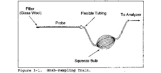

| Time | Traverse point | Q (liter/min) | % Deviationa |
|---|---|---|---|
| Average |
Figure 3-3. Sampling Rate Data
Method 3A—Determination of Oxygen and Carbon Dioxide Concentrations in Emissions From Stationary Sources (Instrumental Analyzer Procedure)
1.0 Scope and Application
What is Method 3A?
Method 3A is a procedure for measuring oxygen (O2) and carbon dioxide (CO2) in stationary source emissions using a continuous instrumental analyzer. Quality assurance and quality control requirements are included to assure that you, the tester, collect data of known quality. You must document your adherence to these specific requirements for equipment, supplies, sample collection and analysis, calculations, and data analysis.
This method does not completely describe all equipment, supplies, and sampling and analytical procedures you will need but refers to other methods for some of the details. Therefore, to obtain reliable results, you should also have a thorough knowledge of these additional test methods which are found in appendix A to this part:
(a) Method 1—Sample and Velocity Traverses for Stationary Sources.
(b) Method 3—Gas Analysis for the Determination of Molecular Weight.
(c) Method 4—Determination of Moisture Content in Stack Gases.
(d) Method 7E—Determination of Nitrogen Oxides Emissions from Stationary Sources (Instrumental Analyzer Procedure).
1.1 Analytes. What does this method determine? This method measures the concentration of oxygen and carbon dioxide.
| Analyte | CAS No. | Sensitivity |
|---|---|---|
| Oxygen (O2) | 7782-44-7 | Typically <2% of Calibration Span. |
| Carbon dioxide (CO2) | 124-38-9 | Typically <2% of Calibration Span. |
1.2 Applicability. When is this method required? The use of Method 3A may be required by specific New Source Performance Standards, Clean Air Marketing rules, State Implementation Plans and permits, where measurements of O2 and CO2 concentrations in stationary source emissions must be made, either to determine compliance with an applicable emission standard or to conduct performance testing of a continuous emission monitoring system (CEMS). Other regulations may also require the use of Method 3A.
1.3 Data Quality Objectives. How good must my collected data be? Refer to section 1.3 of Method 7E.
2.0 Summary of Method
In this method, you continuously or intermittently sample the effluent gas and convey the sample to an analyzer that measures the concentration of O2 or CO2. You must meet the performance requirements of this method to validate your data.
3.0 Definitions
Refer to section 3.0 of Method 7E for the applicable definitions.
4.0 Interferences [Reserved]
5.0 Safety
Refer to section 5.0 of Method 7E.
6.0 Equipment and Supplies
Figure 7E-1 in Method 7E is a schematic diagram of an acceptable measurement system.
6.1 What do I need for the measurement system? The components of the measurement system are described (as applicable) in sections 6.1 and 6.2 of Method 7E, except that the analyzer described in section 6.2 of this method must be used instead of the analyzer described in Method 7E. You must follow the noted specifications in section 6.1 of Method 7E except that the requirements to use stainless steel, Teflon, or non-reactive glass filters do not apply. Also, a heated sample line is not required to transport dry gases or for systems that measure the O2 or CO2 concentration on a dry basis, provided that the system is not also being used to concurrently measure SO2 and/or NOX.
6.2 What analyzer must I use? You must use an analyzer that continuously measures O2 or CO2 in the gas stream and meets the specifications in section 13.0.
7.0 Reagents and Standards
7.1 Calibration Gas. What calibration gases do I need? Refer to Section 7.1 of Method 7E for the calibration gas requirements. Example calibration gas mixtures are listed below. Pre-cleaned or scrubbed air may be used for the O2 high-calibration gas provided it does not contain other gases that interfere with the O2 measurement.
(a) CO2 in Nitrogen (N2).
(b) CO2/SO2 gas mixture in N2.
(c) O2/SO2 gas mixture in N2.
(d) O2/CO2/SO2 gas mixture in N2.
(e) CO2/NOX gas mixture in N2.
(f) CO2/SO2/NOX gas mixture in N2.
The tests for analyzer calibration error and system bias require high-, mid-, and low-level gases.
7.2 Interference Check. What reagents do I need for the interference check? Potential interferences may vary among available analyzers. Table 7E-3 of Method 7E lists a number of gases that should be considered in conducting the interference test.
8.0 Sample Collection, Preservation, Storage, and Transport
8.1 Sampling Site and Sampling Points. You must follow the procedures of section 8.1 of Method 7E to determine the appropriate sampling points, unless you are using Method 3A only to determine the stack gas molecular weight and for no other purpose. In that case, you may use single-point integrated sampling as described in section 8.2.1 of Method 3. If the stratification test provisions in section 8.1.2 of Method 7E are used to reduce the number of required sampling points, the alternative acceptance criterion for 3-point sampling will be ±0.5 percent CO2 or O2, and the alternative acceptance criterion for single-point sampling will be ±0.3 percent CO2 or O2. In that case, you may use single-point integrated sampling as described in section 8.2.1 of Method 3.
8.2 Initial Measurement System Performance Tests. You must follow the procedures in section 8.2 of Method 7E. If a dilution-type measurement system is used, the special considerations in section 8.3 of Method 7E apply.
8.3 Interference Check. The O2 or CO2 analyzer must be documented to show that interference effects to not exceed 2.5 percent of the calibration span. The interference test in section 8.2.7 of Method 7E is a procedure that may be used to show this. The effects of all potential interferences at the concentrations encountered during testing must be addressed and documented. This testing and documentation may be done by the instrument manufacturer.
8.4 Sample Collection. You must follow the procedures in section 8.4 of Method 7E.
8.5 Post-Run System Bias Check and Drift Assessment. You must follow the procedures in section 8.5 of Method 7E.
9.0 Quality Control
Follow quality control procedures in section 9.0 of Method 7E.
10.0 Calibration and Standardization
Follow the procedures for calibration and standardization in section 10.0 of Method 7E.
11.0 Analytical Procedures
Because sample collection and analysis are performed together (see section 8), additional discussion of the analytical procedure is not necessary.
12.0 Calculations and Data Analysis
You must follow the applicable procedures for calculations and data analysis in section 12.0 of Method 7E, substituting percent O2 and percent CO2 for ppmv of NOX as appropriate.
13.0 Method Performance
The specifications for the applicable performance checks are the same as in section 13.0 of Method 7E except for the alternative specifications for system bias, drift, and calibration error. In these alternative specifications, replace the term “0.5 ppmv” with the term “0.5 percent O2” or “0.5 percent CO2” (as applicable).
14.0 Pollution Prevention [Reserved]
15.0 Waste Management [Reserved]
16.0 Alternative Procedures [Reserved]
17.0 References
1. “EPA Traceability Protocol for Assay and Certification of Gaseous Calibration Standards” September 1997 as amended, EPA-600/R-97/121.
18.0 Tables, Diagrams, Flowcharts, and Validation Data
Refer to section 18.0 of Method 7E.
Method 3B—Gas Analysis for the Determination of Emission Rate Correction Factor or Excess Air
This method does not include all of the specifications (e.g., equipment and supplies) and procedures (e.g., sampling) essential to its performance. Some material is incorporated by reference from other methods in this part. Therefore, to obtain reliable results, persons using this method should have a thorough knowledge of at least the following additional test methods: Method 1 and 3.
1.0 Scope and Application
1.1 Analytes.
| Analyte | CAS No. | Sensitivity |
|---|---|---|
| Oxygen (O2) | 7782-44-7 | 2,000 ppmv. |
| Carbon Dioxide (CO2) | 124-38-9 | 2,000 ppmv. |
| Carbon Monoxide (CO) | 630-08-0 | N/A. |
1.2 Applicability. This method is applicable for the determination of O2, CO2, and CO concentrations in the effluent from fossil-fuel combustion processes for use in excess air or emission rate correction factor calculations. Where compounds other than CO2, O2, CO, and nitrogen (N2) are present in concentrations sufficient to affect the results, the calculation procedures presented in this method must be modified, subject to the approval of the Administrator.
1.3 Other methods, as well as modifications to the procedure described herein, are also applicable for all of the above determinations. Examples of specific methods and modifications include:
(1) A multi-point sampling method using an Orsat analyzer to analyze individual grab samples obtained at each point, and
(2) a method using CO2 or O2 and stoichiometric calculations to determine excess air. These methods and modifications may be used, but are subject to the approval of the Administrator.
1.4 Data Quality Objectives. Adherence to the requirements of this method will enhance the quality of the data obtained from air pollutant sampling methods.
2.0 Summary of Method
2.1 A gas sample is extracted from a stack by one of the following methods:
(1) Single-point, grab sampling;
(2) single-point, integrated sampling; or
(3) multi-point, integrated sampling. The gas sample is analyzed for percent CO2, percent O2, and, if necessary, percent CO using an Orsat combustion gas analyzer.
3.0 Definitions [Reserved]
4.0 Interferences
4.1 Several compounds can interfere, to varying degrees, with the results of Orsat analyses. Compounds that interfere with CO2 concentration measurement include acid gases (e.g., sulfur dioxide, hydrogen chloride); compounds that interfere with O2 concentration measurement include unsaturated hydrocarbons (e.g., acetone, acetylene), nitrous oxide, and ammonia. Ammonia reacts chemically with the O2 absorbing solution, and when present in the effluent gas stream must be removed before analysis.
5.0 Safety
5.1 Disclaimer. This method may involve hazardous materials, operations, and equipment. This test method may not address all of the safety problems associated with its use. It is the responsibility of the user of this test method to establish appropriate safety and health practices and determine the applicability of regulatory limitations prior to performing this test method.
5.2 Corrosive Reagents. A typical Orsat analyzer requires four reagents: a gas-confining solution, CO2 absorbent, O2 absorbent, and CO absorbent. These reagents may contain potassium hydroxide, sodium hydroxide, cuprous chloride, cuprous sulfate, alkaline pyrogallic acid, and/or chromous chloride. Follow manufacturer's operating instructions and observe all warning labels for reagent use.
6.0 Equipment and Supplies
As an alternative to the sampling apparatus and systems described herein, other sampling systems (e.g., liquid displacement) may be used, provided such systems are capable of obtaining a representative sample and maintaining a constant sampling rate, and are, otherwise, capable of yielding acceptable results. Use of such systems is subject to the approval of the Administrator.
6.1 Grab Sampling and Integrated Sampling. Same as in sections 6.1 and 6.2, respectively for Method 3.
6.2 Analysis. An Orsat analyzer only. For low CO2 (less than 4.0 percent) or high O2 (greater than 15.0 percent) concentrations, the measuring burette of the Orsat must have at least 0.1 percent subdivisions. For Orsat maintenance and operation procedures, follow the instructions recommended by the manufacturer, unless otherwise specified herein.
7.0 Reagents and Standards
7.1 Reagents. Same as in Method 3, section 7.1.
7.2 Standards. Same as in Method 3, section 7.2.
8.0 Sample Collection, Preservation, Storage, and Transport
Each of the three procedures below shall be used only when specified in an applicable subpart of the standards. The use of these procedures for other purposes must have specific prior approval of the Administrator. A Fyrite-type combustion gas analyzer is not acceptable for excess air or emission rate correction factor determinations, unless approved by the Administrator. If both percent CO2 and percent O2 are measured, the analytical results of any of the three procedures given below may also be used for calculating the dry molecular weight (see Method 3).
8.1 Single-Point, Grab Sampling and Analytical Procedure.
8.1.1 The sampling point in the duct shall either be at the centroid of the cross section or at a point no closer to the walls than 1.0 m (3.3 ft), unless otherwise specified by the Administrator.
8.1.2 Set up the equipment as shown in Figure 3-1 of Method 3, making sure all connections ahead of the analyzer are tight. Leak-check the Orsat analyzer according to the procedure described in section 11.5 of Method 3. This leak-check is mandatory.
8.1.3 Place the probe in the stack, with the tip of the probe positioned at the sampling point; purge the sampling line long enough to allow at least five exchanges. Draw a sample into the analyzer. For emission rate correction factor determinations, immediately analyze the sample for percent CO2 or percent O2, as outlined in section 11.2. For excess air determination, immediately analyze the sample for percent CO2, O2, and CO, as outlined in section 11.2, and calculate excess air as outlined in section 12.2.
8.1.4 After the analysis is completed, leak-check (mandatory) the Orsat analyzer once again, as described in section 11.5 of Method 3. For the results of the analysis to be valid, the Orsat analyzer must pass this leak-test before and after the analysis.
8.2 Single-Point, Integrated Sampling and Analytical Procedure.
8.2.1 The sampling point in the duct shall be located as specified in section 8.1.1.
8.2.2 Leak-check (mandatory) the flexible bag as in section 6.2.6 of Method 3. Set up the equipment as shown in Figure 3-2 of Method 3. Just before sampling, leak-check (mandatory) the train by placing a vacuum gauge at the condenser inlet, pulling a vacuum of at least 250 mm Hg (10 in. Hg), plugging the outlet at the quick disconnect, and then turning off the pump. The vacuum should remain stable for at least 0.5 minute. Evacuate the flexible bag. Connect the probe, and place it in the stack, with the tip of the probe positioned at the sampling point; purge the sampling line. Next, connect the bag, and make sure that all connections are tight.
8.2.3 Sample at a constant rate, or as specified by the Administrator. The sampling run must be simultaneous with, and for the same total length of time as, the pollutant emission rate determination. Collect at least 28 liters (1.0 ft3) of sample gas. Smaller volumes may be collected, subject to approval of the Administrator.
8.2.4 Obtain one integrated flue gas sample during each pollutant emission rate determination. For emission rate correction factor determination, analyze the sample within 4 hours after it is taken for percent CO2 or percent O2 (as outlined in section 11.2).
8.3 Multi-Point, Integrated Sampling and Analytical Procedure.
8.3.1 Unless otherwise specified in an applicable regulation, or by the Administrator, a minimum of eight traverse points shall be used for circular stacks having diameters less than 0.61 m (24 in.), a minimum of nine shall be used for rectangular stacks having equivalent diameters less than 0.61 m (24 in.), and a minimum of 12 traverse points shall be used for all other cases. The traverse points shall be located according to Method 1.
8.3.2 Follow the procedures outlined in sections 8.2.2 through 8.2.4, except for the following: Traverse all sampling points, and sample at each point for an equal length of time. Record sampling data as shown in Figure 3-3 of Method 3.
9.0 Quality Control
9.1 Data Validation Using Fuel Factor. Although in most instances, only CO2 or O2 measurement is required, it is recommended that both CO2 and O2 be measured to provide a check on the quality of the data. The data validation procedure of section 12.3 is suggested.
Since this method for validating the CO2 and O2 analyses is based on combustion of organic and fossil fuels and dilution of the gas stream with air, this method does not apply to sources that (1) remove CO2 or O2 through processes other than combustion, (2) add O2 (e.g., oxygen enrichment) and N2 in proportions different from that of air, (3) add CO2 (e.g., cement or lime kilns), or (4) have no fuel factor, FO, values obtainable (e.g., extremely variable waste mixtures). This method validates the measured proportions of CO2 and O2 for fuel type, but the method does not detect sample dilution resulting from leaks during or after sample collection. The method is applicable for samples collected downstream of most lime or limestone flue-gas desulfurization units as the CO2 added or removed from the gas stream is not significant in relation to the total CO2 concentration. The CO2 concentrations from other types of scrubbers using only water or basic slurry can be significantly affected and would render the fuel factor check minimally useful.
10.0 Calibration and Standardization
10.1 Analyzer. The analyzer and analyzer operator technique should be audited periodically as follows: take a sample from a manifold containing a known mixture of CO2 and O2, and analyze according to the procedure in section 11.3. Repeat this procedure until the measured concentration of three consecutive samples agrees with the stated value ±0.5 percent. If necessary, take corrective action, as specified in the analyzer users manual.
10.2 Rotameter. The rotameter need not be calibrated, but should be cleaned and maintained according to the manufacturer's instruction.
11.0 Analytical Procedure
11.1 Maintenance. The Orsat analyzer should be maintained according to the manufacturers specifications.
11.2 Grab Sample Analysis. To ensure complete absorption of the CO2, O2, or if applicable, CO, make repeated passes through each absorbing solution until two consecutive readings are the same. Several passes (three or four) should be made between readings. (If constant readings cannot be obtained after three consecutive readings, replace the absorbing solution.) Although in most cases, only CO2 or O2 concentration is required, it is recommended that both CO2 and O2 be measured, and that the procedure in section 12.3 be used to validate the analytical data.
Since this single-point, grab sampling and analytical procedure is normally conducted in conjunction with a single-point, grab sampling and analytical procedure for a pollutant, only one analysis is ordinarily conducted. Therefore, great care must be taken to obtain a valid sample and analysis.
11.3 Integrated Sample Analysis. The Orsat analyzer must be leak-checked (see section 11.5 of Method 3) before the analysis. If excess air is desired, proceed as follows: (1) within 4 hours after the sample is taken, analyze it (as in sections 11.3.1 through 11.3.3) for percent CO2, O2, and CO; (2) determine the percentage of the gas that is N2 by subtracting the sum of the percent CO2, percent O2, and percent CO from 100 percent; and (3) calculate percent excess air, as outlined in section 12.2.
11.3.1 To ensure complete absorption of the CO2, O2, or if applicable, CO, follow the procedure described in section 11.2.
Although in most instances only CO2 or O2 is required, it is recommended that both CO2 and O2 be measured, and that the procedures in section 12.3 be used to validate the analytical data.
11.3.2 Repeat the analysis until the following criteria are met:
11.3.2.1 For percent CO2, repeat the analytical procedure until the results of any three analyses differ by no more than
(a) 0.3 percent by volume when CO2 is greater than 4.0 percent or
(b) 0.2 percent by volume when CO2 is less than or equal to 4.0 percent. Average three acceptable values of percent CO2, and report the results to the nearest 0.2 percent.
11.3.2.2 For percent O2, repeat the analytical procedure until the results of any three analyses differ by no more than
(a) 0.3 percent by volume when O2 is less than 15.0 percent or
(b) 0.2 percent by volume when O2 is greater than or equal to 15.0 percent. Average the three acceptable values of percent O2, and report the results to the nearest 0.1 percent.
11.3.2.3 For percent CO, repeat the analytical procedure until the results of any three analyses differ by no more than 0.3 percent. Average the three acceptable values of percent CO, and report the results to the nearest 0.1 percent.
11.3.3 After the analysis is completed, leak-check (mandatory) the Orsat analyzer once again, as described in section 11.5 of Method 3. For the results of the analysis to be valid, the Orsat analyzer must pass this leak-test before and after the analysis.
11.4 Standardization. A periodic check of the reagents and of operator technique should be conducted at least once every three series of test runs as indicated in section 10.1.
12.0 Calculations and Data Analysis
12.1 Nomenclature. Same as section 12.1 of Method 3 with the addition of the following:
%EA = Percent excess air.
0.264 = Ratio of O2 to N2 in air, v/v.
12.2 Percent Excess Air. Determine the percentage of the gas that is N2 by subtracting the sum of the percent CO2, percent CO, and percent O2 from 100 percent. Calculate the percent excess air (if applicable) by substituting the appropriate values of percent O2, CO, and N2 into Equation 3B-1.

The equation above assumes that ambient air is used as the source of O2 and that the fuel does not contain appreciable amounts of N2 (as do coke oven or blast furnace gases). For those cases when appreciable amounts of N2 are present (coal, oil, and natural gas do not contain appreciable amounts of N2) or when oxygen enrichment is used, alternative methods, subject to approval of the Administrator, are required.
12.3 Data Validation When Both CO2 and O2 Are Measured.
12.3.1 Fuel Factor, Fo. Calculate the fuel factor (if applicable) using Equation 3B-2:

Where:
%O2 = Percent O2 by volume, dry basis.
%CO2 = Percent CO2 by volume, dry basis.
20.9 = Percent O2 by volume in ambient air.
If CO is present in quantities measurable by this method, adjust the O2 and CO2 values using Equations 3B-3 and 3B-4 before performing the calculation for Fo:


Where:
%CO = Percent CO by volume, dry basis.
12.3.2 Compare the calculated Fo factor with the expected Fo values. Table 3B-1 in section 17.0 may be used in establishing acceptable ranges for the expected Fo if the fuel being burned is known. When fuels are burned in combinations, calculate the combined fuel Fd and Fc factors (as defined in Method 19, section 12.2) according to the procedure in Method 19, sections 12.2 and 12.3. Then calculate the Fo factor according to Equation 3B-5.

12.3.3 Calculated Fo values, beyond the acceptable ranges shown in this table, should be investigated before accepting the test results. For example, the strength of the solutions in the gas analyzer and the analyzing technique should be checked by sampling and analyzing a known concentration, such as air; the fuel factor should be reviewed and verified. An acceptability range of ±12 percent is appropriate for the Fo factor of mixed fuels with variable fuel ratios. The level of the emission rate relative to the compliance level should be considered in determining if a retest is appropriate; i.e., if the measured emissions are much lower or much greater than the compliance limit, repetition of the test would not significantly change the compliance status of the source and would be unnecessarily time consuming and costly.
13.0 Method Performance [Reserved]
14.0 Pollution Prevention [Reserved]
15.0 Waste Management [Reserved]
16.0 References
Same as Method 3, section 16.0.
17.0 Tables, Diagrams, Flowcharts, and Validation Data
Table 3B-1—Fo Factors for Selected Fuels
| Fuel type | Fo range |
|---|---|
| Coal: | |
| Anthracite and lignite | 1.016-1.130 |
| Bituminous | 1.083-1.230 |
| Oil: | |
| Distillate | 1.260-1.413 |
| Residual | 1.210-1.370 |
| Gas: | |
| Natural | 1.600-1.836 |
| Propane | 1.434-1.586 |
| Butane | 1.405-1.553 |
| Wood | 1.000-1.120 |
| Wood bark | 1.003-1.130 |
Method 3C—Determination of Carbon Dioxide, Methane, Nitrogen, and Oxygen From Stationary Sources
1. Applicability and Principle
1.1 Applicability. This method applies to the analysis of carbon dioxide (CO2), methane (CH4), nitrogen (N2), and oxygen (O2) in samples from municipal solid waste landfills and other sources when specified in an applicable subpart.
1.2 Principle. A portion of the sample is injected into a gas chromatograph (GC) and the CO2, CH4, N2, and O2 concentrations are determined by using a thermal conductivity detector (TCD) and integrator.
2. Range and Sensitivity
2.1 Range. The range of this method depends upon the concentration of samples. The analytical range of TCD's is generally between approximately 10 ppmv and the upper percent range.
2.2 Sensitivity. The sensitivity limit for a compound is defined as the minimum detectable concentration of that compound, or the concentration that produces a signal-to-noise ratio of three to one. For CO2, CH4, N2, and O2, the sensitivity limit is in the low ppmv range.
3. Interferences
Since the TCD exhibits universal response and detects all gas components except the carrier, interferences may occur. Choosing the appropriate GC or shifting the retention times by changing the column flow rate may help to eliminate resolution interferences.
To assure consistent detector response, helium is used to prepare calibration gases. Frequent exposure to samples or carrier gas containing oxygen may gradually destroy filaments.
4. Apparatus
4.1 Gas Chromatograph. GC having at least the following components:
4.1.1 Separation Column. Appropriate column(s) to resolve CO2, CH4, N2, O2, and other gas components that may be present in the sample.
4.1.2 Sample Loop. Teflon or stainless steel tubing of the appropriate diameter.
Mention of trade names or specific products does not constitute endorsement or recommendation by the U. S. Environmental Protection Agency.
4.1.3 Conditioning System. To maintain the column and sample loop at constant temperature.
4.1.4 Thermal Conductivity Detector.
4.2 Recorder. Recorder with linear strip chart. Electronic integrator (optional) is recommended.
4.3 Teflon Tubing. Diameter and length determined by connection requirements of cylinder regulators and the GC.
4.4 Regulators. To control gas cylinder pressures and flow rates.
4.5 Adsorption Tubes. Applicable traps to remove any O2 from the carrier gas.
5. Reagents
5.1 Calibration and Linearity Gases. Standard cylinder gas mixtures for each compound of interest with at least three concentration levels spanning the range of suspected sample concentrations. The calibration gases shall be prepared in helium.
5.2 Carrier Gas. Helium, high-purity.
6. Analysis
6.1 Sample Collection. Use the sample collection procedures described in Methods 3 or 25C to collect a sample of landfill gas (LFG).
6.2 Preparation of GC. Before putting the GC analyzer into routine operation, optimize the operational conditions according to the manufacturer's specifications to provide good resolution and minimum analysis time. Establish the appropriate carrier gas flow and set the detector sample and reference cell flow rates at exactly the same levels. Adjust the column and detector temperatures to the recommended levels. Allow sufficient time for temperature stabilization. This may typically require 1 hour for each change in temperature.
6.3 Analyzer Linearity Check and Calibration. Perform this test before sample analysis.
6.3.1 Using the gas mixtures in section 5.1, verify the detector linearity over the range of suspected sample concentrations with at least three concentrations per compound of interest. This initial check may also serve as the initial instrument calibration.
6.3.2 You may extend the use of the analyzer calibration by performing a single-point calibration verification. Calibration verifications shall be performed by triplicate injections of a single-point standard gas. The concentration of the single-point calibration must either be at the midpoint of the calibration curve or at approximately the source emission concentration measured during operation of the analyzer.
6.3.3 Triplicate injections must agree within 5 percent of their mean, and the average calibration verification point must agree within 10 percent of the initial calibration response factor. If these calibration verification criteria are not met, the initial calibration described in section 6.3.1, using at least three concentrations, must be repeated before analysis of samples can continue.
6.3.4 For each instrument calibration, record the carrier and detector flow rates, detector filament and block temperatures, attenuation factor, injection time, chart speed, sample loop volume, and component concentrations.
6.3.5 Plot a linear regression of the standard concentrations versus area values to obtain the response factor of each compound. Alternatively, response factors of uncorrected component concentrations (wet basis) may be generated using instrumental integration.
Peak height may be used instead of peak area throughout this method.
6.4 Sample Analysis. Purge the sample loop with sample, and allow to come to atmospheric pressure before each injection. Analyze each sample in duplicate, and calculate the average sample area (A). The results are acceptable when the peak areas for two consecutive injections agree within 5 percent of their average. If they do not agree, run additional samples until consistent area data are obtained. Determine the tank sample concentrations according to section 7.2.
7. Calculations
Carry out calculations retaining at least one extra decimal figure beyond that of the acquired data. Round off results only after the final calculation.
7.1 Nomenclature.
Bw = Moisture content in the sample, fraction.
CN2 = Measured N2 concentration (by Method 3C), fraction.
CN2Corr = Measured N2 concentration corrected only for dilution, fraction.
Ct = Calculated NMOC concentration, ppmv C equivalent.
Ctm = Measured NMOC concentration, ppmv C equivalent.
Pb = Barometric pressure, mm Hg.
Pt = Gas sample tank pressure after sampling, but before pressurizing, mm Hg absolute.
Ptf = Final gas sample tank pressure after pressurizing, mm Hg absolute.
Pti = Gas sample tank pressure after evacuation, mm Hg absolute.
Pw = Vapor pressure of H2O (from Table 25C-1), mm Hg.
r = Total number of analyzer injections of sample tank during analysis (where j = injection number, 1 . . . r).
R = Mean calibration response factor for specific sample component, area/ppm.
Tt = Sample tank temperature at completion of sampling, °K.
Tti = Sample tank temperature before sampling, °K.
Ttf = Sample tank temperature after pressurizing, °K.
7.2 Concentration of Sample Components. Calculate C for each compound using Equations 3C-1 and 3C-2. Use the temperature and barometric pressure at the sampling site to calculate Bw. If the sample was diluted with helium using the procedures in Method 25C, use Equation 3C-3 to calculate the concentration.

7.3 Measured N2 Concentration Correction. Calculate the reported N2 correction for Method 25-C using Eq. 3C-4. If oxygen is determined in place of N2, substitute the oxygen concentration for the nitrogen concentration in the equation.
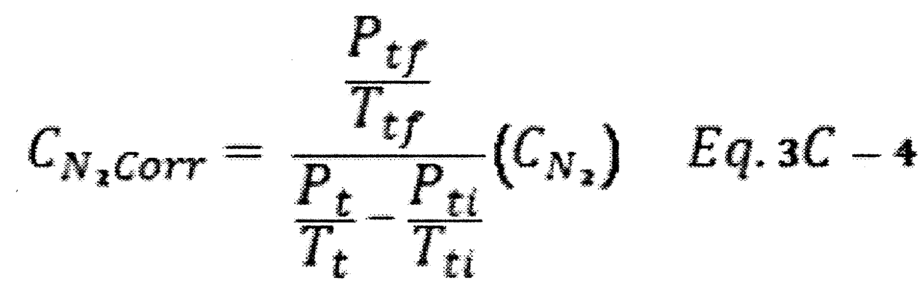
8. Bibliography
1. McNair, H.M., and E.J. Bonnelli. Basic Gas Chromatography. Consolidated Printers, Berkeley, CA. 1969.
[36 FR 24877, Dec. 23, 1971]
Appendix A-3 to Part 60 - Test Methods 4 through 5I
Method 4 - Determination of moisture content in stack gases
Method 5 - Determination of particulate matter emissions from stationary sources
Method 5A - Determination of particulate matter emissions from the asphalt processing and asphalt roofing industry
Method 5B - Determination of nonsulfuric acid particulate matter emissions from stationary sources
Method 5C [Reserved]
Method 5D - Determination of particulate matter emissions from positive pressure fabric filters
Method 5E - Determination of particulate matter emissions from the wool fiberglass insulation manufacturing industry
Method 5F - Determination of nonsulfate particulate matter emissions from stationary sources
Method 5G - Determination of particulate matter emissions from wood heaters (dilution tunnel sampling location)
Method 5H - Determination of particulate emissions from wood heaters from a stack location
Method 5I - Determination of Low Level Particulate Matter Emissions From Stationary Sources
The test methods in this appendix are referred to in § 60.8 (Performance Tests) and § 60.11 (Compliance With Standards and Maintenance Requirements) of 40 CFR part 60, subpart A (General Provisions). Specific uses of these test methods are described in the standards of performance contained in the subparts, beginning with Subpart D.
Within each standard of performance, a section title “Test Methods and Procedures” is provided to: (1) Identify the test methods to be used as reference methods to the facility subject to the respective standard and (2) identify any special instructions or conditions to be followed when applying a method to the respective facility. Such instructions (for example, establish sampling rates, volumes, or temperatures) are to be used either in addition to, or as a substitute for procedures in a test method. Similarly, for sources subject to emission monitoring requirements, specific instructions pertaining to any use of a test method as a reference method are provided in the subpart or in Appendix B.
Inclusion of methods in this appendix is not intended as an endorsement or denial of their applicability to sources that are not subject to standards of performance. The methods are potentially applicable to other sources; however, applicability should be confirmed by careful and appropriate evaluation of the conditions prevalent at such sources.
The approach followed in the formulation of the test methods involves specifications for equipment, procedures, and performance. In concept, a performance specification approach would be preferable in all methods because this allows the greatest flexibility to the user. In practice, however, this approach is impractical in most cases because performance specifications cannot be established. Most of the methods described herein, therefore, involve specific equipment specifications and procedures, and only a few methods in this appendix rely on performance criteria.
Minor changes in the test methods should not necessarily affect the validity of the results and it is recognized that alternative and equivalent methods exist. section 60.8 provides authority for the Administrator to specify or approve (1) equivalent methods, (2) alternative methods, and (3) minor changes in the methodology of the test methods. It should be clearly understood that unless otherwise identified all such methods and changes must have prior approval of the Administrator. An owner employing such methods or deviations from the test methods without obtaining prior approval does so at the risk of subsequent disapproval and retesting with approved methods.
Within the test methods, certain specific equipment or procedures are recognized as being acceptable or potentially acceptable and are specifically identified in the methods. The items identified as acceptable options may be used without approval but must be identified in the test report. The potentially approvable options are cited as “subject to the approval of the Administrator” or as “or equivalent.” Such potentially approvable techniques or alternatives may be used at the discretion of the owner without prior approval. However, detailed descriptions for applying these potentially approvable techniques or alternatives are not provided in the test methods. Also, the potentially approvable options are not necessarily acceptable in all applications. Therefore, an owner electing to use such potentially approvable techniques or alternatives is responsible for: (1) assuring that the techniques or alternatives are in fact applicable and are properly executed; (2) including a written description of the alternative method in the test report (the written method must be clear and must be capable of being performed without additional instruction, and the degree of detail should be similar to the detail contained in the test methods); and (3) providing any rationale or supporting data necessary to show the validity of the alternative in the particular application. Failure to meet these requirements can result in the Administrator's disapproval of the alternative.
Method 4 - Determination of Moisture Content in Stack Gases
This method does not include all the specifications (e.g., equipment and supplies) and procedures (e.g., sampling) essential to its performance. Some material is incorporated by reference from other methods in this part. Therefore, to obtain reliable results, persons using this method should have a thorough knowledge of at least the following additional test methods: Method 1, Method 5, and Method 6.
1.0 Scope and Application
1.1 Analytes.
| Analyte | CAS No. | Sensitivity |
|---|---|---|
| Water vapor (H2O) | 7732-18-5 | N/A |
1.2 Applicability. This method is applicable for the determination of the moisture content of stack gas.
1.3 Data Quality Objectives. Adherence to the requirements of this method will enhance the quality of the data obtained from air pollutant sampling methods.
2.0 Summary of Method
2.1 A gas sample is extracted at a constant rate from the source; moisture is removed from the sample stream and determined gravimetrically.
2.2 The method contains two possible procedures: a reference method and an approximation method.
2.2.1 The reference method is used for accurate determinations of moisture content (such as are needed to calculate emission data). The approximation method, provides estimates of percent moisture to aid in setting isokinetic sampling rates prior to a pollutant emission measurement run. The approximation method described herein is only a suggested approach; alternative means for approximating the moisture content (e.g., drying tubes, wet bulb-dry bulb techniques, condensation techniques, stoichiometric calculations, previous experience, etc.) are also acceptable.
2.2.2 The reference method is often conducted simultaneously with a pollutant emission measurement run. When it is, calculation of percent isokinetic, pollutant emission rate, etc., for the run shall be based upon the results of the reference method or its equivalent. These calculations shall not be based upon the results of the approximation method, unless the approximation method is shown, to the satisfaction of the Administrator, to be capable of yielding results within one percent H2O of the reference method.
3.0 Definitions [Reserved]
4.0 Interferences
4.1 The moisture content of saturated gas streams or streams that contain water droplets, as measured by the reference method, may be positively biased. Therefore, when these conditions exist or are suspected, a second determination of the moisture content shall be made simultaneously with the reference method, as follows: Assume that the gas stream is saturated. Attach a temperature sensor [capable of measuring to ±1 °C (2 °F)] to the reference method probe. Measure the stack gas temperature at each traverse point (see section 8.1.1.1) during the reference method traverse, and calculate the average stack gas temperature. Next, determine the moisture percentage, either by:
(1) Using a psychrometric chart and making appropriate corrections if the stack pressure is different from that of the chart, or
(2) using saturation vapor pressure tables. In cases where the psychrometric chart or the saturation vapor pressure tables are not applicable (based on evaluation of the process), alternative methods, subject to the approval of the Administrator, shall be used.
5.0 Safety
5.1 Disclaimer. This method may involve hazardous materials, operations, and equipment. This test method may not address all of the safety problems associated with its use. It is the responsibility of the user of this test method to establish appropriate safety and health practices and determine the applicability of regulatory limitations prior to performing this test method.
6.0 Equipment and Supplies
6.1 Reference Method. A schematic of the sampling train used in this reference method is shown in Figure 4-1.
6.1.1 Probe. Stainless steel or glass tubing, sufficiently heated to prevent water condensation, and equipped with a filter, either in-stack (e.g., a plug of glass wool inserted into the end of the probe) or heated out-of-stack (e.g., as described in Method 5), to remove particulate matter. When stack conditions permit, other metals or plastic tubing may be used for the probe, subject to the approval of the Administrator.
6.1.2 Condenser. Same as Method 5, section 6.1.1.8.
6.1.3 Cooling System. An ice bath container, crushed ice, and water (or equivalent), to aid in condensing moisture.
6.1.4 Metering System. Same as in Method 5, section 6.1.1.9, except do not use sampling systems designed for flow rates higher than 0.0283 m3/min (1.0 cfm). Other metering systems, capable of maintaining a constant sampling rate to within 10 percent and determining sample gas volume to within 2 percent, may be used, subject to the approval of the Administrator.
6.1.5 Barometer and Balance. Same as Method 5, sections 6.1.2 and 6.2.5, respectively.
6.2. Approximation Method. A schematic of the sampling train used in this approximation method is shown in Figure 4-2.
6.2.1 Probe. Same as section 6.1.1.
6.2.2 Condenser. Two midget impingers, each with 30-ml capacity, or equivalent.
6.2.3 Cooling System. Ice bath container, crushed ice, and water, to aid in condensing moisture in impingers.
6.2.4 Drying Tube. Tube packed with new or regenerated 6- to 16-mesh indicating-type silica gel (or equivalent desiccant), to dry the sample gas and to protect the meter and pump.
6.2.5 Valve. Needle valve, to regulate the sample gas flow rate.
6.2.6 Pump. Leak-free, diaphragm type, or equivalent, to pull the gas sample through the train.
6.2.7 Volume Meter. Dry gas meter, sufficiently accurate to measure the sample volume to within 2 percent, and calibrated over the range of flow rates and conditions actually encountered during sampling.
6.2.8 Rate Meter. Rotameter, or equivalent, to measure the flow range from 0 to 3 liters/min (0 to 0.11 cfm).
6.2.9 Graduated Cylinder. 25-ml.
6.2.10 Barometer. Same as Method 5, section 6.1.2.
6.2.11 Vacuum Gauge. At least 760-mm (30-in.) Hg gauge, to be used for the sampling leak check.
7.0 Reagents and Standards [Reserved]
8.0 Sample Collection, Preservation, Transport, and Storage
8.1 Reference Method. The following procedure is intended for a condenser system (such as the impinger system described in section 6.1.1.8 of Method 5) incorporating volumetric analysis to measure the condensed moisture, and silica gel and gravimetric analysis to measure the moisture leaving the condenser.
8.1.1 Preliminary Determinations.
8.1.1.1 Unless otherwise specified by the Administrator, a minimum of eight traverse points shall be used for circular stacks having diameters less than 0.61 m (24 in.), a minimum of nine points shall be used for rectangular stacks having equivalent diameters less than 0.61 m (24 in.), and a minimum of twelve traverse points shall be used in all other cases. The traverse points shall be located according to Method 1. The use of fewer points is subject to the approval of the Administrator. Select a suitable probe and probe length such that all traverse points can be sampled. Consider sampling from opposite sides of the stack (four total sampling ports) for large stacks, to permit use of shorter probe lengths. Mark the probe with heat resistant tape or by some other method to denote the proper distance into the stack or duct for each sampling point.
8.1.1.2 Select a total sampling time such that a minimum total gas volume of 0.60 scm (21 scf) will be collected, at a rate no greater than 0.021 m3/min (0.75 cfm). When both moisture content and pollutant emission rate are to be determined, the moisture determination shall be simultaneous with, and for the same total length of time as, the pollutant emission rate run, unless otherwise specified in an applicable subpart of the standards.
8.1.2 Preparation of Sampling Train.
8.1.2.1 Transfer water into the first two impingers, leave the third impinger empty and add silica gel to the fourth impinger. Weigh the impingers before sampling and record the weight to the nearest 0.5g at a minimum.
8.1.2.2 Set up the sampling train as shown in Figure 4-1. Turn on the probe heater and (if applicable) the filter heating system to temperatures of approximately 120 °C (248 °F), to prevent water condensation ahead of the condenser. Allow time for the temperatures to stabilize. Place crushed ice and water in the ice bath container.
8.1.3 Leak-Check Procedures.
8.1.3.1 Leak Check of Metering System Shown in Figure 4-1. That portion of the sampling train from the pump to the orifice meter should be leak-checked prior to initial use and after each shipment. Leakage after the pump will result in less volume being recorded than is actually sampled. The following procedure is suggested (see Figure 5-2 of Method 5): Close the main valve on the meter box. Insert a one-hole rubber stopper with rubber tubing attached into the orifice exhaust pipe. Disconnect and vent the low side of the orifice manometer. Close off the low side orifice tap. Pressurize the system to 13 to 18 cm (5 to 7 in.) water column by blowing into the rubber tubing. Pinch off the tubing and observe the manometer for one minute. A loss of pressure on the manometer indicates a leak in the meter box; leaks, if present, must be corrected.
8.1.3.2 Pretest Leak Check. A pretest leak check of the sampling train is recommended, but not required. If the pretest leak check is conducted, the following procedure should be used.
8.1.3.2.1 After the sampling train has been assembled, turn on and set the filter and probe heating systems to the desired operating temperatures. Allow time for the temperatures to stabilize.
8.1.3.2.2 Leak-check the train by first plugging the inlet to the filter holder and pulling a 380 mm (15 in.) Hg vacuum. Then connect the probe to the train, and leak-check at approximately 25 mm (1 in.) Hg vacuum; alternatively, the probe may be leak-checked with the rest of the sampling train, in one step, at 380 mm (15 in.) Hg vacuum. Leakage rates in excess of 4 percent of the average sampling rate or 0.00057 m3/min (0.020 cfm), whichever is less, are unacceptable.
8.1.3.2.3 Start the pump with the bypass valve fully open and the coarse adjust valve completely closed. Partially open the coarse adjust valve, and slowly close the bypass valve until the desired vacuum is reached. Do not reverse the direction of the bypass valve, as this will cause water to back up into the filter holder. If the desired vacuum is exceeded, either leak-check at this higher vacuum, or end the leak check and start over.
8.1.3.2.4 When the leak check is completed, first slowly remove the plug from the inlet to the probe, filter holder, and immediately turn off the vacuum pump. This prevents the water in the impingers from being forced backward into the filter holder and the silica gel from being entrained backward into the third impinger.
8.1.3.3 Leak Checks During Sample Run. If, during the sampling run, a component (e.g., filter assembly or impinger) change becomes necessary, a leak check shall be conducted immediately before the change is made. The leak check shall be done according to the procedure outlined in section 8.1.3.2, except that it shall be done at a vacuum equal to or greater than the maximum value recorded up to that point in the test. If the leakage rate is found to be no greater than 0.00057 m3/min (0.020 cfm) or 4 percent of the average sampling rate (whichever is less), the results are acceptable, and no correction will need to be applied to the total volume of dry gas metered; if, however, a higher leakage rate is obtained, either record the leakage rate and plan to correct the sample volume as shown in section 12.3 of Method 5, or void the sample run.
Note: Immediately after component changes, leak checks are optional. If such leak checks are done, the procedure outlined in section 8.1.3.2 should be used.
8.1.3.4 Post-Test Leak Check. A leak check of the sampling train is mandatory at the conclusion of each sampling run. The leak check shall be performed in accordance with the procedures outlined in section 8.1.3.2, except that it shall be conducted at a vacuum equal to or greater than the maximum value reached during the sampling run. If the leakage rate is found to be no greater than 0.00057 m3 min (0.020 cfm) or 4 percent of the average sampling rate (whichever is less), the results are acceptable, and no correction need be applied to the total volume of dry gas metered. If, however, a higher leakage rate is obtained, either record the leakage rate and correct the sample volume as shown in section 12.3 of Method 5 or void the sampling run.
8.1.4 Sampling Train Operation. During the sampling run, maintain a sampling rate within 10 percent of constant rate, or as specified by the Administrator. For each run, record the data required on a data sheet similar to that shown in Figure 4-3. Be sure to record the dry gas meter reading at the beginning and end of each sampling time increment and whenever sampling is halted. Take other appropriate readings at each sample point at least once during each time increment.
When Method 4 is used concurrently with an isokinetic method (e.g., Method 5) the sampling rate should be maintained at isokinetic conditions rather than 10 percent of constant rate.
8.1.4.1 To begin sampling, position the probe tip at the first traverse point. Immediately start the pump, and adjust the flow to the desired rate. Traverse the cross section, sampling at each traverse point for an equal length of time. Add more ice and, if necessary, salt to maintain a temperature of less than 20 °C (68 °F) at the silica gel outlet.
8.1.4.2 At the end of the sample run, close the coarse adjust valve, remove the probe and nozzle from the stack, turn off the pump, record the final DGM meter reading, and conduct a post-test leak check, as outlined in section 8.1.3.4.
8.2 Approximation Method.
The approximation method described below is presented only as a suggested method (see section 2.0).
8.2.1 Place exactly 5 ml water in each impinger. Leak check the sampling train as follows: Temporarily insert a vacuum gauge at or near the probe inlet. Then, plug the probe inlet and pull a vacuum of at least 250 mm (10 in.) Hg. Note the time rate of change of the dry gas meter dial; alternatively, a rotameter (0 to 40 ml/min) may be temporarily attached to the dry gas meter outlet to determine the leakage rate. A leak rate not in excess of 2 percent of the average sampling rate is acceptable.
Release the probe inlet plug slowly before turning off the pump.
8.2.2 Connect the probe, insert it into the stack, and sample at a constant rate of 2 liters/min (0.071 cfm). Continue sampling until the dry gas meter registers about 30 liters (1.1 ft3) or until visible liquid droplets are carried over from the first impinger to the second. Record temperature, pressure, and dry gas meter readings as indicated by Figure 4-4.
9.0 Quality Control
9.1 Miscellaneous Quality Control Measures.
| Section | Quality control measure | Effect |
|---|---|---|
| Section 8.1.3.2.2 | Leak rate of the sampling system cannot exceed four percent of the average sampling rate or 0.00057 m3/min (0.020 cfm) | Ensures the accuracy of the volume of gas sampled. (Reference Method). |
| Section 8.2.1 | Leak rate of the sampling system cannot exceed two percent of the average sampling rate | Ensures the accuracy of the volume of gas sampled. (Approximation Method). |
9.2 Volume Metering System Checks. Same as Method 5, section 9.2.
10.0 Calibration and Standardization
Maintain a laboratory log of all calibrations.
10.1 Reference Method. Calibrate the metering system, temperature sensors, and barometer according to Method 5, sections 10.3, 10.5, and 10.6, respectively.
10.2 Approximation Method. Calibrate the metering system and the barometer according to Method 6, section 10.1 and Method 5, section 10.6, respectively.
10.3 Field Balance Calibration Check. Check the calibration of the balance used to weigh impingers with a weight that is at least 500g or within 50g of a loaded impinger. The weight must be ASTM E617-13 “Standard Specification for Laboratory Weights and Precision Mass Standards” (incorporated by reference-see 40 CFR 60.17) Class 6 (or better). Daily, before use, the field balance must measure the weight within ± 0.5g of the certified mass. If the daily balance calibration check fails, perform corrective measures and repeat the check before using balance.
11.0 Analytical Procedure
11.1 Reference Method. Weigh the impingers after sampling and record the difference in weight to the nearest 0.5 g at a minimum. Determine the increase in weight of the silica gel (or silica gel plus impinger) to the nearest 0.5 g at a minimum. Record this information (see example data sheet, Figure 4-5), and calculate the moisture content, as described in section 12.0.
11.2 Approximation Method. Weigh the contents of the two impingers, and measure the weight to the nearest 0.5 g.
12.0 Data Analysis and Calculations
Carry out the following calculations, retaining at least one extra significant figure beyond that of the acquired data. Round off figures after final calculation.
12.1 Reference Method.
12.1.1 Nomenclature.
Bws = Proportion of water vapor, by volume, in the gas stream.
Mw = Molecular weight of water, 18.015 g/g-mole (18.015 lb/lb-mole).
Pm = Absolute pressure (for this method, same as barometric pressure) at the dry gas meter, mm Hg (in. Hg).
Pstd = Standard absolute pressure, 760 mm Hg (29.92 in. Hg).
R = Ideal gas constant, 0.06236 (mm Hg)(m3)/(g-mole)(°K) for metric units and 21.85 (in. Hg)(ft3)/(lb-mole) (°R) for English units.
Tm = Absolute temperature at meter, °K (°R).
Tstd = Standard absolute temperature, 293.15 °K (527.67 °R).
Vf = Final weight of condenser water plus impinger, g.
Vi = Initial weight, if any, of condenser water plus impinger, g.
Vm = Dry gas volume measured by dry gas meter, dcm (dcf).
Vm(std) = Dry gas volume measured by the dry gas meter, corrected to standard conditions, dscm (dscf).
Vwc(std) = Volume of water vapor condensed, corrected to standard conditions, scm (scf).
Vwsg(std) = Volume of water vapor collected in silica gel, corrected to standard conditions, scm (scf).
Wf = Final weight of silica gel or silica gel plus impinger, g.
Wi = Initial weight of silica gel or silica gel plus impinger, g.
Y = Dry gas meter calibration factor.
ΔVm = Incremental dry gas volume measured by dry gas meter at each traverse point, dcm (dcf).
12.1.2 Volume of Water Vapor Condensed.

Where:
K1 = 0.001335 m3/g for metric units,
= 0.04716 ft3/g for English units.
12.1.3 Volume of Water Collected in Silica Gel.

Where:
K3 = 0.001335 m3/g for metric units = 0.04716 ft3/g for English units.
12.1.4 Sample Gas Volume.

Where:
K4 = 0.3855 °K/mm Hg for metric units,
= 17.64 °R/in. Hg for English units.
If the post-test leak rate (Section 8.1.4.2) exceeds the allowable rate, correct the value of Vm in Equation 4-3, as described in section 12.3 of Method 5.
12.1.5 Moisture Content.

12.1.6 Verification of Constant Sampling Rate. For each time increment, determine the ΔVm. Calculate the average. If the value for any time increment differs from the average by more than 10 percent, reject the results, and repeat the run.
12.1.7 In saturated or moisture droplet-laden gas streams, two calculations of the moisture content of the stack gas shall be made, one using a value based upon the saturated conditions (see section 4.1), and another based upon the results of the impinger analysis. The lower of these two values of Bws shall be considered correct.
12.2 Approximation Method. The approximation method presented is designed to estimate the moisture in the stack gas; therefore, other data, which are only necessary for accurate moisture determinations, are not collected. The following equations adequately estimate the moisture content for the purpose of determining isokinetic sampling rate settings.
12.2.1 Nomenclature.
Bwm = Approximate proportion by volume of water vapor in the gas stream leaving the second impinger, 0.025.
Bws = Water vapor in the gas stream, proportion by volume.
Mw = Molecular weight of water, 18.015 g/g-mole (18.015 lb/lb-mole).
Pm = Absolute pressure (for this method, same as barometric pressure) at the dry gas meter, mm Hg (in. Hg).
Pstd = Standard absolute pressure, 760 mm Hg (29.92 in. Hg).
R = Ideal gas constant, 0.06236 [(mm Hg)(m3)]/[(g-mole)(K)] for metric units and 21.85 [(in. Hg)(ft3)]/[(lb-mole)(°R)] for English units.
Tm = Absolute temperature at meter, °K (°R).
Tstd = Standard absolute temperature, 293.15 °K (527.67 °R).
Vf = Final weight of condenser water plus impinger, g.
Vi = Initial weight, if any, of condenser water plus impinger, g.
Vm = Dry gas volume measured by dry gas meter, dcm (dcf).
Vm(std) = Dry gas volume measured by dry gas meter, corrected to standard conditions, dscm (dscf).
Vwc(std) = Volume of water vapor condensed, corrected to standard conditions, scm (scf).
Y = Dry gas meter calibration factor.
12.2.2 Volume of Water Vapor Collected.
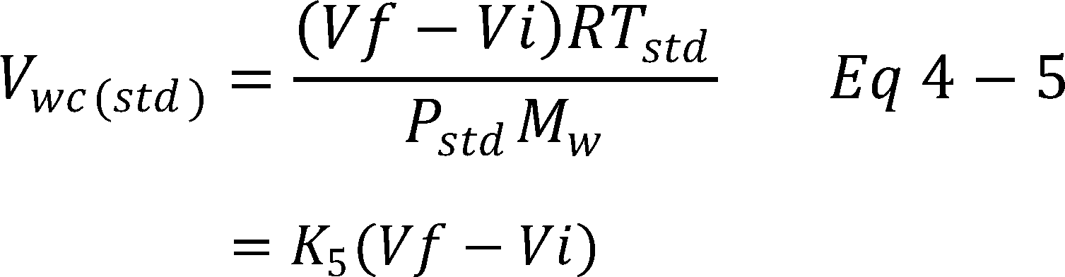
K5 = 0.001335 m3/g for metric units,
= 0.04716 ft3/g for English units.
12.2.3 Sample Gas Volume.

Where:
K6 = 0.3855 °K/mm Hg for metric units,
= 17.64 °R/in. Hg for English units.
12.2.4 Approximate Moisture Content.

12.2.5 Using F-factors to determine approximate moisture for estimating moisture content where no wet scrubber is being used, for the purpose of determining isokinetic sampling rate settings with no fuel sample, is acceptable using the average Fc or Fd factor from Method 19 (see Method 19, section 12.3.1). If this option is selected, calculate the approximate moisture as follows:
Bws = BH + BA+ BF
Where:
BA = Mole Fraction of moisture in the ambient air.
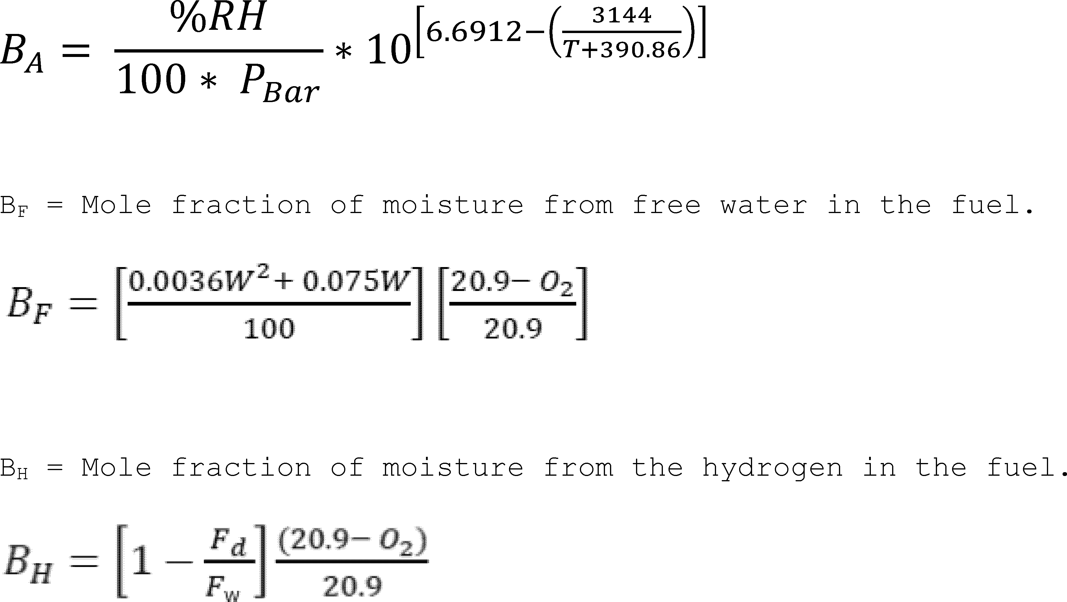
Bws = Mole fraction of moisture in the stack gas.
Fd = Volume of dry combustion components per unit of heat content at 0 percent oxygen, dscf/106.
Btu (scm/J). See Table 19-2 in Method 19.
Fw = Volume of wet combustion components per unit of heat content at 0 percent oxygen, wet.
scf/106 Btu (scm/J). See Table 19-2 in Method 19.
%RH = Percent relative humidity (calibrated hygrometer acceptable), percent.
PBar = Barometric pressure, in. Hg.
T = Ambient temperature, °F.
W = Percent free water by weight, percent.
O2 = Percent oxygen in stack gas, dry basis, percent.
13.0 Method Performance [Reserved]
14.0 Pollution Prevention [Reserved]
15.0 Waste Management [Reserved]
16.0 Alternative Procedures
16.1 The procedure described in Method 5 for determining moisture content is an acceptable alternative to Method 4.
16.2 The procedures in Method 6A for determining moisture is an acceptable alternative to Method 4.
16.3 Method 320 is an acceptable alternative to Method 4 for determining moisture.
16.4 Using F-factors to determine moisture is an acceptable alternative to Method 4 for a combustion stack not using a scrubber, and where a fuel sample is taken during the test run and analyzed for development of an Fd factor (see Method 19, section 12.3.2), and where stack O2 content is measured by Method 3A or 3B during each test run. If this option is selected, calculate the moisture content as follows:
Bws = BH + BA + BF
Where:
BA = Mole fraction of moisture in the ambient air.

Values of BA should be between 0.00 and 0.06 with common values being about 0.015.
BF = Mole fraction of moisture from free water in the fuel.

Free water in fuel is minimal for distillate oil and gases, such as propane and natural gas, so this step may be omitted for those fuels.
BH = Mole fraction of moisture from the hydrogen in the fuel.

Bws = Mole fraction of moisture in the stack gas.
Fd = Volume of dry combustion components per unit of heat content at 0 percent oxygen, dscf/106 Btu (scm/J). Develop a test specific Fd value using an integrated fuel sample from each test run and Equation 19-13 in section 12.3.2 of Method 19.
Fw = Volume of wet combustion components per unit of heat content at 0 percent oxygen, wet scf/106 Btu (scm/J). Develop a test specific Fw value using an integrated fuel sample from each test run and Equation 19-14 in section 12.3.2 of Method 19.
%RH = Percent relative humidity (calibrated hygrometer acceptable), percent.
PBar = Barometric pressure, in. Hg.
T = Ambient temperature, °F.
W = Percent free water by weight, percent.
O2 = Percent oxygen in stack gas, dry basis, percent.
17.0 References
1. Air Pollution Engineering Manual (Second Edition). Danielson, J.A. (ed.). U.S. Environmental Protection Agency, Office of Air Quality Planning and Standards. Research Triangle Park, NC. Publication No. AP-40. 1973.
2. Devorkin, Howard, et al. Air Pollution Source Testing Manual. Air Pollution Control District, Los Angeles, CA. November 1963.
3. Methods for Determination of Velocity, Volume, Dust and Mist Content of Gases. Western Precipitation Division of Joy Manufacturing Co. Los Angeles, CA. Bulletin WP-50. 1968.
18.0 Tables, Diagrams, Flowcharts, and Validation Data
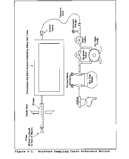

Plant
Location
Operator
Date
Run No.
Ambient temperature
Barometric pressure
Probe Length
Schematic of Stack Cross section
| Traverse Pt. No. | Sampling time
(Δ), min |
Stack
temperature °C ( °F) |
Pressure
differential across orifice meter ΔH mm (in.) H2O |
Meter
reading gas sample volume m3 (ft3) |
ΔVm m3 (ft3) | Gas sample
temperature at dry gas meter |
Temperature
of gas leaving condenser or last impinger °C ( °F) |
|
|---|---|---|---|---|---|---|---|---|
| Inlet
Tmin °C ( °F) |
Outlet
Tmout °C ( °F) |
|||||||
| Average | ||||||||
Location
Test
Date
Operator
Barometric pressure
Comments:
Figure 4-3. Moisture Determination - Reference Method


Method 5 - Determination of Particulate Matter Emissions From Stationary Sources
This method does not include all of the specifications (e.g., equipment and supplies) and procedures (e.g., sampling and analytical) essential to its performance. Some material is incorporated by reference from other methods in this part. Therefore, to obtain reliable results, persons using this method should have a thorough knowledge of at least the following additional test methods: Method 1, Method 2, Method 3.
1.0 Scope and Application
1.1 Analyte. Particulate matter (PM). No CAS number assigned.
1.2 Applicability. This method is applicable for the determination of PM emissions from stationary sources.
1.3 Data Quality Objectives. Adherence to the requirements of this method will enhance the quality of the data obtained from air pollutant sampling methods.
2.0 Summary of Method
Particulate matter is withdrawn isokinetically from the source and collected on a glass fiber filter maintained at a temperature of 120 ±14 °C (248 ±25 °F) or such other temperature as specified by an applicable subpart of the standards or approved by the Administrator for a particular application. The PM mass, which includes any material that condenses at or above the filtration temperature, is determined gravimetrically after the removal of uncombined water.
3.0 Definitions [Reserved]
4.0 Interferences [Reserved]
5.0 Safety
5.1 Disclaimer. This method may involve hazardous materials, operations, and equipment. This test method may not address all of the safety problems associated with its use. It is the responsibility of the user of this test method to establish appropriate safety and health practices and to determine the applicability of regulatory limitations prior to performing this test method.
6.0 Equipment and Supplies
6.1 Sample Collection. The following items are required for sample collection:
6.1.1 Sampling Train. A schematic of the sampling train used in this method is shown in Figure 5-1 in section 18.0. Complete construction details are given in APTD-0581 (Reference 2 in section 17.0); commercial models of this train are also available. For changes from APTD-0581 and for allowable modifications of the train shown in Figure 5-1, see the following subsections.
The operating and maintenance procedures for the sampling train are described in APTD-0576 (Reference 3 in section 17.0). Since correct usage is important in obtaining valid results, all users should read APTD-0576 and adopt the operating and maintenance procedures outlined in it, unless otherwise specified herein.
6.1.1.1 Probe Nozzle. Stainless steel (316) or glass with a sharp, tapered leading edge. The angle of taper shall be ≤30°, and the taper shall be on the outside to preserve a constant internal diameter. The probe nozzle shall be of the button-hook or elbow design, unless otherwise specified by the Administrator. If made of stainless steel, the nozzle shall be constructed from seamless tubing. Other materials of construction may be used, subject to the approval of the Administrator. A range of nozzle sizes suitable for isokinetic sampling should be available. Typical nozzle sizes range from 0.32 to 1.27 cm (1⁄8 to 1⁄2 in) inside diameter (ID) in increments of 0.16 cm (1⁄16 in). Larger nozzles sizes are also available if higher volume sampling trains are used. Each nozzle shall be calibrated, according to the procedures outlined in section 10.1.
6.1.1.2 Probe Liner. Borosilicate or quartz glass tubing with a heating system capable of maintaining a probe gas temperature during sampling of 120 ±14 °C (248 ±25 °F), or such other temperature as specified by an applicable subpart of the standards or as approved by the Administrator for a particular application. Since the actual temperature at the outlet of the probe is not usually monitored during sampling, probes constructed according to APTD-0581 and utilizing the calibration curves of APTD-0576 (or calibrated according to the procedure outlined in APTD-0576) will be considered acceptable. Either borosilicate or quartz glass probe liners may be used for stack temperatures up to about 480 °C (900 °F); quartz glass liners shall be used for temperatures between 480 and 900 °C (900 and 1,650 °F). Both types of liners may be used at higher temperatures than specified for short periods of time, subject to the approval of the Administrator. The softening temperature for borosilicate glass is 820 °C (1500 °F), and for quartz glass it is 1500 °C (2700 °F). Whenever practical, every effort should be made to use borosilicate or quartz glass probe liners. Alternatively, metal liners (e.g., 316 stainless steel, Incoloy 825 or other corrosion resistant metals) made of seamless tubing may be used, subject to the approval of the Administrator.
6.1.1.3 Pitot Tube. Type S, as described in section 6.1 of Method 2, or other device approved by the Administrator. The pitot tube shall be attached to the probe (as shown in Figure 5-1) to allow constant monitoring of the stack gas velocity. The impact (high pressure) opening plane of the pitot tube shall be even with or above the nozzle entry plane (see Method 2, Figure 2-7) during sampling. The Type S pitot tube assembly shall have a known coefficient, determined as outlined in section 10.0 of Method 2.
6.1.1.4 Differential Pressure Gauge. Inclined manometer or equivalent device (two), as described in section 6.2 of Method 2. One manometer shall be used for velocity head (Δp) readings, and the other, for orifice differential pressure readings.
6.1.1.5 Filter Holder. Borosilicate glass, with a glass or Teflon frit filter support and a silicone rubber gasket. Other materials of construction (e.g., stainless steel or Viton) may be used, subject to the approval of the Administrator. The holder design shall provide a positive seal against leakage from the outside or around the filter. The holder shall be attached immediately at the outlet of the probe (or cyclone, if used).
6.1.1.6 Filter Heating System. Any heating system capable of monitoring and maintaining temperature around the filter shall be used to ensure the sample gas temperature exiting the filter of 120 ±14 °C (248 ±25 °F) during sampling or such other temperature as specified by an applicable subpart of the standards or approved by the Administrator for a particular application. The monitoring and regulation of the temperature around the filter may be done with the filter temperature sensor or another temperature sensor.
6.1.1.7 Filter Temperature Sensor. A temperature sensor capable of measuring temperature to within ±3 °C (5.4 °F) shall be installed so that the sensing tip of the temperature sensor is in direct contact with the sample gas exiting the filter. The sensing tip of the sensor may be encased in glass, Teflon, or metal and must protrude at least 1⁄2 in. into the sample gas exiting the filter. The filter temperature sensor must be monitored and recorded during sampling to ensure a sample gas temperature exiting the filter of 120 ±14 °C (248 ±25 °F), or such other temperature as specified by an applicable subpart of the standards or approved by the Administrator for a particular application.
6.1.1.8 Condenser. The following system shall be used to determine the stack gas moisture content: Four impingers connected in series with leak-free ground glass fittings or any similar leak-free noncontaminating fittings. The first, third, and fourth impingers shall be of the Greenburg-Smith design, modified by replacing the tip with a 1.3 cm (1⁄2 in.) ID glass tube extending to about 1.3 cm (1⁄2 in.) from the bottom of the flask. The second impinger shall be of the Greenburg-Smith design with the standard tip. Modifications (e.g., using flexible connections between the impingers, using materials other than glass, or using flexible vacuum lines to connect the filter holder to the condenser) may be used, subject to the approval of the Administrator. The first and second impingers shall contain known quantities of water (Section 8.3.1), the third shall be empty, and the fourth shall contain a known weight of silica gel, or equivalent desiccant. A temperature sensor, capable of measuring temperature to within 1 °C (2 °F) shall be placed at the outlet of the fourth impinger for monitoring purposes. Alternatively, any system that cools the sample gas stream and allows measurement of the water condensed and moisture leaving the condenser, each to within 0.5 g may be used, subject to the approval of the Administrator. An acceptable technique involves the measurement of condensed water either gravimetrically and the determination of the moisture leaving the condenser by:
(1) Monitoring the temperature and pressure at the exit of the condenser and using Dalton's law of partial pressures; or
(2) passing the sample gas stream through a tared silica gel (or equivalent desiccant) trap with exit gases kept below 20 °C (68 °F) and determining the weight gain. If means other than silica gel are used to determine the amount of moisture leaving the condenser, it is recommended that silica gel (or equivalent) still be used between the condenser system and pump to prevent moisture condensation in the pump and metering devices and to avoid the need to make corrections for moisture in the metered volume.
If a determination of the PM collected in the impingers is desired in addition to moisture content, the impinger system described above shall be used, without modification. Individual States or control agencies requiring this information shall be contacted as to the sample recovery and analysis of the impinger contents.
6.1.1.9 Metering System. Vacuum gauge, leak-free pump, calibrated temperature sensors, dry gas meter (DGM) capable of measuring volume to within 2 percent, and related equipment, as shown in Figure 5-1. Other metering systems capable of maintaining sampling rates within 10 percent of isokinetic and of determining sample volumes to within 2 percent may be used, subject to the approval of the Administrator. When the metering system is used in conjunction with a pitot tube, the system shall allow periodic checks of isokinetic rates. The average DGM temperature for use in the calculations of section 12.0 may be obtained by averaging the two temperature sensors located at the inlet and outlet of the DGM as shown in Figure 5-3 or alternatively from a single temperature sensor located at the immediate outlet of the DGM or the plenum of the DGM.
6.1.1.10 Sampling trains utilizing metering systems designed for higher flow rates than that described in APTD-0581 or APTD-0576 may be used provided that the specifications of this method are met.
6.1.2 Barometer. Mercury, aneroid, or other barometer capable of measuring atmospheric pressure to within 2.5 mm Hg (0.1 in.).
The barometric pressure reading may be obtained from a nearby National Weather Service station. In this case, the station value (which is the absolute barometric pressure) shall be requested and an adjustment for elevation differences between the weather station and sampling point shall be made at a rate of minus 2.5 mm Hg (0.1 in.) per 30 m (100 ft) elevation increase or plus 2.5 mm Hg (0.1 in) per 30 m (100 ft) elevation decrease.
6.1.3 Gas Density Determination Equipment. Temperature sensor and pressure gauge, as described in sections 6.3 and 6.4 of Method 2, and gas analyzer, if necessary, as described in Method 3. The temperature sensor shall, preferably, be permanently attached to the pitot tube or sampling probe in a fixed configuration, such that the tip of the sensor extends beyond the leading edge of the probe sheath and does not touch any metal. Alternatively, the sensor may be attached just prior to use in the field. Note, however, that if the temperature sensor is attached in the field, the sensor must be placed in an interference-free arrangement with respect to the Type S pitot tube openings (see Method 2, Figure 2-4). As a second alternative, if a difference of not more than 1 percent in the average velocity measurement is to be introduced, the temperature sensor need not be attached to the probe or pitot tube. (This alternative is subject to the approval of the Administrator.)
6.2 Sample Recovery. The following items are required for sample recovery:
6.2.1 Probe-Liner and Probe-Nozzle Brushes. Nylon bristle brushes with stainless steel wire handles. The probe brush shall have extensions (at least as long as the probe) constructed of stainless steel, Nylon, Teflon, or similarly inert material. The brushes shall be properly sized and shaped to brush out the probe liner and nozzle.
6.2.2 Wash Bottles. Two Glass wash bottles are recommended. Alternatively, polyethylene wash bottles may be used. It is recommended that acetone not be stored in polyethylene bottles for longer than a month.
6.2.3 Glass Sample Storage Containers. Chemically resistant, borosilicate glass bottles, for acetone washes, 500 ml or 1000 ml. Screw cap liners shall either be rubber-backed Teflon or shall be constructed so as to be leak-free and resistant to chemical attack by acetone. (Narrow mouth glass bottles have been found to be less prone to leakage.) Alternatively, polyethylene bottles may be used.
6.2.4 Petri dishes. For filter samples; glass, polystyrene, or polyethylene, unless otherwise specified by the Administrator.
6.2.5 Balance. To measure condensed water to within 0.5 g at a minimum.
6.2.6 Plastic Storage Containers. Air-tight containers to store silica gel.
6.2.7 Funnel and Rubber Policeman. To aid in transfer of silica gel to container; not necessary if silica gel is weighed in the field.
6.2.8 Funnel. Glass or polyethylene, to aid in sample recovery.
6.3 Sample Analysis. The following equipment is required for sample analysis:
6.3.1 Glass Weighing Dishes.
6.3.2 Desiccator.
6.3.3 Analytical Balance. To measure to within 0.1 mg.
6.3.4 Balance. To measure to within 0.5 g.
6.3.5 Beakers. 250 ml.
6.3.6 Hygrometer. To measure the relative humidity of the laboratory environment.
6.3.7 Temperature Sensor. To measure the temperature of the laboratory environment.
7.0 Reagents and Standards
7.1 Sample Collection. The following reagents are required for sample collection:
7.1.1 Filters. Glass fiber filters, without organic binder, exhibiting at least 99.95 percent efficiency (<0.05 percent penetration) on 0.3 micron dioctyl phthalate smoke particles. The filter efficiency test shall be conducted in accordance with ASTM Method D 2986-71, 78, or 95a (incorporated by reference - see § 60.17). Test data from the supplier's quality control program are sufficient for this purpose. In sources containing SO2 or SO3, the filter material must be of a type that is unreactive to SO2 or SO3. Reference 10 in section 17.0 may be used to select the appropriate filter.
7.1.2 Silica Gel. Indicating type, 6 to 16 mesh. If previously used, dry at 175 °C (350 °F) for 2 hours. New silica gel may be used as received. Alternatively, other types of desiccants (equivalent or better) may be used, subject to the approval of the Administrator.
7.1.3 Water. When analysis of the material caught in the impingers is required, deionized distilled water [to conform to ASTM D1193-77 or 91 Type 3 (incorporated by reference - see § 60.17)] with at least <0.001 percent residue shall be used or as specified in the applicable method requiring analysis of the water. Run reagent blanks prior to field use to eliminate a high blank on test samples.
7.1.4 Crushed Ice.
7.2 Sample Recovery. Acetone, reagent grade, ≤0.001 percent residue, in glass bottles, is required. Acetone from metal containers generally has a high residue blank and should not be used. Sometimes, suppliers transfer acetone to glass bottles from metal containers; thus, acetone blanks shall be run prior to field use and only acetone with low blank values (≤0.001 percent) shall be used. In no case shall a blank value of greater than 0.001 percent of the weight of acetone used be subtracted from the sample weight.
7.3 Sample Analysis. The following reagents are required for sample analysis:
7.3.1 Acetone. Same as in section 7.2.
7.3.2 Desiccant. Anhydrous calcium sulfate, indicating type. Alternatively, other types of desiccants may be used, subject to the approval of the Administrator.
8.0 Sample Collection, Preservation, Storage, and Transport
8.1 Pretest Preparation. It is suggested that sampling equipment be maintained according to the procedures described in APTD-0576. Alternative mercury-free thermometers may be used if the thermometers are at a minimum equivalent in terms of performance or suitably effective for the specific temperature measurement application.
8.1.1 Place 200 to 300 g of silica gel in each of several air-tight containers. Weigh each container, including silica gel, to the nearest 0.5 g, and record this weight. As an alternative, the silica gel need not be preweighed, but may be weighed directly in its impinger or sampling holder just prior to train assembly.
8.1.2 Check filters visually against light for irregularities, flaws, or pinhole leaks. Label filters of the proper diameter on the back side near the edge using numbering machine ink. As an alternative, label the shipping containers (glass, polystyrene or polyethylene petri dishes), and keep each filter in its identified container at all times except during sampling.
8.1.3 Desiccate the filters at 20 ±5.6 °C (68 ±10 °F) and ambient pressure for at least 24 hours. Weigh each filter (or filter and shipping container) at intervals of at least 6 hours to a constant weight (i.e., ≤0.5 mg change from previous weighing). Record results to the nearest 0.1 mg. During each weighing, the period for which the filter is exposed to the laboratory atmosphere shall be less than 2 minutes. Alternatively (unless otherwise specified by the Administrator), the filters may be oven dried at 105 °C (220 °F) for 2 to 3 hours, desiccated for 2 hours, and weighed. Procedures other than those described, which account for relative humidity effects, may be used, subject to the approval of the Administrator.
8.2 Preliminary Determinations.
8.2.1 Select the sampling site and the minimum number of sampling points according to Method 1 or as specified by the Administrator. Determine the stack pressure, temperature, and the range of velocity heads using Method 2; it is recommended that a leak check of the pitot lines (see Method 2, section 8.1) be performed. Determine the moisture content using Approximation Method 4 or its alternatives for the purpose of making isokinetic sampling rate settings. Determine the stack gas dry molecular weight, as described in Method 2, section 8.6; if integrated Method 3 sampling is used for molecular weight determination, the integrated bag sample shall be taken simultaneously with, and for the same total length of time as, the particulate sample run.
8.2.2 Select a nozzle size based on the range of velocity heads, such that it is not necessary to change the nozzle size in order to maintain isokinetic sampling rates. During the run, do not change the nozzle size. Ensure that the proper differential pressure gauge is chosen for the range of velocity heads encountered (see section 8.3 of Method 2).
8.2.3 Select a suitable probe liner and probe length such that all traverse points can be sampled. For large stacks, consider sampling from opposite sides of the stack to reduce the required probe length.
8.2.4 Select a total sampling time greater than or equal to the minimum total sampling time specified in the test procedures for the specific industry such that (l) the sampling time per point is not less than 2 minutes (or some greater time interval as specified by the Administrator), and (2) the sample volume taken (corrected to standard conditions) will exceed the required minimum total gas sample volume. The latter is based on an approximate average sampling rate.
8.2.5 The sampling time at each point shall be the same. It is recommended that the number of minutes sampled at each point be an integer or an integer plus one-half minute, in order to avoid timekeeping errors.
8.2.6 In some circumstances (e.g., batch cycles) it may be necessary to sample for shorter times at the traverse points and to obtain smaller gas sample volumes. In these cases, the Administrator's approval must first be obtained.
8.3 Preparation of Sampling Train.
8.3.1 During preparation and assembly of the sampling train, keep all openings where contamination can occur covered until just prior to assembly or until sampling is about to begin. Place 100 ml of water in each of the first two impingers, leave the third impinger empty, and transfer approximately 200 to 300 g of preweighed silica gel from its container to the fourth impinger. More silica gel may be used, but care should be taken to ensure that it is not entrained and carried out from the impinger during sampling. Place the container in a clean place for later use in the sample recovery. Alternatively, the weight of the silica gel plus impinger may be determined to the nearest 0.5 g and recorded.
8.3.2 Using a tweezer or clean disposable surgical gloves, place a labeled (identified) and weighed filter in the filter holder. Be sure that the filter is properly centered and the gasket properly placed so as to prevent the sample gas stream from circumventing the filter. Check the filter for tears after assembly is completed.
8.3.3 When glass probe liners are used, install the selected nozzle using a Viton A O-ring when stack temperatures are less than 260 °C (500 °F) or a heat-resistant string gasket when temperatures are higher. See APTD-0576 for details. Other connecting systems using either 316 stainless steel or Teflon ferrules may be used. When metal liners are used, install the nozzle as discussed above or by a leak-free direct mechanical connection. Mark the probe with heat resistant tape or by some other method to denote the proper distance into the stack or duct for each sampling point.
8.3.4 Set up the train as shown in Figure 5-1 ensuring that the connections are leak-tight. Subject to the approval of the Administrator, a glass cyclone may be used between the probe and filter holder when the total particulate catch is expected to exceed 100 mg or when water droplets are present in the stack gas.
8.3.5 Place crushed ice around the impingers.
8.4 Leak-Check Procedures.
8.4.1 Leak Check of Metering System Shown in Figure 5-1. That portion of the sampling train from the pump to the orifice meter should be leak-checked prior to initial use and after each shipment. Leakage after the pump will result in less volume being recorded than is actually sampled. The following procedure is suggested (see Figure 5-2): Close the main valve on the meter box. Insert a one-hole rubber stopper with rubber tubing attached into the orifice exhaust pipe. Disconnect and vent the low side of the orifice manometer. Close off the low side orifice tap. Pressurize the system to 13 to 18 cm (5 to 7 in.) water column by blowing into the rubber tubing. Pinch off the tubing, and observe the manometer for one minute. A loss of pressure on the manometer indicates a leak in the meter box; leaks, if present, must be corrected.
8.4.2 Pretest Leak Check. A pretest leak check of the sampling train is recommended, but not required. If the pretest leak check is conducted, the following procedure should be used.
8.4.2.1 After the sampling train has been assembled, turn on and set the filter and probe heating systems to the desired operating temperatures. Allow time for the temperatures to stabilize. If a Viton A O-ring or other leak-free connection is used in assembling the probe nozzle to the probe liner, leak-check the train at the sampling site by plugging the nozzle and pulling a 380 mm (15 in.) Hg vacuum.
A lower vacuum may be used, provided that it is not exceeded during the test.
8.4.2.2 If a heat-resistant string is used, do not connect the probe to the train during the leak check. Instead, leak-check the train by first plugging the inlet to the filter holder (cyclone, if applicable) and pulling a 380 mm (15 in.) Hg vacuum (see note in section 8.4.2.1). Then connect the probe to the train, and leak-check at approximately 25 mm (1 in.) Hg vacuum; alternatively, the probe may be leak-checked with the rest of the sampling train, in one step, at 380 mm (15 in.) Hg vacuum. Leakage rates in excess of 4 percent of the average sampling rate or 0.00057 m3/min (0.020 cfm), whichever is less, are unacceptable.
8.4.2.3 The following leak-check instructions for the sampling train described in APTD-0576 and APTD-0581 may be helpful. Start the pump with the bypass valve fully open and the coarse adjust valve completely closed. Partially open the coarse adjust valve, and slowly close the bypass valve until the desired vacuum is reached. Do not reverse the direction of the bypass valve, as this will cause water to back up into the filter holder. If the desired vacuum is exceeded, either leak-check at this higher vacuum, or end the leak check and start over.
8.4.2.4 When the leak check is completed, first slowly remove the plug from the inlet to the probe, filter holder, or cyclone (if applicable), and immediately turn off the vacuum pump. This prevents the water in the impingers from being forced backward into the filter holder and the silica gel from being entrained backward into the third impinger.
8.4.3 Leak Checks During Sample Run. If, during the sampling run, a component (e.g., filter assembly or impinger) change becomes necessary, a leak check shall be conducted immediately before the change is made. The leak check shall be done according to the procedure outlined in section 8.4.2 above, except that it shall be done at a vacuum equal to or greater than the maximum value recorded up to that point in the test. If the leakage rate is found to be no greater than 0.00057 m3/min (0.020 cfm) or 4 percent of the average sampling rate (whichever is less), the results are acceptable, and no correction will need to be applied to the total volume of dry gas metered; if, however, a higher leakage rate is obtained, either record the leakage rate and plan to correct the sample volume as shown in section 12.3 of this method, or void the sample run.
Immediately after component changes, leak checks are optional. If such leak checks are done, the procedure outlined in section 8.4.2 above should be used.
8.4.4 Post-Test Leak Check. A leak check of the sampling train is mandatory at the conclusion of each sampling run. The leak check shall be performed in accordance with the procedures outlined in section 8.4.2, except that it shall be conducted at a vacuum equal to or greater than the maximum value reached during the sampling run. If the leakage rate is found to be no greater than 0.00057 m3 min (0.020 cfm) or 4 percent of the average sampling rate (whichever is less), the results are acceptable, and no correction need be applied to the total volume of dry gas metered. If, however, a higher leakage rate is obtained, either record the leakage rate and correct the sample volume as shown in section 12.3 of this method, or void the sampling run.
8.5 Sampling Train Operation. During the sampling run, maintain an isokinetic sampling rate (within 10 percent of true isokinetic unless otherwise specified by the Administrator) and a sample gas temperature through the filter of 120 ±14 °C (248 ±25 °F) or such other temperature as specified by an applicable subpart of the standards or approved by the Administrator.
8.5.1 For each run, record the data required on a data sheet such as the one shown in Figure 5-3. Be sure to record the initial DGM reading. Record the DGM readings at the beginning and end of each sampling time increment, when changes in flow rates are made, before and after each leak check, and when sampling is halted. Take other readings indicated by Figure 5-3 at least once at each sample point during each time increment and additional readings when significant changes (20 percent variation in velocity head readings) necessitate additional adjustments in flow rate. Level and zero the manometer. Because the manometer level and zero may drift due to vibrations and temperature changes, make periodic checks during the traverse.
8.5.2 Clean the portholes prior to the test run to minimize the chance of collecting deposited material. To begin sampling, verify that the filter and probe heating systems are up to temperature, remove the nozzle cap, verify that the pitot tube and probe are properly positioned. Position the nozzle at the first traverse point with the tip pointing directly into the gas stream. Immediately start the pump, and adjust the flow to isokinetic conditions. Nomographs are available which aid in the rapid adjustment of the isokinetic sampling rate without excessive computations. These nomographs are designed for use when the Type S pitot tube coefficient (Cp) is 0.85 ±0.02, and the stack gas equivalent density [dry molecular weight (Md)] is equal to 29 ±4. APTD-0576 details the procedure for using the nomographs. If Cp and Md are outside the above stated ranges, do not use the nomographs unless appropriate steps (see Reference 7 in section 17.0) are taken to compensate for the deviations.
8.5.3 When the stack is under significant negative pressure (i.e., height of impinger stem), take care to close the coarse adjust valve before inserting the probe into the stack to prevent water from backing into the filter holder. If necessary, the pump may be turned on with the coarse adjust valve closed.
8.5.4 When the probe is in position, block off the openings around the probe and porthole to prevent unrepresentative dilution of the gas stream.
8.5.5 Traverse the stack cross-section, as required by Method 1 or as specified by the Administrator, being careful not to bump the probe nozzle into the stack walls when sampling near the walls or when removing or inserting the probe through the portholes; this minimizes the chance of extracting deposited material.
8.5.6 During the test run, make periodic adjustments to keep the temperature around the filter holder at the proper level to maintain the sample gas temperature exiting the filter; add more ice and, if necessary, salt to maintain a temperature of less than 20 °C (68 °F) at the condenser/silica gel outlet. Also, periodically check the level and zero of the manometer.
8.5.7 If the pressure drop across the filter becomes too high, making isokinetic sampling difficult to maintain, the filter may be replaced in the midst of the sample run. It is recommended that another complete filter assembly be used rather than attempting to change the filter itself. Before a new filter assembly is installed, conduct a leak check (see section 8.4.3). The total PM weight shall include the summation of the filter assembly catches.
8.5.8 A single train shall be used for the entire sample run, except in cases where simultaneous sampling is required in two or more separate ducts or at two or more different locations within the same duct, or in cases where equipment failure necessitates a change of trains. In all other situations, the use of two or more trains will be subject to the approval of the Administrator.
When two or more trains are used, separate analyses of the front-half and (if applicable) impinger catches from each train shall be performed, unless identical nozzle sizes were used on all trains, in which case, the front-half catches from the individual trains may be combined (as may the impinger catches) and one analysis of front-half catch and one analysis of impinger catch may be performed. Consult with the Administrator for details concerning the calculation of results when two or more trains are used.
8.5.9 At the end of the sample run, close the coarse adjust valve, remove the probe and nozzle from the stack, turn off the pump, record the final DGM meter reading, and conduct a post-test leak check, as outlined in section 8.4.4. Also, leak-check the pitot lines as described in Method 2, section 8.1. The lines must pass this leak check, in order to validate the velocity head data.
8.6 Calculation of Percent Isokinetic. Calculate percent isokinetic (see Calculations, section 12.11) to determine whether the run was valid or another test run should be made. If there was difficulty in maintaining isokinetic rates because of source conditions, consult with the Administrator for possible variance on the isokinetic rates.
8.7 Sample Recovery.
8.7.1 Proper cleanup procedure begins as soon as the probe is removed from the stack at the end of the sampling period. Allow the probe to cool.
8.7.2 When the probe can be safely handled, wipe off all external PM near the tip of the probe nozzle, and place a cap over it to prevent losing or gaining PM. Do not cap off the probe tip tightly while the sampling train is cooling down. This would create a vacuum in the filter holder, thereby drawing water from the impingers into the filter holder.
8.7.3 Before moving the sample train to the cleanup site, remove the probe from the sample train and cap the open outlet of the probe. Be careful not to lose any condensate that might be present. Cap the filter inlet where the probe was fastened. Remove the umbilical cord from the last impinger, and cap the impinger. If a flexible line is used between the first impinger or condenser and the filter holder, disconnect the line at the filter holder, and let any condensed water or liquid drain into the impingers or condenser. Cap off the filter holder outlet and impinger inlet. Either ground-glass stoppers, plastic caps, or serum caps may be used to close these openings.
8.7.4 Transfer the probe and filter-impinger assembly to the cleanup area. This area should be clean and protected from the wind so that the chances of contaminating or losing the sample will be minimized.
8.7.5 Save a portion of the acetone used for cleanup as a blank. From each storage container of acetone used for cleanup, save 200 ml and place in a glass sample container labeled “acetone blank.” To minimize any particulate contamination, rinse the wash bottle prior to filling from the tested container.
8.7.6 Inspect the train prior to and during disassembly, and note any abnormal conditions. Treat the samples as follows:
8.7.6.1 Container No. 1. Carefully remove the filter from the filter holder, and place it in its identified petri dish container. Use a pair of tweezers and/or clean disposable surgical gloves to handle the filter. If it is necessary to fold the filter, do so such that the PM cake is inside the fold. Using a dry Nylon bristle brush and/or a sharp-edged blade, carefully transfer to the petri dish any PM and/or filter fibers that adhere to the filter holder gasket. Seal the container.
8.7.6.2 Container No. 2. Taking care to see that dust on the outside of the probe or other exterior surfaces does not get into the sample, quantitatively recover PM or any condensate from the probe nozzle, probe fitting, probe liner, and front half of the filter holder by washing these components with acetone and placing the wash in a glass container. Deionized distilled water may be used instead of acetone when approved by the Administrator and shall be used when specified by the Administrator. In these cases, save a water blank, and follow the Administrator's directions on analysis. Perform the acetone rinse as follows:
8.7.6.2.1 Carefully remove the probe nozzle. Clean the inside surface by rinsing with acetone from a wash bottle and brushing with a Nylon bristle brush. Brush until the acetone rinse shows no visible particles, after which make a final rinse of the inside surface with acetone.
8.7.6.2.2 Brush and rinse the inside parts of the fitting with acetone in a similar way until no visible particles remain.
8.7.6.2.3 Rinse the probe liner with acetone by tilting and rotating the probe while squirting acetone into its upper end so that all inside surfaces will be wetted with acetone. Let the acetone drain from the lower end into the sample container. A funnel (glass or polyethylene) may be used to aid in transferring liquid washes to the container. Follow the acetone rinse with a probe brush. Hold the probe in an inclined position, squirt acetone into the upper end as the probe brush is being pushed with a twisting action through the probe; hold a sample container underneath the lower end of the probe, and catch any acetone and particulate matter that is brushed from the probe. Run the brush through the probe three times or more until no visible PM is carried out with the acetone or until none remains in the probe liner on visual inspection. With stainless steel or other metal probes, run the brush through in the above prescribed manner at least six times since metal probes have small crevices in which particulate matter can be entrapped. Rinse the brush with acetone, and quantitatively collect these washings in the sample container. After the brushing, make a final acetone rinse of the probe.
8.7.6.2.4 It is recommended that two people clean the probe to minimize sample losses. Between sampling runs, keep brushes clean and protected from contamination.
8.7.6.2.5 Clean the inside of the front half of the filter holder by rubbing the surfaces with a Nylon bristle brush and rinsing with acetone. Rinse each surface three times or more if needed to remove visible particulate. Make a final rinse of the brush and filter holder. Carefully rinse out the glass cyclone, also (if applicable). After all acetone washings and particulate matter have been collected in the sample container, tighten the lid on the sample container so that acetone will not leak out when it is shipped to the laboratory. Mark the height of the fluid level to allow determination of whether leakage occurred during transport. Label the container to clearly identify its contents.
8.7.6.3 Container No. 3. Note the color of the indicating silica gel to determine whether it has been completely spent, and make a notation of its condition. Transfer the silica gel from the fourth impinger to its original container, and seal. A funnel may make it easier to pour the silica gel without spilling. A rubber policeman may be used as an aid in removing the silica gel from the impinger. It is not necessary to remove the small amount of dust particles that may adhere to the impinger wall and are difficult to remove. Since the gain in weight is to be used for moisture calculations, do not use any water or other liquids to transfer the silica gel. If a balance is available in the field, follow the procedure for Container No. 3 in section 11.2.3.
8.7.6.4 Impinger Water. Treat the impingers as follows: Make a notation of any color or film in the liquid catch. Measure the liquid that is in the first three impingers by weighing it to within 0.5 g at a minimum by using a balance. Record the weight of liquid present. This information is required to calculate the moisture content of the effluent gas. Discard the liquid after measuring and recording the weight, unless analysis of the impinger catch is required (see Note, section 6.1.1.8). If a different type of condenser is used, measure the amount of moisture condensed gravimetrically.
8.8 Sample Transport. Whenever possible, containers should be shipped in such a way that they remain upright at all times.
9.0 Quality Control
9.1 Miscellaneous Quality Control Measures.
| Section | Quality control measure | Effect |
|---|---|---|
| 8.4, 10.1-10.6 | Sampling equipment leak check and calibration | Ensures accurate measurement of stack gas flow rate, sample volume. |
9.2 Volume Metering System Checks. The following procedures are suggested to check the volume metering system calibration values at the field test site prior to sample collection. These procedures are optional.
9.2.1 Meter Orifice Check. Using the calibration data obtained during the calibration procedure described in section 10.3, determine the ΔH@ for the metering system orifice. The ΔH@ is the orifice pressure differential in units of in. H2O that correlates to 0.75 cfm of air at 528 °R and 29.92 in. Hg. The ΔH@ is calculated as follows:

Where:
ΔH = Average pressure differential across the orifice meter, in. H2O.
Tm = Absolute average DGM temperature, °R.
Pbar = Barometric pressure, in. Hg.
θ = Total sampling time, min.
Y = DGM calibration factor, dimensionless.
Vm = Volume of gas sample as measured by DGM, dcf.
0.0319 = (0.0567 in. Hg/°R) (0.75 cfm)2
9.2.1.1 Before beginning the field test (a set of three runs usually constitutes a field test), operate the metering system (i.e., pump, volume meter, and orifice) at the ΔH@ pressure differential for 10 minutes. Record the volume collected, the DGM temperature, and the barometric pressure. Calculate a DGM calibration check value, Yc, as follows:

where:
Yc = DGM calibration check value, dimensionless.
10 = Run time, min.
9.2.1.2 Compare the Yc value with the dry gas meter calibration factor Y to determine that: 0.97Y <Yc <1.03Y. If the Yc value is not within this range, the volume metering system should be investigated before beginning the test.
9.2.2 Calibrated Critical Orifice. A critical orifice, calibrated against a wet test meter or spirometer and designed to be inserted at the inlet of the sampling meter box, may be used as a check by following the procedure of section 16.2.
10.0 Calibration and Standardization
Maintain a laboratory log of all calibrations.
10.1 Probe Nozzle. Probe nozzles shall be calibrated before their initial use in the field. Using a micrometer, measure the ID of the nozzle to the nearest 0.025 mm (0.001 in.). Make three separate measurements using different diameters each time, and obtain the average of the measurements. The difference between the high and low numbers shall not exceed 0.1 mm (0.004 in.). When nozzles become nicked, dented, or corroded, they shall be reshaped, sharpened, and recalibrated before use. Each nozzle shall be permanently and uniquely identified.
10.2 Pitot Tube Assembly. The Type S pitot tube assembly shall be calibrated according to the procedure outlined in section 10.1 of Method 2.
10.3 Metering System.
10.3.1 Calibration Prior to Use. Before its initial use in the field, the metering system shall be calibrated as follows: Connect the metering system inlet to the outlet of a wet test meter that is accurate to within 1 percent. Refer to Figure 5-4. The wet test meter should have a capacity of 30 liters/rev (1 ft3/rev). A spirometer of 400 liters (14 ft3) or more capacity, or equivalent, may be used for this calibration, although a wet test meter is usually more practical. The wet test meter should be periodically calibrated with a spirometer or a liquid displacement meter to ensure the accuracy of the wet test meter. Spirometers or wet test meters of other sizes may be used, provided that the specified accuracies of the procedure are maintained. Run the metering system pump for about 15 minutes with the orifice manometer indicating a median reading as expected in field use to allow the pump to warm up and to permit the interior surface of the wet test meter to be thoroughly wetted. Then, at each of a minimum of three orifice manometer settings, pass an exact quantity of gas through the wet test meter and note the gas volume indicated by the DGM. Also note the barometric pressure and the temperatures of the wet test meter, the inlet of the DGM, and the outlet of the DGM. Select the highest and lowest orifice settings to bracket the expected field operating range of the orifice. Use a minimum volume of 0.14 m3 (5 ft3) at all orifice settings. Record all the data on a form similar to Figure 5-5 and calculate Y, the DGM calibration factor, and ΔH , the orifice calibration factor, at each orifice setting as shown on Figure 5-5. Allowable tolerances for individual Y and ΔH values are given in Figure 5-5. Use the average of the Y values in the calculations in section 12.0.
10.3.1.1 Before calibrating the metering system, it is suggested that a leak check be conducted. For metering systems having diaphragm pumps, the normal leak-check procedure will not detect leakages within the pump. For these cases the following leak-check procedure is suggested: make a 10-minute calibration run at 0.00057 m3/min (0.020 cfm). At the end of the run, take the difference of the measured wet test meter and DGM volumes. Divide the difference by 10 to get the leak rate. The leak rate should not exceed 0.00057 m3/min (0.020 cfm).
10.3.2 Calibration After Use. After each field use, the calibration of the metering system shall be checked by performing three calibration runs at a single, intermediate orifice setting (based on the previous field test), with the vacuum set at the maximum value reached during the test series. To adjust the vacuum, insert a valve between the wet test meter and the inlet of the metering system. Calculate the average value of the DGM calibration factor. If the value has changed by more than 5 percent, recalibrate the meter over the full range of orifice settings, as detailed in section 10.3.1.
Alternative procedures (e.g., rechecking the orifice meter coefficient) may be used, subject to the approval of the Administrator.
10.3.3 Acceptable Variation in Calibration Check. If the DGM coefficient values obtained before and after a test series differ by more than 5 percent, the test series shall either be voided, or calculations for the test series shall be performed using whichever meter coefficient value (i.e., before or after) gives the lower value of total sample volume.
10.4 Probe Heater Calibration. Use a heat source to generate air heated to selected temperatures that approximate those expected to occur in the sources to be sampled. Pass this air through the probe at a typical sample flow rate while measuring the probe inlet and outlet temperatures at various probe heater settings. For each air temperature generated, construct a graph of probe heating system setting versus probe outlet temperature. The procedure outlined in APTD-0576 can also be used. Probes constructed according to APTD-0581 need not be calibrated if the calibration curves in APTD-0576 are used. Also, probes with outlet temperature monitoring capabilities do not require calibration.
The probe heating system shall be calibrated before its initial use in the field.
10.5 Temperature Sensors. Use the procedure in Section 10.3 of Method 2 to calibrate in-stack temperature sensors. Dial thermometers, such as are used for the DGM and condenser outlet, shall be calibrated against mercury-in-glass thermometers. An alternative mercury-free NIST-traceable thermometer may be used if the thermometer is, at a minimum, equivalent in terms of performance or suitably effective for the specific temperature measurement application. As an alternative, the following single-point calibration procedure may be used. After each test run series, check the accuracy (and, hence, the calibration) of each thermocouple system at ambient temperature, or any other temperature, within the range specified by the manufacturer, using a reference thermometer (either ASTM reference thermometer or a thermometer that has been calibrated against an ASTM reference thermometer). The temperatures of the thermocouple and reference thermometers shall agree to within ±2 °F.
10.6 Barometer. Calibrate against a mercury barometer or NIST-traceable barometer prior to the field test. Alternatively, barometric pressure may be obtained from a weather report that has been adjusted for the test point (on the stack) elevation.
10.7 Field Balance Calibration Check. Check the calibration of the balance used to weigh impingers with a weight that is at least 500g or within 50g of a loaded impinger. The weight must be ASTM E617-13 “Standard Specification for Laboratory Weights and Precision Mass Standards” (incorporated by reference - see 40 CFR 60.17) Class 6 (or better). Daily before use, the field balance must measure the weight within ±0.5g of the certified mass. If the daily balance calibration check fails, perform corrective measures and repeat the check before using balance.
10.8 Analytical Balance Calibration. Perform a multipoint calibration (at least five points spanning the operational range) of the analytical balance before the first use, and semiannually thereafter. The calibration of the analytical balance must be conducted using ASTM E617-13 “Standard Specification for Laboratory Weights and Precision Mass Standards” (incorporated by reference - see 40 CFR 60.17) Class 2 (or better) tolerance weights. Audit the balance each day it is used for gravimetric measurements by weighing at least one ASTM E617-13 Class 2 tolerance (or better) calibration weight that corresponds to 50 to 150 percent of the weight of one filter or between 1g and 5g. If the scale cannot reproduce the value of the calibration weight to within 0.5 mg of the certified mass, perform corrective measures, and conduct the multipoint calibration before use.
11.0 Analytical Procedure
11.1 Record the data required on a sheet such as the one shown in Figure 5-6.
11.2 Handle each sample container as follows:
11.2.1 Container No. 1. Leave the contents in the shipping container or transfer the filter and any loose PM from the sample container to a tared weighing container. Desiccate for 24 hours in a desiccator containing anhydrous calcium sulfate. Weigh to a constant weight, and report the results to the nearest 0.1 mg. For the purposes of this section, the term “constant weight” means a difference of no more than 0.5 mg or 1 percent of total weight less tare weight, whichever is greater, between two consecutive weighings, with no less than 6 hours of desiccation time between weighings. Alternatively, the sample may be oven dried at 104 °C (220 °F) for 2 to 3 hours, cooled in the desiccator, and weighed to a constant weight, unless otherwise specified by the Administrator. The sample may be oven dried at 104 °C (220 °F) for 2 to 3 hours. Once the sample has cooled, weigh the sample, and use this weight as a final weight.
11.2.2 Container No. 2. Note the level of liquid in the container, and confirm on the analysis sheet whether leakage occurred during transport. If a noticeable amount of leakage has occurred, either void the sample or use methods, subject to the approval of the Administrator, to correct the final results. Measure the liquid in this container either volumetrically to ±1 ml or gravimetrically to ±0.5 g. Transfer the contents to a tared 250 ml beaker, and evaporate to dryness at ambient temperature and pressure. Desiccate for 24 hours, and weigh to a constant weight. Report the results to the nearest 0.1 mg.
11.2.3 Container No. 3. Weigh the spent silica gel (or silica gel plus impinger) to the nearest 0.5 g using a balance. This step may be conducted in the field.
11.2.4 Acetone Blank Container. Measure the acetone in this container either volumetrically or gravimetrically. Transfer the acetone to a tared 250 ml beaker, and evaporate to dryness at ambient temperature and pressure. Desiccate for 24 hours, and weigh to a constant weight. Report the results to the nearest 0.1 mg.
The contents of Container No. 2 as well as the acetone blank container may be evaporated at temperatures higher than ambient. If evaporation is done at an elevated temperature, the temperature must be below the boiling point of the solvent; also, to prevent “bumping,” the evaporation process must be closely supervised, and the contents of the beaker must be swirled occasionally to maintain an even temperature. Use extreme care, as acetone is highly flammable and has a low flash point.
12.0 Data Analysis and Calculations
Carry out calculations, retaining at least one extra significant figure beyond that of the acquired data. Round off figures after the final calculation. Other forms of the equations may be used, provided that they give equivalent results.
12.1 Nomenclature.
An = Cross-sectional area of nozzle, m2 (ft2).
Bws = Water vapor in the gas stream, proportion by volume.
Ca = Acetone blank residue concentration, mg/mg.
cs = Concentration of particulate matter in stack gas, dry basis, corrected to standard conditions, g/dscm (gr/dscf).
I = Percent of isokinetic sampling.
L1 = Individual leakage rate observed during the leak-check conducted prior to the first component change, m3/min (ft3/min)
La = Maximum acceptable leakage rate for either a pretest leak-check or for a leak-check following a component change; equal to 0.00057 m3/min (0.020 cfm) or 4 percent of the average sampling rate, whichever is less.
Li = Individual leakage rate observed during the leak-check conducted prior to the “ith” component change (i = 1, 2, 3 . . . n), m3/min (cfm).
Lp = Leakage rate observed during the post-test leak-check, m3/min (cfm).
ma = Mass of residue of acetone after evaporation, mg.
mn = Total amount of particulate matter collected, mg.
Mw = Molecular weight of water, 18.015 g/g-mole (18.015 lb/lb-mole).
Pbar = Barometric pressure at the sampling site, mm Hg (in. Hg).
Ps = Absolute stack gas pressure, mm Hg (in. Hg).
Pstd = Standard absolute pressure, 760 mm Hg (29.92 in. Hg).
R = Ideal gas constant, 0.06236 ((mm Hg)(m3))/((K)(g-mole)) {21.85 ((in. Hg) (ft3))/((°R) (lb-mole))}.
Tm = Absolute average DGM temperature (see Figure 5-3), K (°R).
Ts = Absolute average stack gas temperature (see Figure 5-3), K (°R).
Tstd = Standard absolute temperature, 293.15 K (527.67 °R).
Va = Volume of acetone blank, ml.
Vaw = Volume of acetone used in wash, ml.
V1c = Total volume of liquid collected in impingers and silica gel (see Figure 5-6), g.
Vm = Volume of gas sample as measured by dry gas meter, dcm (dcf).
Vm(std) = Volume of gas sample measured by the dry gas meter, corrected to standard conditions, dscm (dscf).
Vw(std) = Volume of water vapor in the gas sample, corrected to standard conditions, scm (scf).
Vs = Stack gas velocity, calculated by Method 2, Equation 2-7, using data obtained from Method 5, m/sec (ft/sec).
Wa = Weight of residue in acetone wash, mg.
Y = Dry gas meter calibration factor.
ΔH = Average pressure differential across the orifice meter (see Figure 5-4), mm H2O (in. H2O).
ρa = Density of acetone, mg/ml (see label on bottle).
θ = Total sampling time, min.
θ1 = Sampling time interval, from the beginning of a run until the first component change, min.
θi = Sampling time interval, between two successive component changes, beginning with the interval between the first and second changes, min.
θp = Sampling time interval, from the final (nth) component change until the end of the sampling run, min.
13.6 = Specific gravity of mercury.
60 = Sec/min.
100 = Conversion to percent.
12.2 Average Dry Gas Meter Temperature and Average Orifice Pressure Drop. See data sheet (Figure 5-3).
12.3 Dry Gas Volume. Correct the sample volume measured by the dry gas meter to standard conditions (20 °C, 760mm Hg or 68 °F, 29.92 in. Hg) by using Equation 5-1.

Where:
K1 = 0.38572 °K/mm Hg for metric units = 17.636 °R/in. Hg for English units.
Note: Equation 5-1 can be used as written unless the leakage rate observed during any of the mandatory leak checks (i.e., the post-test leak check or leak checks conducted prior to component changes) exceeds La. If Lp or Li exceeds La, Equation 5-1 must be modified as follows:
(a) Case
I. No component changes made during sampling run. In this case, replace Vm in Equation 5-1 with the expression:
(Vm − (Lp − La)θ)
(b) Case II. One or more component changes made during the sampling run. In this case, replace Vm in Equation 5-1 by the expression:

and substitute only for those leakage rates (Li or Lp) which exceed La.
12.4 Volume of Water Vapor Condensed
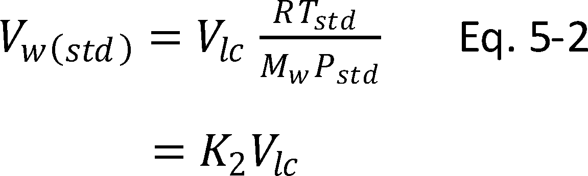
Where:
K2 = 0.001335 m3/g for metric units, = 0.04716 ft3/g for English units.
12.5 Moisture Content.

In saturated or water droplet-laden gas streams, two calculations of the moisture content of the stack gas shall be made, one from the impinger analysis (Equation 5-3), and a second from the assumption of saturated conditions. The lower of the two values of Bws shall be considered correct. The procedure for determining the moisture content based upon the assumption of saturated conditions is given in section 4.0 of Method 4. For the purposes of this method, the average stack gas temperature from Figure 5-3 may be used to make this determination, provided that the accuracy of the in-stack temperature sensor is ±1 °C (2 °F).
12.6 Acetone Blank Concentration.

12.7 Acetone Wash Blank.

12.8 Total Particulate Weight. Determine the total particulate matter catch from the sum of the weights obtained from Containers 1 and 2 less the acetone blank (see Figure 5-6).
In no case shall a blank value of greater than 0.001 percent of the weight of acetone used be subtracted from the sample weight. Refer to section 8.5.8 to assist in calculation of results involving two or more filter assemblies or two or more sampling trains.
12.9 Particulate Concentration.

Where:
K3 = 0.001 g/mg for metric units.
= 0.0154 gr/mg for English units.
12.10 Conversion Factors:
| From | To | Multiply by |
|---|---|---|
| ft3 | m3 | 0.02832 |
| gr | mg | 64.80004 |
| gr/ft3 | mg/m3 | 2288.4 |
| mg | g | 0.001 |
| gr | lb | 1.429 × 10⁻⁴ |
12.11 Isokinetic Variation.
12.11.1 Calculation from Raw Data.

Where:
K4 = 0.003456 ((mm Hg)(m3))/((ml)(°K)) for metric units,
= 0.002668 ((in. Hg)(ft3))/((ml)(°R)) for English units.
12.11.2 Calculation from Intermediate Values.

Where:
K5 = 4.3209 for metric units = 0.09450 for English units.
12.11.3 Acceptable Results. If 90 percent ≤I ≤110 percent, the results are acceptable. If the PM results are low in comparison to the standard, and “I” is over 110 percent or less than 90 percent, the Administrator may opt to accept the results. Reference 4 in section 17.0 may be used to make acceptability judgments. If “I” is judged to be unacceptable, reject the results, and repeat the sampling run.
12.12 Stack Gas Velocity and Volumetric Flow Rate. Calculate the average stack gas velocity and volumetric flow rate, if needed, using data obtained in this method and the equations in sections 12.3 and 12.4 of Method 2.
13.0 Method Performance [Reserved]
14.0 Pollution Prevention [Reserved]
15.0 Waste Management [Reserved]
16.0 Alternative Procedures
16.1 Dry Gas Meter as a Calibration Standard. A DGM may be used as a calibration standard for volume measurements in place of the wet test meter specified in section 10.3, provided that it is calibrated initially and recalibrated periodically as follows:
16.1.1 Standard Dry Gas Meter Calibration.
16.1.1.1. The DGM to be calibrated and used as a secondary reference meter should be of high quality and have an appropriately sized capacity (e.g., 3 liters/rev (0.1 ft3/rev)). A spirometer (400 liters (14 ft3) or more capacity), or equivalent, may be used for this calibration, although a wet test meter is usually more practical. The wet test meter should have a capacity of 30 liters/rev (1 ft3/rev) and capable of measuring volume to within 1.0 percent. Wet test meters should be checked against a spirometer or a liquid displacement meter to ensure the accuracy of the wet test meter. Spirometers or wet test meters of other sizes may be used, provided that the specified accuracies of the procedure are maintained.
16.1.1.2 Set up the components as shown in Figure 5-7. A spirometer, or equivalent, may be used in place of the wet test meter in the system. Run the pump for at least 5 minutes at a flow rate of about 10 liters/min (0.35 cfm) to condition the interior surface of the wet test meter. The pressure drop indicated by the manometer at the inlet side of the DGM should be minimized (no greater than 100 mm H2O (4 in. H2O) at a flow rate of 30 liters/min (1 cfm)). This can be accomplished by using large diameter tubing connections and straight pipe fittings.
16.1.1.3 Collect the data as shown in the example data sheet (see Figure 5-8). Make triplicate runs at each of the flow rates and at no less than five different flow rates. The range of flow rates should be between 10 and 34 liters/min (0.35 and 1.2 cfm) or over the expected operating range.
16.1.1.4 Calculate flow rate, Q, for each run using the wet test meter volume, Vw, and the run time, θ. Calculate the DGM coefficient, Yds, for each run. These calculations are as follows:


Where:
K1 = 0.38572 °K/mm Hg for metric units = 17.636 °R/in. Hg for English units.
Vw = Wet test meter volume, liter (ft3).
Vds = Dry gas meter volume, liter (ft3).
Tds = Average dry gas meter temperature, °C ( °F).
Tadj = 273.15 °C for metric units = 459.67 °F for English units.
Tw = Average wet test meter temperature, °C ( °F).
Pbar = Barometric pressure, mm Hg (in. Hg).
Δp = Dry gas meter inlet differential pressure, mm H2O (in. H2O).
θ = Run time, min.
16.1.1.5 Compare the three Yds values at each of the flow rates and determine the maximum and minimum values. The difference between the maximum and minimum values at each flow rate should be no greater than 0.030. Extra sets of triplicate runs may be made in order to complete this requirement. In addition, the meter coefficients should be between 0.95 and 1.05. If these specifications cannot be met in three sets of successive triplicate runs, the meter is not suitable as a calibration standard and should not be used as such. If these specifications are met, average the three Yds values at each flow rate resulting in no less than five average meter coefficients, Yds.
16.1.1.6 Prepare a curve of meter coefficient, Yds, versus flow rate, Q, for the DGM. This curve shall be used as a reference when the meter is used to calibrate other DGMs and to determine whether recalibration is required.
16.1.2 Standard Dry Gas Meter Recalibration.
16.1.2.1 Recalibrate the standard DGM against a wet test meter or spirometer annually or after every 200 hours of operation, whichever comes first. This requirement is valid provided the standard DGM is kept in a laboratory and, if transported, cared for as any other laboratory instrument. Abuse to the standard meter may cause a change in the calibration and will require more frequent recalibrations.
16.1.2.2 As an alternative to full recalibration, a two-point calibration check may be made. Follow the same procedure and equipment arrangement as for a full recalibration, but run the meter at only two flow rates [suggested rates are 14 and 30 liters/min (0.5 and 1.0 cfm)]. Calculate the meter coefficients for these two points, and compare the values with the meter calibration curve. If the two coefficients are within 1.5 percent of the calibration curve values at the same flow rates, the meter need not be recalibrated until the next date for a recalibration check.
16.2 Critical Orifices As Calibration Standards. Critical orifices may be used as calibration standards in place of the wet test meter specified in section 16.1, provided that they are selected, calibrated, and used as follows:
16.2.1 Selection of Critical Orifices.
16.2.1.1 The procedure that follows describes the use of hypodermic needles or stainless steel needle tubings which have been found suitable for use as critical orifices. Other materials and critical orifice designs may be used provided the orifices act as true critical orifices (i.e., a critical vacuum can be obtained, as described in section 16.2.2.2.3). Select five critical orifices that are appropriately sized to cover the range of flow rates between 10 and 34 liters/min (0.35 and 1.2 cfm) or the expected operating range. Two of the critical orifices should bracket the expected operating range. A minimum of three critical orifices will be needed to calibrate a Method 5 DGM; the other two critical orifices can serve as spares and provide better selection for bracketing the range of operating flow rates. The needle sizes and tubing lengths shown in Table 5-1 in section 18.0 give the approximate flow rates.
16.2.1.2 These needles can be adapted to a Method 5 type sampling train as follows: Insert a serum bottle stopper, 13 by 20 mm sleeve type, into a 1⁄2-inch Swagelok (or equivalent) quick connect. Insert the needle into the stopper as shown in Figure 5-9.
16.2.2 Critical Orifice Calibration. The procedure described in this section uses the Method 5 meter box configuration with a DGM as described in section 6.1.1.9 to calibrate the critical orifices. Other schemes may be used, subject to the approval of the Administrator.
16.2.2.1 Calibration of Meter Box. The critical orifices must be calibrated in the same configuration as they will be used (i.e., there should be no connections to the inlet of the orifice).
16.2.2.1.1 Before calibrating the meter box, leak check the system as follows: Fully open the coarse adjust valve, and completely close the by-pass valve. Plug the inlet. Then turn on the pump, and determine whether there is any leakage. The leakage rate shall be zero (i.e., no detectable movement of the DGM dial shall be seen for 1 minute).
16.2.2.1.2 Check also for leakages in that portion of the sampling train between the pump and the orifice meter. See section 8.4.1 for the procedure; make any corrections, if necessary. If leakage is detected, check for cracked gaskets, loose fittings, worn O-rings, etc., and make the necessary repairs.
16.2.2.1.3 After determining that the meter box is leakless, calibrate the meter box according to the procedure given in section 10.3. Make sure that the wet test meter meets the requirements stated in section 16.1.1.1. Check the water level in the wet test meter. Record the DGM calibration factor, Y.
16.2.2.2 Calibration of Critical Orifices. Set up the apparatus as shown in Figure 5-10.
16.2.2.2.1 Allow a warm-up time of 15 minutes. This step is important to equilibrate the temperature conditions through the DGM.
16.2.2.2.2 Leak check the system as in section 16.2.2.1.1. The leakage rate shall be zero.
16.2.2.2.3 Before calibrating the critical orifice, determine its suitability and the appropriate operating vacuum as follows: Turn on the pump, fully open the coarse adjust valve, and adjust the by-pass valve to give a vacuum reading corresponding to about half of atmospheric pressure. Observe the meter box orifice manometer reading, ΔH. Slowly increase the vacuum reading until a stable reading is obtained on the meter box orifice manometer. Record the critical vacuum for each orifice. Orifices that do not reach a critical value shall not be used.
16.2.2.2.4 Obtain the barometric pressure using a barometer as described in section 6.1.2. Record the barometric pressure, Pbar, in mm Hg (in. Hg).
16.2.2.2.5 Conduct duplicate runs at a vacuum of 25 to 50 mm Hg (1 to 2 in. Hg) above the critical vacuum. The runs shall be at least 5 minutes each. The DGM volume readings shall be in increments of complete revolutions of the DGM. As a guideline, the times should not differ by more than 3.0 seconds (this includes allowance for changes in the DGM temperatures) to achieve ±0.5 percent in K′ (see Eq. 5-11). Record the information listed in Figure 5-11.
16.2.2.2.6 Calculate K′ using Equation 5-11.

Where:
K′ = Critical orifice coefficient,
[m3)(°K) 1⁄2]/
[(mm Hg)(min)] {[(ft3)(°R) 1⁄2)] [(in. Hg)(min)].
Tamb = Absolute ambient temperature, °K (°R).
Calculate the arithmetic mean of the K′ values. The individual K' values should not differ by more than ±0.5 percent from the mean value.
16.2.3 Using the Critical Orifices as Calibration Standards.
16.2.3.1 Record the barometric pressure.
16.2.3.2 Calibrate the metering system according to the procedure outlined in section 16.2.2. Record the information listed in Figure 5-12.
16.2.3.3 Calculate the standard volumes of air passed through the DGM and the critical orifices, and calculate the DGM calibration factor, Y, using the equations below:


Where:
Vcr(std) = Volume of gas sample passed through the critical orifice, corrected to standard conditions, dscm (dscf).
K1 = 0.38572 °K/mm Hg for metric units = 17.636 °R/in. Hg for English units.
16.2.3.4 Average the DGM calibration values for each of the flow rates. The calibration factor, Y, at each of the flow rates should not differ by more than ±2 percent from the average.
16.2.3.5 To determine the need for recalibrating the critical orifices, compare the DGM Y factors obtained from two adjacent orifices each time a DGM is calibrated; for example, when checking orifice 13/2.5, use orifices 12/10.2 and 13/5.1. If any critical orifice yields a DGM Y factor differing by more than 2 percent from the others, recalibrate the critical orifice according to section 16.2.2.
16.3 Alternative Post-Test Metering System Calibration. The following procedure may be used as an alternative to the post-test calibration described in Section 10.3.2. This alternative procedure does not detect leakages between the inlet of the metering system and the dry gas meter. Therefore, two steps must be included to make it an equivalent alternative:
(1) The metering system must pass the post-test leak-check from either the inlet of the sampling train or the inlet of the metering system. Therefore, if the train fails the former leak-check, another leak-check from the inlet of the metering system must be conducted;
(2) The metering system must pass the leak-check of that portion of the train from the pump to the orifice meter as described in Section 8.4.1.
16.3.1 After each test run, do the following:
16.3.1.1 Ensure that the metering system has passed the post-test leak-check. If not, conduct a leak-check of the metering system from its inlet.
16.3.1.2 Conduct the leak-check of that portion of the train from the pump to the orifice meter as described in Section 10.3.1.1.
16.3.1.3 Calculate Yqa for each test run using the following equation:

Where:
Yqa = Dry gas meter calibration check value, dimensionless.
0.0319 = (29.92/528) (0.75)2 (in. Hg/°R) cfm2.
ΔH@ = Orifice meter calibration coefficient, in. H2O.
Md = Dry molecular weight of stack gas, lb/lb-mole.
29 = Dry molecular weight of air, lb/lb-mole.
16.3.2 After each test run series, do the following:
16.3.2.1 Average the three or more Yqa's obtained from the test run series and compare this average Yqa with the dry gas meter calibration factor Y. The average Yqa must be within 5 percent of Y.
16.3.2.2 If the average Yqa does not meet the 5 percent criterion, recalibrate the meter over the full range of orifice settings as detailed in Section 10.3.1. Then follow the procedure in Section 10.3.3.
17.0 References.
1. Addendum to Specifications for Incinerator Testing at Federal Facilities. PHS, NCAPC. December 6, 1967.
2. Martin, Robert M. Construction Details of Isokinetic Source-Sampling Equipment. Environmental Protection Agency. Research Triangle Park, NC. APTD-0581. April 1971.
3. Rom, Jerome J. Maintenance, Calibration, and Operation of Isokinetic Source Sampling Equipment. Environmental Protection Agency. Research Triangle Park, NC. APTD-0576. March 1972.
4. Smith, W.S., R.T. Shigehara, and W.F. Todd. A Method of Interpreting Stack Sampling Data. Paper Presented at the 63rd Annual Meeting of the Air Pollution Control Association, St. Louis, MO. June 14-19, 1970.
5. Smith, W.S., et al. Stack Gas Sampling Improved and Simplified With New Equipment. APCA Paper No. 67-119. 1967.
6. Specifications for Incinerator Testing at Federal Facilities. PHS, NCAPC. 1967.
7. Shigehara, R.T. Adjustment in the EPA Nomograph for Different Pitot Tube Coefficients and Dry Molecular Weights. Stack Sampling News 2:4-11. October 1974.
8. Vollaro, R.F. A Survey of Commercially Available Instrumentation for the Measurement of Low-Range Gas Velocities. U.S. Environmental Protection Agency, Emission Measurement Branch. Research Triangle Park, NC. November 1976 (unpublished paper).
9. Annual Book of ASTM Standards. Part 26. Gaseous Fuels; Coal and Coke; Atmospheric Analysis. American Society for Testing and Materials. Philadelphia, PA. 1974. pp. 617-622.
10. Felix, L.G., G.
I. Clinard, G.E. Lacy, and J.D. McCain. Inertial Cascade Impactor Substrate Media for Flue Gas Sampling. U.S. Environmental Protection Agency. Research Triangle Park, NC 27711. Publication No. EPA-600/7-77-060. June 1977. 83 pp.
11. Westlin, P.R. and R.T. Shigehara. Procedure for Calibrating and Using Dry Gas Volume Meters as Calibration Standards. Source Evaluation Society Newsletter. 3
(1) :17-30. February 1978.
12. Lodge, J.P., Jr., J.B. Pate, B.E. Ammons, and G.A. Swanson. The Use of Hypodermic Needles as Critical Orifices in Air Sampling. J. Air Pollution Control Association. 16:197-200. 1966.
13. Shigehara, Roger T., P.G. Royals, and E.W. Steward. “Alternative Method 5 Post-Test Calibration.” Entropy Incorporated, Research Triangle Park, NC 27709.
18.0 Tables, Diagrams, Flowcharts, and Validation Data
Table 5-1 Flor Rates for Various needle Sizes and Tube Lengths
| Gauge/cm | Flow rate
liters/min. |
Gauge/cm | Flow rate
liters/min. |
|---|---|---|---|
| 12/7.6 | 32.56 | 14/2.5 | 19.54 |
| 12/10.2 | 30.02 | 14/5.1 | 17.27 |
| 13/2.5 | 25.77 | 14/7.6 | 16.14 |
| 13/5.1 | 23.50 | 15/3.2 | 14.16 |
| 13/7.6 | 22.37 | 15/7.6 | 11.61 |
| 13/10.2 | 20.67 | 15/10.2 | 10.48 |
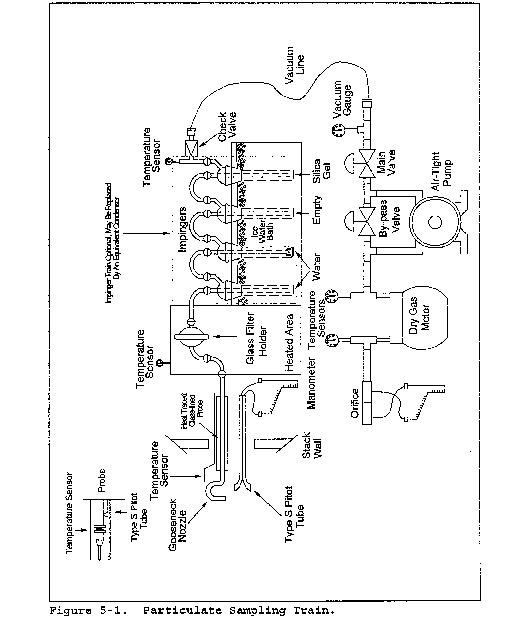
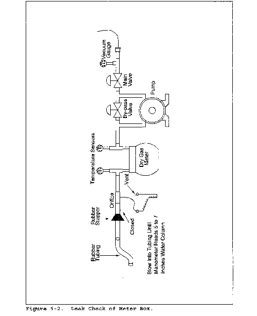

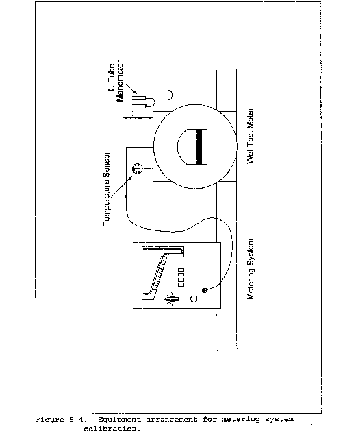


Date
Train ID
DGM cal. factor
Critical orifice ID
| Dry gas meter | Run No. | ||
|---|---|---|---|
| 1 | 2 | ||
| Final reading | m3 (ft3) | ||
| Initial reading | m3 (ft3) | ||
| Difference, Vm | m3 (ft3) | ||
| Inlet/Outlet | |||
| Temperatures: | °C ( °F) | / | / |
| Initial | °C ( °F) | / | / |
| Final | min/sec | / | / |
| Av. Temeperature, tm | min | ||
| Time, θ | |||
| Orifice man. rdg., ΔH | mm (in.) H2 | ||
| Bar. pressure, Pbar | mm (in.) Hg | ||
| Ambient temperature, tamb | mm (in.) Hg | ||
| Pump vacuum | |||
| K′ factor | |||
| Average | |||
Figure 5-11. Data sheet of determining K′ factor.
Date
Train ID
Critical orifice ID
Critical orifice K' factor
| Dry gas meter | Run No. | ||
|---|---|---|---|
| 1 | 2 | ||
| Final reading | m3 (ft3) | ||
| Initial reading | m3 (ft3) | ||
| Difference, Vm | m3 (ft3) | ||
| Inlet/outlet temperatures | °C ( °F) | / | / |
| Initial | °C ( °F) | / | / |
| Final | °C ( °F) | ||
| Avg. Temperature, tm | min/sec | / | / |
| Time, θ | min | ||
| Orifice man. rdg., ΔH | min | ||
| Bar. pressure, Pbar | mm (in.) H2O | ||
| Ambient temperature, tamb | mm (in.) Hg | ||
| Pump vacuum | °C ( °F) | ||
| Vm(std) | mm (in.) Hg | ||
| Vcr(std) | m3 (ft3) | ||
| DGM cal. factor, Y | m3 (ft3) | ||
Figure 5-12. Data Sheet for Determining DGM Y Factor
Method 5A - Determination of Particulate Matter Emissions From the Asphalt Processing and Asphalt Roofing Industry
This method does not include all of the specifications (e.g., equipment and supplies) and procedures (e.g., sampling and analytical) essential to its performance. Some material is incorporated by reference from other methods in this part. Therefore, to obtain reliable results, persons using this method should have a thorough knowledge of at least the following additional test methods: Method 1, Method 2, Method 3, and Method 5.
1.0 Scope and Applications
1.1 Analyte. Particulate matter (PM). No CAS number assigned.
1.2 Applicability. This method is applicable for the determination of PM emissions from asphalt roofing industry process saturators, blowing stills, and other sources as specified in the regulations.
1.3 Data Quality Objectives. Adherence to the requirements of this method will enhance the quality of the data obtained from air pollutant sampling methods.
2.0 Summary of Method
Particulate matter is withdrawn isokinetically from the source and collected on a glass fiber filter maintained at a temperature of 42 ±10 °C (108 ±18 °F). The PM mass, which includes any material that condenses at or above the filtration temperature, is determined gravimetrically after the removal of uncombined water.
3.0 Definitions [Reserved]
4.0 Interferences [Reserved]
5.0 Safety
5.1 Disclaimer. This method may involve hazardous materials, operations, and equipment. This test method may not address all of the safety problems associated with its use. It is the responsibility of the user of this test method to establish appropriate safety and health practices and to determine the applicability of regulatory limitations prior to performing this test method.
6.0 Equipment and Supplies
6.1 Sample Collection. Same as Method 5, section 6.1, with the following exceptions and additions:
6.1.1 Probe Liner. Same as Method 5, section 6.1.1.2, with the note that at high stack gas temperatures greater than 250 °C (480 °F), water-cooled probes may be required to control the probe exit temperature to 42 ±10 °C (108 ±18 °F).
6.1.2 Precollector Cyclone. Borosilicate glass following the construction details shown in Air Pollution Technical Document (APTD)-0581, “Construction Details of Isokinetic Source-Sampling Equipment” (Reference 2 in Method 5, section 17.0).
The cyclone shall be used when the stack gas moisture is greater than 10 percent, and shall not be used otherwise.
6.1.3 Filter Heating System. Any heating (or cooling) system capable of maintaining a sample gas temperature at the exit end of the filter holder during sampling at 42 ±10 °C (108 ±18 °F).
6.2 Sample Recovery. The following items are required for sample recovery:
6.2.1 Probe-Liner and Probe-Nozzle Brushes, Graduated Cylinder and/or Balance, Plastic Storage Containers, and Funnel and Rubber Policeman. Same as in Method 5, sections 6.2.1, 6.2.5, 6.2.6, and 6.2.7, respectively.
6.2.2 Wash Bottles. Glass.
6.2.3 Sample Storage Containers. Chemically resistant 500-ml or 1,000-ml borosilicate glass bottles, with rubber-backed Teflon screw cap liners or caps that are constructed so as to be leak-free, and resistant to chemical attack by 1,1,1-trichloroethane (TCE). (Narrow-mouth glass bottles have been found to be less prone to leakage.)
6.2.4 Petri Dishes. Glass, unless otherwise specified by the Administrator.
6.2.5 Funnel. Glass.
6.3 Sample Analysis. Same as Method 5, section 6.3, with the following additions:
6.3.1 Beakers. Glass, 250-ml and 500-ml.
6.3.2 Separatory Funnel. 100-ml or greater.
7.0. Reagents and Standards
7.1 Sample Collection. The following reagents are required for sample collection:
7.1.1 Filters, Silica Gel, Water, and Crushed Ice. Same as in Method 5, sections 7.1.1, 7.1.2, 7.1.3, and 7.1.4, respectively.
7.1.2 Stopcock Grease. TCE-insoluble, heat-stable grease (if needed). This is not necessary if screw-on connectors with Teflon sleeves, or similar, are used.
7.2 Sample Recovery. Reagent grade TCE, ≤0.001 percent residue and stored in glass bottles. Run TCE blanks before field use, and use only TCE with low blank values (≤0.001 percent). In no case shall a blank value of greater than 0.001 percent of the weight of TCE used be subtracted from the sample weight.
7.3 Analysis. Two reagents are required for the analysis:
7.3.1 TCE. Same as in section 7.2.
7.3.2 Desiccant. Same as in Method 5, section 7.3.2.
8.0. Sample Collection, Preservation, Storage, and Transport
8.1 Pretest Preparation. Unless otherwise specified, maintain and calibrate all components according to the procedure described in APTD-0576, “Maintenance, Calibration, and Operation of Isokinetic Source-Sampling Equipment” (Reference 3 in Method 5, Section 17.0). Alternative mercury-free thermometers may be used if the thermometers are, at a minimum, equivalent in terms of performance or suitably effective for the specific temperature measurement application.
8.1.1 Prepare probe liners and sampling nozzles as needed for use. Thoroughly clean each component with soap and water followed by a minimum of three TCE rinses. Use the probe and nozzle brushes during at least one of the TCE rinses (refer to section 8.7 for rinsing techniques). Cap or seal the open ends of the probe liners and nozzles to prevent contamination during shipping.
8.1.2 Prepare silica gel portions and glass filters as specified in Method 5, section 8.1.
8.2 Preliminary Determinations. Select the sampling site, probe nozzle, and probe length as specified in Method 5, section 8.2. Select a total sampling time greater than or equal to the minimum total sampling time specified in the “Test Methods and Procedures” section of the applicable subpart of the regulations. Follow the guidelines outlined in Method 5, section 8.2 for sampling time per point and total sample volume collected.
8.3 Preparation of Sampling Train. Prepare the sampling train as specified in Method 5, section 8.3, with the addition of the precollector cyclone, if used, between the probe and filter holder. The temperature of the precollector cyclone, if used, should be maintained in the same range as that of the filter, i.e., 42 ±10 °C (108 ±18 °F). Use no stopcock grease on ground glass joints unless grease is insoluble in TCE.
8.4 Leak-Check Procedures. Same as Method 5, section 8.4.
8.5 Sampling Train Operation. Operate the sampling train as described in Method 5, section 8.5, except maintain the temperature of the gas exiting the filter holder at 42 ±10 °C (108 ±18 °F).
8.6 Calculation of Percent Isokinetic. Same as Method 5, section 8.6.
8.7 Sample Recovery. Same as Method 5, section 8.7.1 through 8.7.6.1, with the addition of the following:
8.7.1 Container No. 2 (Probe to Filter Holder).
8.7.1.1 Taking care to see that material on the outside of the probe or other exterior surfaces does not get into the sample, quantitatively recover PM or any condensate from the probe nozzle, probe fitting, probe liner, precollector cyclone and collector flask (if used), and front half of the filter holder by washing these components with TCE and placing the wash in a glass container. Carefully measure the total amount of TCE used in the rinses. Perform the TCE rinses as described in Method 5, section 8.7.6.2, using TCE instead of acetone.
8.7.1.2 Brush and rinse the inside of the cyclone, cyclone collection flask, and the front half of the filter holder. Brush and rinse each surface three times or more, if necessary, to remove visible PM.
8.7.2 Container No. 3 (Silica Gel). Same as in Method 5, section 8.7.6.3.
8.7.3 Impinger Water. Same as Method 5, section 8.7.6.4.
8.8 Blank. Save a portion of the TCE used for cleanup as a blank. Take 200 ml of this TCE directly from the wash bottle being used, and place it in a glass sample container labeled “TCE Blank.”
9.0 Quality Control
9.1 Miscellaneous Quality Control Measures.
| Section | Quality control measure | Effect |
|---|---|---|
| 8.4, 10.0 | Sampling equipment leak check and calibration | Ensures accurate measurement of stack gas flow rate, sample volume. |
9.2 A quality control (QC) check of the volume metering system at the field site is suggested before collecting the sample. Use the procedure outlined in Method 5, section 9.2.
10.0 Calibration and Standardization
Same as Method 5, section 10.0.
11.0 Analytical Procedures
11.1 Analysis. Record the data required on a sheet such as the one shown in Figure 5A-1. Handle each sample container as follows:
11.1.1 Container No. 1 (Filter). Transfer the filter from the sample container to a tared glass weighing dish, and desiccate for 24 hours in a desiccator containing anhydrous calcium sulfate. Rinse Container No. 1 with a measured amount of TCE, and analyze this rinse with the contents of Container No. 2. Weigh the filter to a constant weight. For the purpose of this analysis, the term “constant weight” means a difference of no more than 10 percent of the net filter weight or 2 mg (whichever is greater) between two consecutive weighings made 24 hours apart. Report the “final weight” to the nearest 0.1 mg as the average of these two values.
11.1.2 Container No. 2 (Probe to Filter Holder).
11.1.2.1 Before adding the rinse from Container No. 1 to Container No. 2, note the level of liquid in Container No. 2, and confirm on the analysis sheet whether leakage occurred during transport. If noticeable leakage occurred, either void the sample or take steps, subject to the approval of the Administrator, to correct the final results.
11.1.2.2 Add the rinse from Container No. 1 to Container No. 2 and measure the liquid in this container either volumetrically to ±1 ml or gravimetrically to ±0.5 g. Check to see whether there is any appreciable quantity of condensed water present in the TCE rinse (look for a boundary layer or phase separation). If the volume of condensed water appears larger than 5 ml, separate the oil-TCE fraction from the water fraction using a separatory funnel. Measure the volume of the water phase to the nearest ml; adjust the stack gas moisture content, if necessary (see sections 12.3 and 12.4). Next, extract the water phase with several 25-ml portions of TCE until, by visual observation, the TCE does not remove any additional organic material. Transfer the remaining water fraction to a tared beaker and evaporate to dryness at 93 °C (200 °F), desiccate for 24 hours, and weigh to the nearest 0.1 mg.
11.1.2.3 Treat the total TCE fraction (including TCE from the filter container rinse and water phase extractions) as follows: Transfer the TCE and oil to a tared beaker, and evaporate at ambient temperature and pressure. The evaporation of TCE from the solution may take several days. Do not desiccate the sample until the solution reaches an apparent constant volume or until the odor of TCE is not detected. When it appears that the TCE has evaporated, desiccate the sample, and weigh it at 24-hour intervals to obtain a “constant weight” (as defined for Container No. 1 above). The “total weight” for Container No. 2 is the sum of the evaporated PM weight of the TCE-oil and water phase fractions. Report the results to the nearest 0.1 mg.
11.1.3 Container No. 3 (Silica Gel). This step may be conducted in the field. Weigh the spent silica gel (or silica gel plus impinger) to the nearest 0.5 g using a balance.
11.1.4 “TCE Blank” Container. Measure TCE in this container either volumetrically or gravimetrically. Transfer the TCE to a tared 250-ml beaker, and evaporate to dryness at ambient temperature and pressure. Desiccate for 24 hours, and weigh to a constant weight. Report the results to the nearest 0.1 mg.
In order to facilitate the evaporation of TCE liquid samples, these samples may be dried in a controlled temperature oven at temperatures up to 38 °C (100 °F) until the liquid is evaporated.
12.0 Data Analysis and Calculations
Carry out calculations, retaining at least one extra significant figure beyond that of the acquired data. Round off figures after the final calculation. Other forms of the equations may be used as long as they give equivalent results.
12.1 Nomenclature. Same as Method 5, section 12.1, with the following additions:
Ct = TCE blank residue concentration, mg/g.
mt = Mass of residue of TCE blank after evaporation, mg.
Vpc = Volume of water collected in precollector, ml.
Vt = Volume of TCE blank, ml.
Vtw = Volume of TCE used in wash, ml.
Wt = Weight of residue in TCE wash, mg.
ρt = Density of TCE (see label on bottle), g/ml.
12.2 Dry Gas Meter Temperature, Orifice Pressure Drop, and Dry Gas Volume. Same as Method 5, sections 12.2 and 12.3, except use data obtained in performing this test.
12.3 Volume of Water Vapor.

Where:
K2 = 0.001333 m3/ml for metric units.
= 0.04706 ft3/ml for English units.
12.4 Moisture Content.

In saturated or water droplet-laden gas streams, two calculations of the moisture content of the stack gas shall be made, one from the impinger and precollector analysis (Equations 5A-1 and 5A-2) and a second from the assumption of saturated conditions. The lower of the two values of moisture content shall be considered correct. The procedure for determining the moisture content based upon assumption of saturated conditions is given in section 4.0 of Method 4. For the purpose of this method, the average stack gas temperature from Figure 5-3 of Method 5 may be used to make this determination, provided that the accuracy of the in-stack temperature sensor is within 1 °C (2 °F).
12.5 TCE Blank Concentration.

In no case shall a blank value of greater than 0.001 percent of the weight of TCE used be subtracted from the sample weight.
12.6 TCE Wash Blank.

12.7 Total PM Weight. Determine the total PM catch from the sum of the weights obtained from Containers 1 and 2, less the TCE blank.
12.8 PM Concentration.

Where:
K3 = 0.001 g/mg for metric units
= 0.0154 gr/mg for English units
12.9 Isokinetic Variation. Same as in Method 5, section 12.11.
13.0 Method Performance [Reserved]
14.0 Pollution Prevention [Reserved]
15.0 Waste Management [Reserved]
16.0 References
Same as Method 5, section 17.0.
17.0 Tables, Diagrams, Flowcharts, and Validation Data
Plant
Date
Run No.
Filter No.
Amount liquid lost during transport
Acetone blank volume, m1
Acetone blank concentration, mg/mg (Equation 5-4)
Acetone wash blank, mg (Equation 5-5)
| Container number | Weight of particulate collected, mg | ||
|---|---|---|---|
| Final weight | Tare weight | Weight gain | |
| 1. | |||
| 2. | |||
| Total: | |||
| Less acetone blank | |||
| Weight of particulate matter | |||
| Volume of liquid water collected | ||
|---|---|---|
| Impinger volume,
ml |
Silica gel weight,
g |
|
| Final | ||
| Initial | ||
| Liquid collected | ||
| Total volume collected | g* ml | |

Method 5B - Determination of Nonsulfuric Acid Particulate Matter Emissions From Stationary Sources
This method does not include all of the specifications (e.g., equipment and supplies) and procedures (e.g., sampling and analytical) essential to its performance. Some material is incorporated by reference from other methods in this part. Therefore, to obtain reliable results, persons using this method should have a thorough knowledge of at least the following additional test methods: Method 1, Method 2, Method 3, Method 5.
1.0 Scope and Application
1.1 Analyte. Nonsulfuric acid particulate matter. No CAS number assigned.
1.2 Applicability. This method is determining applicable for the determination of nonsulfuric acid particulate matter from stationary sources, only where specified by an applicable subpart of the regulations or where approved by the Administrator for a particular application.
1.3 Data Quality Objectives. Adherence to the requirements of this method will enhance the quality of the data obtained from air pollutant sampling methods.
2.0 Summary of Method
Particulate matter is withdrawn isokinetically from the source and collected on a glass fiber filter maintained at a temperature of 160 ±14 °C (320 ±25 °F). The collected sample is then heated in an oven at 160 °C (320 °F) for 6 hours to volatilize any condensed sulfuric acid that may have been collected, and the nonsulfuric acid particulate mass is determined gravimetrically.
3.0 Definitions [Reserved]
4.0 Interferences [Reserved]
5.0 Safety
5.1 Disclaimer. This method may involve hazardous materials, operations, and equipment. This test method may not address all of the safety problems associated with its use. It is the responsibility of the user of this test method to establish appropriate safety and health practices and to determine the applicability of regulatory limitations prior to performing this test method.
6.0 Equipment and Supplies
Same as Method 5, section 6.0, with the following addition and exceptions:
6.1 Sample Collection. The probe liner heating system and filter heating system must be capable of maintaining a sample gas temperature of 160 ±14 °C (320 ±25 °F).
6.2 Sample Preparation. An oven is required for drying the sample.
7.0 Reagents and Standards
Same as Method 5, section 7.0.
8.0 Sample Collection, Preservation, Storage, and Transport.
Same as Method 5, with the exception of the following:
8.1 Initial Filter Tare. Oven dry the filter at 160 ±5 °C (320 ±10 °F) for 2 to 3 hours, cool in a desiccator for 2 hours, and weigh. Desiccate to constant weight to obtain the initial tare weight. Use the applicable specifications and techniques of section 8.1.3 of Method 5 for this determination.
8.2 Probe and Filter Temperatures. Maintain the probe outlet and filter temperatures at 160 ±14 °C (320 ±25 °F).
9.0 Quality Control
Same as Method 5, section 9.0.
10.0 Calibration and Standardization
Same as Method 5, section 10.0.
11.0 Analytical Procedure
11.1 Record and report the data required on a sheet such as the one shown in Figure 5B-1.
11.2 Handle each sample container as follows:
11.2.1 Container No. 1. Leave the contents in the shipping container or transfer the filter and any loose PM from the sample container to a tared non-reactive oven-proof container. Oven dry the filter sample at a temperature of 160 ±5 °C (320 ±9 °F) for 6 hours. Cool in a desiccator for 2 hours, and weigh to constant weight. Report the results to the nearest 0.1 mg. For the purposes of this section, the term “constant weight” means a difference of no more than 0.5 mg or 1 percent of total weight less tare weight, whichever is greater, between two consecutive weighings, with no less than 6 hours of desiccation time between weighings.
11.2.2 Container No. 2. Note the level of liquid in the container, and confirm on the analysis sheet whether leakage occurred during transport. If a noticeable amount of leakage has occurred, either void the sample or use methods, subject to the approval of the Administrator, to correct the final results. Measure the liquid in this container either volumetrically to ±1 ml or gravimetrically to ±0.5 g. Transfer the contents to a tared 250 ml beaker, and evaporate to dryness at ambient temperature and pressure. Then oven dry the probe sample at a temperature of 160 ±5 °C (320 ±9 °F) for 6 hours. Cool in a desiccator for 2 hours, and weigh to constant weight. Report the results to the nearest 0.1 mg.
11.2.3 Container No. 3. Weigh the spent silica gel (or silica gel plus impinger) to the nearest 0.5 g using a balance. This step may be conducted in the field.
11.2.4 Acetone Blank Container. Measure the acetone in this container either volumetrically or gravimetrically. Transfer the acetone to a tared 250 ml beaker, and evaporate to dryness at ambient temperature and pressure. Desiccate for 24 hours, and weigh to a constant weight. Report the results to the nearest 0.1 mg.
Note: The contents of Container No. 2 as well as the acetone blank container may be evaporated at temperatures higher than ambient. If evaporation is done at an elevated temperature, the temperature must be below the boiling point of the solvent; also, to prevent “bumping,” the evaporation process must be closely supervised, and the contents of the beaker must be swirled occasionally to maintain an even temperature. Use extreme care, as acetone is highly flammable and has a low flash point.
12.0 Data Analysis and Calculations
Same as in Method 5, section 12.0.
13.0 Method Performance [Reserved]
14.0 Pollution Prevention [Reserved]
15.0 Waste Management [Reserved]
16.0 References
Same as Method 5, section 17.0.
17.0 Tables, Diagrams, Flowcharts, and Validation Data
| Container number | Weight of particulate collected, mg | ||
|---|---|---|---|
| Final weight | Tare weight | Weight gain | |
| 1. | |||
| 2. | |||
| Total: | |||
| Less acetone blank | |||
| Weight of particulate matter | |||
| Volume of liquid water collected | ||
|---|---|---|
| Impinger volume, | Silica gel weight, | |
| ml | g | |
| Final | ||
| Initial | ||
| Liquid collected | ||
| Total volume collected | g* ml | |
Figure 5B-1. Analytical Data Sheet
Method 5C [Reserved]
Method 5D - Determination of Particulate Matter Emissions from Positive Pressure Fabric Filters
This method does not include all of the specifications (e.g., equipment and supplies) and procedures (e.g., sampling and analytical) essential to its performance. Some material is incorporated by reference from other methods in this part. Therefore, to obtain reliable results, persons using this method should have a thorough knowledge of at least the following additional test methods: Method 1, Method 2, Method 3, Method 5, Method 17.
1.0 Scope and Application
1.1 Analyte. Particulate matter (PM). No CAS number assigned.
1.2 Applicability.
1.2.1 This method is applicable for the determination of PM emissions from positive pressure fabric filters. Emissions are determined in terms of concentration (mg/m3 or gr/ft3) and emission rate (kg/hr or lb/hr).
1.2.2 The General Provisions of 40 CFR part 60, § 60.8(e), require that the owner or operator of an affected facility shall provide performance testing facilities. Such performance testing facilities include sampling ports, safe sampling platforms, safe access to sampling sites, and utilities for testing. It is intended that affected facilities also provide sampling locations that meet the specification for adequate stack length and minimal flow disturbances as described in Method 1. Provisions for testing are often overlooked factors in designing fabric filters or are extremely costly. The purpose of this procedure is to identify appropriate alternative locations and procedures for sampling the emissions from positive pressure fabric filters. The requirements that the affected facility owner or operator provide adequate access to performance testing facilities remain in effect.
1.3 Data Quality Objectives. Adherence to the requirements of this method will enhance the quality of the data obtained from air pollutant sampling methods.
2.0 Summary of Method
2.1 Particulate matter is withdrawn isokinetically from the source and collected on a glass fiber filter maintained at a temperature at or above the exhaust gas temperature up to a nominal 120 °C (248 ±25 °F). The particulate mass, which includes any material that condenses at or above the filtration temperature, is determined gravimetrically after the removal of uncombined water.
3.0 Definitions [Reserved]
4.0 Interferences [Reserved]
5.0 Safety
5.1 Disclaimer. This method may involve hazardous materials, operations, and equipment. This test method may not address all of the safety problems associated with its use. It is the responsibility of the user to establish appropriate safety and health practices and to determine the applicability of regulatory limitations prior to performing this test method.
6.0 Equipment and Supplies
Same as section 6.0 of either Method 5 or Method 17.
7.0 Reagents and Standards
Same as section 7.0 of either Method 5 or Method 17.
8.0 Sample Collection, Preservation, Storage, and Transport
Same section 8.0 of either Method 5 or Method 17, except replace section 8.2.1 of Method 5 with the following:
8.1 Determination of Measurement Site. The configuration of positive pressure fabric filter structures frequently are not amenable to emission testing according to the requirements of Method 1. Following are several alternatives for determining measurement sites for positive pressure fabric filters.
8.1.1 Stacks Meeting Method 1 Criteria. Use a measurement site as specified in Method 1, section 11.1.
8.1.2 Short Stacks Not Meeting Method 1 Criteria. Use stack extensions and the procedures in Method 1. Alternatively, use flow straightening vanes of the “egg-crate” type (see Figure 5D-1). Locate the measurement site downstream of the straightening vanes at a distance equal to or greater than two times the average equivalent diameter of the vane openings and at least one-half of the overall stack diameter upstream of the stack outlet.
8.1.3 Roof Monitor or Monovent. (See Figure 5D-2). For a positive pressure fabric filter equipped with a peaked roof monitor, ridge vent, or other type of monovent, use a measurement site at the base of the monovent. Examples of such locations are shown in Figure 5D-2. The measurement site must be upstream of any exhaust point (e.g., louvered vent).
8.1.4 Compartment Housing. Sample immediately downstream of the filter bags directly above the tops of the bags as shown in the examples in Figure 5D-2. Depending on the housing design, use sampling ports in the housing walls or locate the sampling equipment within the compartment housing.
8.2 Determination of Number and Location of Traverse Points. Locate the traverse points according to Method 1, section 11.3. Because a performance test consists of at least three test runs and because of the varied configurations of positive pressure fabric filters, there are several schemes by which the number of traverse points can be determined and the three test runs can be conducted.
8.2.1 Single Stacks Meeting Method 1 Criteria. Select the number of traverse points according to Method 1. Sample all traverse points for each test run.
8.2.2 Other Single Measurement Sites. For a roof monitor or monovent, single compartment housing, or other stack not meeting Method 1 criteria, use at least 24 traverse points. For example, for a rectangular measurement site, such as a monovent, use a balanced 5 × 5 traverse point matrix. Sample all traverse points for each test run.
8.2.3 Multiple Measurement Sites. Sampling from two or more stacks or measurement sites may be combined for a test run, provided the following guidelines are met:
8.2.3.1 All measurement sites up to 12 must be sampled. For more than 12 measurement sites, conduct sampling on at least 12 sites or 50 percent of the sites, whichever is greater. The measurement sites sampled should be evenly, or nearly evenly, distributed among the available sites; if not, all sites are to be sampled.
8.2.3.2 The same number of measurement sites must be sampled for each test run.
8.2.3.3 The minimum number of traverse points per test run is 24. An exception to the 24-point minimum would be a test combining the sampling from two stacks meeting Method 1 criteria for acceptable stack length, and Method 1 specifies fewer than 12 points per site.
8.2.3.4 As long as the 24 traverse points per test run criterion is met, the number of traverse points per measurement site may be reduced to eight.
8.2.3.5 Alternatively, conduct a test run for each measurement site individually using the criteria in section 8.2.1 or 8.2.2 to determine the number of traverse points. Each test run shall count toward the total of three required for a performance test. If more than three measurement sites are sampled, the number of traverse points per measurement site may be reduced to eight as long as at least 72 traverse points are sampled for all the tests.
8.2.3.6 The following examples demonstrate the procedures for sampling multiple measurement sites.
8.2.3.6.1 Example 1: A source with nine circular measurement sites of equal areas may be tested as follows: For each test run, traverse three measurement sites using four points per diameter (eight points per measurement site). In this manner, test run number 1 will include sampling from sites 1,2, and 3; run 2 will include samples from sites 4, 5, and 6; and run 3 will include sites 7, 8, and 9. Each test area may consist of a separate test of each measurement site using eight points. Use the results from all nine tests in determining the emission average.
8.2.3.6.2 Example 2: A source with 30 rectangular measurement sites of equal areas may be tested as follows: For each of the three test runs, traverse five measurement sites using a 3 × 3 matrix of traverse points for each site. In order to distribute the sampling evenly over all the available measurement sites while sampling only 50 percent of the sites, number the sites consecutively from 1 to 30 and sample all the even numbered (or odd numbered) sites. Alternatively, conduct a separate test of each of 15 measurement sites using section 8.2.1 or 8.2.2 to determine the number and location of traverse points, as appropriate.
8.2.3.6.3 Example 3: A source with two measurement sites of equal areas may be tested as follows: For each test of three test runs, traverse both measurement sites, using section 8.2.3 in determining the number of traverse points. Alternatively, conduct two full emission test runs for each measurement site using the criteria in section 8.2.1 or 8.2.2 to determine the number of traverse points.
8.2.3.7 Other test schemes, such as random determination of traverse points for a large number of measurement sites, may be used with prior approval from the Administrator.
8.3 Velocity Determination.
8.3.1 The velocities of exhaust gases from positive pressure baghouses are often too low to measure accurately with the type S pitot tube specified in Method 2 (i.e., velocity head <1.3 mm H2O (0.05 in. H2O)). For these conditions, measure the gas flow rate at the fabric filter inlet following the procedures outlined in Method 2. Calculate the average gas velocity at the measurement site as shown in section 12.2 and use this average velocity in determining and maintaining isokinetic sampling rates.
8.3.2 Velocity determinations to determine and maintain isokinetic rates at measurement sites with gas velocities within the range measurable with the type S pitot tube (i.e., velocity head greater than 1.3 mm H2O (0.05 in. H2O)) shall be conducted according to the procedures outlined in Method 2.
8.4 Sampling. Follow the procedures specified in sections 8.1 through 8.6 of Method 5 or sections 8.1 through 8.25 in Method 17 with the exceptions as noted above.
8.5 Sample Recovery. Follow the procedures specified in section 8.7 of Method 5 or section 8.2 of Method 17.
9.0 Quality Control
9.1 Miscellaneous Quality Control Measures.
| Section | Quality control measure | Effect |
|---|---|---|
| 8.0, 10.0 | Sampling equipment leak check and calibration | Ensures accurate measurement of stack gas flow rate, sample volume. |
9.2 Volume Metering System Checks. Same as Method 5, section 9.2.
10.0 Calibration and Standardization
Same as section 10.0 of either Method 5 or Method 17.
11.0 Analytical Procedure
Same as section 11.0 of either Method 5 or Method 17.
12.0 Data Analysis and Calculations
Same as section 12.0 of either Method 5 or Method 17 with the following exceptions:
12.1 Nomenclature.
Ao = Measurement site(s) total cross-sectional area, m2 (ft2).
C̄ or Cavg = Average concentration of PM for all n runs, mg/scm (gr/scf).
Qi = Inlet gas volume flow rate, m3/sec (ft3/sec).
mi = Mass collected for run i of n, mg (gr).
To = Average temperature of gas at measurement site, °K (°R).
Ti = Average temperature of gas at inlet, °K (°R).
Voli = Sample volume collected for run i of n, scm (scf).
v̄ = Average gas velocity at the measurement site(s), m/s (ft/s)
Qo = Total baghouse exhaust volumetric flow rate, m3/sec (ft3/sec).
Qd = Dilution air flow rate, m3/sec (ft3/sec).
Tamb = Ambient Temperature, (°K).
12.2 Average Gas Velocity. When following section 8.3.1, calculate the average gas velocity at the measurement site as follows:

12.3 Volumetric Flow Rate. Total volumetric flow rate may be determined as follows:

12.4 Dilution Air Flow Rate.

12.5 Average PM Concentration. For multiple measurement sites, calculate the average PM concentration as follows:

13.0 Method Performance [Reserved]
14.0 Pollution Prevention [Reserved]
15.0 Waste Management [Reserved]
16.0 References
Same as Method 5, section 17.0.
17.0 Tables, Diagrams, Flowcharts, and Validation Data

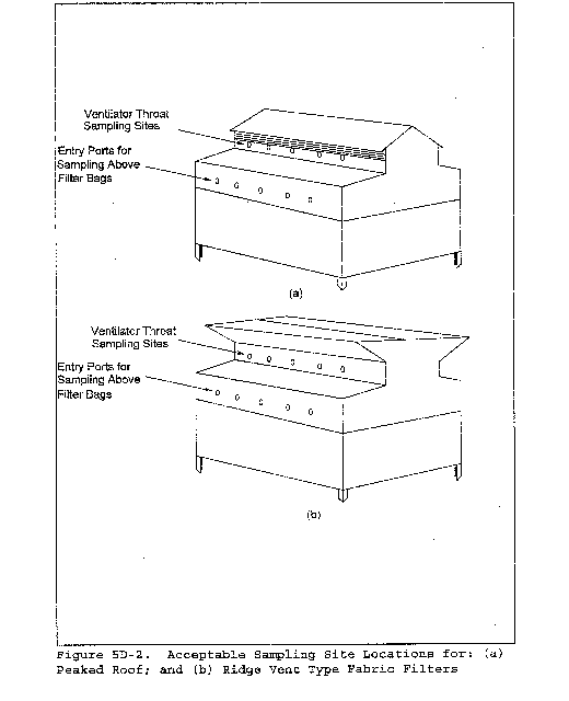
Method 5E - Determination of Particulate Matter Emissions From the Wool Fiberglass Insulation Manufacturing Industry
This method does not include all of the specifications (e.g., equipment and supplies) and procedures (e.g., sampling and analytical) essential to its performance. Some material is incorporated by reference from other methods in this part. Therefore, to obtain reliable results, persons using this method should have a thorough knowledge of at least the following additional test methods: Method 1, Method 2, Method 3, and Method 5.
1.0 Scope and Applications
1.1 Analyte. Particulate matter (PM). No CAS number assigned.
1.2 Applicability. This method is applicable for the determination of PM emissions from wool fiberglass insulation manufacturing sources.
2.0 Summary of Method
Particulate matter is withdrawn isokinetically from the source and is collected either on a glass fiber filter maintained at a temperature in the range of 120 ±14 °C (248 ±25 °F) and in impingers in solutions of 0.1 N sodium hydroxide (NaOH). The filtered particulate mass, which includes any material that condenses at or above the filtration temperature, is determined gravimetrically after the removal of uncombined water. The condensed PM collected in the impinger solutions is determined as total organic carbon (TOC) using a nondispersive infrared type of analyzer. The sum of the filtered PM mass and the condensed PM is reported as the total PM mass.
3.0 Definitions [Reserved]
4.0 Interferences [Reserved]
5.0 Safety
5.1 Disclaimer. This method may involve hazardous materials, operations, and equipment. This test method may not address all of the safety problems associated with its use. It is the responsibility of the user of this test method to establish appropriate safety and health practices and to determine the applicability of regulatory limitations prior to performing this test method.
5.2 Corrosive Reagents. The following reagents are hazardous. Personal protective equipment and safe procedures are useful in preventing chemical splashes. If contact occurs, immediately flush with copious amounts of water at least 15 minutes. Remove clothing under shower and decontaminate. Treat residual chemical burn as thermal burn.
5.2.1 Hydrochloric Acid (HCl). Highly toxic. Vapors are highly irritating to eyes, skin, nose, and lungs, causing severe damage. May cause bronchitis, pneumonia, or edema of lungs. Exposure to concentrations of 0.13 to 0.2 percent in air can be lethal in minutes. Will react with metals, producing hydrogen.
5.2.2 Sodium Hydroxide (NaOH). Causes severe damage to eye tissues and to skin. Inhalation causes irritation to nose, throat, and lungs. Reacts exothermically with limited amounts of water.
6.0 Equipment and Supplies
6.1 Sample Collection. Same as Method 5, section 6.1, with the exception of the following:
6.1.1 Probe Liner. Same as described in section 6.1.1.2 of Method 5 except use only borosilicate or quartz glass liners.
6.1.2 Filter Holder. Same as described in section 6.1.1.5 of Method 5 with the addition of a leak-tight connection in the rear half of the filter holder designed for insertion of a temperature sensor used for measuring the sample gas exit temperature.
6.2 Sample Recovery. Same as Method 5, section 6.2, except three wash bottles are needed instead of two and only glass storage bottles and funnels may be used.
6.3 Sample Analysis. Same as Method 5, section 6.3, with the additional equipment for TOC analysis as described below:
6.3.1 Sample Blender or Homogenizer. Waring type or ultrasonic.
6.3.2 Magnetic Stirrer.
6.3.3 Hypodermic Syringe. 0- to 100-µl capacity.
6.3.4 Total Organic Carbon Analyzer. Rosemount Model 2100A analyzer or equivalent and a recorder.
6.3.5 Beaker. 30-ml.
6.3.6 Water Bath. Temperature controlled.
6.3.7 Volumetric Flasks. 1000-ml and 500-ml.
7.0 Reagents and Standards
Unless otherwise indicated, it is intended that all reagents conform to the specifications established by the Committee on Analytical Reagents of the American Chemical Society, where such specifications are available; otherwise, use the best available grade.
7.1 Sample Collection. Same as Method 5, section 7.1, with the addition of 0.1 N NaOH (Dissolve 4 g of NaOH in water and dilute to 1 liter).
7.2 Sample Recovery. Same as Method 5, section 7.2, with the addition of the following:
7.2.1 Water. Deionized distilled to conform to ASTM Specification D 1193-77 or 91 Type 3 (incorporated by reference - see § 60.17). The potassium permanganate (KMnO4) test for oxidizable organic matter may be omitted when high concentrations of organic matter are not expected to be present.
7.2.2 Sodium Hydroxide. Same as described in section 7.1.
7.3 Sample Analysis. Same as Method 5, section 7.3, with the addition of the following:
7.3.1 Carbon Dioxide-Free Water. Distilled or deionized water that has been freshly boiled for 15 minutes and cooled to room temperature while preventing exposure to ambient air by using a cover vented with an Ascarite tube.
7.3.2 Hydrochloric Acid. HCl, concentrated, with a dropper.
7.3.3 Organic Carbon Stock Solution. Dissolve 2.1254 g of dried potassium biphthalate (HOOCC6H4COOK) in CO2-free water, and dilute to 1 liter in a volumetric flask. This solution contains 1000 mg/L organic carbon.
7.3.4 Inorganic Carbon Stock Solution. Dissolve 4.404 g anhydrous sodium carbonate (Na2CO3.) in about 500 ml of CO2-free water in a 1-liter volumetric flask. Add 3.497 g anhydrous sodium bicarbonate (NaHCO3) to the flask, and dilute to 1 liter with CO2 -free water. This solution contains 1000 mg/L inorganic carbon.
7.3.5 Oxygen Gas. CO2 -free.
8.0 Sample Collection, Preservation, Storage, and Transport
8.1 Pretest Preparation and Preliminary Determinations. Same as Method 5, sections 8.1 and 8.2, respectively.
8.2 Preparation of Sampling Train. Same as Method 5, section 8.3, except that 0.1 N NaOH is used in place of water in the impingers. The volumes of the solutions are the same as in Method 5.
8.3 Leak-Check Procedures, Sampling Train Operation, Calculation of Percent Isokinetic. Same as Method 5, sections 8.4 through 8.6, respectively.
8.4 Sample Recovery. Same as Method 5, sections 8.7.1 through 8.7.4, with the addition of the following:
8.4.1 Save portions of the water, acetone, and 0.1 N NaOH used for cleanup as blanks. Take 200 ml of each liquid directly from the wash bottles being used, and place in glass sample containers labeled “water blank,” “acetone blank,” and “NaOH blank,” respectively.
8.4.2 Inspect the train prior to and during disassembly, and note any abnormal conditions. Treat the samples as follows:
8.4.2.1 Container No. 1. Same as Method 5, section 8.7.6.1.
8.4.2.2 Container No. 2. Use water to rinse the sample nozzle, probe, and front half of the filter holder three times in the manner described in section 8.7.6.2 of Method 5 except that no brushing is done. Put all the water wash in one container, seal, and label.
8.4.2.3 Container No. 3. Rinse and brush the sample nozzle, probe, and front half of the filter holder with acetone as described for Container No. 2 in section 8.7.6.2 of Method 5.
8.4.2.4 Container No. 4. Place the contents of the silica gel impinger in its original container as described for Container No. 3 in section 8.7.6.3 of Method 5.
8.4.2.5 Container No. 5. Measure the liquid in the first three impingers and record the volume or weight as described for the Impinger Water in section 8.7.6.4 of Method 5. Do not discard this liquid, but place it in a sample container using a glass funnel to aid in the transfer from the impingers or graduated cylinder (if used) to the sample container. Rinse each impinger thoroughly with 0.1 N NaOH three times, as well as the graduated cylinder (if used) and the funnel, and put these rinsings in the same sample container. Seal the container and label to clearly identify its contents.
8.5 Sample Transport. Whenever possible, containers should be shipped in such a way that they remain upright at all times.
9.0 Quality Control.
9.1 Miscellaneous Quality Control Measures.
| Section | Quality control measure | Effect |
|---|---|---|
| 8.3, 10.0 | Sampling equipment leak-check and calibration | Ensures accurate measurement of stack gas flow rate, sample volume. |
| 10.1.2, 11.2.5.3 | Repetitive analyses | Ensures precise measurement of total carbon and inorganic carbon concentration of samples, blank, and standards. |
| 10.1.4 | TOC analyzer calibration | Ensures linearity of analyzer response to standards. |
9.2 Volume Metering System Checks. Same as Method 5, section 9.2.
10.0 Calibration and Standardization
Same as Method 5, section 10.0, with the addition of the following procedures for calibrating the total organic carbon analyzer:
10.1 Preparation of Organic Carbon Standard Curve.
10.1.1 Add 10 ml, 20 ml, 30 ml, 40 ml, and 50 ml of the organic carbon stock solution to a series of five 1000-ml volumetric flasks. Add 30 ml, 40 ml, and 50 ml of the same solution to a series of three 500-ml volumetric flasks. Dilute the contents of each flask to the mark using CO2-free water. These flasks contain 10, 20, 30, 40, 50, 60, 80, and 100 mg/L organic carbon, respectively.
10.1.2 Use a hypodermic syringe to withdraw a 20- to 50-µl aliquot from the 10 mg/L standard solution and inject it into the total carbon port of the analyzer. Measure the peak height. Repeat the injections until three consecutive peaks are obtained within 10 percent of their arithmetic mean. Repeat this procedure for the remaining organic carbon standard solutions.
10.1.3 Calculate the corrected peak height for each standard by deducting the blank correction (see section 11.2.5.3) as follows:

Where:
A = Peak height of standard or sample, mm or other appropriate unit.
B = Peak height of blank, mm or other appropriate unit.
10.1.4 Prepare a linear regression plot of the arithmetic mean of the three consecutive peak heights obtained for each standard solution against the concentration of that solution. Calculate the calibration factor as the inverse of the slope of this curve. If the product of the arithmetic mean peak height for any standard solution and the calibration factor differs from the actual concentration by more than 5 percent, remake and reanalyze that standard.
10.2 Preparation of Inorganic Carbon Standard Curve. Repeat the procedures outlined in sections 10.1.1 through 10.1.4, substituting the inorganic carbon stock solution for the organic carbon stock solution, and the inorganic carbon port of the analyzer for the total carbon port.
11.0 Analytical Procedure
11.1 Record the data required on a sheet such as the one shown in Figure 5-6 of Method 5.
11.2 Handle each sample container as follows:
11.2.1 Container No. 1. Same as Method 5, section 11.2.1, except that the filters must be dried at 20 ±6 °C (68 ±10 °F) and ambient pressure.
11.2.2 Containers No. 2 and No. 3. Same as Method 5, section 11.2.2, except that evaporation of the samples must be at 20 ±6 °C (68 ±10 °F) and ambient pressure.
11.2.3 Container No. 4. Same as Method 5, section 11.2.3.
11.2.4 “Water Blank” and “Acetone Blank” Containers. Determine the water and acetone blank values following the procedures for the “Acetone Blank” container in section 11.2.4 of Method 5. Evaporate the samples at ambient temperature (20 ±6 °C (68 ±10 °F)) and pressure.
11.2.5 Container No. 5. For the determination of total organic carbon, perform two analyses on successive identical samples, i.e., total carbon and inorganic carbon. The desired quantity is the difference between the two values obtained. Both analyses are based on conversion of sample carbon into carbon dioxide for measurement by a nondispersive infrared analyzer. Results of analyses register as peaks on a strip chart recorder.
11.2.5.1 The principal differences between the operating parameters for the two channels involve the combustion tube packing material and temperature. In the total carbon channel, a high temperature (950 °C (1740 °F)) furnace heats a Hastelloy combustion tube packed with cobalt oxide-impregnated asbestos fiber. The oxygen in the carrier gas, the elevated temperature, and the catalytic effect of the packing result in oxidation of both organic and inorganic carbonaceous material to CO2, and steam. In the inorganic carbon channel, a low temperature (150 °C (300 °F)) furnace heats a glass tube containing quartz chips wetted with 85 percent phosphoric acid. The acid liberates CO2 and steam from inorganic carbonates. The operating temperature is below that required to oxidize organic matter. Follow the manufacturer's instructions for assembly, testing, calibration, and operation of the analyzer.
11.2.5.2 As samples collected in 0.1 N NaOH often contain a high measure of inorganic carbon that inhibits repeatable determinations of TOC, sample pretreatment is necessary. Measure and record the liquid volume of each sample (or impinger contents). If the sample contains solids or immiscible liquid matter, homogenize the sample with a blender or ultrasonics until satisfactory repeatability is obtained. Transfer a representative portion of 10 to 15 ml to a 30-ml beaker, and acidify with about 2 drops of concentrated HCl to a pH of 2 or less. Warm the acidified sample at 50 °C (120 °F) in a water bath for 15 minutes.
11.2.5.3 While stirring the sample with a magnetic stirrer, use a hypodermic syringe to withdraw a 20-to 50-µ1 aliquot from the beaker. Analyze the sample for total carbon and calculate its corrected mean peak height according to the procedures outlined in sections 10.1.2 and 10.1.3. Similarly analyze an aliquot of the sample for inorganic carbon. Repeat the analyses for all the samples and for the 0.1 N NaOH blank.
11.2.5.4 Ascertain the total carbon and inorganic carbon concentrations (CTC and CIC, respectively) of each sample and blank by comparing the corrected mean peak heights for each sample and blank to the appropriate standard curve.
If samples must be diluted for analysis, apply an appropriate dilution factor.
12.0 Data Analysis and Calculations
Same as Method 5, section 12.0, with the addition of the following:
12.1 Nomenclature.
Cc = Concentration of condensed particulate matter in stack gas, gas dry basis, corrected to standard conditions, g/dscm (gr/dscf).
CIC = Concentration of condensed TOC in the liquid sample, from section 11.2.5, mg/L.
Ct = Total particulate concentration, dry basis, corrected to standard conditions, g/dscm (gr/dscf).
CTC = Concentration of condensed TOC in the liquid sample, from section 11.2.5, mg/L.
CTOC = Concentration of condensed TOC in the liquid sample, mg/L.
mTOC = Mass of condensed TOC collected in the impingers, mg.
Vm(std) = Volume of gas sample measured by the dry gas meter, corrected to standard conditions, from section 12.3 of Method 5, dscm (dscf).
Vs = Total volume of liquid sample, ml.
12.2 Concentration of Condensed TOC in Liquid Sample.

12.3 Mass of Condensed TOC Collected.

Where:
0.001 = Liters per milliliter.
12.4 Concentration of Condensed Particulate Material.

Where:
K4 = 0.001 g/mg for metric units.
= 0.0154 gr/mg for English units.
12.5 Total Particulate Concentration.

13.0 Method Performance [Reserved]
14.0 Pollution Prevention [Reserved]
15.0 Waste Management [Reserved]
16.0 Alternative Procedures
16.1 Total Organic Carbon Analyzer. Tekmar-Dohrmann analyzers using the single injection technique may be used as an alternative to Rosemount Model 2100A analyzers.
17.0 References.
Same as section 17.0 of Method 5, with the addition of the following:
1. American Public Health Association, American Water Works Association, Water Pollution Control Federation. Standard Methods for the Examination of Water and Wastewater. Fifteenth Edition. Washington, D.C. 1980.
18.0 Tables, Diagrams, Flowcharts, and Validation Data [Reserved]
Method 5F - Determination of Nonsulfate Particulate Matter Emissions From Stationary Sources
This method does not include all of the specifications (e.g., equipment and supplies) and procedures (e.g., sampling and analytical) essential to its performance. Some material is incorporated by reference from other methods in this part. Therefore, to obtain reliable results, persons using this method should have a thorough knowledge of at least the following additional test methods: Method 1, Method 2, Method 3, and Method 5.
1.0 Scope and Applications
1.1 Analyte. Nonsulfate particulate matter (PM). No CAS number assigned.
1.2 Applicability. This method is applicable for the determination of nonsulfate PM emissions from stationary sources. Use of this method must be specified by an applicable subpart of the standards, or approved by the Administrator for a particular application.
1.3 Data Quality Objectives. Adherence to the requirements of this method will enhance the quality of the data obtained from air pollutant sampling methods.
2.0 Summary of Method
Particulate matter is withdrawn isokinetically from the source and collected on a filter maintained at a temperature in the range 160 ±14 °C (320 ±25 °F). The collected sample is extracted with water. A portion of the extract is analyzed for sulfate content by ion chromatography. The remainder is neutralized with ammonium hydroxide (NH4OH), dried, and weighed. The weight of sulfate in the sample is calculated as ammonium sulfate ((NH4)2SO4), and is subtracted from the total particulate weight; the result is reported as nonsulfate particulate matter.
3.0 Definitions [Reserved]
4.0 Interferences [Reserved]
5.0 Safety
5.1 Disclaimer. This method may involve hazardous materials, operations, and equipment. This test method may not address all of the safety problems associated with its use. It is the responsibility of the user of this test method to establish appropriate safety and health practices and to determine the applicability of regulatory limitations prior to performing this test method.
6.0 Equipment and Supplies
6.1 Sample Collection and Recovery. Same as Method 5, sections 6.1 and 6.2, respectively.
6.2 Sample Analysis. Same as Method 5, section 6.3, with the addition of the following:
6.2.1 Erlenmeyer Flasks. 125-ml, with ground glass joints.
6.2.2 Air Condenser. With ground glass joint compatible with the Erlenmeyer flasks.
6.2.3 Beakers. 600-ml.
6.2.4 Volumetric Flasks. 1-liter, 500-ml (one for each sample), 200-ml, and 50-ml (one for each sample and standard).
6.2.5 Pipet. 5-ml (one for each sample and standard).
6.2.6 Ion Chromatograph. The ion chromatograph should have at least the following components.
6.2.6.1 Columns. An anion separation column or other column capable of resolving the sulfate ion from other species present and a standard anion suppressor column. Suppressor columns are produced as proprietary items; however, one can be produced in the laboratory using the resin available from BioRad Company, 32nd and Griffin Streets, Richmond, California. Other systems which do not use suppressor columns may also be used.
6.2.6.2 Pump. Capable of maintaining a steady flow as required by the system.
6.2.6.3 Flow Gauges. Capable of measuring the specified system flow rate.
6.2.6.4 Conductivity Detector.
6.2.6.5 Recorder. Compatible with the output voltage range of the detector.
7.0 Reagents and Standards
Unless otherwise indicated, it is intended that all reagents conform to the specifications established by the Committee on Analytical Reagents of the American Chemical Society, where such specifications are available; otherwise, use the best available grade.
7.1 Sample Collection. Same as Method 5, section 7.1.
7.2 Sample Recovery. Same as Method 5, section 7.2, with the addition of the following:
7.2.1 Water. Deionized distilled, to conform to ASTM D 1193-77 or 91 Type 3 (incorporated by reference - see § 60.17). The potassium permanganate (KMnO4) test for oxidizable organic matter may be omitted when high concentrations of organic matter are not expected to be present.
7.3 Analysis. Same as Method 5, section 7.3, with the addition of the following:
7.3.1 Water. Same as in section 7.2.1.
7.3.2 Stock Standard Solution, 1 mg (NH4)2SO4/ml. Dry an adequate amount of primary standard grade ammonium sulfate ((NH4)2SO4) at 105 to 110 °C (220 to 230 °F) for a minimum of 2 hours before preparing the standard solution. Then dissolve exactly 1.000 g of dried (NH4)2SO4 in water in a 1-liter volumetric flask, and dilute to 1 liter. Mix well.
7.3.3 Working Standard Solution, 25 µg (NH4)2SO4/ml. Pipet 5 ml of the stock standard solution into a 200-ml volumetric flask. Dilute to 200 ml with water.
7.3.4 Eluent Solution. Weigh 1.018 g of sodium carbonate (Na2CO3) and 1.008 g of sodium bicarbonate (NaHCO3), and dissolve in 4 liters of water. This solution is 0.0024 M Na2CO3/0.003 M NaHCO3. Other eluents appropriate to the column type and capable of resolving sulfate ion from other species present may be used.
7.3.5 Ammonium Hydroxide. Concentrated, 14.8 M.
7.3.6 Phenolphthalein Indicator. 3,3-Bis(4-hydroxyphenyl)-1-(3H)-isobenzo-furanone. Dissolve 0.05 g in 50 ml of ethanol and 50 ml of water.
8.0 Sample Collection, Preservation, Storage, and Transport
Same as Method 5, section 8.0, with the exception of the following:
8.1 Sampling Train Operation. Same as Method 5, section 8.5, except that the probe outlet and filter temperatures shall be maintained at 160 ±14 °C (320 ±25 °F).
8.2 Sample Recovery. Same as Method 5, section 8.7, except that the recovery solvent shall be water instead of acetone, and a clean filter from the same lot as those used during testing shall be saved for analysis as a blank.
9.0 Quality Control
9.1 Miscellaneous Quality Control Measures
| Section | Quality control measure | Effect |
|---|---|---|
| 8.3, 10.0 | Sampling equipment leak check and calibration | Ensures accurate measurement of stack gas flow rate, sample volume. |
| 10.1.2, 11.2.5.3 | Repetitive analyses | Ensures precise measurement of total carbon and inorganic carbon concentration of samples, blank, and standards. |
9.2 Volume Metering System Checks. Same as Method 5, section 9.2.
10.0 Calibration and Standardization
Same as Method 5, section 10.0, with the addition of the following:
10.1 Determination of Ion Chromatograph Calibration Factor S. Prepare a series of five standards by adding 1.0, 2.0, 4.0, 6.0, and 10.0 ml of working standard solution (25 µg/ml) to a series of five 50-ml volumetric flasks. (The standard masses will equal 25, 50, 100, 150, and 250 µg.) Dilute each flask to the mark with water, and mix well. Analyze each standard according to the chromatograph manufacturer's instructions. Take peak height measurements with symmetrical peaks; in all other cases, calculate peak areas. Prepare or calculate a linear regression plot of the standard masses in µg (x-axis) versus their responses (y-axis). From this line, or equation, determine the slope and calculate its reciprocal which is the calibration factor, S. If any point deviates from the line by more than 7 percent of the concentration at that point, remake and reanalyze that standard. This deviation can be determined by multiplying S times the response for each standard. The resultant concentrations must not differ by more than 7 percent from each known standard mass (i.e., 25, 50, 100, 150, and 250 µg).
10.2 Conductivity Detector. Calibrate according to manufacturer's specifications prior to initial use.
11.0 Analytical Procedure
11.1 Sample Extraction.
11.1.1 Note on the analytical data sheet, the level of the liquid in the container, and whether any sample was lost during shipment. If a noticeable amount of leakage has occurred, either void the sample or use methods, subject to the approval of the Administrator, to correct the final results.
11.1.2 Cut the filter into small pieces, and place it in a 125-ml Erlenmeyer flask with a ground glass joint equipped with an air condenser. Rinse the shipping container with water, and pour the rinse into the flask. Add additional water to the flask until it contains about 75 ml, and place the flask on a hot plate. Gently reflux the contents for 6 to 8 hours. Cool the solution, and transfer it to a 500-ml volumetric flask. Rinse the Erlenmeyer flask with water, and transfer the rinsings to the volumetric flask including the pieces of filter.
11.1.3 Transfer the probe rinse to the same 500-ml volumetric flask with the filter sample. Rinse the sample bottle with water, and add the rinsings to the volumetric flask. Dilute the contents of the flask to the mark with water.
11.1.4 Allow the contents of the flask to settle until all solid material is at the bottom of the flask. If necessary, remove and centrifuge a portion of the sample.
11.1.5 Repeat the procedures outlined in sections 11.1.1 through 11.1.4 for each sample and for the filter blank.
11.2 Sulfate (SO4) Analysis.
11.2.1 Prepare a standard calibration curve according to the procedures outlined in section 10.1.
11.2.2 Pipet 5 ml of the sample into a 50-ml volumetric flask, and dilute to 50 ml with water. (Alternatively, eluent solution may be used instead of water in all sample, standard, and blank dilutions.) Analyze the set of standards followed by the set of samples, including the filter blank, using the same injection volume used for the standards.
11.2.3 Repeat the analyses of the standards and the samples, with the standard set being done last. The two peak height or peak area responses for each sample must agree within 5 percent of their arithmetic mean for the analysis to be valid. Perform this analysis sequence on the same day. Dilute any sample and the blank with equal volumes of water if the concentration exceeds that of the highest standard.
11.2.4 Document each sample chromatogram by listing the following analytical parameters: injection point, injection volume, sulfate retention time, flow rate, detector sensitivity setting, and recorder chart speed.
11.3 Sample Residue.
11.3.1 Transfer the remaining contents of the volumetric flask to a tared 600-ml beaker or similar container. Rinse the volumetric flask with water, and add the rinsings to the tared beaker. Make certain that all particulate matter is transferred to the beaker. Evaporate the water in an oven at 105 °C (220 °F) until only about 100 ml of water remains. Remove the beakers from the oven, and allow them to cool.
11.3.2 After the beakers have cooled, add five drops of phenolphthalein indicator, and then add concentrated ammonium hydroxide until the solution turns pink. Return the samples to the oven at 105 °C (220 °F), and evaporate the samples to dryness. Cool the samples in a desiccator, and weigh the samples to constant weight.
12.0 Data Analysis and Calculations
Same as Method 5, section 12.0, with the addition of the following:
12.1 Nomenclature.
CW = Water blank residue concentration, mg/ml.
F = Dilution factor (required only if sample dilution was needed to reduce the concentration into the range of calibration).
HS = Arithmetic mean response of duplicate sample analyses, mm for height or mm2 for area.
Hb = Arithmetic mean response of duplicate filter blank analyses, mm for height or mm2 for area.
mb = Mass of beaker used to dry sample, mg.
mf = Mass of sample filter, mg.
mn = Mass of nonsulfate particulate matter in the sample as collected, mg.
ms = Mass of ammonium sulfate in the sample as collected, mg.
mt = Mass of beaker, filter, and dried sample, mg.
mw = Mass of residue after evaporation of water blank, mg.
S = Calibration factor, µg/mm.
Vb = Volume of water blank, ml.
VS = Volume of sample collected, 500 ml.
12.2 Water Blank Concentration.

12.3 Mass of Ammonium Sulfate.

Where:
100 = Aliquot factor, 495 ml/5 ml
1000 = Constant, µg/mg
12.4 Mass of Nonsulfate Particulate Matter.

13.0 Method Performance [Reserved]
14.0 Pollution Prevention [Reserved]
15.0 Waste Management [Reserved]
16.0 Alternative Procedures
16.1 The following procedure may be used as an alternative to the procedure in section 11.0
16.1.1 Apparatus. Same as for Method 6, sections 6.3.3 to 6.3.6 with the following additions.
16.1.1.1 Beakers. 250-ml, one for each sample, and 600-ml.
16.1.1.2 Oven. Capable of maintaining temperatures of 75 ±5 °C (167 ±9 °F) and 105 ±5 °C (221 ±9 °F).
16.1.1.3 Buchner Funnel.
16.1.1.4 Glass Columns. 25-mm × 305-mm (1-in. × 12-in.) with Teflon stopcock.
16.1.1.5 Volumetric Flasks. 50-ml and 500-ml, one set for each sample, and 100-ml, 200-ml, and 1000-ml.
16.1.1.6 Pipettes. Two 20-ml and one 200-ml, one set for each sample, and 5-ml.
16.1.1.7 Filter Flasks. 500-ml.
16.1.1.8 Polyethylene Bottle. 500-ml, one for each sample.
16.1.2 Reagents. Same as Method 6, sections 7.3.2 to 7.3.5 with the following additions:
16.1.2.1 Water, Ammonium Hydroxide, and Phenolphthalein. Same as sections 7.2.1, 7.3.5, and 7.3.6 of this method, respectively.
16.1.2.2 Filter. Glass fiber to fit Buchner funnel.
16.1.2.3 Hydrochloric Acid (HCl), 1 m. Add 8.3 ml of concentrated HCl (12 M) to 50 ml of water in a 100-ml volumetric flask. Dilute to 100 ml with water.
16.1.2.4 Glass Wool.
16.1.2.5 Ion Exchange Resin. Strong cation exchange resin, hydrogen form, analytical grade.
16.1.2.6 pH Paper. Range of 1 to 7.
16.1.3 Analysis.
16.1.3.1 Ion Exchange Column Preparation. Slurry the resin with 1 M HCl in a 250-ml beaker, and allow to stand overnight. Place 2.5 cm (1 in.) of glass wool in the bottom of the glass column. Rinse the slurried resin twice with water. Resuspend the resin in water, and pour sufficient resin into the column to make a bed 5.1 cm (2 in.) deep. Do not allow air bubbles to become entrapped in the resin or glass wool to avoid channeling, which may produce erratic results. If necessary, stir the resin with a glass rod to remove air bubbles, after the column has been prepared, never let the liquid level fall below the top of the upper glass wool plug. Place a 2.5-cm (1-in.) plug of glass wool on top of the resin. Rinse the column with water until the eluate gives a pH of 5 or greater as measured with pH paper.
16.1.3.2 Sample Extraction. Followup the procedure given in section 11.1.3 except do not dilute the sample to 500 ml.
16.1.3.3 Sample Residue.
16.1.3.3.1 Place at least one clean glass filter for each sample in a Buchner funnel, and rinse the filters with water. Remove the filters from the funnel, and dry them in an oven at 105 ±5 °C (221 ±9 °F); then cool in a desiccator. Weigh each filter to constant weight according to the procedure in Method 5, section 11.0. Record the weight of each filter to the nearest 0.1 mg.
16.1.3.3.2 Assemble the vacuum filter apparatus, and place one of the clean, tared glass fiber filters in the Buchner funnel. Decant the liquid portion of the extracted sample (Section 16.1.3.2) through the tared glass fiber filter into a clean, dry, 500-ml filter flask. Rinse all the particulate matter remaining in the volumetric flask onto the glass fiber filter with water. Rinse the particulate matter with additional water. Transfer the filtrate to a 500-ml volumetric flask, and dilute to 500 ml with water. Dry the filter overnight at 105 ±5 °C (221 ±9 °F), cool in a desiccator, and weigh to the nearest 0.1 mg.
16.1.3.3.3 Dry a 250-ml beaker at 75 ±5 °C (167 ±9 °F), and cool in a desiccator; then weigh to constant weight to the nearest 0.1 mg. Pipette 200 ml of the filtrate that was saved into a tared 250-ml beaker; add five drops of phenolphthalein indicator and sufficient concentrated ammonium hydroxide to turn the solution pink. Carefully evaporate the contents of the beaker to dryness at 75 ±5 °C (167 ±9 °F). Check for dryness every 30 minutes. Do not continue to bake the sample once it has dried. Cool the sample in a desiccator, and weigh to constant weight to the nearest 0.1 mg.
16.1.3.4 Sulfate Analysis. Adjust the flow rate through the ion exchange column to 3 ml/min. Pipette a 20-ml aliquot of the filtrate onto the top of the ion exchange column, and collect the eluate in a 50-ml volumetric flask. Rinse the column with two 15-ml portions of water. Stop collection of the eluate when the volume in the flask reaches 50-ml. Pipette a 20-ml aliquot of the eluate into a 250-ml Erlenmeyer flask, add 80 ml of 100 percent isopropanol and two to four drops of thorin indicator, and titrate to a pink end point using 0.0100 N barium perchlorate. Repeat and average the titration volumes. Run a blank with each series of samples. Replicate titrations must agree within 1 percent or 0.2 ml, whichever is larger. Perform the ion exchange and titration procedures on duplicate portions of the filtrate. Results should agree within 5 percent. Regenerate or replace the ion exchange resin after 20 sample aliquots have been analyzed or if the end point of the titration becomes unclear.
Protect the 0.0100 N barium perchlorate solution from evaporation at all times.
16.1.3.5 Blank Determination. Begin with a sample of water of the same volume as the samples being processed and carry it through the analysis steps described in sections 16.1.3.3 and 16.1.3.4. A blank value larger than 5 mg should not be subtracted from the final particulate matter mass. Causes for large blank values should be investigated and any problems resolved before proceeding with further analyses.
16.1.4 Calibration. Calibrate the barium perchlorate solutions as in Method 6, section 10.5.
16.1.5 Calculations.
16.1.5.1 Nomenclature. Same as section 12.1 with the following additions:
ma = Mass of clean analytical filter, mg.
md = Mass of dissolved particulate matter, mg.
me = Mass of beaker and dissolved particulate matter after evaporation of filtrate, mg.
mp = Mass of insoluble particulate matter, mg.
mr = Mass of analytical filter, sample filter, and insoluble particulate matter, mg.
mbk = Mass of nonsulfate particulate matter in blank sample, mg.
mn = Mass of nonsulfate particulate matter, mg.
ms = Mass of Ammonium sulfate, mg.
N = Normality of Ba(ClO4) titrant, meq/ml.
Va = Volume of aliquot taken for titration, 20 ml.
Vc = Volume of titrant used for titration blank, ml.
Vd = Volume of filtrate evaporated, 200 ml.
Ve = Volume of eluate collected, 50 ml.
Vf = Volume of extracted sample, 500 ml.
Vi = Volume of filtrate added to ion exchange column, 20 ml.
Vt = Volume of Ba(C104)2 titrant, ml.
W = Equivalent weight of ammonium sulfate, 66.07 mg/meq.
16.1.5.2 Mass of Insoluble Particulate Matter.

16.1.5.3 Mass of Dissolved Particulate Matter.

16.1.5.4 Mass of Ammonium Sulfate.

16.1.5.5 Mass of Nonsulfate Particulate Matter.

17.0 References
Same as Method 5, section 17.0, with the addition of the following:
1. Mulik, J.D. and E. Sawicki. Ion Chromatographic Analysis of Environmental Pollutants. Ann Arbor, Ann Arbor Science Publishers, Inc. Vol. 2, 1979.
2. Sawicki, E., J.D. Mulik, and E. Wittgenstein. Ion Chromatographic Analysis of Environmental Pollutants. Ann Arbor, Ann Arbor Science Publishers, Inc. Vol. 1. 1978.
3. Siemer, D.D. Separation of Chloride and Bromide from Complex Matrices Prior to Ion Chromatographic Determination. Analytical Chemistry 52(12): 1874-1877. October 1980.
4. Small, H., T.S. Stevens, and W.C. Bauman. Novel Ion Exchange Chromatographic Method Using Conductimetric Determination. Analytical Chemistry. 47(11):1801. 1975.
18.0 Tables, Diagrams, Flowcharts, and Validation Data [Reserved]
Method 5G - Determination of Particulate Matter Emissions From Wood Heaters (Dilution Tunnel Sampling Location)
This method does not include all of the specifications (e.g., equipment and supplies) and procedures (e.g., sampling and analytical) essential to its performance. Some material is incorporated by reference from other methods in this part. Therefore, to obtain reliable results, persons using this method should have a thorough knowledge of at least the following additional test methods: Method 1, Method 2, Method 3, Method 4, Method 5, Method 5H, and Method 28.
1.0 Scope and Application
1.1 Analyte. Particulate matter (PM). No CAS number assigned.
1.2 Applicability. This method is applicable for the determination of PM emissions from wood heaters.
1.3 Data Quality Objectives. Adherence to the requirements of this method will enhance the quality of the data obtained from air pollutant sampling methods.
2.0 Summary of Method
2.1 The exhaust from a wood heater is collected with a total collection hood, and is combined with ambient dilution air. Particulate matter is withdrawn proportionally from a single point in a sampling tunnel, and is collected on two glass fiber filters in series. The filters are maintained at a temperature of no greater than 32 °C (90 °F). The particulate mass is determined gravimetrically after the removal of uncombined water.
2.2 There are three sampling train approaches described in this method:
(1) One dual-filter dry sampling train operated at about 0.015 m3/min (0.5 cfm),
(2) One dual-filter plus impingers sampling train operated at about 0.015 m3/min (0.5 cfm), and
(3) two dual-filter dry sampling trains operated simultaneously at any flow rate. Options (2) and (3) are referenced in section 16.0 of this method. The dual-filter dry sampling train equipment and operation, option (1), are described in detail in this method.
3.0 Definitions [Reserved]
4.0 Interferences [Reserved]
5.0 Safety
5.1 Disclaimer. This method may involve hazardous materials, operations, and equipment. This test method may not address all of the safety problems associated with its use. It is the responsibility of the user of this test method to establish appropriate safety and health practices and to determine the applicability of regulatory limitations prior to performing this test method.
6.0 Equipment and Supplies
6.1 Sample Collection. The following items are required for sample collection:
6.1.1 Sampling Train. The sampling train configuration is shown in Figure 5G-1 and consists of the following components:
6.1.1.1 Probe. Stainless steel (e.g., 316 or grade more corrosion resistant) or glass about 9.5 mm (3⁄8 in.)
I. D., 0.6 m (24 in.) in length. If made of stainless steel, the probe shall be constructed from seamless tubing.
6.1.1.2 Pitot Tube. Type S, as described in section 6.1 of Method 2. The Type S pitot tube assembly shall have a known coefficient, determined as outlined in Method 2, section 10. Alternatively, a standard pitot may be used as described in Method 2, section 6.1.2.
6.1.1.3 Differential Pressure Gauge. Inclined manometer or equivalent device, as described in Method 2, section 6.2. One manometer shall be used for velocity head (Δp) readings and another (optional) for orifice differential pressure readings (ΔH).
6.1.1.4 Filter Holders. Two each made of borosilicate glass, stainless steel, or Teflon, with a glass frit or stainless steel filter support and a silicone rubber, Teflon, or Viton gasket. The holder design shall provide a positive seal against leakage from the outside or around the filters. The filter holders shall be placed in series with the backup filter holder located 25 to 100 mm (1 to 4 in.) downstream from the primary filter holder. The filter holder shall be capable of holding a filter with a 100 mm (4 in.) diameter, except as noted in section 16.
6.1.1.5 Filter Temperature Monitoring System. A temperature sensor capable of measuring temperature to within ±3 °C (±5 °F). The sensor shall be installed at the exit side of the front filter holder so that the sensing tip of the temperature sensor is in direct contact with the sample gas or in a thermowell as shown in Figure 5G-1. The temperature sensor shall comply with the calibration specifications in Method 2, section 10.3. Alternatively, the sensing tip of the temperature sensor may be installed at the inlet side of the front filter holder.
6.1.1.6 Dryer. Any system capable of removing water from the sample gas to less than 1.5 percent moisture (volume percent) prior to the metering system. The system shall include a temperature sensor for demonstrating that sample gas temperature exiting the dryer is less than 20 °C (68 °F).
6.1.1.7 Metering System. Same as Method 5, section 6.1.1.9.
6.1.2 Barometer. Same as Method 5, section 6.1.2.
6.1.3 Dilution Tunnel Gas Temperature Measurement. A temperature sensor capable of measuring temperature to within ±3 °C (±5 °F).
6.1.4 Dilution Tunnel. The dilution tunnel apparatus is shown in Figure 5G-2 and consists of the following components:
6.1.4.1 Hood. Constructed of steel with a minimum diameter of 0.3 m (1 ft) on the large end and a standard 0.15 to 0.3 m (0.5 to 1 ft) coupling capable of connecting to standard 0.15 to 0.3 m (0.5 to 1 ft) stove pipe on the small end.
6.1.4.2 90° Elbows. Steel 90° elbows, 0.15 to 0.3 m (0.5 to 1 ft) in diameter for connecting mixing duct, straight duct and optional damper assembly. There shall be at least two 90° elbows upstream of the sampling section (see Figure 5G-2).
6.1.4.3 Straight Duct. Steel, 0.15 to 0.3 m (0.5 to 1 ft) in diameter to provide the ducting for the dilution apparatus upstream of the sampling section. Steel duct, 0.15 m (0.5 ft) in diameter shall be used for the sampling section. In the sampling section, at least 1.2 m (4 ft) downstream of the elbow, shall be two holes (velocity traverse ports) at 90° to each other of sufficient size to allow entry of the pitot for traverse measurements. At least 1.2 m (4 ft) downstream of the velocity traverse ports, shall be one hole (sampling port) of sufficient size to allow entry of the sampling probe. Ducts of larger diameter may be used for the sampling section, provided the specifications for minimum gas velocity and the dilution rate range shown in section 8 are maintained. The length of duct from the hood inlet to the sampling ports shall not exceed 9.1 m (30 ft).
6.1.4.4 Mixing Baffles. Steel semicircles (two) attached at 90° to the duct axis on opposite sides of the duct midway between the two elbows upstream of sampling section. The space between the baffles shall be about 0.3 m (1 ft).
6.1.4.5 Blower. Squirrel cage or other fan capable of extracting gas from the dilution tunnel of sufficient flow to maintain the velocity and dilution rate specifications in section 8 and exhausting the gas to the atmosphere.
6.2 Sample Recovery. The following items are required for sample recovery: probe brushes, wash bottles, sample storage containers, petri dishes, and funnel. Same as Method 5, sections 6.2.1 through 6.2.4, and 6.2.8, respectively.
6.3 Sample Analysis. The following items are required for sample analysis: glass weighing dishes, desiccator, analytical balance, beakers (250-ml or smaller), hygrometer, and temperature sensor. Same as Method 5, sections 6.3.1 through 6.3.3 and 6.3.5 through 6.3.7, respectively.
7.0 Reagents and Standards
7.1 Sample Collection. The following reagents are required for sample collection:
7.1.1 Filters. Glass fiber filters with a minimum diameter of 100 mm (4 in.), without organic binder, exhibiting at least 99.95 percent efficiency (<0.05 percent penetration) on 0.3-micron dioctyl phthalate smoke particles. Gelman A/E 61631 has been found acceptable for this purpose.
7.1.2 Stopcock Grease. Same as Method 5, section 7.1.5. 7.2 Sample Recovery. Acetone-reagent grade, same as Method 5, section 7.2.
7.3 Sample Analysis. Two reagents are required for the sample analysis:
7.3.1 Acetone. Same as in section 7.2.
7.3.2 Desiccant. Anhydrous calcium sulfate, calcium chloride, or silica gel, indicating type.
8.0 Sample Collection, Preservation, Transport, and Storage
8.1 Dilution Tunnel Assembly and Cleaning. A schematic of a dilution tunnel is shown in Figure 5G-2. The dilution tunnel dimensions and other features are described in section 6.1.4. Assemble the dilution tunnel, sealing joints and seams to prevent air leakage. Clean the dilution tunnel with an appropriately sized wire chimney brush before each certification test.
8.2 Draft Determination. Prepare the wood heater as in Method 28, section 6.2.1. Locate the dilution tunnel hood centrally over the wood heater stack exhaust. Operate the dilution tunnel blower at the flow rate to be used during the test run. Measure the draft imposed on the wood heater by the dilution tunnel (i.e., the difference in draft measured with and without the dilution tunnel operating) as described in Method 28, section 6.2.3. Adjust the distance between the top of the wood heater stack exhaust and the dilution tunnel hood so that the dilution tunnel induced draft is less than 1.25 Pa (0.005 in. H2O). Have no fire in the wood heater, close the wood heater doors, and open fully the air supply controls during this check and adjustment.
8.3 Pretest Ignition. Same as Method 28, section 8.7.
8.4 Smoke Capture. During the pretest ignition period, operate the dilution tunnel and visually monitor the wood heater stack exhaust. Operate the wood heater with the doors closed and determine that 100 percent of the exhaust gas is collected by the dilution tunnel hood. If less than 100 percent of the wood heater exhaust gas is collected, adjust the distance between the wood heater stack and the dilution tunnel hood until no visible exhaust gas is escaping. Stop the pretest ignition period, and repeat the draft determination procedure described in section 8.2.
8.5 Velocity Measurements. During the pretest ignition period, conduct a velocity traverse to identify the point of average velocity. This single point shall be used for measuring velocity during the test run.
8.5.1 Velocity Traverse. Measure the diameter of the duct at the velocity traverse port location through both ports. Calculate the duct area using the average of the two diameters. A pretest leak-check of pitot lines as in Method 2, section 8.1, is recommended. Place the calibrated pitot tube at the centroid of the stack in either of the velocity traverse ports. Adjust the damper or similar device on the blower inlet until the velocity indicated by the pitot is approximately 220 m/min (720 ft/min). Continue to read the Δp and temperature until the velocity has remained constant (less than 5 percent change) for 1 minute. Once a constant velocity is obtained at the centroid of the duct, perform a velocity traverse as outlined in Method 2, section 8.3 using four points per traverse as outlined in Method 1. Measure the Δp and tunnel temperature at each traverse point and record the readings. Calculate the total gas flow rate using calculations contained in Method 2, section 12. Verify that the flow rate is 4 ±0.40 dscm/min (140 ±14 dscf/min); if not, readjust the damper, and repeat the velocity traverse. The moisture may be assumed to be 4 percent (100 percent relative humidity at 85 °F). Direct moisture measurements (e.g., according to Method 4) are also permissible.
If burn rates exceed 3 kg/hr (6.6 lb/hr), dilution tunnel duct flow rates greater than 4 dscm/min (140 dscfm) and sampling section duct diameters larger than 150 mm (6 in.) are allowed. If larger ducts or flow rates are used, the sampling section velocity shall be at least 220 m/min (720 fpm). In order to ensure measurable particulate mass catch, it is recommended that the ratio of the average mass flow rate in the dilution tunnel to the average fuel burn rate be less than 150:1 if larger duct sizes or flow rates are used.
8.5.2 Testing Velocity Measurements. After obtaining velocity traverse results that meet the flow rate requirements, choose a point of average velocity and place the pitot and temperature sensor at that location in the duct. Alternatively, locate the pitot and the temperature sensor at the duct centroid and calculate a velocity correction factor for the centroidal position. Mount the pitot to ensure no movement during the test run and seal the port holes to prevent any air leakage. Align the pitot opening to be parallel with the duct axis at the measurement point. Check that this condition is maintained during the test run (about 30-minute intervals). Monitor the temperature and velocity during the pretest ignition period to ensure that the proper flow rate is maintained. Make adjustments to the dilution tunnel flow rate as necessary.
8.6 Pretest Preparation. Same as Method 5, section 8.1.
8.7 Preparation of Sampling Train. During preparation and assembly of the sampling train, keep all openings where contamination can occur covered until just prior to assembly or until sampling is about to begin.
Using a tweezer or clean disposable surgical gloves, place one labeled (identified) and weighed filter in each of the filter holders. Be sure that each filter is properly centered and that the gasket is properly placed so as to prevent the sample gas stream from circumventing the filter. Check each filter for tears after assembly is completed.
Mark the probe with heat resistant tape or by some other method to denote the proper distance into the stack or duct. Set up the train as shown in Figure 5G-1.
8.8 Leak-Check Procedures.
8.8.1 Leak-Check of Metering System Shown in Figure 5G-1. That portion of the sampling train from the pump to the orifice meter shall be leak-checked prior to initial use and after each certification or audit test. Leakage after the pump will result in less volume being recorded than is actually sampled. Use the procedure described in Method 5, section 8.4.1. Similar leak-checks shall be conducted for other types of metering systems (i.e., without orifice meters).
8.8.2 Pretest Leak-Check. A pretest leak-check of the sampling train is recommended, but not required. If the pretest leak check is conducted, the procedures outlined in Method 5, section 8.4.2 should be used. A vacuum of 130 mm Hg (5 in. Hg) may be used instead of 380 mm Hg (15 in. Hg).
8.8.3 Post-Test Leak-Check. A leak-check of the sampling train is mandatory at the conclusion of each test run. The leak-check shall be performed in accordance with the procedures outlined in Method 5, section 8.4.2. A vacuum of 130 mm Hg (5 in. Hg) or the highest vacuum measured during the test run, whichever is greater, may be used instead of 380 mm Hg (15 in. Hg).
8.9 Preliminary Determinations. Determine the pressure, temperature and the average velocity of the tunnel gases as in section 8.5. Moisture content of diluted tunnel gases is assumed to be 4 percent for making flow rate calculations; the moisture content may be measured directly as in Method 4.
8.10 Sampling Train Operation. Position the probe inlet at the stack centroid, and block off the openings around the probe and porthole to prevent unrepresentative dilution of the gas stream. Be careful not to bump the probe into the stack wall when removing or inserting the probe through the porthole; this minimizes the chance of extracting deposited material.
8.10.1 Begin sampling at the start of the test run as defined in Method 28, section 8.8.1. During the test run, maintain a sample flow rate proportional to the dilution tunnel flow rate (within 10 percent of the initial proportionality ratio) and a filter holder temperature of no greater than 32 °C (90 °F). The initial sample flow rate shall be approximately 0.015 m3/min (0.5 cfm).
8.10.2 For each test run, record the data required on a data sheet such as the one shown in Figure 5G-3. Be sure to record the initial dry gas meter reading. Record the dry gas meter readings at the beginning and end of each sampling time increment and when sampling is halted. Take other readings as indicated on Figure 5G-3 at least once each 10 minutes during the test run. Since the manometer level and zero may drift because of vibrations and temperature changes, make periodic checks during the test run.
8.10.3 For the purposes of proportional sampling rate determinations, data from calibrated flow rate devices, such as glass rotameters, may be used in lieu of incremental dry gas meter readings. Proportional rate calculation procedures must be revised, but acceptability limits remain the same.
8.10.4 During the test run, make periodic adjustments to keep the temperature between (or upstream of) the filters at the proper level. Do not change sampling trains during the test run.
8.10.5 At the end of the test run (see Method 28, section 6.4.6), turn off the coarse adjust valve, remove the probe from the stack, turn off the pump, record the final dry gas meter reading, and conduct a post-test leak-check, as outlined in section 8.8.2. Also, leak-check the pitot lines as described in Method 2, section 8.1; the lines must pass this leak-check in order to validate the velocity head data.
8.11 Calculation of Proportional Sampling Rate. Calculate percent proportionality (see section 12.7) to determine whether the run was valid or another test run should be made.
8.12 Sample Recovery. Same as Method 5, section 8.7, with the exception of the following:
8.12.1 An acetone blank volume of about 50-ml or more may be used.
8.12.2 Treat the samples as follows:
8.12.2.1 Container Nos. 1 and 1A. Treat the two filters according to the procedures outlined in Method 5, section 8.7.6.1. The filters may be stored either in a single container or in separate containers. Use the sum of the filter tare weights to determine the sample mass collected.
8.12.2.3 Container No. 2.
8.12.2.3.1 Taking care to see that dust on the outside of the probe or other exterior surfaces does not get into the sample, quantitatively recover particulate matter or any condensate from the probe and filter holders by washing and brushing these components with acetone and placing the wash in a labeled glass container. At least three cycles of brushing and rinsing are required.
8.12.2.3.2 Between sampling runs, keep brushes clean and protected from contamination.
8.12.2.3.3 After all acetone washings and particulate matter have been collected in the sample containers, tighten the lids on the sample containers so that the acetone will not leak out when transferred to the laboratory weighing area. Mark the height of the fluid levels to determine whether leakage occurs during transport. Label the containers clearly to identify contents.
8.13 Sample Transport. Whenever possible, containers should be shipped in such a way that they remain upright at all times.
Requirements for capping and transport of sample containers are not applicable if sample recovery and analysis occur in the same room.
9.0 Quality Control
9.1 Miscellaneous Quality Control Measures.
| Section | Quality control measure | Effect |
|---|---|---|
| 8.8, 10.1-10.4 | Sampling equipment leak check and calibration | Ensures accurate measurement of stack gas flow rate, sample volume. |
| 10.5 | Analytical balance calibration | Ensure accurate and precise measurement of collected particulate. |
| 16.2.5 | Simultaneous, dual-train sample collection | Ensure precision of measured particulate concentration. |
9.2 Volume Metering System Checks. Same as Method 5, section 9.2.
10.0 Calibration and Standardization
Maintain a laboratory record of all calibrations.
10.1 Pitot Tube. The Type S pitot tube assembly shall be calibrated according to the procedure outlined in Method 2, section 10.1, prior to the first certification test and checked semiannually, thereafter. A standard pitot need not be calibrated but shall be inspected and cleaned, if necessary, prior to each certification test.
10.2 Volume Metering System.
10.2.1 Initial and Periodic Calibration. Before its initial use and at least semiannually thereafter, calibrate the volume metering system as described in Method 5, section 10.3.1, except that the wet test meter with a capacity of 3.0 liters/rev (0.1 ft3/rev) may be used. Other liquid displacement systems accurate to within ±1 percent, may be used as calibration standards.
Procedures and equipment specified in Method 5, section 16.0, for alternative calibration standards, including calibrated dry gas meters and critical orifices, are allowed for calibrating the dry gas meter in the sampling train. A dry gas meter used as a calibration standard shall be recalibrated at least once annually.
10.2.2 Calibration After Use. After each certification or audit test (four or more test runs conducted on a wood heater at the four burn rates specified in Method 28), check calibration of the metering system by performing three calibration runs at a single, intermediate flow rate as described in Method 5, section 10.3.2.
Procedures and equipment specified in Method 5, section 16.0, for alternative calibration standards are allowed for the post-test dry gas meter calibration check.
10.2.3 Acceptable Variation in Calibration. If the dry gas meter coefficient values obtained before and after a certification test differ by more than 5 percent, the certification test shall either be voided and repeated, or calculations for the certification test shall be performed using whichever meter coefficient value (i.e., before or after) gives the lower value of total sample volume.
10.3 Temperature Sensors. Use the procedure in Method 2, section 10.3, to calibrate temperature sensors before the first certification or audit test and at least semiannually, thereafter.
10.4 Barometer. Calibrate against a mercury barometer before the first certification test and at least semiannually, thereafter. If a mercury barometer is used, no calibration is necessary. Follow the manufacturer's instructions for operation.
10.5 Analytical Balance. Perform a multipoint calibration (at least five points spanning the operational range) of the analytical balance before the first certification test and semiannually, thereafter. Before each certification test, audit the balance by weighing at least one calibration weight (class F) that corresponds to 50 to 150 percent of the weight of one filter. If the scale cannot reproduce the value of the calibration weight to within 0.1 mg, conduct the multipoint calibration before use.
11.0 Analytical Procedure
11.1 Record the data required on a sheet such as the one shown in Figure 5G-4. Use the same analytical balance for determining tare weights and final sample weights.
11.2 Handle each sample container as follows:
11.2.1 Container Nos. 1 and 1A. Treat the two filters according to the procedures outlined in Method 5, section 11.2.1.
11.2.2 Container No. 2. Same as Method 5, section 11.2.2, except that the beaker may be smaller than 250 ml.
11.2.3 Acetone Blank Container. Same as Method 5, section 11.2.4, except that the beaker may be smaller than 250 ml.
12.0 Data Analysis and Calculations
Carry out calculations, retaining at least one extra significant figure beyond that of the acquired data. Round off figures after the final calculation. Other forms of the equations may be used as long as they give equivalent results.
12.1 Nomenclature.
Bws = Water vapor in the gas stream, proportion by volume (assumed to be 0.04).
cs = Concentration of particulate matter in stack gas, dry basis, corrected to standard conditions, g/dscm (gr/dscf).
E = Particulate emission rate, g/hr (lb/hr).
Eadj = Adjusted particulate emission rate, g/hr (lb/hr).
La = Maximum acceptable leakage rate for either a pretest or post-test leak-check, equal to 0.00057 m3/min (0.020 cfm) or 4 percent of the average sampling rate, whichever is less.
Lp = Leakage rate observed during the post-test leak-check, m3/min (cfm).
ma = Mass of residue of acetone blank after evaporation, mg.
maw = Mass of residue from acetone wash after evaporation, mg.
mn = Total amount of particulate matter collected, mg.
Mw = Molecular weight of water, 18.0 g/g-mole (18.0 lb/lb-mole).
Pbar = Barometric pressure at the sampling site, mm Hg (in. Hg).
PR = Percent of proportional sampling rate.
Ps = Absolute gas pressure in dilution tunnel, mm Hg (in. Hg).
Pstd = Standard absolute pressure, 760 mm Hg (29.92 in. Hg).
Qsd = Average gas flow rate in dilution tunnel, calculated as in Method 2, Equation 2-8, dscm/hr (dscf/hr).
Tm = Absolute average dry gas meter temperature (see Figure 5G-3), °K (°R).
Tmi = Absolute average dry gas meter temperature during each 10-minute interval, i, of the test run, °K (°R).
Ts = Absolute average gas temperature in the dilution tunnel (see Figure 5G-3), °K (°R).
Tsi = Absolute average gas temperature in the dilution tunnel during each 10 minute interval, i, of the test run, °K (°R).
Tstd = Standard absolute temperature, 293 °K (528 °R).
Va = Volume of acetone blank, ml.
Vaw = Volume of acetone used in wash, ml.
Vm = Volume of gas sample as measured by dry gas meter, dcm (dcf).
Vmi = Volume of gas sample as measured by dry gas meter during each 10-minute interval, i, of the test run, dcm.
Vm(std) = Volume of gas sample measured by the dry gas meter, corrected to standard conditions, dscm (dscf).
Vs = Average gas velocity in the dilution tunnel, calculated by Method 2, Equation 2-7, m/sec (ft/sec). The dilution tunnel dry gas molecular weight may be assumed to be 29 g/g mole (lb/lb mole).
Vsi = Average gas velocity in dilution tunnel during each 10-minute interval, i, of the test run, calculated by Method 2, Equation 2-7, m/sec (ft/sec).
Y = Dry gas meter calibration factor.
ΔH = Average pressure differential across the orifice meter, if used (see Figure 5G-2), mm H2O (in. H2O).
U = Total sampling time, min.
10 = 10 minutes, length of first sampling period.
13.6 = Specific gravity of mercury.
100 = Conversion to percent.
12.2 Dry Gas Volume. Same as Method 5, section 12.2, except that component changes are not allowable.
12.3 Solvent Wash Blank.

12.4 Total Particulate Weight. Determine the total particulate catch, mn, from the sum of the weights obtained from Container Nos. 1, 1A, and 2, less the acetone blank (see Figure 5G-4).
12.5 Particulate Concentration.

Where:
K2 = 0.001 g/mg for metric units.
= 0.0154 gr/mg for English units.
12.6 Particulate Emission Rate.

Particulate emission rate results produced using the sampling train described in section 6 and shown in Figure 5G-1 shall be adjusted for reporting purposes by the following method adjustment factor:

Where:
K3 = constant, 1.82 for metric units.
= constant, 0.643 for English units.
12.7 Proportional Rate Variation. Calculate PR for each 10-minute interval, i, of the test run.

Alternate calculation procedures for proportional rate variation may be used if other sample flow rate data (e.g., orifice flow meters or rotameters) are monitored to maintain proportional sampling rates. The proportional rate variations shall be calculated for each 10-minute interval by comparing the stack to nozzle velocity ratio for each 10-minute interval to the average stack to nozzle velocity ratio for the test run. Proportional rate variation may be calculated for intervals shorter than 10 minutes with appropriate revisions to Equation 5G-5. If no more than 10 percent of the PR values for all the intervals exceed 90 percent ≤PR ≤110 percent, and if no PR value for any interval exceeds 80 percent ≤PR ≤120 percent, the results are acceptable. If the PR values for the test run are judged to be unacceptable, report the test run emission results, but do not include the results in calculating the weighted average emission rate, and repeat the test run.
13.0 Method Performance [Reserved]
14.0 Pollution Prevention [Reserved]
15.0 Waste Management [Reserved]
16.0 Alternative Procedures
16.1 Method 5H Sampling Train. The sampling train and sample collection, recovery, and analysis procedures described in Method 5H, sections 6.1.1, 7.1, 7.2, 8.1, 8.10, 8.11, and 11.0, respectively, may be used in lieu of similar sections in Method 5G. Operation of the Method 5H sampling train in the dilution tunnel is as described in section 8.10 of this method. Filter temperatures and condenser conditions are as described in Method 5H. No adjustment to the measured particulate matter emission rate (Equation 5G-4, section 12.6) is to be applied to the particulate emission rate measured by this alternative method.
16.2 Dual Sampling Trains. Two sampling trains may be operated simultaneously at sample flow rates other than that specified in section 8.10, provided that the following specifications are met.
16.2.1 Sampling Train. The sampling train configuration shall be the same as specified in section 6.1.1, except the probe, filter, and filter holder need not be the same sizes as specified in the applicable sections. Filter holders of plastic materials such as Nalgene or polycarbonate materials may be used (the Gelman 1119 filter holder has been found suitable for this purpose). With such materials, it is recommended that solvents not be used in sample recovery. The filter face velocity shall not exceed 150 mm/sec (30 ft/min) during the test run. The dry gas meter shall be calibrated for the same flow rate range as encountered during the test runs. Two separate, complete sampling trains are required for each test run.
16.2.2 Probe Location. Locate the two probes in the dilution tunnel at the same level (see section 6.1.4.3). Two sample ports are necessary. Locate the probe inlets within the 50 mm (2 in.) diameter centroidal area of the dilution tunnel no closer than 25 mm (1 in.) apart.
16.2.3 Sampling Train Operation. Operate the sampling trains as specified in section 8.10, maintaining proportional sampling rates and starting and stopping the two sampling trains simultaneously. The pitot values as described in section 8.5.2 shall be used to adjust sampling rates in both sampling trains.
16.2.4 Recovery and Analysis of Sample. Recover and analyze the samples from the two sampling trains separately, as specified in sections 8.12 and 11.0, respectively.
16.2.4.1 For this alternative procedure, the probe and filter holder assembly may be weighed without sample recovery (use no solvents) described above in order to determine the sample weight gains. For this approach, weigh the clean, dry probe and filter holder assembly upstream of the front filter (without filters) to the nearest 0.1 mg to establish the tare weights. The filter holder section between the front and second filter need not be weighed. At the end of the test run, carefully clean the outside of the probe, cap the ends, and identify the sample (label). Remove the filters from the filter holder assemblies as described for container Nos. 1 and 1A in section 8.12.2.1. Reassemble the filter holder assembly, cap the ends, identify the sample (label), and transfer all the samples to the laboratory weighing area for final weighing. Requirements for capping and transport of sample containers are not applicable if sample recovery and analysis occur in the same room.
16.2.4.2 For this alternative procedure, filters may be weighed directly without a petri dish. If the probe and filter holder assembly are to be weighed to determine the sample weight, rinse the probe with acetone to remove moisture before desiccating prior to the test run. Following the test run, transport the probe and filter holder to the desiccator, and uncap the openings of the probe and the filter holder assembly. Desiccate for 24 hours and weigh to a constant weight. Report the results to the nearest 0.1 mg.
16.2.5 Calculations. Calculate an emission rate (Section 12.6) for the sample from each sampling train separately and determine the average emission rate for the two values. The two emission rates shall not differ by more than 7.5 percent from the average emission rate, or 7.5 percent of the weighted average emission rate limit in the applicable subpart of the regulations, whichever is greater. If this specification is not met, the results are unacceptable. Report the results, but do not include the results in calculating the weighted average emission rate. Repeat the test run until acceptable results are achieved, report the average emission rate for the acceptable test run, and use the average in calculating the weighted average emission rate.
17.0 References
Same as Method 5, section 17.0, References 1 through 11, with the addition of the following:
1. Oregon Department of Environmental Quality. Standard Method for Measuring the Emissions and Efficiencies of Woodstoves. June 8, 1984. Pursuant to Oregon Administrative Rules Chapter 340, Division 21.
2. American Society for Testing and Materials. Proposed Test Methods for Heating Performance and Emissions of Residential Wood-fired Closed Combustion-Chamber Heating Appliances. E-6 Proposal P 180. August 1986.
18.0 Tables, Diagrams, Flowcharts, and Validation Data
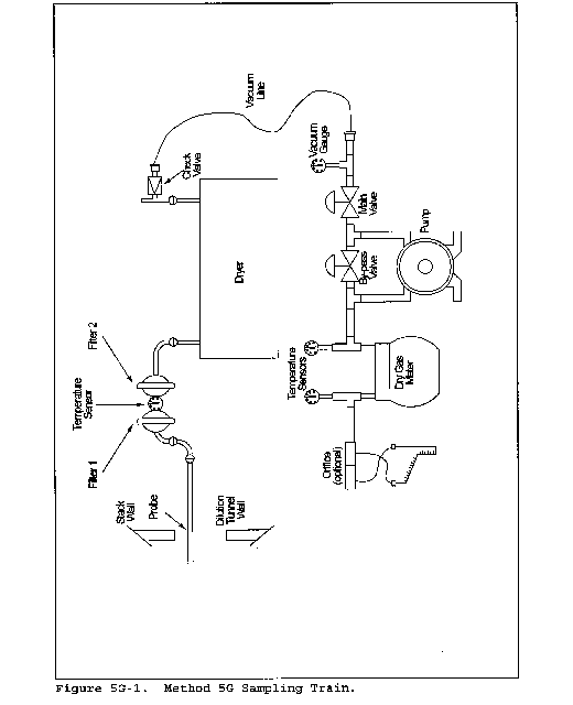
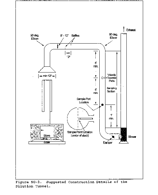
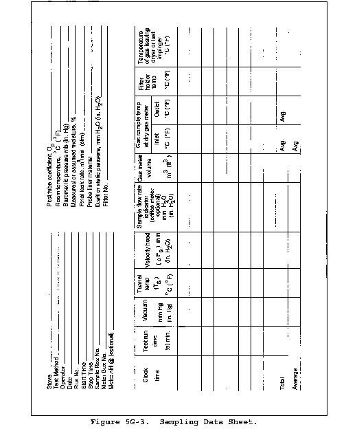

Method 5H - Determination of Particulate Matter Emissions From Wood Heaters From a Stack Location
This method does not include all of the specifications (e.g., equipment and supplies) and procedures (e.g., sampling and analytical) essential to its performance. Some material is incorporated by reference from other methods in this part. Therefore, to obtain reliable results, persons using this method should have a thorough knowledge of at least the following additional test methods: Method 2, Method 3, Method 5, Method 5G, Method 6, Method 6C, Method 16A, and Method 28.
1.0 Scope and Application
1.1 Analyte. Particulate matter (PM). No CAS number assigned.
1.2 Applicability. This method is applicable for the determination of PM and condensible emissions from wood heaters.
1.3 Data Quality Objectives. Adherence to the requirements of this method will enhance the quality of the data obtained from air pollutant sampling methods.
2.0 Summary of Method
2.1 Particulate matter is withdrawn proportionally from the wood heater exhaust and is collected on two glass fiber filters separated by impingers immersed in an ice water bath. The first filter is maintained at a temperature of no greater than 120 °C (248 °F). The second filter and the impinger system are cooled such that the temperature of the gas exiting the second filter is no greater than 20 °C (68 °F). The particulate mass collected in the probe, on the filters, and in the impingers is determined gravimetrically after the removal of uncombined water.
3.0 Definitions
Same as in Method 6C, section 3.0.
4.0 Interferences [Reserved]
5.0 Safety
5.1 Disclaimer. This method may involve hazardous materials, operations, and equipment. This test method may not address all of the safety problems associated with its use. It is the responsibility of the user of this test method to establish appropriate safety and health practices and to determine the applicability of regulatory limitations prior to performing this test method.
6.0 Equipment and Supplies
6.1 Sample Collection. The following items are required for sample collection:
6.1.1 Sampling Train. The sampling train configuration is shown in Figure 5H-1. Same as Method 5, section 6.1.1, with the exception of the following:
6.1.1.1 Probe Nozzle. The nozzle is optional; a straight sampling probe without a nozzle is an acceptable alternative.
6.1.1.2 Probe Liner. Same as Method 5, section 6.1.1.2, except that the maximum length of the sample probe shall be 0.6 m (2 ft) and probe heating is optional.
6.1.1.3 Filter Holders. Two each of borosilicate glass, with a glass frit or stainless steel filter support and a silicone rubber, Teflon, or Viton gasket. The holder design shall provide a positive seal against leakage from the outside or around the filter. The front filter holder shall be attached immediately at the outlet of the probe and prior to the first impinger. The second filter holder shall be attached on the outlet of the third impinger and prior to the inlet of the fourth (silica gel) impinger.
6.1.2 Barometer. Same as Method 5, section 6.2.
6.1.3 Stack Gas Flow Rate Measurement System. A schematic of an example test system is shown in Figure 5H-2. The flow rate measurement system consists of the following components:
6.1.3.1 Sample Probe. A glass or stainless steel sampling probe.
6.1.3.2 Gas Conditioning System. A high density filter to remove particulate matter and a condenser capable of lowering the dew point of the gas to less than 5 °C (40 °F). Desiccant, such as Drierite, may be used to dry the sample gas. Do not use silica gel.
6.1.3.3 Pump. An inert (e.g., Teflon or stainless steel heads) sampling pump capable of delivering more than the total amount of sample required in the manufacturer's instructions for the individual instruments. A means of controlling the analyzer flow rate and a device for determining proper sample flow rate (e.g., precision rotameter, pressure gauge downstream of all flow controls) shall be provided at the analyzer. The requirements for measuring and controlling the analyzer flow rate are not applicable if data are presented that demonstrate that the analyzer is insensitive to flow variations over the range encountered during the test.
6.1.3.4 Carbon Monoxide (CO) Analyzer. Any analyzer capable of providing a measure of CO in the range of 0 to 10 percent by volume at least once every 10 minutes.
6.1.3.5 Carbon Dioxide (CO2) Analyzer. Any analyzer capable of providing a measure of CO2 in the range of 0 to 25 percent by volume at least once every 10 minutes.
Analyzers with ranges less than those specified above may be used provided actual concentrations do not exceed the range of the analyzer.
6.1.3.6 Manifold. A sampling tube capable of delivering the sample gas to two analyzers and handling an excess of the total amount used by the analyzers. The excess gas is exhausted through a separate port.
6.1.3.7 Recorders (optional). To provide a permanent record of the analyzer outputs.
6.1.4 Proportional Gas Flow Rate System. To monitor stack flow rate changes and provide a measurement that can be used to adjust and maintain particulate sampling flow rates proportional to the stack gas flow rate. A schematic of the proportional flow rate system is shown in Figure 5H-2 and consists of the following components:
6.1.4.1 Tracer Gas Injection System. To inject a known concentration of sulfur dioxide (SO2) into the flue. The tracer gas injection system consists of a cylinder of SO2, a gas cylinder regulator, a stainless steel needle valve or flow controller, a nonreactive (stainless steel and glass) rotameter, and an injection loop to disperse the SO2 evenly in the flue.
6.1.4.2 Sample Probe. A glass or stainless steel sampling probe.
6.1.4.3 Gas Conditioning System. A combustor as described in Method 16A, sections 6.1.5 and 6.1.6, followed by a high density filter to remove particulate matter, and a condenser capable of lowering the dew point of the gas to less than 5 °C (40 °F). Desiccant, such as Drierite, may be used to dry the sample gas. Do not use silica gel.
6.1.4.4 Pump. Same as described in section 6.1.3.3.
6.1.4.5 SO2 Analyzer. Any analyzer capable of providing a measure of the SO2 concentration in the range of 0 to 1,000 ppm by volume (or other range necessary to measure the SO2 concentration) at least once every 10 minutes.
6.1.4.6 Recorder (optional). To provide a permanent record of the analyzer outputs.
Other tracer gas systems, including helium gas systems, are acceptable for determination of instantaneous proportional sampling rates.
6.2 Sample Recovery. Same as Method 5, section 6.2.
6.3 Sample Analysis. Same as Method 5, section 6.3, with the addition of the following:
6.3.1 Separatory Funnel. Glass or Teflon, 500-ml or greater.
7.0 Reagents and Standards
7.1 Sample Collection. Same as Method 5, section 7.1, including deionized distilled water.
7.2 Sample Recovery. Same as Method 5, section 7.2.
7.3 Sample Analysis. The following reagents and standards are required for sample analysis:
7.3.1 Acetone. Same as Method 5 section 7.2.
7.3.2 Dichloromethane (Methylene Chloride). Reagent grade, <0.001 percent residue in glass bottles.
7.3.3 Desiccant. Anhydrous calcium sulfate, calcium chloride, or silica gel, indicating type.
7.3.4 Cylinder Gases. For the purposes of this procedure, span value is defined as the upper limit of the range specified for each analyzer as described in section 6.1.3.4 or 6.1.3.5. If an analyzer with a range different from that specified in this method is used, the span value shall be equal to the upper limit of the range for the analyzer used (see note in section 6.1.3.5).
7.3.4.1 Calibration Gases. The calibration gases for the CO2, CO, and SO2 analyzers shall be CO2 in nitrogen (N2), CO in N2, and SO2 in N2, respectively. CO2 and CO calibration gases may be combined in a single cylinder. Use three calibration gases as specified in Method 6C, sections 7.2.1 through 7.2.3.
7.3.4.2 SO2 Injection Gas. A known concentration of SO2 in N2. The concentration must be at least 2 percent SO2 with a maximum of 100 percent SO2.
8.0 Sample Collection, Preservation, Transport, and Storage
8.1 Pretest Preparation. Same as Method 5, section 8.1.
8.2 Calibration Gas and SO2 Injection Gas Concentration Verification, Sampling System Bias Check, Response Time Test, and Zero and Calibration Drift Tests. Same as Method 6C, sections 8.2.1, 8.2.3, 8.2.4, and 8.5, respectively, except that for verification of CO and CO2 gas concentrations, substitute Method 3 for Method 6.
8.3 Preliminary Determinations.
8.3.1 Sampling Location. The sampling location for the particulate sampling probe shall be 2.45 ±0.15 m (8 ±0.5 ft) above the platform upon which the wood heater is placed (i.e., the top of the scale).
8.3.2 Sampling Probe and Nozzle. Select a nozzle, if used, sized for the range of velocity heads, such that it is not necessary to change the nozzle size in order to maintain proportional sampling rates. During the run, do not change the nozzle size. Select a suitable probe liner and probe length to effect minimum blockage.
8.4 Preparation of Particulate Sampling Train. Same as Method 5, section 8.3, with the exception of the following:
8.4.1 The train should be assembled as shown in Figure 5H-1.
8.4.2 A glass cyclone may not be used between the probe and filter holder.
8.5 Leak-Check Procedures.
8.5.1 Leak-Check of Metering System Shown in Figure 5H-1. That portion of the sampling train from the pump to the orifice meter shall be leak-checked after each certification or audit test. Use the procedure described in Method 5, section 8.4.1.
8.5.2 Pretest Leak-Check. A pretest leak-check of the sampling train is recommended, but not required. If the pretest leak-check is conducted, the procedures outlined in Method 5, section 8.5.2 should be used. A vacuum of 130 mm Hg (5 in. Hg) may be used instead of 380 mm Hg (15 in. Hg).
8.5.2 Leak-Checks During Sample Run. If, during the sampling run, a component (e.g., filter assembly or impinger) change becomes necessary, conduct a leak-check as described in Method 5, section 8.4.3.
8.5.3 Post-Test Leak-Check. A leak-check is mandatory at the conclusion of each sampling run. The leak-check shall be performed in accordance with the procedures outlined in Method 5, section 8.4.4, except that a vacuum of 130 mm Hg (5 in. Hg) or the greatest vacuum measured during the test run, whichever is greater, may be used instead of 380 mm Hg (15 in. Hg).
8.6 Tracer Gas Procedure. A schematic of the tracer gas injection and sampling systems is shown in Figure 5H-2.
8.6.1 SO2 Injection Probe. Install the SO2 injection probe and dispersion loop in the stack at a location 2.9 ±0.15 m (9.5 ±0.5 ft) above the sampling platform.
8.6.2 SO2 Sampling Probe. Install the SO2 sampling probe at the centroid of the stack at a location 4.1 ±0.15 m (13.5 ±0.5 ft) above the sampling platform.
8.7 Flow Rate Measurement System. A schematic of the flow rate measurement system is shown in Figure 5H-2. Locate the flow rate measurement sampling probe at the centroid of the stack at a location 2.3 ±0.3 m (7.5 ±1 ft) above the sampling platform.
8.8 Tracer Gas Procedure. Within 1 minute after closing the wood heater door at the start of the test run (as defined in Method 28, section 8.8.1), meter a known concentration of SO2 tracer gas at a constant flow rate into the wood heater stack. Monitor the SO2 concentration in the stack, and record the SO2 concentrations at 10-minute intervals or more often. Adjust the particulate sampling flow rate proportionally to the SO2 concentration changes using Equation 5H-6 (e.g., the SO2 concentration at the first 10-minute reading is measured to be 100 ppm; the next 10 minute SO2 concentration is measured to be 75 ppm: the particulate sample flow rate is adjusted from the initial 0.15 cfm to 0.20 cfm). A check for proportional rate variation shall be made at the completion of the test run using Equation 5H-10.
8.9 Volumetric Flow Rate Procedure. Apply stoichiometric relationships to the wood combustion process in determining the exhaust gas flow rate as follows:
8.9.1 Test Fuel Charge Weight. Record the test fuel charge weight (wet) as specified in Method 28, section 8.8.2. The wood is assumed to have the following weight percent composition: 51 percent carbon, 7.3 percent hydrogen, 41 percent oxygen. Record the wood moisture for each fuel charge as described in Method 28, section 8.6.5. The ash is assumed to have negligible effect on associated C, H, and O concentrations after the test burn.
8.9.2 Measured Values. Record the CO and CO2 concentrations in the stack on a dry basis every 10 minutes during the test run or more often. Average these values for the test run. Use as a mole fraction (e.g., 10 percent CO2 is recorded as 0.10) in the calculations to express total flow (see Equation 5H-6).
8.10 Sampling Train Operation.
8.10.1 For each run, record the data required on a data sheet such as the one shown in Figure 5H-3. Be sure to record the initial dry gas meter reading. Record the dry gas meter readings at the beginning and end of each sampling time increment, when changes in flow rates are made, before and after each leak-check, and when sampling is halted. Take other readings as indicated on Figure 5H-3 at least once each 10 minutes during the test run.
8.10.2 Remove the nozzle cap, verify that the filter and probe heating systems are up to temperature, and that the probe is properly positioned. Position the nozzle, if used, facing into gas stream, or the probe tip in the 50 mm (2 in.) centroidal area of the stack.
8.10.3 Be careful not to bump the probe tip into the stack wall when removing or inserting the probe through the porthole; this minimizes the chance of extracting deposited material.
8.10.4 When the probe is in position, block off the openings around the probe and porthole to prevent unrepresentative dilution of the gas stream.
8.10.5 Begin sampling at the start of the test run as defined in Method 28, section 8.8.1, start the sample pump, and adjust the sample flow rate to between 0.003 and 0.014 m3/min (0.1 and 0.5 cfm). Adjust the sample flow rate proportionally to the stack gas flow during the test run according to the procedures outlined in section 8. Maintain a proportional sampling rate (within 10 percent of the desired value) and a filter holder temperature no greater than 120 °C (248 °F).
8.10.6 During the test run, make periodic adjustments to keep the temperature around the filter holder at the proper level. Add more ice to the impinger box and, if necessary, salt to maintain a temperature of less than 20 °C (68 °F) at the condenser/silica gel outlet.
8.10.7 If the pressure drop across the filter becomes too high, making proportional sampling difficult to maintain, either filter may be replaced during a sample run. It is recommended that another complete filter assembly be used rather than attempting to change the filter itself. Before a new filter assembly is installed, conduct a leak-check (see section 8.5.2). The total particulate weight shall include the summation of all filter assembly catches. The total time for changing sample train components shall not exceed 10 minutes. No more than one component change is allowed for any test run.
8.10.8 At the end of the test run, turn off the coarse adjust valve, remove the probe and nozzle from the stack, turn off the pump, record the final dry gas meter reading, and conduct a post-test leak-check, as outlined in section 8.5.3.
8.11 Sample Recovery. Same as Method 5, section 8.7, with the exception of the following:
8.11.1 Blanks. The volume of the acetone blank may be about 50-ml, rather than 200-ml; a 200-ml water blank shall also be saved for analysis.
8.11.2 Samples.
8.11.2.1 Container Nos. 1 and 1A. Treat the two filters according to the procedures outlined in Method 5, section 8.7.6.1. The filters may be stored either in a single container or in separate containers.
8.11.2.2 Container No. 2. Same as Method 5, section 8.7.6.2, except that the container should not be sealed until the impinger rinse solution is added (see section 8.10.2.4).
8.11.2.3 Container No. 3. Treat the impingers as follows: Measure the liquid which is in the first three impingers to within 1-ml by using a graduated cylinder or by weighing it to within 0.5 g by using a balance (if one is available). Record the volume or weight of liquid present. This information is required to calculate the moisture content of the effluent gas. Transfer the water from the first, second, and third impingers to a glass container. Tighten the lid on the sample container so that water will not leak out.
8.11.2.4 Rinse impingers and graduated cylinder, if used, with acetone three times or more. Avoid direct contact between the acetone and any stopcock grease or collection of any stopcock grease in the rinse solutions. Add these rinse solutions to sample Container No. 2.
8.11.2.5 Container No. 4. Same as Method 5, section 8.7.6.3
8.12 Sample Transport. Whenever possible, containers should be transferred in such a way that they remain upright at all times.
Requirements for capping and transport of sample containers are not applicable if sample recovery and analysis occur in the same room.
9.0 Quality Control
9.1 Miscellaneous Quality Control Measures.
| Section | Quality control measure | Effect |
|---|---|---|
| 8.2 | Sampling system bias check | Ensures that bias introduced by measurement system, minus analyzer, is no greater than 3 percent of span. |
| 8.2 | Analyzer zero and calibration drift tests | Ensures that bias introduced by drift in the measurement system output during the run is no greater than 3 percent of span. |
| 8.5, 10.1, 12.13 | Sampling equipment leak-check and calibration; proportional sampling rate verification | Ensures accurate measurement of stack gas flow rate, sample volume. |
| 10.1 | Analytical balance calibration | Ensure accurate and precise measurement of collected particulate. |
| 10.3 | Analyzer calibration error check | Ensures that bias introduced by analyzer calibration error is no greater than 2 percent of span. |
9.2 Volume Metering System Checks. Same as Method 5, section 9.2.
10.0 Calibration and Standardization
Maintain a laboratory record of all calibrations.
10.1 Volume Metering System, Temperature Sensors, Barometer, and Analytical Balance. Same as Method 5G, sections 10.2 through 10.5, respectively.
10.2 SO2 Injection Rotameter. Calibrate the SO2 injection rotameter system with a soap film flowmeter or similar direct volume measuring device with an accuracy of 2 percent. Operate the rotameter at a single reading for at least three calibration runs for 10 minutes each. When three consecutive calibration flow rates agree within 5 percent, average the three flow rates, mark the rotameter at the calibrated setting, and use the calibration flow rate as the SO2 injection flow rate during the test run. Repeat the rotameter calibration before the first certification test and semiannually thereafter.
10.3. Gas Analyzers. Same as Method 6C, section 10.0.
10.4 Field Balance Calibration Check. Check the calibration of the balance used to weigh impingers with a weight that is at least 500g or within 50g of a loaded impinger. The weight must be ASTM E617-13 “Standard Specification for Laboratory Weights and Precision Mass Standards” (incorporated by reference - see 40 CFR 60.17) Class 6 (or better). Daily before use, the field balance must measure the weight within ± 0.5g of the certified mass. If the daily balance calibration check fails, perform corrective measures and repeat the check before using balance.
10.5 Analytical Balance Calibration. Perform a multipoint calibration (at least five points spanning the operational range) of the analytical balance before the first use, and semiannually thereafter. The calibration of the analytical balance must be conducted using ASTM E617-13 “Standard Specification for Laboratory Weights and Precision Mass Standards” (incorporated by reference - see 40 CFR 60.17) Class 2 (or better) tolerance weights. Audit the balance each day it is used for gravimetric measurements by weighing at least one ASTM E617-13 Class 2 tolerance (or better) calibration weight that corresponds to 50 to 150 percent of the weight of one filter or between 1g and 5g. If the scale cannot reproduce the value of the calibration weight to within 0.5 mg of the certified mass, perform corrective measures, and conduct the multipoint calibration before use.
11.0 Analytical Procedure
11.1 Record the data required on a sheet such as the one shown in Figure 5H-4.
11.2 Handle each sample container as follows:
11.2.1 Container Nos. 1 and 1A. Treat the two filters according to the procedures outlined in Method 5, section 11.2.1.
11.2.2 Container No. 2. Same as Method 5, section 11.2.2, except that the beaker may be smaller than 250-ml.
11.2.3 Container No. 3. Note the level of liquid in the container and confirm on the analysis sheet whether leakage occurred during transport. If a noticeable amount of leakage has occurred, either void the sample or use methods, subject to the approval of the Administrator, to correct the final results. Determination of sample leakage is not applicable if sample recovery and analysis occur in the same room. Measure the liquid in this container either volumetrically to within 1-ml or gravimetrically to within 0.5 g. Transfer the contents to a 500-ml or larger separatory funnel. Rinse the container with water, and add to the separatory funnel. Add 25-ml of dichloromethane to the separatory funnel, stopper and vigorously shake 1 minute, let separate and transfer the dichloromethane (lower layer) into a tared beaker or evaporating dish. Repeat twice more. It is necessary to rinse Container No. 3 with dichloromethane. This rinse is added to the impinger extract container. Transfer the remaining water from the separatory funnel to a tared beaker or evaporating dish and evaporate to dryness at 104 °C (220 °F). Desiccate and weigh to a constant weight. Evaporate the combined impinger water extracts at ambient temperature and pressure. Desiccate and weigh to a constant weight. Report both results to the nearest 0.1 mg.
11.2.4 Container No. 4. Weigh the spent silica gel (or silica gel plus impinger) to the nearest 0.5 g using a balance.
11.2.5 Acetone Blank Container. Same as Method 5, section 11.2.4, except that the beaker may be smaller than 250 ml.
11.2.6 Dichloromethane Blank Container. Treat the same as the acetone blank.
11.2.7 Water Blank Container. Transfer the water to a tared 250 ml beaker and evaporate to dryness at 104 °C (220 °F). Desiccate and weigh to a constant weight.
12.0 Data Analysis and Calculations
Carry out calculations, retaining at least one extra significant figure beyond that of the acquired data. Round off figures after the final calculation. Other forms of the equations may be used as long as they give equivalent results.
12.1 Nomenclature.
A = Sample flow rate adjustment factor.
BR = Dry wood burn rate, kg/hr (lb/hr), from Method 28, Section 8.3.
Bws = Water vapor in the gas stream, proportion by volume.
Ci = Tracer gas concentration at inlet, ppmv.
Co = Tracer gas concentration at outlet, ppmv.
Cs = Concentration of particulate matter in stack gas, dry basis, corrected to standard conditions, g/dscm (g/dscf).
E = Particulate emission rate, g/hr (lb/hr).
ΔH = Average pressure differential across the orifice meter (see Figure 5H-1), mm H2O (in. H2O).
La = Maximum acceptable leakage rate for either a post-test leak-check or for a leak-check following a component change; equal to 0.00057 cmm (0.020 cfm) or 4 percent of the average sampling rate, whichever is less.
L1 = Individual leakage rate observed during the leak-check conducted before a component change, cmm (cfm).
Lp = Leakage rate observed during the post-test leak-check, cmm (cfm).
mn = Total amount of particulate matter collected, mg.
Ma = Mass of residue of solvent after evaporation, mg.
NC = Grams of carbon/gram of dry fuel (lb/lb), equal to 0.0425.
NT = Total dry moles of exhaust gas/kg of dry wood burned, g-moles/kg (lb-moles/lb).
PR = Percent of proportional sampling rate.
Pbar = Barometric pressure at the sampling site, mm Hg (in.Hg).
Pstd = Standard absolute pressure, 760 mm Hg (29.92 in.Hg).
Qi = Gas volumetric flow rate at inlet, cfm (l/min).
Qo = Gas volumetric flow rate at outlet, cfm (l/min).
12.2 Average Dry Gas Meter Temperature and Average Orifice Pressure Drop. See data sheet (Figure 5H-3).
12.3 Dry Gas Volume. Same as Method 5, section 12.3.
12.4 Volume of Water Vapor.

Where:
K2 = 0.001333 m3/ml for metric units.
K2 = 0.04707 ft3/ml for English units.
12.5 Moisture Content.

12.6 Solvent Wash Blank.

12.7 Total Particulate Weight. Determine the total particulate catch from the sum of the weights obtained from containers 1, 2, 3, and 4 less the appropriate solvent blanks (see Figure 5H-4).
Refer to Method 5, section 8.5 to assist in calculation of results involving two filter assemblies.
12.8 Particulate Concentration.

12.9 Sample Flow Rate Adjustment.

12.10 Carbon Balance for Total Moles of Exhaust Gas (dry)/kg of Wood Burned in the Exhaust Gas.

Where:
K3 = 1000 g/kg for metric units.
K3 = 1.0 lb/lb for English units.
The NOX/SOX portion of the gas is assumed to be negligible.
12.11 Total Stack Gas Flow Rate.

Where:
K4 = 0.02406 dscm/g-mole for metric units.
K4 = 384.8 dscf/lb-mole for English units.
12.12 Particulate Emission Rate.

12.13 Proportional Rate Variation. Calculate PR for each 10-minute interval, i, of the test run.
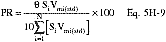
12.14 Acceptable Results. If no more than 15 percent of the PR values for all the intervals fall outside the range 90 percent ≤PR ≤110 percent, and if no PR value for any interval falls outside the range 75 ≤PR ≤125 percent, the results are acceptable. If the PR values for the test runs are judged to be unacceptable, report the test run emission results, but do not include the test run results in calculating the weighted average emission rate, and repeat the test.
12.15 Alternative Tracer Gas Flow Rate Determination.

This gives Q for a single instance only. Repeated multiple determinations are needed to track temporal variations. Very small variations in Qi, Ci, or Co may give very large variations in Qo.
13.0 Method Performance [Reserved]
14.0 Pollution Prevention [Reserved]
15.0 Waste Management [Reserved]
16.0 Alternative Procedures
16.1 Alternative Stack Gas Volumetric Flow Rate Determination (Tracer Gas).
16.1.1 Apparatus.
16.1.1.1 Tracer Gas Injector System. This is to inject a known concentration of tracer gas into the stack. This system consists of a cylinder of tracer gas, a gas cylinder regulator, a stainless steel needle valve or a flow controller, a nonreactive (stainless steel or glass) rotameter, and an injection loop to disperse the tracer gas evenly in the stack.
16.1.1.2 Tracer Gas Probe. A glass or stainless steel sampling probe.
16.1.1.3 Gas Conditioning System. A gas conditioning system is suitable for delivering a cleaned sample to the analyzer consisting of a filter to remove particulate and a condenser capable of lowering the dew point of the sample gas to less than 5 °C (40 °F). A desiccant such as anhydrous calcium sulfate may be used to dry the sample gas. Desiccants which react or absorb tracer gas or stack gas may not be used, e.g. silica gel absorbs CO2.
16.1.1.4 Pump. An inert (i.e., stainless steel or Teflon head) pump to deliver more than the total sample required by the manufacturer's specifications for the analyzer used to measure the downstream tracer gas concentration.
16.1.1.5 Gas Analyzer. A gas analyzer is any analyzer capable of measuring the tracer gas concentration in the range necessary at least every 10 minutes. A means of controlling the analyzer flow rate and a device for determining proper sample flow rate shall be provided unless data is provided to show that the analyzer is insensitive to flow variations over the range encountered during the test. The gas analyzer needs to meet or exceed the following performance specifications:
| Linearity | ±1 percent of full scale. |
| Calibration Error | ≤2 percent of span. |
| Response Time | ≤10 seconds. |
| Zero Drift (24 hour) | ≤2 percent of full scale. |
| Span Drift (24 hour) | ≤2 percent of full scale. |
| Resolution | ≤0.5 percent of span. |
16.1.1.6 Recorder (optional). To provide a permanent record of the analyzer output.
16.1.2 Reagents.
16.1.2.1 Tracer Gas. The tracer gas is sulfur hexafluoride in an appropriate concentration for accurate analyzer measurement or pure sulfur dioxide. The gas used must be nonreactive with the stack effluent and give minimal (<3 percent) interference to measurement by the gas analyzer.
16.1.3 Procedure. Select upstream and downstream locations in the stack or duct for introducing the tracer gas and delivering the sampled gas to the analyzer. The inlet location should be 8 or more duct diameters beyond any upstream flow disturbance. The outlet should be 8 or more undisturbed duct diameters from the inlet and 2 or more duct diameters from the duct exit. After installing the apparatus, meter a known concentration of the tracer gas into the stack at the inlet location. Use the gas sample probe and analyzer to show that no stratification of the tracer gas is found in the stack at the measurement locations. Monitor the tracer gas concentration from the outlet location and record the concentration at 10-minute intervals or more often at the option of the tester. A minimum of three measured intervals is recommended to determine the stack gas volumetric flow rate. Other statistical procedures may be applied for complete flow characterization and additional QA/QC.
17.0 References
Same as Method 5G, section 17.0.
18.0 Tables, Diagrams, Flowcharts, and Validation Data

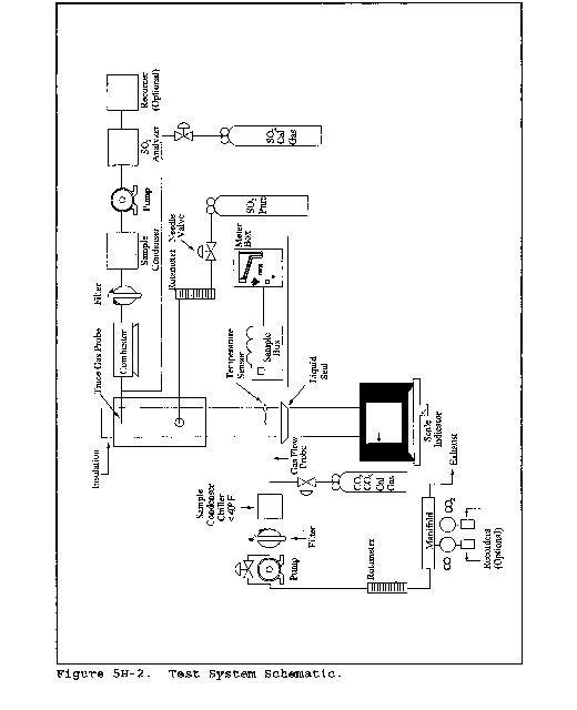
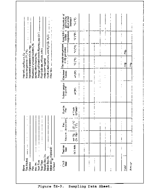

Method 5I - Determination of Low Level Particulate Matter Emissions From Stationary Sources
This method does not include all of the specifications (e.g., equipment and supplies) and procedures (e.g., sampling and analytical) essential to its performance. Certain information is contained in other EPA procedures found in this part. Therefore, to obtain reliable results, persons using this method should have experience with and a thorough knowledge of the following Methods: Methods 1, 2, 3, 4 and 5.
1. Scope and Application.
1.1 Analyte. Particulate matter (PM). No CAS number assigned.
1.2 Applicability. This method is applicable for the determination of low level particulate matter (PM) emissions from stationary sources. The method is most effective for total PM catches of 50 mg or less. This method was initially developed for performing correlation of manual PM measurements to PM continuous emission monitoring systems (CEMS), however it is also useful for other low particulate concentration applications.
1.3 Data Quality Objectives. Adherence to the requirements of this method will enhance the quality of the data obtained from air pollutant sampling methods. Method 5I requires the use of paired trains. Acceptance criteria for the identification of data quality outliers from the paired trains are provided in section 12.2 of this Method.
2. Summary of Method.
2.1. Description. The system setup and operation is essentially identical to Method 5. Particulate is withdrawn isokinetically from the source and collected on a 47 mm glass fiber filter maintained at a temperature of 120 ±14 °C (248 ±25 °F). The PM mass is determined by gravimetric analysis after the removal of uncombined water. Specific measures in this procedure designed to improve system performance at low particulate levels include:
1. Improved sample handling procedures
2 Light weight sample filter assembly
3. Use of low residue grade acetone
Accuracy is improved through the minimization of systemic errors associated with sample handling and weighing procedures. High purity reagents, all glass, grease free, sample train components, and light weight filter assemblies and beakers, each contribute to the overall objective of improved precision and accuracy at low particulate concentrations.
2.2 Paired Trains. This method must be performed using a paired train configuration. These trains may be operated as co-located trains (to trains operating collecting from one port) or as simultaneous trains (separate trains operating from different ports at the same time). Procedures for calculating precision of the paired trains are provided in section 12.
2.3 Detection Limit. a. Typical detection limit for manual particulate testing is 0.5 mg. This mass is also cited as the accepted weight variability limit in determination of “constant weight” as cited in section 8.1.2 of this Method. EPA has performed studies to provide guidance on minimum PM catch. The minimum detection limit (MDL) is the minimum concentration or amount of an analyte that can be determined with a specified degree of confidence to be different from zero. We have defined the minimum or target catch as a concentration or amount sufficiently larger than the MDL to ensure that the results are reliable and repeatable. The particulate matter catch is the product of the average particulate matter concentration on a mass per volume basis and the volume of gas collected by the sample train. The tester can generally control the volume of gas collected by increasing the sampling time or to a lesser extent by increasing the rate at which sample is collected. If the tester has a reasonable estimate of the PM concentration from the source, the tester can ensure that the target catch is collected by sampling the appropriate gas volume.
b. However, if the source has a very low particulate matter concentration in the stack, the volume of gas sampled may need to be very large which leads to unacceptably long sampling times. When determining compliance with an emission limit, EPA guidance has been that the tester does not always have to collect the target catch. Instead, we have suggested that the tester sample enough stack gas, that if the source were exactly at the level of the emission standard, the sample catch would equal the target catch. Thus, if at the end of the test the catch were smaller than the target, we could still conclude that the source is in compliance though we might not know the exact emission level. This volume of gas becomes a target volume that can be translated into a target sampling time by assuming an average sampling rate. Because the MDL forms the basis for our guidance on target sampling times, EPA has conducted a systematic laboratory study to define what is the MDL for Method 5 and determined the Method to have a calculated practical quantitation limit (PQL) of 3 mg of PM and an MDL of 1 mg.
c. Based on these results, the EPA has concluded that for PM testing, the target catch must be no less than 3 mg. Those sample catches between 1 mg and 3 mg are between the detection limit and the limit of quantitation. If a tester uses the target catch to estimate a target sampling time that results in sample catches that are less than 3 mg, you should not automatically reject the results. If the tester calculated the target sampling time as described above by assuming that the source was at the level of the emission limit, the results would still be valid for determining that the source was in compliance. For purposes other than determining compliance, results should be divided into two categories - those that fall between 3 mg and 1 mg and those that are below 1 mg. A sample catch between 1 and 3 mg may be used for such purposes as calculating emission rates with the understanding that the resulting emission rates can have a high degree of uncertainty. Results of less than 1 mg should not be used for calculating emission rates or pollutant concentrations.
d. When collecting small catches such as 3 mg, bias becomes an important issue. Source testers must use extreme caution to reach the PQL of 3 mg by assuring that sampling probes are very clean (perhaps confirmed by low blank weights) before use in the field. They should also use low tare weight sample containers, and establish a well-controlled balance room to weigh the samples.
3. Definitions.
3.1 Light Weight Filter Housing. A smaller housing that allows the entire filtering system to be weighed before and after sample collection. (See. 6.1.3)
3.2 Paired Train. Sample systems trains may be operated as co-located trains (two sample probes attached to each other in the same port) or as simultaneous trains (two separate trains operating from different ports at the same time).
4. Interferences.
a. There are numerous potential interferents that may be encountered during performance of Method 5I sampling and analyses. This Method should be considered more sensitive to the normal interferents typically encountered during particulate testing because of the low level concentrations of the flue gas stream being sampled.
b. Care must be taken to minimize field contamination, especially to the filter housing since the entire unit is weighed (not just the filter media). Care must also be taken to ensure that no sample is lost during the sampling process (such as during port changes, removal of the filter assemblies from the probes, etc.).
c. Balance room conditions are a source of concern for analysis of the low level samples. Relative humidity, ambient temperatures variations, air draft, vibrations and even barometric pressure can affect consistent reproducible measurements of the sample media. Ideally, the same analyst who performs the tare weights should perform the final weights to minimize the effects of procedural differences specific to the analysts.
d. Attention must also be provided to weighing artifacts caused by electrostatic charges which may have to be discharged or neutralized prior to sample analysis. Static charge can affect consistent and reliable gravimetric readings in low humidity environments. Method 5I recommends a relative humidity of less than 50 percent in the weighing room environment used for sample analyses. However, lower humidity may be encountered or required to address sample precision problems. Low humidity conditions can increase the effects of static charge.
e. Other interferences associated with typical Method 5 testing (sulfates, acid gases, etc.) are also applicable to Method 5I.
5. Safety.
Disclaimer. This method may involve hazardous materials, operations, and equipment. This test method may not address all of the safety concerns associated with its use. It is the responsibility of the user to establish appropriate safety and health practices and to determine the applicability and observe all regulatory limitations before using this method.
6. Equipment and Supplies.
6.1 Sample Collection Equipment and Supplies. The sample train is nearly identical in configuration to the train depicted in Figure 5-1 of Method 5. The primary difference in the sample trains is the lightweight Method 5I filter assembly that attaches directly to the exit to the probe. Other exceptions and additions specific to Method 5I include:
6.1.1 Probe Nozzle. Same as Method 5, with the exception that it must be constructed of borosilicate or quartz glass tubing.
6.1.2 Probe Liner. Same as Method 5, with the exception that it must be constructed of borosilicate or quartz glass tubing.
6.1.3 Filter Holder. The filter holder is constructed of borosilicate or quartz glass front cover designed to hold a 47-mm glass fiber filter, with a wafer thin stainless steel (SS) filter support, a silicone rubber or Viton O-ring, and Teflon tape seal. This holder design will provide a positive seal against leakage from the outside or around the filter. The filter holder assembly fits into a SS filter holder and attaches directly to the outlet of the probe. The tare weight of the filter, borosilicate or quartz glass holder, SS filter support, O-ring and Teflon tape seal generally will not exceed approximately 35 grams. The filter holder is designed to use a 47-mm glass fiber filter meeting the quality criteria in of Method 5. These units are commercially available from several source testing equipment vendors. Once the filter holder has been assembled, desiccated and tared, protect it from external sources of contamination by covering the front socket with a ground glass plug. Secure the plug with an impinger clamp or other item that will ensure a leak-free fitting.
6.2 Sample Recovery Equipment and Supplies. Same as Method 5, with the following exceptions:
6.2.1 Probe-Liner and Probe-Nozzle Brushes. Teflon or nylon bristle brushes with stainless steel wire handles, should be used to clean the probe. The probe brush must have extensions (at least as long as the probe) of Teflon, nylon or similarly inert material. The brushes must be properly sized and shaped for brushing out the probe liner and nozzle.
6.2.2 Wash Bottles. Two Teflon wash bottles are recommended however, polyethylene wash bottles may be used at the option of the tester. Acetone should not be stored in polyethylene bottles for longer than one month.
6.2.3 Filter Assembly Transport. A system should be employed to minimize contamination of the filter assemblies during transport to and from the field test location. A carrying case or packet with clean compartments of sufficient size to accommodate each filter assembly can be used. This system should have an air tight seal to further minimize contamination during transport to and from the field.
6.3 Analysis Equipment and Supplies. Same as Method 5, with the following exception:
6.3.1 Lightweight Beaker Liner. Teflon or other lightweight beaker liners are used for the analysis of the probe and nozzle rinses. These light weight liners are used in place of the borosilicate glass beakers typically used for the Method 5 weighings in order to improve sample analytical precision.
6.3.2 Anti-static Treatment. Commercially available gaseous anti-static rinses are recommended for low humidity situations that contribute to static charge problems.
7. Reagents and Standards.
7.1 Sampling Reagents. The reagents used in sampling are the same as Method 5 with the following exceptions:
7.1.1 Filters. The quality specifications for the filters are identical to those cited for Method 5. The only difference is the filter diameter of 47 millimeters.
7.1.2 Stopcock Grease. Stopcock grease cannot be used with this sampling train. We recommend that the sampling train be assembled with glass joints containing O-ring seals or screw-on connectors, or similar.
7.1.3 Acetone. Low residue type acetone, ≤0.001 percent residue, purchased in glass bottles is used for the recovery of particulate matter from the probe and nozzle. Acetone from metal containers generally has a high residue blank and should not be used. Sometimes, suppliers transfer acetone to glass bottles from metal containers; thus, acetone blanks must be run prior to field use and only acetone with low blank values (≤0.001 percent residue, as specified by the manufacturer) must be used. Acetone blank correction is not allowed for this method; therefore, it is critical that high purity reagents be purchased and verified prior to use.
7.1.4 Gloves. Disposable, powder-free, latex surgical gloves, or their equivalent are used at all times when handling the filter housings or performing sample recovery.
7.2 Standards. There are no applicable standards commercially available for Method 5I analyses.
8. Sample Collection, Preservation, Storage, and Transport.
8.1 Pretest Preparation. Same as Method 5 with several exceptions specific to filter assembly and weighing.
8.1.1 Filter Assembly. Uniquely identify each filter support before loading filters into the holder assembly. This can be done with an engraving tool or a permanent marker. Use powder free latex surgical gloves whenever handling the filter holder assemblies. Place the O-ring on the back of the filter housing in the O-ring groove. Place a 47 mm glass fiber filter on the O-ring with the face down. Place a stainless steel filter holder against the back of the filter. Carefully wrap 5 mm (1⁄4 inch) wide Teflon” tape one timearound the outside of the filter holder overlapping the stainless steel filter support by approximately 2.5 mm (1⁄8 inch). Gently brush the Teflon tape down on the back of the stainless steel filter support. Store the filter assemblies in their transport case until time for weighing or field use.
8.1.2 Filter Weighing Procedures. a. Desiccate the entire filter holder assemblies at 20 ±5.6 °C (68 ±10 °F) and ambient pressure for at least 24 hours. Weigh at intervals of at least 6 hours to a constant weight, i.e., 0.5 mg change from previous weighing. Record the results to the nearest 0.1 mg. During each weighing, the filter holder assemblies must not be exposed to the laboratory atmosphere for a period greater than 2 minutes and a relative humidity above 50 percent. Lower relative humidity may be required in order to improve analytical precision. However, low humidity conditions increase static charge to the sample media.
b. Alternatively (unless otherwise specified by the Administrator), the filters holder assemblies may be oven dried at 105 °C (220 °F) for a minimum of 2 hours, desiccated for 2 hours, and weighed. The procedure used for the tare weigh must also be used for the final weight determination.
c. Experience has shown that weighing uncertainties are not only related to the balance performance but to the entire weighing procedure. Therefore, before performing any measurement, establish and follow standard operating procedures, taking into account the sampling equipment and filters to be used.
8.2 Preliminary Determinations. Select the sampling site, traverse points, probe nozzle, and probe length as specified in Method 5.
8.3 Preparation of Sampling Train. Same as Method 5, section 8.3, with the following exception: During preparation and assembly of the sampling train, keep all openings where contamination can occur covered until justbefore assembly or until sampling is about to begin. Using gloves, place a labeled (identified) and weighed filter holder assembly into the stainless steel holder. Then place this whole unit in the Method 5 hot box, and attach it to the probe. Do not use stopcock grease.
8.4 Leak-Check Procedures. Same as Method 5.
8.5 Sampling Train Operation.
8.5.1. Operation. Operate the sampling train in a manner consistent with those described in Methods 1, 2, 4 and 5 in terms of the number of sample points and minimum time per point. The sample rate and total gas volume should be adjusted based on estimated grain loading of the source being characterized. The total sampling time must be a function of the estimated mass of particulate to be collected for the run. Targeted mass to be collected in a typical Method 5I sample train should be on the order of 10 to 20 mg. Method 5I is most appropriate for total collected masses of less than 50 milligrams, however, there is not an exact particulate loading cutoff, and it is likely that some runs may exceed 50 mg. Exceeding 50 mg (or less than 10 mg) for the sample mass does not necessarily justify invalidating a sample run if all other Method criteria are met.
8.5.2 Paired Train. This Method requires PM samples be collected with paired trains.
8.5.2.1 It is important that the systems be operated truly simultaneously. This implies that both sample systems start and stop at the same times. This also means that if one sample system is stopped during the run, the other sample systems must also be stopped until the cause has been corrected.
8.5.2.2 Care should be taken to maintain the filter box temperature of the paired trains as close as possible to the Method required temperature of 120 ±14 °C (248 ±25 °F). If separate ovens are being used for simultaneously operated trains, it is recommended that the oven temperature of each train be maintained within ±14 °C (±25 °F) of each other.
8.5.2.3 The nozzles for paired trains need not be identically sized.
8.5.2.4 Co-located sample nozzles must be within the same plane perpendicular to the gas flow. Co-located nozzles and pitot assemblies should be within a 6.0 cm × 6.0 cm square (as cited for a quadruple train in Reference Method 301).
8.5.3 Duplicate gas samples for molecular weight determination need not be collected.
8.6 Sample Recovery. Same as Method 5 with several exceptions specific to the filter housing.
8.6.1 Before moving the sampling train to the cleanup site, remove the probe from the train and seal the nozzle inlet and outlet of the probe. Be careful not to lose any condensate that might be present. Cap the filter inlet using a standard ground glass plug and secure the cap with an impinger clamp. Remove the umbilical cord from the last impinger and cap the impinger. If a flexible line is used between the first impinger condenser and the filter holder, disconnect the line at the filter holder and let any condensed water or liquid drain into the impingers or condenser.
8.6.2 Transfer the probe and filter-impinger assembly to the cleanup area. This area must be clean and protected from the wind so that the possibility of losing any of the sample will be minimized.
8.6.3 Inspect the train prior to and during disassembly and note any abnormal conditions such as particulate color, filter loading, impinger liquid color, etc.
8.6.4 Container No. 1, Filter Assembly. Carefully remove the cooled filter holder assembly from the Method 5 hot box and place it in the transport case. Use a pair of clean gloves to handle the filter holder assembly.
8.6.5 Container No. 2, Probe Nozzle and Probe Liner Rinse. Rinse the probe and nozzle components with acetone. Be certain that the probe and nozzle brushes have been thoroughly rinsed prior to use as they can be a source of contamination.
8.6.6 All Other Train Components. (Impingers) Same as Method 5.
8.7 Sample Storage and Transport. Whenever possible, containers should be shipped in such a way that they remain upright at all times. All appropriate dangerous goods shipping requirements must be observed since acetone is a flammable liquid.
9. Quality Control.
9.1 Miscellaneous Field Quality Control Measures.
9.1.1 A quality control (QC) check of the volume metering system at the field site is suggested before collecting the sample using the procedures in Method 5, section 4.4.1.
9.1.2 All other quality control checks outlined in Methods 1, 2, 4 and 5 also apply to Method 5I. This includes procedures such as leak-checks, equipment calibration checks, and independent checks of field data sheets for reasonableness and completeness.
9.2 Quality Control Samples.
9.2.1 Required QC Sample. A laboratory reagent blank must be collected and analyzed for each lot of acetone used for a field program to confirm that it is of suitable purity. The particulate samples cannot be blank corrected.
9.2.2 Recommended QC Samples. These samples may be collected and archived for future analyses.
9.2.2.1 A field reagent blank is a recommended QC sample collected from a portion of the acetone used for cleanup of the probe and nozzle. Take 100 ml of this acetone directly from the wash bottle being used and place it in a glass sample container labeled “field acetone reagent blank.” At least one field reagent blank is recommended for every five runs completed. The field reagent blank samples demonstrate the purity of the acetone was maintained throughout the program.
9.2.2.2 A field bias blank train is a recommended QC sample. This sample is collected by recovering a probe and filter assembly that has been assembled, taken to the sample location, leak checked, heated, allowed to sit at the sample location for a similar duration of time as a regular sample run, leak-checked again, and then recovered in the same manner as a regular sample. Field bias blanks are not a Method requirement, however, they are recommended and are very useful for identifying sources of contamination in emission testing samples. Field bias blank train results greater than 5 times the method detection limit may be considered problematic.
10. Calibration and Standardization Same as Method 5, section 5.
10.1 Field Balance Calibration Check. Check the calibration of the balance used to weigh impingers with a weight that is at least 500g or within 50g of a loaded impinger. The weight must be ASTM E617-13 “Standard Specification for Laboratory Weights and Precision Mass Standards” (incorporated by reference - see 40 CFR 60.17) Class 6 (or better). Daily, before use, the field balance must measure the weight within ±0.5g of the certified mass. If the daily balance calibration check fails, perform corrective measures and repeat the check before using balance.
10.2 Analytical Balance Calibration. Perform a multipoint calibration (at least five points spanning the operational range) of the analytical balance before the first use, and semiannually thereafter. The calibration of the analytical balance must be conducted using ASTM E617-13 “Standard Specification for Laboratory Weights and Precision Mass Standards” (incorporated by reference - see 40 CFR 60.17) Class 2 (or better) tolerance weights. Audit the balance each day it is used for gravimetric measurements by weighing at least one ASTM E617-13 Class 2 tolerance (or better) calibration weight that corresponds to 50 to 150 percent of the weight of one filter or between 1g and 5g. If the scale cannot reproduce the value of the calibration weight to within 0.5 mg of the certified mass, perform corrective measures and conduct the multipoint calibration before use.
11. Analytical Procedures.
11.1 Analysis. Same as Method 5, sections 11.1-11.2.4, with the following exceptions:
11.1.1 Container No. 1. Same as Method 5, section 11.2.1, with the following exception: Use disposable gloves to remove each of the filter holder assemblies from the desiccator, transport container, or sample oven (after appropriate cooling).
11.1.2 Container No. 2. Same as Method 5, section 11.2.2, with the following exception: It is recommended that the contents of Container No. 2 be transferred to a 250 ml beaker with a Teflon liner or similar container that has a minimal tare weight before bringing to dryness.
12. Data Analysis and Calculations.
12.1 Particulate Emissions. The analytical results cannot be blank corrected for residual acetone found in any of the blanks. All other sample calculations are identical to Method 5.
12.2 Paired Trains Outliers. a. Outliers are identified through the determination of precision and any systemic bias of the paired trains. Data that do not meet this criteria should be flagged as a data quality problem. The primary reason for performing dual train sampling is to generate information to quantify the precision of the Reference Method data. The relative standard deviation (RSD) of paired data is the parameter used to quantify data precision. RSD for two simultaneously gathered data points is determined according to:

where, Ca and Cb are concentration values determined from trains A and B respectively. For RSD calculation, the concentration units are unimportant so long as they are consistent.
b. A minimum precision criteria for Reference Method PM data is that RSD for any data pair must be less than 10% as long as the mean PM concentration is greater than 10 mg/dscm. If the mean PM concentration is less than 10 mg/dscm higher RSD values are acceptable. At mean PM concentration of 1 mg/dscm acceptable RSD for paired trains is 25%. Between 1 and 10 mg/dscm acceptable RSD criteria should be linearly scaled from 25% to 10%. Pairs of manual method data exceeding these RSD criteria should be eliminated from the data set used to develop a PM CEMS correlation or to assess RCA. If the mean PM concentration is less than 1 mg/dscm, RSD does not apply and the mean result is acceptable.
13. Method Performance [Reserved]
14. Pollution Prevention [Reserved]
15. Waste Management [Reserved]
16. Alternative Procedures. Same as Method 5.
17. Bibliography. Same as Method 5.
18. Tables, Diagrams, Flowcharts and Validation Data. Figure 5I-1 is a schematic of the sample train.

[36 FR 24877, Dec. 23, 1971]
Appendix A-4 to Part 60 - Test Methods 6 through 10B
Method 6 - Determination of sulfur dioxide emissions from stationary sources
Method 6A - Determination of sulfur dioxide, moisture, and carbon dioxide emissions from fossil fuel combustion sources
Method 6B - Determination of sulfur dioxide and carbon dioxide daily average emissions from fossil fuel combustion sources
Method 6C - Determination of Sulfur Dioxide Emissions From Stationary Sources (Instrumental Analyzer Procedure)
Method 7 - Determination of nitrogen oxide emissions from stationary sources
Method 7A - Determination of nitrogen oxide emissions from stationary sources - Ion chromatographic method
Method 7B - Determination of nitrogen oxide emissions from stationary sources (Ultraviolet spectrophotometry)
Method 7C - Determination of nitrogen oxide emissions from stationary sources - Alkaline-permanganate/colorimetric method
Method 7D - Determination of nitrogen oxide emissions from stationary sources - Alkaline-permanganate/ion chromatographic method
Method 7E - Determination of Nitrogen Oxides Emissions From Stationary Sources (Instrumental Analyzer Procedure)
Method 8 - Determination of sulfuric acid mist and sulfur dioxide emissions from stationary sources
Method 9 - Visual determination of the opacity of emissions from stationary sources
Alternate method 1 - Determination of the opacity of emissions from stationary sources remotely by lidar
Method 10 - Determination of carbon monoxide emissions from stationary sources
Method 10A - Determination of carbon monoxide emissions in certifying continuous emission monitoring systems at petroleum refineries
Method 10B - Determination of carbon monoxide emissions from stationary sources
The test methods in this appendix are referred to in § 60.8 (Performance Tests) and § 60.11 (Compliance With Standards and Maintenance Requirements) of 40 CFR part 60, subpart A (General Provisions). Specific uses of these test methods are described in the standards of performance contained in the subparts, beginning with Subpart D.
Within each standard of performance, a section title “Test Methods and Procedures” is provided to: (1) Identify the test methods to be used as reference methods to the facility subject to the respective standard and (2) identify any special instructions or conditions to be followed when applying a method to the respective facility. Such instructions (for example, establish sampling rates, volumes, or temperatures) are to be used either in addition to, or as a substitute for procedures in a test method. Similarly, for sources subject to emission monitoring requirements, specific instructions pertaining to any use of a test method as a reference method are provided in the subpart or in Appendix B.
Inclusion of methods in this appendix is not intended as an endorsement or denial of their applicability to sources that are not subject to standards of performance. The methods are potentially applicable to other sources; however, applicability should be confirmed by careful and appropriate evaluation of the conditions prevalent at such sources.
The approach followed in the formulation of the test methods involves specifications for equipment, procedures, and performance. In concept, a performance specification approach would be preferable in all methods because this allows the greatest flexibility to the user. In practice, however, this approach is impractical in most cases because performance specifications cannot be established. Most of the methods described herein, therefore, involve specific equipment specifications and procedures, and only a few methods in this appendix rely on performance criteria.
Minor changes in the test methods should not necessarily affect the validity of the results and it is recognized that alternative and equivalent methods exist. section 60.8 provides authority for the Administrator to specify or approve (1) equivalent methods, (2) alternative methods, and (3) minor changes in the methodology of the test methods. It should be clearly understood that unless otherwise identified all such methods and changes must have prior approval of the Administrator. An owner employing such methods or deviations from the test methods without obtaining prior approval does so at the risk of subsequent disapproval and retesting with approved methods.
Within the test methods, certain specific equipment or procedures are recognized as being acceptable or potentially acceptable and are specifically identified in the methods. The items identified as acceptable options may be used without approval but must be identified in the test report. The potentially approvable options are cited as “subject to the approval of the Administrator” or as “or equivalent.” Such potentially approvable techniques or alternatives may be used at the discretion of the owner without prior approval. However, detailed descriptions for applying these potentially approvable techniques or alternatives are not provided in the test methods. Also, the potentially approvable options are not necessarily acceptable in all applications. Therefore, an owner electing to use such potentially approvable techniques or alternatives is responsible for: (1) assuring that the techniques or alternatives are in fact applicable and are properly executed; (2) including a written description of the alternative method in the test report (the written method must be clear and must be capable of being performed without additional instruction, and the degree of detail should be similar to the detail contained in the test methods); and (3) providing any rationale or supporting data necessary to show the validity of the alternative in the particular application. Failure to meet these requirements can result in the Administrator's disapproval of the alternative.
Method 6 - Determination of Sulfur Dioxide Emissions From Stationary Sources
This method does not include all of the specifications (e.g., equipment and supplies) and procedures (e.g., sampling and analytical) essential to its performance. Some material is incorporated by reference from other methods in this part. Therefore, to obtain reliable results, persons using this method should have a thorough knowledge of at least the following additional test methods: Method 1, Method 2, Method 3, Method 5, and Method 8.
1.0 Scope and Application
1.1 Analytes.
| Analyte | CAS No. | Sensitivity |
|---|---|---|
| SO2 | 7449-09-5 | 3.4 mg SO2/m3
(2.12 × 10)−7 lb/ft3 |
1.2 Applicability. This method applies to the measurement of sulfur dioxide (SO2) emissions from stationary sources.
1.3 Data Quality Objectives. Adherence to the requirements of this method will enhance the quality of the data obtained from air pollutant sampling methods.
2.0 Summary of Method
2.1 A gas sample is extracted from the sampling point in the stack. The SO2 and the sulfur trioxide, including those fractions in any sulfur acid mist, are separated. The SO2 fraction is measured by the barium-thorin titration method.
3.0 Definitions [Reserved]
4.0 Interferences
4.1 Free Ammonia. Free ammonia interferes with this method by reacting with SO2 to form particulate sulfite and by reacting with the indicator. If free ammonia is present (this can be determined by knowledge of the process and/or noticing white particulate matter in the probe and isopropanol bubbler), alternative methods, subject to the approval of the Administrator are required. One approved alternative is listed in Reference 13 of section 17.0.
4.2 Water-Soluble Cations and Fluorides. The cations and fluorides are removed by a glass wool filter and an isopropanol bubbler; therefore, they do not affect the SO2 analysis. When samples are collected from a gas stream with high concentrations of metallic fumes (i.e., very fine cation aerosols) a high-efficiency glass fiber filter must be used in place of the glass wool plug (i.e., the one in the probe) to remove the cation interferent.
5.0 Safety
5.1 Disclaimer. This method may involve hazardous materials, operations, and equipment. This test method may not address all of the safety problems associated with its use. It is the responsibility of the user to establish appropriate safety and health practices and determine the applicability of regulatory limitations before performing this test method.
5.2 Corrosive reagents. The following reagents are hazardous. Personal protective equipment and safe procedures are useful in preventing chemical splashes. If contact occurs, immediately flush with copious amounts of water for at least 15 minutes. Remove clothing under shower and decontaminate. Treat residual chemical burns as thermal burns.
5.2.1 Hydrogen Peroxide (H2O2). Irritating to eyes, skin, nose, and lungs. 30% H2O2 is a strong oxidizing agent. Avoid contact with skin, eyes, and combustible material. Wear gloves when handling.
5.2.2 Sodium Hydroxide (NaOH). Causes severe damage to eyes and skin. Inhalation causes irritation to nose, throat, and lungs. Reacts exothermically with limited amounts of water.
5.2.3 Sulfuric Acid (H2SO4). Rapidly destructive to body tissue. Will cause third degree burns. Eye damage may result in blindness. Inhalation may be fatal from spasm of the larynx, usually within 30 minutes. May cause lung tissue damage with edema. 1 mg/m3 for 8 hours will cause lung damage or, in higher concentrations, death. Provide ventilation to limit inhalation. Reacts violently with metals and organics.
6.0 Equipment and Supplies
6.1 Sample Collection. The following items are required for sample collection:
6.1.1 Sampling Train. A schematic of the sampling train is shown in Figure 6-1. The sampling equipment described in Method 8 may be substituted in place of the midget impinger equipment of Method 6. However, the Method 8 train must be modified to include a heated filter between the probe and isopropanol impinger, and the operation of the sampling train and sample analysis must be at the flow rates and solution volumes defined in Method 8. Alternatively, SO2 may be determined simultaneously with particulate matter and moisture determinations by either (1) replacing the water in a Method 5 impinger system with a 3 percent H2O2 solution, or (2) replacing the Method 5 water impinger system with a Method 8 isopropanol-filter-H2O2 system. The analysis for SO2 must be consistent with the procedure of Method 8. The Method 6 sampling train consists of the following components:
6.1.1.1 Probe. Borosilicate glass or stainless steel (other materials of construction may be used, subject to the approval of the Administrator), approximately 6 mm (0.25 in.) inside diameter, with a heating system to prevent water condensation and a filter (either in-stack or heated out-of-stack) to remove particulate matter, including sulfuric acid mist. A plug of glass wool is a satisfactory filter.
6.1.1.2 Bubbler and Impingers. One midget bubbler with medium-coarse glass frit and borosilicate or quartz glass wool packed in top (see Figure 6-1) to prevent sulfuric acid mist carryover, and three 30-ml midget impingers. The midget bubbler and midget impingers must be connected in series with leak-free glass connectors. Silicone grease may be used, if necessary, to prevent leakage. A midget impinger may be used in place of the midget bubbler.
Other collection absorbers and flow rates may be used, subject to the approval of the Administrator, but the collection efficiency must be shown to be at least 99 percent for each test run and must be documented in the report. If the efficiency is found to be acceptable after a series of three tests, further documentation is not required. To conduct the efficiency test, an extra absorber must be added and analyzed separately. This extra absorber must not contain more than 1 percent of the total SO2.
6.1.1.3 Glass Wool. Borosilicate or quartz.
6.1.1.4 Stopcock Grease. Acetone-insoluble, heat-stable silicone grease may be used, if necessary.
6.1.1.5 Temperature Sensor. Dial thermometer, or equivalent, to measure temperature of gas leaving impinger train to within 1 °C (2 °F).
6.1.1.6 Drying Tube. Tube packed with 6- to 16- mesh indicating-type silica gel, or equivalent, to dry the gas sample and to protect the meter and pump. If silica gel is previously used, dry at 177 °C (350 °F) for 2 hours. New silica gel may be used as received. Alternatively, other types of desiccants (equivalent or better) may be used, subject to the approval of the Administrator.
6.1.1.7 Valve. Needle valve, to regulate sample gas flow rate.
6.1.1.8 Pump. Leak-free diaphragm pump, or equivalent, to pull gas through the train. Install a small surge tank between the pump and rate meter to negate the pulsation effect of the diaphragm pump on the rate meter.
6.1.1.9 Rate Meter. Rotameter, or equivalent, capable of measuring flow rate to within 2 percent of the selected flow rate of about 1 liter/min (0.035 cfm).
6.1.1.10 Volume Meter. Dry gas meter (DGM), sufficiently accurate to measure the sample volume to within 2 percent, calibrated at the selected flow rate and conditions actually encountered during sampling, and equipped with a temperature sensor (dial thermometer, or equivalent) capable of measuring temperature accurately to within 3 °C (5.4 °F). A critical orifice may be used in place of the DGM specified in this section provided that it is selected, calibrated, and used as specified in section 16.0.
6.1.2 Barometer. Mercury, aneroid, or other barometer capable of measuring atmospheric pressure to within 2.5 mm Hg (0.1 in. Hg). See the note in Method 5, section 6.1.2.
6.1.3 Vacuum Gauge and Rotameter. At least 760-mm Hg (30-in. Hg) gauge and 0- to 40-ml/min rotameter, to be used for leak-check of the sampling train.
6.2 Sample Recovery. The following items are needed for sample recovery:
6.2.1 Wash Bottles. Two polyethylene or glass bottles, 500-ml.
6.2.2 Storage Bottles. Polyethylene bottles, 100-ml, to store impinger samples (one per sample).
6.3 Sample Analysis. The following equipment is needed for sample analysis:
6.3.1 Pipettes. Volumetric type, 5-ml, 20-ml (one needed per sample), and 25-ml sizes.
6.3.2 Volumetric Flasks. 100-ml size (one per sample) and 1000-ml size.
6.3.3 Burettes. 5- and 50-ml sizes.
6.3.4 Erlenmeyer Flasks. 250-ml size (one for each sample, blank, and standard).
6.3.5 Dropping Bottle. 125-ml size, to add indicator.
6.3.6 Graduated Cylinder. 100-ml size.
6.3.7 Spectrophotometer. To measure absorbance at 352 nm.
7.0 Reagents and Standards
Unless otherwise indicated, all reagents must conform to the specifications established by the Committee on Analytical Reagents of the American Chemical Society. Where such specifications are not available, use the best available grade.
7.1 Sample Collection. The following reagents are required for sample collection:
7.1.1 Water. Deionized distilled to conform to ASTM Specification D 1193-77 or 91 Type 3 (incorporated by reference - see § 60.17). The KMnO4 test for oxidizable organic matter may be omitted when high concentrations of organic matter are not expected to be present.
7.1.2 Isopropanol, 80 Percent by Volume. Mix 80 ml of isopropanol with 20 ml of water.
7.1.2.1 Check each lot of isopropanol for peroxide impurities as follows: Shake 10 ml of isopropanol with 10 ml of freshly prepared 10 percent potassium iodide solution. Prepare a blank by similarly treating 10 ml of water. After 1 minute, read the absorbance at 352 nm on a spectrophotometer using a 1-cm path length. If absorbance exceeds 0.1, reject alcohol for use.
7.1.2.2 Peroxides may be removed from isopropanol by redistilling or by passage through a column of activated alumina; however, reagent grade isopropanol with suitably low peroxide levels may be obtained from commercial sources. Rejection of contaminated lots may, therefore, be a more efficient procedure.
7.1.3 Hydrogen Peroxide (H2O2), 3 Percent by Volume. Add 10 ml of 30 percent H2O2 to 90 ml of water. Prepare fresh daily.
7.1.4 Potassium Iodide Solution, 10 Percent Weight by Volume (w/v). Dissolve 10.0 g of KI in water, and dilute to 100 ml. Prepare when needed.
7.2 Sample Recovery. The following reagents are required for sample recovery:
7.2.1 Water. Same as in section 7.1.1.
7.2.2 Isopropanol, 80 Percent by Volume. Same as in section 7.1.2.
7.3 Sample Analysis. The following reagents and standards are required for sample analysis:
7.3.1 Water. Same as in section 7.1.1.
7.3.2 Isopropanol, 100 Percent.
7.3.3 Thorin Indicator. 1-(o-arsonophenylazo)-2-naphthol-3,6-disulfonic acid, disodium salt, or equivalent. Dissolve 0.20 g in 100 ml of water.
7.3.4 Barium Standard Solution, 0.0100 N. Dissolve 1.95 g of barium perchlorate trihydrate [Ba(ClO4)2 3H2O] in 200 ml water, and dilute to 1 liter with isopropanol. Alternatively, 1.22 g of barium chloride dihydrate [BaCl2 2H2O] may be used instead of the barium perchlorate trihydrate. Standardize as in section 10.5.
7.3.5 Sulfuric Acid Standard, 0.0100 N. Purchase or standardize to ±0.0002 N against 0.0100 N NaOH which has previously been standardized against potassium acid phthalate (primary standard grade).
8.0 Sample Collection, Preservation, Storage and Transport
8.1 Preparation of Sampling Train. Measure 15 ml of 80 percent isopropanol into the midget bubbler and 15 ml of 3 percent H2O2 into each of the first two midget impingers. Leave the final midget impinger dry. Assemble the train as shown in Figure 6-1. Adjust the probe heater to a temperature sufficient to prevent water condensation. Place crushed ice and water around the impingers.
8.2 Sampling Train Leak-Check Procedure. A leak-check prior to the sampling run is recommended, but not required. A leak-check after the sampling run is mandatory. The leak-check procedure is as follows:
8.2.1 Temporarily attach a suitable (e.g., 0- to 40- ml/min) rotameter to the outlet of the DGM, and place a vacuum gauge at or near the probe inlet. Plug the probe inlet, pull a vacuum of at least 250 mm Hg (10 in. Hg), and note the flow rate as indicated by the rotameter. A leakage rate in excess of 2 percent of the average sampling rate is not acceptable.
Carefully (i.e., slowly) release the probe inlet plug before turning off the pump.
8.2.2 It is suggested (not mandatory) that the pump be leak-checked separately, either prior to or after the sampling run. To leak-check the pump, proceed as follows: Disconnect the drying tube from the probe-impinger assembly. Place a vacuum gauge at the inlet to either the drying tube or the pump, pull a vacuum of 250 mm Hg (10 in. Hg), plug or pinch off the outlet of the flow meter, and then turn off the pump. The vacuum should remain stable for at least 30 seconds.
If performed prior to the sampling run, the pump leak-check shall precede the leak-check of the sampling train described immediately above; if performed after the sampling run, the pump leak-check shall follow the sampling train leak-check.
8.2.3 Other leak-check procedures may be used, subject to the approval of the Administrator.
8.3 Sample Collection.
8.3.1 Record the initial DGM reading and barometric pressure. To begin sampling, position the tip of the probe at the sampling point, connect the probe to the bubbler, and start the pump. Adjust the sample flow to a constant rate of approximately 1.0 liter/min as indicated by the rate meter. Maintain this constant rate (±10 percent) during the entire sampling run.
8.3.2 Take readings (DGM volume, temperatures at DGM and at impinger outlet, and rate meter flow rate) at least every 5 minutes. Add more ice during the run to keep the temperature of the gases leaving the last impinger at 20 °C (68 °F) or less.
8.3.3 At the conclusion of each run, turn off the pump, remove the probe from the stack, and record the final readings. Conduct a leak-check as described in section 8.2. (This leak-check is mandatory.) If a leak is detected, void the test run or use procedures acceptable to the Administrator to adjust the sample volume for the leakage.
8.3.4 Drain the ice bath, and purge the remaining part of the train by drawing clean ambient air through the system for 15 minutes at the sampling rate. Clean ambient air can be provided by passing air through a charcoal filter or through an extra midget impinger containing 15 ml of 3 percent H2O2. Alternatively, ambient air without purification may be used.
8.4 Sample Recovery. Disconnect the impingers after purging. Discard the contents of the midget bubbler. Pour the contents of the midget impingers into a leak-free polyethylene bottle for shipment. Rinse the three midget impingers and the connecting tubes with water, and add the rinse to the same storage container. Mark the fluid level. Seal and identify the sample container.
9.0 Quality Control
| Section | Quality control measure | Effect |
|---|---|---|
| 7.1.2 | Isopropanol check | Ensure acceptable level of peroxide impurities in isopropanol. |
| 8.2, 10.1-10.4 | Sampling equipment leak-check and calibration | Ensure accurate measurement of stack gas flow rate, sample volume. |
| 10.5 | Barium standard solution standardization | Ensure precision of normality determination |
| 11.2.3 | Replicate titrations | Ensure precision of titration determinations. |
10.0 Calibration and Standardization
10.1 Volume Metering System.
10.1.1 Initial Calibration.
10.1.1.1 Before its initial use in the field, leak-check the metering system (drying tube, needle valve, pump, rate meter, and DGM) as follows: Place a vacuum gauge at the inlet to the drying tube and pull a vacuum of 250 mm Hg (10 in. Hg). Plug or pinch off the outlet of the flow meter, and then turn off the pump. The vacuum must remain stable for at least 30 seconds. Carefully release the vacuum gauge before releasing the flow meter end.
10.1.1.2 Remove the drying tube, and calibrate the metering system (at the sampling flow rate specified by the method) as follows: Connect an appropriately sized wet-test meter (e.g., 1 liter per revolution) to the inlet of the needle valve. Make three independent calibration runs, using at least five revolutions of the DGM per run. Calculate the calibration factor Y (wet-test meter calibration volume divided by the DGM volume, both volumes adjusted to the same reference temperature and pressure) for each run, and average the results (Yi). If any Y-value deviates by more than 2 percent from (Yi), the metering system is unacceptable for use. If the metering system is acceptable, use (Yi) as the calibration factor for subsequent test runs.
10.1.2 Post-Test Calibration Check. After each field test series, conduct a calibration check using the procedures outlined in section 10.1.1.2, except that three or more revolutions of the DGM may be used, and only two independent runs need be made. If the average of the two post-test calibration factors does not deviate by more than 5 percent from Yi, then Yi is accepted as the DGM calibration factor (Y), which is used in Equation 6-1 to calculate collected sample volume (see section 12.2). If the deviation is more than 5 percent, recalibrate the metering system as in section 10.1.1, and determine a post-test calibration factor (Yf). Compare Yi and Yf; the smaller of the two factors is accepted as the DGM calibration factor. If recalibration indicates that the metering system is unacceptable for use, either void the test run or use methods, subject to the approval of the Administrator, to determine an acceptable value for the collected sample volume.
10.1.3 DGM as a Calibration Standard. A DGM may be used as a calibration standard for volume measurements in place of the wet-test meter specified in section 10.1.1.2, provided that it is calibrated initially and recalibrated periodically according to the same procedures outlined in Method 5, section 10.3 with the following exceptions: (a) the DGM is calibrated against a wet-test meter having a capacity of 1 liter/rev (0.035 ft3/rev) or 3 liters/rev (0.1 ft3/rev) and having the capability of measuring volume to within 1 percent; (b) the DGM is calibrated at 1 liter/min (0.035 cfm); and (c) the meter box of the Method 6 sampling train is calibrated at the same flow rate.
10.2 Temperature Sensors. Calibrate against mercury-in-glass thermometers. An alternative mercury-free thermometer may be used if the thermometer is, at a minimum, equivalent in terms of performance or suitably effective for the specific temperature measurement application.
10.3 Rate Meter. The rate meter need not be calibrated, but should be cleaned and maintained according to the manufacturer's instructions.
10.4 Barometer. Calibrate against a mercury barometer or NIST-traceable barometer prior to the field test.
10.5 Barium Standard Solution. Standardize the barium perchlorate or chloride solution against 25 ml of standard sulfuric acid to which 100 ml of 100 percent isopropanol has been added. Run duplicate analyses. Calculate the normality using the average of duplicate analyses where the titrations agree within 1 percent or 0.2 ml, whichever is larger.
11.0 Analytical Procedure
11.1 Sample Loss Check. Note level of liquid in container and confirm whether any sample was lost during shipment; note this finding on the analytical data sheet. If a noticeable amount of leakage has occurred, either void the sample or use methods, subject to the approval of the Administrator, to correct the final results.
11.2 Sample Analysis.
11.2.1 Transfer the contents of the storage container to a 100-ml volumetric flask, dilute to exactly 100 ml with water, and mix the diluted sample.
11.2.2 Pipette a 20-ml aliquot of the diluted sample into a 250-ml Erlenmeyer flask and add 80 ml of 100 percent isopropanol plus two to four drops of thorin indicator. While stirring the solution, titrate to a pink endpoint using 0.0100 N barium standard solution.
11.2.3 Repeat the procedures in section 11.2.2, and average the titration volumes. Run a blank with each series of samples. Replicate titrations must agree within 1 percent or 0.2 ml, whichever is larger.
Protect the 0.0100 N barium standard solution from evaporation at all times.
12.0 Data Analysis and Calculations
Carry out calculations, retaining at least one extra significant figure beyond that of the acquired data. Round off figures after final calculation.
12.1 Nomenclature
CSO2 = Concentration of SO2, dry basis, corrected to standard conditions, mg/dscm (lb/dscf).
N = Normality of barium standard titrant, meq/ml.
Pbar = Barometric pressure, mm Hg (in. Hg).
Pstd = Standard absolute pressure, 760 mm Hg (29.92 in. Hg).
Tm = Average DGM absolute temperature, °K (°R).
Tstd = Standard absolute temperature, 293 °K (528 °R).
Va = Volume of sample aliquot titrated, ml.
Vm = Dry gas volume as measured by the DGM, dcm (dcf).
Vm(std) = Dry gas volume measured by the DGM, corrected to standard conditions, dscm (dscf).
Vsoln = Total volume of solution in which the SO2 sample is contained, 100 ml.
Vt = Volume of barium standard titrant used for the sample (average of replicate titration), ml.
Vtb = Volume of barium standard titrant used for the blank, ml.
Y = DGM calibration factor.
12.2 Dry Sample Gas Volume, Corrected to Standard Conditions.

Where:
K1 = 0.3855 °K/mm Hg for metric units,
K1 = 17.65 °R/in. Hg for English units.
12.3 SO2 Concentration.

Where:
K2 = 32.03 mg SO2/meq for metric units,
K2 = 7.061 × 10⁻⁵ lb SO2/meq for English units.
13.0 Method Performance
13.1 Range. The minimum detectable limit of the method has been determined to be 3.4 mg SO2/m3 (2.12 × 10⁻⁷ lb/ft3). Although no upper limit has been established, tests have shown that concentrations as high as 80,000 mg/m3 (0.005 lb/ft3) of SO2 can be collected efficiently at a rate of 1.0 liter/min (0.035 cfm) for 20 minutes in two midget impingers, each containing 15 ml of 3 percent H2O2. Based on theoretical calculations, the upper concentration limit in a 20 liter (0.7 ft3) sample is about 93,300 mg/m3 (0.00583 lb/ft3).
14.0 Pollution Prevention [Reserved]
15.0 Waste Management [Reserved]
16.0 Alternative Procedures
16.1 Nomenclature. Same as section 12.1, with the following additions:
Bwa = Water vapor in ambient air, proportion by volume.
Ma = Molecular weight of the ambient air saturated at impinger temperature, g/g-mole (lb/lb-mole).
Ms = Molecular weight of the sample gas saturated at impinger temperature, g/g-mole (lb/lb-mole).
Pc = Inlet vacuum reading obtained during the calibration run, mm Hg (in. Hg).
Psr = Inlet vacuum reading obtained during the sampling run, mm Hg (in. Hg).
Q̄std = Volumetric flow rate through critical orifice, scm/min (scf/min).
Qstd = Average flow rate of pre-test and post-test calibration runs, scm/min (scf/min).
Tamb = Ambient absolute temperature of air, °K (°R).
Vsb = Volume of gas as measured by the soap bubble meter, m3 (ft3).
Vsb(std) = Volume of gas as measured by the soap bubble meter, corrected to standard conditions, scm (scf).
θ = Soap bubble travel time, min.
θs = Time, min.
16.2 Critical Orifices for Volume and Rate Measurements. A critical orifice may be used in place of the DGM specified in section 6.1.1.10, provided that it is selected, calibrated, and used as follows:
16.2.1 Preparation of Sampling Train. Assemble the sampling train as shown in Figure 6-2. The rate meter and surge tank are optional but are recommended in order to detect changes in the flow rate.
The critical orifices can be adapted to a Method 6 type sampling train as follows: Insert sleeve type, serum bottle stoppers into two reducing unions. Insert the needle into the stoppers as shown in Figure 6-3.
16.2.2 Selection of Critical Orifices.
16.2.2.1 The procedure that follows describes the use of hypodermic needles and stainless steel needle tubings, which have been found suitable for use as critical orifices. Other materials and critical orifice designs may be used provided the orifices act as true critical orifices, (i.e., a critical vacuum can be obtained) as described in this section. Select a critical orifice that is sized to operate at the desired flow rate. The needle sizes and tubing lengths shown in Table 6-1 give the following approximate flow rates.
16.2.2.2 Determine the suitability and the appropriate operating vacuum of the critical orifice as follows: If applicable, temporarily attach a rate meter and surge tank to the outlet of the sampling train, if said equipment is not present (see section 16.2.1). Turn on the pump and adjust the valve to give an outlet vacuum reading corresponding to about half of the atmospheric pressure. Observe the rate meter reading. Slowly increase the vacuum until a stable reading is obtained on the rate meter. Record the critical vacuum, which is the outlet vacuum when the rate meter first reaches a stable value. Orifices that do not reach a critical value must not be used.
16.2.3 Field Procedures.
16.2.3.1 Leak-Check Procedure. A leak-check before the sampling run is recommended, but not required. The leak-check procedure is as follows: Temporarily attach a suitable (e.g., 0-40 ml/min) rotameter and surge tank, or a soap bubble meter and surge tank to the outlet of the pump. Plug the probe inlet, pull an outlet vacuum of at least 250 mm Hg (10 in. Hg), and note the flow rate as indicated by the rotameter or bubble meter. A leakage rate in excess of 2 percent of the average sampling rate (Q̄std) is not acceptable. Carefully release the probe inlet plug before turning off the pump.
16.2.3.2 Moisture Determination. At the sampling location, prior to testing, determine the percent moisture of the ambient air using the wet and dry bulb temperatures or, if appropriate, a relative humidity meter.
16.2.3.3 Critical Orifice Calibration. At the sampling location, prior to testing, calibrate the entire sampling train (i.e., determine the flow rate of the sampling train when operated at critical conditions). Attach a 500-ml soap bubble meter to the inlet of the probe, and operate the sampling train at an outlet vacuum of 25 to 50 mm Hg (1 to 2 in. Hg) above the critical vacuum. Record the information listed in Figure 6-4. Calculate the standard volume of air measured by the soap bubble meter and the volumetric flow rate using the equations below:


16.2.3.4 Sampling.
16.2.3.4.1 Operate the sampling train for sample collection at the same vacuum used during the calibration run. Start the watch and pump simultaneously. Take readings (temperature, rate meter, inlet vacuum, and outlet vacuum) at least every 5 minutes. At the end of the sampling run, stop the watch and pump simultaneously.
16.2.3.4.2 Conduct a post-test calibration run using the calibration procedure outlined in section 16.2.3.3. If the Qstd obtained before and after the test differ by more than 5 percent, void the test run; if not, calculate the volume of the gas measured with the critical orifice using Equation 6-6 as follows:

16.2.3.4.3 If the percent difference between the molecular weight of the ambient air at saturated conditions and the sample gas is more that ±3 percent, then the molecular weight of the gas sample must be considered in the calculations using the following equation:

A post-test leak-check is not necessary because the post-test calibration run results will indicate whether there is any leakage.
16.2.3.4.4 Drain the ice bath, and purge the sampling train using the procedure described in section 8.3.4.
16.3 Elimination of Ammonia Interference. The following alternative procedures must be used in addition to those specified in the method when sampling at sources having ammonia emissions.
16.3.1 Sampling. The probe shall be maintained at 275 °C (527 °F) and equipped with a high-efficiency in-stack filter (glass fiber) to remove particulate matter. The filter material shall be unreactive to SO2. Whatman 934AH (formerly Reeve Angel 934AH) filters treated as described in Reference 10 in section 17.0 of Method 5 is an example of a filter that has been shown to work. Where alkaline particulate matter and condensed moisture are present in the gas stream, the filter shall be heated above the moisture dew point but below 225 °C (437 °F).
16.3.2 Sample Recovery. Recover the sample according to section 8.4 except for discarding the contents of the midget bubbler. Add the bubbler contents, including the rinsings of the bubbler with water, to a separate polyethylene bottle from the rest of the sample. Under normal testing conditions where sulfur trioxide will not be present significantly, the tester may opt to delete the midget bubbler from the sampling train. If an approximation of the sulfur trioxide concentration is desired, transfer the contents of the midget bubbler to a separate polyethylene bottle.
16.3.3 Sample Analysis. Follow the procedures in sections 11.1 and 11.2, except add 0.5 ml of 0.1 N HCl to the Erlenmeyer flask and mix before adding the indicator. The following analysis procedure may be used for an approximation of the sulfur trioxide concentration. The accuracy of the calculated concentration will depend upon the ammonia to SO2 ratio and the level of oxygen present in the gas stream. A fraction of the SO2 will be counted as sulfur trioxide as the ammonia to SO2 ratio and the sample oxygen content increases. Generally, when this ratio is 1 or less and the oxygen content is in the range of 5 percent, less than 10 percent of the SO2 will be counted as sulfur trioxide. Analyze the peroxide and isopropanol sample portions separately. Analyze the peroxide portion as described above. Sulfur trioxide is determined by difference using sequential titration of the isopropanol portion of the sample. Transfer the contents of the isopropanol storage container to a 100-ml volumetric flask, and dilute to exactly 100 ml with water. Pipette a 20-ml aliquot of this solution into a 250-ml Erlenmeyer flask, add 0.5 ml of 0.1 N HCl, 80 ml of 100 percent isopropanol, and two to four drops of thorin indicator. Titrate to a pink endpoint using 0.0100 N barium perchlorate. Repeat and average the titration volumes that agree within 1 percent or 0.2 ml, whichever is larger. Use this volume in Equation 6-2 to determine the sulfur trioxide concentration. From the flask containing the remainder of the isopropanol sample, determine the fraction of SO2 collected in the bubbler by pipetting 20-ml aliquots into 250-ml Erlenmeyer flasks. Add 5 ml of 3 percent H2O2, 100 ml of 100 percent isopropanol, and two to four drips of thorin indicator, and titrate as before. From this titration volume, subtract the titrant volume determined for sulfur trioxide, and add the titrant volume determined for the peroxide portion. This final volume constitutes Vt, the volume of barium perchlorate used for the SO2 sample.
17.0 References
1. Atmospheric Emissions from Sulfuric Acid Manufacturing Processes. U.S. DHEW, PHS, Division of Air Pollution. Public Health Service Publication No. 999-AP-13. Cincinnati, OH. 1965.
2. Corbett, P.F. The Determination of SO2 and SO3 in Flue Gases. Journal of the Institute of Fuel. 24:237-243. 1961.
3. Matty, R.E., and E.K. Diehl. Measuring Flue-Gas SO2 and SO3. Power. 101:94-97. November 1957.
4. Patton, W.F., and J.A. Brink, Jr. New Equipment and Techniques for Sampling Chemical Process Gases. J. Air Pollution Control Association. 13:162. 1963.
5. Rom, J.J. Maintenance, Calibration, and Operation of Isokinetic Source Sampling Equipment. Office of Air Programs, U.S. Environmental Protection Agency. Research Triangle Park, NC. APTD-0576. March 1972.
6. Hamil, H.F., and D.E. Camann. Collaborative Study of Method for the Determination of Sulfur Dioxide Emissions from Stationary Sources (Fossil-Fuel Fired Steam Generators). U.S. Environmental Protection Agency, Research Triangle Park, NC. EPA-650/4-74-024. December 1973.
7. Annual Book of ASTM Standards. Part 31; Water, Atmospheric Analysis. American Society for Testing and Materials. Philadelphia, PA. 1974. pp. 40-42.
8. Knoll, J.E., and M.R. Midgett. The Application of EPA Method 6 to High Sulfur Dioxide Concentrations. U.S. Environmental Protection Agency. Research Triangle Park, NC. EPA-600/4-76-038. July 1976.
9. Westlin, P.R., and R.T. Shigehara. Procedure for Calibrating and Using Dry Gas Volume Meters as Calibration Standards. Source Evaluation Society Newsletter. 3(1):17-30. February 1978.
10. Yu, K.K. Evaluation of Moisture Effect on Dry Gas Meter Calibration. Source Evaluation Society Newsletter. 5(1):24-28. February 1980.
11. Lodge, J.P., Jr., et al. The Use of Hypodermic Needles as Critical Orifices in Air Sampling. J. Air Pollution Control Association. 16:197-200. 1966.
12. Shigehara, R.T., and C.B. Sorrell. Using Critical Orifices as Method 5 CalibrationStandards. Source Evaluation Society Newsletter. 10:4-15. August 1985.
13. Curtis, F., Analysis of Method 6 Samples in the Presence of Ammonia. Source Evaluation Society Newsletter. 13(1):9-15 February 1988.
18.0 Tables, Diagrams, Flowcharts and Validation Data
Table 6-1 - Approximate Flow Rates for Various Needle Sizes
| Needle size
(gauge) |
Needle length
(cm) |
Flow rate
(ml/min) |
|---|---|---|
| 21 | 7.6 | 1,100 |
| 22 | 2.9 | 1,000 |
| 22 | 3.8 | 900 |
| 23 | 3.8 | 500 |
| 23 | 5.1 | 450 |
| 24 | 3.2 | 400 |
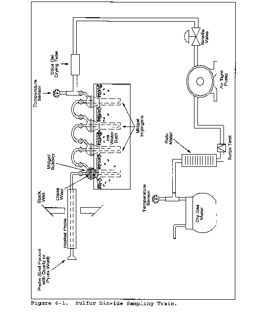
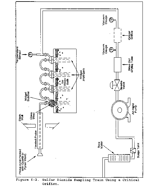

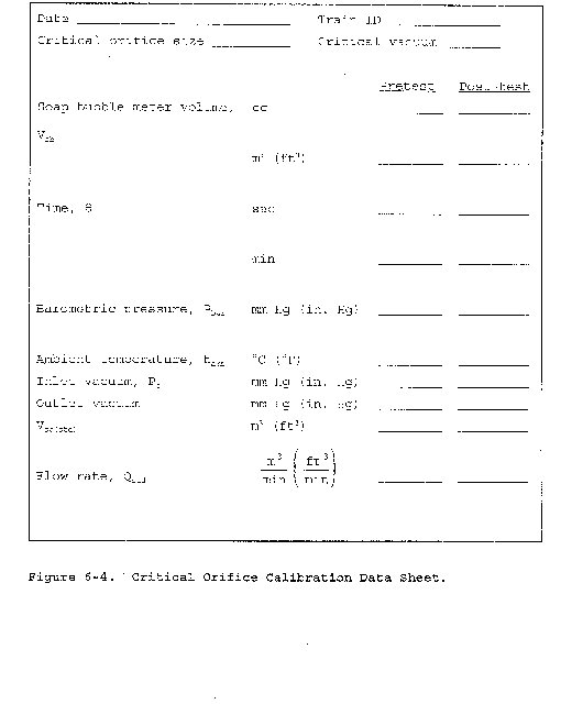
Method 6A - Determination of Sulfur Dioxide, Moisture, and Carbon Dioxide From Fossil Fuel Combustion Sources
This method does not include all of the specifications (e.g., equipment and supplies) and procedures (e.g., sampling and analytical) essential to its performance. Some material is incorporated by reference from other methods in this part. Therefore, to obtain reliable results, persons using this method should have a thorough knowledge of at least the following additional test methods: Method 1, Method 2, Method 3, Method 5, Method 6, and Method 19.
1.0 Scope and Application
1.1 Analytes.
| Analyte | CAS No. | Sensitivity |
|---|---|---|
| SO2 | 7449-09-05 | 3.4 mg SO2/m3
(2.12 × 10⁻⁷ lb/ft3) |
| CO2 | 124-38-9 | N/A |
| H2O | 7732-18-5 | N/A |
1.2 Applicability. This method is applicable for the determination of sulfur dioxide (SO2) emissions from fossil fuel combustion sources in terms of concentration (mg/dscm or lb/dscf) and in terms of emission rate (ng/J or lb/106 Btu) and for the determination of carbon dioxide (CO2) concentration (percent). Moisture content (percent), if desired, may also be determined by this method.
1.3 Data Quality Objectives. Adherence to the requirements of this method will enhance the quality of the data obtained from air pollutant sampling methods.
2.0 Summary of Method
2.1 A gas sample is extracted from a sampling point in the stack. The SO2 and the sulfur trioxide, including those fractions in any sulfur acid mist, are separated. The SO2 fraction is measured by the barium-thorin titration method. Moisture and CO2 fractions are collected in the same sampling train, and are determined gravimetrically.
3.0 Definitions [Reserved]
4.0 Interferences
Same as Method 6, section 4.0.
5.0 Safety
5.1 Disclaimer. This method may involve hazardous materials, operations, and equipment. This test method may not address all of the safety problems associated with its use. It is the responsibility of the user to establish appropriate safety and health practices and determine the applicability of regulatory limitations prior to performing this test method.
5.2 Corrosive reagents. Same as Method 6, section 5.2.
6.0 Equipment and Supplies
6.1 Sample Collection. Same as Method 6, section 6.1, with the exception of the following:
6.1.1 Sampling Train. A schematic of the sampling train used in this method is shown in Figure 6A-1.
6.1.1.1 Impingers and Bubblers. Two 30 = ml midget impingers with a 1 = mm restricted tip and two 30 = ml midget bubblers with unrestricted tips. Other types of impingers and bubblers (e.g., Mae West for SO2 collection and rigid cylinders containing Drierite for moisture absorbers), may be used with proper attention to reagent volumes and levels, subject to the approval of the Administrator.
6.1.1.2 CO2 Absorber. A sealable rigid cylinder or bottle with an inside diameter between 30 and 90 mm , a length between 125 and 250 mm, and appropriate connections at both ends. The filter may be a separate heated unit or may be within the heated portion of the probe. If the filter is within the sampling probe, the filter should not be within 15 cm of the probe inlet or any unheated section of the probe, such as the connection to the first bubbler. The probe and filter should be heated to at least 20 °C (68 °F) above the source temperature, but not greater than 120 °C (248 °F). The filter temperature (i.e., the sample gas temperature) should be monitored to assure the desired temperature is maintained. A heated Teflon connector may be used to connect the filter holder or probe to the first impinger.
For applications downstream of wet scrubbers, a heated out-of-stack filter (either borosilicate glass wool or glass fiber mat) is necessary.
6.2 Sample Recovery. Same as Method 6, section 6.2.
6.3 Sample Analysis. Same as Method 6, section 6.3, with the addition of a balance to measure within 0.05 g.
7.0 Reagents and Standards
Unless otherwise indicated, all reagents must conform to the specifications established by the Committee on Analytical Reagents of the American Chemical Society. Where such specifications are not available, use the best available grade.
7.1 Sample Collection. Same as Method 6, section 7.1, with the addition of the following:
7.1.1 Drierite. Anhydrous calcium sulfate (CaSO4) desiccant, 8 mesh, indicating type is recommended.
Do not use silica gel or similar desiccant in this application.
7.1.2 CO2 Absorbing Material. Ascarite II. Sodium hydroxide-coated silica, 8- to 20-mesh.
7.2 Sample Recovery and Analysis. Same as Method 6, sections 7.2 and 7.3, respectively.
8.0 Sample Collection, Preservation, Transport, and Storage
8.1 Preparation of Sampling Train.
8.1.1 Measure 15 ml of 80 percent isopropanol into the first midget bubbler and 15 ml of 3 percent hydrogen peroxide into each of the two midget impingers (the second and third vessels in the train) as described in Method 6, section 8.1. Insert the glass wool into the top of the isopropanol bubbler as shown in Figure 6A-1. Place about 25 g of Drierite into the second midget bubbler (the fourth vessel in the train). Clean the outside of the bubblers and impingers and allow the vessels to reach room temperature. Weigh the four vessels simultaneously to the nearest 0.1 g, and record this initial weight (mwi).
8.1.2 With one end of the CO2 absorber sealed, place glass wool into the cylinder to a depth of about 1 cm (0.5 in.). Place about 150 g of CO2 absorbing material in the cylinder on top of the glass wool, and fill the remaining space in the cylinder with glass wool. Assemble the cylinder as shown in figure 6A-2. With the cylinder in a horizontal position, rotate it around the horizontal axis. The CO2 absorbing material should remain in position during the rotation, and no open spaces or channels should be formed. If necessary, pack more glass wool into the cylinder to make the CO2 absorbing material stable. Clean the outside of the cylinder of loose dirt and moisture and allow the cylinder to reach room temperature. Weigh the cylinder to the nearest 0.1 g, and record this initial weight (mai).
8.1.3 Assemble the train as shown in figure 6A-1. Adjust the probe heater to a temperature sufficient to prevent condensation (see note in section 6.1). Place crushed ice and water around the impingers and bubblers. Mount the CO2 absorber outside the water bath in a vertical flow position with the sample gas inlet at the bottom. Flexible tubing (e.g., Tygon) may be used to connect the last SO2 absorbing impinger to the moisture absorber and to connect the moisture absorber to the CO2 absorber. A second, smaller CO2 absorber containing Ascarite II may be added in-line downstream of the primary CO2 absorber as a breakthrough indicator. Ascarite II turns white when CO2 is absorbed.
8.2 Sampling Train Leak-Check Procedure and Sample Collection. Same as Method 6, sections 8.2 and 8.3, respectively.
8.3 Sample Recovery.
8.3.1 Moisture Measurement. Disconnect the isopropanol bubbler, the SO2 impingers, and the moisture absorber from the sample train. Allow about 10 minutes for them to reach room temperature, clean the outside of loose dirt and moisture, and weigh them simultaneously in the same manner as in section 8.1. Record this final weight (mwf).
8.3.2 Peroxide Solution. Discard the contents of the isopropanol bubbler and pour the contents of the midget impingers into a leak-free polyethylene bottle for shipping. Rinse the two midget impingers and connecting tubes with water, and add the washing to the same storage container.
8.3.3 CO2 Absorber. Allow the CO2 absorber to warm to room temperature (about 10 minutes), clean the outside of loose dirt and moisture, and weigh to the nearest 0.1 g in the same manner as in section 8.1. Record this final weight (maf). Discard used Ascarite II material.
9.0 Quality Control
Same as Method 6, section 9.0.
10.0 Calibration and Standardization
Same as Method 6, section 10.0.
11.0 Analytical Procedure
11.1 Sample Analysis. The sample analysis procedure for SO2 is the same as that specified in Method 6, section 11.0.
12.0 Data Analysis and Calculations
Same as Method 6, section 12.0, with the addition of the following:
12.1 Nomenclature.
Cw = Concentration of moisture, percent.
CCO2 = Concentration of CO2, dry basis, percent.
ESO2 = Emission rate of SO2, ng/J (lb/106 Btu).
FC = Carbon F-factor from Method 19 for the fuel burned, dscm/J (dscf/106 Btu).
mwi = Initial weight of impingers, bubblers, and moisture absorber, g.
mwf = Final weight of impingers, bubblers, and moisture absorber, g.
mai = Initial weight of CO2 absorber, g.
maf = Final weight of CO2 absorber, g.
mSO2 = Mass of SO2 collected, mg.
VCO2(std) = Equivalent volume of CO2 collected at standard conditions, dscm (dscf).
Vw(std) = Equivalent volume of moisture collected at standard conditions, scm (scf).
12.2 CO2 Volume Collected, Corrected to Standard Conditions.

Where:
K3 = Equivalent volume of gaseous CO2 at standard conditions, 5.467 × 10⁻⁴ dscm/g (1.930 × 10⁻² dscf/g).
12.3 Moisture Volume Collected, Corrected to Standard Conditions.

Where:
K4 = Equivalent volume of water vapor at standard conditions, 1.336 × 10⁻³ scm/g (4.717 × 10⁻² scf/g).
12.4 SO2 Concentration.

Where:
K2 = 32.03 mg SO2/meq. SO2 (7.061 × 10⁻⁵ lb SO2/meq. SO2)
12.5 CO2 Concentration.

12.6 Moisture Concentration.

13.0 Method Performance
13.1 Range and Precision. The minimum detectable limit and the upper limit for the measurement of SO2 are the same as for Method 6. For a 20-liter sample, this method has a precision of ±0.5 percent CO2 for concentrations between 2.5 and 25 percent CO2 and ±1.0 percent moisture for moisture concentrations greater than 5 percent.
14.0 Pollution Prevention [Reserved]
15.0 Waste Management [Reserved]
16.0 Alternative Methods
If the only emission measurement desired is in terms of emission rate of SO2 (ng/J or lb/106 Btu), an abbreviated procedure may be used. The differences between the above procedure and the abbreviated procedure are described below.
16.1 Sampling Train. The sampling train is the same as that shown in Figure 6A-1 and as described in section 6.1, except that the dry gas meter is not needed.
16.2 Preparation of the Sampling Train. Follow the same procedure as in section 8.1, except do not weigh the isopropanol bubbler, the SO2 absorbing impingers, or the moisture absorber.
16.3 Sampling Train Leak-Check Procedure and Sample Collection. Leak-check and operate the sampling train as described in section 8.2, except that dry gas meter readings, barometric pressure, and dry gas meter temperatures need not be recorded during sampling.
16.4 Sample Recovery. Follow the procedure in section 8.3, except do not weigh the isopropanol bubbler, the SO2 absorbing impingers, or the moisture absorber.
16.5 Sample Analysis. Analysis of the peroxide solution is the same as that described in section 11.1.
16.6 Calculations.
16.6.1 SO2 Collected.

Where:
K2 = 32.03 mg SO2/meq. SO2
K2 = 7.061 × 10⁻⁵ lb SO2/meq. SO2
16.6.2 Sulfur Dioxide Emission Rate.

Where:
K5 = 1.829 × 10⁹ mg/dscm
K2 = 0.1142 lb/dscf
17.0 References
Same as Method 6, section 17.0, References 1 through 8, with the addition of the following:
1. Stanley, Jon and P.R. Westlin. An Alternate Method for Stack Gas Moisture Determination. Source Evaluation Society Newsletter. 3(4). November 1978.
2. Whittle, Richard N. and P.R. Westlin. Air Pollution Test Report: Development and Evaluation of an Intermittent Integrated SO2/CO2 Emission Sampling Procedure. Environmental Protection Agency, Emission Standard and Engineering Division, Emission Measurement Branch. Research Triangle Park, NC. December 1979. 14 pp.
18.0 Tables, Diagrams, Flowcharts, and Validation Data
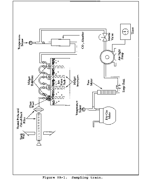

Method 6B - Determination of Sulfur Dioxide and Carbon Dioxide Daily Average Emissions From Fossil Fuel Combustion Sources
This method does not include all of the specifications (e.g., equipment and supplies) and procedures (e.g., sampling and analytical) essential to its performance. Some material is incorporated by reference from other methods in this part. Therefore, to obtain reliable results, persons using this method should have a thorough knowledge of at least the following additional test methods: Method 1, Method 2, Method 3, Method 5, Method 6, and Method 6A.
1.0 Scope and Application
1.1 Analytes.
| Analyte | CAS No. | Sensitivity |
|---|---|---|
| Sulfur dioxide (SO2) | 7449-09-05 | 3.4 mg SO2/m3
(2.12 × 10⁻⁷ lb/ft3) |
| Carbon dioxide (CO2) | 124-38-9 | N/A |
1.2 Applicability. This method is applicable for the determination of SO2 emissions from combustion sources in terms of concentration (ng/dscm or lb/dscf) and emission rate (ng/J or lb/106 Btu), and for the determination of CO2 concentration (percent) on a daily (24 hours) basis.
1.3 Data Quality Objectives. Adherence to the requirements of this method will enhance the quality of the data obtained from air pollutant sampling methods.
2.0 Summary of Method
2.1 A gas sample is extracted from the sampling point in the stack intermittently over a 24-hour or other specified time period. The SO2 fraction is measured by the barium-thorin titration method. Moisture and CO2 fractions are collected in the same sampling train, and are determined gravimetrically.
3.0 Definitions [Reserved]
4.0 Interferences
Same as Method 6, section 4.0.
5.0 Safety
5.1 Disclaimer. This method may involve hazardous materials, operations, and equipment. This test method may not address all of the safety problems associated with its use. It is the responsibility of the user to establish appropriate safety and health practices and determine the applicability of regulatory limitations prior to performing this test method.
5.2 Corrosive Reagents. Same as Method 6, section 5.2.
6.0 Equipment and Supplies
Same as Method 6A, section 6.0, with the following exceptions and additions:
6.1 The isopropanol bubbler is not used. An empty bubbler for the collection of liquid droplets, that does not allow direct contact between the collected liquid and the gas sample, may be included in the sampling train.
6.2 For intermittent operation, include an industrial timer-switch designed to operate in the “on” position at least 2 minutes continuously and “off” the remaining period over a repeating cycle. The cycle of operation is designated in the applicable regulation. At a minimum, the sampling operation should include at least 12, equal, evenly-spaced periods per 24 hours.
6.3 Stainless steel sampling probes, type 316, are not recommended for use with Method 6B because of potential sample contamination due to corrosion. Glass probes or other types of stainless steel, e.g., Hasteloy or Carpenter 20, are recommended for long-term use.
For applications downstream of wet scrubbers, a heated out-of-stack filter (either borosilicate glass wool or glass fiber mat) is necessary. Probe and filter heating systems capable of maintaining a sample gas temperature of between 20 and 120 °C (68 and 248 °F) at the filter are also required in these cases. The electric supply for these heating systems should be continuous and separate from the timed operation of the sample pump.
7.0 Reagents and Standards
Same as Method 6A, section 7.0, with the following exceptions:
7.1 Isopropanol is not used for sampling.
7.2 The hydrogen peroxide absorbing solution shall be diluted to no less than 6 percent by volume, instead of 3 percent as specified in Methods 6 and 6A.
7.3 If the Method 6B sampling train is to be operated in a low sample flow condition (less than 100 ml/min or 0.21 ft3/hr), molecular sieve material may be substituted for Ascarite II as the CO2 absorbing material. The recommended molecular sieve material is Union Carbide 1⁄16 inch pellets, 5 A°, or equivalent. Molecular sieve material need not be discarded following the sampling run, provided that it is regenerated as per the manufacturer's instruction. Use of molecular sieve material at flow rates higher than 100 ml/min (0.21 ft3/hr) may cause erroneous CO2 results.
8.0 Sample Collection, Preservation, Transport, and Storage
8.1 Preparation of Sampling Train. Same as Method 6A, section 8.1, with the addition of the following:
8.1.1 The sampling train is assembled as shown in Figure 6A-1 of Method 6A, except that the isopropanol bubbler is not included.
8.1.2 Adjust the timer-switch to operate in the “on” position from 2 to 4 minutes on a 2-hour repeating cycle or other cycle specified in the applicable regulation. Other timer sequences may be used with the restriction that the total sample volume collected is between 25 and 60 liters (0.9 and 2.1 ft3) for the amounts of sampling reagents prescribed in this method.
8.1.3 Add cold water to the tank until the impingers and bubblers are covered at least two-thirds of their length. The impingers and bubbler tank must be covered and protected from intense heat and direct sunlight. If freezing conditions exist, the impinger solution and the water bath must be protected.
Sampling may be conducted continuously if a low flow-rate sample pump [20 to 40 ml/min (0.04 to 0.08 ft3/hr) for the reagent volumes described in this method] is used. If sampling is continuous, the timer-switch is not necessary. In addition, if the sample pump is designed for constant rate sampling, the rate meter may be deleted. The total gas volume collected should be between 25 and 60 liters (0.9 and 2.1 ft3) for the amounts of sampling reagents prescribed in this method.
8.2 Sampling Train Leak-Check Procedure. Same as Method 6, section 8.2.
8.3 Sample Collection.
8.3.1 The probe and filter (either in-stack, out-of-stack, or both) must be heated to a temperature sufficient to prevent water condensation.
8.3.2 Record the initial dry gas meter reading. To begin sampling, position the tip of the probe at the sampling point, connect the probe to the first impinger (or filter), and start the timer and the sample pump. Adjust the sample flow to a constant rate of approximately 1.0 liter/min (0.035 cfm) as indicated by the rotameter. Observe the operation of the timer, and determine that it is operating as intended (i.e., the timer is in the “on” position for the desired period, and the cycle repeats as required).
8.3.3 One time between 9 a.m. and 11 a.m. during the 24-hour sampling period, record the dry gas meter temperature (Tm) and the barometric pressure (P(bar)).
8.3.4 At the conclusion of the run, turn off the timer and the sample pump, remove the probe from the stack, and record the final gas meter volume reading. Conduct a leak-check as described in section 8.2. If a leak is found, void the test run or use procedures acceptable to the Administrator to adjust the sample volume for leakage. Repeat the steps in sections 8.3.1 to 8.3.4 for successive runs.
8.4 Sample Recovery. The procedures for sample recovery (moisture measurement, peroxide solution, and CO2 absorber) are the same as those in Method 6A, section 8.3.
9.0 Quality Control
Same as Method 6, section 9.0., with the exception of the isopropanol-check.
10.0 Calibration and Standardization
Same as Method 6, section 10.0, with the addition of the following:
10.1 Periodic Calibration Check. After 30 days of operation of the test train, conduct a calibration check according to the same procedures as the post-test calibration check (Method 6, section 10.1.2). If the deviation between initial and periodic calibration factors exceeds 5 percent, use the smaller of the two factors in calculations for the preceding 30 days of data, but use the most recent calibration factor for succeeding test runs.
11.0 Analytical Procedures
11.1 Sample Loss Check and Analysis. Same as Method 6, sections 11.1 and 11.2, respectively.
12.0 Data Analysis and Calculations
Same as Method 6A, section 12.0, except that Pbar and Tm correspond to the values recorded in section 8.3.3 of this method. The values are as follows:
Pbar = Initial barometric pressure for the test period, mm Hg.
Tm = Absolute meter temperature for the test period, °K.
13.0 Method Performance
13.1 Range.
13.1.1 Sulfur Dioxide. Same as Method 6.
13.1.2 Carbon Dioxide. Not determined.
13.2 Repeatability and Reproducibility. EPA-sponsored collaborative studies were undertaken to determine the magnitude of repeatability and reproducibility achievable by qualified testers following the procedures in this method. The results of the studies evolve from 145 field tests including comparisons with Methods 3 and 6. For measurements of emission rates from wet, flue gas desulfurization units in (ng/J), the repeatability (intra-laboratory precision) is 8.0 percent and the reproducibility (inter-laboratory precision) is 11.1 percent.
14.0 Pollution Prevention [Reserved]
15.0 Waste Management [Reserved]
16.0 Alternative Methods
Same as Method 6A, section 16.0, except that the timer is needed and is operated as outlined in this method.
17.0 References
Same as Method 6A, section 17.0, with the addition of the following:
1. Butler, Frank E., et. al. The Collaborative Test of Method 6B: Twenty-Four-Hour Analysis of SO2 and CO2. JAPCA. Vol. 33, No. 10. October 1983.
18.0 Tables, Diagrams, Flowcharts, and Validation Data [Reserved]
Method 6C - Determination of Sulfur Dioxide Emissions From Stationary Sources (Instrumental Analyzer Procedure)
1.0 Scope and Application
What is Method 6C?
Method 6C is a procedure for measuring sulfur dioxide (SO2) in stationary source emissions using a continuous instrumental analyzer. Quality assurance and quality control requirements are included to assure that you, the tester, collect data of known quality. You must document your adherence to these specific requirements for equipment, supplies, sample collection and analysis, calculations, and data analysis.
This method does not completely describe all equipment, supplies, and sampling and analytical procedures you will need but refers to other methods for some of the details. Therefore, to obtain reliable results, you should also have a thorough knowledge of these additional test methods which are found in appendix A to this part:
(a) Method 1 - Sample and Velocity Traverses for Stationary Sources.
(b) Method 4 - Determination of Moisture Content in Stack Gases.
(c) Method 6 - Determination of Sulfur Dioxide Emissions from Stationary Sources.
(d) Method 7E - Determination of Nitrogen Oxides Emissions from Stationary Sources (Instrumental Analyzer Procedure).
1.1 Analytes. What does this method determine? This method measures the concentration of sulfur dioxide.
| Analyte | CAS No. | Sensitivity |
|---|---|---|
| SO2 | 7446-09-5 | Typically <2% of Calibration Span. |
1.2 Applicability. When is this method required? The use of Method 6C may be required by specific New Source Performance Standards, Clean Air Marketing rules, State Implementation Plans, and permits where SO2 concentrations in stationary source emissions must be measured, either to determine compliance with an applicable emission standard or to conduct performance testing of a continuous emission monitoring system (CEMS). Other regulations may also require the use of Method 6C.
1.3 Data Quality Objectives. How good must my collected data be? Refer to section 1.3 of Method 7E.
2.0 Summary of Method
In this method, you continuously sample the effluent gas and convey the sample to an analyzer that measures the concentration of SO2. You must meet the performance requirements of this method to validate your data.
3.0 Definitions
Refer to section 3.0 of Method 7E for the applicable definitions.
4.0 Interferences
Refer to Section 4.0 of Method 7E.
5.0 Safety
Refer to section 5.0 of Method 7E.
6.0 Equipment and Supplies
Figure 7E-1 of Method 7E is a schematic diagram of an acceptable measurement system.
6.1 What do I need for the measurement system? The essential components of the measurement system are the same as those in sections 6.1 and 6.2 of Method 7E, except that the SO2 analyzer described in section 6.2 of this method must be used instead of the analyzer described in section 6.2 of Method 7E. You must follow the noted specifications in section 6.1 of Method 7E.
6.2 What analyzer must I use? You may use an instrument that uses an ultraviolet, non-dispersive infrared, fluorescence, or other detection principle to continuously measure SO2 in the gas stream and meets the performance specifications in section 13.0. The low-range and dual-range analyzer provisions in sections 6.2.8.1 and 6.2.8.2 of Method 7E apply.
7.0 Reagents and Standards
7.1 Calibration Gas. What calibration gases do I need? Refer to section 7.1 of Method 7E for the calibration gas requirements. Example calibration gas mixtures are listed below.
(a) SO2 in nitrogen (N2).
(b) SO2 in air.
(c) SO2 and CO2 in N2.
(d) SO2 andO2 in N2.
(e) SO2/CO2/O2 gas mixture in N2.
(f) CO2/NOX gas mixture in N2.
(g) CO2/SO2/NOX gas mixture in N2.
7.2 Interference Check. What additional reagents do I need for the interference check? The test gases for the interference check are listed in Table 7E-3 of Method 7E. For the alternative interference check, you must use the reagents described in section 7.0 of Method 6.
8.0 Sample Collection, Preservation, Storage, and Transport
8.1 Sampling Site and Sampling Points. You must follow the procedures of section 8.1 of Method 7E.
8.2 Initial Measurement System Performance Tests. You must follow the procedures in section 8.2 of Method 7E. If a dilution-type measurement system is used, the special considerations in section 8.3 of Method 7E also apply.
8.3 Interference Check. You must follow the procedures of section 8.2.7 of Method 7E to conduct an interference check, substituting SO2 for NOX as the method pollutant. For dilution-type measurement systems, you must use the alternative interference check procedure in section 16 and a co-located, unmodified Method 6 sampling train.
8.4 Sample Collection. You must follow the procedures of section 8.4 of Method 7E.
8.5 Post-Run System Bias Check and Drift Assessment. You must follow the procedures of section 8.5 of Method 7E.
9.0 Quality Control
Follow quality control procedures in section 9.0 of Method 7E.
10.0 Calibration and Standardization
Follow the procedures for calibration and standardization in section 10.0 of Method 7E.
11.0 Analytical Procedures
Because sample collection and analysis are performed together (see section 8), additional discussion of the analytical procedure is not necessary.
12.0 Calculations and Data Analysis
You must follow the applicable procedures for calculations and data analysis in section 12.0 of Method 7E as applicable, substituting SO2 for NOX as appropriate.
13.0 Method Performance
13.1 The specifications for the applicable performance checks are the same as in section 13.0 of Method 7E.
13.2 Alternative Interference Check. The results are acceptable if the difference between the Method 6C result and the modified Method 6 result is less than 7.0 percent of the Method 6 result for each of the three test runs. For the purposes of comparison, the Method 6 and 6C results must be expressed in the same units of measure.
14.0 Pollution Prevention [Reserved]
15.0 Waste Management [Reserved]
16.0 Alternative Procedures
16.1 Alternative Interference Check. You may perform an alternative interference check consisting of at least three comparison runs between Method 6C and Method 6. This check validates the Method 6C results at each particular source category (type of facility) where the check is performed. When testing under conditions of low concentrations (<15 ppm), this alternative interference check is not allowed.
The procedure described below applies to non-dilution sampling systems only. If this alternative interference check is used for a dilution sampling system, use a standard Method 6 sampling train and extract the sample directly from the exhaust stream at points collocated with the Method 6C sample probe.
a. Build the modified Method 6 sampling train (flow control valve, two midget impingers containing 3 percent hydrogen peroxide, and dry gas meter) shown in Figure 6C-1. Connect the sampling train to the sample bypass discharge vent. Record the dry gas meter reading before you begin sampling. Simultaneously collect modified Method 6 and Method 6C samples. Open the flow control valve in the modified Method 6 train as you begin to sample with Method 6C. Adjust the Method 6 sampling rate to 1 liter per minute (.10 percent). The sampling time per run must be the same as for Method 6 plus twice the average measurement system response time. If your modified Method 6 train does not include a pump, you risk biasing the results high if you over-pressurize the midget impingers and cause a leak. You can reduce this risk by cautiously increasing the flow rate as sampling begins.
b. After completing a run, record the final dry gas meter reading, meter temperature, and barometric pressure. Recover and analyze the contents of the midget impingers using the procedures in Method 6. Determine the average gas concentration reported by Method 6C for the run.
17.0 References
1. “EPA Traceability Protocol for Assay and Certification of Gaseous Calibration Standards” September 1997 as amended, EPA-600/R-97/121
18.0 Tables, Diagrams, Flowcharts, and Validation Data
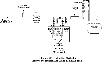
Method 7 - Determination of Nitrogen Oxide Emissions From Stationary Sources
This method does not include all of the specifications (e.g., equipment and supplies) and procedures (e.g., sampling and analytical) essential to its performance. Some material is incorporated by reference from other methods in this part. Therefore, to obtain reliable results, persons using this method should have a thorough knowledge of at least the following additional test methods: Method 1 and Method 5.
1.0 Scope and Application
1.1 Analytes.
| Analyte | CAS No. | Sensitivity |
|---|---|---|
| Nitrogen oxides (NOX), as NO2, including: | ||
| Nitric oxide (NO) | 10102-43-9 | |
| Nitrogen dioxide (NO2) | 10102-44-0 | 2-400 mg/dscm |
1.2 Applicability. This method is applicable for the measurement of nitrogen oxides (NOX) emitted from stationary sources.
1.3 Data Quality Objectives. Adherence to the requirements of this method will enhance the quality of the data obtained from air pollutant sample methods.
2.0 Summary of Method
A grab sample is collected in an evacuated flask containing a dilute sulfuric acid-hydrogen peroxide absorbing solution, and the nitrogen oxides, except nitrous oxide, are measured colorimetrically using the phenoldisulfonic acid (PDS) procedure.
3.0 Definitions [Reserved]
4.0 Interferences
Biased results have been observed when sampling under conditions of high sulfur dioxide concentrations. At or above 2100 ppm SO2, use five times the H2O2 concentration of the Method 7 absorbing solution. Laboratory tests have shown that high concentrations of SO2 (about 2100 ppm) cause low results in Method 7 and 7A. Increasing the H2O2 concentration to five times the original concentration eliminates this bias. However, when no SO2 is present, increasing the concentration by five times results in a low bias.
5.0 Safety
5.1 Disclaimer. This method may involve hazardous materials, operations, and equipment. This test method may not address all of the safety problems associated with its use. It is the responsibility of the user to establish appropriate safety and health practices and to determine the applicability of regulatory limitations prior to performing this test method.
5.2 Corrosive Reagents. The following reagents are hazardous. Personal protective equipment and safe procedures are useful in preventing chemical splashes. If contact occurs, immediately flush with copious amounts of water for at least 15 minutes. Remove clothing under shower and decontaminate. Treat residual chemical burns as thermal burns.
5.2.1 Hydrogen Peroxide (H2O2). Irritating to eyes, skin, nose, and lungs.
5.2.2 Phenoldisulfonic Acid. Irritating to eyes and skin.
5.2.3 Sodium Hydroxide (NaOH). Causes severe damage to eyes and skin. Inhalation causes irritation to nose, throat, and lungs. Reacts exothermically with limited amounts of water.
5.2.4 Sulfuric Acid (H2SO4). Rapidly destructive to body tissue. Will cause third degree burns. Eye damage may result in blindness. Inhalation may be fatal from spasm of the larynx, usually within 30 minutes. May cause lung tissue damage with edema. 1 mg/m3 for 8 hours will cause lung damage or, in higher concentrations, death. Provide ventilation to limit inhalation. Reacts violently with metals and organics.
5.2.5 Phenol. Poisonous and caustic. Do not handle with bare hands as it is absorbed through the skin.
6.0 Equipment and Supplies
6.1 Sample Collection. A schematic of the sampling train used in performing this method is shown in Figure 7-1. Other grab sampling systems or equipment, capable of measuring sample volume to within 2.0 percent and collecting a sufficient sample volume to allow analytical reproducibility to within 5 percent, will be considered acceptable alternatives, subject to the approval of the Administrator. The following items are required for sample collection:
6.1.1 Probe. Borosilicate glass tubing, sufficiently heated to prevent water condensation and equipped with an in-stack or heated out-of-stack filter to remove particulate matter (a plug of glass wool is satisfactory for this purpose). Stainless steel or Teflon tubing may also be used for the probe. Heating is not necessary if the probe remains dry during the purging period.
6.1.2 Collection Flask. Two-liter borosilicate, round bottom flask, with short neck and 24/40 standard taper opening, protected against implosion or breakage.
6.1.3 Flask Valve. T-bore stopcock connected to a 24/40 standard taper joint.
6.1.4 Temperature Gauge. Dial-type thermometer, or other temperature gauge, capable of measuring 1 °C (2 °F) intervals from −5 to 50 °C (23 to 122 °F).
6.1.5 Vacuum Line. Tubing capable of withstanding a vacuum of 75 mm (3 in.) Hg absolute pressure, with “T” connection and T-bore stopcock.
6.1.6 Vacuum Gauge. U-tube manometer, 1 meter (39 in.), with 1 mm (0.04 in.) divisions, or other gauge capable of measuring pressure to within 2.5 mm (0.10 in.) Hg.
6.1.7 Pump. Capable of evacuating the collection flask to a pressure equal to or less than 75 mm (3 in.) Hg absolute.
6.1.8 Squeeze Bulb. One-way.
6.1.9 Volumetric Pipette. 25-ml.
6.1.10 Stopcock and Ground Joint Grease. A high-vacuum, high-temperature chlorofluorocarbon grease is required. Halocarbon 25-5S has been found to be effective.
6.1.11 Barometer. Mercury, aneroid, or other barometer capable of measuring atmospheric pressure to within 2.5 mm (0.1 in.) Hg. See note in Method 5, section 6.1.2.
6.2 Sample Recovery. The following items are required for sample recovery:
6.2.1 Graduated Cylinder. 50-ml with 1 ml divisions.
6.2.2 Storage Containers. Leak-free polyethylene bottles.
6.2.3 Wash Bottle. Polyethylene or glass.
6.2.4 Glass Stirring Rod.
6.2.5 Test Paper for Indicating pH. To cover the pH range of 7 to 14.
6.3 Analysis. The following items are required for analysis:
6.3.1 Volumetric Pipettes. Two 1-ml, two 2-ml, one 3-ml, one 4-ml, two 10-ml, and one 25-ml for each sample and standard.
6.3.2 Porcelain Evaporating Dishes. 175- to 250-ml capacity with lip for pouring, one for each sample and each standard. The Coors No. 45006 (shallowform, 195-ml) has been found to be satisfactory. Alternatively, polymethyl pentene beakers (Nalge No. 1203, 150-ml), or glass beakers (150-ml) may be used. When glass beakers are used, etching of the beakers may cause solid matter to be present in the analytical step; the solids should be removed by filtration.
6.3.3 Steam Bath. Low-temperature ovens or thermostatically controlled hot plates kept below 70 °C (160 °F) are acceptable alternatives.
6.3.4 Dropping Pipette or Dropper. Three required.
6.3.5 Polyethylene Policeman. One for each sample and each standard.
6.3.6 Graduated Cylinder. 100-ml with 1-ml divisions.
6.3.7 Volumetric Flasks. 50-ml (one for each sample and each standard), 100-ml (one for each sample and each standard, and one for the working standard KNO3 solution), and 1000-ml (one).
6.3.8 Spectrophotometer. To measure at 410 nm.
6.3.9 Graduated Pipette. 10-ml with 0.1-ml divisions.
6.3.10 Test Paper for Indicating pH. To cover the pH range of 7 to 14.
6.3.11 Analytical Balance. To measure to within 0.1 mg.
7.0 Reagents and Standards
Unless otherwise indicated, it is intended that all reagents conform to the specifications established by the Committee on Analytical Reagents of the American Chemical Society, where such specifications are available; otherwise, use the best available grade.
7.1 Sample Collection. The following reagents are required for sampling:
7.1.1 Water. Deionized distilled to conform to ASTM D 1193-77 or 91 Type 3 (incorporated by reference - see § 60.17). The KMnO4 test for oxidizable organic matter may be omitted when high concentrations of organic matter are not expected to be present.
7.1.2 Absorbing Solution. Cautiously add 2.8 ml concentrated H2SO4 to a 1-liter flask partially filled with water. Mix well, and add 6 ml of 3 percent hydrogen peroxide, freshly prepared from 30 percent hydrogen peroxide solution. Dilute to 1 liter of water and mix well. The absorbing solution should be used within 1 week of its preparation. Do not expose to extreme heat or direct sunlight.
7.2 Sample Recovery. The following reagents are required for sample recovery:
7.2.1 Water. Same as in 7.1.1.
7.2.2 Sodium Hydroxide, 1 N. Dissolve 40 g NaOH in water, and dilute to 1 liter.
7.3 Analysis. The following reagents and standards are required for analysis:
7.3.1 Water. Same as in 7.1.1.
7.3.2 Fuming Sulfuric Acid. 15 to 18 percent by weight free sulfur trioxide. HANDLE WITH CAUTION.
7.3.3 Phenol. White solid.
7.3.4 Sulfuric Acid. Concentrated, 95 percent minimum assay.
7.3.5 Potassium Nitrate (KNO3). Dried at 105 to 110 °C (221 to 230 °F) for a minimum of 2 hours just prior to preparation of standard solution.
7.3.6 Standard KNO3 Solution. Dissolve exactly 2.198 g of dried KNO3 in water, and dilute to 1 liter with water in a 1000-ml volumetric flask.
7.3.7 Working Standard KNO3 Solution. Dilute 10 ml of the standard solution to 100 ml with water. One ml of the working standard solution is equivalent to 100 µg nitrogen dioxide (NO2).
7.3.8 Phenoldisulfonic Acid Solution. Dissolve 25 g of pure white phenol solid in 150 ml concentrated sulfuric acid on a steam bath. Cool, add 75 ml fuming sulfuric acid (15 to 18 percent by weight free sulfur trioxide - HANDLE WITH CAUTION), and heat at 100 °C (212 °F) for 2 hours. Store in a dark, stoppered bottle.
7.3.9 Concentrated Ammonium Hydroxide.
8.0 Sample Collection, Preservation, Storage and Transport
8.1 Sample Collection.
8.1.1 Flask Volume. The volume of the collection flask and flask valve combination must be known prior to sampling. Assemble the flask and flask valve, and fill with water to the stopcock. Measure the volume of water to ±10 ml. Record this volume on the flask.
8.1.2 Pipette 25 ml of absorbing solution into a sample flask, retaining a sufficient quantity for use in preparing the calibration standards. Insert the flask valve stopper into the flask with the valve in the “purge” position. Assemble the sampling train as shown in Figure 7-1, and place the probe at the sampling point. Make sure that all fittings are tight and leak-free, and that all ground glass joints have been greased properly with a high-vacuum, high temperature chlorofluorocarbon-based stopcock grease. Turn the flask valve and the pump valve to their “evacuate” positions. Evacuate the flask to 75 mm (3 in.) Hg absolute pressure, or less. Evacuation to a pressure approaching the vapor pressure of water at the existing temperature is desirable. Turn the pump valve to its “vent” position, and turn off the pump. Check for leakage by observing the manometer for any pressure fluctuation. (Any variation greater than 10 mm (0.4 in.) Hg over a period of 1 minute is not acceptable, and the flask is not to be used until the leakage problem is corrected. Pressure in the flask is not to exceed 75 mm (3 in.) Hg absolute at the time sampling is commenced.) Record the volume of the flask and valve (Vf), the flask temperature (Ti), and the barometric pressure. Turn the flask valve counterclockwise to its “purge” position, and do the same with the pump valve. Purge the probe and the vacuum tube using the squeeze bulb. If condensation occurs in the probe and the flask valve area, heat the probe, and purge until the condensation disappears. Next, turn the pump valve to its “vent” position. Turn the flask valve clockwise to its “evacuate” position, and record the difference in the mercury levels in the manometer. The absolute internal pressure in the flask (Pi) is equal to the barometric pressure less the manometer reading. Immediately turn the flask valve to the “sample” position, and permit the gas to enter the flask until pressures in the flask and sample line (i.e., duct, stack) are equal. This will usually require about 15 seconds; a longer period indicates a plug in the probe, which must be corrected before sampling is continued. After collecting the sample, turn the flask valve to its “purge” position, and disconnect the flask from the sampling train.
8.1.3 Shake the flask for at least 5 minutes.
8.1.4 If the gas being sampled contains insufficient oxygen for the conversion of NO to NO2 (e.g., an applicable subpart of the standards may require taking a sample of a calibration gas mixture of NO in N2), then introduce oxygen into the flask to permit this conversion. Oxygen may be introduced into the flask by one of three methods: (1) Before evacuating the sampling flask, flush with pure cylinder oxygen, then evacuate flask to 75 mm (3 in.) Hg absolute pressure or less; or (2) inject oxygen into the flask after sampling; or (3) terminate sampling with a minimum of 50 mm (2 in.) Hg vacuum remaining in the flask, record this final pressure, and then vent the flask to the atmosphere until the flask pressure is almost equal to atmospheric pressure.
8.2 Sample Recovery. Let the flask sit for a minimum of 16 hours, and then shake the contents for 2 minutes.
8.2.1 Connect the flask to a mercury filled U-tube manometer. Open the valve from the flask to the manometer, and record the flask temperature (Tf), the barometric pressure, and the difference between the mercury levels in the manometer. The absolute internal pressure in the flask (Pf) is the barometric pressure less the manometer reading. Transfer the contents of the flask to a leak-free polyethylene bottle. Rinse the flask twice with 5 ml portions of water, and add the rinse water to the bottle. Adjust the pH to between 9 and 12 by adding 1 N NaOH, dropwise (about 25 to 35 drops). Check the pH by dipping a stirring rod into the solution and then touching the rod to the pH test paper. Remove as little material as possible during this step. Mark the height of the liquid level so that the container can be checked for leakage after transport. Label the container to identify clearly its contents. Seal the container for shipping.
9.0 Quality Control
| Section | Quality control measure | Effect |
|---|---|---|
| 10.1 | Spectrophotometer calibration | Ensure linearity of spectrophotometer response to standards. |
10.0 Calibration and Standardization
10.1 Spectrophotometer.
10.1.1 Optimum Wavelength Determination.
10.1.1.1 Calibrate the wavelength scale of the spectrophotometer every 6 months. The calibration may be accomplished by using an energy source with an intense line emission such as a mercury lamp, or by using a series of glass filters spanning the measuring range of the spectrophotometer. Calibration materials are available commercially and from the National Institute of Standards and Technology. Specific details on the use of such materials should be supplied by the vendor; general information about calibration techniques can be obtained from general reference books on analytical chemistry. The wavelength scale of the spectrophotometer must read correctly within 5 nm at all calibration points; otherwise, repair and recalibrate the spectrophotometer. Once the wavelength scale of the spectrophotometer is in proper calibration, use 410 nm as the optimum wavelength for the measurement of the absorbance of the standards and samples.
10.1.1.2 Alternatively, a scanning procedure may be employed to determine the proper measuring wavelength. If the instrument is a double-beam spectrophotometer, scan the spectrum between 400 and 415 nm using a 200 µg NO2 standard solution in the sample cell and a blank solution in the reference cell. If a peak does not occur, the spectrophotometer is probably malfunctioning and should be repaired. When a peak is obtained within the 400 to 415 nm range, the wavelength at which this peak occurs shall be the optimum wavelength for the measurement of absorbance of both the standards and the samples. For a single-beam spectrophotometer, follow the scanning procedure described above, except scan separately the blank and standard solutions. The optimum wavelength shall be the wavelength at which the maximum difference in absorbance between the standard and the blank occurs.
10.1.2 Determination of Spectrophotometer Calibration Factor Kc. Add 0 ml, 2.0 ml, 4.0 ml, 6.0 ml, and 8.0 ml of the KNO3 working standard solution (1 ml = 100 µg NO2) to a series of five 50-ml volumetric flasks. To each flask, add 25 ml of absorbing solution and 10 ml water. Add 1 N NaOH to each flask until the pH is between 9 and 12 (about 25 to 35 drops). Dilute to the mark with water. Mix thoroughly, and pipette a 25-ml aliquot of each solution into a separate porcelain evaporating dish. Beginning with the evaporation step, follow the analysis procedure of section 11.2 until the solution has been transferred to the 100-ml volumetric flask and diluted to the mark. Measure the absorbance of each solution at the optimum wavelength as determined in section 10.1.1. This calibration procedure must be repeated on each day that samples are analyzed. Calculate the spectrophotometer calibration factor as shown in section 12.2.
10.1.3 Spectrophotometer Calibration Quality Control. Multiply the absorbance value obtained for each standard by the Kc factor (reciprocal of the least squares slope) to determine the distance each calibration point lies from the theoretical calibration line. The difference between the calculated concentration values and the actual concentrations (i.e., 100, 200, 300, and 400 µg NO2) should be less than 7 percent for all standards.
10.2 Barometer. Calibrate against a mercury barometer or NIST-traceable barometer prior to the field test.
10.3 Temperature Gauge. Calibrate dial thermometers against mercury-in-glass thermometers. An alternative mercury-free thermometer may be used if the thermometer is, at a minimum, equivalent in terms of performance or suitably effective for the specific temperature measurement application.
10.4 Vacuum Gauge. Calibrate mechanical gauges, if used, against a mercury manometer such as that specified in section 6.1.6.
10.5 Analytical Balance. Calibrate against standard weights.
11.0 Analytical Procedures
11.1 Sample Loss Check. Note the level of the liquid in the container, and confirm whether any sample was lost during shipment. Note this on the analytical data sheet. If a noticeable amount of leakage has occurred, either void the sample or use methods, subject to the approval of the Administrator, to correct the final results.
11.2 Sample Preparation. Immediately prior to analysis, transfer the contents of the shipping container to a 50 ml volumetric flask, and rinse the container twice with 5 ml portions of water. Add the rinse water to the flask, and dilute to mark with water; mix thoroughly. Pipette a 25-ml aliquot into the porcelain evaporating dish. Return any unused portion of the sample to the polyethylene storage bottle. Evaporate the 25-ml aliquot to dryness on a steam bath, and allow to cool. Add 2 ml phenoldisulfonic acid solution to the dried residue, and triturate thoroughly with a polyethylene policeman. Make sure the solution contacts all the residue. Add 1 ml water and 4 drops of concentrated sulfuric acid. Heat the solution on a steam bath for 3 minutes with occasional stirring. Allow the solution to cool, add 20 ml water, mix well by stirring, and add concentrated ammonium hydroxide, dropwise, with constant stirring, until the pH is 10 (as determined by pH paper). If the sample contains solids, these must be removed by filtration (centrifugation is an acceptable alternative, subject to the approval of the Administrator) as follows: Filter through Whatman No. 41 filter paper into a 100-ml volumetric flask. Rinse the evaporating dish with three 5-ml portions of water. Filter these three rinses. Wash the filter with at least three 15-ml portions of water. Add the filter washings to the contents of the volumetric flask, and dilute to the mark with water. If solids are absent, the solution can be transferred directly to the 100-ml volumetric flask and diluted to the mark with water.
11.3 Sample Analysis. Mix the contents of the flask thoroughly, and measure the absorbance at the optimum wavelength used for the standards (section 10.1.1), using the blank solution as a zero reference. Dilute the sample and the blank with equal volumes of water if the absorbance exceeds A4, the absorbance of the 400-µg NO2 standard (see section 10.1.3).
12.0 Data Analysis and Calculations
Carry out the calculations, retaining at least one extra significant figure beyond that of the acquired data. Round off figures after final calculations.
12.1 12.1 Nomenclature
A = Absorbance of sample.
A1 = Absorbance of the 100-µg NO2 standard.
A2 = Absorbance of the 200-µg NO2 standard.
A3 = Absorbance of the 300-µg NO2 standard.
A4 = Absorbance of the 400-µg NO2 standard.
C = Concentration of NOX as NO2, dry basis, corrected to standard conditions, mg/dsm3 (lb/dscf).
F = Dilution factor (i.e., 25/5, 25/10, etc., required only if sample dilution was needed to reduce the absorbance into the range of the calibration).
Kc = Spectrophotometer calibration factor.
M = Mass of NOX as NO2 in gas sample, µg.
Pf = Final absolute pressure of flask, mm Hg (in. Hg).
Pi = Initial absolute pressure of flask, mm Hg (in. Hg).
Pstd = Standard absolute pressure, 760 mm Hg (29.92 in. Hg).
Tf = Final absolute temperature of flask, °K (°R).
Ti = Initial absolute temperature of flask, °K (°R).
Tstd = Standard absolute temperature, 293 °K (528°R).
Vsc = Sample volume at standard conditions (dry basis), ml.
Vf = Volume of flask and valve, ml.
Va = Volume of absorbing solution, 25 ml.
12.2 Spectrophotometer Calibration Factor.
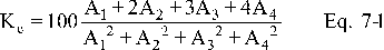
12.3 Sample Volume, Dry Basis, Corrected to Standard Conditions.

Where:
K1 = 0.3858 °K/mm Hg for metric units,
K1 = 17.65 °R/in. Hg for English units.
12.4 Total µg NO2 per sample.

Where:
2 = 50/25, the aliquot factor.
If other than a 25-ml aliquot is used for analysis, the factor 2 must be replaced by a corresponding factor.
12.5 Sample Concentration, Dry Basis, Corrected to Standard Conditions.

Where:
K2 = 103 (mg/m3)/(µg/ml) for metric units,
K2 = 6.242 × 10⁻⁵ (lb/scf)/(µg/ml) for English units.
13.0 Method Performance
13.1 Range. The analytical range of the method has been determined to be 2 to 400 milligrams NOX (as NO2) per dry standard cubic meter, without having to dilute the sample.
14.0 Pollution Prevention [Reserved]
15.0 Waste Management [Reserved]
16.0 References
1. Standard Methods of Chemical Analysis. 6th ed. New York, D. Van Nostrand Co., Inc. 1962. Vol. 1, pp. 329-330.
2. Standard Method of Test for Oxides of Nitrogen in Gaseous Combustion Products (Phenoldisulfonic Acid Procedure). In: 1968 Book of ASTM Standards, Part 26. Philadelphia, PA. 1968. ASTM Designation D 1608-60, pp. 725-729.
3. Jacob, M.B. The Chemical Analysis of Air Pollutants. New York. Interscience Publishers, Inc. 1960. Vol. 10, pp. 351-356.
4. Beatty, R.L., L.B. Berger, and H.H. Schrenk. Determination of Oxides of Nitrogen by the Phenoldisulfonic Acid Method. Bureau of Mines, U.S. Dept. of Interior. R.I. 3687. February 1943.
5. Hamil, H.F. and D.E. Camann. Collaborative Study of Method for the Determination of Nitrogen Oxide Emissions from Stationary Sources (Fossil Fuel-Fired Steam Generators). Southwest Research Institute Report for Environmental Protection Agency. Research Triangle Park, NC. October 5, 1973.
6. Hamil, H.F. and R.E. Thomas. Collaborative Study of Method for the Determination of Nitrogen Oxide Emissions from Stationary Sources (Nitric Acid Plants). Southwest Research Institute Report for Environmental Protection Agency. Research Triangle Park, NC. May 8, 1974.
7. Stack Sampling Safety Manual (Draft). U.S. Environmental Protection Agency, Office of Air Quality Planning and Standards, Research Triangle Park, NC. September 1978.
17.0 Tables, Diagrams, Flowcharts, and Validation Data
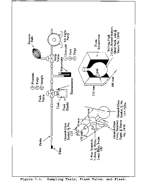
Method 7A - Determination of Nitrogen Oxide Emissions From Stationary Sources (Ion Chromatographic Method)
This method does not include all of the specifications (e.g., equipment and supplies) and procedures (e.g., sampling and analytical) essential to its performance. Some material is incorporated by reference from other methods in this part. Therefore, to obtain reliable results, persons using this method should have a thorough knowledge of at least the following additional test methods: Method 1, Method 3, Method 5, and Method 7.
1.0 Scope and Application
1.1 Analytes.
| Analyte | CAS No. | Sensitivity |
|---|---|---|
| Nitrogen oxides (NOX), as NO2, including: | ||
| Nitric oxide (NO) | 10102-43-9 | |
| Nitrogen dioxide (NO2) | 10102-44-0 | 65-655 ppmv |
1.2 Applicability. This method is applicable for the determination of NOX emissions from stationary sources.
1.3 Data Quality Objectives. Adherence to the requirements of this method will enhance the quality of the data obtained from air pollutant sampling methods.
2.0 Summary of Method
A grab sample is collected in an evacuated flask containing a dilute sulfuric acid-hydrogen peroxide absorbing solution. The nitrogen oxides, excluding nitrous oxide (N2O), are oxidized to nitrate and measured by ion chromatography.
3.0 Definitions [Reserved]
4.0 Interferences
Biased results have been observed when sampling under conditions of high sulfur dioxide concentrations. At or above 2100 ppm SO2, use five times the H2O2 concentration of the Method 7 absorbing solution. Laboratory tests have shown that high concentrations of SO2 (about 2100 ppm) cause low results in Method 7 and 7A. Increasing the H2O2 concentration to five times the original concentration eliminates this bias. However, when no SO2 is present, increasing the concentration by five times results in a low bias.
5.0 Safety
5.1 This method may involve hazardous materials, operations, and equipment. This test method may not address all of the safety problems associated with its use. It is the responsibility of the user of this test method to establish appropriate safety and health practices and to determine the applicability of regulatory limitations prior to performing this test method.
5.2 Corrosive reagents. The following reagents are hazardous. Personal protective equipment and safe procedures are useful in preventing chemical splashes. If contact occurs, immediately flush with copious amounts of water at least 15 minutes. Remove clothing under shower and decontaminate. Treat residual chemical burns as thermal burns.
5.2.1 Hydrogen Peroxide (H2O2). Irritating to eyes, skin, nose, and lungs.
5.2.2 Sulfuric Acid (H2SO4). Rapidly destructive to body tissue. Will cause third degree burns. Eye damage may result in blindness. Inhalation may be fatal from spasm of the larynx, usually within 30 minutes. May cause lung tissue damage with edema. 3 mg/m3 will cause lung damage in uninitiated. 1 mg/m3 for 8 hours will cause lung damage or, in higher concentrations, death. Provide ventilation to limit inhalation. Reacts violently with metals and organics.
6.0 Equipment and Supplies
6.1 Sample Collection. Same as in Method 7, section 6.1.
6.2 Sample Recovery. Same as in Method 7, section 6.2, except the stirring rod and pH paper are not needed.
6.3 Analysis. For the analysis, the following equipment and supplies are required. Alternative instrumentation and procedures will be allowed provided the calibration precision requirement in section 10.1.2 can be met.
6.3.1 Volumetric Pipets. Class A;1-, 2-, 4-, 5-ml (two for the set of standards and one per sample), 6-, 10-, and graduated 5-ml sizes.
6.3.2 Volumetric Flasks. 50-ml (two per sample and one per standard), 200-ml, and 1-liter sizes.
6.3.3 Analytical Balance. To measure to within 0.1 mg.
6.3.4 Ion Chromatograph. The ion chromatograph should have at least the following components:
6.3.4.1 Columns. An anion separation or other column capable of resolving the nitrate ion from sulfate and other species present and a standard anion suppressor column (optional). Suppressor columns are produced as proprietary items; however, one can be produced in the laboratory using the resin available from BioRad Company, 32nd and Griffin Streets, Richmond, California. Peak resolution can be optimized by varying the eluent strength or column flow rate, or by experimenting with alternative columns that may offer more efficient separation. When using guard columns with the stronger reagent to protect the separation column, the analyst should allow rest periods between injection intervals to purge possible sulfate buildup in the guard column.
6.3.4.2 Pump. Capable of maintaining a steady flow as required by the system.
6.3.4.3 Flow Gauges. Capable of measuring the specified system flow rate.
6.3.4.4 Conductivity Detector.
6.3.4.5 Recorder. Compatible with the output voltage range of the detector.
7.0 Reagents and Standards
Unless otherwise indicated, it is intended that all reagents conform to the specifications established by the Committee on Analytical Reagents of the American Chemical Society, where such specifications are available; otherwise, use the best available grade.
7.1 Sample Collection. Same as Method 7, section 7.1.
7.2 Sample Recovery. Same as Method 7, section 7.1.1.
7.3 Analysis. The following reagents and standards are required for analysis:
7.3.1 Water. Same as Method 7, section 7.1.1.
7.3.2 Stock Standard Solution, 1 mg NO2/ml. Dry an adequate amount of sodium nitrate (NaNO3) at 105 to 110 °C (221 to 230 °F) for a minimum of 2 hours just before preparing the standard solution. Then dissolve exactly 1.847 g of dried NaNO3 in water, and dilute to l liter in a volumetric flask. Mix well. This solution is stable for 1 month and should not be used beyond this time.
7.3.3 Working Standard Solution, 25 µg/ml. Dilute 5 ml of the standard solution to 200 ml with water in a volumetric flask, and mix well.
7.3.4 Eluent Solution. Weigh 1.018 g of sodium carbonate (Na2CO3) and 1.008 g of sodium bicarbonate (NaHCO3), and dissolve in 4 liters of water. This solution is 0.0024 M Na2CO3/0.003 M NaHCO3. Other eluents appropriate to the column type and capable of resolving nitrate ion from sulfate and other species present may be used.
8.0 Sample Collection, Preservation, Storage, and Transport
8.1 Sampling. Same as in Method 7, section 8.1.
8.2 Sample Recovery. Same as in Method 7, section 8.2, except delete the steps on adjusting and checking the pH of the sample. Do not store the samples more than 4 days between collection and analysis.
9.0 Quality Control
| Section | Quality control measure | Effect |
|---|---|---|
| 10.1 | Ion chromatographn calibration | Ensure linearity of ion chromatograph response to standards. |
10.0 Calibration and Standardizations
10.1 Ion Chromatograph.
10.1.1 Determination of Ion Chromatograph Calibration Factor S. Prepare a series of five standards by adding 1.0, 2.0, 4.0, 6.0, and 10.0 ml of working standard solution (25 µg/ml) to a series of five 50-ml volumetric flasks. (The standard masses will equal 25, 50, 100, 150, and 250 µg.) Dilute each flask to the mark with water, and mix well. Analyze with the samples as described in section 11.2, and subtract the blank from each value. Prepare or calculate a linear regression plot of the standard masses in µg (x-axis) versus their peak height responses in millimeters (y-axis). (Take peak height measurements with symmetrical peaks; in all other cases, calculate peak areas.) From this curve, or equation, determine the slope, and calculate its reciprocal to denote as the calibration factor, S.
10.1.2 Ion Chromatograph Calibration Quality Control. If any point on the calibration curve deviates from the line by more than 7 percent of the concentration at that point, remake and reanalyze that standard. This deviation can be determined by multiplying S times the peak height response for each standard. The resultant concentrations must not differ by more than 7 percent from each known standard mass (i.e., 25, 50, 100, 150, and 250 µg).
10.2 Conductivity Detector. Calibrate according to manufacturer's specifications prior to initial use.
10.3 Barometer. Calibrate against a mercury barometer.
10.4 Temperature Gauge. Calibrate dial thermometers against mercury-in-glass thermometers. An alternative mercury-free thermometer may be used if the thermometer is, at a minimum, equivalent in terms of performance or suitably effective for the specific temperature measurement application.
10.5 Vacuum Gauge. Calibrate mechanical gauges, if used, against a mercury manometer such as that specified in section 6.1.6 of Method 7.
10.6 Analytical Balance. Calibrate against standard weights.
11.0 Analytical Procedures
11.1 Sample Preparation.
11.1.1 Note on the analytical data sheet, the level of the liquid in the container, and whether any sample was lost during shipment. If a noticeable amount of leakage has occurred, either void the sample or use methods, subject to the approval of the Administrator, to correct the final results. Immediately before analysis, transfer the contents of the shipping container to a 50-ml volumetric flask, and rinse the container twice with 5 ml portions of water. Add the rinse water to the flask, and dilute to the mark with water. Mix thoroughly.
11.1.2 Pipet a 5-ml aliquot of the sample into a 50-ml volumetric flask, and dilute to the mark with water. Mix thoroughly. For each set of determinations, prepare a reagent blank by diluting 5 ml of absorbing solution to 50 ml with water. (Alternatively, eluent solution may be used instead of water in all sample, standard, and blank dilutions.)
11.2 Analysis.
11.2.1 Prepare a standard calibration curve according to section 10.1.1. Analyze the set of standards followed by the set of samples using the same injection volume for both standards and samples. Repeat this analysis sequence followed by a final analysis of the standard set. Average the results. The two sample values must agree within 5 percent of their mean for the analysis to be valid. Perform this duplicate analysis sequence on the same day. Dilute any sample and the blank with equal volumes of water if the concentration exceeds that of the highest standard.
11.2.2 Document each sample chromatogram by listing the following analytical parameters: injection point, injection volume, nitrate and sulfate retention times, flow rate, detector sensitivity setting, and recorder chart speed.
12.0 Data Analysis and Calculations
Carry out the calculations, retaining at least one extra significant figure beyond that of the acquired data. Round off figures after final calculations.
12.1 Sample Volume. Calculate the sample volume Vsc (in ml), on a dry basis, corrected to standard conditions, using Equation 7-2 of Method 7.
12.2 Sample Concentration of NOX as NO2.
12.2.1 Calculate the sample concentration C (in mg/dscm) as follows:

Where:
H = Sample peak height, mm.
S = Calibration factor, µg/mm.
F = Dilution factor (required only if sample dilution was needed to reduce the concentration into the range of calibration), dimensionless.
104 = 1:10 dilution times conversion factor of: (mg/103 µg)(106 ml/m3).
12.2.2 If desired, the concentration of NO2 may be calculated as ppm NO2 at standard conditions as follows:

Where:
0.5228 = ml/mg NO2.
13.0 Method Performance
13.1 Range. The analytical range of the method is from 125 to 1250 mg NOX/m3 as NO2 (65 to 655 ppmv), and higher concentrations may be analyzed by diluting the sample. The lower detection limit is approximately 19 mg/m3 (10 ppmv), but may vary among instruments.
14.0 Pollution Prevention [Reserved]
15.0 Waste Management [Reserved]
16.0 References
1. Mulik, J.D., and E. Sawicki. Ion Chromatographic Analysis of Environmental Pollutants. Ann Arbor, Ann Arbor Science Publishers, Inc. Vol. 2, 1979.
2. Sawicki, E., J.D. Mulik, and E. Wittgenstein. Ion Chromatographic Analysis of Environmental Pollutants. Ann Arbor, Ann Arbor Science Publishers, Inc. Vol. 1. 1978.
3. Siemer, D.D. Separation of Chloride and Bromide from Complex Matrices Prior to Ion Chromatographic Determination. Anal. Chem. 52(12):1874-1877. October 1980.
4. Small, H., T.S. Stevens, and W.C. Bauman. Novel Ion Exchange Chromatographic Method Using Conductimetric Determination. Anal. Chem. 47(11):1801. 1975.
5. Yu, K.K., and P.R. Westlin. Evaluation of Reference Method 7 Flask Reaction Time. Source Evaluation Society Newsletter. 4(4). November 1979. 10 pp.
6. Stack Sampling Safety Manual (Draft). U.S. Environmental Protection Agency, Office of Air Quality Planning and Standard, Research Triangle Park, NC. September 1978.
17.0 Tables, Diagrams, Flowcharts, and Validation Data [Reserved]
Method 7B - Determination of Nitrogen Oxide Emissions From Stationary Sources (Ultraviolet Spectrophotometric Method)
This method does not include all of the specifications (e.g., equipment and supplies) and procedures (e.g., sampling and analytical) essential to its performance. Some material is incorporated by reference from other methods in this part. Therefore, to obtain reliable results, persons using this method should have a thorough knowledge of at least the following additional test methods: Method 1, Method 5, and Method 7.
1.0 Scope and Application
1.1 Analytes.
| Analyte | CAS No. | Sensitivity |
|---|---|---|
| Nitrogen oxides (NOX), as NO2, including: | ||
| Nitric oxide (NO) | 10102-43-9 | |
| Nitrogen dioxide (NO2) | 10102-44-0 | 30-786 ppmv |
1.2 Applicability. This method is applicable for the determination of NOX emissions from nitric acid plants.
1.3 Data Quality Objectives. Adherence to the requirements of this method will enhance the quality of the data obtained from air pollutant sampling methods.
2.0 Summary of Method
2.1 A grab sample is collected in an evacuated flask containing a dilute sulfuric acid-hydrogen peroxide absorbing solution; the NOX, excluding nitrous oxide (N2O), are measured by ultraviolet spectrophotometry.
3.0 Definition [Reserved]
4.0 Interferences [Reserved]
5.0 Safety
5.1 This method may involve hazardous materials, operations, and equipment. This test method may not address all of the safety problems associated with its use. It is the responsibility of the user of this test method to establish appropriate safety and health practices and to determine the applicability of regulatory limitations prior to performing this test method.
5.2 Corrosive reagents. The following reagents are hazardous. Personal protective equipment and safe procedures are useful in preventing chemical splashes. If contact occurs, immediately flush with copious amounts of water at least 15 minutes. Remove clothing under shower and decontaminate. Treat residual chemical burn as thermal burn.
5.2.1 Hydrogen Peroxide (H2O2). Irritating to eyes, skin, nose, and lungs.
5.2.2 Sodium Hydroxide (NaOH). Causes severe damage to eyes and skin. Inhalation causes irritation to nose, throat, and lungs. Reacts exothermically with limited amounts of water.
5.2.3 Sulfuric Acid (H2SO4). Rapidly destructive to body tissue. Will cause third degree burns. Eye damage may result in blindness. Inhalation may be fatal from spasm of the larynx, usually within 30 minutes. May cause lung tissue damage with edema. 3 mg/m3 will cause lung damage in uninitiated. 1 mg/m3 for 8 hours will cause lung damage or, in higher concentrations, death. Provide ventilation to limit inhalation. Reacts violently with metals and organics.
6.0 Equipment and Supplies
6.1 Sample Collection. Same as Method 7, section 6.1.
6.2 Sample Recovery. The following items are required for sample recovery:
6.2.1 Wash Bottle. Polyethylene or glass.
6.2.2 Volumetric Flasks. 100-ml (one for each sample).
6.3 Analysis. The following items are required for analysis:
6.3.1 Volumetric Pipettes. 5-, 10-, 15-, and 20-ml to make standards and sample dilutions.
6.3.2 Volumetric Flasks. 1000- and 100-ml for preparing standards and dilution of samples.
6.3.3 Spectrophotometer. To measure ultraviolet absorbance at 210 nm.
6.3.4 Analytical Balance. To measure to within 0.1 mg.
7.0 Reagents and Standards
Unless otherwise indicated, all reagents are to conform to the specifications established by the Committee on Analytical Reagents of the American Chemical Society, where such specifications are available. Otherwise, use the best available grade.
7.1 Sample Collection. Same as Method 7, section 7.1. It is important that the amount of hydrogen peroxide in the absorbing solution not be increased. Higher concentrations of peroxide may interfere with sample analysis.
7.2 Sample Recovery. Same as Method 7, section 7.2.
7.3 Analysis. Same as Method 7, sections 7.3.1, 7.3.3, and 7.3.4, with the addition of the following:
7.3.1 Working Standard KNO3 Solution. Dilute 10 ml of the standard solution to 1000 ml with water. One milliliter of the working standard is equivalent to 10 µg NO2.
8.0 Sample Collection, Preservation, Storage, and Transport
8.1 Sample Collection. Same as Method 7, section 8.1.
8.2 Sample Recovery.
8.2.1 Let the flask sit for a minimum of 16 hours, and then shake the contents for 2 minutes.
8.2.2 Connect the flask to a mercury filled U-tube manometer. Open the valve from the flask to the manometer, and record the flask temperature (Tf), the barometric pressure, and the difference between the mercury levels in the manometer. The absolute internal pressure in the flask (Pf) is the barometric pressure less the manometer reading.
8.2.3 Transfer the contents of the flask to a leak-free wash bottle. Rinse the flask three times with 10-ml portions of water, and add to the bottle. Mark the height of the liquid level so that the container can be checked for leakage after transport. Label the container to identify clearly its contents. Seal the container for shipping.
9.0 Quality Control
| Section | Quality control measure | Effect |
|---|---|---|
| 10.1 | Spectrophotometer calibration | Ensures linearity of spectrophotometer response to standards. |
10.0 Calibration and Standardizations
Same as Method 7, sections 10.2 through 10.5, with the addition of the following:
10.1 Determination of Spectrophotometer Standard Curve. Add 0 ml, 5 ml, 10 ml, 15 ml, and 20 ml of the KNO3 working standard solution (1 ml = 10 µg NO2) to a series of five 100-ml volumetric flasks. To each flask, add 5 ml of absorbing solution. Dilute to the mark with water. The resulting solutions contain 0.0, 50, 100, 150, and 200 µg NO2, respectively. Measure the absorbance by ultraviolet spectrophotometry at 210 nm, using the blank as a zero reference. Prepare a standard curve plotting absorbance vs. µg NO2.
If other than a 20-ml aliquot of sample is used for analysis, then the amount of absorbing solution in the blank and standards must be adjusted such that the same amount of absorbing solution is in the blank and standards as is in the aliquot of sample used.
10.1.1 Calculate the spectrophotometer calibration factor as follows:

Where:
Mi = Mass of NO2 in standard i, µg.
Ai = Absorbance of NO2 standard i.
n = Total number of calibration standards.
10.1.2 For the set of calibration standards specified here, Equation 7B-1 simplifies to the following:

10.2 Spectrophotometer Calibration Quality Control. Multiply the absorbance value obtained for each standard by the Kc factor (reciprocal of the least squares slope) to determine the distance each calibration point lies from the theoretical calibration line. The difference between the calculated concentration values and the actual concentrations (i.e., 50, 100, 150, and 200 µg NO2) should be less than 7 percent for all standards.
11.0 Analytical Procedures
11.1 Sample Loss Check. Note the level of the liquid in the container, and confirm whether any sample was lost during shipment. Note this on the analytical data sheet. If a noticeable amount of leakage has occurred, either void the sample or use methods, subject to the approval of the Administrator, to correct the final results.
11.2 Sample Preparation. Immediately prior to analysis, transfer the contents of the shipping container to a 100-ml volumetric flask, and rinse the container twice with 5-ml portions of water. Add the rinse water to the flask, and dilute to mark with water.
11.3 Sample Analysis. Mix the contents of the flask thoroughly and pipette a 20 ml-aliquot of sample into a 100-ml volumetric flask. Dilute to the mark with water. Using the blank as zero reference, read the absorbance of the sample at 210 nm.
11.4 Audit Sample Analysis. Same as Method 7, section 11.4, except that a set of audit samples must be analyzed with each set of compliance samples or once per analysis day, or once per week when averaging continuous samples.
12.0 Data Analysis and Calculations
Same as Method 7, section 12.0, except replace section 12.3 with the following:
12.1 Total µg NO2 Per Sample.

Where:
5 = 100/20, the aliquot factor.
If other than a 20-ml aliquot is used for analysis, the factor 5 must be replaced by a corresponding factor.
13.0 Method Performance
13.1 Range. The analytical range of the method as outlined has been determined to be 57 to 1500 milligrams NOX (as NO2) per dry standard cubic meter, or 30 to 786 parts per million by volume (ppmv) NOX.
14.0 Pollution Prevention [Reserved]
15.0 Waste Management [Reserved]
16.0 References
1. National Institute for Occupational Safety and Health. Recommendations for Occupational Exposure to Nitric Acid. In: Occupational Safety and Health Reporter. Washington, D.C. Bureau of National Affairs, Inc. 1976. p. 149.
2. Rennie, P.J., A.M. Sumner, and F.B. Basketter. Determination of Nitrate in Raw, Potable, and Waste Waters by Ultraviolet Spectrophotometry. Analyst. 104:837. September 1979.
17.0 Tables, Diagrams, Flowcharts, and Validation Data [Reserved]
Method 7C - Determination of Nitrogen Oxide Emissions From Stationary Sources (Alkaline Permanganate/Colorimetric Method)
This method does not include all of the specifications (e.g., equipment and supplies) and procedures (e.g., sampling and analytical) essential to its performance. Some material is incorporated by reference from other methods in this part. Therefore, to obtain reliable results, persons using this method should have a thorough knowledge of at least the following additional test methods: Method 1, Method 3, Method 6 and Method 7.
1.0 Scope and Application
1.1 Analytes.
| Analyte | CAS no. | Sensitivity |
|---|---|---|
| Nitrogen oxides (NOX), as NO2, including: | ||
| Nitric oxide (NO) | 10102-43-9 | |
| Nitrogen dioxide (NO2) | 10102-44-07 | ppmv |
1.2 Applicability. This method applies to the measurement of NOX emissions from fossil-fuel fired steam generators, electric utility plants, nitric acid plants, or other sources as specified in the regulations.
1.3 Data Quality Objectives. Adherence to the requirements of this method will enhance the quality of the data obtained from air pollutant sampling methods.
2.0 Summary of Method
An integrated gas sample is extracted from the stack and passed through impingers containing an alkaline potassium permanganate solution; NOX (NO + NO2) emissions are oxidized to NO2 and NO3. Then NO3−is reduced to NO2−with cadmium, and the NO2−is analyzed colorimetrically.
3.0 Definitions [Reserved]
4.0 Interferences
Possible interferents are sulfur dioxides (SO2) and ammonia (NH3).
4.1 High concentrations of SO2 could interfere because SO2 consumes MnO4 (as does NOX) and, therefore, could reduce the NOX collection efficiency. However, when sampling emissions from a coal-fired electric utility plant burning 2.1 percent sulfur coal with no control of SO2 emissions, collection efficiency was not reduced. In fact, calculations show that sampling 3000 ppm SO2 will reduce the MnO4 concentration by only 5 percent if all the SO2 is consumed in the first impinger.
4.2 Ammonia (NH3) is slowly oxidized to NO3− by the absorbing solution. At 100 ppm NH3 in the gas stream, an interference of 6 ppm NOX (11 mg NO2/m3) was observed when the sample was analyzed 10 days after collection. Therefore, the method may not be applicable to plants using NH3 injection to control NOX emissions unless means are taken to correct the results. An equation has been developed to allow quantification of the interference and is discussed in Reference 5 of section 16.0.
5.0 Safety
5.1 Disclaimer. This method may involve hazardous materials, operations, and equipment. This test method may not address all of the safety problems associated with its use. It is the responsibility of the user of this test method to establish appropriate safety and health practices and to determine the applicability of regulatory limitations prior to performing this test method.
5.2 Corrosive Reagents. The following reagents are hazardous. Personal protective equipment and safe procedures are useful in preventing chemical splashes. If contact occurs, immediately flush with copious amounts of water for at least 15 minutes. Remove clothing under shower and decontaminate. Treat residual chemical burns as thermal burns.
5.2.1 Hydrochloric Acid (HCl). Highly toxic and corrosive. Causes severe damage to skin. Vapors are highly irritating to eyes, skin, nose, and lungs, causing severe damage. May cause bronchitis, pneumonia, or edema of lungs. Exposure to vapor concentrations of 0.13 to 0.2 percent can be lethal in minutes. Will react with metals, producing hydrogen.
5.2.2 Oxalic Acid (COOH)2. Poisonous. Irritating to eyes, skin, nose, and throat.
5.2.3 Sodium Hydroxide (NaOH). Causes severe damage to eye tissues and to skin. Inhalation causes irritation to nose, throat, and lungs. Reacts exothermically with small amounts of water.
5.2.4 Potassium Permanganate (KMnO4). Caustic, strong oxidizer. Avoid bodily contact with.
6.0 Equipment and Supplies
6.1 Sample Collection and Sample Recovery. A schematic of the Method 7C sampling train is shown in Figure 7C-1, and component parts are discussed below. Alternative apparatus and procedures are allowed provided acceptable accuracy and precision can be demonstrated to the satisfaction of the Administrator.
6.1.1 Probe. Borosilicate glass tubing, sufficiently heated to prevent water condensation and equipped with an in-stack or heated out-of-stack filter to remove particulate matter (a plug of glass wool is satisfactory for this purpose). Stainless steel or Teflon tubing may also be used for the probe.
6.1.2 Impingers. Three restricted-orifice glass impingers, having the specifications given in Figure 7C-2, are required for each sampling train. The impingers must be connected in series with leak-free glass connectors. Stopcock grease may be used, if necessary, to prevent leakage. (The impingers can be fabricated by a glass blower if not available commercially.)
6.1.3 Glass Wool, Stopcock Grease, Drying Tube, Valve, Pump, Barometer, and Vacuum Gauge and Rotameter. Same as in Method 6, sections 6.1.1.3, 6.1.1.4, 6.1.1.6, 6.1.1.7, 6.1.1.8, 6.1.2, and 6.1.3, respectively.
6.1.4 Rate Meter. Rotameter, or equivalent, accurate to within 2 percent at the selected flow rate of between 400 and 500 ml/min (0.014 to 0.018 cfm). For rotameters, a range of 0 to 1 liter/min (0 to 0.035 cfm) is recommended.
6.1.5 Volume Meter. Dry gas meter (DGM) capable of measuring the sample volume under the sampling conditions of 400 to 500 ml/min (0.014 to 0.018 cfm) for 60 minutes within an accuracy of 2 percent.
6.1.6 Filter. To remove NOX from ambient air, prepared by adding 20 g of 5-angstrom molecular sieve to a cylindrical tube (e.g., a polyethylene drying tube).
6.1.7 Polyethylene Bottles. 1-liter, for sample recovery.
6.1.8 Funnel and Stirring Rods. For sample recovery.
6.2 Sample Preparation and Analysis.
6.2.1 Hot Plate. Stirring type with 50- by 10-mm Teflon-coated stirring bars.
6.2.2 Beakers. 400-, 600-, and 1000-ml capacities.
6.2.3 Filtering Flask. 500-ml capacity with side arm.
6.2.4 Buchner Funnel. 75-mm ID, with spout equipped with a 13-mm ID by 90-mm long piece of Teflon tubing to minimize possibility of aspirating sample solution during filtration.
6.2.5 Filter Paper. Whatman GF/C, 7.0-cm diameter.
6.2.6 Stirring Rods.
6.2.7 Volumetric Flasks. 100-, 200- or 250-, 500-, and 1000-ml capacity.
6.2.8 Watch Glasses. To cover 600- and 1000-ml beakers.
6.2.9 Graduated Cylinders. 50- and 250-ml capacities.
6.2.10 Pipettes. Class A.
6.2.11 pH Meter. To measure pH from 0.5 to 12.0.
6.2.12 Burette. 50-ml with a micrometer type stopcock. (The stopcock is Catalog No. 8225-t-05, Ace Glass, Inc., Post Office Box 996, Louisville, Kentucky 50201.) Place a glass wool plug in bottom of burette. Cut off burette at a height of 43 cm (17 in.) from the top of plug, and have a blower attach a glass funnel to top of burette such that the diameter of the burette remains essentially unchanged. Other means of attaching the funnel are acceptable.
6.2.13 Glass Funnel. 75-mm ID at the top.
6.2.14 Spectrophotometer. Capable of measuring absorbance at 540 nm; 1-cm cells are adequate.
6.2.15 Metal Thermometers. Bimetallic thermometers, range 0 to 150 °C (32 to 300 °F).
6.2.16 Culture Tubes. 20-by 150-mm, Kimax No. 45048.
6.2.17 Parafilm “M.” Obtained from American Can Company, Greenwich, Connecticut 06830.
6.2.18 CO2 Measurement Equipment. Same as in Method 3, section 6.0.
7.0 Reagents and Standards
Unless otherwise indicated, it is intended that all reagents conform to the specifications established by the Committee on Analytical Reagents of the American Chemical Society, where such specifications are available; otherwise, use the best available grade.
7.1 Sample Collection.
7.1.1 Water. Deionized distilled to conform to ASTM Specification D 1193-77 or 91 Type 3 (incorporated by reference - see § 60.17).
7.1.2 Potassium Permanganate, 4.0 Percent (w/w), Sodium Hydroxide, 2.0 Percent (w/w) solution (KMnO4/NaOH solution). Dissolve 40.0 g of KMnO4 and 20.0 g of NaOH in 940 ml of water.
7.2 Sample Preparation and Analysis.
7.2.1 Water. Same as in section 7.1.1.
7.2.2 Oxalic Acid Solution. Dissolve 48 g of oxalic acid [(COOH)2·2H2O] in water, and dilute to 500 ml. Do not heat the solution.
7.2.3 Sodium Hydroxide, 0.5 N. Dissolve 20 g of NaOH in water, and dilute to 1 liter.
7.2.4 Sodium Hydroxide, 10 N. Dissolve 40 g of NaOH in water, and dilute to 100 ml.
7.2.5 Ethylenediamine Tetraacetic Acid (EDTA) Solution, 6.5 percent (w/v). Dissolve 6.5 g of EDTA (disodium salt) in water, and dilute to 100 ml. Dissolution is best accomplished by using a magnetic stirrer.
7.2.6 Column Rinse Solution. Add 20 ml of 6.5 percent EDTA solution to 960 ml of water, and adjust the pH to between 11.7 and 12.0 with 0.5 N NaOH.
7.2.7 Hydrochloric Acid (HCl), 2 N. Add 86 ml of concentrated HCl to a 500 ml-volumetric flask containing water, dilute to volume, and mix well. Store in a glass-stoppered bottle.
7.2.8 Sulfanilamide Solution. Add 20 g of sulfanilamide (melting point 165 to 167 °C (329 to 333 °F)) to 700 ml of water. Add, with mixing, 50 ml concentrated phosphoric acid (85 percent), and dilute to 1000 ml. This solution is stable for at least 1 month, if refrigerated.
7.2.9 N-(1-Naphthyl)-Ethylenediamine Dihydrochloride (NEDA) Solution. Dissolve 0.5 g of NEDA in 500 ml of water. An aqueous solution should have one absorption peak at 320 nm over the range of 260 to 400 nm. NEDA that shows more than one absorption peak over this range is impure and should not be used. This solution is stable for at least 1 month if protected from light and refrigerated.
7.2.10 Cadmium. Obtained from Matheson Coleman and Bell, 2909 Highland Avenue, Norwood, Ohio 45212, as EM Laboratories Catalog No. 2001. Prepare by rinsing in 2 N HCl for 5 minutes until the color is silver-grey. Then rinse the cadmium with water until the rinsings are neutral when tested with pH paper. CAUTION: H2 is liberated during preparation. Prepare in an exhaust hood away from any flame or combustion source.
7.2.11 Sodium Nitrite (NaNO2) Standard Solution, Nominal Concentration, 1000 µg NO2−/ml. Desiccate NaNO2 overnight. Accurately weigh 1.4 to 1.6 g of NaNO2 (assay of 97 percent NaNO2 or greater), dissolve in water, and dilute to 1 liter. Calculate the exact NO2-concentration using Equation 7C-1 in section 12.2. This solution is stable for at least 6 months under laboratory conditions.
7.2.12 Potassium Nitrate (KNO3) Standard Solution. Dry KNO3 at 110 °C (230 °F) for 2 hours, and cool in a desiccator. Accurately weigh 9 to 10 g of KNO3 to within 0.1 mg, dissolve in water, and dilute to 1 liter. Calculate the exact NO3− concentration using Equation 7C-2 in section 12.3. This solution is stable for 2 months without preservative under laboratory conditions.
7.2.13 Spiking Solution. Pipette 7 ml of the KNO3 standard into a 100-ml volumetric flask, and dilute to volume.
7.2.14 Blank Solution. Dissolve 2.4 g of KMnO4 and 1.2 g of NaOH in 96 ml of water. Alternatively, dilute 60 ml of KMnO4/NaOH solution to 100 ml.
8.0 Sample Collection, Preservation, Storage, and Transport
8.1 Preparation of Sampling Train. Add 200 ml of KMnO4/NaOH solution (Section 7.1.2) to each of three impingers, and assemble the train as shown in Figure 7C-1. Adjust the probe heater to a temperature sufficient to prevent water condensation.
8.2 Leak-Checks. Same as in Method 6, section 8.2.
8.3 Sample Collection.
8.3.1 Record the initial DGM reading and barometric pressure. Determine the sampling point or points according to the appropriate regulations (e.g., § 60.46(b)(5) of 40 CFR Part 60). Position the tip of the probe at the sampling point, connect the probe to the first impinger, and start the pump. Adjust the sample flow to a value between 400 and 500 ml/min (0.014 and 0.018 cfm). CAUTION: DO NOT EXCEED THESE FLOW RATES. Once adjusted, maintain a constant flow rate during the entire sampling run. Sample for 60 minutes. For relative accuracy (RA) testing of continuous emission monitors, the minimum sampling time is 1 hour, sampling 20 minutes at each traverse point.
When the SO2 concentration is greater than 1200 ppm, the sampling time may have to be reduced to 30 minutes to eliminate plugging of the impinger orifice with MnO2. For RA tests with SO2 greater than 1200 ppm, sample for 30 minutes (10 minutes at each point).
8.3.2 Record the DGM temperature, and check the flow rate at least every 5 minutes. At the conclusion of each run, turn off the pump, remove the probe from the stack, and record the final readings. Divide the sample volume by the sampling time to determine the average flow rate. Conduct the mandatory post-test leak-check. If a leak is found, void the test run, or use procedures acceptable to the Administrator to adjust the sample volume for the leakage.
8.4 CO2 Measurement. During sampling, measure the CO2 content of the stack gas near the sampling point using Method 3. The single-point grab sampling procedure is adequate, provided the measurements are made at least three times (near the start, midway, and before the end of a run), and the average CO2 concentration is computed. The Orsat or Fyrite analyzer may be used for this analysis.
8.5 Sample Recovery. Disconnect the impingers. Pour the contents of the impingers into a 1-liter polyethylene bottle using a funnel and a stirring rod (or other means) to prevent spillage. Complete the quantitative transfer by rinsing the impingers and connecting tubes with water until the rinsings are clear to light pink, and add the rinsings to the bottle. Mix the sample, and mark the solution level. Seal and identify the sample container.
9.0 Quality Control
| Section | Quality control measure | Effect |
|---|---|---|
| 8.2, 10.1-10.3 | Sampling equipment leak-check and calibration | Ensure accurate measurement of sample volume. |
| 10.4 | Spectrophotometer calibration | Ensure linearity of spectrophotometer response to standards |
| 11.3 | Spiked sample analysis. | Ensure reduction efficiency of column. |
10.0 Calibration and Standardizations
10.1 Volume Metering System. Same as Method 6, section 10.1. For detailed instructions on carrying out these calibrations, it is suggested that section 3.5.2 of Reference 4 of section 16.0 be consulted.
10.2 Temperature Sensors and Barometer. Same as in Method 6, sections 10.2 and 10.4, respectively.
10.3 Check of Rate Meter Calibration Accuracy (Optional). Disconnect the probe from the first impinger, and connect the filter. Start the pump, and adjust the rate meter to read between 400 and 500 ml/min (0.014 and 0.018 cfm). After the flow rate has stabilized, start measuring the volume sampled, as recorded by the dry gas meter and the sampling time. Collect enough volume to measure accurately the flow rate. Then calculate the flow rate. This average flow rate must be less than 500 ml/min (0.018 cfm) for the sample to be valid; therefore, it is recommended that the flow rate be checked as above prior to each test.
10.4 Spectrophotometer.
10.4.1 Dilute 5.0 ml of the NaNO2 standard solution to 200 ml with water. This solution nominally contains 25 µg NO2−/ml. Use this solution to prepare calibration standards to cover the range of 0.25 to 3.00 µg NO2−/ml. Prepare a minimum of three standards each for the linear and slightly nonlinear (described below) range of the curve. Use pipettes for all additions.
10.4.2 Measure the absorbance of the standards and a water blank as instructed in section 11.5. Plot the net absorbance vs. µg NO2−/ml. Draw a smooth curve through the points. The curve should be linear up to an absorbance of approximately 1.2 with a slope of approximately 0.53 absorbance units/µg NO2−/ml. The curve should pass through the origin. The curve is slightly nonlinear from an absorbance of 1.2 to 1.6.
11.0 Analytical Procedures
11.1 Sample Stability. Collected samples are stable for at least four weeks; thus, analysis must occur within 4 weeks of collection.
11.2 Sample Preparation.
11.2.1 Prepare a cadmium reduction column as follows: Fill the burette with water. Add freshly prepared cadmium slowly, with tapping, until no further settling occurs. The height of the cadmium column should be 39 cm (15 in). When not in use, store the column under rinse solution.
The column should not contain any bands of cadmium fines. This may occur if regenerated cadmium is used and will greatly reduce the column lifetime.
11.2.2 Note the level of liquid in the sample container, and determine whether any sample was lost during shipment. If a noticeable amount of leakage has occurred, the volume lost can be determined from the difference between initial and final solution levels, and this value can then be used to correct the analytical result. Quantitatively transfer the contents to a 1-liter volumetric flask, and dilute to volume.
11.2.3 Take a 100-ml aliquot of the sample and blank (unexposed KMnO4/NaOH) solutions, and transfer to 400-ml beakers containing magnetic stirring bars. Using a pH meter, add concentrated H2SO4 with stirring until a pH of 0.7 is obtained. Allow the solutions to stand for 15 minutes. Cover the beakers with watch glasses, and bring the temperature of the solutions to 50 °C (122 °F). Keep the temperature below 60 °C (140 °F). Dissolve 4.8 g of oxalic acid in a minimum volume of water, approximately 50 ml, at room temperature. Do not heat the solution. Add this solution slowly, in increments, until the KMnO4 solution becomes colorless. If the color is not completely removed, prepare some more of the above oxalic acid solution, and add until a colorless solution is obtained. Add an excess of oxalic acid by dissolving 1.6 g of oxalic acid in 50 ml of water, and add 6 ml of this solution to the colorless solution. If suspended matter is present, add concentrated H2SO4 until a clear solution is obtained.
11.2.4 Allow the samples to cool to near room temperature, being sure that the samples are still clear. Adjust the pH to between 11.7 and 12.0 with 10 N NaOH. Quantitatively transfer the mixture to a Buchner funnel containing GF/C filter paper, and filter the precipitate. Filter the mixture into a 500-ml filtering flask. Wash the solid material four times with water. When filtration is complete, wash the Teflon tubing, quantitatively transfer the filtrate to a 500-ml volumetric flask, and dilute to volume. The samples are now ready for cadmium reduction. Pipette a 50-ml aliquot of the sample into a 150-ml beaker, and add a magnetic stirring bar. Pipette in 1.0 ml of 6.5 percent EDTA solution, and mix.
11.3 Determine the correct stopcock setting to establish a flow rate of 7 to 9 ml/min of column rinse solution through the cadmium reduction column. Use a 50-ml graduated cylinder to collect and measure the solution volume. After the last of the rinse solution has passed from the funnel into the burette, but before air entrapment can occur, start adding the sample, and collect it in a 250-ml graduated cylinder. Complete the quantitative transfer of the sample to the column as the sample passes through the column. After the last of the sample has passed from the funnel into the burette, start adding 60 ml of column rinse solution, and collect the rinse solution until the solution just disappears from the funnel. Quantitatively transfer the sample to a 200-ml volumetric flask (a 250-ml flask may be required), and dilute to volume. The samples are now ready for NO2-analysis.
Two spiked samples should be run with every group of samples passed through the column. To do this, prepare two additional 50-ml aliquots of the sample suspected to have the highest NO2-concentration, and add 1 ml of the spiking solution to these aliquots. If the spike recovery or column efficiency (see section 12.2) is below 95 percent, prepare a new column, and repeat the cadmium reduction.
11.5 Sample Analysis. Pipette 10 ml of sample into a culture tube. Pipette in 10 ml of sulfanilamide solution and 1.4 ml of NEDA solution. Cover the culture tube with parafilm, and mix the solution. Prepare a blank in the same manner using the sample from treatment of the unexposed KMnO4/NaOH solution. Also, prepare a calibration standard to check the slope of the calibration curve. After a 10-minute color development interval, measure the absorbance at 540 nm against water. Read µg NO2−/ml from the calibration curve. If the absorbance is greater than that of the highest calibration standard, use less than 10 ml of sample, and repeat the analysis. Determine the NO2−concentration using the calibration curve obtained in section 10.4.
Some test tubes give a high blank NO2− value but culture tubes do not.
11.6 Audit Sample Analysis. Same as in Method 7, section 11.4.
12.0 Data Analysis and Calculations
Carry out calculations, retaining at least one extra significant figure beyond that of the acquired data. Round off figures after final calculation.
12.1 Nomenclature.
B = Analysis of blank, µg NO2−/ml.
C = Concentration of NOX as NO2, dry basis, mg/dsm3.
E = Column efficiency, dimensionless
K2 = 10−3 mg/µg.
m = Mass of NOX, as NO2, in sample, µg.
Pbar = Barometric pressure, mm Hg (in. Hg).
Pstd = Standard absolute pressure, 760 mm Hg (29.92 in. Hg).
s = Concentration of spiking solution, µg NO3/ml.
S = Analysis of sample, µg NO2−/ml.
Tm = Average dry gas meter absolute temperature, °K.
Tstd = Standard absolute temperature, 293 °K (528 °R).
Vm(std) = Dry gas volume measured by the dry gas meter, corrected to standard conditions, dscm (dscf).
Vm = Dry gas volume as measured by the dry gas meter, scm (scf).
x = Analysis of spiked sample, µg NO2−/ml.
X = Correction factor for CO2 collection = 100/(100 − %CO2(V/V)).
y = Analysis of unspiked sample, µg NO2−/ml.
Y = Dry gas meter calibration factor.
1.0 ppm NO = 1.247 mg NO/m3 at STP.
1.0 ppm NO2 = 1.912 mg NO2/m3 at STP.
1 ft3 = 2.832 × 10⁻² m3.
12.2 NO2 Concentration. Calculate the NO2 concentration of the solution (see section 7.2.11) using the following equation:

12.3 NO3 Concentration. Calculate the NO3 concentration of the KNO3 solution (see section 7.2.12) using the following equation:

12.4 Sample Volume, Dry Basis, Corrected to Standard Conditions.

Where:
K1 = 0.3855 °K/mm Hg for metric units.
K1 = 17.65 °R/in. Hg for English units.
12.5 Efficiency of Cadmium Reduction Column. Calculate this value as follows:

Where:
200 = Final volume of sample and blank after passing through the column, ml.
1.0 = Volume of spiking solution added, ml.
46.01=µg NO2−/µmole.
62.01=µg NO3−/µmole.
12.6 Total µg NO2.

Where:
500 = Total volume of prepared sample, ml.
50 = Aliquot of prepared sample processed through cadmium column, ml.
100 = Aliquot of KMnO4/NaOH solution, ml.
1000 = Total volume of KMnO4/NaOH solution, ml.
12.7 Sample Concentration.

13.0 Method Performance
13.1 Precision. The intra-laboratory relative standard deviation for a single measurement is 2.8 and 2.9 percent at 201 and 268 ppm NOX, respectively.
13.2 Bias. The method does not exhibit any bias relative to Method 7.
13.3 Range. The lower detectable limit is 13 mg NOX/m3, as NO2 (7 ppm NOX) when sampling at 500 ml/min for 1 hour. No upper limit has been established; however, when using the recommended sampling conditions, the method has been found to collect NOX emissions quantitatively up to 1782 mg NOX/m3, as NO2 (932 ppm NOX).
14.0 Pollution Prevention [Reserved]
15.0 Waste Management [Reserved]
16.0 References
1. Margeson, J.H., W.J. Mitchell, J.C. Suggs, and M.R. Midgett. Integrated Sampling and Analysis Methods for Determining NOX Emissions at Electric Utility Plants. U.S. Environmental Protection Agency, Research Triangle Park, NC. Journal of the Air Pollution Control Association. 32:1210-1215. 1982.
2. Memorandum and attachment from J.H. Margeson, Source Branch, Quality Assurance Division, Environmental Monitoring Systems Laboratory, to The Record, EPA. March 30, 1983. NH3 Interference in Methods 7C and 7D.
3. Margeson, J.H., J.C. Suggs, and M.R. Midgett. Reduction of Nitrate to Nitrite with Cadmium. Anal. Chem. 52:1955-57. 1980.
4. Quality Assurance Handbook for Air Pollution Measurement Systems. Volume III - Stationary Source Specific Methods. U.S. Environmental Protection Agency. Research Triangle Park, NC. Publication No. EPA-600/4-77-027b. August 1977.
5. Margeson, J.H., et al. An Integrated Method for Determining NOX Emissions at Nitric Acid Plants. Analytical Chemistry. 47 (11):1801. 1975.
17.0 Tables, Diagrams, Flowcharts, and Validation Data
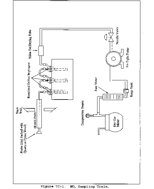
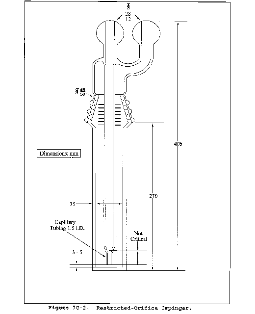
Method 7D - Determination of Nitrogen Oxide Emissions From Stationary Sources (Alkaline-Permanganate/Ion Chromatographic Method)
This method is not inclusive with respect to specifications (e.g., equipment and supplies) and procedures (e.g., sampling and analytical) essential to its performance. Some material is incorporated by reference from other methods in this part. Therefore, to obtain reliable results, persons using this method should have a thorough knowledge of at least the following additional test methods: Method 1, Method 3, Method 6, Method 7, and Method 7C.
1.0 Scope and Application
1.1 Analytes.
| Analyte | CAS No. | Sensitivity |
|---|---|---|
| Nitrogen oxides (NOX), as NO2, including: | ||
| Nitric oxide (NO) | 10102-43-9 | |
| Nitrogen dioxide (NO2) | 10102-44-0 | 7 ppmv |
1.2 Applicability. This method applies to the measurement of NOX emissions from fossil-fuel fired steam generators, electric utility plants, nitric acid plants, or other sources as specified in the regulations.
1.3 Data Quality Objectives. Adherence to the requirements of this method will enhance the quality of the data obtained from air pollutant sampling methods.
2.0 Summary of Method
An integrated gas sample is extracted from the stack and passed through impingers containing an alkaline-potassium permanganate solution; NOX (NO + NO2) emissions are oxidized to NO3−. Then NO3− is analyzed by ion chromatography.
3.0 Definitions [Reserved]
4.0 Interferences
Same as in Method 7C, section 4.0.
5.0 Safety
5.1 Disclaimer. This method may involve hazardous materials, operations, and equipment. This test method may not address all of the safety problems associated with its use. It is the responsibility of the user of this test method to establish appropriate safety and health practices and to determine the applicability of regulatory limitations prior to performing this test method.
5.2 Corrosive reagents. The following reagents are hazardous. Personal protective equipment and safe procedures are useful in preventing chemical splashes. If contact occurs, immediately flush with copious amounts of water for at least 15 minutes. Remove clothing under shower and decontaminate. Treat residual chemical burns as thermal burns.
5.2.1 Hydrogen Peroxide (H2O2). Irritating to eyes, skin, nose, and lungs. 30% H2O2 is a strong oxidizing agent; avoid contact with skin, eyes, and combustible material. Wear gloves when handling.
5.2.2 Sodium Hydroxide (NaOH). Causes severe damage to eye tissues and to skin. Inhalation causes irritation to nose, throat, and lungs. Reacts exothermically with limited amounts of water.
5.2.3 Potassium Permanganate (KMnO4). Caustic, strong oxidizer. Avoid bodily contact with.
6.0 Equipment and Supplies
6.1 Sample Collection and Sample Recovery. Same as Method 7C, section 6.1. A schematic of the sampling train used in performing this method is shown in Figure 7C-1 of Method 7C.
6.2 Sample Preparation and Analysis.
6.2.1 Magnetic Stirrer. With 25- by 10-mm Teflon-coated stirring bars.
6.2.2 Filtering Flask. 500-ml capacity with sidearm.
6.2.3 Buchner Funnel. 75-mm ID, with spout equipped with a 13-mm ID by 90-mm long piece of Teflon tubing to minimize possibility of aspirating sample solution during filtration.
6.2.4 Filter Paper. Whatman GF/C, 7.0-cm diameter.
6.2.5 Stirring Rods.
6.2.6 Volumetric Flask. 250-ml.
6.2.7 Pipettes. Class A.
6.2.8 Erlenmeyer Flasks. 250-ml.
6.2.9 Ion Chromatograph. Equipped with an anion separator column to separate NO3−, H3 + suppressor, and necessary auxiliary equipment. Nonsuppressed and other forms of ion chromatography may also be used provided that adequate resolution of NO3− is obtained. The system must also be able to resolve and detect NO2−.
7.0 Reagents and Standards
Unless otherwise indicated, it is intended that all reagents conform to the specifications established by the Committee on Analytical Reagents of the American Chemical Society, where such specifications are available; otherwise, use the best available grade.
7.1 Sample Collection.
7.1.1 Water. Deionized distilled to conform to ASTM specification D 1193-77 or 91 Type 3 (incorporated by reference - see § 60.17).
7.1.2 Potassium Permanganate, 4.0 Percent (w/w), Sodium Hydroxide, 2.0 Percent (w/w). Dissolve 40.0 g of KMnO4 and 20.0 g of NaOH in 940 ml of water.
7.2 Sample Preparation and Analysis.
7.2.1 Water. Same as in section 7.1.1.
7.2.2 Hydrogen Peroxide (H2O2), 5 Percent. Dilute 30 percent H2O2 1:5 (v/v) with water.
7.2.3 Blank Solution. Dissolve 2.4 g of KMnO4 and 1.2 g of NaOH in 96 ml of water. Alternatively, dilute 60 ml of KMnO4/NaOH solution to 100 ml.
7.2.4 KNO3 Standard Solution. Dry KNO3 at 110 °C for 2 hours, and cool in a desiccator. Accurately weigh 9 to 10 g of KNO3 to within 0.1 mg, dissolve in water, and dilute to 1 liter. Calculate the exact NO3− concentration using Equation 7D-1 in section 12.2. This solution is stable for 2 months without preservative under laboratory conditions.
7.2.5 Eluent, 0.003 M NaHCO3/0.0024 M Na2CO3. Dissolve 1.008 g NaHCO3 and 1.018 g Na2CO3 in water, and dilute to 4 liters. Other eluents capable of resolving nitrate ion from sulfate and other species present may be used.
8.0 Sample Collection, Preservation, Transport, and Storage.
8.1 Sampling. Same as in Method 7C, section 8.1.
8.2 Sample Recovery. Same as in Method 7C, section 8.2.
8.3 Sample Preparation for Analysis.
Samples must be analyzed within 28 days of collection.
8.3.1 Note the level of liquid in the sample container, and determine whether any sample was lost during shipment. If a noticeable amount of leakage has occurred, the volume lost can be determined from the difference between initial and final solution levels, and this value can then be used to correct the analytical result. Quantitatively transfer the contents to a 1-liter volumetric flask, and dilute to volume.
8.3.2 Sample preparation can be started 36 hours after collection. This time is necessary to ensure that all NO2− is converted to NO3− in the collection solution. Take a 50-ml aliquot of the sample and blank, and transfer to 250-ml Erlenmeyer flasks. Add a magnetic stirring bar. Adjust the stirring rate to as fast a rate as possible without loss of solution. Add 5 percent H2O2 in increments of approximately 5 ml using a 5-ml pipette. When the KMnO4 color appears to have been removed, allow the precipitate to settle, and examine the supernatant liquid. If the liquid is clear, the H2O2 addition is complete. If the KMnO4 color persists, add more H2O2, with stirring, until the supernatant liquid is clear.
The faster the stirring rate, the less volume of H2O2 that will be required to remove the KMnO4.) Quantitatively transfer the mixture to a Buchner funnel containing GF/C filter paper, and filter the precipitate. The spout of the Buchner funnel should be equipped with a 13-mm ID by 90-mm long piece of Teflon tubing. This modification minimizes the possibility of aspirating sample solution during filtration. Filter the mixture into a 500-ml filtering flask. Wash the solid material four times with water. When filtration is complete, wash the Teflon tubing, quantitatively transfer the filtrate to a 250-ml volumetric flask, and dilute to volume. The sample and blank are now ready for NO3−analysis.
9.0 Quality Control
| Section | Quality control measure | Effect |
|---|---|---|
| 8.2, 10.1-10.3 | Sampling equipment leak-check and calibration | Ensure accurate measurement of sample volume. |
| 10.4 | Spectrophotometer calibration | Ensure linearity of spectrophotometer response to standards. |
| 11.3 | Spiked sample analysis | Ensure reduction efficiency of column. |
10.0 Calibration and Standardizations
10.1 Dry Gas Meter (DGM) System.
10.1.1 Initial Calibration. Same as in Method 6, section 10.1.1. For detailed instructions on carrying out this calibration, it is suggested that section 3.5.2 of Citation 4 in section 16.0 of Method 7C be consulted.
10.1.2 Post-Test Calibration Check. Same as in Method 6, section 10.1.2.
10.2 Thermometers for DGM and Barometer. Same as in Method 6, sections 10.2 and 10.4, respectively.
10.3 Ion Chromatograph.
10.3.1 Dilute a given volume (1.0 ml or greater) of the KNO3 standard solution to a convenient volume with water, and use this solution to prepare calibration standards. Prepare at least four standards to cover the range of the samples being analyzed. Use pipettes for all additions. Run standards as instructed in section 11.2. Determine peak height or area, and plot the individual values versus concentration in µg NO3−/ml.
10.3.2 Do not force the curve through zero. Draw a smooth curve through the points. The curve should be linear. With the linear curve, use linear regression to determine the calibration equation.
11.0 Analytical Procedures
11.1 The following chromatographic conditions are recommended: 0.003 M NaHCO3/0.0024 Na2CO3 eluent solution (Section 7.2.5), full scale range, 3 µMHO; sample loop, 0.5 ml; flow rate, 2.5 ml/min. These conditions should give a NO3− retention time of approximately 15 minutes (Figure 7D-1).
11.2 Establish a stable baseline. Inject a sample of water, and determine whether any NO3− appears in the chromatogram. If NO3− is present, repeat the water load/injection procedure approximately five times; then re-inject a water sample and observe the chromatogram. When no NO3− is present, the instrument is ready for use. Inject calibration standards. Then inject samples and a blank. Repeat the injection of the calibration standards (to compensate for any drift in response of the instrument). Measure the NO3− peak height or peak area, and determine the sample concentration from the calibration curve.
12.0 Data Analysis and Calculations
Carry out calculations, retaining at least one extra significant figure beyond that of the acquired data. Round off figures after final calculation.
12.1 Nomenclature. Same as in Method 7C, section 12.1.
12.2 NO3− concentration. Calculate the NO3− concentration in the KNO3 standard solution (see section 7.2.4) using the following equation:

12.3 Sample Volume, Dry Basis, Corrected to Standard Conditions. Same as in Method 7C, section 12.4.
12.4 Total µg NO2 Per Sample.

Where:
250 = Volume of prepared sample, ml.
1000 = Total volume of KMnO4 solution, ml.
50 = Aliquot of KMnO4/NaOH solution, ml.
46.01 = Molecular weight of NO3−.
62.01 = Molecular weight of NO3−.
12.5 Sample Concentration. Same as in Method 7C, section 12.7.
13.0 Method Performance
13.1 Precision. The intra-laboratory relative standard deviation for a single measurement is approximately 6 percent at 200 to 270 ppm NOX.
13.2 Bias. The method does not exhibit any bias relative to Method 7.
13.3 Range. The lower detectable limit is similar to that of Method 7C. No upper limit has been established; however, when using the recommended sampling conditions, the method has been found to collect NOX emissions quantitatively up to 1782 mg NOX/m3, as NO2 (932 ppm NOX).
14.0 Pollution Prevention [Reserved]
15.0 Waste Management [Reserved]
16.0 References
Same as Method 7C, section 16.0, References 1, 2, 4, and 5.
17.0 Tables, Diagrams, Flowcharts, and Validation Data
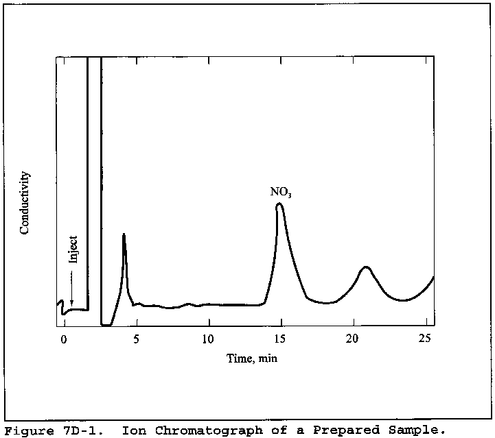
Method 7E - Determination of Nitrogen Oxides Emissions From Stationary Sources (Instrumental Analyzer Procedure)
1.0 Scope and Application
What is Method 7E?
Method 7E is a procedure for measuring nitrogen oxides (NOX) in stationary source emissions using a continuous instrumental analyzer. Quality assurance and quality control requirements are included to assure that you, the tester, collect data of known quality. You must document your adherence to these specific requirements for equipment, supplies, sample collection and analysis, calculations, and data analysis. This method does not completely describe all equipment, supplies, and sampling and analytical procedures you will need but refers to other methods for some of the details. Therefore, to obtain reliable results, you should also have a thorough knowledge of these additional test methods which are found in appendix A to this part:
(a) Method 1 - Sample and Velocity Traverses for Stationary Sources.
(b) Method 4 - Determination of Moisture Content in Stack Gases.
1.1 Analytes. What does this method determine? This method measures the concentration of nitrogen oxides as NO2.
| Analyte | CAS No. | Sensitivity |
|---|---|---|
| Nitric oxide (NO) | 10102-43-9 | Typically <2% of |
| Nitrogen dioxide (NO2) | 10102-44-0 | Calibration Span. |
1.2 Applicability. When is this method required? The use of Method 7E may be required by specific New Source Performance Standards, Clean Air Marketing rules, State Implementation Plans, and permits where measurement of NOX concentrations in stationary source emissions is required, either to determine compliance with an applicable emissions standard or to conduct performance testing of a continuous monitoring system (CEMS). Other regulations may also require the use of Method 7E.
1.3 Data Quality Objectives (DQO). How good must my collected data be? Method 7E is designed to provide high-quality data for determining compliance with Federal and State emission standards and for relative accuracy testing of CEMS. In these and other applications, the principal objective is to ensure the accuracy of the data at the actual emission levels encountered. To meet this objective, the use of EPA traceability protocol calibration gases and measurement system performance tests are required.
1.4 Data Quality Assessment for Low Emitters. Is performance relief granted when testing low-emission units? Yes. For low-emitting sources, there are alternative performance specifications for analyzer calibration error, system bias, drift, and response time. Also, the alternative dynamic spiking procedure in section 16 may provide performance relief for certain low-emitting units.
2.0 Summary of Method
In this method, a sample of the effluent gas is continuously sampled and conveyed to the analyzer for measuring the concentration of NOX. You may measure NO and NO2 separately or simultaneously together but, for the purposes of this method, NOX is the sum of NO and NO2. You must meet the performance requirements of this method to validate your data.
3.0 Definitions
3.1 Analyzer Calibration Error , for non-dilution systems, means the difference between the manufacturer certified concentration of a calibration gas and the measured concentration of the same gas when it is introduced into the analyzer in direct calibration mode.
3.2 Calibration Curve means the relationship between an analyzer's response to the injection of a series of calibration gases and the actual concentrations of those gases.
3.3 Calibration Gas means the gas mixture containing NOX at a known concentration and produced and certified in accordance with “EPA Traceability Protocol for Assay and Certification of Gaseous Calibration Standards,” September 1997, as amended August 25, 1999, EPA-600/R-97/121 or more recent updates. The tests for analyzer calibration error, drift, and system bias require the use of calibration gas prepared according to this protocol. If a zero gas is used for the low-level gas, it must meet the requirements under the definition for “zero air material” in 40 CFR 72.2 in place of being prepared by the traceability protocol.
3.3.1 Low-Level Gas means a calibration gas with a concentration that is less than 20 percent of the calibration span and may be a zero gas.
3.3.2 Mid-Level Gas means a calibration gas with a concentration that is 40 to 60 percent of the calibration span.
3.3.3 High-Level Gas means a calibration gas with a concentration that is equal to the calibration span.
3.4 Calibration Span means the upper limit of the analyzer's calibration that is set by the choice of high-level calibration gas. No valid run average concentration may exceed the calibration span. To the extent practicable, the measured emissions should be between 20 to 100 percent of the selected calibration span. This may not be practicable in some cases of low-concentration measurements or testing for compliance with an emission limit when emissions are substantially less than the limit. In such cases, calibration spans that are practicable to achieving the data quality objectives without being excessively high should be chosen.
3.5 Centroidal Area means the central area of the stack or duct that is no greater than 1 percent of the stack or duct cross section. This area has the same geometric shape as the stack or duct.
3.6 Converter Efficiency Gas means a calibration gas with a known NO or NO2 concentration and of Traceability Protocol quality.
3.7 Data Recorder means the equipment that permanently records the concentrations reported by the analyzer.
3.8 Direct Calibration Mode means introducing the calibration gases directly into the analyzer (or into the assembled measurement system at a point downstream of all sample conditioning equipment) according to manufacturer's recommended calibration procedure. This mode of calibration applies to non-dilution-type measurement systems.
3.9 Drift means the difference between the pre- and post-run system bias (or system calibration error) checks at a specific calibration gas concentration level (i.e. low-, mid- or high-).
3.10 Gas Analyzer means the equipment that senses the gas being measured and generates an output proportional to its concentration.
3.11 Interference Check means the test to detect analyzer responses to compounds other than the compound of interest, usually a gas present in the measured gas stream, that is not adequately accounted for in the calibration procedure and may cause measurement bias.
3.12 Low-Concentration Analyzer means any analyzer that operates with a calibration span of 20 ppm NOX or lower. Each analyzer model used routinely to measure low NOX concentrations must pass a manufacturer's stability test (MST). An MST subjects the analyzer to a range of line voltages and temperatures that reflect potential field conditions to demonstrate its stability following procedures similar to those provided in 40 CFR 53.23. Ambient-level analyzers are exempt from the MST requirements of section 16.3. A copy of this information must be included in each test report. Table 7E-5 lists the criteria to be met.
3.13 Measurement System means all of the equipment used to determine the NOX concentration. The measurement system comprises six major subsystems: Sample acquisition, sample transport, sample conditioning, calibration gas manifold, gas analyzer, and data recorder.
3.14 Response Time means the time it takes the measurement system to respond to a change in gas concentration occurring at the sampling point when the system is operating normally at its target sample flow rate or dilution ratio.
3.15 Run means a series of gas samples taken successively from the stack or duct. A test normally consists of a specific number of runs.
3.16 System Bias means the difference between a calibration gas measured in direct calibration mode and in system calibration mode. System bias is determined before and after each run at the low- and mid- or high-concentration levels. For dilution-type systems, pre- and post-run system calibration error is measured rather than system bias.
3.17 System Calibration Error applies to dilution-type systems and means the difference between the measured concentration of low-, mid-, or high-level calibration gas and the certified concentration for each gas when introduced in system calibration mode. For dilution-type systems, a 3-point system calibration error test is conducted in lieu of the analyzer calibration error test, and 2-point system calibration error tests are conducted in lieu of system bias tests.
3.18 System Calibration Mode means introducing the calibration gases into the measurement system at the probe, upstream of the filter and all sample conditioning components.
3.19 Test refers to the series of runs required by the applicable regulation.
4.0 Interferences
Note that interferences may vary among instruments and that instrument-specific interferences must be evaluated through the interference test.
5.0 Safety
What safety measures should I consider when using this method? This method may require you to work with hazardous materials and in hazardous conditions. We encourage you to establish safety procedures before using the method. Among other precautions, you should become familiar with the safety recommendations in the gas analyzer user's manual. Occupational Safety and Health Administration (OSHA) regulations concerning cylinder and noxious gases may apply. Nitric oxide and NO2 are toxic and dangerous gases. Nitric oxide is immediately converted to NO2 upon reaction with air. Nitrogen dioxide is a highly poisonous and insidious gas. Inflammation of the lungs from exposure may cause only slight pain or pass unnoticed, but the resulting edema several days later may cause death. A concentration of 100 ppm is dangerous for even a short exposure, and 200 ppm may be fatal. Calibration gases must be handled with utmost care and with adequate ventilation. Emission-level exposure to these gases should be avoided.
6.0 Equipment and Supplies
The performance criteria in this method will be met or exceeded if you are properly using equipment designed for this application.
6.1 What do I need for the measurement system? You may use any equipment and supplies meeting the following specifications:
(1) Sampling system components that are not evaluated in the system bias or system calibration error test must be glass, Teflon, or stainless steel. Other materials are potentially acceptable, subject to approval by the Administrator.
(2) The interference, calibration error, and system bias criteria must be met.
(3) Sample flow rate must be maintained within 10 percent of the flow rate at which the system response time was measured.
(4) All system components (excluding sample conditioning components, if used) must maintain the sample temperature above the moisture dew point. Ensure minimal contact between any condensate and the sample gas. Section 6.2 provides example equipment specifications for a NOX measurement system. Figure 7E-1 is a diagram of an example dry-basis measurement system that is likely to meet the method requirements and is provided as guidance. For wet-basis systems, you may use alternative equipment and supplies as needed (some of which are described in Section 6.2), provided that the measurement system meets the applicable performance specifications of this method.
6.2 Measurement System Components
6.2.1 Sample Probe. Glass, stainless steel, or other approved material, of sufficient length to traverse the sample points.
6.2.2 Particulate Filter. An in-stack or out-of-stack filter. The filter must be made of material that is non-reactive to the gas being sampled. The filter media for out-of-stack filters must be included in the system bias test. The particulate filter requirement may be waived in applications where no significant particulate matter is expected (e.g., for emission testing of a combustion turbine firing natural gas).
6.2.3 Sample Line. The sample line from the probe to the conditioning system/sample pump should be made of Teflon or other material that does not absorb or otherwise alter the sample gas. For a dry-basis measurement system (as shown in Figure 7E-1), the temperature of the sample line must be maintained at a sufficiently high level to prevent condensation before the sample conditioning components. For wet-basis measurement systems, the temperature of the sample line must be maintained at a sufficiently high level to prevent condensation before the analyzer.
6.2.4 Conditioning Equipment. For dry basis measurements, a condenser, dryer or other suitable device is required to remove moisture continuously from the sample gas. Any equipment needed to heat the probe or sample line to avoid condensation prior to the sample conditioning component is also required.
For wet basis systems, you must keep the sample above its dew point either by: (1) Heating the sample line and all sample transport components up to the inlet of the analyzer (and, for hot-wet extractive systems, also heating the analyzer) or (2) by diluting the sample prior to analysis using a dilution probe system. The components required to do either of the above are considered to be conditioning equipment.
6.2.5 Sampling Pump. For systems similar to the one shown in Figure 7E-1, a leak-free pump is needed to pull the sample gas through the system at a flow rate sufficient to minimize the response time of the measurement system. The pump may be constructed of any material that is non-reactive to the gas being sampled. For dilution-type measurement systems, an ejector pump (eductor) is used to create a vacuum that draws the sample through a critical orifice at a constant rate.
6.2.6 Calibration Gas Manifold. Prepare a system to allow the introduction of calibration gases either directly to the gas analyzer in direct calibration mode or into the measurement system, at the probe, in system calibration mode, or both, depending upon the type of system used. In system calibration mode, the system should be able to flood the sampling probe and vent excess gas. Alternatively, calibration gases may be introduced at the calibration valve following the probe. Maintain a constant pressure in the gas manifold. For in-stack dilution-type systems, a gas dilution subsystem is required to transport large volumes of purified air to the sample probe and a probe controller is needed to maintain the proper dilution ratio.
6.2.7 Sample Gas Manifold. For the type of system shown in Figure 7E-1, the sample gas manifold diverts a portion of the sample to the analyzer, delivering the remainder to the by-pass discharge vent. The manifold should also be able to introduce calibration gases directly to the analyzer (except for dilution-type systems). The manifold must be made of material that is non-reactive to the gas sampled or the calibration gas and be configured to safely discharge the bypass gas.
6.2.8 NOX Analyzer. An instrument that continuously measures NOX in the gas stream and meets the applicable specifications in section 13.0. An analyzer that operates on the principle of chemiluminescence with an NO2 to NO converter is one example of an analyzer that has been used successfully in the past. Analyzers operating on other principles may also be used provided the performance criteria in section 13.0 are met.
6.2.8.1 Dual Range Analyzers. For certain applications, a wide range of gas concentrations may be encountered, necessitating the use of two measurement ranges. Dual-range analyzers are readily available for these applications. These analyzers are often equipped with automated range-switching capability, so that when readings exceed the full-scale of the low measurement range, they are recorded on the high range. As an alternative to using a dual-range analyzer, you may use two segments of a single, large measurement scale to serve as the low and high ranges. In all cases, when two ranges are used, you must quality-assure both ranges using the proper sets of calibration gases. You must also meet the interference, calibration error, system bias, and drift checks. However, we caution that when you use two segments of a large measurement scale for dual range purposes, it may be difficult to meet the performance specifications on the low range due to signal-to-noise ratio considerations.
6.2.8.2 Low Concentration Analyzer. When an analyzer is routinely calibrated with a calibration span of 20 ppmv or less, the manufacturer's stability test (MST) is required. See Table 7E-5 for test parameters.
6.2.9 Data Recording. A strip chart recorder, computerized data acquisition system, digital recorder, or data logger for recording measurement data may be used.
7.0 Reagents and Standards
7.1 Calibration Gas. What calibration gases do I need? Your calibration gas must be NO in N2 and certified (or recertified) within an uncertainty of 2.0 percent in accordance with “EPA Traceability Protocol for Assay and Certification of Gaseous Calibration Standards” September 1997, as amended August 25, 1999, EPA-600/R-97/121. Blended gases meeting the Traceability Protocol are allowed if the additional gas components are shown not to interfere with the analysis. If a zero gas is used for the low-level gas, it must meet the requirements under the definition for “zero air material” in 40 CFR 72.2. The calibration gas must not be used after its expiration date. Except for applications under part 75 of this chapter, it is acceptable to prepare calibration gas mixtures from EPA Traceability Protocol gases in accordance with Method 205 in appendix M to part 51 of this chapter. For part 75 applications, the use of Method 205 is subject to the approval of the Administrator. The goal and recommendation for selecting calibration gases is to bracket the sample concentrations. The following calibration gas concentrations are required:
7.1.1 High-Level Gas. This concentration is chosen to set the calibration span as defined in Section 3.4.
7.1.2 Mid-Level Gas. 40 to 60 percent of the calibration span.
7.1.3 Low-Level Gas. Less than 20 percent of the calibration span.
7.1.4 Converter Efficiency Gas. What reagents do I need for the converter efficiency test? The converter efficiency gas is a manufacturer-certified gas with a concentration sufficient to show NO2 conversion at the concentrations encountered in the source. A test gas concentration in the 40 to 60 ppm range is suggested, but other concentrations may be more appropriate to specific sources. For the test described in section 8.2.4.1, NO2 is required. For the alternative converter efficiency tests in section 16.2, NO is required.
7.2 Interference Check. What reagents do I need for the interference check? Use the appropriate test gases listed in Table 7E-3 or others not listed that can potentially interfere (as indicated by the test facility type, instrument manufacturer, etc.) to conduct the interference check. These gases should be manufacturer certified but do not have to be prepared by the EPA traceability protocol.
8.0 Sample Collection, Preservation, Storage, and Transport
Emission Test Procedure
Since you are allowed to choose different options to comply with some of the performance criteria, it is your responsibility to identify the specific options you have chosen, to document that the performance criteria for that option have been met, and to identify any deviations from the method.
8.1 What sampling site and sampling points do I select?
8.1.1 Unless otherwise specified in an applicable regulation or by the Administrator, when this method is used to determine compliance with an emission standard, conduct a stratification test as described in section 8.1.2 to determine the sampling traverse points to be used. For performance testing of continuous emission monitoring systems, follow the sampling site selection and traverse point layout procedures described in the appropriate performance specification or applicable regulation (e.g., Performance Specification 2 in appendix B to this part).
8.1.2 Determination of Stratification. Perform a stratification test at each test site to determine the appropriate number of sample traverse points. If testing for multiple pollutants or diluents at the same site, a stratification test using only one pollutant or diluent satisfies this requirement. A stratification test is not required for small stacks that are less than 4 inches in diameter. To test for stratification, use a probe of appropriate length to measure the NOX (or pollutant of interest) concentration at 12 traverse points located according to Table 1-1 or Table 1-2 of Method 1. Alternatively, you may measure at three points on a line passing through the centroidal area. Space the three points at 16.7, 50.0, and 83.3 percent of the measurement line. Sample for a minimum of twice the system response time (see section 8.2.6) at each traverse point. Calculate the individual point and mean NOX concentrations. If the concentration at each traverse point differs from the mean concentration for all traverse points by no more than: ±5.0 percent of the mean concentration; or ±0.5 ppm (whichever is less restrictive), the gas stream is considered unstratified, and you may collect samples from a single point that most closely matches the mean. If the 5.0 percent or 0.5 ppm criterion is not met, but the concentration at each traverse point differs from the mean concentration for all traverse points by not more than: ±10.0 percent of the mean concentration; or ±1.0 ppm (whichever is less restrictive), the gas stream is considered to be minimally stratified and you may take samples from three points. Space the three points at 16.7, 50.0, and 83.3 percent of the measurement line. Alternatively, if a 12-point stratification test was performed and the emissions were shown to be minimally stratified (all points within ± 10.0 percent of their mean or within ±1.0 ppm), and if the stack diameter (or equivalent diameter, for a rectangular stack or duct) is greater than 2.4 meters (7.8 ft), then you may use 3-point sampling and locate the three points along the measurement line exhibiting the highest average concentration during the stratification test at 0.4, 1.2 and 2.0 meters from the stack or duct wall. If the gas stream is found to be stratified because the 10.0 percent or 1.0 ppm criterion for a 3-point test is not met, locate 12 traverse points for the test in accordance with Table 1-1 or Table 1-2 of Method 1.
8.2 Initial Measurement System Performance Tests. What initial performance criteria must my system meet before I begin collecting samples? Before measuring emissions, perform the following procedures:
(a) Calibration gas verification,
(b) Measurement system preparation,
(c) Calibration error test,
(d) NO2 to NO conversion efficiency test, if applicable,
(e) System bias check,
(f) System response time test, and
(g) Interference check
8.2.1 Calibration Gas Verification. How must I verify the concentrations of my calibration gases? Obtain a certificate from the gas manufacturer documenting the quality of the gas. Confirm that the manufacturer certification is complete and current. Ensure that your calibration gas certifications have not expired. This documentation should be available on-site for inspection. To the extent practicable, select a high-level gas concentration that will result in the measured emissions being between 20 and 100 percent of the calibration span.
8.2.2 Measurement System Preparation. How do I prepare my measurement system? Assemble, prepare, and precondition the measurement system according to your standard operating procedure. Adjust the system to achieve the correct sampling rate or dilution ratio (as applicable).
8.2.3 Calibration Error Test. How do I confirm my analyzer calibration is correct? After you have assembled, prepared and calibrated your sampling system and analyzer, you must conduct a 3-point analyzer calibration error test (or a 3-point system calibration error test for dilution systems) before the first run and again after any failed system bias test (or 2-point system calibration error test for dilution systems) or failed drift test. Introduce the low-, mid-, and high-level calibration gases sequentially. For non-dilution-type measurement systems, introduce the gases in direct calibration mode. For dilution-type measurement systems, introduce the gases in system calibration mode.
(1) For non-dilution systems, you may adjust the system to maintain the correct flow rate at the analyzer during the test, but you may not make adjustments for any other purpose. For dilution systems, you must operate the measurement system at the appropriate dilution ratio during all system calibration error checks, and may make only the adjustments necessary to maintain the proper ratio.
(2) Record the analyzer's response to each calibration gas on a form similar to Table 7E-1. For each calibration gas, calculate the analyzer calibration error using Equation 7E-1 in section 12.2 or the system calibration error using Equation 7E-3 in section 12.4 (as applicable). The calibration error specification in section 13.1 must be met for the low-, mid-, and high-level gases. If the calibration error specification is not met, take corrective action and repeat the test until an acceptable 3-point calibration is achieved.
8.2.4 NO2 to NO Conversion Efficiency Test. Before or after each field test, you must conduct an NO2 to NO conversion efficiency test if your system converts NO2 to NO before analyzing for NOX. You may risk testing multiple facilities before performing this test provided you pass this test at the conclusion of the final facility test. A failed final conversion efficiency test in this case will invalidate all tests performed subsequent to the test in which the converter efficiency test was passed. Follow the procedures in section 8.2.4.1, or 8.2.4.2. If desired, the converter efficiency factor derived from this test may be used to correct the test results for converter efficiency if the NO2 fraction in the measured test gas is known. Use Equation 7E-8 in section 12.8 for this correction.
8.2.4.1 Introduce NO2 converter efficiency gas to the analyzer in direct calibration mode and record the NOX concentration displayed by the analyzer. Calculate the converter efficiency using Equation 7E-7 in section 12.7. The specification for converter efficiency in section 13.5 must be met. The user is cautioned that state-of-the-art NO2 calibration gases may have limited shelf lives, and this could affect the ability to pass the 90-percent conversion efficiency requirement.
8.2.4.2 Alternatively, either of the procedures for determining conversion efficiency using NO in section 16.2 may be used.
8.2.5 Initial System Bias and System Calibration Error Checks. Before sampling begins, determine whether the high-level or mid-level calibration gas best approximates the emissions and use it as the upscale gas. Introduce the upscale gas at the probe upstream of all sample conditioning components in system calibration mode. Record the time it takes for the measured concentration to increase to a value that is at least 95 percent or within 0.5 ppm (whichever is less restrictive) of a stable response for both the low-level and upscale gases. Continue to observe the gas concentration reading until it has reached a final, stable value. Record this value on a form similar to Table 7E-2.
(1) Next, introduce the low-level gas in system calibration mode and record the time required for the concentration response to decrease to a value that is within 5.0 percent or 0.5 ppm (whichever is less restrictive) of the certified low-range gas concentration. If the low-level gas is a zero gas, use the procedures described above and observe the change in concentration until the response is 0.5 ppm or 5.0 percent of the upscale gas concentration (whichever is less restrictive).
(2) Continue to observe the low-level gas reading until it has reached a final, stable value and record the result on a form similar to Table 7E-2. Operate the measurement system at the normal sampling rate during all system bias checks. Make only the adjustments necessary to achieve proper calibration gas flow rates at the analyzer.
(3) From these data, calculate the measurement system response time (see section 8.2.6) and then calculate the initial system bias using Equation 7E-2 in section 12.3. For dilution systems, calculate the system calibration error in lieu of system bias using equation 7E-3 in section 12.4. See section 13.2 for acceptable performance criteria for system bias and system calibration error. If the initial system bias (or system calibration error) specification is not met, take corrective action. Then, you must repeat the applicable calibration error test from section 8.2.3 and the initial system bias (or 2-point system calibration error) check until acceptable results are achieved, after which you may begin sampling.
(Note: For dilution-type systems, data from the 3-point system calibration error test described in section 8.2.3 may be used to meet the initial 2-point system calibration error test requirement of this section, if the calibration gases were injected as described in this section, and if response time data were recorded).
8.2.6 Measurement System Response Time. As described in section 8.2.5, you must determine the measurement system response time during the initial system bias (or 2-point system calibration error) check. Observe the times required to achieve 95 percent of a stable response for both the low-level and upscale gases. The longer interval is the response time.
8.2.7 Interference Check. Conduct an interference response test of the gas analyzer prior to its initial use in the field. If you have multiple analyzers of the same make and model, you need only perform this alternative interference check on one analyzer. You may also meet the interference check requirement if the instrument manufacturer performs this or a similar check on an analyzer of the same make and model of the analyzer that you use and provides you with documented results.
(1) You may introduce the appropriate interference test gases (that are potentially encountered during a test; see examples in Table 7E-3) into the analyzer separately or as mixtures. Test the analyzer with the interference gas alone at the highest concentration expected at a test source and again with the interference gas and NOX at a representative NOX test concentration. For analyzers measuring NOX greater than 20 ppm, use a calibration gas with a NOX concentration of 80 to 100 ppm and set this concentration equal to the calibration span. For analyzers measuring less than 20 ppm NOX, select an NO concentration for the calibration span that reflects the emission levels at the sources to be tested, and perform the interference check at that level. Measure the total interference response of the analyzer to these gases in ppmv. Record the responses and determine the interference using Table 7E-4. The specification in section 13.4 must be met.
(2) A copy of this data, including the date completed and signed certification, must be available for inspection at the test site and included with each test report. This interference test is valid for the life of the instrument unless major analytical components (e.g., the detector) are replaced with different model parts. If major components are replaced with different model parts, the interference gas check must be repeated before returning the analyzer to service. If major components are replaced, the interference gas check must be repeated before returning the analyzer to service. The tester must ensure that any specific technology, equipment, or procedures that are intended to remove interference effects are operating properly during testing.
8.3 Dilution-Type Systems - Special Considerations. When a dilution-type measurement system is used, there are three important considerations that must be taken into account to ensure the quality of the emissions data. First, the critical orifice size and dilution ratio must be selected properly so that the sample dew point will be below the sample line and analyzer temperatures. Second, a high-quality, accurate probe controller must be used to maintain the dilution ratio during the test. The probe controller should be capable of monitoring the dilution air pressure, eductor vacuum, and sample flow rates. Third, differences between the molecular weight of calibration gas mixtures and the stack gas molecular weight must be addressed because these can affect the dilution ratio and introduce measurement bias.
8.4 Sample Collection.
(1) Position the probe at the first sampling point. Purge the system for at least two times the response time before recording any data. Then, traverse all required sampling points, sampling at each point for an equal length of time and maintaining the appropriate sample flow rate or dilution ratio (as applicable). You must record at least one valid data point per minute during the test run.
(2) Each time the probe is removed from the stack and replaced, you must recondition the sampling system for at least two times the system response time prior to your next recording. If the average of any run exceeds the calibration span value, that run is invalid.
(3) You may satisfy the multipoint traverse requirement by sampling sequentially using a single-hole probe or a multi-hole probe designed to sample at the prescribed points with a flow within 10 percent of mean flow rate. Notwithstanding, for applications under part 75 of this chapter, the use of multi-hole probes is subject to the approval of the Administrator.
8.5 Post-Run System Bias Check and Drift Assessment.
How do I confirm that each sample I collect is valid? After each run, repeat the system bias check or 2-point system calibration error check (for dilution systems) to validate the run. Do not make adjustments to the measurement system (other than to maintain the target sampling rate or dilution ratio) between the end of the run and the completion of the post-run system bias or system calibration error check. Note that for all post-run system bias or 2-point system calibration error checks, you may inject the low-level gas first and the upscale gas last, or vice-versa. If conducting a relative accuracy test or relative accuracy test audit, consisting of nine runs or more, you may risk sampling for up to three runs before performing the post-run bias or system calibration error check provided you pass this test at the conclusion of the group of three runs. A failed post-run bias or system calibration error check in this case will invalidate all runs subsequent to the last passed check. When conducting a performance or compliance test, you must perform a post-run system bias or system calibration error check after each individual test run.
(1) If you do not pass the post-run system bias (or system calibration error) check, then the run is invalid. You must diagnose and fix the problem and pass another calibration error test (Section 8.2.3) and system bias (or 2-point system calibration error) check (Section 8.2.5) before repeating the run. Record the system bias (or system calibration error) results on a form similar to Table 7E-2.
(2) After each run, calculate the low-level and upscale drift, using Equation 7E-4 in section 12.5. If the post-run low- and upscale bias (or 2-point system calibration error) checks are passed, but the low-or upscale drift exceeds the specification in section 13.3, the run data are valid, but a 3-point calibration error test and a system bias (or 2-point system calibration error) check must be performed and passed before any more test runs are done.
(3) For dilution systems, data from a 3-point system calibration error test may be used to met the pre-run 2-point system calibration error requirement for the first run in a test sequence. Also, the post-run bias (or 2-point calibration error) check data may be used as the pre-run data for the next run in the test sequence at the discretion of the tester.
8.6 Alternative Interference and System Bias Checks (Dynamic Spike Procedure). If I want to use the dynamic spike procedure to validate my data, what procedure should I follow? Except for applications under part 75 of this chapter, you may use the dynamic spiking procedure and requirements provided in section 16.1 during each test as an alternative to the interference check and the pre- and post-run system bias checks. The calibration error test is still required under this option. Use of the dynamic spiking procedure for Part 75 applications is subject to the approval of the Administrator.
8.7 Moisture correction. You must determine the moisture content of the flue gas and correct the measured gas concentrations to a dry basis using Method 4 or other appropriate methods, subject to the approval of the Administrator, when the moisture basis (wet or dry) of the measurements made with this method is different from the moisture basis of either:
(1) The applicable emissions limit; or
(2) the CEMS being evaluated for relative accuracy. Moisture correction is also required if the applicable limit is in lb/mmBtu and the moisture basis of the Method 7E NOX analyzer is different from the moisture basis of the Method 3A diluent gas (CO2 or O2) analyzer.
9.0 Quality Control
What quality control measures must I take?
The following table is a summary of the mandatory, suggested, and alternative quality assurance and quality control measures and the associated frequency and acceptance criteria. All of the QC data, along with the sample run data, must be documented and included in the test report.
Summary Table of AQ/QC
| Status | Process or element | QA/QC specification | Acceptance criteria | Checking frequency |
|---|---|---|---|---|
| S | Identify Data User | Regulatory Agency or other primary end user of data | Before designing test. | |
| S | Analyzer Design | Analyzer resolution or sensitivity | <2.0% of full-scale range | Manufacturer design. |
| M | Interference gas check | Sum of responses ≤2.5% of calibration span Alternatively, sum of responses: | ||
| ≤0.5 ppmv for calibration spans of 5 to 10 ppmv | ||||
| ≤0.2 ppmv for calibration spans <5 ppmv | ||||
| See Table 7E-3 | ||||
| M | Calibration Gases | Traceability protocol (G1, G2) | Valid certificate required Uncertainty ≤2.0% of tag value | |
| M | High-level gas | Equal to the calibration span | Each test. | |
| M | Mid-level gas | 40 to 60% of calibration span | Each test. | |
| M | Low-level gas | <20% of calibration span | Each test. | |
| S | Data Recorder Design | Data resolution | ≤0.5% of full-scale range | Manufacturer design. |
| S | Sample Extraction | Probe material | SS or quartz if stack >500 °F | East test. |
| M | Sample Extraction | Probe, filter and sample line temperature | For dry-basis analyzers, keep sample above the dew point by heating, prior to sample conditioning | Each run. |
| For wet-basis analyzers, keep sample above dew point at all times, by heating or dilution | ||||
| S | Sample Extraction | Calibration valve material | SS | Each test. |
| S | Sample Extraction | Sample pump material | Inert to sample constituents | Each test. |
| S | Sample Extraction | Manifolding material | Inert to sample constituents | Each test. |
| S | Moisture Removal | Equipment efficiency | <5% target compound removal | Verified through system bias check. |
| S | Particulate Removal | Filter inertness | Pass system bias check | Each bias check. |
| M | Analyzer & Calibration Gas Performance | Analyzer calibration error (of 3-point system calibration error for dilution systems) | Within ±2.0 percent of the calibration span of the analyzer for the low-, mid-, and high-level calibration gases | Before initial run and after a failed system bias test or drift test. |
| Alternative specification: ≤0.5 ppmv absolute difference | ||||
| M | System Performance | System bias (or pre- and post-run 2-point system calibration error for dilution (Systems) | Within ±5.0% of the analyzer calibration span for low-sacle and upscale calibration gases | Before and after each run. |
| Alternative specification: ≤0.5 ppmv absolute difference | ||||
| M | System Performance | System response time | Determines minimum sampling time per point | During initial sampling system bias test. |
| M | System Performance | Drift | ≤3.0% of calibration span for low-level and mid- or high-level gases | After each test run. |
| Alternative specification: ≤0.5 ppmv absolute difference | ||||
| M | System Performance | NO2-NO conversion efficiency | ≥90% of certified test gas concentration | Before or after each test. |
| M | System Performance | Purge time | ≥2 times system response time | Before starting the first run and when probe is removed from and re-inserted into the stack. |
| M | System Performance | Minimum sample time at each point | Two times the system response time | Each sample point. |
| M | System Performance | Stable sample flow rate (surrogate for maintaining system response time) | Within 10% of flow rate established during system response time check | Each run. |
| M | Sample Point Selection | Stratification test | All points within: | Prior to first run. |
| ±5% of mean for 1-point sampling | ||||
| ±10% of mean for 3-point | ||||
| Alternatively, all points within: | ||||
| ±0.5 ppm of mean for 1-point sampling | ||||
| ±1.0 ppm of mean for 3-point sampling | ||||
| A | Multiple sample points simultaneously | No. of openings in probe | Multi-hole probe with verifiable constant flow through all holes within 10% of mean flow rate (requires Administrative approval for Part 75) | Each run. |
| M | Data Recording | Frequency | ≤1 minute average | During run. |
| S | Data Parameters | Sample concentration range | All 1-minute averages within calibration span | Each run. |
| M | Date Parameters | Average concentration for the run | Run average ≤calibration span | Each run. |
10.0 Calibration and Standardization
What measurement system calibrations are required?
(1) The initial 3-point calibration error test as described in section 8.2.3 and the system bias (or system calibration error) checks described in section 8.2.5 are required and must meet the specifications in section 13 before you start the test. Make all necessary adjustments to calibrate the gas analyzer and data recorder. Then, after the test commences, the system bias or system calibration error checks described in section 8.5 are required before and after each run. Your analyzer must be calibrated for all species of NOX that it detects. Analyzers that measure NO and NO2 separately without using a converter must be calibrated with both NO and NO2.
(2) You must include a copy of the manufacturer's certification of the calibration gases used in the testing as part of the test report. This certification must include the 13 documentation requirements in the EPA Traceability Protocol For Assay and Certification of Gaseous Calibration Standards, September 1997, as amended August 25, 1999. When Method 205 is used to produce diluted calibration gases, you must document that the specifications for the gas dilution system are met for the test. You must also include the date of the most recent dilution system calibration against flow standards and the name of the person or manufacturer who carried out the calibration in the test report.
11.0 Analytical Procedures
Because sample collection and analysis are performed together (see section 8), additional discussion of the analytical procedure is not necessary.
12.0 Calculations and Data Analysis
You must follow the procedures for calculations and data analysis listed in this section.
12.1 Nomenclature. The terms used in the equations are defined as follows:
ACE = Analyzer calibration error, percent of calibration span.
BWS = Moisture content of sample gas as measured by Method 4 or other approved method, percent/100.
CAvg = Average unadjusted gas concentration indicated by data recorder for the test run, ppmv.
CD = Pollutant concentration adjusted to dry conditions, ppmv.
CDir = Measured concentration of a calibration gas (low, mid, or high) when introduced in direct calibration mode, ppmv.
CGas = Average effluent gas concentration adjusted for bias, ppmv.
CM = Average of initial and final system calibration bias (or 2-point system calibration error) check responses for the upscale calibration gas, ppmv.
CMA = Actual concentration of the upscale calibration gas, ppmv.
CNative = NOX concentration in the stack gas as calculated in section 12.6, ppmv.
CO = Average of the initial and final system calibration bias (or 2-point system calibration error) check responses from the low-level (or zero) calibration gas, ppmv.
COA = Actual concentration of the low-level calibration gas, ppmv.
CS = Measured concentration of a calibration gas (low, mid, or high) when introduced in system calibration mode, ppmv.
CSS = Concentration of NOX measured in the spiked sample, ppmv.
CSpike = Concentration of NOX in the undiluted spike gas, ppmv.
CCalc = Calculated concentration of NOX in the spike gas diluted in the sample, ppmv.
CV = Manufacturer certified concentration of a calibration gas (low, mid, or high), ppmv.
CW = Pollutant concentration measured under moist sample conditions, wet basis, ppmv.
CS = Calibration span, ppmv.
D = Drift assessment, percent of calibration span.
DF = Dilution system dilution factor or spike gas dilution factor, dimensionless.
EffNO2 = NO2 to NO converter efficiency, percent.
NOXCorr = The NOX concentration corrected for the converter efficiency, ppmv.
NOXFinal = The final NOX concentration observed during the converter efficiency test in section 16.2.2, ppmv.
NOXPeak = The highest NOX concentration observed during the converter efficiency test in section 16.2.2, ppmv.
QSpike = Flow rate of spike gas introduced in system calibration mode, L/min.
QTotal = Total sample flow rate during the spike test, L/min.
R = Spike recovery, percent.
SB = System bias, percent of calibration span.
SBi = Pre-run system bias, percent of calibration span.
SBfinal = Post-run system bias, percent of calibration span.
SCE = System calibration error, percent of calibration span.
SCEi = Pre-run system calibration error, percent of calibration span.
SCEFinal = Post-run system calibration error, percent of calibration span.
12.2 Analyzer Calibration Error. For non-dilution systems, use Equation 7E-1 to calculate the analyzer calibration error for the low-, mid-, and high-level calibration gases.

12.3 System Bias. For non-dilution systems, use Equation 7E-2 to calculate the system bias separately for the low-level and upscale calibration gases.

12.4 System Calibration Error. Use Equation 7E-3 to calculate the system calibration error for dilution systems. Equation 7E-3 applies to both the initial 3-point system calibration error test and the subsequent 2-point calibration error checks between test runs. In this equation, the term “Cs” refers to the diluted calibration gas concentration measured by the analyzer.

12.5 Drift Assessment. Use Equation 7E-4 to separately calculate the low-level and upscale drift over each test run. For dilution systems, replace “SBfinal” and “SBi” with “SCEfinal” and “SCEi”, respectively, to calculate and evaluate drift.

12.6 Effluent Gas Concentration. For each test run, calculate Cavg, the arithmetic average of all valid NOX concentration values (e.g., 1-minute averages). Then adjust the value of Cavg for bias using Equation 7E-5a if you use a non-zero gas as your low-level calibration gas, or Equation 7E-5b if you use a zero gas as your low-level calibration gas.


12.7 NO2 - NO Conversion Efficiency. If the NOX converter efficiency test described in section 8.2.4.1 is performed, calculate the efficiency using Equation 7E-7.

12.8 NO2 - NO Conversion Efficiency Correction. If desired, calculate the total NOX concentration with a correction for converter efficiency using Equation 7E-8.

12.9 Alternative NO2 Converter Efficiency. If the alternative procedure of section 16.2.2 is used, determine the NOX concentration decrease from NOXPeak after the minimum 30-minute test interval using Equation 7E-9. This decrease from NOXPeak must meet the requirement in section 13.5 for the converter to be acceptable.

12.10 Moisture Correction. Use Equation 7E-10 if your measurements need to be corrected to a dry basis.

12.11 Calculated Spike Gas Concentration and Spike Recovery for the Example Alternative Dynamic Spiking Procedure in section 16.1.3. Use Equation 7E-11 to determine the calculated spike gas concentration. Use Equation 7E-12 to calculate the spike recovery.


13.0 Method Performance
13.1 Calibration Error. This specification is applicable to both the analyzer calibration error and the 3-point system calibration error tests described in section 8.2.3. At each calibration gas level (low, mid, and high) the calibration error must either be within ±2.0 percent of the calibration span. Alternatively, the results are acceptable if |Cdir − Cv| or |Cs−Cv| (as applicable) is ≤0.5 ppmv.
13.2 System Bias. This specification is applicable to both the system bias and 2-point system calibration error tests described in section 8.2.5 and 8.5. The pre- and post-run system bias (or system calibration error) must be within ±5.0 percent of the calibration span for the low-level and upscale calibration gases. Alternatively, the results are acceptable if | Cs −Cdir | is ≤0.5 ppmv or if | Cs− Cv | is ≤0.5 ppmv (as applicable).
13.3 Drift. For each run, the low-level and upscale drift must be less than or equal to 3.0 percent of the calibration span. The drift is also acceptable if the pre- and post-run bias (or the pre- and post-run system calibration error) responses do not differ by more than 0.5 ppmv at each gas concentration (i.e. | Cs post-run− Cs pre-run | ≤0.5 ppmv).
13.4 Interference Check. The total interference response (i.e., the sum of the interference responses of all tested gaseous components) must not be greater than 2.50 percent of the calibration span for the analyzer tested. In summing the interferences, use the larger of the absolute values obtained for the interferent tested with and without the pollutant present. The results are also acceptable if the sum of the responses does not exceed 0.5 ppmv for a calibration span of 5 to 10 ppmv, or 0.2 ppmv for a calibration span <5 ppmv.
13.5 NO2 to NO Conversion Efficiency Test (as applicable). The NO2 to NO conversion efficiency, calculated according to Equation 7E-7, must be greater than or equal to 90 percent. The alternative conversion efficiency check, described in section 16.2.2 and calculated according to Equation 7E-9, must not result in a decrease from NOXPeak by more than 2.0 percent.
13.6 Alternative Dynamic Spike Procedure. Recoveries of both pre-test spikes and post-test spikes must be within 100 ±10 percent. If the absolute difference between the calculated spike value and measured spike value is equal to or less than 0.20 ppmv, then the requirements of the ADSC are met.
14.0 Pollution Prevention [Reserved]
15.0 Waste Management [Reserved]
16.0 Alternative Procedures
16.1 Dynamic Spike Procedure. Except for applications under part 75 of this chapter, you may use a dynamic spiking procedure to validate your test data for a specific test matrix in place of the interference check and pre- and post-run system bias checks. For part 75 applications, use of this procedure is subject to the approval of the Administrator. Best results are obtained for this procedure when source emissions are steady and not varying. Fluctuating emissions may render this alternative procedure difficult to pass. To use this alternative, you must meet the following requirements.
16.1.1 Procedure Documentation. You must detail the procedure you followed in the test report, including how the spike was measured, added, verified during the run, and calculated after the test.
16.1.2 Spiking Procedure Requirements. The spikes must be prepared from EPA Traceability Protocol gases. Your procedure must be designed to spike field samples at two target levels both before and after the test. Your target spike levels should bracket the average sample NOX concentrations. The higher target concentration must be less than the calibration span. You must collect at least 5 data points for each target concentration. The spiking procedure must be performed before the first run and repeated after the last run of the test program.
16.1.3 Example Spiking Procedure. Determine the NO concentration needed to generate concentrations that are 50 and 150 percent of the anticipated NOX concentration in the stack at the total sampling flow rate while keeping the spike flow rate at or below 10 percent of this total. Use a mass flow meter (accurate within 2.0 percent) to generate these NO spike gas concentrations at a constant flow rate. Use Equation 7E-11 in section 12.11 to determine the calculated spike concentration in the collected sample.
(1) Prepare the measurement system and conduct the analyzer calibration error test as described in sections 8.2.2 and 8.2.3. Following the sampling procedures in section 8.1, determine the stack NOX concentration and use this concentration as the average stack concentration (Cavg) for the first spike level, or if desired, for both pre-test spike levels. Introduce the first level spike gas into the system in system calibration mode and begin sample collection. Wait for at least two times the system response time before measuring the spiked sample concentration. Then record at least five successive 1-minute averages of the spiked sample gas. Monitor the spike gas flow rate and maintain at the determined addition rate. Average the five 1-minute averages and determine the spike recovery using Equation 7E-12. Repeat this procedure for the other pre-test spike level. The recovery at each level must be within the limits in section 13.6 before proceeding with the test.
(2) Conduct the number of runs required for the test. Then repeat the above procedure for the post-test spike evaluation. The last run of the test may serve as the average stack concentration for the post-test spike test calculations. The results of the post-test spikes must meet the limits in section 13.6.
16.2 Alternative NO2 to NO Conversion Efficiency Procedures. You may use either of the following procedures to determine converter efficiency in place of the procedure in section 8.2.4.1.
16.2.1 The procedure for determining conversion efficiency using NO in 40 CFR 86.123-78.
16.2.2 Bag Procedure. Perform the analyzer calibration error test to document the calibration (both NO and NOX modes, as applicable). Fill a Tedlar or equivalent bag approximately half full with either ambient air, pure oxygen, or an oxygen standard gas with at least 19.5 percent by volume oxygen content. Fill the remainder of the bag with mid- to high-level NO in N2 (or other appropriate concentration) calibration gas. (Note that the concentration of the NO standard should be sufficiently high enough for the diluted concentration to be easily and accurately measured on the scale used. The size of the bag should be large enough to accommodate the procedure and time required. Verify through the manufacturer that the Tedlar alternative is suitable for NO and make this verifed information available for inspection.)
(1) Immediately attach the bag to the inlet of the NOX analyzer (or external converter if used). In the case of a dilution-system, introduce the gas at a point upstream of the dilution assembly. Measure the NOX concentration for a period of 30 minutes. If the NOX concentration drops more than 2 percent absolute from the peak value observed, then the NO2 converter has failed to meet the criteria of this test. Take corrective action. The highest NOX value observed is considered to be NOXPeak. The final NOX value observed is considered to be NOXfinal.
(2) [Reserved]
16.3 Manufacturer's Stability Test. A manufacturer's stability test is required for all analyzers that routinely measure emissions below 20 ppmv and is optional but recommended for other analyzers. This test evaluates each analyzer model by subjecting it to the tests listed in Table 7E-5 following procedures similar to those in 40 CFR 53.23 for thermal stability and insensitivity to supply voltage variations. If the analyzer will be used under temperature conditions that are outside the test conditions in Table B-4 of Part 53.23, alternative test temperatures that better reflect the analyzer field environment should be used. Alternative procedures or documentation that establish the analyzer's stability over the appropriate line voltages and temperatures are acceptable.
17.0 References
1. “ERA Traceability Protocol for Assay and Certification of Gaseous Calibration Standards” September 1997 as amended, ERA-600/R-97/121.
18.0 Tables, Diagrams, Flowcharts, and Validation Data
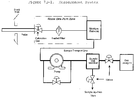
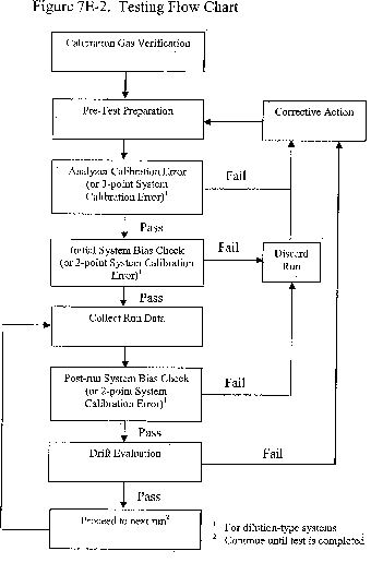
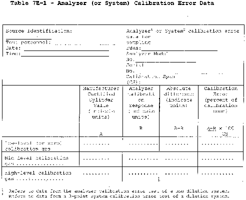

Table 7E-3 - Example Interference Check Gas Concentrations
| Potential interferent gas1 | Concentrations2 sample conditioning type | |
|---|---|---|
| Hot wet | Dried | |
| CO2 | 5 and 15% | 5 and 15% |
| H2O | 25% | 1% |
| NO | 15 ppmv | 15 ppmv |
| NO2 | 15 ppmv | 15 ppmv |
| N2O | 10 ppmv | 10 ppmv |
| CO | 50 ppmv | 50 ppmv |
| NH3 | 10 ppmv | 10 ppmv |
| CH4 | 50 ppmv | 50 ppmv |
| SO2 | 20 ppmv | 20 ppmv |
| H2 | 50 ppmv | 50 ppmv |
| HCl | 10 ppmv | 10 ppmv |
Table 7E-4 - Interference Response
Date of Test:
Analyzer Type:
Model No.:
Serial No:
Calibration Span:
| Test gas type | Concentration
(ppm) |
Analyzer
response |
|---|---|---|
| Sum of Responses | ||
| % of Calibration Span | ||
Table 7E-5 - Manufacturer Stability Test
| Test description | Acceptance criteria
(note 1) |
|---|---|
| Thermal Stability | Temperature range when drift does not exceed 3.0% of analyzer range over a 12-hour run when measured with NOX present @ 80% of calibration span. |
| Fault Conditions | Identify conditions which, when they occur, result in performance which is not in compliance with the Manufacturer's Stability Test criteria. These are to be indicated visually or electrically to alert the operator of the problem. |
| Insensitivity to Supply Voltage Variations | ±10.0% (or manufacturers alternative) variation from nominal voltage must produce a drift of ≤2.0% of calibration span for either zero or concentration ≥80% NOX present. |
| Analyzer Calibration Error | For a low-, medium-, and high-calibration gas, the difference between the manufacturer certified value and the analyzer response in direct calibration mode, no more than 2.0% of calibration span. |
Method 8 - Determination of Sulfuric Acid and Sulfur Dioxide Emissions From Stationary Sources
This method does not include all of the specifications (e.g., equipment and supplies) and procedures (e.g., sampling and analytical) essential to its performance. Some material is incorporated by reference from other methods in this part. Therefore, to obtain reliable results, persons using this method should have a thorough knowledge of at least the following additional test methods: Method 1, Method 2, Method 3, Method 5, and Method 6.
1.0 Scope and Application
1.1 Analytes.
| Analyte | CAS No. | Sensitivity |
|---|---|---|
| Sulfuric acid, including: Sulfuric acid (H2SO4) mist, Sulfur trioxide (SO3) | 7664-93-9, 7449-11-9 | 0.05 mg/m3 (0.03 × 10⁻⁷ lb/ft3). |
| Sulfur dioxide (SO2) | 7449-09-5 | 1.2 mg/m3 (3 × 10⁻⁹ lb/ft3). |
1.2 Applicability. This method is applicable for the determination of H2SO4 (including H2SO4 mist and SO3) and gaseous SO2 emissions from stationary sources.
Filterable particulate matter may be determined along with H2SO4 and SO2 (subject to the approval of the Administrator) by inserting a heated glass fiber filter between the probe and isopropanol impinger (see section 6.1.1 of Method 6). If this option is chosen, particulate analysis is gravimetric only; sulfuric acid is not determined separately.
1.3 Data Quality Objectives. Adherence to the requirements of this method will enhance the quality of the data obtained from air pollutant sampling methods.
2.0 Summary of Method
A gas sample is extracted isokinetically from the stack. The H2SO4 and the SO2 are separated, and both fractions are measured separately by the barium-thorin titration method.
3.0 Definitions [Reserved]
4.0 Interferences
4.1 Possible interfering agents of this method are fluorides, free ammonia, and dimethyl aniline. If any of these interfering agents is present (this can be determined by knowledge of the process), alternative methods, subject to the approval of the Administrator, are required.
5.0 Safety
5.1 Disclaimer. This method may involve hazardous materials, operations, and equipment. This test method may not address all of the safety problems associated with its use. It is the responsibility of the user of this test method to establish appropriate safety and health practices and determine the applicability of regulatory limitations prior to performing this test method.
5.2 Corrosive reagents. Same as Method 6, section 5.2.
6.0 Equipment and Supplies
6.1 Sample Collection. Same as Method 5, section 6.1, with the following additions and exceptions:
6.1.1 Sampling Train. A schematic of the sampling train used in this method is shown in Figure 8-1; it is similar to the Method 5 sampling train, except that the filter position is different, and the filter holder does not have to be heated. See Method 5, section 6.1.1, for details and guidelines on operation and maintenance.
6.1.1.1 Probe Nozzle. Borosilicate or quartz glass with a sharp, tapered leading edge and coupled to the probe liner using a polytetrafluoroethylene (PTFE) or glass-lined union (e.g., fused silica, Slico, or equivalent). When the stack temperature exceeds 210 °C (410 °F), a leak-free ground glass fitting or other leak free, non-contaminating fitting must be used to couple the nozzle to the probe liner. It is also acceptable to use a one-piece glass nozzle/liner assembly. The angle of the taper shall be ≤30°, and the taper shall be on the outside to preserve a constant internal diameter. The probe nozzle shall be of the button-hook or elbow design, unless otherwise specified by the Administrator. Other materials of construction may be used, subject to the approval of the Administrator. A range of nozzle sizes suitable for isokinetic sampling should be available. Typical nozzle sizes range from 0.32 to 1.27 cm (1⁄8 to 1⁄2 in) inside diameter (ID) in increments of 0.16 cm (1⁄16 in). Larger nozzles sizes are also available if higher volume sampling trains are used.
6.1.1.2 Probe Liner. Borosilicate or quartz glass, with a heating system to prevent visible condensation during sampling. Do not use metal probe liners.
6.1.1.3 Filter Holder. Borosilicate glass, with a glass frit filter support and a silicone rubber gasket. Other gasket materials (e.g., Teflon or Viton) may be used, subject to the approval of the Administrator. The holder design shall provide a positive seal against leakage from the outside or around the filter. The filter holder shall be placed between the first and second impingers. Do not heat the filter holder.
6.1.1.4 Impingers. Four, of the Greenburg-Smith design, as shown in Figure 8-1. The first and third impingers must have standard tips. The second and fourth impingers must be modified by replacing the insert with an approximately 13-mm (1⁄2-in.) ID glass tube, having an unconstricted tip located 13 mm (1⁄2 in.) from the bottom of the impinger. Similar collection systems, subject to the approval of the Administrator, may be used.
6.1.1.5 Temperature Sensor. Thermometer, or equivalent, to measure the temperature of the gas leaving the impinger train to within 1 °C (2 °F).
6.2 Sample Recovery. The following items are required for sample recovery:
6.2.1 Wash Bottles. Two polyethylene or glass bottles, 500-ml.
6.2.2 Graduated Cylinders. Two graduated cylinders (volumetric flasks may be used), 250-ml, 1-liter.
6.2.3 Storage Bottles. Leak-free polyethylene bottles, 1-liter size (two for each sampling run).
6.2.4 Trip Balance. 500-g capacity, to measure to ±0.5 g (necessary only if a moisture content analysis is to be done).
6.3 Analysis. The following items are required for sample analysis:
6.3.1 Pipettes. Volumetric 10-ml, 100-ml.
6.3.2 Burette. 50-ml.
6.3.3 Erlenmeyer Flask. 250-ml (one for each sample, blank, and standard).
6.3.4 Graduated Cylinder. 100-ml.
6.3.5 Dropping Bottle. To add indicator solution, 125-ml size.
7.0 Reagents and Standards
Unless otherwise indicated, all reagents are to conform to the specifications established by the Committee on Analytical Reagents of the American Chemical Society, where such specifications are available. Otherwise, use the best available grade.
7.1 Sample Collection. The following reagents are required for sample collection:
7.1.1 Filters and Silica Gel. Same as in Method 5, sections 7.1.1 and 7.1.2, respectively.
7.1.2 Water. Same as in Method 6, section 7.1.1.
7.1.3 Isopropanol, 80 Percent by Volume. Mix 800 ml of isopropanol with 200 ml of water.
Check for peroxide impurities using the procedure outlined in Method 6, section 7.1.2.1.
7.1.4 Hydrogen Peroxide (H2O2), 3 Percent by Volume. Dilute 100 ml of 30 percent H2O2) to 1 liter with water. Prepare fresh daily.
7.1.5 Crushed Ice.
7.2 Sample Recovery. The reagents and standards required for sample recovery are:
7.2.1 Water. Same as in section 7.1.2.
7.2.2 Isopropanol, 80 Percent. Same as in section 7.1.3.
7.3 Sample Analysis. Same as Method 6, section 7.3.
8.0 Sample Collection, Preservation, Storage, and Transport
8.1 Pretest Preparation. Same as Method 5, section 8.1, except that filters should be inspected but need not be desiccated, weighed, or identified. If the effluent gas can be considered dry (i.e., moisture-free), the silica gel need not be weighed.
8.2 Preliminary Determinations. Same as Method 5, section 8.2.
8.3 Preparation of Sampling Train. Same as Method 5, section 8.3, with the following exceptions:
8.3.1 Use Figure 8-1 instead of Figure 5-1.
8.3.2 Replace the second sentence of Method 5, section 8.3.1 with: Place 100 ml of 80 percent isopropanol in the first impinger, 100 ml of 3 percent H2O2 in both the second and third impingers; retain a portion of each reagent for use as a blank solution. Place about 200 g of silica gel in the fourth impinger.
8.3.3 Ignore any other statements in section 8.3 of Method 5 that are obviously not applicable to the performance of Method 8.
If moisture content is to be determined by impinger analysis, weigh each of the first three impingers (plus absorbing solution) to the nearest 0.5 g, and record these weights. Weigh also the silica gel (or silica gel plus container) to the nearest 0.5 g, and record.)
8.4 Metering System Leak-Check Procedure. Same as Method 5, section 8.4.1.
8.5 Pretest Leak-Check Procedure. Follow the basic procedure in Method 5, section 8.4.2, noting that the probe heater shall be adjusted to the minimum temperature required to prevent condensation, and also that verbage such as “* * * plugging the inlet to the filter holder * * * ” found in section 8.4.2.2 of Method 5 shall be replaced by “ * * * plugging the inlet to the first impinger * * * ”. The pretest leak-check is recommended, but is not required.
8.6 Sampling Train Operation. Follow the basic procedures in Method 5, section 8.5, in conjunction with the following special instructions:
8.6.1 Record the data on a sheet similar to that shown in Figure 8-2 (alternatively, Figure 5-2 in Method 5 may be used). The sampling rate shall not exceed 0.030 m3/min (1.0 cfm) during the run. Periodically during the test, observe the connecting line between the probe and first impinger for signs of condensation. If condensation does occur, adjust the probe heater setting upward to the minimum temperature required to prevent condensation. If component changes become necessary during a run, a leak-check shall be performed immediately before each change, according to the procedure outlined in section 8.4.3 of Method 5 (with appropriate modifications, as mentioned in section 8.5 of this method); record all leak rates. If the leakage rate(s) exceeds the specified rate, the tester shall either void the run or plan to correct the sample volume as outlined in section 12.3 of Method 5. Leak-checks immediately after component changes are recommended, but not required. If these leak-checks are performed, the procedure in section 8.4.2 of Method 5 (with appropriate modifications) shall be used.
8.6.2 After turning off the pump and recording the final readings at the conclusion of each run, remove the probe from the stack. Conduct a post-test (mandatory) leak-check as outlined in section 8.4.4 of Method 5 (with appropriate modifications), and record the leak rate. If the post-test leakage rate exceeds the specified acceptable rate, either correct the sample volume, as outlined in section 12.3 of Method 5, or void the run.
8.6.3 Drain the ice bath and, with the probe disconnected, purge the remaining part of the train by drawing clean ambient air through the system for 15 minutes at the average flow rate used for sampling.
Clean ambient air can be provided by passing air through a charcoal filter. Alternatively, ambient air (without cleaning) may be used.
8.7 Calculation of Percent Isokinetic. Same as Method 5, section 8.6.
8.8 Sample Recovery. Proper cleanup procedure begins as soon as the probe is removed from the stack at the end of the sampling period. Allow the probe to cool. Treat the samples as follows:
8.8.1 Container No. 1.
8.8.1.1 If a moisture content analysis is to be performed, clean and weigh the first impinger (plus contents) to the nearest 0.5 g, and record this weight.
8.8.1.2 Transfer the contents of the first impinger to a 250-ml graduated cylinder. Rinse the probe, first impinger, all connecting glassware before the filter, and the front half of the filter holder with 80 percent isopropanol. Add the isopropanol rinse solution to the cylinder. Dilute the contents of the cylinder to 225 ml with 80 percent isopropanol, and transfer the cylinder contents to the storage container. Rinse the cylinder with 25 ml of 80 percent isopropanol, and transfer the rinse to the storage container. Add the filter to the solution in the storage container and mix. Seal the container to protect the solution against evaporation. Mark the level of liquid on the container, and identify the sample container.
8.8.2 Container No. 2.
8.8.2.1 If a moisture content analysis is to be performed, clean and weigh the second and third impingers (plus contents) to the nearest 0.5 g, and record the weights. Also, weigh the spent silica gel (or silica gel plus impinger) to the nearest 0.5 g, and record the weight.
8.8.2.2 Transfer the solutions from the second and third impingers to a 1-liter graduated cylinder. Rinse all connecting glassware (including back half of filter holder) between the filter and silica gel impinger with water, and add this rinse water to the cylinder. Dilute the contents of the cylinder to 950 ml with water. Transfer the solution to a storage container. Rinse the cylinder with 50 ml of water, and transfer the rinse to the storage container. Mark the level of liquid on the container. Seal and identify the sample container.
9.0 Quality Control
9.1 Miscellaneous Quality Control Measures.
| Section | Quality control measure | Effect |
|---|---|---|
| 7.1.3 | Isopropanol check | Ensure acceptable level of peroxide impurities in isopropanol. |
| 8.4, 8.5, 10.1 | Sampling equipment leak-check and calibration | Ensure accurate measurement of stack gas flow rate, sample volume. |
| 10.2 | Barium standard solution standardization | Ensure normality determination. |
| 11.2 | Replicate titrations | Ensure precision of titration determinations. |
9.2 Volume Metering System Checks. Same as Method 5, section 9.2.
10.0 Calibration and Standardization
10.1 Sampling Equipment. Same as Method 5, section 10.0.
10.2 Barium Standard Solution. Same as Method 6, section 10.5.
11.0 Analytical Procedure
11.1. Sample Loss. Same as Method 6, section 11.1.
11.2. Sample Analysis.
11.2.1 Container No. 1. Shake the container holding the isopropanol solution and the filter. If the filter breaks up, allow the fragments to settle for a few minutes before removing a sample aliquot. Pipette a 100-ml aliquot of this solution into a 250-ml Erlenmeyer flask, add 2 to 4 drops of thorin indicator, and titrate to a pink endpoint using 0.0100 N barium standard solution. Repeat the titration with a second aliquot of sample, and average the titration values. Replicate titrations must agree within 1 percent or 0.2 ml, whichever is greater.
11.2.2 Container No. 2. Thoroughly mix the solution in the container holding the contents of the second and third impingers. Pipette a 10-ml aliquot of sample into a 250-ml Erlenmeyer flask. Add 40 ml of isopropanol, 2 to 4 drops of thorin indicator, and titrate to a pink endpoint using 0.0100 N barium standard solution. Repeat the titration with a second aliquot of sample, and average the titration values. Replicate titrations must agree within 1 percent or 0.2 ml, whichever is greater.
11.2.3 Blanks. Prepare blanks by adding 2 to 4 drops of thorin indicator to 100 ml of 80 percent isopropanol. Titrate the blanks in the same manner as the samples.
12.0 Data Analysis and Calculations
Carry out calculations retaining at least one extra significant figure beyond that of the acquired data. Round off figures after final calculation.
12.1 Nomenclature. Same as Method 5, section 12.1, with the following additions and exceptions:
CH2SO4 = Sulfuric acid (including SO3) concentration, g/dscm (lb/dscf).
CSO2 = Sulfur dioxide concentration, g/dscm (lb/dscf).
N = Normality of barium perchlorate titrant, meq/ml.
Va = Volume of sample aliquot titrated, 100 ml for H2SO4 and 10 ml for SO2.
Vsoln = Total volume of solution in which the sample is contained, 1000 ml for the SO2 sample and 250 ml for the H2SO4 sample.
Vt = Volume of barium standard solution titrant used for the sample, ml.
Vtb = Volume of barium standard solution titrant used for the blank, ml.
12.2 Average Dry Gas Meter Temperature and Average Orifice Pressure Drop. See data sheet (Figure 8-2).
12.3 Dry Gas Volume. Same as Method 5, section 12.3.
12.4 Volume of Water Vapor Condensed and Moisture Content. Calculate the volume of water vapor using Equation 5-2 of Method 5; the weight of water collected in the impingers and silica gel can be converted directly to milliliters (the specific gravity of water is 1 g/ml). Calculate the moisture content of the stack gas (Bws) using Equation 5-3 of Method 5. The note in section 12.5 of Method 5 also applies to this method. Note that if the effluent gas stream can be considered dry, the volume of water vapor and moisture content need not be calculated.
12.5 Sulfuric Acid Mist (Including SO3) Concentration.

Where:
K3 = 0.04904 g/meq for metric units,
K3 = 1.081 × 10⁻⁴ lb/meq for English units.
12.6 Sulfur Dioxide Concentration.

Where:
K4 = 0.03203 g/meq for metric units,
K4 = 7.061 × 10⁻⁵ lb/meq for English units.
12.7 Isokinetic Variation. Same as Method 5, section 12.11.
12.8 Stack Gas Velocity and Volumetric Flow Rate. Calculate the average stack gas velocity and volumetric flow rate, if needed, using data obtained in this method and the equations in sections 12.6 and 12.7 of Method 2.
13.0 Method Performance
13.1 Analytical Range. Collaborative tests have shown that the minimum detectable limits of the method are 0.06 mg/m3 (4 × 10⁻⁹ lb/ft3) for H2SO4 and 1.2 mg/m3 (74 × 10−9 lb/ft3) for SO2. No upper limits have been established. Based on theoretical calculations for 200 ml of 3 percent H2O2 solution, the upper concentration limit for SO2 in a 1.0 m3 (35.3 ft3) gas sample is about 12,000 mg/m3 (7.7 × 10⁻⁴ lb/ft3). The upper limit can be extended by increasing the quantity of peroxide solution in the impingers.
14.0 Pollution Prevention [Reserved]
15.0 Waste Management [Reserved]
16.0 References
Same as section 17.0 of Methods 5 and 6.
17.0 Tables, Diagrams, Flowcharts, and Validation Data
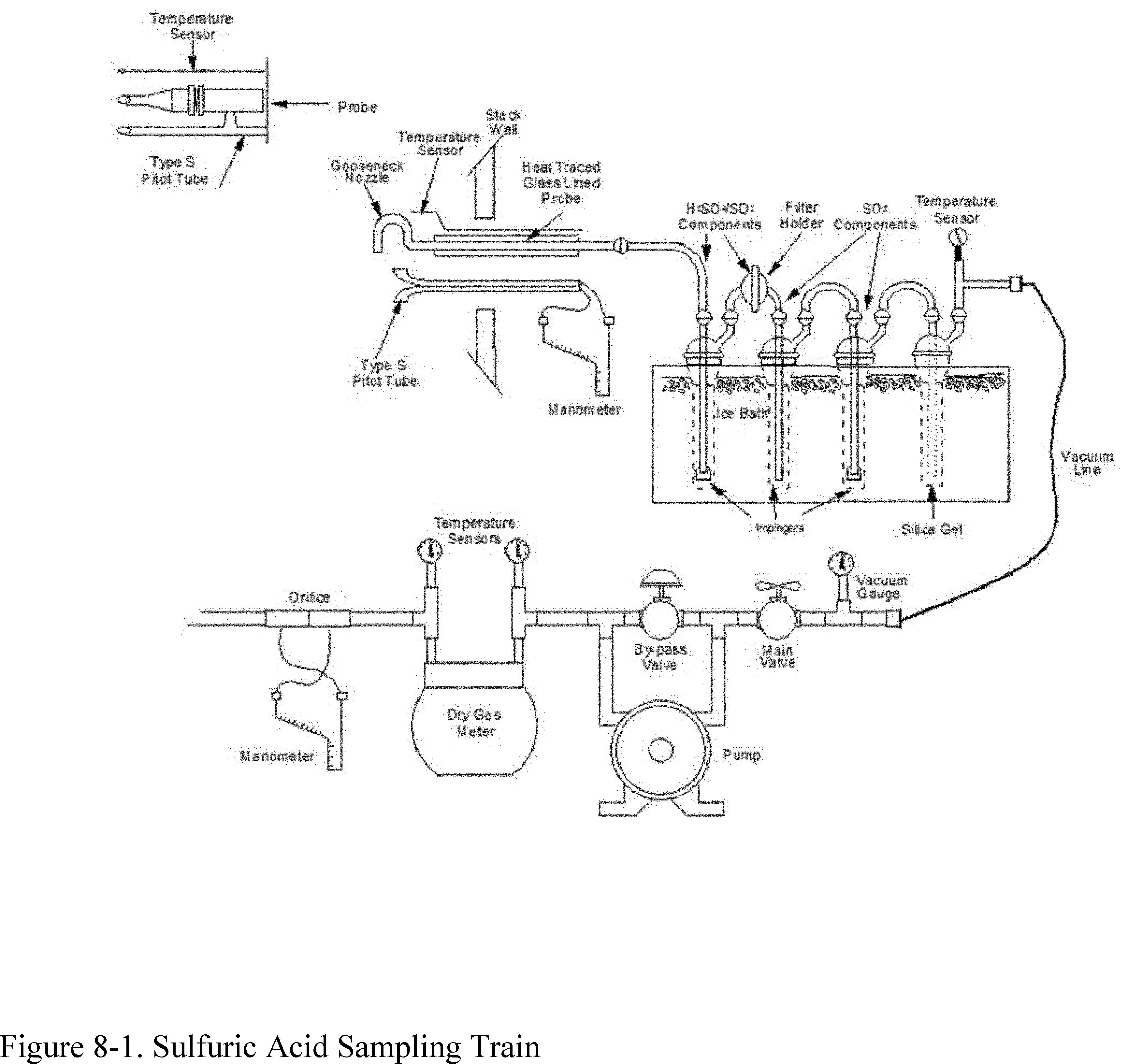

Method 9 - Visual Determination of the Opacity of Emissions From Stationary Sources
Many stationary sources discharge visible emissions into the atmosphere; these emissions are usually in the shape of a plume. This method involves the determination of plume opacity by qualified observers. The method includes procedures for the training and certification of observers, and procedures to be used in the field for determination of plume opacity. The appearance of a plume as viewed by an observer depends upon a number of variables, some of which may be controllable and some of which may not be controllable in the field. Variables which can be controlled to an extent to which they no longer exert a significant influence upon plume appearance include: Angle of the observer with respect to the plume; angle of the observer with respect to the sun; point of observation of attached and detached steam plume; and angle of the observer with respect to a plume emitted from a rectangular stack with a large length to width ratio. The method includes specific criteria applicable to these variables.
Other variables which may not be controllable in the field are luminescence and color contrast between the plume and the background against which the plume is viewed. These variables exert an influence upon the appearance of a plume as viewed by an observer, and can affect the ability of the observer to accurately assign opacity values to the observed plume. Studies of the theory of plume opacity and field studies have demonstrated that a plume is most visible and presents the greatest apparent opacity when viewed against a contrasting background. It follows from this, and is confirmed by field trials, that the opacity of a plume, viewed under conditions where a contrasting background is present can be assigned with the greatest degree of accuracy. However, the potential for a positive error is also the greatest when a plume is viewed under such contrasting conditions. Under conditions presenting a less contrasting background, the apparent opacity of a plume is less and approaches zero as the color and luminescence contrast decrease toward zero. As a result, significant negative bias and negative errors can be made when a plume is viewed under less contrasting conditions. A negative bias decreases rather than increases the possibility that a plant operator will be cited for a violation of opacity standards due to observer error.
Studies have been undertaken to determine the magnitude of positive errors which can be made by qualified observers while reading plumes under contrasting conditions and using the procedures set forth in this method. The results of these studies (field trials) which involve a total of 769 sets of 25 readings each are as follows:
(1) For black plumes (133 sets at a smoke generator), 100 percent of the sets were read with a positive error[1] of less than 7.5 percent opacity; 99 percent were read with a positive error of less than 5 percent opacity.
(2) For white plumes (170 sets at a smoke generator, 168 sets at a coal-fired power plant, 298 sets at a sulfuric acid plant), 99 percent of the sets were read with a positive error of less than 7.5 percent opacity; 95 percent were read with a positive error of less than 5 percent opacity.
The positive observational error associated with an average of twenty-five readings is therefore established. The accuracy of the method must be taken into account when determining possible violations of applicable opacity standards.
1. Principle and Applicability
1.1 Principle. The opacity of emissions from stationary sources is determined visually by a qualified observer.
1.2 Applicability. This method is applicable for the determination of the opacity of emissions from stationary sources pursuant to § 60.11(b) and for qualifying observers for visually determining opacity of emissions.
2. Procedures
The observer qualified in accordance with section 3 of this method shall use the following procedures for visually determining the opacity of emissions:
2.1 Position. The qualified observer shall stand at a distance sufficient to provide a clear view of the emissions with the sun oriented in the 140° sector to his back. Consistent with maintaining the above requirement, the observer shall, as much as possible, make his observations from a position such that his line of vision is approximately perpendicular to the plume direction, and when observing opacity of emissions from rectangular outlets (e.g., roof monitors, open baghouses, noncircular stacks), approximately perpendicular to the longer axis of the outlet. The observer's line of sight should not include more than one plume at a time when multiple stacks are involved, and in any case the observer should make his observations with his line of sight perpendicular to the longer axis of such a set of multiple stacks (e.g., stub stacks on baghouses).
2.2 Field Records. The observer shall record the name of the plant, emission location, type facility, observer's name and affiliation, a sketch of the observer's position relative to the source, and the date on a field data sheet (Figure 9-1). The time, estimated distance to the emission location, approximate wind direction, estimated wind speed, description of the sky condition (presence and color of clouds), and plume background are recorded on a field data sheet at the time opacity readings are initiated and completed.
2.3 Observations. Opacity observations shall be made at the point of greatest opacity in that portion of the plume where condensed water vapor is not present. The observer shall not look continuously at the plume, but instead shall observe the plume momentarily at 15-second intervals.
2.3.1 Attached Steam Plumes. When condensed water vapor is present within the plume as it emerges from the emission outlet, opacity observations shall be made beyond the point in the plume at which condensed water vapor is no longer visible. The observer shall record the approximate distance from the emission outlet to the point in the plume at which the observations are made.
2.3.2 Detached Steam Plume. When water vapor in the plume condenses and becomes visible at a distinct distance from the emission outlet, the opacity of emissions should be evaluated at the emission outlet prior to the condensation of water vapor and the formation of the steam plume.
2.4 Recording Observations. Opacity observations shall be recorded to the nearest 5 percent at 15-second intervals on an observational record sheet. (See Figure 9-2 for an example.) A minimum of 24 observations shall be recorded. Each momentary observation recorded shall be deemed to represent the average opacity of emissions for a 15-second period.
2.5 Data Reduction. Opacity shall be determined as an average of 24 consecutive observations recorded at 15-second intervals. Divide the observations recorded on the record sheet into sets of 24 consecutive observations. A set is composed of any 24 consecutive observations. Sets need not be consecutive in time and in no case shall two sets overlap. For each set of 24 observations, calculate the average by summing the opacity of the 24 observations and dividing this sum by 24. If an applicable standard specifies an averaging time requiring more than 24 observations, calculate the average for all observations made during the specified time period. Record the average opacity on a record sheet. (See Figure 9-1 for an example.)
3. Qualifications and Testing
3.1 Certification Requirements. To receive certification as a qualified observer, a candidate must be tested and demonstrate the ability to assign opacity readings in 5 percent increments to 25 different black plumes and 25 different white plumes, with an error not to exceed 15 percent opacity on any one reading and an average error not to exceed 7.5 percent opacity in each category. Candidates shall be tested according to the procedures described in section 3.2. Smoke generators used pursuant to section 3.2 shall be equipped with a smoke meter which meets the requirements of section 3.3.
The certification shall be valid for a period of 6 months, at which time the qualification procedure must be repeated by any observer in order to retain certification.
3.2 Certification Procedure. The certification test consists of showing the candidate a complete run of 50 plumes - 25 black plumes and 25 white plumes - generated by a smoke generator. Plumes within each set of 25 black and 25 white runs shall be presented in random order. The candidate assigns an opacity value to each plume and records his observation on a suitable form. At the completion of each run of 50 readings, the score of the candidate is determined. If a candidate fails to qualify, the complete run of 50 readings must be repeated in any retest. The smoke test may be administered as part of a smoke school or training program, and may be preceded by training or familiarization runs of the smoke generator during which candidates are shown black and white plumes of known opacity.
3.3 Smoke Generator Specifications. Any smoke generator used for the purposes of section 3.2 shall be equipped with a smoke meter installed to measure opacity across the diameter of the smoke generator stack. The smoke meter output shall display instack opacity based upon a pathlength equal to the stack exit diameter, on a full 0 to 100 percent chart recorder scale. The smoke meter optical design and performance shall meet the specifications shown in Table 9-1. The smoke meter shall be calibrated as prescribed in section 3.3.1 prior to the conduct of each smoke reading test. At the completion of each test, the zero and span drift shall be checked and if the drift exceeds ±1 percent opacity, the condition shall be corrected prior to conducting any subsequent test runs. The smoke meter shall be demonstrated, at the time of installation, to meet the specifications listed in Table 9-1. This demonstration shall be repeated following any subsequent repair or replacement of the photocell or associated electronic circuitry including the chart recorder or output meter, or every 6 months, whichever occurs first.
Table 9-1 - Smoke Meter Design and Performance Specifications
| Parameter | Specification |
|---|---|
| a. Light source | Incandescent lamp operated at nominal rated voltage. |
| b. Spectral response of photocell | Photopic (daylight spectral response of the human eye - Citation 3). |
| c. Angle of view | 15° maximum total angle. |
| d. Angle of projection | 15° maximum total angle. |
| e. Calibration error | ±3% opacity, maximum. |
| f. Zero and span drift | ±1% opacity, 30 minutes. |
| g. Response time | 5 seconds. |
3.3.1 Calibration. The smoke meter is calibrated after allowing a minimum of 30 minutes warmup by alternately producing simulated opacity of 0 percent and 100 percent. When stable response at 0 percent or 100 percent is noted, the smoke meter is adjusted to produce an output of 0 percent or 100 percent, as appropriate. This calibration shall be repeated until stable 0 percent and 100 percent readings are produced without adjustment. Simulated 0 percent and 100 percent opacity values may be produced by alternately switching the power to the light source on and off while the smoke generator is not producing smoke.
3.3.2 Smoke Meter Evaluation. The smoke meter design and performance are to be evaluated as follows:
3.3.2.1 Light Source. Verify from manufacturer's data and from voltage measurements made at the lamp, as installed, that the lamp is operated within ±5 percent of the nominal rated voltage.
3.3.2.2 Spectral Response of Photocell. Verify from manufacturer's data that the photocell has a photopic response; i.e., the spectral sensitivity of the cell shall closely approximate the standard spectral-luminosity curve for photopic vision which is referenced in (b) of Table 9-1.

Figure 9-2 - Observation Record
Page ____ of ____
| Company | Observer | |
| Location | Type facility | |
| Test Number | Point of emissions | |
| Date |
| Hr. | Min. | Seconds | Steam plume (check if applicable) | Comments | ||||
|---|---|---|---|---|---|---|---|---|
| 0 | 15 | 30 | 45 | Attached | Detached | |||
| 0 | ||||||||
| 1 | ||||||||
| 2 | ||||||||
| 3 | ||||||||
| 4 | ||||||||
| 5 | ||||||||
| 6 | ||||||||
| 7 | ||||||||
| 8 | ||||||||
| 9 | ||||||||
| 10 | ||||||||
| 11 | ||||||||
| 12 | ||||||||
| 13 | ||||||||
| 14 | ||||||||
| 15 | ||||||||
| 16 | ||||||||
| 17 | ||||||||
| 18 | ||||||||
| 19 | ||||||||
| 20 | ||||||||
| 21 | ||||||||
| 22 | ||||||||
| 23 | ||||||||
| 24 | ||||||||
| 25 | ||||||||
| 26 | ||||||||
| 27 | ||||||||
| 28 | ||||||||
| 29 | ||||||||
Figure 9-2 - Observation Record (Continued)
Page ____ of ____
| Company | Observer | |
| Location | Type facility | |
| Test Number | Point of emissions | |
| Date |
| Hr. | Min. | Seconds | Steam plume (check if applicable) | Comments | ||||
|---|---|---|---|---|---|---|---|---|
| 0 | 15 | 30 | 45 | Attached | Detached | |||
| 30 | ||||||||
| 31 | ||||||||
| 32 | ||||||||
| 33 | ||||||||
| 34 | ||||||||
| 35 | ||||||||
| 36 | ||||||||
| 37 | ||||||||
| 38 | ||||||||
| 39 | ||||||||
| 40 | ||||||||
| 41 | ||||||||
| 42 | ||||||||
| 43 | ||||||||
| 44 | ||||||||
| 45 | ||||||||
| 46 | ||||||||
| 47 | ||||||||
| 48 | ||||||||
| 49 | ||||||||
| 50 | ||||||||
| 51 | ||||||||
| 52 | ||||||||
| 53 | ||||||||
| 54 | ||||||||
| 55 | ||||||||
| 56 | ||||||||
| 57 | ||||||||
| 58 | ||||||||
| 59 | ||||||||
3.3.2.3 Angle of View. Check construction geometry to ensure that the total angle of view of the smoke plume, as seen by the photocell, does not exceed 15°. The total angle of view may be calculated from: θ = 2 tan−1d/2L, where θ = total angle of view; d = the sum of the photocell diameter + the diameter of the limiting aperture; and L = the distance from the photocell to the limiting aperture. The limiting aperture is the point in the path between the photocell and the smoke plume where the angle of view is most restricted. In smoke generator smoke meters this is normally an orifice plate.
3.3.2.4 Angle of Projection. Check construction geometry to ensure that the total angle of projection of the lamp on the smoke plume does not exceed 15°. The total angle of projection may be calculated from: θ = 2 tan−1d/2L, where θ = total angle of projection; d = the sum of the length of the lamp filament + the diameter of the limiting aperture; and L = the distance from the lamp to the limiting aperture.
3.3.2.5 Calibration Error. Using neutral-density filters of known opacity, check the error between the actual response and the theoretical linear response of the smoke meter. This check is accomplished by first calibrating the smoke meter according to 3.3.1 and then inserting a series of three neutral-density filters of nominal opacity of 20, 50, and 75 percent in the smoke meter pathlength. Filters calibrated within ±2 percent shall be used. Care should be taken when inserting the filters to prevent stray light from affecting the meter. Make a total of five nonconsecutive readings for each filter. The maximum error on any one reading shall be 3 percent opacity.
3.3.2.6 Zero and Span Drift. Determine the zero and span drift by calibrating and operating the smoke generator in a normal manner over a 1-hour period. The drift is measured by checking the zero and span at the end of this period.
3.3.2.7 Response Time. Determine the response time by producing the series of five simulated 0 percent and 100 percent opacity values and observing the time required to reach stable response. Opacity values of 0 percent and 100 percent may be simulated by alternately switching the power to the light source off and on while the smoke generator is not operating.
4. Bibliography
1. Air Pollution Control District Rules and Regulations, Los Angeles County Air Pollution Control District, Regulation IV, Prohibitions, Rule 50.
2. Weisburd, Melvin I., Field Operations and Enforcement Manual for Air, U.S. Environmental Protection Agency, Research Triangle Park, NC. APTD-1100, August 1972, pp. 4.1-4.36.
3. Condon, E.U., and Odishaw, H., Handbook of Physics, McGraw-Hill Co., New York, NY, 1958, Table 3.1, p. 6-52.
Alternate Method 1 - Determination of the Opacity of Emissions From Stationary Sources Remotely by Lidar
This alternate method provides the quantitative determination of the opacity of an emissions plume remotely by a mobile lidar system (laser radar; Light Detection and Ranging). The method includes procedures for the calibration of the lidar and procedures to be used in the field for the lidar determination of plume opacity. The lidar is used to measure plume opacity during either day or nighttime hours because it contains its own pulsed light source or transmitter. The operation of the lidar is not dependent upon ambient lighting conditions (light, dark, sunny or cloudy).
The lidar mechanism or technique is applicable to measuring plume opacity at numerous wavelengths of laser radiation. However, the performance evaluation and calibration test results given in support of this method apply only to a lidar that employs a ruby (red light) laser [Reference 5.1].
1. Principle and Applicability
1.1 Principle. The opacity of visible emissions from stationary sources (stacks, roof vents, etc.) is measured remotely by a mobile lidar (laser radar).
1.2 Applicability. This method is applicable for the remote measurement of the opacity of visible emissions from stationary sources during both nighttime and daylight conditions, pursuant to 40 CFR § 60.11(b). It is also applicable for the calibration and performance verification of the mobile lidar for the measurement of the opacity of emissions. A performance/design specification for a basic lidar system is also incorporated into this method.
1.3 Definitions.
Azimuth angle: The angle in the horizontal plane that designates where the laser beam is pointed. It is measured from an arbitrary fixed reference line in that plane.
Backscatter: The scattering of laser light in a direction opposite to that of the incident laser beam due to reflection from particulates along the beam's atmospheric path which may include a smoke plume.
Backscatter signal: The general term for the lidar return signal which results from laser light being backscattered by atmospheric and smoke plume particulates.
Convergence distance: The distance from the lidar to the point of overlap of the lidar receiver's field-of-view and the laser beam.
Elevation angle: The angle of inclination of the laser beam referenced to the horizontal plane.
Far region: The region of the atmosphere's path along the lidar line-of-sight beyond or behind the plume being measured.
Lidar: Acronym for Light Detection and Ranging.
Lidar range: The range or distance from the lidar to a point of interest along the lidar line-of-sight.
Near region: The region of the atmospheric path along the lidar line-of-sight between the lidar's convergence distance and the plume being measured.
Opacity: One minus the optical transmittance of a smoke plume, screen target, etc.
Pick interval: The time or range intervals in the lidar backscatter signal whose minimum average amplitude is used to calculate opacity. Two pick intervals are required, one in the near region and one in the far region.
Plume: The plume being measured by lidar.
Plume signal: The backscatter signal resulting from the laser light pulse passing through a plume.
1/R2Correction: The correction made for the systematic decrease in lidar backscatter signal amplitude with range.
Reference signal: The backscatter signal resulting from the laser light pulse passing through ambient air.
Sample interval: The time period between successive samples for a digital signal or between successive measurements for an analog signal.
Signal spike: An abrupt, momentary increase and decrease in signal amplitude.
Source: The source being tested by lidar.
Time reference: The time (to) when the laser pulse emerges from the laser, used as the reference in all lidar time or range measurements.
2. Procedures
The mobile lidar calibrated in accordance with Paragraph 3 of this method shall use the following procedures for remotely measuring the opacity of stationary source emissions:
2.1 Lidar Position. The lidar shall be positioned at a distance from the plume sufficient to provide an unobstructed view of the source emissions. The plume must be at a range of at least 50 meters or three consecutive pick intervals (whichever is greater) from the lidar's transmitter/receiver convergence distance along the line-of-sight. The maximum effective opacity measurement distance of the lidar is a function of local atmospheric conditions, laser beam diameter, and plume diameter. The test position of the lidar shall be selected so that the diameter of the laser beam at the measurement point within the plume shall be no larger than three-fourths the plume diameter. The beam diameter is calculated by Equation (AM1-1):
D(lidar) = A + Rφ≤0.75 D(Plume) (AM1-1)
Where:
D(Plume) = diameter of the plume (cm),
φ = laser beam divergence measured in radians
R = range from the lidar to the source (cm)
D(Lidar) = diameter of the laser beam at range R (cm),
A = diameter of the laser beam or pulse where it leaves the laser.
The lidar range, R, is obtained by aiming and firing the laser at the emissions source structure immediately below the outlet. The range value is then determined from the backscatter signal which consists of a signal spike (return from source structure) and the atmospheric backscatter signal [Reference 5.1]. This backscatter signal should be recorded.
When there is more than one source of emissions in the immediate vicinity of the plume, the lidar shall be positioned so that the laser beam passes through only a single plume, free from any interference of the other plumes for a minimum of 50 meters or three consecutive pick intervals (whichever is greater) in each region before and beyond the plume along the line-of-sight (determined from the backscatter signals). The lidar shall initially be positioned so that its line-of-sight is approximately perpendicular to the plume.
When measuring the opacity of emissions from rectangular outlets (e.g., roof monitors, open baghouses, noncircular stacks, etc.), the lidar shall be placed in a position so that its line-of-sight is approximately perpendicular to the longer (major) axis of the outlet.
2.2 Lidar Operational Restrictions. The lidar receiver shall not be aimed within an angle of ±15° (cone angle) of the sun.
This method shall not be used to make opacity measurements if thunderstorms, snowstorms, hail storms, high wind, high-ambient dust levels, fog or other atmospheric conditions cause the reference signals to consistently exceed the limits specified in section 2.3.
2.3 Reference Signal Requirements. Once placed in its proper position for opacity measurement, the laser is aimed and fired with the line-of-sight near the outlet height and rotated horizontally to a position clear of the source structure and the associated plume. The backscatter signal obtained from this position is called the ambient-air or reference signal. The lidar operator shall inspect this signal [Section V of Reference 5.1] to: (1) determine if the lidar line-of-sight is free from interference from other plumes and from physical obstructions such as cables, power lines, etc., for a minimum of 50 meters or three consecutive pick intervals (whichever is greater) in each region before and beyond the plume, and (2) obtain a qualitative measure of the homogeneity of the ambient air by noting any signal spikes.
Should there be any signal spikes on the reference signal within a minimum of 50 meters or three consecutive pick intervals (whichever is greater) in each region before and beyond the plume, the laser shall be fired three more times and the operator shall inspect the reference signals on the display. If the spike(s) remains, the azimuth angle shall be changed and the above procedures conducted again. If the spike(s) disappears in all three reference signals, the lidar line-of-sight is acceptable if there is shot-to-shot consistency and there is no interference from other plumes.
Shot-to-shot consistency of a series of reference signals over a period of twenty seconds is verified in either of two ways. (1) The lidar operator shall observe the reference signal amplitudes. For shot-to-shot consistency the ratio of Rf to Rn [amplitudes of the near and far region pick intervals (Section 2.6.1)] shall vary by not more than ±6% between shots; or (2) the lidar operator shall accept any one of the reference signals and treat the other two as plume signals; then the opacity for each of the subsequent reference signals is calculated (Equation AM1-2). For shot-to-shot consistency, the opacity values shall be within ±3% of 0% opacity and the associated So values less than or equal to 8% (full scale) [Section 2.6].
If a set of reference signals fails to meet the requirements of this section, then all plume signals [Section 2.4] from the last set of acceptable reference signals to the failed set shall be discarded.
2.3.1 Initial and Final Reference Signals. Three reference signals shall be obtained within a 90-second time period prior to any data run. A final set of three reference signals shall be obtained within three (3) minutes after the completion of the same data run.
2.3.2 Temporal Criterion for Additional Reference Signals. An additional set of reference signals shall be obtained during a data run if there is a change in wind direction or plume drift of 30° or more from the direction that was prevalent when the last set of reference signals was obtained. An additional set of reference signals shall also be obtained if there is an increase in value of SIn (near region standard deviation, Equation AM1-5) or SIf (far region standard deviation, Equation AM1-6) that is greater than 6% (full scale) over the respective values calculated from the immediately previous plume signal, and this increase in value remains for 30 seconds or longer. An additional set of reference signals shall also be obtained if there is a change in amplitude in either the near or the far region of the plume signal, that is greater than 6% of the near signal amplitude and this change in amplitude remains for 30 seconds or more.
2.4 Plume Signal Requirements. Once properly aimed, the lidar is placed in operation with the nominal pulse or firing rate of six pulses/minute (1 pulse/10 seconds). The lidar operator shall observe the plume backscatter signals to determine the need for additional reference signals as required by section 2.3.2. The plume signals are recorded from lidar start to stop and are called a data run. The length of a data run is determined by operator discretion. Short-term stops of the lidar to record additional reference signals do not constitute the end of a data run if plume signals are resumed within 90 seconds after the reference signals have been recorded, and the total stop or interrupt time does not exceed 3 minutes.
2.4.1 Non-hydrated Plumes. The laser shall be aimed at the region of the plume which displays the greatest opacity. The lidar operator must visually verify that the laser is aimed clearly above the source exit structure.
2.4.2 Hydrated Plumes. The lidar will be used to measure the opacity of hydrated or so-called steam plumes. As listed in the reference method, there are two types, i.e., attached and detached steam plumes.
2.4.2.1 Attached Steam Plumes. When condensed water vapor is present within a plume, lidar opacity measurements shall be made at a point within the residual plume where the condensed water vapor is no longer visible. The laser shall be aimed into the most dense region (region of highest opacity) of the residual plume.
During daylight hours the lidar operator locates the most dense portion of the residual plume visually. During nighttime hours a high-intensity spotlight, night vision scope, or low light level TV, etc., can be used as an aid to locate the residual plume. If visual determination is ineffective, the lidar may be used to locate the most dense region of the residual plume by repeatedly measuring opacity, along the longitudinal axis or center of the plume from the emissions outlet to a point just beyond the steam plume. The lidar operator should also observe color differences and plume reflectivity to ensure that the lidar is aimed completely within the residual plume. If the operator does not obtain a clear indication of the location of the residual plume, this method shall not be used.
Once the region of highest opacity of the residual plume has been located, aiming adjustments shall be made to the laser line-of-sight to correct for the following: movement to the region of highest opacity out of the lidar line-of-sight (away from the laser beam) for more than 15 seconds, expansion of the steam plume (air temperature lowers and/or relative humidity increases) so that it just begins to encroach on the field-of-view of the lidar's optical telescope receiver, or a decrease in the size of the steam plume (air temperature higher and/or relative humidity decreases) so that regions within the residual plume whose opacity is higher than the one being monitored, are present.
2.4.2.2 Detached Steam Plumes. When the water vapor in a hydrated plume condenses and becomes visible at a finite distance from the stack or source emissions outlet, the opacity of the emissions shall be measured in the region of the plume clearly above the emissions outlet and below condensation of the water vapor.
During daylight hours the lidar operators can visually determine if the steam plume is detached from the stack outlet. During nighttime hours a high-intensity spotlight, night vision scope, low light level TV, etc., can be used as an aid in determining if the steam plume is detached. If visual determination is ineffective, the lidar may be used to determine if the steam plume is detached by repeatedly measuring plume opacity from the outlet to the steam plume along the plume's longitudinal axis or center line. The lidar operator should also observe color differences and plume reflectivity to detect a detached plume. If the operator does not obtain a clear indication of the location of the detached plume, this method shall not be used to make opacity measurements between the outlet and the detached plume.
Once the determination of a detached steam plume has been confirmed, the laser shall be aimed into the region of highest opacity in the plume between the outlet and the formation of the steam plume. Aiming adjustments shall be made to the lidar's line-of-sight within the plume to correct for changes in the location of the most dense region of the plume due to changes in wind direction and speed or if the detached steam plume moves closer to the source outlet encroaching on the most dense region of the plume. If the detached steam plume should move too close to the source outlet for the lidar to make interference-free opacity measurements, this method shall not be used.
2.5 Field Records. In addition to the recording recommendations listed in other sections of this method the following records should be maintained. Each plume measured should be uniquely identified. The name of the facility, type of facility, emission source type, geographic location of the lidar with respect to the plume, and plume characteristics should be recorded. The date of the test, the time period that a source was monitored, the time (to the nearest second) of each opacity measurement, and the sample interval should also be recorded. The wind speed, wind direction, air temperature, relative humidity, visibility (measured at the lidar's position), and cloud cover should be recorded at the beginning and end of each time period for a given source. A small sketch depicting the location of the laser beam within the plume should be recorded.
If a detached or attached steam plume is present at the emissions source, this fact should be recorded. Figures AM1-I and AM1-II are examples of logbook forms that may be used to record this type of data. Magnetic tape or paper tape may also be used to record data.


2.6 Opacity Calculation and Data Analysis. Referring to the reference signal and plume signal in Figure AM1-III, the measured opacity (Op) in percent for each lidar measurement is calculated using Equation AM1-2. (Op = 1−Tp; Tp is the plume transmittance.)

Where:
In = near-region pick interval signal amplitude, plume signal, 1/R2 corrected,
If = far-region pick interval signal amplitude, plume signal, 1/R2 corrected,
Rn = near-region pick interval signal amplitude, reference signal, 1/R2 corrected, and
Rf = far-region pick interval signal amplitude, reference signal, 1/R2 corrected.
The 1/R2 correction to the plume and reference signal amplitudes is made by multiplying the amplitude for each successive sample interval from the time reference, by the square of the lidar time (or range) associated with that sample interval [Reference 5.1].
The first step in selecting the pick intervals for Equation AM1-2 is to divide the plume signal amplitude by the reference signal amplitude at the same respective ranges to obtain a “normalized” signal. The pick intervals selected using this normalized signal, are a minimum of 15 m (100 nanoseconds) in length and consist of at least 5 contiguous sample intervals. In addition, the following criteria, listed in order of importance, govern pick interval selection. (1) The intervals shall be in a region of the normalized signal where the reference signal meets the requirements of section 2.3 and is everywhere greater than zero. (2) The intervals (near and far) with the minimum average amplitude are chosen. (3) If more than one interval with the same minimum average amplitude is found, the interval closest to the plume is chosen. (4) The standard deviation, So, for the calculated opacity shall be 8% or less. (So is calculated by Equation AM1-7).
If So is greater than 8%, then the far pick interval shall be changed to the next interval of minimal average amplitude. If So is still greater than 8%, then this procedure is repeated for the far pick interval. This procedure may be repeated once again for the near pick interval, but if So remains greater than 8%, the plume signal shall be discarded.
The reference signal pick intervals, Rn and Rf, must be chosen over the same time interval as the plume signal pick intervals, In and If, respectively [Figure AM1-III]. Other methods of selecting pick intervals may be used if they give equivalent results. Field-oriented examples of pick interval selection are available in Reference 5.1.
The average amplitudes for each of the pick intervals, In, If, Rn, Rf, shall be calculated by averaging the respective individual amplitudes of the sample intervals from the plume signal and the associated reference signal each corrected for 1/R2. The amplitude of In shall be calculated according to Equation (AM-3).

Where:
Ini = the amplitude of the ith sample interval (near-region),
Σ = sum of the individual amplitudes for the sample intervals,
m = number of sample intervals in the pick interval, and
In = average amplitude of the near-region pick interval.
Similarly, the amplitudes for If, Rn, and Rf are calculated with the three expressions in Equation (AM1-4).

The standard deviation, SIn, of the set of amplitudes for the near-region pick interval, In, shall be calculated using Equation (AM1-5).
Similarly, the standard deviations SIf, SRn, and SRf are calculated with the three expressions in Equation (AM1-6).


The standard deviation, So, for each associated opacity value, Op, shall be calculated using Equation (AM1-7).

The calculated values of In, If, Rn, Rf, SIn, SIf, SRn, SRf, Op, and So should be recorded. Any plume signal with an So greater than 8% shall be discarded.
2.6.1 Azimuth Angle Correction. If the azimuth angle correction to opacity specified in this section is performed, then the elevation angle correction specified in section 2.6.2 shall not be performed. When opacity is measured in the residual region of an attached steam plume, and the lidar line-of-sight is not perpendicular to the plume, it may be necessary to correct the opacity measured by the lidar to obtain the opacity that would be measured on a path perpendicular to the plume. The following method, or any other method which produces equivalent results, shall be used to determine the need for a correction, to calculate the correction, and to document the point within the plume at which the opacity was measured.
Figure AM1-IV(b) shows the geometry of the opacity correction. L′ is the path through the plume along which the opacity measurement is made. P′ is the path perpendicular to the plume at the same point. The angle ε is the angle between L′ and the plume center line. The angle (π/2-ε), is the angle between the L′ and P′. The measured opacity, Op, measured along the path L′ shall be corrected to obtain the corrected opacity, Opc, for the path P′, using Equation (AM1-8).

The correction in Equation (AM1-8) shall be performed if the inequality in Equation (AM1-9) is true.

Figure AM1-IV(a) shows the geometry used to calculate ε and the position in the plume at which the lidar measurement is made. This analysis assumes that for a given lidar measurement, the range from the lidar to the plume, the elevation angle of the lidar from the horizontal plane, and the azimuth angle of the lidar from an arbitrary fixed reference in the horizontal plane can all be obtained directly.

Rs = range from lidar to source*
βs = elevation angle of Rs*
Rp = range from lidar to plume at the opacity measurement point*
βp = elevation angle of Rp*
Ra = range from lidar to plume at some arbitrary point, Pa, so the drift angle of the plume can be determined*
βa = elevation angle of Ra*
α = angle between Rp and Ra
R′s = projection of Rs in the horizontal plane
R′p = projection of Rp in the horizontal plane
R′a = projection of Ra in the horizontal plane
ψ′ = angle between R′s and R′p*
α′ = angle between R′p and R′a*
R≤ = distance from the source to the opacity measurement point projected in the horizontal plane
Rθ = distance from opacity measurement point Pp to the point in the plume Pa.

The correction angle ε shall be determined using Equation AM1-10.
Where:
α = Cos−1 (Cosβp Cosβa Cosα′ + Sinβp Sinβa),
and
Rθ = (Rp2 + Ra2 − 2 Rp Ra Cosα) 1⁄2
R≤, the distance from the source to the opacity measurement point projected in the horizontal plane, shall be determined using Equation AM1-11.

Where:
R′s = Rs Cos βs, and
R′p = Rp Cos βp.
In the special case where the plume centerline at the opacity measurement point is horizontal, parallel to the ground, Equation AM1-12 may be used to determine ε instead of Equation AM1-10.

Where:
R″s = (R′2s + Rp2Sin2βp)1/2.
If the angle ε is such that ε≤30° or ε ≥150°, the azimuth angle correction shall not be performed and the associated opacity value shall be discarded.
2.6.2 Elevation Angle Correction. An individual lidar-measured opacity, Op, shall be corrected for elevation angle if the laser elevation or inclination angle, βp [Figure AM1-V], is greater than or equal to the value calculated in Equation AM1-13.

The measured opacity, Op, along the lidar path L, is adjusted to obtain the corrected opacity, Opc, for the actual plume (horizontal) path, P, by using Equation (AM1-14).

Where:
βp = lidar elevation or inclination angle,
Op = measured opacity along path L, and
Opc = corrected opacity for the actual plume thickness P.
The values for βp, Op and Opc should be recorded.

2.6.3 Determination of Actual Plume Opacity. Actual opacity of the plume shall be determined by Equation AM1-15.

2.6.4 Calculation of Average Actual Plume Opacity. The average of the actual plume opacity, Opa, shall be calculated as the average of the consecutive individual actual opacity values, Opa, by Equation AM1-16.

Where:
(Opa)k = the kth actual opacity value in an averaging interval containing n opacity values; k is a summing index.
Σ = the sum of the individual actual opacity values.
n = the number of individual actual opacity values contained in the averaging interval.
Opa = average actual opacity calculated over the averaging interval.
3. Lidar Performance Verification
The lidar shall be subjected to two types of performance verifications that shall be performed in the field. The annual calibration, conducted at least once a year, shall be used to directly verify operation and performance of the entire lidar system. The routine verification, conducted for each emission source measured, shall be used to insure proper performance of the optical receiver and associated electronics.
3.1 Annual Calibration Procedures. Either a plume from a smoke generator or screen targets shall be used to conduct this calibration.
If the screen target method is selected, five screens shall be fabricated by placing an opaque mesh material over a narrow frame (wood, metal extrusion, etc.). The screen shall have a surface area of at least one square meter. The screen material should be chosen for precise optical opacities of about 10, 20, 40, 60, and 80%. Opacity of each target shall be optically determined and should be recorded. If a smoke generator plume is selected, it shall meet the requirements of section 3.3 of Reference Method 9. This calibration shall be performed in the field during calm (as practical) atmospheric conditions. The lidar shall be positioned in accordance with section 2.1.
The screen targets must be placed perpendicular to and coincident with the lidar line-of-sight at sufficient height above the ground (suggest about 30 ft) to avoid ground-level dust contamination. Reference signals shall be obtained just prior to conducting the calibration test.
The lidar shall be aimed through the center of the plume within 1 stack diameter of the exit, or through the geometric center of the screen target selected. The lidar shall be set in operation for a 6-minute data run at a nominal pulse rate of 1 pulse every 10 seconds. Each backscatter return signal and each respective opacity value obtained from the smoke generator transmissometer, shall be obtained in temporal coincidence. The data shall be analyzed and reduced in accordance with section 2.6 of this method. This calibration shall be performed for 0% (clean air), and at least five other opacities (nominally 10, 20, 40, 60, and 80%).
The average of the lidar opacity values obtained during a 6-minute calibration run shall be calculated and should be recorded. Also the average of the opacity values obtained from the smoke generator transmissometer for the same 6-minute run shall be calculated and should be recorded.
Alternate calibration procedures that do not meet the above requirements but produce equivalent results may be used.
3.2 Routine Verification Procedures. Either one of two techniques shall be used to conduct this verification. It shall be performed at least once every 4 hours for each emission source measured. The following parameters shall be directly verified.
1) The opacity value of 0% plus a minimum of 5 (nominally 10, 20, 40, 60, and 80%) opacity values shall be verified through the PMT detector and data processing electronics.
2) The zero-signal level (receiver signal with no optical signal from the source present) shall be inspected to insure that no spurious noise is present in the signal. With the entire lidar receiver and analog/digital electronics turned on and adjusted for normal operating performance, the following procedures shall be used for Techniques 1 and 2, respectively.
3.2.1 Procedure for Technique 1. This test shall be performed with no ambient or stray light reaching the PMT detector. The narrow band filter (694.3 nanometers peak) shall be removed from its position in front of the PMT detector. Neutral density filters of nominal opacities of 10, 20, 40, 60, and 80% shall be used. The recommended test configuration is depicted in Figure AM1-VI.

The zero-signal level shall be measured and should be recorded, as indicated in Figure AM1-VI(a). This simulated clear-air or 0% opacity value shall be tested in using the selected light source depicted in Figure AM1-VI(b).
The light source either shall be a continuous wave (CW) laser with the beam mechanically chopped or a light emitting diode controlled with a pulse generator (rectangular pulse). (A laser beam may have to be attenuated so as not to saturate the PMT detector). This signal level shall be measured and should be recorded. The opacity value is calculated by taking two pick intervals [Section 2.6] about 1 microsecond apart in time and using Equation (AM1-2) setting the ratio Rn/Rf = 1. This calculated value should be recorded.
The simulated clear-air signal level is also employed in the optical test using the neutral density filters. Using the test configuration in Figure AM1-VI(c), each neutral density filter shall be separately placed into the light path from the light source to the PMT detector. The signal level shall be measured and should be recorded. The opacity value for each filter is calculated by taking the signal level for that respective filter (If), dividing it by the 0% opacity signal level (In) and performing the remainder of the calculation by Equation (AM1-2) with Rn/Rf = 1. The calculated opacity value for each filter should be recorded.
The neutral density filters used for Technique 1 shall be calibrated for actual opacity with accuracy of ±2% or better. This calibration shall be done monthly while the filters are in use and the calibrated values should be recorded.
3.2.2 Procedure for Technique 2. An optical generator (built-in calibration mechanism) that contains a light-emitting diode (red light for a lidar containing a ruby laser) is used. By injecting an optical signal into the lidar receiver immediately ahead of the PMT detector, a backscatter signal is simulated. With the entire lidar receiver electronics turned on and adjusted for normal operating performance, the optical generator is turned on and the simulation signal (corrected for 1/R2) is selected with no plume spike signal and with the opacity value equal to 0%. This simulated clear-air atmospheric return signal is displayed on the system's video display. The lidar operator then makes any fine adjustments that may be necessary to maintain the system's normal operating range.
The opacity values of 0% and the other five values are selected one at a time in any order. The simulated return signal data should be recorded. The opacity value shall be calculated. This measurement/calculation shall be performed at least three times for each selected opacity value. While the order is not important, each of the opacity values from the optical generator shall be verified. The calibrated optical generator opacity value for each selection should be recorded.
The optical generator used for Technique 2 shall be calibrated for actual opacity with an accuracy of ±1% or better. This calibration shall be done monthly while the generator is in use and calibrated value should be recorded.
Alternate verification procedures that do not meet the above requirements but produce equivalent results may be used.
3.3 Deviation. The permissible error for the annual calibration and routine verification are:
3.3.1 Annual Calibration Deviation.
3.3.1.1 Smoke Generator. If the lidar-measured average opacity for each data run is not within ±5% (full scale) of the respective smoke generator's average opacity over the range of 0% through 80%, then the lidar shall be considered out of calibration.
3.3.1.2 Screens. If the lidar-measured average opacity for each data run is not within ±3% (full scale) of the laboratory-determined opacity for each respective simulation screen target over the range of 0% through 80%, then the lidar shall be considered out of calibration.
3.3.2 Routine Verification Error. If the lidar-measured average opacity for each neutral density filter (Technique 1) or optical generator selection (Technique 2) is not within ±3% (full scale) of the respective laboratory calibration value then the lidar shall be considered non-operational.
4. Performance/Design Specification for Basic Lidar System
4.1 Lidar Design Specification. The essential components of the basic lidar system are a pulsed laser (transmitter), optical receiver, detector, signal processor, recorder, and an aiming device that is used in aiming the lidar transmitter and receiver. Figure AM1-VII shows a functional block diagram of a basic lidar system.

4.2 Performance Evaluation Tests. The owner of a lidar system shall subject such a lidar system to the performance verification tests described in section 3, prior to first use of this method. The annual calibration shall be performed for three separate, complete runs and the results of each should be recorded. The requirements of section 3.3.1 must be fulfilled for each of the three runs.
Once the conditions of the annual calibration are fulfilled the lidar shall be subjected to the routine verification for three separate complete runs. The requirements of section 3.3.2 must be fulfilled for each of the three runs and the results should be recorded. The Administrator may request that the results of the performance evaluation be submitted for review.
5. References
5.1 The Use of Lidar for Emissions Source Opacity Determination, U.S. Environmental Protection Agency, National Enforcement Investigations Center, Denver, CO. EPA-330/1-79-003-R, Arthur W. Dybdahl, current edition [NTIS No. PB81-246662].
5.2 Field Evaluation of Mobile Lidar for the Measurement of Smoke Plume Opacity, U.S. Environmental Protection Agency, National Enforcement Investigations Center, Denver, CO. EPA/NEIC-TS-128, February 1976.
5.3 Remote Measurement of Smoke Plume Transmittance Using Lidar, C. S. Cook, G. W. Bethke, W. D. Conner (EPA/RTP). Applied Optics 11, pg 1742. August 1972.
5.4 Lidar Studies of Stack Plumes in Rural and Urban Environments, EPA-650/4-73-002, October 1973.
5.5 American National Standard for the Safe Use of Lasers ANSI Z 136.1-176, March 8, 1976.
5.6 U.S. Army Technical Manual TB MED 279, Control of Hazards to Health from Laser Radiation, February 1969.
5.7 Laser Institute of America Laser Safety Manual, 4th Edition.
5.8 U.S. Department of Health, Education and Welfare, Regulations for the Administration and Enforcement of the Radiation Control for Health and Safety Act of 1968, January 1976.
5.9 Laser Safety Handbook, Alex Mallow, Leon Chabot, Van Nostrand Reinhold Co., 1978.
Method 10 - Determination of Carbon Monoxide Emissions From Stationary Sources (Instrumental Analyzer Procedure)
1.0 Scope and Application
What is Method 10?
Method 10 is a procedure for measuring carbon monoxide (CO) in stationary source emissions using a continuous instrumental analyzer. Quality assurance and quality control requirements are included to assure that you, the tester, collect data of known quality. You must document your adherence to these specific requirements for equipment, supplies, sample collection and analysis, calculations, and data analysis. This method does not completely describe all equipment, supplies, and sampling and analytical procedures you will need but refers to other methods for some of the details. Therefore, to obtain reliable results, you should also have a thorough knowledge of these additional test methods which are found in appendix A to this part:
(a) Method 1 - Sample and Velocity Traverses for Stationary Sources.
(b) Method 4 - Determination of Moisture Content in Stack Gases.
(c) Method 7E - Determination of Nitrogen Oxides Emissions from Stationary Sources (Instrumental Analyzer Procedure).
1.1 Analytes. What does this method determine? This method measures the concentration of carbon monoxide.
| Analyte | CAS No. | Sensitivity |
|---|---|---|
| CO | 630-08-0 | Typically <2% of Calibration Span. |
1.2 Applicability. When is this method required? The use of Method 10 may be required by specific New Source Performance Standards, State Implementation Plans, and permits where CO concentrations in stationary source emissions must be measured, either to determine compliance with an applicable emission standard or to conduct performance testing of a continuous emission monitoring system (CEMS). Other regulations may also require the use of Method 10.
1.3 Data Quality Objectives. Refer to section 1.3 of Method 7E.
2.0 Summary of Method
In this method, you continuously or intermittently sample the effluent gas and convey the sample to an analyzer that measures the concentration of CO. You must meet the performance requirements of this method to validate your data.
3.0 Definitions
Refer to section 3.0 of Method 7E for the applicable definitions.
4.0 Interferences
Substances having a strong absorption of infrared energy may interfere to some extent in some analyzers. Instrumental correction may be used to compensate for the interference. You may also use silica gel and ascarite traps to eliminate the interferences. If this option is used, correct the measured gas volume for the carbon dioxide (CO2) removed in the trap.
5.0 Safety
Refer to section 5.0 of Method 7E.
6.0 Equipment and Supplies
What do I need for the measurement system?
6.1 Continuous Sampling. Figure 7E-1 of Method 7E is a schematic diagram of an acceptable measurement system. The components are the same as those in sections 6.1 and 6.2 of Method 7E, except that the CO analyzer described in section 6.2 of this method must be used instead of the analyzer described in section 6.2 of Method 7E. You must follow the noted specifications in section 6.1 of Method 7E except that the requirements to use stainless steel, Teflon, or non-reactive glass filters do not apply. Also, a heated sample line is not required to transport dry gases or for systems that measure the CO concentration on a dry basis.
6.2 Integrated Sampling.
6.2.1 Air-Cooled Condenser or Equivalent. To remove any excess moisture.
6.2.2 Valve. Needle valve, or equivalent, to adjust flow rate.
6.2.3 Pump. Leak-free diaphragm type, or equivalent, to transport gas.
6.2.4 Rate Meter. Rotameter, or equivalent, to measure a flow range from 0 to 1.0 liter per minute (0.035 cfm).
6.2.5 Flexible Bag. Tedlar, or equivalent, with a capacity of 60 to 90 liters (2 to 3 ft3). (Verify through the manufacturer that the Tedlar alternative is suitable for CO and make this verified information available for inspection.) Leak-test the bag in the laboratory before using by evacuating with a pump followed by a dry gas meter. When the evacuation is complete, there should be no flow through the meter.
6.2.6 Sample Tank. Stainless steel or aluminum tank equipped with a pressure indicator with a minimum volume of 4 liters.
6.3 What analyzer must I use? You must use an instrument that continuously measures CO in the gas stream and meets the specifications in section 13.0. The dual-range analyzer provisions in section 6.2.8.1 of Method 7E apply.
7.0 Reagents and Standards
7.1 Calibration Gas. What calibration gases do I need? Refer to section 7.1 of Method 7E for the calibration gas requirements.
7.2 Interference Check. What additional reagents do I need for the interference check? Use the appropriate test gases listed in Table 7E-3 of Method 7E (i.e., potential interferents, as identified by the instrument manufacturer) to conduct the interference check.
8.0 Sample Collection, Preservation, Storage, and Transport
Emission Test Procedure
8.1 Sampling Site and Sampling Points. You must follow section 8.1 of Method 7E.
8.2 Initial Measurement System Performance Tests. You must follow the procedures in section 8.2 of Method 7E. If a dilution-type measurement system is used, the special considerations in section 8.3 of Method 7E also apply.
8.3 Interference Check. You must follow the procedures of section 8.2.7 of Method 7E.
8.4 Sample Collection.
8.4.1 Continuous Sampling. You must follow the procedures of section 8.4 of Method 7E.
8.4.2 Integrated Sampling. Evacuate the flexible bag or sample tank. Set up the equipment as shown in Figure 10-1 with the bag disconnected. Place the probe in the stack and purge the sampling line. Connect the bag, making sure that all connections are leak-free. Sample at a rate proportional to the stack velocity. If needed, the CO2 content of the gas may be determined by using the Method 3 integrated sample procedures, or by weighing an ascarite CO2 removal tube used and computing CO2 concentration from the gas volume sampled and the weight gain of the tube. Data may be recorded on a form similar to Table 10-1. If a sample tank is used for sample collection, follow procedures similar to those in sections 8.1.2, 8.2.3, 8.3, and 12.4 of Method 25 as appropriate to prepare the tank, conduct the sampling, and correct the measured sample concentration.
8.5 Post-Run System Bias Check, Drift Assessment, and Alternative Dynamic Spike Procedure. You must follow the procedures in sections 8.5 and 8.6 of Method 7E.
9.0 Quality Control
Follow the quality control procedures in section 9.0 of Method 7E.
10.0 Calibration and Standardization
Follow the procedures for calibration and standardization in section 10.0 of Method 7E.
11.0 Analytical Procedures
Because sample collection and analysis are performed together (see section 8), additional discussion of the analytical procedure is not necessary.
12.0 Calculations and Data Analysis
You must follow the procedures for calculations and data analysis in section 12.0 of Method 7E, as applicable, substituting CO for NOX as applicable.
12.1 Concentration Correction for CO2 Removal. Correct the CO concentration for CO2 removal (if applicable) using Eq. 10-1.

Where:
CAvg = Average gas concentration for the test run, ppm.
CCO stack = Average unadjusted stack gas CO concentration indicated by the data recorder for the test run, ppmv.
FCO2 = Volume fraction of CO2 in the sample, i.e., percent CO2 from Orsat analysis divided by 100.
13.0 Method Performance
The specifications for analyzer calibration error, system bias, drift, interference check, and alternative dynamic spike procedure are the same as in section 13.0 of Method 7E.
14.0 Pollution Prevention [Reserved]
15.0 Waste Management [Reserved]
16.0 Alternative Procedures
The dynamic spike procedure and the manufacturer stability test are the same as in sections 16.1 and 16.3 of Method 7E
17.0 References
1. “EPA Traceability Protocol for Assay and Certification of Gaseous Calibration Standards - September 1997 as amended, EPA-600/R-97/121
18.0 Tables, Diagrams, Flowcharts, and Validation Data

Table 10-1 - Field Data
[Integrated sampling]
| Location: Date: | ||
| Test: Operator: | ||
| Clock Time | Rotameter Reading liters/min (cfm) | Comments |
Method 10A - Determination of Carbon Monoxide Emissions in Certifying Continuous Emission Monitoring Systems at Petroleum Refineries
This method does not include all of the specifications (e.g., equipment and supplies) and procedures (e.g., sampling and analytical) essential to its performance. Some material is incorporated by reference from other methods in this part. Therefore, to obtain reliable results, persons using this method should have a thorough knowledge of at least the following additional test methods: Method 1, Method 4, and Method 5.
1.0 Scope and Application
1.1 Analytes.
| Analyte | CAS No. | Sensitivity |
|---|---|---|
| Carbon monoxide (CO) | 630-08-0 | 3 ppmv |
1.2 Applicability. This method is applicable for the determination of CO emissions at petroleum refineries. This method serves as the reference method in the relative accuracy test for nondispersive infrared (NDIR) CO continuous emission monitoring systems (CEMS) that are required to be installed in petroleum refineries on fluid catalytic cracking unit catalyst regenerators (§ 60.105(a)(2) of this part).
1.3 Data Quality Objectives. Adherence to the requirements of this method will enhance the quality of the data obtained from air pollutant sampling methods.
2.0 Summary of Method
An integrated gas sample is extracted from the stack, passed through an alkaline permanganate solution to remove sulfur oxides and nitrogen oxides, and collected in a Tedlar or equivalent bag. (Verify through the manufacturer that the Tedlar alternative is suitable for NO and make this verified information available for inspection.) The CO concentration in the sample is measured spectrophotometrically using the reaction of CO with p-sulfaminobenzoic acid.
3.0 Definitions [Reserved]
4.0 Interferences
Sulfur oxides, nitric oxide, and other acid gases interfere with the colorimetric reaction. They are removed by passing the sampled gas through an alkaline potassium permanganate scrubbing solution. Carbon dioxide (CO2) does not interfere, but, because it is removed by the scrubbing solution, its concentration must be measured independently and an appropriate volume correction made to the sampled gas.
5.0 Safety
5.1 Disclaimer. This method may involve hazardous materials, operations, and equipment. This test method may not address all of the safety problems associated with its use. It is the responsibility of the user of this test method to establish appropriate safety and health practices and determine the applicability of regulatory limitations prior to performing this test method. The analyzer users manual should be consulted for specific precautions to be taken with regard to the analytical procedure.
5.2 Corrosive reagents. The following reagents are hazardous. Personal protective equipment and safe procedures are useful in preventing chemical splashes. If contact occurs, immediately flush with copious amounts of water for at least 15 minutes. Remove clothing under shower and decontaminate. Treat residual chemical burns as thermal burns.
5.2.1 Sodium Hydroxide (NaOH). Causes severe damage to eyes and skin. Inhalation causes irritation to nose, throat, and lungs. Reacts exothermically with limited amounts of water.
6.0 Equipment and Supplies
6.1 Sample Collection. The sampling train shown in Figure 10A-1 is required for sample collection. Component parts are described below:
6.1.1 Probe. Stainless steel, sheathed Pyrex glass, or equivalent, equipped with a glass wool plug to remove particulate matter.
6.1.2 Sample Conditioning System. Three Greenburg-Smith impingers connected in series with leak-free connections.
6.1.3 Pump. Leak-free pump with stainless steel and Teflon parts to transport sample at a flow rate of 300 ml/min (0.01 ft3/min) to the flexible bag.
6.1.4 Surge Tank. Installed between the pump and the rate meter to eliminate the pulsation effect of the pump on the rate meter.
6.1.5 Rate Meter. Rotameter, or equivalent, to measure flow rate at 300 ml/min (0.01 ft3/min). Calibrate according to section 10.2.
6.1.6 Flexible Bag. Tedlar, or equivalent, with a capacity of 10 liters (0.35 ft3) and equipped with a sealing quick-connect plug. The bag must be leak-free according to section 8.1. For protection, it is recommended that the bag be enclosed within a rigid container.
6.1.7 Sample Tank. Stainless steel or aluminum tank equipped with a pressure indicator with a minimum volume of 10 liters.
6.1.8 Valves. Stainless-steel needle valve to adjust flow rate, and stainless-steel 3-way valve, or equivalent.
6.1.9 CO2 Analyzer. Fyrite, or equivalent, to measure CO2 concentration to within 0.5 percent.
6.1.10 Volume Meter. Dry gas meter, capable of measuring the sample volume under calibration conditions of 300 ml/min (0.01 ft3/min) for 10 minutes.
6.1.11 Pressure Gauge. A water filled U-tube manometer, or equivalent, of about 30 cm (12 in.) to leak-check the flexible bag.
6.2 Sample Analysis.
6.2.1 Spectrophotometer. Single- or double-beam to measure absorbance at 425 and 600 nm. Slit width should not exceed 20 nm.
6.2.2 Spectrophotometer Cells. 1-cm pathlength.
6.2.3 Vacuum Gauge. U-tube mercury manometer, 1 meter (39 in.), with 1-mm divisions, or other gauge capable of measuring pressure to within 1 mm Hg.
6.2.4 Pump. Capable of evacuating the gas reaction bulb to a pressure equal to or less than 40 mm Hg absolute, equipped with coarse and fine flow control valves.
6.2.5 Barometer. Mercury, aneroid, or other barometer capable of measuring atmospheric pressure to within 1 mm Hg.
6.2.6 Reaction Bulbs. Pyrex glass, 100-ml with Teflon stopcock (Figure 10A-2), leak-free at 40 mm Hg, designed so that 10 ml of the colorimetric reagent can be added and removed easily and accurately. Commercially available gas sample bulbs such as Supelco Catalog No. 2-2161 may also be used.
6.2.7 Manifold. Stainless steel, with connections for three reaction bulbs and the appropriate connections for the manometer and sampling bag as shown in Figure 10A-3.
6.2.8 Pipets. Class A, 10-ml size.
6.2.9 Shaker Table. Reciprocating-stroke type such as Eberbach Corporation, Model 6015. A rocking arm or rotary-motion type shaker may also be used. The shaker must be large enough to accommodate at least six gas sample bulbs simultaneously. It may be necessary to construct a table top extension for most commercial shakers to provide sufficient space for the needed bulbs (Figure 10A-4).
6.2.10 Valve. Stainless steel shut-off valve.
6.2.11 Analytical Balance. Capable of weighing to 0.1 mg.
7.0 Reagents and Standards
Unless otherwise indicated, all reagents shall conform to the specifications established by the Committee on Analytical Reagents of the American Chemical Society, where such specifications are available; otherwise, the best available grade shall be used.
7.1 Sample Collection.
7.1.1 Water. Deionized distilled, to conform to ASTM D 1193-77 or 91, Type 3 (incorporated by reference - see § 60.17). If high concentrations of organic matter are not expected to be present, the potassium permanganate test for oxidizable organic matter may be omitted.
7.1.2 Alkaline Permanganate Solution, 0.25 M KMnO4/1.5 M Sodium Hydroxide (NaOH). Dissolve 40 g KMnO4 and 60 g NaOH in approximately 900 ml water, cool, and dilute to 1 liter.
7.2 Sample Analysis.
7.2.1 Water. Same as in section 7.1.1.
7.2.2 1 M Sodium Hydroxide Solution. Dissolve 40 g NaOH in approximately 900 ml of water, cool, and dilute to 1 liter.
7.2.3 0.1 M NaOH Solution. Dilute 50 ml of the 1 M NaOH solution prepared in section 7.2.2 to 500 ml.
7.2.4 0.1 M Silver Nitrate (AgNO3) Solution. Dissolve 8.5 g AgNO3 in water, and dilute to 500 ml.
7.2.5 0.1 M Para-Sulfaminobenzoic Acid (p-SABA) Solution. Dissolve 10.0 g p-SABA in 0.1 M NaOH, and dilute to 500 ml with 0.1 M NaOH.
7.2.6 Colorimetric Solution. To a flask, add 100 ml of 0.1 M p-SABA solution and 100 ml of 0.1 M AgNO3 solution. Mix, and add 50 ml of 1 M NaOH with shaking. The resultant solution should be clear and colorless. This solution is acceptable for use for a period of 2 days.
7.2.7 Standard Gas Mixtures. Traceable to National Institute of Standards and Technology (NIST) standards and containing between 50 and 1000 ppm CO in nitrogen. At least two concentrations are needed to span each calibration range used (Section 10.3). The calibration gases must be certified by the manufacturer to be within 2 percent of the specified concentrations.
8.0 Sample Collection, Preservation, Storage, and Transport
8.1 Sample Bag or Tank Leak-Checks. While a leak-check is required after bag or sample tank use, it should also be done before the bag or sample tank is used for sample collection. The tank should be leak-checked according to the procedure specified in section 8.1.2 of Method 25. The bag should be leak-checked in the inflated and deflated condition according to the following procedure:
8.1.1 Connect the bag to a water manometer, and pressurize the bag to 5 to 10 cm H2O (2 to 4 in H2O). Allow the bag to stand for 60 minutes. Any displacement in the water manometer indicates a leak.
8.1.2 Evacuate the bag with a leakless pump that is connected to the downstream side of a flow indicating device such as a 0- to 100-ml/min rotameter or an impinger containing water. When the bag is completely evacuated, no flow should be evident if the bag is leak-free.
8.2 Sample Collection.
8.2.1 Evacuate and leak check the sample bag or tank as specified in section 8.1. Assemble the apparatus as shown in Figure 10A-1. Loosely pack glass wool in the tip of the probe. Place 400 ml of alkaline permanganate solution in the first two impingers and 250 ml in the third. Connect the pump to the third impinger, and follow this with the surge tank, rate meter, and 3-way valve. Do not connect the bag or sample tank to the system at this time.
8.2.2 Leak-check the sampling system by plugging the probe inlet, opening the 3-way valve, and pulling a vacuum of approximately 250 mm Hg on the system while observing the rate meter for flow. If flow is indicated on the rate meter, do not proceed further until the leak is found and corrected.
8.2.3 Purge the system with sample gas by inserting the probe into the stack and drawing the sample gas through the system at 300 ml/min ±10 percent for 5 minutes. Connect the evacuated bag or sample tank to the system, record the starting time, and sample at a rate of 300 ml/min for 30 minutes, or until the bag is nearly full, or the sample tank reaches ambient pressure. Record the sampling time, the barometric pressure, and the ambient temperature. Purge the system as described above immediately before each sample.
8.2.4 The scrubbing solution is adequate for removing sulfur oxides and nitrogen oxides from 50 liters (1.8 ft3) of stack gas when the concentration of each is less than 1,000 ppm and the CO2 concentration is less than 15 percent. Replace the scrubber solution after every fifth sample.
8.3 Carbon Dioxide Measurement. Measure the CO2 content in the stack to the nearest 0.5 percent each time a CO sample is collected. A simultaneous grab sample analyzed by the Fyrite analyzer is acceptable.
9.0 Quality Control
9.1 Miscellaneous Quality Control Measures.
| Section | Quality control measure | Effect |
|---|---|---|
| 8.1 | Sampling equipment leak-checks and calibration | Ensure accuracy and precision of sampling measurements. |
| 10.3 | Spectrophotometer calibration | Ensure linearity of spectrophotometer response to standards. |
9.2 Volume Metering System Checks. Same as Method 5, section 9.2.
10.0 Calibration and Standardization
Maintain a laboratory log of all calibrations.
10.1 Gas Bulb Calibration. Weigh the empty bulb to the nearest 0.1 g. Fill the bulb to the stopcock with water, and again weigh to the nearest 0.1 g. Subtract the tare weight, and calculate the volume in liters to three significant figures using the density of water at the measurement temperature. Record the volume on the bulb. Alternatively, mark an identification number on the bulb, and record the volume in a notebook.
10.2 Rate Meter Calibration. Assemble the system as shown in Figure 10A-1 (the impingers may be removed), and attach a volume meter to the probe inlet. Set the rotameter at 300 ml/min, record the volume meter reading, start the pump, and pull ambient air through the system for 10 minutes. Record the final volume meter reading. Repeat the procedure and average the results to determine the volume of gas that passed through the system.
10.3 Spectrophotometer Calibration Curve.
10.3.1 Collect the standards as described in section 8.2. Prepare at least two sets of three bulbs as standards to span the 0 to 400 or 400 to 1000 ppm range. If any samples span both concentration ranges, prepare a calibration curve for each range using separate reagent blanks. Prepare a set of three bulbs containing colorimetric reagent but no CO to serve as a reagent blank. Analyze each standard and blank according to the sample analysis procedure of section 11.0 Reject the standard set where any of the individual bulb absorbances differs from the set mean by more than 10 percent.
10.3.2 Calculate the average absorbance for each set (3 bulbs) of standards using Equation 10A-1 and Table 10A-1. Construct a graph of average absorbance for each standard against its corresponding concentration. Draw a smooth curve through the points. The curve should be linear over the two concentration ranges discussed in section 13.3.
11.0 Analytical Procedure
11.1 Assemble the system shown in Figure 10A-3, and record the information required in Table 10A-1 as it is obtained. Pipet 10.0 ml of the colorimetric reagent into each gas reaction bulb, and attach the bulbs to the system. Open the stopcocks to the reaction bulbs, but leave the valve to the bag closed. Turn on the pump, fully open the coarse-adjust flow valve, and slowly open the fine-adjust valve until the pressure is reduced to at least 40 mm Hg. Now close the coarse adjust valve, and observe the manometer to be certain that the system is leak-free. Wait a minimum of 2 minutes. If the pressure has increased less than 1 mm Hg, proceed as described below. If a leak is present, find and correct it before proceeding further.
11.2 Record the vacuum pressure (Pv) to the nearest 1 mm Hg, and close the reaction bulb stopcocks. Open the bag valve, and allow the system to come to atmospheric pressure. Close the bag valve, open the pump coarse adjust valve, and evacuate the system again. Repeat this fill/evacuation procedure at least twice to flush the manifold completely. Close the pump coarse adjust valve, open the bag valve, and let the system fill to atmospheric pressure. Open the stopcocks to the reaction bulbs, and let the entire system come to atmospheric pressure. Close the bulb stopcocks, remove the bulbs, record the room temperature and barometric pressure (Pbar, to nearest mm Hg), and place the bulbs on the shaker table with their main axis either parallel to or perpendicular to the plane of the table top. Purge the bulb-filling system with ambient air for several minutes between samples. Shake the samples for exactly 2 hours.
11.3 Immediately after shaking, measure the absorbance (A) of each bulb sample at 425 nm if the concentration is less than or equal to 400 ppm CO or at 600 nm if the concentration is above 400 ppm.
This may be accomplished with multiple bulb sets by sequentially collecting sets and adding to the shaker at staggered intervals, followed by sequentially removing sets from the shaker for absorbance measurement after the two-hour designated intervals have elapsed.
11.4 Use a small portion of the sample to rinse a spectrophotometer cell several times before taking an aliquot for analysis. If one cell is used to analyze multiple samples, rinse the cell with deionized distilled water several times between samples. Prepare and analyze standards and a reagent blank as described in section 10.3. Use water as the reference. Reject the analysis if the blank absorbance is greater than 0.1. All conditions should be the same for analysis of samples and standards. Measure the absorbances as soon as possible after shaking is completed.
11.5 Determine the CO concentration of each bag sample using the calibration curve for the appropriate concentration range as discussed in section 10.3.
12.0 Calculations and Data Analysis
Carry out calculations retaining at least one extra decimal figure beyond that of the acquired data. Round off figures after final calculation.
12.1 Nomenclature.
A = Sample absorbance, uncorrected for the reagent blank.
Ar = Absorbance of the reagent blank.
As = Average sample absorbance per liter, units/liter.
Bw = Moisture content in the bag sample.
C = CO concentration in the stack gas, dry basis, ppm.
Cb = CO concentration of the bag sample, dry basis, ppm.
Cg = CO concentration from the calibration curve, ppm.
F = Volume fraction of CO2 in the stack.
n = Number of reaction bulbs used per bag sample.
Pb = Barometric pressure, mm Hg.
Pv = Residual pressure in the sample bulb after evacuation, mm Hg.
Pw = Vapor pressure of H2O in the bag (from Table 10A-2), mm Hg.
Vb = Volume of the sample bulb, liters.
Vr = Volume of reagent added to the sample bulb, 0.0100 liter.
12.2 Average Sample Absorbance per Liter. Calculate As for each gas bulb using Equation 10A-1, and record the value in Table 10A-1. Calculate the average As for each bag sample, and compare the three values to the average. If any single value differs by more than 10 percent from the average, reject this value, and calculate a new average using the two remaining values.

A and Ar must be at the same wavelength.
12.3 CO Concentration in the Bag. Calculate Cb using Equations 10A-2 and 10A-3. If condensate is visible in the bag, calculate Bw using Table 10A-2 and the temperature and barometric pressure in the analysis room. If condensate is not visible, calculate Bw using the temperature and barometric pressure at the sampling site.


12.4 CO Concentration in the Stack.

13.0 Method Performance
13.1 Precision. The estimated intralaboratory standard deviation of the method is 3 percent of the mean for gas samples analyzed in duplicate in the concentration range of 39 to 412 ppm. The interlaboratory precision has not been established.
13.2 Accuracy. The method contains no significant biases when compared to an NDIR analyzer calibrated with NIST standards.
13.3 Range. Approximately 3 to 1800 ppm CO. Samples having concentrations below 400 ppm are analyzed at 425 nm, and samples having concentrations above 400 ppm are analyzed at 600 nm.
13.4 Sensitivity. The detection limit is 3 ppmv based on a change in concentration equal to three times the standard deviation of the reagent blank solution.
13.5 Stability. The individual components of the colorimetric reagent are stable for at least one month. The colorimetric reagent must be used within two days after preparation to avoid excessive blank correction. The samples in the bag should be stable for at least one week if the bags are leak-free.
14.0 Pollution Prevention [Reserved]
15.0 Waste Management [Reserved]
16.0 References
1. Butler, F.E., J.E. Knoll, and M.R. Midgett. Development and Evaluation of Methods for Determining Carbon Monoxide Emissions. U.S. Environmental Protection Agency, Research Triangle Park, N.C. June 1985. 33 pp.
2. Ferguson, B.B., R.E. Lester, and W.J. Mitchell. Field Evaluation of Carbon Monoxide and Hydrogen Sulfide Continuous Emission Monitors at an Oil Refinery. U.S. Environmental Protection Agency, Research Triangle Park, N.C. Publication No. EPA-600/4-82-054. August 1982. 100 pp.
3. Lambert, J.L., and R.E. Weins. Induced Colorimetric Method for Carbon Monoxide. Analytical Chemistry. 46(7):929-930. June 1974.
4. Levaggi, D.A., and M. Feldstein. The Colorimetric Determination of Low Concentrations of Carbon Monoxide. Industrial Hygiene Journal. 25:64-66. January-February 1964.
5. Repp, M. Evaluation of Continuous Monitors For Carbon Monoxide in Stationary Sources. U.S. Environmental Protection Agency. Research Triangle Park, N.C. Publication No. EPA-600/2-77-063. March 1977. 155 pp.
6. Smith, F., D.E. Wagoner, and R.P. Donovan. Guidelines for Development of a Quality Assurance Program: Volume VIII - Determination of CO Emissions from Stationary Sources by NDIR Spectrometry. U.S. Environmental Protection Agency. Research Triangle Park, N.C. Publication No. EPA-650/4-74-005-h. February 1975. 96 pp.
17.0 Tables, Diagrams, Flowcharts, and Validation Data
Table 10A-1 - Data Recording Sheet for Samples Analyzed in Triplicate
| Sample
No./type |
Room
temp °C |
Stack
%CO2 |
Bulb
No. |
Bulb
vol. liters |
Reagent
vol. in bulb, liter |
Partial
pressure of gas in bulb, mm Hg |
Pb,
mm Hg |
Shaking
time, min |
Abs
versus water |
A-Ar | As | Avg As |
|---|---|---|---|---|---|---|---|---|---|---|---|---|
| blank | ||||||||||||
| Std. 1 | ||||||||||||
| Std. 2 | ||||||||||||
| Sample 1 | ||||||||||||
| Sample 2 | ||||||||||||
| Sample 3 |
Table 10A-2 - Moisture Correction
| Temperature °C | Vapor
pressure of H2O, mm Hg |
Temperature °C | Vapor
pressure of H2, mm Hg |
|---|---|---|---|
| 4 | 6.1 | 18 | 15.5 |
| 6 | 7.0 | 20 | 17.5 |
| 8 | 8.0 | 22 | 19.8 |
| 10 | 9.2 | 24 | 22.4 |
| 12 | 10.5 | 26 | 25.2 |
| 14 | 12.0 | 28 | 28.3 |
| 16 | 13.6 | 30 | 31.8 |
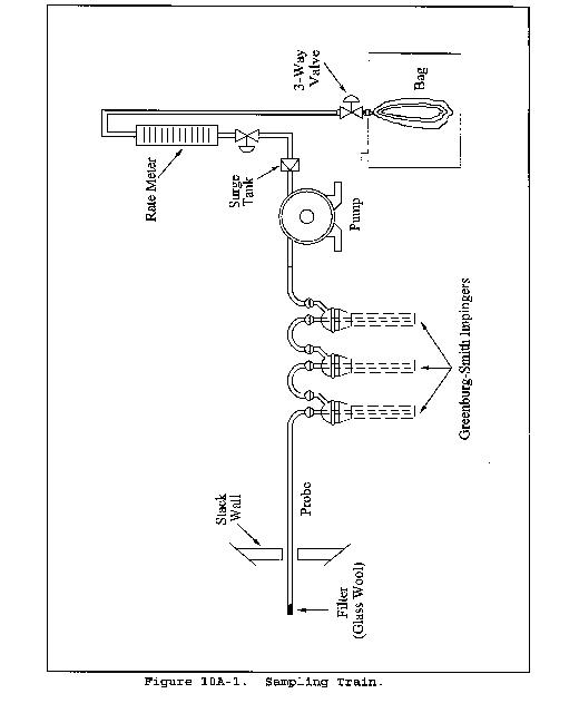

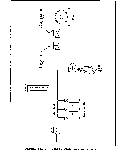

Method 10B - Determination of Carbon Monoxide Emissions From Stationary Sources
This method is not inclusive with respect to specifications (e.g., equipment and supplies) and procedures (e.g., sampling and analytical) essential to its performance. Some material is incorporated by reference from other methods in this part. Therefore, to obtain reliable results, persons using this method should have a thorough knowledge of at least the following additional test methods: Method 1, Method 4, Method 10A, and Method 25.
1.0 Scope and Application
1.1 Analytes.
| Analyte | CAS No. | Sensitivity |
|---|---|---|
| Carbon monoxide (CO) | 630-08-0 | Not determined. |
1.2 Applicability. This method applies to the measurement of CO emissions at petroleum refineries and from other sources when specified in an applicable subpart of the regulations.
1.3 Data Quality Objectives. Adherence to the requirements of this method will enhance the quality of the data obtained from air pollutant sampling methods.
2.0 Summary of Method
2.1 An integrated gas sample is extracted from the sampling point, passed through a conditioning system to remove interferences, and collected in a Tedlar or equivalent bag. (Verify through the manufacturer that the Tedlar alternative is suitable for NO and make this verifying information available for inspection.) The CO is separated from the sample by gas chromatography (GC) and catalytically reduced to methane (CH4) which is determined by flame ionization detection (FID). The analytical portion of this method is identical to applicable sections in Method 25 detailing CO measurement.
3.0 Definitions [Reserved]
4.0 Interferences
4.1 Carbon dioxide (CO2) and organics potentially can interfere with the analysis. Most of the CO2 is removed from the sample by the alkaline permanganate conditioning system; any residual CO2 and organics are separated from the CO by GC.
5.0 Safety
5.1 Disclaimer. This method may involve hazardous materials, operations, and equipment. This test method may not address all of the safety problems associated with its use. It is the responsibility of the user of this test method to establish appropriate safety and health practices and determine the applicability of regulatory limitations prior to performing this test method. The analyzer users manual should be consulted for specific precautions concerning the analytical procedure.
6.0 Equipment and Supplies
6.1 Sample Collection. Same as in Method 10A, section 6.1 (paragraphs 6.1.1 through 6.1.11).
6.2 Sample Analysis. A GC/FID analyzer, capable of quantifying CO in the sample and consisting of at least the following major components, is required for sample analysis. [Alternatively, complete Method 25 analytical systems (Method 25, section 6.3) are acceptable alternatives when calibrated for CO and operated in accordance with the Method 25 analytical procedures (Method 25, section 11.0).]
6.2.1 Separation Column. A column capable of separating CO from CO2 and organic compounds that may be present. A 3.2-mm (1⁄8-in.) OD stainless steel column packed with 1.7 m (5.5 ft.) of 60/80 mesh Carbosieve S-II (available from Supelco) has been used successfully for this purpose.
6.2.2 Reduction Catalyst. Same as in Method 25, section 6.3.1.2.
6.2.3 Sample Injection System. Same as in Method 25, Section 6.3.1.4, equipped to accept a sample line from the bag.
6.2.4 Flame Ionization Detector. Meeting the linearity specifications of section 10.3 and having a minimal instrument range of 10 to 1,000 ppm CO.
6.2.5 Data Recording System. Analog strip chart recorder or digital integration system, compatible with the FID, for permanently recording the analytical results.
7.0 Reagents and Standards
7.1 Sample Collection. Same as in Method 10A, section 7.1.
7.2 Sample Analysis.
7.2.1 Carrier, Fuel, and Combustion Gases. Same as in Method 25, sections 7.2.1, 7.2.2, and 7.2.3, respectively.
7.2.2 Calibration Gases. Three standard gases with nominal CO concentrations of 20, 200, and 1,000 ppm CO in nitrogen. The calibration gases shall be certified by the manufacturer to be ±2 percent of the specified concentrations.
7.2.3 Reduction Catalyst Efficiency Check Calibration Gas. Standard CH4 gas with a nominal concentration of 1,000 ppm in air.
8.0 Sample Collection, Preservation, Storage, and Transport
Same as in Method 10A, section 8.0.
9.0 Quality Control
| Section | Quality control measure | Effect |
|---|---|---|
| 8.0 | Sample bag/sampling system leak-checks | Ensures that negative bias introduced through leakage is minimized. |
| 10.1 | Carrier gas blank check | Ensures that positive bias introduced by contamination of carrier gas is less than 5 ppmv. |
| 10.2 | Reduction catalyst efficiency check | Ensures that negative bias introduced by inefficient reduction catalyst is less than 5 percent. |
| 10.3 | Analyzer calibration | Ensures linearity of analyzer response to standards. |
| 11.2 | Triplicate sample analyses | Ensures precision of analytical results. |
10.0 Calibration and Standardization
10.1 Carrier Gas Blank Check. Analyze each new tank of carrier gas with the GC analyzer according to section 11.2 to check for contamination. The corresponding concentration must be less than 5 ppm for the tank to be acceptable for use.
10.2 Reduction Catalyst Efficiency Check. Prior to initial use, the reduction catalyst shall be tested for reduction efficiency. With the heated reduction catalyst bypassed, make triplicate injections of the 1,000 ppm CH4 gas (Section 7.2.3) to calibrate the analyzer. Repeat the procedure using 1,000 ppm CO gas (Section 7.2.2) with the catalyst in operation. The reduction catalyst operation is acceptable if the CO response is within 5 percent of the certified gas value.
10.3 Analyzer Calibration. Perform this test before the system is first placed into operation. With the reduction catalyst in operation, conduct a linearity check of the analyzer using the standards specified in section 7.2.2. Make triplicate injections of each calibration gas, and then calculate the average response factor (area/ppm) for each gas, as well as the overall mean of the response factor values. The instrument linearity is acceptable if the average response factor of each calibration gas is within 2.5 percent of the overall mean value and if the relative standard deviation (calculated in section 12.8 of Method 25) for each set of triplicate injections is less than 2 percent. Record the overall mean of the response factor values as the calibration response factor (R).
11.0 Analytical Procedure
11.1 Preparation for Analysis. Before putting the GC analyzer into routine operation, conduct the calibration procedures listed in section 10.0. Establish an appropriate carrier flow rate and detector temperature for the specific instrument used.
11.2 Sample Analysis. Purge the sample loop with sample, and then inject the sample. Analyze each sample in triplicate, and calculate the average sample area (A). Determine the bag CO concentration according to section 12.2.
12.0 Calculations and Data Analysis
Carry out calculations retaining at least one extra significant figure beyond that of the acquired data. Round off results only after the final calculation.
12.1 Nomenclature.
A = Average sample area.
Bw = Moisture content in the bag sample, fraction.
C = CO concentration in the stack gas, dry basis, ppm.
Cb = CO concentration in the bag sample, dry basis, ppm.
F = Volume fraction of CO2 in the stack, fraction.
Pbar = Barometric pressure, mm Hg.
Pw = Vapor pressure of the H2O in the bag (from Table 10A-2, Method 10A), mm Hg.
R = Mean calibration response factor, area/ppm.
12.2 CO Concentration in the Bag. Calculate Cb using Equations 10B-1 and 10B-2. If condensate is visible in the bag, calculate Bw using Table 10A-2 of Method 10A and the temperature and barometric pressure in the analysis room. If condensate is not visible, calculate Bw using the temperature and barometric pressure at the sampling site.


12.3 CO Concentration in the Stack

13.0 Method Performance [Reserved]
14.0 Pollution Prevention [Reserved]
15.0 Waste Management [Reserved]
16.0 References
Same as in Method 25, section 16.0, with the addition of the following:
1. Butler, F.E, J.E. Knoll, and M.R. Midgett. Development and Evaluation of Methods for Determining Carbon Monoxide Emissions. Quality Assurance Division, Environmental Monitoring Systems Laboratory, U.S. Environmental Protection Agency, Research Triangle Park, NC. June 1985. 33 pp.
17.0 Tables, Diagrams, Flowcharts, and Validation Data [Reserved]
[36 FR 24877, Dec. 23, 1971]
Appendix A-5 to Part 60 - Test Methods 11 through 15A
Method 11 - Determination of hydrogen sulfide content of fuel gas streams in petroleum refineries
Method 12 - Determination of inorganic lead emissions from stationary sources
Method 13A - Determination of total fluoride emissions from stationary sources - SPADNS zirconium lake method
Method 13B - Determination of total fluoride emissions from stationary sources - Specific ion electrode method
Method 14 - Determination of fluoride emissions from potroom roof monitors for primary aluminum plants
Method 14A - Determination of Total Fluoride Emissions from Selected Sources at Primary Aluminum Production Facilities
Method 15 - Determination of hydrogen sulfide, carbonyl sulfide, and carbon disulfide emissions from stationary sources
Method 15A - Determination of total reduced sulfur emissions from sulfur recovery plants in petroleum refineries
The test methods in this appendix are referred to in § 60.8 (Performance Tests) and § 60.11 (Compliance With Standards and Maintenance Requirements) of 40 CFR part 60, subpart A (General Provisions). Specific uses of these test methods are described in the standards of performance contained in the subparts, beginning with Subpart D.
Within each standard of performance, a section title “Test Methods and Procedures” is provided to: (1) Identify the test methods to be used as reference methods to the facility subject to the respective standard and (2) identify any special instructions or conditions to be followed when applying a method to the respective facility. Such instructions (for example, establish sampling rates, volumes, or temperatures) are to be used either in addition to, or as a substitute for procedures in a test method. Similarly, for sources subject to emission monitoring requirements, specific instructions pertaining to any use of a test method as a reference method are provided in the subpart or in Appendix B.
Inclusion of methods in this appendix is not intended as an endorsement or denial of their applicability to sources that are not subject to standards of performance. The methods are potentially applicable to other sources; however, applicability should be confirmed by careful and appropriate evaluation of the conditions prevalent at such sources.
The approach followed in the formulation of the test methods involves specifications for equipment, procedures, and performance. In concept, a performance specification approach would be preferable in all methods because this allows the greatest flexibility to the user. In practice, however, this approach is impractical in most cases because performance specifications cannot be established. Most of the methods described herein, therefore, involve specific equipment specifications and procedures, and only a few methods in this appendix rely on performance criteria.
Minor changes in the test methods should not necessarily affect the validity of the results and it is recognized that alternative and equivalent methods exist. section 60.8 provides authority for the Administrator to specify or approve (1) equivalent methods, (2) alternative methods, and (3) minor changes in the methodology of the test methods. It should be clearly understood that unless otherwise identified all such methods and changes must have prior approval of the Administrator. An owner employing such methods or deviations from the test methods without obtaining prior approval does so at the risk of subsequent disapproval and retesting with approved methods.
Within the test methods, certain specific equipment or procedures are recognized as being acceptable or potentially acceptable and are specifically identified in the methods. The items identified as acceptable options may be used without approval but must be identified in the test report. The potentially approvable options are cited as “subject to the approval of the Administrator” or as “or equivalent.” Such potentially approvable techniques or alternatives may be used at the discretion of the owner without prior approval. However, detailed descriptions for applying these potentially approvable techniques or alternatives are not provided in the test methods. Also, the potentially approvable options are not necessarily acceptable in all applications. Therefore, an owner electing to use such potentially approvable techniques or alternatives is responsible for: (1) assuring that the techniques or alternatives are in fact applicable and are properly executed; (2) including a written description of the alternative method in the test report (the written method must be clear and must be capable of being performed without additional instruction, and the degree of detail should be similar to the detail contained in the test methods); and (3) providing any rationale or supporting data necessary to show the validity of the alternative in the particular application. Failure to meet these requirements can result in the Administrator's disapproval of the alternative.
Method 11 - Determination of Hydrogen Sulfide Content of Fuel Gas Streams in Petroleum Refineries
1.0 Scope and Application
1.1 Analytes.
| Analyte | CAS No. | Sensitivity |
|---|---|---|
| Hydrogen sulfide (H2S) | 7783-06-4 | 8 mg/m3 - 740 mg/m3, (6 ppm - 520 ppm). |
1.2 Applicability. This method is applicable for the determination of the H2S content of fuel gas streams at petroleum refineries.
1.3 Data Quality Objectives. Adherence to the requirements of this method will enhance the quality of the data obtained from air pollutant sampling methods.
2.0 Summary of Method
2.1 A sample is extracted from a source and passed through a series of midget impingers containing a cadmium sulfate (CdSO4) solution; H2S is absorbed, forming cadmium sulfide (CdS). The latter compound is then measured iodometrically.
3.0 Definitions [Reserved]
4.0 Interferences
4.1 Any compound that reduces iodine (I2) or oxidizes the iodide ion will interfere in this procedure, provided it is collected in the CdSO4 impingers. Sulfur dioxide in concentrations of up to 2,600 mg/m3 is removed with an impinger containing a hydrogen peroxide (H2O2) solution. Thiols precipitate with H2S. In the absence of H2S, only traces of thiols are collected. When methane-and ethane-thiols at a total level of 300 mg/m3 are present in addition to H2S, the results vary from 2 percent low at an H2S concentration of 400 mg/m3 to 14 percent high at an H2S concentration of 100 mg/m3. Carbonyl sulfide at a concentration of 20 percent does not interfere. Certain carbonyl-containing compounds react with iodine and produce recurring end points. However, acetaldehyde and acetone at concentrations of 1 and 3 percent, respectively, do not interfere.
4.2 Entrained H2O2 produces a negative interference equivalent to 100 percent of that of an equimolar quantity of H2S. Avoid the ejection of H2O2 into the CdSO4 impingers.
5.0 Safety
5.1 Disclaimer. This method may involve hazardous materials, operations, and equipment. This test method may not address all of the safety problems associated with its use. It is the responsibility of the user of this test method to establish appropriate safety and health practices and determine the applicability of regulatory limitations prior to performing this test method.
5.2 Corrosive reagents. The following reagents are hazardous. Personal protective equipment and safe procedures are useful in preventing chemical splashes. If contact occurs, immediately flush with copious amounts of water for at least 15 minutes. Remove clothing under shower and decontaminate. Treat residual chemical burns as thermal burns.
5.2.1 Hydrogen Peroxide. Irritating to eyes, skin, nose, and lungs. 30% H2O2 is a strong oxidizing agent. Avoid contact with skin, eyes, and combustible material. Wear gloves when handling.
5.2.2 Hydrochloric Acid. Highly toxic. Vapors are highly irritating to eyes, skin, nose, and lungs, causing severe damage. May cause bronchitis, pneumonia, or edema of lungs. Exposure to concentrations of 0.13 to 0.2 percent can be lethal in minutes. Will react with metals, producing hydrogen.
6.0 Equipment and Supplies
6.1 Sample Collection. The following items are needed for sample collection:
6.1.1 Sampling Line. Teflon tubing, 6- to 7- mm (1⁄4-in.) ID, to connect the sampling train to the sampling valve.
6.1.2 Impingers. Five midget impingers, each with 30-ml capacity. The internal diameter of the impinger tip must be 1 mm ±0.05 mm. The impinger tip must be positioned 4 to 6 mm from the bottom of the impinger.
6.1.3 Tubing. Glass or Teflon connecting tubing for the impingers.
6.1.4 Ice Water Bath. To maintain absorbing solution at a low temperature.
6.1.5 Drying Tube. Tube packed with 6- to 16- mesh indicating-type silica gel, or equivalent, to dry the gas sample and protect the meter and pump. If the silica gel has been used previously, dry at 175 °C (350 °F) for 2 hours. New silica gel may be used as received. Alternatively, other types of desiccants (equivalent or better) may be used, subject to approval of the Administrator.
Do not use more than 30 g of silica gel. Silica gel adsorbs gases such as propane from the fuel gas stream, and use of excessive amounts of silica gel could result in errors in the determination of sample volume.
6.1.6 Sampling Valve. Needle valve, or equivalent, to adjust gas flow rate. Stainless steel or other corrosion-resistant material.
6.1.7 Volume Meter. Dry gas meter (DGM), sufficiently accurate to measure the sample volume within 2 percent, calibrated at the selected flow rate (about 1.0 liter/min) and conditions actually encountered during sampling. The meter shall be equipped with a temperature sensor (dial thermometer or equivalent) capable of measuring temperature to within 3 °C (5.4 °F). The gas meter should have a petcock, or equivalent, on the outlet connector which can be closed during the leak-check. Gas volume for one revolution of the meter must not be more than 10 liters.
6.1.8 Rate Meter. Rotameter, or equivalent, to measure flow rates in the range from 0.5 to 2 liters/min (1 to 4 ft3/hr).
6.1.9 Graduated Cylinder. 25-ml size.
6.1.10 Barometer. Mercury, aneroid, or other barometer capable of measuring atmospheric pressure to within 2.5 mm Hg (0.1 in. Hg). In many cases, the barometric reading may be obtained from a nearby National Weather Service station, in which case, the station value (which is the absolute barometric pressure) shall be requested and an adjustment for elevation differences between the weather station and the sampling point shall be applied at a rate of minus 2.5 mm Hg (0.1 in Hg) per 30 m (100 ft) elevation increase or vice-versa for elevation decrease.
6.1.11 U-tube Manometer. 0-; to 30-cm water column, for leak-check procedure.
6.1.12 Rubber Squeeze Bulb. To pressurize train for leak-check.
6.1.13 Tee, Pinchclamp, and Connecting Tubing. For leak-check.
6.1.14 Pump. Diaphragm pump, or equivalent. Insert a small surge tank between the pump and rate meter to minimize the pulsation effect of the diaphragm pump on the rate meter. The pump is used for the air purge at the end of the sample run; the pump is not ordinarily used during sampling, because fuel gas streams are usually sufficiently pressurized to force sample gas through the train at the required flow rate. The pump need not be leak-free unless it is used for sampling.
6.1.15 Needle Valve or Critical Orifice. To set air purge flow to 1 liter/min.
6.1.16 Tube Packed with Active Carbon. To filter air during purge.
6.1.17 Volumetric Flask. One 1000-ml.
6.1.18 Volumetric Pipette. One 15-ml.
6.1.19 Pressure-Reduction Regulator. Depending on the sampling stream pressure, a pressure-reduction regulator may be needed to reduce the pressure of the gas stream entering the Teflon sample line to a safe level.
6.1.20 Cold Trap. If condensed water or amine is present in the sample stream, a corrosion-resistant cold trap shall be used immediately after the sample tap. The trap shall not be operated below 0 °C (32 °F) to avoid condensation of C3 or C4 hydrocarbons.
6.2 Sample Recovery. The following items are needed for sample recovery:
6.2.1 Sample Container. Iodine flask, glass-stoppered, 500-ml size.
6.2.2 Volumetric Pipette. One 50-ml.
6.2.3 Graduated Cylinders. One each 25- and 250-ml.
6.2.4 Erlenmeyer Flasks. 125-ml.
6.2.5 Wash Bottle.
6.2.6 Volumetric Flasks. Three 1000-ml.
6.3 Sample Analysis. The following items are needed for sample analysis:
6.3.1 Flask. Glass-stoppered iodine flask, 500-ml.
6.3.2 Burette. 50-ml.
6.3.3 Erlenmeyer Flask. 125-ml.
6.3.4 Volumetric Pipettes. One 25-ml; two each 50- and 100-ml.
6.3.5 Volumetric Flasks. One 1000-ml; two 500-ml.
6.3.6 Graduated Cylinders. One each 10- and 100-ml.
7.0 Reagents and Standards
Unless otherwise indicated, it is intended that all reagents conform to the specifications established by the Committee on Analytical Reagents of the American Chemical Society, where such specifications are available. Otherwise, use the best available grade.
7.1 Sample Collection. The following reagents are required for sample collection:
7.1.1 CdSO4 Absorbing Solution. Dissolve 41 g of 3CdSO48H2O and 15 ml of 0.1 M sulfuric acid in a 1-liter volumetric flask that contains approximately 3⁄4 liter of water. Dilute to volume with deionized, distilled water. Mix thoroughly. The pH should be 3 ±0.1. Add 10 drops of Dow-Corning Antifoam B. Shake well before use. This solution is stable for at least one month. If Antifoam B is not used, a more labor-intensive sample recovery procedure is required (see section 11.2).
7.1.2 Hydrogen Peroxide, 3 Percent. Dilute 30 percent H2O2 to 3 percent as needed. Prepare fresh daily.
7.1.3 Water. Deionized distilled to conform to ASTM D 1193-77 or 91, Type 3 (incorporated by reference - see § 60.17). The KMnO4 test for oxidizable organic matter may be omitted when high concentrations of organic matter are not expected to be present.
7.2 Sample Recovery. The following reagents are needed for sample recovery:
7.2.1 Water. Same as section 7.1.3.
7.2.2 Hydrochloric Acid (HCl) Solution, 3 M. Add 240 ml of concentrated HCl (specific gravity 1.19) to 500 ml of water in a 1-liter volumetric flask. Dilute to 1 liter with water. Mix thoroughly.
7.2.3 Iodine (I2) Solution, 0.1 N. Dissolve 24 g of potassium iodide (KI) in 30 ml of water. Add 12.7 g of resublimed iodine (I2) to the KI solution. Shake the mixture until the I2 is completely dissolved. If possible, let the solution stand overnight in the dark. Slowly dilute the solution to 1 liter with water, with swirling. Filter the solution if it is cloudy. Store solution in a brown-glass reagent bottle.
7.2.4 Standard I2 Solution, 0.01 N. Pipette 100.0 ml of the 0.1 N iodine solution into a 1-liter volumetric flask, and dilute to volume with water. Standardize daily as in section 10.2.1. This solution must be protected from light. Reagent bottles and flasks must be kept tightly stoppered.
7.3 Sample Analysis. The following reagents and standards are needed for sample analysis:
7.3.1 Water. Same as in section 7.1.3.
7.3.2 Standard Sodium Thiosulfate Solution, 0.1 N. Dissolve 24.8 g of sodium thiosulfate pentahydrate (Na2S2O3·5H2O) or 15.8 g of anhydrous sodium thiosulfate (Na2S2O3) in 1 liter of water, and add 0.01 g of anhydrous sodium carbonate (Na2CO3) and 0.4 ml of chloroform (CHCl3) to stabilize. Mix thoroughly by shaking or by aerating with nitrogen for approximately 15 minutes, and store in a glass-stoppered, reagent bottle. Standardize as in section 10.2.2.
7.3.3 Standard Sodium Thiosulfate Solution, 0.01 N. Pipette 50.0 ml of the standard 0.1 N Na2S2O3 solution into a volumetric flask, and dilute to 500 ml with water.
A 0.01 N phenylarsine oxide (C6H5AsO) solution may be prepared instead of 0.01 N Na2S2O3 (see section 7.3.4).
7.3.4 Standard Phenylarsine Oxide Solution, 0.01 N. Dissolve 1.80 g of (C6H5AsO) in 150 ml of 0.3 N sodium hydroxide. After settling, decant 140 ml of this solution into 800 ml of water. Bring the solution to pH 6-7 with 6 N HCl, and dilute to 1 liter with water. Standardize as in section 10.2.3.
7.3.5 Starch Indicator Solution. Suspend 10 g of soluble starch in 100 ml of water, and add 15 g of potassium hydroxide (KOH) pellets. Stir until dissolved, dilute with 900 ml of water, and let stand for 1 hour. Neutralize the alkali with concentrated HCl, using an indicator paper similar to Alkacid test ribbon, then add 2 ml of glacial acetic acid as a preservative.
Test starch indicator solution for decomposition by titrating with 0.01 N I2 solution, 4 ml of starch solution in 200 ml of water that contains 1 g of KI. If more than 4 drops of the 0.01 N I2 solution are required to obtain the blue color, a fresh solution must be prepared.
8.0 Sample Collection, Preservation, Storage, and Transport
8.1 Sampling Train Preparation. Assemble the sampling train as shown in Figure 11-1, connecting the five midget impingers in series. Place 15 ml of 3 percent H2O2 solution in the first impinger. Leave the second impinger empty. Place 15 ml of the CdSO4 solution in the third, fourth, and fifth impingers. Place the impinger assembly in an ice water bath container, and place water and crushed ice around the impingers. Add more ice during the run, if needed.
8.2 Leak-Check Procedure.
8.2.1 Connect the rubber bulb and manometer to the first impinger, as shown in Figure 11-1. Close the petcock on the DGM outlet. Pressurize the train to 25 cm water with the bulb, and close off the tubing connected to the rubber bulb. The train must hold 25 cm water pressure with not more than a 1 cm drop in pressure in a 1-minute interval. Stopcock grease is acceptable for sealing ground glass joints.
8.2.2 If the pump is used for sampling, it is recommended, but not required, that the pump be leak-checked separately, either prior to or after the sampling run. To leak-check the pump, proceed as follows: Disconnect the drying tube from the impinger assembly. Place a vacuum gauge at the inlet to either the drying tube or the pump, pull a vacuum of 250 mm Hg (10 in. Hg), plug or pinch off the outlet of the flow meter, and then turn off the pump. The vacuum should remain stable for at least 30 seconds. If performed prior to the sampling run, the pump leak-check should precede the leak-check of the sampling train described immediately above; if performed after the sampling run, the pump leak-check should follow the sampling train leak-check.
8.3 Purge the connecting line between the sampling valve and the first impinger by disconnecting the line from the first impinger, opening the sampling valve, and allowing process gas to flow through the line for one to two minutes. Then, close the sampling valve, and reconnect the line to the impinger train. Open the petcock on the dry gas meter outlet. Record the initial DGM reading.
8.4 Open the sampling valve, and then adjust the valve to obtain a rate of approximately 1 liter/min (0.035 cfm). Maintain a constant (±10 percent) flow rate during the test. Record the DGM temperature.
8.5 Sample for at least 10 minutes. At the end of the sampling time, close the sampling valve, and record the final volume and temperature readings. Conduct a leak-check as described in Section 8.2. A yellow color in the final cadmium sulfate impinger indicates depletion of the absorbing solution. An additional cadmium sulfate impinger should be added for subsequent samples and the sample with yellow color in the final impinger should be voided.
8.6 Disconnect the impinger train from the sampling line. Connect the charcoal tube and the pump as shown in Figure 11-1. Purge the train [at a rate of 1 liter/min (0.035 ft3/min)] with clean ambient air for 15 minutes to ensure that all H2S is removed from the H2O2. For sample recovery, cap the open ends, and remove the impinger train to a clean area that is away from sources of heat. The area should be well lighted, but not exposed to direct sunlight.
8.7 Sample Recovery.
8.7.1 Discard the contents of the H2O2 impinger. Carefully rinse with water the contents of the third, fourth, and fifth impingers into a 500-ml iodine flask.
The impingers normally have only a thin film of CdS remaining after a water rinse. If Antifoam B was not used or if significant quantities of yellow CdS remain in the impingers, the alternative recovery procedure in section 11.2 must be used.
8.7.2 Proceed to section 11 for the analysis.
9.0 Quality Control
| Section | Quality control measure | Effect |
|---|---|---|
| 8.2, 10.1 | Sampling equipment leak-check and calibration | Ensure accurate measurement of sample volume. |
| 11.2 | Replicate titrations of blanks | Ensure precision of titration determinations. |
10.0 Calibration and Standardization
Maintain a log of all calibrations.
10.1 Calibration. Calibrate the sample collection equipment as follows.
10.1.1 Dry Gas Meter.
10.1.1.1 Initial Calibration. The DGM shall be calibrated before its initial use in the field. Proceed as follows: First, assemble the following components in series: Drying tube, needle valve, pump, rotameter, and DGM. Then, leak-check the metering system as follows: Place a vacuum gauge (at least 760 mm Hg) at the inlet to the drying tube, and pull a vacuum of 250 mm Hg (10 in. Hg); plug or pinch off the outlet of the flow meter, and then turn off the pump. The vacuum shall remain stable for at least 30 seconds. Carefully release the vacuum gauge before releasing the flow meter end. Next, calibrate the DGM (at the sampling flow rate specified by the method) as follows: Connect an appropriately sized wet-test meter (e.g., 1 liter per revolution) to the inlet of the drying tube. Make three independent calibration runs, using at least five revolutions of the DGM per run. Calculate the calibration factor, Y (wet-test meter calibration volume divided by the DGM volume, both volumes adjusted to the same reference temperature and pressure), for each run, and average the results. If any Y value deviates by more than 2 percent from the average, the DGM is unacceptable for use. Otherwise, use the average as the calibration factor for subsequent test runs.
10.1.1.2 Post-Test Calibration Check. After each field test series, conduct a calibration check as in section 10.1.1.1, above, except for the following two variations:
(a) three or more revolutions of the DGM may be used and
(b) only two independent runs need be made. If the calibration factor does not deviate by more than 5 percent from the initial calibration factor (determined in section 10.1.1.1), then the DGM volumes obtained during the test series are acceptable. If the calibration factor deviates by more than 5 percent, recalibrate the DGM as in section 10.1.1.1, and for the calculations, use the calibration factor (initial or recalibration) that yields the lower gas volume for each test run.
10.1.2 Temperature Sensors. Calibrate against mercury-in-glass thermometers. An alternative mercury-free thermometer may be used if the thermometer is at a minimum equivalent in terms of performance or suitably effective for the specific temperature measurement application.
10.1.3 Rate Meter. The rate meter need not be calibrated, but should be cleaned and maintained according to the manufacturer's instructions.
10.1.4 Barometer. Calibrate against a mercury barometer.
10.2 Standardization.
10.2.1 Iodine Solution Standardization. Standardize the 0.01 N I2 solution daily as follows: Pipette 25 ml of the I2 solution into a 125-ml Erlenmeyer flask. Add 2 ml of 3 M HCl. Titrate rapidly with standard 0.01 N Na2S2O3 solution or with 0.01 N C6H5AsO until the solution is light yellow, using gentle mixing. Add four drops of starch indicator solution, and continue titrating slowly until the blue color just disappears. Record the volume of Na2S2O3 solution used, VSI, or the volume of C6H5AsO solution used, VAI, in ml. Repeat until replicate values agree within 0.05 ml. Average the replicate titration values which agree within 0.05 ml, and calculate the exact normality of the I2 solution using Equation 11-3. Repeat the standardization daily.
10.2.2 Sodium Thiosulfate Solution Standardization. Standardize the 0.1 N Na2S2O3 solution as follows: Oven-dry potassium dichromate (K2Cr2O7) at 180 to 200 °C (360 to 390 °F). To the nearest milligram, weigh 2 g of the dichromate (W). Transfer the dichromate to a 500-ml volumetric flask, dissolve in water, and dilute to exactly 500 ml. In a 500-ml iodine flask, dissolve approximately 3 g of KI in 45 ml of water, then add 10 ml of 3 M HCl solution. Pipette 50 ml of the dichromate solution into this mixture. Gently swirl the contents of the flask once, and allow it to stand in the dark for 5 minutes. Dilute the solution with 100 to 200 ml of water, washing down the sides of the flask with part of the water. Titrate with 0.1 N Na2S2O3 until the solution is light yellow. Add 4 ml of starch indicator and continue titrating slowly to a green end point. Record the volume of Na2S2O3 solution used, VS, in ml. Repeat until replicate values agree within 0.05 ml. Calculate the normality using Equation 11-1. Repeat the standardization each week or after each test series, whichever time is shorter.
10.2.3 Phenylarsine Oxide Solution Standardization. Standardize the 0.01 N C6H5AsO (if applicable) as follows: Oven-dry K2Cr2O7 at 180 to 200 °C (360 to 390 °F). To the nearest milligram, weigh 2 g of the dichromate (W). Transfer the dichromate to a 500-ml volumetric flask, dissolve in water, and dilute to exactly 500 ml. In a 500-ml iodine flask, dissolve approximately 0.3 g of KI in 45 ml of water, then add 10 ml of 3 M HCl. Pipette 5 ml of the dichromate solution into the iodine flask. Gently swirl the contents of the flask once, and allow it to stand in the dark for 5 minutes. Dilute the solution with 100 to 200 ml of water, washing down the sides of the flask with part of the water. Titrate with 0.01 N C6H5AsO until the solution is light yellow. Add 4 ml of starch indicator, and continue titrating slowly to a green end point. Record the volume of C6H5AsO used, VA, in ml. Repeat until replicate analyses agree within 0.05 ml. Calculate the normality using Equation 11-2. Repeat the standardization each week or after each test series, whichever time is shorter.
11.0 Analytical Procedure
Conduct the titration analyses in a clean area away from direct sunlight.
11.1 Pipette exactly 50 ml of 0.01 N I2 solution into a 125-ml Erlenmeyer flask. Add 10 ml of 3 M HCl to the solution. Quantitatively rinse the acidified I2 into the iodine flask. Stopper the flask immediately, and shake briefly.
11.2 Use these alternative procedures if Antifoam B was not used or if significant quantities of yellow CdS remain in the impingers. Extract the remaining CdS from the third, fourth, and fifth impingers using the acidified I2 solution. Immediately after pouring the acidified I2 into an impinger, stopper it and shake for a few moments, then transfer the liquid to the iodine flask. Do not transfer any rinse portion from one impinger to another; transfer it directly to the iodine flask. Once the acidified I2 solution has been poured into any glassware containing CdS, the container must be tightly stoppered at all times except when adding more solution, and this must be done as quickly and carefully as possible. After adding any acidified I2 solution to the iodine flask, allow a few minutes for absorption of the H2S before adding any further rinses. Repeat the I2 extraction until all CdS is removed from the impingers. Extract that part of the connecting glassware that contains visible CdS. Quantitatively rinse all the I2 from the impingers, connectors, and the beaker into the iodine flask using water. Stopper the flask and shake briefly.
11.3 Allow the iodine flask to stand about 30 minutes in the dark for absorption of the H2S into the I2, then complete the titration analysis as outlined in sections 11.5 and 11.6.
Iodine evaporates from acidified I2 solutions. Samples to which acidified I2 has been added may not be stored, but must be analyzed in the time schedule stated above.
11.4 Prepare a blank by adding 45 ml of CdSO4 absorbing solution to an iodine flask. Pipette exactly 50 ml of 0.01 N I2 solution into a 125-ml Erlenmeyer flask. Add 10 ml of 3 M HCl. Stopper the flask, shake briefly, let stand 30 minutes in the dark, and titrate with the samples.
The blank must be handled by exactly the same procedure as that used for the samples.
11.5 Using 0.01 N Na2S2O3 solution (or 0.01 N C6H5AsO, if applicable), rapidly titrate each sample in an iodine flask using gentle mixing, until solution is light yellow. Add 4 ml of starch indicator solution, and continue titrating slowly until the blue color just disappears. Record the volume of Na2S2O3 solution used, VTT, or the volume of C6H5AsO solution used, VAT, in ml.
11.6 Titrate the blanks in the same manner as the samples. Run blanks each day until replicate values agree within 0.05 ml. Average the replicate titration values which agree within 0.05 ml.
12.0 Data Analysis and Calculations
Carry out calculations, retaining at least one extra significant figure beyond that of the acquired data. Round off figures only after the final calculation.
12.1 Nomenclature.
CH2S = Concentration of H2S at standard conditions, mg/dscm.
NA = Normality of standard C6H5AsO solution, g-eq/liter.
NI = Normality of standard I2 solution, g-eq/liter.
NS = Normality of standard (≃0.1 N) Na2S2O3 solution, g-eq/liter.
NT = Normality of standard (≃0.01 N) Na2S2O3 solution, assumed to be 0.1 NS, g-eq/liter.
Pbar = Barometric pressure at the sampling site, mm Hg.
Pstd = Standard absolute pressure, 760 mm Hg.
Tm = Average DGM temperature, °K.
Tstd = Standard absolute temperature, 293 °K.
VA = Volume of C6H5AsO solution used for standardization, ml.
VAI = Volume of standard C6H5AsO solution used for titration analysis, ml.
VI = Volume of standard I2 solution used for standardization, ml.
VIT = Volume of standard I2 solution used for titration analysis, normally 50 ml.
Vm = Volume of gas sample at meter conditions, liters.
Vm(std) = Volume of gas sample at standard conditions, liters.
VSI = Volume of “0.1 N Na2S2O3 solution used for standardization, ml.
VT = Volume of standard (≃0.01 N) Na2S2O3 solution used in standardizing iodine solution (see section 10.2.1), ml.
VTT = Volume of standard (∼0.01 N) Na2S2O3 solution used for titration analysis, ml.
W = Weight of K2Cr2O7 used to standardize Na2s2O3 or C6H5AsO solutions, as applicable (see sections 10.2.2 and 10.2.3), g.
Y = DGM calibration factor.
12.2 Normality of the Standard (≃0.1 N) Sodium Thiosulfate Solution.

Where:
2.039 = Conversion factor
= (6 g-eq I2/mole K2Cr2O7) (1,000 ml/liter)/(294.2 g K2Cr2O7/mole) (10 aliquot factor)
12.3 Normality of Standard Phenylarsine Oxide Solution (if applicable).

Where:
0.2039 = Conversion factor.
= (6 g-eq I2/mole K2Cr2O7) (1,000 ml/liter)/(294.2 g K2Cr2O7/mole) (100 aliquot factor)
12.4 Normality of Standard Iodine Solution.

If C6H5AsO is used instead of Na2S2O3, replace NT and VT in Equation 11-3 with NA and VAS, respectively (see sections 10.2.1 and 10.2.3).
12.5 Dry Gas Volume. Correct the sample volume measured by the DGM to standard conditions (20 °C and 760 mm Hg).

12.6 Concentration of H2S. Calculate the concentration of H2S in the gas stream at standard conditions using Equation 11-5:

Where:
17.04 × 103 = Conversion factor
= (34.07 g/mole H2S) (1,000 liters/m3) (1,000mg/g)/(1,000 ml/liter) (2H2S eq/mole)
If C6H5AsO is used instead of NaS22O3, replace NA and VAT in Equation 11-5 with NA and VAT, respectively (see sections 11.5 and 10.2.3).
13.0 Method Performance
13.1 Precision. Collaborative testing has shown the intra-laboratory precision to be 2.2 percent and the inter-laboratory precision to be 5 percent.
13.2 Bias. The method bias was shown to be −4.8 percent when only H2S was present. In the presence of the interferences cited in section 4.0, the bias was positive at low H2S concentration and negative at higher concentrations. At 230 mg H2S/m3, the level of the compliance standard, the bias was + 2.7 percent. Thiols had no effect on the precision.
14.0 Pollution Prevention [Reserved]
15.0 Waste Management [Reserved]
16.0 References
1. Determination of Hydrogen Sulfide, Ammoniacal Cadmium Chloride Method. API Method 772-54. In: Manual on Disposal of Refinery Wastes, Vol. V: Sampling and Analysis of Waste Gases and Particulate Matter. American Petroleum Institute, Washington, D.C. 1954.
2. Tentative Method of Determination of Hydrogen Sulfide and Mercaptan Sulfur in Natural Gas. Natural Gas Processors Association, Tulsa, OK. NGPA Publication No. 2265-65. 1965.
3. Knoll, J.D., and M.R. Midgett. Determination of Hydrogen Sulfide in Refinery Fuel Gases. Environmental Monitoring Series, Office of Research and Development, USEPA. Research Triangle Park, NC 27711. EPA 600/4-77-007.
4. Scheil, G.W., and M.C. Sharp. Standardization of Method 11 at a Petroleum Refinery. Midwest Research Institute Draft Report for USEPA. Office of Research and Development. Research Triangle Park, NC 27711. EPA Contract No. 68-02-1098. August 1976. EPA 600/4-77-088a (Volume 1) and EPA 600/4-77-088b (Volume 2).
17.0 Tables, Diagrams, Flowcharts, and Validation Data

Method 12 - Determination of Inorganic Lead Emissions From Stationary Sources
This method does not include all of the specifications (e.g., equipment and supplies) and procedures (e.g., sampling and analytical) essential to its performance. Some material is incorporated by reference from other methods in this part. Therefore, to obtain reliable results, persons using this method should have a thorough knowledge of at least the following additional test methods: Method 1, Method 2, Method 3, and Method 5.
1.0 Scope and Application
1.1 Analytes.
| Analyte | CAS No. | Sensitivity |
|---|---|---|
| Inorganic Lead Compounds as lead (Pb) | 7439-92-1 | see section 13.3. |
1.2 Applicability. This method is applicable for the determination of inorganic lead emissions from stationary sources, only as specified in an applicable subpart of the regulations.
1.3 Data Quality Objectives. Adherence to the requirements of this method will enhance the quality of the data obtained from air pollutant sampling methods.
2.0 Summary of Method
2.1 Particulate and gaseous Pb emissions are withdrawn isokinetically from the source and are collected on a filter and in dilute nitric acid. The collected samples are digested in acid solution and are analyzed by atomic absorption spectrophotometry using an air/acetylene flame.
3.0 Definitions [Reserved]
4.0 Interferences
4.1 Copper. High concentrations of copper may interfere with the analysis of Pb at 217.0 nm. This interference can be avoided by analyzing the samples at 283.3 nm.
4.2 Matrix Effects. Analysis for Pb by flame atomic absorption spectrophotometry is sensitive to the chemical composition and to the physical properties (e.g., viscosity, pH) of the sample. The analytical procedure requires the use of the Method of Standard Additions to check for these matrix effects, and requires sample analysis using the Method of Standard Additions if significant matrix effects are found to be present.
5.0 Safety
5.1 Disclaimer. This method may involve hazardous materials, operations, and equipment. This test method may not address all of the safety problems associated with its use. It is the responsibility of the user of this test method to establish appropriate safety and health practices and to determine the applicability of regulatory limitations prior to performing this test method.
5.2 Corrosive Reagents. The following reagents are hazardous. Personal protective equipment and safe procedures are useful in preventing chemical splashes. If contact occurs, immediately flush with copious amounts of water at least 15 minutes. Remove clothing under shower and decontaminate. Treat residual chemical burn as thermal burn.
5.2.1 Hydrogen Peroxide (H2O2). Irritating to eyes, skin, nose, and lungs.
5.2.2 Nitric Acid (HNO3). Highly corrosive to eyes, skin, nose, and lungs. Vapors cause bronchitis, pneumonia, or edema of lungs. Reaction to inhalation may be delayed as long as 30 hours and still be fatal. Provide ventilation to limit exposure. Strong oxidizer. Hazardous reaction may occur with organic materials such as solvents.
6.0 Equipment and Supplies
6.1 Sample Collection. A schematic of the sampling train used in performing this method is shown in Figure 12-1 in section 18.0; it is similar to the Method 5 train. The following items are needed for sample collection:
6.1.1 Probe Nozzle, Probe Liner, Pitot Tube, Differential Pressure Gauge, Filter Holder, Filter Heating System, Temperature Sensor, Metering System, Barometer, and Gas Density Determination Equipment. Same as Method 5, sections 6.1.1.1 through 6.1.1.7, 6.1.1.9, 6.1.2, and 6.1.3, respectively.
6.1.2 Impingers. Four impingers connected in series with leak-free ground glass fittings or any similar leak-free noncontaminating fittings are needed. For the first, third, and fourth impingers, use the Greenburg-Smith design, modified by replacing the tip with a 1.3 cm (1⁄2 in.) ID glass tube extending to about 1.3 cm (1⁄2 in.) from the bottom of the flask. For the second impinger, use the Greenburg-Smith design with the standard tip.
6.1.3 Temperature Sensor. Place a temperature sensor, capable of measuring temperature to within 1 °C (2 °F) at the outlet of the fourth impinger for monitoring purposes.
6.2 Sample Recovery. The following items are needed for sample recovery:
6.2.1 Probe-Liner and Probe-Nozzle Brushes, Petri Dishes, Graduated Cylinder and/or Balance, Plastic Storage Containers, and Funnel and Rubber Policeman. Same as Method 5, sections 6.2.1 and 6.2.4 through 6.2.7, respectively.
6.2.2 Wash Bottles. Glass (2).
6.2.3 Sample Storage Containers. Chemically resistant, borosilicate glass bottles, for 0.1 N nitric acid (HNO3) impinger and probe solutions and washes, 1000-ml. Use screw-cap liners that are either rubber-backed Teflon or leak-free and resistant to chemical attack by 0.1 N HNO3. (Narrow mouth glass bottles have been found to be less prone to leakage.)
6.2.4 Funnel. Glass, to aid in sample recovery.
6.3 Sample Analysis. The following items are needed for sample analysis:
6.3.1 Atomic Absorption Spectrophotometer. With lead hollow cathode lamp and burner for air/acetylene flame.
6.3.2 Hot Plate.
6.3.3 Erlenmeyer Flasks. 125-ml, 24/40 standard taper.
6.3.4 Membrane Filters. Millipore SCWPO 4700, or equivalent.
6.3.5 Filtration Apparatus. Millipore vacuum filtration unit, or equivalent, for use with the above membrane filter.
6.3.6 Volumetric Flasks. 100-ml, 250-ml, and 1000-ml.
7.0 Reagents and Standards
Unless otherwise indicated, it is intended that all reagents conform to the specifications established by the Committee on Analytical Reagents of the American Chemical Society, where such specifications are available; otherwise, use the best available grade.
7.1 Sample Collection. The following reagents are needed for sample collection:
7.1.1 Filter. Gelman Spectro Grade, Reeve Angel 934 AH, MSA 1106 BH, all with lot assay for Pb, or other high-purity glass fiber filters, without organic binder, exhibiting at least 99.95 percent efficiency (<0.05 percent penetration) on 0.3 micron dioctyl phthalate smoke particles. Conduct the filter efficiency test using ASTM D 2986-71, 78, or 95a (incorporated by reference - see § 60.17) or use test data from the supplier's quality control program.
7.1.2 Silica Gel and Crushed Ice. Same as Method 5, sections 7.1.2 and 7.1.4, respectively.
7.1.3 Water. Deionized distilled, to conform to ASTM D 1193-77 or 91, Type 3 (incorporated by reference - see § 60.17). If high concentrations of organic matter are not expected to be present, the potassium permanganate test for oxidizable organic matter may be omitted.
7.1.4 Nitric Acid, 0.1 N. Dilute 6.5 ml of concentrated HNO3 to 1 liter with water. (It may be desirable to run blanks before field use to eliminate a high blank on test samples.)
7.2 Sample Recovery. 0.1 N HNO3 (Same as in section 7.1.4 above).
7.3 Sample Analysis. The following reagents and standards are needed for sample analysis:
7.3.1 Water. Same as in section 7.1.3.
7.3.2 Nitric Acid, Concentrated.
7.3.3 Nitric Acid, 50 Percent (v/v). Dilute 500 ml of concentrated HNO3 to 1 liter with water.
7.3.4 Stock Lead Standard Solution, 1000 µg Pb/ml. Dissolve 0.1598 g of lead nitrate [Pb(NO3)2] in about 60 ml water, add 2 ml concentrated HNO3, and dilute to 100 ml with water.
7.3.5 Working Lead Standards. Pipet 0.0, 1.0, 2.0, 3.0, 4.0, and 5.0 ml of the stock lead standard solution (Section 7.3.4) into 250-ml volumetric flasks. Add 5 ml of concentrated HNO3 to each flask, and dilute to volume with water. These working standards contain 0.0, 4.0, 8.0, 12.0, 16.0, and 20.0 µg Pb/ml, respectively. Prepare, as needed, additional standards at other concentrations in a similar manner.
7.3.6 Air. Suitable quality for atomic absorption spectrophotometry.
7.3.7 Acetylene. Suitable quality for atomic absorption spectrophotometry.
7.3.8 Hydrogen Peroxide, 3 Percent (v/v). Dilute 10 ml of 30 percent H2O2 to 100 ml with water.
8.0 Sample Collection, Preservation, Storage, and Transport
8.1 Pretest Preparation. Follow the same general procedure given in Method 5, section 8.1, except that the filter need not be weighed.
8.2 Preliminary Determinations. Follow the same general procedure given in Method 5, section 8.2.
8.3 Preparation of Sampling Train. Follow the same general procedure given in Method 5, section 8.3, except place 100 ml of 0.1 N HNO3 (instead of water) in each of the first two impingers. As in Method 5, leave the third impinger empty and transfer approximately 200 to 300 g of preweighed silica gel from its container to the fourth impinger. Set up the train as shown in Figure 12-1.
8.4 Leak-Check Procedures. Same as Method 5, section 8.4.
8.5 Sampling Train Operation. Same as Method 5, section 8.5.
8.6 Calculation of Percent Isokinetic. Same as Method 5, section 8.6.
8.7 Sample Recovery. Same as Method 5, sections 8.7.1 through 8.7.6.1, with the addition of the following:
8.7.1 Container No. 2 (Probe).
8.7.1.1 Taking care that dust on the outside of the probe or other exterior surfaces does not get into the sample, quantitatively recover sample matter and any condensate from the probe nozzle, probe fitting, probe liner, and front half of the filter holder by washing these components with 0.1 N HNO3 and placing the wash into a glass sample storage container. Measure and record (to the nearest 2 ml) the total amount of 0.1 N HNO3 used for these rinses. Perform the 0.1 N HNO3 rinses as follows:
8.7.1.2 Carefully remove the probe nozzle, and rinse the inside surfaces with 0.1 N HNO3 from a wash bottle while brushing with a stainless steel, Nylon-bristle brush. Brush until the 0.1 N HNO3 rinse shows no visible particles, then make a final rinse of the inside surface with 0.1 N HNO3.
8.7.1.3 Brush and rinse with 0.1 N HNO3 the inside parts of the Swagelok fitting in a similar way until no visible particles remain.
8.7.1.4 Rinse the probe liner with 0.1 N HNO3. While rotating the probe so that all inside surfaces will be rinsed with 0.1 N HNO3, tilt the probe, and squirt 0.1 N HNO3 into its upper end. Let the 0.1 N HNO3 drain from the lower end into the sample container. A glass funnel may be used to aid in transferring liquid washes to the container. Follow the rinse with a probe brush. Hold the probe in an inclined position, squirt 0.1 N HNO3 into the upper end of the probe as the probe brush is being pushed with a twisting action through the probe; hold the sample container underneath the lower end of the probe, and catch any 0.1 N HNO3 and sample matter that is brushed from the probe. Run the brush through the probe three times or more until no visible sample matter is carried out with the 0.1 N HNO3 and none remains on the probe liner on visual inspection. With stainless steel or other metal probes, run the brush through in the above prescribed manner at least six times, since metal probes have small crevices in which sample matter can be entrapped. Rinse the brush with 0.1 N HNO3, and quantitatively collect these washings in the sample container. After the brushing, make a final rinse of the probe as described above.
8.7.1.5 It is recommended that two people clean the probe to minimize loss of sample. Between sampling runs, keep brushes clean and protected from contamination.
8.7.1.6 Brush and rinse with 0.1 N HNO3 the inside of the front half of the filter holder. Brush and rinse each surface three times or more, if needed, to remove visible sample matter. Make a final rinse of the brush and filter holder. After all 0.1 N HNO3 washings and sample matter are collected in the sample container, tighten the lid on the sample container so that the fluid will not leak out when it is shipped to the laboratory. Mark the height of the fluid level to determine whether leakage occurs during transport. Label the container to identify its contents clearly.
8.7.2 Container No. 3 (Silica Gel). Note the color of the indicating silica gel to determine if it has been completely spent, and make a notation of its condition. Transfer the silica gel from the fourth impinger to the original container, and seal. A funnel may be used to pour the silica gel from the impinger and a rubber policeman may be used to remove the silica gel from the impinger. It is not necessary to remove the small amount of particles that may adhere to the walls and are difficult to remove. Since the gain in weight is to be used for moisture calculations, do not use any water or other liquids to transfer the silica gel. If a balance is available in the field, follow the procedure for Container No. 3 in section 11.4.2.
8.7.3 Container No. 4 (Impingers). Due to the large quantity of liquid involved, the impinger solutions may be placed in several containers. Clean each of the first three impingers and connecting glassware in the following manner:
8.7.3.1 Cap the impinger ball joints.
8.7.3.2. Rotate and agitate each impinger, so that the impinger contents might serve as a rinse solution.
8.7.3.3 Treat the impingers as follows: Make a notation of any color or film in the liquid catch. Measure the liquid that is in the first three impingers by weighing it to within 0.5 g at a minimum by using a balance. Record the weight of liquid present. The liquid weight is needed, along with the silica gel data, to calculate the stack gas moisture content (see Method 5, Figure 5-6).
8.7.3.4. Transfer the contents to Container No. 4.
In sections 8.7.3.5 and 8.7.3.6, measure and record the total amount of 0.1 N HNO3 used for rinsing.
8.7.3.5. Pour approximately 30 ml of 0.1 N HNO3 into each of the first three impingers and agitate the impingers. Drain the 0.1 N HNO3 through the outlet arm of each impinger into Container No. 4. Repeat this operation a second time; inspect the impingers for any abnormal conditions.
8.7.3.6 Rinse the insides of each piece of connecting glassware for the impingers twice with 0.1 N HNO3; transfer this rinse into Container No. 4. Do not rinse or brush the glass-fritted filter support. Mark the height of the fluid level to determine whether leakage occurs during transport. Label the container to identify its contents clearly.
8.8 Blanks.
8.8.1 Nitric Acid. Save 200 ml of the 0.1 N HNO3 used for sampling and cleanup as a blank. Take the solution directly from the bottle being used and place into a glass sample container labeled “0.1 N HNO3 blank.”
8.8.2 Filter. Save two filters from each lot of filters used in sampling. Place these filters in a container labeled “filter blank.”
9.0 Quality Control
9.1 Miscellaneous Quality Control Measures.
| Section | Quality control measure | Effect |
|---|---|---|
| 8.4, 10.1 | Sampling equipment leak-checks and calibration | Ensure accuracy and precision of sampling measurements. |
| 10.2 | Spectrophotometer calibration | Ensure linearity of spectrophotometer response to standards. |
| 11.5 | Check for matrix effects | Eliminate matrix effects. |
9.2 Volume Metering System Checks. Same as Method 5, section 9.2.
10.0 Calibration and Standardizations
Maintain a laboratory log of all calibrations.
10.1 Sampling Equipment. Same as Method 5, section 10.0.
10.2 Spectrophotometer.
10.2.1 Measure the absorbance of the standard solutions using the instrument settings recommended by the spectrophotometer manufacturer. Repeat until good agreement (±3 percent) is obtained between two consecutive readings. Plot the absorbance (y-axis) versus concentration in µg Pb/ml (x-axis). Draw or compute a straight line through the linear portion of the curve. Do not force the calibration curve through zero, but if the curve does not pass through the origin or at least lie closer to the origin than ±0.003 absorbance units, check for incorrectly prepared standards and for curvature in the calibration curve.
10.2.2 To determine stability of the calibration curve, run a blank and a standard after every five samples, and recalibrate as necessary.
11.0 Analytical Procedures
11.1 Sample Loss Check. Prior to analysis, check the liquid level in Containers Number 2 and Number 4. Note on the analytical data sheet whether leakage occurred during transport. If a noticeable amount of leakage occurred, either void the sample or take steps, subject to the approval of the Administrator, to adjust the final results.
11.2 Sample Preparation.
11.2.1 Container No. 1 (Filter). Cut the filter into strips and transfer the strips and all loose particulate matter into a 125-ml Erlenmeyer flask. Rinse the petri dish with 10 ml of 50 percent HNO3 to ensure a quantitative transfer, and add to the flask.
If the total volume required in section 11.2.3 is expected to exceed 80 ml, use a 250-ml flask in place of the 125-ml flask.
11.2.2 Containers No. 2 and No. 4 (Probe and Impingers). Combine the contents of Containers No. 2 and No. 4, and evaporate to dryness on a hot plate.
11.2.3 Sample Extraction for Lead.
11.2.3.1 Based on the approximate stack gas particulate concentration and the total volume of stack gas sampled, estimate the total weight of particulate sample collected. Next, transfer the residue from Containers No. 2 and No. 4 to the 125-ml Erlenmeyer flask that contains the sampling filter using a rubber policeman and 10 ml of 50 percent HNO3 for every 100 mg of sample collected in the train or a minimum of 30 ml of 50 percent HNO3, whichever is larger.
11.2.3.2 Place the Erlenmeyer flask on a hot plate, and heat with periodic stirring for 30 minutes at a temperature just below boiling. If the sample volume falls below 15 ml, add more 50 percent HNO3. Add 10 ml of 3 percent H2O2, and continue heating for 10 minutes. Add 50 ml of hot (80 °C, 176 °F) water, and heat for 20 minutes. Remove the flask from the hot plate, and allow to cool. Filter the sample through a Millipore membrane filter, or equivalent, and transfer the filtrate to a 250-ml volumetric flask. Dilute to volume with water.
11.2.4 Filter Blank. Cut each filter into strips, and place each filter in a separate 125-ml Erlenmeyer flask. Add 15 ml of 50 percent HNO3, and treat as described in section 11.2.3 using 10 ml of 3 percent H2O2 and 50 ml of hot water. Filter and dilute to a total volume of 100 ml using water.
11.2.5 Nitric Acid Blank, 0.1 N. Take the entire 200 ml of 0.1 N HNO3 to dryness on a steam bath, add 15 ml of 50 percent HNO3, and treat as described in section 11.2.3 using 10 ml of 3 percent H202 and 50 ml of hot water. Dilute to a total volume of 100 ml using water.
11.3 Spectrophotometer Preparation. Turn on the power; set the wavelength, slit width, and lamp current; and adjust the background corrector as instructed by the manufacturer's manual for the particular atomic absorption spectrophotometer. Adjust the burner and flame characteristics as necessary.
11.4 Analysis.
11.4.1 Lead Determination. Calibrate the spectrophotometer as outlined in section 10.2, and determine the absorbance for each source sample, the filter blank, and 0.1 N HNO3 blank. Analyze each sample three times in this manner. Make appropriate dilutions, as needed, to bring all sample Pb concentrations into the linear absorbance range of the spectrophotometer. Because instruments vary between manufacturers, no detailed operating instructions will be given here. Instead, the instructions provided with the particular instrument should be followed. If the Pb concentration of a sample is at the low end of the calibration curve and high accuracy is required, the sample can be taken to dryness on a hot plate and the residue dissolved in the appropriate volume of water to bring it into the optimum range of the calibration curve.
11.4.2 Container No. 3 (Silica Gel). This step may be conducted in the field. Weigh the spent silica gel (or silica gel plus impinger) to the nearest 0.5 g; record this weight.
11.5 Check for Matrix Effects. Use the Method of Standard Additions as follows to check at least one sample from each source for matrix effects on the Pb results:
11.5.1 Add or spike an equal volume of standard solution to an aliquot of the sample solution.
11.5.2 Measure the absorbance of the resulting solution and the absorbance of an aliquot of unspiked sample.
11.5.3 Calculate the Pb concentration Cm in µg/ml of the sample solution using Equation 12-1 in section 12.5.
Volume corrections will not be required if the solutions as analyzed have been made to the same final volume. Therefore, Cm and Ca represent Pb concentration before dilutions.
Method of Standard Additions procedures described on pages 9-4 and 9-5 of the section entitled “General Information” of the Perkin Elmer Corporation Atomic Absorption Spectrophotometry Manual, Number 303-0152 (Reference 1 in section 17.0) may also be used. In any event, if the results of the Method of Standard Additions procedure used on the single source sample do not agree to within ±5 percent of the value obtained by the routine atomic absorption analysis, then reanalyze all samples from the source using the Method of Standard Additions procedure.
12.0 Data Analysis and Calculations
12.1 Nomenclature.
Am = Absorbance of the sample solution.
An = Cross-sectional area of nozzle, m2 (ft2).
At = Absorbance of the spiked sample solution.
Bws = Water in the gas stream, proportion by volume.
Ca = Lead concentration in standard solution, µg/ml.
Cm = Lead concentration in sample solution analyzed during check for matrix effects, µg/ml.
Cs = Lead concentration in stack gas, dry basis, converted to standard conditions, mg/dscm (gr/dscf).
I = Percent of isokinetic sampling.
L1 = Individual leakage rate observed during the leak-check conducted prior to the first component change, m3/min (ft3/min).
La = Maximum acceptable leakage rate for either a pretest leak-check or for a leak-check following a component change; equal to 0.00057 m3/min (0.020 cfm) or 4 percent of the average sampling rate, whichever is less.
Li = Individual leakage rate observed during the leak-check conducted prior to the “ith” component change (i = 1, 2, 3 * * * n), m3/min (cfm).
Lp = Leakage rate observed during the post-test leak-check, m3/min (cfm).
mt = Total weight of lead collected in the sample, µg.
Mw = Molecular weight of water, 18.0 g/g-mole (18.0 lb/lb-mole).
Pbar = Barometric pressure at the sampling site, mm Hg (in. Hg).
Ps = Absolute stack gas pressure, mm Hg (in. Hg).
Pstd = Standard absolute pressure, 760 mm Hg (29.92 in. Hg).
R = Ideal gas constant, 0.06236 [(mm Hg) (m3)]/[(°K) (g-mole)] {21.85 [(in. Hg) (ft3)]/[(°R) (lb-mole)]}.
Tm = Absolute average dry gas meter temperature (see Figure 5-3 of Method 5), °K (°R).
Tstd = Standard absolute temperature, 293 °K (528 °R).
vs = Stack gas velocity, m/sec (ft/sec).
Vm = Volume of gas sample as measured by the dry gas meter, dry basis, m3 (ft3).
Vm(std) = Volume of gas sample as measured by the dry gas meter, corrected to standard conditions, m3 (ft3).
Vw(std) = Volume of water vapor collected in the sampling train, corrected to standard conditions, m3 (ft3).
Y = Dry gas meter calibration factor.
ΔH = Average pressure differential across the orifice meter (see Figure 5-3 of Method 5), mm H2O (in. H2O).
θ = Total sampling time, min.
θl = Sampling time interval, from the beginning of a run until the first component change, min.
θi = Sampling time interval, between two successive component changes, beginning with the interval between the first and second changes, min.
θp = Sampling time interval, from the final (nth) component change until the end of the sampling run, min.
12.2 Average Dry Gas Meter Temperatures (Tm) and Average Orifice Pressure Drop (ΔH). See data sheet (Figure 5-3 of Method 5).
12.3 Dry Gas Volume, Volume of Water Vapor Condensed, and Moisture Content. Using data obtained in this test, calculate Vm(std), Vw(std), and Bws according to the procedures outlined in Method 5, sections 12.3 through 12.5.
12.4 Total Lead in Source Sample. For each source sample, correct the average absorbance for the contribution of the filter blank and the 0.1 N HNO3 blank. Use the calibration curve and this corrected absorbance to determine the Pb concentration in the sample aspirated into the spectrophotometer. Calculate the total Pb content mt (in µg) in the original source sample; correct for all the dilutions that were made to bring the Pb concentration of the sample into the linear range of the spectrophotometer.
12.5 Sample Lead Concentration. Calculate the Pb concentration of the sample using the following equation:

12.6 Lead Concentration. Calculate the stack gas Pb concentration Cs using Equation 12-2:

Where:
K3 = 0.001 mg/µg for metric units.
= 1.54 × 10⁻⁵ gr/µg for English units
12.7 Stack Gas Velocity and Volumetric Flow Rate. Calculate the average stack gas velocity and volumetric flow rate using data obtained in this method and the equations in sections 12.2 and 12.3 of Method 2.
12.8 Isokinetic Variation. Same as Method 5, section 12.11.
13.0 Method Performance
13.1 Precision. The within-laboratory precision, as measured by the coefficient of variation, ranges from 0.2 to 9.5 percent relative to a run-mean concentration. These values were based on tests conducted at a gray iron foundry, a lead storage battery manufacturing plant, a secondary lead smelter, and a lead recovery furnace of an alkyl lead manufacturing plant. The concentrations encountered during these tests ranged from 0.61 to 123.3 mg Pb/m3.
13.2 Analytical Range. For a minimum analytical accuracy of ±10 percent, the lower limit of the range is 100 µg. The upper limit can be extended considerably by dilution.
13.3 Analytical Sensitivity. Typical sensitivities for a 1-percent change in absorption (0.0044 absorbance units) are 0.2 and 0.5 µg Pb/ml for the 217.0 and 283.3 nm lines, respectively.
14.0 Pollution Prevention [Reserved]
15.0 Waste Management [Reserved]
16.0 Alternative Procedures
16.1 Simultaneous Determination of Particulate Matter and Lead Emissions. Method 12 may be used to simultaneously determine Pb and particulate matter provided:
(1) A glass fiber filter with a low Pb background is used and this filter is checked, desiccated and weighed per section 8.1 of Method 5,
(2) An acetone rinse, as specified by Method 5, sections 7.2 and 8.7.6.2, is used to remove particulate matter from the probe and inside of the filter holder prior to and kept separate from the 0.1 N HNO3 rinse of the same components,
(3) The recovered filter, the acetone rinse, and an acetone blank (Method 5, section 7.2) are subjected to the gravimetric analysis of Method 5, sections 6.3 and 11.0 prior to the analysis for Pb as described below, and
(4) The entire train contents, including the 0.1 N HNO3 impingers, filter, acetone and 0.1 N HNO3 probe rinses are treated and analyzed for Pb as described in sections 8.0 and 11.0 of this method.
16.2 Filter Location. A filter may be used between the third and fourth impingers provided the filter is included in the analysis for Pb.
16.3 In-Stack Filter. An in-stack filter may be used provided:
(1) A glass-lined probe and at least two impingers, each containing 100 ml of 0.1 N HNO3 after the in-stack filter, are used and
(2) the probe and impinger contents are recovered and analyzed for Pb. Recover sample from the nozzle with acetone if a particulate analysis is to be made as described in section 16.1 of this method.
16.4 Inductively Coupled Plasma-Atomic Emission Spectrometry (ICP-AES) Analysis. ICP-AES may be used as an alternative to atomic absorption analysis provided the following conditions are met:
16.4.1 Sample collection/recovery, sample loss check, and sample preparation procedures are as defined in sections 8.0, 11.1, and 11.2, respectively, of this method.
16.4.2 Analysis shall be conducted following Method 6010D of SW-846 (incorporated by reference, see § 60.17). The limit of detection for the ICP-AES must be demonstrated according to section 15.0 of Method 301 in appendix A of part 63 of this chapter and must be no greater than one-third of the applicable emission limit. Perform a check for matrix effects according to section 11.5 of this method.
16.5 Inductively Coupled Plasma-Mass Spectrometry (ICP-MS) Analysis. ICP-MS may be used as an alternative to atomic absorption analysis provided the following conditions are met:
16.5.1 Sample collection/recovery, sample loss check, and sample preparation procedures are as defined in sections 8.0, 11.1, and 11.2, respectively of this method.
16.5.2 Analysis shall be conducted following Method 6020B of SW-846 (incorporated by reference, see § 60.17). The limit of detection for the ICP-MS must be demonstrated according to section 15.0 of Method 301 in appendix A to part 63 of this chapter and must be no greater than one-third of the applicable emission limit. Use the multipoint calibration curve option in section 10.4 of Method 6020B and perform a check for matrix effects according to section 11.5 of this method.
17.0 References
Same as Method 5, section 17.0, References 2, 3, 4, 5, and 7, with the addition of the following:
1. Perkin Elmer Corporation. Analytical Methods for Atomic Absorption Spectrophotometry. Norwalk, Connecticut. September 1976.
2. American Society for Testing and Materials. Annual Book of ASTM Standards, Part 31: Water, Atmospheric Analysis. Philadelphia, PA 1974. p. 40-42.
3. Kelin, R., and C. Hach. Standard Additions - Uses and Limitations in Spectrophotometric Analysis. Amer. Lab. 9:21-27. 1977.
4. Mitchell, W.J., and M.R. Midgett. Determining Inorganic and Alkyl Lead Emissions from Stationary Sources. U.S. Environmental Protection Agency. Emission Monitoring and Support Laboratory. Research Triangle Park, NC. (Presented at National APCA Meeting, Houston. June 26, 1978).
18.0 Tables, Diagrams, Flowcharts, and Validation Data

Method 13A - Determination of Total Fluoride Emissions From Stationary Sources (Spadns Zirconium Lake Method)
This method does not include all of the specifications (e.g., equipment and supplies) and procedures (e.g., sampling and analytical) essential to its performance. Some material is incorporated by reference from other methods in this part. Therefore, to obtain reliable results, persons using this method should have a thorough knowledge of at least the following additional test methods: Method 1, Method 2, Method 3, and Method 5.
1.0 Scope and Application
1.1 Analytes.
| Analyte | CAS No. | Sensitivity |
|---|---|---|
| Total fluorides as Fluorine | 7782-41-4 | Not determined. |
1.2 Applicability. This method is applicable for the determination of fluoride (F−) emissions from sources as specified in the regulations. It does not measure fluorocarbons, such as Freons.
1.3 Data Quality Objectives. Adherence to the requirements of this method will enhance the quality of the data obtained from air pollutant sampling methods.
2.0 Summary
Gaseous and particulate F− are withdrawn isokinetically from the source and collected in water and on a filter. The total F− is then determined by the SPADNS Zirconium Lake Colorimetric method.
3.0 Definitions [Reserved]
4.0 Interferences
4.1 Chloride. Large quantities of chloride will interfere with the analysis, but this interference can be prevented by adding silver sulfate into the distillation flask (see section 11.3). If chloride ion is present, it may be easier to use the specific ion electrode method of analysis (Method 13B).
4.2 Grease. Grease on sample-exposed surfaces may cause low F− results due to adsorption.
5.0 Safety
5.1 Disclaimer. This method may involve hazardous materials, operations, and equipment. This test method may not address all of the safety problems associated with its use. It is the responsibility of the user of this test method to establish appropriate safety and health practices and to determine the applicability of regulatory limitations prior to performing this test method.
5.2 Corrosive Reagents. The following reagents are hazardous. Personal protective equipment and safe procedures are useful in preventing chemical splashes. If contact occurs, immediately flush with copious amounts of water at least 15 minutes. Remove clothing under shower and decontaminate. Treat residual chemical burn as thermal burn.
5.2.1 Hydrochloric Acid (HCl). Highly toxic. Vapors are highly irritating to eyes, skin, nose, and lungs, causing severe damage. May cause bronchitis, pneumonia, or edema of lungs. Exposure to concentrations of 0.13 to 0.2 percent can be lethal in minutes. Will react with metals, producing hydrogen.
5.2.2 Sodium Hydroxide (NaOH). Causes severe damage to eye tissues and to skin. Inhalation causes irritation to nose, throat, and lungs. Reacts exothermically with limited amounts of water.
5.2.3 Sulfuric Acid (H2SO4). Rapidly destructive to body tissue. Will cause third degree burns. Eye damage may result in blindness. Inhalation may be fatal from spasm of the larynx, usually within 30 minutes. May cause lung tissue damage with edema. 1 mg/m3 for 8 hours will cause lung damage or, in higher concentrations, death. Provide ventilation to limit inhalation. Reacts violently with metals and organics.
6.0 Equipment and Supplies
6.1 Sample Collection. A schematic of the sampling train used in performing this method is shown in Figure 13A-1; it is similar to the Method 5 sampling train except that the filter position is interchangeable. The sampling train consists of the following components:
6.1.1 Probe Nozzle, Pitot Tube, Differential Pressure Gauge, Filter Heating System, Temperature Sensor, Metering System, Barometer, and Gas Density Determination Equipment. Same as Method 5, sections 6.1.1.1, 6.1.1.3 through 6.1.1.7, 6.1.1.9, 6.1.2, and 6.1.3, respectively. The filter heating system and temperature sensor are needed only when moisture condensation is a problem.
6.1.2 Probe Liner. Borosilicate glass or 316 stainless steel. When the filter is located immediately after the probe, a probe heating system may be used to prevent filter plugging resulting from moisture condensation, but the temperature in the probe shall not be allowed to exceed 120 ±14 °C (248 ±25 °F).
6.1.3 Filter Holder. With positive seal against leakage from the outside or around the filter. If the filter is located between the probe and first impinger, use borosilicate glass or stainless steel with a 20-mesh stainless steel screen filter support and a silicone rubber gasket; do not use a glass frit or a sintered metal filter support. If the filter is located between the third and fourth impingers, borosilicate glass with a glass frit filter support and a silicone rubber gasket may be used. Other materials of construction may be used, subject to the approval of the Administrator.
6.1.4 Impingers. Four impingers connected as shown in Figure 13A-1 with ground-glass (or equivalent), vacuum-tight fittings. For the first, third, and fourth impingers, use the Greenburg-Smith design, modified by replacing the tip with a 1.3-cm (1⁄2 in.) ID glass tube extending to 1.3 cm (1⁄2 in.) from the bottom of the flask. For the second impinger, use a Greenburg-Smith impinger with the standard tip. Modifications (e.g., flexible connections between the impingers or materials other than glass) may be used, subject to the approval of the Administrator. Place a temperature sensor, capable of measuring temperature to within 1 °C (2 °F), at the outlet of the fourth impinger for monitoring purposes.
6.2 Sample Recovery. The following items are needed for sample recovery:
6.2.1 Probe-liner and Probe-Nozzle Brushes, Wash Bottles, Graduated Cylinder and/or Balance, Plastic Storage Containers, Funnel and Rubber Policeman, and Funnel. Same as Method 5, sections 6.2.1, 6.2.2 and 6.2.5 to 6.2.8, respectively.
6.2.2 Sample Storage Container. Wide-mouth, high-density polyethylene bottles for impinger water samples, 1 liter.
6.3 Sample Preparation and Analysis. The following items are needed for sample preparation and analysis:
6.3.1 Distillation Apparatus. Glass distillation apparatus assembled as shown in Figure 13A-2.
6.3.2 Bunsen Burner.
6.3.3 Electric Muffle Furnace. Capable of heating to 600 °C (1100 °F).
6.3.4 Crucibles. Nickel, 75- to 100-ml.
6.3.5 Beakers. 500-ml and 1500-ml.
6.3.6 Volumetric Flasks. 50-ml.
6.3.7 Erlenmeyer Flasks or Plastic Bottles. 500-ml.
6.3.8 Constant Temperature Bath. Capable of maintaining a constant temperature of ±1.0 °C at room temperature conditions.
6.3.9 Balance. 300-g capacity, to measure to ±0.5 g.
6.3.10 Spectrophotometer. Instrument that measures absorbance at 570 nm and provides at least a 1-cm light path.
6.3.11 Spectrophotometer Cells. 1-cm path length.
7.0 Reagents and Standards
Unless otherwise indicated, all reagents are to conform to the specifications established by the Committee on Analytical Reagents of the American Chemical Society, where such specifications are available. Otherwise, use the best available grade.
7.1 Sample Collection. The following reagents are needed for sample collection:
7.1.1 Filters.
7.1.1.1 If the filter is located between the third and fourth impingers, use a Whatman No. 1 filter, or equivalent, sized to fit the filter holder.
7.1.1.2 If the filter is located between the probe and first impinger, use any suitable medium (e.g., paper, organic membrane) that can withstand prolonged exposure to temperatures up to 135 °C (275 °F), and has at least 95 percent collection efficiency (<5 percent penetration) for 0.3 µm dioctyl phthalate smoke particles. Conduct the filter efficiency test before the test series, using ASTM D 2986-71, 78, or 95a (incorporated by reference - see § 60.17), or use test data from the supplier's quality control program. The filter must also have a low F− blank value (<0.015 mg F−/cm2 of filter area). Before the test series, determine the average F− blank value of at least three filters (from the lot to be used for sampling) using the applicable procedures described in sections 8.3 and 8.4 of this method. In general, glass fiber filters have high and/or variable F− blank values, and will not be acceptable for use.
7.1.2 Water. Deionized distilled, to conform to ASTM D 1193-77 or 91, Type 3 (incorporated by reference - see § 60.17). If high concentrations of organic matter are not expected to be present, the potassium permanganate test for oxidizable organic matter may be deleted.
7.1.3 Silica Gel, Crushed Ice, and Stopcock Grease. Same as Method 5, sections 7.1.2, 7.1.4, and 7.1.5, respectively.
7.2 Sample Recovery. Water, as described in section 7.1.2, is needed for sample recovery.
7.3 Sample Preparation and Analysis. The following reagents and standards are needed for sample preparation and analysis:
7.3.1 Calcium Oxide (CaO). Certified grade containing 0.005 percent F− or less.
7.3.2 Phenolphthalein Indicator. Dissolve 0.1 g of phenolphthalein in a mixture of 50 ml of 90 percent ethanol and 50 ml of water.
7.3.3 Silver Sulfate (Ag2SO4).
7.3.4 Sodium Hydroxide (NaOH), Pellets.
7.3.5 Sulfuric Acid (H2SO4), Concentrated.
7.3.6 Sulfuric Acid, 25 Percent (v/v). Mix 1 part of concentrated H2SO4 with 3 parts of water.
7.3.7 Filters. Whatman No. 541, or equivalent.
7.3.8 Hydrochloric Acid (HCl), Concentrated.
7.3.9 Water. Same as in section 7.1.2.
7.3.10 Fluoride Standard Solution, 0.01 mg F−/ml. Dry approximately 0.5 g of sodium fluoride (NaF) in an oven at 110 °C (230 °F) for at least 2 hours. Dissolve 0.2210 g of NaF in 1 liter of water. Dilute 100 ml of this solution to 1 liter with water.
7.3.11 SPADNS Solution [4,5 Dihydroxyl-3-(p-Sulfophenylazo)-2,7-Naphthalene-Disulfonic Acid Trisodium Salt]. Dissolve 0.960 ±0.010 g of SPADNS reagent in 500 ml water. If stored in a well-sealed bottle protected from the sunlight, this solution is stable for at least 1 month.
7.3.12 Spectrophotometer Zero Reference Solution. Add 10 ml of SPADNS solution to 100 ml water, and acidify with a solution prepared by diluting 7 ml of concentrated HCl to 10 ml with deionized, distilled water. Prepare daily.
7.3.13 SPADNS Mixed Reagent. Dissolve 0.135 ±0.005 g of zirconyl chloride octahydrate (ZrOCl2 8H2O) in 25 ml of water. Add 350 ml of concentrated HCl, and dilute to 500 ml with deionized, distilled water. Mix equal volumes of this solution and SPADNS solution to form a single reagent. This reagent is stable for at least 2 months.
8.0 Sample Collection, Preservation, Storage, and Transport
8.1 Pretest Preparation. Follow the general procedure given in Method 5, section 8.1, except that the filter need not be weighed.
8.2 Preliminary Determinations. Follow the general procedure given in Method 5, section 8.2, except that the nozzle size must be selected such that isokinetic sampling rates below 28 liters/min (1.0 cfm) can be maintained.
8.3 Preparation of Sampling Train. Follow the general procedure given in Method 5, section 8.3, except for the following variation: Assemble the train as shown in Figure 13A-1 with the filter between the third and fourth impingers. Alternatively, if a 20-mesh stainless steel screen is used for the filter support, the filter may be placed between the probe and first impinger. A filter heating system to prevent moisture condensation may be used, but shall not allow the temperature to exceed 120 ±14 °C (248 ±25 °F). Record the filter location on the data sheet (see section 8.5).
8.4 Leak-Check Procedures. Follow the leak-check procedures given in Method 5, section 8.4.
8.5 Sampling Train Operation. Follow the general procedure given in Method 5, section 8.5, keeping the filter and probe temperatures (if applicable) at 120 ±14 °C (248 ±25 °F) and isokinetic sampling rates below 28 liters/min (1.0 cfm). For each run, record the data required on a data sheet such as the one shown in Method 5, Figure 5-3.
8.6 Sample Recovery. Proper cleanup procedure begins as soon as the probe is removed from the stack at the end of the sampling period. Allow the probe to cool.
8.6.1 When the probe can be safely handled, wipe off all external particulate matter near the tip of the probe nozzle, and place a cap over it to keep from losing part of the sample. Do not cap off the probe tip tightly while the sampling train is cooling down as this would create a vacuum in the filter holder, thus drawing water from the impingers into the filter holder.
8.6.2 Before moving the sample train to the cleanup site, remove the probe from the sample train, wipe off any silicone grease, and cap the open outlet of the probe. Be careful not to lose any condensate that might be present. Remove the filter assembly, wipe off any silicone grease from the filter holder inlet, and cap this inlet. Remove the umbilical cord from the last impinger, and cap the impinger. After wiping off any silicone grease, cap off the filter holder outlet and any open impinger inlets and outlets. Ground-glass stoppers, plastic caps, or serum caps may be used to close these openings.
8.6.3 Transfer the probe and filter-impinger assembly to the cleanup area. This area should be clean and protected from the wind so that the chances of contaminating or losing the sample will be minimized.
8.6.4 Inspect the train prior to and during disassembly, and note any abnormal conditions. Treat the samples as follows:
8.6.4.1 Container No. 1 (Probe, Filter, and Impinger Catches).
8.6.4.1.1 Using a graduated cylinder, measure to the nearest ml, and record the volume of the water in the first three impingers; include any condensate in the probe in this determination. Transfer the impinger water from the graduated cylinder into a polyethylene container. Add the filter to this container. (The filter may be handled separately using procedures subject to the Administrator's approval.) Taking care that dust on the outside of the probe or other exterior surfaces does not get into the sample, clean all sample-exposed surfaces (including the probe nozzle, probe fitting, probe liner, first three impingers, impinger connectors, and filter holder) with water. Use less than 500 ml for the entire wash. Add the washings to the sample container. Perform the water rinses as follows:
8.6.4.1.2 Carefully remove the probe nozzle and rinse the inside surface with water from a wash bottle. Brush with a Nylon bristle brush, and rinse until the rinse shows no visible particles, after which make a final rinse of the inside surface. Brush and rinse the inside parts of the Swagelok fitting with water in a similar way.
8.6.4.1.3 Rinse the probe liner with water. While squirting the water into the upper end of the probe, tilt and rotate the probe so that all inside surfaces will be wetted with water. Let the water drain from the lower end into the sample container. A funnel (glass or polyethylene) may be used to aid in transferring the liquid washes to the container. Follow the rinse with a probe brush. Hold the probe in an inclined position, and squirt water into the upper end as the probe brush is being pushed with a twisting action through the probe. Hold the sample container underneath the lower end of the probe, and catch any water and particulate matter that is brushed from the probe. Run the brush through the probe three times or more. With stainless steel or other metal probes, run the brush through in the above prescribed manner at least six times since metal probes have small crevices in which particulate matter can be entrapped. Rinse the brush with water, and quantitatively collect these washings in the sample container. After the brushing, make a final rinse of the probe as described above.
8.6.4.1.4 It is recommended that two people clean the probe to minimize sample losses. Between sampling runs, keep brushes clean and protected from contamination.
8.6.4.1.5 Rinse the inside surface of each of the first three impingers (and connecting glassware) three separate times. Use a small portion of water for each rinse, and brush each sample-exposed surface with a Nylon bristle brush, to ensure recovery of fine particulate matter. Make a final rinse of each surface and of the brush.
8.6.4.1.6 After ensuring that all joints have been wiped clean of the silicone grease, brush and rinse with water the inside of the filter holder (front-half only, if filter is positioned between the third and fourth impingers). Brush and rinse each surface three times or more if needed. Make a final rinse of the brush and filter holder.
8.6.4.1.7 After all water washings and particulate matter have been collected in the sample container, tighten the lid so that water will not leak out when it is shipped to the laboratory. Mark the height of the fluid level to transport. Label the container clearly to identify its contents.
8.6.4.2 Container No. 2 (Sample Blank). Prepare a blank by placing an unused filter in a polyethylene container and adding a volume of water equal to the total volume in Container No. 1. Process the blank in the same manner as for Container No. 1.
8.6.4.3 Container No. 3 (Silica Gel). Note the color of the indicating silica gel to determine whether it has been completely spent, and make a notation of its condition. Transfer the silica gel from the fourth impinger to its original container, and seal. A funnel may be used to pour the silica gel and a rubber policeman to remove the silica gel from the impinger. It is not necessary to remove the small amount of dust particles that may adhere to the impinger wall and are difficult to remove. Since the gain in weight is to be used for moisture calculations, do not use any water or other liquids to transfer the silica gel. If a balance is available in the field, follow the analytical procedure for Container No. 3 in section 11.4.2.
9.0 Quality Control
9.1 Miscellaneous Quality Control Measures.
| Section | Quality control measure | Effect |
|---|---|---|
| 8.4, 10.1 | Sampling equipment leak-check and calibration | Ensure accurate measurement of stack gas flow rate and sample volume. |
| 10.2 | Spectrophotometer calibration | Evaluate analytical technique, preparation of standards. |
| 11.3.3 | Interference/recovery efficiency check during distillation | Minimize negative effects of used acid. |
9.2 Volume Metering System Checks. Same as Method 5, section 9.2.
10.0 Calibration and Standardization
Maintain a laboratory log of all calibrations.
10.1 Sampling Equipment. Calibrate the probe nozzle, pitot tube, metering system, probe heater, temperature sensors, and barometer according to the procedures outlined in Method 5, sections 10.1 through 10.6. Conduct the leak-check of the metering system according to the procedures outlined in Method 5, section 8.4.1.
10.2 Spectrophotometer.
10.2.1 Prepare the blank standard by adding 10 ml of SPADNS mixed reagent to 50 ml of water.
10.2.2 Accurately prepare a series of standards from the 0.01 mg F−/ml standard fluoride solution (Section 7.3.10) by diluting 0, 2, 4, 6, 8, 10, 12, and 14 ml to 100 ml with deionized, distilled water. Pipet 50 ml from each solution, and transfer each to a separate 100-ml beaker. Then add 10 ml of SPADNS mixed reagent (Section 7.3.13) to each. These standards will contain 0, 10, 20, 30, 40, 50, 60, and 70 µg F−(0 to 1.4 µg/ml), respectively.
10.2.3 After mixing, place the blank and calibration standards in a constant temperature bath for 30 minutes before reading the absorbance with the spectrophotometer. Adjust all samples to this same temperature before analyzing.
10.2.4 With the spectrophotometer at 570 nm, use the blank standard to set the absorbance to zero. Determine the absorbance of the standards.
10.2.5 Prepare a calibration curve by plotting µg F−/50 ml versus absorbance on linear graph paper. Prepare the standard curve initially and thereafter whenever the SPADNS mixed reagent is newly made. Also, run a calibration standard with each set of samples and, if it differs from the calibration curve by more than ±2 percent, prepare a new standard curve.
11.0 Analytical Procedures
11.1 Sample Loss Check. Note the liquid levels in Containers No. 1 and No. 2, determine whether leakage occurred during transport, and note this finding on the analytical data sheet. If noticeable leakage has occurred, either void the sample or use methods, subject to the approval of the Administrator, to correct the final results.
11.2 Sample Preparation. Treat the contents of each sample container as described below:
11.2.1 Container No. 1 (Probe, Filter, and Impinger Catches). Filter this container's contents, including the sampling filter, through Whatman No. 541 filter paper, or equivalent, into a 1500-ml beaker.
11.2.1.1 If the filtrate volume exceeds 900 ml, make the filtrate basic (red to phenolphthalein) with NaOH, and evaporate to less than 900 ml.
11.2.1.2 Place the filtered material (including sampling filter) in a nickel crucible, add a few ml of water, and macerate the filters with a glass rod.
11.2.1.2.1 Add 100 mg CaO to the crucible, and mix the contents thoroughly to form a slurry. Add two drops of phenolphthalein indicator. Place the crucible in a hood under infrared lamps or on a hot plate at low heat. Evaporate the water completely. During the evaporation of the water, keep the slurry basic (red to phenolphthalein) to avoid loss of F−. If the indicator turns colorless (acidic) during the evaporation, add CaO until the color turns red again.
11.2.1.2.2 After evaporation of the water, place the crucible on a hot plate under a hood, and slowly increase the temperature until the Whatman No. 541 and sampling filters char. It may take several hours to char the filters completely.
11.2.1.2.3 Place the crucible in a cold muffle furnace. Gradually (to prevent smoking) increase the temperature to 600 °C (1100 °F), and maintain this temperature until the contents are reduced to an ash. Remove the crucible from the furnace, and allow to cool.
11.2.1.2.4 Add approximately 4 g of crushed NaOH to the crucible, and mix. Return the crucible to the muffle furnace, and fuse the sample for 10 minutes at 600 °C.
11.2.1.2.5 Remove the sample from the furnace, and cool to ambient temperature. Using several rinsings of warm water, transfer the contents of the crucible to the beaker containing the filtrate. To ensure complete sample removal, rinse finally with two 20-ml portions of 25 percent H2SO4, and carefully add to the beaker. Mix well, and transfer to a 1-liter volumetric flask. Dilute to volume with water, and mix thoroughly. Allow any undissolved solids to settle.
11.2.2 Container No. 2 (Sample Blank). Treat in the same manner as described in section 11.2.1 above.
11.2.3 Adjustment of Acid/Water Ratio in Distillation Flask. Place 400 ml of water in the distillation flask, and add 200 ml of concentrated H2SO4. Add some soft glass beads and several small pieces of broken glass tubing, and assemble the apparatus as shown in Figure 13A-2. Heat the flask until it reaches a temperature of 175 °C (347 °F) to adjust the acid/water ratio for subsequent distillations. Discard the distillate.
Caution: Use a protective shield when carrying out this procedure. Observe standard precautions when mixing H2SO4 with water. Slowly add the acid to the flask with constant swirling.
11.3 Distillation.
11.3.1 Cool the contents of the distillation flask to below 80 °C (180 °F). Pipet an aliquot of sample containing less than 10.0 mg F− directly into the distillation flask, and add water to make a total volume of 220 ml added to the distillation flask. (To estimate the appropriate aliquot size, select an aliquot of the solution, and treat as described in section 11.4.1. This will be an approximation of the F− content because of possible interfering ions.)
If the sample contains chloride, add 5 mg of Ag2SO4 to the flask for every mg of chloride.
11.3.2 Place a 250-ml volumetric flask at the condenser exit. Heat the flask as rapidly as possible with a Bunsen burner, and collect all the distillate up to 175 °C (347 °F). During heatup, play the burner flame up and down the side of the flask to prevent bumping. Conduct the distillation as rapidly as possible (15 minutes or less). Slow distillations have been found to produce low F− recoveries. Be careful not to exceed 175 °C (347 °F) to avoid causing H2SO4 to distill over. If F− distillation in the mg range is to be followed by a distillation in the fractional mg range, add 220 ml of water and distill it over as in the acid adjustment step to remove residual F− from the distillation system.
11.3.3 The acid in the distillation flask may be used until there is carry-over of interferences or poor F− recovery. Check for interference and for recovery efficiency every tenth distillation using a water blank and a standard solution. Change the acid whenever the F− recovery is less than 90 percent or the blank value exceeds 0.1 µg/ml.
11.4 Sample Analysis.
11.4.1 Containers No. 1 and No. 2.
11.4.1.1 After distilling suitable aliquots from Containers No. 1 and No. 2 according to section 11.3, dilute the distillate in the volumetric flasks to exactly 250 ml with water, and mix thoroughly. Pipet a suitable aliquot of each sample distillate (containing 10 to 40 µg F−/ml) into a beaker, and dilute to 50 ml with water. Use the same aliquot size for the blank. Add 10 ml of SPADNS mixed reagent (Section 7.3.13), and mix thoroughly.
11.4.1.2 After mixing, place the sample in a constant-temperature bath containing the standard solutions for 30 minutes before reading the absorbance on the spectrophotometer.
After the sample and colorimetric reagent are mixed, the color formed is stable for approximately 2 hours. Also, a 3 °C (5.4 °F) temperature difference between the sample and standard solutions produces an error of approximately 0.005 mg F−/liter. To avoid this error, the absorbencies of the sample and standard solutions must be measured at the same temperature.
11.4.1.3 Set the spectrophotometer to zero absorbance at 570 nm with the zero reference solution (Section 7.3.12), and check the spectrophotometer calibration with the standard solution (Section 7.3.10). Determine the absorbance of the samples, and determine the concentration from the calibration curve. If the concentration does not fall within the range of the calibration curve, repeat the procedure using a different size aliquot.
11.4.2 Container No. 3 (Silica Gel). Weigh the spent silica gel (or silica gel plus impinger) to the nearest 0.5 g using a balance. This step may be conducted in the field.
12.0 Data Analysis and Calculations
Carry out calculations, retaining at least one extra significant figure beyond that of the acquired data. Round off figures after final calculation. Other forms of the equations may be used, provided that they yield equivalent results.
12.1 Nomenclature.
Ad = Aliquot of distillate taken for color development, ml.
At = Aliquot of total sample added to still, ml.
Bws = Water vapor in the gas stream, portion by volume.
Cs = Concentration of F− in stack gas, mg/dscm (gr/dscf).
Fc = F− concentration from the calibration curve, µg.
Ft = Total F− in sample, mg.
Tm = Absolute average dry gas meter (DGM) temperature (see Figure 5-3 of Method 5), °K (°R).
Ts = Absolute average stack gas temperature (see Figure 5-3 of Method 5), °K (°R).
Vd = Volume of distillate as diluted, ml.
Vm(std) = Volume of gas sample as measured by DGM at standard conditions, dscm (dscf).
Vt = Total volume of F− sample, after final dilution, ml.
Vw(std) = Volume of water vapor in the gas sample at standard conditions, scm (scf)
12.2 Average DGM Temperature and Average Orifice Pressure Drop (see Figure 5-3 of Method 5).
12.3 Dry Gas Volume. Calculate Vm(std), and adjust for leakage, if necessary, using Equation 5-1 of Method 5.
12.4 Volume of Water Vapor and Moisture Content. Calculate Vw(std) and Bws from the data obtained in this method. Use Equations 5-2 and 5-3 of Method 5.
12.5 Total Fluoride in Sample. Calculate the amount of F− in the sample using the following equation:

Where:
K = 10−3 mg/µg (metric units)
= 1.54 × 10⁻⁵ gr/µg (English units)
12.6 Fluoride Concentration in Stack Gas. Determine the F− concentration in the stack gas using the following equation:

12.7 Isokinetic Variation. Same as Method 5, section 12.11.
13.0 Method Performance
The following estimates are based on a collaborative test done at a primary aluminum smelter. In the test, six laboratories each sampled the stack simultaneously using two sampling trains for a total of 12 samples per sampling run. Fluoride concentrations encountered during the test ranged from 0.1 to 1.4 mg F−/m3.
13.1 Precision. The intra- and inter-laboratory standard deviations, which include sampling and analysis errors, were 0.044 mg F−/m3 with 60 degrees of freedom and 0.064 mg F−/m3 with five degrees of freedom, respectively.
13.2 Bias. The collaborative test did not find any bias in the analytical method.
13.3 Range. The range of this method is 0 to 1.4 µg F−/ml.
14.0 Pollution Prevention [Reserved]
15.0 Waste Management [Reserved]
16.0 Alternative Procedures
16.1 Compliance with ASTM D 3270-73T, 80, 91, or 95 (incorporated by reference - see § 60.17) “Analysis of Fluoride Content of the Atmosphere and Plant Tissues (Semiautomated Method) is an acceptable alternative for the requirements specified in sections 11.2, 11.3, and 11.4.1 when applied to suitable aliquots of Containers 1 and 2 samples.
17.0 References
1. Bellack, Ervin. Simplified Fluoride Distillation Method. J. of the American Water Works Association. 50:5306. 1958.
2. Mitchell, W.J., J.C. Suggs, and F.J. Bergman. Collaborative Study of EPA Method 13A and Method 13B. Publication No. EPA-300/4-77-050. U.S. Environmental Protection Agency, Research Triangle Park, NC. December 1977.
3. Mitchell, W.J., and M.R. Midgett. Adequacy of Sampling Trains and Analytical Procedures Used for Fluoride. Atm. Environ. 10:865-872. 1976.
18.0 Tables, Diagrams, Flowcharts, and Validation Data
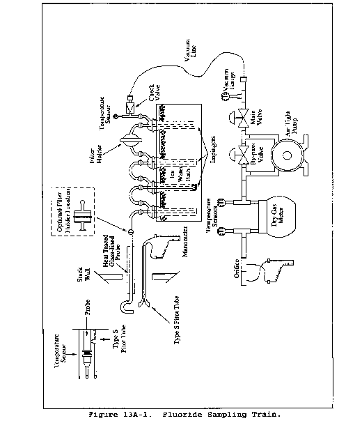
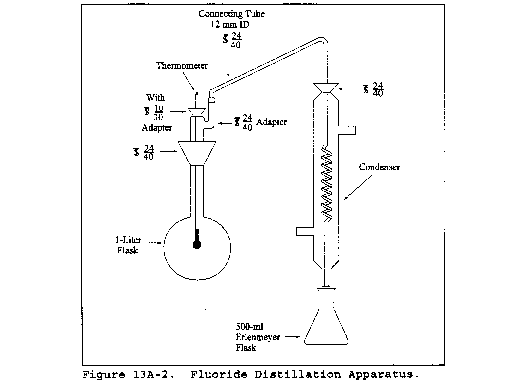
Method 13B - Determination of Total Fluoride Emissions From Stationary Sources (Specific Ion Electrode Method)
This method does not include all of the specifications (e.g., equipment and supplies) and procedures (e.g., sampling and analytical) essential to its performance. Some material is incorporated by reference from other methods in this part. Therefore, to obtain reliable results, persons using this method should have a thorough knowledge of at least the following additional test methods: Method 1, Method 2, Method 3, Method 5, and Method 13A.
1.0 Scope and Application
1.1 Analytes.
| Analyte | CAS No. | Sensitivity |
|---|---|---|
| Total fluorides as Fluorine | 7782-41-4 | Not determined. |
1.2 Applicability. This method is applicable for the determination of fluoride (F−) emissions from sources as specified in the regulations. It does not measure fluorocarbons, such as Freons.
1.3 Data Quality Objectives. Adherence to the requirements of this method will enhance the quality of the data obtained from air pollutant sampling methods.
2.0 Summary
Gaseous and particulate F− are withdrawn isokinetically from the source and collected in water and on a filter. The total F− is then determined by the specific ion electrode method.
3.0 Definitions [Reserved]
4.0 Interferences
Grease on sample-exposed surfaces may cause low F− results because of adsorption.
5.0 Safety
5.1 Disclaimer. This method may involve hazardous materials, operations, and equipment. This test method does not purport to address all of the safety problems associated with its use. It is the responsibility of the user of this test method to establish appropriate safety and health practices and to determine the applicability of regulatory limitations prior to performing this test method.
5.2 Corrosive Reagents. The following reagents are hazardous. Personal protective equipment and safe procedures are useful in preventing chemical splashes. If contact occurs, immediately flush with copious amounts of water at least 15 minutes. Remove clothing under shower and decontaminate. Treat residual chemical burn as thermal burn.
5.2.1 Sodium Hydroxide (NaOH). Causes severe damage to eye tissues and to skin. Inhalation causes irritation to nose, throat, and lungs. Reacts exothermically with limited amounts of water.
5.2.2 Sulfuric Acid (H2SO4). Rapidly destructive to body tissue. Will cause third degree burns. Eye damage may result in blindness. Inhalation may be fatal from spasm of the larynx, usually within 30 minutes. May cause lung tissue damage with edema. 1 mg/m3 for 8 hours will cause lung damage or, in higher concentrations, death. Provide ventilation to limit inhalation. Reacts violently with metals and organics.
6.0 Equipment and Supplies
6.1 Sample Collection and Sample Recovery. Same as Method 13A, sections 6.1 and 6.2, respectively.
6.2 Sample Preparation and Analysis. The following items are required for sample preparation and analysis:
6.2.1 Distillation Apparatus, Bunsen Burner, Electric Muffle Furnace, Crucibles, Beakers, Volumetric Flasks, Erlenmeyer Flasks or Plastic Bottles, Constant Temperature Bath, and Balance. Same as Method 13A, sections 6.3.1 to 6.3.9, respectively.
6.2.2 Fluoride Ion Activity Sensing Electrode.
6.2.3 Reference Electrode. Single junction, sleeve type.
6.2.4 Electrometer. A pH meter with millivolt-scale capable of ±0.1-mv resolution, or a specific ion meter made specifically for specific ion electrode use.
6.2.5 Magnetic Stirrer and Tetrafluoroethylene (TFE) Fluorocarbon-Coated Stirring Bars.
6.2.6 Beakers. Polyethylene, 100-ml.
7.0 Reagents and Standards
Unless otherwise indicated, all reagents are to conform to the specifications established by the Committee on Analytical Reagents of the American Chemical Society, where such specifications are available. Otherwise, use the best available grade.
7.1 Sample Collection and Sample Recovery. Same as Method 13A, sections 7.1 and 7.2, respectively.
7.2 Sample Preparation and Analysis. The following reagents and standards are required for sample analysis:
7.2.1 Calcium Oxide (CaO). Certified grade containing 0.005 percent F− or less.
7.2.2 Phenolphthalein Indicator. Dissolve 0.1 g phenolphthalein in a mixture of 50 ml of 90 percent ethanol and 50 ml water.
7.2.3 Sodium Hydroxide (NaOH), Pellets.
7.2.4 Sulfuric Acid (H2SO4), Concentrated.
7.2.5 Filters. Whatman No. 541, or equivalent.
7.2.6 Water. Same as section 7.1.2 of Method 13A.
7.2.7 Sodium Hydroxide, 5 M. Dissolve 20 g of NaOH in 100 ml of water.
7.2.8 Sulfuric Acid, 25 Percent (v/v). Mix 1 part of concentrated H2SO4 with 3 parts of water.
7.2.9 Total Ionic Strength Adjustment Buffer (TISAB). Place approximately 500 ml of water in a 1-liter beaker. Add 57 ml of glacial acetic acid, 58 g of sodium chloride, and 4 g of cyclohexylene dinitrilo tetraacetic acid. Stir to dissolve. Place the beaker in a water bath and cool to 20 °C (68 °F). Slowly add 5 M NaOH to the solution, measuring the pH continuously with a calibrated pH/reference electrode pair, until the pH is 5.3. Pour into a 1-liter volumetric flask, and dilute to volume with deionized, distilled water. Commercially prepared TISAB may be substituted for the above.
7.2.10 Fluoride Standard Solution, 0.1 M. Oven dry approximately 10 g of sodium fluoride (NaF) for a minimum of 2 hours at 110 °C (230 °F), and store in a desiccator. Then add 4.2 g of NaF to a 1-liter volumetric flask, and add enough water to dissolve. Dilute to volume with water.
8.0 Sample Collection, Preservation, Storage, and Transport
Same as Method 13A, section 8.0.
9.0 Quality Control
9.1 Miscellaneous Quality Control Measures.
| Section | Quality control measure | Effect |
|---|---|---|
| 8.0, 10.1 | Sampling equipment leak-check and calibration | Ensure accurate measurement of stack gas flow rate and sample volume. |
| 10.2 | Fluoride electrode | Evaluate analytical technique, preparation of standards. |
| 11.1 | Interference/recovery efficiency-check during distillation | Minimize negative effects of used acid. |
9.2 Volume Metering System Checks. Same as Method 5, section 9.2.
10.0 Calibration and Standardizations
Maintain a laboratory log of all calibrations.
10.1 Sampling Equipment. Same as Method 13A, section 10.1.
10.2 Fluoride Electrode. Prepare fluoride standardizing solutions by serial dilution of the 0.1 M fluoride standard solution. Pipet 10 ml of 0.1 M fluoride standard solution into a 100-ml volumetric flask, and make up to the mark with water for a 10−2 M standard solution. Use 10 ml of 10−2 M solution to make a 10−3 M solution in the same manner. Repeat the dilution procedure, and make 10−4 and 10−5 M solutions.
10.2.1 Pipet 50 ml of each standard into a separate beaker. Add 50 ml of TISAB to each beaker. Place the electrode in the most dilute standard solution. When a steady millivolt reading is obtained, plot the value on the linear axis of semilog graph paper versus concentration on the log axis. Plot the nominal value for concentration of the standard on the log axis, (e.g., when 50 ml of 10−2 M standard is diluted with 50 ml of TISAB, the concentration is still designated “10−2 M”).
10.2.2 Between measurements, soak the fluoride sensing electrode in water for 30 seconds, and then remove and blot dry. Analyze the standards going from dilute to concentrated standards. A straight-line calibration curve will be obtained, with nominal concentrations of 10−4, 10−3, 10−2, 10−1 fluoride molarity on the log axis plotted versus electrode potential (in mv) on the linear scale. Some electrodes may be slightly nonlinear between 10−5 and 10−4 M. If this occurs, use additional standards between these two concentrations.
10.2.3 Calibrate the fluoride electrode daily, and check it hourly. Prepare fresh fluoride standardizing solutions daily (10−2 M or less). Store fluoride standardizing solutions in polyethylene or polypropylene containers.
Certain specific ion meters have been designed specifically for fluoride electrode use and give a direct readout of fluoride ion concentration. These meters may be used in lieu of calibration curves for fluoride measurements over a narrow concentration ranges. Calibrate the meter according to the manufacturer's instructions.
11.0 Analytical Procedures
11.1 Sample Loss Check, Sample Preparation, and Distillation. Same as Method 13A, sections 11.1 through 11.3, except that the note following section 11.3.1 is not applicable.
11.2 Analysis.
11.2.1 Containers No. 1 and No. 2. Distill suitable aliquots from Containers No. 1 and No. 2. Dilute the distillate in the volumetric flasks to exactly 250 ml with water, and mix thoroughly. Pipet a 25-ml aliquot from each of the distillate into separate beakers. Add an equal volume of TISAB, and mix. The sample should be at the same temperature as the calibration standards when measurements are made. If ambient laboratory temperature fluctuates more than ±2 °C from the temperature at which the calibration standards were measured, condition samples and standards in a constant-temperature bath before measurement. Stir the sample with a magnetic stirrer during measurement to minimize electrode response time. If the stirrer generates enough heat to change solution temperature, place a piece of temperature insulating material, such as cork, between the stirrer and the beaker. Hold dilute samples (below 10−4 M fluoride ion content) in polyethylene beakers during measurement.
11.2.2 Insert the fluoride and reference electrodes into the solution. When a steady millivolt reading is obtained, record it. This may take several minutes. Determine concentration from the calibration curve. Between electrode measurements, rinse the electrode with water.
11.2.3 Container No. 3 (Silica Gel). Same as in Method 13A, section 11.4.2.
12.0 Data Analysis and Calculations
Carry out calculations, retaining at least one extra significant figure beyond that of the acquired data. Round off figures after final calculation.
12.1 Nomenclature. Same as Method 13A, section 12.1, with the addition of the following:
M = F− concentration from calibration curve, molarity.
12.2 Average DGM Temperature and Average Orifice Pressure Drop, Dry Gas Volume, Volume of Water Vapor and Moisture Content, Fluoride Concentration in Stack Gas, and Isokinetic Variation. Same as Method 13A, sections 12.2 to 12.4, 12.6, and 12.7, respectively.
12.3 Total Fluoride in Sample. Calculate the amount of F− in the sample using Equation 13B-1:

Where:
K = 19 [(mg·l)/(mole·ml)] (metric units)
= 0.292 [(gr·l)/(mole·ml)] (English units)
13.0 Method Performance
The following estimates are based on a collaborative test done at a primary aluminum smelter. In the test, six laboratories each sampled the stack simultaneously using two sampling trains for a total of 12 samples per sampling run. Fluoride concentrations encountered during the test ranged from 0.1 to 1.4 mg F−/m3.
13.1 Precision. The intra-laboratory and inter-laboratory standard deviations, which include sampling and analysis errors, are 0.037 mg F−/m3 with 60 degrees of freedom and 0.056 mg F−/m3 with five degrees of freedom, respectively.
13.2 Bias. The collaborative test did not find any bias in the analytical method.
13.3 Range. The range of this method is 0.02 to 2,000 µg F−/ml; however, measurements of less than 0.1 µg F−/ml require extra care.
14.0 Pollution Prevention [Reserved]
15.0 Waste Management [Reserved]
16.0 Alternative Procedures
16.1 Compliance with ASTM D 3270-73T, 91, 95 “Analysis for Fluoride Content of the Atmosphere and Plant Tissues (Semiautomated Method)” is an acceptable alternative for the distillation and analysis requirements specified in sections 11.1 and 11.2 when applied to suitable aliquots of Containers 1 and 2 samples.
17.0 References
Same as Method 13A, section 16.0, References 1 and 2, with the following addition:
1. MacLeod, Kathryn E., and Howard L. Crist. Comparison of the SPADNS-Zirconium Lake and Specific Ion Electrode Methods of Fluoride Determination in Stack Emission Samples. Analytical Chemistry. 45:1272-1273. 1973.
18.0 Tables, Diagrams, Flowcharts, and Validation Data [Reserved]
Method 14 - Determination of Fluoride Emissions From Potroom Roof Monitors for Primary Aluminum Plants
This method does not include all of the specifications (e.g., equipment and supplies) and procedures (e.g., sampling and analytical) essential to its performance. Some material is incorporated by reference from other methods in this part. Therefore, to obtain reliable results, persons using this method should have a thorough knowledge of at least the following additional test methods: Method 1, Method 2, Method 3, Method 5, Method 13A, and Method 13B.
1.0 Scope and Application
1.1 Analytes.
| Analyte | CAS No. | Sensitivity |
|---|---|---|
| Total fluorides as Fluorine | 7782-41-4 | Not determined. |
1.2 Applicability. This method is applicable for the determination of fluoride emissions from roof monitors at primary aluminum reduction plant potroom groups.
1.3 Data Quality Objectives. Adherence to the requirements of this method will enhance the quality of the data obtained from air pollutant sampling methods.
2.0 Summary of Method
2.1 Gaseous and particulate fluoride roof monitor emissions are drawn into a permanent sampling manifold through several large nozzles. The sample is transported from the sampling manifold to ground level through a duct. The fluoride content of the gas in the duct is determined using either Method 13A or Method 13B. Effluent velocity and volumetric flow rate are determined using anemometers located in the roof monitor.
3.0 Definitions
Potroom means a building unit which houses a group of electrolytic cells in which aluminum is produced.
Potroom group means an uncontrolled potroom, a potroom which is controlled individually, or a group of potrooms or potroom segments ducted to a common control system.
Roof monitor means that portion of the roof of a potroom where gases not captured at the cell exit from the potroom.
4.0 Interferences
Same as section 4.0 of either Method 13A or Method 13B, with the addition of the following:
4.1 Magnetic Field Effects. Anemometer readings can be affected by potroom magnetic field effects. section 6.1 provides for minimization of this interference through proper shielding or encasement of anemometer components.
5.0 Safety
5.1 Disclaimer. This method may involve hazardous materials, operations, and equipment. This test method may not address all of the safety problems associated with its use. It is the responsibility of the user of this test method to establish appropriate safety and health practices and to determine the applicability of regulatory limitations prior to performing this test method.
5.2 Corrosive Reagents. Same as section 5.2 of either Method 13A or Method 13B.
6.0 Equipment and Supplies
Same as section 6.0 of either Method 13A or Method 13B, as applicable, with the addition of the following:
6.1 Velocity Measurement Apparatus.
6.1.1 Anemometer Specifications. Propeller anemometers, or equivalent. Each anemometer shall meet the following specifications:
6.1.1.1 Its propeller shall be made of polystyrene, or similar material of uniform density. To ensure uniformity of performance among propellers, it is desirable that all propellers be made from the same mold.
6.1.1.2 The propeller shall be properly balanced, to optimize performance.
6.1.1.3 When the anemometer is mounted horizontally, its threshold velocity shall not exceed 15 m/min (50 ft/min).
6.1.1.4 The measurement range of the anemometer shall extend to at least 600 m/min (2,000 ft/min).
6.1.1.5 The anemometer shall be able to withstand prolonged exposure to dusty and corrosive environments; one way of achieving this is to purge the bearings of the anemometer continuously with filtered air during operation.
6.1.1.6 All anemometer components shall be properly shielded or encased, such that the performance of the anemometer is uninfluenced by potroom magnetic field effects.
6.1.1.7 A known relationship shall exist between the electrical output signal from the anemometer generator and the propeller shaft rpm (see section 10.2.1). Anemometers having other types of output signals (e.g., optical) may be used, subject to the approval of the Administrator. If other types of anemometers are used, there must be a known relationship between output signal and shaft rpm (see section 10.2.2).
6.1.1.8 Each anemometer shall be equipped with a suitable readout system (see section 6.1.3).
6.1.2 Anemometer Installation Requirements.
6.1.2.1 Single, Isolated Potroom. If the affected facility consists of a single, isolated potroom (or potroom segment), install at least one anemometer for every 85 m (280 ft) of roof monitor length. If the length of the roof monitor divided by 85 m (280 ft) is not a whole number, round the fraction to the nearest whole number to determine the number of anemometers needed. For monitors that are less than 130 m (430 ft) in length, use at least two anemometers. Divide the monitor cross-section into as many equal areas as anemometers, and locate an anemometer at the centroid of each equal area. See exception in section 6.1.2.3.
6.1.2.2 Two or More Potrooms. If the affected facility consists of two or more potrooms (or potroom segments) ducted to a common control device, install anemometers in each potroom (or segment) that contains a sampling manifold. Install at least one anemometer for every 85 m (280 ft) of roof monitor length of the potroom (or segment). If the potroom (or segment) length divided by 85 m (280 ft) is not a whole number, round the fraction to the nearest whole number to determine the number of anemometers needed. If the potroom (or segment) length is less than 130 m (430 ft), use at least two anemometers. Divide the potroom (or segment) monitor cross-section into as many equal areas as anemometers, and locate an anemometer at the centroid of each equal area. See exception in section 6.1.2.3.
6.1.2.3 Placement of Anemometer at the Center of Manifold. At least one anemometer shall be installed in the immediate vicinity (i.e., within 10 m (33 ft)) of the center of the manifold (see section 6.2.1). For its placement in relation to the width of the monitor, there are two alternatives. The first is to make a velocity traverse of the width of the roof monitor where an anemometer is to be placed and install the anemometer at a point of average velocity along this traverse. The traverse may be made with any suitable low velocity measuring device, and shall be made during normal process operating conditions. The second alternative is to install the anemometer half-way across the width of the roof monitor. In this latter case, the velocity traverse need not be conducted.
6.1.3 Recorders. Recorders that are equipped with suitable auxiliary equipment (e.g., transducers) for converting the output signal from each anemometer to a continuous recording of air flow velocity or to an integrated measure of volumetric flowrate shall be used. A suitable recorder is one that allows the output signal from the propeller anemometer to be read to within 1 percent when the velocity is between 100 and 120 m/min (330 and 390 ft/min). For the purpose of recording velocity, “continuous” shall mean one readout per 15-minute or shorter time interval. A constant amount of time shall elapse between readings. Volumetric flow rate may be determined by an electrical count of anemometer revolutions. The recorders or counters shall permit identification of the velocities or flowrates measured by each individual anemometer.
6.1.4 Pitot Tube. Standard-type pitot tube, as described in section 6.7 of Method 2, and having a coefficient of 0.99 ±0.01.
6.1.5 Pitot Tube (Optional). Isolated, Type S pitot, as described in section 6.1 of Method 2, and having a known coefficient, determined as outlined in section 4.1 of Method 2.
6.1.6 Differential Pressure Gauge. Inclined manometer, or equivalent, as described in section 6.1.2 of Method 2.
6.2 Roof Monitor Air Sampling System.
6.2.1 Manifold System and Ductwork. A minimum of one manifold system shall be installed for each potroom group. The manifold system and ductwork shall meet the following specifications:
6.2.1.1 The manifold system and connecting duct shall be permanently installed to draw an air sample from the roof monitor to ground level. A typical installation of a duct for drawing a sample from a roof monitor to ground level is shown in Figure 14-1 in section 17.0. A plan of a manifold system that is located in a roof monitor is shown in Figure 14-2. These drawings represent a typical installation for a generalized roof monitor. The dimensions on these figures may be altered slightly to make the manifold system fit into a particular roof monitor, but the general configuration shall be followed.
6.2.1.2 There shall be eight nozzles, each having a diameter of 0.40 to 0.50 m.
6.2.1.3 The length of the manifold system from the first nozzle to the eighth shall be 35 m (115 ft) or eight percent of the length of the potroom (or potroom segment) roof monitor, whichever is greater. Deviation from this requirement is subject to the approval of the Administrator.
6.2.1.4 The duct leading from the roof monitor manifold system shall be round with a diameter of 0.30 to 0.40 m (1.0 to 1.3 ft). All connections in the ductwork shall be leak-free.
6.2.1.5 As shown in Figure 14-2, each of the sample legs of the manifold shall have a device, such as a blast gate or valve, to enable adjustment of the flow into each sample nozzle.
6.2.1.6 The manifold system shall be located in the immediate vicinity of one of the propeller anemometers (see section 8.1.1.4) and as close as possible to the midsection of the potroom (or potroom segment). Avoid locating the manifold system near the end of a potroom or in a section where the aluminum reduction pot arrangement is not typical of the rest of the potroom (or potroom segment). The sample nozzles shall be centered in the throat of the roof monitor (see Figure 14-1).
6.2.1.7 All sample-exposed surfaces within the nozzles, manifold, and sample duct shall be constructed with 316 stainless steel. Alternatively, aluminum may be used if a new ductwork is conditioned with fluoride-laden roof monitor air for a period of six weeks before initial testing. Other materials of construction may be used if it is demonstrated through comparative testing, to the satisfaction of the Administrator, that there is no loss of fluorides in the system.
6.2.1.8 Two sample ports shall be located in a vertical section of the duct between the roof monitor and the exhaust fan (see section 6.2.2). The sample ports shall be at least 10 duct diameters downstream and three diameters upstream from any flow disturbance such as a bend or contraction. The two sample ports shall be situated 90° apart. One of the sample ports shall be situated so that the duct can be traversed in the plane of the nearest upstream duct bend.
6.2.2 Exhaust Fan. An industrial fan or blower shall be attached to the sample duct at ground level (see Figure 14-1). This exhaust fan shall have a capacity such that a large enough volume of air can be pulled through the ductwork to maintain an isokinetic sampling rate in all the sample nozzles for all flow rates normally encountered in the roof monitor. The exhaust fan volumetric flow rate shall be adjustable so that the roof monitor gases can be drawn isokinetically into the sample nozzles. This control of flow may be achieved by a damper on the inlet to the exhauster or by any other workable method.
6.3 Temperature Measurement Apparatus. To monitor and record the temperature of the roof monitor effluent gas, and consisting of the following:
6.3.1 Temperature Sensor. A temperature sensor shall be installed in the roof monitor near the sample duct. The temperature sensor shall conform to the specifications outlined in Method 2, section 6.3.
6.3.2 Signal Transducer. Transducer, to change the temperature sensor voltage output to a temperature readout.
6.3.3 Thermocouple Wire. To reach from roof monitor to signal transducer and recorder.
6.3.4 Recorder. Suitable recorder to monitor the output from the thermocouple signal transducer.
7.0 Reagents and Standards
Same as section 7.0 of either Method 13A or Method 13B, as applicable.
8.0 Sample Collection, Preservation, Storage, and Transport
8.1 Roof Monitor Velocity Determination.
8.1.1 Velocity Estimate(s) for Setting Isokinetic Flow. To assist in setting isokinetic flow in the manifold sample nozzles, the anticipated average velocity in the section of the roof monitor containing the sampling manifold shall be estimated before each test run. Any convenient means to make this estimate may be used (e.g., the velocity indicated by the anemometer in the section of the roof monitor containing the sampling manifold may be continuously monitored during the 24-hour period before the test run). If there is question as to whether a single estimate of average velocity is adequate for an entire test run (e.g., if velocities are anticipated to be significantly different during different potroom operations), the test run may be divided into two or more “sub-runs,” and a different estimated average velocity may be used for each sub-run (see section 8.4.2).
8.1.2 Velocity Determination During a Test Run. During the actual test run, record the velocity or volumetric flowrate readings of each propeller anemometer in the roof monitor. Readings shall be taken from each anemometer at equal time intervals of 15 minutes or less (or continuously).
8.2 Temperature Recording. Record the temperature of the roof monitor effluent gases at least once every 2 hours during the test run.
8.3 Pretest Ductwork Conditioning. During the 24-hour period immediately preceding the test run, turn on the exhaust fan, and draw roof monitor air through the manifold system and ductwork. Adjust the fan to draw a volumetric flow through the duct such that the velocity of gas entering the manifold nozzles approximates the average velocity of the air exiting the roof monitor in the vicinity of the sampling manifold.
8.4 Manifold Isokinetic Sample Rate Adjustment(s).
8.4.1 Initial Adjustment. Before the test run (or first sub-run, if applicable; see sections 8.1.1 and 8.4.2), adjust the fan such that air enters the manifold sample nozzles at a velocity equal to the appropriate estimated average velocity determined under section 8.1.1. Use Equation 14-1 (Section 12.2.2) to determine the correct stream velocity needed in the duct at the sampling location, in order for sample gas to be drawn isokinetically into the manifold nozzles. Next, verify that the correct stream velocity has been achieved, by performing a pitot tube traverse of the sample duct (using either a standard or Type S pitot tube); use the procedure outlined in Method 2.
8.4.2 Adjustments During Run. If the test run is divided into two or more “sub-runs” (see section 8.1.1), additional isokinetic rate adjustment(s) may become necessary during the run. Any such adjustment shall be made just before the start of a sub-run, using the procedure outlined in section 8.4.1 above.
Isokinetic rate adjustments are not permissible during a sub-run.
8.5 Pretest Preparation, Preliminary Determinations, Preparation of Sampling Train, Leak-Check Procedures, Sampling Train Operation, and Sample Recovery. Same as Method 13A, sections 8.1 through 8.6, with the exception of the following:
8.5.1 A single train shall be used for the entire sampling run. Alternatively, if two or more sub-runs are performed, a separate train may be used for each sub-run; note, however, that if this option is chosen, the area of the sampling nozzle shall be the same (±2 percent) for each train. If the test run is divided into sub-runs, a complete traverse of the duct shall be performed during each sub-run.
8.5.2 Time Per Run. Each test run shall last 8 hours or more; if more than one run is to be performed, all runs shall be of approximately the same (±10 percent) length. If questions exist as to the representativeness of an 8-hour test, a longer period should be selected. Conduct each run during a period when all normal operations are performed underneath the sampling manifold. For most recently-constructed plants, 24 hours are required for all potroom operations and events to occur in the area beneath the sampling manifold. During the test period, all pots in the potroom group shall be operated such that emissions are representative of normal operating conditions in the potroom group.
9.0 Quality Control
9.1 Miscellaneous Quality Control Measures.
| Section | Quality Control Measure | Effect |
|---|---|---|
| 8.0, 10.0 | Sampling equipment leak-check and calibration | Ensure accurate measurement of gas flow rate in duct and of sample volume. |
| 10.3, 10.4 | Initial and periodic performance checks of roof monitor effluent gas characterization apparatus | Ensure accurate and precise measurement of roof monitor effluent gas temperature and flow rate. |
| 11.0 | Interference/recovery efficiency check during distillation | Minimize negative effects of used acid. |
9.2 Volume Metering System Checks. Same as Method 5, section 9.2.
10.0 Calibration and Standardization
Same as section 10.0 of either Method 13A or Method 13B, as applicable, with the addition of the following:
10.1 Manifold Intake Nozzles. The manifold intake nozzles shall be calibrated when the manifold system is installed or, alternatively, the manifold may be preassembled and the nozzles calibrated on the ground prior to installation. The following procedures shall be observed:
10.1.1 Adjust the exhaust fan to draw a volumetric flow rate (refer to Equation 14-1) such that the entrance velocity into each manifold nozzle approximates the average effluent velocity in the roof monitor.
10.1.2 Measure the velocity of the air entering each nozzle by inserting a standard pitot tube into a 2.5 cm or less diameter hole (see Figure 14-2) located in the manifold between each blast gate (or valve) and nozzle. Note that a standard pitot tube is used, rather than a type S, to eliminate possible velocity measurement errors due to cross-section blockage in the small (0.13 m diameter) manifold leg ducts. The pitot tube tip shall be positioned at the center of each manifold leg duct. Take care to ensure that there is no leakage around the pitot tube, which could affect the indicated velocity in the manifold leg.
10.1.3 If the velocity of air being drawn into each nozzle is not the same, open or close each blast gate (or valve) until the velocity in each nozzle is the same. Fasten each blast gate (or valve) so that it will remain in position, and close the pitot port holes.
10.2 Initial Calibration of Propeller Anemometers.
10.2.1 Anemometers that meet the specifications outlined in section 6.1.1 need not be calibrated, provided that a reference performance curve relating anemometer signal output to air velocity (covering the velocity range of interest) is available from the manufacturer. If a reference performance curve is not available from the manufacturer, such a curve shall be generated.
For the purpose of this method, a “reference” performance curve is defined as one that has been derived from primary standard calibration data, with the anemometer mounted vertically. “Primary standard” data are obtainable by: (a) direct calibration of one or more of the anemometers by the National Institute of Standards and Technology (NIST); (b) NIST-traceable calibration; or (c) Calibration by direct measurement of fundamental parameters such as length and time (e.g., by moving the anemometers through still air at measured rates of speed, and recording the output signals).
10.2.2 Anemometers having output signals other than electrical (e.g., optical) may be used, subject to the approval of the Administrator. If other types of anemometers are used, a reference performance curve shall be generated, using procedures subject to the approval of the Administrator.
10.2.3 The reference performance curve shall be derived from at least the following three points: 60 ±15, 900 ±100, and 1800 ±100 rpm.
10.3 Initial Performance Checks. Conduct these checks within 60 days before the first performance test.
10.3.1 Anemometers. A performance-check shall be conducted as outlined in sections 10.3.1.1 through 10.3.1.3. Alternatively, any other suitable method that takes into account the signal output, propeller condition, and threshold velocity of the anemometer may be used, subject to the approval of the Administrator.
10.3.1.1 Check the signal output of the anemometer by using an accurate rpm generator (see Figure 14-3) or synchronous motors to spin the propeller shaft at each of the three rpm settings described in section 10.2.3, and measuring the output signal at each setting. If, at each setting, the output signal is within 5 percent of the manufacturer's value, the anemometer can be used. If the anemometer performance is unsatisfactory, the anemometer shall either be replaced or repaired.
10.3.1.2 Check the propeller condition, by visually inspecting the propeller, making note of any significant damage or warpage; damaged or deformed propellers shall be replaced.
10.3.1.3 Check the anemometer threshold velocity as follows: With the anemometer mounted as shown in Figure 14-4(A), fasten a known weight (a straight-pin will suffice) to the anemometer propeller at a fixed distance from the center of the propeller shaft. This will generate a known torque; for example, a 0.1-g weight, placed 10 cm from the center of the shaft, will generate a torque of 1.0 g-cm. If the known torque causes the propeller to rotate downward, approximately 90° [see Figure 14-4(B)], then the known torque is greater than or equal to the starting torque; if the propeller fails to rotate approximately 90°, the known torque is less than the starting torque. By trying different combinations of weight and distance, the starting torque of a particular anemometer can be satisfactorily estimated. Once an estimate of the starting torque has been obtained, the threshold velocity of the anemometer (for horizontal mounting) can be estimated from a graph such as Figure 14-5 (obtained from the manufacturer). If the horizontal threshold velocity is acceptable [<15 m/min (50 ft/min), when this technique is used], the anemometer can be used. If the threshold velocity of an anemometer is found to be unacceptably high, the anemometer shall either be replaced or repaired.
10.3.2 Recorders and Counters. Check the calibration of each recorder and counter (see section 6.1.2) at a minimum of three points, approximately spanning the expected range of velocities. Use the calibration procedures recommended by the manufacturer, or other suitable procedures (subject to the approval of the Administrator). If a recorder or counter is found to be out of calibration by an average amount greater than 5 percent for the three calibration points, replace or repair the system; otherwise, the system can be used.
10.3.3 Temperature Measurement Apparatus. Check the calibration of the Temperature Measurement Apparatus, using the procedures outlined in section 10.3 of Method 2, at temperatures of 0, 100, and 150 °C (32, 212, and 302 °F). If the calibration is off by more than 5 °C (9 °F) at any of the temperatures, repair or replace the apparatus; otherwise, the apparatus can be used.
10.4 Periodic Performance Checks. Repeat the procedures outlined in section 10.3 no more than 12 months after the initial performance checks. If the above systems pass the performance checks (i.e., if no repair or replacement of any component is necessary), continue with the performance checks on a 12-month interval basis. However, if any of the above systems fail the performance checks, repair or replace the system(s) that failed, and conduct the periodic performance checks on a 3-month interval basis, until sufficient information (to the satisfaction of the Administrator) is obtained to establish a modified performance check schedule and calculation procedure.
If any of the above systems fails the 12-month periodic performance checks, the data for the past year need not be recalculated.
11.0 Analytical Procedures
Same as section 11.0 of either Method 13A or Method 13B.
12.0 Data Analysis and Calculations
Same as section 12.0 of either Method 13A or Method 13B, as applicable, with the following additions and exceptions:
12.1 Nomenclature.
A = Roof monitor open area, m2 (ft2).
Bws = Water vapor in the gas stream, portion by volume.
Cs = Average fluoride concentration in roof monitor air, mg F/dscm (gr/dscf).
Dd = Diameter of duct at sampling location, m (ft).
Dn = Diameter of a roof monitor manifold nozzle, m (ft).
F = Emission Rate multiplication factor, dimensionless.
Ft = Total fluoride mass collected during a particular sub-run (from Equation 13A-1 of Method 13A or Equation 13B-1 of Method 13B), mg F− (gr F−).
Md = Mole fraction of dry gas, dimensionless.
Prm = Pressure in the roof monitor; equal to barometric pressure for this application.
Qsd = Average volumetric flow from roof monitor at standard conditions on a dry basis, m3/min.
Trm = Average roof monitor temperature (from section 8.2), °C ( °F).
Vd = Desired velocity in duct at sampling location, m/sec.
Vm = Anticipated average velocity (from section 8.1.1) in sampling duct, m/sec.
Vmt = Arithmetic mean roof monitor effluent gas velocity, m/sec.
Vs = Actual average velocity in the sampling duct (from Equation 2-9 of Method 2 and data obtained from Method 13A or 13B), m/sec.
12.2 Isokinetic Sampling Check.
12.2.1 Calculate the arithmetic mean of the roof monitor effluent gas velocity readings (vm) as measured by the anemometer in the section of the roof monitor containing the sampling manifold. If two or more sub-runs have been performed, the average velocity for each sub-run may be calculated separately.
12.2.2 Calculate the expected average velocity (vd) in the duct, corresponding to each value of vm obtained under section 12.2.1, using Equation 14-1.

Where:
8 = number of required manifold nozzles.
60 = sec/min.
12.2.3 Calculate the actual average velocity (vs) in the sampling duct for each run or sub-run according to Equation 2-9 of Method 2, using data obtained during sampling (Section 8.0 of Method 13A).
12.2.4 Express each vs value from section 12.2.3 as a percentage of the corresponding vd value from section 12.2.2.
12.2.4.1 If vs is less than or equal to 120 percent of vd, the results are acceptable (note that in cases where the above calculations have been performed for each sub-run, the results are acceptable if the average percentage for all sub-runs is less than or equal to 120 percent).
12.2.4.2 If vs is more than 120 percent of vd, multiply the reported emission rate by the following factor:

12.3 Average Velocity of Roof Monitor Effluent Gas. Calculate the arithmetic mean roof monitor effluent gas velocity (vmt) using all the velocity or volumetric flow readings from section 8.1.2.
12.4 Average Temperature of Roof Monitor Effluent Gas. Calculate the arithmetic mean roof monitor effluent gas temperature (Tm) using all the temperature readings recorded in section 8.2.
12.5 Concentration of Fluorides in Roof Monitor Effluent Gas.
12.5.1 If a single sampling train was used throughout the run, calculate the average fluoride concentration for the roof monitor using Equation 13A-2 of Method 13A.
12.5.2 If two or more sampling trains were used (i.e., one per sub-run), calculate the average fluoride concentration for the run using Equation 14-3:

Where:
n = Total number of sub-runs.
12.6 Mole Fraction of Dry Gas.

12.7 Average Volumetric Flow Rate of Roof Monitor Effluent Gas. Calculate the arithmetic mean volumetric flow rate of the roof monitor effluent gases using Equation 14-5.

Where:
K1 = 0.3858 K/mm Hg for metric units,
= 17.64 °R/in. Hg for English units.
13.0 Method Performance [Reserved]
14.0 Pollution Prevention [Reserved]
15.0 Waste Management [Reserved]
16.0 References
Same as section 16.0 of either Method 13A or Method 13B, as applicable, with the addition of the following:
1. Shigehara, R.T. A Guideline for Evaluating Compliance Test Results (Isokinetic Sampling Rate Criterion). U.S. Environmental Protection Agency, Emission Measurement Branch, Research Triangle Park, NC. August 1977.
17.0 Tables, Diagrams, Flowcharts, and Validation Data
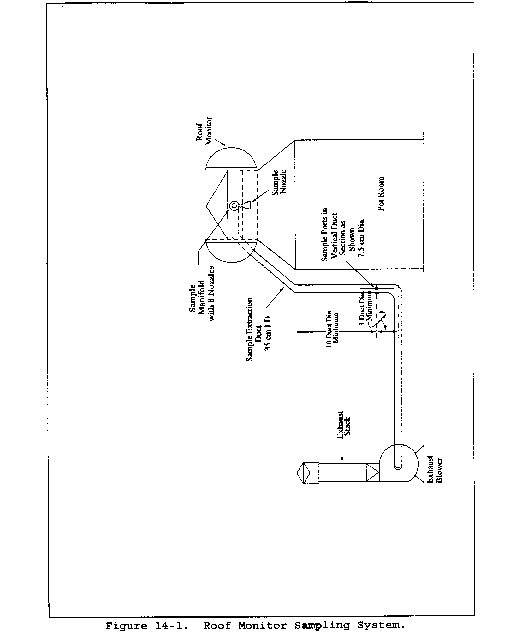

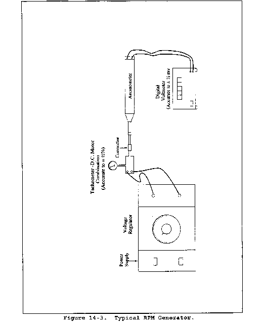
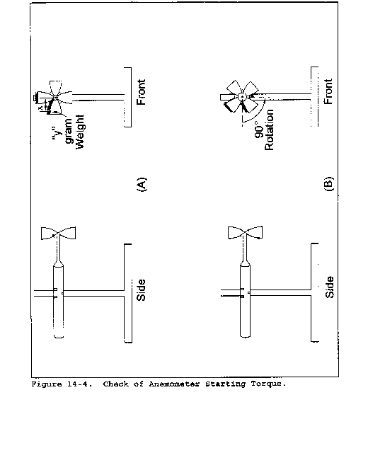

Method 14A - Determination of Total Fluoride Emissions from Selected Sources at Primary Aluminum Production Facilities
This method does not include all the specifications (e.g., equipment and supplies) and procedures (e.g., sampling) essential to its performance. Some material is incorporated by reference from other methods in this part. Therefore, to obtain reliable results, persons using this method should have a thorough knowledge of at least the following additional test methods: Method 5, Methods 13A and 13B, and Method 14 of this appendix.
1.0 Scope and Application
1.1 Analytes.
| Analyte | CAS No. | Sensitivity |
|---|---|---|
| Total fluorides | None assigned | Not determined. |
| Includes hydrogen fluoride | 007664-39-3 | Not determined. |
1.2 Applicability. This method is applicable for the determination of total fluorides (TF) emissions from sources specified in the applicable regulation. This method was developed by consensus with the Aluminum Association and the U.S. Environmental Protection Agency (EPA).
2.0 Summary of Method
2.1 Total fluorides, in the form of solid and gaseous fluorides, are withdrawn from the ascending air stream inside of an aluminum reduction potroom and, prior to exiting the potroom roof monitor, into a specific cassette arrangement. The cassettes are connected by tubing to flowmeters and a manifold system that allows for the equal distribution of volume pulled through each cassette, and finally to a dry gas meter. The cassettes have a specific internal arrangement of one unaltered cellulose filter and support pad in the first section of the cassette for solid fluoride retention and two cellulose filters with support pads that are impregnated with sodium formate for the chemical absorption of gaseous fluorides in the following two sections of the cassette. A minimum of eight cassettes shall be used for a potline and shall be strategically located at equal intervals across the potroom roof so as to encompass a minimum of 8 percent of the total length of the potroom. A greater number of cassettes may be used should the regulated facility choose to do so. The mass flow rate of pollutants is determined with anemometers and temperature sensing devices located immediately below the opening of the roof monitor and spaced evenly within the cassette group.
3.0 Definitions
3.1 Cassette. A segmented, styrene acrylonitrile cassette configuration with three separate segments and a base, for the purpose of this method, to capture and retain fluoride from potroom gases.
3.2 Cassette arrangement. The cassettes, tubing, manifold system, flowmeters, dry gas meter, and any other related equipment associated with the actual extraction of the sample gas stream.
3.3 Cassette group. That section of the potroom roof monitor where a distinct group of cassettes is located.
3.4 Potline. A single, discrete group of electrolytic reduction cells electrically connected in series, in which alumina is reduced to form aluminum.
3.5 Potroom. A building unit that houses a group of electrolytic reduction cells in which aluminum is produced.
3.6 Potroom group. An uncontrolled potroom, a potroom that is controlled individually, or a group of potrooms or potroom segments ducted to a common primary control system.
3.7 Primary control system. The equipment used to capture the gases and particulate matter generated during the reduction process and the emission control device(s) used to remove pollutants prior to discharge of the cleaned gas to the atmosphere.
3.8 Roof monitor. That portion of the roof of a potroom building where gases, not captured at the cell, exit from the potroom.
3.9 Total fluorides (TF). Elemental fluorine and all fluoride compounds as measured by Methods 13A or 13B of this appendix or by an approved alternative method.
4.0 Interferences and Known Limitations
4.1 There are two principal categories of limitations that must be addressed when using this method. The first category is sampling bias and the second is analytical bias. Biases in sampling can occur when there is an insufficient number of cassettes located along the roof monitor of a potroom or if the distribution of those cassettes is spatially unequal. Known sampling biases also can occur when there are leaks within the cassette arrangement and if anemometers and temperature devices are not providing accurate data. Applicable instruments must be properly calibrated to avoid sampling bias. Analytical biases can occur when instrumentation is not calibrated or fails calibration and the instrument is used out of proper calibration. Additionally, biases can occur in the laboratory if fusion crucibles retain residual fluorides over lengthy periods of use. This condition could result in falsely elevated fluoride values. Maintaining a clean work environment in the laboratory is crucial to producing accurate values.
4.2 Biases during sampling can be avoided by properly spacing the appropriate number of cassettes along the roof monitor, conducting leak checks of the cassette arrangement, calibrating the dry gas meter every 30 days, verifying the accuracy of individual flowmeters (so that there is no more than 5 percent difference in the volume pulled between any two flowmeters), and calibrating or replacing anemometers and temperature sensing devices as necessary to maintain true data generation.
4.3 Analytical biases can be avoided by calibrating instruments according to the manufacturer's specifications prior to conducting any analyses, by performing internal and external audits of up to 10 percent of all samples analyzed, and by rotating individual crucibles as the “blank” crucible to detect any potential residual fluoride carry-over to samples. Should any contamination be discovered in the blank crucible, the crucible shall be thoroughly cleaned to remove any detected residual fluorides and a “blank” analysis conducted again to evaluate the effectiveness of the cleaning. The crucible shall remain in service as long as no detectable residual fluorides are present.
5.0 Safety
5.1 This method may involve the handling of hazardous materials in the analytical phase. This method does not purport to address all of the potential safety hazards associated with its use. It is the responsibility of the user to establish appropriate safety and health practices and determine the applicability of regulatory limitations prior to performing this test method.
5.2 Corrosive reagents. The following reagents are hazardous. Personal protective equipment and safe procedures are useful in preventing chemical splashes. If contact occurs, immediately flush with copious amounts of water for at least 15 minutes. Remove clothing under shower and decontaminate. Treat residual chemical burn as thermal burn.
5.3 Sodium Hydroxide (NaOH). Causes severe damage to eyes and skin. Inhalation causes irritation to nose, throat, and lungs. Reacts exothermically with limited amounts of water.
5.4 Perchloric Acid (HClO4). Corrosive to eyes, skin, nose, and throat. Provide ventilation to limit exposure. Very strong oxidizer. Keep separate from water and oxidizable materials to prevent vigorous evolution of heat, spontaneous combustion, or explosion. Heat solutions containing HClO4 only in hoods specifically designed for HClO4.
6.0 Equipment and Supplies
6.1 Sampling.
6.1.1 Cassette arrangement. The cassette itself is a three-piece, styrene acrylonitrile cassette unit (a Gelman Sciences product), 37 millimeter (mm), with plastic connectors. In the first section (the intake section), an untreated Gelman Sciences 37 mm, 0.8 micrometer (µm) DM-800 metricel membrane filter and cellulose support pad, or equivalent, is situated. In the second and third segments of the cassette there is placed one each of Gelman Sciences 37 mm, 5 µm GLA-5000 low-ash PVC filter with a cellulose support pad or equivalent product. Each of these two filters and support pads shall have been immersed in a solution of 10 percent sodium formate (volume/volume in an ethyl alcohol solution). The impregnated pads shall be placed in the cassette segments while still wet and heated at 50 °C (122 °F) until the pad is completely dry. It is important to check for a proper fit of the filter and support pad to the cassette segment to ensure that there are no areas where gases could bypass the filter. Once all of the cassette segments have been prepared, the cassette shall be assembled and a plastic plug shall be inserted into the exhaust hole of the cassette. Prior to placing the cassette into service, the space between each segment shall be taped with an appropriately durable tape to prevent the infiltration of gases through the points of connection, and an aluminum nozzle shall be inserted into the intake hole of the cassette. The aluminum nozzle shall have a short section of tubing placed over the opening of the nozzle, with the tubing plugged to prevent dust from entering the nozzle and to prepare the nozzle for the cassette arrangement leak check. An alternate nozzle type can be used if historical results or scientific demonstration of applicability can be shown.
6.1.2 Anemometers and temperature sensing devices. To calculate the mass flow rate of TF from the roof monitor under standard conditions, anemometers that meet the specifications in section 2.1.1 in Method 14 of this appendix or an equivalent device yielding equivalent information shall be used. A recording mechanism capable of accurately recording the exit gas temperature at least every 2 hours shall be used.
6.1.3 Barometer. To correct the volumetric flow from the potline roof monitor to standard conditions, a mercury (Hg), aneroid, or other barometer capable of measuring atmospheric pressure to within 2.5 mm [0.1 inch (in)] Hg shall be used.
The barometric reading may be obtained from a nearby National Weather Service Station. In this case, the station value (which is absolute barometric pressure) shall be requested and an adjustment for elevation differences between the weather station and the sampling point shall be made at a rate of minus 2.5 mm (0.1 in) Hg per 30 meters (m) [100 feet (ft)] elevation increase or plus 2.5 mm (0.1 in) Hg per 30 m (100 ft) elevation decrease.
6.2 Sample recovery.
6.2.1 Hot plate.
6.2.2 Muffle furnace.
6.2.3 Nickel crucible.
6.2.4 Stirring rod. Teflon.
6.2.5 Volumetric flask. 50-milliliter (ml).
6.2.6 Plastic vial. 50-ml.
6.3 Analysis.
6.3.1 Primary analytical method. An automated analyzer having the following components or equivalent: a multichannel proportioning pump, multiposition sampler, voltage stabilizer, colorimeter, instrument recording device, microdistillation apparatus, flexible Teflon ® heating bath, vacuum pump, pulse suppressers and an air flow system.
6.3.2 Secondary analytical method. Specific Ion Electrode (SIE).
7.0 Reagents and Standards
7.1 Water. Deionized distilled to conform to ASTM Specification D 1193-77, Type 3 (incorporated by reference in § 60.17(a)(22) of this part). The KMnO4 test for oxidizable organic matter may be omitted when high concentrations of organic matter are not expected to be present.
7.2 Calcium oxide.
7.3 Sodium hydroxide (NaOH). Pellets.
7.4 Perchloric acid (HClO4). Mix 1:1 with water. Sulfuric acid (H2SO4) may be used in place of HClO4.
7.5 Audit samples. The audit samples discussed in section 9.1 shall be prepared from reagent grade, water soluble stock reagents, or purchased as an aqueous solution from a commercial supplier. If the audit stock solution is purchased from a commercial supplier, the standard solution must be accompanied by a certificate of analysis or an equivalent proof of fluoride concentration.
8.0 Sample Collection and Analysis
8.1 Preparing cassette arrangement for sampling. The cassettes are initially connected to flexible tubing. The tubing is connected to flowmeters and a manifold system. The manifold system is connected to a dry gas meter (Research Appliance Company model 201009 or equivalent). The length of tubing is managed by pneumatically or electrically operated hoists located in the roof monitor, and the travel of the tubing is controlled by encasing the tubing in aluminum conduit. The tubing is lowered for cassette insertion by operating a control box at floor level. Once the cassette has been securely inserted into the tubing and the leak check performed, the tubing and cassette are raised to the roof monitor level using the floor level control box. Arrangements similar to the one described are acceptable if the scientific sample collection principles are followed.
8.2 Test run sampling period. A test run shall comprise a minimum of a 24-hour sampling event encompassing at least eight cassettes per potline (or four cassettes per potroom group). Monthly compliance shall be based on three test runs during the month. Test runs of greater than 24 hours are allowed; however, three such runs shall be conducted during the month.
8.3 Leak-check procedures.
8.3.1 Pretest leak check. A pretest leak-check is recommended; however, it is not required. To perform a pretest leak-check after the cassettes have been inserted into the tubing, isolate the cassette to be leak-checked by turning the valves on the manifold to stop all flows to the other sampling points connected to the manifold and meter. The cassette, with the plugged tubing section securing the intake of the nozzle, is subjected to the highest vacuum expected during the run. If no leaks are detected, the tubing plug can be briefly removed as the dry gas meter is rapidly turned off.
8.3.2 Post-test leak check. A leak check is required at the conclusion of each test run for each cassette. The leak check shall be performed in accordance with the procedure outlined in section 8.3.1 of this method except that it shall be performed at a vacuum greater than the maximum vacuum reached during the test run. If the leakage rate is found to be no greater than 4 percent of the average sampling rate, the results are acceptable. If the leakage rate is greater than 4 percent of the average sampling rate, either record the leakage rate and correct the sampling volume as discussed in section 12.4 of this method or void the test run if the minimum number of cassettes were used. If the number of cassettes used was greater than the minimum required, discard the leaking cassette and use the remaining cassettes for the emission determination.
8.3.3 Anemometers and temperature sensing device placement. Install the recording mechanism to record the exit gas temperature. Anemometers shall be installed as required in section 6.1.2 of Method 14 of this appendix, except replace the word “manifold” with “cassette group” in section 6.1.2.3. These two different instruments shall be located near each other along the roof monitor. See conceptual configurations in Figures 14A-1, 14A-2, and 14A-3 of this method. Fewer temperature devices than anemometers may be used if at least one temperature device is located within the span of the cassette group. Other anemometer location siting scenarios may be acceptable as long as the exit velocity of the roof monitor gases is representative of the entire section of the potline being sampled.
8.4 Sampling. The actual sample run shall begin with the removal of the tubing and plug from the cassette nozzle. Each cassette is then raised to the roof monitor area, the dry gas meter is turned on, and the flowmeters are set to the calibration point, which allows an equal volume of sampled gas to enter each cassette. The dry gas meter shall be set to a range suitable for the specific potroom type being sampled that will yield valid data known from previous experience or a range determined by the use of the calculation in section 12 of this method. Parameters related to the test run that shall be recorded, either during the test run or after the test run if recording devices are used, include: anemometer data, roof monitor exit gas temperature, dry gas meter temperature, dry gas meter volume, and barometric pressure. At the conclusion of the test run, the cassettes shall be lowered, the dry gas meter turned off, and the volume registered on the dry gas meter recorded. The post-test leak check procedures described in section 8.3.2 of this method shall be performed. All data relevant to the test shall be recorded on a field data sheet and maintained on file.
8.5 Sample recovery.
8.5.1 The cassettes shall be brought to the laboratory with the intake nozzle contents protected with the section of plugged tubing previously described. The exterior of cassettes shall carefully be wiped free of any dust or debris, making sure that any falling dust or debris does not present a potential laboratory contamination problem.
8.5.2 Carefully remove all tape from the cassettes and remove the initial filter, support pad, and all loose solids from the first (intake) section of the cassette. Fold the filter and support pad several times and, along with all loose solids removed from the interior of the first section of the cassette, place them into a nickel crucible. Using water, wash the interior of the nozzle into the same nickel crucible. Add 0.1 gram (g) [±0.1 milligram (mg)] of calcium oxide and a sufficient amount of water to make a loose slurry. Mix the contents of the crucible thoroughly with a Teflon” stirring rod. After rinsing any adhering residue from the stirring rod back into the crucible, place the crucible on a hot plate or in a muffle furnace until all liquid is evaporated and allow the mixture to gradually char for 1 hour.
8.5.3 Transfer the crucible to a cold muffle furnace and ash at 600 °C (1,112 °F). Remove the crucible after the ashing phase and, after the crucible cools, add 3.0 g (±0.1 g) of NaOH pellets. Place this mixture in a muffle furnace at 600 °C (1,112 °F) for 3 minutes. Remove the crucible and roll the melt so as to reach all of the ash with the molten NaOH. Let the melt cool to room temperature. Add 10 to 15 ml of water to the crucible and place it on a hot plate at a low temperature setting until the melt is soft or suspended. Transfer the contents of the crucible to a 50-ml volumetric flask. Rinse the crucible with 20 ml of 1:1 perchloric acid or 20 ml of 1:1 sulfuric acid in two (2) 10 ml portions. Pour the acid rinse slowly into the volumetric flask and swirl the flask after each addition. Cool to room temperature. The product of this procedure is particulate fluorides.
8.5.4 Gaseous fluorides can be isolated for analysis by folding the gaseous fluoride filters and support pads to approximately 1⁄4 of their original size and placing them in a 50-ml plastic vial. To the vial add exactly 10 ml of water and leach the sample for a minimum of 1 hour. The leachate from this process yields the gaseous fluorides for analysis.
9.0 Quality Control
9.1 Laboratory auditing. Laboratory audits of specific and known concentrations of fluoride shall be submitted to the laboratory with each group of samples submitted for analysis. An auditor shall prepare and present the audit samples as a “blind” evaluation of laboratory performance with each group of samples submitted to the laboratory. The audits shall be prepared to represent concentrations of fluoride that could be expected to be in the low, medium and high range of actual results. Average recoveries of all three audits must equal 90 to 110 percent for acceptable results; otherwise, the laboratory must investigate procedures and instruments for potential problems.
The analytical procedure allows for the analysis of individual or combined filters and pads from the cassettes provided that equal volumes (±10 percent) are sampled through each cassette.
10.0 Calibrations
10.1 Equipment evaluations. To ensure the integrity of this method, periodic calibrations and equipment replacements are necessary.
10.1.1 Metering system. At 30-day intervals the metering system shall be calibrated. Connect the metering system inlet to the outlet of a wet test meter that is accurate to 1 percent. Refer to Figure 5-4 of Method 5 of this appendix. The wet-test meter shall have a capacity of 30 liters/revolution [1 cubic foot (ft3)/revolution]. A spirometer of 400 liters (14 ft3) or more capacity, or equivalent, may be used for calibration; however, a wet-test meter is usually more practical. The wet-test meter shall be periodically tested with a spirometer or a liquid displacement meter to ensure the accuracy. Spirometers or wet-test meters of other sizes may be used, provided that the specified accuracies of the procedure are maintained. Run the metering system pump for about 15 min. with the orifice manometer indicating a median reading as expected in field use to allow the pump to warm up and to thoroughly wet the interior of the wet-test meter. Then, at each of a minimum of three orifice manometer settings, pass an exact quantity of gas through the wet-test meter and record the volume indicated by the dry gas meter. Also record the barometric pressure, the temperatures of the wet test meter, the inlet temperatures of the dry gas meter, and the temperatures of the outlet of the dry gas meter. Record all calibration data on a form similar to the one shown in Figure 5-5 of Method 5 of this appendix and calculate Y, the dry gas meter calibration factor, and ΔH@, the orifice calibration factor at each orifice setting. Allowable tolerances for Y and ΔH@ are given in Figure 5-6 of Method 5 of this appendix. Allowable tolerances for Y and ΔH@ are given in Figure 5-5 of Method 5 of this appendix.
10.1.2 Estimating volumes for initial test runs. For a facility's initial test runs, the regulated facility must have a target or desired volume of gases to be sampled and a target range of volumes to use during the calibration of the dry gas meter. Use Equations 14A-1 and 14A-2 in section 12 of this method to derive the target dry gas meter volume (Fv) for these purposes.
10.1.3 Calibration of anemometers and temperature sensing devices. If the standard anemometers in Method 14 of this appendix are used, the calibration and integrity evaluations in sections 10.3.1.1 through 10.3.1.3 of Method 14 of this appendix shall be used as well as the recording device described in section 2.1.3 of Method 14. The calibrations or complete change-outs of anemometers shall take place at a minimum of once per year. The temperature sensing and recording devices shall be calibrated according to the manufacturer's specifications.
10.1.4 Calibration of flowmeters. The calibration of flowmeters is necessary to ensure that an equal volume of sampled gas is entering each of the individual cassettes and that no large differences, which could possibly bias the sample, exist between the cassettes.
10.1.4.1 Variable area, 65 mm flowmeters or equivalent shall be used. These flowmeters can be mounted on a common base for convenience. These flowmeters shall be calibrated by attaching a prepared cassette, complete with filters and pads, to the flowmeter and then to the system manifold. This manifold is an aluminum cylinder with valved inlets for connections to the flowmeters/cassettes and one outlet to a dry gas meter. The connection is then made to the wet-test meter and finally to a dry gas meter. All connections are made with tubing.
10.1.4.2 Turn the dry gas meter on for 15 min. in preparation for the calibration. Turn the dry gas meter off and plug the intake hole of the cassette. Turn the dry gas meter back on to evaluate the entire system for leaks. If the dry gas meter shows a leakage rate of less than 0.02 ft3/min at 10 in. of Hg vacuum as noted on the dry gas meter, the system is acceptable to further calibration.
10.1.4.3 With the dry gas meter turned on and the flow indicator ball at a selected flow rate, record the exact amount of gas pulled through the flowmeter by taking measurements from the wet test meter after exactly 10 min. Record the room temperature and barometric pressure. Conduct this test for all flowmeters in the system with all flowmeters set at the same indicator ball reading. When all flowmeters have gone through the procedure above, correct the volume pulled through each flowmeter to standard conditions. The acceptable difference between the highest and lowest flowmeter rate is 5 percent. Should one or more flowmeters be outside of the acceptable limit of 5 percent, repeat the calibration procedure at a lower or higher indicator ball reading until all flowmeters show no more than 5 percent difference among them.
10.1.4.4 This flowmeter calibration shall be conducted at least once per year.
10.1.5 Miscellaneous equipment calibrations. Miscellaneous equipment used such as an automatic recorder/ printer used to measure dry gas meter temperatures shall be calibrated according to the manufacturer's specifications in order to maintain the accuracy of the equipment.
11.0 Analytical Procedure
11.1 The preferred primary analytical determination of the individual isolated samples or the combined particulate and gaseous samples shall be performed by an automated methodology. The analytical method for this technology shall be based on the manufacturer's instructions for equipment operation and shall also include the analysis of five standards with concentrations in the expected range of the actual samples. The results of the analysis of the five standards shall have a coefficient of correlation of at least 0.99. A check standard shall be analyzed as the last sample of the group to determine if instrument drift has occurred. The acceptable result for the check standard is 95 to 105 percent of the standard's true value.
11.2 The secondary analytical method shall be by specific ion electrode if the samples are distilled or if a TISAB IV buffer is used to eliminate aluminum interferences. Five standards with concentrations in the expected range of the actual samples shall be analyzed, and a coefficient of correlation of at least 0.99 is the minimum acceptable limit for linearity. An exception for this limit for linearity is a condition when low-level standards in the range of 0.01 to 0.48 µg fluoride/ml are analyzed. In this situation, a minimum coefficient of correlation of 0.97 is required. TISAB II shall be used for low-level analyses.
12.0 Data Analysis and Calculations
12.1 Carry out calculations, retaining at least one extra decimal point beyond that of the acquired data. Round off values after the final calculation. Other forms of calculations may be used as long as they give equivalent results.
12.2 Estimating volumes for initial test runs.

Where
Fv = Desired volume of dry gas to be sampled, ft3.
Fd = Desired or analytically optimum mass of TF per cassette, micrograms of TF per cassette (µg/cassette).
X = Number of cassettes used.
Fe = Typical concentration of TF in emissions to be sampled, µg/ft3, calculated from Equation 14A-2.

Where
Re = Typical emission rate from the facility, pounds of TF per ton (lb/ton) of aluminum.
Rp = Typical production rate of the facility, tons of aluminum per minute (ton/min).
Vr = Typical exit velocity of the roof monitor gases, feet per minute (ft/min).
Ar = Open area of the roof monitor, square feet (ft2).
12.2.1 Example calculation. Assume that the typical emission rate (Re) is 1.0 lb TF/ton of aluminum, the typical roof vent gas exit velocity (Vr) is 250 ft/min, the typical production rate (Rp) is 0.10 ton/min, the known open area for the roof monitor (Ar) is 8,700 ft2, and the desired (analytically optimum) mass of TF per cassette is 1,500 µg. First calculate the concentration of TF per cassette (Fe) in µg/ft3 using Equation 14A-2. Then calculate the desired volume of gas to be sampled (Fv) using Equation 14A-1.


This is a total of 575.40 ft3 for eight cassettes or 71.925 ft3/cassette.
12.3 Calculations of TF emissions from field and laboratory data that would yield a production related emission rate can be calculated as follows:
12.3.1 Obtain a standard cubic feet (scf) value for the volume pulled through the dry gas meter for all cassettes by using the field and calibration data and Equation 5-1 of Method 5 of this appendix.
12.3.2 Derive the average quantity of TF per cassette (in µg TF/cassette) by adding all laboratory data for all cassettes and dividing this value by the total number of cassettes used. Divide this average TF value by the corrected dry gas meter volume for each cassette; this value then becomes TFstd (µg/ft3).
12.3.3 Calculate the production-based emission rate (Re) in lb/ton using Equation 14A-5.

12.3.4 As an example calculation, assume eight cassettes located in a potline were used to sample for 72 hours during the run. The analysis of all eight cassettes yielded a total of 3,000 µg of TF. The dry gas meter volume was corrected to yield a total of 75 scf per cassette, which yields a value for TFstd of 3,000/75 = 5 µg/ft3. The open area of the roof monitor for the potline (Ar) is 17,400 ft2. The exit velocity of the roof monitor gases (Vr) is 250 ft/min. The production rate of aluminum over the previous 720 hours was 5,000 tons, which is 6.94 tons/hr or 0.116 ton/min (Rp). Substituting these values into Equation 14A-5 yields:

12.4 Corrections to volumes due to leakage. Should the post-test leak check leakage rate exceed 4 percent as described in section 8.3.2 of this method, correct the volume as detailed in Case I in section 6.3 of Method 5 of this appendix.


Method 15 - Determination of Hydrogen Sulfide, Carbonyl Sulfide, and Carbon Disulfide Emissions From Stationary Sources
This method is not inclusive with respect to specifications (e.g., equipment and supplies) and procedures (e.g., sampling and analytical) essential to its performance. Some material is incorporated by reference from other methods in this part. Therefore, to obtain reliable results, persons using this method should have a thorough knowledge of gas chromatography techniques.
1.0 Scope and Application
1.1 Analytes.
| Analyte | CAS No. | Sensitivity
(See Sec 13.2) |
|---|---|---|
| Carbon disulfide [CS2] | 75-15-0 | 0.5 ppmv |
| Carbonyl sulfide [COS] | 463-58-1 | 0.5 ppmv |
| Hydrogen sulfide [H2S] | 7783-06-4 | 0.5 ppmv |
1.2 Applicability.
1.2.1 This method applies to the determination of emissions of reduced sulfur compounds from tail gas control units of sulfur recovery plants, H2S in fuel gas for fuel gas combustion devices, and where specified in other applicable subparts of the regulations.
1.2.2 The method described below uses the principle of gas chromatographic (GC) separation and flame photometric detection (FPD). Since there are many systems or sets of operating conditions that represent useable methods for determining sulfur emissions, all systems which employ this principle, but differ only in details of equipment and operation, may be used as alternative methods, provided that the calibration precision and sample-line loss criteria are met.
1.3 Data Quality Objectives. Adherence to the requirements of this method will enhance the quality of the data obtained from air pollutant sampling methods.
2.0 Summary of Method
2.1 A gas sample is extracted from the emission source and diluted with clean dry air (if necessary). An aliquot of the diluted sample is then analyzed for CS2, COS, and H2S by GC/FPD.
3.0 Definitions [Reserved]
4.0 Interferences
4.1 Moisture Condensation. Moisture condensation in the sample delivery system, the analytical column, or the FPD burner block can cause losses or interferences. This potential is eliminated by heating the probe, filter box, and connections, and by maintaining the SO2 scrubber in an ice water bath. Moisture is removed in the SO2 scrubber and heating the sample beyond this point is not necessary provided the ambient temperature is above 0 °C (32 °F). Alternatively, moisture may be eliminated by heating the sample line, and by conditioning the sample with dry dilution air to lower its dew point below the operating temperature of the GC/FPD analytical system prior to analysis.
4.2 Carbon Monoxide (CO) and Carbon Dioxide (CO2). CO and CO2 have substantial desensitizing effects on the FPD even after 9:1 dilution. (Acceptable systems must demonstrate that they have eliminated this interference by some procedure such as eluting CO and CO2 before any of the sulfur compounds to be measured.) Compliance with this requirement can be demonstrated by submitting chromatograms of calibration gases with and without CO2 in the diluent gas. The CO2 level should be approximately 10 percent for the case with CO2 present. The two chromatograms should show agreement within the precision limits of section 13.3.
4.3 Elemental Sulfur. The condensation of sulfur vapor in the sampling system can lead to blockage of the particulate filter. This problem can be minimized by observing the filter for buildup and changing as needed.
4.4 Sulfur Dioxide (SO2). SO2 is not a specific interferent but may be present in such large amounts that it cannot be effectively separated from the other compounds of interest. The SO2 scrubber described in section 6.1.3 will effectively remove SO2 from the sample.
4.5 Alkali Mist. Alkali mist in the emissions of some control devices may cause a rapid increase in the SO2 scrubber pH, resulting in low sample recoveries. Replacing the SO2 scrubber contents after each run will minimize the chances of interference in these cases.
5.0 Safety
5.1 Disclaimer. This method may involve hazardous materials, operations, and equipment. This test method may not address all of the safety problems associated with its use. It is the responsibility of the user of this test to establish appropriate safety and health practices and determine the applicability of regulatory limitations to performing this test.
6.0 Equipment and Supplies
6.1 Sample Collection. See Figure 15-1. The sampling train component parts are discussed in the following sections:
6.1.1 Probe. The probe shall be made of Teflon or Teflon-lined stainless steel and heated to prevent moisture condensation. It shall be designed to allow calibration gas to enter the probe at or near the sample point entry. Any portion of the probe that contacts the stack gas must be heated to prevent moisture condensation. The probe described in section 6.1.1 of Method 16A having a nozzle directed away from the gas stream is recommended for sources having particulate or mist emissions. Where very high stack temperatures prohibit the use of Teflon probe components, glass or quartz-lined probes may serve as substitutes.
6.1.2 Particulate Filter. 50-mm Teflon filter holder and a 1- to 2-micron porosity Teflon filter (available through Savillex Corporation, 5325 Highway 101, Minnetonka, Minnesota 55343). The filter holder must be maintained in a hot box at a temperature of at least 120 °C (248 °F).
6.1.3 SO2 Scrubber. Three 300-ml Teflon segment impingers connected in series with flexible, thick-walled, Teflon tubing. (Impinger parts and tubing available through Savillex.) The first two impingers contain 100 ml of citrate buffer, and the third impinger is initially dry. The tip of the tube inserted into the solution should be constricted to less than 3-mm (1⁄8-in.) ID and should be immersed to a depth of at least 50 cm (2 in.). Immerse the impingers in an ice water bath and maintain near 0 °C. The scrubber solution will normally last for a 3-hour run before needing replacement. This will depend upon the effects of moisture and particulate matter on the solution strength and pH. Connections between the probe, particulate filter, and SO2 scrubber shall be made of Teflon and as short in length as possible. All portions of the probe, particulate filter, and connections prior to the SO2 scrubber (or alternative point of moisture removal) shall be maintained at a temperature of at least 120 °C (248 °F).
6.1.4 Sample Line. Teflon, no greater than 13-mm (1⁄2-in.) ID. Alternative materials, such as virgin Nylon, may be used provided the line-loss test is acceptable.
6.1.5 Sample Pump. The sample pump shall be a leakless Teflon-coated diaphragm type or equivalent.
6.2 Analysis. The following items are needed for sample analysis:
6.2.1 Dilution System. The dilution system must be constructed such that all sample contacts are made of Teflon, glass, or stainless steel. It must be capable of approximately a 9:1 dilution of the sample.
6.2.2 Gas Chromatograph (see Figure 15-2). The gas chromatograph must have at least the following components:
6.2.2.1 Oven. Capable of maintaining the separation column at the proper operating temperature ±1 °C.
6.2.2.2 Temperature Gauge. To monitor column oven, detector, and exhaust temperature ±1 °C.
6.2.2.3 Flow System. Gas metering system to measure sample, fuel, combustion gas, and carrier gas flows.
6.2.2.4 Flame Photometric Detector.
6.2.2.4.1 Electrometer. Capable of full scale amplification of linear ranges of 10−9 to 10−4 amperes full scale.
6.2.2.4.2 Power Supply. Capable of delivering up to 750 volts.
6.2.2.5 Recorder. Compatible with the output voltage range of the electrometer.
6.2.2.6 Rotary Gas Valves. Multiport Teflon-lined valves equipped with sample loop. Sample loop volumes shall be chosen to provide the needed analytical range. Teflon tubing and fittings shall be used throughout to present an inert surface for sample gas. The GC shall be calibrated with the sample loop used for sample analysis.
6.2.2.7 GC Columns. The column system must be demonstrated to be capable of resolving three major reduced sulfur compounds: H2S, COS, and CS2. To demonstrate that adequate resolution has been achieved, a chromatogram of a calibration gas containing all three reduced sulfur compounds in the concentration range of the applicable standard must be submitted. Adequate resolution will be defined as base line separation of adjacent peaks when the amplifier attenuation is set so that the smaller peak is at least 50 percent of full scale. Base line separation is defined as a return to zero (±5 percent) in the interval between peaks. Systems not meeting this criteria may be considered alternate methods subject to the approval of the Administrator.
6.3 Calibration System (See Figure 15-3). The calibration system must contain the following components:
6.3.1 Flow System. To measure air flow over permeation tubes within 2 percent. Each flowmeter shall be calibrated after each complete test series with a wet-test meter. If the flow measuring device differs from the wet-test meter by more than 5 percent, the completed test shall be discarded. Alternatively, use the flow data that will yield the lowest flow measurement. Calibration with a wet-test meter before a test is optional. Flow over the permeation device may also be determined using a soap bubble flowmeter.
6.3.2 Constant Temperature Bath. Device capable of maintaining the permeation tubes at the calibration temperature within 0.1 °C.
6.3.3 Temperature Sensor. Thermometer or equivalent to monitor bath temperature within 0.1 °C.
7.0 Reagents and Standards
7.1 Fuel. Hydrogen gas (H2). Prepurified grade or better.
7.2 Combustion Gas. Oxygen (O2) or air, research purity or better.
7.3 Carrier Gas. Prepurified grade or better.
7.4 Diluent. Air containing less than 0.5 ppmv total sulfur compounds and less than 10 ppmv each of moisture and total hydrocarbons.
7.5 Calibration Gases.
7.5.1 Permeation Devices. One each of H2S, COS, and CS2, gravimetrically calibrated and certified at some convenient operating temperature. These tubes consist of hermetically sealed FEP Teflon tubing in which a liquified gaseous substance is enclosed. The enclosed gas permeates through the tubing wall at a constant rate. When the temperature is constant, calibration gases covering a wide range of known concentrations can be generated by varying and accurately measuring the flow rate of diluent gas passing over the tubes. These calibration gases are used to calibrate the GC/FPD system and the dilution system.
7.5.2 Cylinder Gases. Cylinder gases may be used as alternatives to permeation devices. The gases must be traceable to a primary standard (such as permeation tubes) and not used beyond the certification expiration date.
7.6 Citrate Buffer. Dissolve 300 g of potassium citrate and 41 g of anhydrous citric acid in 1 liter of water. Alternatively, 284 g of sodium citrate may be substituted for the potassium citrate. Adjust the pH to between 5.4 and 5.6 with potassium citrate or citric acid, as required.
8.0 Sample Collection, Preservation, Transport, and Storage
8.1 Pretest Procedures. After the complete measurement system has been set up at the site and deemed to be operational, the following procedures should be completed before sampling is initiated. These procedures are not required, but would be helpful in preventing any problem which might occur later to invalidate the entire test.
8.1.1 Leak-Check. Appropriate leak-check procedures should be employed to verify the integrity of all components, sample lines, and connections. The following procedure is suggested: For components upstream of the sample pump, attach the probe end of the sample line to a manometer or vacuum gauge, start the pump and pull a vacuum greater than 50 mm (2 in.) Hg, close off the pump outlet, and then stop the pump and ascertain that there is no leak for 1 minute. For components after the pump, apply a slight positive pressure and check for leaks by applying a liquid (detergent in water, for example) at each joint. Bubbling indicates the presence of a leak. As an alternative to the initial leak-test, the sample line loss test described in section 8.3.1 may be performed to verify the integrity of components.
8.1.2 System Performance. Since the complete system is calibrated at the beginning and end of each day of testing, the precise calibration of each component is not critical. However, these components should be verified to operate properly. This verification can be performed by observing the response of flowmeters or of the GC output to changes in flow rates or calibration gas concentrations, respectively, and ascertaining the response to be within predicted limits. If any component or the complete system fails to respond in a normal and predictable manner, the source of the discrepancy should be identified and corrected before proceeding.
8.2 Sample Collection and Analysis
8.2.1 After performing the calibration procedures outlined in section 10.0, insert the sampling probe into the test port ensuring that no dilution air enters the stack through the port. Begin sampling and dilute the sample approximately 9:1 using the dilution system. Note that the precise dilution factor is the one determined in section 10.4. Condition the entire system with sample for a minimum of 15 minutes before beginning the analysis. Inject aliquots of the sample into the GC/FPD analyzer for analysis. Determine the concentration of each reduced sulfur compound directly from the calibration curves or from the equation for the least-squares line.
8.2.2 If reductions in sample concentrations are observed during a sample run that cannot be explained by process conditions, the sampling must be interrupted to determine if the probe or filter is clogged with particulate matter. If either is found to be clogged, the test must be stopped and the results up to that point discarded. Testing may resume after cleaning or replacing the probe and filter. After each run, the probe and filter shall be inspected and, if necessary, replaced.
8.2.3 A sample run is composed of 16 individual analyses (injects) performed over a period of not less than 3 hours or more than 6 hours.
8.3 Post-Test Procedures.
8.3.1 Sample Line Loss. A known concentration of H2S at the level of the applicable standard, ±20 percent, must be introduced into the sampling system at the opening of the probe in sufficient quantities to ensure that there is an excess of sample which must be vented to the atmosphere. The sample must be transported through the entire sampling system to the measurement system in the same manner as the emission samples. The resulting measured concentration is compared to the known value to determine the sampling system loss. For sampling losses greater than 20 percent, the previous sample run is not valid. Sampling losses of 0-20 percent must be corrected by dividing the resulting sample concentration by the fraction of recovery. The known gas sample may be calibration gas as described in section 7.5. Alternatively, cylinder gas containing H2S mixed in nitrogen and verified according to section 7.1.4 of Method 16A may be used. The optional pretest procedures provide a good guideline for determining if there are leaks in the sampling system.
8.3.2 Determination of Calibration Drift. After each run, or after a series of runs made within a 24-hour period, perform a partial recalibration using the procedures in section 10.0. Only H2S (or other permeant) need be used to recalibrate the GC/FPD analysis system and the dilution system. Partial recalibration may be performed at the midlevel calibration gas concentration or at a concentration measured in the samples but not less than the lowest calibration standard used in the initial calibration. Compare the calibration curves obtained after the runs to the calibration curves obtained under section 10.3. The calibration drift should not exceed the limits set forth in section 13.4. If the drift exceeds this limit, the intervening run or runs should be considered invalid. As an option, the calibration data set that gives the highest sample values may be chosen by the tester.
9.0 Quality Control
| Section | Quality control measure | Effect |
|---|---|---|
| 8.3.1 | Sample line loss check | Ensures that uncorrected negative bias introduced by sample loss is no greater than 20 percent, and provides for correction of bias of 20 percent or less. |
| 8.3.2 | Calibration drift test | Ensures that bias introduced by drift in the measurement system output during the run is no greater than 5 percent. |
| 10.0 | Analytical calibration | Ensures precision of analytical results within 5 percent. |
10.0 Calibration and Standardization
Prior to any sampling run, calibrate the system using the following procedures. (If more than one run is performed during any 24-hour period, a calibration need not be performed prior to the second and any subsequent runs. However, the calibration drift must be determined as prescribed in section 8.3.2 after the last run is made within the 24-hour period.)
This section outlines steps to be followed for use of the GC/FPD and the dilution system. The calibration procedure does not include detailed instructions because the operation of these systems is complex, and it requires an understanding of the individual system being used. Each system should include a written operating manual describing in detail the operating procedures associated with each component in the measurement system. In addition, the operator should be familiar with the operating principles of the components, particularly the GC/FPD. The references in section 16.0 are recommended for review for this purpose.
10.1 Calibration Gas Permeation Tube Preparation.
10.1.1 Insert the permeation tubes into the tube chamber. Check the bath temperature to assure agreement with the calibration temperature of the tubes within 0.1 °C. Allow 24 hours for the tubes to equilibrate. Alternatively, equilibration may be verified by injecting samples of calibration gas at 1-hour intervals. The permeation tubes can be assumed to have reached equilibrium when consecutive hourly samples agree within 5 percent of their mean.
10.1.2 Vary the amount of air flowing over the tubes to produce the desired concentrations for calibrating the analytical and dilution systems. The air flow across the tubes must at all times exceed the flow requirement of the analytical systems. The concentration in ppmv generated by a tube containing a specific permeant can be calculated using Equation 15-1 in section 12.2.
10.2 Calibration of Analytical System. Generate a series of three or more known concentrations spanning the linear range of the FPD (approximately 0.5 to 10 ppmv for a 1-ml sample) for each of the three major sulfur compounds. Bypassing the dilution system, inject these standards into the GC/FPD and monitor the responses until three consecutive injections for each concentration agree within 5 percent of their mean. Failure to attain this precision indicates a problem in the calibration or analytical system. Any such problem must be identified and corrected before proceeding.
10.3 Calibration Curves. Plot the GC/FPD response in current (amperes) versus their causative concentrations in ppmv on log-log coordinate graph paper for each sulfur compound. Alternatively, a least-squares equation may be generated from the calibration data using concentrations versus the appropriate instrument response units.
10.4 Calibration of Dilution System. Generate a known concentration of H2S using the permeation tube system. Adjust the flow rate of diluent air for the first dilution stage so that the desired level of dilution is approximated. Inject the diluted calibration gas into the GC/FPD system until the results of three consecutive injections for each dilution agree within 5 percent of their mean. Failure to attain this precision in this step is an indication of a problem in the dilution system. Any such problem must be identified and corrected before proceeding. Using the calibration data for H2S (developed under section 10.3), determine the diluted calibration gas concentration in ppmv. Then calculate the dilution factor as the ratio of the calibration gas concentration before dilution to the diluted calibration gas concentration determined under this section. Repeat this procedure for each stage of dilution required. Alternatively, the GC/FPD system may be calibrated by generating a series of three or more concentrations of each sulfur compound and diluting these samples before injecting them into the GC/FPD system. These data will then serve as the calibration data for the unknown samples and a separate determination of the dilution factor will not be necessary. However, the precision requirements are still applicable.
11.0 Analytical Procedure
Sample collection and analysis are concurrent for this method (see section 8.0).
12.0 Data Analysis and Calculations
12.1 Nomenclature.
C = Concentration of permeant produced, ppmv.
COS = Carbonyl sulfide concentration, ppmv.
CS2 = Carbon disulfide concentration, ppmv.
d = Dilution factor, dimensionless.
H2S = Hydrogen sulfide concentration, ppmv.
K = 24.04 L/g mole. (Gas constant at 20 °C and 760 mm Hg)
L = Flow rate, L/min, of air over permeant 20 °C, 760 mm Hg.
M = Molecular weight of the permeant, g/g-mole.
N = Number of analyses performed.
Pr = Permeation rate of the tube, µg/min.
12.2 Permeant Concentration. Calculate the concentration generated by a tube containing a specific permeant (see section 10.1) using the following equation:

12.3 Calculation of SO2 Equivalent. SO2 equivalent will be determined for each analysis made by summing the concentrations of each reduced sulfur compound resolved during the given analysis. The SO2 equivalent is expressed as SO2 in ppmv.

12.4 Average SO2 Equivalent. This is determined using the following equation. Systems that do not remove moisture from the sample but condition the gas to prevent condensation must correct the average SO2 equivalent for the fraction of water vapor present. This is not done under applications where the emission standard is not specified on a dry basis.

Where:
Avg SO2 equivalent = Average SO2 equivalent in ppmv, dry basis.
Average SO2 equivalenti = SO2 in ppmv as determined by Equation 15-2.
13.0 Method Performance
13.1 Range. Coupled with a GC system using a 1-ml sample size, the maximum limit of the FPD for each sulfur compound is approximately 10 ppmv. It may be necessary to dilute samples from sulfur recovery plants a hundredfold (99:1), resulting in an upper limit of about 1000 ppmv for each compound.
13.2 Sensitivity. The minimum detectable concentration of the FPD is also dependent on sample size and would be about 0.5 ppmv for a 1-ml sample.
13.3 Calibration Precision. A series of three consecutive injections of the same calibration gas, at any dilution, shall produce results which do not vary by more than 5 percent from the mean of the three injections.
13.4 Calibration Drift. The calibration drift determined from the mean of three injections made at the beginning and end of any run or series of runs within a 24-hour period shall not exceed 5 percent.
14.0 Pollution Prevention [Reserved]
15.0 Waste Management [Reserved]
16.0 References.
1. O'Keeffe, A.E., and G.C. Ortman. “Primary Standards for Trace Gas Analysis.” Anal. Chem. 38,760. 1966.
2. Stevens, R.K., A.E. O'Keeffe, and G.C. Ortman. “Absolute Calibration of a Flame Photometric Detector to Volatile Sulfur Compounds at Sub-Part-Per-Million Levels.” Environmental Science and Technology 3:7. July 1969.
3. Mulik, J.D., R.K. Stevens, and R. Baumgardner. “An Analytical System Designed to Measure Multiple Malodorous Compounds Related to Kraft Mill Activities.” Presented at the 12th Conference on Methods in Air Pollution and Industrial Hygiene Studies, University of Southern California, Los Angeles, CA, April 6-8, 1971.
4. Devonald, R.H., R.S. Serenius, and A.D. McIntyre. “Evaluation of the Flame Photometric Detector for Analysis of Sulfur Compounds.” Pulp and Paper Magazine of Canada, 73,3. March 1972.
5. Grimley, K.W., W.S. Smith, and R.M. Martin. “The Use of a Dynamic Dilution System in the Conditioning of Stack Gases for Automated Analysis by a Mobile Sampling Van.” Presented at the 63rd Annual APCA Meeting in St. Louis, MO. June 14-19, 1970.
6. General Reference. Standard Methods of Chemical Analysis Volume III-A and III-B: Instrumental Analysis. Sixth Edition. Van Nostrand Reinhold Co.
17.0 Tables, Diagrams, Flowcharts, and Validation Data

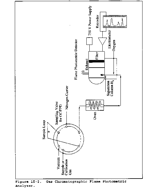
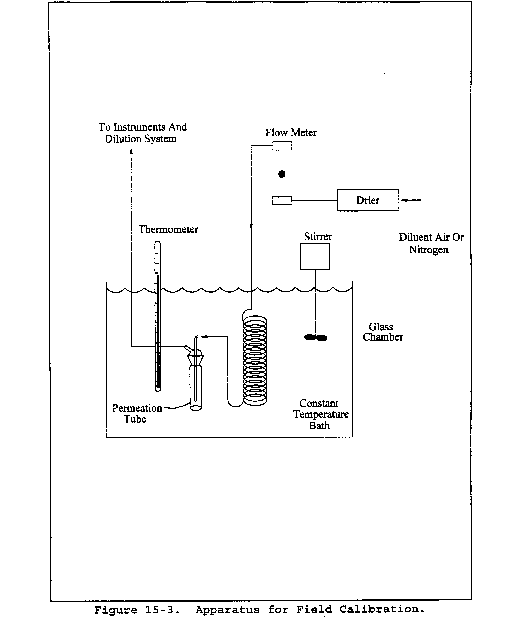
Method 15A - Determination of Total Reduced Sulfur Emissions From Sulfur Recovery Plants in Petroleum Refineries
This method does not include all of the specifications (e.g., equipment and supplies) and procedures (e.g., sampling and analytical) essential to its performance. Some material is incorporated by reference from other methods in this part. Therefore, to obtain reliable results, persons using this method should have a thorough knowledge of at least the following additional test methods: Method 1, Method 6, Method 15, and Method 16A.
1.0 Scope and Application
1.1 Analytes.
| Analyte | CAS No. | Sensitivity |
|---|---|---|
| Reduced sulfur compounds | None assigned | Not determined. |
1.2 Applicability. This method is applicable for the determination of emissions of reduced sulfur compounds from sulfur recovery plants where the emissions are in a reducing atmosphere, such as in Stretford units.
1.3 Data Quality Objectives. Adherence to the requirements of this method will enhance the quality of the data obtained from air pollutant sampling methods.
2.0 Summary of Method
2.1 An integrated gas sample is extracted from the stack, and combustion air is added to the oxygen (O2)-deficient gas at a known rate. The reduced sulfur compounds [including carbon disulfide (CS2), carbonyl sulfide (COS), and hydrogen sulfide (H2S)] are thermally oxidized to sulfur dioxide (SO2), which is then collected in hydrogen peroxide as sulfate ion and analyzed according to the Method 6 barium-thorin titration procedure.
3.0 Definitions [Reserved]
4.0 Interferences
4.1 Reduced sulfur compounds, other than CS2, COS, and H2S, that are present in the emissions will also be oxidized to SO2, causing a positive bias relative to emission standards that limit only the three compounds listed above. For example, thiophene has been identified in emissions from a Stretford unit and produced a positive bias of 30 percent in the Method 15A result. However, these biases may not affect the outcome of the test at units where emissions are low relative to the standard.
4.2 Calcium and aluminum have been shown to interfere in the Method 6 titration procedure. Since these metals have been identified in particulate matter emissions from Stretford units, a Teflon filter is required to minimize this interference.
4.3 Dilution of the hydrogen peroxide (H2O2) absorbing solution can potentially reduce collection efficiency, causing a negative bias. When used to sample emissions containing 7 percent moisture or less, the midget impingers have sufficient volume to contain the condensate collected during sampling. Dilution of the H2O2 does not affect the collection of SO2. At higher moisture contents, the potassium citrate-citric acid buffer system used with Method 16A should be used to collect the condensate.
5.0 Safety
5.1 Disclaimer. This method may involve hazardous materials, operations, and equipment. This test method may not address all of the safety problems associated with its use. It is the responsibility of the user of this test method to establish appropriate safety and health practices and determine the applicability of regulatory limitations prior to performing this test method.
5.2 Corrosive reagents. The following reagents are hazardous. Personal protective equipment and safe procedures are useful in preventing chemical splashes. If contact occurs, immediately flush with copious amounts of water for at least 15 minutes. Remove clothing under shower and decontaminate. Treat residual chemical burns as thermal burns.
5.2.1 Hydrogen Peroxide (H2O2). Irritating to eyes, skin, nose, and lungs.
5.2.2 Sodium Hydroxide (NaOH). Causes severe damage to eyes and skin. Inhalation causes irritation to nose, throat, and lungs. Reacts exothermically with limited amounts of water.
5.2.3 Sulfuric Acid (H2SO4). Rapidly destructive to body tissue. Will cause third degree burns. Eye damage may result in blindness. Inhalation may be fatal from spasm of the larynx, usually within 30 minutes. May cause lung tissue damage with edema. 3 mg/m3 will cause lung damage in uninitiated. 1 mg/m3 for 8 hours will cause lung damage or, in higher concentrations, death. Provide ventilation to limit inhalation. Reacts violently with metals and organics.
6.0 Equipment and Supplies
6.1 Sample Collection. The sampling train used in performing this method is shown in Figure 15A-1, and component parts are discussed below. Modifications to this sampling train are acceptable provided that the system performance check is met.
6.1.1 Probe. 6.4-mm (1⁄4-in.) OD Teflon tubing sequentially wrapped with heat-resistant fiber strips, a rubberized heating tape (with a plug at one end), and heat-resistant adhesive tape. A flexible thermocouple or some other suitable temperature-measuring device shall be placed between the Teflon tubing and the fiber strips so that the temperature can be monitored. The probe should be sheathed in stainless steel to provide in-stack rigidity. A series of bored-out stainless steel fittings placed at the front of the sheath will prevent flue gas from entering between the probe and sheath. The sampling probe is depicted in Figure 15A-2.
6.1.2 Particulate Filter. A 50-mm Teflon filter holder and a 1- to 2-mm porosity Teflon filter (available through Savillex Corporation, 5325 Highway 101, Minnetonka, Minnesota 55345). The filter holder must be maintained in a hot box at a temperature high enough to prevent condensation.
6.1.3 Combustion Air Delivery System. As shown in the schematic diagram in Figure 15A-3. The rate meter should be selected to measure an air flow rate of 0.5 liter/min (0.02 ft3/min).
6.1.4 Combustion Tube. Quartz glass tubing with an expanded combustion chamber 2.54 cm (1 in.) in diameter and at least 30.5 cm (12 in.) long. The tube ends should have an outside diameter of 0.6 cm (1⁄4 in.) and be at least 15.3 cm (6 in.) long. This length is necessary to maintain the quartz-glass connector near ambient temperature and thereby avoid leaks. Alternatively, the outlet may be constructed with a 90 degree glass elbow and socket that would fit directly onto the inlet of the first peroxide impinger.
6.1.5 Furnace. Of sufficient size to enclose the combustion tube. The furnace must have a temperature regulator capable of maintaining the temperature at 1100 ±50 °C (2,012 ±90 °F). The furnace operating temperature must be checked with a thermocouple to ensure accuracy. Lindberg furnaces have been found to be satisfactory.
6.1.6 Peroxide Impingers, Stopcock Grease, Temperature Sensor, Drying Tube, Valve, Pump, and Barometer. Same as in Method 6, sections 6.1.1.2, 6.1.1.4, 6.1.1.5, 6.1.1.6, 6.1.1.7, 6.1.1.8, and 6.1.2, respectively, except that the midget bubbler of Method 6, section 6.1.1.2 is not required.
6.1.7 Vacuum Gauge and Rate Meter. At least 760 mm Hg (30 in. Hg) gauge and rotameter, or equivalent, capable of measuring flow rate to ±5 percent of the selected flow rate and calibrated as in section 10.2.
6.1.8 Volume Meter. Dry gas meter capable of measuring the sample volume under the particular sampling conditions with an accuracy of 2 percent.
6.1.9 U-tube manometer. To measure the pressure at the exit of the combustion gas dry gas meter.
6.2 Sample Recovery and Analysis. Same as Method 6, sections 6.2 and 6.3, except a 10-ml buret with 0.05-ml graduations is required for titrant volumes of less than 10.0 ml, and the spectrophotometer is not needed.
7.0 Reagents and Standards
Unless otherwise indicated, all reagents must conform to the specifications established by the Committee on Analytical Reagents of the American Chemical Society. When such specifications are not available, the best available grade shall be used.
7.1 Sample Collection. The following reagents and standards are required for sample analysis:
7.1.1 Water. Same as Method 6, section 7.1.1.
7.1.2 Hydrogen Peroxide (H2O2), 3 Percent by Volume. Same as Method 6, section 7.1.3 (40 ml is needed per sample).
7.1.3 Recovery Check Gas. Carbonyl sulfide in nitrogen [100 parts per million by volume (ppmv) or greater, if necessary] in an aluminum cylinder. Concentration certified by the manufacturer with an accuracy of ±2 percent or better, or verified by gas chromatography where the instrument is calibrated with a COS permeation tube.
7.1.4 Combustion Gas. Air, contained in a gas cylinder equipped with a two-stage regulator. The gas shall contain less than 50 ppb of reduced sulfur compounds and less than 10 ppm total hydrocarbons.
7.2 Sample Recovery and Analysis. Same as Method 6, sections 7.2 and 7.3.
8.0 Sample Collection, Preservation, Storage, and Transport
8.1 Preparation of Sampling Train. For the Method 6 part of the train, measure 20 ml of 3 percent H2O2 into the first and second midget impingers. Leave the third midget impinger empty and add silica gel to the fourth impinger. Alternatively, a silica gel drying tube may be used in place of the fourth impinger. Place crushed ice and water around all impingers. Maintain the oxidation furnace at 1100 ±50 °C (2,012 ±90 °F) to ensure 100 percent oxidation of COS. Maintain the probe and filter temperatures at a high enough level (no visible condensation) to prevent moisture condensation and monitor the temperatures with a thermocouple.
8.2 Leak-Check Procedure. Assemble the sampling train and leak-check as described in Method 6, section 8.2. Include the combustion air delivery system from the needle valve forward in the leak-check.
8.3 Sample Collection. Adjust the pressure on the second stage of the regulator on the combustion air cylinder to 10 psig. Adjust the combustion air flow rate to 0.5 ±0.05 L/min (1.1 ±0.1 ft3/hr) before injecting combustion air into the sampling train. Then inject combustion air into the sampling train, start the sample pump, and open the stack sample gas valve. Carry out these three operations within 15 to 30 seconds to avoid pressurizing the sampling train. Adjust the total sample flow rate to 2.0 ±0.2 L/min (4.2 ±0.4 ft3/hr). These flow rates produce an O2 concentration of 5.0 percent in the stack gas, which must be maintained constantly to allow oxidation of reduced sulfur compounds to SO2. Adjust these flow rates during sampling as necessary. Monitor and record the combustion air manometer reading at regular intervals during the sampling period. Sample for 1 or 3 hours. At the end of sampling, turn off the sample pump and combustion air simultaneously (within 30 seconds of each other). All other procedures are the same as in Method 6, section 8.3, except that the sampling train should not be purged. After collecting the sample, remove the probe from the stack and conduct a leak-check according to the procedures outlined in section 8.2 of Method 6 (mandatory). After each 3-hour test run (or after three 1-hour samples), conduct one system performance check (see section 8.5). After this system performance check and before the next test run, it is recommended that the probe be rinsed and brushed and the filter replaced.
In Method 15, a test run is composed of 16 individual analyses (injects) performed over a period of not less than 3 hours or more than 6 hours. For Method 15A to be consistent with Method 15, the following may be used to obtain a test run: (1) Collect three 60-minute samples or (2) collect one 3-hour sample. (Three test runs constitute a test.)
8.4 Sample Recovery. Recover the hydrogen peroxide-containing impingers as detailed in Method 6, section 8.4.
8.5 System Performance Check.
8.5.1 A system performance check is done (1) to validate the sampling train components and procedure (before testing, optional) and (2) to validate a test run (after a run, mandatory). Perform a check in the field before testing consisting of at least two samples (optional), and perform an additional check after each 3-hour run or after three 1-hour samples (mandatory).
8.5.2 The checks involve sampling a known concentration of COS and comparing the analyzed concentration with the known concentration. Mix the recovery gas with N2 as shown in Figure 15A-4 if dilution is required. Adjust the flow rates to generate a COS concentration in the range of the stack gas or within 20 percent of the applicable standard at a total flow rate of at least 2.5 L/min (5.3 ft3/hr). Use Equation 15A-4 (see section 12.5) to calculate the concentration of recovery gas generated. Calibrate the flow rate from both sources with a soap bubble flow tube so that the diluted concentration of COS can be accurately calculated. Collect 30-minute samples, and analyze in the same manner as the emission samples. Collect the samples through the probe of the sampling train using a manifold or some other suitable device that will ensure extraction of a representative sample.
8.5.3 The recovery check must be performed in the field before replacing the particulate filter and before cleaning the probe. A sample recovery of 100 ±20 percent must be obtained for the data to be valid and should be reported with the emission data, but should not be used to correct the data. However, if the performance check results do not affect the compliance or noncompliance status of the affected facility, the Administrator may decide to accept the results of the compliance test. Use Equation 15A-5 (see section 12.6) to calculate the recovery efficiency.
9.0 Quality Control
| Section | Quality control measure | Effect |
|---|---|---|
| 8.5 | System performance check | Ensures validity of sampling train components and analytical procedure. |
| 8.2, 10.0 | Sampling equipment leak-check and calibration | Ensures accurate measurement of stack gas flow rate, sample volume. |
| 10.0 | Barium standard solution standardization | Ensures precision of normality determination. |
| 11.1 | Replicate titrations | Ensures precision of titration determinations. |
10.0 Calibration and Standardization
10.1 Metering System, Temperature Sensors, Barometer, and Barium Perchlorate Solution. Same as Method 6, sections 10.1, 10.2, 10.4, and 10.5, respectively.
10.2 Rate Meter. Calibrate with a bubble flow tube.
11.0 Analytical Procedure
11.1 Sample Loss Check and Sample Analysis. Same as Method 6, sections 11.1 and 11.2.
12.0 Data Analysis and Calculations
In the calculations, retain at least one extra decimal figure beyond that of the acquired data. Round off figures after final calculations.
12.1 Nomenclature.
CCOS = Concentration of COS recovery gas, ppm.
CRG(act) = Actual concentration of recovery check gas (after dilution), ppm.
CRG(m) = Measured concentration of recovery check gas generated, ppm.
CRS = Concentration of reduced sulfur compounds as SO2, dry basis, corrected to standard conditions, ppm.
N = Normality of barium perchlorate titrant, milliequivalents/ml.
Pbar = Barometric pressure at exit orifice of the dry gas meter, mm Hg.
Pstd = Standard absolute pressure, 760 mm Hg.
QCOS = Flow rate of COS recovery gas, liters/min.
QN = Flow rate of diluent N2, liters/min.
R = Recovery efficiency for the system performance check, percent.
Tm = Average dry gas meter absolute temperature, °K.
Tstd = Standard absolute temperature, 293 °K.
Va = Volume of sample aliquot titrated, ml.
Vms = Dry gas volume as measured by the sample train dry gas meter, liters.
Vmc = Dry gas volume as measured by the combustion air dry gas meter, liters.
Vms(std) = Dry gas volume measured by the sample train dry gas meter, corrected to standard conditions, liters.
Vmc(std) = Dry gas volume measured by the combustion air dry gas meter, corrected to standard conditions, liters.
Vsoln = Total volume of solution in which the sulfur dioxide sample is contained, 100 ml.
Vt = Volume of barium perchlorate titrant used for the sample (average of replicate titrations), ml.
Vtb = Volume of barium perchlorate titrant used for the blank, ml.
Y = Calibration factor for sampling train dry gas meter.
Yc = Calibration factor for combustion air dry gas meter.
32.03 = Equivalent weight of sulfur dioxide, mg/meq.
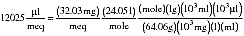
12.2 Dry Sample Gas Volume, Corrected to Standard Conditions.

Where:
K1 = 0.3855 °K/mm Hg for metric units,
= 17.65 °R/in. Hg for English units.
12.3 Combustion Air Gas Volume, corrected to Standard Conditions.

Correct Pbar for the average pressure of the manometer during the sampling period.
12.4 Concentration of reduced sulfur compounds as ppm SO2.

Where:
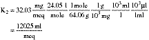
12.5 Concentration of Generated Recovery Gas.

12.6 Recovery Efficiency for the System Performance Check.

13.0 Method Performance
13.1 Analytical Range. The lower detectable limit is 0.1 ppmv when sampling at 2 lpm for 3 hours or 0.3 ppmv when sampling at 2 lpm for 1 hour. The upper concentration limit of the method exceeds concentrations of reduced sulfur compounds generally encountered in sulfur recovery plants.
13.2 Precision. Relative standard deviations of 2.8 and 6.9 percent have been obtained when sampling a stream with a reduced sulfur compound concentration of 41 ppmv as SO2 for 1 and 3 hours, respectively.
13.3 Bias. No analytical bias has been identified. However, results obtained with this method are likely to contain a positive bias relative to emission regulations due to the presence of nonregulated sulfur compounds (that are present in petroleum) in the emissions. The magnitude of this bias varies accordingly, and has not been quantified.
14.0 Pollution Prevention [Reserved]
15.0 Waste Management [Reserved]
16.0 References
1. American Society for Testing and Materials Annual Book of ASTM Standards. Part 31: Water, Atmospheric Analysis. Philadelphia, Pennsylvania. 1974. pp. 40-42.
2. Blosser, R.O., H.S. Oglesby, and A.K. Jain. A Study of Alternate SO2 Scrubber Designs Used for TRS Monitoring. National Council of the Paper Industry for Air and Stream Improvement, Inc., New York, New York. Special Report 77-05. July 1977.
3. Curtis, F., and G.D. McAlister. Development and Evaluation of an Oxidation/Method 6 TRS Emission Sampling Procedure. Emission Measurement Branch, Emission Standards and Engineering Division, U.S. Environmental Protection Agency, Research Triangle Park, North Carolina. February 1980.
4. Gellman, I. A Laboratory and Field Study of Reduced Sulfur Sampling and Monitoring Systems. National Council of the Paper Industry for Air and Stream Improvement, Inc., New York, New York. Atmospheric Quality Improvement Technical Bulletin No. 81. October 1975.
5. Margeson, J.H., et al. A Manual Method for TRS Determination. Journal of Air Pollution Control Association. 35:1280-1286. December 1985.
17.0 Tables, Diagrams, Flowcharts, and Validation Data
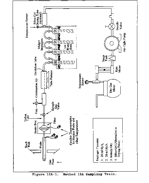
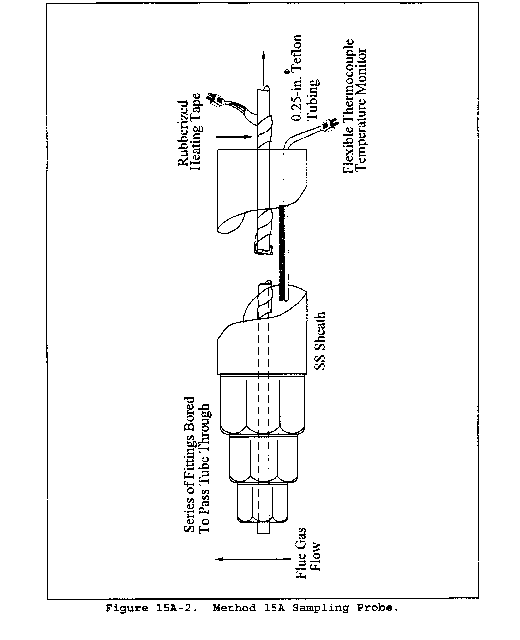
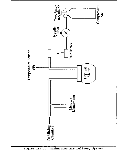

[36 FR 24877, Dec. 23, 1971]
Appendix A-6 to Part 60 - Test Methods 16 through 18
Method 16 - Semicontinuous determination of sulfur emissions from stationary sources
Method 16A - Determination of total reduced sulfur emissions from stationary sources (impinger technique)
Method 16B - Determination of total reduced sulfur emissions from stationary sources
Method 16C - Determination of Total Reduced Sulfur Emissions From Stationary Sources
Method 17 - Determination of particulate emissions from stationary sources (in-stack filtration method)
Method 18 - Measurement of gaseous organic compound emissions by gas chromatography
The test methods in this appendix are referred to in § 60.8 (Performance Tests) and § 60.11 (Compliance With Standards and Maintenance Requirements) of 40 CFR part 60, subpart A (General Provisions). Specific uses of these test methods are described in the standards of performance contained in the subparts, beginning with Subpart D.
Within each standard of performance, a section title “Test Methods and Procedures” is provided to: (1) Identify the test methods to be used as reference methods to the facility subject to the respective standard and (2) identify any special instructions or conditions to be followed when applying a method to the respective facility. Such instructions (for example, establish sampling rates, volumes, or temperatures) are to be used either in addition to, or as a substitute for procedures in a test method. Similarly, for sources subject to emission monitoring requirements, specific instructions pertaining to any use of a test method as a reference method are provided in the subpart or in Appendix B.
Inclusion of methods in this appendix is not intended as an endorsement or denial of their applicability to sources that are not subject to standards of performance. The methods are potentially applicable to other sources; however, applicability should be confirmed by careful and appropriate evaluation of the conditions prevalent at such sources.
The approach followed in the formulation of the test methods involves specifications for equipment, procedures, and performance. In concept, a performance specification approach would be preferable in all methods because this allows the greatest flexibility to the user. In practice, however, this approach is impractical in most cases because performance specifications cannot be established. Most of the methods described herein, therefore, involve specific equipment specifications and procedures, and only a few methods in this appendix rely on performance criteria.
Minor changes in the test methods should not necessarily affect the validity of the results and it is recognized that alternative and equivalent methods exist. section 60.8 provides authority for the Administrator to specify or approve (1) equivalent methods, (2) alternative methods, and (3) minor changes in the methodology of the test methods. It should be clearly understood that unless otherwise identified all such methods and changes must have prior approval of the Administrator. An owner employing such methods or deviations from the test methods without obtaining prior approval does so at the risk of subsequent disapproval and retesting with approved methods.
Within the test methods, certain specific equipment or procedures are recognized as being acceptable or potentially acceptable and are specifically identified in the methods. The items identified as acceptable options may be used without approval but must be identified in the test report. The potentially approvable options are cited as “subject to the approval of the Administrator” or as “or equivalent.” Such potentially approvable techniques or alternatives may be used at the discretion of the owner without prior approval. However, detailed descriptions for applying these potentially approvable techniques or alternatives are not provided in the test methods. Also, the potentially approvable options are not necessarily acceptable in all applications. Therefore, an owner electing to use such potentially approvable techniques or alternatives is responsible for: (1) assuring that the techniques or alternatives are in fact applicable and are properly executed; (2) including a written description of the alternative method in the test report (the written method must be clear and must be capable of being performed without additional instruction, and the degree of detail should be similar to the detail contained in the test methods); and (3) providing any rationale or supporting data necessary to show the validity of the alternative in the particular application. Failure to meet these requirements can result in the Administrator's disapproval of the alternative.
Method 16 - Semicontinuous Determination of Sulfur Emissions From Stationary Sources
This method does not include all of the specifications (e.g., equipment and supplies) and procedures (e.g., sampling and analytical) essential to its performance. Some material is incorporated by reference from other methods in this part. Therefore, to obtain reliable results, persons using this method should have a thorough knowledge of at least the following additional test methods: Method 1, Method 4, Method 15, and Method 16A.
1.0 Scope and Application
1.1 Analytes.
| Analyte | CAS No. | Sensitivity |
|---|---|---|
| Dimethyl disulfide [(CH3)2S2] | 62-49-20 | 50 ppb. |
| Dimethyl sulfide [(CH3)2S] | 75-18-3 | 50 ppb. |
| Hydrogen sulfide [H2S] | 7783-06-4 | 50 ppb. |
| Methyl mercaptan [CH4S] | 74-93-1 | 50 ppb. |
1.2 Applicability. This method is applicable for the determination of total reduced sulfur (TRS) compounds from recovery furnaces, lime kilns, and smelt dissolving tanks at kraft pulp mills and fuel gas combustion devices at petroleum refineries.
The method described below uses the principle of gas chromatographic (GC) separation and flame photometric detection (FPD). Since there are many systems or sets of operating conditions that represent useable methods of determining sulfur emissions, all systems which employ this principle, but differ only in details of equipment and operation, may be used as alternative methods, provided that the calibration precision and sample line loss criteria are met.
1.3 Data Quality Objectives. Adherence to the requirements of this method will enhance the quality of the data obtained from air pollutant sampling methods.
2.0 Summary of Method
2.1 A gas sample is extracted from the emission source and an aliquot is analyzed for hydrogen sulfide (H2S), methyl mercaptan (MeSH), dimethyl sulfide (DMS), and dimethyl disulfide (DMDS) by GC/FPD. These four compounds are known collectively as TRS.
3.0 Definitions [Reserved]
4.0 Interferences
4.1 Moisture. Moisture condensation in the sample delivery system, the analytical column, or the FPD burner block can cause losses or interferences. This is prevented by maintaining the probe, filter box, and connections at a temperature of at least 120 °C (248 °F). Moisture is removed in the SO2 scrubber and heating the sample beyond this point is not necessary when the ambient temperature is above 0 °C (32 °F). Alternatively, moisture may be eliminated by heating the sample line, and by conditioning the sample with dry dilution air to lower its dew point below the operating temperature of the GC/FPD analytical system prior to analysis.
4.2 Carbon Monoxide (CO) and Carbon Dioxide (CO2). CO and CO2 have a substantial desensitizing effect on the flame photometric detector even after dilution. Acceptable systems must demonstrate that they have eliminated this interference by some procedure such as eluting these compounds before any of the compounds to be measured. Compliance with this requirement can be demonstrated by submitting chromatograms of calibration gases with and without CO2 in the diluent gas. The CO2 level should be approximately 10 percent for the case with CO2 present. The two chromatograms should show agreement within the precision limits of section 10.2.
4.3 Particulate Matter. Particulate matter in gas samples can cause interference by eventual clogging of the analytical system. This interference is eliminated by using the Teflon filter after the probe.
4.4 Sulfur Dioxide (SO2). Sulfur dioxide is not a specific interferant but may be present in such large amounts that it cannot effectively be separated from the other compounds of interest. The SO2 scrubber described in section 6.1.3 will effectively remove SO2 from the sample.
5.0 Safety
5.1 Disclaimer. This method may involve hazardous materials, operations, and equipment. This test method may not address all of the safety problems associated with its use. It is the responsibility of the user of this test method to establish appropriate safety and health practices and determine the applicability of regulatory limitations prior to performing this test method.
5.2 Hydrogen Sulfide. A flammable, poisonous gas with the odor of rotten eggs. H2S is extremely hazardous and can cause collapse, coma, and death within a few seconds of one or two inhalations at sufficient concentrations. Low concentrations irritate the mucous membranes and may cause nausea, dizziness, and headache after exposure.
6.0 Equipment and Supplies
6.1. Sample Collection. The following items are needed for sample collection.
6.1.1 Probe. Teflon or Teflon-lined stainless steel. The probe must be heated to prevent moisture condensation. It must be designed to allow calibration gas to enter the probe at or near the sample point entry. Any portion of the probe that contacts the stack gas must be heated to prevent moisture condensation. Figure 16-1 illustrates the probe used in lime kilns and other sources where significant amounts of particulate matter are present. The probe is designed with the deflector shield placed between the sample and the gas inlet holes to reduce clogging of the filter and possible adsorption of sample gas. As an alternative, the probe described in section 6.1.1 of Method 16A having a nozzle directed away from the gas stream may be used at sources having significant amounts of particulate matter.
6.1.2 Particulate Filter. 50-mm Teflon filter holder and a 1- to 2-micron porosity Teflon filter (available through Savillex Corporation, 5325 Highway 101, Minnetonka, Minnesota 55343). The filter holder must be maintained in a hot box at a temperature of at least 120 °C (248 °F).
6.1.3 SO2 Scrubber. Three 300-ml Teflon segmented impingers connected in series with flexible, thick-walled, Teflon tubing. (Impinger parts and tubing available through Savillex.) The first two impingers contain 100 ml of citrate buffer and the third impinger is initially dry. The tip of the tube inserted into the solution should be constricted to less than 3 mm (1⁄8 in.) ID and should be immersed to a depth of at least 5 cm (2 in.). Immerse the impingers in an ice water bath and maintain near 0 °C (32 °F). The scrubber solution will normally last for a 3-hour run before needing replacement. This will depend upon the effects of moisture and particulate matter on the solution strength and pH. Connections between the probe, particulate filter, and SO2 scrubber must be made of Teflon and as short in length as possible. All portions of the probe, particulate filter, and connections prior to the SO2 scrubber (or alternative point of moisture removal) must be maintained at a temperature of at least 120 °C (248 °F).
6.1.4 Sample Line. Teflon, no greater than 1.3 cm (1⁄2 in.) ID. Alternative materials, such as virgin Nylon, may be used provided the line loss test is acceptable.
6.1.5 Sample Pump. The sample pump must be a leakless Teflon-coated diaphragm type or equivalent.
6.2 Analysis. The following items are needed for sample analysis:
6.2.1 Dilution System. Needed only for high sample concentrations. The dilution system must be constructed such that all sample contacts are made of Teflon, glass, or stainless steel.
6.2.2 Gas Chromatograph. The gas chromatograph must have at least the following components:
6.2.2.1 Oven. Capable of maintaining the separation column at the proper operating temperature ±1 °C (2 °F).
6.2.2.2 Temperature Gauge. To monitor column oven, detector, and exhaust temperature ±1 °C (2 °F).
6.2.2.3 Flow System. Gas metering system to measure sample, fuel, combustion gas, and carrier gas flows.
6.2.2.4 Flame Photometric Detector.
6.2.2.4.1 Electrometer. Capable of full scale amplification of linear ranges of 10−9 to 10−4 amperes full scale.
6.2.2.4.2 Power Supply. Capable of delivering up to 750 volts.
6.2.2.4.3 Recorder. Compatible with the output voltage range of the electrometer.
6.2.2.4.4 Rotary Gas Valves. Multiport Teflon-lined valves equipped with sample loop. Sample loop volumes must be chosen to provide the needed analytical range. Teflon tubing and fittings must be used throughout to present an inert surface for sample gas. The gas chromatograph must be calibrated with the sample loop used for sample analysis.
6.2.3 Gas Chromatogram Columns. The column system must be demonstrated to be capable of resolving the four major reduced sulfur compounds: H2S, MeSH, DMS, and DMDS. It must also demonstrate freedom from known interferences. To demonstrate that adequate resolution has been achieved, submit a chromatogram of a calibration gas containing all four of the TRS compounds in the concentration range of the applicable standard. Adequate resolution will be defined as base line separation of adjacent peaks when the amplifier attenuation is set so that the smaller peak is at least 50 percent of full scale. Baseline separation is defined as a return to zero ±5 percent in the interval between peaks. Systems not meeting this criteria may be considered alternate methods subject to the approval of the Administrator.
6.3 Calibration. A calibration system, containing the following components, is required (see Figure 16-2).
6.3.1 Tube Chamber. Chamber of glass or Teflon of sufficient dimensions to house permeation tubes.
6.3.2 Flow System. To measure air flow over permeation tubes at ±2 percent. Flow over the permeation device may also be determined using a soap bubble flowmeter.
6.3.3 Constant Temperature Bath. Device capable of maintaining the permeation tubes at the calibration temperature within 0.1 °C (0.2 °F).
6.3.4 Temperature Gauge. Thermometer or equivalent to monitor bath temperature within 1 °C (2 °F).
7.0 Reagents and Standards
7.1 Fuel. Hydrogen (H2), prepurified grade or better.
7.2 Combustion Gas. Oxygen (O2) or air, research purity or better.
7.3 Carrier Gas. Prepurified grade or better.
7.4 Diluent (if required). Air containing less than 50 ppb total sulfur compounds and less than 10 ppmv each of moisture and total hydrocarbons.
7.5 Calibration Gases
7.5.1 Permeation tubes, one each of H2S, MeSH, DMS, and DMDS, gravimetrically calibrated and certified at some convenient operating temperature. These tubes consist of hermetically sealed FEP Teflon tubing in which a liquified gaseous substance is enclosed. The enclosed gas permeates through the tubing wall at a constant rate. When the temperature is constant, calibration gases covering a wide range of known concentrations can be generated by varying and accurately measuring the flow rate of diluent gas passing over the tubes. These calibration gases are used to calibrate the GC/FPD system and the dilution system.
7.5.2 Cylinder Gases. Cylinder gases may be used as alternatives to permeation devices. The gases must be traceable to a primary standard (such as permeation tubes) and not used beyond the certification expiration date.
7.6 Citrate Buffer and Sample Line Loss Gas. Same as Method 15, sections 7.6 and 7.7.
8.0 Sample Collection, Preservation, Storage, and Transport
Same as Method 15, section 8.0, except that the references to the dilution system may not be applicable.
9.0 Quality Control
| Section | Quality control measure | Effect |
|---|---|---|
| 8.0 | Sample line loss check | Ensures that uncorrected negative bias introduced by sample loss is no greater than 20 percent, and provides for correction of bias of 20 percent or less. |
| 8.0 | Calibration drift test | Ensures that bias introduced by drift in the measurement system output during the run is no greater than 5 percent. |
| 10.0 | Analytical calibration | Ensures precision of analytical results within 5 percent. |
10.0 Calibration and Standardization
Same as Method 15, section 10.0, with the following addition and exceptions:
10.1 Use the four compounds that comprise TRS instead of the three reduced sulfur compounds measured by Method 15.
10.2 Flow Meter. Calibration before each test run is recommended, but not required; calibration following each test series is mandatory. Calibrate each flow meter after each complete test series with a wet-test meter. If the flow measuring device differs from the wet-test meter by 5 percent or more, the completed test runs must be voided. Alternatively, the flow data that yield the lower flow measurement may be used. Flow over the permeation device may also be determined using a soap bubble flowmeter.
11.0 Analytical Procedure
Sample collection and analysis are concurrent for this method (see section 8.0).
12.0 Data Analysis and Calculations
12.1 Concentration of Reduced Sulfur Compounds. Calculate the average concentration of each of the four analytes (i.e., DMDS, DMS, H2S, and MeSH) over the sample run (specified in section 8.2 of Method 15 as 16 injections).

Where:
Si = Concentration of any reduced sulfur compound from the ith sample injection, ppm.
C = Average concentration of any one of the reduced sulfur compounds for the entire run, ppm.
N = Number of injections in any run period.
12.2 TRS Concentration. Using Equation 16-2, calculate the TRS concentration for each sample run.

Where:
CTRS = TRS concentration, ppmv.
CH2S = Hydrogen sulfide concentration, ppmv.
CMeSH = Methyl mercaptan concentration, ppmv.
CDMS = Dimethyl sulfide concentration, ppmv.
CDMDS = Dimethyl disulfide concentration, ppmv.
d = Dilution factor, dimensionless.
12.3 Average TRS Concentration. Calculate the average TRS concentration for all sample runs performed.
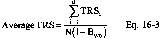
Where:
Average TRS = Average total reduced sulfur in ppm.
TRSi = Total reduced sulfur in ppm as determined by Equation 16-2.
N = Number of samples.
Bwo = Fraction of volume of water vapor in the gas stream as determined by Method 4 - Determination of Moisture in Stack Gases.
13.0 Method Performance
13.1 Analytical Range. The analytical range will vary with the sample loop size. Typically, the analytical range may extend from 0.1 to 100 ppmv using 10- to 0.1-ml sample loop sizes. This eliminates the need for sample dilution in most cases.
13.2 Sensitivity. Using the 10-ml sample size, the minimum detectable concentration is approximately 50 ppb.
14.0 Pollution Prevention [Reserved]
15.0 Waste Management [Reserved]
16.0 References
1. O'Keeffe, A.E., and G.C. Ortman. “Primary Standards for Trace Gas Analysis.” Analytical Chemical Journal, 38,76. 1966.
2. Stevens, R.K., A.E. O'Keeffe, and G.C. Ortman. “Absolute Calibration of a Flame Photometric Detector to Volatile Sulfur Compounds at Sub-Part-Per-Million Levels.” Environmental Science and Technology, 3:7. July 1969.
3. Mulik, J.D., R.K. Stevens, and R. Baumgardner. “An Analytical System Designed to Measure Multiple Malodorous Compounds Related to Kraft Mill Activities.” Presented at the 12th Conference on Methods in Air Pollution and Industrial Hygiene Studies, University of Southern California, Los Angeles, CA. April 6-8, 1971.
4. Devonald, R.H., R.S. Serenius, and A.D. McIntyre. “Evaluation of the Flame Photometric Detector for Analysis of Sulfur Compounds.” Pulp and Paper Magazine of Canada, 73,3. March 1972.
5. Grimley, K.W., W.S. Smith, and R.M. Martin. “The Use of a Dynamic Dilution System in the Conditioning of Stack Gases for Automated Analysis by a Mobile Sampling Van.” Presented at the 63rd Annual APCA Meeting, St. Louis, MO. June 14-19, 1970.
6. General Reference. Standard Methods of Chemical Analysis, Volumes III-A and III-B Instrumental Methods. Sixth Edition. Van Nostrand Reinhold Co.
17.0 Tables, Diagrams, Flowcharts, and Validation Data
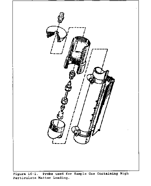
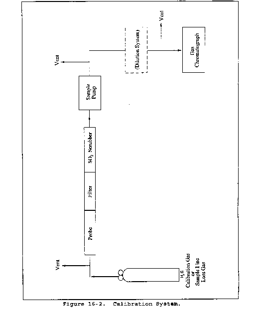
Method 16A - Determination of Total Reduced Sulfur Emissions From Stationary Sources (Impinger Technique)
This method does not include all of the specifications (e.g., equipment and supplies) and procedures (e.g., sampling and analytical) essential to its performance. Some material is incorporated by reference from other methods in this part. Therefore, to obtain reliable results, persons using this method should have a thorough knowledge of at least the following additional test methods: Method 1, Method 6, and Method 16.
1.0 Scope and Application
1.1 Analytes.
| Analyte | CAS No. | Sensitivity |
|---|---|---|
| Total reduced sulfur (TRS) including: | N/A | See section 13.1. |
| Dimethyl disulfide [(CH3)2S2] | 62-49-20 | |
| Dimethyl sulfide [(CH3)2S] | 75-18-3 | |
| Hydrogen sulfide [H2S] | 7783-06-4 | |
| Methyl mercaptan [CH4S] | 74-93-1 | |
| Reduced sulfur (RS) including: | N/A | |
| H2S | 7783-06-4 | |
| Carbonyl sulfide [COS] | 463-58-1 | |
| Carbon disulfide [CS2] | 75-15-0 | |
| Reported as: Sulfur dioxide (SO2) | 7449-09-5 |
1.2 Applicability. This method is applicable for the determination of TRS emissions from recovery boilers, lime kilns, and smelt dissolving tanks at kraft pulp mills, reduced sulfur compounds (H2S, carbonyl sulfide, and carbon disulfide) from sulfur recovery units at onshore natural gas processing facilities, and from other sources when specified in an applicable subpart of the regulations. The flue gas must contain at least 1 percent oxygen for complete oxidation of all TRS to SO2. Note: If sources other than kraft pulp mills experience low oxygen levels in the emissions, the method results may be biased low.
1.3 Data Quality Objectives. Adherence to the requirements of this method will enhance the quality of the data obtained from air pollutant sampling methods.
2.0 Summary of Method
2.1 An integrated gas sample is extracted from the stack. SO2 is removed selectively from the sample using a citrate buffer solution. TRS compounds are then thermally oxidized to SO2, collected in hydrogen peroxide as sulfate, and analyzed by the Method 6 barium-thorin titration procedure.
3.0 Definitions [Reserved]
4.0 Interferences
4.1 Reduced sulfur compounds other than those regulated by the emission standards, if present, may be measured by this method. Therefore, carbonyl sulfide, which is partially oxidized to SO2 and may be present in a lime kiln exit stack, would be a positive interferant.
4.2 Particulate matter from the lime kiln stack gas (primarily calcium carbonate) can cause a negative bias if it is allowed to enter the citrate scrubber; the particulate matter will cause the pH to rise and H2S to be absorbed prior to oxidation. Furthermore, if the calcium carbonate enters the hydrogen peroxide impingers, the calcium will precipitate sulfate ion. Proper use of the particulate filter described in section 6.1.3 will eliminate this interference.
5.0 Safety
5.1 Disclaimer. This method may involve hazardous materials, operations, and equipment. This test method may not address all of the safety problems associated with its use. It is the responsibility of the user of this test method to establish appropriate safety and health practices and determine the applicability of regulatory limitations prior to performing this test method.
5.2 Corrosive reagents. The following reagents are hazardous. Personal protective equipment and safe procedures are useful in preventing chemical splashes. If contact occurs, immediately flush with copious amounts of water for at least 15 minutes. Remove clothing under shower and decontaminate. Treat residual chemical burns as thermal burns.
5.2.1 Hydrogen Peroxide (H2O2). Irritating to eyes, skin, nose, and lungs.
5.2.2 Sodium Hydroxide (NaOH). Causes severe damage to eyes and skin. Inhalation causes irritation to nose, throat, and lungs. Reacts exothermically with limited amounts of water.
5.2.3 Sulfuric Acid (H2SO4). Rapidly destructive to body tissue. Will cause third degree burns. Eye damage may result in blindness. Inhalation may be fatal from spasm of the larynx, usually within 30 minutes. May cause lung tissue damage with edema. 3 mg/m3 will cause lung damage in uninitiated. 1 mg/m3 for 8 hours will cause lung damage or, in higher concentrations, death. Provide ventilation to limit inhalation. Reacts violently with metals and organics.
5.3 Hydrogen Sulfide (H2S). A flammable, poisonous gas with the odor of rotten eggs. H2S is extremely hazardous and can cause collapse, coma, and death within a few seconds of one or two inhalations at sufficient concentrations. Low concentrations irritate the mucous membranes and may cause nausea, dizziness, and headache after exposure.
6.0 Equipment and Supplies
6.1 Sample Collection. The sampling train is shown in Figure 16A-1 and component parts are discussed below. Modifications to this sampling train are acceptable provided the system performance check is met (see section 8.5).
6.1.1 Probe. Teflon tubing, 6.4-mm (1⁄4-in.) diameter, sequentially wrapped with heat-resistant fiber strips, a rubberized heat tape (plug at one end), and heat-resistant adhesive tape. A flexible thermocouple or other suitable temperature measuring device should be placed between the Teflon tubing and the fiber strips so that the temperature can be monitored to prevent softening of the probe. The probe should be sheathed in stainless steel to provide in-stack rigidity. A series of bored-out stainless steel fittings placed at the front of the sheath will prevent moisture and particulate from entering between the probe and sheath. A 6.4-mm (1⁄4-in.) Teflon elbow (bored out) should be attached to the inlet of the probe, and a 2.54 cm (1 in.) piece of Teflon tubing should be attached at the open end of the elbow to permit the opening of the probe to be turned away from the particulate stream; this will reduce the amount of particulate drawn into the sampling train. The probe is depicted in Figure 16A-2.
6.1.2 Probe Brush. Nylon bristle brush with handle inserted into a 3.2-mm (1⁄8-in.) Teflon tubing. The Teflon tubing should be long enough to pass the brush through the length of the probe.
6.1.3 Particulate Filter. 50-mm Teflon filter holder and a 1- to 2-µm porosity, Teflon filter (available through Savillex Corporation, 5325 Highway 101, Minnetonka, Minnesota 55343). The filter holder must be maintained in a hot box at a temperature sufficient to prevent moisture condensation. A temperature of 121 °C (250 °F) was found to be sufficient when testing a lime kiln under sub-freezing ambient conditions.
6.1.4 SO2 Scrubber. Three 300-ml Teflon segmented impingers connected in series with flexible, thick-walled, Teflon tubing. (Impinger parts and tubing available through Savillex.) The first two impingers contain 100 ml of citrate buffer and the third impinger is initially dry. The tip of the tube inserted into the solution should be constricted to less than 3 mm (1⁄8-in.) ID and should be immersed to a depth of at least 5 cm (2 in.).
6.1.5 Combustion Tube. Quartz glass tubing with an expanded combustion chamber 2.54 cm (1 in.) in diameter and at least 30.5 cm (12 in.) long. The tube ends should have an outside diameter of 0.6 cm (1⁄4 in.) and be at least 15.3 cm (6 in.) long. This length is necessary to maintain the quartz-glass connector near ambient temperature and thereby avoid leaks. Alternatively, the outlet may be constructed with a 90-degree glass elbow and socket that would fit directly onto the inlet of the first peroxide impinger.
6.1.6 Furnace. A furnace of sufficient size to enclose the combustion chamber of the combustion tube with a temperature regulator capable of maintaining the temperature at 800 ±100 °C (1472 ±180 °F). The furnace operating temperature should be checked with a thermocouple to ensure accuracy.
6.1.7 Peroxide Impingers, Stopcock Grease, Temperature Sensor, Drying Tube, Valve, Pump, and Barometer. Same as Method 6, sections 6.1.1.2, 6.1.1.4, 6.1.1.5, 6.1.1.6, 6.1.1.7, 6.1.1.8, and 6.1.2, respectively, except that the midget bubbler of Method 6, section 6.1.1.2 is not required.
6.1.8 Vacuum Gauge. At least 760 mm Hg (30 in. Hg) gauge.
6.1.9 Rate Meter. Rotameter, or equivalent, accurate to within 5 percent at the selected flow rate of approximately 2 liters/min (4.2 ft3/hr).
6.1.10 Volume Meter. Dry gas meter capable of measuring the sample volume under the sampling conditions of 2 liters/min (4.2 ft3/hr) with an accuracy of 2 percent.
6.2 Sample Recovery. Polyethylene Bottles, 250-ml (one per sample).
6.3 Sample Preparation and Analysis. Same as Method 6, section 6.3, except a 10-ml buret with 0.05-ml graduations is required, and the spectrophotometer is not needed.
7.0 Reagents and Standards
Unless otherwise indicated, all reagents must conform to the specifications established by the Committee on Analytical Reagents of the American Chemical Society. When such specifications are not available, the best available grade must be used.
7.1 Sample Collection. The following reagents are required for sample analysis:
7.1.1 Water. Same as in Method 6, section 7.1.1.
7.1.2 Citrate Buffer. Dissolve 300 g of potassium citrate (or 284 g of sodium citrate) and 41 g of anhydrous citric acid in 1 liter of water (200 ml is needed per test). Adjust the pH to between 5.4 and 5.6 with potassium citrate or citric acid, as required.
7.1.3 Hydrogen Peroxide, 3 percent. Same as in Method 6, section 7.1.3 (40 ml is needed per sample).
7.1.4 Recovery Check Gas. Hydrogen sulfide (100 ppmv or less) in nitrogen, stored in aluminum cylinders. Verify the concentration by Method 11 or by gas chromatography where the instrument is calibrated with an H2S permeation tube as described below. For Method 11, the relative standard deviation should not exceed 5 percent on at least three 20-minute runs.
Alternatively, hydrogen sulfide recovery gas generated from a permeation device gravimetrically calibrated and certified at some convenient operating temperature may be used. The permeation rate of the device must be such that at a dilution gas flow rate of 3 liters/min (6.4 ft3/hr), an H2S concentration in the range of the stack gas or within 20 percent of the standard can be generated.
7.1.5 Combustion Gas. Gas containing less than 50 ppb reduced sulfur compounds and less than 10 ppmv total hydrocarbons. The gas may be generated from a clean-air system that purifies ambient air and consists of the following components: Diaphragm pump, silica gel drying tube, activated charcoal tube, and flow rate measuring device. Flow from a compressed air cylinder is also acceptable.
7.2 Sample Recovery and Analysis. Same as Method 6, sections 7.2.1 and 7.3, respectively.
8.0 Sample Collection, Preservation, Storage, and Transport
8.1 Preparation of Sampling Train.
8.1.1 For the SO2 scrubber, measure 100 ml of citrate buffer into the first and second impingers; leave the third impinger empty. Immerse the impingers in an ice bath, and locate them as close as possible to the filter heat box. The connecting tubing should be free of loops. Maintain the probe and filter temperatures sufficiently high to prevent moisture condensation, and monitor with a suitable temperature sensor.
8.1.2 For the Method 6 part of the train, measure 20 ml of 3 percent hydrogen peroxide into the first and second midget impingers. Leave the third midget impinger empty, and place silica gel in the fourth midget impinger. Alternatively, a silica gel drying tube may be used in place of the fourth impinger. Maintain the oxidation furnace at 800 ±100 °C (1472 ±180 °F). Place crushed ice and water around all impingers.
8.2 Citrate Scrubber Conditioning Procedure. Condition the citrate buffer scrubbing solution by pulling stack gas through the Teflon impingers and bypassing all other sampling train components. A purge rate of 2 liters/min for 10 minutes has been found to be sufficient to obtain equilibrium. After the citrate scrubber has been conditioned, assemble the sampling train, and conduct (optional) a leak-check as described in Method 6, section 8.2.
8.3 Sample Collection. Same as in Method 6, section 8.3, except the sampling rate is 2 liters/min (±10 percent) for 1 or 3 hours. After the sample is collected, remove the probe from the stack, and conduct (mandatory) a post-test leak-check as described in Method 6, section 8.2. The 15-minute purge of the train following collection should not be performed. After each 3-hour test run (or after three 1-hour samples), conduct one system performance check (see section 8.5) to determine the reduced sulfur recovery efficiency through the sampling train. After this system performance check and before the next test run, rinse and brush the probe with water, replace the filter, and change the citrate scrubber (optional but recommended).
In Method 16, a test run is composed of 16 individual analyses (injects) performed over a period of not less than 3 hours or more than 6 hours. For Method 16A to be consistent with Method 16, the following may be used to obtain a test run: (1) collect three 60-minute samples or (2) collect one 3-hour sample. (Three test runs constitute a test.)
8.4 Sample Recovery. Disconnect the impingers. Quantitatively transfer the contents of the midget impingers of the Method 6 part of the train into a leak-free polyethylene bottle for shipment. Rinse the three midget impingers and the connecting tubes with water and add the washings to the same storage container. Mark the fluid level. Seal and identify the sample container.
8.5 System Performance Check.
8.5.1 A system performance check is done (1) to validate the sampling train components and procedure (prior to testing; optional) and (2) to validate a test run (after a run). Perform a check in the field prior to testing consisting of at least two samples (optional), and perform an additional check after each 3 hour run or after three 1-hour samples (mandatory).
8.5.2 The checks involve sampling a known concentration of H2S and comparing the analyzed concentration with the known concentration. Mix the H2S recovery check gas (Section 7.1.4) and combustion gas in a dilution system such as that shown in Figure 16A-3. Adjust the flow rates to generate an H2S concentration in the range of the stack gas or within 20 percent of the applicable standard and an oxygen concentration greater than 1 percent at a total flow rate of at least 2.5 liters/min (5.3 ft3/hr). Use Equation 16A-3 to calculate the concentration of recovery gas generated. Calibrate the flow rate from both sources with a soap bubble flow meter so that the diluted concentration of H2S can be accurately calculated.
8.5.3 Collect 30-minute samples, and analyze in the same manner as the emission samples. Collect the sample through the probe of the sampling train using a manifold or some other suitable device that will ensure extraction of a representative sample.
8.5.4 The recovery check must be performed in the field prior to replacing the SO2 scrubber and particulate filter and before the probe is cleaned. Use Equation 16A-4 (see section 12.5) to calculate the recovery efficiency. Report the recovery efficiency with the emission data; do not correct the emission data for the recovery efficiency. A sample recovery of 100 ±20 percent must be obtained for the emission data to be valid. However, if the recovery efficiency is not in the 100 ±20 percent range but the results do not affect the compliance or noncompliance status of the affected facility, the Administrator may decide to accept the results of the compliance test.
9.0 Quality Control
| Section | Quality control measure | Effect |
|---|---|---|
| 8.5 | System performance check | Ensure validity of sampling train components and analytical procedure. |
| 8.2, 10.0 | Sampling equipment leak-check and calibration | Ensure accurate measurement of stack gas flow rate, sample volume. |
| 10.0 | Barium standard solution standardization | Ensure precision of normality determination. |
| 11.1 | Replicate titrations | Ensure precision of titration determinations. |
10.0 Calibration
Same as Method 6, section 10.0.
11.0 Analytical Procedure
11.1 Sample Loss Check and Sample Analysis. Same as Method 6, sections 11.1 and 11.2, respectively, with the following exception: for 1-hour sampling, take a 40-ml aliquot, add 160 ml of 100 percent isopropanol and four drops of thorin.
12.0 Data Analysis and Calculations
In the calculations, at least one extra decimal figure should be retained beyond that of the acquired data. Figures should be rounded off after final calculations.
12.1 Nomenclature.
CTRS = Concentration of TRS as SO2, dry basis corrected to standard conditions, ppmv.
CRG(act) = Actual concentration of recovery check gas (after dilution), ppm.
CRG(m) = Measured concentration of recovery check gas generated, ppm.
CH2S = Verified concentration of H2S recovery gas.
N = Normality of barium perchlorate titrant, milliequivalents/ml.
Pbar = Barometric pressure at exit orifice of the dry gas meter, mm Hg (in. Hg).
Pstd = Standard absolute pressure, 760 mm Hg (29.92 in. Hg).
QH2S = Calibrated flow rate of H2S recovery gas, liters/min.
QCG = Calibrated flow rate of combustion gas, liters/min.
R = Recovery efficiency for the system performance check, percent.
Tm = Average dry gas meter absolute temperature, °K (°R).
Tstd = Standard absolute temperature, 293 °K (528 °R).
Va = Volume of sample aliquot titrated, ml.
Vm = Dry gas volume as measured by the dry gas meter, liters (dcf).
Vm(std) = Dry gas volume measured by the dry gas meter, corrected to standard conditions, liters (dscf).
Vsoln = Total volume of solution in which the sulfur dioxide sample is contained, 100 ml.
Vt = Volume of barium perchlorate titrant used for the sample, ml (average of replicate titrations).
Vtb = Volume of barium perchlorate titrant used for the blank, ml.
Y = Dry gas meter calibration factor.
32.03 = Equivalent weight of sulfur dioxide, mg/meq.
12.2 Dry Sample Gas Volume, Corrected to Standard Conditions.

Where:
K1 = 0.3855 °K/mm Hg for metric units,
= 17.65 °R/in. Hg for English units.
12.3 Concentration of TRS as ppm SO2.

Where:

12.4 Concentration of Recovery Gas Generated in the System Performance Check.

12.5 Recovery Efficiency for the System Performance Check.

13.0 Method Performance
13.1 Analytical Range. The lower detectable limit is 0.1 ppmv SO2 when sampling at 2 liters/min (4.2 ft3/hr) for 3 hours or 0.3 ppmv when sampling at 2 liters/min (4.2 ft3/hr) for 1 hour. The upper concentration limit of the method exceeds the TRS levels generally encountered at kraft pulp mills.
13.2 Precision. Relative standard deviations of 2.0 and 2.6 percent were obtained when sampling a recovery boiler for 1 and 3 hours, respectively.
13.3 Bias.
13.3.1 No bias was found in Method 16A relative to Method 16 in a separate study at a recovery boiler.
13.3.2 Comparison of Method 16A with Method 16 at a lime kiln indicated that there was no bias in Method 16A. However, instability of the source emissions adversely affected the comparison. The precision of Method 16A at the lime kiln was similar to that obtained at the recovery boiler (Section 13.2.1).
13.3.3 Relative standard deviations of 2.7 and 7.7 percent have been obtained for system performance checks.
14.0 Pollution Prevention [Reserved]
15.0 Waste Management [Reserved]
16.0 Alternative Procedures
As an alternative to the procedures specified in section 7.1.4, the following procedure may be used to verify the H2S concentration of the recovery check gas.
16.1 Summary. The H2S is collected from the calibration gas cylinder and is absorbed in zinc acetate solution to form zinc sulfide. The latter compound is then measured iodometrically.
16.2 Range. The procedure has been examined in the range of 5 to 1500 ppmv.
16.3 Interferences. There are no known interferences to this procedure when used to analyze cylinder gases containing H2S in nitrogen.
16.4 Precision and Bias. Laboratory tests have shown a relative standard deviation of less than 3 percent. The procedure showed no bias when compared to a gas chromatographic method that used gravimetrically certified permeation tubes for calibration.
16.5 Equipment and Supplies.
16.5.1 Sampling Apparatus. The sampling train is shown in Figure 16A-4. Its component parts are discussed in sections 16.5.1.1 through 16.5.2.
16.5.1.1 Sampling Line. Teflon tubing (1⁄4-in.) to connect the cylinder regulator to the sampling valve.
16.5.1.2 Needle Valve. Stainless steel or Teflon needle valve to control the flow rate of gases to the impingers.
16.5.1.3 Impingers. Three impingers of approximately 100-ml capacity, constructed to permit the addition of reagents through the gas inlet stem. The impingers shall be connected in series with leak-free glass or Teflon connectors. The impinger bottoms have a standard 24/25 ground-glass fitting. The stems are from standard 6.4-mm (1⁄4-in.) ball joint midget impingers, custom lengthened by about 1 in. When fitted together, the stem end should be approximately 1.27 cm (1⁄2 in.) from the bottom (Southern Scientific, Inc., Micanopy, Florida: Set Number S6962-048). The third in-line impinger acts as a drop-out bottle.
16.5.1.4 Drying Tube, Rate Meter, and Barometer. Same as Method 11, sections 6.1.5, 6.1.8, and 6.1.10, respectively.
16.5.1.5 Cylinder Gas Regulator. Stainless steel, to reduce the pressure of the gas stream entering the Teflon sampling line to a safe level.
16.5.1.6 Soap Bubble Meter. Calibrated for 100 and 500 ml, or two separate bubble meters.
16.5.1.7 Critical Orifice. For volume and rate measurements. The critical orifice may be fabricated according to section 16.7.3 and must be calibrated as specified in section 16.12.4.
16.5.1.8 Graduated Cylinder. 50-ml size.
16.5.1.9 Volumetric Flask. 1-liter size.
16.5.1.10 Volumetric Pipette. 15-ml size.
16.5.1.11 Vacuum Gauge. Minimum 20 in. Hg capacity.
16.5.1.12 Stopwatch.
16.5.2 Sample Recovery and Analysis.
16.5.2.1 Erlenmeyer Flasks. 125- and 250-ml sizes.
16.5.2.2 Pipettes. 2-, 10-, 20-, and 100-ml volumetric.
16.5.2.3 Burette. 50-ml size.
16.5.2.4 Volumetric Flask. 1-liter size.
16.5.2.5 Graduated Cylinder. 50-ml size.
16.5.2.6 Wash Bottle.
16.5.2.7 Stirring Plate and Bars.
16.6 Reagents and Standards. Unless otherwise indicated, all reagents must conform to the specifications established by the Committee on Analytical Reagents of the American Chemical Society, where such specifications are available. Otherwise, use the best available grade.
16.6.1 Water. Same as Method 11, section 7.1.3.
16.6.2 Zinc Acetate Absorbing Solution. Dissolve 20 g zinc acetate in water, and dilute to 1 liter.
16.6.3 Potassium Bi-iodate [KH(IO3)2] Solution, Standard 0.100 N. Dissolve 3.249 g anhydrous KH(IO3)2 in water, and dilute to 1 liter.
16.6.4 Sodium Thiosulfate (Na2S2O3) Solution, Standard 0.1 N. Same as Method 11, section 7.3.2. Standardize according to section 16.12.2.
16.6.5 Na2S2O3 Solution, Standard 0.01 N. Pipette 100.0 ml of 0.1 N Na2S2O3 solution into a 1-liter volumetric flask, and dilute to the mark with water.
16.6.6 Iodine Solution, 0.1 N. Same as Method 11, section 7.2.3.
16.6.7 Standard Iodine Solution, 0.01 N. Same as in Method 11, section 7.2.4. Standardize according to section 16.12.3.
16.6.8 Hydrochloric Acid (HCl) Solution, 10 Percent by Weight. Add 230 ml concentrated HCl (specific gravity 1.19) to 770 ml water.
16.6.9 Starch Indicator Solution. To 5 g starch (potato, arrowroot, or soluble), add a little cold water, and grind in a mortar to a thin paste. Pour into 1 liter of boiling water, stir, and let settle overnight. Use the clear supernatant. Preserve with 1.25 g salicylic acid, 4 g zinc chloride, or a combination of 4 g sodium propionate and 2 g sodium azide per liter of starch solution. Some commercial starch substitutes are satisfactory.
16.7 Pre-test Procedures.
16.7.1 Selection of Gas Sample Volumes. This procedure has been validated for estimating the volume of cylinder gas sample needed when the H2S concentration is in the range of 5 to 1500 ppmv. The sample volume ranges were selected in order to ensure a 35 to 60 percent consumption of the 20 ml of 0.01 N iodine (thus ensuring a 0.01 N Na2S2O3 titer of approximately 7 to 12 ml). The sample volumes for various H2S concentrations can be estimated by dividing the approximate ppm-liters desired for a given concentration range by the H2S concentration stated by the manufacturer. For example, for analyzing a cylinder gas containing approximately 10 ppmv H2S, the optimum sample volume is 65 liters (650 ppm-liters/10 ppmv). For analyzing a cylinder gas containing approximately 1000 ppmv H2S, the optimum sample volume is 1 liter (1000 ppm-liters/1000 ppmv).
| Approximate cylinder gas H2S concentration (ppmv) | Approximate
ppm-liters desired |
|---|---|
| 5 to <30 | 650 |
| 30 to <500 | 800 |
| 500 to <1500 | 1000 |
16.7.2 Critical Orifice Flow Rate Selection. The following table shows the ranges of sample flow rates that are desirable in order to ensure capture of H2S in the impinger solution. Slight deviations from these ranges will not have an impact on measured concentrations.
| Cylinder gas H2S concentration (ppmv) | Critical
orifice flow rate (ml/min) |
|---|---|
| 5 to 50 ppmv | 1500 ±500 |
| 50 to 250 ppmv | 500 ±250 |
| 250 to <1000 ppmv | 200 ±50 |
| >1000 ppmv | 75 ±25 |
16.7.3 Critical Orifice Fabrication. Critical orifice of desired flow rates may be fabricated by selecting an orifice tube of desired length and connecting 1⁄16-in. × 1⁄4-in. (0.16 cm × 0.64 cm) reducing fittings to both ends. The inside diameters and lengths of orifice tubes needed to obtain specific flow rates are shown below.
| Tube
(in. OD) |
Tube
(in. ID) |
Length
(in.) |
Flowrate
(ml/min) |
Altech
Catalog No. |
|---|---|---|---|---|
| 1⁄16 | 0.007 | 1.2 | 85 | 301430 |
| 1⁄16 | 0.01 | 3.2 | 215 | 300530 |
| 1⁄16 | 0.01 | 1.2 | 350 | 300530 |
| 1⁄16 | 0.02 | 1.2 | 1400 | 300230 |
16.7.4 Determination of Critical Orifice Approximate Flow Rate. Connect the critical orifice to the sampling system as shown in Figure 16A-4 but without the H2S cylinder. Connect a rotameter in the line to the first impinger. Turn on the pump, and adjust the valve to give a reading of about half atmospheric pressure. Observe the rotameter reading. Slowly increase the vacuum until a stable flow rate is reached, and record this as the critical vacuum. The measured flow rate indicates the expected critical flow rate of the orifice. If this flow rate is in the range shown in section 16.7.2, proceed with the critical orifice calibration according to section 16.12.4.
16.7.5 Determination of Approximate Sampling Time. Determine the approximate sampling time for a cylinder of known concentration. Use the optimum sample volume obtained in section 16.7.1.

16.8 Sample Collection.
16.8.1 Connect the Teflon tubing, Teflon tee, and rotameter to the flow control needle valve as shown in Figure 16A-4. Vent the rotameter to an exhaust hood. Plug the open end of the tee. Five to 10 minutes prior to sampling, open the cylinder valve while keeping the flow control needle valve closed. Adjust the delivery pressure to 20 psi. Open the needle valve slowly until the rotameter shows a flow rate approximately 50 to 100 ml above the flow rate of the critical orifice being used in the system.
16.8.2 Place 50 ml of zinc acetate solution in two of the impingers, connect them and the empty third impinger (dropout bottle) and the rest of the equipment as shown in Figure 16A-4. Make sure the ground-glass fittings are tight. The impingers can be easily stabilized by using a small cardboard box in which three holes have been cut, to act as a holder. Connect the Teflon sample line to the first impinger. Cover the impingers with a dark cloth or piece of plastic to protect the absorbing solution from light during sampling.
16.8.3 Record the temperature and barometric pressure. Note the gas flow rate through the rotameter. Open the closed end of the tee. Connect the sampling tube to the tee, ensuring a tight connection. Start the sampling pump and stopwatch simultaneously. Note the decrease in flow rate through the excess flow rotameter. This decrease should equal the known flow rate of the critical orifice being used. Continue sampling for the period determined in section 16.7.5.
16.8.4 When sampling is complete, turn off the pump and stopwatch. Disconnect the sampling line from the tee and plug it. Close the needle valve followed by the cylinder valve. Record the sampling time.
16.9 Blank Analysis. While the sample is being collected, run a blank as follows: To a 250-ml Erlenmeyer flask, add 100 ml of zinc acetate solution, 20.0 ml of 0.01 N iodine solution, and 2 ml HCl solution. Titrate, while stirring, with 0.01 N Na2S2O3 until the solution is light yellow. Add starch, and continue titrating until the blue color disappears. Analyze a blank with each sample, as the blank titer has been observed to change over the course of a day.
Iodine titration of zinc acetate solutions is difficult to perform because the solution turns slightly white in color near the end point, and the disappearance of the blue color is hard to recognize. In addition, a blue color may reappear in the solution about 30 to 45 seconds after the titration endpoint is reached. This should not be taken to mean the original endpoint was in error. It is recommended that persons conducting this test perform several titrations to be able to correctly identify the endpoint. The importance of this should be recognized because the results of this analytical procedure are extremely sensitive to errors in titration.
16.10 Sample Analysis. Sample treatment is similar to the blank treatment. Before detaching the stems from the bottoms of the impingers, add 20.0 ml of 0.01 N iodine solution through the stems of the impingers holding the zinc acetate solution, dividing it between the two (add about 15 ml to the first impinger and the rest to the second). Add 2 ml HCl solution through the stems, dividing it as with the iodine. Disconnect the sampling line, and store the impingers for 30 minutes. At the end of 30 minutes, rinse the impinger stems into the impinger bottoms. Titrate the impinger contents with 0.01 N Na2S2O3. Do not transfer the contents of the impinger to a flask because this may result in a loss of iodine and cause a positive bias.
16.11 Post-test Orifice Calibration. Conduct a post-test critical orifice calibration run using the calibration procedures outlined in section 16.12.4. If the Qstd obtained before and after the test differs by more than 5 percent, void the sample; if not, proceed to perform the calculations.
16.12 Calibrations and Standardizations.
16.12.1 Rotameter and Barometer. Same as Method 11, sections 10.1.3 and 10.1.4.
16.12.2 Na2S2O3 Solution, 0.1 N. Standardize the 0.1 N Na2S2O3 solution as follows: To 80 ml water, stirring constantly, add 1 ml concentrated H2SO4, 10.0 ml of 0.100 N KH(IO3)2 and 1 g potassium iodide. Titrate immediately with 0.1 N Na2S2O3 until the solution is light yellow. Add 3 ml starch solution, and titrate until the blue color just disappears. Repeat the titration until replicate analyses agree within 0.05 ml. Take the average volume of Na2S2O3 consumed to calculate the normality to three decimal figures using Equation 16A-5.
16.12.3 Iodine Solution, 0.01 N. Standardize the 0.01 N iodine solution as follows: Pipet 20.0 ml of 0.01 N iodine solution into a 125-ml Erlenmeyer flask. Titrate with standard 0.01 N Na2S2O3 solution until the solution is light yellow. Add 3 ml starch solution, and continue titrating until the blue color just disappears. If the normality of the iodine tested is not 0.010, add a few ml of 0.1 N iodine solution if it is low, or a few ml of water if it is high, and standardize again. Repeat the titration until replicate values agree within 0.05 ml. Take the average volume to calculate the normality to three decimal figures using Equation 16A-6.
16.12.4 Critical Orifice. Calibrate the critical orifice using the sampling train shown in Figure 16A-4 but without the H2S cylinder and vent rotameter. Connect the soap bubble meter to the Teflon line that is connected to the first impinger. Turn on the pump, and adjust the needle valve until the vacuum is higher than the critical vacuum determined in section 16.7.4. Record the time required for gas flow to equal the soap bubble meter volume (use the 100-ml soap bubble meter for gas flow rates below 100 ml/min, otherwise use the 500-ml soap bubble meter). Make three runs, and record the data listed in Table 16A-1. Use these data to calculate the volumetric flow rate of the orifice.
16.13 Calculations.
16.13.1 Nomenclature.
Bwa = Fraction of water vapor in ambient air during orifice calibration.
CH2S = H2S concentration in cylinder gas, ppmv.

Ma = Molecular weight of ambient air saturated at impinger temperature, g/g-mole.
Ms = Molecular weight of sample gas (nitrogen) saturated at impinger temperature, g/g-mole.
(For tests carried out in a laboratory where the impinger temperature is 25 °C, Ma = 28.5 g/g-mole and Ms = 27.7 g/g-mole.)
NI = Normality of standard iodine solution (0.01 N), g-eq/liter.
NT = Normality of standard Na2S2O3 solution (0.01 N), g-eq/liter.
Pbar = Barometric pressure, mm Hg.
Pstd = Standard absolute pressure, 760 mm Hg.
Qstd = Average volumetric flow rate through critical orifice, liters/min.
Tamb = Absolute ambient temperature, °K.
Tstd = Standard absolute temperature, 293 °K.
θs = Sampling time, min.
θsb = Time for soap bubble meter flow rate measurement, min.
Vm(std) = Sample gas volume measured by the critical orifice, corrected to standard conditions, liters.
Vsb = Volume of gas as measured by the soap bubble meter, ml.
Vsb(std) = Volume of gas as measured by the soap bubble meter, corrected to standard conditions, liters.
VI = Volume of standard iodine solution (0.01 N) used, ml.
VT = Volume of standard Na2S2O3 solution (0.01 N) used, ml.
VTB = Volume of standard Na2S2O3 solution (0.01 N) used for the blank, ml.
16.13.2 Normality of Standard Na2S2O3 Solution (0.1 N).

16.13.3 Normality of Standard Iodine Solution (0.01 N).

16.13.4 Sample Gas Volume.

16.13.5 Concentration of H2S in the Gas Cylinder.
17.0 References

1. American Public Health Association, American Water Works Association, and Water Pollution Control Federation. Standard Methods for the Examination of Water and Wastewater. Washington, DC. American Public Health Association. 1975. pp. 316-317.
2. American Society for Testing and Materials. Annual Book of ASTM Standards. Part 31: Water, Atmospheric Analysis. Philadelphia, PA. 1974. pp. 40-42.
3. Blosser, R.O. A Study of TRS Measurement Methods. National Council of the Paper Industry for Air and Stream Improvement, Inc., New York, NY. Technical Bulletin No. 434. May 1984. 14 pp.
4. Blosser, R.O., H.S. Oglesby, and A.K. Jain. A Study of Alternate SO2 Scrubber Designs Used for TRS Monitoring. A Special Report by the National Council of the Paper Industry for Air and Stream Improvement, Inc., New York, NY. July 1977.
5. Curtis, F., and G.D. McAlister. Development and Evaluation of an Oxidation/Method 6 TRS Emission Sampling Procedure. Emission Measurement Branch, Emission Standards and Engineering Division, U.S. Environmental Protection Agency, Research Triangle Park, NC 27711. February 1980.
6. Gellman, I. A Laboratory and Field Study of Reduced Sulfur Sampling and Monitoring Systems. National Council of the Paper Industry for Air and Stream Improvement, Inc., New York, NY. Atmospheric Quality Improvement Technical Bulletin No. 81. October 1975.
7. Margeson, J.H., J.E. Knoll, and M.R. Midgett. A Manual Method for TRS Determination. Source Branch, Quality Assurance Division, U.S. Environmental Protection Agency, Research Triangle Park, NC 27711.
8. National Council of the Paper Industry for Air and Stream Improvement. An Investigation of H2S and SO2. Calibration Cylinder Gas Stability and Their Standardization Using Wet Chemical Techniques. Special Report 76-06. New York, NY. August 1976.
9. National Council of the Paper Industry for Air and Stream Improvement. Wet Chemical Method for Determining the H2S Concentration of Calibration Cylinder Gases. Technical Bulletin Number 450. New York, NY. January 1985. 23 pp.
10. National Council of the Paper Industry for Air and Stream Improvement. Modified Wet Chemical Method for Determining the H2S Concentration of Calibration Cylinder Gases. Draft Report. New York, NY. March 1987. 29 pp.
18.0 Tables, Diagrams, Flowcharts, and Validation Data
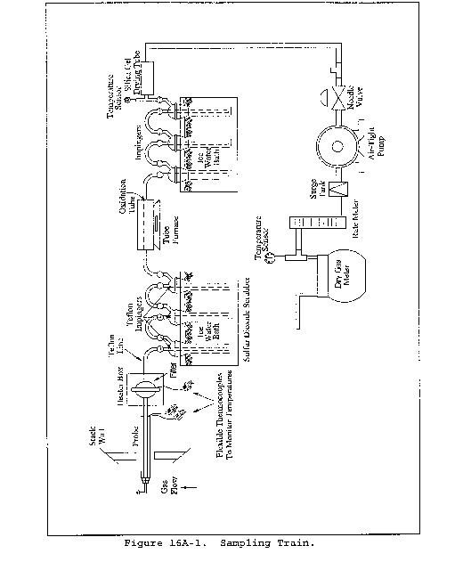
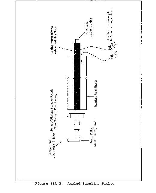

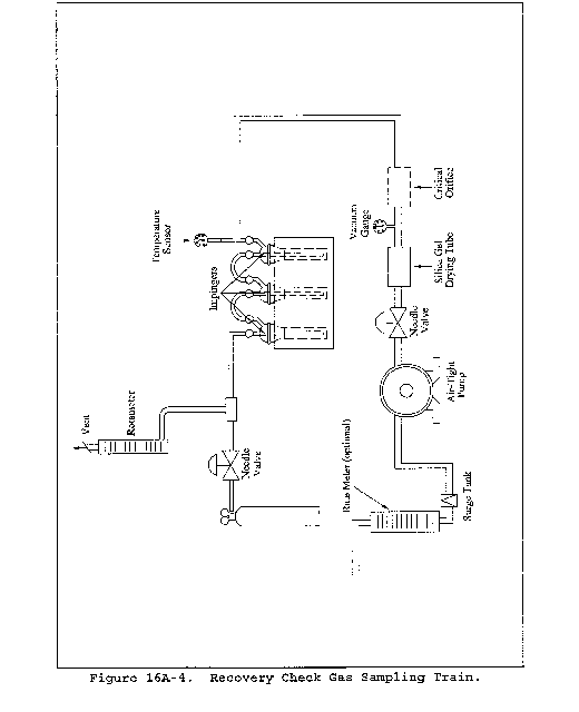
Date
Critical orifice ID
Soap bubble meter volume, Vsb____ liters
Time, θsb
Run no. 1 ____ min ____ sec
Run no. 2 ____ min ____ sec
Run no. 3 ____ min ____ sec
Average ____ min ____ sec
Covert the seconds to fraction of minute:
Time=____ min + ____ Sec/60=____ min
Barometric pressure, Pbar=____ mm Hg
Ambient temperature, tamb = 273 + ____ °C=____ °K=____ mm Hg. (This should be approximately 0.4 times barometric pressure.)
Pump vacuum,

Table 16A-1. Critical Orifice Calibration Data
Method 16B - Determination of Total Reduced Sulfur Emissions From Stationary Sources
This method does not include all of the specifications (e.g., equipment and supplies) and procedures (e.g., sampling and analytical) essential to its performance. Some material is incorporated by reference from other methods in this part. Therefore, to obtain reliable results, persons using this method should have a knowledge of at least the following additional test methods: Method 6C, Method 16, and Method 16A.
1.0 Scope and Application
1.1 Analytes.
| Analyte | CAS No. |
|---|---|
| Total reduced sulfur (TRS) including: | N/A |
| Dimethyl disulfide (DMDS), [(CH3)2S2] | 62-49-20 |
| Dimethyl sulfide (DMS), [(CH3)2S] | 75-18-3 |
| Hydrogen sulfide (H2S) | 7783-06-4 |
| Methyl mercaptan (MeSH), [CH4S] | 74-93-1 |
| Reported as: Sulfur dioxide (SO2) | 7449-09-5 |
1.2 Applicability. This method is applicable for determining TRS emissions from recovery furnaces (boilers), lime kilns, and smelt dissolving tanks at kraft pulp mills, and from other sources when specified in an applicable subpart of the regulations. The flue gas must contain at least 1 percent oxygen for complete oxidation of all TRS to SO2.
1.3 Data Quality Objectives. Adherence to the requirements of this method will enhance the quality of the data obtained from air pollutant sampling methods.
2.0 Summary of Method
2.1 A gas sample is extracted from the stack. The SO2 is removed selectively from the sample using a citrate buffer solution. The TRS compounds are then thermally oxidized to SO2 and analyzed as SO2 by gas chromatography (GC) using flame photometric detection (FPD).
3.0 Definitions [Reserved]
4.0 Interferences
4.1 Reduced sulfur compounds other than those regulated by the emission standards, if present, may be measured by this method. Therefore, carbonyl sulfide, which is partially oxidized to SO2 and may be present in a lime kiln exit stack, would be a positive interferant.
4.2 Particulate matter from the lime kiln stack gas (primarily calcium carbonate) can cause a negative bias if it is allowed to enter the citrate scrubber; the particulate matter will cause the pH to rise and H2S to be absorbed before oxidation. Proper use of the particulate filter, described in section 6.1.3 of Method 16A, will eliminate this interference.
4.3 Carbon monoxide (CO) and carbon dioxide (CO2) have substantial desensitizing effects on the FPD even after dilution. Acceptable systems must demonstrate that they have eliminated this interference by some procedure such as eluting these compounds before the SO2. Compliance with this requirement can be demonstrated by submitting chromatograms of calibration gases with and without CO2 in diluent gas. The CO2 level should be approximately 10 percent for the case with CO2 present. The two chromatograms should show agreement within the precision limits of section 13.0.
5.0 Safety
5.1 Disclaimer. This method may involve hazardous materials, operations, and equipment. This test method may not address all of the safety problems associated with its use. It is the responsibility of the user of this test method to establish appropriate safety and health practices and determine the applicability of regulatory limitations prior to performing this test method.
5.2 Hydrogen Sulfide (H2S). A flammable, poisonous gas with the odor of rotten eggs. H2S is extremely hazardous and can cause collapse, coma, and death within a few seconds of one or two inhalations at sufficient concentrations. Low concentrations irritate the mucous membranes and may cause nausea, dizziness, and headache after exposure.
6.0 Equipment and Supplies
6.1 Sample Collection. The sampling train is shown in Figure 16B-1. Modifications to the apparatus are accepted provided the system performance check in section 8.3.1 is met.
6.1.1 Probe, Probe Brush, Particulate Filter, SO2 Scrubber, Combustion Tube, and Furnace. Same as in Method 16A, sections 6.1.1 to 6.1.6.
6.1.2 Sampling Pump. Leakless Teflon-coated diaphragm type or equivalent.
6.2 Analysis.
6.2.1 Dilution System (optional), Gas Chromatograph, Oven, Temperature Gauges, Flow System, Flame Photometric Detector, Electrometer, Power Supply, Recorder, Calibration System, Tube Chamber, Flow System, and Constant Temperature Bath. Same as in Method 16, sections 6.2.1, 6.2.2, and 6.3.
6.2.2 Gas Chromatograph Columns. Same as in Method 16, section 6.2.3. Other columns with demonstrated ability to resolve SO2 and be free from known interferences are acceptable alternatives. Single column systems such as a 7-ft Carbsorb B HT 100 column have been found satisfactory in resolving SO2 from CO2.
7.0 Reagents and Standards
Same as in Method 16, section 7.0, except for the following:
7.1 Calibration Gas. SO2 permeation tube gravimetrically calibrated and certified at some convenient operating temperature. These tubes consist of hermetically sealed FEP Teflon tubing in which a liquefied gaseous substance is enclosed. The enclosed gas permeates through the tubing wall at a constant rate. When the temperature is constant, calibration gases covering a wide range of known concentrations can be generated by varying and accurately measuring the flow rate of diluent gas passing over the tubes. In place of SO2 permeation tubes, cylinder gases containing SO2 in nitrogen may be used for calibration. The cylinder gas concentration must be verified according to section 8.2.1 of Method 6C. The calibration gas is used to calibrate the GC/FPD system and the dilution system.
7.2 Recovery Check Gas.
7.2.1 Hydrogen sulfide [100 parts per million by volume (ppmv) or less] in nitrogen, stored in aluminum cylinders. Verify the concentration by Method 11, the procedure discussed in section 16.0 of Method 16A, or gas chromatography where the instrument is calibrated with an H2S permeation tube as described below. For the wet-chemical methods, the standard deviation should not exceed 5 percent on at least three 20-minute runs.
7.2.2 Hydrogen sulfide recovery gas generated from a permeation device gravimetrically calibrated and certified at some convenient operation temperature may be used. The permeation rate of the device must be such that at a dilution gas flow rate of 3 liters/min (64 ft3/hr), an H2S concentration in the range of the stack gas or within 20 percent of the emission standard can be generated.
7.3 Combustion Gas. Gas containing less than 50 ppbv reduced sulfur compounds and less than 10 ppmv total hydrocarbons. The gas may be generated from a clean-air system that purifies ambient air and consists of the following components: diaphragm pump, silica gel drying tube, activated charcoal tube, and flow rate measuring device. Gas from a compressed air cylinder is also acceptable.
8.0 Sample Collection, Preservation, Storage, and Transport
8.1 Pretest Procedures. Same as in Method 15, section 8.1.
8.2 Sample Collection. Before any source sampling is performed, conduct a system performance check as detailed in section 8.3.1 to validate the sampling train components and procedures. Although this test is optional, it would significantly reduce the possibility of rejecting tests as a result of failing the post-test performance check. At the completion of the pretest system performance check, insert the sampling probe into the test port making certain that no dilution air enters the stack though the port. Condition the entire system with sample for a minimum of 15 minutes before beginning analysis. If the sample is diluted, determine the dilution factor as in section 10.4 of Method 15.
8.3. Post-Test Procedures
8.3.1 System Performance Check. Same as in Method 16A, section 8.5. A sufficient number of sample injections should be made so that the precision requirements of section 13.2 are satisfied.
8.3.2 Determination of Calibration Drift. Same as in Method 15, section 8.3.2.
9.0 Quality Control
| Section | Quality control measure | Effect |
|---|---|---|
| 8.2, 8.3 | System performance check | Ensure validity of sampling train components and analytical procedure. |
| 8.1 | Sampling equipment leak-check and calibration | Ensure accurate measurement of stack gas flow rate, sample volume. |
| 10.0 | Analytical calibration | Ensure precision of analytical results within 5 percent. |
10.0 Calibration
Same as in Method 16, section 10, except SO2 is used instead of H2S.
11.0 Analytical Procedure
11.1 Analysis. Inject aliquots of the sample into the GC/FPD analyzer for analysis. Determine the concentration of SO2 directly from the calibration curves or from the equation for the least-squares line.
11.2 Perform analysis of a minimum of three aliquots or one every 15 minutes, whichever is greater, spaced evenly over the test period.
12.0 Data Analysis and Calculations
12.1 Nomenclature.
CSO2 = Sulfur dioxide concentration, ppmv.
CTRS = Total reduced sulfur concentration as determined by Equation 16B-1, ppmv.
d = Dilution factor, dimensionless.
N = Number of samples.
12.2 SO2 Concentration. Determine the concentration of SO2, CSO2, directly from the calibration curves. Alternatively, the concentration may be calculated using the equation for the least-squares line.
12.3 TRS Concentration.

12.4 Average TRS Concentration
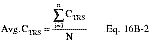
13.0 Method Performance.
13.1 Range and Sensitivity. Coupled with a GC using a 1-ml sample size, the maximum limit of the FPD for SO2 is approximately 10 ppmv. This limit is extended by diluting the sample gas before analysis or by reducing the sample aliquot size. For sources with emission levels between 10 and 100 ppm, the measuring range can be best extended by reducing the sample size.
13.2 GC/FPD Calibration and Precision. A series of three consecutive injections of the sample calibration gas, at any dilution, must produce results which do not vary by more than 5 percent from the mean of the three injections.
13.3 Calibration Drift. The calibration drift determined from the mean of the three injections made at the beginning and end of any run or series of runs within a 24-hour period must not exceed 5 percent.
13.4 System Calibration Accuracy. Losses through the sample transport system must be measured and a correction factor developed to adjust the calibration accuracy to 100 percent.
13.5 Field tests between this method and Method 16A showed an average difference of less than 4.0 percent. This difference was not determined to be significant.
14.0 Pollution Prevention [Reserved]
15.0 Waste Management [Reserved]
16.0 References
1. Same as in Method 16, section 16.0.
2. National Council of the Paper Industry for Air and Stream Improvement, Inc, A Study of TRS Measurement Methods. Technical Bulletin No. 434. New York, NY. May 1984. 12p.
3. Margeson, J.H., J.E. Knoll, and M.R. Midgett. A Manual Method for TRS Determination. Draft available from the authors. Source Branch, Quality Assurance Division, U.S. Environmental Protection Agency, Research Triangle Park, NC 27711.
17.0 Tables, Diagrams, Flowcharts, and Validation Data
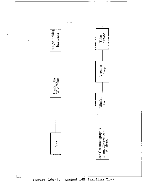
Method 16C - Determination of Total Reduced Sulfur Emissions From Stationary Sources
1.0 Scope and Application
What is Method 16C?
Method 16C is a procedure for measuring total reduced sulfur (TRS) in stationary source emissions using a continuous instrumental analyzer. Quality assurance and quality control requirements are included to assure that you, the tester, collect data of known quality. You must document your adherence to these specific requirements for equipment, supplies, sample collection and analysis, calculations, and data analysis. This method does not completely describe all equipment, supplies, and sampling and analytical procedures you will need but refers to other methods for some of the details. Therefore, to obtain reliable results, you should also have a thorough knowledge of these additional test methods which are found in appendix A to this part:
(a) Method 6C - Determination of Sulfur Dioxide Emissions from Stationary Sources (Instrumental Analyzer Procedure)
(b) Method 7E - Determination of Nitrogen Oxides Emissions from Stationary Sources (Instrumental Analyzer Procedure)
(c) Method 16A - Determination of Total Reduced Sulfur Emissions from Stationary Sources (Impinger Technique)
1.1 Analytes. What does Method 16C determine?
| Analyte | CAS No. |
|---|---|
| Total reduced sulfur including: | N/A |
| Dimethyl disulfide (DMDS), [(CH3)2S2] | 62-49-20 |
| Dimethyl sulfide (DMS), [(CH3)2S] | 75-18-3 |
| Hydrogen sulfide (H2S) | 7783-06-4 |
| Methyl mercaptan (MeSH), (CH4S) | 74-93-1 |
| Reported as: Sulfur dioxide (SO2) | 7449-09-5 |
1.2 Applicability. This method is applicable for determining TRS emissions from recovery furnaces (boilers), lime kilns, and smelt dissolving tanks at kraft pulp mills, and from other sources when specified in an applicable subpart of the regulations.
1.3 Data Quality Objectives. Adherence to the requirements described in Method 16C will enhance the quality of the data obtained.
2.0 Summary of Method
2.1 An integrated gas sample is extracted from the stack. The SO2 is removed selectively from the sample using a citrate buffer solution. The TRS compounds are then thermally oxidized to SO2 and determined as SO2 by an instrumental analyzer. This method is a combination of the sampling procedures of Method 16A and the analytical procedures of Method 6C (referenced in Method 7E), with minor modifications to facilitate their use together.
3.0 Definitions
Analyzer calibration error, Calibration curve, Calibration gas, Low-level gas, Mid-level gas, High-level gas, Calibration drift, Calibration span, Data recorder, Direct calibration mode, Gas analyzer, Interference check, Measurement system, Response time, Run, System calibration mode, System performance check, and Test are the same as used in Methods 16A and 6C.
4.0 Interferences
4.1 Reduced sulfur compounds other than those defined as TRS, if present, may be measured by this method. Compounds like carbonyl sulfide, which is partially oxidized to SO2 and may be present in a lime kiln exit stack, would be a positive interferent. Interferences may vary among instruments, and instrument-specific interferences must be evaluated through the interference check.
4.2 Particulate matter from the lime kiln stack gas (primarily calcium carbonate) can cause a negative bias if it is allowed to enter the citrate scrubber; the particulate matter will cause the pH to rise and H2S to be absorbed before oxidation. Proper use of the particulate filter, described in section 6.1.3 of Method 16A, will eliminate this interference.
5.0 Safety
5.1 Disclaimer. This method may involve hazardous materials, operations, and equipment. This test method may not address all of the safety problems associated with its use. It is the responsibility of the user to establish appropriate safety and health practices before performing this test method.
5.2 Hydrogen Sulfide. Hydrogen sulfide is a flammable, poisonous gas with the odor of rotten eggs. Hydrogen sulfide is extremely hazardous and can cause collapse, coma, and death within a few seconds of one or two inhalations at sufficient concentrations. Low concentrations irritate the mucous membranes and may cause nausea, dizziness, and headache after exposure. It is the responsibility of the user of this test method to establish appropriate safety and health practices.
6.0 Equipment and Supplies
What do I need for the measurement system?
The measurement system is similar to those applicable components in Methods 16A and 6C. Modifications to the apparatus are accepted provided the performance criteria in section 13.0 are met.
6.1 Probe. Teflon tubing, 6.4-mm (1⁄4 in.) diameter, sequentially wrapped with heat-resistant fiber strips, a rubberized heat tape (plug at one end), and heat-resistant adhesive tape. A flexible thermocouple or other suitable temperature measuring device must be placed between the Teflon tubing and the fiber strips so that the temperature can be monitored to prevent softening of the probe. The probe must be sheathed in stainless steel to provide in-stack rigidity. A series of bored-out stainless steel fittings placed at the front of the sheath will prevent moisture and particulate from entering between the probe and sheath. A 6.4-mm (1⁄4 in.) Teflon elbow (bored out) must be attached to the inlet of the probe, and a 2.54 cm (1 in.) piece of Teflon tubing must be attached at the open end of the elbow to permit the opening of the probe to be turned away from the particulate stream; this will reduce the amount of particulate drawn into the sampling train. The probe is depicted in Figure 16A-2 of Method 16A.
6.2 Probe Brush. Nylon bristle brush with handle inserted into a 3.2-mm (1⁄8 in.) Teflon tubing. The Teflon tubing should be long enough to pass the brush through the length of the probe.
6.3 Particulate Filter. 50-mm Teflon filter holder and a 1- to 2-µm porosity, Teflon filter (may be available through Savillex Corporation, 5325 Highway 101, Minnetonka, Minnesota 55343, or other suppliers of filters). The filter holder must be maintained in a hot box at a temperature sufficient to prevent moisture condensation. A temperature of 121 °C (250 °F) was found to be sufficient when testing a lime kiln under sub-freezing ambient conditions.
6.4 SO2 Scrubber. Three 300-ml Teflon segmented impingers connected in series with flexible, thick-walled, Teflon tubing. (Impinger parts and tubing may be available through Savillex or other suppliers.) The first two impingers contain 100 ml of citrate buffer, and the third impinger is initially dry. The tip of the tube inserted into the solution should be constricted to less than 3 mm (1⁄8 in.) ID and should be immersed to a depth of at least 5 cm (2 in.).
6.5 Combustion Tube. Quartz glass tubing with an expanded combustion chamber 2.54 cm (1 in.) in diameter and at least 30.5 cm (12 in.) long. The tube ends should have an outside diameter of 0.6 cm (1⁄4 in.) and be at least 15.3 cm (6 in.) long. This length is necessary to maintain the quartz-glass connector near ambient temperature and thereby avoid leaks. Alternative combustion tubes are acceptable provided they are shown to combust TRS at concentrations encountered during tests.
6.6 Furnace. A furnace of sufficient size to enclose the combustion chamber of the combustion tube with a temperature regulator capable of maintaining the temperature at 800 ±100 °C (1472 ±180 °F). The furnace operating temperature should be checked with a thermocouple to ensure accuracy.
6.7 Sampling Pump. A leak-free pump is required to pull the sample gas through the system at a flow rate sufficient to minimize the response time of the measurement system and must be constructed of material that is non-reactive to the gas it contacts. For dilution-type measurement systems, an eductor pump may be used to create a vacuum that draws the sample through a critical orifice at a constant rate.
6.8 Calibration Gas Manifold. The calibration gas manifold must allow the introduction of calibration gases either directly to the gas analyzer in direct calibration mode or into the measurement system, at the probe, in system calibration mode, or both, depending upon the type of system used. In system calibration mode, the system must be able to flood the sampling probe and vent excess gas. Alternatively, calibration gases may be introduced at the calibration valve following the probe. Maintain a constant pressure in the gas manifold. For in-stack dilution-type systems, a gas dilution subsystem is required to transport large volumes of purified air to the sample probe, and a probe controller is needed to maintain the proper dilution ratio.
6.9 Sample Gas Manifold. The sample gas manifold diverts a portion of the sample to the analyzer, delivering the remainder to the by-pass discharge vent. The manifold should also be able to introduce calibration gases directly to the analyzer. The manifold must be made of material that is non-reactive to SO2 and be configured to safely discharge the bypass gas.
6.10 SO2 Analyzer. You must use an instrument that uses an ultraviolet, non-dispersive infrared, fluorescence, or other detection principle to continuously measure SO2 in the gas stream provided it meets the performance specifications in section 13.0.
6.11 Data Recording. A strip chart recorder, computerized data acquisition system, digital recorder, or data logger for recording measurement data must be used.
7.0 Reagents and Standards
Unless otherwise indicated, all reagents must conform to the specifications established by the Committee on Analytical Reagents of the American Chemical Society. When such specifications are not available, the best available grade must be used.
7.1 Water. Deionized distilled water must conform to ASTM Specification D 1193-77 or 91 Type 3 (incorporated by reference - see § 60.17). The KMnO4 test for oxidizable organic matter may be omitted when high concentrations of organic matter are not expected to be present.
7.2 Citrate Buffer. Dissolve 300 g of potassium citrate (or 284 g of sodium citrate) and 41 g of anhydrous citric acid in 1 liter of water (200 ml is needed per test). Adjust the pH to between 5.4 and 5.6 with potassium citrate or citric acid, as required.
7.3 Calibration Gas. Refer to section 7.1 of Method 7E (as applicable) for the calibration gas requirements. Example calibration gas mixtures are listed below.
(a) SO2 in nitrogen (N2).
(b) SO2 in air.
(c) SO2 and carbon dioxide (CO2) in N2.
(d) SO2 and oxygen (O2) in N2.
(e) SO2/CO2/O2 gas mixture in N2.
(f) CO2/NOX gas mixture in N2.
(g) CO2/SO2/NOX gas mixture in N2.
For fluorescence-based analyzers, the O2 and CO2 concentrations of the calibration gases as introduced to the analyzer must be within 1.0 percent (absolute) O2 and 1.0 percent (absolute) CO2 of the O2 and CO2 concentrations of the effluent samples as introduced to the analyzer. Alternatively, for fluorescence-based analyzers, use calibration blends of SO2 in air and the nomographs provided by the vendor to determine the quenching correction factor (the effluent O2 and CO2 concentrations must be known). This requirement does not apply to ambient-level fluorescence analyzers that are used in conjunction with sample dilution systems. Alternatively, H2S in O2 or air may be used to calibrate the analyzer through the tube furnace.
7.4 System Performance Check Gas. You must use H2S (100 ppmv or less) stored in aluminum cylinders with the concentration certified by the manufacturer. Hydrogen sulfide in nitrogen is more stable than H2S in air, but air may be used as the balance gas.
Alternatively, H2S recovery gas generated from a permeation device gravimetrically calibrated and certified at some convenient operating temperature may be used. The permeation rate of the device must be such that at the appropriate dilution gas flow rate, an H2S concentration can be generated in the range of the stack gas or within 20 percent of the emission standard.
7.5 Interference Check. Examples of test gases for the interference check are listed in Table 7E-3 of Method 7E.
8.0 Sample Collection, Preservation, Storage, and Transport
8.1 Pre-sampling Tests. Before measuring emissions, perform the following procedures:
(a) Calibration gas verification,
(b) Calibration error test,
(c) System performance check,
(d) Verification that the interference check has been satisfied.
8.1.1 Calibration Gas Verification. Obtain a certificate from the gas manufacturer documenting the quality of the gas. Confirm that the manufacturer certification is complete and current. Ensure that your calibration gas certifications have not expired. This documentation should be available on-site for inspection. To the extent practicable, select a high-level gas concentration that will result in the measured emissions being between 20 and 100 percent of the calibration span.
8.1.2 Analyzer Calibration Error Test. After you have assembled, prepared, and calibrated your sampling system and analyzer, you must conduct a 3-point analyzer calibration error test before the first run and again after any failed system performance check or failed drift test to ensure the calibration is acceptable. Introduce the low-, mid-, and high-level calibration gases sequentially to the analyzer in direct calibration mode. For each calibration gas, calculate the analyzer calibration error using Equation 16C-1 in section 12.2. The calibration error for the low-, mid-, and high-level gases must not exceed 5.0 percent or 0.5 ppmv. If the calibration error specification is not met, take corrective action and repeat the test until an acceptable 3-point calibration is achieved.
8.1.3 System Performance Check. A system performance check is done
(1) to validate the sampling train components and procedure (prior to testing), and
(2) to validate a test run (after a run). You must conduct a performance check in the field prior to testing, and after each 3-hour run or after three 1-hour runs. A performance check consists of sampling and analyzing a known concentration of H2S (system performance check gas) and comparing the analyzed concentration to the known concentration. To conduct the system performance check, mix the system performance check gas (Section 7.4) and ambient air, that has been conditioned to remove moisture and sulfur-containing gases, in a dilution system such as that shown in Figure 16A-3 of Method 16A. Alternatively, ultra-high purity (UHP) grade air may be used. Adjust the gas flow rates to generate an H2S concentration in the range of the stack gas or within 20 percent of the applicable standard and an oxygen concentration greater than 1 percent at a total flow rate of at least 2.5 liters/min (5.3 ft3/hr). Use Equation 16A-3 from Method 16A to calculate the concentration of system performance check gas generated. Calibrate the flow rate from both gas sources with a soap bubble flow meter so that the diluted concentration of H2S can be accurately calculated. Alternatively, mass flow controllers with documented calibrations may be used if UHP grade air is being used. Sample duration should be sufficiently long to ensure a stable response from the analyzer. Analyze in the same manner as the emission samples. Collect the sample through the probe of the sampling train using a manifold or other suitable device that will ensure extraction of a representative sample. The TRS sample concentration measured between system performance checks is corrected by the average of the pre- and post-system performance checks.
8.1.4 Interference Check. Same as in Method 7E, section 8.2.7.
8.2 Measurement System Preparation.
8.2.1 For the SO2 scrubber, measure 100 ml of citrate buffer into the first and second impingers; leave the third impinger empty. Immerse the impingers in an ice bath, and locate them as close as possible to the filter heat box. The connecting tubing should be free of loops. Maintain the probe and filter temperatures sufficiently high to prevent moisture condensation, and monitor with a suitable temperature sensor. Prepare the oxidation furnace and maintain at 800 ±100 °C (1472 ±180 °F).
8.2.2 Citrate Scrubber Conditioning Procedure. Condition the citrate buffer scrubbing solution by pulling stack gas through the Teflon impingers as described in section 8.4.1.
8.3 Pretest Procedures. After the complete measurement system has been set up at the site and deemed to be operational, the following procedures must be completed before sampling is initiated.
8.3.1 Leak-Check. Appropriate leak-check procedures must be employed to verify the integrity of all components, sample lines, and connections. For components upstream of the sample pump, attach the probe end of the sample line to a manometer or vacuum gauge, start the pump and pull a vacuum greater than 50 mm (2 in.) Hg, close off the pump outlet, and then stop the pump and ascertain that there is no leak for 1 minute. For components after the pump, apply a slight positive pressure and check for leaks by applying a liquid (detergent in water, for example) at each joint. Bubbling indicates the presence of a leak.
8.3.2 Initial System Performance Check. A system performance check using the test gas (Section 7.4) is performed prior to testing to validate the sampling train components and procedure.
8.4 Sample Collection and Analysis.
8.4.1 After performing the required pretest procedures described in section 8.1, insert the sampling probe into the test port ensuring that no dilution air enters the stack through the port. Condition the sampling system and citrate buffer solution for a minimum of 15 minutes before beginning analysis. Begin sampling and analysis. A source test consists of three test runs. A test run shall consist of a single sample collected over a 3-hour period or three separate 1-hour samples collected over a period not to exceed six hours.
8.5 Post-Run Evaluations.
8.5.1 System Performance Check. Perform a post-run system performance check before replacing the citrate buffer solution and particulate filter and before the probe is cleaned. The check results must not exceed the 100 ±20 percent limit set forth in section 13.2. If this limit is exceeded, the intervening run is considered invalid. However, if the recovery efficiency is not in the 100 ±20 percent range, but the results do not affect the compliance or noncompliance status of the affected facility, the Administrator may decide to accept the results of the compliance test.
8.5.2 Calibration Drift. After a run or series of runs, not to exceed a 24-hour period after initial calibration, perform a calibration drift test using a calibration gas (preferably the level that best approximates the sample concentration) in direct calibration mode. This drift must not differ from the initial calibration error percent by more than 3.0 percent or 0.5 ppm. If the drift exceeds this limit, the intervening run or runs are considered valid, but a new analyzer calibration error test must be performed and passed before continuing sampling.
9.0 Quality Control
| Section | Quality control measure | Effect |
|---|---|---|
| 8.1.2 | Analyzer calibration error test | Establishes initial calibration accuracy within 5.0%. |
| 8.1.3, 8.5.1 | System performance check | Ensures accuracy of sampling/analytical procedure to 100 ±20%. |
| 8.5.2 | Calibration drift test | Ensures calibration drift is within 3.0%. |
| 8.1.4 | Interference check | Checks for analytical interferences. |
| 8.3 | Sampling equipment leak-check | Ensures accurate measurement of sample gas flow rate, sample volume. |
10.0 Calibration
10.1 Calibrate the system using the gases described in section 7.3. Perform the initial 3-point calibration error test as described in section 8.1.2 before you start the test. The specification in section 13 must be met. Conduct an initial system performance test described in section 8.1.3 as well before the test to validate the sampling components and procedures before sampling. After the test commences, a system performance check is required after each run. You must include a copy of the manufacturer's certification of the calibration gases used in the testing as part of the test report. This certification must include the 13 documentation requirements in the EPA Traceability Protocol for Assay and Certification of Gaseous Calibration Standards, September 1997, as amended August 25, 1999.
11.0 Analytical Procedure
Because sample collection and analysis are performed together (see section 8.0), additional discussion of the analytical procedure is not necessary.
12.0 Calculations and Data Analysis
12.1 Nomenclature.
ACE = Analyzer calibration error, percent of calibration span.
CD = Calibration drift, percent.
CDir = Measured concentration of a calibration gas (low, mid, or high) when introduced in direct calibration mode, ppmv.
CH2S = Concentration of the system performance check gas, ppmv H2S.
CS = Measured concentration of the system performance gas when introduced in system calibration mode, ppmv H2S.
CV = Manufacturer certified concentration of a calibration gas (low, mid, or high), ppmv SO2.
CSO2 = Unadjusted sample SO2 concentration, ppmv.
CTRS = Total reduced sulfur concentration corrected for system performance, ppmv.
CS = Calibration span, ppmv.
DF = Dilution system (if used) dilution factor, dimensionless.
SP = System performance, percent.
12.2 Analyzer Calibration Error. For non-dilution systems, use Equation 16C-1 to calculate the analyzer calibration error for the low-, mid-, and high-level calibration gases.

12.3 System Performance Check. Use Equation 16C-2 to calculate the system performance.

12.4 Calibration Drift. Use Equation 16C-3 to calculate the calibration drift at a single concentration level after a run or series of runs (not to exceed a 24-hr period) from initial calibration. Compare the single-level calibration gas error (ACEn) to the original error obtained for that gas in the initial analyzer calibration error test (ACEi).

12.5 TRS Concentration as SO2. For each sample or test run, calculate the arithmetic average of SO2 concentration values (e.g., 1-minute averages). Then calculate the sample TRS concentration by adjusting the average value of CSO2 for system performance using Equation 16C-4.
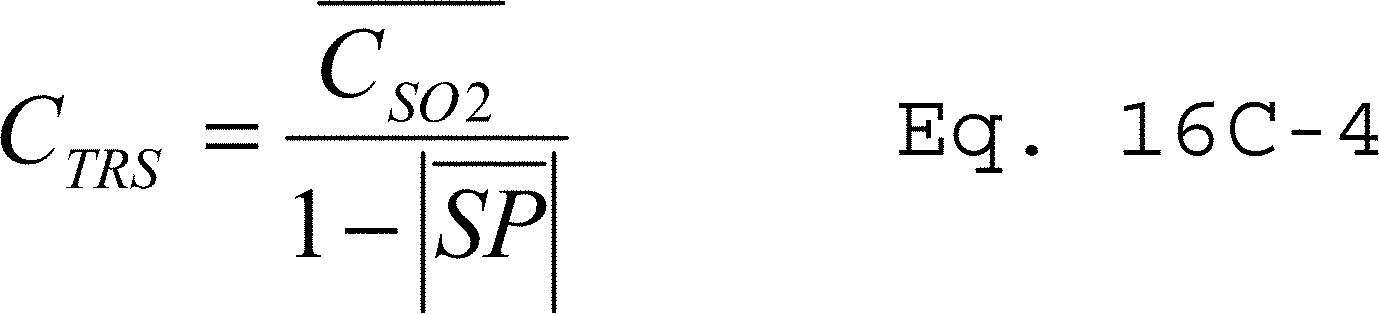
13.0 Method Performance
13.1 Analyzer Calibration Error. At each calibration gas level (low, mid, and high), the calibration error must either not exceed 5.0 percent of the calibration span or |CDir−Cv| must be ≤0.5 ppmv.
13.2 System Performance. Each system performance check must not deviate from the system performance gas concentration by more than 20 percent. Alternatively, the results are acceptable if |Cs−CH2S| is ≤0.5 ppmv.
13.3 Calibration Drift. The calibration drift at the end of any run or series of runs within a 24-hour period must not differ by more than 3.0 percent from the original ACE at the test concentration level or |ACEi−ACEn| must not exceed 0.5 ppmv.
13.4 Interference Check. For the analyzer, the total interference response (i.e., the sum of the interference responses of all tested gaseous components) must not be greater than 2.5 percent of the calibration span. Any interference is also acceptable if the sum of the responses does not exceed 0.5 ppmv for a calibration span of 5 to 10 ppmv, or 0.2 ppmv for a calibration span <5 ppmv.
14.0 Pollution Prevention [Reserved]
15.0 Waste Management [Reserved]
16.0 References
1. The references are the same as in section 16.0 of Method 16, section 17.0 of Method 16A, and section 17.0 of Method 6C.
2. National Council of the Paper Industry for Air and Stream Improvement, Inc,. A Study of TRS Measurement Methods. Technical Bulletin No. 434. New York, NY. May 1984. 12p.
3. Margeson, J.H., J.E. Knoll, and M.R. Midgett. A Manual Method for TRS Determination. Draft available from the authors. Source Branch, Quality Assurance Division, U.S. Environmental Protection Agency, Research Triangle Park, NC 27711.
17.0 Tables, Diagrams, Flowcharts, and Validation Data [Reserved]
Method 17 - Determination of Particulate Matter Emissions From Stationary Sources
This method does not include all of the specifications (e.g., equipment and supplies) and procedures (e.g., sampling and analytical) essential to its performance. Some material is incorporated by reference from other methods in this part. Therefore, to obtain reliable results, persons using this method should have a thorough knowledge of at least the following additional test methods: Method 1, Method 2, Method 3, Method 5.
1.0 Scope and Application
1.1 Analyte. Particulate matter (PM). No CAS number assigned.
Particulate matter is not an absolute quantity. It is a function of temperature and pressure. Therefore, to prevent variability in PM emission regulations and/or associated test methods, the temperature and pressure at which PM is to be measured must be carefully defined. Of the two variables (i.e., temperature and pressure), temperature has the greater effect upon the amount of PM in an effluent gas stream; in most stationary source categories, the effect of pressure appears to be negligible. In Method 5, 120 °C (248 °F) is established as a nominal reference temperature. Thus, where Method 5 is specified in an applicable subpart of the standard, PM is defined with respect to temperature. In order to maintain a collection temperature of 120 °C (248 °F), Method 5 employs a heated glass sample probe and a heated filter holder. This equipment is somewhat cumbersome and requires care in its operation. Therefore, where PM concentrations (over the normal range of temperature associated with a specified source category) are known to be independent of temperature, it is desirable to eliminate the glass probe and the heating systems, and to sample at stack temperature.
1.2 Applicability. This method is applicable for the determination of PM emissions, where PM concentrations are known to be independent of temperature over the normal range of temperatures characteristic of emissions from a specified source category. It is intended to be used only when specified by an applicable subpart of the standards, and only within the applicable temperature limits (if specified), or when otherwise approved by the Administrator. This method is not applicable to stacks that contain liquid droplets or are saturated with water vapor. In addition, this method shall not be used as written if the projected cross-sectional area of the probe extension-filter holder assembly covers more than 5 percent of the stack cross-sectional area (see section 8.1.2).
1.3 Data Quality Objectives. Adherence to the requirements of this method will enhance the quality of the data obtained from air pollutant sampling methods.
2.0 Summary of Method
2.1 Particulate matter is withdrawn isokinetically from the source and collected on a glass fiber filter maintained at stack temperature. The PM mass is determined gravimetrically after the removal of uncombined water.
3.0 Definitions
Same as Method 5, section 3.0.
4.0 Interferences [Reserved]
5.0 Safety
5.1 Disclaimer. This method may involve hazardous materials, operations, and equipment. This test method may not address all of the safety problems associated with its use. It is the responsibility of the user of this test method to establish appropriate safety and health practices and determine the applicability of regulatory limitations prior to performing this test method.
6.0 Equipment and Supplies
6.1 Sampling Train. A schematic of the sampling train used in this method is shown in Figure 17-1. The sampling train components and operation and maintenance are very similar to Method 5, which should be consulted for details.
6.1.1 Probe Nozzle, Differential Pressure Gauge, Metering System, Barometer, Gas Density Determination Equipment. Same as in Method 5, sections 6.1.1, 6.1.4, 6.1.8, 6.1.9, and 6.1.10, respectively.
6.1.2 Filter Holder. The in-stack filter holder shall be constructed of borosilicate or quartz glass, or stainless steel. If a gasket is used, it shall be made of silicone rubber, Teflon, or stainless steel. Other holder and gasket materials may be used, subject to the approval of the Administrator. The filter holder shall be designed to provide a positive seal against leakage from the outside or around the filter.
6.1.3 Probe Extension. Any suitable rigid probe extension may be used after the filter holder.
6.1.4 Pitot Tube. Same as in Method 5, section 6.1.3.
6.1.4.1 It is recommended
(1) that the pitot tube have a known baseline coefficient, determined as outlined in section 10 of Method 2; and
(2) that this known coefficient be preserved by placing the pitot tube in an interference-free arrangement with respect to the sampling nozzle, filter holder, and temperature sensor (see Figure 17-1). Note that the 1.9 cm (3⁄4-in.) free-space between the nozzle and pitot tube shown in Figure 17-1, is based on a 1.3 cm (1⁄2-in.) ID nozzle. If the sampling train is designed for sampling at higher flow rates than that described in APTD-0581, thus necessitating the use of larger sized nozzles, the free-space shall be 1.9 cm (3⁄4-in.) with the largest sized nozzle in place.
6.1.4.2 Source-sampling assemblies that do not meet the minimum spacing requirements of Figure 17-1 (or the equivalent of these requirements, e.g., Figure 2-4 of Method 2) may be used; however, the pitot tube coefficients of such assemblies shall be determined by calibration, using methods subject to the approval of the Administrator.
6.1.5 Condenser. It is recommended that the impinger system or alternatives described in Method 5 be used to determine the moisture content of the stack gas. Flexible tubing may be used between the probe extension and condenser. Long tubing lengths may affect the moisture determination.
6.2 Sample Recovery. Probe-liner and probe-nozzle brushes, wash bottles, glass sample storage containers, petri dishes, graduated cylinder and/or balance, plastic storage containers, funnel and rubber policeman, funnel. Same as in Method 5, sections 6.2.1 through 6.2.8, respectively.
6.3 Sample Analysis. Glass weighing dishes, desiccator, analytical balance, balance, beakers, hygrometer, temperature sensor. Same as in Method 5, sections 6.3.1 through 6.3.7, respectively.
7.0 Reagents and Standards
7.1 Sampling. Filters, silica gel, water, crushed ice, stopcock grease. Same as in Method 5, sections 7.1.1, 7.1.2, 7.1.3, 7.1.4, and 7.1.5, respectively. Thimble glass fiber filters may also be used.
7.2 Sample Recovery. Acetone (reagent grade). Same as in Method 5, section 7.2.
7.3 Sample Analysis. Acetone and Desiccant. Same as in Method 5, sections 7.3.1 and 7.3.2, respectively.
8.0 Sample Collection, Preservation, Storage, and Transport
8.1 Sampling.
8.1.1 Pretest Preparation. Same as in Method 5, section 8.1.1.
8.1.2 Preliminary Determinations. Same as in Method 5, section 8.1.2, except as follows: Make a projected-area model of the probe extension-filter holder assembly, with the pitot tube face openings positioned along the centerline of the stack, as shown in Figure 17-2. Calculate the estimated cross-section blockage, as shown in Figure 17-2. If the blockage exceeds 5 percent of the duct cross sectional area, the tester has the following options exist:
(1) a suitable out-of-stack filtration method may be used instead of in-stack filtration; or
(2) a special in-stack arrangement, in which the sampling and velocity measurement sites are separate, may be used; for details concerning this approach, consult with the Administrator (see also Reference 1 in section 17.0). Select a probe extension length such that all traverse points can be sampled. For large stacks, consider sampling from opposite sides of the stack to reduce the length of probes.
8.1.3 Preparation of Sampling Train. Same as in Method 5, section 8.1.3, except the following: Using a tweezer or clean disposable surgical gloves, place a labeled (identified) and weighed filter in the filter holder. Be sure that the filter is properly centered and the gasket properly placed so as not to allow the sample gas stream to circumvent the filter. Check filter for tears after assembly is completed. Mark the probe extension with heat resistant tape or by some other method to denote the proper distance into the stack or duct for each sampling point. Assemble the train as in Figure 17-1, using a very light coat of silicone grease on all ground glass joints and greasing only the outer portion (see APTD-0576) to avoid possibility of contamination by the silicone grease. Place crushed ice around the impingers.
8.1.4 Leak-Check Procedures. Same as in Method 5, section 8.1.4, except that the filter holder is inserted into the stack during the sampling train leak-check. To do this, plug the inlet to the probe nozzle with a material that will be able to withstand the stack temperature. Insert the filter holder into the stack and wait approximately 5 minutes (or longer, if necessary) to allow the system to come to equilibrium with the temperature of the stack gas stream.
8.1.5 Sampling Train Operation. The operation is the same as in Method 5. Use a data sheet such as the one shown in Figure 5-3 of Method 5, except that the filter holder temperature is not recorded.
8.1.6 Calculation of Percent Isokinetic. Same as in Method 5, section 12.11.
8.2 Sample Recovery.
8.2.1 Proper cleanup procedure begins as soon as the probe extension assembly is removed from the stack at the end of the sampling period. Allow the assembly to cool.
8.2.2 When the assembly can be safely handled, wipe off all external particulate matter near the tip of the probe nozzle and place a cap over it to prevent losing or gaining particulate matter. Do not cap off the probe tip tightly while the sampling train is cooling down as this would create a vacuum in the filter holder, forcing condenser water backward.
8.2.3 Before moving the sample train to the cleanup site, disconnect the filter holder-probe nozzle assembly from the probe extension; cap the open inlet of the probe extension. Be careful not to lose any condensate, if present. Remove the umbilical cord from the condenser outlet and cap the outlet. If a flexible line is used between the first impinger (or condenser) and the probe extension, disconnect the line at the probe extension and let any condensed water or liquid drain into the impingers or condenser. Disconnect the probe extension from the condenser; cap the probe extension outlet. After wiping off the silicone grease, cap off the condenser inlet. Ground glass stoppers, plastic caps, or serum caps (whichever are appropriate) may be used to close these openings.
8.2.4 Transfer both the filter holder-probe nozzle assembly and the condenser to the cleanup area. This area should be clean and protected from the wind so that the chances of contaminating or losing the sample will be minimized.
8.2.5 Save a portion of the acetone used for cleanup as a blank. Take 200 ml of this acetone from the wash bottle being used and place it in a glass sample container labeled “acetone blank.” Inspect the train prior to and during disassembly and not any abnormal conditions. Treat the sample as discussed in Method 5, section 8.2.
9.0 Quality Control [Reserved]
10.0 Calibration and Standardization
The calibrations of the probe nozzle, pitot tube, metering system, temperature sensors, and barometer are the same as in Method 5, sections 10.1 through 10.3, 10.5, and 10.6, respectively.
11.0 Analytical Procedure
Same as in Method 5, section 11.0. Analytical data should be recorded on a form similar to that shown in Figure 5-6 of Method 5.
12.0 Data Analysis and Calculations.
Same as in Method 5, section 12.0.
13.0 Method Performance [Reserved]
14.0 Pollution Prevention [Reserved]
15.0 Waste Management [Reserved]
16.0 Alternative Procedures
Same as in Method 5, section 16.0.
17.0 References
Same as in Method 5, section 17.0, with the addition of the following:
1. Vollaro, R.F. Recommended Procedure for Sample Traverses in Ducts Smaller than 12 Inches in Diameter. U.S. Environmental Protection Agency, Emission Measurement Branch. Research Triangle Park, NC. November 1976.
18.0 Tables, Diagrams, Flowcharts, and Validation Data
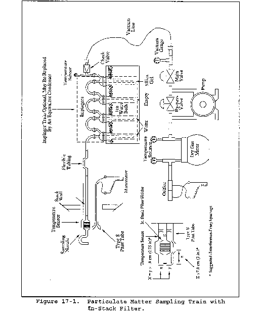
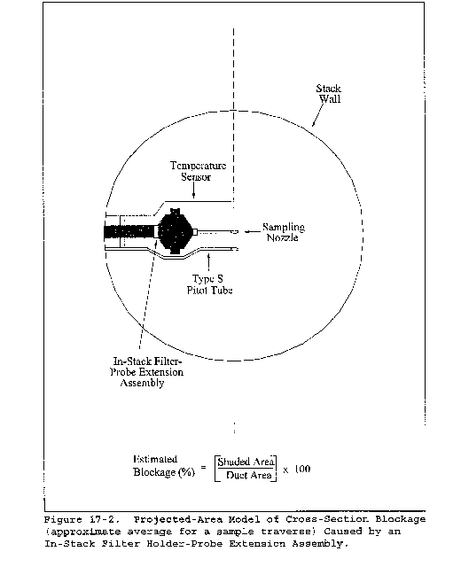
Method 18 - Measurement of Gaseous Organic Compound Emissions By Gas Chromatography
This method is not inclusive with respect to specifications (e.g., equipment and supplies) and procedures (e.g., sampling and analytical) essential to its performance. Some material is incorporated by reference from other methods in this part. Therefore, to obtain reliable results, persons using this method should have a thorough knowledge of at least the following additional test methods: Method 1, Method 2, Method 3.
This method should not be attempted by persons unfamiliar with the performance characteristics of gas chromatography, nor by those persons who are unfamiliar with source sampling. Particular care should be exercised in the area of safety concerning choice of equipment and operation in potentially explosive atmospheres.
1.0 Scope and Application
1.1 Analyte. Total gaseous organic compounds.
1.2 Applicability.
1.2.1 This method is designed to measure gaseous organics emitted from an industrial source. While designed for ppm level sources, some detectors are quite capable of detecting compounds at ambient levels, e.g., ECD, ELCD, and helium ionization detectors. Some other types of detectors are evolving such that the sensitivity and applicability may well be in the ppb range in only a few years.
1.2.2 This method will not determine compounds that
(1) are polymeric (high molecular weight),
(2) can polymerize before analysis, or
(3) have very low vapor pressures at stack or instrument conditions.
1.3 Range. The lower range of this method is determined by the sampling system; adsorbents may be used to concentrate the sample, thus lowering the limit of detection below the 1 part per million (ppm) typically achievable with direct interface or bag sampling. The upper limit is governed by GC detector saturation or column overloading; the upper range can be extended by dilution of sample with an inert gas or by using smaller volume gas sampling loops. The upper limit can also be governed by condensation of higher boiling compounds.
1.4 Sensitivity. The sensitivity limit for a compound is defined as the minimum detectable concentration of that compound, or the concentration that produces a signal-to-noise ratio of three to one. The minimum detectable concentration is determined during the presurvey calibration for each compound.
2.0 Summary of Method
The major organic components of a gas mixture are separated by gas chromatography (GC) and individually quantified by flame ionization, photoionization, electron capture, or other appropriate detection principles. The retention times of each separated component are compared with those of known compounds under identical conditions. Therefore, the analyst confirms the identity and approximate concentrations of the organic emission components beforehand. With this information, the analyst then prepares or purchases commercially available standard mixtures to calibrate the GC under conditions identical to those of the samples. The analyst also determines the need for sample dilution to avoid detector saturation, gas stream filtration to eliminate particulate matter, and prevention of moisture condensation.
3.0 Definitions [Reserved]
4.0 Interferences
4.1 Resolution interferences that may occur can be eliminated by appropriate GC column and detector choice or by shifting the retention times through changes in the column flow rate and the use of temperature programming.
4.2 The analytical system is demonstrated to be essentially free from contaminants by periodically analyzing blanks that consist of hydrocarbon-free air or nitrogen.
4.3 Sample cross-contamination that occurs when high-level and low-level samples or standards are analyzed alternately is best dealt with by thorough purging of the GC sample loop between samples.
4.4 To assure consistent detector response, calibration gases are contained in dry air. To adjust gaseous organic concentrations when water vapor is present in the sample, water vapor concentrations are determined for those samples, and a correction factor is applied.
4.5 The gas chromatograph run time must be sufficient to clear all eluting peaks from the column before proceeding to the next run (in order to prevent sample carryover).
5.0 Safety
5.1 Disclaimer. This method may involve hazardous materials, operations, and equipment. This test method may not address all of the safety problems associated with its use. It is the responsibility of the user of this test method to establish appropriate safety and health practices and determine the applicability of regulatory limitations prior to performing this test method. The analyzer users manual should be consulted for specific precautions to be taken with regard to the analytical procedure.
6.0 Equipment and Supplies
6.1 Equipment needed for the presurvey sampling procedure can be found in section 16.1.1.
6.2 Equipment needed for the integrated bag sampling and analysis procedure can be found in section 8.2.1.1.1.
6.3 Equipment needed for direct interface sampling and analysis can be found in section 8.2.2.1.
6.4 Equipment needed for the dilution interface sampling and analysis can be found in section 8.2.3.1.
6.5 Equipment needed for adsorbent tube sampling and analysis can be found in section 8.2.4.1.
7.0 Reagents and Standards
7.1 Reagents needed for the presurvey sampling procedure can be found in section 16.1.2.
8.0 Sample Collection, Preservation, Storage, and Transport
8.2 Final Sampling and Analysis Procedure. Considering safety (flame hazards) and the source conditions, select an appropriate sampling and analysis procedure (Section 8.2.1, 8.2.2, 8.2.3 or 8.2.4). In situations where a hydrogen flame is a hazard and no intrinsically safe GC is suitable, use the flexible bag collection technique or an adsorption technique.
8.2.1 Integrated Bag Sampling and Analysis.
8.2.1.1 Evacuated Container Sampling Procedure. In this procedure, the bags are filled by evacuating the rigid air-tight container holding the bags. Use a field sample data sheet as shown in Figure 18-10. Collect triplicate samples from each sample location.
8.2.1.1.1 Apparatus.
8.2.1.1.1.1 Probe. Stainless steel, Pyrex glass, or Teflon tubing probe, according to the duct temperature, with Teflon tubing of sufficient length to connect to the sample bag. Use stainless steel or Teflon unions to connect probe and sample line.
8.2.1.1.1.2 Quick Connects. Male (2) and female (2) of stainless steel construction.
8.2.1.1.1.3 Needle Valve. To control gas flow.
8.2.1.1.1.4 Pump. Leakless Teflon-coated diaphragm-type pump or equivalent. To deliver at least 1 liter/min.
8.2.1.1.1.5 Charcoal Adsorption Tube. Tube filled with activated charcoal, with glass wool plugs at each end, to adsorb organic vapors.
8.2.1.1.1.6 Flowmeter. 0 to 500-ml flow range; with manufacturer's calibration curve.
8.2.1.1.2 Sampling Procedure. To obtain a sample, assemble the sample train as shown in Figure 18-9. Leak-check both the bag and the container. Connect the vacuum line from the needle valve to the Teflon sample line from the probe. Place the end of the probe at the centroid of the stack or at a point no closer to the walls than 1 in., and start the pump. Set the flow rate so that the final volume of the sample is approximately 80 percent of the bag capacity. After allowing sufficient time to purge the line several times, connect the vacuum line to the bag, and evacuate until the rotameter indicates no flow. Then position the sample and vacuum lines for sampling, and begin the actual sampling, keeping the rate proportional to the stack velocity. As a precaution, direct the gas exiting the rotameter away from sampling personnel. At the end of the sample period, shut off the pump, disconnect the sample line from the bag, and disconnect the vacuum line from the bag container. Record the source temperature, barometric pressure, ambient temperature, sampling flow rate, and initial and final sampling time on the data sheet shown in Figure 18-10. Protect the bag and its container from sunlight. Record the time lapsed between sample collection and analysis, and then conduct the recovery procedure in Section 8.4.2.
8.2.1.2 Direct Pump Sampling Procedure. Follow 8.2.1.1, except place the pump and needle valve between the probe and the bag. Use a pump and needle valve constructed of inert material not affected by the stack gas. Leak-check the system, and then purge with stack gas before connecting to the previously evacuated bag.
8.2.1.3 Explosion Risk Area Bag Sampling Procedure. Follow 8.2.1.1 except replace the pump with another evacuated can (see Figure 18-9a). Use this method whenever there is a possibility of an explosion due to pumps, heated probes, or other flame producing equipment.
8.2.1.4 Other Modified Bag Sampling Procedures. In the event that condensation is observed in the bag while collecting the sample and a direct interface system cannot be used, heat the bag during collection and maintain it at a suitably elevated temperature during all subsequent operations. (Note: Take care to leak-check the system prior to the dilutions so as not to create a potentially explosive atmosphere.) As an alternative, collect the sample gas, and simultaneously dilute it in the bag.
8.2.1.4.1 First Alternative Procedure. Heat the box containing the sample bag to 120 °C (±5 °C). Then transport the bag as rapidly as possible to the analytical area while maintaining the heating, or cover the box with an insulating blanket. In the analytical area, keep the box heated to 120 °C (±5 °C) until analysis. Be sure that the method of heating the box and the control for the heating circuit are compatible with the safety restrictions required in each area.
8.2.1.4.2 Second Alternative Procedure. Prefill the bag with a known quantity of inert gas. Meter the inert gas into the bag according to the procedure for the preparation of gas concentration standards of volatile liquid materials (Section 10.1.2.2), but eliminate the midget impinger section. Take the partly filled bag to the source, and meter the source gas into the bag through heated sampling lines and a heated flowmeter, or Teflon positive displacement pump. Verify the dilution factors before sampling each bag through dilution and analysis of gases of known concentration.
8.2.1.5 Analysis of Bag Samples.
8.2.1.5.1 Apparatus. Same as section 8.1. A minimum of three gas standards are required.
8.2.1.5.2 Procedure.
8.2.1.5.2.1 Establish proper GC operating conditions as described in section 10.2, and record all data listed in Figure 18-7. Prepare the GC so that gas can be drawn through the sample valve. Flush the sample loop with calibration gas mixture, and activate the valve (sample pressure at the inlet to the GC introduction valve should be similar during calibration as during actual sample analysis). Obtain at least three chromatograms for the mixture. The results are acceptable when the peak areas for the three injections agree to within 5 percent of their average. If they do not agree, run additional samples or correct the analytical techniques until this requirement is met. Then analyze the other two calibration mixtures in the same manner. Prepare a calibration curve as described in section 10.2.
8.2.1.5.2.2 Analyze the three source gas samples by connecting each bag to the sampling valve with a piece of Teflon tubing identified with that bag. Analyze each bag sample three times. Record the data in Figure 18-11. If certain items do not apply, use the notation “N.A.” If the bag has been maintained at an elevated temperature as described in section 8.2.1.4, determine the stack gas water content by Method 4. After all samples have been analyzed, repeat the analysis of the mid-level calibration gas for each compound. Compare the average response factor of the pre- and post-test analysis for each compound. If they differ by >5percent, analyze the other calibration gas levels for that compound, and prepare a calibration curve using all the pre- and post-test calibration gas mixture values. If the two response factor averages (pre-and post-test) differ by less than 5 percent from their mean value, the tester has the option of using only the pre-test calibration curve to generate the concentration values.
8.2.1.6 Determination of Bag Water Vapor Content. Measure the ambient temperature and barometric pressure near the bag. From a water saturation vapor pressure table, determine and record the water vapor content of the bag as a decimal figure. (Assume the relative humidity to be 100 percent unless a lesser value is known.) If the bag has been maintained at an elevated temperature as described in section 8.2.1.4, determine the stack gas water content by Method 4.
8.2.1.8 Emission Calculations. From the calibration curve described in section 8.2.1.5, select the value of Cs that corresponds to the peak area. Calculate the concentration Cc in ppm, dry basis, of each organic in the sample using Equation 18-5 in section 12.6.
8.2.2 Direct Interface Sampling and Analysis Procedure. The direct interface procedure can be used provided that the moisture content of the gas does not interfere with the analysis procedure, the physical requirements of the equipment can be met at the site, and the source gas concentration falls within the linear range of the detector. Adhere to all safety requirements with this method.
8.2.2.1 Apparatus.
8.2.2.1.1 Probe. Constructed of stainless steel, Pyrex glass, or Teflon tubing as dictated by duct temperature and reactivity of target compounds. A filter or glass wool plug may be needed if particulate is present in the stack gas. If necessary, heat the probe with heating tape or a special heating unit capable of maintaining a temperature greater than 110 °C.
8.2.2.1.2 Sample Lines. 6.4-mm OD (or other diameter as needed) Teflon lines, heat-traced to prevent condensation of material (greater than 110 °C).
8.2.2.1.3 Quick Connects. To connect sample line to gas sampling valve on GC instrument and to pump unit used to withdraw source gas. Use a quick connect or equivalent on the cylinder or bag containing calibration gas to allow connection of the calibration gas to the gas sampling valve.
8.2.2.1.4 Thermocouple Readout Device. Potentiometer or digital thermometer, to measure source temperature and probe temperature.
8.2.2.1.5 Heated Gas Sampling Valve. Of two-position, six-port design, to allow sample loop to be purged with source gas or to direct source gas into the GC instrument.
8.2.2.1.6 Needle Valve. To control gas sampling rate from the source.
8.2.2.1.7 Pump. Leakless Teflon-coated diaphragm-type pump or equivalent, capable of at least 1 liter/minute sampling rate.
8.2.2.1.8 Flowmeter. Of suitable range to measure sampling rate.
8.2.2.1.9 Charcoal Adsorber. To adsorb organic vapor vented from the source to prevent exposure of personnel to source gas.
8.2.2.1.10 Gas Cylinders. Carrier gas, oxygen and fuel as needed to run GC and detector.
8.2.2.1.11 Gas Chromatograph. Capable of being moved into the field, with detector, heated gas sampling valve, column required to complete separation of desired components, and option for temperature programming.
8.2.2.1.12 Recorder/Integrator. To record results.
8.2.2.2 Procedure. Calibrate the GC using the procedures in section 8.2.1.5.2.1. To obtain a stack gas sample, assemble the sampling system as shown in Figure 18-12. Make sure all connections are tight. Turn on the probe and sample line heaters. As the temperature of the probe and heated line approaches the target temperature as indicated on the thermocouple readout device, control the heating to maintain a temperature greater than 110 °C. Conduct a 3-point calibration of the GC by analyzing each gas mixture in triplicate. Generate a calibration curve. Place the inlet of the probe at the centroid of the duct, or at a point no closer to the walls than 1 m, and draw source gas into the probe, heated line, and sample loop. After thorough flushing, analyze the stack gas sample using the same conditions as for the calibration gas mixture. For each run, sample, analyze, and record five consecutive samples. A test consists of three runs (five samples per run times three runs, for a total of fifteen samples). After all samples have been analyzed, repeat the analysis of the mid-level calibration gas for each compound. For each calibration standard, compare the pre- and post-test average response factors (RF) for each compound. If the two calibration RF values (pre- and post-analysis) differ by more than 5 percent from their mean value, then analyze the other calibration gas levels for that compound and determine the stack gas sample concentrations by comparison to both calibration curves (this is done by preparing a calibration curve using all the pre- and post-test calibration gas mixture values.) If the two calibration RF values differ by less than 5 percent from their mean value, the tester has the option of using only the pre-test calibration curve to generate the concentration values. Record this calibration data and the other required data on the data sheet shown in Figure 18-11, deleting the dilution gas information.
Take care to draw all samples and calibration mixtures through the sample loop at the same pressure.
8.2.2.3 Determination of Stack Gas Moisture Content. Use Method 4 to measure the stack gas moisture content.
8.2.2.5 Emission Calculations. Same as section 8.2.1.8.
8.2.3 Dilution Interface Sampling and Analysis Procedure. Source samples that contain a high concentration of organic materials may require dilution prior to analysis to prevent saturating the GC detector. The apparatus required for this direct interface procedure is basically the same as that described in the section 8.2.2, except a dilution system is added between the heated sample line and the gas sampling valve. The apparatus is arranged so that either a 10:1 or 100:1 dilution of the source gas can be directed to the chromatograph. A pump of larger capacity is also required, and this pump must be heated and placed in the system between the sample line and the dilution apparatus.
8.2.3.1 Apparatus. The equipment required in addition to that specified for the direct interface system is as follows:
8.2.3.1.1 Sample Pump. Leakless Teflon-coated diaphragm-type that can withstand being heated to 120 °C and deliver 1.5 liters/minute.
8.2.3.1.2 Dilution Pumps. Two Model A-150 Komhyr Teflon positive displacement type delivering 150 cc/minute, or equivalent. As an option, calibrated flowmeters can be used in conjunction with Teflon-coated diaphragm pumps.
8.2.3.1.3 Valves. Two Teflon three-way valves, suitable for connecting to Teflon tubing.
8.2.3.1.4 Flowmeters. Two, for measurement of diluent gas.
8.2.3.1.5 Diluent Gas with Cylinders and Regulators. Gas can be nitrogen or clean dry air, depending on the nature of the source gases.
8.2.3.1.6 Heated Box. Suitable for being heated to 120 °C, to contain the three pumps, three-way valves, and associated connections. The box should be equipped with quick connect fittings to facilitate connection of:
(1) the heated sample line from the probe,
(2) the gas sampling valve,
(3) the calibration gas mixtures, and
(4) diluent gas lines. A schematic diagram of the components and connections is shown in Figure 18-13. The heated box shown in Figure 18-13 is designed to receive a heated line from the probe. An optional design is to build a probe unit that attaches directly to the heated box. In this way, the heated box contains the controls for the probe heaters, or, if the box is placed against the duct being sampled, it may be possible to eliminate the probe heaters. In either case, a heated Teflon line is used to connect the heated box to the gas sampling valve on the chromatograph.
Care must be taken to leak-check the system prior to the dilutions so as not to create a potentially explosive atmosphere.
8.2.3.2 Procedure.
8.2.3.2.1 Assemble the apparatus by connecting the heated box, shown in Figure 18-13, between the heated sample line from the probe and the gas sampling valve on the chromatograph. Vent the source gas from the gas sampling valve directly to the charcoal filter, eliminating the pump and rotameter. Heat the sample probe, sample line, and heated box. Insert the probe and source thermocouple at the centroid of the duct, or to a point no closer to the walls than 1 m. Measure the source temperature, and adjust all heating units to a temperature 0 to 3 °C above this temperature. If this temperature is above the safe operating temperature of the Teflon components, adjust the heating to maintain a temperature high enough to prevent condensation of water and organic compounds (greater than 110 °C). Calibrate the GC through the dilution system by following the procedures in section 8.2.1.5.2.1. Determine the concentration of the diluted calibration gas using the dilution factor and the certified concentration of the calibration gas. Record the pertinent data on the data sheet shown in Figure 18-11.
8.2.3.2.2 Once the dilution system and GC operations are satisfactory, proceed with the analysis of source gas, maintaining the same dilution settings as used for the standards.
8.2.3.2.3 Analyze the audit samples using either the dilution system, or directly connect to the gas sampling valve as required. Record all data and report the results to the audit supervisor.
8.2.3.3 Determination of Stack Gas Moisture Content. Same as section 8.2.2.3.
8.2.3.4 Quality Assurance. Same as section 8.2.2.4.
8.2.3.5 Emission Calculations. Same as section 8.2.2.5, with the dilution factor applied.
8.2.4 Adsorption Tube Procedure. Any commercially available adsorbent is allowed for the purposes of this method, as long as the recovery study criteria in section 8.4.3 are met. Help in choosing the adsorbent may be found by calling the distributor, or the tester may refer to National Institute for Occupational Safety and Health (NIOSH) methods for the particular organics to be sampled. For some adsorbents, the principal interferent will be water vapor. If water vapor is thought to be a problem, the tester may place a midget impinger in an ice bath before the adsorbent tubes. If this option is chosen, the water catch in the midget impinger shall be analyzed for the target compounds. Also, the spike for the recovery study (in section 8.4.3) shall be conducted in both the midget impinger and the adsorbent tubes. The combined recovery (add the recovered amount in the impinger and the adsorbent tubes to calculate R) shall then meet the criteria in section 8.4.3.
Post-test leak-checks are not allowed for this technique since this can result in sample contamination.
8.2.4.1 Additional Apparatus. The following items (or equivalent) are suggested.
8.2.4.1.1 Probe. Borosilicate glass or stainless steel, approximately 6-mm ID, with a heating system if water condensation is a problem, and a filter (either in-stack or out-of-stack, heated to stack temperature) to remove particulate matter. In most instances, a plug of glass wool is a satisfactory filter.
8.2.4.1.2 Flexible Tubing. To connect probe to adsorption tubes. Use a material that exhibits minimal sample adsorption.
8.2.4.1.3 Leakless Sample Pump. Flow controlled, constant rate pump, with a set of limiting (sonic) orifices.
8.2.4.1.4 Bubble-Tube Flowmeter. Volume accuracy within 1 percent, to calibrate pump.
8.2.4.1.5 Stopwatch. To time sampling and pump rate calibration.
8.2.4.1.6 Adsorption Tubes. Precleaned adsorbent, with mass of adsorbent to be determined by calculating breakthrough volume and expected concentration in the stack.
8.2.4.1.7 Barometer. Accurate to 5 mm Hg, to measure atmospheric pressure during sampling and pump calibration.
8.2.4.1.8 Rotameter. O to 100 cc/min, to detect changes in flow rate during sampling.
8.2.4.2 Sampling and Analysis.
8.2.4.2.1 Calibrate the pump and limiting orifice flow rate through adsorption tubes with the bubble tube flowmeter before sampling. The sample system can be operated as a “recirculating loop” for this operation. Record the ambient temperature and barometric pressure. Then, during sampling, use the rotameter to verify that the pump and orifice sampling rate remains constant.
8.2.4.2.2 Use a sample probe, if required, to obtain the sample at the centroid of the duct or at a point no closer to the walls than 1 m. Minimize the length of flexible tubing between the probe and adsorption tubes. Several adsorption tubes can be connected in series, if the extra adsorptive capacity is needed. Adsorption tubes should be maintained vertically during the test in order to prevent channeling. Provide the gas sample to the sample system at a pressure sufficient for the limiting orifice to function as a sonic orifice. Record the total time and sample flow rate (or the number of pump strokes), the barometric pressure, and ambient temperature. Obtain a total sample volume commensurate with the expected concentration(s) of the volatile organic(s) present and recommended sample loading factors (weight sample per weight adsorption media). Laboratory tests prior to actual sampling may be necessary to predetermine this volume. If water vapor is present in the sample at concentrations above 2 to 3 percent, the adsorptive capacity may be severely reduced. Operate the gas chromatograph according to the manufacturer's instructions. After establishing optimum conditions, verify and document these conditions during all operations. Calibrate the instrument and then analyze the emission samples.
8.2.4.3 Standards and Calibration. If using thermal desorption, obtain calibration gases using the procedures in section 10.1. If using solvent extraction, prepare liquid standards in the desorption solvent. Use a minimum of three different standards; select the concentrations to bracket the expected average sample concentration. Perform the calibration before and after each day's sample analyses using the procedures in section 8.2.1.5.2.1.
8.2.4.4 Quality Assurance.
8.2.4.4.1 Determine the recovery efficiency of the pollutants of interest according to section 8.4.3.
8.2.4.4.2 Determination of Sample Collection Efficiency (Optional). If sample breakthrough is thought to be a problem, a routine procedure for determining breakthrough is to analyze the primary and backup portions of the adsorption tubes separately. If the backup portion exceeds 10 percent of the total amount (primary and back-up), it is usually a sign of sample breakthrough. For the purposes of this method, only the recovery efficiency value (Section 8.4.3) is used to determine the appropriateness of the sampling and analytical procedure.
8.2.4.4.3 Volume Flow Rate Checks. Perform this check immediately after sampling with all sampling train components in place. Use the bubble-tube flowmeter to measure the pump volume flow rate with the orifice used in the test sampling, and record the result. If it has changed by more than 5 but less than 20 percent, calculate an average flow rate for the test. If the flow rate has changed by more than 20 percent, recalibrate the pump and repeat the sampling.
8.2.4.4.4 Calculations. Correct all sample volumes to standard conditions. If a sample dilution system has been used, multiply the results by the appropriate dilution ratio. Correct all results according to the applicable procedure in section 8.4.3. Report results as ppm by volume, dry basis.
8.3 Reporting of Results. At the completion of the field analysis portion of the study, ensure that the data sheets shown in Figure 18-11 have been completed. Summarize this data on the data sheets shown in Figure 18-15.
8.4 Recovery Study. After conducting the presurvey and identifying all of the pollutants of interest, conduct the appropriate recovery study during the test based on the sampling system chosen for the compounds of interest.
8.4.1 Recovery Study for Direct Interface or Dilution Interface Sampling. If the procedures in section 8.2.2 or 8.2.3 are to be used to analyze the stack gas, conduct the calibration procedure as stated in section 8.2.2.2 or 8.2.3.2, as appropriate. Upon successful completion of the appropriate calibration procedure, attach the mid-level calibration gas for at least one target compound to the inlet of the probe or as close as possible to the inlet of the probe, but before the filter. Repeat the calibration procedure by sampling and analyzing the mid-level calibration gas through the entire sampling and analytical system in triplicate. The mean of the calibration gas response sampled through the probe shall be within 10 percent of the analyzer response. If the difference in the two means is greater than 10 percent, check for leaks throughout the sampling system and repeat the analysis of the standard through the sampling system until this criterion is met.
8.4.2 Recovery Study for Bag Sampling.
8.4.2.1 Follow the procedures for the bag sampling and analysis in section 8.2.1. After analyzing all three bag samples, choose one of the bag samples and tag this bag as the spiked bag. Spike the chosen bag sample with a known mixture (gaseous or liquid) of all of the target pollutants. The theoretical concentration, in ppm, of each spiked compound in the bag shall be 40 to 60 percent of the average concentration measured in the three bag samples. If a target compound was not detected in the bag samples, the concentration of that compound to be spiked shall be 5 times the limit of detection for that compound. Store the spiked bag for the same period of time as the bag samples collected in the field. After the appropriate storage time has passed, analyze the spiked bag three times. Calculate the average fraction recovered (R) of each spiked target compound with the equation in section 12.7.
8.4.2.2 For the bag sampling technique to be considered valid for a compound, 0.70 ≤R ≤1.30. If the R value does not meet this criterion for a target compound, the sampling technique is not acceptable for that compound, and therefore another sampling technique shall be evaluated for acceptance (by repeating the recovery study with another sampling technique). Report the R value in the test report and correct all field measurements with the calculated R value for that compound by using the equation in section 12.8.
8.4.3 Recovery Study for Adsorption Tube Sampling. If following the adsorption tube procedure in section 8.2.4, conduct a recovery study of the compounds of interest during the actual field test. Set up two identical sampling trains. Collocate the two sampling probes in the stack. The probes shall be placed in the same horizontal plane, where the first probe tip is 2.5 cm from the outside edge of the other. One of the sampling trains shall be designated the spiked train and the other the unspiked train. Spike all of the compounds of interest (in gaseous or liquid form) onto the adsorbent tube(s) in the spiked train before sampling. The mass of each spiked compound shall be 40 to 60 percent of the mass expected to be collected with the unspiked train. Sample the stack gas into the two trains simultaneously. Analyze the adsorbents from the two trains utilizing identical analytical procedures and instrumentation. Determine the fraction of spiked compound recovered (R) using the equations in section 12.9.
8.4.3.1 Repeat the procedure in section 8.4.3 twice more, for a total of three runs. In order for the adsorbent tube sampling and analytical procedure to be acceptable for a compound, 0.70≤R≤1.30 (R in this case is the average of three runs). If the average R value does not meet this criterion for a target compound, the sampling technique is not acceptable for that compound, and therefore another sampling technique shall be evaluated for acceptance (by repeating the recovery study with another sampling technique). Report the R value in the test report and correct all field measurements with the calculated R value for that compound by using the equation in section 12.8.
9.0 Quality Control
9.1 Miscellaneous Quality Control Measures
| Section | Quality control measure | Effect |
|---|---|---|
| 8.4.1 | Recovery study for direct interface or dilution interface sampling | Ensure that there are no significant leaks in the sampling system. |
| 8.4.2 | Recovery study for bag sampling | Demonstrate that proper sampling/analysis procedures were selected. |
| 8.4.3 | Recovery study for adsorption tube sampling | Demonstrate that proper sampling/analysis procedures were selected. |
10.0 Calibration and Standardization.
10.1 Calibration Standards. Obtain calibration gas standards for each target compound to be analyzed. Commercial cylinder gases certified by the manufacturer to be accurate to within 1 percent of the certified label value are preferable, although cylinder gases certified by the manufacturer to 2 percent accuracy are allowed. Another option allowed by this method is for the tester to obtain high concentration certified cylinder gases and then use a dilution system meeting the requirements of Test Method 205, 40 CFR Part 51, Appendix M to make multi-level calibration gas standards. Prepare or obtain enough calibration standards so that there are three different concentrations of each organic compound expected to be measured in the source sample. For each organic compound, select those concentrations that bracket the concentrations expected in the source samples. A calibration standard may contain more than one organic compound. If samples are collected in adsorbent tubes and extracted using solvent extraction, prepare or obtain standards in the same solvent used for the sample extraction procedure. Verify the stability of all standards for the time periods they are used.
10.2 Preparation of Calibration Curves.
10.2.1 Establish proper GC conditions, then flush the sampling loop for 30 seconds. Allow the sample loop pressure to equilibrate to atmospheric pressure, and activate the injection valve. Record the standard concentration, attenuator factor, injection time, chart speed, retention time, peak area, sample loop temperature, column temperature, and carrier gas flow rate. Analyze each standard in triplicate.
10.2.2 Repeat this procedure for each standard. Prepare a graphical plot of concentration (Cs) versus the calibration area values. Perform a regression analysis, and draw the least square line.
11.0 Analytical Procedures
11.1 Analysis Development
11.1.1 Selection of GC Parameters
11.1.1.1 Column Choice. Based on the initial contact with plant personnel concerning the plant process and the anticipated emissions, choose a column that provides good resolution and rapid analysis time. The choice of an appropriate column can be aided by a literature search, contact with manufacturers of GC columns, and discussion with personnel at the emission source.
Most column manufacturers keep excellent records on their products. Their technical service departments may be able to recommend appropriate columns and detector type for separating the anticipated compounds, and they may be able to provide information on interferences, optimum operating conditions, and column limitations. Plants with analytical laboratories may be able to provide information on their analytical procedures.
11.1.1.2 Preliminary GC Adjustment. Using the standards and column obtained in section 11.1.1.1, perform initial tests to determine appropriate GC conditions that provide good resolution and minimum analysis time for the compounds of interest.
11.1.1.3 Preparation of Presurvey Samples. If the samples were collected on an adsorbent, extract the sample as recommended by the manufacturer for removal of the compounds with a solvent suitable to the type of GC analysis. Prepare other samples in an appropriate manner.
11.1.1.4 Presurvey Sample Analysis.
11.1.1.4.1 Before analysis, heat the presurvey sample to the duct temperature to vaporize any condensed material. Analyze the samples by the GC procedure, and compare the retention times against those of the calibration samples that contain the components expected to be in the stream. If any compounds cannot be identified with certainty by this procedure, identify them by other means such as GC/mass spectroscopy (GC/MS) or GC/infrared techniques. A GC/MS system is recommended.
11.1.1.4.2 Use the GC conditions determined by the procedure of section 11.1.1.2 for the first injection. Vary the GC parameters during subsequent injections to determine the optimum settings. Once the optimum settings have been determined, perform repeat injections of the sample to determine the retention time of each compound. To inject a sample, draw sample through the loop at a constant rate (100 ml/min for 30 seconds). Be careful not to pressurize the gas in the loop. Turn off the pump and allow the gas in the sample loop to come to ambient pressure. Activate the sample valve, and record injection time, loop temperature, column temperature, carrier flow rate, chart speed, and attenuator setting. Calculate the retention time of each peak using the distance from injection to the peak maximum divided by the chart speed. Retention times should be repeatable within 0.5 seconds.
11.1.1.4.3 If the concentrations are too high for appropriate detector response, a smaller sample loop or dilutions may be used for gas samples, and, for liquid samples, dilution with solvent is appropriate. Use the standard curves (Section 10.2) to obtain an estimate of the concentrations.
11.1.1.4.4 Identify all peaks by comparing the known retention times of compounds expected to be in the retention times of peaks in the sample. Identify any remaining unidentified peaks which have areas larger than 5 percent of the total using a GC/MS, or estimation of possible compounds by their retention times compared to known compounds, with confirmation by further GC analysis.
12.0 Data Analysis and Calculations
12.1 Nomenclature.
Bws = Water vapor content of the bag sample or stack gas, proportion by volume.
Cs = Concentration of the organic from the calibration curve, ppm.
Gv = Gas volume or organic compound injected, ml.
Lv = Liquid volume of organic injected, µl.
M = Molecular weight of organic, g/g-mole.
ms = Total mass of compound measured on adsorbent with spiked train (µg).
mu = Total mass of compound measured on adsorbent with unspiked train (µg).
mv = Mass per volume of spiked compound measured (µg/L).
Pi = Barometric or absolute sample loop pressure at time of sample analysis, mm Hg.
Pm = Absolute pressure of dry gas meter, mm Hg.
Pr = Reference pressure, the barometric pressure or absolute sample loop pressure recorded during calibration, mm Hg.
Ps = Absolute pressure of syringe before injection, mm Hg.
qc = Flow rate of the calibration gas to be diluted.
qc1 = Flow rate of the calibration gas to be diluted in stage 1.
qc2 = Flow rate of the calibration gas to be diluted in stage 2.
qd = Diluent gas flow rate.
qd1 = Flow rate of diluent gas in stage 1.
qd2 = Flow rate of diluent gas in stage 2.
s = Theoretical concentration (ppm) of spiked target compound in the bag.
S = Theoretical mass of compound spiked onto adsorbent in spiked train (µg).
t = Measured average concentration (ppm) of target compound and source sample (analysis results subsequent to bag spiking)
Ti = Sample loop temperature at the time of sample analysis, °K.
Tm = Absolute temperature of dry gas meter, °K.
Ts = Absolute temperature of syringe before injection, °K.
u = Source sample average concentration (ppm) of target compound in the bag (analysis results before bag spiking).
Vm = Gas volume indicated by dry gas meter, liters.
vs = volume of stack gas sampled with spiked train (L).
vu = volume of stack gas sampled with unspiked train (L).
X = Mole or volume fraction of the organic in the calibration gas to be diluted.
Y = Dry gas meter calibration factor, dimensionless.
µl = Liquid organic density as determined, g/ml.
24.055 = Ideal gas molar volume at 293 °K and 760 mm Hg, liters/g-mole.
1000 = Conversion factor, ml/liter.
106 = Conversion to ppm.
12.2 Calculate the concentration, Cs, in ppm using the following equation:

12.3 Calculate the concentration, Cs, in ppm of the organic in the final gas mixture using the following equation:

12.4 Calculate each organic standard concentration, Cs, in ppm using the following equation:

12.5 Calculate each organic standard concentration, Cs, in ppm using the following equation:

12.6 Calculate the concentration, Cc, in ppm, dry basis, of each organic is the sample using the following equation:

12.7 Calculate the average fraction recovered (R) of each spiked target compound using the following equation:

12.8 Correct all field measurements with the calculated R value for that compound using the following equation:

12.9 Determine the mass per volume of spiked compound measured using the following equation:

12.10 Calculate the fraction of spiked compound recovered, R, using the following equation:

13.0 Method Performance
13.1 Since a potential sample may contain a variety of compounds from various sources, a specific precision limit for the analysis of field samples is impractical. Precision in the range of 5 to 10 percent relative standard deviation (RSD) is typical for gas chromatographic techniques, but an experienced GC operator with a reliable instrument can readily achieve 5 percent RSD. For this method, the following combined GC/operator values are required.
(a) Precision. Triplicate analyses of calibration standards fall within 5 percent of their mean value.
(b) Recovery. After developing an appropriate sampling and analytical system for the pollutants of interest, conduct the procedure in section 8.4. Conduct the appropriate recovery study in section 8.4 at each sampling point where the method is being applied. Submit the data and results of the recovery procedure with the reporting of results under section 8.3.
14.0 Pollution Prevention [Reserved]
15.0 Waste Management [Reserved]
16.0 Alternative Procedures
16.1 Optional Presurvey and Presurvey Sampling.
Presurvey screening is optional. Presurvey sampling should be conducted for sources where the target pollutants are not known from previous tests and/or process knowledge.
Perform a presurvey for each source to be tested. Refer to Figure 18-1. Some of the information can be collected from literature surveys and source personnel. Collect gas samples that can be analyzed to confirm the identities and approximate concentrations of the organic emissions.
16.1.1 Apparatus. This apparatus list also applies to sections 8.2 and 11.
16.1.1.1 Teflon Tubing. (Mention of trade names or specific products does not constitute endorsement by the U.S. Environmental Protection Agency.) Diameter and length determined by connection requirements of cylinder regulators and the GC. Additional tubing is necessary to connect the GC sample loop to the sample.
16.1.1.2 Gas Chromatograph. GC with suitable detector, columns, temperature-controlled sample loop and valve assembly, and temperature programmable oven, if necessary. The GC shall achieve sensitivity requirements for the compounds under study.
16.1.1.3 Pump. Capable of pumping 100 ml/min. For flushing sample loop.
16.1.1.4 Flow Meter. To measure flow rates.
16.1.1.5 Regulators. Used on gas cylinders for GC and for cylinder standards.
16.1.1.6 Recorder. Recorder with linear strip chart is minimum acceptable. Integrator (optional) is recommended.
16.1.1.7 Syringes. 0.5-ml, 1.0- and 10-microliter size, calibrated, maximum accuracy (gas tight) for preparing calibration standards. Other appropriate sizes can be used.
16.1.1.8 Tubing Fittings. To plumb GC and gas cylinders.
16.1.1.9 Septa. For syringe injections.
16.1.1.10 Glass Jars. If necessary, clean, colored glass jars with Teflon-lined lids for condensate sample collection. Size depends on volume of condensate.
16.1.1.11 Soap Film Flowmeter. To determine flow rates.
16.1.1.12 Flexible Bags. Tedlar or equivalent, 10- and 50-liter capacity, for preparation of standards. (Verify through the manufacturer that the Tedlar alternative is suitable for the compound of interest and make this verifying information available for inspection.)
16.1.1.13 Dry Gas Meter with Temperature and Pressure Gauges. Accurate to ±2 percent, for preparation of gas standards.
16.1.1.14 Midget Impinger/Hot Plate Assembly. For preparation of gas standards.
16.1.1.15 Sample Flasks. For presurvey samples, must have gas-tight seals.
16.1.1.16 Adsorption Tubes. If necessary, blank tubes filled with necessary adsorbent (charcoal, Tenax, XAD-2, etc.) for presurvey samples.
16.1.1.17 Personnel Sampling Pump. Calibrated, for collecting adsorbent tube presurvey samples.
16.1.1.18 Dilution System. Calibrated, the dilution system is to be constructed following the specifications of an acceptable method.
16.1.1.19 Sample Probes. Pyrex or stainless steel, of sufficient length to reach centroid of stack, or a point no closer to the walls than 1 m.
16.1.1.20 Barometer. To measure barometric pressure.
16.1.2 Reagents.
16.1.2.1 Water. Deionized distilled.
16.1.2.2 Methylene chloride.
16.1.2.3 Calibration Gases. A series of standards prepared for every compound of interest.
16.1.2.4 Organic Compound Solutions. Pure (99.9 percent), or as pure as can reasonably be obtained, liquid samples of all the organic compounds needed to prepare calibration standards.
16.1.2.5 Extraction Solvents. For extraction of adsorbent tube samples in preparation for analysis.
16.1.2.6 Fuel. As recommended by the manufacturer for operation of the GC.
16.1.2.7 Carrier Gas. Hydrocarbon free, as recommended by the manufacturer for operation of the detector and compatibility with the column.
16.1.2.8 Zero Gas. Hydrocarbon free air or nitrogen, to be used for dilutions, blank preparation, and standard preparation.
16.1.3 Sampling.
16.1.3.1 Collection of Samples with Glass Sampling Flasks. Presurvey samples may be collected in precleaned 250-ml double-ended glass sampling flasks. Teflon stopcocks, without grease, are preferred. Flasks should be cleaned as follows: Remove the stopcocks from both ends of the flasks, and wipe the parts to remove any grease. Clean the stopcocks, barrels, and receivers with methylene chloride (or other non-target pollutant solvent, or heat and humidified air). Clean all glass ports with a soap solution, then rinse with tap and deionized distilled water. Place the flask in a cool glass annealing furnace, and apply heat up to 500 °C. Maintain at this temperature for 1 hour. After this time period, shut off and open the furnace to allow the flask to cool. Return the stopcocks to the flask receivers. Purge the assembly with high-purity nitrogen for 2 to 5 minutes. Close off the stopcocks after purging to maintain a slight positive nitrogen pressure. Secure the stopcocks with tape. Presurvey samples can be obtained either by drawing the gases into the previously evacuated flask or by drawing the gases into and purging the flask with a rubber suction bulb.
16.1.3.1.1 Evacuated Flask Procedure. Use a high-vacuum pump to evacuate the flask to the capacity of the pump; then close off the stopcock leading to the pump. Attach a 6-mm outside diameter (OD) glass tee to the flask inlet with a short piece of Teflon tubing. Select a 6-mm OD borosilicate sampling probe, enlarged at one end to a 12-mm OD and of sufficient length to reach the centroid of the duct to be sampled. Insert a glass wool plug in the enlarged end of the probe to remove particulate matter. Attach the other end of the probe to the tee with a short piece of Teflon tubing. Connect a rubber suction bulb to the third leg of the tee. Place the filter end of the probe at the centroid of the duct, and purge the probe with the rubber suction bulb. After the probe is completely purged and filled with duct gases, open the stopcock to the grab flask until the pressure in the flask reaches duct pressure. Close off the stopcock, and remove the probe from the duct. Remove the tee from the flask and tape the stopcocks to prevent leaks during shipment. Measure and record the duct temperature and pressure.
16.1.3.1.2 Purged Flask Procedure. Attach one end of the sampling flask to a rubber suction bulb. Attach the other end to a 6-mm OD glass probe as described in section 8.3.3.1.1. Place the filter end of the probe at the centroid of the duct, or at a point no closer to the walls than 1 m, and apply suction with the bulb to completely purge the probe and flask. After the flask has been purged, close off the stopcock near the suction bulb, and then close off the stopcock near the probe. Remove the probe from the duct, and disconnect both the probe and suction bulb. Tape the stopcocks to prevent leakage during shipment. Measure and record the duct temperature and pressure.
16.1.3.2 Flexible Bag Procedure. Any leak-free plastic (e.g., Tedlar, Mylar, Teflon) or plastic-coated aluminum (e.g., aluminized Mylar) bag, or equivalent, can be used to obtain the pre-survey sample. Use new bags, and leak-check them before field use. In addition, check the bag before use for contamination by filling it with nitrogen or air and analyzing the gas by GC at high sensitivity. Experience indicates that it is desirable to allow the inert gas to remain in the bag about 24 hours or longer to check for desorption of organics from the bag. Follow the leak-check and sample collection procedures given in Section 8.2.1.
16.1.3.3 Determination of Moisture Content. For combustion or water-controlled processes, obtain the moisture content from plant personnel or by measurement during the presurvey. If the source is below 59 °C, measure the wet bulb and dry bulb temperatures, and calculate the moisture content using a psychrometric chart. At higher temperatures, use Method 4 to determine the moisture content.
16.1.4 Determination of Static Pressure. Obtain the static pressure from the plant personnel or measurement. If a type S pitot tube and an inclined manometer are used, take care to align the pitot tube 90° from the direction of the flow. Disconnect one of the tubes to the manometer, and read the static pressure; note whether the reading is positive or negative.
16.1.5 Collection of Presurvey Samples with Adsorption Tube. Follow section 8.2.4 for presurvey sampling.
17.0 References
1. American Society for Testing and Materials. C1 Through C5 Hydrocarbons in the Atmosphere by Gas Chromatography. ASTM D 2820-72, Part 23. Philadelphia, Pa. 23:950-958. 1973.
2. Corazon, V.V. Methodology for Collecting and Analyzing Organic Air Pollutants. U.S. Environmental Protection Agency. Research Triangle Park, N.C. Publication No. EPA-600/2-79-042. February 1979.
3. Dravnieks, A., B.K. Krotoszynski, J. Whitfield, A. O'Donnell, and T. Burgwald. Environmental Science and Technology. 5(12):1200-1222. 1971.
4. Eggertsen, F.T., and F.M. Nelsen. Gas Chromatographic Analysis of Engine Exhaust and Atmosphere. Analytical Chemistry. 30(6): 1040-1043. 1958.
5. Feairheller, W.R., P.J. Marn, D.H. Harris, and D.L. Harris. Technical Manual for Process Sampling Strategies for Organic Materials. U.S. Environmental Protection Agency. Research Triangle Park, N.C. Publication No. EPA 600/2-76-122. April 1976. 172 p.
6. Federal Register, 39 FR 9319-9323. 1974.
7. Federal Register, 39 FR 32857-32860. 1974.
8. Federal Register, 23069-23072 and 23076-23090. 1976.
9. Federal Register, 46569-46571. 1976.
10. Federal Register, 41771-41776. 1977.
11. Fishbein, L. Chromatography of Environmental Hazards, Volume II. Elesevier Scientific Publishing Company. New York, N.Y. 1973.
12. Hamersma, J.W., S.L. Reynolds, and R.F. Maddalone. EPA/IERL-RTP Procedures Manual: Level 1 Environmental Assessment. U.S. Environmental Protection Agency. Research Triangle Park, N.C. Publication No. EPA 600/276-160a. June 1976. 130 p.
13. Harris, J.C., M.J. Hayes, P.L. Levins, and D.B. Lindsay. EPA/IERL-RTP Procedures for Level 2 Sampling and Analysis of Organic Materials. U.S. Environmental Protection Agency. Research Triangle Park, N.C. Publication No. EPA 600/7-79-033. February 1979. 154 p.
14. Harris, W.E., H.W. Habgood. Programmed Temperature Gas Chromatography. John Wiley and Sons, Inc. New York. 1966.
15. Intersociety Committee. Methods of Air Sampling and Analysis. American Health Association. Washington, D.C. 1972.
16. Jones, P.W., R.D. Grammer, P.E. Strup, and T.B. Stanford. Environmental Science and Technology. 10:806-810. 1976.
17. McNair Han Bunelli, E.J. Basic Gas Chromatography. Consolidated Printers. Berkeley. 1969.
18. Nelson, G.O. Controlled Test Atmospheres, Principles and Techniques. Ann Arbor. Ann Arbor Science Publishers. 1971. 247 p.
19. NIOSH Manual of Analytical Methods, Volumes 1, 2, 3, 4, 5, 6, 7. U.S. Department of Health and Human Services, National Institute for Occupational Safety and Health. Center for Disease Control. 4676 Columbia Parkway, Cincinnati, Ohio 45226. April 1977 - August 1981. May be available from the Superintendent of Documents, Government Printing Office, Washington, D.C. 20402. Stock Number/Price:
Volume 1 - O17-033-00267-3/$13
Volume 2 - O17-033-00260-6/$11
Volume 3 - O17-033-00261-4/$14
Volume 4 - O17-033-00317-3/$7.25
Volume 5 - O17-033-00349-1/$10
Volume 6 - O17-033-00369-6/$9
Volume 7 - O17-033-00396-5/$7
Prices subject to change. Foreign orders add 25 percent.
20. Schuetzle, D., T.J. Prater, and S.R. Ruddell. Sampling and Analysis of Emissions from Stationary Sources; I. Odor and Total Hydrocarbons. Journal of the Air Pollution Control Association. 25(9): 925-932. 1975.
21. Snyder, A.D., F.N. Hodgson, M.A. Kemmer and J.R. McKendree. Utility of Solid Sorbents for Sampling Organic Emissions from Stationary Sources. U.S. Environmental Protection Agency. Research Triangle Park, N.C. Publication No. EPA 600/2-76-201. July 1976. 71 p.
22. Tentative Method for Continuous Analysis of Total Hydrocarbons in the Atmosphere. Intersociety Committee, American Public Health Association. Washington, D.C. 1972. p. 184-186.
23. Zwerg, G. CRC Handbook of Chromatography, Volumes I and II. Sherma, Joseph (ed.). CRC Press. Cleveland. 1972.
18.0 Tables, Diagrams, Flowcharts, and Validation Data
I. Name of company
Date
Address
Contracts
Phone
Process to be sampled
Duct or vent to be sampled
II. Process description
Raw material
Products
Operating cycle
Check: Batch ________ Continuous ________ Cyclic ________
Timing of batch or cycle
Best time to test
III. Sampling site
A. Description
Site decription
Duct shape and size
Material
Wall thickness ________ inches
Upstream distance ________ inches ________ diameter
Downstream distance ________ inches ________ diameter
Size of port
Size of access area
Hazards ________ Ambient temp. ________ °F
B. Properties of gas stream
Temperature ________ °C ________ °F, Data source ________
Velocity ________, Data source ________
Static pressure ________ inches H2O, Data source ________
Moisture content ________%, Data source ________
Particulate content ________, Data source________
Gaseous components
N2 ________ % Hydrocarbons ________ ppm
O2 ________% ________
CO ________ % ________ ________
CO2 ________ % ________ ________
SO2 ________ % ________ ________
Hydrocarbon components
________ ________ ppm
________ ________ ppm
________ ________ ppm
________ ________ ppm
________ ________ ppm
________ ________ ppm
C. Sampling considerations
Location to set up GC
Special hazards to be considered
Power available at duct
Power available for GC
Plant safety requirements
Vehicle traffic rules
Plant entry requirements
Security agreements
Potential problems
D. Site diagrams. (Attach additional sheets if required).
Figure 18-1. Preliminary Survey Data Sheet
Components to be analyzed and Expected concentration
Suggested chromatographic column
Column flow rate __ ml/min
Head pressure ________ mm Hg
Column temperature: Isothermal ________ °C, Programmed from ________ °C to ________ °C at ________ °C/min
Injection port/sample loop temperature ________ °C
Detector temperature ________ °C
Detector flow rates: Hydrogen ________ ml/min., head pressure ________ mm Hg, Air/Oxygen ________ ml/min., head pressure ________ mm Hg.
Chart speed ________ inches/minute
Compound data:
Compound and Retention time and Attenuation
Figure 18-2. Chromatographic Conditions Data Sheet
Figure 18-3. Preparation of Standards in Tedlar or Tedlar-Equlivalent Bags and Calibration Curve
| Standards | |||
|---|---|---|---|
| Mixture #1 | Mixture #2 | Mixture #3 | |
| Standards Preparation Data: | |||
| Organic: | |||
| Bag number or identification | |||
| Dry gas meter calibration factor | |||
| Final meter reading (liters) | |||
| Initial meter reading (liters) | |||
| Metered volume (liters) | |||
| Average meter temperature (°K) | |||
| Average meter pressure, gauge (mm Hg) | |||
| Average atmospheric perssure (mm Hg) | |||
| Average meter pressure, absolute (mm Hg) | |||
| Syringe temperature (°K) (see section 10.1.2.1) | |||
| Syringe pressure, absolute (mm Hg) (see section 10.1.2.1) | |||
| Volume of gas in syringe (ml) (Section 10.1.2.1) | |||
| Density of liquid organic (g/ml) (Section 10.1.2.1) | |||
| Volume of liquid in syringe (ml) (Section 10.1.2.1) | |||
| GC Operating Conditions: | |||
| Sample loop volume (ml) | |||
| Sample loop temperature ( °C) | |||
| Carrier gas flow rate (ml/min) | |||
| Column temperature: | |||
| Initial ( °C) | |||
| Rate change ( °C/min) | |||
| Final ( °C) | |||
| Organic Peak Identification and Calculated Concentrations: | |||
| Injection time (24 hour clock) | |||
| Distance to peak (cm) | |||
| Chart speed (cm/min) | |||
| Organic retention time (min) | |||
| Attenuation factor | |||
| Peak height (mm) | |||
| Peak area (mm2) | |||
| Peak area * attenuation factor (mm2) | |||
| Calculated concentration (ppm) (Equation 18-3 or 18-4) | |||
Flowmeter number or identification
Flowmeter Type
Method: Bubble meter____ Spirometer____ Wet test meter ____
Readings at laboratory conditions:
Laboratory temperature (Tlab) ____ °K
Laboratory barometric pressure (Plab)____ mm Hg
Flow data:
Flowmeter
| Reading (as marked) | Temp. (°K) | Pressure (absolute) |
|---|---|---|
Calibration Device
| Time (min) | Gas volumea | Flow rateb |
|---|---|---|

| Flow rate (laboratory conditions) | Flow rate (STD conditions) |
|---|---|
Figure 18-4. Flowmeter Calibration

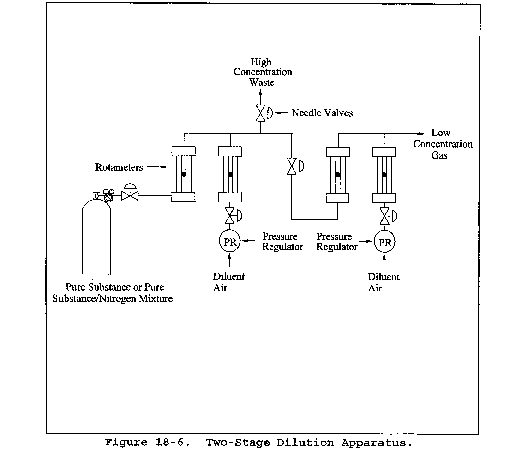
Preparation of Standards by Dilution of Cylinder Standard
[Cylinder Standard: Organic ________ Certified Concentration ________ ppm]
| Standards preparation data: | Date: | ||
|---|---|---|---|
| Mixture 1 | Mixture 2 | Mixture 3 | |
| Stage 1: | |||
| Standard gas flowmeter reading | |||
| Diluent gas flowmeter reading | |||
| Laboratory temperature (°K) | |||
| Barometric pressure (mm Hg) | |||
| Flowmeter gage pressure (mm Hg) | |||
| Flow rate cylinder gas at standard conditions (ml/min) | |||
| Flow rate diluent gas at standard conditions (ml/min) | |||
| Calculated concentration (ppm) | |||
| Stage 2 (if used): | |||
| Standard gas flowmeter reading | |||
| Diluent gas flowmeter reading | |||
| Flow rate Stage 1 gas at standard conditions (ml/min) | |||
| Flow rate diluent gas at standard conditions | |||
| Calculated concentration (ppm) | |||
| GC Operating Conditions: | |||
| Sample loop volume (ml) | |||
| Sample loop temperature ( °C) | |||
| Carrier gas flow rate (ml/min) | |||
| Column temperature: | |||
| Initial ( °C) | |||
| Program rate ( °C/min) | |||
| Final ( °C) | |||
| Organic Peak Identification and Calculated Concentrations: | |||
| Injection time (24-hour clock) | |||
| Distance to peak (cm) | |||
| Chart speed (cm/min) | |||
| Retention time (min) | |||
| Attenuation factor | |||
| Peak area (mm2) | |||
| Peak area *attenuation factor | |||
Figure 18-7. Standards Prepared by Dilution of Cylinder Standard
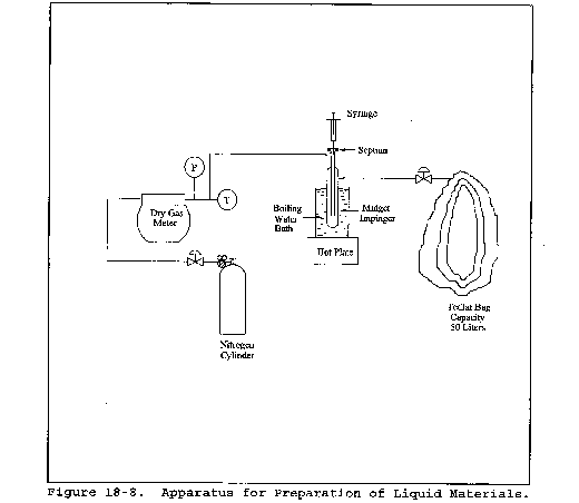
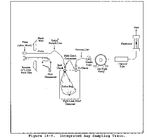
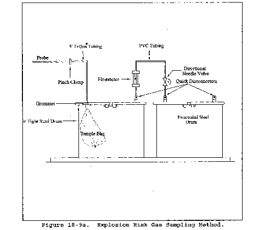
Plant________ Date________ Site________
| Sample 1 | Sample 2 | Sample 3 | |
|---|---|---|---|
| Source temperature ( °C) | |||
| Barometric pressure (mm Hg) | |||
| Ambient temperature ( °C) | |||
| Sample flow rate (appr.) | |||
| Bag number | |||
| Start time | |||
| Finish time |
Figure 18-10. Field Sample Data Sheet - Tedlar or Tedlar-Equivalent Bag Collection Method
Plant __________________ Date ________________ Location ________________________
| 1. General information: | |
| Source temperature ( °C) | |
| Probe temperature ( °C) | |
| Ambient temperature ( °C) | |
| Atmospheric pressure (mm) | |
| Source pressure (′Hg) | |
| Absolute source pressure (mm) | |
| Sampling rate (liter/min) | |
| Sample loop volume (ml) | |
| Sample loop temperature ( °C) | |
| Columnar temperature: | |
| Initial ( °C) time (min) | |
| Program rate ( °C/min) | |
| Final ( °C)/time (min) | |
| Carrier gas flow rate (ml/min) | |
| Detector temperature ( °C) | |
| Injection time (24-hour basis) | |
| Chart Speed (mm/min) | |
| Dilution gas flow rate (ml/min) | |
| Dilution gas used (symbol) | |
| Dilution ratio |
2. Field Analysis Data - Calibration Gas
2. [Run No. ________ Time ____________]
| Components | Area | Attenuation | A × A Factor | Conc.__ (ppm) |
|---|---|---|---|---|
Figure 18-11. Field Analysis Data Sheets

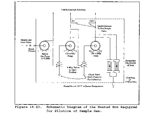
Gaseous Organic Sampling and Analysis Check List
[Respond with initials or number as appropriate]
| Date | ||
|---|---|---|
| 1. Presurvey data: | ||
| A. Grab sample collected | □ | ______ |
| B. Grab sample analyzed for composition | □ | ______ |
| Method GC | □ | ______ |
| GC/MS | □ | ______ |
| Other | □ | ______ |
| C. GC-FID analysis performed | □ | ______ |
| 2. Laboratory calibration data: | ||
| A. Calibration curves prepared | □ | ______ |
| Number of components | □ | ______ |
| Number of concentrations/component (3 required) | □ | ______ |
| B. Audit samples (optional): | ||
| Analysis completed | □ | ______ |
| Verified for concentration | □ | ______ |
| OK obtained for field work | □ | ______ |
| 3. Sampling procedures: | ||
| A. Method: | ||
| Bag sample | □ | ______ |
| Direct interface | □ | ______ |
| Dilution interface | □ | ______ |
| B. Number of samples collected | □ | ______ |
| 4. Field Analysis: | ||
| A. Total hydrocarbon analysis performed | □ | ______ |
| B. Calibration curve prepared | □ | ______ |
| Number of components | □ | ______ |
| Number of concentrations per component (3 required) | □ | ______ |
Gaseous Organic Sampling and Analysis Data
Plant
Date
Location
Gaseous Organic Sampling and Analysis Check List (Respond With Initials or Number as Appropriate)
| 1. Pre-survey data | Date |
| A. Grab sample collected | ________ |
| B. Grab sample analyzed for composition | ________ |
| Method GC | ________ |
| GC/MS | ________ |
| Other________________________ | ________ |
| C. GC-FID analysis performed | ________ |
| 2. Laboratory calibration curves prepared | ________ |
| A. Number of components | ________ |
| B. Number of concentrations per component (3 required) | ________ |
| C. OK obtained for field work | ________ |
| 3. Sampling procedures | |
| A. Method | |
| Bag sample | ________ |
| Direct interface | ________ |
| Dilution interface | ________ |
| B. Number of samples collected | ________ |
| 4. Field Analysis | |
| A. Total hydrocarbon analysis performed | ________ |
| B. Calibration curve prepared | ____ |
| Number of components | ____ |
| Number of concentrations per component (3 required) | ____ |
Figure 18-14. Sampling and Analysis Sheet
[36 FR 24877, Dec. 23, 1971]
Appendix A-7 to Part 60 - Test Methods 19 through 25E
Method 19 - Determination of sulfur dioxide removal efficiency and particulate, sulfur dioxide and nitrogen oxides emission rates
Method 20 - Determination of nitrogen oxides, sulfur dioxide, and diluent emissions from stationary gas turbines
Method 21 - Determination of volatile organic compound leaks
Method 22 - Visual determination of fugitive emissions from material sources and smoke emissions from flares
Method 23 - Determination of Polychlorinated Dibenzo-p-Dioxins and Polychlorinated Dibenzofurans From Stationary Sources
Method 24 - Determination of volatile matter content, water content, density, volume solids, and weight solids of surface coatings
Method 24A - Determination of volatile matter content and density of printing inks and related coatings
Method 25 - Determination of total gaseous nonmethane organic emissions as carbon
Method 25A - Determination of total gaseous organic concentration using a flame ionization analyzer
Method 25B - Determination of total gaseous organic concentration using a nondispersive infrared analyzer
Method 25C - Determination of nonmethane organic compounds (NMOC) in MSW landfill gases
Method 25D - Determination of the Volatile Organic Concentration of Waste Samples
Method 25E - Determination of Vapor Phase Organic Concentration in Waste Samples
The test methods in this appendix are referred to in § 60.8 (Performance Tests) and § 60.11 (Compliance With Standards and Maintenance Requirements) of 40 CFR part 60, subpart A (General Provisions). Specific uses of these test methods are described in the standards of performance contained in the subparts, beginning with Subpart D.
Within each standard of performance, a section title “Test Methods and Procedures” is provided to: (1) Identify the test methods to be used as reference methods to the facility subject to the respective standard and (2) identify any special instructions or conditions to be followed when applying a method to the respective facility. Such instructions (for example, establish sampling rates, volumes, or temperatures) are to be used either in addition to, or as a substitute for procedures in a test method. Similarly, for sources subject to emission monitoring requirements, specific instructions pertaining to any use of a test method as a reference method are provided in the subpart or in Appendix B.
Inclusion of methods in this appendix is not intended as an endorsement or denial of their applicability to sources that are not subject to standards of performance. The methods are potentially applicable to other sources; however, applicability should be confirmed by careful and appropriate evaluation of the conditions prevalent at such sources.
The approach followed in the formulation of the test methods involves specifications for equipment, procedures, and performance. In concept, a performance specification approach would be preferable in all methods because this allows the greatest flexibility to the user. In practice, however, this approach is impractical in most cases because performance specifications cannot be established. Most of the methods described herein, therefore, involve specific equipment specifications and procedures, and only a few methods in this appendix rely on performance criteria.
Minor changes in the test methods should not necessarily affect the validity of the results and it is recognized that alternative and equivalent methods exist. section 60.8 provides authority for the Administrator to specify or approve (1) equivalent methods, (2) alternative methods, and (3) minor changes in the methodology of the test methods. It should be clearly understood that unless otherwise identified all such methods and changes must have prior approval of the Administrator. An owner employing such methods or deviations from the test methods without obtaining prior approval does so at the risk of subsequent disapproval and retesting with approved methods.
Within the test methods, certain specific equipment or procedures are recognized as being acceptable or potentially acceptable and are specifically identified in the methods. The items identified as acceptable options may be used without approval but must be identified in the test report. The potentially approvable options are cited as “subject to the approval of the Administrator” or as “or equivalent.” Such potentially approvable techniques or alternatives may be used at the discretion of the owner without prior approval. However, detailed descriptions for applying these potentially approvable techniques or alternatives are not provided in the test methods. Also, the potentially approvable options are not necessarily acceptable in all applications. Therefore, an owner electing to use such potentially approvable techniques or alternatives is responsible for: (1) assuring that the techniques or alternatives are in fact applicable and are properly executed; (2) including a written description of the alternative method in the test report (the written method must be clear and must be capable of being performed without additional instruction, and the degree of detail should be similar to the detail contained in the test methods); and (3) providing any rationale or supporting data necessary to show the validity of the alternative in the particular application. Failure to meet these requirements can result in the Administrator's disapproval of the alternative.
Method 19 - Determination of Sulfur Dioxide Removal Efficiency and Particulate Matter, Sulfur Dioxide, and Nitrogen Oxide Emission Rates
1.0 Scope and Application
1.1 Analytes. This method provides data reduction procedures relating to the following pollutants, but does not include any sample collection or analysis procedures.
| Analyte | CAS No. | Sensitivity |
|---|---|---|
| Nitrogen oxides (NOX), including: | ||
| Nitric oxide (NO) | 10102-43-9 | N/A |
| Nitrogen dioxide (NO2) | 10102-44-0 | |
| Particulate matter (PM) | None assigned | N/A |
| Sulfur dioxide (SO2) | 7499-09-05 | N/A |
1.2 Applicability. Where specified by an applicable subpart of the regulations, this method is applicable for the determination of
(a) PM, SO2, and NOX emission rates;
(b) sulfur removal efficiencies of fuel pretreatment and SO2 control devices; and
(c) overall reduction of potential SO2 emissions.
2.0 Summary of Method
2.1 Emission Rates. Oxygen (O2) or carbon dioxide (CO2) concentrations and appropriate F factors (ratios of combustion gas volumes to heat inputs) are used to calculate pollutant emission rates from pollutant concentrations.
2.2 Sulfur Reduction Efficiency and SO2 Removal Efficiency. An overall SO2 emission reduction efficiency is computed from the efficiency of fuel pretreatment systems, where applicable, and the efficiency of SO2 control devices.
2.2.1 The sulfur removal efficiency of a fuel pretreatment system is determined by fuel sampling and analysis of the sulfur and heat contents of the fuel before and after the pretreatment system.
2.2.2 The SO2 removal efficiency of a control device is determined by measuring the SO2 rates before and after the control device.
2.2.2.1 The inlet rates to SO2 control systems (or, when SO2 control systems are not used, SO2 emission rates to the atmosphere) are determined by fuel sampling and analysis.
3.0 Definitions [Reserved]
4.0 Interferences [Reserved]
5.0 Safety [Reserved]
6.0 Equipment and Supplies [Reserved]
7.0 Reagents and Standards [Reserved]
8.0 Sample Collection, Preservation, Storage, and Transport [Reserved]
9.0 Quality Control [Reserved]
10.0 Calibration and Standardization [Reserved]
11.0 Analytical Procedures [Reserved]
12.0 Data Analysis and Calculations
12.1 Nomenclature
Bwa = Moisture fraction of ambient air, percent.
Bws = Moisture fraction of effluent gas, percent.
%C = Concentration of carbon from an ultimate analysis of fuel, weight percent.
Cd = Pollutant concentration, dry basis, ng/scm (lb/scf)
%CO2d,%CO2w = Concentration of carbon dioxide on a dry and wet basis, respectively, percent.
Cw = Pollutant concentration, wet basis, ng/scm (lb/scf).
D = Number of sampling periods during the performance test period.
E = Pollutant emission rate, ng/J (lb/million Btu).
Ea = Average pollutant rate for the specified performance test period, ng/J (lb/million Btu).
Eao, Eai = Average pollutant rate of the control device, outlet and inlet, respectively, for the performance test period, ng/J (lb/million Btu).
Ebi = Pollutant rate from the steam generating unit, ng/J (lb/million Btu)
Ebo = Pollutant emission rate from the steam generating unit, ng/J (lb/million Btu).
Eci = Pollutant rate in combined effluent, ng/J (lb/million Btu).
Eco = Pollutant emission rate in combined effluent, ng/J (lb/million Btu).
Ed = Average pollutant rate for each sampling period (e.g., 24-hr Method 6B sample or 24-hr fuel sample) or for each fuel lot (e.g., amount of fuel bunkered), ng/J (lb/million Btu).
Edi = Average inlet SO2 rate for each sampling period d, ng/J (lb/million Btu)
Eg = Pollutant rate from gas turbine, ng/J (lb/million Btu).
Ega = Daily geometric average pollutant rate, ng/J (lbs/million Btu) or ppm corrected to 7 percent O2.
Ejo,Eji = Matched pair hourly arithmetic average pollutant rate, outlet and inlet, respectively, ng/J (lb/million Btu) or ppm corrected to 7 percent O2.
Eh = Hourly average pollutant, ng/J (lb/million Btu).
Ehj = Hourly arithmetic average pollutant rate for hour “j,” ng/J (lb/million Btu) or ppm corrected to 7 percent O2.
EXP = Natural logarithmic base (2.718) raised to the value enclosed by brackets.
Fd, Fw, Fc = Volumes of combustion components per unit of heat content, scm/J (scf/million Btu).
GCV = Gross calorific value of the fuel consistent with the ultimate analysis, kJ/kg (Btu/lb).
GCVp, GCVr = Gross calorific value for the product and raw fuel lots, respectively, dry basis, kJ/kg (Btu/lb).
%H = Concentration of hydrogen from an ultimate analysis of fuel, weight percent.
H = Total number of operating hours for which pollutant rates are determined in the performance test period.
Hb = Heat input rate to the steam generating unit from fuels fired in the steam generating unit, J/hr (million Btu/hr).
Hg = Heat input rate to gas turbine from all fuels fired in the gas turbine, J/hr (million Btu/hr).
%H2O = Concentration of water from an ultimate analysis of fuel, weight percent.
Hr = Total numbers of hours in the performance test period (e.g., 720 hours for 30-day performance test period).
K = Conversion factor, 10−5 (kJ/J)/(%) [106 Btu/million Btu].
Kc = (9.57 scm/kg)/% [(1.53 scf/lb)/%].
Kcc = (2.0 scm/kg)/% [(0.321 scf/lb)/%].
Khd = (22.7 scm/kg)/% [(3.64 scf/lb)/%].
Khw = (34.74 scm/kg)/% [(5.57 scf/lb)/%].
Kn = (0.86 scm/kg)/% [(0.14 scf/lb)/%].
Ko = (2.85 scm/kg)/% [(0.46 scf/lb)/%].
Ks = (3.54 scm/kg)/% [(0.57 scf/lb)/%].
Kw = (1.30 scm/kg)/% [(0.21 scf/lb)/%].
ln = Natural log of indicated value.
Lp,Lr = Weight of the product and raw fuel lots, respectively, metric ton (ton).
%N = Concentration of nitrogen from an ultimate analysis of fuel, weight percent.
N = Number of fuel lots during the averaging period.
n = Number of fuels being burned in combination.
nd = Number of operating hours of the affected facility within the performance test period for each Ed determined.
nt = Total number of hourly averages for which paired inlet and outlet pollutant rates are available within the 24-hr midnight to midnight daily period.
%O = Concentration of oxygen from an ultimate analysis of fuel, weight percent.
%O2d, %O2w = Concentration of oxygen on a dry and wet basis, respectively, percent.
Ps = Potential SO2 emissions, percent.
%Rf = SO2 removal efficiency from fuel pretreatment, percent.
%Rg = SO2 removal efficiency of the control device, percent.
%Rga = Daily geometric average percent reduction.
%Ro = Overall SO2 reduction, percent.
%S = Sulfur content of as-fired fuel lot, dry basis, weight percent.
Se = Standard deviation of the hourly average pollutant rates for each performance test period, ng/J (lb/million Btu).
%Sf = Concentration of sulfur from an ultimate analysis of fuel, weight percent.
Si = Standard deviation of the hourly average inlet pollutant rates for each performance test period, ng/J (lb/million Btu).
So = Standard deviation of the hourly average emission rates for each performance test period, ng/J (lb/million Btu).
%Sp, %Sr = Sulfur content of the product and raw fuel lots respectively, dry basis, weight percent.
t0.95 = Values shown in Table 19-3 for the indicated number of data points n.
Xk = Fraction of total heat input from each type of fuel k.
12.2 Emission Rates of PM, SO2, and NOX. Select from the following sections the applicable procedure to compute the PM, SO2, or NOX emission rate (E) in ng/J (lb/million Btu). The pollutant concentration must be in ng/scm (lb/scf) and the F factor must be in scm/J (scf/million Btu). If the pollutant concentration (C) is not in the appropriate units, use Table 19-1 in section 17.0 to make the proper conversion. An F factor is the ratio of the gas volume of the products of combustion to the heat content of the fuel. The dry F factor (Fd) includes all components of combustion less water, the wet F factor (Fw) includes all components of combustion, and the carbon F factor (Fc) includes only carbon dioxide.
Since Fw factors include water resulting only from the combustion of hydrogen in the fuel, the procedures using Fw factors are not applicable for computing E from steam generating units with wet scrubbers or with other processes that add water (e.g., steam injection).
12.2.1 Oxygen-Based F Factor, Dry Basis. When measurements are on a dry basis for both O (%O2d) and pollutant (Cd) concentrations, use the following equation:

12.2.2 Oxygen-Based F Factor, Wet Basis. When measurements are on a wet basis for both O2 (%O2w) and pollutant (Cw) concentrations, use either of the following:
12.2.2.1 If the moisture fraction of ambient air (Bwa) is measured:

Instead of actual measurement, Bwa may be estimated according to the procedure below.
The estimates are selected to ensure that negative errors will not be larger than −1.5 percent. However, positive errors, or over-estimation of emissions by as much as 5 percent may be introduced depending upon the geographic location of the facility and the associated range of ambient moisture.
12.2.2.1.1 Bwa = 0.027. This value may be used at any location at all times.
12.2.2.1.2 Bwa = Highest monthly average of Bwa that occurred within the previous calendar year at the nearest Weather Service Station. This value shall be determined annually and may be used as an estimate for the entire current calendar year.
12.2.2.1.3 Bwa = Highest daily average of Bwa that occurred within a calendar month at the nearest Weather Service Station, calculated from the data from the past 3 years. This value shall be computed for each month and may be used as an estimate for the current respective calendar month.
12.2.2.2 If the moisture fraction (Bws) of the effluent gas is measured:

12.2.3 Oxygen-Based F Factor, Dry/Wet Basis.
12.2.3.1 When the pollutant concentration is measured on a wet basis (Cw) and O2 concentration is measured on a dry basis (%O2d), use the following equation:

12.2.3.2 When the pollutant concentration is measured on a dry basis (Cd) and the O2 concentration is measured on a wet basis (%O2w), use the following equation:

12.2.4 Carbon Dioxide-Based F Factor, Dry Basis. When measurements are on a dry basis for both CO2 (%CO2d) and pollutant (Cd) concentrations, use the following equation:

12.2.5 Carbon Dioxide-Based F Factor, Wet Basis. When measurements are on a wet basis for both CO2 (%CO2w) and pollutant (Cw) concentrations, use the following equation:

12.2.6 Carbon Dioxide-Based F Factor, Dry/Wet Basis.
12.2.6.1 When the pollutant concentration is measured on a wet basis (Cw) and CO2 concentration is measured on a dry basis (%CO2d), use the following equation:

12.2.6.2 When the pollutant concentration is measured on a dry basis (Cd) and CO2 concentration is measured on a wet basis (%CO2w), use the following equation:

12.2.7 Direct-Fired Reheat Fuel Burning. The effect of direct-fired reheat fuel burning (for the purpose of raising the temperature of the exhaust effluent from wet scrubbers to above the moisture dew-point) on emission rates will be less than 1.0 percent and, therefore, may be ignored.
12.2.8 Combined Cycle-Gas Turbine Systems. For gas turbine-steam generator combined cycle systems, determine the emissions from the steam generating unit or the percent reduction in potential SO2 emissions as follows:
12.2.8.1 Compute the emission rate from the steam generating unit using the following equation:

12.2.8.1.1 Use the test methods and procedures section of 40 CFR Part 60, Subpart GG to obtain Eco and Eg. Do not use Fw factors for determining Eg or Eco. If an SO2 control device is used, measure Eco after the control device.
12.2.8.1.2 Suitable methods shall be used to determine the heat input rates to the steam generating units (Hb) and the gas turbine (Hg).
12.2.8.2 If a control device is used, compute the percent of potential SO2 emissions (Ps) using the following equations:


Use the test methods and procedures section of Subpart GG to obtain Eci and Eg. Do not use Fw factors for determining Eg or Eci.
12.3 F Factors. Use an average F factor according to section 12.3.1 or determine an applicable F factor according to section 12.3.2. If combined fuels are fired, prorate the applicable F factors using the procedure in section 12.3.3.
12.3.1 Average F Factors. Average F factors (Fd, Fw, or Fc) from Table 19-2 in section 17.0 may be used.
12.3.2 Determined F Factors. If the fuel burned is not listed in Table 19-2 or if the owner or operator chooses to determine an F factor rather than use the values in Table 19-2, use the procedure below:
12.3.2.1 Equations. Use the equations below, as appropriate, to compute the F factors:


Omit the %H2O term in the equations for Fw if %H and %O include the unavailable hydrogen and oxygen in the form of H2O.)
12.3.2.2 Use applicable sampling procedures in section 12.5.2.1 or 12.5.2.2 to obtain samples for analyses.
12.3.2.3 Use ASTM D 3176-74 or 89 (all cited ASTM standards are incorporated by reference - see § 60.17) for ultimate analysis of the fuel.
12.3.2.4 Use applicable methods in section 12.5.2.1 or 12.5.2.2 to determine the heat content of solid or liquid fuels. For gaseous fuels, use ASTM D 1826-77 or 94 (incorporated by reference - see § 60.17) to determine the heat content.
12.3.3 F Factors for Combination of Fuels. If combinations of fuels are burned, use the following equations, as applicable unless otherwise specified in an applicable subpart:


12.4 Determination of Average Pollutant Rates.
12.4.1 Average Pollutant Rates from Hourly Values. When hourly average pollutant rates (Eh), inlet or outlet, are obtained (e.g., CEMS values), compute the average pollutant rate (Ea) for the performance test period (e.g., 30 days) specified in the applicable regulation using the following equation:

12.4.2 Average Pollutant Rates from Other than Hourly Averages. When pollutant rates are determined from measured values representing longer than 1-hour periods (e.g., daily fuel sampling and analyses or Method 6B values), or when pollutant rates are determined from combinations of 1-hour and longer than 1-hour periods (e.g., CEMS and Method 6B values), compute the average pollutant rate (Ea) for the performance test period (e.g., 30 days) specified in the applicable regulation using the following equation:

12.4.3 Daily Geometric Average Pollutant Rates from Hourly Values. The geometric average pollutant rate (Ega) is computed using the following equation:

12.5 Determination of Overall Reduction in Potential Sulfur Dioxide Emission.
12.5.1 Overall Percent Reduction. Compute the overall percent SO2 reduction (%Ro) using the following equation:

12.5.2 Pretreatment Removal Efficiency (Optional). Compute the SO2 removal efficiency from fuel pretreatment (%Rf) for the averaging period (e.g., 90 days) as specified in the applicable regulation using the following equation:

In calculating %Rf, include %S and GCV values for all fuel lots that are not pretreated and are used during the averaging period.
12.5.2.1 Solid Fossil (Including Waste) Fuel/Sampling and Analysis.
For the purposes of this method, raw fuel (coal or oil) is the fuel delivered to the desulfurization (pretreatment) facility. For oil, the input oil to the oil desulfurization process (e.g., hydrotreatment) is considered to be the raw fuel.
12.5.2.1.1 Sample Increment Collection. Use ASTM D 2234-76, 96, 97a, or 98 (incorporated by reference - see § 60.17), Type I, Conditions A, B, or C, and systematic spacing. As used in this method, systematic spacing is intended to include evenly spaced increments in time or increments based on equal weights of coal passing the collection area. As a minimum, determine the number and weight of increments required per gross sample representing each coal lot according to Table 2 or Paragraph 7.1.5.2 of ASTM D 2234. Collect one gross sample for each lot of raw coal and one gross sample for each lot of product coal.
12.5.2.1.2 ASTM Lot Size. For the purpose of section 12.5.2 (fuel pretreatment), the lot size of product coal is the weight of product coal from one type of raw coal. The lot size of raw coal is the weight of raw coal used to produce one lot of product coal. Typically, the lot size is the weight of coal processed in a 1-day (24-hour) period. If more than one type of coal is treated and produced in 1 day, then gross samples must be collected and analyzed for each type of coal. A coal lot size equaling the 90-day quarterly fuel quantity for a steam generating unit may be used if representative sampling can be conducted for each raw coal and product coal.
Alternative definitions of lot sizes may be used, subject to prior approval of the Administrator.
12.5.2.1.3 Gross Sample Analysis. Use ASTM D 2013-72 or 86 to prepare the sample, ASTM D 3177-75 or 89 or ASTM D 4239-85, 94, or 97 to determine sulfur content (%S), ASTM D 3173-73 or 87 to determine moisture content, and ASTM D 2015-77 (Reapproved 1978) or 96, D 3286-85 or 96, or D 5865-98 or 10 to determine gross calorific value (GCV) (all standards cited are incorporated by reference - see § 60.17 for acceptable versions of the standards) on a dry basis for each gross sample.
12.5.2.2 Liquid Fossil Fuel-Sampling and Analysis. See Note under section 12.5.2.1.
12.5.2.2.1 Sample Collection. Follow the procedures for continuous sampling in ASTM D 270 or D 4177-95 (incorporated by reference - see § 60.17) for each gross sample from each fuel lot.
12.5.2.2.2 Lot Size. For the purpose of section 12.5.2 (fuel pretreatment), the lot size of a product oil is the weight of product oil from one pretreatment facility and intended as one shipment (ship load, barge load, etc.). The lot size of raw oil is the weight of each crude liquid fuel type used to produce a lot of product oil.
Alternative definitions of lot sizes may be used, subject to prior approval of the Administrator.
12.5.2.2.3 Sample Analysis. Use ASTM D 129-64, 78, or 95, ASTM D 1552-83 or 95, or ASTM D 4057-81 or 95 to determine the sulfur content (%S) and ASTM D 240-76 or 92 (all standards cited are incorporated by reference - see § 60.17) to determine the GCV of each gross sample. These values may be assumed to be on a dry basis. The owner or operator of an affected facility may elect to determine the GCV by sampling the oil combusted on the first steam generating unit operating day of each calendar month and then using the lowest GCV value of the three GCV values per quarter for the GCV of all oil combusted in that calendar quarter.
12.5.2.3 Use appropriate procedures, subject to the approval of the Administrator, to determine the fraction of total mass input derived from each type of fuel.
12.5.3 Control Device Removal Efficiency. Compute the percent removal efficiency (%Rg) of the control device using the following equation:

12.5.3.1 Use continuous emission monitoring systems or test methods, as appropriate, to determine the outlet SO2 rates and, if appropriate, the inlet SO2 rates. The rates may be determined as hourly (Eh) or other sampling period averages (Ed). Then, compute the average pollutant rates for the performance test period (Eao and Eai) using the procedures in section 12.4.
12.5.3.2 As an alternative, as-fired fuel sampling and analysis may be used to determine inlet SO2 rates as follows:
12.5.3.2.1 Compute the average inlet SO2 rate (Edi) for each sampling period using the following equation:

Where:

After calculating Edi, use the procedures in section 12.4 to determine the average inlet SO2 rate for the performance test period (Eai).
12.5.3.2.2 Collect the fuel samples from a location in the fuel handling system that provides a sample representative of the fuel bunkered or consumed during a steam generating unit operating day. For the purpose of as-fired fuel sampling under section 12.5.3.2 or section 12.6, the lot size for coal is the weight of coal bunkered or consumed during each steam generating unit operating day. The lot size for oil is the weight of oil supplied to the “day” tank or consumed during each steam generating unit operating day. For reporting and calculation purposes, the gross sample shall be identified with the calendar day on which sampling began. For steam generating unit operating days when a coal-fired steam generating unit is operated without coal being added to the bunkers, the coal analysis from the previous “as bunkered” coal sample shall be used until coal is bunkered again. For steam generating unit operating days when an oil-fired steam generating unit is operated without oil being added to the oil “day” tank, the oil analysis from the previous day shall be used until the “day” tank is filled again. Alternative definitions of fuel lot size may be used, subject to prior approval of the Administrator.
12.5.3.2.3 Use ASTM procedures specified in section 12.5.2.1 or 12.5.2.2 to determine %S and GCV.
12.5.4 Daily Geometric Average Percent Reduction from Hourly Values. The geometric average percent reduction (%Rga) is computed using the following equation:

The calculation includes only paired data sets (hourly average) for the inlet and outlet pollutant measurements.
12.6 Sulfur Retention Credit for Compliance Fuel. If fuel sampling and analysis procedures in section 12.5.2.1 are being used to determine average SO2 emission rates (Eas) to the atmosphere from a coal-fired steam generating unit when there is no SO2 control device, the following equation may be used to adjust the emission rate for sulfur retention credits (no credits are allowed for oil-fired systems) (Edi) for each sampling period using the following equation:

Where:

After calculating Edi, use the procedures in section 12.4.2 to determine the average SO2 emission rate to the atmosphere for the performance test period (Eao).
12.7 Determination of Compliance When Minimum Data Requirement Is Not Met.
12.7.1 Adjusted Emission Rates and Control Device Removal Efficiency. When the minimum data requirement is not met, the Administrator may use the following adjusted emission rates or control device removal efficiencies to determine compliance with the applicable standards.
12.7.1.1 Emission Rate. Compliance with the emission rate standard may be determined by using the lower confidence limit of the emission rate (Eao*) as follows:

12.7.1.2 Control Device Removal Efficiency. Compliance with the overall emission reduction (%Ro) may be determined by using the lower confidence limit of the emission rate (Eao*) and the upper confidence limit of the inlet pollutant rate (Eai*) in calculating the control device removal efficiency (%Rg) as follows:


12.7.2 Standard Deviation of Hourly Average Pollutant Rates. Compute the standard deviation (Se) of the hourly average pollutant rates using the following equation:

Equation 19-19 through 19-31 may be used to compute the standard deviation for both the outlet (So) and, if applicable, inlet (Si) pollutant rates.
13.0 Method Performance [Reserved]
14.0 Pollution Prevention [Reserved]
15.0 Waste Management [Reserved]
16.0 References [Reserved]
17.0 Tables, Diagrams, Flowcharts, and Validation Data
Table 19-1 - Conversion Factors for Concentration
| From | To | Multiply by |
|---|---|---|
| g/scm | ng/scm | 109 |
| mg/scm | ng/scm | 106 |
| lb/scf | ng/scm | 1.602 × 10¹³ |
| ppm SO2 | ng/scm | 2.66 × 10⁶ |
| ppm NOX | ng/scm | 1.912 × 10⁶ |
| ppm SO2 | lb/scf | 1.660 × 10⁻⁷ |
| ppm NOX | lb/scf | 1.194 × 10⁻⁷ |
Table 19-2 - F Factors for Various Fuels1
| Fuel Type | Fd | Fw | Fc | |||
|---|---|---|---|---|---|---|
| dscm/J | dscf/106 Btu | wscm/J | wscf/106 Btu | scm/J | scf/106 Btu | |
| Coal: | ||||||
| Anthracite2 | 2.71 × 10⁻⁷ | 10,100 | 2.83 × 10⁻⁷ | 10,540 | 0.530 × 10⁻⁷ | 1,970 |
| Bituminus2 | 2.63 × 10⁻⁷ | 9,780 | 2.86 × 10⁻⁷ | 10,640 | 0.484 × 10⁻⁷ | 1,800 |
| Lignite | 2.65 × 10⁻⁷ | 9,860 | 3.21 × 10⁻⁷ | 11,950 | 0.513 × 10⁻⁷ | 1,910 |
| Oil3 | 2.47 × 10⁻⁷ | 9,190 | 2.77 × 10⁻⁷ | 10,320 | 0.383 × 10⁻⁷ | 1,420 |
| Gas: | ||||||
| Natural | 2.34 × 10⁻⁷ | 8,710 | 2.85 × 10⁻⁷ | 10,610 | 0.287 × 10⁻⁷ | 1,040 |
| Propane | 2.34 × 10⁻⁷ | 8,710 | 2.74 × 10⁻⁷ | 10,200 | 0.321 × 10⁻⁷ | 1,190 |
| Butane | 2.34 × 10⁻⁷ | 8,710 | 2.79 × 10⁻⁷ | 10,390 | 0.337 × 10⁻⁷ | 1,250 |
| Wood | 2.48 × 10⁻⁷ | 9,240 | 0.492 × 10⁻⁷ | 1,830 | ||
| Wood Bark | 2.58 × 10⁻⁷ | 9,600 | 0.516 × 10⁻⁷ | 1,920 | ||
| Municipal | 2.57 × 10⁻⁷ | 9,570 | 0.488 × 10⁻⁷ | 1,820 | ||
| Solid Waste | ||||||
Table 19-3 - Values for T0.95*
| n1 | t0.95 | n1 | t0.95 | n1 | t0.95 |
|---|---|---|---|---|---|
| 2 | 6.31 | 8 | 1.89 | 22-26 | 1.71 |
| 3 | 2.42 | 9 | 1.86 | 27-31 | 1.70 |
| 4 | 2.35 | 10 | 1.83 | 32-51 | 1.68 |
| 5 | 2.13 | 11 | 1.81 | 52-91 | 1.67 |
| 6 | 2.02 | 12-16 | 1.77 | 92-151 | 1.66 |
| 7 | 1.94 | 17-21 | 1.73 | 152 or more | 1.65 |
Method 20 - Determination of Nitrogen Oxides, Sulfur Dioxide, and Diluent Emissions From Stationary Gas Turbines
1.0 Scope and Application
What is Method 20?
Method 20 contains the details you must follow when using an instrumental analyzer to determine concentrations of nitrogen oxides, oxygen, carbon dioxide, and sulfur dioxide in the emissions from stationary gas turbines. This method follows the specific instructions for equipment and performance requirements, supplies, sample collection and analysis, calculations, and data analysis in the methods listed in section 2.0.
1.1 Analytes. What does this method determine?
| Analyte | CAS No. | Sensitivity |
|---|---|---|
| Nitrogen oxides (NOX) as nitrogen dioxide: | 10102-43-9 | Typically <2% of Calibration Span. |
| Nitric oxide (NO) | 10102-44-0 | |
| Nitrogen dioxide NO2 | ||
| Diluent oxygen (O2) or carbon dioxide (CO2) | Typically <2% of Calibration Span. | |
| Sulfur dioxide (SOX) | 7446-09-5 | Typically <2% of Calibration Span. |
1.2 Applicability. When is this method required? The use of Method 20 may be required by specific New Source Performance Standards, Clean Air Marketing rules, and State Implementation Plans and permits where measuring SO2, NOX, CO2, and/or O2 concentrations in stationary gas turbines emissions are required. Other regulations may also require its use.
1.3 Data Quality Objectives. How good must my collected data be? Refer to section 1.3 of Method 7E.
2.0 Summary of Method
In this method, NOX, O2 (or CO2), and SOX are measured using the following methods found in appendix A to this part:
(a) Method 1 - Sample and Velocity Traverses for Stationary Sources.
(b) Method 3A - Determination of Oxygen and Carbon Dioxide Emissions From Stationary Sources (Instrumental Analyzer Procedure).
(c) Method 6C - Determination of Sulfur Dioxide Emissions From Stationary Sources (Instrumental Analyzer Procedure).
(d) Method 7E - Determination of Nitrogen Oxides Emissions From Stationary Sources (Instrumental Analyzer Procedure).
(e) Method 19 - Determination of Sulfur Dioxide Removal Efficiency and Particulate Matter, Sulfur Dioxide, and Nitrogen Oxide Emission Rates.
3.0 Definitions
Refer to section 3.0 of Method 7E for the applicable definitions.
4.0 Interferences
Refer to section 4.0 of Methods 3A, 6C, and 7E as applicable.
5.0 Safety
Refer to section 5.0 of Method 7E.
6.0 Equipment and Supplies
The measurement system design is shown in Figure 7E-1 of Method 7E. Refer to the appropriate methods listed in section 2.0 for equipment and supplies.
7.0 Reagents and Standards
Refer to the appropriate methods listed in section 2.0 for reagents and standards.
8.0 Sample Collection, Preservation, Storage, and Transport
8.1 Sampling Site and Sampling Points. Follow the procedures of section 8.1 of Method 7E. For the stratification test in section 8.1.2, determine the diluent-corrected pollutant concentration at each traverse point.
8.2 Initial Measurement System Performance Tests. You must refer to the appropriate methods listed in section 2.0 for the measurement system performance tests as applicable.
8.3 Interference Check. You must follow the procedures in section 8.3 of Method 3A or 6C, or section 8.2.7 of Method 7E (as appropriate).
8.4 Sample Collection. You must follow the procedures of section 8.4 of the appropriate methods listed in section 2.0. A test run must have a duration of at least 21 minutes.
8.5 Post-Run System Bias Check, Drift Assessment, and Alternative Dynamic Spike Procedure. You must follow the procedures of sections 8.5 and 8.6 of the appropriate methods listed in section 2.0. A test run must have a duration of at least 21 minutes.
9.0 Quality Control
Follow quality control procedures in section 9.0 of Method 7E.
10.0 Calibration and Standardization
Follow the procedures for calibration and standardization in section 10.0 of Method 7E.
11.0 Analytical Procedures
Because sample collection and analysis are performed together (see section 8), additional discussion of the analytical procedure is not necessary.
12.0 Calculations and Data Analysis
You must follow the procedures for calculations and data analysis in section 12.0 of the appropriate method listed in section 2.0. Follow the procedures in section 12.0 of Method 19 for calculating fuel-specific F factors, diluent-corrected pollutant concentrations, and emission rates.
13.0 Method Performance
The specifications for the applicable performance checks are the same as in section 13.0 of Method 7E.
14.0 Pollution Prevention [Reserved]
15.0 Waste Management [Reserved]
16.0 Alternative Procedures
Refer to section 16.0 of the appropriate method listed in section 2.0 for alternative procedures.
17.0 References
Refer to section 17.0 of the appropriate method listed in section 2.0 for references.
18.0 Tables, Diagrams, Flowcharts, and Validation Data
Refer to section 18.0 of the appropriate method listed in section 2.0 for tables, diagrams, flowcharts, and validation data.
Method 21 - Determination of Volatile Organic Compound Leaks
1.0 Scope and Application
1.1 Analytes.
| Analyte | CAS No. |
|---|---|
| Volatile Organic Compounds (VOC) | No CAS number assigned. |
1.2 Scope. This method is applicable for the determination of VOC leaks from process equipment. These sources include, but are not limited to, valves, flanges and other connections, pumps and compressors, pressure relief devices, process drains, open-ended valves, pump and compressor seal system degassing vents, accumulator vessel vents, agitator seals, and access door seals.
1.3 Data Quality Objectives. Adherence to the requirements of this method will enhance the quality of the data obtained from air pollutant sampling methods.
2.0 Summary of Method
2.1 A portable instrument is used to detect VOC leaks from individual sources. The instrument detector type is not specified, but it must meet the specifications and performance criteria contained in section 6.0. A leak definition concentration based on a reference compound is specified in each applicable regulation. This method is intended to locate and classify leaks only, and is not to be used as a direct measure of mass emission rate from individual sources.
3.0 Definitions
3.1 Calibration gas means the VOC compound used to adjust the instrument meter reading to a known value. The calibration gas is usually the reference compound at a known concentration approximately equal to the leak definition concentration.
3.2 Calibration precision means the degree of agreement between measurements of the same known value, expressed as the relative percentage of the average difference between the meter readings and the known concentration to the known concentration.
3.3 Leak definition concentration means the local VOC concentration at the surface of a leak source that indicates that a VOC emission (leak) is present. The leak definition is an instrument meter reading based on a reference compound.
3.4 No detectable emission means a local VOC concentration at the surface of a leak source, adjusted for local VOC ambient concentration, that is less than 2.5 percent of the specified leak definition concentration. that indicates that a VOC emission (leak) is not present.
3.5 Reference compound means the VOC species selected as the instrument calibration basis for specification of the leak definition concentration. (For example, if a leak definition concentration is 10,000 ppm as methane, then any source emission that results in a local concentration that yields a meter reading of 10,000 on an instrument meter calibrated with methane would be classified as a leak. In this example, the leak definition concentration is 10,000 ppm and the reference compound is methane.)
3.6 Response factor means the ratio of the known concentration of a VOC compound to the observed meter reading when measured using an instrument calibrated with the reference compound specified in the applicable regulation.
3.7 Response time means the time interval from a step change in VOC concentration at the input of the sampling system to the time at which 90 percent of the corresponding final value is reached as displayed on the instrument readout meter.
4.0 Interferences [Reserved]
5.0 Safety
5.1 Disclaimer. This method may involve hazardous materials, operations, and equipment. This test method may not address all of the safety problems associated with its use. It is the responsibility of the user of this test method to establish appropriate safety and health practices and determine the applicability of regulatory limitations prior to performing this test method.
5.2 Hazardous Pollutants. Several of the compounds, leaks of which may be determined by this method, may be irritating or corrosive to tissues (e.g., heptane) or may be toxic (e.g., benzene, methyl alcohol). Nearly all are fire hazards. Compounds in emissions should be determined through familiarity with the source. Appropriate precautions can be found in reference documents, such as reference No. 4 in section 16.0.
6.0 Equipment and Supplies
A VOC monitoring instrument meeting the following specifications is required:
6.1 The VOC instrument detector shall respond to the compounds being processed. Detector types that may meet this requirement include, but are not limited to, catalytic oxidation, flame ionization, infrared absorption, and photoionization.
6.2 The instrument shall be capable of measuring the leak definition concentration specified in the regulation.
6.3 The scale of the instrument meter shall be readable to ±2.5 percent of the specified leak definition concentration.
6.4 The instrument shall be equipped with an electrically driven pump to ensure that a sample is provided to the detector at a constant flow rate. The nominal sample flow rate, as measured at the sample probe tip, shall be 0.10 to 3.0 l/min (0.004 to 0.1 ft3/min) when the probe is fitted with a glass wool plug or filter that may be used to prevent plugging of the instrument.
6.5 The instrument shall be equipped with a probe or probe extension or sampling not to exceed 6.4 mm (1⁄4 in) in outside diameter, with a single end opening for admission of sample.
6.6 The instrument shall be intrinsically safe for operation in explosive atmospheres as defined by the National Electrical Code by the National Fire Prevention Association or other applicable regulatory code for operation in any explosive atmospheres that may be encountered in its use. The instrument shall, at a minimum, be intrinsically safe for Class 1, Division 1 conditions, and/or Class 2, Division 1 conditions, as appropriate, as defined by the example code. The instrument shall not be operated with any safety device, such as an exhaust flame arrestor, removed.
7.0 Reagents and Standards
7.1 Two gas mixtures are required for instrument calibration and performance evaluation:
7.1.1 Zero Gas. Air, less than 10 parts per million by volume (ppmv) VOC.
7.1.2 Calibration Gas. For each organic species that is to be measured during individual source surveys, obtain or prepare a known standard in air at a concentration approximately equal to the applicable leak definition specified in the regulation.
7.2 Cylinder Gases. If cylinder calibration gas mixtures are used, they must be analyzed and certified by the manufacturer to be within 2 percent accuracy, and a shelf life must be specified. Cylinder standards must be either reanalyzed or replaced at the end of the specified shelf life.
7.3 Prepared Gases. Calibration gases may be prepared by the user according to any accepted gaseous preparation procedure that will yield a mixture accurate to within 2 percent. Prepared standards must be replaced each day of use unless it is demonstrated that degradation does not occur during storage.
7.4 Mixtures with non-Reference Compound Gases. Calibrations may be performed using a compound other than the reference compound. In this case, a conversion factor must be determined for the alternative compound such that the resulting meter readings during source surveys can be converted to reference compound results.
8.0 Sample Collection, Preservation, Storage, and Transport
8.1 Instrument Performance Evaluation. Assemble and start up the instrument according to the manufacturer's instructions for recommended warmup period and preliminary adjustments.
8.1.1 Response Factor. A response factor must be determined for each compound that is to be measured, either by testing or from reference sources. The response factor tests are required before placing the analyzer into service, but do not have to be repeated at subsequent intervals.
8.1.1.1 Calibrate the instrument with the reference compound as specified in the applicable regulation. Introduce the calibration gas mixture to the analyzer and record the observed meter reading. Introduce zero gas until a stable reading is obtained. Make a total of three measurements by alternating between the calibration gas and zero gas. Calculate the response factor for each repetition and the average response factor.
8.1.1.2 The instrument response factors for each of the individual VOC to be measured shall be less than 10 unless otherwise specified in the applicable regulation. When no instrument is available that meets this specification when calibrated with the reference VOC specified in the applicable regulation, the available instrument may be calibrated with one of the VOC to be measured, or any other VOC, so long as the instrument then has a response factor of less than 10 for each of the individual VOC to be measured.
8.1.1.3 Alternatively, if response factors have been published for the compounds of interest for the instrument or detector type, the response factor determination is not required, and existing results may be referenced. Examples of published response factors for flame ionization and catalytic oxidation detectors are included in References 1-3 of section 17.0.
8.1.2 Calibration Precision. The calibration precision test must be completed prior to placing the analyzer into service and at subsequent 3-month intervals or at the next use, whichever is later.
8.1.2.1 Make a total of three measurements by alternately using zero gas and the specified calibration gas. Record the meter readings. Calculate the average algebraic difference between the meter readings and the known value. Divide this average difference by the known calibration value and multiply by 100 to express the resulting calibration precision as a percentage.
8.1.2.2 The calibration precision shall be equal to or less than 10 percent of the calibration gas value.
8.1.3 Response Time. The response time test is required before placing the instrument into service. If a modification to the sample pumping system or flow configuration is made that would change the response time, a new test is required before further use.
8.1.3.1 Introduce zero gas into the instrument sample probe. When the meter reading has stabilized, switch quickly to the specified calibration gas. After switching, measure the time required to attain 90 percent of the final stable reading. Perform this test sequence three times and record the results. Calculate the average response time.
8.1.3.2 The instrument response time shall be equal to or less than 30 seconds. The instrument pump, dilution probe (if any), sample probe, and probe filter that will be used during testing shall all be in place during the response time determination.
8.2 Instrument Calibration. Calibrate the VOC monitoring instrument according to section 10.0.
8.3 Individual Source Surveys.
8.3.1 Type I - Leak Definition Based on Concentration. Place the probe inlet at the surface of the component interface where leakage could occur. Move the probe along the interface periphery while observing the instrument readout. If an increased meter reading is observed, slowly sample the interface where leakage is indicated until the maximum meter reading is obtained. Leave the probe inlet at this maximum reading location for approximately two times the instrument response time. If the maximum observed meter reading is greater than the leak definition in the applicable regulation, record and report the results as specified in the regulation reporting requirements. Examples of the application of this general technique to specific equipment types are:
8.3.1.1 Valves. The most common source of leaks from valves is the seal between the stem and housing. Place the probe at the interface where the stem exits the packing gland and sample the stem circumference. Also, place the probe at the interface of the packing gland take-up flange seat and sample the periphery. In addition, survey valve housings of multipart assembly at the surface of all interfaces where a leak could occur.
8.3.1.2 Flanges and Other Connections. For welded flanges, place the probe at the outer edge of the flange-gasket interface and sample the circumference of the flange. Sample other types of nonpermanent joints (such as threaded connections) with a similar traverse.
8.3.1.3 Pumps and Compressors. Conduct a circumferential traverse at the outer surface of the pump or compressor shaft and seal interface. If the source is a rotating shaft, position the probe inlet within 1 cm of the shaft-seal interface for the survey. If the housing configuration prevents a complete traverse of the shaft periphery, sample all accessible portions. Sample all other joints on the pump or compressor housing where leakage could occur.
8.3.1.4 Pressure Relief Devices. The configuration of most pressure relief devices prevents sampling at the sealing seat interface. For those devices equipped with an enclosed extension, or horn, place the probe inlet at approximately the center of the exhaust area to the atmosphere.
8.3.1.5 Process Drains. For open drains, place the probe inlet at approximately the center of the area open to the atmosphere. For covered drains, place the probe at the surface of the cover interface and conduct a peripheral traverse.
8.3.1.6 Open-ended Lines or Valves. Place the probe inlet at approximately the center of the opening to the atmosphere.
8.3.1.7 Seal System Degassing Vents and Accumulator Vents. Place the probe inlet at approximately the center of the opening to the atmosphere.
8.3.1.8 Access door seals. Place the probe inlet at the surface of the door seal interface and conduct a peripheral traverse.
8.3.2 Type II - “No Detectable Emission”. Determine the local ambient VOC concentration around the source by moving the probe randomly upwind and downwind at a distance of one to two meters from the source. If an interference exists with this determination due to a nearby emission or leak, the local ambient concentration may be determined at distances closer to the source, but in no case shall the distance be less than 25 centimeters. Then move the probe inlet to the surface of the source and determine the concentration as outlined in section 8.3.1. The difference between these concentrations determines whether there are no detectable emissions. Record and report the results as specified by the regulation. For those cases where the regulation requires a specific device installation, or that specified vents be ducted or piped to a control device, the existence of these conditions shall be visually confirmed. When the regulation also requires that no detectable emissions exist, visual observations and sampling surveys are required. Examples of this technique are:
8.3.2.1 Pump or Compressor Seals. If applicable, determine the type of shaft seal. Perform a survey of the local area ambient VOC concentration and determine if detectable emissions exist as described in section 8.3.2.
8.3.2.2 Seal System Degassing Vents, Accumulator Vessel Vents, Pressure Relief Devices. If applicable, observe whether or not the applicable ducting or piping exists. Also, determine if any sources exist in the ducting or piping where emissions could occur upstream of the control device. If the required ducting or piping exists and there are no sources where the emissions could be vented to the atmosphere upstream of the control device, then it is presumed that no detectable emissions are present. If there are sources in the ducting or piping where emissions could be vented or sources where leaks could occur, the sampling surveys described in section 8.3.2 shall be used to determine if detectable emissions exist.
8.3.3 Alternative Screening Procedure.
8.3.3.1 A screening procedure based on the formation of bubbles in a soap solution that is sprayed on a potential leak source may be used for those sources that do not have continuously moving parts, that do not have surface temperatures greater than the boiling point or less than the freezing point of the soap solution, that do not have open areas to the atmosphere that the soap solution cannot bridge, or that do not exhibit evidence of liquid leakage. Sources that have these conditions present must be surveyed using the instrument technique of section 8.3.1 or 8.3.2.
8.3.3.2 Spray a soap solution over all potential leak sources. The soap solution may be a commercially available leak detection solution or may be prepared using concentrated detergent and water. A pressure sprayer or squeeze bottle may be used to dispense the solution. Observe the potential leak sites to determine if any bubbles are formed. If no bubbles are observed, the source is presumed to have no detectable emissions or leaks as applicable. If any bubbles are observed, the instrument techniques of section 8.3.1 or 8.3.2 shall be used to determine if a leak exists, or if the source has detectable emissions, as applicable.
9.0 Quality Control
| Section | Quality control measure | Effect |
|---|---|---|
| 8.1.2 | Instrument calibration precision check | Ensure precision and accuracy, respectively, of instrument response to standard. |
| 10.0 | Instrument calibration |
10.0 Calibration and Standardization
10.1 Calibrate the VOC monitoring instrument as follows. After the appropriate warmup period and zero internal calibration procedure, introduce the calibration gas into the instrument sample probe. Adjust the instrument meter readout to correspond to the calibration gas value.
If the meter readout cannot be adjusted to the proper value, a malfunction of the analyzer is indicated and corrective actions are necessary before use.
11.0 Analytical Procedures [Reserved]
12.0 Data Analyses and Calculations [Reserved]
13.0 Method Performance [Reserved]
14.0 Pollution Prevention [Reserved]
15.0 Waste Management [Reserved]
16.0 References
1. Dubose, D.A., and G.E. Harris. Response Factors of VOC Analyzers at a Meter Reading of 10,000 ppmv for Selected Organic Compounds. U.S. Environmental Protection Agency, Research Triangle Park, NC. Publication No. EPA 600/2-81051. September 1981.
2. Brown, G.E., et al. Response Factors of VOC Analyzers Calibrated with Methane for Selected Organic Compounds. U.S. Environmental Protection Agency, Research Triangle Park, NC. Publication No. EPA 600/2-81-022. May 1981.
3. DuBose, D.A. et al. Response of Portable VOC Analyzers to Chemical Mixtures. U.S. Environmental Protection Agency, Research Triangle Park, NC. Publication No. EPA 600/2-81-110. September 1981.
4. Handbook of Hazardous Materials: Fire, Safety, Health. Alliance of American Insurers. Schaumberg, IL. 1983.
17.0 Tables, Diagrams, Flowcharts, and Validation Data [Reserved]
Method 22 - Visual Determination of Fugitive Emissions From Material Sources and Smoke Emissions From Flares
This method is not inclusive with respect to observer certification. Some material is incorporated by reference from Method 9.
1.0 Scope and Application
This method is applicable for the determination of the frequency of fugitive emissions from stationary sources, only as specified in an applicable subpart of the regulations. This method also is applicable for the determination of the frequency of visible smoke emissions from flares.
2.0 Summary of Method
2.1 Fugitive emissions produced during material processing, handling, and transfer operations or smoke emissions from flares are visually determined by an observer without the aid of instruments.
2.2 This method is used also to determine visible smoke emissions from flares used for combustion of waste process materials.
2.3 This method determines the amount of time that visible emissions occur during the observation period (i.e., the accumulated emission time). This method does not require that the opacity of emissions be determined. Since this procedure requires only the determination of whether visible emissions occur and does not require the determination of opacity levels, observer certification according to the procedures of Method 9 is not required. However, it is necessary that the observer is knowledgeable with respect to the general procedures for determining the presence of visible emissions. At a minimum, the observer must be trained and knowledgeable regarding the effects of background contrast, ambient lighting, observer position relative to lighting, wind, and the presence of uncombined water (condensing water vapor) on the visibility of emissions. This training is to be obtained from written materials found in References 1 and 2 or from the lecture portion of the Method 9 certification course.
3.0 Definitions
3.1 Emission frequency means the percentage of time that emissions are visible during the observation period.
3.2 Emission time means the accumulated amount of time that emissions are visible during the observation period.
3.3 Fugitive emissions means emissions generated by an affected facility which is not collected by a capture system and is released to the atmosphere. This includes emissions that
(1) escape capture by process equipment exhaust hoods;
(2) are emitted during material transfer;
(3) are emitted from buildings housing material processing or handling equipment; or
(4) are emitted directly from process equipment.
3.4 Observation period means the accumulated time period during which observations are conducted, not to be less than the period specified in the applicable regulation.
3.5 Smoke emissions means a pollutant generated by combustion in a flare and occurring immediately downstream of the flame. Smoke occurring within the flame, but not downstream of the flame, is not considered a smoke emission.
4.0 Interferences
4.1 Occasionally, fugitive emissions from sources other than the affected facility (e.g., road dust) may prevent a clear view of the affected facility. This may particularly be a problem during periods of high wind. If the view of the potential emission points is obscured to such a degree that the observer questions the validity of continuing observations, then the observations shall be terminated, and the observer shall clearly note this fact on the data form.
5.0 Safety
5.1 Disclaimer. This method may involve hazardous materials, operations, and equipment. This test method may not address all of the safety problems associated with its use. It is the responsibility of the user of this test method to establish appropriate safety and health practices and determine the applicability of regulatory limitations prior to performing this test method.
6.0 Equipment
6.1 Stopwatches (two). Accumulative type with unit divisions of at least 0.5 seconds.
6.2 Light Meter. Light meter capable of measuring illuminance in the 50 to 200 lux range, required for indoor observations only.
7.0 Reagents and Supplies [Reserved]
8.0 Sample Collection, Preservation, Storage, and Transfer [Reserved]
9.0 Quality Control [Reserved]
10.0 Calibration and Standardization [Reserved]
11.0 Analytical Procedure
11.1 Selection of Observation Location. Survey the affected facility, or the building or structure housing the process to be observed, and determine the locations of potential emissions. If the affected facility is located inside a building, determine an observation location that is consistent with the requirements of the applicable regulation (i.e., outside observation of emissions escaping the building/structure or inside observation of emissions directly emitted from the affected facility process unit). Then select a position that enables a clear view of the potential emission point(s) of the affected facility or of the building or structure housing the affected facility, as appropriate for the applicable subpart. A position at least 4.6 m (15 feet), but not more than 400 m (0.25 miles), from the emission source is recommended. For outdoor locations, select a position where the sunlight is not shining directly in the observer's eyes.
11.2 Field Records.
11.2.1 Outdoor Location. Record the following information on the field data sheet (Figure 22-1): Company name, industry, process unit, observer's name, observer's affiliation, and date. Record also the estimated wind speed, wind direction, and sky condition. Sketch the process unit being observed, and note the observer location relative to the source and the sun. Indicate the potential and actual emission points on the sketch. Alternatively, digital photography as described in section 11.2.3 may be used for a subset of the recordkeeping requirements of this section.
11.2.2 Indoor Location. Record the following information on the field data sheet (Figure 22-2): Company name, industry, process unit, observer's name, observer's affiliation, and date. Record as appropriate the type, location, and intensity of lighting on the data sheet. Sketch the process unit being observed, and note the observer location relative to the source. Indicate the potential and actual fugitive emission points on the sketch. Alternatively, digital photography as described in section 11.2.3 may be used for a subset of the recordkeeping requirements of this section.
11.2.3 Digital Photographic Records. Digital photographs, annotated or unaltered, may be used to record and report sky conditions, observer's location relative to the source, observer's location relative to the sun, process unit being observed, potential emission points and actual emission points for the requirements in sections 11.2.1 and 11.2.2. The image must have the proper lighting, field of view and depth of field to properly distinguish the sky condition (if applicable), process unit, potential emission point and actual emission point. At least one digital photograph must be from the point of the view of the observer. The photograph(s) representing the environmental conditions including the sky conditions and the position of the sun relative to the observer and the emission point must be taken within a reasonable time of the observation (i.e., 15 minutes). When observations are taken from exactly the same observation point on a routine basis (i.e., daily) and as long as there are no modifications to the units depicted, only a single photograph each is necessary to document the observer's location relative to the emissions source, the process unit being observed, and the location of potential and actual emission points. Any photographs altered or annotated must be retained in an unaltered format for recordkeeping purposes.
11.3 Indoor Lighting Requirements. For indoor locations, use a light meter to measure the level of illumination at a location as close to the emission source(s) as is feasible. An illumination of greater than 100 lux (10 foot candles) is considered necessary for proper application of this method.
11.4 Observations.
11.4.1 Procedure. Record the clock time when observations begin. Use one stopwatch to monitor the duration of the observation period. Start this stopwatch when the observation period begins. If the observation period is divided into two or more segments by process shutdowns or observer rest breaks (see section 11.4.3), stop the stopwatch when a break begins and restart the stopwatch without resetting it when the break ends. Stop the stopwatch at the end of the observation period. The accumulated time indicated by this stopwatch is the duration of observation period. When the observation period is completed, record the clock time. During the observation period, continuously watch the emission source. Upon observing an emission (condensed water vapor is not considered an emission), start the second accumulative stopwatch; stop the watch when the emission stops. Continue this procedure for the entire observation period. The accumulated elapsed time on this stopwatch is the total time emissions were visible during the observation period (i.e., the emission time.)
11.4.2 Observation Period. Choose an observation period of sufficient length to meet the requirements for determining compliance with the emission standard in the applicable subpart of the regulations. When the length of the observation period is specifically stated in the applicable subpart, it may not be necessary to observe the source for this entire period if the emission time required to indicate noncompliance (based on the specified observation period) is observed in a shorter time period. In other words, if the regulation prohibits emissions for more than 6 minutes in any hour, then observations may (optional) be stopped after an emission time of 6 minutes is exceeded. Similarly, when the regulation is expressed as an emission frequency and the regulation prohibits emissions for greater than 10 percent of the time in any hour, then observations may (optional) be terminated after 6 minutes of emission are observed since 6 minutes is 10 percent of an hour. In any case, the observation period shall not be less than 6 minutes in duration. In some cases, the process operation may be intermittent or cyclic. In such cases, it may be convenient for the observation period to coincide with the length of the process cycle.
11.4.3 Observer Rest Breaks. Do not observe emissions continuously for a period of more than 15 to 20 minutes without taking a rest break. For sources requiring observation periods of greater than 20 minutes, the observer shall take a break of not less than 5 minutes and not more than 10 minutes after every 15 to 20 minutes of observation. If continuous observations are desired for extended time periods, two observers can alternate between making observations and taking breaks.
11.5 Recording Observations. Record the accumulated time of the observation period on the data sheet as the observation period duration. Record the accumulated time emissions were observed on the data sheet as the emission time. Record the clock time the observation period began and ended, as well as the clock time any observer breaks began and ended.
12.0 Data Analysis and Calculations
If the applicable subpart requires that the emission rate be expressed as an emission frequency (in percent), determine this value as follows: Divide the accumulated emission time (in seconds) by the duration of the observation period (in seconds) or by any minimum observation period required in the applicable subpart, if the actual observation period is less than the required period, and multiply this quotient by 100.
13.0 Method Performance [Reserved]
14.0 Pollution Prevention [Reserved]
15.0 Waste Management [Reserved]
16.0 References
1. Missan, R., and
A. Stein. Guidelines for Evaluation of Visible Emissions Certification, Field Procedures, Legal Aspects, and Background Material. EPA Publication No. EPA-340/1-75-007. April 1975.
2. Wohlschlegel, P., and D.E. Wagoner. Guideline for Development of a Quality Assurance Program: Volume IX - Visual Determination of Opacity Emissions from Stationary Sources. EPA Publication No. EPA-650/4-74-005i. November 1975.
17.0 Tables, Diagrams, Flowcharts, and Validation Data

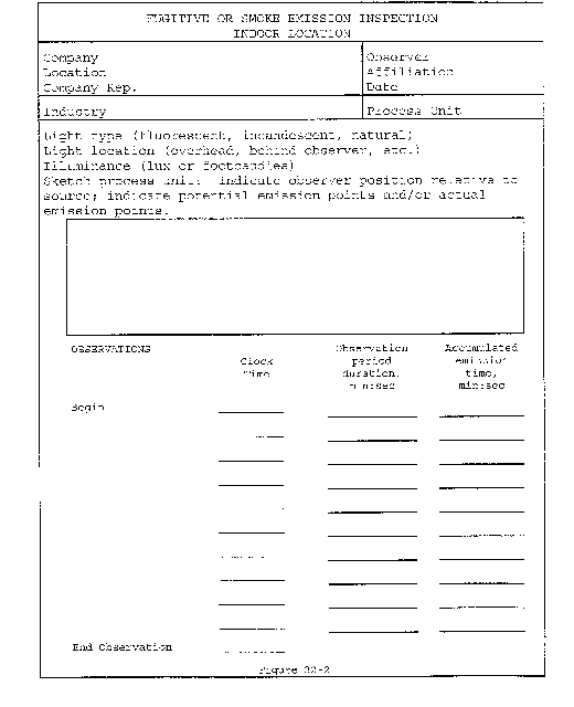
Method 23 - Determination of Polychlorinated Dibenzo-p-Dioxins and Polychlorinated Dibenzofurans From Stationary Sources
1. Applicability and Principle
1.1 Applicability. This method is applicable to the determination of polychlorinated dibenzo-p-dioxins (PCDD's) and polychlorinated dibenzofurans (PCDF's) from stationary sources.
1.2 Principle. A sample is withdrawn from the gas stream isokinetically and collected in the sample probe, on a glass fiber filter, and on a packed column of adsorbent material. The sample cannot be separated into a particle vapor fraction. The PCDD's and PCDF's are extracted from the sample, separated by high resolution gas chromatography, and measured by high resolution mass spectrometry.
2. Apparatus
2.1 Sampling. A schematic of the sampling train used in this method is shown in Figure 23-1. Sealing greases may not be used in assembling the train. The train is identical to that described in section 2.1 of Method 5 of this appendix with the following additions:

2.1.1 Nozzle. The nozzle shall be made of nickel, nickel-plated stainless steel, quartz, or borosilicate glass.
2.1.2 Sample Transfer Lines. The sample transfer lines, if needed, shall be heat traced, heavy walled TFE (1⁄2 in. OD with 1⁄8 in. wall) with connecting fittings that are capable of forming leak-free, vacuum-tight connections without using sealing greases. The line shall be as short as possible and must be maintained at 120 °C.
2.1.1 Filter Support. Teflon or Teflon-coated wire.
2.1.2 Condenser. Glass, coil type with compatible fittings. A schematic diagram is shown in Figure 23-2.
2.1.3 Water Bath. Thermostatically controlled to maintain the gas temperature exiting the condenser at <20 °C (68 °F).
2.1.4 Adsorbent Module. Glass container to hold the solid adsorbent. A shematic diagram is shown in Figure 23-2. Other physical configurations of the resin trap/condenser assembly are acceptable. The connecting fittings shall form leak-free, vacuum tight seals. No sealant greases shall be used in the sampling train. A coarse glass frit is included to retain the adsorbent.
2.2 Sample Recovery.
2.2.1 Fitting Caps. Ground glass, Teflon tape, or aluminum foil (Section 2.2.6) to cap off the sample exposed sections of the train.
2.2.2 Wash Bottles. Teflon, 500-ml.
2.2.3 Probe-Liner Probe-Nozzle, and Filter-Holder Brushes. Inert bristle brushes with precleaned stainless steel or Teflon handles. The probe brush shall have extensions of stainless steel or Teflon, at least as long as the probe. The brushes shall be properly sized and shaped to brush out the nozzle, probe liner, and transfer line, if used.

2.2.4 Filter Storage Container. Sealed filter holder, wide-mouth amber glass jar with Teflon-lined cap, or glass petri dish.
2.2.5 Balance. Triple beam.
2.2.6 Aluminum Foil. Heavy duty, hexane-rinsed.
2.2.7 Storage Container. Air-tight container to store silica gel.
2.2.8 Graduated Cylinder. Glass, 250-ml with 2-ml graduation.
2.2.9 Glass Sample Storage Container. Amber glass bottle for sample glassware washes, 500- or 1000-ml, with leak free Teflon-lined caps.
2.3 Analysis.
2.3.1 Sample Container. 125- and 250-ml flint glass bottles with Teflon-lined caps.
2.3.2 Test Tube. Glass.
2.3.3 Soxhlet Extraction Apparatus. Capable of holding 43 × 123 mm extraction thimbles.
2.3.4 Extraction Thimble. Glass, precleaned cellulosic, or glass fiber.
2.3.5 Pasteur Pipettes. For preparing liquid chromatographic columns.
2.3.6 Reacti-vials. Amber glass, 2-ml, silanized prior to use.
2.3.7 Rotary Evaporator. Buchi/Brinkman RF-121 or equivalent.
2.3.8 Nitrogen Evaporative Concentrator. N-Evap Analytical Evaporator Model III or equivalent.
2.3.9 Separatory Funnels. Glass, 2-liter.
2.3.10 Gas Chromatograph. Consisting of the following components:
2.3.10.1 Oven. Capable of maintaining the separation column at the proper operating temperature ±°C and performing programmed increases in temperature at rates of at least 40 °C/min.
2.3.10.2 Temperature Gauge. To monitor column oven, detector, and exhaust temperatures ±1 °C.
2.3.10.3 Flow System. Gas metering system to measure sample, fuel, combustion gas, and carrier gas flows.
2.3.10.4 Capillary Columns. A fused silica column, 60 × 0.25 mm inside diameter (ID), coated with DB-5 and a fused silica column, 30 m × 0.25 mm ID coated with DB-225. Other column systems may be used provided that the user is able to demonstrate using calibration and performance checks that the column system is able to meet the specifications of section 6.1.2.2.
2.3.11 Mass Spectrometer. Capable of routine operation at a resolution of 1:10000 with a stability of ±5 ppm.
2.3.12 Data System. Compatible with the mass spectrometer and capable of monitoring at least five groups of 25 ions.
2.3.13 Analytical Balance. To measure within 0.1 mg.
3. Reagents
3.1 Sampling.
3.1.1 Filters. Glass fiber filters, without organic binder, exhibiting at least 99.95 percent efficiency (<0.05 percent penetration) on 0.3-micron dioctyl phthalate smoke particles. The filter efficiency test shall be conducted in accordance with ASTM Standard Method D 2986-71 (Reapproved 1978) (incorporated by reference - see § 60.17).
3.1.1.1 Precleaning. All filters shall be cleaned before their initial use. Place a glass extraction thimble and 1 g of silica gel and a plug of glass wool into a Soxhlet apparatus, charge the apparatus with toluene, and reflux for a minimum of 3 hours. Remove the toluene and discard it, but retain the silica gel. Place no more than 50 filters in the thimble onto the silica gel bed and top with the cleaned glass wool. Charge the Soxhlet with toluene and reflux for 16 hours. After extraction, allow the Soxhlet to cool, remove the filters, and dry them under a clean N2 stream. Store the filters in a glass petri dish sealed with Teflon tape.
3.1.2 Adsorbent Resin. Amberlite XAD-2 resin. Thoroughly cleaned before initial use.
3.1.2.1 Cleaning Procedure. This procedure may be carried out in a giant Soxhlet extractor. An all-glass filter thimble containing an extra-course frit is used for extraction of XAD-2. The frit is recessed 10-15 mm above a crenelated ring at the bottom of the thimble to facilitate drainage. The resin must be carefully retained in the extractor cup with a glass wool plug and a stainless steel ring because it floats on methylene chloride. This process involves sequential extraction in the following order.
| Solvent | Procedure |
|---|---|
| Water | Initial rinse: Place resin in a beaker, rinse once with water, and discard. Fill with water a second time, let stand overnight, and discard. |
| Water | Extract with water for 8 hours. |
| Methanol | Extract for 22 hours. |
| Methylene Chloride | Extract for 22 hours. |
| Toluene | Extract for 22 hours. |
3.1.2.2 Drying.
3.1.2.2.1 Drying Column. Pyrex pipe, 10.2 cm ID by 0.6 m long, with suitable retainers.
3.1.2.2.2 Procedure. The adsorbent must be dried with clean inert gas. Liquid nitrogen from a standard commercial liquid nitrogen cylinder has proven to be a reliable source of large volumes of gas free from organic contaminants. Connect the liquid nitrogen cylinder to the column by a length of cleaned copper tubing, 0.95 cm ID, coiled to pass through a heat source. A convenient heat source is a water-bath heated from a steam line. The final nitrogen temperature should only be warm to the touch and not over 40 °C. Continue flowing nitrogen through the adsorbent until all the residual solvent is removed. The flow rate should be sufficient to gently agitate the particles but not so excessive as the cause the particles to fracture.
3.1.2.3 Quality Control Check. The adsorbent must be checked for residual toluene.
3.1.2.3.1 Extraction. Weigh 1.0 g sample of dried resin into a small vial, add 3 ml of toluene, cap the vial, and shake it well.
3.1.2.3.2 Analysis. Inject a 2 µl sample of the extract into a gas chromatograph operated under the following conditions:
Column: 6 ft × 1⁄8 in stainless steel containing 10 percent OV-101 on 100/120 Supelcoport.
Carrier Gas: Helium at a rate of 30 ml/min.
Detector: Flame ionization detector operated at a sensitivity of 4 × 10⁻¹¹ A/mV.
Injection Port Temperature: 250 °C.
Detector Temperature: 305 °C.
Oven Temperature: 30 °C for 4 min; programmed to rise at 40 °C/min until it reaches 250 °C; return to 30 °C after 17 minutes.
Compare the results of the analysis to the results from the reference solution. Prepare the reference solution by injection 2.5 µl of methylene chloride into 100 ml of toluene. This corresponds to 100 µg of methylene chloride per g of adsorbent. The maximum acceptable concentration is 1000 µg/g of adsorbent. If the adsorbent exceeds this level, drying must be continued until the excess methylene chloride is removed.
3.1.2.4 Storage. The adsorbent must be used within 4 weeks of cleaning. After cleaning, it may be stored in a wide mouth amber glass container with a Teflon-lined cap or placed in one of the glass adsorbent modules tightly sealed with glass stoppers. If precleaned adsorbent is purchased in sealed containers, it must be used within 4 weeks after the seal is broken.
3.1.3 Glass Wool. Cleaned by sequential immersion in three aliquots of methylene chloride, dried in a 110 °C oven, and stored in a methylene chloride-washed glass jar with a Teflon-lined screw cap.
3.1.4 Water. Deionized distilled and stored in a methylene chloride-rinsed glass container with a Teflon-lined screw cap.
3.1.5 Silica Gel. Indicating type, 6 to 16 mesh. If previously used, dry at 175 °C (350 °F) for two hours. New silica gel may be used as received. Alternately other types of desiccants (equivalent or better) may be used, subject to the approval of the Administrator.
3.1.6 Chromic Acid Cleaning Solution. Dissolve 20 g of sodium dichromate in 15 ml of water, and then carefully add 400 ml of concentrated sulfuric acid.
3.2 Sample Recovery.
3.2.2 Acetone. Pesticide quality.
3.2.2 Methylene Chloride. Pesticide qualtity.
3.2.3 Toluene. Pesticide quality.
3.3 Analysis.
3.3.1 Potassium Hydroxide. ACS grade, 2-percent (weight/volume) in water.
3.3.2 Sodium Sulfate. Granulated, reagent grade. Purify prior to use by rinsing with methylene chloride and oven drying. Store the cleaned material in a glass container with a Teflon-lined screw cap.
3.3.3 Sulfuric Acid. Reagent grade.
3.3.4 Sodium Hydroxide. 1.0 N. Weigh 40 g of sodium hydroxide into a 1-liter volumetric flask. Dilute to 1 liter with water.
3.3.5 Hexane. Pesticide grade.
3.3.6 Methylene Chloride. Pesticide grade.
3.3.7 Benzene. Pesticide Grade.
3.3.8 Ethyl Acetate.
3.3.9 Methanol. Pesticide Grade.
3.3.10 Toluene. Pesticide Grade.
3.3.11 Nonane. Pesticide Grade.
3.3.12 Cyclohexane. Pesticide Grade.
3.3.13 Basic Alumina. Activity grade 1, 100-200 mesh. Prior to use, activate the alumina by heating for 16 hours at 130 °C before use. Store in a desiccator. Pre-activated alumina may be purchased from a supplier and may be used as received.
3.3.14 Silica Gel. Bio-Sil A, 100-200 mesh. Prior to use, activate the silica gel by heating for at least 30 minutes at 180 °C. After cooling, rinse the silica gel sequentially with methanol and methylene chloride. Heat the rinsed silica gel at 50 °C for 10 minutes, then increase the temperature gradually to 180 °C over 25 minutes and maintain it at this temperature for 90 minutes. Cool at room temperature and store in a glass container with a Teflon-lined screw cap.
3.3.15 Silica Gel Impregnated with Sulfuric Acid. Combine 100 g of silica gel with 44 g of concentrated sulfuric acid in a screw capped glass bottle and agitate thoroughly. Disperse the solids with a stirring rod until a uniform mixture is obtained. Store the mixture in a glass container with a Teflon-lined screw cap.
3.3.16 Silica Gel Impregnated with Sodium Hydroxide. Combine 39 g of 1 N sodium hydroxide with 100 g of silica gel in a screw capped glass bottle and agitate thoroughly. Disperse solids with a stirring rod until a uniform mixture is obtained. Store the mixture in glass container with a Teflon-lined screw cap.
3.3.17 Carbon/Celite. Combine 10.7 g of AX-21 carbon with 124 g of Celite 545 in a 250-ml glass bottle with a Teflon-lined screw cap. Agitate the mixture thoroughly until a uniform mixture is obtained. Store in the glass container.
3.3.18 Nitrogen. Ultra high purity.
3.3.19 Hydrogen. Ultra high purity.
3.3.20 Internal Standard Solution. Prepare a stock standard solution containing the isotopically labelled PCDD's and PCDF's at the concentrations shown in Table 1 under the heading “Internal Standards” in 10 ml of nonane.
3.3.21 Surrogate Standard Solution. Prepare a stock standard solution containing the isotopically labelled PCDD's and PCDF's at the concentrations shown in Table 1 under the heading “Surrogate Standards” in 10 ml of nonane.
3.3.22 Recovery Standard Solution. Prepare a stock standard solution containing the isotopically labelled PCDD's and PCDF's at the concentrations shown in Table 1 under the heading “Recovery Standards” in 10 ml of nonane.
4. Procedure
4.1 Sampling. The complexity of this method is such that, in order to obtain reliable results, testers should be trained and experienced with the test procedures.
4.1.1 Pretest Preparation.
4.1.1.1 Cleaning Glassware. All glass components of the train upstream of and including the adsorbent module, shall be cleaned as described in section 3A of the “Manual of Analytical Methods for the Analysis of Pesticides in Human and Environmental Samples.” Special care shall be devoted to the removal of residual silicone grease sealants on ground glass connections of used glassware. Any residue shall be removed by soaking the glassware for several hours in a chromic acid cleaning solution prior to cleaning as described above.
4.1.1.2 Adsorbent Trap. The traps must be loaded in a clean area to avoid contamination. They may not be loaded in the field. Fill a trap with 20 to 40 g of XAD-2. Follow the XAD-2 with glass wool and tightly cap both ends of the trap. Add 100 µl of the surrogate standard solution (section 3.3.21) to each trap.
4.1.1.3 Sample Train. It is suggested that all components be maintained according to the procedure described in APTD-0576. Alternative mercury-free thermometers may be used if the thermometers are, at a minimum, equivalent in terms of performance or suitably effective for the specific temperature measurement application.
4.1.1.4 Silica Gel. Weigh several 200 to 300 g portions of silica gel in an air tight container to the nearest 0.5 g. Record the total weight of the silica gel plus container, on each container. As an alternative, the silica gel may be weighed directly in its impinger or sampling holder just prior to sampling.
4.1.1.5 Filter. Check each filter against light for irregularities and flaws or pinhole leaks. Pack the filters flat in a clean glass container.
4.1.2 Preliminary Determinations. Same as section 4.1.2 of Method 5.
4.1.3 Preparation of Collection Train.
4.1.3.1 During preparation and assembly of the sampling train, keep all train openings where contamination can enter, sealed until just prior to assembly or until sampling is about to begin.
Do not use sealant grease in assembling the train.
4.1.3.2 Place approximately 100 ml of water in the second and third impingers, leave the first and fourth impingers empty, and transfer approximately 200 to 300 g of preweighed silica gel from its container to the fifth impinger.
4.1.3.3 Place the silica gel container in a clean place for later use in the sample recovery. Alternatively, the weight of the silica gel plus impinger may be determined to the nearest 0.5 g and recorded.
4.1.3.4 Assemble the train as shown in Figure 23-1.
4.1.3.5 Turn on the adsorbent module and condenser coil recirculating pump and begin monitoring the adsorbent module gas entry temperature. Ensure proper sorbent temperature gas entry temperature before proceeding and before sampling is initiated. It is extremely important that the XAD-2 adsorbent resin temperature never exceed 50 °C because thermal decomposition will occur. During testing, the XAD-2 temperature must not exceed 20 °C for efficient capture of the PCDD's and PCDF's.
4.1.4 Leak-Check Procedure. Same as Method 5, section 4.1.4.
4.1.5 Sample Train Operation. Same as Method 5, section 4.1.5.
4.2 Sample Recovery. Proper cleanup procedure begins as soon as the probe is removed from the stack at the end of the sampling period. Seal the nozzle end of the sampling probe with Teflon tape or aluminum foil.
When the probe can be safely handled, wipe off all external particulate matter near the tip of the probe. Remove the probe from the train and close off both ends with aluminum foil. Seal off the inlet to the train with Teflon tape, a ground glass cap, or aluminum foil.
Transfer the probe and impinger assembly to the cleanup area. This area shall be clean and enclosed so that the chances of losing or contaminating the sample are minimized. Smoking, which could contaminate the sample, shall not be allowed in the cleanup area.
Inspect the train prior to and during disassembly and note any abnormal conditions, e.g., broken filters, colored impinger liquid, etc. Treat the samples as follows:
4.2.1 Container No. 1. Either seal the filter holder or carefully remove the filter from the filter holder and place it in its identified container. Use a pair of cleaned tweezers to handle the filter. If it is necessary to fold the filter, do so such that the particulate cake is inside the fold. Carefully transfer to the container any particulate matter and filter fibers which adhere to the filter holder gasket, by using a dry inert bristle brush and a sharp-edged blade. Seal the container.
4.2.2 Adsorbent Module. Remove the module from the train, tightly cap both ends, label it, cover with aluminum foil, and store it on ice for transport to the laboratory.
4.2.3 Container No. 2. Quantitatively recover material deposited in the nozzle, probe transfer lines, the front half of the filter holder, and the cyclone, if used, first, by brushing while rinsing three times each with acetone and then, by rinsing the probe three times with methylene chloride. Collect all the rinses in Container No. 2.
Rinse the back half of the filter holder three times with acetone. Rinse the connecting line between the filter and the condenser three times with acetone. Soak the connecting line with three separate portions of methylene chloride for 5 minutes each. If using a separate condenser and adsorbent trap, rinse the condenser in the same manner as the connecting line. Collect all the rinses in Container No. 2 and mark the level of the liquid on the container.
4.2.4 Container No. 3. Repeat the methylene chloride-rinsing described in section 4.2.3 using toluene as the rinse solvent. Collect the rinses in Container No. 3 and mark the level of the liquid on the container.
4.2.5 Impinger Water. Measure the liquid in the first three impingers to within ±1 ml by using a graduated cylinder or by weighing it to within ±0.5 g by using a balance. Record the volume or weight of liquid present. This information is required to calculate the moisture content of the effluent gas.
Discard the liquid after measuring and recording the volume or weight.
4.2.7 Silica Gel. Note the color of the indicating silica gel to determine if it has been completely spent and make a mention of its condition. Transfer the silica gel from the fifth impinger to its original container and seal. If a moisture determination is made, follow the applicable procedures in sections 8.7.6.3 and 11.2.3 of Method 5 to handle and weigh the silica gel. If moisture is not measured, the silica gel may be disposed.
5. Analysis
All glassware shall be cleaned as described in section 3A of the “Manual of Analytical Methods for the Analysis of Pesticides in Human and Environmental Samples.” All samples must be extracted within 30 days of collection and analyzed within 45 days of extraction.
5.1 Sample Extraction.
5.1.1 Extraction System. Place an extraction thimble (section 2.3.4), 1 g of silica gel, and a plug of glass wool into the Soxhlet apparatus, charge the apparatus with toluene, and reflux for a minimum of 3 hours. Remove the toluene and discard it, but retain the silica gel. Remove the extraction thimble from the extraction system and place it in a glass beaker to catch the solvent rinses.
5.1.2 Container No. 1 (Filter). Transfer the contents directly to the glass thimble of the extraction system and extract them simultaneously with the XAD-2 resin.
5.1.3 Adsorbent Cartridge. Suspend the adsorbent module directly over the extraction thimble in the beaker (See section 5.1.1). The glass frit of the module should be in the up position. Using a Teflon squeeze bottle containing toluene, flush the XAD-2 into the thimble onto the bed of cleaned silica gel. Thoroughly rinse the glass module catching the rinsings in the beaker containing the thimble. If the resin is wet, effective extraction can be accomplished by loosely packing the resin in the thimble. Add the XAD-2 glass wool plug into the thimble.
5.1.4 Container No. 2 (Acetone and Methylene Chloride). Concentrate the sample to a volume of about 1-5 ml using the rotary evaporator apparatus, at a temperature of less than 37 °C. Rinse the sample container three times with small portions of methylene chloride and add these to the concentrated solution and concentrate further to near dryness. This residue contains particulate matter removed in the rinse of the train probe and nozzle. Add the concentrate to the filter and the XAD-2 resin in the Soxhlet apparatus described in section 5.1.1.
5.1.5 Extraction. Add 100 µl of the internal standard solution (Section 3.3.20) to the extraction thimble containing the contents of the adsorbent cartridge, the contents of Container No. 1, and the concentrate from section 5.1.4. Cover the contents of the extraction thimble with the cleaned glass wool plug to prevent the XAD-2 resin from floating into the solvent reservoir of the extractor. Place the thimble in the extractor, and add the toluene contained in the beaker to the solvent reservoir. Pour additional toluene to fill the reservoir approximately 2⁄3 full. Add Teflon boiling chips and assemble the apparatus. Adjust the heat source to cause the extractor to cycle three times per hour. Extract the sample for 16 hours. After extraction, allow the Soxhlet to cool. Transfer the toluene extract and three 10-ml rinses to the rotary evaporator. Concentrate the extract to approximately 10 ml. At this point the analyst may choose to split the sample in half. If so, split the sample, store one half for future use, and analyze the other according to the procedures in sections 5.2 and 5.3. In either case, use a nitrogen evaporative concentrator to reduce the volume of the sample being analyzed to near dryness. Dissolve the residue in 5 ml of hexane.
5.1.6 Container No. 3 (Toluene Rinse). Add 100 µl of the Internal Standard solution (section 3.3.2) to the contents of the container. Concentrate the sample to a volume of about 1-5 ml using the rotary evaporator apparatus at a temperature of less than 37 °C. Rinse the sample container apparatus at a temperature of less than 37 °C. Rinse the sample container three times with small portions of toluene and add these to the concentrated solution and concentrate further to near dryness. Analyze the extract separately according to the procedures in sections 5.2 and 5.3, but concentrate the solution in a rotary evaporator apparatus rather than a nitrogen evaporative concentrator.
5.2 Sample Cleanup and Fractionation.
5.2.1 Silica Gel Column. Pack one end of a glass column, 20 mm × 230 mm, with glass wool. Add in sequence, 1 g silica gel, 2 g of sodium hydroxide impregnated silica gel, 1 g silica gel, 4 g of acid-modified silica gel, and 1 g of silica gel. Wash the column with 30 ml of hexane and discard it. Add the sample extract, dissolved in 5 ml of hexane to the column with two additional 5-ml rinses. Elute the column with an additional 90 ml of hexane and retain the entire eluate. Concentrate this solution to a volume of about 1 ml using the nitrogen evaporative concentrator (section 2.3.7).
5.2.2 Basic Alumina Column. Shorten a 25-ml disposable Pasteur pipette to about 16 ml. Pack the lower section with glass wool and 12 g of basic alumina. Transfer the concentrated extract from the silica gel column to the top of the basic alumina column and elute the column sequentially with 120 ml of 0.5 percent methylene chloride in hexane followed by 120 ml of 35 percent methylene chloride in hexane. Discard the first 120 ml of eluate. Collect the second 120 ml of eluate and concentrate it to about 0.5 ml using the nitrogen evaporative concentrator.
5.2.3 AX-21 Carbon/Celite 545 Column. Remove the botton 0.5 in. from the tip of a 9-ml disposable Pasteur pipette. Insert a glass fiber filter disk in the top of the pipette 2.5 cm from the constriction. Add sufficient carbon/celite mixture to form a 2 cm column. Top with a glass wool plug. In some cases AX-21 carbon fines may wash through the glass wool plug and enter the sample. This may be prevented by adding a celite plug to the exit end of the column. Rinse the column in sequence with 2 ml of 50 percent benzene in ethyl acetate, 1 ml of 50 percent methylene chloride in cyclohexane, and 2 ml of hexane. Discard these rinses. Transfer the concentrate in 1 ml of hexane from the basic alumina column to the carbon/celite column along with 1 ml of hexane rinse. Elute the column sequentially with 2 ml of 50 percent methylene chloride in hexane and 2 ml of 50 percent benzene in ethyl acetate and discard these eluates. Invert the column and elute in the reverse direction with 13 ml of toluene. Collect this eluate. Concentrate the eluate in a rotary evaporator at 50 °C to about 1 ml. Transfer the concentrate to a Reacti-vial using a toluene rinse and concentrate to a volume of 200 µl using a stream of N2. Store extracts at room temperature, shielded from light, until the analysis is performed.
5.3 Analysis. Analyze the sample with a gas chromatograph coupled to a mass spectrometer (GC/MS) using the instrumental parameters in sections 5.3.1 and 5.3.2. Immediately prior to analysis, add a 20 µl aliquot of the Recovery Standard solution from Table 1 to each sample. A 2 µl aliquot of the extract is injected into the GC. Sample extracts are first analyzed using the DB-5 capillary column to determine the concentration of each isomer of PCDD's and PCDF's (tetra-through octa-). If tetra-chlorinated dibenzofurans are detected in this analysis, then analyze another aliquot of the sample in a separate run, using the DB-225 column to measure the 2,3,7,8 tetra-chloro dibenzofuran isomer. Other column systems may be used, provided that the user is able to demonstrate using calibration and performance checks that the column system is able to meet the specifications of section 6.1.2.2.
5.3.1 Gas Chromatograph Operating Conditions.
5.3.1.1 Injector. Configured for capillary column, splitless, 250 °C.
5.3.1.2 Carrier Gas. Helium, 1-2 ml/min.
5.3.1.3 Oven. Initially at 150 °C. Raise by at least 40 °C/min to 190 °C and then at 3 °C/min up to 300 °C.
5.3.2 High Resolution Mass Spectrometer.
5.3.2.1 Resolution. 10000 m/e.
5.3.2.2 Ionization Mode. Electron impact.
5.3.2.3 Source Temperature 250 °C.
5.3.2.4 Monitoring Mode. Selected ion monitoring. A list of the various ions to be monitored is summarized in Table 3.
5.3.2.5 Identification Criteria. The following identification criteria shall be used for the characterization of polychlorinated dibenzodioxins and dibenzofurans.
1. The integrated ion-abundance ratio (M/M + 2 or M + 2/M + 4) shall be within 15 percent of the theoretical value. The acceptable ion-abundance ratio ranges for the identification of chlorine-containing compounds are given in Table 4.
2. The retention time for the analytes must be within 3 seconds of the corresponding13 C-labeled internal standard, surrogate or alternate standard.
3. The monitored ions, shown in Table 3 for a given analyte, shall reach their maximum within 2 seconds of each other.
4. The identification of specific isomers that do not have corresponding13 C-labeled standards is done by comparison of the relative retention time (RRT) of the analyte to the nearest internal standard retention time with reference (i.e., within 0.005 RRT units) to the comparable RRT's found in the continuing calibration.
5. The signal to noise ratio for all monitored ions must be greater than 2.5.
6. The confirmation of 2, 3, 7, 8-TCDD and 2, 3, 7, 8-TCDF shall satisfy all of the above identification criteria.
7. For the identification of PCDF's, no signal may be found in the corresponding PCDPE channels.
5.3.2.6 Quantification. The peak areas for the two ions monitored for each analyte are summed to yield the total response for each analyte. Each internal standard is used to quantify the indigenous PCDD's or PCDF's in its homologous series. For example, the13 C12-2,3,7,8-tetra chlorinated dibenzodioxin is used to calculate the concentrations of all other tetra chlorinated isomers. Recoveries of the tetra- and penta- internal standards are calculated using the13 C12-1,2,3,4-TCDD. Recoveries of the hexa- through octa- internal standards are calculated using13 C12-1,2,3,7,8,9-HxCDD. Recoveries of the surrogate standards are calculated using the corresponding homolog from the internal standard.
6. Calibration
Same as Method 5 with the following additions.
6.1 GC/MS System.
6.1.1 Initial Calibration. Calibrate the GC/MS system using the set of five standards shown in Table 2. The relative standard deviation for the mean response factor from each of the unlabeled analytes (Table 2) and of the internal, surrogate, and alternate standards shall be less than or equal to the values in Table 5. The signal to noise ratio for the GC signal present in every selected ion current profile shall be greater than or equal to 2.5. The ion abundance ratios shall be within the control limits in Table 4.
6.1.2 Daily Performance Check.
6.1.2.1 Calibration Check. Inject on µl of solution Number 3 from Table 2. Calculate the relative response factor (RRF) for each compound and compare each RRF to the corresponding mean RRF obtained during the initial calibration. The analyzer performance is acceptable if the measured RRF's for the labeled and unlabeled compounds for the daily run are within the limits of the mean values shown in Table 5. In addition, the ion-abundance ratios shall be within the allowable control limits shown in Table 4.
6.1.2.2 Column Separation Check. Inject a solution of a mixture of PCDD's and PCDF's that documents resolution between 2,3,7,8-TCDD and other TCDD isomers. Resolution is defined as a valley between peaks that is less than 25 percent of the lower of the two peaks. Identify and record the retention time windows for each homologous series.
Perform a similar resolution check on the confirmation column to document the resolution between 2,3,7,8 TCDF and other TCDF isomers.
6.2 Lock Channels. Set mass spectrometer lock channels as specified in Table 3. Monitor the quality control check channels specified in Table 3 to verify instrument stability during the analysis.
7. Quality Control
7.1 Sampling Train Collection Efficiency Check. Add 100 µl of the surrogate standards in Table 1 to the absorbent cartridge of each train before collecting the field samples.
7.2 Internal Standard Percent Recoveries. A group of nine carbon labeled PCDD's and PCDF's representing, the tetra-through octachlorinated homologues, is added to every sample prior to extraction. The role of the internal standards is to quantify the native PCDD's and PCDF's present in the sample as well as to determine the overall method efficiency. Recoveries of the internal standards must be between 40 to 130 percent for the tetra-through hexachlorinated compounds while the range is 25 to 130 percent for the higher hepta- and octachlorinated homologues.
7.3 Surrogate Recoveries. The five surrogate compounds in Table 2 are added to the resin in the adsorbent sampling cartridge before the sample is collected. The surrogate recoveries are measured relative to the internal standards and are a measure of collection efficiency. They are not used to measure native PCDD's and PCDF's. All recoveries shall be between 70 and 130 percent. Poor recoveries for all the surrogates may be an indication of breakthrough in the sampling train. If the recovery of all standards is below 70 percent, the sampling runs must be repeated. As an alternative, the sampling runs do not have to be repeated if the final results are divided by the fraction of surrogate recovery. Poor recoveries of isolated surrogate compounds should not be grounds for rejecting an entire set of the samples.
7.4 Toluene QA Rinse. Report the results of the toluene QA rinse separately from the total sample catch. Do not add it to the total sample.
8.0 [Reserved]
9. Calculations
Same as Method 5, section 6 with the following additions.
9.1 Nomenclature.
Aai = Integrated ion current of the noise at the retention time of the analyte.
A*ci = Integrated ion current of the two ions characteristic of the internal standard i in the calibration standard.
Acij = Integrated ion current of the two ions characteristic of compound i in the jth calibration standard.
A*cij = Integrated ion current of the two ions characteristic of the internal standard i in the jth calibration standard.
Acsi = Integrated ion current of the two ions characteristic of surrogate compound i in the calibration standard.
Ai = Integrated ion current of the two ions characteristic of compound i in the sample.
A*i = Integrated ion current of the two ions characteristic of internal standard i in the sample.
Ars = Integrated ion current of the two ions characteristic of the recovery standard.
Asi = Integrated ion current of the two ions characteristic of surrogate compound i in the sample.
Ci = Concentration of PCDD or PCDF i in the sample, pg/M3.
CT = Total concentration of PCDD's or PCDF's in the sample, pg/M3.
mci = Mass of compound i in the calibration standard injected into the analyzer, pg.
mrs = Mass of recovery standard in the calibration standard injected into the analyzer, pg.
msi = Mass of surrogate compound in the calibration standard, pg.
RRFi = Relative response factor.
RRFrs = Recovery standard response factor.
RRFs = Surrogate compound response factor.
9.2 Average Relative Response Factor.

9.3 Concentration of the PCDD's and PCDF's.

9.4 Recovery Standard Response Factor.

9.5 Recovery of Internal Standards (R*).

9.6 Surrogate Compound Response Factor.

9.7 Recovery of Surrogate Compounds (Rs).

9.8 Minimum Detectable Limit (MDL).

9.9 Total Concentration of PCDD's and PCDF's in the Sample.

Any PCDD's or PCDF's that are reported as nondetected (below the MDL) shall be counted as zero for the purpose of calculating the total concentration of PCDD's and PCDF's in the sample.
10. Bibliography
1. American Society of Mechanical Engineers. Sampling for the Determination of Chlorinated Organic Compounds in Stack Emissions. Prepared for U.S. Department of Energy and U.S. Environmental Protection Agency. Washington DC. December 1984. 25 p.
2. American Society of Mechanical Engineers. Analytical Procedures to Assay Stack Effluent Samples and Residual Combustion Products for Polychlorinated Dibenzo-p-Dioxins (PCDD) and Polychlorinated Dibenzofurans (PCDF). Prepared for the U.S. Department of Energy and U.S. Environmental Protection Agency. Washington, DC. December 1984. 23 p.
3. Thompson, J. R. (ed.). Analysis of Pesticide Residues in Human and Environmental Samples. U.S. Environmental Protection Agency. Research Triangle Park, NC. 1974.
4. Triangle Laboratories. Case Study: Analysis of Samples for the Presence of Tetra Through Octachloro-p-Dibenzodioxins and Dibenzofurans. Research Triangle Park, NC. 1988. 26 p.
5. U.S. Environmental Protection Agency. Method 8290 - The Analysis of Polychlorinated Dibenzo-p-dioxin and Polychlorinated Dibenzofurans by High-Resolution Gas Chromotography/High-Resolution Mass Spectrometry. In: Test Methods for Evaluating Solid Waste. Washington, DC. SW-846.
Table 1 - Composition of the Sample Fortification and Recovery Standards Solutions
| Analyte | Concentration (pg/µl) |
|---|---|
| Internal Standards: | |
| 13 C12-2,3,7,8-TCDD | 100 |
| 13 C12-1,2,3,7,8-PeCDD | 100 |
| 13 C12-1,2,3,6,7,8-HxCDD | 100 |
| 13 C12-1,2,3,4,6,7,8-HpCDD | 100 |
| 13 C12-OCDD | 100 |
| 13 C12-2,3,7,8-TCDF | 100 |
| 13 C12-1,2,3,7,8-PeCDF | 100 |
| 13 C12-1,2,3,6,7,8-HxCDF | 100 |
| 13 C12-1,2,3,4,6,7,8-HpCDF | 100 |
| Surrogate Standards: | |
| 37 Cl4-2,3,7,8-TCDD | 100 |
| 13 C12-1,2,3,4,7,8-HxCDD | 100 |
| 13 C12-2,3,4,7,8-PeCDF | 100 |
| 13 C12-1,2,3,4,7,8-HxCDF | 100 |
| 13 C12-1,2,3,4,7,8,9-HpCDF | 100 |
| Recovery Standards: | |
| 13 C12-1,2,3,4-TCDD | 500 |
| 13 C12-1,2,3,7,8,9-HxCDD | 500 |
Table 2 - Composition of the Initial Calibration Solutions
| Compound | Concentrations (pg/µL) | ||||
|---|---|---|---|---|---|
| Solution No. | |||||
| 1 | 2 | 3 | 4 | 5 | |
| Alternate Standard: | |||||
| 13 C12-1,2,3,7,8,9-HxCDF | 2.5 | 5 | 25 | 250 | 500 |
| Recovery Standards: | |||||
| 13 C12-1,2,3,4-TCDD | 100 | 100 | 100 | 100 | 100 |
| 13 C12-1,2,3,7,8,9-HxCDD | 100 | 100 | 100 | 100 | 100 |
Table 3 - Elemental Compositions and Exact Masses of the Ions Monitored by High Resolution Mass Spectrometry for PCDD's and PCDF's
| Descriptor No. | Accurate mass | Ion type | Elemental composition | Analyte |
|---|---|---|---|---|
| 2 | 292.9825 | LOCK | C7F11 | PFK |
| 303.9016 | M | C12H435Cl4O | TCDF | |
| 305.8987 | M + 2 | C12H435Cl37O | TCDF | |
| 315.9419 | M | 13C12H435Cl4O | TCDF (S) | |
| 317.9389 | M + 2 | 13C12H435Cl337ClO | TCDF (S) | |
| 319.8965 | M | C12H435ClO2 | TCDD | |
| 321.8936 | M + 2 | C12H435Cl337ClO2 | TCDD | |
| 327.8847 | M | C12H437Cl4O2 | TCDD (S) | |
| 330.9792 | QC | C7F13 | PFK | |
| 331.9368 | M | 13C12H435Cl4O2 | TCDD (S) | |
| 333.9339 | M + 2 | 13C12H435Cl37ClO2 | TCDD (S) | |
| 339.8597 | M + 2 | C12H335Cl437ClO | PECDF | |
| 341.8567 | M + 4 | C12H335Cl337Cl2O | PeCDF | |
| 351.9000 | M + 2 | 13C12H335Cl437ClO | PeCDF (S) | |
| 353.8970 | M + 4 | 13C12H335Cl3537Cl2O | PeCDF (S) | |
| 355.8546 | M + 2 | C12H335Cl337ClO2 | PeCDD | |
| 357.8516 | M + 4 | C12H335Cl337Cl2O2 | PeCDD | |
| 367.8949 | M + 2 | 13C12H335Cl437ClO2 | PeCDD (S) | |
| 369.8919 | M + 4 | 13C12H335Cl337 Cl2O2 | PeCDD (S) | |
| 375.8364 | M + 2 | C12H435Cl537ClO | HxCDPE | |
| 409.7974 | M + 2 | C12H335Cl637ClO | HpCPDE | |
| 3 | 373.8208 | M + 2 | C12H235Cl537ClO | HxCDF |
| 375.8178 | M + 4 | C12H235Cl437Cl2O | HxCDF | |
| 383.8639 | M | 13C12H235Cl6O | HxCDF (S) | |
| 385.8610 | M + 2 | 13C12H235Cl537ClO | HxCDF (S) | |
| 389.8157 | M + 2 | C12H235Cl537ClO2 | HxCDD | |
| 391.8127 | M + 4 | C12H235Cl437Cl2O2 | HxCDD | |
| 392.9760 | LOCK | C9F15 | PFK | |
| 401.8559 | M + 2 | 13C12H235Cl537ClO2 | HxCDD (S) | |
| 403.8529 | M + 4 | 13C12H235Cl437Cl2O | HxCDD (S) | |
| 445.7555 | M + 4 | C12H235Cl637Cl2O | OCDPE | |
| 430.9729 | QC | C9F17 | PFK | |
| 4 | 407.7818 | M + 2 | C12H35Cl637ClO | HpCDF |
| 409.7789 | M + 4 | C12H35Cl537Cl2O | HpCDF | |
| 417.8253 | M | 13C12H35Cl7O | HpCDF (S) | |
| 419.8220 | M + 2 | 13C12H35Cl637ClO | HpCDF (S) | |
| 423.7766 | M + 2 | C12H35Cl637ClO2 | HpCDD | |
| 425.7737 | M + 4 | C12H35Cl537Cl2O2 | HpCDD | |
| 435.8169 | M + 2 | 13C12H35Cl637ClO2 | HpCDD (S) | |
| 437.8140 | M + 4 | 13C12H35Cl537Cl2O2 | HpCDD (S) | |
| 479.7165 | M + 4 | C12H35Cl737Cl2O | NCPDE | |
| 430.9729 | LOCK | C9F17 | PFK | |
| 441.7428 | M + 2 | C1235Cl737ClO | OCDF | |
| 443.7399 | M + 4 | C1235Cl637Cl2O | OCDF | |
| 457.7377 | M + 2 | C1235Cl737ClO2 | OCDD | |
| 459.7348 | M + 4 | C1235Cl637Cl2O2 | OCDD | |
| 469.7779 | M + 2 | 13C1235Cl737ClO2 | OCDD (S) | |
| 471.7750 | M + 4 | 13C1235Cl637Cl2O2 | OCDD (S) | |
| 513.6775 | M + 4 | C1235Cl837Cl2O2 | DCDPE | |
| 442.9728 | QC | C10F17 | PFK |
Table 4 - Acceptable Ranges for Ion-Abundance Ratios of PCDD's and PCDF's
| No. of chlorine atoms | Ion type | Theoretical ratio | Control limits | |
|---|---|---|---|---|
| Lower | Upper | |||
| 4 | M/M + 2 | 0.77 | 0.65 | 0.89 |
| 5 | M + 2/M + 4 | 1.55 | 1.32 | 1.78 |
| 6 | M + 2/M + 4 | 1.24 | 1.05 | 1.43 |
| 6a | M/M + 2 | 0.51 | 0.43 | 0.59 |
| 7b | M/M + 2 | 0.44 | 0.37 | 0.51 |
| 7 | M + 2/M + 4 | 1.04 | 0.88 | 1.20 |
| 8 | M + 2/M + 4 | 0.89 | 0.76 | 1.02 |
Table 5 - Minimum Requirements for Initial and Daily Calibration Response Factors
| Compound | Relative response factors | |
|---|---|---|
| Initial calibration RSD | Daily calibration % difference | |
| Unlabeled
Analytes: |
||
| 2,3,7,8-TCDD | 25 | 25 |
| 2,3,7,8-TCDF | 25 | 25 |
| 1,2,3,7,8-PeCDD | 25 | 25 |
| 1,2,3,7,8-PeCDF | 25 | 25 |
| 2,3,4,7,8-PeCDF | 25 | 25 |
| 1,2,4,5,7,8-HxCDD | 25 | 25 |
| 1,2,3,6,7,8-HxCDD | 25 | 25 |
| 1,2,3,7,8,9-HxCDD | 25 | 25 |
| 1,2,3,4,7,8-HxCDF | 25 | 25 |
| 1,2,3,6,7,8-HxCDF | 25 | 25 |
| 1,2,3,7,8,9-HxCDF | 25 | 25 |
| 2,3,4,6,7,8-HxCDF | 25 | 25 |
| 1,2,3,4,6,7,8-HpCDD | 25 | 25 |
| 1,2,3,4,6,7,8-HpCDF | 25 | 25 |
| OCDD | 25 | 25 |
| OCDF | 30 | 30 |
| Internal
Standards: |
||
| 13C12-2,3,7,8-TCDD | 25 | 25 |
| 13C12-1,2,3,7,8-PeCDD | 30 | 30 |
| 13C12-1,2,3,6,7,8-HxCDD | 25 | 25 |
| 13C12-1,2,3,4,6,7,8-HpCDD | 30 | 30 |
| 13C12-OCDD | 30 | 30 |
| 13C12-2,3,7,8-TCDF | 30 | 30 |
| 13C12-1,2,3,7,8-PeCDF | 30 | 30 |
| 13C12-1,2,3,6,7,8-HxCDF | 30 | 30 |
| 13C12-1,2,3,4,6,7,8-HpCDF | 30 | 30 |
| Surrogate
Standards: |
||
| 37Cl4-2,3,7,8-TCDD | 25 | 25 |
| 13C12-2,3,4,7,8-PeCDF | 25 | 25 |
| 13C12-1,2,3,4,7,8-HxCDD | 25 | 25 |
| 13C12-1,2,3,4,7,8-HxCDF | 25 | 25 |
| 13C12-1,2,3,4,7,8,9-HpCDF | 25 | 25 |
| Alternate
Standard: |
||
| 13C12-1,2,3,7,8,9-HxCDF | 25 | 25 |
Method 24 - Determination of Volatile Matter Content, Water Content, Density, Volume Solids, and Weight Solids of Surface Coatings
1.0 Scope and Application
1.1 Analytes.
| Analyte | CAS No. |
|---|---|
| Volatile organic compounds Water | No CAS Number assigned 7732-18-5 |
1.2 Applicability. This method is applicable for the determination of volatile matter content, water content, density, volume solids, and weight solids of paint, varnish, lacquer, or other related surface coatings.
1.3 Precision and Bias. Intra-and inter-laboratory analytical precision statements are presented in section 13.1. No bias has been identified.
2.0 Summary of Method
2.1 Standard methods are used to determine the volatile matter content, water content, density, volume solids, and weight solids of paint, varnish, lacquer, or other related surface coatings.
3.0 Definitions
3.1 Waterborne coating means any coating which contains more than 5 percent water by weight in its volatile fraction.
3.2 Multicomponent coatings are coatings that are packaged in two or more parts, which are combined before application. Upon combination a coreactant from one part of the coating chemically reacts, at ambient conditions, with a coreactant from another part of the coating.
3.3 Ultraviolet (UV) radiation-cured coatings are coatings which contain unreacted monomers that are polymerized by exposure to ultraviolet light.
4.0 Interferences [Reserved]
5.0 Safety
5.1 Disclaimer. This method may involve hazardous materials, operations, and equipment. This test method may not address all of the safety problems associated with its use. It is the responsibility of the user of this test method to establish appropriate safety and health practices and to determine the applicability of regulatory limitations prior to performing this test method.
5.2 Hazardous Components. Several of the compounds that may be contained in the coatings analyzed by this method may be irritating or corrosive to tissues (e.g., heptane) or may be toxic (e.g., benzene, methyl alcohol). Nearly all are fire hazards. Appropriate precautions can be found in reference documents, such as Reference 3 of section 16.0.
6.0 Equipment and Supplies
The equipment and supplies specified in the ASTM methods listed in sections 6.1 through 6.6 (incorporated by reference - see § 60.17 for acceptable versions of the methods) are required:
6.1 ASTM D 1475-60, 80, or 90, Standard Test Method for Density of Paint, Varnish, Lacquer, and Related Products.
6.2 ASTM D 2369-81, 87, 90, 92, 93, 95, or 10. Standard Test Method for Volatile Content of Coatings.
6.3 ASTM D 3792-79 or 91, Standard Test Method for Water Content of Water Reducible Paints by Direct Injection into a Gas Chromatograph.
6.4 ASTM D 4017-81, 90, or 96a, Standard Test Method for Water in Paints and Paint Materials by the Karl Fischer Titration Method.
6.5 ASTM 4457-85 91, Standard Test Method for Determination of Dichloromethane and 1,1,1-Trichloroethane in Paints and Coatings by Direct Injection into a Gas Chromatograph.
6.6 ASTM D 5403-93, Standard Test Methods for Volatile Content of Radiation Curable Materials.
6.7 ASTM D 6419-00, Test Method for Volatile Content of Sheet-Fed and Coldset Web Offset Printing Inks.
7.0 Reagents and Standards
7.1 The reagents and standards specified in the ASTM methods listed in sections 6.1 through 6.6 are required.
8.0 Sample Collection, Preservation, Storage, and Transport
8.1 Follow the sample collection, preservation, storage, and transport procedures described in Reference 1 of section 16.0.
9.0 Quality Control
9.1 Reproducibility
Not applicable to UV radiation-cured coatings). The variety of coatings that may be subject to analysis makes it necessary to verify the ability of the analyst and the analytical procedures to obtain reproducible results for the coatings tested. Verification is accomplished by running duplicate analyses on each sample tested (Sections 11.2 through 11.4) and comparing the results with the intra-laboratory precision statements (Section 13.1) for each parameter.
9.2 Confidence Limits for Waterborne Coatings. Because of the inherent increased imprecision in the determination of the VOC content of waterborne coatings as the weight percent of water increases, measured parameters for waterborne coatings are replaced with appropriate confidence limits (Section 12.6). These confidence limits are based on measured parameters and inter-laboratory precision statements.
10.0 Calibration and Standardization
10.1 Perform the calibration and standardization procedures specified in the ASTM methods listed in sections 6.1 through 6.6.
11.0 Analytical Procedure
Additional guidance can be found in Reference 2 of section 16.0.
11.1 Non Thin-film Ultraviolet Radiation-cured (UV radiation-cured) Coatings.
11.1.1 Volatile Content. Use the procedure in ASTM D 5403 to determine the volatile matter content of the coating except the curing test described in NOTE 2 of ASTM D 5403 is required.
11.1.2 Water Content. To determine water content, follow section 11.3.2.
11.1.3 Coating Density. To determine coating density, follow section 11.3.3.
11.1.4 Solids Content. To determine solids content, follow section 11.3.4.
11.1.5 To determine if a coating or ink can be classified as a thin-film UV cured coating or ink, use the equation in section 12.2. If C is less than 0.2 g and A is greater than or equal to 225 cm2 (35 in2) then the coating or ink is considered a thin-film UV radiation-cured coating and ASTM D 5403 is not applicable.
As noted in section 1.4 of ASTM D 5403, this method may not be applicable to radiation curable materials wherein the volatile material is water.
11.2 Multi-component Coatings.
11.2.1 Sample Preparation.
11.2.1.1 Prepare about 100 ml of sample by mixing the components in a storage container, such as a glass jar with a screw top or a metal can with a cap. The storage container should be just large enough to hold the mixture. Combine the components (by weight or volume) in the ratio recommended by the manufacturer. Tightly close the container between additions and during mixing to prevent loss of volatile materials. However, most manufacturers mixing instructions are by volume. Because of possible error caused by expansion of the liquid when measuring the volume, it is recommended that the components be combined by weight. When weight is used to combine the components and the manufacturer's recommended ratio is by volume, the density must be determined by section 11.3.3.
11.2.1.2 Immediately after mixing, take aliquots from this 100 ml sample for determination of the total volatile content, water content, and density.
11.2.2 Volatile Content. To determine total volatile content, use the apparatus and reagents described in ASTM D2369 (incorporated by reference; see § 60.17 for the approved versions of the standard), respectively, and use the following procedures:
11.2.2.1 Weigh and record the weight of an aluminum foil weighing dish. Add 3 ±1 ml of suitable solvent as specified in ASTM D2369 to the weighing dish. Using a syringe as specified in ASTM D2369, weigh to 1 mg, by difference, a sample of coating into the weighing dish. For coatings believed to have a volatile content less than 40 weight percent, a suitable size is 0.3 + 0.10 g, but for coatings believed to have a volatile content greater than 40 weight percent, a suitable size is 0.5 ±0.1 g.
If the volatile content determined pursuant to section 12.4 is not in the range corresponding to the sample size chosen repeat the test with the appropriate sample size. Add the specimen dropwise, shaking (swirling) the dish to disperse the specimen completely in the solvent. If the material forms a lump that cannot be dispersed, discard the specimen and prepare a new one. Similarly, prepare a duplicate. The sample shall stand for a minimum of 1 hour, but no more than 24 hours prior to being oven cured at 110 ±5 °C (230 ±9 °F) for 1 hour.
11.2.2.2 Heat the aluminum foil dishes containing the dispersed specimens in the forced draft oven for 60 min at 110 ±5 °C (230 ±9 °F). Caution - provide adequate ventilation, consistent with accepted laboratory practice, to prevent solvent vapors from accumulating to a dangerous level.
11.2.2.3 Remove the dishes from the oven, place immediately in a desiccator, cool to ambient temperature, and weigh to within 1 mg.
11.2.2.4 Run analyses in pairs (duplicate sets) for each coating mixture until the criterion in section 11.4 is met. Calculate WV following Equation 24-2 and record the arithmetic average.
11.2.3 Water Content. To determine water content, follow section 11.3.2.
11.2.4 Coating Density. To determine coating density, follow section 11.3.3.
11.2.5 Solids Content. To determine solids content, follow section 11.3.4.
11.2.6 Exempt Solvent Content. To determine the exempt solvent content, follow section 11.3.5.
For all other coatings (i.e., water-or solvent-borne coatings) not covered by multicomponent or UV radiation-cured coatings, analyze as shown below:
11.3 Water-or Solvent-borne coatings.
11.3.1 Volatile Content. Use the procedure in ASTM D 2369 to determine the volatile matter content (may include water) of the coating.
11.3.1.1 Record the following information:
W1 = weight of dish and sample before heating, g
W2 = weight of dish and sample after heating, g
W3 = sample weight, g.
11.3.1.2 Calculate the weight fraction of the volatile matter (Wv) for each analysis as shown in section 12.3.
11.3.1.3 Run duplicate analyses until the difference between the two values in a set is less than or equal to the intra-laboratory precision statement in section 13.1.
11.3.1.4 Record the arithmetic average (Wv).
11.3.2 Water Content. For waterborne coatings only, determine the weight fraction of water (Ww) using either ASTM D 3792 or ASTM D 4017.
11.3.2.1 Run duplicate analyses until the difference between the two values in a set is less than or equal to the intra-laboratory precision statement in section 13.1.
11.3.2.2 Record the arithmetic average (ww).
11.3.3 Coating Density. Determine the density (Dc, kg/l) of the surface coating using the procedure in ASTM D 1475.
11.3.3.1 Run duplicate analyses until each value in a set deviates from the mean of the set by no more than the intra-laboratory precision statement in section 13.1.
11.3.3.2 Record the arithmetic average (Dc).
11.3.4 Solids Content. Determine the volume fraction (Vs) solids of the coating by calculation using the manufacturer's formulation.
11.3.5 Exempt Solvent Content. Determine the weight fraction of exempt solvents (WE) by using ASTM Method D4457. Run a duplicate set of determinations and record the arithmetic average (WE).
11.4 Sample Analysis Criteria. For Wv and Ww, run duplicate analyses until the difference between the two values in a set is less than or equal to the intra-laboratory precision statement for that parameter. For Dc, run duplicate analyses until each value in a set deviates from the mean of the set by no more than the intra-laboratory precision statement. If, after several attempts, it is concluded that the ASTM procedures cannot be used for the specific coating with the established intra-laboratory precision (excluding UV radiation-cured coatings), the U.S. Environmental Protection Agency (EPA) will assume responsibility for providing the necessary procedures for revising the method or precision statements upon written request to: Director, Emissions, Monitoring, and Analysis Division, MD-14, Office of Air Quality Planning and Standards, U.S. Environmental Protection Agency, Research Triangle Park, NC 27711.
12.0 Calculations and Data Analysis
12.1 Nomenclature.
A = Area of substrate, cm2, (in2).
C = Amount of coating or ink added to the substrate, g.
Dc = Density of coating or ink, g/cm3 (g/in3).
F = Manufacturer's recommended film thickness, cm (in).
Wo = Weight fraction of nonaqueous volatile matter, g/g.
Ws = Weight fraction of solids, g/g.
Wv = Weight fraction of the volatile matter, g/g.
Ww = Weight fraction of the water, g/g.
12.2 To determine if a coating or ink can be classified as a thin-film UV cured coating or ink, use the following equation:

12.3 Calculate Wv for each analysis as shown below:

12.4 Nonaqueous Volatile Matter.
12.4.1 Solvent-borne Coatings.

12.4.2 Waterborne Coatings.

12.4.3 Coatings Containing Exempt Solvents.

12.5 Weight Fraction Solids.

12.6 Confidence Limit Calculations for Waterborne Coatings. To calculate the lower confidence limit, subtract the appropriate inter-laboratory precision value from the measured mean value for that parameter. To calculate the upper confidence limit, add the appropriate inter-laboratory precision value to the measured mean value for that parameter. For Wv and Dc, use the lower confidence limits; for Ww, use the upper confidence limit. Because Ws is calculated, there is no adjustment for this parameter.
13.0 Method Performance
13.1 Analytical Precision Statements. The intra-and inter-laboratory precision statements are given in Table 24-1 in section 17.0.
14.0 Pollution Prevention [Reserved]
15.0 Waste Management [Reserved]
16.0 References
Same as specified in section 6.0, with the addition of the following:
1. Standard Procedure for Collection of Coating and Ink Samples for Analysis by Reference Methods 24 and 24A. EPA-340/1-91-010. U.S. Environmental Protection Agency, Stationary Source Compliance Division, Washington, D.C. September 1991.
2. Standard Operating Procedure for Analysis of Coating and Ink Samples by Reference Methods 24 and 24A.
EPA-340/1-91-011. U.S. Environmental Protection Agency, Stationary Source Compliance Division, Washington, D.C. September 1991.
3. Handbook of Hazardous Materials: Fire, Safety, Health. Alliance of American Insurers. Schaumberg, IL. 1983.
17.0 Tables, Diagrams, Flowcharts, and Validation Data
Table 24-1 - Analytical Precision Statements
| Intra-laboratory | Inter-laboratory | |
|---|---|---|
| Volatile matter content, Wv | ±0.015 Wv | ±0.047 W̄v |
| Water content, Ww | ±0.029 W̄w | ±0.075 Ww |
| Density, Dc | ±0.001 kg/l | ±0.002 kg/l |
Method 24A - Determination of Volatile Matter Content and Density of Publication Rotogravure Inks and Related Publication Rotogravure Coatings
1.0 Scope and Application
1.1 Analytes.
| Analyte | CAS No. |
|---|---|
| Volatile organic compounds (VOC) | No CAS number assigned. |
1.2 Applicability. This method is applicable for the determination of the VOC content and density of solvent-borne (solvent-reducible) publication rotogravure inks and related publication rotogravure coatings.
2.0 Summary of Method
2.1 Separate procedures are used to determine the VOC weight fraction and density of the ink or related coating and the density of the solvent in the ink or related coating. The VOC weight fraction is determined by measuring the weight loss of a known sample quantity which has been heated for a specified length of time at a specified temperature. The density of both the ink or related coating and solvent are measured by a standard procedure. From this information, the VOC volume fraction is calculated.
3.0 Definitions [Reserved]
4.0 Interferences [Reserved]
5.0 Safety
5.1 Disclaimer. This method may involve hazardous materials, operations, and equipment. This test method does not purport to address all of the safety problems associated with its use. It is the responsibility of the user of this test method to establish appropriate safety and health practices and to determine the applicability of regulatory limitations prior to performing this test method.
5.2 Hazardous Components. Some of the compounds that may be contained in the inks or related coatings analyzed by this method may be irritating or corrosive to tissues or may be toxic. Nearly all are fire hazards. Appropriate precautions can be found in reference documents, such as Reference 6 of section 16.0.
6.0 Equipment and Supplies
The following equipment and supplies are required for sample analysis:
6.1 Weighing Dishes. Aluminum foil, 58 mm (2.3 in.) in diameter by 18 mm (0.7 in.) high, with a flat bottom. There must be at least three weighing dishes per sample.
6.2 Disposable Syringe. 5 ml.
6.3 Analytical Balance. To measure to within 0.1 mg.
6.4 Oven. Vacuum oven capable of maintaining a temperature of 120 ±2 °C (248 ±4 °F) and an absolute pressure of 510 ±51 mm Hg (20 ±2 in. Hg) for 4 hours. Alternatively, a forced draft oven capable of maintaining a temperature of 120 ±2 °C (248 ±4 °F) for 24 hours.
6.5 The equipment and supplies specified in ASTM D 1475-60, 80, or 90 (incorporated by reference - see § 60.17).
7.0 Reagents and Standards
7.1 The reagents and standards specified in ASTM D 1475-60, 80, or 90 are required.
8.0 Sample Collection, Preservation, Storage, and Transport
8.1 Follow the sample collection, preservation, storage, and transport procedures described in Reference 4 of section 16.0.
9.0 Quality Control [Reserved]
10.0 Calibration and Standardization [Reserved]
11.0 Analytical Procedure
Additional guidance can be found in Reference 5 of section 16.0.
11.1 VOC Weight Fraction. Shake or mix the ink or related coating sample thoroughly to assure that all the solids are completely suspended. Label and weigh to the nearest 0.1 mg a weighing dish and record this weight (Mx1). Using a 5 ml syringe, without a needle, extract an aliquot from the ink or related coating sample. Weigh the syringe and aliquot to the nearest 0.1 mg and record this weight (Mcy1). Transfer 1 to 3 g of the aliquot to the tared weighing dish. Reweigh the syringe and remaining aliquot to the nearest 0.1 mg and record this weight (Mcy2). Heat the weighing dish with the transferred aliquot in a vacuum oven at an absolute pressure of 510 ±51 mm Hg (20 ±2 in. Hg) and a temperature of 120 ±2 °C (248 ±4 °F) for 4 hours. Alternatively, heat the weighing dish with the transferred aliquot in a forced draft oven at a temperature of 120 ±2 °C for 24 hours. After the weighing dish has cooled, reweigh it to the nearest 0.1 mg and record the weight (Mx2). Repeat this procedure two times for each ink or related coating sample, for a total of three samples.
11.2 Ink or Related Coating Density. Determine the density of the ink or related coating (Dc) according to the procedure outlined in ASTM D 1475. Make a total of three determinations for each ink or related coating sample. Report the ink or related coating density as the arithmetic average (Dc) of the three determinations.
11.3 Solvent Density. Determine the density of the solvent (Do) according to the procedure outlined in ASTM D 1475. Make a total of three determinations for each ink or related coating sample. Report the solvent density as the arithmetic average (Do) of the three determinations.
12.0 Calculations and Data Analysis
12.1 VOC Weight Fraction. For each determination, calculate the volatile organic content weight fraction (Wo) using the following equation:

Make a total of three determinations. Report the VOC weight fraction as the arithmetic average (W̄o) of the three determinations.
12.2 VOC Volume Fraction. Calculate the volume fraction volatile organic content (Vo) using the following equation:

13.0 Method Performance [Reserved]
14.0 Pollution Prevention [Reserved]
15.0 Waste Management [Reserved]
16.0 References
1. Standard Test Method for Density of Paint, Varnish, Lacquer, and Related Products. ASTM Designation D 1475.
2. Teleconversation. Wright, Chuck, Inmont Corporation with Reich, R., A., Radian Corporation. September 25, 1979, Gravure Ink Analysis.
3. Teleconversation. Oppenheimer, Robert, Gravure Research Institute with Burt, Rick, Radian Corporation, November 5, 1979, Gravure Ink Analysis.
4. Standard Procedure for Collection of Coating and Ink Samples for Analysis by Reference Methods 24 and 24A. EPA-340/1-91-010. U.S. Environmental Protection Agency, Stationary Source Compliance Division, Washington, D.C. September 1991.
5. Standard Operating Procedure for Analysis of Coating and Ink Samples by Reference Methods 24 and 24A. EPA-340/1-91-011. U.S. Environmental Protection Agency, Stationary Source Compliance Division, Washington, D.C. September 1991.
6. Handbook of Hazardous Materials: Fire, Safety, Health. Alliance of American Insurers. Schaumberg, IL. 1983.
17.0 Tables, Diagrams, Flowcharts, and Validation Data [Reserved]
Method 25 - Determination of Total Gaseous Nonmethane Organic Emissions as Carbon
1.0 Scope and Application
1.1 Analytes.
| Analyte | CAS No. | Sensitivity |
|---|---|---|
| Total gaseous nonmethane organic compounds (TGNMO) | N/A | Dependent upon analytical equipment. |
1.2 Applicability.
1.2.1 This method is applicable for the determination of volatile organic compounds (VOC) (measured as total gaseous nonmethane organics (TGNMO) and reported as carbon) in stationary source emissions. This method is not applicable for the determination of organic particulate matter.
1.2.2 This method is not the only method that applies to the measurement of VOC. Costs, logistics, and other practicalities of source testing may make other test methods more desirable for measuring VOC contents of certain effluent streams. Proper judgment is required in determining the most applicable VOC test method. For example, depending upon the molecular composition of the organics in the effluent stream, a totally automated semicontinuous nonmethane organics (NMO) analyzer interfaced directly to the source may yield accurate results. This approach has the advantage of providing emission data semicontinuously over an extended time period.
1.2.3 Direct measurement of an effluent with a flame ionization detector (FID) analyzer may be appropriate with prior characterization of the gas stream and knowledge that the detector responds predictably to the organic compounds in the stream. If present, methane (CH4) will, of course, also be measured. The FID can be used under any of the following limited conditions:
(1) Where only one compound is known to exist;
(2) when the organic compounds consist of only hydrogen and carbon;
(3) where the relative percentages of the compounds are known or can be determined, and the FID responses to the compounds are known;
(4) where a consistent mixture of the compounds exists before and after emission control and only the relative concentrations are to be assessed; or
(5) where the FID can be calibrated against mass standards of the compounds emitted (solvent emissions, for example).
1.2.4 Another example of the use of a direct FID is as a screening method. If there is enough information available to provide a rough estimate of the analyzer accuracy, the FID analyzer can be used to determine the VOC content of an uncharacterized gas stream. With a sufficient buffer to account for possible inaccuracies, the direct FID can be a useful tool to obtain the desired results without costly exact determination.
1.2.5 In situations where a qualitative/quantitative analysis of an effluent stream is desired or required, a gas chromatographic FID system may apply. However, for sources emitting numerous organics, the time and expense of this approach will be formidable.
2.0 Summary of Method
2.1 An emission sample is withdrawn from the stack at a constant rate through a heated filter and a chilled condensate trap by means of an evacuated sample tank. After sampling is completed, the TGNMO are determined by independently analyzing the condensate trap and sample tank fractions and combining the analytical results. The organic content of the condensate trap fraction is determined by oxidizing the NMO to carbon dioxide (CO2) and quantitatively collecting in the effluent in an evacuated vessel; then a portion of the CO2 is reduced to CH4 and measured by an FID. The organic content of the sample tank fraction is measured by injecting a portion of the sample into a gas chromatographic column to separate the NMO from carbon monoxide (CO), CO2, and CH4; the NMO are oxidized to CO2, reduced to CH4, and measured by an FID. In this manner, the variable response of the FID associated with different types of organics is eliminated.
3.0 Definitions [Reserved]
4.0 Interferences
4.1 Carbon Dioxide and Water Vapor. When carbon dioxide (CO2) and water vapor are present together in the stack, they can produce a positive bias in the sample. The magnitude of the bias depends on the concentrations of CO2 and water vapor. As a guideline, multiply the CO2 concentration, expressed as volume percent, times the water vapor concentration. If this product does not exceed 100, the bias can be considered insignificant. For example, the bias is not significant for a source having 10 percent CO2 and 10 percent water vapor, but it might be significant for a source having 10 percent CO2 and 20 percent water vapor.
4.2. Particulate Matter. Collection of organic particulate matter in the condensate trap would produce a positive bias. A filter is included in the sampling equipment to minimize this bias.
5.0 Safety
5.1 Disclaimer. This method may involve hazardous materials, operations, and equipment. This test method may not address all of the safety problems associated with its use. It is the responsibility of the user of this test method to establish appropriate safety and health practices and determine the applicability of regulatory limitations prior to performing this test method.
6.0 Equipment and Supplies
6.1 Sample Collection. The sampling system consists of a heated probe, heated filter, condensate trap, flow control system, and sample tank (see Figure 25-1). The TGNMO sampling equipment can be constructed from commercially available components and components fabricated in a machine shop. The following equipment is required:
6.1.1 Heated Probe. 6.4-mm (1⁄4-in.) OD stainless steel tubing with a heating system capable of maintaining a gas temperature at the exit end of at least 129 °C (265 °F). The probe shall be equipped with a temperature sensor at the exit end to monitor the gas temperature. A suitable probe is shown in Figure 25-1. The nozzle is an elbow fitting attached to the front end of the probe while the temperature sensor is inserted in the side arm of a tee fitting attached to the rear of the probe. The probe is wrapped with a suitable length of high temperature heating tape, and then covered with two layers of glass cloth insulation and one layer of aluminum foil or an equivalent wrapping.
If it is not possible to use a heating system for safety reasons, an unheated system with an in-stack filter is a suitable alternative.
6.1.2 Filter Holder. 25-mm (15⁄16-in.) ID Gelman filter holder with 303 stainless steel body and 316 stainless steel support screen with the Viton O-ring replaced by a Teflon O-ring.
6.1.3 Filter Heating System.
6.1.3.1 A metal box consisting of an inner and an outer shell separated by insulating material with a heating element in the inner shell capable of maintaining a gas temperature at the filter of 121 ±3 °C (250 ±5 °F). The heating box shall include temperature sensors to monitor the gas temperature immediately upstream and immediately downstream of the filter.
6.1.3.2 A suitable heating box is shown in Figure 25-2. The outer shell is a metal box that measures 102 mm × 280 mm × 292 mm (4 in. × 11 in. × 111⁄2 in.), while the inner shell is a metal box measuring 76 mm × 229 mm × 241 mm (3 in. × 9 in. × 91⁄2 in.). The inner box is supported by 13-mm (1⁄2-in.) phenolic rods. The void space between the boxes is filled with ceramic fiber insulation which is sealed in place by means of a silicon rubber bead around the upper sides of the box. A removable lid made in a similar manner, with a 25-mm (1-in.) gap between the parts is used to cover the heating chamber. The inner box is heated with a 250-watt cartridge heater, shielded by a stainless steel shroud. The heater is regulated by a thermostatic temperature controller which is set to maintain a gas temperature of 121 °C (250 °F) as measured by the temperature sensor upstream of the filter.
If it is not possible to use a heating system for safety reasons, an unheated system with an in-stack filter is a suitable alternative.
6.1.4 Condensate Trap. 9.5-mm (3⁄8-in.) OD 316 stainless steel tubing bent into a U-shape. Exact dimensions are shown in Figure 25-3. The tubing shall be packed with coarse quartz wool, to a density of approximately 0.11 g/cm3 before bending. While the condensate trap is packed with dry ice in the Dewar, an ice bridge may form between the arms of the condensate trap making it difficult to remove the condensate trap. This problem can be prevented by attaching a steel plate between the arms of the condensate trap in the same plane as the arms to completely fill the intervening space.
6.1.5 Valve. Stainless steel control valve for starting and stopping sample flow.
6.1.6 Metering Valve. Stainless steel valve for regulating the sample flow rate through the sample train.
6.1.7 Rate Meter. Rotameter, or equivalent, capable of measuring sample flow in the range of 60 to 100 cm3/min (0.13 to 0.21 ft3/hr).
6.1.8 Sample Tank. Stainless steel or aluminum tank with a minimum volume of 4 liters (0.14 ft3).
Sample volumes greater than 4 liters may be required for sources with low organic concentrations.
6.1.9 Mercury Manometer. U-tube manometer or absolute pressure gauge capable of measuring pressure to within 1 mm Hg in the range of 0 to 900 mm.
6.1.10 Vacuum Pump. Capable of evacuating to an absolute pressure of 10 mm Hg.
6.2 Condensate Recovery. The system for the recovery of the organics captured in the condensate trap consists of a heat source, an oxidation catalyst, a nondispersive infrared (NDIR) analyzer, and an intermediate collection vessel (ICV). Figure 25-4 is a schematic of a typical system. The system shall be capable of proper oxidation and recovery, as specified in section 10.1.1. The following major components are required:
6.2.1 Heat Source. Sufficient to heat the condensate trap (including probe) to a temperature of 200 °C (390 °F). A system using both a heat gun and an electric tube furnace is recommended.
6.2.2 Heat Tape. Sufficient to heat the connecting tubing between the water trap and the oxidation catalyst to 100 °C (212 °F).
6.2.3 Oxidation Catalyst. A suitable length of 9.5 mm (3⁄8-in.) OD Inconel 600 tubing packed with 15 cm (6 in.) of 3.2 mm (3⁄8-in.) diameter 19 percent chromia on alumina pellets. The catalyst material is packed in the center of the catalyst tube with quartz wool packed on either end to hold it in place.
6.2.4 Water Trap. Leak-proof, capable of removing moisture from the gas stream.
6.2.5 Syringe Port. A 6.4-mm (1⁄4-in.) OD stainless steel tee fitting with a rubber septum placed in the side arm.
6.2.6 NDIR Detector. Capable of indicating CO2 concentration in the range of zero to 5 percent, to monitor the progress of combustion of the organic compounds from the condensate trap.
6.2.7 Flow-Control Valve. Stainless steel, to maintain the trap conditioning system near atmospheric pressure.
6.2.8 Intermediate Collection Vessel. Stainless steel or aluminum, equipped with a female quick connect. Tanks with nominal volumes of at least 6 liters (0.2 ft3) are recommended.
6.2.9 Mercury Manometer. Same as described in section 6.1.9.
6.2.10 Syringe. 10-ml gas-tight glass syringe equipped with an appropriate needle.
6.2.11 Syringes. 10-µl and 50-µl liquid injection syringes.
6.2.12 Liquid Sample Injection Unit. 316 Stainless steel U-tube fitted with an injection septum (see Figure 25-7).
6.3 Analysis.
6.3.1 NMO Analyzer. The NMO analyzer is a gas chromatograph (GC) with backflush capability for NMO analysis and is equipped with an oxidation catalyst, reduction catalyst, and FID. Figures 25-5 and 25-6 are schematics of a typical NMO analyzer. This semicontinuous GC/FID analyzer shall be capable of: (1) Separating CO, CO2, and CH4 from NMO, (2) reducing the CO2 to CH4 and quantifying as CH4, and (3) oxidizing the NMO to CO2, reducing the CO2 to CH4 and quantifying as CH4, according to section 10.1.2. The analyzer consists of the following major components:
6.3.1.1 Oxidation Catalyst. A suitable length of 9.5-mm (3⁄8-in.) OD Inconel 600 tubing packed with 5.1 cm (2 in.) of 19 percent chromia on 3.2-mm (1⁄8-in.) alumina pellets. The catalyst material is packed in the center of the tube supported on either side by quartz wool. The catalyst tube must be mounted vertically in a 650 °C (1200 °F) furnace. Longer catalysts mounted horizontally may be used, provided they can meet the specifications of section 10.1.2.1.
6.3.1.2 Reduction Catalyst. A 7.6-cm (3-in.) length of 6.4-mm (1⁄4-in.) OD Inconel tubing fully packed with 100-mesh pure nickel powder. The catalyst tube must be mounted vertically in a 400 °C (750 °F) furnace.
6.3.1.3 Separation Column(s). A 30-cm (1-ft) length of 3.2-mm (1⁄8-in.) OD stainless steel tubing packed with 60/80 mesh Unibeads 1S followed by a 61-cm (2-ft) length of 3.2-mm (1⁄8-in.) OD stainless steel tubing packed with 60/80 mesh Carbosieve G. The Carbosieve and Unibeads columns must be baked separately at 200 °C (390 °F) with carrier gas flowing through them for 24 hours before initial use.
6.3.1.4 Sample Injection System. A single 10-port GC sample injection valve or a group of valves with sufficient ports fitted with a sample loop properly sized to interface with the NMO analyzer (1-cc loop recommended).
6.3.1.5 FID. An FID meeting the following specifications is required:
6.3.1.5.1 Linearity. A linear response (±5 percent) over the operating range as demonstrated by the procedures established in section 10.1.2.3.
6.3.1.5.2 Range. A full scale range of 10 to 50,000 ppm CH4. Signal attenuators shall be available to produce a minimum signal response of 10 percent of full scale.
6.3.1.6 Data Recording System. Analog strip chart recorder or digital integration system compatible with the FID for permanently recording the analytical results.
6.3.2 Barometer. Mercury, aneroid, or other barometer capable of measuring atmospheric pressure to within 1 mm Hg.
6.3.3 Temperature Sensor. Capable of measuring the laboratory temperature within 1 °C (2 °F).
6.3.4 Vacuum Pump. Capable of evacuating to an absolute pressure of 10 mm Hg.
7.0 Reagents and Standards
7.1 Sample Collection. The following reagents are required for sample collection:
7.1.1 Dry Ice. Solid CO2, crushed.
7.1.2 Coarse Quartz Wool. 8 to 15 um.
7.1.3 Filters. Glass fiber filters, without organic binder, exhibiting at least 99.95 percent efficiency (<0.05 percent penetration) on 0.3 micron dioctyl phthalate smoke particles. The filter efficiency test shall be conducted in accordance with ASTM Method D2986-71, 78, or 95a (incorporated by reference - see § 60.17). Test data from the supplier's quality control program are sufficient for this purpose.
7.2 NMO Analysis. The following gases are required for NMO analysis:
7.2.1 Carrier Gases. Helium (He) and oxygen (O2) containing less than 1 ppm CO2 and less than 0.1 ppm hydrocarbon.
7.2.2 Fuel Gas. Hydrogen (H2), at least 99.999 percent pure.
7.2.3 Combustion Gas. Either air (less than 0.1 ppm total hydrocarbon content) or O2 (purity 99.99 percent or greater), as required by the detector.
7.3 Condensate Analysis. The following are required for condensate analysis:
7.3.1 Gases. Containing less than 1 ppm carbon.
7.3.1.1 Air.
7.3.1.2 Oxygen.
7.3.2 Liquids. To conform to the specifications established by the Committee on Analytical Reagents of the American Chemical Society.
7.3.2.1 Hexane.
7.3.2.2 Decane.
7.4 Calibration. For all calibration gases, the manufacturer must recommend a maximum shelf life for each cylinder (i.e., the length of time the gas concentration is not expected to change more than ±5 percent from its certified value). The date of gas cylinder preparation, certified organic concentration, and recommended maximum shelf life must be affixed to each cylinder before shipment from the gas manufacturer to the buyer. The following calibration gases are required:
7.4.1 Oxidation Catalyst Efficiency Check Calibration Gas. Gas mixture standard with nominal concentration of 1 percent methane in air.
7.4.2 FID Linearity and NMO Calibration Gases. Three gas mixture standards with nominal propane concentrations of 20 ppm, 200 ppm, and 3000 ppm, in air.
7.4.3 CO2 Calibration Gases. Three gas mixture standards with nominal CO2 concentrations of 50 ppm, 500 ppm, and 1 percent, in air.
Total NMO less than 1 ppm required for 1 percent mixture.
7.4.4 NMO Analyzer System Check Calibration Gases. Four calibration gases are needed as follows:
7.4.4.1 Propane Mixture. Gas mixture standard containing (nominal) 50 ppm CO, 50 ppm CH4, 1 percent CO2, and 20 ppm C3H8, prepared in air.
7.4.4.2 Hexane. Gas mixture standard containing (nominal) 50 ppm hexane in air.
7.4.4.3 Toluene. Gas mixture standard containing (nominal) 20 ppm toluene in air.
7.4.4.4 Methanol. Gas mixture standard containing (nominal) 100 ppm methanol in air.
8.0 Sample Collection, Preservation, Transport, and Storage
8.1 Sampling Equipment Preparation.
8.1.1 Condensate Trap Cleaning. Before its initial use and after each use, a condensate trap should be thoroughly cleaned and checked to ensure that it is not contaminated. Both cleaning and checking can be accomplished by installing the trap in the condensate recovery system and treating it as if it were a sample. The trap should be heated as described in section 11.1.3. A trap may be considered clean when the CO2 concentration in its effluent gas drops below 10 ppm. This check is optional for traps that most recently have been used to collect samples which were then recovered according to the procedure in section 11.1.3.
8.1.2 Sample Tank Evacuation and Leak-Check. Evacuate the sample tank to 10 mm Hg absolute pressure or less. Then close the sample tank valve, and allow the tank to sit for 60 minutes. The tank is acceptable if a change in tank vacuum of less than 1 mm Hg is noted. The evacuation and leak-check may be conducted either in the laboratory or the field.
8.1.3 Sampling Train Assembly. Just before assembly, measure the tank vacuum using a mercury manometer. Record this vacuum, the ambient temperature, and the barometric pressure at this time. Close the sample tank valve and assemble the sampling system as shown in Figure 25-1. Immerse the condensate trap body in dry ice at least 30 minutes before commencing sampling to improve collection efficiency. The point where the inlet tube joins the trap body should be 2.5 to 5 cm (1 to 2 in.) above the top of the dry ice.
8.1.4 Pretest Leak-Check. A pretest leak-check is required. Calculate or measure the approximate volume of the sampling train from the probe tip to the sample tank valve. After assembling the sampling train, plug the probe tip, and make certain that the sample tank valve is closed. Turn on the vacuum pump, and evacuate the sampling system from the probe tip to the sample tank valve to an absolute pressure of 10 mm Hg or less. Close the purge valve, turn off the pump, wait a minimum period of 10 minutes, and recheck the indicated vacuum. Calculate the maximum allowable pressure change based on a leak rate of 1 percent of the sampling rate using Equation 25-1, section 12.2. If the measured pressure change exceeds the allowable, correct the problem and repeat the leak-check before beginning sampling.
8.2 Sample Collection.
8.2.1 Unplug the probe tip, and place the probe into the stack such that the probe is perpendicular to the duct or stack axis; locate the probe tip at a single preselected point of average velocity facing away from the direction of gas flow. For stacks having a negative static pressure, seal the sample port sufficiently to prevent air in-leakage around the probe. Set the probe temperature controller to 129 °C (265 °F) and the filter temperature controller to 121 °C (250 °F). Allow the probe and filter to heat for about 30 minutes before purging the sample train.
8.2.2 Close the sample valve, open the purge valve, and start the vacuum pump. Set the flow rate between 60 and 100 cm3/min (0.13 and 0.21 ft3/hr), and purge the train with stack gas for at least 10 minutes.
8.2.3 When the temperatures at the exit ends of the probe and filter are within the corresponding specified ranges, check the dry ice level around the condensate trap, and add dry ice if necessary. Record the clock time. To begin sampling, close the purge valve and stop the pump. Open the sample valve and the sample tank valve. Using the flow control valve, set the flow through the sample train to the proper rate. Adjust the flow rate as necessary to maintain a constant rate (±10 percent) throughout the duration of the sampling period. Record the sample tank vacuum and flowmeter setting at 5-minute intervals. (See Figure 25-8.) Select a total sample time greater than or equal to the minimum sampling time specified in the applicable subpart of the regulations; end the sampling when this time period is reached or when a constant flow rate can no longer be maintained because of reduced sample tank vacuum.
If sampling had to be stopped before obtaining the minimum sampling time (specified in the applicable subpart) because a constant flow rate could not be maintained, proceed as follows: After closing the sample tank valve, remove the used sample tank from the sampling train (without disconnecting other portions of the sampling train). Take another evacuated and leak-checked sample tank, measure and record the tank vacuum, and attach the new tank to the sampling train. After the new tank is attached to the sample train, proceed with the sampling until the required minimum sampling time has been exceeded.
8.3 Sample Recovery. After sampling is completed, close the flow control valve, and record the final tank vacuum; then record the tank temperature and barometric pressure. Close the sample tank valve, and disconnect the sample tank from the sample system. Disconnect the condensate trap at the inlet to the rate meter, and tightly seal both ends of the condensate trap. Do not include the probe from the stack to the filter as part of the condensate sample.
8.4 Sample Storage and Transport. Keep the trap packed in dry ice until the samples are returned to the laboratory for analysis. Ensure that run numbers are identified on the condensate trap and the sample tank(s).
9.0 Quality Control
| Section | Quality control measure | Effect |
|---|---|---|
| 10.1.1 | Initial performance check of condensate recovery apparatus | Ensure acceptable condensate recovery efficiency. |
| 10.1.2, 10.2 | NMO analyzer initial and daily performance checks | Ensure precision of analytical results. |
10.0 Calibration and Standardization
Maintain a record of performance of each item.
10.1 Initial Performance Checks.
10.1.1 Condensate Recovery Apparatus. Perform these tests before the system is first placed in operation, after any shutdown of 6 months or more, and after any major modification of the system, or at the frequency recommended by the manufacturer.
10.1.1.1 Carrier Gas and Auxiliary O2 Blank Check. Analyze each new tank of carrier gas or auxiliary O2 with the NMO analyzer to check for contamination. Treat the gas cylinders as noncondensible gas samples, and analyze according to the procedure in section 11.2.3. Add together any measured CH4, CO, CO2, or NMO. The total concentration must be less than 5 ppm.
10.1.1.2 Oxidation Catalyst Efficiency Check.
10.1.1.2.1 With a clean condensate trap installed in the recovery system or a 1⁄8″ stainless steel connector tube, replace the carrier gas cylinder with the high level methane standard gas cylinder (Section 7.4.1). Set the four-port valve to the recovery position, and attach an ICV to the recovery system. With the sample recovery valve in vent position and the flow-control and ICV valves fully open, evacuate the manometer or gauge, the connecting tubing, and the ICV to 10 mm Hg absolute pressure. Close the flow-control and vacuum pump valves.
10.1.1.2.2 After the NDIR response has stabilized, switch the sample recovery valve from vent to collect. When the manometer or pressure gauge begins to register a slight positive pressure, open the flow-control valve. Keep the flow adjusted such that the pressure in the system is maintained within 10 percent of atmospheric pressure. Continue collecting the sample in a normal manner until the ICV is filled to a nominal gauge pressure of 300 mm Hg. Close the ICV valve, and remove the ICV from the system. Place the sample recovery valve in the vent position, and return the recovery system to its normal carrier gas and normal operating conditions. Analyze the ICV for CO2 using the NMO analyzer; the catalyst efficiency is acceptable if the CO2 concentration is within 2 percent of the methane standard concentration.
10.1.1.3 System Performance Check. Construct a liquid sample injection unit similar in design to the unit shown in Figure 25-7. Insert this unit into the condensate recovery and conditioning system in place of a condensate trap, and set the carrier gas and auxiliary O2 flow rates to normal operating levels. Attach an evacuated ICV to the system, and switch from system vent to collect. With the carrier gas routed through the injection unit and the oxidation catalyst, inject a liquid sample (see sections 10.1.1.3.1 to 10.1.1.3.4) into the injection port. Operate the trap recovery system as described in section 11.1.3. Measure the final ICV pressure, and then analyze the vessel to determine the CO2 concentration. For each injection, calculate the percent recovery according to section 12.7. Calculate the relative standard deviation for each set of triplicate injections according to section 12.8. The performance test is acceptable if the average percent recovery is 100 ±5 percent and the relative standard deviation is less than 2 percent for each set of triplicate injections.
10.1.1.3.1 50 µl hexane.
10.1.1.3.2 10 µl hexane.
10.1.1.3.3 50 µl decane.
10.1.1.3.4 10 µl decane.
10.1.2 NMO Analyzer. Perform these tests before the system is first placed in operation, after any shutdown longer than 6 months, and after any major modification of the system.
10.1.2.1 Oxidation Catalyst Efficiency Check. Turn off or bypass the NMO analyzer reduction catalyst. Make triplicate injections of the high level methane standard (Section 7.4.1). The oxidation catalyst operation is acceptable if the FID response is less than 1 percent of the injected methane concentration.
10.1.2.2 Reduction Catalyst Efficiency Check. With the oxidation catalyst unheated or bypassed and the heated reduction catalyst bypassed, make triplicate injections of the high level methane standard (Section 7.4.1). Repeat this procedure with both catalysts operative. The reduction catalyst operation is acceptable if the responses under both conditions agree within 5 percent of their average.
10.1.2.3 NMO Analyzer Linearity Check Calibration. While operating both the oxidation and reduction catalysts, conduct a linearity check of the analyzer using the propane standards specified in section 7.4.2. Make triplicate injections of each calibration gas. For each gas (i.e., each set of triplicate injections), calculate the average response factor (area/ppm C) for each gas, as well as and the relative standard deviation (according to section 12.8). Then calculate the overall mean of the response factor values. The instrument linearity is acceptable if the average response factor of each calibration gas is within 2.5 percent of the overall mean value and if the relative standard deviation gas is less than 2 percent of the overall mean value. Record the overall mean of the propane response factor values as the NMO calibration response factor (RFNMO). Repeat the linearity check using the CO2 standards specified in section 7.4.3. Make triplicate injections of each gas, and then calculate the average response factor (area/ppm C) for each gas, as well as the overall mean of the response factor values. Record the overall mean of the response factor values as the CO2 calibration response factor (RFCO2). The RFCO2 must be within 10 percent of the RFNMO.
10.1.2.4 System Performance Check. Check the column separation and overall performance of the analyzer by making triplicate injections of the calibration gases listed in section 7.4.4. The analyzer performance is acceptable if the measured NMO value for each gas (average of triplicate injections) is within 5 percent of the expected value.
10.2 NMO Analyzer Daily Calibration. The following calibration procedures shall be performed before and immediately after the analysis of each set of samples, or on a daily basis, whichever is more stringent:
10.2.1 CO2 Response Factor. Inject triplicate samples of the high level CO2 calibration gas (Section 7.4.3), and calculate the average response factor. The system operation is adequate if the calculated response factor is within 5 percent of the RFCO2 calculated during the initial performance test (Section 10.1.2.3). Use the daily response factor (DRFCO2) for analyzer calibration and the calculation of measured CO2 concentrations in the ICV samples.
10.2.2 NMO Response Factors. Inject triplicate samples of the mixed propane calibration cylinder gas (Section 7.4.4.1), and calculate the average NMO response factor. The system operation is adequate if the calculated response factor is within 10 percent of the RFNMO calculated during the initial performance test (Section 10.1.2.4). Use the daily response factor (DRFNMO) for analyzer calibration and calculation of NMO concentrations in the sample tanks.
10.3 Sample Tank and ICV Volume. The volume of the gas sampling tanks used must be determined. Determine the tank and ICV volumes by weighing them empty and then filled with deionized distilled water; weigh to the nearest 5 g, and record the results. Alternatively, measure the volume of water used to fill them to the nearest 5 ml.
11.0 Analytical Procedure
11.1 Condensate Recovery. See Figure 25-9. Set the carrier gas flow rate, and heat the catalyst to its operating temperature to condition the apparatus.
11.1.1 Daily Performance Checks. Each day before analyzing any samples, perform the following tests:
11.1.1.1 Leak-Check. With the carrier gas inlets and the sample recovery valve closed, install a clean condensate trap in the system, and evacuate the system to 10 mm Hg absolute pressure or less. Monitor the system pressure for 10 minutes. The system is acceptable if the pressure change is less than 2 mm Hg.
11.1.1.2 System Background Test. Adjust the carrier gas and auxiliary oxygen flow rate to their normal values of 100 cc/min and 150 cc/min, respectively, with the sample recovery valve in vent position. Using a 10-ml syringe, withdraw a sample from the system effluent through the syringe port. Inject this sample into the NMO analyzer, and measure the CO2 content. The system background is acceptable if the CO2 concentration is less than 10 ppm.
11.1.1.3 Oxidation Catalyst Efficiency Check. Conduct a catalyst efficiency test as specified in section 10.1.1.2. If the criterion of this test cannot be met, make the necessary repairs to the system before proceeding.
11.1.2 Condensate Trap CO2 Purge and Sample Tank Pressurization.
11.1.2.1 After sampling is completed, the condensate trap will contain condensed water and organics and a small volume of sampled gas. This gas from the stack may contain a significant amount of CO2 which must be removed from the condensate trap before the sample is recovered. This is accomplished by purging the condensate trap with zero air and collecting the purged gas in the original sample tank.
11.1.2.2 Begin with the sample tank and condensate trap from the test run to be analyzed. Set the four-port valve of the condensate recovery system in the CO2 purge position as shown in Figure 25-9. With the sample tank valve closed, attach the sample tank to the sample recovery system. With the sample recovery valve in the vent position and the flow control valve fully open, evacuate the manometer or pressure gauge to the vacuum of the sample tank. Next, close the vacuum pump valve, open the sample tank valve, and record the tank pressure.
11.1.2.3 Attach the dry ice-cooled condensate trap to the recovery system, and initiate the purge by switching the sample recovery valve from vent to collect position. Adjust the flow control valve to maintain atmospheric pressure in the recovery system. Continue the purge until the CO2 concentration of the trap effluent is less than 5 ppm. CO2 concentration in the trap effluent should be measured by extracting syringe samples from the recovery system and analyzing the samples with the NMO analyzer. This procedure should be used only after the NDIR response has reached a minimum level. Using a 10-ml syringe, extract a sample from the syringe port prior to the NDIR, and inject this sample into the NMO analyzer.
11.1.2.4 After the completion of the CO2 purge, use the carrier gas bypass valve to pressurize the sample tank to approximately 1,060 mm Hg absolute pressure with zero air.
11.1.3 Recovery of the Condensate Trap Sample (See Figure 25-10).
11.1.3.1 Attach the ICV to the sample recovery system. With the sample recovery valve in a closed position, between vent and collect, and the flow control and ICV valves fully open, evacuate the manometer or gauge, the connecting tubing, and the ICV to 10 mm Hg absolute pressure. Close the flow-control and vacuum pump valves.
11.1.3.2 Begin auxiliary oxygen flow to the oxidation catalyst at a rate of 150 cc/min, then switch the four-way valve to the trap recovery position and the sample recovery valve to collect position. The system should now be set up to operate as indicated in Figure 25-10. After the manometer or pressure gauge begins to register a slight positive pressure, open the flow control valve. Adjust the flow-control valve to maintain atmospheric pressure in the system within 10 percent.
11.1.3.3 Remove the condensate trap from the dry ice, and allow it to warm to ambient temperature while monitoring the NDIR response. If, after 5 minutes, the CO2 concentration of the catalyst effluent is below 10,000 ppm, discontinue the auxiliary oxygen flow to the oxidation catalyst. Begin heating the trap by placing it in a furnace preheated to 200 °C (390 °F). Once heating has begun, carefully monitor the NDIR response to ensure that the catalyst effluent concentration does not exceed 50,000 ppm. Whenever the CO2 concentration exceeds 50,000 ppm, supply auxiliary oxygen to the catalyst at the rate of 150 cc/min. Begin heating the tubing that connected the heated sample box to the condensate trap only after the CO2 concentration falls below 10,000 ppm. This tubing may be heated in the same oven as the condensate trap or with an auxiliary heat source such as a heat gun. Heating temperature must not exceed 200 °C (390 °F). If a heat gun is used, heat the tubing slowly along its entire length from the upstream end to the downstream end, and repeat the pattern for a total of three times. Continue the recovery until the CO2 concentration drops to less than 10 ppm as determined by syringe injection as described under the condensate trap CO2 purge procedure (Section 11.1.2).
11.1.3.4 After the sample recovery is completed, use the carrier gas bypass valve to pressurize the ICV to approximately 1060 mm Hg absolute pressure with zero air.
11.2 Analysis. Once the initial performance test of the NMO analyzer has been successfully completed (see section 10.1.2) and the daily CO2 and NMO response factors have been determined (see section 10.2), proceed with sample analysis as follows:
11.2.1 Operating Conditions. The carrier gas flow rate is 29.5 cc/min He and 2.2 cc/min O2. The column oven is heated to 85 °C (185 °F). The order of elution for the sample from the column is CO, CH4, CO2, and NMO.
11.2.2 Analysis of Recovered Condensate Sample. Purge the sample loop with sample, and then inject the sample. Under the specified operating conditions, the CO2 in the sample will elute in approximately 100 seconds. As soon as the detector response returns to baseline following the CO2 peak, switch the carrier gas flow to backflush, and raise the column oven temperature to 195 °C (380 °F) as rapidly as possible. A rate of 30 °C/min (90 °F) has been shown to be adequate. Record the value obtained for the condensible organic material (Ccm) measured as CO2 and any measured NMO. Return the column oven temperature to 85 °C (185 °F) in preparation for the next analysis. Analyze each sample in triplicate, and report the average Ccm.
11.2.3 Analysis of Sample Tank. Perform the analysis as described in section 11.2.2, but record only the value measured for NMO (Ctm).
12.0 Data Analysis and Calculations
Carry out the calculations, retaining at least one extra significant figure beyond that of the acquired data. Round off figures after final calculations. All equations are written using absolute pressure; absolute pressures are determined by adding the measured barometric pressure to the measured gauge or manometer pressure.
12.1 Nomenclature.
C = TGNMO concentration of the effluent, ppm C equivalent.
Cc = Calculated condensible organic (condensate trap) concentration of the effluent, ppm C equivalent.
Ccm = Measured concentration (NMO analyzer) for the condensate trap ICV, ppm CO2.
Ct = Calculated noncondensible organic concentration (sample tank) of the effluent, ppm C equivalent.
Ctm = Measured concentration (NMO analyzer) for the sample tank, ppm NMO.
F = Sampling flow rate, cc/min.
L = Volume of liquid injected, µl.
M = Molecular weight of the liquid injected, g/g-mole.
Mc = TGNMO mass concentration of the effluent, mg C/dsm3.
N = Carbon number of the liquid compound injected (N = 12 for decane, N = 6 for hexane).
n = Number of data points.
Pf = Final pressure of the intermediate collection vessel, mm Hg absolute.
Pb = Barometric pressure, cm Hg.
Pti = Gas sample tank pressure before sampling, mm Hg absolute.
Pt = Gas sample tank pressure after sampling, but before pressurizing, mm Hg absolute.
Ptf = Final gas sample tank pressure after pressurizing, mm Hg absolute.
q = Total number of analyzer injections of intermediate collection vessel during analysis (where k = injection number, 1 * * * q).
r = Total number of analyzer injections of sample tank during analysis (where j = injection number, 1 * * * r).
r = Density of liquid injected, g/cc.
Tf = Final temperature of intermediate collection vessel, °K.
Tti = Sample tank temperature before sampling, °K.
Tt = Sample tank temperature at completion of sampling, °K.
Ttf = Sample tank temperature after pressurizing, °K.
V = Sample tank volume, m3.
Vt = Sample train volume, cc.
Vv = Intermediate collection vessel volume, m3.
Vs = Gas volume sampled, dsm3.
xi = Individual measurements.
x̄ = Mean value.
ΔP = Allowable pressure change, cm Hg.
Θ = Leak-check period, min.
12.2 Allowable Pressure Change. For the pretest leak-check, calculate the allowable pressure change using Equation 25-1:

12.3 Sample Volume. For each test run, calculate the gas volume sampled using Equation 25-2:

12.4 Noncondensible Organics. For each sample tank, determine the concentration of nonmethane organics (ppm C) using Equation 25-3:

12.5 Condensible Organics. For each condensate trap determine the concentration of organics (ppm C) using Equation 25-4:

12.6 TGNMO Mass Concentration. Determine the TGNMO mass concentration as carbon for each test run, using Equation 25-5:

12.7 Percent Recovery. Calculate the percent recovery for the liquid injections to the condensate recovery and conditioning system using Equation 25-6:

where K = 1.604 (°K)(g-mole)(%)/(mm Hg)(ml)(m3)(ppm).
12.8 Relative Standard Deviation. Use Equation 25-7 to calculate the relative standard deviation (RSD) of percent recovery and analyzer linearity.

13.0 Method Performance
13.1 Range. The minimum detectable limit of the method has been determined to be 50 parts per million by volume (ppm). No upper limit has been established.
14.0 Pollution Prevention [Reserved]
15.0 Waste Management [Reserved]
16.0 References
1. Salo,
A. E., S. Witz, and R.D. MacPhee. Determination of Solvent Vapor Concentrations by Total Combustion Analysis: A Comparison of Infrared with Flame Ionization Detectors. Paper No. 75-33.2. (Presented at the 68th Annual Meeting of the Air Pollution Control Association. Boston, MA. June 15-20, 1975.) 14 p.
2. Salo,
A. E., W.L. Oaks, and R.D. MacPhee. Measuring the Organic Carbon Content of Source Emissions for Air Pollution Control. Paper No. 74-190. (Presented at the 67th Annual Meeting of the Air Pollution Control Association. Denver, CO. June 9-13, 1974.) 25 p.
17.0 Tables, Diagrams, Flowcharts, and Validation Data
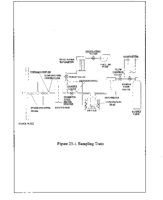


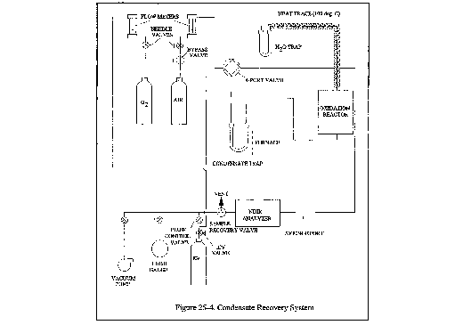
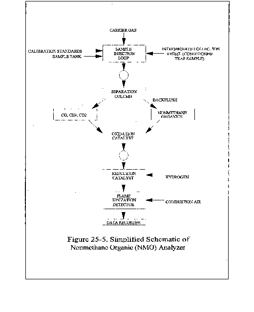
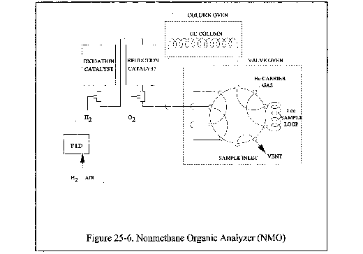

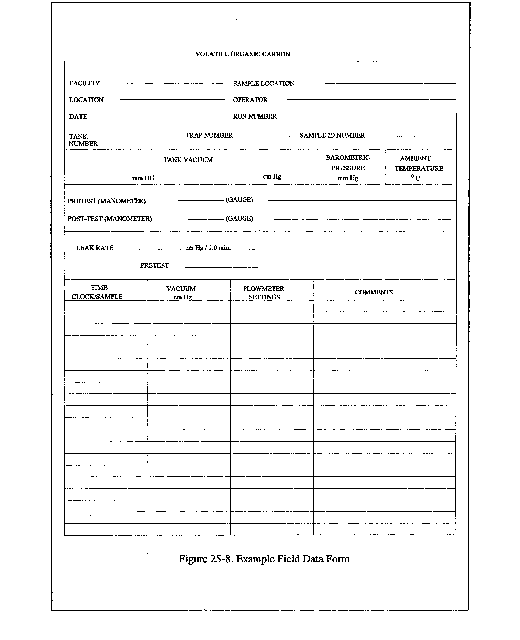

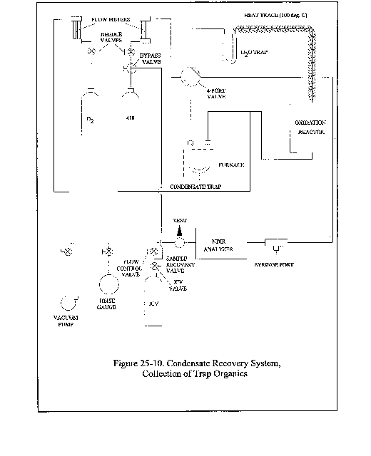
Method 25A - Determination of Total Gaseous Organic Concentration Using a Flame Ionization Analyzer
1.0 Scope and Application
1.1 Analytes.
| Analyte | CAS No. | Sensitivity |
|---|---|---|
| Total Organic Compounds | N/A | <2% of span. |
1.2 Applicability. This method is applicable for the determination of total gaseous organic concentration of vapors consisting primarily of alkanes, alkenes, and/or arenes (aromatic hydrocarbons). The concentration is expressed in terms of propane (or other appropriate organic calibration gas) or in terms of carbon.
1.3 Data Quality Objectives. Adherence to the requirements of this method will enhance the quality of the data obtained from air pollutant sampling methods.
2.0 Summary of Method
2.1 A gas sample is extracted from the source through a heated sample line and glass fiber filter to a flame ionization analyzer (FIA). Results are reported as volume concentration equivalents of the calibration gas or as carbon equivalents.
3.0 Definitions
3.1 Calibration drift means the difference in the measurement system response to a mid-level calibration gas before and after a stated period of operation during which no unscheduled maintenance, repair, or adjustment took place.
3.2 Calibration error means the difference between the gas concentration indicated by the measurement system and the know concentration of the calibration gas.
3.3 Calibration gas means a known concentration of a gas in an appropriate diluent gas.
3.4 Measurement system means the total equipment required for the determination of the gas concentration. The system consists of the following major subsystems:
3.4.1 Sample interface means that portion of a system used for one or more of the following: sample acquisition, sample transportation, sample conditioning, or protection of the analyzer(s) from the effects of the stack effluent.
3.4.2 Organic analyzer means that portion of the measurement system that senses the gas to be measured and generates an output proportional to its concentration.
3.5 Response time means the time interval from a step change in pollutant concentration at the inlet to the emission measurement system to the time at which 95 percent of the corresponding final value is reached as displayed on the recorder.
3.6 Span Value means the upper limit of a gas concentration measurement range that is specified for affected source categories in the applicable part of the regulations. The span value is established in the applicable regulation and is usually 1.5 to 2.5 times the applicable emission limit. If no span value is provided, use a span value equivalent to 1.5 to 2.5 times the expected concentration. For convenience, the span value should correspond to 100 percent of the recorder scale.
3.7 Zero drift means the difference in the measurement system response to a zero level calibration gas before or after a stated period of operation during which no unscheduled maintenance, repair, or adjustment took place.
4.0 Interferences [Reserved]
5.0 Safety
5.1 Disclaimer. This method may involve hazardous materials, operations, and equipment. This test method may not address all of the safety problems associated with its use. It is the responsibility of the user of this test method to establish appropriate safety and health practices and determine the applicability of regulatory limitations prior to performing this test method. The analyzer users manual should be consulted for specific precautions to be taken with regard to the analytical procedure.
5.2 Explosive Atmosphere. This method is often applied in highly explosive areas. Caution and care should be exercised in choice of equipment and installation.
6.0 Equipment and Supplies
6.1 Measurement System. Any measurement system for total organic concentration that meets the specifications of this method. A schematic of an acceptable measurement system is shown in Figure 25A-1. All sampling components leading to the analyzer shall be heated ≥110 °C (220 °F) throughout the sampling period, unless safety reasons are cited (Section 5.2) The essential components of the measurement system are described below:
6.1.1 Organic Concentration Analyzer. A flame ionization analyzer (FIA) capable of meeting or exceeding the specifications of this method. The flame ionization detector block shall be heated >120 °C (250 °F).
6.1.2 Sample Probe. Stainless steel, or equivalent, three-hole rake type. Sample holes shall be 4 mm (0.16-in.) in diameter or smaller and located at 16.7, 50, and 83.3 percent of the equivalent stack diameter. Alternatively, a single opening probe may be used so that a gas sample is collected from the centrally located 10 percent area of the stack cross-section.
6.1.3 Heated Sample Line. Stainless steel or Teflon” tubing to transport the sample gas to the analyzer. The sample line should be heated (≥110 °C) to prevent any condensation.
6.1.4 Calibration Valve Assembly. A three-way valve assembly to direct the zero and calibration gases to the analyzers is recommended. Other methods, such as quick-connect lines, to route calibration gas to the analyzers are applicable.
6.1.5 Particulate Filter. An in-stack or an out-of-stack glass fiber filter is recommended if exhaust gas particulate loading is significant. An out-of-stack filter should be heated to prevent any condensation.
6.1.6 Recorder. A strip-chart recorder, analog computer, or digital recorder for recording measurement data. The minimum data recording requirement is one measurement value per minute.
7.0 Reagents and Standards
7.1 Calibration Gases. The calibration gases for the gas analyzer shall be propane in air or propane in nitrogen. Alternatively, organic compounds other than propane can be used; the appropriate corrections for response factor must be made. Calibration gases shall be prepared in accordance with the procedure listed in Citation 2 of section 16. Additionally, the manufacturer of the cylinder should provide a recommended shelf life for each calibration gas cylinder over which the concentration does not change more than ±2 percent from the certified value. For calibration gas values not generally available (i.e., organics between 1 and 10 percent by volume), alternative methods for preparing calibration gas mixtures, such as dilution systems (Test Method 205, 40 CFR Part 51, Appendix M), may be used with prior approval of the Administrator.
7.1.1 Fuel. A 40 percent H2/60 percent N2 gas mixture is recommended to avoid an oxygen synergism effect that reportedly occurs when oxygen concentration varies significantly from a mean value.
7.1.2 Zero Gas. High purity air with less than 0.1 part per million by volume (ppmv) of organic material (propane or carbon equivalent) or less than 0.1 percent of the span value, whichever is greater.
7.1.3 Low-level Calibration Gas. An organic calibration gas with a concentration equivalent to 25 to 35 percent of the applicable span value.
7.1.4 Mid-level Calibration Gas. An organic calibration gas with a concentration equivalent to 45 to 55 percent of the applicable span value.
7.1.5 High-level Calibration Gas. An organic calibration gas with a concentration equivalent to 80 to 90 percent of the applicable span value.
8.0 Sample Collection, Preservation, Storage, and Transport
8.1 Selection of Sampling Site. The location of the sampling site is generally specified by the applicable regulation or purpose of the test (i.e., exhaust stack, inlet line, etc.). The sample port shall be located to meet the testing requirements of Method 1.
8.2 Location of Sample Probe. Install the sample probe so that the probe is centrally located in the stack, pipe, or duct and is sealed tightly at the stack port connection.
8.3 Measurement System Preparation. Prior to the emission test, assemble the measurement system by following the manufacturer's written instructions for preparing sample interface and the organic analyzer. Make the system operable (Section 10.1).
8.4 Calibration Error Test. Immediately prior to the test series (within 2 hours of the start of the test), introduce zero gas and high-level calibration gas at the calibration valve assembly. Adjust the analyzer output to the appropriate levels, if necessary. Calculate the predicted response for the low-level and mid-level gases based on a linear response line between the zero and high-level response. Then introduce low-level and mid-level calibration gases successively to the measurement system. Record the analyzer responses for low-level and mid-level calibration gases and determine the differences between the measurement system responses and the predicted responses. These differences must be less than 5 percent of the respective calibration gas value. If not, the measurement system is not acceptable and must be replaced or repaired prior to testing. No adjustments to the measurement system shall be conducted after the calibration and before the drift check (Section 8.6.2). If adjustments are necessary before the completion of the test series, perform the drift checks prior to the required adjustments and repeat the calibration following the adjustments. If multiple electronic ranges are to be used, each additional range must be checked with a mid-level calibration gas to verify the multiplication factor.
8.5 Response Time Test. Introduce zero gas into the measurement system at the calibration valve assembly. When the system output has stabilized, switch quickly to the high-level calibration gas. Record the time from the concentration change to the measurement system response equivalent to 95 percent of the step change. Repeat the test three times and average the results.
8.6 Emission Measurement Test Procedure.
8.6.1 Organic Measurement. Begin sampling at the start of the test period, recording time and any required process information as appropriate. In particulate, note on the recording chart, periods of process interruption or cyclic operation.
8.6.2 Drift Determination. Immediately following the completion of the test period and hourly during the test period, reintroduce the zero and mid-level calibration gases, one at a time, to the measurement system at the calibration valve assembly. (Make no adjustments to the measurement system until both the zero and calibration drift checks are made.) Record the analyzer response. If the drift values exceed the specified limits, invalidate the test results preceding the check and repeat the test following corrections to the measurement system. Alternatively, recalibrate the test measurement system as in section 8.4 and report the results using both sets of calibration data (i.e., data determined prior to the test period and data determined following the test period).
Note on the recording chart periods of process interruption or cyclic operation.
9.0 Quality Control
| Method section | Quality control measure | Effect |
|---|---|---|
| 8.4 | Zero and calibration drift tests | Ensures that bias introduced by drift in the measurement system output during the run is no greater than 3 percent of span. |
10.0 Calibration and Standardization
10.1 FIA equipment can be calibrated for almost any range of total organic concentrations. For high concentrations of organics (>1.0 percent by volume as propane), modifications to most commonly available analyzers are necessary. One accepted method of equipment modification is to decrease the size of the sample to the analyzer through the use of a smaller diameter sample capillary. Direct and continuous measurement of organic concentration is a necessary consideration when determining any modification design.
11.0 Analytical Procedure
The sample collection and analysis are concurrent for this method (see section 8.0).
12.0 Calculations and Data Analysis
12.1 Determine the average organic concentration in terms of ppmv as propane or other calibration gas. The average shall be determined by integration of the output recording over the period specified in the applicable regulation. If results are required in terms of ppmv as carbon, adjust measured concentrations using Equation 25A-1.

Where:
Cc = Organic concentration as carbon, ppmv.
Cmeas = Organic concentration as measured, ppmv.
K = Carbon equivalent correction factor.
= 2 for ethane.
= 3 for propane.
= 4 for butane.
= Appropriate response factor for other organic calibration gases.
13.0 Method Performance
13.1 Measurement System Performance Specifications.
13.1.1 Zero Drift. Less than ±3 percent of the span value.
13.1.2 Calibration Drift. Less than ±3 percent of span value.
13.1.3 Calibration Error. Less than ±5 percent of the calibration gas value.
14.0 Pollution Prevention [Reserved]
15.0 Waste Management [Reserved]
16.0 References
1. Measurement of Volatile Organic Compounds - Guideline Series. U.S. Environmental Protection Agency. Research Triangle Park, NC. Publication No. EPA-450/2-78-041. June 1978. p. 46-54.
2. EPA Traceability Protocol for Assay and Certification of Gaseous Calibration Standards. U.S. Environmental Protection Agency, Quality Assurance and Technical Support Division. Research Triangle Park, N.C. September 1993.
3. Gasoline Vapor Emission Laboratory Evaluation - Part 2. U.S. Environmental Protection Agency, Office of Air Quality Planning and Standards. Research Triangle Park, NC. EMB Report No. 75-GAS-6. August 1975.
17.0 Tables, Diagrams, Flowcharts, and Validation Data
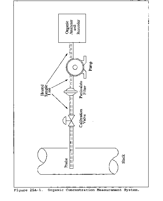
Method 25B - Determination of Total Gaseous Organic Concentration Using a Nondispersive Infrared Analyzer
This method does not include all of the specifications (e.g., equipment and supplies) and procedures (e.g., sampling) essential to its performance. Some material is incorporated by reference from other methods in this part. Therefore, to obtain reliable results, persons using this method should have a thorough knowledge of at least the following additional test methods: Method 1, Method 6C, and Method 25A.
1.0 Scope and Application
1.1 Analytes.
| Analyte | CAS No. | Sensitivity |
|---|---|---|
| Total Organic Compounds | N/A | <2% of span. |
1.2 Applicability. This method is applicable for the determination of total gaseous organic concentration of vapors consisting primarily of alkanes. Other organic materials may be measured using the general procedure in this method, the appropriate calibration gas, and an analyzer set to the appropriate absorption band.
1.3 Data Quality Objectives. Adherence to the requirements of this method will enhance the quality of the data obtained from air pollutant sampling methods.
2.0 Summary of Method
A gas sample is extracted from the source through a heated sample line, if necessary, and glass fiber filter to a nondispersive infrared analyzer (NDIR). Results are reported as volume concentration equivalents of the calibration gas or as carbon equivalents.
3.0 Definitions
Same as Method 25A, section 3.0.
4.0 Interferences [Reserved]
5.0 Safety
5.1 Disclaimer. This method may involve hazardous materials, operations, and equipment. This test method may not address all of the safety problems associated with its use. It is the responsibility of the user of this test method to establish appropriate safety and health practices and determine the applicability of regulatory limitations prior to performing this test method. The analyzer users manual should be consulted for specific precautions to be taken with regard to the analytical procedure.
5.2 Explosive Atmosphere. This method is often applied in highly explosive areas. Caution and care should be exercised in choice of equipment and installation.
6.0 Equipment and Supplies
Same as Method 25A, section 6.0, with the exception of the following:
6.1 Organic Concentration Analyzer. A nondispersive infrared analyzer designed to measure alkane organics and capable of meeting or exceeding the specifications in this method.
7.0 Reagents and Standards
Same as Method 25A, section 7.1. No fuel gas is required for an NDIR.
8.0 Sample Collection, Preservation, Storage, and Transport
Same as Method 25A, section 8.0.
9.0 Quality Control
Same as Method 25A, section 9.0.
10.0 Calibration and Standardization
Same as Method 25A, section 10.0.
11.0 Analytical Procedure
The sample collection and analysis are concurrent for this method (see section 8.0).
12.0 Calculations and Data Analysis
Same as Method 25A, section 12.0.
13.0 Method Performance [Reserved]
14.0 Pollution Prevention [Reserved]
15.0 Waste Management [Reserved]
16.0 References
Same as Method 25A, section 16.0.
17.0 Tables, Diagrams, Flowcharts, and Validation Data [Reserved]
Method 25C - Determination of Nonmethane Organic Compounds (NMOC) in Landfill Gases
This method does not include all of the specifications (e.g., equipment and supplies) and procedures (e.g., sampling and analytical) essential to its performance. Some material is incorporated by reference from other methods in this part. Therefore, to obtain reliable results, persons using this method should also have a thorough knowledge of EPA Method 25.
1.0 Scope and Application
1.1 Analytes.
| Analyte | CAS No. |
|---|---|
| Nonmethane organic compounds (NMOC) | No CAS number assigned. |
1.2 Applicability. This method is applicable to the sampling and measurement of NMOC as carbon in landfill gases (LFG).
1.3 Data Quality Objectives. Adherence to the requirements of this method will enhance the quality of the data obtained from air pollutant sampling methods.
2.0 Summary of Method
2.1 A sample probe that has been perforated at one end is driven or augured to a depth of 0.9 m (3 ft) below the bottom of the landfill cover. A sample of the landfill gas is extracted with an evacuated cylinder. The NMOC content of the gas is determined by injecting a portion of the gas into a gas chromatographic column to separate the NMOC from carbon monoxide (CO), carbon dioxide (CO2), and methane (CH4); the NMOC are oxidized to CO2, reduced to CH4, and measured by a flame ionization detector (FID). In this manner, the variable response of the FID associated with different types of organics is eliminated.
3.0 Definitions [Reserved]
4.0 Interferences [Reserved]
5.0 Safety
5.1 Since this method is complex, only experienced personnel should perform this test. LFG contains methane, therefore explosive mixtures may exist on or near the landfill. It is advisable to take appropriate safety precautions when testing landfills, such as refraining from smoking and installing explosion-proof equipment.
6.0 Equipment and Supplies
6.1 Sample Probe. Stainless steel, with the bottom third perforated. Teflon probe liners and sampling lines are also allowed. Non-perforated probes are allowed as long as they are withdrawn to create a gap equivalent to having the bottom third perforated. The sample probe must be capped at the bottom and must have a threaded cap with a sampling attachment at the top. The sample probe must be long enough to go through and extend no less than 0.9 m (3 ft) below the landfill cover. If the sample probe is to be driven into the landfill, the bottom cap should be designed to facilitate driving the probe into the landfill.
6.2 Sampling Train.
6.2.1 Rotameter with Flow Control Valve. Capable of measuring a sample flow rate of 100 ±10 ml/min. The control valve must be made of stainless steel.
6.2.2 Sampling Valve. Stainless steel.
6.2.3 Pressure Gauge. U-tube mercury manometer, or equivalent, capable of measuring pressure to within 1 mm Hg (0.5 in H2O) in the range of 0 to 1,100 mm Hg (0 to 590 in H2O).
6.2.4 Sample Tank. Stainless steel or aluminum cylinder, equipped with a stainless steel sample tank valve.
6.3 Vacuum Pump. Capable of evacuating to an absolute pressure of 10 mm Hg (5.4 in H2O).
6.4 Purging Pump. Portable, explosion proof, and suitable for sampling NMOC.
6.5 Pilot Probe Procedure. The following are needed only if the tester chooses to use the procedure described in section 8.2.1.
6.5.1 Pilot Probe. Tubing of sufficient strength to withstand being driven into the landfill by a post driver and an outside diameter of at least 6 mm (0.25 in.) smaller than the sample probe. The pilot probe shall be capped on both ends and long enough to go through the landfill cover and extend no less than 0.9 m (3 ft) into the landfill.
6.5.2 Post Driver and Compressor. Capable of driving the pilot probe and the sampling probe into the landfill. The Kitty Hawk portable post driver has been found to be acceptable.
6.6 Auger Procedure. The following are needed only if the tester chooses to use the procedure described in section 8.2.2.
6.6.1 Auger. Capable of drilling through the landfill cover and to a depth of no less than 0.9 m (3 ft) into the landfill.
6.6.2 Pea Gravel.
6.6.3 Bentonite.
6.7 NMOC Analyzer, Barometer, Thermometer, and Syringes. Same as in sections 6.3.1, 6.3.2, 6.33, and 6.2.10, respectively, of Method 25.
7.0 Reagents and Standards
7.1 NMOC Analysis. Same as in Method 25, section 7.2.
7.2 Calibration. Same as in Method 25, section 7.4, except omit section 7.4.3.
8.0 Sample Collection, Preservation, Storage, and Transport
8.1 Sample Tank Evacuation and Leak-Check. Conduct the sample tank evacuation and leak-check either in the laboratory or the field. Connect the pressure gauge and sampling valve to the sample tank. Evacuate the sample tank to 10 mm Hg (5.4 in H2O) absolute pressure or less. Close the sampling valve, and allow the tank to sit for 30 minutes. The tank is acceptable if no change more than ±2 mm is noted. Include the results of the leak-check in the test report.
8.2 Sample Probe Installation. The tester may use the procedure in section 8.2.1 or 8.2.2.
8.2.1 Pilot Probe Procedure. Use the post driver to drive the pilot probe at least 0.9 m (3 ft) below the landfill cover. Alternative procedures to drive the probe into the landfill may be used subject to the approval of the Administrator's designated representative.
8.2.1.1 Remove the pilot probe and drive the sample probe into the hole left by the pilot probe. The sample probe shall extend at least 0.9 m (3 ft) below the landfill cover and shall protrude about 0.3 m (1 ft) above the landfill cover. Seal around the sampling probe with bentonite and cap the sampling probe with the sampling probe cap.
8.2.2 Auger Procedure. Use an auger to drill a hole to at least 0.9 m (3 ft) below the landfill cover. Place the sample probe in the hole and backfill with pea gravel to a level 0.6 m (2 ft) from the surface. The sample probe shall protrude at least 0.3 m (1 ft) above the landfill cover. Seal the remaining area around the probe with bentonite. Allow 24 hours for the landfill gases to equilibrate inside the augured probe before sampling.
8.2.3 Driven Probes. Closed-point probes may be driven directly into the landfill in a single step. This method may not require backfilling if the probe is adequately sealed by its insertion. Unperforated probes that are inserted in this manner and withdrawn at a distance from a detachable tip to create an open space are also acceptable.
8.3 Sample Train Assembly. Just before assembling the sample train, measure the sample tank vacuum using the pressure gauge. Record the vacuum, the ambient temperature, and the barometric pressure at this time. Assemble the sampling probe purging system as shown in Figure 25C-1.
8.4 Sampling Procedure. Open the sampling valve and use the purge pump and the flow control valve to evacuate at least two sample probe volumes from the system at a flow rate of 500 ml/min or less. Close the sampling valve and replace the purge pump with the sample tank apparatus as shown in Figure 25C-2. Open the sampling valve and the sample tank valve and, using the flow control valve, sample at a flow rate of 500 ml/min or less until either a constant flow rate can no longer be maintained because of reduced sample tank vacuum or the appropriate composite volume is attained. Disconnect the sampling tank apparatus and pressurize the sample cylinder to approximately 1,060 mm Hg (567 in. H2O) absolute pressure with helium, and record the final pressure. Alternatively, the sample tank may be pressurized in the lab.
8.4.1 The following restrictions apply to compositing samples from different probe sites into a single cylinder:
(1) Individual composite samples per cylinder must be of equal volume; this must be verified by recording the flow rate, sampling time, vacuum readings, or other appropriate volume measuring data,
(2) individual composite samples must have a minimum volume of 1 liter unless data is provided showing smaller volumes can be accurately measured, and
(3) composite samples must not be collected using the final cylinder vacuum as it diminishes to ambient pressure.
8.4.2 Use Method 3C to determine the percent N2 and O2 in each cylinder. The presence of N2 and O2 indicate either infiltration of ambient air into the landfill gas sample or an inappropriate testing site has been chosen where anaerobic decomposition has not begun. The landfill gas sample is acceptable if the concentration of N2 is less than 20 percent. Alternatively, the oxygen content of each cylinder must be less than 5 percent. Landfills with 3-year average annual rainfalls equal to or less than 20 inches annual rainfalls samples are acceptable when the N2 to O2 concentration ratio is greater than 3.71.
9.0 Quality Control
9.1 Miscellaneous Quality Control Measures.
| Section | Quality control measure | Effect |
|---|---|---|
| 8.4.2 | If the 3-year average annual rainfall is greater than 20 inches, verify that landfill gas sample contains less than 20 percent N2 and 5 percent O2. Landfills with 3-year average annual rainfalls equal to or less than 20 inches annual rainfalls samples are acceptable when the N2 to O2 concentration ratio is greater than 3.71 | Ensures that ambient air was not drawn into the landfill gas sample and gas was sampled from an appropriate location. If outside of range, invalidate sample and repeat sample collection. |
| 10.1, 10.2 | NMOC analyzer initial and daily performance checks | Ensures precision of analytical results. |
10.0 Calibration and Standardization
Maintain a record of performance of each item.
10.1 Initial NMOC Analyzer Performance Test. Same as in Method 25, section 10.1, except omit the linearity checks for CO2 standards.
10.2 NMOC Analyzer Daily Calibration.
10.2.1 NMOC Response Factors. Same as in Method 25, section 10.2.2.
10.3 Sample Tank Volume. The volume of the gas sampling tanks must be determined. Determine the tank volumes by weighing them empty and then filled with deionized water; weigh to the nearest 5 g, and record the results. Alternatively, measure the volume of water used to fill them to the nearest 5 ml.
11.0 Analytical Procedures
11.1 The oxidation, reduction, and measurement of NMOC's is similar to Method 25. Before putting the NMOC analyzer into routine operation, conduct an initial performance test. Start the analyzer, and perform all the necessary functions in order to put the analyzer into proper working order. Conduct the performance test according to the procedures established in section 10.1. Once the performance test has been successfully completed and the NMOC calibration response factor has been determined, proceed with sample analysis as follows:
11.1.1 Daily Operations and Calibration Checks. Before and immediately after the analysis of each set of samples or on a daily basis (whichever occurs first), conduct a calibration test according to the procedures established in section 10.2. If the criteria of the daily calibration test cannot be met, repeat the NMOC analyzer performance test (Section 10.1) before proceeding.
11.1.2 Operating Conditions. Same as in Method 25, section 11.2.1.
11.1.3 Analysis of Sample Tank. Purge the sample loop with sample, and then inject the sample. Under the specified operating conditions, the CO2 in the sample will elute in approximately 100 seconds. As soon as the detector response returns to baseline following the CO2 peak, switch the carrier gas flow to backflush, and raise the column oven temperature to 195 °C (383 °F) as rapidly as possible. A rate of 30 °C/min (54 °F/min) has been shown to be adequate. Record the value obtained for any measured NMOC. Return the column oven temperature to 85 °C (185 °F) in preparation for the next analysis. Analyze each sample in triplicate, and report the average as Ctm.
12.0 Data Analysis and Calculations
All equations are written using absolute pressure; absolute pressures are determined by adding the measured barometric pressure to the measured gauge or manometer pressure.
12.1 Nomenclature
Bw = Moisture content in the sample, fraction.
CN2 = N2 concentration in the diluted sample gas.
CmN2 = Measured N2 concentration, fraction in landfill gas.
CmOx = Measured Oxygen concentration, fraction in landfill gas.
COx = Oxygen concentration in the diluted sample gas.
Ct = Calculated NMOC concentration, ppmv C equivalent.
Ctm = Measured NMOC concentration, ppmv C equivalent.
Pb = Barometric pressure, mm Hg.
Pt = Gas sample tank pressure after sampling, but before pressurizing, mm Hg absolute.
Ptf = Final gas sample tank pressure after pressurizing, mm Hg absolute.
Pti = Gas sample tank pressure after evacuation, mm Hg absolute.
Pw = Vapor pressure of H2O (from Table 25C-1), mm Hg.
r = Total number of analyzer injections of sample tank during analysis (where j = injection number, 1 . . . r).
Tt = Sample tank temperature at completion of sampling, °K.
Tti = Sample tank temperature before sampling, °K.
Ttf = Sample tank temperature after pressuring, °K.
12.2 Water Correction. Use Table 25C-1 (Section 17.0), the LFG temperature, and barometric pressure at the sampling site to calculate Bw.

12.3 Nitrogen Concentration in the landfill gas. Use equation 25C-2 to calculate the measured concentration of nitrogen in the original landfill gas.

12.4 Oxygen Concentration in the landfill gas. Use equation 25C-3 to calculate the measured concentration of oxygen in the original landfill gas.

12.5 You must correct the NMOC Concentration for the concentration of nitrogen or oxygen based on which gas or gases passes the requirements in section 9.1 or based on the 3-year average annual rainfall based on the closest NOAA land-based station.
12.5.1 NMOC Concentration with nitrogen correction. Use Equation 25C-4 to calculate the concentration of NMOC for each sample tank when the nitrogen concentration is less than 20 percent.

12.5.2 NMOC Concentration with oxygen correction. Use Equation 25C-5 to calculate the concentration of NMOC for each sample tank if the landfill gas oxygen is less than 5 percent and the landfill gas nitrogen concentration is greater than 20 percent, or 3-year average annual rainfall based annual rainfall of less than 20 inches.
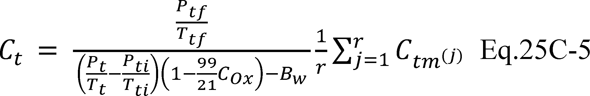
13.0 Method Performance [Reserved]
14.0 Pollution Prevention [Reserved]
15.0 Waste Management [Reserved]
16.0 References
1. Salo, Albert E., Samuel Witz, and Robert D. MacPhee. Determination of Solvent Vapor Concentrations by Total Combustion Analysis: A Comparison of Infrared with Flame Ionization Detectors. Paper No. 75-33.2. (Presented at the 68th Annual Meeting of the Air Pollution Control Association. Boston, Massachusetts. June 15-20, 1975.) 14 p.
2. Salo, Albert E., William L. Oaks, and Robert D. MacPhee. Measuring the Organic Carbon Content of Source Emissions for Air Pollution Control. Paper No. 74-190. (Presented at the 67th Annual Meeting of the Air Pollution Control Association. Denver, Colorado. June 9-13, 1974.) 25 p.
17.0 Tables, Diagrams, Flowcharts, and Validation Data
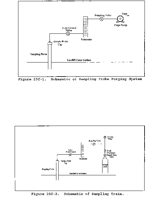
Table 25C-1 - Moisture Correction
| Temperature, °C | Vapor Pressure of H2O, mm Hg | Temperature, °C | Vapor Pressure of H2O, mm Hg |
|---|---|---|---|
| 4 | 6.1 | 18 | 15.5 |
| 6 | 7.0 | 20 | 17.5 |
| 8 | 8.0 | 22 | 19.8 |
| 10 | 9.2 | 24 | 22.4 |
| 12 | 10.5 | 26 | 25.2 |
| 14 | 12.0 | 28 | 28.3 |
| 16 | 13.6 | 30 | 31.8 |
Method 25D - Determination of the Volatile Organic Concentration of Waste Samples
Performance of this method should not be attempted by persons unfamiliar with the operation of a flame ionization detector (FID) or an electrolytic conductivity detector (ELCD) because knowledge beyond the scope of this presentation is required.
1.0 Scope and Application
1.1 Analyte. Volatile Organic Compounds. No CAS No. assigned.
1.2 Applicability. This method is applicable for determining the volatile organic (VO) concentration of a waste sample.
2.0 Summary of Method
2.1 Principle. A sample of waste is obtained at a point which is most representative of the unexposed waste (where the waste has had minimum opportunity to volatilize to the atmosphere). The sample is suspended in an organic/aqueous matrix, then heated and purged with nitrogen for 30 min. in order to separate certain organic compounds. Part of the sample is analyzed for carbon concentration, as methane, with an FID, and part of the sample is analyzed for chlorine concentration, as chloride, with an ELCD. The VO concentration is the sum of the carbon and chlorine content of the sample.
3.0 Definitions
3.1 Well-mixed in the context of this method refers to turbulent flow which results in multiple-phase waste in effect behaving as single-phase waste due to good mixing.
4.0 Interferences [Reserved]
5.0 Safety
5.1 Disclaimer. This method may involve hazardous materials, operations, and equipment. This test method may not address all of the safety problems associated with its use. It is the responsibility of the user of this test method to establish appropriate safety and health practices and to determine the applicability of regulatory limitations prior to performing this test method.
6.0 Equipment and Supplies
Mention of trade names or specific products does not constitute endorsement by the Environmental Protection Agency.
6.1 Sampling. The following equipment is required:
6.1.1 Sampling Tube. Flexible Teflon, 0.25 in. ID (6.35 mm).
6.1.2 Sample Container. Borosilicate glass, 40-mL, and a Teflon-lined screw cap capable of forming an air tight seal.
6.1.3 Cooling Coil. Fabricated from 0.25 in (6.35 mm). ID 304 stainless steel tubing with a thermocouple at the coil outlet.
6.2 Analysis. The following equipment is required.
6.2.1 Purging Apparatus. For separating the VO from the waste sample. A schematic of the system is shown in Figure 25D-1. The purging apparatus consists of the following major components.
6.2.1.1 Purging Flask. A glass container to hold the sample while it is heated and purged with dry nitrogen. The cap of the purging flask is equipped with three fittings: one for a purging lance (fitting with the #7 Ace-thread), one for the Teflon exit tubing (side fitting, also a #7 Ace-thread), and a third (a 50-mm Ace-thread) to attach the base of the purging flask as shown in Figure 25D-2. The base of the purging flask is a 50-mm ID (2 in) cylindrical glass tube. One end of the tube is open while the other end is sealed. Exact dimensions are shown in Figure 25D-2.
6.2.1.2 Purging Lance. Glass tube, 6-mm OD (0.2 in) by 30 cm (12 in) long. The purging end of the tube is fitted with a four-arm bubbler with each tip drawn to an opening 1 mm (0.04 in) in diameter. Details and exact dimensions are shown in Figure 25D-2.
6.2.1.3 Coalescing Filter. Porous fritted disc incorporated into a container with the same dimensions as the purging flask. The details of the design are shown in Figure 25D-3.
6.2.1.4 Constant Temperature Chamber. A forced draft oven capable of maintaining a uniform temperature around the purging flask and coalescing filter of 75 ±2 °C (167 ±3.6 °F).
6.2.1.5 Three-way Valve. Manually operated, stainless steel. To introduce calibration gas into system.
6.2.1.6 Flow Controllers. Two, adjustable. One capable of maintaining a purge gas flow rate of 6 ±0.06 L/min (0.2 ±0.002 ft3/min) The other capable of maintaining a calibration gas flow rate of 1-100 mL/min (0.00004-0.004 ft3/min).
6.2.1.7 Rotameter. For monitoring the air flow through the purging system (0-10 L/min)(0-0.4 ft3/min).
6.2.1.8 Sample Splitters. Two heated flow restrictors (placed inside oven or heated to 120 ±10 °C (248 ±18 °F) ). At a purge rate of 6 L/min (0.2 ft3/min), one will supply a constant flow to the first detector (the rest of the flow will be directed to the second sample splitter). The second splitter will split the analytical flow between the second detector and the flow restrictor. The approximate flow to the FID will be 40 mL/min (0.0014 ft3/min) and to the ELCD will be 15 mL/min (0.0005 ft3/min), but the exact flow must be adjusted to be compatible with the individual detector and to meet its linearity requirement. The two sample splitters will be connected to each other by 1/8′ OD (3.175 mm) stainless steel tubing.
6.2.1.9 Flow Restrictor. Stainless steel tubing, 1/8′ OD (3.175 mm), connecting the second sample splitter to the ice bath. Length is determined by the resulting pressure in the purging flask (as measured by the pressure gauge). The resulting pressure from the use of the flow restrictor shall be 6-7 psig.
6.2.1.10 Filter Flask. With one-hole stopper. Used to hold ice bath. Excess purge gas is vented through the flask to prevent condensation in the flowmeter and to trap volatile organic compounds.
6.2.1.11 Four-way Valve. Manually operated, stainless steel. Placed inside oven, used to bypass purging flask.
6.2.1.12 On/Off Valves. Two, stainless steel. One heat resistant up to 130 °C (266 °F) and placed between oven and ELCD. The other a toggle valve used to control purge gas flow.
6.2.1.13 Pressure Gauge. Range 0-40 psi. To monitor pressure in purging flask and coalescing filter.
6.2.1.14 Sample Lines. Teflon, 1/4′ OD (6.35 mm), used inside the oven to carry purge gas to and from purging chamber and to and from coalescing filter to four-way valve. Also used to carry sample from four-way valve to first sample splitter.
6.2.1.15 Detector Tubing. Stainless steel, 1/8′ OD (3.175 mm), heated to 120 ±10 °C (248 ±18 °F) . Used to carry sample gas from each sample splitter to a detector. Each piece of tubing must be wrapped with heat tape and insulating tape in order to insure that no cold spots exist. The tubing leading to the ELCD will also contain a heat-resistant on-off valve (Section 6.2.1.12) which shall also be wrapped with heat-tape and insulation.
6.2.2 Volatile Organic Measurement System. Consisting of an FID to measure the carbon concentration of the sample and an ELCD to measure the chlorine concentration.
6.2.2.1 FID. A heated FID meeting the following specifications is required.
6.2.2.1.1 Linearity. A linear response (±5 percent) over the operating range as demonstrated by the procedures established in section 10.1.1.
6.2.2.1.2 Range. A full scale range of 50 pg carbon/sec to 50 µg carbon/sec. Signal attenuators shall be available to produce a minimum signal response of 10 percent of full scale.
6.2.2.1.3 Data Recording System. A digital integration system compatible with the FID for permanently recording the output of the detector. The recorder shall have the capability to start and stop integration at points selected by the operator or it shall be capable of the “integration by slices” technique (this technique involves breaking down the chromatogram into smaller increments, integrating the area under the curve for each portion, subtracting the background for each portion, and then adding all of the areas together for the final area count).
6.2.2.2 ELCD. An ELCD meeting the following specifications is required. 1-propanol must be used as the electrolyte. The electrolyte flow through the conductivity cell shall be 1 to 2 mL/min (0.00004 to 0.00007 ft3/min).
A 1⁄4-in. ID (6.35 mm) quartz reactor tube is strongly recommended to reduce carbon buildup and the resulting detector maintenance.
6.2.2.2.1 Linearity. A linear response (±10 percent) over the response range as demonstrated by the procedures in section 10.1.2.
6.2.2.2.2 Range. A full scale range of 5.0 pg/sec to 500 ng/sec chloride. Signal attenuators shall be available to produce a minimum signal response of 10 percent of full scale.
6.2.2.2.3 Data Recording System. A digital integration system compatible with the output voltage range of the ELCD. The recorder must have the capability to start and stop integration at points selected by the operator or it shall be capable of performing the “integration by slices” technique.
7.0 Reagents and Standards
7.1 Sampling.
7.1.1 Polyethylene Glycol (PEG). Ninety-eight percent pure with an average molecular weight of 400. Before using the PEG, remove any organic compounds that might be detected as volatile organics by heating it to 120 °C (248 °F) and purging it with nitrogen at a flow rate of 1 to 2 L/min (0.04 to 0.07 ft3/min) for 2 hours. The cleaned PEG must be stored under a 1 to 2 L/min (0.04 to 0.07 ft3/min) nitrogen purge until use. The purge apparatus is shown in Figure 25D-4.
7.2 Analysis.
7.2.1 Sample Separation. The following are required for the sample purging step.
7.2.1.1 PEG. Same as section 7.1.1.
7.2.1.2 Purge Gas. Zero grade nitrogen (N2), containing less than 1 ppm carbon.
7.2.2 Volatile Organics Measurement. The following are required for measuring the VO concentration.
7.2.2.1 Hydrogen (H2). Zero grade H2, 99.999 percent pure.
7.2.2.2 Combustion Gas. Zero grade air or oxygen as required by the FID.
7.2.2.3 Calibration Gas. Pressurized gas cylinder containing 10 percent propane and 1 percent 1,1-dichloroethylene by volume in nitrogen.
7.2.2.4 Water. Deionized distilled water that conforms to American Society for Testing and Materials Specification D 1193-74, Type 3, is required for analysis. At the option of the analyst, the KMnO4 test for oxidizable organic matter may be omitted when high concentrations are not expected to be present.
7.2.2.5 1-Propanol. ACS grade or better. Electrolyte Solution. For use in the ELCD.
8.0 Sample Collection, Preservation, Storage, and Transport
8.1 Sampling.
8.1.1 Sampling Plan Design and Development. Use the procedures in chapter nine of Reference 1 in section 16 as guidance in developing a sampling plan.
8.1.2 Single Phase or Well-mixed Waste.
8.1.2.1 Install a sampling tap to obtain the sample at a point which is most representative of the unexposed waste (where the waste has had minimum opportunity to volatilize to the atmosphere). Assemble the sampling apparatus as shown in Figure 25D-5.
8.1.2.2 Prepare the sampling containers as follows: Pour 30 mL of clean PEG into the container. PEG will reduce but not eliminate the loss of organics during sample collection. Weigh the sample container with the screw cap, the PEG, and any labels to the nearest 0.01 g and record the weight (mst). Store the containers in an ice bath until 1 hour before sampling (PEG will solidify at ice bath temperatures; allow the containers to reach room temperature before sampling).
8.1.2.3 Begin sampling by purging the sample lines and cooling coil with at least four volumes of waste. Collect the purged material in a separate container and dispose of it properly.
8.1.2.4 After purging, stop the sample flow and direct the sampling tube to a preweighed sample container, prepared as described in section 8.1.2.2. Keep the tip of the tube below the surface of the PEG during sampling to minimize contact with the atmosphere. Sample at a flow rate such that the temperature of the waste is less than 10 °C (50 °F). Fill the sample container and immediately cap it (within 5 seconds) so that a minimum headspace exists in the container. Store immediately in a cooler and cover with ice.
8.1.3 Multiple-phase Waste. Collect a 10 g sample of each phase of waste generated using the procedures described in section 8.1.2 or 8.1.5. Each phase of the waste shall be analyzed as a separate sample. Calculate the weighted average VO concentration of the waste using Equation 25D-13 (Section 12.14).
8.1.4 Solid waste. Add approximately 10 g of the solid waste to a container prepared in the manner described in section 8.1.2.2, minimizing headspace. Cap and chill immediately.
8.1.5 Alternative to Tap Installation. If tap installation is impractical or impossible, fill a large, clean, empty container by submerging the container into the waste below the surface of the waste. Immediately fill a container prepared in the manner described in section 8.1.2.2 with approximately 10 g of the waste collected in the large container. Minimize headspace, cap and chill immediately.
8.1.6 Alternative sampling techniques may be used upon the approval of the Administrator.
8.2 Sample Recovery.
8.2.1 Assemble the purging apparatus as shown in Figures 25D-1 and 25D-2. The oven shall be heated to 75 ±2 °C (167 ±3.6 °F). The sampling lines leading from the oven to the detectors shall be heated to 120 ±10 °C (248 ±18 °F) with no cold spots. The flame ionization detector shall be operated with a heated block. Adjust the purging lance so that it reaches the bottom of the chamber.
8.2.2 Remove the sample container from the cooler, and wipe the exterior of the container to remove any extraneous ice, water, or other debris. Reweigh the sample container to the nearest 0.01 g, and record the weight (msf). Pour the contents of the sample container into the purging flask, rinse the sample container three times with a total of 20 mL of PEG (since the sample container originally held 30 mL of PEG, the total volume of PEG added to the purging flask will be 50 mL), transferring the rinsings to the purging flask after each rinse. Cap purging flask between rinses. The total volume of PEG in the purging flask shall be 50 mL. Add 50 mL of water to the purging flask.
9.0 Quality Control
9.1 Quality Control Samples. If audit samples are not available, prepare and analyze the two types of quality control samples (QCS) listed in Sections 9.1.1 and 9.1.2. Before placing the system in operation, after a shutdown of greater than six months, and after any major modifications, analyze each QCS in triplicate. For each detector, calculate the percent recovery by dividing measured concentration by theoretical concentration and multiplying by 100. Determine the mean percent recovery for each detector for each QCS triplicate analysis. The RSD for any triplicate analysis shall be ≤10 percent. For QCS 1 (methylene chloride), the percent recovery shall be ≥90 percent for carbon as methane, and ≥55 percent for chlorine as chloride. For QCS 2 (1,3-dichloro-2-propanol), the percent recovery shall be ≤15 percent for carbon as methane, and ≤6 percent for chlorine as chloride. If the analytical system does not meet the above-mentioned criteria for both detectors, check the system parameters (temperature, system pressure, purge rate, etc.), correct the problem, and repeat the triplicate analysis of each QCS.
9.1.1 QCS 1, Methylene Chloride. Prepare a stock solution by weighing, to the nearest 0.1 mg, 55 µL of HPLC grade methylene chloride in a tared 5 mL volumetric flask. Record the weight in milligrams, dilute to 5 mL with cleaned PEG, and inject 100 µL of the stock solution into a sample prepared as a water blank (50 mL of cleaned PEG and 60 mL of water in the purging flask). Analyze the QCS according to the procedures described in sections 10.2 and 10.3, excluding section 10.2.2. To calculate the theoretical carbon concentration (in mg) in QCS 1, multiply mg of methylene chloride in the stock solution by 3.777 × 10⁻³. To calculate the theoretical chlorine concentration (in mg) in QCS 1, multiply mg of methylene chloride in the stock solution by 1.670 × 10⁻².
9.1.2 QCS 2, 1,3-dichloro-2-propanol. Prepare a stock solution by weighing, to the nearest 0.1 mg, 60 µL of high purity grade 1,3-dichloro-2-propanol in a tared 5 mL volumetric flask. Record the weight in milligrams, dilute to 5 mL with cleaned PEG, and inject 100 µL of the stock solution into a sample prepared as a water blank (50 mL of cleaned PEG and 60 mL of water in the purging flask). Analyze the QCS according to the procedures described in sections 10.2 and 10.3, excluding section 10.2.2. To calculate the theoretical carbon concentration (in mg) in QCS 2, multiply mg of 1,3-dichloro-2-propanol in the stock solution by 7.461 × 10⁻³. To calculate the theoretical chlorine concentration (in mg) in QCS 2, multiply mg of 1,3-dichloro-2-propanol in the stock solution by 1.099 × 10⁻².
9.1.3 Routine QCS Analysis. For each set of compliance samples (in this context, set is per facility, per compliance test), analyze one QCS 1 and one QCS 2 sample. The percent recovery for each sample for each detector shall be ±13 percent of the mean recovery established for the most recent set of QCS triplicate analysis (Section 9.4). If the sample does not meet this criteria, check the system components and analyze another QCS 1 and 2 until a single set of QCS meet the ±13 percent criteria.
10.0 Calibration and Standardization
10.1 Initial Performance Check of Purging System. Before placing the system in operation, after a shutdown of greater than six months, after any major modifications, and at least once per month during continuous operation, conduct the linearity checks described in sections 10.1.1 and 10.1.2. Install calibration gas at the three-way calibration gas valve. See Figure 25D-1.
10.1.1 Linearity Check Procedure. Using the calibration standard described in section 7.2.2.3 and by varying the injection time, it is possible to calibrate at multiple concentration levels. Use Equation 25D-3 to calculate three sets of calibration gas flow rates and run times needed to introduce a total mass of carbon, as methane, (mc) of 1, 5, and 10 mg into the system (low, medium and high FID calibration, respectively). Use Equation 25D-4 to calculate three sets of calibration gas flow rates and run times needed to introduce a total chloride mass (mch) of 1, 5, and 10 mg into the system (low, medium and high ELCD calibration, respectively). With the system operating in standby mode, allow the FID and the ELCD to establish a stable baseline. Set the secondary pressure regulator of the calibration gas cylinder to the same pressure as the purge gas cylinder and set the proper flow rate with the calibration flow controller (see Figure 25D-1). The calibration gas flow rate can be measured with a flowmeter attached to the vent position of the calibration gas valve. Set the four-way bypass valve to standby position so that the calibration gas flows through the coalescing filter only. Inject the calibration gas by turning the calibration gas valve from vent position to inject position. Continue the calibration gas flow for the appropriate period of time before switching the calibration valve to vent position. Continue recording the response of the FID and the ELCD for 5 min after switching off calibration gas flow. Make triplicate injections of all six levels of calibration.
10.1.2 Linearity Criteria. Calculate the average response factor (Equations 25D-5 and 25D-6) and the relative standard deviation (RSD) (Equation 25D-10) at each level of the calibration curve for both detectors. Calculate the overall mean of the three response factor averages for each detector. The FID linearity is acceptable if each response factor is within 5 percent of the overall mean and if the RSD for each set of triplicate injections is less than 5 percent. The ELCD linearity is acceptable if each response factor is within 10 percent of the overall mean and if the RSD for each set of triplicate injections is less than 10 percent. Record the overall mean value of the response factors for the FID and the ELCD. If the calibration for either the FID or the ELCD does not meet the criteria, correct the detector/system problem and repeat sections 10.1.1 and 10.1.2.
10.2 Daily Calibrations.
10.2.1 Daily Linearity Check. Follow the procedures outlined in section 10.1.1 to analyze the medium level calibration for both the FID and the ELCD in duplicate at the start of the day. Calculate the response factors and the RSDs for each detector. For the FID, the calibration is acceptable if the average response factor is within 5 percent of the overall mean response factor (Section 10.1.2) and if the RSD for the duplicate injection is less than 5 percent. For the ELCD, the calibration is acceptable if the average response factor is within 10 percent of the overall mean response factor (Section 10.1.2) and if the RSD for the duplicate injection is less than 10 percent. If the calibration for either the FID or the ELCD does not meet the criteria, correct the detector/system problem and repeat sections 10.1.1 and 10.1.2.
10.2.2 Calibration Range Check.
10.2.2.1 If the waste concentration for either detector falls below the range of calibration for that detector, use the procedure outlined in section 10.1.1 to choose two calibration points that bracket the new target concentration. Analyze each of these points in triplicate (as outlined in section 10.1.1) and use the criteria in section 10.1.2 to determine the linearity of the detector in this “mini-calibration” range.
10.2.2.2 After the initial linearity check of the mini-calibration curve, it is only necessary to test one of the points in duplicate for the daily calibration check (in addition to the points specified in section 10.2.1). The average daily mini-calibration point should fit the linearity criteria specified in section 10.2.1. If the calibration for either the FID or the ELCD does not meet the criteria, correct the detector/system problem and repeat the calibration procedure mentioned in the first paragraph of section 10.2.2. A mini-calibration curve for waste concentrations above the calibration curve for either detector is optional.
10.3 Analytical Balance. Calibrate against standard weights.
11.0 Analysis
11.1 Sample Analysis.
11.1.1 Turn on the constant temperature chamber and allow the temperature to equilibrate at 75 ±2 °C (167 ±3.6 °F). Turn the four-way valve so that the purge gas bypasses the purging flask, the purge gas flowing through the coalescing filter and to the detectors (standby mode). Turn on the purge gas. Allow both the FID and the ELCD to warm up until a stable baseline is achieved on each detector. Pack the filter flask with ice. Replace ice after each run and dispose of the waste water properly. When the temperature of the oven reaches 75 ±2 °C (167 ±3.6 °F), start both integrators and record baseline. After 1 min, turn the four-way valve so that the purge gas flows through the purging flask, to the coalescing filter and to the sample splitters (purge mode). Continue recording the response of the FID and the ELCD. Monitor the readings of the pressure gauge and the rotameter. If the readings fall below established setpoints, stop the purging, determine the source of the leak, and resolve the problem before resuming. Leaks detected during a sampling period invalidate that sample.
11.1.2 As the purging continues, monitor the output of the detectors to make certain that the analysis is proceeding correctly and that the results are being properly recorded. Every 10 minutes read and record the purge flow rate, the pressure and the chamber temperature. Continue the purging for 30 minutes.
11.1.3 For each detector output, integrate over the entire area of the peak starting at 1 minute and continuing until the end of the run. Subtract the established baseline area from the peak area. Record the corrected area of the peak. See Figure 25D-6 for an example integration.
11.2 Water Blank. A water blank shall be analyzed for each batch of cleaned PEG prepared. Transfer about 60 mL of water into the purging flask. Add 50 mL of the cleaned PEG to the purging flask. Treat the blank as described in sections 8.2 and 8.3, excluding section 8.2.2. Calculate the concentration of carbon and chlorine in the blank sample (assume 10 g of waste as the mass). A VO concentration equivalent to ≤10 percent of the applicable standard may be subtracted from the measured VO concentration of the waste samples. Include all blank results and documentation in the test report.
12.0 Data Analysis and Calculations
12.1 Nomenclature.
Ab = Area under the water blank response curve, counts.
Ac = Area under the calibration response curve, counts.
As = Area under the sample response curve, counts.
C = Concentration of volatile organics in the sample, ppmw.
Cc = Concentration of carbon, as methane, in the calibration gas, mg/L.
Cch = Concentration of chloride in the calibration gas, mg/L.
Cj = VO concentration of phase j, ppmw.
DRt = Average daily response factor of the FID, mg CH4/counts.
Drth = Average daily response factor of the ELCD, mg Cl−/counts.
Fj = Weight fraction of phase j present in the waste.
mc = Mass of carbon, as methane, in a calibration run, mg.
mch = Mass of chloride in a calibration run, mg.
ms = Mass of the waste sample, g.
msc = Mass of carbon, as methane, in the sample, mg.
msf = Mass of sample container and waste sample, g.
msh = Mass of chloride in the sample, mg.
mst = Mass of sample container prior to sampling, g.
mVO = Mass of volatile organics in the sample, mg.
n = Total number of phases present in the waste.
Pp = Percent propane in calibration gas (L/L).
Pvc = Percent 1,1-dichloroethylene in calibration gas (L/L).
Qc = Flow rate of calibration gas, L/min.
tc = Length of time standard gas is delivered to the analyzer, min.
W = Weighted average VO concentration, ppmw.
12.2 Concentration of Carbon, as Methane, in the Calibration Gas.

12.3 Concentration of Chloride in the Calibration Gas.

12.4 Mass of Carbon, as Methane, in a Calibration Run.

12.5 Mass of Chloride in a Calibration Run.

12.6 FID Response Factor, mg/counts.

12.7 ELCD Response Factor, mg/counts.

12.8 Mass of Carbon in the Sample.

12.9 Mass of Chloride in the Sample.

12.10 Mass of Volatile Organics in the Sample.

12.11 Relative Standard Deviation.

12.12 Mass of Sample.

12.13 Concentration of Volatile Organics in Waste.

12.14 Weighted Average VO Concentration of Multi-phase Waste.

13.0 Method Performance [Reserved]
14.0 Pollution Prevention [Reserved]
15.0 Waste Management [Reserved]
16.0 References
1. “Test Methods for Evaluating Solid Waste, Physical/Chemistry Methods” , U.S. Environmental Protection Agency. Publication SW-846, 3rd Edition, November 1986 as amended by Update I, November 1990.
17.0 Tables, Diagrams, Flowcharts, and Validation Data
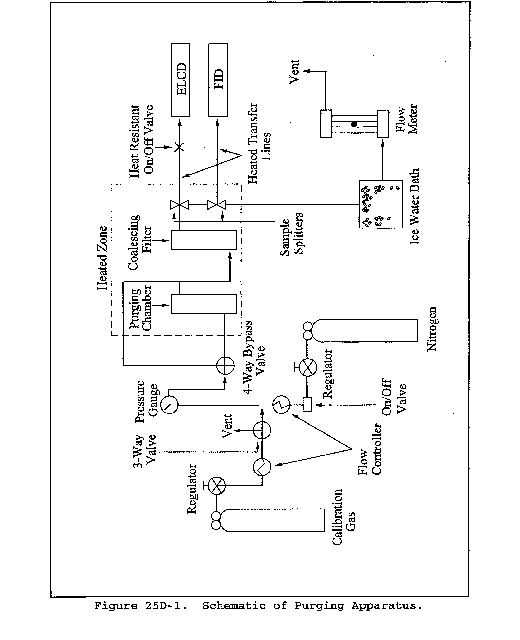
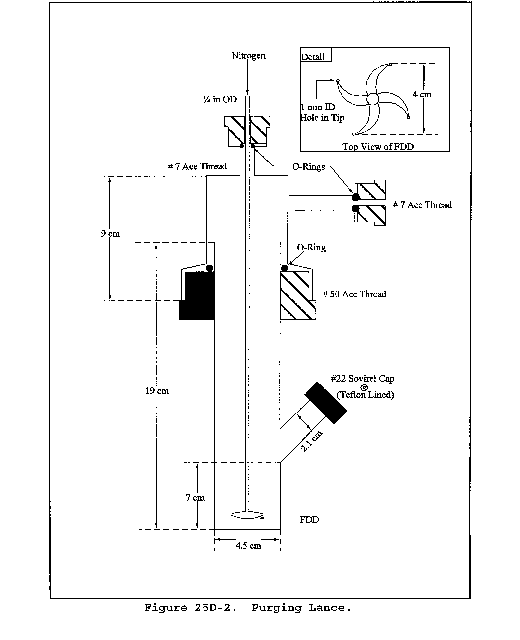
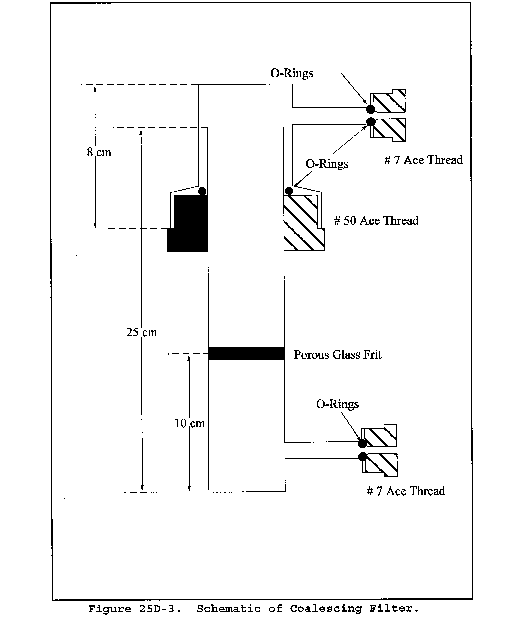
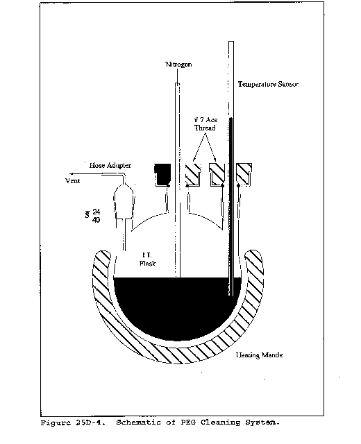

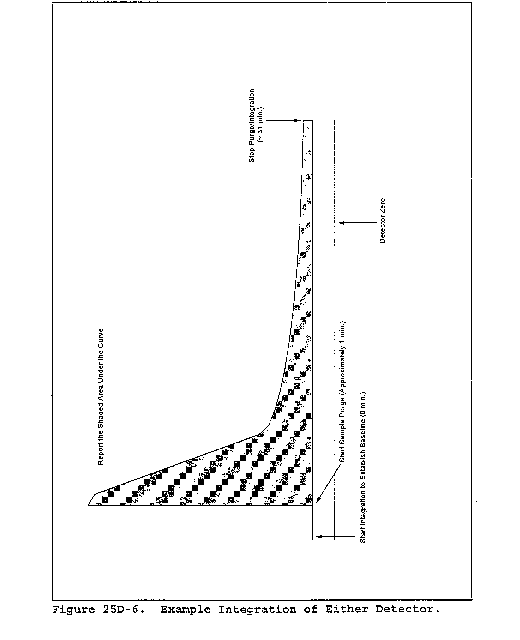
Method 25E - Determination of Vapor Phase Organic Concentration in Waste Samples
Performance of this method should not be attempted by persons unfamiliar with the operation of a flame ionization detector (FID) nor by those who are unfamiliar with source sampling because knowledge beyond the scope of this presentation is required. This method is not inclusive with respect to specifications (e.g., reagents and standards) and calibration procedures. Some material is incorporated by reference from other methods. Therefore, to obtain reliable results, persons using this method should have a thorough knowledge of at least the following additional test methods: Method 106, part 61, Appendix B, and Method 18, part 60, Appendix A.
1.0 Scope and Application
1.1 Applicability. This method is applicable for determining the vapor pressure of waste cited by an applicable regulation.
1.2 Data Quality Objectives. Adherence to the requirements of this method will enhance the quality of the data obtained from air pollutant sampling methods.
2.0 Summary of Method
2.1 The headspace vapor of the sample is analyzed for carbon content by a headspace analyzer, which uses an FID.
3.0 Definitions [Reserved]
4.0 Interferences
4.1 The analyst shall select the operating parameters best suited to the requirements for a particular analysis. The analyst shall produce confirming data through an adequate supplemental analytical technique and have the data available for review by the Administrator.
5.0 Safety [Reserved]
6.0 Equipment and Supplies
6.1 Sampling. The following equipment is required:
6.1.1 Sample Containers. Vials, glass, with butyl rubber septa, Perkin-Elmer Corporation Numbers 0105-0129 (glass vials), B001-0728 (gray butyl rubber septum, plug style), 0105-0131 (butyl rubber septa), or equivalent. The seal must be made from butyl rubber. Silicone rubber seals are not acceptable.
6.1.2 Vial Sealer. Perkin-Elmer Number 105-0106, or equivalent.
6.1.3 Gas-Tight Syringe. Perkin-Elmer Number 00230117, or equivalent.
6.1.4 The following equipment is required for sampling.
6.1.4.1 Tap.
6.1.4.2 Tubing. Teflon, 0.25-in. ID.
Mention of trade names or specific products does not constitute endorsement by the Environmental Protection Agency.
6.1.4.3 Cooling Coil. Stainless steel (304), 0.25 in.-ID, equipped with a thermocouple at the coil outlet.
6.2 Analysis. The following equipment is required.
6.2.1 Balanced Pressure Headspace Sampler. Perkin-Elmer HS-6, HS-100, or equivalent, equipped with a glass bead column instead of a chromatographic column.
6.2.2 FID. An FID meeting the following specifications is required.
6.2.2.1 Linearity. A linear response (±5 percent) over the operating range as demonstrated by the procedures established in section 10.2.
6.2.2.2 Range. A full scale range of 1 to 10,000 parts per million (ppm) propane (C3H8). Signal attenuators shall be available to produce a minimum signal response of 10 percent of full scale.
6.2.3 Data Recording System. Analog strip chart recorder or digital integration system compatible with the FID for permanently recording the output of the detector.
6.2.4 Temperature Sensor. Capable of reading temperatures in the range of 30 to 60 °C (86 to 140 °F) with an accuracy of ±0.1 °C (±0.2 °F).
7.0 Reagents and Standards
7.1 Analysis. The following items are required for analysis.
7.1.1 Hydrogen (H2). Zero grade hydrogen, as required by the FID.
7.1.2 Carrier Gas. Zero grade nitrogen, containing less than 1 ppm carbon (C) and less than 1 ppm carbon dioxide.
7.1.3 Combustion Gas. Zero grade air or oxygen as required by the FID.
7.2 Calibration and Linearity Check.
7.2.1 Stock Cylinder Gas Standard. 100 percent propane. The manufacturer shall: (a) Certify the gas composition to be accurate to ±3 percent or better (see section 7.2.1.1); (b) recommend a maximum shelf life over which the gas concentration does not change by greater than ±5 percent from the certified value; and (c) affix the date of gas cylinder preparation, certified propane concentration, and recommended maximum shelf life to the cylinder before shipment to the buyer.
7.2.1.1 Cylinder Standards Certification. The manufacturer shall certify the concentration of the calibration gas in the cylinder by
(a) directly analyzing the cylinder and
(b) calibrating his analytical procedure on the day of cylinder analysis. To calibrate his analytical procedure, the manufacturer shall use, as a minimum, a three-point calibration curve.
7.2.1.2 Verification of Manufacturer's Calibration Standards. Before using, the manufacturer shall verify each calibration standard by
(a) comparing it to gas mixtures prepared in accordance with the procedure described in section 7.1 of Method 106 of Part 61, Appendix B, or by
(b) calibrating it against Standard Reference Materials (SRM's) prepared by the National Bureau of Standards, if such SRM's are available. The agreement between the initially determined concentration value and the verification concentration value must be within ±5 percent. The manufacturer must reverify all calibration standards on a time interval consistent with the shelf life of the cylinder standards sold.
8.0 Sampling Collection, Preservation, Storage, and Transport
8.1 Install a sampling tap to obtain a sample at a point which is most representative of the unexposed waste (where the waste has had minimum opportunity to volatilize to the atmosphere). Assemble the sampling apparatus as shown in Figure 25E-1.
8.2 Begin sampling by purging the sample lines and cooling coil with at least four volumes of waste. Collect the purged material in a separate container and dispose of it properly.
8.3 After purging, stop the sample flow and transfer the Teflon sampling tube to a sample container. Sample at a flow rate such that the temperature of the waste is <10 °C (<50 °F). Fill the sample container halfway (±5 percent) and cap it within 5 seconds. Store immediately in a cooler and cover with ice.
8.4 Alternative sampling techniques may be used upon the approval of the Administrator.
9.0 Quality Control
9.1 Miscellaneous Quality Control Measures.
| Section | Quality control measure | Effect |
|---|---|---|
| 10.2, 10.3 | FID calibration and response check | Ensure precision of analytical results. |
10.0 Calibration and Standardization
Maintain a record of performance of each item.
10.1 Use the procedures in sections 10.2 to calibrate the headspace analyzer and FID and check for linearity before the system is first placed in operation, after any shutdown longer than 6 months, and after any modification of the system.
10.2 Calibration and Linearity. Use the procedures in section 10 of Method 18 of Part 60, Appendix A, to prepare the standards and calibrate the flowmeters, using propane as the standard gas. Fill the calibration standard vials halfway (±5 percent) with deionized water. Purge and fill the airspace with calibration standard. Prepare a minimum of three concentrations of calibration standards in triplicate at concentrations that will bracket the applicable cutoff. For a cutoff of 5.2 kPa (0.75 psi), prepare nominal concentrations of 30,000, 50,000, and 70,000 ppm as propane. For a cutoff of 27.6 kPa (4.0 psi), prepare nominal concentrations of 200,000, 300,000, and 400,000 ppm as propane.
10.2.1 Use the procedures in section 11.3 to measure the FID response of each standard. Use a linear regression analysis to calculate the values for the slope (k) and the y-intercept (b). Use the procedures in sections 12.3 and 12.2 to test the calibration and the linearity.
10.3 Daily FID Calibration Check. Check the calibration at the beginning and at the end of the daily runs by using the following procedures. Prepare 2 calibration standards at the nominal cutoff concentration using the procedures in section 10.2. Place one at the beginning and one at the end of the daily run. Measure the FID response of the daily calibration standard and use the values for k and b from the most recent calibration to calculate the concentration of the daily standard. Use an equation similar to 25E-2 to calculate the percent difference between the daily standard and Cs. If the difference is within 5 percent, then the previous values for k and b can be used. Otherwise, use the procedures in section 10.2 to recalibrate the FID.
11.0 Analytical Procedures
11.1 Allow one hour for the headspace vials to equilibrate at the temperature specified in the regulation. Allow the FID to warm up until a stable baseline is achieved on the detector.
11.2 Check the calibration of the FID daily using the procedures in section 10.3.
11.3 Follow the manufacturer's recommended procedures for the normal operation of the headspace sampler and FID.
11.4 Use the procedures in sections 12.4 and 12.5 to calculate the vapor phase organic vapor pressure in the samples.
11.5 Monitor the output of the detector to make certain that the results are being properly recorded.
12.0 Data Analysis and Calculations
12.1 Nomenclature.
A = Measurement of the area under the response curve, counts.
b = y-intercept of the linear regression line.
Ca = Measured vapor phase organic concentration of sample, ppm as propane.
Cma = Average measured vapor phase organic concentration of standard, ppm as propane.
Cm = Measured vapor phase organic concentration of standard, ppm as propane.
Cs = Calculated standard concentration, ppm as propane.
k = Slope of the linear regression line.
Pbar = Atmospheric pressure at analysis conditions, mm Hg (in. Hg).
P* = Organic vapor pressure in the sample, kPa (psi).
PD = Percent difference between the average measured vapor phase organic concentration (Cm) and the calculated standard concentration (Cs).
RSD = Relative standard deviation.
β = 1.333 × 10⁻⁷ kPa/[(mm Hg)(ppm)], (4.91 × 10⁻⁷ psi/[(in. Hg)(ppm)])
12.2 Linearity. Use the following equation to calculate the measured standard concentration for each standard vial.

12.2.1 Calculate the average measured standard concentration (Cma) for each set of triplicate standards and use the following equation to calculate PD between Cma and Cs. The instrument linearity is acceptable if the PD is within five for each standard.

12.3. Relative Standard Deviation (RSD). Use the following equation to calculate the RSD for each triplicate set of standards.

The calibration is acceptable if the RSD is within five for each standard concentration.
12.4 Concentration of organics in the headspace. Use the following equation to calculate the concentration of vapor phase organics in each sample.

12.5 Vapor Pressure of Organics in the Headspace Sample. Use the following equation to calculate the vapor pressure of organics in the sample.

13.0 Method Performance [Reserved]
14.0 Pollution Prevention [Reserved]
15.0 Waste Management [Reserved]
16.0 References
1. Salo, Albert E., Samuel Witz, and Robert D. MacPhee. “Determination of Solvent Vapor Concentrations by Total Combustion Analysis: a Comparison of Infared with Flame Ionization Detectors. Paper No. 75-33.2. (Presented at the 68th Annual Meeting of the Air Pollution Control Association. Boston, Massachusetts.
2. Salo, Albert E., William L. Oaks, and Robert D. MacPhee. “Measuring the Organic Carbon Content of Source Emissions for Air Pollution Control. Paper No. 74-190. (Presented at the 67th Annual Meeting of the Air Pollution Control Association. Denver, Colorado. June 9-13, 1974.) p. 25.
17.0 Tables, Diagrams, Flowcharts, and Validation Data
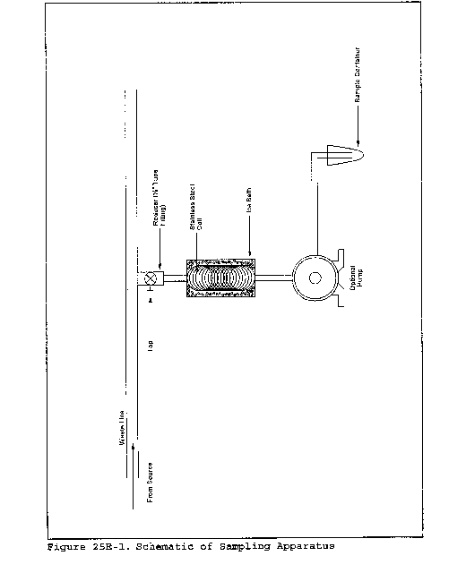
[36 FR 24877, Dec. 23, 1971]
Appendix A-8 to Part 60 - Test Methods 26 through 30B
Method 26 - Determination of Hydrogen Chloride Emissions From Stationary Sources
Method 26A - Determination of hydrogen halide and halogen emissions from stationary sources - isokinetic method
Method 27 - Determination of vapor tightness of gasoline delivery tank using pressure-vacuum test
Method 28 - Certification and auditing of wood heaters
Method 28A - Measurement of air to fuel ratio and minimum achievable burn rates for wood-fired appliances
Method 29 - Determination of metals emissions from stationary sources
The test methods in this appendix are referred to in § 60.8 (Performance Tests) and § 60.11 (Compliance With Standards and Maintenance Requirements) of 40 CFR part 60, subpart A (General Provisions). Specific uses of these test methods are described in the standards of performance contained in the subparts, beginning with Subpart D.
Within each standard of performance, a section title “Test Methods and Procedures” is provided to: (1) Identify the test methods to be used as reference methods to the facility subject to the respective standard and (2) identify any special instructions or conditions to be followed when applying a method to the respective facility. Such instructions (for example, establish sampling rates, volumes, or temperatures) are to be used either in addition to, or as a substitute for procedures in a test method. Similarly, for sources subject to emission monitoring requirements, specific instructions pertaining to any use of a test method as a reference method are provided in the subpart or in Appendix B.
Inclusion of methods in this appendix is not intended as an endorsement or denial of their applicability to sources that are not subject to standards of performance. The methods are potentially applicable to other sources; however, applicability should be confirmed by careful and appropriate evaluation of the conditions prevalent at such sources.
The approach followed in the formulation of the test methods involves specifications for equipment, procedures, and performance. In concept, a performance specification approach would be preferable in all methods because this allows the greatest flexibility to the user. In practice, however, this approach is impractical in most cases because performance specifications cannot be established. Most of the methods described herein, therefore, involve specific equipment specifications and procedures, and only a few methods in this appendix rely on performance criteria.
Minor changes in the test methods should not necessarily affect the validity of the results and it is recognized that alternative and equivalent methods exist. section 60.8 provides authority for the Administrator to specify or approve (1) equivalent methods, (2) alternative methods, and (3) minor changes in the methodology of the test methods. It should be clearly understood that unless otherwise identified all such methods and changes must have prior approval of the Administrator. An owner employing such methods or deviations from the test methods without obtaining prior approval does so at the risk of subsequent disapproval and retesting with approved methods.
Within the test methods, certain specific equipment or procedures are recognized as being acceptable or potentially acceptable and are specifically identified in the methods. The items identified as acceptable options may be used without approval but must be identified in the test report. The potentially approvable options are cited as “subject to the approval of the Administrator” or as “or equivalent.” Such potentially approvable techniques or alternatives may be used at the discretion of the owner without prior approval. However, detailed descriptions for applying these potentially approvable techniques or alternatives are not provided in the test methods. Also, the potentially approvable options are not necessarily acceptable in all applications. Therefore, an owner electing to use such potentially approvable techniques or alternatives is responsible for: (1) assuring that the techniques or alternatives are in fact applicable and are properly executed; (2) including a written description of the alternative method in the test report (the written method must be clear and must be capable of being performed without additional instruction, and the degree of detail should be similar to the detail contained in the test methods); and (3) providing any rationale or supporting data necessary to show the validity of the alternative in the particular application. Failure to meet these requirements can result in the Administrator's disapproval of the alternative.
Method 26 - Determination of Hydrogen Halide and Halogen Emissions From Stationary Sources Non-Isokinetic Method
1.0 Scope and Application
1.1 Analytes.
| Analytes | CAS No. |
|---|---|
| Hydrogen Chloride (HCl) | 7647-01-0 |
| Hydrogen Bromide (HBr) | 10035-10-6 |
| Hydrogen Fluoride (HF) | 7664-39-3 |
| Chlorine (Cl2) | 7882-50-5 |
| Bromine (Br2) | 7726-95-6 |
1.2 Applicability. This method is applicable for determining emissions of hydrogen halides (HX) (HCl, HBr, and HF) and halogens (X2) (Cl2 and Br2) from stationary sources when specified by the applicable subpart. Sources, such as those controlled by wet scrubbers, that emit acid particulate matter must be sampled using Method 26A.
1.3 Data Quality Objectives. Adherence to the requirements of this method will enhance the quality of the data obtained from air pollutant sampling methods.
2.0 Summary of Method
2.1 An integrated sample is extracted from the source and passed through a prepurged heated probe and filter into dilute sulfuric acid and dilute sodium hydroxide solutions which collect the gaseous hydrogen halides and halogens, respectively. The filter collects particulate matter including halide salts but is not routinely recovered and analyzed. The hydrogen halides are solubilized in the acidic solution and form chloride (Cl−), bromide (Br−), and fluoride (F−) ions. The halogens have a very low solubility in the acidic solution and pass through to the alkaline solution where they are hydrolyzed to form a proton (H + ), the halide ion, and the hypohalous acid (HClO or HBrO). Sodium thiosulfate is added in excess to the alkaline solution to assure reaction with the hypohalous acid to form a second halide ion such that 2 halide ions are formed for each molecule of halogen gas. The halide ions in the separate solutions are measured by ion chromatography (IC).
3.0 Definitions [Reserved]
4.0 Interferences
4.1 Volatile materials, such as chlorine dioxide (ClO2) and ammonium chloride (NH4Cl), which produce halide ions upon dissolution during sampling are potential interferents. Interferents for the halide measurements are the halogen gases which disproportionate to a hydrogen halide and a hydrohalous acid upon dissolution in water. However, the use of acidic rather than neutral or basic solutions for collection of the hydrogen halides greatly reduces the dissolution of any halogens passing through this solution.
4.2 The simultaneous presence of HBr and CL2 may cause a positive bias in the HCL result with a corresponding negative bias in the Cl2 result as well as affecting the HBr/Br2 split.
4.3 High concentrations of nitrogen oxides (NOX) may produce sufficient nitrate (NO3− to interfere with measurements of very low Br− levels.
4.4 A glass wool plug should not be used to remove particulate matter since a negative bias in the data could result.
4.5 There is anecdotal evidence that HF may be outgassed from new teflon components. If HF is a target analyte, then preconditioning of new teflon components, by heating should be considered.
5.0 Safety
5.1 Disclaimer. This method may involve hazardous materials, operations, and equipment. This test method may not address all of the safety problems associated with its use. It is the responsibility of the user to establish appropriate safety and health practices and determine the applicability of regulatory limitations before performing this test method.
5.2 Corrosive Reagents. The following reagents are hazardous. Personal protective equipment and safe procedures are useful in preventing chemical splashes. If contact occurs, immediately flush with copious amounts of water for at least 15 minutes. Remove clothing under shower and decontaminate. Treat residual chemical burns as thermal burns.
5.2.1 Sodium Hydroxide (NaOH). Causes severe damage to eyes and skin. Inhalation causes irritation to nose, throat, and lungs. Reacts exothermically with limited amounts of water.
5.2.2 Sulfuric Acid (H2SO4). Rapidly destructive to body tissue. Will cause third degree burns. Eye damage may result in blindness. Inhalation may be fatal from spasm of the larynx, usually within 30 minutes. May cause lung tissue damage with edema. 1 mg/m3 for 8 hours will cause lung damage or, in higher concentrations, death. Provide ventilation to limit inhalation. Reacts violently with metals and organics.
6.0 Equipment and Supplies
Mention of trade names or specific products does not constitute endorsement by the Environmental Protection Agency.
6.1 Sampling. The sampling train is shown in Figure 26-1, and component parts are discussed below.
6.1.1 Probe. Borosilicate glass, approximately 3/8-in. (9-mm) I.D. with a heating system capable of maintaining a probe gas temperature during sampling between 120 and 134 °C (248 and 273 °F) to prevent moisture condensation; or Teflon where stack probes are below 210 °C. If HF is a target analyte, then preconditioning of new teflon components by heating should be considered to prevent potential HF outgassing. A Teflon-glass filter in a mat configuration should be installed to remove particulate matter from the gas stream.
6.1.2 Three-way Stopcock. A borosilicate-glass three-way stopcock with a heating system to prevent moisture condensation. The heated stopcock should connect to the outlet of the heated filter and the inlet of the first impinger. The heating system should be capable of preventing condensation up to the inlet of the first impinger. Silicone grease may be used, if necessary, to prevent leakage.
6.1.3 Impingers. Four 30-ml midget impingers with leak-free glass connectors. Silicone grease may be used, if necessary, to prevent leakage. For sampling at high moisture sources or for sampling times greater than one hour, a midget impinger with a shortened stem (such that the gas sample does not bubble through the collected condensate) should be used in front of the first impinger.
6.1.4 Drying Tube or Impinger. Tube or impinger, of Mae West design, filled with 6- to 16-mesh indicating type silica gel, or equivalent, to dry the gas sample and to protect the dry gas meter and pump. If the silica gel has been used previously, dry at 175 °C (350 °F) for 2 hours. New silica gel may be used as received. Alternatively, other types of desiccants (equivalent or better) may be used.
6.1.5 Heating System. Any heating system capable of maintaining a temperature around the probe and filter holder between 120 and 134 °C (248 and 273 °F) during sampling, or such other temperature as specified by an applicable subpart of the standards or approved by the Administrator for a particular application.
6.1.6 Filter Holder and Support. The filter holder shall be made of Teflon or quartz. The filter support shall be made of Teflon. All Teflon filter holders and supports are available from Savillex Corp., 5325 Hwy 101, Minnetonka, MN 55345.
6.1.7 Sample Line. Leak-free, with compatible fittings to connect the last impinger to the needle valve.
6.1.8 Rate Meter. Rotameter, or equivalent, capable of measuring flow rate to within 2 percent of the selected flow rate of 2 liters/min (0.07 ft3/min).
6.1.9 Purge Pump, Purge Line, Drying Tube, Needle Valve, and Rate Meter. Pump capable of purging the sampling probe at 2 liters/min, with drying tube, filled with silica gel or equivalent, to protect pump, and a rate meter capable of measuring 0 to 5 liters/min (0.2 ft3/min).
6.1.10 Stopcock Grease, Valve, Pump, Volume Meter, Barometer, and Vacuum Gauge. Same as in Method 6, sections 6.1.1.4, 6.1.1.7, 6.1.1.8, 6.1.1.10, 6.1.2, and 6.1.3.
6.1.11 Temperature Measuring Devices. Temperature sensors to monitor the temperature of the probe and to monitor the temperature of the sampling system from the outlet of the probe to the inlet of the first impinger.
6.1.12 Ice Water Bath. To minimize loss of absorbing solution.
6.2 Sample Recovery.
6.2.1 Wash Bottles. Polyethylene or glass, 500-ml or larger, two.
6.2.2 Storage Containers. 100- or 250-ml, high-density polyethylene or glass sample storage containers with Teflon screw cap liners to store impinger samples.
6.3 Sample Preparation and Analysis. The materials required for volumetric dilution and chromatographic analysis of samples are described below.
6.3.1 Volumetric Flasks. Class A, 100-ml size.
6.3.2 Volumetric Pipets. Class A, assortment. To dilute samples to the calibration range of the ion chromatograph.
6.3.3 Ion Chromatograph (IC). Suppressed or non-suppressed, with a conductivity detector and electronic integrator operating in the peak area mode. Other detectors, strip chart recorders, and peak height measurements may be used.
7.0 Reagents and Standards
Unless otherwise indicated, all reagents must conform to the specifications established by the Committee on Analytical Reagents of the American Chemical Society (ACS reagent grade). When such specifications are not available, the best available grade shall be used.
7.1 Sampling.
7.1.1 Filter. A 25-mm (1 in) (or other size) Teflon glass mat, Pallflex TX40HI75 (Pallflex Inc., 125 Kennedy Drive, Putnam, CT 06260). This filter is in a mat configuration to prevent fine particulate matter from entering the sampling train. Its composition is 75% Teflon/25% borosilicate glass. Other filters may be used, but they must be in a mat (as opposed to a laminate) configuration and contain at least 75% Teflon. For practical rather than scientific reasons, when the stack gas temperature exceeds 210 °C (410 °F) and the HCl concentration is greater than 20 ppm, a quartz-fiber filter may be used since Teflon becomes unstable above this temperature.
7.1.2 Water. Deionized, distilled water that conforms to American Society of Testing and Materials (ASTM) Specification D 1193-77 or 91, Type 3 (incorporated by reference - see § 60.17).
7.1.3 Acidic Absorbing Solution, 0.1 N Sulfuric Acid (H2SO4). To prepare 100 ml of the absorbing solution for the front impinger pair, slowly add 0.28 ml of concentrated H2SO4 to about 90 ml of water while stirring, and adjust the final volume to 100 ml using additional water. Shake well to mix the solution.
7.1.4 Silica Gel. Indicating type, 6 to 16 mesh. If previously used, dry at 180 °C (350 °F) for 2 hours. New silica gel may be used as received. Alternatively, other types of desiccants may be used, subject to the approval of the Administrator.
7.1.5 Alkaline Adsorbing Solution, 0.1 N Sodium Hydroxide (NaOH). To prepare 100 ml of the scrubber solution for the third and fourth impinger, dissolve 0.40 g of solid NaOH in about 90 ml of water, and adjust the final solution volume to 100 ml using additional water. Shake well to mix the solution.
7.1.6 Sodium Thiosulfate (Na2S2O3 5 H2O)
7.2 Sample Preparation and Analysis.
7.2.1 Water. Same as in section 7.1.2.
7.2.2 Absorbing Solution Blanks. A separate blank solution of each absorbing reagent should be prepared for analysis with the field samples. Dilute 30 ml of each absorbing solution to approximately the same final volume as the field samples using the blank sample of rinse water.
7.2.3 Halide Salt Stock Standard Solutions. Prepare concentrated stock solutions from reagent grade sodium chloride (NaCl), sodium bromide (NaBr), and sodium fluoride (NaF). Each must be dried at 110 °C (230 °F) for two or more hours and then cooled to room temperature in a desiccator immediately before weighing. Accurately weigh 1.6 to 1.7 g of the dried NaCl to within 0.1 mg, dissolve in water, and dilute to 1 liter. Calculate the exact Cl− concentration using Equation 26-1 in section 12.2. In a similar manner, accurately weigh and solubilize 1.2 to 1.3 g of dried NaBr and 2.2 to 2.3 g of NaF to make 1-liter solutions. Use Equations 26-2 and 26-3 in section 12.2, to calculate the Br− and F− concentrations. Alternately, solutions containing a nominal certified concentration of 1000 mg/l NaCl are commercially available as convenient stock solutions from which standards can be made by appropriate volumetric dilution. Refrigerate the stock standard solutions and store no longer than one month.
7.2.4 Chromatographic Eluent. Effective eluents for nonsuppressed IC using a resin-or silica-based weak ion exchange column are a 4 mM potassium hydrogen phthalate solution, adjusted to pH 4.0 using a saturated sodium borate solution, and a 4 mM 4-hydroxy benzoate solution, adjusted to pH 8.6 using 1 N NaOH. An effective eluent for suppressed ion chromatography is a solution containing 3 mM sodium bicarbonate and 2.4 mM sodium carbonate. Other dilute solutions buffered to a similar pH and containing no interfering ions may be used. When using suppressed ion chromatography, if the “water dip” resulting from sample injection interferes with the chloride peak, use a 2 mM NaOH/2.4 mM sodium bicarbonate eluent.
8.0 Sample Collection, Preservation, Storage, and Transport
Because of the complexity of this method, testers and analyst should be trained and experienced with the procedure to ensure reliable results.
8.1 Sampling.
8.1.1 Preparation of Collection Train. Prepare the sampling train as follows: Pour 15 ml of the acidic absorbing solution into each one of the first pair of impingers, and 15 ml of the alkaline absorbing solution into each one of the second pair of impingers. Connect the impingers in series with the knockout impinger first, if used, followed by the two impingers containing the acidic absorbing solution and the two impingers containing the alkaline absorbing solution. Place a fresh charge of silica gel, or equivalent, in the drying tube or impinger at the end of the impinger train.
8.1.2 Adjust the probe temperature and the temperature of the filter and the stopcock (i.e., the heated area in Figure 26-1) to a temperature sufficient to prevent water condensation. This temperature must be maintained between 120 and 134 °C (248 and 273 °F). The temperature should be monitored throughout a sampling run to ensure that the desired temperature is maintained. It is important to maintain a temperature around the probe and filter in this range since it is extremely difficult to purge acid gases off these components. (These components are not quantitatively recovered and, hence, any collection of acid gases on these components would result in potential under reporting of these emissions. The applicable subparts may specify alternative higher temperatures.)
8.1.3 Leak-Check Procedure.
8.1.3.1 Sampling Train. A leak-check prior to the sampling run is optional; however, a leak-check after the sampling run is mandatory. The leak-check procedure is as follows: Temporarily attach a suitable [e.g., 0-40 cc/min (0-2.4 in3/min)] rotameter to the outlet of the dry gas meter and place a vacuum gauge at or near the probe inlet. Plug the probe inlet, pull a vacuum of at least 250 mm Hg (10 in. Hg), and note the flow rate as indicated by the rotameter. A leakage rate not in excess of 2 percent of the average sampling rate is acceptable.
Carefully release the probe inlet plug before turning off the pump.
8.1.3.2 Pump. It is suggested (not mandatory) that the pump be leak-checked separately, either prior to or after the sampling run. If done prior to the sampling run, the pump leak-check shall precede the leak-check of the sampling train described immediately above; if done after the sampling run, the pump leak-check shall follow the train leak-check. To leak-check the pump, proceed as follows: Disconnect the drying tube from the probe-impinger assembly. Place a vacuum gauge at the inlet to either the drying tube or pump, pull a vacuum of 250 mm (10 in) Hg, plug or pinch off the outlet of the flow meter, and then turn off the pump. The vacuum should remain stable for at least 30 sec. Other leak-check procedures may be used, subject to the approval of the Administrator, U.S. Environmental Protection Agency.
8.1.4 Purge Procedure. Immediately before sampling, connect the purge line to the stopcock, and turn the stopcock to permit the purge pump to purge the probe (see Figure 1A of Figure 26-1). Turn on the purge pump, and adjust the purge rate to 2 liters/min (0.07 ft3/min). Purge for at least 5 minutes before sampling.
8.1.5 Sample Collection. Turn on the sampling pump, pull a slight vacuum of approximately 25 mm Hg (1 in Hg) on the impinger train, and turn the stopcock to permit stack gas to be pulled through the impinger train (see Figure 1C of Figure 26-1). Adjust the sampling rate to 2 liters/min, as indicated by the rate meter, and maintain this rate to within 10 percent during the entire sampling run. Take readings of the dry gas meter volume and temperature, rate meter, and vacuum gauge at least once every five minutes during the run. A sampling time of one hour is recommended. Shorter sampling times may introduce a significant negative bias in the HCl concentration. At the conclusion of the sampling run, remove the train from the stack, cool, and perform a leak-check as described in section 8.1.3.1.
8.2 Sample Recovery.
8.2.1 Disconnect the impingers after sampling. Quantitatively transfer the contents of the acid impingers and the knockout impinger, if used, to a leak-free storage bottle. Add the water rinses of each of these impingers and connecting glassware to the storage bottle.
8.2.2 Repeat this procedure for the alkaline impingers and connecting glassware using a separate storage bottle. Add 25 mg of sodium thiosulfate per the product of ppm of halogen anticipated to be in the stack gas times the volume (dscm) of stack gas sampled (0.7 mg per ppm-dscf).
This amount of sodium thiosulfate includes a safety factor of approximately 5 to assure complete reaction with the hypohalous acid to form a second Cl− ion in the alkaline solution.
8.2.3 Save portions of the absorbing reagents (0.1 N H2SO4 and 0.1 N NaOH) equivalent to the amount used in the sampling train (these are the absorbing solution blanks described in section 7.2.2); dilute to the approximate volume of the corresponding samples using rinse water directly from the wash bottle being used. Add the same amount of sodium thiosulfate solution to the 0.1 N NaOH absorbing solution blank. Also, save a portion of the rinse water used to rinse the sampling train. Place each in a separate, prelabeled storage bottle. The sample storage bottles should be sealed, shaken to mix, and labeled. Mark the fluid level.
8.3 Sample Preparation for Analysis. Note the liquid levels in the storage bottles and confirm on the analysis sheet whether or not leakage occurred during transport. If a noticeable leakage has occurred, either void the sample or use methods, subject to the approval of the Administrator, to correct the final results. Quantitatively transfer the sample solutions to 100-ml volumetric flasks, and dilute to 100 ml with water.
9.0 Quality Control [Reserved]
10.0 Calibration and Standardization
Maintain a laboratory log of all calibrations.
10.1 Volume Metering System, Temperature Sensors, Rate Meter, and Barometer. Same as in Method 6, sections 10.1, 10.2, 10.3, and 10.4.
10.2 Ion Chromatograph.
10.2.1 To prepare the calibration standards, dilute given amounts (1.0 ml or greater) of the stock standard solutions to convenient volumes, using 0.1 N H2SO4 or 0.1 N NaOH, as appropriate. Prepare at least four calibration standards for each absorbing reagent containing the appropriate stock solutions such that they are within the linear range of the field samples.
10.2.2 Using one of the standards in each series, ensure adequate baseline separation for the peaks of interest.
10.2.3 Inject the appropriate series of calibration standards, starting with the lowest concentration standard first both before and after injection of the quality control check sample, reagent blanks, and field samples. This allows compensation for any instrument drift occurring during sample analysis. The values from duplicate injections of these calibration samples should agree within 5 percent of their mean for the analysis to be valid.
10.2.4 Determine the peak areas, or heights, for the standards and plot individual values versus halide ion concentrations in µg/ml.
10.2.5 Draw a smooth curve through the points. Use linear regression to calculate a formula describing the resulting linear curve.
11.0 Analytical Procedures
11.1 Sample Analysis.
11.1.1 The IC conditions will depend upon analytical column type and whether suppressed or non-suppressed IC is used. An example chromatogram from a non-suppressed system using a 150-mm Hamilton PRP-X100 anion column, a 2 ml/min flow rate of a 4 mM 4-hydroxy benzoate solution adjusted to a pH of 8.6 using 1 N NaOH, a 50 µl sample loop, and a conductivity detector set on 1.0 µS full scale is shown in Figure 26-2.
11.1.2 Before sample analysis, establish a stable baseline. Next, inject a sample of water, and determine if any Cl−, Br−, or F− appears in the chromatogram. If any of these ions are present, repeat the load/injection procedure until they are no longer present. Analysis of the acid and alkaline absorbing solution samples requires separate standard calibration curves; prepare each according to section 10.2. Ensure adequate baseline separation of the analyses.
11.1.3 Between injections of the appropriate series of calibration standards, inject in duplicate the reagent blanks, quality control sample, and the field samples. Measure the areas or heights of the Cl−, Br−, and F− peaks. Use the mean response of the duplicate injections to determine the concentrations of the field samples and reagent blanks using the linear calibration curve. The values from duplicate injections should agree within 5 percent of their mean for the analysis to be valid. If the values of duplicate injections are not within 5 percent of the mean, the duplicate injections shall be repeated and all four values used to determine the average response. Dilute any sample and the blank with equal volumes of water if the concentration exceeds that of the highest standard.
12.0 Data Analysis and Calculations
Retain at least one extra decimal figure beyond those contained in the available data in intermediate calculations, and round off only the final answer appropriately.
12.1 Nomenclature.
BX− = Mass concentration of applicable absorbing solution blank, µg halide ion (Cl−, Br−, F−) /ml, not to exceed 1 µg/ml which is 10 times the published analytical detection limit of 0.1 µg/ml.
C = Concentration of hydrogen halide (HX) or halogen (X2), dry basis, mg/dscm.
K = 10−3 mg/µg.
KHCl = 1.028 (µg HCl/µg-mole)/(µg Cl−/µg-mole).
KHBr = 1.013 (µg HBr/µg-mole)/(µg Br−/µg-mole).
KHF = 1.053 (µg HF/µg-mole)/(µg F−/µg-mole).
mHX = Mass of HCl, HBr, or HF in sample, µg.
mX2 = Mass of Cl2 or Br2 in sample, µg.
SX− = Analysis of sample, µg halide ion (Cl−, Br−, F−)/ml.
Vm(std) = Dry gas volume measured by the dry gas meter, corrected to standard conditions, dscm.
Vs = Volume of filtered and diluted sample, ml.
12.2 Calculate the exact Cl−, Br−, and F− concentration in the halide salt stock standard solutions using the following equations.

12.3 Sample Volume, Dry Basis, Corrected to Standard Conditions. Calculate the sample volume using Eq. 6-1 of Method 6.
12.4 Total µg HCl, HBr, or HF Per Sample.

12.5 Total µg Cl2 or Br2 Per Sample.

12.6 Concentration of Hydrogen Halide or Halogen in Flue Gas.

13.0 Method Performance
13.1 Precision and Bias. The within-laboratory relative standard deviations are 6.2 and 3.2 percent at HCl concentrations of 3.9 and 15.3 ppm, respectively. The method does not exhibit a bias to Cl2 when sampling at concentrations less than 50 ppm.
13.2 Sample Stability. The collected Cl−samples can be stored for up to 4 weeks.
13.3 Detection Limit. A typical IC instrumental detection limit for Cl− is 0.2 µg/ml. Detection limits for the other analyses should be similar. Assuming 50 ml liquid recovered from both the acidified impingers, and the basic impingers, and 0.12 dscm (4.24 dscf) of stack gas sampled, then the analytical detection limit in the stack gas would be about 0.05 ppm for HCl and Cl2, respectively.
14.0 Pollution Prevention [Reserved]
15.0 Waste Management [Reserved]
16.0 Alternative Procedures
Method 26A. Method 26A, which uses isokinetic sampling equipment, is an acceptable alternative to Method 26.
17.0 References
1. Steinsberger, S. C. and J. H. Margeson, “Laboratory and Field Evaluation of a Methodology for Determination of Hydrogen Chloride Emissions from Municipal and Hazardous Waste Incinerators,” U.S. Environmental Protection Agency, Office of Research and Development, Report No. 600/3-89/064, April 1989. Available from the National Technical Information Service, Springfield, VA 22161 as PB89220586/AS.
2. State of California, Air Resources Board, Method 421, “Determination of Hydrochloric Acid Emissions from Stationary Sources,” March 18, 1987.
3. Cheney, J.L. and C.R. Fortune. Improvements in the Methodology for Measuring Hydrochloric Acid in Combustion Source Emissions. J. Environ. Sci. Health. A19(3): 337-350. 1984.
4. Stern, D. A., B. M. Myatt, J. F. Lachowski, and K. T. McGregor. Speciation of Halogen and Hydrogen Halide Compounds in Gaseous Emissions. In: Incineration and Treatment of Hazardous Waste: Proceedings of the 9th Annual Research Symposium, Cincinnati, Ohio, May 2-4, 1983. Publication No. 600/9-84-015. July 1984. Available from National Technical Information Service, Springfield, VA 22161 as PB84-234525.
5. Holm, R. D. and S. A. Barksdale. Analysis of Anions in Combustion Products. In: Ion Chromatographic Analysis of Environmental Pollutants. E. Sawicki, J. D. Mulik, and E. Wittgenstein (eds.). Ann Arbor, Michigan, Ann Arbor Science Publishers. 1978. pp. 99-110.
18.0 Tables, Diagrams, Flowcharts, and Validation Data
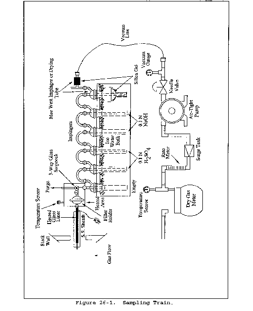
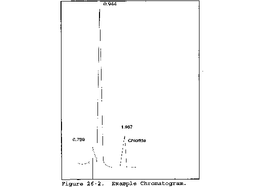
Method 26A - Determination of Hydrogen Halide and Halogen Emissions From Stationary Sources Isokinetic Method
This method does not include all of the specifications (e.g., equipment and supplies) and procedures (e.g., sampling and analytical) essential to its performance. Some material is incorporated by reference from other methods in this part. Therefore, to obtain reliable results, persons using this method should have a thorough knowledge of at least the following additional test methods: Method 2, Method 5, and Method 26.
1.0 Scope and Application
1.1 Analytes.
| Analytes | CAS No. |
|---|---|
| Hydrogen Chloride (HCl) | 7647-01-0 |
| Hydrogen Bromide (HBr) | 10035-10-6 |
| Hydrogen Fluoride (HF) | 7664-39-3 |
| Chlorine (Cl2) | 7882-50-5 |
| Bromine (Br2) | 7726-95-6 |
1.2 This method is applicable for determining emissions of hydrogen halides (HX) [HCl, HBr, and HF] and halogens (X2) [Cl2 and Br2] from stationary sources when specified by the applicable subpart. This method collects the emission sample isokinetically and is therefore particularly suited for sampling at sources, such as those controlled by wet scrubbers, emitting acid particulate matter (e.g., hydrogen halides dissolved in water droplets).
1.3 Data Quality Objectives. Adherence to the requirements of this method will enhance the quality of the data obtained from air pollutant sampling methods.
2.0 Summary of Method
2.1 Principle. Gaseous and particulate pollutants are withdrawn isokinetically from the source and collected in an optional cyclone, on a filter, and in absorbing solutions. The cyclone collects any liquid droplets and is not necessary if the source emissions do not contain them; however, it is preferable to include the cyclone in the sampling train to protect the filter from any liquid present. The filter collects particulate matter including halide salts but is not routinely recovered or analyzed. Acidic and alkaline absorbing solutions collect the gaseous hydrogen halides and halogens, respectively. Following sampling of emissions containing liquid droplets, any halides/halogens dissolved in the liquid in the cyclone and on the filter are vaporized to gas and collected in the impingers by pulling conditioned ambient air through the sampling train. The hydrogen halides are solubilized in the acidic solution and form chloride (Cl−), bromide (Br−), and fluoride (F−) ions. The halogens have a very low solubility in the acidic solution and pass through to the alkaline solution where they are hydrolyzed to form a proton (H + ), the halide ion, and the hypohalous acid (HClO or HBrO). Sodium thiosulfate is added to the alkaline solution to assure reaction with the hypohalous acid to form a second halide ion such that 2 halide ions are formed for each molecule of halogen gas. The halide ions in the separate solutions are measured by ion chromatography (IC). If desired, the particulate matter recovered from the filter and the probe is analyzed following the procedures in Method 5.
If the tester intends to use this sampling arrangement to sample concurrently for particulate matter, the alternative Teflon probe liner, cyclone, and filter holder should not be used. The Teflon filter support must be used. The tester must also meet the probe and filter temperature requirements of both sampling trains.
3.0 Definitions [Reserved]
4.0 Interferences
4.1 Volatile materials, such as chlorine dioxide (ClO2) and ammonium chloride (NH4Cl), which produce halide ions upon dissolution during sampling are potential interferents. Interferents for the halide measurements are the halogen gases which disproportionate to a hydrogen halide and a hypohalous acid upon dissolution in water. The use of acidic rather than neutral or basic solutions for collection of the hydrogen halides greatly reduces the dissolution of any halogens passing through this solution.
4.2 The simultaneous presence of both HBr and Cl2 may cause a positive bias in the HCl result with a corresponding negative bias in the Cl2 result as well as affecting the HBr/Br2 split.
4.3 High concentrations of nitrogen oxides (NOX) may produce sufficient nitrate (NO3−) to interfere with measurements of very low Br− levels. Dissociating chloride salts (e.g., ammonium chloride) at elevated temperatures interfere with halogen acid measurement in this method. Maintaining particulate probe/filter temperatures between 120 °C and 134 °C (248 °F and 273 °F) minimizes this interference.
4.4 There is anecdotal evidence that HF may be outgassed from new Teflon components. If HF is a target analyte then preconditioning of new Teflon components, by heating, should be considered.
5.0 Safety
5.1 Disclaimer. This method may involve hazardous materials, operations, and equipment. This test method may not address all of the safety problems associated with its use. It is the responsibility of the user to establish appropriate safety and health practices and determine the applicability of regulatory limitations before performing this test method.
5.2 Corrosive Reagents. The following reagents are hazardous. Personal protective equipment and safe procedures are useful in preventing chemical splashes. If contact occurs, immediately flush with copious amounts of water for at least 15 minutes. Remove clothing under shower and decontaminate. Treat residual chemical burns as thermal burns.
5.2.1 Sodium Hydroxide (NaOH). Causes severe damage to eyes and skin. Inhalation causes irritation to nose, throat, and lungs. Reacts exothermically with limited amounts of water.
5.2.2 Sulfuric Acid (H2SO4). Rapidly destructive to body tissue. Will cause third degree burns. Eye damage may result in blindness. Inhalation may be fatal from spasm of the larynx, usually within 30 minutes. May cause lung tissue damage with edema. 1 mg/m3 for 8 hours will cause lung damage or, in higher concentrations, death. Provide ventilation to limit inhalation. Reacts violently with metals and organics.
6.0. Equipment and Supplies
Mention of trade names or specific products does not constitute endorsement by the Environmental Protection Agency.
6.1 Sampling. The sampling train is shown in Figure 26A-1; the apparatus is similar to the Method 5 train where noted as follows:
6.1.1 Probe Nozzle. Borosilicate or quartz glass; constructed and calibrated according to Method 5, sections 6.1.1.1 and 10.1, and coupled to the probe liner using a Teflon union; a stainless steel nut is recommended for this union. When the stack temperature exceeds 210 °C (410 °F), a one-piece glass nozzle/liner assembly must be used.
6.1.2 Probe Liner. Same as Method 5, section 6.1.1.2, except metal liners shall not be used. Water-cooling of the stainless steel sheath is recommended at temperatures exceeding 500 °C (932 °F). Teflon may be used in limited applications where the minimum stack temperature exceeds 120 °C (250 °F) but never exceeds the temperature where Teflon is estimated to become unstable [approximately 210 °C (410 °F)].
6.1.3 Pitot Tube, Differential Pressure Gauge, Filter Heating System, Filter Temperature Sensor with a glass or Teflon encasement, Metering System, Barometer, Gas Density Determination Equipment. Same as Method 5, sections 6.1.1.3, 6.1.1.4, 6.1.1.6, 6.1.1.7, 6.1.1.9, 6.1.2, and 6.1.3.
6.1.4 Cyclone (Optional). Glass or Teflon. Use of the cyclone is required only when the sample gas stream is saturated with moisture; however, the cyclone is recommended to protect the filter from any liquid droplets present.
6.1.5 Filter Holder. Borosilicate or quartz glass, or Teflon filter holder, with a Teflon filter support and a sealing gasket. The sealing gasket shall be constructed of Teflon or equivalent materials. The holder design shall provide a positive seal against leakage at any point along the filter circumference. The holder shall be attached immediately to the outlet of the cyclone.
6.1.6 Impinger Train. The following system shall be used to determine the stack gas moisture content and to collect the hydrogen halides and halogens: five or six impingers connected in series with leak-free ground glass fittings or any similar leak-free noncontaminating fittings. The first impinger shown in Figure 26A-1 (knockout or condensate impinger) is optional and is recommended as a water knockout trap for use under high moisture conditions. If used, this impinger should be constructed as described below for the alkaline impingers, but with a shortened stem, and should contain 50 ml of 0.1 N H2SO4. The following two impingers (acid impingers which each contain 100 ml of 0.1 N H2SO4) shall be of the Greenburg-Smith design with the standard tip (Method 5, section 6.1.1.8). The next two impingers (alkaline impingers which each contain 100 ml of 0.1 N NaOH) and the last impinger (containing silica gel) shall be of the modified Greenburg-Smith design (Method 5, section 6.1.1.8). The condensate, acid, and alkaline impingers shall contain known quantities of the appropriate absorbing reagents. The last impinger shall contain a known weight of silica gel or equivalent desiccant. Teflon impingers are an acceptable alternative.
6.1.7 Heating System. Any heating system capable of maintaining a temperature around the probe and filter holder between 120 and 134 °C (248 to 273 °F) during sampling, or such other temperature as specified by an applicable subpart of the standards or approved by the Administrator for a particular application.
6.1.8 Ambient Air Conditioning Tube (Optional). Tube tightly packed with approximately 150 g of fresh 8 to 20 mesh sodium hydroxide-coated silica, or equivalent, (Ascarite II has been found suitable) to dry and remove acid gases from the ambient air used to remove moisture from the filter and cyclone, when the cyclone is used. The inlet and outlet ends of the tube should be packed with at least 1-cm thickness of glass wool or filter material suitable to prevent escape of fines. Fit one end with flexible tubing, etc. to allow connection to probe nozzle following the test run.
6.2 Sample Recovery.
6.2.1 Probe-Liner and Probe-Nozzle Brushes, Wash Bottles, Petri Dishes, Graduated Cylinder and/or Balance, and Rubber Policeman. Same as Method 5, sections 6.2.1, 6.2.2, 6.2.4, 6.2.5, and 6.2.7.
6.2.2 Plastic Storage Containers. Screw-cap polypropylene or polyethylene containers to store silica gel. High-density polyethylene bottles with Teflon screw cap liners to store impinger reagents, 1-liter.
6.2.3 Funnels. Glass or high-density polyethylene, to aid in sample recovery.
6.2.4 Sample Storage Containers. High-density polyethylene or glass sample storage containers with Teflon screw cap liners to store impinger samples.
6.3 Sample Preparation and Analysis.
6.3.1 Volumetric Flasks. Class A, various sizes.
6.3.2 Volumetric Pipettes. Class A, assortment. To dilute samples to calibration range of the ion chromatograph (IC).
6.3.3 Ion Chromatograph (IC). Suppressed or nonsuppressed, with a conductivity detector and electronic integrator operating in the peak area mode. Other detectors, a strip chart recorder, and peak heights may be used.
7.0 Reagents and Standards
Unless otherwise indicated, all reagents must conform to the specifications established by the Committee on Analytical Reagents of the American Chemical Society (ACS reagent grade). When such specifications are not available, the best available grade shall be used.
7.1 Sampling.
7.1.1 Filter. Teflon mat (e.g., Pallflex TX40HI45) filter. When the stack gas temperature exceeds 210 °C (410 °F) a quartz fiber filter may be used.
7.1.2 Water. Deionized, distilled water that conforms to American Society of Testing and Materials (ASTM) Specification D 1193-77 or 91, Type 3 (incorporated by reference - see § 60.17).
7.1.3 Acidic Absorbing Solution, 0.1 N Sulfuric Acid (H2SO4). To prepare 1 L, slowly add 2.80 ml of concentrated 17.9 M H2SO4 to about 900 ml of water while stirring, and adjust the final volume to 1 L using additional water. Shake well to mix the solution.
7.1.4 Silica Gel, Crushed Ice, and Stopcock Grease. Same as Method 5, sections 7.1.2, 7.1.4, and 7.1.5, respectively.
7.1.5 Alkaline Absorbing Solution, 0.1 N Sodium Hydroxide (NaOH). To prepare 1 L, dissolve 4.00 g of solid NaOH in about 900 ml of water and adjust the final volume to 1 L using additional water. Shake well to mix the solution.
7.1.6 Sodium Thiosulfate, (Na2S2O33.5 H2O).
7.2 Sample Preparation and Analysis.
7.2.1 Water. Same as in section 7.1.2.
7.2.2 Absorbing Solution Blanks. A separate blank solution of each absorbing reagent should be prepared for analysis with the field samples. Dilute 200 ml of each absorbing solution (250 ml of the acidic absorbing solution, if a condensate impinger is used) to the same final volume as the field samples using the blank sample of rinse water. If a particulate determination is conducted, collect a blank sample of acetone.
7.2.3 Halide Salt Stock Standard Solutions. Prepare concentrated stock solutions from reagent grade sodium chloride (NaCl), sodium bromide (NaBr), and sodium fluoride (NaF). Each must be dried at 110 °C (230 °F) for two or more hours and then cooled to room temperature in a desiccator immediately before weighing. Accurately weigh 1.6 to 1.7 g of the dried NaCl to within 0.1 mg, dissolve in water, and dilute to 1 liter. Calculate the exact Cl−concentration using Equation 26A-1 in section 12.2. In a similar manner, accurately weigh and solubilize 1.2 to 1.3 g of dried NaBr and 2.2 to 2.3 g of NaF to make 1-liter solutions. Use Equations 26A-2 and 26A-3 in section 12.2, to calculate the Br−and F−concentrations. Alternately, solutions containing a nominal certified concentration of 1000 mg/L NaCl are commercially available as convenient stock solutions from which standards can be made by appropriate volumetric dilution. Refrigerate the stock standard solutions and store no longer than one month.
7.2.4 Chromatographic Eluent. Same as Method 26, section 7.2.4.
7.2.5 Water. Same as section 7.1.1.
7.2.6 Acetone. Same as Method 5, section 7.2.
8.0 Sample Collection, Preservation, Storage, and Transport
Because of the complexity of this method, testers and analysts should be trained and experienced with the procedures to ensure reliable results.
8.1 Sampling.
8.1.1 Pretest Preparation. Follow the general procedure given in Method 5, section 8.1, except the filter need only be desiccated and weighed if a particulate determination will be conducted.
8.1.2 Preliminary Determinations. Same as Method 5, section 8.2.
8.1.3 Preparation of Sampling Train. Follow the general procedure given in Method 5, section 8.1.3, except for the following variations: Add 50 ml of 0.1 N H2SO4 to the condensate impinger, if used. Place 100 ml of 0.1 N H2SO4 in each of the next two impingers. Place 100 ml of 0.1 N NaOH in each of the following two impingers. Finally, transfer approximately 200-300 g of preweighed silica gel from its container to the last impinger. Set up the train as in Figure 26A-1. When used, the optional cyclone is inserted between the probe liner and filter holder and located in the heated filter box.
8.1.4 Leak-Check Procedures. Follow the leak-check procedures given in Method 5, sections 8.4.2 (Pretest Leak-Check), 8.4.3 (Leak-Checks During the Sample Run), and 8.4.4 (Post-Test Leak-Check).
8.1.5 Sampling Train Operation. Follow the general procedure given in Method 5, Section 8.5. It is important to maintain a temperature around the probe, filter (and cyclone, if used) between 120 and 134 °C (248 and 273 °F) since it is extremely difficult to purge acid gases off these components. (These components are not quantitatively recovered and hence any collection of acid gases on these components would result in potential under reporting these emissions. The applicable subparts may specify alternative higher temperatures.) For each run, record the data required on a data sheet such as the one shown in Method 5, Figure 5-3. If the condensate impinger becomes too full, it may be emptied, recharged with 50 ml of 0.1 N H2SO4, and replaced during the sample run. The condensate emptied must be saved and included in the measurement of the volume of moisture collected and included in the sample for analysis. The additional 50 ml of absorbing reagent must also be considered in calculating the moisture. Before the sampling train integrity is compromised by removing the impinger, conduct a leak-check as described in Method 5, section 8.4.2.
8.1.6 Post-Test Moisture Removal (Optional). When the optional cyclone is included in the sampling train or when liquid is visible on the filter at the end of a sample run even in the absence of a cyclone, perform the following procedure. Upon completion of the test run, connect the ambient air conditioning tube at the probe inlet and operate the train with the filter heating system between 120 and 134 °C (248 and 273 °F) at a low flow rate (e.g., ΔH = 1 in. H2O) to vaporize any liquid and hydrogen halides in the cyclone or on the filter and pull them through the train into the impingers. After 30 minutes, turn off the flow, remove the conditioning tube, and examine the cyclone and filter for any visible liquid. If liquid is visible, repeat this step for 15 minutes and observe again. Keep repeating until the cyclone is dry.
It is critical that this procedure is repeated until the cyclone is completely dry.
8.2 Sample Recovery. Allow the probe to cool. When the probe can be handled safely, wipe off all the external surfaces of the tip of the probe nozzle and place a cap loosely over the tip to prevent gaining or losing particulate matter. Do not cap the probe tip tightly while the sampling train is cooling down because this will create a vacuum in the filter holder, drawing water from the impingers into the holder. Before moving the sampling train to the cleanup site, remove the probe from the sample train, wipe off any silicone grease, and cap the open outlet of the impinger train, being careful not to lose any condensate that might be present. Wipe off any silicone grease and cap the filter or cyclone inlet. Remove the umbilical cord from the last impinger and cap the impinger. If a flexible line is used between the first impinger and the filter holder, disconnect it at the filter holder and let any condensed water drain into the first impinger. Wipe off any silicone grease and cap the filter holder outlet and the impinger inlet. Ground glass stoppers, plastic caps, serum caps, Teflon tape, Parafilm, or aluminum foil may be used to close these openings. Transfer the probe and filter/impinger assembly to the cleanup area. This area should be clean and protected from the weather to minimize sample contamination or loss. Inspect the train prior to and during disassembly and note any abnormal conditions. Treat samples as follows:
8.2.1 Container No. 1 (Optional; Filter Catch for Particulate Determination). Same as Method 5, section 8.7.6.1, Container No. 1.
8.2.2 Container No. 2 (Optional; Front-Half Rinse for Particulate Determination). Same as Method 5, section 8.7.6.2, Container No. 2.
8.2.3 Container No. 3 (Knockout and Acid Impinger Catch for Moisture and Hydrogen Halide Determination). Disconnect the impingers. Measure the liquid in the acid and knockout impingers to ±1 ml by using a graduated cylinder or by weighing it to ±0.5 g by using a balance. Record the volume or weight of liquid present. This information is required to calculate the moisture content of the effluent gas. Quantitatively transfer this liquid to a leak-free sample storage container. Rinse these impingers and connecting glassware including the back portion of the filter holder (and flexible tubing, if used) with water and add these rinses to the storage container. Seal the container, shake to mix, and label. The fluid level should be marked so that if any sample is lost during transport, a correction proportional to the lost volume can be applied. Retain rinse water and acidic absorbing solution blanks to be analyzed with the samples.
8.2.4 Container No. 4 (Alkaline Impinger Catch for Halogen and Moisture Determination). Measure and record the liquid in the alkaline impingers as described in section 8.2.3. Quantitatively transfer this liquid to a leak-free sample storage container. Rinse these two impingers and connecting glassware with water and add these rinses to the container. Add 25 mg of sodium thiosulfate per ppm halogen anticipated to be in the stack gas multiplied by the volume (dscm) of stack gas sampled (0.7 mg/ppm-dscf). Seal the container, shake to mix, and label; mark the fluid level. Retain alkaline absorbing solution blank to be analyzed with the samples.
25 mg per sodium thiosulfate per ppm halogen anticipated to be in the stack includes a safety factor of approximately 5 to assure complete reaction with the hypohalous acid to form a second Cl− ion in the alkaline solution.
8.2.5 Container No. 5 (Silica Gel for Moisture Determination). Same as Method 5, section 8.7.6.3, Container No. 3.
8.2.6 Container Nos. 6 through 9 (Reagent Blanks). Save portions of the absorbing reagents (0.1 N H2SO4 and 0.1 N NaOH) equivalent to the amount used in the sampling train; dilute to the approximate volume of the corresponding samples using rinse water directly from the wash bottle being used. Add the same ratio of sodium thiosulfate solution used in container No. 4 to the 0.1 N NaOH absorbing reagent blank. Also, save a portion of the rinse water alone and a portion of the acetone equivalent to the amount used to rinse the front half of the sampling train. Place each in a separate, prelabeled sample container.
8.2.7 Prior to shipment, recheck all sample containers to ensure that the caps are well-secured. Seal the lids of all containers around the circumference with Teflon tape. Ship all liquid samples upright and all particulate filters with the particulate catch facing upward.
9.0 Quality Control
9.1 Miscellaneous Quality Control Measures.
| Section | Quality control measure | Effect |
|---|---|---|
| 8.1.4, 10.1 | Sampling equipment leak-check and calibration | Ensure accurate measurement of stack gas flow rate, sample volume. |
9.2 Volume Metering System Checks. Same as Method 5, section 9.2.
10.0 Calibration and Standardization
Maintain a laboratory log of all calibrations.
10.1 Probe Nozzle, Pitot Tube Assembly, Dry Gas Metering System, Probe Heater, Temperature Sensors, Leak-Check of Metering System, and Barometer. Same as Method 5, sections 10.1, 10.2, 10.3, 10.4, 10.5, 8.4.1, and 10.6, respectively.
10.2 Ion Chromatograph.
10.2.1 To prepare the calibration standards, dilute given amounts (1.0 ml or greater) of the stock standard solutions to convenient volumes, using 0.1 N H2SO4 or 0.1 N NaOH, as appropriate. Prepare at least four calibration standards for each absorbing reagent containing the three stock solutions such that they are within the linear range of the field samples.
10.2.2 Using one of the standards in each series, ensure adequate baseline separation for the peaks of interest.
10.2.3 Inject the appropriate series of calibration standards, starting with the lowest concentration standard first both before and after injection of the quality control check sample, reagent blanks, and field samples. This allows compensation for any instrument drift occurring during sample analysis. The values from duplicate injections of these calibration samples should agree within 5 percent of their mean for the analysis to be valid.
10.2.4 Determine the peak areas, or height, of the standards and plot individual values versus halide ion concentrations in µg/ml.
10.2.5 Draw a smooth curve through the points. Use linear regression to calculate a formula describing the resulting linear curve.
11.0 Analytical Procedures
The liquid levels in the sample containers and confirm on the analysis sheet whether or not leakage occurred during transport. If a noticeable leakage has occurred, either void the sample or use methods, subject to the approval of the Administrator, to correct the final results.
11.1 Sample Analysis.
11.1.1 The IC conditions will depend upon analytical column type and whether suppressed or non-suppressed IC is used. An example chromatogram from a non-suppressed system using a 150-mm Hamilton PRP-X100 anion column, a 2 ml/min flow rate of a 4 mM 4-hydroxy benzoate solution adjusted to a pH of 8.6 using 1 N NaOH, a 50 µl sample loop, and a conductivity detector set on 1.0 µS full scale is shown in Figure 26-2.
11.1.2 Before sample analysis, establish a stable baseline. Next, inject a sample of water, and determine if any Cl−, Br−, or F− appears in the chromatogram. If any of these ions are present, repeat the load/injection procedure until they are no longer present. Analysis of the acid and alkaline absorbing solution samples requires separate standard calibration curves; prepare each according to section 10.2. Ensure adequate baseline separation of the analyses.
11.1.3 Between injections of the appropriate series of calibration standards, inject in duplicate the reagent blanks, quality control sample, and the field samples. Measure the areas or heights of the Cl−, Br−, and F− peaks. Use the mean response of the duplicate injections to determine the concentrations of the field samples and reagent blanks using the linear calibration curve. The values from duplicate injections should agree within 5 percent of their mean for the analysis to be valid. If the values of duplicate injections are not within 5 percent of the mean, the duplicator injections shall be repeated and all four values used to determine the average response. Dilute any sample and the blank with equal volumes of water if the concentration exceeds that of the highest standard.
11.2 Container Nos. 1 and 2 and Acetone Blank (Optional; Particulate Determination). Same as Method 5, sections 11.2.1 and 11.2.2, respectively.
11.3 Container No. 5. Same as Method 5, section 11.2.3 for silica gel.
12.0 Data Analysis and Calculations
Retain at least one extra decimal figure beyond those contained in the available data in intermediate calculations, and round off only the final answer appropriately.
12.1 Nomenclature. Same as Method 5, section 12.1. In addition:
BX− = Mass concentration of applicable absorbing solution blank, µg halide ion (Cl−, Br−, F−)/ml, not to exceed 1 µg/ml which is 10 times the published analytical detection limit of 0.1 µg/ml. (It is also approximately 5 percent of the mass concentration anticipated to result from a one hour sample at 10 ppmv HCl.)
C = Concentration of hydrogen halide (HX) or halogen (X2), dry basis, mg/dscm.
K = 10−3 mg/µg.
KHCl = 1.028 (µg HCl/µg-mole)/(µg Cl−/µg-mole).
KHBr = 1.013 (µg HBr/µg-mole)/(µg Br−/µg-mole).
KHF = 1.053 (µg HF/µg-mole)/(µg F−/µg-mole).
mHX = Mass of HCl, HBr, or HF in sample, ug.
mX2 = Mass of Cl2 or Br2 in sample, ug.
SX− = Analysis of sample, ug halide ion (Cl−, Br−, F−)/ml.
Vs = Volume of filtered and diluted sample, ml.
12.2 Calculate the exact Cl−, Br−, and F− concentration in the halide salt stock standard solutions using the following equations.
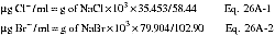

12.3 Average Dry Gas Meter Temperature and Average Orifice Pressure Drop. See data sheet (Figure 5-3 of Method 5).
12.4 Dry Gas Volume. Calculate Vm(std) and adjust for leakage, if necessary, using the equation in section 12.3 of Method 5.
12.5 Volume of Water Vapor and Moisture Content. Calculate the volume of water vapor Vw(std) and moisture content Bws from the data obtained in this method (Figure 5-3 of Method 5); use Equations 5-2 and 5-3 of Method 5.
12.6 Isokinetic Variation and Acceptable Results. Use Method 5, section 12.11.
12.7 Acetone Blank Concentration, Acetone Wash Blank Residue Weight, Particulate Weight, and Particulate Concentration. For particulate determination.
12.8 Total µg HCl, HBr, or HF Per Sample.

12.9 Total µg Cl2 or Br2 Per Sample.

12.10 Concentration of Hydrogen Halide or Halogen in Flue Gas.

12.11 Stack Gas Velocity and Volumetric Flow Rate. Calculate the average stack gas velocity and volumetric flow rate, if needed, using data obtained in this method and the equations in sections 12.3 and 12.4 of Method 2.
13.0 Method Performance
13.1 Precision and Bias. The method has a possible measurable negative bias below 20 ppm HCl perhaps due to reaction with small amounts of moisture in the probe and filter. Similar bias for the other hydrogen halides is possible.
13.2 Sample Stability. The collected Cl-samples can be stored for up to 4 weeks for analysis for HCl and Cl2.
13.3 Detection Limit. A typical analytical detection limit for HCl is 0.2 µg/ml. Detection limits for the other analyses should be similar. Assuming 300 ml of liquid recovered for the acidified impingers and a similar amounts recovered from the basic impingers, and 1 dscm of stack gas sampled, the analytical detection limits in the stack gas would be about 0.04 ppm for HCl and Cl2, respectively.
14.0 Pollution Prevention [Reserved]
15.0 Waste Management [Reserved]
16.0 References
1. Steinsberger, S. C. and J. H. Margeson. Laboratory and Field Evaluation of a Methodology for Determination of Hydrogen Chloride Emissions from Municipal and Hazardous Waste Incinerators. U.S. Environmental Protection Agency, Office of Research and Development. Publication No. 600/3-89/064. April 1989. Available from National Technical Information Service, Springfield, VA 22161 as PB89220586/AS.
2. State of California Air Resources Board. Method 421 - Determination of Hydrochloric Acid Emissions from Stationary Sources. March 18, 1987.
3. Cheney, J.L. and C.R. Fortune. Improvements in the Methodology for Measuring Hydrochloric Acid in Combustion Source Emissions. J. Environ. Sci. Health. A19(3): 337-350. 1984.
4. Stern, D.A., B.M. Myatt, J.F. Lachowski, and K.T. McGregor. Speciation of Halogen and Hydrogen Halide Compounds in Gaseous Emissions. In: Incineration and Treatment of Hazardous Waste: Proceedings of the 9th Annual Research Symposium, Cincinnati, Ohio, May 2-4, 1983. Publication No. 600/9-84-015. July 1984. Available from National Technical Information Service, Springfield, VA 22161 as PB84-234525.
5. Holm, R.D. and S.A. Barksdale. Analysis of Anions in Combustion Products. In: Ion Chromatographic Analysis of Environmental Pollutants, E. Sawicki, J.D. Mulik, and E. Wittgenstein (eds.). Ann Arbor, Michigan, Ann Arbor Science Publishers. 1978. pp. 99-110.
17.0 Tables, Diagrams, Flowcharts, and Validation Data
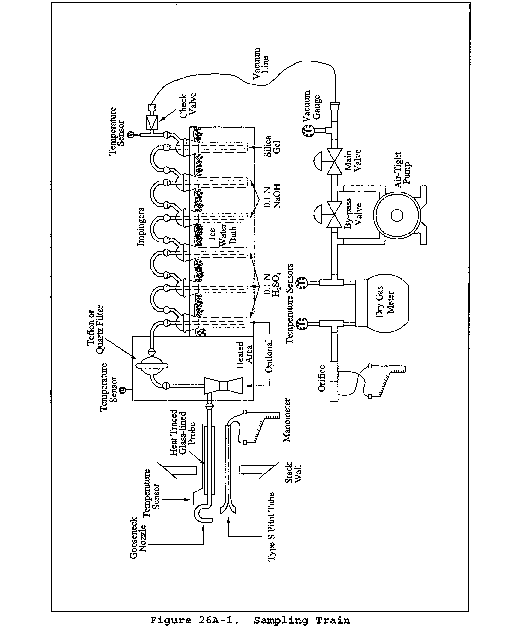
Method 27 - Determination of Vapor Tightness of Gasoline Delivery Tank Using Pressure Vacuum Test
1.0 Scope and Application
1.1 Applicability. This method is applicable for the determination of vapor tightness of a gasoline delivery collection equipment.
2.0 Summary of Method
2.1 Pressure and vacuum are applied alternately to the compartments of a gasoline delivery tank and the change in pressure or vacuum is recorded after a specified period of time.
3.0 Definitions
3.1 Allowable pressure change (Δp) means the allowable amount of decrease in pressure during the static pressure test, within the time period t, as specified in the appropriate regulation, in mm H2O.
3.2 Allowable vacuum change (Δv) means the allowable amount of decrease in vacuum during the static vacuum test, within the time period t, as specified in the appropriate regulation, in mm H2O.
3.3 Compartment means a liquid-tight division of a delivery tank.
3.4 Delivery tank means a container, including associated pipes and fittings, that is attached to or forms a part of any truck, trailer, or railcar used for the transport of gasoline.
3.5 Delivery tank vapor collection equipment means any piping, hoses, and devices on the delivery tank used to collect and route gasoline vapors either from the tank to a bulk terminal vapor control system or from a bulk plant or service station into the tank.
3.6 Gasoline means a petroleum distillate or petroleum distillate/alcohol blend having a Reid vapor pressure of 27.6 kilopascals or greater which is used as a fuel for internal combustion engines.
3.7 Initial pressure (Pi ) means the pressure applied to the delivery tank at the beginning of the static pressure test, as specified in the appropriate regulation, in mm H2O.
3.8 Initial vacuum (Vi ) means the vacuum applied to the delivery tank at the beginning of the static vacuum test, as specified in the appropriate regulation, in mm H3.
3.9 Time period of the pressure or vacuum test (t) means the time period of the test, as specified in the appropriate regulation, during which the change in pressure or vacuum is monitored, in minutes.
4.0 Interferences [Reserved]
5.0 Safety
5.1 Gasoline contains several volatile organic compounds (e.g., benzene and hexane) which presents a potential for fire and/or explosions. It is advisable to take appropriate precautions when testing a gasoline vessel's vapor tightness, such as refraining from smoking and using explosion-proof equipment.
5.2 This method may involve hazardous materials, operations, and equipment. This test method may not address all of the safety problems associated with its use. It is the responsibility of the user of this test method to establish appropriate safety and health practices and determine the applicability of regulatory limitations prior to performing this test method
6.0 Equipment and Supplies
The following equipment and supplies are required for testing:
6.1 Pressure Source. Pump or compressed gas cylinder of air or inert gas sufficient to pressurize the delivery tank to 500 mm (20 in.) H2O above atmospheric pressure.
6.2 Regulator. Low pressure regulator for controlling pressurization of the delivery tank.
6.3 Vacuum Source. Vacuum pump capable of evacuating the delivery tank to 250 mm (10 in.) H2O below atmospheric pressure.
6.4 Pressure-Vacuum Supply Hose.
6.5 Manometer. Liquid manometer, or equivalent instrument, capable of measuring up to 500 mm (20 in.) H2O gauge pressure with ±2.5 mm (0.1 in.) H2O precision.
6.6 Pressure-Vacuum Relief Valves. The test apparatus shall be equipped with an inline pressure-vacuum relief valve set to activate at 675 mm (26.6 in.) H2O above atmospheric pressure or 250 mm (10 in.) H2O below atmospheric pressure, with a capacity equal to the pressurizing or evacuating pumps.
6.7 Test Cap for Vapor Recovery Hose. This cap shall have a tap for manometer connection and a fitting with shut-off valve for connection to the pressure-vacuum supply hose.
6.8 Caps for Liquid Delivery Hoses.
7.0 Reagents and Standards [Reserved]
8.0 Sample Collection, Preservation, Storage, and Transport
8.1 Pretest Preparations.
8.1.1 Summary. Testing problems may occur due to the presence of volatile vapors and/or temperature fluctuations inside the delivery tank. Under these conditions, it is often difficult to obtain a stable initial pressure at the beginning of a test, and erroneous test results may occur. To help prevent this, it is recommended that prior to testing, volatile vapors be removed from the tank and the temperature inside the tank be allowed to stabilize. Because it is not always possible to completely attain these pretest conditions, a provision to ensure reproducible results is included. The difference in results for two consecutive runs must meet the criteria in sections 8.2.2.5 and 8.2.3.5.
8.1.2 Emptying of Tank. The delivery tank shall be emptied of all liquid.
8.1.3 Purging of Vapor. As much as possible the delivery tank shall be purged of all volatile vapors by any safe, acceptable method. One method is to carry a load of non-volatile liquid fuel, such as diesel or heating oil, immediately prior to the test, thus flushing out all the volatile gasoline vapors. A second method is to remove the volatile vapors by blowing ambient air into each tank compartment for at least 20 minutes. This second method is usually not as effective and often causes stabilization problems, requiring a much longer time for stabilization during the testing.
8.1.4 Temperature Stabilization. As much as possible, the test shall be conducted under isothermal conditions. The temperature of the delivery tank should be allowed to equilibrate in the test environment. During the test, the tank should be protected from extreme environmental and temperature variability, such as direct sunlight.
8.2 Test Procedure.
8.2.1 Preparations.
8.2.1.1 Open and close each dome cover.
8.2.1.2 Connect static electrical ground connections to the tank. Attach the liquid delivery and vapor return hoses, remove the liquid delivery elbows, and plug the liquid delivery fittings.
The purpose of testing the liquid delivery hoses is to detect tears or holes that would allow liquid leakage during a delivery. Liquid delivery hoses are not considered to be possible sources of vapor leakage, and thus, do not have to be attached for a vapor leakage test. Instead, a liquid delivery hose could be either visually inspected, or filled with water to detect any liquid leakage.
8.2.1.3 Attach the test cap to the end of the vapor recovery hose.
8.2.1.4 Connect the pressure-vacuum supply hose and the pressure-vacuum relief valve to the shut-off valve. Attach a manometer to the pressure tap.
8.2.1.5 Connect compartments of the tank internally to each other if possible. If not possible, each compartment must be tested separately, as if it were an individual delivery tank.
8.2.2 Pressure Test.
8.2.2.1 Connect the pressure source to the pressure-vacuum supply hose.
8.2.2.2 Open the shut-off valve in the vapor recovery hose cap. Apply air pressure slowly, pressurize the tank to Pi, the initial pressure specified in the regulation.
8.2.2.3 Close the shut-off and allow the pressure in the tank to stabilize, adjusting the pressure if necessary to maintain pressure of Pi. When the pressure stabilizes, record the time and initial pressure.
8.2.2.4 At the end of the time period (t) specified in the regulation, record the time and final pressure.
8.2.2.5 Repeat steps 8.2.2.2 through 8.2.2.4 until the change in pressure for two consecutive runs agrees within 12.5 mm (0.5 in.) H2O. Calculate the arithmetic average of the two results.
8.2.2.6 Compare the average measured change in pressure to the allowable pressure change, Δp, specified in the regulation. If the delivery tank does not satisfy the vapor tightness criterion specified in the regulation, repair the sources of leakage, and repeat the pressure test until the criterion is met.
8.2.2.7 Disconnect the pressure source from the pressure-vacuum supply hose, and slowly open the shut-off valve to bring the tank to atmospheric pressure.
8.2.3 Vacuum Test.
8.2.3.1 Connect the vacuum source to the pressure-vacuum supply hose.
8.2.3.2 Open the shut-off valve in the vapor recovery hose cap. Slowly evacuate the tank to Vi, the initial vacuum specified in the regulation.
8.2.3.3 Close the shut-off valve and allow the pressure in the tank to stabilize, adjusting the pressure if necessary to maintain a vacuum of Vi. When the pressure stabilizes, record the time and initial vacuum.
8.2.3.4 At the end of the time period specified in the regulation (t), record the time and final vacuum.
8.2.3.5 Repeat steps 8.2.3.2 through 8.2.3.4 until the change in vacuum for two consecutive runs agrees within 12.5 mm (0.5 in.) H2O. Calculate the arithmetic average of the two results.
8.2.3.6 Compare the average measured change in vacuum to the allowable vacuum change, Δv, as specified in the regulation. If the delivery tank does not satisfy the vapor tightness criterion specified in the regulation, repair the sources of leakage, and repeat the vacuum test until the criterion is met.
8.2.3.7 Disconnect the vacuum source from the pressure-vacuum supply hose, and slowly open the shut-off valve to bring the tank to atmospheric pressure.
8.2.4 Post-Test Clean-up. Disconnect all test equipment and return the delivery tank to its pretest condition.
9.0 Quality Control
| Section(s) | Quality control measure | Effect |
|---|---|---|
| 8.2.2.5, 8.3.3.5 | Repeat test procedures until change in pressure or vacuum for two consecutive runs agrees within ±12.5 mm (0.5 in.) H2O | Ensures data precision. |
10.0 Calibration and Standardization [Reserved]
11.0 Analytical Procedures [Reserved]
12.0 Data Analysis and Calculations [Reserved]
13.0 Method Performance
13.1 Precision. The vapor tightness of a gasoline delivery tank under positive or negative pressure, as measured by this method, is precise within 12.5 mm (0.5 in.) H2O
13.2 Bias. No bias has been identified.
14.0 Pollution Prevention [Reserved]
15.0 Waste Management [Reserved]
16.0 Alternative Procedures
16.1 The pumping of water into the bottom of a delivery tank is an acceptable alternative to the pressure source described above. Likewise, the draining of water out of the bottom of a delivery tank may be substituted for the vacuum source. Note that some of the specific step-by-step procedures in the method must be altered slightly to accommodate these different pressure and vacuum sources.
16.2 Techniques other than specified above may be used for purging and pressurizing a delivery tank, if prior approval is obtained from the Administrator. Such approval will be based upon demonstrated equivalency with the above method.
17.0 References [Reserved]
18.0 Tables, Diagrams, Flowcharts, and Validation Data [Reserved]
Method 28 - Certification and Auditing of Wood Heaters
This method does not include all of the specifications (e.g., equipment and supplies) and procedures (e.g., sampling and analytical) essential to its performance. Some material is incorporated by reference from other methods in this part. Therefore, to obtain reliable results, persons using this method should have a thorough knowledge of at least the following additional test methods: Method 1, Method 2, Method 3, Method 4, Method 5, Method 5G, Method 5H, Method 6, Method 6C, and Method 16A.
1.0 Scope and Application
1.1 Analyte. Particulate matter (PM). No CAS number assigned.
1.2 Applicability. This method is applicable for the certification and auditing of wood heaters, including pellet burning wood heaters.
1.3 Data Quality Objectives. Adherence to the requirements of this method will enhance the quality of the data obtained from air pollutant sampling methods.
2.0 Summary of Method
2.1 Particulate matter emissions are measured from a wood heater burning a prepared test fuel crib in a test facility maintained at a set of prescribed conditions. Procedures for determining burn rates and particulate emission rates and for reducing data are provided.
3.0 Definitions
3.1 2 × 4 or 4 × 4 means two inches by four inches or four inches by four inches (50 mm by 100 mm or 100 mm by 100 mm), as nominal dimensions for lumber.
3.2 Burn rate means the rate at which test fuel is consumed in a wood heater. Measured in kilograms or lbs of wood (dry basis) per hour (kg/hr or lb/hr).
3.3 Certification or audit test means a series of at least four test runs conducted for certification or audit purposes that meets the burn rate specifications in section 8.4.
3.4 Firebox means the chamber in the wood heater in which the test fuel charge is placed and combusted.
3.5 Height means the vertical distance extending above the loading door, if fuel could reasonably occupy that space, but not more than 2 inches above the top (peak height) of the loading door, to the floor of the firebox (i.e., below a permanent grate) if the grate allows a 1-inch diameter piece of wood to pass through the grate, or, if not, to the top of the grate. Firebox height is not necessarily uniform but must account for variations caused by internal baffles, air channels, or other permanent obstructions.
3.6 Length means the longest horizontal fire chamber dimension that is parallel to a wall of the chamber.
3.7 Pellet burning wood heater means a wood heater which meets the following criteria:
(1) The manufacturer makes no reference to burning cord wood in advertising or other literature,
(2) the unit is safety listed for pellet fuel only,
(3) the unit operating and instruction manual must state that the use of cordwood is prohibited by law, and
(4) the unit must be manufactured and sold including the hopper and auger combination as integral parts.
3.8 Secondary air supply means an air supply that introduces air to the wood heater such that the burn rate is not altered by more than 25 percent when the secondary air supply is adjusted during the test run. The wood heater manufacturer can document this through design drawings that show the secondary air is introduced only into a mixing chamber or secondary chamber outside the firebox.
3.9 Test facility means the area in which the wood heater is installed, operated, and sampled for emissions.
3.10 Test fuel charge means the collection of test fuel pieces placed in the wood heater at the start of the emission test run.
3.11 Test fuel crib means the arrangement of the test fuel charge with the proper spacing requirements between adjacent fuel pieces.
3.12 Test fuel loading density means the weight of the as-fired test fuel charge per unit volume of usable firebox.
3.13 Test fuel piece means the 2 × 4 or 4 × 4 wood piece cut to the length required for the test fuel charge and used to construct the test fuel crib.
3.14 Test run means an individual emission test which encompasses the time required to consume the mass of the test fuel charge.
3.15 Usable firebox volume means the volume of the firebox determined using its height, length, and width as defined in this section.
3.16 Width means the shortest horizontal fire chamber dimension that is parallel to a wall of the chamber.
3.17 Wood heater means an enclosed, woodburning appliance capable of and intended for space heating or domestic water heating, as defined in the applicable regulation.
4.0 Interferences [Reserved]
5.0 Safety
5.1 Disclaimer. This method may involve hazardous materials, operations, and equipment. This test method may not address all of the safety problems associated with its use. It is the responsibility of the user of this test method to establish appropriate safety and health practices and to determine the applicability of regulatory limitations prior to performing this test method.
6.0 Equipment and Supplies
Same as section 6.0 of either Method 5G or Method 5H, with the addition of the following:
6.1 Insulated Solid Pack Chimney. For installation of wood heaters. Solid pack insulated chimneys shall have a minimum of 2.5 cm (1 in.) solid pack insulating material surrounding the entire flue and possess a label demonstrating conformance to U.L. 103 (incorporated by reference - see § 60.17).
6.2 Platform Scale and Monitor. For monitoring of fuel load weight change. The scale shall be capable of measuring weight to within 0.05 kg (0.1 lb) or 1 percent of the initial test fuel charge weight, whichever is greater.
6.3 Wood Heater Temperature Monitors. Seven, each capable of measuring temperature to within 1.5 percent of expected absolute temperatures.
6.4 Test Facility Temperature Monitor. A thermocouple located centrally in a vertically oriented 150 mm (6 in.) long, 50 mm (2 in.) diameter pipe shield that is open at both ends, capable of measuring temperature to within 1.5 percent of expected temperatures.
6.5 Balance (optional). Balance capable of weighing the test fuel charge to within 0.05 kg (0.1 lb).
6.6 Moisture Meter. Calibrated electrical resistance meter for measuring test fuel moisture to within 1 percent moisture content.
6.7 Anemometer. Device capable of detecting air velocities less than 0.10 m/sec (20 ft/min), for measuring air velocities near the test appliance.
6.8 Barometer. Mercury, aneroid or other barometer capable of measuring atmospheric pressure to within 2.5 mm Hg (0.1 in. Hg).
6.9 Draft Gauge. Electromanometer or other device for the determination of flue draft or static pressure readable to within 0.50 Pa (0.002 in. H2O).
6.10 Humidity Gauge. Psychrometer or hygrometer for measuring room humidity.
6.11 Wood Heater Flue.
6.11.1 Steel flue pipe extending to 2.6 ±0.15 m (8.5 ±0.5 ft) above the top of the platform scale, and above this level, insulated solid pack type chimney extending to 4.6 ±0.3 m (15 ±1 ft) above the platform scale, and of the size specified by the wood heater manufacturer. This applies to both freestanding and insert type wood heaters.
6.11.2 Other chimney types (e.g., solid pack insulated pipe) may be used in place of the steel flue pipe if the wood heater manufacturer's written appliance specifications require such chimney for home installation (e.g., zero clearance wood heater inserts). Such alternative chimney or flue pipe must remain and be sealed with the wood heater following the certification test.
6.12 Test Facility. The test facility shall meet the following requirements during testing:
6.12.1 The test facility temperature shall be maintained between 18 and 32 °C (65 and 90 °F) during each test run.
6.12.2 Air velocities within 0.6 m (2 ft) of the test appliance and exhaust system shall be less than 0.25 m/sec (50 ft/min) without fire in the unit.
6.12.3 The flue shall discharge into the same space or into a space freely communicating with the test facility. Any hood or similar device used to vent combustion products shall not induce a draft greater than 1.25 Pa (0.005 in. H2O) on the wood heater measured when the wood heater is not operating.
6.12.4 For test facilities with artificially induced barometric pressures (e.g., pressurized chambers), the barometric pressure in the test facility shall not exceed 775 mm Hg (30.5 in. Hg) during any test run.
7.0 Reagents and Standards
Same as section 6.0 of either Method 5G or Method 5H, with the addition of the following:
7.1 Test Fuel. The test fuel shall conform to the following requirements:
7.1.1 Fuel Species. Untreated, air-dried, Douglas fir lumber. Kiln-dried lumber is not permitted. The lumber shall be certified C grade (standard) or better Douglas fir by a lumber grader at the mill of origin as specified in the West Coast Lumber Inspection Bureau Standard No. 16 (incorporated by reference - see § 60.17).
7.1.2 Fuel Moisture. The test fuel shall have a moisture content range between 16 to 20 percent on a wet basis (19 to 25 percent dry basis). Addition of moisture to previously dried wood is not allowed. It is recommended that the test fuel be stored in a temperature and humidity-controlled room.
7.1.3 Fuel Temperature. The test fuel shall be at the test facility temperature of 18 to 32 °C (65 to 90 °F).
7.1.4 Fuel Dimensions. The dimensions of each test fuel piece shall conform to the nominal measurements of 2 × 4 and 4 × 4 lumber. Each piece of test fuel (not including spacers) shall be of equal length, except as necessary to meet requirements in section 8.8, and shall closely approximate 5⁄6 the dimensions of the length of the usable firebox. The fuel piece dimensions shall be determined in relation to the appliance's firebox volume according to guidelines listed below:
7.1.4.1 If the usable firebox volume is less than or equal to 0.043 m3 (1.5 ft3), use 2 × 4 lumber.
7.1.4.2 If the usable firebox volume is greater than 0.043 m3 (1.5 ft3) and less than or equal to 0.085 m3 (3.0 ft3), use 2 × 4 and 4 × 4 lumber. About half the weight of the test fuel charge shall be 2 × 4 lumber, and the remainder shall be 4 × 4 lumber.
7.1.4.3 If the usable firebox volume is greater than 0.085 m3 (3.0 ft3), use 4 × 4 lumber.
7.2 Test Fuel Spacers. Air-dried, Douglas fir lumber meeting the requirements outlined in sections 7.1.1 through 7.1.3. The spacers shall be 130 × 40 × 20 mm (5 × 1.5 × 0.75 in.).
8.0 Sample Collection, Preservation, Storage, and Transport
8.1 Test Run Requirements.
8.1.1 Burn Rate Categories. One emission test run is required in each of the following burn rate categories:
Burn Rate Categories
[Average kg/hr (lb/hr), dry basis]
| Category 1 | Category 2 | Category 3 | Category 4 |
|---|---|---|---|
| <0.80 | 0.80 to 1.25 | 1.25 to 1.90 | Maximum. |
| (<1.76) | (1.76 to 2.76) | (2.76 to 4.19) | burn rate. |
8.1.1.1 Maximum Burn Rate. For Category 4, the wood heater shall be operated with the primary air supply inlet controls fully open (or, if thermostatically controlled, the thermostat shall be set at maximum heat output) during the entire test run, or the maximum burn rate setting specified by the manufacturer's written instructions.
8.1.1.2 Other Burn Rate Categories. For burn rates in Categories 1 through 3, the wood heater shall be operated with the primary air supply inlet control, or other mechanical control device, set at a predetermined position necessary to obtain the average burn rate required for the category.
8.1.1.3 Alternative Burn Rates for Burn Rate Categories 1 and 2.
8.1.1.3.1 If a wood heater cannot be operated at a burn rate below 0.80 kg/hr (1.76 lb/hr), two test runs shall be conducted with burn rates within Category 2. If a wood heater cannot be operated at a burn rate below 1.25 kg/hr (2.76 lb/hr), the flue shall be dampered or the air supply otherwise controlled in order to achieve two test runs within Category 2.
8.1.1.3.2 Evidence that a wood heater cannot be operated at a burn rate less than 0.80 kg/hr shall include documentation of two or more attempts to operate the wood heater in burn rate Category 1 and fuel combustion has stopped, or results of two or more test runs demonstrating that the burn rates were greater than 0.80 kg/hr when the air supply controls were adjusted to the lowest possible position or settings. Stopped fuel combustion is evidenced when an elapsed time of 30 minutes or more has occurred without a measurable (<0.05 kg (0.1 lb) or 1.0 percent, whichever is greater) weight change in the test fuel charge. See also section 8.8.3. Report the evidence and the reasoning used to determine that a test in burn rate Category 1 cannot be achieved; for example, two unsuccessful attempts to operate at a burn rate of 0.4 kg/hr are not sufficient evidence that burn rate Category 1 cannot be achieved.
After July 1, 1990, if a wood heater cannot be operated at a burn rate less than 0.80 kg/hr, at least one test run with an average burn rate of 1.00 kg/hr or less shall be conducted. Additionally, if flue dampering must be used to achieve burn rates below 1.25 kg/hr (or 1.0 kg/hr), results from a test run conducted at burn rates below 0.90 kg/hr need not be reported or included in the test run average provided that such results are replaced with results from a test run meeting the criteria above.
8.2 Catalytic Combustor and Wood Heater Aging. The catalyst-equipped wood heater or a wood heater of any type shall be aged before the certification test begins. The aging procedure shall be conducted and documented by a testing laboratory accredited according to procedures in § 60.535 of 40 CFR part 60.
8.2.1 Catalyst-equipped Wood Heater. Operate the catalyst-equipped wood heater using fuel meeting the specifications outlined in sections 7.1.1 through 7.1.3, or cordwood with a moisture content between 15 and 25 percent on a wet basis. Operate the wood heater at a medium burn rate (Category 2 or 3) with a new catalytic combustor in place and in operation for at least 50 hours. Record and report hourly catalyst exit temperature data (Section 8.6.2) and the hours of operation.
8.2.2 Non-Catalyst Wood Heater. Operate the wood heater using the fuel described in section 8.4.1 at a medium burn rate for at least 10 hours. Record and report the hours of operation.
8.3 Pretest Recordkeeping. Record the test fuel charge dimensions and weights, and wood heater and catalyst descriptions as shown in the example in Figure 28-1.
8.4 Wood Heater Installation. Assemble the wood heater appliance and parts in conformance with the manufacturer's written installation instructions. Place the wood heater centrally on the platform scale and connect the wood heater to the flue described in section 6.11. Clean the flue with an appropriately sized, wire chimney brush before each certification test.
8.5 Wood Heater Temperature Monitors.
8.5.1 For catalyst-equipped wood heaters, locate a temperature monitor (optional) about 25 mm (1 in.) upstream of the catalyst at the centroid of the catalyst face area, and locate a temperature monitor (mandatory) that will indicate the catalyst exhaust temperature. This temperature monitor is centrally located within 25 mm (1 in.) downstream at the centroid of catalyst face area. Record these locations.
8.5.2 Locate wood heater surface temperature monitors at five locations on the wood heater firebox exterior surface. Position the temperature monitors centrally on the top surface, on two sidewall surfaces, and on the bottom and back surfaces. Position the monitor sensing tip on the firebox exterior surface inside of any heat shield, air circulation walls, or other wall or shield separated from the firebox exterior surface. Surface temperature locations for unusual design shapes (e.g., spherical, etc.) shall be positioned so that there are four surface temperature monitors in both the vertical and horizontal planes passing at right angles through the centroid of the firebox, not including the fuel loading door (total of five temperature monitors).
8.6 Test Facility Conditions.
8.6.1 Locate the test facility temperature monitor on the horizontal plane that includes the primary air intake opening for the wood heater. Locate the temperature monitor 1 to 2 m (3 to 6 ft) from the front of the wood heater in the 90° sector in front of the wood heater.
8.6.2 Use an anemometer to measure the air velocity. Measure and record the room air velocity before the pretest ignition period (Section 8.7) and once immediately following the test run completion.
8.6.3 Measure and record the test facility's ambient relative humidity, barometric pressure, and temperature before and after each test run.
8.6.4 Measure and record the flue draft or static pressure in the flue at a location no greater than 0.3 m (1 ft) above the flue connector at the wood heater exhaust during the test run at the recording intervals (Section 8.8.2).
8.7 Wood Heater Firebox Volume.
8.7.1 Determine the firebox volume using the definitions for height, width, and length in section 3. Volume adjustments due to presence of firebrick and other permanent fixtures may be necessary. Adjust width and length dimensions to extend to the metal wall of the wood heater above the firebrick or permanent obstruction if the firebrick or obstruction extending the length of the side(s) or back wall extends less than one-third of the usable firebox height. Use the width or length dimensions inside the firebrick if the firebrick extends more than one-third of the usable firebox height. If a log retainer or grate is a permanent fixture and the manufacturer recommends that no fuel be placed outside the retainer, the area outside of the retainer is excluded from the firebox volume calculations.
8.7.2 In general, exclude the area above the ash lip if that area is less than 10 percent of the usable firebox volume. Otherwise, take into account consumer loading practices. For instance, if fuel is to be loaded front-to-back, an ash lip may be considered usable firebox volume.
8.7.3 Include areas adjacent to and above a baffle (up to two inches above the fuel loading opening) if four inches or more horizontal space exist between the edge of the baffle and a vertical obstruction (e.g., sidewalls or air channels).
8.8 Test Fuel Charge.
8.8.1 Prepare the test fuel pieces in accordance with the specifications outlined in sections 7.1 and 7.2. Determine the test fuel moisture content with a calibrated electrical resistance meter or other equivalent performance meter. If necessary, convert fuel moisture content values from dry basis (%Md) to wet basis (%Mw) in section 12.2 using Equation 28-1. Determine fuel moisture for each fuel piece (not including spacers) by averaging at least three moisture meter readings, one from each of three sides, measured parallel to the wood grain. Average all the readings for all the fuel pieces in the test fuel charge. If an electrical resistance type meter is used, penetration of insulated electrodes shall be one-fourth the thickness of the test fuel piece or 19 mm (0.75 in.), whichever is greater. Measure the moisture content within a 4-hour period prior to the test run. Determine the fuel temperature by measuring the temperature of the room where the wood has been stored for at least 24 hours prior to the moisture determination.
8.8.2 Attach the spacers to the test fuel pieces with uncoated, ungalvanized nails or staples as illustrated in Figure 28-2. Attachment of spacers to the top of the test fuel piece(s) on top of the test fuel charge is optional.
8.8.3 To avoid stacking difficulties, or when a whole number of test fuel pieces does not result, all piece lengths shall be adjusted uniformly to remain within the specified loading density. The shape of the test fuel crib shall be geometrically similar to the shape of the firebox volume without resorting to special angular or round cuts on the individual fuel pieces.
8.8.4 The test fuel loading density shall be 112 ±11.2 kg/m3 (7 ±0.7 lb/ft3) of usable firebox volume on a wet basis.
8.9 Sampling Equipment. Prepare the sampling equipment as defined by the selected method (i.e., either Method 5G or Method 5H). Collect one particulate emission sample for each test run.
8.10 Secondary Air Adjustment Validation.
8.10.1 If design drawings do not show the introduction of secondary air into a chamber outside the firebox (see “secondary air supply” under section 3.0, Definitions), conduct a separate test of the wood heater's secondary air supply. Operate the wood heater at a burn rate in Category 1 (Section 8.1.1) with the secondary air supply operated following the manufacturer's written instructions. Start the secondary air validation test run as described in section 8.8.1, except no emission sampling is necessary and burn rate data shall be recorded at 5-minute intervals.
8.10.2 After the start of the test run, operate the wood heater with the secondary air supply set as per the manufacturer's instructions, but with no adjustments to this setting. After 25 percent of the test fuel has been consumed, adjust the secondary air supply controls to another setting, as per the manufacturer's instructions. Record the burn rate data (5-minute intervals) for 20 minutes following the air supply adjustment.
8.10.3 Adjust the air supply control(s) to the original position(s), operate at this condition for at least 20 minutes, and repeat the air supply adjustment procedure above. Repeat the procedure three times at equal intervals over the entire burn period as defined in section 8.8. If the secondary air adjustment results in a burn rate change of more than an average of 25 percent between the 20-minute periods before and after the secondary adjustments, the secondary air supply shall be considered a primary air supply, and no adjustment to this air supply is allowed during the test run.
8.10.4 The example sequence below describes a typical secondary air adjustment validation check. The first cycle begins after at least 25 percent of the test fuel charge has been consumed.
Cycle 1
Part 1, sec air adjusted to final position - 20 min
Part 2, sec air adjusted to final position - 20 min
Part 3, sec air adjusted to final position - 20 min
Cycle 2
Part 1, sec air adjusted to final position - 20 min
Part 2, sec air adjusted to final position - 20 min
Part 3, sec air adjusted to final position - 20 min
Cycle 3
Part 1, sec air adjusted to final position - 20 min
Part 2, sec air adjusted to final position - 20 min
Part 3, sec air adjusted to final position - 20 min
Note that the cycles may overlap; that is, Part 3 of Cycle 1 may coincide in part or in total with Part 1 of Cycle 2. The calculation of the secondary air percent effect for this example is as follows:

8.11 Pretest Ignition. Build a fire in the wood heater in accordance with the manufacturer's written instructions.
8.11.1 Pretest Fuel Charge. Crumpled newspaper loaded with kindling may be used to help ignite the pretest fuel. The pretest fuel, used to sustain the fire, shall meet the same fuel requirements prescribed in section 7.1. The pretest fuel charge shall consist of whole 2 × 4's that are no less than 1⁄3 the length of the test fuel pieces. Pieces of 4 × 4 lumber in approximately the same weight ratio as for the test fuel charge may be added to the pretest fuel charge.
8.11.2 Wood Heater Operation and Adjustments. Set the air inlet supply controls at any position that will maintain combustion of the pretest fuel load. At least one hour before the start of the test run, set the air supply controls at the approximate positions necessary to achieve the burn rate desired for the test run. Adjustment of the air supply controls, fuel addition or subtractions, and coalbed raking shall be kept to a minimum but are allowed up to 15 minutes prior to the start of the test run. For the purposes of this method, coalbed raking is the use of a metal tool (poker) to stir coals, break burning fuel into smaller pieces, dislodge fuel pieces from positions of poor combustion, and check for the condition of uniform charcoalization. Record all adjustments made to the air supply controls, adjustments to and additions or subtractions of fuel, and any other changes to wood heater operations that occur during pretest ignition period. Record fuel weight data and wood heater temperature measurements at 10-minute intervals during the hour of the pretest ignition period preceding the start of the test run. During the 15-minute period prior to the start of the test run, the wood heater loading door shall not be open more than a total of 1 minute. Coalbed raking is the only adjustment allowed during this period.
One purpose of the pretest ignition period is to achieve uniform charcoalization of the test fuel bed prior to loading the test fuel charge. Uniform charcoalization is a general condition of the test fuel bed evidenced by an absence of large pieces of burning wood in the coal bed and the remaining fuel pieces being brittle enough to be broken into smaller charcoal pieces with a metal poker. Manipulations to the fuel bed prior to the start of the test run should be done to achieve uniform charcoalization while maintaining the desired burn rate. In addition, some wood heaters (e.g., high mass units) may require extended pretest burn time and fuel additions to reach an initial average surface temperature sufficient to meet the thermal equilibrium criteria in section 8.3.
8.11.3 The weight of pretest fuel remaining at the start of the test run is determined as the difference between the weight of the wood heater with the remaining pretest fuel and the tare weight of the cleaned, dry wood heater with or without dry ash or sand added consistent with the manufacturer's instructions and the owner's manual. The tare weight of the wood heater must be determined with the wood heater (and ash, if added) in a dry condition.
8.12 Test Run. Complete a test run in each burn rate category, as follows:
8.12.1 Test Run Start.
8.12.1.1 When the kindling and pretest fuel have been consumed to leave a fuel weight between 20 and 25 percent of the weight of the test fuel charge, record the weight of the fuel remaining and start the test run. Record and report any other criteria, in addition to those specified in this section, used to determine the moment of the test run start (e.g., firebox or catalyst temperature), whether such criteria are specified by the wood heater manufacturer or the testing laboratory. Record all wood heater individual surface temperatures, catalyst temperatures, any initial sampling method measurement values, and begin the particulate emission sampling. Within 1 minute following the start of the test run, open the wood heater door, load the test fuel charge, and record the test fuel charge weight. Recording of average, rather than individual, surface temperatures is acceptable for tests conducted in accordance with § 60.533(o)(3)(i) of 40 CFR part 60.
8.12.1.2 Position the fuel charge so that the spacers are parallel to the floor of the firebox, with the spacer edges abutting each other. If loading difficulties result, some fuel pieces may be placed on edge. If the usable firebox volume is between 0.043 and 0.085 m3 (1.5 and 3.0 ft3), alternate the piece sizes in vertical stacking layers to the extent possible. For example, place 2 × 4's on the bottom layer in direct contact with the coal bed and 4 × 4's on the next layer, etc. (See Figure 28-3). Position the fuel pieces parallel to each other and parallel to the longest wall of the firebox to the extent possible within the specifications in section 8.8.
8.12.1.3 Load the test fuel in appliances having unusual or unconventional firebox design maintaining air space intervals between the test fuel pieces and in conformance with the manufacturer's written instructions. For any appliance that will not accommodate the loading arrangement specified in the paragraph above, the test facility personnel shall contact the Administrator for an alternative loading arrangement.
8.12.1.4 The wood heater door may remain open and the air supply controls adjusted up to five minutes after the start of the test run in order to make adjustments to the test fuel charge and to ensure ignition of the test fuel charge has occurred. Within the five minutes after the start of the test run, close the wood heater door and adjust the air supply controls to the position determined to produce the desired burn rate. No other adjustments to the air supply controls or the test fuel charge are allowed (except as specified in sections 8.12.3 and 8.12.4) after the first five minutes of the test run. Record the length of time the wood heater door remains open, the adjustments to the air supply controls, and any other operational adjustments.
8.12.2 Data Recording. Record on a data sheet similar to that shown in Figure 28-4, at intervals no greater than 10 minutes, fuel weight data, wood heater individual surface and catalyst temperature measurements, other wood heater operational data (e.g., draft), test facility temperature and sampling method data.
8.12.3 Test Fuel Charge Adjustment. The test fuel charge may be adjusted (i.e., repositioned) once during a test run if more than 60 percent of the initial test fuel charge weight has been consumed and more than 10 minutes have elapsed without a measurable (<0.05 kg (0.1 lb) or 1.0 percent, whichever is greater) weight change. The time used to make this adjustment shall be less than 15 seconds.
8.12.4 Air Supply Adjustment. Secondary air supply controls may be adjusted once during the test run following the manufacturer's written instructions (see section 8.10). No other air supply adjustments are allowed during the test run. Recording of wood heater flue draft during the test run is optional for tests conducted in accordance with § 60.533(o)(3)(i) of 40 CFR part 60.
8.12.5 Auxiliary Wood Heater Equipment Operation. Heat exchange blowers sold with the wood heater shall be operated during the test run following the manufacturer's written instructions. If no manufacturer's written instructions are available, operate the heat exchange blower in the “high” position. (Automatically operated blowers shall be operated as designed.) Shaker grates, by-pass controls, or other auxiliary equipment may be adjusted only one time during the test run following the manufacturer's written instructions.
Record all adjustments on a wood heater operational written record.
If the wood heater is sold with a heat exchange blower as an option, test the wood heater with the heat exchange blower operating as described in sections 8.1 through 8.12 and report the results. As an alternative to repeating all test runs without the heat exchange blower operating, one additional test run may be without the blower operating as described in section 8.12.5 at a burn rate in Category 2 (Section 8.1.1). If the emission rate resulting from this test run without the blower operating is equal to or less than the emission rate plus 1.0 g/hr (0.0022 lb/hr) for the test run in burn rate Category 2 with the blower operating, the wood heater may be considered to have the same average emission rate with or without the blower operating. Additional test runs without the blower operating are unnecessary.
8.13 Test Run Completion. Continue emission sampling and wood heater operation for 2 hours. The test run is completed when the remaining weight of the test fuel charge is 0.00 kg (0.0 lb). End the test run when the scale has indicated a test fuel charge weight of 0.00 kg (0.0 lb) or less for 30 seconds. At the end of the test run, stop the particulate sampling, and record the final fuel weight, the run time, and all final measurement values.
8.14 Wood Heater Thermal Equilibrium. The average of the wood heater surface temperatures at the end of the test run shall agree with the average surface temperature at the start of the test run to within 70 °C (126 °F).
8.15 Consecutive Test Runs. Test runs on a wood heater may be conducted consecutively provided that a minimum one-hour interval occurs between test runs.
8.16 Additional Test Runs. The testing laboratory may conduct more than one test run in each of the burn rate categories specified in section 8.1.1. If more than one test run is conducted at a specified burn rate, the results from at least two-thirds of the test runs in that burn rate category shall be used in calculating the weighted average emission rate (see section 12.2). The measurement data and results of all test runs shall be reported regardless of which values are used in calculating the weighted average emission rate (see note in section 8.1).
9.0 Quality Control
Same as section 9.0 of either Method 5G or Method 5H.
10.0 Calibration and Standardizations
Same as section 10.0 of either Method 5G or Method 5H, with the addition of the following:
10.1 Platform Scale. Perform a multi-point calibration (at least five points spanning the operational range) of the platform scale before its initial use. The scale manufacturer's calibration results are sufficient for this purpose. Before each certification test, audit the scale with the wood heater in place by weighing at least one calibration weight (Class F) that corresponds to between 20 percent and 80 percent of the expected test fuel charge weight. If the scale cannot reproduce the value of the calibration weight within 0.05 kg (0.1 lb) or 1 percent of the expected test fuel charge weight, whichever is greater, recalibrate the scale before use with at least five calibration weights spanning the operational range of the scale.
10.2 Balance (optional). Calibrate as described in section 10.1.
10.3 Temperature Monitor. Calibrate as in Method 2, section 4.3, before the first certification test and semiannually thereafter.
10.4 Moisture Meter. Calibrate as per the manufacturer's instructions before each certification test.
10.5 Anemometer. Calibrate the anemometer as specified by the manufacturer's instructions before the first certification test and semiannually thereafter.
10.6 Barometer. Calibrate against a mercury barometer before the first certification test and semiannually thereafter.
10.7 Draft Gauge. Calibrate as per the manufacturer's instructions; a liquid manometer does not require calibration.
10.8 Humidity Gauge. Calibrate as per the manufacturer's instructions before the first certification test and semiannually thereafter.
11.0 Analytical Procedures
Same as section 11.0 of either Method 5G or Method 5H.
12.0 Data Analysis and Calculations
Same as section 12.0 of either Method 5G or Method 5H, with the addition of the following:
12.1 Nomenclature.
BR = Dry wood burn rate, kg/hr (lb/hr)
Ei = Emission rate for test run, i, from Method 5G or 5H, g/hr (lb/hr)
Ew = Weighted average emission rate, g/hr (lb/hr)
ki = Test run weighting factor = Pi + 1 − Pi−1
%Md = Fuel moisture content, dry basis, percent.
%Mw = Average moisture in test fuel charge, wet basis, percent.
n = Total number of test runs.
Pi = Probability for burn rate during test run, i, obtained from Table 28-1. Use linear interpolation to determine probability values for burn rates between those listed on the table.
Wwd = Total mass of wood burned during the test run, kg (lb).
12.2 Wet Basis Fuel Moisture Content.

12.3 Weighted Average Emission Rate. Calculate the weighted average emission rate (Ew) using Equation 28-1:

Po always equals 0, P(n + 1) always equals 1, P1 corresponds to the probability of the lowest recorded burn rate, P2 corresponds to the probability of the next lowest burn rate, etc. An example calculation is in section 12.3.1.
12.3.1 Example Calculation of Weighted Average Emission Rate.
| Burn rate category | Test
No. |
Burn rate
(Dry-kg/hr) |
Emissions
(g/hr) |
|---|---|---|---|
| 1 | 1 | 0.65 | 5.0 |
| 21 | 2 | 0.85 | 6.7 |
| 2 | 3 | 0.90 | 4.7 |
| 2 | 4 | 1.00 | 5.3 |
| 3 | 5 | 1.45 | 3.8 |
| 4 | 6 | 2.00 | 5.1 |
| Test No. | Burn rate | Pi | Ei | Ki |
|---|---|---|---|---|
| 0 | 0.000 | |||
| 1 | 0.65 | 0.121 | 5.0 | 0.300 |
| 2 | 0.90 | 0.300 | 4.7 | 0.259 |
| 3 | 1.00 | 0.380 | 5.3 | 0.422 |
| 4 | 1.45 | 0.722 | 3.8 | 0.532 |
| 5 | 2.00 | 0.912 | 5.1 | 0.278 |
| 6 | 1.000 |
Weighted Average Emission Rate, Ew, Calculation

12.4 Average Wood Heater Surface Temperatures. Calculate the average of the wood heater surface temperatures for the start of the test run (Section 8.12.1) and for the test run completion (Section 8.13). If the two average temperatures do not agree within 70 °C (125 °F), report the test run results, but do not include the test run results in the test average. Replace such test run results with results from another test run in the same burn rate category.
12.5 Burn Rate. Calculate the burn rate (BR) using Equation 28-3:

12.6 Reporting Criteria. Submit both raw and reduced test data for wood heater tests.
12.6.1 Suggested Test Report Format.
12.6.1.1 Introduction.
12.6.1.1.1 Purpose of test-certification, audit, efficiency, research and development.
12.6.1.1.2 Wood heater identification-manufacturer, model number, catalytic/noncatalytic, options.
12.6.1.1.3 Laboratory-name, location (altitude), participants.
12.6.1.1.4 Test information-date wood heater received, date of tests, sampling methods used, number of test runs.
12.6.1.2 Summary and Discussion of Results
12.6.1.2.1 Table of results (in order of increasing burn rate)-test run number, burn rate, particulate emission rate, efficiency (if determined), averages (indicate which test runs are used).
12.6.1.2.2 Summary of other data-test facility conditions, surface temperature averages, catalyst temperature averages, pretest fuel weights, test fuel charge weights, run times.
12.6.1.2.3 Discussion-Burn rate categories achieved, test run result selection, specific test run problems and solutions.
12.6.1.3 Process Description.
12.6.1.3.1 Wood heater dimensions-volume, height, width, lengths (or other linear dimensions), weight, volume adjustments.
12.6.1.3.2 Firebox configuration-air supply locations and operation, air supply introduction location, refractory location and dimensions, catalyst location, baffle and by-pass location and operation (include line drawings or photographs).
12.6.1.3.3 Process operation during test-air supply settings and adjustments, fuel bed adjustments, draft.
12.6.1.3.4 Test fuel-test fuel properties (moisture and temperature), test fuel crib description (include line drawing or photograph), test fuel loading density.
12.6.1.4 Sampling Locations.
12.6.1.4.1 Describe sampling location relative to wood heater. Include drawing or photograph.
12.6.1.5 Sampling and Analytical Procedures
12.6.1.5.1 Sampling methods-brief reference to operational and sampling procedures and optional and alternative procedures used.
12.6.1.5.2 Analytical methods-brief description of sample recovery and analysis procedures.
12.6.1.6 Quality Control and Assurance Procedures and Results
12.6.1.6.1 Calibration procedures and results-certification procedures, sampling and analysis procedures.
12.6.1.6.2 Test method quality control procedures-leak-checks, volume meter checks, stratification (velocity) checks, proportionality results.
12.6.1.7 Appendices
12.6.1.7.1 Results and Example Calculations. Complete summary tables and accompanying examples of all calculations.
12.6.1.7.2 Raw Data. Copies of all uncorrected data sheets for sampling measurements, temperature records and sample recovery data. Copies of all pretest burn rate and wood heater temperature data.
12.6.1.7.3 Sampling and Analytical Procedures. Detailed description of procedures followed by laboratory personnel in conducting the certification test, emphasizing particular parts of the procedures differing from the methods (e.g., approved alternatives).
12.6.1.7.4 Calibration Results. Summary of all calibrations, checks, and audits pertinent to certification test results with dates.
12.6.1.7.5 Participants. Test personnel, manufacturer representatives, and regulatory observers.
12.6.1.7.6 Sampling and Operation Records. Copies of uncorrected records of activities not included on raw data sheets (e.g., wood heater door open times and durations).
12.6.1.7.7 Additional Information. Wood heater manufacturer's written instructions for operation during the certification test.
12.6.2.1 Wood Heater Identification. Report wood heater identification information. An example data form is shown in Figure 28-4.
12.6.2.2 Test Facility Information. Report test facility temperature, air velocity, and humidity information. An example data form is shown on Figure 28-4.
12.6.2.3 Test Equipment Calibration and Audit Information. Report calibration and audit results for the platform scale, test fuel balance, test fuel moisture meter, and sampling equipment including volume metering systems and gaseous analyzers.
12.6.2.4 Pretest Procedure Description. Report all pretest procedures including pretest fuel weight, burn rates, wood heater temperatures, and air supply settings. An example data form is shown on Figure 28-4.
12.6.2.5 Particulate Emission Data. Report a summary of test results for all test runs and the weighted average emission rate. Submit copies of all data sheets and other records collected during the testing. Submit examples of all calculations.
13.0 Method Performance [Reserved]
14.0 Pollution Prevention [Reserved]
15.0 Waste Management [Reserved]
16.0 Alternative Procedures
16.1 Pellet Burning Heaters. Certification testing requirements and procedures for pellet burning wood heaters are identical to those for other wood heaters, with the following exceptions:
16.1.1 Test Fuel Properties. The test fuel shall be all wood pellets with a moisture content no greater than 20 percent on a wet basis (25 percent on a dry basis). Determine the wood moisture content with either ASTM D 2016-74 or 83, (Method A), ASTM D 4444-92, or ASTM D 4442-84 or 92 (all noted ASTM standards are incorporated by reference - see § 60.17).
16.1.2 Test Fuel Charge Specifications. The test fuel charge size shall be as per the manufacturer's written instructions for maintaining the desired burn rate.
16.1.3 Wood Heater Firebox Volume. The firebox volume need not be measured or determined for establishing the test fuel charge size. The firebox dimensions and other heater specifications needed to identify the heater for certification purposes shall be reported.
16.1.4 Heater Installation. Arrange the heater with the fuel supply hopper on the platform scale as described in section 8.6.1.
16.1.5 Pretest Ignition. Start a fire in the heater as directed by the manufacturer's written instructions, and adjust the heater controls to achieve the desired burn rate. Operate the heater at the desired burn rate for at least 1 hour before the start of the test run.
16.1.6 Test Run. Complete a test run in each burn rate category as follows:
16.1.6.1 Test Run Start. When the wood heater has operated for at least 1 hour at the desired burn rate, add fuel to the supply hopper as necessary to complete the test run, record the weight of the fuel in the supply hopper (the wood heater weight), and start the test run. Add no additional fuel to the hopper during the test run.
Record all the wood heater surface temperatures, the initial sampling method measurement values, the time at the start of the test, and begin the emission sampling. Make no adjustments to the wood heater air supply or wood supply rate during the test run.
16.1.6.2 Data Recording. Record the fuel (wood heater) weight data, wood heater temperature and operational data, and emission sampling data as described in section 8.12.2.
16.1.6.3 Test Run Completion. Continue emission sampling and wood heater operation for 2 hours. At the end of the test run, stop the particulate sampling, and record the final fuel weight, the run time, and all final measurement values, including all wood heater individual surface temperatures.
16.1.7 Calculations. Determine the burn rate using the difference between the initial and final fuel (wood heater) weights and the procedures described in section 12.4. Complete the other calculations as described in section 12.0.
17.0 References
Same as Method 5G, with the addition of the following:
1. Radian Corporation. OMNI Environmental Services, Inc., Cumulative Probability for a Given Burn Rate Based on Data Generated in the CONEG and BPA Studies. Package of materials submitted to the Fifth Session of the Regulatory Negotiation Committee, July 16-17, 1986.
18.0 Tables, Diagrams, Flowcharts, and Validation Data
Table 28-1 - Burn Rate Weighted Probabilities for Calculating Weighted Average Emission Rates
| Burn rate
(kg/hr-dry) |
Cumulative
probability (P) |
Burn rate
(kg/hr-dry) |
Cumulative
probability (P) |
Burn rate
(kg/hr-dry) |
Cumulative
probability (P) |
|---|---|---|---|---|---|
| 0.00 | 0.000 | 1.70 | 0.840 | 3.40 | 0.989 |
| 0.05 | 0.002 | 1.75 | 0.857 | 3.45 | 0.989 |
| 0.10 | 0.007 | 1.80 | 0.875 | 3.50 | 0.990 |
| 0.15 | 0.012 | 1.85 | 0.882 | 3.55 | 0.991 |
| 0.20 | 0.016 | 1.90 | 0.895 | 3.60 | 0.991 |
| 0.25 | 0.021 | 1.95 | 0.906 | 3.65 | 0.992 |
| 0.30 | 0.028 | 2.00 | 0.912 | 3.70 | 0.992 |
| 0.35 | 0.033 | 2.05 | 0.920 | 3.75 | 0.992 |
| 0.40 | 0.041 | 2.10 | 0.925 | 3.80 | 0.993 |
| 0.45 | 0.054 | 2.15 | 0.932 | 3.85 | 0.994 |
| 0.50 | 0.065 | 2.20 | 0.936 | 3.90 | 0.994 |
| 0.55 | 0.086 | 2.25 | 0.940 | 3.95 | 0.994 |
| 0.60 | 0.100 | 2.30 | 0.945 | 4.00 | 0.994 |
| 0.65 | 0.121 | 2.35 | 0.951 | 4.05 | 0.995 |
| 0.70 | 0.150 | 2.40 | 0.956 | 4.10 | 0.995 |
| 0.75 | 0.185 | 2.45 | 0.959 | 4.15 | 0.995 |
| 0.80 | 0.220 | 2.50 | 0.964 | 4.20 | 0.995 |
| 0.85 | 0.254 | 2.55 | 0.968 | 4.25 | 0.995 |
| 0.90 | 0.300 | 2.60 | 0.972 | 4.30 | 0.996 |
| 0.95 | 0.328 | 2.65 | 0.975 | 4.35 | 0.996 |
| 1.00 | 0.380 | 2.70 | 0.977 | 4.40 | 0.996 |
| 1.05 | 0.407 | 2.75 | 0.979 | 4.45 | 0.996 |
| 1.10 | 0.460 | 2.80 | 0.980 | 4.50 | 0.996 |
| 1.15 | 0.490 | 2.85 | 0.981 | 4.55 | 0.996 |
| 1.20 | 0.550 | 2.90 | 0.982 | 4.60 | 0.996 |
| 1.25 | 0.572 | 2.95 | 0.984 | 4.65 | 0.996 |
| 1.30 | 0.620 | 3.00 | 0.984 | 4.70 | 0.996 |
| 1.35 | 0.654 | 3.05 | 0.985 | 4.75 | 0.997 |
| 1.40 | 0.695 | 3.10 | 0.986 | 4.80 | 0.997 |
| 1.45 | 0.722 | 3.15 | 0.987 | 4.85 | 0.997 |
| 1.50 | 0.750 | 3.20 | 0.987 | 4.90 | 0.997 |
| 1.55 | 0.779 | 3.25 | 0.988 | 4.95 | 0.997 |
| 1.60 | 0.800 | 3.30 | 0.988 | ≥5.00 | 1.000 |
| 1.65 | 0.825 | 3.35 | 0.989 |
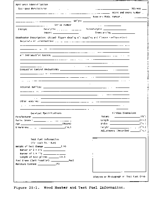
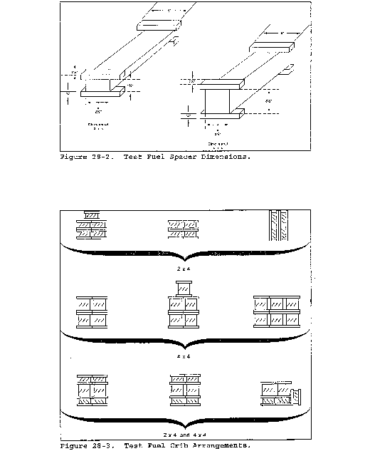
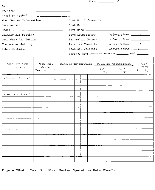
Method 28A - Measurement of Air- to-Fuel Ratio and Minimum Achievable Burn Rates for Wood-Fired Appliances
This method does not include all or the specifications (e.g., equipment and supplies) and procedures (e.g., sampling and analytical) essential to its performance. Some material is incorporated by reference from other methods in this part. Therefore, to obtain reliable results, persons using this method should also have a thorough knowledge of at least the following additional test methods: Method 3, Method 3A, Method 5H, Method 6C, and Method 28.
1.0 Scope and Application
1.1 Analyte. Particulate matter (PM). No CAS number assigned.
1.2 Applicability. This method is applicable for the measurement of air-to-fuel ratios and minimum achievable burn rates, for determining whether a wood-fired appliance is an affected facility, as specified in 40 CFR 60.530.
1.3 Data Quality Objectives. Adherence to the requirements of this method will enhance the quality of the data obtained from air pollutant sampling methods.
2.0 Summary of Method
2.1 A gas sample is extracted from a location in the stack of a wood-fired appliance while the appliance is operating at a prescribed set of conditions. The gas sample is analyzed for carbon dioxide (CO2), oxygen (O2), and carbon monoxide (CO). These stack gas components are measured for determining the dry molecular weight of the exhaust gas. Total moles of exhaust gas are determined stoichiometrically. Air-to-fuel ratio is determined by relating the mass of dry combustion air to the mass of dry fuel consumed.
3.0 Definitions
Same as Method 28, section 3.0, with the addition of the following:
3.1 Air-to-fuel ratio means the ratio of the mass of dry combustion air introduced into the firebox to the mass of dry fuel consumed (grams of dry air per gram of dry wood burned).
4.0 Interferences [Reserved]
5.0 Safety
5.1 Disclaimer. This method may involve hazardous materials, operations, and equipment. This test method may not address all of the safety problems associated with its use. It is the responsibility of the user of this test method to establish appropriate safety and health practices and to determine the applicability of regulatory limitations prior to performing this test method.
6.0 Equipment and Supplies
6.1 Test Facility. Insulated Solid Pack Chimney, Platform Scale and Monitor, Test Facility Temperature Monitor, Balance, Moisture Meter, Anemometer, Barometer, Draft Gauge, Humidity Gauge, Wood Heater Flue, and Test Facility. Same as Method 28, sections 6.1, 6.2, and 6.4 to 6.12, respectively.
6.2 Sampling System. Probe, Condenser, Valve, Pump, Rate Meter, Flexible Bag, Pressure Gauge, and Vacuum Gauge. Same as Method 3, sections 6.2.1 to 6.2.8, respectively. Alternatively, the sampling system described in Method 5H, section 6.1 may be used.
6.3 Exhaust Gas Analysis. Use one or both of the following:
6.3.1 Orsat Analyzer. Same as Method 3, section 6.1.3
6.3.2 Instrumental Analyzers. Same as Method 5H, sections 6.1.3.4 and 6.1.3.5, for CO2 and CO analyzers, except use a CO analyzer with a range of 0 to 5 percent and use a CO2 analyzer with a range of 0 to 5 percent. Use an O2 analyzer capable of providing a measure of O2 in the range of 0 to 25 percent by volume at least once every 10 minutes.
7.0 Reagents and Standards
7.1 Test Fuel and Test Fuel Spacers. Same as Method 28, sections 7.1 and 7.2, respectively.
7.2 Cylinder Gases. For each of the three analyzers, use the same concentration as specified in sections 7.2.1, 7.2.2, and 7.2.3 of Method 6C.
8.0 Sample Collection, Preservation, Storage, and Transport
8.1 Wood Heater Air Supply Adjustments.
8.1.1 This section describes how dampers are to be set or adjusted and air inlet ports closed or sealed during Method 28A tests. The specifications in this section are intended to ensure that affected facility determinations are made on the facility configurations that could reasonably be expected to be employed by the user. They are also intended to prevent circumvention of the standard through the addition of an air port that would often be blocked off in actual use. These specifications are based on the assumption that consumers will remove such items as dampers or other closure mechanism stops if this can be done readily with household tools; that consumers will block air inlet passages not visible during normal operation of the appliance using aluminum tape or parts generally available at retail stores; and that consumers will cap off any threaded or flanged air inlets. They also assume that air leakage around glass doors, sheet metal joints or through inlet grilles visible during normal operation of the appliance would not be further blocked or taped off by a consumer.
8.1.2 It is not the intention of this section to cause an appliance that is clearly designed, intended, and, in most normal installations, used as a fireplace to be converted into a wood heater for purposes of applicability testing. Such a fireplace would be identifiable by such features as large or multiple glass doors or panels that are not gasketed, relatively unrestricted air inlets intended, in large part, to limit smoking and fogging of glass surfaces, and other aesthetic features not normally included in wood heaters.
8.1.3 Adjustable Air Supply Mechanisms. Any commercially available flue damper, other adjustment mechanism or other air inlet port that is designed, intended or otherwise reasonably expected to be adjusted or closed by consumers, installers, or dealers and which could restrict air into the firebox shall be set so as to achieve minimum air into the firebox (i.e., closed off or set in the most closed position).
8.1.3.1 Flue dampers, mechanisms and air inlet ports which could reasonably be expected to be adjusted or closed would include:
8.1.3.1.1 All internal or externally adjustable mechanisms (including adjustments that affect the tightness of door fittings) that are accessible either before and/or after installation.
8.1.3.1.2 All mechanisms, other inlet ports, or inlet port stops that are identified in the owner's manual or in any dealer literature as being adjustable or alterable. For example, an inlet port that could be used to provide access to an outside air duct but which is identified as being closable through use of additional materials whether or not they are supplied with the facility.
8.1.3.1.3 Any combustion air inlet port or commercially available flue damper or mechanism stop, which would readily lend itself to closure by consumers who are handy with household tools by the removal of parts or the addition of parts generally available at retail stores (e.g., addition of a pipe cap or plug, addition of a small metal plate to an inlet hole on a nondecorative sheet metal surface, or removal of riveted or screwed damper stops).
8.1.3.1.4 Any flue damper, other adjustment mechanisms or other air inlet ports that are found and documented in several (e.g., a number sufficient to reasonably conclude that the practice is not unique or uncommon) actual installations as having been adjusted to a more closed position, or closed by consumers, installers, or dealers.
8.1.4 Air Supply Adjustments During Test. The test shall be performed with all air inlets identified under this section in the closed or most closed position or in the configuration which otherwise achieves the lowest air inlet (i.e., greatest blockage).
For the purposes of this section, air flow shall not be minimized beyond the point necessary to maintain combustion or beyond the point that forces smoke into the room.
8.1.5 Notwithstanding section 8.1.1, any flue damper, adjustment mechanism, or air inlet port (whether or not equipped with flue dampers or adjusting mechanisms) that is visible during normal operation of the appliance and which could not reasonably be closed further or blocked except through means that would significantly degrade the aesthetics of the facility (e.g., through use of duct tape) will not be closed further or blocked.
8.2 Sampling System.
8.2.1 Sampling Location. Same as Method 5H, section 8.1.2.
8.2.2 Sampling System Set Up. Set up the sampling equipment as described in Method 3, section 8.1.
8.3 Wood Heater Installation, Test Facility Conditions, Wood Heater Firebox Volume, and Test Fuel Charge. Same as Method 28, sections 8.4 and 8.6 to 8.8, respectively.
8.4 Pretest Ignition. Same as Method 28, section 8.11. Set the wood heater air supply settings to achieve a burn rate in Category 1 or the lowest achievable burn rate (see section 8.1).
8.5 Test Run. Same as Method 28, section 8.12. Begin sample collection at the start of the test run as defined in Method 28, section 8.12.1.
8.5.1 Gas Analysis.
8.5.1.1 If Method 3 is used, collect a minimum of two bag samples simultaneously at a constant sampling rate for the duration of the test run. A minimum sample volume of 30 liters (1.1 ft3) per bag is recommended.
8.5.1.2 If instrumental gas concentration measurement procedures are used, conduct the gas measurement system performance tests, analyzer calibration, and analyzer calibration error check outlined in Method 6C, sections 8.2.3, 8.2.4, 8.5, and 10.0, respectively. Sample at a constant rate for the duration of the test run.
8.5.2 Data Recording. Record wood heater operational data, test facility temperature, sample train flow rate, and fuel weight data at intervals of no greater than 10 minutes.
8.5.3 Test Run Completion. Same as Method 28, section 8.13.
9.0 Quality Control
9.1 Data Validation. The following quality control procedure is suggested to provide a check on the quality of the data.
9.1.1 Calculate a fuel factor, Fo, using Equation 28A-1 in section 12.2.
9.1.2 If CO is present in quantities measurable by this method, adjust the O2 and CO2 values before performing the calculation for Fo as shown in section 12.3 and 12.4.
9.1.3 Compare the calculated Fo factor with the expected Fo range for wood (1.000-1.120). Calculated Fo values beyond this acceptable range should be investigated before accepting the test results. For example, the strength of the solutions in the gas analyzer and the analyzing technique should be checked by sampling and analyzing a known concentration, such as air. If no detectable or correctable measurement error can be identified, the test should be repeated. Alternatively, determine a range of air-to-fuel ratio results that could include the correct value by using an Fo value of 1.05 and calculating a potential range of CO2 and O2 values. Acceptance of such results will be based on whether the calculated range includes the exemption limit and the judgment of the Administrator.
9.2 Method 3 Analyses. Compare the results of the analyses of the two bag samples. If all the gas components (O2, CO, and CO2) values for the two analyses agree within 0.5 percent (e.g., 6.0 percent O2 for bag 1 and 6.5 percent O2 for bag 2, agree within 0.5 percent), the results of the bag analyses may be averaged for the calculations in section 12. If the analysis results do not agree within 0.5 percent for each component, calculate the air-to-fuel ratio using both sets of analyses and report the results.
10.0 Calibration and Standardization [Reserved]
11.0 Analytical Procedures
11.1 Method 3 Integrated Bag Samples. Within 4 hours after the sample collection, analyze each bag sample for percent CO2, O2, and CO using an Orsat analyzer as described in Method 3, section 11.0.
11.2 Instrumental Analyzers. Average the percent CO2, CO, and O2 values for the test run.
12.0 Data Analyses and Calculations
Carry out calculations, retaining at least one extra significant figure beyond that of the acquired data. Round off figure after the final calculation. Other forms of the equations may be used as long as they give equivalent results.
12.1 Nomenclature.
Md = Dry molecular weight, g/g-mole (lb/lb-mole).
NT = Total gram-moles of dry exhaust gas per kg of wood burned (lb-moles/lb).
%CO2 = Percent CO2 by volume (dry basis).
%CO = Percent CO by volume (dry basis).
%N2 = Percent N2 by volume (dry basis).
%O2 = Percent O2 by volume (dry basis).
YHC = Assumed mole fraction of HC (dry as CH4) = 0.0088 for catalytic wood heaters; = 0.0132 for noncatalytic wood heaters. = 0.0080 for pellet-fired wood heaters.
YCO = Measured mole fraction of CO (e.g., 1 percent CO = .01 mole fraction), g/g-mole (lb/lb-mole).
YCO2 = Measured mole fraction of COCO2 (e.g., 10 percent CO2 = .10 mole fraction), g/g-mole (lb/lb-mole).
0.280 = Molecular weight of N2 or CO, divided by 100.
0.320 = Molecular weight of O2 divided by 100.
0.440 = Molecular weight of CO2 divided by 100.
20.9 = Percent O2 by volume in ambient air.
42.5 = Gram-moles of carbon in 1 kg of dry wood assuming 51 percent carbon by weight dry basis (.0425 lb/lb-mole).
510 = Grams of carbon in exhaust gas per kg of wood burned.
1,000 = Grams in 1 kg.
12.2 Fuel Factor. Use Equation 28A-1 to calculate the fuel factor.

12.3 Adjusted %CO2. Use Equation 28A-2 to adjust CO2 values if measurable CO is present.

12.4 Adjusted %O2. Use Equation 28A-3 to adjust O2 value if measurable CO is present.

12.5 Dry Molecular Weight. Use Equation 28A-4 to calculate the dry molecular weight of the stack gas.

The above equation does not consider argon in air (about 0.9 percent, molecular weight of 39.9). A negative error of about 0.4 percent is introduced. Argon may be included in the analysis using procedures subject to approval of the Administrator.
12.6 Dry Moles of Exhaust Gas. Use Equation 28A-5 to calculate the total moles of dry exhaust gas produced per kilogram of dry wood burned.
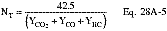
12.7 Air-to-Fuel Ratio. Use Equation 28A-6 to calculate the air-to-fuel ratio on a dry mass basis.

12.8 Burn Rate. Calculate the fuel burn rate as in Method 28, section 12.4.
13.0 Method Performance [Reserved]
14.0 Pollution Prevention [Reserved]
15.0 Waste Management [Reserved]
16.0 References
Same as section 16.0 of Method 3 and section 17 of Method 5G.
17.0 Tables, Diagrams, Flowcharts, and Validation Data [Reserved]
Test Method 28R for Certification and Auditing of Wood Heaters
1.0 Scope and Application
1.1 This test method applies to certification and auditing of wood-fired room heaters and fireplace inserts.
1.2 The test method covers the fueling and operating protocol for measuring particulate emissions, as well as determining burn rates, heat output and efficiency.
1.3 Particulate emissions are measured by the dilution tunnel method as specified in ASTM E2515-11 Standard Test Method for Determination of Particulate Matter Emissions Collected in a Dilution Tunnel (IBR, see § 60.17). Upon request, four-inch filters may be used. Upon request, Teflon membrane filters or Teflon-coated glass fiber filters may be used.
2.0 Procedures
2.1 This method incorporates the provisions of ASTM E2780-10 (IBR, see § 60.17) except as follows:
2.1.1 The burn rate categories, low burn rate requirement, and weightings in Method 28 shall be used.
2.1.2 The startup procedures shall be the same as in Method 28.
2.1.3 Manufacturers shall not specify a smaller volume of the firebox for testing than the full usable firebox.
2.1.4 Prior to testing, the heater must be operated for a minimum of 50 hours using a medium burn rate. The conditioning may be at the manufacturer's facility prior to the certification test. If the conditioning is at the certification test laboratory, the pre-burn for the first test can be included as part of the conditioning requirement.
2.2 Manufacturers may use ASTM E871-82 (reapproved 2013) (IBR, see § 60.17) as an alternative to the procedures in Method 5H or Method 28 for determining total weight basis moisture in the analysis sample of particulate wood fuel.
Test Method 28WHH for Measurement of Particulate Emissions and Heating Efficiency of Wood-Fired Hydronic Heating Appliances
1.0 Scope and Application
1.1 This test method applies to wood-fired hydronic heating appliances. The units typically transfer heat through circulation of a liquid heat exchange media such as water or a water-antifreeze mixture.
1.2 The test method measures particulate emissions and delivered heating efficiency at specified heat output rates based on the appliance's rated heating capacity.
1.3 Particulate emissions are measured by the dilution tunnel method as specified in ASTM E2515-11 Standard Test Method for Determination of Particulate Matter Emissions Collected in a Dilution Tunnel (IBR, see § 60.17). Upon request, four-inch filters may be used. Upon request, Teflon membrane filters or Teflon-coated glass fiber filters may be used. Delivered efficiency is measured by determining the heat output through measurement of the flow rate and temperature change of water circulated through a heat exchanger external to the appliance and determining the input from the mass of dry wood fuel and its higher heating value. Delivered efficiency does not attempt to account for pipeline loss.
1.4 Products covered by this test method include both pressurized and non-pressurized heating appliances intended to be fired with wood. These products are wood-fired hydronic heating appliances that the manufacturer specifies for indoor or outdoor installation. They are often connected to a heat exchanger by insulated pipes and normally include a pump to circulate heated liquid. They are used to heat structures such as homes, barns and greenhouses and can heat domestic hot water, spas or swimming pools.
1.5 Distinguishing features of products covered by this standard include:
1.5.1 Manufacturer specifies for indoor or outdoor installation.
1.5.2 A firebox with an access door for hand loading of fuel.
1.5.3 Typically, an aquastat that controls combustion air supply to maintain the liquid in the appliance within a predetermined temperature range provided sufficient fuel is available in the firebox.
1.5.4 A chimney or vent that exhausts combustion products from the appliance.
1.6 The values stated are to be regarded as the standard whether in I-P or SI units. The values given in parentheses are for information only.
2.0 Summary of Method and References
2.1 Particulate matter emissions are measured from a wood-fired hydronic heating appliance burning a prepared test fuel crib in a test facility maintained at a set of prescribed conditions. Procedures for determining burn rates, and particulate emissions rates and for reducing data are provided.
2.2 Referenced Documents
2.2.1 EPA Standards
2.2.1.1 Method 28 Certification and Auditing of Wood Heaters
2.2.2 Other Standards
2.2.2.1 ASTM E2515-11 - Standard Test Method for Determination of Particulate Matter Emissions Collected in a Dilution Tunnel (IBR, see § 60.17).
2.2.2.2 CSA-B415.1-10 Performance Testing of Solid-Fuel-Burning Heating Appliances (IBR, see § 60.17).
3.0 Terminology
3.1 Definitions.
3.1.1 Hydronic Heating - A heating system in which a heat source supplies energy to a liquid heat exchange media such as water that is circulated to a heating load and returned to the heat source through pipes.
3.1.2 Aquastat - A control device that opens or closes a circuit to control the rate of fuel consumption in response to the temperature of the heating media in the heating appliance.
3.1.3 Delivered Efficiency - The percentage of heat available in a test fuel charge that is delivered to a simulated heating load as specified in this test method.
3.1.4 Manufacturer's Rated Heat Output Capacity - The value in Btu/hr (MJ/hr) that the manufacturer specifies that a particular model of hydronic heating appliance is capable of supplying at its design capacity as verified by testing, in accordance with Section 13.
3.1.5 Burn Rate - The rate at which test fuel is consumed in an appliance. Measured in pounds (lbs) or kilograms of wood (dry basis) per hour (lb/hr or kg/hr).
3.1.6 Firebox - The chamber in the appliance in which the test fuel charge is placed and combusted.
3.1.7 Test Fuel Charge - The collection of test fuel layers placed in the appliance at the start of the emission test run.
3.1.8 Test Fuel Layer - Horizontal arrangement of test fuel units.
3.1.9 Test Fuel Unit - One or more test fuel pieces with 3⁄4 inch (19 mm) spacers attached to the bottom and to one side. If composed of multiple test fuel pieces, the bottom spacer may be one continuous piece.
3.1.10 Test Fuel Piece - A single 4 × 4 (4 ±0.25 inches by 4 ±0.25 inches) [100 ±6 mm by 100 ±6 mm] white or red oak wood piece cut to the length required.
3.1.11 Test Run - An individual emission test that encompasses the time required to consume the mass of the test fuel charge.
3.1.12 Overall Efficiency (SLM) - The efficiency for each test run as determined using the CSA B415.1-10 (IBR, see § 60.17) stack loss method.
3.1.13 Thermopile - A device consisting of a number of thermocouples connected in series, used for measuring differential temperature.
4.0 Summary of Test Method
4.1 Dilution Tunnel. Emissions are determined using the “dilution tunnel” method specified in ASTM E2515-11 Standard Test Method for Determination of Particulate Matter Emissions Collected in a Dilution Tunnel (IBR, see § 60.17). The flow rate in the dilution tunnel is maintained at a constant level throughout the test cycle and accurately measured. Samples of the dilution tunnel flow stream are extracted at a constant flow rate and drawn through high efficiency filters. The filters are dried and weighed before and after the test to determine the emissions catch and this value is multiplied by the ratio of tunnel flow to filter flow to determine the total particulate emissions produced in the test cycle.
4.2 Efficiency. The efficiency test procedure takes advantage of the fact that this type of appliance delivers heat through circulation of the heated liquid (water) from the appliance to a remote heat exchanger and back to the appliance. Measurements of the water temperature difference as it enters and exits the heat exchanger along with the measured flow rate allow for an accurate determination of the useful heat output of the appliance. The input is determined by weight of the test fuel charge, adjusted for moisture content, multiplied by the higher heating value. Additional measurements of the appliance weight and temperature at the beginning and end of a test cycle are used to correct for heat stored in the appliance. Overall efficiency (SLM) is determined using the CSA B415.1-10 (IBR, see § 60.17) stack loss method for data quality assurance purposes.
4.3 Operation. Appliance operation is conducted on a hot-to-hot test cycle meaning that the appliance is brought to operating temperature and a coal bed is established prior to the addition of the test fuel charge and measurements are made for each test fuel charge cycle. The measurements are made under constant heat draw conditions within predetermined ranges. No attempt is made to modulate the heat demand to simulate an indoor thermostat cycling on and off in response to changes in the indoor environment. Four test categories are used. These are:
4.3.1 Category I: A heat output of 15 percent or less of manufacturer's rated heat output capacity.
4.3.2 Category II: A heat output of 16 percent to 24 percent of manufacturer's rated heat output capacity.
4.3.3 Category III: A heat output of 25 percent to 50 percent of manufacturer's rated heat output capacity.
4.3.4 Category IV: Manufacturer's rated heat output capacity.
5.0 Significance and Use
5.1 The measurement of particulate matter emission rates is an important test method widely used in the practice of air pollution control.
5.1.1 These measurements, when approved by state or federal agencies, are often required for the purpose of determining compliance with regulations and statutes.
5.1.2 The measurements made before and after design modifications are necessary to demonstrate the effectiveness of design changes in reducing emissions and make this standard an important tool in manufacturers' research and development programs.
5.2 Measurement of heating efficiency provides a uniform basis for comparison of product performance that is useful to the consumer. It is also required to relate emissions produced to the useful heat production.
5.3 This is a laboratory method and is not intended to be fully representative of all actual field use. It is recognized that users of hand-fired, wood-burning equipment have a great deal of influence over the performance of any wood-burning appliance. Some compromises in realism have been made in the interest of providing a reliable and repeatable test method.
6.0 Test Equipment
6.1 Scale. A platform scale capable of weighing the appliance under test and associated parts and accessories when completely filled with water to an accuracy of ±1.0 pound (±0.5 kg).
6.2 Heat Exchanger. A water-to-water heat exchanger capable of dissipating the expected heat output from the system under test.
6.3 Water Temperature Difference Measurement. A Type - T 'special limits' thermopile with a minimum of 5 pairs of junctions shall be used to measure the temperature difference in water entering and leaving the heat exchanger. The temperature difference measurement uncertainty of this type of thermopile is equal to or less than ±0.50 °F (±0.25 °C). Other temperature measurement methods may be used if the temperature difference measurement uncertainty is equal to or less than ±0.50 °F (±0.25 °C).
6.4 Water Flow Meter. A water flow meter shall be installed in the inlet to the load side of the heat exchanger. The flow meter shall have an accuracy of ±1 percent of measured flow.
6.4.1 Optional - Appliance Side Water Flow Meter. A water flow meter with an accuracy of ±1 percent of the flow rate is recommended to monitor supply side water flow rate.
6.5 Optional Recirculation Pump. Circulating pump used during test to prevent stratification of liquid being heated.
6.6 Water Temperature Measurement - Thermocouples or other temperature sensors to measure the water temperature at the inlet and outlet of the load side of the heat exchanger. Must meet the calibration requirements specified in section 10.1.
6.7 Wood Moisture Meter - Calibrated electrical resistance meter capable of measuring test fuel moisture to within 1 percent moisture content. Must meet the calibration requirements specified in section 10.4.
6.8 Flue Gas Temperature Measurement - Must meet the requirements of CSA B415.1-10 (IBR, see § 60.17), clause 6.2.2.
6.9 Test Room Temperature Measurement - Must meet the requirements of CSA B415.1-10 (IBR, see § 60.17), clause 6.2.1.
6.10 Flue Gas Composition Measurement - Must meet the requirements of CSA B415.1-10 (IBR, see § 60.17), clauses 6.3.1 through 6.3.3.
7.0 Safety
7.1 These tests involve combustion of wood fuel and substantial release of heat and products of combustion. The heating system also produces large quantities of very hot water and the potential for steam production and system pressurization. Appropriate precautions must be taken to protect personnel from burn hazards and respiration of products of combustion.
8.0 Sampling, Test Specimens and Test Appliances
8.1 Test specimens shall be supplied as complete appliances including all controls and accessories necessary for installation in the test facility. A full set of specifications and design and assembly drawings shall be provided when the product is to be placed under certification of a third-party agency. The manufacturer's written installation and operating instructions are to be used as a guide in the set-up and testing of the appliance.
9.0 Preparation of Test Equipment
9.1 The appliance is to be placed on a scale capable of weighing the appliance fully loaded with a resolution of ±1.0 lb (0.5 kg).
9.2 The appliance shall be fitted with the type of chimney recommended or provided by the manufacturer and extending to 15 ±0.5 feet (4.6 ±0.15 m) from the upper surface of the scale. If no flue or chimney system is recommended or provided by the manufacturer, connect the appliance to a flue of a diameter equal to the flue outlet of the appliance. The flue section from the appliance flue collar to 8 ±0.5 feet above the scale shall be single wall stove pipe and the remainder of the flue shall be double wall insulated class A chimney.
9.3 Optional Equipment Use
9.3.1 A recirculation pump may be installed between connections at the top and bottom of the appliance to minimize thermal stratification if specified by the manufacturer. The pump shall not be installed in such a way as to change or affect the flow rate between the appliance and the heat exchanger.
9.3.2 If the manufacturer specifies that a thermal control valve or other device be installed and set to control the return water temperature to a specific set point, the valve or other device shall be installed and set per the manufacturer's written instructions.
9.4 Prior to filling the tank, weigh and record the appliance mass.
9.5 Heat Exchanger
9.5.1 Plumb the unit to a water-to-water heat exchanger with sufficient capacity to draw off heat at the maximum rate anticipated. Route hoses, electrical cables, and instrument wires in a manner that does not influence the weighing accuracy of the scale as indicated by placing dead weights on the platform and verifying the scale's accuracy.
9.5.2 Locate thermocouples to measure the water temperature at the inlet and outlet of the load side of the heat exchanger.
9.5.3 Install a thermopile meeting the requirements of section 6.3 to measure the water temperature difference between the inlet and outlet of the load side of the heat exchanger.
9.5.4 Install a calibrated water flow meter in the heat exchanger load side supply line. The water flow meter is to be installed on the cooling water inlet side of the heat exchanger so that it will operate at the temperature at which it is calibrated.
9.5.5 Place the heat exchanger in a box with 2 in. (50 mm) of expanded polystyrene (EPS) foam insulation surrounding it to minimize heat losses from the heat exchanger.
9.5.6 The reported efficiency and heat output rate shall be based on measurements made on the load side of the heat exchanger.
9.5.7 Temperature instrumentation per section 6.6 shall be installed in the appliance outlet and return lines. The average of the outlet and return water temperature on the supply side of the system shall be considered the average appliance temperature for calculation of heat storage in the appliance (TFavg and TIavg). Installation of a water flow meter in the supply side of the system is optional.
9.6 Fill the system with water. Determine the total weight of the water in the appliance when the water is circulating. Verify that the scale indicates a stable weight under operating conditions. Make sure air is purged properly.
10.0 Calibration and Standardization
10.1 Water Temperature Sensors. Temperature measuring equipment shall be calibrated before initial use and at least semi-annually thereafter. Calibrations shall be in compliance with National Institute of Standards and Technology (NIST) Monograph 175, Standard Limits of Error.
10.2 Heat Exchanger Load Side Water Flow Meter.
10.2.1 The heat exchanger load side water flow meter shall be calibrated within the flow range used for the test run using NIST traceable methods. Verify the calibration of the water flow meter before and after each test run and at least once during each test run by comparing the water flow rate indicated by the flow meter to the mass of water collected from the outlet of the heat exchanger over a timed interval. Volume of the collected water shall be determined based on the water density calculated from section 13, Eq. 8, using the water temperature measured at the flow meter. The uncertainty in the verification procedure used shall be 1 percent or less. The water flow rate determined by the collection and weighing method shall be within 1 percent of the flow rate indicated by the water flow meter.
10.3 Scales. The scales used to weigh the appliance and test fuel charge shall be calibrated using NIST traceable methods at least once every 6 months.
10.4 Moisture Meter. The moisture meter shall be calibrated per the manufacturer's instructions and checked before each use.
10.5 Flue Gas Analyzers - In accordance with CSA B415.1-10 (IBR, see § 60.17), clause 6.8.
11.0 Conditioning
11.1 Prior to testing, the appliance is to be operated for a minimum of 50 hours using a medium heat draw rate. The conditioning may be at the manufacturer's facility prior to the certification test. If the conditioning is at the certification test laboratory, the pre-burn for the first test can be included as part of the conditioning requirement. If conditioning is included in pre-burn, then the appliance shall be aged with fuel meeting the specifications outlined in sections 12.2 with a moisture content between 19 and 25 percent on a dry basis. Operate the appliance at a medium burn rate (Category II or III) for at least 10 hours for noncatalytic appliances and 50 hours for catalytic appliances. Record and report hourly flue gas exit temperature data and the hours of operation. The aging procedure shall be conducted and documented by a testing laboratory.
12.0 Procedure
12.1 Appliance Installation. Assemble the appliance and parts in conformance with the manufacturer's written installation instructions. Clean the flue with an appropriately sized, wire chimney brush before each certification test series.
12.2 Fuel. Test fuel charge fuel shall be red (Quercus ruba L. ) or white (Quercus alba) oak 19 to 25 percent moisture content on a dry basis. Piece length shall be 80 percent of the firebox depth rounded down to the nearest 1 inch (25mm) increment. For example, if the firebox depth is 46 inches (1168mm) the 4 × 4 piece length would be 36 inches (46 inches × 0.8 = 36.8 inches rounded down to 36 inches). Pieces are to be placed in the firebox parallel to the longest firebox dimension. For fireboxes with sloped surfaces that create a non-uniform firebox length, the piece length shall be adjusted for each layer based on 80 percent of the length at the level where the layer is placed. Pieces are to be spaced 3⁄4 inches (19 mm) apart on all faces. The first fuel layer may be assembled using fuel units consisting of multiple 4 × 4s consisting of single pieces with bottom and side spacers of 3 or more pieces if needed for a stable layer. The second layer may consist of fuel units consisting of no more than two pieces with spacers attached on the bottom and side. The top two layers of the fuel charge must consist of single pieces unless the fuel charge is only three layers. In that instance only the top layer must consist of single units. Three-quarter inch (19 mm) by 1.5 inch (38 mm) spacers shall be attached to the bottom of piece to maintain a 3⁄4 inch (19 mm) separation. When a layer consists of two or more units of 4 × 4s an additional 3⁄4 inch (19 mm) thick by 1.5 inch (38 mm) wide spacer shall be attached to the vertical face of each end of one 4 × 4, such that the 3⁄4 inch (19 mm) space will be maintained when two 4 × 4 units or pieces are loaded side by side. In cases where a layer contains an odd number of 4 × 4s one piece shall not be attached, but shall have spacers attached in a manner that will provide for the 3⁄4 inch (19 mm) space to be maintained (See Figure 1). Spacers shall be attached perpendicular to the length of the 4 × 4s such that the edge of the spacer is 1 ± 0.25 inch from the end of the 4 × 4s in the previous layers. Spacers shall be red or white oak and will be attached with either nails (non-galvanized), brads or oak dowels. The use of kiln-dried wood is not allowed.
12.2.1 Using a fuel moisture meter as specified in section 6.7 of the test method, determine the fuel moisture for each test fuel piece used for the test fuel load by averaging at least five fuel moisture meter readings measured parallel to the wood grain. Penetration of the moisture meter insulated electrodes for all readings shall be 1⁄4 the thickness of the fuel piece or 19 mm (3⁄4 in.), whichever is lesser. One measurement from each of three sides shall be made at approximately 3 inches from each end and the center. Two additional measurements shall be made centered between the other three locations. Each individual moisture content reading shall be in the range of 18 to 28 percent on a dry basis. The average moisture content of each piece of test fuel shall be in the range of 19 to 25 percent. It is not required to measure the moisture content of the spacers. Moisture shall not be added to previously dried fuel pieces except by storage under high humidity conditions and temperature up to 100 °F. Fuel moisture shall be measured within 4 hours of using the fuel for a test.
12.2.2 Firebox Volume. Determine the firebox volume in cubic feet. Firebox volume shall include all areas accessible through the fuel loading door where firewood could reasonably be placed up to the horizontal plane defined by the top of the loading door. A drawing of the firebox showing front, side and plan views or an isometric view with interior dimensions shall be provided by the manufacturer and verified by the laboratory. Calculations for firebox volume from computer aided design (CAD) software programs are acceptable and shall be included in the test report if used. If the firebox volume is calculated by the laboratory the firebox drawings and calculations shall be included in the test report.
12.2.3 Test Fuel Charge. Test fuel charges shall be determined by multiplying the firebox volume by 10 pounds (4.54 kg) per ft3 (28L), or a higher load density as recommended by the manufacturer's printed operating instructions, of wood (as used wet weight). Select the number of pieces of standard fuel that most nearly match this target weight. This is the standard fuel charge for all tests. For example, if the firebox loading area volume is 10 ft3 (280L) and the firebox depth is 46 inches (1168 mm), test fuel charge target is 100 lbs (45 kg) minimum and the piece length is 36 inches (914 mm). If eight 4 × 4s, 36 inches long weigh 105 lbs (48 kg), use 8 pieces for each test fuel charge. All test fuel charges will be of the same configuration.
12.3 Sampling Equipment. Prepare the particulate emission sampling equipment as defined by ASTM E2515-11 Standard Test Method for Determination of Particulate Matter Emissions Collected in a Dilution Tunnel (IBR, see § 60.17). Upon request, four-inch filters may be used. Upon request, Teflon membrane filters or Teflon-coated glass fiber filters may be used.
12.4 Appliance Startup. The appliance shall be fired with wood fuel of any species, size and moisture content at the laboratories' discretion to bring it up to operating temperature. Operate the appliance until the water is heated to the upper operating control limit and has cycled at least two times. Then remove all unburned fuel, zero the scale and verify the scales accuracy using dead weights.
12.4.1 Pretest Burn Cycle. Reload appliance with oak wood and allow it to burn down to the specified coal bed weight. The pretest burn cycle fuel charge weight shall be within ±10 percent of the test fuel charge weight. Piece size and length shall be selected such that charcoalization is achieved by the time the fuel charge has burned down to the required coal bed weight. Pieces with a maximum thickness of approximately 2 inches have been found to be suitable. Charcoalization is a general condition of the test fuel bed evidenced by an absence of large pieces of burning wood in the coal bed and the remaining fuel pieces being brittle enough to be broken into smaller charcoal pieces with a metal poker. Manipulations to the fuel bed prior to the start of the test run are to be done to achieve charcoalization while maintaining the desired heat output rate. During the pre-test burn cycle and at least one hour prior to starting the test run, adjust water flow to the heat exchanger to establish the target heat draw for the test. For the first test run the heat draw rate shall be equal to the manufacturer's rated heat output capacity.
12.4.1.1 Allowable Adjustments. Fuel addition or subtractions, and coal bed raking shall be kept to a minimum but are allowed up to 15 minutes prior to the start of the test run. For the purposes of this method, coal bed raking is the use of a metal tool (poker) to stir coals, break burning fuel into smaller pieces, dislodge fuel pieces from positions of poor combustion, and check for the condition of charcoalization. Record all adjustments to and additions or subtractions of fuel, and any other changes to the appliance operations that occur during pretest ignition period. During the 15-minute period prior to the start of the test run, the wood heater loading door shall not be open more than a total of 1 minute. Coal bed raking is the only adjustment allowed during this period.
12.4.2 Coal Bed Weight. The appliance is to be loaded with the test fuel charge when the coal bed weight is between 10 percent and 20 percent of the test fuel charge weight. Coals may be raked as necessary to level the coal bed but may only be raked and stirred once between 15 to 20 minutes prior to the addition of the test fuel charge.
12.5 Test Runs. For all test runs, the return water temperature to the hydronic heater must be equal to or greater than 120 °F. Aquastat or other heater output control device settings that are adjustable shall be set using manufacturer specifications, either as factory set or in accordance with the owner's manual, and shall remain the same for all burn categories.
Complete a test run in each heat output rate category, as follows:
12.5.1 Test Run Start. Once the appliance is operating normally and the pretest coal bed weight has reached the target value per section 12.4.2, tare the scale and load the full test charge into the appliance. Time for loading shall not exceed 5 minutes. The actual weight of the test fuel charge shall be measured and recorded within 30 minutes prior to loading. Start all sampling systems.
12.5.1.1 Record all water temperatures, differential water temperatures and water flow rates at time intervals of one minute or less.
12.5.1.2 Record particulate emissions data per the requirements of ASTM E2515 (IBR, see § 60.17).
12.5.1.3 Record data needed to determine overall efficiency (SLM) per the requirements of CSA B415.1-10 (IBR, see § 60.17), clauses 6.2.1, 6.2.2, 6.3, 8.5.7, 10.4.3 (a), 10.4.3(f), and 13.7.9.3
12.5.1.3.1 Measure and record the test room air temperature in accordance with the requirements of CSA B415.1-10 (IBR, see § 60.17), clauses 6.2.1, 8.5.7 and 10.4.3 (g).
12.5.1.3.2 Measure and record the flue gas temperature in accordance with the requirements of CSA B415.1-10 (IBR, see § 60.17), clauses 6.2.2, 8.5.7 and 10.4.3 (f).
12.5.1.3.3 Determine and record the carbon monoxide (CO) and carbon dioxide (CO2) concentrations in the flue gas in accordance with CSA B415.1-10 (IBR, see § 60.17), clauses 6.3, 8.5.7 and 10.4.3 (i) and (j).
12.5.1.3.4 Measure and record the test fuel weight per the requirements of CSA B415.1-10 (IBR, see § 60.17), clauses 8.5.7 and 10.4.3 (h).
12.5.1.3.5 Record the test run time per the requirements of CSA B415.1-10 (IBR, see § 60.17), clauses 10.4.3 (a).
12.5.1.4 Monitor the average heat output rate on the load side of the heat exchanger. If the heat output rate gets close to the upper or lower limit of the target range (±5 percent) adjust the water flow through the heat exchanger to compensate. Make changes as infrequently as possible while maintaining the target heat output rate. The first test run shall be conducted at the Category IV heat output rate to validate that the appliance is capable of producing the manufacturer's rated heat output capacity.
12.5.2 Test Fuel Charge Adjustment. It is acceptable to adjust the test fuel charge (i.e., reposition) once during a test run if more than 60 percent of the initial test fuel charge weight has been consumed and more than 10 minutes have elapsed without a measurable (1 lb or 0. 5 kg) weight change while the operating control is in the demand mode. The time used to make this adjustment shall be less than 60 seconds.
12.5.3 Test Run Completion. The test run is completed when the remaining weight of the test fuel charge is 0.0 lb (0.0 kg). End the test run when the scale has indicated a test fuel charge weight of 0.0 lb (0.0 kg) or less for 30 seconds.
12.5.3.1 At the end of the test run, stop the particulate sampling train and overall efficiency (SLM) measurements, and record the run time, and all final measurement values.
12.5.4 Heat Output Capacity Validation. The first test run must produce a heat output rate that is within 10 percent of the manufacturer's rated heat output capacity (Category IV) throughout the test run and an average heat output rate within 5 percent of the manufacturer's rated heat output capacity. If the appliance is not capable of producing a heat output within these limits, the manufacturer's rated heat output capacity is considered not validated and testing is to be terminated. In such cases, the tests may be restarted using a lower heat output capacity if requested by the manufacturer.
12.5.5 Additional Test Runs. Using the manufacturer's rated heat output capacity as a basis, conduct a test for additional heat output categories as specified in section 4.3. It is not required to run these tests in any particular order.
12.5.6 Alternative Heat Output Rate for Category
I. If an appliance cannot be operated in the Category I heat output range due to stopped combustion, two test runs shall be conducted at heat output rates within Category II, provided that the completed test run burn rate is no greater than the burn rate expected in home use. If this rate cannot be achieved, the test is not valid.
When the alternative heat output rate is used, the weightings for the weighted averages indicated in Table 2 shall be the average of the Category I and II weightings and shall be applied to both Category II results. The two completed runs in Category II will be deemed to meet the requirement for runs completed in both Category I and Category II. Appliances that are not capable of operation within Category II (<25 percent of maximum) cannot be evaluated by this test method. The test report must include full documentation and discussion of the attempted runs, completed rums and calculations.
12.5.6.1 Stopped Fuel Combustion. Evidence that an appliance cannot be operated at a Category I heat output rate due to stopped fuel combustion shall include documentation of two or more attempts to operate the appliance in burn rate Category I and fuel combustion has stopped prior to complete consumption of the test fuel charge. Stopped fuel combustion is evidenced when an elapsed time of 60 minutes or more has occurred without a measurable (1 lb or 0.5 kg) weight change in the test fuel charge while the appliance operating control is in the demand mode. Report the evidence and the reasoning used to determine that a test in burn rate Category I cannot be achieved. For example, two unsuccessful attempts to operate at an output rate of 10 percent of the rated output capacity are not sufficient evidence that burn rate Category I cannot be achieved. Note that section 12.5.6 requires that the completed test run burn rate can be no greater than the burn rate expected in home use. If this rate cannot be achieved, the test is not valid.
12.5.7 Appliance Overheating. Appliances shall be capable of operating in all heat output categories without overheating to be rated by this test method. Appliance overheating occurs when the rate of heat withdrawal from the appliance is lower than the rate of heat production when the unit control is in the idle mode. This condition results in the water in the appliance continuing to increase in temperature well above the upper limit setting of the operating control. Evidence of overheating includes: 1 hour or more of appliance water temperature increase above the upper temperature set-point of the operating control, exceeding the temperature limit of a safety control device (independent from the operating control), boiling water in a non-pressurized system or activation of a pressure or temperature relief valve in a pressurized system.
12.6 Additional Test Runs. The testing laboratory may conduct more than one test run in each of the heat output categories specified in section 4.3.1. If more than one test run is conducted at a specified heat output rate, the results from at least two-thirds of the test runs in that heat output rate category shall be used in calculating the weighted average emission rate (See section 14.1.14). The measurement data and results of all test runs shall be reported regardless of which values are used in calculating the weighted average emission rate.
13.0 Calculation of Results
13.1 Nomenclature
ET - Total particulate emissions for the full test run as determined per ASTM E2515-11 (IBR, see § 60.17) in grams
Eg/MJ - Emissions rate in grams per megajoule of heat output
Elb/mmBtu output - Emissions rate in pounds per million Btu of heat output
Eg/kg - Emissions factor in grams per kilogram of dry fuel burned
Eg/hr - Emissions factor in grams per hour
HHV - Higher heating value of fuel = 8600 Btu/lb (19.990 MJ/kg)
LHV - Lower heating value of fuel = 7988 Btu/lb (18.567 MJ/kg)
ΔT - Temperature difference between water entering and exiting the heat exchanger
Qout - Total heat output in BTU's (megajoules)
Qin - Total heat input available in test fuel charge in BTU (megajoules)
M - Mass flow rate of water in lb/min (kg/min)
Vi - Volume of water indicated by a totalizing flow meter at the ith reading in gallons (liters)
Vf - Volumetric flow rate of water in heat exchange system in gallons per minute (liters/min)
Θ - Total length of test run in hours
ti - Data sampling interval in minutes
ηdel - Delivered heating efficiency in percent
Fi - Weighting factor for heat output category i (See Table 2)
T1 - Temperature of water at the inlet on the supply side of the heat exchanger
T2 - Temperature of the water at the outlet on the supply side of the heat exchanger
T3 - Temperature of water at the inlet to the load side of the heat exchanger
TIavg - Average temperature of the appliance and water at start of the test

TFavg - Average temperature of the appliance and water at the end of the test

MC - Fuel moisture content in percent dry basis
MCi - Average moisture content of individual 4 × 4 fuel pieces in percent dry basis
MCsp - Moisture content of spacers assumed to be 10 percent dry basis
σ - Density of water in pounds per gallon
Cp - Specific heat of water in Btu/lb, °F
Csteel - Specific heat of steel (0.1 Btu/lb, ºF)
Wfuel - Fuel charge weight in pounds (kg)
Wi - Weight of individual fuel 4 × 4 pieces in pounds (kg)
Wsp - Weight of all spacers used in a fuel load in pounds (kg)
Wapp - Weight of empty appliance in pounds
Wwa - Weight of water in supply side of the system in pounds
13.2 After the test is completed, determine the particulate emissions ET in accordance with ASTM E2515-11 (IBR, see § 60.17).
13.3 Determine Average Fuel Load Moisture Content

13.4 Determine heat input
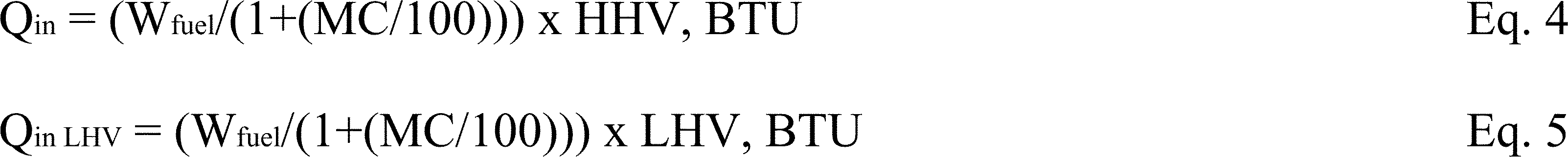
13.5 Determine Heat Output and Efficiency
13.5.1 Determine heat output as:
Qout = Σ [Heat output determined for each sampling time interval] + Change in heat stored in the appliance.

The subscript (i) indicates the parameter value for sampling time interval ti.
Mi = Mass flow rate = gal/min × density of water (lb/gal) = lb/min


Csteel = 0.1 Btu/lb, ° F


Vi is the total water volume at the end of interval i and Vi-1 is the total water volume at the beginning of the time interval. This calculation is necessary when a totalizing type water meter is used.
13.5.2 Determine heat output rate as:

13.5.3 Determine emission rates and emission factors as:
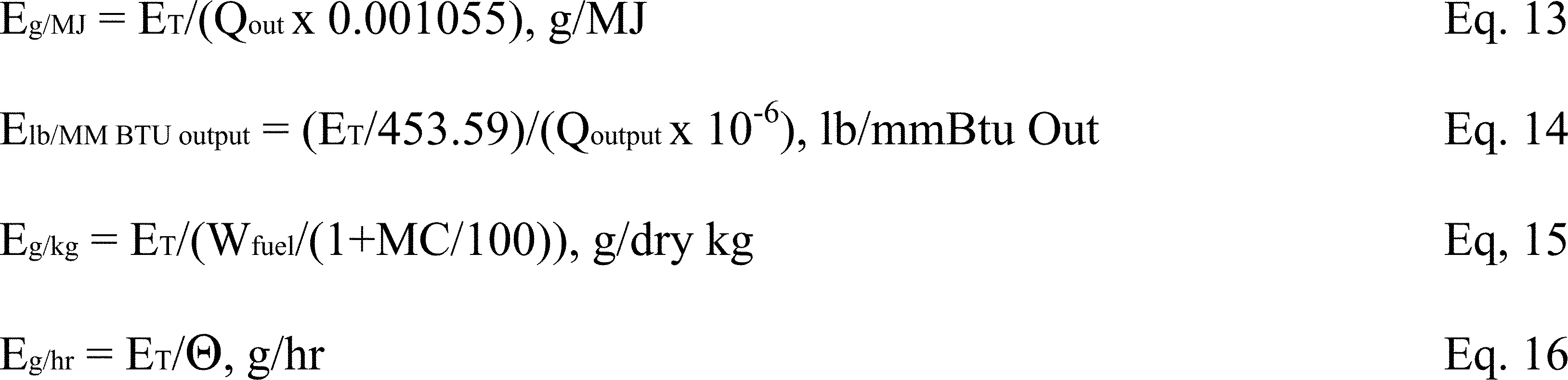
13.5.4 Determine delivered efficiency as:
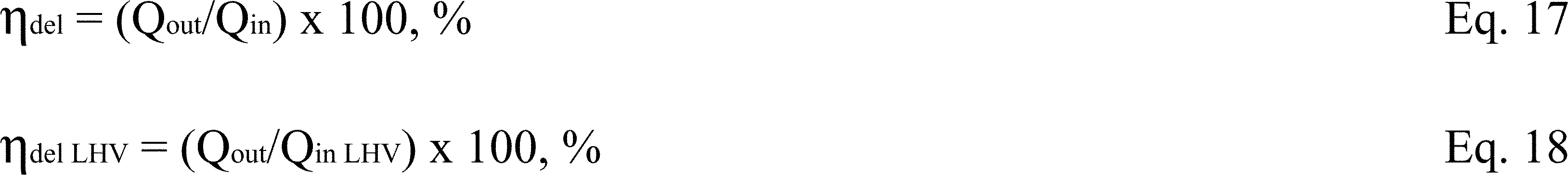
13.5.5 Determine ηSLM - Overall Efficiency (SLM) using Stack Loss
For determination of the average overall thermal efficiency (ηSLM) for the test run, use the data collected over the full test run and the calculations in accordance with CSA B415.1-10 (IBR, see § 60.17), clause 13.7 except for 13.7.2 (e), (f), (g), and (h), use the following average fuel properties for oak: percent C = 50.0, percent H = 6.6, percent O = 43.2, percent ash = 0.2 percent. The averaging period for determination of efficiency by the stack loss method allows averaging over 10 minute time periods for flue gas temperature, flue gas CO2, and flue gas CO for the determination of the efficiency. However, under some cycling conditions the “on” period may be short relative to this 10 minute period. For this reason, during cycling operation the averaging period for these parameters may not be longer than the burner on period divided by 10. The averaging period need not be shorter than one minute. During the off period, under cycling operation, the averaging periods specified may be used. Where short averaging times are used, however, the averaging period for fuel consumption may still be at 10 minutes. This average wood consumption rate shall be applied to all of the smaller time intervals included.
13.5.5.1 Whenever the CSA B415.1-10 (IBR, see § 60.17) overall efficiency is found to be lower than the overall efficiency based on load side measurements, as determined by Eq. 16 of this method, section 14.1.7 of the test report must include a discussion of the reasons for this result.
13.6 Weighted Average Emissions and Efficiency
13.6.1 Determine the weighted average emission rate and delivered efficiency from the individual tests in the specified heat output categories. The weighting factors (Fi) are derived from an analysis of ASHRAE bin data which provides details of normal building heating requirements in terms of percent of design capacity and time in a particular capacity range - or “bin” - over the course of a heating season. The values used in this method represent an average of data from several cities located in the northern United States.
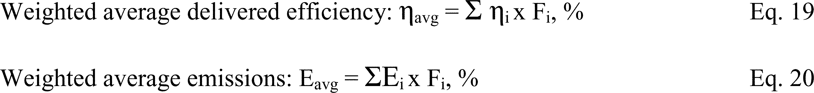
13.7 Average Heat Output (Qout-8hr) and Efficiency ((ηavg-8hr) for 8 hour burn time.
13.7.1 Units tested under this standard typically require infrequent fuelling, 8 to 12 hours intervals being typical. Rating unit's based on an average output sustainable over an 8 hour duration will assist consumers in appropriately sizing units to match the theoretical heat demand of their application.
13.7.2 Calculations:
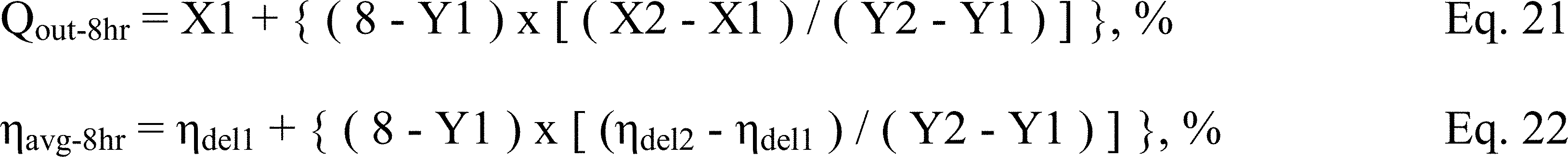
Where:
Y1 = Test duration just above 8 hrs
Y2 = Test duration just below 8 hrs
X1 = Actual load for duration Y1
X2 = Actual load for duration Y2
ηdel1 = Average delivered efficiency for duration Y1
ηdel2 = Average delivered efficiency for duration Y2
13.7.2.1 Determine the test durations and actual load for each category as recorded in Table 1A.
13.7.2.2 Determine the data point that has the nearest duration greater than 8 hrs.
X1 = Actual load,
Y1 = Test duration, and
ηdel1 = Average delivered efficiency for this data point
13.7.2.3 Determine the data point that has the nearest duration less than 8 hours.
X2 = Actual load,
Y2 = Test duration, and
ηdel2 = Average delivered efficiency for this data point
13.7.2.4 Example:
Category Actual Load Duration
[Category Actual Load Duration ηdel]
| (Btu/Hr) | (Hr) | (%) |
|---|---|---|
| 1 15,000 | 10.2 | 70.0 |
| 2 26,000 | 8.4 | 75.5 |
| 3 50,000 | 6.4 | 80.1 |
| 4 100,000 | 4.7 | 80.9 |
Category 2 duration is just above 8 hours, therefore: X1 = 26,000 Btu/hr, ηdel1 = 75.5% and Y1 = 8.4 hrs
Category 3 duration is just below 8 hours, therefore: X2 = 50,000 Btu/hr, ηdel2 = 80.1% and Y2 = 6.4 hrs
Qout-8hr = 26,000 + {(8 - 8.4) × [(50,000 - 26,000)/(6.4 - 8.4)]} = 30,800 BTU/hr
ηavg-8hr = 75.5 + {(8 - 8.4) × [(80.1 - 75.5)/(6.4 - 8.4)]} = 76.4%
13.8 Carbon Monoxide Emissions
For each minute of the test period, the carbon monoxide emission rate shall be calculated as:

Total CO emissions for each of the three test periods (CO_1, CO_2, CO_3) shall be calculated as the sum of the emission rates for each of the 1 minute intervals.
Total CO emission for the test run, COT, shall be calculated as the sum of CO_1, CO_2, and CO_3.
14.0 Report
14.1.1 The report shall include the following.
14.1.2 Name and location of the laboratory conducting the test.
14.1.3 A description of the appliance tested and its condition, date of receipt and dates of tests.
14.1.4 A statement that the test results apply only to the specific appliance tested.
14.1.5 A statement that the test report shall not be reproduced except in full, without the written approval of the laboratory.
14.1.6 A description of the test procedures and test equipment including a schematic or other drawing showing the location of all required test equipment. Also, a description of test fuel sourcing, handling and storage practices shall be included.
14.1.7 Details of deviations from, additions to or exclusions from the test method, and their data quality implications on the test results (if any), as well as information on specific test conditions, such as environmental conditions.
14.1.8 A list of participants and observers present for the tests.
14.1.9 Data and drawings indicating the fire box size and location of the fuel charge.
14.1.10 Drawings and calculations used to determine firebox volume.
14.1.11 Information for each test run fuel charge including piece size, moisture content, and weight.
14.1.12 All required data for each test run shall be provided in spreadsheet format. Formulae used for all calculations shall be accessible for review.
14.1.13 Test run duration for each test.
14.1.14 Calculated results for delivered efficiency at each burn rate and the weighted average emissions reported as total emissions in grams, pounds per mm Btu of delivered heat, grams per MJ of delivered heat, grams per kilogram of dry fuel and grams per hour. Results shall be reported for each heat output category and the weighted average.
14.1.15 Tables 1A, 1B, 1C and Table 2 must be used for presentation of results in test reports.
14.1.16 A statement of the estimated uncertainty of measurement of the emissions and efficiency test results.
14.1.17 Raw data, calibration records, and other relevant documentation shall be retained by the laboratory for a minimum of 7 years.
15.0 Precision and Bias
15.1 Precision - It is not possible to specify the precision of the procedure in Method 28WHH because the appliance operation and fueling protocols and the appliances themselves produce variable amounts of emissions and cannot be used to determine reproducibility or repeatability of this measurement method.
15.2 Bias - No definitive information can be presented on the bias of the procedure in Method 28WHH for measuring solid fuel burning hydronic heater emissions because no material having an accepted reference value is available.
16.0 Keywords
16.1 Solid fuel, hydronic heating appliances, wood-burning hydronic heaters.

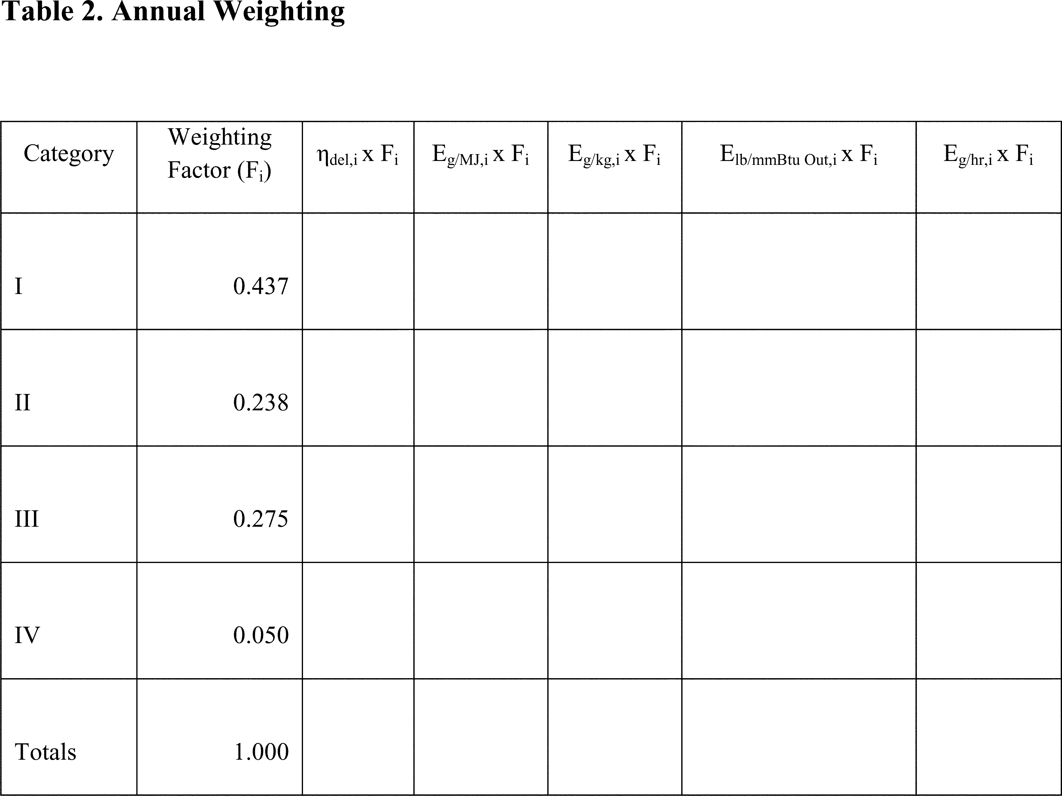

Test Method 28WHH for Certification of Cord Wood-Fired Hydronic Heating Appliances With Partial Thermal Storage: Measurement of Particulate Matter (PM) and Carbon Monoxide (CO) Emissions and Heating Efficiency of Wood-Fired Hydronic Heating Appliances With Partial Thermal Storage
1.0 Scope and Application
1.1 This test method applies to wood-fired hydronic heating appliances with heat storage external to the appliance. The units typically transfer heat through circulation of a liquid heat exchange media such as water or a water-antifreeze mixture. Throughout this document, the term “water” will be used to denote any of the heat transfer liquids approved for use by the manufacturer.
1.2 The test method measures PM and CO emissions and delivered heating efficiency at specified heat output rates referenced against the appliance's rated heating capacity as specified by the manufacturer and verified under this test method.
1.3 PM emissions are measured by the dilution tunnel method as specified in the EPA Method 28WHH and the standards referenced therein with the exceptions noted in section 12.5.9. Delivered efficiency is measured by determining the fuel energy input and appliance output. Heat output is determined through measurement of the flow rate and temperature change of water circulated through a heat exchanger external to the appliance and the increase in energy of the external storage. Heat input is determined from the mass of dry wood fuel and its higher heating value (HHV). Delivered efficiency does not attempt to account for pipeline loss.
1.4 Products covered by this test method include both pressurized and non-pressurized hydronic heating appliances intended to be fired with wood and for which the manufacturer specifies for indoor or outdoor installation. The system, which includes the heating appliance and external storage, is commonly connected to a heat exchanger by insulated pipes and normally includes a pump to circulate heated liquid. These systems are used to heat structures such as homes, barns and greenhouses. They also provide heat for domestic hot water, spas and swimming pools.
1.5 Distinguishing features of products covered by this standard include:
1.5.1 The manufacturer specifies the application for either indoor or outdoor installation.
1.5.2 A firebox with an access door for hand loading of fuel.
1.5.3 Typically an aquastat mounted as part of the appliance that controls combustion air supply to maintain the liquid in the appliance within a predetermined temperature range provided sufficient fuel is available in the firebox. The appliance may be equipped with other devices to control combustion.
1.5.4 A chimney or vent that exhausts combustion products from the appliance.
1.5.5 A liquid storage system, typically water, which is not large enough to accept all of the heat produced when a full load of wood is burned and the storage system starts a burn cycle at 125 °F.
1.5.6 The heating appliances require external thermal storage and these units will only be installed as part of a system which includes thermal storage. The manufacturer specifies the minimum amount of thermal storage required. However, the storage system shall be large enough to ensure that the boiler (heater) does not cycle, slumber, or go into an off-mode when operated in a Category III load condition (See section 4.3).
1.6 The values stated are to be regarded as the standard whether in I-P or SI units. The values given in parentheses are for information only.
2.0 Summary of Method and References
2.1 PM and CO emissions are measured from a wood-fired hydronic heating appliance burning a prepared test fuel charge in a test facility maintained at a set of prescribed conditions. Procedures for determining heat output rates, PM and CO emissions, and efficiency and for reducing data are provided.
2.2 Referenced Documents
2.2.1 EPA Standards
2.2.1.1 Method 28 Certification and Auditing of Wood Heaters
2.2.1.2 Method 28WHH Measurement of Particulate Emissions and Heating Efficiency of Wood-Fired Hydronic Heating Appliances and the Standards Referenced therein.
2.2.2 Other Standards
2.2.2.1 CSA-B415.1-10 Performance Testing of Solid-Fuel-Burning Heating Appliances
3.0 Terminology
3.1 Definitions
3.1.1 Hydronic Heating - A heating system in which a heat source supplies energy to a liquid heat exchange media such as water that is circulated to a heating load and returned to the heat source through pipes.
3.1.2 Aquastat - A control device that opens or closes a circuit to control the rate of fuel consumption in response to the temperature of the heating media in the heating appliance.
3.1.3 Delivered Efficiency - The percentage of heat available in a test fuel charge that is delivered to a simulated heating load or the storage system as specified in this test method.
3.1.4 Emission Factor - The emission of a pollutant expressed in mass per unit of energy (typically) output from the boiler/heater.
3.1.5 Emission Index - The emission of a pollutant expressed in mass per unit mass of fuel used.
3.1.6 Emission Rate - The emission of a pollutant expressed in mass per unit time
3.1.7 Manufacturer's Rated Heat Output Capacity - The value in Btu/hr (MJ/hr) that the manufacturer specifies that a particular model of hydronic heating appliance is capable of supplying at its design capacity as verified by testing, in accordance with section 12.5.4.
3.1.8 Heat Output Rate - The average rate of energy output from the appliance during a specific test period in Btu/hr (MJ/hr).
3.1.9 Firebox - The chamber in the appliance in which the test fuel charge is placed and combusted.
3.1.10 NIST - National Institute of Standards and Technology.
3.1.11 Test Fuel Charge - The collection of test fuel placed in the appliance at the start of the emission test run.
3.1.12 Test Run - An individual emission test which encompasses the time required to consume the mass of the test fuel charge. The time of the test run also considers the time for the energy to be drawn from the thermal storage.
3.1.13 Test Run Under “Cold-to-Cold” Condition - Under this test condition the test fuel is added into an empty chamber along with kindling and ignition materials (paper). The boiler/heater at the start of this test is typically 125° to 130 °F.
3.1.14 Test Run Under “Hot-to-Hot” Condition - Under this test condition the test fuel is added onto a still-burning bed of charcoals produced in a pre-burn period. The boiler/heater water is near its operating control limit at the start of the test.
3.1.15 Overall Efficiency, also known as Stack Loss Efficiency - The efficiency for each test run as determined using the CSA B415.1-10 (IBR, see § 60.17) stack loss method (SLM).
3.1.16 Phases of a Burn Cycle - The “startup phase” is defined as the period from the start of the test until 15 percent of the test fuel charge is consumed. The “steady-state phase” is defined as the period from the end of the startup phase to a point at which 80 percent of the test fuel charge is consumed. The “end phase” is defined as the time from the end of the steady-state period to the end of the test.
3.1.17 Thermopile - A device consisting of a number of thermocouples connected in series, used for measuring differential temperature.
3.1.18 Slumber Mode - This is a mode in which the temperature of the water in the boiler/heater has exceeded the operating control limit and the control has changed the boiler/heater fan speed, dampers, and/or other operating parameters to minimize the heat output of the boiler/heater.
4.0 Summary of Test Method
4.1 Dilution Tunnel. Emissions are determined using the “dilution tunnel” method specified in EPA Method 28WHH and the standards referenced therein. The flow rate in the dilution tunnel is maintained at a constant level throughout the test cycle and accurately measured. Samples of the dilution tunnel flow stream are extracted at a constant flow rate and drawn through high efficiency filters. The filters are dried and weighed before and after the test to determine the emissions collected and this value is multiplied by the ratio of tunnel flow to filter flow to determine the total particulate emissions produced in the test cycle.
4.2 Efficiency. The efficiency test procedure takes advantage of the fact that this type of system delivers heat through circulation of the heated liquid (water) from the system to a remote heat exchanger (e.g. baseboard radiators in a room) and back to the system. Measurements of the cooling water temperature difference as it enters and exits the test system heat exchanger along with the measured flow rate allow for an accurate determination of the useful heat output of the appliance. Also included in the heat output is the change in the energy content in the storage system during a test run. Energy input to the appliance during the test run is determined by weight of the test fuel charge, adjusted for moisture content, multiplied by the higher heating value. Additional measurements of the appliance weight and temperature at the beginning and end of a test cycle are used to correct for heat stored in the appliance. Overall efficiency (SLM) is determined using the CSA B415.1-10 (IBR, see § 60.17) stack loss method for data quality assurance purposes.
4.3 Operation. Four test categories are defined for use in this method. These are:
4.3.1 Category I: A heat output of 15 percent or less of manufacturer's rated heat output capacity.
4.3.2 Category II: A heat output of 16 percent to 24 percent of manufacturer's rated heat output capacity.
4.3.3 Category III: A heat output of 25 percent to 50 percent of manufacturer's rated heat output capacity.
4.3.4 Category IV: Manufacturer's Rated Heat Output Capacity. These heat output categories refer to the output from the system by way of the load heat exchanger installed for the test. The output from just the boiler/heater part of the system may be higher for all or part of a test, as part of this boiler/heater output goes to storage.
For the Category III and IV runs, appliance operation is conducted on a hot-to-hot test cycle meaning that the appliance is brought to operating temperature and a coal bed is established prior to the addition of the test fuel charge and measurements are made for each test fuel charge cycle. The measurements are made under constant heat draw conditions within pre-determined ranges. No attempt is made to modulate the heat demand to simulate an indoor thermostat cycling on and off in response to changes in the indoor environment.
For the Category I and II runs, the unit is tested with a “cold start.” At the manufacturer's option, the Category II and III runs may be waived and it may be assumed that the particulate emission values and efficiency values determined in the startup, steady-state, and end phases of Category I are applicable in Categories II and III for the purpose of determining the annual averages in lb/mmBtu and g/MJ (See section 13). For the annual average in g/hr, the length of time for stored heat to be drawn from thermal storage shall be determined for the test load requirements of the respective category.
All test operations and measurements shall be conducted by personnel of the laboratory responsible for the submission of the test report.
5.0 Significance and Use
5.1 The measurement of particulate matter emission and CO rates is an important test method widely used in the practice of air pollution control.
5.1.1 These measurements, when approved by state or federal agencies, are often required for the purpose of determining compliance with regulations and statutes.
5.1.2 The measurements made before and after design modifications are necessary to demonstrate the effectiveness of design changes in reducing emissions and make this standard an important tool in manufacturers' research and development programs.
5.2 Measurement of heating efficiency provides a uniform basis for comparison of product performance that is useful to the consumer. It is also required to relate emissions produced to the useful heat production.
5.3 This is a laboratory method and is not intended to be fully representative of all actual field use. It is recognized that users of hand-fired, wood-burning equipment have a great deal of influence over the performance of any wood-burning appliance. Some compromises in realism have been made in the interest of providing a reliable and repeatable test method.
6.0 Test Equipment
6.1 Scale. A platform scale capable of weighing the boiler/heater under test and associated parts and accessories when completely filled with water to an accuracy of ±1.0 pound (±0.5 kg) and a readout resolution of ±0.2 pound (±0.1 kg).
6.2 Heat Exchanger. A water-to-water heat exchanger capable of dissipating the expected heat output from the system under test.
6.3 Water Temperature Difference Measurement. A Type - T 'special limits' thermopile with a minimum of 5 pairs of junctions shall be used to measure the temperature difference in water entering and leaving the heat exchanger. The temperature difference measurement uncertainty of this type of thermopile is equal to or less than ±0.50 °F (±0.25 °C). Other temperature measurement methods may be used if the temperature difference measurement uncertainty is equal to or less than ±0.50 °F (±0.25 °C). This measurement uncertainty shall include the temperature sensor, sensor well arrangement, piping arrangements, lead wire, and measurement/recording system. The response time of the temperature measurement system shall be less than half of the time interval at which temperature measurements are recorded.
6.4 Water Flow Meter. A water flow meter shall be installed in the inlet to the load side of the heat exchanger. The flow meter shall have an accuracy of ±1 percent of measured flow.
6.4.1 Optional - Appliance Side Water Flow Meter. A water flow meter with an accuracy of ±1 percent of the flow rate is recommended to monitor supply side water flow rate.
6.5 Optional Recirculation Pump. Circulating pump used during test to prevent stratification, in the boiler/heater, of liquid being heated.
6.6 Water Temperature Measurement. Thermocouples or other temperature sensors to measure the water temperature at the inlet and outlet of the load side of the heat exchanger must meet the calibration requirements specified in 10.1 of this method.
6.7 Lab Scale. For measuring the moisture content of wood slices as part of the overall wood moisture determination. Accuracy of ±0.01 pounds.
6.8 Flue Gas Temperature Measurement. Must meet the requirements of CSA B415.1-10 (IBR, see § 60.17), clause 6.2.2.
6.9 Test Room Temperature Measurement. Must meet the requirements of CSA B415.1-10 (IBR, see § 60.17), clause 6.2.1.
6.10 Flue Gas Composition Measurement. Must meet the requirements of CSA B415.1-10 (IBR, see § 60.17), clauses 6.3.1 through 6.3.3.
6.11 Dilution Tunnel CO Measurement. In parallel with the flue gas composition measurements, the CO concentration in the dilution tunnel shall also be measured and reported at time intervals not to exceed one minute. This analyzer shall meet the zero and span drift requirements of CSA B415.1-10 (IBR, see § 60.17). In addition the measurement repeatability shall be better than ±15 ppm over the range of CO levels observed in the dilution tunnel.
7.0 Safety
7.1 These tests involve combustion of wood fuel and substantial release of heat and products of combustion. The heating system also produces large quantities of very hot water and the potential for steam production and system pressurization. Appropriate precautions must be taken to protect personnel from burn hazards and respiration of products of combustion.
8.0 Sampling, Test Specimens and Test Appliances
8.1 Test specimens shall be supplied as complete appliances, as described in marketing materials, including all controls and accessories necessary for installation in the test facility. A full set of specifications, installation and operating instructions, and design and assembly drawings shall be provided when the product is to be placed under certification of a third-party agency. The manufacturer's written installation and operating instructions are to be used as a guide in the set-up and testing of the appliance and shall be part of the test record.
8.2 The size, connection arrangement, and control arrangement for the thermal storage shall be as specified in the manufacturer's documentation. It is not necessary to use the specific storage system that the boiler/heater will be marketed with. However, the capacity of the system used in the test cannot be greater than that specified as the minimum allowable for the boiler/heater.
8.3 All system control settings shall be the as-shipped, default settings. These default settings shall be the same as those communicated in a document to the installer or end user. These control settings and the documentation of the control settings as to be provided to the installer or end user shall be part of the test record.
8.4 Where the manufacturer defines several alternatives for the connection and loading arrangement, one shall be defined in the appliance documentation as the default or standard installation. It is expected that this will be the configuration for use with a simple baseboard heating system. This is the configuration to be followed for these tests. The manufacturer's documentation shall define the other arrangements as optional or alternative arrangements.
9.0 Preparation of Test Equipment
9.1 The appliance is to be placed on a scale capable of weighing the appliance fully loaded with a resolution of ±0.2 lb (0.1 kg).
9.2 The appliance shall be fitted with the type of chimney recommended or provided by the manufacturer and extending to 15 ±0.5 feet (4.6 ±0.15 m) from the upper surface of the scale. If no flue or chimney system is recommended or provided by the manufacturer, connect the appliance to a flue of a diameter equal to the flue outlet of the appliance. The flue section from the appliance flue collar to 8 ±0.5 feet above the scale shall be single wall stove pipe and the remainder of the flue shall be double wall insulated class A chimney.
9.3 Optional Equipment Use
9.3.1 A recirculation pump may be installed between connections at the top and bottom of the appliance to minimize thermal stratification if specified by the manufacturer. The pump shall not be installed in such a way as to change or affect the flow rate between the appliance and the heat exchanger.
9.3.2 If the manufacturer specifies that a thermal control valve or other device be installed and set to control the return water temperature to a specific set point, the valve or other device shall be installed and set per the manufacturer's written instructions.
9.4 Prior to filling the boiler/heater with water, weigh and record the appliance mass.
9.5 Heat Exchanger
9.5.1 Plumb the unit to a water-to-water heat exchanger with sufficient capacity to draw off heat at the maximum rate anticipated. Route hoses and electrical cables and instrument wires in a manner that does not influence the weighing accuracy of the scale as indicated by placing dead weights on the platform and verifying the scale's accuracy.
9.5.2 Locate thermocouples to measure the water temperature at the inlet and outlet of the load side of the heat exchanger.
9.5.3 Install a thermopile (or equivalent instrumentation) meeting the requirements of section 6.3 to measure the water temperature difference between the inlet and outlet of the load side of the heat exchanger
9.5.4 Install a calibrated water flow meter in the heat exchanger load side supply line. The water flow meter is to be installed on the cooling water inlet side of the heat exchanger so that it will operate at the temperature at which it is calibrated.
9.5.5 Place the heat exchanger in a box with 2 in. (50 mm) of expanded polystyrene (EPS) foam insulation surrounding it to minimize heat losses from the heat exchanger.
9.5.6 The reported efficiency and heat output rate shall be based on measurements made on the load side of the heat exchanger.
9.5.7 Temperature instrumentation per section 6.6 shall be installed in the appliance outlet and return lines. The average of the outlet and return water temperature on the supply side of the system shall be considered the average appliance temperature for calculation of heat storage in the appliance (TFavg and TIavg). Installation of a water flow meter in the supply side of the system is optional.
9.6 Storage Tank. The storage tank shall include a destratification pump as illustrated in Figure 1. The pump will draw from the bottom of the tank and return to the top as illustrated. Temperature sensors (TS1 and TS2 in Figure 1) shall be included to measure the temperature in the recirculation loop. The valve plan in Figure 1 allows the tank recirculation loop to operate and the boiler/heater-to-heat exchanger loop to operate at the same time but in isolation. This would typically be done before the start of a test or following completion of a test to determine the end of test average tank temperature. The nominal flow rate in the storage tank recirculation loop can be estimated based on pump manufacturers' performance curves and any significant restriction in the recirculation loop.
9.7 Fill the system with water. Determine the total weight of the water in the appliance when the water is circulating. Verify that the scale indicates a stable weight under operating conditions. Make sure air is purged properly.
10.0 Calibration and Standardization
10.1 Water Temperature Sensors. Temperature measuring equipment shall be calibrated before initial use and at least semi-annually thereafter. Calibrations shall be in compliance with National Institute of Standards and Technology (NIST) Monograph 175, Standard Limits of Error.
10.2 Heat Exchanger Load Side Water Flow Meter.
10.2.1 The heat exchanger load side water flow meter shall be calibrated within the flow range used for the test run using NIST-traceable methods. Verify the calibration of the water flow meter before and after each test run and at least once during each test run by comparing the water flow rate indicated by the flow meter to the mass of water collected from the outlet of the heat exchanger over a timed interval. Volume of the collected water shall be determined based on the water density calculated from section 13, Eq. 12, using the water temperature measured at the flow meter. The uncertainty in the verification procedure used shall be 1 percent or less. The water flow rate determined by the collection and weighing method shall be within 1 percent of the flow rate indicated by the water flow meter.
10.3 Scales. The scales used to weigh the appliance and test fuel charge shall be calibrated using NIST-traceable methods at least once every 6 months.
10.4 Flue Gas Analyzers - In accordance with CSA B415.1-10 (IBR, see § 60.17), clause 6.8.
11.0 Conditioning
11.1 Prior to testing, an appliance is to be operated for a minimum of 50 hours using a medium heat draw rate. The conditioning may be at the manufacturer's facility prior to the certification test. If the conditioning is at the certification test laboratory, the pre-burn for the first test can be included as part of the conditioning requirement. If conditioning is included in pre-burn, then the appliance shall be aged with fuel meeting the specifications outlined in section 12.2 with a moisture content between 19 and 25 percent on a dry basis. Operate the appliance at a medium heat output rate (Category II or III) for at least 10 hours for non-catalytic appliances and 50 hours for catalytic appliances. Record and report hourly flue gas exit temperature data and the hours of operation. The aging procedure shall be conducted and documented by a testing laboratory.
12.0 Procedure
12.1 Appliance Installation. Assemble the appliance and parts in conformance with the manufacturer's written installation instructions. Clean the flue with an appropriately sized, wire chimney brush before each certification test series.
12.2 Fuel. Test fuel charge fuel shall be red (Quercus ruba L. ) or white (Quercus Alba) oak 19 to 25 percent moisture content on a dry basis. Piece length shall be 80 percent of the firebox depth rounded down to the nearest 1 inch (25mm) increment. For example, if the firebox depth is 46 inches (1168mm) the piece length would be 36 inches (46 inches × 0.8 = 36.8 inches, rounded down to 36 inches). Pieces are to be placed in the firebox parallel to the longest firebox dimension. For fireboxes with sloped surfaces that create a non-uniform firebox length, the piece length shall be adjusted for each layer based on 80 percent of the length at the level where the layer is placed. The test fuel shall be cord wood with cross section dimensions and weight limits as defined in CSA B415.1-10 (IBR, see § 60.17), section 8.3, Table 4. The use of dimensional lumber is not allowed.
12.2.1 Select three pieces of cord wood from the same batch of wood as the test fuel and the same weight as the average weight of the pieces in the test load ±1.0 lb. From each of these three pieces, cut three slices. Each slice shall be 1⁄2 inch to 3⁄4 inch thick. One slice shall be cut across the center of the length of the piece. The other two slices shall be cut half way between the center and the end. Immediately measure the mass of each piece in pounds. Dry each slice in an oven at 220 °F for 24 hours or until no further weight change occurs. The slices shall be arranged in the oven so as to provide separation between faces. Remove from the oven and measure the mass of each piece again as soon as practical, in pounds.
The moisture content of each slice, on a dry basis, shall be calculated as:
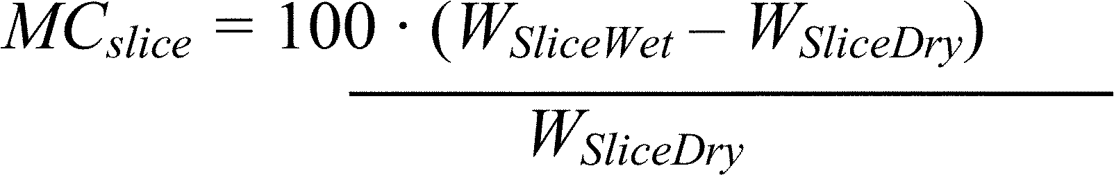
Where:
WSliceWet = weight of the slice before drying in pounds
WSliceDry = weight of the slice after drying in pounds
MCSlice = moisture content of the slice in % dry basis
The average moisture content of the entire test load (MC) shall be determined using Eq. 6. Each individual slice shall have a moisture content in the range of 18 percent to 28 percent on a dry basis. The average moisture content for the test fuel load shall be in the range of 19 percent to 25 percent. Moisture shall not be added to previously dried fuel pieces except by storage under high humidity conditions and temperature up to 100 °F. Fuel moisture measurement shall begin within 4 hours of using the fuel batch for a test. Use of a pin-type meter to estimate the moisture content prior to a test is recommended.
12.2.2 Firebox Volume. Determine the firebox volume in cubic feet. Firebox volume shall include all areas accessible through the fuel loading door where firewood could reasonably be placed up to the horizontal plane defined by the top of the loading door. A drawing of the firebox showing front, side and plan views or an isometric view with interior dimensions shall be provided by the manufacturer and verified by the laboratory. Calculations for firebox volume from computer aided design (CAD) software programs are acceptable and shall be included in the test report if used. If the firebox volume is calculated by the laboratory the firebox drawings and calculations shall be included in the test report.
12.2.3 Test Fuel charge. Test fuel charges shall be determined by multiplying the firebox volume by 10 pounds (4.54 kg) per ft3 (28L), or a higher load density as recommended by the manufacturer's printed operating instructions, of wood (as used wet weight). Select the number of pieces of cord wood that most nearly match this target weight. However, the test fuel charge cannot be less than the target of 10 pounds (4.54 kg) per ft3 (28L).
12.3 Sampling Equipment. Prepare the particulate emission sampling equipment as defined by EPA Method 28WHH and the standards referenced therein.
12.4 Appliance Startup. The appliance shall be fired with wood fuel of any species, size and moisture content, at the laboratory's discretion, to bring it up to operating temperature. Operate the appliance until the water is heated to the upper operating control limit and has cycled at least two times. Then remove all unburned fuel, zero the scale and verify the scales accuracy using dead weights.
12.4.1 Startup Procedure for Category III and IV Test Runs, “Hot-to-Hot.”
12.4.1.1 Pretest t Burn Cycle. Following appliance startup (section 12.4), reload appliance with oak cord wood and allow it to burn down to the specified coal bed weight. The pre-test burn cycle fuel charge weight shall be within ±10 percent of the test fuel charge weight. Piece size and length shall be selected such that charcoalization is achieved by the time the fuel charge has burned down to the required coal bed weight. Pieces with a maximum thickness of approximately 2 inches have been found to be suitable. Charcoalization is a general condition of the test fuel bed evidenced by an absence of large pieces of burning wood in the coal bed and the remaining fuel pieces being brittle enough to be broken into smaller charcoal pieces with a metal poker. Manipulations to the fuel bed prior to the start of the test run are to be done to achieve charcoalization while maintaining the desired heat output rate. During the pre-test burn cycle and at least one hour prior to starting the test run, adjust water flow to the heat exchanger to establish the target heat draw for the test. For the first test run the heat draw rate shall be equal to the manufacturer's rated heat output capacity.
12.4.1.2 Allowable Adjustments. Fuel addition or subtractions, and coal bed raking shall be kept to a minimum but are allowed up to 15 minutes prior to the start of the test run. For the purposes of this method, coal bed raking is the use of a metal tool (poker) to stir coals, break burning fuel into smaller pieces, dislodge fuel pieces from positions of poor combustion, and check for the condition of charcoalization. Record all adjustments to and additions or subtractions of fuel, and any other changes to the appliance operations that occur during pretest ignition period. During the 15-minute period prior to the start of the test run, the wood heater loading door shall not be open more than a total of 1 minute. Coal bed raking is the only adjustment allowed during this period.
12.4.1.3 Coal Bed Weight. The appliance is to be loaded with the test fuel charge when the coal bed weight is between 10 percent and 20 percent of the test fuel charge weight. Coals may be raked as necessary to level the coal bed but may only be raked and stirred once between 15 to 20 minutes prior to the addition of the test fuel charge.
12.4.1.4 Storage. The Category III and IV test runs may be done either with or without the thermal storage. If thermal storage is used, the initial temperature of the storage must be 125 °F or greater at the start of the test. The storage may be heated during the pre-test burn cycle or it may be heated by external means. If thermal storage is used, prior to the start of the test run, the storage tank destratification pump, shown in Figure 1, shall be operated until the total volume pumped exceeds 1.5 times the tank volume and the difference between the temperature at the top and bottom of the storage tank (TS1 and TS2) is less than 1 °F. These two temperatures shall then be recorded to determine the starting average tank temperature. The total volume pumped may be based on the nominal flow rate of the destratification pump (See section 9.6). If the Category III and IV runs are done with storage, it is recognized that during the last hour of the pre-burn cycle the storage tank must be mixed to achieve a uniform starting temperature and cannot receive heat from the boiler/heater during this time. During this time period, the boiler/heater might cycle or go into a steady reduced output mode. (Note - this would happen, for example, in a Category IV run if the actual maximum output of the boiler/heater exceed the manufacturer's rated output.) A second storage tank may be used temporarily to enable the boiler/heater to operate during this last hour of the pre-burn period as it will during the test period. The temperature of this second storage tank is not used in the calculations but the return water to the boiler/heater (after mixing device if used) must be 125 °F or greater.
12.4.2 Startup Procedure for Category I and II Test Runs, “Cold-to-Cold.”
12.4.2.1 Initial Temperatures. This test shall be started with both the boiler/heater and the storage at a minimum temperature of 125 °F. The boiler/heater maximum temperature at the start of this test shall be 135 °F. The boiler/heater and storage may be heated through a pre-burn or it may be heated by external means.
12.4.2.2 Firebox Condition at Test Start. Prior to the start of this test remove all ash and charcoal from the combustion chamber(s). The loading of the test fuel and kindling should follow the manufacturer's recommendations, subject to the following constraints: Up to 10 percent kindling and paper may be used which is in addition to the fuel load. Further, up to 10 percent of the fuel load (i.e., included in the 10 lb/ft3) may be smaller than the main fuel. This startup fuel shall still be larger than 2 inches.
12.4.2.3 Storage. The Category I and II test runs shall be done with thermal storage. The initial temperature of the storage must be 125 °F or greater at the start of the test. The storage may be heated during the pre-test burn cycle or it may be heated by external means. Prior to the start of the test run, the storage tank destratification pump, shown in Figure 1, shall be operated until the total volume pumped exceeds 1.5 times the tank volume and the difference between the temperature at the top and bottom of the storage tank (TS1 and TS2) is less than 1 °F. These two temperatures shall then be recorded to determine the starting average tank temperature. The total volume pumped may be based on the nominal flow rate of the destratification pump (See section 9.6).
12.5 Test Runs. For all test runs, the return water temperature to the hydronic heater must be equal to or greater than 120 °F (this is lower than the initial tank temperature to allow for any pipeline losses). Where the storage system is used, flow of water from the boiler/heater shall be divided between the storage tank and the heat exchanger such that the temperature change of the circulating water across the heat exchanger shall be 30 ±5 °F, averaged over the entire test run. This is typically adjusted using the system valves.
Complete a test run in each heat output rate category, as follows:
12.5.1 Test Run Start. For Category III and IV runs: Once the appliance is operating normally and the pretest coal bed weight has reached the target value per section 12.4.1, tare the scale and load the full test charge into the appliance. Time for loading shall not exceed 5 minutes. The actual weight of the test fuel charge shall be measured and recorded within 30 minutes prior to loading. Start all sampling systems.
For Category I and II runs: Once the appliance has reached the starting temperature, tare the scale and load the full test charge, including kindling into the appliance. The actual weight of the test fuel charge shall be measured and recorded within 30 minutes prior to loading. Light the fire following the manufacturer's written normal startup procedure. Start all sampling systems.
12.5.1.1 Record all water temperatures, differential water temperatures and water flow rates at time intervals of one minute or less.
12.5.1.2 Record particulate emissions data per the requirements of EPA Method 28WHH and the standards referenced therein.
12.5.1.3 Record data needed to determine overall efficiency (SLM) per the requirements of CSA B415.1-10 (IBR, see § 60.17) clauses 6.2.1, 6.2.2, 6.3, 8.5.7, 10.4.3(a), 10.4.3(f), and 13.7.9.3
12.5.1.3.1 Measure and record the test room air temperature in accordance with the requirements of CSA B415.1-10 (IBR, see § 60.17), clauses 6.2.1, 8.5.7 and 10.4.3(g).
12.5.1.3.2 Measure and record the flue gas temperature in accordance with the requirements of CSA B415.1-10 (IBR, see § 60.17), clauses 6.2.2, 8.5.7 and 10.4.3(f).
12.5.1.3.3 Determine and record the carbon monoxide (CO) and carbon dioxide (CO2) concentrations in the flue gas in accordance with CSA B415.1-10 (IBR, see § 60.17), clauses 6.3, 8.5.7 and 10.4.3(i) and (j).
12.5.1.3.4 Measure and record the test fuel weight per the requirements of CSA B415.1-10 (IBR, see § 60.17), clauses 8.5.7 and 10.4.3(h).
12.5.1.3.5 Record the test run time per the requirements of CSA B415.1-10 (IBR, see § 60.17), clause 10.4.3(a).
12.5.1.3.6 Record and document all settings and adjustments, if any, made to the boiler/heater as recommended/required by manufacturer's instruction manual for different combustion conditions or heat loads. These may include temperature setpoints, under and over-fire air adjustment, or other adjustments that could be made by an operator to optimize or alter combustion. All such settings shall be included in the report for each test run.
12.5.1.4 Monitor the average heat output rate on the load side of the heat exchanger based on water temperatures and flow. If the heat output rate over a 10 minute averaging period gets close to the upper or lower limit of the target range (±5 percent), adjust the water flow through the heat exchanger to compensate. Make changes as infrequently as possible while maintaining the target heat output rate. The first test run shall be conducted at the Category IV heat output rate to validate that the appliance is capable of producing the manufacturer's rated heat output capacity.
12.5.2 Test Fuel Charge Adjustment. It is acceptable to adjust the test fuel charge (i.e., reposition) once during a test run if more than 60 percent of the initial test fuel charge weight has been consumed and more than 10 minutes have elapsed without a measurable (1 lb or 0.5 kg) weight change while the operating control is in the demand mode. The time used to make this adjustment shall be less than 60 seconds.
12.5.3 Test Run Completion. For the Category III and IV, “hot-to-hot” test runs, the test run is completed when the remaining weight of the test fuel charge is 0.0 lb (0.0 kg). (WFuelBurned = Wfuel) End the test run when the scale has indicated a test fuel charge weight of 0.0 lb (0.0 kg) or less for 30 seconds.
For the Category I and II “cold-to-cold” test runs, the test run is completed; and the end of a test is defined at the first occurrence of any one of the following:
(a) The remaining weight of the test fuel charge is less than 1 percent of the total test fuel weight (WFuelBurned > 0.99 · Wfuel);
(b) The automatic control system on the boiler/heater switches to an off mode. In this case, the boiler/heater fan (if used) is typically stopped and all air flow dampers are closed by the control system. Note that this off mode cannot be an “overheat” or emergency shutdown which typically requires a manual reset; or
(c) If the boiler/heater does not have an automatic off mode: After 90 percent of the fuel load has been consumed and the scale has indicated a rate of change of the test fuel charge of less than 1.0 lb/hr for a period of 10 minutes or longer. Note - this is not considered “stopped fuel combustion,” See section 12.5.6.1.
12.5.3.1 At the end of the test run, stop the particulate sampling train and overall efficiency (SLM) measurements, and record the run time, and all final measurement values.
12.5.3.2 At the end of the test run, continue to operate the storage tank destratification pump until the total volume pumped exceeds 1.5 times the tank volume. The maximum average of the top and bottom temperatures measured after this time may be taken as the average tank temperature at the end of the tests (TFSavg, See section 13.1). The total volume pumped may be based on the nominal flow rate of the destratification pump (See section 9.6).
12.5.3.3 For the Category I and II test runs, there is a need to determine the energy content of the unburned fuel remaining in the chamber if the remaining mass in the chamber is greater than 1 percent of the test fuel weight. Following the completion of the test, as soon as safely practical, this remaining fuel is removed from the chamber, separated from the remaining ash and weighed. This separation could be implemented with a slotted “scoop” or similar tool. A 1⁄4 inch opening size in the separation tool shall be used to separate the ash and charcoal. This separated char is assigned a heating value of 12,500 Btu/lb.
12.5.4 Heat Output Capacity Validation. The first test run must produce a heat output rate that is within 10 percent of the manufacturer's rated heat output capacity (Category IV) throughout the test run and an average heat output rate within 5 percent of the manufacturer's rated heat output capacity. If the appliance is not capable of producing a heat output within these limits, the manufacturer's rated heat output capacity is considered not validated and testing is to be terminated. In such cases, the tests may be restarted using a lower heat output capacity if requested by the manufacturer. Alternatively, during the Category IV run, if the rated output cannot be maintained for a 15 minute interval, the manufacturer may elect to reduce the rated output to match the test and complete the Category IV run on this basis. The target outputs for Categories I, II, and III shall then be recalculated based on this change in rated output capacity.
12.5.5 Additional Test Runs. Using the manufacturer's rated heat output capacity as a basis, conduct a test for additional heat output categories as specified in section 4.3. It is not required to run these tests in any particular order.
12.5.6 Alternative Heat Output Rate for Category
I. If an appliance cannot be operated in the Category I heat output range due to stopped combustion, two test runs shall be conducted at heat output rates within Category
II. When this is the case, the weightings for the weighted averages indicated in section 14.1.15 shall be the average of the Category I and II weighting's and shall be applied to both Category II results. Appliances that are not capable of operation within Category II (<25 percent of maximum) cannot be evaluated by this test method.
12.5.6.1 Stopped Fuel Combustion. Evidence that an appliance cannot be operated at a Category I heat output rate due to stopped fuel combustion shall include documentation of two or more attempts to operate the appliance in heat output rate Category I and fuel combustion has stopped prior to complete consumption of the test fuel charge. Stopped fuel combustion is evidenced when an elapsed time of 60 minutes or more has occurred without a measurable (1 lb or 0.5 kg) weight change in the test fuel charge while the appliance operating control is in the demand mode. Report the evidence and the reasoning used to determine that a test in heat output rate Category I cannot be achieved. For example, two unsuccessful attempts to operate at an output rate of 10 percent of the rated output capacity are not sufficient evidence that heat output rate Category I cannot be achieved.
12.5.7 Appliance Overheating. Appliances with their associated thermal storage shall be capable of operating in all heat output categories without overheating to be rated by this test method. Appliance overheating occurs when the rate of heat withdrawal from the appliance is lower than the rate of heat production when the unit control is in the idle mode. This condition results in the water in the appliance continuing to increase in temperature well above the upper limit setting of the operating control. Evidence of overheating includes: 1 hour or more of appliance water temperature increase above the upper temperature set-point of the operating control, exceeding the temperature limit of a safety control device (independent from the operating control - typically requires manual reset), boiling water in a non-pressurized system or activation of a pressure or temperature relief valve in a pressurized system.
12.5.8 Option to Eliminate Tests in Category II and III. Following successful completion of a test run in Category I, the manufacturer may eliminate the Category II and III tests. For the purpose of calculating the annual averages for particulates and efficiency, the values obtained in the Category I run shall be assumed to apply also to Category II and Category III. It is envisioned that this option would be applicable to systems which have sufficient thermal storage such that the fuel load in the Category I test can be completely consumed without the system reaching its upper operating temperature limit. In this case, the boiler/heater would likely be operating at maximum thermal output during the entire test and this output rate may be higher than the manufacturer's rated heat output capacity. The Category II and III runs would then be the same as the Category I run. It may be assumed that the particulate emission values and efficiency values determined in the startup, steady-state, and end phases of Category I are applicable in Categories II and III, for the purpose of determining the annual averages in lb/mmBtu and g/MJ (See section 13). For the annual average in g/hr, the length of time for stored heat to be drawn from thermal storage shall be determined for the test load requirements of the respective category.
12.5.9 Modification to Measurement Procedure in EPA Method 28WHH to Determine Emissions Separately During the Startup, Steady-State and End Phases. With one of the two particulate sampling trains used, filter changes shall be made at the end of the startup phase and the steady-state phase (See section 3.0). This shall be done to determine the particulate emission rate and particulate emission index for the startup, steady-state, and end phases individually. For this one train, the particulates measured during each of these three phases shall be added together to also determine the particulate emissions for the whole run.
12.5.10 Modification to Measurement Procedure in EPA Method 28WHH and the Standards Referenced therein on Averaging Period for Determination of Efficiency by the Stack Loss Method. The methods currently defined in Method 28WHH allow averaging over 10-minute time periods for flue gas temperature, flue gas CO2, and flue gas CO for the determination of the efficiency with the stack loss method. However, under some cycling conditions the “on” period may be short relative to this 10-minute period. For this reason, during cycling operation the averaging period for these parameters may not be longer than the burner on period divided by 10. The averaging period need not be shorter than one minute. During the off period, under cycling operation, averaging periods as specified in EPA Method 28WHH and the standards referenced therein, may be used. Where short averaging times are used, however, the averaging period for fuel consumption may still be at 10 minutes. This average wood consumption rate shall be applied to all of the smaller time intervals included.
12.6 Additional Test Runs. The testing laboratory may conduct more than one test run in each of the heat output categories specified in section 4.3. If more than one test run is conducted at a specified heat output rate, the results from at least two-thirds of the test runs in that heat output rate category shall be used in calculating the weighted average emission rate. The measurement data and results of all test runs shall be reported regardless of which values are used in calculating the weighted average emission rate.
13.0 Calculation of Results
13.1 Nomenclature
COs - Carbon monoxide measured in the dilution tunnel at arbitrary time in ppm dry basis.
COg/min - Carbon monoxide emission rate in g/min.
COT - Total carbon monoxide emission for the full test run in grams.
CO_1 - Startup period carbon monoxide emissions in grams.
CO_2 - Steady-state period carbon monoxide emission in grams.
CO_3 - End period carbon monoxide emission in grams.
ET - Total particulate emissions for the full test run as determined per EPA Method 28WHH and the standards referenced therein in grams.
E1 - Startup period particulate emissions in grams.
E2 - Steady-state period particulate emissions in grams.
E3 - End period particulate emissions in grams.
E1_g/kg - Startup period particulate emission index in grams per kg fuel.
E2_g/kg - Steady-state period particulate emission index in grams per kg fuel.
E3_g/kg - End period particulate emission index in grams per kg fuel.
E1_g/hr - Startup period particulate emission rate in grams per hour.
E2_g/hr - Steady-state period particulate emission rate in grams per hour.
E3_g/hr - End period particulate emission rate in grams per hour.
Eg/MJ - Emission rate in grams per MJ of heat output.
Elb/mmBtu output - Emissions rate in pounds per million Btu of heat output.
Eg/kg - Emissions factor in grams per kilogram of dry fuel burned.
Eg/hr - Emission factor in grams per hour.
HHV - Higher heating value of fuel = 8600 Btu/lb (19.990 MJ/kg).
LHV - Lower heating value of fuel = 7988 Btu/lb (18.567 MJ/kg).
ΔT - Temperature difference between cooling water entering and exiting the heat exchanger.
Qout - Total heat output in Btu (MJ).
Qin - Total heat input available in test fuel charge in Btu's (MJ).
Qstd - Volumetric flow rate in dilution tunnel in dscfm.
M - Mass flow rate of water in lb/min (kg/min).
Vi - Volume of water indicated by a totalizing flow meter at the ith reading in gallons (liters).
Vf - Volumetric flow rate of water in heat exchange system in gallons per minute (liters/min).
Θ - Total length of burn period in hours (Θ1 + Θ2 + Θ3).
Θ1 - Length of time of the startup period in hours.
Θ2 - Length of time of the steady-state period in hours.
Θ3 - Length of time of the end period in hours.
Θ4 - Length of time for stored heat to be used following a burn period in hours.
ti - Data sampling interval in minutes.
ηdel - Delivered heating efficiency in percent.
Fi - Weighting factor for heat output category i. (See Table 2.)
T1 - Temperature of water at the inlet on the supply side of the heat exchanger, °F.
T2 - Temperature of the water at the outlet on the supply side of the heat exchanger, °F.
T3 - Temperature of cooling water at the inlet to the load side of the heat exchanger, °F.
T4 - Temperature of cooling water at the outlet of the load side of the heat exchanger, °F.
T5 - Temperature of the hot water supply as it leaves the boiler/heater, °F.
T6 - Temperature of return water as it enters the boiler/heater, °F.
T7 - Temperature in the boiler/heater optional destratification loop at the top of the boiler/heater, °F.
T8 - Temperature in the boiler/heater optional destratification loop at the bottom of the boiler/heater, °F.
TIavg - Average temperature of the appliance and water at start of the test.

TFavg - Average temperature of the appliance and water at the end of the test.

TIS1 - Temperature at the inlet to the storage system at the start of the test.
TIS2 - Temperature at the outlet from the storage system at the start of the test.
TFS1 - Temperature at the inlet to the storage system at the end of the test.
TFS2 - Temperature at the outlet from the storage system at the end of the test.
TISavg - Average temperature of the storage system at the start of the test.

TFSavg - Average temperature of the storage system at the end of the test.

MC - Fuel moisture content in percent dry basis.
σ - Density of water in pounds per gallon.
σInitial - Density of water in the boiler/heater system at the start of the test in pounds per gallons.
σboiler/heater - Density of water in the boiler/heater system at an arbitrary time during the test in pounds per gallon.
Cp - Specific heat of water in Btu/lb, °F.
Csteel - Specific heat of steel (0.1 Btu/lb, °F).
Vboiler/heater - total volume of water in the boiler/heater system on the weight scale in gallons.
Wfuel - Fuel charge weight, as-fired or “wet”, in pounds (kg).
Wfuel_1 - Fuel consumed during the startup period in pounds (kg).
Wfuel_2 - Fuel consumed during the steady state period in pounds (kg).
Wfuel_3 - Fuel consumed during the end period in pounds (kg).
WFuelBurned - Weight of fuel that has been burned from the start of the test to an arbitrary time, including the needed correction for the change in density and weight of the water in the boiler/heater system on the scale in pounds (kg).
WRemainingFuel - Weight of unburned fuel separated from the ash at the end of a test. Useful only for Category I and Category II tests.
Wapp - Weight of empty appliance in pounds (kg).
Wwat - Weight of water in supply side of the system in pounds (kg).
WScaleInitial - Weight reading on the scale at the start of the test, just after the test load has been added in pounds (kg).
WScale - Reading of the weight scale at an arbitrary time during the test run in pounds (kg).
WStorageTank - Weight of the storage tank empty in pounds (kg).
WWaterStorage - Weight of the water in the storage tank at TISavg in pounds (kg).
13.2 After the test is completed, determine the particulate emissions ET in accordance with EPA Method 28WHH and the standards referenced therein.
13.3 Determination of the weight of fuel that has been burned at an arbitrary time.
For the purpose of tracking the consumption of the test fuel load during a test run the following may be used to calculate the weight of fuel that burned since the start of the test:

Water density, σ, is calculated using Equation 12.
13.4 Determine Average Fuel Load Moisture Content.

13.5 Determine Heat Input.

13.5.1 Correction to Qin for the Category I and II tests, where there is greater than 1 percent of the test fuel charge in the chamber at the end of the test period.

13.6 Determine Heat Output, Efficiency, and Emissions.
13.6.1 Determine heat output as:
Qout = Σ [Heat output determined for each sampling time interval] + Change in heat stored in the appliance + Change in heat in storage tank.

The subscript (i) indicates the parameter value for sampling time interval ti.Mi = Mass flow rate = gal/min × density of water (lb/gal) = lb/min.

Csteel = 0.1 Btu/lb, -° F.

Vi is the total water volume at the end of interval i and Vi-1 is the total water volume at the beginning of the time interval. This calculation is necessary when a totalizing type water meter is used.
13.6.2 Determine Heat Output Rate Over Burn Period (Θ1 + Θ2 + Θ3) as:

13.6.3 Determine Emission Rates and Emission Factors as:

If thermal storage is not used in a Category III or IV run, then Θ4 = 0.
E1_g/kg = E1/(Wfuel_1/(1 + MC/100)), g/dry kg.
E2_g/kg = E2/(Wfuel_2/(1 + MC/100)), g/dry kg.
E3_g/kg = E3/(Wfuel_3/(1 + MC/100)), g/dry kg.
E1_g/hr = E1/Θ1, g/hr.
E2_g/hr = E2/Θ2, g/hr.
E3_g/hr = E3/Θ3, g/hr.
13.6.4 Determine delivered efficiency as:

13.6.5 Determine ηSLM - Overall Efficiency, also known as Stack Loss Efficiency, using stack loss method (SLM).
For determination of the average overall thermal efficiency (ηSLM) for the test run, use the data collected over the full test run and the calculations in accordance with CSA B415.1-10 (IBR, see § 60.17), clause 13.7 except for 13.7.2(e), (f), (g), and (h), use the following average fuel properties for oak: %C = 50.0, %H = 6.6, %O = 43.2, %Ash = 0.2.
13.6.5.1 Whenever the CSA B415.1-10 (IBR, see § 60.17) overall efficiency is found to be lower than the overall efficiency based on load side measurements, as determined by Eq. 22 of this method, section 14.1.7 of the test report must include a discussion of the reasons for this result. For a test where the CSA B415.1-10 overall efficiency SLM is less than 2 percentage points lower than the overall efficiency based on load side measurements, the efficiency based on load side measurements shall be considered invalid. [Note on the rationale for the 2 percentage points limit. The SLM method does not include boiler/heater jacket losses and, for this reason, should provide an efficiency which is actually higher than the efficiency based on the energy input and output measurements or “delivered efficiency.” A delivered efficiency that is higher than the efficiency based on the SLM could be considered suspect. A delivered efficiency greater than 2 percentage points higher than the efficiency based on the SLM, then, clearly indicates a measurement error.]
13.6.6 Carbon Monoxide Emissions
For each minute of the test period, the carbon monoxide emission rate shall be calculated as:

Total CO emissions for each of the three test periods (CO_1, CO_2, CO_3) shall be calculated as the sum of the emission rates for each of the 1-minute intervals. Total CO emission for the test run, COT, shall be calculated as the sum of CO_1, CO_2, and CO_3.
13.7 Weighted Average Emissions and Efficiency.
13.7.1 Determine the weighted average emission rate and delivered efficiency from the individual tests in the specified heat output categories. The weighting factors (Fi) are derived from an analysis of ASHRAE bin data which provides details of normal building heating requirements in terms of percent of design capacity and time in a particular capacity range - or “bin” - over the course of a heating season. The values used in this method represent an average of data from several cities located in the northern United States.

If, as discussed in section 12.5.8, the option to eliminate tests in Category II and III is elected, the values of efficiency and particulate emission rate as measured in Category I, shall be assigned also to Category II and III for the purpose of determining the annual averages.
14.0 Report
14.1.1 The report shall include the following:
14.1.2 Name and location of the laboratory conducting the test.
14.1.3 A description of the appliance tested and its condition, date of receipt and dates of tests.
14.1.4 A description of the minimum amount of external thermal storage that is required for use with this system. This shall be specified both in terms of volume in gallons and stored energy content in Btu with a storage temperature ranging from 125 °F to the manufacturer's specified setpoint temperature.
14.1.5 A statement that the test results apply only to the specific appliance tested.
14.1.6 A statement that the test report shall not be reproduced except in full, without the written approval of the laboratory.
14.1.7 A description of the test procedures and test equipment including a schematic or other drawing showing the location of all required test equipment. Also, a description of test fuel sourcing, handling and storage practices shall be included.
14.1.8 Details of deviations from, additions to or exclusions from the test method, and their data quality implications on the test results (if any), as well as information on specific test conditions, such as environmental conditions.
14.1.9 A list of participants and their roles and observers present for the tests.
14.1.10 Data and drawings indicating the fire box size and location of the fuel charge.
14.1.11 Drawings and calculations used to determine firebox volume.
14.1.12 Information for each test run fuel charge including piece size, moisture content and weight.
14.1.13 All required data and applicable blanks for each test run shall be provided in spreadsheet format both in the printed report and in a computer file such that the data can be easily analyzed and calculations easily verified. Formulas used for all calculations shall be accessible for review.
14.1.14 For each test run, Θ1,Θ2, Θ3, the total CO and particulate emission for each of these three periods, and Θ4.
14.1.15 Calculated results for delivered efficiency at each heat output rate and the weighted average emissions reported as total emissions in grams, pounds per mm Btu of delivered heat, grams per MJ of delivered heat, grams per kilogram of dry fuel and grams per hour. Results shall be reported for each heat output category and the weighted average.
14.1.16 Tables 1A, 1B, 1C, 1D, 1E and Table 2 must be used for presentation of results in test reports.
14.1.17 A statement of the estimated uncertainty of measurement of the emissions and efficiency test results.
14.1.18 A plot of CO emission rate in grams/minute vs. time, based on 1 minute averages, for the entire test period, for each run.
14.1.19 A plot of estimated boiler/heater energy release rate in Btu/hr based on 10 minute averages, for the entire test period, for each run. This will be calculated from the fuel used, the wood heating value and moisture content, and the SLM efficiency during each 10 minute period.
14.1.20 Raw data, calibration records, and other relevant documentation shall be retained by the laboratory for a minimum of 7 years.
15.0 Precision and Bias
15.1 Precision - It is not possible to specify the precision of the procedure in this test method because the appliance operation and fueling protocols and the appliances themselves produce variable amounts of emissions and cannot be used to determine reproducibility or repeatability of this test method.
15.2 Bias - No definitive information can be presented on the bias of the procedure in this test method for measuring solid fuel burning hydronic heater emissions because no material having an accepted reference value is available.
16.0 Keywords
16.1 Solid fuel, hydronic heating appliances, wood-burning hydronic heaters, partial thermal storage.
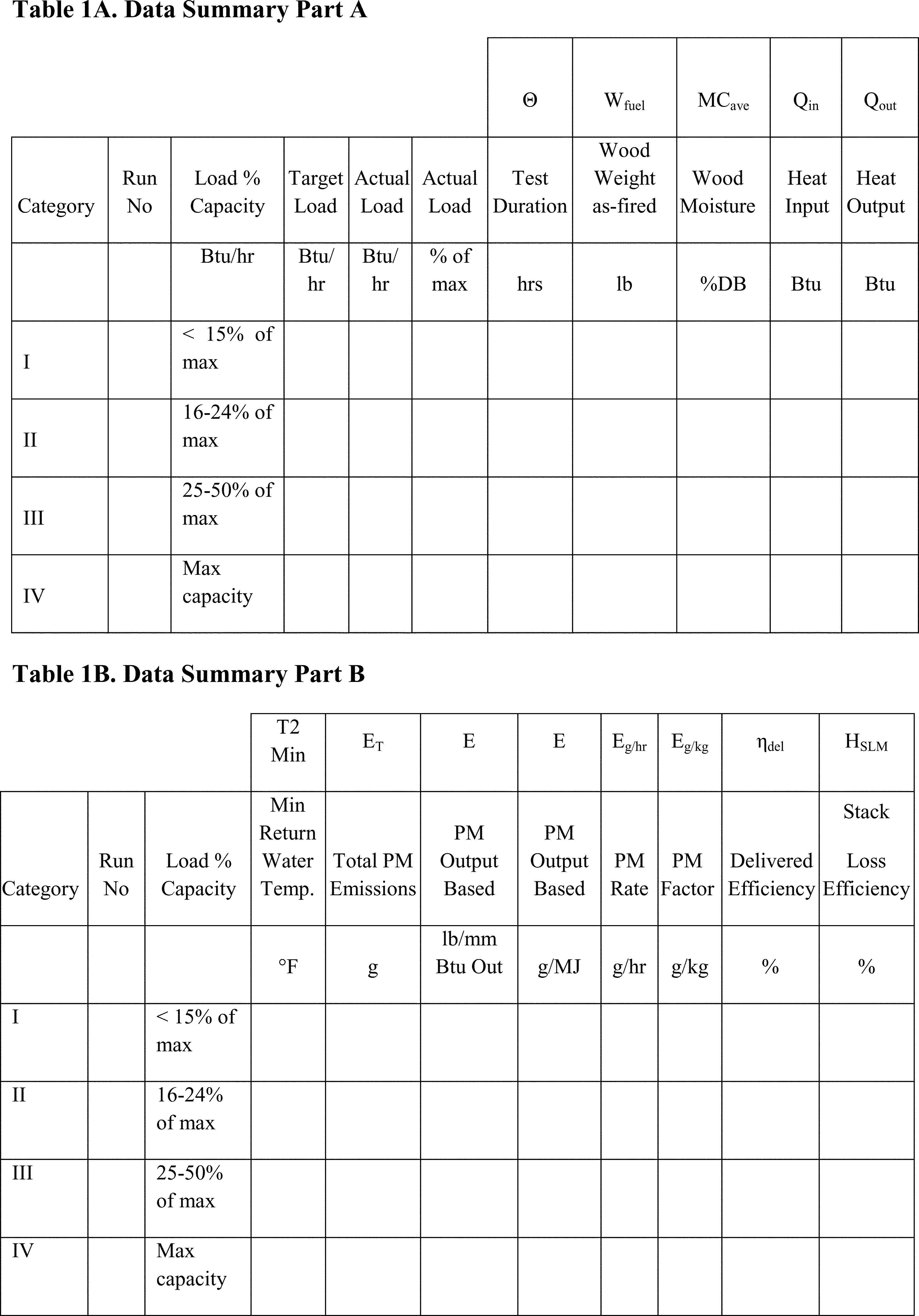
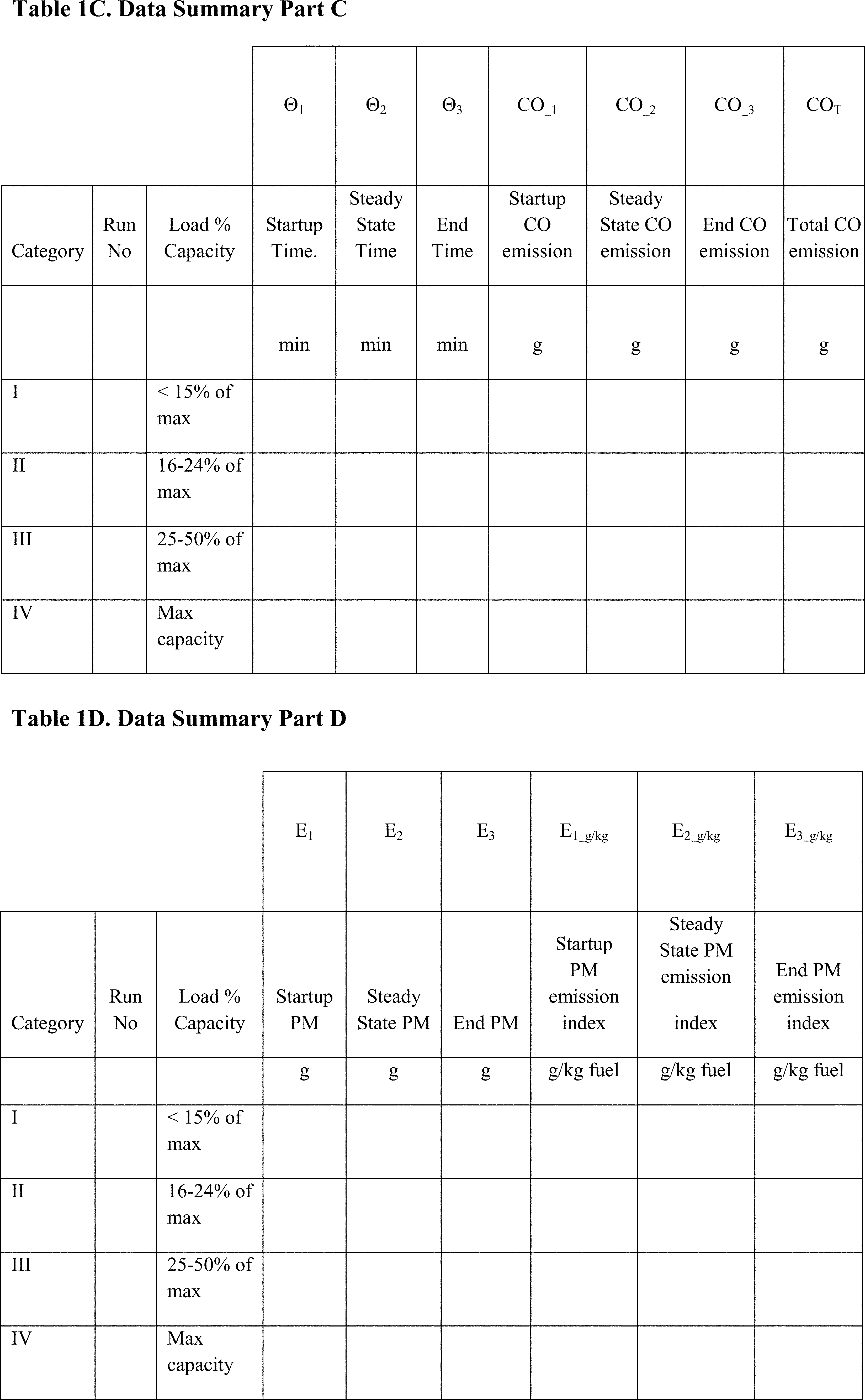
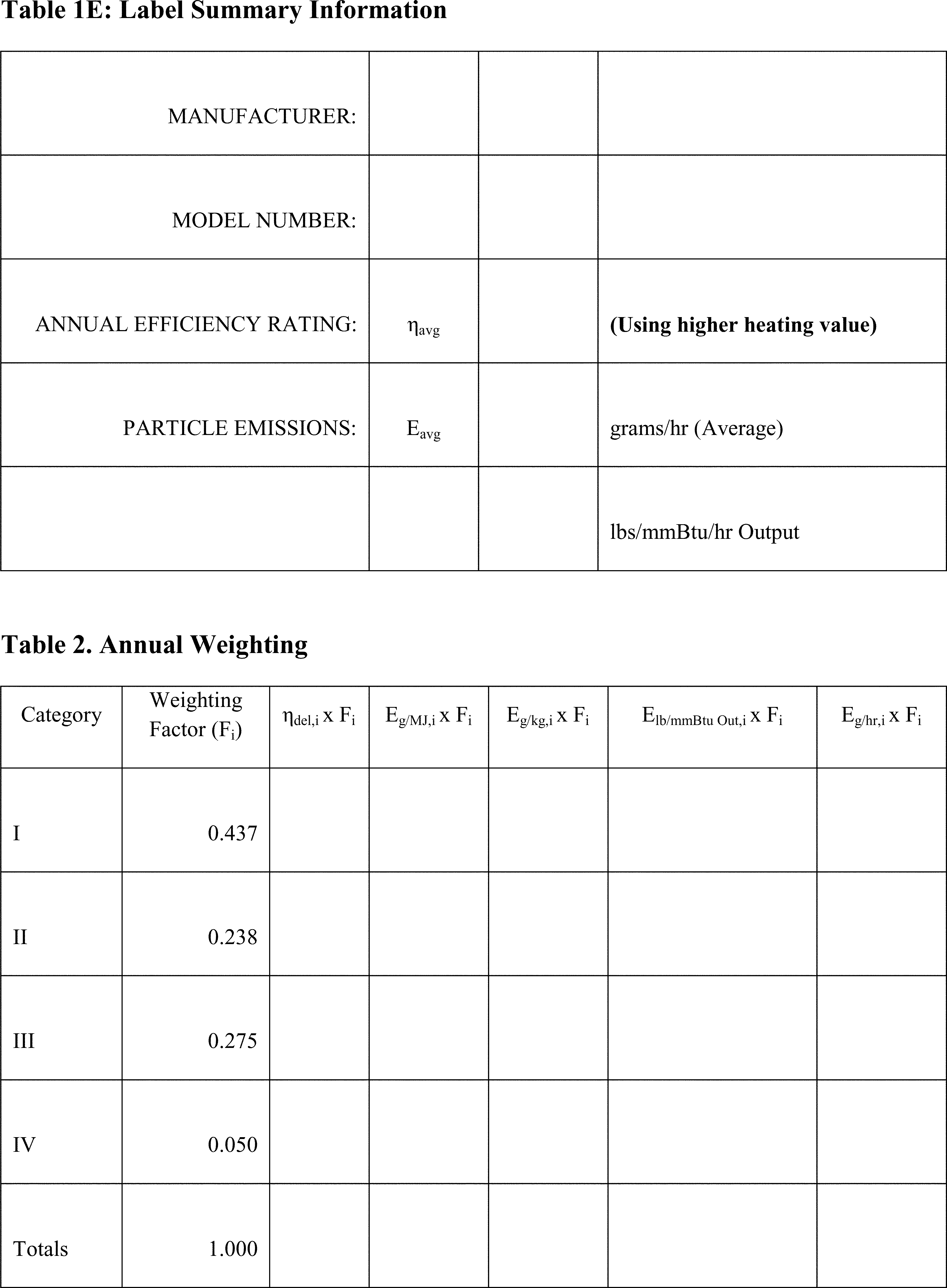


Method 29 - Determination of Metals Emissions From Stationary Sources
This method does not include all of the specifications (e.g., equipment and supplies) and procedures (e.g., sampling and analytical) essential to its performance. Some material is incorporated by reference from other methods in this part. Therefore, to obtain reliable results, persons using this method should have a thorough knowledge of at least the following additional test methods: Method 5 and Method 12.
1.0 Scope and Application
1.1 Analytes.
| Analyte | CAS No. |
|---|---|
| Antimony (Sb) | 7440-36-0 |
| Arsenic (As) | 7440-38-2 |
| Barium (Ba) | 7440-39-3 |
| Beryllium (Be) | 7440-41-7 |
| Cadmium (Cd) | 7440-43-9 |
| Chromium (Cr) | 7440-47-3 |
| Cobalt (Co) | 7440-48-4 |
| Copper (Cu) | 7440-50-8 |
| Lead (Pb) | 7439-92-1 |
| Manganese (Mn) | 7439-96-5 |
| Mercury (Hg) | 7439-97-6 |
| Nickel (Ni) | 7440-02-0 |
| Phosphorus (P) | 7723-14-0 |
| Selenium (Se) | 7782-49-2 |
| Silver (Ag) | 7440-22-4 |
| Thallium (Tl) | 7440-28-0 |
| Zinc (Zn) | 7440-66-6 |
1.2 Applicability. This method is applicable to the determination of metals emissions from stationary sources. This method may be used to determine particulate emissions in addition to the metals emissions if the prescribed procedures and precautions are followed.
1.2.1 Hg emissions can be measured, alternatively, using EPA Method 101A of Appendix B, 40 CFR Part 61. Method 101-A measures only Hg but it can be of special interest to sources which need to measure both Hg and Mn emissions.
2.0 Summary of Method
2.1 Principle. A stack sample is withdrawn isokinetically from the source, particulate emissions are collected in the probe and on a heated filter, and gaseous emissions are then collected in an aqueous acidic solution of hydrogen peroxide (analyzed for all metals including Hg) and an aqueous acidic solution of potassium permanganate (analyzed only for Hg). The recovered samples are digested, and appropriate fractions are analyzed for Hg by cold vapor atomic absorption spectroscopy (CVAAS) and for Sb, As, Ba, Be, Cd, Cr, Co, Cu, Pb, Mn, Ni, P, Se, Ag, Tl, and Zn by inductively coupled argon plasma emission spectroscopy (ICAP) or atomic absorption spectroscopy (AAS). Graphite furnace atomic absorption spectroscopy (GFAAS) is used for analysis of Sb, As, Cd, Co, Pb, Se, and Tl if these elements require greater analytical sensitivity than can be obtained by ICAP. If one so chooses, AAS may be used for analysis of all listed metals if the resulting in-stack method detection limits meet the goal of the testing program. Similarly, inductively coupled plasma-mass spectroscopy (ICP-MS) may be used for analysis of Sb, As, Ba, Be, Cd, Cr, Co, Cu, Pb, Mn, Ni, Ag, Tl and Zn.
3.0 Definitions [Reserved]
4.0 Interferences
4.1 Iron (Fe) can be a spectral interference during the analysis of As, Cr, and Cd by ICAP. Aluminum (Al) can be a spectral interference during the analysis of As and Pb by ICAP. Generally, these interferences can be reduced by diluting the analytical sample, but such dilution raises the in-stack detection limits. Background and overlap corrections may be used to adjust for spectral interferences. Refer to Method 6010 of Reference 2 in section 16.0 or the other analytical methods used for details on potential interferences to this method. For all GFAAS analyses, use matrix modifiers to limit interferences, and matrix match all standards.
5.0 Safety
5.1 Disclaimer. This method may involve hazardous materials, operations, and equipment. This test method may not address all of the safety problems associated with its use. It is the responsibility of the user of this test method to establish appropriate safety and health practices and to determine the applicability of regulatory limitations prior to performing this test method.
5.2 Corrosive Reagents. The following reagents are hazardous. Personal protective equipment and safe procedures are useful in preventing chemical splashes. If contact occurs, immediately flush with copious amounts of water at least 15 minutes. Remove clothing under shower and decontaminate. Treat residual chemical burn as thermal burn.
5.2.1 Nitric Acid (HNO3). Highly corrosive to eyes, skin, nose, and lungs. Vapors cause bronchitis, pneumonia, or edema of lungs. Reaction to inhalation may be delayed as long as 30 hours and still be fatal. Provide ventilation to limit exposure. Strong oxidizer. Hazardous reaction may occur with organic materials such as solvents.
5.2.2 Sulfuric Acid (H2SO4). Rapidly destructive to body tissue. Will cause third degree burns. Eye damage may result in blindness. Inhalation may be fatal from spasm of the larynx, usually within 30 minutes. May cause lung tissue damage with edema. 1 mg/m3 for 8 hours will cause lung damage or, in higher concentrations, death. Provide ventilation to limit inhalation. Reacts violently with metals and organics.
5.2.3 Hydrochloric Acid (HC1). Highly corrosive liquid with toxic vapors. Vapors are highly irritating to eyes, skin, nose, and lungs, causing severe damage. May cause bronchitis, pneumonia, or edema of lungs. Exposure to concentrations of 0.13 to 0.2 percent can be lethal to humans in a few minutes. Provide ventilation to limit exposure. Reacts with metals, producing hydrogen gas.
5.2.4 Hydrofluoric Acid (HF). Highly corrosive to eyes, skin, nose, throat, and lungs. Reaction to exposure may be delayed by 24 hours or more. Provide ventilation to limit exposure.
5.2.5 Hydrogen Peroxide (H2O2). Irritating to eyes, skin, nose, and lungs. 30% H2O2 is a strong oxidizing agent. Avoid contact with skin, eyes, and combustible material. Wear gloves when handling.
5.2.6 Potassium Permanganate (KMnO4). Caustic, strong oxidizer. Avoid bodily contact with.
5.2.7 Potassium Persulfate. Strong oxidizer. Avoid bodily contact with. Keep containers well closed and in a cool place.
5.3 Reaction Pressure. Due to the potential reaction of the potassium permanganate with the acid, there could be pressure buildup in the acidic KMnO4 absorbing solution storage bottle. Therefore these bottles shall not be fully filled and shall be vented to relieve excess pressure and prevent explosion potentials. Venting is required, but not in a manner that will allow contamination of the solution. A No. 70-72 hole drilled in the container cap and Teflon liner has been used.
6.0 Equipment and Supplies
6.1 Sampling. A schematic of the sampling train is shown in Figure 29-1. It has general similarities to the Method 5 train.
6.1.1 Probe Nozzle (Probe Tip) and Borosilicate or Quartz Glass Probe Liner. Same as Method 5, sections 6.1.1.1 and 6.1.1.2, except that glass nozzles are required unless alternate tips are constructed of materials that are free from contamination and will not interfere with the sample. If a probe tip other than glass is used, no correction to the sample test results to compensate for the nozzle's effect on the sample is allowed. Probe fittings of plastic such as Teflon, polypropylene, etc. are recommended instead of metal fittings to prevent contamination. If one chooses to do so, a single glass piece consisting of a combined probe tip and probe liner may be used.
6.1.2 Pitot Tube and Differential Pressure Gauge. Same as Method 2, sections 6.1 and 6.2, respectively.
6.1.3 Filter Holder. Glass, same as Method 5, section 6.1.1.5, except use a Teflon filter support or other non-metallic, non-contaminating support in place of the glass frit.
6.1.4 Filter Heating System. Same as Method 5, section 6.1.1.6.
6.1.5 Condenser. Use the following system for condensing and collecting gaseous metals and determining the moisture content of the stack gas. The condensing system shall consist of four to seven impingers connected in series with leak-free ground glass fittings or other leak-free, non-contaminating fittings. Use the first impinger as a moisture trap. The second impinger (which is the first HNO3/H2O2 impinger) shall be identical to the first impinger in Method 5. The third impinger (which is the second HNO3/H2O2 impinger) shall be a Greenburg Smith impinger with the standard tip as described for the second impinger in Method 5, section 6.1.1.8. The fourth (empty) impinger and the fifth and sixth (both acidified KMnO4) impingers are the same as the first impinger in Method 5. Place a temperature sensor capable of measuring to within 1 °C (2 °F) at the outlet of the last impinger. If no Hg analysis is planned, then the fourth, fifth, and sixth impingers are not used.
6.1.6 Metering System, Barometer, and Gas Density Determination Equipment. Same as Method 5, sections 6.1.1.9, 6.1.2, and 6.1.3, respectively.
6.1.7 Teflon Tape. For capping openings and sealing connections, if necessary, on the sampling train.
6.2 Sample Recovery. Same as Method 5, sections 6.2.1 through 6.2.8 (Probe-Liner and Probe-Nozzle Brushes or Swabs, Wash Bottles, Sample Storage Containers, Petri Dishes, Glass Graduated Cylinder, Plastic Storage Containers, Funnel and Rubber Policeman, and Glass Funnel), respectively, with the following exceptions and additions:
6.2.1 Non-metallic Probe-Liner and Probe-Nozzle Brushes or Swabs. Use non-metallic probe-liner and probe-nozzle brushes or swabs for quantitative recovery of materials collected in the front-half of the sampling train.
6.2.2 Sample Storage Containers. Use glass bottles (see section 8.1 of this Method) with Teflon-lined caps that are non-reactive to the oxidizing solutions, with capacities of 1000- and 500-ml, for storage of acidified KMnO4 - containing samples and blanks. Glass or polyethylene bottles may be used for other sample types.
6.2.3 Graduated Cylinder. Glass or equivalent.
6.2.4 Funnel. Glass or equivalent.
6.2.5 Labels. For identifying samples.
6.2.6 Polypropylene Tweezers and/or Plastic Gloves. For recovery of the filter from the sampling train filter holder.
6.3 Sample Preparation and Analysis.
6.3.1 Volumetric Flasks, 100-ml, 250-ml, and 1000-ml. For preparation of standards and sample dilutions.
6.3.2 Graduated Cylinders. For preparation of reagents.
6.3.3 Parr Bombs or Microwave Pressure Relief Vessels with Capping Station (CEM Corporation model or equivalent). For sample digestion.
6.3.4 Beakers and Watch Glasses. 250-ml beakers, with watch glass covers, for sample digestion.
6.3.5 Ring Stands and Clamps. For securing equipment such as filtration apparatus.
6.3.6 Filter Funnels. For holding filter paper.
6.3.7 Disposable Pasteur Pipets and Bulbs.
6.3.8 Volumetric Pipets.
6.3.9 Analytical Balance. Accurate to within 0.1 mg.
6.3.10 Microwave or Conventional Oven. For heating samples at fixed power levels or temperatures, respectively.
6.3.11 Hot Plates.
6.3.12 Atomic Absorption Spectrometer (AAS). Equipped with a background corrector.
6.3.12.1 Graphite Furnace Attachment. With Sb, As, Cd, Co, Pb, Se, and Tl hollow cathode lamps (HCLs) or electrodeless discharge lamps (EDLs). Same as Reference 2 in section 16.0. Methods 7041 (Sb), 7060 (As), 7131 (Cd), 7201 (Co), 7421 (Pb), 7740 (Se), and 7841 (Tl).
6.3.12.2 Cold Vapor Mercury Attachment. With a mercury HCL or EDL, an air recirculation pump, a quartz cell, an aerator apparatus, and a heat lamp or desiccator tube. The heat lamp shall be capable of raising the temperature at the quartz cell by 10 °C above ambient, so that no condensation forms on the wall of the quartz cell. Same as Method 7470 in Reference 2 in section 16.0. See note 2: section 11.1.3 for other acceptable approaches for analysis of Hg in which analytical detection limits of 0.002 ng/ml were obtained.
6.3.13 Inductively Coupled Argon Plasma Spectrometer. With either a direct or sequential reader and an alumina torch. Same as EPA Method 6010 in Reference 2 in section 16.0.
6.3.14 Inductively Coupled Plasma-Mass Spectrometer.
Same as EPA Method 6020 in Reference 2 in section 16.0.
7.0 Reagents and Standards
7.1 Unless otherwise indicated, it is intended that all reagents conform to the specifications established by the Committee on Analytical Reagents of the American Chemical Society, where such specifications are available. Otherwise, use the best available grade.
7.2 Sampling Reagents.
7.2.1 Sample Filters. Without organic binders. The filters shall contain less than 1.3 µg/in.2 of each of the metals to be measured. Analytical results provided by filter manufacturers stating metals content of the filters are acceptable. However, if no such results are available, analyze filter blanks for each target metal prior to emission testing. Quartz fiber filters meeting these requirements are recommended. However, if glass fiber filters become available which meet these requirements, they may be used. Filter efficiencies and unreactiveness to sulfur dioxide (SO2) or sulfur trioxide (SO3) shall be as described in section 7.1.1 of Method 5.
7.2.2 Water. To conform to ASTM Specification D1193-77 or 91, Type II (incorporated by reference - see § 60.17). If necessary, analyze the water for all target metals prior to field use. All target metals should be less than 1 ng/ml.
7.2.3 HNO3, Concentrated. Baker Instra-analyzed or equivalent.
7.2.4 HCl, Concentrated. Baker Instra-analyzed or equivalent.
7.2.5 H2O2, 30 Percent (V/V).
7.2.6 KMnO4.
7.2.7 H2SO4, Concentrated.
7.2.8 Silica Gel and Crushed Ice. Same as Method 5, sections 7.1.2 and 7.1.4, respectively.
7.3 Pretest Preparation of Sampling Reagents.
7.3.1 HNO3/H2O2 Absorbing Solution, 5 Percent HNO3/10 Percent H2O2. Add carefully with stirring 50 ml of concentrated HNO3 to a 1000-ml volumetric flask containing approximately 500 ml of water, and then add carefully with stirring 333 ml of 30 percent H2O2. Dilute to volume with water. Mix well. This reagent shall contain less than 2 ng/ml of each target metal.
7.3.2 Acidic KMnO4 Absorbing Solution, 4 Percent KMnO4 (W/V), 10 Percent H2SO4 (V/V). Prepare fresh daily. Mix carefully, with stirring, 100 ml of concentrated H2SO4 into approximately 800 ml of water, and add water with stirring to make a volume of 1 liter: this solution is 10 percent H2SO4 (V/V). Dissolve, with stirring, 40 g of KMnO4 into 10 percent H2SO4 (V/V) and add 10 percent H2SO4 (V/V) with stirring to make a volume of 1 liter. Prepare and store in glass bottles to prevent degradation. This reagent shall contain less than 2 ng/ml of Hg.
Precaution: To prevent autocatalytic decomposition of the permanganate solution, filter the solution through Whatman 541 filter paper.
7.3.3 HNO3, 0.1 N. Add with stirring 6.3 ml of concentrated HNO3 (70 percent) to a flask containing approximately 900 ml of water. Dilute to 1000 ml with water. Mix well. This reagent shall contain less than 2 ng/ml of each target metal.
7.3.4 HCl, 8 N. Carefully add with stirring 690 ml of concentrated HCl to a flask containing 250 ml of water. Dilute to 1000 ml with water. Mix well. This reagent shall contain less than 2 ng/ml of Hg.
7.4 Glassware Cleaning Reagents.
7.4.1 HNO3, Concentrated. Fisher ACS grade or equivalent.
7.4.2 Water. To conform to ASTM Specifications D1193, Type II.
7.4.3 HNO3, 10 Percent (V/V). Add with stirring 500 ml of concentrated HNO3 to a flask containing approximately 4000 ml of water. Dilute to 5000 ml with water. Mix well. This reagent shall contain less than 2 ng/ml of each target metal.
7.5 Sample Digestion and Analysis Reagents. The metals standards, except Hg, may also be made from solid chemicals as described in Reference 3 in section 16.0. Refer to References 1, 2, or 5 in section 16.0 for additional information on Hg standards. The 1000 µg/ml Hg stock solution standard may be made according to section 7.2.7 of Method 101A.
7.5.1 HCl, Concentrated.
7.5.2 HF, Concentrated.
7.5.3 HNO3, Concentrated. Baker Instra-analyzed or equivalent.
7.5.4 HNO3, 50 Percent (V/V). Add with stirring 125 ml of concentrated HNO3 to 100 ml of water. Dilute to 250 ml with water. Mix well. This reagent shall contain less than 2 ng/ml of each target metal.
7.5.5 HNO3, 5 Percent (V/V). Add with stirring 50 ml of concentrated HNO3 to 800 ml of water. Dilute to 1000 ml with water. Mix well. This reagent shall contain less than 2 ng/ml of each target metal.
7.5.6 Water. To conform to ASTM Specifications D1193, Type II.
7.5.7 Hydroxylamine Hydrochloride and Sodium Chloride Solution. See Reference 2 In section 16.0 for preparation.
7.5.8 Stannous Chloride. See Reference 2 in section 16.0 for preparation.
7.5.9 KMnO4, 5 Percent (W/V). See Reference 2 in section 16.0 for preparation.
7.5.10 H2SO4, Concentrated.
7.5.11 Potassium Persulfate, 5 Percent (W/V). See Reference 2 in section 16.0 for preparation.
7.5.12 Nickel Nitrate, Ni(N03)2 6H20.
7.5.13 Lanthanum Oxide, La203.
7.5.14 Hg Standard (AAS Grade), 1000 µg/ml.
7.5.15 Pb Standard (AAS Grade), 1000 µg/ml.
7.5.16 As Standard (AAS Grade), 1000 µg/ml.
7.5.17 Cd Standard (AAS Grade), 1000 µg/ml.
7.5.18 Cr Standard (AAS Grade), 1000 µg/ml.
7.5.19 Sb Standard (AAS Grade), 1000 µg/ml.
7.5.20 Ba Standard (AAS Grade), 1000 µg/ml.
7.5.21 Be Standard (AAS Grade), 1000 µg/ml.
7.5.22 Co Standard (AAS Grade), 1000 µg/ml.
7.5.23 Cu Standard (AAS Grade), 1000 µg/ml.
7.5.24 Mn Standard (AAS Grade), 1000 µg/ml.
7.5.25 Ni Standard (AAS Grade), 1000 µg/ml.
7.5.26 P Standard (AAS Grade), 1000 µg/ml.
7.5.27 Se Standard (AAS Grade), 1000 µg/ml.
7.5.28 Ag Standard (AAS Grade), 1000 µg/ml.
7.5.29 Tl Standard (AAS Grade), 1000 µg/ml.
7.5.30 Zn Standard (AAS Grade), 1000 µg/ml.
7.5.31 Al Standard (AAS Grade), 1000 µg/ml.
7.5.32 Fe Standard (AAS Grade), 1000 µg/ml.
7.5.33 Hg Standards and Quality Control Samples. Prepare fresh weekly a 10 µg/ml intermediate Hg standard by adding 5 ml of 1000 µg/ml Hg stock solution prepared according to Method 101A to a 500-ml volumetric flask; dilute with stirring to 500 ml by first carefully adding 20 ml of 15 percent HNO3 and then adding water to the 500-ml volume. Mix well. Prepare a 200 ng/ml working Hg standard solution fresh daily: add 5 ml of the 10 µg/ml intermediate standard to a 250-ml volumetric flask, and dilute to 250 ml with 5 ml of 4 percent KMnO4, 5 ml of 15 percent HNO3, and then water. Mix well. Use at least five separate aliquots of the working Hg standard solution and a blank to prepare the standard curve. These aliquots and blank shall contain 0.0, 1.0, 2.0, 3.0, 4.0, and 5.0 ml of the working standard solution containing 0, 200, 400, 600, 800, and 1000 ng Hg, respectively. Prepare quality control samples by making a separate 10 µg/ml standard and diluting until in the calibration range.
7.5.34 ICAP Standards and Quality Control Samples. Calibration standards for ICAP analysis can be combined into four different mixed standard solutions as follows:
Mixed Standard Solutions for ICAP Analysis
| Solution | Elements |
|---|---|
| I | As, Be, Cd, Mn, Pb, Se, Zn. |
| II | Ba, Co, Cu, Fe. |
| III | Al, Cr, Ni. |
| IV | Ag, P, Sb, Tl. |
Prepare these standards by combining and diluting the appropriate volumes of the 1000 µg/ml solutions with 5 percent HNO3. A minimum of one standard and a blank can be used to form each calibration curve. However, prepare a separate quality control sample spiked with known amounts of the target metals in quantities in the mid-range of the calibration curve. Suggested standard levels are 25 µg/ml for Al, Cr and Pb, 15 µg/ml for Fe, and 10 µg/ml for the remaining elements. Prepare any standards containing less than 1 µg/ml of metal on a daily basis. Standards containing greater than 1 µg/ml of metal should be stable for a minimum of 1 to 2 weeks. For ICP-MS, follow Method 6020 in EPA Publication SW-846 Third Edition (November 1986) including updates I, II, IIA, IIB and III, as incorporated by reference in § 60.17(i).
7.5.35 GFAAS Standards. Sb, As, Cd, Co, Pb, Se, and Tl. Prepare a 10 µg/ml standard by adding 1 ml of 1000 µg/ml standard to a 100-ml volumetric flask. Dilute with stirring to 100 ml with 10 percent HNO3. For GFAAS, matrix match the standards. Prepare a 100 ng/ml standard by adding 1 ml of the 10 µg/ml standard to a 100-ml volumetric flask, and dilute to 100 ml with the appropriate matrix solution. Prepare other standards by diluting the 100 ng/ml standards. Use at least five standards to make up the standard curve. Suggested levels are 0, 10, 50, 75, and 100 ng/ml. Prepare quality control samples by making a separate 10 µg/ml standard and diluting until it is in the range of the samples. Prepare any standards containing less than 1 µg/ml of metal on a daily basis. Standards containing greater than 1 µg/ml of metal should be stable for a minimum of 1 to 2 weeks.
7.5.36 Matrix Modifiers.
7.5.36.1 Nickel Nitrate, 1 Percent (V/V). Dissolve 4.956 g of Ni(N03)2·6H20 or other nickel compound suitable for preparation of this matrix modifier in approximately 50 ml of water in a 100-ml volumetric flask. Dilute to 100 ml with water.
7.5.36.2 Nickel Nitrate, 0.1 Percent (V/V). Dilute 10 ml of 1 percent nickel nitrate solution to 100 ml with water. Inject an equal amount of sample and this modifier into the graphite furnace during GFAAS analysis for As.
7.5.36.3 Lanthanum. Carefully dissolve 0.5864 g of La203 in 10 ml of concentrated HN03, and dilute the solution by adding it with stirring to approximately 50 ml of water. Dilute to 100 ml with water, and mix well. Inject an equal amount of sample and this modifier into the graphite furnace during GFAAS analysis for Pb.
7.5.37 Whatman 40 and 541 Filter Papers (or equivalent). For filtration of digested samples.
8.0 Sample Collection, Preservation, Transport, and Storage
8.1 Sampling. The complexity of this method is such that, to obtain reliable results, both testers and analysts must be trained and experienced with the test procedures, including source sampling; reagent preparation and handling; sample handling; safety equipment and procedures; analytical calculations; reporting; and the specific procedural descriptions throughout this method.
8.1.1 Pretest Preparation. Follow the same general procedure given in Method 5, section 8.1, except that, unless particulate emissions are to be determined, the filter need not be desiccated or weighed. First, rinse all sampling train glassware with hot tap water and then wash in hot soapy water. Next, rinse glassware three times with tap water, followed by three additional rinses with water. Then soak all glassware in a 10 percent (V/V) nitric acid solution for a minimum of 4 hours, rinse three times with water, rinse a final time with acetone, and allow to air dry. Cover all glassware openings where contamination can occur until the sampling train is assembled for sampling.
8.1.2 Preliminary Determinations. Same as Method 5, section 8.1.2.
8.1.3 Preparation of Sampling Train.
8.1.3.1 Set up the sampling train as shown in Figure 29-1. Follow the same general procedures given in Method 5, section 8.3, except place 100 ml of the HNO3/H2O2 solution (Section 7.3.1 of this method) in each of the second and third impingers as shown in Figure 29-1. Place 100 ml of the acidic KMnO4 absorbing solution (Section 7.3.2 of this method) in each of the fifth and sixth impingers as shown in Figure 29-1, and transfer approximately 200 to 300 g of pre-weighed silica gel from its container to the last impinger. Alternatively, the silica gel may be weighed directly in the impinger just prior to final train assembly.
8.1.3.2 Based on the specific source sampling conditions, the use of an empty first impinger can be eliminated if the moisture to be collected in the impingers will be less than approximately 100 ml.
8.1.3.3 If Hg analysis will not be performed, the fourth, fifth, and sixth impingers as shown in Figure 29-1 are not required.
8.1.3.4 To insure leak-free sampling train connections and to prevent possible sample contamination problems, use Teflon tape or other non-contaminating material instead of silicone grease.
Precaution: Exercise extreme care to prevent contamination within the train. Prevent the acidic KMnO4 from contacting any glassware that contains sample material to be analyzed for Mn. Prevent acidic H2O2 from mixing with the acidic KMnO4.
8.1.4 Leak-Check Procedures. Follow the leak-check procedures given in Method 5, section 8.4.2 (Pretest Leak-Check), section 8.4.3 (Leak-Checks During the Sample Run), and section 8.4.4 (Post-Test Leak-Checks).
8.1.5 Sampling Train Operation. Follow the procedures given in Method 5, section 8.5. When sampling for Hg, use a procedure analogous to that described in section 8.1 of Method 101A, 40 CFR Part 61, Appendix B, if necessary to maintain the desired color in the last acidified permanganate impinger. For each run, record the data required on a data sheet such as the one shown in Figure 5-3 of Method 5.
8.1.6 Calculation of Percent Isokinetic. Same as Method 5, section 12.11.
8.2 Sample Recovery.
8.2.1 Begin cleanup procedures as soon as the probe is removed from the stack at the end of a sampling period. The probe should be allowed to cool prior to sample recovery. When it can be safely handled, wipe off all external particulate matter near the tip of the probe nozzle and place a rinsed, non-contaminating cap over the probe nozzle to prevent losing or gaining particulate matter. Do not cap the probe tip tightly while the sampling train is cooling; a vacuum can form in the filter holder with the undesired result of drawing liquid from the impingers onto the filter.
8.2.2 Before moving the sampling train to the cleanup site, remove the probe from the sampling train and cap the open outlet. Be careful not to lose any condensate that might be present. Cap the filter inlet where the probe was fastened. Remove the umbilical cord from the last impinger and cap the impinger. Cap the filter holder outlet and impinger inlet. Use non-contaminating caps, whether ground-glass stoppers, plastic caps, serum caps, or Teflon ® tape to close these openings.
8.2.3 Alternatively, the following procedure may be used to disassemble the train before the probe and filter holder/oven are completely cooled: Initially disconnect the filter holder outlet/impinger inlet and loosely cap the open ends. Then disconnect the probe from the filter holder or cyclone inlet and loosely cap the open ends. Cap the probe tip and remove the umbilical cord as previously described.
8.2.4 Transfer the probe and filter-impinger assembly to a cleanup area that is clean and protected from the wind and other potential causes of contamination or loss of sample. Inspect the train before and during disassembly and note any abnormal conditions. Take special precautions to assure that all the items necessary for recovery do not contaminate the samples. The sample is recovered and treated as follows (see schematic in Figures 29-2a and 29-2b):
8.2.5 Container No. 1 (Sample Filter). Carefully remove the filter from the filter holder and place it in its labeled petri dish container. To handle the filter, use either acid-washed polypropylene or Teflon coated tweezers or clean, disposable surgical gloves rinsed with water and dried. If it is necessary to fold the filter, make certain the particulate cake is inside the fold. Carefully transfer the filter and any particulate matter or filter fibers that adhere to the filter holder gasket to the petri dish by using a dry (acid-cleaned) nylon bristle brush. Do not use any metal-containing materials when recovering this train. Seal the labeled petri dish.
8.2.6 Container No. 2 (Acetone Rinse). Perform this procedure only if a determination of particulate emissions is to be made. Quantitatively recover particulate matter and any condensate from the probe nozzle, probe fitting, probe liner, and front half of the filter holder by washing these components with a total of 100 ml of acetone, while simultaneously taking great care to see that no dust on the outside of the probe or other surfaces gets in the sample. The use of exactly 100 ml is necessary for the subsequent blank correction procedures. Distilled water may be used instead of acetone when approved by the Administrator and shall be used when specified by the Administrator; in these cases, save a water blank and follow the Administrator's directions on analysis.
8.2.6.1 Carefully remove the probe nozzle, and clean the inside surface by rinsing with acetone from a wash bottle while brushing with a non-metallic brush. Brush until the acetone rinse shows no visible particles, then make a final rinse of the inside surface with acetone.
8.2.6.2 Brush and rinse the sample exposed inside parts of the probe fitting with acetone in a similar way until no visible particles remain. Rinse the probe liner with acetone by tilting and rotating the probe while squirting acetone into its upper end so that all inside surfaces will be wetted with acetone. Allow the acetone to drain from the lower end into the sample container. A funnel may be used to aid in transferring liquid washings to the container. Follow the acetone rinse with a non-metallic probe brush. Hold the probe in an inclined position, squirt acetone into the upper end as the probe brush is being pushed with a twisting action three times through the probe. Hold a sample container underneath the lower end of the probe, and catch any acetone and particulate matter which is brushed through the probe until no visible particulate matter is carried out with the acetone or until none remains in the probe liner on visual inspection. Rinse the brush with acetone, and quantitatively collect these washings in the sample container. After the brushing, make a final acetone rinse of the probe as described above.
8.2.6.3 It is recommended that two people clean the probe to minimize sample losses. Between sampling runs, keep brushes clean and protected from contamination. Clean the inside of the front-half of the filter holder by rubbing the surfaces with a non-metallic brush and rinsing with acetone. Rinse each surface three times or more if needed to remove visible particulate. Make a final rinse of the brush and filter holder. After all acetone washings and particulate matter have been collected in the sample container, tighten the lid so that acetone will not leak out when shipped to the laboratory. Mark the height of the fluid level to determine whether or not leakage occurred during transport. Clearly label the container to identify its contents.
8.2.7 Container No. 3 (Probe Rinse). Keep the probe assembly clean and free from contamination during the probe rinse. Rinse the probe nozzle and fitting, probe liner, and front-half of the filter holder thoroughly with a total of 100 ml of 0.1 N HNO3, and place the wash into a sample storage container. Perform the rinses as applicable and generally as described in Method 12, section 8.7.1. Record the volume of the rinses. Mark the height of the fluid level on the outside of the storage container and use this mark to determine if leakage occurs during transport. Seal the container, and clearly label the contents. Finally, rinse the nozzle, probe liner, and front-half of the filter holder with water followed by acetone, and discard these rinses.
The use of a total of exactly 100 ml is necessary for the subsequent blank correction procedures.
8.2.8 Container No. 4 (Impingers 1 through 3, Moisture Knockout Impinger, when used, HNO3/H2O2 Impingers Contents and Rinses). Due to the potentially large quantity of liquid involved, the tester may place the impinger solutions from impingers 1 through 3 in more than one container, if necessary. Measure the liquid in the first three impingers to within 0.5 ml using a graduated cylinder. Record the volume. This information is required to calculate the moisture content of the sampled flue gas. Clean each of the first three impingers, the filter support, the back half of the filter housing, and connecting glassware by thoroughly rinsing with 100 ml of 0.1 N HNO3 using the procedure as applicable in Method 12, section 8.7.3.
The use of exactly 100 ml of 0.1 N HNO3 rinse is necessary for the subsequent blank correction procedures. Combine the rinses and impinger solutions, measure and record the final total volume. Mark the height of the fluid level, seal the container, and clearly label the contents.
8.2.9 Container Nos. 5A (0.1 N HNO3), 5B (KMnO4/H2SO4 absorbing solution), and 5C (8 N HCl rinse and dilution).
8.2.9.1 When sampling for Hg, pour all the liquid from the impinger (normally impinger No. 4) that immediately preceded the two permanganate impingers into a graduated cylinder and measure the volume to within 0.5 ml. This information is required to calculate the moisture content of the sampled flue gas. Place the liquid in Container No. 5A. Rinse the impinger with exactly 100 ml of 0.1 N HNO3 and place this rinse in Container No. 5A.
8.2.9.2 Pour all the liquid from the two permanganate impingers into a graduated cylinder and measure the volume to within 0.5 ml. This information is required to calculate the moisture content of the sampled flue gas. Place this acidic KMnO4 solution into Container No. 5B. Using a total of exactly 100 ml of fresh acidified KMnO4 solution for all rinses (approximately 33 ml per rinse), rinse the two permanganate impingers and connecting glassware a minimum of three times. Pour the rinses into Container No. 5B, carefully assuring transfer of all loose precipitated materials from the two impingers. Similarly, using 100 ml total of water, rinse the permanganate impingers and connecting glass a minimum of three times, and pour the rinses into Container 5B, carefully assuring transfer of any loose precipitated material. Mark the height of the fluid level, and clearly label the contents. Read the Precaution: in section 7.3.2.
Due to the potential reaction of KMnO4 with acid, pressure buildup can occur in the sample storage bottles. Do not fill these bottles completely and take precautions to relieve excess pressure. A No. 70-72 hole drilled in the container cap and Teflon liner has been used successfully.
8.2.9.3 Wash the two permanganate impingers with 25 ml of 8 N HCl, and place the wash in a separate sample container labeled No. 5C containing 200 ml of water. First, place 200 ml of water in the container. Then wash the impinger walls and stem with the 8 N HCl by turning the impinger on its side and rotating it so that the HCl contacts all inside surfaces. Use a total of only 25 ml of 8 N HCl for rinsing both permanganate impingers combined. Rinse the first impinger, then pour the actual rinse used for the first impinger into the second impinger for its rinse. Finally, pour the 25 ml of 8 N HCl rinse carefully into the container with the 200 ml of water. Mark the height of the fluid level on the outside of the container in order to determine if leakage occurs during transport.
8.2.10 Container No. 6 (Silica Gel). Note the color of the indicating silica gel to determine whether it has been completely spent and make a notation of its condition. Transfer the silica gel from its impinger to its original container and seal it. The tester may use a funnel to pour the silica gel and a rubber policeman to remove the silica gel from the impinger. The small amount of particles that might adhere to the impinger wall need not be removed. Do not use water or other liquids to transfer the silica gel since weight gained in the silica gel impinger is used for moisture calculations. Alternatively, if a balance is available in the field, record the weight of the spent silica gel (or silica gel plus impinger) to the nearest 0.5 g.
8.2.11 Container No. 7 (Acetone Blank). If particulate emissions are to be determined, at least once during each field test, place a 100-ml portion of the acetone used in the sample recovery process into a container labeled No. 7. Seal the container.
8.2.12 Container No. 8A (0.1 N HNO3 Blank). At least once during each field test, place 300 ml of the 0.1 N HNO3 solution used in the sample recovery process into a container labeled No. 8A. Seal the container.
8.2.13 Container No. 8B (Water Blank). At least once during each field test, place 100 ml of the water used in the sample recovery process into a container labeled No. 8B. Seal the container.
8.2.14 Container No. 9 (5 Percent HNO3/10 Percent H2O2 Blank). At least once during each field test, place 200 ml of the 5 Percent HNO3/10 Percent H2O2 solution used as the nitric acid impinger reagent into a container labeled No. 9. Seal the container.
8.2.15 Container No. 10 (Acidified KMnO4 Blank). At least once during each field test, place 100 ml of the acidified KMnO4 solution used as the impinger solution and in the sample recovery process into a container labeled No. 10. Prepare the container as described in section 8.2.9.2. Read the Precaution: in section 7.3.2 and read the note in section 8.2.9.2.
8.2.16 Container No. 11 (8 N HCl Blank). At least once during each field test, place 200 ml of water into a sample container labeled No. 11. Then carefully add with stirring 25 ml of 8 N HCl. Mix well and seal the container.
8.2.17 Container No. 12 (Sample Filter Blank). Once during each field test, place into a petri dish labeled No. 12 three unused blank filters from the same lot as the sampling filters. Seal the petri dish.
8.3 Sample Preparation. Note the level of the liquid in each of the containers and determine if any sample was lost during shipment. If a noticeable amount of leakage has occurred, either void the sample or use methods, subject to the approval of the Administrator, to correct the final results. A diagram illustrating sample preparation and analysis procedures for each of the sample train components is shown in Figure 29-3.
8.3.1 Container No. 1 (Sample Filter).
8.3.1.1 If particulate emissions are being determined, first desiccate the filter and filter catch without added heat (do not heat the filters to speed the drying) and weigh to a constant weight as described in section 11.2.1 of Method 5.
8.3.1.2 Following this procedure, or initially, if particulate emissions are not being determined in addition to metals analysis, divide the filter with its filter catch into portions containing approximately 0.5 g each. Place the pieces in the analyst's choice of either individual microwave pressure relief vessels or Parr Bombs. Add 6 ml of concentrated HNO3 and 4 ml of concentrated HF to each vessel. For microwave heating, microwave the samples for approximately 12 to 15 minutes total heating time as follows: heat for 2 to 3 minutes, then turn off the microwave for 2 to 3 minutes, then heat for 2 to 3 minutes, etc., continue this alternation until the 12 to 15 minutes total heating time are completed (this procedure should comprise approximately 24 to 30 minutes at 600 watts). Microwave heating times are approximate and are dependent upon the number of samples being digested simultaneously. Sufficient heating is evidenced by sorbent reflux within the vessel. For conventional heating, heat the Parr Bombs at 140 °C (285 °F) for 6 hours. Then cool the samples to room temperature, and combine with the acid digested probe rinse as required in section 8.3.3.
8.3.1.3 If the sampling train includes an optional glass cyclone in front of the filter, prepare and digest the cyclone catch by the procedures described in section 8.3.1.2 and then combine the digestate with the digested filter sample.
8.3.2 Container No. 2 (Acetone Rinse). Note the level of liquid in the container and confirm on the analysis sheet whether or not leakage occurred during transport. If a noticeable amount of leakage has occurred, either void the sample or use methods, subject to the approval of the Administrator, to correct the final results. Measure the liquid in this container either volumetrically within 1 ml or gravimetrically within 0.5 g. Transfer the contents to an acid-cleaned, tared 250-ml beaker and evaporate to dryness at ambient temperature and pressure. If particulate emissions are being determined, desiccate for 24 hours without added heat, weigh to a constant weight according to the procedures described in section 11.2.1 of Method 5, and report the results to the nearest 0.1 mg. Redissolve the residue with 10 ml of concentrated HNO3. Quantitatively combine the resultant sample, including all liquid and any particulate matter, with Container No. 3 before beginning section 8.3.3.
8.3.3 Container No. 3 (Probe Rinse). Verify that the pH of this sample is 2 or lower. If it is not, acidify the sample by careful addition with stirring of concentrated HNO3 to pH 2. Use water to rinse the sample into a beaker, and cover the beaker with a ribbed watch glass. Reduce the sample volume to approximately 20 ml by heating on a hot plate at a temperature just below boiling. Digest the sample in microwave vessels or Parr Bombs by quantitatively transferring the sample to the vessel or bomb, carefully adding the 6 ml of concentrated HNO3, 4 ml of concentrated HF, and then continuing to follow the procedures described in section 8.3.1.2. Then combine the resultant sample directly with the acid digested portions of the filter prepared previously in section 8.3.1.2. The resultant combined sample is referred to as “Sample Fraction 1”. Filter the combined sample using Whatman 541 filter paper. Dilute to 300 ml (or the appropriate volume for the expected metals concentration) with water. This diluted sample is “Analytical Fraction 1”. Measure and record the volume of Analytical Fraction 1 to within 0.1 ml. Quantitatively remove a 50-ml aliquot and label as “Analytical Fraction 1B”. Label the remaining 250-ml portion as “Analytical Fraction 1A”. Analytical Fraction 1A is used for ICAP or AAS analysis for all desired metals except Hg. Analytical Fraction 1B is used for the determination of front-half Hg.
8.3.4 Container No. 4 (Impingers 1-3). Measure and record the total volume of this sample to within 0.5 ml and label it “Sample Fraction 2”. Remove a 75- to 100-ml aliquot for Hg analysis and label the aliquot “Analytical Fraction 2B”. Label the remaining portion of Container No. 4 as “Sample Fraction 2A”. Sample Fraction 2A defines the volume of Analytical Fraction 2A prior to digestion. All of Sample Fraction 2A is digested to produce “Analytical Fraction 2A”. Analytical Fraction 2A defines the volume of Sample Fraction 2A after its digestion and the volume of Analytical Fraction 2A is normally 150 ml. Analytical Fraction 2A is analyzed for all metals except Hg. Verify that the pH of Sample Fraction 2A is 2 or lower. If necessary, use concentrated HNO3 by careful addition and stirring to lower Sample Fraction 2A to pH 2. Use water to rinse Sample Fraction 2A into a beaker and then cover the beaker with a ribbed watchglass. Reduce Sample Fraction 2A to approximately 20 ml by heating on a hot plate at a temperature just below boiling. Then follow either of the digestion procedures described in sections 8.3.4.1 or 8.3.4.2.
8.3.4.1 Conventional Digestion Procedure. Add 30 ml of 50 percent HNO3, and heat for 30 minutes on a hot plate to just below boiling. Add 10 ml of 3 percent H2O2 and heat for 10 more minutes. Add 50 ml of hot water, and heat the sample for an additional 20 minutes. Cool, filter the sample, and dilute to 150 ml (or the appropriate volume for the expected metals concentrations) with water. This dilution produces Analytical Fraction 2A. Measure and record the volume to within 0.1 ml.
8.3.4.2 Microwave Digestion Procedure. Add 10 ml of 50 percent HNO3 and heat for 6 minutes total heating time in alternations of 1 to 2 minutes at 600 Watts followed by 1 to 2 minutes with no power, etc., similar to the procedure described in section 8.3.1. Allow the sample to cool. Add 10 ml of 3 percent H2O2 and heat for 2 more minutes. Add 50 ml of hot water, and heat for an additional 5 minutes. Cool, filter the sample, and dilute to 150 ml (or the appropriate volume for the expected metals concentrations) with water. This dilution produces Analytical Fraction 2A. Measure and record the volume to within 0.1 ml.
All microwave heating times given are approximate and are dependent upon the number of samples being digested at a time. Heating times as given above have been found acceptable for simultaneous digestion of up to 12 individual samples. Sufficient heating is evidenced by solvent reflux within the vessel.
8.3.5 Container No. 5A (Impinger 4), Container Nos. 5B and 5C (Impingers 5 and 6). Keep the samples in Containers Nos. 5A, 5B, and 5C separate from each other. Measure and record the volume of 5A to within 0.5 ml. Label the contents of Container No. 5A to be Analytical Fraction 3A. To remove any brown MnO2 precipitate from the contents of Container No. 5B, filter its contents through Whatman 40 filter paper into a 500 ml volumetric flask and dilute to volume with water. Save the filter for digestion of the brown MnO2 precipitate. Label the 500 ml filtrate from Container No. 5B to be Analytical Fraction 3B. Analyze Analytical Fraction 3B for Hg within 48 hours of the filtration step. Place the saved filter, which was used to remove the brown MnO2 precipitate, into an appropriately sized vented container, which will allow release of any gases including chlorine formed when the filter is digested. In a laboratory hood which will remove any gas produced by the digestion of the MnO2, add 25 ml of 8 N HCl to the filter and allow to digest for a minimum of 24 hours at room temperature. Filter the contents of Container No. 5C through a Whatman 40 filter into a 500-ml volumetric flask. Then filter the result of the digestion of the brown MnO2 from Container No. 5B through a Whatman 40 filter into the same 500-ml volumetric flask, and dilute and mix well to volume with water. Discard the Whatman 40 filter. Mark this combined 500-ml dilute HCl solution as Analytical Fraction 3C.
8.3.6 Container No. 6 (Silica Gel). Weigh the spent silica gel (or silica gel plus impinger) to the nearest 0.5 g using a balance.
9.0 Quality Control
9.1 Field Reagent Blanks, if analyzed. Perform the digestion and analysis of the blanks in Container Nos. 7 through 12 that were produced in sections 8.2.11 through 8.2.17, respectively. For Hg field reagent blanks, use a 10 ml aliquot for digestion and analysis.
9.1.1 Digest and analyze one of the filters from Container No. 12 per section 8.3.1, 100 ml from Container No. 7 per section 8.3.2, and 100 ml from Container No. 8A per section 8.3.3. This step produces blanks for Analytical Fractions 1A and 1B.
9.1.2 Combine 100 ml of Container No. 8A with 200 ml from Container No. 9, and digest and analyze the resultant volume per section 8.3.4. This step produces blanks for Analytical Fractions 2A and 2B.
9.1.3 Digest and analyze a 100-ml portion of Container No. 8A to produce a blank for Analytical Fraction 3A.
9.1.4 Combine 100 ml from Container No. 10 with 33 ml from Container No. 8B to produce a blank for Analytical Fraction 3B. Filter the resultant 133 ml as described for Container No. 5B in section 8.3.5, except do not dilute the 133 ml. Analyze this blank for Hg within 48 hr of the filtration step, and use 400 ml as the blank volume when calculating the blank mass value. Use the actual volumes of the other analytical blanks when calculating their mass values.
9.1.5 Digest the filter that was used to remove any brown MnO2 precipitate from the blank for Analytical Fraction 3B by the same procedure as described in section 8.3.5 for the similar sample filter. Filter the digestate and the contents of Container No. 11 through Whatman 40 paper into a 500-ml volumetric flask, and dilute to volume with water. These steps produce a blank for Analytical Fraction 3C.
9.1.6 Analyze the blanks for Analytical Fraction Blanks 1A and 2A per section 11.1.1 and/or section 11.1.2. Analyze the blanks for Analytical Fractions 1B, 2B, 3A, 3B, and 3C per section 11.1.3. Analysis of the blank for Analytical Fraction 1A produces the front-half reagent blank correction values for the desired metals except for Hg; Analysis of the blank for Analytical Fraction 1B produces the front-half reagent blank correction value for Hg. Analysis of the blank for Analytical Fraction 2A produces the back-half reagent blank correction values for all of the desired metals except for Hg, while separate analyses of the blanks for Analytical Fractions 2B, 3A, 3B, and 3C produce the back-half reagent blank correction value for Hg.
9.2 Quality Control Samples. Analyze the following quality control samples.
9.2.1 ICAP and ICP-MS Analysis. Follow the respective quality control descriptions in section 8 of Methods 6010 and 6020 in EPA Publication SW-846 Third Edition (November 1986) including updates I, II, IIA, IIB and III, as incorporated by reference in § 60.17(i). For the purposes of a source test that consists of three sample runs, modify those requirements to include the following: two instrument check standard runs, two calibration blank runs, one interference check sample at the beginning of the analysis (analyze by Method of Standard Additions unless within 25 percent), one quality control sample to check the accuracy of the calibration standards (required to be within 25 percent of calibration), and one duplicate analysis (required to be within 20 percent of average or repeat all analyses).
9.2.2 Direct Aspiration AAS and/or GFAAS Analysis for Sb, As, Ba, Be, Cd, Cu, Cr, Co, Pb, Ni, Mn, Hg, P, Se, Ag, Tl, and Zn. Analyze all samples in duplicate. Perform a matrix spike on at least one front-half sample and one back-half sample, or one combined sample. If recoveries of less than 75 percent or greater than 125 percent are obtained for the matrix spike, analyze each sample by the Method of Standard Additions. Analyze a quality control sample to check the accuracy of the calibration standards. If the results are not within 20 percent, repeat the calibration.
9.2.3 CVAAS Analysis for Hg. Analyze all samples in duplicate. Analyze a quality control sample to check the accuracy of the calibration standards (if not within 15 percent, repeat calibration). Perform a matrix spike on one sample (if not within 25 percent, analyze all samples by the Method of Standard Additions). Additional information on quality control can be obtained from Method 7470 in EPA Publication SW-846 Third Edition (November 1986) including updates I, II, IIA, IIB and III, as incorporated by reference in § 60.17(i), or in Standard Methods for Water and Wastewater Method 303F.
10.0 Calibration and Standardization
Maintain a laboratory log of all calibrations.
10.1 Sampling Train Calibration. Calibrate the sampling train components according to the indicated sections of Method 5: Probe Nozzle (Section 10.1); Pitot Tube (Section 10.2); Metering System (Section 10.3); Probe Heater (Section 10.4); Temperature Sensors (Section 10.5); Leak-Check of the Metering System (Section 8.4.1); and Barometer (Section 10.6).
10.2 Inductively Coupled Argon Plasma Spectrometer Calibration. Prepare standards as outlined in section 7.5. Profile and calibrate the instrument according to the manufacturer's recommended procedures using those standards. Check the calibration once per hour. If the instrument does not reproduce the standard concentrations within 10 percent, perform the complete calibration procedures. Perform ICP-MS analysis by following Method 6020 in EPA Publication SW-846 Third Edition (November 1986) including updates I, II, IIA, IIB and III, as incorporated by reference in § 60.17(i).
10.3 Atomic Absorption Spectrometer - Direct Aspiration AAS, GFAAS, and CVAAS analyses. Prepare the standards as outlined in section 7.5 and use them to calibrate the spectrometer. Calibration procedures are also outlined in the EPA methods referred to in Table 29-2 and in Method 7470 in EPA Publication SW-846 Third Edition (November 1986) including updates I, II, IIA, IIB and III, as incorporated by reference in § 60.17(i), or in Standard Methods for Water and Wastewater Method 303F (for Hg). Run each standard curve in duplicate and use the mean values to calculate the calibration line. Recalibrate the instrument approximately once every 10 to 12 samples.
10.4 Field Balance Calibration Check. Check the calibration of the balance used to weigh impingers with a weight that is at least 500g or within 50g of a loaded impinger. The weight must be ASTM E617-13 “Standard Specification for Laboratory Weights and Precision Mass Standards” (incorporated by reference-see 40 CFR 60.17) Class 6 (or better). Daily before use, the field balance must measure the weight within ±0.5g of the certified mass. If the daily balance calibration check fails, perform corrective measures and repeat the check before using balance.
10.5 Analytical Balance Calibration. Perform a multipoint calibration (at least five points spanning the operational range) of the analytical balance before the first use, and semiannually thereafter. The calibration of the analytical balance must be conducted using ASTM E617-13 “Standard Specification for Laboratory Weights and Precision Mass Standards” (incorporated by reference - see 40 CFR 60.17) Class 2 (or better) tolerance weights. Audit the balance each day it is used for gravimetric measurements by weighing at least one ASTM E617-13 Class 2 tolerance (or better) calibration weight that corresponds to 50 to 150 percent of the weight of one filter or between 1g and 5g. If the scale cannot reproduce the value of the calibration weight to within 0.5 mg of the certified mass, perform corrective measures, and conduct the multipoint calibration before use.
11.0 Analytical Procedure
11.1 Sample Analysis. For each sampling train sample run, seven individual analytical samples are generated; two for all desired metals except Hg, and five for Hg. A schematic identifying each sample container and the prescribed analytical preparation and analysis scheme is shown in Figure 29-3. The first two analytical samples, labeled Analytical Fractions 1A and 1B, consist of the digested samples from the front-half of the train. Analytical Fraction 1A is for ICAP, ICP-MS or AAS analysis as described in sections 11.1.1 and 11.1.2, respectively. Analytical Fraction 1B is for front-half Hg analysis as described in section 11.1.3. The contents of the back-half of the train are used to prepare the third through seventh analytical samples. The third and fourth analytical samples, labeled Analytical Fractions 2A and 2B, contain the samples from the moisture removal impinger No. 1, if used, and HNO3/H2O2 impingers Nos. 2 and 3. Analytical Fraction 2A is for ICAP, ICP-MS or AAS analysis for target metals, except Hg. Analytical Fraction 2B is for analysis for Hg. The fifth through seventh analytical samples, labeled Analytical Fractions 3A, 3B, and 3C, consist of the impinger contents and rinses from the empty impinger No. 4 and the H2SO4/KMnO4 Impingers Nos. 5 and 6. These analytical samples are for analysis for Hg as described in section 11.1.3. The total back-half Hg catch is determined from the sum of Analytical Fractions 2B, 3A, 3B, and 3C. Analytical Fractions 1A and 2A can be combined proportionally prior to analysis.
11.1.1 ICAP and ICP-MS Analysis. Analyze Analytical Fractions 1A and 2A by ICAP using Method 6010 or Method 200.7 (40 CFR 136, Appendix C). Calibrate the ICAP, and set up an analysis program as described in Method 6010 or Method 200.7. Follow the quality control procedures described in section 9.2.1. Recommended wavelengths for analysis are as shown in Table 29-2. These wavelengths represent the best combination of specificity and potential detection limit. Other wavelengths may be substituted if they can provide the needed specificity and detection limit, and are treated with the same corrective techniques for spectral interference. Initially, analyze all samples for the target metals (except Hg) plus Fe and Al. If Fe and Al are present, the sample might have to be diluted so that each of these elements is at a concentration of less than 50 ppm so as to reduce their spectral interferences on As, Cd, Cr, and Pb. Perform ICP-MS analysis by following Method 6020 in EPA Publication SW-846 Third Edition (November 1986) including updates I, II, IIA, IIB and III, as incorporated by reference in § 60.17(i).
When analyzing samples in a HF matrix, an alumina torch should be used; since all front-half samples will contain HF, use an alumina torch.
11.1.2 AAS by Direct Aspiration and/or GFAAS. If analysis of metals in Analytical Fractions 1A and 2A by using GFAAS or direct aspiration AAS is needed, use Table 29-3 to determine which techniques and procedures to apply for each target metal. Use Table 29-3, if necessary, to determine techniques for minimization of interferences. Calibrate the instrument according to section 10.3 and follow the quality control procedures specified in section 9.2.2.
11.1.3 CVAAS Hg analysis. Analyze Analytical Fractions 1B, 2B, 3A, 3B, and 3C separately for Hg using CVAAS following the method outlined in Method 7470 in EPA Publication SW-846 Third Edition (November 1986) including updates I, II, IIA, IIB and III, as incorporated by reference in § 60.17(i), or in Standard Methods for Water and Wastewater Analysis, 15th Edition, Method 303F, or, optionally using note no. 2 at the end of this section. Set up the calibration curve (zero to 1000 ng) as described in Method 7470 or similar to Method 303F using 300-ml BOD bottles instead of Erlenmeyers. Perform the following for each Hg analysis. From each original sample, select and record an aliquot in the size range from 1 ml to 10 ml. If no prior knowledge of the expected amount of Hg in the sample exists, a 5 ml aliquot is suggested for the first dilution to 100 ml (see note no. 1 at end of this section). The total amount of Hg in the aliquot shall be less than 1 µg and within the range (zero to 1000 ng) of the calibration curve. Place the sample aliquot into a separate 300-ml BOD bottle, and add enough water to make a total volume of 100 ml. Next add to it sequentially the sample digestion solutions and perform the sample preparation described in the procedures of Method 7470 or Method 303F. (See note no. 2 at the end of this section). If the maximum readings are off-scale (because Hg in the aliquot exceeded the calibration range; including the situation where only a 1-ml aliquot of the original sample was digested), then dilute the original sample (or a portion of it) with 0.15 percent HNO3 (1.5 ml concentrated HNO3 per liter aqueous solution) so that when a 1- to 10-ml aliquot of the “0.15 HNO3 percent dilution of the original sample” is digested and analyzed by the procedures described above, it will yield an analysis within the range of the calibration curve.
When Hg levels in the sample fractions are below the in-stack detection limit given in Table 29-1, select a 10 ml aliquot for digestion and analysis as described.
Optionally, Hg can be analyzed by using the CVAAS analytical procedures given by some instrument manufacturer's directions. These include calibration and quality control procedures for the Leeman Model PS200, the Perkin Elmer FIAS systems, and similar models, if available, of other instrument manufacturers. For digestion and analyses by these instruments, perform the following two steps: (1), Digest the sample aliquot through the addition of the aqueous hydroxylamine hydrochloride/sodium chloride solution the same as described in this section: (The Leeman, Perkin Elmer, and similar instruments described in this note add automatically the necessary stannous chloride solution during the automated analysis of Hg.); (2), Upon completion of the digestion described in (1), analyze the sample according to the instrument manufacturer's directions. This approach allows multiple (including duplicate) automated analyses of a digested sample aliquot.
12.0 Data Analysis and Calculations
12.1 Nomenclature.
A = Analytical detection limit, µg/ml.
B = Liquid volume of digested sample prior to aliquotting for analysis, ml.
C = Stack sample gas volume, dsm3.
Ca1 = Concentration of metal in Analytical Fraction 1A as read from the standard curve, µg/ml.
Ca2 = Concentration of metal in Analytical Fraction 2A as read from the standard curve, (µg/ml).
Cs = Concentration of a metal in the stack gas, mg/dscm.
D = In-stack detection limit, µg/m3.
Fa = Aliquot factor, volume of Sample Fraction 2 divided by volume of Sample Fraction 2A (see section 8.3.4.)
Fd = Dilution factor (Fd = the inverse of the fractional portion of the concentrated sample in the solution actually used in the instrument to produce the reading Ca1. For example, if a 2 ml aliquot of Analytical Fraction 1A is diluted to 10 ml to place it in the calibration range, Fd = 5).
Hgbh = Total mass of Hg collected in the back-half of the sampling train, µg.
Hgbh2 = Total mass of Hg collected in Sample Fraction 2, µg.
Hgbh3(A,B,C) = Total mass of Hg collected separately in Fraction 3A, 3B, or 3C, µg.
Hgbhb = Blank correction value for mass of Hg detected in back-half field reagent blanks, µg.
Hgfh = Total mass of Hg collected in the front-half of the sampling train (Sample Fraction 1), µg.
Hgfhb = Blank correction value for mass of Hg detected in front-half field reagent blank, µg.
Hgt = Total mass of Hg collected in the sampling train, µg.
Mbh = Total mass of each metal (except Hg) collected in the back-half of the sampling train (Sample Fraction 2), µg.
Mbhb = Blank correction value for mass of metal detected in back-half field reagent blank, µg.
Mfh = Total mass of each metal (except Hg) collected in the front half of the sampling train (Sample Fraction 1), µg.
Mfhb = Blank correction value for mass of metal detected in front-half field reagent blank, µg.
Mt = Total mass of each metal (separately stated for each metal) collected in the sampling train, µg.
Mt = Total mass of that metal collected in the sampling train, µg; (substitute Hgt for Mt for the Hg calculation).
Qbh2 = Quantity of Hg, µg, TOTAL in the ALIQUOT of Analytical Fraction 2B selected for digestion and analysis .
For example, if a 10 ml aliquot of Analytical Fraction 2B is taken and digested and analyzed (according to section 11.1.3 and its notes nos. 1 and 2), then calculate and use the total amount of Hg in the 10 ml aliquot for Qbh2.
Qbh3(A,B,C) = Quantity of Hg, µg, TOTAL, separately, in the ALIQUOT of Analytical Fraction 3A, 3B, or 3C selected for digestion and analysis (see notes in sections 12.7.1 and 12.7.2 describing the quantity “Q” and calculate similarly).
Qfh = Quantity of Hg, µg, TOTAL in the ALIQUOT of Analytical Fraction 1B selected for digestion and analysis.
For example, if a 10 ml aliquot of Analytical Fraction 1B is taken and digested and analyzed (according to section 11.1.3 and its notes nos. 1 and 2), then calculate and use the total amount of Hg in the 10 ml aliquot for Qfh.
Va = Total volume of digested sample solution (Analytical Fraction 2A), ml (see section 8.3.4.1 or 8.3.4.2, as applicable).
Vf1B = Volume of aliquot of Analytical Fraction 1B analyzed, ml.
For example, if a 1 ml aliquot of Analytical Fraction 1B was diluted to 50 ml with 0.15 percent HNO3 as described in section 11.1.3 to bring it into the proper analytical range, and then 1 ml of that 50-ml was digested according to section 11.1.3 and analyzed, Vf1B would be 0.02 ml.
Vf2B = Volume of Analytical Fraction 2B analyzed, ml.
For example, if 1 ml of Analytical Fraction 2B was diluted to 10 ml with 0.15 percent HNO3 as described in section 11.1.3 to bring it into the proper analytical range, and then 5 ml of that 10 ml was analyzed, Vf2B would be 0.5 ml.
Vf3(A,B,C) = Volume, separately, of Analytical Fraction 3A, 3B, or 3C analyzed, ml (see previous notes in sections 12.7.1 and 12.7.2, describing the quantity “V” and calculate similarly).
Vm(std) = Volume of gas sample as measured by the dry gas meter, corrected to dry standard conditions, dscm.
Vsoln,1 = Total volume of digested sample solution (Analytical Fraction 1), ml.
Vsoln,1 = Total volume of Analytical Fraction 1, ml.
Vsoln,2 = Total volume of Sample Fraction 2, ml.
Vsoln,3(A,B,C) = Total volume, separately, of Analytical Fraction 3A, 3B, or 3C, ml.
K4 = 10−3 mg/µg.
12.2 Dry Gas Volume. Using the data from this test, calculate Vm(std), the dry gas sample volume at standard conditions as outlined in section 12.3 of Method 5.
12.3 Volume of Water Vapor and Moisture Content. Using the total volume of condensate collected during the source sampling, calculate the volume of water vapor Vw(std) and the moisture content Bws of the stack gas. Use Equations 5-2 and 5-3 of Method 5.
12.4 Stack Gas Velocity. Using the data from this test and Equation 2-9 of Method 2, calculate the average stack gas velocity.
12.5 In-Stack Detection Limits. Calculate the in-stack method detection limits shown in Table 29-4 using the conditions described in section 13.3.1 as follows:

12.6 Metals (Except Hg) in Source Sample.
12.6.1 Analytical Fraction 1A, Front-Half, Metals (except Hg). Calculate separately the amount of each metal collected in Sample Fraction 1 of the sampling train using the following equation:

If Analytical Fractions 1A and 2A are combined, use proportional aliquots. Then make appropriate changes in Equations 29-2 through 29-4 to reflect this approach.
12.6.2 Analytical Fraction 2A, Back-Half, Metals (except Hg). Calculate separately the amount of each metal collected in Fraction 2 of the sampling train using the following equation:

12.6.3 Total Train, Metals (except Hg). Calculate the total amount of each of the quantified metals collected in the sampling train as follows:

If the measured blank value for the front half (Mfhb) is in the range 0.0 to “A” µg (where “A” µg equals the value determined by multiplying 1.4 µg/in.2 times the actual area in in.2 of the sample filter), use Mfhb to correct the emission sample value (Mfh); if Mfhb exceeds “A” µg, use the greater of I or II:
I. “A” µg.
II. The lesser of (a) Mfhb, or (b) 5 percent of Mfh. If the measured blank value for the back-half (Mbhb) is in the range 0.0 to 1 µg, use Mbhb to correct the emission sample value (Mbh); if Mbhb exceeds 1 µg, use the greater of I or II:
I. 1 µg.
II. The lesser of (a) Mbhb, or (b) 5 percent of Mbh.
12.7 Hg in Source Sample.
12.7.1 Analytical Fraction 1B; Front-Half Hg. Calculate the amount ofHg collected in the front-half, Sample Fraction 1, of the sampling train by using Equation 29-5:

12.7.2 Analytical Fractions 2B, 3A, 3B, and 3C; Back Half Hg.
12.7.2.1 Calculate the amount of Hg collected in Sample Fraction 2 by using Equation 29-6:

12.7.2.2 Calculate each of the back-half Hg values for Analytical Fractions 3A, 3B, and 3C by using Equation 29-7:

12.7.2.3 Calculate the total amount of Hg collected in the back-half of the sampling train by using Equation 29-8:

12.7.3 Total Train Hg Catch. Calculate the total amount of Hg collected in the sampling train by using Equation 29-9:

If the total of the measured blank values (Hgfhb + Hgbhb) is in the range of 0.0 to 0.6 µg, then use the total to correct the sample value (Hgfh + Hgbh); if it exceeds 0.6 µg, use the greater of I. or II:
I. 0.6 µg.
II. The lesser of (a) (Hgfhb + Hgbhb), or (b) 5 percent of the sample value (Hgfh + Hgbh).
12.8 Individual Metal Concentrations in Stack Gas. Calculate the concentration of each metal in the stack gas (dry basis, adjusted to standard conditions) by using Equation 29-10:

12.9 Isokinetic Variation and Acceptable Results. Same as Method 5, sections 12.11 and 12.12, respectively.
13.0 Method Performance
13.1 Range. For the analysis described and for similar analyses, the ICAP response is linear over several orders of magnitude. Samples containing metal concentrations in the nanograms per ml (ng/ml) to micrograms per ml (µg/ml) range in the final analytical solution can be analyzed using this method. Samples containing greater than approximately 50 µg/ml As, Cr, or Pb should be diluted to that level or lower for final analysis. Samples containing greater than approximately 20 µg/ml of Cd should be diluted to that level before analysis.
13.2 Analytical Detection Limits.
See section 13.3 for the description of in-stack detection limits.
13.2.1 ICAP analytical detection limits for the sample solutions (based on SW-846, Method 6010) are approximately as follows: Sb (32 ng/ml), As (53 ng/ml), Ba (2 ng/ml), Be (0.3 ng/ml), Cd (4 ng/ml), Cr (7 ng/ml), Co (7 ng/ml), Cu (6 ng/ml), Pb (42 ng/ml), Mn (2 ng/ml), Ni (15 ng/ml), P (75 ng/ml), Se (75 ng/ml), Ag (7 ng/ml), Tl (40 ng/ml), and Zn (2 ng/ml). ICP-MS analytical detection limits (based on SW-846, Method 6020) are lower generally by a factor of ten or more. Be is lower by a factor of three. The actual sample analytical detection limits are sample dependent and may vary due to the sample matrix.
13.2.2 The analytical detection limits for analysis by direct aspiration AAS (based on SW-846, Method 7000 series) are approximately as follows: Sb (200 ng/ml), As (2 ng/ml), Ba (100 ng/ml), Be (5 ng/ml), Cd (5 ng/ml), Cr (50 ng/ml), Co (50 ng/ml), Cu (20 ng/ml), Pb (100 ng/ml), Mn (10 ng/ml), Ni (40 ng/ml), Se (2 ng/ml), Ag (10 ng/ml), Tl (100 ng/ml), and Zn (5 ng/ml).
13.2.3 The detection limit for Hg by CVAAS (on the resultant volume of the digestion of the aliquots taken for Hg analyses) can be approximately 0.02 to 0.2 ng/ml, depending upon the type of CVAAS analytical instrument used. 13.2.4 The use of GFAAS can enhance the detection limits compared to direct aspiration AAS as follows: Sb (3 ng/ml), As (1 ng/ml), Be (0.2 ng/ml), Cd (0.1 ng/ml), Cr (1 ng/ml), Co (1 ng/ml), Pb (1 ng/ml), Se (2 ng/ml), and Tl (1 ng/ml).
13.3 In-stack Detection Limits.
13.3.1 For test planning purposes in-stack detection limits can be developed by using the following information:
(1) The procedures described in this method,
(2) the analytical detection limits described in section 13.2 and in SW-846,
(3) the normal volumes of 300 ml (Analytical Fraction 1) for the front-half and 150 ml (Analytical Fraction 2A) for the back-half samples, and
(4) a stack gas sample volume of 1.25 m3. The resultant in-stack method detection limits for the above set of conditions are presented in Table 29-1 and were calculated by using Eq. 29-1 shown in section 12.5.
13.3.2 To ensure optimum precision/resolution in the analyses, the target concentrations of metals in the analytical solutions should be at least ten times their respective analytical detection limits. Under certain conditions, and with greater care in the analytical procedure, these concentrations can be as low as approximately three times the respective analytical detection limits without seriously impairing the precision of the analyses. On at least one sample run in the source test, and for each metal analyzed, perform either repetitive analyses, Method of Standard Additions, serial dilution, or matrix spike addition, etc., to document the quality of the data.
13.3.3 Actual in-stack method detection limits are based on actual source sampling parameters and analytical results as described above. If required, the method in-stack detection limits can be improved over those shown in Table 29-1 for a specific test by either increasing the sampled stack gas volume, reducing the total volume of the digested samples, improving the analytical detection limits, or any combination of the three. For extremely low levels of Hg only, the aliquot size selected for digestion and analysis can be increased to as much as 10 ml, thus improving the in-stack detection limit by a factor of ten compared to a 1 ml aliquot size.
13.3.3.1 A nominal one hour sampling run will collect a stack gas sampling volume of about 1.25 m3. If the sampling time is increased to four hours and 5 m3 are collected, the in-stack method detection limits would be improved by a factor of four compared to the values shown in Table 29-1.
13.3.3.2 The in-stack detection limits assume that all of the sample is digested and the final liquid volumes for analysis are the normal values of 300 ml for Analytical Fraction 1, and 150 ml for Analytical Fraction 2A. If the volume of Analytical Fraction 1 is reduced from 300 to 30 ml, the in-stack detection limits for that fraction of the sample would be improved by a factor of ten. If the volume of Analytical Fraction 2A is reduced from 150 to 25 ml, the in-stack detection limits for that fraction of the sample would be improved by a factor of six. Matrix effect checks are necessary on sample analyses and typically are of much greater significance for samples that have been concentrated to less than the normal original sample volume. Reduction of Analytical Fractions 1 and 2A to volumes of less than 30 and 25 ml, respectively, could interfere with the redissolving of the residue and could increase interference by other compounds to an intolerable level.
13.3.3.3 When both of the modifications described in sections 13.3.3.1 and 13.3.3.2 are used simultaneously on one sample, the resultant improvements are multiplicative. For example, an increase in stack gas volume by a factor of four and a reduction in the total liquid sample digested volume of both Analytical Fractions 1 and 2A by a factor of six would result in an improvement by a factor of twenty-four of the in-stack method detection limit.
13.4 Precision. The precision (relative standard deviation) for each metal detected in a method development test performed at a sewage sludge incinerator were found to be as follows:
Sb (12.7 percent), As (13.5 percent), Ba (20.6 percent), Cd (11.5 percent), Cr (11.2 percent), Cu (11.5 percent), Pb (11.6 percent), P (14.6 percent), Se (15.3 percent), Tl (12.3 percent), and Zn (11.8 percent). The precision for Ni was 7.7 percent for another test conducted at a source simulator. Be, Mn, and Ag were not detected in the tests. However, based on the analytical detection limits of the ICAP for these metals, their precisions could be similar to those for the other metals when detected at similar levels.
14.0 Pollution Prevention [Reserved]
15.0 Waste Management [Reserved]
16.0 Alternative Procedures
16.1 Alternative Analyzer. Samples may also be analyzed by cold vapor atomic fluorescence spectrometry.
16.2 [Reserved]
17.0 References
1. Method 303F in Standard Methods for the Examination of Water Wastewater, 15th Edition, 1980. Available from the American Public Health Association, 1015 18th Street N.W., Washington, D.C. 20036.
2. EPA Methods 6010, 6020, 7000, 7041, 7060, 7131, 7421, 7470, 7740, and 7841, Test Methods for Evaluating Solid Waste: Physical/Chemical Methods. SW-846, Third Edition, November 1986, with updates I, II, IIA, IIB and III. Office of Solid Waste and Emergency Response, U. S. Environmental Protection Agency, Washington, DC 20460.
3. EPA Method 200.7, Code of Federal Regulations, Title 40, Part 136, Appendix C. July 1, 1987.
4. EPA Methods 1 through 5, Code of Federal Regulations, Title 40, Part 60, Appendix A, July 1, 1991.
5. EPA Method 101A, Code of Federal Regulations, Title 40, Part 61, Appendix B, July 1, 1991.
18.0 Tables, Diagrams, Flowcharts, and Validation Data
Table 29-1 - In Stack Method Detection Limits (ug/m3) for the Front-Half, the Back Half, and the Total Sampling Train Using ICAP, GFAAS, and CVAAS
| Metal | Front-half: probe and
filter |
Back-half: impinters 1-3 | Back-half: impringers
4-6a |
Total train |
|---|---|---|---|---|
| Antimony | 1 7.7 (0.7) | 1 3.8 (0.4) | 1 11.5 (1.1) | |
| Arsenic | 1 12.7 (0.3) | 1 6.4 (0.1) | 1 19.1 (0.4) | |
| Barium | 0.5 | 0.3 | 0.8 | |
| Beryllium | 1 0.07 (0.05) | 1 0.04 (0.03) | 1 0.11 (0.08) | |
| Cadmium | 1 1.0 (0.02) | 1 0.5 (0.01) | 1 1.5 (0.03) | |
| Chromium | 1 1.7 (0.2) | 1 0.8 (0.1) | 1 2.5 (0.3) | |
| Cobalt | 1 1.7 (0.2) | 1 0.8 (0.1) | 1 2.5 (0.3) | |
| Copper | 1.4 | 0.7 | 2.1 | |
| Lead | 1 10.1 (0.2) | 1 5.0 (0.1) | 1 15.1 (0.3) | |
| Manganese | 1 0.5 (0.2) | 1 0.2 (0.1) | 1 0.7 (0.3) | |
| Mercury | 2 0.06 | 2 0.3 | 2 0.2 | 2 0.56 |
| Nickel | 3.6 | 1.8 | 5.4 | |
| Phosphorus | 18 | 9 | 27 | |
| Selenium | 1 18 (0.5) | 1 9 (0.3) | 1 27 (0.8) | |
| Silver | 1.7 | 0.9 (0.7) | 2.6 | |
| Thallium | 1 9.6 (0.2) | 1 4.8 (0.1) | 1 14.4 (0.3) | |
| Zinc | 0.5 | 0.3 | 0.8 |
Table 29-2 - Recommended Wavelengths for ICAP Analysis
| Analyte | Wavelength
(nm) |
|---|---|
| Aluminum (Al) | 308.215 |
| Antimony (Sb) | 206.833 |
| Arsenic (As) | 193.696 |
| Barium (Ba) | 455.403 |
| Beryllium (Be) | 313.042 |
| Cadmium (Cd) | 226.502 |
| Chromium (Cr) | 267.716 |
| Cobalt (Co) | 228.616 |
| Copper (Cu) | 328.754 |
| Iron (Fe) | 259.940 |
| Lead (Pb) | 220.353 |
| Manganese (Mn) | 257.610 |
| Nickel (Ni) | 231.604 |
| Phosphorus (P) | 214.914 |
| Selenium (Se) | 196.026 |
| Silver (Ag) | 328.068 |
| Thallium (T1) | 190,864 |
| Zinc (Zn) | 213,856 |
Table 29-3 - Applicable Techniques, Methods and Minimization of Interferences for AAS Analysis
| Metal | Technique | SW-8461
Methods No. |
Wavelength
(nm) |
Interferences | |
|---|---|---|---|---|---|
| Cause | Minimization | ||||
| Fe | Aspiration | 7380 | 248.3 | Contamination | Great care taken to avoid contamination. |
| Pb | Aspiration | 7420 | 283.3 | 217.0 nm alternate | Background correction required. |
| Pb | Furnace | 7421 | 283.3 | Poor recoveries | Matrix modifier, add 10 µl of phosphorus acid to 1 ml of prepared sample in sampler cup. |
| Mn | Aspiration | 7460 | 279.5 | 403.1 nm alternate | Background correction required. |
| Ni | Aspiration | 7520 | 232.0 | 352.4 nm alternate Fe, Co, and Cr
Nonlinear response |
Background correction required. Matrix matching or nitrous-oxide/acetylene flame
Sample dilution or use 352.3 nm line |
| Se | Furnace | 7740 | 196.0 | Volatility | Spike samples and reference materials and add nickel nitrate to minimize volatilization. |
| Adsorption & scatter | Background correction is required and Zeeman background correction can be useful. | ||||
| Ag | Aspiration | 7760 | 328.1 | Adsorption & scatter AgCl insoluble | Background correction is required. Avoid hydrochloric acid unless silver is in solution as a chloride complex. Sample and standards monitored for aspiration rate. |
| Tl | Aspiration | 7840 | 276.8 | Background correction is required. Hydrochloric acid should not be used. | |
| Tl | Furnace | 7841 | 276.8 | Hydrochloric acid or chloride | Background correction is required. Verify that losses are not occurring for volatilization by spiked samples or standard addition; Palladium is a suitable matrix modifier. |
| Zn | Aspiration | 7950 | 213.9 | High Si, Cu, & P Contamination | Strontium removes Cu and phosphate.
Great care taken to avoid contamination. |
| Sb | Aspiration | 7040 | 217.6 | 1000 mg/ml Pb, Ni, Cu, or acid | Use secondary wavelength of 231.1 nm; match sample & standards acid concentration or use nitrous oxide/acetylene flame. |
| Sb | Furnace | 7041 | 217.6 | High Pb | Secondary wavelength or Zeeman correction. |
| As | Furnace | 7060 | 193.7 | Arsenic Volatilization Aluminum | Spike samples and add nickel nitrate solution to digestates prior to analysis. Use Zeeman background correction. |
| Ba | Aspiration | 7080 | 553.6 | ||
| Calcium | |||||
| Barium Ionization | High hollow cathode current and narrow band set.
2 ml of KCl per 100 m1 of sample. |
||||
| Be | Aspiration | 7090 | 234.9 | 500 ppm Al. High Mg and Si | Add 0.1% fluoride. |
| Be | Furnace | 7091 | 234.9 | Be in optical path | Optimize parameters to minimize effects. |
| Cd | Aspiration | 7130 | 228.8 | Absorption and light scattering | Background correction is required. |
| Cd | Furnace | 7131 | 228.8 | As above
Excess Chloride Pipet Tips |
As above.
Ammonium phosphate used as a matrix modifier. Use cadmium-free tips. |
| Cr | Aspiration | 7190 | 357.9 | Alkali metal | KCl ionization suppressant in samples and standards - Consult mfgs' literature. |
| Co | Furnace | 7201 | 240.7 | Excess chloride | Use Method of Standard Additions. |
| Cr | Furnace | 7191 | 357.9 | 200 mg/L Ca and P | All calcium nitrate for a know constant effect and to eliminate effect of phosphate. |
| Cu | Aspiration | 7210 | 324.7 | Absorption and Scatter | Consult manufacturer's manual. |


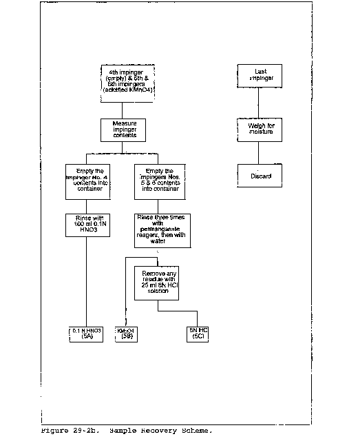
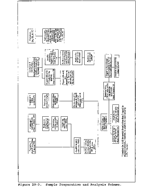
Method 30A - Determination of Total Vapor Phase Mercury Emissions From Stationary Sources (Instrumental Analyzer Procedure)
1.0 Scope and Application
What Is Method 30A?
Method 30A is a procedure for measuring total vapor phase mercury (Hg) emissions from stationary sources using an instrumental analyzer. This method is particularly appropriate for performing emissions testing and for conducting relative accuracy test audits (RATAs) of mercury continuous emissions monitoring systems (Hg CEMS) and sorbent trap monitoring systems at coal-fired combustion sources. Quality assurance and quality control requirements are included to assure that you, the tester, collect data of known and acceptable quality for each testing site. This method does not completely describe all equipment, supplies, and sampling procedures and analytical procedures you will need but refers to other test methods for some of the details. Therefore, to obtain reliable results, you should also have a thorough knowledge of these additional methods which are also found in appendices A-1 and A-3 to this part:
(a) Method 1 - Sample and Velocity Traverses for Stationary Sources.
(b) Method 4 - Determination of Moisture Content in Stack Gases.
1.1 Analytes. What does this method determine? This method is designed to measure the mass concentration of total vapor phase Hg in flue gas, which represents the sum of elemental Hg (Hg0) and oxidized forms of Hg (Hg+2), in mass concentration units of micrograms per cubic meter (µg/m3).
| Analyte | CAS No. | Sensitivity |
|---|---|---|
| Elemental Hg (Hg0) | 7439-97-6 | Typically <2% of Calibration Span. |
| Oxidized Hg (Hg+2) | (Same). |
1.2 Applicability. When is this method required? Method 30A is offered as a reference method for emission testing and for RATAs of Hg CEMS and sorbent trap monitoring systems at coal-fired boilers. Method 30A may also be specified for other source categories in the future, either by New Source Performance Standards (NSPS), National Emission Standards for Hazardous Air Pollutants (NESHAP), emissions trading programs, State Implementation Plans (SIP), or operating permits that require measurement of Hg concentrations in stationary source emissions to determine compliance with an applicable emission standard or limit, or to conduct RATAs of Hg CEMS and sorbent trap monitoring systems.
1.3 Data Quality Objectives (DQO). How good must my collected data be? Method 30A has been designed to provide data of high and known quality for Hg emission testing and for relative accuracy testing of Hg monitoring systems including Hg CEMS and sorbent trap monitoring systems. In these and other applications, the principle objective is to ensure the accuracy of the data at the actual emission levels encountered. To meet this objective, calibration standards prepared according to an EPA traceability protocol must be used and measurement system performance tests are required.
2.0 Summary of Method
In this method, a sample of the effluent gas is continuously extracted and conveyed to an analyzer capable of measuring the total vapor phase Hg concentration. Elemental and oxidized mercury (i.e., Hg0 and Hg+2) may be measured separately or simultaneously but, for purposes of this method, total vapor phase Hg is the sum of Hg0 and Hg+2. You must meet the performance requirements of this method (i.e., system calibration, interference testing, dynamic spiking, and system integrity/drift checks) to validate your data. The dynamic spiking requirement is deferred until January 1, 2009.
3.0 Definitions
3.1 Calibration Curve means the relationship between an analyzer's response to the injection of a series of calibration gases and the actual concentrations of those gases.
3.2 Calibration Gas means a gas standard containing Hg0 or HgCl2 at a known concentration that is produced and certified in accordance with an EPA traceability protocol for certification of Hg calibration standards.
3.2.1 Zero Gas means a calibration gas with a concentration that is below the level detectable by the measurement system.
3.2.2 Low-Level Gas means a calibration gas with a concentration that is 10 to 30 percent of the calibration span.
3.2.3 Mid-Level Gas means a calibration gas with a concentration that is 40 to 60 percent of the calibration span.
3.2.4 High-Level Gas means a calibration gas whose concentration is equal to the calibration span.
3.3 Converter means a device that reduces oxidized mercury (Hg+2) to elemental mercury (Hg0).
3.4 Calibration Span means the upper limit of valid instrument response during sampling. To the extent practicable the measured emissions are to be between 10 and 100 percent of the selected calibration span (i.e., the measured emissions should be within the calibrated range determined by the Low- and High-Level gas standards). It is recommended that the calibration span be at least twice the native concentration to accommodate the dynamic spiking procedure.
3.5 Centroidal Area means the central area that has the same shape as the stack or duct cross section and is no greater than one percent of the stack or duct total cross-sectional area.
3.6 Data Recorder means the equipment that permanently records the concentrations reported by the analyzer.
3.7 Drift Check means the test to determine the difference between the measurement system readings obtained in a post-run system integrity check and the prior pre-run system integrity check at a specific calibration gas concentration level (i.e., zero, mid-level, or high-level).
3.8 Dynamic Spiking means a procedure in which a known mass or concentration of vapor phase HgCl2 is injected into the probe sample gas stream at a known flow rate, in order to assess the effects of the flue gas matrix on the accuracy of the measurement system.
3.9 Gas Analyzer means the equipment that detects the total vapor phase Hg being measured and generates an output proportional to its concentration.
3.10 Interference Test means the test to detect analyzer responses to compounds other than Hg, usually gases present in the measured gas stream, that are not adequately accounted for in the calibration procedure and may cause measurement bias.
3.11 Measurement System means all of the equipment used to determine the Hg concentration. The measurement system may generally include the following major subsystems: sample acquisition, Hg+2 to Hg0 converter, sample transport, sample conditioning, flow control/gas manifold, gas analyzer, and data recorder.
3.12 Native Concentration means the total vapor phase Hg concentration in the effluent gas stream.
3.13 NIST means the National Institute of Standards and Technology, located in Gaithersburg, Maryland.
3.14 Response Time means the time it takes for the measurement system, while operating normally at its target sample flow rate or dilution ratio, to respond to a known step change in gas concentration (from a low-level to a high-level gas) and to read within 5 percent of the stable high-level gas response.
3.15 Run means a series of gas samples taken successively from the stack or duct. A test normally consists of a specific number of runs.
3.16 System Calibration Error means the difference between the measured concentration of a low-, mid-, or high-level Hg0 calibration gas and the certified concentration of the gas when it is introduced in system calibration mode.
3.17 System Calibration Mode means introducing the calibration gases into the measurement system at the probe, upstream of all sample conditioning components.
3.18 Test refers to the series of runs required by the applicable regulation.
4.0 Interferences
Interferences will vary among instruments and potential instrument-specific spectral and matrix interferences must be evaluated through the interference test and the dynamic spiking tests.
5.0 Safety
What safety measures should I consider when using this method?
This method may require you to work with hazardous materials and in hazardous conditions. You are encouraged to establish safety procedures before using the method. Among other precautions, you should become familiar with the safety recommendations in the gas analyzer user's manual. Occupational Safety and Health Administration (OSHA) regulations concerning use of compressed gas cylinders and noxious gases may apply.
6.0 Equipment and Supplies
6.1 What do I need for the measurement system? This method is intended to be applicable to multiple instrumental technologies. You may use any equipment and supplies that meet the following specifications.
6.1.1 All wetted sampling system components, including probe components prior to the point at which the calibration gas is introduced, must be chemically inert to all Hg species. Materials such as perfluoroalkoxy (PFA) TeflonTM, quartz, treated stainless steel (SS) are examples of such materials. [Note: These materials of construction are required because components prior to the calibration gas injection point are not included in the system calibration error, system integrity, and interference tests.]
6.1.2 The interference, system calibration error, system integrity, drift and dynamic spiking test criteria must all be met by the system used.
6.1.3 The system must be capable of measuring and controlling sample flow rate.
6.1.4 All system components prior to the Hg+2 to Hg0 converter must be maintained at a sample temperature above the acid gas dew point.
6.2 Measurement System Components. Figure 30A-1 in section 17.0 is an example schematic of a Method 30A measurement system.
6.2.1 Sample Probe. The probe must be made of the appropriate materials as noted in section 6.1.1, heated when necessary (see section 6.1.4), configured with ports for introduction of calibration and spiking gases, and of sufficient length to traverse all of the sample points.
6.2.2 Filter or Other Particulate Removal Device. The filter or other particulate removal device is considered to be a part of the measurement system, must be made of appropriate materials as noted in section 6.1.1, and must be included in all system tests.
6.2.3 Sample Line. The sample line that connects the probe to the converter, conditioning system and analyzer must be made of appropriate materials as noted in section 6.1.1.
6.2.4 Conditioning Equipment. For dry basis measurements, a condenser, dryer or other suitable device is required to remove moisture continuously from the sample gas. Any equipment needed to heat the probe, or sample line to avoid condensation prior to the moisture removal component is also required. For wet basis systems, you must keep the sample above its dew point either by:
(1) Heating the sample line and all sample transport components up to the inlet of the analyzer (and, for hot-wet extractive systems, also heating the analyzer) or
(2) by diluting the sample prior to analysis using a dilution probe system. The components required to do either of the above are considered to be conditioning equipment.
6.2.5 Sampling Pump. A pump is needed to push or pull the sample gas through the system at a flow rate sufficient to minimize the response time of the measurement system. If a mechanical sample pump is used and its surfaces are in contact with the sample gas prior to detection, the pump must be leak free and must be constructed of a material that is non-reactive to the gas being sampled (see section 6.1.1). For dilution-type measurement systems, an ejector pump (eductor) may be used to create a sufficient vacuum that sample gas will be drawn through a critical orifice at a constant rate. The ejector pump may be constructed of any material that is non-reactive to the gas being sampled.
6.2.6 Calibration Gas System(s). One or more systems may be needed to introduce calibration gases into the measurement system. A system should be able to flood the sampling probe sufficiently to prevent entry of gas from the effluent stream.
6.2.7 Dynamic Spiking Port. For the purposes of the dynamic spiking procedure described in section 8.2.7, the measurement system must be equipped with a port to allow introduction of the dynamic spike gas stream with the sample gas stream, at a point as close as possible to the inlet of the probe so as to ensure adequate mixing. The same port used for system calibrations and calibration error checks may be used for dynamic spiking purposes.
6.2.8 Sample Gas Delivery. The sample line may feed directly to a converter, to a by-pass valve (for speciating systems), or to a sample manifold. All valve and/or manifold components must be made of material that is non-reactive to the gas sampled and the calibration gas, and must be configured to safely discharge any excess gas.
6.2.9 Hg Analyzer. An instrument is required that continuously measures the total vapor phase Hg in the gas stream and meets the applicable specifications in section 13.0.
6.2.10 Data Recorder. A recorder, such as a computerized data acquisition and handling system (DAHS), digital recorder, strip chart, or data logger, is required for recording measurement data.
6.3 Moisture Measurement System. If correction of the measured Hg emissions for moisture is required (see section 8.5), either Method 4 in appendix A-3 to this part or other moisture measurement methods approved by the Administrator will be needed to measure stack gas moisture content.
7.0 Reagents and Standards
7.1 Calibration Gases. What calibration gases do I need? You will need calibration gases of known concentrations of Hg0 and HgCl2. Special reagents and equipment may be required to prepare the HgCl2 gas standards (e.g., a NIST-traceable solution of HgCl2 and a gas generator equipped with mass flow controllers).
The following calibration gas concentrations are required:
7.1.1 High-Level Gas. Equal to the selected calibration span.
7.1.2 Mid-Level Gas. 40 to 60 percent of the calibration span.
7.1.3 Low-Level Gas. 10 to 30 percent of the calibration span.
7.1.4 Zero Gas. No detectable Hg.
7.1.5 Dynamic Spike Gas. The exact concentration of the HgCl2 calibration gas used to perform the pre-test dynamic spiking procedure described in section 8.2.7 depends on the native Hg concentration in the stack The spike gas must produce a spiked sample concentration above the native concentration, as specified in section 8.2.7.2.2.
7.2 Interference Test. What reagents do I need for the interference test? Use the appropriate test gases listed in Table 30A-3 in section 17.0 (i.e., the potential interferents for the source to be tested, as identified by the instrument manufacturer) to conduct the interference check. These gases need not be of protocol gas quality.
8.0 Sample Collection
Emission Test Procedure
Figure 30A-2 in section 17.0 presents an overview of the test procedures required by this method. Since you may choose different options to comply with certain performance criteria, you must identify the specific options and associated frequencies you select and document your results in regard to the performance criteria.
8.1 Selection of Sampling Sites and Sampling Points. What sampling site and sampling points do I select?
8.1.1 When this method is used solely for Hg emission testing (e.g., to determine compliance with an emission standard or limit), use twelve sampling points located according to Table 1-1 or Table 1-2 of Method 1 in appendix A-1 to this part. Alternatively, you may conduct a stratification test as described in section 8.1.3 to determine the number and location of the sampling points.
8.1.2 When this method is used for relative accuracy testing of a Hg CEMS or sorbent trap monitoring system, follow the sampling site selection and sampling point layout procedures for gas monitor RATA testing described in the appropriate performance specification or applicable regulation (e.g., Performance Specification 2, section 8.1.3 of appendix B to this part or section 6.5.6 of appendix A to part 75 of this chapter), with one exception. If you elect to perform stratification testing as part of the sampling point selection process, perform the testing in accordance with section 8.1.3 of this method (see also “Summary Table of QA/QC Requirements” in section 9.0).
8.1.3 Determination of Stratification. If you elect to perform stratification testing as part of the sampling point selection process and the test results show your effluent gas stream to be unstratified or minimally stratified, you may be allowed to sample at fewer points or at different points than would otherwise be required.
8.1.3.1 Test Procedure. To test for stratification, use a probe of appropriate length to measure the total vapor phase Hg concentration at twelve traverse points located according to Table 1-1 or Table 1-2 of Method 1 in appendix A-1 to this part. Alternatively, for a sampling location where stratification is expected (e.g., after a wet scrubber or at a point where dissimilar gas streams are combined together), if a 12-point Hg stratification test has been previously performed at that location and the results of the test showed the location to be minimally stratified or unstratified according to the criteria in section 8.1.3.2, you may perform an abbreviated 3-point or 6-point Hg stratification test at the points specified in section 6.5.6.2(a) of appendix A to part 75 of this chapter in lieu of performing the 12-point test. Sample for a minimum of twice the system response time (see section 8.2.6) at each traverse point. Calculate the individual point and mean Hg concentrations.
8.1.3.2 Acceptance Criteria and Sampling Point Location.
8.1.3.2.1 If the Hg concentration at each traverse point differs from the mean concentration for all traverse points by no more than:
(a) ±5 percent of the mean concentration; or
(b) ±0.2 µg/m3 (whichever is less restrictive), the gas stream is considered to be unstratified and you may collect samples from a single point that most closely matches the mean.
8.1.3.2.2 If the 5 percent or 0.2 µg/m3 criterion in section 8.1.3.2.1 is not met, but the Hg concentration at each traverse point differs from the mean concentration for all traverse points by no more than:
(a) ±10 percent of the mean; or
(b) ±0.5 µg/m3 (whichever is less restrictive), the gas stream is considered to be minimally stratified, and you may take samples from three points, provided the points are located on the measurement line exhibiting the highest average Hg concentration during the stratification test. If the stack diameter (or equivalent diameter, for a rectangular stack or duct) is greater than 2.4 meters (7.8 ft), locate the three sampling points at 0.4, 1.0, and 2.0 meters from the stack or duct wall. Alternatively, if a RATA required by part 75 of this chapter is being conducted, you may locate the three points at 4.4, 14.6, and 29.6 percent of the duct diameter, in accordance with Method 1 in appendix A-1 to this part. For stack or duct diameters of 2.4 meters (7.8 ft) or less, locate the three sampling points at 16.7, 50.0, and 83.3 percent of the measurement line.
8.1.3.2.3 If the gas stream is found to be stratified because the 10 percent or 0.5 µg/m3 criterion in section 8.1.3.2.2 is not met, then either locate three sampling points at 16.7, 50.0, and 83.3 percent of the measurement line that exhibited the highest average Hg concentration during the stratification test, or locate twelve traverse points for the test in accordance with Table 1-1 or Table 1-2 of Method 1 in appendix A-1 to this part; or, if a RATA required by part 75 of this chapter is being conducted, locate six Method 1 points along the measurement line that exhibited the highest average Hg concentration.
8.1.3.3 Temporal Variations. Temporal variations in the source Hg concentration during a stratification test may complicate the determination of stratification. If temporal variations are a concern, you may use the following procedure to normalize the stratification test data. A second Hg measurement system, i.e., either an installed Hg CEMS or another Method 30A system, is required to perform this procedure. Position the sampling probe of the second Hg measurement system at a fixed point in the stack or duct, at least one meter from the stack or duct wall. Then, each time that the Hg concentration is measured at one of the stratification test points, make a concurrent measurement of Hg concentration at the fixed point. Normalize the Hg concentration measured at each traverse point, by multiplying it by the ratio of CF,avg to CF, where CF is the corresponding fixed-point Hg concentration measurement, and CF,avg is the average of all of the fixed-point measurements over the duration of the stratification test. Evaluate the results of the stratification test according to section 8.1.3.2, using the normalized Hg concentrations.
8.1.3.4 Stratification Testing Exemption. Stratification testing need not be performed at a test location where it would otherwise be required to justify using fewer sample points or different sample points, if the owner or operator documents that the Hg concentration in the stack gas is expected to be 3 µg/m3 or less at the time of a Hg monitoring system RATA or an Hg emissions test. To demonstrate that a particular test location qualifies for the stratification testing exemption, representative Hg emissions data must be collected just prior to the RATA or emissions test. At least one hour of Hg concentration data is required for the demonstration. The data used for the demonstration shall be recorded at process operating conditions that closely approximate the operating conditions that will exist during the RATA or emissions test. It is recommended that collection of the demonstration data be integrated with the on-site pretest procedures required by the reference method being used for the RATA or emissions test (whether this method or another approved Hg reference method is used). Quality-assured data from an installed Hg monitoring system may also be used for the demonstration. If a particular test location qualifies for the stratification testing exemption, sampling shall be performed at three points, as described in section 8.1.3.2.2 of this method. The owner or operator shall fully document the method used to collect the demonstration data and shall keep this documentation on file with the data from the associated RATA or Hg emissions test.
8.1.3.5 Interim Alternative Stratification Test Procedures. In the time period between the effective date of this method and January 1, 2009, you may follow one of the following two procedures. Substitute a stratification test for sulfur dioxide (SO2) for the Hg stratification test described in section 8.1.3.1. If this option is chosen, follow the test procedures in section 6.5.6.1 of appendix A to part 75 of this chapter. Evaluate the test results and determine the sampling point locations according to section 6.5.6.3 of appendix A to part 75 of this chapter. If the sampling location is found to be minimally stratified or unstratified for SO2, it shall be considered minimally stratified or unstratified for Hg. Alternatively, you may forgo stratification testing, assume the gas stream is minimally stratified, and sample at three points as described in section 8.1.3.2.2 of this method.
8.2 Initial Measurement System Performance Tests. What initial performance criteria must my system meet before I begin sampling? Before measuring emissions, perform the following procedures:
(a) Interference Test;
(b) Calibration Gas Verification;
(c) Measurement System Preparation;
(d) 3-Point System Calibration Error Test;
(e) System Integrity Check;
(f) Measurement System Response Time Test; and
(g) Dynamic Spiking Test.
8.2.1 Interference Test (Optional). Your measurement system should be free of known interferences. It is recommended that you conduct this interference test of your measurement system prior to its initial use in the field to verify that the candidate test instrument is free from inherent biases or interferences resulting from common combustion emission constituents. If you have multiple measurement systems with components of the same make and model numbers, you need only perform this interference check on one system and you may also rely on an interference test conducted by the manufacturer on a system having components of the same make and model(s) of the system that you use. The interference test procedure is found in section 8.6 of this method.
8.2.2 Calibration Gas Verification. How must I verify the concentrations of my calibration gases?
8.2.2.1 Cylinder Gas Standards. When cylinder gas standards are used for Hg0, obtain a certificate from the gas manufacturer and confirm that the documentation includes all information required by an EPA traceability protocol (see section 16). Confirm that the manufacturer certification is complete and current. Ensure that the calibration gas certifications have not expired.
8.2.2.2 Other Calibration Standards. All other calibration standards for HgCl2 and Hg0, such as gas generators, must meet the requirements of an EPA traceability protocol (see section 16), and the certification procedures must be fully documented in the test report.
8.2.2.3 Calibration Span. Select the calibration span (i.e., high-level gas concentration) so that the measured source emissions are 10 to 100 percent of the calibration span. This requirement is waived for applications in which the Hg concentrations are consistently below 1 µg/m3; however, the calibration span for these low-concentration applications shall not exceed 5 µg/m3.
8.2.3 Measurement System Preparation. How do I prepare my measurement system for use? Assemble, prepare, and precondition the measurement system according to your standard operating procedure. Adjust the system to achieve the correct sampling rate or dilution ratio (as applicable). Then, conduct a 3-point system calibration error test using Hg0 as described in section 8.2.4, an initial system integrity check using HgCl2 and a zero gas as described in section 8.2.5, and a pre-test dynamic spiking test as described in section 8.2.7.
8.2.4 System Calibration Error Test. Conduct a 3-point system calibration error test before the first test run. Use Hg0 standards for this test. Introduce the low-, mid-, and high-level calibration gases in any order, in system calibration mode, unless you desire to determine the system response time during this test, in which case, inject the gases such that the high-level injection directly follows the low-level injection. For non-dilution systems, you may adjust the system to maintain the correct flow rate at the analyzer during the test, but you may not make adjustments for any other purpose. For dilution systems, you must operate the measurement system at the appropriate dilution ratio during all system calibration error checks, and you may make only the adjustments necessary to maintain the proper ratio. After each gas injection, wait until a stable response has been obtained. Record the analyzer's final, stable response to each calibration gas on a form similar to Table 30A-1 in section 17.0. For each calibration gas, calculate the system calibration error using Equation 30A-1 in section 12.2. The calibration error specification in section 13.1 must be met for the low-, mid-, and high-level gases. If the calibration error specification is not met for all three gases, take corrective action and repeat the test until an acceptable 3-point calibration is achieved.
8.2.5 System Integrity Check. Perform a two-point system integrity check before the first test run. Use the zero gas and either the mid- or high-level HgCl2 calibration gas for the check, whichever one best represents the total vapor phase Hg concentration levels in the stack. Record the data on a form similar to Table 30A-2 in section 17.0. The system integrity check specification in section 13.2 must be met for both the zero gas and the mid- or high-level gas. If the system integrity specification is not met for both gases, take corrective action and repeat the test until an acceptable system integrity check is achieved.
8.2.6 Measurement System Response Time. The measurement system response time is used to determine the minimum sampling time for each sampling point and is equal to the time that is required for the measured Hg concentration to increase from the stable low-level calibration gas response to a value within 5 percent of the stable high-level calibration gas response during the system calibration error test in section 8.2.4. Round off the measured system response time to the nearest minute.
8.2.7 Dynamic Spiking Test. You must perform dynamic spiking prior to the first test run to validate your test data. The purpose of this procedure is to demonstrate that the site-specific flue gas matrix does not adversely affect the accuracy of the measurement system. The specifications in section 13.5 must be met to validate your data. If these specifications are not met for the pre-test dynamic spiking, you may not proceed with the test until satisfactory results are obtained. For the time period between the effective date of this method and January 1, 2009, the dynamic spiking requirement is waived.
8.2.7.1 How do I perform dynamic spiking? Dynamic spiking is a gas phase application of the method of standard additions, which involves injecting a known quantity of Hg into the measurement system upstream of all sample conditioning components, similar to system calibration mode, except the probe is not flooded and the resulting sample stream includes both effluent gas and the spike gas. You must follow a written procedure that details how the spike is added to the system, how the spike dilution factor (DF) is measured, and how the Hg concentration data are collected and processed.
8.2.7.2 Spiking Procedure Requirements.
8.2.7.2.1 Spiking Gas Requirements. The spike gas must also be a HgCl2 calibration gas certified by an EPA traceability protocol. You must choose concentrations that can produce the target levels while being injected at a volumetric flow rate that is ≤20 percent of the total volumetric flow rate through the measurement system (i.e., sample flow rate plus spike gas flow rate).
8.2.7.2.2 Target Spiking Level. The target level for spiking must be 150 to 200 percent of the native Hg concentration; however, if the native Hg concentration is <1 µg/m3, set the target level to add between 1 and 4 µg/m3 Hg+2 to the native concentration. Use Equation 30A-5 in section 12.5 to calculate the acceptable range of spike gas concentrations at the target level. Then select a spike gas concentration in that range.
8.2.7.2.3 Spike Injections. You must inject spikes in such a manner that the spiking does not alter the total volumetric sample system flow rate and dilution ratio (if applicable). You must collect at least 3 data points, and the relative standard deviation (RSD) specification in section 13.5 must be met. Each data point represents a single spike injection, and pre- and post-injection measurements of the native Hg concentration (or diluted native concentration, as applicable) are required for each spike injection.
8.2.7.2.4 Spike Dilution Factor (DF). For each spike injection, DF, the dilution factor must be determined. DF is the ratio of the total volumetric flow rate of gas through the measurement system to the spike gas flow rate. This factor must be ≥5. The spiking mass balance calculation is directly dependent on the accuracy of the DF determination. As a result, high accuracy total volumetric flow rate and spike gas flowrate measurements are required. These flow rates may be determined by direct or indirect measurement. Calibrated flow meters, venturies, orifices or tracer gas measurements are examples of potential flow measurement techniques.
8.2.7.2.5 Concentrations. The measurement system must record total vapor phase Hg concentrations continuously during the dynamic spiking procedure. It is possible that dynamic spiking at a level close to 200 percent of the native Hg concentration may cause the measured Hg concentration to exceed the calibration span value. Avoid this by choosing a lower spiking level or by recalibration at a higher span. The measurements shall not exceed 120 percent of the calibration span. The “baseline” measurements made between spikes may represent the native Hg concentration (if spike gas flow is stopped between injections) or the native Hg concentration diluted by blank or carrier gas flowing at the same rate as the spike gas (if gas flow cannot be stopped between injections). Each baseline measurement must include at least 4 readings or 1 minute (whichever is greater) of stable responses. Use Equation 30A-10 or 30A-11 in section 12.10 (as applicable) to convert baseline measurements to native concentration.
8.2.7.2.6 Recovery. Calculate spike recoveries using Equation 30A-7 in section 12.7. Mass recoveries may be calculated from stable responses based on injected mass flows or from integrated response peaks based on total mass injected. Calculate the mean and RSD for the three (or more) spike injections and compare to the specifications in section 13.5.
8.2.7.2.7 Error Adjustment Option. You may adjust the measurement data collected during dynamic spiking for the system calibration error using Equation 30A-3 in section 12. To do this, perform the initial system integrity check prior to the dynamic spiking test, and perform another system integrity check following the dynamic spiking test and before the first test run. If you choose this option, you must apply Equation 30A-3 to both the spiked sample concentration measurement (Css) and the baseline or native concentration measurement (Cnative), each substituted in place of Cavg in the equation.
8.2.7.3 Example Spiking Procedure Using a Hot Vapor Calibration Source Generator.
(a) Introduce the spike gas into the probe using a hot vapor calibration source generator and a solution of HgCl2 in dilute HC1 and HNO3. The calibrator uses a mass flow controller (accurate within 2 percent) to measure the gas flow, and the solution feed is measured using a top-loading balance accurate to 0.01g. The challenges of injecting oxidized Hg may make it impractical to stop the flow of gas between spike injections. In this case, operate the hot vapor calibration source generator continuously during the spiking procedure, swapping blank solutions for HgCl2 solutions when switching between spiking and baseline measurements.
(b) If applicable, monitor the measurement system to make sure the total sampling system flow rate and the sample dilution ratio do not change during this procedure. Record all data on a data sheet similar to Table 30A-5 in section 17.0. If the Hg measurement system design makes it impractical to measure the total volumetric flow rate through the system, use a spike gas that includes a tracer for measuring the dilution factor, DF (see Equation 30A-9 in section 12.9). Allow the measurements to stabilize between each spike injection, average the pre- and post-injection baseline measurements, and calculate the native concentration. If this measurement shifts by more than 5 percent during any injection, it may be necessary to discard that data point and repeat the injection to achieve the required RSD among the injections. If the spikes persistently show poor repeatability, or if the recoveries are not within the range specified in section 13.5, take corrective action.
8.2.8 Run Validation. How do I confirm that each run I conduct is valid?
8.2.8.1 System Integrity Checks.
(a) Before and after each test run, perform a two-point system integrity check using the same procedure as the initial system integrity check described in section 8.2.5. You may use data from that initial system integrity check as the pre-run data for the first test run, provided it is the most recent system integrity check done before the first run. You may also use the results of a successful post-run system integrity check as the pre-run data for the next test run. Do not make any adjustments to the measurement system during these checks, other than to maintain the target calibration gas flow rate and the proper dilution ratio.
(b) As a time-saving alternative, you may, at the risk of invalidating multiple test runs, skip one or more integrity checks during a test day. Provided there have been no auto-calibrations or other instrument alterations, a single integrity check may suffice as a post-run check to validate (or invalidate) as many consecutive test runs as can be completed during a single test day. All subsequent test days must begin with a pre-run system integrity check subject to the same performance criteria and corrective action requirements as a post-run system integrity check.
(c) Each system integrity check must meet the criteria for system integrity checks in section 13.2. If a post-run system integrity check is failed, all test runs since the last passed system integrity check are invalid. If a post-run or a pre-run system integrity check is failed, you must take corrective action and pass another 3-point Hg0 system calibration error test (Section 8.2.4) followed by another system integrity check before conducting any additional test runs. Record the results of the pre- and post-run system integrity checks on a form similar to Table 30A-2 in section 17.0.
8.2.8.2 Drift Check. Using the data from the successful pre- and post-run system integrity checks, calculate the zero and upscale drift, using Equation 30A-2 in section 12.3. Exceeding the section 13.3 specification does not invalidate the run, but corrective action must be taken and a new 3-point Hg0 system calibration error test and a system integrity check must be passed before any more runs are made.
8.3 Dilution-Type Systems - Special Considerations. When a dilution-type measurement system is used, there are three important considerations that must be taken into account to ensure the quality of the emissions data. First, the critical orifice size and dilution ratio must be selected properly so that the sample dew point will be below the sample line and analyzer temperatures. Second, a high-quality, accurate dilution controller must be used to maintain the correct dilution ratio during sampling. The dilution controller should be capable of monitoring the dilution air pressure, orifice upstream pressure, eductor vacuum, and sample flow rates. Third, differences between the molecular weight of calibration gas mixtures, dilution air, and the stack gas molecular weight must be considered because these can affect the dilution ratio and introduce measurement bias.
8.4 Sampling.
(a) Position the probe at the first sampling point. Allow the system to flush and equilibrate for at least two times the measurement system response time before recording any data. Then, traverse and record measurements at all required sampling points. Sample at each traverse point for an equal length of time, maintaining the appropriate sample flow rate or dilution ratio (as applicable). For all Hg instrumental method systems, the minimum sampling time at each sampling point must be at least two times the system response time, but not less than 10 minutes. For concentrating systems, the minimum sampling time must also include at least 4 concentration measurement cycles.
(b) After recording data for the appropriate period of time at the first traverse point, you may move the sample probe to the next point and continue recording, omitting the requirement to allow the system to equilibrate for two times the system response time before recording data at the subsequent traverse points. You must, however, sample at this and all subsequent traverse points for the required minimum amount of time specified in this section. If you must remove the probe from the stack for any reason, you must again allow the sampling system to equilibrate for at least two times the system response time prior to resuming data recording.
(c) If at any point the measured Hg concentration exceeds the calibration span value, you must at a minimum identify and report this as a deviation from the method. Depending on the data quality objectives of the test, this event may require corrective action before proceeding. If the average Hg concentration for any run exceeds the calibration span value, the run is invalidated.
8.5 Moisture Correction. If the moisture basis (wet or dry) of the measurements made with this method is different from the moisture basis of either:
(1) The applicable emission limit; or
(2) a Hg CEMS or sorbent trap monitoring system being evaluated for relative accuracy, you must determine the moisture content of the flue gas and correct the measured gas concentrations to a dry basis using Method 4 in appendix A-3 of this part or other appropriate methods, subject to the approval of the Administrator.
8.6 Optional Interference Test Procedure.
(a) Select an appropriate calibration span that reflects the source(s) to be tested and perform the interference check at 40 percent of the lowest calibration span value anticipated, e.g., 10 µg/m3. Alternatively, successfully conducting the interference test at an absolute Hg concentration of 2 µg/m3 will demonstrate performance for an equivalent calibration span of 5 µg/m3, the lowest calibration span allowed for Method 30A testing. Therefore, performing the interference test at the 2 µ/m3 level will serve to demonstrate acceptable performance for all calibration spans greater than or equal to 5 µg/m3.
(b) Introduce the interference test gases listed in Table 30A-3 in section 17.0 into the measurement system separately or as a mixture. The interference test gases HCl and NO must be introduced as a mixture. The interference test gases must be introduced into the sampling system at the probe such that the interference gas mixtures pass through all filters, scrubbers, conditioners, and other components as would be configured for normal sampling.
(c) The interference test must be performed using HgCl2, and each interference test gas (or gas mixture) must be evaluated in triplicate. This is accomplished by measuring the Hg response first with only the HgCl2 gas present and then when adding the interference test gas(es) while maintaining the HgCl2 concentration of the test stream constant. It is important that the equipment used to conduct the interference test be of sufficient quality so as to be capable of blending the HgCl2 and interference gases while maintaining the Hg concentration constant. Gas blending system or manifolds may be used.
(d) The duration of each test should be for a sufficient period of time to ensure the Hg measurement system surfaces are conditioned and a stable output is obtained. Measure the Hg response of the analyzer to these gases in µg/m3. Record the responses and determine the overall interference response using Table 30A-4 in section 17.0 and the equations presented in section 12.11. The specification in section 13.4 must be met.
(e) A copy of these data, including the date completed and a signed certification, must be included with each test report. The intent of this test is that the interference test results are intended to be valid for the life of the system. As a result, the Hg measurement system should be operated and tested in a configuration consistent with the configuration that will be used for field applications. However, if the system used for field testing is not consistent with the system that was interference-tested, the interference test must be repeated before it is used for any field applications. Examples of such conditions include, but are not limited to: major changes in dilution ratio (for dilution based systems), changes in catalyst materials, changes in filtering device design or materials, changes in probe design or configuration, and changes in gas conditioning materials or approaches.
9.0 Quality Control
What quality control measures must I take?
The table which follows is a summary of the mandatory, suggested, and alternative quality assurance and quality control measures and the associated frequency and acceptance criteria. All of the QC data, along with the run data, must be documented and included in the test report.
Summary Table of QA/QC Requirements
| Status1 | Process or element | QA/QC specification | Acceptance criteria | Checking frequency |
|---|---|---|---|---|
| S | Identify Data User | Regulatory Agency or other primary end user of data | Before designing test. | |
| M | Analyzer Design | Analyzer range | Sufficiently >high-level gas to allow determination of system calibration error | |
| S | Analyzer resolution or sensitivity | <2.0 % of full-scale range | Manufacturer design. | |
| S | Interference response | Overall response ≤3% of calibration span
Alternatively, overall response ≤0.3 µg/m3 |
||
| M | Calibration Gases | Traceability protocol | Validation of concentration required | |
| M | High-level Hg0 gas | Equal to the calibration span | Each calibration error test. | |
| M | Mid-level Hg0 gas | 40 to 60% of calibration span | Each calibration error test. | |
| M | Low-level Hg0 gas | 10 to 30% of calibration span | Each calibration error test. | |
| M | High-level HgCl2 gas | Equal to the calibration span | Each system integrity check (if it better represents Cnative than the mid level gas). | |
| M | Mid-level HgCl2 | 40 to 60% of calibration span | Each system gas integrity check (if it better represents Cnative than the high level gas). | |
| M | Zero gas | Each system integrity check. | ||
| M | Dynamic spike gas (Cnative ≥1 µg/m3) | A high-concentration HgCl2 gas, used to produce a spiked sample concentration that is 150 to 200% of the native concentration | Pre-test; dynamic spiking not required until 1/1/09. | |
| M | Dynamic spike gas (Cnative <1 µg/m3) | A high-concentration HgCl2 gas, used to produce a spiked sample concentration that is 1 to 2 µg/m3 above the native concentration | Pre-test; dynamic spiking not required until 1/1/09. | |
| S | Data Recorder Design | Data resolution | ≤0.5% of full-scale | Manufacturer design. |
| M | Sample Extraction | Probe material | Inert to sample constituents (e.g., PFA Teflon, or quartz if stack >500 °F) | Each run. |
| M | Sample Extraction | Probe, filter and sample line temperature | For dry-basis analyzers, keep sample above the dew point, by heating prior to moisture removal
For wet-basis analyzers, keep sample above dew point at all times, by heating or dilution |
Each run. |
| M | Sample Extraction | Calibration valve material | Inert to sample constituents (e.g., PFA Teflon or PFA Teflon coated) | Each test. |
| S | Sample Extraction | Sample pump material | Inert to sample constituents | Each test. |
| M | Sample Extraction | Manifold material | Inert to sample constituents | Each test. |
| M | Particulate Removal | Filter inertness | Pass calibration error check | Each calibration error check. |
| M | System Calibration Performance | System calibration error (CE) test | CE ≤5.0 % of the calibration span for the low-, mid-or high-level Hg0 calibration gas
Alternative specification: ≤0.5 µg/m3 absolute difference between system response and reference value |
Before initial run and after a failed system integrity check or drift test. |
| M | System Calibration Performance | System integrity check | Error ≤5.0% of the calibration span for the zero and mid- or high-level HgCl2 calibration gas
Alternative specification: ≤0.5 µg/m3 absolute difference between system response and reference value |
Before initial run, after each run, at the beginning of subsequent test days, and after a failed system integrity check or drift test. |
| M | System Performance | System response time | Used to determine minimum sampling time per point | During initial 3-point system calibration error test. |
| M | System Performance | Drift | ≤3.0% of calibration span for the zero and mid- or high-level gas
Alternative specification: ≤0.3 µg/m3 absolute difference between pre- and post-run system calibration error percentages. |
At least once per test day. |
| M | System Performance | Minimum sampling time | The greater of two times the system response time or 10 minutes. Concentrating systems must also include at least 4 cycles | Each sampling point. |
| M | System Performance | Percentage spike recovery and relative standard deviation | Percentage spike recovery, at the target level: 100 ±10%
Relative standard deviation: ≤5 percent Alternative specification: absolute difference between calculated and measured spike values ≤0.5 µg/m3 |
Before initial run; dynamic spiking not required until 1/1/09. |
| M | Sample Point Selection | Number and Location of Sample Points | For emission testing applications, use 12 points, located according to Method 1 in appendix A-1 to this part, unless the results of a stratification test allow fewer points to be used | Prior to first run. |
| For Part 60 RATAs, follow the procedures in Performance Specification 2, section 8.1.3, and for Part 75 RATAs, follow the procedures in section 6.5.6 of appendix A to Part 75. That is: | ||||
| • At any test location, you may use 3 sample points located at 16.7, 50.0, and 83.3% of a “long” measurement line passing through the centroidal area; or | ||||
| • At any test location, you may use 6 sample points along a diameter, located according to Method 1 (Part 75 RATAs, only); or | ||||
| • At a location where stratification is not expected and the measurement line is >2.4 m (7.8 ft), you may use 3 sample points located along a “short” measurement line at 0.4, 1.0, and 2.0 m from the stack or duct wall or, for Part 75 only, sample points may be located at 4.4, 14.6, and 29.6% of the measurement line; or | ||||
| • After a wet scrubber or at a point where dissimilar gas streams are combined, either locate 3 sample points along the “long” measurement line or locate 6 Method 1 points along a diameter (Part 75, only), unless the results of a stratification test allow you to use a “short” 3-point measurement line or to sample at a single point | ||||
| • If it can be demonstrated that stack gas concentration is ≤3 µg/m3, then the test site is exempted from stratification testing. Use the 3-point “short” measurement line if the stack diameter is >2.4 m (7.8 ft) and the 3-point “long” line for stack diameters ≤2.4 m (7.8 ft) | ||||
| A | Sample Point Selection | Stratification Test (See section 8.1.3). | If the Hg concentration2 at each traverse point during the stratification test is:
• Within ±5% of mean, use 1-point sampling (at the point closest to the mean); or • Not within ±5% of mean, but is within ±10% of mean, use 3-point sampling. Locate points according to section 8.1.3.2.2 of this method. Alternatively, if the Hg concentration at each point is: • Within ±0.2 µg/m3 of mean, use 1-point sampling (at the point closest to the mean); or • Not within ±0.2 µg/m3 of mean, but is within ±0.5 µg/m3 of mean, use 3-point sampling. Locate points according to section 8.1.3.2.2 of this method. |
Prior to first run.
Prior to 1/1/09, you may (1) forgo stratification testing and use 3 sampling points (as per section 8.1.3.2.2) or (2) perform a SO2 stratification test (see sections 6.5.6.1 and 6.5.6.3 of appendix A to part 75), in lieu of a Hg stratification test. If the test location is unstratified or minimally stratified for SO2, it can be considered unstratified or minimally stratified for Hg also. |
| M | Data Recording | Frequency | Once per cycle | During run. |
| S | Data Parameters | Sample concentration and calibration span | All analyzer readings during each run within calibration span | Each run. |
| M | Data Parameters | Sample concentration and calibration span | All analyzer readings during dynamic spiking tests within 120% of calibration span | Each spike injection. |
| M | Data Parameters | Sample concentration and calibration span | Average Hg concentration for the run ≤calibration span | Each run. |
10.0 Calibration and Standardization
What measurement system calibrations are required?
Your analyzer must be calibrated with Hg° standards. The initial 3-point system calibration error test described in section 8.2.4 is required before you start the test. Also, prior to and following test runs, the two-point system integrity checks described in sections 8.2.5 and 8.2.8 are required. On and after January 1, 2009, the pre-test dynamic spiking procedure described in section 8.2.7 is also required to verify that the accuracy of the measurement system is suitable and not adversely affected by the flue gas matrix.
11.0 Analytical Procedures
Because sample collection and analysis are performed together (see section 8), additional discussion of the analytical procedure is not necessary.
12.0 Calculations and Data Analysis
You must follow the procedures for calculations and data analysis listed in this section.
12.1 Nomenclature. The terms used in the equations are defined as follows:
Bws = Moisture content of sample gas as measured by Method 4 in Appendix A-3 to this part, percent/100.
Cavg = Average unadjusted Hg concentration for the test run, as indicated by the data recorder µg/m3.
C̄baseline = Average Hg concentration measured before and after dynamic spiking injections, µg/m3.
Cd = Hg concentration, dry basis, µg/m3.
Cdif = Absolute value of the difference between the measured Hg concentrations of the reference HgCl2 calibration gas, with and without the individual or combined interference gases, µg/m3.
Cdif avg = Average of the 3 absolute values of the difference between the measured Hg concentrations of the reference HgCl2 calibration gas, with and without the individual or combined interference gases, µg/m3.
Cgas = Average Hg concentration in the effluent gas for the test run, adjusted for system calibration error, µg/m3.
Cint = Measured Hg concentration of the reference HgCl2 calibration gas plus the individual or combined interference gases, µg/m3.
Cm = Average of pre- and post-run system integrity check responses for the upscale (i.e., mid- or high-level) calibration gas, µg/m3.
Cma = Actual concentration of the upscale (i.e., mid- or high-level) calibration gas used for the system integrity checks, µg/m3.
C0 = Average of pre- and post-run system integrity check responses from the zero gas, µg/m3.
Cnative = Vapor phase Hg concentration in the source effluent, µg/m3.
Cref = Measured Hg concentration of the reference HgCl2 calibration gas alone, in the interference test, µg/m3.
Cs = Measured concentration of a calibration gas (zero-, low-, mid-, or high-level), when introduced in system calibration mode, µg/m3.
Cspike = Actual Hg concentration of the spike gas, µg/m3.
C*spike = Hg concentration of the spike gas required to achieve a certain target value for the spiked sample Hg concentration, µg/m3.
Css = Measured Hg concentration of the spiked sample at the target level, µg/m3.
C*ss = Expected Hg concentration of the spiked sample at the target level, µg/m3.
Ctarget = Target Hg concentration of the spiked sample, µg/m3.
CTnative = Measured tracer gas concentration present in native effluent gas, ppm.
CTdir = Tracer gas concentration injected with spike gas, ppm.
CTv = Diluted tracer gas concentration measured in a spiked sample, ppm.
Cv = Certified Hg° or HgCl2 concentration of a calibration gas (zero, low, mid, or high), µg/m3.
Cw = Hg concentration measured under moist sample conditions, wet basis, µg/m3.
CS = Calibration span, µg/m3.
D = Zero or upscale drift, percent of calibration span.
DF = Dilution factor of the spike gas, dimensionless.
I = Interference response, percent of calibration span.
Qprobe = Total flow rate of the stack gas sample plus the spike gas, liters/min.
Qspike = Flow rate of the spike gas, liters/min.
Ri = Individual injection spike recovery, %.
R̄ = Mean value of spike recoveries at a particular target level, %.
RSD = Relative standard deviation, %;.
SCE = System calibration error, percent of calibration span.
SCEi = Pre-run system calibration error during the two-point system integrity check, percent of calibration span.
SCEf = Post-run system calibration error during the two-point system integrity check, percent of calibration span.
12.2 System Calibration Error. Use Equation 30A-1 to calculate the system calibration error. Equation 30A-1 applies to: 3-point system calibration error tests performed with Hg° standards; and pre- and post-run two-point system integrity checks performed with HgCl2.

12.3 Drift Assessment. Use Equation 30A-2 to separately calculate the zero and upscale drift for each test run.

12.3 Effluent Hg Concentration. For each test run, calculate Cavg, the arithmetic average of all valid Hg concentration values recorded during the run. Then, adjust the value of Cavg for system calibration error, using Equation 30A-3.

12.4 Moisture Correction. Use Equation 30A-4a if your measurements need to be corrected to a dry basis.

Use Equation 30A-4b if your measurements need to be corrected to a wet basis.

12.5 Dynamic Spike Gas Concentrations. Use Equation 30A-5 to determine the spike gas concentration needed to produce a spiked sample with a certain “target” Hg concentration.

12.6 Spiked Sample Concentration. Use Equation 30A-6 to determine the expected or theoretical Hg concentration of a spiked sample.

12.7 Spike Recovery. Use Equation 30A-7 to calculate the percentage recovery of each spike.

12.8 Relative Standard Deviation. Use Equation 30A-8 to calculate the relative standard deviation of the individual percentage spike recovery values from the mean.

12.9 Spike Dilution Factor. Use Equation 30A-9 to calculate the spike dilution factor, using either direct flow measurements or tracer gas measurements.

12.10 Native Concentration. For spiking procedures that inject blank or carrier gases (at the spiking flow rate, Qspike) between spikes, use Equation 30A-10 to calculate the native concentration.

For spiking procedures that halt all injections between spikes, the native concentration equals the average baseline concentration (see Equation 30A-11).

12.11 Overall Interference Response. Use equation 30A-12 to calculate the overall interference response.

Where, for each interference gas (or mixture):


13.0 Method Performance
13.1 System Calibration Error Test. This specification applies to the 3-point system calibration error tests using Hg0. At each calibration gas level tested (low-, mid-, or high-level), the calibration error must be within ±5.0 percent of the calibration span. Alternatively, the results are acceptable if | Cs − Cv | ≤0.5 µg/m3.
13.2 System Integrity Checks. This specification applies to all pre- and post-run 2-point system integrity checks using HgCl2 and zero gas. At each calibration gas level tested (zero and mid- or high-level), the error must be within ±5.0 percent of the calibration span. Alternatively, the results are acceptable if | Cs − Cv | ≤0.5 µg/m3.
13.3 Drift. For each run, the low-level and upscale drift must be less than or equal to 3.0 percent of the calibration span. The drift is also acceptable if the pre- and post-run system integrity check responses do not differ by more than 0.3 µg/m3 (i.e., | Cs post-run − Cs pre-run | ≤0.3 µg/m3).
13.4 Interference Test. Summarize the results following the format contained in Table 30A-4. For each interference gas (or mixture), calculate the mean difference between the measurement system responses with and without the interference test gas(es). The overall interference response for the analyzer that was used for the test (calculated according to Equation 30A-12), must not be greater than 3.0 percent of the calibration span used for the test (see section 8.6). The results of the interference test are also acceptable if the sum of the absolute average differences for all interference gases (i.e., Σ Cdif avg) does not exceed 0.3 µg/m3.
13.5 Dynamic Spiking Test. For the pre-test dynamic spiking, the mean value of the percentage spike recovery must be 100 ±10 percent. In addition, the relative standard deviation (RSD) of the individual percentage spike recovery values from the mean must be ≤5.0 percent. Alternatively, if the mean percentage recovery is not met, the results are acceptable if the absolute difference between the theoretical spiked sample concentration (see section 12.6) and the actual average value of the spiked sample concentration is ≤0.5 µg/m3.
14.0 Pollution Prevention [Reserved]
15.0 Waste Management [Reserved]
16.0 References
1. EPA Traceability Protocol for Qualification and Certification of Elemental Mercury Gas Generators, expected publication date December 2008, see www.epa.gov/ttn/emc.
2. EPA Traceability Protocol for Qualification and Certification of Oxidized Mercury Gas Generators, expected publication date December 2008, see www.epa.gov/ttn/emc.
3. EPA Traceability Protocol for Assay and Certification of Gaseous Calibration Standards, expected revision publication date December 2008, see www.epa.gov/ttn/emc.
17.0 Figures and Tables


Table 30A-3 - Interference Check Gas Concentrations
| Potential interferent gas1 | Concentration,
tentative - (balance N2) |
|---|---|
| CO2 | 15% ±1% CO2 |
| CO | 100 ±20 ppm |
| HCl2 | 100 ±20 ppm |
| NO2 | 250 ±50 ppm |
| SO2 | 200 ±20 ppm |
| O2 | 3% ±1% O2 |
| H2O | 10% ±1% H2O |
| Nitrogen | Balance |
| Other |


Method 30B - Determination of Total Vapor Phase Mercury Emissions From Coal-Fired Combustion Sources Using Carbon Sorbent Traps
1.0 Scope and Application
What is Method 30B?
Method 30B is a procedure for measuring total vapor phase mercury (Hg) emissions from coal-fired combustion sources using sorbent trap sampling and an extractive or thermal analytical technique. This method is only intended for use only under relatively low particulate conditions (e.g., sampling after all pollution control devices). Quality assurance and quality control requirements are included to assure that you, the tester, collect data of known and acceptable quality for each testing program. This method does not completely describe all equipment, supplies, and sampling and analytical procedures you will need, but instead refers to other test methods for some of the details. Therefore, to obtain reliable results, you should also have a thorough knowledge of these additional methods which are found in Appendices A-1 and A-3 to this part:
(a) Method 1 - Sample and Velocity Traverses for Stationary Sources.
(b) Method 4 - Determination of Moisture Content in Stack Gases.
(c) Method 5 - Determination of Particulate Matter Emissions from Stationary Sources
1.1 Analytes. What does this method determine? This method is designed to measure the mass concentration of total vapor phase Hg in flue gas, including elemental Hg (Hg0) and oxidized forms of Hg (Hg+2), in micrograms per dry standard cubic meter (µg/dscm).
| Analyte | CAS No. | Analytical range and sensitivity |
|---|---|---|
| Elemental Hg (Hg0 ) | 7439-97-6 | Typically 0.1 µg/dscm to >50 µg/dscm. |
| Oxidized Hg (Hg+2) | (Same) |
1.2 Applicability. When is this method required? Method 30B is a reference method for relative accuracy test audits (RATAs) of vapor phase Hg CEMS and sorbent trap monitoring systems installed at coal-fired boilers and is also appropriate for Hg emissions testing at such boilers. It is intended for use only under relatively low particulate conditions (i.e., sampling after all pollution control devices); in cases where significant amounts of particle-bound Hg may be present, an isokinetic sampling method for Hg should be used. Method 30B may also be specified by New Source Performance Standards (NSPS), National Emission Standards for Hazardous Air Pollutants (NESHAP), emissions trading programs, State Implementation Plans (SIPs), and operating permits that require measurement of Hg concentrations in stationary source emissions, either to determine compliance with an applicable emission standard or limit, or to conduct RATAs of Hg CEMS and sorbent trap monitoring systems.
1.3 Data Quality Objectives (DQO). How good must my collected data be? Method 30B has been designed to provide data of high and known quality for Hg emissions testing and for RATA testing of Hg monitoring systems, including CEMS and sorbent trap monitors. In these and other applications, the principal objective is to ensure the accuracy of the data at the actual emissions levels and in the actual emissions matrix encountered. To meet this objective, NIST-traceable calibration standards must be used and method performance tests are required.
2.0 Summary of Method
Known volumes of flue gas are extracted from a stack or duct through paired, in-stack sorbent media traps at an appropriate flow rate. Collection of mercury on the sorbent media in the stack mitigates potential loss of mercury during transport through a probe/sample line. For each test run, paired train sampling is required to determine measurement precision and verify acceptability of the measured emissions data. A field recovery test which assesses recovery of an elemental Hg spike to determine measurement bias is also used to verify data acceptability. The sorbent traps are recovered from the sampling system, prepared for analysis as needed, and analyzed by any suitable determinative technique that can meet the performance criteria.
3.0 Definitions
3.1 Analytical System is the combined equipment and apparatus used to perform sample analyses. This includes any associated sample preparation apparatus e.g., digestion equipment, spiking systems, reduction devices, etc., as well as analytical instrumentation such as UV AA and UV AF cold vapor analyzers.
3.2 Calibration Standards are the Hg containing solutions prepared from NIST traceable standards and are used to directly calibrate analytical systems.
3.3 Independent Calibration Standard is a NIST traceable standard obtained from a source or supplier independent of that for the calibration standards and is used to confirm the integrity of the calibration standards used.
3.4 Method Detection Limit (MDL) is the lowest mass of Hg greater than zero that can be estimated and reported by your candidate analytical technique. The MDL is statistically derived from replicate low level measurements near your analytical instrument's detection level.
3.5 NIST means the National Institute of Standards and Technology, located in Gaithersburg, Maryland.
3.6 Run means a series of gas samples taken successively from the stack or duct. A test normally consists of a specific number of runs.
3.7 Sorbent Trap means a cartridge or sleeve containing a sorbent media (typically activated carbon treated with iodine or some other halogen) with multiple sections separated by an inert material such as glass wool. These sorbent traps are optimized for the quantitative capture of elemental and oxidized forms of Hg and can be analyzed by multiple techniques.
3.8 Test refers to the series of runs required by the applicable regulation.
3.9 Thermal Analysis means an analytical technique where the contents of the sorbent traps are analyzed using a thermal technique (desorption or combustion) to release the captured Hg in a detectable form for quantification.
3.10 Wet Analysis means an analytical technique where the contents of the sorbent tube are first leached or digested to quantitatively transfer the captured Hg to liquid solution for subsequent analysis.
4.0 Interferences
Interferences may result from the sorbent trap material used as well as from the measurement environment itself. The iodine present on some sorbent traps may impart a negative measurement bias. High levels of sulfur trioxide (SO3) are also suspected to compromise the performance of sorbent trap Hg capture. These, and other, potential interferences are assessed by performing the analytical matrix interference, Hg0 and HgCl2 analytical bias and field recovery tests.
5.0 Safety
What safety measures should I consider when using this method? This method may require you to work with hazardous materials and in hazardous conditions. You are encouraged to establish safety procedures before using the method. Among other precautions, you should become familiar with the safety recommendations in the gas analyzer user's manual. Occupational Safety and Health Administration (OSHA) regulations concerning use of compressed gas cylinders and noxious gases may apply.
5.1 Site Hazards. Prior to applying these procedures/specifications in the field, the potential hazards at the test site should be considered; advance coordination with the site is critical to understand the conditions and applicable safety policies. At a minimum, portions of the sampling system will be hot, requiring appropriate gloves, long sleeves, and caution in handling this equipment.
5.2 Laboratory Safety. Policies should be in place to minimize risk of chemical exposure and to properly handle waste disposal in the laboratory. Personnel shall wear appropriate laboratory attire according to a Chemical Hygiene Plan established by the laboratory.
5.3 Reagent Toxicity/Carcinogenicity. The toxicity and carcinogenicity of any reagents used must be considered. Depending upon the sampling and analytical technologies selected, this measurement may involve hazardous materials, operations, and equipment and this method does not address all of the safety problems associated with implementing this approach. It is the responsibility of the user to establish appropriate safety and health practices and determine the applicable regulatory limitations prior to performance. Any chemical should be regarded as a potential health hazard and exposure to these compounds should be minimized. Chemists should refer to the Material Safety Data Sheet (MSDS) for each chemical used.
5.4 Waste Disposal. Any waste generated by this procedure must be disposed of according to a hazardous materials management plan that details and tracks various waste streams and disposal procedures.
6.0 Equipment and Supplies
The following list is presented as an example of key equipment and supplies likely required to measure vapor-phase Hg using a sorbent trap sampling system. It is recognized that additional equipment and supplies may be needed. Collection of paired samples is required.
6.1 Sorbent Trap Sampling System. A typical sorbent trap sampling system is shown in Figure 30B-1 in section 17.0. The sorbent trap sampling system shall include the following components:
6.1.1 Sorbent Traps. The sorbent media used to collect Hg must be configured in a trap with at least two distinct segments or sections, connected in series, that are amenable to separate analyses. section 1 is designated for primary capture of gaseous Hg. section 2 is designated as a backup section for determination of vapor phase Hg breakthrough. Each sorbent trap must be inscribed or otherwise permanently marked with a unique identification number, for tracking purposes. The sorbent media may be any collection material (e.g., carbon, chemically-treated filter, etc.) capable of quantitatively capturing and recovering for subsequent analysis, all gaseous forms of Hg in the emissions from the intended application. Selection of the sorbent media shall be based on the material's ability to achieve the performance criteria contained in this method as well as the sorbent's vapor phase Hg capture efficiency for the emissions matrix and the expected sampling duration at the test site. The sorbent media must be obtained from a source that can demonstrate their quality assurance and quality control (see section 7.2). The paired sorbent traps are supported on a probe (or probes) and inserted directly into the flue gas stream.
6.1.2 Sampling Probe Assembly. Each probe assembly shall have a leak-free attachment to the sorbent trap(s). Each sorbent trap must be mounted at the entrance of or within the probe such that the gas sampled enters the trap directly. Each probe/sorbent trap assembly must be heated to a temperature sufficient to prevent liquid condensation in the sorbent trap(s). Auxiliary heating is required only where the stack temperature is too low to prevent condensation. Use a calibrated thermocouple to monitor the stack temperature. A single probe capable of operating the paired sorbent traps may be used. Alternatively, individual probe/sorbent trap assemblies may be used, provided that the individual sorbent traps are co-located to ensure representative Hg monitoring.
6.1.3 Moisture Removal Device. A moisture removal device or system shall be used to remove water vapor from the gas stream prior to entering dry gas flow metering devices.
6.1.4 Vacuum Pump. Use a leak-tight, vacuum pump capable of operating within the system's flow range.
6.1.5 Gas Flow Meter. A gas flow meter (such as a dry gas meter, thermal mass flow meter, or other suitable measurement device) shall be used to determine the total sample volume on a dry basis, in units of standard cubic meters. The meter must be sufficiently accurate to measure the total sample volume to within 2 percent and must be calibrated at selected flow rates across the range of sample flow rates at which the sampling train will be operated. The gas flow meter shall be equipped with any necessary auxiliary measurement devices (e.g., temperature sensors, pressure measurement devices) needed to correct the sample volume to standard conditions.
6.1.6 Sample Flow Rate Meter and Controller. Use a flow rate indicator and controller for maintaining necessary sampling flow rates.
6.1.7 Temperature Sensor. Same as section 6.1.1.7 of Method 5 in Appendix A-3 to this part.
6.1.8 Barometer. Same as section 6.1.2 of Method 5 in Appendix A-3 to this part.
6.1.9 Data Logger (optional). Device for recording associated and necessary ancillary information (e.g., temperatures, pressures, flow, time, etc.).
6.2 Gaseous Hg0 Sorbent Trap Spiking System. A known mass of gaseous Hg0 must be either present on or spiked onto the first section of sorbent traps in order to perform the Hg0 and HgCl2 analytical bias test and the field recovery study. Any approach capable of quantitatively delivering known masses of Hg0 onto sorbent traps is acceptable. Several spiking technologies or devices are available to meet this objective. Their practicality is a function of Hg mass spike levels. For low levels, NIST-certified or NIST-traceable gas generators or tanks may be suitable. An alternative system, capable of delivering almost any mass required, makes use of NIST-certified or NIST-traceable Hg salt solutions (e.g., HgCl2, Hg(NO3)2). With this system, an aliquot of known volume and concentration is added to a reaction vessel containing a reducing agent (e.g., stannous chloride); the Hg salt solution is reduced to Hg0 and purged onto the sorbent trap using an impinger sparging system. When available, information on example spiking systems will be posted at http://www.epa.gov/ttn/emc.
6.3 Sample Analysis Equipment. Any analytical system capable of quantitatively recovering and quantifying total Hg from the sorbent media selected is acceptable provided that the analysis can meet the performance criteria described in this method. Example recovery techniques include acid leaching, digestion, and thermal desorption/direct combustion. Example analytical techniques include, but are not limited to, ultraviolet atomic fluorescence (UV AF), ultraviolet atomic absorption (UV AA) with and without gold trapping, and X-ray fluorescence (XRF) analysis.
6.3 Moisture Measurement System. If correction of the measured Hg emissions for moisture is required (see section 8.3.3.7), either Method 4 in Appendix A-3 to this part or other moisture measurement methods approved by the Administrator will be needed to measure stack gas moisture content.
7.0 Reagents and Standards
7.1 Reagents and Standards. Only NIST-certified or NIST-traceable calibration standards, standard reference materials, and reagents shall be used for the tests and procedures required by this method.
7.2 Sorbent Trap Media. The sorbent trap media shall be prepared such that the material used for testing is of known and acceptable quality. Sorbent supplier quality assurance/quality control measures to ensure appropriate and consistent performance such as sorptive capacity, uniformity of preparation treatments, and background levels shall be considered.
8.0 Sample Collection and Handling
This section presents the sample collection and handling procedures along with the pretest and on-site performance tests required by this method. Since you may choose different options to comply with certain performance criteria, each test report must identify the specific options selected and document the results with respect to the performance criteria of this method.
8.1 Selection of Sampling Sites and Sampling Points. What sampling site and sampling points do I select? Same as section 8.1 of Method 30A of this appendix.
8.2 Measurement System Performance Tests. What performance criteria must my measurement system meet? The following laboratory and field procedures and associated criteria of this section are designed to ensure (1) selection of a sorbent and analytical technique combination capable of quantitative collection and analysis of gaseous Hg, (2) collection of an adequate amount of Hg on each sorbent trap during field tests, and (3) adequate performance of the method for each test program: The primary objectives of these performance tests are to characterize and verify the performance of your intended analytical system and associated sampling and analytical procedures, and to define the minimum amount of Hg (as the sample collection target) that can be quantified reliably.
(a) Analytical Matrix Interference Test;
(b) Determination of Minimum Sample Mass;
(c) Hg0 and HgCl2 Analytical Bias Test;
(d) Determination of Nominal Sample Volume;
(e) Field Recovery Test.
8.2.1 Analytical Matrix Interference Test and Minimum Sample Dilution.
(a) The analytical matrix interference test is a laboratory procedure. It is required only if you elect to use a liquid digestion analytical approach and needs to be performed only once for each sorbent material used. The purpose of the test is to verify the presence or absence of known and potential analytical matrix interferences, including the potential negative bias associated with iodine common to many sorbent trap materials. The analytical matrix interference test determines the minimum dilution (if any) necessary to mitigate matrix effects on the sample digestate solutions.
(b) The result of the analytical matrix interference test, i.e., the minimum sample dilution required (if any) for all sample analyses, is used to establish the minimum sample mass needed for the Hg0 and HgCl2 analytical bias test and to determine the nominal sample volume for a test run. The analytical matrix interference test is sorbent material-specific and shall be performed for each sorbent material you intend to use for field sampling and analysis. The test shall be performed using a mass of sorbent material comparable to the sorbent mass typically used in the first section of the trap for sampling. Similar sorbent materials from different sources of supply are considered to be different materials and must be tested individually. You must conduct the analytical matrix interference test for each sorbent material prior to the analysis of field samples.
8.2.1.1 Analytical Matrix Interference Test Procedures. Digest and prepare for analysis a representative mass of sorbent material (unsampled) according to your intended laboratory techniques for field samples. Analyze the digestate according to your intended analytical conditions at the least diluted level you intend to use for sample analysis (e.g., undiluted, 1 in 10 dilution, etc.). Determine the Hg concentration of the undiluted digestate solution. Prepare a series of solutions with a fixed final volume containing graduated aliquots of the sample digestate and, a fixed aliquot of a calibration standard (with the balance being Hg-free reagent or H20) to establish solutions of varied digestate dilution ratio (e.g., 1:2, 1:5, 1:10, 1:100, etc. - see example in section 8.2.1.3, below). One of these solutions should contain only the aliquot of the calibration standard in Hg-free reagent or H2O. This will result in a series of solutions where the amount of Hg is held relatively constant and only the volume of digestate diluted is varied. Analyze each of these solutions following intended sample analytical procedures and conditions, determining the concentration for each solution.
8.2.1.2 Analytical Matrix Interference Test Acceptance Criteria. Compare the measured concentration of each solution containing digestate to the measured concentration of the digestate-free solution. The lowest dilution ratio of any solution having a Hg concentration within ±5 percent of the digestate-free solution is the minimum dilution ratio required for analysis of all samples. If you desire to measure the digestate without dilution, the ±5 percent criterion must be met at a dilution ratio of at least 9:10 (i.e., ≥90% digestate).
8.2.1.3 Example Analytical Matrix Interference Test. An example analytical matrix interference test is presented below. Additional information on the conduct of the analytical matrix interference test will be posted at http://www.epa.gov/ttn/emc. Determine the most sensitive working range for the analyzer to be used. This will be a narrow range of concentrations. Digest and prepare for analysis a representative mass of sorbent material (unsampled) according to your intended laboratory techniques for sample preparation and analysis. Prepare a calibration curve for the most sensitive analytical region, e.g., 0.0, 0.5, 1.0, 3.0, 5.0, 10 ppb. Using the highest calibration standard, e.g., 10.0 ppb, prepare a series of solutions by adding successively smaller increments of the digestate to a fixed volume of the calibration standard and bringing each solution to a final fixed volume with mercury-free deionized water (diH2O). To 2.0 ml of the calibration standard add 18.0, 10.0, 4.0, 2.0, 1.0, 0.2, and 0.0 ml of the digestate. Bring the final volume of each solution to a total volume of 20 ml by adding 0.0, 8.0, 14.0, 16.0, 17.0, 17.8, and 18.0 ml of diH2O. This will yield solutions with dilution ratios of 9:10, 1:2, 1:5, 1:10, 1:20, 1:100, and 0:10, respectively. Determine the Hg concentration of each solution. The dilution ratio of any solution having a concentration that is within ±5 percent of the concentration of the solution containing 0.0 ml of digestate is an acceptable dilution ratio for analyzing field samples. If more than one solution meets this criterion, the one with the lowest dilution ratio is the minimum dilution required for analysis of field samples. If the 9:10 dilution meets this criterion, then no sample dilution is required.
8.2.2 Determination of Minimum Sample Mass. The minimum mass of Hg that must be collected per sample must be determined. This information is necessary in order to effectively perform the Hg0 and HgCl2 Analytical Bias Test, to estimate target sample volumes/sample times for test runs, and to ensure the quality of the measurements. The determination of minimum sample mass is a direct function of analytical technique, measurement sensitivity, dilutions, etc. This determination is required for all analytical techniques. Based on the analytical approach you employ, you should determine the most sensitive calibration range. Based on a calibration point within that range, you must consider all sample treatments (e.g., dilutions) to determine the mass of sample that needs to be collected to ensure that all sample analyses fall within your calibration curve.
8.2.2.1 Determination of Minimum Calibration Concentration or Mass. Based on your instrument's sensitivity and linearity, determine the calibration concentrations or masses that make up a representative low level calibration range. Verify that you are able to meet the multipoint calibration performance criteria in section 11.0 of this method. Select a calibration concentration or mass that is no less than 2 times the lowest concentration or mass in your calibration curve. The lowest point in your calibration curve must be at least 5, and preferably 10, times the Method Detection Limit (MDL), which is the minimum amount of the analyte that can be detected and reported. The MDL must be determined at least once for the analytical system using an MDL study such as that found in section 15.0 to Method 301 of appendix A to part 63 of this chapter.
While it might be desirable to base the minimum calibration concentration or mass on the lowest point in the calibration curve, selecting a higher concentration or mass is necessary to ensure that all analyses of the field samples will fall within the calibration curve. Therefore, it is strongly recommended that you select a minimum calibration concentration or mass that is sufficiently above the lowest point of the calibration curve (see examples in sections 8.2.2.2.1 and 8.2.2.2.2 below).
8.2.2.2 Determination of Minimum Sample Mass. Based on your minimum calibration concentration or mass and other sample treatments including, but not limited to, final digestate volume and minimum sample dilution, determine the minimum sample mass. Consideration should also be given to the Hg levels expected to be measured in section 2 of the sorbent traps and to the breakthrough criteria presented in Table 9-1.
8.2.2.2.1 Example Determination of Minimum Sample Mass for Thermal Desorption Analysis. A thermal analysis system has been calibrated at five Hg mass levels: 10 ng, 20 ng, 50 ng, 100 ng, 200 ng, and shown to meet the calibration performance criteria in this method. Based on 2 times the lowest point in the calibration curve, 20 ng is selected as the minimum calibration mass. Because the entire sample is analyzed and there are no dilutions involved, the minimum sample mass is also 20 ng.
In this example, if the typical background (blank) Hg levels in section 2 were relatively high (e.g., 3 to 5 ng), a sample mass of 20 ng might not have been sufficient to ensure that the breakthrough criteria in Table 9-1 would be met, thereby necessitating the use of a higher point on the calibration curve (e.g., 50 ng) as the minimum calibration and sample mass.
8.2.2.2.2 Example Determination of Minimum Sample Mass for Acid Leachate/Digestate Analysis. A cold vapor analysis system has been calibrated at four Hg concentration levels: 2 ng/L, 5 ng, 10 ng/L, 20 ng/L, and shown to meet the calibration performance criteria in this method. Based on 2 times the lowest point in the calibration curve, 4 ng/L was selected as the minimum calibration concentration. The final sample volume of a digestate is nominally 50 ml (0.05 L) and the minimum dilution necessary was determined to be 1:100 by the Analytical Matrix Interference Test of section 8.2.1. The following calculation would be used to determine the minimum sample mass.
Minimum sample mass = (4 ng/L) × (0.05 L) × (100) = 20 ng
In this example, if the typical background (blank) Hg levels in section 2 were relatively high (e.g., 3 to 5 ng), a sample mass of 20 ng might not have been sufficient to ensure that the breakthrough criterion in Table 9-1 would be met, thereby necessitating the use of a higher point on the calibration curve (e.g., 10 ng/L) as the minimum calibration concentration.
8.2.3 Hg0 and HgCl2 Analytical Bias Test. Before analyzing any field samples, the laboratory must demonstrate the ability to recover and accurately quantify Hg0 and HgCl2 from the chosen sorbent media by performing the following analytical bias test for sorbent traps spiked with Hg0 and HgCl2. The analytical bias test is performed at a minimum of two distinct sorbent trap Hg loadings that will: (1) Represent the lower and upper bound of sample Hg loadings for application of the analytical technique to the field samples, and (2) be used for data validation.
8.2.3.1 Hg0 and HgCl2 Analytical Bias Test Procedures. Determine the lower and upper bound mass loadings. The minimum sample mass established in section 8.2.2.2 can be used for the lower bound Hg mass loading although lower Hg loading levels are acceptable. The upper bound Hg loading level should be an estimate of the greatest mass loading that may result as a function of stack concentration and volume sampled. As previously noted, this test defines the bounds that actual field samples must be within in order to be valid.
8.2.3.1.1 Hg0 Analytical Bias Test. Analyze the front section of three sorbent traps containing Hg0 at the lower bound mass loading level and the front section of three sorbent traps containing Hg0 at the upper bound mass loading level. In other words, analyze each mass loading level in triplicate. You may refer to section 6.2 for spiking guidance. Prepare and analyze each spiked trap, using the same techniques that will be used to prepare and analyze the field samples. The average recovery for the three traps at each mass loading level must be between 90 and 110 percent. If multiple types of sorbent media are to be analyzed, a separate analytical bias test is required for each sorbent material.
8.2.3.1.2 HgCl2 Analytical Bias Test. Analyze the front section of three sorbent traps containing HgCl2 at the lower bound mass loading level and the front section of three traps containing HgCl2 at the upper bound mass loading level. HgCl2 can be spiked as a gas, or as a liquid solution containing HgCl2. However the liquid volume spiked must be <100 µL. Prepare and analyze each spiked trap, using the techniques that will be used to prepare and analyze the field samples. The average recovery for three traps at each spike concentration must be between 90 and 110 percent. Again, if multiple types of sorbent media are to be analyzed, a separate analytical bias test is required for each sorbent material.
8.2.4 Determination of Target Sample Volume. The target sample volume is an estimate of the sample volume needed to ensure that valid emissions data are collected (i.e., that sample mass Hg loadings fall within the analytical calibration curve and are within the upper and lower bounds set by the analytical bias tests). The target sample volume and minimum sample mass can also be determined by performing a diagnostic test run prior to initiation of formal testing.
Example:
If the minimum sample mass is 50 ng and the concentration of mercury in the stack gas is estimated to be 2 µg/m3 (ng/L) then the following calculation would be used to determine the target sample volume:
Target Sample Volume = (50 ng) / (2 ng/L) = 25 L
For the purposes of relative accuracy testing of Hg monitoring systems under subpart UUUUU of part 63 of this chapter and Performance Specifications 12A and 12B in appendix B to this part, when the stack gas Hg concentration is expected to be very low (<0.5 µg/dscm), you may estimate the Hg concentration at 0.5 µg/dscm.
8.2.5 Determination of Sample Run Time. Sample run time will be a function of minimum sample mass (see section 8.2.2), target sample volume and nominal equipment sample flow rate. The minimum sample run time for conducting relative accuracy test audits of Hg monitoring systems is 30 minutes and for emissions testing to characterize an emission source is 1 hour. The target sample run time can be calculated using the following example.
Example:
If the target sample volume has been determined to be 25 L, then the following formula would be used to determine the sampling time necessary to acquire 25 L of gas when sampling at a rate of 0.4 L/min.
Sampling time (min) = 25 L / 0.4 L/min = 63 minutes
8.2.6 Field Recovery Test. The field recovery test provides a test program-specific verification of the performance of the combined sampling and analytical approach. Three sets of paired samples, one of each pair which is spiked with a known level of Hg, are collected and analyzed and the average recovery of the spiked samples is used to verify performance of the measurement system under field conditions during that test program. The conduct of this test requires an estimate or confirmation of the stack Hg concentrations at the time of testing.
8.2.6.1 Calculation of Pre-sampling Spiking Level. Determine the sorbent trap spiking level for the field recovery test using estimates of the stack Hg concentration, the target sample flow rate, and the planned sample duration. First, determine the Hg mass expected to be collected in section 1 of the sorbent trap. The pre-sampling spike must be within 50 to 150 percent of this expected mass.
Example calculation:
For an expected stack Hg concentration of 5 ug/m3 (ng/L) a target sample rate of 0.40 liters/min, and a sample duration of 1 hour:
(0.40 L/min) * (60 min) * (5ng/L) = 120 ng
A Hg spike of 60 to 180 ng (50-150% of 120 ng) would be appropriate.
8.2.6.2 Procedures. Set up two identical sampling trains. One of the sampling trains shall be designated the spiked train and the other the unspiked train. Spike Hg0 onto the front section of the sorbent trap in the spiked train before sampling. The mass of Hg spiked shall be 50 to 150 percent of the mass expected to be collected with the unspiked train. Sample the stack gas with the two trains simultaneously using the same procedures as for the field samples (see section 8.3). The total sample volume must be within ±20 percent of the target sample volume for the field sample test runs. Analyze the sorbent traps from the two trains utilizing the same analytical procedures and instrumentation as for the field samples (see section 11.0). Determine the fraction of spiked Hg recovered (R) using the equations in section 12.7. Repeat this procedure for a total of three runs. Report the individual R values in the test report; the average of the three R values must be between 85 and 115 percent.
It is acceptable to perform the field recovery test concurrent with actual test runs (e.g., through the use of a quad probe). It is also acceptable to use the field recovery test runs as test runs for emissions testing or for the RATA of a Hg monitoring system under subpart UUUUU of part 63 of this chapter and Performance Specifications 12A and 12B in appendix B to this part, if certain conditions are met. To determine whether a particular field recovery test run may be used as a RATA run, subtract the mass of the Hg0 spike from the total Hg mass collected in sections 1 and 2 of the spiked trap. The difference represents the mass of Hg in the stack gas sample. Divide this mass by the sample volume to obtain the Hg concentration in the effluent gas stream, as measured with the spiked trap. Compare this concentration to the corresponding Hg concentration measured with the unspiked trap. If the paired trains meet the relative deviation and other applicable data validation criteria in Table 9-1, then the average of the two Hg concentrations may be used as an emissions test run value or as the reference method value for a RATA run.
8.3 Sampling. This section describes the procedures and criteria for collecting the field samples for analysis. As noted in section 8.2.6, the field recovery test samples are also collected using these procedures.
8.3.1 Pre-test leak check. Perform a leak check of the sampling system with the sorbent traps in place. For each of the paired sampling trains, draw a vacuum in the train, and adjust the vacuum to ∼15″ Hg; and, using the gas flow meter, determine leak rate. The leak rate for an individual train must not exceed 4 percent of the target sampling rate. Once the leak check passes this criterion, carefully release the vacuum in the sample train, then seal the sorbent trap inlet until the probe is ready for insertion into the stack or duct.
8.3.2 Determination of Flue Gas Characteristics. Determine or measure the flue gas measurement environment characteristics (gas temperature, static pressure, gas velocity, stack moisture, etc.) in order to determine ancillary requirements such as probe heating requirements (if any), initial sampling rate, moisture management, etc.
8.3.3 Sample Collection
8.3.3.1 Remove the plug from the end of each sorbent trap and store each plug in a clean sorbent trap storage container. Remove the stack or duct port cap and insert the probe(s). Secure the probe(s) and ensure that no leakage occurs between the duct and environment.
8.3.3.2 Record initial data including the sorbent trap ID, date, and the run start time.
8.3.3.3 Record the initial gas flow meter reading, stack temperature, meter temperatures (if needed), and any other appropriate information, before beginning sampling. Begin sampling and target a sampling flow rate similar to that for the field recovery test. Then, at regular intervals (≤5 minutes) during the sampling period, record the date and time, the sample flow rate, the gas meter reading, the stack temperature, the flow meter temperatures (if using a dry gas meter), temperatures of heated equipment such as the vacuum lines and the probes (if heated), and the sampling system vacuum readings. Adjust the sampling flow rate as necessary to maintain the initial sample flow rate. Ensure that the total volume sampled for each run is within 20 percent of the total volume sampled for the field recovery test.
8.3.3.4 Data Recording. Obtain and record any essential operating data for the facility during the test period, e.g., the barometric pressure must be obtained for correcting sample volume to standard conditions when using a dry gas meter. At the end of the data collection period, record the final gas flow meter reading and the final values of all other essential parameters.
8.3.3.5 Post-Test Leak Check. When sampling is completed, turn off the sample pump, remove the probe(s) with sorbent traps from the port, and carefully seal the end of each sorbent trap. Perform another leak check of each sampling train with the sorbent trap in place, at the maximum vacuum reached during the sampling period. Record the leakage rates and vacuums. The leakage rate for each train must not exceed 4 percent of the average sampling rate for the data collection period. Following each leak check, carefully release the vacuum in the sample train.
8.3.3.6 Sample Recovery. Recover each sampled sorbent trap by removing it from the probe and sealing both ends. Wipe any deposited material from the outside of the sorbent trap. Place the sorbent trap into an appropriate sample storage container and store/preserve in appropriate manner (see section 8.3.3.8).
8.3.3.7 Stack Gas Moisture Determination. If the moisture basis of the measurements made with this method (dry) is different from the moisture basis of either:
(1) the applicable emission limit; or
(2) a Hg CEMS being evaluated for relative accuracy, you must determine the moisture content of the flue gas and correct for moisture using Method 4 in appendix A-3 to this part. If correction of the measured Hg concentrations for moisture is required, at least one Method 4 moisture determination shall be made during each test run.
8.3.3.8 Sample Handling, Preservation, Storage, and Transport. While the performance criteria of this approach provides for verification of appropriate sample handling, it is still important that the user consider, determine and plan for suitable sample preservation, storage, transport, and holding times for these measurements. Therefore, procedures in ASTM D6911-15 “Standard Guide for Packaging and Shipping Environmental Samples for Laboratory Analysis” (incorporated by reference-see 40 CFR 60.17) shall be followed for all samples, where appropriate. To avoid Hg contamination of the samples, special attention should be paid to cleanliness during transport, field handling, sampling, recovery, and laboratory analysis, as well as during preparation of the sorbent cartridges. Collection and analysis of blank samples (e.g., reagent, sorbent, field, etc.) is useful in verifying the absence or source of contaminant Hg.
8.3.3.9 Sample Custody. Proper procedures and documentation for sample chain of custody are critical to ensuring data integrity. The chain of custody procedures in ASTM D4840-99 “Standard Guide for Sampling Chain-of-Custody Procedures” shall be followed for all samples (including field samples and blanks).
9.0 Quality Assurance and Quality Control
Table 9-1 summarizes the QA/QC performance criteria that are used to validate the Hg emissions data from Method 30B sorbent trap measurement systems.
Table 9-1 - Quality Assurance/Quality Control Criteria for Method 30B
| QA/QC test or specification | Acceptance criteria | Frequency | Consequences if not met |
|---|---|---|---|
| Gas flow meter calibration (At 3 settings or points) | Calibration factor (Yi) at each flow rate must be within ±2% of the average value (Y) | Prior to initial use and when post-test check is not within ±5% of Y | Recalibrate at 3 points until the acceptance criteria are met. |
| Gas flow meter post-test calibration check (Single-point) | Calibration factor (Yi) must be within ±5% of the Y value from the most recent 3-point calibration | After each field test. For mass flow meters, must be done on-site, using stack gas | Recalibrate gas flow meter at 3 points to determine a new value of Y. For mass flow meters, must be done on-site, using stack gas. Apply the new Y value to the field test data. |
| Temperature sensor calibration | Absolute temperature measures by sensor within ±1.5% of a reference sensor | Prior to initial use and before each test thereafter | Recalibrate; sensor may not be used until specification is met. |
| Barometer calibration | Absolute pressure measured by instrument within ±10 mm Hg of reading with a mercury barometer or NIST traceable barometer | Prior to initial use and before each test thereafter | Recalibrate; instrument may not be used until specification is met. |
| Pre-test leak check | ≤4% of target sampling rate | Prior to sampling | Sampling shall not commence until the leak check is passed. |
| Post-test leak check | ≤4% of average sampling rate | After sampling | Sample invalidated.* |
| Analytical matrix interference test (wet chemical analysis, only) | Establish minimum dilution (if any) needed to eliminate sorbent matrix interferences | Prior to analyzing any field samples; repeat for each type of sorbent used | Field sample results not validated. |
| Analytical bias test | Average recovery between 90% and 110% for Hg0 and HgCl2 at each of the 2 spike concentration levels | Prior to analyzing field samples and prior to use of new sorbent media | Field samples shall not be analyzed until the percent recovery criteria has been met. |
| Multipoint analyzer calibration | Each analyzer reading within ±10% of true value and r2≥0.99 | On the day of analysis, before analyzing any samples | Recalibrate until successful. |
| Analysis of independent calibration standard | Within ±10% of true value | Following daily calibration, prior to analyzing field samples | Recalibrate and repeat independent standard analysis until successful. |
| Analysis of continuing calibration verification standard (CCVS) | Within ±10% of true value | Following daily calibration, after analyzing ≤10 field samples, and at end of each set of analyses | Recalibrate and repeat independent standard analysis, reanalyze samples until successful, if possible; for destructive techniques, samples invalidated. |
| Test run total sample volume | Within ±20% of total volume sampled during field recovery test | Each individual sample | Sample invalidated. |
| Sorbent trap section 2 breakthrough | For compliance/emissions testing: | Every sample | Sample invalidated.* |
| ≤10% of section 1 Hg mass for Hg concentrations >1 µg/dscm; | |||
| ≤20% of section 1 Hg mass for Hg concentrations ≤1 µg/dscm | |||
| ≤50% of section 1 Hg mass if the stack Hg concentration is ≤30% of the Hg concentration that is equivalent to the applicable emission limit | |||
| For relative accuracy testing: | |||
| ≤10% of section 1 Hg mass for Hg concentrations >1 µg/dscm; | |||
| ≤20% of section 1 Hg mass for Hg concentrations ≤1 µg/dscm and >0.5 µg/dscm; | |||
| ≤50% of section 1 Hg mass for Hg concentrations ≤0.5 µg/dscm >0.1 µg/dscm; | |||
| no criterion for Hg concentrations ≤0.1 µg/dscm (must meet all other QA/QC specifications) | |||
| Paired sorbent trap agreement | ≤10% Relative Deviation (RD) mass for Hg concentrations >1 µg/dscm; | Every run | Run invalidated.* |
| ≤20% RD or ≤0.2 µg/dscm absolute difference for Hg concentrations ≤1 µg/dscm | |||
| Sample analysis | Within valid calibration range (within calibration curve) | All Section 1 samples where stack Hg concentration is ≥0.02 µg/dscm except in case where stack Hg concentration is ≤30% of the applicable emission limit | Reanalyze at more concentrated level if possible, samples invalidated if not within calibrated range. |
| Sample analysis | Within bounds of Hg0 and HgCl2 Analytical Bias Test | All Section 1 samples where stack Hg concentration is ≥0.5 µg/dscm | Expand bounds of Hg0 and HgCl2 Analytical Bias Test; if not successful, samples invalidated. |
| Field recovery test | Average recovery between 85% and 115% for Hg0 | Once per field test | Field sample runs not validated without successful field recovery test. |
10.0 Calibration and Standardization
10.1 Only NIST-certified and NIST-traceable calibration standards (i.e., calibration gases, solutions, etc.) shall be used for the spiking and analytical procedures in this method.
10.2 Gas Flow Meter Calibration.
10.2.1 Preliminaries. The manufacturer or equipment supplier of the gas flow meter should perform all necessary set-up, testing, programming, etc., and should provide the end user with any necessary instructions, to ensure that the meter will give an accurate readout of dry gas volume in standard cubic meters for this method.
10.2.2 Initial Calibration. Prior to its initial use, a calibration of the gas flow meter shall be performed. The initial calibration may be done by the manufacturer, by the equipment supplier, or by the end user. If the flow meter is volumetric in nature (e.g., a dry gas meter), the manufacturer or end user may perform a direct volumetric calibration using any gas. For a mass flow meter, the manufacturer, equipment supplier, or end user may calibrate the meter using either: (1) A bottled gas mixture containing 12 ±0.5% CO2, 7 ±0.5% O2, and balance N2 (when this method is applied to coal-fired boilers); (2) a bottled gas mixture containing CO2, O2, and N2 in proportions representative of the expected stack gas composition; or (3) the actual stack gas.
10.2.2.1 Initial Calibration Procedures. Determine an average calibration factor (Y) for the gas flow meter by calibrating it at three sample flow rate settings covering the range of sample flow rates at which the sampling system will be operated. You may either follow the procedures in section 10.3.1 of Method 5 in appendix A-3 to this part or in section 16 of Method 5 in appendix A-3 to this part. If a dry gas meter is being calibrated, use at least five revolutions of the meter at each flow rate.
10.2.2.2 Alternative Initial Calibration Procedures. Alternatively, you may perform the initial calibration of the gas flow meter using a reference gas flow meter (RGFM). The RGFM may be:
(1) A wet test meter calibrated according to section 10.3.1 of Method 5 in appendix A-3 to this part;
(2) a gas flow metering device calibrated at multiple flow rates using the procedures in section 16 of Method 5 in appendix A-3 to this part; or
(3) a NIST-traceable calibration device capable of measuring volumetric flow to an accuracy of 1 percent. To calibrate the gas flow meter using the RGFM, proceed as follows: While the Method 30B sampling system is sampling the actual stack gas or a compressed gas mixture that simulates the stack gas composition (as applicable), connect the RGFM to the discharge of the system. Care should be taken to minimize the dead volume between the gas flow meter being tested and the RGFM. Concurrently measure dry stack gas volume with the RGFM and the flow meter being calibrated for at least 10 minutes at each of three flow rates covering the typical range of operation of the sampling system. For each set of concurrent measurements, record the total sample volume, in units of dry standard cubic meters (dscm), measured by the RGFM and the gas flow meter being tested.
10.2.2.3 Initial Calibration Factor. Calculate an individual calibration factor Yi at each tested flow rate from section 10.2.2.1 or 10.2.2.2 of this method (as applicable) by taking the ratio of the reference sample volume to the sample volume recorded by the gas flow meter. Average the three Yi values, to determine Y, the calibration factor for the flow meter. Each of the three individual values of Yi must be within ±0.02 of Y. Except as otherwise provided in sections 10.2.2.4 and 10.2.2.5 of this method, use the average Y value from the initial 3-point calibration to adjust subsequent gas volume measurements made with the gas flow meter.
10.2.2.4 Pretest On-Site Calibration Check (Optional). For a mass flow meter, if the most recent 3-point calibration of the flow meter was performed using a compressed gas mixture, you may want to conduct the following on-site calibration check prior to testing, to ensure that the flow meter will accurately measure the volume of the stack gas: While sampling stack gas, check the calibration of the flow meter at one intermediate flow rate setting representative of normal operation of the sampling system. If the pretest calibration check shows that the value of Yi, the calibration factor at the tested flow rate, differs from the current value of Y by more than 5 percent, perform a full 3-point recalibration of the meter using stack gas to determine a new value of Y, and (except as otherwise provided in section 10.2.2.5 of this method) apply the new Y value to the data recorded during the field test.
10.2.2.5 Post-Test Calibration Check. Check the calibration of the gas flow meter following each field test at one intermediate flow rate setting, either at, or in close proximity to, the average sample flow rate during the field test. For dry gas meters, ensure at least three revolutions of the meter during the calibration check. For mass flow meters, this check must be performed before leaving the test site, while sampling stack gas. If a one-point calibration check shows that the value of Yi at the tested flow rate differs by more than 5 percent from the current value of Y, repeat the full 3-point calibration procedure to determine a new value of Y, and apply the new Y value to the gas volume measurements made with the gas flow meter during the field test that was just completed. For mass flow meters, perform the 3-point recalibration while sampling stack gas.
10.3 Thermocouples and Other Temperature Sensors. Use the procedures and criteria in Section 10.3 of Method 2 in appendix A-1 to this part to calibrate in-stack temperature sensors and thermocouples. Dial thermometers shall be calibrated against mercury-in-glass thermometers or equivalent. Calibrations must be performed prior to initial use and before each field test thereafter. At each calibration point, the absolute temperature measured by the temperature sensor must agree to within ±1.5 percent of the temperature measured with the reference sensor, otherwise the sensor may not continue to be used.
10.4 Barometer. Calibrate against a mercury barometer or other NIST-traceable barometer as per Section 10.6 of Method 5 in appendix A-3 to this part. Calibration must be performed prior to initial use and before each test program, and the absolute pressure measured by the barometer must agree to within ±10 mm Hg of the pressure measured by the mercury or other NIST-traceable barometer, otherwise the barometer may not continue to be used.
10.5 Other Sensors and Gauges. Calibrate all other sensors and gauges according to the procedures specified by the instrument manufacturer(s).
10.6 Analytical System Calibration. See section 11.1 of this method.
11.0 Analytical Procedures
The analysis of Hg in the field and quality control samples may be conducted using any instrument or technology capable of quantifying total Hg from the sorbent media and meeting the performance criteria in this method. Because multiple analytical approaches, equipment and techniques are appropriate for the analysis of sorbent traps, it is not possible to provide detailed, technique-specific analytical procedures. As they become available, detailed procedures for a variety of candidate analytical approaches will be posted at http://www.epa.gov/ttn/emc.
11.1 Analytical System Calibration. Perform a multipoint calibration of the analyzer at three or more upscale points over the desired quantitative range (multiple calibration ranges shall be calibrated, if necessary). The field samples analyzed must fall within a calibrated, quantitative range and meet the performance criteria specified below. For samples suitable for aliquotting, a series of dilutions may be needed to ensure that the samples fall within a calibrated range. However, for sorbent media samples consumed during analysis (e.g., when using thermal desorption techniques), extra care must be taken to ensure that the analytical system is appropriately calibrated prior to sample analysis. The calibration curve range(s) should be determined such that the levels of Hg mass expected to be collected and measured will fall within the calibrated range. The calibration curve may be generated by directly introducing standard solutions into the analyzer or by spiking the standards onto the sorbent media and then introducing into the analyzer after preparing the sorbent/standard according to the particular analytical technique. For each calibration curve, the value of the square of the linear correlation coefficient, i.e., r2, must be ≥0.99, and the analyzer response must be within ±10 percent of the reference value at each upscale calibration point. Calibrations must be performed on the day of the analysis, before analyzing any of the samples. Following calibration, an independent standard shall be analyzed. The measured value of the independently prepared standard must be within ±10 percent of the expected value.
11.2 Sample Preparation. Carefully separate the sections of each sorbent trap. Combine for analysis all materials associated with each section; any supporting substrate that the sample gas passes through prior to entering a media section (e.g., glass wool separators, acid gas traps, etc.) must be analyzed with that segment.
11.3 Field Sample Analyses. Analyze the sorbent trap samples following the same procedures that were used for conducting the Hg0 and HgCl2 analytical bias tests. The individual sections of the sorbent trap and their respective components must be analyzed separately (i.e., section 1 and its components, then section 2 and its components). All sorbent trap section 1 sample analyses must be within the calibrated range of the analytical system as specified in Table 9-1. For wet analyses, the sample can simply be diluted to fall within the calibrated range. However, for the destructive thermal analyses, samples that are not within the calibrated range cannot be re-analyzed. As a result, the sample cannot be validated, and another sample must be collected. It is strongly suggested that the analytical system be calibrated over multiple ranges so that thermally analyzed samples fall within the calibrated range. The total mass of Hg measured in each sorbent trap section 1 must also fall within the lower and upper mass limits established during the initial Hg0 and HgCl2 analytical bias test. If a sample is analyzed and found to fall outside of these limits, it is acceptable for an additional Hg0 and HgCl2 analytical bias test to be performed that now includes this level. However, some samples (e.g., the mass collected in trap section 2), may have Hg levels so low that it may not be possible to quantify them in the analytical system's calibrated range. Because a reliable estimate of these low-level Hg measurements is necessary to fully validate the emissions data, the MDL (see section 8.2.2.1 of this method) is used to establish the minimum amount that can be detected and reported. If the measured mass or concentration is below the lowest point in the calibration curve and above the MDL, the analyst must estimate the mass or concentration of the sample based on the analytical instrument response relative to an additional calibration standard at a concentration or mass between the MDL and the lowest point in the calibration curve. This is accomplished by establishing a response factor (e.g., area counts per Hg mass or concentration) and estimating the amount of Hg present in the sample based on the analytical response and this response factor.
Example:
The analysis of a particular sample results in a measured mass above the MDL, but below the lowest point in the calibration curve which is 10 ng. An MDL of 1.3 ng Hg has been established by the MDL study. A calibration standard containing 5 ng of Hg is analyzed and gives an analytical response of 6,170 area counts, which equates to a response factor of 1,234 area counts/ng Hg. The analytical response for the sample is 4,840 area counts. Dividing the analytical response for the sample (4,840 area counts) by the response factor gives 3.9 ng Hg, which is the estimated mass of Hg in the sample.
11.4 Analysis of Continuing Calibration Verification Standard (CCVS). After no more than 10 samples and at the end of each set of analyses, a continuing calibration verification standard must be analyzed. The measured value of the continuing calibration standard must be within ±10 percent of the expected value.
11.5 Blanks. The analysis of blanks is optional. The analysis of blanks is useful to verify the absence of, or an acceptable level of, Hg contamination. Blank levels should be considered when quantifying low Hg levels and their potential contribution to meeting the sorbent trap section 2 breakthrough requirements; however, correcting sorbent trap results for blank levels is prohibited.
12.0 Calculations and Data Analysis
You must follow the procedures for calculation and data analysis listed in this section.
12.1 Nomenclature. The terms used in the equations are defined as follows:
B = Breakthrough (%).
Bws = Moisture content of sample gas as measured by Method 4, percent/100.
Ca = Concentration of Hg for the sample collection period, for sorbent trap “a” (µg/dscm).
Cb = Concentration of Hg for the sample collection period, for sorbent trap “b” (µg/dscm).
Cd = Hg concentration, dry basis (µg/dscm).
Crec = Concentration of spiked compound measured (µg/m3).
Cw = Hg concentration, wet basis (µg/m3).
m1 = Mass of Hg measured on sorbent trap section 1 (µg).
m2 = Mass of Hg measured on sorbent trap section 2 (µg).
mrecovered = Mass of spiked Hg recovered in Analytical Bias or Field Recovery Test (µg).
ms = Total mass of Hg measured on spiked trap in Field Recovery Test (µg).
mspiked = Mass of Hg spiked in Analytical Bias or Field Recovery Test (µg).
mu = Total mass of Hg measured on unspiked trap in Field Recovery Test (µg).
R = Percentage of spiked mass recovered (%).
RD = Relative deviation between the Hg concentrations from traps “a” and “b” (%).
vs = Volume of gas sampled, spiked trap in Field Recovery Test (dscm).
Vt = Total volume of dry gas metered during the collection period (dscm); for the purposes of this method, standard temperature and pressure are defined as 20 °C and 760 mm Hg, respectively.
vu = Volume of gas sampled, unspiked trap in Field Recovery Test (dscm).
12.2 Calculation of Spike Recovery (Analytical Bias Test). Calculate the percent recovery of Hg0 and HgCl2 using Equation 30B-1.

12.3 Calculation of Breakthrough. Use Equation 30B-2 to calculate the percent breakthrough to the second section of the sorbent trap.

12.4 Calculation of Hg Concentration. Calculate the Hg concentration measured with sorbent trap “a”, using Equation 30B-3.

For sorbent trap “b”, replace “Ca ” with “Cb ” in Equation 30B-3. Report the average concentration, i.e., 1⁄2 (Ca + Cb).
12.5 Moisture Correction. Use Equation 30B-4 if your measurements need to be corrected to a wet basis.

12.6 Calculation of Paired Trap Agreement. Calculate the relative deviation (RD) between the Hg concentrations measured with the paired sorbent traps using Equation 30B-5.

12.7 Calculation of Measured Spike Hg Concentration (Field Recovery Test). Calculate the measured spike concentration using Equation 30B-6.

Then calculate the spiked Hg recovery, R, using Equation 30B-7.

13.0 Method Performance
How do I validate my data? Measurement data are validated using initial, one-time laboratory tests coupled with test program-specific tests and procedures. The analytical matrix interference test and the Hg0 and HgCl2 analytical bias test described in section 8.2 are used to verify the appropriateness of the selected analytical approach(es) as well as define the valid working ranges for sample analysis. The field recovery test serves to verify the performance of the combined sampling and analysis as applied for each test program. Field test samples are validated by meeting the above requirements as well as meeting specific sampling requirements (i.e., leak checks, paired train agreement, total sample volume agreement with field recovery test samples) and analytical requirements (i.e., valid calibration curve, continuing calibration performance, sample results within calibration curve and bounds of Hg0 and HgCl2 analytical bias test). Complete data validation requirements are summarized in Table 9-1.
14.0 Pollution Prevention [Reserved]
15.0 Waste Management [Reserved]
16.0 References
1. EPA Traceability Protocol for Qualification and Certification of Elemental Mercury Gas Generators, expected publication date December 2008, see www.epa.gov/ttn/emc.
2. EPA Traceability Protocol for Qualification and Certification of Oxidized Mercury Gas Generators, expected publication date December 2008, see www.epa.gov/ttn/emc.
3. EPA Traceability Protocol for Assay and Certification of Gaseous Calibration Standards, expected revision publication date December 2008, see www.epa.gov/ttn/emc.
17.0 Figures and Tables

[36 FR 24877, Dec. 23, 1971]
Appendix B to Part 60 - Performance Specifications
Performance Specification 1 - Specifications and test procedures for continuous opacity monitoring systems in stationary sources
Performance Specification 2 - Specifications and Test Procedures for SO2 and NOX Continuous Emission Monitoring Systems in Stationary Sources
Performance Specification 3 - Specifications and Test Procedures for O2 and CO2 Continuous Emission Monitoring Systems in Stationary Sources
Performance Specification 4 - Specifications and Test Procedures for Carbon Monoxide Continuous Emission Monitoring Systems in Stationary Sources
Performance Specification 4A - Specifications and Test Procedures for Carbon Monoxide Continuous Emission Monitoring Systems in Stationary Sources
Performance Specification 4B - Specifications and Test Procedures for Carbon Monoxide and Oxygen Continuous Monitoring Systems in Stationary Sources
Performance Specification 5 - Specifications and Test Procedures for TRS Continuous Emission Monitoring Systems in Stationary Sources
Performance Specification 6 - Specifications and Test Procedures for Continuous Emission Rate Monitoring Systems in Stationary Sources
Performance Specification 7 - Specifications and Test Procedures for Hydrogen Sulfide Continuous Emission Monitoring Systems in Stationary Sources
Performance Specification 8 - Performance Specifications for Volatile Organic Compound Continuous Emission Monitoring Systems in Stationary Sources
Performance Specification 8A - Specifications and Test Procedures for Total Hydrocarbon Continuous Monitoring Systems in Stationary Sources
Performance Specification 9 - Specifications and Test Procedures for Gas Chromatographic Continuous Emission Monitoring Systems in Stationary Sources
Performance Specification 11 - Specifications and Test Procedures for Particulate Matter Continuous Emission Monitoring Systems at Stationary Sources
Performance Specification 12A - Specifications and Text Procedures for Total Vapor Phase Mercury Continuous Emission Monitoring Systems in Stationary Sources
Performance Specification 12B - Specifications and Test Procedures for Monitoring Total Vapor Phase Mercury Emissions From Stationary Sources Using A Sorbent Trap Monitoring System
Performance Specification 15 - Performance Specification for Extractive FTIR Continuous Emissions Monitor Systems in Stationary Sources
Performance Specification 16 - Specifications and Test Procedures for Predictive Emission Monitoring Systems in Stationary Sources
Performance Specification 17 [Reserved]
Performance Specification 18 - Performance Specifications and Test Procedures for Gaseous Hydrogen Chloride (HCl) Continuous Emission Monitoring Systems at Stationary Sources
PS-18 - Appendix A Standard Addition Procedures
Performance Specification 1 - Specifications and Test Procedures for Continuous Opacity Monitoring Systems in Stationary Sources
1.0 What Is the Purpose and Applicability of Performance Specification 1?
Performance Specification 1 (PS-1) provides (1) requirements for the design, performance, and installation of a continuous opacity monitoring system (COMS) and (2) data computation procedures for evaluating the acceptability of a COMS. It specifies activities for two groups (1) the owner or operator and (2) the opacity monitor manufacturer.
1.1 Measurement Parameter. PS-1 covers the instrumental measurement of opacity caused by attenuation of projected light due to absorption and scatter of the light by particulate matter in the effluent gas stream.
1.2 What COMS must comply with PS-1? If you are an owner or operator of a facility with a COMS as a result of this Part, then PS-1 applies to your COMS if one of the following is true:
(1) Your facility has a new COMS installed after February 6, 2001; or
(2) Your COMS is replaced, relocated, or substantially refurbished (in the opinion of the regulatory authority) after February 6, 2001; or
(3) Your COMS was installed before February 6, 2001 and is specifically required by regulatory action other than the promulgation of PS-1 to be recertified.
If you are an opacity monitor manufacturer, then paragraph 8.2 applies to you.
1.3 Does PS-1 apply to a facility with an applicable opacity limit less than 10 percent? If you are an owner or operator of a facility with a COMS as a result of this Part and the applicable opacity limit is less than 10 percent, then PS-1 applies to your COMS as described in section 1.2; taking into account (through statistical procedures or otherwise) the uncertainties associated with opacity measurements, and following the conditions for attenuators selection for low opacity applications as outlined in section 8.1(3)(ii). At your option, you, the source owner or operator, may select to establish a reduced full scale range of no less than 50 percent opacity instead of the 80 percent as prescribed in section 3.5, if the applicable opacity limit for your facility is less than 10 percent. The EPA recognizes that reducing the range of the analyzer to 50 percent does not necessarily result in any measurable improvement in measurement accuracy at opacity levels less than 10 percent; however, it may allow improved chart recorder interpretation.
1.4 What data uncertainty issues apply to COMS data? The measurement uncertainties associated with COMS data result from several design and performance factors including limitations on the availability of calibration attenuators for opacities less than about 6 percent (3 percent for single-pass instruments), calibration error tolerances, zero and upscale drift tolerances, and allowance for dust compensation that are significant relative to low opacity levels. The full scale requirements of this PS may also contribute to measurement uncertainty for opacity measurements where the applicable limits are below 10 percent opacity.
2.0 What Are the Basic Requirements of PS-1?
PS-1 requires (1) opacity monitor manufacturers comply with a comprehensive series of design and performance specifications and test procedures to certify opacity monitoring equipment before shipment to the end user, (2) the owner or operator to follow installation guidelines, and (3) the owner or operator to conduct a set of field performance tests that confirm the acceptability of the COMS after it is installed.
2.1 ASTM D6216-12 (incorporated by reference, see § 60.17) is the reference for design specifications, manufacturer's performance specifications, and test procedures. The opacity monitor manufacturer must periodically select and test an opacity monitor, that is representative of a group of monitors produced during a specified period or lot, for conformance with the design specifications in ASTM D6216-12. The opacity monitor manufacturer must test each opacity monitor for conformance with the manufacturer's performance specifications in ASTM D6216-12. Note: If the initial certification of the opacity monitor occurred before November 14, 2018 using D6216-98, D6216-03, or D6216-07, it is not necessary to recertify using D6216-12.
2.2 section 8.1(2) provides guidance for locating an opacity monitor in vertical and horizontal ducts. You are encouraged to seek approval for the opacity monitor location from the appropriate regulatory authority prior to installation.
2.3 After the COMS is installed and calibrated, the owner or operator must test the COMS for conformance with the field performance specifications in PS-1.
3.0 What Special Definitions Apply to PS-1?
3.1 All definitions and discussions from section 3 of ASTM D6216-12 are applicable to PS-1.
3.2 Centroid Area. A concentric area that is geometrically similar to the stack or duct cross-section and is no greater than 1 percent of the stack or duct cross-sectional area.
3.3 Data Recorder. That portion of the installed COMS that provides a permanent record of the opacity monitor output in terms of opacity. The data recorder may include automatic data reduction capabilities.
3.4 External Audit Device. The inherent design, equipment, or accommodation of the opacity monitor allowing the independent assessment of the COMS's calibration and operation.
3.5 Full Scale. The maximum data display output of the COMS. For purposes of recordkeeping and reporting, full scale will be greater than 80 percent opacity.
3.6 Operational Test Period. A period of time (168 hours) during which the COMS is expected to operate within the established performance specifications without any unscheduled maintenance, repair, or adjustment.
3.7 Primary Attenuators. Those devices (glass or grid filter that reduce the transmission of light) calibrated according to procedures in section 7.1.
3.8 Secondary Attenuators. Those devices (glass or grid filter that reduce the transmission of light) calibrated against primary attenuators according to procedures in section 7.2.
3.9 System Response Time. The amount of time the COMS takes to display 95 percent of a step change in opacity on the COMS data recorder.
4.0 Interferences. Water Droplets
5.0 What Do I Need To Know To Ensure the Safety of Persons Using PS-1?
The procedures required under PS-1 may involve hazardous materials, operations, and equipment. PS-1 does not purport to address all of the safety problems associated with these procedures. Before performing these procedures, you must establish appropriate safety and health practices, and you must determine the applicable regulatory limitations. You should consult the COMS user's manual for specific precautions to take.
6.0 What Equipment and Supplies Do I Need?
6.1 Continuous Opacity Monitoring System. You, as owner or operator, are responsible for purchasing an opacity monitor that meets the specifications of ASTM D6216-12, including a suitable data recorder or automated data acquisition handling system. Example data recorders include an analog strip chart recorder or more appropriately an electronic data acquisition and reporting system with an input signal range compatible with the analyzer output.
6.2 Calibration Attenuators. You, as owner or operator, are responsible for purchasing a minimum of three calibration attenuators that meet the requirements of PS-1. Calibration attenuators are optical filters with neutral spectral characteristics. Calibration attenuators must meet the requirements in section 7 and must be of sufficient size to attenuate the entire light beam received by the detector of the COMS. For transmissometers operating over a narrow bandwidth (e.g., laser), a calibration attenuator's value is determined for the actual operating wavelengths of the transmissometer. Some filters may not be uniform across the face. If errors result in the daily calibration drift or calibration error test, you may want to examine the across-face uniformity of the filter.
6.3 Calibration Spectrophotometer. Whoever calibrates the attenuators must have a spectrophotometer that meets the following minimum design specifications:
| Parameter | Specification |
|---|---|
| Wavelength range | 300-800 nm. |
| Detector angle of view | <10°. |
| Accuracy | <0.5% transmittance, NIST traceable calibration. |
7.0 What Reagents and Standards Do I Need?
You will need to use attenuators (i.e., neutral density filters) to check the daily calibration drift and calibration error of a COMS. Attenuators are designated as either primary or secondary based on how they are calibrated.
7.1 Attenuators are designated primary in one of two ways:
(1) They are calibrated by NIST; or
(2) They are calibrated on a 6-month frequency through the assignment of a luminous transmittance value in the following manner:
(i) Use a spectrophotometer meeting the specifications of section 6.3 to calibrate the required filters. Verify the spectrophotometer calibration through use of a NIST 930D Standard Reference Material (SRM). A SRM 930D consists of three neutral density glass filters and a blank, each mounted in a cuvette. The wavelengths and temperature to be used in the calibration are listed on the NIST certificate that accompanies the reported values. Determine and record a transmittance of the SRM values at the NIST wavelengths (three filters at five wavelengths each for a total of 15 determinations). Calculate a percent difference between the NIST certified values and the spectrophotometer response. At least 12 of the 15 differences (in percent) must be within ±0.5 percent of the NIST SRM values. No difference can be greater than ±1.0 percent. Recalibrate the SRM or service the spectrophotometer if the calibration results fail the criteria.
(ii) Scan the filter to be tested and the NIST blank from wavelength 380 to 780 nm, and record the spectrophotometer percent transmittance responses at 10 nm intervals. Test in this sequence: blank filter, tested filter, tested filter rotated 90 degrees in the plane of the filter, blank filter. Calculate the average transmittance at each 10 nm interval. If any pair of the tested filter transmittance values (for the same filter and wavelength) differ by more than ±0.25 percent, rescan the tested filter. If the filter fails to achieve this tolerance, do not use the filter in the calibration tests of the COMS.
(iii) Correct the tested filter transmittance values by dividing the average tested filter transmittance by the average blank filter transmittance at each 10 nm interval.
(iv) Calculate the weighted (to the response of the human eye), tested filter transmittance by multiplying the transmittance value by the corresponding response factor shown in table 1-1, to obtain the Source C Human Eye Response.
(v) Recalibrate the primary attenuators semi-annually if they are used for the required calibration error test. Recalibrate the primary attenuators annually if they are used only for calibration of secondary attenuators.
7.2 Attenuators are designated secondary if the filter calibration is done using a laboratory-based transmissometer. Conduct the secondary attenuator calibration using a laboratory-based transmissometer calibrated as follows:
(i) Use at least three primary filters of nominal luminous transmittance 50, 70 and 90 percent, calibrated as specified in section 7.1(2)(i), to calibrate the laboratory-based transmissometer. Determine and record the slope of the calibration line using linear regression through zero opacity. The slope of the calibration line must be between 0.99 and 1.01, and the laboratory-based transmissometer reading for each primary filter must not deviate by more than ±2 percent from the linear regression line. If the calibration of the laboratory-based transmissometer yields a slope or individual readings outside the specified ranges, secondary filter calibrations cannot be performed. Determine the source of the variations (either transmissometer performance or changes in the primary filters) and repeat the transmissometer calibration before proceeding with the attenuator calibration.
(ii) Immediately following the laboratory-based transmissometer calibration, insert the secondary attenuators and determine and record the percent effective opacity value per secondary attenuator from the calibration curve (linear regression line).
(iii) Recalibrate the secondary attenuators semi-annually if they are used for the required calibration error test.
8.0 What Performance Procedures Are Required To Comply With PS-1?
Procedures to verify the performance of the COMS are divided into those completed by the owner or operator and those completed by the opacity monitor manufacturer.
8.1 What procedures must I follow as the Owner or Operator?
(1) You must purchase an opacity monitor that complies with ASTM D6216-12 and obtain a certificate of conformance from the opacity monitor manufacturer.
(2) You must install the opacity monitor at a location where the opacity measurements are representative of the total emissions from the affected facility. You must meet this requirement by choosing a measurement location and a light beam path as follows:
(i) Measurement Location. Select a measurement location that is (1) at least 4 duct diameters downstream from all particulate control equipment or flow disturbance, (2) at least 2 duct diameters upstream of a flow disturbance, (3) where condensed water vapor is not present, and (4) accessible in order to permit maintenance. Alternatively, you may select a measurement location specified in paragraph 8.1(2)(ii) or 8.1(2)(iii).
(ii) Light Beam Path. Select a light beam path that passes through the centroidal area of the stack or duct. Also, you must follow these additional requirements or modifications for these measurement locations:
| If your measurement location is in a: | And is: | Then use a light beam path that is: |
|---|---|---|
| 1. Straight vertical section of stack or duct | Less than 4 equivalent diameters downstream from a bend | In the plane defined by the upstream bend (see figure 1-1). |
| 2. Straight vertical section of stack or duct | Less than 4 equivalent diameters upstream from a bend | In the plane defined by the downstream bend (see figure 1-2). |
| 3. Straight vertical section of stack or duct | Less than 4 equivalent diameters downstream and is also less than 1 diameter upstream from a bend | In the plane defined by the upstream bend (see figure 1-3). |
| 4. Horizontal section of stack or duct | At least 4 equivalent diameters downstream from a vertical bend | In the horizontal plane that is between 1⁄3 and 1⁄2 the distance up the vertical axis from the bottom of the duct (see figure 1-4). |
| 5. Horizontal section of duct | Less than 4 equivalent diameters downstream from a vertical bend | In the horizontal plane that is between 1⁄2 and 2⁄3 the distance up the vertical axis from the bottom of the duct for upward flow in the vertical section, and is between 1⁄3 and 1⁄2 the distance up the vertical axis from the bottom of the duct for downward flow (figure 1-5). |
(iii) Alternative Locations and Light Beam Paths. You may select locations and light beam paths, other than those cited above, if you demonstrate, to the satisfaction of the Administrator or delegated agent, that the average opacity measured at the alternative location or path is equivalent to the opacity as measured at a location meeting the criteria of sections 8.1(2)(i) and 8.1(2)(ii). The opacity at the alternative location is considered equivalent if (1) the average opacity value measured at the alternative location is within ±10 percent of the average opacity value measured at the location meeting the installation criteria, and (2) the difference between any two average opacity values is less than 2 percent opacity (absolute). You use the following procedure to conduct this demonstration: simultaneously measure the opacities at the two locations or paths for a minimum period of time (e.g., 180-minutes) covering the range of normal operating conditions and compare the results. The opacities of the two locations or paths may be measured at different times, but must represent the same process operating conditions. You may use alternative procedures for determining acceptable locations if those procedures are approved by the Administrator.
(3) Field Audit Performance Tests. After you install the COMS, you must perform the following procedures and tests on the COMS.
(i) Optical Alignment Assessment. Verify and record that all alignment indicator devices show proper alignment. A clear indication of alignment is one that is objectively apparent relative to reference marks or conditions.
(ii) Calibration Error Check. Conduct a three-point calibration error test using three calibration attenuators that produce outlet pathlength corrected, single-pass opacity values shown in ASTM D6216-12, section 7.5. If your applicable limit is less than 10 percent opacity, use attenuators as described in ASTM D6216-12, section 7.5 for applicable standards of 10 to 19 percent opacity. Confirm the external audit device produces the proper zero value on the COMS data recorder. Separately, insert each calibration attenuators (low, mid, and high-level) into the external audit device. While inserting each attenuator, (1) ensure that the entire light beam passes through the attenuator, (2) minimize interference from reflected light, and (3) leave the attenuator in place for at least two times the shortest recording interval on the COMS data recorder. Make a total of five nonconsecutive readings for each attenuator. At the end of the test, correlate each attenuator insertion to the corresponding value from the data recorder. Subtract the single-pass calibration attenuator values corrected to the stack exit conditions from the COMS responses. Calculate the arithmetic mean difference, standard deviation, and confidence coefficient of the five measurements value using equations 1-3, 1-4, and 1-5. Calculate the calibration error as the sum of the absolute value of the mean difference and the 95 percent confidence coefficient for each of the three test attenuators using equation 1-6. Report the calibration error test results for each of the three attenuators.
(iii) System Response Time Check. Using a high-level calibration attenuator, alternately insert the filter five times and remove it from the external audit device. For each filter insertion and removal, measure the amount of time required for the COMS to display 95 percent of the step change in opacity on the COMS data recorder. For the upscale response time, measure the time from insertion to display of 95 percent of the final, steady upscale reading. For the downscale response time, measure the time from removal to display 5 percent of the initial upscale reading. Calculate the mean of the five upscale response time measurements and the mean of the five downscale response time measurements. Report both the upscale and downscale response times.
(iv) Averaging Period Calculation and Recording Check. After the calibration error check, conduct a check of the averaging period calculation (e.g., 6-minute integrated average). Consecutively insert each of the calibration error check attenuators (low, mid, and high-level) into the external audit device for a period of two times the averaging period plus 1 minute (e.g., 13 minutes for a 6-minute averaging period). Compare the path length corrected opacity value of each attenuator to the valid average value calculated by the COMS data recording device for that attenuator.
(4) Operational Test Period. Before conducting the operational testing, you must have successfully completed the field audit tests described in sections 8.1(3)(i) through 8.1(3)(iv). Then, you operate the COMS for an initial 168-hour test period while the source is operating under normal operating conditions. If normal operations contain routine source shutdowns, include the source's down periods in the 168-hour operational test period. However, you must ensure that the following minimum source operating time is included in the operational test period: (1) For a batch operation, the operational test period must include at least one full cycle of batch operation during the 168-hour period unless the batch operation is longer than 168 hours or (2) for continuous operating processes, the unit must be operating for at least 50 percent of the 168-hour period. Except during times of instrument zero and upscale calibration drift checks, you must analyze the effluent gas for opacity and produce a permanent record of the COMS output. During this period, you may not perform unscheduled maintenance, repair, or adjustment to the COMS. Automatic zero and calibration adjustments (i.e., intrinsic adjustments), made by the COMS without operator intervention or initiation, are allowable at any time. At the end of the operational test period, verify and record that the COMS optical alignment is still correct. If the test period is interrupted because of COMS failure, record the time when the failure occurred. After the failure is corrected, you restart the 168-hour period and tests from the beginning (0-hour). During the operational test period, perform the following test procedures:
(i) Zero Calibration Drift Test. At the outset of the 168-hour operational test period and at each 24-hour interval, the automatic calibration check system must initiate the simulated zero device to allow the zero drift to be determined. Record the COMS response to the simulated zero device. After each 24-hour period, subtract the COMS zero reading from the nominal value of the simulated zero device to calculate the 24-hour zero drift (ZD). At the end of the 168-hour period, calculate the arithmetic mean, standard deviation, and confidence coefficient of the 24-hour ZDs using equations 1-3, 1-4, and 1-5. Calculate the sum of the absolute value of the mean and the absolute value of the confidence coefficient using equation 1-6, and report this value as the 24-hour ZD error.
(ii) Upscale Calibration Drift Test. At each 24-hour interval after the simulated zero device value has been checked, check and record the COMS response to the upscale calibration device. After each 24-hour period, subtract the COMS upscale reading from the nominal value of the upscale calibration device to calculate the 24-hour calibration drift (CD). At the end of the 168-hour period, calculate the arithmetic mean, standard deviation, and confidence coefficient of the 24-hour CD using equations 1-3, 1-4, and 1-5. Calculate the sum of the absolute value of the mean and the absolute value of the confidence coefficient using equation 1-6, and report this value as the 24-hour CD error.
(5) Retesting. If the COMS fails to meet the specifications for the tests conducted under the operational test period, make the necessary corrections and restart the operational test period. Depending on the opinion of the enforcing agency, you may have to repeat some or all of the field audit tests.
8.2 What are the responsibilities of the Opacity Monitor Manufacturer?
You, the manufacturer, must carry out the following activities:
(1) Conduct the verification procedures for design specifications in section 6 of ASTM D6216-12.
(2) Conduct the verification procedures for performance specifications in section 7 of ASTM D6216-12.
(3) Provide to the owner or operator, a report of the opacity monitor's conformance to the design and performance specifications required in sections 6 and 7 of ASTM D6216-12 in accordance with the reporting requirements of section 9 in ASTM D6216-12.
9.0 What quality control measures are required by PS-1?
Opacity monitor manufacturers must initiate a quality program following the requirements of ASTM D6216-12, section 8. The quality program must include (1) a quality system and (2) a corrective action program.
10.0 Calibration and Standardization [Reserved]
11.0 Analytical Procedure [Reserved]
12.0 What Calculations Are Needed for PS-1?
12.1 Desired Attenuator Values. Calculate the desired attenuator value corrected to the emission outlet pathlength as follows:

Where:
OP1 = Nominal opacity value of required low-, mid-, or high-range calibration attenuators.
OP2 = Desired attenuator opacity value from ASTM D6216-12, section 7.5 at the opacity limit required by the applicable subpart.
L1 = Monitoring pathlength.
L2 = Emission outlet pathlength.
12.2 Luminous Transmittance Value of a Filter. Calculate the luminous transmittance of a filter as follows:

Where:
LT = Luminous transmittance
Ti = Weighted tested filter transmittance.
12.3 Arithmetic Mean. Calculate the arithmetic mean of a data set as follows:

Where:

12.4 Standard Deviation. Calculate the standard deviation as follows:

Where:
Sd = Standard deviation of a data set.
12.5 Confidence Coefficient. Calculate the 2.5 percent error confidence coefficient (one-tailed) as follows:

Where:
CC = Confidence coefficient
t0.975 = t − value (see table 1-2).
12.6 Calibration Error. Calculate the error (calibration error, zero drift error, and calibration drift error) as follows:

Where:
Er = Error.
12.7 Conversion of Opacity Values for Monitor Pathlength to Emission Outlet Pathlength. When the monitor pathlength is different from the emission outlet pathlength, use either of the following equations to convert from one basis to the other (this conversion may be automatically calculated by the monitoring system):


Where:
Op1 = Opacity of the effluent based upon L1.
Op2 = Opacity of the effluent based upon L2.
L1 = Monitor pathlength.
L2 = Emission outlet pathlength.
OD1 = Optical density of the effluent based upon L1.
OD2 = Optical density of the effluent based upon L2.
12.8 Mean Response Wavelength. Calculate the mean of the effective spectral response curve from the individual responses at the specified wavelength values as follows:

Where:
L = mean of the effective spectral response curve
Li = The specified wavelength at which the response gi is calculated at 20 nm intervals.
gi = The individual response value at Li.
13.0 What Specifications Does a COMS Have to Meet for Certification?
A COMS must meet the following design, manufacturer's performance, and field audit performance specifications:
Note: If the initial certification of the opacity monitor occurred before November 14, 2018 using D6216-98, D6216-03, or D6216-07, it is not necessary to recertify using D6216-12.A. COMS must meet the following design, manufacturer's performance, and field audit performance specifications.
13.1 Design Specifications. The opacity monitoring equipment must comply with the design specifications of ASTM D6216-12.
13.2 Manufacturer's Performance Specifications. The opacity monitor must comply with the manufacturer's performance specifications of ASTM D6216-12.
13.3 Field Audit Performance Specifications. The installed COMS must comply with the following performance specifications:
(1) Optical Alignment. Objectively indicate proper alignment relative to reference marks (e.g., bull's-eye) or conditions.
(2) Calibration Error. The calibration error must be ≤3 percent opacity for each of the three calibration attenuators.
(3) System Response Time. The COMS upscale and downscale response times must be ≤10 seconds as measured at the COMS data recorder.
(4) Averaging Period Calculation and Recording. The COMS data recorder must average and record each calibration attenuator value to within ±2 percent opacity of the certified value of the attenuator.
(5) Operational Test Period. The COMS must be able to measure and record opacity and to perform daily calibration drift assessments for 168 hours without unscheduled maintenance, repair, or adjustment.
(6) Zero and Upscale Calibration Drift Error. The COMS zero and upscale calibration drift error must not exceed 2 percent opacity over a 24 hour period.
14.0 Pollution Prevention [Reserved]
15.0 Waste Management [Reserved]
16.0 Which references are relevant to this method?
1. Experimental Statistics. Department of Commerce. National Bureau of Standards Handbook 91. Paragraph 3-3.1.4. 1963. 3-31 p.
2. Performance Specifications for Stationary Source Monitoring Systems for Gases and Visible Emissions, EPA-650/2-74-013, January 1974, U. S. Environmental Protection Agency, Research Triangle Park, NC.
3. Koontz, E.C., Walton, J. Quality Assurance Programs for Visible Emission Evaluations. Tennessee Division of Air Pollution Control. Nashville, TN. 78th Meeting of the Air Pollution Control Association. Detroit, MI. June 16-21, 1985.
4. Evaluation of Opacity CEMS Reliability and Quality Assurance Procedures. Volume 1. U. S. Environmental Protection Agency. Research Triangle Park, NC. EPA-340/1-86-009a.
5. Nimeroff, I. “Colorimetry Precision Measurement and Calibration.” NBS Special Publication 300. Volume 9. June 1972.
6. Technical Assistance Document: Performance Audit Procedures for Opacity Monitors. U. S. Environmental Protection Agency. Research Triangle Park, NC. EPA-600/8-87-025. April 1987.
7. Technical Assistance Document: Performance Audit Procedures for Opacity Monitors. U. S. Environmental Protection Agency. Research Triangle Park, NC. EPA-450/4-92-010. April 1992.
8. ASTM D6216-12: Standard Practice for Opacity Monitor Manufacturers to Certify Conformance with Design and Performance Specifications. ASTM. October 2012.
17.0 What tables and diagrams are relevant to this method?
17.1 Reference Tables.
Table 1-1 - Source C, Human Eye Response Factor
| Wavelength
nanometers |
Weighting
factora |
Wavelength
nanometers |
Weighting
factora |
|---|---|---|---|
| 380 | 0 | 590 | 6627 |
| 390 | 0 | 600 | 5316 |
| 400 | 2 | 610 | 4176 |
| 410 | 9 | 620 | 3153 |
| 420 | 37 | 630 | 2190 |
| 430 | 122 | 640 | 1443 |
| 440 | 262 | 650 | 886 |
| 450 | 443 | 660 | 504 |
| 460 | 694 | 670 | 259 |
| 470 | 1058 | 680 | 134 |
| 480 | 1618 | 690 | 62 |
| 490 | 2358 | 700 | 29 |
| 500 | 3401 | 720 | 14 |
| 510 | 4833 | 720 | 6 |
| 520 | 6462 | 730 | 3 |
| 530 | 7934 | 740 | 2 |
| 540 | 9194 | 750 | 1 |
| 550 | 9832 | 760 | 1 |
| 560 | 9841 | 770 | 0 |
| 570 | 9147 | 780 | 0 |
| 580 | 7992 |
Table 1-2T Values
| na | t 0.975 | na | t 0.975 | na | t 0.975 |
|---|---|---|---|---|---|
| 2 | 12.706 | 7 | 2.447 | 12 | 2.201 |
| 3 | 4.303 | 8 | 2.365 | 13 | 2.179 |
| 4 | 3.182 | 9 | 2.306 | 14 | 2.160 |
| 5 | 2.776 | 10 | 2.262 | 15 | 2.145 |
| 6 | 2.571 | 11 | 2.228 | 16 | 2.131 |
17.2 Diagrams.


Performance Specification 2 - Specifications and Test Procedures for SO2 and NOX Continuous Emission Monitoring Systems in Stationary Sources
1.0 Scope and Application
1.1 Analytes
| Analyte | CAS Nos. |
|---|---|
| Sulfur Dioxide (SO2) | 7449-09-5 |
| Nitrogen Oxides (NOX) | 10102-44-0 (NO2), 10024-97-2 (NO) |
1.2 Applicability.
1.2.1 This specification is for evaluating the acceptability of SO2 and NOX continuous emission monitoring systems (CEMS) at the time of installation or soon after and whenever specified in the regulations. The CEMS may include, for certain stationary sources, a diluent (O2 or CO2) monitor.
1.2.2 This specification is not designed to evaluate the installed CEMS performance over an extended period of time nor does it identify specific calibration techniques and other auxiliary procedures to assess the CEMS performance. The source owner or operator is responsible to calibrate, maintain, and operate the CEMS properly. The Administrator may require, under section 114 of the Act, the operator to conduct CEMS performance evaluations at other times besides the initial test to evaluate the CEMS performance. See 40 CFR Part 60, § 60.13(c).
2.0 Summary of Performance Specification
Procedures for measuring CEMS relative accuracy and calibration drift are outlined. CEMS installation and measurement location specifications, equipment specifications, performance specifications, and data reduction procedures are included. Conformance of the CEMS with the Performance Specification is determined.
3.0 Definitions
3.1 Calibration Drift (CD) means the difference in the CEMS output readings from the established reference value after a stated period of operation during which no unscheduled maintenance, repair, or adjustment took place.
3.2 Centroidal Area means a concentric area that is geometrically similar to the stack or duct cross section and is no greater than l percent of the stack or duct cross-sectional area.
3.3 Continuous Emission Monitoring System means the total equipment required for the determination of a gas concentration or emission rate. The sample interface, pollutant analyzer, diluent analyzer, and data recorder are the major subsystems of the CEMS.
3.4 Data Recorder means that portion of the CEMS that provides a permanent record of the analyzer output. The data recorder may include automatic data reduction capabilities.
3.5 Diluent Analyzer means that portion of the CEMS that senses the diluent gas (i.e., CO2 or O2) and generates an output proportional to the gas concentration.
3.6 Path CEMS means a CEMS that measures the gas concentration along a path greater than 10 percent of the equivalent diameter of the stack or duct cross section.
3.7 Point CEMS means a CEMS that measures the gas concentration either at a single point or along a path equal to or less than 10 percent of the equivalent diameter of the stack or duct cross section.
3.8 Pollutant Analyzer means that portion of the CEMS that senses the pollutant gas and generates an output proportional to the gas concentration.
3.9 Relative Accuracy (RA) means the absolute mean difference between the gas concentration or emission rate determined by the CEMS and the value determined by the reference method (RM), plus the 2.5 percent error confidence coefficient of a series of tests, divided by the mean of the RM tests or the applicable emission limit.
3.10 Sample Interface means that portion of the CEMS used for one or more of the following: sample acquisition, sample delivery, sample conditioning, or protection of the monitor from the effects of the stack effluent.
3.11 Span Value means the calibration portion of the measurement range as specified in the applicable regulation or other requirement. If the span is not specified in the applicable regulation or other requirement, then it must be a value approximately equivalent to two times the emission standard. For spans less than 500 ppm, the span value may either be rounded upward to the next highest multiple of 10 ppm, or to the next highest multiple of 100 ppm such that the equivalent emission concentration is not less than 30 percent of the selected span value.
4.0 Interferences [Reserved]
5.0 Safety
The procedures required under this performance specification may involve hazardous materials, operations, and equipment. This performance specification may not address all of the safety problems associated with these procedures. It is the responsibility of the user to establish appropriate safety and health practices and determine the applicable regulatory limitations prior to performing these procedures. The CEMS user's manual and materials recommended by the reference method should be consulted for specific precautions to be taken.
6.0 Equipment and Supplies
6.1 CEMS Equipment Specifications.
6.1.1 Data Recorder. The portion of the CEMS that provides a record of analyzer output. The data recorder may record other pertinent data such as effluent flow rates, various instrument temperatures or abnormal CEMS operation. The data recorder output range must include the full range of expected concentration values in the gas stream to be sampled including zero and span values.
6.1.2 The CEMS design should also allow the determination of calibration drift at the zero and span values. If this is not possible or practical, the design must allow these determinations to be conducted at a low-level value (zero to 20 percent of the span value) and at a value between 50 and 100 percent of the span value. In special cases, the Administrator may approve a single-point calibration drift determination.
6.2 Other equipment and supplies, as needed by the applicable reference method(s) (see section 8.4.2 of this Performance Specification), may be required.
7.0 Reagents and Standards
7.1 Reference Gases, Gas Cells, or Optical Filters. As specified by the CEMS manufacturer for calibration of the CEMS (these need not be certified).
7.2 Reagents and Standards. May be required as needed by the applicable reference method(s) (see section 8.4.2 of this Performance Specification).
8.0 Performance Specification Test Procedure
8.1 Installation and Measurement Location Specifications.
8.1.1 CEMS Installation. Install the CEMS at an accessible location where the pollutant concentration or emission rate measurements are directly representative or can be corrected so as to be representative of the total emissions from the affected facility or at the measurement location cross section. Then select representative measurement points or paths for monitoring in locations that the CEMS will pass the RA test (see section 8.4). If the cause of failure to meet the RA test is determined to be the measurement location and a satisfactory correction technique cannot be established, the Administrator may require the CEMS to be relocated. Suggested measurement locations and points or paths that are most likely to provide data that will meet the RA requirements are listed below.
8.1.2 CEMS Measurement Location. It is suggested that the measurement location be (1) at least two equivalent diameters downstream from the nearest control device, the point of pollutant generation, or other point at which a change in the pollutant concentration or emission rate may occur and (2) at least a half equivalent diameter upstream from the effluent exhaust or control device.
8.1.2.1 Point CEMS. It is suggested that the measurement point be
(1) no less than 1.0 meter (3.3 ft) from the stack or duct wall or
(2) within or centrally located over the centroidal area of the stack or duct cross section.
8.1.2.2 Path CEMS. It is suggested that the effective measurement path
(1) be totally within the inner area bounded by a line 1.0 meter (3.3 ft) from the stack or duct wall, or
(2) have at least 70 percent of the path within the inner 50 percent of the stack or duct cross-sectional area, or
(3) be centrally located over any part of the centroidal area.
8.1.3 Reference Method Measurement Location and Traverse Points.
8.1.3.1 Select, as appropriate, an accessible RM measurement point at least two equivalent diameters downstream from the nearest control device, the point of pollutant generation, or other point at which a change in the pollutant concentration or emission rate may occur, and at least a half equivalent diameter upstream from the effluent exhaust or control device. When pollutant concentration changes are due solely to diluent leakage (e.g., air heater leakages) and pollutants and diluents are simultaneously measured at the same location, a half diameter may be used in lieu of two equivalent diameters. The CEMS and RM locations need not be the same.
8.1.3.2 Select traverse points that assure acquisition of representative samples over the stack or duct cross section. The minimum requirements are as follows: Establish a “measurement line” that passes through the centroidal area and in the direction of any expected stratification. If this line interferes with the CEMS measurements, displace the line up to 30 cm (12 in.) (or 5 percent of the equivalent diameter of the cross section, whichever is less) from the centroidal area. Locate three traverse points at 16.7, 50.0, and 83.3 percent of the measurement line. If the measurement line is longer than 2.4 meters (7.8 ft) and pollutant stratification is not expected, the three traverse points may be located on the line at 0.4, 1.2, and 2.0 meters from the stack or duct wall. This option must not be used after wet scrubbers or at points where two streams with different pollutant concentrations are combined. If stratification is suspected, the following procedure is suggested. For rectangular ducts, locate at least nine sample points in the cross section such that sample points are the centroids of similarly-shaped, equal area divisions of the cross section. Measure the pollutant concentration, and, if applicable, the diluent concentration at each point using appropriate reference methods or other appropriate instrument methods that give responses relative to pollutant concentrations. Then calculate the mean value for all sample points. For circular ducts, conduct a 12-point traverse (i.e., six points on each of the two perpendicular diameters) locating the sample points as described in 40 CFR 60, Appendix A, Method 1. Perform the measurements and calculations as described above. Determine if the mean pollutant concentration is more than 10% different from any single point. If so, the cross section is considered to be stratified, and the tester may not use the alternative traverse point locations (...0.4, 1.2, and 2.0 meters from the stack or duct wall.) but must use the three traverse points at 16.7, 50.0, and 83.3 percent of the entire measurement line. Other traverse points may be selected, provided that they can be shown to the satisfaction of the Administrator to provide a representative sample over the stack or duct cross section. Conduct all necessary RM tests within 3 cm (1.2 in.) of the traverse points, but no closer than 3 cm (1.2 in.) to the stack or duct wall.
8.2 Pretest Preparation. Install the CEMS, prepare the RM test site according to the specifications in section 8.1, and prepare the CEMS for operation according to the manufacturer's written instructions.
8.3 Calibration Drift Test Procedure.
8.3.1 CD Test Period. While the affected facility is operating, determine the magnitude of the CD once each day (at 24-hour intervals) for 7 consecutive calendar days according to the procedure given in sections 8.3.2 through 8.3.4. Alternatively, the CD test may be conducted over 7 consecutive unit operating days.
8.3.2 The purpose of the CD measurement is to verify the ability of the CEMS to conform to the established CEMS calibration used for determining the emission concentration or emission rate. Therefore, if periodic automatic or manual adjustments are made to the CEMS zero and calibration settings, conduct the CD test immediately before these adjustments, or conduct it in such a way that the CD can be determined.
8.3.3 Conduct the CD test at the two points specified in section 6.1.2. Introduce to the CEMS the reference gases, gas cells, or optical filters (these need not be certified). Record the CEMS response and subtract this value from the reference value (see example data sheet in Figure 2-1).
8.4 Relative Accuracy Test Procedure.
8.4.1 RA Test Period. Conduct the RA test according to the procedure given in sections 8.4.2 through 8.4.6 while the affected facility is operating at more than 50 percent of normal load, or as specified in an applicable subpart. The RA test may be conducted during the CD test period.
8.4.2 Reference Methods. Unless otherwise specified in an applicable subpart of the regulations, Methods 3B, 4, 6, and 7, or their approved alternatives, are the reference methods for diluent (O2 and CO2), moisture, SO2, and NOX, respectively.
8.4.3 Sampling Strategy for RM Tests. Conduct the RM tests in such a way that they will yield results representative of the emissions from the source and can be correlated to the CEMS data. It is preferable to conduct the diluent (if applicable), moisture (if needed), and pollutant measurements simultaneously. However, diluent and moisture measurements that are taken within an hour of the pollutant measurements may be used to calculate dry pollutant concentration and emission rates. In order to correlate the CEMS and RM data properly, note the beginning and end of each RM test period of each run (including the exact time of day) on the CEMS chart recordings or other permanent record of output. Use the following strategies for the RM tests:
8.4.3.1 For integrated samples (e.g., Methods 6 and Method 4), make a sample traverse of at least 21 minutes, sampling for an equal time at each traverse point (see section 8.1.3.2 for discussion of traverse points.
8.4.3.2 For grab samples (e.g., Method 7), take one sample at each traverse point, scheduling the grab samples so that they are taken simultaneously (within a 3-minute period) or at an equal interval of time apart over the span of time the CEM pollutant is measured. A test run for grab samples must be made up of at least three separate measurements.
At times, CEMS RA tests are conducted during new source performance standards performance tests. In these cases, RM results obtained during CEMS RA tests may be used to determine compliance as long as the source and test conditions are consistent with the applicable regulations.
8.4.4 Number of RM Tests. Conduct a minimum of nine sets of all necessary RM test runs.
More than nine sets of RM tests may be performed. If this option is chosen, a maximum of three sets of the test results may be rejected so long as the total number of test results used to determine the RA is greater than or equal to nine. However, all data must be reported, including the rejected data.
8.4.5 Correlation of RM and CEMS Data. Correlate the CEMS and the RM test data as to the time and duration by first determining from the CEMS final output (the one used for reporting) the integrated average pollutant concentration or emission rate for each pollutant RM test period. Consider system response time, if important, and confirm that the pair of results are on a consistent moisture, temperature, and diluent concentration basis. Then, compare each integrated CEMS value against the corresponding average RM value. Use the following guidelines to make these comparisons.
8.4.5.1 If the RM has an integrated sampling technique, make a direct comparison of the RM results and CEMS integrated average value.
8.4.5.2 If the RM has a grab sampling technique, first average the results from all grab samples taken during the test run, and then compare this average value against the integrated value obtained from the CEMS chart recording or output during the run. If the pollutant concentration is varying with time over the run, the arithmetic average of the CEMS value recorded at the time of each grab sample may be used.
8.4.6 Calculate the mean difference between the RM and CEMS values in the units of the emission standard, the standard deviation, the confidence coefficient, and the relative accuracy according to the procedures in section 12.0.
8.5 Reporting. At a minimum (check with the appropriate regional office, State, or Local agency for additional requirements, if any), summarize in tabular form the results of the CD tests and the RA tests or alternative RA procedure, as appropriate. Include all data sheets, calculations, charts (records of CEMS responses), cylinder gas concentration certifications, and calibration cell response certifications (if applicable) necessary to confirm that the performance of the CEMS met the performance specifications.
9.0 Quality Control [Reserved]
10.0 Calibration and Standardization [Reserved]
11.0 Analytical Procedure
Sample collection and analysis are concurrent for this Performance Specification (see section 8.0). Refer to the RM for specific analytical procedures.
12.0 Calculations and Data Analysis
Summarize the results on a data sheet similar to that shown in Figure 2-2 (in section 18.0).
12.1 All data from the RM and CEMS must be on a consistent dry basis and, as applicable, on a consistent diluent basis and in the units of the emission standard. Correct the RM and CEMS data for moisture and diluent as follows:
12.1.1 Moisture Correction (as applicable). Correct each wet RM run for moisture with the corresponding Method 4 data; correct each wet CEMS run using the corresponding CEMS moisture monitor date using Equation 2-1.

12.1.2 Correction to Units of Standard (as applicable). Correct each dry RM run to the units of the emission standard with the corresponding Method 3B data; correct each dry CEMS run using the corresponding CEMS diluent monitor data as follows:
12.1.2.1 Correct to Diluent Basis. The following is an example of concentration (ppm) correction to 7% oxygen.

The following is an example of mass/gross calorific value (lbs/million Btu) correction.
lbs/MMBtu = Conc(dry) (F-factor) (20.9/20.9-%02)
12.2 Arithmetic Mean. Calculate the arithmetic mean of the difference, d, of a data set as follows:

Where:
n = Number of data points.

12.3 Standard Deviation. Calculate the standard deviation, Sd, as follows:

12.4 Confidence Coefficient. Calculate the 2.5 percent error confidence coefficient (one-tailed), CC, as follows:

Where:
t̀0.975 = t-value (see Table 2-1).
12.5 Relative Accuracy. Calculate the RA of a set of data as follows:

Where:
|d̄| = Absolute value of the mean differences (from Equation 2-3).
|CC| = Absolute value of the confidence coefficient (from Equation 2-3).
RM = Average RM value. In cases where the average emissions for the test are less than 50 percent of the applicable standard, substitute the emission standard value in the denominator of Eq. 2-6 in place of RM. In all other cases, use RM.
13.0 Method Performance
13.1 Calibration Drift Performance Specification. The CEMS calibration must not drift or deviate from the reference value of the gas cylinder, gas cell, or optical filter by more than 2.5 percent of the span value. If the CEMS includes pollutant and diluent monitors, the CD must be determined separately for each in terms of concentrations (See Performance Specification 3 for the diluent specifications), and none of the CDs may exceed the specification.
13.2 Relative Accuracy Performance Specification.
| Calculate . . . | RA criteria
(%) |
|
|---|---|---|
| If average emissions during the RATA are ≥50% of emission standard | Use Eq. 2-6, with RM in the denominator | ≤20.0 |
| If average emissions during the RATA are <50% of emission standard | Use Eq. 2-6, emission standard in the denominator | ≤10.0 |
| For SO2 emission standards ≤130 but ≥86 ng/J (0.30 and 0.20 lb/million Btu) | Use Eq. 2-6, emission standard in the denominator | ≤15.0 |
| For SO2 emission standards <86 ng/J (0.20 lb/million Btu) | Use Eq. 2-6, emission standard in the denominator | ≤20.0 |
13.3 For instruments that use common components to measure more than one effluent gas constituent, all channels must simultaneously pass the RA requirement, unless it can be demonstrated that any adjustments made to one channel did not affect the others.
14.0 Pollution Prevention [Reserved]
15.0 Waste Management [Reserved]
16.0 Alternative Procedures
Paragraphs 60.13(j)(1) and (2) of 40 CFR part 60 contain criteria for which the reference method procedure for determining relative accuracy (see section 8.4 of this Performance Specification) may be waived and the following procedure substituted.
16.1 Conduct a complete CEMS status check following the manufacturer's written instructions. The check should include operation of the light source, signal receiver, timing mechanism functions, data acquisition and data reduction functions, data recorders, mechanically operated functions (mirror movements, zero pipe operation, calibration gas valve operations, etc.), sample filters, sample line heaters, moisture traps, and other related functions of the CEMS, as applicable. All parts of the CEMS shall be functioning properly before proceeding to the alternative RA procedure.
16.2 Alternative RA Procedure.
16.2.1 Challenge each monitor (both pollutant and diluent, if applicable) with cylinder gases of known concentrations or calibration cells that produce known responses at two measurement points within the ranges shown in Table 2-2 (Section 18).
16.2.2 Use a separate cylinder gas (for point CEMS only) or calibration cell (for path CEMS or where compressed gas cylinders can not be used) for measurement points 1 and 2. Challenge the CEMS and record the responses three times at each measurement point. The Administrator may allow dilution of cylinder gas using the performance criteria in Test Method 205, 40 CFR Part 51, Appendix M. Use the average of the three responses in determining relative accuracy.
16.2.3 Operate each monitor in its normal sampling mode as nearly as possible. When using cylinder gases, pass the cylinder gas through all filters, scrubbers, conditioners, and other monitor components used during normal sampling and as much of the sampling probe as practical. When using calibration cells, the CEMS components used in the normal sampling mode should not be by-passed during the RA determination. These include light sources, lenses, detectors, and reference cells. The CEMS should be challenged at each measurement point for a sufficient period of time to assure adsorption-desorption reactions on the CEMS surfaces have stabilized.
16.2.4 Use cylinder gases that have been certified by comparison to National Institute of Standards and Technology (NIST) gaseous standard reference material (SRM) or NIST/EPA approved gas manufacturer's certified reference material (CRM) (See Reference 2 in section 17.0) following EPA Traceability Protocol Number 1 (See Reference 3 in section 17.0). As an alternative to Protocol Number 1 gases, CRM's may be used directly as alternative RA cylinder gases. A list of gas manufacturers that have prepared approved CRM's is available from EPA at the address shown in Reference 2. Procedures for preparation of CRM's are described in Reference 2.
16.2.5 Use calibration cells certified by the manufacturer to produce a known response in the CEMS. The cell certification procedure shall include determination of CEMS response produced by the calibration cell in direct comparison with measurement of gases of known concentration. This can be accomplished using SRM or CRM gases in a laboratory source simulator or through extended tests using reference methods at the CEMS location in the exhaust stack. These procedures are discussed in Reference 4 in section 17.0. The calibration cell certification procedure is subject to approval of the Administrator.
16.3 The differences between the known concentrations of the cylinder gases and the concentrations indicated by the CEMS are used to assess the accuracy of the CEMS. The calculations and limits of acceptable relative accuracy are as follows:
16.3.1 For pollutant CEMS:

Where:
d̄ = Average difference between responses and the concentration/responses (see section 16.2.2).
AC = The known concentration/response of the cylinder gas or calibration cell.
16.3.2 For diluent CEMS:
RA=̄d; ≤0.7 percent O2 or CO2, as applicable.
Waiver of the relative accuracy test in favor of the alternative RA procedure does not preclude the requirements to complete the CD tests nor any other requirements specified in an applicable subpart for reporting CEMS data and performing CEMS drift checks or audits.
17.0 References
1. Department of Commerce. Experimental Statistics. Handbook 91. Washington, D.C. p. 3-31, paragraphs 3-3.1.4.
2. “A Procedure for Establishing Traceability of Gas Mixtures to Certain National Bureau of Standards Standard Reference Materials.” Joint publication by NBS and EPA. EPA 600/7-81-010. Available from U.S. Environmental Protection Agency, Quality Assurance Division (MD-77), Research Triangle Park, North Carolina 27711.
3. “Traceability Protocol for Establishing True Concentrations of Gases Used for Calibration and Audits of Continuous Source Emission Monitors. (Protocol Number 1).” June 1978. Protocol Number 1 is included in the Quality Assurance Handbook for Air Pollution Measurement Systems, Volume III, Stationary Source Specific Methods. EPA-600/4-77-027b. August 1977.
4. “Gaseous Continuous Emission Monitoring Systems - Performance Specification Guidelines for SO2, NOX, CO2, O2, and TRS.” EPA-450/3-82-026. Available from the U.S. EPA, Emission Measurement Center, Emission Monitoring and Data Analysis Division (MD-19), Research Triangle Park, North Carolina 27711.
18.0 Tables, Diagrams, Flowcharts, and Validation Data
Table 2-1 - t-Values
| na | t0.975 | na | t0.975 | na | t0.975 |
|---|---|---|---|---|---|
| 2 | 12.706 | 7 | 2.447 | 12 | 2.201 |
| 3 | 4.303 | 8 | 2.365 | 13 | 2.179 |
| 4 | 3.182 | 9 | 2.306 | 14 | 2.160 |
| 5 | 2.776 | 10 | 2.262 | 15 | 2.145 |
| 6 | 2.571 | 11 | 2.228 | 16 | 2.131 |
Table 2-2 - Measurement Range
| Measurement point | Pollutant monitor | Diluent monitor for | |
|---|---|---|---|
| CO2 | O2 | ||
| 1 | 20-30% of span value | 5-8% by volume | 4-6% by volume. |
| 2 | 50-60% of span value | 10-14% by volume | 8-12% by volume. |
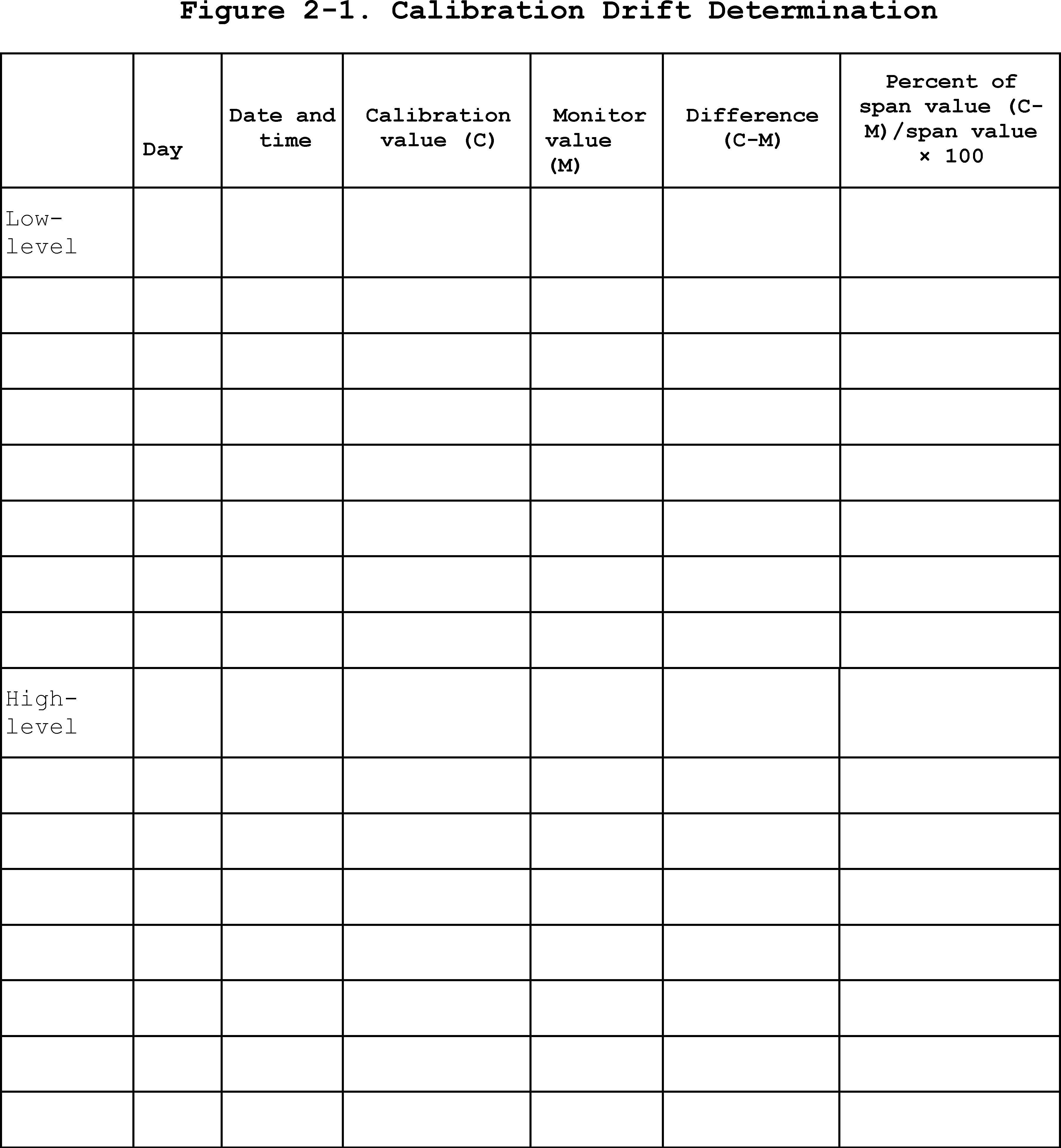
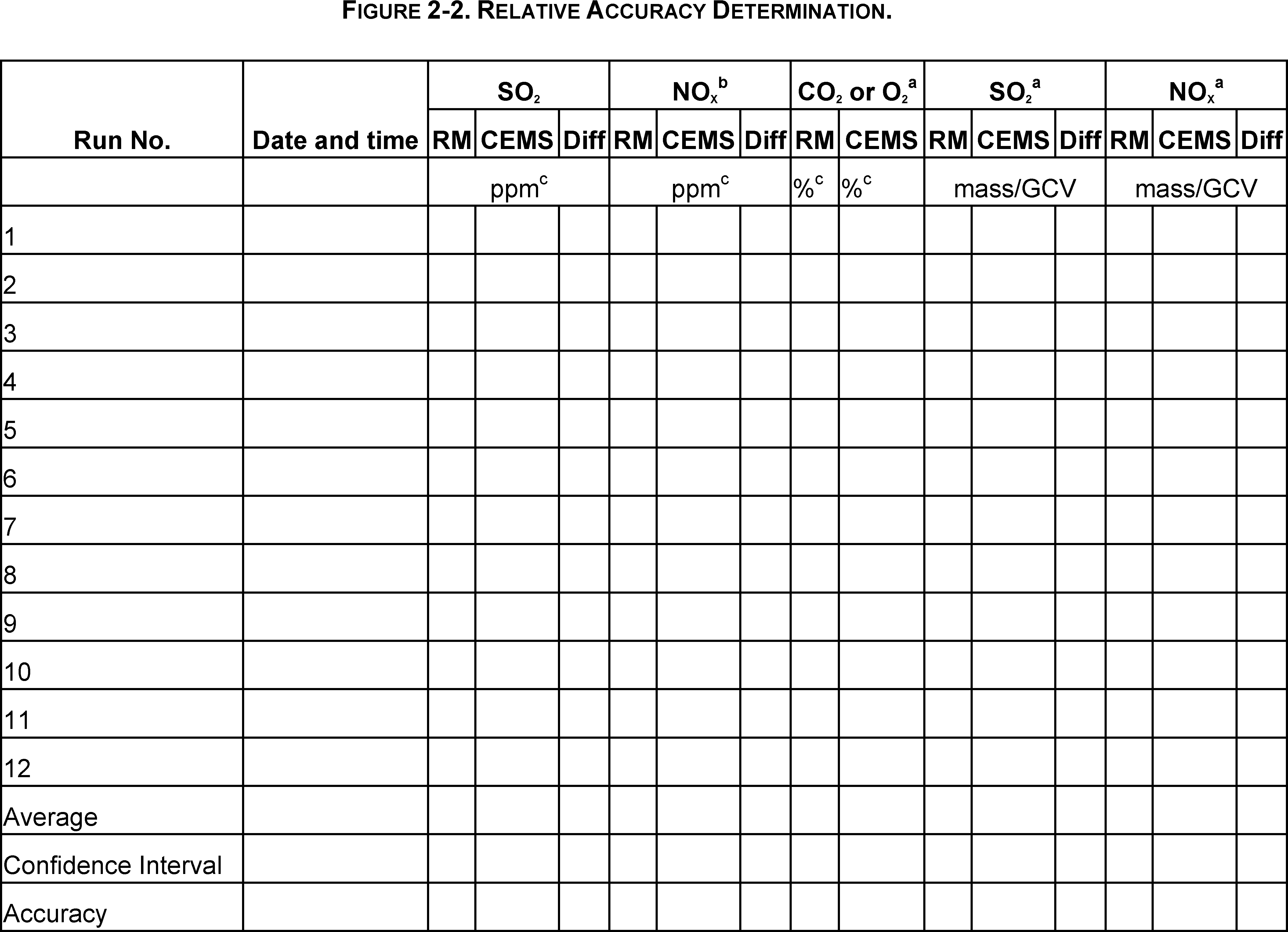
Performance Specification 3 - Specifications and Test Procedures for O2 and CO2 Continuous Emission Monitoring Systems in Stationary Sources
1.0 Scope and Application
1.1 Analytes.
| Analytes | CAS No. |
|---|---|
| Carbon Dioxide (CO2) | 124-38-9 |
| Oxygen (O2) | 7782-44-7 |
1.2 Applicability.
1.2.1 This specification is for evaluating acceptability of O2 and CO2 continuous emission monitoring systems (CEMS) at the time of installation or soon after and whenever specified in an applicable subpart of the regulations. This specification applies to O2 or CO2 monitors that are not included under Performance Specification 2 (PS 2).
1.2.2 This specification is not designed to evaluate the installed CEMS performance over an extended period of time, nor does it identify specific calibration techniques and other auxiliary procedures to assess the CEMS performance. The source owner or operator, is responsible to calibrate, maintain, and operate the CEMS properly. The Administrator may require, under section 114 of the Act, the operator to conduct CEMS performance evaluations at other times besides the initial test to evaluate the CEMS performance. See 40 CFR part 60, section 60.13(c).
1.2.3 The definitions, installation and measurement location specifications, calculations and data analysis, and references are the same as in PS 2, sections 3, 8.1, 12, and 17, respectively, and also apply to O2 and CO2 CEMS under this specification. The performance and equipment specifications and the relative accuracy (RA) test procedures for O2 and CO2 CEMS do not differ from those for SO2 and NOX CEMS (see PS 2), except as noted below.
2.0 Summary of Performance Specification
The RA and calibration drift (CD) tests are conducted to determine conformance of the CEMS to the specification.
3.0 Definitions
Same as in section 3.0 of PS 2.
4.0 Interferences [Reserved]
5.0 Safety
This performance specification may involve hazardous materials, operations, and equipment. This performance specification may not address all of the safety problems associated with its use. It is the responsibility of the user to establish appropriate safety and health practices and determine the applicable regulatory limitations prior to performing this performance specification. The CEMS users manual should be consulted for specific precautions to be taken with regard to the analytical procedures.
6.0 Equipment and Supplies
Same as section 6.0 of PS2.
7.0 Reagents and Standards
Same as section 7.0 of PS2.
8.0 Sample Collection, Preservation, Storage, and Transport
8.1 Relative Accuracy Test Procedure. Sampling Strategy for reference method (RM) Tests, Correlation of RM and CEMS Data, and Number of RM Tests. Same as PS 2, sections 8.4.3, 8.4.5, and 8.4.4, respectively.
8.2 Reference Method. Unless otherwise specified in an applicable subpart of the regulations, Method 3B or other approved alternative is the RM for O2 or CO2.
9.0 Quality Control [Reserved]
10.0 Calibration and Standardization [Reserved]
11.0 Analytical Procedure
Sample collection and analyses are concurrent for this performance specification (see section 8). Refer to the RM for specific analytical procedures.
12.0 Calculations and Data Analysis
Calculate the RA using equations 3-1 and 3-2. Summarize the results on a data sheet similar to that shown in Figure 2.2 of PS2.
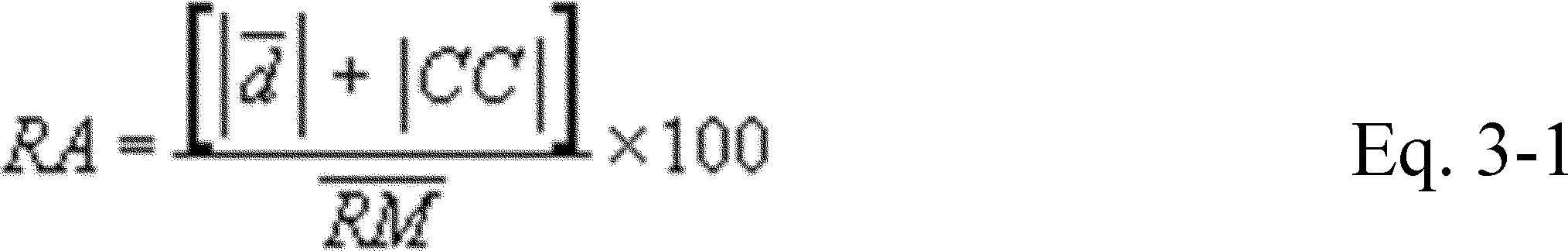

13.0 Method Performance
13.1 Calibration Drift Performance Specification. The CEMS calibration must not drift by more than 0.5 percent O2 or CO2 from the reference value of the gas, gas cell, or optical filter.
13.2 CEMS Relative Accuracy Performance Specification. The RA of the CEMS must be no greater than 20.0 percent of the mean value of the reference method (RM) data when calculated using equation 3-1. The results are also acceptable if the result of Equation 3-2 is less than or equal to 1.0 percent O2 (or CO2).
14.0 Pollution Prevention [Reserved]
15.0 Waste Management [Reserved]
16.0 References
Same as in section 17.0 of PS 2.
17.0 Tables, Diagrams, Flowcharts, and Validation Data [Reserved]
Performance Specification 4 - Specifications and Test Procedures for Carbon Monoxide Continuous Emission Monitoring Systems in Stationary Sources
1.0 Scope and Application
1.1 Analytes.
| Analyte | CAS No. |
|---|---|
| Carbon Monoxide (CO) | 630-08-0 |
1.2 Applicability.
1.2.1 This specification is for evaluating the acceptability of carbon monoxide (CO) continuous emission monitoring systems (CEMS) at the time of installation or soon after and whenever specified in an applicable subpart of the regulations. This specification was developed primarily for CEMS having span values of 1,000 ppmv CO.
1.2.2 This specification is not designed to evaluate the installed CEMS performance over an extended period of time nor does it identify specific calibration techniques and other auxiliary procedures to assess CEMS performance. The source owner or operator, is responsible to calibrate, maintain, and operate the CEMS. The Administrator may require, under section 114 of the Act, the source owner or operator to conduct CEMS performance evaluations at other times besides the initial test to evaluate the CEMS performance. See 40 CFR part 60, section 60.13(c).
1.2.3 The definitions, performance specification test procedures, calculations, and data analysis procedures for determining calibration drift (CD) and relative accuracy (RA) of Performance Specification 2 (PS 2), sections 3, 8.0, and 12, respectively, apply to this specification.
2.0 Summary of Performance Specification
The CD and RA tests are conducted to determine conformance of the CEMS to the specification.
3.0 Definitions
Same as in section 3.0 of PS 2.
4.0 Interferences [Reserved]
5.0 Safety
This performance specification may involve hazardous materials, operations, and equipment. This performance specification may not address all of the safety problems associated with its use. It is the responsibility of the user to establish appropriate safety and health practices and determine the applicable regulatory limitations prior to performing this performance specification. The CEMS users manual should be consulted for specific precautions to be taken with regard to the analytical procedures.
6.0 Equipment and Supplies
Same as section 6.0 of PS 2.
7.0 Reagents and Standards
Same as section 7.0 of PS 2.
8.0 Sample Collection, Preservation, Storage, and Transport
8.1 Relative Accuracy Test Procedure. Sampling Strategy for reference method (RM) Tests, Number of RM Tests, and Correlation of RM and CEMS Data are the same as PS 2, sections 8.4.3, 8.4.4, and 8.4.5, respectively.
8.2 Reference Methods. Unless otherwise specified in an applicable subpart of the regulation, Method 10, 10A, 10B or other approved alternative are the RM for this PS.
9.0 Quality Control [Reserved]
10.0 Calibration and Standardization [Reserved]
11.0 Analytical Procedure
Sample collection and analysis are concurrent for this performance specification (see section 8.0). Refer to the RM for specific analytical procedures.
12.0 Calculations and Data Analysis
Same as section 12.0 of PS 2.
13.0 Method Performance
13.1 Calibration Drift. The CEMS calibration must not drift or deviate from the reference value of the calibration gas, gas cell, or optical filter by more than 5 percent of the established span value for 6 out of 7 test days (e.g., the established span value is 1000 ppm for Subpart J affected facilities).
13.2 Relative Accuracy. The RA of the CEMS must be no greater than 10 percent when the average RM value is used to calculate RA or 5 percent when the applicable emission standard is used to calculate RA.
14.0 Pollution Prevention [Reserved]
15.0 Waste Management [Reserved]
16.0 Alternative Procedures [Reserved]
17.0 References
1. Ferguson, B.B., R.E. Lester, and W.J. Mitchell. Field Evaluation of Carbon Monoxide and Hydrogen Sulfide Continuous Emission Monitors at an Oil Refinery. U.S. Environmental Protection Agency. Research Triangle Park, N.C. Publication No. EPA-600/4-82-054. August 1982. 100 p.
2. “Gaseous Continuous Emission Monitoring Systems - Performance Specification Guidelines for SO2, NOX, CO2, O2, and TRS.” EPA-450/3-82-026. U.S. Environmental Protection Agency, Technical Support Division (MD-19), Research Triangle Park, NC 27711.
3. Repp, M. Evaluation of Continuous Monitors for Carbon Monoxide in Stationary Sources. U.S. Environmental Protection Agency. Research Triangle Park, N.C. Publication No. EPA-600/2-77-063. March 1977. 155 p.
4. Smith, F., D.E. Wagoner, and R.P. Donovan. Guidelines for Development of a Quality Assurance Program: Volume VIII - Determination of CO Emissions from Stationary Sources by NDIR Spectrometry. U.S. Environmental Protection Agency. Research Triangle Park, N.C. Publication No. EPA-650/4-74-005-h. February 1975. 96 p.
18.0 Tables, Diagrams, Flowcharts, and Validation Data
Same as section 18.0 of PS 2.
Performance Specification 4A - Specifications and Test Procedures for Carbon Monoxide Continuous Emission Monitoring Systems in Stationary Sources
1.0 Scope and Application
1.1 Analytes.
| Analyte | CAS No. |
|---|---|
| Carbon Monoxide (CO) | 630-80-0 |
1.2 Applicability.
1.2.1 This specification is for evaluating the acceptability of carbon monoxide (CO) continuous emission monitoring systems (CEMS) at the time of installation or soon after and whenever specified in an applicable subpart of the regulations. This specification was developed primarily for CEMS that comply with low emission standards (less than 200 ppmv).
1.2.2 This specification is not designed to evaluate the installed CEMS performance over an extended period of time nor does it identify specific calibration techniques and other auxiliary procedures to assess CEMS performance. The source owner or operator is responsible to calibrate, maintain, and operate the CEMS. The Administrator may require, under section 114 of the Act, the source owner or operator to conduct CEMS performance evaluations at other times besides the initial test to evaluate CEMS performance. See 40 CFR Part 60, section 60.13(c).
1.2.3 The definitions, performance specification, test procedures, calculations and data analysis procedures for determining calibration drifts (CD) and relative accuracy (RA), of Performance Specification 2 (PS 2), sections 3, 8.0, and 12, respectively, apply to this specification.
2.0 Summary of Performance Specification
The CD and RA tests are conducted to determine conformance of the CEMS to the specification.
3.0 Definitions
Same as in section 3.0 of PS 2.
4.0 Interferences [Reserved]
5.0 Safety
This performance specification may involve hazardous materials, operations, and equipment. This performance specification may not address all of the safety problems associated with its use. It is the responsibility of the user to establish appropriate safety and health practices and determine the applicable regulatory limitations prior to performing this performance specification. The CEMS users manual should be consulted for specific precautions to be taken with regard to the analytical procedures.
6.0 Equipment and Supplies
Same as section 6.0 of PS 2 with the following additions.
6.1 Data Recorder Scale.
6.1.1 This specification is the same as section 6.1 of PS 2. The CEMS shall be capable of measuring emission levels under normal conditions and under periods of short-duration peaks of high concentrations. This dual-range capability may be met using two separate analyzers (one for each range) or by using dual-range units which have the capability of measuring both levels with a single unit. In the latter case, when the reading goes above the full-scale measurement value of the lower range, the higher-range operation shall be started automatically. The CEMS recorder range must include zero and a high-level value. Under applications of consistent low emissions, a single-range analyzer is allowed provided normal and spike emissions can be quantified. In this case, set an appropriate high-level value to include all emissions.
6.1.2 For the low-range scale of dual-range units, the high-level value shall be between 1.5 times the pollutant concentration corresponding to the emission standard level and the span value. For the high-range scale, the high-level value shall be set at 2000 ppm, as a minimum, and the range shall include the level of the span value. There shall be no concentration gap between the low-and high-range scales.
7.0 Reagents and Standards
Same as section 7.0 of PS 2.
8.0 Sample Collection, Preservation, Storage, and Transport
8.1 Relative Accuracy Test Procedure. Sampling Strategy for reference method (RM) Tests, Number of RM Tests, and Correlation of RM and CEMS Data are the same as PS 2, sections 8.4.3, 8.4.4, and 8.4.5, respectively.
8.2 Reference Methods. Unless otherwise specified in an applicable subpart of the regulation, Methods 10, 10A, 10B, or other approved alternative is the RM for this PS. When evaluating nondispersive infrared CEMS using Method 10 as the RM, the alternative interference trap specified in section 16.0 of Method 10 shall be used.
8.3 Response Time Test Procedure. The response time test applies to all types of CEMS, but will generally have significance only for extractive systems. The entire system is checked with this procedure including applicable sample extraction and transport, sample conditioning, gas analyses, and data recording.
8.3.1 Introduce zero gas into the system. When the system output has stabilized (no change greater than 1 percent of full scale for 30 sec), introduce an upscale calibration gas and wait for a stable value. Record the time (upscale response time) required to reach 95 percent of the final stable value. Next, reintroduce the zero gas and wait for a stable reading before recording the response time (downscale response time). Repeat the entire procedure until you have three sets of data to determine the mean upscale and downscale response times. The slower or longer of the two means is the system response time.
8.4 Interference Check. The CEMS must be shown to be free from the effects of any interferences.
9.0 Quality Control [Reserved]
10.0 Calibration and Standardization [Reserved]
11.0 Analytical Procedure
Sample collection and analysis are concurrent for this performance specification (see section 8.0). Refer to the RM for specific analytical procedures.
12.0 Calculations and Data Analysis. Same as section 12.0 of PS 2
13.0 Method Performance
13.1 Calibration Drift. The CEMS calibration must not drift or deviate from the reference value of the calibration gas, gas cell, or optical filter by more than 5 percent of the established span value for 6 out of 7 test days.
13.2 Relative Accuracy. The RA of the CEMS must be no greater than 10 percent when the average RM value is used to calculate RA, 5 percent when the applicable emission standard is used to calculate RA, or within 5 ppmv when the RA is calculated as the absolute average difference between the RM and CEMS plus the 2.5 percent confidence coefficient.
13.3 Response Time. The CEMS response time shall not exceed 240 seconds to achieve 95 percent of the final stable value.
14.0 Pollution Prevention [Reserved]
15.0 Waste Management [Reserved]
16.0 Alternative Procedures
16.1 Under conditions where the average CO emissions are less than 10 percent of the standard and this is verified by Method 10, a cylinder gas audit may be performed in place of the RA test to determine compliance with these limits. In this case, the cylinder gas shall contain CO in 12 percent carbon dioxide as an interference check. If this option is exercised, Method 10 must be used to verify that emission levels are less than 10 percent of the standard.
17.0 References
Same as section 17 of PS 4.
18.0 Tables, Diagrams, Flowcharts, and Validation Data
Same as section 18.0 of PS 2.
Performance Specification 4B - Specifications and Test Procedures for Carbon Monoxide and Oxygen Continuous Monitoring Systems in Stationary Sources
a. Applicability and Principle
1.1 Applicability. a. This specification is to be used for evaluating the acceptability of carbon monoxide (CO) and oxygen (O2) continuous emission monitoring systems (CEMS) at the time of or soon after installation and whenever specified in the regulations. The CEMS may include, for certain stationary sources, (a) flow monitoring equipment to allow measurement of the dry volume of stack effluent sampled, and (b) an automatic sampling system.
b. This specification is not designed to evaluate the installed CEMS' performance over an extended period of time nor does it identify specific calibration techniques and auxiliary procedures to assess the CEMS' performance. The source owner or operator, however, is responsible to properly calibrate, maintain, and operate the CEMS. To evaluate the CEMS' performance, the Administrator may require, under section 114 of the Act, the operator to conduct CEMS performance evaluations at times other than the initial test.
c. The definitions, installation and measurement location specifications, test procedures, data reduction procedures, reporting requirements, and bibliography are the same as in PS 3 (for O2) and PS 4A (for CO) except as otherwise noted below.
1.2 Principle. Installation and measurement location specifications, performance specifications, test procedures, and data reduction procedures are included in this specification. Reference method tests, calibration error tests, calibration drift tests, and interferant tests are conducted to determine conformance of the CEMS with the specification.
b. Definitions
2.1 Continuous Emission Monitoring System (CEMS). This definition is the same as PS 2 section 2.1 with the following addition. A continuous monitor is one in which the sample to be analyzed passes the measurement section of the analyzer without interruption.
2.2 Response Time. The time interval between the start of a step change in the system input and when the pollutant analyzer output reaches 95 percent of the final value.
2.3 Calibration Error (CE). The difference between the concentration indicated by the CEMS and the known concentration generated by a calibration source when the entire CEMS, including the sampling interface is challenged. A CE test procedure is performed to document the accuracy and linearity of the CEMS over the entire measurement range.
3. Installation and Measurement Location Specifications
3.1 The CEMS Installation and Measurement Location. This specification is the same as PS 2 section 3.1 with the following additions. Both the CO and O2 monitors should be installed at the same general location. If this is not possible, they may be installed at different locations if the effluent gases at both sample locations are not stratified and there is no in-leakage of air between sampling locations.
3.1.1 Measurement Location. Same as PS 2 section 3.1.1.
3.1.2 Point CEMS. The measurement point should be within or centrally located over the centroidal area of the stack or duct cross section.
3.1.3 Path CEMS. The effective measurement path should: (1) Have at least 70 percent of the path within the inner 50 percent of the stack or duct cross sectional area, or (2) be centrally located over any part of the centroidal area.
3.2 Reference Method (RM) Measurement Location and Traverse Points. This specification is the same as PS 2 section 3.2 with the following additions. When pollutant concentration changes are due solely to diluent leakage and CO and O2 are simultaneously measured at the same location, one half diameter may be used in place of two equivalent diameters.
3.3 Stratification Test Procedure. Stratification is defined as the difference in excess of 10 percent between the average concentration in the duct or stack and the concentration at any point more than 1.0 meter from the duct or stack wall. To determine whether effluent stratification exists, a dual probe system should be used to determine the average effluent concentration while measurements at each traverse point are being made. One probe, located at the stack or duct centroid, is used as a stationary reference point to indicate change in the effluent concentration over time. The second probe is used for sampling at the traverse points specified in Method 1 (40 CFR part 60 appendix A). The monitoring system samples sequentially at the reference and traverse points throughout the testing period for five minutes at each point.
d. Performance and Equipment Specifications
4.1 Data Recorder Scale. For O2, same as specified in PS 3, except that the span must be 25 percent. The span of the O2 may be higher if the O2 concentration at the sampling point can be greater than 25 percent. For CO, same as specified in PS 4A, except that the low-range span must be 200 ppm and the high range span must be 3000 ppm. In addition, the scale for both CEMS must record all readings within a measurement range with a resolution of 0.5 percent.
4.2 Calibration Drift. For O2, same as specified in PS 3. For CO, the same as specified in PS 4A except that the CEMS calibration must not drift from the reference value of the calibration standard by more than 3 percent of the span value on either the high or low range.
4.3 Relative Accuracy (RA). For O2, same as specified in PS 3. For CO, the same as specified in PS 4A.
4.4 Calibration Error (CE). The mean difference between the CEMS and reference values at all three test points (see Table I) must be no greater than 5 percent of span value for CO monitors and 0.5 percent for O2 monitors.
4.5 Response Time. The response time for the CO or O2 monitor must not exceed 240 seconds.
e. Performance Specification Test Procedure
5.1 Calibration Error Test and Response Time Test Periods. Conduct the CE and response time tests during the CD test period.
F. The CEMS Calibration Drift and Response Time Test Procedures
The response time test procedure is given in PS 4A, and must be carried out for both the CO and O2 monitors.
7. Relative Accuracy and Calibration Error Test Procedures
7.1 Calibration Error Test Procedure. Challenge each monitor (both low and high range CO and O2) with zero gas and EPA Protocol 1 cylinder gases at three measurement points within the ranges specified in Table I.
Table I. Calibration Error Concentration Ranges
| Measurement point | CO Low range (ppm) | CO High range (ppm) | O2 (%) |
|---|---|---|---|
| 1 | 0-40 | 0-600 | 0-2 |
| 2 | 60-80 | 900-1200 | 8-10 |
| 3 | 140-160 | 2100-2400 | 14-16 |
Operate each monitor in its normal sampling mode as nearly as possible. The calibration gas must be injected into the sample system as close to the sampling probe outlet as practical and should pass through all CEMS components used during normal sampling. Challenge the CEMS three non-consecutive times at each measurement point and record the responses. The duration of each gas injection should be sufficient to ensure that the CEMS surfaces are conditioned.
7.1.1 Calculations. Summarize the results on a data sheet. Average the differences between the instrument response and the certified cylinder gas value for each gas. Calculate the CE results for the CO monitor according to:
CE = | d/FS | × 100 (1)
Where d is the mean difference between the CEMS response and the known reference concentration, and FS is the span value. The CE for the O2 monitor is the average percent O2 difference between the O2 monitor and the certified cylinder gas value for each gas.
7.2 Relative Accuracy Test Procedure. Follow the RA test procedures in PS 3 (for O2) section 3 and PS 4A (for CO) section 4.
7.3 Alternative RA Procedure. Under some operating conditions, it may not be possible to obtain meaningful results using the RA test procedure. This includes conditions where consistent, very low CO emission or low CO emissions interrupted periodically by short duration, high level spikes are observed. It may be appropriate in these circumstances to waive the RA test and substitute the following procedure.
Conduct a complete CEMS status check following the manufacturer's written instructions. The check should include operation of the light source, signal receiver, timing mechanism functions, data acquisition and data reduction functions, data recorders, mechanically operated functions, sample filters, sample line heaters, moisture traps, and other related functions of the CEMS, as applicable. All parts of the CEMS must be functioning properly before the RA requirement can be waived. The instrument must also successfully passed the CE and CD specifications. Substitution of the alternate procedure requires approval of the Regional Administrator.
8. Bibliography
1. 40 CFR Part 266, Appendix IX, section 2, “Performance Specifications for Continuous Emission Monitoring Systems.”
Performance Specification 5 - Specifications and Test Procedures for TRS Continuous Emission Monitoring Systems in Stationary Sources
1.0 Scope and Application
1.1 Analytes.
| Analyte | CAS No. |
|---|---|
| Total Reduced Sulfur (TRS) | NA |
1.2 Applicability. This specification is for evaluating the applicability of TRS continuous emission monitoring systems (CEMS) at the time of installation or soon after and whenever specified in an applicable subpart of the regulations. The CEMS may include oxygen monitors which are subject to Performance Specification 3 (PS 3).
1.3 The definitions, performance specification, test procedures, calculations and data analysis procedures for determining calibration drifts (CD) and relative accuracy (RA) of PS 2, sections 3.0, 8.0, and 12.0, respectively, apply to this specification.
2.0 Summary of Performance Specification
The CD and RA tests are conducted to determine conformance of the CEMS to the specification.
3.0 Definitions
Same as in section 3.0 of PS 2.
4.0 Interferences [Reserved]
5.0 Safety
This performance specification may involve hazardous materials, operations, and equipment. This performance specification may not address all of the safety problems associated with its use. It is the responsibility of the user to establish appropriate safety and health practices and determine the applicable regulatory limitations prior to performing this performance specification. The CEMS user's manual should be consulted for specific precautions to be taken with regard to the analytical procedures.
6.0 Equipment and Supplies
Same as section 6.0 of PS 2.
7.0 Reagents and Standards
Same as section 7.0 of PS 2.
8.0 Sample Collection, Preservation, Storage, and Transport
8.1 Relative Accuracy Test Procedure. Sampling Strategy for reference method (RM) Tests, Number of RM Tests, and Correlation of RM and CEMS Data are the same as PS 2, sections 8.4.3, 8.4.4, and 8.4.5, respectively.
For Method 16, a sample is made up of at least three separate injects equally spaced over time. For Method 16A, a sample is collected for at least 1 hour. For Method 16B, you must analyze a minimum of three aliquots spaced evenly over the test period.
For Method 16, a sample is made up of at least three separate injects equally space over time. For Method 16A, a sample is collected for at least 1 hour.
8.2 Reference Methods. Unless otherwise specified in the applicable subpart of the regulations, Method 16, Method 16A, 16B or other approved alternative is the RM for TRS.
9.0 Quality Control [Reserved]
10.0 Calibration and Standardization [Reserved]
11.0 Analytical Procedure
Sample collection and analysis are concurrent for this performance specification (see section 8.0). Refer to the reference method for specific analytical procedures.
12.0 Calculations and Data Analysis
Same as section 12.0 of PS 2.
13.0 Method Performance
13.1 Calibration Drift. The CEMS detector calibration must not drift or deviate from the reference value of the calibration gas by more than 5 percent of the established span value for 6 out of 7 test days. This corresponds to 1.5 ppm drift for Subpart BB sources where the span value is 30 ppm. If the CEMS includes pollutant and diluent monitors, the CD must be determined separately for each in terms of concentrations (see PS 3 for the diluent specifications).
13.2 Relative Accuracy. The RA of the CEMS must be no greater than 20 percent when the average RM value is used to calculate RA or 10 percent when the applicable emission standard is used to calculate RA.
14.0 Pollution Prevention [Reserved]
15.0 Waste Management [Reserved]
16.0 Alternative Procedures [Reserved]
17.0 References
1. Department of Commerce. Experimental Statistics, National Bureau of Standards, Handbook 91. 1963. Paragraphs 3-3.1.4, p. 3-31.
2. A Guide to the Design, Maintenance and Operation of TRS Monitoring Systems. National Council for Air and Stream Improvement Technical Bulletin No. 89. September 1977.
3. Observation of Field Performance of TRS Monitors on a Kraft Recovery Furnace. National Council for Air and Stream Improvement Technical Bulletin No. 91. January 1978.
18.0 Tables, Diagrams, Flowcharts, and Validation Data
Same as section 18.0 of PS 2.
Performance Specification 6 - Specifications and Test Procedures for Continuous Emission Rate Monitoring Systems in Stationary Sources
1.0 Scope and Application
1.1 Applicability. This specification is used for evaluating the acceptability of continuous emission rate monitoring systems (CERMSs).
1.2 The installation and measurement location specifications, performance specification test procedure, calculations, and data analysis procedures, of Performance Specifications (PS 2), sections 8.0 and 12, respectively, apply to this specification.
2.0 Summary of Performance Specification
The calibration drift (CD) and relative accuracy (RA) tests are conducted to determine conformance of the CERMS to the specification.
3.0 Definitions
The definitions are the same as in section 3 of PS 2, except this specification refers to the continuous emission rate monitoring system rather than the continuous emission monitoring system. The following definitions are added:
3.1 Continuous Emission Rate Monitoring System (CERMS). The total equipment required for the determining and recording the pollutant mass emission rate (in terms of mass per unit of time).
3.2 Flow Rate Sensor. That portion of the CERMS that senses the volumetric flow rate and generates an output proportional to that flow rate. The flow rate sensor shall have provisions to check the CD for each flow rate parameter that it measures individually (e.g., velocity, pressure).
4.0 Interferences [Reserved]
5.0 Safety
This performance specification may involve hazardous materials, operations, and equipment. This performance specification may not address all of the safety problems associated with its use. It is the responsibility of the user to establish appropriate safety and health practices and determine the applicable regulatory limitations prior to performing this performance specification. The CERMS users manual should be consulted for specific precautions to be taken with regard to the analytical procedures.
6.0 Equipment and Supplies
Same as section 6.0 of PS 2.
7.0 Reagents and Standards
Same as section 7.0 of PS 2.
8.0 Sample Collection, Preservation, Storage, and Transport
8.1 Calibration Drift Test Procedure.
8.1.1 The CD measurements are to verify the ability of the CERMS to conform to the established CERMS calibrations used for determining the emission rate. Therefore, if periodic automatic or manual adjustments are made to the CERMS zero and calibration settings, conduct the CD tests immediately before these adjustments, or conduct them in such a way that CD can be determined.
8.1.2 Conduct the CD tests for pollutant concentration at the two values specified in section 6.1.2 of PS 2. For other parameters that are selectively measured by the CERMS (e.g., velocity, pressure, flow rate), use two analogous values (e.g., Low: 0-20% of full scale, High: 50-100% of full scale). Introduce to the CERMS the reference signals (these need not be certified). Record the CERMS response to each and subtract this value from the respective reference value (see example data sheet in Figure 6-1).
8.2 Relative Accuracy Test Procedure.
8.2.1 Sampling Strategy for reference method (RM) Tests, Correlation of RM and CERMS Data, and Number of RM Tests are the same as PS 2, sections 8.4.3, 8.4.5, and 8.4.4, respectively. Summarize the results on a data sheet. An example is shown in Figure 6-1. The RA test may be conducted during the CD test period.
8.2.2 Reference Methods. Unless otherwise specified in the applicable subpart of the regulations, the RM for the pollutant gas is the Appendix A method that is cited for compliance test purposes, or its approved alternatives. Methods 2, 2A, 2B, 2C, or 2D, as applicable, are the RMs for the determination of volumetric flow rate.
9.0 Quality Control [Reserved]
10.0 Calibration and Standardization [Reserved]
11.0 Analytical Procedure
Same as section 11.0 of PS 2.
12.0 Calculations and Data Analysis
Same as section 12.0 of PS 2.
13.0 Method Performance
13.1 Calibration Drift. Since the CERMS includes analyzers for several measurements, the CD shall be determined separately for each analyzer in terms of its specific measurement. The calibration for each analyzer associated with the measurement of flow rate shall not drift or deviate from each reference value of flow rate by more than 3 percent of the respective high-level reference value over the CD test period (e.g., seven-day) associated with the pollutant analyzer. The CD specification for each analyzer for which other PSs have been established (e.g., PS 2 for SO2 and NOX), shall be the same as in the applicable PS.
13.2 CERMS Relative Accuracy. Calculate the CERMS Relative Accuracy using Eq. 2-6 of section 12 of Performance Specification 2. The RA of the CERMS shall be no greater than 20 percent of the mean value of the RM's test data in terms of the units of the emission standard, or in cases where the average emissions for the test are less than 50 percent of the applicable standard, substitute the emission standard value in the denominator of Eq. 2-6 in place of the RM.
14.0 Pollution Prevention [Reserved]
15.0 Waste Management [Reserved]
16.0 Alternative Procedures
Same as in section 16.0 of PS 2.
17.0 References
1. Brooks, E.F., E.C. Beder, C.A. Flegal, D.J. Luciani, and R. Williams. Continuous Measurement of Total Gas Flow Rate from Stationary Sources. U.S. Environmental Protection Agency. Research Triangle Park, North Carolina. Publication No. EPA-650/2-75-020. February 1975. 248 p.
18.0 Tables, Diagrams, Flowcharts, and Validation Data
| Run No. | Date and time | Emission rate (kg/hr)a | ||
|---|---|---|---|---|
| CERMS | RMs | Difference
(RMs-CERMS) |
||
| 1 | ||||
| 2 | ||||
| 3 | ||||
| 4 | ||||
| 5 | ||||
| 6 | ||||
| 7 | ||||
| 8 | ||||
| 9 | ||||
Figure 6-1 - Emission Rate Determinations
Performance Specification 7 - Specifications and Test Procedures for Hydrogen Sulfide Continuous Emission Monitoring Systems in Stationary Sources
1.0 Scope and Application
1.1 Analytes.
| Analyte | CAS No. |
|---|---|
| Hydrogen Sulfide | 7783-06-4 |
1.2 Applicability.
1.2.1 This specification is to be used for evaluating the acceptability of hydrogen sulfide (H2S) continuous emission monitoring systems (CEMS) at the time of or soon after installation and whenever specified in an applicable subpart of the regulations.
1.2.2 This specification is not designed to evaluate the installed CEMS performance over an extended period of time nor does it identify specific calibration techniques and other auxiliary procedures to assess CEMS performance. The source owner or operator, however, is responsible to calibrate, maintain, and operate the CEMS. To evaluate CEMS performance, the Administrator may require, under section 114 of the Act, the source owner or operator to conduct CEMS performance evaluations at other times besides the initial test. See section 60.13(c).
2.0 Summary
Calibration drift (CD) and relative accuracy (RA) tests are conducted to determine that the CEMS conforms to the specification.
3.0 Definitions
Same as section 3.0 of PS 2.
4.0 Interferences [Reserved]
5.0 Safety
The procedures required under this performance specification may involve hazardous materials, operations, and equipment. This performance specification may not address all of the safety problems associated with these procedures. It is the responsibility of the user to establish appropriate safety problems associated with these procedures. It is the responsibility of the user to establish appropriate safety and health practices and determine the application regulatory limitations prior to performing these procedures. The CEMS user's manual and materials recommended by the reference method should be consulted for specific precautions to be taken.
6.0 Equipment and Supplies
6.1 Instrument Zero and Span. This specification is the same as section 6.1 of PS 2.
6.2 Calibration Drift. The CEMS calibration must not drift or deviate from the reference value of the calibration gas or reference source by more than 5 percent of the established span value for 6 out of 7 test days (e.g., the established span value is 300 ppm for Subpart J fuel gas combustion devices).
6.3 Relative Accuracy. The RA of the CEMS must be no greater than 20 percent when the average reference method (RM) value is used to calculate RA or 10 percent when the applicable emission standard is used to calculate RA.
7.0 Reagents and Standards
Same as section 7.0 of PS 2.
8.0 Sample Collection, Preservation, Storage, and Transport.
8.1 Installation and Measurement Location Specification. Same as section 8.1 of PS 2.
8.2 Pretest Preparation. Same as section 8.2 of PS 2.
8.3 Calibration Drift Test Procedure. Same as section 8.3 of PS 2.
8.4 Relative Accuracy Test Procedure.
8.4.1 Sampling Strategy for RM Tests, Number of RM Tests, Correlation of RM and CEMS Data, and Calculations. These are the same as that in PS-2, Sections 8.4.3 (except as specified below), 8.4.4, 8.4.5, and 8.4.6, respectively.
8.4.2 Reference Methods. Unless otherwise specified in an applicable subpart of the regulation, Methods 11, 15, and 16 may be used for the RM for this PS.
8.4.2.1 Sampling Time Per Run - Method 11. A sampling run, when Method 11 (integrated sampling) is used, shall consist of a single measurement for at least 10 minutes and 0.010 dscm (0.35 dscf). Each sample shall be taken at approximately 30-minute intervals.
8.4.2.2 Sampling Time Per Run - Methods 15 and 16. The sampling run shall consist of two injections equally spaced over a 30-minute period following the procedures described in the particular method. Note: Caution! Heater or non-approved electrical probes should not be used around explosive or flammable sources.
8.5 Reporting. Same as section 8.5 of PS 2.
9.0 Quality Control [Reserved]
10.0 Calibration and Standardizations [Reserved]
11.0 Analytical Procedures
Sample Collection and analysis are concurrent for this PS (see section 8.0). Refer to the RM for specific analytical procedures.
12.0 Data Analysis and Calculations
Same as section 12.0 of PS 2.
13.0 Method Performance [Reserved]
14.0 Pollution Prevention [Reserved]
15.0 Waste Management [Reserved]
16.0 References
1. U.S. Environmental Protection Agency. Standards of Performance for New Stationary Sources; Appendix B; Performance Specifications 2 and 3 for SO2, NOX, CO2, and O2 Continuous Emission Monitoring Systems; Final Rule. 48 CFR 23608. Washington, D.C. U.S. Government Printing Office. May 25, 1983.
2. U.S. Government Printing Office. Gaseous Continuous Emission Monitoring Systems - Performance Specification Guidelines for SO2, NOX, CO2, O2, and TRS. U.S. Environmental Protection Agency. Washington, D.C. EPA-450/3-82-026. October 1982. 26 p.
3. Maines, G.D., W.C. Kelly (Scott Environmental Technology, Inc.), and J.B. Homolya. Evaluation of Monitors for Measuring H2S in Refinery Gas. Prepared for the U.S. Environmental Protection Agency. Research Triangle Park, N.C. Contract No. 68-02-2707. 1978. 60 p.
4. Ferguson, B.B., R.E. Lester (Harmon Engineering and Testing), and W.J. Mitchell. Field Evaluation of Carbon Monoxide and Hydrogen Sulfide Continuous Emission Monitors at an Oil Refinery. Prepared for the U.S. Environmental Protection Agency. Research Triangle Park, N.C. Publication No. EPA-600/4-82-054. August 1982. 100 p.
5. Letter to RAMCON Environmental Corp. from Robert Kellam, December 27, 1992.
17.0 Tables, Diagrams, Flowcharts, and Validation Data
Same as section 18.0 of PS 2.
Performance Specification 8 - Performance Specifications for Volatile Organic Compound Continuous Emission Monitoring Systems in Stationary Sources
1.0 Scope and Application
1.1 Analytes. Volatile Organic Compounds (VOCs).
1.2 Applicability.
1.2.1 This specification is to be used for evaluating a continuous emission monitoring system (CEMS) that measures a mixture of VOC's and generates a single combined response value. The VOC detection principle may be flame ionization (FI), photoionization (PI), non-dispersive infrared absorption (NDIR), or any other detection principle that is appropriate for the VOC species present in the emission gases and that meets this performance specification. The performance specification includes procedures to evaluate the acceptability of the CEMS at the time of or soon after its installation and whenever specified in emission regulations or permits. This specification is not designed to evaluate the installed CEMS performance over an extended period of time, nor does it identify specific calibration techniques and other auxiliary procedures to assess the CEMS performance. The source owner or operator, however, is responsible to calibrate, maintain, and operate the CEMS properly. To evaluate the CEMS performance, the Administrator may require, under section 114 of the Act, the operator to conduct CEMS performance evaluations in addition to the initial test. See section 60.13(c).
1.2.2 In most emission circumstances, most VOC monitors can provide only a relative measure of the total mass or volume concentration of a mixture of organic gases, rather than an accurate quantification. This problem is removed when an emission standard is based on a total VOC measurement as obtained with a particular detection principle. In those situations where a true mass or volume VOC concentration is needed, the problem can be mitigated by using the VOC CEMS as a relative indicator of total VOC concentration if statistical analysis indicates that a sufficient margin of compliance exists for this approach to be acceptable. Otherwise, consideration can be given to calibrating the CEMS with a mixture of the same VOC's in the same proportions as they actually occur in the measured source. In those circumstances where only one organic species is present in the source, or where equal incremental amounts of each of the organic species present generate equal CEMS responses, the latter choice can be more easily achieved.
2.0 Summary of Performance Specification
2.1 Calibration drift and relative accuracy tests are conducted to determine adherence of the CEMS with specifications given for those items. The performance specifications include criteria for installation and measurement location, equipment and performance, and procedures for testing and data reduction.
3.0 Definitions.
Same as section 3.0 of PS 2.
4.0 Interferences [Reserved]
5.0 Safety
The procedures required under this performance specification may involve hazardous materials, operations, and equipment. This performance specification may not address all of the safety problems associated with these procedures. It is the responsibility of the user to establish appropriate safety problems associated with these procedures. It is the responsibility of the user to establish appropriate safety and health practices and determine the application regulatory limitations prior to performing these procedures. The CEMS user's manual and materials recommended by the reference method should be consulted for specific precautions to be taken.
6.0 Equipment and Supplies
6.1 VOC CEMS Selection. When possible, select a VOC CEMS with the detection principle of the reference method specified in the regulation or permit (usually either FI, NDIR, or PI). Otherwise, use knowledge of the source process chemistry, previous emission studies, or gas chromatographic analysis of the source gas to select an appropriate VOC CEMS. Exercise extreme caution in choosing and installing any CEMS in an area with explosive hazard potential.
6.2 Data Recorder Scale. Same as section 6.1 of PS 2.
7.0 Reagents and Standards [Reserved]
8.0 Sample Collection, Preservation, Storage, and Transport
8.1 Installation and Measurement Location Specifications. Same as section 8.1 of PS 2.
8.2 Pretest Preparation. Same as section 8.2 of PS 2.
8.3 Calibration Drift Test Procedure. Same as section 8.3 of PS 2.
8.4 Reference Method (RM). Use the method specified in the applicable regulation or permit, or any approved alternative, as the RM.
8.5 Sampling Strategy for RM Tests, Correlation of RM and CEMS Data, and Number of RM Tests. Follow PS 2, sections 8.4.3, 8.4.5, and 8.4.4, respectively.
8.6 Reporting. Same as section 8.5 of PS 2.
9.0 Quality Control [Reserved]
10.0 Calibration and Standardization [Reserved]
11.0 Analytical Procedure
Sample collection and analysis are concurrent for this PS (see section 8.0). Refer to the RM for specific analytical procedures.
12.0 Calculations and Data Analysis
Same as section 12.0 of PS 2.
13.0 Method Performance
13.1 Calibration Drift. The CEMS calibration must not drift by more than 2.5 percent of the span value.
13.2 CEMS Relative Accuracy. Unless stated otherwise in the regulation or permit, the RA of the CEMS must not be greater than 20 percent of the mean value of the RM test data in terms of the units of the emission standard, or 10 percent of the applicable standard, whichever is greater.
14.0 Pollution Prevention [Reserved]
15.0 Waste Management [Reserved]
16.0 References
Same as section 17.0 of PS 2.
17.0 Tables, Diagrams, Flowcharts, and Validation Data [Reserved]
Performance Specification 8A - Specifications and Test Procedures for Total Hydrocarbon Continuous Monitoring Systems in Stationary Sources
1. Applicability and Principle
1.1 Applicability. These performance specifications apply to hydrocarbon (HC) continuous emission monitoring systems (CEMS) installed on stationary sources. The specifications include procedures which are intended to be used to evaluate the acceptability of the CEMS at the time of its installation or whenever specified in regulations or permits. The procedures are not designed to evaluate CEMS performance over an extended period of time. The source owner or operator is responsible for the proper calibration, maintenance, and operation of the CEMS at all times.
1.2 Principle. A gas sample is extracted from the source through a heated sample line and heated filter to a flame ionization detector (FID). Results are reported as volume concentration equivalents of propane. Installation and measurement location specifications, performance and equipment specifications, test and data reduction procedures, and brief quality assurance guidelines are included in the specifications. Calibration drift, calibration error, and response time tests are conducted to determine conformance of the CEMS with the specifications.
2. Definitions
2.1 Continuous Emission Monitoring System (CEMS). The total equipment used to acquire data, which includes sample extraction and transport hardware, analyzer, data recording and processing hardware, and software. The system consists of the following major subsystems:
2.1.1 Sample Interface. That portion of the system that is used for one or more of the following: Sample acquisition, sample transportation, sample conditioning, or protection of the analyzer from the effects of the stack effluent.
2.1.2 Organic Analyzer. That portion of the system that senses organic concentration and generates an output proportional to the gas concentration.
2.1.3 Data Recorder. That portion of the system that records a permanent record of the measurement values. The data recorder may include automatic data reduction capabilities.
2.2 Instrument Measurement Range. The difference between the minimum and maximum concentration that can be measured by a specific instrument. The minimum is often stated or assumed to be zero and the range expressed only as the maximum.
2.3 Span or Span Value. Full scale instrument measurement range. The span value must be documented by the CEMS manufacturer with laboratory data.
2.4 Calibration Gas. A known concentration of a gas in an appropriate diluent gas.
2.5 Calibration Drift (CD). The difference in the CEMS output readings from the established reference value after a stated period of operation during which no unscheduled maintenance, repair, or adjustment takes place. A CD test is performed to demonstrate the stability of the CEMS calibration over time.
2.6 Response Time. The time interval between the start of a step change in the system input (e.g., change of calibration gas) and the time when the data recorder displays 95 percent of the final value.
2.7 Accuracy. A measurement of agreement between a measured value and an accepted or true value, expressed as the percentage difference between the true and measured values relative to the true value. For these performance specifications, accuracy is checked by conducting a calibration error (CE) test.
2.8 Calibration Error (CE). The difference between the concentration indicated by the CEMS and the known concentration of the cylinder gas. A CE test procedure is performed to document the accuracy and linearity of the monitoring equipment over the entire measurement range.
2.9 Performance Specification Test (PST) Period. The period during which CD, CE, and response time tests are conducted.
2.10 Centroidal Area. A concentric area that is geometrically similar to the stack or duct cross section and is no greater than 1 percent of the stack or duct cross-sectional area.
3. Installation and Measurement Location Specifications
3.1 CEMS Installation and Measurement Locations. The CEMS must be installed in a location in which measurements representative of the source's emissions can be obtained. The optimum location of the sample interface for the CEMS is determined by a number of factors, including ease of access for calibration and maintenance, the degree to which sample conditioning will be required, the degree to which it represents total emissions, and the degree to which it represents the combustion situation in the firebox (where applicable). The location should be as free from in-leakage influences as possible and reasonably free from severe flow disturbances. The sample location should be at least two equivalent duct diameters downstream from the nearest control device, point of pollutant generation, or other point at which a change in the pollutant concentration or emission rate occurs and at least 0.5 diameter upstream from the exhaust or control device. The equivalent duct diameter is calculated as per 40 CFR part 60, appendix A, method 1, section 2.1. If these criteria are not achievable or if the location is otherwise less than optimum, the possibility of stratification should be investigated as described in section 3.2. The measurement point must be within the centroidal area of the stack or duct cross section.
3.2 Stratification Test Procedure. Stratification is defined as a difference in excess of 10 percent between the average concentration in the duct or stack and the concentration at any point more than 1.0 meter from the duct or stack wall. To determine whether effluent stratification exists, a dual probe system should be used to determine the average effluent concentration while measurements at each traverse point are being made. One probe, located at the stack or duct centroid, is used as a stationary reference point to indicate the change in effluent concentration over time. The second probe is used for sampling at the traverse points specified in 40 CFR part 60 appendix A, method 1. The monitoring system samples sequentially at the reference and traverse points throughout the testing period for five minutes at each point.
4. CEMS Performance and Equipment Specifications
If this method is applied in highly explosive areas, caution and care must be exercised in choice of equipment and installation.
4.1 Flame Ionization Detector (FID) Analyzer. A heated FID analyzer capable of meeting or exceeding the requirements of these specifications. Heated systems must maintain the temperature of the sample gas between 150 °C (300 °F) and 175 °C (350 °F) throughout the system. This requires all system components such as the probe, calibration valve, filter, sample lines, pump, and the FID to be kept heated at all times such that no moisture is condensed out of the system. The essential components of the measurement system are described below:
4.1.1 Sample Probe. Stainless steel, or equivalent, to collect a gas sample from the centroidal area of the stack cross-section.
4.1.2 Sample Line. Stainless steel or Teflon tubing to transport the sample to the analyzer.
Mention of trade names or specific products does not constitute endorsement by the Environmental Protection Agency.
4.1.3 Calibration Valve Assembly. A heated three-way valve assembly to direct the zero and calibration gases to the analyzer is recommended. Other methods, such as quick-connect lines, to route calibration gas to the analyzers are applicable.
4.1.4 Particulate Filter. An in-stack or out-of-stack sintered stainless steel filter is recommended if exhaust gas particulate loading is significant. An out-of-stack filter must be heated.
4.1.5 Fuel. The fuel specified by the manufacturer (e.g., 40 percent hydrogen/60 percent helium, 40 percent hydrogen/60 percent nitrogen gas mixtures, or pure hydrogen) should be used.
4.1.6 Zero Gas. High purity air with less than 0.1 parts per million by volume (ppm) HC as methane or carbon equivalent or less than 0.1 percent of the span value, whichever is greater.
4.1.7 Calibration Gases. Appropriate concentrations of propane gas (in air or nitrogen). Preparation of the calibration gases should be done according to the procedures in EPA Protocol 1. In addition, the manufacturer of the cylinder gas should provide a recommended shelf life for each calibration gas cylinder over which the concentration does not change by more than ±2 percent from the certified value.
4.2 CEMS Span Value. 100 ppm propane. The span value must be documented by the CEMS manufacturer with laboratory data.
4.3 Daily Calibration Gas Values. The owner or operator must choose calibration gas concentrations that include zero and high-level calibration values.
4.3.1 The zero level may be between zero and 0.1 ppm (zero and 0.1 percent of the span value).
4.3.2 The high-level concentration must be between 50 and 90 ppm (50 and 90 percent of the span value).
4.4 Data Recorder Scale. The strip chart recorder, computer, or digital recorder must be capable of recording all readings within the CEMS' measurement range and must have a resolution of 0.5 ppm (0.5 percent of span value).
4.5 Response Time. The response time for the CEMS must not exceed 2 minutes to achieve 95 percent of the final stable value.
4.6 Calibration Drift. The CEMS must allow the determination of CD at the zero and high-level values. The CEMS calibration response must not differ by more than ±3 ppm (±3 percent of the span value) after each 24-hour period of the 7-day test at both zero and high levels.
4.7 Calibration Error. The mean difference between the CEMS and reference values at all three test points listed below must be no greater than 5 ppm (±5 percent of the span value).
4.7.1 Zero Level. Zero to 0.1 ppm (0 to 0.1 percent of span value).
4.7.2 Mid-Level. 30 to 40 ppm (30 to 40 percent of span value).
4.7.3 High-Level. 70 to 80 ppm (70 to 80 percent of span value).
4.8 Measurement and Recording Frequency. The sample to be analyzed must pass through the measurement section of the analyzer without interruption. The detector must measure the sample concentration at least once every 15 seconds. An average emission rate must be computed and recorded at least once every 60 seconds.
4.9 Hourly Rolling Average Calculation. The CEMS must calculate every minute an hourly rolling average, which is the arithmetic mean of the 60 most recent 1-minute average values.
4.10 Retest. If the CEMS produces results within the specified criteria, the test is successful. If the CEMS does not meet one or more of the criteria, necessary corrections must be made and the performance tests repeated.
5. Performance Specification Test (PST) Periods
5.1 Pretest Preparation Period. Install the CEMS, prepare the PTM test site according to the specifications in section 3, and prepare the CEMS for operation and calibration according to the manufacturer's written instructions. A pretest conditioning period similar to that of the 7-day CD test is recommended to verify the operational status of the CEMS.
5.2 Calibration Drift Test Period. While the facility is operating under normal conditions, determine the magnitude of the CD at 24-hour intervals for seven consecutive days according to the procedure given in section 6.1. All CD determinations must be made following a 24-hour period during which no unscheduled maintenance, repair, or adjustment takes place. If the combustion unit is taken out of service during the test period, record the onset and duration of the downtime and continue the CD test when the unit resumes operation.
5.3 Calibration Error Test and Response Time Test Periods. Conduct the CE and response time tests during the CD test period.
6. Performance Specification Test Procedures
6.1 Relative Accuracy Test Audit (RATA) and Absolute Calibration Audits (ACA). The test procedures described in this section are in lieu of a RATA and ACA.
6.2 Calibration Drift Test.
6.2.1 Sampling Strategy. Conduct the CD test at 24-hour intervals for seven consecutive days using calibration gases at the two daily concentration levels specified in section 4.3. Introduce the two calibration gases into the sampling system as close to the sampling probe outlet as practical. The gas must pass through all CEM components used during normal sampling. If periodic automatic or manual adjustments are made to the CEMS zero and calibration settings, conduct the CD test immediately before these adjustments, or conduct it in such a way that the CD can be determined. Record the CEMS response and subtract this value from the reference (calibration gas) value. To meet the specification, none of the differences may exceed 3 percent of the span of the CEM.
6.2.2 Calculations. Summarize the results on a data sheet. An example is shown in Figure 1. Calculate the differences between the CEMS responses and the reference values.
6.3 Response Time. The entire system including sample extraction and transport, sample conditioning, gas analyses, and the data recording is checked with this procedure.
6.3.1 Introduce the calibration gases at the probe as near to the sample location as possible. Introduce the zero gas into the system. When the system output has stabilized (no change greater than 1 percent of full scale for 30 sec), switch to monitor stack effluent and wait for a stable value. Record the time (upscale response time) required to reach 95 percent of the final stable value.
6.3.2 Next, introduce a high-level calibration gas and repeat the above procedure. Repeat the entire procedure three times and determine the mean upscale and downscale response times. The longer of the two means is the system response time.
6.4 Calibration Error Test Procedure.
6.4.1 Sampling Strategy. Challenge the CEMS with zero gas and EPA Protocol 1 cylinder gases at measurement points within the ranges specified in section 4.7.
6.4.1.1 The daily calibration gases, if Protocol 1, may be used for this test.
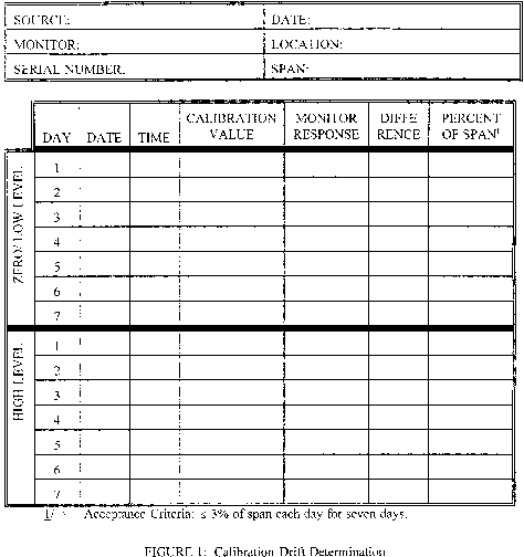
6.4.1.2 Operate the CEMS as nearly as possible in its normal sampling mode. The calibration gas should be injected into the sampling system as close to the sampling probe outlet as practical and must pass through all filters, scrubbers, conditioners, and other monitor components used during normal sampling. Challenge the CEMS three non-consecutive times at each measurement point and record the responses. The duration of each gas injection should be for a sufficient period of time to ensure that the CEMS surfaces are conditioned.
6.4.2 Calculations. Summarize the results on a data sheet. An example data sheet is shown in Figure 2. Average the differences between the instrument response and the certified cylinder gas value for each gas. Calculate three CE results according to Equation 1. No confidence coefficient is used in CE calculations.
7. Equations
Calibration Error. Calculate CE using Equation 1.

Where:
d = Mean difference between CEMS response and the known reference concentration, determined using Equation 2.

Where:
di = Individual difference between CEMS response and the known reference concentration.
8. Reporting
At a minimum, summarize in tabular form the results of the CD, response time, and CE test, as appropriate. Include all data sheets, calculations, CEMS data records, and cylinder gas or reference material certifications.
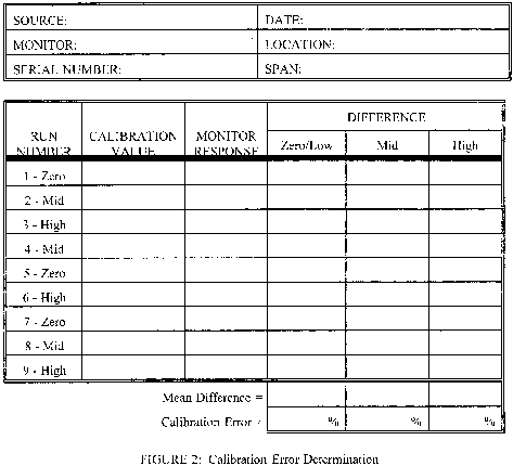
9. References
1. Measurement of Volatile Organic Compounds-Guideline Series. U.S. Environmental Protection Agency, Research Triangle Park, North Carolina, 27711, EPA-450/2-78-041, June 1978.
2. Traceability Protocol for Establishing True Concentrations of Gases Used for Calibration and Audits of Continuous Source Emission Monitors (Protocol No. 1). U.S. Environmental Protection Agency ORD/EMSL, Research Triangle Park, North Carolina, 27711, June 1978.
3. Gasoline Vapor Emission Laboratory Evaluation-Part 2. U.S. Environmental Protection Agency, OAQPS, Research Triangle Park, North Carolina, 27711, EMB Report No. 76-GAS-6, August 1975.
Performance Specification 9 - Specifications and Test Procedures for Gas Chromatographic Continuous Emission Monitoring Systems in Stationary Sources
1.0 Scope and Application
1.1 Applicability. These requirements apply to continuous emission monitoring systems (CEMSs) that use gas chromatography (GC) to measure gaseous organic compound emissions. The requirements include procedures intended to evaluate the acceptability of the CEMS at the time of its installation and whenever specified in regulations or permits. Quality assurance procedures for calibrating, maintaining, and operating the CEMS properly at all times are also given in this procedure.
2.0 Summary of Performance Specification
2.1 Calibration precision, calibration error, and performance audit tests are conducted to determine conformance of the CEMS with these specifications. Daily calibration and maintenance requirements are also specified.
3.0 Definitions
3.1 Gas Chromatograph (GC). That portion of the system that separates and detects organic analytes and generates an output proportional to the gas concentration. The GC must be temperature controlled.
The term temperature controlled refers to the ability to maintain a certain temperature around the column. Temperature-programmable GC is not required for this performance specification, as long as all other requirements for precision, linearity and accuracy listed in this performance specification are met. It should be noted that temperature programming a GC will speed up peak elution, thus allowing increased sampling frequency.
3.1.1 Column. Analytical column capable of separating the analytes of interest.
3.1.2 Detector. A detection system capable of detecting and quantifying all analytes of interest.
3.1.3 Integrator. That portion of the system that quantifies the area under a particular sample peak generated by the GC.
3.1.4 Data Recorder. A strip chart recorder, computer, or digital recorder capable of recording all readings within the instrument's calibration range.
3.2 Calibration Precision. The error between triplicate injections of each calibration standard.
4.0 Interferences [Reserved]
5.0 Safety
The procedures required under this performance specification may involve hazardous materials, operations, and equipment. This performance specification does not purport to address all of the safety problems associated with these procedures. It is the responsibility of the user to establish appropriate safety problems associated with these procedures. It is the responsibility of the user to establish appropriate safety and health practices and determine the application regulatory limitations prior to performing these procedures. The CEMS user's manual and materials recommended by the reference method should be consulted for specific precautions to be taken.
6.0 Equipment and Supplies
6.1 Presurvey Sample Analysis and GC Selection. Determine the pollutants to be monitored from the applicable regulation or permit and determine the approximate concentration of each pollutant (this information can be based on past compliance test results). Select an appropriate GC configuration to measure the organic compounds. The GC components should include a heated sample injection loop (or other sample introduction systems), separatory column, temperature-controlled oven, and detector. If the source chooses dual column and/or dual detector configurations, each column/detector is considered a separate instrument for the purpose of this performance specification and thus the procedures in this performance specification shall be carried out on each system. If this method is applied in highly explosive areas, caution should be exercised in selecting the equipment and method of installation.
6.2 Sampling System. The sampling system shall be heat traced and maintained at a minimum of 120 °C with no cold spots. All system components shall be heated, including the probe, calibration valve, sample lines, sampling loop (or sample introduction system), GC oven, and the detector block (when appropriate for the type of detector being utilized, e.g., flame ionization detector).
7.0 Reagents and Standards
7.1 Calibration Gases. Obtain three concentrations of calibration gases certified by the manufacturer to be accurate to within 2 percent of the value on the label. A gas dilution system may be used to prepare the calibration gases from a high concentration certified standard if the gas dilution system meets the requirements specified in Test Method 205, 40 CFR Part 51, Appendix M. The performance test specified in Test Method 205 shall be repeated quarterly, and the results of the Method 205 test shall be included in the report. The calibration gas concentration of each target analyte shall be as follows (measured concentration is based on the presurvey concentration determined in section 6.1).
If the low level calibration gas concentration falls at or below the limit of detection for the instrument for any target pollutant, a calibration gas with a concentration at 4 to 5 times the limit of detection for the instrument may be substituted for the low-level calibration gas listed in section 7.1.1.
7.1.1 Low-level. 40-60 percent of measured concentration.
7.1.2 Mid-level. 90-110 percent of measured concentration.
7.1.3 High-level. 140-160 percent of measured concentration, or select highest expected concentration.
7.2 Performance Audit Gas. Performance Audit Gas is an independent cylinder gas or cylinder gas mixture. A certified EPA audit gas shall be used, when possible. A gas mixture containing all the target compounds within the calibration range and certified by EPA's Traceability Protocol for Assay and Certification of Gaseous Calibration Standards may be used when EPA performance audit materials are not available. If a certified EPA audit gas or a traceability protocol gas is not available, use a gas manufacturer standard accurate to 2 percent.
8.0 Sample Collection, Preservation, Storage, and Transport
8.1 Installation and Measurement Location Specifications. Install the CEMs in a location where the measurements are representative of the source emissions. Consider other factors, such as ease of access for calibration and maintenance purposes. The location should not be close to air in-leakages. The sampling location should be at least two equivalent duct diameters downstream from the nearest control device, point of pollutant generation, or other point at which a change in the pollutant concentration or emission rate occurs. The location should be at least 0.5 diameter upstream from the exhaust or control device. To calculate equivalent duct diameter, see section 12.2 of Method 1 (40 CFR Part 60, Appendix A). Sampling locations not conforming to the requirements in this section may be used if necessary upon approval of the Administrator.
8.2 Pretest Preparation Period. Using the procedures described in Method 18
(40 CFR Part 60, Appendix A), perform initial tests to determine GC conditions that provide good resolution and minimum analysis time for compounds of interest. Resolution interferences that may occur can be eliminated by appropriate GC column and detector choice or by shifting the retention times through changes in the column flow rate and the use of temperature programming.
8.3 Seven (7)-Day Calibration Error (CE) Test Period. At the beginning of each 24-hour period, set the initial instrument set points by conducting a multi-point calibration for each compound. The multi-point calibration shall meet the requirements in sections 13.1, 13.2, and 13.3. Throughout the 24-hour period, sample and analyze the stack gas at the sampling intervals prescribed in the regulation or permit. At the end of the 24-hour period, inject the calibration gases at three concentrations for each compound in triplicate and determine the average instrument response. Determine the CE for each pollutant at each concentration using Equation 9-2. Each CE shall be ≤10 percent. Repeat this procedure six more times for a total of 7 consecutive days.
8.4 Performance Audit Test Periods. Conduct the performance audit once during the initial 7-day CE test and quarterly thereafter. Performance Audit Tests must be conducted through the entire sampling and analyzer system. Sample and analyze the EPA audit gas(es) (or the gas mixture) three times. Calculate the average instrument response. Results from the performance audit test must meet the requirements in sections 13.3 and 13.4.
8.5 Reporting. Follow the reporting requirements of the applicable regulation or permit. If the reporting requirements include the results of this performance specification, summarize in tabular form the results of the CE tests. Include all data sheets, calculations, CEMS data records, performance audit results, and calibration gas concentrations and certifications.
9.0 Quality Control [Reserved]
10.0 Calibration and Standardization
10.1 Multi-Point Calibration. After initial startup of the GC, after routine maintenance or repair, or at least once per month, conduct a multi-point calibration of the GC for each target analyte. Calibration is performed at the instrument independent of the sample transport system. The multi-point calibration for each analyte shall meet the requirements in sections 13.1, 13.2, and 13.3.
10.2 Daily Calibration. Once every 24 hours, analyze the mid-level calibration standard for each analyte in triplicate. Calibration is performed at the instrument independent of the sample transport system. Calculate the average instrument response for each analyte. The average instrument response shall not vary by more than 10 percent from the certified concentration value of the cylinder for each analyte. If the difference between the analyzer response and the cylinder concentration for any target compound is greater than 10 percent, immediately inspect the instrument making any necessary adjustments, and conduct an initial multi-point calibration as described in section 10.1.
11.0 Analytical Procedure. Sample Collection and Analysis Are Concurrent for This Performance Specification (See section 8.0)
12.0 Calculations and Data Analysis
12.1 Nomenclature.
Cm = average instrument response, ppm.
Ca = cylinder gas value, ppm.
F = Flow rate of stack gas through sampling system, in Liters/min.
n = Number of measurement points.
r2 = Coefficient of determination.
V = Sample system volume, in Liters, which is the volume inside the sample probe and tubing leading from the stack to the sampling loop.
x = CEMS response.
y = Actual value of calibration standard.
12.2 Coefficient of Determination. Calculate r2 using linear regression analysis and the average concentrations obtained at three calibration points as shown in Equation 9-1.

12.3 Calibration Error Determination. Determine the percent calibration error (CE) at each concentration for each pollutant using the following equation.

12.4 Sampling System Time Constant (T).

13.0 Method Performance
13.1 Calibration Error (CE). The CEMS must allow the determination of CE at all three calibration levels. The average CEMS calibration response must not differ by more than 10 percent of calibration gas value at each level after each 24-hour period and after any triplicate calibration response check.
13.2 Calibration Precision and Linearity. For each triplicate injection at each concentration level for each target analyte, any one injection shall not deviate more than 5 percent from the average concentration measured at that level. When the CEMS response is evaluated over three concentration levels, the linear regression curve for each organic compound shall be determined using Equation 9-1 and must have an r2 ≥0.995.
13.3 Measurement Frequency. The sample to be analyzed shall flow continuously through the sampling system. The sampling system time constant shall be ≤5 minutes or the sampling frequency specified in the applicable regulation, whichever is less. Use Equation 9-3 to determine T. The analytical system shall be capable of measuring the effluent stream at the frequency specified in the appropriate regulation or permit.
13.4 Audit Test Error. Determine the error for each average pollutant measurement using the Equation 9-2 in section 12.3. Each error shall be less than or equal to 10 percent of the cylinder gas certified value. Report the audit results including the average measured concentration, the error and the certified cylinder concentration of each pollutant as part of the reporting requirements in the appropriate regulation or permit.
14.0 Pollution Prevention [Reserved]
15.0 Waste Management [Reserved]
16.0 References [Reserved]
17.0 Tables, Diagrams, Flowcharts, and Validation Data [Reserved]
Performance Specification 11 - Specifications and Test Procedures for Particulate Matter Continuous Emission Monitoring Systems at Stationary Sources
1.0 What Are the Purpose and Applicability of Performance Specification 11?
The purpose of Performance Specification 11 (PS-11) is to establish the initial installation and performance procedures that are required for evaluating the acceptability of a particulate matter (PM) continuous emission monitoring system (CEMS); it is not to evaluate the ongoing performance of your PM CEMS over an extended period of time, nor to identify specific calibration techniques and auxiliary procedures to assess CEMS performance. You will find procedures for evaluating the ongoing performance of a PM CEMS in Procedure 2 of Appendix F - Quality Assurance Requirements for Particulate Matter Continuous Emission Monitoring Systems Used at Stationary Sources.
1.1 Under what conditions does PS-11 apply to my PM CEMS? The PS-11 applies to your PM CEMS if you are required by any provision of Title 40 of the Code of Federal Regulations (CFR) to install and operate PM CEMS.
1.2 When must I comply with PS-11? You must comply with PS-11 when directed by the applicable rule that requires you to install and operate a PM CEMS.
1.3 What other monitoring must I perform? To report your PM emissions in units of the emission standard, you may need to monitor additional parameters to correct the PM concentration reported by your PM CEMS. Your CEMS may include the components listed in paragraphs (1) through (3) of this section:
(1) A diluent monitor (i.e., O2, CO2, or other CEMS specified in the applicable regulation), which must meet its own performance specifications (also found in this appendix),
(2) Auxiliary monitoring equipment to allow measurement, determination, or input of the flue gas temperature, pressure, moisture content, and/or dry volume of stack effluent sampled, and
(3) An automatic sampling system. The performance of your PM CEMS and the establishment of its correlation to manual reference method measurements must be determined in units of mass concentration as measured by your PM CEMS (e.g., milligrams per actual cubic meter (mg/acm) or milligrams per dry standard cubic meter (mg/dscm)).
2.0 What Are the Basic Requirements of PS-11?
The PS-11 requires you to perform initial installation and calibration procedures that confirm the acceptability of your CEMS when it is installed and placed into operation. You must develop a site-specific correlation of your PM CEMS response against manual gravimetric reference method measurements (including those made using EPA Methods 5, 5I, or 17).
2.1 What types of PM CEMS technologies are covered? Several different types of PM CEMS technologies (e.g., light scattering, Beta attenuation, etc.) can be designed with in-situ or extractive sample gas handling systems. Each PM CEMS technology and sample gas handling technology has certain site-specific advantages. You should select and install a PM CEMS that is appropriate for the flue gas conditions at your source.
2.2 How is PS-11 different from other performance specifications? The PS-11 is based on a technique of correlating PM CEMS responses relative to emission concentrations determined by the reference method. This technique is called “the correlation.” This differs from CEMS used to measure gaseous pollutants that have available calibration gases of known concentration. Because the type and characteristics of PM vary from source to source, a single PM correlation, applicable to all sources, is not possible.
2.3 How are the correlation data handled? You must carefully review your manual reference method data and your PM CEMS responses to include only valid, high-quality data. For the correlation, you must convert the manual reference method data to measurement conditions (e.g., wet or dry basis) that are consistent with your PM CEMS. Then, you must correlate the manual method and PM CEMS data in terms of the output as received from the monitor (e.g., milliamps). At the appropriate PM CEMS response specified in section 13.2 of this performance specification, you must calculate the confidence interval half range and tolerance interval half range as a percentage of the applicable PM concentration emission limit and compare the confidence interval and tolerance interval percentages with the performance criteria. Also, you must calculate the correlation coefficient and compare the correlation coefficient with the applicable performance criterion specified in section 13.2 of this performance specification.
Situations may arise where you will need two or more correlations. If you need multiple correlations, you must collect sufficient data for each correlation, and each correlation must satisfy the performance criteria specified in section 13.2 of this performance specification.
2.4 How do I design my PM CEMS correlation program? When planning your PM CEMS correlation effort, you must address each of the items in paragraphs (1) through (7) of this section to enhance the probability of success. You will find each of these elements further described in this performance specification or in the applicable reference method procedure.
(1) What type of PM CEMS should I select? You should select a PM CEMS that is appropriate for your source with technical consideration for potential factors such as interferences, site-specific configurations, installation location, flue gas conditions, PM concentration range, and other PM characteristics. You can find guidance on which technology is best suited for specific situations in our report “Current Knowledge of Particulate Matter (PM) Continuous Emission Monitoring” (PM CEMS Knowledge Document, see section 16.5).
(2) Where should I install my PM CEMS? Your PM CEMS must be installed in a location that is most representative of PM emissions, as determined by the reference method, such that the correlation between PM CEMS response and emissions determined by the reference method will meet these performance specifications. Care must be taken in selecting a location and measurement point to minimize problems due to flow disturbances, cyclonic flow, and varying PM stratification.
(3) How should I record my CEMS data? You need to ensure that your PM CEMS and data logger are set up to collect and record all normal emission levels and excursions. You must ensure that your data logger and PM CEMS have been properly programmed to accept and transfer status signals of valid monitor operation (e.g., flags for internal calibration, suspect data, or maintenance periods).
(4) What CEMS data should I review? You must review drift data daily to document proper operation. You must also ensure that any audit material is appropriate for the typical operating range of your PM CEMS.
(5) How long should I operate my PM CEMS before conducting the initial correlation test? You should allow sufficient time for your PM CEMS to operate for you to become familiar with your PM CEMS.
(i) You should observe PM CEMS response over time during normal and varying process conditions. This will ensure that your PM CEMS has been properly set up to operate at a range that is compatible with the concentrations and characteristics of PM emissions for your source. You should use this information to establish the range of operating conditions necessary to determine the correlations of PM CEMS data to manual reference method measurements over a wide operating range.
(ii) You must determine the types of process changes that will influence, on a definable and repeatable basis, flue gas PM concentrations and the resulting PM CEMS responses. You may find this period useful to make adjustments to your planned approach for operating your PM CEMS at your source. For instance, you may change the measurement range or batch sampling period to something other than those you initially planned to use.
(6) How do I conduct the initial correlation test? When conducting the initial correlation test of your PM CEMS response to PM emissions determined by the reference method, you must pay close attention to accuracy and details. Your PM CEMS must be operating properly. You must perform the manual reference method testing accurately, with attention to eliminating site-specific systemic errors. You must coordinate the timing of the manual reference method testing with the sampling cycle of your PM CEMS. You must complete a minimum of 15 manual reference method tests. You must perform the manual reference method testing over the full range of PM CEMS responses that correspond to normal operating conditions for your source and control device and will result in the widest range of emission concentrations.
(7) How should I perform the manual reference method testing? You must perform the manual reference method testing in accordance with specific rule requirements, coordinated closely with PM CEMS and process operations. It is highly recommended that you use paired trains for the manual reference method testing. You must perform the manual reference method testing over a suitable PM concentration range that corresponds to the full range of normal process and control device operating conditions. Because the manual reference method testing for this correlation test is not for compliance reporting purposes, you may conduct the reference method test runs for less than the typical minimum test run duration of 1 hour.
(8) What do I do with the manual reference method data and PM CEMS data? You must complete each of the activities in paragraphs (8)(i) through (v) of this section.
(i) Screen the manual reference method data for validity (e.g., isokinetics, leak checks), quality assurance, and quality control (e.g., outlier identification).
(ii) Screen your PM CEMS data for validity (e.g., daily drift check requirements) and quality assurance (e.g., flagged data).
(iii) Convert the manual reference method test data into measurement units (e.g., mg/acm) consistent with the measurement conditions of your PM CEMS.
(iv) Calculate the correlation equation(s) as specified in section 12.3.
(v) Calculate the correlation coefficient, confidence interval half range, and tolerance interval half range for the complete set of PM CEMS and reference method correlation data for comparison with the correlation performance criteria specified in section 13.2.
2.5 What other procedures must I perform? Before conducting the initial correlation test, you must successfully complete a 7-day drift test (See section 8.5).
3.0 What Special Definitions Apply to PS-11?
3.1 “Appropriate Measurement Range of your PM CEMS” means a measurement range that is capable of recording readings over the complete range of your source's PM emission concentrations during routine operations. The appropriate range is determined during the pretest preparations as specified in section 8.4.
3.2 “Appropriate Data Range for PM CEMS Correlation” means the data range that reflects the full range of your source's PM emission concentrations recorded by your PM CEMS during the correlation test planning period or other normal operations as defined in the applicable regulations.
3.3 “Batch Sampling” means that gas is sampled on an intermittent basis and concentrated on a collection medium before intermittent analysis and follow-up reporting. Beta gauge PM CEMS are an example of batch sampling devices.
3.4 “Confidence Interval Half Range (CI)” is a statistical term and means one-half of the width of the 95 percent confidence interval around the predicted mean PM concentration (y value) calculated at the PM CEMS response value (x value) where the confidence interval is narrowest. Procedures for calculating CI are specified in section 12.3. The CI as a percent of the emission limit value (CI%) is calculated at the appropriate PM CEMS response value and must satisfy the criteria specified in section 13.2 (2).
3.5 “Continuous Emission Monitoring System (CEMS)” means all of the equipment required for determination of PM mass concentration in units of the emission standard. The sample interface, pollutant monitor, diluent monitor, other auxiliary data monitor(s), and data recorder are the major subsystems of your CEMS.
3.6 “Correlation” means the primary mathematical relationship for correlating the output from your PM CEMS to a PM concentration, as determined by the PM reference method. The correlation is expressed in the measurement units that are consistent with the measurement conditions (e.g., mg/dscm, mg/acm) of your PM CEMS.
3.7 “Correlation Coefficient (r)” means a quantitative measure of the association between your PM CEMS outputs and the reference method measurements. Equations for calculating the r value are provided in section 12.3(1)(iv) for linear correlations and in section 12.3(2)(iv) for polynomial correlations.
3.8 “Cycle Time” means the time required to complete one sampling, measurement, and reporting cycle. For a batch sampling PM CEMS, the cycle time would start when sample gas is first extracted from the stack/duct and end when the measurement of that batch sample is complete and a new result for that batch sample is produced on the data recorder.
3.9 “Data Recorder” means the portion of your CEMS that provides a permanent record of the monitor output in terms of response and status (flags). The data recorder may also provide automatic data reduction and CEMS control capabilities (see section 6.6).
3.10 “Diluent Monitor and Other Auxiliary Data Monitor(s) (if applicable)” means the portion of your CEMS that provides the diluent gas concentration (such as O2 or CO2, as specified by the applicable regulations), temperature, pressure, and/or moisture content, and generates an output proportional to the diluent gas concentration or gas property.
3.11 “Drift Check” means a check of the difference between your PM CEMS output readings and the established reference value of a reference standard or procedure after a stated period of operation during which no unscheduled maintenance, repair, or adjustment took place. The procedures used to determine drift are specific to the operating principles of your specific PM CEMS. A drift check includes both a zero drift check and an upscale drift check.
3.12 “Exponential Correlation” means an exponential equation used to define the relationship between your PM CEMS output and the reference method PM concentration, as indicated by Equation 11-37.
3.13 “Flagged Data” means data marked by your CEMS indicating that the response value(s) from one or more CEMS subsystems is suspect or invalid or that your PM CEMS is not in source-measurement operating mode.
3.14 “Linear Correlation” means a first-order mathematical relationship between your PM CEMS output and the reference method PM concentration that is linear in form, as indicated by Equation 11-3.
3.15 “Logarithmic Correlation” means a first-order mathematical relationship between the natural logarithm of your PM CEMS output and the reference method PM concentration that is linear in form, as indicated by Equation 11-34.
3.16 “Low-Emitting Source” means a source that operated at no more than 50 percent of the emission limit during the most recent performance test, and, based on the PM CEMS correlation, the daily average emissions for the source, measured in the units of the applicable emission limit, have not exceeded 50 percent of the emission limit for any day since the most recent performance test.
3.17 “Paired Trains” means two reference method trains that are used to conduct simultaneous measurements of PM concentrations. Guidance on the use of paired sampling trains can be found in the PM CEMS Knowledge Document (see section 16.5).
3.18 “Polynomial Correlation” means a second-order equation used to define the relationship between your PM CEMS output and reference method PM concentration, as indicated by Equation 11-16.
3.19 “Power Correlation” means an equation used to define a power function relationship between your PM CEMS output and the reference method concentration, as indicated by Equation 11-42.
3.20 “Reference Method” means the method defined in the applicable regulations, but commonly refers to those methods collectively known as EPA Methods 5, 5I, and 17 (for particulate matter), found in Appendix A of 40 CFR 60. Only the front half and dry filter catch portions of the reference method can be correlated to your PM CEMS output.
3.21 “Reference Standard” means a reference material or procedure that produces a known and unchanging response when presented to the pollutant monitor portion of your CEMS. You must use these standards to evaluate the overall operation of your PM CEMS, but not to develop a PM CEMS correlation.
3.22 “Response Time” means the time interval between the start of a step change in the system input and the time when the pollutant monitor output reaches 95 percent of the final value (see sections 6.5 and 13.3 for procedures and acceptance criteria).
3.23 “Sample Interface” means the portion of your CEMS used for one or more of the following: sample acquisition, sample delivery, sample conditioning, or protection of the monitor from the effects of the stack effluent.
3.24 “Sample Volume Check” means a check of the difference between your PM CEMS sample volume reading and the sample volume reference value.
3.25 “Tolerance Interval half range (TI)” means one-half of the width of the tolerance interval with upper and lower limits, within which a specified percentage of the future data population is contained with a given level of confidence, as defined by the respective tolerance interval half range equations in section 12.3(1)(iii) for linear correlations and in section 12.3(2)(iii) for polynomial correlations. The TI as a percent of the emission limit value (TI%) is calculated at the appropriate PM CEMS response value specified in section 13.2(3).
3.26 “Upscale Check Value” means the expected response to a reference standard or procedure used to check the upscale response of your PM CEMS.
3.27 “Upscale Drift (UD) Check” means a check of the difference between your PM CEMS output reading and the upscale check value.
3.28 “Zero Check Value” means the expected response to a reference standard or procedure used to check the response of your PM CEMS to particulate-free or low-particulate concentration conditions.
3.29 “Zero Drift (ZD) Check” means a check of the difference between your PM CEMS output reading and the zero check value.
3.30 “Zero Point Correlation Value” means a value added to PM CEMS correlation data to represent low or near zero PM concentration data (see section 8.6 for rationale and procedures).
4.0 Are There Any Potential Interferences for My PM CEMS?
Yes, condensible water droplets or condensible acid gas aerosols (i.e., those with condensation temperatures above those specified by the reference method) at the measurement location can be interferences for your PM CEMS if the necessary precautions are not met.
4.1 Where are interferences likely to occur? Interferences may develop if your CEMS is installed downstream of a wet air pollution control system or any other conditions that produce flue gases, which, at your PM CEMS measurement point, normally or occasionally contain entrained water droplets or condensible salts before release to the atmosphere.
4.2 How do I deal with interferences? We recommend that you use a PM CEMS that extracts and heats representative samples of the flue gas for measurement to simulate results produced by the reference method for conditions such as those described in section 4.1. Independent of your PM CEMS measurement technology and extractive technique, you should have a configuration simulating the reference method to ensure that:
(1) No formation of new PM or deposition of PM occurs in sample delivery from the stack or duct; and
(2) No condensate accumulates in the sample flow measurement apparatus.
4.3 What PM CEMS measurement technologies should I use? You should use a PM CEMS measurement technology that is free of interferences from any condensible constituent in the flue gas.
5.0 What Do I Need To Know To Ensure the Safety of Persons Using PS-11?
People using the procedures required under PS-11 may be exposed to hazardous materials, operations, site conditions, and equipment. This performance specification does not purport to address all of the safety issues associated with its use. It is your responsibility to establish appropriate safety and health practices and determine the applicable regulatory limitations before performing these procedures. You must consult your CEMS user's manual and other reference materials recommended by the reference method for specific precautions to be taken.
6.0 What Equipment and Supplies Do I Need?
Different types of PM CEMS use different operating principles. You should select an appropriate PM CEMS based on your site-specific configurations, flue gas conditions, and PM characteristics.
(1) Your PM CEMS must sample the stack effluent continuously or, for batch sampling PM CEMS, intermittently.
(2) You must ensure that the averaging time, the number of measurements in an average, the minimum data availability, and the averaging procedure for your CEMS conform with those specified in the applicable emission regulation.
(3) Your PM CEMS must include, as a minimum, the equipment described in sections 6.1 through 6.7.
6.1 What equipment is needed for my PM CEMS's sample interface? Your PM CEMS's sample interface must be capable of delivering a representative sample of the flue gas to your PM CEMS. This subsystem may be required to heat the sample gas to avoid PM deposition or moisture condensation, provide dilution air, perform other gas conditioning to prepare the sample for analysis, or measure the sample volume or flow rate.
(1) If your PM CEMS is installed downstream of a wet air pollution control system such that the flue gases normally or occasionally contain entrained water droplets, we recommend that you select a sampling system that includes equipment to extract and heat a representative sample of the flue gas for measurement so that the pollutant monitor portion of your CEMS measures only dry PM. Heating should be sufficient to raise the temperature of the extracted flue gas above the water condensation temperature and should be maintained at all times and at all points in the sample line from where the flue gas is extracted, including the pollutant monitor and any sample flow measurement devices.
(2) You must consider the measured conditions of the sample gas stream to ensure that manual reference method test data are converted to units of PM concentration that are appropriate for the correlation calculations. Additionally, you must identify what, if any, additional auxiliary data from other monitoring and handling systems are necessary to convert your PM CEMS response into the units of the PM standard.
(3) If your PM CEMS is an extractive type and your source's flue gas volumetric flow rate varies by more than 10 percent from nominal, your PM CEMS should maintain an isokinetic sampling rate (within 10 percent of true isokinetic). If your extractive-type PM CEMS does not maintain an isokinetic sampling rate, you must use actual site-specific data or data from a similar installation to prove to us, the State, and/or local enforcement agency that isokinetic sampling is not necessary.
6.2 What type of equipment is needed for my PM CEMS? Your PM CEMS must be capable of providing an electronic output that can be correlated to the PM concentration.
(1) Your PM CEMS must be able to perform zero and upscale drift checks. You may perform these checks manually, but performing these checks automatically is preferred.
(2) We recommend that you select a PM CEMS that is capable of performing automatic diagnostic checks and sending instrument status signals (flags) to the data recorder.
(3) If your PM CEMS is an extractive type that measures the sample volume and uses the measured sample volume as part of calculating the output value, your PM CEMS must be able to perform a check of the sample volume to verify the accuracy of the sample volume measuring equipment. The sample volume check must be conducted daily and at the normal sampling rate of your PM CEMS.
6.3 What is the appropriate measurement range for my PM CEMS? Initially, your PM CEMS must be set up to measure over the expected range of your source's PM emission concentrations during routine operations. You may change the measurement range to a more appropriate range prior to correlation testing.
6.4 What if my PM CEMS does automatic range switching? Your PM CEMS may be equipped to perform automatic range switching so that it is operating in a range most sensitive to the detected concentrations. If your PM CEMS does automatic range switching, you must configure the data recorder to handle the recording of data values in multiple ranges during range-switching intervals.
6.5 What averaging time and sample intervals should be used? Your CEMS must sample the stack effluent such that the averaging time, the number of measurements in an average, the minimum sampling time, and the averaging procedure for reporting and determining compliance conform with those specified in the applicable regulation. Your PM CEMS must be designed to meet the specified response time and cycle time established in this performance specification (see section 13.3).
6.6 What type of equipment is needed for my data recorder? Your CEMS data recorder must be able to accept and record electronic signals from all the monitors associated with your PM CEMS.
(1) Your data recorder must record the signals from your PM CEMS that can be correlated to PM mass concentrations. If your PM CEMS uses multiple ranges, your data recorder must identify what range the measurement was made in and provide range-adjusted results.
(2) Your data recorder must accept and record monitor status signals (flagged data).
(3) Your data recorder must accept signals from auxiliary data monitors, as appropriate.
6.7 What other equipment and supplies might I need? You may need other supporting equipment as defined by the applicable reference method(s) (see section 7) or as specified by your CEMS manufacturer.
7.0 What Reagents and Standards Do I Need?
You will need reference standards or procedures to perform the zero drift check, the upscale drift check, and the sample volume check.
7.1 What is the reference standard value for the zero drift check? You must use a zero check value that is no greater than 20 percent of the PM CEMS's response range. You must obtain documentation on the zero check value from your PM CEMS manufacturer.
7.2 What is the reference standard value for the upscale drift check? You must use an upscale check value that produces a response between 50 and 100 percent of the PM CEMS's response range. For a PM CEMS that produces output over a range of 4 mA to 20 mA, the upscale check value must produce a response in the range of 12 mA to 20 mA. You must obtain documentation on the upscale check value from your PM CEMS manufacturer.
7.3 What is the reference standard value for the sample volume check? You must use a reference standard value or procedure that produces a sample volume value equivalent to the normal sampling rate. You must obtain documentation on the sample volume value from your PM CEMS manufacturer.
8.0 What Performance Specification Test Procedure Do I Follow?
You must complete each of the activities in sections 8.1 through 8.8 for your performance specification test.
8.1 How should I select and set up my equipment? You should select a PM CEMS that is appropriate for your source, giving consideration to potential factors such as flue gas conditions, interferences, site-specific configuration, installation location, PM concentration range, and other PM characteristics. Your PM CEMS must meet the equipment specifications in sections 6.1 and 6.2.
(1) You should select a PM CEMS that is appropriate for the flue gas conditions at your source. If your source's flue gas contains entrained water droplets, we recommend that your PM CEMS include a sample delivery and conditioning system that is capable of extracting and heating a representative sample.
(i) Your PM CEMS must maintain the sample at a temperature sufficient to prevent moisture condensation in the sample line before analysis of PM.
(ii) If condensible PM is an issue, we recommend that you operate your PM CEMS to maintain the sample gas temperature at the same temperature as the reference method filter.
(iii) Your PM CEMS must avoid condensation in the sample flow rate measurement lines.
(2) Some PM CEMS do not have a wide measurement range capability. Therefore, you must select a PM CEMS that is capable of measuring the full range of PM concentrations expected from your source from normal levels through the emission limit concentration.
(3) Some PM CEMS are sensitive to particle size changes, water droplets in the gas stream, particle charge, stack gas velocity changes, or other factors. Therefore, you should select a PM CEMS appropriate for the emission characteristics of your source.
(4) We recommend that you consult your PM CEMS vendor to obtain basic recommendations on the instrument capabilities and setup configuration. You are ultimately responsible for setup and operation of your PM CEMS.
8.2 Where do I install my PM CEMS? You must install your PM CEMS at an accessible location downstream of all pollution control equipment. You must perform your PM CEMS concentration measurements from a location considered representative or be able to provide data that can be corrected to be representative of the total PM emissions as determined by the manual reference method.
(1) You must select a measurement location that minimizes problems due to flow disturbances, cyclonic flow, and varying PM stratification (refer to Method 1 for guidance).
(2) If you plan to achieve higher emissions for correlation test purposes by adjusting the performance of the air pollution control device (per section 8.6(4)(i)), you must locate your PM CEMS and reference method sampling points well downstream of the control device (e.g., downstream of the induced draft fan), in order to minimize PM stratification that may be created in these cases.
8.3 How do I select the reference method measurement location and traverse points? You must follow EPA Method 1 for identifying manual reference method traverse points. Ideally, you should perform your manual reference method measurements at locations that satisfy the measurement site selection criteria specified in EPA Method 1 of at least eight duct diameters downstream and at least two duct diameters upstream of any flow disturbance. Where necessary, you may conduct testing at a location that is two diameters downstream and 0.5 diameters upstream of flow disturbances. If your location does not meet the minimum downstream and upstream requirements, you must obtain approval from us to test at your location.
8.4 What are my pretest preparation steps? You must install your CEMS and prepare the reference method test site according to the specifications in sections 8.2 and 8.3.
(1) After completing the initial field installation, we recommend that you operate your PM CEMS according to the manufacturer's instructions to familiarize yourself with its operation before you begin correlation testing.
(i) During this initial period of operation, we recommend that you conduct daily checks (zero and upscale drift and sample volume, as appropriate), and, when any check exceeds the daily specification (see section 13.1), make adjustments and perform any necessary maintenance to ensure reliable operation.
(2) When you are confident that your PM CEMS is operating properly, we recommend that you operate your CEMS over a correlation test planning period of sufficient duration to identify the full range of operating conditions and PM emissions to be used in your PM CEMS correlation test.
(i) During the correlation test planning period, you should operate the process and air pollution control equipment over the normal range of operating conditions, except when you attempt to produce higher emissions.
(ii) Your data recorder should record PM CEMS response during the full range of routine process operating conditions.
(iii) You should try to establish the relationships between operating conditions and PM CEMS response, especially those conditions that produce the highest PM CEMS response over 15-minute averaging periods, and the lowest PM CEMS response as well. The objective is to be able to reproduce the conditions for purposes of the actual correlation testing discussed in section 8.6.
(3) You must set the response range of your PM CEMS such that the instrument measures the full range of responses that correspond to the range of source operating conditions that you will implement during correlation testing.
(4) We recommend that you perform preliminary reference method testing after the correlation test planning period. During this preliminary testing, you should measure the PM emission concentration corresponding to the highest PM CEMS response observed during the full range of normal operation, when perturbing the control equipment, or as the result of PM spiking.
(5) Before performing correlation testing, you must perform a 7-day zero and upscale drift test (see section 8.5).
(6) You must not change the response range of the monitor once the response range has been set and the drift test successfully completed.
8.5 How do I perform the 7-day drift test? You must check the zero (or low-level value between 0 and 20 percent of the response range of the instrument) and upscale (between 50 and 100 percent of the instrument's response range) drift. You must perform this check at least once daily over 7 consecutive days. Your PM CEMS must quantify and record the zero and upscale measurements and the time of the measurements. If you make automatic or manual adjustments to your PM CEMS zero and upscale settings, you must conduct the drift test immediately before these adjustments, or conduct it in such a way that you can determine the amount of drift. You will find the calculation procedures for drift in section 12.1 and the acceptance criteria for allowable drift in section 13.1.
(1) What is the purpose of 7-day drift tests? The purpose of the 7-day drift test is to demonstrate that your system is capable of operating in a stable manner and maintaining its calibration for at least a 7-day period.
(2) How do I conduct the 7-day drift test? To conduct the 7-day drift test, you must determine the magnitude of the drift once each day, at 24-hour intervals, for 7 consecutive days while your source is operating normally.
(i) You must conduct the 7-day drift test at the two points specified in section 8.5. You may perform the 7-day drift tests automatically or manually by introducing to your PM CEMS suitable reference standards (these need not be certified) or by using other appropriate procedures.
(ii) You must record your PM CEMS zero and upscale response and evaluate them against the zero check value and upscale check value.
(3) When must I conduct the 7-day drift test? You must complete a valid 7-day drift test before attempting the correlation test.
8.6 How do I conduct my PM CEMS correlation test? You must conduct the correlation test according to the procedure given in paragraphs (1) through (5) of this section. If you need multiple correlations, you must conduct testing and collect at least 15 sets of reference method and PM CEMS data for calculating each separate correlation.
(1) You must use the reference method for PM (usually EPA Methods 5, 5I, or 17) that is prescribed by the applicable regulations. You may need to perform other reference methods or performance specifications (e.g., Method 3 for oxygen, Method 4 for moisture, etc.) depending on the units in which your PM CEMS reports PM concentration.
(i) We recommend that you use paired reference method trains when collecting manual PM data to identify and screen the reference method data for imprecision and bias. Procedures for checking reference method data for bias and precision can be found in the PM CEMS Knowledge Document (see section 16.5).
(ii) You may use test runs that are shorter than 60 minutes in duration (e.g., 20 or 30 minutes). You may perform your PM CEMS correlation tests during new source performance standards performance tests or other compliance tests subject to the Clean Air Act or other statutes, such as the Resource Conservation and Recovery Act. In these cases, your reference method results obtained during the PM CEMS correlation test may be used to determine compliance so long as your source and the test conditions and procedures (e.g., reference method sample run durations) are consistent with the applicable regulations and the reference method.
(iii) You must convert the reference method results to units consistent with the conditions of your PM CEMS measurements. For example, if your PM CEMS measures and reports PM emissions in the units of mass per actual volume of stack gas, you must convert your reference method results to those units (e.g., mg/acm). If your PM CEMS extracts and heats the sample gas to eliminate water droplets, then measures and reports PM emissions under those actual conditions, you must convert your reference method results to those same conditions (e.g., mg/acm at 160 °C).
(2) During each test run, you must coordinate process operations, reference method sampling, and PM CEMS operations. For example, you must ensure that the process is operating at the targeted conditions, both reference method trains are sampling simultaneously (if paired sampling trains are being used), and your PM CEMS and data logger are operating properly.
(i) You must coordinate the start and stop times of each run between the reference method sampling and PM CEMS operation. For a batch sampling PM CEMS, you must start the reference method at the same time as your PM CEMS sampling.
(ii) You must note the times for port changes (and other periods when the reference method sampling may be suspended) on the data sheets so that you can adjust your PM CEMS data accordingly, if necessary.
(iii) You must properly align the time periods for your PM CEMS and your reference method measurements to account for your PM CEMS response time.
(3) You must conduct a minimum of 15 valid runs each consisting of simultaneous PM CEMS and reference method measurement sets.
(i) You may conduct more than 15 sets of CEMS and reference method measurements. If you choose this option, you may reject certain test results so long as the total number of valid test results you use to determine the correlation is greater than or equal to 15.
(ii) You must report all data, including the rejected data.
(iii) You may reject the results of up to five test runs without explanation.
(iv) If you reject the results of more than five test runs, the basis for rejecting the results of the additional test runs must be explicitly stated in the reference method, this performance specification, Procedure 2 of appendix F, or your quality assurance plan.
(4) Simultaneous PM CEMS and reference method measurements must be performed in a manner to ensure that the range of data that will be used to establish the correlation for your PM CEMS is maximized. You must first attempt to maximize your correlation range by following the procedures described in paragraphs (4)(i) through (iv) of this section. If you cannot obtain the three levels as described in paragraphs (i) through (iv), then you must use the procedure described in section 8.6(5).
(i) You must attempt to obtain the three different levels of PM mass concentration by varying process operating conditions, varying PM control device conditions, or by means of PM spiking.
(ii) The three PM concentration levels you use in the correlation tests must be distributed over the complete operating range experienced by your source.
(iii) At least 20 percent of the minimum 15 measured data points you use should be contained in each of the following levels:
• Level 1: From no PM (zero concentration) emissions to 50 percent of the maximum PM concentration;
• Level 2: 25 to 75 percent of the maximum PM concentration; and
• Level 3: 50 to 100 percent of the maximum PM concentration.
(iv) Although the above levels overlap, you may only apply individual run data to one level.
(5) If you cannot obtain three distinct levels of PM concentration as described, you must perform correlation testing over the maximum range of PM concentrations that is practical for your PM CEMS. To ensure that the range of data used to establish the correlation for your PM CEMS is maximized, you must follow one or more of the steps in paragraphs (5)(i) through (iv) of this section.
(i) Zero point data for in-situ instruments should be obtained, to the extent possible, by removing the instrument from the stack and monitoring ambient air on a test bench.
(ii) Zero point data for extractive instruments should be obtained by removing the extractive probe from the stack and drawing in clean ambient air.
(iii) Zero point data also can be obtained by performing manual reference method measurements when the flue gas is free of PM emissions or contains very low PM concentrations (e.g., when your process is not operating, but the fans are operating or your source is combusting only natural gas).
(iv) If none of the steps in paragraphs (5)(i) through (iii) of this section are possible, you must estimate the monitor response when no PM is in the flue gas (e.g., 4 mA = 0 mg/acm).
8.7 What do I do with the initial correlation test data for my PM CEMS? You must calculate and report the results of the correlation testing, including the correlation coefficient, confidence interval, and tolerance interval for the PM CEMS response and reference method correlation data that are use to establish the correlation, as specified in section 12. You must include all data sheets, calculations, charts (records of PM CEMS responses), process data records including PM control equipment operating parameters, and reference media certifications necessary to confirm that your PM CEMS met the requirements of this performance specification. In addition, you must:
(1) Determine the integrated (arithmetic average) PM CEMS output over each reference method test period;
(2) Adjust your PM CEMS outputs and reference method test data to the same clock time (considering response time of your PM CEMS);
(3) Confirm that the reference method results are consistent with your PM CEMS response in terms of, where applicable, moisture, temperature, pressure, and diluent concentrations; and
(4) Determine whether any of the reference method test results do not meet the test method criteria.
8.8 What is the limitation on the range of my PM CEMS correlation? Although the data you collect during the correlation testing should be representative of the full range of normal operating conditions at your source, you must conduct additional correlation testing if either of the conditions specified in paragraphs (1) and (2) of this section occurs.
(1) If your source is a low-emitting source, as defined in section 3.16 of this specification, you must conduct additional correlation testing if either of the events specified in paragraphs (1)(i) or (ii) of this section occurs while your source is operating under normal conditions.
(i) Your source generates 24 consecutive hourly average PM CEMS responses that are greater than 125 percent of the highest PM CEMS response (e.g., mA reading) used for the correlation curve or are greater than the PM CEMS response that corresponds to 50 percent of the emission limit, whichever is greater, or
(ii) The cumulative hourly average PM CEMS responses generated by your source are greater than 125 percent of the highest PM CEMS response used for the correlation curve or are greater than the PM CEMS response that corresponds to 50 percent of the emission limit, whichever is greater, for more than 5 percent of your PM CEMS operating hours for the previous 30-day period.
(2) If your source is not a low-emitting source, as defined in section 3.16 of this specification, you must conduct additional correlation testing if either of the events specified in paragraph (i) or (ii) of this section occurs while your source is operating under normal conditions.
(i) Your source generates 24 consecutive hourly average PM CEMS responses that are greater than 125 percent of the highest PM CEMS response (e.g., mA reading) used for the correlation curve, or
(ii) The cumulative hourly average PM CEMS responses generated by your source are greater than 125 percent of the highest PM CEMS response used for the correlation curve for more than 5 percent of your PM CEMS operating hours for the previous 30-day period.
(3) If additional correlation testing is required, you must conduct at least three additional test runs under the conditions that caused the higher PM CEMS response.
(i) You must complete the additional testing and use the resulting new data along with the previous data to calculate a revised correlation equation within 60 days after the occurrence of the event that requires additional testing, as specified in paragraphs 8.8(1) and (2).
(4) If your source generates consecutive PM CEMS hourly responses that are greater than 125 percent of the highest PM CEMS response used to develop the correlation curve for 24 hours or for a cumulative period that amounts to more than 5 percent of the PM CEMS operating hours for the previous 30-day period, you must report the reason for the higher PM CEMS responses.
9.0 What Quality Control Measures Are Required?
Quality control measures for PM CEMS are specified in 40 CFR 60, Appendix F, Procedure 2.
10.0 What Calibration and Standardization Procedures Must I Perform? [Reserved]
11.0 What Analytical Procedures Apply to This Procedure?
Specific analytical procedures are outlined in the applicable reference method(s).
12.0 What Calculations and Data Analyses Are Needed?
You must determine the primary relationship for correlating the output from your PM CEMS to a PM concentration, typically in units of mg/acm or mg/dscm of flue gas, using the calculations and data analysis process in sections 12.2 and 12.3. You develop the correlation by performing an appropriate regression analysis between your PM CEMS response and your reference method data.
12.1 How do I calculate upscale drift and zero drift? You must determine the difference in your PM CEMS output readings from the established reference values (zero and upscale check values) after a stated period of operation during which you performed no unscheduled maintenance, repair or adjustment.
(1) Calculate the upscale drift (UD) using Equation 11-1:

Where:
UD = The upscale (high-level) drift of your PM CEMS in percent,
RCEM = The measured PM CEMS response to the upscale reference standard,
RU = The pre-established numerical value of the upscale reference standard, and
Rr = The response range of the analyzer.
(2) Calculate the zero drift (ZD) using Equation 11-2:

Where:
ZD = The zero (low-level) drift of your PM CEMS in percent,
RCEM = The measured PM CEMS response to the zero reference standard,
RL = The pre-established numerical value of the zero reference standard, and
Rr = The response range of the analyzer.
(3) Summarize the results on a data sheet similar to that shown in Table 2 (see section 17).
12.2 How do I perform the regression analysis? You must couple each reference method PM concentration measurement, y, in the appropriate units, with an average PM CEMS response, x, over corresponding time periods. You must complete your PM CEMS correlation calculations using data deemed acceptable by quality control procedures identified in 40 CFR 60, Appendix F, Procedure 2.
(1) You must evaluate all flagged or suspect data produced during measurement periods and determine whether they should be excluded from your PM CEMS's average.
(2) You must assure that the reference method and PM CEMS results are on a consistent moisture, temperature, and diluent basis. You must convert the reference method PM concentration measurements (dry standard conditions) to the units of your PM CEMS measurement conditions. The conditions of your PM CEMS measurement are monitor-specific. You must obtain from your PM CEMS vendor or instrument manufacturer the conditions and units of measurement for your PM CEMS.
(i) If your sample gas contains entrained water droplets and your PM CEMS is an extractive system that measures at actual conditions (i.e., wet basis), you must use the measured moisture content determined from the impinger analysis when converting your reference method PM data to PM CEMS conditions; do not use the moisture content calculated from a psychrometric chart based on saturated conditions.
12.3 How do I determine my PM CEMS correlation? To predict PM concentrations from PM CEMS responses, you must use the calculation method of least squares presented in paragraphs (1) through (5) of this section. When performing the calculations, each reference method PM concentration measurement must be treated as a discrete data point; if using paired sampling trains, do not average reference method data pairs for any test run.
This performance specification describes procedures for evaluating five types of correlation models: linear, polynomial, logarithmic, exponential, and power. Procedures for selecting the most appropriate correlation model are presented in section 12.4 of this specification.
(1) How do I evaluate a linear correlation for my correlation test data? To evaluate a linear correlation, follow the procedures described in paragraphs (1)(i) through (iv) of this section.
(i) Calculate the linear correlation equation, which gives the predicted PM concentration () as a function of the PM CEMS response (x), as indicated by Equation 11-3:

Where:
ŷ = the predicted PM concentration,
b0 = the intercept for the correlation curve, as calculated using Equation 11-4,
b1 = the slope of the correlation curve, as calculated using Equation 11-6, and
x = the PM CEMS response value.
Calculate the y intercept (b0) of the correlation curve using Equation 11-4:

Where:
x̄ = the mean value of the PM CEMS response data, as calculated using Equation 11-5, and
ȳ = the mean value of the PM concentration data, as calculated using Equation 11-5:

Where:
xi = the PM CEMS response value for run i,
yi = the PM concentration value for run i, and
n = the number of data points.
Calculate the slope (b1) of the correlation curve using Equation 11-6:

Where:
Sxx, Sxy = as calculated using Equation 11-7:

(ii) Calculate the half range of the 95 percent confidence interval (CI) for the predicted PM concentration () at the mean value of x, using Equation 11-8:

Where:
CI = the half range of the 95 percent confidence interval for the predicted PM concentration at the mean x value,
tdf,1-a/2 = the value for the t statistic provided in Table 1 for df = (n - 2), and
SL = the scatter or deviation of values about the correlation curve, which is determined using Equation 11-9:
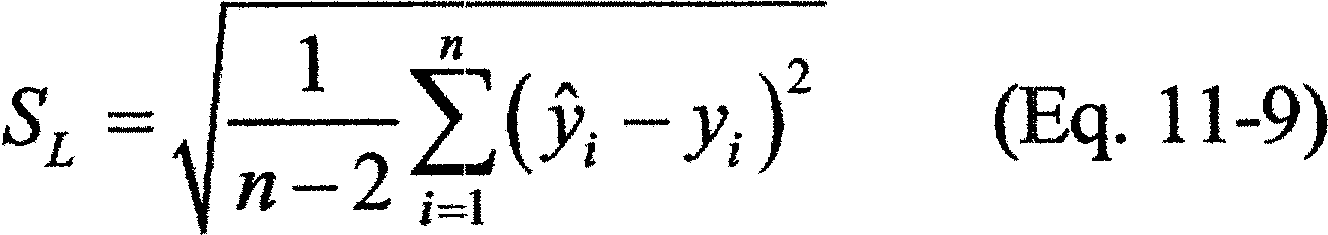
Calculate the confidence interval half range for the predicted PM concentration () at the mean x value as a percentage of the emission limit (CI%) using Equation 11-10:

Where:
CI = the half range of the 95 percent confidence interval for the predicted PM concentration at the mean x value, and
EL = PM emission limit, as described in section 13.2.
(iii) Calculate the half range of the tolerance interval (TI) for the predicted PM concentration () at the mean x value using Equation 11-11:

Where:
TI = the half range of the tolerance interval for the predicted PM concentration () at the mean x value,
kT = as calculated using Equation 11-12, and
SL = as calculated using Equation 11-9:

Where:
n′ = the number of test runs (n),
un′ = the tolerance factor for 75 percent coverage at 95 percent confidence provided in Table 1 for df = (n−2), and
vdf = the value from Table 1 for df = (n−2).
Calculate the half range of the tolerance interval for the predicted PM concentration () at the mean x value as a percentage of the emission limit (TI%) using Equation 11-13:

Where:
TI = the half range of the tolerance interval for the predicted PM concentration () at the mean x value, and
EL = PM emission limit, as described in section 13.2.
(iv) Calculate the linear correlation coefficient (r) using Equation 11-14:

Where:
SL = as calculated using Equation 11-9, and
Sy = as calculated using Equation 11-15:

(2) How do I evaluate a polynomial correlation for my correlation test data? To evaluate a polynomial correlation, follow the procedures described in paragraphs (2)(i) through (iv) of this section.
(i) Calculate the polynomial correlation equation, which is indicated by Equation 11-16, using Equations 11-17 through 11-22:

Where:
= the PM CEMS concentration predicted by the polynomial correlation equation, and
b0, b1, b2 = the coefficients determined from the solution to the matrix equation Ab = B
Where:

Where:
Xi = the PM CEMS response for run i,
Yi = the reference method PM concentration for run i, and
n = the number of test runs.
Calculate the polynomial correlation curve coefficients (b0, b1, and b2) using Equations 11-19 through 11-21, respectively:

Where:

(ii) Calculate the 95 percent confidence interval half range (CI) by first calculating the C coefficients (Co to C5) using Equations 11-23 and 11-24:

Where:

Calculate Δ using Equation 11-25 for each x value:

Determine the x value that corresponds to the minimum value of Δ (Δmin). Determine the scatter or deviation of values about the polynomial correlation curve (SP) using Equation 11-26:
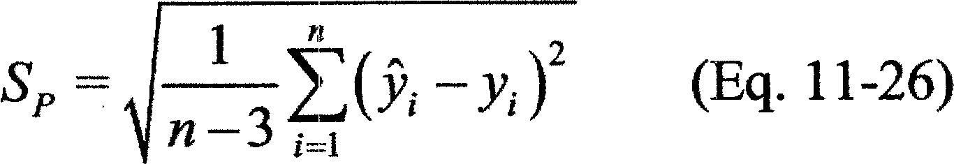
Calculate the half range of the 95 percent confidence interval (CI) for the predicted PM concentration () at the x value that corresponds to Δmin using Equation 11-27:

Where:
df = (n-3), and
tdf = as listed in Table 1 (see section 17).
Calculate the half range of the 95 percent confidence interval for the predicted PM concentration at the x value that corresponds to Δmin as a percentage of the emission limit (CI%) using Equation 11-28:

Where:
CI = the half range of the 95 percent confidence interval for the predicted PM concentration at the x value that corresponds to Δmin, and
EL = PM emission limit, as described in section 13.2.
(iii) Calculate the tolerance interval half range (TI) for the predicted PM concentration at the x value that corresponds to Δmin, as indicated in Equation 11-29 for the polynomial correlation, using Equations 11-30 and 11-31:

Where:

un′ = the value indicated in Table 1 for df = (n′-3), and
vdf = the value indicated in Table 1 for df = (n′ - 3).
Calculate the tolerance interval half range for the predicted PM concentration at the x value that corresponds to Δmin as a percentage of the emission limit (TI%) using Equation 11-32:

Where:
TI = the tolerance interval half range for the predicted PM concentration at the x value that corresponds to Δmin, and
EL = PM emission limit, as described in section 13.2.
(iv) Calculate the polynomial correlation coefficient (r) using Equation 11-33:

Where:
SP = as calculated using Equation 11-26, and
Sy = as calculated using Equation 11-15.
(3) How do I evaluate a logarithmic correlation for my correlation test data? To evaluate a logarithmic correlation, which has the form indicated by Equation 11-34, follow the procedures described in paragraphs (3)(i) through (iii) of this section.

(i) Perform a logarithmic transformation of each PM CEMS response value (x values) using Equation 11-35:

Where:
xi′ = is the transformed value of xi, and
Ln(xi) = the natural logarithm of the PM CEMS response for run i.
(ii) Using the values for xi′ in place of the values for xi, perform the same procedures used to develop the linear correlation equation described in paragraph (1)(i) of this section. The resulting equation has the form indicated by Equation 11-36:

Where:
x′ = the natural logarithm of the PM CEMS response, and the variables , b0, and b1 are as defined in paragraph (1)(i) of this section.
(iii) Using the values for xi′ in place of the values for xi, calculate the confidence interval half range at the mean x′ value as a percentage of the emission limit (CI%), the tolerance interval half range at the mean x′ value as a percentage of the emission limit (TI%), and the correlation coefficient (r) using the procedures described in paragraphs (1)(ii) through (iv) of this section.
(4) How do I evaluate an exponential correlation for my correlation test data? To evaluate an exponential correlation, which has the form indicated by Equation 11-37, follow the procedures described in paragraphs (4)(i) through (v) of this section:
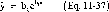
(i) Perform a logarithmic transformation of each PM concentration measurement (y values) using Equation 11-38:

Where:
y′i = is the transformed value of yi, and
Ln(yi) = the natural logarithm of the PM concentration measurement for run i.
(ii) Using the values for y′i in place of the values for yi, perform the same procedures used to develop the linear correlation equation described in paragraph (1)(i) of this section. The resulting equation will have the form indicated by Equation 11-39.
Where:
′ = the predicted log PM concentration value,
b′0 = the natural logarithm of b0, and the variables b0, b1, and x are as defined in paragraph (1)(i) of this section.
(iii) Using the values for y″i in place of the values for yi, calculate the half range of the 95 percent confidence interval (CI′), as described in paragraph (1)(ii) of this section for CI. Note that CI′ is on the log scale. Next, calculate the upper and lower 95 percent confidence limits for the mean value y′ using Equations 11-40 and 11-41:


Where:
LCL′ = the lower 95 percent confidence limit for the mean value y′,
UCL′ = the upper 95 percent confidence limit for the mean value y′,
y′ = the mean value of the log-transformed PM concentrations, and
CI′ = the half range of the 95 percent confidence interval for the predicted PM concentration (′), as calculated in Equation 11-8.
Calculate the half range of the 95 percent confidence interval (CI) on the original PM concentration scale using Equation 11-42:

Where:
CI = the half range of the 95 percent confidence interval on the original PM concentration scale, and UCL′ and LCL′ are as defined previously.
Calculate the half range of the 95 percent confidence interval for the predicted PM concentration corresponding to the mean value of x as a percentage of the emission limit (CI%) using Equation 11-10.
(iv) Using the values for y′i in place of the values for yi, calculate the half range tolerance interval (TI′), as described in paragraph (1)(iii) of this section for TI. Note that TI′ is on the log scale. Next, calculate the half range tolerance limits for the mean value y′ using Equations 11-43 and 11-44:


Where:
LTL′ = the lower 95 percent tolerance limit for the mean value y′,
UTL′ = the upper 95 percent tolerance limit for the mean value y′,
y′, = the mean value of the log-transformed PM concentrations, and
TI′ = the half range of the 95 percent tolerance interval for the predicted PM concentration (′), as calculated in Equation 11-11.
Calculate the half range tolerance interval (TI) on the original PM concentration scale using Equation 11-45:

TI = the half range of the 95 percent tolerance interval on the original PM scale, and UTL′ and LTL′ are as defined previously.
Calculate the tolerance interval half range for the predicted PM concentration corresponding to the mean value of x as a percentage of the emission limit (TI%) using Equation 11-13.
(v) Using the values for y″i in place of the values for yi, calculate the correlation coefficient (r) using the procedure described in paragraph (1)(iv) of this section.
(5) How do I evaluate a power correlation for my correlation test data? To evaluate a power correlation, which has the form indicated by Equation 11-46, follow the procedures described in paragraphs (5)(i) through (v) of this section.

(i) Perform logarithmic transformations of each PM CEMS response (x values) and each PM concentration measurement (y values) using Equations 11-35 and 11-38, respectively.
(ii) Using the values for x″i in place of the values for xi, and the values for y″i in place of the values for yi, perform the same procedures used to develop the linear correlation equation described in paragraph (1)(i) of this section. The resulting equation will have the form indicated by Equation 11-47:

Where:
′ = the predicted log PM concentration value, and
x′ = the natural logarithm of the PM CEMS response values,
b′0 = the natural logarithm of b0, and the variables b0, b1, and x are as defined in paragraph (1)(i) of this section.
(iii) Using the same procedure described for exponential models in paragraph (4)(iii) of this section, calculate the half range of the 95 percent confidence interval for the predicted PM concentration corresponding to the mean value of x′ as a percentage of the emission limit.
(iv) Using the same procedure described for exponential models in paragraph (4)(iv) of this section, calculate the tolerance interval half range for the predicted PM concentration corresponding to the mean value of x′ as a percentage of the emission limit.
(v) Using the values for y′i in place of the values for yi, calculate the correlation coefficient (r) using the procedure described in paragraph (1)(iv) of this section.
Note: PS-11 does not address the application of correlation equations to calculate PM emission concentrations using PM CEMS response data during normal operations of a PM CEMS. However, we will provide guidance on the use of specific correlation models (i.e., logarithmic, exponential, and power models) to calculate PM concentrations in an operating PM CEMS in situations when the PM CEMS response values are equal to or less than zero, and the correlation model is undefined.
12.4 Which correlation model should I use? Follow the procedures described in paragraphs (1) through (4) of this section to determine which correlation model you should use.
(1) For each correlation model that you develop using the procedures described in section 12.3 of this specification, compare the confidence interval half range percentage, tolerance interval half range percentage, and correlation coefficient to the performance criteria specified in section 13.2 of this specification. You can use the linear, logarithmic, exponential, or power correlation model if the model satisfies all of the performance criteria specified in section 13.2 of this specification. However, to use the polynomial model you first must check that the polynomial correlation curve satisfies the criteria for minimum and maximum values specified in paragraph (3) of this section.
(2) If you develop more than one correlation curve that satisfy the performance criteria specified in section 13.2 of this specification, you should use the correlation curve with the greatest correlation coefficient. If the polynomial model has the greatest correlation coefficient, you first must check that the polynomial correlation curve satisfies the criteria for minimum and maximum values specified in paragraph (3) of this section.
(3) You can use the polynomial model that you develop using the procedures described in section 12.3(2) if the model satisfies the performance criteria specified in section 13.2 of this specification, and the minimum or maximum value of the polynomial correlation curve does not occur within the expanded data range. The minimum or maximum value of the polynomial correlation curve is the point where the slope of the curve equals zero. To determine if the minimum or maximum value occurs within the expanded data range, follow the procedure described in paragraphs (3)(i) through (iv) of this section.
(i) Determine if your polynomial correlation curve has a minimum or maximum point by comparing the polynomial coefficient b2 to zero. If b2 is less than zero, the curve has a maximum value. If b2 is greater than zero, the curve has a minimum value. (Note: If b2 equals zero, the correlation curve is linear.)
(ii) Calculate the minimum value using Equation 11-48.

(iii) If your polynomial correlation curve has a minimum point, you must compare the minimum value to the minimum PM CEMS response used to develop the correlation curve. If the correlation curve minimum value is less than or equal to the minimum PM CEMS response value, you can use the polynomial correlation curve, provided the correlation curve also satisfies all of the performance criteria specified in section 13.2 of this specification. If the correlation curve minimum value is greater than the minimum PM CEMS response value, you cannot use the polynomial correlation curve to predict PM concentrations.
(iv) If your polynomial correlation curve has a maximum, the maximum value must be greater than the allowable extrapolation limit. If your source is not a low-emitting source, as defined in section 3.16 of this specification, the allowable extrapolation limit is 125 percent of the highest PM CEMS response used to develop the correlation curve. If your source is a low-emitting source, the allowable extrapolation limit is 125 percent of the highest PM CEMS response used to develop the correlation curve or the PM CEMS response that corresponds to 50 percent of the emission limit, whichever is greater. If the polynomial correlation curve maximum value is greater than the extrapolation limit, and the correlation curve satisfies all of the performance criteria specified in section 13.2 of this specification, you can use the polynomial correlation curve to predict PM concentrations. If the correlation curve maximum value is less than the extrapolation limit, you cannot use the polynomial correlation curve to predict PM concentrations.
(4) You may petition the Administrator for alternative solutions or sampling recommendations if the correlation models described in section 12.3 of this specification do not satisfy the performance criteria specified in section 13.2 of this specification.
13.0 What Are the Performance Criteria for My PM CEMS?
You must evaluate your PM CEMS based on the 7-day drift check, the accuracy of the correlation, and the sampling periods and cycle/response time.
13.1 What is the 7-day drift check performance specification? Your daily PM CEMS internal drift checks must demonstrate that the daily drift of your PM CEMS does not deviate from the value of the reference light, optical filter, Beta attenuation signal, or other technology-suitable reference standard by more than 2 percent of the response range. If your CEMS includes diluent and/or auxiliary monitors (for temperature, pressure, and/or moisture) that are employed as a necessary part of this performance specification, you must determine the calibration drift separately for each ancillary monitor in terms of its respective output (see the appropriate performance specification for the diluent CEMS specification). None of the calibration drifts may exceed their individual specification.
13.2 What performance criteria must my PM CEMS correlation satisfy? Your PM CEMS correlation must meet each of the minimum specifications in paragraphs (1), (2), and (3) of this section. Before confidence and tolerance interval half range percentage calculations are made, you must convert the emission limit to the appropriate units of your PM CEMS measurement conditions using the average of emissions gas property values (e.g., diluent concentration, temperature, pressure, and moisture) measured during the correlation test.
(1) The correlation coefficient must satisfy the criterion specified in paragraph (1)(i) or (ii), whichever applies.
(i) If your source is not a low-emitting source, as defined in section 3.16 of this specification, the correlation coefficient (r) must be greater than or equal to 0.85.
(ii) If your source is a low-emitting source, as defined in section 3.16 of this specification, the correlation coefficient (r) must be greater than or equal to 0.75.
(2) The confidence interval half range must satisfy the applicable criterion specified in paragraph (2)(i), (ii), or (iii) of this section, based on the type of correlation model.
(i) For linear or logarithmic correlations, the 95 percent confidence interval half range at the mean PM CEMS response value from the correlation test must be within 10 percent of the PM emission limit value specified in the applicable regulation. Therefore, the CI% calculated using Equation 11-10 must be less than or equal to 10 percent.
(ii) For polynomial correlations, the 95 percent confidence interval half range at the PM CEMS response value from the correlation test that corresponds to the minimum value for Δ must be within 10 percent of the PM emission limit value specified in the applicable regulation. Therefore, the CI% calculated using Equation 11-28 must be less than or equal to 10 percent.
(iii) For exponential or power correlations, the 95 percent confidence interval half range at the mean of the logarithm of the PM CEMS response values from the correlation test must be within 10 percent of the PM emission limit value specified in the applicable regulation. Therefore, the CI% calculated using Equation 11-10 must be less than or equal to 10 percent.
(3) The tolerance interval half range must satisfy the applicable criterion specified in paragraph (3)(i), (ii), or (iii) of this section, based on the type of correlation model.
(i) For linear or logarithmic correlations, the half range tolerance interval with 95 percent confidence and 75 percent coverage at the mean PM CEMS response value from the correlation test must be within 25 percent of the PM emission limit value specified in the applicable regulation. Therefore, the TI% calculated using Equation 11-13 must be less than or equal to 25 percent.
(ii) For polynomial correlations, the half range tolerance interval with 95 percent confidence and 75 percent coverage at the PM CEMS response value from the correlation test that corresponds to the minimum value for Δ must be within 25 percent of the PM emission limit value specified in the applicable regulation. Therefore, the TI% calculated using Equation 11-32 must be less than or equal to 25 percent.
(iii) For exponential or power correlations, the half range tolerance interval with 95 percent confidence and 75 percent coverage at the mean of the logarithm of the PM CEMS response values from the correlation test must be within 25 percent of the PM emission limit value specified in the applicable regulation. Therefore, the TI% calculated using Equation 11-13 must be less than or equal to 25 percent.
13.3 What are the sampling periods and cycle/response time? You must document and maintain the response time and any changes in the response time following installation.
(1) If you have a batch sampling PM CEMS, you must evaluate the limits presented in paragraphs (1)(i) and (ii) of this section.
(i) The response time of your PM CEMS, which is equivalent to the cycle time, must be no longer than 15 minutes. In addition, the delay between the end of the sampling time and reporting of the sample analysis must be no greater than 3 minutes. You must document any changes in the response time following installation.
(ii) The sampling time of your PM CEMS must be no less than 30 percent of the cycle time. If you have a batch sampling PM CEMS, sampling must be continuous except during pauses when the collected pollutant on the capture media is being analyzed and the next capture medium starts collecting a new sample.
13.4 What PM compliance monitoring must I do? You must report your CEMS measurements in the units of the standard expressed in the regulations (e.g., mg/dscm @ 7 percent oxygen, pounds per million Btu (lb/mmBtu), etc.). You may need to install auxiliary data monitoring equipment to convert the units reported by your PM CEMS into units of the PM emission standard.
14.0 Pollution Prevention [Reserved]
15.0 Waste Management [Reserved]
16.0 Which References Are Relevant to This Performance Specification?
16.1 Technical Guidance Document: Compliance Assurance Monitoring. U.S. Environmental Protection Agency Office of Air Quality Planning and Standards Emission Measurement Center. August 1998.
16.2 40 CFR 60, Appendix B, “Performance Specification 2 - Specifications and Test Procedures for SO2, and NOX, Continuous Emission Monitoring Systems in Stationary Sources.”
16.3 40 CFR 60, Appendix B, “Performance Specification 1 - Specification and Test Procedures for Opacity Continuous Emission Monitoring Systems in Stationary Sources.”
16.4 40 CFR 60, Appendix A, “Method 1 - Sample and Velocity Traverses for Stationary Sources.”
16.5 “Current Knowledge of Particulate Matter (PM) Continuous Emission Monitoring.” EPA-454/R-00-039. U.S. Environmental Protection Agency, Research Triangle Park, NC. September 2000.
16.6 40 CFR 266, Appendix IX, section 2, “Performance Specifications for Continuous Emission Monitoring Systems.”
16.7 ISO 10155, “Stationary Source Emissions - Automated Monitoring of Mass Concentrations of Particles: Performance Characteristics, Test Procedures, and Specifications.” American National Standards Institute, New York City. 1995.
16.8 Snedecor, George W. and Cochran, William G. (1989), Statistical Methods, Eighth Edition, Iowa State University Press.
16.9 Wallis, W. A. (1951) “Tolerance Intervals for Linear Regression,” in Second Berkeley Symposium on Mathematical Statistics and Probability, ed. J. Neyman, Berkeley: University of California Press, pp. 43-51.
17.0 What Reference Tables and Validation Data Are Relevant to PS-11?
Use the information in Table 1 for determining the confidence and tolerance interval half ranges. Use Table 2 to record your 7-day drift test data.
Table 1 - Factors for Calculation of Confidence and Tolerance Interval Half Ranges
| df | Student's t, tdf | Tolerance interval with 75% coverage and 95% confidence level | ||
|---|---|---|---|---|
| vdf (95%) | un′ (75%) | kT | ||
| 3 | 3.182 | 2.920 | 1.266 | 3.697 |
| 4 | 2.776 | 2.372 | 1.247 | 2.958 |
| 5 | 2.571 | 2.089 | 1.233 | 2.576 |
| 6 | 2.447 | 1.915 | 1.223 | 2.342 |
| 7 | 2.365 | 1.797 | 1.214 | 2.183 |
| 8 | 2.306 | 1.711 | 1.208 | 2.067 |
| 9 | 2.262 | 1.645 | 1.203 | 1.979 |
| 10 | 2.228 | 1.593 | 1.198 | 1.909 |
| 11 | 2.201 | 1.551 | 1.195 | 1.853 |
| 12 | 2.179 | 1.515 | 1.192 | 1.806 |
| 13 | 2.160 | 1.485 | 1.189 | 1.766 |
| 14 | 2.145 | 1.460 | 1.186 | 1.732 |
| 15 | 2.131 | 1.437 | 1.184 | 1.702 |
| 16 | 2.120 | 1.418 | 1.182 | 1.676 |
| 17 | 2.110 | 1.400 | 1.181 | 1.653 |
| 18 | 2.101 | 1.384 | 1.179 | 1.633 |
| 19 | 2.093 | 1.370 | 1.178 | 1.614 |
| 20 | 2.086 | 1.358 | 1.177 | 1.597 |
| 21 | 2.080 | 1.346 | 1.175 | 1.582 |
| 22 | 2.074 | 1.335 | 1.174 | 1.568 |
| 23 | 2.069 | 1.326 | 1.173 | 1.555 |
| 24 | 2.064 | 1.316 | 1.172 | 1.544 |
| 25 | 2.060 | 1.308 | 1.172 | 1.533 |
| 26 | 2.056 | 1.300 | 1.171 | 1.522 |
| 27 | 2.052 | 1.293 | 1.170 | 1.513 |
| 28 | 2.048 | 1.286 | 1.170 | 1.504 |
| 29 | 2.045 | 1.280 | 1.169 | 1.496 |
| 30 | 2.042 | 1.274 | 1.168 | 1.488 |
| 31 | 2.040 | 1.268 | 1.168 | 1.481 |
| 32 | 2.037 | 1.263 | 1.167 | 1.474 |
| 33 | 2.035 | 1.258 | 1.167 | 1.467 |
| 34 | 2.032 | 1.253 | 1.166 | 1.461 |
| 35 | 2.030 | 1.248 | 1.166 | 1.455 |
| 36 | 2.028 | 1.244 | 1.165 | 1.450 |
| 37 | 2.026 | 1.240 | 1.165 | 1.444 |
| 38 | 2.024 | 1.236 | 1.165 | 1.439 |
| 39 | 2.023 | 1.232 | 1.164 | 1.435 |
| 40 | 2.021 | 1.228 | 1.164 | 1.430 |
| 41 | 2.020 | 1.225 | 1.164 | 1.425 |
| 42 | 2.018 | 1.222 | 1.163 | 1.421 |
| 43 | 2.017 | 1.218 | 1.163 | 1.417 |
| 44 | 2.015 | 1.215 | 1.163 | 1.413 |
| 45 | 2.014 | 1.212 | 1.163 | 1.410 |
| 46 | 2.013 | 1.210 | 1.162 | 1.406 |
| 47 | 2.012 | 1.207 | 1.162 | 1.403 |
| 48 | 2.011 | 1.204 | 1.162 | 1.399 |
| 49 | 2.010 | 1.202 | 1.162 | 1.396 |
| 50 | 2.009 | 1.199 | 1.161 | 1.393 |
| 51 | 2.008 | 1.197 | 1.161 | 1.390 |
| 52 | 2.007 | 1.195 | 1.161 | 1.387 |
| 53 | 2.006 | 1.192 | 1.161 | 1.384 |
| 54 | 2.005 | 1.190 | 1.161 | 1.381 |
| 55 | 2.004 | 1.188 | 1.160 | 1.379 |
| 56 | 2.003 | 1.186 | 1.160 | 1.376 |
| 57 | 2.002 | 1.184 | 1.160 | 1.374 |
| 58 | 2.002 | 1.182 | 1.160 | 1.371 |
| 59 | 2.001 | 1.180 | 1.160 | 1.369 |
| 60 | 2.000 | 1.179 | 1.160 | 1.367 |
Table 2 - 7-Day Drift Test Data
| Zero drift day # | Date
and time |
Zero check
value (RL) |
PM CEMS
response (RCEMS) |
Difference
(RCEMS−RL) |
Zero drift
((RCEMS−RL) /RU) × 100 |
|---|---|---|---|---|---|
| 1 | |||||
| 2 | |||||
| 3 | |||||
| 4 | |||||
| 5 | |||||
| 6 | |||||
| 7 |
| Upscale drift day # | Date
and time |
Upscale
check value (RU) |
PM CEMS
response (RCEMS) |
Difference
(RCEMS−RU) |
Upscale drift
((RCEMS−RU)/RU) × 100% |
|---|---|---|---|---|---|
| 1 | |||||
| 2 | |||||
| 3 | |||||
| 4 | |||||
| 5 | |||||
| 6 | |||||
| 7 |
Performance Specification 12A - Specifications and Test Procedures for Total Vapor Phase Mercury Continuous Emission Monitoring Systems in Stationary Sources
1.0 Scope and Application
1.1 Analyte. The analyte measured by these procedures and specifications is total vapor phase mercury (Hg) in the flue gas, which represents the sum of elemental Hg (Hg°, CAS Number 7439-97-6) and oxidized forms of gaseous Hg (Hg+2), in concentration units of micrograms per cubic meter (µg/m3).
1.2 Applicability.
1.2.1 This specification is for evaluating the acceptability of total vapor phase Hg continuous emission monitoring systems (CEMS) installed at stationary sources at the time of or soon after installation and whenever specified in the regulations. The Hg CEMS must be capable of measuring the total concentration in µg/m3 of vapor phase Hg, regardless of speciation, and recording that concentration at standard conditions on a wet or dry basis. These specifications do not address measurement of particle bound Hg.
1.2.2 This specification is not designed to evaluate an installed CEMS's performance over an extended period of time nor does it identify specific calibration techniques and auxiliary procedures to assess the CEMS's performance. The source owner or operator, however, is responsible to calibrate, maintain, and operate the CEMS properly. The Administrator may require, under section 114 of the Clean Air Act, the operator to conduct CEMS performance evaluations at other times besides the initial performance evaluation test. See §§ 60.13(c) and 63.8(e)(1).
1.2.3 Mercury monitoring approaches not entirely suited to these specifications may be approvable under the alternative monitoring or alternative test method provisions of § 60.13(i) and § 63.8(f) or § 60.8(b)(3) and § 63.7(f), respectively.
2.0 Summary of Performance Specification
Procedures for determining CEMS relative accuracy, linearity, and calibration drift are outlined. CEMS installation and measurement location specifications, data reduction procedures, and performance criteria are included.
3.0 Definitions
3.1 Continuous Emission Monitoring System (CEMS) means the total equipment required to measure a pollutant concentration. The system generally consists of the following three major subsystems:
3.2 Sample Interface means that portion of the CEMS used for one or more of the following: sample acquisition, sample transport, sample conditioning, and protection of the monitor from the effects of the stack effluent.
3.3 Hg Analyzer means that portion of the Hg CEMS that measures the total vapor phase Hg mass concentration and generates a proportional output.
3.4 Data Recorder means that portion of the CEMS that provides a permanent electronic record of the analyzer output. The data recorder may provide automatic data reduction and CEMS control capabilities.
3.5 Span Value means the measurement range as specified in the applicable regulation or other requirement. If the span is not specified in the applicable regulation or other requirement, then it must be a value approximately equivalent to two times the emission standard. Unless otherwise specified, the span value may be rounded up to the nearest multiple of 10.
3.6 Measurement Error Test means a test procedure in which the accuracy of the concentrations measured by a CEMS at three or more points over its measurement range is evaluated using reference gases. For Hg CEMS, elemental and oxidized Hg (Hg0 and mercuric chloride, HgCl2) gas standards of known concentration are used for this procedure.
3.7 Measurement Error (ME) means the absolute value of the difference between the concentration indicated by the CEMS and the known concentration of a reference gas, expressed as a percentage of the span value, when the entire CEMS, including the sampling interface, is challenged.
3.8 Calibration Drift (CD) means the absolute value of the difference between the CEMS output response and either an upscale Hg reference gas or a zero-level Hg reference gas, expressed as a percentage of the span value, when the entire CEMS, including the sampling interface, is challenged after a stated period of operation during which no unscheduled maintenance or repair took place.
3.9 Relative Accuracy Test Procedure means a test procedure consisting of at least nine test runs, in which the accuracy of the concentrations measured by a CEMS is evaluated by comparison against concurrent measurements made with a reference method (RM). Relative accuracy tests repeated on a regular, on-going basis are referred to as relative accuracy test audits or RATAs.
3.10 Relative Accuracy (RA) means the absolute mean difference between the pollutant concentrations determined by the CEMS and the values determined by the RM plus the 2.5 percent error confidence coefficient of a series of tests divided by the mean of the RM tests. Alternatively, for sources with an average RM concentration less than 5.0 micrograms per standard cubic meter (µg/scm), the RA may be expressed as the absolute value of the difference between the mean CEMS and RM values.
4.0 Interferences [Reserved]
5.0 Safety
The procedures required under this performance specification may involve hazardous materials, operations, and equipment. This performance specification may not address all of the safety problems associated with these procedures. It is the responsibility of the user to establish appropriate safety and health practices and determine the applicable regulatory limitations prior to performing these procedures. The CEMS user's manual and materials recommended by the RM should be consulted for specific precautions to be taken.
6.0 Equipment and Supplies
6.1 CEMS Equipment Specifications.
6.1.1 Data Recorder Scale. The Hg CEMS data recorder output range must include the full range of expected Hg concentration values in the gas stream to be sampled including zero and the span value.
6.1.2 The Hg CEMS design should also provide for the determination of CD and ME at a zero value (zero to 20 percent of the span value) and at upscale values (between 50 and 100 percent of the span value). The Hg CEMS must be constructed to permit the introduction of known concentrations of Hg and HgCl2 separately into the sampling system of the CEMS immediately preceding the sample extraction filtration system such that the entire CEMS can be challenged.
6.2 Reference Gas Delivery System. The reference gas delivery system must be designed so that the flowrate exceeds the sampling system flow requirements of the CEMS and that the gas is delivered to the CEMS at atmospheric pressure.
6.3 Other equipment and supplies, as needed by the reference method used for the Relative Accuracy Test Procedure. See section 8.6.2.
7.0 Reagents and Standards
7.1 Reference Gases. Reference gas standards are required for both elemental and oxidized Hg (Hg and mercuric chloride, HgCl2). The use of National Institute of Standards and Technology (NIST)-traceable standards and reagents is required. The following gas concentrations are required.
7.1.1 Zero-level. 0 to 20 percent of the span value.
7.1.2 Mid-level. 50 to 60 percent of the span value.
7.1.3 High-level. 80 to 100 percent of the span value.
7.2 Reference gas standards may also be required for the reference methods. See section 8.6.2.
8.0 Performance Specification Test Procedure
8.1 Installation and Measurement Location Specifications.
8.1.1 CEMS Installation. Install the CEMS at an accessible location downstream of all pollution control equipment. Place the probe outlet or other sampling interface at a point or location in the stack (or vent) representative of the stack gas concentration of Hg. Since the Hg CEMS sample system normally extracts gas from a single point in the stack, a location that has been shown to be free of stratification for Hg or, alternatively, SO2 is recommended. If the cause of failure to meet the RA test requirement is determined to be the measurement location and a satisfactory correction technique cannot be established, the Administrator may require the CEMS to be relocated. Measurement locations and points or paths that are most likely to provide data that will meet the RA requirements are described in sections 8.1.2 and 8.1.3 below.
8.1.2 Measurement Location. The measurement location should be
(1) at least two equivalent diameters downstream of the nearest control device, point of pollutant generation or other point at which a change of pollutant concentration may occur, and
(2) at least half an equivalent diameter upstream from the effluent exhaust. The equivalent duct diameter is calculated according to Method 1 in appendix A-1 to this part.
8.1.3 Hg CEMS Sample Extraction Point. Use a sample extraction point either
(1) no less than 1.0 meter from the stack or duct wall, or
(2) within the centroidal velocity traverse area of the stack or duct cross section. This does not apply to cross-stack, in-situ measurement systems.
8.2 Measurement Error (ME) Test Procedure. Sequentially inject each of at least three elemental Hg reference gases (zero, mid-level, and high level, as defined in section 7.1), three times each for a total of nine injections. Inject the gases in such a manner that the entire CEMS is challenged. Do not inject the same gas concentration twice in succession. At each reference gas concentration, determine the average of the three CEMS responses and subtract the average response from the reference gas value. Calculate the measurement error (ME) using Equation 12-1 by expressing the absolute value of the difference between the average CEMS response (A) and the reference gas value (R) as a percentage of the span (see example data sheet in Figure 12A-1). For each elemental Hg reference gas, the absolute value of the difference between the CEMS response and the reference value must not exceed 5 percent of the span value. If this specification is not met, identify and correct the problem before proceeding. Repeat the measurement error test procedure using oxidized Hg reference gases. For each oxidized Hg reference gas, the absolute value of the difference between the CEMS response and the reference value shall not exceed 10 percent of the span value. If this specification is not met, identify and correct the problem before proceeding.

8.3 Seven-Day Calibration Drift (CD) Test Procedure.
8.3.1 CD Test Period. While the affected facility is operating normally, or as specified in an applicable regulation, determine the magnitude of the CD once each day (at 24-hour intervals, to the extent practicable) for 7 consecutive unit operating days according to the procedures in sections 8.3.2 and 8.3.3. The 7 consecutive unit operating days need not be 7 consecutive calendar days. Use either Hg° or HgCl2 standards for this test.
8.3.2 The purpose of the CD measurement is to verify the ability of the CEMS to conform to the established CEMS response used for determining emission concentrations or emission rates. Therefore, if periodic automatic or manual adjustments are made to the CEMS zero and upscale response settings, conduct the CD test immediately before these adjustments, or conduct it in such a way that the CD can be determined.
8.3.3 Conduct the CD test using the zero gas specified and either the mid-level or high-level gas as specified in section 7.1. Sequentially introduce the reference gases to the CEMS at the sampling system of the CEMS immediately preceding the sample extraction filtration system. Record the CEMS response (A) for each reference gas and, using Equation 12A-2, subtract the corresponding reference value (R) from the CEMS value, and express the absolute value of the difference as a percentage of the span value (see also example data sheet in Figure 12A-2). For each reference gas, the absolute value of the difference between the CEMS response and the reference value must not exceed 5 percent of the span value. If these specifications are not met, identify and correct the problem before proceeding.

8.4 Relative Accuracy (RA) Test Procedure.
8.4.1 RA Test Period. Conduct the RA test according to the procedure given in sections 8.4.2 through 8.4.6 while the affected facility is operating normally, or as specified in an applicable subpart. The RA test may be conducted during the CD test period.
8.4.2 Reference Methods (RM). Unless otherwise specified in an applicable subpart of the regulations, use Method 29, Method 30A, or Method 30B in appendix A-8 to this part or American Society of Testing and Materials (ASTM) Method D6784-02 (incorporated by reference, see § 60.17) as the RM for Hg concentration. For Method 29 and ASTM Method D6784-02 only, the filterable portion of the sample need not be included when making comparisons to the CEMS results. When Method 29, Method 30B, or ASTM D6784-02 is used, conduct the RM test runs with paired or duplicate sampling systems and use the average of the vapor phase Hg concentrations measured by the two trains. When Method 30A is used, paired sampling systems are not required. If the RM and CEMS measure on a different moisture basis, data derived with Method 4 in appendix A-3 to this part must also be obtained during the RA test.
8.4.3 Sampling Strategy for RM Tests. Conduct the RM tests in such a way that they will yield results representative of the emissions from the source and can be compared to the CEMS data. The RM and CEMS locations need not be immediately adjacent. Locate the RM measurement points in accordance with section 8.1.3 of Performance Specification 2 (PS 2) in this appendix. It is preferable to conduct moisture measurements (if needed) and Hg measurements simultaneously, although moisture measurements that are taken within an hour of the Hg measurements may be used to adjust the Hg concentrations to a consistent moisture basis. In order to correlate the CEMS and RM data properly, note the beginning and end of each RM test period for each paired RM run (including the exact time of day) on the CEMS chart recordings or other permanent record of output.
8.4.4 Number and Length of RM Test Runs. Conduct a minimum of nine RM test runs. When Method 29, Method 30B, or ASTM D6784-02 is used, only test runs for which the paired RM trains meet the relative deviation criteria (RD) of this PS must be used in the RA calculations. In addition, for Method 29 and ASTM D6784-02, use a minimum sample time of 2 hours and for Methods 30A and 30B use a minimum sample time of 30 minutes.
More than nine sets of RM test runs may be performed. If this option is chosen, RM test run results may be excluded so long as the total number of RM test run results used to determine the CEMS RA is greater than or equal to nine. However, all data must be reported including the excluded test run data.
8.4.5 Correlation of RM and CEMS Data. Correlate the CEMS and the RM test data as to the time and duration by first determining from the CEMS final output (the one used for reporting) the integrated average pollutant concentration for each RM test period. Consider system response time, if important, and confirm that the results are on a consistent moisture basis with the RM test. Then, compare each integrated CEMS value against the corresponding RM value. When Method 29, Method 30B, or ASTM D6784-02 is used, compare each CEMS value against the corresponding average of the paired RM values.
8.4.6 Paired RM Outliers.
8.4.6.1 When Method 29, Method 30B, or ASTM D6784-02 is used, outliers are identified through the determination of relative deviation (RD) of the paired RM tests. Data that do not meet the RD criteria must be flagged as a data quality problem and may not be used in the calculation of RA. The primary reason for performing paired RM sampling is to ensure the quality of the RM data. The percent RD of paired data is the parameter used to quantify data quality. Determine RD for paired data points as follows:

Where:
Ca and Cb are the Hg concentration values determined from the paired samples.
8.4.6.2 The minimum performance criteria for RM Hg data is that RD for any data pair must be ≤10 percent as long as the mean Hg concentration is greater than 1.0 µg/m3. If the mean Hg concentration is less than or equal to 1.0 µg/m3, the RD must be ≤20 percent or ≤0.2 µg/m3 absolute difference. Pairs of RM data exceeding these RD criteria should be eliminated from the data set used to develop a Hg CEMS correlation or to assess CEMS RA.
8.4.7 Calculate the mean difference between the RM and CEMS values in the units of micrograms per cubic meter (µg/m3), the standard deviation, the confidence coefficient, and the RA according to the procedures in section 12.0.
8.5 Reporting. At a minimum (check with the appropriate EPA Regional Office, State or local Agency for additional requirements, if any), summarize in tabular form the results of the CD tests, the linearity tests, and the RA test or alternative RA procedure, as appropriate. Include all data sheets, calculations, charts (records of CEMS responses), reference gas concentration certifications, and any other information necessary to confirm that the CEMS meets the performance criteria.
9.0 Quality Control [Reserved]
10.0 Calibration and Standardization [Reserved]
11.0 Analytical Procedure
For Method 30A, sample collection and analysis are concurrent. For the other RM, post-run sample analyses are performed. Refer to the RM employed for specific analytical procedures.
12.0 Calculations and Data Analysis
Calculate and summarize the RA test results on a data sheet similar to Figure 12A-3.
12.1 Consistent Basis. All data from the RM and CEMS must be compared in units of micrograms per standard cubic meter (µg/scm), on a consistent and identified moisture basis. The values must be standardized to 20 °C, 760 mm Hg.
12.1.1 Moisture Correction (as applicable). If the RM and CEMS measure Hg on a different moisture basis, they will need to be corrected to a consistent basis. Use Equation 12A-4a to correct data from a wet basis to a dry basis.

Use Equation 12A-4b to correct data from a dry basis to a wet basis.

Where:
Bws is the moisture content of the flue gas from Method 4, expressed as a decimal fraction (e.g., for 8.0 percent H2O, Bws= 0.08).
12.2 Arithmetic Mean. Calculate d̄, the arithmetic mean of the differences (di) of a data set as follows:

Where:
n = Number of data points.
12.3 Standard Deviation. Calculate the standard deviation, Sd, as follows:

12.3 Confidence Coefficient (CC). Calculate the 2.5 percent error confidence coefficient (one-tailed), CC, as follows:

12.4 Relative Accuracy. Calculate the RA of a set of data as follows:

Where:
|d̄| = Absolute value of the mean of the differences (from Equation 12A-5)
|CC| = Absolute value of the confidence coefficient (from Equation 12A-7)
RM = Average reference method value
13.0 Method Performance
13.1 Measurement Error (ME). For Hg0, the ME must not exceed 5 percent of the span value at the zero-, mid-, and high-level reference gas concentrations. For HgCl2, the ME must not exceed 10 percent of the span value at the zero-, mid-, and high-level reference gas concentrations.
13.2 Calibration Drift (CD). The CD must not exceed 5 percent of the span value on any of the 7 days of the CD test.
13.3 Relative Accuracy (RA). The RA of the CEMS must be no greater than 20 percent of the mean value of the RM test data in terms of units of µg/scm. Alternatively, if the mean RM is less than 5.0 µg/scm, the results are acceptable if the absolute value of the difference between the mean RM and CEMS values does not exceed 1.0 µg/scm.
14.0 Pollution Prevention [Reserved]
15.0 Waste Management [Reserved]
16.0 Alternative Procedures [Reserved]
17.0 Bibliography
17.1 40 CFR part 60, appendix B, “Performance Specification 2 - Specifications and Test Procedures for SO2 and NOX Continuous Emission Monitoring Systems in Stationary Sources.”
17.2 40 CFR part 60, appendix A, “Method 29 - Determination of Metals Emissions from Stationary Sources.”
17.3 40 CFR part 60, appendix A, “Method 30A - Determination of Total Vapor Phase Mercury Emissions From Stationary Sources (Instrumental Analyzer Procedure).
17.4 40 CFR part 60, appendix A, “Method 30B - Determination of Total Vapor Phase Mercury Emissions From Coal-Fired Combustion Sources Using Carbon Sorbent Traps.”
17.5 ASTM Method D6784-02, “Standard Test Method for Elemental, Oxidized, Particle-Bound and Total Mercury in Flue Gas Generated from Coal-Fired Stationary Sources (Ontario Hydro Method).”
18.0 Tables and Figures
Table 12A-1 - T-Values
| na | t0.975 | na | t0.975 | na | t0.975 |
|---|---|---|---|---|---|
| 2 | 12.706 | 7 | 2.447 | 12 | 2.201 |
| 3 | 4.303 | 8 | 2.365 | 13 | 2.179 |
| 4 | 3.182 | 9 | 2.306 | 14 | 2.160 |
| 5 | 2.776 | 10 | 2.262 | 15 | 2.145 |
| 6 | 2.571 | 11 | 2.228 | 16 | 2.131 |
Figure 12A-1 - ME Determination
| Date | Time | Reference
gas value (µg/m3) |
CEMS
measured value (µg/m3) |
Absolute
difference (µg/m3) |
ME
(% of span value) |
|
|---|---|---|---|---|---|---|
| Zero level | ||||||
| Average | ||||||
| Mid level | ||||||
| Average | ||||||
| High level | ||||||
| Average | ||||||
Figure 12A-2 - 7-Day Calibration Drift Determination
| Date | Time | Reference
gas value (µg/m3) |
CEMS
measured value (µg/m3) |
Absolute
difference (µg/m3) |
CD
(% of span value) |
|
|---|---|---|---|---|---|---|
| Zero level | ||||||
| Upscale
(Mid or High) |
||||||
Figure 12A-3 - Relative Accuracy Test Data
| Run No. | Date | Begin time | End time | RM value (µg/m3) | CEMS value (µg/m3) | Difference
(µg/m3) |
Run used? (Yes/No) | RD1 |
|---|---|---|---|---|---|---|---|---|
| 1 | ||||||||
| 2 | ||||||||
| 3 | ||||||||
| 4 | ||||||||
| 5 | ||||||||
| 6 | ||||||||
| 7 | ||||||||
| 8 | ||||||||
| 9 | ||||||||
| 10 | ||||||||
| 11 | ||||||||
| 12 | ||||||||
| Average Values | ||||||||
| Arithmetic Mean Difference: | ||||||||
| Standard Deviation: | ||||||||
| Confidence Coefficient: | ||||||||
| T-Value: | ||||||||
| % Relative Accuracy: | ||||||||
| | (RM)avg − (CEMS)avg | : | ||||||||
Performance Specification 12B - Specifications and Test Procedures for Monitoring Total Vapor Phase Mercury Emissions From Stationary Sources Using a Sorbent Trap Monitoring System
1.0 Scope and Application
The purpose of Performance Specification 12B (PS 12B) is to establish performance benchmarks for, and to evaluate the acceptability of, sorbent trap monitoring systems used to monitor total vapor-phase mercury (Hg) emissions in stationary source flue gas streams. These monitoring systems involve continuous repetitive in-stack sampling using paired sorbent media traps with periodic analysis of the time-integrated samples. Persons using PS 12B should have a thorough working knowledge of Methods 1, 2, 3, 4, 5 and 30B in appendices A-1 through A-3 and A-8 to this part.
1.1 Analyte. The analyte measured by these procedures and specifications is total vapor phase Hg in the flue gas, which represents the sum of elemental Hg (Hg0, CAS Number 7439-97-6) and gaseous forms of oxidized Hg (i.e., Hg+2) in mass concentration units of micrograms per dry standard cubic meter (µg/dscm).
1.2 Applicability
1.2.1 These procedures are only intended for use under relatively low particulate conditions (e.g., monitoring after all pollution control devices). This specification is for evaluating the acceptability of total vapor phase Hg sorbent trap monitoring systems installed at stationary sources at the time of, or soon after, installation and whenever specified in the regulations. The Hg monitoring system must be capable of measuring the total concentration of vapor phase Hg (regardless of speciation), in units of µg/dscm.
1.2.2 This specification contains routine procedures and specifications designed to evaluate an installed sorbent trap monitoring system's performance over time; Procedure 5 of appendix F to this part contains additional procedures and specifications which may be required for long term operation. In addition, the source owner or operator is responsible to calibrate, maintain, and operate the monitoring system properly. The Administrator may require the owner or operator, under section 114 of the Clean Air Act, to conduct performance evaluations at other times besides the initial test to evaluate the CEMS performance. See § 60.13(c) and 63.8(e)(1).
2.0 Principle
Known volumes of flue gas are continuously extracted from a stack or duct through paired, in-stack, pre-spiked sorbent media traps at appropriate nominal flow rates. The sorbent traps in the sampling system are periodically exchanged with new ones, prepared for analysis as needed, and analyzed by any technique that can meet the performance criteria. For quality-assurance purposes, a section of each sorbent trap is spiked with Hg0 prior to sampling. Following sampling, this section is analyzed separately and a specified minimum percentage of the spike must be recovered. Paired train sampling is required to determine method precision.
3.0 Definitions
3.1 Sorbent Trap Monitoring System means the total equipment required for the collection of gaseous Hg samples using paired three-partition sorbent traps.
3.2 Relative Accuracy Test Procedure means a test procedure consisting of at least nine runs, in which the accuracy of the total vapor phase Hg concentrations measured by the sorbent trap monitoring system is evaluated by comparison against concurrent measurements made with a reference method (RM). Relative accuracy tests repeated on a regular, on-going basis are referred to as relative accuracy test audits or RATAs.
3.3 Relative Accuracy (RA) means the absolute mean difference between the pollutant (Hg) concentrations determined by the sorbent trap monitoring system and the values determined by the reference method (RM) plus the 2.5 percent error confidence coefficient of a series of tests divided by the mean of the RM tests. Alternatively, for low concentration sources, the RA may be expressed as the absolute value of the difference between the mean sorbent trap monitoring system and RM values.
3.4 Relative Deviation (RD) means the absolute difference of the Hg concentration values obtained with a pair of sorbent traps divided by the sum of those concentrations, expressed as a percentage. RD is used to assess the precision of the sorbent trap monitoring system.
3.5 Spike Recovery means the mass of Hg recovered from the spiked trap section, expressed as a percentage of the amount spiked. Spike recovery is used to assess sample matrix interference.
4.0 Interferences [Reserved]
5.0 Safety
The procedures required under this performance specification may involve hazardous materials, operations, and equipment. This performance specification may not address all of the safety problems associated with these procedures. It is the responsibility of the user to establish appropriate safety and health practices and determine the applicable regulatory limitations prior to performing these procedures.
6.0 Equipment and Supplies
6.1 Sorbent Trap Monitoring System Equipment Specifications.
6.1.1 Monitoring System. The equipment described in Method 30B in appendix A-8 to this part must be used to continuously sample for Hg emissions, with the substitution of three-section traps in place of two-section traps, as described below. A typical sorbent trap monitoring system is shown in Figure 12B-1.
6.1.2 Three-Section Sorbent Traps. The sorbent media used to collect Hg must be configured in traps with three distinct and identical segments or sections, connected in series, to be separately analyzed. section 1 is designated for primary capture of gaseous Hg. section 2 is designated as a backup section for determination of vapor-phase Hg breakthrough. section 3 is designated for quality assurance/quality control (QA/QC) purposes. section 3 must be spiked with a known amount of gaseous Hg0 prior to sampling and later analyzed to determine the spike (and hence sample) recovery efficiency.

6.1.3 Gaseous Hg0 Sorbent Trap Spiking System. A known mass of gaseous Hg0 must be spiked onto section 3 of each sorbent trap prior to sampling. Any approach capable of quantitatively delivering known masses of Hg0 onto sorbent traps is acceptable. Several technologies or devices are available to meet this objective. Their practicality is a function of Hg mass spike levels. For low levels, NIST-certified or NIST-traceable gas generators or tanks may be suitable, but will likely require long preparation times. A more practical, alternative system, capable of delivering almost any mass required, employs NIST-certified or NIST-traceable Hg salt solutions (e.g., Hg(NO3)2). With this system, an aliquot of known volume and concentration is added to a reaction vessel containing a reducing agent (e.g., stannous chloride); the Hg salt solution is reduced to Hg0 and purged onto section 3 of the sorbent trap by using an impinger sparging system.
6.1.4 Sample Analysis Equipment. Any analytical system capable of quantitatively recovering and quantifying total gaseous Hg from sorbent media is acceptable provided that the analysis can meet the performance criteria in Table 12B-1 in section 9 of this performance specification. Candidate recovery techniques include leaching, digestion, and thermal desorption. Candidate analytical techniques include ultraviolet atomic fluorescence (UV AF); ultraviolet atomic absorption (UV AA), with and without gold trapping; and in-situ X-ray fluorescence (XRF).
7.0 Reagents and Standards
Only NIST-certified or NIST-traceable calibration gas standards and reagents must be used for the tests and procedures required under this performance specification. The sorbent media may be any collection material (e.g., carbon, chemically treated filter, etc.) capable of quantitatively capturing and recovering for subsequent analysis, all gaseous forms of Hg in the emissions from the intended application. Selection of the sorbent media must be based on the material's ability to achieve the performance criteria contained in this method as well as the sorbent's vapor phase Hg capture efficiency for the emissions matrix and the expected sampling duration at the test site.
8.0 Performance Specification Test Procedure
8.1 Installation and Measurement Location Specifications.
8.1.1 Selection of Monitoring Site. Sampling site information should be obtained in accordance with Method 1 in appendix A-1 to this part. Place the probe inlet at a point or location in the stack (or vent) downstream of all pollution control equipment and representative of the stack gas concentration of Hg. A location that has been shown to be free of stratification for Hg or, alternatively, SO2 is recommended. An estimation of the expected stack Hg concentration is required to establish a target sample flow rate, total gas sample volume, and the mass of Hg0 to be spiked onto section 3 of each sorbent trap.
8.1.2 Pre-sampling Spiking of Sorbent Traps. Based on the estimated Hg concentration in the stack, the target sample rate and the target sampling duration, calculate the expected mass loading for section 1 of each sorbent trap (see section 12.1 of this performance specification). The pre-sampling spike to be added to section 3 of each sorbent trap must be within ±50 percent of the expected section 1 mass loading. Spike section 3 of each sorbent trap at this level, as described in section 6.1.3 of this performance specification. For each sorbent trap, keep a record of the mass of Hg0 added to section 3. This record must include, at a minimum, the identification number of the trap, the date and time of the spike, the name of the analyst performing the procedure, the method of spiking, the mass of Hg0 added to section 3 of the trap (µg), and the supporting calculations.
8.1.3 Pre-monitoring Leak Check. Perform a leak check with the sorbent traps in place in the sampling system. Draw a vacuum in each sample train. Adjust the vacuum in each sample train to ∼15″ Hg. Use the gas flow meter to determine leak rate. The leakage rate must not exceed 4 percent of the target sampling rate. Once the leak check passes this criterion, carefully release the vacuum in the sample train, then seal the sorbent trap inlet until the probe is ready for insertion into the stack or duct.
8.1.4 Determination of Flue Gas Characteristics. Determine or measure the flue gas measurement environment characteristics (gas temperature, static pressure, gas velocity, stack moisture, etc.) in order to determine ancillary requirements such as probe heating requirements (if any), sampling rate, proportional sampling conditions, moisture management, etc.
8.2 Monitoring.
8.2.1 System Preparation and Initial Data Recording. Remove the plug from the end of each sorbent trap and store each plug in a clean sorbent trap storage container. Remove the stack or duct port cap and insert the probe(s) with the inlet(s) aligned perpendicular to the stack gas flow. Secure the probe(s) and ensure that no leakage occurs between the duct and environment. Record initial data including the sorbent trap ID, start time, starting gas flow meter readings, initial temperatures, set points, and any other appropriate information.
8.2.2 Flow Rate Control. Set the initial sample flow rate at the target value from section 8.1.1 of this performance specification. Then, for every operating hour during the sampling period, record the date and time, the sample flow rate, the gas flow meter reading, the stack temperature (if needed), the flow meter temperatures (if needed), temperatures of heated equipment such as the vacuum lines and the probes (if heated), and the sampling system vacuum readings. Also, record the stack gas flow rate and the ratio of the stack gas flow rate to the sample flow rate. Adjust the sampling flow rate to maintain proportional sampling, i.e., keep the ratio of the stack gas flow rate to sample flow rate within ±25 percent of the reference ratio from the first hour of the data collection period (see section 12.2 of this performance specification). The sample flow rate through a sorbent trap monitoring system during any hour (or portion of an hour) that the unit is not operating must be zero.
8.2.3 Stack Gas Moisture Determination. If data from the sorbent trap monitoring system will be used to calculate Hg mass emissions, determine the stack gas moisture content using a continuous moisture monitoring system or other means acceptable to the Administrator, such as the ones described in § 75.11(b) of this chapter. Alternatively, for combustion of coal, wood, or natural gas in boilers only, a default moisture percentage from § 75.11(b) of this chapter may be used.
8.2.4 Essential Operating Data. Obtain and record any essential operating data for the facility during the test period, e.g., the barometric pressure for correcting the sample volume measured by a dry gas meter to standard conditions. At the end of the data collection period, record the final gas flow meter reading and the final values of all other essential parameters.
8.2.5 Post-monitoring Leak Check. When the monitoring period is completed, turn off the sample pump, remove the probe/sorbent trap from the port and carefully re-plug the end of each sorbent trap. Perform a leak check with the sorbent traps in place, at the maximum vacuum reached during the monitoring period. Use the same general approach described in section 8.1.3 of this performance specification. Record the leakage rate and vacuum. The leakage rate must not exceed 4 percent of the average sampling rate for the monitoring period. Following the leak check, carefully release the vacuum in the sample train.
8.2.6 Sample Recovery. Recover each sampled sorbent trap by removing it from the probe and seal both ends. Wipe any deposited material from the outside of the sorbent trap. Place the sorbent trap into an appropriate sample storage container and store/preserve it in an appropriate manner.
8.2.7 Sample Preservation, Storage, and Transport. While the performance criteria of this approach provide for verification of appropriate sample handling, it is still important that the user consider, determine, and plan for suitable sample preservation, storage, transport, and holding times for these measurements. Therefore, procedures in recognized voluntary consensus standards such as those in ASTM D6911-03 “Standard Guide for Packaging and Shipping Environmental Samples for Laboratory Analysis” should be followed for all samples.
8.2.8 Sample Custody. Proper procedures and documentation for sample chain of custody are critical to ensuring data integrity. Chain of custody procedures in recognized voluntary consensus standards such as those in ASTM D4840-99 “Standard Guide for Sample Chain-of-Custody Procedures” should be followed for all samples (including field samples and blanks).
8.3 Relative Accuracy (RA) Test Procedure
8.3.1 For the initial certification of a sorbent trap monitoring system, a RA Test is required. Follow the basic RA test procedures and calculation methodology described in sections 8.4.1 through 8.4.7 and 12.4 of PS 12A in this appendix, replacing the term “CEMS” with “sorbent trap monitoring system”.
8.3.2 Special Considerations. The type of sorbent material used in the traps must be the same as that used for daily operation of the monitoring system; however, the size of the traps used for the RA test may be smaller than the traps used for daily operation of the system. Spike the third section of each sorbent trap with elemental Hg, as described in section 8.1.2 of this performance specification. Install a new pair of sorbent traps prior to each test run. For each run, the sorbent trap data must be validated according to the quality assurance criteria in Table 12B-1 in section 9.0, below.
8.3.3 Acceptance Criteria. The RA of the sorbent trap monitoring system must be no greater than 20 percent of the mean value of the RM test data in terms of units of µg/scm. Alternatively, if the RM concentration is less than or equal to 5.0 µg/scm, then the RA results are acceptable if the absolute difference between the means of the RM and sorbent trap monitoring system values does not exceed 1.0 µg/scm.
9.0 Quality Assurance and Quality Control (QA/QC)
Table 12B-1 summarizes the QA/QC performance criteria that are used to validate the Hg emissions data from a sorbent trap monitoring system. Failure to achieve these performance criteria will result in invalidation of Hg emissions data, except where otherwise noted.
Table 12B-1 - QA/QC Criteria for Sorbent Trap Monitoring Systems
| QA/QC test or
specification |
Acceptance criteria | Frequency | Consequences if not met |
|---|---|---|---|
| Pre-test leak check | ≤4% of target sampling rate | Prior to monitoring | Monitoring must not commence until the leak check is passed. |
| Post-test leak check | ≤4% of average sampling rate | After monitoring | Invalidate the data from the paired traps or, if certain conditions are met, report adjusted data from a single trap (see Section 12.8.3). |
| Ratio of stack gas flow rate to sample flow rate | No more than 5% of the hourly ratios or 5 hourly ratios (whichever is less restrictive) may deviate from the reference ratio by more than ±25% | Every hour throughout monitoring period | Invalidate the data from the paired traps or, if certain conditions are met, report adjusted data from a single trap (see Section 12.8.3). |
| Sorbent trap section 2 breakthrough | ≤5% of Section 1 Hg mass
≤10% of Section 1 Hg mass if average Hg concentration is ≤0.5 µg/scm |
Every sample | Invalidate the data from the paired traps or, if certain conditions are met, report adjusted data from a single trap (see Section 12.8.3). |
| No criterion when Hg concentration for trap less than 10% of the applicable emission limit (must meet all other QA/QC specifications) | |||
| Paired sorbent trap agreement | ≤10% Relative Deviation (RD) if the average concentration is > 1.0 µg/m3
≤20% RD if the average concentration is ≤1.0 µg/m3 |
Every sample | Either invalidate the data from the paired traps or report the results from the trap with the higher Hg concentration. |
| Results also acceptable if absolute difference between concentrations from paired traps is ≤ 0.03 µg/m3 | |||
| Spike Recovery Study | Average recovery between 85% and 115% for each of the 3 spike concentration levels | Prior to analyzing field samples and prior to use of new sorbent media | Field samples must not be analyzed until the percent recovery criteria have been met. |
| Multipoint analyzer calibration | Each analyzer reading within ±10% of true value and r2 ≥ 0.99 | On the day of analysis, before analyzing any samples | Recalibrate until successful. |
| Analysis of independent calibration standard | Within ±10% of true value | Following daily calibration, prior to analyzing field samples | Recalibrate and repeat independent standard analysis until successful. |
| Spike recovery from section 3 of both sorbent traps | 75-125% of spike amount | Every sample | Invalidate the data from the paired traps or, if certain conditions are met, report adjusted data from a single trap (see Section 12.8.3). |
| Relative Accuracy | RA ≤ 20.0% of RM mean value; or if RM mean value ≤5.0 µg/scm, absolute difference between RM and sorbent trap monitoring system mean values ≤1.0 µg/scm | RA specification must be met for initial certification | Data from the system are invalid until a RA test is passed. |
| Gas flow meter calibration | An initial calibration factor (Y) has been determined at 3 settings; for mass flow meters, initial calibration with stack gas has been performed. For subsequent calibrations, Y within ±5% of average value from the most recent 3-point calibration | At 3 settings prior to initial use and at least quarterly at one setting thereafter | Recalibrate meter at 3 settings to determine a new value of Y. |
| Temperature sensor calibration | Absolute temperature measured by sensor within ±1.5% of a reference sensor | Prior to initial use and at least quarterly thereafter | Recalibrate; sensor may not be used until specification is met. |
| Barometer calibration | Absolute pressure measured by instrument within ±10 mm Hg of reading with a NIST-traceable barometer | Prior to initial use and at least quarterly thereafter | Recalibrate; instrument may not be used until specification is met. |
10.0 Calibration and Standardization
10.1 Gaseous and Liquid Standards. Only NIST certified or NIST-traceable calibration standards (i.e., calibration gases, solutions, etc.) must be used for the spiking and analytical procedures in this performance specification.
10.2 Gas Flow Meter Calibration. The manufacturer or supplier of the gas flow meter should perform all necessary set-up, testing, programming, etc., and should provide the end user with any necessary instructions, to ensure that the meter will give an accurate readout of dry gas volume in standard cubic meters for the particular field application.
10.2.1 Initial Calibration. Prior to its initial use, a calibration of the flow meter must be performed. The initial calibration may be done by the manufacturer, by the equipment supplier, or by the end user. If the flow meter is volumetric in nature (e.g., a dry gas meter), the manufacturer, equipment supplier, or end user may perform a direct volumetric calibration using any gas. For a mass flow meter, the manufacturer, equipment supplier, or end user may calibrate the meter using a bottled gas mixture containing 12 ±0.5% CO2, 7 ±0.5% O2, and balance N2, or these same gases in proportions more representative of the expected stack gas composition. Mass flow meters may also be initially calibrated on-site, using actual stack gas.
10.2.1.1 Initial Calibration Procedures. Determine an average calibration factor (Y) for the gas flow meter, by calibrating it at three sample flow rate settings covering the range of sample flow rates at which the sorbent trap monitoring system typically operates. Either the procedures in section 10.3.1 of Method 5 in appendix A-3 to this part or the procedures in section 16 of Method 5 in appendix A-3 to this part may be followed. If a dry gas meter is being calibrated, use at least five revolutions of the meter at each flow rate.
10.2.1.2 Alternative Initial Calibration Procedures. Alternatively, the initial calibration of the gas flow meter may be performed using a reference gas flow meter (RGFM). The RGFM may be either:
(1) A wet test meter calibrated according to section 10.3.1 of Method 5 in appendix A-3 to this part;
(2) A gas flow metering device calibrated at multiple flow rates using the procedures in section 16 of Method 5 in appendix A-3 to this part; or
(3) A NIST-traceable calibration device capable of measuring volumetric flow to an accuracy of 1 percent. To calibrate the gas flow meter using the RGFM, proceed as follows: While the sorbent trap monitoring system is sampling the actual stack gas or a compressed gas mixture that simulates the stack gas composition (as applicable), connect the RGFM to the discharge of the system. Care should be taken to minimize the dead volume between the sample flow meter being tested and the RGFM. Concurrently measure dry gas volume with the RGFM and the flow meter being calibrated for a minimum of 10 minutes at each of three flow rates covering the typical range of operation of the sorbent trap monitoring system. For each 10-minute (or longer) data collection period, record the total sample volume, in units of dry standard cubic meters (dscm), measured by the RGFM and the gas flow meter being tested.
10.2.1.3 Initial Calibration Factor. Calculate an individual calibration factor Yi at each tested flow rate from section 10.2.1.1 or 10.2.1.2 of this performance specification (as applicable), by taking the ratio of the reference sample volume to the sample volume recorded by the gas flow meter. Average the three Yi values, to determine Y, the calibration factor for the flow meter. Each of the three individual values of Yi must be within ±0.02 of Y. Except as otherwise provided in sections 10.2.1.4 and 10.2.1.5 of this performance specification, use the average Y value from the three level calibration to adjust all subsequent gas volume measurements made with the gas flow meter.
10.2.2 Initial On-Site Calibration Check. For a mass flow meter that was initially calibrated using a compressed gas mixture, an on-site calibration check must be performed before using the flow meter to provide data. While sampling stack gas, check the calibration of the flow meter at one intermediate flow rate typical of normal operation of the monitoring system. Follow the basic procedures in section 10.2.1.1 or 10.2.1.2 of this performance specification. If the onsite calibration check shows that the value of Yi, the calibration factor at the tested flow rate, differs by more than 5 percent from the value of Y obtained in the initial calibration of the meter, repeat the full 3-level calibration of the meter using stack gas to determine a new value of Y, and apply the new Y value to all subsequent gas volume measurements made with the gas flow meter.
10.2.3 Ongoing Quality Control. Recalibrate the gas flow meter quarterly at one intermediate flow rate setting representative of normal operation of the monitoring system. Follow the basic procedures in section 10.2.1.1 or 10.2.1.2 of this performance specification. If a quarterly recalibration shows that the value of Yi, the calibration factor at the tested flow rate, differs from the current value of Y by more than 5 percent, repeat the full 3-level calibration of the meter to determine a new value of Y, and apply the new Y value to all subsequent gas volume measurements made with the gas flow meter.
10.3 Calibration of Thermocouples and Other Temperature Sensors. Use the procedures and criteria in section 10.3 of Method 2 in appendix A-1 to this part to calibrate in-stack temperature sensors and thermocouples. Calibrations must be performed prior to initial use and at least quarterly thereafter. At each calibration point, the absolute temperature measured by the temperature sensor must agree to within ±1.5 percent of the temperature measured with the reference sensor, otherwise the sensor may not continue to be used.
10.4 Barometer Calibration. Calibrate the barometer against another barometer that has a NIST-traceable calibration. This calibration must be performed prior to initial use and at least quarterly thereafter. At each calibration point, the absolute pressure measured by the barometer must agree to within ±10 mm Hg of the pressure measured by the NIST-traceable barometer, otherwise the barometer may not continue to be used.
10.5 Calibration of Other Sensors and Gauges. Calibrate all other sensors and gauges according to the procedures specified by the instrument manufacturer(s).
10.6 Analytical System Calibration. See section 11.1 of this performance specification.
11.0 Analytical Procedures
The analysis of the Hg samples may be conducted using any instrument or technology capable of quantifying total Hg from the sorbent media and meeting the performance criteria in section 9 of this performance specification.
11.1 Analyzer System Calibration. Perform a multipoint calibration of the analyzer at three or more upscale points over the desired quantitative range (multiple calibration ranges must be calibrated, if necessary). The field samples analyzed must fall within a calibrated, quantitative range and meet the necessary performance criteria. For samples that are suitable for aliquotting, a series of dilutions may be needed to ensure that the samples fall within a calibrated range. However, for sorbent media samples that are consumed during analysis (e.g., thermal desorption techniques), extra care must be taken to ensure that the analytical system is appropriately calibrated prior to sample analysis. The calibration curve range(s) should be determined based on the anticipated level of Hg mass on the sorbent media. Knowledge of estimated stack Hg concentrations and total sample volume may be required prior to analysis. The calibration curve for use with the various analytical techniques (e.g., UV AA, UV AF, and XRF) can be generated by directly introducing standard solutions into the analyzer or by spiking the standards onto the sorbent media and then introducing into the analyzer after preparing the sorbent/standard according to the particular analytical technique. For each calibration curve, the value of the square of the linear correlation coefficient, i.e., r2, must be ≥0.99, and the analyzer response must be within ±10 percent of reference value at each upscale calibration point. Calibrations must be performed on the day of the analysis, before analyzing any of the samples. Following calibration, an independently prepared standard (not from same calibration stock solution) must be analyzed. The measured value of the independently prepared standard must be within ±10 percent of the expected value.
11.2 Sample Preparation. Carefully separate the three sections of each sorbent trap. Combine for analysis all materials associated with each section, i.e., any supporting substrate that the sample gas passes through prior to entering a media section (e.g., glass wool, polyurethane foam, etc.) must be analyzed with that segment.
11.3 Spike Recovery Study. Before analyzing any field samples, the laboratory must demonstrate the ability to recover and quantify Hg from the sorbent media by performing the following spike recovery study for sorbent media traps spiked with elemental mercury. Using the procedures described in sections 6.2 and 12.1 of this performance specification, spike the third section of nine sorbent traps with gaseous Hg0, i.e., three traps at each of three different mass loadings, representing the range of masses anticipated in the field samples. This will yield a 3 × 3 sample matrix. Prepare and analyze the third section of each spiked trap, using the techniques that will be used to prepare and analyze the field samples. The average recovery for each spike concentration must be between 85 and 115 percent. If multiple types of sorbent media are to be analyzed, a separate spike recovery study is required for each sorbent material. If multiple ranges are calibrated, a separate spike recovery study is required for each range.
11.4 Field Sample Analyses. Analyze the sorbent trap samples following the same procedures that were used for conducting the spike recovery study. The three sections of each sorbent trap must be analyzed separately (i.e., section 1, then section 2, then section 3). Quantify the total mass of Hg for each section based on analytical system response and the calibration curve from section 11.1 of this performance specification. Determine the spike recovery from sorbent trap section 3. The spike recovery must be no less than 75 percent and no greater than 125 percent. To report the final Hg mass for each trap, add together the Hg masses collected in trap sections 1 and 2.
12.0 Calculations, Data Reduction, and Data Analysis
12.1 Calculation of Pre-Sampling Spiking Level. Determine sorbent trap section 3 spiking level using estimates of the stack Hg concentration, the target sample flow rate, and the expected monitoring period. Calculate Mexp, the expected Hg mass that will be collected in section 1 of the trap, using Equation 12B-1. The pre-sampling spike must be within ±50 percent of this mass.

Where:
Mexp = Expected sample mass (µg)
Qs = Sample flow rate (L/min)
ts = Expected monitoring period (min)
Cest = Estimated Hg concentration in stack gas (µg/m3)
10−3 = Conversion factor (m3/L)
Example calculation:
For an estimated stack Hg concentration of 5 µg/m3, a target sample rate of 0.30 L/min, and a monitoring period of 5 days:
Mexp = (0.30 L/min)(1440 min/day)(5 days)(10−3 m3/L)(5 µg/m3) = 10.8 µg
A pre-sampling spike of 10.8 µg ±50 percent is, therefore, appropriate.
12.2 Calculations for Flow-Proportional Sampling. For the first hour of the data collection period, determine the reference ratio of the stack gas volumetric flow rate to the sample flow rate, as follows:

Where:
Rref = Reference ratio of hourly stack gas flow rate to hourly sample flow rate
Qref = Average stack gas volumetric flow rate for first hour of collection period (scfh)
Fref = Average sample flow rate for first hour of the collection period, in appropriate units (e.g., liters/min, cc/min, dscm/min)
K = Power of ten multiplier, to keep the value of Rref between 1 and 100. The appropriate K value will depend on the selected units of measure for the sample flow rate.
Then, for each subsequent hour of the data collection period, calculate ratio of the stack gas flow rate to the sample flow rate using Equation 12B-3:

Where:
Rh = Ratio of hourly stack gas flow rate to hourly sample flow rate
Qh = Average stack gas volumetric flow rate for the hour (scfh)
Fh = Average sample flow rate for the hour, in appropriate units (e.g., liters/min, cc/min, dscm/min)
K = Power of ten multiplier, to keep the value of Rh between 1 and 100. The appropriate K value will depend on the selected units of measure for the sample flow rate and the range of expected stack gas flow rates.
Maintain the value of Rh within ±25 percent of Rref throughout the data collection period.
12.3 Calculation of Spike Recovery. Calculate the percent recovery of each section 3 spike, as follows:

Where:
%R = Percentage recovery of the pre-sampling spike
M3 = Mass of Hg recovered from section 3 of the sorbent trap, (µg)
Ms = Calculated Hg mass of the pre-sampling spike, from section 8.1.2 of this performance specification, (µg)
12.4 Calculation of Breakthrough. Calculate the percent breakthrough to the second section of the sorbent trap, as follows:

Where:
%B = Percent breakthrough
M2 = Mass of Hg recovered from section 2 of the sorbent trap, (µg)
M1 = Mass of Hg recovered from section 1 of the sorbent trap, (µg)
12.5 Calculation of Hg Concentration. Calculate the Hg concentration for each sorbent trap, using the following equation:

Where:
C = Concentration of Hg for the collection period, (µg/dscm)
M* = Total mass of Hg recovered from sections 1 and 2 of the sorbent trap, (µg)
Vt = Total volume of dry gas metered during the collection period, (dscm). For the purposes of this performance specification, standard temperature and pressure are defined as 20 °C and 760 mm Hg, respectively.
12.6 Calculation of Paired Trap Agreement. Calculate the relative deviation (RD) between the Hg concentrations measured with the paired sorbent traps:

Where:
RD = Relative deviation between the Hg concentrations from traps “a” and “b” (percent)
Ca = Concentration of Hg for the collection period, for sorbent trap “a” (µg/dscm)
Cb = Concentration of Hg for the collection period, for sorbent trap “b” (µg/dscm)
12.7 Calculation of Relative Accuracy. Calculate the relative accuracy as described in section 12.4 of PS 12A in this appendix.
12.8 Data Reduction. Typical monitoring periods for normal, day-to-day operation of a sorbent trap monitoring system range from about 24 hours to 168 hours. For the required RA tests of the system, smaller sorbent traps are often used, and the “monitoring period” or time per run is considerably shorter (e.g., 1 hour or less). Generally speaking, to validate sorbent trap monitoring system data, the acceptance criteria for the following five QC specifications in Table 12B-1 above must be met for both traps: (a) the post-monitoring leak check; (b) the ratio of stack gas flow rate to sample flow rate; (c) section 2 breakthrough; (d) paired trap agreement; and (e) section 3 spike recovery.
12.8.1 For routine day-to-day operation of a sorbent trap monitoring system, when both traps meet the acceptance criteria for all five QC specifications, the two measured Hg concentrations must be averaged arithmetically and the average value must be applied to each hour of the data collection period.
12.8.2 To validate a RA test run, both traps must meet the acceptance criteria for all five QC specifications. However, as specified in section 12.8.3 below, for routine day-to-day operation of the monitoring system, a monitoring period may, in certain instances, be validated based on the results from one trap.
12.8.3 For the routine, day-to-day operation of the monitoring system, when one of the two sorbent trap samples or sampling systems either:
(a) Fails the post-monitoring leak check; or
(b) has excessive section 2 breakthrough; or
(c) fails to maintain the proper stack flow-to-sample flow ratio; or
(d) fails to achieve the required section 3 spike recovery; or
(e) is lost, broken, or damaged, provided that the other trap meets the acceptance criteria for all four of these QC specifications, the Hg concentration measured by the valid trap may be multiplied by a factor of 1.111 and then used for reporting purposes. Further, if both traps meet the acceptance criteria for all four of these QC specifications, but the acceptance criterion for paired trap agreement is not met, the owner or operator may report the higher of the two Hg concentrations measured by the traps, in lieu of invalidating the data from the paired traps.
12.8.4 Whenever the data from a pair of sorbent traps must be invalidated and no quality-assured data from a certified backup Hg monitoring system or Hg reference method are available to cover the hours in the data collection period, treat those hours in the manner specified in the applicable regulation (i.e., use missing data substitution procedures or count the hours as monitoring system down time, as appropriate).
13.0 Monitoring System Performance
These monitoring criteria and procedures have been successfully applied to coal-fired utility boilers (including units with post-combustion emission controls), having vapor-phase Hg concentrations ranging from 0.03 µg/dscm to approximately 100 µg/dscm.
14.0 Pollution Prevention [Reserved]
15.0 Waste Management [Reserved]
16.0 Alternative Procedures [Reserved]
17.0 Bibliography
17.1 40 CFR Part 60, Appendix B, “Performance Specification 2 - Specifications and Test Procedures for SO2 and NOX Continuous Emission Monitoring Systems in Stationary Sources.”
17.2 40 CFR Part 60, Appendix B, “Performance Specification 12A - Specifications and Test Procedures for Total Vapor Phase Mercury Continuous Emission Monitoring Systems in Stationary Sources.”
Performance Specification 15 - Performance Specification for Extractive FTIR Continuous Emissions Monitor Systems in Stationary Sources
1.0 Scope and Application
1.1 Analytes. This performance specification is applicable for measuring all hazardous air pollutants (HAPs) which absorb in the infrared region and can be quantified using Fourier Transform Infrared Spectroscopy (FTIR), as long as the performance criteria of this performance specification are met. This specification is to be used for evaluating FTIR continuous emission monitoring systems for measuring HAPs regulated under Title III of the 1990 Clean Air Act Amendments. This specification also applies to the use of FTIR CEMs for measuring other volatile organic or inorganic species.
1.2 Applicability. A source which can demonstrate that the extractive FTIR system meets the criteria of this performance specification for each regulated pollutant may use the FTIR system to continuously monitor for the regulated pollutants.
2.0 Summary of Performance Specification
For compound-specific sampling requirements refer to FTIR sampling methods (e.g., reference 1). For data reduction procedures and requirements refer to the EPA FTIR Protocol (reference 2), hereafter referred to as the “FTIR Protocol.” This specification describes sampling and analytical procedures for quality assurance. The infrared spectrum of any absorbing compound provides a distinct signature. The infrared spectrum of a mixture contains the superimposed spectra of each mixture component. Thus, an FTIR CEM provides the capability to continuously measure multiple components in a sample using a single analyzer. The number of compounds that can be speciated in a single spectrum depends, in practice, on the specific compounds present and the test conditions.
3.0 Definitions
For a list of definitions related to FTIR spectroscopy refer to Appendix A of the FTIR Protocol. Unless otherwise specified, spectroscopic terms, symbols and equations in this performance specification are taken from the FTIR Protocol or from documents cited in the Protocol. Additional definitions are given below.
3.1 FTIR Continuous Emission Monitoring System (FTIR CEM).
3.1.1 FTIR System. Instrument to measure spectra in the mid-infrared spectral region (500 to 4000 cm−1). It contains an infrared source, interferometer, sample gas containment cell, infrared detector, and computer. The interferometer consists of a beam splitter that divides the beam into two paths, one path a fixed distance and the other a variable distance. The computer is equipped with software to run the interferometer and store the raw digitized signal from the detector (interferogram). The software performs the mathematical conversion (the Fourier transform) of the interferogram into a spectrum showing the frequency dependent sample absorbance. All spectral data can be stored on computer media.
3.1.2 Gas Cell. A gas containment cell that can be evacuated. It contains the sample as the infrared beam passes from the interferometer, through the sample, and to the detector. The gas cell may have multi-pass mirrors depending on the required detection limit(s) for the application.
3.1.3 Sampling System. Equipment used to extract sample from the test location and transport the gas to the FTIR analyzer. Sampling system components include probe, heated line, heated non-reactive pump, gas distribution manifold and valves, flow measurement devices and any sample conditioning systems.
3.2 Reference CEM. An FTIR CEM, with sampling system, that can be used for comparison measurements.
3.3 Infrared Band (also Absorbance Band or Band). Collection of lines arising from rotational transitions superimposed on a vibrational transition. An infrared absorbance band is analyzed to determine the analyte concentration.
3.4 Sample Analysis. Interpreting infrared band shapes, frequencies, and intensities to obtain sample component concentrations. This is usually performed by a software routine using a classical least squares (cls), partial least squares (pls), or K- or P- matrix method.
3.5 (Target) Analyte. A compound whose measurement is required, usually to some established limit of detection and analytical uncertainty.
3.6 Interferant. A compound in the sample matrix whose infrared spectrum overlaps at least part of an analyte spectrum complicating the analyte measurement. The interferant may not prevent the analyte measurement, but could increase the analytical uncertainty in the measured concentration. Reference spectra of interferants are used to distinguish the interferant bands from the analyte bands. An interferant for one analyte may not be an interferant for other analytes.
3.7 Reference Spectrum. Infrared spectra of an analyte, or interferant, prepared under controlled, documented, and reproducible laboratory conditions (see section 4.6 of the FTIR Protocol). A suitable library of reference spectra can be used to measure target analytes in gas samples.
3.8 Calibration Spectrum. Infrared spectrum of a compound suitable for characterizing the FTIR instrument configuration (Section 4.5 in the FTIR Protocol).
3.9 One hundred percent line. A double beam transmittance spectrum obtained by combining two successive background single beam spectra. Ideally, this line is equal to 100 percent transmittance (or zero absorbance) at every point in the spectrum. The zero absorbance line is used to measure the RMS noise of the system.
3.10 Background Deviation. Any deviation (from 100 percent) in the one hundred percent line (or from zero absorbance). Deviations greater than ±5 percent in any analytical region are unacceptable. Such deviations indicate a change in the instrument throughput relative to the single-beam background.
3.11 Batch Sampling. A gas cell is alternately filled and evacuated. A Spectrum of each filled cell (one discreet sample) is collected and saved.
3.12 Continuous Sampling. Sample is continuously flowing through a gas cell. Spectra of the flowing sample are collected at regular intervals.
3.13 Continuous Operation. In continuous operation an FTIR CEM system, without user intervention, samples flue gas, records spectra of samples, saves the spectra to a disk, analyzes the spectra for the target analytes, and prints concentrations of target analytes to a computer file. User intervention is permitted for initial set-up of sampling system, initial calibrations, and periodic maintenance.
3.14 Sampling Time. In batch sampling - the time required to fill the cell with flue gas. In continuous sampling - the time required to collect the infrared spectrum of the sample gas.
3.15 PPM-Meters. Sample concentration expressed as the concentration-path length product, ppm (molar) concentration multiplied by the path length of the FTIR gas cell. Expressing concentration in these units provides a way to directly compare measurements made using systems with different optical configurations. Another useful expression is (ppm-meters)/K, where K is the absolute temperature of the sample in the gas cell.
3.16 CEM Measurement Time Constant. The Time Constant (TC, minutes for one cell volume to flow through the cell) determines the minimum interval for complete removal of an analyte from the FTIR cell. It depends on the sampling rate (Rs in Lpm), the FTIR cell volume (Vcell in L) and the chemical and physical properties of an analyte.

For example, if the sample flow rate (through the FTIR cell) is 5 Lpm and the cell volume is 7 liters, then TC is equal to 1.4 minutes (0.71 cell volumes per minute). This performance specification defines 5 * TC as the minimum interval between independent samples.
3.17 Independent Measurement. Two independent measurements are spectra of two independent samples. Two independent samples are separated by, at least 5 cell volumes. The interval between independent measurements depends on the cell volume and the sample flow rate (through the cell). There is no mixing of gas between two independent samples. Alternatively, estimate the analyte residence time empirically:
(1) Fill cell to ambient pressure with a (known analyte concentration) gas standard,
(2) measure the spectrum of the gas standard,
(3) purge the cell with zero gas at the sampling rate and collect a spectrum every minute until the analyte standard is no longer detected spectroscopically. If the measured time corresponds to less than 5 cell volumes, use 5 * TC as the minimum interval between independent measurements. If the measured time is greater than 5 * TC, then use this time as the minimum interval between independent measurements.
3.18 Test Condition. A period of sampling where all process, and sampling conditions, and emissions remain constant and during which a single sampling technique and a single analytical program are used. One Run may include results for more than one test condition. Constant emissions means that the composition of the emissions remains approximately stable so that a single analytical program is suitable for analyzing all of the sample spectra. A greater than two-fold change in analyte or interferant concentrations or the appearance of additional compounds in the emissions, may constitute a new test condition and may require modification of the analytical program.
3.19 Run. A single Run consists of spectra (one spectrum each) of at least 10 independent samples over a minimum of one hour. The concentration results from the spectra can be averaged together to give a run average for each analyte measured in the test run.
4.0 Interferences
Several compounds, including water, carbon monoxide, and carbon dioxide, are known interferences in the infrared region in which the FTIR instrument operates. Follow the procedures in the FTIR protocol for subtracting or otherwise dealing with these and other interferences.
5.0 Safety
The procedures required under this performance specification may involve hazardous materials, operations, and equipment. This performance specification may not address all of the safety problems associated with these procedures. It is the responsibility of the user to establish appropriate safety and health practices and determine the applicable regulatory limitations prior to performing these procedures. The CEMS users manual and materials recommended by this performance specification should be consulted for specific precautions to be taken.
6.0 Equipment and Supplies
6.1 Installation of sampling equipment should follow requirements of FTIR test Methods such as references 1 and 3 and the EPA FTIR Protocol (reference 2). Select test points where the gas stream composition is representative of the process emissions. If comparing to a reference method, the probe tips for the FTIR CEM and the RM should be positioned close together using the same sample port if possible.
6.2 FTIR Specifications. The FTIR CEM must be equipped with reference spectra bracketing the range of path length-concentrations (absorbance intensities) to be measured for each analyte. The effective concentration range of the analyzer can be adjusted by changing the path length of the gas cell or by diluting the sample. The optical configuration of the FTIR system must be such that maximum absorbance of any target analyte is no greater than 1.0 and the minimum absorbance of any target analyte is at least 10 times the RMSD noise in the analytical region. For example, if the measured RMSD in an analytical region is equal to 10−3, then the peak analyte absorbance is required to be at least 0.01. Adequate measurement of all of the target analytes may require changing path lengths during a run, conducting separate runs for different analytes, diluting the sample, or using more than one gas cell.
6.3 Data Storage Requirements. The system must have sufficient capacity to store all data collected in one week of routine sampling. Data must be stored to a write-protected medium, such as write-once-read-many (WORM) optical storage medium or to a password protected remote storage location. A back-up copy of all data can be temporarily saved to the computer hard drive. The following items must be stored during testing.
• At least one sample interferogram per sampling Run or one interferogram per hour, whichever is greater. This assumes that no sampling or analytical conditions have changed during the run.
• All sample absorbance spectra (about 12 per hr, 288 per day).
• All background spectra and interferograms (variable, but about 5 per day).
• All CTS spectra and interferograms (at least 2 each 24 hour period).
• Documentation showing a record of resolution, path length, apodization, sampling time, sampling conditions, and test conditions for all sample, CTS, calibration, and background spectra.
Using a resolution of 0.5 cm−1, with analytical range of 3500 cm−1, assuming about 65 Kbytes per spectrum and 130 Kb per interferogram, the storage requirement is about 164 Mb for one week of continuous sampling. Lower spectral resolution requires less storage capacity. All of the above data must be stored for at least two weeks. After two weeks, storage requirements include: (1) all analytical results (calculated concentrations), (2) at least 1 sample spectrum with corresponding background and sample interferograms for each test condition, (3) CTS and calibration spectra with at least one interferogram for CTS and all interferograms for calibrations, (4) a record of analytical input used to produce results, and (5) all other documentation. These data must be stored according to the requirements of the applicable regulation.
7.0 Reagents and Standards [Reserved]
8.0 Sample Collection, Preservation, Storage, and Transport [Reserved]
9.0 Quality Control
These procedures shall be used for periodic quarterly or semiannual QA/QC checks on the operation of the FTIR CEM. Some procedures test only the analytical program and are not intended as a test of the sampling system.
9.1 Audit Sample. This can serve as a check on both the sampling system and the analytical program.
9.1.1 Sample Requirements. The audit sample can be a mixture or a single component. It must contain target analyte(s) at approximately the expected flue gas concentration(s). If possible, each mixture component concentration should be NIST traceable (±2 percent accuracy). If a cylinder mixture standard(s) cannot be obtained, then, alternatively, a gas phase standard can be generated from a condensed phase analyte sample. Audit sample contents and concentrations are not revealed to the FTIR CEM operator until after successful completion of procedures in 5.3.2.
9.1.2 Test Procedure. Spike the audit sample using the analyte spike procedure in section 11. The audit sample is measured directly by the FTIR system (undiluted) and then spiked into the effluent at a known dilution ratio. Measure a series of spiked and unspiked samples using the same procedures as those used to analyze the stack gas. Analyze the results using sections 12.1 and 12.2. The measured concentration of each analyte must be within ±5 percent of the expected concentration (plus the uncertainty), i.e., the calculated correction factor must be within 0.93 and 1.07 for an audit with an analyte uncertainty of ±2 percent.
9.2 Audit Spectra. Audit spectra can be used to test the analytical program of the FTIR CEM, but provide no test of the sampling system.
9.2.1 Definition and Requirements. Audit spectra are absorbance spectra that;
(1) have been well characterized, and
(2) contain absorbance bands of target analyte(s) and potential interferants at intensities equivalent to what is expected in the source effluent. Audit spectra are provided by the administrator without identifying information. Methods of preparing Audit spectra include; (1) mathematically adding sample spectra or adding reference and interferant spectra, (2) obtaining sample spectra of mixtures prepared in the laboratory, or (3) they may be sample spectra collected previously at a similar source. In the last case it must be demonstrated that the analytical results are correct and reproducible. A record associated with each Audit spectrum documents its method of preparation. The documentation must be sufficient to enable an independent analyst to reproduce the Audit spectra.
9.2.2 Test Procedure. Audit spectra concentrations are measured using the FTIR CEM analytical program. Analytical results must be within ±5 percent of the certified audit concentration for each analyte (plus the uncertainty in the audit concentration). If the condition is not met, demonstrate how the audit spectra are unrepresentative of the sample spectra. If the audit spectra are representative, modify the FTIR CEM analytical program until the test requirement is met. Use the new analytical program in subsequent FTIR CEM analyses of effluent samples.
9.3 Submit Spectra For Independent Analysis. This procedure tests only the analytical program and not the FTIR CEM sampling system. The analyst can submit FTIR CEM spectra for independent analysis by EPA. Requirements for submission include;
(1) three representative absorbance spectra (and stored interferograms) for each test period to be reviewed,
(2) corresponding CTS spectra,
(3) corresponding background spectra and interferograms,
(4) spectra of associated spiked samples if applicable, and
(5) analytical results for these sample spectra. The analyst will also submit documentation of process times and conditions, sampling conditions associated with each spectrum, file names and sampling times, method of analysis and reference spectra used, optical configuration of FTIR CEM including cell path length and temperature, spectral resolution and apodization used for every spectrum. Independent analysis can also be performed on site in conjunction with the FTIR CEM sampling and analysis. Sample spectra are stored on the independent analytical system as they are collected by the FTIR CEM system. The FTIR CEM and the independent analyses are then performed separately. The two analyses will agree to within ±120 percent for each analyte using the procedure in section 12.3. This assumes both analytical routines have properly accounted for differences in optical path length, resolution, and temperature between the sample spectra and the reference spectra.
10.0 Calibration and Standardization
10.1 Calibration Transfer Standards. For CTS requirements see section 4.5 of the FTIR Protocol. A well characterized absorbance band in the CTS gas is used to measure the path length and line resolution of the instrument. The CTS measurements made at the beginning of every 24 hour period must agree to within ±5 percent after correction for differences in pressure.
Verify that the frequency response of the instrument and CTS absorbance intensity are correct by comparing to other CTS spectra or by referring to the literature.
10.2 Analyte Calibration. If EPA library reference spectra are not available, use calibration standards to prepare reference spectra according to section 6 of the FTIR Protocol. A suitable set of analyte reference data includes spectra of at least 2 independent samples at each of at least 2 different concentrations. The concentrations bracket a range that includes the expected analyte absorbance intensities. The linear fit of the reference analyte band areas must have a fractional calibration uncertainty (FCU in Appendix F of the FTIR Protocol) of no greater than 10 percent. For requirements of analyte standards refer to section 4.6 of the FTIR Protocol.
10.3 System Calibration. The calibration standard is introduced at a point on the sampling probe. The sampling system is purged with the calibration standard to verify that the absorbance measured in this way is equal to the absorbance in the analyte calibration. Note that the system calibration gives no indication of the ability of the sampling system to transport the target analyte(s) under the test conditions.
10.4 Analyte Spike. The target analyte(s) is spiked at the outlet of the sampling probe, upstream of the particulate filter, and combined with effluent at a ratio of about 1 part spike to 9 parts effluent. The measured absorbance of the spike is compared to the expected absorbance of the spike plus the analyte concentration already in the effluent. This measures sampling system bias, if any, as distinguished from analyzer bias. It is important that spiked sample pass through all of the sampling system components before analysis.
10.5 Signal-to-Noise Ratio (S/N). The measure of S/N in this performance specification is the root-mean-square (RMS) noise level as given in Appendix C of the FTIR Protocol. The RMS noise level of a contiguous segment of a spectrum is defined as the RMS difference (RMSD) between the n contiguous absorbance values (Ai) which form the segment and the mean value (AM) of that segment.

A decrease in the S/N may indicate a loss in optical throughput, or detector or interferometer malfunction.
10.6 Background Deviation. The 100 percent baseline must be between 95 and 105 percent transmittance (absorbance of 0.02 to −0.02) in every analytical region. When background deviation exceeds this range, a new background spectrum must be collected using nitrogen or other zero gas.
10.7 Detector Linearity. Measure the background and CTS at three instrument aperture settings; one at the aperture setting to be used in the testing, and one each at settings one half and twice the test aperture setting. Compare the three CTS spectra. CTS band areas should agree to within the uncertainty of the cylinder standard. If test aperture is the maximum aperture, collect CTS spectrum at maximum aperture, then close the aperture to reduce the IR through-put by half. Collect a second background and CTS at the smaller aperture setting and compare the spectra as above. Instead of changing the aperture neutral density filters can be used to attenuate the infrared beam. Set up the FTIR system as it will be used in the test measurements. Collect a CTS spectrum. Use a neutral density filter to attenuate the infrared beam (either immediately after the source or the interferometer) to approximately 1⁄2 its original intensity. Collect a second CTS spectrum. Use another filter to attenuate the infrared beam to approximately 1⁄4 its original intensity. Collect a third background and CTS spectrum. Compare the CTS spectra as above. Another check on linearity is to observe the single beam background in frequency regions where the optical configuration is known to have a zero response. Verify that the detector response is “flat” and equal to zero in these regions. If detector response is not linear, decrease aperture, or attenuate the infrared beam. Repeat the linearity check until system passes the requirement.
11.0 Analytical Procedure
11.1 Initial Certification. First, perform the evaluation procedures in section 6.0 of the FTIR Protocol. The performance of an FTIR CEM can be certified upon installation using EPA Method 301 type validation (40 CFR, Part 63, Appendix A), or by comparison to a reference Method if one exists for the target analyte(s). Details of each procedure are given below. Validation testing is used for initial certification upon installation of a new system. Subsequent performance checks can be performed with more limited analyte spiking. Performance of the analytical program is checked initially, and periodically as required by EPA, by analyzing audit spectra or audit gases.
11.1.1 Validation. Use EPA Method 301 type sampling (reference 4, section 5.3 of Method 301) to validate the FTIR CEM for measuring the target analytes. The analyte spike procedure is as follows: (1) a known concentration of analyte is mixed with a known concentration of a non-reactive tracer gas, (2) the undiluted spike gas is sent directly to the FTIR cell and a spectrum of this sample is collected, (3) pre-heat the spiked gas to at least the sample line temperature, (4) introduce spike gas at the back of the sample probe upstream of the particulate filter, (5) spiked effluent is carried through all sampling components downstream of the probe, (6) spike at a ratio of roughly 1 part spike to 9 parts flue gas (or more dilute), (7) the spike-to-flue gas ratio is estimated by comparing the spike flow to the total sample flow, and (8) the spike ratio is verified by comparing the tracer concentration in spiked flue gas to the tracer concentration in undiluted spike gas. The analyte flue gas concentration is unimportant as long as the spiked component can be measured and the sample matrix (including interferences) is similar to its composition under test conditions. Validation can be performed using a single FTIR CEM analyzing sample spectra collected sequentially. Since flue gas analyte (unspiked) concentrations can vary, it is recommended that two separate sampling lines (and pumps) are used; one line to carry unspiked flue gas and the other line to carry spiked flue gas. Even with two sampling lines the variation in unspiked concentration may be fast compared to the interval between consecutive measurements. Alternatively, two FTIR CEMs can be operated side-by-side, one measuring spiked sample, the other unspiked sample. In this arrangement spiked and unspiked measurements can be synchronized to minimize the affect of temporal variation in the unspiked analyte concentration. In either sampling arrangement, the interval between measured concentrations used in the statistical analysis should be, at least, 5 cell volumes (5 * TC in equation 1). A validation run consists of, at least, 24 independent analytical results, 12 spiked and 12 unspiked samples. See section 3.17 for definition of an “independent” analytical result. The results are analyzed using sections 12.1 and 12.2 to determine if the measurements passed the validation requirements. Several analytes can be spiked and measured in the same sampling run, but a separate statistical analysis is performed for each analyte. In lieu of 24 independent measurements, averaged results can be used in the statistical analysis. In this procedure, a series of consecutive spiked measurements are combined over a sampling period to give a single average result. The related unspiked measurements are averaged in the same way. The minimum 12 spiked and 12 unspiked result averages are obtained by averaging measurements over subsequent sampling periods of equal duration. The averaged results are grouped together and statistically analyzed using section 12.2.
11.1.1.1 Validation with a Single Analyzer and Sampling Line. If one sampling line is used, connect the sampling system components and purge the entire sampling system and cell with at least 10 cell volumes of sample gas. Begin sampling by collecting spectra of 2 independent unspiked samples. Introduce the spike gas into the back of the probe, upstream of the particulate filter. Allow 10 cell volumes of spiked flue gas to purge the cell and sampling system. Collect spectra of 2 independent spiked samples. Turn off the spike flow and allow 10 cell volumes of unspiked flue gas to purge the FTIR cell and sampling system. Repeat this procedure 6 times until the 24 samples are collected. Spiked and unspiked samples can also be measured in groups of 4 instead of in pairs. Analyze the results using sections 12.1 and 12.2. If the statistical analysis passes the validation criteria, then the validation is completed. If the results do not pass the validation, the cause may be that temporal variations in the analyte sample gas concentration are fast relative to the interval between measurements. The difficulty may be avoided by:
(1) Averaging the measurements over long sampling periods and using the averaged results in the statistical analysis,
(2) modifying the sampling system to reduce TC by, for example, using a smaller volume cell or increasing the sample flow rate,
(3) using two sample lines
(4) use two analyzers to perform synchronized measurements. This performance specification permits modifications in the sampling system to minimize TC if the other requirements of the validation sampling procedure are met.
11.1.1.2 Validation With a Single Analyzer and Two Sampling Lines. An alternative sampling procedure uses two separate sample lines, one carrying spiked flue gas, the other carrying unspiked gas. A valve in the gas distribution manifold allows the operator to choose either sample. A short heated line connects the FTIR cell to the 3-way valve in the manifold. Both sampling lines are continuously purged. Each sample line has a rotameter and a bypass vent line after the rotameter, immediately upstream of the valve, so that the spike and unspiked sample flows can each be continuously monitored. Begin sampling by collecting spectra of 2 independent unspiked samples. Turn the sampling valve to close off the unspiked gas flow and allow the spiked flue gas to enter the FTIR cell. Isolate and evacuate the cell and fill with the spiked sample to ambient pressure. (While the evacuated cell is filling, prevent air leaks into the cell by making sure that the spike sample rotameter always indicates that a portion of the flow is directed out the by-pass vent.) Open the cell outlet valve to allow spiked sample to continuously flow through the cell. Measure spectra of 2 independent spiked samples. Repeat this procedure until at least 24 samples are collected.
11.1.1.3 Synchronized Measurements With Two Analyzers. Use two FTIR analyzers, each with its own cell, to perform synchronized spiked and unspiked measurements. If possible, use a similar optical configuration for both systems. The optical configurations are compared by measuring the same CTS gas with both analyzers. Each FTIR system uses its own sampling system including a separate sampling probe and sampling line. A common gas distribution manifold can be used if the samples are never mixed. One sampling system and analyzer measures spiked effluent. The other sampling system and analyzer measures unspiked flue gas. The two systems are synchronized so that each measures spectra at approximately the same times. The sample flow rates are also synchronized so that both sampling rates are approximately the same (TC1 ∼ TC2 in equation 1). Start both systems at the same time. Collect spectra of at least 12 independent samples with each (spiked and unspiked) system to obtain the minimum 24 measurements. Analyze the analytical results using sections 12.1 and 12.2. Run averages can be used in the statistical analysis instead of individual measurements.
11.1.1.4 Compare to a Reference Method (RM). Obtain EPA approval that the method qualifies as an RM for the analyte(s) and the source to be tested. Follow the published procedures for the RM in preparing and setting up equipment and sampling system, performing measurements, and reporting results. Since FTIR CEMS have multicomponent capability, it is possible to perform more than one RM simultaneously, one for each target analyte. Conduct at least 9 runs where the FTIR CEM and the RM are sampling simultaneously. Each Run is at least 30 minutes long and consists of spectra of at least 5 independent FTIR CEM samples and the corresponding RM measurements. If more than 9 runs are conducted, the analyst may eliminate up to 3 runs from the analysis if at least 9 runs are used.
11.1.1.4.1 RMs Using Integrated Sampling. Perform the RM and FTIR CEM sampling simultaneously. The FTIR CEM can measure spectra as frequently as the analyst chooses (and should obtain measurements as frequently as possible) provided that the measurements include spectra of at least 5 independent measurements every 30 minutes. Concentration results from all of the FTIR CEM spectra within a run may be averaged for use in the statistical comparison even if all of the measurements are not independent. When averaging the FTIR CEM concentrations within a run, it is permitted to exclude some measurements from the average provided the minimum of 5 independent measurements every 30 minutes are included: The Run average of the FTIR CEM measurements depends on both the sample flow rate and the measurement frequency (MF). The run average of the RM using the integrated sampling method depends primarily on its sampling rate. If the target analyte concentration fluctuates significantly, the contribution to the run average of a large fluctuation depends on the sampling rate and measurement frequency, and on the duration and magnitude of the fluctuation. It is, therefore, important to carefully select the sampling rate for both the FTIR CEM and the RM and the measurement frequency for the FTIR CEM. The minimum of 9 run averages can be compared according to the relative accuracy test procedure in Performance Specification 2 for SO2 and NOX CEMs (40 CFR, Part 60, App. B).
11.1.1.4.2 RMs Using a Grab Sampling Technique. Synchronize the RM and FTIR CEM measurements as closely as possible. For a grab sampling RM, record the volume collected and the exact sampling period for each sample. Synchronize the FTIR CEM so that the FTIR measures a spectrum of a similar cell volume at the same time as the RM grab sample was collected. Measure at least five independent samples with both the FTIR CEM and the RM for each of the minimum nine runs. Compare the run concentration averages by using the relative accuracy analysis procedure in Performance Specification 2 of appendix B of 40 CFR part 60.
11.1.1.4.3 Continuous Emission Monitors as RMs. If the RM is a CEM, synchronize the sampling flow rates of the RM and the FTIR CEM. Each run is at least 1 hour long and consists of at least 10 FTIR CEM measurements and the corresponding 10 RM measurements (or averages). For the statistical comparison, use the relative accuracy analysis procedure in Performance Specification 2 of appendix B of 40 CFR part 60. If the RM time constant is < 1⁄2 the FTIR CEM time constant, brief fluctuations in analyte concentrations that are not adequately measured with the slower FTIR CEM time constant can be excluded from the run average along with the corresponding RM measurements. However, the FTIR CEM run average must still include at least 10 measurements over a 1-hour period.
12.0 Calculations and Data Analysis
12.1 Spike Dilution Ratio, Expected Concentration. The Method 301 bias is calculated as follows.

Where:
B = Bias at the spike level
Sm = Mean of the observed spiked sample concentrations
Mm = Mean of the observed unspiked sample concentrations
CS = Expected value of the spiked concentration.
The CS is determined by comparing the SF6 tracer concentration in undiluted spike gas to the SF6 tracer concentrations in the spiked samples;

The expected concentration (CS) is the measured concentration of the analyte in undiluted spike gas divided by the dilution factor
Where:
[anal]dir = The analyte concentration in undiluted spike gas measured directly by filling the FTIR cell with the spike gas.
If the bias is statistically significant (Section 12.2), Method 301 requires that a correction factor, CF, be multiplied by the analytical results, and that 0.7 ≤CF ≤1.3.

12.2 Statistical Analysis of Validation Measurements. Arrange the independent measurements (or measurement averages) as in Table 1. More than 12 pairs of measurements can be analyzed. The statistical analysis follows EPA Method 301, section 6.3. section 12.1 of this performance specification shows the calculations for the bias, expected spike concentration, and correction factor. This section shows the determination of the statistical significance of the bias. Determine the statistical significance of the bias at the 95 percent confidence level by calculating the t-value for the set of measurements. First, calculate the differences, di, for each pair of spiked and each pair of unspiked measurements. Then calculate the standard deviation of the spiked pairs of measurements.

Where:
di = The differences between pairs of spiked measurements.
SDs = The standard deviation in the di values.
n = The number of spiked pairs, 2n = 12 for the minimum of 12 spiked and 12 unspiked measurements.
Calculate the relative standard deviation, RSD, using SDs and the mean of the spiked concentrations, Sm. The RSD must be ≤50%.

Repeat the calculations in equations 7 and 8 to determine SDu and RSD, respectively, for the unspiked samples. Calculate the standard deviation of the mean using SDs and SDu from equation 7.

The t-statistic is calculated as follows to test the bias for statistical significance;

where the bias, B, and the correction factor, CF, are given in section 12.1. For 11 degrees of freedom, and a one-tailed distribution, Method 301 requires that t ≤2.201. If the t-statistic indicates the bias is statistically significant, then analytical measurements must be multiplied by the correction factor. There is no limitation on the number of measurements, but there must be at least 12 independent spiked and 12 independent unspiked measurements. Refer to the t-distribution (Table 2) at the 95 percent confidence level and appropriate degrees of freedom for the critical t-value.
13.0 Method Performance [Reserved]
14.0 Pollution Prevention [Reserved]
15.0 Waste Management [Reserved]
16.0 References
1. Method 318, 40 CFR, Part 63, Appendix A (Draft), “Measurement of Gaseous Formaldehyde, Phenol and Methanol Emissions by FTIR Spectroscopy,” EPA Contract No. 68D20163, Work Assignment 2-18, February, 1995.
2. “EPA Protocol for the Use of Extractive Fourier Transform Infrared (FTIR) Spectrometry in Analyses of Gaseous Emissions from Stationary Industrial Sources,” February, 1995.
3. “Measurement of Gaseous Organic and Inorganic Emissions by Extractive FTIR Spectroscopy,” EPA Contract No. 68-D2-0165, Work Assignment 3-08.
4. “Method 301 - Field Validation of Pollutant Measurement Methods from Various Waste Media,” 40 CFR 63, App A.
17.0 Tables, Diagrams, Flowcharts, and Validation Data
Table 1 - Arrangement of Validation Measurements for Statistical Analysis
| Measurement
(or average) |
Time | Spiked
(ppm) |
di spiked | Unspiked
(ppm) |
di unspiked |
|---|---|---|---|---|---|
| 1 | S1 | U1 | |||
| 2 | S2 | S2−S1 | U2 | U2−U1 | |
| 3 | S3 | U3 | |||
| 4 | S4 | S4−S3 | U4 | U4−U3 | |
| 5 | S5 | U5 | |||
| 6 | S6 | S6−S5 | U6 | U6−U5 | |
| 7 | S7 | U7 | |||
| 8 | S8 | S8−S7 | U8 | U8−U7 | |
| 9 | S9 | U9 | |||
| 10 | S10 | S10−S9 | U10 | U10−U9 | |
| 11 | S11 | U11 | |||
| 12 | S12 | S12−S11 | U12 | U12−U11 | |
| Average −> | Sm | Mm |
Table 2 - t = Values
| n−1a | t−value | n−1a | t−value | n−1a | t−value | n−1a | t−value |
|---|---|---|---|---|---|---|---|
| 11 | 2.201 | 17 | 2.110 | 23 | 2.069 | 29 | 2.045 |
| 12 | 2.179 | 18 | 2.101 | 24 | 2.064 | 30 | 2.042 |
| 13 | 2.160 | 19 | 2.093 | 25 | 2.060 | 40 | 2.021 |
| 14 | 2.145 | 20 | 2.086 | 26 | 2.056 | 60 | 2.000 |
| 15 | 2.131 | 21 | 2.080 | 27 | 2.052 | 120 | 1.980 |
| 16 | 2.120 | 22 | 2.074 | 28 | 2.048 | 8 | 1.960 |
Performance Specification 16 - Specifications and Test Procedures for Predictive Emission Monitoring Systems in Stationary Sources
1.0 Scope and Application
1.1 Does this performance specification apply to me? If you, the source owner or operator, intend to use (with any necessary approvals) a predictive emission monitoring system (PEMS) to show compliance with your emission limitation under 40 CFR 60, 61, or 63, you must use the procedures in this performance specification (PS) to determine whether your PEMS is acceptable for use in demonstrating compliance with applicable requirements. Use these procedures to certify your PEMS after initial installation and periodically thereafter to ensure the PEMS is operating properly. If your PEMS contains a diluent (O2 or CO2) measuring component and your emissions limitation is in units that require a diluent measurement (e.g. lbs/mm Btu), the diluent component must be tested as well. These specifications apply to PEMS that are installed under 40 CFR 60, 61, and 63 after the effective date of this performance specification. These specifications do not apply to parametric monitoring systems, these are covered under PS-17.
1.1.1 How do I certify my PEMS after it is installed? PEMS must pass a relative accuracy (RA) test and accompanying statistical tests in the initial certification test to be acceptable for use in demonstrating compliance with applicable requirements. Ongoing quality assurance tests also must be conducted to ensure the PEMS is operating properly. An ongoing sensor evaluation procedure must be in place before the PEMS certification is complete. The amount of testing and data validation that is required depends upon the regulatory needs, i.e., whether precise quantification of emissions will be needed or whether indication of exceedances of some regulatory threshold will suffice. Performance criteria are more rigorous for PEMS used in determining continual compliance with an emission limit than those used to measure excess emissions. You must perform the initial certification test on your PEMS before reporting any PEMS data as quality-assured.
1.1.2 Is other testing required after certification? After you initially certify your PEMS, you must pass additional periodic performance checks to ensure the long-term quality of data. These periodic checks are listed in the table in section 9. You are always responsible for properly maintaining and operating your PEMS.
2.0 Summary of Performance Specification
The following performance tests are required in addition to other equipment and measurement location requirements.
2.1 Initial PEMS Certification.
2.1.1 Excess Emissions PEMS. For a PEMS that is used for excess emission reporting, the owner or operator must perform a minimum 9-run, 3-level (3 runs at each level) RA test (see section 8.2).
2.1.2 Compliance PEMS. For a PEMS that is used for continual compliance standards, the owner or operator must perform a minimum 27-run, 3-level (9 runs at each level) RA test (see section 8.2). Additionally, the data must be evaluated for bias and by F-test and correlation analysis.
2.2 Periodic Quality Assurance (QA) Assessments. Owners and operators of all PEMS are required to conduct quarterly relative accuracy audits (RAA) and yearly relative accuracy test audits (RATA) to assess ongoing PEMS operation. The frequency of these periodic assessments may be shortened by successful operation during a prior year.
3.0 Definitions
The following definitions apply:
3.1 Centroidal Area means that area in the center of the stack (or duct) comprising no more than 1 percent of the stack cross-sectional area and having the same geometric shape as the stack.
3.2 Data Recorder means the equipment that provides a permanent record of the PEMS output. The data recorder may include automatic data reduction capabilities and may include electronic data records, paper records, or a combination of electronic data and paper records.
3.3 Defective sensor means a sensor that is responsible for PEMS malfunction or that operates outside the approved operating envelope. A defective sensor may be functioning properly, but because it is operating outside the approved operating envelope, the resulting predicted emission is not validated.
3.4 Diluent PEMS means the total equipment required to predict a diluent gas concentration or emission rate.
3.5 Operating envelope means the defined range of a parameter input that is established during PEMS development. Emission data generated from parameter inputs that are beyond the operating envelope are not considered quality assured and are therefore unacceptable.
3.6 PEMS means all of the equipment required to predict an emission concentration or emission rate. The system may consist of any of the following major subsystems: sensors and sensor interfaces, emission model, algorithm, or equation that uses process data to generate an output that is proportional to the emission concentration or emission rate, diluent emission model, data recorder, and sensor evaluation system. Systems that use fewer than 3 variables do not qualify as PEMS unless the system has been specifically approved by the Administrator for use as a PEMS. A PEMS may predict emissions data that are corrected for diluent if the relative accuracy and relevant QA tests are passed in the emission units corrected for diluent. Parametric monitoring systems that serve as indicators of compliance and have parametric limits but do not predict emissions to comply with an emissions limit are not included in this definition.
3.7 PEMS training means the process of developing or confirming the operation of the PEMS against a reference method under specified conditions.
3.8 Quarter means a quarter of a calendar year in which there are at least 168 unit operating hours.
3.9 Reconciled Process Data means substitute data that are generated by a sensor evaluation system to replace that of a failed sensor. Reconciled process data may not be used without approval from the Administrator.
3.10 Relative Accuracy means the accuracy of the PEMS when compared to a reference method (RM) at the source. The RA is the average difference between the pollutant PEMS and RM data for a specified number of comparison runs plus a 2.5 percent confidence coefficient, divided by the average of the RM tests. For a diluent PEMS, the RA may be expressed as a percentage of absolute difference between the PEMS and RM. Alternative specifications are given for units that have very low emissions.
3.11 Relative Accuracy Audit means a quarterly audit of the PEMS against a portable analyzer meeting the requirements of ASTM D6522-00 or a RM for a specified number of runs. A RM may be used in place of the portable analyzer for the RAA.
3.12 Relative Accuracy Test Audit means a RA test that is performed at least once every four calendar quarters after the initial certification test while the PEMS is operating at the normal operating level.
3.13 Reference Value means a PEMS baseline value that may be established by RM testing under conditions when all sensors are functioning properly. This reference value may then be used in the sensor evaluation system or in adjusting new sensors.
3.14 Sensor Evaluation System means the equipment or procedure used to periodically assess the quality of sensor input data. This system may be a sub-model that periodically cross-checks sensor inputs among themselves or any other procedure that checks sensor integrity at least daily (when operated for more than one hour in any calendar day).
3.15 Sensors and Sensor Interface means the equipment that measures the process input signals and transports them to the emission prediction system.
4.0 Interferences [Reserved]
5.0 Safety [Reserved]
6.0 Equipment and Supplies
6.1 PEMS Design. You must detail the design of your PEMS and make this available in reports and for on-site inspection. You must also establish the following, as applicable:
6.1.1 Number of Input Parameters. An acceptable PEMS will normally use three or more input parameters. You must obtain the Administrator's permission on a case-by-case basis if you desire to use a PEMS having fewer than three input parameters.
6.1.2 Parameter Operating Envelopes. Before you evaluate your PEMS through the certification test, you must specify the input parameters your PEMS uses, define their range of minimum and maximum values (operating envelope), and demonstrate the integrity of the parameter operating envelope using graphs and data from the PEMS development process, vendor information, or engineering calculations, as appropriate. If you operate the PEMS beyond these envelopes at any time after the certification test, the data generated during this condition will not be acceptable for use in demonstrating compliance with applicable requirements. If these parameter operating envelopes are not clearly defined and supported by development data, the PEMS operation will be limited to the range of parameter inputs encountered during the certification test until the PEMS has a new operating envelope established.
6.1.3 Source-Specific Operating Conditions. Identify any source-specific operating conditions, such as fuel type, that affect the output of your PEMS. You may only use the PEMS under the source-specific operating conditions it was certified for.
6.1.4 Ambient Conditions. You must explain whether and how ambient conditions and seasonal changes affect your PEMS. Some parameters such as absolute ambient humidity cannot be manipulated during a test. The effect of ambient conditions such as humidity on the pollutant concentration must be determined and this effect extrapolated to include future anticipated conditions. Seasonal changes and their effects on the PEMS must be evaluated unless you can show that such effects are negligible.
6.1.5 PEMS Principle of Operation. If your PEMS is developed on the basis of known physical principles, you must identify the specific physical assumptions or mathematical manipulations that support its operation. If your PEMS is developed on the basis of linear or nonlinear regression analysis, you must make available the paired data (preferably in graphic form) used to develop or train the model.
6.1.6 Data Recorder Scale. If you are not using a digital recorder, you must choose a recorder scale that accurately captures the desired range of potential emissions. The lower limit of your data recorder's range must be no greater than 20 percent of the applicable emission standard (if subject to an emission standard). The upper limit of your data recorder's range must be determined using the following table. If you obtain approval first, you may use other lower and upper recorder limits.
| If PEMS is measuring. . . | And if. . . | Then your upper limit. . . |
|---|---|---|
| Uncontrolled emissions, such as NOX at the stack of a natural gas-fired boiler | No other regulation sets an upper limit for the data recorder's range | Must be 1.25 to 2 times the average potential emission level |
| Uncontrolled emissions, such as NOX at the stack of a natural gas-fired boiler | Another regulation sets an upper limit for the data recorder's range | Must follow the other regulation |
| Controlled emissions | Must be 1.5 to 2.0 times concentration of the emission standard that applies to your emission unit | |
| Continual compliance emissions for an applicable regulation | Must be 1.1 to 1.5 times the concentration of the emission standard that applies to your emission unit |
6.1.7 Sensor Location and Repair. We recommend you install sensors in an accessible location in order to perform repairs and replacements. Permanently-installed platforms or ladders may not be needed. If you install sensors in an area that is not accessible, you may be required to shut down the emissions unit to repair or replace a sensor. Conduct a new RATA after replacing a sensor that supplies a critical PEMS parameter if the new sensor provides a different output or scaling or changes the historical training dataset of the PEMS. Replacement of a non-critical sensor that does not cause an impact in the accuracy of the PEMS does not trigger a RATA. All sensors must be calibrated as often as needed but at least as often as recommended by the manufacturers.
6.1.8 Sensor Evaluation System. Your PEMS must be designed to perform automatic or manual determination of defective sensors on at least a daily basis. This sensor evaluation system may consist of a sensor validation sub-model, a comparison of redundant sensors, a spot check of sensor input readings at a reference value, operation, or emission level, or other procedure that detects faulty or failed sensors. Some sensor evaluation systems generate substitute values (reconciled data) that are used when a sensor is perceived to have failed. You must obtain prior approval before using reconciled data.
6.1.9 Parameter Envelope Exceedances. Your PEMS must include a plan to detect and notify the operator of parameter envelope exceedances. Emission data collected outside the ranges of the sensor envelopes will not be considered quality assured.
6.2 Recordkeeping. All valid data recorded by the PEMS must be used to calculate the emission value.
7.0 Reagents and Standards [Reserved]
8.0 Sample Collection, Preservation, Storage, and Transport
8.1 Initial Certification. Use the following procedure to certify your PEMS. Complete all PEMS training before the certification begins.
8.2 Relative Accuracy Test.
8.2.1 Reference Methods. Unless otherwise specified in the applicable regulations, you must use the test methods in appendix A of this part for the RM test. Conduct the RM tests at three operating levels. The RM tests shall be performed at a low-load (or production) level between the minimum safe, stable load and 50 percent of the maximum level load, at the mid-load level (an intermediary level between the low and high levels), and at a high-load level between 80 percent and the maximum load. Alternatively, if practicable, you may test at three levels of the key operating parameter (e.g. selected based on a covariance analysis between each parameter and the PEMS output) equally spaced within the normal range of the parameter.
8.2.2 Number of RM Tests for Excess Emission PEMS. For PEMS used for excess emission reporting, conduct at least the following number of RM tests at the following key parameter operating levels:
(1) Three at a low level.
(2) Three at a mid level.
(3) Three at a high level.
You may choose to perform more than nine total RM tests. If you perform more than nine tests, you may reject a maximum of three tests as long as the total number of test results used to determine the RA is nine or greater and each operating level has at least three tests. You must report all data, including the rejected data.
8.2.3 Number of RM Tests for Continual Compliance PEMS. For PEMS used to determine compliance, conduct at least the following number of RM tests at the following key parameter operating levels:
(1) Nine at a low level.
(2) Nine at a mid level.
(3) Nine at a high level.
You may choose to perform more than 9 RM runs at each operating level. If you perform more than 9 runs, you may reject a maximum of three runs per level as long as the total number of runs used to determine the RA at each operating level is 9 or greater.
8.2.4 Reference Method Measurement Location. Select an accessible measurement point for the RM that will ensure you measure emissions representatively. Ensure the location is at least two equivalent stack diameters downstream and half an equivalent diameter upstream from the nearest flow disturbance such as the control device, point of pollutant generation, or other place where the pollutant concentration or emission rate can change. You may use a half diameter downstream instead of the two diameters if you meet both of the following conditions:
(1) Changes in the pollutant concentration are caused solely by diluent leakage, such as leaks from air heaters.
(2) You measure pollutants and diluents simultaneously at the same locations.
8.2.5 Traverse Points. Select traverse points that ensure representative samples. Conduct all RM tests within 3 cm of each selected traverse point but no closer than 3 cm to the stack or duct wall. The minimum requirement for traverse points are as follows:
(1) Establish a measurement line across the stack that passes through the center and in the direction of any expected stratification.
(2) Locate a minimum of three traverse points on the line at 16.7, 50.0, and 83.3 percent of the stack inside diameter.
(3) Alternatively, if the stack inside diameter is greater than 2.4 meters, you may locate the three traverse points on the line at 0.4, 1.2, and 2.0 meters from the stack or duct wall. You may not use this alternative option after wet scrubbers or at points where two streams with different pollutant concentrations are combined. You may select different traverse points if you demonstrate and provide verification that it provides a representative sample. You may also use the traverse point specifications given the RM.
8.2.6 Relative Accuracy Procedure. Perform the number of RA tests at the levels required in sections 8.2.2 and 8.2.3. For integrated samples (e.g., Method 3A or 7E), make a sample traverse of at least 21 minutes, sampling for 7 minutes at each traverse point. For grab samples (e.g., Method 3 or 7), take one sample at each traverse point, scheduling the grab samples so that they are taken simultaneously (within a 3-minute period) or at an equal interval of time apart over a 21-minute period. A test run for grab samples must be made up of at least three separate measurements. Where multiple fuels are used in the monitored unit and the fuel type affects the predicted emissions, determine a RA for each fuel unless the effects of the alternative fuel on predicted emissions or diluent were addressed in the model training process. The unit may only use fuels that have been evaluated this way.
8.2.7 Correlation of RM and PEMS Data. Mark the beginning and end of each RM test run (including the exact time of day) on the permanent record of PEMS output. Correlate the PEMS and the RM test data by the time and duration using the following steps:
A. Determine the integrated pollutant concentration for the PEMS for each corresponding RM test period.
B. Consider system response time, if important, and confirm that the pair of results is on a consistent moisture, temperature, and diluent concentration basis.
C. Compare each average PEMS value to the corresponding average RM value. Use the following guidelines to make these comparisons.
| If . . . | Then . . . | And then . . . |
|---|---|---|
| The RM has an instrumental or integrated non-instrumental sampling technique | Directly compare RM and PEMS results | |
| The RM has a grab sampling technique | Average the results from all grab samples taken during the test run. The test run must include ≥3 separate grab measurements | Compare this average RM result with the PEMS result obtained during the run. |
Use the paired PEMS and RM data and the equations in section 12.2 to calculate the RA in the units of the applicable emission standard. For this 3-level RA test, calculate the RA at each operation level.
8.3 Statistical Tests for PEMS that are Used for Continual Compliance. In addition to the RA determination, evaluate the paired RA and PEMS data using the following statistical tests.
8.3.1 Bias Test. From the RA data taken at the mid-level, determine if a bias exists between the RM and PEMS. Use the equations in section 12.3.1.
8.3.2 F-test. Perform a separate F-test for the RA paired data from each operating level to determine if the RM and PEMS variances differ by more than might be expected from chance. Use the equations in section 12.3.2.
8.3.3 Correlation Analysis. Perform a correlation analysis using the RA paired data from all operating levels combined to determine how well the RM and PEMS correlate. Use the equations in section 12.3.3. The correlation is waived if the process cannot be varied to produce a concentration change sufficient for a successful correlation test because of its technical design. In such cases, should a subsequent RATA identify a variation in the RM measured values by more than 30 percent, the waiver will not apply, and a correlation analysis test must be performed at the next RATA.
8.4 Reporting. Summarize in tabular form the results of the RA and statistical tests. Include all data sheets, calculations, and charts (records of PEMS responses) necessary to verify that your PEMS meets the performance specifications. Include in the report the documentation used to establish your PEMS parameter envelopes.
8.5 Reevaluating Your PEMS After a Failed Test, Change in Operations, or Change in Critical PEMS Parameter. After initial certification, if your PEMS fails to pass a quarterly RAA or yearly RATA, or if changes occur or are made that could result in a significant change in the emission rate (e.g., turbine aging, process modification, new process operating modes, or changes to emission controls), your PEMS must be recertified using the tests and procedures in section 8.1. For example, if you initially developed your PEMS for the emissions unit operating at 80-100 percent of its range, you would have performed the initial test under these conditions. Later, if you wanted to operate the emission unit at 50-100 percent of its range, you must conduct another RA test and statistical tests, as applicable, to verify that the new conditions of 50-100 percent of range are functional. These tests must demonstrate that your PEMS provides acceptable data when operating in the new range or with the new critical PEMS parameter(s). The requirements of section 8.1 must be completed by the earlier of 60 unit operating days or 180 calendar days after the failed RATA or after the change that caused a significant change in emission rate.
9.0 Quality Control
You must incorporate a QA plan beyond the initial PEMS certification test to verify that your system is generating quality-assured data. The QA plan must include the components of this section.
9.1 QA/QC Summary. Conduct the applicable ongoing tests listed below.
Ongoing Quality Assurance Tests
| Test | PEMS regulatory
purpose |
Acceptability | Frequency |
|---|---|---|---|
| Sensor Evaluation | All | Daily. | |
| RAA | Compliance | 3-test avg ≤10% of simultaneous analyzer or RM average | Each quarter except quarter when RATA performed. |
| RATA | All | Same as for RA in Sec. 13.1 | Yearly in quarter when RAA not performed. |
| Bias Correction | All | If davg ≤ |cc| | Bias test passed (no correction factor needed). |
| PEMS Training | All | If Fcritical ≥F
r ≥0.8 |
Optional after initial and subsequent RATAs. |
| Sensor Evaluation Alert Test (optional) | All | See Section 6.1.8 | After each PEMS training. |
9.2 Daily Sensor Evaluation Check. Your sensor evaluation system must check the integrity of each PEMS input at least daily.
9.3 Quarterly Relative Accuracy Audits. In the first year of operation after the initial certification, perform a RAA consisting of at least three 30-minute portable analyzer or RM determinations each quarter a RATA is not performed. To conduct a RAA, follow the procedures in Section 8.2 for the relative accuracy test, except that only three sets of measurement data are required, and the statistical tests are not required. The average of the three or more portable analyzer or RM determinations must not exceed the limits given in Section 13.5. Report the data from all sets of measurement data. If a PEMS passes all quarterly RAAs in the first year and also passes the subsequent yearly RATA in the second year, you may elect to perform a single mid-year RAA in the second year in place of the quarterly RAAs. This option may be repeated, but only until the PEMS fails either a mid-year RAA or a yearly RATA. When such a failure occurs, you must resume quarterly RAAs in the quarter following the failure and continue conducting quarterly RAAs until the PEMS successfully passes both a year of quarterly RAAs and a subsequent RATA.
9.4 Yearly Relative Accuracy Test. Perform a minimum 9-run RATA at the normal operating level on a yearly basis in the quarter that the RAA is not performed. The statistical tests in Section 8.3 are not required for the yearly RATA.
10.0 Calibration and Standardization [Reserved]
11.0 Analytical Procedure [Reserved]
12.0 Calculations and Data Analysis
12.1 Nomenclature
B = PEMS bias adjustment factor.
cc = Confidence coefficient.
di = Difference between each RM and PEMS run.
d̄ = Arithmetic mean of differences for all runs.
ei = Individual measurement provided by the PEMS or RM at a particular level.
em = Mean of the PEMS or RM measurements at a particular level.
ep = Individual measurement provided by the PEMS.
ev = Individual measurement provided by the RM.
F = Calculated F-value.
n = Number of RM runs.
PEMSi = Individual measurement provided by the PEMS.
PEMSiAdjusted = Individual measurement provided by the PEMS adjusted for bias.
PEMS = Mean of the values provided by the PEMS at the normal operating range during the bias test.
r = Coefficient of correlation.
RA = Relative accuracy.
RAA = Relative accuracy audit.
RM = Average RM value (or in the case of the RAA, the average portable analyzer value). In cases where the average emissions for the test are less than 50 percent of the applicable standard, substitute the emission standard value here in place of the average RM value.
Sd = Standard deviation of differences.
S2 = Variance of your PEMS or RM.
t0.025 = t-value for a one-sided, 97.5 percent confidence interval (see Table 16-1).
12.2 Relative Accuracy Calculations. Calculate the mean of the RM values. Calculate the differences between the pairs of observations for the RM and the PEMS output sets. Finally, calculate the mean of the differences, standard deviation, confidence coefficient, and PEMS RA, using Equations 16-1, 16-2, 16-3, and 16-4, respectively. For compliance PEMS, calculate the RA at each test level. The PEMS must pass the RA criterion at each test level.
12.2.1 Arithmetic Mean. Calculate the arithmetic mean of the differences between paired RM and PEMS observations using Equation 16-1.

12.2.2 Standard Deviation. Calculate the standard deviation of the differences using Equation 16-2 (positive square root).

12.2.3 Confidence Coefficient. Calculate the confidence coefficient using Equation 16-3 and Table 16-1 for n−1 degrees of freedom.

12.2.4 Relative Accuracy. Calculate the RA of your data using Equation 16-4.

12.3 Compliance PEMS Statistical Tests. If your PEMS will be used for continual compliance purposes, conduct the following tests using the information obtained during the RA tests. For the pollutant measurements at any one test level, if the mean value of the RM is less than either 10 ppm or 5 percent of the emission standard, all statistical tests are waived at that specific test level. For diluent measurements at any one test level, if the mean value of the RM is less than 3 percent of span, all statistical tests are waived for that specific test level.
12.3.1 Bias Test. Conduct a bias test to determine if your PEMS is biased relative to the RM. Determine the PEMS bias by comparing the confidence coefficient obtained from Equation 16-3 to the arithmetic mean of the differences determined in Equation 16-1. If the arithmetic mean of the differences (d̄) is greater than the absolute value of the confidence coefficient (cc), your PEMS must incorporate a bias factor to adjust future PEMS values as in Equation 16-5.

Where:

12.3.2 F-test. Conduct an F-test for each of the three RA data sets collected at different test levels. Calculate the variances of the PEMS and the RM using Equation 16-6.

Determine if the variance of the PEMS data is significantly different from that of the RM data at each level by calculating the F-value using Equation 16-7.

Compare the calculated F-value with the critical value of F at the 95 percent confidence level with n-1 degrees of freedom. The critical value is obtained from Table 16-2 or a similar table for F-distribution. If the calculated F-value is greater than the critical value at any level, your proposed PEMS is unacceptable. For pollutant PEMS measurements, if the standard deviation of the RM is less than either 3 percent of the span or 5 ppm, use a RM standard deviation of either 5 ppm or 3 percent of span. For diluent PEMS measurements, if the standard deviation of the reference method is less than 3 percent of span, use a RM standard deviation of 3 percent of span.
12.3.3 Correlation Analysis. Calculate the correlation coefficient either manually using Eq. 16-8, on a graph, or by computer using all of the paired data points from all operating levels. Your PEMS correlation must be 0.8 or greater to be acceptable. If during the initial certification test, your PEMS data are determined to be auto-correlated according to the procedures in 40 CFR 75.41(b)(2), or if the signal-to-noise ratio of the data is less than 4, then the correlation analysis is permanently waived.

12.4 Relative Accuracy Audit. Calculate the quarterly RAA using Equation 16-9.
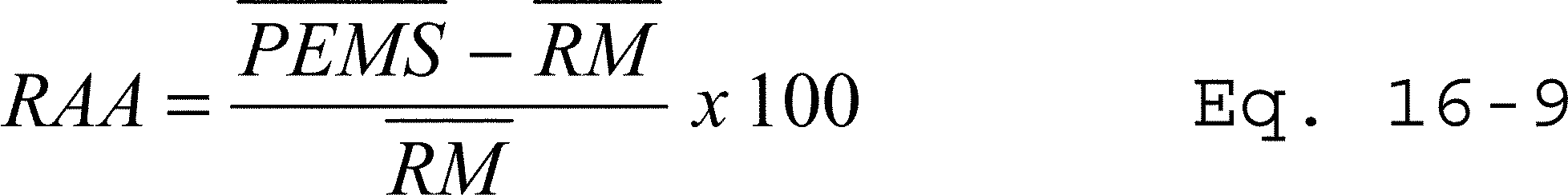
13.0 Method Performance
13.1 PEMS Relative Accuracy. The RA must not exceed 10 percent if the PEMS measurements are greater than 100 ppm or 0.2 lbs/mm Btu. The RA must not exceed 20 percent if the PEMS measurements are between 100 ppm (or 0.2 lb/mm Btu) and 10 ppm (or 0.05 lb/mm Btu). For measurements below 10 ppm, the absolute mean difference between the PEMS measurements and the RM measurements must not exceed 2 pppm. For diluent PEMS, an alternative criterion of ±1 percent absolute difference between the PEMS and RM may be used if less stringent.
13.2 PEMS Bias. Your PEMS data is considered biased and must be adjusted if the arithmetic mean (d) is greater than the absolute value of the confidence coefficient (cc) in Equations 16.1 and 16.3. In such cases, a bias factor must be used to correct your PEMS data.
13.3 PEMS Variance. Your calculated F-value must not be greater than the critical F-value at the 95-percent confidence level for your PEMS to be acceptable.
13.4 PEMS Correlation. Your calculated r-value must be greater than or equal to 0.8 for your PEMS to be acceptable.
13.5 Relative Accuracy Audits. The average of the three portable analyzer or RM determinations must not differ from the simultaneous PEMS average value by more than 10 percent of the analyzer or RM for concentrations greater than 100 ppm or 20 percent for concentrations between 100 and 20 ppm, or the test is failed. For measurements at 20 ppm or less, this difference must not exceed 2 ppm for a pollutant PEMS and 1 percent absolute for a diluents PEMS.
14.0 Pollution Prevention [Reserved]
15.0 Waste Management [Reserved]
16.0 References [Reserved]
17.0 Tables, Diagrams, Flowcharts, and Validation Data
Table 16-1 - t-Values for One-sided, 97.5 Percent Confidence Intervals for Selected Sample Sizes *
| n−1 * | t-value | n−1 | t-value |
|---|---|---|---|
| 1 | 12.706 | 15 | 2.131 |
| 2 | 4.303 | 16 | 2.120 |
| 3 | 3.182 | 17 | 2.110 |
| 4 | 2.776 | 18 | 2.101 |
| 5 | 2.571 | 19 | 2.093 |
| 6 | 2.447 | 20 | 2.086 |
| 7 | 2.365 | 21 | 2.080 |
| 8 | 2.306 | 22 | 2.074 |
| 9 | 2.262 | 23 | 2.069 |
| 10 | 2.228 | 24 | 2.064 |
| 11 | 2.201 | 25 | 2.060 |
| 12 | 2.179 | 26 | 2.056 |
| 13 | 2.160 | 27 | 2.052 |
| 14 | 2.145 | >28 | t-Table |
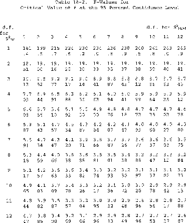
Performance Specification 17 [Reserved]
Performance Specification 18 - Performance Specifications and Test Procedures for Gaseous Hydrogen Chloride (HCI) Continuous Emission Monitoring Systems at Stationary Sources
1.0 Scope and Application
1.1 Analyte. This performance specification (PS) is applicable for measuring gaseous concentrations of hydrogen chloride (HCl), CAS: 7647-01-0, on a continuous basis in the units of the applicable standard or in units that can be converted to units of the applicable standard(s).
1.2 Applicability.
1.2.1 This specification is used to evaluate the acceptability of HCl continuous emission monitoring systems (CEMS) at the time of installation or soon after and whenever specified in the regulations. The specification includes requirements for initial acceptance including instrument accuracy and stability assessments and use of audit samples if they are available.
1.2.2 The Administrator may require the operator, under section 114 of the Clean Air Act, to conduct CEMS performance evaluations at other times besides the initial test to evaluate the CEMS performance. See 40 CFR part 60, §§ 60.13(c) and 63.8(e)(1).
1.2.3 A source that demonstrates their CEMS meets the criteria of this PS may use the system to continuously monitor gaseous HCl under any regulation or permit that requires compliance with this PS. If your CEMS is capable of reporting the HCl concentration in the units of the applicable standard, no additional CEMS components are necessary. If your CEMS does not report concentrations in the units of the existing standard, then other CEMS components (e.g., oxygen (O2), temperature, stack gas flow, moisture and pressure) may be necessary to convert the units reported by your CEMS to the units of the standard.
1.2.4 These specification test results are intended to be valid for the life of the system. As a result, the HCl measurement system must be tested and operated in a configuration consistent with the configuration that will be used for ongoing continuous emissions monitoring.
1.2.5 Substantive changes to the system configuration require retesting according to this PS. Examples of such conditions include, but are not limited to: major changes in dilution ratio (for dilution based systems); changes in sample conditioning and transport, if used, such as filtering device design or materials; changes in probe design or configuration and changes in materials of construction. Changes consistent with instrument manufacturer upgrade that fall under manufacturer's certification do not require additional field verification. Manufacturer's upgrades require recertification by the manufacturer for those requirements allowed by this PS, including interference, level of detection (LOD), and light intensity qualification.
1.2.6 This specification is not designed to evaluate the ongoing CEMS performance nor does it identify specific calibration techniques and auxiliary procedures to assess CEMS performance over an extended period of time. The requirements in appendix F, Procedure 6 are designed to provide a way to assess CEMS performance over an extended period of time. The source owner or operator is responsible to calibrate, maintain, and operate the CEMS properly.
2.0 Summary of Performance Specification
2.1 This specification covers the procedures that each CEMS must meet during the performance evaluation test. Installation and measurement location specifications, data reduction procedures, and performance criteria are included.
2.2 The technology used to measure gaseous HCl must provide a distinct response and address any appropriate interference correction(s). It must accurately measure gaseous HCl in a representative sample (path or point sampling) of stack effluent.
2.3 The relative accuracy (RA) must be established against a reference method (RM) (e.g., Method 26A, Method 320, ASTM International (ASTM) D6348-12, including mandatory annexes, or Method 321 for Portland cement plants as specified by the applicable regulation or, if not specified, as appropriate for the source concentration and category). Method 26 may be approved as a RM by the Administrator on a case-by-case basis if not otherwise allowed or denied in an applicable regulation.
2.4 A standard addition (SA) procedure using a reference standard is included in appendix A to this performance specification for use in verifying LOD. For extractive CEMS, where the SA is done by dynamic spiking (DS), the appendix A procedure is allowed as an option for assessing calibration drift and is also referenced by Procedure 6 of appendix F to this part for ongoing quality control tests.
3.0 Definitions
3.1 Beam attenuation is the reduction in electromagnetic radiation (light) throughput from the maximum beam intensity experienced during site specific CEMS operation.
3.2 Beam intensity is the electromagnetic radiation (light) throughput for an IP-CEMS instrument measured following manufacturers specifications.
3.3 Calibration cell means a gas containment cell used with cross stack or integrated path (IP) CEMS for calibration and to perform many of the test procedures required by this performance specification. The cell may be a removable sealed cell or an evacuated and/or purged cell capable of exchanging reference and other calibration gases as well as zero gas standards. When charged, it contains a known concentration of HCl and/or interference gases. The calibration cell is filled with zero gas or removed from the optical path during stack gas measurement.
3.4 Calibration drift (CD) means the absolute value of the difference between the CEMS output response and an upscale reference gas or a zero-level gas, expressed as a percentage of the span value, when the CEMS is challenged after a stated period of operation during which no unscheduled adjustments, maintenance or repairs took place.
3.5 Centroidal area means a central area that is geometrically similar to the stack or duct cross section and is no greater than 10 percent of the stack or duct cross-sectional area.
3.6 Continuous Emission Monitoring System (CEMS) means the total equipment required to measure the pollutant concentration or emission rate continuously. The system generally consists of the following three major subsystems:
3.6.1 Sample interface means that portion of the CEMS used for one or more of the following: Sample acquisition, sample transport, sample conditioning, defining the optical measurement path, and protection of the monitor from the effects of the stack effluent.
3.6.2 HCl analyzer means that portion of the HCl CEMS that measures the total vapor phase HCl concentration and generates a proportional output.
3.6.3 Data recorder means that portion of the CEMS that provides a permanent electronic record of the analyzer output. The data recorder may record other pertinent data such as effluent flow rates, various instrument temperatures or abnormal CEMS operation. The data recorder may also include automatic data reduction capabilities and CEMS control capabilities.
3.7 Diluent gas means a major gaseous constituent in a gaseous pollutant mixture. For combustion sources, either carbon dioxide (CO2) or oxygen (O2) or a combination of these two gases are the major gaseous diluents of interest.
3.8 Dynamic spiking (DS) means the procedure where a known concentration of HCl gas is injected into the probe sample gas stream for extractive CEMS at a known flow rate to assess the performance of the measurement system in the presence of potential interference from the flue gas sample matrix.
3.9 Independent measurement(s) means the series of CEMS data values taken during sample gas analysis separated by two times the procedure specific response time (RT) of the CEMS.
3.10 Integrated path CEMS (IP-CEMS) means an in-situ CEMS that measures the gas concentration along an optical path in the stack or duct cross section.
3.11 Interference means a compound or material in the sample matrix other than HCl whose characteristics may bias the CEMS measurement (positively or negatively). The interference may not prevent the sample measurement, but could increase the analytical uncertainty in the measured HCl concentration through reaction with HCl or by changing the electronic signal generated during HCl measurement.
3.12 Interference test means the test to detect CEMS responses to interferences that are not adequately accounted for in the calibration procedure and may cause measurement bias.
3.13 Level of detection (LOD) means the lowest level of pollutant that the CEMS can detect in the presence of the source gas matrix interferents with 99 percent confidence.
3.14 Liquid evaporative standard means a reference gas produced by vaporizing National Institute of Standards and Technology (NIST) traceable liquid standards of known HCl concentration and quantitatively diluting the resultant vapor with a carrier gas.
3.15 Measurement error (ME) is the mean difference between the concentration measured by the CEMS and the known concentration of a reference gas standard, divided by the span, when the entire CEMS, including the sampling interface, is challenged.
3.16 Optical path means the route light travels from the light source to the receiver used to make sample measurements.
3.17 Path length means, for an extractive optical CEMS, the distance in meters of the optical path within a gas measurement cell. For an IP-CEMS, path length means the distance in meters of the optical path that passes through the source gas in the stack or duct.
3.18 Point CEMS means a CEMS that measures the source gas concentration, either at a single point at the sampling probe tip or over a path length for IP-CEMS less than 10 percent of the equivalent diameter of the stack or duct cross section.
3.19 Stack pressure measurement device means a NIST-traceable gauge or monitor that measures absolute pressure and conforms to the design requirements of ASME B40.100-2010, “Pressure Gauges and Gauge Attachments” (incorporated by reference - see § 60.17).
3.20 Reference gas standard means a NIST-traceable gas standard containing a known concentration of HCl certified in accordance with an EPA traceability protocol in section 7.1 of this PS.
3.21 Relative accuracy (RA) means the absolute mean difference between the gas concentration or the emission rate determined by the CEMS and the value determined by the RM, plus the confidence coefficient of a series of nine test runs, divided by the average of the RM or the applicable emission standard.
3.22 Response time (RT) means the time it takes for the measurement system, while operating normally at its target sample flow rate, dilution ratio, or data collection rate to respond to a known step change in gas concentration, either from a low- or zero-level to a high-level gas concentration or from a high-level to a low or zero-level gas concentration, and to read 95 percent of the change to the stable instrument response. There may be several RTs for an instrument related to different functions or procedures (e.g., DS, LOD, and ME).
3.23 Span value means an HCl concentration approximately equal to two times the concentration equivalent to the emission standard unless otherwise specified in the applicable regulation, permit or other requirement. Unless otherwise specified, the span may be rounded up to the nearest multiple of 5.
3.24 Standard addition means the addition of known amounts of HCl gas (either statically or dynamically) to the actual measurement path or measured sample gas stream.
3.25 Zero gas means a gas or liquid with an HCl concentration that is below the LOD of the measurement system.
4.0 Interferences
Sample gas interferences will vary depending on the instrument or technology used to make the measurement. Interferences must be evaluated through the interference test in this PS. Several compounds including carbon dioxide (CO2), carbon monoxide (CO), formaldehyde (CH2O), methane (CH4), and water (H2O) are potential optical interferences with certain types of HCl monitoring technology. Ammonia is a potential chemical interference with HCl.
5.0 Safety
The procedures required under this PS may involve hazardous materials, operations, and equipment. This PS may not address all of the safety issues associated with these procedures. It is the responsibility of the user to establish appropriate safety and health practices and determine the applicable regulatory limitations prior to performing these procedures. The CEMS user's manual and materials recommended by the RM should be consulted for specific precautions to be taken.
6.0 Equipment and Supplies
Equipment and supplies for CEMS will vary depending on the measurement technology and equipment vendors. This section provides a description of the equipment and supplies typically found in one or more types of CEMS.
6.1 Sample Extraction System. The portion of an extractive CEMS that collects and transports the sample to the pressure regulation and sample conditioning module. The extraction system must deliver a representative sample to the measurement instrument. The sample extraction system typically consists of a sample probe and a heated umbilical line.
6.2 Sample Conditioning Module. The portion of an extractive CEMS that removes particulate matter and moisture from the gas stream and provides a sample gas stream to the CEMS analysis module or analyzer. You must keep the particle-free gas sample above the dew point temperature of its components.
6.3 HClAnalyzer. The portion of the CEMS that detects, quantifies and generates an output proportional to the sample gas HCl concentration.
6.4 System Controller. The portion of the CEMS that provides control of the analyzer and other sub-systems (e.g., sample extraction, sample conditioning, reference gas) as necessary for continuous operation and periodic maintenance/QC activities.
6.5 Data Recorder. The portion of the CEMS that provides a record of analyzer output. The data recorder may record other pertinent data such as effluent flow rates, various instrument temperatures or abnormal CEMS operation. The data recorder output range must include the full range of expected HCl concentration values in the gas stream to be sampled including zero and span value.
6.6 Reference Gas System(s). Gas handling system(s) needed to introduce reference and other gases into the measurement system. For extractive CEMS, the system must be able to introduce gas flow sufficient to flood the sampling probe and prevent entry of gas from the effluent stream. For IP-CEMS, the system must be able to introduce a known concentration of HCl, at known cell length, pressure and temperature, into the optical path used to measure HCl gas concentration.
6.7 Moisture Measurement System. If correction of the measured HCl emissions for moisture is required, you must install, operate, maintain, and quality assure a continuous moisture monitoring system for measuring and recording the moisture content of the flue gases. The following continuous moisture monitoring systems are acceptable: An FTIR system validated according to Method 301 or section 13.0 of Method 320 in appendix A to part 63 of this chapter; a continuous moisture sensor; an oxygen analyzer (or analyzers) capable of measuring O2 both on a wet basis and on a dry basis; a stack temperature sensor and a moisture look-up table, i.e., a psychrometric chart (for saturated gas streams following wet scrubbers or other demonstrably saturated gas streams, only); or other continuous moisture measurement methods approved by the Administrator. Alternatively, for any type of fuel, you may determine an appropriate site-specific default moisture value (or values), using measurements made with Method 4 - Determination of Moisture Content In Stack Gases, in appendix A-3 to of this part. If this option is selected, the site-specific moisture default value(s) must represent the fuel(s) or fuel blends that are combusted in the unit during normal, stable operation, and must account for any distinct difference(s) in the stack gas moisture content associated with different process operating conditions. At least nine Method 4 runs are required for determining each site-specific default moisture percentage. Calculate each site-specific default moisture value by taking the arithmetic average of the Method 4 runs. Each site-specific moisture default value shall be updated whenever the current value is non-representative, due to changes in unit or process operation, but in any event no less frequently than annually.
7.0 Reagents and Standards
7.1 Reference Gases. Reference gases (e.g., cylinder gases or liquid evaporative standards) used to meet the requirements of this PS must be NIST certified or NIST-traceable and vendor certified to ±5.0 percent accuracy. HCl cylinder gases must be certified according to Reference 5 in section 16 of this PS through a documented unbroken chain of comparisons each contributing to the reported uncertainty. Liquid evaporative standards must be certified using the gravimetrically-based procedures of the latest version of the EPA Traceability Protocol for Qualification and Certification of Evaporative HCl Gas Standards and Humidification of HCl Gas Standards from Cylinders (see EPA-HQ-OAR-2013-0696-0026.pdf).
7.2 Cylinder gas and/or liquid evaporative standards must be used within their certification periods.
7.3 High concentration cylinder gas or liquid evaporative HCl standards may be diluted for use in this specification. You must document the quantitative introduction of HCl standards into the system using Method 205, found in 40 CFR part 51, appendix M, or other procedure approved by the Administrator.
8.0 CEMS Measurement Location Specifications and Pretest Preparation
8.1 Prior to the start of your initial PS tests, you must ensure that the CEMS is installed according to the manufacturer's specifications and the requirements in this section. You may use either point or IP sampling technology.
8.2 CEMS Installation. Install the CEMS at an accessible location where the pollutant concentration or emission rate measurements are directly representative of the HCl emissions or can be corrected so as to be representative of the total emissions from the affected facility. The CEMS need not be installed at the same location as the relative accuracy test location. If you fail the RA requirements in this specification due to the CEMS measurement location and a satisfactory correction technique cannot be established, the Administrator may require the CEMS to be relocated.
8.2.1 Single point sample gas extraction should be
(1) no less than 1.0 m (3.3 ft.) from the stack or duct wall or
(2) within the centroidal area of the stack or duct cross section.
8.2.2 IP-CEMS measurements should (1) be conducted totally within the inner area bounded by a line 1.0 m (3.3 ft.) from the stack or duct wall, (2) have at least 70 percent of the path within the inner 50 percent of the stack or duct cross-sectional area, or (3) be located over any part of the centroidal area.
8.2.2.1 You must measure the IP-CEMS path length from the inner flange of the sampling ports or the inner end of the instrument insertion into the stack cavity using a laser tape measure, mechanical measurement tape, or similar device accurate to ±1.5 mm (0.059 in).
8.2.2.2 You must ensure that any purge flow used to protect IP-CEMS instrument windows from stack gas does not alter the measurement path length. Purge flow of less than or equal to 10 percent of the gas velocity in the duct meets this requirement.
8.2.3 CEMS and Data Recorder Scale Check. After CEMS installation, record and document the measurement range of the HCl CEMS. The CEMS operating range and the range of the data recording device must encompass all potential and expected HCl concentrations, including the concentration equivalent to the applicable emission limit and the span value.
9.0 Quality Control [Reserved]
10.0 Calibration and Standardization [Reserved]
11.0 Performance Specification Test Procedure
After completing the CEMS installation, setup and calibration, you must complete the PS test procedures in this section. You must perform the following procedures and meet the performance requirements for the initial demonstration of your CEMS:
a. Interference Test;
b. Beam Intensity Test (IP-CEMS only);
c. Temperature Verification Procedure (IP-CEMS only);
d. Pressure Verification Procedure (IP-CEMS only);
e. Level of Detection Determination;
f. Response Time Test;
g. Measurement Error Test;
h. Calibration Drift Test; and
i. Relative Accuracy Test.
11.1 Interference Test
11.1.1 Prior to its initial use in the field, you must demonstrate that your monitoring system meets the performance requirements of the interference test in section 13.5 to verify that the candidate system measures HCl accurately in the presence of common interferences in emission matrices.
11.1.2 Your interference test must be conducted in a controlled environment. The equipment you test for interference must include the combination of the analyzer, related analysis software, and any sample conditioning equipment (e.g., dilution module, moisture removal equipment or other interferent scrubber) used to control interferents.
11.1.3 If you own multiple measurement systems with components of the same make and model numbers, you need only perform this interference test on one analyzer and associated interference conditioning equipment combination. You may also rely on an interference test conducted by the manufacturer or a continuous measurement system integrator on a system having components of the same make and model(s) of the system that you use.
11.1.4 Perform the interference check using an HCl reference gas concentration of approximately five times the LOD.
11.1.5 Introduce the interference test gases listed in Table 1 in section 17.0 of this PS to the analyzer/conditioning system separately or in any combination. The interference test gases need not be of reference gas quality.
11.1.5.1 For extractive CEMS, the interference test gases may be introduced directly into the inlet to the analyzer/conditioning system after the probe extension coupling.
11.1.5.2 For IP-CEMS, the interference test gases may be added with the HCl in a calibration cell or separately in a temperature-controlled cell. The effective concentration of the gas in the cell must meet the requirements in Table 1 corrected for absolute pressure, temperature and the nominal stack sampling path length of the CEMS.
11.1.6 The interference test must be performed by combining an HCl reference gas with each interference test gas (or gas mixture). You must measure the baseline HCl response, followed by the response after adding the interference test gas(es) while maintaining a constant HCl concentration. You must perform each interference gas injection and evaluation in triplicate.
The baseline HCl gas may include interference gases at concentrations typical of ambient air (e.g., 21 percent O2, 400 parts per million (ppm) CO2, 2 percent H2O), but these concentrations must be brought to the concentrations listed in Table 1 when their interference effects are being evaluated.
11.1.7 You should document the gas volume/rate, temperature, and pressure used to conduct the interference test. A gas blending system or manifold may be used.
11.1.8 Ensure the duration of each interference test is sufficient to condition the HCl measurement system surfaces before a stable measurement is obtained.
11.1.9 Measure the HCl response of the analyzer/sample conditioning system combination to the test gases in ppmv. Record the responses and determine the overall interference response using Table 2 in section 17.0.
11.1.10 For each interference gas (or mixture), calculate the mean difference (ΔMCavg) between the measurement system responses with and without the interference test gas(es) using Equation 1 in section 12.2. Summarize the results following the format contained in Table 2 in section 17.
11.1.11 Calculate the percent interference (I) for the gas runs using Equation 2 in section 12.2.
11.1.12 The total interference response (i.e., the sum of the interference responses of all tested gaseous components) must not exceed the criteria set forth in section 13.5 of this PS.
11.2 Beam Intensity Test for IP-CEMS
11.2.1 For IP-CEMS, you must establish the tolerance of your system to beam intensity attenuation.
11.2.1.1 Your beam intensity test may be conducted in either a controlled environment or on-site during initial setup and demonstration of your CEMS.
11.2.1.2 If you have multiple measurement systems with components of the same make and model numbers, you need only perform this attenuation check on one system and you may also rely on an attenuation test conducted by the manufacturer on a system having components of the same make and model(s) of the system that you use.
11.2.2 Insert one or more neutral density filter(s) or otherwise attenuate the beam intensity by a known percentage (e.g., 90 percent of the beam intensity).
11.2.3 Perform a high-level HCl reference gas measurement.
11.2.4 Record and report the attenuated beam intensity, the measured HCl calibration gas concentration at full beam intensity, the measured HCl gas concentration with attenuated beam intensity, and the percent difference between the two HCl measurements with and without attenuation of the beam intensity. The percent difference must not exceed the criteria set forth in section 13.6 of this PS.
11.2.5 In the future, you may not operate your IP-CEMS at a beam intensity lower than that established based on the attenuation used during this test. However, you may repeat the test to establish a lower beam intensity limit or level.
11.3 Temperature Measurement Verification Procedure for IP-CEMS
11.3.1 Any measurement instrument or device that is used as a reference in verification of temperature measurement must have an accuracy that is traceable to NIST.
11.3.2 You must verify the temperature sensor used in IP-CEMS measurements on-site as part of the initial installation and verification procedures.
11.3.3 Comparison to Calibrated Temperature Measurement Device.
11.3.3.1 Place the sensor of a calibrated temperature reference device adjacent to the sensor used to measure stack temperature for your IP-CEMS. The calibrated temperature reference device must satisfy the accuracy requirements specified in Table 3 of this PS. The calibrated temperature reference device must also have a range equal to or greater than the range of your IP-CEMS temperature sensor.
11.3.3.2 Allow sufficient time for the response of the calibrated temperature reference device to reach equilibrium. With the process and control device operating under normal conditions, concurrently record the temperatures measured by your IP-CEMS system (Mt) and the calibrated temperature reference device (Vt). You must meet the accuracy requirements specified in section 13.7 of this PS.
11.3.3.3 If your IP-CEMS temperature sensor does not satisfy the accuracy requirement of this PS, check all system components and take any corrective action that is necessary to achieve the required minimum accuracy. Repeat this verification procedure until the accuracy requirement of this specification is satisfied.
11.4 Pressure Measurement Verification Procedure for IP-CEMS
11.4.1 For stack pressure measurement verification, you must select a NIST-traceable gauge or monitor that conforms to the design requirements of ASME B40.100-2010, “Pressure Gauges and Gauge Attachments,” (incorporated by reference - see § 60.17) as a reference device.
11.4.2 As an alternative for a calibrated pressure reference device with NIST-traceable accuracy, you may use a water-in-glass U-tube manometer to verify your IP-CEMS pressure measurement equipment, provided there is also an accurate measurement of absolute atmospheric pressure at the manometer location.
11.4.3 Allow sufficient time for the response of the reference pressure measurement device to reach equilibrium. With the process and control device operating under normal conditions, concurrently record the pressures measured by your IP-CEMS system (MP) and the pressure reference device (Vp). You must meet the accuracy requirements specified in section 13.8 of this PS.
11.4.4 If your IP-CEMS pressure sensor does not satisfy the accuracy requirement of this PS, check all system components and take any corrective action that is necessary to achieve the required minimum accuracy. Repeat this verification procedure until the accuracy requirement of this specification is satisfied.
11.5 Level of Detection Determination
11.5.1 You must determine the minimum amount of HCl that can be detected above the background in a representative gas matrix.
11.5.2 You must perform the LOD determination in a controlled environment such as a laboratory or manufacturer's facility.
11.5.3 You must add interference gases listed in Table 1 of this PS to a constant concentration of HCl reference gas.
11.5.3.1 You may not use an effective reference HCl gas concentration greater than five times the estimated instrument LOD.
11.5.3.2 For extractive CEMS, inject the HCl and interferents described in section 11.1.5 directly into the inlet to the analyzer.
11.5.3.3 For IP-CEMS, the HCl and interference test gases may be added to a calibration cell or separately in a temperature-controlled cell that is part of the measurement path. The effective concentration of the gas in the cell must meet the requirements in Table 1 corrected for absolute pressure, temperature and the nominal stack sampling path length of the CEMS.
11.5.4 Collect seven or more consecutive measurements separated by twice the RT (described in section 11.6) to determine the LOD.
11.5.5 Calculate the standard deviation of the measured values and define the LOD as three times the standard deviation of these measurements.
11.5.5.1 The LOD for extractive units must be determined and reported in ppmv.
11.5.5.2 The LOD for IP units must be determined and reported on a ppm-meter basis and the site- or installation-specific LOD must be calculated based on the actual measurement path length and gas density of the emissions at the specific site installation in ppmv.
11.5.6 You must verify the controlled environment LOD of section 11.5.2 of this PS for your CEMS during initial setup and field certification testing. You must use the SA procedure in appendix A of this PS with the following exceptions:
11.5.6.1 For the LOD verification in the field, you must make three independent SA measurements spiking the native source concentration by no more than three times the controlled environment LOD concentration determined in section 11.5.5.
11.5.6.2 For extractive CEMS, you must perform the SA as a dynamic spike by passing the spiked source gas sample through all filters, scrubbers, conditioners and other monitoring system components used during normal sampling, and as much of the sampling probe as practical. For IP-CEMS, you must perform the SA procedure by adding or passing a known concentration reference gas into a calibration cell in the optical path of the CEMS; you must also include the source measurement optical path while performing the SA measurement.
11.5.6.3 The amount detected, or standard addition response (SAR), is based on the average difference of the native HCl concentration in the stack or duct relative to the native stack concentration plus the SA. You must be able to detect the effective spike addition (ESA) above the native HCl present in the stack gas matrix. For extractive CEMS, the ESA is calculated using Equation A7 in appendix A of this PS. For IP-CEMS, the ESA is calculated as Ci,eff using Equation 4 of this PS.
11.5.6.4 For extractive CEMS, calculate the SAR using Equation A4 in appendix A of this PS. For IP-CEMS, calculate the SAR using Equation A8.
11.5.6.5 If your system LOD field verification does not demonstrate a SAR greater than or equal to your initial controlled environment LOD, you must increase the SA concentration incrementally and repeat the field verification procedure until the SAR is equal to or greater than LOD. The site-specific standard addition detection level (SADL) is equal to the standard addition needed to achieve the acceptable SAR, and SADL replaces the controlled environment LOD. For extractive CEMS, the SADL is calculated as the ESA using Equation A7 in appendix A of this PS. For IP-CEMS, the SADL is the SA calculated using Equation A8 in appendix A of this PS. As described in section 13.1 of this PS, the LOD or the SADL that replaces an LOD must be less than 20 percent of the applicable emission limit.
11.6 Response Time Determination. You must determine ME-, LOD- and SA-RT
11.6.1 For ME- or LOD-RT, start the upscale RT determination by injecting zero gas into the measurement system as required by the procedures in section 11.7 or 11.5, respectively. You may use humidified zero gas. For standard addition RT, start the upscale RT determination by measuring the native stack gas concentration of HCl.
11.6.1.1 For extractive CEMS measuring ME- or LOD-RT, the output has stabilized when there is no change greater than 1.0 percent of full scale for 30 seconds.
11.6.1.2 For standard addition RT that includes the stack gas matrix the final stable response may continue to vary by more than 1 percent, but may be considered stable if the variability is random and not continuously rising or falling.
11.6.2 When the CEMS output has stabilized, record the response in ppmv and introduce an upscale (high level) or spike reference gas as required by the relevant procedure.
11.6.3 Record the time (upscale RT) required to reach 95 percent of the change to the final stable value.
11.6.4 Next, for ME or LOD RT, reintroduce the zero gas and record the time required to reach 95 percent of the change to the stable instrument response at the zero gas reading. For SA RT, introduce zero gas to the IP-CEMS cell or stop the spike gas flow to the extractive CEMS as required by the specified procedure and record the time required to reach 95 percent of the change to the stable instrument response of the native gas reading. This time is the downscale RT.
(Note: For CEMS that perform a series of operations (purge, blow back, sample integration, analyze, etc.), you must start adding reference or zero gas immediately after these procedures are complete.)
11.6.5 Repeat the entire procedure until you have three sets of data, then determine the mean upscale and mean downscale RTs for each relevant procedure. Report the greater of the average upscale or average downscale RTs as the RT for the system.
11.7 Measurement Error (ME) Test
11.7.1 On the same day and as close in time as practicable to when the ME test is conducted, perform and meet requirements for a calibration drift (CD) test using a zero gas as used in the Seven-Day Drift Test (see section 11.8) and document and report the results. To meet this requirement, the ME test may be conducted during the Seven-Day CD Test.
11.7.2 Extractive CEMS ME Test.
11.7.2.1 Introduce reference gases to the CEMS probe, prior to the sample conditioning and filtration system.
11.7.2.2 Measure three upscale HCl reference gas concentrations in the range shown in Table 4 of this PS.
11.7.2.3 Introduce the gases into the sampling probe with sufficient flow rate to replace the entire source gas sample.
11.7.2.4 Continue to add the reference gas until the response is stable as evidenced when the difference between two consecutive measurements is less than the LOD or within five percent of each other.
11.7.2.5 Make triplicate measurements for each reference gas for a total of nine measurements. Introduce different reference gas concentrations in any order but do not introduce the same gas concentration twice in succession.
11.7.2.6 At each reference gas concentration, determine the average of the three CEMS responses (MCl). Calculate the ME using Equation 3A in section 12.3.
11.7.2.7 If you desire to determine the system RT during this test, you must inject zero gas immediately before and after each injection of the high-level gas standard.
11.7.2.8 For non-dilution systems, you may adjust the system to maintain the correct flow rate at the analyzer during the test, but you may not make adjustments for any other purpose. For dilution systems, you must operate the measurement system at the appropriate dilution ratio during all system ME checks, and you may make only the adjustments necessary to maintain the proper ratio.
11.7.3 IP-CEMS ME Test.
11.7.3.1 Conduct a 3-level system ME test by individually adding the known concentrations of HCl reference gases into a calibration cell of known volume, temperature, pressure and path length.
Note: The optical path used for IP-CEMS ME checks must include the native HCl measurement path. You must also collect native stack concentration HCl measurements before and after each HCl standard measurement. Bracketing HCl reference gas measurements with native stack HCl measurements must be used in the calculations in Equation 5 in section 12.4.2 to correct the upscale measurements for stack gas HCl concentration changes.
11.7.3.2 Introduce HCl reference gas into your calibration cell in a range of concentrations that produce responses equivalent to the source concentrations shown in Table 4 of this PS for your path length.
11.7.3.3 Make triplicate measurements for each reference gas standard for a total of nine measurements. Introduce different calibration concentrations in any order but do not introduce the same reference gas concentration twice in succession.
11.7.3.4 You must calculate the effective concentration (Ci,eff) of the HCl reference gas equivalent to the stack concentration by correcting for calibration cell temperature, pressure, path length, line strength factor (LSF) and, if necessary, the native stack gas HCl concentration using Equation 4 in section 12.0.
11.7.3.5 You may use the LSF provided by your instrument manufacturer or determine an instrument-specific LSF as a function of temperature using a heated gas cell and equivalent concentrations (Ci,eff) between 50 and 150 percent of the emission limit.
11.7.3.6 At each reference gas concentration, average the three independent CEMS measurement responses corrected for native HCl stack concentration. Calculate the ME using Equation 6A in section 12.4.3.
11.7.4 You may use Figure 1 in section 17.0 to record and report your ME test results.
11.7.5 If the ME specification in section 13.3 is not met for all three reference gas concentrations, take corrective action and repeat the test until an acceptable 3-level ME test is achieved.
11.8 Seven-Day Calibration Drift (CD) Test
11.8.1 The CD Test Period. Prior to the start of the RA tests, you must perform a seven-day CD test. The purpose of the seven-day CD test is to verify the ability of the CEMS to maintain calibration for each of seven consecutive unit operating days as specified in section 11.8.5 of this PS.
11.8.2 The CD tests must be performed using the zero gas and mid-level reference gas standards as defined in Table 4 of this PS.
11.8.3 Conduct the CD test on each day during continuous operation of the CEMS and normal facility operations following the procedures in section 11.7 of this PS, except that the zero gas and mid-level gas need only be introduced to the measurement system once each.
11.8.4 If periodic automatic or manual adjustments are made to the CEMS zero and upscale response factor settings, conduct the CD test immediately before these adjustments.
Automatic signal or mathematical processing of all measurement data to determine emission results may be performed throughout the entire CD process.
11.8.5 Determine the magnitude of the CD at approximately 24-hour intervals, for 7 consecutive unit operating days. The 7 consecutive unit operating days need not be 7 consecutive calendar days.
11.8.6 Record the CEMS response for single measurements of zero gas and mid-level reference gas. You may use Figure 2 in section 17 of this PS to record and report the results of your 7-day CD test.
11.8.6.1 For extractive CEMS, calculate the CD using Equation 3B in section 12.3. Report the absolute value of the differences as a percentage of the span value.
11.8.6.2 For IP-CEMS, you must include the source measurement optical path while performing the upscale CD measurement; you may exclude the source measurement optical path when determining the zero gas concentration. Calculate the CD for IP CEMS using equations 4, 5, 6B, and 7 in section 12.4.
11.8.7 The zero-level and mid-level CD for each day must be less than 5.0 percent of the span value as specified in section 13.2 of this PS. You must meet this criterion for 7 consecutive operating days.
11.8.8 Dynamic Spiking Option for Seven-Day CD Test. For extractive CEMS, you have the option to conduct a mid-level dynamic spiking procedure for each of the 7 days in lieu of the mid-level reference gas injection described in sections 11.8.2 and 11.8.3. If this option is selected, the daily zero CD check is still required.
11.8.8.1 To conduct each of the seven daily mid-level dynamic spikes, you must use the DS procedure described in appendix A of this PS using a single spike of the mid-level reference gas (see Table 4).
11.8.8.2 You must perform the dynamic spike procedure by passing the spiked source gas sample through all filters, scrubbers, conditioners and other monitoring system components used during normal sampling, and as much of the sampling probe as practical.
11.8.8.3 Calculate the mid-level CD as a percent of span using Equation A6 of appendix A to this PS and calculate the zero drift using Equation 3B in section 12.3. Record and report the results as described in sections 11.8.6 and 11.8.7.
11.9 Relative Accuracy Test
11.9.1 Unless otherwise specified in an applicable regulation, use Method 26A in 40 CFR part 60, appendix A-8, Method 320 in 40 CFR part 63, appendix A, or ASTM D6348-12 including all annexes, as applicable, as the RMs for HCl measurement. Obtain and analyze RM audit samples, if they are available, concurrently with RM test samples according to the same procedure specified for performance tests in the general provisions of the applicable part. If Method 26 is not specified in an applicable subpart of the regulations, you may request approval to use Method 26 in appendix A-8 to this part as the RM on a site-specific basis under §§ 63.7(f) or 60.8(b). Other RMs for moisture, O2, etc., may be necessary. Conduct the RM tests in such a way that they will yield results representative of the emissions from the source and can be compared to the CEMS data.
11.9.1.1 When Method 26A is used as the RM, you must sample sufficient gas to reach three times your method detection limit for Method 26A in 40 CFR part 60, appendix A-8, or for a minimum of one hour, whichever is greater.
11.9.1.2 When Method 320 or Method 321, both found in 40 CFR part 63, appendix A, or ASTM D6348-12, are used as the RM, you must collect gas samples that are at stack conditions (hot and wet) and you must traverse as required in section 11.9.3.
11.9.2 Conduct the diluent (if applicable), moisture (if needed), and pollutant measurements simultaneously. However, diluent and moisture measurements that are taken within an hour of the pollutant measurements may be used to calculate dry pollutant concentration and emission rates.
11.9.3 Reference Method Measurement Location and Traverse Point(s) Selection.
11.9.3.1 Measurement Location. Select, as appropriate, an accessible RM measurement location at least two equivalent diameters downstream from the nearest control device, point of pollutant generation, or other point at which a change in the pollutant concentration or emission rate may occur, and at least one half equivalent diameter upstream from the effluent exhaust or a control device. When pollutant concentration changes are due solely to diluent leakage (e.g., air heater leakages) and pollutants and diluents are simultaneously measured at the same location, a half diameter may be used in lieu of two equivalent diameters. The equivalent duct diameter is calculated according to Method 1 in appendix A-1 to this part. The CEMS and RM sampling locations need not be the same.
11.9.3.2 Traverse Point Selection. Select traverse points that assure acquisition of representative RM samples over the stack or duct cross section according to one of the following options: (a) sample at twelve traverse points located according to section 11.3 of Method 1 in appendix A-1 to this part, (b) sample at 6 Method 1 traverse points according to section 6.5.6(b)(1) of appendix A to part 75 of this chapter, or (c) sample at three points on a measurement line (“3-point long line”) that passes through the centroidal area of the duct in the direction of any potential stratification. If this line interferes with the CEMS measurements, you may displace the line up to 20 cm (12 in.) or 5.0 percent of the equivalent diameter of the cross section, whichever is less, from the centroidal area. Locate the three traverse points at 16.7, 50.0, and 83.3 percent of the measurement line. Alternatively, you may conduct a stratification test following the procedures in sections 11.9.3.2.1 through 11.9.3.2.4 to justify sampling at a single point or three points located on the measurement line at 0.4, 1.2, and 2.0 m from the stack wall (“3-point short line”). Stratification testing must be conducted at the sampling location to be used for the RM measurements during the RA test and must be made during normal facility operating conditions. You must evaluate the stratification by measuring the gas on the same moisture basis as the HCl CEMS (wet or dry). Stratification testing must be repeated for each RA test program to justify single point or “3-point short line” sampling.
11.9.3.2.1 Use a probe of appropriate length to measure the HCl concentration or an alternative analyte, as described in this section, using 12 traverse points located according to section 11.3 of Method 1 in appendix A-1 to 40 CFR part 60 for a circular stack or nine points at the centroids of similarly-shaped, equal area divisions of the cross section of a rectangular stack.
11.9.3.2.2 You may substitute a stratification test for SO2 for the HCl stratification test. If you select this option, you must follow the test procedures in Method 6C of appendix A-4 to 40 CFR part 60 or Method 320 of appendix A of 40 CFR part 63.
11.9.3.2.3 Calculate the mean measured concentration for all sampling points (MNavg).
11.9.3.2.4 Calculate the percent stratification (St) of each traverse point using Equation 8 in section 12.5.
11.9.3.2.5 The gas stream is considered to be unstratified and you may perform the RA testing at a single point that most closely matches the mean if the concentration at each traverse point differs from the mean concentration for all traverse points by: (a) No more than 5.0 percent of the mean concentration; or (b) 0.2 ppm (for HCl) or 3 ppm (for SO2) absolute, whichever is less restrictive.
11.9.3.2.6 If the criterion for single point sampling (5.0 percent, 0.2 ppm for HCl or 3 ppm for SO2 are not met, but the concentration at each traverse point differs from the mean concentration for all traverse points by no more than 10.0 percent of the mean, the gas stream is considered to be minimally stratified, and you may take RA samples using the “3-point short line”. Alternatively, you may use the 3-point short line if each traverse point differs from the mean value by no more than 0.4 ppm (for HCl) or 5 ppm (for SO2).
11.9.3.2.7 If the concentration at any traverse point differs from the mean concentration by more than 10 percent, the gas stream is considered stratified and you must sample using one of the options in section 11.9.3.2 above.
11.9.3.3 Conduct all necessary RM tests within 3 cm (1.2 in.) of the traverse points, but no closer than 3 cm (1.2 in.) to the stack or duct wall.
11.9.4 In order to correlate the CEMS and RM data properly, record the beginning and end of each RM run (including the time of day in hours, minutes, and seconds) using a clock synchronized with the CEM clock used to create a permanent time record with the CEMS output.
11.9.5 You must conduct the RATA during representative process and control operating conditions or as specified in an applicable regulation, permit or subpart.
11.9.6 Conduct a minimum of nine RM test runs. NOTE: More than nine RM test runs may be performed. If this option is chosen, up to three test run results may be excluded so long as the total number of test run results used to determine the CEMS RA is greater than or equal to nine. However, all data must be reported including the excluded test runs.
11.9.7 Analyze the results from the RM test runs using Equations 9-14 in section 12.6. Calculate the RA between the CEMS results and the RM.
11.10 Record Keeping and Reporting
11.10.1 For systems that use a liquid evaporative standard generator to deliver HCl reference gas standards, record supporting data for these devices, including liquid feed calibrations, liquid standard concentration(s) and NIST-traceability, feed rate and gas flow calibrations for all diluent and HCl gas flows. All calibrations must include a stated uncertainty, and the combined uncertainty of the delivered HCl reference gas concentration must be calculated and reported.
11.10.2 Record the results of the CD test, the RT test, the ME test, the RA test, and for IP-CEMS, the results of the beam intensity, temperature and pressure verification procedures. Also keep records of the RM and CEMS field data, calculations, and reference gas certifications necessary to confirm that the performance of the CEMS met the performance specifications.
11.10.3 For systems that use Method 205 to prepare HCl reference gas standards, record results of Method 205 performance test field evaluation, reference gas certifications, and gas dilution system calibration.
11.10.4 Record the LOD for the CEMS. For extractive CEMS, record the LOD in ppmv. For IP-CEMS, record the LOD on a ppm-meter basis along with a calculation of the installation specific LOD in ppmv. For both CEMS types, you must also record the field verified SADL.
11.10.5 Record the results of the interference test.
11.10.6 Report the results of all certification tests to the appropriate regulatory agency (or agencies), in hardcopy and/or electronic format, as required by the applicable regulation or permit.
12.0 Calculations and Data Analysis
12.1 Nomenclature
Ci = Zero or HCl reference gas concentration used for test i (ppmv);
Ci,eff = Equivalent concentration of the reference gas value, Ci, at the specified conditions (ppmv);
CC = Confidence coefficient (ppmv);
CDextractive = Calibration drift for extractive CEMS (percent);
CDIP = Calibration drift for IP-CEMS (percent);
CD0 = Calibration drift at zero HCl concentrations for an IP-CEMS (percent);
davg = Mean difference between CEMS response and the reference gas (ppmv);
di = Difference of CEMS response and the RM value (ppmv);
I = Total interference from major matrix stack gases, (percent);
LSF = Line strength factor for IP-CEMS instrument specific correction for temperature and gas matrix effects derived from the HITRAN and/or manufacturer specific database (unitless);
ΔMCavg = Average of the 3 absolute values of the difference between the measured HCl calibration gas concentrations with and without interference from selected stack gases (ppmv);
MCi = Measured HCl reference gas concentration i (ppmv);
MCi = Average of the measured HCl reference gas concentration i (ppmv);
MCint = Measured HCl concentration of the HCl reference gas plus the individual or combined interference gases (ppmv);
MEextractive = Measurement error for extractive CEMS (percent);
MEIP = Measurement error for IP-CEMS (percent);
MNavg = Average concentration at all sampling points (ppmv);
MNbi = Measured native concentration bracketing each calibration check measurement (ppmv);
MNi = Measured native concentration for test or run I (ppmv);
n = Number of measurements in an average value;
Pstack = Absolute stack pressure (mm Hg)
Preference = Absolute pressure of the calibration cell for IP-CEMS (mm Hg)
PLCell = Path length of IP-CEMS calibration cell (m);
PLStack = Path length of IP-CEMS stack optical path (m);
RA = Relative accuracy of CEMS compared to a RM (percent);
RMi = RM concentration for test run i (ppmv);
RMavg = Mean measured RM value (ppmv);
S = Span value (ppmv);
Sd = Standard deviation of the differences (ppmv);
Sti = Stratification at traverse point i (percent);
SADL = Standard addition detection level (ppmv);
t0.975 = One-sided t-value at the 97.5th percentile obtained from Table 5 in section 17.0 for n-1 measurements;
Treference = Temperature of the calibration cell for IP-CEMS (degrees Kelvin);
Tstack = Temperature of the stack at the monitoring location for IP-CEM (degrees Kelvin).
12.2 Calculate the difference between the measured HCl concentration with and without interferents for each interference gas (or mixture) for your CEMS as:

Calculate the total percent interference as:

12.2.1 Calculate the equivalent concentration Ci,eff using Equation 4:

12.3 Calculate the ME or CD at Concentration i for an Extractive CEMS as:


12.4 Calculate the ME or CD at Concentration i for IP-CEMS That Use a Calibration Cell as Follows:
12.4.1 Calculate the equivalent concentration Ci,eff using Equation 4:

12.4.2 Calculate the average native concentration before and after each calibration check measurement as:

12.4.3 Calculate the ME or CD at concentration i for an IP-CEM as:


12.4.4 Calculate the zero CD as a percent of span for an IP-CEMS as:

12.5 Calculate the Percent Stratification at Each Traverse Point as:
12.6 Calculate the RA Using RM and CEMS Data
12.6.1 Determine the CEMS final integrated minute average pollutant concentration or emission rate for each RM test period. Consider system RT, if important, and confirm that the results have been corrected to the same moisture, temperature and diluent concentration basis.
12.6.2 When Method 26A (or if approved for use, Method 26), found in 40 CFR part 60, appendix A-8 of this part, is used as the RM, compare each CEMS integrated average value against the corresponding RM value for identical test periods. Make these comparisons on the same basis (e.g., wet, dry, ppmv, or units of the standard). To convert results generate by Method 26A or 26 in mg/DSCM to ppmv, use the conversion factor 0.662 ppm/(mg/DSCM).
12.6.3 If the RM is Method 320 or Method 321, found in 40 CFR part 63, appendix A, or ASTM D6348-12, make a direct comparison of the average RM results and CEMS average value for identical test periods.
12.6.4 For each test run, calculate the arithmetic difference of the RM and CEMS results using Equation 9.

12.6.5 Calculate the standard deviation of the differences (Sd) of the CEMS measured and RM results using Equation 10.
12.6.6 Calculate the confidence coefficient (CC) for the RATA using Equation 11.

12.6.7 Calculate the mean difference (davg) between the RM and CEMS values in the units of ppmv or the emission standard using Equation 12.

12.6.8 Calculate the average RM value using Equation 13.

12.6.9 Calculate RA of the CEMS using Equation 14.

13.0 Method Performance
13.1 Level of Detection. You may not use a CEMS whose LOD or SADL is greater than 20 percent of the applicable regulatory limit or other action level for the intended use of the data.
13.2 Calibration Drift. The zero- and mid-level calibration drift for the CEMS must not exceed 5.0 percent of the span value for 7 consecutive operating days.
13.3 Measurement Error. The ME must be less than or equal to 5.0 percent of the span value at the low-, mid-, and high-level reference gas concentrations.
13.4 Relative Accuracy. Unless otherwise specified in an applicable regulation or permit, the RA of the CEMS, whether calculated in units of HCl concentration or in units of the emission standard, must be less than or equal to 20.0 percent of the RM when RMavg is used in the denominator of Equation 14.
13.4.1 In cases where the RA is calculated on a concentration (ppmv) basis, if the average RM emission level for the test is less than 75 percent of the HCl concentration equivalent to the emission standard, you may substitute the HCl concentration equivalent to the standard in the denominator of Equation 14 in place of RMavg.
13.4.2 Similarly, if the RA is calculated in units of the emission standard and the HCl emission level measured by the RMs is less than 75 percent of the emission standard, you may substitute the emission standard in the denominator of Equation 14 in place of RMavg.
13.4.3 The alternative calculated RA in paragraph 13.4.1 or 13.4.2 must be less than or equal to 15.0 percent.
13.5 Interference Test.
13.5.1 The sum of the interference response(s) from Equation 2 must not be greater than 2.5 percent of the calibration span or ±3.0 percent of the equivalent HCl concentration used for the interference test, whichever is less restrictive. The results are also acceptable if the sum of the interference response(s) does not exceed six times the LOD or 0.5 ppmv for a calibration span of 5 to 10 ppm, or 0.2 ppmv for a calibration span of less than 5 ppmv.
13.6 IP-CEMS Beam Intensity Test. For IP-CEMS, the percent difference between the measured concentration with and without attenuation of the light source must not exceed ±3.0 percent.
13.7 IP-CEMS Temperature Measurement Verification. Your temperature sensor satisfies the accuracy required if the absolute relative difference between measured value of stack temperature (Mt) and the temperature value from the calibrated temperature reference device (Vt) is ≤1.0 percent or if the absolute difference between Mt and Vt is ≤2.8 °C (5.0 °F), whichever is less restrictive.
13.8 IP-CEMS Pressure Sensor Measurement Verification. Your pressure sensor satisfies the accuracy required if the absolute relative difference between the measured value of stack pressure (MP) and the pressure value from the calibrated pressure reference device (VP) is ≤5.0 percent or if the absolute difference between Mp and VP is ≤0.12 kilopascals (0.5 inches of water column), whichever is less restrictive.
14.0 Pollution Prevention [Reserved]
15.0 Waste Management [Reserved]
16.0 Bibliography
1. Method 318 - Extractive FTIR Method for the Measurement of Emissions From the Mineral Wool and Wool Fiberglass Industries, 40 CFR, part 63, subpart HHHHHHH, appendix A.
2. “EPA Protocol for the Use of Extractive Fourier Transform Infrared (FTIR) Spectrometry in Analyses of Gaseous Emissions from Stationary Industrial Sources,” February, 1995.
3. “Measurement of Gaseous Organic and Inorganic Emissions by Extractive FTIR Spectroscopy,” EPA Contract No. 68-D2-0165, Work Assignment 3-08.
4. “Method 301 - Field Validation of Pollutant Measurement Methods from Various Waste Media,” 40 CFR part 63, appendix A.
5. EPA Traceability Protocol for Assay and Certification of Gaseous Calibration Standards, U.S. Environmental Protection Agency office of Research and Development, EPA/600/R-12/531, May 2012.
17.0 Tables, Diagrams, Flowcharts, and Validation Data
Table 1 - Interference Test Gas Concentrations
| Potential interferent gas1 | Approximate concentration (balance N2) |
|---|---|
| CO2 | 15% ± 1% CO2.2 |
| CO | 100 ± 20 ppm. |
| CH2O | 20 ± 5 ppm. |
| CH4 | 100 ± 20 ppm. |
| NH3 | 10 ± 5 ppm (extractive CEMS only). |
| NO | 250 ± 50 ppm. |
| SO2 | 200 ± 20 ppm. |
| O2 | 3% ± 1% O2.2 |
| H2O | 10% ± 1% H2O.2 |
| N2 | Balance.2 |

Table 3 - Design Standards for Temperature Sensors
| If the sensor is a . . . | You can use the following design standards as guidance in selecting a sensor for your IP-CEMS |
|---|---|
| 1. Thermocouple | a. ASTM E235-88 (1996), “Specification for Thermocouples, Sheathed, Type K, for Nuclear or Other High-Reliability Applications.” |
| b. ASTM E585/E585M-04, “Specification for Compacted Mineral-Insulated, Metal-Sheathed, Base Metal Thermocouple Cable.” | |
| c. ASTM E608/E608M-06, “Specification for Mineral-Insulated, Metal-Sheathed Base Metal Thermocouples.” | |
| d. ASTM E696-07, “Specification for Tungsten-Rhenium Alloy Thermocouple Wire.” | |
| e. ASTM E1129/E1129M-98 (2002), “Standard Specification for Thermocouple Connectors.” | |
| f. ASTM E1159-98 (2003), “Specification for Thermocouple Materials, Platinum-Rhodium Alloys, and Platinum.” | |
| g. ISA-MC96.1-1982, “Temperature Measurement Thermocouples.” | |
| 2. Resistance temperature detector | ASTM E1137/E1137M-04, “Standard Specification for Industrial Platinum Resistance Thermometers.” |
Table 4 - Performance Specification Test Zero and Reference Gas Ranges
| Test | Units | HCl Zero and Reference Gas Concentrations in Terms of Percent of Spana | Section | |||
|---|---|---|---|---|---|---|
| Zero | Low Level | Mid Level | High Level | |||
| Calibration Drift | % of Span | <LOD | NA | 50-60b | NA | 11.8 |
| Measurement Error | % of Span | NA | 20-30 | 50-60 | 80-100 | 11.7 |
Table 5 - Student's t-Values
| n-1a | t-value | n-1a | t-value | n-1a | t-value |
|---|---|---|---|---|---|
| 1 | 12.71 | 11 | 2.201 | 21 | 2.080 |
| 2 | 4.303 | 12 | 2.179 | 22 | 2.074 |
| 3 | 3.182 | 13 | 2.160 | 23 | 2.069 |
| 4 | 2.776 | 14 | 2.145 | 24 | 2.064 |
| 5 | 2.571 | 15 | 2.131 | 25 | 2.060 |
| 6 | 2.447 | 16 | 2.120 | 26 | 2.056 |
| 7 | 2.365 | 17 | 2.110 | 27 | 2.052 |
| 8 | 2.306 | 18 | 2.101 | 28 | 2.048 |
| 9 | 2.262 | 19 | 2.093 | 29 | 2.045 |
| 10 | 2.228 | 20 | 2.086 | 30 | 2.042 |

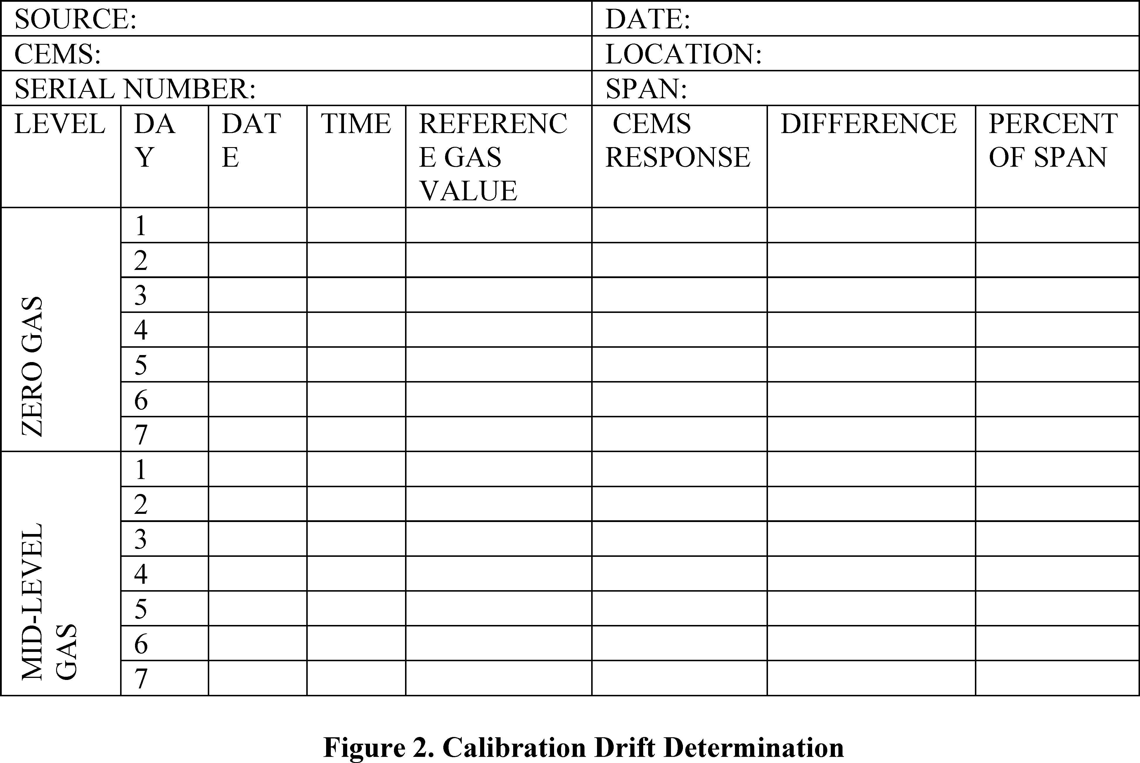
PS-18 Appendix A Standard Addition Procedures
1.0 Scope and Application
1.1 This appendix to Performance Specification (PS) 18 describes the procedure and performance requirements for standard addition (SA) as a quality check for hydrogen chloride (HCl) continuous emission monitoring systems (CEMS).
1.2 This appendix is applicable to quality checks of both extractive and integrated path (IP) technologies used to measure HCl emissions.
1.3 For extractive CEMS, this procedure must be used, as a level of detection (LOD) verification of all field-installed CEMS. Additionally, it is allowed by Procedure 6 in appendix F to this part as an alternative to upscale calibration drift (CD) tests, cylinder gas audits and relative accuracy audits (RAAs), and may be used for quality assurance purposes under other applicable regulations or permits that require HCl monitoring.
1.4 For IP-CEMS, this procedure must be used as a LOD verification of all field-installed CEMS.
2.0 Summary of the Appendix for Standard Addition
As used here, SA is a gas phase method of standard additions (either static or dynamic) used to verify the accuracy of CEMS measurements in the presence of the sample matrix. For extractive CEMS, it consists of spiking a known quantity of HCl dynamically into the measurement system as an addition to the native HCl and the native source gas matrix. For IP-CEMS, this procedure consists of introducing a known quantity of HCl into the optical path that also includes the native source gas.
3.0 Definitions. (See PS-18 and Procedure 6 of Appendix F to Part 60 for the Definitions Used in This Appendix.)
4.0 Interferences. Interferences are discussed in PS-18, section 4.0
5.0 Safety. The procedures required under this appendix may involve hazardous materials, operations and equipment. This procedure may not address all of the safety problems associated with these procedures. You as the facility or operator must establish appropriate safety and health practices and determine the applicable regulatory limitations prior to performing these procedures. As the CEMS user, you should consult instrument operation manuals, material safety data sheets, compressed gas safety requirements, and other Occupational Safety and Health Administration regulations for specific precautions to be taken.
6.0 Equipment and Supplies. An example of equipment and supplies is described in section 6 of PS-18.
7.0 Reagents and Standards. SA materials must meet the requirements defined for reference gases in section 7 of PS-18 to perform this procedure with the following exception. You may use gases certified by the gas vendor to ±5 percent to perform the daily calibration drift assessment in section 4.1 of Procedure 6 in appendix F of this part.
For extractive CEMS the concentrations of reference gases required for SA are likely to be significantly higher than the concentration of reference gases associated with PS-18 requirements.
8.0 Standard Addition and Dynamic Spiking Procedure. The standard addition procedure consists of measuring the native source gas concentration, addition of reference gas, and measurement of the resulting SA elevated source gas concentration. For extractive CEMS, HCl is spiked dynamically and thus, one must account for the dilution of sample gas from the addition of the HCl reference gas. For IP-CEMS, standard addition of an HCl reference gas is made by either adding an HCl reference gas to a flow through cell or inserting a sealed reference gas cell into the measurement path of the CEMS. The enclosed cell or a fixed cell must contain an HCl concentration that accounts for the difference in path length of the cell used for SA relative to the measurement path.
8.1 SA Concentration and Measurement Replicates.
8.1.1 You must inject HCl gas to create a measured concentration based on the requirements of the particular performance test (e.g., LOD verification, CD, DSA).
8.1.2 Each dynamic spike (DS) or standard addition (SA) replicate consists of a measurement of the source emissions concentration of HCl (native stack concentration) with and without the addition of HCl. With a single CEMS, you must alternate the measurement of the native and SA-elevated source gas so that each measurement of SA-elevated source gas is immediately preceded and followed by a measurement of native stack gas. Introduce the SA gases in such a manner that the entire CEMS is challenged. Alternatively, you may use an independent continuous HCl monitor to measure the native source concentration before and after each standard addition as described in section 8.1.4.
8.1.3 Unless specified otherwise by an applicable rule, your SA-elevated concentration may not exceed 100 percent of span when the SA and native HCl concentration are combined.
8.1.4 As an alternative to making background measurements pre- and post-SA, you may use an independent continuous HCl monitor as a temporary unit to measure native stack HCl concentration while simultaneously using the CEMS to measure the SA-elevated source concentration. If you use an independent continuous HCl monitor you must make one concurrent background or native HCl measurement using both the installed CEMS and the independent continuous HCl monitor, immediately before the SA procedure in section 8.2 or 8.3 begins, to confirm that the independent monitoring system measures the same background concentration as the CEMS being qualified with this PS.
8.2 SA Procedure for Extractive CEMS (Dynamic Spiking)
8.2.1 Your HCl spike addition must not alter the total volumetric sample system flow rate or basic dilution ratio of your CEMS (if applicable).
8.2.2 Your spike gas flow rate must not contribute more than 10 percent of the total volumetric flow rate through the CEMS.
8.2.3 You must determine a dilution factor (DF) or relative concentration of HCl for each dynamic spike. Calibrated, NIST-traceable flow meters accurate to within 2.0 percent or highly accurate tracer gas measurements are required to make the necessary DF determinations at the accuracy required for this PS. Calibrated, NIST-traceable flow meters (e.g., venturi, orifice) accurate to within 2.0 percent should be recertified against an NIST-traceable flow meter annually. Note: Since the spiking mass balance calculation is directly dependent on the accuracy of the DF determination, the accuracy of measurements required to determine the total volumetric gas flow rate, spike gas flow rate, or tracer gas standard addition concentration is critical to your ability to accurately perform the DS procedure and calculate the results.
8.2.4 You must monitor and record the total sampling system flow rate and sample dilution factor (DF) for the spiking and stack gas sampling systems to ensure they are known and do not change during the spiking procedure. Record all data on a data sheet similar to Table A1 in section 13 of this appendix.
8.2.4.1 You may either measure the spike gas flow and the total flow with calibrated flow meters capable of NIST traceable accuracy to ±2.0 percent or calculate the flow using a stable tracer gas included in your spike gas standard.
8.2.4.2 If you use flow measurements to determine the spike dilution, then use Equation A1 in section 11.2.1 of this appendix to calculate the DF. Determination of the spike dilution requires measurement of HCl spike flow (Qspike) and total flow through the CEM sampling system (Qprobe).
8.2.4.3 If your CEMS is capable of measuring an independent stable tracer gas, you may use a spike gas that includes the tracer to determine the DF using Equation A2 or A3 (sections 11.2.2 and 11.2.3 of this appendix) depending on whether the tracer gas is also present in the native source emissions.
8.2.4.4 For extractive CEMS, you must correct the background measurements of HCl for the dilution caused by the addition of the spike gas standard. For spiking systems that alternate between addition of HCl and zero gas at a constant DF, the background measurements between spikes will not be equal to the native source concentration.
8.2.5 Begin by collecting unspiked sample measurements of HCl. You must use the average of two unspiked sample measurements as your pre-spike background.
Measurements should agree within 5.0 percent or three times the level of detection to avoid biasing the spike results.
8.2.5.1 Introduce the HCl gas spike into the permanent CEMS probe, upstream of the particulate filter or sample conditioning system and as close to the sampling inlet as practical.
8.2.5.2 Maintain the HCl gas spike for at least twice the DS response time of your CEMS or until the consecutive measurements agree within 5.0 percent. Collect two independent measurements of the native plus spiked HCl concentration.
8.2.5.3 Stop the flow of spike gas for at least twice the DS response time of your CEMS or until the consecutive measurements agree within 5.0 percent. Collect two independent measurements of the native HCl concentration.
8.2.6 Repeat the collection of sample measurements in section 8.2.5 until you have data for each spike concentration including a final set of unspiked sample measurements according to section 8.2.5.3.
8.2.7 Verify that the CEMS responded as expected for each spike gas injection, and that the data quality is not impacted by large shifts in the native source concentration. Discard and repeat any spike injections as necessary to generate a complete set of the required replicate spike measurements.
8.2.8 Calculate the standard addition response (SAR) for extractive CEMS, using Equation A4 in section 11.2, of this appendix.
8.2.9 If the DS results do not meet the specifications for the appropriate performance test in PS-18 or Procedure 6 of appendix F of this part, you must take corrective action and repeat the DS procedure.
8.3 SA Procedure for IP-CEMS (Static Spiking).
8.3.1 For IP-CEMS, you must make measurements of native source gas HCl concentration and an HCl standard addition using a calibration cell added to the optical measurement path.
8.3.2 Introduce zero gas into a calibration cell located in the optical measurement path of the instrument. Continue to flush the zero gas into the cell for at least the SA response time of your CEMS or until two consecutive measurements taken are within 5.0 percent, then collect two independent measurements. Alternatively you may measure native concentrations without the calibration cell in the optical path.
8.3.3 Introduce the HCl spike gas into the calibration cell. Continue to flush the spike gas into the cell for at least the SA response time of your CEMS or until two consecutive measurements taken are within 5.0 percent of one another. Then collect two independent measurements of the SA addition to the native concentration. Alternatively you may insert a sealed calibration cell, containing HCl at the appropriate concentration, into the optical path to measure the SA addition to the native concentration.
8.3.4 Repeat the collection of SA-elevated and native HCl measurements in sections 8.3.2 and 8.3.3 until you have data for each SA concentration. Then, make a final native HCl measurement. The measured concentrations must be corrected for calibration cell and stack temperature, pressure and stack measurement path length.
8.3.5 Calculate the standard addition response (SAR) for an IP-CEMS, using Equation A8 in section 11.3 of this appendix.
8.3.6 If the SA results do not meet the specifications for the appropriate performance test in PS-18 or Procedure 6 of appendix F of this part, you must take corrective action and repeat the SA procedure.
9.0 Quality Control [Reserved]
10.0 Calibration and Standardization [Reserved]
11.0 Calculations and Data Analysis. Calculate the SA response for each measurement and its associated native HCl measurement(s), using equations in this section. (Note: For cases where the emission standard is expressed in units of lb/MMBtu or corrected to a specified O2 or CO2 concentration, an absolute accuracy specification based on a span at stack conditions may be calculated using the average concentration and applicable conversion factors. The appropriate procedures for use in cases where a percent removal standard is more restrictive than the emission standard are the same as in 40 CFR part 60, PS-2, sections 12 and 13.)
11.1 Nomenclature.
Cspike = Actual HCl reference gas concentration spiked (e.g., bottle or reference gas concentration) ppmv;
Ctracer spiked = Tracer gas concentration injected with spike gas (“reference concentration”) ppmv;
DF = Spiked gas dilution factor;
DSCD = Calibration drift determined using DS procedure (percent);
DSE = Dynamic spike error (ppmv);
ESA = Effective spike addition (ppmv);
MCSA = Measured SA-elevated source gas concentration (ppmv);
MCspiked = Measured HCl reference gas concentration i (ppmv);
MCnative = Average measured concentration of the native HCl (ppmv);
Mnative tracer = Measured tracer gas concentration present in native effluent gas (ppmv);
Mspiked tracer = Measured diluted tracer gas concentration in a spiked sample (ppmv);
Qspike = Flow rate of the dynamic spike gas (Lpm);
Qprobe = Average total stack sample flow through the system (Lpm);
S = Span (ppmv);
SAR = Standard addition response (ppmv)
11.2 Calculating Dynamic Spike Response and Error for Extractive CEMS.
11.2.1 If you determine your spike DF using spike gas and stack sample flow measurements, calculate the DF using equation A1:
11.2.2 If you determine your spike DF using an independent stable tracer gas that is not present in the native source emissions, calculate the DF for DS using equation A2:

11.2.3 If you determine your spike dilution factor using an independent stable tracer that is present in the native source emissions, calculate the dilution factor for dynamic spiking using equation A3:

11.2.4 Calculate the SA response using Equation A4:

11.2.5 Calculate the DS error using Equation A5.

11.2.6 Calculating CD using DS. When using the DS option for determining mid-level CD, calculate the CD as a percent of span using equation A6:

11.2.7 The effective spike addition (ESA) is the expected increase in the measured concentration as a result of injecting a spike. Calculate ESA using Equation A7:
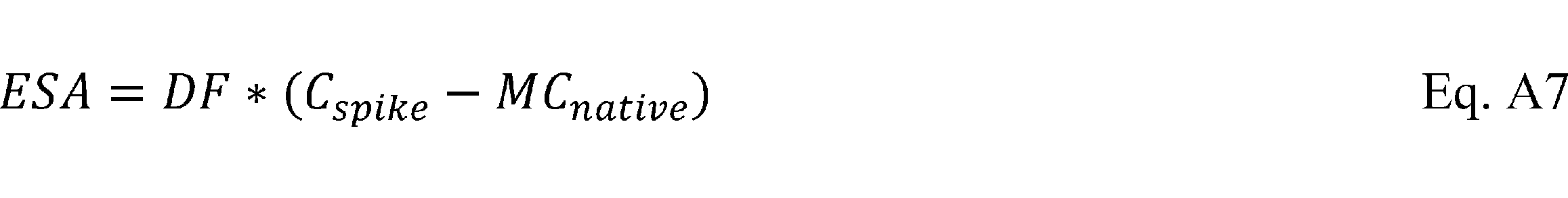
11.3 Standard Addition Response for IP-CEMS. If you use an IP-CEMS and a calibration cell, calculate the SA response using Equation A8.
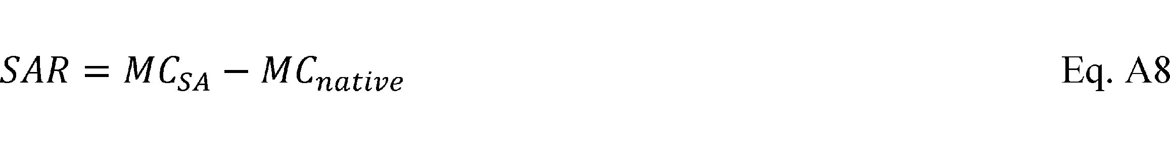
12.0 [Reserved]
13. Tables and Figures.

[48 FR 13327, Mar. 30, 1983 and 48 FR 23611, May 25, 1983]
Appendix C to Part 60—Determination of Emission Rate Change
1. Introduction
1.1 The following method shall be used to determine whether a physical or operational change to an existing facility resulted in an increase in the emission rate to the atmosphere. The method used is the Student's t test, commonly used to make inferences from small samples.
2. Data
2.1 Each emission test shall consist of n runs (usually three) which produce n emission rates. Thus two sets of emission rates are generated, one before and one after the change, the two sets being of equal size.
2.2 When using manual emission tests, except as provided in § 60.8(b) of this part, the reference methods of appendix A to this part shall be used in accordance with the procedures specified in the applicable subpart both before and after the change to obtain the data.
2.3 When using continuous monitors, the facility shall be operated as if a manual emission test were being performed. Valid data using the averaging time which would be required if a manual emission test were being conducted shall be used.
3. Procedure
3.1 Subscripts a and b denote prechange and postchange respectively.
3.2 Calculate the arithmetic mean emission rate, E, for each set of data using Equation 1.

Where:
Ei = Emission rate for the i th run.
n = number of runs.
3.3 Calculate the sample variance, S2, for each set of data using Equation 2.

3.4 Calculate the pooled estimate, Sp, using Equation 3.

3.5 Calculate the test statistic, t, using Equation 4.

4. Results
4.1 If Eb>,Ea and t>t′, where t′ is the critical value of t obtained from Table 1, then with 95% confidence the difference between Eb and Ea is significant, and an increase in emission rate to the atmosphere has occurred.
Table 1
| Degrees of freedom (na=nb−2) | t′ (95 percent confidence level) |
|---|---|
| 2 | 2.920 |
| 3 | 2.353 |
| 4 | 2.132 |
| 5 | 2.015 |
| 6 | 1.943 |
| 7 | 1.895 |
| 8 | 1.860 |
For greater than 8 degrees of freedom, see any standard statistical handbook or text.
5.1 Assume the two performance tests produced the following set of data:
| Test a | Test b |
|---|---|
| Run 1. 100 | 115 |
| Run 2. 95 | 120 |
| Run 3. 110 | 125 |
5.2 Using Equation 1—
Ea = 100 + 95 + 110/3 = 102
Eb = 115 + 120 + 125/3 = 120
5.3 Using Equation 2—
Sa 2 = (100−102)2 + (95−102)2 + (110−102)2/3−1 = 58.5
Sb 2 = (115−120)2 + (120−120)2 + (125−120)2/3−1 = 25
5.4 Using Equation 3—
Sp = [(3 − 1)(58.5) + (3 + 1)(25) / 3 + 3 − 2] 1⁄2 = 6.46
5.5 Using Equation 4—

5.6 Since (n1 + n2 − 2) = 4, t′ = 2.132 (from Table 1). Thus since t>t′ the difference in the values of Ea and Eb is significant, and there has been an increase in emission rate to the atmosphere.
6. Continuous Monitoring Data
6.1 Hourly averages from continuous monitoring devices, where available, should be used as data points and the above procedure followed.
[40 FR 58420, Dec. 16, 1975]
Appendix D to Part 60—Required Emission Inventory Information
(a) Completed NEDS point source form(s) for the entire plant containing the designated facility, including information on the applicable criteria pollutants. If data concerning the plant are already in NEDS, only that information must be submitted which is necessary to update the existing NEDS record for that plant. Plant and point identification codes for NEDS records shall correspond to those previously assigned in NEDS; for plants not in NEDS, these codes shall be obtained from the appropriate Regional Office.
(b) Accompanying the basic NEDS information shall be the following information on each designated facility:
(1) The state and county identification codes, as well as the complete plant and point identification codes of the designated facility in NEDS. (The codes are needed to match these data with the NEDS data.)
(2) A description of the designated facility including, where appropriate:
(i) Process name.
(ii) Description and quantity of each product (maximum per hour and average per year).
(iii) Description and quantity of raw materials handled for each product (maximum per hour and average per year).
(iv) Types of fuels burned, quantities and characteristics (maximum and average quantities per hour, average per year).
(v) Description and quantity of solid wastes generated (per year) and method of disposal.
(3) A description of the air pollution control equipment in use or proposed to control the designated pollutant, including:
(i) Verbal description of equipment.
(ii) Optimum control efficiency, in percent. This shall be a combined efficiency when more than one device operates in series. The method of control efficiency determination shall be indicated (e.g., design efficiency, measured efficiency, estimated efficiency).
(iii) Annual average control efficiency, in percent, taking into account control equipment down time. This shall be a combined efficiency when more than one device operates in series.
(4) An estimate of the designated pollutant emissions from the designated facility (maximum per hour and average per year). The method of emission determination shall also be specified (e.g., stack test, material balance, emission factor).
[40 FR 53349, Nov. 17, 1975]
Appendix E to Part 60 [Reserved]
Appendix F to Part 60 - Quality Assurance Procedures
Procedure 1. Quality Assurance Requirements for Gas Continuous Emission Monitoring Systems Used for Compliance Determination
1. Applicability and Principle
1.1 Applicability. Procedure 1 is used to evaluate the effectiveness of quality control (QC) and quality assurance (QA) procedures and the quality of data produced by any continuous emission monitoring system (CEMS) that is used for determining compliance with the emission standards on a continuous basis as specified in the applicable regulation. The CEMS may include pollutant (e.g., S02 and N0x) and diluent (e.g., 02 or C02) monitors.
This procedure specifies the minimum QA requirements necessary for the control and assessment of the quality of CEMS data submitted to the Environmental Protection Agency (EPA). Source owners and operators responsible for one or more CEMS's used for compliance monitoring must meet these minimum requirements and are encouraged to develop and implement a more extensive QA program or to continue such programs where they already exist.
Data collected as a result of QA and QC measures required in this procedure are to be submitted to the Agency. These data are to be used by both the Agency and the CEMS operator in assessing the effectiveness of the CEMS QC and QA procedures in the maintenance of acceptable CEMS operation and valid emission data.
Appendix F, Procedure 1 is applicable December 4, 1987. The first CEMS accuracy assessment shall be a relative accuracy test audit (RATA) (see section 5) and shall be completed by March 4, 1988 or the date of the initial performance test required by the applicable regulation, whichever is later.
1.2 Principle. The QA procedures consist of two distinct and equally important functions. One function is the assessment of the quality of the CEMS data by estimating accuracy. The other function is the control and improvement of the quality of the CEMS data by implementing QC policies and corrective actions. These two functions form a control loop: When the assessment function indicates that the data quality is inadequate, the control effort must be increased until the data quality is acceptable. In order to provide uniformity in the assessment and reporting of data quality, this procedure explicitly specifies the assessment methods for response drift and accuracy. The methods are based on procedures included in the applicable performance specifications (PS's) in appendix B of 40 CFR part 60. Procedure 1 also requires the analysis of the EPA audit samples concurrent with certain reference method (RM) analyses as specified in the applicable RM's.
Because the control and corrective action function encompasses a variety of policies, specifications, standards, and corrective measures, this procedure treats QC requirements in general terms to allow each source owner or operator to develop a QC system that is most effective and efficient for the circumstances.
2. Definitions
2.1 Continuous Emission Monitoring System. The total equipment required for the determination of a gas concentration or emission rate.
2.2 Diluent Gas. A major gaseous constituent in a gaseous pollutant mixture. For combustion sources, CO2 and O2 are the major gaseous constituents of interest.
2.3 Span Value. The upper limit of a gas concentration measurement range that is specified for affected source categories in the applicable subpart of the regulation.
2.4 Zero, Low-Level, and High-Level Values. The CEMS response values related to the source specific span value. Determination of zero, low-level, and high-level values is defined in the appropriate PS in appendix B of this part.
2.5 Calibration Drift (CD). The difference in the CEMS output reading from a reference value after a period of operation during which no unscheduled maintenance, repair or adjustment took place. The reference value may be supplied by a cylinder gas, gas cell, or optical filter and need not be certified.
2.6 Relative Accuracy (RA). The absolute mean difference between the gas concentration or emission rate determined by the CEMS and the value determined by the RM's plus the 2.5 percent error confidence coefficient of a series of tests divided by the mean of the RM tests or the applicable emission limit.
3. QC Requirements
Each source owner or operator must develop and implement a QC program. As a minimum, each QC program must include written procedures which should describe in detail, complete, step-by-step procedures and operations for each of the following activities:
1. Calibration of CEMS.
2. CD determination and adjustment of CEMS.
3. Preventive maintenance of CEMS (including spare parts inventory).
4. Data recording, calculations, and reporting.
5. Accuracy audit procedures including sampling and analysis methods.
6. Program of corrective action for malfunctioning CEMS.
As described in section 5.2, whenever excessive inaccuracies occur for two consecutive quarters, the source owner or operator must revise the current written procedures or modify or replace the CEMS to correct the deficiency causing the excessive inaccuracies.
These written procedures must be kept on record and available for inspection by the enforcement agency.
4. CD Assessment
4.1 CD Requirement. As described in 40 CFR 60.13(d), source owners and operators of CEMS must check, record, and quantify the CD at two concentration values at least once daily (approximately 24 hours) in accordance with the method prescribed by the manufacturer. The CEMS calibration must, as minimum, be adjusted whenever the daily zero (or low-level) CD or the daily high-level CD exceeds two times the limits of the applicable PS's in appendix B of this regulation.
4.2 Recording Requirement for Automatic CD Adjusting Monitors. Monitors that automatically adjust the data to the corrected calibration values (e.g., microprocessor control) must be programmed to record the unadjusted concentration measured in the CD prior to resetting the calibration, if performed, or record the amount of adjustment.
4.3 Criteria for Excessive CD. If either the zero (or low-level) or high-level CD result exceeds twice the applicable drift specification in appendix B for five, consecutive, daily periods, the CEMS is out-of-control. If either the zero (or low-level) or high-level CD result exceeds four times the applicable drift specification in appendix B during any CD check, the CEMS is out-of-control. If the CEMS is out-of-control, take necessary corrective action. Following corrective action, repeat the CD checks.
4.3.1 Out-Of-Control Period Definition. The beginning of the out-of-control period is the time corresponding to the completion of the fifth, consecutive, daily CD check with a CD in excess of two times the allowable limit, or the time corresponding to the completion of the daily CD check preceding the daily CD check that results in a CD in excess of four times the allowable limit. The end of the out-of-control period is the time corresponding to the completion of the CD check following corrective action that results in the CD's at both the zero (or low-level) and high-level measurement points being within the corresponding allowable CD limit (i.e., either two times or four times the allowable limit in appendix B).
4.3.2 CEMS Data Status During Out-of-Control Period. During the period the CEMS is out-of-control, the CEMS data may not be used in calculating emission compliance nor be counted towards meeting minimum data availability as required and described in the applicable subpart [e.g., § 60.47a(f)].
4.4 Data Recording and Reporting. As required in § 60.7(d) of this regulation (40 CFR part 60), all measurements from the CEMS must be retained on file by the source owner for at least 2 years. However, emission data obtained on each successive day while the CEMS is out-of-control may not be included as part of the minimum daily data requirement of the applicable subpart [e.g., § 60.47a(f)] nor be used in the calculation of reported emissions for that period.
5. Data Accuracy Assessment
5.1 Auditing Requirements. Each CEMS must be audited at least once each calendar quarter. Successive quarterly audits shall occur no closer than 2 months. The audits shall be conducted as follows:
5.1.1 Relative Accuracy Test Audit (RATA). The RATA must be conducted at least once every four calendar quarters, except as otherwise noted in section 5.1.4 of this appendix. Conduct the RATA as described for the RA test procedure in the applicable PS in appendix B (e.g., PS 2 for SO2 and NOX). In addition, analyze the appropriate performance audit samples received from EPA as described in the applicable sampling methods (e.g., Methods 6 and 7).
5.1.2 Cylinder Gas Audit (CGA). If applicable, a CGA may be conducted in three of four calendar quarters, but in no more than three quarters in succession.
To conduct a CGA: (1) Challenge the CEMS (both pollutant and diluent portions of the CEMS, if applicable) with an audit gas of known concentration at two points within the following ranges:
| Audit point | Audit range | ||
|---|---|---|---|
| Pollutant monitors | Diluent monitors for - | ||
| CO2 | O2 | ||
| 1 | 20 to 30% of span value | 5 to 8% by volume | 4 to 6% by volume. |
| 2 | 50 to 60% of span value | 10 to 14% by volume | 8 to 12% by volume. |
Introduce each of the audit gases, three times each for a total of six challenges. Introduce the gases in such a manner that the entire CEMS is challenged. Do not introduce the same gas concentration twice in succession.
Use of separate audit gas cylinder for audit points 1 and 2. Do not dilute gas from audit cylinder when challenging the CEMS.
The monitor should be challenged at each audit point for a sufficient period of time to assure adsorption-desorption of the CEMS sample transport surfaces has stabilized.
(2) Operate each monitor in its normal sampling mode, i.e., pass the audit gas through all filters, scrubbers, conditioners, and other monitor components used during normal sampling, and as much of the sampling probe as is practical. At a minimum, the audit gas should be introduced at the connection between the probe and the sample line.
(3) Use Certified Reference Materials (CRM's) (See Citation 1) audit gases that have been certified by comparison to National Institute of Standards and Technology (NIST) Standard Reference Materials (SRM's) or EPA Protocol Gases following the most recent edition of the EPA Traceability Protocol for Assay and Certification of Gaseous Calibration Standards (See Citation 2). Procedures for preparation of CRM's are described in Citation 1. Procedures for preparation of EPA Protocol Gases are described in Citation 2. In the case that a suitable audit gas level is not commercially available, Method 205 (See Citation 3) may be used to dilute CRM's or EPA Protocol Gases to the needed level. The difference between the actual concentration of the audit gas and the concentration indicated by the monitor is used to assess the accuracy of the CEMS.
5.1.3 Relative Accuracy Audit (RAA). The RAA may be conducted three of four calendar quarters, but in no more than three quarters in succession. To conduct a RAA, follow the procedure described in the applicable PS in appendix B for the relative accuracy test, except that only three sets of measurement data are required. Analyses of EPA performance audit samples are also required.
The relative difference between the mean of the RM values and the mean of the CEMS responses will be used to assess the accuracy of the CEMS.
5.1.4 Other Alternative Audits. Other alternative audit procedures may be used as approved by the Administrator for three of four calendar quarters. One RATA is required at least every four calendar quarters, except in the case where the affected facility is off-line (does not operate) in the fourth calendar quarter since the quarter of the previous RATA. In that case, the RATA shall be performed in the quarter in which the unit recommences operation. Also, cylinder gas audits are not be required for calendar quarters in which the affected facility does not operate.
5.2 Excessive Audit Inaccuracy. If the RA, using the RATA, CGA, or RAA exceeds the criteria in section 5.2.3, the CEMS is out-of-control. If the CEMS is out-of-control, take necessary corrective action to eliminate the problem. Following corrective action, the source owner or operator must audit the CEMS with a RATA, CGA, or RAA to determine if the CEMS is operating within the specifications. A RATA must always be used following an out-of-control period resulting from a RATA. The audit following corrective action does not require analysis of EPA performance audit samples. If audit results show the CEMS to be out-of-control, the CEMS operator shall report both the audit showing the CEMS to be out-of-control and the results of the audit following corrective action showing the CEMS to be operating within specifications.
5.2.1 Out-Of-Control Period Definition. The beginning of the out-of-control period is the time corresponding to the completion of the sampling for the RATA, RAA, or CGA. The end of the out-of-control period is the time corresponding to the completion of the sampling of the subsequent successful audit.
5.2.2 CEMS Data Status During Out-Of-Control Period. During the period the monitor is out-of-control, the CEMS data may not be used in calculating emission compliance nor be counted towards meeting minimum data availabilty as required and described in the applicable subpart [e.g., § 60.47a(f)].
5.2.3 Criteria for Excessive Audit Inaccuracy. Unless specified otherwise in the applicable subpart, the criteria for excessive inaccuracy are:
(1) For the RATA, the allowable RA in the applicable PS in appendix B.
(2) For the CGA, ±15 percent of the average audit value or ±5 ppm, whichever is greater; for diluent monitors, ±15 percent of the average audit value.
(3) For the RAA, ±15 percent of the three run average or ±7.5 percent of the applicable standard, whichever is greater.
5.3 Criteria for Acceptable QC Procedure. Repeated excessive inaccuracies (i.e., out-of-control conditions resulting from the quarterly audits) indicates the QC procedures are inadequate or that the CEMS is incapable of providing quality data. Therefore, whenever excessive inaccuracies occur for two consective quarters, the source owner or operator must revise the QC procedures (see section 3) or modify or replace the CEMS.
6. Calculations for CEMS Data Accuracy
6.1 RATA RA Calculation. Follow the equations described in section 8 of appendix B, PS 2 to calculate the RA for the RATA. The RATA must be calculated in units of the applicable emission standard (e.g., ng/J).
6.2 RAA Accuracy Calculation. Use the calculation procedure in the relevant performance specification to calculate the accuracy for the RAA. The RAA must be calculated in the units of the applicable emission standard.
6.3 CGA Accuracy Calculation. Use Equation 1-1 to calculate the accuracy for the CGA, which is calculated in units of the appropriate concentration (e.g., ppm SO2 or percent O2). Each component of the CEMS must meet the acceptable accuracy requirement.

where:
A = Accuracy of the CEMS, percent.
Cm = Average CEMS response during audit in units of applicable standard or appropriate concentration.
Ca = Average audit value (CGA certified value or three-run average for RAA) in units of applicable standard or appropriate concentration.
6.4 Example Accuracy Calculations. Example calculations for the RATA, RAA, and CGA are available in Citation 3.
7. Reporting Requirements
At the reporting interval specified in the applicable regulation, report for each CEMS the accuracy results from section 6 and the CD assessment results from section 4. Report the drift and accuracy information as a Data Assessment Report (DAR), and include one copy of this DAR for each quarterly audit with the report of emissions required under the applicable subparts of this part.
As a minimum, the DAR must contain the following information:
1. Source owner or operator name and address.
2. Identification and location of monitors in the CEMS.
3. Manufacturer and model number of each monitor in the CEMS.
4. Assessment of CEMS data accuracy and date of assessment as determined by a RATA, RAA, or CGA described in section 5 including the RA for the RATA, the A for the RAA or CGA, the RM results, the cylinder gases certified values, the CEMS responses, and the calculations results as defined in section 6. If the accuracy audit results show the CEMS to be out-of-control, the CEMS operator shall report both the audit results showing the CEMS to be out-of-control and the results of the audit following corrective action showing the CEMS to be operating within specifications.
5. Results from EPA performance audit samples described in section 5 and the applicable RM's.
6. Summary of all corrective actions taken when CEMS was determined out-of-control, as described in sections 4 and 5.
An example of a DAR format is shown in Figure 1.
8. Bibliography
1. “A Procedure for Establishing Traceability of Gas Mixtures to Certain National Bureau of Standards Standard Reference Materials.” Joint publication by NBS and EPA-600/7-81-010, Revised 1989. Available from the U.S. Environmental Protection Agency. Quality Assurance Division (MD-77). Research Triangle Park, NC 27711.
2. “EPA Traceability Protocol For Assay And Certification Of Gaseous Calibration Standards.” EPA-600/R-97/121, September 1997. Available from EPA's Emission Measurement Center at http://www.epa.gov/ttn/emc.
3. Method 205, “Verification of Gas Dilution Systems for Field Instrument Calibrations,” 40 CFR 51, appendix M.
Figure 1 - Example Format for Data Assessment Report
Period ending date
Year
Company name
Plant name
Source unit no.
CEMS manufacturer
Model no.
CEMS serial no.
CEMS type (e.g., in situ)
CEMS sampling location (e.g., control device outlet)
CEMS span values as per the applicable regulation: ______ (e.g., SO2 ____ ppm, NOX ____ ppm). ________
I. Accuracy assessment results (Complete A, B, or C below for each CEMS or for each pollutant and diluent analyzer, as applicable.) If the quarterly audit results show the CEMS to be out-of-control, report the results of both the quarterly audit and the audit following corrective action showing the CEMS to be operating properly.
A. Relative accuracy test audit (RATA) for ____ (e.g., SO2 in ng/J).
1. Date of audit ____.
2. Reference methods (RM's) used ____ (e.g., Methods 3 and 6).
3. Average RM value ____ (e.g., ng/J, mg/dsm3, or percent volume).
4. Average CEMS value ____.
5. Absolute value of mean difference [d] ____.
6. Confidence coefficient [CC] ____.
7. Percent relative accuracy (RA) ____ percent.
8. EPA performance audit results:
a. Audit lot number
(1) ____
(2) ____
b. Audit sample number
(1) ____
(2) ____
c. Results (mg/dsm3)
(1) ____
(2) ____
d. Actual value (mg/dsm3)*
(1) ____
(2) ____
e. Relative error*
(1) ____
(2) ____
B. Cylinder gas audit (CGA) for ____ (e.g., SO2 in ppm).
| Audit point 1 | Audit point 2 | ||
|---|---|---|---|
| 1. Date of audit | |||
| 2. Cylinder ID number | |||
| 3. Date of certification | |||
| 4. Type of certification | (e.g., EPA Protocol 1 or CRM). | ||
| 5. Certified audit value | (e.g., ppm). | ||
| 6. CEMS response value | (e.g., ppm). | ||
| 7. Accuracy | percent. |
C. Relative accuracy audit (RAA) for ____ (e.g., SO2 in ng/J).
1. Date of audit ____.
2. Reference methods (RM's) used ____ (e.g., Methods 3 and 6).
3. Average RM value ____ (e.g., ng/J).
4. Average CEMS value ____.
5. Accuracy ____ percent.
6. EPA performance audit results:
a. Audit lot number
(1) ____
(2) ____
b. Audit sample number
(1) ____
(2) ____
c. Results (mg/dsm3)
(1) ____
(2) ____
d. Actual value (mg/dsm3) *(1) ____ (2)
e. Relative error*
(1) ____
(2) ____
D. Corrective action for excessive inaccuracy.
1. Out-of-control periods.
a. Date(s) ____.
b. Number of days ____.
2. Corrective action taken
3. Results of audit following corrective action. (Use format of A, B, or C above, as applicable.)
II. Calibration drift assessment.
A. Out-of-control periods.
1. Date(s) ____.
2. Number of days ____.
B. Corrective action taken
Procedure 2 - Quality Assurance Requirements for Particulate Matter Continuous Emission Monitoring Systems at Stationary Sources
1.0 What Are the Purpose and Applicability of Procedure 2?
The purpose of Procedure 2 is to establish the minimum requirements for evaluating the effectiveness of quality control (QC) and quality assurance (QA) procedures and the quality of data produced by your particulate matter (PM) continuous emission monitoring system (CEMS). Procedure 2 applies to PM CEMS used for continuously determining compliance with emission standards or operating permit limits as specified in an applicable regulation or permit. Other QC procedures may apply to diluent (e.g., O2) monitors and other auxiliary monitoring equipment included with your CEMS to facilitate PM measurement or determination of PM concentration in units specified in an applicable regulation.
1.1 What measurement parameter does Procedure 2 address? Procedure 2 covers the instrumental measurement of PM as defined by your source's applicable reference method (no Chemical Abstract Service number assigned).
1.2 For what types of devices must I comply with Procedure 2? You must comply with Procedure 2 for the total equipment that:
(1) We require you to install and operate on a continuous basis under the applicable regulation, and
(2) You use to monitor the PM mass concentration associated with the operation of a process or emission control device.
1.3 What are the data quality objectives (DQOs) of Procedure 2? The overall DQO of Procedure 2 is the generation of valid, representative data that can be transferred into useful information for determining PM CEMS concentrations averaged over a prescribed interval. Procedure 2 is also closely associated with Performance Specification 11 (PS-11).
(1) Procedure 2 specifies the minimum requirements for controlling and assessing the quality of PM CEMS data submitted to us or the delegated permitting authority.
(2) You must meet these minimum requirements if you are responsible for one or more PM CEMS used for compliance monitoring. We encourage you to develop and implement a more extensive QA program or to continue such programs where they already exist.
1.4 What is the intent of the QA/QC procedures specified in Procedure 2? Procedure 2 is intended to establish the minimum QA/QC requirements for PM CEMS and is presented in general terms to allow you to develop a program that is most effective for your circumstances. You may adopt QA/QC procedures that go beyond these minimum requirements to ensure compliance with applicable regulations.
1.5 When must I comply with Procedure 2? You must comply with the basic requirements of Procedure 2 immediately following successful completion of the initial correlation test of PS-11.
2.0 What Are the Basic Requirements of Procedure 2?
Procedure 2 requires you to perform periodic evaluations of PM CEMS performance and to develop and implement QA/QC programs to ensure that PM CEMS data quality is maintained.
2.1 What are the basic functions of Procedure 2?
(1) Assessment of the quality of your PM CEMS data by estimating measurement accuracy;
(2) Control and improvement of the quality of your PM CEMS data by implementing QC requirements and corrective actions until the data quality is acceptable; and
(3) Specification of requirements for daily instrument zero and upscale drift checks and daily sample volume checks, as well as routine response correlation audits, absolute correlation audits, sample volume audits, and relative response audits.
3.0 What Special Definitions Apply to Procedure 2?
The definitions in Procedure 2 include those provided in PS-11 of Appendix B, with the following additions:
3.1 “Absolute Correlation Audit (ACA)” means an evaluation of your PM CEMS response to a series of reference standards covering the full measurement range of the instrument (e.g., 4 mA to 20 mA).
3.2 “Correlation Range” means the range of PM CEMS responses used in the complete set of correlation test data.
3.3 “PM CEMS Correlation” means the site-specific relationship (i.e., a regression equation) between the output from your PM CEMS (e.g., mA) and the particulate concentration, as determined by the reference method. The PM CEMS correlation is expressed in the same units as the PM concentration measured by your PM CEMS (e.g., mg/acm). You must derive this relation from PM CEMS response data and manual reference method data that were gathered simultaneously. These data must be representative of the full range of source and control device operating conditions that you expect to occur. You must develop the correlation by performing the steps presented in sections 12.2 and 12.3 of PS-11.
3.4 “Reference Method Sampling Location” means the location in your source's exhaust duct from which you collect manual reference method data for developing your PM CEMS correlation and for performing relative response audits (RRAs) and response correlation audits (RCAs).
3.5 “Response Correlation Audit (RCA)” means the series of tests specified in section 10.3(8) of this procedure that you conduct to ensure the continued validity of your PM CEMS correlation.
3.6 “Relative Response Audit (RRA)” means the brief series of tests specified in section 10.3(6) of this procedure that you conduct between consecutive RCAs to ensure the continued validity of your PM CEMS correlation.
3.7 “Sample Volume Audit (SVA)” means an evaluation of your PM CEMS measurement of sample volume if your PM CEMS determines PM concentration based on a measure of PM mass in an extracted sample volume and an independent determination of sample volume.
4.0 Interferences [Reserved]
5.0 What Do I Need To Know To Ensure the Safety of Persons Using Procedure 2?
People using Procedure 2 may be exposed to hazardous materials, operations, and equipment. Procedure 2 does not purport to address all of the safety issues associated with its use. It is your responsibility to establish appropriate safety and health practices and determine the applicable regulatory limitations before performing this procedure. You must consult your CEMS user's manual for specific precautions to be taken with regard to your PM CEMS procedures.
6.0 What Equipment and Supplies Do I Need? [Reserved]
7.0 What Reagents and Standards Do I Need?
You will need reference standards or procedures to perform the zero drift check, the upscale drift check, and the sample volume check.
7.1 What is the reference standard value for the zero drift check? You must use a zero check value that is no greater than 20 percent of the PM CEMS's response range. You must obtain documentation on the zero check value from your PM CEMS manufacturer.
7.2 What is the reference standard value for the upscale drift check? You must use an upscale check value that produces a response between 50 and 100 percent of the PM CEMS's response range. For a PM CEMS that produces output over a range of 4 mA to 20 mA, the upscale check value must produce a response in the range of 12 mA to 20 mA. You must obtain documentation on the upscale check value from your PM CEMS manufacturer.
7.3 What is the reference standard value for the sample volume check? You must use a reference standard value or procedure that produces a sample volume value equivalent to the normal sampling rate. You must obtain documentation on the sample volume value from your PM CEMS manufacturer.
8.0 What Sample Collection, Preservation, Storage, and Transport Are Relevant to This Procedure? [Reserved]
9.0 What Quality Control Measures Are Required by This Procedure for My PM CEMS?
You must develop and implement a QC program for your PM CEMS. Your QC program must, at a minimum, include written procedures that describe, in detail, complete step-by-step procedures and operations for the activities in paragraphs (1) through (8) of this section.
(1) Procedures for performing drift checks, including both zero drift and upscale drift and the sample volume check (see sections 10.2(1), (2), and (5)).
(2) Methods for adjustment of PM CEMS based on the results of drift checks, sample volume checks (if applicable), and the periodic audits specified in this procedure.
(3) Preventative maintenance of PM CEMS (including spare parts inventory and sampling probe integrity).
(4) Data recording, calculations, and reporting.
(5) RCA and RRA procedures, including sampling and analysis methods, sampling strategy, and structuring test conditions over the prescribed range of PM concentrations.
(6) Procedures for performing ACAs and SVAs and methods for adjusting your PM CEMS response based on ACA and SVA results.
(7) Program of corrective action for malfunctioning PM CEMS, including flagged data periods.
(8) For extractive PM CEMS, procedures for checking extractive system ducts for material accumulation.
9.1 What QA/QC documentation must I have? You are required to keep the written QA/QC procedures on record and available for inspection by us, the State, and/or local enforcement agency for the life of your CEMS or until you are no longer subject to the requirements of this procedure.
9.2 How do I know if I have acceptable QC procedures for my PM CEMS? Your QC procedures are inadequate or your PM CEMS is incapable of providing quality data if you fail two consecutive QC audits (i.e., out-of-control conditions resulting from the annual audits, quarterly audits, or daily checks). Therefore, if you fail the same two consecutive audits, you must revise your QC procedures or modify or replace your PM CEMS to correct the deficiencies causing the excessive inaccuracies (see section 10.4 for limits for excessive audit inaccuracy).
10.0 What Calibration/Correlation and Standardization Procedures Must I Perform for My PM CEMS?
You must generate a site-specific correlation for each of your PM CEMS installation(s) relating response from your PM CEMS to results from simultaneous PM reference method testing. The PS-11 defines procedures for developing the correlation and defines a series of statistical parameters for assessing acceptability of the correlation. However, a critical component of your PM CEMS correlation process is ensuring the accuracy and precision of reference method data. The activities listed in sections 10.1 through 10.10 assure the quality of the correlation.
10.1 When should I use paired trains for reference method testing? Although not required, we recommend that you should use paired-train reference method testing to generate data used to develop your PM CEMS correlation and for RCA testing. Guidance on the use of paired sampling trains can be found in the PM CEMS Knowledge Document (see section 16.5 of PS-11).
10.2 What routine system checks must I perform on my PM CEMS? You must perform routine checks to ensure proper operation of system electronics and optics, light and radiation sources and detectors, and electric or electro-mechanical systems. Necessary components of the routine system checks will depend on design details of your PM CEMS. As a minimum, you must verify the system operating parameters listed in paragraphs (1) through (5) of this section on a daily basis. Some PM CEMS may perform one or more of these functions automatically or as an integral portion of unit operations; for other PM CEMS, you must initiate or perform one or more of these functions manually.
(1) You must check the zero drift to ensure stability of your PM CEMS response to the zero check value. You must determine system output on the most sensitive measurement range when the PM CEMS is challenged with a zero reference standard or procedure. You must, at a minimum, adjust your PM CEMS whenever the daily zero drift exceeds 4 percent.
(2) You must check the upscale drift to ensure stability of your PM CEMS response to the upscale check value. You must determine system output when the PM CEMS is challenged with a reference standard or procedure corresponding to the upscale check value. You must, at a minimum, adjust your PM CEMS whenever the daily upscale drift check exceeds 4 percent.
(3) For light-scattering and extinction-type PM CEMS, you must check the system optics to ensure that system response has not been altered by the condition of optical components, such as fogging of lens and performance of light monitoring devices.
(4) You must record data from your automatic drift-adjusting PM CEMS before any adjustment is made. If your PM CEMS automatically adjusts its response to the corrected calibration values (e.g., microprocessor control), you must program your PM CEMS to record the unadjusted concentration measured in the drift check before resetting the calibration. Alternately, you may program your PM CEMS to record the amount of adjustment.
(5) For extractive PM CEMS that measure the sample volume and use the measured sample volume as part of calculating the output value, you must check the sample volume on a daily basis to verify the accuracy of the sample volume measuring equipment. This sample volume check must be done at the normal sampling rate of your PM CEMS. You must adjust your PM CEMS sample volume measurement whenever the daily sample volume check error exceeds 10 percent.
10.3 What are the auditing requirements for my PM CEMS? You must subject your PM CEMS to an ACA and an SVA, as applicable, at least once each calendar quarter. Successive quarterly audits must occur no closer than 2 months apart. You must conduct an RCA and an RRA at the frequencies specified in the applicable regulation or facility operating permit. An RRA or RCA conducted during any calendar quarter can take the place of the ACA required for that calendar quarter. An RCA conducted during the period in which an RRA is required can take the place of the RRA for that period.
(1) When must I perform an ACA? You must perform an ACA each quarter unless you conduct an RRA or RCA during that same quarter.
(2) How do I perform an ACA? You perform an ACA according to the procedure specified in paragraphs (2)(i) through (v) of this section.
(i) You must challenge your PM CEMS with an audit standard or an equivalent audit reference to reproduce the PM CEMS's measurement at three points within the following ranges:
| Audit point | Audit range |
|---|---|
| 1 | 0 to 20 percent of measurement range |
| 2 | 40 to 60 percent of measurement range |
| 3 | 70 to 100 percent of measurement range |
(ii) You must then challenge your PM CEMS three times at each audit point and use the average of the three responses in determining accuracy at each audit point. Use a separate audit standard for audit points 1, 2, and 3. Challenge the PM CEMS at each audit point for a sufficient period of time to ensure that your PM CEMS response has stabilized.
(iii) Operate your PM CEMS in the mode, manner, and range specified by the manufacturer.
(iv) Store, maintain, and use audit standards as recommended by the manufacturer.
(v) Use the difference between the actual known value of the audit standard and the response of your PM CEMS to assess the accuracy of your PM CEMS.
(3) When must I perform an SVA? You must perform an audit of the measured sample volume (e.g., the sampling flow rate for a known time) once per quarter for applicable PM CEMS with an extractive sampling system. Also, you must perform and pass an SVA prior to initiation of any of the reference method data collection runs for an RCA or RRA.
(4) How do I perform an SVA? You perform an SVA according to the procedure specified in paragraphs (4)(i) through (iii) of this section.
(i) You perform an SVA by independently measuring the volume of sample gas extracted from the stack or duct over each batch cycle or time period with a calibrated device. You may make this measurement either at the inlet or outlet of your PM CEMS, so long as it measures the sample gas volume without including any dilution or recycle air. Compare the measured volume with the volume reported by your PM CEMS for the same cycle or time period to calculate sample volume accuracy.
(ii) You must make measurements during three sampling cycles for batch extractive monitors (e.g., Beta-gauge) or during three periods of at least 20 minutes for continuous extractive PM CEMS.
(iii) You may need to condense, collect, and measure moisture from the sample gas prior to the calibrated measurement device (e.g., dry gas meter) and correct the results for moisture content. In any case, the volumes measured by the calibrated device and your PM CEMS must be on a consistent temperature, pressure, and moisture basis.
(5) How often must I perform an RRA? You must perform an RRA at the frequency specified in the applicable regulation or facility operating permit. You may conduct an RCA instead of an RRA during the period when the RRA is required.
(6) How do I perform an RRA? You must perform the RRA according to the procedure specified in paragraphs (6)(i) and (ii) of this section.
(i) You perform an RRA by collecting three simultaneous reference method PM concentration measurements and PM CEMS measurements at the as-found source operating conditions and PM concentration.
(ii) We recommend that you use paired trains for reference method sampling. Guidance on the use of paired sampling trains can be found in the PM CEMS Knowledge Document (see section 16.5 of PS-11).
(7) How often must I perform an RCA? You must perform an RCA at the frequency specified in the applicable regulation or facility operating permit.
(8) How do I perform an RCA? You must perform the RCA according to the procedures for the PM CEMS correlation test described in PS-11, section 8.6, except that the minimum number of runs required is 12 in the RCA instead of 15 as specified in PS-11.
(9) What other alternative audits can I use? You can use other alternative audit procedures as approved by us, the State, or local agency for the quarters when you would conduct ACAs.
10.4 What are my limits for excessive audit inaccuracy? Unless specified otherwise in the applicable subpart, the criteria for excessive audit inaccuracy are listed in paragraphs (1) through (6) of this section.
(1) What are the criteria for excessive zero or upscale drift? Your PM CEMS is out of control if the zero drift check or upscale drift check either exceeds 4 percent for five consecutive daily periods or exceeds 8 percent for any one day.
(2) What are the criteria for excessive sample volume measurement error? Your PM CEMS is out of control if sample volume check error exceeds 10 percent for five consecutive daily periods or exceeds 20 percent for any one day.
(3) What are the criteria for excessive ACA error? Your PM CEMS is out of control if the results of any ACA exceed ±10 percent of the average audit value, as calculated using Equation 2-1a, or 7.5 percent of the applicable standard, as calculated using Equation 2-1b, whichever is greater.
(4) What is the criterion for excessive SVA error? Your PM CEMS is out of control if results exceed ±5 percent of the average sample volume audit value.
(5) What are the criteria for passing a RCA? To pass a RCA, you must meet the criteria specified in paragraphs (5)(i) and (ii) of this section. If your PM CEMS fails to meet these RCA criteria, it is out of control.
(i) For all 12 data points, the PM CEMS response value can be no greater than the greatest PM CEMS response value used to develop your correlation curve.
(ii) At least 75 percent of a minimum number of 12 sets of PM CEMS and reference method measurements must fall within a specified area on a graph of the correlation regression line. The specified area on the graph of the correlation regression line is defined by two lines parallel to the correlation regression line, offset at a distance of ±25 percent of the numerical emission limit value from the correlation regression line. If any of the PM CEMS response values resulting from your RCA are lower than the lowest PM CEMS response value of your existing correlation curve, you may extend your correlation regression line to the point corresponding to the lowest PM CEMS response value obtained during the RCA. This extended correlation regression line must then be used to determine if the RCA data meets this criterion.
(6) What are the criteria to pass a RRA? To pass a RRA, you must meet the criteria specified in paragraphs (6)(i) and (ii) of this section. If your PM CEMS fails to meet these RRA criteria, it is out of control.
(i) For all three data points, the PM CEMS response value can be no greater than the greatest PM CEMS response value used to develop your correlation curve.
(ii) At least two of the three sets of PM CEMS and reference method measurements must fall within the same specified area on a graph of the correlation regression line as required for the RCA and described in paragraph (5)(ii) of this section.
10.5 What do I do if my PM CEMS is out of control? If your PM CEMS is out of control, you must take the actions listed in paragraphs (1) and (2) of this section.
(1) You must take necessary corrective action to eliminate the problem and perform tests, as appropriate, to ensure that the corrective action was successful.
(i) Following corrective action, you must repeat the previously failed audit to confirm that your PM CEMS is operating within the specifications.
(ii) If your PM CEMS failed an RRA, you must take corrective action until your PM CEMS passes the RRA criteria. If the RRA criteria cannot be achieved, you must perform an RCA.
(iii) If your PM CEMS failed an RCA, you must follow procedures specified in section 10.6 of this procedure.
(2) You must report both the audit showing your PM CEMS to be out of control and the results of the audit following corrective action showing your PM CEMS to be operating within specifications.
10.6 What do I do if my PM CEMS fails an RCA? After an RCA failure, you must take all applicable actions listed in paragraphs (1) through (3) of this section.
(1) Combine RCA data with data from the active PM CEMS correlation and perform the mathematical evaluations defined in PS-11 for development of a PM CEMS correlation, including examination of alternate correlation models (i.e., linear, polynomial, logarithmic, exponential, and power). If the expanded data base and revised correlation meet PS-11 statistical criteria, use the revised correlation.
(2) If the criteria specified in paragraph (1) of this section are not achieved, you must develop a new PM CEMS correlation based on revised data. The revised data set must consist of the test results from only the RCA. The new data must meet all requirements of PS-11 to develop a revised PM CEMS correlation, except that the minimum number of sets of PM CEMS and reference method measurements is 12 instead of the minimum of 15 sets required by PS-11. Your PM CEMS is considered to be back in controlled status when the revised correlation meets all of the performance criteria specified in section 13.2 of PS-11.
(3) If the actions in paragraphs (1) and (2) of this section do not result in an acceptable correlation, you must evaluate the cause(s) and comply with the actions listed in paragraphs (3)(i) through (iv) of this section within 90 days after the completion of the failed RCA.
(i) Completely inspect your PM CEMS for mechanical or operational problems. If you find a mechanical or operational problem, repair your PM CEMS and repeat the RCA.
(ii) You may need to relocate your PM CEMS to a more appropriate measurement location. If you relocate your PM CEMS, you must perform a new correlation test according to the procedures specified in PS-11.
(iii) The characteristics of the PM or gas in your source's flue gas stream may have changed such that your PM CEMS measurement technology is no longer appropriate. If this is the case, you must install a PM CEMS with measurement technology that is appropriate for your source's flue gas characteristics. You must perform a new correlation test according to the procedures specified in PS-11.
(iv) If the corrective actions in paragraphs (3)(i) through (iii) of this section were not successful, you must petition us, the State, or local agency for approval of alternative criteria or an alternative for continuous PM monitoring.
10.7 When does the out-of-control period begin and end? The out-of-control period begins immediately after the last test run or check of an unsuccessful RCA, RRA, ACA, SVA, drift check, or sample volume check. The out-of-control period ends immediately after the last test run or check of the subsequent successful audit or drift check.
10.8 Can I use the data recorded by my PM CEMS during out-of-control periods? During any period when your PM CEMS is out of control, you may not use your PM CEMS data to calculate emission compliance or to meet minimum data availability requirements described in the applicable regulation.
10.9 What are the QA/QC reporting requirements for my PM CEMS? You must report the accuracy results for your PM CEMS, specified in section 10.4 of this procedure, at the interval specified in the applicable regulation. Report the drift and accuracy information as a Data Assessment Report (DAR), and include one copy of this DAR for each quarterly audit with the report of emissions required under the applicable regulation. An example DAR is provided in Procedure 1, Appendix F of this part.
10.10 What minimum information must I include in my DAR? As a minimum, you must include the information listed in paragraphs (1) through (5) of this section in the DAR:
(1) Your name and address.
(2) Identification and location of monitors in your CEMS.
(3) Manufacturer and model number of each monitor in your CEMS.
(4) Assessment of PM CEMS data accuracy/acceptability, and date of assessment, as determined by an RCA, RRA, ACA, or SVA described in section 10, including the acceptability determination for the RCA or RRA, the accuracy for the ACA or SVA, the reference method results, the audit standards, your PM CEMS responses, and the calculation results as defined in section 12. If the accuracy audit results show your PM CEMS to be out of control, you must report both the audit results showing your PM CEMS to be out of control and the results of the audit following corrective action showing your PM CEMS to be operating within specifications.
(5) Summary of all corrective actions you took when you determined your PM CEMS to be out of control, as described in section 10.5, or after failing on RCA, as described in section 10.6.
10.7 Where and how long must I retain the QA data that this procedure requires me to record for my PM CEMS? You must keep the records required by this procedure for your PM CEMS onsite and available for inspection by us, the State, and/or local enforcement agency for a period of 5 years.
11.0 What Analytical Procedures Apply to This Procedure?
Sample collection and analysis are concurrent for this procedure. You must refer to the appropriate reference method for the specific analytical procedures.
12.0 What Calculations and Data Analysis Must I Perform for my PM CEMS?
(1) How do I determine RCA and RRA acceptability? You must plot each of your PM CEMS and reference method data sets from an RCA or RRA on a graph based on your PM CEMS correlation line to determine if the criteria in paragraphs 10.4(5) or (6), respectively, are met.
(2) How do I calculate ACA accuracy? You must use either Equation 2-1a or 2-1b to calculate ACA accuracy for each of the three audit points. However, when calculating ACA accuracy for the first audit point (0 to 20 percent of measurement range), you must use Equation 2-1b to calculate ACA accuracy if the reference standard value (Rv) equals zero.

Where:
ACA Accuracy = The ACA accuracy at each audit point, in percent,
RCEM = Your PM CEMS response to the reference standard, and
RV = The reference standard value.

Where:
ACA Accuracy = The ACA accuracy at each audit point, in percent,
CCEM = The PM concentration that corresponds to your PM CEMS response to the reference standard, as calculated using the correlation equation for your PM CEMS,
CRV = The PM concentration that corresponds to the reference standard value in units consistent with CCEM, and
Cs = The PM concentration that corresponds to the applicable emission limit in units consistent with CCEM.
(3) How do I calculate daily upscale and zero drift? You must calculate the upscale drift using Equation 2-2 and the zero drift using Equation 2-3:

Where:
UD = The upscale drift of your PM CEMS, in percent,
RCEM = Your PM CEMS response to the upscale check value,
RU = The upscale check value, and
Rr = The response range of the analyzer.

Where:
ZD = The zero (low-level) drift of your PM CEMS, in percent,
RCEM = Your PM CEMS response of the zero check value,
RL = The zero check value, and
Rr = The response range of the analyzer.
(4) How do I calculate SVA accuracy? You must use Equation 2-4 to calculate the accuracy, in percent, for each of the three SVA tests or the daily sample volume check:

Where:
SVA Accuracy = The SVA accuracy at each audit point, in percent,
VM = Sample gas volume determined/reported by your PM CEMS (e.g., dscm), and
VR = Sample gas volume measured by the independent calibrated reference device (e.g., dscm) for the SVA or the reference value for the daily sample volume check.
Before calculating SVA accuracy, you must correct the sample gas volumes measured by your PM CEMS and the independent calibrated reference device to the same basis of temperature, pressure, and moisture content. You must document all data and calculations.
13.0 Method Performance [Reserved]
14.0 Pollution Prevention [Reserved]
15.0 Waste Management [Reserved]
16.0 Which References are Relevant to This Method? [Reserved]
17.0 What Tables, Diagrams, Flowcharts, and Validation Data Are Relevant to This Method? [Reserved]
Procedure 3 - Quality Assurance Requirements for Continuous Opacity Monitoring Systems at Stationary Sources
1.0 What are the purpose and applicability of Procedure 3?
The purpose of Procedure 3 is to establish quality assurance and quality control (QA/QC) procedures for continuous opacity monitoring systems (COMS). Procedure 3 applies to COMS used to demonstrate continuous compliance with opacity standards specified in new source performance standards (NSPS) promulgated by EPA pursuant to section 111(b) of the Clean Air Act, 42 U.S.C. 7411(b) - Standards of Performance for New Stationary Sources.
1.1 What are the data quality objectives of Procedure 3? The overall data quality objective (DQO) of Procedure 3 is the generation of valid and representative opacity data. Procedure 3 specifies the minimum requirements for controlling and assessing the quality of COMS data submitted to us or the delegated regulatory agency. Procedure 3 requires you to perform periodic evaluations of a COMS performance and to develop and implement QA/QC programs to ensure that COMS data quality is maintained.
1.2 What is the intent of the QA/QC procedures specified in Procedure 3? Procedure 3 is intended to establish the minimum QA/QC requirements to verify and maintain an acceptable level of quality of the data produced by COMS. It is presented in general terms to allow you to develop a program that is most effective for your circumstances.
1.3 When must I comply with Procedure 3? You must comply with Procedure 3 no later than November 12, 2014.
2.0 What are the basic functions of Procedure 3?
The basic functions of Procedure 3 are assessment of the quality of your COMS data and control and improvement of the quality of the data by implementing QC requirements and corrective actions. Procedure 3 provides requirements for:
(1) Daily instrument zero and upscale drift checks and status indicators checks;
(2) Quarterly performance audits which include the following assessments:
(i) Optical alignment,
(ii) Calibration error, and
(iii) Zero compensation.
Sources that achieve quality assured data for four consecutive quarters may reduce their auditing frequency to semi-annual. If a performance audit is failed, the source must resume quarterly testing for that audit requirement until it again demonstrates successful performance over four consecutive quarters.
(3) Annual zero alignment.
3.0 What special definitions apply to Procedure 3?
The definitions in Procedure 3 include those provided in Performance Specification 1 (PS-1) of Appendix B of this part and ASTM D6216-12 and the following additional definitions.
3.1 Out-of-control periods. Out-of-control periods mean that one or more COMS parameters falls outside of the acceptable limits established by this rule.
(1) Daily Assessments. Whenever the calibration drift (CD) exceeds twice the specification of PS-1, the COMS is out-of-control. The beginning of the out-of-control period is the time corresponding to the completion of the daily calibration drift check. The end of the out-of-control period is the time corresponding to the completion of appropriate adjustment and subsequent successful CD assessment.
(2) Quarterly and Annual Assessments. Whenever an annual zero alignment or quarterly performance audit fails to meet the criteria established in paragraphs (2) and
(3) of section 10.4, the COMS is out-of-control. The beginning of the out-of-control period is the time corresponding to the completion of the performance audit indicating the failure to meet these established criteria. The end of the out-of-control period is the time corresponding to the completion of appropriate corrective actions and the subsequent successful audit (or, if applicable, partial audit).
4.0 What interferences must I avoid?
Opacity cannot be measured accurately in the presence of condensed water vapor. Thus, COMS opacity compliance determinations cannot be made when condensed water vapor is present, such as downstream of a wet scrubber without a reheater or at other saturated flue gas locations. Therefore, COMS must be located where condensed water vapor is not present.
5.0 What do I need to know to ensure the safety of persons using Procedure 3?
Those implementing Procedure 3 may be exposed to hazardous materials, operations and equipment. Procedure 3 does not purport to address all of the safety issues associated with its use. It is your responsibility to establish appropriate health and safety practices and determine the applicable regulatory limitations before performing this procedure. You should consult the COMS user's manual for specific precautions to take.
6.0 What equipment and supplies do I need?
The equipment and supplies that you need are specified in PS-1. You are not required to purchase a new COMS if your existing COMS meets the requirements specified in Procedure 3.
7.0 What reagents and standards do I need?
The reagents and standards that you need are specified in PS-1. You are not required to purchase a new COMS if your existing COMS meets the requirements specified in Procedure 3.
8.0 What sample collection, preservation, storage, and transport are relevant to this procedure? [Reserved]
9.0 What quality control measures are required by this procedure for my COMS?
You must develop and implement a QC program for your COMS. Your QC program must, at a minimum, include written procedures which describe in detail complete step-by-step procedures and operations for the activities in paragraphs (1) through (4):
(1) Procedures for performing drift checks, including both zero and upscale drift and the status indicators check,
(2) Procedures for performing quarterly performance audits,
(3) A means of checking the zero alignment of the COMS, and
(4) A program of corrective action for a malfunctioning COMS. The corrective action must include, at a minimum, the requirements specified in section 10.5.
9.1 What QA/QC documentation must I have? You are required to keep the QA/QC written procedures required in section 9.0 on site and available for inspection by us, the state, and/or local enforcement agencies.
9.2 What actions must I take if I fail QC audits? If you fail two consecutive annual audits, two consecutive quarterly audits, or five consecutive daily checks, you must either revise your QC procedures or determine if your COMS is malfunctioning. If you determine that your COMS is malfunctioning, you must take the necessary corrective action as specified in section 10.5. If you determine that your COMS requires extensive repairs, you may use a substitute COMS provided the substitute meets the requirements in section 10.6.
10.0 What calibration and standardization procedures must I perform for my COMS?
(1) You must perform daily system checks to ensure proper operation of system electronics and optics, light and radiation sources and detectors, electric or electro-mechanical systems, and general stability of the system calibration. Daily is defined as any portion of a calendar day in which a unit operates.
(2) You must subject your COMS to a performance audit to include checks of the individual COMS components and factors affecting the accuracy of the monitoring data at least once per QA operating quarter. A QA operating quarter is a calendar quarter in which a unit operates at least 168 hours.
(3) At least annually, you must perform a zero alignment by comparing the COMS simulated zero to the actual clear path zero. Annually is defined as a period wherein the unit is operating at least 28 days in a calendar year. The simulated zero device produces a simulated clear path condition or low-level opacity condition, where the energy reaching the detector is between 90 and 110 percent of the energy reaching the detector under actual clear path conditions.
10.1 What daily system checks must I perform on my COMS? The specific components required to undergo daily system checks will depend on the design details of your COMS. At a minimum, you must verify the system operating parameters listed in paragraphs (1) through (3) of this section. Some COMS may perform one or more of these functions automatically or as an integral portion of unit operations; other COMS may perform one or more of these functions manually.
(1) You must check the zero drift to ensure stability of your COMS response to the simulated zero device. The simulated zero device, an automated mechanism within the transmissometer that produces a simulated clear path condition or low-level opacity condition, is used to check the zero drift. You must, at a minimum, take corrective action on your COMS whenever the daily zero drift exceeds twice the applicable drift specification in section 13.3(6) of PS-1.
(2) You must check the upscale drift to ensure stability of your COMS response to the upscale drift value. The upscale calibration device, an automated mechanism (employing an attenuator or reduced reflectance device) within the transmissometer that produces an upscale opacity value is used to check the upscale drift. You must, at a minimum, take corrective action on your COMS whenever the daily upscale drift check exceeds twice the applicable drift specification in section 13.3(6) of PS-1.
(3) You must, at a minimum, check the status indicators, data acquisition system error messages, and other system self-diagnostic indicators. You must take appropriate corrective action based on the manufacturer's recommendations when the COMS is operating outside preset limits.
10.2 What are the quarterly auditing requirements for my COMS? At a minimum, the parameters listed in paragraphs (1) through (3) of this section must be included in the performance audit conducted on a quarterly basis as defined in section 10.0(2).
(1) For units with automatic zero compensation, you must determine the zero compensation for the COMS. The value of the zero compensation applied at the time of the audit must be calculated as equivalent opacity and corrected to stack exit conditions according to the procedures specified by the manufacturer. The compensation applied to the effluent by the monitor system must be recorded.
(2) You must conduct a three-point calibration error test of the COMS. Three calibration attenuators, either primary or secondary must meet the requirements of PS-1, with one exception. Instead of recalibrating the attenuators semi-annually, they must be recalibrated annually. If two annual calibrations agree within 0.5 percent opacity, the attenuators may then be calibrated once every five years. The three attenuators must be placed in the COMS light beam path for at least three nonconsecutive readings. All monitor responses must then be independently recorded from the COMS permanent data recorder. Additional guidance for conducting this test is included in section 8.1(3)(ii) of PS-1. The low-, mid-, and high-range calibration error results must be computed as the mean difference and 95 percent confidence interval for the difference between the expected and actual responses of the monitor as corrected to stack exit conditions. The equations necessary to perform the calculations are found in section 12.0 of PS-1. For the calibration error test method, you must use the external audit device. When the external audit device is installed, with no calibration attenuator inserted, the COMS measurement reading must be less than or equal to one percent opacity. You must also document procedures for properly handling and storing the external audit device and calibration attenuators within your written QC program.
(3) You must check the optical alignment of the COMS in accordance with the instrument manufacturer's recommendations. If the optical alignment varies with stack temperature, perform the optical alignment test when the unit is operating.
10.3 What are the annual auditing requirements for my COMS?
(1) You must perform the primary zero alignment method under clear path conditions. The COMS must be removed from its installation and set up under clear path conditions. There must be no adjustments to the monitor other than the establishment of the proper monitor path length and correct optical alignment of the COMS components. You must record the COMS response to a clear condition and to the COMS's simulated zero condition as percent opacity corrected to stack exit conditions. For a COMS with automatic zero compensation, you must disconnect or disable the zero compensation mechanism or record the amount of correction applied to the COMS's simulated zero condition. The response difference in percent opacity to the clear path and simulated zero conditions must be recorded as the zero alignment error. You must adjust the COMS's simulated zero device to provide the same response as the clear path condition as specified in paragraph (3) of section 10.0.
(2) As an alternative, monitors capable of allowing the installation of an external zero device may use the device for the zero alignment provided that: (1) The external zero device setting has been established for the monitor path length and recorded for the specific COMS by comparison of the COMS responses to the installed external zero device and to the clear path condition, and (2) the external zero device is demonstrated to be capable of producing a consistent zero response when it is repeatedly (i.e., three consecutive installations and removals prior to conducting the final zero alignment check) installed on the COMS. This can be demonstrated by either the manufacturer's certificate of conformance (MCOC) or actual on-site performance. The external zero device setting must be permanently set at the time of initial zeroing to the clear path zero value and protected when not in use to ensure that the setting equivalent to zero opacity does not change. The external zero device response must be checked and recorded prior to initiating the zero alignment. If the external zero device setting has changed, you must remove the COMS from the stack in order to reset the external zero device. If you employ an external zero device, you must perform the zero alignment audits with the COMS off the stack at least every three years. If the external zero device is adjusted within the three-year period, you must perform the zero alignment with the COMS off the stack no later than three years from the date of adjustment.
(3) The procedure in section 6.8 of ASTM D6216-12 is allowed.
10.4 What are my limits for excessive audit inaccuracy? Unless specified otherwise in the applicable subpart, the criteria for excessive inaccuracy are listed in paragraphs (1) through (4).
(1) What is the criterion for excessive zero or upscale drift? Your COMS is out-of-control if either the zero drift check or upscale drift check exceeds twice the applicable drift specification in PS-1 for any one day.
(2) What is the criterion for excessive zero alignment? Your COMS is out-of-control if the zero alignment error exceeds 2 percent opacity.
(3) What is the criterion to pass the quarterly performance audit? Your COMS is out-of-control if the results of a quarterly performance audit indicate noncompliance with the following criteria:
(i) The optical alignment indicator does not show proper alignment (i.e., does not fall within a specific reference mark or condition).
(ii) The zero compensation exceeds 4 percent opacity, or
(iii) The calibration error exceeds 3 percent opacity.
(4) What is the criterion for data capture? You must adhere to the data capture criterion specified in the applicable subpart.
10.5 What corrective action must I take if my COMS is malfunctioning? You must have a corrective action program in place to address the repair and/or maintenance of your COMS. The corrective action program must address routine/preventative maintenance and various types of analyzer repairs. The corrective action program must establish what diagnostic testing must be performed after each type of activity to ensure that the COMS is collecting valid, quality-assured data. Recommended maintenance and repair procedures and diagnostic testing after repairs may be found in an associated guidance document.
10.6 What requirements must I meet if I use a temporary opacity monitor?
(1) In the event that your certified opacity monitor has to be removed for extended service, you may install a temporary replacement monitor to obtain required opacity emissions data provided that:
(i) The temporary monitor has been certified according to ASTM D6216-12 for which a MCOC has been provided;
(ii) The use of the temporary monitor does not exceed 1080 hours (45 days) of operation per year as a replacement for a fully certified opacity monitor. After that time, the analyzer must complete a full certification according to PS-1 prior to further use as a temporary replacement monitor. Once a temporary replacement monitor has been installed and required testing and adjustments have been successfully completed, it cannot be replaced by another temporary replacement monitor to avoid the full PS-1 certification testing required after 1080 hours (45 days) of use;
(iii) The temporary monitor has been installed and successfully completed an optical alignment assessment and status indicator assessment;
(iv) The temporary monitor has successfully completed an off-stack clear path zero assessment and zero calibration value adjustment procedure;
(v) The temporary monitor has successfully completed an abbreviated zero and upscale drift check consisting of seven zero and upscale calibration value drift checks which may be conducted within a 24-hour period with not more than one calibration drift check every three hours and not less than one calibration drift check every 25 hours. Calculated zero and upscale drift requirements are the same as specified for the normal PS-1 certification;
(vi) The temporary monitor has successfully completed a three-point calibration error test;
(vii) The upscale reference calibration check value of the new monitor has been updated in the associated data recording equipment;
(viii) The overall calibration of the monitor and data recording equipment has been verified; and
(ix) The user has documented all of the above in the maintenance log.
(2) Data generated by the temporary monitor is considered valid when paragraphs (i) through (ix) in this section have been met.
10.7 When do out-of-control periods begin and end? The out-of-control periods are as specified in section 3.1.
10.8 What are the limitations on the use of my COMS data collected during out-of-control periods? During the period your COMS is out-of-control, you may not use your COMS data to calculate emission compliance or to meet minimum data capture requirements in this procedure or the applicable regulation.
10.9 What are the QA/QC reporting requirements for my COMS? You must report in a Data Assessment Report (DAR) the information required by sections 10.0, 10.1, 10.2, and 10.3 for your COMS at the interval specified in the applicable regulation.
10.10 What minimum information must I include in my DAR? At a minimum, you must include the information listed in paragraphs (1) through (5) of this section in the DAR.
(1) Name of person completing the report and facility address,
(2) Identification and location of your COMS(s),
(3) Manufacturer, model, and serial number of your COMS(s),
(4) Assessment of COMS data accuracy/acceptability and date of assessment as determined by a performance audit described in section 10.0. If the accuracy audit results show your COMS to be out-of-control, you must report both the audit results showing your COMS to be out-of-control and the results of the audit following corrective action showing your COMS to be operating within specifications, and
(5) Summary of all corrective actions you took when you determined your COMS was out-of-control.
10.11 Where and how long must I retain the QA data that this procedure requires me to record for my COMS? You must keep the records required by this procedure for your COMS on site and available for inspection by us, the state, and/or the local enforcement agency for the period specified in the regulations requiring the use of COMS.
11.0 What analytical procedures apply to this procedure? [Reserved]
12.0 What calculations and data analysis must I perform for my COMS? The calculations required for the quarterly performance audit are in section 12.0 of PS-1.
13.0 Method Performance [Reserved]
14.0 Pollution Prevention [Reserved]
15.0 Waste Management [Reserved]
16.0 References
16.1 Performance Specification 1-Specifications and Test Procedures for Continuous Opacity Monitoring Systems in Stationary Sources, 40 CFR part 60, Appendix B.
16.2 ASTM D6216-12-Standard Practice for Opacity Monitor Manufacturers to Certify Conformance with Design and Performance Specifications, American Society for Testing and Materials (ASTM).
17.0 What tables, diagrams, flowcharts, and validation data are relevant to this procedure? [Reserved]
Procedure 4. [Reserved]
Procedure 5. Quality Assurance Requirements for Vapor Phase Mercury Continuous Emissions Monitoring Systems and Sorbent Trap Monitoring Systems Used for Compliance Determination at Stationary Sources
1.0 Applicability and Principle
1.1 Applicability. The purpose of Procedure 5 is to establish the minimum requirements for evaluating the effectiveness of quality control (QC) and quality assurance (QA) procedures as well as the quality of data produced by vapor phase mercury (Hg) continuous emissions monitoring systems (CEMS) and sorbent trap monitoring systems. Procedure 5 applies to Hg CEMS and sorbent trap monitoring systems used for continuously determining compliance with emission standards or operating permit limits as specified in an applicable regulation or permit. Other QA/QC procedures may apply to other auxiliary monitoring equipment that may be needed to determine Hg emissions in the units of measure specified in an applicable permit or regulation.
Procedure 5 covers the measurement of Hg emissions as defined in Performance Specification 12A (PS 12A) and Performance Specification 12B (PS 12B) in appendix B to this part, i.e., total vapor phase Hg representing the sum of the elemental (Hg°, CAS Number 7439-97-6) and oxidized (Hg+2) forms of gaseous Hg.
Procedure 5 specifies the minimum requirements for controlling and assessing the quality of Hg CEMS and sorbent trap monitoring system data submitted to EPA or a delegated permitting authority. You must meet these minimum requirements if you are responsible for one or more Hg CEMS or sorbent trap monitoring systems used for compliance monitoring. We encourage you to develop and implement a more extensive QA program or to continue such programs where they already exist.
You must comply with the basic requirements of Procedure 5 immediately following successful completion of the initial performance test described in PS 12A or PS 12B in appendix B to this part (as applicable).
1.2 Principle. The QA procedures consist of two distinct and equally important functions. One function is the assessment of the quality of the Hg CEMS or sorbent trap monitoring system data by estimating accuracy. The other function is the control and improvement of the quality of the CEMS or sorbent trap monitoring system data by implementing QC policies and corrective actions. These two functions form a control loop: When the assessment function indicates that the data quality is inadequate, the quality control effort must be increased until the data quality is acceptable. In order to provide uniformity in the assessment and reporting of data quality, this procedure explicitly specifies assessment methods for calibration drift, system integrity, and accuracy. Several of the procedures are based on those of PS 12A and PS 12B in appendix B to this part. Because the control and corrective action function encompasses a variety of policies, specifications, standards, and corrective measures, this procedure treats QC requirements in general terms to allow each source owner or operator to develop a QC system that is most effective and efficient for the circumstances.
2.0 Definitions
2.1 Mercury Continuous Emission Monitoring System (Hg CEMS) means the equipment required for the determination of the total vapor phase Hg concentration in the stack effluent. The Hg CEMS consists of the following major subsystems:
2.1.1 Sample Interface means that portion of the CEMS used for one or more of the following: sample acquisition, sample transport, sample conditioning, and protection of the monitor from the effects of the stack effluent.
2.1.2 Hg Analyzer means that portion of the Hg CEMS that measures the total vapor phase Hg concentration and generates a proportional output.
2.1.3 Data Recorder means that portion of the CEMS that provides a permanent electronic record of the analyzer output. The data recorder may provide automatic data reduction and CEMS control capabilities.
2.2 Sorbent Trap Monitoring System means the total equipment required for the collection of gaseous Hg samples using paired three-partition sorbent traps as described in PS 12B in appendix B to this part.
2.3 Span Value means the measurement range as specified for the affected source category in the applicable regulation and/or monitoring performance specification.
2.4 Zero, Mid-Level, and High Level Values means the reference gas concentrations used for calibration drift assessments and system integrity checks on a Hg CEMS, expressed as percentages of the span value (see section 7.1 of PS 12A in appendix B to this part).
2.5 Calibration Drift (CD) means the absolute value of the difference between the CEMS output response and either the upscale Hg reference gas or the zero-level Hg reference gas, expressed as a percentage of the span value, when the entire CEMS, including the sampling interface, is challenged after a stated period of operation during which no unscheduled maintenance, repair, or adjustment took place.
2.6 System Integrity (SI) Check means a test procedure assessing transport and measurement of oxidized Hg by a Hg CEMS. In particular, system integrity is expressed as the absolute value of the difference between the CEMS output response and the reference value of either a mid- or high-level mercuric chloride (HgCl2) reference gas, as a percentage of span, when the entire CEMS, including the sampling interface, is challenged.
2.7 Relative Accuracy (RA) means the absolute mean difference between the pollutant concentrations determined by a continuous monitoring system (e.g., Hg CEMS or sorbent trap monitoring system) and the values determined by a reference method (RM) plus the 2.5 percent error confidence coefficient of a series of tests divided by the mean of the RM tests. Alternatively, for sources with an average RM concentration less than 5.0 micrograms per standard cubic meter (µg/scm), the RA may be expressed as the absolute value of the difference between the mean CEMS and RM values.
2.8 Relative Accuracy Test Audit (RATA) means an audit test procedure consisting of at least nine runs, in which the accuracy of the total vapor phase Hg concentrations measured by a CEMS or sorbent trap monitoring system is evaluated by comparison against concurrent measurements made with a reference test method.
2.9 Quarterly Gas Audit (QGA) means an audit procedure in which the accuracy of the total vapor phase Hg concentrations measured by a CEMS is evaluated by challenging the CEMS with a zero and two upscale reference gases.
3.0 QC Requirements
3.1 Each source owner or operator must develop and implement a QC program. At a minimum, each QC program must include written procedures which should describe in detail, complete, step-by-step procedures and operations for each of the following activities (as applicable):
(a) Calibration drift (CD) checks of Hg CEMS.
(b) CD determination and adjustment of Hg CEMS.
(c) Weekly system integrity check procedures for Hg CEMS.
(d) Routine operation, maintenance, and QA/QC procedures for sorbent trap monitoring systems.
(e) Routine and preventive maintenance procedures for Hg CEMS (including spare parts inventory).
(f) Data recording, calculations, and reporting.
(g) Accuracy audit procedures for Hg CEMS and sorbent trap monitoring systems including sampling and analysis methods.
(h) Program of corrective action for malfunctioning Hg CEMS and sorbent trap monitoring systems.
These written procedures must be kept on record and available for inspection by the responsible enforcement agency. Also, as noted in section 5.2.4, below, whenever excessive inaccuracies of a Hg CEMS occur for two consecutive quarters, the source owner or operator must revise the current written procedures or modify or replace the CEMS or sorbent trap monitoring system to correct the deficiency causing the excessive inaccuracies.
4.0 Calibration Drift (CD) Assessment
4.1 CD Requirement. As described in 40 CFR 60.13(d) and 63.8(c), source owners and operators of Hg CEMS must check, record, and quantify the CD at two concentration values at least once daily (approximately 24 hours) in accordance with the method prescribed by the manufacturer. The Hg CEMS calibration must, as minimum, be adjusted whenever the daily zero (or low-level) CD or the daily high-level CD exceeds two times the limits of the applicable PS in appendix B of this part.
4.2 Recording Requirement for Automatic CD Adjusting CEMS. CEMS that automatically adjust the data to the corrected calibration values (e.g., microprocessor control) must either be programmed to record the unadjusted concentration measured in the CD prior to resetting the calibration, if performed, or to record the amount of adjustment.
4.3 Criteria for Excessive CD. If either the zero (or low-level) or high-level CD result exceeds twice the applicable drift specification in section 13.2 of PS 12A in appendix B to this part for five, consecutive, daily periods, the CEMS is out-of-control. If either the zero (or low-level) or high-level CD result exceeds four times the applicable drift specification in PS 12A during any CD check, the CEMS is out-of-control. If the CEMS is out-of-control, take necessary corrective action. Following corrective action, repeat the CD checks.
4.3.1 Out-Of-Control Period Definition. The beginning of the out-of-control period is the time corresponding to the completion of the fifth, consecutive, daily CD check with a CD in excess of two times the allowable limit, or the time corresponding to the completion of the daily CD check preceding the daily CD check that results in a CD in excess of four times the allowable limit. The end of the out-of-control period is the time corresponding to the completion of the CD check following corrective action that results in the CD's at both the zero (or low-level) and high-level measurement points being within the corresponding allowable CD limit (i.e., either two times or four times the allowable limit in the applicable PS in appendix B).
4.3.2 CEMS Data Status During Out-of-Control Period. During the period the CEMS is out-of-control, the CEMS data may not be used either to determine compliance with an emission limit or to meet a minimum data availability requirement specified in an applicable regulation or permit.
5.0 Data Accuracy Assessment
5.1 Hg CEMS Audit Requirements. For each Hg CEMS, an accuracy audit must be performed at least once each calendar quarter. Successive quarterly audits must, to the extent practicable, be performed no less than 2 months apart. The audits must be conducted as follows:
5.1.1 Relative Accuracy Test Audit (RATA). A RATA of the Hg CEMS must be conducted at least once every four calendar quarters, except as otherwise noted in section 5.1.4 of this appendix. Perform the RATA as described in section 8.5 of PS 12A in appendix B to this part. Calculate the results according to section 12.4 of PS 12A.
5.1.2 Quarterly Gas Audit. A quarterly gas audit (QGA) may be conducted in three of four calendar quarters, but in no more than three quarters in succession. To perform a QGA, challenge the CEMS with a zero-level and two upscale level audit gases of known concentrations, first of elemental Hg and then of oxidized Hg, within the following ranges:
| Audit point | Audit range |
|---|---|
| 1 | 20 to 30% of span value. |
| 2 | 50 to 60% of span value. |
Sequentially inject each of the three audit gases (zero and two upscale), three times each for a total of nine injections. Inject the gases in such a manner that the entire CEMS is challenged. Do not inject the same gas concentration twice in succession.
Use elemental Hg and oxidized Hg (mercuric chloride, HgCl2) audit gases that are National Institute of Standards and Technology (NIST)-certified or NIST-traceable following an EPA Traceability Protocol. If audit gas cylinders are used, do not dilute gas when challenging the Hg CEMS. For each reference gas concentration, determine the average of the three CEMS responses and subtract the average response from the reference gas value. Calculate the measurement error at each gas level using Equation 12A-1 in section 8.2 of PS 12A.
5.1.3 Relative Accuracy Audit (RAA). As an alternative to the QGA, a RAA may be conducted in three of four calendar quarters, but in no more than three quarters in succession. To conduct a RAA, follow the RATA test procedures in section 8.5 of PS 12A in appendix B to this part, except that only three test runs are required.
5.1.4 Alternative Quarterly Audits. Alternative quarterly audit procedures may be used as approved by the Administrator for three of four calendar quarters. One RATA is required at least every four calendar quarters, except in the case where the affected facility is off-line (does not operate) in the fourth calendar quarter since the quarter of the previous RATA. In that case, the RATA must be performed in the quarter in which the unit recommences operation. Also, quarterly gas audits (or RAAs, if applicable) are not required for calendar quarters in which the affected facility does not operate.
5.2 Sorbent Trap Monitoring System Audit Requirements. For each sorbent trap monitoring system, a RATA must be conducted at least once every four calendar quarters, except as otherwise noted in section 5.1.4 of this appendix. Perform the RATA as described in section 8.3 of PS 12B in appendix B to this part. Calculate the results according to section 12.4 of PS 12A.
5.3 Excessive Audit Inaccuracy. If the results of a RATA, QGA, or RAA exceed the applicable criteria in section 5.3.3, the Hg CEMS or sorbent trap monitoring system is out-of-control. If the Hg CEMS or sorbent trap monitoring system is out-of-control, take necessary corrective action to eliminate the problem. Following corrective action, the source owner or operator must audit the CEMS or sorbent trap monitoring system using the same type of test that failed to meet the accuracy criterion. For instance, a RATA must always be performed following an out-of-control period resulting from a failed RATA. Whenever audit results show the Hg CEMS or sorbent trap monitoring system to be out-of-control, the owner or operator must report both the results of the failed test and the results of the retest following corrective action showing the CEMS to be operating within specifications.
5.3.1 Out-Of-Control Period Definition. The beginning of the out-of-control period is the hour immediately following the completion of a RATA, RAA, QGA or system integrity check that fails to meet the applicable performance criteria in section 5.3.3, below. The end of the out-of-control period is the time corresponding to the completion of a subsequent successful test of the same type.
5.3.2 Monitoring Data Status During Out-Of-Control Period. During the period the monitor is out-of-control, the monitoring data may not be used to determine compliance with an applicable emission limit or to meet a minimum data availability requirement in an applicable regulation or permit.
5.3.3 Criteria for Excessive Audit Inaccuracy. Unless specified otherwise in an applicable regulation or permit, the criteria for excessive inaccuracy are:
(a) For the RATA, the allowable RA in the applicable PS in appendix B (e.g., PS 12A or PS 12B).
(b) For the QGA, ±15 percent of the average audit value or ±0.5 µg/m3, whichever is greater.
(c) For the RAA, ±20 percent of the three run average or ±10 percent of the applicable standard, whichever is greater.
5.3.4 Criteria for Acceptable QC Procedures. Repeated excessive inaccuracies (i.e., out-of-control conditions resulting from the quarterly audits) indicates the QC procedures are inadequate or that the CEMS or sorbent trap monitoring system is incapable of providing quality data. Therefore, whenever excessive inaccuracies occur for two consecutive quarters, the source owner or operator must revise the QC procedures (see section 3) or modify, repair, or replace the CEMS or sorbent trap monitoring system.
6.0 Reporting Requirements
6.1 Data Assessment Report. At the reporting interval specified in the applicable regulation or permit, report for each Hg CEMS and/or sorbent trap monitoring system the accuracy assessment results from section 5, above. For Hg CEMS, also report the CD assessment results from section 4, above. Report this information as a Data Assessment Report (DAR), and include the appropriate DAR(s) with the emissions report required under the applicable regulation or permit.
6.2 Contents of the DAR. At a minimum, the DAR must contain the following information:
6.2.1 Facility name and address including identification of source owner/operator.
6.2.2 Identification and location of each Hg CEMS and/or sorbent trap monitoring system.
6.2.3 Manufacturer, model, and serial number of each Hg CEMS and/or sorbent trap monitoring system.
6.2.4 CD Assessment for each Hg CEMS, including the identification of out-of-control periods.
6.2.5 System integrity check data for each Hg CEMS.
6.2.6 Accuracy assessment for each Hg CEMS and/or sorbent trap monitoring system, including the identification of out-of-control periods. The results of all required RATAs, QGAs, RAAs, and audits of auxiliary equipment must be reported. If an accuracy audit shows a CEMS or sorbent trap monitoring system to be out-of-control, report both the audit results that caused the out-of-control period and the results of the retest following corrective action, showing the monitoring system to be operating within specifications.
6.2.7 Summary of all corrective actions taken when the Hg CEMS and/or sorbent trap monitoring system was determined to be out-of-control.
6.3 Data Retention. As required in 40 CFR 60.7(d) and 63.10(b), all measurements from CEMS and sorbent trap monitoring systems, including the quality assurance data required by this procedure, must be retained by the source owner for at least 5 years.
7.0 Bibliography
7.1 Calculation and Interpretation of Accuracy for Continuous Emission Monitoring Systems (CEMS). section 3.0.7 of the Quality Assurance Handbook for Air Pollution Measurement Systems, Volume III, Stationary Source Specific Methods. EPA-600/4-77-027b. August 1977. U.S. Environmental Protection Agency. Office of Research and Development Publications, 26 West St. Clair Street, Cincinnati, OH 45268.
Procedure 6. Quality Assurance Requirements for Gaseous Hydrogen Chloride (HCl) Continuous Emission Monitoring Systems Used for Compliance Determination at Stationary Sources
1.0 Applicability and Principle
1.1 Applicability. Procedure 6 is used to evaluate the effectiveness of quality control (QC) and quality assurance (QA) procedures and evaluate the quality of data produced by any hydrogen chloride (HCl) gas, CAS: 7647-01-0, continuous emission monitoring system (CEMS) that is used for determining compliance with emission standards for HCl on a continuous basis as specified in an applicable permit or regulation.
1.1.1 This procedure specifies the minimum QA requirements necessary for the control and assessment of the quality of CEMS data submitted to the Environmental Protection Agency (EPA) or a delegated authority. If you are responsible for one or more CEMS used for HCl compliance monitoring you must meet these minimum requirements and you are encouraged to develop and implement a more extensive QA program or to continue such programs where they already exist.
1.1.2 Data collected as a result of QA and QC measures required in this procedure are to be submitted to the EPA or the delegated authority in accordance with the applicable regulation or permit. These data are to be used by both the delegated authority and you, as the CEMS operator, in assessing the effectiveness of the CEMS QC and QA procedures in the maintenance of acceptable CEMS operation and valid emission data.
1.2 Principle
1.2.1 The QA procedures consist of two distinct and equally important functions. One function is the assessment of the quality of the CEMS data by estimating accuracy. The other function is the control and improvement of the quality of the CEMS data by implementing QC policies and corrective actions. These two functions form an iterative control loop. When the assessment function indicates that the data quality is inadequate, the control effort must be increased until the data quality is acceptable. In order to provide uniformity in the assessment and reporting of data quality, this procedure specifies the assessment procedures to evaluate response drift and accuracy. The procedures specified are based on Performance Specification 18 (PS-18) in appendix B to this part.
(Note: Because the control and corrective action function encompasses a variety of policies, specifications, standards and corrective measures, this procedure treats QC requirements in general terms to allow you, as source owner or operator to develop the most effective and efficient QC system for your circumstances.)
2.0 Definitions
See PS-18 of this subpart for the primary definitions used in this Procedure.
3.0 QC Requirements
3.1 You, as a source owner or operator, must develop and implement a QC program. At a minimum, each QC program must include written procedures and/or manufacturer's information which should describe in detail, complete, step-by-step procedures and operations for each of the following activities:
(a) Calibration Drift (CD) checks of CEMS;
(b) CD determination and adjustment of CEMS;
(c) Integrated Path (IP) CEMS temperature and pressure sensor accuracy checks;
(d) IP CEMS beam intensity checks;
(e) Routine and preventative maintenance of CEMS (including spare parts inventory);
(f) Data recording, calculations, and reporting;
(g) Accuracy audit procedures for CEMS including reference method(s); and
(h) Program of corrective action for malfunctioning CEMS.
3.2 These written procedures must be kept on site and available for inspection by the delegated authority. As described in section 5.4, whenever excessive inaccuracies occur for two consecutive quarters, you must revise the current written procedures, or modify or replace the CEMS to correct the deficiency causing the excessive inaccuracies.
4.0 Daily Data Quality Requirements and Measurement Standardization Procedures
4.1 CD Assessment. An upscale gas, used to meet a requirement in this section must be either a NIST-traceable reference gas or a gas certified by the gas vendor to ±5.0 percent accuracy.
4.1.1 CD Requirement. Consistent with 40 CFR 60.13(d) and 63.8(c), you, as source owners or operators of CEMS must check, record, and quantify the CD at two levels, using a zero gas and mid-level gas at least once daily (approximately every 24 hours). Perform the CD check in accordance with the procedure in applicable performance specification (e.g., section 11.8 of PS-18 in appendix B of this part). The daily zero- and mid-level CD must not exceed two times the drift limits specified in the applicable performance specification (e.g., section 13.2 of PS-18 in appendix B to this part.)
4.1.2 Recording Requirement for CD Corrective action. Corrective actions taken to bring a CEMS back in control after exceeding a CD limit must be recorded and reported with the associated CEMS data. Reporting corrective action must include the unadjusted concentration measured prior to resetting the calibration and the adjusted value after resetting the calibration to bring the CEMS back into control.
4.1.3 Dynamic Spiking Option for Mid-level CD. For extractive CEMS, you have the option to conduct a daily dynamic spiking procedure found in section 11.8.8 of PS-18 of appendix B of this part in lieu of the daily mid-level CD check. If this option is selected, the daily zero CD check is still required.
4.1.4 Out of Control Criteria for Excessive CD. As specified in § 63.8(c)(7)(i)(A), a CEMS is out of control if the zero or mid-level CD exceeds two times the applicable CD specification in the applicable PS or in the relevant standard. When a CEMS is out of control, you as owner or operator of the affected source must take the necessary corrective actions and repeat the tests that caused the system to go out of control (in this case, the failed CD check) until the applicable performance requirements are met.
4.1.5 Additional Quality Assurance for Data above Span. This procedure must be used when required by an applicable regulation and may be used when significant data above span are being collected. Furthermore, the terms of this procedure do not apply to the extent that alternate terms are otherwise specified in an applicable rule or permit.
4.1.5.1 Any time the average measured concentration of HCl exceeds 150 percent of the span value for two consecutive one-hour averages, conduct the following 'above span' CEMS response check.
4.1.5.1.1 Within a period of 24 hours (before or after) of the 'above span' period, introduce a higher, 'above span' HCl reference gas standard to the CEMS. Use 'above span' reference gas that meets the requirements of section 7.0 of PS-18 and target a concentration level between 75 and 125 percent of the highest hourly concentration measured during the period of measurements above span.
4.1.5.1.2 Introduce the reference gas at the probe for extractive CEMS or for IP-CEMS as an equivalent path length corrected concentration in the instrument calibration cell.
4.1.5.1.3 At no time may the 'above span' concentration exceed the analyzer full-scale range.
4.1.5.2 Record and report the results of this procedure as you would for a daily calibration. The 'above span' response check is successful if the value measured by the CEMS is within 20 percent of the certified value of the reference gas.
4.1.5.3 If the 'above span' response check is conducted during the period when measured emissions are above span and there is a failure to collect at least one data point in an hour due to the response check duration, then determine the emissions average for that missed hour as the average of hourly averages for the hour preceding the missed hour and the hour following the missed hour.
4.1.5.4 In the event that the 'above span' response check is not successful (i.e., the CEMS measured value is not within 20 percent of the certified value of the reference gas), then you must normalize the one-hour average stack gas values measured above the span during the 24-hour period preceding or following the 'above span' response check for reporting based on the CEMS response to the reference gas as shown in Eq. 6-1:
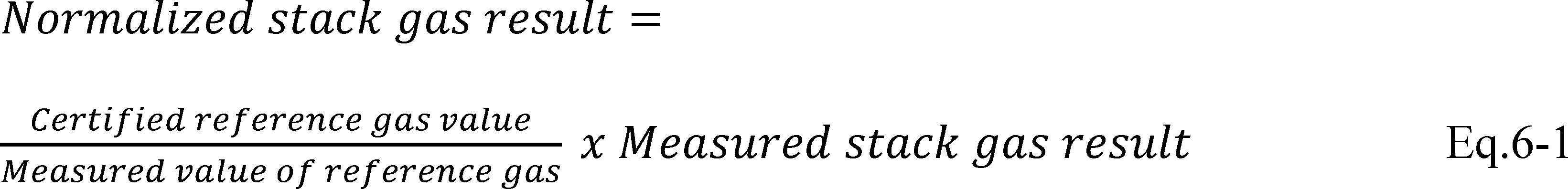
4.2 Beam Intensity Requirement for HCl IP-CEMS.
4.2.1 Beam Intensity Measurement. If you use a HCl IP-CEMS, you must quantify and record the beam intensity of the IP-CEMS in appropriate units at least once daily (approximately 24 hours apart) according to manufacturer's specifications and procedures.
4.2.2 Out of Control Criteria for Excessive Beam Intensity Loss. If the beam intensity falls below the level established for the operation range determined following the procedures in section 11.2 of PS-18 of this part, then your CEMS is out-of-control. This quality check is independent of whether the CEMS daily CD is acceptable. If your CEMS is out-of-control, take necessary corrective action. You have the option to repeat the beam intensity test procedures in section 11.2 of PS-18 to expand the acceptable range of acceptable beam intensity. Following corrective action, repeat the beam intensity check.
4.3 Out Of Control Period Duration for Daily Assessments. The beginning of the out-of-control period is the hour in which the owner or operator conducts a daily performance check (e.g., calibration drift or beam intensity check) that indicates an exceedance of the performance requirements established under this procedure. The end of the out-of-control period is the completion of daily assessment of the same type following corrective actions, which shows that the applicable performance requirements have been met.
4.4 CEMS Data Status During Out-of-Control Period. During the period the CEMS is out-of-control, the CEMS data may not be used in calculating compliance with an emissions limit nor be counted towards meeting minimum data availability as required and described in the applicable regulation or permit.
5.0 Data Accuracy Assessment
You must audit your CEMS for the accuracy of HCl measurement on a regular basis at the frequency described in this section, unless otherwise specified in an applicable regulation or permit. Quarterly audits are performed at least once each calendar quarter. Successive quarterly audits, to the extent practicable, shall occur no closer than 2 months apart. Annual audits are performed at least once every four consecutive calendar quarters.
5.1 Temperature and Pressure Accuracy Assessment for IP CEMS.
5.1.1 Stack or source gas temperature measurement audits for HCl IP-CEMS must be conducted and recorded at least annually in accordance with the procedure described in section 11.3 of PS-18 in appendix B to this part. As an alternative, temperature measurement devices may be replaced with certified instruments on an annual basis. Units removed from service may be bench tested against an NIST traceable sensor and reused during subsequent years. Any measurement instrument or device that is used to conduct ongoing verification of temperature measurement must have an accuracy that is traceable to NIST.
5.1.2 Stack or source gas pressure measurement audits for HCl IP-CEMS must be conducted and recorded at least annually in accordance with the procedure described in section 11.4 of PS-18 in appendix B of this part. As an alternative, pressure measurement devices may be replaced with certified instruments on an annual basis. Units removed from service may be bench tested against an NIST traceable sensor and reused during subsequent years. Any measurement instrument or device that is used to conduct ongoing verification of pressure measurement must have an accuracy that is traceable to NIST.
5.1.3 Out of Control Criteria for Excessive Parameter Verification Inaccuracy. If the temperature or pressure verification audit exceeds the criteria in sections 5.3.4.5 and 5.3.4.6, respectively, the CEMS is out-of-control. If the CEMS is out-of-control, take necessary corrective action to eliminate the problem. Following corrective action, you must repeat the failed verification audit until the temperature or pressure measurement device is operating within the applicable specifications, at which point the out-of-control period ends.
5.2 Concentration Accuracy Auditing Requirements. Unless otherwise specified in an applicable rule or permit, you must audit the HCl measurement accuracy of each CEMS at least once each calendar quarter, except in the case where the affected facility is off-line (does not operate). In that case, the audit must be performed as soon as is practicable in the quarter in which the unit recommences operation. Successive quarterly audits must, to the extent practicable, be performed no less than 2 months apart. The accuracy audits shall be conducted as follows:
5.2.1 Relative Accuracy Test Audit. A RATA must be conducted at least once every four calendar quarters, except as otherwise noted in sections 5.2.5 or 5.5 of this procedure. Perform the RATA as described in section 11.9 of PS-18 in appendix B to this part. If the HCl concentration measured by the RM during a RATA (in ppmv) is less than or equal to 20 percent of the concentration equivalent to the applicable emission standard, you must perform a Cylinder Gas Audit (CGA) or a Dynamic Spike Audit (DSA) for at least one subsequent (one of the following three) quarterly accuracy audits.
5.2.2 Quarterly Relative Accuracy Audit (RAA). A quarterly RAA may be conducted as an option to conducting a RATA in three of four calendar quarters, but in no more than three quarters in succession. To conduct an RAA, follow the test procedures in section 11.9 of PS-18 in appendix B to this part, except that only three test runs are required. The difference between the mean of the RM values and the mean of the CEMS responses relative to the mean of the RM values (or alternatively the emission standard) is used to assess the accuracy of the CEMS. Calculate the RAA results as described in section 6.2. As an alternative to an RAA, a cylinder gas audit or a dynamic spiking audit may be conducted.
5.2.3 Cylinder Gas Audit. A quarterly CGA may be conducted as an option to conducting a RATA in three of four calendar quarters, but in no more than three consecutive quarters. To perform a CGA, challenge the CEMS with a zero-level and two upscale level audit gases of known concentrations within the following ranges:
| Audit point | Audit range |
|---|---|
| 1 (Mid-Level) | 50 to 60% of span value. |
| 2 (High-Level) | 80 to 100% of span value. |
5.2.3.1 Inject each of the three audit gases (zero and two upscale) three times each for a total of nine injections. Inject the gases in such a manner that the entire CEMS is challenged. Do not inject the same gas concentration twice in succession.
5.2.3.2 Use HCl audit gases that meet the requirements of section 7 of PS-18 in appendix B to this part.
5.2.3.3 Calculate results as described in section 6.3.
5.2.4 Dynamic Spiking Audit. For extractive CEMS, a quarterly DSA may be conducted as an option to conducting a RATA in three of four calendar quarters, but in no more than three quarters in succession.
5.2.4.1 To conduct a DSA, you must challenge the entire HCl CEMS with a zero gas in accordance with the procedure in section 11.8 of PS-18 in appendix B of this part. You must also conduct the DS procedure as described in appendix A to PS-18 of appendix B to this part. You must conduct three spike injections with each of two upscale level audit gases. The upscale level gases must meet the requirements of section 7 of PS-18 in appendix B to this part and must be chosen to yield concentrations at the analyzer of 50 to 60 percent of span and 80 to 100 percent of span. Do not inject the same gas concentration twice in succession.
5.2.4.2 Calculate results as described in section 6.4. To determine CEMS accuracy, you must calculate the dynamic spiking error (DSE) for each of the two upscale audit gases using Equation A5 in appendix A to PS-18 and Equation 6-3 in section 6.4 of Procedure 6 in appendix B to this part.
5.2.5 Other Alternative Quarterly Audits. Other alternative audit procedures, as approved by the Administrator, may be used for three of four calendar quarters.
5.3 Out of Control Criteria for Excessive Audit Inaccuracy. If the results of the RATA, RAA, CGA, or DSA do not meet the applicable performance criteria in section 5.3.4, the CEMS is out-of-control. If the CEMS is out-of-control, take necessary corrective action to eliminate the problem. Following corrective action, the CEMS must pass a test of the same type that resulted in the out-of-control period to determine if the CEMS is operating within the specifications (e.g., a RATA must always follow an out-of-control period resulting from a RATA).
5.3.1 If the audit results show the CEMS to be out-of-control, you must report both the results of the audit showing the CEMS to be out-of-control and the results of the audit following corrective action showing the CEMS to be operating within specifications.
5.3.2 Out-Of-Control Period Duration for Excessive Audit Inaccuracy. The beginning of the out-of-control period is the time corresponding to the completion of the sampling for the failed RATA, RAA, CGA or DSA. The end of the out-of-control period is the time corresponding to the completion of the sampling of the subsequent successful audit.
5.3.3 CEMS Data Status During Out-Of-Control Period. During the period the CEMS is out-of-control, the CEMS data may not be used in calculating emission compliance nor be counted towards meeting minimum data availability as required and described in the applicable regulation or permit.
5.3.4 Criteria for Excessive Quarterly and Yearly Audit Inaccuracy. Unless specified otherwise in the applicable regulation or permit, the criteria for excessive inaccuracy are:
5.3.4.1 For the RATA, the CEMS must meet the RA specifications in section 13.4 of PS-18 in appendix B to this part.
5.3.4.2 For the CGA, the accuracy must not exceed 5.0 percent of the span value at the zero gas and the mid- and high-level reference gas concentrations.
5.3.4.3 For the RAA, the RA must not exceed 20.0 percent of the RMavg as calculated using Equation 6-2 in section 6.2 of this procedure whether calculated in units of HCl concentration or in units of the emission standard. In cases where the RA is calculated on a concentration (ppmv) basis, if the average HCl concentration measured by the RM during the test is less than 75 percent of the HCl concentration equivalent to the applicable standard, you may substitute the equivalent emission standard value (in ppmvw) in the denominator of Equation 6-2 in the place of RMavg and the result of this alternative calculation of RA must not exceed 15.0 percent.
5.3.4.4 For DSA, the accuracy must not exceed 5.0 percent of the span value at the zero gas and the mid- and high-level reference gas concentrations or 20.0 percent of the applicable emission standard, whichever is greater.
5.3.4.5 For the gas temperature measurement audit, the CEMS must satisfy the requirements in section 13.7 in PS-18 of appendix B to this part.
5.3.4.6 For the gas pressure measurement audit, the CEMS must satisfy the requirements in section 13.8 in PS-18 of appendix B to this part.
5.4 Criteria for Acceptable QC Procedures. Repeated excessive inaccuracies (i.e., out-of-control conditions resulting from the quarterly or yearly audits) indicate that the QC procedures are inadequate or that the CEMS is incapable of providing quality data. Therefore, whenever excessive inaccuracies occur for two consecutive quarters, you must revise the QC procedures (see section 3.0) or modify or replace the CEMS.
5.5 Criteria for Optional QA Test Frequency. If all the quality criteria are met in sections 4 and 5 of this procedure, the CEMS is in-control.
5.5.1 Unless otherwise specified in an applicable rule or permit, if the CEMS is in-control and if your source emits ≤75 percent of the HCl emission limit for each averaging period as specified in the relevant standard for eight consecutive quarters that include a minimum of two RATAs, you may revise your auditing procedures to use CGA, RAA or DSA each quarter for seven subsequent quarters following a RATA.
5.5.2 You must perform at least one RATA that meets the acceptance criteria every 2 years.
5.5.3 If you fail a RATA, RAA, CGA, or DSA, then the audit schedule in section 5.2 must be followed until the audit results meet the criteria in section 5.3.4 to start requalifying for the optional QA test frequency in section 5.5.
6.0 Calculations for CEMS Data Accuracy
6.1 RATA RA Calculation. Follow Equations 9 through 14 in section 12 of PS-18 in appendix B to this part to calculate the RA for the RATA. The RATA must be calculated either in units of the applicable emission standard or in concentration units (ppmv).
6.2 RAA Accuracy Calculation. Use Equation 6-2 to calculate the accuracy for the RAA. The RA may be calculated in concentration units (ppmv) or in the units of the applicable emission standard.

Where:
RA = Accuracy of the CEMS (percent)
MNavg = Average measured CEMS response during the audit in units of applicable standard or appropriate concentration.
RMavg = Average reference method value in units of applicable standard or appropriate concentration.
6.3 CGA Accuracy Calculation. For each gas concentration, determine the average of the three CEMS responses and subtract the average response from the audit gas value. For extractive CEMS, calculate the ME at each gas level using Equation 3A in section 12.3 of PS-18 in appendix B to this part. For IP-CEMS, calculate the ME at each gas level using Equation 6A in section 12.4.3 of PS-18 in appendix B to this part.
6.4 DSA Accuracy Calculation. DSA accuracy is calculated as a percent of span. To calculate the DSA accuracy for each upscale spike concentration, first calculate the DSE using Equation A5 in appendix A of PS-18 in appendix B to this part. Then use Equation 6-3 to calculate the average DSA accuracy for each upscale spike concentration. To calculate DSA accuracy at the zero level, use equation 3A in section 12.3 of PS-18 in appendix B to this part.

7.0 Reporting Requirements
At the reporting interval specified in the applicable regulation or permit, report for each CEMS the quarterly and annual accuracy audit results from section 6 and the daily assessment results from section 4. Unless otherwise specified in the applicable regulation or permit, include all data sheets, calculations, CEMS data records (i.e., charts, records of CEMS responses), reference gas certifications and reference method results necessary to confirm that the performance of the CEMS met the performance specifications.
7.1 Unless otherwise specified in the applicable regulations or permit, report the daily assessments (CD and beam intensity) and accuracy audit information at the interval for emissions reporting required under the applicable regulations or permits.
7.1.1 At a minimum, the daily assessments and accuracy audit information reporting must contain the following information:
a. Company name and address.
b. Identification and location of monitors in the CEMS.
c. Manufacturer and model number of each monitor in the CEMS.
d. Assessment of CEMS data accuracy and date of assessment as determined by a RATA, RAA, CGA or DSA described in section 5 including:
i. The RA for the RATA;
ii. The accuracy for the CGA, RAA, or DSA;
iiii. Temperature and pressure sensor audit results for IP-CEMS;
iv. The RM results, the reference gas certified values;
v. The CEMS responses;
vi. The calculation results as defined in section 6; and
vii. Results from the performance audit samples described in section 5 and the applicable RMs.
e. Summary of all out-of-control periods including corrective actions taken when CEMS was determined out-of-control, as described in sections 4 and 5.
7.1.2 If the accuracy audit results show the CEMS to be out-of-control, you must report both the audit results showing the CEMS to be out-of-control and the results of the audit following corrective action showing the CEMS to be operating within specifications.
8.0 Bibliography
1. EPA Traceability Protocol for Assay and Certification of Gaseous Calibration Standards, U.S. Environmental Protection Agency office of Research and Development, EPA/600/R-12/531, May 2012.
2. Method 205, “Verification of Gas Dilution Systems for Field Instrument Calibrations,” 40 CFR part 51, appendix M.
9.0 Tables, Diagrams, Flowcharts [Reserved]
[52 FR 21008, June 4, 1987; 52 FR 27612, July 22, 1987, as amended at 56 FR 5527, Feb. 11, 1991; 69 FR 1816, Jan. 12, 2004; 72 FR 32768, June 13, 2007; 74 FR 12590, Mar. 25, 2009; 75 FR 55040, Sept. 9, 2010; 79 FR 11274, Feb. 27, 2014; 79 FR 28441, May 16, 2014; 80 FR 38649, July 7, 2015; 81 FR 59824, Aug. 30, 2016; 82 FR 37824, Aug. 14, 2017; 82 FR 44108, Sept. 21, 2017; 83 FR 56725, Nov. 14, 2018; 85 FR 63418, Oct. 7, 2020]
Appendix G to Part 60—Provisions for an Alternative Method of Demonstrating Compliance With 40 CFR 60.43 for the Newton Power Station of Central Illinois Public Service Company
1. Designation of Affected Facilities
1.1 The affected facilities to which this alternative compliance method applies are the Unit 1 and 2 coal-fired steam generating units located at the Central Illinois Public Service Company's (CIPS) Newton Power Station in Jasper County, Illinois. Each of these units is subject to the Standards of Performance for Fossil-Fuel-Fired Steam Generators for Which Construction Commenced After August 17, 1971 (subpart D).
2. Definitions
2.1 All definitions in subparts D and Da of part 60 apply to this provision except that:
24-hour period means the period of time between 12:00 midnight and the following midnight.
Boiler operating day means a 24-hour period during which any fossil is combusted in either the Unit 1 or Unit 2 steam generating unit and during which the provisions of § 60.43(e) are applicable.
CEMs means continuous emission monitoring system.
Coal bunker means a single or group of coal trailers, hoppers, silos or other containers that:
(1) are physically attached to the affected facility; and
(2) provide coal to the coal pulverizers.
DAFGDS means the dual alkali flue gas desulfurization system for the Newton Unit 1 steam generating unit.
3. Compliance Provisions
3.1 If the owner or operator of the affected facility elects to comply with the 470 ng/J (1.1 lbs/MMBTU) of combined heat input emission limit under § 60.43(e), he shall notify the Regional Administrator, of the United States Environmental Protection Agency (USEPA), Region 5 and the Director, of the Illinois Environmental Protection Agency (IEPA) at least 30 days in advance of the date such election is to take effect, stating the date such operation is to commence. When the owner or operator elects to comply with this limit after one or more periods of reverting to the 520 ng/J heat input (1.2 lbs/MMBTU) limit of § 60.43(a)(2), as provided under 3.4, he shall notify the Regional Administrator of the USEPA, Region 5 and the Director of the (IEPA) in writing at least ten (10) days in advance of the date such election is to take effect.
3.2 Compliance with the sulfur dioxide emission limit under § 60.43(e) is determined on a continuous basis by performance testing using CEMs. Within 60 days after the initial operation of Units 1 and 2 subject to the combined emission limit in § 60.43(e), the owner or operator shall conduct an initial performance test, as required by § 60.8, to determine compliance with the combined emission limit. This initial performance test is to be scheduled so that the thirtieth boiler operating day of the 30 successive boiler operating days is completed within 60 days after initial operation subject to the 470 ng/J (1.1 lbs/MMBTU) combined emission limit. Following the initial performance test, a separate performance test is completed at the end of each boiler operating day Unit 1 and Unit 2 are subject to § 60.43(e), and a new 30 day average emission rate calculated.
3.2.1 Following the initial performance test, a new 30 day average emission rate is calculated for each boiler operating day the affected facility is subject to § 60.43(e). If the owner or operator of the affected facility elects to comply with § 60.43(e) after one or more periods of reverting to the 520 ng/J heat input (1.2 lbs/MMBTU) limit under § 60.43(a)(2), as provided under 3.4, the 30 day average emission rate under § 60.43(e) is calculated using emissions data of the current boiler operating day and data for the previous 29 boiler operating days when the affected facility was subject to § 60.43(e). Periods of operation of the affected facility under § 60.43(a)(2) are not considered boiler operating days. Emissions data collected during operation under § 60.43(a)(2) are not considered relative to 4.6 and emissions data are not included in calculations of emission under § 60.43(e).
3.2.2 When the affected facility is operated under the provisions of § 60.43(e), the Unit 1 DAFGDS bypass damper must be fully closed. The DAFGDS bypass may be opened only during periods of DAFGDS startup, shutdown, malfunction or testing as described under sections 3.5.1, 3.5.2, 3.5.3, 3.5.4, and 4.8.2.
3.3 Compliance with the sulfur dioxide emission limit set forth in § 60.43(e) is based on the average combined hourly emission rate from Units 1 and 2 for 30 successive boiler operating days determined as follows:

where:
n = the number of available hourly combined emission rate values in the 30 successive boiler operating day period where Unit 1 and Unit 2 are subject to § 60.43(e).
E30 = average emission rate for 30 successive boiler operating days where Unit 1 and Unit 2 are subject to § 60.43(e).
EC = the hourly combined emission rate from Units 1 and 2, in ng/J or lbs/MMBTU.
3.3.1 The average hourly combined emission rate for Units 1 and 2for each hour of operation of either Unit 1 or 2, or both, is determined as follows:
EC=[(E1) + (E2)]/[H1 + H2]
where:
EC = the hourly combined SO2 emission rate, lbs/MMBTU, from Units 1 and 2 when Units 1 and 2 are subject to § 60.43(e).
E1 = the hourly SO2 mass emission, lb/hr, from Unit 1 as determined from CEMs data using the calculation procedures in section 4 of this appendix.
E2 = the hourly SO2 mass emission, lb/hr, from Unit 2 as determined from CEMs data using the calculation procedures in section 4 of this appendix.
H1 = the hourly heat input, MMBTU/HR to Unit 1 as determined in section 4 of this appendix.
H2 = the hourly heat input, MMBTU/HR, to Unit 2 as determined by section 4 of this appendix.
3.3.2 If data for any of the four hourly parameters (E1, E2, H1and H2, under 3.3.1 are unavailable during an hourly period, the combined emission rate (EC) is not calculated and the period is counted as missing data under 4.6.1., except as provided under 3.5. and 4.4.2.
3.4 After the date of initial operation subject to the combined emission limit, Units 1 and 2 shall remain subject to the combined emission limit and the owner or operator shall remain subject to the requirements of this Appendix until the initial performance test as required by 3.2 is completed and the owner or operator of the affected facility elects and provides notice to revert on a certain date to the 520 ng/J heat input (1.2 lbs/MMBTU) limit of § 60.43(a)(2) applicable separately at each unit. The Regional Administrator of the USEPA, Region 5 and the Director, of the IEPA shall be given written notification from CIPS as soon as possible of CIPs' decision to revert to the 520 ng/J heat input (1.2 lbs/MMBTU) limit of § 60.43(a)(2) separately at each unit, but no later than 10 days in advance of the date such election is to take effect.
3.5 Emission monitoring data for Unit 1 may be excluded from calculations of the 30 day rolling average only during the following times:
3.5.1 Periods of DAFGDS startup.
3.5.2 Periods of DAFGDS shutdown.
3.5.3 Periods of DAFGDS malfunction during system emergencies as defined in § 60.41a.
3.5.4 The first 250 hours per calendar year of DAFGDS malfunctions of Unit 1 DAFGDS provided that efforts are made to minimize emissions from Unit 1 in accordance with § 60.11(d), and if, after 16 hours but not more than 24 hours of DAFGDS malfunction, the owner or operator of the affected facility begins (following the customary loading procedures) loading into the Unit 1 coal bunker, coal with a potential SO2 emission rate equal to or less than the emission rate of Unit 2 recorded at the beginning of the DAFGDS malfunction. Malfunction periods under 3.5.3 are not counted toward the 250 hour/yr limit under this section.
3.5.4.1 The malfunction exemption in 3.5.4 is limited to the first 250 hours per calendar year of DAFGDS malfunction.
3.5.4.2 For malfunctions of the DAFGDS after the 250 hours per calendar year limit (cumulative), other than those defined in 3.5.3, the owner or operator of the affected facility shall combust lower sulfur coal or use any other method to comply with the 470 ng/J (1.1 lbs/MMBTU) combined emission limit.
3.5.4.3 During the first 250 hours of DAFGDS malfunction per year or during periods of DAFGDS startup, or DAFGDS shutdown, CEMs emissions data from Unit 2 shall continue to be included in the daily calculation of the combined 30 day rolling average emission rate; that is, the load on Unit 1 is assumed to be zero (H1 and E1 = O; EC = E2/H2).
3.5.5 -3.5.7 [Reserved]
3.6 The provision for excluding CEMs data from Unit 1 during the first 250 hours of DAFGDS malfunctions from combined hourly emissions calculations supersedes the provisions of § 60.11(d). However, the general purpose contained in § 60.11(d) (i.e., following good control practices to minimize air pollution emission during malfunctions) has not been superseded.
4. Continuous Emission Monitoring
4.1 The CEMs required under section 3.2 are operated and data are recorded for all periods of operation of the affected facility including periods of the DAFGDS startup, shutdown and malfunction except for CEMs breakdowns, repairs, calibration checks, and zero and span adjustment. All provisions of § 60.45 apply except as follows:
4.2 The owner or operator shall install, calibrate, maintain, and operate CEMs and monitoring devices for measuring the following:
4.2.1 For Unit 1:
4.2.1.1 Sulfur dioxide, oxygen or carbon dioxide, and volumetric flow rate for the Unit 1 DAFGDS stack.
4.2.1.2 Sulfur dioxide, oxygen or carbon dioxide, and volumetric flow rate for the Unit 1 DAFGDS bypass stack.
4.2.1.3 Moisture content of the flue gas must be determined continuously for the Unit 1 DAFGDS stack and the Unit 1 DAFGDS bypass stack, if the sulfur dioxide concentration in each stack is measured on a dry basis.
4.2.2 For Unit 2, sulfur dioxide, oxygen or carbon dioxide, and volumetric flow rate.
4.2.2.1 Moisture content of the flue gas must be determined continuously for the Unit 2 stack, if the sulfur dioxide concentration in the stack is measured on a dry basis.
4.2.3 For Units 1 and 2, the hourly heat input, the hourly steam production rate, or the hourly gross electrical power output from each unit.
4.3 For the Unit 1 bypass stack and the Unit 2 stack, the span value of the sulfur dioxide analyzer shall be equivalent to 200 percent of the maximum estimated hourly potential sulfur dioxide emissions of the fuel fired in parts per million sulfur dioxide. For the Unit 1 DAFGDS stack, the span value of the sulfur dioxide analyzer shall be equivalent to 100 percent of the maximum estimated hourly potential emissions of the fuel fired in parts per million sulfur dioxide. The span value for volumetric flow monitors shall be equivalent to 125 percent of the maximum estimated hourly flow in standard cubic meters/minute (standard cubic feet per minute). The span value of the continuous moisture monitors, if required by 4.2.1.3 and 4.2.2.1, shall be equivalent to 100 percent by volume. The span value of the oxygen or carbon dioxide analyzers shall be equivalent to 25 percent by volume.
4.3.1 -4.3.2 [Reserved]
4.4 The monitoring devices required in 4.2 shall be installed, calibrated, and maintained as follows:
4.4.1 Each volumetric flow rate monitoring device specified in 4.2 shall be installed at approximately the same location as the sulfur dioxide emission monitoring sample location.
4.4.2 Hourly steam production rate and hourly electrical power output monitoring devices for Unit 1 and Unit 2 shall be calibrated and maintained according to manufacturer's specifications. The data from either of these devices may be used in the calculation of the combined emission rate in section 3.3.1, only when the hourly heat input for Unit 1 (H1) or the hourly heat input for Unit 2 (H2) cannot be determined from CEM data, and the hourly heat input to steam production or hourly heat input to electrical power output efficiency over a given segment of each boiler or generator operating range, respectively, varies by less than 5 percent within the specified operating range, or the efficiencies of the boiler/generator units differ by less than 5 percent. The hourly heat input for Unit 1 (H1) or the hourly heat input for Unit 2 (H2) in section 3.3.1 may also be calculated based on the fuel firing rates and fuel analysis.
4.4.3 -4.4.5 [Reserved]
4.5 The hourly mass emissions from Unit 1 (E1) and Unit 2 (E2) and the hourly heat inputs from Unit 1 (H1) and Unit 2 (H2) used to determine the hourly combined emission rate for Units 1 and 2 (EC) in section 3.3.1 are calculated using CEM data for each respective stack as follows:
4.5.1 The hourly SO2 mass emission from each respective stack is determined as follows:
E = (C) (F) (D) (K)
Where:
E = SO2 mass emission from the respective stack in lb per hour
C = SO2 concentration from the respective stack ppm
F = flue gas flow rate from the respective stack in scfm
D = density of SO2 in lb per standard cubic feet
K = time conversion, 60 mins./hr
4.5.2 The hourly heat input from each respective stack is determined as follows:
H=[(F) (C) (K)/(Fc)
where:
H = heat input from the respective stack in MMBTU per hour
C = CO2 or O2 concentration from the respective stack as a decimal
F = flue gas flow rate from the respective stack in scfm
K = time conversion, 60 mins./hr
Fc = fuel constant for the appropriate diluent in scf/MMBTU as per §§ 60.45(f) (4) and (5)
4.5.3 The hourly SO2 mass emission for Unit 1 in pounds per hour (E1) is calculated as follows, when leakage or diversion of any DAFGDS inlet gas to the bypass stack occurs:
E1 = (EF) + (EB)
Where:
EF = Hourly SO2 mass emission measured in DAFGDS stack, lb/hr, using the calculation in section 4.5.1.
EB = Hourly SO2 mass emission measured in bypass stack, lb/hr, using the calculation in section 4.5.1.
Other than during conditions under 3.5.1, 3.5.2, 3.5.3, 3.5.4, or 4.8.2, the DAFGDS bypass damper must be fully closed and any leakage will be indicated by the bypass stack volumetric flow and SO2 measurements, and when no leakage through the bypass damper is indicated:
E1 = EF
4.5.4 The hourly heat input for Unit 1 in MMBTU per hour (H1) is calculated as follows, when leakage or diversion of any DAFGDS inlet gas to the bypass stack occurs:
H1 = (HF) + (HB)
where:
HF = Hourly heat input as determined from the DAFGDS stack CEMs, in MMBTU per hour, using the calculation in section 4.5.2
HB = Hourly heat input as determined from the DAFGDS bypass stack CEMs, in MMBTU per hour, using the calculation in section 4.5.2
4.6 For the CEMs required for Unit 1 and Unit 2, the owner or operator of the affected facility shall maintain and operate the CEMs and obtain combined emission data values (EC) for at least 75 percent of the boiler operting hours per day for at least 26 out of each 30 successive boiler operating days.
4.6.1 When hourly SO2 emission data are not obtained by the CEMs because of CEMs breakdowns, repairs, calibration checks and zero and span adjustment, hourly emission data required by 4.6 are obtained by using Methods 6 or 6C and 3 or 3A, 6A, or 8 and 3, or by other alternative methods approved by the Regional Administrator of the USEPA, Region 5 and the Director, of the IEPA. Failure to obtain the minimum data requirements of 4.6 by CEMs, or by CEMs supplemented with alternative methods of this section, is a violation of performance testing requirements.
4.6.2 Independent of complying with the minimum data requirements of 4.6, all valid emissions data collected are used to calculate combined hourly emission rates (EC) and 30-day rolling average emission rates (E30) are calculated and used to judge compliance with 60.43(e).
4.7 For each continuous emission monitoring system, a quality control plan shall be prepared by CIPS and submitted to the Regional Administrator of the USEPA, Region 5 and the Director, of the IEPA. The plan is to be submitted to the Regional Administrator of the USEPA, Region 5 and the Director, of the IEPA 45 days before initiation of the initial performance test. At a minimum, the plan shall contain the following quality control elements:
4.7.1 Calibration of continuous emission monitoring systems (CEMs) and volumetric flow measurement devices.
4.7.2 Calibration drift determination and adjustment of CEMs and volumetric flow measurement devices.
4.7.3 Periodic CEMs, volumetric flow measurement devices and relative accuracy determinations.
4.7.4 Preventive maintenance of CEMs and volumetric flow measurement devices (including spare parts inventory).
4.7.5 Data recording and reporting.
4.7.6 Program of corrective action for malfunctioning CEMs and volumetric flow measurement devices.
4.7.7 Criteria for determining when the CEMs and volumetric flow measurement devices are not producing valid data.
4.7.8 Calibration and periodic checks of monitoring devices identified in 4.4.2.
4.8 For the purpose of conducting the continuous emission monitoring system performance specification tests as required by § 60.13 and appendix B, the following conditions apply:
4.8.1 The calibration drift specification of Performance Specification 2, appendix B shall be determined separately for each of the Unit 1 SO2 CEMs and the Unit 2 SO2 CEMs. The calibration drift specification of Performance Specification 3, appendix B shall be determined separately for each of the Unit 1 diluent CEMs and Unit 2 diluent CEMs.
4.8.2 The relative accuracy of the combined SO2 emission rate for Unit 1 and Unit 2, as calculated from CEMs and volumetric flow data using the procedures in 3.3.1, 4.5.1, 4.5.2 and 4.5.3 shall be no greater than 20 percent of the mean value of the combined emission rate, as determined from testing conducted simultaneously on the DAFGDS stack, the DAFGDS bypass stack and the Unit 2 stack using reference methods 2, 3, or 3A and 6 or 6C, or shall be no greater than 10 percent of the emission limit in § 60.43(e), whichever criteria is less stringent. The relative accuracy shall be computed from at least nine comparisons of the combined emission rate values using the procedures in section 7 and the equations in section 8, Performance Specification 2, appendix B. Throughout, but only during, the relative accuracy test period the DAFGDS bypass damper shall be partially opened such that there is a detectable flow.
4.8.3 -4.8.3.4 [Reserved]
4.9 The total monitoring system required by 4.2 shall be subject only to an annual relative accuracy test audit (RATA) in accordance with the quality assurance requirements of section 5.1.1 of 40 CFR part 60, appendix F. Each SO2 and diluent CEMs shall be subject to cylinder gas audits (OGA) in accordance with the quality assurance requirements of section 5.1.2 of appendix F with the exception that any SO2 or diluent CEMs without any type of probe or sample line shall be exempt from the OGA requirements.
5. Recordkeeping Requirements
5.1 The plant owner or operator shall keep a record of each hourly emission rate, each hourly SO2 CEMs value and hourly flow rate value, and each hourly Btu heat input rate, hourly steam rate, or hourly electrical power output, and a record of each hourly weighted average emission rate. These records shall be kept for all periods of operation of Unit 1 or 2 under provisions of § 60.43(e), including operations of Unit 1 (E1) during periods of DAFGDS startup, shutdown, and malfunction when H1 and E1 are assumed to be zero (0) (see 4.5).
5.2 The plant owner or operator shall keep a record of each hourly gas flow rate through the DAFGDS stack, each hourly stack gas flow rate through the bypass stack during any periods that the DAFGDS bypass damper is opened or flow is indicated, and reason for bypass operation.
6. Reporting Requirements
6.1 The owner or operator of any affected facility shall submit the written reports required under 6.2 of this section and subpart A to the Regional Administrator of the USEPA, Region 5 and the Director, of the IEPA for every calendar quarter. All quarterly reports shall be submitted by the 30th day following the end of each calendar quarter.
6.2 For sulfur dioxide, the following data resubmitted to the Regional Administrator of the USEPA, Region 5 and the Director, of the IEPA for each 24-hour period:
6.2.1 Calendar date
6.2.2 The combined average sulfur dioxide emission rate (ng/J or lb/million Btu) for the past 30 successive boiler operating days (ending with the last 30-day period in the quarter); and, for any noncompliance periods, reasons for noncompliance with the emission standards and description of corrective action taken.
6.2.3 Identification of the boiler operating days for which valid sulfur dioxide emissions data required by 4.6 have not been obtained for 75 percent of the boiler operating hours; reasons for not obtaining sufficient data; and description of corrective actions taken to prevent recurrence.
6.2.4 Identification of the time periods (hours) when Unit 1 or Unit 2 were operated but combined hourly emission rates (EC) were not calculated because of the unavailability of parameters E1, E2, H1, or H2 as described in 3.2.
6.2.5 Identification of the time periods (hours) when Unit 1 and Unit 2 were operated and where the combined hourly emission rate (EC) equalled Unit 2 (E2/H2) emissions because of the Unit 1 malfunction provisions under 3.5.3, and 3.5.4.
6.2.6 Identification of the time periods (hours) when emissions from the Unit 1 DAFGDS have been excluded from the calculation of average sulfur dioxide emission rates because of Unit 1 DAFGDS startup, shutdown, malfunction, or other reasons; and justification for excluding data for reasons other than startup or shutdown. Reporting of hourly emission rate of Unit 1 (E1/H2) during each hour of the DAFGDS startup, malfunction under 3.5.1, 3.5.2, 3.5.3, and 3.5.4 (see 4.5).
6.2.7 Identification of the number of days in the calendar quarter that the affected facility was operated (any fuel fired).
6.2.8 Identify any periods where Unit 1 DAFGDS malfunctions occurred and the cumulative hours of Unit 1 DAFGDS malfunction for the quarter.
6.2.9 Identify any periods of time that any exhaust gases were discharged to the DAFGDS bypass stack and the hourly gas flow rate through the DAFGDS stack and through the DAFGDS bypass stack during such periods and reason for bypass operation.
6.2.10 [Reserved]
[52 FR 28955, Aug. 4, 1987, as amended at 58 FR 28785, May 17, 1993; 59 FR 8135, Feb. 18, 1994]
Appendix H to Part 60 [Reserved]
Appendix I to Part 60 - Owner's Manuals and Temporary Labels for Wood Heaters Subject to Subparts AAA and QQQQ of Part 60
1. Introduction
The purpose of this appendix is to provide specific instructions and examples to manufacturers for compliance with the owner's manual provisions of subparts AAA and QQQQ of this part.
2. Instructions for Preparation of Wood Heater Owner's Manuals
2.1 Introduction
Although the owner's manuals do not require premarket approval, EPA will monitor the contents to ensure that sufficient information is included to provide heater proper operation and maintenance information affecting emissions to consumers. The manufacturer must make current and historical owner's manuals available on the company Web site and upon request to the EPA. The purpose of this section is to provide instructions to manufacturers for compliance with the owner's manual provisions of § 60.536(g) of subpart AAA that applies to wood heaters and § 60.5478(f) of subpart QQQQ that applies to hydronic heaters and forced-air furnaces. A checklist of topics and illustrative language is provided as instructions. Owner's manuals should be tailored to specific wood heater models, as appropriate.
2.2 Topics Required To Be Addressed in Owner's Manual
(a) Wood heater description and compliance status;
(b) Tamper warnings;
(c) Overall heater warranty information and catalyst information and warranty (if catalyst-equipped);
(d) Fuel selection;
(e) Achieving and maintaining catalyst light-off (if catalyst-equipped);
(f) Catalyst monitoring (if catalyst-equipped);
(g) Troubleshooting catalytic-equipped heaters (if catalyst-equipped);
(h) Catalyst replacement (if catalyst-equipped);
(i) Wood heater proper operation and maintenance, including minimizing visible emissions;
(j) Wood heater proper installation, including location, stack height and achieving proper draft;
(k) Use of smoke detectors and carbon monoxide monitors; and
(l) Efficiency.
2.3 Sample Text/Descriptions
(a) The following are example texts and/or further descriptions illustrating the topics identified above. Although the regulation requires manufacturers to address (where applicable) the 10 topics identified above, the exact language is not specified. Manuals should be written specific to the model and design of the wood heater. The following instructions are composed of generic descriptions and texts.
(b) If manufacturers choose to use the language provided in the example, the portion in italics should be revised as appropriate. Any manufacturer electing to use the EPA example language will be considered to be in compliance with owner's manual requirements provided that the particular language is printed in full with only such changes as are necessary to ensure accuracy.
Example language is not provided for certain topics, since these areas are generally heater specific. For these topics, manufacturers should develop text that is specific to the proper operation and maintenance of their particular products.
2.3.1 Wood Heater Description and Compliance Status
Owner's manuals must include:
(a) Manufacturer and model;
(b) Compliance status (2015 standard, 2016 standard, 2017 standard, 2020 standard, crib wood standard or cord wood alternative standard, last allowable sell date, etc.); and
(c) Heat output range.
Exhibit 1 - Example Text covering 2.3.1(a), (b), and (c) of this appendix:
“This manual describes the installation and operation of the Brand X, Model 0 catalytic equipped wood heater. This heater meets the 2015 U.S. Environmental Protection Agency's crib wood emission limits for wood heaters sold after May 15, 2015. Under specific test conditions this heater has been shown to deliver heat at rates ranging from 8,000 to 35,000 Btu/hr.”
2.3.2 Tamper Warnings
(a) The following statement must be included in the owner's manual for all units:
“This wood heater has a manufacturer-set minimum low burn rate that must not be altered. It is against federal regulations to alter this setting or otherwise operate this wood heater in a manner inconsistent with operating instructions in this manual.”
(b) The following statement must be included in the owner's manual for catalyst-equipped units:
“This wood heater contains a catalytic combustor, which needs periodic inspection and replacement for proper operation. It is against federal regulations to operate this wood heater in a manner inconsistent with operating instructions in this manual, or if the catalytic element is deactivated or removed.”
2.3.3 Overall Heater Warranty Information and Catalyst Information and Warranty (if catalyst-equipped)
The following information must be included with or supplied in the owner's and warranty manuals:
(a) Manufacturer and model, including catalyst if catalyst-equipped;
(b) Warranty details, including catalyst if catalyst-equipped; and
(c) Instructions for warranty claims.
Exhibit 2 - Example Text covering 2.3.3(a), (b), and (c) of this appendix for catalysts:
“The combustor supplied with this heater is a Brand Z, Long Life Combustor. Consult the catalytic combustor warranty also supplied with this wood heater. Warranty claims should be addressed to:
Stove or Catalyst Manufacturer
Address
Phone #______________”
2.3.3.1 This section should also provide clear instructions on how to exercise the warranty (how to package parts for return shipment, etc.).
2.3.4 Fuel Selection
Owner's manuals must include:
(a) Instructions on acceptable fuels;
(b) Warning against inappropriate fuels; and
(c) How to determine seasoned wood compared to unseasoned wood, how to use moisture meters and other techniques and the importance of seasoned wood.
Exhibit 3 - Example Text covering 2.3.4(a) and (b) of this appendix:
“This heater is designed to burn natural wood only. Higher efficiencies and lower emissions generally result when burning air dried seasoned hardwoods, as compared to softwoods or to green or freshly cut hardwoods. DO NOT BURN:
(1) Garbage;
(2) Lawn clippings or yard waste;
(3) Materials containing rubber, including tires;
(4) Materials containing plastic;
(5) Waste petroleum products, paints or paint thinners, or asphalt products;
(6) Materials containing asbestos;
(7) Construction or demolition debris;
(8) Railroad ties or pressure-treated wood;
(9) Manure or animal remains;
(10) Salt water driftwood or other previously salt water saturated materials;
(11) Unseasoned wood; or
(12) Paper products, cardboard, plywood, or particleboard. The prohibition against burning these materials does not prohibit the use of fire starters made from paper, cardboard, saw dust, wax and similar substances for the purpose of starting a fire in an affected wood heater.
Burning these materials may result in release of toxic fumes or render the heater ineffective and cause smoke.”
2.3.5 Achieving and Maintaining Catalyst Light-Off
Owner's manuals must describe in detail proper procedures for:
(a) Operation of catalyst bypass (stove specific);
(b) Achieving catalyst light-off from a cold start; and
(c) Achieving catalyst light-off when refueling.
2.3.5.1 No example text is supplied for describing operation of catalyst bypass mechanisms (Item 2.3.5(a) of this appendix) since these are typically stove-specific. Manufacturers must provide instructions specific to their model describing:
(1) Bypass position during startup;
(2) Bypass position during normal operation; and
(3) Bypass position during reloading.
Exhibit 4 - Example Text for Item 2.3.5(b) of this appendix:
“The temperature in the stove and the gases entering the combustor must be raised to between 500 ° to 700 °F for catalytic activity to be initiated. During the startup of a cold stove, a medium to high firing rate must be maintained for about 20 minutes. This ensures that the stove, catalyst, and fuel are all stabilized at proper operating temperatures. Even though it is possible to have gas temperatures reach 600 °F within 2 to 3 minutes after a fire is started, if the fire is allowed to die down immediately, it may go out or the combustor may stop working. Once the combustor starts working, heat generated in it by burning the smoke will keep it working.”
Exhibit 5 - Example Text for Item 2.3.5(c) of this appendix:
“REFUELING: During the refueling and rekindling of a cool fire, or a fire that has burned down to the charcoal phase, operate the stove at a medium to high firing rate for about 10 minutes to ensure that the catalyst reaches approximately 600 °F.”
2.3.6 Catalyst Monitoring
Owner's manuals must include:
(a) Recommendation to visually inspect combustor at least three times during the heating season;
(b) Discussion on expected combustor temperatures for monitor-equipped units; and
(c) Suggested monitoring and inspection techniques and importance of ensuring catalyst is operating properly.
Exhibit 6 - Example Text covering 2.3.6(a), (b) and (c) of this appendix:
“It is important to periodically monitor the operation of the catalytic combustor to ensure that it is functioning properly and to determine when it needs to be replaced. A non-functioning combustor will result in a loss of heating efficiency, and an increase in creosote and emissions. Following is a list of items that should be checked on a periodic basis:
• Combustors should be visually inspected at least three times during the heating season to determine if physical degradation has occurred. Actual removal of the combustor is not recommended unless more detailed inspection is warranted because of decreased performance. If any of these conditions exists, refer to Catalyst Troubleshooting section of this owner's manual.
• This catalytic (or hybrid) heater is equipped with a temperature probe to monitor catalyst operation. Properly functioning combustors typically maintain temperatures in excess of 500 °F, and often reach temperatures in excess of 1,000 °F. If catalyst temperatures are not in excess of 500 °F, refer to Catalyst Troubleshooting section of this owner's manual.
• You can get an indication of whether the catalyst is working by comparing the amount of smoke leaving the chimney when the smoke is going through the combustor and catalyst light-off has been achieved, to the amount of smoke leaving the chimney when the smoke is not routed through the combustor (bypass mode).
Step 1 - Light stove in accordance with instructions in section 3.3.5.
Step 2 - With smoke routed through the catalyst, go outside and observe the emissions leaving the chimney.
Step 3 - Engage the bypass mechanism and again observe the emissions leaving the chimney.
Significantly more smoke will be seen when the exhaust is not routed through the combustor (bypass mode).”
2.3.7 Catalyst Troubleshooting
The owner's manual must provide clear descriptions of symptoms and remedies to common combustor problems and importance. It is recommended that photographs of catalyst peeling, plugging, thermal cracking, mechanical cracking, and masking be included in the manual to aid the consumer in identifying problems and to provide direction for corrective action.
2.3.8 Catalyst Replacement
The owner's manual must provide clear step-by-step instructions on how to remove and replace the catalytic combustor. The section should include diagrams and/or photographs.
2.3.9 Wood Heater Proper Operation and Maintenance
The owner's manual must provide clear descriptions of symptoms and remedies to common heater problems and importance. The owner's manual information must be adequate to enable consumers to achieve optimal emissions performance. Such information must be consistent with the operating instructions provided by the manufacturer to the approved test laboratory for operating the wood heater during certification testing, except for details of the certification test that would not be relevant to the user.
Owner's manual must include:
(a) Recommendations about building and maintaining a fire, especially for cold starts and the effectiveness of the top-down approach for starting fires;
(b) Instruction on proper use of air controls, including how to establish good combustion and how to ensure good combustion at the lowest burn rate for which the heater is warranted;
(c) Ash removal and disposal;
(d) Instruction replacement of gaskets, air tubes and other parts that are critical to the emissions performance of the unit, and other maintenance and repair instructions;
(e) Warning against overfiring; and
(f) Suggested monitoring and inspection techniques and importance of ensuring heater is operating properly, including ensuring visible emissions are minimized.
2.3.9.1 No example text is supplied for 2.3.9(a), (b), (d) and (f) of this appendix since these items are model specific. Manufacturers should provide detailed instructions on building and maintaining a fire including selection of fuel pieces, fuel quantity and stacking arrangement. Manufacturers should also provide instruction on proper air settings (both primary and secondary) for attaining minimum and maximum heat outputs and any special instructions for operating thermostatic controls. Step-by-step instructions on inspection and replacement of gaskets should also be included. Manufacturers should provide diagrams and/or photographs to assist the consumer. Gasket type and size should be specified.
Exhibit 7 - Example Text for Item 2.3.9(c) of this appendix:
“Whenever ashes get 3 to 4 inches deep in your firebox or ash pan, and when the fire has burned down and cooled, remove excess ashes. Leave an ash bed approximately 1 inch deep on the firebox bottom to help maintain a hot charcoal bed.”
“Ashes should be placed in a metal container with a tight-fitting lid. The closed container of ashes should be placed on a noncombustible floor or on the ground, away from all combustible materials, pending final disposal. The ashes should be retained in the closed container until all cinders have thoroughly cooled.”
Exhibit 8 - Example Text covering Item 2.3.9(e) of this appendix:
“DO NOT OVERFIRE THIS HEATER”
“Attempts to achieve heat output rates that exceed heater design specifications can result in permanent damage to the heater and to the catalytic combustor if so equipped.”
2.3.10 Wood Heater Installation, Including Stack Height, Heater Locations and Achieving Proper Draft
Owner's manual must include:
(a) Importance of proper draft;
(b) Conditions indicating inadequate draft;
(c) Conditions indicating excessive draft; and
(d) Guidance on proper stack height and proper heater locations, i.e., not too close to neighbors or in valleys that would cause unhealthy air quality or nuisance conditions.
2.3.10.1 No example text is supplied for (d) because state, local and tribal requirements are model and location specific.
Exhibit 9 - Example Text for Item (a):
“Draft is the force which moves air from the appliance up through the chimney. The amount of draft in your chimney depends on the length of the chimney, local geography, nearby obstructions and other factors. Too much draft may cause excessive temperatures in the appliance and may damage the catalytic combustor. Inadequate draft may cause backpuffing into the room and 'plugging' of the chimney or the catalyst.”
Exhibit 10 - Example Text for Item (b):
“Inadequate draft will cause the appliance to leak smoke into the room through appliance and chimney connector joints.”
Exhibit 11 - Example Text for Item (c):
“An uncontrollable burn or excessive temperature indicates excessive draft.”
2.3.11 Efficiency
Owner's manual must include:
(a) Description of how the efficiency was determined, e.g., use higher heating value of the fuel instead of lower heating value of the fuel, discuss sweet spot versus annual average versus annual fuel usage efficiency (AFUE);
(b) How operation and fuels affect efficiency, e.g., seasoned wood versus high moisture fuel; operation at sweet spot versus low-burn rates; and
(c) How location affects the efficiency, e.g., in main living area versus basement versus outdoors in sub-freezing temperatures.
2.3.12 Smoke and Carbon Monoxide Emissions and Monitors
Owner's manual must include:
(a) Discussion of smoke and carbon monoxide (CO) emissions, including the CO data submitted in the certification application and expected variations for different operating conditions;
(b) Recommendation to have smoke monitors; and
(c) Recommendation to have monitors for areas that are expected to generate CO, e.g., heater fueling areas, pellet fuel bulk storage areas, sheds containing hydronic heaters.
3. Instructions for Preparation of Wood Heater Temporary Labels
3.1 Temporary labels that show the values for emissions, efficiency, recommended heating area and the compliance status may (voluntarily) be affixed by the manufacturer to wood heaters that meet the 2020 particulate matter emission standards early or that meet the cord wood alternative compliance options in subparts AAA and QQQQ of this part.
3.2 The seller of each heater covered by section 3.1 may ensure that the temporary label remains affixed until each heater is purchased by the end user.
3.3 The temporary label option for the 2020 particulate matter emission standards end as of May 15, 2020.
3.4 The template for the temporary labels will be supplied by the Administrator upon request.
[80 FR 13751, Mar. 16, 2015]